Embed Size (px)
Citation preview

21 Feb 2006 4:35 AR ANRV272-PC57-06.tex XMLPublishSM(2004/02/24) P1: KUV
10.1146/annurev.physchem.55.091602.094337
Annu. Rev. Phys. Chem. 2006. 57:159–90doi: 10.1146/annurev.physchem.55.091602.094337
Copyright c© 2006 by Annual Reviews. All rights reservedFirst published online as a Review in Advance on December 1, 2005
STARK DECELERATION AND TRAPPING
OF OH RADICALS
Sebastiaan Y.T. van de Meerakker, Nicolas Vanhaecke,and Gerard MeijerFritz-Haber-Institut der Max-Planck-Gesellschaft, 14195 Berlin, Germany;email: [email protected], [email protected],[email protected]
Key Words cold molecules
■ Abstract The motion of polar molecules can be controlled by time-varying in-homogeneous electric fields. In a Stark decelerator, this is exploited to accelerate,transport, or decelerate a fraction of a molecular beam. When combined with a trap,the decelerator provides a means to store the molecules for times up to seconds. Here,we review our efforts to produce cold molecules via this technique. In particular, wepresent a new generation Stark decelerator and electrostatic trap that selects a signifi-cant part of a molecular beam pulse that can be loaded into the trap. Deceleration andtrapping experiments using a beam of OH radicals are discussed.
1. INTRODUCTION
Getting better control over both the internal and external degrees of freedom ofgas-phase molecules has been an important theme in molecular physics during thepast decades. Molecular beams, both continuous and pulsed, are used throughout toproduce large densities of molecules in selected quantum states (1). In these beams,the longitudinal temperature of the molecules is typically 1 K. State selection ofa beam of (polar) molecules, and control over the orientation of the moleculesin space, can be achieved by actively manipulating the transverse motion of themolecules using electrostatic or magnetic multipole fields, as well as with the helpof laser radiation (1, 2, 3). Sophisticated and powerful detection schemes have beendeveloped to experimentally study (half-) collisions (4, 5) and reactions (6, 7) of thethus prepared molecules in the required detail. Molecular beams have thereforebeen indispensable in a number of research areas, such as molecular (reactive)scattering studies, high-resolution spectroscopy, and surface science, as well as,for instance, the production and investigation of transient species. Until recently,it was difficult to obtain full control over the longitudinal motion of molecules ina molecular beam. The mean velocity of the beam can be varied by adjusting thetemperature of the source or by using different seed gases, allowing the production
0066-426X/06/0505-0159$20.00 159
Ann
u. R
ev. P
hys.
Che
m. 2
006.
57:1
59-1
90. D
ownl
oade
d fr
om w
ww
.ann
ualr
evie
ws.
org
Acc
ess
prov
ided
by
WIB
6417
- M
ax-P
lanc
k-G
esel
lsch
aft o
n 04
/11/
17. F
or p
erso
nal u
se o
nly.

21 Feb 2006 4:35 AR ANRV272-PC57-06.tex XMLPublishSM(2004/02/24) P1: KUV
160 VAN DE MEERAKKER � VANHAECKE � MEIJER
of beams in the 250–3000 m s−1 range. However, more precise control over thelongitudinal motion, i.e., the ability to vary the velocity (distribution) of the beamto any desired (low) value, was not possible until the development of the so-calledStark deceleration technique. The Stark decelerator for neutral polar moleculesis the equivalent of a linear accelerator (LINAC) for charged particles. In a Starkdecelerator, the quantum state specific force that a polar molecule experiences inan electric field is exploited. This force is rather weak, typically some eight toten orders of magnitude weaker than the force that the corresponding molecularion would experience in the same electric field. This force nevertheless sufficesto achieve complete control over the motion of polar molecules, using techniquesakin to those used for the control of charged particles. This has been explicitlydemonstrated by the construction of two types of linear accelerators (8, 9), abuncher (10), two types of traps (11, 12), and a storage ring (13) for neutral polarmolecules.
With the Stark decelerator, a part of a molecular beam can be selected and trans-ferred to any arbitrary velocity, producing bunches of state-selected molecules witha computer-controlled velocity and with longitudinal temperatures as low as a fewmK (14, 15). When the Stark decelerator is combined with an electrostatic trap,bunches of state-selected polar molecules can be brought to a standstill and storedin the trap for times up to seconds. These experiments are of particular interestto the field of cold molecules, as the Stark deceleration technique is one of thefew techniques that offers the possibility of confining ground-state molecules in atrap. Recently, extensive overviews of cold molecule production techniques haveappeared (15, 16). Therefore, we confine this review to an overview of the exper-iments that have been conducted by us and other groups using Stark decelerators.In the second part of this review we discuss a Stark decelerator and an electrostatictrap that allow the deceleration and electrostatic trapping of a large fraction of amolecular beam. The operation of the decelerator and trap is demonstrated usinga beam of OH radicals.
Interest in the field of cold molecules is triggered by various potential applica-tions and by the promise of the occurrence of interesting new physics (and chem-istry!) at the low temperatures and high densities that can ultimately be achieved.In the following, we give a brief summary of a selection of proposed experiments.
The resolution in a spectroscopic experiment can greatly benefit from the in-creased interaction time that decelerated molecular beams and/or trapped moleculesoffer. Cooling and confinement of molecules in the mK range improve the attain-able resolution by orders of magnitude compared to the resolution that is obtain-able for thermal molecules. This is generally important to study the moleculesin the most detail, and it is essential for the great promise that the use of coldmolecules holds in metrology, i.e., in experiments aimed at testing fundamentalsymmetries. For instance, it is expected that the most sensitive measurement ofa possible electric dipole moment (EDM) of the electron can be performed ona polar molecule because of the large enhancement of electric fields inside themolecule. The existence of an EDM would have profound consequences for our
Ann
u. R
ev. P
hys.
Che
m. 2
006.
57:1
59-1
90. D
ownl
oade
d fr
om w
ww
.ann
ualr
evie
ws.
org
Acc
ess
prov
ided
by
WIB
6417
- M
ax-P
lanc
k-G
esel
lsch
aft o
n 04
/11/
17. F
or p
erso
nal u
se o
nly.

21 Feb 2006 4:35 AR ANRV272-PC57-06.tex XMLPublishSM(2004/02/24) P1: KUV
DECELERATION AND TRAPPING OF OH RADICALS 161
understanding of the evolution of the universe, and would test the standard model(17). The molecules YbF and PbO are of particular interest for this (18, 19). Theimproved resolution can also be used to study the difference in the energy lev-els between two enantiomers of a chiral molecule that could be a manifestationof the weak interaction in molecules (20, 21). Such an energy difference couldexplain the imbalance between D- and L-amino acids in biochemical systems.Precise measurements of ro-vibrational transitions in molecules that have a strongdependence on the proton-electron mass ratio (mp/me) could be used to measurea possible time dependence of fundamental constants, which would be a conse-quence of the expansion of the universe (22). Apart from the obvious benefitsin high-resolution spectroscopy, the long interaction times allow the direct mea-surement of the lifetime of an electronically or vibrationally excited state. Withconventional molecular beam techniques, the determination of these lifetimes islimited to a few milliseconds. By measuring the temporal decay of the populationof vibrationally excited OH radicals in an electrostatic trap, we recently obtainedan accurate value for the Einstein A-coefficient of the fundamental 1–0 band ofOH (23). This measurement benchmarks the infrared radiative properties in theMeinel system of OH that is of particular atmospheric and astrophysical importance(24–27).
When particles are brought to (ultra-)low temperatures, the de Broglie wave-length associated with the wave character of the particles can become comparableto, or even larger than, the inter-particle separation. In this exotic regime, interest-ing phenomena can be expected that are governed by quantum physics and thatare foreign to processes that take place at higher temperatures. In this respect, theability to cool and slow atoms with light for subsequent trapping (28–30) has ledto exciting and sometimes unforeseen results, and the payoffs include atom inter-ferometry, precision spectroscopy, Bose-Einstein condensation, and the formationof atom lasers (31, 32). Laser cooling and the techniques to further cool the atomshave therefore revolutionized atomic physics over the last two decades. Methodsto cool and trap molecules have the potential to do the same for molecular physics.Using molecules would add extra dimensions to these experiments as they can beprepared in a wide variety of selected rotational and vibrational quantum states andas they can be spatially oriented. Arguably one of the most interesting propertiesof molecules that are foreign to atoms is that a molecule can possess a permanentEDM. Ultra-cold polar molecules are therefore currently at the center of theoreticaland experimental interest. The anisotropic long-range dipole-dipole interaction ina molecular Bose-Einstein Condensate (BEC) is predicted to give the molecularcondensate new and intriguing properties. If the dipoles are oriented head-to-tail,the dipole-dipole interaction is attractive, whereas this interaction is repulsive fororiented dipoles in lateral geometry. In a polarized bosonic gas, the stability ofthe BEC therefore depends on the geometry of the trap (33). By changing thegeometry of the trap, one has the possibility of tuning the interactions in the gas,offering new possibilities to engineer macroscopic quantum states (34). Further-more, the use of trapped dipolar molecules in an optical lattice has been proposed
Ann
u. R
ev. P
hys.
Che
m. 2
006.
57:1
59-1
90. D
ownl
oade
d fr
om w
ww
.ann
ualr
evie
ws.
org
Acc
ess
prov
ided
by
WIB
6417
- M
ax-P
lanc
k-G
esel
lsch
aft o
n 04
/11/
17. F
or p
erso
nal u
se o
nly.

21 Feb 2006 4:35 AR ANRV272-PC57-06.tex XMLPublishSM(2004/02/24) P1: KUV
162 VAN DE MEERAKKER � VANHAECKE � MEIJER
to study exotic quantum phase transitions (35), as well as quantum computation(36).
The study of chemistry at ultra-low temperatures is another exciting avenue.Cooling molecules to (ultra-)low temperatures gives access to an exotic regimefor chemical reactivity, governed by quantum tunneling and resonances (37, 38).Interesting effects are predicted to occur for collisions at low energies of collision.The elastic and inelastic cross sections show sharp resonances at these energies(39). Unusual resonant states can be formed when the colliding molecules begin torotate, leaving them with insufficient translational energy to overcome their van derWaals attraction, effectively binding the molecules transiently together. The slow(or trapped) molecules produced by a Stark decelerator are particularly amenableto these kind of experiments. In a molecular (reactive) scattering experiment usingcrossed Stark-decelerated molecular beams of identical or different species, forinstance, the scattering process can be studied as a function of the collision energy,probing the potential energy surface with unprecedented detail. These new kindsof experiments are complementary to conventional spectroscopy of collision com-plexes and to molecular beam scattering experiments at relatively high-collisionenergies.
2. STARK DECELERATION OF A MOLECULAR BEAM
Analogous to the transverse focusing of a molecular beam using transversally in-homogeneous electric fields, the longitudinal velocity of a beam of polar moleculescan be changed using longitudinally inhomogeneous electric fields. The longitu-dinal velocity of a molecular beam is typically too large, however, to enable asignificant change of the velocity in experimentally attainable electric fields. Inaddition, as the molecule leaves the region of high field, the velocity change iscanceled. If, however, time-varying inhomogeneous electric fields are used, thissituation can be avoided. When the electric field is reduced before the molecule hasleft the region of high electric field, the velocity of the molecule will not return toits original value and can therefore be permanently changed. When this process isrepeated using multiple electric field stages, the longitudinal velocity of the beamcan be changed to any desired value. This idea was already considered in the late1950s and 1960s (40–44). Although even large-scale efforts were undertaken, thedeceleration or acceleration of polar molecules could not be demonstrated (45–47), mainly due to lack of flexibility of the constructed machines. In recent years,our group has successfully developed the Stark deceleration technique. For thefirst time, the deceleration of neutral polar molecules, using time-varying inho-mogeneous electric fields, could be demonstrated (8). The development of fastsemiconductor high-voltage switches allows the use of an array of high-voltageelectrodes that are equally spaced, greatly improving the flexibility of the device.In addition, the advent of pulsed supersonic molecular beams provides a sourceof high densities of molecules distributed over only a small number of internal
Ann
u. R
ev. P
hys.
Che
m. 2
006.
57:1
59-1
90. D
ownl
oade
d fr
om w
ww
.ann
ualr
evie
ws.
org
Acc
ess
prov
ided
by
WIB
6417
- M
ax-P
lanc
k-G
esel
lsch
aft o
n 04
/11/
17. F
or p
erso
nal u
se o
nly.

21 Feb 2006 4:35 AR ANRV272-PC57-06.tex XMLPublishSM(2004/02/24) P1: KUV
DECELERATION AND TRAPPING OF OH RADICALS 163
quantum states and with a narrow velocity distribution that is ideal to be injectedin the decelerator. By employing a properly chosen sequence of switch times,the final velocity of the beam can be selected. Pulsed molecular beams with acomputer-controlled velocity and with a narrow velocity distribution can thus beproduced. This will be of advantage for the use of decelerated molecular beamsin any molecular beam experiment where the velocity, or velocity distribution, ofthe molecules is an important parameter.
2.1. Previous Work Using Stark Decelerators
The possibility of decelerating a beam of neutral polar molecules with an arrayof time-varying inhomogeneous electric fields was first demonstrated by Bethlemet al. in 1999 (8). In this work, a small part of a pulsed beam of CO molecules in theirmetastable a 3� state was slowed down from 225 m s−1 to 98 m s−1 using a 35 cmlong Stark decelerator that consisted of 63 electric field stages. The similarity of theStark decelerator for neutral molecules with a LINAC for charged particles, and inparticular the demonstration that molecular motion through the Stark deceleratoris also governed by the concept of phase stability, was demonstrated one yearlater, again using a beam of metastable CO molecules (48). This is important as itclearly demonstrates the potential of the Stark decelerator for transferring the highinitial phase-space density of molecules in the appropriate quantum state that ispresent in a molecular beam to any desired laboratory velocity, without loss. Thedescription of longitudinal phase stability has since then been refined includinghigher-order terms in the analysis (49, 50). It was shown that these higher-orderterms can lead to additional phase-stable regions (49). A detailed analysis of thetransverse stability, and of the coupling between the transverse and longitudinalmotion has also been given (51). In some cases, this coupling can lead to unstabletrajectories that significantly reduce the acceptance of the decelerator, whereas inother situations the acceptance is actually enhanced. The existence of the additionalphase-stable regions, and the influence of the transverse motion on longitudinalphase stability, has experimentally been verified using a beam of OH radicals(49, 51).
In 2000, the same decelerator that was used in the CO experiments was usedto decelerate ground-state ND3 molecules to a standstill and to subsequently trapthese molecules in a quadrupole electrostatic trap (11). A more detailed descrip-tion of the Stark decelerator and the trap-loading process was published two yearslater (14). Meanwhile, an electrostatic storage ring that allows the confinement ofa slow molecular packet in two dimensions was designed and constructed. In thisprototype storage ring, packages of ammonia molecules, traveling with a velocityof about 100 m s−1, could be observed up to six round trips (13). A buncher, anelement that allows one to longitudinally focus a molecular beam (either spatiallyor in velocity space), was developed and used to spatially focus a decelerated beamof deuterated ammonia, as well as to create a molecular beam with a record-lowlongitudinal temperature of 250 μK (10). Recently, this buncher has been installed
Ann
u. R
ev. P
hys.
Che
m. 2
006.
57:1
59-1
90. D
ownl
oade
d fr
om w
ww
.ann
ualr
evie
ws.
org
Acc
ess
prov
ided
by
WIB
6417
- M
ax-P
lanc
k-G
esel
lsch
aft o
n 04
/11/
17. F
or p
erso
nal u
se o
nly.

21 Feb 2006 4:35 AR ANRV272-PC57-06.tex XMLPublishSM(2004/02/24) P1: KUV
164 VAN DE MEERAKKER � VANHAECKE � MEIJER
between the Stark decelerator and the storage ring to enable the injection of colderpackages in the ring; the number of observable round trips could be increased tomore than 50 (52). A second Stark decelerator, which is identical to the initialdesign but with an increased number of 95 deceleration stages, was constructed todemonstrate the improved spectroscopic resolution that can be obtained when us-ing Stark-decelerated molecular beams (53). After deceleration of a beam of ND3
to approximately 50 m s−1, the spectral width of individual hyperfine transitions,determined by transit-time broadening in the 6.5 cm long microwave interactionzone, could be reduced to approximately 1 kHz. The hyperfine structure on theinversion doubling transition in the |J,K〉 = |1,1〉 state of 15ND3 could be com-pletely resolved and analyzed. This method has also been used to produce slow15ND3 molecules in the high-field seeking |J,K〉 = |1,1〉 state that could subse-quently be trapped in an AC electric field trap (12). This is the first trap of itskind for molecules in their absolute ground state. The strong dipole-dipole inter-action between polar molecules is predicted to lead to high loss rates from thetrap if the molecules are electrostatically trapped in a low-field seeking state (54),and the development of the AC trap is therefore expected to be essential for thedemonstration of evaporative cooling. The manipulation of polar molecules usingminiaturized electrode geometries and only modest voltages has been investigatedas well. In a proof-of-principle experiment, a beam of ammonia molecules wasretro-reflected from a planar array of 20 μm wide gold electrodes, spaced 20 μmapart, on a sapphire substrate (55). With a voltage difference of only 350 V betweenadjacent electrodes, the microstructure acts as a flat mirror for ND3 molecules witha velocity as high as 30 m s−1.
All molecular beam deceleration experiments described above have been per-formed with molecules in so-called low-field seeking states, i.e., molecules thatexperience an appreciable positive Stark shift in experimentally attainable elec-tric fields. Although this covers a relatively large class of polar molecules, manyinteresting molecules, in particular large or massive polar molecules, exclusivelyexhibit high-field seeking states. In addition, the absolute ground state of any polarmolecule is high-field seeking. Deceleration of molecules in a high-field seekingstate in the Stark decelerator is in principle straightforward, but the molecules areattracted to the region where the fields are the highest. Therefore, high-field seekingmolecules have the tendency to crash into the electrodes. An electrode geometrythat produces a maximum of the electric field in three dimensions, required tosolve this fundamental problem, is not possible (Earnshaw’s theorem). A schemethat is well known from charged particle accelerator physics, where the same prin-ciple difficulty exists, can be used to advantage, however. By alternately focusingand defocusing molecules in each transverse direction, a net overall focusing of abeam of molecules in a high-field seeking state can be obtained. A prototype of analternating gradient (AG) decelerator with only 12 electric field stages has beenconstructed to demonstrate focusing and deceleration of metastable CO moleculesin a high-field seeking state (9) in 2002. A mechanically improved version of thisdecelerator has subsequently been used to decelerate a beam of YbF molecules
Ann
u. R
ev. P
hys.
Che
m. 2
006.
57:1
59-1
90. D
ownl
oade
d fr
om w
ww
.ann
ualr
evie
ws.
org
Acc
ess
prov
ided
by
WIB
6417
- M
ax-P
lanc
k-G
esel
lsch
aft o
n 04
/11/
17. F
or p
erso
nal u
se o
nly.

21 Feb 2006 4:35 AR ANRV272-PC57-06.tex XMLPublishSM(2004/02/24) P1: KUV
DECELERATION AND TRAPPING OF OH RADICALS 165
(56). As mentioned in Section 1, YbF is of particular interest because it offersone of the most sensitive ways to search for elementary particle physics beyondthe standard model through a measurement of the EDM of the electron (18). Byusing a decelerated molecular beam, the precision with which this quantity canbe measured can greatly be enhanced. When sufficient electric field stages areemployed in these AG decelerators, in principle the molecules can be deceleratedto rest. In combination with the AC electric trap discussed before (12), poten-tially any polar molecule, including biomolecules, can then be decelerated andtrapped.
Since the introduction of the Stark decelerator in 1999, various research groupshave followed this experimental approach with the aim of producing samples ofcold molecules. Of these, the group of Jun Ye at JILA in Boulder, Colorado,has successfully implemented the method in recent years. Using a design that isidentical to the original design of the decelerator, the possibility of manipulating thephase-space distribution of OH radicals in a Stark decelerator was demonstrated(57), and the deceleration of part of a beam of OH radicals from 385 m s−1 to58 m s−1 was shown (58). The group of Tiemann and Lisdat in Hannover, Germany,are constructing a (long) Stark decelerator with the aim to decelerate a beam ofSO2 molecules to subsequently produce slow SO radicals via photodissociation(C. Lisdat, private communication). Another Stark decelerator is currently underconstruction in the group of Softley in Oxford. A long decelerator of the AG typewith the aim to decelerate YbF molecules to rest has just been completed in thegroup of Hinds and Tarbutt at Imperial College in London.
Inspired by the manipulation of polar molecules in a Stark decelerator, studieson the manipulation of atoms and molecules in high Rydberg states with electricfields were recently performed. Compared to the polar molecules used in a Starkdecelerator, atoms or molecules in a Rydberg state offer a much larger EDM.Hence, these particles can be efficiently manipulated using only modest electricfield strengths in a single or a few electric field stages. These methods have beenpioneered using H2 molecules (60) and Ar atoms (61). Sophisticated schemes inwhich the electric field continuously follows the motion of the particles, and henceallows phase-stable deceleration, have been proposed as well (62). The disadvan-tages of these decelerators are that the atoms or molecules need to be prepared inthe Rydberg states using sophisticated laser systems and that the lifetime of theRydberg states severely limits the time available to bring the molecules to rest andto store them in a trap.
The interaction of polar molecules with an electric field has also been exploitedin schemes to filter out the slow molecules from a thermal gas. Using a linearelectrostatic quadrupole guide with a curved section, samples of slow H2CO andND3 molecules, in a large number of quantum states, have been selected fromthe low-velocity tail of a Maxwellian distribution of a room-temperature effusivesource (63), a successful reincarnation of the Zacharias fountain. (The work ofJ.R. Zacharias has never been published, but knowledge of the Zacharias fountainhas been passed down in the oral tradition.) More recently, AC voltages have been
Ann
u. R
ev. P
hys.
Che
m. 2
006.
57:1
59-1
90. D
ownl
oade
d fr
om w
ww
.ann
ualr
evie
ws.
org
Acc
ess
prov
ided
by
WIB
6417
- M
ax-P
lanc
k-G
esel
lsch
aft o
n 04
/11/
17. F
or p
erso
nal u
se o
nly.

21 Feb 2006 4:35 AR ANRV272-PC57-06.tex XMLPublishSM(2004/02/24) P1: KUV
166 VAN DE MEERAKKER � VANHAECKE � MEIJER
applied to the guide to (in principle) select ND3 molecules in both low-field seekingand high-field seeking states (65).
An optical analog of the Stark decelerator has been proposed as well (66, 67). Inthis scheme, the interaction of polarizable molecules with a high-intensity pulsedoptical lattice, produced by two counter-propagating laser beams, is utilized. Bychirping one of the beams, the lattice velocity can be reduced from the mean veloc-ity of a molecular beam to any desired final velocity. In a recent proof-of-principleexperiment, a single-stage optical Stark decelerator has been used to reduce thevelocity of a beam of benzene molecules from 320 m s−1 to 295 m s−1 (68).
2.2. Phase Stability in a Stark Decelerator
The operation principle of a Stark decelerator and a description of phase stabilityare given in detail in References 8, 14, and 48. The description is only brieflyrepeated here. The decelerator consists of an array of electric field stages centereda distance L apart, as schematically represented in Figure 1. Opposing electrodes
2 L
20 kV 20 kV
- 20 kV - 20 kV
W(z
)
Figure 1 Scheme of the Stark decelerator, together with the Stark energy of a molecule
as a function of position z along the molecular beam axis. Adjacent electric field stages are
spaced a distance L = 11 mm apart. Each electric field stage consists of two parallel 6 mm
diameter cylindrical rods with a center-to-center distance of 10 mm. A maximum voltage
difference of 40 kV is applied to opposing rods in an electric field stage.
Ann
u. R
ev. P
hys.
Che
m. 2
006.
57:1
59-1
90. D
ownl
oade
d fr
om w
ww
.ann
ualr
evie
ws.
org
Acc
ess
prov
ided
by
WIB
6417
- M
ax-P
lanc
k-G
esel
lsch
aft o
n 04
/11/
17. F
or p
erso
nal u
se o
nly.

21 Feb 2006 4:35 AR ANRV272-PC57-06.tex XMLPublishSM(2004/02/24) P1: KUV
DECELERATION AND TRAPPING OF OH RADICALS 167
are connected to a switchable power supply with different polarity. All alternatingelectric field stages are electrically connected to each other. When the odd elec-trodes are switched to high voltage, the even electrodes are switched to ground andvice versa. At a given time t, the potential energy of a polar molecule as a functionof its position z has periodicity 2L. It is therefore convenient to describe the motionof a molecule in terms of its reduced position zπ/L, which has periodicity 2π . Theenergy a molecule loses per stage depends on its position at the time the fields areswitched. This position is indicated by the phase angle φ (8, 14, 48). We define theposition φ = 0 at the position in between two adjacent pairs of electrodes suchthat the electrodes at φ = π/2 are grounded just after the fields are switched.
By definition, a molecule with velocity v0 is called synchronous if its phaseφ0 on the potential is always the same at the time the fields are switched, i.e., φ0
remains constant and the molecule will lose a constant amount of kinetic energy perstage. The synchronous molecule achieves this by traveling exactly a distance L inthe time �T between two successive switch times. This means that the synchronousmolecule is always in phase with the switching of the decelerator. A molecule thathas a slightly different phase φ and/or velocity v than the synchronous moleculewill experience an automatic correction toward the equilibrium values φ0 andv0. For instance, a molecule that has a phase slightly higher than φ0 at a certainswitch time will lose more kinetic energy than the synchronous molecule, and themolecule will slow down with respect to the synchronous molecule. Its phase willget smaller, until it lags behind, after which the process reverses. Molecules withina certain region in phase space, bounded by the so-called separatrix, will undergostable phase-space oscillations around the synchronous molecule. This mechanismis called phase stability and ensures that a package of molecules is kept togetherin the Stark decelerator throughout the deceleration process.
To derive the longitudinal equation of motion of molecules through the Starkdecelerator, we will consider molecules that move along the molecular beam axisof the decelerator. The Stark energy of a molecule W(zπ/L) is symmetric aroundthe position of a pair of electrodes and can conveniently be written as a Fourierseries:
W (zπ/L) = a0
2+
∞∑
n=1
an cos(n(zπ/L + π/2)). 1.
By definition, the synchronous molecule travels a distance L in the time�T betweentwo successive switch times. The change in kinetic energy per stage �K (φ0) =−�W (φ0) for a synchronous molecule with phase φ0 and velocity v0 at a certainswitch time is then given by the difference in potential energy at the positionszπ/L = φ0 and zπ/L = φ0 + π :
�W (φ0) = W (φ0 + π ) − W (φ0) = 2a1 sin φ0. 2.
In the Stark decelerator, one repeatedly switches between two static situations.This is represented by the variable φ that is only defined when the fields areswitched and zπ/L whose origin jumps by π every time the fields are switched.
Ann
u. R
ev. P
hys.
Che
m. 2
006.
57:1
59-1
90. D
ownl
oade
d fr
om w
ww
.ann
ualr
evie
ws.
org
Acc
ess
prov
ided
by
WIB
6417
- M
ax-P
lanc
k-G
esel
lsch
aft o
n 04
/11/
17. F
or p
erso
nal u
se o
nly.

21 Feb 2006 4:35 AR ANRV272-PC57-06.tex XMLPublishSM(2004/02/24) P1: KUV
168 VAN DE MEERAKKER � VANHAECKE � MEIJER
However, to derive the equation of motion, continuous variables are required. If thedeceleration rate is small compared to the kinetic energy of the molecule, we canregard the lost kinetic energy of the synchronous molecule between two successiveswitch times as the result of a continuously acting average force F = −�W/L .This approximation is equivalent to assuming that the phase of the synchronousmolecule φ0 is not only constant (and defined) at a switch time, but is also constantfor the time in between two successive switch times. In this picture, the repeatedswitching of the potential between two static situations after a time interval �T isreplaced by a traveling potential well that moves with velocity L/� T. An equationof motion can then be derived that describes the motion of molecules through theStark decelerator.
Within these approximations, the average force F that acts on the synchronousmolecule is simply
F(φ0) = −�W (φ0)
L= −2a1
Lsin φ0 3.
if we only take the leading terms up to n = 2 in Equation 1 into account. Theaverage force acting on a nonsynchronous molecule with a phase φ = φ0 + �φ,but with a velocity v0, is given by − 2a1
L sin(φ0 + �φ), and the equation of motionwith respect to the synchronous molecule is
mL
π
d2�φ
dt2+ 2a1
L(sin(φ0 + �φ) − sin(φ0)) = 0, 4.
where m is the mass of the molecule.In the phase-stability diagrams of Figure 2, lines of constant energy are shown
that result from a numerical integration of Equation 4 for OH radicals in the J =3/2, M� = −9/4 state and for the decelerator used in the present experiments. Theequilibrium phase angles φ0 = 0◦ and φ0 = 70◦ for the synchronous moleculeare used. The solid lines indicate the trajectories in phase space that molecules
Figure 2 Phase stability diagram for OH (J = 3/2, M� = −9/4) radicals when the
decelerator is operated at a phase angle of φ0 = 0◦ or φ0 = 70◦. The positions of the
electrodes of the decelerator are indicated by the dashed lines; a phase difference of 2π
corresponds to a distance of 22 mm.
Ann
u. R
ev. P
hys.
Che
m. 2
006.
57:1
59-1
90. D
ownl
oade
d fr
om w
ww
.ann
ualr
evie
ws.
org
Acc
ess
prov
ided
by
WIB
6417
- M
ax-P
lanc
k-G
esel
lsch
aft o
n 04
/11/
17. F
or p
erso
nal u
se o
nly.

21 Feb 2006 4:35 AR ANRV272-PC57-06.tex XMLPublishSM(2004/02/24) P1: KUV
DECELERATION AND TRAPPING OF OH RADICALS 169
will follow. The positions of the electrodes of the decelerator are indicated by thevertical dashed lines. In the decelerator that is used here, a phase difference of 2π
corresponds to a distance of 22 mm, a factor of 2 larger than the correspondingdistance in Stark decelerators of earlier designs. Closed curves in the phase-spacediagram correspond to bound orbits; molecules within the so-called bucket boundby the thick contour (called separatrix) will oscillate in phase space around thephase and velocity of the synchronous molecule. It is noted that operation of thedecelerator at φ0 = 0◦ corresponds to transporting (part of) the beam throughthe decelerator without deceleration, whereas acceleration and deceleration of thebeam occurs for −90◦ < φ0 < 0 and 0 < φ0 < 90◦, respectively.
3. THE STARK DECELERATOR
In principle, the technique of Stark deceleration as described in Section 2.2 can beapplied to any polar molecule that experiences a positive Stark shift in an appliedelectric field. In the first experiments, Stark decelerators were used that could onlyselect and decelerate a relatively small fraction of a molecular beam. To exploitthe possibilities that these slow molecular beams offer, the fraction of the pulsedmolecular beam that is decelerated and/or trapped needs to come closer to unity, i.e.,the six-dimensional phase-space acceptance of the various elements needs to beincreased to better match the typical emittance of a molecular beam. In addition,for collision and reactive scattering experiments, the deceleration and trappingneeds to be performed on those molecules that are chemically most relevant. Wetherefore set out to decelerate and trap a beam of ground-state OH (X 2�3/2, J =3/2) radicals, using a new generation molecular beam deceleration and trappingmachine, designed such that a large fraction of the molecular beam pulse can becaptured.
The role of the omnipresent OH radical as intermediate in many chemical reac-tions, and in particular its major importance to astrophysical (69), atmospheric (24),and combustion (70) processes, has made this a benchmark molecule in collisionand reactive scattering studies (71). The ability to decelerate and/or confine OH rad-icals in a trap offers the possibility of studying these processes with unprecedenteddetail. Triggered by this, the interaction between OH radicals at (ultra-)low tem-peratures and its implications for (ultra-)low-temperature chemistry is currently atthe center of theoretical interest (72). Indeed, theoretical investigations predict fas-cinating processes will occur that are foreign to collisions at higher temperatures.In particular, in the presence of an electric field, the long-range dipole-dipole inter-action between two OH radicals generates a shallow potential that supports boundstates of the excited [OH]2 dimer (73, 74). The existence of these so-called field-linked states depends very critically on the value of the field strength, offering theunique possibility of controlling the collision process by varying the electric fieldstrength. As the OH radical possesses a relatively large magnetic dipole moment, itcan in principle be magnetically trapped as well (75). This leaves the electric field
Ann
u. R
ev. P
hys.
Che
m. 2
006.
57:1
59-1
90. D
ownl
oade
d fr
om w
ww
.ann
ualr
evie
ws.
org
Acc
ess
prov
ided
by
WIB
6417
- M
ax-P
lanc
k-G
esel
lsch
aft o
n 04
/11/
17. F
or p
erso
nal u
se o
nly.

21 Feb 2006 4:35 AR ANRV272-PC57-06.tex XMLPublishSM(2004/02/24) P1: KUV
170 VAN DE MEERAKKER � VANHAECKE � MEIJER
strength as a free parameter to control the collision process (57). The Stark decel-eration and electrostatic trapping technique can also be used to confine fermionicOD radicals, in which case inelastic collisions between the trapped molecules thatlead to trap loss are suppressed (76).
3.1. Experimental Setup
The experiments described here are performed in a molecular beam machine,schematically shown in Figure 3, that consists of three differentially pumped vac-uum chambers. The source, deceleration, and detection chamber are pumped by a1400 l s−1 (Pfeiffer Vacuum TMU 1600 M), 2 × 400 l s−1 (TMU 400 M), anda 400 l s−1 turbo molecular drag pump, respectively. The oil-free turbo pumpsare equipped with magnetic bearings to make the vacuum system compatible withradical production methods that rely on the use of corrosive gases as a precursor. Apulsed beam of OH radicals is produced by photodissociation of HNO3 moleculesthat are co-expanded with a rare gas through a room-temperature pulsed solenoidvalve (General valve, series 9). The dissociation takes place at the tip of a quartzcapillary that is mounted on top of the nozzle. In the experiments, either Kr or
Figure 3 Scheme of the experimental setup. A pulsed beam of OH with a mean velocity of
450 m s−1 is produced via ArF-laser photodissociation of HNO3 seeded in Kr. The molec-
ular beam passes through a skimmer, hexapole, and Stark decelerator into the electrostatic
quadrupole trap. State-selective laser-induced fluorescence detection is used to measure the
density of the OH (J = 3/2) radicals at the center of the trap.
Ann
u. R
ev. P
hys.
Che
m. 2
006.
57:1
59-1
90. D
ownl
oade
d fr
om w
ww
.ann
ualr
evie
ws.
org
Acc
ess
prov
ided
by
WIB
6417
- M
ax-P
lanc
k-G
esel
lsch
aft o
n 04
/11/
17. F
or p
erso
nal u
se o
nly.
21 Feb 2006 4:35 AR ANRV272-PC57-06.tex XMLPublishSM(2004/02/24) P1: KUV
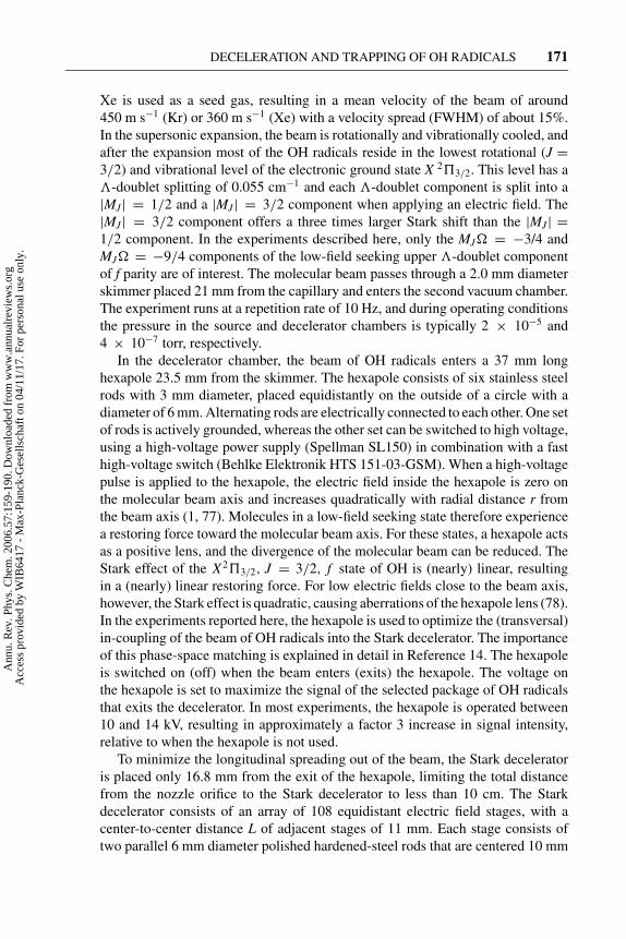
DECELERATION AND TRAPPING OF OH RADICALS 171
Xe is used as a seed gas, resulting in a mean velocity of the beam of around450 m s−1 (Kr) or 360 m s−1 (Xe) with a velocity spread (FWHM) of about 15%.In the supersonic expansion, the beam is rotationally and vibrationally cooled, andafter the expansion most of the OH radicals reside in the lowest rotational (J =3/2) and vibrational level of the electronic ground state X 2�3/2. This level has a�-doublet splitting of 0.055 cm−1 and each �-doublet component is split into a|MJ| = 1/2 and a |MJ| = 3/2 component when applying an electric field. The|MJ| = 3/2 component offers a three times larger Stark shift than the |MJ| =1/2 component. In the experiments described here, only the MJ� = −3/4 andMJ� = −9/4 components of the low-field seeking upper �-doublet componentof f parity are of interest. The molecular beam passes through a 2.0 mm diameterskimmer placed 21 mm from the capillary and enters the second vacuum chamber.The experiment runs at a repetition rate of 10 Hz, and during operating conditionsthe pressure in the source and decelerator chambers is typically 2 × 10⁻⁵ and4 × 10−7 torr, respectively.
In the decelerator chamber, the beam of OH radicals enters a 37 mm longhexapole 23.5 mm from the skimmer. The hexapole consists of six stainless steelrods with 3 mm diameter, placed equidistantly on the outside of a circle with adiameter of 6 mm. Alternating rods are electrically connected to each other. One setof rods is actively grounded, whereas the other set can be switched to high voltage,using a high-voltage power supply (Spellman SL150) in combination with a fasthigh-voltage switch (Behlke Elektronik HTS 151-03-GSM). When a high-voltagepulse is applied to the hexapole, the electric field inside the hexapole is zero onthe molecular beam axis and increases quadratically with radial distance r fromthe beam axis (1, 77). Molecules in a low-field seeking state therefore experiencea restoring force toward the molecular beam axis. For these states, a hexapole actsas a positive lens, and the divergence of the molecular beam can be reduced. TheStark effect of the X2�3/2, J = 3/2, f state of OH is (nearly) linear, resultingin a (nearly) linear restoring force. For low electric fields close to the beam axis,however, the Stark effect is quadratic, causing aberrations of the hexapole lens (78).In the experiments reported here, the hexapole is used to optimize the (transversal)in-coupling of the beam of OH radicals into the Stark decelerator. The importanceof this phase-space matching is explained in detail in Reference 14. The hexapoleis switched on (off) when the beam enters (exits) the hexapole. The voltage onthe hexapole is set to maximize the signal of the selected package of OH radicalsthat exits the decelerator. In most experiments, the hexapole is operated between10 and 14 kV, resulting in approximately a factor 3 increase in signal intensity,relative to when the hexapole is not used.
To minimize the longitudinal spreading out of the beam, the Stark deceleratoris placed only 16.8 mm from the exit of the hexapole, limiting the total distancefrom the nozzle orifice to the Stark decelerator to less than 10 cm. The Starkdecelerator consists of an array of 108 equidistant electric field stages, with acenter-to-center distance L of adjacent stages of 11 mm. Each stage consists oftwo parallel 6 mm diameter polished hardened-steel rods that are centered 10 mm
Ann
u. R
ev. P
hys.
Che
m. 2
006.
57:1
59-1
90. D
ownl
oade
d fr
om w
ww
.ann
ualr
evie
ws.
org
Acc
ess
prov
ided
by
WIB
6417
- M
ax-P
lanc
k-G
esel
lsch
aft o
n 04
/11/
17. F
or p
erso
nal u
se o
nly.

21 Feb 2006 4:35 AR ANRV272-PC57-06.tex XMLPublishSM(2004/02/24) P1: KUV
172 VAN DE MEERAKKER � VANHAECKE � MEIJER
apart, symmetrically around the beam axis. All alternating stages are rotated by 90◦
with respect to each other, providing a 4 × 4 mm2 spatial transverse acceptancearea. The geometry of this decelerator is scaled up by a factor of 2 compared toearlier designs, increasing the spatial acceptance of the decelerator by a factor of23. This up-scaling has been performed while keeping the electric fields in thedecelerator the same. The electrodes of the decelerator are positioned relative tothe molecular beam axis within a specified precision of 0.05 mm. The deceleratoris operated using a voltage of ±20 kV between opposing electrodes in a field stage,creating a maximum electric field strength near the electrodes of 115 kV cm−1.A picture of the decelerator, with a close-up of the 4 × 4 mm2 opening areabetween the electrodes, is shown in Figure 4.
The high-voltage pulses can be applied to the electrodes using fast high-voltageswitches (Behlke Elektronik HTS 651-03-GSM) that have been specifically devel-oped for the decelerator described here. The individual electrodes of alternatingstages are electrically connected to a single high-voltage switch, requiring a totalof four independent switches for the decelerator. During a single time sequence,the high voltage is delivered by a 300 nF capacitor bank, limiting the voltage dropduring a burst to better than 3%. Depending on the experiment, the duration of a
Figure 4 Picture of the Stark decelerator. The electric field stages are spaced 11 mm from
each other. The length of the device is 1111 mm. The molecular beam passes through the
4 × 4 mm2 opening area between the electrodes, which is shown enlarged in the inset.
The molecules are decelerated by switching at the appropriate times a voltage difference of
40 kV between opposing electrodes.
Ann
u. R
ev. P
hys.
Che
m. 2
006.
57:1
59-1
90. D
ownl
oade
d fr
om w
ww
.ann
ualr
evie
ws.
org
Acc
ess
prov
ided
by
WIB
6417
- M
ax-P
lanc
k-G
esel
lsch
aft o
n 04
/11/
17. F
or p
erso
nal u
se o
nly.

21 Feb 2006 4:35 AR ANRV272-PC57-06.tex XMLPublishSM(2004/02/24) P1: KUV
DECELERATION AND TRAPPING OF OH RADICALS 173
high-voltage burst is typically 2–6 ms. In the remaining time before the next burststarts, the capacitor is charged by a 1.2 kW high-voltage power supply (SpellmanSL1200) that is connected in series with a 26 k� loading resistor to the capaci-tor bank. The high-voltage push-pull switches switch between both voltage inputports upon application of a trigger pulse. The two voltage inputs are, in series witha 2.5 k� resistor, connected to ground and to the high-voltage capacitor bank,respectively. The decelerator represents a capacitance of approximately 120 pF.With a total resistance of 3 k� between the voltage supply and the decelerator,the voltage can be switched with a 1/e time of about 450 ns. During switching, amaximum current of approximately 13 A flows through the switch and the high-voltage circuitry. Each of the four-switch units is placed in a metal box that shieldsthe generated radiation. The molecular beam machine runs at a repetition rate of10 Hz. Every unit switches about 1000 times per second, and the total power thatis dissipated in a unit is on the order of 150 W. Therefore, the resistors are cooledby small fans, and the switches are cooled by a 3 l min−1 oil (Galden ht 200) flow.
The last seven stages of the decelerator are electrically and mechanically decou-pled from the first 101 stages and are operated with a separate set of high-voltageswitches and power supplies. The advantage of this is that maximum flexibilityis obtained, as these last stages are easily replaced or modified leaving the maindecelerator intact. The limited number of electric field stages enables a compactdesign that is advantageous when the decelerator is to be used in combination withan electrostatic trap. In addition, the operation voltage of these last stages can beselected independently from the first 101 stages to reduce the risk of electricalbreakdown between the decelerator and the electrostatic trap. A maximum voltageof ±15 kV is applied to these last stages, using a separate set of switches (BehlkeElektronik HTS 301-03-GSM) and power supplies (Spellman SL150). For theseswitch units, no oil or air cooling is required. The trigger pulses for the switchesare generated by a programmable pulse generator, with a resolution of 100 ns. Intotal eight independent channels are available, where each channel can trigger amaximum of two switch units. The valve, lasers, and pulse generator are synchro-nized by a master clock (Stanford research DG535) running at a repetition rate of10 Hz.
The OH radicals are state selectively detected inside the quadrupole trap,21 mm downstream from the last electric field stage (1.307 m from the nozzle), us-ing an off-resonant laser-induced fluorescence (LIF) detection scheme. The trap isdescribed in detail in Section 4. All high voltages of the decelerator and hexapoleare switched off 3 μs prior to detection. The 282 nm radiation of a pulsed dyelaser (Spectra Physics INDI Nd:YAG laser/PDL3 dye laser combination) crossesthe molecular beam at right angles. Optical access to the trap is provided by two6 mm diameter holes in the ring electrode. The population of the low-field seekingJ = 3/2 component of f parity is probed by inducing both the Q21(1) and theQ1(1) transitions of the A2�+, v = 1 ← X2�3/2, v = 0 band. The population inboth MJ� components of this level is probed simultaneously. Typically, 1.5 mJof radiation in a 5 ns pulse with a 0.08 cm−1 bandwidth is used in a 5 mm
Ann
u. R
ev. P
hys.
Che
m. 2
006.
57:1
59-1
90. D
ownl
oade
d fr
om w
ww
.ann
ualr
evie
ws.
org
Acc
ess
prov
ided
by
WIB
6417
- M
ax-P
lanc
k-G
esel
lsch
aft o
n 04
/11/
17. F
or p
erso
nal u
se o
nly.

21 Feb 2006 4:35 AR ANRV272-PC57-06.tex XMLPublishSM(2004/02/24) P1: KUV
174 VAN DE MEERAKKER � VANHAECKE � MEIJER
laser beam diameter, sufficient to saturate the transitions. The A2�+, v = 1 statehas a radiative lifetime of 760 ns (79), and fluorescence occurs mainly via theA2�+, v = 1 → X2�3/2, v = 1 band around 313 nm. The LIF is imaged througha 6 mm diameter opening in the second end-cap onto a photomultiplier tube (PMT)(electron tubes B2/RFI, 9813 QB). Stray light from the laser is reduced by passingthe laser beam through light baffles between the entrance and the exit windows.Stray light is further suppressed by optical filtering in front of the PMT.
The performance of the Stark decelerator is studied by recording the time-of-flight (TOF) profile of the OH radicals exciting the decelerator and by scanningthe timing of the excitation laser relative to the dissociation laser. It is emphasizedthat in using photodissociation as the production method for the OH radicals, thebeam is prepared at a well-defined position and time that is ideal for an accurateinterpretation of the observed TOF profiles.
3.2. Guiding a Molecular Beam of OH Radicals
In the experiments described in this section, Kr is used as a carrier gas, produc-ing a molecular beam with a mean velocity of 450 m s−1. In the upper curve ofFigure 5, the TOF profile shown is observed when the decelerator is operated at aphase angle of φ0 = 0◦ for a velocity of the synchronous molecule of 450 m s−1.Operation of the decelerator at φ0 = 0◦ corresponds to a traveling potential well,moving with a constant velocity. The first pair of electrodes of the deceleratoris switched to high voltage when the synchronous molecule for which the timesequence is calculated is exactly in between the first and second set of electrodes,thereby coupling in the beam at the center of the longitudinal acceptance regionof the decelerator. The observed TOF profile clearly demonstrates that a signifi-cant fraction of the molecular beam, centered around the velocity of the potentialwell, is selected by the decelerator, transported through the machine, and arrives atthe detector as a compact package, about 2.9 ms after production. The moleculesin the beam that are not trapped by the traveling potential well experience theswitched electric fields as well, resulting in rich phase-space dynamics that man-ifests itself by the features in the wings of the TOF profiles. From a calculationof the (time-dependent) electric-field distribution inside the decelerator, and byusing the known Stark effect of OH, the trajectory of the OH molecules throughthe Stark decelerator can be simulated. The arrival time distribution that resultsfrom three-dimensional trajectory calculations of the experiment is shown directlyunderneath the experimental profile. It is seen that the simulations quantitativelyreproduce the observations. From the calculations, the contributions of the indi-vidual MJ� components to the TOF profiles can be identified. The lower curvesof Figure 5 show simulations of the individual contributions of the MJ� = −9/4and the MJ� = −3/4 components to the TOF profile. In the simulations, bothMJ� components of the OH (J = 3/2) state are taken into account, and it is as-sumed that directly after production both MJ� components are equally populatedin the beam. The MJ� = −9/4 contributes mainly to the main peak, reflecting
Ann
u. R
ev. P
hys.
Che
m. 2
006.
57:1
59-1
90. D
ownl
oade
d fr
om w
ww
.ann
ualr
evie
ws.
org
Acc
ess
prov
ided
by
WIB
6417
- M
ax-P
lanc
k-G
esel
lsch
aft o
n 04
/11/
17. F
or p
erso
nal u
se o
nly.

21 Feb 2006 4:35 AR ANRV272-PC57-06.tex XMLPublishSM(2004/02/24) P1: KUV
DECELERATION AND TRAPPING OF OH RADICALS 175
2.4 2.8 3.2 3.6
Time of flight (ms)
LIF
sig
nal
(ar
b.
un
its)
MJ Ω = -9/4
MJ Ω = -3/4
MJ Ω = -9/4 +
Experiment
MJ Ω = -3/4
Figure 5 Observed TOF profile when the decelerator is operated at a phase angle φ0 = 0◦ for
a synchronous molecule with a velocity of 450 m s−1. The TOF profile obtained from a three-
dimensional trajectory simulation of the experiment is shown underneath the experimental
profile. The individual contributions of both MJ� components of the OH (2�3/2, J = 3/2)
state to the overall profile are indicated.
the larger phase-space acceptance of the decelerator, and the more ideal focusingproperties of the hexapole for this component. It is evident from Figure 5 that bothMJ� components need to be taken into account to obtain a quantitative agreementbetween trajectory simulations and experimental data.
3.3. Deceleration of a Molecular Beam of OH Radicals
A part of the molecular beam can be decelerated when operating the deceleratorat a phase angle 0◦ < φ0 < 90◦, decreasing the velocity of the potential well
Ann
u. R
ev. P
hys.
Che
m. 2
006.
57:1
59-1
90. D
ownl
oade
d fr
om w
ww
.ann
ualr
evie
ws.
org
Acc
ess
prov
ided
by
WIB
6417
- M
ax-P
lanc
k-G
esel
lsch
aft o
n 04
/11/
17. F
or p
erso
nal u
se o
nly.

21 Feb 2006 4:35 AR ANRV272-PC57-06.tex XMLPublishSM(2004/02/24) P1: KUV
176 VAN DE MEERAKKER � VANHAECKE � MEIJER
2.0 2.5 3.0 3.5 4.0
(a)
(d)
(c)
(b)
LIF
sig
nal
(ar
b. unit
s)
Time of flight (ms)
Experiment
MJ Ω = -9/4 +MJ Ω = -3/4
MJ Ω = -9/4
MJ Ω = -3/4
**
**
237 m/s
Figure 6 LIF signal of OH (J = 3/2) radicals exiting the decelerator as a function of time
after OH production (curve a). The decelerator is operated at a phase angle of φ0 = 70◦ for
a synchronous molecule with an initial velocity of 470 m s−1. A significant fraction of the
molecular beam is decelerated to 237 m s−1. The TOF profile that results from a simulation
of the experiment is shown in curve b, together with the individual contributions of both MJ�
components to the profile (curves c and d ).
gradually. The observed TOF profile is shown in Figure 6 (curve a) when thedecelerator is operated with a time sequence that is calculated for a phase angle ofφ0 = 70◦ and for a synchronous molecule with an initial velocity of 470 m s−1.With these settings, the decelerator extracts 1.1 cm−1 of kinetic energy from thesynchronous molecule in every electric field stage. A selected fraction of themolecular beam is decelerated from 470 m s−1 (kinetic energy of 157 cm−1)to a final velocity of 237 m s−1 (40 cm−1) and is split off from the remaining partof the beam that is not decelerated. The decelerated bunch of molecules arrives inthe LIF zone about 3.8 ms after production. The hole in the TOF profile of the fastbeam due to the disappearance of OH radicals that are decelerated is indicated byan arrow. The improved spatial acceptance of this new generation Stark deceleratorresults in a peak intensity of the decelerated package similar to the peak intensityof the nondecelerated beam. The TOF profile obtained from a three-dimensional
Ann
u. R
ev. P
hys.
Che
m. 2
006.
57:1
59-1
90. D
ownl
oade
d fr
om w
ww
.ann
ualr
evie
ws.
org
Acc
ess
prov
ided
by
WIB
6417
- M
ax-P
lanc
k-G
esel
lsch
aft o
n 04
/11/
17. F
or p
erso
nal u
se o
nly.

21 Feb 2006 4:35 AR ANRV272-PC57-06.tex XMLPublishSM(2004/02/24) P1: KUV
DECELERATION AND TRAPPING OF OH RADICALS 177
trajectory simulation of the experiment is shown in curve b, together with theindividual contributions of both MJ� components to the profile (curves c and d).The simulations quantitatively reproduce the observed TOF profile. As expected,the decelerated package purely consists of molecules in the J = 3/2, MJ � =−9/4 state, but molecules in the J = 3/2, MJ � = −3/4 state significantlycontribute to the signal of the nondecelerated beam. The MJ� composition ofthe structured TOF profile of the nondecelerated beam is easily identified fromthe simulations. In addition, these calculations reveal the origin of the interestingstructure of the nondecelerated beam that manifests itself for instance by the seriesof peaks indicated with a star in Figure 6 (curve c). A detailed discussion of theorigin of these features is given in Section 3.4.
The molecular beam can be decelerated to lower final velocities by operatingthe decelerator at a higher phase angle, and/or by selecting a lower initial velocityof the synchronous molecule. The depth of the traveling potential well rapidlydecreases for increasing values of φ0. It is therefore advantageous to use a lowerinitial velocity instead. In Figure 7 a series of TOF profiles is shown that is ob-tained when the Stark decelerator is operated at a phase angle of φ0 = 70◦ andan initial velocity of the synchronous molecule of 470 m s−1 (curve a), 450 m s−1
(curve b), 430 m s−1 (curve c), and 417 m s−1 (curve d). With these settings,the decelerated bunch of molecules exits the decelerator with a final velocity of237 m s−1, 194 m s−1, 142 m s−1, and 95 m s−1, respectively. These measurementsare complementary to the TOF profile shown in Figure 6 that is identical to Figure 7(curve a). Again, the holes in the profiles of the nondecelerated beam that re-sult from the removal of the bunches of OH radicals that are decelerated areindicated by the vertical arrows. As the width of the velocity distribution of thedecelerated package only depends on the phase angle and not on the initial ve-locity of the synchronous molecule, the width of the arrival time distribution ofthe decelerated package becomes larger for lower values of the final velocity.Both the spreading out of the beam while flying from the exit of the decelera-tor to the LIF zone and the spatial extent of the detection laser beam are incor-porated in the trajectory simulations of the experiments, shown underneath theobserved profiles. In Figure 7 curves c and d, a rich oscillatory structure on theTOF profile of the fast beam is observed as shown enlarged in the figure. Thisstructure results from a modulation of the phase-space distribution of the beamin the decelerator and is discussed in more detail elsewhere (49). In general, anexcellent agreement between the trajectory simulations and the observed TOFprofiles is obtained. The relative signal intensities of the different experimentalTOF profiles, as well as the relative peak intensity of the decelerated beam andthe fast beam within each profile, are quantitatively reproduced. This verifies thatindeed the decelerator transports the selected package of molecules to lower ve-locities without loss. To date, no indications have been found for the occurrenceof losses due to, for instance, Majorana transitions (80) or the re-projection of theMJ� = −9/4 component onto the MJ� = −3/4 component when the fields areswitched.
Ann
u. R
ev. P
hys.
Che
m. 2
006.
57:1
59-1
90. D
ownl
oade
d fr
om w
ww
.ann
ualr
evie
ws.
org
Acc
ess
prov
ided
by
WIB
6417
- M
ax-P
lanc
k-G
esel
lsch
aft o
n 04
/11/
17. F
or p
erso
nal u
se o
nly.

21 Feb 2006 4:35 AR ANRV272-PC57-06.tex XMLPublishSM(2004/02/24) P1: KUV
178 VAN DE MEERAKKER � VANHAECKE � MEIJER
Figure 7 Observed and simulated TOF profiles of a molecular beam of OH radicals
exiting the Stark decelerator when the decelerator is operated at a phase angle of 70◦
for a synchronous molecule with an initial velocity of 470 m s−1 (curve a), 450 m s−1
(curve b), 430 m s−1 (curve c), and 417 m s−1 (curve d ). The molecules that are
accepted by the decelerator are split off from the molecular beam and arrive at later
times in the detection region.
Ann
u. R
ev. P
hys.
Che
m. 2
006.
57:1
59-1
90. D
ownl
oade
d fr
om w
ww
.ann
ualr
evie
ws.
org
Acc
ess
prov
ided
by
WIB
6417
- M
ax-P
lanc
k-G
esel
lsch
aft o
n 04
/11/
17. F
or p
erso
nal u
se o
nly.

21 Feb 2006 4:35 AR ANRV272-PC57-06.tex XMLPublishSM(2004/02/24) P1: KUV
DECELERATION AND TRAPPING OF OH RADICALS 179
Obviously, selecting a velocity that is lower than the mean velocity of the beamresults in a lower phase-space density of the decelerated package than the peakphase-space density of the molecular beam. Using Xe as a carrier gas instead of Kr,the mean velocity of the beam can be reduced to approximately 365 m s−1, enablingthe operation of the decelerator at significantly lower phase angles. However, Xeenhances cluster formation in the expansion, resulting in a lower beam intensity.Together with the increased spreading out of the beam before the entrance of theStark decelerator, this reduces the advantages of the lower initial velocity. Froma sequence of experiments using Kr and Xe as carrier gases, it is found that Xeis superior if final velocities lower than approximately 150 m s−1 are required.In experiments described in Section 4, Xe is used as a carrier gas to decelerate abunch of OH radicals to a final velocity of approximately 20 m s−1 before loadingthem into an electrostatic quadrupole trap.
3.4. Evolution of the Beam Through the Stark Decelerator
In addition to demonstrating the operation principle of a decelerator, the TOFprofiles of Figures 5 and 7 indicate rich phase-space dynamics of the untrappedmolecules as well. A detailed understanding of the dynamics of the beam in thedecelerator, both of the part that undergoes phase-stable oscillations and of themolecules that are not trapped, can be obtained from the trajectory simulations.These simulations accurately reproduce the observed TOF profiles; the calculatedphase-space distributions should therefore be realistic as well. The details of theevolution of the phase-space distribution of the beam throughout the decelerationprocess will depend on the exact settings of the decelerator, but a good understand-ing of the general features can be obtained by studying two limiting cases.
In this section, we discuss the progression of the beam inside the decelerator,if the decelerator is operated with a time sequence that corresponds to the guid-ing experiment presented in Figure 5 (the decelerator is operated at phase angleφ0 = 0◦) and to the deceleration experiment shown in Figure 6 (φ0 = 70◦). Totest the validity of the (one-dimensional) model presented in Section 2.2, one-dimensional trajectory simulations are carried out for a beam of OH radicals thatare exclusively in the J = 3/2, MJ � = −9/4 state. The influence of transverseeffects on the longitudinal phase-space distributions has recently been discussedin detail elsewhere (51).
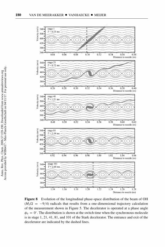
Figure 8 shows the evolution of the longitudinal phase-space distribution ofthe beam of OH (MJ� = −9/4) radicals that results from a one-dimensionaltrajectory calculation of the measurement presented in Figure 5. The deceleratoris operated at a phase angle φ0 = 0◦ for a synchronous molecule with an ini-tial velocity of 450 m s−1. The phase-space distribution is shown at the switchtime when the synchronous molecule is in stage 1 (T = 0.23 ms after productionof the beam), stage 21 (T = 0.72 ms), stage 41 (T = 1.21 ms), stage 81 (T =2.19 ms), and stage 101 (T = 2.68 ms) of the Stark decelerator. In this notation,stage i represents the region in the decelerator between electrode pairs i and i + 1.
Ann
u. R
ev. P
hys.
Che
m. 2
006.
57:1
59-1
90. D
ownl
oade
d fr
om w
ww
.ann
ualr
evie
ws.
org
Acc
ess
prov
ided
by
WIB
6417
- M
ax-P
lanc
k-G
esel
lsch
aft o
n 04
/11/
17. F
or p
erso
nal u
se o
nly.
21 Feb 2006 4:35 AR ANRV272-PC57-06.tex XMLPublishSM(2004/02/24) P1: KUV
180 VAN DE MEERAKKER � VANHAECKE � MEIJER
Figure 8 Evolution of the longitudinal phase-space distribution of the beam of OH
(MJ� = −9/4) radicals that results from a one-dimensional trajectory calculation
of the measurement shown in Figure 5. The decelerator is operated at a phase angle
φ0 = 0◦. The distribution is shown at the switch time when the synchronous molecule
is in stage 1, 21, 41, 81, and 101 of the Stark decelerator. The entrance and exit of the
decelerator are indicated by the dashed lines.
Ann
u. R
ev. P
hys.
Che
m. 2
006.
57:1
59-1
90. D
ownl
oade
d fr
om w
ww
.ann
ualr
evie
ws.
org
Acc
ess
prov
ided
by
WIB
6417
- M
ax-P
lanc
k-G
esel
lsch
aft o
n 04
/11/
17. F
or p
erso
nal u
se o
nly.

21 Feb 2006 4:35 AR ANRV272-PC57-06.tex XMLPublishSM(2004/02/24) P1: KUV
DECELERATION AND TRAPPING OF OH RADICALS 181
The entrance (center of electrode pair 1) and exit (center of electrode pair 102)are indicated by vertical dashed lines. The phase-space diagrams that result fromthe model presented in Section 2.2 are given as an overlay. In the simulations,we assume that just after production (T = 0.00 ms), the beam has a Gaussianvelocity profile with a mean velocity of 450 m s−1 and a velocity spread of 15%.The longitudinal position spread is determined by the width of the dissociationlaser focus, and a Gaussian profile with a width of 4 mm is assumed. This resultsin a vertical phase-space distribution at the position of the nozzle orifice (phase-space distribution not shown). The upper graph in Figure 8 shows the phase-spacedistribution of the beam at T = 0.23 ms. At this time, the most intense part ofthe molecular beam is at the center of the first electric field stage, and the firsthigh-voltage pulse is applied to the Stark decelerator. The tilted phase-space dis-tribution results from the free flight of the beam from the production region tothe Stark decelerator. It is seen that the longitudinal acceptance of the deceleratorencompasses a significant fraction of the emittance of the molecular beam. AtT = 0.72 ms, the synchronous molecule has progressed to stage 21 in the deceler-ator. Molecules within the separatrix (bucket) have rotated around the synchronousmolecule. Molecules outside this bound region follow the lines of constant energyin the phase-space diagram, resulting in a pronounced modulation of the phase-space distribution of the beam. This modulation represents the influence of theswitched electric fields on the molecules that are not trapped by the traveling po-tential well. In fact, the regions where the modulated distribution is horizontalgive rise to the small peaks in the wings of the TOF profiles of Figure 5. Thetrajectory of the molecules outside the separatrix is unstable, and the correspond-ing fraction of the molecular beam will continue to spread out as it progressesthrough the decelerator. This becomes increasingly apparent in the phase-spacedistributions at T = 1.21 ms (stage 41), T = 2.19 ms (stage 81), and T = 2.68 ms(stage 101). In Figure 8, only a selected fraction of the phase-space distribution ofthe beam is shown for reasons of clarity. The bound molecules continue to rotatearound the synchronous molecule and are kept together throughout the decelerator.The unbound molecules spread out in position and approach the separatrices ofthe buckets in front of and behind the bucket that contains the stable molecules.Obviously, for an infinite decelerator, the density of the unbound molecules willapproach zero, resulting in a TOF profile that consists of a sharp narrow peak ona zero signal baseline. For the decelerator used in the present experiments, the101 electric field stages used are sufficient to diminish the density of the beamclose to the first neighboring separatrices to an undetectable value, as is seen inFigure 5 by the region of zero signal in the TOF profiles on either side of the mainpeak.
In analogy to Figure 8, the longitudinal phase-space dynamics of a beam ofOH (J = 3/2, M� = −9/4) radicals is depicted in Figure 9, for settings of thedecelerator that correspond to the deceleration experiment shown in Figure 6. TheStark decelerator is operated at a phase angle of φ0 = 70◦ for a synchronousmolecule with an initial velocity of 470 m s−1, and the corresponding phase-space
Ann
u. R
ev. P
hys.
Che
m. 2
006.
57:1
59-1
90. D
ownl
oade
d fr
om w
ww
.ann
ualr
evie
ws.
org
Acc
ess
prov
ided
by
WIB
6417
- M
ax-P
lanc
k-G
esel
lsch
aft o
n 04
/11/
17. F
or p
erso
nal u
se o
nly.

21 Feb 2006 4:35 AR ANRV272-PC57-06.tex XMLPublishSM(2004/02/24) P1: KUV
182 VAN DE MEERAKKER � VANHAECKE � MEIJER
Figure 9 Evolution of the longitudinal phase-space distribution of the beam of OH
(MJ� = −9/4) radicals that results from a one-dimensional trajectory calculation of
the deceleration experiment shown in Figure 6. The decelerator is operated at a phase
angle φ0 = 70◦ for a synchronous molecule with an initial velocity of 470 m s−1.
Ann
u. R
ev. P
hys.
Che
m. 2
006.
57:1
59-1
90. D
ownl
oade
d fr
om w
ww
.ann
ualr
evie
ws.
org
Acc
ess
prov
ided
by
WIB
6417
- M
ax-P
lanc
k-G
esel
lsch
aft o
n 04
/11/
17. F
or p
erso
nal u
se o
nly.

21 Feb 2006 4:35 AR ANRV272-PC57-06.tex XMLPublishSM(2004/02/24) P1: KUV
DECELERATION AND TRAPPING OF OH RADICALS 183
diagrams of the decelerator are given as an overlay. The upper graph shows thedistribution at T = 0.24 ms, when the synchronous molecule is at the center ofthe phase-stable region in the first electric field stage of the decelerator. The centerposition of the first pair of electrodes is again indicated by the vertical dashed line.The nozzle-to-skimmer distance used in this experiment is slightly larger than inthe guiding experiment. In the discussion of the progression of the beam throughthe decelerator, three different regions in the phase-space distribution of the beamin stage 1 are considered separately, namely (a) molecules that are within the bucketbound by the separatrix; (b) the part of the beam that is in position, and thereforealso in velocity, ahead of the bucket; and (c) the part of the beam that lags behind.The molecules within the bucket (part a) are phase stable and oscillate aroundthe velocity and phase of the synchronous molecule. The size of the separatrixis sufficiently small so that the bucket is completely filled with molecules, andthe spiral-like structure occurring in Figure 8 is absent. The separatrix accuratelydescribes the shape of the phase-stable region, and the selected bunch of moleculesleaves the decelerator with a velocity of 237 m s−1, 3.36 ms after production ofthe beam.
Analogous to operating the decelerator at φ0 = 0◦, the part of the beam thatwas initially too fast (part b) is modulated by the presence of empty buckets alongthe length of the entire decelerator. When the beam overtakes the position of abucket, the interaction with the fields results in a horizontal phase-space distri-bution, ultimately leading to a peak in the TOF distribution. However, the pro-nounced oscillatory structure in the observed TOF profiles of the nondeceleratedbeam, shown enlarged in Figure 7, cannot be understood from this alone and a fullunderstanding of these oscillations is only obtained when higher-order effects areincluded in the model (49).
Molecules just outside the bucket and that are initially too slow (part c) arenot captured by the decelerating potential well and follow the curves of equalenergy in the phase-space diagrams. These molecules accelerate with respect tothe synchronous molecule, as can be seen from the phase-space distribution of thebeam at T = 0.73 ms (stage 21). Molecules that were initially even slower startinteracting with the empty buckets that lag behind. The beam cannot penetrateinto the stable area and evolves around the separatrix of the corresponding bucket.This leads to turning points in the phase-space distribution of the beam, which aremost apparent in the diagram in Figure 9 that corresponds to T = 1.26 ms (stage41). These turning points result in the series of peaks in the TOF profile of thenondecelerated beam, indicated by stars in Figure 6. The tail in the distribution thatconnects the filled bucket containing the trapped package and the correspondingturning point becomes increasingly longer and less dense as the velocity of thesynchronous molecule decreases. At T = 2.54 ms, the decelerated package has avelocity close to 290 m s−1 and is almost completely decoupled from the part ofthe beam that is not decelerated. At this time, the fastest molecules in the beamhave already reached the detection zone.
Ann
u. R
ev. P
hys.
Che
m. 2
006.
57:1
59-1
90. D
ownl
oade
d fr
om w
ww
.ann
ualr
evie
ws.
org
Acc
ess
prov
ided
by
WIB
6417
- M
ax-P
lanc
k-G
esel
lsch
aft o
n 04
/11/
17. F
or p
erso
nal u
se o
nly.

21 Feb 2006 4:35 AR ANRV272-PC57-06.tex XMLPublishSM(2004/02/24) P1: KUV
184 VAN DE MEERAKKER � VANHAECKE � MEIJER
4. ELECTROSTATIC TRAPPING OF OH RADICALS
To exploit the possibilities that this new Stark decelerator offers to study moleculesat (ultra-)low temperatures and for collision and reactive scattering experimentsat these temperatures, the slow beam needs to be decelerated further and confinedin a trap. For this, the decelerator is extended with an electrostatic quadrupoletrap (11, 14) (Figure 3). The trap consists of a ring electrode, centered 21 mmdownstream from the last electrodes of the decelerator, with an inner radius R of10 mm and two hyperbolic end-caps with a half-spacing of R/
√2. This trap is
scaled up by a factor 2 compared with the trap used to trap ND3 molecules (11, 14).The molecular beam enters the trap through a 4-mm-diameter hole in the first end-cap. This hole is the only vacuum connection between the deceleration chamber andthe trap chamber, and the pressure in the trap chamber can be kept at approximately3 × 10−9 torr under operating conditions. The OH radicals are detected inside thetrap using the detection scheme described above.
To be able to load the OH radicals into the electrostatic trap, the beam needsto be decelerated to approximately 20 m s−1. This can best be achieved whenXe is used as a carrier gas, producing a molecular beam with a mean velocity of360 m s−1. Figure 10 shows the observed TOF profile when the first 101 stagesof the decelerator are operated at φ0 = 53◦, extracting approximately 0.9 cm−1
Figure 10 LIF signal of OH (J = 3/2) radicals at the center of the quadrupole trap as
a function of time after OH production for a deceleration and trapping sequence. The syn-
chronous molecule is decelerated from the initial velocity of 371 m s−1 to a standstill. The
hole in the TOF profile of the fast beam due to the removal of OH radicals that are decelerated
is indicated by an arrow. The time at which the trap is switched on is indicated by a vertical
arrow as well. In the inset, the LIF signal intensity of the electrostatically trapped OH radicals
is shown on a longer timescale.
Ann
u. R
ev. P
hys.
Che
m. 2
006.
57:1
59-1
90. D
ownl
oade
d fr
om w
ww
.ann
ualr
evie
ws.
org
Acc
ess
prov
ided
by
WIB
6417
- M
ax-P
lanc
k-G
esel
lsch
aft o
n 04
/11/
17. F
or p
erso
nal u
se o
nly.

21 Feb 2006 4:35 AR ANRV272-PC57-06.tex XMLPublishSM(2004/02/24) P1: KUV
DECELERATION AND TRAPPING OF OH RADICALS 185
-15 kV15 kV-15 kV -15 kV7 kV 15 kV
Loading geometry Trapping geometry
-12 -6 0 6 120
0.2
0.4
0.6
Ener
gy (
cm-1
)
-12 -6 0 6 12
Position (mm)
0
0.2
0.4
0.6
Ener
gy (
cm-1
)
Position (mm)
Figure 11 A schematic representation of the loading procedure of the electrostatic trap. In
the loading geometry, the potentials on the trap electrodes are chosen such that a potential
hill is created in the trap that is higher than the remaining kinetic energy of the incoming
molecules. At the time the molecules come to a standstill at the center of the trap, the trap
is switched into the trapping geometry. In this geometry, a (nearly) symmetric 500 mK deep
potential well is created, in which the molecules are confined.
of kinetic energy per deceleration stage. OH radicals with an initial velocity of371 m s−1 (Ekin = 97.8 cm−1) are decelerated to a velocity of 84 m s−1 in stage101. The last seven stages can only be used with a maximum voltage differenceof 30 kV between the electrodes in a deceleration stage. These stages are operatedat the lower phase angle of φ0 = 48◦ to compensate for the reduced acceptance of
Ann
u. R
ev. P
hys.
Che
m. 2
006.
57:1
59-1
90. D
ownl
oade
d fr
om w
ww
.ann
ualr
evie
ws.
org
Acc
ess
prov
ided
by
WIB
6417
- M
ax-P
lanc
k-G
esel
lsch
aft o
n 04
/11/
17. F
or p
erso
nal u
se o
nly.

21 Feb 2006 4:35 AR ANRV272-PC57-06.tex XMLPublishSM(2004/02/24) P1: KUV
186 VAN DE MEERAKKER � VANHAECKE � MEIJER
the decelerator in these last stages. Here, the decelerator extracts approximately0.6 cm−1 of kinetic energy per deceleration stage, and the OH radicals exit thedecelerator with a velocity of approximately 21 m s−1 (Ekin = 0.3 cm−1).
The slow beam of OH radicals is loaded into the electrostatic trap with voltagesof 7 kV, 15 kV, and −15 kV on the first end-cap, the ring electrode, and the secondend-cap, respectively. This so-called loading geometry of the trap is schematicallyrepresented on the left side of Figure 11. In the loading geometry, a potentialhill in the trap is created that is higher than the remaining kinetic energy of themolecules. The OH radicals therefore come to a standstill near the center of thetrap, approximately 8.3 ms after their production. At that time, indicated by anarrow in Figure 10, the trap is switched into the so-called trapping geometry,as schematically represented on the right side of Figure 11; the first end-cap isswitched from 7 kV to −15 kV to create a (nearly) symmetric 500 mK deeppotential well. After some initial oscillations, a steady LIF signal is observedfrom the OH radicals in the trap. The LIF intensity of the trapped OH radicalsis approximately 40% of the peak LIF intensity of the nondecelerated beam ofOH that passes through the trap. The hole in the TOF profile of the fast beam,due to the removal of OH radicals that are decelerated, is again indicated by anarrow.
Quantifying LIF signals is notoriously difficult. The observed LIF signal ofthe trapped OH radicals corresponds to a total number of approximately 105 OH(J = 3/2, MJ � = −9/4) radicals, in the approximately 0.03 cm3 detectionvolume in the trap. The inset of Figure 10 shows the LIF signal intensity on a longertimescale. The latter experiments are performed while running the experiment at arepetition rate of 1 Hz, limiting the maximum trapping time that can be measuredto 1.0 s. From these experiments, a 1/e trap lifetime on the order of 1.0 s, limited bycollisions with background gas, is deduced. The absolute number of OH radicalsthat can be trapped, as well as the phase-space distribution of the trapped molecules,critically depends on the details of the trap-loading sequence (81). Depending onthe loading characteristics, the density of the trapped cloud is approximately 107–108 cm−3, and the temperature can be as low as 50 mK.
5. CONCLUSIONS
In this review, we describe a Stark decelerator designed to capture and slow down alarge fraction of a molecular beam. Deceleration experiments are performed usinga beam of OH radicals, a chemically highly relevant species. We study in detailboth the deceleration process and the phase-space dynamics of the molecules thatare not phase stable. The Stark decelerator is extended with an electrostatic trap inwhich the selected part of the molecular beam can be brought to a standstill andstored up to seconds. The produced cold packages of OH radicals are ideally suitedto study cold (reactive) collisions between the trapped polar molecules, which isa very new and exciting field of physics. At present, however, the density of
Ann
u. R
ev. P
hys.
Che
m. 2
006.
57:1
59-1
90. D
ownl
oade
d fr
om w
ww
.ann
ualr
evie
ws.
org
Acc
ess
prov
ided
by
WIB
6417
- M
ax-P
lanc
k-G
esel
lsch
aft o
n 04
/11/
17. F
or p
erso
nal u
se o
nly.

21 Feb 2006 4:35 AR ANRV272-PC57-06.tex XMLPublishSM(2004/02/24) P1: KUV
DECELERATION AND TRAPPING OF OH RADICALS 187
107–108 OH radicals cm−3 that we have reached is not sufficient to observe thesecollisions in the trap. By improving the deceleration and trap-loading process, it isestimated that approximately an order of magnitude can be gained in density. If amore intense molecular beam can be produced, the density could be enhanced evenfurther. Using state-of-the-art molecular beam techniques, densities exceeding 1010
molecules cm−3 should therefore be realistic. Once these densities are obtained,methods such as evaporative cooling or sympathetic cooling could be applied tocool down the trapped sample further and hence increase the phase-space densityin the trap. These methods have not yet been demonstrated to work for moleculesand rely on the (presently unknown) elastic and inelastic collision cross sections.Also direct laser cooling prior to the loading of the trap could be used to cool thesample. An alternative approach to increase the phase-space density in the trapis to accumulate several packages of molecules in the trap, which is possible inspecific systems (82, 83).
ACKNOWLEDGMENTS
This work started at the FOM-Institute for Plasmaphysics Rijnhuizen,Nieuwegein, the Netherlands, and continued since the end of 2003 at the Fritz-Haber-Institut der Max-Planck-Gesellschaft in Berlin, Germany. We acknowledgefruitful discussions with all group members and the help from the technical staffat both institutes. In particular, we thank P.H.M. Smeets for his expert technicalsupport. This work is supported by the EU “Cold Molecules” network.
The Annual Review of Physical Chemistry is online athttp://physchem.annualreviews.org
LITERATURE CITED
1. Scoles G, ed. 1988/1992. Atomic andMolecular Beam Methods, Vols. 1, 2.
New York: Oxford Univ. Press
2. Stapelfeldt H, Seideman T. 2003. Col-
loquium: aligning molecules with strong
laser pulses. Rev. Mod. Phys. 75:543–57
3. Yang X, Liu K, eds. 2004. Modern Trendsin Chemical Reaction Dynamics, Vol. 1.
Singapore: World Sci.
4. Sato H. 2001. Photodissociation of sim-
ple molecules in the gas phase. Chem. Rev.101:2687–725
5. Rakitzis TP, van den Brom AJ, Janssen
MHM. 2004. Directional dynamics in the
photodissociation of oriented molecules.
Science 303:1852–54
6. Liu K. 2001. Crossed-beam studies of
neutral reactions: State-specific differen-
tial cross sections. Annu. Rev. Phys. Chem.52:139–64
7. Lin JJ, Zhou J, Shiu W, Liu K. 2003. State-
specific correlation of coincident product
pairs in the F + CD4 reaction. Science300:966–69
8. Bethlem HL, Berden G, Meijer G. 1999.
Decelerating neutral dipolar molecules.
Phys. Rev. Lett. 83:1558–61
9. Bethlem HL, van Roij AJA, Jongma RT,
Meijer G. 2002. Alternate gradient focus-
ing and deceleration of a molecular beam.
Phys. Rev. Lett. 88(13):133003
10. Crompvoets FMH, Jongma RT, Bethlem
Ann
u. R
ev. P
hys.
Che
m. 2
006.
57:1
59-1
90. D
ownl
oade
d fr
om w
ww
.ann
ualr
evie
ws.
org
Acc
ess
prov
ided
by
WIB
6417
- M
ax-P
lanc
k-G
esel
lsch
aft o
n 04
/11/
17. F
or p
erso
nal u
se o
nly.

21 Feb 2006 4:35 AR ANRV272-PC57-06.tex XMLPublishSM(2004/02/24) P1: KUV
188 VAN DE MEERAKKER � VANHAECKE � MEIJER
HL, van Roij AJA, Meijer G. 2002. Long-
tudinal focusing and cooling of a molecular
beam. Phys. Rev. Lett. 89(9):093004
11. Bethlem HL, Berden G, Crompvoets FMH,
Jongma RT, van Roij AJA, Meijer G.
2000. Electrostatic trapping of ammonia
molecules. Nature 406:491–94
12. van Veldhoven J, Bethlem HL, Meijer G.
2005. AC electric trap for ground-state
molecules. Phys. Rev. Lett. 94:083001
13. Crompvoets FMH, Bethlem HL, Jongma
RT, Meijer G. 2001. A prototype storage
ring for neutral molecules. Nature 411:
174–76
14. Bethlem HL, Crompvoets FMH, Jongma
RT, van de Meerakker SYT, Meijer G.
2002. Deceleration and trapping of ammo-
nia using time-varying electric fields. Phys.Rev. A 65(5):053416
15. Bethlem HL, Meijer G. 2003. Produc-
tion and application of translationally cold
molecules. Int. Rev. Phys. Chem. 22(1):73–
128
16. 2004. Special Issue: Ultracold PolarMolecules: Formation and Collision. Eur.Phys. J. D 31(2)
17. Hunter LR. 1991. Tests of time-reversal in-
variance in atoms, molecules, and the neu-
tron. Science 252:73–79
18. Hudson JJ, Sauer BE, Tarbutt MR, Hinds
EA. 2002. Measurement of the elec-
tron electric dipole moment using YbF
molecules. Phys. Rev. Lett. 89:023003
19. Kawall D, Bay F, Bickman S, Jiang Y,
DeMille D. 2004. Precision Zeeman–Stark
spectroscopy of the metastable a(1)3�+
state of PbO. Phys. Rev. Lett. 92:133007
20. Rein DW. 1974. Some remarks on parity
violating effects of intramolecular interac-
tions. J. Mol. Evol. 4:15–22
21. Letokhov VS. 1975. On difference of en-
ergy levels of left and right molecules due
to weak interactions. Phys. Lett. A 53:275–
76
22. Uzan J-P. 2003. The fundamental constants
and their variation: observational and the-
oretical status. Rev. Mod. Phys. 75:403–
55
23. van de Meerakker SYT, Vanhaecke N, van
der Loo MPJ, Groenenboom GC, Meijer G.
2005. Direct measurement of the radiative
lifetime of vibrationally excited OH radi-
cals. Phys. Rev. Lett. 95:013003
24. Wennberg PO, Cohen RC, Stimpfle RM,
Koplow JP, Anderson JG, et al. 1994.
Removal of stratospheric O3 by radicals:
In situ measurements of OH, HO2, NO,
NO2, ClO and BrO. Science 266:398–404
25. Wennberg PO, Hanisco TF, Jaegle L, Ja-
cob DJ, Hintsa EJ, et al. 1998. Hydrogen
radicals, nitrogen radicals, and the produc-
tion of O3 in the upper troposphere. Science279:49–53
26. Summers ME, Conway RR, Siskind DE,
Stevens MH, Offermann D, et al. 1997. Im-
plications of satellite OH observations for
middle atmospheric H2O and ozone. Sci-ence 277:1967–70
27. Wilson WJ, Barrett AH. 1968. Discovery
of hydroxyl radio emission from infrared
stars. Science 161:778–79
28. Chu S. 1998. The manipulation of neutral
particles. Rev. Mod. Phys. 70:685–706
29. Cohen-Tannoudji CN. 1998. Manipulat-
ing atoms with photons. Rev. Mod. Phys.70:707–19
30. Phillips WD. 1998. Laser cooling and trap-
ping of neutral atoms. Rev. Mod. Phys.70:721–41
31. 2002. Special Issue. Nature Insight: Ultra-cold Matter. Nature 416:205–46
32. Anderson MH, Ensher JR, Matthews MR,
Wieman CE, Cornell EA. 1995. Observa-
tion of Bose–Einstein condensation in a di-
lute atomic vapor. Science 269:198–201
33. Baranov M, Dobrek L, Goral K, Santos
L, Lewenstein M. 2002. Ultracold dipo-
lar gases—a challenge for experiments and
theory. Phys. Scr. T 102:74–81
34. Santos L, Shlyapnikov GV, Soller P,
Lewenstein M. 2000. Bose–Einstein con-
densation in trapped dipolar gases. Phys.Rev. Lett. 85:1791–94
35. Goral K, Santos L, Lewenstein M. 2002.
Quantum phases of dipolar bosons in opti-
cal lattices. Phys. Rev. Lett. 88:170406
Ann
u. R
ev. P
hys.
Che
m. 2
006.
57:1
59-1
90. D
ownl
oade
d fr
om w
ww
.ann
ualr
evie
ws.
org
Acc
ess
prov
ided
by
WIB
6417
- M
ax-P
lanc
k-G
esel
lsch
aft o
n 04
/11/
17. F
or p
erso
nal u
se o
nly.

21 Feb 2006 4:35 AR ANRV272-PC57-06.tex XMLPublishSM(2004/02/24) P1: KUV
DECELERATION AND TRAPPING OF OH RADICALS 189
36. DeMille D. 2002. Quantum computation
with trapped polar molecules. Phys. Rev.Lett. 88:067901
37. Herschbach D. 1999. Chemical physics:
Molecular clouds, clusters and corrals. Rev.Mod. Phys. 71:S411–18
38. Balakrishnan N, Dalgarno A. 2001. Chem-
istry at ultracold temperatures. Chem. Phys.Lett. 341(5–6):652–56
39. Balakrishnan N, Dalgarno A, Forrey RC.
2000. Vibrational relaxation of CO by col-
lisions with 4He at ultracold temperatures.
J. Chem. Phys. 113:621–27
40. King JG. 1959. Experiments with slow
molecules. Proc. 13th Annu. Symp. Fre-quency Control, Ashbury Park. U.S. Army
Signal Res. Dev. Lab., Fort Monmouth, p.
603
41. King JG, Zacharias JR. 1958. Q. ProgressRep., Res. Lab. Electron., MIT, No. 48, Jan.
15
42. Oraevskii AN. 1964. Molecular Genera-tors. Moscow: Nauka
43. Kazachok VS. 1965. The electrodynamic
method of slowing down molecules. Sov.Phys. Tech. Phys. 10:882
44. Golub R. 1967. On decelerating molecules.
PhD thesis. MIT
45. Auerbach D, Bromberg EEA, Wharton
L. 1966. Alternate-gradient focusing of
molecular beams. J. Chem. Phys. 45:2160–
66
46. Wolfgang R. 1968. Chemical accelerators.
Sci. Am. 219(4):44
47. Bromberg EEA. 1972. Acceleration andalternate-gradient focusing of neutral po-lar diatomic molecules. PhD thesis. Univ.
Chicago
48. Bethlem HL, Berden G, van Roij AJA,
Crompvoets FMH, Meijer G. 2000. Trap-
ping neutral molecules in a traveling poten-
tial well. Phys. Rev. Lett. 84:5744–47
49. van de Meerakker SYT, Vanhaecke N,
Bethlem HL, Meijer G. 2005. Higher-order
resonances in a Stark decelerator. Phys.Rev. A 71:053409
50. Friedrich B. 2004. A quasi-analytical
model for a linear Stark accelerator/
decelerator for polar molecules. Eur. Phys.J. D 31:313–36
51. van de Meerakker SYT, Vanhaecke N,
Bethlem HL, Meijer G. 2006. Transverse
stability in a Stark decelerator. Phys. Rev.A. In press
52. Crompvoets FMH, Bethlem HL, Kupper J,
van Roij AJA, Meijer G. 2004. Dynamics
of neutral molecules stored in a ring. Phys.Rev. A 69(6):063406
53. van Veldhoven J, Kupper J, Bethlem HL,
Sartakov B, van Roij AJA, Meijer G.
2004. Decelerated molecular beams for
high-resolution spectroscopy: The hyper-
fine structure of 15ND3. Eur. Phys. J. D31(2):337–49
54. Bohn JL. 2001. Inelastic collisions of ul-
tracold polar molecules. Phys. Rev. A 63:
052714
55. Schulz SA, Bethlem HL, van Veldhoven J,
Kupper J, Conrad H, Meijer G. 2004. Mi-
crostructured switchable mirror for polar
molecules. Phys. Rev. Lett. 93(2):020406
56. Tarbutt MR, Bethlem HL, Hudson JJ,
Ryabov VL, Ryzhov VA, et al. 2004. Slow-
ing heavy, ground-state molecules using an
alternating gradient decelerator. Phys. Rev.Lett. 92(17):173002
57. Bochinski JR, Hudson ER, Lewandowski
HJ, Meijer G, Ye J. 2003. Phase space
manipulation of cold free radical OH
molecules. Phys. Rev. Lett. 91:243001
58. Bochinski JR, Hudson ER, Lewandowski
HJ, Ye J. 2004. Cold free-radical molecules
in the laboratory frame. Phys. Rev. A 70:
043410
59. Deleted in proof
60. Yamakita Y, Procter SR, Goodgame AL,
Softley TP. 2004. Deflection and deceler-
ation of hydrogen Rydberg molecules in
inhomogeneous electric fields. J. Chem.Phys. 121:1419–31
61. Vliegen E, Worner HJ, Softley TP, Merkt
F. 2004. Nonhydrogenic effects in the de-
celeration of Rydberg atoms in inhomo-
geneous electric fields. Phys. Rev. Lett.92:033005
62. Vanhaecke N, Comparat D, Pillet P. 2005.
Ann
u. R
ev. P
hys.
Che
m. 2
006.
57:1
59-1
90. D
ownl
oade
d fr
om w
ww
.ann
ualr
evie
ws.
org
Acc
ess
prov
ided
by
WIB
6417
- M
ax-P
lanc
k-G
esel
lsch
aft o
n 04
/11/
17. F
or p
erso
nal u
se o
nly.

21 Feb 2006 4:35 AR ANRV272-PC57-06.tex XMLPublishSM(2004/02/24) P1: KUV
190 VAN DE MEERAKKER � VANHAECKE � MEIJER
Rydberg decelerator using a travelling elec-
tric field gradient. J. Phys. B 38:409–
19
63. Rangwala SA, Junglen T, Rieger T, Pinkse
PWH, Rempe G. 2003. Continuous source
of translationally cold dipolar molecules.
Phys. Rev. A 67:043406
64. Deleted in proof
65. Junglen T, Rieger T, Pinkse PWH, Rempe
G. 2004. Two-dimensional trapping of
dipolar molecules in time-varying electric
fields. Phys. Rev. Lett. 92:223001
66. Barker PF, Shneider MN. 2002. Slowing
molecules by optical microlinear decelera-
tion. Phys. Rev. A 66:065402
67. Dong GJ, Lu WP, Barker PF. 2004. De-
celerating and bunching molecules with
pulsed traveling optical lattices. Phys. Rev.A 69:013409
68. Fulton R, Bishop AI, Barker PF. 2004. Op-
tical Stark decelerator for molecules. Phys.Rev. Lett. 93:243004
69. Wardle M, Yusef-Zadeh F. 2002. Super-
nova remnant OH masers: Signposts of cos-
mic collision. Science 296:2350–54
70. Miller JA, Kee RJ. 1990. Chemical kinet-
ics and combustion modeling. Annu. Rev.Phys. Chem. 41:345–87
71. Whitehead JC. 1996. Molecular beam stud-
ies of free-radical processes: Photodissoci-
ation, inelastic and reactive collisions. Rep.Prog. Phys. 59:993–1040
72. Avdeenkov AV, Bohn JL. 2002. Collisional
dynamics of ultracold OH molecules in an
electrostatic field. Phys. Rev. A 66:052718
73. Avdeenkov AV, Bohn JL. 2003. Linking
ultracold polar molecules. Phys. Rev. Lett.90(4):043006
74. Avdeenkov AV, Bortolotti DCA, Bohn JL.
2004. Field-linked states of ultracold polar
molecules. Phys. Rev. A 69:012710
75. Ticknor C, Bohn JL. 2005. Influence of
magnetic fields on cold collisions of polar
molecules. Phys. Rev. A 71:022709
76. Avdeenkov AV, Bohn JL. 2005. Ultracold
collisions of fermionic OD radicals. Phys.Rev. A 71:022706
77. Anderson RW. 1997. Tracks of symmetric
top molecules in hexapole electric fields. J.Phys. Chem. A 101:7664–73
78. Jongma RT, Rasing Th, Meijer G.
1995. Two-dimensional imaging of
metastable CO molecules. J. Chem. Phys.102(5):1925–33
79. Yarkony DR. 1992. A theoretical treatment
of the predissociation of the individual rovi-
bronic levels of OH/OD (A 2�+). J. Chem.Phys. 97:1838–49
80. Harland PW, Hu WP, Vallance C, Brooks
PR. 1999. Spatial deorientation of upper-
stark-state-selected supersonic beams of
CH3F -Cl -Br and -I. Phys. Rev. A 60:3138–
43
81. van de Meerakker SYT, Smeets PHM, Van-
haecke N, Meijer G. 2005. Deceleration
and electrostatic trapping of OH radicals.
Phys. Rev. Lett. 94:23004
82. van de Meerakker SYT, Jongma RT, Beth-
lem HL, Meijer G. 2001. Accumulating NH
radicals in a magnetic trap. Phys. Rev. A64:041401
83. van de Meerakker SYT, Sartakov BG,
Mosk AP, Jongma RT, Meijer G. 2003. Op-
tical pumping of metastable NH radicals
into the paramagnetic ground state. Phys.Rev. A 68:032508
Ann
u. R
ev. P
hys.
Che
m. 2
006.
57:1
59-1
90. D
ownl
oade
d fr
om w
ww
.ann
ualr
evie
ws.
org
Acc
ess
prov
ided
by
WIB
6417
- M
ax-P
lanc
k-G
esel
lsch
aft o
n 04
/11/
17. F
or p
erso
nal u
se o
nly.

P1: JRX/KUV
February 23, 2006 1:40 Annual Reviews AR272-FM
Annual Review of Physical ChemistryVolume 57, 2006
CONTENTS
REFLECTIONS ON PHYSICAL CHEMISTRY: SCIENCE AND SCIENTISTS,
Joshua Jortner 1
ON A RESEARCH ROLLERCOASTER WITH FRIENDS,
Robin M. Hochstrasser 37
4D ULTRAFAST ELECTRON DIFFRACTION, CRYSTALLOGRAPHY,
AND MICROSCOPY, Ahmed H. Zewail 65
HETEROGENEOUS CHEMISTRY OF CARBON AEROSOLS,
Amanda M. Nienow and Jeffrey T. Roberts 105
PROGRESS IN THE THEORY OF MIXED QUANTUM-CLASSICAL
DYNAMICS, Raymond Kapral 129
STARK DECELERATION AND TRAPPING OF OH RADICALS,
Sebastiaan Y.T. van de Meerakker, Nicolas Vanhaecke,and Gerard Meijer 159
ATMOSPHERIC FIELD MEASUREMENTS OF THE HYDROXYL RADICAL
USING LASER-INDUCED FLUORESCENCE SPECTROSCOPY,
Dwayne E. Heard 191
EXCITONS IN CONJUGATED OLIGOMER AGGREGATES, FILMS,
AND CRYSTALS, Frank C. Spano 217
LASER PROBING OF SINGLE-AEROSOL DROPLET DYNAMICS,
Jonathan P. Reid and Laura Mitchem 245
CONNECTING CHEMICAL DYNAMICS IN GASES AND LIQUIDS,
Christopher G. Elles and F. Fleming Crim 273
NEAR-FIELD OPTICAL MICROSCOPY AND SPECTROSCOPY WITH
POINTED PROBES, Lukas Novotny and Stephan J. Stranick 303
ON THE NATURE OF IONS AT THE LIQUID WATER SURFACE,
Poul B. Petersen and Richard J. Saykally 333
CORRELATED ELECTRONIC STRUCTURE NONLINEAR RESPONSE
METHODS FOR STRUCTURED ENVIRONMENTS, Kurt V. Mikkelsen 365
COHERENT EXCITATION OF VIBRATIONAL MODES IN METALLIC
NANOPARTICLES, Gregory V. Hartland 403
ix
Ann
u. R
ev. P
hys.
Che
m. 2
006.
57:1
59-1
90. D
ownl
oade
d fr
om w
ww
.ann
ualr
evie
ws.
org
Acc
ess
prov
ided
by
WIB
6417
- M
ax-P
lanc
k-G
esel
lsch
aft o
n 04
/11/
17. F
or p
erso
nal u
se o
nly.

P1: JRX/KUV
February 23, 2006 1:40 Annual Reviews AR272-FM
x CONTENTS
ION PAIR DISSOCIATION: SPECTROSCOPY AND DYNAMICS,
Arthur G. Suits and John W. Hepburn 431
REACTIVITY OF THE GERMANIUM SURFACE: CHEMICAL PASSIVATION
AND FUNCTIONALIZATION, Paul W. Loscutoff and Stacey F. Bent 467
SCANNING TUNNELING MICROSCOPY MANIPULATION OF COMPLEX
ORGANIC MOLECULES ON SOLID SURFACES, Roberto Otero,Federico Rosei, and Flemming Besenbacher 497
RAMAN CRYSTALLOGRAPHY AND OTHER BIOCHEMICAL
APPLICATIONS OF RAMAN MICROSCOPY, Paul R. Carey 527
FEMTOSECOND TIME-RESOLVED PHOTOELECTRON IMAGING,
Toshinori Suzuki 555
SINGLE-MOLECULE ELECTRICAL JUNCTIONS, Yoram Selzerand David L. Allara 593
DYNAMICAL STUDIES OF THE OZONE ISOTOPE EFFECT: A STATUS
REPORT, R. Schinke, S. Yu. Grebenshchikov, M.V. Ivanov,and P. Fleurat-Lessard 625
INDEXES
Subject Index 663
Cumulative Index of Contributing Authors, Volumes 53–57 683
Cumulative Index of Chapter Titles, Volumes 53–57 685
ERRATA
An online log of corrections to Annual Review of Physical Chemistrychapters may be found at http://physchem.annualreviews.org/errata.shtml
Ann
u. R
ev. P
hys.
Che
m. 2
006.
57:1
59-1
90. D
ownl
oade
d fr
om w
ww
.ann
ualr
evie
ws.
org
Acc
ess
prov
ided
by
WIB
6417
- M
ax-P
lanc
k-G
esel
lsch
aft o
n 04
/11/
17. F
or p
erso
nal u
se o
nly.