Embed Size (px)
Citation preview

STARBUCK POWER PROJECTAPPLICATION FOR SITE CERTIFICATION
PDX/011590002.DOC D-1REVISED NOVEMBER 2001
APPENDIX D
Starbuck Power Company—Engineering Report
D.1 Introduction
D.1.1 BackgroundThis engineering report has been prepared for the Starbuck Power Company, L.L.C., ofBellevue, Washington, for the 1,200-megawatt (MW), natural gas fueled, combustion turbinegeneration plant to be built in Columbia County, Washington (Figure D.1-1). This report hasbeen prepared in accordance with WAC 173-240-130 and WAC 463-42-195 and is a referencedocument for the Energy Facility Site Evaluation Council (EFSEC). This document isprepared to provide EFSEC with engineering information necessary to issue a wastewaterdischarge permit.
D.1.2 PurposeA wastewater discharge permit is necessary for the Applicant to divert its wastewater toinfiltration and evaporation ponds. This wastewater will be low in dissolved solids as aresult of alternative processes to be used at the generation plant for the production ofelectrical power. The Washington Department of Ecology (Ecology) regulates the dischargeof industrial wastewater through a permitting system (WAC 173-216). However, forgeneration plants that produce more than 350 MW, EFSEC has the permitting authority.
D.1.3 Water Supply SourceThe Applicant is awaiting a recommendation on its groundwater right application. If thewater right is granted, it will allow the Applicant to construct the proposed onsite well thatwill serve as the water supply for the generation plant (Elmer, April 2001). Because thegroundwater right application is pending, water quality data from wells in the vicinity andtwo sources in the Town of Starbuck were used as a reference in this report.
As a water supply alternative in case the onsite well proves infeasible, the Applicant hassecured an option to purchase up to 100 gallons per minute (gpm), or up to 144,000 gallonsper day (gpd), of water from the Town of Starbuck under the Town’s existing water right.Under this alternative, the Applicant would construct an approximately 6-mile-long, 4-inch-diameter water pipeline, primarily along an abandoned railroad bed, to connect the Town’swater system to the site in order to supply water to the generation plant. Because the actualwater supply characteristics may vary between the proposed onsite well and the Townwater system via the alternative water pipeline, for purposes of the engineering report, aconservative approach was taken that uses the highest concentration of each constituent.
D.1.4 Evaluation of Treatment MethodsThrough Black & Veatch Corporation, the Applicant evaluated several water treatment anddisposal alternatives. Process alternatives were also evaluated to determine the method that

STARBUCK POWER PROJECTAPPLICATION FOR SITE CERTIFICATION
D-2 PDX/011590002.DOC REVISED NOVEMBER 2001
would minimize the amount of supply water required and generate the least amount ofwastewater.
Water analyses determined that the well water supply should undergo pretreatment in ademineralization unit due to mineral content. High purity water is required for theproduction of steam in the generation plant. A mobile demineralization unit will treat thewater using an ion-exchange process. The water will pass over resins, leaving behinddissolved solids. The clean water then will be fed to the steam generators and the “fogging”unit. The resin containing the solids will be used until regeneration is required. Because thedemineralization unit is mobile, the trailer will be removed and the resin regenerated offsite,thus eliminating wastewater high in solids and containing spent regenerates.
The generation plant will be designed to use air-cooled condensers, “fogging,” steaminjection, and blowdown recovery. The improved qualities of each of these processalternatives are as follows: Other electrical generation processes include wet-cooled systemsthat use cooling towers. While a wet-cooled system is less costly, it requires a much largerwater source and results in wastewater discharges containing biocides and chemicalresiduals.
• The use of “fogging” for inlet air cooling for the combustion turbines generates nowastewater, unlike evaporative coolers. This process injects “fog” (a water mist) into theintake of the turbines increasing their power output. This also reduces the amount ofcooling water needed by the generation plant. The use of a “fogging” system eliminatesa potential source of chemicals from the wastewater stream.
• Blowdown recovery is accomplished by recirculating the blowdown water instead ofintroducing fresh water into the system. Blowdown water discharge is eliminatedthrough evaporation. This occurs once the recirculated blowdown water reaches a pointof high solids concentration. This recovery process eliminates the introduction of boilertreatment chemicals, solids, and heat to the wastewater system.
Because sources of contamination will be removed from the wastewater stream, thefollowing approach to wastewater treatment was taken. The main source of wastewater willbe process wastewater which includes housekeeping water from generation plant drainsand wash down areas, sanitary water, and rainfall. The Applicant will segregate itswastewater streams and provide separate disposal methods for the streams as follows:
• Process wastewater – infiltration/evaporation pond• Sanitary wastewater – septic system to drain field• Stormwater – infiltration/evaporation pond
Process wastewater that has the potential to contain oil or lubricants will be routed to anoil/water separator before discharge to the infiltration pond. It should be noted that the useof infiltration ponds will avoid having a discharge to the Snake River.

10 0 10 20 Miles
Figure D.1-1Area Map
Application forSite Certification
Starbuck Power ProjectStarbuck, Washington
COLUMBIACOUNTY
WHITMANCOUNTY
WALLA WALLACOUNTY
Proposed PowerPlant Project Site
Snake R.
FRANKLINCOUNTY
GARFIELDCOUNTY
ADAMSCOUNTY
Snake R.
LINCOLNCOUNTY
SPOKANECOUNTY
GRANTCOUNTY
BENTONCOUNTY
ASOTINCOUNTY
STATE OF OREGON
STATE OF IDAHO
Columbia R.
Columbia R.
.-,90
.-,82 (/12
(/12"!261
"!260"!26
"!125"!124
"!271
Connell
Pomeroy
Dayton
Ritzville
PascoRichland
Kennewick
Othello
Pullman
Starbuck
Walla Walla
Moses Lake
Spokane
WardenRoyal City
Ephrata
Washtucna
Kahlotus
Legend
CH2M Hill GIS Project Number 155676 \\Starbuck\Aprs\facility.apr 8-7-2001
(/Interstate Freeways
US Highways
State Routes (SR)#S
.-,
S 75 Mile Radiusfrom Site
Urbanized Areas
County Boundaries
Highways/Interstates
WASHINGTONWASHINGTON
Area ofInterest
N

STARBUCK POWER PROJECTAPPLICATION FOR SITE CERTIFICATION
PDX/011590002.DOC D-5REVISED NOVEMBER 2001
D.2 Supporting DocumentationThe following sections, which follow the format of Washington Administrative Code (WAC)173-240-130, provide supporting documentation for permitting of a discharge of industrialwater to groundwater (see Attachment 1 to Appendix D, Application for a WastewaterDischarge Permit for Discharge of Industrial Wastewater to Groundwater).
(a) Type of Industry or BusinessThe generation plant will be a 1,200-MW, natural-gas-fueled, combustion turbine generationplant. It will consist of a generation plant, a step-up substation, and auxiliary support units.
The generation plant will consist of combined-cycle combustion gas turbines, four heatrecovery steam generators, two steam turbine generators, and air-cooled condensers. Theadministrative and general facility support areas will be located in the generation plant.
The required support units will include the Fire Pump Building, the Substation ControlBuilding, the Ammonia Transfer System, and the mobile water treatment unit. Thebuildings will house necessary equipment and the systems will support operations.
The Fire Water Pump Building will house two redundant fire water pumps for maintainingfire fighting water system pressure. One pump will be electrical and the other will be dieselfueled, to be used in the event of a power outage. A diesel storage tank will be locatedadjacent to the building.
The Substation Control Building will contain the necessary equipment to transfer theelectrical power generated into the new transmission line and through the Bonneville PowerAdministration (BPA) transmission corridor.
The Ammonia Transfer System will consist of a storage tank for aqueous ammonia, avaporizing unit, dilution equipment, transfer pumps, and controls. A truck loading stationwill be a part of the system.
The water treatment unit will include a trailer-mounted demineralization unit with transferequipment and controls. This unit will use resin to complete an ion exchange to producehigh-purity water for the generation plant. When the resin is exhausted, the trailers will bemoved offsite and regenerated.
Utilities at the generation plant will include water supplied from the proposed onsite well(or, alternatively, from the Town water system via the alternative water pipeline) andnatural gas supplied from a mainline maintained by Gas Transmission-Northwest. Servicewater will be stored onsite in a 500,000-gallon tank. Sanitary water will be supplied from thestored water and treated through a septic system. The natural gas will be metered andregulated through a station located at the generation plant.
Figure D.2-1 shows the generation plant location and boundaries. Figure D.2-2 presents thesite arrangement.

STARBUCK POWER PROJECTAPPLICATION FOR SITE CERTIFICATION
D-6 PDX/011590002.DOC REVISED NOVEMBER 2001
(b) The Kind and Quantity of Finished ProductThe generation plant will generate about 1,200 MW of electrical power for residential andcommercial use. Electricity will be transported from the generation plant to the BPAregional distribution system by connecting to one of two existing transmission lines, or tothe proposed 500-kilovolt (kV) transmission line.
(c) The Quantity and Quality of Water Used by the Industry and a Descriptionof How Consumed or Disposed of, Including:
(i) How Water Used by the Industry is Consumed or Disposed ofWell water pumped from the onsite well to the generation plant will be used as servicewater or sent to the mobile demineralization unit for purification before use in the genera-tion plant. Water will be consumed in the steam turbine generators and “fogging”/ steaminjector unit. Well water will be stored for the fire fighting system.
Process wastewater, sanitary wastewater, and stormwater from the generation plant will bedisposed of by the following methods, respectively:
• Process wastewater infiltration/evaporation pond• Sanitary septic system/ drain field• Stormwater infiltration/evaporation pond
It is estimated that an average of 9 gallons per minute (gpm), or about 13,000 gallons perday (gpd), of wastewater will be sent to the process wastewater infiltration/evaporationpond. An estimated 1 gpm (1,440 gpd) of sanitary wastewater will be transferred to thesanitary septic system and then to the drain field. Discharges to the stormwaterinfiltration/evaporation pond will be based on the amount of rainfall in the area. The watermass balance shown in Figure D.2-3 shows numerically and graphically how water will beconsumed and disposed of.
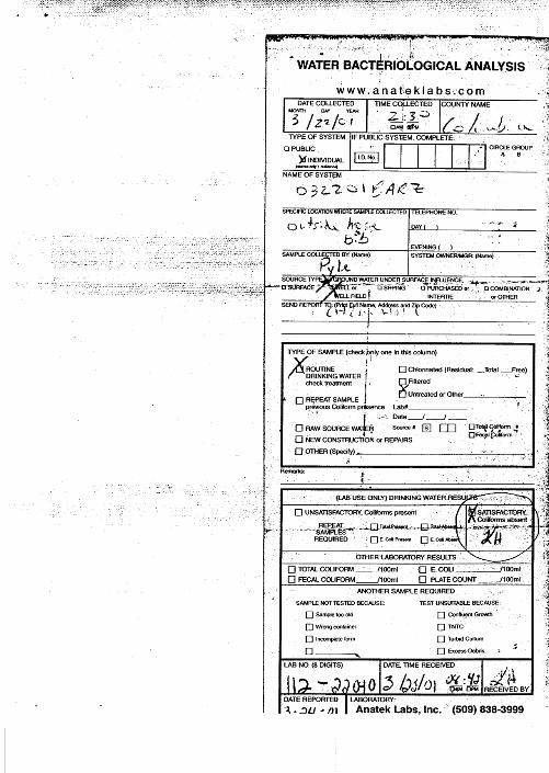
(ii) The Quality of Water Used by the IndustryProduction of electricity through the use of steam turbines will require that high puritywater be used in the process. The source of the service water will be from a proposed onsitewell or, alternatively, from the Town water system via the alternative water pipeline. Beforeuse in the generation plant, the water will be purified to remove dissolved solids.Table D.2-1 shows water quality data from two nearby wells, two Town of Starbuck sources,and a monitoring well at the generation plant site.
The samples were tested for inorganic chemicals and organic compounds by Anatek Labs,Inc. The water sources meet the drinking water standards set forth by the Washington StateDepartment of Health except for the new onsite monitoring well (B-6), which exceededmaximum contaminant levels for manganese and iron and was positive for coliformbacteria. This well was not fully developed and further development could reduce theseexceedance levels. It is not unusual to find high levels of manganese and iron in Washingtonwells; however, because the nearby Columbia County Grain Growers well and the rentalhouse well are both under detection limits for these parameters, it is likely that the futureproduction well could be low in both manganese and iron. In addition, it is not uncommonto have a positive coliform test after a well has been drilled, as a result of the well

Snake River
Columbia Co.
Whitman Co.
"!261
600
900
1000
700
600
700
600
700
800
Columbia Co.Grain Growers
500 0 500 Feet
Legend
InsetInset
Snake R."!261
Site Property
ColumbiaCounty
WhitmanCounty
WASHINGTONWASHINGTON
Inset
Figure D.2-1Vicinity Map
Application forSite Certification
Starbuck Power ProjectStarbuck, Washington
Proposed Site Property
Facility Buildings
Proposed Facility
Facility Roads
State Routes (SR)
Secondary Roads
Union Pacific Railroad
Transmission Lines
Contours 100 Foot
Other Buildings
Facility Fence
Transmission Lines
Proposed Gas Lateral
PG&E "A" Gas Pipeline
Septic Tank and Drainfield
Facility Ponds
CH2M Hill GIS Project Number 155676 \\Starbuck\Aprs\facility.apr 8-7-2001
N

2
51
9
76
8
3
28 24
26
2923
31
14
22 32
1917 21 15
16
1829
23 20 29
343133
13
1227
1110
25
29
13
14
12
2930
35
4
19
18
100 0 100 200 Feet
Key
Figure D.2-2Site Arrangement
Application forSite Certification
Starbuck Power ProjectStarbuck, Washington
1 - Combustion Turbine Building2 - Steam Turbine Building Block 13 - Steam Turbine Building Block 24 - CT Air Inlet Filter5 - Control/Administration Building6 - Heat Recovery Steam Generator7 - Exhaust Stack8 - Emissions Monitoring Skid9 - Exterior Steam Piping Piperack10 - Isophase Bus Duct11 - CT Generator Step-Up Transformer12 - ST Generator Step-Up Transformer13 - Steam Turbine Exhaust Duct to Condenser14 - Air-Cooled Condenser15 - Portable Water Treatment Equip. Parking16 - Demin. Water Transfer Station17 - Fire Pump Building18 - Demin. Water Storage Tank19 - Service/Fire Water Storage Tank20 - Gas Metering Station21 - SCR Ammonia Storage22 - Parking23 - Site Access Road24 - Existing 500 kV Transmission Lines25 - Step-Up Substation26 - 75 Foot Easement to 500 kV Line27 - Substation Control Building28 - 500 kV Starbuck Substation (By Others)29 - Site Perimeter Fencing and Gates30 - Drainfield31 - Relocated Existing Overhead Line (REA)32 - Septic Tank33 - Natural Gas Supply Line Corridor34 - Stormwater Pond35 - Infiltration/Evaporation Pond
CH2M Hill GIS Project Number 155676 \\Starbuck\Aprs\facility.apr 8-7-2001
N

������������������ �����������������
��������������������������� ����������
��������������������������������� ���������������������
����������� �������
���� ���������������

STARBUCK POWER PROJECTAPPLICATION FOR SITE CERTIFICATION
PDX/011590002.DOC D-13REVISED NOVEMBER 2001
construction process. Usually, disinfection of these newly drilled wells will provide futurenegative coliform analyses.
TABLE D.2-1Water Source Analyses
WATER SOURCE:1. Town of Starbuck Source S022. Town of Starbuck Source S013. Bar-Z Ranch Well
4. Columbia County Grain Growers Well5. SPP Site Monitoring Well B6
1 2 3 4 5
Parameter mg/L mg/L mg/L mg/L mg/L
Calcium (Ca) 26.7 29.9 29.2 38.6 40.3
Magnesium (Mg) 10.4 11.7 7.7 11.3 16.0
Sodium (Na) 10 10.7 11 18 21
Potassium (K) 3.14 4.86 6.4
Sulfate (SO4) 148 ND 22 29 30
Chloride (Cl) 3.5 ND < 20 < 20 < 20
Nitrate (NO3) 0.6 0.5 1.3 2.0 1.3
Nitrite (NO2) 0.4 < 0.1 < 0.1 < 0.1
Total Nitrate/Nitrite-N 1.3 2.0 1.3
Ammonia (as N) < 1 < 1 < 1
Silica (SiO2) 27.3 16 18 22
M alkalinity (as CaCO3) 150
Alkalinity (as CaCO3) 78 92 100
Hardness (CaCO3) 107 146 171
Specific Cond. (uS) 308 208 281 468
TDS 300 175 211 242 237
TSS (NTUs) 254 0.3
Color (units) 0.2 ND < 5 < 5 60
Turbidity (NTU) 10 0.2 0.1 > 40
Orthophosphate ND < 0.1 < 0.1 0.65
Aluminum (Al) < 0.05 < 0.05 11.3
Antimony (Sb) < 0.005 < 0.005 < 0.005
Arsenic (As) < 0.01 < 0.01 0.01
Barium (Ba) 0.0005 < 0.1 < 0.1 0.1
Beryllium (Be) 0.005 < 0.003 < 0.003 < 0.003
Cadmium (Cd) 0.01 ND < 0.002 0.003 < 0.002
Chromium (Cr) 0.034 ND < 0.01 < 0.01 0.05
Copper (Cu) ND < 0.2 < 0.2 < 0.2
Fluoride (F) 0.5 < 0.5 < 0.5 1.6
Iron (Fe) 0.14 < 0.1 < 0.1 27.4
Lead (Pb) < 0.002 < 0.002 < 0.002
Manganese (Mn) ND < 0.01 < 0.01 0.34
Mercury (Hg) < 0.0005 < 0.0005 < 0.0005
Nickel (Ni) < 0.04 < 0.04 < 0.04
Selenium (Se) < 0.005 < 0.005 < 0.005

STARBUCK POWER PROJECTAPPLICATION FOR SITE CERTIFICATION
D-14 PDX/011590002.DOC REVISED NOVEMBER 2001
TABLE D.2-1Water Source Analyses
WATER SOURCE:1. Town of Starbuck Source S022. Town of Starbuck Source S013. Bar-Z Ranch Well
4. Columbia County Grain Growers Well5. SPP Site Monitoring Well B6
1 2 3 4 5
Parameter mg/L mg/L mg/L mg/L mg/L
Silver (Ag) < 0.01 < 0.01 < 0.01
Thallium (Tl) < 0.002 < 0.002 < 0.002
Zinc (Zn) 0.20 0.02 0.03
Cyanide (CN) < 0.05 < 0.05 < 0.05
Coliform none present None present present
Notes:ND = not detected, detection limit unknown.> = not detected.mg/L = milligrams per liter.
Sources:Black & Veatch (2001).Anatek Labs, Inc. (2001a).Anatek Labs, Inc. (2001b).CH2M HILL (C. Sauer) (2001).
(iii) The Quantity of Water Used by the ApplicantThe average expected well water use for the generation plant is about 432,000 gpd or300 gpm. The maximum instantaneous flow expected from the onsite well is about 300 gpm.Alternative supply water from the Town of Starbuck is expected to flow at 100 gpm(144,000 gpd). With the alternative supply, “fogging”/steam injection will be minimized oreliminated because of the smaller volume of water available. Under the proposed 300 gpmsupply scenario, the water will be divided into two major flows as follows:
• About 290 gpm to the generation plant• About 10 gpm to the service water system
The sanitary system will use about 1 percent of the total service water. The remaining 9 gpmof the service water primarily will be used in the generation plant for housekeeping pur-poses. Forty percent of the generation plant water will be sent directly to the demineraliza-tion unit for treatment before use. The balance will be stored for the fire fighting system.
(iv) Quantity of Water Consumed or Lost by EvaporationThe steam and evaporative losses between the two steam generators and the “fogging”/steam injector unit are estimated to average 28 gpm (40,300 gpd) and 262 gpm (377,300 gpd),respectively. In addition, about 3 gpm of evaporative losses are expected from theinfiltration/evaporation ponds.
(d) The Amount and Kind of Chemicals Used in the Treatment ProcessThere will be no chemicals used in the water and wastewater treatment processes at thegeneration plant. The resins in the ion-exchange demineralization unit will be regeneratedoffsite. None of the cooling towers will require biocides or other treatment chemicals. The

STARBUCK POWER PROJECTAPPLICATION FOR SITE CERTIFICATION
PDX/011590002.DOC D-15REVISED NOVEMBER 2001
primary unit in the wastewater treatment system will be a gravity oil/water separator. Oilskimmed/drained from the unit will be collected and disposed of by an offsite contractor.
Cooling tower wash water drains and chemical drains will be routed to the chemical sump.These wastes may contain surfactants that interfere with oil/water separation. Thus, thesump will be monitored/tested and pumped out to a truck for offsite disposal.
(e) The Basic Design Data and Sizing Calculations of the Treatment Units
(i) Demineralization UnitThe demineralization unit was sized to purify 290 gpm of well water. This will be theamount of water available to operate the steam generating turbines and the“fogging”/steam injection unit.
(ii) Oil/Water SeparatorThe oil/water separator will have a 10,000-gallon capacity and will treat the 9 gpm ofprocess wastewater. This capacity is based on the estimated number of oil/lubricant storageareas that will be located in the generation plant and the estimated amount of material to bestored at each contained area.
(iii) Sanitary Septic SystemThere will be about 10 people working each shift during a three-shift day at the generationplant. Current water consumption data estimate that one person uses about 25 gallons ofwater per day. As a result, a 750-gallon septic tank will be adequate. However, a1,000-gallon septic tank will be installed to reduce the pump-out frequency. Water from theseptic system will drain to a 1,100-square-foot tile drain field.
(iv) Stormwater Infiltration/Evaporation PondA 2-acre, 4-acre-foot stormwater basin will be constructed for natural drainage of rainfall.The volume of the basin was based on a 100-year, 24-hour storm event across the totalsquare footage of the generation plant site. Estimated rainfall for this scenario is 4 inches(see Attachment 3).
(v) Process Wastewater Infiltration/Evaporation PondA 1.3-acre, 6.5-acre-foot infiltration pond will be constructed to receive the discharge fromthe oil/water separator. The size of this pond was based on a discharge flow rate of 9 gpmof process wastewater from the separator in addition to the amount of rain that would fallinto the pond during a 100-year, 24-hour storm event (see Attachment 3).
(f) A Discussion of the Suitability of the Proposed Site for the FacilityThe Applicant plans to contruct the generation plant on approximately 40 acres of a 100-acresite located about 6 miles northwest of the Town of Starbuck in Columbia County,Washington (Figure D.2-1). State Route 261 (SR-261), a two-lane highway, is adjacent to thesouthwest side of the property, and a Union Pacific rail line passes southwest of thehighway. An additional 10 acres would be disturbed during the construction process.

STARBUCK POWER PROJECTAPPLICATION FOR SITE CERTIFICATION
D-16 PDX/011590002.DOC REVISED NOVEMBER 2001
The site is located at the top of a steep bluff of the Snake River, about 170 feet above normalriver elevation and about 350 feet from the shoreline, between Little Goose Dam and LowerMonumental Dam. The Applicant has an option to purchase the property from the currentowner, the BAR-Z Ranch, Inc. Figure D.2-4 shows the property boundaries and site charac-teristics. Although much of the site has been used for grazing in the past, it is currentlyzoned for heavy industrial uses, including energy facilities such as the generation plant.
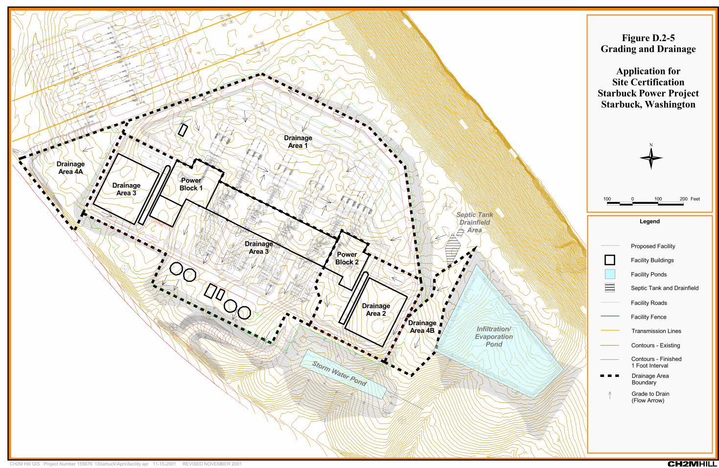
Also shown in Figure D.2-4, two BPA 500-kV transmission lines cross the approximatecenter of the property. The generation plant will be constructed on the portion of theproperty southeast of those lines. The terrain in this area generally slopes to the south, awayfrom the river. Figure D.2-5 depicts the site conceptual grading and drainage plan.
The selected site for the generation plant will reduce environmental impacts associated withthe construction of a lengthy gas pipeline and transmission line corridors because thesefacilities will be located close to the generation plant. The GTN natural gas mainline islocated within 200 feet of the Applicant’s property and the BPA transmission lines forconnection into the electrical transmission grid transect the property. The closest residenceis about 1 mile away (at the Lyons Ferry Marina).
(g) A Discussion of the Treatment Process and Operation, Including a FlowDiagram
Figures D.2-6 through D.2-9 present process flow diagrams for the demineralization unit,the oil/water separator, the septic system treatment process, and the infiltration ponds.
(i) Demineralization UnitWater pumped from the proposed onsite well will be transferred to a 500,000-gallonaboveground storage tank. This water then will be separated into two streams. One streamwill be used as service water and the other sent to the demineralization unit. The water sentto the demineralization unit will enter the chambers and pass over the enclosed resins. Theresin will remove the dissolved solids from the stream using an ion-exchange process. Thehigh-purity water exiting the demineralization unit will be sent to storage and later used asboiler makeup water and for combustion turbine “fogging”/steam injection (Figure D.2-7).If the alternative water pipeline replaces the proposed onsite well, the “fogging” processwill not be used.
(ii) Oil/Water SeparatorProcess water from indoor areas with the potential for oil or lubricant spills will drain to acentral gravity oil/water separator. The oil that accumulates at the water surface will beskimmed/drained and disposed of by an offsite contractor. The water from the separatorwill be sent to the process wastewater infiltration/evaporation pond (Figure D.2-8).
(iii) Sanitary Septic SystemA septic system will be used for the onsite treatment of sanitary wastes. The septic systemwill consist of a septic tank with a baffled entry and exit. There will be no chemicaltreatment of the water in the septic tank. In the septic tank the inlet and outlet of the tankboth will be near the top of the tank, allowing the larger solids to settle to the bottom of thetank. A portion of the solids accumulating on the bottom of the tank eventually will be

®
PowerBlock 2
PowerBlock 1
Storm Water Pond
Septic TankDrainfield
Area
Infiltration/Evaporation
Pond
®
® ®
®® ®
®
®
®
® ®® ®
®®
®®
®®
®
®
®®®®
®
®®®
®
®DrainageArea 4A
DrainageArea 3
DrainageArea 2
DrainageArea 1
DrainageArea 4B
DrainageArea 3
100 0 100 200 Feet
Legend
Figure D.2-5Grading and Drainage
Application forSite Certification
Starbuck Power ProjectStarbuck, Washington
CH2M Hill GIS Project Number 155676 \\Starbuck\Aprs\facility.apr 11-15-2001 REVISED NOVEMBER 2001
N
Contours - Existing
Facility Fence
Facility Roads
Facility Buildings
Proposed Facility
Transmission Lines
Contours - Finished1 Foot Interval
® Grade to Drain(Flow Arrow)
Facility Ponds
Septic Tank and Drainfield
Drainage AreaBoundary

��������������������������� ����
�������������������������������������������������
��������������������� ����������� �������
������������������ �� �� ��������������
�������� �!�"�#����"
���������$
�������"�� %&"��
���������'
������������ ���!
��(���"�� "#��)�����*
��+�,����"�� %&"��
���������-

������������������ �� �� �������������
������������������������� ��
��������������������������������������������������
��������������������� ����������� �������
������� �!�"����#� !$
%���&
�$� !$#"' ($)�"�$#� ��#"*$
�"!+
�",��"�$#
-��** !*./ �$"��!0$1� �!��! �
�$"��$1�2$#3
�$"��$!$#"��#
%�� �&
��������������
����"�$#
�$"����#� !$�$!$#"��#
% ��&
��,$#��,$#
4�� '$��$� !$#"' ($#��#" '$#
�$"� �$"�

������������������ �� �� ��������������
��������������������������
����������������� ����������������������������
��������������������� ����������� �������
��������� ����! ��"# �$%
��&��� ���#'�(���)
�*#�+,�% ��(�% ��!�-���%.�����%!
�%� ��)�!�-�
�� ��
�� ��
�� �� �/�,���( #,+!
�&�-���� ��
��(0�� �� �+��� $�
+�((���! �
��()��� ��
�11!� ����!+$!�(
��(
�� ��
�+ �� )! �,
�� ��
$(�.! ��(������%����(.
�11!� ����!+$!�(
�11!� ����!+$!�(
��$��!!���! �&� ���%1�( �� �$%0���+$�� �$%��$%.

������������������ �� �� ��������������
��������������������������� ����������� �
������������������� ��������������������������������
��������������������� ����������� �������
��������� ���� !!��""�#$
%"��&
���������� �"�'������ �(�$������$")"�����* �����+,
!�((��"��
�--"������"!#"�(
������ &!� �('�$*
���"�(�� �( �#��*�
�#�&�������$-�(�����#$.�/�!#����#$��#$'
��� ��(�����$�*�
�##-��#!�����$"�&!��/�# "� �-�0�"
��/�'��#�'"
��# $'
�#�&�����

STARBUCK POWER PROJECTAPPLICATION FOR SITE CERTIFICATION
PDX/011590002.DOC D-25REVISED NOVEMBER 2001
“broken down” by anaerobic bacteria. The balance of the solids will be pumped out anddisposed of offsite. Greases, oils, and lighter solids that float on top of the water in the tankwill be prevented from exiting by baffles that cover the inlet and outlet of the tank, allowingonly relatively cleaner water near the middle of the tank to exit. After the partially treatedwater exists the septic tank, the water will be pumped to a tile drain field made up ofperforated pipes laid in gravel-filled trenches (Figure D.2-8).
(iv) Stormwater Infiltration/Evaporation PondStormwater from impervious surfaces, paved roads, rooftop drains, and surfaces around theperimeter of the generation plant will be sent to the stormwater pond through naturaldrainage means (e.g., inclined culverts, shallow swales, ditches, and trenches) to the pond,which will be at the lowest point on the site. The collected stormwater will be allowed toinfiltrate into the soil and to the ground. As a result, no industrial wastewater orcontaminated stormwater will leave the site as surface runoff (Figure D.2-9).
(h) All Necessary Maps and Layout SketchesPlease see the Table of Contents for all figures, tables, and attachments associated with thisengineering report.
(i) Provisions for Bypass, if AnyThere are no provisions for bypass of untreated process or contaminated storm wastewaterat the generation plant.
(j) Physical Provision for Oil and Hazardous Material Spill Control and/orAccidental Discharge Prevention
The generation plant building, administration building, and ancillary working areas will bedesigned to drain any spilled oils, chemicals, or wastewater to various treatment areas. Anyspills that occur will be either (1) captured in containment areas that surround equipment orchemical storage tanks or (2) directed to drains that lead to the oil/water separator. Spillsfrom the various areas will be segregated as follows:
(i) Diesel Fuel Storage AreaFuel oil storage onsite during operation is expected to be limited to the diesel fuel stored forthe diesel fire fighting pump, used for fire suppression. A concrete containment area locatedbeneath the tank and the filling hook-up will be provided to capture and contain fillingspills and overfills. A drain line will connect the containment to a separate holding tank,ensuring spilled diesel fuel will not reach the stormwater collection system. This holdingtank will be emptied by an approved offsite contractor.
(ii) Ammonia Transfer and Storage AreaThe ammonia truck unloading system will be designed for the safe transfer of aqueousammonia reagent from the truck to the ammonia storage tank. The system will returndisplaced ammonia vapor to the unloading vehicle. The ammonia storage tank will bedesigned to hold a 1-week supply of ammonia (about 60,000 gallons). Common spillcontainment will be provided around both the truck unloading station and the ammonia

STARBUCK POWER PROJECTAPPLICATION FOR SITE CERTIFICATION
D-26 PDX/011590002.DOC REVISED NOVEMBER 2001
storage tank. In the event of a spill or tank rupture, the contents of the containment area willbe pumped out and disposed of offsite by an approved contractor. An emergency responsemanagement and spill control plan will be developed for the aqueous ammonia storage andtransfer system.
(iii) Indoor/Outdoor Process DrainsIndoor areas with the potential for oil or lubricant spills will be protected by concrete con-tainment structures. The drains from these areas will be directed to the oil/water separator.Water from this oil/water separator will be discharged as wastewater to the processwastewater infiltration/evaporation pond. Oils will be drained and disposed of offsite.
Spills from outdoor areas of potential oil contamination, such as the oil spill containmentstructures around the transformers, will be pumped to trucks and disposed of offsite.
(iv) Chemical SumpAreas housing chemicals will be protected with concrete containment areas. Drains in areaswhere chemical contamination could occur will be diverted to the dedicated chemical sump.Combustion turbine offline wash water will be collected in the dedicated sump. Wastewaterfrom this sump will be tested to determine the chemical content and if necessary, collectedand disposed of by an approved contractor.
(k) Results to be Expected from the Treatment Process Including the PredictedWastewater Characteristics, as Shown in the Waste Discharge Permit
(i) Process Wastewater Infiltration/Evaporation Pond DischargeTable D.2-2 summarizes the expected quality of the water discharged from the oil/waterseparator and percolating to the ground from the infiltration/evaporation pond. Becausethe potential exists to have two sources of water supply the generation plant, the qualityvalues shown in Table D.2-2 were selected to represent the highest anticipated concen-trations based on available analyses of two surrounding area wells and the two sources ofwater from the Town of Starbuck. The use of the highest concentrations of wastewaterconstituents in the analysis provides a conservative assessment. It is estimated that thewater in the pond will concentrate 25 percent due to evaporation.
(ii) Sanitary Septic System Discharge to Tile FieldTable D.2-2 summarizes the expected quality of the water that will be discharged from theseptic system and transferred to the drain field. Because there will be no chemical treatmentof the sanitary wastewater in the septic tank, no further processing of the water is requiredprior to discharge.
(l) A Description of the Receiving Water, Location of the Point of Discharge,Applicable Water Quality Standards, and How Water Quality Standards Willbe Met Outside of Any Applicable Dilution Zone
The generation plant is designed so that there will be no discharge of wastewater orcontaminated stormwater to any surface water body, including the nearby Snake River. All

STARBUCK POWER PROJECTAPPLICATION FOR SITE CERTIFICATION
PDX/011590002.DOC D-27REVISED NOVEMBER 2001
wastewater and contaminated stormwater will be collected in retention/evaporation pondsor drain fields for infiltration to ground and evaporation.
The applicable water quality standards governing the generation plant are those presentedin WAC 173-200: Water Quality Standards for Ground Waters of the State of Washington.Constituents found in the discharge waters will not exceed the criteria set forth in that rule.
(m) Detailed Outfall AnalysisThis section is not applicable to this report.
(n) The Relationship to Existing Treatment Facilities, If AnyThis section is not applicable to this report.
TABLE D.2-2Quality of Water to GroundStarbuck Power Company – Engineering Report
WASTEWATER SOURCE:1. Oil/Water Separator Discharge
2. Sanitary Septic System Discharge
1 2Parameter mg/L as CaCO3 mg/L as CaCO3
Chloride 1Fluoride 1
Nitrate 1Silica 28pH 6.5 to 9Total Alkalinity 190TDS (as such) 340Sulfate 5Calcium 93Magnesium 60Sodium 30Iron 0.1
Remarks:ND = Sampled but Not Detected within the sensitivity of the instrument.
Source:Black & Veatch file; Water Treatment Writeup.doc by Bingham, Jerry L.;5/14/2001Black & Veatch file

STARBUCK POWER PROJECTAPPLICATION FOR SITE CERTIFICATION
D-28 PDX/011590002.DOC REVISED NOVEMBER 2001
(o) Where Discharge is to a Municipal Sewerage System, a Discussion of thatSystems Ability to Transport and Treat the Proposed Industrial WasteDischarge Without Exceeding the Municipality’s Allocated IndustrialCapacity. Also, a Discussion of the Effects of the Proposed IndustrialDischarge on Municipal Sludge Utilization or Disposal
This section is not applicable to this report.
(p) Where Discharge is Through Land Application, Including SeepageLagoons, Irrigation, and Subsurface Disposal, a Geohydrologic Evaluationof Such Factors as:
The results of the geohydrologic evaluation can be found in Section 3.1, Earth, of thisApplication for Site Certification.
(i) Depth to Groundwater and Groundwater Movement During Different Times of the YearPreliminary evaluations estimate that the generation plant will be located about 200 feetabove groundwater, which will allow filtering of water before it reaches groundwater thatmay be hydraulically connected to the Snake River.
(ii) Water Balance Analysis of the Proposed Discharge Area
Stormwater Infiltration/Evaporation PondThe 2-acre unlined stormwater pond is located in the southwest portion of the generationplant site, east of access Road No. 1 and south of the Block 2 air-cooled condenser. It isdesigned to accommodate a maximum stormwater event based on a 24-hour, 100-year stormevent for this area, which has an average annual precipitation of 9.73 inches (at LowerMonumental Dam approximately 15 miles west–southwest of the plant site) to 11.37 inches(at Little Goose Dam approximately 8 miles east of the plant site). The areas used instormwater calculations include 8.80 acres for asphalt, 12.6 acres for graveled areas, and6.5 acres of grass for a total acreage of 27.9 acres. Travel time calculations were done for eachof the four drainage areas to determine travel time by accounting for the distance to thestormwater pond, Manning’s Coefficient, a 2-year/24-hour rainfall event, and slope (see theStormwater Plan and Grading-Drainage Plan presented in Appendix H for more detailedinformation on the design of the stormwater pond and conveyance systems).
The 100-year storm event of 89 cubic feet per second (cfs) was calculated using the followingguidelines from the Highway Runoff Manual published by the Washington State Depart-ment of Transportation: A 100-year, 24-hour duration rainfall volume of 4 inches wasobtained from the previously mentioned manual. The curve numbers from hydrologic soilgroup D (Starbuck) were 73 for grass and 98 for parking lots, gravel, pavements, and roofs.These values were combined as follows to get a weighted CN value of 92.17:
Weighted CN = ((CN1*A1)+(CN2*A2)+……(CNn*An))/( A1+ A2+……An)
To calculate the travel time, Tt in minutes, four segments were used. The Tt value for eachsegment was 2.46, 3.8, 6.9, and 3.8. The Tt value for a sheet flow of up to 300 feet wascalculated by using Manning’s kinematic solution:

STARBUCK POWER PROJECTAPPLICATION FOR SITE CERTIFICATION
PDX/011590002.DOC D-29REVISED NOVEMBER 2001
Tt = (0.42(nsL)0.8)/((P2)0.527(so)0.4)
where:Tt = travel time (min)ns = sheet flow Manning’s coefficient = 0.011L = flow length (ft) = 3P2 = 2-year, 24-hour rainfall (in) = 2so = slope of hydraulic grade line (land slope, ft/ft) = 0.053
After a maximum of 300 feet, the travel time was calculated by dividing the length (L) ofeach segment by each segment’s average velocity (V).
Tt = L/(60*V)V = (k)(so0.5)
where:
k = time of concentration velocity factor (ft/s); for shallow concentrated k = ks = 27,for channel flow (Intermittent) k = kc = 42.
so = slope of flow path (ft/ft)
Summing these travel times together, a time of concentration of 17 minutes, or 0.28 hour,was calculated.
HEC-1 was used to size the stormwater pond. The constraints placed on this stormwaterpond were a peak inflow of 82 cfs, a peak outflow of 10 cfs, and a peak stage elevation of691.75 feet. The required volume for this pond was 3.7 acre-feet. It has been sized to 4.0 acre-feet.
Process Water Infiltration/Evaporation PondThe average flow of 9 gpm of process water (housekeeping water from equipment/plantdrains) will be routed to an oil-water separator and then to an infiltration/ evaporationpond. The maximum daily flow will be 29 gpm. The water is expected to concentrate about25 percent as a result of evaporation from the infiltration pond. The assumptions for sizingthe infiltration/evaporation pond for process wastewater are as follows:
• Infiltration rates used were based on 6- to 7-foot-deep test pits that were excavated toprovide soil logs for review by the Columbia County Environmental Health District. Theinfiltration rates varied from 0.45 gallon per day per square foot (gpd/ft2) to0.80 gpd/ft2. The estimated pond area was obtained using the lower, 0.45-gpd/ft2 value.
• The pond size was estimated for an inflow rate of 9 gpm. For 9 gpm, the required pondsize is estimated to be 1.3 acres. The size estimate is based on an assumed pond depth of5 feet, with the pond acting solely as a percolation pond and no evaporation included.On the basis of the estimated depth to groundwater, it is assumed that the soil below thepond will be unsaturated. It is assumed that the pond will produce a saturated depth tothe pond equal to one-half the depth of the water in the pond. Below this depth,unsaturated conditions are assumed. This estimate does not take into account thepossibility that soil permeability may decrease with time. The Applicant will minimize

STARBUCK POWER PROJECTAPPLICATION FOR SITE CERTIFICATION
D-30 PDX/011590002.DOC REVISED NOVEMBER 2001
this phenomenon by removing any fines that may settle out at the top of the subgrade asa normal maintenance item, thereby restoring the permeability of the soils.
The process wastewater will be routed to a 10,000-gallon oil/water separator before reachngthe infiltration/evaporation pond. The oil/water separator will be checked on a monthlybasis unless an oil spill incident occurs during plant operations, in which case the oil/waterseparator will be checked immediately after the spill. When necessary, the separator will becleaned out by a licensed contractor; this is expected to occur infrequently because, unless aspill occurs, there will be little to no oil to be collected and disposed of. The separator will beprovided with an alarm in the event that the oil compartment fills with oil, and maintenanceaction would then be required. When necessary, a contractor will clean the oil-waterseparator and dispose of its contents at an approved disposal site.
Plant drains in areas where chemical contamination could occur will be diverted to adedicated chemical drains sump (approximately 400 gallons). Wastewater from this sumpwill be tested to determine the chemical content and, if necessary, collected and disposed ofby an approved contractor. No flow will be discharged from the sump to onsite disposalareas.
(iii) Overall Effects of the Proposed Facility upon the Groundwater in Conjunction with AnyOther Land Application Facilities that May Be Present
All process wastewater discharged will be slightly warmer than well-temperature (basaltwater is typically between 48 and 54°F) because the water will warm up as it is exposed topiping that is subjected to surface air temperatures. There will be no thermal impactsbecause the temperature of the infiltrated water that eventually will reach the groundwaterand flow toward the Snake River is not expected to be higher than the temperature of theSnake River water.
(q) A Statement, Expressing Sound Engineering Justification Through the Useof Pilot Plant Data, Results from Other Similar Installations, and/orScientific Evidence from the Literature, that the Effluent from the ProposedFacility will Meet Applicable Permit Effluent Limitations and/or PretreatmentStandards.
Statements addressing the basic design data and sizing calculations of the various treatmentunits can be found in Section D.2(e) of this report. The demineralization unit will be apackaged ion-exchange system and designed for a specific maximum water throughput.The use of gravity oil/water separators and infiltration/evaporation ponds are standard intreatment systems.
(r) Discussion of the Method of Final Sludge Disposal Selected and AnyAlternatives Considered with Reasons for Rejection.
There will be no sludge associated with the use of the water demineralization unit ordischarge water from the oil/water separator. Spent resins from the demineralization unitwill be regenerated or disposed of offsite by an approved contractor. The sludge or solidsgenerated from the sanitary septic system will be pumped out and disposed of by an offsitecontractor.

STARBUCK POWER PROJECTAPPLICATION FOR SITE CERTIFICATION
PDX/011590002.DOC D-31REVISED NOVEMBER 2001
(s) A Statement as to Who will Own, Operate, and Maintain the System AfterConstruction
The Applicant will fully own and operate the demineralization unit, the oil/water separator,and any other processes associated with the generation plant. As indicated by the Applicant,the role of offsite contractors will be to dispose of waste.
(t) A Statement Regarding Compliance with Any State or Local Water QualityManagement Plan or Any Such Plan Adopted Pursuant to the Federal WaterPollution Control Act as Amended
This generation plant will address current standards for infiltration of groundwater set forthby the State of Washington and is projected to meet established water quality standardsdeveloped under WAC 173-200. There are no TMDLs or 303(d) listed water bodies that areapplicable to this project’s discharges.
(u) Provisions for Any Committed Future PlansAt present, there are no plans for future expansion of the generation plant.
(v) A Discussion of the Various Alternatives Evaluated, if Any, and ReasonsThey Are Unacceptable
Because the wastewater generated at the generation plant will be low in dissolved solids,complex wastewater treatment will not be necessary. As a result, no other alternativetreatment methods were considered.
(w) A Timetable for Final Design and ConstructionConstruction is expected to begin with site preparation in fall 2002 and be completed byfall/winter 2004. The generation plant will be constructed generally following the sequenceindicated below:
• The site will be cleared and grubbed in the areas of permanent structures and in otherareas required outside the loop road.
• Temporary site security fencing will be installed.
• Excavation and boulder removal will be completed. Unsuitable material and boulderswill be spoiled onsite as nonstructural fill. The stormwater retention basin will beexcavated and surrounding embankments installed.
• Structural fill will be installed, the site will be graded to rough grade elevation, and theunderground portion of the stormwater drainage system will be constructed.
• The tile field and septic tank for sanitary wastewater will be installed.
• The roadway base will be constructed.
• The major foundations for the equipment and structures will be constructed.
• The underground utilities and process wastewater infiltration basin will be constructed.

STARBUCK POWER PROJECTAPPLICATION FOR SITE CERTIFICATION
D-32 PDX/011590002.DOC REVISED NOVEMBER 2001
• The equipment will be installed and structures will be erected.
• The finish road surfaces will be constructed.
• The site will be graded to finish grade elevation.
• The final stabilization (seeding and erosion control) of the site will be installed.
(x) A Statement Regarding Compliance with the State Environmental PolicyAct (SEPA) and the National Environmental Policy Act (NEPA), if Applicable
The Applicant is working with EFSEC and its consultant, Jones & Stokes, to prepare a jointNational Environmental Policy Act (NEPA)/SEPA environmental impact statement (EIS)for the generation plant, which includes the construction of a generation plant andinstallation of the proposed 500-kV transmission line. The EIS will be reviewed by EFSECand BPA.
(y) Additional Items to be Included in an Engineering Report for a Solid wasteLeachate Treatment System Are:
The elements of this section are not applicable to this report.
PDX/012360002.DOC
ATTACHMENT 1
Application for a Wastewater DischargePermit for Discharge of Industrial
Wastewater to Groundwater

ECY 040-179 (Rev. 12/00) Page 1 of 15SAI2L003.DOC
APPLICATION FOR A WASTEWATERDISCHARGE PERMIT FOR DISCHARGE OF
INDUSTRIAL WASTEWATERTO GROUND WATER
FOR OFFICE USE ONLY Check One New/Renewal � Modification �Date Application Received Application/Permit No. Date Application Accepted Date Fee Paid
This application is for a wastewater discharge permit as required in accordance with provisions ofChapter 90.48 RCW and Chapter 173-216 WAC. Permit applications provide the Department withinformation on pollutants in the waste stream, materials which may enter the waste stream, the flowcharacteristics of the discharge, and the site characteristics at the point of discharge.
The Department may request additional information at a later date to clarify the conditions of thisdischarge. Information previously submitted to the Department and which is applicable to thisapplication should be referenced in the appropriate section.
SECTION A. GENERAL INFORMATION
1. Applicant Name: Starbuck Power Company , LLC
2. Facility Name: Starbuck Power Project (if different from Applicant)
3. Applicant Address: 10500 NE 8th Street, Suite 1100 Street
Bellevue, WA 98004 City/State Zip
4. Facility Address: Highway 261 Street
Columbia County, WA City/State Zip
5. Latitude/longitude of mechanical portion of the wastewater treatment plant:
46° 34' 30" N 118° 12' 0" W
6. Person to contact who is familiar with the information contained in this application:
Mr. Michael Elmer Starbuck Power Plant Project Manager Name Title
(425) 454-5664 (425) 455-3977 Telephone Number Fax Number

Page 2 of 15 ECY 040-179 (Rev. 12/00)
7. Check One:
� Permit Renewal (including renewal of temporary permits authorized by RCW 90.48.200)
Does this application request a greater amount of wastewater discharge, a greateramount of pollutant discharge, or a discharge of different pollutants than specified inthe last permit application for this facility?� �Yes �No
For permit renewals, the current permit is an attachment, by reference, to thisapplication.
� Permit Modification
� Existing Unpermitted Discharge
� Proposed Discharge
Anticipated date of discharge: Fall 2004
I certify under penalty of law that this document and all attachments were prepared under my direction or supervision inaccordance with a system designed to assure that qualified personnel properly gather and evaluate the information submitted. Based on my inquiry of the person or persons who manage the system, or those persons directly responsible for gathering theinformation, the information submitted is, to the best of my knowledge and belief, true, accurate, and complete. I am aware thatthere are significant penalties for submitting false information, including the possibility of a fine and/or imprisonment forknowing violations.
Signature* Date Title
Printed Name
*Applications must be signed as follows: Corporations, by a principal executive officer of at least thelevel of vice-president; partnership, by a general partner; sole proprietorship, by the proprietor. If thesetitles do not apply to your organization, the application is to be signed by the person who makes budgetdecisions for this facility.
The Department of Ecology is an equal opportunity agency and does not discriminate on the basis ofrace, creed, color, disability, age, religion, national origin, sex, marital status, disabled veteran’s status,Vietnam Era veteran’s status or sexual orientation.
If you have special accommodation needs or require this document in alternative format, please contactEcology at (360) 407-6401 (voice). Ecology’s telecommunications devise for the deaf (TDD) is (360)407-6006.

ECY 040-179 (Rev. 12/00) Page 3 of 15
SECTION B. PRODUCT INFORMATION
1. Briefly describe all manufacturing processes and products, and/or commercial activities at thisfacility. Provide the applicable Standard Industrial Classification (SIC) Code(s) for each activity(see Standard Industrial Classification Manual, 1987 ed.).
Description:
2. List raw materials and products:
Type RAW MATERIALS Quantity
Type PRODUCTS Quantity

Page 4 of 15 ECY 040-179 (Rev. 12/00)
SECTION C. PLANT OPERATIONAL CHARACTERISTICS
1. For each process listed in B.1. that generates wastewater, list the process, assign the waste streama name and an ID # and describe whether it is a batch or continuous flow.
Process Waste Stream Name Waste StreamID#
Batch orContinuous
Process
2. On a separate sheet, produce a schematic drawing showing production processes, water flowthrough the facility and wastewater treatment devices. The drawing should indicate the source ofintake water and the operations contributing wastewater to the effluent. The treatment unitsshould be labeled. Construct the water balance by showing average flows between intakes,operations, treatment units, and points of discharge to land. If a water balance cannot bedetermined (e.g., for certain mining activities), provide a description of the nature and amount ofany sources of water and any collection or treatment measures.
3. What is the maximum daily discharge flow 14,400 gallons/day
What is the maximum average monthlydischarge flow (daily flows averaged over a month) 14,400 gallons/day
4. Describe any planned wastewater treatment improvements or changes in wastewater disposalmethods and the schedule for the improvements or changes. (Use additional sheets, if necessaryand label as attachment C4.)
Facility is new construction; no improvements, changes, or expansions are scheduled
at this time.

ECY 040-179 (Rev. 12/00) Page 5 of 15
5. If production processes are subject to seasonal variations, provide the following information. List discharge for each wastestream in gallons per day (GPD). The combined value for eachmonth should equal the estimated total monthly flow. NO SEASONAL VARIATIONS.
Waste Stream ID# MONTHS
J F M A M J J A S O N D
Estimated TotalMonthly Flow (GPD)
6. How many hours a day does this facility typically operate? 24 How many days a week does this facility typically operate? 7 How many weeks per year does this facility typically operate? 52
7. List all incidental materials like oil, paint, grease, solvents, and cleaners that are used or storedon site (List only those with quantities greater than 10 gallons for liquids and 50 pound quantitiesfor solids.) For solvents and solvent-based cleaners include a copy of the material safety datasheet for each material and estimate the quantity used. Use additional sheets, if necessary andlabel as attachment C.7.)
Materials/Quantity Stored: Lube oil (total amount inside turbines and transformers) - 96,500 gal;
Diesel (fuel) - 500 gal.; Aqueous Ammonia - 60,000 gal.; Hydrazine - 55 gal.;
Tri-sodium Phosphate - 500 lbs.
8. Some types of facilities are required to have spill or waste control plans. Does this facility have:
a. A Spill Prevention, Control, and Countermeasure Plan (40 CFR 112)? � Yes � Nob. An Emergency Response Plan (per WAC 173-303-350)? � Yes � Noc. A Runoff, spillage, or leak control plan (per WAC 173-216-110(f))? � Yes � Nod. Any spill or pollution prevention plan required by local, State or Federal authorities?
� Yes � No If yes specify: Spill Pollution Prevention Plan--WAC 173-220 e. A Solid Waste Management Plan? � Yes � No

Page 6 of 15 ECY 040-179 (Rev. 12/00)
SECTION D. WATER CONSUMPTION AND WATER LOSS
1. Water source(s):
� Public System (Specify) � Private Well � Surface Water
a. Water Right Permit Number: Pending; Application No. G3-29568
b. Legal Description:
¼S, ¼S, , Section, TWN, R
2. a. Indicate total water use: Gallons per day (average) 300 gpd Gallons per day (maximum) 300 gpd
b. Is water metered? � Yes � No

SECTION E. WASTEWATER INFORMATION
1. How are the water intake and effluent flow measured?
Intake Flowmeter with Totalizer
Effluent Flowmeter
2. Provide measurements for treated wastewater prior to land application for the parameters with an "X" in the left column. Use the analytical methods given in the table unless an alternate method is approved by Ecology. All analyses (except pH) must be conducted bya laboratory registered or accredited by the Department of Ecology (WAC 173-216-125). If this is an application for permit renewal,provide data for the last year for those parameters that are routinely measured. For parameters measured only for this application, placevalues under maximum.
X ParameterConcentrations Measured
Minimum Maximum Average
Numberof
Analyses
Analytical MethodStd. Methods 19th edition
DetectionLimit
BOD (5 day) 5210 2 mg/lCOD 5220 B, C, or D 5 mg/lTotal Suspended Solids 2540D 1 mg/lTotal Dissolved Solids 2540 CConductivity 2510 B
Ammonia-N 4500-NH3 C 20 µg/lpH 4500-H 0.1 unitsTotal Residual Chlorine 4500-Cl E 1 mg/lFecal Coliform 9222 DTotal Coliform 9221 B or 9222 BDissolved Oxygen 4500-O C or 4500-O G
Nitrate + Nitrite-N 4500-NO3 E 0.5 mg/lTotal Kjeldahl N 4500-Norg 20 µg/lOrtho-phosphate-P 4500-P E or 4500-P F 1 µg/lTotal-phosphate-P 4500-P B.4. 1 µg/lTotal Oil & Grease 5520 C 0.2 mg/l

ParameterConcentrations Measured
Minimum Maximum Average
Numberof
Analyses
Analytical MethodStd. Methods 19th edition
DetectionLimit
Total Petroleum Hydrocarbon 5520 C, F 0.2 mg/lCalcium 3500-Ca B 3 µg/lChloride 4500-Cl C 0.15 µg/lFluoride 4500-F D 0.1 mg/lMagnesium 3500-Mg B 0.5 µg/lPotassium 3500-K B 5 µg/lSodium 3500-Na B 2 µg/lSulfate 4500-SO4 E 1 mg/l
Barium (total) 3500-Ba B 30 µg/lCadmium (total) 3500-Cd B 5 µg/lChromium (total) 3500-Cr B 50 µg/lCopper (total) 3500-Cu B 20 µg/lIron (total) 3500-Fe B 20 µg/lLead (total) 3500-Pb B 100 µg/l
Manganese (total) 3500-Mn B 10 µg/lMercury 3500-Hg B 0.2 µg/lSelenium (total) 3500-Se C 2 µg/lSilver (total) 3500-Ag B 10 µg/lZinc (total) 3500-Zn B 5 µg/l
3. Describe the collection method for the samples which were analyzed above (ie. grab, 24 hour composite).

ECY 040-179 (Rev. 12/00) Page 9 of 15
4. Has the effluent been analyzed for any other parameters than those identified in question E.2.?� Yes � No If yes, when? Attach results and label attachment E.4. (Note: Ecologymay require additional testing.)
5. Does this facility use any of the following chemicals as raw materials in production, producethem as part of the manufacturing process, or are they present in the wastewater? (The numberfollowing the chemical name is the Chemical Abstract Service (CAS) reference number to aid inidentifying the compound.) �Yes �No
If yes, specify how the chemical is used and the quantity used or produced:
Acrylamide/79-06-1Acrylonitrile/107-13-1Aldrin/309-00-2Aniline/62-53-3Aramite/140-57-8Arsenic/7440-38-2Azobenzene/103-33-3Benzene/71-43-2Benzidine/92-87-5Benzo(a)pyrene/50-32-8Benzotrichloride/98-07-7Benzyl chloride/100-44-7Bis(chloroethyl)ether/111-44-4Bis(chloromethyl)ether/542-88-1Bis(2-ethylhexyl) phthalate/117-81-7Bromodichloromethane/75-27-4Bromoform/75-25-2Carbazole/86-74-8Carbon tetrachloride/56-23-5Chlordane/57-74-9Chlorodibromomethane/124-48-1Chloroform/67-66-3Chlorthalonil/1897-45-62,4-D/94-75-7DDT/50-29-3Diallate/2303-16-41,2 Dibromoethane/106-93-41,4 Dichlorobenzene/106-46-73,3' Dichlorobenzidine/91-94-11,1 Dichloroethane/75-34-31,2 Dichloroethane/107-06-2Nitrofurazone/59-87-0
N-nitrosodiethanolamine/1116-54-7N-nitrosodiethylamine/55-18-5N-nitrosodimethylamine/62-75-9N-nitrosodiphenylamine/86-30-6N-nitroso-di-n-propylamine/621-64-7N-nitrosopyrrolidine/930-55-2N-nitroso-di-n-butylamine/924-16-3N-nitroso-n-methylethylamine/10595-95-6PAH/NAPBBs/NAPCBs/1336-36-31,2 Dichloropropane/78-87-51,3 Dichloropropene/542-75-6Dichlorvos/62-73-7Dieldrin/60-57-13,3' Dimethoxybenzidine/119-90-43,3 Dimethylbenzidine/119-93-71,2 Dimethylhydrazine/540-73-82,4 Dinitrotoluene/121-14-22,6 Dinitrotoluene/606-20-21,4 Dioxane/123-91-11,2 Diphenylhydrazine/122-66-7Endrin/72-20-8Epichlorohydrin/106-89-8Ethyl acrylate/140-88-5Ethylene dibromide/106-93-4Ethylene thioureae/96-45-7Folpet/133-07-3Furmecyclox/60568-05-0
Heptachlor/76-44-8Heptachlor epoxide/1024-57-3Hexachlorobenzene/118-74-1Hexachlorocyclohexane (alpha)/319-84-6Hexachlorocyclohexane (tech.)/608-73-1Hexachlorodibenzo-p-dioxin,mix/19408-74-3Hydrazine/hydrazine sulfate/302-01-2Lindane/58-89-92 Methylaniline/100-61-82 Methylaniline hydrochloride/636-21-54,4' Methylene bis(N,N-dimethyl)aniline/101-61-1Methylene chloride(dichloromethane)/75-09-2Mirex/2385-85-5O-phenylenediamine/106-50-3Propylene oxide/75-56-92,3,7,8-Tetrachlorodibenzo-p-dioxin/ 1746-01-6Tetrachloroethylene/127-18-42,4 Toluenediamine/95-80-7o-Toluidine/95-53-4Toxaphene/8001-35-2Trichloroethylene/79-01-62,4,6-Trichlorophenol/88-06-2Trimethyl phosphate/512-56-1Vinyl chloride/75-01-4
6. Are any other pesticides, herbicides or fungicides used at this facility? �Yes �No
If yes, specify the material and quantity used:

Page 10 of 15 ECY 040-179 (Rev. 12/00)
7. Are there other pollutants that you know of or believe to be present?
�Yes �No
If yes, specify the pollutants and their concentration if known (attach laboratory analyses ifavailable).

ECY 040-179 (Rev. 12/00) Page 11 of 15
SECTION F. GROUND WATER INFORMATION
Provide available data measurements or range of measurements from monitoring wells or supplywells in the area of discharge. Provide the analytical method and detection limit, if known. Provide the location of each well on the map required in G.3 below. Attach well logs and wellI.D. # when available. Copy this page as necessary for each well.
Well ID #
Parameter Range of Measurements Number ofAnalyses
Analytical Method DetectionLimit
BOD (5 day)CODTotal Organic CarbonAmmonia-NpHTotal Dissolved SolidsConductivityTotal HardnessFecal ColiformTotal ColiformDissolved Oxygen
Nitrate + Nitrite-N, NitrateTotal Kjeldahl NOrtho-phosphate-PTotal-phosphate-PTotal Petroleum Hydrocarbon
CalciumChlorideFluorideMagnesiumPotassiumSodiumSulfate
BariumCadmiumChromiumCopperIronLeadManganeseMercurySeleniumSilverZincWater Level

ECY 040-179 (Rev. 12/00) Page 11a of 15
SECTION F. GROUND WATER INFORMATION
Provide available data measurements or range of measurements from monitoring wells or supplywells in the area of discharge. Provide the analytical method and detection limit, if known. Provide the location of each well on the map required in G.3 below. Attach well logs and wellI.D. # when available. Copy this page as necessary for each well.
Well ID #
Parameter Range of Measurements Number ofAnalyses
Analytical Method DetectionLimit
BOD (5 day)CODTotal Organic CarbonAmmonia-NpHTotal Dissolved SolidsConductivityTotal HardnessFecal ColiformTotal ColiformDissolved Oxygen
Nitrate + Nitrite-N, NitrateTotal Kjeldahl NOrtho-phosphate-PTotal-phosphate-PTotal Petroleum Hydrocarbon
CalciumChlorideFluorideMagnesiumPotassiumSodiumSulfate
BariumCadmiumChromiumCopperIronLeadManganeseMercurySeleniumSilverZincWater Level

Page 12 of 15 ECY 040-179 (Rev. 12/00)
SECTION G. SITE ASSESSMENTThe local library and local city or county planning offices may be helpful in providing theinformation required in this section. The Department of Ecology Water Resources Section can beconsulted for identifying wells within one mile of your site.
1. Give the legal description of the land treatment site(s) by section/township/range andlatitude/longitude. Indicate owner for each site. Give the acreage of each land treatment site(s).Attach a copy of the contract(s) authorizing use of land for treatment.
2. If this is a new discharge, list all environmental control permits or approvals needed for thisproject; for example, SEPA review, septic tank permits, sludge application permits, or airemissions permits.
3. Attach an original United States Geological Survey (USGS) 7.5 minute topographic map. USGStopographical maps are available from the Department of Natural Resources (360 902-1234),Metsker Maps (206 588-5222), some local bookstores and internet vendors. Show the followingon this map:
a. Location and name of internal and adjacent streets.b. Surface water drainage systems within ¼ mile of the site.c. All wells within 1 mile of the site.d. Wastewater discharge points.e. Land uses and zoning adjacent to the wastewater application site.f. Ground water gradient.
4. Describe soils on the site using information from local soil survey reports. Soils information isavailable from your local County Conservation District. (Submit on separate sheet and label asattachment G.4.)
5. Describe the local geology and hydrogeology within one mile of the site. Include any ground waterquality data. The local library or local Soil Conservation Service may have this information. (Submit on separate sheet and label as attachment G.5.)
6. List the names and addresses of contractors or consultants who provided information and citesources of information by title and author.

ECY 040-179 (Rev. 12/00) Page 13 of 15
SECTION H. STORMWATER1. Do you have a Washington State Stormwater Baseline General Permit? If
yes, please list the permit number here. � Yes � No
2. Have you applied for a Washington State Stormwater Baseline GeneralPermit?
� Yes � No
3. Do you have any stormwater quality or quantity data? � Yes � No
Note: If you answered "no" to questions 1 or 2 above, complete questions 4 through 8.
4. Describe the size of the stormwater collection area.
a. Unpaved Area sq.ft.
5. Does your facility's stormwater discharge to: (Check all that apply)
� Storm sewer system; name of storm sewer system (operator): � Directly to surface waters of Washington State (e.g., river, lake, creek, estuary, ocean).
Specify waterbody name � Indirectly to surface waters of Washington State (i.e., flows over adjacent properties first).� Directly to ground waters of Washington State: (indirectly)
� dry � drainfield
well
� other - Infiltration/Evaporation Ponds� Sanitary Sewer
6. Areas with industrial activities at facility: (check all that apply)
� Manufacturing Building� Material Handling� Material Storage� Hazardous Waste Treatment, Storage, or Disposal (Refers to RCRA, Subtitle C Facilities Only)� Waste Treatment, Storage, or Disposal� Application or Disposal of Wastewaters� Storage and Maintenance of Material Handling Equipment� Vehicle Maintenance� Areas Where Significant Materials Remain� Access Roads and Rail Lines for Shipping and Receiving� Other
b. Paved Area Paved Area sq.ft.c. Other Collection Areas (Roofs) sq.ft. sq.ft.

Page 14 of 15 ECY 040-179 (Rev. 12/00)
7. Material handling/management practices
a. Types of materials handled and/or stored outdoors: (check all that apply)
� Solvents � Hazardous Wastes� Scrap Metal � Acids or Alkalies� Petroleum or Petrochemical Products � Paints/Coatings� Plating Products � Woodtreating Products� Pesticides � Other (please list):
b. Identify existing management practices employed to reduce pollutants in industrial storm waterdischarges: (check all that apply)
� Oil/Water Separator � Detention Facilities� Containment � Infiltration Basins� Spill Prevention � Operational BMPs� Surface Leachate Collection � Vegetation Management� Overhead Coverage � Other (please list):
8. Attach a map showing storm water drainage/collection areas, disposal areas and discharge points. This may be a hand drawn map if no other site map is available. Label this as attachment H.8.
SECTION I. OTHER INFORMATION
1. Describe liquid wastes or sludges being generated that are not disposed of in the waste stream(s) andhow they are being disposed. For each type of waste, provide type of waste, name, address, andphone number of hauler.
2. Describe storage areas for raw materials, products, and wastes.
3. Have you designated the wastes described above according to the applicableprocedures of Dangerous Waste Regulations, Chapter 173-303 WAC?
� Yes � No

ECY 040-179 (Rev. 12/00) Page 15 of 15
Summary of Attachments That May be Required for This Application:(Please check those attachments which are included)
� C.2. Production schematic flow diagram and water balance� C.4. Wastewater treatment improvements� C.7. Additional incidental materials� E.4. Additional results of effluent testing� G.1. Copies of land use contracts� G.3. USGS topographical map� G.4. Soils description� G.5. Local geology and hydrology� H.8. Stormwater drainage map

������������������ �����������������
����������������������������� ����������
������������������������������������� �����������������
���� ���������������
������������� ������


STARBUCK POWER PROJECTAPPLICATION FOR SITE CERTIFICATION
PDX/011590002.DOC 708/25/2001 1:45 PM
ATTACHMENT G.2
Applicable Environmental Control Permits orApprovalsApplication for Wastewater Discharge Permit
Federal Permits:National Environmental Policy Act (NEPA)U.S. Army Corps of Engineers Dredge and Fill Section 404 PermitU.S. Army Corps of Engineers Nationwide Permit ProgramThreatened or Endangered Species AssessmentsHistoric Preservation/Landmark Review
State of Washington Permits:State Environmental Policy Act (SEPA)Notice of Construction (NOC) Approval (for Air Quality)Air Contaminant Source RegistrationPrevention of Significant Deterioration of Air Quality PermitAir Operating PermitCompliance with State Noise RegulationsHydraulic Project Approval (HPA)Public Water Supply ApprovalShorelines PermitAquatic Resources Use Authorization NotificationNPDES General Permit for Stormwater Associated with Construction ActivitiesNPDES General Permit for Stormwater Associated with Industrial ActivitiesState Waster Discharge Permit
Local Permits:On-Site Sewage Disposal System Permit

Legend
Facility Fence
Facility Roads
Facility Buildings
Proposed Facility
1 Mile Radius From Site
Proposed Site Property
Stormwater and WastewaterDischarge Ponds
Heavy Industrial Landuse
State Route (SR)
Well#
#
#"!261
Bar-ZWell
C.C.G.G.Well
1000 0 1000 2000 Feet
Attachment G.3USGS Topographic Map
Application forWastewater Discharge Permit
Starbuck Power ProjectStarbuck, Washington
CH2M Hill GIS Project Number 155676 \\Starbuck\Aprs\facility.apr 8-7-2001
Background Image:
USGS 7.5 Minute Quadrangle (Topographic)Original Scale 1:24000North American Datum 1983Washington Zone - SouthContours and Elevations in MetersScanned at 300 dpi
N

STARBUCK POWER PROJECTAPPLICATION FOR SITE CERTIFICATION
PDX/011590002.DOC 1108/25/2001 1:45 PM
ATTACHMENT G.4
Description of Soil(s) on SiteApplication for Wastewater Discharge Permit
The soil at the proposed site of the Starbuck generation plant is a gravel/cobble soil. It isdelineated as Stratford Series soil, which consists of well-drained, very stony silt loams thatare underlain by sand, gravel, cobblestones, and boulders at a depth of 20 to 40 inches. Testtrenches excavated at the site show that the soil is well-drained and has stony to very stonysilt loams. The soil profile consists of a surface layer of grayish brown, very stony silt loamto a depth of 13 inches. The substratum, to a depth of 24 inches, is pale brown gravelly loam.Below this loam, to a depth of 60 inches, is loose, coarse-sand gravel, cobblestones, andboulders.
The Stratford Series soils have a moderate permeability above the coarse gravels, cobble-stones, and boulders. Root penetration is restricted by the coarser layers. The availablewater-holding capacity is moderate to moderately high (4 to 6 inches of water). Runoff isslow to medium, and the erosion hazard is slight to moderate, depending on the slope of theground surface.

STARBUCK POWER PROJECTAPPLICATION FOR SITE CERTIFICATION
PDX/011590002.DOC 13REVISED NOVEMBER 2001
ATTACHMENT G.5
Local Geology and HydrogeologyApplication for Wastewater Discharge Permit
GeologyThe proposed generation plant site is situated on a gravel bar that was deposited along theSnake River approximately 13,000 years ago. This bar was deposited by floodwaters thatbacked up into the Snake River valley from the confluence of the Palouse and Snake Riversduring the last of the catastrophic Lake Missoula floods. Borings conducted at thegeneration plant site indicate that subsurface conditions consist of two relatively thick layersof gravel, underlain by basalt bedrock. The upper layer extends to 150 feet below groundsurface (bgs) in the northern portion of the generation plant site, to 115 feet bgs toward thesoutheast. This layer consists of poorly graded gravels, cobbles, and boulders with traces ofsand and silt. The lower layer starts at the bottom of the upper layer and is assumed toextend down to basalt bedrock; this layer has a higher content of sand and silt whencompared to the upper layer. A geologic log associated with a domestic water well drilled inthe area indicates that at least 193 feet of coarse gravelly sediments overlie the basaltbedrock. The basaltic bedrock underlying the generation plant site and forming the walls ofthe Snake River canyon to the north and south consists of lava flows of the Grande RondeBasalt. This basalt is the most abundant and widespread formation of the Columbia RiverBasalt Group. It consists of about 120 individual flow units and makes up about 90 percentof the total volume of the Columbia River Basalt Group. The thickness of the basalt belowthe site is not known but is likely on the order of 1,000 feet. The only other major geologicunit in the immediate site vicinity is a sand and gravel deposit that is exposed on the slopeto the south of the site. As with the gravel bar deposit underlying the site, these sedimentswere also deposited during the Missoula Floods. They differ from the bar deposit in thatthey are typically finer grained and were deposited in protected places on the canyon walls.
HydrogeologyThe terrace that the generation plant site will be located upon is slightly to moderatelysloped, generally from north to south. The highest elevations are located near the bank ofthe Snake River and near the north end of the site; the lowest elevations are near the southend of the site. Elevations within the generation plant property boundary vary fromapproximately 720 feet above mean sea level (msl) in the north to approximately 690 feetmsl in the south. To the far southern and eastern regions of the terrace, outside of thegeneration plant site, elevations reach 600 feet msl. The horizontal distance between thenearest project facility (perimeter road) and the Snake River is approximately 41 feet, andthe vertical drop from the site to the normal river water level is approximately 170 feet. Thearea to be developed for the generation plant slopes away from the river.

STARBUCK POWER PROJECTAPPLICATION FOR SITE CERTIFICATION
14 PDX/011590002.DOC REVISED NOVEMBER 2001
Precipitation on the site infiltrates through the soil or is directed by the sloping topographytoward the south end of the site. Four small ravines in the southern portion of the site collectprecipitation and direct it to the southeast, away from the Snake River and toward SR-261.This runoff is directed under SR-261 via a 24-inch-diameter culvert and allowed to disperseand percolate on the west side of SR-261. On the basis of site soil properties, runoff potentialis classified as low to moderate. Because the generation plant site does not contain surfacewater bodies other than during periods immediately following rainfall or snowmelt, nosurface water quality data are available. As a result of erosion and soil conditions at the site,runoff during the periods of rainfall or snowmelt does typically contain suspended solids.As previously discussed, this runoff is directed away from the Snake River, toward SR-261.
Two main aquifers surround the proposed generation plant site:
• Flood Gravel Aquifer. The aquifer in the flood gravels below the generation plant site isat a depth of 190 feet, based on a geologic log of a residential well drilled near thenorthwest end of the site. This groundwater elevation corresponds closely to the poolelevation of Lake Herbert G. West, about 1,000 feet north of the well, suggesting thatgroundwater in the flood gravel aquifer is hydraulically connected with the lake. Thisgroundwater is likely to be restricted to the geographic extent of the terrace, although itcould be in contact with a bedrock aquifer at essentially the same elevation. The ground-water is recharged by infiltration of precipitation through the terrace, seepage from thelake, and perhaps by discharge from the adjoining bedrock. The well log indicates thatthe aquifer is situated in highly permeable gravels; a pumping test in the well yielded190 gallons per minute (gpm) with 70 feet of drawdown after 2 hours.
• Columbia Plateau Aquifer System. The Columbia Plateau aquifer system underliesabout 50,600 square miles of Washington, Oregon, and Idaho. The thickest, mostextensive, and most important geologic unit in the aquifer system is the Columbia RiverBasalt Group. In the vicinity of the generation plant site, the Grande Ronde Basaltformation (of the Columbia River Basalt Group) may be as much as 1,000 feet thick andserves as the primary regional aquifer; it is the area’s only available source of largequantities of good-quality water. Within the Grande Ronde aquifer, groundwater occursat numerous horizons within the thick sequence of lava flows and is derived mainlyfrom relatively thin, permeable flow-contact zones between thicker, less permeable partsof the flows. Several water-bearing zones within the Grande Ronde basalt aquifer areused for water supply in the area, with most of the wells open to more than one water-bearing zone.
The regional basalt aquifers are recharged mainly by infiltration of precipitation, both at thebasalt surface and in stormwater runoff channels crossing the basalt. Most of theprecipitation falls during the cooler seasons, when loss of water to evaporation and plantgrowth is relatively small and the opportunity for infiltration is enhanced. Discharge fromthe aquifer systems is mainly to the river systems and, in lesser quantities, to springs andseeps along canyon and coulee walls. Groundwater flow direction in the vicinity of thegeneration plant site is toward the Snake River canyon to the north, generally indicating thatthe Snake River canyon is hydraulically connected to the regional aquifer. Although thebasalt aquifers are capable of yielding large quantities of water to wells, they containrelatively small volumes of groundwater per unit volume of rock. Considerable effort has

STARBUCK POWER PROJECTAPPLICATION FOR SITE CERTIFICATION
PDX/011590002.DOC 15REVISED NOVEMBER 2001
been made in parts of the Columbia River basin to evaluate the impact of extraction ongroundwater levels in the Columbia River Basalt Group. However, these studies havefocused on areas to the north and west of the generation plant site, where there isconsiderably greater groundwater withdrawal. No published studies have evaluated long-term effects of groundwater withdrawal in Columbia County, and this project does notpropose to withdraw water from the basalt aquifer system.
According to Federal Emergency Management Agency (FEMA) maps, the generation plantsite is not within the 100- or 500-year floodplains. Several dams control the elevation of theriver in the site vicinity; river elevation normally fluctuates between 537 and 540 feet msl(Black & Veatch, 2000). The lowest point within the generation plant property boundary isapproximately 690 feet msl (approximately 150 feet above the normal river level). The onsitewell at the generation plant site would be above the 100- and 500-year floodplain of theSnake River and would not be susceptible to flood impacts.
Water Quality DataWater quality data from this area can be found in Section F, Groundwater Information, ofthis Applicant for a Wastewater Discharge Permit.

®
Infiltration/Evaporation
PondStormwater Pond
Septic TankDrainfield
®
®
® ®
®® ®
®
®
®
® ®® ®
®®
®®
®®
®
®
®®®®
®
®®®
®
®DrainageArea 4A
DrainageArea 3
DrainageArea 2
DrainageArea 1
DrainageArea 4B
DrainageArea 3
100 0 100 200 Feet
Legend
CH2M Hill GIS Project Number 155676 \\Starbuck\Aprs\facility.apr 11-15-2001 REVISED NOVEMBER 2001
Contours - Existing
Facility Fence
Facility Roads
Facility Buildings
Proposed Facility
Transmission Lines
Contours - Finished1 Foot Interval
® Grade to Drain(Flow Arrow)
Stormwater and Wastewater DischargePonds
Septic Tank Drainfield
Drainage AreaBoundar
Attachment H.8Stormwater Drainage/Collectionand Wastewater Discharge Points
Application forWastewater Discharge Permit
Starbuck Power ProjectStarbuck, Washington
N

PDX/011590002.DOC08/25/2001 1:45 PM
ATTACHMENT 2
Anatek Labs Reports