Embed Size (px)
Citation preview

STAR-CCM+ In The Process Industry
Mark Farrall,
Director, Engineering Services Europe

Outline
• Introduction to Engineering Services
• Process Equipment: An Overview
• Case Study – Flare Knock Out Drum
• Case Study – Stabilizer Feed Drum
• Case Study – Surge Sphere

Engineering Services:
The Customer-Flexible Role
We concentrate on the underlying need: what do “You” need to know or find out
Jump Start In-house Analysis Capabilities
Further advance In-house Analysis Capabilities
• Where CD-adapco already knows how to do it
• Where no one knows how to do it
Validate/Evaluate the Software in “Your” Application
Understand How a Current Product Works
Support New Product Development
Overcome Short Term Resource Needs
Overcome Near Term Schedule Needs
Team with CD-adapco in a Proposal to Make “Your” Services More Comprehensive to “Your” customers
Fulfill a Contractual or Legal Requirement

Companies Helped By CD-adapco
Outline
• Introduction to Engineering Services
• Projects Work Areas
• Process Equipment: An Overview
• Case Study – Flare Knock Out Drum
• Case Study – Stabilizer Feed Drum
• Case Study – Surge Sphere

• Onshore / Offshore Pipelines – Slugging
– Chemical injection management
– Investigation of the effects of Gas lift
– Thermal Insulation (Start-up and Shut-down)
– STAR-Olga coupled analyses
Typical tie-back infrastructure
Project Work Areas

Project Work Areas
Typical tie-back infrastructure
• Vessels / FPSOs • Wave impact analysis
• Sloshing in tanks / separators
• Vessel Integrity

Project Work Areas
• Safety – Flare radiation
– Gas dispersion / Re-ingestion
– Free Falling Life Boats
Typical tie-back infrastructure

Outline
• Introduction to Engineering Services
• Process Equipment: An Overview
• Case Study – Flare Knock Out Drum
• Case Study – Stabilizer Feed Drum
• Case Study – Surge Sphere

Areas Of Interest
• Design Verification - Separation performance
– Liquid carry over
– Liquid carry under
– Sloshing – Effectiveness of baffles
– Vessel Integrity

Areas Of Interest
• Design Verification - Separation performance
– Liquid carry over
– Liquid carry under
– Sloshing vessels
• Resolving Current Issues
– Under performance
– Operational Issues

Outline
• Introduction to Engineering Services
• Process Equipment: An Overview
• Case Study – Flare Knock Out Drum
• Case Study – Stabilizer Feed Drum
• Case Study – Surge Sphere

Flare Knock Out Drum
• Motivation: Oil carry-over from the Knock-Out Flare Drum during
flaring. The liquid level inside the vessel was observed to drop during
flaring events. Further indicators of this came from a temperature
increase in the vessel. Heavier hydro-carbons can produce a diesel
“sheen” on the surrounding sea after flaring. Lighter hydro-carbons can
sometimes produce a “burning rain” from partially burnt oil.
• Solution: Multiphase model of the Knock-Out Flare Drum to identify
cause of carry-over; Identify potential design solutions.
• Business Benefit: Oil carry-over can lead to poor combustion and
resultant damage to the flare tip. Liquid level dropping can trip the level
alarm which shuts down production.

Operations Data
Flare event:
Increase in gas flow
Decrease in liquid
level

Flare Knock Out Drum
Gas Outlet Pipe
Liquid Outlet Pipe:
Wall (closed)
Gas Inlet Pipe:
Fixed mass inlet
Baffle Plate

Original Design
Inlet gas flow is directed
downwards onto the liquid surface
where it creates a large standing
wave.

Design Variations
Flat plate perpendicular to the inlet ducting
Flat plate angled towards the upper surface of the vessel

Design Variations
Saucer perpendicular to the inlet ducting
Vertical half pipe

Design Variations
Horizontal half pipe
Convex plate

Final Design
The new concave plate design directs the flow to the sides of the drum and
then downwards. When the inlet gas stream reaches the liquid surface it has
lower velocity and is directed more horizontally than the original design. Only
small waves are generated
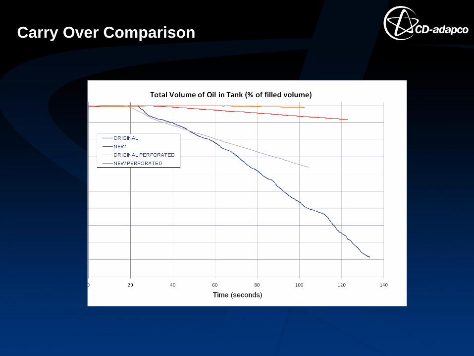
Carry Over Comparison

Outline
• Introduction to Engineering Services
• Process Equipment: An Overview
• Case Study – Flare Knock Out Drum
• Case Study – Stabilizer Feed Drum
• Case Study – Surge Sphere

Inlet Pipe
Inlet Pipe
Diffuser
Vane Unit
Weir Plate
Boot
Vortex
Breaker
Condensate
Outlet
Gas Outlet
Vane Pack
Glycol
Outlet
Stabilizer Feed Drum
• Motivation: Condensate carry-under from the Stabilizer Feed Drum
• Solution: Multiphase model of the Stabilizer Feed Drum to identify
cause of carry-under; Identify potential design solutions; Qualitative flow
field comparisons; Quantitative carry-over comparisons
• Business Benefit: Vessel out of use

Flow Field Overview
Liquid hydrocarbons present
in the boot section

Flow Field Overview
Gas Recirculation
Zone
• The gas exiting the inlet device impacts the liquid surface and moves
around the upstream part of the vessel.
• As the vane pack covers only have the vessel height the gas flows over the
top and down, generating a large recirculation zone in the main part of the
vessel.
• Chance for surface entrainment leading to liquid carry over

Original Configuration
Modified Configuration
Distributor Plate
Modified Weir Plate:
Glycol / Condensate
Interface raised 50mm
Alternative Internals Arrangement

Original Configuration
Modified Configuration
Flow Field Comparison

Original Configuration
Modified Configuration
Reduced
recirculation
zones
Improved flow through
the vane unit
Flow Field Comparison

Volume Fraction
of Oil
Original Configuration Modified Configuration
Carry-over Quantification:
Droplet Diameter 0.1mm