Embed Size (px)
Citation preview

STAIRISER CR USER HANDBOOK
IMPORTANT Before using your Stannah Stairiser platform stairlift, please ensure that you read and familiarise yourself with these
instructions.
2
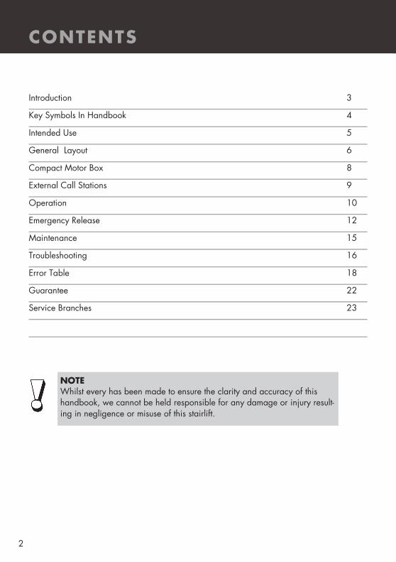
NOTE Whilst every has been made to ensure the clarity and accuracy of this handbook, we cannot be held responsible for any damage or injury result-ing in negligence or misuse of this stairlift.
Introduction 3
Key Symbols In Handbook 4
Intended Use 5
General Layout 6
Compact Motor Box 8
External Call Stations 9
Operation 10
Emergency Release 12
Maintenance 15
Troubleshooting 16
Error Table 18
Guarantee 22
Service Branches 23
CONTENTS
3
This users handbook is to help provide an understanding of correct and safe use of the Stannah Stairiser CR.
Your lift has been manufactured and installed in accordance with the Machinery Directive 98/37/EC.
It is important that you arrange for the lift to receive regular inspection and servicing by a competent person at intervals not exceeding six months, after the 12 months guarantee period.
Failure to ensure servicing is carried out could lead to unreliable or unsafe operation.
For all enquiries regarding servicing, please contact your local Stannah Service Office at the address given on this booklet. A Service Log Card supplied by the Service Office will be completed after each service visit.
As requested by the European Legislation On Machinery Regulations, the following maximum noise emission has been measured at a distance of 1metre from the stairlift carriage:
INTRODUCTION
For your records:

4
KEY SYMBOLS IN HANDBOOK
The following signs stress important areas:
Pay attention to all paragraphs marked with this sign. These paragraphs contain important hints that will ensure smooth operation of the lift.
WARNING! Important safety advice! Observing these instructions greatly reduces the possibility of hazardous situations.
Pay attention! Do not execute the actions marked with this sign!
5
INTENDED USE
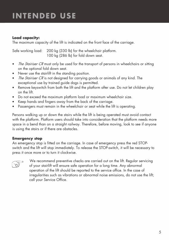
Load capacity: The maximum capacity of the lift is indicated on the front face of the carriage.
Safe working load: 200 kg (330 lb) for the wheelchair platform. 100 kg (286 lb) for fold down seat.
• The Stairiser CR must only be used for the transport of persons in wheelchairs or sitting on the optional fold down seat.
• Never use the stairlift in the standing position. • The Stairiser CR is not designed for carrying goods or animals of any kind. The
exceptional use by trained guide dogs is permitted. • Remove keyswitch from both the lift and the platform after use. Do not let children play
on the lift. • Do not exceed the maximum platform load or maximum wheelchair size. • Keep hands and fingers away from the back of the carriage. • Passengers must remain in the wheelchair or seat while the lift is operating.
Persons walking up or down the stairs while the lift is being operated must avoid contact with the platform. Platform users should take into consideration that the platform needs more space in a bend than on a straight railway. Therefore, before moving, look to see if anyone is using the stairs or if there are obstacles. Emergency stop An emergency stop is fitted on the carriage. In case of emergency press the red STOP-switch and the lift will stop immediately. To release the STOP-switch, it will be necessary to press it once more or to turn it clockwise.
We recommend preventive checks are carried out on the lift. Regular servicing of your stairlift will ensure safe operation for a long time. Any abnormal operation of the lift should be reported to the service office. In the case of irregularities such as vibrations or abnormal noise emissions, do not use the lift; call your Service Office.

6
GENERAL LAYOUT
WARNING - Before using your lift, please read and familiarise yourself with these instructions
1. Wall control 2. Drive box (small or big) 3. Carriage 4. Upper stop position 5. Intermediate stop position
6. Lower stop position 7. Horizontal railway 8. Upper railway tube 9. Lower railway tube 10. Overspeed governor

7
GENERAL LAYOUT
Carriage with platform for wheelchairs
1. Handset with direction buttons, audio alarm and stop switch (key switch optional) 2. Display 3. Access ramps 4. Barrier arms 5. Sidewall covers 6. Directional control (joystick) 7. Folding seat Carriage with seat performance 1. Directional control 2. Armrest 3. Seat 4. Footrest 5. Carriage, sidewall Horizontal railway If the gradient is less than 20 degrees a third pipe is required to stabilise the platform. Horizontal sections may be necessary at half-landings or stop positions.
8
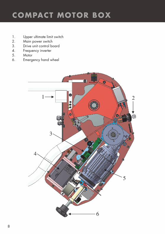
1. Upper ultimate limit switch 2. Main power switch 3. Drive unit control board 4. Frequency inverter 5. Motor 6. Emergency hand wheel
COMPACT MOTOR BOX
1 2
3
4
5
6

9
EXTERNAL CALL STATIONS
Drive up button The platform will drive up when in closed (unfolded) position Drive down button The platform will drive down when in closed (unfolded) posi-tion Platform open button The platform will open (unfold). This button works only when the platform is in the landing station. Platform close button The platform will close (fold). The platform should be closed when in the landing station.
All Stairiser CR installations are equipped with calling stations, with which you can call and send the lift. Call stations are located in the area of the upper and lower landing position. Each landing call station needs to be activated with a key switch before use. The call stations are needed to call and send the lift with closed platform and to open and close the platform in the landing stations.
Key switch
LED Light

10
Main power switch The main power switch connects the lift to the power supply system. For use of the lift, first turn on the main power switch. By switching off the main power switch, the stairlift can be isolated from the circuit.
It is necessary to switch off the main power switch while repairs are done to the lift, especially in the drive box. The main power switch can be locked in both the “on” and “off” position with a padlock.
The main power switch is located either on the side of the drive box (drive type K) or on the external control box (drive type S).
Turn on the landing control station (using the key). Lock the landing control station after use.
Bring the carriage to the desired position using one of the landing stations control. First, unlock the landing control station with the key, then press the “up” or “down” button. Keep it pressed until the carriage automatically stops in the desired landing position. Release the button and lock the landing control station again. The lift is now ready for use.
Driving/Moving onto the platform The platform is folded down by pressing the “open” button (4 – see above). Keep it pressed and the barrier will automatically fold up. Simultaneously the ramps fold down to the correct position enabling safe driving/moving onto the platform.
Always face the direction of travel and apply the wheelchair brake for safety.
OPERATION
WARNING - Before operating the lift, ensure the platform area is clear
11
OPERATION
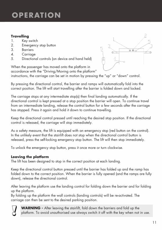
Travelling 1. Key switch 2. Emergency stop button 3. Barriers 4. Carriage 5. Directional controls (on device and hand held)
When the passenger has moved onto the platform in accordance with the “Driving/Moving onto the platform” instructions, the carriage can be set in motion by pressing the “up” or “down” control.
By pressing the directional control, the barrier and ramps will automatically fold into the correct position. The lift will start travelling after the barrier is folded down and locked.
The carriage stops at any intermediate stop(s) then final landing automatically. If the directional control is kept pressed at a stop position the barrier will open. To continue travel from an intermediate landing, release the control button for a few seconds after the carriage has stopped. Press it again and hold it down to continue travelling.
Keep the directional control pressed until reaching the desired stop position. If the directional control is released, the carriage will stop immediately.
As a safety measure, the lift is equipped with an emergency stop (red button on the control). In the unlikely event that the stairlift does not stop when the directional control button is released, press the self-locking emergency stop button. The lift will then stop immediately.
To unlock the emergency stop button, press it once more or turn clockwise. Leaving the platform The lift has been designed to stop in the correct position at each landing.
Keep the directional control button pressed until the barrier has folded up and the ramp has folded down to the correct position. When the barrier is fully opened (and the ramps are fully down), release the directional control.
After leaving the platform use the landing control for folding down the barrier and for folding up the platform. By folding up the platform the wall controls (landing controls) will be re-activated. The carriage can then be sent to the desired parking position.
WARNING - After leaving the stairlift, fold down the barriers and fold up the platform. To avoid unauthorised use always switch it off with the key when not in use.

12
EMERGENCY RELEASE
If it necessary to evacuate a user from the lift due to either lift or power failure, the procedures described here should be followed. A different process is needed, dependant on where the platform has stopped: Case 1 The occupied platform is near a stop position. The position of the main power switch, the hand lever for brake release and the hand wheel is indicated on page 8. 1. Turn the main power switch to off. 2. Take the hand wheel and insert it into the hole located at the back of the motor. 3. Press the hand lever for brake release and turn the hand wheel until the next station
has been reached. The direction for moving the lift up is indicated on the hand wheel (fig. 1 shows the platform at the stop position)).
4. When the platform is positioned at a landing as illustrated in fig. 1, the barrier arm only on the side of the lift from which the platform is to be exited, may be forced upwards by hand. Refer to fig. 2.
5. Now the wheelchair user can leave the platform.on the barriers. 6. With the user evacuated push down hard on the barriers. As the barriers fold
down the platform will fold up (see fig. 4). The platform must now be locked with the padlock on the carriage.
7. Call your service office.
Fig. 1 Fig. 2 Fig. 3 Fig. 4

13
EMERGENCY RELEASE
Case 2 The occupied platform is not close to a stop position. The position of the main power switch, the hand lever for brake release and the hand wheel is indicated on page 8. Please note for the rescue of the passenger with the carriage in such position two people are needed! If there is only one person available, it will be necessary to wind the carriage into the next station (see case 1). 1. Turn the main power switch to off. 2. Take the hand wheel and insert it into the hole located at the back of the motor. 3. Press the hand lever for brake release and turn the hand wheel until reaching the
next half-landing or straight part of the staircase (see fig 1.1). Do not stop at a curved area of the rail.
4. Unlock the barrier arm by following procedure described on page 18. Note that this process is only applicable when the carriage is not positioned at a landing station. The barrier arm to the stairs side only of the lift should be raised; raising the arm to the open side of the carriage would expose the user to toppling off the platform and falling down the stairs. Refer to Fig 2.1.
5. The wheelchair user can now be lifted down from the platform. 6. With the user evacuated, push down hard on the barriers. As the barriers fold
down the platform will fold up (see fig. 4.1). The platform must now be locked with the padlock on the carriage.
7. Call your service office.
Fig. 1.1 Fig. 2.1 Fig. 3.1 Fig. 4.1
14
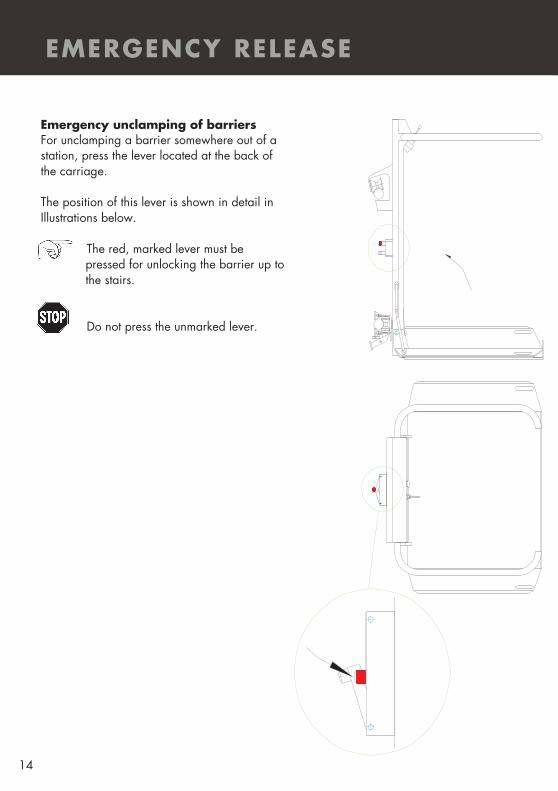
Emergency unclamping of barriers For unclamping a barrier somewhere out of a station, press the lever located at the back of the carriage. The position of this lever is shown in detail in Illustrations below.
The red, marked lever must be pressed for unlocking the barrier up to the stairs.
Do not press the unmarked lever.
EMERGENCY RELEASE

15
MAINTENANCE
It is recommended that a service contract is made with Stannah Lifts Services to ensure the lift is regularly serviced. Check-up and care Check the following points at regular intervals: 1. The carriage must not start travelling until the barrier is folded down and the ramp is
turned down to the appropriate position. 2. It should be impossible to fold up the barriers while travelling. This should be tested
between two stop positions. 3. Check operation of the safety switches mounted on the platform end ramps: with the
carriage in motion, press downwards on the one of the platform ramp edges – the carriage should stop immediately. Be sure to stand clear while undertaking this operation in case the carriage does not stop as expected. Repeat this test pressing upwards on the ramp and also perform checks on the second platform ramp (if fitted).
4. Check the operation of the safety tray on the underside of the platform. The purpose of this device is to detect the presence of objects which could interfere with the lift travel, and would be crushed by the platform underside. While standing clear and with the platform in motion, press the undertray of the carriage – the carriage should stop immediately.
5. The carriage must stop when the directional control is released. 6. The emergency stop button must put the whole lift out of operation. 7. If an emergency call system is in place, ensure that it works. 8. Remove dust and dirt from the rail tubes at regular intervals. 9. Keep the access free to the drive and to the main power switch. Note: Dust or other materials should not be allowed to accumulate inside the slot of the upper tube of the railway. For cleaning the stairlift use a soft cloth and soapy water.
WARNING - DISMANTLING/REMOVAL You should not attempt to dismantle any parts of the lift. Such work should be entrusted only to competent personnel with relevant expert knowledge and training. Advise any malfunctions of the lift operation to the Stannah Service Office or to our service personnel when they are next in attendance.
16
TROUBLESHOOTING
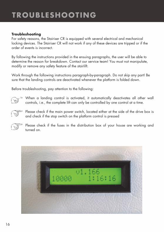
Troubleshooting For safety reasons, the Stairiser CR is equipped with several electrical and mechanical locking devices. The Stairiser CR will not work if any of these devices are tripped or if the order of events is incorrect. By following the instructions provided in the ensuing paragraphs, the user will be able to determine the reason for breakdown. Contact our service team! You must not manipulate, modify or remove any safety feature of the stairlift. Work through the following instructions paragraph-by-paragraph. Do not skip any part! Be sure that the landing controls are deactivated whenever the platform is folded down. Before troubleshooting, pay attention to the following:
When a landing control is activated, it automatically deactivates all other wall controls, i.e., the complete lift can only be controlled by one control at a time.
Please check if the main power switch, located either at the side of the drive box is and check if the stop switch on the platform control is pressed Please check if the fuses in the distribution box of your house are working and turned on.
17
Possible Errors If during the operation of the lift an error is occurring, it will be displayed as an error code on the 7 segment display on the control boards as well as on the LCD display. If there is no error the display shows Omega as in the picture on the left. If a safety switch is pressed or the platform is used in a wrong way the following status re-port could be shown on the display – “Issue reason”:
• S11p – platform is not fully opened
• S11o – platform is not fully closed
• Contact down (downward ramp or lateral bar is pressed)
• Contact up (upward ramp or lateral bar is pressed)
• Safety bottom: contact plate under the platform is pressed
• S. circuit p – emergency stop button or lever for barrier arm unblocking are pressed
• S. circuit d – ultimate stop switch at upper end of rail is pressed
• S. circuit br – ultimate stop switch at lower rail end or overspeed governor switch is pressed
If the unit does not work, check on the Display what the error code is shown and see on the list below what this error means. Talk to the service technician and tell him the error code so the correct action for fixing the lift can be taken.
TROUBLESHOOTING
18
TROUBLESHOOTING
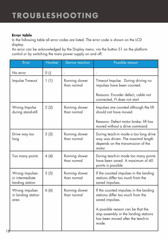
Error table In the following table all error codes are listed. The error code is shown on the LCD display. An error can be acknowledged by the Display menu, via the button S1 on the platform control or by switching the main power supply on and off.
Error Number Device reaction Possible reason
No error 0 (-) - -
Impulse Timeout 1 (1) Running slower than normal
Timeout Impulse. During driving no impulses have been counted.
Reasons: Encoder defect, cable not connected, FI does not start
Wrong Impulse during stand-still
2 (2) Running slower than normal
Impulses are counted although the lift should not have moved.
Reasons: Defect motor brake; lift has moved without a drive command
Drive way too long
3 (3) Running slower than normal
During teach-in mode a too long drive way was driven. The maximal length depends on the transmission of the motor.
Too many points 4 (4) Running slower than normal
During teach-in mode too many points have been saved. A maximum of 40 points is possible.
Wrong impulses in intermediate landing station
5 (5) Running slower than normal
If the counted impulses in the landing stations differ too much from the saved impulses.
Wrong impulses in landing station area
6 (6) Running slower than normal
If the counted impulses in the landing stations differ too much from the saved impulses.
A possible reason can be that the stop assembly in the landing stations has been moved after the teach-in mode.

19
TROUBLESHOOTING
Name Number Device reaction Possible reason
Wrong impulses
in intermediate
landing station
area
7 (7) Running slower than normal
If the counted impulses in the landing
stations differ too much from the
saved impulses.
A possible reason can be that the
stop assembly in the intermediate
landing stations has been moved after
the teach-in mode.
Wrong impulse
on limit switch
8 (8) Running slower than normal
If too many impulses are counted
while a limit switch is still pressed.
This can be a signal that a limit switch
contact did not close after the unit left
the landing station.
Power cut off on
runway
9 (9) Running slower than normal
If the platform is on the runway
(outside of landing stations) and a
power cut occurs then the unit cannot
detect its position on the rail.
The platform then has to be driven in
slow drive mode into the next landing
station were the failure will automati-
cally reset.
Wrong rotation
direction of motor
10 (A) Running slower than normal
If the encoder detects a different rota-
tion directions than the inverter pro-
duces.
Solution: Interchange contacts IMP1
and IMP2 on drive unit control board
Brake is weak 11 (b) Running slower than normal
If the drive is stopped and the en-
coder still detects a certain amount of
impulses it is an indication that the
brake does not stop the lift correctly.

20
TROUBLESHOOTING
Name Number Device reaction Possible reason
Overload 12 (C) Platform will travel to the next landing station, then stop
If the platform is overloaded and the overload switch SU gives a signal to the controller.
Motor tempera-ture
13 (d) Platform will travel to the next landing station, then stop
The thermostat relay in the motor was activated.
Short circuit be-tween the tension rope and the rail
14 (E) Platform will travel to the next landing station, then stop
If there is a short circuit between the tension rope and the rail
Short circuit be-tween the support rope and the rail
15 (F) Platform will travel to the next landing station, then stop
If there is a short circuit between the support rope and the rail
SPI Timeout on drive unit
16 (1.) Platform will not move
The communication between the PIC microcontroller and the Echelon Pow-erline module was defunct or not cor-rectly adjusted.
Safety circuit 17 (2.) Platform will not move
Safety circuit relays (KAUF, KAB) on the platform are not released.
FI-communication 18 (3.) Running slower than normal
The communication with the fre-quency inverter via the RS485 Mod-bus interface did not work.
Communication with EEPROM on drive unit
19 (4.) The communication between the mi-cro controller and the EEPROM on the drive unit did not work.
Feedback from main contactors
20 (5.) Platform will travel to the next landing station, then stop
One of the main drive contactors or the safety circuit relay KSK has not been released after the platform stopped driving.

21
TROUBLESHOOTING
Name Number Device reaction Possible reason
Feedback from main contactors
20 (5.) Platform will travel to the next landing station, then stop
One of the main drive contactors or the safety circuit relay KSK has not been released after the platform stopped driving.
Data transfer between the drive unit and the platform con-trol
21 (6.) Platform will not move
The communication via the tension rope did not work correctly. This fail-ure is detected on the drive unit.
Power cut for short time
24 (9.) Platform will still move
Reset error in landing station.
SPI Timeout Plat-form
112 (-) Platform will not move
The communication between the PIC micro controller and the Echelon Pow-erline module was not correct. The Powerline module is defect or not cor-rectly plugged.
Data transfer between the drive unit and the platform con-trol
113 (-) Platform will not move
The communication via the tension rope did not work.
Communication with EEPROM on platform
115 (-) Platform will not move
The communication of the micro con-troller with the EEPROM on the plat-form control did not work.

22
GUARANTEE
YOUR STANNAH GUARANTEE Stannah Lifts Ltd are proud to have secured British Standards BS EN ISO 9001 Quality Assurance Certification and are pleased to guarantee the whole of our materials and workmanship for a period of twelve months from completion of installation and handover of the lift to you, on the following conditions:
• That you enter into a service contract with our sister company Stannah Lifts Service Ltd. As with a motor car, your new lift must be properly serviced and maintained to keep it safe and at its very best.
• Should any defect in workmanship or material become evident within the twelve month period, we undertake to repair or replace the defective part, as soon as possible during normal working hours (Monday to Thursday 8.00am to 4.45pm, Friday 8.00am to 3.45pm.).
• Should attendance be required outside normal working hours be requested, it will be subject to a reasonable excess charge. Details of your designated Stannah Service Branch can be found on page 3 of this Handbook. Contact information can be found on page 19.
• The Guarantee does not cover repairs, replacements or adjustment which may be required as a result of ordinary wear and tear, wilful or accidental damage, misuse, neglect or any other cause beyond our control.
• That all outstanding monies have been paid to us.
Stannah Lifts Ltd Anton Mill, Andover, Hampshire SP10 2NX Tel: 01264 339090
23
STANNAH SERVICE BRANCHES
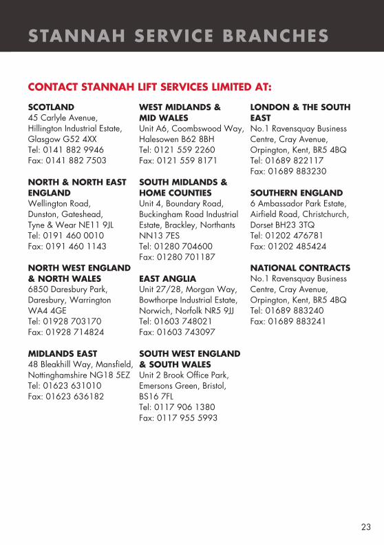
SCOTLAND 45 Carlyle Avenue, Hillington Industrial Estate, Glasgow G52 4XX Tel: 0141 882 9946 Fax: 0141 882 7503 NORTH & NORTH EAST ENGLAND Wellington Road, Dunston, Gateshead, Tyne & Wear NE11 9JL Tel: 0191 460 0010 Fax: 0191 460 1143 NORTH WEST ENGLAND & NORTH WALES 6850 Daresbury Park, Daresbury, Warrington WA4 4GE Tel: 01928 703170 Fax: 01928 714824 MIDLANDS EAST 48 Bleakhill Way, Mansfield, Nottinghamshire NG18 5EZ Tel: 01623 631010 Fax: 01623 636182
WEST MIDLANDS & MID WALES Unit A6, Coombswood Way, Halesowen B62 8BH Tel: 0121 559 2260 Fax: 0121 559 8171 SOUTH MIDLANDS & HOME COUNTIES Unit 4, Boundary Road, Buckingham Road Industrial Estate, Brackley, Northants NN13 7ES Tel: 01280 704600 Fax: 01280 701187 EAST ANGLIA Unit 27/28, Morgan Way, Bowthorpe Industrial Estate, Norwich, Norfolk NR5 9JJ Tel: 01603 748021 Fax: 01603 743097 SOUTH WEST ENGLAND & SOUTH WALES Unit 2 Brook Office Park, Emersons Green, Bristol, BS16 7FL Tel: 0117 906 1380 Fax: 0117 955 5993
LONDON & THE SOUTH EAST No.1 Ravensquay Business Centre, Cray Avenue, Orpington, Kent, BR5 4BQ Tel: 01689 822117 Fax: 01689 883230 SOUTHERN ENGLAND 6 Ambassador Park Estate, Airfield Road, Christchurch, Dorset BH23 3TQ Tel: 01202 476781 Fax: 01202 485424 NATIONAL CONTRACTS No.1 Ravensquay Business Centre, Cray Avenue, Orpington, Kent, BR5 4BQ Tel: 01689 883240 Fax: 01689 883241
CONTACT STANNAH LIFT SERVICES LIMITED AT:

www.stannahlifts.co.uk
NOTE Whilst every effort has been used to ensure the clarity and accuracy of this Handbook, we cannot be held responsible for damage or injury resulting from negligence or misuse of this lift equipment. We are continually developing and improving the Stairiser range and we therefore reserve the right to alter or amend the specification without prior notice.
Stannah Lifts Ltd Anton Mill, Andover, Hampshire SP10 2NX Telephone: 01264 339090
Stairiser C
R UM—
Jan 2016