Embed Size (px)
Citation preview

1Standards, Protocols,and FunctionsLTE (Long-Term Evolution) of UMTS (Universal Mobile Telecommunications Service) is one of thelatest steps in an advancing series of mobile telecommunication systems. The standards body behindthe paperwork is the 3rd Generation Partnership Project (3GPP).
Along with the term LTE, the acronyms EPS (Evolved Packet System), EPC (Evolved PacketCore), and SAE (System Architecture Evolution) are often heard. Figure 1.1 shows how these termsare related to each other: EPS is the umbrella that covers both the LTE of the Evolved UniversalTerrestrial Radio Access Network (E-UTRAN) and the SAE of the EPC network.
LTE was and is standardized in parallel to other radio access network technologies like EDGE(Enhanced Data Rates for GSM evolution) and HSPA (High-Speed Packet Access). This means thatLTE is not a simple replacement of existing technologies. Rather it is expected that different kinds ofradio access will coexist in operator networks.
From this background it emerges that understanding LTE also requires understanding alternativeand coexisting technologies. Indeed, one of the major challenges of LTE signaling analysis willconcern the analysis of handover procedures. Especially, the options for possible inter-RAT (RadioAccess Technology) handovers have multiplied compared to what was possible in UMTS Release 99.However, also intra-system handover and dynamic allocation of radio resources to particular sub-scribers will play an important role.
The main drivers for LTE development are:
• reduced delay for connection establishment;• reduced transmission latency for user plane data;• increased bandwidth and bit rate per cell, also at the cell edge;• reduced costs per bit for radio transmission;• greater flexibility of spectrum usage;• simplified network architecture;• seamless mobility, including between different radio access technologies;• reasonable power consumption for the mobile terminal.
It must be said that LTE as a radio access technology is flanked by a couple of significant improve-ments in the core network known as the EPS. Simplifying things a little, it is not wrong to state thatEPS is an all-IP (Internet Protocol) transport network for mobile operators. IP will also become thephysical transport layer on the wired interfaces of the E-UTRAN. This all-IP architecture is also oneof the facts behind the bullet point on simplified network architecture. However, to assume that to
LTE Signaling, Troubleshooting and Optimization, First Edition. Ralf Kreher and Karsten Gaenger.© 2011 John Wiley & Sons, Ltd. Published 2011 by John Wiley & Sons, Ltd.
COPYRIG
HTED M
ATERIAL

2 LTE Signaling, Troubleshooting and Optimization
Figure 1.1 EPC and LTE under the umbrella of EPS.
be familiar with the TCP/IP world is enough to understand and measure LTE would be a fatal error.While the network architecture and even the basic signaling procedures (except the handovers) becomesimpler, the understanding and tracking of radio parameters require more knowledge and deeper inves-tigation than they did before. Conditions on the radio interface will change rapidly and with a timegranularity of 1 ms the radio resources assigned to a particular connection can be adjusted accordingly.
For instance, the radio quality that is impacted by the distance between the User Equipment (UE)and base station can determine the modulation scheme and, hence, the maximum bandwidth of aparticular connection. Simultaneously, the cell load and neighbor cell interference – mostly depend-ing on the number of active subscribers in that cell – will trigger fast handover procedures due tochanging the best serving cell in city center areas, while in rural areas macro cells will ensure thebest possibley coverage.
The typical footprint of a LTE cell is expected by 3GPP experts to be in the range from approxi-mately 700 m up to 100 km. Surely, due to the wave propagation laws such macro cells cannot coverall services over their entire footprint. Rather, the service coverage within a single cell will vary, forexample, from the inner to the outer areas and the maximum possible bit rates will decline. Thus,service optimization will be another challenge, too.
1.1 LTE Standards and Standard Roadmap
To understand LTE it is necessary to look back at its predecessors and follow its path of evolutionfor packet switched services in mobile networks.
The first stage of the General Packet Radio Service (GPRS), that is often referred to as the 2.5Gnetwork, was deployed in live networks starting after the year 2000. It was basically a system thatoffered a model of how radio resources (in this case, GSM time slots) that had not been used byCircuit Switched (CS) voice calls could be used for data transmission and, hence, profitability of thenetwork could be enhanced. At the beginning there was no pre-emption for PS (Packet Switched)services, which meant that the packet data needed to wait to be transmitted until CS calls had beenfinished.
In contrast to the GSM CS calls that had a Dedicated Traffic Channel (DTCH) assigned on theradio interface, the PS data had no access to dedicated radio resources and PS signaling, and thepayload was transmitted in unidirectional Temporary Block Flows (TBFs) as shown in Figure 1.2.

Standards, Protocols, and Functions 3
Figure 1.2 Packet data transfer in 2.5G GPRS across Radio and Abis interfaces.
These TBFs were short and the size of data blocks was small due to the fact that the blocksmust fit the transported data into the frame structure of a 52-multiframe, which is the GSM radiotransmission format on the physical layer. Larger Logical Link Control (LLC) frames that containalready segmented IP packets needed to be segmented into smaller Radio Link Control (RLC) blocks.
The following tasks are handled by the RLC protocol in 2.5G:
• Segmentation and reassembly of LLC packets → segmentation results in RLC blocks.• Provision of reliable links on the air interface → control information is added to each RLC block
to allow Backward Error Correction (BEC).• Performing sub-multiplexing to support more than one MS (Mobile Station) by one physical channel.
The Medium Access Control (MAC) protocol is responsible for:
• point-to-point transfer of signaling and user data within a cell;• channel combining to provide up to eight physical channels to one MS;• mapping RLC blocks onto physical channels (time slots).
As several subscribers can be multiplexed on one physical channel, each connection has to be(temporarily) uniquely identified. Each TBF is identified by a Temporary Flow Identifier (TFI). TheTBF is unidirectional (uplink (UL) and downlink (DL)) and is maintained only for the duration of thedata transfer.
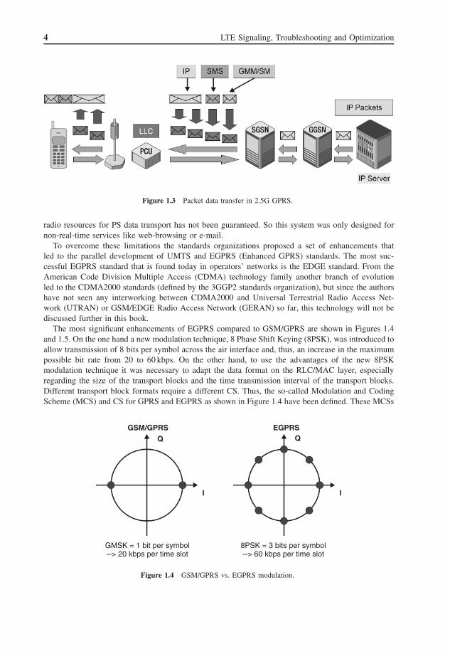
Toward the core network in 2.5G GPRS the Gb interface is used to transport the IP payload as well asGPRS Mobility Management/Session Management (GMM/SM) signaling messages and short messages(Short Message Service, SMS) between SGSN and the PCU (Packet Control Unit) – see Figure 1.3.The LLC protocol is used for peer-to-peer communication between SGSN and the MS and providesacknowledged and unacknowledged transport services. Due to different transmission conditions onphysical layers (E1/T1 on the Gb and Abis interfaces, 52-multiframe on the Air interface), the size ofIP packets needs to be adapted. The maximum size of the LLC payload field is 1540 octets (bytes)while IP packets can have up to 65 535 octets (bytes). So the IP frame is segmented on SGSN beforetransmission via LLC and reassembled on the receiver side.
All in all, the multiple segmentation/reassembly of IP payload frames generates a fair overhead oftransport header information that limits the chargeable data throughput. In addition, the availability of
4 LTE Signaling, Troubleshooting and Optimization
Figure 1.3 Packet data transfer in 2.5G GPRS.
radio resources for PS data transport has not been guaranteed. So this system was only designed fornon-real-time services like web-browsing or e-mail.
To overcome these limitations the standards organizations proposed a set of enhancements thatled to the parallel development of UMTS and EGPRS (Enhanced GPRS) standards. The most suc-cessful EGPRS standard that is found today in operators’ networks is the EDGE standard. From theAmerican Code Division Multiple Access (CDMA) technology family another branch of evolutionled to the CDMA2000 standards (defined by the 3GGP2 standards organization), but since the authorshave not seen any interworking between CDMA2000 and Universal Terrestrial Radio Access Net-work (UTRAN) or GSM/EDGE Radio Access Network (GERAN) so far, this technology will not bediscussed further in this book.
The most significant enhancements of EGPRS compared to GSM/GPRS are shown in Figures 1.4and 1.5. On the one hand a new modulation technique, 8 Phase Shift Keying (8PSK), was introduced toallow transmission of 8 bits per symbol across the air interface and, thus, an increase in the maximumpossible bit rate from 20 to 60 kbps. On the other hand, to use the advantages of the new 8PSKmodulation technique it was necessary to adapt the data format on the RLC/MAC layer, especiallyregarding the size of the transport blocks and the time transmission interval of the transport blocks.Different transport block formats require a different CS. Thus, the so-called Modulation and CodingScheme (MCS) and CS for GPRS and EGPRS as shown in Figure 1.4 have been defined. These MCSs
GSM/GPRS
GMSK = 1 bit per symbol--> 20 kbps per time slot
8PSK = 3 bits per symbol--> 60 kbps per time slot
EGPRSQ Q
I I
Figure 1.4 GSM/GPRS vs. EGPRS modulation.

Standards, Protocols, and Functions 5
Figure 1.5 Modulation/coding scheme and maximum bit rate in GSM/GPRS vs. EGPRS.
stand for defined radio transmission capabilities on the UE and BTS (Base Transceiver Station) side.It is important to mention this, because in a similar way capability definition with UE physical layercategories instead of MCS were introduced for HSPA and will be found in LTE again.
In comparison to GSM/GPRS, the EGPRS technology also offered a more efficient retransmissionof erroneous data blocks, mostly with a lower MCS than the one used previously. The retransmitteddata also does not need to be sent in separate data blocks, but can be appended piece by piece topresent regular data frames. This highly sophisticated error correction method, which is unique forEGPRS, is called Incremental Redundancy or Automatic Repeat Request (ARQ) II and is anotherreason why higher data transmission rates can be reached using EGPRS.
As a matter of fact, as shown in Figure 1.6, the risk of interference and transmission errors becomesmuch higher when the distance between a base station and a UE is large. Consequently, the MCS thatallows the highest maximum bit rate cannot be used in the overall cell coverage area, but only in asmaller area close to the base station’s antenna. Also for this specific behavior, an adequate expressionwill be found in LTE radio access.
Figure 1.6 Cell footprint of maximum bit rate as function of MCS in (E)GPRS.
6 LTE Signaling, Troubleshooting and Optimization
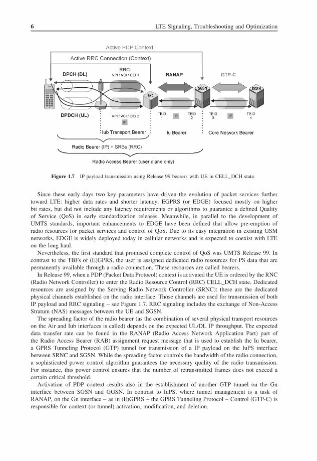
Figure 1.7 IP payload transmission using Release 99 bearers with UE in CELL_DCH state.
Since these early days two key parameters have driven the evolution of packet services furthertoward LTE: higher data rates and shorter latency. EGPRS (or EDGE) focused mostly on higherbit rates, but did not include any latency requirements or algorithms to guarantee a defined Qualityof Service (QoS) in early standardization releases. Meanwhile, in parallel to the development ofUMTS standards, important enhancements to EDGE have been defined that allow pre-emption ofradio resources for packet services and control of QoS. Due to its easy integration in existing GSMnetworks, EDGE is widely deployed today in cellular networks and is expected to coexist with LTEon the long haul.
Nevertheless, the first standard that promised complete control of QoS was UMTS Release 99. Incontrast to the TBFs of (E)GPRS, the user is assigned dedicated radio resources for PS data that arepermanently available through a radio connection. These resources are called bearers.
In Release 99, when a PDP (Packet Data Protocol) context is activated the UE is ordered by the RNC(Radio Network Controller) to enter the Radio Resource Control (RRC) CELL_DCH state. Dedicatedresources are assigned by the Serving Radio Network Controller (SRNC): these are the dedicatedphysical channels established on the radio interface. Those channels are used for transmission of bothIP payload and RRC signaling – see Figure 1.7. RRC signaling includes the exchange of Non-AccessStratum (NAS) messages between the UE and SGSN.
The spreading factor of the radio bearer (as the combination of several physical transport resourceson the Air and Iub interfaces is called) depends on the expected UL/DL IP throughput. The expecteddata transfer rate can be found in the RANAP (Radio Access Network Application Part) part ofthe Radio Access Bearer (RAB) assignment request message that is used to establish the Iu bearer,a GPRS Tunneling Protocol (GTP) tunnel for transmission of a IP payload on the IuPS interfacebetween SRNC and SGSN. While the spreading factor controls the bandwidth of the radio connection,a sophisticated power control algorithm guarantees the necessary quality of the radio transmission.For instance, this power control ensures that the number of retransmitted frames does not exceed acertain critical threshold.
Activation of PDP context results also in the establishment of another GTP tunnel on the Gninterface between SGSN and GGSN. In contrast to IuPS, where tunnel management is a task ofRANAP, on the Gn interface – as in (E)GPRS – the GPRS Tunneling Protocol – Control (GTP-C) isresponsible for context (or tunnel) activation, modification, and deletion.

Standards, Protocols, and Functions 7
Figure 1.8 IP data transfer using HSDPA.
However, in Release 99 the maximum possible bit rate is still limited to 384 kbps for a singleconnection and, more dramatically, the number of users per cell that can be served by this highestpossible bit rate is very limited (only four simultaneous 384 kbps connections per cell are possible onthe DL due to the shortness of DL spreading codes).
To increase the maximum possible bit rate per cell as well as for the individual user, HSPA wasdefined in Releases 5 and 6 of 3GPP.
In High-Speed Downlink Packet Access (HSDPA) the High-Speed Downlink Shared Channel (HS-DSCH) which bundles several High-Speed Physical Downlink Shared Channels (HS-PDSCHs) is usedby several UEs simultaneously – that is why it is called a shared channel.
A single UE using HSDPA works in the RRC CELL_DCH state. For DL payload transport theHSDSCH is used, that is, mapped onto the HS-PDSCH. The UL IP payload is still transferred using adedicated physical data channel (and appropriate Iub transport bearer); in addition, the RRC signalingis exchanged between the UE and RNC using the dedicated channels – see Figure 1.8.
All these channels have to be set up and (re)configured during the call. In all these cases bothparties of the radio connection, cell and UE, have to be informed about the required changes. Whilecommunication between NodeB (cell) and CRNC (Controlling Radio NetworkController) uses NBAP(Node B Application Part), the connection between the UE and SRNC (physically the same RNC unit,but different protocol entity) uses the RRC protocol.
The big advantage of using a shared channel is higher efficiency in the usage of available radioresources. There is no limitation due to the availability of codes and the individual data rate assignedto a UE can be adjusted quicker to the real needs. The only limitation is the availability of processingresources (represented by channel card elements) and buffer memory in the base station.
In 3G networks the benefits of an Uplink Shared Channel (UL-SCH) have not yet been introduceddue to the need for UL power control, that is, a basic constraint of Wideband CDMA (WCDMA)
8 LTE Signaling, Troubleshooting and Optimization
networks. Hence, the UL channel used for High-Speed Uplink Packet Access (HSUPA) is an EnhancedDedicated Channel (E-DCH). The UL transmission data volume that can be transmitted by the UE onthe UL is controlled by the network using so-called “grants” to prevent buffer overflow in the basestation and RNC. The same “grant” mechanism will be found in LTE.
All in all, with HSPA in the UTRAN the data rates on the UL and DL have been significantlyincreased, but packet latency is still a critical factor. It takes quite a long time until the RRC con-nection in the first step and the radio bearer in the second step are established. Then, due to limitedbuffer memory and channel card resources in NodeB, an often quite progressive settings of user inac-tivity timers leads to transport channel-type switching and RRC state change procedures that can besummarized as intra-cell hard handovers. Hard handovers are characterized by the fact that the activeradio connection including the radio bearer is interrupted for a few hundred milliseconds. Similarinterruptions of the data transmission stream are observed during serving HSDPA cell change proce-dures (often triggered by a previous soft handover) due to flushing of buffered data in NodeB andrescheduling of data to be transmitted by the RNC. That such interruptions (occurring in dense citycenter areas with a periodicity of 10–20 seconds) are a major threat for delay-sensitive services isself-explanatory.
Hence, from the user plane QoS perspective the two major targets of LTE are:
• a further increase in the available bandwidth and maximum data rate per cell as well as for theindividual subscriber;
• reducing the delays and interruptions in user data transfer to a minimum.
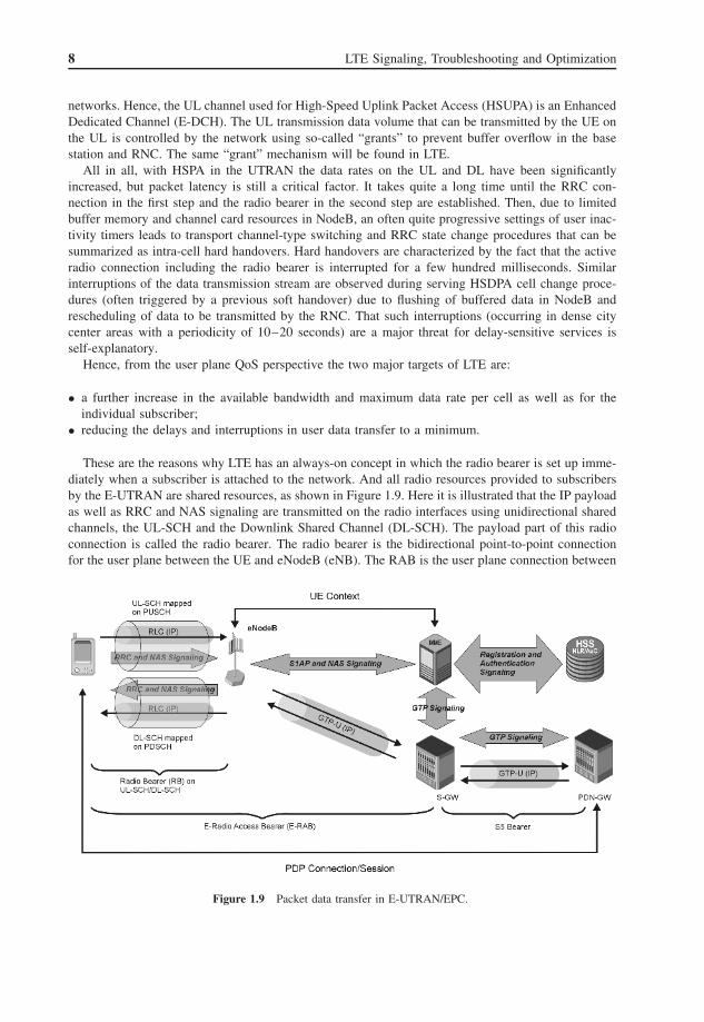
These are the reasons why LTE has an always-on concept in which the radio bearer is set up imme-diately when a subscriber is attached to the network. And all radio resources provided to subscribersby the E-UTRAN are shared resources, as shown in Figure 1.9. Here it is illustrated that the IP payloadas well as RRC and NAS signaling are transmitted on the radio interfaces using unidirectional sharedchannels, the UL-SCH and the Downlink Shared Channel (DL-SCH). The payload part of this radioconnection is called the radio bearer. The radio bearer is the bidirectional point-to-point connectionfor the user plane between the UE and eNodeB (eNB). The RAB is the user plane connection between
Figure 1.9 Packet data transfer in E-UTRAN/EPC.

Standards, Protocols, and Functions 9
the UE and the Serving Gateway (S-GW) and the S5 bearer is the user plane connection between theS-GW and public data network gateway (PDN-GW).
Note that a more detailed explanation of the LTE/EPC bearer concept is given in Section 1.6 ofthis chapter.
The end-to-end connection between the UE and PDN-GW, that is, the gateway to the IP worldoutside the operator’s network, is called a PDN connection in the E-UTRAN standard documents anda session in the core network standards. Regardless, the main characteristic of this PDN connectionis that the IP payload is transparently tunneled through the core and the radio access network.
To control the tunnels and radio resources a set of control plane connections runs in parallel withthe payload transport. On the radio interface RRC and NAS signaling messages are transmitted usingthe same shared channels and the same RLC transport layer that is used to transport the IP payload.
RRC signaling terminates in the eNB (different from 3G UTRAN where RRC was transparentlyrouted by NodeB to the RNC). The NAS signaling information is – as in 3G UTRAN – simplyforwarded to the Mobility Management Entity (MME) and/or UE by the eNB.
For registration and authentication the MME exchanges signaling messages with the central mainsubscriber databases of the network, the Home Subscriber Server (HSS).
To open, close, and modify the GTP/IP tunnel between the eNB and S-GW, the MME exchangesGTP signaling messages with the S-GW and the S-GW has the same kind of signaling connectionwith the PDN-GW to establish, release, and maintain the GTP/IP tunnel called the S5 bearer.
Between the MME and eNB, together with the E-RAB, a UE context is established to storeconnection-relevant parameters like the context information for ciphering and integrity protection.This UE context can be stored in multiple eNBs, all of them belonging to the list of registeredtracking areas for a single subscriber. Using this tracking area list and UE contexts, the inter-eNBhandover delay can be reduced to a minimum.
The two most basic LTE standard documents are 3GPP 23.401 “GPRS Enhancements for E-UTRANAccess” and 3GPP 36.300 “Overall Description Evolved Universal Terrestrial Radio Access (E-UTRA)and E-UTRAN.” These two specs explain in a comprehensive way the major improvements in LTEthat are pushed by an increasing demand for higher bandwidth and shorter latency of PS user planeservices. The basic network functions and signaling procedures are explained as well as the networkarchitecture, interfaces, and protocol stacks.
Although this book will not become simply a copy of what is already described in the standarddocuments, it is necessary to give a summary of the facts and parameters that are required to understandthe signaling procedures and key performance indicators of the network and services. Additionalexplanations will be given to highlight facts that cannot be found in the specs.
1.2 LTE Radio Access Network Architecture
The E-UTRAN comes with a simple architecture that is illustrated in Figure 1.10. The base stations ofthe network are called eNodeB and each eNB is connected to one or multiple MMEs. These MMEs inturn are connected to a S-GW that may also be co-located (comprising the same physical hardware)with the MME. The interface between the eNB and MME is the called the S1 interface. In case theMME and S-GW are not found in the same physical entity, the S1 control plane interface (S1-MME)will connect the eNB and MME while the S1 user plane interface (here S1-U) will connect the eNBwith the S-GW.
In case one eNB is connected to multiple MMEs, these MMEs form a so-called MME pool and theappropriate network functionality is called S1 flex. The initial signaling procedure used to connect aneNB with a MME is the S1 setup procedure of the S1 Application Part (S1AP).
The X2 interface is used to connect eNBs with each other. The main purpose of this connectivity isintra-E-UTRAN handover. In the real world it will not be possible for all eNBs of the network to be

10 LTE Signaling, Troubleshooting and Optimization
Figure 1.10 E-UTRAN network architecture (according to 3GPP 36.300). Reproduced with permission from ©2008 3GPP™.
connected via X2 due to limited transport resources on the wired interfaces. It also must be expectedthat, physically, the X2 links will lead from one eNB to the MME and then back to a second eNB.In other words, the hubs will be located at the physical location of the MME.
It is important to understand that only the base stations and their physical connections (wires orfibers) are defined by 3GPP as the E-UTRAN, while MME and S-GW are seen as elements of theEPC network.
1.3 Network Elements and Functions
The explanation given in the previous section indicates that, compared to base stations in GSM andUMTS UTRAN, the eNB will cover a set of new functions that are crucial to understand how theE-UTRAN is working.
In addition, the functionality of the MME and S-GW is different from that of their 2G/3G relatives,the RNC and the SGSN.
The following list of logical meta-functions performed within the overall network/system wasdefined by 3GPP:
• Network access control functions.• Packet routing and transfer functions.• Mobility management functions.• Security functions.• Radio resource management functions.• Network management functions.
These meta-functions are found in the different network elements with a more specific functionalitydefinition.
Standards, Protocols, and Functions 11
1.3.1 The eNodeB (eNB)
The eNB is the network entity that is responsible for radio interface transmission and reception.This includes radio channel modulation/demodulation as well as channel coding/decoding andmultiplexing/demultiplexing.
System information is broadcast in each cell on the radio interface DL to provide basic informationto UEs as a prerequisite to access the network.
The LTE base station hosts all RRC functions such as broadcast of system information and RRCconnection control including:
• Paging of subscribers.• Establishment, modification, and release of RRC connection including the allocation of temporary
UE identities (Radio Network Temporary Identifier, RNTI).• Initial security activation, which means the initial configuration of the Access Stratum (AS) integrity
protection for the control plane and AS ciphering for both control plane and user plane traffic.• RRC connection mobility that includes all types of intra-LTE handover (intra-frequency and inter-
frequency). In the case of handover, the source eNB will take care of the associated security handlingand provide the necessary key and algorithm information to the handover target cell by sendingspecific RRC context information embedded in a transparent container to the handover target eNB.
• Establishment, modification, and release of DRBs (Dedicated Radio Bearers) carrying user data.• Radio configuration control, especially the assignment and modification of ARQ and Hybrid
Automatic Repeat Request (HARQ) parameters as well as Discontinuous Reception (DRX)configuration parameters.
• QoS control to ensure that, for example, user plane packets of different connections are scheduledwith the required priority for DL transmission and that mobiles receive the scheduling grants forUL data transmission according to the QoS parameters of the radio bearers.
• Recovery functions that allow re-establishment of radio connections after physical channel failureor Radio Link Control Acknowledged Mode (RLC AM) retransmission errors.
The most crucial part for measuring the eNB performance is the UL/DL resource management andpacket scheduling performed by the eNB. This is probably the most difficult function which requiresthe eNB to cope with many different constraints like radio link quality, user priority, requested QoS,and UE capabilities. It is the task of the eNB to make use of the available resources in the mostefficient way.
Furthermore, the RRC entity of the eNB covers all types of intra-LTE and inter-RAT measurements,in particular:
• Setup, modification, and release of measurements for intra-LTE intra-frequency, intra-LTE inter-frequency, inter-RAT mobility, transport channel quality, UE internal measurement reports toindicate, for example, current power consumption and GPS positioning reports sent by the handset.
• For compressed mode measurements it is necessary to configure, activate, and deactivate the requiredmeasurement gaps.
• The evaluation of reported measurement results and start of necessary handover procedures are alsoeNB functions (while in 3G UMTS all measurement evaluation and handover control functions havebeen embedded in the RNC). The many different parameters used in RRC measurement controlfunctions like hysteresis values, time to trigger timer values, and event level threshold of RSRP andRSRQ (Received Signal Reference Power and Received Signal Reference Quality) are the focus ofradio network optimization activities.
Other functions of the eNB comprise the transfer of dedicated NAS information and non-3GPPdedicated information, the transfer of UE radio access capability information, support for E-UTRAN
12 LTE Signaling, Troubleshooting and Optimization
sharing (multiple Public Land Mobile Network (PLMN) identities), and management of multicast/broadcast services.
The support of self-configuration and self-optimization is seen as one of the key features of theE-UTRAN. Among these functions we find, for example, intelligent learning functions for automaticupdates of neighbor cell lists (handover candidates) as they are used for RRC measurement tasks andhandover decisions.
The eNB is a critical part of the user plane connections. Here the data is routed, multiplexed,ciphered/deciphered, segmented, and reassembled. It is correct to say that on the E-UTRAN transportlayer level, the eNB acts as an IP router and switch. The eNB is also responsible for optional IPheader compression. On the control plane level, the eNB selects the MME to which NAS signalingmessages are routed.
1.3.2 Mobility Management Entity (MME)
The MME is responsible for the NAS connection with the UE. All NAS signaling messages areexchanged between the UE and MME to trigger further procedures in the core network if necessary.
A new function of the E-UTRAN is NAS signaling security. The purpose of this feature is toprotect the signaling messages that could reveal the true subscriber’s identity and location fromunauthorized eavesdropping.
The MME is also responsible for paging subscribers in the EPS Connection Management (ECM)IDLE state (including control and execution of paging retransmission) and is concerned with trackingarea list management. The list of tracking areas is the list of locations where the UE will be paged.
To route the user plane data streams the MME will select the best fitting PDN-GW and S-GW. Itwill also connect the E-UTRAN with the 3G UTRAN using the S3 interface (MME to SGSN). Whennecessary, a relocation of gateways will be triggered and controlled by the MME.
As its name suggests, the MME will perform management of handovers by selecting a new (target)MME or SGSN for handovers to 2G or 3G 3GPP access networks. Also, it is the MME that hosts theconnection to the HSS across the S6a interface and, hence, it is responsible for roaming managementand authentication of subscribers.
Last but not least, the MME sets up, modifies, and releases default and dedicated bearers. Thisfunction is commonly known as the bearer management function.
According to standard documents, the MME will allow lawful interception of signaling traffic andtransfer of warning messages (including selection of an appropriate eNB). The purpose of warningmessage transfer is to inform people living in a larger area about upcoming natural disasters likestorms, bush fires, or tsunamis.
1.3.3 Serving Gateway (S-GW)
The S-GW is the gateway which terminates the interface to the E-UTRAN. A particular LTE subscriberwill always be connected by a single S-GW.
In the case of inter-eNB handover, the S-GW acts as the mobility anchor of the connection andremains the same while the path for the transport of signaling and user plane will be switched onto theS1 interface. Once a handover is executed successfully and the associated UE has left the S-GW, theold S-GW will send one or more “end marker” packets to the source eNB, source SGSN, or sourceRNC of the handover to assist the reordering of user plane packets in these network elements.
Mobility anchoring of the S-GW is also defined for inter-3GPP mobility. Here the S-GW acts asthe terminating point of the S4 interface (see Chapter 2 for interface definitions and figures) and routesthe traffic between the 2G/3G SGSN and the PDN-GW of the EPC. In other words, when it comes tointer-RAT handover involving the S4 interface, the S-GW acts as the Gateway GPRS Support Node

Standards, Protocols, and Functions 13
(GGSN) (of the 2G/3G PS core network) that enables usage of the EPC transport and functions forUTRAN/GERAN PS services.
If the UE is in ECM-IDLE mode (see Section 1.10.9 for a description of different NAS states) theS-GW buffers user plane packets that will be sent to the UE after a successful paging response. Thepaging via the S1 and Uu interfaces is also triggered by the S-GW.
The S-GW is the network element that provides connectivity and software implementations forlawful interception.
On the IP transport layer the S-GW acts as a packet router. User plane packets are forwardedtransparently in the UL and DL direction and their underlying transport units are marked by S-GWwith parameters like DiffServ Code Point, based on the QoS Class Indicator (QCI) of the associatedEPS bearer.
Also embedded in the S-GW software are various charging functions for UL and DL charging perUE, PDN, and QCI. These functions are used to charge the operator’s own subscribers as well asroaming users (inter-operator charging).
The S-GW can be connected to SGSNs in non-roaming and roaming scenarios. However, connec-tivity to a GGSN is not supported.
1.3.4 Packet Data Network Gateway (PDN-GW)
The PDN-GW provides access from the mobile operator’s network to the PS networks that host thepayload contents and operator’s IP services. If a user has access to more than one packet data networkit is possible that this user is connected to more than just one PDN-GW. It is not possible for thesame UE to simultaneously open connections to a PDN-GW and to a GGSN in the 3G PS domain,according to 3GPP standards.
The main function of the PDN-GW is to establish, maintain, and delete GTP tunnels to S-GW orSGSN in the case of inter-RAT mobility scenarios. The PDN-GW allocates the user’s dynamic IPaddresses and routes the user plane packets. In addition, it provides functions for lawful interception,policy/QoS control, and charging.
For policy control and charging, the PDN-GW can be connected to a Policy and Charging RuleFunction (PCRF) via the Gx reference point. The PCRF provides guidance on how a particular servicedata flow should be treated in terms of priority, throughput, and other QoS parameters according tothe user’s subscription profile.
1.3.5 Interfaces and Reference Points1
As already explained, the E-UTRAN is an all-IP network. Figure 1.10 shows the network elementsthat are typically involved in the signaling procedures and routing of payload data from the UE tothe PDN and vice versa. The figure also shows the reference points for inter-RAT handover (andinter-RAT packet routing) between E-UTRAN, UTRAN, and GERAN.
The pipeline symbols in the figure illustrate the different signaling connections and tunnels forIP payload transport established and maintained during the connection. The signaling on Gx and Rxused to negotiate specific QoS policies is ignored for reasons of better understandability. Besides, theexistence of the PCRF is optional. Due to the fact that the MME and the S-GW may also be combinedinto a single physical entity, the S11 interface is also optional. The lab test scenarios existing at thetime of writing (spring 2010) all have separated physical entities for the MME and S-GW.
The signaling connection across the LTE-Uu interface is the RRC signaling connection, representedby a set of Signaling Radio Bearers (SRBs). The user plane tunnel across LTE-Uu is the radio bearer
1 Reproduced with permission from © 3GPP™.

14 LTE Signaling, Troubleshooting and Optimization
(see also Section 1.6 in this book). The other user plane tunnels are named after the appropriatereference points: namely, S1 bearer and S5 bearer. After the PDN-GW the connection is carried bythe external bearer on SGi. S1AP signaling between the E-UTRAN and MME will be used to establishthe tunnel on S1-U and GTP-C signaling will be used to create the tunnel on S5. On SGi we can seealready plain IP traffic – pure payload, so to say.
The reference points shown in Figures 1.11–1.13 can be briefly described as follows:
• S1-MME: Reference point for the control plane protocol between the E-UTRAN and MME. Thiscontrol plane protocol is the S1AP, which is quite similar to UTRAN RANAP. Indeed, in earlydrafts of LTE specs this protocol was called “E-RANAP.”
• S1-U: Reference point between the E-UTRAN and S-GW for the per bearer user plane tunnelingand inter-eNB path switching during handover. The protocol used at this reference point is theGPRS Tunneling Protocol for the User Plane (GTP-U).
• S3: This is the reference point between the MME and SGSN. The SGSN may serve UTRAN,GERAN, or both. On S3 we can see plain control plane information for user and bearer informa-tion exchange for inter-3GPP access network mobility (inter-RAT handover) in the idle and/oractive state. If the connection was set up originally in the E-UTRAN and is handed over toUTRAN/GERAN the appropriate user plane streams are routed across the S4 reference point. Whathappens in the case of UTRAN/GERAN to E-UTRAN handover depends on whether S-GW alsoacts as the anchor for UTRAN/GERAN traffic. If this is true the user plane tunnel can be switchedsmoothly between S4 and S1-U during the handover. The protocol used at the S3 reference pointis the GTP-C.
Figure 1.11 Connection via E-UTRAN non-roaming architecture.

Standards, Protocols, and Functions 15
Figure 1.12 Connection after inter-RAT handover from E-UTRAN to UTRAN/GERAN.
• S4: The S4 reference point provides related control and mobility support between the GPRS coreand the 3GPP anchor function of the S-GW using GTP-C. In addition, if a direct tunnel across S12is not established, it provides user plane tunneling using GTP-U.
• S5: The S5 reference point provides user plane tunneling and tunnel management between theS-GW and PDN-GW. It is used in case of S-GW relocation due to UE mobility and if the S-GWneeds to connect to a non-collocated PDN-GW for the required PDN connectivity. The protocolused at this reference point is GTP for both the control plane and user plane.
• S6a: The S6a reference point enables the transfer of subscription and authentication data for autho-rizing user access to the network. The reference point can be also described as the AAA interfacebetween the MME and HSS. Compared to the legacy core network of 2G/3G standards, the func-tionality provided by S6a is similar to the one on the Gr interface, but due to the all-IP concept ofEPC the protocol used at this reference point is the DIAMETER protocol. In the IP world DIAM-ETER is known as the successor of RADIUS, a protocol for granting access and authentication.However, the DIAMETER used on S6a does not have much in common with what is found inthe IP world. The protocol header is based on IP standards, but the messages and parameters on theapplication layer are defined in a 3GPP-specific DIAMETER standard that has no meaning in theIP world.
• Gx: This point provides transfer of (QoS) policy and charging rules from the PCRF to the Policyand Charging Enforcement Function (PCEF) in the PDN-GW. This means that a set of rules forcharging the transmission of a particular user data stream (called service flow) will be requestedby the PDN-GW upon bearer establishment and the PCRF will provide the required parameters forthe charging process. Especially, it will signal which of the following charging models will apply:
– Volume-based charging.– Time-based charging.
16 LTE Signaling, Troubleshooting and Optimization
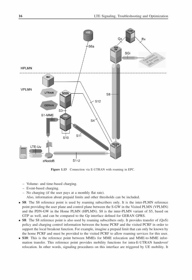
Figure 1.13 Connection via E-UTRAN with roaming in EPC.
– Volume- and time-based charging.– Event-based charging.– No charging (if the user pays at a monthly flat rate).
Also, information about prepaid limits and other thresholds can be included.
• S8: The S8 reference point is used by roaming subscribers only. It is the inter-PLMN referencepoint providing the user plane and control plane between the S-GW in the Visited PLMN (VPLMN)and the PDN-GW in the Home PLMN (HPLMN). S8 is the inter-PLMN variant of S5, based onGTP as well, and can be compared to the Gp interface defined for GERAN GPRS.
• S8: The S8 reference point is also used by roaming subscribers only. It provides transfer of (QoS)policy and charging control information between the home PCRF and the visited PCRF in order tosupport the local breakout function. For example, imagine a prepaid limit that can only be known bythe home PCRF and must be provided to the visited PCRF to allow roaming services for this user.
• S10: This is the reference point between MMEs for MME relocation and MME-to-MME infor-mation transfer. This reference point provides mobility functions for intra-E-UTRAN handover/relocation. In other words, signaling procedures on this interface are triggered by UE mobility. It

Standards, Protocols, and Functions 17
should be noted that this kind of MME relocation in 3GPP 23.401 is called S1 handover. Hence,S10 is seen as special kind of S1 interface and the S1AP is used at this reference point.
• S11: This is the reference point between the MME and S-GW. The protocol used here is the GTP-C.The appropriate user plane is routed across S1-U.
• S12: The S12 reference point is located between the RNC in the 3G UTRAN and the S-GW foruser plane tunneling when a “direct tunnel” is established. It is based on the Iu user plane and Gnuser plane reference points using the GTP-U as defined between the SGSN and RNC, or betweenthe SGSN and GGSN in the 3G core network. Use of the S12 reference point is an operatorconfiguration option. On S12 only GTP-U traffic can be monitored, as on S1-U.
• S13: This point enables a UE identity check procedure between the MME and EIR (EquipmentIdentity Register). Typically there is no EIR installed in public networks due to the high admin-istrative efforts, but this network element is found in some private networks. For instance, theGSM-based mobile network of the railway company Deutsche Bahn is equipped with an EIR. Thepurpose is to ensure that only staff of Deutsche Bahn can use the company’s PLMN, but no privatepersons and staff of other European railway companies such as France’s SNCF that also runs trainsthrough Germany.
• SGi: This is the reference point between the PDN-GW and the packet data network. This networkmay be an operator external public or private packet data network or an intra-operator packet datanetwork, for example for the provision of IP Multimedia Subsystem (IMS) services. To simplifythe definition, it can be said that for many user plane connections SGi is the interface to the publicInternet. This reference point corresponds to Gi for 3GPP access. Typically the complete TCP/IPsuite can be monitored at this point.
• Rx: The Rx reference point resides between the Application Function (AF) and the PCRF definedin 3GPP 23.203. It is for instance mandatory if real-time communication services such as Voiceover IP (VoIP) are to be charged differently than common PS data transfer.
• SBc: The SBc reference point lies between the Cell Broadcast Center (CBC) and MME for warningmessage delivery and control functions. This interface is used to broadcast warning messages tosubscribers (not to send warning messages about network element status to the operation andmaintenance center). A typical example of such warning messages could be the broadcast of bushfire or tsunami alarms.
The special anchor function of the S-GW can be illustrated when looking at a connection that washanded over from the E-UTRAN to UTRAN or GERAN as shown in Figure 1.12. In this case theconnections on S5 and SGi remain the same, but the payload is now routed through a tunnel acrossS4 or S12 while the signaling necessary to execute the inter-RAT mobility will be sent across S3. Theold bearers and signaling connections on S1 and LTE-Uu will be deleted after successful handover ofthe connection.
Figure 1.13 illustrates the basic connection of a roaming subscriber. Signaling and payload takethe same route as in Figure 1.12, but the HSS and PDN-GW and, thus, the connection to the publicpacket network are located in a foreign network. The IP tunneling from the S-GW to PDN-GW andvice versa is realized through the S8 interface, which has identical protocol structure and functionsto S5. The only difference is that S8 must fulfill higher requirements in terms of inter-operability,because equipment from different manufacturers must be interconnected through this reference point.
1.4 Area and Subscriber Identities
1.4.1 Domains and Strati
For the EPC a complete new NAS was designed including a new NAS protocol layer described in3GPP 24.301.

18 LTE Signaling, Troubleshooting and Optimization
Figure 1.14 Domains and strati in E-UTRAN and EPC.
In contrast to the core network of 3GPP Release 99 to Release 6 where a CS and PS domain weredefined as subdomains of the serving network domain, the EPC will not host any CS domain due toits all-IP character. However, it still distinguishes between AS and NAS signaling and functions asshown in Figure 1.14.
The AS comprises the radio chipset of the UE including the RRC protocol entity and all underlyingtransport layer entities. Here all parameters that more or less frequently change during radio accesscan be found, including transport formats and radio-specific identities of serving cell and possiblehandover candidates (neighbor cells).
The NAS covers all signaling exchanged between the USIM (UMTS Subscriber Identity Module)and the core network node, in case of LTE radio access: the MME. This is the home of all parametersthat allow unambiguous identification of a subscriber or the handset hardware such as InternationalMobile Subscriber Identity (IMSI) and International Mobile Equipment Identity (IMEI). There arealso temporary identities stored on the USIM card like Temporary Mobile Subscriber Identity (TMSI)and Globally Unique Temporary UE Identity (GUTI). From a protocol point of view the NAS is thehome of network access, initial subscriber registration, and mobility management procedures. Due tothe all-IP concept of LTE/EPC, a new NAS protocol was defined, namely 3GPP 24.301, while similarfunctions for 2G/3G networks are defined in the standard 3GPP 24.008. The E-UTRAN NAS protocol3GPP 24.301 does not contain any functions for CS call control and SMS. In the early planning stagesof the E-UTRAN it was assumed that all speech services via the E-UTRAN would use VoIP and theIMS architecture. As an alternative the CS fallback option (implemented in the S1AP protocol) wasdesigned, but obviously this did not satisfy the need for reliable and cost-efficient CS services in theE-UTRAN. Hence, an initiative formed of operators and Network Equipment Manufacturers (NEMs)started to work on the Voice over LTE via Generic Access standards (VoLGA). VoLGA is beyondthe scope of 3GPP. Its principle is to establish an IP connection between the UE and E-UTRAN anduse the radio bearer for transparent forwarding of 3GPP 24.008 NAS signaling message and AMR

Standards, Protocols, and Functions 19
(Adaptive Multirate) voice packets across the logical Z1 interface. Instead, in the S-GW the RABused for VoLGA is terminated in a special protocol converter and media gateway device, the VoLGAAccess Network Controller (VANC), that is, the interconnecting point between the E-UTRAN/EPCand UTRAN/GERAN/Legacy Core Network.
1.4.2 IMSI
The IMSI allows unambiguous identification of a particular SIM or USIM card. The IMSI is composedof three parts (Figure 1.15):
• The Mobile Country Code (MCC), consisting of three digits. The MCC uniquely identifies thecountry of domicile of the mobile subscriber. MCC values are administrated and allocated by aninternational numbering plan.
• The Mobile Network Code (MNC), consisting of two or three digits for GSM/UMTS applications.The MNC identifies the home PLMN of the mobile subscriber. The length of the MNC (two orthree digits) depends on the value of the MCC. A mixture of two- and three-digit MNC codeswithin a single MCC area is not recommended and is beyond the scope of this specification.
• The Mobile Subscriber Identification Number (MSIN), identifying the mobile subscriber within aPLMN. As a rule the first two or three digits of the MSIN reveal the identity of the Home LocationRegister (HLR) or HSS that is used for Signaling Connection Control Part (SCCP) Global Titletranslation procedures when roaming subscribers register in foreign networks.
The National Mobile Subscriber Identity (NMSI) consists of the MNC and the MSIN.A combination of MCC and MNC can be used to aggregate call-specific performance measurement
data (such as cumulative counters) on IMSI groups. This will help to highlight problems of roamingsubscribers such as network failures during registration procedures, as described later in this book.Table 1.1 shows some samples from an IMSI group mapping table with MCC/MNC combinations in
Figure 1.15 Structure of IMSI (according to 3GPP 23.303). Reproduced with permission from © 3GPP™.
Table 1.1 IMSI group mapping table from Tektronix Communications NSA software
<IMSI IMSINumber= '26201' IMSIGroupName= 'T-MOBILE DEUTSCHLAND GMBH (GERMANY)' /><IMSI IMSINumber= '26202' IMSIGroupName= 'VODAFONE D2 GMBH (GERMANY)' /><IMSI IMSINumber= '26801' IMSIGroupName= 'VODAFONE TELECEL (PORTUGAL)' /><IMSI IMSINumber= '27201' IMSIGroupName= 'VODAFONE IRELAND PLC (IRELAND)' /><IMSI IMSINumber= '310560' IMSIGroupName= 'T-MOBILE USA, INC. (UNITED STATES)' />

20 LTE Signaling, Troubleshooting and Optimization
“IMSINumber” fields and operator names in the “IMSIGroupName” field. Note the three-digit MNCused for the American operator.
It is possible that one-use equipment will work with more than just one (U)SIM. A good exampleis a mobile phone that has both business and private SIM cards as one device. Depending on thenature of the call (private or business), the owner of the handset can choose which (U)SIM shouldbe used to make the call. Such a procedure might be required in case private phone calls need to becharged separately due to national income tax laws (as found, for example, in Germany).
1.4.3 LMSI, TMSI, P-TMSI, M-TMSI, and S-TMSI
All temporary subscriber identities, Local Mobile Subscriber Identity (LMSI), TMSI, and P-TMSI,will not be seen in E-UTRAN signaling as long as there is no inter-RAT mobility between the E-UTRAN and UTRAN/GERAN. Indeed, for LTE a new NAS protocol was specified (3GPP 24.301) thatintroduces a new temporary subscriber identity for the E-UTRAN: the GUTI described in Section 1.4.4.However, to fulfill inter-RAT mobility requirements TMSI, P-TMSI, and LMSI will still be foundin E-UTRAN NAS messages, or at least it will be indicated if valid values of these parameters arestored on the USIM card.
The LMSI is a four-octet/byte number. It is a pointer to a database record for a particular IMSIin the Visitor Location Register (VLR) database. Although the VLR is no longer found in the EPCnetwork architecture, there is a database with the same function hosted by the MME. The purpose ofthe LMSI was to speed up the search for particular database records. If this is still required, with thenew powerful computer hardware used to build today’s network elements it is a design detail to bedefined by NEMs. From definitions given in 3GPP 23.003 it can be guessed that the LMSI will notbe used by the MME.
The TMSI is also encoded as a four-octet/byte hex number. It is allocated to a particular subscriber(more correctly, to a particular subscriber’s (U)SIM card) during initial attach. The TMSI is used tomask the true subscriber’s identity, which is the IMSI, in NAS signaling procedures. In the E-UTRANit is often used together with the GUTI. It can be coded using a full hexadecimal representation. Sincethe TMSI has only local significance (i.e., within a VLR and the area controlled by a VLR, or withina SGSN and the area controlled by a SGSN, or within a MME and the area controlled by a MME),the structure and coding of it can be chosen by agreement between the operator and manufacturer inorder to meet local needs.
The TMSI allocation procedure should always be executed in ciphered mode to prevent unauthorizedeavesdropping.
The P-TMSI is the complement of TMSI in the UTRAN/GERAN PS domain. It is allocated by theSGSN and, hence, will be monitored in the EPC and E-UTRAN during inter-RAT handover/relocationpreparation and execution. The P-TMSI is encoded in the same way as the TMSI. The difference isin defining value ranges. If the first two leading digits have the value “11” the parameter is identifiedas a P-TMSI. Thus, in the hexadecimal format, all TMSI values starting with C, D, E, or F as thefirst hex number are P-TMSIs.
The M-TMSI is a 32-digit binary number that is part of the GUTI and exclusively used in theE-UTRAN.
The S-TMSI consists of the Mobility Management Entity Code (MMEC) and M-TMSI. Indeed, itis just a shorter variant of the GUTI.
1.4.4 GUTI
The GUTI is assigned only by the MME during initial attach of a UE to the E-UTRAN.

Standards, Protocols, and Functions 21
Figure 1.16 Format of GUTI and S-TMSI.
The purpose of the GUTI is to provide an unambiguous identification of the UE that does notreveal the UE or the user’s permanent identity in the E-UTRAN. It also allows identification of theMME and network to which the UE attaches. The GUTI can be used by the network to identify eachUE unambiguously during signaling connections.
The GUTI has two main components: the Globally Unique Mobility Management Entity Identifier(GUMMEI) that uniquely identifies the MME which allocated the GUTI; and the M-TMSI thatuniquely identifies the UE within the MME that allocated the GUTI. The GUMMEI is constructedfrom the MCC, MNC, and Mobility Management Entity Identifier (MMEI).
The MMEI should be constructed from a Mobility Management Entity Group ID (MMEGI) anda MMEC. The GUTI should be constructed from the GUMMEI and the M-TMSI as shown inFigure 1.16.
For paging purposes, the mobile is paged with the S-TMSI. The S-TMSI is constructed from theMMEC and the M-TMSI. It is correct to say that the S-TMSI is a shorter format of GUTI that can beused because, after successful registration of a UE, the serving network as well as the serving MMEgroup are known and stored in the core network databases.
The operator needs to ensure that the MMEC is unique within the MME pool area and, if overlappingpool areas are in use, unique within the area of overlapping MME pools.
The GUTI should be used to support subscriber identity confidentiality and, in the shortened S-TMSIform, to enable more efficient radio signaling procedures (e.g., paging and service request).
MCC and MNC should have the same field size as described for the IMSI.The M-TMSI has a length of 32 bits, MMEGI is 16 bits in length, and MMEC 8 bits in length.It is important to understand that on the S1 interface the IMSI is typically not seen, just like the
GUTI. Exceptions are initial attach to the network when no old GUTI is stored on the USIM card orthe true subscriber’s identity is checked using NAS signaling, which regularly happens when roamingsubscribers attach. Also, in the case of the paging procedure the IMSI might be seen.
For monitoring and network performance measurement the IMSI on S1 can only be revealed if thechanging temporary identities are tracked with a quite sophisticated architecture. Full IMSI trackingcan only be ensured by monitoring all S1 interfaces of an operator’s E-UTRAN and ideally all S6ainterfaces and storing the current GUTI/IMSI relations in a central point as stored in the HSS.
1.4.5 IMEI
The IMEI or IMEISV is used to unambiguously identify the hardware and (with IMSISV) softwareversion of a mobile phone. The IMEISV that is expected to be used for all 4G and UEs consists of16 bits as shown in Figure 1.17.

22 LTE Signaling, Troubleshooting and Optimization
Figure 1.17 Structure of IMEISV (according to 3GPP 23.303). Reproduced with permission from © 3GPP™.
Table 1.2 Example of handset name mapping table
<Handset IMEI='35942100' HandsetName='MOTOROLA V3 RAZR' /><Handset IMEI='35942200' HandsetName='MOTOROLA V3 RAZR' /><Handset IMEI='35942300' HandsetName='MOTOROLA V3 RAZR' /><Handset IMEI='01161200' HandsetName='APPLE IPHONE 3G' /><Handset IMEI='01161300' HandsetName='APPLE IPHONE 3G' /><Handset IMEI='01161400' HandsetName='APPLE IPHONE 3G' /><Handset IMEI='35179700' HandsetName='SAMSUNG SGH-E100' /><Handset IMEI='35179800' HandsetName='SAMSUNG SGH-E100' /><Handset IMEI = '35179900' HandsetName = 'SAMSUNG SGH-A800' />
The eight leading digits stand for the Type Approval Code (TAC). This TAC indicates the manu-facturer of the equipment. The next six digits stand for the Serial Number (SNR) and finally the twolast digits represent the software version.
As shown in Table 1.2 (which gives a list for 3G handsets) the TAC (in the table named “HandsetIMEI”) is always unique for a particular equipment type, but due to large manufacturing series severalTACs are assigned to the same type if the number of manufactured units exceeds the threshold of100 000 that can be numbered with the six-digit SNR.
1.4.6 RNTI
In 3G UMTS the Radio Network Temporary Identifiers (RNTIs) are always used to identify informationdedicated to a particular subscriber on the radio interface, especially if common or shared channels areused for data transmission. Now, in LTE it is the rule that common channels and shared channels areused to transmit all UE-specific data, but also some network-specific data across the radio interface.For this reason the RNTI in LTE is not always related to a particular subscriber, but sometimes alsoused to distinguish broadcast network information from data streams of subscribers.
The RNTI is signaled in the MAC layer.When MAC uses the Physical Downlink Control Channel (PDCCH) to indicate radio resource
allocation, the RNTI that is mapped on the PDCCH depends on the logical channel type:
• C-RNTI, Temporary Cell Radio Network Temporary Identifier (temp C-RNTI), and Semi-PersistentScheduling (SPS) C-RNTI for Dedicated Control Channel (DCCH) and DTCH;
• Paging Radio Network Temporary Identity (P-RNTI) for Paging Control Channel (PCCH);• Random Access Radio Network Temporary Identifier (RA-RNTI) for Random Access Response
(RAR) on DL-SCH;• Temporary C-RNTI for Common Control Channel (CCCH) during the random access procedure;• System Information Radio Network Temporary Identifier (SI-RNTI) for Broadcast Control
Channel (BCCH).

Standards, Protocols, and Functions 23
Table 1.3 RNTI values (according to 3GPP 36.321). Reproduced with permission from © 3GPP™
Value (hexadecimal) RNTI
FDD TDD
0000-0009 0000-003B RA-RNTI000A-FFF2 003C-FFF2 C-RNTI, semi-persistent scheduling C-RNTI, temporary C-RNTI,
TPC-PUCCH-RNTI, and TPC-PUSCH-RNTIFFF3-FFFC Reserved for future useFFFE P-RNTIFFFF SI-RNTI
All RNTIs are encoded using the same 16-bit format (two octets = 2 bytes).2
The following values (given in Table 1.3) are defined for the different types of RNTI.
1.4.6.1 P-RNTI
The P-RNTI is the 4G complement of the paging indicator known from 3G UMTS. It does not referto a particular UE, but to a group of UEs.
The P-RNTI is derived from the IMSI of the subscriber to be paged and constructed by the eNB.For this reason the IMSI is transmitted in a S1AP paging message from the MME to eNB, althoughin other S1 signaling only the GUTI is used to mask the true identity of the subscriber.
1.4.6.2 RA-RNTI
The RA-RNTI is assigned by the eNB to a particular UE after this UE has sent a random accesspreamble on the Physical Random Access Channel (PRACH). If this random access preamble isreceived by the eNB and network access granted, the base station sends an acquisition indication backto the mobile and this acquisition indication message contains the RA-RNTI. In turn the UE will usethe RA-RNTI to send a RRC connection request message on the radio interface UL and the parameterwill help to distinguish messages sent by different UEs on the Random Access Channel (RACH).
1.4.6.3 C-RNTI
The C-RNTI is a 16-bit numeric value. Its format and encoding are specified in 3GPP 36.321 (MAC).The C-RNTI is part of the MAC Logical Channel Group ID field (LCG ID). It defines unambiguouslywhich data sent in a DL direction within a particular LTE cell belongs to a particular subscriber.For instance, all RRC messages belonging to a single connection between a UE and the network aremarked with the same C-RNTI value by the MAC entity that provided transport services to the RRCand NAS. Thus, C-RNTI is an important parameter for call tracing.
The C-RNTI comes in three different flavors: temp C-RNTI, semi-persistent scheduling C-RNTI,and permanent C-RNTI.
The temp C-RNTI is allocated to the UE during random access procedure (with a RRC connectionsetup message) and may turn into a permanent C-RNTI depending on the result of a subsequentlyperformed contention resolution procedure or in the case of contention-free random access.
2 The terms octet and byte have the same meaning, but the origin is different. While “octet” was used in the telecommunicationstandards of CCITT and ITU to describe a field of 8 bits, in computer science and hence in the TCP/IP standardization the term“byte” was introduced.

24 LTE Signaling, Troubleshooting and Optimization
The semi-persistent scheduling C-RNTI is used if the subscriber is running services with a pre-dictable unchanging QoS profile. A typical example is VoIP for which the required bit rate will notchange during the entire connection. In such a case the dynamic (re)scheduling of radio resources,which is mandatory in the case of bursty payload traffic to ensure optimal usage of resource blocks,is not required. The SPS C-RNTI is used to indicate an area of resource blocks that will be used bythe same UE for a longer time frame without any expected change.
1.4.6.4 SI-RNTI
The SI-RNTI is sent on the PDCCH. It does not stand for a particular UE identity. Instead it signals toall mobiles in a cell where the broadcast System Information Blocks (SIBs) are found on the PhysicalDownlink Shared Channel (PDSCH). This is necessary since the PDSCH is used to transport bothbroadcast system information for all UEs and signaling/payload for particular mobiles. In other words,the SI-RNTI indicates which DL resource blocks are used to carry SIBs that in 3G UMTS have beensent on the broadcast (transport) channel mapped onto the Primary Common Control Physical Channel(P-CCPCH). In LTE there is no CCPCH, only DL-SCH.
1.4.7 Location Area, Routing Area, Service Area, Tracking Area,Cell Global Identity
The Location Area (LA) and Routing Area (RA), known from 2G and 3G RAN, will be used in theE-UTRAN only if the UE was involved in inter-RAT mobility procedures.
The LA is a set of cells (defined by the mobile operator) throughout which a mobile that is campingon UTRAN or GERAN will be paged. The LA is identified by the Location Area Identity (LAI) withina PLMN. The LAI consists of the MCC, MNC, and Location Area Code (LAC) – see Figure 1.18.
The RA is defined as a sub-area of a LA with specific means for PS services. Each UE informsthe SGSN about the current RA. RAs can consist of one or more cells. Each RA is identified by aRouting Area Identity (RAI). The RAI is used for paging and registration purposes and consists ofthe LAC and Routing Area Code (RAC). The RAC (length 1 octet, fixed) identifies a RA within aLA and is part of the RAI.
The RAI is composed of the following elements, shown in Figure 1.19:
<MCC><MNC><LAC><RAC>
The Tracking Area Identity (TAI) is the identity used to identify tracking areas. The TAI is con-structed from the MCC, MNC, and TAC (Tracking Area Code).
A Tracking Area (TA) includes one or several E-UTRAN cells. Although the details of TA designare subject to individual radio network planning, it can be guessed that a TA will typically be definedas a single E-UTRAN cell or all cells of an eNB. In theory a single eNB or even a single cell may
Figure 1.18 Structure of location area identification (according to 3GPP 23.303). Reproduced with permissionfrom © 3GPP™.

Standards, Protocols, and Functions 25
Figure 1.19 Structure of routing area identification (according to 3GPP 23.303). Reproduced with permissionfrom © 3GPP™.
Figure 1.20 Areas in UTRAN/GERAN and E-UTRAN.
also belong to multiple TAs, for example, in the case of network sharing. In any case the details ofarea configuration are defined in radio network planning using proprietary definitions and rules. Thescheme shown in Figure 1.20 is based on the assumption that in a typical network plan one TA coversall cells of one eNB.
A UTRAN/GERAN LA corresponds to a MME group as defined in 3GPP standards – seeSection 1.4.8. Surely, each MME may also work as a MME group on its own.
The network allocates a list with one or more TAs to the UE. In certain operating modes, the UEmay move freely in all TAs of the list without updating the MME.
The E-UTRAN Cell Global Identity (CGI) consists of the PLMN-ID (MCC + MNC) plus theE-UTRAN Cell Identity (CI), a 28-bit string. The leftmost bits of the CI correspond to the eNB ID.Using the E-UTRAN CGI, any cell in any E-UTRAN in the world can be unambiguously identified.To have a unique format for all cells in all RATs also for GERAN and UTRAN cells, a global CI is

26 LTE Signaling, Troubleshooting and Optimization
defined; since Release 8 it is requested that these identities are broadcast in each cell and included inRRC measurement reports.
Indeed, on the radio interface the cells of the different RATs are identified by the followingparameters:
• GERAN: Absolute Radio Frequency Channel Number (ARFCN) + Base Station Color Code(BCC).
• UTRAN: UMTS Absolute Radio Frequency Channel Number (uARFCN) + primary scramblingcode.
• E-UTRAN: eARFCN + physical Cell ID (c-ID) (in fact also a scrambling code).
The ARFCN values are used to identify the frequency of the cell.
1.4.8 Mapping between Temporary and Area Identities for EUTRAN- andUTRAN/GERAN-Based Systems3
For the construction of the RA update request message in GERAN/UTRAN or TA update requestmessage in E-UTRAN the following identities should be included.
In GERAN and UTRAN the RAI is constructed from the MCC, MNC, LAC, and RAC. In addition,the routing area update request message contains the P-TMSI that includes the mapped NetworkResource Identifier (NRI) that is used in Iu flex networks. (An example of NRI usage is given inKreher and Ruedebusch, 2007.)
P-TMSI should be of 32-bit length where the two topmost bits are reserved and always set to 11.These are needed since the GERAN representation of P-TMSI, of the form TLLI (Temporary LogicalLink Identity), imposes this restriction. Hence, for a UE which may hand over to GERAN/UTRAN(based on subscription and UE capabilities), the corresponding bits in the M-TMSI are set to 11.
The NRI field is of variable length and should be mapped into the P-TMSI starting at bit 23 anddown to bit 14. The most significant bit of the NRI is located at bit 23 of the P-TMSI regardless ofthe configured length of the NRI.
In the case of a combined MME-SGSN node, the NRI of the SGSN part and the MMEC ofthe MME part refer to the same combined node. The RAN configuration allows NAS messages onGERAN/UTRAN and E-UTRAN to be routed to the same combined node. The same or differentvalues of NRI and MMEC may be used for a combined node.
The mapping of the GUTI should be done to a combination of the RAI of GERAN/UTRAN andthe P-TMSI as follows:
E-UTRAN <MCC> maps to GERAN/UTRAN <MCC>
E-UTRAN <MNC> maps to GERAN/UTRAN <MNC>
E-UTRAN <MME Group ID> maps to GERAN/UTRAN <LAC>
E-UTRAN <MME Code> maps to GERAN/UTRAN <RAC>
It is also copied into the eight most significant bits of the NRI field within the P-TMSI.E-UTRAN <S-TMSI> maps as follows:
• 22 bits of the E-UTRAN <M-TMSI> starting at bit 30 and down to bit 9 are mapped into theremaining 22 bits of the GERAN/UTRAN <P-TMSI>;
• the remaining 8 bits of the E-UTRAN <M-TMSI> are copied into 8 bits of the <P-TMSIsignature> field.
3 Reproduced with permission from © 3GPP™.

Standards, Protocols, and Functions 27
For the UTRAN, the 10-bit-long NRI bits are masked out from the P-TMSI and also supplied tothe RAN node as an Intra-Domain NAS Node Selector (IDNNS).
The mapping of P-TMSI (TLLI) and RAI in GERAN/UTRAN to GUTI in E-UTRAN should beperformed as follows:
GERAN/UTRAN <MCC> maps to E-UTRAN <MCC>
GERAN/UTRAN <MNC> maps to E-UTRAN <MNC>
GERAN/UTRAN <LAC> maps to E-UTRAN <MME Group ID>
GERAN/UTRAN <RAC> maps to 8 bits of the M-TMSI
The eight most significant bits of GERAN/UTRAN <NRI> map to the MMEC.GERAN/UTRAN <P-TMSI or TLLI> excluding the eight most significant bits at the NRI position
maps to the remaining bits of the M-TMSI.The values of <LAC> and <MME group id> should be disjoint, so that they can be differentiated.
It is recommended that the most significant bit of the <LAC> be set to zero, and the most significantbit of <MME group id> set to one.
1.4.9 GSM Base Station Identification4
To identify the target cell of an inter-RAT handover from the E-UTRAN to GERAN and possiblehandover candidates in RRC measurement reports, it is necessary to know how these cells are identifiedon the radio interface and in core network signaling procedures.
1.4.9.1 CI and CGI
The BSS and cell within the BSS are identified within a LA or RA by adding a CI to the LA or RAidentification, as shown in Figure 1.21. The CI is of fixed length with two octets and can be codedusing a full hexadecimal representation.
The CGI is the concatenation of the LA identification and the CI. The CI should be uniquewithin a LA.
1.4.9.2 Base Station Identity Code (BSIC)
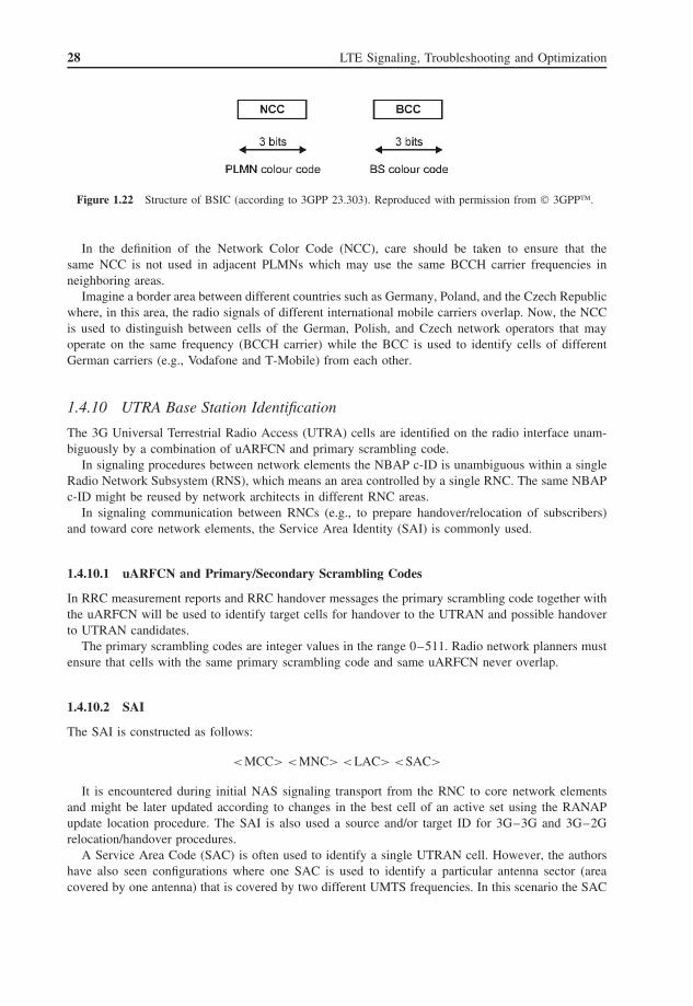
The BSIC is a local color code that allows a MS to distinguish between different neighboring basestations. The BSIC is a 6-bit code which is structured as shown in Figure 1.22.
Figure 1.21 Structure of cell global identification (according to 3GPP 23.303). Reproduced with permissionfrom © 3GPP™.
4 Reproduced with permission from © 3GPP™.
28 LTE Signaling, Troubleshooting and Optimization
Figure 1.22 Structure of BSIC (according to 3GPP 23.303). Reproduced with permission from © 3GPP™.
In the definition of the Network Color Code (NCC), care should be taken to ensure that thesame NCC is not used in adjacent PLMNs which may use the same BCCH carrier frequencies inneighboring areas.
Imagine a border area between different countries such as Germany, Poland, and the Czech Republicwhere, in this area, the radio signals of different international mobile carriers overlap. Now, the NCCis used to distinguish between cells of the German, Polish, and Czech network operators that mayoperate on the same frequency (BCCH carrier) while the BCC is used to identify cells of differentGerman carriers (e.g., Vodafone and T-Mobile) from each other.
1.4.10 UTRA Base Station Identification
The 3G Universal Terrestrial Radio Access (UTRA) cells are identified on the radio interface unam-biguously by a combination of uARFCN and primary scrambling code.
In signaling procedures between network elements the NBAP c-ID is unambiguous within a singleRadio Network Subsystem (RNS), which means an area controlled by a single RNC. The same NBAPc-ID might be reused by network architects in different RNC areas.
In signaling communication between RNCs (e.g., to prepare handover/relocation of subscribers)and toward core network elements, the Service Area Identity (SAI) is commonly used.
1.4.10.1 uARFCN and Primary/Secondary Scrambling Codes
In RRC measurement reports and RRC handover messages the primary scrambling code together withthe uARFCN will be used to identify target cells for handover to the UTRAN and possible handoverto UTRAN candidates.
The primary scrambling codes are integer values in the range 0–511. Radio network planners mustensure that cells with the same primary scrambling code and same uARFCN never overlap.
1.4.10.2 SAI
The SAI is constructed as follows:
<MCC> <MNC> <LAC> <SAC>
It is encountered during initial NAS signaling transport from the RNC to core network elementsand might be later updated according to changes in the best cell of an active set using the RANAPupdate location procedure. The SAI is also used a source and/or target ID for 3G–3G and 3G–2Grelocation/handover procedures.
A Service Area Code (SAC) is often used to identify a single UTRAN cell. However, the authorshave also seen configurations where one SAC is used to identify a particular antenna sector (areacovered by one antenna) that is covered by two different UMTS frequencies. In this scenario the SAC

Standards, Protocols, and Functions 29
addressed two cells that used the same primary scrambling code but different uARFCN and differentNBAP c-ID.
1.4.10.3 Shared Network Area Identifier
The Shared Network Area Identifier (SNA-ID) is a new identity introduced in Release 8 standardsand used to identify an area consisting of one or more LAs. Such an area can be used to grant accessrights to parts of a shared network to a UE in connected mode.
The SNA-ID consists of the PLMN-Id followed by the Shared Network Area Code (SNAC)
<MCC><MCN><SNAC>
where the SNAC is defined by the operator.
1.4.11 Numbering, Addressing, and Identification in the Session InitiationProtocol
The Session Initiation Protocol (SIP) addresses so-called Uniform Resource Identifiers (URIs). Thegeneric format is defined as follows:
sip:user:password@host:port:uri-parameters?headers.
This format can be compared to the structure of an e-mail address (e.g., [email protected]).Optionally some specific SIP parameters may be included in the SIP address. Among such parameters,it can be defined which transport protocol should be used to exchange SIP messages, for instance.Also, a priority can be given to messages, authentication procedures can be invoked, errors reported,and routing instructions given by using the header fields. Some header fields only make sense inrequests or responses. These are called request header fields and response header fields, respectively.A complete list of header fields and their relation to different SIP methods can be found in RFC(Request For Comments) 3261.
At the end a SIP address monitored in a live network may look like this:
sip:ralf @tektronix.com;transport=tcp?priority=urgent.
Besides the recipient’s name and host, this address contains a URI parameter to request transportof this SIP information using the reliable TCP, and the header information indicates that this SIPinformation will be treated with urgent priority.
1.4.12 Access Point Name
In the GPRS backbone, an Access Point Name (APN) is a reference to a GGSN. To support inter-PLMN roaming, the internal GPRS DNS (Domain Name System) functionality is used to translatethe APN into the IP address of the GGSN.
In the EPC network the APN is found in GTP-C signaling when packet contexts are established,but it is no longer found in LTE NAS signaling. This means in turn that for 2.5G and 3G phonesthe APN is an important parameter to be stored on the (U)SIM card, but for 4G phones the APNdoes not need to be configured by the end user. This will also resolve the problem where manyPDP context setup failures seen currently in the GERAN and UTRAN are due to an unknown ormissing APN.

30 LTE Signaling, Troubleshooting and Optimization
The APN is composed of two parts as follows:
• The APN network identifier; this defines to which external network the GGSN is connected andoptionally a requested service by the MS. This part of the APN is mandatory.
• The APN operator identifier; this defines in which PLMN GPRS backbone the GGSN is located.This part of the APN is optional.
The APN operator identifier is placed after the APN network identifier. An APN consisting of boththe network identifier and operator identifier corresponds to the DNS name of a GGSN; the APN has,after encoding as defined below, a maximum length of 100 octets.
The encoding of the APN follows the name syntax defined in RFC 2181 [18], RFC 1035 [19],and RFC 1123 [20]. The APN consists of one or more labels. Each label is coded as a one-octetlength field followed by that number of octets coded as 8-bit ASCII characters. Following RFC 1035[19], the labels should consist only of the alphabetic characters (A–Z and a–z), digits (0–9), andthe hyphen (-). Following RFC 1123 [20], the labels should begin and end with either an alphabeticcharacter or a digit. The case of alphabetic characters is not significant. The APN is not terminatedby a length byte of zero.
Typical APNs are:
• mms.tim.net;• wap.eplus.net;• wap.beeline.ru;• wap.debitel.de;• web.vodafone.de;• internet.t-mobile.
The APN of a 3G subscriber is stored in the USIM. In LTE NAS signaling the APN is no longerused, because it is chosen by the intelligent packet routing functions of MME. However, the APNAverage Maximum Bit Rate (APN-AMBR) may be signaled to the UE by the MME to control theamount and bandwidth of UL traffic.
1.5 User Equipment
As in UMTS, the LTE mobile station is called User Equipment (UE). It is constructed using a modulararchitecture that consists of three main components (see Figure 1.23):
Figure 1.23 Modular architecture of a UE.

Standards, Protocols, and Functions 31
• Mobile Termination: The MT represents termination of the radio interface. In this entity the RRCsignaling is terminated and RRC messages are sent/received.
• Terminal Adapter: The terminal adapter represents the termination of the application-specificservice protocols, for example, SIP signaling for VoIP. The terminal adapter might be constructedas an external interface, for example, USB to connect a laptop PC using LTE technology with amobile network.
• Terminal Equipment: The TE represents termination of the service. Depending on the UE’s appli-cation capabilities, it may act as the TE or not. For instance, the Apple iPhone with its browserfunctionalities has full TE capability while a simple USB stick for mobile data transmission has noTE capability at all. In the case of the USB stick, the connected laptop PC is the TE.
1.5.1 UE Categories
The UE categories stand for an abstract grouping of common UE radio access capabilities and aredefined in 3GPP 36.306.
In particular, the handset-type groups vary in maximum possible throughput (the maximum numberof DL-SCH transport blocks bits received within a Time Transmission Interval (TTI)). Assuming a TTIof 1 ms for category 1, the maximum possible throughput is 10 296 bits/1 ms which is approximately10 Mbps of physical layer DL throughput (including the RLC/MAC header information – so thepayload throughput will be slightly less).
Category 5 mobiles are the only handsets that support 64 Quadrature Amplitude Modulation (QAM)on the UL as highlighted in Tables 1.4 and 1.5. The maximum possible bit rate ranges from 5 Mbps(Cat. 1) to 75 Mbps (Cat. 5).
1.6 QoS Architecture
The EPS bearer service layered architecture is depicted in Figure 1.24. Besides the different namesof bearers and reference points, this architecture does not look very different from the bearer servicearchitecture defined in Release 99. However, there is a major difference that is not obvious at first sight.
In 3G UMTS the request of a subscriber for a defined QoS of an end-to-end service starts the QoSnegotiation procedure. This depends on the subscriber’s subscribed QoS stored in the HLR and theavailable network resources which QoS is granted to a particular connection at the end. The QoSnegotiation and control process starts on the NAS layer with the first SM message sent by the UE.
In LTE – different to 2.5 and 3G PS connections – a default bearer with a default QoS isalready established when the UE attaches to the network. The QoS attributes of this default bearer
Table 1.4 UE categories and DL capabilities (according to 3GPP 36.306). Reproduced withpermission from © 3GPP™
UE category Maximum number of Maximum number of ApproximateDL-SCH transport bits of a DL-SCH maximum bit rateblock bits received transport block received DL (Mbps)
within a TTI within a TTI
Category 1 10 296 10 296 10Category 2 51 024 51 024 50Category 3 102 048 75 376 75Category 4 150 752 75 376 75Category 5 302 752 151 376 150

32 LTE Signaling, Troubleshooting and Optimization
Table 1.5 UE categories and UL capabilities (according to 3GPP 36.306). Reproducedwith permission from © 3GPP™
UE category Maximum number of bits Support for Approximateof an UL-SCH transport 64QAM in UL maximum bit
block transmitted rate UL (Mbps)within a TTI
Category 1 5 160 No 5Category 2 25 456 No 25Category 3 51 024 No 50Category 4 51 024 No 50Category 5 75 376 Yes 75
Figure 1.24 LTE QoS architecture (according to 3GPP 23.401). Reproduced with permission from © 3GPP™.
are determined by the subscribed QoS parameters stored in the HSS. This is still as seen in2.5/3G networks.
However, if now the first user plane packet is sent by the UE it is routed toward the PDN wherethe PCRF analyzes the requested end-to-end service. Depending on this service, the PCRF may nowtrigger a modification of QoS parameters in all the involved bearers. There is no option for thesubscriber to request a particular QoS; only the network is in charge of QoS control. There is also noway for the UE to request something known as a secondary context in 3G (see Section 3.26 in Kreherand Ruedebusch, 2007). In LTE all QoS management is tied to the application, not to SM signaling.

Standards, Protocols, and Functions 33
Table 1.6 Standardized QCI, QoS parameter thresholds, and example services (according to 3GPP 23.203).Reproduced with permission from © 3GPP™
QCI Resource Priority Packet delay Packet error Example servicestype budget (ms) loss rate
1 GBR 2 100 10–2 Conversational voice2 4 150 10–3 Conversational video (live streaming)3 3 50 10–3 Real-time gaming4 5 300 10–6 Non-conversational video (buffered
streaming)5 Non-GBR 1 100 10–6 IMS signaling6 6 300 10–6 Video (buffered streaming) TCP based
(e.g., www, e-mail, chat, ftp, p2p filesharing, progressive video, etc.)
7 7 100 10–3 Voice, video (live streaming) interactivegaming
89
89
300 10–6 Video (buffered streaming) TCP based(e.g., www, e-mail, chat, ftp, p2p filesharing, progressive video, etc.)
It is important to understand that one UE in LTE can have multiple end-to-end services active andeach of these services will have its own individual bearer. It is not intended by LTE standards that, forexample, non-real-time services like web-browsing and e-mail will be mapped onto the same bearer(e.g., the same S1-U GTP tunnel) as we have seen in 3G UMTS. For this reason also 256 individualE-RABs for a single UE can be addressed by E-UTRAN protocols while in UMTS only 15 differentRAB-IDs had been defined by the standard organizations.
In the 3GPP specs there is also a Traffic Flow Template (TFT) mentioned for the UL as well asfor the DL part of the connection. These TFTs are bound to the EPS bearers. In general, a TFT canbe described as a set of filters for a particular end-to-end service. Each TFT consists of a destinationIP address and a set of source/destination port numbers. On the DL, the IP address is the addressassigned to the UE; on the UL, it is the address of a server on the PDN. If we assume, for example,an HTTP 1.1 end-to-end service, the DL TFT of this service consists of the UE’s IP address, the TCPsource port number is 80, and the TCP destination port number is 80. On the UL, the port numbersare the same, but the IP address is the address of the server that hosts the web site.
To standardize the QoS handling, a set of nine QCIs have been defined by 3GPP. There arefour classes with a Guaranteed Bit Rate (GBR) and five classes with a Non-Guaranteed Bit Rate(Non-GBR).
Besides the bit rate, the parameter priority, packet delay budget, and packet error loss rate arecritical factors as given in Table 1.6.
1.7 LTE Security5
What are the new security functions in the E-UTRAN? This question can briefly be answeredas follows.
5 Reproduced with permission from © 3GPP™.

34 LTE Signaling, Troubleshooting and Optimization
The first feature we see is a completely new ciphering mechanism and integrity protection for NASsignaling messages that was never seen in any 2G or 3G radio access network. On the radio interfacethis new NAS security leads to situations with double ciphering. On top of the protocol stack the NASmessages exchanged between the UE and MME are encrypted and the underlying RRC that acts asthe transport layer for NAS is secured by ciphering mechanisms as well, so that the ciphered NASmessage is ciphered together with its RRC transport message a second time.
The second new security feature is the option to secure the complete IP-based transport of thecontrol plane and user plane on the S1 reference point using Secure IP (IPsec). There is no wayto decipher IPsec by just monitoring the data that is exchanged between two endpoints of an IPsecconnection. To decipher IPsec requires the monitoring software to be informed about which IPsecciphering parameters (which can be changed frequently) are currently used in each of the involvedendpoints of the IP connection. In a typical case these endpoints are the eNB and the MME orS-GW. To allow deciphering, there must be a dedicated Application Programming Interface (API)installed that allows the monitoring software to access IPsec-relevant parameters for deciphering. Todesign such an API requires close cooperation between the NEMs of eNB and MME/S-GW and themanufacturers of the monitoring software. The conclusion related to this fact is that free-of-chargemonitoring software like WireShark will not be able to decipher IPsec. However, to obtain statistics ofS1 control plane and user plane performance it is crucial to have metrics for E-UTRAN QoS and QoE(Quality of Experience). Consequently, IPsec deciphering will become one of the key differentiatorsfor E-UTRAN monitoring software.
Besides these new security features, all the security elements from previous standards such asmutual authentication and masking of subscriber identity by using temporary identities can be foundin the E-UTRAN. There is only a minor change here: the TMSI will be replaced by the newGUTI parameter.
To understand how the overall LTE security concept works, it is crucial to understand the hierarchyof LTE security keys first. This LTE security key hierarchy, shown in Figure 1.25, includes thefollowing keys: KeNB, KNASint, KNASenc, KUPenc, KRRCint, and KRRCenc:
• KeNB is a key derived by the UE and MME from KASME or by the UE and target eNB from KeNB*
during eNB handover. KeNB should only be used for the derivation of keys for RRC traffic andthe derivation of keys for UP (User Plane) traffic, or to derive a transition key KeNB* during aneNB handover.
Keys for NAS traffic:
• KNASint is a key which should only be used for the protection of NAS traffic with a particularintegrity algorithm. This key is derived by the UE and MME from KASME, as well as an identifierfor the integrity algorithm.
• KNASenc is a key which should only be used for the protection of NAS traffic with a particularencryption algorithm. This key is derived by the UE and MME from KASME, as well as an identifierfor the encryption algorithm.
Keys for UP traffic:
• KUPenc is a key which should only be used for the protection of UP traffic with a particularencryption algorithm. This key is derived by the UE and eNB from KeNB, as well as an identifierfor the encryption algorithm.

Standards, Protocols, and Functions 35
Figure 1.25 LTE security key hierarchy (according to 3GPP 33.401). Reproduced with permission from© 3GPP™.
Keys for RRC traffic:
• KRRCint is a key which should only be used for the protection of RRC traffic with a particularintegrity algorithm. KRRCint is derived by the UE and eNB from KeNB, as well as an identifier forthe integrity algorithm.
• KRRCenc is a key which should only be used for the protection of RRC traffic with a particularencryption algorithm. KRRCenc is derived by the UE and eNB from KeNB as well as an identifier forthe encryption algorithm.
Now, whenever a call is established the security functions will work as shown in Figures 1.26–1.28.The start trigger of the security functions is when an initial NAS signaling message sent by the UE thatcontains UE security capability information arrives at the MME. The security capability list informs theMME for instance about which ciphering and integrity protection algorithms are supported by this UE.

36 LTE Signaling, Troubleshooting and Optimization
Figure 1.26 Subscriber authentication.
After the MME has received the initial NAS message and it has not been in contact with thissubscriber before, or if all previously received security tokens sent by the HSS have been used, theMME must contact the HSS to receive new tokens. Thus, the MME sends a DIAMETER authenticationinformation request message to the HSS that contains the subscriber’s identity. The HSS holds thesecret network key “K” that is also stored on the USIM card of each subscriber. “K” is unique toevery network operator.
From “K” and the subscriber’s identity the HSS derives three of the four parameters found inside theDIAMETER authentication information response message: the security key KASME, the AuthenticationToken (AUTN), and the Expected Response (XRES) parameter. The random number parameter RANDis truly just a random number.
After the MME has received these four parameters, it produces three more derivatives from KASME.These derivatives are the NAS encryption key KNASenc, the NAS integrity protection key KNASint, andthe security key for the eNB KeNB.
What follows is the authentication procedure between the MME and the UE. The MME sendsthe unciphered NAS authentication request message that includes the random number RAND and theAUTN. Now the UE must use its secret key “K” from the USIM card to calculate another numberbased on “K,” AUTN, and RAND. The number is the UE’s authentication response number RES.
RES is sent back to the MME by using the authentication response message, and in the last stepof the authentication procedure the MME compares the value of RES to the value of XRES, whichis the XRES value computed previously by the HSS. If RES and XRES have the same value the UEhas successfully authenticated itself to the network and the NAS signaling connection can proceed.

Standards, Protocols, and Functions 37
Figure 1.27 NAS security initiation and RRC security initiation.
Figure 1.28 RRC security completion.

38 LTE Signaling, Troubleshooting and Optimization
At this point, after successful authentication, it is time to activate the NAS security functions:namely, NAS ciphering and NAS integrity protection. Thus, the MME sends the NAS security modecommand message to the UE including the security key KASME received previously from the HSS,and the algorithms for EPS encryption and EPS integrity protection that have been selected from theUE capability list and will be used to secure this NAS signaling connection.
After the UE has received the NAS security command, it computes on behalf of the assigned EPSencryption/integrity algorithms and the KASME key the keys for NAS encryption and NAS integrityprotection that are identical to those already stored in the MME. Now NAS security is in servicethe UE sends back the NAS security mode complete message, which is the encrypted and integrityprotected NAS message. It is not mandatory to use NAS encryption and integrity protection. It isalways up to the operator to decide what is required to secure the network.
After the NAS security functions are in service, the underlying RRC connection and the cipheringfor user plane traffic need to be activated. For this purpose, first a so-called security context is installedbetween the MME and eNB. Since security is not the only context-related information to be exchangedbetween these two network elements, the S1AP initial context setup message will also contain otherparameters besides the UE security capabilities and the eNB’s security key KeNB. Note that the UEsecurity capabilities so far are unknown to the eNB.
Now the eNB derives the keys for RRC encryption (KRRCenc), RRC integrity protection (KRRCint),and user plane encryption (KUPenc) from KASME. Then the eNB sends the RRC security mode commandmessage to the UE. This message contains the AS encryption algorithm and AS integrity protectionalgorithm bundled with the START parameters for the AS security activation procedure.
The UE computes the keys for RRC encryption (KRRCenc), RRC integrity protection (KRRCint), anduser plane encryption (KUPenc) from the KASME together with the received keys and activates therequested security functions using these parameters. After successful activation, the UE sends theRRC security mode complete message (i.e., ciphered and/or integrity protected) back to the eNB. Andthe eNB confirms the successful establishment of the security context to the MME by sending theS1AP successful outcome message for the procedure code “Initial Context Setup.”
1.8 Radio Interface Basics
Wireless transmissions within mobile networks make use of electromagnetic waves to carry thetransmitted information from source to destination. The data is modulated to complex waves (ina mathematical sense) using a modulation scheme. Furthermore, a duplex method (see Section 1.8.1)and a multiple access scheme or multiplex scheme (see Section 1.8.2) are applied to those complexwaves. The resulting modulated spectrum is called baseband. The baseband carries all information andthe utilized bandwidth of this baseband depends on the amount of information and spectral efficiencyof the modulation scheme. The spectral efficiency is measured in bits per hertz. The baseband ismultiplied by a carrier frequency, resulting in a frequency shift in the amount of the carrier frequency.This signal is amplified with an RF amplifier and is transmitted via an antenna. Before the signal isreceived by the receiving station, the electromagnetic waves carrying the information are distorted bythe wireless channel.
The wireless channel is characterized by various time-variant and time-invariant parameters. Thissection gives only a short introduction to the characteristics of the wireless channel. The propertiesof the mobile wireless channel can be roughly characterized by the following two attributes:
• Large-scale fading: This is due to loss of signal strength by distance and shadowing of largeobjects like hills or buildings. It is typically frequency independent, but a function of time andspace which fluctuates by means of cell areas.

Standards, Protocols, and Functions 39
• Small-scale fading: This is due to the constructive and destructive interference of the multiplesignal paths between the transmitting node and the receiving one, resulting in signal strength changeson a spatial scale of the wavelength. Therefore, signal strength variation greatly increases with fastermoving stations and is frequency selective.
Free space attenuation as a function of distance d and wavelength λ is shown in the followingequation. This basic attenuation (part of large-scale fading) denotes the signal decrease between sourceand destination without taking any shadowing, multipath fading, or scattering into account:
L = 10 log
(4πd
λ
)2
[dB]
Especially, the small-scale fading introduces distortion in the received signal to such an extent thatit needs to be eliminated, or at least reduced by entities called channel estimator and channel equalizerdescribed later in this section.
Figure 1.29 shows a typical received wireless channel quality as a function of frequency andtime. The channel quality (received signal strength of certain frequencies) changes on a large scale(large-scale fading) and is superposed by the small-scale fading of a moving node. The physical layerof mobile wireless transmission systems have to deal with these characteristics of mobile channelsto ensure data transmission to a specific subscriber velocity. Because small-scale fading spatiallychanges by means of the wavelength, typically by several centimeters in mobile networks, the uservelocity introduces fast fading to the received signal. As an example, a user velocity of 100 km/h
24 chunks at 375kHz, 100358 samples at 0.5ms = 50.179s, v = 3kmh, case3
Figure 1.29 Time-variant frequency-selective wireless channel. Reproduced with permission from Nomor.

40 LTE Signaling, Troubleshooting and Optimization
(27.8 m/s) can result in signal fading changes of 250 times a second. As a result, the received signalis additionally amplitude modulated (a fast amplitude change) caused by the fast fading of a movinguser. The amplitude modulated due to the time-variant wireless channel causes additionally frequencydispersion. Entities like fast power control and fast frequency-selective scheduling (see Sections 1.8.7and 1.8.9) are introduced into mobile systems in order to counteract this.
A multipath channel is time dispersive, which means that a single transmitted signal is receivedmore than once with different strong echoes (reflections). The electromagnetic waves are reflectedby obstacles like buildings, hills, and mountains. The direct beam between the transmit antennaand receiver is called the LOS (Line Of Sight). The LOS is usually the strongest pattern withinthe brought field of received reflections. h(τ, t) is the time-variant (t and τ ) impulse response ofthe wireless channel with i paths (reflections) and an attenuation ai(t) of each path i. The impulseresponse denotes the characteristic behavior of a system (in a mathematical sense), like the wirelesschannel when an impulse (delta peak) is given as input. In theory, this impulse is so steep that allpossible frequencies are included, thus it shows the behavior of all transmitted patterns. τ is the delayof the signal between the source and receiver. This delay is called the propagation delay. τi is theadditional delay of the reflection path i. Thus,
h(τ, t) =∑∀i
ai(t)δ(τ − τi(t))
The transmitted baseband signal is distorted by the wireless channel because different reflections ofthe signal are interfering at the receiver. Thus, the time-continuous received complex baseband signalyb(t) of a transmitted signal xb(t) with additive white Gaussian noise n(t) is
yb(t) =∑∀i
ai(t) exp[−j2πfcτi(t)]xb(t − τi(t)) + n(t)
fc is the frequency which is used to transmit the information. It is referred to as the carrier frequency,as mentioned above. The term exp[−j2πfcτi(t)] denotes the time-variant phase shift of each reflectionpath i.
By knowing the distortion h(τ, t) which was applied to the received signal due to wireless trans-mission, the receiving entity is able to reverse this distortion and retrieve the transmitted information.In order to estimate the wireless impulse response by the receiver, the transmitter entity inserts knownpatterns into the transmit signal. Those signals are referred to as pilot or reference signals. Addition-ally, pilot, reference, or synchronization signals can be applied for time and frame synchronization(in LTE special synchronization signals are used, see Section 1.8.15). The receiver scans the receivedsignal for the pilot or synchronization signals by using correlation functions. Once frame synchro-nization is established, the channel estimator unit of the receiver analyzes the known signal part inorder to estimate h(τ, t).
The channel estimator passes the results of the process of estimation to the channel equalizer. Thechannel equalizer is the entity which removes the distortion due to wireless transmission. Thus, thequality of channel equalization depends on the provided information of the estimator unit. Almostevery mobile cell phone standard uses different estimators and equalizers depending on the structureof reference symbols and slot structure. In LTE, channel estimation and equalization are done in thefrequency domain and interpolated between adjacent time domain transmission symbols, resulting ina two-dimensional channel equalization. The process of channel estimation and equalization used inLTE is described in Sections 1.8.6 and 1.8.15.
1.8.1 Duplex Methods
A valuable communication feature is bidirectional communication between peers. Feedback is themajor difference to unicast or broadcast systems, such as TV or radio transmission. Bidirectional
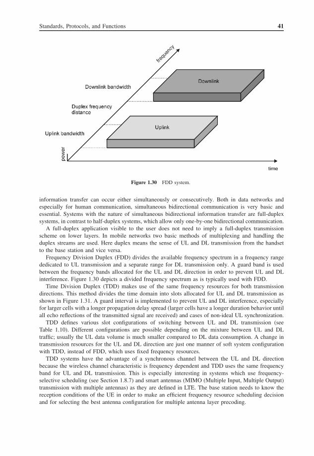
Standards, Protocols, and Functions 41
Figure 1.30 FDD system.
information transfer can occur either simultaneously or consecutively. Both in data networks andespecially for human communication, simultaneous bidirectional communication is very basic andessential. Systems with the nature of simultaneous bidirectional information transfer are full-duplexsystems, in contrast to half-duplex systems, which allow only one-by-one bidirectional communication.
A full-duplex application visible to the user does not need to imply a full-duplex transmissionscheme on lower layers. In mobile networks two basic methods of multiplexing and handling theduplex streams are used. Here duplex means the sense of UL and DL transmission from the handsetto the base station and vice versa.
Frequency Division Duplex (FDD) divides the available frequency spectrum in a frequency rangededicated to UL transmission and a separate range for DL transmission only. A guard band is usedbetween the frequency bands allocated for the UL and DL direction in order to prevent UL and DLinterference. Figure 1.30 depicts a divided frequency spectrum as is typically used with FDD.
Time Division Duplex (TDD) makes use of the same frequency resources for both transmissiondirections. This method divides the time domain into slots allocated for UL and DL transmission asshown in Figure 1.31. A guard interval is implemented to prevent UL and DL interference, especiallyfor larger cells with a longer propagation delay spread (larger cells have a longer duration behavior untilall echo reflections of the transmitted signal are received) and cases of non-ideal UL synchronization.
TDD defines various slot configurations of switching between UL and DL transmission (seeTable 1.10). Different configurations are possible depending on the mixture between UL and DLtraffic; usually the UL data volume is much smaller compared to DL data consumption. A change intransmission resources for the UL and DL direction are just one manner of soft system configurationwith TDD, instead of FDD, which uses fixed frequency resources.
TDD systems have the advantage of a synchronous channel between the UL and DL directionbecause the wireless channel characteristic is frequency dependent and TDD uses the same frequencyband for UL and DL transmission. This is especially interesting in systems which use frequency-selective scheduling (see Section 1.8.7) and smart antennas (MIMO (Multiple Input, Multiple Output)transmission with multiple antennas) as they are defined in LTE. The base station needs to know thereception conditions of the UE in order to make an efficient frequency resource scheduling decisionand for selecting the best antenna configuration for multiple antenna layer precoding.

42 LTE Signaling, Troubleshooting and Optimization
Figure 1.31 TDD system with example duplex slot structure.
1.8.2 Multiple Access Methods
Multiple access has to be performed in systems where a medium is shared for transmission and recep-tion by multiple users or entities. Those entities or users, sometimes also called nodes, are accessingthe very same medium to transmit their information, other than, for example, in CS communica-tion schemes. For example, within classical CS communications like Plain Old Telephone Systems(POTSs), each communication node gets a dedicated resource (a telephone landline) to dedicatedlyaccess for the complete communication session. On the other hand, it is necessary to apply a multipleaccess method when multiple nodes share the same medium for their information transfer, in order toprevent or detect collisions on the shared medium.
This implies that the users share the same resources for communication in a certain way. Multipleaccess methods are mainly used with PS data transmission, as multiple nodes usually share the sameresources for efficiency reasons. Packet Switched (PS) data transmission is mostly characterized bybursty traffic patterns. There are different schemes which can be applied to share those resources.These access schemes are known as multiple access methods.
Multiple access methods introduce rules for accessing the shared medium, generally resources. Carehas to be taken not to use the same resources by two or more nodes at once, because this would resultin distortion of the transferred information.
Transmission/reception resources are one or multiples of the following: time, code, frequency,space, etc.
One of the first radio-based multiple access scheme is Aloha. Early research in these schemeswas carried out at the University of Hawaii in the early 1970s. In the Hawaiian language Alohameans “Hello” which indicates a fundamental mechanism: the university ran several campuses ondifferent islands where an early radio-based packet data network was established. Stations immediatelytransmitted packets to be sent and waited for a fixed time (double the round-trip time of the most distantstations in the network plus the transmission and processing time of packets) for an acknowledgment(ACK) from the receiving station. If an ACK was received, the packet was retransmitted. Aloha showsthat many collisions of packets occur when applying this scheme.
Most modern access methods use mechanisms of avoiding, detecting, or preventing collisions withinthe shared medium, in order to reach a certain system efficiency. A basic method to avoid collisions issensing the medium before starting a transmission, to avoid interrupting or interfering with an ongoingtransmission of other communication peers.
This scheme is known as Carrier Sense Multiple Access (CSMA). Sensing the medium beforetransmission adds Collision Avoidance functionality (i.e., CSMA/CA). In addition to sensing the
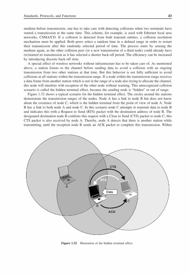
Standards, Protocols, and Functions 43
medium before transmission, one has to take care with detecting collisions when two terminals havestarted a transmission at the same time. This scheme, for example, is used with Ethernet local areanetworks, CSMA/CD. If a collision is detected from both transmit entities, a collision resolutionmechanism must be applied. Both peers select a random time in a defined range in order to restarttheir transmission after this randomly selected period of time. The process starts by sensing themedium again, as the other collision peer (or a new transmission of a third node) could already have(re)started its transmission as it has selected a shorter back-off period. The efficiency can be increasedby introducing discrete back-off slots.
A special effect of wireless networks without infrastructure has to be taken care of. As mentionedabove, a station listens to the channel before sending data to avoid a collision with an ongoingtransmission from two other stations at that time. But this behavior is not fully sufficient to avoidcollisions at all stations within the transmission range. If a node within the transmission range receivesa data frame from another station which is not in the range of a node also trying to allocate the channel,this node will interfere with reception of the other node without warning. This unrecognized collisionscenario is called the hidden terminal effect, because the sending node is “hidden” or out of range.
Figure 1.32 shows a typical scenario for the hidden terminal effect. The circles around the stationsdemonstrate the transmission ranges of the nodes. Node A has a link to node B but does not knowabout the existence of node C, which is the hidden terminal from the point of view of node A. NodeB has a link to both node A and node C. In this scenario node C attempts to transmit data to node Band indicates this with a Request to Send (RTS) packet with the destination address of node B. Thedesignated destination node B confirms this request with a Clear to Send (CTS) packet to node C; thisCTS packet is also received by node A. Thereby, node A detects that there is another station whiletransmitting, until the reception node B sends an ACK packet to complete this transmission. Within
Figure 1.32 Illustration of the hidden terminal effect.

44 LTE Signaling, Troubleshooting and Optimization
Figure 1.33 Schematic example of a Time Division Multiple Access (TDMA) system.
that time, node A will not initiate any transmission, not to node B nor to any other possible node, inorder not to corrupt reception at node B.
Note that this effect only occurs in mobile networks without fixed infrastructure, for example,mobile ad-hoc networks. Thus, the hidden terminal effect does not affect LTE.
One way of sharing the same resources between communication entities is to introduce a masterentity, which takes care of the usage of the shared medium. This scheme is widely used within mobilecell phone networks, as the base station controls and grants the access of resources within its cell.Within a Time Division Multiple Access (TDMA) mobile network, one frequency resource is dividedinto time slots which are used by different users. Mobile networks of the second generation (GSM)share eight time slots within a certain frequency band. Figure 1.33 illustrates the DL frame of a TDMAsystem which uses FDD. Thus, UL and DL utilize different frequency bands and both use TDMA. AGuard Period (GP) used between time slots serves to reduce the risk of multi-user interference. Thetraining sequence in the middle of the time slot is used to estimate the wireless channel conditions.This information is extrapolated time-wise to the adjacent data sections.
Non-overlapping frequency bands are assigned to different UEs within Frequency Division MultipleAccess (FDMA). A single user allocates one frequency resource which is used for the complete activetime. Guard bands need to be designed for the system in order to prevent multi-user interference.Systems (as GSM) often use a mixture of TDMA and FDMA, as multiple frequency channels with,for example, eight time slots serve as cell resources. Figure 1.34 depicts a FDMA system with fiveusers assigned to five different frequency bands.
UMTS users share orthogonal codes which are used to spread transmission data in order to betransmitted on the same frequency resources within one cell. Picture this as a metaphor: each user usesthe same time, space, and frequency resources, but communicates in a different language. This multipleaccess method is known as Code Division Multiple Access (CDMA) and illustrated in Figure 1.35.

Standards, Protocols, and Functions 45
Figure 1.34 Schematic of Frequency Division Multiple Access (FDMA).
Figure 1.35 Code Division Multiple Access (CDMA).
The shared resources in LTE are very small frequency bands and small transmission time slots.Thus, the method combines FDMA and TDMA behavior, but in a very agile way. Frequency andtime resources are often reassigned for diversity or efficiency reasons during ongoing user trans-missions. This method is known as Orthogonal Frequency Division Multiple Access (OFDMA).OFDMA is described in Section 1.8.4 in detail, as well as OFDM signal generation and characteristicsin Section 1.8.3.
Within mobile cell phone network systems, time slot resources, frequency resources, and coderesources are controlled by the base station. This controlled multiple access method is known asscheduling. The scheduling method applied in LTE is described for the DL direction in Section 1.8.7and for the UL in Section 1.8.9. This scheduling case allows active transmission collision protection,as well as other parameters, to be taken into account when granting transmissions between users. Theseparameters can be fairness, QoS requests of nodes, medium/channel quality or (charging) policies.Details on scheduling parameters are found in the above-mentioned sections.
1.8.3 OFDM Principles and Modulation
Most recent communication systems like WiFi, WiMAX, and digital audio and video broadcasts makeuse of OFDM, as in the LTE DL transmission scheme and a slightly modified version in the LTE ULtransmission scheme.
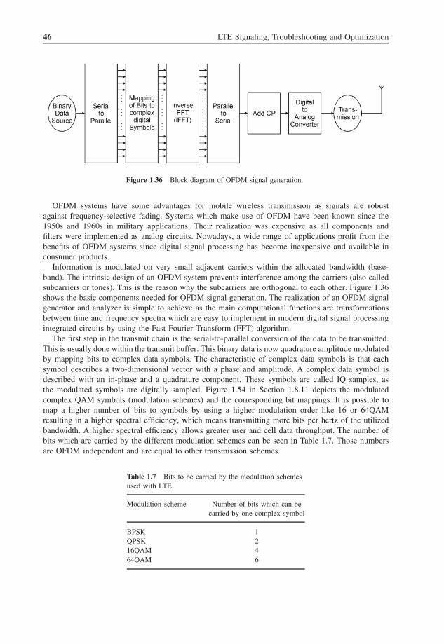
46 LTE Signaling, Troubleshooting and Optimization
Figure 1.36 Block diagram of OFDM signal generation.
OFDM systems have some advantages for mobile wireless transmission as signals are robustagainst frequency-selective fading. Systems which make use of OFDM have been known since the1950s and 1960s in military applications. Their realization was expensive as all components andfilters were implemented as analog circuits. Nowadays, a wide range of applications profit from thebenefits of OFDM systems since digital signal processing has become inexpensive and available inconsumer products.
Information is modulated on very small adjacent carriers within the allocated bandwidth (base-band). The intrinsic design of an OFDM system prevents interference among the carriers (also calledsubcarriers or tones). This is the reason why the subcarriers are orthogonal to each other. Figure 1.36shows the basic components needed for OFDM signal generation. The realization of an OFDM signalgenerator and analyzer is simple to achieve as the main computational functions are transformationsbetween time and frequency spectra which are easy to implement in modern digital signal processingintegrated circuits by using the Fast Fourier Transform (FFT) algorithm.
The first step in the transmit chain is the serial-to-parallel conversion of the data to be transmitted.This is usually done within the transmit buffer. This binary data is now quadrature amplitude modulatedby mapping bits to complex data symbols. The characteristic of complex data symbols is that eachsymbol describes a two-dimensional vector with a phase and amplitude. A complex data symbol isdescribed with an in-phase and a quadrature component. These symbols are called IQ samples, asthe modulated symbols are digitally sampled. Figure 1.54 in Section 1.8.11 depicts the modulatedcomplex QAM symbols (modulation schemes) and the corresponding bit mappings. It is possible tomap a higher number of bits to symbols by using a higher modulation order like 16 or 64QAMresulting in a higher spectral efficiency, which means transmitting more bits per hertz of the utilizedbandwidth. A higher spectral efficiency allows greater user and cell data throughput. The number ofbits which are carried by the different modulation schemes can be seen in Table 1.7. Those numbersare OFDM independent and are equal to other transmission schemes.
Table 1.7 Bits to be carried by the modulation schemesused with LTE
Modulation scheme Number of bits which can becarried by one complex symbol
BPSK 1QPSK 216QAM 464QAM 6

Standards, Protocols, and Functions 47
Figure 1.37 OFDM signal of orthogonal Si functions (subcarriers); subcarriers do not interfere because at eachsubcarrier the signals from other subcarriers are zero.
Mobile cell phone standards which do not use OFDM, like GSM, CDMA2000, or UMTS, modulatethe data to complex symbols in the time domain. This means that the resulting sinusoid over time aftermodulation is the time domain signal of the baseband to be transmitted on the RF carrier frequency.OFDM systems interpret the modulated symbols as modulated frequency tones, which are to betransformed to a signal over time in order to be transmitted. Thus, the modulated symbols are mappedto orthogonal subcarriers (tones) of the baseband spectrum. The transformation to the time domainis done with an n-point inverse Fast Fourier Transform (iFFT). The Fourier transformation adds theorthogonal spectrum of each subcarrier to the resulting baseband spectrum. The spectrum of eachsubtone is a si(x) function (sin(x)/x), thus the resulting spectrum is an addition of si(x) functions asdepicted in Figure 1.37. The inherent behavior of the Fourier transformation lets each si(x) maximummatch zero transitions of all other si(x) functions, resulting in non-interfering subtones since the datawas modulated to individual subcarriers (peaks of the si(x) functions). This characteristic is knownas orthogonal behavior, which means data is perfectly demodulatable and no guard band betweensubcarriers is needed, in contrast to FDM, where intercarrier interference needs to be taken care of,for example, with guard bands.
The designated system bandwidth (baseband bandwidth) is divided into m subcarriers which aresampled with an n-point Fourier transformation, where n >m, indicating oversampling. System band-width is defined by a number of resource blocks (see Section 1.8.5) from 6 to 110, each resource blockgrouping 12 subcarriers. For approximately 20 MHz system bandwidth (100 resource blocks), 1200subcarriers are defined and a common FFT size is 2048 samples. LTE defines the sampling frequencyas fs = 1/Ts = 30.72 MHz, which leads to a LTE OFDM symbol length of 66.67 μs for normal CP(Cyclic Prefix). The CP is 5.2 μs or 160 samples in the first symbol and 4.7 μs or 144 samples in theother symbols for normal CP. The CP lasts 16.7 μs or 512 samples for extended CP. Details of LTEslot definitions are given in Section 1.8.6.

48 LTE Signaling, Troubleshooting and Optimization
OFDM systems show robust characteristics against frequency-selective fading caused by the wire-less channel, because fading holes are bigger compared to the subcarrier bandwidth, leading to a flatfading of individual subcarriers which is equalized by interpolating between defined reference symbols(reference subcarriers).
LTE defines a set of reference symbols in order to distinguish between various entities: cell-specific,UE-specific, antenna-port-specific, and MBMS-specific (Multimedia Broadcast/Multicast Service) ref-erence symbols. MBMS data and reference symbols are always transmitted on antenna port 4 if MBMSdata transmission is enabled.
In other words, the time domain is just the “transmit domain” for OFDM systems. The resultingtime domain signal after transforming the modulated frequency signal representing the data is, soto say, “just noise” and cannot be interpreted without transformation back to the frequency domain.All channel estimation, equalization, and interpretation of the data are done in the frequency domainwithin OFDM systems.
A timely guard interval or GP between OFDM symbols is needed to prevent intersymbol interfer-ence due to channel delay spread (arrival of all reflections). This is realized by copying the end of eachOFDM symbol in front of the OFDM samples to be transmitted. This GP, also known as the CP (CyclicPrefix), decreases alias effects caused by a windowing effect of the Fourier spectrum as the Fouriertransformation expects an infinite repeated spectrum, but the OFDM symbol has a time-limited dura-tion. LTE defines two CP lengths, a normal CP and an extended CP, for cells with a larger channel delayspread. Additionally, the CP is used for frame synchronization using an auto/cross-correlation function.
OFDM systems have the drawback of a high dynamic range after transforming the frequencysignal to a time domain signal which is amplified and transmitted. This high Peak-to-Average PowerRatio (PAPR) (squared peak signal amplitude to average signal power level) leads to cost-intense RFamplifiers and shorter battery life. This is especially a disadvantage for mobile handset devices; thus,another transmission scheme needs to be found for the UL.
LTE uses Single Carrier Frequency Division Multiple Access (SC-FDMA) or Discrete FourierTransform (DFT) spread OFDM as the UL transmission scheme to overcome some drawbacks of pureOFDM systems. SC-FDMA is described in more detail in Section 1.8.8.
Figure 1.38 presents an overview of the functional steps needed for physical channel processing.
1.8.4 Multiple Access in OFDM – OFDMA
LTE uses OFDM as the transmission scheme, as described in the section above. Multiple access, asintroduced in Section 1.8.4, is realized with OFDMA with the base station (eNB) taking care of theresources within its cell; this procedure is also called scheduling as the eNB schedules the transmission
Figure 1.38 Overview of physical channel processing. Reproduced with permission from © 3GPP™.

Standards, Protocols, and Functions 49
Figure 1.39 OFDM shared channel-based multiple user communication. Reproduced with permission fromNomor.
of user data in the DL and UL direction on the transmission medium used by all users within this cell.The transmission is done on the basis of a shared channel. The control information for granting an ULtransmission on the UL-SCH, or informing a UE about data that is transmitted for it on the DL-SCH,is done within the DL control channel with designated control information. Physical channels definedwith LTE are described in more detail in Section 1.8.12. Figure 1.39 shows the principle of an OFDMshared channel-based multiple user communication.
Resources to be scheduled with OFDMA systems are units of frequency resources and time unitsdescribing a time slot for which the scheduled frequency units are valid.
This scheduling procedure not only adds overhead, but also enables the system to be more efficientby introducing a frequency-selective scheduling algorithm with feedback from the UEs regardingcurrent reception quality, rather than use only diversity gains by spreading transmitted data.
Figure 1.40 compares a shared channel of an OFDMA system using localized and distributedscheduling of user data. In the localized mode, granted areas belonging to one user allocate adjacentfrequency resources within one block. The distributed mode is used when frequency diversity is to beused by spreading the user data of the shared channel to distributed non-adjacent frequency resources.Simulations show that systems with frequency-selective scheduling with a fast channel quality feedbackreport from users can achieve higher cell throughput compared to systems just spreading data overthe spectrum in order to achieve frequency diversity.

50 LTE Signaling, Troubleshooting and Optimization
Figure 1.40 Localized vs. distributed shared channel scheduling.
LTE defines both localized and distributed scheduling in the DL direction but only localized schedul-ing in the UL direction in order to keep the PAPR small in the SC-FDMA symbols of each user.Details of scheduling the LTE DL can be found in Sections 1.8.7 and 1.8.9, which describe the LTEUL scheduling.
1.8.5 Resource Blocks
This section describes how LTE defines and divides the bandwidth from physical subcarriers of theOFDM symbol in the logical abstract sense used for scheduling shared channel data.
The smallest division of the LTE spectrum carrying data is a subcarrier, as described in more detailin the sections above. OFDM systems modulate all data in the frequency domain on the subcarrierof the OFDM spectrum. A modulated subcarrier is defined as a Resource Element (RE) and is thesmallest logical unit of the LTE spectrum. One subcarrier or RE has a bandwidth of 15 kHz in normaland extended CP mode, but a special 7.5 kHz subcarrier spacing mode is defined with extended CPtransmission. All physical LTE channels use REs to modulate the data. Each RE of the shared channelis modulated using a variable modulation scheme from Quadrature Phase Shift Keying (QPSK) to64QAM as assigned by the scheduling process of the eNB. REs carry a variable number of data bits,due to the variable number of bits mapped to a RE because of the modulation order, but also becauseof applied CSs. CSs are used to make the data transmission more robust against transmission errors.They add redundancy to the transmitted information, which increases the probability of the receiver toretrieve the information error-free. LTE defines an Adaptive Modulation and Coding (AMC) process,which is described in Section 1.8.11 in more detail.
A physical Resource Block (RB) defines the smallest unit used by the scheduling algorithm. There-fore, the minimal scheduled user transmission on the shared channels is one RB. A RB consists of12 adjacent REs on the frequency axis. Consequently, it has a bandwidth of 180 kHz, since one REis 15 kHz wide in normal and extended CP mode (additionally a mode with 7.5 kHz is defined forextended CP). The possible configurations of CPs are given in Table 1.8.

Standards, Protocols, and Functions 51
Table 1.8 Configuration of cyclic prefix. Reproduced with permission from © 3GPP™
Configuration NRBsc NDL
symb
Normal cyclic prefix �f = 15 kHz 12 7
Extended cyclic prefix �f = 15 kHz 24 6�f = 7.5 kHz 3
From a time perspective, a RB spans one scheduling period which is defined as one subframe. Onesubframe has a duration of 1 ms. A subframe is divided into two slots of 0.5 ms. Within a subframe14 OFDM symbols are transmitted in the case of normal CP length and 12 OFDM symbols in thecase of extended CP length, hence a RB covers an area of, respectively, 12 × 14 and 12 × 12 REs.The time-wise LTE slot and frame structure is described in Section 1.8.6.
A third dimension is introduced by using multiple antenna ports with MIMO. The MIMO transportlayers depend on and correlate with the number of used transmit antenna ports. Each antenna port layeradds additional RB elements to the antenna port dimension. Figure 1.41 shows the two-dimensional(frequency and time) area of a RB.
RBs have a primary role in the scheduling process, but are also used for describing the LTE overallcell bandwidth. The cell bandwidth is announced in the data transmitted in the Physical BroadcastChannel (PBCH) in number of resource blocks. Table 1.9 maps the number of RBs to the LTEspectrum bandwidth in megahertz.
The scheduling procedure defines virtual resource blocks. Virtual resource blocks and physicalresource blocks are of equal size. The scheduler always uses virtual resource blocks for defining userallocations. There are two different types of virtual resource blocks:
• Localized virtual resource blocks.• Distributed virtual resource blocks.
Localized virtual RBs are equal to physical RBs. Therefore, localized virtual RBs address physicalRBs directly. Distributed RB mapping enables the usage of frequency diversity without schedulingdistributed RBs directly. Distributed virtual RBs split a physical RB at the slot boundary into twohalves. The first half of the scheduled distributed virtual RB directly equals the physical RBs. Thesecond slot is hopped to another second slot of another UE which is virtually scheduled in thedistributed way. There is one hopping gap between the scheduled RBs at system bandwidths smaller50 RBs and two gaps at systems with a larger number of RBs. Virtual RBs are used with resourceallocation type 2 described in Section 1.8.7.
Resource Element Groups (REGs) are defined to map physical channels to OFDM symbols, this isdone especially in the first OFDM symbols used by the PDCCH. The maximum length of the PDCCHis three OFDM symbols, thus other PHY channels are mapped into the resources of the PDCCH. AREG is defined in such a way that it spreads the information over a bigger frequency range to gainfrequency diversity. Figure 1.59 in Section 1.8.12 illustrates REGs in the PDCCH.
1.8.6 Downlink Slot Structure
This section introduces the LTE DL structure with respect to time. In the time domain, the DL isdivided into slots and frames. A radio frame is the largest unit and lasts 10 ms. As both duplex modes,FDD and TDD, use similar timings, this makes a UE starting to synchronize to a LTE cell unawareof the duplex method used. Thus, TDD and FDD both introduce radio frames of 10 ms timing.

52 LTE Signaling, Troubleshooting and Optimization
Figure 1.41 Downlink resource grid. Reproduced with permission from © 3GPP™.
Table 1.9 Commonly used number of resource blocks
Bandwidth (MHz) Resource blocks
1.4 63 135 2510 5015 7520 100

Standards, Protocols, and Functions 53
Both duplex methods define different types of radio frames:
• Frame type 1 is the frame type used with FDD.• Frame type 2 is the frame type used with TDD.
One radio frame is split into 10 subframes of 1 ms duration. A subframe is also the most importantunit of scheduling and for physical control channel durations the PDCCH is found in the first OFDMsymbols of each subframe. Furthermore, subframes are divided into two slots of 0.5 ms. The smallestunit is an OFDM symbol. Depending on the CP length (normal or extended) used (see Section 1.8.3),the length will be seven or six OFDM symbols transmitted within one slot, resulting in 14 or 12 OFDMsymbols within one subframe, respectively. Figure 1.42 shows one radio frame of type 1 (FDD) with20 slots and 10 subframes. The length of one radio frame is defined as Tf = 307 200 × Ts where Ts
is the sampling period. Therefore, the base sampling frequency of 30.72 MHz (Ts = 1/30.72 MHz)is used.
Figure 1.43 shows a complete radio frame of type 1 as used with FDD. It illustrates all 10subframes with areas for the PDSCH. The first OFDM symbols are allocated by the PDCCH. Inthe area of the PDCCH, additional physical channels for control information are embedded. Thesechannels are the Physical HARQ Indicator Channel (PHICH) and the Physical Control FormatIndicator Channel (PCFICH).
The PCFICH indicates the number of OFDM symbols allocated for the complete PDCCH in itscurrent subframe. Thus, the PDCCH is transmitted on a variable number of OFDM symbols dependingon how much control or scheduling information has to be transmitted, and the resulting number ofOFDM symbols which are used for the PDSCH is variable as well. The PDCCH allocates between1 and 3 OFDM symbols and the PDSCH between 13 and 11 for normal CP and between 11 and 9OFDM symbols for extended CP, respectively.
In the middle (around the DC subcarrier) of the bandwidth are six RBs used for some commonsignals and channels in some subframes. These locations are used for initial cell search and cellsynchronization. This central location enables a bandwidth-independent cell and frame synchronizationas well as initial cell access. Two step hierarchical synchronization signals are defined and located inthe first and sixth subframes. The Primary Synchronization Signal (PSS) is transmitted on the seventhOFDM symbol and the Secondary Synchronization Signal (SSS) is transmitted on the sixth OFDMsymbol of subframes described above. PSS and SSS can be seen in Figure 1.43 and Figure 1.62 showsthe bandwidth of the synchronization signals. Only 62 subcarriers of the 72 provided by six allocatedRBs are used for synchronization signals. Initial UE radio access is described in Section 1.8.15 aswell as the information carried by those signals.
Figure 1.42 Frame structure type 1 used with FDD TS36.211. Reproduced with permission from © 3GPP™.

54 LTE Signaling, Troubleshooting and Optimization
Fig
ure
1.43
Dow
nlin
kFD
Dra
dio
fram
e(n
orm
alcy
clic
prefi
x)w
ithPD
CC
H,
PDSC
H,
PBC
H,
refe
renc
esi
gnal
s,an
dsy
nchr
oniz
atio
nsi
gnal
s.R
epro
duce
dw
ithpe
rmis
sion
from
Nom
or.

Standards, Protocols, and Functions 55
Resources for the PBCH are allocated apart from the SSS. The PBCH is transmitted in each firstsubframe of all radio frames. Other than the synchronization signals, the PBCH uses all 72 subcarriersof the six central RBs (see Figures 1.43 and 1.62).
Reference signals are needed by the channel estimation process in order to correct the wirelesschannel distortion in the signal at the receiver. Four sets of reference signals are specified for eachtransmit antenna as LTE defines multi-antenna transmissions (DL MIMO). The receiver needs to knowthe propagation conditions of each transmit antenna for using the complete MIMO gain. Therefore, adefined signal (reference signal) is transmitted from each individual antenna completely independentlyand all other transmit antennas do not transmit any signals on those specific frequencies and timeresources (REs). Figure 1.44 illustrates the frequency and time RE used for transmitting referencesignals depending on the number of antennas configured.
Frame type 2 is used with TDD. The general slot structure of a TDD frame is similar to a FDDframe, since a mobile is not aware of the duplex method before synchronizing to the cell. A radioframe of type 2 has a duration of 10 ms as its FDD equivalent. The TDD radio frame is also dividedinto 10 transmission time intervals of 1 ms duration called subframes. Furthermore, TDD subframesare split as well into two slots of 0.5 ms period.
TDD systems switch on one frequency between DL and UL transmission. Therefore, as described inSection 1.8.1, TDD needs defined switch points and guard intervals between UL and DL transmission.
Figure 1.44 Mapping of downlink reference signals (normal cyclic prefix) (TS36.211). Reproduced with permis-sion from © 3GPP™.
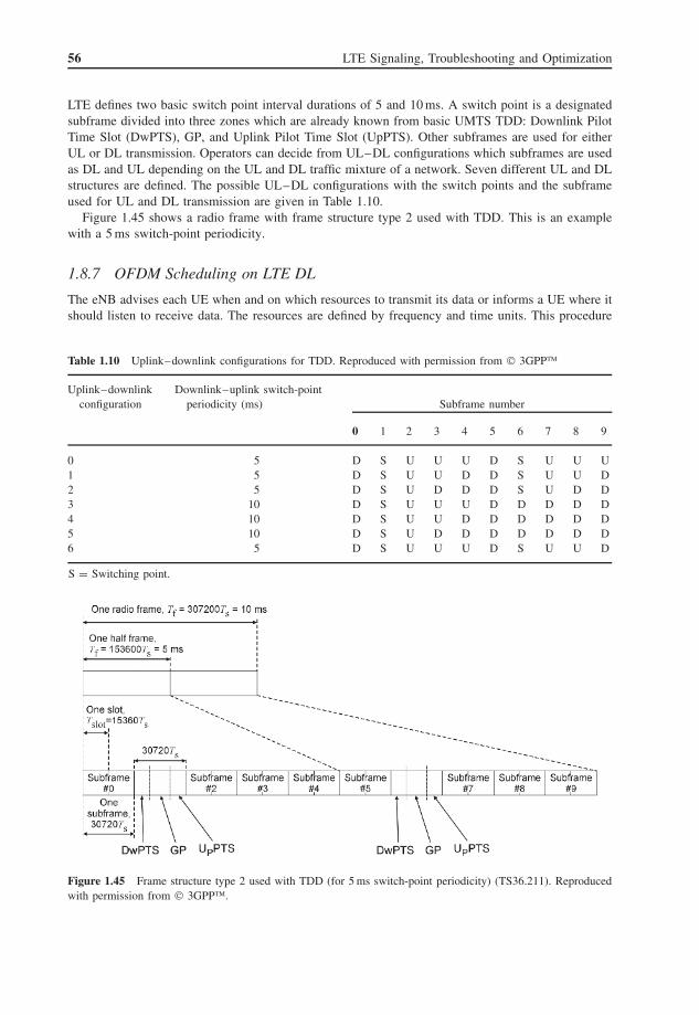
56 LTE Signaling, Troubleshooting and Optimization
LTE defines two basic switch point interval durations of 5 and 10 ms. A switch point is a designatedsubframe divided into three zones which are already known from basic UMTS TDD: Downlink PilotTime Slot (DwPTS), GP, and Uplink Pilot Time Slot (UpPTS). Other subframes are used for eitherUL or DL transmission. Operators can decide from UL–DL configurations which subframes are usedas DL and UL depending on the UL and DL traffic mixture of a network. Seven different UL and DLstructures are defined. The possible UL–DL configurations with the switch points and the subframeused for UL and DL transmission are given in Table 1.10.
Figure 1.45 shows a radio frame with frame structure type 2 used with TDD. This is an examplewith a 5 ms switch-point periodicity.
1.8.7 OFDM Scheduling on LTE DL
The eNB advises each UE when and on which resources to transmit its data or informs a UE where itshould listen to receive data. The resources are defined by frequency and time units. This procedure
Table 1.10 Uplink–downlink configurations for TDD. Reproduced with permission from © 3GPP™
Uplink–downlinkconfiguration
Downlink–uplink switch-pointperiodicity (ms) Subframe number
0 1 2 3 4 5 6 7 8 9
0 5 D S U U U D S U U U1 5 D S U U D D S U U D2 5 D S U D D D S U D D3 10 D S U U U D D D D D4 10 D S U U D D D D D D5 10 D S U D D D D D D D6 5 D S U U U D S U U D
S = Switching point.
Figure 1.45 Frame structure type 2 used with TDD (for 5 ms switch-point periodicity) (TS36.211). Reproducedwith permission from © 3GPP™.

Standards, Protocols, and Functions 57
of assigning system resource is called scheduling. The system resources are divided into units of RBs,as described in Section 1.8.5. Only integer numbers of RBs can be assigned to one user. Localizedand distributed RB allocations are possible. Localized allocations assign adjacent RBs to one UE,distributed allocations distribute the scheduled RBs over the spectrum with gaps, for example, inorder to achieve frequency diversity.
A new scheduling assignment is transmitted for each subframe, thus the scheduling period on thetime axis is 1 ms. The DL scheduling information is transmitted in the PDCCH. The assignments onthe frequency scale vary between one RB (minimal scheduled transmission) and the maximum numberof available RBs in respect of the system bandwidth.
Generally, the LTE scheduling algorithm is not defined by the standard; it is a matter for the eNBvendors. This enables the base station vendors to differentiate between each other and use differentoptimization goals. Various parameters can be used as input for the scheduling decisions: channelquality of different users (measured or reported by the UE with the Channel Quality Indicator, CQI),QoS, congestion/resource situation, fairness, charging policies, and so on. Most schedulers aim tomaximize the cell throughput under consideration of fairness metrics between cell edge users andusers with very good channel conditions. Figure 1.46 shows a screenshot of a typical scheduling andcell resource allocation analysis tool. It gives insight into the scheduling process of the eNB and isable to evaluate the scheduler performance and the utilization of cell resources.
The CQI is reported in the UL direction and can be derived periodically or upon request by theeNB. It gives reception quality feedback to the scheduling algorithm in the eNB in order to schedule
Figure 1.46 Scheduling and cell resource allocation analysis.

58 LTE Signaling, Troubleshooting and Optimization
data on those frequency regions with the best possible reception characteristics. CQI is describedfurther in Section 1.8.11.
The scheduling information is encoded as Downlink Control Information (DCI). The DCI is thenmapped to REGs of the PDCCH. The length of the PDCCH can vary between one and three OFDMsymbols depending on the load to be transmitted on the PDCCH. The number of used OFDM symbolsis indicated in the PCFICH.
The DCI does not just transmit RB assignments and its assignment type, but also other informationneeded for the transmission or reception of data. This information is, for example, the Modulation andCoding Scheme (MCS), HARQ feedback information, or power control commands for UL transmissionof the Physical Uplink Control Channel (PUCCH) or Physical Uplink Shared Channel (PUSCH)(see below).
The following DCI formats are defined and used for scheduling and UL Transmit Power Control(TPC) commands:
• DCI format 0: UL scheduling grant, see Section 1.8.9.• DCI format 1: Single transport block (code word) scheduling assignment, for example, used for
assigning resources to system information, paging, or random access. Further information: MCS,HARQ (New Data Indicator (NDI), redundancy version, HARQ process number), and TPCfor PUCCH.
• DCI format 1A: Compact single transport block scheduling assignment. Further information: MCS,HARQ (NDI, redundancy version, HARQ process number), and TPC for PUCCH.
• DCI format 1B: A special DCI format for transmission mode 6 (MIMO closed loop rank 1 pre-coding). Further information: precoding vector, MCS, HARQ (NDI, redundancy version, HARQprocess number), and TPC for PUCCH.
• DCI format 1C: Even more compact scheduling format as DCI 1A. For example, used for assigningresources to SIBs, paging, or RARs. This DCI is always transmitted using frequency diversity viadistributed virtual resource block assignments using resource allocation type 2 (see below). This isdone because channel feedback cannot be derived for such common information, as it is receivedby multiple users. The modulation is fixed to QPSK. Further information: MCS, HARQ (NDI,redundancy version, HARQ process number), and TPC for PUCCH.
• DCI format 1D: A special DCI format for transmission mode 5 (multi-user MIMO). Further infor-mation: MCS, HARQ (NDI, redundancy version, HARQ process number), power offset indicatorif two UEs share power resources, and TPC for PUCCH.
• DCI format 2: Scheduling for transmission mode 4 (closed loop MIMO), multiple antenna porttransmission operation, addressing multiple transport blocks (code words) to be transmitted ondifferent antenna ports (layers). Further information: MCS for each transport block, HARQ (NDI,redundancy version, HARQ process number), number of transmission layers, precoding, and TPCfor PUCCH.
• DCI format 2A: Used with transmission mode 3 (open loop MIMO using Cyclic Delay Diversity(CDD)), multiple antenna port transmission operation, addressing multiple transport blocks (codewords) to be transmitted on different antenna ports (layers). Further information: MCS for eachtransport block, HARQ (NDI, redundancy version, HARQ process number), number of transmissionlayers, precoding, and TPC for PUCCH.
• DCI format 3: A 2-bit UL TPC command applying for PUSCH and PUCCH. Multiple users areaddressed.
• DCI format 3A: A 1-bit UL TPC command applying for PUSCH and PUCCH. Multiple users areaddressed.
The resource allocation assignments of the above DCI formats can use different resource allocationtypes. Table 1.11 maps the DCI formats to the allowed resource allocation types:

Standards, Protocols, and Functions 59
Table 1.11 Resource allocation types and the applying DCIformats TS36.213. Reproduced with permission from © 3GPP™
Resource allocation type Applying DCI formats
Type 0 1, 2, 2A, and 2BType 1 1, 2, 2A, and 2BType 2 1A, 1B, 1C, and 1D
Table 1.12 Type 0 resource allocationRBG size vs. DL system bandwidth
System bandwidth NDLRB RBG size (P )
≤10 111–26 227–63 364–110 4
• Resource allocation type 0: With resource allocation type 0 a bit map is transmitted describingResource Block Groups (RBGs). A RBG is a number of consecutive physical resource blocks (RBs).The number depends on the system bandwidth and has a range between one and four physical RBs.Table 1.12 maps the size of a RBG to the system bandwidth. The allocated RBGs do not have tobe adjacent.
• Resource allocation type 1: The bit map transmitted with resource allocation type 1 makes usealso of RBGs but can address single physical RBs by introducing additional flags. The number ofRBGs is smaller than the ones used with resource allocation type 0, thus not reaching the completebandwidth. The bit map addresses not whole RBGs, but a subset within each RBG which is pointedto by the bit map. A selection flag indicates the position within the RBG regions and a shift flagshows the position of the numbered RBGs within the system bandwidth as the number of RBGsdoes not address the complete system bandwidth: shift flag = 0 indicates that the RBGs start atthe beginning of the system bandwidth leaving an unaddressable region at the end of the systembandwidth; shift flag = 1 indicates that the RBGs are shifted to the end of the system bandwidthleaving the unaddressable region at the beginning of the system bandwidth.
• Resource allocation type 2: This resource allocation type uses virtual RBs as scheduling units asdescribed in Section 1.8.5. Two types of virtual RB scheduling assignments are used:
– A localized type, where the allocated virtual RBs equal a number of consecutive physical RBsaddressed with a starting RB and a number of adjacently assigned RBs. This information isencoded into an 11-bit Resource Indication Value (RIV).
– A distributed type, where the addressed virtual RBs are distributed over the frequency with oneor two gaps (depending on the system bandwidth) hopping at slot boundaries as described inSection 1.8.5. Virtually distributed RB assignments are always used with DCI format 1C. Thereis a 1-bit flag indicating whether virtual distributed or virtual localized RB assignment is usedin the case of DCI formats 1A, 1B, and 1D.
Instead of addressing a UE with a PDCCH scheduling assignment (DCI) directly by adding a UEID (e.g., a RNTI) to the DCI, the 16-bit CRC of the PDCCH message is scrambled with the RNTI,introducing common and UE-specific search spaces. This CRC scrambling saves additional resources

60 LTE Signaling, Troubleshooting and Optimization
Figure 1.47 Example PDCCH message of DCI format 1 (downlink scheduling assignment).
in DCIs, but increases slightly the chance of decoding a DCI for a different UE which is not intendedto be addressed.
Figure 1.47 depicts an example PDCCH message of DCI format type 1 with all the transmittedinformation.
Some special applications require the transmission of small data chunks in equidistant periodsof time. An example is a VoIP application. In order to minimize the signaling overhead in suchcases, a mode Semi Persistent Scheduling (SRS) is introduced. SPS parameters are configured by theRRC layer, enabling the transmission of data on defined RBs in frequency and time without furtherscheduling on the PDCCH.
Battery energy saving is always an important topic with mobile handset systems. A potentialscheduling assignment could be sent in each PDCCH which occurs every millisecond. Therefore,each attached UE would need to monitor the PDCCH each millisecond for scheduling information.The DRX mode enables the UE just to listen to defined subframes for scheduling assignments and turnoff its receiver in between, in order to save battery consumption. Short and long DRX cycle periodsare defined. The DRX parameters are set by MAC and RRC. Figure 1.48 depicts a DRX cycle.
1.8.8 SC-FDMA Principles and Modulation
The OFDM transmission scheme shows robustness against multipath fading and is especially useful formobile communication systems due to various reasons. An example is the complexity of the receiverwhere fairly simple and channel estimation/equalization is done in the frequency domain. Why isanother transmission scheme selected for the LTE UL? A major disadvantage of OFDM systems is

Standards, Protocols, and Functions 61
UE shall monitoringPDCCH
Figure 1.48 DRX cycle. Reproduced with permission from © 3GPP™.
Figure 1.49 Block diagram of SC-FDMA transmitter with localized mapping to frequency resources.
that the time domain signal which is amplified and transmitted shows a large dynamic range aftermodulating symbols on subcarriers and transformation to a time signal. This leads to a high Peak-to-Average Power Ratio (PARP) of the signal, which should be avoided for battery-powered handsets,which underlies a limit on the budget to justify the business case. The linear transmission of such asignal needs a highly complex RF amplifier for the handsets in order not to run into the nonlinearregion of the transmitter. Additionally, the power consumption is larger compared to a transmitterrunning a smaller linear dynamic range. The PAPR even increases with a wider OFDM bandwidthfor a larger number of modulated subcarriers. This results in another transmission scheme for the UL:Single Carrier FDMA (SC-FDMA).
Actually SC-FDMA is very similar to OFDMA but shows a better PAPR, leading to a longerbattery lifetime and a cost-effective RF amplifier design. Figure 1.49 illustrates the components of aSC-FDMA transmitter system with its block entities. Highlighted in the figure are the main differencesfrom a regular OFDM system. The main difference is the Discrete Fourier Transform (DFT) in thetransmitter and the inverse DFT (iDFT) in the receiver, respectively. Thus, SC-FDMA is sometimescalled DFT-spread-OFDM. Due to this difference, we can picture the information to be transmittedas modulated (bits mapped to two-dimensional QAM symbols with an I and Q component) to a timedomain signal instead of modulating subcarriers of a frequency domain signal. The output of the DFTcan be interpreted as a spectrum of the previously modulated data symbols. This spectrum has thecharacteristic of consecutive modulated subcarriers; it has therefore no scattered spectral distribution.Thus, it has the inherent behavior of localized RE usage as described in Section 1.8.5.
This localized spectrum is now mapped to the consecutive frequency REs which are specifiedin the UL scheduling grant, as only localized frequency resource assignments are allowed with ULtransmission, which refers to the intrinsic signal characteristic of DFT-spread-OFDM. The rest of thespectrum for the full system bandwidth is filled with zeros. This zero patched spectrum is fed to

62 LTE Signaling, Troubleshooting and Optimization
an iFFT unit transforming a full system-wide spectrum “back” to the time domain for transmission.Figure 1.49 shows this mapping of the DFT symbols to the full iFFT width by adding zeros tofrequency positions at the block in the center. The zero patched frequency areas are not used by thisuser and could be assigned to other users transmitting in the same time slot.
As for the future, a current research item is to overcome the lack of a high PAPR of OFDM signalsin such a way that a digital reverse distorted signal is added to the signal which is to be transmitted.The nonlinear distortion is known for a given RF amplifier. Therefore, it is possible to pre-calculatethe distortion applied to the transmitted signal. This distortion is inverted and joined to the signal tosuch a degree that the RF amplifier distortion eliminates the inverted signal again.
1.8.9 Scheduling on LTE UL
The LTE UL scheduling is very similar to the DL scheduling described in Section 1.8.7, although theUL scheduler is a distinct entity. This section describes the difference from the DL scheduling only.
UL scheduling grants are indicated to the UE by transmitting all relevant UL scheduling infor-mation within the PDCCH. This is done by using a dedicated DCI type, DCI 0. Each UE has tomonitor the PDCCH in every subframe for DCI types 0 scrambled with their RNTI (for a messageexample see Figure 1.50). This does not apply for the case when power saving mode DRX is enabled,which switches off the UE’s receiver periodically. UL resources are allocated without a designatedPDCCH UL grant in the case of SPS (see Section 1.8.7) or for non-adaptive HARQ retransmissions.A non-adaptive HARQ retransmission is triggered by the transmission of a Negative Acknowledgment(NACK) by the UE.
In the UL only localized scheduling is allowed, which means that an integer number of consecutiveRBs is allocated to one UE. Furthermore, there is only one scheduling process per UE, thus there isnot a dedicated scheduling process per radio bearer.
The UE feeds the UL scheduler with CQI, Buffer Status Reports (BSRs), ACKs/NACKs, andScheduling Requests (SRs). BSRs indicate the fill level status of the current transmit buffer. Thisbuffer status is reported in bins, quantizing the fill level in bytes. Figure 1.51 shows an example of aMAC BSR message.
Figure 1.50 Example PDCCH message of DCI format 0 (uplink scheduling grant).

Standards, Protocols, and Functions 63
Figure 1.51 Example MAC Buffer Status Report (BSR) message.
LTE trial studies show that there are various cases of scheduled empty UL grants. This happenswhen the eNB assigns UL resources to a UE and the designated UE does not use those UL resourcesfor an UL transmission. Operators should minimize such empty scheduled UL resource in order tooptimize the usage of UL radio resources.
1.8.10 Uplink Slot Structure
The UL slot structure is similar to the DL slot structure. Differences are mainly due to simplifications ofreference symbols, robustness, and physical UL channel multiplexing. A radio frame lasts 10 ms and isdivided into 10 subframes with two slots of 0.5 ms duration as a DL radio frame is split into subframesand slots. Figure 1.52 shows an UL radio frame with its subframe and slot structure. An UL RB has12 subcarriers on the frequency axis and on the time domain it has, seven SC-FDMA symbols per slotwhen normal CP is used, and six SC-FDMA symbols when extended CP is used (see Figure 1.53).
UL synchronization signals are not used because all UL signals from UEs transmitting within thecell are time aligned at the eNB with an UL timing control procedure. The eNB signals a TimingAdvance (TA) command to each UE to track the UL alignment. Timing varies due to the differentspecial distribution of UEs within a cell region. Signals are delayed because of the propagation delay.Firstly, during the random access procedure a total timing offset to the UE is transmitted. After thisthere is a control loop just tracking and signaling differential timing offsets in steps of 0.52 μs (16 × Ts).
The PRACH always uses six consecutive RBs on the frequency axis and is time-wise one subframewide. Which six RBs are used is variable and set in SIB type 2. The PRACH configuration indexis signaled in SIB type 2 as well, which defines the subframes which carry the PRACH’s six RBs.This subframe configuration applies for either even or any radio frame. There are 64 possible PRACHconfiguration index permutations.
Resources at the upper and lower edges of the system bandwidth are used to carry the PUCCH.The frequency resources in between the PUCCH bands are designated to PUSCH transmission.
UL reference signals are used for UL channel estimation. DL reference signals are spread overfrequency and time as single REs, which leads to a two-dimensional spheric channel estimation. UL
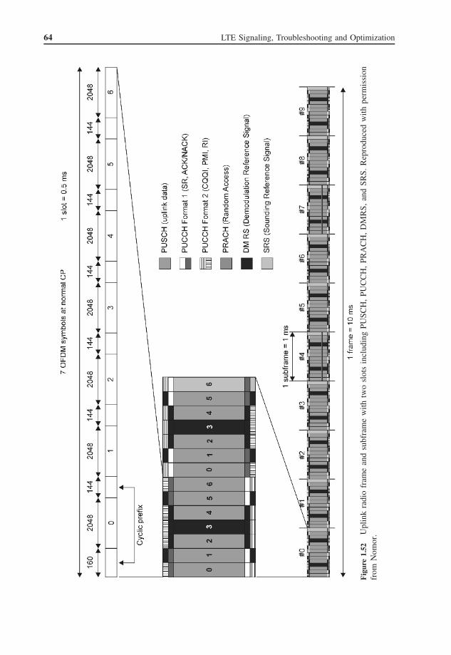
64 LTE Signaling, Troubleshooting and Optimization
Fig
ure
1.52
Upl
ink
radi
ofr
ame
and
subf
ram
ew
ith
two
slot
sin
clud
ing
PUSC
H,
PUC
CH
,PR
AC
H,
DM
RS,
and
SRS.
Rep
rodu
ced
wit
hpe
rmis
sion
from
Nom
or.

Standards, Protocols, and Functions 65
Figure 1.53 Uplink resource grid showing on UL RB. Reproduced with permission from © 3GPP™.
reference signals are similar to TDMA pilots in the middle of each time slot. LTE defines referencesignals in the middle of each slot (on the fourth OFDM symbol assuming normal CP duration) andspanning via the complete allocated frequency range of each UE.
The eNB can instruct UEs to transmit special reference signals over the complete system bandwidth,or parts of it, independently of UL data transmission either on PUSCH or PUCCH. These referencesignals are called Sounding Reference Signals (SRSs). SRSs are used to estimate UL channel qualityof a wider frequency range in order to optimize frequency-selective UL scheduling.

66 LTE Signaling, Troubleshooting and Optimization
Figure 1.52 depicts, in addition to the radio frame, a zoomed UL subframe with a PUCCH andPUSCH example configuration with UL demodulation reference symbols (DMRS) and SRS symbols.
1.8.11 Link Adaptation in LTE
Mobile wireless reception conditions vary greatly over frequency and time as described in Section1.8. In order to cope with these circumstances and guarantee best possible QoS, a procedure is imple-mented known as Adaptive Modulation and Coding (AMC). AMC controls and changes transmissionparameters to achieve a defined Transport Block Error Rate (BLER) of below 10%, in order to keepretransmissions in a suitable range. This is done by adapting the modulation scheme, in LTE on theshared channels between QPSK and 64QAM, and the Forward Error Correction (FEC) coding rate.
Different modulation schemes make the bit detection more robust against noise and other distortioncaused by the wireless channel. Figure 1.54 shows the applied modulation scheme for the LTE sharedchannels. Most robust transmission is achieved by mapping just 2 bits to each modulation symbol asseen with QPSK, resulting in four stages. A large distance between modulation points as seen withQPSK allows a higher probability of the correct decision at the receiver even with noisy receptionconditions. Both 16QAM and 64QAM map 4 and 6 bits respectively to one modulation symbol usedwith better wireless channel conditions to achieve a higher data throughput. It is to find the bestcompromise between the modulation scheme and code rate for a given channel quality. LTE definesa list of MCS combinations and just signals an MCS index.
The data modulated with the different modulation schemes to subcarriers needs to be protectedagainst transmission errors. LTE defines a turbo de-/encoder with trellis termination of a native coderate of one-third. The turbo coder adds redundancy bits to the data, which makes it possible to correctsome bit errors. The code rate is a fraction of source data rate to resulting protected data rate; thus, acode rate of one-third encodes 1 bit into 3 bits. Other code rates are needed in order to optimize thetrade-off between protection and efficiency. This is done by puncturing the native coded bit stream toa higher (less protection) code rate by deterministically leaving out coded bits, or by deterministicallyrepeating coded bits if a smaller code rate is desired (more protection).
Additionally, one parameter being controlled is the UL transmit power. UL power control is imple-mented to deal with the near–far effect. Figure 1.55 shows an UL scenario with a near–far effectcompared to a DL scenario without power differences between user signals as they are equally atten-uated because the mix of the signal is transmitted from one position (eNB). This occurs when a useris close to the base station (near) and another user is far away from the base station, introducing ahigher power path loss which leads to a lower receive power of the signal of the cell edge user. All
Figure 1.54 Different QAM schemes used with LTE and the number of bits mapped to each scheme.

Standards, Protocols, and Functions 67
Figure 1.55 Near–far effect occurring in uplink direction, compared to equal signal strength receptionin downlink.
UL receive signals should have equal power in order to have the same analog-to-digital convertersaturation of each signal to reduce the quantization noise of users with low received signals, reduc-ing inter-subcarrier interference between the users. This happens with imperfect UL synchronizationwithin real-life scenarios.
UL TPC commands are sent via designated DCI formats 3 and 3A. DCI 3 and 3A are differentialpower control commands for PUCCH and PUSCH transmission in steps of decibels. DCI 3 is a 2-bit assignment as opposed to DCI 3A which is a single bit command. These dedicated DCIs withTPC commands are only used when there is no data to be transmitted to the UE; otherwise, theTPC command is transmitted embedded in other control information on the PDCCH for this UE. Aninitial 3-bit TPC command is embedded in the RAR message, see Section 1.8.16. The different TPCcommands are listed in Tables 1.13 and 1.14.
UEs report their received channel quality to the eNB by transmitting a CQI value (see alsoSection 1.8.7). The CQI value represents either a wideband receive quality as a scalar or a moredetailed report about frequency sections (sub-bands) as a vector. CQI reports are transmitted periodi-cally or aperiodically configured by higher layers. Sub-band CQI reports indicate the receive qualityof each sub-band relative to the wideband average with four steps: worse, equal, better, and much

68 LTE Signaling, Troubleshooting and Optimization
Table 1.13 Mapping of TPC command field in DCI format1A/1B/1D/1/2A/2/3 to δPUCCH values. Reproduced with permissionfrom © 3GPP™
TPC command field in DCIformat 1A/1B/1D/1/2A/2/3
δPUCCH (dB)
0 −11 02 13 3
Table 1.14 Mapping of TPC command field in DCI format 3A toδPUCCH values. Reproduced with permission from © 3GPP™
TPC command field in DCIformat 3A
δPUCCH(dB)
0 −11 1
better. The UE reports the best M sub-bands compared to the average channel quality with the bestM method as depicted in Figure 1.56.
The UE should derive a MCS scheme from the above measurement information, which is indexing1 MCS out of 16 to suit the target BLER of below 10%. This enables differentiation between high-and low-cost handsets which use more or less expensive RF hardware and/or a more sophisticated IQsignal processing engine.
Recapitulating, LTE link adaptation uses various stacked link adaptation techniques, securingtransmission, or in order to make it more effective using different control loop delays regarding theprocess’s dimension. The following items summarize the LTE link adaptation functions with theirresponsiveness:
fast
slow
• Adaptive frequency-selective scheduling: Assign frequency resource to UEs on a 1 msbasis, which provides each UE with the individual best reception quality.
• AMC: Obtain the most efficient modulation and FEC code rate in order to balanceretransmissions vs. maximization of throughput.
• HARQ: Multiple retransmission process using prior transmission to increase the correctdecoding probability.
• TPC: Provides UL power control in order to minimize multiple user interference.
1.8.12 Physical Channels in LTE
As indicated in the above sections, LTE uses a completely new transmission scheme and physicallayer design compared to WCDMA, resulting in an entirely new physical channel layout. Main userdata, both control plane and user plane, is transmitted via shared channel architecture. Physical controlchannels control physical layer procedures only.
Physical DL channels and signals are listed below. Physical channels carry user-relevant informationand physical signals do not carry user-specific information, just the SSS.

Standards, Protocols, and Functions 69
Figure 1.56 CQI illustration with sub-bands and best M reporting. Reproduced with permission from Nomor.
Physical DL channels:
• Physical Downlink Shared Channel (PDSCH).• Physical Broadcast Channel (PBCH).• Physical Multicast Channel (PMCH).• Physical Control Format Indicator Channel (PCFICH).• Physical Downlink Control Channel (PDCCH).• Physical HARQ Indicator Channel (PHICH).
DL signals:
• Reference signals.• Synchronization signals:
– Primary Synchronization Signal (PSS).– Secondary Synchronization Signal (SSS).
1.8.12.1 PDSCH
As LTE relies fundamentally on shared channel architecture, the PDSCH carries all data in the DLdirection to the UEs within a cell. RBs with their REs are modulated with user data (MAC PDUs,

70 LTE Signaling, Troubleshooting and Optimization
Packet Data Units) as described in the above sections. The PDSCH bears both control plane (in-band signaling) and user plane data, which is multiplexed on logical channels on the DL-SCH asdescribed in Section 1.8.14. Data is transmitted using adaptive modulation schemes of QPSK, 16QAM,or 64QAM.
UE-specific RRC messages are transmitted with the PDSCH together with user plane packets, andalso with paging and system broadcast information (SIBs).
The different Transmission Modes (TMs) such as, for example, multiple antenna transmission orsingle antenna transmission, apply for the PDSCH only. Different TMs can be used dynamicallybetween UEs signaled within the rrcConnectionSetup message.
Defined TM:
• TM 1: Single antenna transmission.• TM 2: Transmit diversity.• TM 3: Open loop spatial multiplexing (MIMO) using Cyclic Delay Diversity (CDD). The signal
is transmitted on another antenna with a cyclic delay, in order to increase the multipath receptionwhich leads to a MIMO gain.
• TM 4: Closed loop spatial multiplexing (MIMO).• TM 5: Multi-user MIMO (or “virtual” MIMO).• TM 6: Closed loop rank 1 precoding.• TM 7: Beamforming (Space Division Multiple Access (SDMA)) with UE-specific reference
symbols.
Each transport block transmitted on the PDSCH is transmitted with a 24-bit checksum for errordetection.
1.8.12.2 PBCH
The PBCH carries the Master Information Block (MIB), which is transmitted logically in an intervalof 40 ms. FEC is protecting the MIB in such a way that four equal-sized blocks are derived. It ispossible to decode each block individually and retrieve all the information in the MIB. Each block istransmitted in the PBCH resources in every radio frame (see Figure 1.57), thus a MIB is decodableevery 10 ms.
Information being transmitted is mainly the system bandwidth in RBs. An example of a PBCH for5 MHz bandwidth with 25 RBs is shown in Figure 1.58.
Figure 1.57 Master information block encoding and mapping to four DL radio frames.
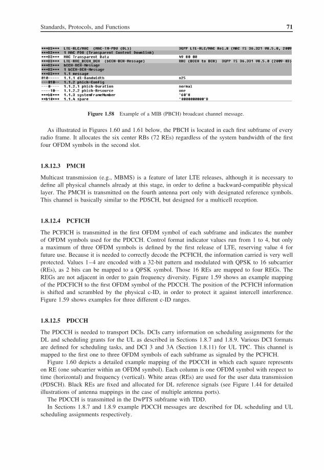
Standards, Protocols, and Functions 71
Figure 1.58 Example of a MIB (PBCH) broadcast channel message.
As illustrated in Figures 1.60 and 1.61 below, the PBCH is located in each first subframe of everyradio frame. It allocates the six center RBs (72 REs) regardless of the system bandwidth of the firstfour OFDM symbols in the second slot.
1.8.12.3 PMCH
Multicast transmission (e.g., MBMS) is a feature of later LTE releases, although it is necessary todefine all physical channels already at this stage, in order to define a backward-compatible physicallayer. The PMCH is transmitted on the fourth antenna port only with designated reference symbols.This channel is basically similar to the PDSCH, but designed for a multicell reception.
1.8.12.4 PCFICH
The PCFICH is transmitted in the first OFDM symbol of each subframe and indicates the numberof OFDM symbols used for the PDCCH. Control format indicator values run from 1 to 4, but onlya maximum of three OFDM symbols is defined by the first release of LTE, reserving value 4 forfuture use. Because it is needed to correctly decode the PCFICH, the information carried is very wellprotected. Values 1–4 are encoded with a 32-bit pattern and modulated with QPSK to 16 subcarrier(REs), as 2 bits can be mapped to a QPSK symbol. Those 16 REs are mapped to four REGs. TheREGs are not adjacent in order to gain frequency diversity. Figure 1.59 shows an example mappingof the PDCFICH to the first OFDM symbol of the PDCCH. The position of the PCFICH informationis shifted and scrambled by the physical c-ID, in order to protect it against intercell interference.Figure 1.59 shows examples for three different c-ID ranges.
1.8.12.5 PDCCH
The PDCCH is needed to transport DCIs. DCIs carry information on scheduling assignments for theDL and scheduling grants for the UL as described in Sections 1.8.7 and 1.8.9. Various DCI formatsare defined for scheduling tasks, and DCI 3 and 3A (Section 1.8.11) for UL TPC. This channel ismapped to the first one to three OFDM symbols of each subframe as signaled by the PCFICH.
Figure 1.60 depicts a detailed example mapping of the PDCCH in which each square representson RE (one subcarrier within an OFDM symbol). Each column is one OFDM symbol with respect totime (horizontal) and frequency (vertical). White areas (REs) are used for the user data transmission(PDSCH). Black REs are fixed and allocated for DL reference signals (see Figure 1.44 for detailedillustrations of antenna mappings in the case of multiple antenna ports).
The PDCCH is transmitted in the DwPTS subframe with TDD.In Sections 1.8.7 and 1.8.9 example PDCCH messages are described for DL scheduling and UL
scheduling assignments respectively.

72 LTE Signaling, Troubleshooting and Optimization
Figure 1.59 Mapping examples of PCFICH into resource element groups (always within the first OFDM symbolof a subframe) within the PDCCH area. Reproduced with permission from Nomor.
UE-specific DCI is addressed to UEs implicitly by scrambling the CRC to save signaling resources.The DCI can be located in various positions, thus UEs have to blind-decode and “search” for theirdesignated information. Twelve common search spaces and 32 UE-specific search spaces are defined,resulting in a worst case of 44 decoding attempts.

Standards, Protocols, and Functions 73
Fig
ure
1.60
Det
aile
dil
lust
rati
onof
one
DL
radi
ofr
ame
for
a1.
4M
Hz
band
wid
thex
ampl
ew
ithm
appi
ngs
ofal
lD
Lph
ysic
alch
anne
lsan
dsi
gnal
s.R
epro
duce
dw
ithpe
rmis
sion
from
Nom
or.

74 LTE Signaling, Troubleshooting and Optimization
Table 1.15 Supported PDCCH formats with different FEC protection.Reproduced with permission from © 3GPP™
PDCCH Number of Number of resource Number offormat CCEs element groups PDCCH bits
0 1 9 721 2 18 1442 4 36 2883 8 72 576
Different PDCCH formats are specified which use different FEC protection code rates in orderto achieve higher protection, for example, for cell edge users with poor reception conditions (seeTable 1.15).
1.8.12.6 PHICH
The PHICH carries HARQ feedback information in the DL to the UEs. In other words, the ACK orNACK of a previous UL transmission is signaled to the sending UE via the PHICH. This feedbackinformation (1 bit) is repeated three times and each triple is orthogonally Walsh spread to fourcomplex symbols. This orthogonal sequence carrying the HARQ feedback information is then robustlymodulated using Binary Phase Shift Keying (BPSK) on REGs within the PDCCH. REGs used by thePHICH are shown in Figure 1.60.
1.8.12.7 Reference Signals
Reference signals are used for estimating the wireless channel leading to distortion of the receivedsignals as described in Section 1.8. The LTE DL uses a two-dimensional spherical channel estimationprocedure on frequency and time. Reference symbols are interleaved in frequency and time as canbe seen in Figure 1.44 which shows the DL reference signal grid for each transmit antenna port.Furthermore, reference signals are depicted in Figure 1.60.
1.8.12.8 PSS
The PSS is a basic signal for synchronizing an LTE cell. It is primarily used for cell search and timeslot synchronization. Zadoff–Chu sequences are used as PSS signals, which are sequences with anamplitude of one and varying phase shifts. Three types of PSS signals are defined, which indicate thephysical c-ID group. Figure 1.62 below shows an example PSS and SSS signal as a screenshot of anIQ sample analysis dashboard. Note that the gray plane shows the IQ layer. In the third dimensionthe occurrence of a specific IQ combination (specific IQ vector) is depicted.
1.8.12.9 SSS
The SSS already carries the first information modulated with BPSK. After synchronizing with theSSS, the mobile has not only retrieved slot and radio frame timing, but also detected the duplexmethod (TDD or FDD), CP length, and the 9-bit physical layer c-ID. Figures 1.61 and 1.62 show thelocation of the synchronization signals within a radio frame and a subframe respectively (Figure 1.61depicts the first subframe of a radio frame with its 14 OFDM symbols in the case of FDD and normalCP). Furthermore, note that both synchronization signals use the centered six RBs of the spectrum,but only use 62 of the 72 REs in order to gain more robustness with this spectral guard gap.

Standards, Protocols, and Functions 75
Figure 1.61 Illustration of the location of the physical broadcast channel and the primary and secondary syn-chronization signals within the first subframe of each radio frame. Reproduced with permission from Nomor.
Occurrence
Occurrence
Figure 1.62 Vector IQ analysis of a primary and secondary synchronization signal on two transmit antennas.
Table 1.16 lists the applied modulation schemes for each DL channel. Physical UL channels:
• Physical Uplink Shared Channel (PUSCH).• Physical Uplink Control Channel (PUCCH).• Physical Random Access Channel (PRACH).

76 LTE Signaling, Troubleshooting and Optimization
Table 1.16 Physical downlink channels and theirmodulation schemes
Physical downlink channel Modulation schemes
PDSCH QPSK, 16QAM, 64QAMPDCCH QPSKPMCH QPSK, 16QAM, 64QAMPHICH BPSKPCFICH QPSKPBCH QPSK
UL signals:
• Reference signal:
– Demodulation Reference Signal (DMRS).– Sounding Reference Signal (SRS).
1.8.12.10 PUSCH
The PUSCH is the physical channel carrying the transport channel UL-SCH. Therefore, UL datatransmission is shared channel based similar to the DL-SCH approach. The eNB assigns UL-SCHresources through UL grants transmitted via the PDCCH, see Section 1.8.9.
All UL higher layer control plane (in-band signaling) and user plane information is sent via thePUSCH using the modulation schemes of QPSK, 16QAM, or 64QAM. UL 64QAM is UE and system(signaled cell wide in an SIB) optional. PUSCH transport blocks are transmitted with a 24-bit CRCchecksum.
Physical layer control information is transmitted via the PUSCH as well, in the case of parallelPUSCH and UL control information transmission.
There is no MIMO defined in the UL direction, therefore the above-mentioned transmission modesdo not apply for PUSCH. The eNB has the option of selecting a transmit antenna port of the UE for thebest reception.
1.8.12.11 PUCCH
UL physical layer control information (UCI) is sent via the PUCCH. The PUCCH resources areallocated at both system bandwidth edges in order to decrease interference and gain frequency diversity.UL control information is:
• HARQ feedback: Inner loop retransmission/reception ACK/NACK feedback.• Precoding Matrix Indicator (PMI): Used with multiple antenna transmission.• SR: Used to request UL resources.• CQI: DL reception quality feedback.• Rank Indicator (RI): Used with multiple antenna transmission.
Figure 1.52 depicts an example PUCCH configuration in the middle of the figure. The mostimportant information is transmitted adjacent to the demodulation reference symbols as the channelestimation here is most accurate.
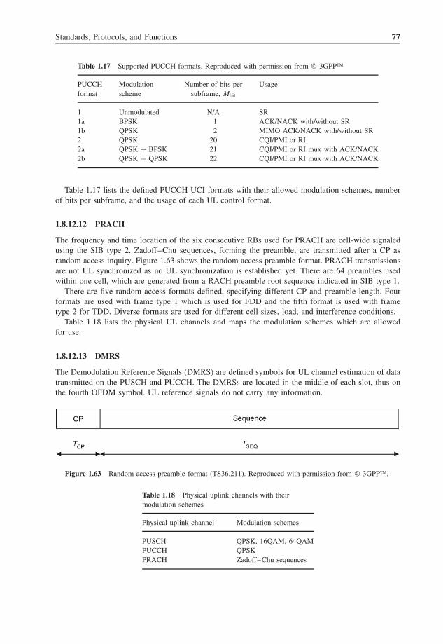
Standards, Protocols, and Functions 77
Table 1.17 Supported PUCCH formats. Reproduced with permission from © 3GPP™
PUCCH Modulation Number of bits per Usageformat scheme subframe, Mbit
1 Unmodulated N/A SR1a BPSK 1 ACK/NACK with/without SR1b QPSK 2 MIMO ACK/NACK with/without SR2 QPSK 20 CQI/PMI or RI2a QPSK + BPSK 21 CQI/PMI or RI mux with ACK/NACK2b QPSK + QPSK 22 CQI/PMI or RI mux with ACK/NACK
Table 1.17 lists the defined PUCCH UCI formats with their allowed modulation schemes, numberof bits per subframe, and the usage of each UL control format.
1.8.12.12 PRACH
The frequency and time location of the six consecutive RBs used for PRACH are cell-wide signaledusing the SIB type 2. Zadoff–Chu sequences, forming the preamble, are transmitted after a CP asrandom access inquiry. Figure 1.63 shows the random access preamble format. PRACH transmissionsare not UL synchronized as no UL synchronization is established yet. There are 64 preambles usedwithin one cell, which are generated from a RACH preamble root sequence indicated in SIB type 1.
There are five random access formats defined, specifying different CP and preamble length. Fourformats are used with frame type 1 which is used for FDD and the fifth format is used with frametype 2 for TDD. Diverse formats are used for different cell sizes, load, and interference conditions.
Table 1.18 lists the physical UL channels and maps the modulation schemes which are allowedfor use.
1.8.12.13 DMRS
The Demodulation Reference Signals (DMRS) are defined symbols for UL channel estimation of datatransmitted on the PUSCH and PUCCH. The DMRSs are located in the middle of each slot, thus onthe fourth OFDM symbol. UL reference signals do not carry any information.
Figure 1.63 Random access preamble format (TS36.211). Reproduced with permission from © 3GPP™.
Table 1.18 Physical uplink channels with theirmodulation schemes
Physical uplink channel Modulation schemes
PUSCH QPSK, 16QAM, 64QAMPUCCH QPSKPRACH Zadoff–Chu sequences

78 LTE Signaling, Troubleshooting and Optimization
1.8.12.14 SRS
The Sounding Reference Signal (SRS) is a signal transmitted upon request by the eNB. It is used forUE-specific UL channel quality also on frequencies which were not used for transmission previously.The eNB requests the UEs to transmit an SRS symbol on parts of the bandwidth or on the completesystem bandwidth. SRS transmission takes place always on the last OFDM symbol of the subframe,if it is requested.
1.8.13 Transport Channels in LTE
The physical layer provides a transport service for MAC PDUs. This service is accessed by transportchannels. Most transport channels are directly mapped to physical channels as described in Section1.8.14. Thus, in other words, transport channels are the gateway to physical channels and a selectionfor MAC PDUs where they are to be transmitted.
The following DL transport channel types are defined:
• Broadcast Channel (BCH):– Uses a static transport format and has the requirement that all UEs within the cell have to receive
its information error-free. The reception of the BCH is mandatory for accessing any service ofa cell.
• DL-SCH:
– Carries all semi-static broadcast information (SIB) and all UE-specific traffic channels.– DL-SCH is secured with HARQ algorithms.– Efficiency is realized with AMC link adaptation.– Various TMs are defined to meet different environment scenarios to increase efficiency in respect
of current conditions.– DRX is available in order to increase handset operating time.– Makes use of spatial algorithms like beamforming or MIMO.
• Paging Channel (PCH):– Needs to be received in complete cell coverage area.– Supports DRX in order to increase battery operating cycle.– Dynamically allocated via own physical identifier (P-RNTI).
• Multicast Channel (MCH):
– Broadcast to entire cell coverage area.– MBMS transmission with use of multiple cells.
A designated DL control channel is not defined as the PDCCH is used for physical channel controlonly. All the higher layer control plane is transmitted via the DL-SCH.
Defined UL transport channel types are shown in the following items:
• UL-SCH:
– UL-SCH is secured with HARQ algorithms.– Fully dynamic and semi-static resource allocation schemes.– Can make use of multi-user MIMO (UL “virtual” MIMO).– Uses dynamic link adaptation like AMC.
• RACH:
– Accessible without UL synchronization.– Collision-based and collision-free operating modes.– Various modes depending on cell size and interference.

Standards, Protocols, and Functions 79
Figure 1.64 Downlink channel mapping and multiplexing from logical channels via transport channels to physicalchannels.
As in the DL direction, no UL control transport channel is defined as all the higher layer con-trol plane is transmitted on the UL-SCH. The PUCCH is a control channel used by the physicallayer only.
1.8.14 Channel Mapping and Multiplexing
Besides physical and transport channels, LTE also defines logical channels. Logical channels aremultiplexed to transport channels within the MAC layer. Logical channels map different contentconnections to transport channels, like CCCHs to multiple UEs or DCCHs to a specific UE or dedicatedtransport channels carrying higher layer application data.
Logical channels are addressed with a logical channel ID. The logical ID is a field within the MACheader PDU. Logical channels are multiplexed by using logical channel IDs to transport channelsspecifying where the information should be transmitted. Finally, transport channels are transferredwith physical channels as a service provided by the physical channel.
Figures 1.64 and 1.65 show the above-described channel architecture from the basic physicalchannels via transport channels to logical channels bearing higher layer messages for DL andUL respectively.
Two basic sets of logical channels are defined:
• Control channels: CCCH and DCCHs.• Traffic channels: CCCH and DTCHs.
The nature of common channels is such that no specific UE is addressed, but the information iseither general for all cell-wide subscribers or a message from a UE which has not yet established adedicated control/traffic channel. A typical example of a CCCH is the broadcast of SIBs.
Traffic channels carry user plane protocols like the Packet Data Convergence Protocol (PDCP) andapplication IP packets, while control channels carry control plane protocols as RRC and NAS.
• DL logical channels:
– Broadcast Control Channel (BCCH).– Paging Control Channel (PCCH).

80 LTE Signaling, Troubleshooting and Optimization
Figure 1.65 Uplink channel mapping and multiplexing from logical channels via transport channels to physicalchannels.
– Common Control Channel (CCCH).– Dedicated Control Channel (DCCH).– Dedicated Traffic Channel (DTCH).
• UL logical channels:
– Common Control Channel (CCCH).– Dedicated Control Channel (DCCH).– Dedicated Traffic Channel (DTCH).
Logical Channel Identifiers (LCIDs) are depicted in Section 1.10.4.
1.8.15 Initial UE Radio Access
Cell search is a procedure for synchronizing time and frequency to a base station sector. Additionally,cell search and synchronization include deriving basic information of the target cell.
LTE defines a hierarchical cell search as it is deployed with WCDMA UMTS. PSS and SSS provideradio frame and slot synchronization, as well as information like the duplex mode TDD or FDD andthe physical layer group and c-ID.
UEs synchronizing to a new LTE cell start searching for a PSS which is a Zadoff–Chu sequence.Three sequences are defined indicating the physical cell group ID. Three physical layer c-ID groupswith 168 physical layer c-IDs each are defined. After successfully detecting the PSS with its physicallayer c-ID group and slot timing, the SSS is decoded which is broadcasted one OFDM symbol priorto the PSS. Now the UE retrieved DL slot, radio frame timing and frequency synchronization. Withdecoding successfully PSS and SSS, it obtained as well the complete 9-bit physical layer c-ID togetherwith the radio frame type (either type 1 for FDD or type 2 for TDD) and the CP length.
Figure 1.66 illustrates the initial steps of cell synchronization and access. After synchronization,the UE is ready to detect and decode the PBCH in order to derive the system bandwidth, PHICHconfiguration, and the current System Frame Number (SFN). Other common system information nowneeds to be retrieved from the DL-SCH. SIBs are scheduled on regular shared channel resources by

Standards, Protocols, and Functions 81
FDD
System InformationBlocks,e.g., UL/RACHconfiguration
Figure 1.66 Initial cell access with level of retrieved information.
using a special C-RNTI = 0xFFFF. SIBs provide general system configuration information like ULconfiguration and random access configuration.
With the procedure described above, the UE is ready to access the random access procedure outlinedin the next section.
1.8.16 UE Random Access
A UE random access is performed not just with the UE initial access to the network, but for variousother reasons. Especially in LTE, the random access procedure is a central UE procedure as thephysical transport channel architecture is shared channel based and only two RRC states are defined:RRC_CONNECTED and RRC_IDLE. FDD and TDD define a common random access procedure.The PRACH is designed in such a way that the same routine and format is used for all cell sizes(long propagation delay and long channel echo spread) and just some configuration parameters canbe changed in order to cope with various cell conditions, as described in Section 1.8.12.

82 LTE Signaling, Troubleshooting and Optimization
The following items outline the events in which a random access procedure should be made:
• At UE initial access.• For RRC connection re-establishment, for example, when radio link failures occur.• When handovers are triggered, usually a contention-free RACH procedure is configured.• In case of no UL synchronization and arrival of DL data.• In case of no UL synchronization and UL data is to be transmitted.• In case UL data is to be transmitted but no PUCCH resources are available to indicate a SR.
Two random access procedures are defined to distinguish an eNB-initiated RACH procedure againsta completely independent RACH access:
• Non-contention based: The eNB assignment of used RACH resources in cases of handover andDL data arrival. Collisions should not occur.
• Contention based: In previously fully unknown RACH resources because of random selection byUEs accessing a cell, for example, initial access or radio link failure. Collisions might occur.
The nature of the PRACH is described in Section 1.8.12. The contention-based RACH procedureis described in the following.
Figure 1.67 illustrates the contention-based RACH procedure with its four messages. A UE selectsa random access preamble and transmits it in the time and frequency resources of the PRACH withinitial RACH power settings derived from SIBs. This is depicted in Figure 1.67 as message 1.
Figure 1.67 Contention-based random access procedure (TS36.300). Reproduced with permission from© 3GPP™.
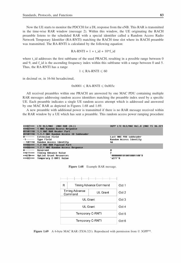
Standards, Protocols, and Functions 83
Now the UE starts to monitor the PDCCH for a DL response from the eNB. This RAR is transmittedin the time-wise RAR window (message 2). Within this window, the UE originating the RACHpreamble listens to the scheduled RAR with a special identifier called a Random Access RadioNetwork Temporary Identifier (RA-RNTI) matching the RACH time slot where its RACH preamblewas transmitted. The RA-RNTI is calculated by the following equation:
RA-RNTI = 1 + t_id + 10*f_id
where t_id addresses the first subframe of the used PRACH, resulting in a possible range between 0and 9, and f_id is the ascending frequency index within this subframe with a range between 0 and 5.Thus, the RA-RNTI has a range
1 � RA-RNTI � 60
in decimal or, in 16-bit hexadecimal,
0x0001 � RA-RNTI � 0x003c
All received preambles within one PRACH are answered by one MAC PDU containing multipleRAR messages addressing random access identifiers matching the preamble index used by a specificUE. Each preamble indicates a single UE random access attempt which is addressed and answeredby one MAC RAR as depicted in Figures 1.68 and 1.69.
A new preamble with additional power is transmitted if there is no RAR message received withinthe RAR window by a UE which has sent a preamble. This random access power ramping procedure
Figure 1.68 Example RAR message.
Figure 1.69 A 6-byte MAC RAR (TS36.321). Reproduced with permission from © 3GPP™.

84 LTE Signaling, Troubleshooting and Optimization
is repeated until a RAR message for its preamble is received or the maximum allowed transmit poweris reached.
An initial timing advance command is calculated by the eNB in order to synchronize all UL trafficto the orthogonal UL slot structure. A first physical layer address, the temp C-RNTI, is assigned tothe UE with the RAR message.
Furthermore, the RAR message carries a 20-bit UL grant field containing the following information:
• Hopping flag – 1 bit.• Fixed size UL resource block assignment for the first scheduled UL transmission in the PUSCH –
10 bits.• Truncated MCS – 4 bits.• TPC command for above scheduled UL transmission – 3 bits.• UL delay – 1 bit.• CQI request – 1 bit.
Other than TPC commands within an established connection (1-bit or 2-bit TPC commands), theTPC command within the MAC RAR message consists of 3 bits addressing the power adjustmentrange, as in Table 1.19.
The first scheduled UL transmission on the PUSCH (RACH contention-based procedure message 3)takes place after decoding the correct RAR message. This RACH procedure message number 3 is,for example, the rrcConnectionRequest in case of a UE initial access and the rrcReestabilishmentafter, for example, a radio link failure or the rrcConfigurationComplete in case of a Hand Over (HO).It is mandatory to use the RACH contention-based procedure in both cases because the eNB cannotassign RACH resources previously in order to prevent RACH collisions.
The contention resolution message number 4 mirrors the RACH procedure message number 3 whichincludes at least a NAS identifier. This message is used to detect collusions as each UE compares itstransmitted message number 2 (message 3 of the RACH procedure as depicted in Figure 1.67) withthe received contention resolution payload field.
A non-contention-based RACH procedure is defined as illustrated in Figure 1.70. This procedureis used in cases of handover and DL data arrival in the UL non-synchronized state.
Message number 0 assigns a random access preamble to the UE which is not broadcast for thecontention-based RACH procedure. This is done on the source eNB triggered by a handover commandvia the X2 interface from the target eNB in the case of handover. It is signaled via the PDCCH onDL data arrival.
The assigned random access preamble is used within the PRACH resources of the target eNB oron PRACH in case of DL data arrival.
Table 1.19 TPC command δmsg2 in RAR forscheduled PUSCH UL grant. Reproduced withpermission from © 3GPP™
TPC command Value (in dB)
0 –61 –42 –23 04 25 46 67 8

Standards, Protocols, and Functions 85
Figure 1.70 Non-contention-based random access procedure. Reproduced with permission from © 3GPP™.
Message number 2 is the RAR message similar to the contention-based procedure but a TempC-RNTI assignment is not mandatory as the UE might already have an RNTI assigned.
Regular UL and DL transmission can take place after the random access procedure as all mandatoryparameters are known by both sides and UL synchronization is established.
1.9 LTE Network Protocol Architecture
1.9.1 Uu – Control/User Plane
The protocol stack used on radio interface Uu is shown in Figure 1.71. The physical layer in this stackis represented by OFDM in the DL and SC-FDMA in the UL. Then we see the MAC protocol that is
Figure 1.71 Protocol stack LTE Uu interface.

86 LTE Signaling, Troubleshooting and Optimization
responsible for mapping the transport channels onto the physical channels, but also for such importanttasks as packet scheduling and timing advance control. RLC provides reliable transport services andcan be used to segment/reassemble large frames. The main purpose of PDCP is the compression oflarger IP headers as well as ciphering of user plane data and integrity protection of both user planeand control plane data.
On top of PDCP the stack is split into the user plane and control plane parts. On the control planeside we see RRC protocol, that is, the expression for the communication between the UE and eNB.RRC provides all the necessary functions to set up, maintain, and release a radio connection for aparticular subscriber. Details of these functions are described in Section 1.10.7.
RRC also serves as a transport protocol for NAS signaling messages. NAS is the expression forthe communication between the UE and MME in which MME represents the core network.
On the user plane side we see IP as the transport layer for end-to-end applications. On the Uu stackthe IP is always end-to-end IP, which means that all these IP packets are transparently routed, oftentunneled through the mobile network. The user plane IP frames we see on Uu are the same IP framesthat can be monitored at SGi reference points before or behind the PDN-GW.
The IP version can be Internet Protocol version 4 (IPv4) or Internet Protocol version 6 (IPv6). Inthe case of VPN (Virtual Private Network) traffic, IPsec will be used.
The applications on top of IP in the user plane stack are all protocols of the TCP/IP suite, suchas the File Transfer Protocol (FTP), HTTP (web-browsing), and POP3/SMTP (for e-mail), but alsoReal-Time Transport Protocol (RTP) and SIP for real-time services like VoIP.
1.9.2 S1 – Control/User Plane
On the S1 reference point the physical layer L1 will in most cases be realized by Gigabit Ethernetcables. L2 in this case will be Ethernet. On top of Ethernet we find IP, but used as a transportprotocol between two network nodes: eNB and MME. This lower layer IP does not represent the userplane frames.
Instead, the user plane IP frames (higher layer IP) are carried by the GTP Tunneling Packet DataUnit (T-PDU). The GTP is responsible for the transport of payload frames through the IP tunnels onS1-U. The transport layer for GTP-U is the User Datagram Protocol (UDP). As IP this protocol maybe found twice in the user plane stack: lower UDP for transport between the eNB and MME andhigher UDP (not shown in Figure 1.72) that is transparently routed through the mobile network as the
Figure 1.72 Protocol stack S1 control/user plane.

Standards, Protocols, and Functions 87
transport protocol for real-time application data. The higher layer IP on top of GTP-U as well as allapplication data on top of this higher layer IP are identical with the user plane information describedin the previous section.
On the control plane side, the Streaming Control Transport Protocol (SCTP) provides reliable trans-port functionality for the very important signaling messages. S1AP is the communication expressionbetween MME and S-GW while NAS – as already explained in the previous section – is used forcommunication between the UE and MME.
1.9.3 X2 – User/Control Plane
On the X2 interface the user plane protocol stack is identical to that of the S1 reference point.However, as shown in Figure 1.73, on the control plane there is a different protocol: X2 ApplicationPart (X2-AP).
The main purpose of X2-AP is to provide inter-eNB handover functionality. It also is used toexchange traffic-related and radio quality measurement reports between different eNBs.
1.9.4 S6a – Control Plane
There is no user plane at the S6a reference point due to the fact that we find here the connectionbetween the MME and HSS, which is a plain signaling communication.
L1, L2, IP, and SCTP shown in Figure 1.74 provide the same functionality as explained in thesection on the S1 protocol stack.
The new player in the S6a stack is the DIAMETER protocol. In the EPC network DIAMETERhas taken over the role of the Mobile Application Part (MAP). It is used to update the HSS about thecurrent location of the subscriber and to provide crucial subscriber attributes stored in HSS databasesto the MME so that network access can be granted and the subscriber’s traffic can be routed accordingto these parameters. DIAMETER is also involved in the security functions of the network: subscriberauthentication, integrity protection, and ciphering.
The protocol stack on S6a is identical to the protocol stack of the S13 reference point between theMME and EIR – in case an EIR exists in the network.
Figure 1.73 Protocol stack X2 control/user plane.

88 LTE Signaling, Troubleshooting and Optimization
Figure 1.74 Protocol stack S6a.
Figure 1.75 Protocol stack S3S4/S5/S8/S10/S11.
1.9.5 S3/S4/S5/S8/S10/S11 – Control Plane/User Plane
At the S3, S4, S5, S8, S10, and S11 reference points we find the same protocol stack as shown inFigure 1.75. The reason is that all these interfaces are used to tunnel IP payload transparently fromone network node to the other. The tunnel management is provided by GTP-C while the IP payloadis transported using GTP-U T-PDUs. Indeed, the user plane protocol stack is the same as on the S1reference point.
Simplifying the functionality of GTP-C, it can be said that this protocol is used to create, modify,and delete user plane tunnels. It also supports mobility of subscribers between core network nodes.
1.10 Protocol Functions, Encoding, Basic Messages, and InformationElements
1.10.1 Ethernet
Ethernet is the typical transport layer protocol in IP networks. It is designed to transmit packets froma sender to a receiver, both identified on behalf of an address information element.
According to this limited functionality, Ethernet has a very small header. The header field(Figure 1.76) contains only the information elements:
• Destination address.• Source address.• Ethernet type.

Standards, Protocols, and Functions 89
Figure 1.76 Ethernet header example.
Ethernet type is similar to a SAPI (Service Access Point Identifier). It contains information aboutwhich higher layer protocol information is transported by Ethernet frames.
The Ethernet addresses, often called MAC addresses (but with nothing in common withRLC/MAC!), consist of 6 bytes. These MAC addresses are fixed hardware addresses and, due to adefined numbering scheme, each address is unique worldwide.
If IP data is to be transmitted using Ethernet the hardware MAC address of the receiver of IP packetsis unknown when the connection starts. Only the target IP address is known. However, since Ethernetis the lowest layer of the connection there must be a source and a destination MAC address includedin each header. In other words, for each sender IP address there is an appropriate sender hardwareaddress, and for each destination IP address there must be an appropriate target hardware address.
The target hardware address that is related to the target IP address is requested by the AddressResolution Protocol (ARP). Its sister protocol, the Reverse Address Resolution Protocol (RARP), canbe used to find the target IP address (or, in terms of ARP/RARP, the target protocol address) to aknown MAC address.
The address resolution procedure consists of two steps:
1. ARP request (req) message with Target Hardware Address = “0” is sent to all(!) IP clients inthe network.
2. The client that has the target protocol address as set in the ARP req message sends ARP Replay (rpl).The sender hardware address in ARP rpl is the Ethernet MAC address related to the destinationIP address that the sender of the ARP req is looking for. An example of the Ethernet addressresolution procedure is shown in Figure 1.77.
1.10.2 Internet Protocol (IPv4/IPv6)
The IP frame is called the datagram and there exist two main versions of the IP: IPv4 and IPv6.
1.10.2.1 IPv4
The IP header has a minimum size of 20 bytes (if no options are used) and a maximum size of 64bytes (including options and padding bits). Due to a set of different options that can be appended tothe IPv4 header, these headers can become very large.
Figure 1.77 Ethernet address resolution.

90 LTE Signaling, Troubleshooting and Optimization
Figure 1.78 IP datagram structure.
The included information elements shown in Figure 1.78 are:
• Version: IP protocol version, here IPv4.• Internet header length (IHL length): The length of the header.• Type of Service: The QoS parameters for IP.• Total Length: The length of the IP frame including header and payload field.• Identification, Fragment Offset: Both used in case of fragmentation/reassembly.• Time to Live: A hop counter to prevent circular routing.• Protocol: Indicates the higher layer protocol that uses IP as the transport layer; typical examples
are ICMP, TCP, UDP.• Source Address: IP address of the sender of the datagram.• Destination Address: IP address of the receiver of the datagram.• Options: For example, the timestamp of each router that the IP packet passed.• Padding: Fill bits to align the header to a multiple of 32 bits.
Since the maximum packet size of an IP datagram can vary from one local network to the next,the IP is equipped with fragmentation/reassembly functionality that allows the transmission of largerframes in series of smaller portions. Figure 1.79 shows an example where a frame with 1600 bytes ofdata is fragmented into two smaller frames with 1480 and 120 bytes of data each. Fragmented framesdo all have the same frame ID (in the example: 1234). As long as more fragments are followingthe first one, the fragmentation flag MF is set to “1.” The last frame in a series of fragments hasfragmentation flag MF = “0,” but a fragmentation offset that is required for proper reassembly on thereceiver side.
IP fragmentation (Figure 1.79) may be found in the user plane data streams, but should be avoidedon interfaces that carry 3GPP signaling.
IPv4 addresses are typically written in the so-called dotted decimal notation, for example,195.24.1.2. There are 32 bits (= 4 bytes) reserved for the address fields in the IP datagram. Eachnumber in the dotted decimal format represents the decimal value of a single byte. The dot “.” isused as the separator between the different bytes of the IP address. Figure 1.80 shows a sampleaddress in binary, hexadecimal, and decimal dotted notation format.

Standards, Protocols, and Functions 91
Figure 1.79 IP fragmentation.
Figure 1.80 Example of IPv4 address format.
1.10.2.2 IPv6
The most important improvements that come with IPv6 are:
• A larger number of possible address values become available. In IPv4 the number of addressesis limited to 32 bits, which means in turn that 232 (≈ 4.3 billion = 4.3 × 10⁹) possible valuescan be addressed. IPv6 provides space for 2128 (= 3.4 × 1038) possible address values. This is animprovement by a factor of 296 and reached by a restructuring of the IP header. In the IPv6 headershown in Figure 1.81, 128 bits (16 bytes) is reserved for source and destination addresses. Thelarger address ranges available for IPv6 will also allow more direct end-to-end packet routing and,hence, less address translation in network nodes is required and the packet routing in the overallnetwork is expected to be faster and more efficient.
• The automatic configuration of dynamically assigned IP addresses is improved and in turn legacyprocedures like DHCP (Dynamic Host Configuration Protocol) become unnecessary.

92 LTE Signaling, Troubleshooting and Optimization
Figure 1.81 IPv6 header format.
• IPv6 supports Mobile IP, simplifies renumbering (change of dynamically assigned IP addresses),and allows multihoming of subscribers. The purpose of multihoming is to increase the reliability ofInternet connections by using two different Internet service providers simultaneously. If the accessto one of the providers is interrupted a redirection of packets via the second connection is possible.Mobile IP means that the subscriber always gets the same IP address assigned, no matter if workingat home or traveling around.
• IPsec is integrated into IPv6 to achieve a higher security of IP data transmission, while back inIPv4 no security functions were provided at all.
• All in all, the basic header of IPv6 has a simpler structure compared to the header of IPv4. Althoughthe overall header size is larger than in IPv4 (40 bytes, most of them occupied by the longer IPaddresses), there are less basic header fields.
• For the version, the decimal number 6 is encoded as binary bit sequence “0110.”• The IPv6 traffic class indicates the packet priority and should not be mistaken for the traffic
class QoS element introduced in 3GPP standards that classifies the throughput sensitivity and delaysensitivity of application services. IPv6 traffic class priority values subdivide into two ranges: traffic,where the source provides congestion control, and non-congestion control traffic.
• The flow label is used for QoS management and encoded in 20 bits. Packets having the same flowlabel value will be treated with the same priority and reliability. This is important for the routingof packets that contain real-time service data.
• The payload length indicates the size of the payload in octets and is encoded in 16 bits. Whencleared to zero, the option is a “Jumbo Payload” (hop by hop). The size of the basic header isnot counted by the payload length, but the optional header extensions are included. So payloadlength + 40 bytes (of basic header) = total length of the IPv6 packet.
• The next header information element specifies the next upper layer protocol of the transportedpayload such as UDP and TCP. The values are compatible with those specified for the IPv4protocol field (8 bits). The next header information can also point to optional extension headers. Inthis case the upper layer payload protocol is not indicated by this field.
• The hop limit field (8 bits) indicates the maximum number of routers that are allowed to be involvedin routing an IPv6 packet. It replaces the time to live field of IPv4. If the hop limit reaches thevalue “zero” the packet will be discarded by the router.
• Source and destination addresses, 128 bits each, represent the sender and receiver of the IPv6datagram.
IPv6 addresses are normally written as eight groups of 16 bits, where each group is separated bya colon (:). For example, 2001:0db8:85a3:0000:0000:8a2e:0370:7334 is a valid IPv6 address.

Standards, Protocols, and Functions 93
To shorten the writing and presentation of addresses, several simplifications to the notationare permitted. Any leading zeros in a group may be omitted; thus, the given example becomes:2001:db8:85a3:0:0:8a2e:370:7334.
Also, one or any number of consecutive groups of value 0 may be replaced with two colons (::):2001:db8:85a3::8a2e:370:7334.
It is possible to use IPv6 addresses in the URL notation format. In this case the IPv6 addressinformation is enclosed in square brackets:
http://[2001:0db8:85a3:08d3:1319:8a2e:0370:7344]/.
The brackets prevent that part of the IPv6 address being misinterpreted as port number information.A URL including IPv6 address and port number looks like this:
http://[2001:0db8:85a3:08d3:1319:8a2e:0370:7344]:8080/.
1.10.3 Stream Control Transmission Protocol (SCTP)
Originally the SCTP was defined as a transport protocol for SS7 messages to be transmitted over IPnetworks. As TCP and UDP it is seen as a layer 4 transport protocol in the ISO OSI model.
The SCTP frames are called chunks. All chunks are associated to a connection that guarantees in-order delivery. However, within the same chunk there might be data blocks of different connectionstransmitted simultaneously. In addition, it is also possible to send urgent packets “out of order” witha higher priority.
SCTP also supports multihoming scenarios where one host owns multiple valid IP addresses.Besides the data streams, SCTP frequently sends heartbeat messages to test the state of connection.How SCTP works will be demonstrated by means of an example. Figure 1.82 shows the message
flow required to transport the NAS signaling message Attach Request from the eNB to MME acrossthe S1 interface.
After setting up a RRC connection on the Uu interface between the UE and the eNB, the UE sendsthe attach request message. When the appropriate RRC transport container is received by the eNB, theestablishment of a dedicated SCTP stream on the S1 interface as shown in Figure 1.82 is triggered.
The establishment of the SCTP stream starts with a SCTP initiation message. It will always be sentby the eNB in the case of the attach procedure, because the RRC connection is established earlier andthe request to transport the NAS message triggers the request to have a S1 connection. The SCTPinitiation message contains the IP addresses of both the eNB and MME. The individual subscriberfor which this connection is established is represented by a unique pair of SCTP source port anddestination port numbers.
The SCTP initiation needs to be acknowledged by the peer SCTP entity in the MME. In the nextstep a SCTP cookie echo message is sent and acknowledged by Cookie Echo ACK. In the protocolworld, this is called a heartbeat procedure. Such a procedure periodically checks the availability andfunction of the active connection. Similar functions with other message names are found, for example,in SS7 SCCP Inactivity Test or GTP Echo Request/Response.
On SCTP higher layer messages are transported using SCTP datagram (SCTP DTGR) packets. EachSCTP DTGR contains a Transaction Sequence Number (TSN) in addition to source and destinationaddress information. This TSN will later be used by the peer entity to acknowledge the successfulreception of the DTGR by sending an SCTP selective ACK message on S1 that confirms error-freereception of the SCTP DTGR that carried the attach request message. Further S1AP and NAS messagesof this connection will be transported in the same way and the Cookie Echo/Cookie Echo ACKs willbe sent periodically as long as the connection remains active.

94 LTE Signaling, Troubleshooting and Optimization
Figure 1.82 SCTP example.
If the S1 signaling transport layer SCTP has problems in offering proper functionality, there willbe no signaling transport on S1 if the problems are located in the eNB SCTP entity. If the MMEsuffers from congestion or protocol errors on the SCTP level as shown in Figure 1.83, the expectedselective ACK messages will be missing (maybe not sent at all, maybe sent with a TSN out of theexpected range). This malfunction may be detected by a NACK Cookie Echo and as a result theconnection will be terminated. Or the attach accept message expected to be received by the UE willbe missed. The missing attach accept message will be recognized by the UE where a timer is guardingthe NAS procedures. After the guard timer expires on the UE side the attach request message willbe repeatedly sent up to n times (the counter value of n is configurable and typically signaled onthe broadcast channel SIBs; the default value recommended by 3GPP is n = 5). If neither an attachrequest message nor an attach reject message is received by the UE the handset will go back to IDLEwhen the maximum number of attach request repetitions has been sent.
1.10.4 Radio Interface Layer 2 Protocols
LTE splits the layer 2 into three sublayers: MAC layer, RLC layer, and PDCP layer. Figure 1.84illustrates the layer 2 architecture for DL and Figure 1.85 that for UL.
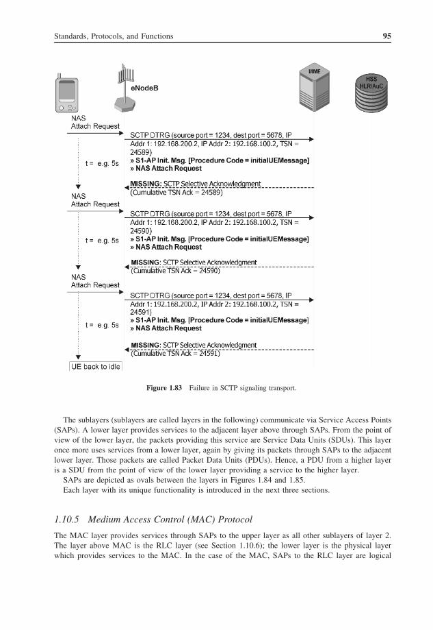
Standards, Protocols, and Functions 95
Figure 1.83 Failure in SCTP signaling transport.
The sublayers (sublayers are called layers in the following) communicate via Service Access Points(SAPs). A lower layer provides services to the adjacent layer above through SAPs. From the point ofview of the lower layer, the packets providing this service are Service Data Units (SDUs). This layeronce more uses services from a lower layer, again by giving its packets through SAPs to the adjacentlower layer. Those packets are called Packet Data Units (PDUs). Hence, a PDU from a higher layeris a SDU from the point of view of the lower layer providing a service to the higher layer.
SAPs are depicted as ovals between the layers in Figures 1.84 and 1.85.Each layer with its unique functionality is introduced in the next three sections.
1.10.5 Medium Access Control (MAC) Protocol
The MAC layer provides services through SAPs to the upper layer as all other sublayers of layer 2.The layer above MAC is the RLC layer (see Section 1.10.6); the lower layer is the physical layerwhich provides services to the MAC. In the case of the MAC, SAPs to the RLC layer are logical

96 LTE Signaling, Troubleshooting and Optimization
Figure 1.84 Layer 2 structure for DL (TS36.300). Reproduced with permission from © 3GPP™.
Figure 1.85 Layer 2 structure for UL (TS36.300). Reproduced with permission from © 3GPP™.
channels. Logical channels are used by higher layers to differentiate between logical connectionswhich may use different metrics, for example, in terms of quality or delay, and so on. Furthermore,logical channels are used to distinguish control plane connections, either CCCHs or DCCHs, fromuser plane connections (DTCHs).

Standards, Protocols, and Functions 97
Table 1.20 Values of LCID for DL-SCH.Reproduced with permission from © 3GPP™
Index LCID values
00000 CCCH00001–01010 Identity of the logical channel01011–11011 Reserved11100 UE contention resolution identity11101 Timing advance command11110 DRX command11111 Padding
Table 1.21 Values of LCID for UL-SCH.Reproduced with permission from © 3GPP™
Index LCID values
00000 CCCH00001–01010 Identity of the logical channel01011–11001 Reserved11010 Power headroom report11011 C-RNTI11100 Truncated BSR11101 Short BSR11110 Long BSR11111 Padding
Services provided by the physical layer to the MAC layer are granted via another type of SAP.SAPs between the MAC and the physical layer are transport channels. Transport channels match dataunits to physical channels in which data is supposed to be transmitted. One exception is the PCHwhich is multiplexed into the PDSCH identified with the P-RNTI = 0xFFFE.
Multiplexing of data units from logical channels to transport channels is one of the tasks of theMAC layer. Logical channels are differentiated with LCIDs. Tables 1.20 and 1.21 show the definedLCIDs and their values for DL and UL respectively. A CCCH always has LCID = 0. Other UEdedicated channels start with LCID = 1.
A MAC PDU consists of a MAC payload part and a MAC header part. The MAC payload conveysmultiple units of MAC control elements and MAC SDUs from higher layers. Therefore, the MACheader is also divided into sub-headers depending on the units carried in the MAC payload as MACsub-headers describe the MAC payload units. There are various possible combinations of MAC controlelements, MAC SDUs, and MAC padding derivatives. An example of a MAC PDU with a combinationof MAC sub-headers, MAC control elements, and MAC SDUs in the payload section is depictedin Figure 1.86.
Logical channels which are multiplexed to transport channels are prioritized by the schedulingalgorithm. The scheduling algorithm decides what to schedule on which physical resources as describedin detail for DL scheduling in Section 1.8.6 and UL scheduling in Section 1.8.9. There is only oneMAC entity per UE; thus, the UL within the UE has one MAC entity and the eNB executes multipleparallel MAC entities in the DL direction in case the eNB has to handle multiple UEs (as seen inFigures 1.84 and 1.85).

98 LTE Signaling, Troubleshooting and Optimization
Figure 1.86 Example of MAC PDU consisting of MAC header, MAC control elements, MAC SDUs, and padding(TS36.321). Reproduced with permission from © 3GPP™.
The MAC layer implements a soft combining N -process stop-and-wait FEC and detection mech-anism, or HARQ (Hybrid Automatic Repeat Request). Transport blocks are protected with a FECalgorithm known as turbo codes. Soft combining means not correctly decoded blocks are not acknowl-edged in order to conduct a retransmission, but the previous received not decoded block is held ina soft buffer to be recombined with the new retransmission. This process of soft combining two ormore receptions increases the chance that the last received retransmission can be decoded error-free.
1.10.6 Radio Link Control (RLC) Protocol
The RLC layer uses SAPs of the MAC layer which are logical channels. Those SAPs are used to inductits RLC PDUs from the RLC entities. The RLC layer instead provides basically three types of SAPsto the PDCP layer above the RLC layer. The SAPs provide access to the three operating modes toconvey data PDUs, either the control plane or user plane: Transparent Mode (TM), UnacknowledgedMode (UM), and Acknowledged Mode (AM). Basic operating entities of the RLC layer are depictedin Figure 1.87.
1.10.6.1 RLC Transparent Mode (TM)
The TM transmits PDUs from the upper layer transparently, which means that the RLC layer isbasically just storing and forwarding those PDUs. No feedback is requested on whether the dataunits were delivered or not. Furthermore, packets are transparently forwarded by keeping them at thesame size.
Figure 1.88 illustrates a transmitting and a receiving RLC TM entity.The TM is used to transmit cell-wide channels as UE paging and the broadcast of system infor-
mation. It is a typical mode for point-to-multipoint connections without any feedback from receivers.Additionally, CCCHs (LCID = 0) are sent by using the RLC TM.
1.10.6.2 RLC Unacknowledged Mode (UM)
In contrast to the TM, the UM adds segmentation and concatenation of PDUs. This processingstep fits higher layer PDUs to the current available transport block size indicated by lower layers.
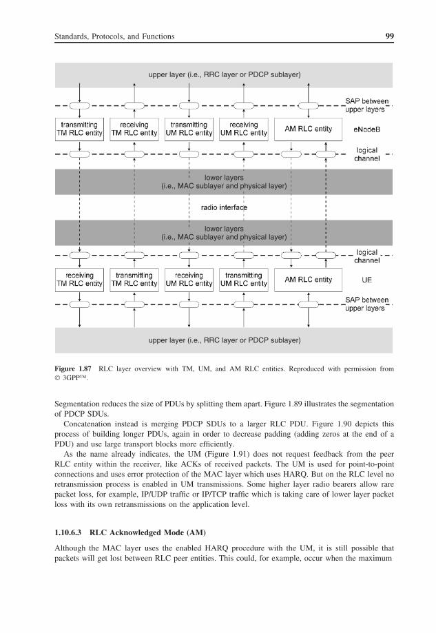
Standards, Protocols, and Functions 99
upper layer (i.e., RRC layer or PDCP sublayer)
upper layer (i.e., RRC layer or PDCP sublayer)
lower layers(i.e., MAC sublayer and physical layer)
lower layers(i.e., MAC sublayer and physical layer)
Figure 1.87 RLC layer overview with TM, UM, and AM RLC entities. Reproduced with permission from© 3GPP™.
Segmentation reduces the size of PDUs by splitting them apart. Figure 1.89 illustrates the segmentationof PDCP SDUs.
Concatenation instead is merging PDCP SDUs to a larger RLC PDU. Figure 1.90 depicts thisprocess of building longer PDUs, again in order to decrease padding (adding zeros at the end of aPDU) and use large transport blocks more efficiently.
As the name already indicates, the UM (Figure 1.91) does not request feedback from the peerRLC entity within the receiver, like ACKs of received packets. The UM is used for point-to-pointconnections and uses error protection of the MAC layer which uses HARQ. But on the RLC level noretransmission process is enabled in UM transmissions. Some higher layer radio bearers allow rarepacket loss, for example, IP/UDP traffic or IP/TCP traffic which is taking care of lower layer packetloss with its own retransmissions on the application level.
1.10.6.3 RLC Acknowledged Mode (AM)
Although the MAC layer uses the enabled HARQ procedure with the UM, it is still possible thatpackets will get lost between RLC peer entities. This could, for example, occur when the maximum

100 LTE Signaling, Troubleshooting and Optimization
Figure 1.88 Model of two Transparent Mode peer entities. Reproduced with permission from © 3GPP™.
Figure 1.89 Example of RLC segmentation of PDCP SDUs into MAC PDUs. The MAC Payload is equivalentto RLC PDUs.
Figure 1.90 Example of RLC concatenation of several PDCP SDUs into one MAC PDU.

Standards, Protocols, and Functions 101
Figure 1.91 Model of two Unacknowledged Mode peer entities. Reproduced with permission from © 3GPP™.
number of retransmissions of the HARQ process is reached. Thus, the AM introduces a secondaryouter loop ARQ with ACK feedback from the receiving RLC entity in order to conduct retransmissionsof lost packets. Two stacked ARQ loops, fast retransmissions of HARQ, and the outer loop ARQ ofthe RLC AM lead to good protection for point-to-point DTCHs or DCCHs (used, for example, forRRC and NAS packets).
Furthermore, segmentation and concatenation are applied with the AM as with the UM in order tofit PDU sizes. Figure 1.92 illustrates RLC entities in the AM with the information flow through thedifferent functions.
1.10.7 Packet Data Convergence Protocol (PDCP)
Located above the RLC layer is the PDCP layer. The PDCP layer provides direct data transportfor control plane messages (RRC and NAS) and for user plane packets. User plane packets areapplication layer IP packets as LTE defines only packet-based (IP) data communication. Thus, voiceor video service is always IP based (VoIP).
SAPs above the PDCP layer are radio bearers which are mapped to TM, UM, or AM SAPs of theRLC layer below. Figure 1.93 depicts the systematic functions and services of the PDCP layer.
Sequence numbering ensures in-sequence delivery of SDUs for the user plane and control planeof disordered delivered packets of lower layers. Different sequence number lengths are defined: 5, 7,and 12 bits. The 5-bit sequence numbers are reserved for Signaling Radio Bearers (SRBs) carrying
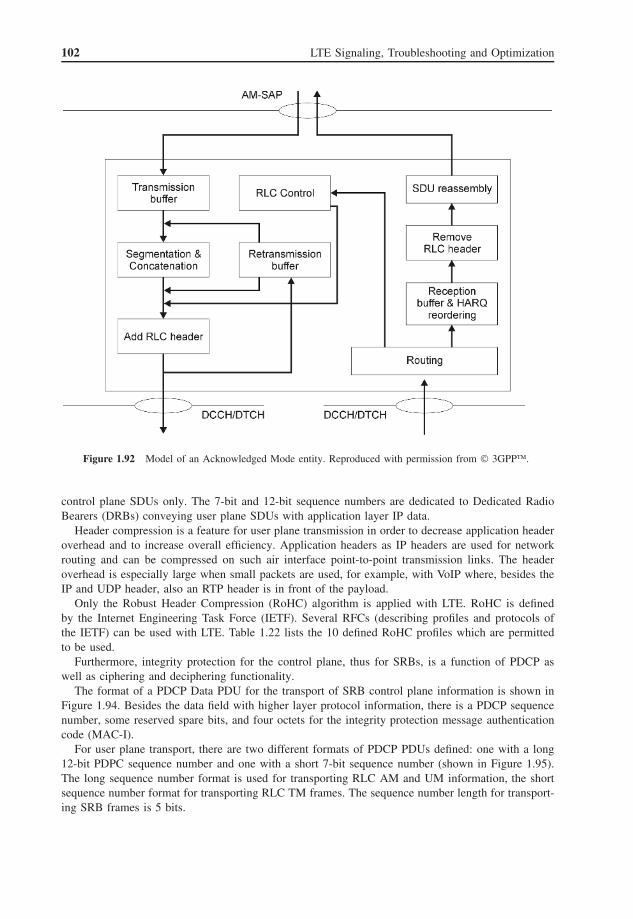
102 LTE Signaling, Troubleshooting and Optimization
Figure 1.92 Model of an Acknowledged Mode entity. Reproduced with permission from © 3GPP™.
control plane SDUs only. The 7-bit and 12-bit sequence numbers are dedicated to Dedicated RadioBearers (DRBs) conveying user plane SDUs with application layer IP data.
Header compression is a feature for user plane transmission in order to decrease application headeroverhead and to increase overall efficiency. Application headers as IP headers are used for networkrouting and can be compressed on such air interface point-to-point transmission links. The headeroverhead is especially large when small packets are used, for example, with VoIP where, besides theIP and UDP header, also an RTP header is in front of the payload.
Only the Robust Header Compression (RoHC) algorithm is applied with LTE. RoHC is definedby the Internet Engineering Task Force (IETF). Several RFCs (describing profiles and protocols ofthe IETF) can be used with LTE. Table 1.22 lists the 10 defined RoHC profiles which are permittedto be used.
Furthermore, integrity protection for the control plane, thus for SRBs, is a function of PDCP aswell as ciphering and deciphering functionality.
The format of a PDCP Data PDU for the transport of SRB control plane information is shown inFigure 1.94. Besides the data field with higher layer protocol information, there is a PDCP sequencenumber, some reserved spare bits, and four octets for the integrity protection message authenticationcode (MAC-I).
For user plane transport, there are two different formats of PDCP PDUs defined: one with a long12-bit PDPC sequence number and one with a short 7-bit sequence number (shown in Figure 1.95).The long sequence number format is used for transporting RLC AM and UM information, the shortsequence number format for transporting RLC TM frames. The sequence number length for transport-ing SRB frames is 5 bits.

Standards, Protocols, and Functions 103
Figure 1.93 Functional overview of the PDCP layer (TS36.323). Reproduced with permission from © 3GPP™.
Table 1.22 Supported header compression protocols and profiles.Reproduced with permission from © 3GPP™
Profile Usage Referenceidentifier
0x0000 No compression RFC 49950x0001 RTP/UDP/IP RFC 3095, RFC 48150x0002 UDP/IP RFC 3095, RFC 48150x0003 ESP/IP RFC 3095, RFC 48150x0004 IP RFC 3843, RFC 48150x0006 TCP/IP RFC 49960x0101 RTP/UDP/IP RFC 52250x0102 UDP/IP RFC 52250x0103 ESP/IP RFC 52250x0104 IP RFC 5225

104 LTE Signaling, Troubleshooting and Optimization
Figure 1.94 Format of PDCP data PDU for transport of signaling radio bearer information. Reproduced withpermission from © 3GPP™.
Figure 1.95 Format of PDCP data PDU for transport of user plane information. Reproduced with permissionfrom © 3GPP™.
The D/C field is used to distinguish between user plane (D) and control plane (C) data carriedby PDCP.
1.10.8 Radio Resource Control (RRC) Protocol
The RRC protocol is responsible for the setup, reconfiguration, and release of the radio interfaceconnection. This includes the setup, modification, and release of SRBs, default and dedicated radiobearers, along with the necessary QoS control and initial security activation. Also the paging of UEsto request establishment of mobile terminated connections is a function of RRC. To provide network-specific access parameters, RRC system information is broadcasted by all cells of the network. TheUE uses RRC to report a set of various measurements to the eNB. Some of these measurement reportscan trigger intra-LTE or inter-RAT handover and RRC is in charge of all these mobility procedures.As a special function that is required to support the best possible “always-on” scenario, RRC comeswith an error recovery function that allows a dropped RRC connection to be re-established quickly.Similar functionality, called RRC re-establishment, was introduced with RRC used in 3G UTRAN.
Although the functions of LTE RRC are almost the same as for 3G UTRAN RRC, far fewer signalingmessages have been defined for LTE RRC. So at first sight LTE RRC looks simpler. The trick used bythe standard definition group is that it has defined only dedicated messages for RRC connection setup,release, reconfiguration, and re-establishment, but in fact the LTE RRC reconfiguration procedureis a very complex process that combines all functions covered by the 3G UTRAN RRC protocolprocedures, namely physical channel reconfiguration, transport channel reconfiguration, radio bearer

Standards, Protocols, and Functions 105
setup, radio bearer reconfiguration, radio bearer release, and RRC measurement control. Consequently,it is now very difficult in LTE to find out what exactly is reconfigured.
1.10.8.1 RRC States
In contrast to 3G UMTS where four different RRC states have been defined, LTE recognizes onlytwo RRC states, which means that the radio connection between the UE and network can be eitheractive or not active (as was known from GSM).
In the RRC_IDLE state the radio connection is inactive. The UE mobility is not under controlof the network and the UE does not need to send any measurement reports for updating, althoughit performs neighbor cell measurement for cell (re)selection. However, the UE monitors the PCH todetect incoming calls and it also monitors system information broadcast on the BCCH. This is themost important part of the system information, typically the MIB, since in LTE the larger part ofsystem information is not signaled on the BCH but on the DL-SCH.
In the RRC_CONNECTED state the UE is able to send and receive data in the UL and DL direction.It measures the DL radio quality of neighbor cells and sends RRC measurement reports according tothe measurement configuration received from the MME. However, it is the eNodeB, and the MME,that are respectively in charge of making handover decisions and triggering handover execution whennecessary. The UE continues to monitor the PCH to detect incoming calls. In the RRC_CONNECTEDmode all system information sent on the DL-SCH, especially SIB 1 which contains information aboutchange of system parameters, is readable by the UE.
When it is necessary to perform inter-RAT mobility, there will be a transition from LTE RRC statesto UTRA or GSM states as illustrated in Figure 1.96.
Figure 1.96 RRC state transitions in case of inter-RAT mobility. Reproduced with permission from © 3GPP™.
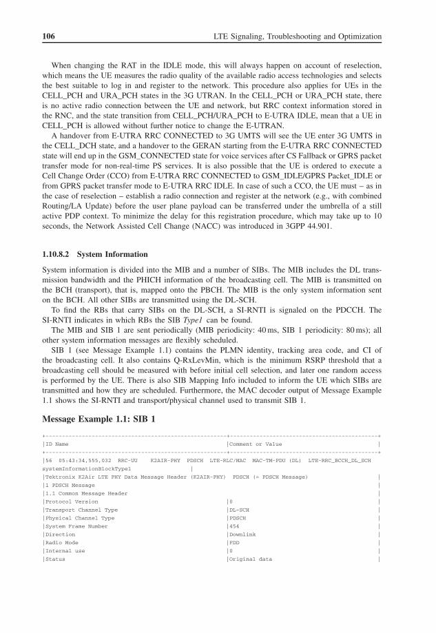
106 LTE Signaling, Troubleshooting and Optimization
When changing the RAT in the IDLE mode, this will always happen on account of reselection,which means the UE measures the radio quality of the available radio access technologies and selectsthe best suitable to log in and register to the network. This procedure also applies for UEs in theCELL_PCH and URA_PCH states in the 3G UTRAN. In the CELL_PCH or URA_PCH state, thereis no active radio connection between the UE and network, but RRC context information stored inthe RNC, and the state transition from CELL_PCH/URA_PCH to E-UTRA IDLE, mean that a UE inCELL_PCH is allowed without further notice to change the E-UTRAN.
A handover from E-UTRA RRC CONNECTED to 3G UMTS will see the UE enter 3G UMTS inthe CELL_DCH state, and a handover to the GERAN starting from the E-UTRA RRC CONNECTEDstate will end up in the GSM_CONNECTED state for voice services after CS Fallback or GPRS packettransfer mode for non-real-time PS services. It is also possible that the UE is ordered to execute aCell Change Order (CCO) from E-UTRA RRC CONNECTED to GSM_IDLE/GPRS Packet_IDLE orfrom GPRS packet transfer mode to E-UTRA RRC IDLE. In case of such a CCO, the UE must – as inthe case of reselection – establish a radio connection and register at the network (e.g., with combinedRouting/LA Update) before the user plane payload can be transferred under the umbrella of a stillactive PDP context. To minimize the delay for this registration procedure, which may take up to 10seconds, the Network Assisted Cell Change (NACC) was introduced in 3GPP 44.901.
1.10.8.2 System Information
System information is divided into the MIB and a number of SIBs. The MIB includes the DL trans-mission bandwidth and the PHICH information of the broadcasting cell. The MIB is transmitted onthe BCH (transport), that is, mapped onto the PBCH. The MIB is the only system information senton the BCH. All other SIBs are transmitted using the DL-SCH.
To find the RBs that carry SIBs on the DL-SCH, a SI-RNTI is signaled on the PDCCH. TheSI-RNTI indicates in which RBs the SIB Type1 can be found.
The MIB and SIB 1 are sent periodically (MIB periodicity: 40 ms, SIB 1 periodicity: 80 ms); allother system information messages are flexibly scheduled.
SIB 1 (see Message Example 1.1) contains the PLMN identity, tracking area code, and CI ofthe broadcasting cell. It also contains Q-RxLevMin, which is the minimum RSRP threshold that abroadcasting cell should be measured with before initial cell selection, and later one random accessis performed by the UE. There is also SIB Mapping Info included to inform the UE which SIBs aretransmitted and how they are scheduled. Furthermore, the MAC decoder output of Message Example1.1 shows the SI-RNTI and transport/physical channel used to transmit SIB 1.
Message Example 1.1: SIB 1
+-------------------------------------------------------+---------------------------------------------+
|ID Name |Comment or Value |
+-------------------------------------------------------+---------------------------------------------+
|56 05:43:34,555,032 RRC-UU K2AIR-PHY PDSCH LTE-RLC/MAC MAC-TM-PDU (DL) LTE-RRC_BCCH_DL_SCH
systemInformationBlockType1 |
|Tektronix K2Air LTE PHY Data Message Header (K2AIR-PHY) PDSCH (= PDSCH Message) |
|1 PDSCH Message |
|1.1 Common Message Header |
|Protocol Version |0 |
|Transport Channel Type |DL-SCH |
|Physical Channel Type |PDSCH |
|System Frame Number |454 |
|Direction |Downlink |
|Radio Mode |FDD |
|Internal use |0 |
|Status |Original data |

Standards, Protocols, and Functions 107
|Reserved |0 |
|Physical Cell ID |0 |
|UE ID/RNTI Type |SI-RNTI |
|Subframe Number |5 |
|UE ID/RNTI Value |'ffff'H |
|1.2 PDSCH Header |
|CRC report |CRC ok |
|HARQ process number |0 |
|Reserved |0 |
|Transport Block Indicator |single TB info |
|Reserved |0 |
|1.2.1 Transport Block#1 Information |
|Transport Block#1 Size |144 |
|Modulation Order DL 1 |QPSK |
|New Data Indicator DL 1 |new data |
|Redundancy Version DL 1 |1 |
|Reserved |0 |
|Modulation Scheme Index DL 1 |5 |
|Reserved |0 |
|1.2.2 Transport Block Data |
|TB1 Mac-PDU Data |40 51 00 21 00 00 20 00 10 0c 14 01 10
21 00 68 22 b6 |
|Padding |'0068'H |
|1.3 Additional Call related Info |
|Number Of Logical Channel Informations |1 |
|1.3.1 Logical Channel Information |
|LCID |0 |
|RLC Mode |Transparent Mode |
|Radio Bearer ID |0 |
|Radio Bearer Type |Control Plane (Signalling) |
|Spare |0 |
|Spare |0 |
|Logical Channel Type |BCCH |
|Call ID |'fffffff5'H |
|3GPP LTE-RLC/MAC Rel.8 (MAC TS 36.321 V8.5.0, 2009-03, RLC TS 36.322 V8.5.0, 2009-03) (LTE-RLC/
MAC) MAC-TM-PDU (DL) (= MAC PDU (Transparent Content Downlink)) |
|1 MAC PDU (Transparent Content Downlink) |
|MAC Transparent Data |40 51 00 21 00 00 20 00 10 0c 14 01 10
21 00 68 22 b6 |
|RRC (BCCH DL SCH) 3GPP TS 36.331 V8.5.0 (2009-03) (LTE-RRC_BCCH_DL_SCH)
systemInformationBlockType1 (= systemInformationBlockType1) |
|bCCH-DL-SCH-Message |
|1 message |
|1.1 Standard |
|1.1.1 systemInformationBlockType1 |
|1.1.1.1 cellAccessRelatedInfo |
|1.1.1.1.1 plmn-IdentityList |
|1.1.1.1.1.1 pLMN-IdentityInfo |
|1.1.1.1.1.1.1 plmn-Identity |
|1.1.1.1.1.1.1.1 mcc |
|1.1.1.1.1.1.1.1.1 mCC-MNC-Digit |2 |
|1.1.1.1.1.1.1.1.2 mCC-MNC-Digit |9 |
|1.1.1.1.1.1.1.1.3 mCC-MNC-Digit |9 |
|1.1.1.1.1.1.1.2 mnc |
|1.1.1.1.1.1.1.2.1 mCC-MNC-Digit |0 |
|1.1.1.1.1.1.1.2.2 mCC-MNC-Digit |0 |
|1.1.1.1.1.1.2 cellReservedForOperatorUse |notReserved |
|1.1.1.1.2 trackingAreaCode |'0000'H |
|1.1.1.1.3 cellIdentity |'2000100'H |
|1.1.1.1.4 cellBarred |notBarred |
|1.1.1.1.5 intraFreqReselection |notAllowed |

108 LTE Signaling, Troubleshooting and Optimization
|1.1.1.1.6 csg-Indication |false |
|1.1.1.2 cellSelectionInfo |
|1.1.1.2.1 q-RxLevMin |-65 |
|1.1.1.3 freqBandIndicator |1 |
|1.1.1.4 schedulingInfoList |
|1.1.1.4.1 schedulingInfo |
|1.1.1.4.1.1 si-Periodicity |rf16 |
|1.1.1.4.1.2 sib-MappingInfo |
|1.1.1.4.2 schedulingInfo |
|1.1.1.4.2.1 si-Periodicity |rf32 |
|1.1.1.4.2.2 sib-MappingInfo |
|1.1.1.4.2.2.1 sIB-Type |sibType3 |
|1.1.1.4.2.2.2 sIB-Type |sibType6 |
|1.1.1.4.3 schedulingInfo |
|1.1.1.4.3.1 si-Periodicity |rf32 |
|1.1.1.4.3.2 sib-MappingInfo |
|1.1.1.4.3.2.1 sIB-Type |sibType5 |
|1.1.1.5 si-WindowLength |ms20 |
|1.1.1.6 systemInfoValueTag |22 |
SIB 2 contains timers and constants, barring information, UL frequency information, and ULbandwidth information. SIB 3 contains parameters for the cell reselection procedure. SIB 4 containsneighbor cell information for intra-frequency cell reselection. SIB 5 contains information for inter-frequency cell reselection. SIB 6 contains information for inter-RAT cell reselection to the UTRAN.SIB 7 contains information for inter-RAT cell reselection to the GERAN. SIB 8 contains informa-tion for inter-RAT cell reselection to CDMA2000. SIB 9 is used to broadcast the home eNB name(HNB name). SIB 10 and SIB 11 can be used to broadcast warning information to subscribers (e.g.,tsunami warnings).
1.10.8.3 RRC Measurements
As in 3G UTRAN, the RRC measurement reports are expected to be sent mostly as event-triggeredreports. The events listed in Table 1.23 have been specified so far (3GPP 36.331 v.8.9.0 2010-03).
The thresholds mentioned in the event description refer either to RSRP or RSRQ measurements.This is specified when the measurement is set up. To ensure that only significant changes of the radioquality are reported, the measurements are guarded with the additional parameters of hysteresis, offset,and time-to-trigger. The hysteresis parameter is used to eliminate ping-pong effects in measurementreporting as shown in Figure 1.97. Here the events A1 and A2 will only be reported for the servingcell measured by UE 1, but not for the serving cell of UE 2.
Table 1.23 RRC measurement event IDs and description
Event ID Description
A1 Serving becomes better than thresholdA2 Serving becomes worse than thresholdA3 Neighbor becomes offset better than servingA4 Neighbor becomes better than thresholdA5 Serving becomes worse than threshold 1 and neighbor
becomes better than threshold 2B1 Inter-RAT neighbor becomes better than thresholdB2 Serving becomes worse than threshold 1 and
inter-RAT neighbor becomes better than threshold 2

Standards, Protocols, and Functions 109
Figure 1.97 Hysteresis parameter for RRC measurements.
Figure 1.98 Offset parameter for RRC measurements.
The offset parameter (see Figure 1.98) is not related to a predefined threshold, like hysteresis, butto the actual measurement result. The offset can have positive or negative values. The purpose ofusing the offset parameter is to speed up or slow down handover in/from strong/weak cells.
Time-to-trigger should prevent short-time peaks of measured signals from triggering measurementreports and subsequent handover procedures. Looking at Figure 1.99, the setting of the time-to-triggerparameter prevents a handover to cell 2, where the radio quality would have dropped quickly backto below the required threshold. Instead the call can be handed over to cell 1 after A1’s report is

110 LTE Signaling, Troubleshooting and Optimization
Figure 1.99 Time-to-trigger parameter for RRC measurements.
sent, knowing that cell 1 offers not just a radio quality above the required threshold, but also stableradio conditions.
1.10.9 Non-Access Stratum (NAS) Protocol
1.10.9.1 EPS Mobility Management and Connection Management States
On the NAS layer there are two EPS Mobility Management (EMM) states defined to describe the resultsof mobility management procedures like Attach and Tracking Area Update. The EMM states are:
• EMM-DEREGISTERED.• EMM-REGISTERED.
The UE in the EMM-DEREGISTERED state is not attached to the network. From the MME’s pointof view, there is no active context for a UE, no routing information, and no location information.
After a successful attach the UE enters the EMM-REGISTERED state. Now the MME knows whereto page the UE and the HSS is able to provide routing information for mobile terminating connectionsof this particular subscriber. In the EMM-REGISTERED state the UE always has an active PDNconnection and EPS security context.
The ECM states indicate if there is an active signaling connectivity between the UE and the EPC.The ECM states are:
• ECM-IDLE.• ECM-CONNECTED.
The location of a UE in the ECM-IDLE state is known by the network on behalf of the currentTracking Area List. This list contains all tracking areas for which the UE performed successful initialregistration (attach) to the network and subsequent successful tracking area update procedures. All

Standards, Protocols, and Functions 111
tracking areas in a Tracking Area List to which a UE is registered must be connected to the sameMME (according to 3GPP 23.401).
A UE is in the ECM-IDLE state when no active NAS signaling connection between the UE andnetwork exists. In other words, there are no SRBs assigned to this mobile. If the UE changes itsgeographic position it may perform cell selection/reselection when necessary.
The UE and MME should enter the ECM-CONNECTED state whenever the UE sends or MMEreceives one of the following NAS messages: Attach Request, Tracking Area Update Request, ServiceRequest, or Detach Request.
When the UE is in the ECM-IDLE state it is possible that the UE and the network have differentsets of established EPS bearers stored in their system memory. When the UE and MME enter theECM-CONNECTED state, the set of EPS bearers is synchronized between the UE and network.
ECM state and EMM state do not strictly depend on each other. For instance, a UE can be inECM-IDLE, but EMM-REGISTERED. However, a UE can also be in ECM-CONNECTED while inEMM-DEREGISTERED, yet this happens during the radio connection for initial registration. Firstly,the UE must enter ECM-CONNECTED to send Attach Request, and only if Attach Accept is sentback by the network does this UE enter EMM-REGISTERED.
1.10.10 S1 Application Part (S1AP)6
The S1AP is used for the protocol dialog between the MME and eNB. Here its first function is toestablish a relation between these two network elements, known in the protocol standard documentas the S1 setup procedure. A set of S1AP management messages is further used to maintain thisconnection, change configuration parameters, indicate possible errors and overload situations, balancethe load, and reset, re-establish, or release the connection.
Once the relation between the eNB and MME is successfully established, UEs camping on the cellsof this eNB can be paged using the S1AP to establish mobile terminating connections or can registerand set up mobile originating calls by themselves. In the case of such a registration of connectionsetup procedure, the S1AP provides functions for transparent forwarding of NAS messages. Duringconnection setup the S1AP is in charge of the tunnel management of S1-U GTP tunnels. Using theS1AP signaling procedure, these S1 user plane tunnels can be established, modified according tochanging QoS parameters, and released. The S1-U GTP tunnels are part of the E-RAB and in factit is the S1AP that provides full E-RAB management functions. Setup and modification of E-RABsare always triggered by the MME, while the release of E-RABs can be triggered by both the MMEand eNB.
In using the S1AP during initial registration and connection setup, an S1 UE context is establishedin the eNB. Each S1AP connection related to a particular UE is identified by a pair of MME UES1AP ID and eNB UE S1AP ID. These connection identifiers link all S1AP messages belonging to asingle subscriber except paging messages (i.e., sent before the UE context is established). Table 1.24shows the occurrence of the UE S1AP IDs in the different UE-related messages of this protocol.
Messages that are used to establish and maintain the relation between the MME and eNB on thenetwork element level, like the messages of the S1 setup procedure, do not contain any UE ID.
As can be seen in Table 1.24, the S1AP is also responsible for different mobility functions. Belong-ing to this category is the path switch procedure, that is, a handover between eNBs connected tothe same MME. Inter-MME handover and inter-RAT handover are executed using the set of S1APhandover messages – for more details on this topic see Chapter 2 in this book.
E-RABs can be set up, modified, and released at any time during an active connection. Hence,separate E-RAB management messages are provided by the S1AP.
6 Parts of this chapter are reproduced with permission from © 3GPP™.

112 LTE Signaling, Troubleshooting and Optimization
Table 1.24 S1AP UE IDs in UE-related messages
S1-AP UE related messages MME UE S1AP ID eNB UE S1AP ID
E-RAB setup Request × ×E-RAB setup Response × ×E-RAB Modify Request × ×E-RAB Modify Response × ×E-RAB Release Command × ×E-RAB Release Response × ×E-RAB Release Indication × ×Initial Context Setup Request × ×Initial Context Setup Response × ×Initial Context Setup Failure × ×UE Context Release Request × ×UE Context Release Command (optionally there
is only the MME UE S1AP ID)× × (but optional)
UE Context Release Complete × ×UE Context Modification Request × ×UE Context Modification Response × ×UE Context Modification Failure × ×Handover Required × ×Handover Command × ×Handover Preparation Failure × ×Handover request × NoHandover request acknowledge × ×Handover Failure × NoHandover Notify × ×Path Switch Request No ×Path Switch Request acknowledge × ×Path Switch Request Failure × ×Handover Cancel × ×Handover Cancel acknowledge × ×eNB Status Transfer × ×MME Status Transfer × ×Paging No NoInitial UE Message No ×Uplink NAS Transport × ×Downlink NAS Transport × ×NAS Non delivery indication × ×LOCATION REPORTING CONTROL × ×LOCATION REPORT FAILURE INDICATION × ×LOCATION REPORT × ×
In addition, there are messages for the transmission of broadcast warning messages and for locationreporting. The S1AP location report will keep the MME update about the ID of the serving cellcurrently used by the UE.
Looking a little deeper into the protocol details of the S1AP, it emerges that there are twoclasses of S1AP elementary procedures. Class 1 procedures are characterized by the fact that theinitiating message should be answered with a successful or unsuccessful outcome message. The

Standards, Protocols, and Functions 113
Table 1.25 S1AP Class 1 elementary procedures. Reproduced with permission from © 3GPP™
Elementary Initiating messageprocedure Successful outcome Unsuccessful outcome
Response message Response message
HandoverPreparation
HANDOVERREQUIRED
HANDOVERCOMMAND
HANDOVERPREPARATION FAILURE
HandoverResourceAllocation
HANDOVERREQUEST
HANDOVERREQUESTACKNOWLEDGE
HANDOVER FAILURE
Path switchREquest
PATH SWITCHREQUEST
PATH SWITCHREQUESTACKNOWLEDGE
PATH SWITCHREQUEST FAILURE
HandoverCancellation
HANDOVERCANCEL
HANDOVERCANCELACKNOWLEDGE
–
E-RAB SETup E-RAB SETUPREQUEST
E-RAB SETUPRESPONSE
–
E-RABMODify
E-RAB MODIFYREQUEST
E-RAB MODIFYRESPONSE
–
E-RABRELease
E-RAB RELEASECOMMAND
E-RAB RELEASERESPONSE
–
Initial ContextSetup
INITIAL CONTEXTSETUP REQUEST
INITIAL CONTEXTSETUP RESPONSE
INITIAL CONTEXTSETUP FAILURE
Reset RESET RESETACKNOWLEDGE
–
S1 SETUP S1 SETUP REQUEST S1 SETUP RESPONSE S1 SETUP FAILUREUE Context
ReleaseUE CONTEXT
RELEASECOMMAND
UE CONTEXTRELEASECOMPLETE
–
UE ContextModification
UE CONTEXTMODIFICATIONREQUEST
UE CONTEXTMODIFICATIONRESPONSE
UE CONTEXTMODIFICATIONFAILURE
eNBconfigurationupdate
ENBCONFIGURATIONUPDATE
ENB UPDATECONFIGURATIONACKNOWLEDGE
ENB CONFIGURATIONUPDATE FAILURE
MMEConfigurationUpdate
MMECONFIGURATIONUPDATE
MMECONFIGURATIONUPDATEACKNOWLEDGE
MME CONFIGURATIONUPDATE FAILURE
Write-ReplaceWarning
WRITE-REPLACEWARNINGREQUEST
WRITE-REPLACEWARNINGRESPONSE
–
complete list of Class 1 elementary procedures and messages according to 3GPP 36.4313 is givenin Table 1.25.
Class 1 elementary procedures are characterized by the fact that each request sent is positively ornegatively acknowledged by an appropriate success or failure message.
As known from UTRAN RANAP, there is a difference between message names used in standarddocuments and encoding of these messages following ASN.1 encoding rules. An example will be

114 LTE Signaling, Troubleshooting and Optimization
given using the encoding of messages of the handover preparation procedure that is defined in theASN.1 part of 3GPP 36.413 as follows:
handoverPreparation S1AP-ELEMENTARY-PROCEDURE ::= {
INITIATING MESSAGE HandoverRequired
SUCCESSFUL OUTCOME HandoverCommand
UNSUCCESSFUL OUTCOME HandoverPreparationFailure
PROCEDURE CODE id-HandoverPreparation
CRITICALITY reject
}
Translated into a written explanation, this ASN.1 notation means the handover required mes-sage will be encoded as Initiating Message with the procedure code = “id-HandoverPreparation,” thehandover command message will be encoded as Successful Outcome with the procedure code = “id-HandoverPreparation,” and Handover Preparation Failure will be encoded as Unsuccessful Outcomewith the procedure code = “id-HandoverPreparation.”
In contrast to the Class 1 message, the messages of Class 2 are unidirectional messages that are notexplicitly acknowledged by the receiving entity. The complete list of Class 2 procedures and messagesaccording to 3GPP 26.314 is given in Table 1.26.
Call scenarios, message examples, and the most important parameters of S1AP messages aredescribed in Chapter 2 of this book.
Table 1.26 S1AP Class 2 elementary procedures. Reproduced with permission from © 3GPP™
Elementary procedure Message
Handover Notification HANDOVER NOTIFYE-RAB Release Request E-RAB RELEASE REQUESTPaging PAGINGInitial UE MEssage INITIAL UE MESSAGEDownlink NAS TRansport DOWNLINK NAS TRANSPORTUplink NAS Transport UPLINK NAS TRANSPORTNAS non delivery indication NAS NON DELIVERY INDICATIONError Indication ERROR INDICATIONUE Context Release Request UE CONTEXT RELEASE REQUESTDownlink S1 CDMA2000 Tunneling DOWNLINK S1 CDMA2000 TUNNELINGUplink S1 CDMA2000 Tunneling UPLINK S1 CDMA2000 TUNNELINGUE Capability Info Indication UE CAPABILITY INFO INDICATIONeNB Status Transfer eNB STATUS TRANSFERMME Status Transfer MME STATUS TRANSFERDeactivate Trace DEACTIVATE TRACETrace Start TRACE STARTTrace Failure Indication TRACE FAILURE INDICATIONLocation Reporting Control LOCATION REPORTING CONTROLLocation Reporting Failure Indication LOCATION REPORTING FAILURE INDICATIONLocation Report LOCATION REPORTOverload Start OVERLOAD STARTOverload Stop OVERLOAD STOPeNB Direct Information Transfer eNB DIRECT INFORMATION TRANSFERMME Direct Information Transfer MME DIRECT INFORMATION TRANSFER

Standards, Protocols, and Functions 115
Figure 1.100 UDP datagram.
1.10.11 User Datagram Protocol (UDP)
UDP is a connection-less transport protocol (ISO OSI Model Layer 4), that is, a member of the IPfamily. UDP is used to transmit higher data quickly from one end of a connection to the other. Thesource and destination port information elements in the UDP datagram header identify the applicationson top of UDP. In the example shown in Figure 1.100 the higher layer application is GTP, so thissample UDP frame is lower layer UDP as can be found on all interfaces of the mobile network thatallow tunneling of IP payload.
1.10.12 GPRS Tunneling Protocol (GTP)7
GTP is used on various EPC interfaces. Its main functionality is to create, modify, and delete tunnelsfor IP payload transport. However, besides the tunnel management functionality, the GTP controlplane protocol also offers functions and messages for:
• Path management.• Mobility management.• CS fallback.• Non-3GPP-related access.• Trace management.
Table 1.27 gives an overview of all GTP messages. As in the S1AP we see message pairs ofconnection-oriented procedures, for instance Create Session Request/Create Session Response. How-ever, there is also a set of connectionless unidirectional messages like Modify Bearer Command.
It should further be noticed that the name of a message often indicates who initiates a connec-tion setup or change of connection parameters. If there is a connection set up by the mobile, thecreate session procedure will be used to activate the default bearer. If the network requests a bearerestablishment it will perform the create bearer procedure. The same differentiation can be seen inthe case of bearer modification: a modification requested by the UE side will be performed usingthe modify bearer procedure; a modification requested by the network is executed using the updatebearer procedure.
All in all, the use of GTP on various interfaces in the EPC has the advantage of simplified protocolstacks. This is also an advantage for NEMs, because the implementation effort for network elementprotocol entity software can be reduced due to the fact that the same or very similar code can be usedto program the software, for example, S-GW and PDN-GW. However, for measurement equipmentmanufacturers like Tektronix Communications the simplified protocol stacks make it harder to trackmessages of a single connection across multiple interfaces. Additional algorithms in the software
7 Parts of this chapter are reproduced with permission from © 3GPP™.

116 LTE Signaling, Troubleshooting and Optimization
Table 1.27 GTP messages. Reproduced with permission from © 3GPP™
Message type Message Reference GTP-C GTP-Uvalue (decimal)
0 Reserved – – –1 Echo Request – × ×2 Echo Response – × ×3 Version Not Supported Indication – × –4–24 Reserved for S101 interface TS 29.276 [14] – –25–31 Reserved for Sv interface TS 29.280 [15] – –
SGSN/MME to PGW (S4/S11, S5/S8)32 Create Session Request – × –33 Create Session Response – × –34 Modify Bearer Request – × –35 Modify Bearer Response – × –36 Delete Session Request – × –37 Delete Session Response – × –38 Change Notification Request – × –39 Change Notification Response – × –40–63 For future use – – –
Messages without explicit response64 Modify Bearer Command
(MME/SGSN to PGW – S11/S4, S5/S8)– × –
65 Modify Bearer Failure Indication(PGW to MME/SGSN – S5/S8, S11/S4)
– × –
66 Delete Bearer Command(MME to PGW – S11, S5/S8)
– × –
67 Delete Bearer Failure Indication(PGW to MME – S5/S8, S11)
– × –
68 Bearer Resource Command(MME/SGSN to PGW – S11/S4, S5/S8)
– × –
69 Bearer Resource Failure Indication(PGW to MME/SGSN – S5/S8, S11/S4)
– × –
70 Downlink Data Notification Failure Indication(SGSN/MME to S-GW – S4/S11)
– × –
71 Trace Session Activation – × –72 Trace Session Deactivation – × –73 Stop Paging Indication – × –74–94 For future use – – –
PGW to SGSN/MME (S5/S8, S4/S11)95 Create Bearer Request – × –96 Create Bearer Response – × –97 Update Bearer Request – × –98 Update Bearer Response – × –99 Delete Bearer Request – × –100 Delete Bearer Response – × –101–127 For future use – – –
MME to MME, SGSN to MME, MME toSGSN, SGSN to SGSN (S3/10/S16)
128 Identification Request – × –129 Identification Response – × –130 Context Request – × –
(continued overleaf )

Standards, Protocols, and Functions 117
Table 1.27 (continued )
Message type Message Reference GTP-C GTP-Uvalue (decimal)
131 Context Response – × –132 Context Acknowledge – × –133 Forward Relocation Request – × –134 Forward Relocation Response – × –135 Forward Relocation Complete Notification – × –136 Forward Relocation Complete Acknowledge – × –137 Forward Access Context Notification – × –138 Forward Access Context Acknowledge – × –139 Relocation Cancel Request – × –140 Relocation Cancel Response – × –141 Configuration Transfer Tunnel – × –142–148 For future use – – –
SGSN to MME, MME to SGSN (S3)149 Detach Notification – × –150 Detach Acknowledge – × –151 CS Paging Indication – × –152 RAN Information Relay – – –153–159 For future use – – –
MME to S-GW (S11)160 Create Forwarding Tunnel Request – × –161 Create Forwarding Tunnel Response – × –162 Suspend Notification – × –163 Suspend Acknowledge – × –164 Resume Notification – × –165 Resume Acknowledge – × –166 Create Indirect Data Forwarding Tunnel Request – × –167 Create Indirect Data Forwarding Tunnel Response – × –168 Delete Indirect Data Forwarding Tunnel Request – × –169 Delete Indirect Data Forwarding Tunnel Response – × –170 Release Access Bearers Request – × –171 Release Access Bearers Response – × –172–175 For future use – – –
S-GW to SGSN/MME (S4/S11)176 Downlink Data Notification – × –177 Downlink Data Notification Acknowledgement – × –178 Update Bearer Complete – × –179–191 For future use – – –
Other192–255 For future use – – –
are necessary to program call trace functions (filter and sequence messages belonging to a singleconnection) and to correlate performance measurement statistical counters and measurement with thedifferent network elements. In other words, in the past it was quite clear that the GTP-C protocolwas only used on the Gn interface between SGSN and GGSN. Now, in EPC, the GTP-C protocol isfound on many different interfaces and a bunch of different network elements are using it. Further, astate-of-the-art protocol tester or network monitoring system is required to detect automatically whichinterfaces and network elements are monitored.

118 LTE Signaling, Troubleshooting and Optimization
Figure 1.101 GTP path management.
1.10.12.1 Path Management
The path management messages are used to check the activity status of a GTP tunnel on behalf ofa heartbeat check mechanism. The messages involved in this procedure are GTP Echo Request andGTP Echo Response as shown in Figure 1.101.
GTP Echo Request is sent with a sequence number that is expected to be received again in anGTP Echo Response sent by the peer entity. The sending of Echo Request is triggered by a timer, butshould not happen more often than one Echo Request in 60 seconds for each GTP tunnel.
The functions of the non-3GPP-related access ensure interworking (handover) between E-UTRANand the CDMA2000 HRDP radio access network.
Trace management is a term that covers all necessary functions to track the activities of selectedsubscribers. The trace functionality can be used for network element troubleshooting or legalinterception.
The path management heartbeat messages are found on both GTP-C and GTP-U connections.
1.10.12.2 Tunnel Management
The create session request message should be sent on the S11 interface by the MME to the S-GW,and on the S5/S8 interface by the S-GW to the PDN GW as part of the procedure:
• E-UTRAN initial attach.• UE requested PDN connectivity.
The message should also be sent on the S11 interface by the MME to the S-GW in case the S-GWis changed due to mobility. In such cases the create session procedure is embedded in a tracking areaupdate or handover/relocation procedure.
In the create session request message the IMSI is included as a mandatory information element. Thenetwork elements on both ends of the GTP-C connection will be identified by their Tunnel EndpointIdentifiers (TEIDs) that during initial assignment are signaled together with the IP addresses of theappropriate network element (see Section 2.2 for more details). Since there will always be a defaultbearer established when a session is activated, the EPS Bearer ID (EBI) is included as a mandatoryinformation element as well. Together with the TEIDs for the GTP-C signaling connection, a uniquetriplet of information elements is formed that can always be used to identify a single subscriber’s

Standards, Protocols, and Functions 119
Figure 1.102 GTP tunnel management.
session or bearer unambiguously on any GTP-C interface. The TEIDs are not only used to identifythe network elements on both sides of the GTP tunnel, but also used to determine the direction inwhich the message is sent. This is especially important for monitoring and analyzing user plane traffic.
Figure 1.102 shows the key parameters involved in tunnel management procedures. TEID a andTEID b are used to identify the participating core network elements on the control plane level. EBIX and EBI Y represent two different bearers for the same UE. A maximum of up to 256 bearers perUE is supported. Now, within each bearer there is a unique pair of TEIDs that is used to route thetraffic in the UL and DL directions. Since the EBI is only signaled on the control plane, these TEIDsare also used to identify the tunnel established for a particular bearer.
In addition to the differences in TEID parameter values, the IP addresses configured on the transportnetwork layer for user plane and control plane transport are often different as well. However, this isnot a standardized setting.
The create bearer request message should be sent on the S5/S8 interface by the PGW (PacketGateway) to the S-GW and on the S11 interface by the S-GW to the MME as part of the dedicatedbearer activation procedure. It contains the EBI as a mandatory information element that links thenew dedicated bearer with the previously established session.
If the UE wishes to modify an established bearer, a bearer resource command message should besent from the MME to the S-GW and forwarded to the PDN-GW. The Bearer Resource Commandis triggered by a NAS message with the same name received by the MME. Again it is the EBIinformation element and the TEIDs that link this.
A bearer resource failure indication should be sent by the PGW to a S-GW and forwarded to theMME to indicate failure of the UE requested bearer resource modification procedure.
The modify bearer request message should only be sent on the S11 interface by the MME to theS-GW and on the S5/S8 interfaces by the S-GW to the PDN GW in case of Tracking Area Updatewithout changing the S-GW, UE-triggered Service Request, or UE.
A DL data notification procedure is used on the S11 interface between the S-GW and the MME toexecute the network triggered service request procedure (mobile terminated PS connection request).
The delete indirect data forwarding tunnel request message is sent on the S11 interface by theMME to the S-GW as part of handover procedures.
The Modify Bearer Command should be sent on the S11 interface by the MME to the S-GW, onthe S5/S8 interface by the S-GW to the P-GW, and on the S4 interface by the SGSN to the S-GWwhenever the subscribed QoS needs to be modified according to QoS information stored in the HSS.

120 LTE Signaling, Troubleshooting and Optimization
For GTP-based S5/S8, the Update Bearer Request should be sent by the PGW to the S-GW andforwarded to the MME by the following procedures:
• PGW-initiated bearer modification with bearer QoS update.• HSS-initiated subscribed QoS modification.• PGW-initiated bearer modification without bearer QoS update.• UE request bearer resource modification procedure.
The message should also be sent on the S5/S8 interface by the PGW to the S-GW and on the S4interface by the S-GW to the SGSN as part of the following procedures:
• PGW-initiated EPS bearer modification.• Execution part of MS-initiated EPS bearer modification.• SGSN-initiated EPS bearer modification procedure using S4.
A delete bearer command message should be sent on the S11 interface by the MME to the S-GWand on the S5/S8 interface by the S-GW to the PGW as a part of the eNB requested bearer release orMME-initiated dedicated bearer deactivation procedure.
The message should also be sent on the S4 interface by the SGSN to the S-GW and on theS5/S8 interface by the S-GW to the PGW as part of the MS and SGSN-initiated non-default bearerdeactivation procedure using S4.
The create indirect data forwarding tunnel request message should be sent on the S11/S4 interfaceby the MME/SGSN to the S-GW as part of the handover procedures.
The release access bearers request message should be sent on the S11 interface by the MME to theS-GW as part of the S1 release procedure. The message should also be sent on the S4 interface bythe SGSN to the S-GW as part of the following procedures:
• RAB release using S4.• Iu release using S4.
A stop paging indication message should be sent on the S11/S4 interface by the S-GW to theMME/SGSN as part of the network triggered service request procedure.
1.10.12.3 Mobility Management
A forward relocation request message should be sent from the source MME to the target MME overthe S10 interface as part of S1-based handover relocation procedure from the source MME to thetarget SGSN, or from the source SGSN to the target MME over the S3 interface as part of inter-RAThandover and combined hard handover and SRNS relocation procedures, or from the source SGSN tothe target SGSN over the S16 interface as part of the SRNS relocation and PS handover procedures.
The new MME/SGSN should send the context request message to the old MME/SGSN on theS3/S16/S10 interface as part of the TAU/RAU procedure to get the MM and EPS bearer contexts forthe UE. If the UE identifies itself with a temporary identity and it has changed SGSN/MME sincedetaching in the attach procedure, the new MME/SGSN should send an identification request messageto the old SGSN/MME over the S3, S16, or S10 interface to request IMSI.
A forward access context notification message should be sent from the old SGSN to the new SGSNover the S16 interface to forward the RNC contexts to the target system, or sent from the old MMEto the new MME over the S10 interface to forward the RNC/eNB contexts to the target system.

Standards, Protocols, and Functions 121
A detach notification message should be sent from an MME to the associated SGSN, or froman SGSN to the associated MME, as part of the detach procedure if the ISR (Idle Mode SignalingReduction) is activated between the MME and SGSN for the UE. Possible cause values are:
• “Local Detach.”• “Complete Detach.”
“Local Detach” indicates that this detach is local to the MME/SGSN and so the associatedSGSN/MME registration where the ISR is activated should not be detached. The MME/SGSN thatreceives this message including this cause value of “Local Detach” only deactivates the ISR. Thiscause value should be included in the following procedures:
• MME/SGSN-initiated detach procedure in case of implicit detach.• HSS-initiated detach procedure.
“Complete Detach” indicates that both the MME registration and the SGSN registration that theISR is activated for should be detached. This “Complete Detach” cause value should be included inthe following procedures:
• UE-initiated detach procedure.• MME/SGSN-initiated detach procedure in case of explicit detach.
The change notification request message is sent on the S4 interface by the SGSN to the S-GWand on the S5/S8 interface by the S-GW to the PGW as part of location-dependent charging-relatedprocedures.
A relocation cancel request message should be sent from the source MME/SGSN to the targetMME/SGSN on the S3/S10/S16 interface as part of the inter-RAT handover cancel procedure and onthe S16 interface as part of the SRNS relocation cancel procedure. A relocation cancellation typicallyhappens if:
• a relocation timer expires in the source MME/RNC – this means the relocation/handover cannot beperformed within an expected time;
• the UE cannot hand over on the radio interface either because of defects in the UE software (asseen with early releases of HSDPA data cards) or because of the wrong radio interface parametersassigned by the target system (e.g., wrong BCCH ARFCN of the GSM cell).
A configuration transfer tunnel message should be used to tunnel eNB configuration transfer mes-sages from a source MME to a target MME over the S10 interface. The purpose of the eNB directconfiguration transfer is to transfer information from an eNB to another eNB in UM. This is a pos-sibility to exchange important information (e.g., UL interference status) between eNBs that are notphysically connected using the X2 interface.
The RAN information relay message should be sent on the S3 interface between the SGSN andMME to transfer the RAN information received by an SGSN from BSS or RNS (GERAN Iu mode)or by an MME from eNB.
1.10.12.4 CS Fallback
The purpose of CS fallback is to send service requests for voice calls from LTE/EPC to UMTS/GSM.Network operators running both GSM/UMTS and 4G networks in parallel may optimize their resource

122 LTE Signaling, Troubleshooting and Optimization
usage by reserving the high-speed PS transmission capabilities of LTE and EPC for PS traffic, whilevoice calls can be delegated by using CS fallback functions to the reliable and profitable legacy GSMand UMTS network. The following GTP messages support this functionality.
The suspend notification message should be sent on the S11 interface by the MME to the S-GWas part of the CS fallback from E-UTRAN access to UTRAN/GERAN CS domain access-relatedprocedures. It is answered with a suspend acknowledge message by the receiving entity. To suspendthe call means to stop the call proceeding for a short time, here as long as is necessary to switch thesignaling connection from 4G to UMTS/GSM.
The resume notification message should be sent on the S11 interface by the MME to the S-GW aspart of the resume procedure returning from CS fallback to the E-UTRAN. With the resume notificationmessage a previously suspended call is taken back into service. Resume Notification is answered bythe receiving entity with Resume Acknowledge.
The CS paging indication should be sent on the S3 interface by the MME to the associated SGSNwhen ISR is activated as part of mobile-terminated CS services. This will happen if a UE was redirectedto UTRAN/GERAN radio access by CS fallback, but paging is still received over the EPS.
1.10.12.5 Non-3GPP-Related Access
The messages for non-3GPP-related access are used to support mobility between E-UTRAN andCDMA2000 radio access networks.
A create forwarding tunnel request message should be sent by a MME to a S-GW as part of theMME configuration resources for indirect data forwarding during the active handover procedure fromE-UTRAN to CDMA2000 HRPD access. This message is answered with a create forwarding tunnelresponse message sent back by the receiving entity.
1.10.12.6 Trace Management
The trace session activation message should be sent on S11 by the MME to the S-GW, and on S5/S8by the S-GW to the PGW, when session trace is activated for a particular IMSI or IMEI for a UEthat is attached and active or attached and idle.
The trace session deactivation message should be sent on S11 by the MME to the S-GW, and onS5/S8 by the S-GW to the PGW, when session trace is deactivated for a particular subscriber that isattached and active or attached and idle.
The report data of the trace functionality has a proprietary structure defined by the individual NEMs.
1.10.13 Transmission Control Protocol (TCP)
Like its sister protocol UDP, TCP is a member of the IP family. However, TCP is a reliable, connection-oriented protocol that has capabilities for error detection, error correction, and in-sequence deliveryof data streams. Figure 1.103 shows the generic header format of TCP frames.
As in case of UDP, the source and destination ports identify the application on top of the transportlayer. Each TCP packet is sent with a unique sequence number that is acknowledged by the receiverafter error-free reception of the packet. There is no separate ACK message. Instead the ACK istransmitted using the next available frame in the opposite direction.
The meaning of the other TCP header information elements is as follows:
• Data offset: The length of the TCP header without the data field (payload).• Flags (8 bits) (aka control bits): These are eight 1-bit flags with the following meaning:

Standards, Protocols, and Functions 123
– Congestion Window Reduced (CWR) (1 bit): This flag is set by the sending host to indicatethat it received a TCP segment with the ECN-Echo (ECE) flag set and had responded in thecongestion control mechanism.
– ECE (1 bit): Value (1) indicates that the TCP peer is ECN capable during three-way handshake,and value (2) that a packet with the congestion experienced flag in the IP header set is receivedduring normal transmission.
– URG (1 bit): This is the URGent pointer field for datagrams with high priority.– ACK (1 bit): This indicates that the ACK field is significant.– PSH (1 bit): The push function.– RST (1 bit): Reset the connection.– SYN (1 bit): Synchronize sequence numbers.– FIN (1 bit): No more data from sender. This flag should trigger the TCP FIN procedure to
terminate the TCP connection.
• Window (16 bits): This is the size of the receive window, which specifies the number of bytes(beyond the sequence number in the ACK field) that the receiver is currently willing to receive.
• Checksum (16 bits): This 16-bit field is used for error checking of the header and the payload data.• Urgent pointer (16 bits): If the URG flag is set, then this 16-bit field is an offset from the sequence
number indicating the last urgent data byte.• Options (variable bits): This is an appendix with optional additional information. The total length of
the option field must be a multiple of a 32-bit word and the data offset field adjusted appropriately.
Each TCP connection starts with a so-called three-way handshake, as shown in the first three linesof Figure 1.104.
Figure 1.103 TCP header format.
Figure 1.104 TCP startup for a FTP service.

124 LTE Signaling, Troubleshooting and Optimization
Firstly, the side that wants to establish a TCP connection sends a TCP SYN message. The sequencenumber in this SYN message is a random number. The ACK number is always 0, because no receivedframe needs to be acknowledged.
When the peer entity receives the SYN message it sends back a SYN-ACK including the previoussequence number + 1 as the ACK number. The originating party of the connection will do the sameto acknowledge the SYN-ACK with the first payload packet to be sent. Starting with this first payloadpacket, the size of the payload data field is encoded in the sequence number and the SYN-ACK isagain acknowledged with its sequence number value + 1.
Due to the fact that the initial round-trip time must be calculated on each side of the connection,the TCP startup procedure may take quite a while, especially if there is a long distance or a longchain of network nodes between the endpoints. Based on delay measurement results, it has becomecommon to describe this typical behavior as “TCP slow start.”
TCP detects missing packets on behalf of timer expiry. The initial timer values on both sides of theconnection are calculated during the startup procedure as the initial round-trip time. If the expectedACK for a sent packet does not arrive before the timer in the sending entity expires, the previouslysent frame is retransmitted as shown in Figure 1.105.
During the ongoing connection the round-trip time on both endpoints of the connection is adjustedmultiple times. However, due to outliers in end-to-end latency, it is also possible that duplicatedmessages are sent in case the receiving entity detects timeout and hence a necessary retransmission,but the expected frame is indeed received – after the retransmission was already sent.
Figure 1.105 TCP retransmission scenarios.
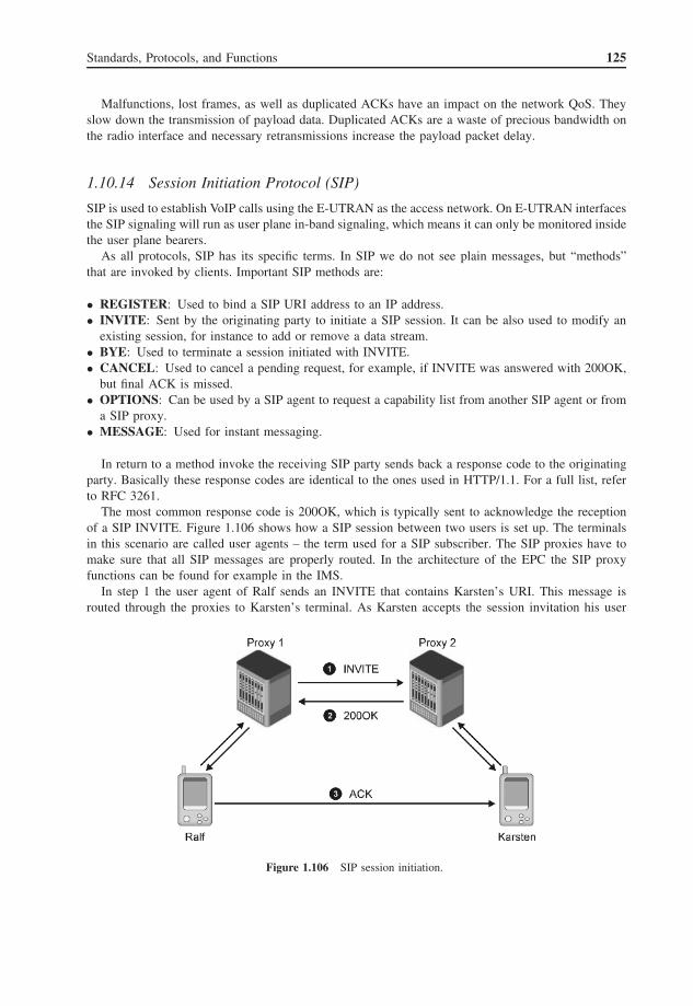
Standards, Protocols, and Functions 125
Malfunctions, lost frames, as well as duplicated ACKs have an impact on the network QoS. Theyslow down the transmission of payload data. Duplicated ACKs are a waste of precious bandwidth onthe radio interface and necessary retransmissions increase the payload packet delay.
1.10.14 Session Initiation Protocol (SIP)
SIP is used to establish VoIP calls using the E-UTRAN as the access network. On E-UTRAN interfacesthe SIP signaling will run as user plane in-band signaling, which means it can only be monitored insidethe user plane bearers.
As all protocols, SIP has its specific terms. In SIP we do not see plain messages, but “methods”that are invoked by clients. Important SIP methods are:
• REGISTER: Used to bind a SIP URI address to an IP address.• INVITE: Sent by the originating party to initiate a SIP session. It can be also used to modify an
existing session, for instance to add or remove a data stream.• BYE: Used to terminate a session initiated with INVITE.• CANCEL: Used to cancel a pending request, for example, if INVITE was answered with 200OK,
but final ACK is missed.• OPTIONS: Can be used by a SIP agent to request a capability list from another SIP agent or from
a SIP proxy.• MESSAGE: Used for instant messaging.
In return to a method invoke the receiving SIP party sends back a response code to the originatingparty. Basically these response codes are identical to the ones used in HTTP/1.1. For a full list, referto RFC 3261.
The most common response code is 200OK, which is typically sent to acknowledge the receptionof a SIP INVITE. Figure 1.106 shows how a SIP session between two users is set up. The terminalsin this scenario are called user agents – the term used for a SIP subscriber. The SIP proxies have tomake sure that all SIP messages are properly routed. In the architecture of the EPC the SIP proxyfunctions can be found for example in the IMS.
In step 1 the user agent of Ralf sends an INVITE that contains Karsten’s URI. This message isrouted through the proxies to Karsten’s terminal. As Karsten accepts the session invitation his user
Figure 1.106 SIP session initiation.

126 LTE Signaling, Troubleshooting and Optimization
agent sends a 200OK response code back to Ralf (step 2). Finally Ralf’s user agent sends the finalACK that may be transmitted on a different route not involving the proxies. This is possible because,after the previous messages have been sent, each user agent knows the address of its connection peer.
This SIP call setup procedure is also known as the SIP trapezoid.SIP by itself does not provide any media format description or QoS indication. For this reason it is
generally used in combination with the Session Description Protocol (SDP) that is used to negotiate,for example, the audio codec of the VoIP connection.
1.10.15 DIAMETER on EPC Interfaces
On the EPC network interfaces that are used to connect the HSS with other network elements such asthe MME a specific version of the DIAMETER protocol is used. DIAMETER is a protocol designedfor authentication, authorization, and accounting. In the IP world it is the successor to the RADIUSprotocol. To express the step forward in words, the name DIAMETER was invented as a word play:in geometry the diameter is double the radius. So, in contrast to many other protocols, DIAMETERis not an acronym.
Figure 1.107 MME startup and activity check on S6a reference point.
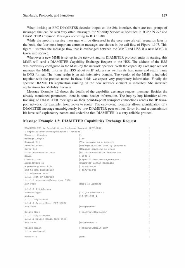
Standards, Protocols, and Functions 127
When looking at EPC DIAMETER decoder output on the S6a interface, there are two groups ofmessages that can be seen very often: messages for Mobility Service as specified in 3GPP 29.272 andDIAMETER Common Messages according to RFC 3588.
While the mobility service messages will be discussed in the core network call scenarios later inthe book, the four most important common messages are shown in the call flow of Figure 1.107. Thisfigure illustrates the message flow that is exchanged between the MME and HSS if a new MME istaken into service.
Whenever a new MME is set up in the network and its DIAMETER protocol entity is starting, thisMME will send a DIAMETER Capability Exchange Request to the HSS. The address of the HSSwas previously configured in the MME by the network operator. With the capability exchange requestmessage the MME informs the HSS about its IP address as well as its host name and realm namein DNS format. The home realm is an administrative domain. The vendor of the MME is includedtogether with the product name. In these fields we expect very proprietary information. Finally thespecific DIAMETER application running on the new network element is indicated: S6a interfaceapplications for Mobility Services.
Message Example 1.2 shows the details of the capability exchange request message. Besides thealready mentioned parameters, there is some header information. The hop-by-hop identifier allowstracking of DIAMETER messages on their point-to-point transport connections across the IP trans-port network, for example, from router to router. The end-to-end identifier allows identification of aDIAMETER message unambiguously by two DIAMETER peer entities. Error bit and retransmissionbit have self-explanatory names and underline that DIAMETER is a very reliable protocol.
Message Example 1.2: DIAMETER Capabilities Exchange Request
|DIAMETER CER (= Capabilities-Exchange-Request (RFC3588)) |
|1 Capabilities-Exchange-Request (RFC3588) |
|Diameter Version |1 |
|Message Length |180 |
|Request-Bit |The message is a request |
|Proxiable-Bit |Message MUST be locally processed |
|Error-Bit |Message contains no error |
|T(re-transmission)-Bit |No re-transmission indication |
|Spare |'0000'B |
|Command Code |Capabilities-Exchange-Request |
|Application-ID |Diameter Common Messages |
|Hop-by-Hop Identifier |'653740ce'H |
|End-to-End Identifier |'3e927b1f'H |
|1.1 Diameter AVPs |
|1.1.1 Host-IP-Address |
|1.1.1.1 Host-IP-Address (RFC 3588) |
|AVP Code |Host-IP-Address |
|1.1.1.1.1.1 Address |
|Address-Type |IP (IP version 4) |
|Address |10.251.122.4 |
|1.1.2 Origin-Host |
|1.1.2.1 Origin-Host (RFC 3588) |
|AVP Code |Origin-Host |
|Origin-Host |"mmeOriginHost.com" |
|1.1.3 Origin-Realm |
|1.1.3.1 Origin-Realm (RFC 3588) |
|AVP Code |Origin-Realm |
|Origin-Realm |"mmeOriginRealm.com" |
|1.1.4 Vendor-Id |
|Vendor-Id |NEM |

128 LTE Signaling, Troubleshooting and Optimization
|1.1.5 Product-Name |
|1.1.5.1 Product-Name (RFC 3588) |
|Product-Name |"MME Diameter" |
|1.1.6 Auth-Application-Id |
|1.1.6.1 Auth-Application-Id (RFC 3588) |
|Auth-Application-Id |S6a interface application |
|1.1.8 Vendor-Specific-Application-Id |
|1.1.8.1 Vendor-Specific-Application-Id (RFC 3588) |
|Auth-Application-Id |S6a interface application |
|1.1.8.1.1.2 Vendor-Id |
|1.1.8.1.1.2.1 Vendor-Id (RFC 3588) |
|Vendor-Id |3GPP |
In response to the capability exchange request message the HSS will send a capability exchangeanswer message, as shown in Message Example 1.3. This message contains the IP address, host nameand realm name of the HSS, and the DIAMETER Result Code. The Result Code indicates a successfulprocedure on the HSS side or, in the case of failure, it contains the appropriate error cause.
Message Example 1.3: DIAMETER Capabilities Exchange Answer
|DIAMETER CEA (= Capabilities-Exchange-Answer (RFC3588) |
|1 Capabilities-Exchange-Answer (RFC3588) |
|Diameter Version |1 |
|Message Length |160 |
|Request-Bit |The message is an answer |
|Proxiable-Bit |Message MUST be locally processed |
|Error-Bit |Message contains no error |
|T(re-transmission)-Bit |No re-transmission indication |
|Command Code |Capabilities-Exchange-Answer |
|Application-ID |Diameter Common Messages |
|Hop-by-Hop Identifier |'653740ce'H |
|End-to-End Identifier |'3e927b1f'H |
|1.1 Diameter AVPs |
|1.1.1 Result-Code |
|1.1.1.1 Result-Code (RFC 3588) |
|AVP Code |Result-Code |
|Result-Code |DIAMETER_SUCCESS |
|1.1.2 Origin-Host |
|1.1.2.1 Origin-Host (RFC 3588) |
|Origin-Host |"hss1" |
|1.1.3 Origin-Realm |
|1.1.3.1 Origin-Realm (RFC 3588) |
|Origin-Realm |"hss.tek.com" |
|Padding |'00'H |
|1.1.4 Host-IP-Address |
|1.1.4.1 Host-IP-Address (RFC 3588) |
|AVP Code |Host-IP-Address |
|Address-Type |IP (IP version 4) |
|Address |10.254.0.1 |
|1.1.5 Vendor-Id |
|1.1.5.1 Vendor-Id (RFC 3588) |
|Vendor-Id |Tektronix Communications |
|1.1.6 Product-Name |
|1.1.6.1 Product-Name (RFC 3588) |

Standards, Protocols, and Functions 129
|Product-Name |"Tektronix G35" |
|1.1.7 Vendor-Specific-Application-Id |
|1.1.7.1 Vendor-Specific-Application-Id (RFC 3588) |
|Vendor-Id |3GPP |
|1.1.7.1.1.2 Auth-Application-Id |
|Auth-Application-Id |S6a interface application |
Now, after the two peer entities have exchanged their address information and capabilities theywill check the availability of their connection periodically using a heartbeat check procedure. TheDIAMETER-specific name for this period check is the device watchdog procedure and it worksas follows.
One entity sends a DIAMETER device watchdog request message (as shown in MessageExample 1.4) containing the host name and real name of the sender.
Message Example 1.4: DIAMETER Device Watchdog Request
|DIAMETER DWR (= Device-Watchdog-Request (RFC3588)) |
|1 Device-Watchdog-Request (RFC3588) |
|Command Code |Device-Watchdog-Request |
|Application-ID |Diameter Common Messages |
|Hop-by-Hop Identifier |'653740d0'H |
|End-to-End Identifier |'3f3db3e6'H |
|1.1 Diameter AVPs |
|1.1.1 Origin-Host |
|1.1.1.1 Origin-Host (RFC 3588) |
|AVP Code |Origin-Host |
|Origin-Host |"mmeOriginHost.com" |
|Padding |'000000'H |
|1.1.2 Origin-Realm |
|1.1.2.1 Origin-Realm (RFC 3588) |
|AVP Code |Origin-Realm |
|Origin-Realm |"mmeOriginRealm.com" |
On receiving the Device Watchdog Request the peer entity sends back a Device Watchdog Answer(Message Example 1.5) including the address information and Result Code. Again, the Result Codeindicates a successful procedure or, in case of failure, it contains the appropriate error cause.
Message Example 1.5: DIAMETER Device Watchdog Answer
|DIAMETER DWA (= Device-Watchdog-Answer (RFC3588)) |
|1 Device-Watchdog-Answer (RFC3588) |
|Command Code |Device-Watchdog-Answer |
|1.1.1.1 Result-Code (RFC 3588) |
|AVP Code |Result-Code |
|Result-Code |DIAMETER_SUCCESS |
|1.1.2 Origin-Host |
|Origin-Host |"hss1" |
|1.1.3 Origin-Realm |
|1.1.3.1 Origin-Realm (RFC 3588) |
|AVP Code |Origin-Realm |
|Origin-Realm |"hss.tek.com" |