Embed Size (px)
Citation preview
SERIES ‘‘ATS/ERS TASK FORCE: STANDARDISATION OF LUNGFUNCTION TESTING’’Edited by V. Brusasco, R. Crapo and G. ViegiNumber 2 in this Series
Standardisation of spirometryM.R. Miller, J. Hankinson, V. Brusasco, F. Burgos, R. Casaburi, A. Coates,R. Crapo, P. Enright, C.P.M. van der Grinten, P. Gustafsson, R. Jensen,D.C. Johnson, N. MacIntyre, R. McKay, D. Navajas, O.F. Pedersen, R. Pellegrino,G. Viegi and J. Wanger
CONTENTS
Background . . . . . . . . . . . . . . . . . . . . . . . . . . . . . . . . . . . . . . . . . . . . . . . . . . . . . . . . . . . . . . . 320
FEV1 and FVC manoeuvre . . . . . . . . . . . . . . . . . . . . . . . . . . . . . . . . . . . . . . . . . . . . . . . . . . . . 321
Definitions . . . . . . . . . . . . . . . . . . . . . . . . . . . . . . . . . . . . . . . . . . . . . . . . . . . . . . . . . . . . . . . 321
Equipment . . . . . . . . . . . . . . . . . . . . . . . . . . . . . . . . . . . . . . . . . . . . . . . . . . . . . . . . . . . . . . . 321
Requirements . . . . . . . . . . . . . . . . . . . . . . . . . . . . . . . . . . . . . . . . . . . . . . . . . . . . . . . . . . . 321
Display . . . . . . . . . . . . . . . . . . . . . . . . . . . . . . . . . . . . . . . . . . . . . . . . . . . . . . . . . . . . . . . . 321
Validation . . . . . . . . . . . . . . . . . . . . . . . . . . . . . . . . . . . . . . . . . . . . . . . . . . . . . . . . . . . . . . 322
Quality control . . . . . . . . . . . . . . . . . . . . . . . . . . . . . . . . . . . . . . . . . . . . . . . . . . . . . . . . . . . 322
Quality control for volume-measuring devices . . . . . . . . . . . . . . . . . . . . . . . . . . . . . . . . . . . 322
Quality control for flow-measuring devices . . . . . . . . . . . . . . . . . . . . . . . . . . . . . . . . . . . . . 323
Test procedure . . . . . . . . . . . . . . . . . . . . . . . . . . . . . . . . . . . . . . . . . . . . . . . . . . . . . . . . . . . . 323
Within-manoeuvre evaluation . . . . . . . . . . . . . . . . . . . . . . . . . . . . . . . . . . . . . . . . . . . . . . . . . . 324
Start of test criteria. . . . . . . . . . . . . . . . . . . . . . . . . . . . . . . . . . . . . . . . . . . . . . . . . . . . . . . . 324
End of test criteria . . . . . . . . . . . . . . . . . . . . . . . . . . . . . . . . . . . . . . . . . . . . . . . . . . . . . . . . 324
Additional criteria . . . . . . . . . . . . . . . . . . . . . . . . . . . . . . . . . . . . . . . . . . . . . . . . . . . . . . . . . 324
Summary of acceptable blow criteria . . . . . . . . . . . . . . . . . . . . . . . . . . . . . . . . . . . . . . . . . . . 325
Between-manoeuvre evaluation . . . . . . . . . . . . . . . . . . . . . . . . . . . . . . . . . . . . . . . . . . . . . . . . 325
Manoeuvre repeatability . . . . . . . . . . . . . . . . . . . . . . . . . . . . . . . . . . . . . . . . . . . . . . . . . . . . 325
Maximum number of manoeuvres . . . . . . . . . . . . . . . . . . . . . . . . . . . . . . . . . . . . . . . . . . . . . 326
Test result selection . . . . . . . . . . . . . . . . . . . . . . . . . . . . . . . . . . . . . . . . . . . . . . . . . . . . . . . . 326
Other derived indices . . . . . . . . . . . . . . . . . . . . . . . . . . . . . . . . . . . . . . . . . . . . . . . . . . . . . . . 326
FEVt . . . . . . . . . . . . . . . . . . . . . . . . . . . . . . . . . . . . . . . . . . . . . . . . . . . . . . . . . . . . . . . . . . 326
Standardisation of FEV1 for expired volume, FEV1/FVC and FEV1/VC . . . . . . . . . . . . . . . . . . . . 326
FEF25–75% . . . . . . . . . . . . . . . . . . . . . . . . . . . . . . . . . . . . . . . . . . . . . . . . . . . . . . . . . . . . . . 326
PEF . . . . . . . . . . . . . . . . . . . . . . . . . . . . . . . . . . . . . . . . . . . . . . . . . . . . . . . . . . . . . . . . . . 326
Maximal expiratory flow–volume loops . . . . . . . . . . . . . . . . . . . . . . . . . . . . . . . . . . . . . . . . . . . 326
Definitions . . . . . . . . . . . . . . . . . . . . . . . . . . . . . . . . . . . . . . . . . . . . . . . . . . . . . . . . . . . . . . 326
Equipment . . . . . . . . . . . . . . . . . . . . . . . . . . . . . . . . . . . . . . . . . . . . . . . . . . . . . . . . . . . . . 327
Test procedure . . . . . . . . . . . . . . . . . . . . . . . . . . . . . . . . . . . . . . . . . . . . . . . . . . . . . . . . . . 327
Within- and between-manoeuvre evaluation . . . . . . . . . . . . . . . . . . . . . . . . . . . . . . . . . . . . . . 327
Flow–volume loop examples. . . . . . . . . . . . . . . . . . . . . . . . . . . . . . . . . . . . . . . . . . . . . . . . . 327
Reversibility testing . . . . . . . . . . . . . . . . . . . . . . . . . . . . . . . . . . . . . . . . . . . . . . . . . . . . . . . . . 327
Method . . . . . . . . . . . . . . . . . . . . . . . . . . . . . . . . . . . . . . . . . . . . . . . . . . . . . . . . . . . . . . . . 327
Comment on dose and delivery method . . . . . . . . . . . . . . . . . . . . . . . . . . . . . . . . . . . . . . . . 328
Determination of reversibility . . . . . . . . . . . . . . . . . . . . . . . . . . . . . . . . . . . . . . . . . . . . . . . . . 328
VC and IC manoeuvre . . . . . . . . . . . . . . . . . . . . . . . . . . . . . . . . . . . . . . . . . . . . . . . . . . . . . . . 329
Definitions . . . . . . . . . . . . . . . . . . . . . . . . . . . . . . . . . . . . . . . . . . . . . . . . . . . . . . . . . . . . . . . 329
AFFILIATIONS
For affiliations, please see
Acknowledgements section
CORRESPONDENCE
V. Brusasco
Internal Medicine
University of Genoa
V.le Benedetto XV, 6
I-16132 Genova
Italy
Fax: 39 103537690
E-mail: [email protected]
Received:
March 23 2005
Accepted after revision:
April 05 2005
European Respiratory Journal
Print ISSN 0903-1936
Online ISSN 1399-3003
Previous articles in this series: No. 1: Miller MR, Crapo R, Hankinson J, et al. General considerations for lung function testing. Eur Respir J 2005; 26:
153–161.
EUROPEAN RESPIRATORY JOURNAL VOLUME 26 NUMBER 2 319
Eur Respir J 2005; 26: 319–338
DOI: 10.1183/09031936.05.00034805
Copyright�ERS Journals Ltd 2005
c
VC and IVC . . . . . . . . . . . . . . . . . . . . . . . . . . . . . . . .329
IC. . . . . . . . . . . . . . . . . . . . . . . . . . . . . . . . . . . . . . .329
Equipment . . . . . . . . . . . . . . . . . . . . . . . . . . . . . . . . . .329
Test procedure . . . . . . . . . . . . . . . . . . . . . . . . . . . . . . .329
VC . . . . . . . . . . . . . . . . . . . . . . . . . . . . . . . . . . . . . .329
IC. . . . . . . . . . . . . . . . . . . . . . . . . . . . . . . . . . . . . . .330
Use of a nose clip . . . . . . . . . . . . . . . . . . . . . . . . . . .330
Within-manoeuvre evaluation . . . . . . . . . . . . . . . . . . . . .330
Between-manoeuvre evaluation . . . . . . . . . . . . . . . . . . .330
Test result selection . . . . . . . . . . . . . . . . . . . . . . . . . . .330
Peak expiratory flow . . . . . . . . . . . . . . . . . . . . . . . . . . .330
Definition . . . . . . . . . . . . . . . . . . . . . . . . . . . . . . . . . . .330
Equipment . . . . . . . . . . . . . . . . . . . . . . . . . . . . . . . . . .330
Test procedure . . . . . . . . . . . . . . . . . . . . . . . . . . . . . . .330
Within-manoeuvre evaluation . . . . . . . . . . . . . . . . . . . . .331
Between-manoeuvre evaluation . . . . . . . . . . . . . . . . . . .331
Test result selection . . . . . . . . . . . . . . . . . . . . . . . . . . .331
Maximum voluntary ventilation . . . . . . . . . . . . . . . . . . .331
Definition . . . . . . . . . . . . . . . . . . . . . . . . . . . . . . . . . . .331
Equipment . . . . . . . . . . . . . . . . . . . . . . . . . . . . . . . . . .331
Test procedure . . . . . . . . . . . . . . . . . . . . . . . . . . . . . . .331
Within-manoeuvre evaluation . . . . . . . . . . . . . . . . . . . . .331
Between-manoeuvre evaluation . . . . . . . . . . . . . . . . . . .331
Test result selection . . . . . . . . . . . . . . . . . . . . . . . . . . .331
Technical considerations . . . . . . . . . . . . . . . . . . . . . . . .331
Minimal recommendations for spirometry systems . . . . . .331
BTPS correction . . . . . . . . . . . . . . . . . . . . . . . . . . . . . .332
Comments . . . . . . . . . . . . . . . . . . . . . . . . . . . . . . . .332
Test signals for spirometer testing . . . . . . . . . . . . . . . . .333
Method . . . . . . . . . . . . . . . . . . . . . . . . . . . . . . . . . . .333
Accuracy test . . . . . . . . . . . . . . . . . . . . . . . . . . . . . .333
Repeatability test . . . . . . . . . . . . . . . . . . . . . . . . . . . .333
Test signals for PEF meter testing . . . . . . . . . . . . . . . . .333
Method . . . . . . . . . . . . . . . . . . . . . . . . . . . . . . . . . . .333
Accuracy test . . . . . . . . . . . . . . . . . . . . . . . . . . . . . .333
Repeatability test . . . . . . . . . . . . . . . . . . . . . . . . . . . .334
Test signals for MVV testing. . . . . . . . . . . . . . . . . . . . . .334
Abbreviations. . . . . . . . . . . . . . . . . . . . . . . . . . . . . . . . .334
Appendix . . . . . . . . . . . . . . . . . . . . . . . . . . . . . . . . . . . .335
KEYWORDS: Peak expiratory flow, spirometry, spirometry standardisation, spirometry technique, spirometry traning,
ventilation
BACKGROUNDSpirometry is a physiological test that measures how anindividual inhales or exhales volumes of air as a function oftime. The primary signal measured in spirometry may bevolume or flow.
Spirometry is invaluable as a screening test of generalrespiratory health in the same way that blood pressureprovides important information about general cardiovascularhealth. However, on its own, spirometry does not leadclinicians directly to an aetiological diagnosis. Some indica-tions for spirometry are given in table 1.
In this document, the most important aspects of spirometry arethe forced vital capacity (FVC), which is the volume deliveredduring an expiration made as forcefully and completely aspossible starting from full inspiration, and the forced expira-tory volume (FEV) in one second, which is the volumedelivered in the first second of an FVC manoeuvre. Otherspirometric variables derived from the FVC manoeuvre arealso addressed.
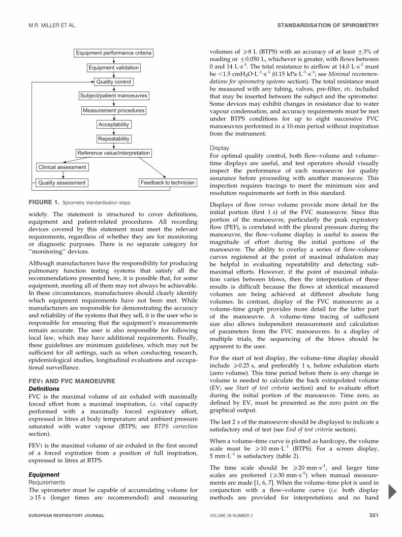
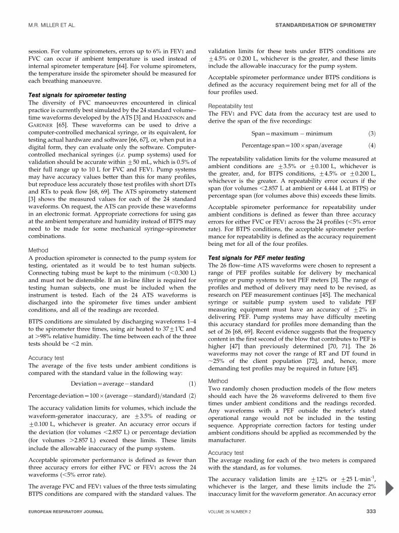
Spirometry can be undertaken with many different types ofequipment, and requires cooperation between the subject andthe examiner, and the results obtained will depend ontechnical as well as personal factors (fig. 1). If the variabilityof the results can be diminished and the measurementaccuracy can be improved, the range of normal values forpopulations can be narrowed and abnormalities more easilydetected. The Snowbird workshop held in 1979 resulted in thefirst American Thoracic Society (ATS) statement on thestandardisation of spirometry [1]. This was updated in 1987and again in 1994 [2, 3]. A similar initiative was undertaken bythe European Community for Steel and Coal, resulting in thefirst European standardisation document in 1983 [4]. This was
then updated in 1993 as the official statement of the EuropeanRespiratory Society (ERS) [5]. There are generally only minordifferences between the two most recent ATS and ERSstatements, except that the ERS statement includes absolutelung volumes and the ATS does not.
This document brings the views of the ATS and ERS togetherin an attempt to publish standards that can be applied more
TABLE 1 Indications for spirometry
Diagnostic
To evaluate symptoms, signs or abnormal laboratory tests
To measure the effect of disease on pulmonary function
To screen individuals at risk of having pulmonary disease
To assess pre-operative risk
To assess prognosis
To assess health status before beginning strenuous physical activity
programmes
Monitoring
To assess therapeutic intervention
To describe the course of diseases that affect lung function
To monitor people exposed to injurious agents
To monitor for adverse reactions to drugs with known pulmonary toxicity
Disability/impairment evaluations
To assess patients as part of a rehabilitation programme
To assess risks as part of an insurance evaluation
To assess individuals for legal reasons
Public health
Epidemiological surveys
Derivation of reference equations
Clinical research
STANDARDISATION OF SPIROMETRY M.R. MILLER ET AL.
320 VOLUME 26 NUMBER 2 EUROPEAN RESPIRATORY JOURNAL
widely. The statement is structured to cover definitions,equipment and patient-related procedures. All recordingdevices covered by this statement must meet the relevantrequirements, regardless of whether they are for monitoringor diagnostic purposes. There is no separate category for‘‘monitoring’’ devices.
Although manufacturers have the responsibility for producingpulmonary function testing systems that satisfy all therecommendations presented here, it is possible that, for someequipment, meeting all of them may not always be achievable.In these circumstances, manufacturers should clearly identifywhich equipment requirements have not been met. Whilemanufacturers are responsible for demonstrating the accuracyand reliability of the systems that they sell, it is the user who isresponsible for ensuring that the equipment’s measurementsremain accurate. The user is also responsible for followinglocal law, which may have additional requirements. Finally,these guidelines are minimum guidelines, which may not besufficient for all settings, such as when conducting research,epidemiological studies, longitudinal evaluations and occupa-tional surveillance.
FEV1 AND FVC MANOEUVREDefinitionsFVC is the maximal volume of air exhaled with maximallyforced effort from a maximal inspiration, i.e. vital capacityperformed with a maximally forced expiratory effort,expressed in litres at body temperature and ambient pressuresaturated with water vapour (BTPS; see BTPS correctionsection).
FEV1 is the maximal volume of air exhaled in the first secondof a forced expiration from a position of full inspiration,expressed in litres at BTPS.
EquipmentRequirementsThe spirometer must be capable of accumulating volume foro15 s (longer times are recommended) and measuring
volumes of o8 L (BTPS) with an accuracy of at least ¡3% ofreading or ¡0.050 L, whichever is greater, with flows between0 and 14 L?s-1. The total resistance to airflow at 14.0 L?s-1 mustbe ,1.5 cmH2O?L-1?s-1 (0.15 kPa?L-1?s-1; see Minimal recommen-dations for spirometry systems section). The total resistance mustbe measured with any tubing, valves, pre-filter, etc. includedthat may be inserted between the subject and the spirometer.Some devices may exhibit changes in resistance due to watervapour condensation, and accuracy requirements must be metunder BTPS conditions for up to eight successive FVCmanoeuvres performed in a 10-min period without inspirationfrom the instrument.
DisplayFor optimal quality control, both flow–volume and volume–time displays are useful, and test operators should visuallyinspect the performance of each manoeuvre for qualityassurance before proceeding with another manoeuvre. Thisinspection requires tracings to meet the minimum size andresolution requirements set forth in this standard.
Displays of flow versus volume provide more detail for theinitial portion (first 1 s) of the FVC manoeuvre. Since thisportion of the manoeuvre, particularly the peak expiratoryflow (PEF), is correlated with the pleural pressure during themanoeuvre, the flow–volume display is useful to assess themagnitude of effort during the initial portions of themanoeuvre. The ability to overlay a series of flow–volumecurves registered at the point of maximal inhalation maybe helpful in evaluating repeatability and detecting sub-maximal efforts. However, if the point of maximal inhala-tion varies between blows, then the interpretation of theseresults is difficult because the flows at identical measuredvolumes are being achieved at different absolute lungvolumes. In contrast, display of the FVC manoeuvre as avolume–time graph provides more detail for the latter partof the manoeuvre. A volume–time tracing of sufficientsize also allows independent measurement and calculationof parameters from the FVC manoeuvres. In a display ofmultiple trials, the sequencing of the blows should beapparent to the user.
For the start of test display, the volume–time display shouldinclude o0.25 s, and preferably 1 s, before exhalation starts(zero volume). This time period before there is any change involume is needed to calculate the back extrapolated volume(EV; see Start of test criteria section) and to evaluate effortduring the initial portion of the manoeuvre. Time zero, asdefined by EV, must be presented as the zero point on thegraphical output.
The last 2 s of the manoeuvre should be displayed to indicate asatisfactory end of test (see End of test criteria section).
When a volume–time curve is plotted as hardcopy, the volumescale must be o10 mm?L-1 (BTPS). For a screen display,5 mm?L-1 is satisfactory (table 2).
The time scale should be o20 mm?s-1, and larger timescales are preferred (o30 mm?s-1) when manual measure-ments are made [1, 6, 7]. When the volume–time plot is used inconjunction with a flow–volume curve (i.e. both displaymethods are provided for interpretations and no hand
������������ �������������
��������������� �
������� �� �
��������������� ������
������������ �������
�����������
�����������
������������������������ �
�����������������
��������������� �������� �� ������
FIGURE 1. Spirometry standardisation steps.
M.R. MILLER ET AL. STANDARDISATION OF SPIROMETRY
cEUROPEAN RESPIRATORY JOURNAL VOLUME 26 NUMBER 2 321
measurements are performed), the time scale requirementis reduced to 10 mm?s-1 from the usually required minimumof 20 mm?s-1 (table 2). The rationale for this exception isthat the flow–volume curve can provide the means forquality assessment during the initial portion of the FVCmanoeuvre. The volume–time curve can be used to evaluatethe latter part of the FVC manoeuvre, making the time scaleless critical.
ValidationIt is strongly recommended that spirometry systems should beevaluated using a computer-driven mechanical syringe or itsequivalent, in order to test the range of exhalations that arelikely to be encountered in the test population. Testing theperformance of equipment is not part of the usual laboratoryprocedures (see Test signals for spirometer testing section).
Quality controlAttention to equipment quality control and calibration isan important part of good laboratory practice. At a minimum,the requirements are as follows: 1) a log of calibration resultsis maintained; 2) the documentation of repairs or otheralterations which return the equipment to acceptable opera-tion; 3) the dates of computer software and hardwareupdates or changes; and 4) if equipment is changed orrelocated (e.g. industrial surveys), calibration checks andquality-control procedures must be repeated before furthertesting begins.
Key aspects of equipment quality control are summarised intable 3.
Calibration is the procedure for establishing the relationshipbetween sensor-determined values of flow or volume and theactual flow or volume.
A calibration check is different from calibration and is theprocedure used to validate that the device is within calibrationlimits, e.g. ¡3% of true. If a device fails its calibration check,then a new calibration procedure or equipment maintenance isrequired. Calibration checks must be undertaken daily, ormore frequently, if specified by the manufacturer.
The syringe used to check the volume calibration of spiro-meters must have an accuracy of ¡15 mL or ¡0.5% of the fullscale (15 mL for a 3-L syringe), and the manufacturer must
provide recommendations concerning appropriate intervalsbetween syringe calibration checks. Users should be awarethat a syringe with an adjustable or variable stop may be outof calibration if the stop is reset or accidentally moved.Calibration syringes should be periodically (e.g. monthly) leaktested at more than one volume up to their maximum; this canbe done by attempting to empty them with the outlet corked. Adropped or damaged syringe should be considered out ofcalibration until it is checked.
With regard to time, assessing mechanical recorder time scaleaccuracy with a stopwatch must be performed at leastquarterly. An accuracy of within 2% must be achieved.
Quality control for volume-measuring devicesThe volume accuracy of the spirometer must be checked at leastdaily, with a single discharge of a 3-L calibrated syringe. Dailycalibration checking is highly recommended so that the onset ofa problem can be determined within 1 day, and also to helpdefine day-to-day laboratory variability. More frequent checksmay be required in special circumstances, such as: 1) duringindustrial surveys or other studies in which a large number ofsubject manoeuvres are carried out, the equipment’s calibrationshould be checked more frequently than daily [8]; and 2) whenthe ambient temperature is changing (e.g. field studies), volumeaccuracy must be checked more frequently than daily and theBTPS correction factor appropriately updated.
The accuracy of the syringe volume must be considered indetermining whether the measured volume is within accep-table limits. For example, if the syringe has an accuracy of0.5%, a reading of ¡3.5% is appropriate.
The calibration syringe should be stored and used in such away as to maintain the same temperature and humidity of thetesting site. This is best accomplished by keeping the syringe inclose proximity to the spirometer, but out of direct sunlightand away from heat sources.
Volume-type spirometer systems must be evaluated for leaksevery day [9, 10]. The importance of undertaking this daily testcannot be overstressed. Leaks can be detected by applying aconstant positive pressure of o3.0 cmH2O (0.3 kPa) with thespirometer outlet occluded (preferably at or including themouthpiece). Any observed volume loss .30 mL after 1 minindicates a leak [9, 10] and needs to be corrected.
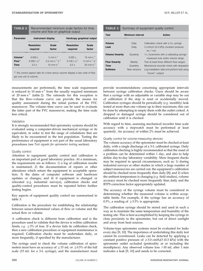
TABLE 2 Recommended minimum scale factors for time,volume and flow on graphical output
Instrument display Hardcopy graphical outputParameter
Resolution
required
Scale
factor
Resolution
required
Scale
factor
Volume# 0.050 L 5 mm?L-1 0.025 L 10 mm?L-1
Flow# 0.200 L?s-1 2.5 mm?L-1?s-1 0.100 L?s-1 5 mm?L-1?s-1
Time 0.2 s 10 mm?s-1 0.2 s 20 mm?s-1
#: the correct aspect ratio for a flow versus volume display is two units of flow
per one unit of volume.
TABLE 3 Summary of equipment quality control
Test Minimum interval Action
Volume Daily Calibration check with a 3-L syringe
Leak Daily 3 cmH2O (0.3 kPa) constant pressure
for 1 min
Volume linearity Quarterly 1-L increments with a calibrating syringe
measured over entire volume range
Flow linearity Weekly Test at least three different flow ranges
Time Quarterly Mechanical recorder check with stopwatch
Software New versions Log installation date and perform test using
‘‘known’’ subject
STANDARDISATION OF SPIROMETRY M.R. MILLER ET AL.
322 VOLUME 26 NUMBER 2 EUROPEAN RESPIRATORY JOURNAL
At least quarterly, volume spirometers must have theircalibration checked over their entire volume range using acalibrated syringe [11] or an equivalent volume standard. Themeasured volume should be within ¡3.5% of the reading or65 mL, whichever is greater. This limit includes the 0.5%accuracy limit for a 3-L syringe. The linearity check procedureprovided by the manufacturer can be used if it is equivalent toone of the following procedures: 1) consecutive injections of1-L volume increments while comparing observed volumewith the corresponding cumulative measured volume, e.g. 0–1,1–2, 2–3,…6–7 and 7–8 L, for an 8-L spirometer; and 2)injection of a 3-L volume starting at a minimal spirometervolume, then repeating this with a 1-L increment in the startposition, e.g. 0–3, 1–4, 2–5, 3–6, 4–7 and 5–8 L, for an 8-Lspirometer.
The linearity check is considered acceptable if the spirometermeets the volume accuracy requirements for all volumestested.
Quality control for flow-measuring devicesWith regards to volume accuracy, calibration checks must beundertaken at least daily, using a 3-L syringe discharged atleast three times to give a range of flows varying between 0.5and 12 L?s-1 (with 3-L injection times of ,6 s and ,0.5 s). Thevolume at each flow should meet the accuracy requirement of¡3.5%. For devices using disposable flow sensors, a newsensor from the supply used for patient tests should be testedeach day.
For linearity, a volume calibration check should be per-formed weekly with a 3-L syringe to deliver three relativelyconstant flows at a low flow, then three at a mid-range flowand finally three at a high flow. The volumes achieved at eachof these flows should each meet the accuracy requirement of¡3.5%.
Test procedureThere are three distinct phases to the FVC manoeuvre, asfollows: 1) maximal inspiration; 2) a ‘‘blast’’ of exhalation; and3) continued complete exhalation to the end of test (EOT).
The technician should demonstrate the appropriate techniqueand follow the procedure described in table 4. The subjectshould inhale rapidly and completely from functional residualcapacity (FRC), the breathing tube should be inserted into thesubject’s mouth (if this has not already been done), makingsure the lips are sealed around the mouthpiece and that thetongue does not occlude it, and then the FVC manoeuvreshould be begun with minimal hesitation. Reductions in PEFand FEV1 have been shown when inspiration is slow and/orthere is a 4–6 s pause at total lung capacity (TLC) beforebeginning exhalation [12]. It is, therefore, important that thepreceding inspiration is fast and any pause at full inspirationbe minimal (i.e. only for 1–2 s). The test assumes a fullinhalation before beginning the forced exhalation, and it isimperative that the subject takes a complete inhalation beforebeginning the manoeuvre. The subject should be prompted to‘‘blast,’’ not just ‘‘blow,’’ the air from their lungs, and then he/she should be encouraged to fully exhale. Throughout themanoeuvre, enthusiastic coaching of the subject using appro-priate body language and phrases, such as ‘‘keep going’’, is
required. It is particularly helpful to observe the subject withoccasional glances to check for distress, and to observe thetracing or computer display during the test to help ensuremaximal effort. If the patient feels ‘‘dizzy’’, the manoeuvreshould be stopped, since syncope could follow due toprolonged interruption of venous return to the thorax. This ismore likely to occur in older subjects and those with airflowlimitation. Performing a vital capacity (VC) manoeuvre (see VCand IC manoeuvre section), instead of obtaining FVC, may helpto avoid syncope in some subjects. Reducing the effort part-way through the manoeuvre [13] may give a higher expiratoryvolume in some subjects, but then is no longer a maximallyforced expiration. Well-fitting false teeth should not beroutinely removed, since they preserve oropharyngeal geome-try and spirometry results are generally better with them inplace [14].
With appropriate coaching, children as young as 5 yrs ofage are often able to perform acceptable spirometry [15].The technicians who are involved in the pulmonary functiontesting of children should be specifically trained to dealwith such a situation. A bright, pleasant atmosphere,
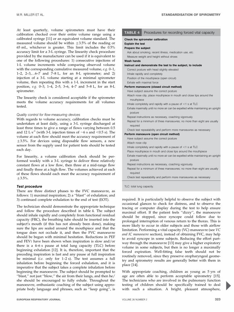
TABLE 4 Procedures for recording forced vital capacity
Check the spirometer calibration
Explain the test
Prepare the subject
Ask about smoking, recent illness, medication use, etc.
Measure weight and height without shoes
Wash hands
Instruct and demonstrate the test to the subject, to include
Correct posture with head slightly elevated
Inhale rapidly and completely
Position of the mouthpiece (open circuit)
Exhale with maximal force
Perform manoeuvre (closed circuit method)
Have subject assume the correct posture
Attach nose clip, place mouthpiece in mouth and close lips around the
mouthpiece
Inhale completely and rapidly with a pause of ,1 s at TLC
Exhale maximally until no more air can be expelled while maintaining an upright
posture
Repeat instructions as necessary, coaching vigorously
Repeat for a minimum of three manoeuvres; no more than eight are usually
required
Check test repeatability and perform more manoeuvres as necessary
Perform manoeuvre (open circuit method)
Have subject assume the correct posture
Attach nose clip
Inhale completely and rapidly with a pause of ,1 s at TLC
Place mouthpiece in mouth and close lips around the mouthpiece
Exhale maximally until no more air can be expelled while maintaining an upright
posture
Repeat instructions as necessary, coaching vigorously
Repeat for a minimum of three manoeuvres; no more than eight are usually
required
Check test repeatability and perform more manoeuvres as necessary
TLC: total lung capacity.
M.R. MILLER ET AL. STANDARDISATION OF SPIROMETRY
cEUROPEAN RESPIRATORY JOURNAL VOLUME 26 NUMBER 2 323
including age-appropriate toys, reading material and art, isimportant in making children feel at ease. Encouragement,detailed but simple instructions, lack of intimidation andvisual feedback in the teaching are important in helpingchildren to perform the manoeuvre. Even if unsuccessful atthe first session, children will learn to be less intimidatedand may perform far better in a subsequent session. Testingchildren in ‘‘adult’’ laboratories, where no effort is made tocater for the specific needs of the younger subjects, is to bediscouraged.
The use of a nose clip or manual occlusion of the nares isrecommended, and, for safety reasons, testing should bepreferably done in the sitting position, using a chair witharms and without wheels. If testing is undertaken with thepatient standing or in another position, this must bedocumented on the report.
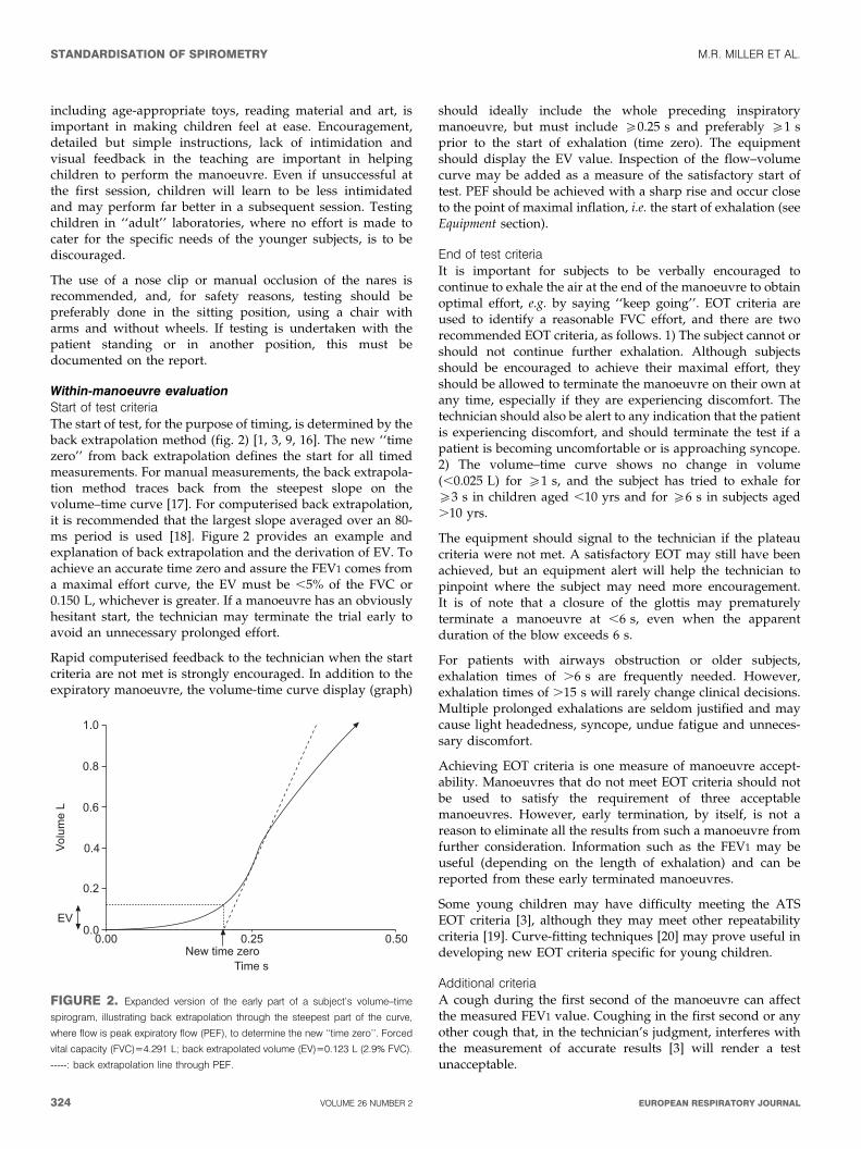
Within-manoeuvre evaluationStart of test criteriaThe start of test, for the purpose of timing, is determined by theback extrapolation method (fig. 2) [1, 3, 9, 16]. The new ‘‘timezero’’ from back extrapolation defines the start for all timedmeasurements. For manual measurements, the back extrapola-tion method traces back from the steepest slope on thevolume–time curve [17]. For computerised back extrapolation,it is recommended that the largest slope averaged over an 80-ms period is used [18]. Figure 2 provides an example andexplanation of back extrapolation and the derivation of EV. Toachieve an accurate time zero and assure the FEV1 comes froma maximal effort curve, the EV must be ,5% of the FVC or0.150 L, whichever is greater. If a manoeuvre has an obviouslyhesitant start, the technician may terminate the trial early toavoid an unnecessary prolonged effort.
Rapid computerised feedback to the technician when the startcriteria are not met is strongly encouraged. In addition to theexpiratory manoeuvre, the volume-time curve display (graph)
should ideally include the whole preceding inspiratorymanoeuvre, but must include o0.25 s and preferably o1 sprior to the start of exhalation (time zero). The equipmentshould display the EV value. Inspection of the flow–volumecurve may be added as a measure of the satisfactory start oftest. PEF should be achieved with a sharp rise and occur closeto the point of maximal inflation, i.e. the start of exhalation (seeEquipment section).
End of test criteriaIt is important for subjects to be verbally encouraged tocontinue to exhale the air at the end of the manoeuvre to obtainoptimal effort, e.g. by saying ‘‘keep going’’. EOT criteria areused to identify a reasonable FVC effort, and there are tworecommended EOT criteria, as follows. 1) The subject cannot orshould not continue further exhalation. Although subjectsshould be encouraged to achieve their maximal effort, theyshould be allowed to terminate the manoeuvre on their own atany time, especially if they are experiencing discomfort. Thetechnician should also be alert to any indication that the patientis experiencing discomfort, and should terminate the test if apatient is becoming uncomfortable or is approaching syncope.2) The volume–time curve shows no change in volume(,0.025 L) for o1 s, and the subject has tried to exhale foro3 s in children aged ,10 yrs and for o6 s in subjects aged.10 yrs.
The equipment should signal to the technician if the plateaucriteria were not met. A satisfactory EOT may still have beenachieved, but an equipment alert will help the technician topinpoint where the subject may need more encouragement.It is of note that a closure of the glottis may prematurelyterminate a manoeuvre at ,6 s, even when the apparentduration of the blow exceeds 6 s.
For patients with airways obstruction or older subjects,exhalation times of .6 s are frequently needed. However,exhalation times of .15 s will rarely change clinical decisions.Multiple prolonged exhalations are seldom justified and maycause light headedness, syncope, undue fatigue and unneces-sary discomfort.
Achieving EOT criteria is one measure of manoeuvre accept-ability. Manoeuvres that do not meet EOT criteria should notbe used to satisfy the requirement of three acceptablemanoeuvres. However, early termination, by itself, is not areason to eliminate all the results from such a manoeuvre fromfurther consideration. Information such as the FEV1 may beuseful (depending on the length of exhalation) and can bereported from these early terminated manoeuvres.
Some young children may have difficulty meeting the ATSEOT criteria [3], although they may meet other repeatabilitycriteria [19]. Curve-fitting techniques [20] may prove useful indeveloping new EOT criteria specific for young children.
Additional criteriaA cough during the first second of the manoeuvre can affectthe measured FEV1 value. Coughing in the first second or anyother cough that, in the technician’s judgment, interferes withthe measurement of accurate results [3] will render a testunacceptable.
!"#
�$!"!
%"!
!"&
!"'
!"(
$ ���
�)
!"*!!"(*!"!!+�,���-��
.����
FIGURE 2. Expanded version of the early part of a subject’s volume–time
spirogram, illustrating back extrapolation through the steepest part of the curve,
where flow is peak expiratory flow (PEF), to determine the new ‘‘time zero’’. Forced
vital capacity (FVC)54.291 L; back extrapolated volume (EV)50.123 L (2.9% FVC).
-----: back extrapolation line through PEF.
STANDARDISATION OF SPIROMETRY M.R. MILLER ET AL.
324 VOLUME 26 NUMBER 2 EUROPEAN RESPIRATORY JOURNAL
A Valsalva manoeuvre (glottis closure) or hesitation during themanoeuvre that causes a cessation of airflow in a manner thatprecludes an accurate estimate of either FEV1 or FVC [3] willrender a test unacceptable.
There must be no leak at the mouth [3]. Patients withneuromuscular disease may require manual or other assistancefrom the technician to guarantee an adequate seal.
Obstruction of the mouthpiece, e.g. by the tongue being placedin front of the mouthpiece or by teeth in front of themouthpiece, or by distortion from biting, may affect theperformance of either the device or the subject.
Summary of acceptable blow criteriaThe acceptability criteria are a satisfactory start of test and asatisfactory EOT, i.e. a plateau in the volume–time curve. Inaddition, the technician should observe that the subjectunderstood the instructions and performed the manoeuvrewith a maximum inspiration, a good start, a smoothcontinuous exhalation and maximal effort. The followingconditions must also be met: 1) without an unsatisfactory startof expiration, characterised by excessive hesitation or falsestart extrapolated volume or EV .5% of FVC or 0.150 L,whichever is greater (fig. 2); 2) without coughing during thefirst second of the manoeuvre, thereby affecting the measuredFEV1 value, or any other cough that, in the technician’sjudgment, interferes with the measurement of accurate results[3]; 3) without early termination of expiration (see End of testcriteria section); 4) without a Valsalva manoeuvre (glottisclosure) or hesitation during the manoeuvre that causes acessation of airflow, which precludes accurate measurement ofFEV1 or FVC [3]; 5) without a leak [3]; 6) without an obstructedmouthpiece (e.g. obstruction due to the tongue being placed infront of the mouthpiece, or teeth in front of the mouthpiece, ormouthpiece deformation due to biting); and 7) withoutevidence of an extra breath being taken during the manoeuvre.
It should be noted that a usable curve must only meetconditions 1 and 2 above, while an acceptable curve must meetall of the above seven conditions.
It is desirable to use a computer-based system that providesfeedback to the technician when the above conditions are notmet. The reporting format should include qualifiers indicatingthe acceptability of each manoeuvre. However, failure to meetthese goals should not necessarily prevent reporting of results,since, for some subjects, this is their best performance. Recordsof such manoeuvres should be retained since they may containuseful information.
Between-manoeuvre evaluationUsing the previously described criteria, an adequate testrequires a minimum of three acceptable FVC manoeuvres.Acceptable repeatability is achieved when the differencebetween the largest and the next largest FVC is f0.150 Land the difference between the largest and next largest FEV1 isf0.150 L [21]. For those with an FVC of f1.0 L, both thesevalues are 0.100 L. If these criteria are not met in threemanoeuvres, additional trials should be attempted, up to, butusually no more than, eight manoeuvres. Large variabilityamong tests is often due to incomplete inhalations. Somepatients may require a brief rest period between manoeuvres.
Volume–time or flow–volume curves from at least the bestthree FVC manoeuvres must be retained. Table 5 gives asummary of the within- and between-manoeuvre evaluation.
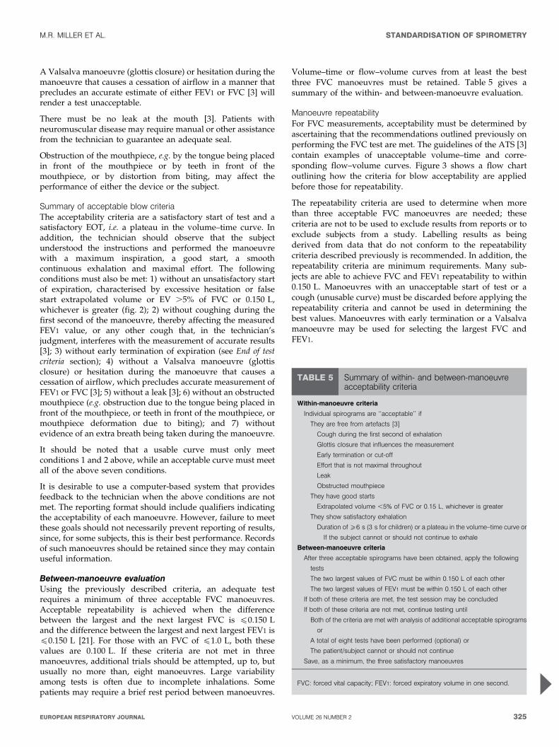
Manoeuvre repeatabilityFor FVC measurements, acceptability must be determined byascertaining that the recommendations outlined previously onperforming the FVC test are met. The guidelines of the ATS [3]contain examples of unacceptable volume–time and corre-sponding flow–volume curves. Figure 3 shows a flow chartoutlining how the criteria for blow acceptability are appliedbefore those for repeatability.
The repeatability criteria are used to determine when morethan three acceptable FVC manoeuvres are needed; thesecriteria are not to be used to exclude results from reports or toexclude subjects from a study. Labelling results as beingderived from data that do not conform to the repeatabilitycriteria described previously is recommended. In addition, therepeatability criteria are minimum requirements. Many sub-jects are able to achieve FVC and FEV1 repeatability to within0.150 L. Manoeuvres with an unacceptable start of test or acough (unusable curve) must be discarded before applying therepeatability criteria and cannot be used in determining thebest values. Manoeuvres with early termination or a Valsalvamanoeuvre may be used for selecting the largest FVC andFEV1.
TABLE 5 Summary of within- and between-manoeuvreacceptability criteria
Within-manoeuvre criteria
Individual spirograms are ‘‘acceptable’’ if
They are free from artefacts [3]
Cough during the first second of exhalation
Glottis closure that influences the measurement
Early termination or cut-off
Effort that is not maximal throughout
Leak
Obstructed mouthpiece
They have good starts
Extrapolated volume ,5% of FVC or 0.15 L, whichever is greater
They show satisfactory exhalation
Duration of o6 s (3 s for children) or a plateau in the volume–time curve or
If the subject cannot or should not continue to exhale
Between-manoeuvre criteria
After three acceptable spirograms have been obtained, apply the following
tests
The two largest values of FVC must be within 0.150 L of each other
The two largest values of FEV1 must be within 0.150 L of each other
If both of these criteria are met, the test session may be concluded
If both of these criteria are not met, continue testing until
Both of the criteria are met with analysis of additional acceptable spirograms
or
A total of eight tests have been performed (optional) or
The patient/subject cannot or should not continue
Save, as a minimum, the three satisfactory manoeuvres
FVC: forced vital capacity; FEV1: forced expiratory volume in one second.
M.R. MILLER ET AL. STANDARDISATION OF SPIROMETRY
cEUROPEAN RESPIRATORY JOURNAL VOLUME 26 NUMBER 2 325
No spirogram or test result should be rejected solely on thebasis of its poor repeatability. The repeatability of resultsshould be considered at the time of interpretation. The use ofdata from manoeuvres with poor repeatability or failure tomeet the EOT requirements is left to the discretion of theinterpreter.
Maximum number of manoeuvresAlthough there may be some circumstances in which morethan eight consecutive FVC manoeuvres may be needed, eightis generally a practical upper limit for most subjects [22, 23].After several forced expiratory manoeuvres, fatigue can beginto take its toll on subjects and additional manoeuvres would beof little added value. In extremely rare circumstances, subjectsmay show a progressive reduction in FEV1 or FVC with eachsubsequent blow. If the cumulative drop exceeds 20% of startvalue, the test procedure should be terminated in the interestof patient safety. The sequence of the manoeuvres should berecorded.
Test result selectionFVC and FEV1 should be measured from a series of at leastthree forced expiratory curves that have an acceptable start oftest and are free from artefact, such as a cough (i.e. ‘‘usablecurves’’). The largest FVC and the largest FEV1 (BTPS) shouldbe recorded after examining the data from all of the usablecurves, even if they do not come from the same curve.
Other derived indicesFEVt
FEVt is the maximal volume exhaled by time t seconds (timedfrom the time zero defined by back extrapolation) of a forcedexpiration from a position of full inspiration, expressed in litresat BTPS. Very young children may not be able to produceprolonged expirations, but there is increasing evidence thatindices derived from blows with forced expiratory times of
,1 s may have clinical usefulness [19]. At present, there areinsufficient data to recommend the use of FEV0.5 or FEV0.75.
When the subject does not exhale completely, the volumeaccumulated over a shorter period of time (e.g. 6 s) may beused as an approximate surrogate for FVC. When suchsurrogates are used, the volume label should reflect the shorterexhalation time (e.g. FEV6 for a 6-s exhalation). FEV6 has beenincreasingly considered a reasonably reliable surrogate forFVC [24] and can be used for normalising FEV1 (e.g. FEV1/FEV6). Recording FEV6 seems to have the advantage of beingmore reproducible than FVC, being less physically demandingfor patients and providing a more explicit EOT. Confirmationfrom other studies is required.
Standardisation of FEV1 for expired volume, FEV1/FVC and FEV1/VCIn some patients, a slow or unforced VC or inspiratory vitalcapacity (IVC) manoeuvre (see VC and IC manoeuvre section)may provide a larger and more appropriate denominator forcalculation of the FEV1/VC%. Some investigators havereported that the VC is slightly higher than the FVC in normalsubjects [25].
FEF25–75%
The mean forced expiratory flow between 25% and 75% ofthe FVC (FEF25–75%) has also been known as the maximummid-expiratory flow. This index is taken from the blowwith the largest sum of FEV1 and FVC. The FEF25–75% mustbe measured with an accuracy of at least ¡5% of reading or¡0.200 L?s-1 whichever is greater, over a range of up to 7 L?s-1.It should be noted that it is highly dependent on the validity ofthe FVC measurement and the level of expiratory effort.
PEFPEF is usually obtained from flow–volume curve data. It is themaximum expiratory flow achieved from a maximum forcedexpiration, starting without hesitation from the point ofmaximal lung inflation, expressed in L?s-1. When PEF isrecorded using a patient-administered portable PEF meter, it isoften expressed in L?min-1. PEF is covered in more detail later.
Maximal expiratory flow–volume loopsThe shape of a maximum flow–volume loop (MFVL), whichincludes forced inspiratory manoeuvres, can be helpful inquality control and in detecting the presence of upper airwayobstruction. None of the numerical indices from a MFVL hasclinical utility superior to FEV1, FVC, FEF25–75% and PEF, andare not considered in detail here.
DefinitionsWith regard to instantaneous flows, the recommendedmeasure is the instantaneous forced expiratory flow whenX% of the FVC has been expired (FEFX%). The maximalinstantaneous forced expiratory flow when X% of the FVCremains to be expired (MEFX%) was the term previouslyrecommended in Europe.
Instantaneous forced inspiratory flow when X% of the FVC hasbeen expired (FIFX%) and mid-inspiratory flow when X% of theFVC has been expired refer to the flows measured onthe inspiratory limb of a flow–volume loop. FIF25–75%, also
/��� ���$���� �����
��,� ��0��� �����������������������1
�� ����� ��������������� ������1
����,������ �����������������������1
2����������3���$�������3����$%
�������� �����,� ���3����� ��$�4��$% �������� ���������
� ������������
5��
5��
5��
+
+
+
FIGURE 3. Flow chart outlining how acceptability and reapeatability criteria are
to be applied. FVC: forced vital capacity; FEV1: forced expiratory volume in one
second.
STANDARDISATION OF SPIROMETRY M.R. MILLER ET AL.
326 VOLUME 26 NUMBER 2 EUROPEAN RESPIRATORY JOURNAL
referred to as maximal mid-inspiratory flow, is analogous toFEF25–75% (see Other derived indices section).
EquipmentInstantaneous flows must be measured with an accuracy of¡5% of reading or ¡0.200 L?s-1, whichever is greater, over arange of -14–14 L?s-1. The level of minimum detectable flowshould be 0.025 L?s-1. When a maximum flow–volume loop isplotted or displayed, exhaled flow must be plotted upwards,and exhaled volume towards the right. A 2:1 ratio must bemaintained between the flow and volume scales, e.g. 2 L?s-1 offlow and 1 L of exhaled volume must be the same distance ontheir respective axes. The flow and volume scales, used inreviewing test performance, must be equivalent to that shownin table 2.
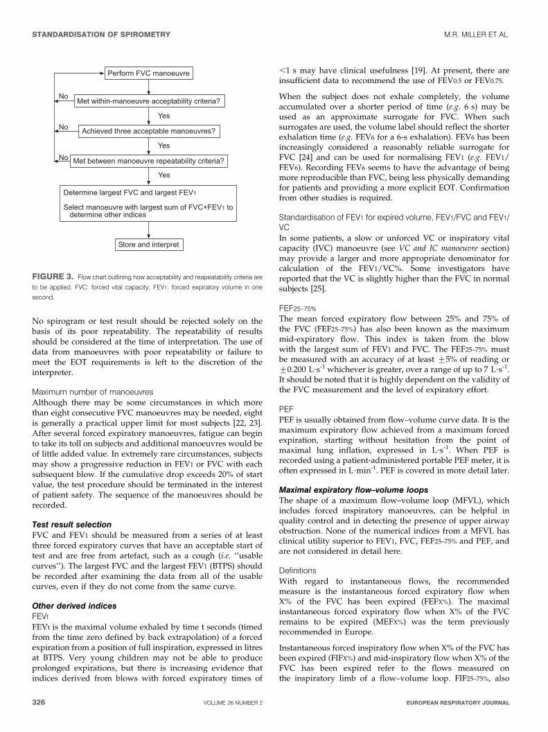
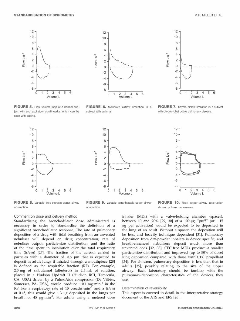
Test procedureThe subject has to make a full expiratory and inspiratory loopas a single manoeuvre. In many laboratories, this is theprimary manoeuvre for spirometry. The subject is asked totake a rapid full inspiration to TLC from room air through themouth, then insert the mouthpiece and, without hesitation,perform an expiration with maximum force until no more gascan be expelled, followed by a quick maximum inspiration. Atthis point, the manoeuvre is finished.
An alternative procedure is for the subject to insert themouthpiece while undertaking tidal breathing at FRC, andthen, in one continuous sequence, do the following: make aslow expiration to residual volume (RV); followed directly by aslow inspiration to TLC; follow this by a rapid full expirationwith maximal effort to RV; and followed by a rapid fullinspiration with maximal effort back to TLC.
This procedure is slightly more complicated and may not besuitable for all equipment, but it obtains a measurement of VCas well as FVC.
Within- and between-manoeuvre evaluationThese evaluations are the same as for FVC (see Within-manoeuvre evaluation and Between-manoeuvre evaluation sec-tions). Occasionally, a subject is unable to perform asatisfactory inspiratory limb immediately following a maximalforced expiratory manoeuvre. This is particularly common inthe elderly and the infirm. In these circumstances, it may benecessary for the subject to record an inspiratory manoeuvreseparately from the expiratory manoeuvre. Equipment shouldbe able to perform these separately and then present three ormore loops together on a graphical display or output.
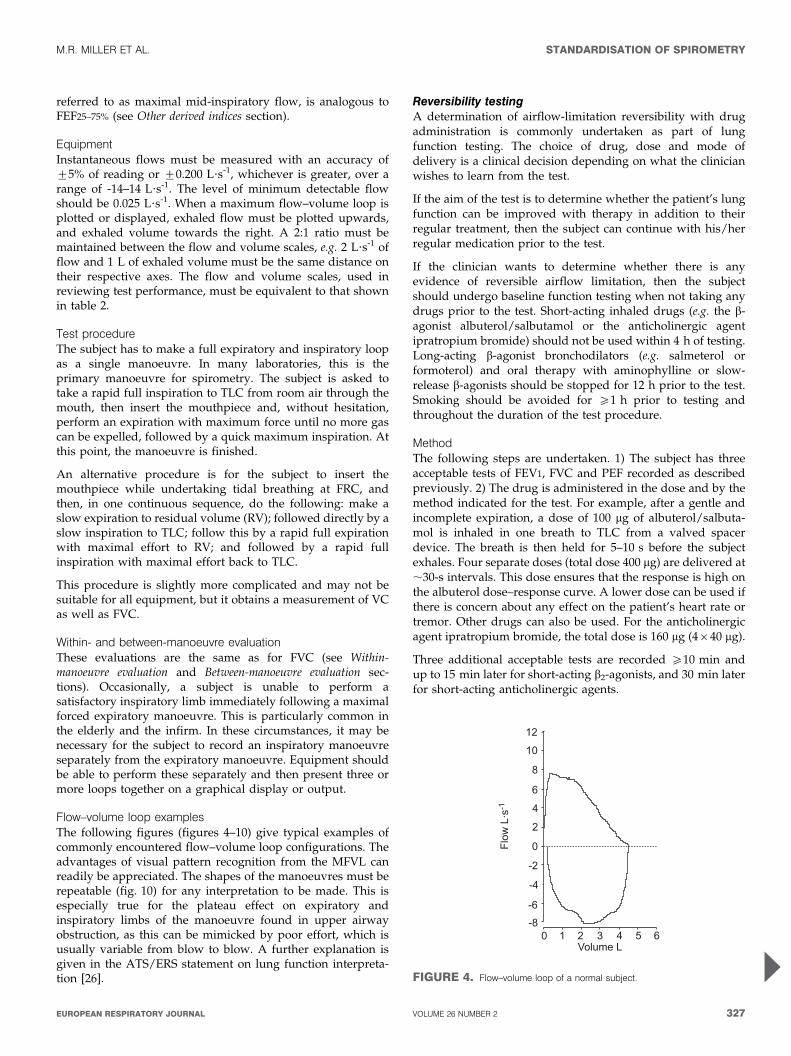
Flow–volume loop examplesThe following figures (figures 4–10) give typical examples ofcommonly encountered flow–volume loop configurations. Theadvantages of visual pattern recognition from the MFVL canreadily be appreciated. The shapes of the manoeuvres must berepeatable (fig. 10) for any interpretation to be made. This isespecially true for the plateau effect on expiratory andinspiratory limbs of the manoeuvre found in upper airwayobstruction, as this can be mimicked by poor effort, which isusually variable from blow to blow. A further explanation isgiven in the ATS/ERS statement on lung function interpreta-tion [26].
Reversibility testingA determination of airflow-limitation reversibility with drugadministration is commonly undertaken as part of lungfunction testing. The choice of drug, dose and mode ofdelivery is a clinical decision depending on what the clinicianwishes to learn from the test.
If the aim of the test is to determine whether the patient’s lungfunction can be improved with therapy in addition to theirregular treatment, then the subject can continue with his/herregular medication prior to the test.
If the clinician wants to determine whether there is anyevidence of reversible airflow limitation, then the subjectshould undergo baseline function testing when not taking anydrugs prior to the test. Short-acting inhaled drugs (e.g. the b-agonist albuterol/salbutamol or the anticholinergic agentipratropium bromide) should not be used within 4 h of testing.Long-acting b-agonist bronchodilators (e.g. salmeterol orformoterol) and oral therapy with aminophylline or slow-release b-agonists should be stopped for 12 h prior to the test.Smoking should be avoided for o1 h prior to testing andthroughout the duration of the test procedure.
MethodThe following steps are undertaken. 1) The subject has threeacceptable tests of FEV1, FVC and PEF recorded as describedpreviously. 2) The drug is administered in the dose and by themethod indicated for the test. For example, after a gentle andincomplete expiration, a dose of 100 mg of albuterol/salbuta-mol is inhaled in one breath to TLC from a valved spacerdevice. The breath is then held for 5–10 s before the subjectexhales. Four separate doses (total dose 400 mg) are delivered at,30-s intervals. This dose ensures that the response is high onthe albuterol dose–response curve. A lower dose can be used ifthere is concern about any effect on the patient’s heart rate ortremor. Other drugs can also be used. For the anticholinergicagent ipratropium bromide, the total dose is 160 mg (4640 mg).
Three additional acceptable tests are recorded o10 min andup to 15 min later for short-acting b2-agonists, and 30 min laterfor short-acting anticholinergic agents.
%(
%!
#
&
'
(
!
0(
0'
0&
0#
�� ,)6�0%
! % ( 7 ' * &$ ����)
FIGURE 4. Flow–volume loop of a normal subject.
M.R. MILLER ET AL. STANDARDISATION OF SPIROMETRY
cEUROPEAN RESPIRATORY JOURNAL VOLUME 26 NUMBER 2 327
Comment on dose and delivery methodStandardising the bronchodilator dose administered isnecessary in order to standardise the definition of asignificant bronchodilator response. The rate of pulmonarydeposition of a drug with tidal breathing from an unventednebuliser will depend on drug concentration, rate ofnebuliser output, particle-size distribution, and the ratioof the time spent in inspiration over the total respiratorytime (ti/ttot) [27]. The fraction of the aerosol carried inparticles with a diameter of f5 mm that is expected todeposit in adult lungs if inhaled through a mouthpiece [28]is defined as the respirable fraction (RF). For example,2.5 mg of salbutamol (albuterol) in 2.5 mL of solution,placed in a Hudson Updraft II (Hudson RCI, Temecula,CA, USA) driven by a PulmoAide compressor (De Vilbiss,Somerset, PA, USA), would produce ,0.1 mg?min-1 in theRF. For a respiratory rate of 15 breaths?min-1 and a ti/ttot
of 0.45, this would give ,3 mg deposited in the lungs perbreath, or 45 mg?min-1. For adults using a metered dose
inhaler (MDI) with a valve-holding chamber (spacer),between 10 and 20% [29, 30] of a 100-mg ‘‘puff’’ (or ,15mg per activation) would be expected to be deposited inthe lung of an adult. Without a spacer, the deposition willbe less, and heavily technique dependent [31]. Pulmonarydeposition from dry-powder inhalers is device specific, andbreath-enhanced nebulisers deposit much more thanunvented ones [32, 33]. CFC-free MDIs produce a smallerparticle-size distribution and improved (up to 50% of dose)lung deposition compared with those with CFC propellant[34]. For children, pulmonary deposition is less than that inadults [35], possibly relating to the size of the upperairway. Each laboratory should be familiar with thepulmonary-deposition characteristics of the devices theyuse.
Determination of reversibilityThis aspect is covered in detail in the interpretative strategydocument of the ATS and ERS [26].
%(
%!
#
&
'
(
!
0(
0'
0&
0#
�� ,)6�0%
! % ( 7 ' * &$ ����)
FIGURE 5. Flow–volume loop of a normal sub-
ject with end expiratory curvilinearity, which can be
seen with ageing.
%(
%!
#
&
'
(
!
0(
0'
0&
0#
�� ,)6�0%
! % ( 7 ' * &$ ����)
FIGURE 6. Moderate airflow limitation in a
subject with asthma.
%(
%!
#
&
'
(
!
0(
0'
0&
0#
�� ,)6�0%
! % ( 7 ' * &$ ����)
FIGURE 7. Severe airflow limitation in a subject
with chronic obstructive pulmonary disease.
%(
%!
#
&
'
(
!
0(
0'
0&
0#
�� ,)6�0%
! % ( 7 ' * &$ ����)
FIGURE 8. Variable intra-thoracic upper airway
obstruction.
%(
%!
#
&
'
(
!
0(
0'
0&
0#
�� ,)6�0%
! % ( 7 ' * &$ ����)
FIGURE 9. Variable extra-thoracic upper airway
obstruction.
%(
%!
#
&
'
(
!
0(
0'
0&
0#
�� ,)6�0%
! % ( 7 ' * &$ ����)
FIGURE 10. Fixed upper airway obstruction
shown by three manoeuvres.
STANDARDISATION OF SPIROMETRY M.R. MILLER ET AL.
328 VOLUME 26 NUMBER 2 EUROPEAN RESPIRATORY JOURNAL
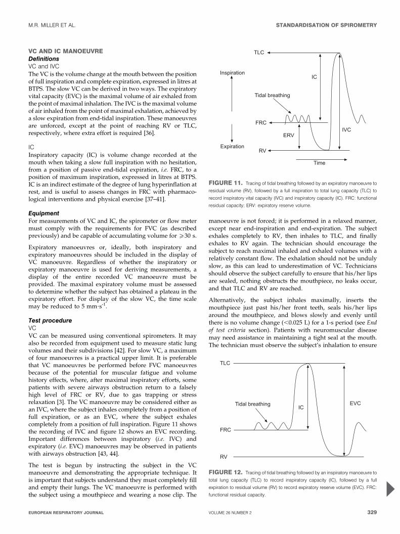
VC AND IC MANOEUVREDefinitionsVC and IVCThe VC is the volume change at the mouth between the positionof full inspiration and complete expiration, expressed in litres atBTPS. The slow VC can be derived in two ways. The expiratoryvital capacity (EVC) is the maximal volume of air exhaled fromthe point of maximal inhalation. The IVC is the maximal volumeof air inhaled from the point of maximal exhalation, achieved bya slow expiration from end-tidal inspiration. These manoeuvresare unforced, except at the point of reaching RV or TLC,respectively, where extra effort is required [36].
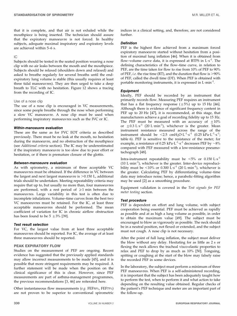
ICInspiratory capacity (IC) is volume change recorded at themouth when taking a slow full inspiration with no hesitation,from a position of passive end-tidal expiration, i.e. FRC, to aposition of maximum inspiration, expressed in litres at BTPS.IC is an indirect estimate of the degree of lung hyperinflation atrest, and is useful to assess changes in FRC with pharmaco-logical interventions and physical exercise [37–41].
EquipmentFor measurements of VC and IC, the spirometer or flow metermust comply with the requirements for FVC (as describedpreviously) and be capable of accumulating volume for o30 s.
Expiratory manoeuvres or, ideally, both inspiratory andexpiratory manoeuvres should be included in the display ofVC manoeuvre. Regardless of whether the inspiratory orexpiratory manoeuvre is used for deriving measurements, adisplay of the entire recorded VC manoeuvre must beprovided. The maximal expiratory volume must be assessedto determine whether the subject has obtained a plateau in theexpiratory effort. For display of the slow VC, the time scalemay be reduced to 5 mm?s-1.
Test procedureVCVC can be measured using conventional spirometers. It mayalso be recorded from equipment used to measure static lungvolumes and their subdivisions [42]. For slow VC, a maximumof four manoeuvres is a practical upper limit. It is preferablethat VC manoeuvres be performed before FVC manoeuvresbecause of the potential for muscular fatigue and volumehistory effects, where, after maximal inspiratory efforts, somepatients with severe airways obstruction return to a falselyhigh level of FRC or RV, due to gas trapping or stressrelaxation [3]. The VC manoeuvre may be considered either asan IVC, where the subject inhales completely from a position offull expiration, or as an EVC, where the subject exhalescompletely from a position of full inspiration. Figure 11 showsthe recording of IVC and figure 12 shows an EVC recording.Important differences between inspiratory (i.e. IVC) andexpiratory (i.e. EVC) manoeuvres may be observed in patientswith airways obstruction [43, 44].
The test is begun by instructing the subject in the VCmanoeuvre and demonstrating the appropriate technique. Itis important that subjects understand they must completely filland empty their lungs. The VC manoeuvre is performed withthe subject using a mouthpiece and wearing a nose clip. The
manoeuvre is not forced; it is performed in a relaxed manner,except near end-inspiration and end-expiration. The subjectexhales completely to RV, then inhales to TLC, and finallyexhales to RV again. The technician should encourage thesubject to reach maximal inhaled and exhaled volumes with arelatively constant flow. The exhalation should not be undulyslow, as this can lead to underestimation of VC. Techniciansshould observe the subject carefully to ensure that his/her lipsare sealed, nothing obstructs the mouthpiece, no leaks occur,and that TLC and RV are reached.
Alternatively, the subject inhales maximally, inserts themouthpiece just past his/her front teeth, seals his/her lipsaround the mouthpiece, and blows slowly and evenly untilthere is no volume change (,0.025 L) for a 1-s period (see Endof test criteria section). Patients with neuromuscular diseasemay need assistance in maintaining a tight seal at the mouth.The technician must observe the subject’s inhalation to ensure
.)�
8�
��$8$�
���
�$
.�������� ��3
8������� �
�9����� �
.���
FIGURE 11. Tracing of tidal breathing followed by an expiratory manoeuvre to
residual volume (RV), followed by a full inspiration to total lung capacity (TLC) to
record inspiratory vital capacity (IVC) and inspiratory capacity (IC). FRC: functional
residual capacity; ERV: expiratory reserve volume.
.�������� ��3
.)�
���
�$
8��$�
FIGURE 12. Tracing of tidal breathing followed by an inspiratory manoeuvre to
total lung capacity (TLC) to record inspiratory capacity (IC), followed by a full
expiration to residual volume (RV) to record expiratory reserve volume (EVC). FRC:
functional residual capacity.
M.R. MILLER ET AL. STANDARDISATION OF SPIROMETRY
cEUROPEAN RESPIRATORY JOURNAL VOLUME 26 NUMBER 2 329
that it is complete, and that air is not exhaled while themouthpiece is being inserted. The technician should assurethat the expiratory manoeuvre is not forced. In healthysubjects, adequate maximal inspiratory and expiratory levelsare achieved within 5–6 s.
ICSubjects should be tested in the seated position wearing a noseclip with no air leaks between the mouth and the mouthpiece.Subjects should be relaxed (shoulders down and relaxed) andasked to breathe regularly for several breaths until the end-expiratory lung volume is stable (this usually requires at leastthree tidal manoeuvres). They are then urged to take a deepbreath to TLC with no hesitation. Figure 12 shows a tracingfrom the recording of IC.
Use of a nose clipThe use of a nose clip is encouraged in VC measurements,since some people breathe through the nose when performinga slow VC manoeuvre. A nose clip must be used whenperforming inspiratory manoeuvres such as the IVC or IC.
Within-manoeuvre evaluationThese are the same as for FVC EOT criteria as describedpreviously. There must be no leak at the mouth, no hesitationduring the manoeuvre, and no obstruction of the mouthpiece(see Additional criteria section). The IC may be underestimatedif the inspiratory manoeuvre is too slow due to poor effort orhesitation, or if there is premature closure of the glottis.
Between-manoeuvre evaluationAs with spirometry, a minimum of three acceptable VCmanoeuvres must be obtained. If the difference in VC betweenthe largest and next largest manoeuvre is .0.150 L, additionaltrials should be undertaken. Meeting repeatability criteria mayrequire that up to, but usually no more than, four manoeuvresare performed, with a rest period of o1 min between themanoeuvres. Large variability in this test is often due toincomplete inhalations. Volume–time curves from the best twoVC manoeuvres must be retained. For the IC, at least threeacceptable manoeuvres should be performed. The meancoefficient of variation for IC in chronic airflow obstructionhas been found to be 5 ¡3% [39].
Test result selectionFor VC, the largest value from at least three acceptablemanoeuvres should be reported. For IC, the average of at leastthree manoeuvres should be reported.
PEAK EXPIRATORY FLOWStudies on the measurement of PEF are ongoing. Recentevidence has suggested that the previously applied standardsmay allow incorrect measurements to be made [45], and it ispossible that more stringent requirements may be required. Afurther statement will be made when the position on theclinical significance of this is clear. However, since PEFmeasurements are part of asthma-management programmes,the previous recommendations [3, 46] are reiterated here.
Other instantaneous flow measurements (e.g. FEF50%, FEF75%)are not proven to be superior to conventional spirometric
indices in a clinical setting, and, therefore, are not consideredfurther.
DefinitionPEF is the highest flow achieved from a maximum forcedexpiratory manoeuvre started without hesitation from a posi-tion of maximal lung inflation [46]. When it is obtained fromflow–volume curve data, it is expressed at BTPS in L?s-1. Thedefining characteristics of the flow–time curve, in relation toPEF, are the time taken for flow to rise from 10% of PEF to 90%of PEF, i.e. the rise time (RT), and the duration that flow is .90%of PEF, called the dwell time (DT). When PEF is obtained withportable monitoring instruments, it is expressed in L?min-1.
EquipmentIdeally, PEF should be recorded by an instrument thatprimarily records flow. Measuring PEF requires an instrumentthat has a flat frequency response (¡5%) up to 15 Hz [46].Although there is evidence of significant frequency content inPEF up to 20 Hz [47], it is recommended, at this stage, thatmanufacturers achieve a goal of recording fidelity up to 15 Hz.The PEF must be measured with an accuracy of ¡10%or ¡0.3 L?s-1 (20 L?min-1), whichever is the greater. Meaninstrument resistance measured across the range of theinstrument should be ,2.5 cmH2O?L-1?s-1 (0.25 kPa?L-1?s-1;table 6). PEF is sensitive to the resistance of the meter; forexample, a resistance of 0.25 kPa?L-1?s-1 decreases PEF by ,8%compared with PEF measured with a low-resistance pneumo-tachograph [48].
Intra-instrument repeatability must be ,5% or 0.150 L?s-1
(10 L?min-1), whichever is the greater. Inter-device reproduci-bility must be ,10% or 0.300 L?s-1 (20 L?min-1), whichever isthe greater. Calculating PEF by differentiating volume–timedata may introduce noise; hence, a parabolic-fitting algorithmmay be used [2] as a smoothing procedure.
Equipment validation is covered in the Test signals for PEFmeter testing section.
Test procedurePEF is dependent on effort and lung volume, with subjectcooperation being essential. PEF must be achieved as rapidlyas possible and at as high a lung volume as possible, in orderto obtain the maximum value [49]. The subject must beencouraged to blow as vigorously as possible. The neck shouldbe in a neutral position, not flexed or extended, and the subjectmust not cough. A nose clip is not necessary.
After the point of full lung inflation, the subject must deliverthe blow without any delay. Hesitating for as little as 2 s orflexing the neck allows the tracheal visco-elastic properties torelax and PEF to drop by as much as 10% [50]. Tonguing,spitting or coughing at the start of the blow may falsely raisethe recorded PEF in some devices.
In the laboratory, the subject must perform a minimum of threePEF manoeuvres. When PEF is a self-administered recording,it is important that the subject has been adequately taught howto perform the test, when to perform it and what action to takedepending on the resulting value obtained. Regular checks ofthe patient’s PEF technique and meter are an important part ofthe follow-up.
STANDARDISATION OF SPIROMETRY M.R. MILLER ET AL.
330 VOLUME 26 NUMBER 2 EUROPEAN RESPIRATORY JOURNAL
Within-manoeuvre evaluationThe subject must be observed to ensure a good seal at themouth, no hesitation occurred, and there was no abnormalstart to the manoeuvre.
Between-manoeuvre evaluationThe PEF values and their order must be recorded so thatmanoeuvre-induced bronchospasm can be detected. If thelargest two out of three acceptable blows are not reproduciblewithin 0.67 L?s-1 (40 L?min-1), up to two additional blows canbe performed. Ninety-five per cent of untrained healthysubjects and patients can reproduce PEF to within 0.67 L?s-1
(40 L?min-1), and 90% to within 0.5 L?s-1 (30 L?min-1) [48]. Ifsatisfactory repeatability has not been in achieved in fiveattempts, more are not likely to be helpful [51].
Test result selectionThe largest value from at least three acceptable blows isrecorded.
MAXIMUM VOLUNTARY VENTILATIONThis test has been largely superseded by FEV1, which wasdefined as the index from a single maximum forced expiratorymanoeuvre that best correlated with maximum voluntaryventilation (MVV). If FEV1 is available, then MVV has littleadditional contribution to make in a clinical setting. However,it may be useful in those conditions where ventilatory capacitymay be impaired by mechanisms that are different from thoseaffecting FEV1 [26].
DefinitionThe MVV is the maximum volume of air a subject can breatheover a specified period of time (12 s for normal subjects). It isexpressed in L?min-1 at BTPS.
EquipmentA spirometer used for measuring MVV must have anamplitude–frequency response that is flat (¡10%) from zeroto o4 Hz, at flows of up to 12 L?s-1, over the volume range.The time for exhaled volume integration or recording must beno less than 12 s and no more than 15 s [52]. The indicated timemust be accurate to within ¡3%. The MVV must be measuredwith an accuracy of ¡10% of reading or ¡15 L?min-1,whichever is greater.
The evaluation of equipment is covered in the Test signals forMVV testing section.
Test procedureThe technician should provide proper instructions anddemonstrate the manoeuvre prior to the start of testing.The subject should be tested in the sitting position wearinga nose clip. After the subject makes an airtight seal aroundthe mouthpiece, at least three resting tidal breaths should beobtained, followed by breathing as rapidly and deeply aspossible. The tongue and teeth must be positioned so as tonot obstruct airflow. The technician should enthusiasticallycoach the subject throughout the manoeuvre, and may needto suggest faster or slower breathing to achieve an ideal rateof 90–110 breaths?min-1 [53, 54], although subjects withdisease may not always achieve this rate. The technicianwill need to carefully observe the subject with occasional
glances at the tracing to help the subject to obtain anacceptable manoeuvre. An acceptable manoeuvre should beperformed with maximal effort without evidence of leakage,hesitation or measurement artefact. The subject is instructedto breathe as deeply and rapidly as possible and the tidalvolume (VT) during the manoeuvre should be greater thanthe subject’s resting VT.
The test interval (e.g. 12 s) should be reported. A rest betweenmanoeuvres will improve subsequent efforts.
The MVV should be calculated from the sum of all individualexhalations, multiplied by the appropriate BTPS correctionfactor during the best 12 s of the manoeuvre. From a technicalstandpoint, changes in respiratory rate or VT during themanoeuvre will influence test results.
Within-manoeuvre evaluationIn normal subjects, the goal for an acceptable MVV should be aVT that is ,50% of the VC, with a breathing frequency that is,90 breaths?min-1 [54]. It is unlikely that an acceptablemanoeuvre will be obtained when the breathing frequency is,65 breaths?min-1 [54]. However, since there are little data onMVV acceptability criteria, no specific breathing frequency orvolume is required. The emphasis should be on maximal effortwith a goal of 90 breaths?min-1 and a volume representing,50% of the VC. VT during the manoeuvre is probably not asimportant as breathing frequency, since patients tend tobreathe on the portion of the expiratory curve where air isbest moved at a given frequency.
Between-manoeuvre evaluationThe subject should perform a minimum of two acceptablemanoeuvres. There are no clinical studies addressing repeat-ability; however, additional trials should be considered whenthe variability between acceptable manoeuvres exceeds 20%.
Test result selectionThe highest acceptable MVV (L?min-1 BTPS) and MVV rate(breaths?min-1) should be reported. An MVV/(406FEV1),0.80 indicates that the MVV is low relative to the FEV1,and suggests disease or poor effort. Volume versus timetracings from at least two acceptable manoeuvres should beretained and available for inspection.
TECHNICAL CONSIDERATIONSMinimal recommendations for spirometry systemsAccurate results require accurate equipment. Spirometer equip-ment recommendations apply to all spirometers and are minimalrequirements. In some circumstances, it may be appropriateto exceed these requirements (i.e. in some research/surveillance applications). Instrumentation recommendationsshould be followed to provide accurate spirometric data andinformation that is comparable from laboratory to laboratory andfrom one time period to another [1]. The accuracy of a spirometrysystem depends on characteristics of the entire system, from thevolume or flow transducer and the use of an in-line filter, tothe recorder, display or processor. Changes in any aspect ofthe equipment or errors at any step in the process can affect theaccuracy of the results. For example, if the BTPS correction factoris wrong, an accurately measured FVC will be incorrectlyreported.
M.R. MILLER ET AL. STANDARDISATION OF SPIROMETRY
cEUROPEAN RESPIRATORY JOURNAL VOLUME 26 NUMBER 2 331
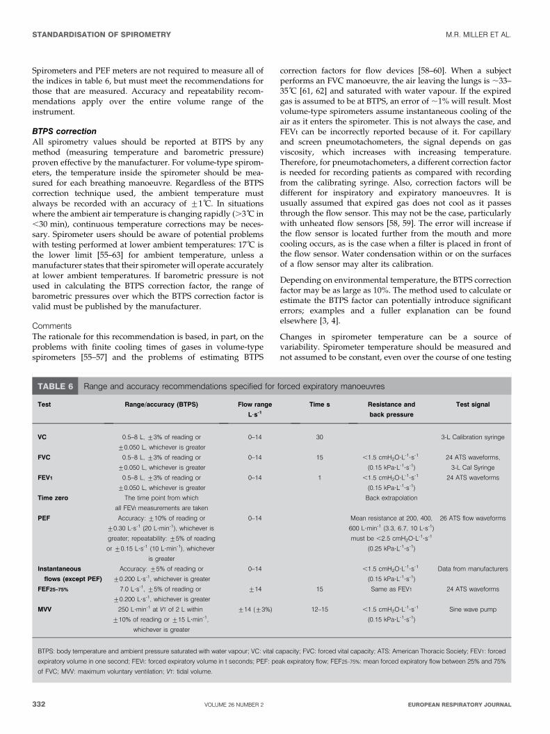
Spirometers and PEF meters are not required to measure all ofthe indices in table 6, but must meet the recommendations forthose that are measured. Accuracy and repeatability recom-mendations apply over the entire volume range of theinstrument.
BTPS correctionAll spirometry values should be reported at BTPS by anymethod (measuring temperature and barometric pressure)proven effective by the manufacturer. For volume-type spirom-eters, the temperature inside the spirometer should be mea-sured for each breathing manoeuvre. Regardless of the BTPScorrection technique used, the ambient temperature mustalways be recorded with an accuracy of ¡1 C. In situationswhere the ambient air temperature is changing rapidly (.3 C in,30 min), continuous temperature corrections may be neces-sary. Spirometer users should be aware of potential problemswith testing performed at lower ambient temperatures: 17 C isthe lower limit [55–63] for ambient temperature, unless amanufacturer states that their spirometer will operate accuratelyat lower ambient temperatures. If barometric pressure is notused in calculating the BTPS correction factor, the range ofbarometric pressures over which the BTPS correction factor isvalid must be published by the manufacturer.
CommentsThe rationale for this recommendation is based, in part, on theproblems with finite cooling times of gases in volume-typespirometers [55–57] and the problems of estimating BTPS
correction factors for flow devices [58–60]. When a subjectperforms an FVC manoeuvre, the air leaving the lungs is ,33–35 C [61, 62] and saturated with water vapour. If the expiredgas is assumed to be at BTPS, an error of ,1% will result. Mostvolume-type spirometers assume instantaneous cooling of theair as it enters the spirometer. This is not always the case, andFEVt can be incorrectly reported because of it. For capillaryand screen pneumotachometers, the signal depends on gasviscosity, which increases with increasing temperature.Therefore, for pneumotachometers, a different correction factoris needed for recording patients as compared with recordingfrom the calibrating syringe. Also, correction factors will bedifferent for inspiratory and expiratory manoeuvres. It isusually assumed that expired gas does not cool as it passesthrough the flow sensor. This may not be the case, particularlywith unheated flow sensors [58, 59]. The error will increase ifthe flow sensor is located further from the mouth and morecooling occurs, as is the case when a filter is placed in front ofthe flow sensor. Water condensation within or on the surfacesof a flow sensor may alter its calibration.
Depending on environmental temperature, the BTPS correctionfactor may be as large as 10%. The method used to calculate orestimate the BTPS factor can potentially introduce significanterrors; examples and a fuller explanation can be foundelsewhere [3, 4].
Changes in spirometer temperature can be a source ofvariability. Spirometer temperature should be measured andnot assumed to be constant, even over the course of one testing
TABLE 6 Range and accuracy recommendations specified for forced expiratory manoeuvres
Test Range/accuracy (BTPS) Flow range
L?s-1
Time s Resistance and
back pressure
Test signal
VC 0.5–8 L, ¡3% of reading or
¡0.050 L, whichever is greater
0–14 30 3-L Calibration syringe
FVC 0.5–8 L, ¡3% of reading or
¡0.050 L, whichever is greater
0–14 15 ,1.5 cmH2O?L-1?s-1
(0.15 kPa?L-1?s-1)
24 ATS waveforms,
3-L Cal Syringe
FEV1 0.5–8 L, ¡3% of reading or
¡0.050 L, whichever is greater
0–14 1 ,1.5 cmH2O?L-1?s-1
(0.15 kPa?L-1?s-1)
24 ATS waveforms
Time zero The time point from which
all FEVt measurements are taken
Back extrapolation
PEF Accuracy: ¡10% of reading or
¡0.30 L?s-1 (20 L?min-1), whichever is
greater; repeatability: ¡5% of reading
or ¡0.15 L?s-1 (10 L?min-1), whichever
is greater
0–14 Mean resistance at 200, 400,
600 L?min-1 (3.3, 6.7, 10 L?s-1)
must be ,2.5 cmH2O?L-1?s-1
(0.25 kPa?L-1?s-1)
26 ATS flow waveforms
Instantaneous
flows (except PEF)
Accuracy: ¡5% of reading or
¡0.200 L?s-1, whichever is greater
0–14 ,1.5 cmH2O?L-1?s-1
(0.15 kPa?L-1?s-1)
Data from manufacturers
FEF25–75% 7.0 L?s-1, ¡5% of reading or
¡0.200 L?s-1, whichever is greater
¡14 15 Same as FEV1 24 ATS waveforms
MVV 250 L?min-1 at VT of 2 L within
¡10% of reading or ¡15 L?min-1,
whichever is greater
¡14 (¡3%) 12–15 ,1.5 cmH2O?L-1?s-1
(0.15 kPa?L-1?s-1)
Sine wave pump
BTPS: body temperature and ambient pressure saturated with water vapour; VC: vital capacity; FVC: forced vital capacity; ATS: American Thoracic Society; FEV1: forced
expiratory volume in one second; FEVt: forced expiratory volume in t seconds; PEF: peak expiratory flow; FEF25–75%: mean forced expiratory flow between 25% and 75%
of FVC; MVV: maximum voluntary ventilation; VT: tidal volume.
STANDARDISATION OF SPIROMETRY M.R. MILLER ET AL.
332 VOLUME 26 NUMBER 2 EUROPEAN RESPIRATORY JOURNAL
session. For volume spirometers, errors up to 6% in FEV1 andFVC can occur if ambient temperature is used instead ofinternal spirometer temperature [64]. For volume spirometers,the temperature inside the spirometer should be measured foreach breathing manoeuvre.
Test signals for spirometer testingThe diversity of FVC manoeuvres encountered in clinicalpractice is currently best simulated by the 24 standard volume–time waveforms developed by the ATS [3] and HANKINSON andGARDNER [65]. These waveforms can be used to drive acomputer-controlled mechanical syringe, or its equivalent, fortesting actual hardware and software [66, 67], or, when put in adigital form, they can evaluate only the software. Computer-controlled mechanical syringes (i.e. pump systems) used forvalidation should be accurate within ¡50 mL, which is 0.5% oftheir full range up to 10 L for FVC and FEV1. Pump systemsmay have accuracy values better than this for many profiles,but reproduce less accurately those test profiles with short DTsand RTs to peak flow [68, 69]. The ATS spirometry statement[3] shows the measured values for each of the 24 standardwaveforms. On request, the ATS can provide these waveformsin an electronic format. Appropriate corrections for using gasat the ambient temperature and humidity instead of BTPS mayneed to be made for some mechanical syringe–spirometercombinations.
MethodA production spirometer is connected to the pump system fortesting, orientated as it would be to test human subjects.Connecting tubing must be kept to the minimum (,0.300 L)and must not be distensible. If an in-line filter is required fortesting human subjects, one must be included when theinstrument is tested. Each of the 24 ATS waveforms isdischarged into the spirometer five times under ambientconditions, and all of the readings are recorded.
BTPS conditions are simulated by discharging waveforms 1–4to the spirometer three times, using air heated to 37¡1 C andat .98% relative humidity. The time between each of the threetests should be ,2 min.
Accuracy testThe average of the five tests under ambient conditions iscompared with the standard value in the following way:
Deviation~average{standard ð1Þ
Percentage deviation~100|(average{standard)=standard ð2Þ
The accuracy validation limits for volumes, which include the
waveform-generator inaccuracy, are ¡3.5% of reading or
¡0.100 L, whichever is greater. An accuracy error occurs if
the deviation (for volumes ,2.857 L) or percentage deviation
(for volumes .2.857 L) exceed these limits. These limits
include the allowable inaccuracy of the pump system.
Acceptable spirometer performance is defined as fewer thanthree accuracy errors for either FVC or FEV1 across the 24waveforms (,5% error rate).
The average FVC and FEV1 values of the three tests simulatingBTPS conditions are compared with the standard values. The
validation limits for these tests under BTPS conditions are¡4.5% or 0.200 L, whichever is the greater, and these limitsinclude the allowable inaccuracy for the pump system.
Acceptable spirometer performance under BTPS conditions isdefined as the accuracy requirement being met for all of thefour profiles used.
Repeatability testThe FEV1 and FVC data from the accuracy test are used toderive the span of the five recordings:
Span~maximum�minimum ð3Þ
Percentage span~100|span=average ð4Þ
The repeatability validation limits for the volume measured atambient conditions are ¡3.5% or ¡0.100 L, whichever isthe greater, and, for BTPS conditions, ¡4.5% or ¡0.200 L,whichever is the greater. A repeatability error occurs if thespan (for volumes ,2.857 L at ambient or 4.444 L at BTPS) orpercentage span (for volumes above this) exceeds these limits.
Acceptable spirometer performance for repeatability underambient conditions is defined as fewer than three accuracyerrors for either FVC or FEV1 across the 24 profiles (,5% errorrate). For BTPS conditions, the acceptable spirometer perfor-mance for repeatability is defined as the accuracy requirementbeing met for all of the four profiles.
Test signals for PEF meter testingThe 26 flow–time ATS waveforms were chosen to represent arange of PEF profiles suitable for delivery by mechanicalsyringe or pump systems to test PEF meters [3]. The range ofprofiles and method of delivery may need to be revised, asresearch on PEF measurement continues [45]. The mechanicalsyringe or suitable pump system used to validate PEFmeasuring equipment must have an accuracy of ¡2% indelivering PEF. Pump systems may have difficulty meetingthis accuracy standard for profiles more demanding than theset of 26 [68, 69]. Recent evidence suggests that the frequencycontent in the first second of the blow that contributes to PEF ishigher [47] than previously determined [70, 71]. The 26waveforms may not cover the range of RT and DT found in,25% of the client population [72], and, hence, moredemanding test profiles may be required in future [45].
MethodTwo randomly chosen production models of the flow metersshould each have the 26 waveforms delivered to them fivetimes under ambient conditions and the readings recorded.Any waveforms with a PEF outside the meter’s statedoperational range would not be included in the testingsequence. Appropriate correction factors for testing underambient conditions should be applied as recommended by themanufacturer.
Accuracy testThe average reading for each of the two meters is comparedwith the standard, as for volumes.
The accuracy validation limits are ¡12% or ¡25 L?min-1,whichever is the larger, and these limits include the 2%inaccuracy limit for the waveform generator. An accuracy error
M.R. MILLER ET AL. STANDARDISATION OF SPIROMETRY
cEUROPEAN RESPIRATORY JOURNAL VOLUME 26 NUMBER 2 333
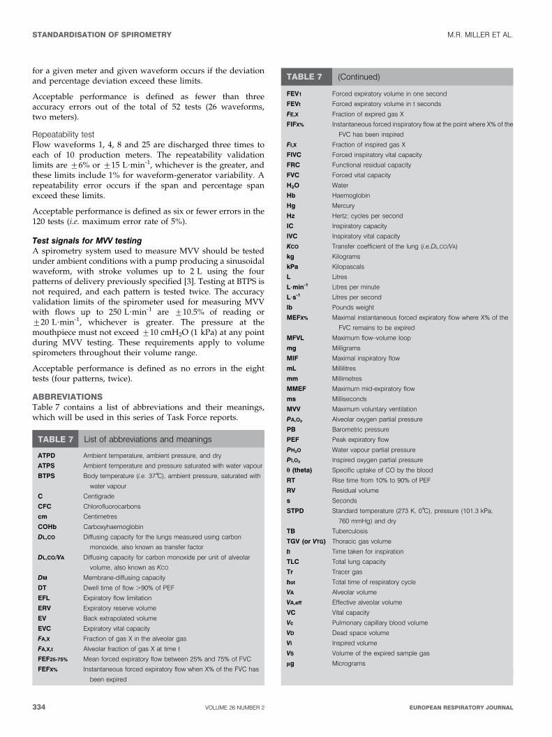
for a given meter and given waveform occurs if the deviationand percentage deviation exceed these limits.
Acceptable performance is defined as fewer than threeaccuracy errors out of the total of 52 tests (26 waveforms,two meters).
Repeatability testFlow waveforms 1, 4, 8 and 25 are discharged three times toeach of 10 production meters. The repeatability validationlimits are ¡6% or ¡15 L?min-1, whichever is the greater, andthese limits include 1% for waveform-generator variability. Arepeatability error occurs if the span and percentage spanexceed these limits.
Acceptable performance is defined as six or fewer errors in the120 tests (i.e. maximum error rate of 5%).
Test signals for MVV testingA spirometry system used to measure MVV should be testedunder ambient conditions with a pump producing a sinusoidalwaveform, with stroke volumes up to 2 L using the fourpatterns of delivery previously specified [3]. Testing at BTPS isnot required, and each pattern is tested twice. The accuracyvalidation limits of the spirometer used for measuring MVVwith flows up to 250 L?min-1 are ¡10.5% of reading or¡20 L?min-1, whichever is greater. The pressure at themouthpiece must not exceed ¡10 cmH2O (1 kPa) at any pointduring MVV testing. These requirements apply to volumespirometers throughout their volume range.
Acceptable performance is defined as no errors in the eighttests (four patterns, twice).
ABBREVIATIONSTable 7 contains a list of abbreviations and their meanings,which will be used in this series of Task Force reports.
TABLE 7 List of abbreviations and meanings
ATPD Ambient temperature, ambient pressure, and dry
ATPS Ambient temperature and pressure saturated with water vapour
BTPS Body temperature (i.e. 37 C), ambient pressure, saturated with
water vapour
C Centigrade
CFC Chlorofluorocarbons
cm Centimetres
COHb Carboxyhaemoglobin
DL,CO Diffusing capacity for the lungs measured using carbon
monoxide, also known as transfer factor
DL,CO/VA Diffusing capacity for carbon monoxide per unit of alveolar
volume, also known as KCO
DM Membrane-diffusing capacity
DT Dwell time of flow .90% of PEF
EFL Expiratory flow limitation
ERV Expiratory reserve volume
EV Back extrapolated volume
EVC Expiratory vital capacity
FA,X Fraction of gas X in the alveolar gas
FA,X,t Alveolar fraction of gas X at time t
FEF25-75% Mean forced expiratory flow between 25% and 75% of FVC
FEFX% Instantaneous forced expiratory flow when X% of the FVC has
been expired
FEV1 Forced expiratory volume in one second
FEVt Forced expiratory volume in t seconds
FE,X Fraction of expired gas X
FIFX% Instantaneous forced inspiratory flow at the point where X% of the
FVC has been inspired
FI,X Fraction of inspired gas X
FIVC Forced inspiratory vital capacity
FRC Functional residual capacity
FVC Forced vital capacity
H2O Water
Hb Haemoglobin
Hg Mercury
Hz Hertz; cycles per second
IC Inspiratory capacity
IVC Inspiratory vital capacity
KCO Transfer coefficient of the lung (i.e.DL,CO/VA)
kg Kilograms
kPa Kilopascals
L Litres
L?min-1 Litres per minute
L?s-1 Litres per second
lb Pounds weight
MEFX% Maximal instantaneous forced expiratory flow where X% of the
FVC remains to be expired
MFVL Maximum flow–volume loop
mg Milligrams
MIF Maximal inspiratory flow
mL Millilitres
mm Millimetres
MMEF Maximum mid-expiratory flow
ms Milliseconds
MVV Maximum voluntary ventilation
PA,O2 Alveolar oxygen partial pressure
PB Barometric pressure
PEF Peak expiratory flow
PH2O Water vapour partial pressure
PI,O2 Inspired oxygen partial pressure
h (theta) Specific uptake of CO by the blood
RT Rise time from 10% to 90% of PEF
RV Residual volume
s Seconds
STPD Standard temperature (273 K, 0 C), pressure (101.3 kPa,
760 mmHg) and dry
TB Tuberculosis
TGV (or VTG) Thoracic gas volume
tI Time taken for inspiration
TLC Total lung capacity
Tr Tracer gas
ttot Total time of respiratory cycle
VA Alveolar volume
VA,eff Effective alveolar volume
VC Vital capacity
Vc Pulmonary capillary blood volume
VD Dead space volume
VI Inspired volume
VS Volume of the expired sample gas
mg Micrograms
TABLE 7 (Continued)
STANDARDISATION OF SPIROMETRY M.R. MILLER ET AL.
334 VOLUME 26 NUMBER 2 EUROPEAN RESPIRATORY JOURNAL
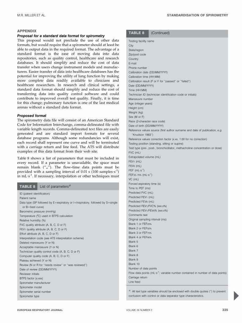
APPENDIXProposal for a standard data format for spirometryThis proposal would not preclude the use of other dataformats, but would require that a spirometer should at least beable to output data in the required format. The advantage of astandard format is the ease of moving data into datarepositories, such as quality control, healthcare and researchdatabases. It should simplify and reduce the cost of datatransfer when users change instrument models and manufac-turers. Easier transfer of data into healthcare databases has thepotential for improving the utility of lung function by makingmore complete data readily available to clinicians andhealthcare researchers. In research and clinical settings, astandard data format should simplify and reduce the cost oftransferring data into quality control software and couldcontribute to improved overall test quality. Finally, it is timefor this change; pulmonary function is one of the last medicalarenas without a standard data format.
Proposed formatThe spirometry data file will consist of an American StandardCode for Information Interchange, comma-delineated file withvariable length records. Comma-delineated text files are easilygenerated and are standard import formats for severaldatabase programs. Although some redundancies will exist,each record shall represent one curve and will be terminatedwith a carriage return and line feed. The ATS will distributeexamples of this data format from their web site.
Table 8 shows a list of parameters that must be included inevery record. If a parameter is unavailable, the space mustremain blank (‘‘,,’’). The flow–time data points must beprovided with a sampling interval of 0.01 s (100 samples?s-1)in mL?s-1. If necessary, interpolation or other techniques must
TABLE 8 List of parameters#
ID (patient identification)
Patient name
Data type (SP followed by E5expiratory or I5Inspiratory, followed by S5single
or B5best curve)
Barometric pressure (mmHg)
Temperature ( C) used in BTPS calculation
Relative humidity (%)
FVC quality attribute (A, B, C, D or F)
FEV1 quality attribute (A, B, C, D or F)
Effort attribute (A, B, C, D or F)
Interpretation code (see ATS interpretation scheme)
Deleted manoeuvre (Y or N)
Acceptable manoeuvre (Y or N)
Technician quality control code (A, B, C, D or F)
Computer quality code (A, B, C, D or F)
Plateau achieved (Y or N)
Review (N or R for ‘‘needs review’’ or ‘‘was reviewed’’)
Date of review (DD/MM/YYYY)
Reviewer initials
BTPS factor (x.xxx)
Spirometer manufacturer
Spirometer model
Spirometer serial number
Spirometer type
Testing facility name
City
State/region
Zip/post code
Country
Phone number
Calibration date (DD/MM/YYYY)
Calibration time (HH:MM)
Calibration result (P or F for ‘‘passed’’ or ‘‘failed’’)
Date (DD/MM/YYYY)
Time (HH:MM)
Technician ID (technician identification code or initials)
Manoeuvre number
Age (integer years)
Height (cm)
Weight (kg)
Sex (M or F)
Race (2-character race code)
Date of birth (DD/MM/YYYY)
Reference values source (first author surname and date of publication, e.g.
‘‘Knudson 1983’’)
Reference values correction factor (x.xx, 1.00 for no correction)
Testing position (standing, sitting or supine)
Test type (pre-, post-, bronchodilator, methacholine concentration or dose)
FVC (mL)
Extrapolated volume (mL)
FEV1 (mL)
FEV6 (mL)
PEF (mL?s-1)
FEF25–75% (mL?s-1)
VC (mL)
Forced expiratory time (s)
Time to PEF (ms)
Predicted FVC (mL)
Predicted FEV1 (mL)
Predicted FEV6 (mL)
Predicted FEV1/FVC% (xxx.x%)
Predicted FEV1/FEV6% (xxx.x%)
Comments text
Original sampling interval (ms)
Blank 1 or FEF25%
Blank 2 or FEF50%
Blank 3 or FEF75%
Blank 4 or FEF90%
Blank 5
Blank 6
Blank 7
Blank 8
Blank 9
Blank 10
Number of data points
Flow data points (mL?s-1; variable number contained in number of data points)
Carriage return
Line feed
#: All text type variables should be enclosed with double quotes (‘‘) to prevent
confusion with control or data separator type characteristics.
TABLE 8 (Continued)
M.R. MILLER ET AL. STANDARDISATION OF SPIROMETRY
cEUROPEAN RESPIRATORY JOURNAL VOLUME 26 NUMBER 2 335
ACKNOWLEDGEMENTSM.R. Miller: University Hospital Birmingham NHS Trust,Birmingham, UK; J. Hankinson: Hankinson Consulting, Inc.,Valdosta, GA, USA; V. Brusasco: Universita degli Studi diGenova, Genova, Italy; F. Burgos: Hospital Clinic Villarroel,Barcelona, Spain; R. Casaburi: Harbor UCLA MedicalCenter, Torrance, CA, USA; A. Coates: Hospital for SickChildren, Toronto, ON, Canada; R. Crapo and R. Jensen:LDS Hospital, Salt Lake City, UT, USA; P. Enright: 4460E Ina Rd, Tucson, AZ, USA; C.P.M. van der Grinten:University Hospital of Maastrict, Maastricht, theNetherlands; P. Gustafsson: Queen Silvias Children’sHospital, Goteborg, Sweden; D.C. Johnson: MassachusettsGeneral Hospital and Harvard Medical School, Boston, MA,USA; N. MacIntyre: Duke University Medical Center,Durham, NC, USA; R. McKay: Occupational Medicine,Cincinnati, OH, USA: D. Navajas: Universitat de Barcelona- IDIBAPS, Barcelona, Spain; O.F. Pedersen: University ofAarhus, Aarhus, Denmark; R. Pellegrino: AziendaOspedaliera S. Croce e Carle, Cuneo, Italy; G. Viegi: CNRInstitute of Clinical Physiology, Pisa, Italy; J. Wagner:Pharmaceutical Research Associates, Inc., Lenexa, KS, USA.
REFERENCES1 Renzetti AD Jr. Standardization of spirometry. Am Rev
Respir Dis 1979; 119: 831–838.2 American Thoracic Society. Standardization of spirometry:
1987 update. Am Rev Respir Dis 1987; 136: 1285–1298.3 American Thoracic Society. Standardization of spirometry,
1994 update. Am J Respir Crit Care Med 1995; 152:1107–1136.
4 Quanjer PH, ed. Standardized lung function testing.Report Working Party Standardization of Lung FunctionTests. European Community for Coal and Steel. Bull EurPhysiopathol Respir 1983; 19: Suppl. 5, 1–95.
5 Quanjer PH, Tammeling GJ, Cotes JE, Pedersen OF,Peslin R, Yernault J-C. Lung volume and forced ventilatoryflows. Report Working Party Standardization of LungFunction Tests, European Community for Steel and Coal.Official Statement of the European Respiratory Society. EurRespir J 1993; 6: Suppl. 16, 5–40.
6 Morgan KC. The assessment of ventilatory capacity(committee recommendations). Chest 1975; 67: 95–97.
7 Gardner RM, Crapo RO, Billings RG, Shigeoka JW,Hankinson JL. Spirometry: what paper speed? Chest 1983;84: 161–165.
8 Gardner RM, Clausen JL, Crapo RO, et al. Qualityassurance in pulmonary function laboratories. Am RevRespir Dis 1986; 134: 626–627.
9 Morris AH, Kanner RE, Crapo RO, Gardner RM. Clinicalpulmonary function testing: a manual of uniform labora-tory procedures. 2nd Edn. Salt Lake City, UT,Intermountain Thoracic Society, 1984.
10 Townsend MC. The effects of leaks in spirometers onmeasurement of pulmonary function. J Occup Med 1984; 26:835–841.
11 Association for the Advancement of MedicalInstrumentation, Standard for spirometers (draft),October 1980. AAMI Suite 602, 1901 N. Ft. Myer Drive,Arlington, VA 22209–1699.
12 D’Angelo E, Prandi E, Milic-Emili J. Dependence ofmaximal flow-volume curves on time course of precedinginspiration. J Appl Physiol 1993; 75: 1155–1159.
13 Stoller JK, Basheda S, Laskowski D, Goormastic M,McCarthy K. Trial of standard versus modified expirationto achieve end-of-test spirometry criteria. Am Rev RespirDis 1993; 148: 275–280.
14 Bucca CB, Carossa S, Colagrande P, et al. Effect ofedentulism on spirometric tests. Am J Respir Crit CareMed 2001; 163: 1018–1020.
15 Eigen H, Bieler H, Grant D, et al. Spirometric pulmonaryfunction in healthy preschool children. Am J Respir CritCare Med 2001; 163: 619–623.
16 Smith AA, Gaensler EA. Timing of forced expiratoryvolume in one second. Am Rev Respir Dis 1975; 112:882–885.
17 Horvath EP Jr, ed. Manual of spirometry in occupationalmedicine. Division of Training and ManpowerDevelopment, National Institutes for Occupational Safetyand Health. Cincinnati, NIOSH, 1981.
18 Hankinson JL, Gardner RM. Standard waveforms forspirometer testing. Am Rev Respir Dis 1982; 126: 362–364.
19 Aurora P, Stocks J, Oliver C, et al. Quality control forspirometry in preschoolchildren with and without lungdisease. Am J Crit Care Med 2004; 169: 1152–1159.
20 Desmond KJ, Allen PD, Demizio DL, Kovesi T, Coates AL.Redefining end of test (EOT) criteria for pulmonaryfunction testing in children. Am J Respir Crit Care Med1997; 156: 542–545.
21 Hankinson JL, Bang KM. Acceptability and reproducibilitycriteria of the American Thoracic Society as observed in asample of the general population. Am Rev Respir Dis 1991;143: 516–521.
22 Ferris BG Jr, Speizer FE, Bishop Y, Prang G, Weener J.Spirometry for an epidemiologic study: deriving optimumsummary statistics for each subject. Bull Eur PhysiopatholRespir 1978; 14: 146–166.
23 Kanner RE, Schenker MB, Munoz A, Speizer FE.Spirometry in children: methodology for obtaining optimalresults for clinical and epidemiological studies. Am RevRespir Dis 1983; 127: 720–724.
24 Swanney MP, Jensen RL, Crichton DA, Beckert LE,Cardno LA, Crapo RO. FEV(6) is an acceptable surrogatefor FVC in the spirometric diagnosis of airway obstructionand restriction. Am J Respir Crit Care Med 2000; 162:917–919.
25 Paoletti P, Pistelli G, Fazzi P, et al. Reference values forvital capacity and flow-volume curves from a generalpopulation study. Bull Eur Physiopathol Respir 1986; 22:451–459.
be used to provide the 0.01-s sampling interval. The recordlength will vary, depending on the number of data pointspresent in the flow–time portions of the record. The curve datamust include o0.25 s of data points prior to the onset of theinspiratory or expiratory manoeuvre.
Volume–time curves may be calculated by adding the flow–time values (mL?s-1) and multiplying the sum by 0.01 s. Toobtain the highest precision, the sum of the flow values shouldbe calculated for each volume data point before multiplying by0.01 s.
STANDARDISATION OF SPIROMETRY M.R. MILLER ET AL.
336 VOLUME 26 NUMBER 2 EUROPEAN RESPIRATORY JOURNAL
26 Pellegrino R, Viegi G, Enright P, et al. Interpretativestrategies for lung function tests. Eur Respir J 2005 (Inpress).
27 Coates AL, Allen PD, MacNeish CF, Ho SL, Lands LC.Effect of size and disease on expected deposition of drugsadministered using jet nebulization in children with cysticfibrosis. Chest 2001; 119: 1123–1130.
28 Coates AL, Ho SL. Drug administration by jet nebulization.Pediatr Pulmonol 1998; 26: 412–423.
29 Newman SP, Clark AR, Talaee N, Clark SW. Pressurizedaerosol deposition in the human lung with and without an‘‘open’’ spacer device. Thorax 1989; 44: 706–710.
30 Tal A, Golan H, Grauer N, Aviram M, Albin D,Quastel MR. Deposition pattern of radiolabeled salbutamolinhaled from a meter-dose inhaler by means of a spacerwith mask in young children with airway obstruction. JPediatr 1996; 128: 479–484.
31 Newhouse MT. Asthma therapy with aerosols: arenebulizers obsolete? A continuing controversy. J Pediatr1999; 135: 5–8.
32 Coates AL, MacNeish CF, Lands LC, Meisner D,Kelemen S, Vadas EB. A comparison of the availability oftobramycin for inhalation from vented versus unventednebulizers. Chest 1998; 113: 951–956.
33 Devadason SG, Everard ML, Linto JM, LeSouef PN.Comparison of drug delivery form conventional versus‘‘Venturi’’ nebulizers. Eur Respir J 1997; 10: 2479–2483.
34 Leach CL, Davidson PJ, Hasselquist BE, Boudreau RJ.Lung deposition of hydofluoroalkane-134a beclometha-sone is greater than that of chlorofluorocarbon fluticasoneand chlorofluorocarbon beclomethasone: a cross-overstudy in healthy volunteers. Chest 2002; 122: 510–516.
35 Wildhaber JH, Devadason SG, Hayden MJ, Elber E,Summers QA, LeSouef PN. Aerosol delivery to wheezyinfants: a comparison between a nebulizer and two smallvolume spacers. Pediatr Pulmonol 1997; 23: 212–216.
36 Guidelines for the measurement of respiratory function.Recommendations of the British Thoracic Society and theAssociation of Respiratory Technicians and Physiologists.Respir Med 1994; 88: 165–194.
37 Babb TG, Viggiano R, Hurley B, Staats B, Rodarte JR. Effectof mild-to-moderate airflow limitation on exercise capa-city. J Appl Physiol 1991; 70: 223–230.
38 O’Donnell DE, Lam M, Webb KA. Spirometric correlates ofimprovement in exercise performance after cholinergictherapy in chronic obstructive pulmonary disease. Am JRespir Crit Care Med 1999; 160: 542–549.
39 Pellegrino R, Rodarte JR, Brusasco V. Assessing thereversibility of airway obstruction. Chest 1998; 114:1607–1612.
40 Pellegrino R, Brusasco V. Lung hyperinflation and flowlimitation in chronic airway obstruction. Eur Respir J 1997;10: 543–549.
41 Younes M, Kivinen G. Respiratory mechanics and breath-ing pattern during and following maximal exercise. J ApplPhysiol 1984; 57: 1773–1782.
42 Wanger J, Clausen JL, Coates A, Pedersen OF.Standardisation of the measurement of lung volumes.Eur Respir J 2005; (In press).
43 Brusasco V, Pellegrino R, Rodarte JR. Vital capacitiesduring acute and chronic bronchoconstriction: dependence
on flow and volume histories. Eur Respir J 1997; 10:1316–1320.
44 Hansen LM, Pedersen OF, Lyager S, Naerra N.[Differences in vital capacity due to the methodsemployed]. Ugerkr Laeger 1983; 145: 2752–2756.
45 Miller MR, Atkins P, Pedersen OF. Inadequate peakexpiratory flow meter characteristics detected by acomputerised explosive decompression device. Thorax2003; 58: 411–416.
46 Quanjer PH, Lebowitz MD, Gregg I, Miller MR,Pedersen OF. Peak expiratory flow: conclusions andrecommendations of the European Respiratory Society.Eur Respir J 1997; 10: Suppl. 24, 2s–8s.
47 Miller MR, Lloyd J, Bright P. Recording flow in the firstsecond of a maximal forced expiratory manoeuvre: influ-ence of frequency content. Eur Respir J 2002; 19: 530–533.
48 Pedersen OF, Rasmussen TR, Omland Ø, Sigsgaard T,Quanjer PH, Miller MR. Peak expiratory flow and theresistance of the mini-Wright peak flow meter. Eur Respir J1996; 9: 828–833.
49 Pedersen OF, Pedersen TF, Miller MR. Gas compression inlungs decreases peak expiratory flow depending onresistance of peak flow meter. J Appl Physiol 1997; 83:1517–1521.
50 Kano S, Burton DL, Lanteri CJ, Sly PD. Determination ofpeak expiratory flow. Eur Respir J 1993; 6: 1347–1352.
51 Ferris BG Jr, Speizer FE, Bishop Y, et al. Spirometry for anepidemiologic study: deriving optimum summary statis-tics for each subject. Bull Eur Physiopathol Respir 1978; 14:145–166.
52 Federal Register, 38:4265, Feb. 12, 1973, Section ofpulmonary function specifications. Washington, DC,United States Government Printing Office.
53 Bernstein L. The effect of the rate of breathing onmaximum breathing capacity determined with a newspirometer. Thorax 1952; 7: 255–262.
54 Miller WF, Johnson RL Jr, Wu N. Relationships betweenmaximal breathing capacity and timed expiratory capa-cities. J Appl Physiol 1959; 14: 510–516.
55 Hankinson JL, Viola JO. Dynamic BTPS correction factorsfor spirometric data. J Appl Physiol 1983; 44: 1354–1360.
56 Hankinson JL, Castellan RM, Kinsley KB, Keimig DG.Effects of spirometer temperature on FEV1 shift changes.J Occup Med 1986; 28: 1222–1225.
57 Pincock AC, Miller MR. The effect of temperature onrecording spirograms. Am Rev Respir Dis 1983; 128: 894–898.
58 Hankinson JL, Viola JO, Petsonk EL, Ebeling TR. BTPScorrection for ceramic flow sensors. Chest 1994; 105:1481–1486.
59 Miller MR, Pincock AC. Linearity and temperature controlof the Fleisch pneumotachograph. J Appl Physiol 1986; 60:710–715.
60 Perks WH, Sopwith T, Brown D, Jones CH, Green M.Effects of temperature on Vitalograph spirometer readings.Thorax 1983; 38: 592–594.
61 Cole P. Recordings of respiratory air temperature. JLaryngol 1954; 68: 295–307.
62 Madan I, Bright P, Miller MR. Expired air temperature atthe mouth during a maximal forced expiratory manoeuvre.Eur Respir J 1993; 6: 1556–1562.
M.R. MILLER ET AL. STANDARDISATION OF SPIROMETRY
cEUROPEAN RESPIRATORY JOURNAL VOLUME 26 NUMBER 2 337
63 Liese W, Warwick WJ, Cumming G. Water vapourpressure in expired air. Respiration 1974; 31: 252–261.
64 Johnson LR, Enright PL, Voelker HT, Tashkin DP. Volumespirometers need automated internal temperature sensors.Am J Respir Crit Care Med 1994; 150: 1575–1580.
65 Hankinson JL, Gardner RM. Standard waveforms forspirometer testing. Am Rev Respir Dis 1982; 126: 362–364.
66 Nelson SB, Gardner RM, Crapo RO, Jensen RL.Performance evaluation of contemporary spirometers.Chest 1990; 97: 288–297.
67 Gardner RM, Hankinson JL, West BJ. Evaluating commer-cially available spirometers. Am Rev Respir Dis 1986; 134:626–627.
68 Hankinson JL, Reynolds JS, Das MK, Viola JO. Method toproduce American Thoracic Society flow–time waveformsusing a mechanical pump. Eur Respir J 1997; 10: 690–694.
69 Miller MR, Jones B, Xu Y, Pedersen OF, Quanjer PH. Peakexpiratory flow profiles delivered by pump systems:limitations due to wave action. Am J Respir Crit Care Med2000; 162: 1887–1896.
70 Peslin R, Jardin P, Bohadana A, Hannhart B. Contenuharmonique du signal de debit pendant l’expiration forceechez l’homme normal [Harmonic content of the flow signalduring forced expiration in normal man]. Bull EurPhysiopath Respir 1982; 18: 491–500.
71 McCall CB, Hyatt RE, Noble FW, Fry DL. Harmoniccontent of certain respiratory flow phenomena of normalindividuals. J Appl Physiol 1957; 10: 215–218.
72 Miller MR, Pedersen OF, Quanjer PH. The rise and dwelltime for peak expiratory flow in patients with and withoutairflow limitation. Am J Respir Crit Care Med 1998; 158:23–27.
STANDARDISATION OF SPIROMETRY M.R. MILLER ET AL.
338 VOLUME 26 NUMBER 2 EUROPEAN RESPIRATORY JOURNAL


![SERIES ‘‘ATS/ERS TASK FORCE: STANDARDISATION OF LUNG ... · (e.g. steady-state, intra-breath and rebreathing techniques) [3– 9], the following recommendations will be restricted](https://img.dokumen.tips/doc/110x75/5e9cec9baa6f7b41cf69ceeb/series-aaatsers-task-force-standardisation-of-lung-eg-steady-state.jpg)