Embed Size (px)
Citation preview

AWS A3.0M/A3.0:2010An American National Standard
Including Terms for AdhesiveBonding, Brazing, Soldering,Thermal Cutting, andThermal Spraying
StandardWelding Termsand Definitions

550 N.W. LeJeune Road, Miami, FL 33126
AWS A3.0M/A3.0:2010An American National Standard
Approved by theAmerican National Standards Institute
July 1, 2009
Standard Welding Terms and Definitions
Including Terms for Adhesive Bonding, Brazing,
Soldering, Thermal Cutting, and Thermal Spraying
12th Edition
Supersedes AWS A3.0:2001
Prepared by theAmerican Welding Society (AWS) A2 Committee on Definitions and Symbols
Under the Direction of theAWS Technical Activities Committee
Approved by theAWS Board of Directors
AbstractThis standard is a glossary of the technical terms used in the welding industry. Its purpose is to establish standard termsto aid in the communication of welding information. Since it is intended to be a comprehensive compilation of weldingterminology, nonstandard terms used in the welding industry are also included. All terms are either standard or nonstandard.They are arranged in word-by-word alphabetical sequence.
ii
AWS A3.0M/A3.0:2010
International Standard Book Number: 978-0-87171-763-4American Welding Society
550 N.W. LeJeune Road, Miami, FL 33126© 2009 by American Welding Society
All rights reservedPrinted in the United States of America
Photocopy Rights. No portion of this standard may be reproduced, stored in a retrieval system, or transmitted in anyform, including mechanical, photocopying, recording, or otherwise, without the prior written permission of the copyrightowner.
Authorization to photocopy items for internal, personal, or educational classroom use only or the internal, personal, oreducational classroom use only of specific clients is granted by the American Welding Society provided that the appropriatefee is paid to the Copyright Clearance Center, 222 Rosewood Drive, Danvers, MA 01923, tel: (978) 750-8400; Internet:<www.copyright.com>.

iii
AWS A3.0M/A3.0:2010
Statement on the Use of American Welding Society Standards
All standards (codes, specifications, recommended practices, methods, classifications, and guides) of the AmericanWelding Society (AWS) are voluntary consensus standards that have been developed in accordance with the rules of theAmerican National Standards Institute (ANSI). When AWS American National Standards are either incorporated in, ormade part of, documents that are included in federal or state laws and regulations, or the regulations of other govern-mental bodies, their provisions carry the full legal authority of the statute. In such cases, any changes in those AWSstandards must be approved by the governmental body having statutory jurisdiction before they can become a part ofthose laws and regulations. In all cases, these standards carry the full legal authority of the contract or other documentthat invokes the AWS standards. Where this contractual relationship exists, changes in or deviations from requirementsof an AWS standard must be by agreement between the contracting parties.
AWS American National Standards are developed through a consensus standards development process that bringstogether volunteers representing varied viewpoints and interests to achieve consensus. While the AWS administers theprocess and establishes rules to promote fairness in the development of consensus, it does not independently test, evalu-ate, or verify the accuracy of any information or the soundness of any judgments contained in its standards.
AWS disclaims liability for any injury to persons or to property, or other damages of any nature whatsoever, whetherspecial, indirect, consequential, or compensatory, directly or indirectly resulting from the publication, use of, or relianceon this standard. AWS also makes no guarantee or warranty as to the accuracy or completeness of any informationpublished herein.
In issuing and making this standard available, AWS is neither undertaking to render professional or other services for oron behalf of any person or entity, nor is AWS undertaking to perform any duty owed by any person or entity to someoneelse. Anyone using these documents should rely on his or her own independent judgment or, as appropriate, seek theadvice of a competent professional in determining the exercise of reasonable care in any given circumstances. It isassumed that the use of this standard and its provisions are entrusted to appropriately qualified and competent personnel.
This standard may be superseded by the issuance of new editions. Users should ensure that they have the latest edition.
Publication of this standard does not authorize infringement of any patent or trade name. Users of this standard acceptany and all liabilities for infringement of any patent or trade name items. AWS disclaims liability for the infringement ofany patent or product trade name resulting from the use of this standard.
Finally, the AWS does not monitor, police, or enforce compliance with this standard, nor does it have the power to do so.
On occasion, text, tables, or figures are printed incorrectly, constituting errata. Such errata, when discovered, are postedon the AWS web page (www.aws.org).
Official interpretations of any of the technical requirements of this standard may only be obtained by sending a request, inwriting, to the appropriate technical committee. Such requests should be addressed to the American Welding Society,Attention: Managing Director, Technical Services Division, 550 N.W. LeJeune Road, Miami, FL 33126 (see Annex E).With regard to technical inquiries made concerning AWS standards, oral opinions on AWS standards may be rendered.These opinions are offered solely as a convenience to users of this standard, and they do not constitute professionaladvice. Such opinions represent only the personal opinions of the particular individuals giving them. These individuals donot speak on behalf of AWS, nor do these oral opinions constitute official or unofficial opinions or interpretations ofAWS. In addition, oral opinions are informal and should not be used as a substitute for an official interpretation.
This standard is subject to revision at any time by the AWS A2 Committee on Definitions and Symbols. It must bereviewed every five years, and if not revised, it must be either reaffirmed or withdrawn. Comments (recommendations,additions, or deletions) and any pertinent data that may be of use in improving this standard are required and shouldbe addressed to AWS Headquarters. Such comments will receive careful consideration by the AWS A2 Committee onDefinitions and Symbols and the author of the comments will be informed of the Committee’s response to thecomments. Guests are invited to attend all meetings of the AWS A2 Committee on Definitions and Symbols to expresstheir comments verbally. Procedures for appeal of an adverse decision concerning all such comments are provided in theRules of Operation of the Technical Activities Committee. A copy of these Rules can be obtained from the AmericanWelding Society, 550 N.W. LeJeune Road, Miami, FL 33126.

This page is intentionally blank.
iv
AWS A3.0M/A3.0:2010
iv

v
AWS A3.0M/A3.0:2010
Personnel
AWS A2 Committee on Definitions and SymbolsB. B. Grimmett, Chair Areva NP
J. P. Christein, Vice Chair Northrop Grumman Shipbuilding—Newport NewsA. M. Alonso, Secretary American Welding Society
L. J. Barley ConsultantD. M. Beneteau CenterLine (Windsor) Limited
C. K. Ford Hobart Institute of Welding TechnologyB. C. Galliers General Electric Aviation
J. A. Grantham Welding & Joining Management GroupJ. J. Gullotti Electric Boat Corporation
C. Lander St. John Inspection ServicesR. L. Holdren Application Technologies Company, LLC
P. M. Newhouse BC Hydro EngineeringW. F. Qualls Consultant
L. J. Siy ConsultantJ. J. Vagi Engineering Consultant
J. L. Warren CNH America, LLCK. R. Willens Kenal AssociatesB. D. Worley Unison Industries—Elano Division
Advisors to the AWS A2 Committee on Definitions and Symbols
J. E. Greer Moraine Valley CollegeA. J. Kathrens Canadian Welding Bureau
Special ContributorR. L. Peaslee Wall Colmonoy Corporation
AWS A2B Subcommittee on DefinitionsR. L. Holdren, Chair Applications Technologies Company, LLC
B. B. Grimmett, Vice Chair Areva NPA. M. Alonso, Secretary American Welding Society
L. J. Barley ConsultantD. M. Beneteau CenterLine (Windsor) Limited
B. C. Galliers General Electric AviationJ. A. Grantham Welding & Joining Management Group
W. F. Qualls ConsultantJ. J. Vagi Engineering Consultant
K. R. Willens Kenal Associates

vi
AWS A3.0M/A3.0:2010
Advisors to the AWS A2B Subcommittee on Definitions
A. B. Cedilote WABCOA. T. Cullison American Welding Society
C. K. Ford Hobart Institute of Welding TechnologyJ. E. Greer Moraine Valley College
M. F. Smith Sandia National LaboratoriesB. D. Worley Unison Industries—Elano Division

vii
AWS A3.0M/A3.0:2010
Foreword
This foreword is not part of AWS A3.0M/A3.0:2010, Standard Welding Terms and DefinitionsIncluding Terms for Adhesive Bonding, Brazing, Soldering, Thermal Cutting, and
Thermal Spraying, but is included for informational purposes only.
The A2 Committee on Definitions and Symbols was formed by the American Welding Society to establish standardterms and definitions to aid in the communication of welding information. This publication is the major product of workdone by the Subcommittee on Definitions in support of that purpose.
The first AWS document containing welding definitions was prepared by the Committee of Definitions and Chart andapproved by the Executive Committee as Tentative Definitions of Welding Terms and Master Chart of Welding Processes,on January 18, 1940. A revision was approved by the AWS Board of Directors on May 7, 1942.
The next revision, bearing the designation A3.0, was called Standard Welding Terms and Their Definitions. This revision,published in 1949, listed the terms alphabetically.
During the late 1950s, the Committee was reorganized as the AWS Committee on Definitions and Symbols, and afterseveral years’ work, produced A3.0-61, AWS Definitions, Welding and Cutting. Subsequent revisions were published in1969, 1976, 1980, 1985, 1989, and 1994.
In 2001, the title of the document was changed to Standard Welding Terms and Definitions Including Terms for AdhesiveBonding, Brazing, Soldering, Thermal Cutting, and Thermal Spraying, to align with the objectives of the Society and thescope of the publication.
The present publication, A3.0M/A3.0:2010, Standard Welding Terms and Definitions Including Terms for AdhesiveBonding, Brazing, Soldering, Thermal Cutting, and Thermal Spraying, defines over 1400 terms, with 60 illustrations tosupport and clarify the definitions, as well as classification charts and corollary information related to welding and alliedprocesses. This latest revision includes significant enhancements to terms relating to brazing, resistance welding, andsoldering. Hybrid processes have been addressed for the first time. New process groupings include high energy beamwelding (HEBW) and thermal gouging (TG). The Master Chart of Processes has been revised to classify the latest pro-cess developments and enhancements.
Revisions to the 2001 edition are identified by a vertical line in the margin next to the text (see Clause 1, Scope).
Figures in this edition have been relocated to Annex B to comply with the new document style. The committee does notconsider this numbering change as justification for the use of vertical lines to denote this revision. Figures in Annex B ofthis standard are examples and are not intended to represent all possible conceptual variations.
It must be understood that the Definitions Subcommittee cannot be the ultimate judge in terms of the preferability,acceptability, or correctness of any term for a specific situation. Such determinations are left to the discretion and opin-ion of the welding terminology user. There is one exception: when the use of a nonstandard term may endanger personalsafety, that term is defined as both nonstandard and incorrect. The Definitions Subcommittee has neither the authority northe desire to dictate welding terminology, but considers it within its province to establish standard terms and nonstandardterms.

This page is intentionally blank.
viii
AWS A3.0M/A3.0:2010
viii

ix
AWS A3.0M/A3.0:2010
Table of Contents
Page No.
Personnel ......................................................................................................................................................................vForeword .....................................................................................................................................................................viiList of Tables.................................................................................................................................................................xList of Figures ...............................................................................................................................................................x
1. Scope .....................................................................................................................................................................1
2. Normative References .........................................................................................................................................1
3. Terms and Definitions .........................................................................................................................................2
4. Glossary................................................................................................................................................................2
Annex A (Normative)—Process, Classifications, and Designations..........................................................................51Annex B (Normative)—Figures .................................................................................................................................63Annex C (Informative)—Principles of A3.0M/A3.0 Style ......................................................................................133Annex D (Informative)—Modifications to A3.0M/A3.0 from A3.0:2001...............................................................137Annex E (Informative)—Guidelines for the Preparation of Technical Inquiries .....................................................145
List of AWS Documents on Definitions and Symbols .............................................................................................147

x
AWS A3.0M/A3.0:2010
List of Tables
Table Page No.
A.1 Letter Designations of Welding, Joining, and Allied Processes .................................................................52A.2 Alphabetical Cross-Reference to Table A.1 by Process .............................................................................53A.3 Alphabetical Cross-Reference to Table A.1 by Letter Designation............................................................54A.4 Suffixes for Optional Use in Applying Welding, Joining, and Allied Processes........................................55A.5 Obsolete or Seldom Used Processes ...........................................................................................................56
List of Figures
Figure Page No.
A.1 Master Chart of Welding and Joining Processes.........................................................................................57A.2 Master Chart of Allied Processes................................................................................................................58A.3 Joining Method Chart .................................................................................................................................58A.4 Fusion Welding Classification Chart ..........................................................................................................59A.5 Solid-State Welding Classification Chart ...................................................................................................60A.6 Brazing and Soldering Classification Chart................................................................................................61B.1 Joint Types ..................................................................................................................................................64B.2 Flanged Joints .............................................................................................................................................65B.3 Spliced Butt Joints ......................................................................................................................................66B.4 Joint Root ....................................................................................................................................................67B.5 Groove Face, Root Edge, and Root Face ....................................................................................................68B.6 Bevel Angle, Bevel Face, Depth of Bevel, Groove Angle, Bevel Radius, and Root Opening ...................69B.7 Edge Shapes ................................................................................................................................................71B.8 Single-Groove Welds ..................................................................................................................................72B.9 Double-Groove Welds.................................................................................................................................75B.10 Welds in Flanged Joints ..............................................................................................................................77B.11 Butting and Nonbutting Member or Members............................................................................................78B.12 Split Pipe Backing ......................................................................................................................................78B.13 Edge Weld, Scarf Groove, Weld Joint Mismatch, Root Face Extension, Consumable Insert,
and Preplaced Filler Metal in a Brazed Joint ..............................................................................................79B.14 Seam Welds and Spot Welds.......................................................................................................................80B.15 Various Weld Types ....................................................................................................................................81B.16A Welding Position Diagram for Groove Welds in Plate ...............................................................................82B.16B Welding Position Diagram for Fillet Welds in Plate...................................................................................83B.16C Welding Position Diagram for Groove Welds in Pipe ................................................................................84B.17 Welding Test Positions and Their Designations for Groove Welds in Plate...............................................85B.18 Welding Test Positions and Their Designations for Fillet Welds in Plate ..................................................86B.19 Welding Test Positions and Their Designations for Groove Welds in Pipe................................................88B.20 Welding Test Positions and Their Designations for Fillet Welds in Pipe ...................................................89B.21 Position of Beam, Filler Materials, Gun, or Torch .....................................................................................91B.22 Weld Bead Types ........................................................................................................................................92B.23 Welding Application Nomenclature ...........................................................................................................93

xi
AWS A3.0M/A3.0:2010
Figure Page No.
B.24 Parts of a Weld ............................................................................................................................................95B.25 Weld Sizes.................................................................................................................................................100B.26 Groove Weld Size and Joint Penetration...................................................................................................104B.27 Melt-Through and Root Surface Profile ...................................................................................................106B.28 Complete Fusion .......................................................................................................................................107B.29 Incomplete Fusion.....................................................................................................................................108B.30 Fusion Welds (Transverse Section)...........................................................................................................109B.31 Joining Without Fusion.............................................................................................................................111B.32 Weld Discontinuities .................................................................................................................................112B.33 Crack Types ..............................................................................................................................................113B.34 Welding Current Polarity ..........................................................................................................................114B.35 Plasma Arc Torch Nomenclature ..............................................................................................................115B.36 Gas Tungsten Arc Welding Torch Nomenclature .....................................................................................115B.37 Electroslag Welding Process Nomenclature .............................................................................................116B.38 Gas Metal Arc and Flux Cored Arc Welding Gun Nomenclature ............................................................117B.39 Metal Transfer in Gas Metal Arc Welding................................................................................................118B.40 Oxyacetylene Flame Types .......................................................................................................................119B.41 Oxygen Cutting.........................................................................................................................................120B.42 Filler Metal Packaging..............................................................................................................................120B.43 Thermal Spraying Surface Preparation.....................................................................................................121B.44 Generalized Diagram of Inertia Friction Welding ....................................................................................122B.45 Generalized Diagram of Direct Drive Friction Welding...........................................................................123B.46 Typical Arrangements for Multiple Spot Welding....................................................................................124B.47 Typical Arrangements for Single Spot Welds...........................................................................................125B.48 Resistance Welding Current Characteristics for Frequency Converter Equipment ..................................126B.49 Example of a Multiple-Impulse Resistance Spot Welding Schedule........................................................127B.50 Example of a Single-Impulse Resistance Spot Welding Schedule ...........................................................127B.51 Electro-Mechanical Synchronization in Typical Flash Welding Cycle ....................................................128B.52 High-Frequency Resistance Welding........................................................................................................129B.53 Typical GTAW or PAW Program for Automatic Welding ........................................................................131B.54 Typical GMAW, FCAW, and SAW Program for Automatic Welding ......................................................131

This page is intentionally blank.
xii
AWS A3.0M/A3.0:2010
xii

AWS A3.0M/A3.0:2010
1
1. Scope
The purpose of this document is to establish standardterms and definitions to aid in the communication ofinformation related to welding, adhesive bonding, braz-ing, soldering, thermal cutting, and thermal spraying.The standard terms and definitions published in this doc-ument should be used in the oral and written languageassociated with these related processes.
Whenever A3.0 is mentioned in this document, it refersto the latest edition, A3.0M/A3.0:2010.
When terms from A3.0 are included in the glossary ofother documents, it is intended that the definitions beidentical to those in A3.0, except that the references maybe changed if appropriate.
It is one of the goals of the Definitions Subcommitteethat A3.0 encompass all terms, not adequately defined inthe dictionary, directly related to welding or allied fields.Both standard and nonstandard jargon, as well as dialectand vernacular terms, are accepted for inclusion in A3.0.
Since this document is a comprehensive compilation ofterminology, nonstandard terms are included with cross-references to the corresponding standard terms. Boldfacetype indicates standard terms, lightface type indicatesnonstandard terms. Terms for standard welding processesand for standard welding process variations are followedby their standard letter designations.
For the user’s convenience, a vertical line in the marginnext to a term indicates that a revision, i.e., modification,addition, or correction, has been made. A single linedenotes a minor change to an existing definition. A doubleline denotes a new term or a major change. Terms forstandard processes and standard process variations arefollowed by their standard letter designation. All termsare arranged in word-by-word alphabetical sequence.
The principles applied by the Definitions Subcommitteefor the creation of terms and definitions in A3.0 aredescribed in Informative Annex C.
This standard makes use of both the International Systemof Units (SI) and U.S. Customary Units. The latter areshown within brackets ([ ]) or in appropriate columnsin tables and figures. The measurements may not beexact equivalents; therefore, each system must be usedindependently.
Safety and health issues and concerns are beyond thescope of this standard, and therefore are not fullyaddressed herein. Safety and health information is avail-able from other sources, including, but not limited to,ANSI Z49.1, Safety in Welding, Cutting, and AlliedProcesses, and applicable federal and state regulations.
2. Normative References
The following standards contain provisions which,through reference in this text, constitute mandatory pro-visions of this AWS standard. For undated references, thelatest edition of the referenced standard shall apply.
American Welding Society (AWS) document:1
AWS A1.1, Metric Practice Guide for the WeldingIndustry; and
Other document:
Webster’s Third New International Dictionary of theEnglish Language, Unabridged.2
1 AWS standards are published by the American WeldingSociety, 550 N.W. LeJeune Rd., Miami, FL 33126.2 Webster’s Third New International Dictionary of the EnglishLanguage, Unabridged is published by Merriam-Webster, Incor-porated, Springfield, MA. It is available at most bookstores.
Standard Welding Terms and DefinitionsIncluding Terms for Adhesive Bonding, Brazing,
Soldering, Thermal Cutting, and Thermal Spraying

AWS A3.0M/A3.0:2010
2
3. Terms and Definitions
For the purposes of this document, the following defini-tions apply:
definition. A statement of the meaning of a word orword group. The statement may also describe theinterrelationship with other terms and associationwith other relevant information such as tables andfigures.
nonstandard term. A word or expression used colloqui-ally that is provided as a link to the standard term inAWS A3.0. When used in AWS A3.0, nonstandardterms are shown in lightface type.
standard term. A word or expression recognized inAWS A3.0 as the preferred terminology for use in oraland written language. When used in AWS A3.0, stan-dard terms are shown in boldface type.
term. A word or expression directly related to weldingor allied areas which has a meaning more specializedor restricted than that given in the dictionary (seeClause 2).
4. Glossary
1F, pipe. A welding test position designation for a cir-cumferential fillet weld applied to a joint in pipe, withits axis approximately 45° from horizontal, in whichthe weld is made in the flat welding position by rotat-ing the pipe about its axis. See Figure B.20(A).
1F, plate. A welding test position designation for a linearfillet weld applied to a joint in which the weld is madein the flat welding position. See Figure B.18(A).
1G, pipe. A welding test position designation for a cir-cumferential groove weld applied to a joint in pipe, inwhich the weld is made in the flat welding position byrotating the pipe about its axis. See Figure B.19(A).
1G, plate. A welding test position designation for a lin-ear groove weld applied to a joint in which the weld ismade in the flat welding position. See Figure B.17(A).
2F, pipe. A welding test position designation for a cir-cumferential fillet weld applied to a joint in pipe, withits axis approximately vertical, in which the weld ismade in the horizontal welding position. See FigureB.20(B).
2F, plate. A welding test position designation for a linearfillet weld applied to a joint in which the weld is madein the horizontal welding position. See Figure B.18(B).
2FR, pipe. A welding test position designation for a cir-cumferential fillet weld applied to a joint in pipe, withits axis approximately horizontal, in which the weld ismade in the horizontal welding position by rotatingthe pipe about its axis. See Figure B.20(C).
2G, pipe. A welding test position designation for a cir-cumferential groove weld applied to a joint in a pipe,with its axis approximately vertical, in which the weldis made in the horizontal welding position. See FigureB.19(B).
2G, plate. A welding test position designation for a lin-ear groove weld applied to a joint in which the weld ismade in the horizontal welding position. See FigureB.17(B).
3F, plate. A welding test position designation for a linearfillet weld applied to a joint in which the weld is madein the vertical welding position. See Figure B.18(C).
3G, plate. A welding test position designation for a lin-ear groove weld applied to a joint in which the weldis made in the vertical welding position. See FigureB.17(C).
4F, pipe. A welding test position designation for a cir-cumferential fillet weld applied to a joint in pipe, withits axis vertical, in which the weld is made in the over-head welding position. See Figure B.20(D).
4F, plate. A welding test position designation for a linearfillet weld applied to a joint in which the weld is madein the overhead welding position. See Figure B.18(D).
4G, plate. A welding test position designation for a lin-ear groove weld applied to a joint in which the weldis made in the overhead welding position. See FigureB.17(D).
5F, pipe. A welding test position designation for a cir-cumferential fillet weld applied to a joint in pipe, withits axis approximately horizontal, in which the weld ismade in the horizontal, vertical, and overhead weldingpositions. The pipe remains fixed until the welding ofthe joint is complete. See Figure B.20(E).
5G, pipe. A welding test position designation for a cir-cumferential groove weld applied to a joint in a pipewith its axis horizontal, in which the weld is made inthe flat, vertical, and overhead welding positions. Thepipe remains fixed until the welding of the joint iscomplete. See Figure B.19(C).
6F, pipe. A welding test position designation for a cir-cumferential fillet weld applied to a joint in pipe, withits axis approximately 45° from horizontal, in whichthe weld is made in flat, vertical, and overhead welding

AWS A3.0M/A3.0:2010
3
positions. The pipe remains fixed until welding iscomplete. See Figure B.20(F).
6G, pipe. A welding test position designation for acircumferential groove weld applied to a joint in pipe,with its axis approximately 45° from horizontal, inwhich the weld is made in the flat, vertical, and over-head welding positions. The pipe remains fixed untilwelding is complete. See Figure B.19(D).
6GR, pipe. A welding test position designation for a cir-cumferential groove weld applied to a joint in pipe,with its axis approximately 45° from horizontal, inwhich the weld is made in the flat, vertical, and over-head welding positions. A restriction ring is added,adjacent to the joint, to restrict access to the weld. Thepipe remains fixed until welding is complete. See Fig-ure B.19(E).
Aabrasion soldering. A soldering process variation dur-
ing which surface wetting is enhanced by abrading thefaying surfaces.
abrasive blasting. A method of cleaning or surfaceroughening by a forcibly projected stream of abrasiveparticles.
absorptive lens. A filter lens designed to attenuate theeffects of transmitted and reflected light. See also filterplate.
accelerating potential, electron beam welding and cut-ting. The potential imparting velocity to the electrons.
acceptable weld. A weld meeting the applicablerequirements.
acetylene feather. The intense white, feathery-edgedportion adjacent to the cone of a carburizing oxyacet-ylene flame. See Figure B.40.
acid core solder. A solder wire or bar containing acidflux as a core.
activated rosin flux. A rosin-based flux containing anadditive that increases wetting by the solder.
active flux, submerged arc welding. A flux formulated toproduce a weld metal composition dependent on thewelding parameters, especially arc voltage. See alsoalloy flux and neutral flux.
actual throat. The shortest distance between the weldroot and the face of a fillet weld. See Figure B.25. Seealso effective throat and theoretical throat.
adaptive control, adj. Pertaining to process control thatsenses changes in conditions and directs the equip-ment to take appropriate action. See Table A.4. Seealso automatic, manual, mechanized, robotic, andsemiautomatic.
adaptive control brazing (B-AD). See adaptive controlprocess.
adaptive control process (XXXX-AD). An operationwith a control system sensing changes in conditionsand automatically directing the equipment to takeappropriate action. See adaptive control brazing,adaptive control soldering, adaptive control ther-mal cutting, adaptive control thermal spraying,and adaptive control welding. See Table A.4. Seealso automatic process, manual process, mecha-nized process, robotic process, and semiautomaticprocess.
adaptive control soldering (S-AD). See adaptive con-trol process.
adaptive control thermal cutting (TC-AD). See adap-tive control process.
adaptive control thermal spraying (TS-AD). Seeadaptive control process.
adaptive control welding (W-AD). See adaptive controlprocess.
adhesive. A polymeric material having chemical andphysical properties differing from those of the basematerials, placed at their faying surfaces, to join thematerials together as a result of the attractive forces ofthis polymeric material.
adhesive bond. An attraction, generally physical innature, between an adhesive and the base materials.
adhesive bonding (AB). A joining process in which anadhesive, placed between faying surfaces, solidifies toproduce an adhesive bond.
agglomerated flux, submerged arc welding. A granularflux produced by baking a pelletized mixture of pow-dered ingredients and bonding agents at a temperaturesufficient to remove the water, followed by processingto produce the desired particle size. See also bondedflux and fused flux.
air acetylene welding (AAW). An oxyfuel gas weldingprocess using an air-acetylene flame. The process isused without the application of pressure. This is anobsolete or seldom used process. See Table A.5.
air cap. A nonstandard term for the nozzle of a flamespraying gun for wire or ceramic rod.

AWS A3.0M/A3.0:2010
4
air carbon arc cutting (CAC-A). A carbon arc cuttingprocess variation removing molten metal with a jet ofair.
air carbon arc cutting torch. A device used to transfercurrent to a fixed cutting electrode, position the elec-trode, and direct the flow of air.
air feed. A thermal spraying process variation in whichan air stream carries the powdered surfacing materialthrough the gun and into the heat source.
aligned discontinuities. Three or more discontinuitiesaligned approximately parallel to the weld axis,spaced sufficiently close together to be considered asingle intermittent discontinuity.
aligned porosity. A localized array of porosity orientedin a line.
alloy. A substance with metallic properties and com-posed of two or more chemical elements of which atleast one is a metal.
alloy flux, submerged arc welding. A flux containingingredients reacting with the filler metal to establish adesired alloy content in the weld metal. See alsoactive flux and neutral flux.
alloy powder. Powder prepared from a homogeneousmolten alloy or from the solidification product of suchan alloy. See also powder blend.
angle of bevel. See bevel angle.
arc. See welding arc.
arc blow. The deflection of an arc from its normal pathdue to magnetic forces.
arc braze welding (ABW). A braze welding processvariation using an electric arc as the heat source. Seealso carbon arc braze welding.
arc chamber. A nonstandard term for plenum chamber.
arc cutter. See thermal cutter. See also oxygen cuttingoperator.
arc cutting (AC). A group of thermal cutting processessevering or removing metal by melting with the heatof an arc between an electrode and the workpiece.
arc cutting gun. A device used to transfer current to acontinuously fed cutting electrode, guide the electrode,and direct the shielding gas.
arc cutting operator. See thermal cutting operator.See also oxygen cutter.
arc cutting torch. See air carbon arc cutting torch,gas tungsten arc cutting torch, and plasma arc cut-ting torch.
arc force. The axial force developed by arc plasma.
arc gap. A nonstandard term when used for arc length.
arc gas. A nonstandard term when used for orifice gas.
arc gouging. Thermal gouging using an arc cutting pro-cess variation to form a bevel or groove.
arc length. The distance from the tip of the welding elec-trode to the adjacent surface of the weld pool.
arc oxygen cutting. A nonstandard term for oxygen arccutting.
arc plasma. A gas heated by an arc to at least a partiallyionized condition, enabling it to conduct an electriccurrent.
arc seam weld. A seam weld made by an arc weldingprocess. See Figures B.14(A) and B.14(B).
arc seam weld size. See seam weld size.
arc spot weld. A spot weld made by an arc weldingprocess. See Figures B.14(G) and B.14(H).
arc spot weld size. See spot weld size.
arc sprayer. See thermal sprayer.
arc spraying (ASP). A thermal spraying process usingan arc between two consumable electrodes of sur-facing materials as a heat source and a compressedgas to atomize and propel the surfacing material tothe substrate.
arc spraying operator. See thermal spraying operator.
arc strike. A discontinuity resulting from an arc, consist-ing of any localized remelted metal, heat-affectedmetal, or change in the surface profile of any metalobject.
arc stud welding (SW). An arc welding process using anarc between a metal stud, or similar part, and the otherworkpiece. The process is used without filler metal,with or without shielding gas or flux, with or withoutpartial shielding from a ceramic or graphite ferrulesurrounding the stud, and with the application of pres-sure after the faying surfaces are sufficiently heated.
arc time. The time during which an arc is maintained inmaking an arc weld.
arc voltage, arc welding. The electrical potential betweenthe electrode and workpiece.
arc welding (AW). A group of welding processes pro-ducing coalescence of workpieces by melting themwith an arc. The processes are used with or withoutthe application of pressure and with or without fillermetal.

AWS A3.0M/A3.0:2010
5
arc welding deposition efficiency. The ratio of theweight of filler metal deposited in the weld metal tothe weight of filler metal melted, expressed in percent.
arc welding electrode. A component of the weldingcircuit through which current is conducted and thatterminates at the arc.
arc welding gun. A device used to transfer current to acontinuously fed consumable electrode, guide the elec-trode, and direct the shielding gas. See Figure B.38.
arc welding torch. A device used to transfer current to afixed welding electrode, position the electrode, anddirect the shielding gas. See Figures B.35 and B.36.
arm. A beam extending from the frame of a resistancewelding machine to transmit electrode force and some-times conduct welding current.
as-brazed, adj. Pertaining to the condition of brazementsprior to subsequent thermal, mechanical, or chemicaltreatments.
assembly. One or more components, members, or parts fitin preparation for joining.
assist gas. A gas used to blow molten metal away toform the kerf in laser beam inert gas cutting, or toblow vaporized metal away from the beam path inlaser beam evaporative cutting.
as-soldered, adj. Pertaining to the condition of solder-ments prior to subsequent thermal, mechanical, orchemical treatments.
as-welded, adj. Pertaining to the condition of weldmentsprior to subsequent thermal, mechanical, or chemicaltreatments.
atomic hydrogen welding (AHW). An arc welding pro-cess using an arc between two metal electrodes in ashielding atmosphere of hydrogen and without theapplication of pressure. This is an obsolete or seldomused process. See Table A.5.
autogenous weld. A fusion weld made without fillermetal.
automatic, adj. Pertaining to process control with equip-ment requiring only occasional or no observation andno manual adjustments during its operation. See TableA.4. See also adaptive control, manual, mechanized,robotic, and semiautomatic.
automatic arc welding current. The current in thewelding circuit during the making of a weld, butexcluding upslope, downslope, and crater fill current.See Figures B.53 and B.54.
automatic arc welding downslope time. The time dur-ing which the current is changed continuously fromfinal taper current or welding current to final current.See Figure B.53.
automatic arc welding upslope time. The time duringwhich the current changes continuously from the ini-tial current to the welding current. See Figure B.53.
automatic arc welding weld time. The time intervalfrom the end of start time or end of upslope to begin-ning of crater fill time or beginning of downslope. SeeFigures B.53 and B.54.
automatic brazing (B-AU). See automatic process.
automatic gas cutting. A nonstandard term for automaticoxygen cutting.
automatic process (XXXX-AU). An operation per-formed with equipment requiring occasional or noobservation and no manual adjustment during its oper-ation. Variations of this term are automatic brazing,automatic soldering, automatic thermal cutting,automatic thermal spraying, and automatic weld-ing. See Table A.4. See also adaptive control pro-cess, manual process, mechanized process, roboticprocess, and semiautomatic process.
automatic soldering (S-AU). See automatic process.
automatic thermal cutting (TC-AU). See automaticprocess.
automatic thermal spraying (TS-AU). See automaticprocess.
automatic welding (W-AU). See automatic process.
auxiliary enlarger. A nonstandard term for auxiliarymagnifier.
auxiliary magnifier. An additional lens used to magnifythe field of vision.
axis of weld. See weld axis.
Bback bead. A weld bead resulting from a back weld
pass.
back cap. A device used to exert pressure on the collet ina gas tungsten arc welding torch and create a seal toprevent air from entering the back of the torch. SeeFigure B.36.
back weld. A weld made at the back of a single grooveweld. See Figure B.24(C).
back weld pass. A weld pass resulting in a back weld.
AWS A3.0M/A3.0:2010
6
backfire. The momentary recession of the flame into thetorch, potentially causing a flashback or sustainedbackfire. It is usually signaled by a popping sound,after which the flame may either extinguish or reig-nite at the end of the tip. See also flashback andsustained backfire.
backgouging. The removal of weld metal and base metalfrom the weld root side of a welded joint to facilitatecomplete fusion and complete joint penetration uponsubsequent welding from that side.
backhand welding. A welding technique in which thewelding torch or gun is directed opposite to theprogress of welding. See Figure B.21. See also dragangle, forehand welding, push angle, travel angle,and work angle.
backing. A material or device placed against the backside of the joint adjacent to the joint root, or at bothsides of a joint in electroslag and electrogas welding,to support and shield molten weld metal. The materialmay be partially fused or remain unfused duringwelding and may be either metal or nonmetal. SeeFigures B.8(D), B.12, and B.37.
backing bead. A weld bead resulting from a backingweld pass.
backing filler metal. A nonstandard term for consumableinsert.
backing gas. Backing in the form of a shielding gasemployed primarily to provide a protective atmosphere.
backing ring. Backing in the form of a ring, generallyused in the welding of pipe.
backing shoe. A barrier device used in electroslag andelectrogas welding to contain the weld without beingfused. See Figure B.37. See also moving shoe andstationary shoe.
backing weld. Backing in the form of a weld. See FigureB.24(D).
backing weld pass. A weld pass resulting in a backingweld.
backstep sequence. A longitudinal sequence in whichweld passes are made in the direction opposite to theprogress of welding. See Figure B.23(A).
backup, flash and upset welding. A locating device usedto transmit all or a portion of the upset force to theworkpieces or to aid in preventing the workpiecesfrom slipping during upsetting.
backup electrode. An electrode having a large electrodeface opposing the welding force.
balling up, brazing and soldering. The formation ofglobules of molten filler metal or flux due to insuffi-cient base metal wetting.
bare electrode. A filler metal electrode produced as awire, strip, or bar with no coating or covering exceptone incidental to its manufacture or preservation.
bare metal arc welding (BMAW). An arc welding pro-cess using an arc between a bare or lightly coatedelectrode and the weld pool. The process is used with-out shielding, without the application of pressure, andfiller metal is obtained from the electrode. This is anobsolete or seldom used process. See Table A.5.
base material. The material being welded, brazed, sol-dered, or cut. See also base metal and substrate.
base metal. The metal or alloy being welded, brazed,soldered, or cut. See also base material and substrate.
base metal test specimen. A test specimen composedwholly of base metal.
base metal zone (BMZ). The portion of base metal adja-cent to a weld, braze or solder joint or thermal cut andunaffected by welding, brazing, soldering, or thermalcutting. See Figure B.24(G). See also heat-affectedzone and weld metal zone.
base plate. A nonstandard term when used for basemetal.
bead. See weld bead.
bead weld. A nonstandard term for surfacing weld.
beam divergence. The expansion of a beam’s cross sec-tion as the beam emanates from its source.
bend test. A test in which a specimen is bent to a speci-fied bend radius. See also face bend test, root bendtest, and side bend test.
berry formation. A nonstandard term for nozzleaccumulation.
bevel. An angular edge shape. See Figures B.6 and B.7.
bevel angle. The angle between the bevel of a jointmember and a plane perpendicular to the surface ofthe member. See Figure B.6.
bevel edge shape. A type of edge shape in which theprepared surface or surfaces lies at some angle otherthan perpendicular to the material surface. See Fig-ures B.7(B) and B.7(C).
bevel face. The prepared surface of a bevel edge shape.See Figures B.6(G) and B.6(H). See also groove faceand root face.

AWS A3.0M/A3.0:2010
7
bevel radius. The radius used to form a J-edge shape.See Figures B.6(B) and B.6(E).
bevel-groove weld. A type of groove weld. See FiguresB.8(B) and B.9(B).
bit. Part of the soldering iron, usually made of copper,provided to directly transfer heat, and sometimes sol-dering filler metal, to the joint.
blacksmith welding. A nonstandard term when used forforge welding.
blanket brazing. A brazing process variation employing aflexible, resistance-heated blanket(s) as the heat source.
blasting. See abrasive blasting.
blind joint. A joint, no portion of which is visible.
block brazing (BB). A brazing process employingheated blocks as the heat source. This is an obsolete orseldom used process. See Table A.5.
block sequence. A combined longitudinal and cross-sectional sequence for a continuous multiple-pass weldin which separated segments are completely or par-tially welded before intervening segments are welded.See Figure B.23(B). See also cascade sequence, cross-sectional sequence, progressive block sequence, andselective block sequence.
blowhole. A nonstandard term when used for porosity.
blowpipe. See brazing blowpipe, soldering blowpipe,and welding blowpipe.
bond. See covalent bond, ionic bond, mechanicalbond, and metallic bond.
bond bar. A nonstandard term for bond specimen.
bond cap. A nonstandard term for bond specimen.
bond coat, thermal spraying. A preliminary (or prime)coat of material applied to improve adherence of thesubsequent thermal spray deposit.
bond line, thermal spraying. The cross section of theinterface between a thermal spray deposit and the sub-strate. See Figure B.31(B).
bond specimen, thermal spraying. The test specimen onwhich a thermal spray deposit has been applied todetermine bond strength and thermal spray depositstrength.
bond strength, thermal spraying. The unit force requiredto separate a thermal spray deposit from the substrate.
bonded flux, submerged arc welding. A granular fluxproduced by baking a pelletized mixture of powderedingredients and bonding agents at a temperature
below its melting point, but high enough to create achemical bond, followed by processing to produce thedesired particle size. See also agglomerated flux andfused flux.
bonding. A nonstandard term when used for brazing,soldering, and welding.
bonding force. The attractive force holding atomstogether.
bottle. A nonstandard term when used for gas cylinder.
boxing. The continuation of a fillet weld around a cornerof a member as an extension of the principal weld.See Figure B.23(F).
braze, n. A bond produced as a result of heating anassembly to the brazing temperature using a brazingfiller metal distributed and retained between theclosely fitted faying surfaces of the joint by capillaryaction. See Figure B.31(A).
braze, v. The act of brazing.
braze interface. The boundary between braze metal andbase material in a brazed joint. See Figure B.31(A).
braze metal. The portion of a braze that has been meltedduring brazing. See Figure B.31(A).
braze welding (BW). A joining process in which thebrazing filler metal is deposited in the joint withoutcapillary action or melting of the base material. Seealso arc braze welding, carbon arc braze welding,electron beam braze welding, exothermic braze weld-ing, flow welding, and laser beam braze welding.
brazeability. The capacity of a material to be brazedunder the imposed fabrication conditions into a spe-cific, suitably designed structure capable of perform-ing satisfactorily in the intended service.
brazed joint. A joint that has been brazed.
brazement. An assembly joined by brazing.
brazer. One who performs manual or semiautomaticbrazing.
brazing (B). A group of joining processes producing thebonding of materials by heating them to the brazingtemperature in the presence of a brazing filler metalhaving a liquidus above 450°C [840°F] and below thesolidus of the base metal. The brazing filler metal isdistributed and retained between the closely fittedfaying surfaces of the joint by capillary action. SeeFigures A.1, A.3, and A.6.
brazing alloy. A nonstandard term for brazing fillermetal.

AWS A3.0M/A3.0:2010
8
brazing blowpipe. A device used to obtain a small,accurately directed flame for fine work. A portion ofany flame is blown to the desired location by theblowpipe, which is usually mouth operated.
brazing filler metal. The metal or alloy to be added inmaking a brazed joint. The filler metal has a liquidusabove 450°C [840°F] and below the solidus of thebase material. See also brazing foil, brazing fillermetal paste, brazing powder, brazing rod, brazingrope, brazing sheet, brazing strip, brazing tape,and brazing wire.
brazing filler metal paste. Brazing filler metal in theform of a paste consisting of finely divided brazingfiller metal with a flux or neutral carrier.
brazing foil. Brazing filler metal in thin sheet form.
brazing flux. A flux used for brazing. See noncorrosiveflux. See also soldering flux and welding flux.
brazing operator. One who operates automatic or mech-anized brazing equipment.
brazing paste. A nonstandard term when used for braz-ing filler metal paste.
brazing powder. Brazing filler metal in the form offinely divided particles.
brazing procedure. The detailed methods and practicesinvolved in the production of a brazement. See alsobrazing procedure specification.
brazing procedure qualification record (BPQR). Arecord of brazing variables used to produce an accept-able test brazement and the results of tests conductedon the brazement to qualify a brazing procedurespecification.
brazing procedure specification (BPS). A documentspecifying the required brazing variables for a specificapplication.
brazing rod. A form of solid or flux cored brazing fillermetal supplied in straight lengths that may include aflux coating.
brazing rope. Brazing powder held in an extruded formby a plastic binder.
brazing sheet. Brazing powder held in sheet form by aplastic binder.
brazing shim. A nonstandard term for brazing foil.
brazing strip. A long, narrow form of brazing foil orbrazing sheet.
brazing symbol. A graphical representation of the speci-fications for producing a brazed joint. For examples
and rules for their application, refer to AWS A2.4,Standard Symbols for Welding, Brazing, and Non-destructive Examination.
brazing tape. Brazing strip with an applied adhesive.
brazing technique. Details of the brazing operationcontrolled by the brazer or brazing operator.
brazing temperature. The base material temperature(s)at which a braze can be accomplished.
brazing wire. A solid or flux cored form of brazing fillermetal supplied on coils or spools.
brittle nugget. A nonstandard term when used to describea faying plane failure of a weld in a peel test.
bronze welding. A nonstandard term when used forbraze welding.
buildup. A surfacing variation in which surfacing mate-rial is deposited to achieve the required dimensions.See also buttering, cladding, and hardfacing.
buildup sequence. A nonstandard term for cross-sectional sequence.
burnback time. A nonstandard term for meltback time.
burner. A nonstandard term when used for oxyfuel gascutter.
burning. A nonstandard term when used for oxyfuel gascutting.
burning in. A nonstandard term for flow welding.
burnoff rate. A nonstandard term when used for meltingrate.
burn-through. A hole or depression in the root bead of asingle-groove weld due to excess penetration.
burn-through. A nonstandard term when used for melt-through.
burn-through weld. A nonstandard term for an arc seamweld or arc spot weld.
butt joint. A joint type in which the butting ends of oneor more workpieces are aligned in approximately thesame plane. See Figures B.1(A), B.2(A), B.3, B.10(A),B.10(B), B.10(D), B.51(A), and B.51(B). See alsoskewed joint.
butt weld. A nonstandard term for a weld in a butt joint.
buttering. A surfacing variation depositing surfacingmetal on one or more surfaces to provide metallurgi-cally compatible weld metal for the subsequent com-pletion of the weld. See also buildup, cladding, andhardfacing.

AWS A3.0M/A3.0:2010
9
butting member. A joint member prevented, by theother member, from movement in one direction per-pendicular to its thickness dimension. For example,both members of a butt joint, or one member of a T-joint or corner joint. See Figure B.11. See also non-butting member.
button. Part of a weld, including all or part of the nugget,torn out in the destructive testing of projection, seam,or spot welds.
Ccap. A nonstandard term for the final layer of a groove
weld.
cap, resistance welding. A nonstandard term for elec-trode cap.
capillary action. The force by which liquid in contactwith a solid is distributed between the closely fittedfaying surfaces of the joint to be brazed or soldered.
carbon arc braze welding (CABW). A braze weldingprocess variation using an arc between a carbon elec-trode and the base metal as the heat source.
carbon arc brazing (CAB). A brazing process usingheat from a carbon arc. This is an obsolete or seldomused process. See Table A.5.
carbon arc brazing. A nonstandard term when used fortwin carbon arc brazing.
carbon arc cutting (CAC). An arc cutting processemploying a carbon electrode. See also air carbonarc cutting.
carbon arc gouging (CAG). A thermal gouging processusing heat from a carbon arc and the force of com-pressed air or other nonflammable gas. See also oxy-gen gouging and plasma arc gouging.
carbon arc welding (CAW). An arc welding processusing an arc between a carbon electrode and the weldpool. The process is used with or without shieldingand without the application of pressure. See also gascarbon arc welding, shielded carbon arc welding,and twin carbon arc welding.
carbon electrode. A nonfiller metal electrode used in arcwelding and cutting, consisting of a carbon or graph-ite rod, which may be coated with copper or othermaterials.
carbonizing flame. A nonstandard term for carburizingflame.
carburizing flame. A reducing oxyfuel gas flame inwhich there is an excess of fuel gas, resulting in a
carbon-rich zone extending around and beyond thecone. See Figure B.40(D). See also neutral flame,oxidizing flame, and reducing flame.
carrier gas. The gas used to transport powdered materialfrom the feeder or hopper to a thermal spraying gun ora thermal cutting torch.
cascade sequence. A combined longitudinal and cross-sectional sequence in which weld beads are made inoverlapping layers. See Figure B.23(C). See alsoblock sequence, continuous sequence, and cross-sectional sequence.
caulk weld. A nonstandard term for seal weld.
caulking. Plastic deformation of weld and adjacent basemetal surfaces by mechanical means to seal orobscure discontinuities.
ceramic rod flame spraying. A thermal spraying pro-cess variation in which the surfacing material is in rodform.
chain intermittent weld. An intermittent weld on bothsides of a joint in which the weld segments on oneside are approximately opposite those on the otherside. See Figure B.23(G).
chemical flux cutting. A nonstandard term for fluxcutting.
chemical-bath dip brazing. A dip brazing process vari-ation using a chemical compound also serving as aflux. See also metal-bath dip brazing and salt-bathdip brazing.
chill ring. A nonstandard term when used for backingring.
chill time. A nonstandard term when used for quenchtime.
circular electrode. A rotatable electrode with the con-tacting surface at the periphery through which weld-ing current and force are applied to the workpieces.See resistance welding electrode.
clad brazing sheet. A metal sheet on which one or bothsides are clad with brazing filler metal. See also cladmetal.
clad metal. A laminar composite consisting of a metal oralloy, with a metal or alloy of different chemical com-position applied to one or more sides by casting,drawing, rolling, surfacing, chemical deposition, orelectroplating.
cladding. A surfacing variation depositing or applyingsurfacing material usually to improve corrosion or

AWS A3.0M/A3.0:2010
10
heat resistance. See also buildup, buttering, andhardfacing.
cluster porosity. A localized array of porosity having arandom geometric distribution.
CO2 welding. A nonstandard term when used for fluxcored arc welding or gas metal arc welding withcarbon dioxide shielding gas.
coalescence. The growing together or growth into onebody of the materials being joined.
coated electrode. A nonstandard term for covered elec-trode or lightly coated electrode.
coating. A nonstandard term when used for thermalspray deposit.
coating density. A nonstandard term when used forspray deposit density ratio.
coextrusion welding (CEW). A solid-state weldingprocess producing a weld by heating to the weldingtemperature and forcing the workpieces through anextrusion die.
coil with support. A filler metal packaging configura-tion in which the wire or strip is wound around a cyl-inder without flanges. See Figure B.42(B). See alsocoil without support and spool.
coil without support. A filler metal packaging configu-ration in which the wire is coiled without an internalsupport and appropriately bound to maintain its shape.See also coil with support and spool.
cold brazed joint. A brazed joint with incomplete metal-lic bonding due to insufficient heating of the basematerial during brazing.
cold crack. A crack occurring in a metal at or near ambi-ent temperatures. Cold cracks can occur in base metal(BMZ), heat-affected (HAZ), and weld metal zones(WMZ). See also hot crack.
cold lap. A nonstandard term when used for incompletefusion or overlap, fusion welding.
cold soldered joint. A soldered joint with incompletemetallic bonding due to insufficient heating of thebase material during soldering.
cold welding (CW). A solid-state welding process inwhich pressure is used to produce a weld at room tem-perature with substantial deformation at the weld. Seealso diffusion welding, forge welding, and hot pres-sure welding.
collar. The reinforcing metal of a nonpressure thermiteweld.
collaring, thermal spraying. Adding a shoulder to a shaftor similar component as a protective confining wallfor the thermal spray deposit. See Figures B.43(A)and B.43(B).
collet, gas tungsten arc welding, plasma arc cutting,plasma arc welding, and thermal spraying. Amechanical clamping device used to hold the elec-trode in position within the welding, cutting or spray-ing torch. See Figure B.36.
commutator-controlled welding. A resistance spot orprojection welding variation in which multiple weldsare produced sequentially as controlled by a commu-tating device activated when the contactor is closed.
companion panel. A nonstandard term when used forspray tab.
complete fusion. Fusion over the entire fusion faces andbetween all adjoining weld beads. See Figure B.28.See also incomplete fusion.
complete joint penetration (CJP). A groove weld con-dition in which weld metal extends through the jointthickness. See Figure B.26. See also complete jointpenetration weld, incomplete joint penetration,joint penetration, and partial joint penetrationweld.
complete joint penetration weld. A groove weld inwhich weld metal extends through the joint thickness.See Figures B.26(F) and B.26(G). See also completejoint penetration, incomplete joint penetration,joint penetration, and partial joint penetrationweld.
composite. A material consisting of two or more discretematerials with each material retaining its physicalidentity. See also clad metal, composite electrode,and composite thermal spray deposit.
composite electrode. A generic term for multicompo-nent filler metal electrodes in various physical formssuch as stranded wires, tubes, and covered wire. Seealso covered electrode, flux cored electrode, metalcored electrode, and stranded electrode.
composite thermal spray deposit. A thermal spraydeposit made with two or more dissimilar surfacingmaterials that may be formed in layers.
concave fillet weld. A fillet weld having a concave face.See Figure B.25(B).
concave root surface. The configuration of a grooveweld exhibiting underfill at the root surface. See Fig-ure B.27(F).
AWS A3.0M/A3.0:2010
11
concavity. The maximum distance from the face of aconcave fillet weld perpendicular to a line joining theweld toes. See Figure B.25(B).
concurrent heating. The application of supplementalheat to a structure during welding or cutting.
cone. The conical part of an oxyfuel gas flame adjacentto the tip orifice. See Figure B.40.
connection. A nonstandard term when used for a welded,brazed, or soldered joint.
constant current power source. An arc welding powersource with a volt-ampere relationship yielding asmall welding current change from a large arc voltagechange. See also welding power source.
constant voltage power source. An arc welding powersource with a volt-ampere relationship yielding alarge welding current change from a small arc voltagechange. See also welding power source.
constricted arc. A plasma arc column shaped by theconstricting orifice in the nozzle of the plasma arctorch or plasma spraying gun.
constricting nozzle. A device at the exit end of a plasmaarc torch or plasma spraying gun, containing theconstricting orifice. See Figure B.35.
constricting orifice. The hole in the constricting nozzleof the plasma arc torch or plasma spraying gunthrough which the arc plasma passes. See Figure B.35.
constricting orifice diameter. See Figure B.35.
constricting orifice length. See Figure B.35.
consumable electrode. An electrode providing fillermetal.
consumable guide electroslag welding (ESW-CG). Anelectroslag welding process variation in which fillermetal is supplied by an electrode and its guidingmember. See Figure B.37(B).
consumable insert. Filler metal placed at the joint rootbefore welding, and intended to be completely fusedinto the joint root to become part of the weld. SeeFigure B.13(E).
contact resistance, resistance welding. Resistance to theflow of electric current through faying surfaces ofworkpieces, an electrode and workpiece, or matingsurfaces of components in the secondary circuit.
contact tip. A tubular component of an arc welding gundelivering welding current to, and guiding, a continu-ous electrode. See Figures B.38 and B.39.
contact tip setback, flux cored arc welding and gasmetal arc welding. The distance from the contact tipto the end of the gas nozzle. See Figure B.38(A). Seealso electrode setback.
contact tube. A nonstandard term when used for contacttip.
contact tube setback. A nonstandard term when used forcontact tip setback.
continuous feed. A nonstandard term when used formelt-in feed.
continuous sequence. A longitudinal sequence in whicheach weld bead is made continuously from one end ofthe joint to the other. See also backstep sequence,block sequence, and cascade sequence.
continuous wave laser. A laser having an output operat-ing in a continuous rather than a pulsed mode. A laseroperating with a continuous output for a periodgreater than 25 milliseconds is regarded as a continu-ous wave laser.
continuous weld. A weld extending continuously fromone end of a joint to the other. Where the joint isessentially circular, it extends completely around thejoint.
convex fillet weld. A fillet weld having a convex weldface. See Figure B.25(A).
convex root surface. The configuration of a groove weldexhibiting root reinforcement at the root surface. SeeFigure B.27(E).
convexity. The maximum distance from the face of aconvex fillet weld perpendicular to a line joining theweld toes. See Figure B.25(A).
cool time, resistance welding. The duration between suc-cessive heat times in multiple-impulse welding. SeeFigures B.48(B) and B.49.
copper brazing. A nonstandard term when used for braz-ing with a copper brazing filler metal.
cord, thermal spraying. Surfacing material in the form ofa plastic tube filled with powder extruded to a com-pact, flexible cord with characteristics similar to awire.
cored solder. A solder wire or bar containing flux as acore.
corner joint. A joint type in which butting or nonbuttingends of one or more workpieces converge approxi-mately perpendicular to one another. See FiguresB.1(B), B.2(B), B.10(C), and B.10(E). See also skewedjoint.

AWS A3.0M/A3.0:2010
12
corner-flange weld. A nonstandard term when used foran edge weld in a flanged corner joint.
corona, resistance welding. The region of a resistanceweld where joining is the result of solid-state welding.
corrective lens. A lens ground to the wearer’s individualcorrective prescription.
corrosive flux, brazing and soldering. A flux with aresidue chemically attacking the base metal. It may becomposed of inorganic salts and acids, organic saltsand acids, or activated rosin.
cosmetic weld bead. A weld bead used to enhanceappearance.
cosmetic weld pass. A weld pass resulting in a cosmeticweld bead.
covalent bond. A primary bond arising from the reduc-tion in energy associated with overlapping half-filledorbitals of two atoms.
cover bead. A weld bead resulting from a cover pass.
cover lens. A nonstandard term for a cover plate.
cover pass. A weld pass or passes resulting in theexposed layer of a multipass weld on the side fromwhich welding was done.
cover plate. A removable pane of colorless glass, plas-tic-coated glass, or plastic covering the filter plate andprotecting it from weld spatter, pitting, or scratching.
covered electrode. A composite filler metal electrodeconsisting of a bare or metal cored electrode with aflux covering sufficient to provide a slag layer and/oralloying elements. See also lightly coated electrode.
crack. A fracture-type discontinuity characterized by asharp tip and high ratio of length and width to openingdisplacement. See Figure B.33.
crater. A depression in the weld face at the terminationof a weld bead.
crater crack. A crack initiated and localized within acrater. See Figure B.33.
crater fill current. The current value during crater filltime. See Figure B.54.
crater fill time. The time interval following weld timebut prior to meltback time during which arc voltage orcurrent reach a preset value greater or less than weld-ing values. Weld travel may or may not stop at thispoint. See Figure B.54.
crater fill voltage. The arc voltage value during craterfill time. See Figure B.54.
cross wire welding. A projection welding joint design inwhich the localization of the welding current andforce is achieved by the contact of intersecting wires.
cross-sectional sequence. The order in which the weldpasses of a multiple-pass weld are made with respectto the cross section of the weld. See Figures B.23(B)–(E). See also block sequence, cascade sequence, andcontinuous sequence.
crushed slag. A nonstandard term when used for recy-cled slag for submerged arc welding.
cup. A nonstandard term when used for gas nozzle.
cutter. See thermal cutter. See also oxygen cuttingoperator.
cutting. See thermal cutting.
cutting attachment. A device for converting an oxyfuelgas welding torch into an oxyfuel gas cutting torch.
cutting blowpipe. A nonstandard term for oxyfuel gascutting torch.
cutting electrode. A nonfiller metal electrode used in arccutting. See also carbon electrode, metal electrode,and tungsten electrode.
cutting head. The part of a cutting machine in which acutting torch or tip is incorporated.
cutting nozzle. A nonstandard term for cutting tip.
cutting operator. See thermal cutting operator. Seealso oxygen cutter.
cutting tip. The part of an oxyfuel gas cutting torch fromwhich the gases issue. See Figure B.41.
cutting torch. See air carbon arc cutting torch, gastungsten arc cutting torch, oxyfuel gas cuttingtorch, and plasma arc cutting torch.
cycle. The duration of one waveform period.
cylinder. See gas cylinder.
cylinder manifold. A header for interconnection of mul-tiple gas sources with distribution points.
Ddefect. A discontinuity or discontinuities that by nature
or accumulated effect render a part or product unableto meet minimum applicable acceptance standards orspecifications. The term designates rejectability. Seealso discontinuity and flaw.
delayed crack. A nonstandard term when used for coldcrack or underbead crack.

AWS A3.0M/A3.0:2010
13
deposit. A nonstandard term when used for thermalspray deposit.
deposit sequence. A nonstandard term when used forweld pass sequence.
deposited metal, brazing, soldering, and welding. Fillermetal added during brazing, soldering or welding.
deposited metal, surfacing. Surfacing metal added dur-ing surfacing.
deposition efficiency. See arc welding deposition effi-ciency and thermal spraying deposition efficiency.
deposition rate. The weight of material deposited in aunit of time.
deposition sequence. A nonstandard term when used forweld pass sequence.
depth of bevel. The perpendicular distance from the basemetal surface to the root edge or the beginning of theroot face. See Figure B.6.
depth of fusion. The distance that fusion extends intothe base metal or previous bead from the surfacemelted during welding. See Figure B.30. See alsojoint penetration.
detonation flame spraying. A thermal spraying processvariation in which the controlled explosion of a mix-ture of fuel gas, oxygen, and powdered surfacingmaterial is utilized to melt and propel the surfacingmaterial to the substrate.
die. A nonstandard term when used for resistance weld-ing die.
die welding. A nonstandard term when used for coldwelding and forge welding.
differential thermal expansion. Dimensional effectsresulting from differences in expansion coefficientsand/or thermal gradients within a workpiece orassembly.
diffusion aid. A solid filler metal applied to the fayingsurfaces to assist in diffusion welding.
diffusion bonding. A nonstandard term for diffusionbrazing and diffusion welding.
diffusion brazing (DFB). A brazing process using abrazing filler metal or an in situ liquid phase that dif-fuses with the base material(s) to produce joint prop-erties approaching those of the base material(s).Pressure may or may not be applied. See Figures A.1and A.6. See Tables A.1, A.2, and A.3.
diffusion welding (DFW). A solid-state welding processproducing a weld by the application of pressure at ele-
vated temperature with no macroscopic deformationor relative motion of the workpieces. A solid fillermetal may be inserted between the faying surfaces.See also cold welding, diffusion aid, forge welding,and hot pressure welding.
dilution. The change in chemical composition of a weld-ing filler metal caused by the admixture of the basemetal or previous weld metal in the weld bead. It ismeasured by the percentage of base metal or previousweld metal in the weld bead. See Figure B.24(L).
dip brazing (DB). A brazing process using heat from amolten bath. See also chemical-bath dip brazing,metal-bath dip brazing, and salt-bath dip brazing.
dip feed, gas tungsten arc welding, oxyfuel gas weldingand plasma arc welding. A process variation in whichfiller metal is intermittently fed into the leading edgeof the weld pool.
dip soldering (DS). A soldering process using heatfrom a metal, oil, or salt bath in which it is immersed.See metal-bath dip soldering, oil-bath dip sol-dering, and salt-bath dip soldering. See also wavesoldering.
dip transfer. A nonstandard term when used for dip feedor short circuiting transfer.
direct current electrode negative (DCEN). The arrange-ment of direct current arc welding leads in which theelectrode is the negative pole and workpiece is thepositive pole of the welding arc. See Figure B.34(B).
direct current electrode positive (DCEP). The arrange-ment of direct current arc welding leads in which theelectrode is the positive pole and the workpiece is thenegative pole of the welding arc. See Figure B.34(A).
direct current reverse polarity. A nonstandard term fordirect current electrode positive.
direct current straight polarity. A nonstandard term fordirect current electrode negative.
direct drive friction welding (FRW-DD). A variation offriction welding in which the energy required to makethe weld is supplied to the welding machine through adirect motor connection for a preset period of thewelding cycle. See Figure B.45. See also inertia fric-tion welding.
direct welding, resistance welding. A secondary circuitconfiguration in which welding current and force areapplied to workpieces by directly opposed electrodes.See Figures B.47(A) – B.47(C).
discontinuity. An interruption of the typical structure ofa material, such as a lack of homogeneity in its

AWS A3.0M/A3.0:2010
14
mechanical, metallurgical, or physical characteristics.A discontinuity is not necessarily a defect. See alsodefect and flaw.
dissolution, brazing. Dissolving of the base materialinto the filler metal or the filler metal into the basematerial.
double arcing. A condition in which the welding or cut-ting arc of a plasma arc torch does not pass throughthe constricting orifice but transfers to the inside sur-face of the nozzle. A secondary arc is simultaneouslyestablished between the outside surface of the nozzleand the workpiece.
double-bevel edge shape. A type of bevel edge shapehaving two prepared surfaces adjacent to oppositesides of the material. See Figure B.7(C).
double-bevel groove. A double-sided weld grooveformed by the combination of a butting member hav-ing a double-bevel edge shape abutting a planar sur-face of a companion member. See Figure B.9(B).
double-bevel-groove weld. A weld in a double-bevel-groove welded from both sides. See Figure B.9(B).
double-flare-bevel groove. A double-sided weld grooveformed by the combination of a butting member hav-ing a round edge shape and a planar surface of a com-panion member. See Figure B.9(F).
double-flare-bevel-groove weld. A weld in a double-flare-bevel groove welded from both sides. See FigureB.9(F).
double-flare-V groove. A double-sided weld grooveformed by the combination of butting members hav-ing round edge shapes. See Figure B.9(G).
double-flare-V-groove weld. A weld in a double-flare-V-groove welded from both sides. See Figure B.9(G).
double-groove weld, fusion welding. A groove weldmade from both sides. See Figures B.9, B.24(C), andB.24(D).
double-J edge shape. A type of edge shape having twoprepared surfaces adjacent to opposite sides of thematerial. See Figure B.9(D).
double-J groove. A double-sided weld groove formedby the combination of a butting member having a dou-ble-J edge shape abutting a planar surface of a com-panion member. See Figure B.9(D).
double-J-groove weld. A weld in a double-J groovewelded from both sides. See Figure B.9(D).
double-spliced butt joint. See spliced joint. See FigureB.3(B).
double-square-groove weld. A weld in a square groovewelded from both sides. See Figure B.9(A).
double-U groove. A double-sided weld groove formedby the combination of butting members having dou-ble-J edge shapes. See Figure B.9(E).
double-U-groove weld. A weld in a double-U groovewelded from both sides. See Figure B.9(E).
double-V groove. A double-sided weld groove formedby the combination of butting members having double-bevel edge shapes. See Figure B.9(C).
double-V-groove weld. A weld in a double-V groovewelded from both sides. See Figure B.9(C).
double-welded joint, fusion welding. A joint weldedfrom both sides. See Figures B.9, B.24(C), andB.24(D).
dovetailing, thermal spraying. A method of surfaceroughening involving angular undercutting to inter-lock the thermal spray deposit. See Figure B.43(C).
downhand. A nonstandard term for flat welding position.
downhill, adv. Welding with a downward progression.
downslope time. See automatic arc welding down-slope time and resistance welding downslope time.
drag, thermal cutting. The offset distance between theactual and straight line exit points of the gas stream orcutting beam measured on the exit surface of the basemetal. See Figure B.41.
drag angle. The travel angle when the electrode is point-ing in a direction opposite to the progression of weld-ing. This angle can also be used to partially define theposition of guns, torches, rods, and beams. See FigureB.21. See also backhand welding, push angle,travel angle, and work angle.
drop-through. An undesirable sagging or surface irregu-larity, usually encountered when brazing or weldingnear the solidus of the base metal, caused by overheat-ing with rapid diffusion or alloying between the fillermetal and the base metal.
dross, thermal cutting. The remaining solidified, oxi-dized metallic material adhering to the workpieceadjacent to the cut surface.
drum. A cylindrical filler metal package used to containa continuous length of wound or coiled filler metal wire.
duty cycle. The percentage of time during a specifiedtest period that a power source or its accessories canbe operated at rated output without overheating. Thetest periods for arc welding and resistance welding areten (10) minutes and one (1) minute, respectively.

AWS A3.0M/A3.0:2010
15
dwell time, thermal spraying. The length of time that thesurfacing material is exposed to the heat zone of thethermal spraying gun.
dwell time, welding. The time during which the energysource pauses at any point in each oscillation.
dynamic electrode force, resistance welding. The actualforce applied to the workpieces by the electrodes dur-ing welding. See also electrode force, static elec-trode force, and theoretical electrode force.
Eedge effect, thermal spraying. Loosening of the bond
between the thermal spray deposit and the substrate atthe edge of the thermal spray deposit.
edge joint. A joint type in which the nonbutting ends ofone or more workpieces lie approximately parallel.See Figures B.1(E) and B.2(E). See also skewed joint.
edge loss, thermal spraying. Thermal spray deposit lostas overspray beyond the edge of the workpiece.
edge preparation. The preparation of the edges of thejoint members, by cutting, cleaning, plating, or othermeans.
edge preparation. A nonstandard term when used foredge shape.
edge shape. The shape of the edge of the joint member.See Figure B.7.
edge weld. A weld in an edge joint, a flanged butt jointor a flanged corner joint in which the full thickness ofthe members are fused. See Figures B.10(A) throughB.10(C), B.13(A), and B.25(H).
edge weld size. The weld metal thickness measured fromthe weld root. See Figure B.25(H).
edge-flange weld. A nonstandard term for an edge weldin a flanged butt joint.
effective throat. The minimum distance from the filletweld face, minus any convexity, and the weld root. Inthe case of a fillet weld combined with a groove weld,the weld root of the groove weld shall be used. SeeFigures B.25(A)–(D) and B.25(I)–(K). See alsoactual throat and theoretical throat.
electric arc spraying. A nonstandard term for arcspraying.
electric bonding. A nonstandard term when used forsurfacing by thermal spraying.
electric brazing. A nonstandard term for arc brazing andresistance brazing.
electrode. A component of the secondary circuit termi-nating at the arc, molten conductive slag, or basemetal. See consumable electrode, cutting electrode,nonconsumable electrode, resistance welding elec-trode, tungsten electrode, and welding electrode.
electrode adapter, resistance welding. A device used toadapt an electrode to an electrode holder.
electrode cap. A replaceable electrode adapter tip usedfor resistance spot welding.
electrode extension, carbon arc cutting. The length ofelectrode extending beyond the electrode holder orcutting torch.
electrode extension, flux cored arc welding, electrogaswelding, gas metal arc welding, and submerged arcwelding. The length of electrode extending beyondthe end of the contact tip. See Figure B.38.
electrode extension, gas tungsten arc welding andplasma arc welding. The length of tungsten electrodeextending beyond the end of the collet. See FiguresB.35 and B.36.
electrode face, resistance welding. The surface of aresistance welding electrode that contacts the workpiece.
electrode force, resistance welding. The force applied bythe electrodes to the workpieces in making spot,seam, or projection welds. See also dynamic elec-trode force, static electrode force, and theoreticalelectrode force.
electrode gap. A nonstandard term for arc length.
electrode holder, resistance welding. A device used formechanically holding and conducting current to anelectrode or electrode adapter.
electrode indentation, resistance welding. A depressionformed on the surface of the workpiece by anelectrode.
electrode lead. A secondary circuit conductor transmit-ting energy from the power source to the electrodeholder, gun, or torch. See Figures B.34 and B.36.
electrode life, resistance welding. The endurance of awelding electrode, normally expressed in terms of thenumber and/or length of welds produced betweenrequired servicing or replacement.
electrode mushrooming, resistance welding. The en-largement of the electrode face due to the heat andpressure of welding.
electrode pickup, resistance welding. Contamination ofthe electrode by the base metal or its coating duringwelding.

AWS A3.0M/A3.0:2010
16
electrode setback. The distance the electrode is recessedbehind the constricting orifice of the plasma arc torchor thermal spraying gun, measured from the outer faceof the constricting nozzle. See Figure B.35. See alsocontact tip setback.
electrode skid. A surface discontinuity resulting fromelectrode skidding.
electrode skidding, resistance welding. The transversemovement of the electrode with respect to the work-piece resulting from the application of electrode force.
electrode tip. A nonstandard term when used for elec-trode cap or electrode face.
electrogas welding (EGW). An arc welding processusing an arc between a continuous filler metal elec-trode and the weld pool, employing approximatelyvertical welding progression with backing to confinethe molten weld metal. The process is used with orwithout an externally supplied shielding gas and with-out the application of pressure.
electron beam braze welding (EBBW). A braze weld-ing process variation employing a defocused or oscil-lating electron beam as the heat source. See FiguresA.1 and A.6. See Tables A.1, A.2, and A.3.
electron beam brazing (EBB). A brazing process usingheat from a slightly defocused or oscillating electronbeam. See Figures A.1 and A.6. See Tables A.1, A.2,and A.3.
electron beam cutting (EBC). A thermal cutting pro-cess severing metals by melting them with the heatfrom a concentrated beam, composed primarily ofhigh-velocity electrons, impinging on the workpiece.
electron beam cutting operator. See thermal cuttingoperator.
electron beam gun. A device for producing and acceler-ating electrons. Typical components include the emit-ter (also called the filament or cathode) heated toproduce electrons via thermionic emission, a cup (alsocalled the grid or grid cup), and the anode.
electron beam gun column. The electron beam gun plusauxiliary mechanical and electrical components thatmay include beam alignment, focus, and deflectioncoils.
electron beam welding (EBW). A welding process pro-ducing coalescence with a concentrated beam, com-posed primarily of high-velocity electrons, impingingon the joint. The process is used without shielding gasand without the application of pressure. See also highvacuum electron beam welding, medium vacuum
electron beam welding, and nonvacuum electronbeam welding.
electroslag welding (ESW). A welding process produc-ing coalescence of metals with molten slag, meltingthe filler metal and the surfaces of the workpieces.The weld pool is shielded by this slag, which movesalong the full cross section of the joint as weldingprogresses. The process is initiated by an arc thatheats the slag. The arc is then extinguished by theconductive slag, which is kept molten by its resistanceto electric current passing between the electrode andthe workpieces. See also electroslag welding elec-trode and consumable guide electroslag welding.See Figure B.37.
electroslag welding electrode. A filler metal componentof the welding circuit through which current is con-ducted from the electrode guiding member to the mol-ten slag.
elongated porosity. A form of porosity having a lengthgreater than its width that lies approximately parallelto the weld axis.
emissive electrode. A filler metal electrode consisting ofa core of a bare electrode or a composite electrode towhich a very light coating has been applied to pro-duce a stable arc.
end return. A nonstandard term for boxing.
erosion, brazing. The condition in which the base metalthickness has been reduced by dissolution.
exhaust booth. A mechanically ventilated, semi-enclosed area in which an air flow across the workarea is used to remove fumes, gases, and solid particles.
exothermic braze welding (EXBW). A braze weldingprocess variation using an exothermic chemical reac-tion as heat source with the brazing filler metal pro-vided as a reaction product. See Figures A.1 and A.6.See Tables A.1, A.2, and A.3.
exothermic brazing (EXB). A brazing process using anexothermic chemical reaction as the heat source forthe joint in which the brazing filler metal has beenpreplaced. See Figures A.1 and A.6. See Tables A.1,A.2, and A.3.
explosion welding (EXW). A solid-state welding pro-cess producing a weld by high velocity impact of theworkpieces as the result of controlled detonation.
expulsion, resistance welding. The ejection of moltenmetal during welding, either at the faying surface orthe contact point(s) of the electrode face. See alsosurface expulsion.

AWS A3.0M/A3.0:2010
17
expulsion point, resistance welding. The amount ofwelding current above which expulsion occurs for agiven set of welding conditions.
extension, resistance welding. The distance the work-piece or electrode projects from a resistance weldingdie, clamp, chuck, or electrode holder.
Fface bend test. A test in which the weld face is on the
convex surface of a specified bend radius.
face crack. See Figure B.33.
face feed, brazing and soldering. Manual or mechanicalapplication of filler metal to the preheated joint.
face of weld. See weld face.
face reinforcement. Weld reinforcement on the side ofthe joint from which welding was done. See FiguresB.24(A) and B.24(C). See also root reinforcement.
face shield. A device positioned in front of the eyes andover all or a portion of the face to protect the eyes andface. See also hand shield and welding helmet.
faying surface. The mating surface of a workpiece incontact with or in close proximity to another work-piece to which it is to be joined. See Figure B.30(D).
feather. See acetylene feather.
feed rate, thermal spraying. A nonstandard term forspraying rate.
Ferrite Number (FN). An arbitrary, standardized valuedesignating the ferrite content of an austenitic orduplex ferritic-austenitic stainless steel weld metalbased on its magnetic properties. The term is always aproper noun and is always capitalized. Ferrite Numbershould not be confused with percent ferrite; the twoare not equivalent.
ferrule, arc stud welding. A ceramic device surroundingthe stud base to contain the molten metal and shieldthe arc.
field weld. A weld made at a location other than a shopor the place of initial construction.
fill bead. A nonstandard term when used for intermedi-ate weld bead.
fill pass. A nonstandard term when used for intermedi-ate weld pass.
fill weld. A fusion weld made with filler metal.
filler. See joint filler.
filler bead. A nonstandard term when used for inter-mediate weld bead.
filler material. The material to be added in making abrazed, soldered, or welded joint. See also brazingfiller metal, consumable insert, diffusion aid, fillermetal, solder, welding electrode, welding fillermetal, welding rod, and welding wire.
filler metal. The metal or alloy to be added in making abrazed, soldered, or welded joint. See also brazingfiller metal, consumable insert, diffusion aid, fillermaterial, filler metal powder, soldering fillermetal, welding electrode, welding filler metal,welding rod, and welding wire.
filler metal powder. Filler metal in particle form.
filler metal start delay time. The time interval from arcinitiation to the start of filler metal feeding. See Fig-ure B.54.
filler metal stop delay time. The time delay intervalfrom beginning of downslope time to the stop of fillermetal feeding. See Figure B.53.
filler pass. A nonstandard term when used for intermedi-ate weld pass.
filler wire. A nonstandard term for welding wire.
fillet, brazing and soldering. The radiussed portion ofthe braze metal or solder metal adjacent to the joint.
fillet weld. A weld of approximately triangular cross sec-tion joining two surfaces approximately at rightangles to each other in a lap joint, T-joint, or cornerjoint. See Figures B.10(F), B.15(F), B.18, B.20,B.21(B), B.23(G), B.23(H), B.24(E), B.24(J), B.24(P),B.25(A)–(E), B.25(I), and B.30(B).
fillet weld break test. A test in which the specimen isloaded so that the weld root is in tension.
fillet weld leg. The distance from the joint root to the toeof the fillet weld. See Figures B.24(E) and B.25(A)–(E).
fillet weld size. For equal leg fillet welds, the leg lengthsof the largest isosceles right triangle that can beinscribed within the fillet weld cross section. Forunequal leg fillet welds, the leg lengths of the largestright triangle that can be inscribed within the filletweld cross section. See Figures B.25(A)–(E).
fillet weld throat. See actual throat, effective throat,and theoretical throat.
filter glass. A nonstandard term for filter plate.
filter lens. A nonstandard term for a round filter plate.

AWS A3.0M/A3.0:2010
18
filter plate. An optical material protecting the eyesagainst excessive ultraviolet, infrared, and visibleradiation.
final current. The current after downslope but prior tocurrent shut-off. See Figure B.53.
final taper current. The current at the end of the taperinterval prior to downslope. See Figure B.53.
fines. Particles of flux or filler metal having a sizesmaller than a particular mesh size.
firecracker welding. A shielded metal arc welding pro-cess variation employing a length of covered elec-trode placed along the joint in contact with theworkpieces during welding. The stationary electrodeis consumed as the arc travels the length of the elec-trode. This is an obsolete or seldom used process vari-ation.
fisheye. A discontinuity, attributed to the presence ofhydrogen in the weld, observed on the fracture surfaceof a weld in steel consisting of a small pore or inclu-sion surrounded by an approximately round, brightarea.
fit, v. The act of bringing together the workpiece(s) inpreparation for joining.
fitter. One who fits the workpiece(s) in preparation forjoining.
fitup. The as-fit joint geometry.
fixture. A device designed to maintain the fit work-piece(s) in the proper relationship.
flame cutting. A nonstandard term for oxygen cutting.
flame propagation rate. The speed at which flame trav-els through a mixture of gases.
flame sprayer. See thermal sprayer. See also thermalspraying operator.
flame spraying (FLSP). A thermal spraying process inwhich an oxyfuel gas flame is the source of heat formelting the surfacing material. Compressed gas mayor may not be used for atomizing and propelling thesurfacing material to the substrate.
flame spraying operator. See thermal spraying opera-tor. See also thermal sprayer.
flame. See carburizing flame, neutral flame, oxidizingflame, and reducing flame.
flange weld. A nonstandard term for a weld in a flangedjoint.
flanged butt joint. A form of a butt joint in which atleast one of the members has a flanged edge shape at
the joint. See Figures B.2(A), B.10(A), B.10(B),B.10(D), and B.27(D).
flanged corner joint. A form of a corner joint in whichthe butting member has a flanged edge shape at thejoint, and an edge weld is applicable. See FiguresB.2(B), B.10(C), B.10(E), and B.27(B).
flanged edge joint. A form of an edge joint in which atleast one of the members has a flanged edge shape atthe joint. See Figure B.2(E).
flanged edge shape. A type of edge shape produced byforming the member. See Figure B.7(F).
flanged joint. A form of one of the five basic joint typesin which at least one of the joint members has aflanged edge shape at the weld joint. See Figures B.2,B.10, B.27(B), and B.27(D).
flanged lap joint. A form of a lap joint in which at leastone of the members has a flanged edge shape at thejoint, and an edge weld is not applicable. See FigureB.2(D).
flanged T-joint. A form of a T-joint in which the buttingmember has a flanged edge shape at the joint, and anedge weld is not applicable. See Figures B.2(C) andB.10(F).
flare-bevel-groove weld. A weld in the groove formedbetween a joint member with a curved surface andanother with a planar surface. See Figures B.8(H),B.9(F), B.10(F), and B.26(H).
flare-groove weld. A weld in the groove formedbetween a joint member with a curved surface andanother with a planar surface, or between two jointmembers with curved surfaces. See Figures B.8(H),B.8(I), B.9(F), B.9(G), B.10(D), and B.10(F). See alsoflare-bevel-groove weld and flare-V-groove weld.
flare-V-groove weld. A weld in a groove formed by twomembers with curved surfaces. See Figures B.8(H),B.9(G), and B.10(D).
flash, arc stud welding. Molten metal displaced from theweld joint and contained by a ferrule.
flash, flash welding. Molten metal displaced from theweld joint by expulsion or extrusion.
flash butt welding. A nonstandard term for flash welding.
flash coat, brazing and soldering. A thin metallic coat-ing, usually less than 0.005 mm [0.0002 in] thick,applied to the workpiece(s) to promote joining.
flash time. Period of the flash welding cycle duringwhich flashing action occurs. See Figure B.51.

AWS A3.0M/A3.0:2010
19
flash welding (FW). A resistance welding processproducing a weld at the faying surfaces of buttingmembers by the rapid upsetting of the workpiecesafter a controlled period of flashing action.
flashback. The recession of the flame through the torchand into the hose, regulator, and/or cylinder, poten-tially causing an explosion. See also backfire andsustained backfire.
flashback arrester. A device to limit damage from aflashback by preventing propagation of the flamefront beyond the location of the arrester.
flashing action. The phenomenon in flash weldingwherein points on the faying surfaces are melted andexplosively ejected.
flashover, electron beam welding. Undesirable arcingoccurring within the electron beam gun.
flat position. See flat welding position.
flat position, brazing. The position used to braze fromthe upper side of the joint resulting in the face of thebraze being oriented approximately horizontal.
flat welding position. The welding position used to weldfrom the upper side of the joint at a point where theweld axis is approximately horizontal, and the weldface lies in an approximately horizontal plane. See Fig-ures B.16(A) through (C), B.17(A), B.18(A), B.19(A),and B.20(A).
flaw. An undesirable discontinuity. See also defect.
flood cooling, resistance seam welding. The applicationof liquid coolant directly on the workpieces andelectrodes.
flow brazing (FLB). A brazing process using heat fromthe brazing filler metal poured over the joint. This isan obsolete or seldom used process. See also flowwelding and wave soldering. See Figures A.1 andA.6. See also Tables A.1, A.2, A.3, and A.5.
flow brightening, soldering. Bonding of a solderingfiller metal coating on a base metal to improve itsfinish. See also precoating.
flow welding (FLOW). A braze welding process varia-tion using molten filler metal poured over the fusionfaces as the heat source. This is an obsolete or seldomused process. See Table A.5. See also flow brazing.
flowability, brazing and soldering. The ability of moltenfiller metal to be drawn into the joint or spread overthe surface of the base material.
flux. A material applied to the workpiece(s) before orduring joining or surfacing to cause interactions that
remove oxides and other contaminants, improve wet-ting, and affect the final surface profile. Welding fluxmay also affect the weld metal chemical composition.See also brazing flux, soldering flux, and weldingflux.
flux coated rod, brazing. Brazing rod coated with flux.
flux cored arc welding (FCAW). An arc welding pro-cess using an arc between a continuous filler metalelectrode and the weld pool. The process is used withshielding gas from a flux contained within the tubularelectrode, with or without additional shielding froman externally supplied gas, and without the applica-tion of pressure. See also flux cored electrode, gasshielded flux cored arc welding, and self-shieldedflux cored arc welding.
flux cored electrode. A composite tubular filler metalelectrode consisting of a metal sheath and a core ofvarious powdered materials, producing an extensiveslag cover on the face of a weld bead.
flux cored soldering filler metal. Soldering filler rod orwire containing a flux. See also acid core solder.
flux cover, metal-bath dip brazing and dip soldering. Alayer of molten flux over the molten filler metal bath.
flux cutting (OC-F). An oxygen cutting process usingheat from an oxyfuel gas flame, with a flux in theflame to aid cutting.
flux oxygen cutting. A nonstandard term for fluxcutting.
focal point. A nonstandard term for focal spot.
focal spot. In a high energy beam, the location havingthe smallest cross-sectional area, and, consequently,the highest energy density.
follow-up, resistance welding. The ability of the move-able electrode to maintain specified electrode forceand contact with the workpiece as metal movementoccurs.
forehand welding. A welding technique in which thewelding torch or gun is directed toward the progressof welding. See Figure B.21. See also push angle,travel angle, and work angle.
forge force. A compressive force applied to the weld,causing plastic deformation.
forge welding (FOW). A solid-state welding processproducing a weld by heating the workpieces to thewelding temperature and applying sufficient blows tocause permanent deformation at the faying surfaces.See also cold welding, diffusion welding, and hotpressure welding.

AWS A3.0M/A3.0:2010
20
forge-delay time, resistance welding. The durationbetween a preselected point in the welding cycle andthe initiation of the forging force. See Figure B.49.
forging speed, friction welding. The relative velocity ofthe workpieces at the instant the forge force isapplied.
freezing point. A nonstandard term when used for liqui-dus and solidus.
friction soldering. A nonstandard term for abrasionsoldering.
friction speed, friction welding. The relative velocity ofthe workpieces at the time of initial contact. See Fig-ures B.44 and B.45.
friction stir welding (FSW). A variation of frictionwelding producing a weld by the friction heating andplastic material displacement caused by a rapidlyrotating tool traversing the weld joint.
friction upset distance. The decrease in length of work-pieces during the time of friction welding force appli-cation. See Figures B.44 and B.45.
friction welding (FRW). A solid-state welding processproducing a weld under the compressive force contactof workpieces rotating or moving relative to oneanother to produce heat and plastically displace mate-rial from the faying surfaces. See Figures B.31(D), B.44,and B.45. See also direct drive friction welding,friction stir welding, and inertia friction welding.
friction welding force. The compressive force applied tothe faying surfaces during the time there is relativemovement between the workpieces from the start ofwelding until the application of the forge force. SeeFigures B.44 and B.45.
fuel gas. A gas, when mixed with air or oxygen andignited, producing heat for cutting, joining, or thermalspraying.
full fillet weld. A fillet weld equal in size to the thick-ness of the thinner member joined.
full penetration. A nonstandard term for complete jointpenetration.
furnace brazing (FB). A brazing process in whichassemblies are heated to the brazing temperature in afurnace.
furnace soldering (FS). A soldering process using heatfrom a furnace or oven.
fused flux, submerged arc welding. A granular flux pro-duced by mixing the ingredients followed by melting,cooling to the solid state and processing to produce
the desired particle size. See also agglomerated fluxand bonded flux.
fused thermal spray deposit. A self-fluxing thermalspray deposit subsequently heated to coalescencewithin itself and with the substrate using the spray-fuse thermal spraying technique.
fused zone. A nonstandard term for fusion zone.
fusing. A nonstandard term for fusion.
fusion, fusion welding. The melting together of fillermetal and base metal, or of base metal only, to pro-duce a weld. See also depth of fusion.
fusion face. A surface of the base metal melted duringwelding. See Figure B.30.
fusion line. A nonstandard term for weld interface.
fusion welding. Any welding process using fusion of thebase metal to make the weld. See Figures A.1, A.3,and A.4.
fusion zone. The area of base metal melted as deter-mined on the cross section of a weld. See Figure B.30.
Ggap. A nonstandard term when used for arc length, joint
clearance, and root opening.
gas brazing. A nonstandard term for torch brazing.
gas carbon arc welding (CAW-G). A carbon arc weld-ing process variation employing a shielding gas. Thisis an obsolete or seldom used process. See Table A.5.
gas cup. A nonstandard term for gas nozzle.
gas cutter. A nonstandard term for oxygen cutter.
gas cutting. A nonstandard term for oxygen cutting.
gas cylinder. A portable container used for transporta-tion and storage of compressed gas.
gas generator. Equipment producing a gas for joining orcutting.
gas gouging. A nonstandard term for oxygen gouging.
gas laser. A laser in which the lasing medium is a gas.
gas lens. One or more fine mesh screens located in thegas nozzle to produce a stable stream of shielding gas.This device is primarily used for gas tungsten arcwelding.
gas metal arc cutting (GMAC). An arc cutting processemploying a continuous consumable electrode and ashielding gas.

AWS A3.0M/A3.0:2010
21
gas metal arc welding (GMAW). An arc welding pro-cess using an arc between a continuous filler metalelectrode and the weld pool. The process is used withshielding from an externally supplied gas and withoutthe application of pressure. See also pulsed gas metalarc welding and short circuit gas metal arc weld-ing. See Figures B.38(A) and B.39.
gas nozzle. A device at the exit end of the torch or gunthat directs shielding gas. See Figures B.35, B.36,B.38(A), B.39(A), and B.39(C).
gas pocket. A nonstandard term for porosity.
gas regulator. A device for controlling the delivery ofgas at some substantially constant pressure.
gas shielded arc welding. A group of processes includ-ing electrogas welding, flux cored arc welding, gasmetal arc welding, gas tungsten arc welding, andplasma arc welding.
gas shielded flux cored arc welding (FCAW-G). A fluxcored arc welding process variation in which shield-ing gas is supplied through the gas nozzle in additionto that obtained from the flux within the electrode.
gas torch. A nonstandard term when used for cuttingtorch and welding torch.
gas tungsten arc cutting (GTAC). An arc cutting pro-cess employing a single tungsten electrode with gasshielding.
gas tungsten arc cutting torch. A device used to trans-fer current to a fixed cutting electrode, position theelectrode, and direct the flow of shielding gas.
gas tungsten arc welding (GTAW). An arc welding pro-cess using an arc between a tungsten electrode (non-consumable) and the weld pool. The process is usedwith shielding gas and without the application ofpressure. See also hot wire welding and pulsed gastungsten arc welding. See Figure B.36.
gas tungsten arc welding torch. A device used to trans-fer current to a fixed welding electrode, position theelectrode, and direct the flow of shielding gas. SeeFigure B.36.
gas welding. A nonstandard term for oxyfuel gaswelding.
getter. A material, such as hot titanium or zirconium,used to purify vacuum or inert gas atmospheres byabsorbing or reacting with impurities.
globular arc. A nonstandard term for globular transfer.
globular transfer, gas metal arc welding. The transfer ofmolten metal in large drops from a consumable elec-
trode across the arc. See Figure B.39(A). See alsoshort circuiting transfer and spray transfer.
goggles. Protective glasses equipped with filter plates setin a frame fitting snugly against the face and usedprimarily with oxyfuel gas processes.
gouging. See thermal gouging.
governing metal thickness, resistance welding. Theworkpiece thickness on which the required weld nug-get size and depth of fusion are based.
gradated thermal spray deposit. A composite thermalspray deposit composed of mixed materials in succes-sive layers progressively changing in compositionfrom the substrate to the surface of the thermal spraydeposit.
groove and rotary roughening, thermal spraying. Amethod of surface preparation in which grooves aremade and the original surface is roughened andspread. See Figure B.43(D). See also knurling,rotary roughening, and threading and knurling.
groove angle. The included angle between the groovefaces of a weld groove. See Figure B.6. See also bevelangle.
groove face. Any surface in a weld groove prior to weld-ing. See Figure B.5. See also bevel face and rootface.
groove radius. A nonstandard term when used for bevelradius.
groove weld. A weld in a weld groove on a workpiecesurface, between workpiece edges, between work-piece surfaces, or between workpiece edges and sur-faces. See Figures B.8, B.9, B.17, B.19, and B.21(A).
groove weld size. The joint penetration of a groove weld.See Figure B.26.
ground clamp. A nonstandard and incorrect term forworkpiece connection.
ground connection. An electrical connection of thewelding machine frame to the earth for safety. SeeFigure B.34. See also workpiece connection andworkpiece lead.
ground lead. A nonstandard and incorrect term for work-piece lead.
gun. See arc cutting gun, arc welding gun, electronbeam gun, resistance welding gun, soldering gun,and thermal spraying gun.
gun extension. The extension tube attached in front ofthe thermal spraying gun to permit spraying withinconfined areas or deep recesses.
AWS A3.0M/A3.0:2010
22
Hhammer welding. A nonstandard term for cold welding
and forge welding.
hammering, resistance spot welding. Excessive elec-trode impact on the surface of the workpiece duringthe welding cycle.
hand shield. A protective device used in arc cutting, arcwelding, and thermal spraying, for shielding the eyes,face, and neck. It is equipped with a filter plate and isdesigned to be held by hand.
hand soldering. A nonstandard term when used for manualsoldering.
hard solder. A nonstandard term for silver-based brazingfiller metal.
hard surfacing. A nonstandard term for hardfacing.
hardfacing. A surfacing variation in which surfacingmaterial is deposited to reduce wear. See also buildup,buttering, and cladding.
head. See cutting head and welding head.
heat balance. The various material, joint, and weldingconditions determining the welding heat pattern in thejoint.
heat input. The energy applied to the workpiece duringwelding. See also heat input rate.
heat input rate. The heat input per unit length of weld.See also heat input.
heat pattern. The shape of the heat distribution in amaterial resulting from the application of heat.
heat time. The duration of any one impulse in multiple-impulse welding or resistance seam welding. SeeFigures B.48(B) and B.49.
heat-affected zone (HAZ). The portion of base metalwhose mechanical properties or microstructure havebeen altered by the heat of welding, brazing, solder-ing, or thermal cutting. See Figure B.24(G). See alsobase metal zone and weld metal zone.
heat-affected zone crack. A crack occurring in the heat-affected zone. See Figure B.33.
heating gate. The opening in a thermite mold throughwhich the workpieces are preheated.
heating pattern. A description of the manner in whichsome heat source is applied for joining, cutting, ther-mal spraying, preheating, postheating, or thermalforming to produce a heat pattern.
heating torch. A device for directing the heating flameproduced by the controlled combustion of fuel gases.
helmet. See welding helmet.
hermetically sealed container. A container closed ina manner to provide a nonpermeable barrier to thepassage of air or gas in either direction.
high energy beam cutting (HEBC). A group of thermalcutting processes severing or removing material bylocalized melting, burning or vaporizing of the work-pieces using beams having high energy densities.
high energy beam welding (HEBW). A group of weld-ing processes using beams of energy with sufficientdensity to produce the coalescence of workpieces.The processes are applied with and without the appli-cation of pressure and with or without the applicationof filler metal. See Figure A.1.
high pulse current, pulsed power welding. The currentduring the high pulse time producing the high heatlevel. See Figure B.53.
high pulse time, pulsed power welding. The duration ofthe high pulse current. See Figure B.53.
high vacuum electron beam welding (EBW-HV). Anelectron beam welding process variation in whichwelding is accomplished at a pressure of 10–4 to 10–1
pascals [approximately 10–6 to 10–3 torr].
high velocity oxyfuel spraying (HVOF). A thermalspraying process using a high pressure oxyfuel mix-ture to heat and propel a powdered surfacing materialto a substrate.
high-frequency resistance welding. A group of resis-tance welding process variations using welding cur-rent of at least 10 kHz to concentrate the welding heatat the desired location. See Figure B.52. See also high-frequency seam welding, high-frequency upset weld-ing, and induction welding.
high-frequency seam welding (RSEW-HF). A resis-tance seam welding process variation in which weld-ing current of at least 10 kHz is supplied throughelectrodes into the workpieces. See Figure B.52(C).See also high-frequency resistance welding andinduction seam welding.
high-frequency upset welding (UW-HF). An upsetwelding process variation in which welding current ofat least 10 kHz is supplied through electrodes into theworkpieces. See Figures B.52(A), B.52(B), and B.52(D).See also high-frequency resistance welding andinduction upset welding.
high-low. A nonstandard term for weld joint mismatch.

AWS A3.0M/A3.0:2010
23
hold time, projection welding, resistance seam welding,and resistance spot welding. The duration of electrodeforce application at the end of the welding cycle topermit solidification of the weld. See Figures B.49and B.50.
hollow bead. A nonstandard term when used for elon-gated porosity occurring in a root bead.
hood. A nonstandard term when used for weldinghelmet.
horizontal fixed position, pipe. A nonstandard term whenused for multiple welding position designated as 5G.
horizontal position. See horizontal welding position.
horizontal rolled position, pipe. A nonstandard term whenused for the flat welding position designated as 1G.
horizontal welding position, fillet weld. The weldingposition in which the weld is on the upper side of anapproximately horizontal surface and against anapproximately vertical surface. See Figures B.16(B),B.18(B), B.20(B), and B.20(C).
horizontal welding position, groove weld. The weldingposition in which the weld face lies in an approxi-mately vertical plane and the weld axis at the point ofwelding is approximately horizontal. See FiguresB.16(A), B.16(C), B.17(B), and B.19(B).
horn. An extension of the arm of a resistance weldingmachine transmitting the electrode force, usuallyconducts the welding current, and may support theworkpiece.
horn spacing. A nonstandard term for throat height.
hot crack. A crack occurring in a metal during solidifi-cation or at elevated temperatures. Hot cracks canoccur in both heat-affected (HAZ) and weld metalzones (WMZ). See also cold crack.
hot isostatic pressure welding (HIPW). A diffusionwelding process variation producing coalescence ofmetals by heating and applying hot inert gas underpressure.
hot pass, pipe. A nonstandard term when used for theweld pass subsequent to the root pass.
hot pressure welding (HPW). A solid-state weldingprocess producing a weld with heat and application ofpressure sufficient to produce macro deformation ofthe workpieces. See also cold welding, diffusionwelding, and forge welding.
hot start current. A very brief current pulse at arc initia-tion to stabilize the arc quickly. See Figure B.53.
hot wire welding. A variation of a fusion welding pro-cess in which a filler metal wire is resistance heatedby current flowing through the wire as it is fed into theweld pool.
hybrid welding. The combination of two or more weld-ing processes applied concurrently to produce a weldbead or nugget.
hydrogen brazing. A nonstandard term when used forbrazing in a hydrogen atmosphere.
hydromatic welding. A nonstandard term for pressure-controlled resistance welding.
Iimpulse, resistance welding. A group of pulses occur-
ring on a regular frequency separated only by an inter-pulse time. See Figures B.48 through B.50.
inclined position. A nonstandard term when used for themultiple welding position designated as 6G.
inclined position with restriction ring. A nonstandardterm when used for the multiple welding positiondesignated as 6GR.
included angle. A nonstandard term when used forgroove angle.
inclusion. Entrapped foreign solid material, such as slag,flux, tungsten, or oxide.
incomplete coalescence, solid-state welding. A welddiscontinuity in which complete joining of joint fay-ing surfaces has not been achieved.
incomplete fusion (IF). A weld discontinuity in whichfusion did not occur between the weld metal and thefusion faces or the adjoining weld beads. See FigureB.29. See also complete fusion.
incomplete joint penetration (IJP). A joint root condi-tion in a groove weld in which weld metal does notextend through the joint thickness. See Figure B.26.See also complete joint penetration, complete jointpenetration weld, joint penetration, and partialjoint penetration weld.
indentation, resistance welding. A nonstandard term forelectrode indentation.
indirect welding, projection welding, resistance seamwelding, and resistance spot welding. A secondarycircuit variation in which the welding current isdirected to the weld zone through the workpiecesfrom application points away from the weld zone. SeeFigures B.47(D) through (G).

AWS A3.0M/A3.0:2010
24
induction brazing (IB). A brazing process using heatfrom the resistance of the assembly to the inducedelectric current.
induction coil. Electrical conductor transmitting high-frequency energy from an induction power source to ametallic workpiece to create localized heating. SeeFigure B.52 (E).
induction power source. An electrical device used toconvert line frequency into high frequency for induc-tion heating.
induction seam welding (RSEW-I). A resistance seamwelding process variation in which high-frequencywelding current is induced in the workpieces. Seealso high-frequency resistance welding and high-frequency seam welding.
induction soldering (IS). A soldering process in whichthe heat required is obtained from the resistance of theworkpieces to induced electric current.
induction upset welding (UW-I). An upset welding pro-cess variation in which high-frequency welding cur-rent is induced in the workpieces. See Figure B.52(E).See also high-frequency resistance welding andhigh-frequency upset welding.
induction welding (IW). A resistance welding processvariation in which heat results from the resistance ofthe workpieces to the flow of induced high-frequencywelding current, with or without the application ofpressure. See Figure B.52(E).
induction work coil. The inductor used when welding,brazing, or soldering with induction heating equip-ment. See Figure B.52(E).
inert gas. A gas that does not react chemically withmaterials. See also protective atmosphere.
inert gas metal arc welding. A nonstandard term for gasmetal arc welding.
inert gas tungsten arc welding. A nonstandard term forgas tungsten arc welding.
inertia friction welding (FRW-I). A variation of fric-tion welding in which the energy required to make theweld is supplied primarily by the stored rotationalkinetic energy of the welding machine. See FigureB.44. See also direct drive friction welding.
infrared brazing (IRB). A brazing process using heatfrom infrared radiation.
infrared radiation. Electromagnetic energy with wavelengths from 770 nanometers to 12,000 nanometers[7,700 Å to 120,000 Å].
infrared soldering (IRS). A soldering process in whichthe heat required is furnished by infrared radiation.
initial current. The current after starting, but beforeestablishment of welding current. See Figure B.53.
insulating nozzle, self-shielded flux cored arc welding.A device at the exit end of the welding gun protectingthe contact tip from spatter and possibly increasingthe electrode extension while maintaining a shorterstickout. See Figure B.38(B).
interface. See braze interface, solder interface, ther-mal spray deposit interface, and weld interface.
intergranular penetration. The penetration of liquidmetal along the grain boundaries of a base metal.
intermediate flux. A soldering flux with a residue thatgenerally does not attack the base metal. The originalcomposition may be corrosive.
intermediate weld bead. A weld bead resulting from anintermediate weld pass.
intermediate weld pass. A single progression of weld-ing along a joint subsequent to the root pass(es) andprior to the cover pass(es).
intermittent weld. A weld in which continuity is inter-rupted by recurring unwelded spaces. See FiguresB.23(G) through (I).
interpass temperature, thermal spraying. In multipassthermal spraying, the temperature of the thermal sprayarea between thermal spray passes.
interpass temperature, welding. In a multipass weld,the temperature of the weld area between weld passes.
interpulse time, resistance welding. The time betweensuccessive pulses of current within the same impulse.See Figure B.48.
interrupted spot welding. A nonstandard term when usedfor multiple-impulse welding.
ionic bond. A primary bond arising from the electro-static attraction between two oppositely charged ions.
iron soldering (INS). A soldering process in which theheat required is obtained from a soldering iron.
JJ-edge shape. An edge shape formed by the combination
of a bevel with a bevel radius. See Figures B.7(D) andB.7(E).
J-groove weld. A type of groove weld. See FiguresB.8(F) and B.9(D).
AWS A3.0M/A3.0:2010
25
joining. Any process used for connecting materials. SeeFigures A.1 though A.6.
joint. The junction of the workpiece(s) that are to bejoined or have been joined. See Figures B.1 and B.2.
joint brazing procedure. A nonstandard term when usedfor brazing procedure specification.
joint buildup sequence. A nonstandard term for cross-sectional sequence.
joint clearance, brazing and soldering. The distancebetween the faying surfaces of a joint.
joint design. The shape, dimensions, and configurationof the joint.
joint efficiency. The ratio of the strength of a joint to thestrength of the base metal.
joint filler. A metal plate inserted between the splicemember and thinner joint member to accommodatejoint members of dissimilar thickness in a spliced buttjoint. See Figure B.3(B).
joint geometry. The shape, dimensions, and configura-tion of a joint prior to joining.
joint opening. A nonstandard term for root opening.
joint penetration. The distance the weld metal extendsfrom the weld face into a joint, exclusive of weld rein-forcement. See Figure B.26. See also groove weldsize.
joint recognition. A function of an adaptive controldetermining changes in joint geometry during weld-ing and directing the welding equipment to takeappropriate action. See also joint tracking and weldrecognition.
joint remelt temperature, brazing and soldering. Thetemperature to which a brazed or soldered joint mustbe raised in order to remelt the braze metal or soldermetal. The joint remelt temperature may be higherthan the original process temperature.
joint root. The portion of a joint to be welded where themembers approach closest to each other. In cross sec-tion, the joint root may be either a point, a line, or anarea. See Figure B.4.
joint spacer. A metal part, such as a strip, bar, or ring,inserted in the joint root to serve as a backing and tomaintain the root opening during welding. See FigureB.24(F).
joint tracking. A function of an adaptive control deter-mining changes in joint location during welding anddirecting the welding machine to take appropriate ac-tion. See also joint recognition and weld recognition.
joint type. A weld joint classification based on the rela-tive orientation of the members being joined. The fivebasic joint types are the butt, corner, edge, lap, and T-joints. See Figures B.1 and B.2.
joint welding sequence. See welding sequence.
Kkerf. The gap produced by a cutting process. See Figure
B.41.
keyhole welding. A technique in which a concentratedheat source penetrates partially or completely througha workpiece, forming a hole (keyhole) at the leadingedge of the weld pool. As the heat source progresses,the molten metal fills in behind the hole to form theweld bead.
keying. A nonstandard term for mechanical bond.
knee. The supporting structure of the lower arm or platenof a resistance welding machine.
knurling, thermal spraying. A method of surface rough-ening in which the surface is upset with a knurlingtool. See also groove and rotary roughening, rotaryroughening, and threading and knurling. See Fig-ure B.43(E).
Llack of fusion. A nonstandard term for incomplete
fusion.
lack of penetration. A nonstandard term for incompletejoint penetration.
lamellar tear. A subsurface terrace and step-like crack inthe base metal with a basic orientation parallel to thewrought surface caused by tensile stresses in thethrough-thickness direction of the base metals weak-ened by the presence of small dispersed, planar-shaped, nonmetallic inclusions parallel to the metalsurface. See Figure B.33(B).
lamination. A type of discontinuity with separation orweakness generally aligned parallel to the worked sur-face of a metal.
lance. See oxygen lance and oxygen lance cutting.
land. A nonstandard term for root face.
lap joint. A joint type in which the nonbutting ends ofone or more workpieces overlap approximately paral-lel to one another. See Figures B.1(D), B.2(D), andB.52(C). See also skewed joint.

AWS A3.0M/A3.0:2010
26
laser. A device producing a concentrated coherent lightbeam by stimulated electronic or molecular transitionsto lower energy levels. Laser is an acronym for “lightamplification by simulated emission of radiation.”
laser beam air cutting (LBC-A). A laser beam cuttingprocess variation melting the workpiece and using anair jet to remove molten and vaporized material.
laser beam braze welding (LBBW). A braze weldingprocess variation using a laser beam as the heatsource.
laser beam brazing (LBB). A brazing process using alaser beam as the heat source.
laser beam cutting (LBC). A thermal cutting processsevering metal by locally melting or vaporizing it withthe heat from a laser beam. The process is used withor without assist gas to aid the removal of molten andvaporized material. See also laser beam air cutting,laser beam evaporative cutting, laser beam inertgas cutting, and laser beam oxygen cutting.
laser beam cutting operator. See thermal cuttingoperator.
laser beam diameter. The diameter of a laser beam cir-cular cross section at a specified location along thelaser beam axis.
laser beam evaporative cutting (LBC-EV). A laserbeam cutting process variation vaporizing the work-piece, with or without an assist gas, typically inertgas, to aid the removal of vaporized material.
laser beam expander. A combination of optical ele-ments that will increase the diameter of a laser beam.
laser beam inert gas cutting (LBC-IG). A laser beamcutting process variation melting the workpiece andusing an inert assist gas to remove molten and vapor-ized material.
laser beam oxygen cutting (LBC-O). A laser beam cut-ting process variation using heat from the chemicalreaction between oxygen and the base metal at ele-vated temperatures. The necessary temperature ismaintained with a laser beam.
laser beam splitter. An optical device using controlledreflection to produce two beams from a single inci-dent beam.
laser beam welding (LBW). A welding process produc-ing coalescence with the heat from a laser beamimpinging on the joint.
lasing gas. A gaseous lasing medium.
lasing medium. A material emitting coherent radiationby virtue of stimulated electronic or molecular transi-tions to lower energy.
layer. A stratum of weld metal consisting of one or moreweld beads. See Figures B.23(D) and (E).
layer level wound. A nonstandard term for level wound.
layer wound. A nonstandard term for level wound.
lead angle. A nonstandard term for travel angle.
lead burning. A nonstandard term when used for thewelding of lead.
leg of a fillet weld. See fillet weld leg.
lens. See filter lens.
level wound. Spooled or coiled filler metal wound indistinct layers with adjacent turns touching. See alsorandom wound.
lightly coated electrode, shielded metal arc welding. Afiller metal electrode consisting of a metal wire with alight coating applied subsequent to the drawing opera-tion, primarily for stabilizing the arc. This is an obso-lete or seldom used term. See also covered electrode.
linear discontinuity. A discontinuity with a length sub-stantially greater than its width.
linear indication. A test result in which a discontinuityin the material being tested is displayed as a linear oraligned array.
linear porosity. A nonstandard term when used foraligned porosity.
liquation. The partial melting of compositional hetero-geneities such as banding or inclusion stringers inheated base metal or heat-affected zones.
liquation, brazing. The separation of a low-melting con-stituent of a brazing filler metal from the remainingconstituents, usually apparent in brazing filler metalshaving a wide melting range.
liquidus. The lowest temperature at which a metal iscompletely liquid.
local preheating. Preheating a specific portion of astructure.
local stress relief heat treatment. Stress relief heattreatment of a specific portion of a structure.
locked-up stress. A nonstandard term for residual stress.
long electrode extension, electrogas welding, flux coredarc welding, gas metal arc welding, and submergedarc welding. An increased length of electrode exten-sion for the purpose of increasing electrical resistance

AWS A3.0M/A3.0:2010
27
to assure enhanced flux activation to provide adequateshielding (FCAW-S) or increased weld depositionrate. See Figure B.38(B).
longitudinal bend specimen. See longitudinal weldtest specimen.
longitudinal crack. A crack approximately parallel tothe joint axis or the weld axis.
longitudinal sequence. The order in which the weldpasses of a continuous weld are made with respect toits length. See also backstep sequence, blocksequence, cascade sequence, continuous sequence,and random sequence. See Figure B.23(A) through(C).
longitudinal tension specimen. See longitudinal weldtest specimen.
longitudinal weld test specimen. A weld test specimenwith its major axis parallel to the weld axis. See alsotransverse weld test specimen.
low pulse current, pulsed power welding. The currentduring the low pulse time producing the low heatlevel. See Figure B.52.
low pulse time, pulsed power welding. The duration ofthe low current pulse. See Figure B.52.
Mmachine. A nonstandard term when used for mechanized.
machine brazing. A nonstandard term for mechanizedbrazing.
machine welding. A nonstandard term when used formechanized welding.
macroetch test. A test in which a specimen is preparedwith a fine finish, etched, and examined using nomagnification or low magnification.
macroexamination. A metallographic examination inwhich a surface is examined using no magnificationor low magnification.
magnetically impelled arc welding (MIAW). An arcwelding process in which an arc is created betweenthe butted ends of tubes and propelled around theweld joint by a magnetic field, followed by an upset-ting operation.
manifold. See cylinder manifold.
manual, adj. Pertaining to the control of a process withthe torch, gun, or electrode holder held and manipu-lated by hand. Accessory equipment, such as partmotion devices and handheld material feeders may be
used. See Table A.4. See also adaptive control, auto-matic, mechanized, robotic, and semiautomatic.
manual brazing (B-MA). See manual process.
manual gun, resistance welding. A resistance weldinggun configured for manipulation by hand. See alsomanual transgun.
manual process (XXXX-MA). An operation with thetorch, gun, or electrode holder held and manipulatedby hand. Accessory equipment, such as part motiondevices and handheld filler material feeders may beused. Variations of this term are manual brazing,manual soldering, manual thermal cutting, man-ual thermal spraying, and manual welding. SeeTable A.4. See also adaptive control process, auto-matic process, mechanized process, robotic, andsemiautomatic process.
manual soldering (S-MA). See manual process.
manual thermal cutting (TC-MA). See manualprocess.
manual thermal spraying (TS-MA). See manualprocess.
manual transgun, resistance welding. A transgun con-figured for manipulation by hand. See also manualgun.
manual welding (W-MA). See manual process.
mash resistance seam welding. A nonstandard term formash seam welding.
mash seam welding (RSEW-MS). A resistance seamwelding process variation producing a solid-stateweld using electrodes extending beyond the jointoverlap. The resulting joint thickness is less than theoriginal assembled thickness. See Figure B.30(G).
mask, thermal spraying. A device for protecting a sub-strate surface from the effects of blasting or adherenceof a thermal spray deposit.
mechanical bond, thermal spraying. The adherence of athermal spray deposit to a roughened surface by themechanism of particle interlocking.
mechanically mixed flux, submerged arc welding. Aflux produced by intentionally mixing two or moretypes of fluxes.
mechanized, adj. Pertaining to the control of a processwith equipment that requires manual adjustment by anoperator in response to visual observation, with thetorch, gun, wire guide assembly, or electrode holderheld by a mechanical device. See Table A.4. See also

AWS A3.0M/A3.0:2010
28
adaptive control, automatic, manual, robotic, andsemiautomatic.
mechanized brazing (B-ME). See mechanizedprocess.
mechanized process (XXXX-ME). An operation withequipment requiring manual adjustment by an opera-tor in response to visual observation, with the torch,gun, wire guide assembly, or electrode holder held bya mechanical device. See mechanized brazing,mechanized soldering, mechanized thermal cut-ting, mechanized thermal spraying, and mecha-nized welding. See Table A.4. See also adaptivecontrol process, automatic process, manual pro-cess, robotic process, and semiautomatic process.
mechanized soldering (S-ME). See mechanizedprocess.
mechanized thermal cutting (TC-ME). See mecha-nized process.
mechanized thermal spraying (TS-ME). See mecha-nized process.
mechanized welding (W-ME). See mechanizedprocess.
medium vacuum electron beam welding (EBW-MV).An electron beam welding process variation in whichwelding is accomplished at a pressure of 10–1 pascalto 3 × 10³ pascal [approximately 10–3 torr to 25 torr].
meltback time. The time interval at the end of crater filltime to arc outage during which electrode feed isstopped. See Figure B.54.
melt-in feed, gas tungsten arc welding, oxyfuel gaswelding and plasma arc welding. A process variationin which filler metal is preplaced or continuously fedinto the leading edge of the weld pool.
melting range. The temperature range between solidusand liquidus.
melting rate. The weight or length of electrode, wire,rod, or powder melted in a unit of time.
melt-through. Visible root reinforcement in a jointwelded from one side. See Figure B.27. See also rootreinforcement and root surface.
metal. An opaque, lustrous, elemental chemical sub-stance that is a good conductor of heat and electricity,usually malleable, ductile, and more dense than otherelemental substances.
metal-bath dip brazing. A dip brazing process variationin which the components to be joined are placed in a
bath of molten brazing filler metal. See also chemi-cal-bath dip brazing and salt-bath dip brazing.
metal-bath dip soldering. A dip soldering variationusing heat from a bath of molten soldering fillermetal. See also oil-bath dip soldering and salt-bathdip soldering. See also wave soldering.
metal cored electrode. A composite tubular filler metalelectrode consisting of a metal sheath and a core ofvarious powdered materials, producing no more thanslag islands on the face of a weld bead.
metal electrode. A filler or nonfiller metal electrodeused in arc welding and cutting that consists of ametal wire or rod manufactured by any method andeither bare or covered.
metal powder cutting (OC-P). An oxygen cutting pro-cess using heat from an oxyfuel gas flame, with ironor other metal powder to aid cutting.
metal transfer mode, gas metal arc welding. The man-ner in which molten metal travels from the end of aconsumable electrode across the welding arc to theworkpiece. See also globular transfer, pulsed spraytransfer, rotational spray transfer, short circuitingtransfer, and spray transfer.
metallic bond. The primary bond holding metalstogether, arising from the increased spacing ofvalence electrons when an aggregate of metal atomsare in close proximity. See also bonding force, cova-lent bond, ionic bond, and mechanical bond.
metallizing. A nonstandard term when used for thermalspraying or the application of a metal coating.
metallurgical bond. A nonstandard term when used formetallic bond.
microetch test. A test in which the specimen is preparedwith a polished finish, etched, and examined underhigh magnification.
microexamination. A metallographic examination in whicha prepared surface is examined at high magnification.
MIG welding. A nonstandard term for flux cored arcwelding or gas metal arc welding.
mismatch. See weld joint mismatch.
mixed zone. The portion of the weld metal consisting ofa mixture of base metal and filler metal. See alsounmixed zone.
mixing chamber. The part of a welding or cutting torchin which a fuel gas and oxygen are mixed.
molding shoe. A nonstandard term for backing shoe.

AWS A3.0M/A3.0:2010
29
molten weld pool. A nonstandard term for weld pool.
moving shoe. A backing shoe sliding along the joint dur-ing welding. See also stationary shoe.
multipass weld. A fusion weld produced by more thanone progression of the arc, flame or energy sourcealong the joint.
multiple welding position. An orientation for a non-rotated circumferential joint requiring welding inmore than one welding position. See 5F, 5G, 6F, 6G,and 6GR.
multiple-impulse welding. A resistance welding processvariation in which welds are made by more than oneimpulse. See Figure B.49.
multiport nozzle. A constricting nozzle of the plasmaarc torch containing two or more orifices located in aconfiguration to achieve some control over the arcshape.
Nnarrow gap welding. A nonstandard term for narrow
groove welding.
narrow groove welding. A variation of a welding pro-cess using multiple-pass welding with filler metal.The use of a small root opening, with either a squaregroove or a V-groove and a small groove angle, yieldsa weld with a high ratio of depth to width.
neutral flame. An oxyfuel gas flame that is neither oxi-dizing nor reducing. See Figure B.40(B). See alsocarburizing flame, oxidizing flame, and reducingflame.
neutral flux, submerged arc welding. A flux formulatedto produce a weld metal composition that is notdependent on the welding parameters, especially arcvoltage. See also active flux and alloy flux.
nonbutting member. A joint member free to move inany direction perpendicular to its thickness dimen-sion. For example, both members of a lap joint, or onemember of a T-joint or corner joint. See Figure B.11.See also butting member.
nonconsumable electrode. An electrode that does notprovide filler metal. See Figures B.35 and B.36.
noncorrosive flux, brazing and soldering. A flux ineither its original or residual form that does not chem-ically attack the base metal.
nondestructive evaluation. A nonstandard term when usedfor nondestructive examination.
nondestructive examination (NDE). The act of deter-mining the suitability of a material or a component forits intended purpose using techniques not affecting itsserviceability.
nondestructive inspection. A nonstandard term whenused for nondestructive examination.
nondestructive testing. A nonstandard term when usedfor nondestructive examination.
nonsynchronous initiation. The closing of the resis-tance welding contactor without regard to the polarityreversal of the power supply.
nonsynchronous timing. A nonstandard term for nonsyn-chronous initiation.
nontransferred arc. An arc established between theelectrode and the constricting nozzle of the plasma arctorch or thermal spraying gun. The workpiece is not inthe electrical circuit. See also transferred arc.
nonvacuum electron beam welding (EBW-NV). Anelectron beam welding process variation in whichwelding is accomplished at atmospheric pressure.
nozzle. See constricting nozzle, gas nozzle, and insu-lating nozzle.
nozzle, arc spraying. A device at the exit end of the gunthat directs the atomizing air or other gas.
nozzle, flame spraying. A device at the exit end of thegun that directs and forms the flow shape of atomizedspray particles and the accompanying air or othergases.
nozzle accumulation. Filler metal or surfacing materialdeposited on the inner surface and on the exit end ofthe nozzle.
nugget. The weld metal zone in a spot, seam, or projec-tion weld.
nugget size. A nonstandard term when used for projec-tion weld size, resistance weld size, or seam weldsize.
Ooff time. The interval between welding cycles when
operating in a repeat mode. See Figure B.50.
oil-bath dip soldering. A dip soldering variation usingheat from a bath of heated oil. See also metal-bathdip soldering and salt-bath dip soldering.
open butt joint. A nonstandard term when used for a buttjoint with a root opening and with no backing. Seealso open root joint.

AWS A3.0M/A3.0:2010
30
open circuit voltage. The voltage between the outputterminals of the power source when the rated primaryvoltage is applied and no current is flowing in thesecondary circuit.
open groove. A nonstandard term for open root joint.
open joint. A nonstandard term for open root joint.
open root joint. An unwelded joint without backing orconsumable insert.
orifice. See constricting orifice.
orifice gas. The gas directed into the plasma arc torch orthermal spraying gun to surround the electrode. Itbecomes ionized in the arc to form the arc plasma andissues from the constricting orifice of the nozzle as aplasma jet. See Figure B.35.
orifice throat length. The length of the constricting ori-fice in the plasma arc torch or thermal spraying gun.
oscillation. An alternating pattern of motion relative tothe direction of travel in a welding, brazing, soldering,thermal cutting, or thermal spraying process device.See also weaving and whipping.
oven soldering. A nonstandard term for furnace soldering.
overhang. A nonstandard term when used for extension.
overhead position. See overhead welding position.
overhead welding position. The welding position inwhich welding is performed from the underside of thejoint. See Figures B.16(A) through (C), B.17(D),B.18(D), and B.20(D).
overlap, fusion welding. The protrusion of weld metalbeyond the weld toe or weld root. See FiguresB.32(C) and B.32(D).
overlap, resistance seam welding. The portion of thepreceding weld nugget remelted by the succeedingweld. See Figure B.14(D) and B.30(E).
overlap. A nonstandard term when used for incompletefusion.
overlaying. A nonstandard term when used for surfacing.
overspray, thermal spraying. The portion of the thermalspray deposit not deposited on the workpiece.
oxidizing flame. An oxyfuel gas flame in which there isan excess of oxygen, resulting in an oxygen-rich zoneextending around and beyond the cone. See FigureB.40(C). See also carburizing flame, neutral flame,and reducing flame.
oxyacetylene cutting (OFC-A). An oxyfuel gas cuttingprocess variation employing acetylene as the fuel gas.
oxyacetylene welding (OAW). An oxyfuel gas weldingprocess employing acetylene as the fuel gas. The pro-cess is used without the application of pressure. SeeFigure B.40.
oxyfuel gas cutter. One who performs oxyfuel gascutting.
oxyfuel gas cutting (OFC). A group of oxygen cuttingprocesses using heat from an oxyfuel gas flame. Seealso oxyacetylene cutting, oxyhydrogen cutting,oxynatural gas cutting, and oxypropane cutting.
oxyfuel gas cutting torch. A device used for directingthe preheating flame produced by the controlled com-bustion of fuel gases and to direct and control the cut-ting oxygen.
oxyfuel gas spraying. A nonstandard term for flamespraying.
oxyfuel gas welding (OFW). A group of welding pro-cesses producing coalescence of workpieces by heat-ing them with an oxyfuel gas flame. The processes areused with or without the application of pressure andwith or without filler metal.
oxyfuel gas welding torch. A device used in oxyfuel gaswelding, torch brazing, and torch soldering for direct-ing the heating flame produced by the controlled com-bustion of fuel gases.
oxygas cutting. A nonstandard term for oxyfuel gascutting.
oxygen arc cutting (OAC). An oxygen cutting processusing an arc between the workpiece and a consumabletubular electrode through which oxygen is directed tothe workpiece.
oxygen cutter. See thermal cutter. See also oxygen cut-ting operator.
oxygen cutting (OC). A group of thermal cutting pro-cesses severing or removing metal by means of thechemical reaction between oxygen and the base metalat elevated temperature. The necessary temperature ismaintained by the heat from an arc, an oxyfuel gasflame, or another source.
oxygen cutting operator. See thermal cutting opera-tor. See also oxygen cutter.
oxygen gouging (OG). Thermal gouging using an oxy-gen cutting process variation to form a bevel orgroove.
oxygen grooving. A nonstandard term for oxygen gouging.
oxygen lance. A length of pipe used to convey oxygen tothe point of cutting in oxygen lance cutting.

AWS A3.0M/A3.0:2010
31
oxygen lance cutting (OLC). An oxygen cutting pro-cess employing oxygen supplied through a consum-able lance. Preheat to start the cutting is obtained byother means.
oxygen lancing. A nonstandard term for oxygen lancecutting.
oxyhydrogen cutting (OFC-H). An oxyfuel gas cuttingprocess variation employing hydrogen as the fuel gas.
oxyhydrogen welding (OHW). An oxyfuel gas weldingprocess employing hydrogen as the fuel gas. The pro-cess is used without the application of pressure.
oxynatural gas cutting (OFC-N). An oxyfuel gas cut-ting process variation employing natural gas as thefuel gas.
oxypropane cutting (OFC-P). An oxyfuel gas cuttingprocess variation employing propane as the fuel gas.
Pparallel gap welding. A nonstandard term when used for
series welding with closely spaced electrodes.
parallel welding, resistance welding. A secondary cir-cuit variation in which the welding current is con-ducted through the workpieces in parallel electricalpaths to form multiple resistance spot, seam, orprojection welds simultaneously. See Figures B.46(A)and B.46(B).
parent metal. A nonstandard term for base metal orsubstrate.
partial joint penetration weld. A groove weld in whichincomplete joint penetration exists. See FiguresB.26(A) through B.26(E) and B.26(H) throughB.26(J). See also complete joint penetration, com-plete joint penetration weld, incomplete joint pene-tration, and joint penetration.
pass. See thermal spraying pass and weld pass.
pass sequence. See weld pass sequence.
paste braze. A nonstandard term when used for brazingfiller metal paste.
paste brazing filler metal. A nonstandard term when usedfor brazing filler metal paste.
paste solder. A nonstandard term when used for solder-ing filler metal paste.
paste soldering filler metal. A nonstandard term whenused for soldering filler metal paste.
peel test. A destructive testing method mechanically sep-arating a lap joint by peeling.
peening. The mechanical working of metals usingimpact blows.
penetration. A nonstandard term when used for depth offusion, joint penetration, or root penetration.
penetration-enhancing flux, gas tungsten arc welding.A material applied to the base metal surface adjacentto the weld joint prior to gas tungsten arc weldingresulting in increased weld penetration.
percent ferrite. A nonstandard term when used forFerrite Number.
percussion welding (PEW). A welding process produc-ing coalescence with an arc resulting from a rapiddischarge of electrical energy. Pressure is appliedpercussively during or immediately following theelectrical discharge.
pilot arc. A low current arc between the electrode andthe constricting nozzle of the plasma arc torch to ion-ize the gas and facilitate the start of the welding arc.
piping porosity. A form of porosity having a lengthgreater than its width that lies approximately perpen-dicular to the weld face.
plasma. See arc plasma.
plasma arc cutting (PAC). An arc cutting processemploying a constricted arc and removing moltenmetal with a high-velocity jet of ionized gas issuingfrom the constricting orifice.
plasma arc cutting torch. A device used to transfer cur-rent to a fixed cutting electrode, position the elec-trode, and direct the flow of shielding gas and orificegas. See Figure B.35.
plasma arc gouging (PAG). A thermal gouging processusing heat from a constricted arc and the force of anorifice gas. See also carbon arc gouging and oxygengouging. See Figure A.2.
plasma arc welding (PAW). An arc welding processemploying a constricted arc between a nonconsum-able electrode and the weld pool (transferred arc) orbetween the electrode and the constricting nozzle(nontransferred arc). Shielding is obtained from theionized gas issuing from the torch, which may be sup-plemented by an auxiliary source of shielding gas.The process is used without the application of pres-sure. See also hot wire welding.
plasma arc welding torch. A device used to transfercurrent to a fixed welding electrode, position the elec-trode, and direct the flow of shielding gas and orificegas. See Figure B.35.

AWS A3.0M/A3.0:2010
32
plasma sprayer. See thermal sprayer. See also thermalspraying operator.
plasma spraying (PSP). A thermal spraying process inwhich a nontransferred arc is used to create an arcplasma for melting and propelling the surfacingmaterial to the substrate. See also vacuum plasmaspraying.
plasma spraying operator. See thermal sprayingoperator. See also thermal sprayer.
platen, resistance welding. A component of the second-ary circuit with a flat mounting surface to which elec-trodes, fixtures, or electrode holders are attached, andwhich transmits the electrode or upset force.
platen spacing. The distance between adjacent platensurfaces in a resistance welding machine.
plenum. See plenum chamber.
plenum chamber. The space between the electrode andthe inside wall of the constricting nozzle of theplasma arc torch or thermal spraying gun. See FigureB.35.
plug weld. A weld made in a circular hole in one mem-ber of a joint fusing that member to another member.A fillet-welded hole is not to be construed as con-forming to this definition. See Figure B.15(E).
plug weld size. The diameter of the weld metal in theplane of the faying surfaces.
poke welding. A nonstandard term for push welding.
polarity. See direct current electrode negative anddirect current electrode positive.
porosity. Cavity-type discontinuities formed by gasentrapment during solidification or in a thermal spraydeposit.
portable gun, resistance welding. A nonstandard termwhen used for a manual gun.
portable transgun, resistance welding. A nonstandardterm when used for a manual transgun.
position. See welding position.
position of welding. See welding position.
positional usability. A measure of the relative ease ofapplication of a welding filler metal to make a soundweld in a given welding position and progression.
postflow time. The time interval from current shut-off toeither the shielding gas or the cooling water shut-off.See Figures B.53 and B.54.
postheating. The application of heat to an assembly afterbrazing, soldering, thermal spraying, thermal cutting,or welding.
postweld interval, resistance welding. The durationfrom the end of the weld interval through the holdtime. See Figure B.49.
powder alloy. A nonstandard term for alloy powder.
powder blend. A mixture of two or more alloy, metal, ornonmetal powders. See also alloy powder.
powder composite. Two or more different materialscombined to form a single particle, formed by eitherchemical coating or mechanical agglomeration.
powder cutting. A nonstandard term for flux cutting andmetal powder cutting.
powder feed gas. A nonstandard term for carrier gas.
powder feed rate. The quantity of powder fed to a ther-mal spraying gun or a cutting torch per unit of time.
powder feeder. A device for supplying powdered mate-rial for thermal cutting, thermal spraying or welding.
powder flame spraying. A flame spraying process vari-ation in which the surfacing material is in powderform. See also flame spraying.
power density. The power per unit area.
power source. An apparatus for supplying current andvoltage suitable for welding, thermal cutting, or ther-mal spraying.
power supply. A nonstandard term when used for powersource.
precoating, brazing and soldering. The application of afiller metal to components prior to assembly and join-ing. See also flow brightening.
preflow time. The time interval between start of shield-ing gas flow and arc starting. See Figures B.53 andB.54.
preform, brazing and soldering. Filler metal in a shapesuitable for preplacement within or adjacent to thejoint prior to application of heat.
preheat, n. The heat applied to the workpiece(s) to attainand maintain the preheat temperature prior to joining,thermal cutting, or thermal spraying.
preheat, v. The act of applying heat to the workpiece(s)prior to joining, thermal cutting, or thermal spraying.
preheat current, resistance welding. An impulse orseries of impulses occurring prior to and separatedfrom the welding current. See Figure B.49.

AWS A3.0M/A3.0:2010
33
preheat temperature, brazing and soldering. The tem-perature of the base material in the volume surround-ing the joint immediately before brazing or solderingis started.
preheat temperature, thermal cutting. The temperatureof the base material in the volume surrounding thepoint of thermal cutting immediately before thermalcutting is started.
preheat temperature, thermal spraying. The tempera-ture of the substrate in the volume surrounding thepoint of thermal spraying immediately before thermalspraying is started. In a multipass thermal spraying, itis also the temperature immediately before the secondand subsequent passes are started.
preheat temperature, welding. The temperature of thebase material in the volume surrounding the point ofwelding immediately before welding is started. In amultipass weld, it is also the temperature immediatelybefore the second and subsequent passes are started.
preheat time, resistance welding. The duration of pre-heat current flow during the preweld interval. See Fig-ure B.49.
prequalified welding procedure specification (PWPS).A welding procedure specification in compliance withthe stipulated conditions of a particular welding codeor specification and therefore acceptable for use underthat code or specification without a requirement forqualification testing.
pressure gas welding (PGW). An oxyfuel gas weldingprocess producing a weld simultaneously over theentire faying surfaces. The process is used with theapplication of pressure and without filler metal.
pressure welding. A nonstandard term when used forcold welding, diffusion welding, forge welding, hotpressure welding, pressure gas welding, and solid-state welding.
pressure-controlled resistance welding (RW-PC). Aresistance welding process variation in which a num-ber of spot or projection welds are made with severalelectrodes functioning progressively under the controlof a pressure-sequencing device.
pretinning. A nonstandard term for precoating.
preweld interval, resistance welding. The elapsed timebetween the initiation of the squeeze time and thebeginning of the weld time or weld interval time. SeeFigure B.49.
procedure. The detailed elements of a process or methodused to produce a specific result.
procedure qualification. The demonstration that the useof prescribed joining processes, materials, and tech-niques will result in a joint exhibiting specified sound-ness and mechanical properties.
procedure qualification record (PQR). See brazingprocedure qualification record and welding proce-dure qualification record.
process. A grouping of basic operational elements usedin brazing, soldering, thermal cutting, thermal spray-ing, or welding. See Figures A.1 and A.2.
progressive block sequence. A block sequence in whichsuccessive blocks are completed progressively alongthe weld, either from one end to the other or from anintermediate location of the weld toward either end.See also selective block sequence.
projection weld size. The nugget dimension(s) in theplane of the faying surfaces. See Figure B.25(F).
projection welding (PW). A resistance welding processin which the weld size, shape, and placement is deter-mined by the presence of a projection, embossment,or intersection in one overlapping member whichserves to localize the applied heat and force. See crosswire welding. See Figure B.30(F).
protective atmosphere. A gas or vacuum envelopepresent during joining, thermal cutting, or thermalspraying used to prevent or reduce the formation ofoxides and other detrimental surface substances andfacilitate their removal. See also backing gas, inertgas, reducing atmosphere, and shielding gas.
puddle. A nonstandard term when used for weld pool.
puddle weld. A nonstandard term for an arc spot weld orplug weld.
pull gun technique. A nonstandard term for backhandwelding.
pulsation welding. A nonstandard term for multiple-impulse welding.
pulse, resistance welding. A single-polarity half cycle ofalternating welding current. See Figures B.48 and B.49.
pulse start delay time. The time interval from currentinitiation to the beginning of current pulsation. SeeFigure B.53.
pulse time, resistance welding. The duration of a pulse.See Figure B.48 and B.49.
pulsed gas metal arc welding (GMAW-P). A gas metalarc welding process variation in which the current ispulsed. See also pulsed power welding.

AWS A3.0M/A3.0:2010
34
pulsed gas tungsten arc welding (GTAW-P). A gastungsten arc welding process variation in which thecurrent is pulsed. See also pulsed power welding.
pulsed laser. A laser whose output is controlled to pro-duce a pulse whose duration is 25 milliseconds orless.
pulsed power welding. An arc welding process variationin which the welding power source is programmed tocycle between low and high power levels.
pulsed spray transfer, gas metal arc welding. A varia-tion of spray transfer in which the welding power iscycled from a low level to a high level, at which pointspray transfer is attained, resulting in a lower averagevoltage and current. See also globular transfer, shortcircuiting transfer, and spray transfer.
pulsed spray welding. An arc welding process variationin which pulsed spray transfer occurs.
purge. The introduction of a gas to remove contaminantsfrom a system or provide backing during welding.
push angle. The travel angle when the electrode is point-ing in the direction of weld progression. This anglecan also be used to partially define the position ofguns, torches, rods, and beams. See Figure B.21. Seealso drag angle, forehand welding, travel angle, andwork angle.
push welding. A resistance welding process variation inwhich spot or projection welds are produced by man-ually applying force to one electrode.
Qqualification. See procedure qualification and welder
performance qualification.
quench time, resistance welding. The duration from theend of the weld interval or downslope time to thebeginning of the temper time, during which no currentflows through the workpieces and the weld is rapidlycooled by the electrodes. See Figure B.49.
Rrandom intermittent welds. Intermittent welds on one
or both sides of a joint in which the weld segments aremade without regard to spacing.
random sequence. A longitudinal sequence in which theweld bead segments are made at random.
random wound. Spooled or coiled filler metal notwound in distinct layers. See also level wound.
rate of deposition. See deposition rate.
rate of flame propagation. See flame propagationrate.
reaction soldering. A soldering process variation inwhich a reactive flux is used.
reaction stress. A stress that cannot exist in a member ifthe member is isolated as a free body without connec-tion to other parts of the structure.
reactive flux, soldering. Flux containing constituentsreacting with the workpiece(s) during heating to con-tribute filler metal.
reactor. A device used in arc welding circuits to mini-mize irregularities in the flow of the welding current.
reconditioned flux, submerged arc welding. Virgin orrecycled flux processed for use or reuse. The process-ing may include screening for particle sizing, removalof magnetic particles and baking to remove moisture.
recrushed slag. A nonstandard term when used for recy-cled slag.
recycled flux, submerged arc welding. Unfused granularflux remaining after welding that has been recoveredfor reuse. See also virgin flux.
recycled slag, submerged arc welding. Fused slagremaining after welding that has been recovered andprocessed for reuse.
reduced section tension test. A test in which a trans-verse section of the weld is located in the center of thereduced section of the specimen.
reducing atmosphere. A type of protective atmospherethat dissociates metal oxides at elevated temperatures.
reducing flame. An oxyfuel gas flame with an excess offuel gas. See Figure B.40(D). See also carburizingflame, neutral flame, oxidizing flame, and reducingatmosphere.
reflow soldering. A soldering process in which the fillermetal, normally in the form of a paste or preform, isapplied to the joint prior to the application of heat.
reflowing. A nonstandard term when used for flowbrightening.
remelt temperature, brazing and soldering. Thetemperature necessary to melt braze metal or soldermetal in a completed joint. See also joint remelttemperature.
residual stress. Stress present in a joint member or mate-rial that is free of external forces or thermal gradients.

AWS A3.0M/A3.0:2010
35
resistance brazing (RB). A brazing process using heatfrom the resistance to the electric current flow in acircuit that includes the assembly.
resistance butt welding. A nonstandard term for flashwelding and upset welding.
resistance seam weld size. See seam weld size.
resistance seam welding (RSEW). A resistance weldingprocess producing a weld at the faying surfaces ofoverlapped parts progressively along a length of ajoint. The weld may be made with overlapping weldnuggets, a continuous weld nugget, or by forging thejoint as it is heated to the welding temperature byresistance to the flow of the welding current. See Fig-ures B.14(D), B.23(I), B.30(D), and B.52. See alsohigh-frequency seam welding and induction seamwelding.
resistance soldering (RS). A soldering process usingheat from the resistance to the flow of electric currentin a circuit containing the workpiece(s).
resistance spot weld size. See spot weld size.
resistance spot welding (RSW). A resistance weldingprocess producing a spot weld. See Figures B.14(E),B.14(F), B.30(D), and B.46-50.
resistance welding (RW). A group of welding processesproducing coalescence of the faying surfaces with theheat obtained from the resistance of the workpieces tothe flow of the welding current in a circuit of whichthe workpieces form part and by the application ofpressure. See Figure A.1.
resistance welding control. The device, usually elec-tronic, determining the welding sequence and timingwith regard to the welding current waveforms, elec-trode or platen force or movement, and other opera-tional conditions of a resistance welding machine.
resistance welding current. The current in the second-ary circuit during the weld interval or weld time. SeeFigures B.42, B.49 and B.50.
resistance welding die. A resistance welding electrodematching the contour of the workpiece to clamp orshape the workpieces and conduct welding current.
resistance welding downslope time. The time duringwhich the welding current is continuously decreased.See Figure B.49.
resistance welding electrode. The part of a secondarycircuit responsible for the transmission of weldingcurrent and force to the workpieces. The electrodemay be in the form of a rotating wheel, rotating roll,bar, cylinder, plate, clamp, or modification thereof.
resistance welding gun. A device used to apply elec-trode force and transfer welding current to the work-pieces. It may be manipulatable or an element of awelding machine. See also manual gun, manualtransgun, servogun, and robot gun.
resistance welding time. The duration of welding cur-rent flow through the workpieces in single-impulsewelding. See Figure B.50. See also weld interval.
resistance welding upslope time. The time duringwhich the welding current continuously increasesfrom the beginning of the welding interval. See FigureB.49.
resistance welding voltage. The voltage between theresistance welding electrodes, measured across theworkpieces.
resistance welding weld time. The duration of weldingcurrent flow through the workpieces in single-impulsewelding. See Figure B.50. See also weld interval.
retaining shoe. A nonstandard term for backing shoe.
reverse polarity. A nonstandard term for direct currentelectrode positive.
robot gun. A resistance welding gun adapted for manip-ulation by a robot.
robotic, adj. Pertaining to process control with equip-ment that moves along a controlled path usingcontrolled parameters with no manual interventiononce a cycle is initiated. See Table A.4. See alsoadaptive control, automatic, manual, mechanized,and semiautomatic.
robotic brazing (B-RO). See robotic process.
robotic process (XXXX-RO). An operation with equip-ment that moves along a controlled path using con-trolled parameters with no manual intervention once acycle is initiated. See robotic brazing, robotic sol-dering, robotic thermal cutting, robotic thermalspraying, and robotic welding. See Table A.4. Seealso adaptive control process, automatic process,manual process, mechanized process, and semi-automatic process.
robotic soldering (S-RO). See robotic process.
robotic thermal cutting (TC-RO). See robotic process.
robotic thermal spraying (TS-RO). See robotic process.
robotic welding (W-RO). See robotic process.
roll spot welding. A resistance seam welding processvariation producing spot welds at intervals using oneor more circular electrodes that are rotated continu-ously or intermittently.

AWS A3.0M/A3.0:2010
36
roll welding (ROW). A solid-state welding process pro-ducing a weld by the application of heat and sufficientpressure with rolls to cause deformation at the fayingsurfaces. See also forge welding.
rollover. A nonstandard term when used for overlap,fusion welding.
root. A nonstandard term when used for joint root orweld root.
root bead. A weld bead extending into or including partor all of the joint root.
root bend test. A test in which the weld root is on theconvex surface of a specified bend radius.
root crack. See Figure B.33.
root edge. A root face of zero width. See Figure B.5.
root face. The portion of the groove face within the jointroot. See Figure B.5.
root face extension. An extension of the base metaladjacent to the root face in a bevel or J-edge shapebeyond the bevel or bevel radius, respectively, to pro-vide for improved weld penetration control or jointroot access. See Figure B.13(D).
root gap. A nonstandard term for root opening.
root of joint. See joint root.
root of weld. See weld root.
root opening. A separation at the joint root between theworkpieces. See Figures B.6(A), B.6(E), and B.25(D).
root pass. A weld pass made to produce a root bead.
root penetration. The distance the weld metal extendsinto the joint root. See Figure B.26.
root radius. A nonstandard term for bevel radius.
root reinforcement. Weld reinforcement opposite theside from which welding was done. See FigureB.24(A). See also face reinforcement.
root shielding gas. A nonstandard term for backing gas.
root surface. The exposed surface of a weld opposite theside from which welding was done. See FiguresB.24(B), B.27(E), and B.27(F).
root surface crack. See Figure B.33.
root surface underfill. See underfill. See FigureB.32(E).
rotary roughening, thermal spraying. A method of sur-face roughening in which a revolving tool is pressedagainst the surface being prepared, while either thework or the tool, or both, move. See Figure B.43(D).
See also groove and rotary roughening, knurling,and threading and knurling.
rotational spray transfer, gas metal arc welding. Avariation of spray transfer in which a longer electrodeextension and specialized gas mixtures are used toproduce a helical pattern of very fine droplets.
rough threading, thermal spraying. A method of surfaceroughening consisting of cutting threads with thesides and tops of the threads jagged and torn.
round edge shape. A type of edge shape in which thesurface is curved. See Figure B.7(G).
rub soldering. A nonstandard term when used for abra-sion soldering.
runoff weld tab. Additional material extending beyondthe end of the joint, on which the weld is terminated.See also starting weld tab and weld tab.
Ssalt-bath dip brazing. A variation of chemical-bath dip
brazing using heat from a molten salt bath. See alsometal-bath dip brazing.
salt-bath dip soldering. A dip soldering variation usingheat from a molten salt bath. See metal-bath dip sol-dering and oil-bath dip soldering.
sandwich brazement. A brazed assembly consisting oflayers of dissimilar materials joined using preplacedbrazing filler metal.
scarf. A nonstandard term for bevel.
scarf groove. A groove formed by the assembly ofbutting members having single-bevel edge shapeswith parallel groove faces. See Figure B.13(B).
scarf joint. A nonstandard term for scarf groove.
seal coat, thermal spraying. Material applied to infiltrateand close the pores of a thermal spray deposit.
seal weld. Any weld intended primarily to provide a spe-cific degree of tightness against leakage.
seal-bonding material, thermal spraying. A materialpartially forming, in the as-sprayed condition, ametallic bond with the substrate.
seam. A nonstandard term when used for joint.
seam weld. A continuous weld produced between over-lapping members with coalescence initiating andoccurring at faying surfaces proceeding from the outersurface of one member. The weld can consist of eithera weld bead, multiple overlapping nuggets, or a singlenugget formed by the simultaneous application of

AWS A3.0M/A3.0:2010
37
resistance heating and forging force along the weldjoint. See Figures B.14 and B.52(C). See also arcseam weld and resistance seam welding.
seam weld size. The nugget width in the plane of thefaying surfaces. See Figures B.25(F) and B.25(G).
secondary circuit. The portion of the welding circuitconducting current between output terminals of thepower source and electrodes or between electrodesand the workpiece.
secondary current path, resistance welding. The elec-trical path through which the welding current passes.
selective block sequence. A block sequence in whichsuccessive blocks are completed in an order selectedto control residual stresses and distortion. See alsoprogressive block sequence.
self-fluxing alloy, thermal spraying. A surfacing mate-rial wetting the substrate and coalescing when heatedto its melting point, with no flux other than the boronand silicon contained in the alloy.
self-shielded flux cored arc welding (FCAW-S). A fluxcored arc welding process variation in which shield-ing gas is obtained exclusively from the flux withinthe electrode.
semiautomatic, adj. Pertaining to the manual applica-tion of a process with equipment controlling one ormore of the process conditions. See Table A.4. Seealso adaptive control, automatic, manual, mecha-nized, and robotic.
semiautomatic brazing (B-SA). See semiautomaticprocess.
semiautomatic process (XXXX-SA). An operation per-formed manually with equipment controlling one ormore of the process conditions. See semiautomaticbrazing, semiautomatic soldering, semiautomaticthermal cutting, semiautomatic thermal spraying,and semiautomatic welding. See Table A.4. See alsoadaptive control process, automatic process, manualprocess, mechanized process, and robotic process.
semiautomatic soldering (S-SA). See semiautomaticprocess.
semiautomatic thermal cutting (TC-SA). See semi-automatic process.
semiautomatic thermal spraying (TS-SA). See semi-automatic process.
semiautomatic welding (W-SA). See semiautomaticprocess.
semiblind joint. A joint in which a portion of the joint isnot visible.
sequence time. A nonstandard term when used for weld-ing cycle.
series submerged arc welding (SAW-S). A submergedarc welding process variation in which the arc isestablished between two consumable electrodes meet-ing just above the surface of the workpieces, whichare not part of the welding current circuit.
series welding. A resistance welding secondary circuitvariation in which the welding current is conductedthrough electrodes and workpieces in a series electri-cal path to form multiple resistance, spot, seam, orprojection welds simultaneously. See Figures B.46(C)and B.46(D). See also parallel welding.
servogun. A resistance welding gun incorporating anelectric, hydraulic, or pneumatic servoactuator togenerate electrode force.
set down. A nonstandard term when used for upsetdistance.
setback. See contact tip setback and electrode setback.
shadow mask, thermal spraying. A device partiallyshielding an area of the workpiece, producing a feath-ered edge of the thermal spray deposit.
sheet separation, resistance welding. The distancebetween faying surfaces adjacent to the weld once aspot, seam, or projection weld has been produced.
shielded carbon arc welding (CAW-S). A carbon arcwelding process variation using shielding from thecombustion of solid material fed into the arc, or froma blanket of flux on the workpieces, or both. This is anobsolete or seldom used process.
shielded metal arc cutting (SMAC). An arc cutting pro-cess employing a covered electrode.
shielded metal arc welding (SMAW). An arc weldingprocess with an arc between a covered electrode andthe weld pool. The process is used with shieldingfrom the decomposition of the electrode covering,without the application of pressure, and with fillermetal from the electrode. See also firecracker welding.
shielding gas. A gas used to produce a protective atmo-sphere. See also backing gas and inert gas.
short arc. A nonstandard term when used for short cir-cuiting transfer.
short circuit gas metal arc welding (GMAW-S). A gasmetal arc welding process variation in which the con-sumable electrode is deposited during repeated shortcircuits.

AWS A3.0M/A3.0:2010
38
short circuiting arc welding. A nonstandard term forshort circuit gas metal arc welding.
short circuiting transfer, gas metal arc welding. Metaltransfer in which molten metal from a consumableelectrode is deposited during repeated short circuits.See Figure B.39(B). See also globular transfer andspray transfer.
shoulder. A nonstandard term when used for root face.
shrinkage stress. Residual stress resulting from thecontraction of materials upon cooling from joining,thermal cutting, or thermal spraying.
shrinkage void. A cavity-type discontinuity formed as ametal contracts during solidification.
side bend test. A test in which the side of a transversesection of the weld is on the convex surface of a spec-ified bend radius.
sidewall. A nonstandard term when used for bevel faceor groove face.
sieve analysis. A method of determining particle sizedistribution, usually expressed as the weight percent-age retained upon each of a series of standard screensof decreasing mesh size.
silver alloy brazing. A nonstandard term when used forbrazing with a silver-based brazing filler metal.
silver soldering. An incorrect term for brazing or solder-ing with a silver-containing filler metal.
single welded joint, fusion welding. A joint welded fromone side only. See Figure B.8.
single-bevel edge shape. A type of bevel edge shapehaving one prepared surface. See Figure B.7(B).
single-bevel groove. A weld groove formed by the com-bination of a butting member having a bevel edgeshape and a planar surface of a companion member ora butting member with a square edge shape and askewed surface of a nonbutting member. See FigureB.8(B).
single-bevel-groove weld. A weld in a single-bevelgroove welded from one side. See Figure B.8(B).
single-flare-bevel groove. A weld groove formed by thecombination of a butting member having a round edgeshape and a planar surface of a companion member.See Figure B.8(H).
single-flare-bevel-groove weld. A weld in a single-flare-bevel groove welded from one side. See FigureB.8(H).
single-flare-V groove. A weld groove formed by thecombination of butting members having round edgeshapes. See Figure B.8(I).
single-flare-V-groove weld. A weld in a single-flare-Vgroove welded from one side. See Figure B.8(I).
single-groove weld, fusion welding. A groove weldmade from one side only. See Figure B.8.
single-impulse welding. A resistance welding processvariation in which spot, projection, or upset welds areproduced with a single impulse of welding current.See Figure B.50.
single-J edge shape. A type of J-edge shape having oneprepared surface. See Figure B.7(D).
single-J groove. A weld groove formed by the combina-tion of a butting member having a single-J edge shapeabutting a planar surface of a companion member. SeeFigure B.8(F).
single-J-groove weld. A weld in a single-J groovewelded from one side. See Figure B.7(D).
single-port nozzle. A constricting nozzle of the plasmaarc torch containing one orifice, located below andconcentric with the electrode.
single-spliced butt joint. See spliced joint. See FigureB.3(A).
single-spliced joint. See spliced joint. See FigureB.3(A).
single-square-groove weld. A weld in a square groovewelded from one side. See Figure B.8(A).
single-U groove. A weld groove formed by the combina-tion of two butting members having single-J edgeshapes. See Figure B.8(G).
single-U-groove weld. A weld in a single-U groovewelded from one side. See Figure B.8(G).
single-V groove. A V-shaped weld groove formed by thecombination of (a) butting members having single-bevel edge shapes, (b) butting and nonbutting mem-bers having planar surfaces arranged to form a groove,or (c) a V-shaped groove in the surface of a member.See Figures B.8(C) through (E).
single-V-groove weld. A weld in a single-V groovewelded from one side. See Figures B.8(C) through(E).
size of weld. See weld size.
skewed joint. A variation of any one of the five basicjoint types in which the members are oriented atangles different than the typical orthogonal angles.

AWS A3.0M/A3.0:2010
39
See skewed butt joint, skewed corner joint, skewededge joint, skewed lap joint, and skewed T-joint.
skip weld. A nonstandard term for intermittent weld.
skull, brazing and soldering. The unmelted residue froma filler metal resulting from either incomplete meltingor an inadequate protective atmosphere.
slag. A nonmetallic product resulting from the mutualdissolution of flux and nonmetallic impurities in somewelding and brazing processes.
slag inclusion. A discontinuity consisting of slagentrapped in weld metal or at the weld interface.
slot weld. A weld made in an elongated hole in onemember of a joint fusing that member to anothermember. The hole may be open at one end. A fillet-welded slot is not to be construed as conforming tothis definition. See Figure B.15(D).
slot weld size. The width and length of the weld metal inthe plane of the faying surfaces.
slugging. The unauthorized addition of metal, such as alength of rod, to a joint before welding or betweenpasses, often resulting in a weld with incompletefusion.
smoothing bead. A weld bead made to correct an unde-sirable weld surface contour. See also cosmetic weldbead.
smoothing pass. A weld pass resulting in a smoothingbead. See also cosmetic weld pass.
soft solder. A nonstandard term for soldering fillermetal.
solder, n. A bond produced as a result of heating anassembly to the soldering temperature using a solder-ing filler metal distributed and retained between theclosely fitted faying surfaces of the joint by capillaryaction. See Figure B.31(A).
solder, v. The act of soldering.
solder. A nonstandard term when used for solderingfiller metal.
solder interface. The boundary between solder metaland base material in a soldered joint. See FigureB.31(A).
solder metal. The portion of a soldered joint meltedduring soldering.
solder paste. A nonstandard term when used for solder-ing filler metal paste.
solderability. The capacity of a material to be solderedunder the imposed fabrication conditions into a spe-
cific, suitably designed structure and to perform satis-factorily in the intended service.
soldering (S). A group of joining processes in which theworkpiece(s) and solder are heated to the solderingtemperature to form a soldered joint. See Figures A.1,A.3, and A.6.
soldering blowpipe. A device used to divert a portion ofa flame for fine work, such as jewelry. Using thisdevice, the flame is blown to the desired location,usually by mouth.
soldering filler metal. The metal or alloy to be added inmaking a soldered joint. The filler metal has a liqui-dus below 450°C (840°F).
soldering filler metal paste. Paste consisting of a fillermetal powder, a flux, and a neutral carrier.
soldering flux. A flux used for soldering. See acid coresolder, activated rosin flux, intermediate flux, non-corrosive flux, and reaction flux. See also brazingflux and welding flux.
soldering gun. An electrically heated soldering iron witha pistol grip.
soldering iron. A tool for manual soldering used to heatthe workpiece(s) by thermal conduction from the tip,which is heated by internal electrical resistance orexternal flame.
soldering temperature. The temperature to which thebase material is heated to enable the solder to wet thebase material and form a soldered joint.
solderment. An assembly joined by soldering.
solid-state welding (SSW). A group of welding pro-cesses producing coalescence by the application ofpressure without melting any of the joint components.See Figures A.1, A.3, and A.5.
solidus. The highest temperature at which a metal iscompletely solid.
spacer. See joint spacer.
spacer strip. A nonstandard term when used for jointspacer.
spatter. The metal particles expelled during fusion weld-ing that do not form a part of the weld.
spatter loss. Metal lost due to spatter.
spiking, electron beam welding and laser beam welding.A condition where the joint penetration is nonuniformand changes abruptly over the length of the weld.
spit. A nonstandard term when used for expulsion andflash.

AWS A3.0M/A3.0:2010
40
splice. A nonstandard term when used for a brazed,soldered or welded joint.
splice member. The workpiece spanning the joint in aspliced joint. See Figures B.3(A) and B.3(B).
spliced butt joint. See spliced joint. See Figures B.3(A)and B.3(B).
spliced joint. A joint in which an additional workpiecespans the joint and is welded to each joint member.See Figures B.3(A) and B.3(B). See also splicemember.
split layer technique. A welding technique resulting inlayers having more than one weld bead. See FigureB.23(D).
split pipe backing. A pipe segment used as a backing forwelding butt joints in round bars. See Figure B.12.
spool. A filler metal packaging configuration in whichthe wire is wound around a cylinder (called a barrel),which is flanged at both ends. The flanges contain aspindle hole centered inside the barrel. See FigureB.42(A). See also coil without support and coil withsupport.
spot weld. A weld produced between or upon overlap-ping members with coalescence initiating and occur-ring at faying surfaces or proceeding from the outersurface of one member. The weld typically has around cross section in the plane of the faying surfaces.See Figures B.14(E), B.14(F), B.14(G), and B.14(H).See also arc spot weld and resistance spot welding.
spot weld size. The diameter of the nugget in the planeof the faying surfaces. See Figures B.25(F), B.25(G),and B.30(D).
spray arc. A nonstandard term for spray transfer.
spray deposit. See thermal spray deposit.
spray deposit density ratio. See thermal spray depositdensity ratio.
spray tab, thermal spraying. A small piece of additionalmaterial thermally sprayed concurrently with theworkpiece, and used to evaluate the quality of thethermal spray deposit.
spray transfer, gas metal arc welding. Metal transfer inwhich molten metal from a consumable electrode ispropelled axially across the arc in small droplets. SeeFigure B.39(C). See also globular transfer and shortcircuiting transfer.
sprayer. See thermal sprayer. See also sprayingoperator.
spray–fuse. A thermal spraying technique in which thedeposit is reheated to fuse the particles and form ametallurgical bond with the substrate.
spraying booth. An exhaust booth where thermal spray-ing is performed.
spraying operator. See thermal spraying operator.See also sprayer.
spraying rate, thermal spraying. The rate at which sur-facing material passes through the gun.
spraying sequence, thermal spraying. The order inwhich layers of materials are applied, such as over-lapped, superimposed, or at various angles.
square edge shape. A type of edge shape in which theprepared surface lies perpendicular to the materialsurface. See Figure B.7(A).
square groove. A weld groove formed by the combina-tion of a butting member having a square edge shapeand a planar surface of a companion member. See Fig-ures B.8(A) and B.9(A).
square groove weld. A weld in a square groove. SeeFigures B.8(A) and B.9(A).
squeeze time, resistance welding. The time between theinitiation of the welding cycle and first application ofcurrent in spot, seam, or projection and some types ofupset welds. See Figures B.49 and B.50.
stack cutting. Thermal cutting of stacked metal platesarranged so that all the plates are severed by a singlecut.
staggered intermittent weld. An intermittent weld onboth sides of a joint in which the weld segments onone side are alternated with respect to those on theother side. See Figure B.23(H).
standard welding procedure specification (SWPS). Awelding procedure specification qualified accordingto the requirements of AWS B2.1, approved by AWS,and made available for production welding by compa-nies or individuals other than those performing thequalification test.
standoff distance. The distance between a nozzle andthe workpiece. See Figures B.35, B.36, and B.38.
standoff distance, explosion welding. The distancebetween two plates to be joined.
start current. The current value during the start timeinterval. See Figure B.54.
start time. The time interval prior to the weld time dur-ing which arc voltage and current reach a preset valuegreater or less than welding values. See Figure B.54.

AWS A3.0M/A3.0:2010
41
starting weld tab. Additional material extending beyondthe beginning of the joint, on which the weld isstarted. See also runoff weld tab and weld tab.
static electrode force, resistance welding. The forceexerted by electrodes on the workpieces under weld-ing conditions, but without welding current flowing ormovement between the welding electrodes. See alsodynamic electrode force and theoretical electrodeforce.
stationary shoe. A backing shoe remaining in a fixedposition during welding. See also moving shoe.
step brazing. A brazing process variation in which suc-cessive joints of an assembly are produced withoutmelting previously brazed joints.
step soldering. A soldering process variation in whichsuccessive joints of an assembly are soldered withoutmelting previously soldered joints.
stepback sequence. A nonstandard term for backstepsequence.
stick electrode. A nonstandard term for covered electrode.
stick electrode welding. A nonstandard term for shieldedmetal arc welding.
stickout, gas metal arc welding and gas-shielded fluxcored arc welding. The length of unmelted electrodeextending beyond the end of the gas nozzle. See Fig-ure B.38. See also electrode extension.
stickout, gas tungsten arc welding. The length oftungsten electrode extending beyond the end of thegas nozzle. See Figure B.36. See also electrodeextension.
stitch weld. A nonstandard term for intermittent weld.
stopoff, brazing and soldering. A material applied tosurfaces adjacent to a joint to limit the spread of fillermetal or flux.
stored energy welding. A resistance welding processvariation in which the welding current is producedfrom electrical energy that is accumulated electrostati-cally, electromagnetically, or electrochemically at alow rate and released at a relatively high rate.
straight polarity. A nonstandard term for direct currentelectrode negative.
stranded electrode. A composite filler metal electrodeconsisting of stranded wires that may mechanicallyenclose materials to improve properties, stabilize thearc, or provide shielding.
stress-corrosion cracking. Failure of metals by crackingunder the combined actions of corrosion and stress,residual or applied. In brazing, the term applies to thecracking of stressed base metal due to the presence ofa liquid filler metal.
stress-relief cracking. Intergranular cracking in theheat-affected zone or weld metal as a result of thecombined action of residual stresses and postweldexposure to an elevated temperature.
stress-relief heat treatment. Uniform heating of a struc-ture or a portion thereof to a sufficient temperature torelieve the major portion of the residual stresses, fol-lowed by uniform cooling.
strike. See arc strike.
stringer bead. A weld bead formed without appreciableweaving. See Figure B.22(A). See also weave bead.
strongback. A device attached to the members of a weldjoint to maintain their alignment during welding.
stub. The short length of filler metal electrode, weldingrod, or brazing rod remaining after its use for weldingor brazing.
stud arc welding. A nonstandard term for arc studwelding.
stud welding. A general term for joining a metal stud orsimilar part to a workpiece. Welding may be accom-plished by arc, resistance, friction, or other processwith or without external gas shielding. See also arcstud welding.
submerged arc welding (SAW). An arc welding processusing an arc or arcs between a bare metal electrode orelectrodes and the weld pool. The arc and moltenmetal are shielded by a blanket of granular flux on theworkpieces. The process is used without pressure andwith filler metal from the electrode and sometimesfrom a supplemental source (welding rod, flux, ormetal granules). See also hot wire welding and seriessubmerged arc welding.
substrate. A workpiece onto which a coating is applied.
suck-back. A nonstandard term when used for underfillat the root surface.
surface expulsion, resistance welding. Expulsion occur-ring between the electrode and the workpiece.
surface preparation. The operations necessary to pro-duce a desired or specified surface condition.
surface roughening, thermal spraying. A group ofmethods for producing irregularities on a surface. Seealso dovetailing, groove and rotary roughening,

AWS A3.0M/A3.0:2010
42
rotary roughening, rough threading, and threadingand knurling.
surfacing. The application by welding, brazing, or ther-mal spraying of a layer, or layers, of material to a sur-face to obtain desired properties or dimensions, asopposed to making a joint. See also buildup, butter-ing, cladding, and hardfacing.
surfacing material. The material applied to a base metalor substrate during surfacing.
surfacing metal. The metal or alloy applied to a basemetal or substrate during surfacing.
surfacing weld. A weld applied to a surface, as opposedto making a joint, to obtain desired properties ordimensions. See Figures B.15(C) and B.30(C).
susceptor. An inductively heated component positionednear a joint to aid in heating.
sustained backfire. The recession of the flame into thetorch body with continued burning characterized byan initial popping sound followed by a squealing orhissing sound, potentially burning through the torchbody. See also backfire and flashback.
sweat soldering. A nonstandard term for soldering.
sweating. A nonstandard term for soldering.
synchronous timing, resistance welding. The initiationof each half cycle of welding transformer primary cur-rent on an accurately timed delay with respect to thepolarity reversal of the power supply.
Ttab. See runoff weld tab, starting weld tab, and weld
tab.
tack weld. A weld made to hold the parts of a weldmentin proper alignment until the final welds are made.
tack welder. One who performs manual or semiauto-matic welding to produce tack welds.
tacker. A nonstandard term for tack welder.
tap. A nonstandard term when used for transformer tap.
taper delay time. The time interval after upslope duringwhich the maximum welding current or high pulsecurrent is constant. See Figure B.53.
taper time. The time interval when current increases ordecreases continuously from the welding current tofinal taper current. See Figure B.53.
temper time, resistance welding. The time followingquench time during which a current is passed throughthe weld for heat treating. See Figure B.49.
temporary weld. A weld made to attach a piece orpieces to a weldment for temporary use in handling,shipping, or working on the weldment.
tension test. A test in which a specimen is loaded in ten-sion until failure occurs. See also reduced sectiontest specimen.
test coupon. A weldment, brazement, or solderment usedfor procedure or performance qualification testing.
test specimen. A sample of a test coupon subjected totesting.
theoretical electrode force, resistance welding. Thecalculated force, neglecting friction and inertia, devel-oped by the mechanical system of a resistance weld-ing device. See also dynamic electrode force andstatic electrode force.
theoretical throat. The distance from the beginning ofthe joint root perpendicular to the hypotenuse of thelargest right triangle that can be inscribed within thecross section of a fillet weld. This dimension is basedon the assumption that the root opening is equal tozero. See Figures B.25(A)-(D). See also actual throatand effective throat.
thermal cutter. One who performs manual or semiauto-matic thermal cutting. Variations of this term are arccutter and oxygen cutter. See also thermal cuttingoperator.
thermal cutting (TC). A group of cutting processes sev-ering or removing metal by localized melting, burn-ing, or vaporizing of the workpieces. See also arccutting, high energy beam cutting, and oxygencutting.
thermal cutting operator. One who operates automatic,mechanized, or robotic thermal cutting equipment.Variations of this term are arc cutting operator, elec-tron beam cutting operator, laser beam cuttingoperator, and oxygen cutting operator. See alsothermal cutter.
thermal gouging (TG). A thermal cutting process varia-tion removing metal by melting or burning the entireremoved portion, to form a bevel or groove. See alsoarc gouging, backgouging, and oxygen gouging.
thermal spray deposit. The coating or layer of surfacingmaterial applied by a thermal spraying process. SeeFigure B.31(B).
AWS A3.0M/A3.0:2010
43
thermal spray deposit density ratio. The ratio of thedensity of the thermal spray deposit to the theoreticaldensity of the surfacing material, usually expressed aspercent of theoretical density.
thermal spray deposit interface. The boundarybetween the thermal spray deposit and the substrate.
thermal spray deposit strength. The tensile strength ofa thermal spray deposit.
thermal spray deposit stress. The residual stress in athermal spray deposit resulting from rapid cooling ofmolten or semimolten particles as they impinge on thesubstrate.
thermal spray pass. A single progression of the thermalspraying gun across the substrate surface.
thermal sprayer. One who performs semiautomaticthermal spraying. Variations of this term are arcsprayer, flame sprayer, and plasma sprayer.
thermal spraying (THSP). A group of processes inwhich finely divided metallic or nonmetallic surfacingmaterials are deposited in a molten or semimoltencondition on a substrate to form a thermal spraydeposit. The surfacing material may be in the form ofpowder, rod, cord, or wire. See also arc spraying,flame spraying, and plasma spraying.
thermal spraying deposition efficiency. The ratio of theweight of thermal spray deposit to the weight of sur-facing material sprayed, expressed as a percentage.
thermal spraying gun. A device for heating, feeding,and directing the flow of surfacing material.
thermal spraying operator. One who operates auto-matic, mechanized, or robotic thermal spraying equip-ment. Variations of this term are arc sprayingoperator, flame spraying operator, and plasmaspraying operator.
thermal stress. Stress in a material or assembly resultingfrom nonuniform temperature distribution or differen-tial thermal expansion.
thermite crucible. The vessel in which the thermitereaction takes place.
thermite mixture. A mixture of metal oxide and finelydivided aluminum with the addition of alloying metalsas required.
thermite mold. A mold formed around the workpiecesto receive molten metal.
thermite reaction. The chemical reaction between metaloxide and aluminum producing superheated moltenmetal and a slag containing aluminum oxide.
thermite welding (TW). A welding process producingcoalescence of metals by heating them with super-heated liquid metal from a chemical reaction betweena metal oxide and aluminum, with or without theapplication of pressure. Filler metal is obtained fromthe liquid metal.
thermocompression bonding. A nonstandard term for hotpressure welding.
threading and knurling, thermal spraying. A methodof surface roughening in which spiral threads areprepared, followed by upsetting with a knurling tool.See Figure B.43(E). See also groove and rotaryroughening, knurling, and rotary roughening.
throat area, resistance welding. The region bounded bythe physical components of the secondary circuit of awelding machine.
throat crack. A crack in the throat of a fillet weld. SeeFigure B.33.
throat depth, resistance welding. The distance from thecenterline of the electrodes or platens to the nearestpoint of interference for flat sheets.
throat height, resistance welding. The minimum dis-tance between the arms of the welding machinethroughout the throat area.
throat length. A nonstandard term when used for con-stricting orifice length.
throat of a groove weld. A nonstandard term for grooveweld size.
throat opening. A nonstandard term for throat height.
tie-in, n., fusion welding. The junction of weld metaland base metal or prior weld metal where fusion isintended.
tie-in, v., fusion welding. To manipulate the welding pro-cess at the junction of the weld metal and base metalor weld metal to facilitate fusion.
TIG welding. A nonstandard term for gas tungsten arcwelding.
tinning. A nonstandard term when used for precoatingfor soldering.
tip. See cutting tip and welding tip.
tip skid. A nonstandard term for electrode skidding.
T-joint. A joint type in which the butting end of a work-piece is aligned approximately perpendicular witheither its surface or the surface of a nonbutting work-piece. See Figures B.1(C), B.2(C), and B.10(F). Seealso skewed joint.

AWS A3.0M/A3.0:2010
44
toe crack. A crack observed at the weld toe. See FiguresB.32(A) and B.33(A).
toe of weld. See weld toe.
torch. See air carbon arc cutting torch, gas tungstenarc cutting torch, gas tungsten arc welding torch,heating torch, oxyfuel gas cutting torch, oxyfuelgas welding torch, plasma arc cutting torch, andplasma arc welding torch.
torch brazing (TB). A brazing process using heat from afuel gas flame.
torch soldering (TS). A soldering process using heatfrom a fuel gas flame.
torch tip. See cutting tip and welding tip.
transfer tape. A nonstandard term when used for brazingtape.
transferred arc. A plasma arc established between theelectrode of the plasma arc torch and the workpiece.See also nontransferred arc.
transformer tap. Connections to a transformer windingused to vary the transformer turns ratio, thereby con-trolling welding voltage and current.
transgun. A resistance welding gun with an integral,closely coupled resistance welding transformer.
transverse bend specimen. See transverse weld testspecimen.
transverse crack. A crack with its major axis orientedapproximately perpendicular to the weld axis. SeeFigure B.33(A).
transverse tension specimen. See transverse weld testspecimen.
transverse weld test specimen. A weld test specimenwith its major axis perpendicular to the weld axis. Seealso longitudinal weld test specimen.
travel angle. The angle less than 90° between the elec-trode axis and a line perpendicular to the weld axis, ina plane determined by the electrode axis and the weldaxis. This angle can also be used to partially definethe position of guns, torches, rods, and beams. SeeFigure B.21. See also drag angle, push angle, andwork angle.
travel angle, pipe. The angle less than 90° between theelectrode axis and a line perpendicular to the weldaxis at its point of intersection with the extension ofthe electrode axis, in a plane determined by the elec-trode axis and a line tangent to the pipe surface at thesame point. This angle can also be used to partiallydefine the position of guns, torches, rods, and beams.
See Figure B.21. See also drag angle, push angle,and work angle.
travel start delay time. The time interval from arc initi-ation to the start of the torch, gun, or workpiece travel.See Figure B.53.
travel stop delay time. The time interval from begin-ning of downslope time or crater fill time to shut-offof torch, gun, or workpiece travel. See Figure B.53.
tubular joint. A joint between two or more members, atleast one of which is tubular.
tungsten electrode. A nonfiller metal electrode used inarc welding, arc cutting, and plasma spraying, madeprincipally of tungsten.
tungsten inclusion. A discontinuity consisting of tung-sten entrapped in weld metal.
twin carbon arc brazing (TCAB). A brazing processusing heat from an arc between two carbon electrodes.This is an obsolete or seldom used process. See TableA.5.
twin carbon arc welding (CAW-T). A carbon arc weld-ing process variation using an arc between two carbonelectrodes and no shielding. This is an obsolete orseldom used process.
type of joint. See joint type.
UU-groove weld. A type of groove weld. See Figures
B.8(G) and B.9(E).
ultrasonic coupler, ultrasonic soldering and ultrasonicwelding. Elements through which ultrasonic vibrationis transmitted from the transducer to the tip.
ultrasonic soldering (USS). A soldering process varia-tion in which high-frequency vibratory energy is trans-mitted through molten solder to remove undesirablesurface films and thereby promote wetting of the basemetal. This operation is usually accomplished withoutflux.
ultrasonic welding (USW). A solid-state welding pro-cess producing a weld by the local application ofhigh-frequency vibratory energy as the workpiecesare held together under pressure.
ultra-speed welding. A nonstandard term for commutator-controlled welding.
underbead crack. A heat-affected zone crack in steelweldments arising from the occurrence of a crack-susceptible microstructure, residual or applied stress,and the presence of hydrogen. See Figures B.32(B)and B.33(A).

AWS A3.0M/A3.0:2010
45
undercut. A groove melted into the base metal adjacentto the weld toe or weld root and left unfilled by weldmetal. See Figures B.32(C) and B.32(D).
underfill. A groove weld condition in which the weldface or root surface is below the adjacent surface ofthe base metal. See Figures B.32(E) and B.32(F).
unfused flux, submerged arc welding. Flux not meltedduring welding.
unmixed zone. A thin boundary layer of weld metal,adjacent to the weld interface, solidified without mix-ing with the remaining weld metal. See also mixedzone.
uphill, adv. Welding with an upward progression.
upset. Bulk deformation of a workpiece(s) resultingfrom the application of pressure, with or withoutadded heat, expressed in terms of increase in trans-verse section area, reduction in length, reduction inthickness, or reduction of the cross wire weld stackheight.
upset butt welding. A nonstandard term for upset welding.
upset distance. The total reduction in the axial length ofthe workpieces from the initial contact to the comple-tion of the weld. In flash welding, the upset distance isequal to the platen movement from the end of flashtime to the end of upset. See Figures B.44 and B.45.
upset force. The force exerted at the faying surfaces dur-ing upsetting.
upset time. The portion of a welding cycle during whichupset occurs.
upset welding (UW). A resistance welding process pro-ducing a weld over the entire area of faying surfacesor progressively along a butt joint. See FiguresB.15(A), B.31(C), and B.52. See also high-frequencyupset welding and induction upset welding.
upslope time. See automatic arc welding upslope timeand resistance welding upslope time.
usability. A measure of the relative ease of application ofa welding filler metal to make a sound weld.
Vvacuum brazing. A nonstandard term for various brazing
processes taking place in a chamber or retort belowatmospheric pressure.
vacuum plasma spraying (VPSP). A thermal sprayingprocess variation using a plasma spraying gun con-fined to a stable enclosure that is partially evacuated.
vertical position. See vertical welding position.
vertical position, pipe welding. A nonstandard term whenused for the pipe welding test position designated as2G.
vertical welding position. The welding position inwhich the weld axis, at the point of welding, isapproximately vertical, and the weld face lies in anapproximately vertical plane. See Figures B.16(A)–(C), B.17(C), and B.18(C).
vertical-down. A nonstandard term for downhill.
vertical-up. A nonstandard term for uphill.
V-groove weld. A type of groove weld. See FiguresB.8(C), B.8(D), and B.9(C).
virgin flux, submerged arc welding. Unused flux pro-duced using new raw materials. See also recycledflux.
voltage regulator. An automatic electrical control devicefor maintaining a constant voltage supply to theprimary of a welding transformer.
Wwash pass. A nonstandard term when used for a cosmetic
weld pass, cover pass, or smoothing pass.
waster plate, oxyfuel gas cutting. A carbon steel plateplaced on an alloy workpiece at the torch side to pro-vide the necessary iron to facilitate cutting of the alloyworkpiece.
water wash. The forcing of exhaust air and fumes from aspray booth through water so the vented air is free ofthermal sprayed particles or fumes.
wave soldering (WS). A soldering process using heatfrom a bath of filler metal in which the filler metal isflowed against the joint by an induced wave action.See also dip soldering.
wax pattern, thermite welding. Wax molded around theworkpieces to the form desired for the completedweld.
weave bead. A weld bead formed using weaving. SeeFigure B.22(B). See also stringer bead.
weaving. A welding technique in which the thermalsource is oscillated transversely as it progresses alongthe weld path. See also oscillation and whipping.
weld, n. A localized coalescence of metals or nonmetalsproduced either by heating the materials to the weld-ing temperature, with or without the application of
AWS A3.0M/A3.0:2010
46
pressure, or by the application of pressure alone andwith or without the use of filler material.
weld, v. The act of welding.
weld axis. A line through the length of the weld, perpen-dicular to and at the geometric center of its cross sec-tion. See Figures B.16(A), B.16(B), and B.21.
weld bead. A weld resulting from a weld pass. See Fig-ures B.22, B.23(D), and B.23(E). See also stringerbead and weave bead.
weld bonding. A welding process variation in which theweld strength is augmented by adhesive at the fayingsurfaces.
weld brazing. Brazing using heat from a welding pro-cess such that the preplaced brazing filler metal ismelted to form a braze augmenting the weld byincreasing joint strength or creating a seal betweenspot or intermittent welds.
weld brazing. A nonstandard term when used for resis-tance brazing.
weld crack. A crack located in the weld metal or heat-affected zone. See Figure B.33.
weld dam. A metallic or nonmetallic object placed at theend of a weld groove to contain the molten metal andfacilitate complete cross-sectional filling of the weldgroove. See also weld tab.
weld dam. A nonstandard term when used for backingshoe.
weld face. The exposed surface of a weld on the sidefrom which welding was done. See Figures B.24(A)and B.24(E).
weld face underfill. See underfill. See Figures B.32(E)and B.32(F).
weld gauge. A device designed for measuring the shapeand size of welds.
weld groove, fusion welding. A channel in the surface ofa workpiece or an opening between two joint mem-bers providing space to contain weld metal.
weld interface. The boundary between weld metal andbase metal in a fusion weld, between base metals in asolid-state weld without filler metal, or between fillermetal and base metal in a solid-state weld with fillermetal. See Figures B.30 and B.31.
weld interval, resistance welding. The sum of heat andcool times to produce a multiple-impulse weld. SeeFigure B.49. See also weld time.
weld joint mismatch. Misalignment of the joint mem-bers. See Figure B.13(C).
weld line. A nonstandard term for weld interface.
weld metal. Metal in a fusion weld consisting of thatportion of the base metal and filler metal melted dur-ing welding. See also mixed zone and unmixed zone.
weld metal crack. A crack occurring in the weld metalzone. See Figure B.33.
weld metal zone (WMZ). The portion of the weld areaconsisting of weld metal. See Figure B.24(G). Seealso base metal zone and heat-affected zone.
weld pass. A single progression of welding along a joint.The result of a weld pass is a weld bead or layer.
weld pass sequence. The order in which the weld passesare made. See cross-sectional sequence and longitu-dinal sequence.
weld penetration. A nonstandard term for joint penetra-tion or root penetration.
weld pool. The localized volume of molten metal in aweld prior to its solidification as weld metal.
weld puddle. A nonstandard term for weld pool.
weld recognition. A function of an adaptive controldetermining changes in the shape of the weld pool orthe weld metal during welding, and directing thewelding machine to take appropriate action. See alsojoint recognition and joint tracking.
weld reinforcement. Weld metal in excess of the quan-tity required to fill a weld groove. See also convexity,face reinforcement, and root reinforcement.
weld root. The points, shown in cross section, at whichthe weld metal intersects the base metal and extendsfurthest into the weld joint. See Figures B.24(B)through B.24(E), B.24(H) through (K), and B.24(M)through (P).
weld seam. A nonstandard term for joint, seam weld,weld, or weld joint.
weld shoe. A nonstandard term when used for backingshoe.
weld size. See edge weld size, fillet weld size, grooveweld size, plug weld size, projection weld size,seam weld size, slot weld size, and spot weld size.
weld symbol. A graphic character connected to the refer-ence line of a brazing or welding symbol specifyingthe joint geometry or weld type.

AWS A3.0M/A3.0:2010
47
weld tab. Additional material extending beyond eitherend of the joint, on which the weld is started or termi-nated. See runoff weld tab and starting weld tab.
weld throat. See actual throat, effective throat, andtheoretical throat.
weld time. See automatic arc welding weld time andresistance welding weld time.
weld toe. The junction of the weld face and the basemetal. See Figures B.24(A) and B.24(E).
weld voltage. See arc voltage.
weldability. The capacity of material to be welded underthe imposed fabrication conditions into a specific,suitably designed structure performing satisfactorilyin the intended service.
welder. One who performs manual or semiautomaticwelding.
welder certification. Written verification that a welderhas produced welds meeting a prescribed standard ofwelder performance.
welder performance qualification. The demonstrationof a welder’s or welding operator’s ability to producewelds meeting prescribed standards.
welder registration. The act of registering a weldercertification or a photostatic copy of the weldercertification.
welding. A joining process producing coalescence ofmaterials by heating them to the welding temperature,with or without the application of pressure or by theapplication of pressure alone, and with or without theuse of filler metal. See Figures A.1 and A.3 throughA.5.
welding arc. A controlled electrical discharge betweenthe electrode and the workpiece formed and sustainedby the establishment of a gaseous conductive medium,called an arc plasma.
welding blowpipe. A nonstandard term for oxyfuel gaswelding torch.
welding current. See automatic arc welding currentand resistance welding current.
welding cycle. The complete series of events involved inthe making of a weld. See Figures B.49, B.50, B.53,and B.54.
welding electrode. A component of the welding circuitthrough which current is conducted and that termi-nates at the arc, molten conductive slag, or base metal.See also arc welding electrode, bare electrode, car-bon electrode, composite electrode, covered elec-
trode, electroslag welding electrode, emissiveelectrode, flux cored electrode, lightly coated elec-trode, metal cored electrode, metal electrode, resis-tance welding electrode, stranded electrode, andtungsten electrode.
welding filler metal. The metal or alloy to be added inmaking a weld joint that alloys with the base metal toform weld metal in a fusion welded joint.
welding flux. A flux used for welding. See also brazingflux and soldering flux.
welding flux, submerged arc welding. A granular mate-rial comprised of metallic and nonmetallic constitu-ents applied during welding to provide atmosphericshielding and cleaning of the molten weld metal andinfluence the profile of the solidified weld metal. Thismaterial may also provide filler metal and affect theweld metal composition. See active flux, agglomer-ated flux, alloy flux, bonded flux, fused flux,mechanically mixed flux, neutral flux, recondi-tioned flux, recycled flux, and virgin flux.
welding force. See dynamic electrode force, electrodeforce, forge force, friction welding force, static elec-trode force, theoretical electrode force, and upsetforce.
welding generator. A generator used for supplying cur-rent for welding.
welding ground. A nonstandard and incorrect term forworkpiece connection.
welding head. The part of a welding machine in which awelding gun or torch is incorporated.
welding helmet. A device equipped with a filter platedesigned to be worn on the head to protect eyes, face,and neck from arc radiation, radiated heat, spatter, orother harmful matter expelled during some weldingand cutting processes.
welding hood. A nonstandard term for welding helmet.
welding leads. The workpiece lead and the electrodelead of an arc welding circuit. See Figure B.34.
welding machine. Equipment used to perform the weld-ing operation. For example, spot welding machine,arc welding machine, and seam welding machine.
welding operator. One who operates adaptive control,automatic, mechanized, or robotic welding equipment.
welding position. The relationship between the weldpool, joint, joint members, and welding heat sourceduring welding. See Figures B.16 through B.20.See also flat welding position, horizontal welding

AWS A3.0M/A3.0:2010
48
position, overhead welding position, and verticalwelding position.
welding power source. An apparatus for supplying cur-rent and voltage suitable for welding. See also con-stant current power source, constant voltagepower source, welding generator, welding rectifier,and welding transformer.
welding procedure. The detailed methods and practicesinvolved in the production of a weldment. See alsowelding procedure specification.
welding procedure qualification record (WPQR). Arecord of welding variables used to produce anacceptable test weldment and the results of tests con-ducted on the weldment to qualify a welding proce-dure specification.
welding procedure specification (WPS). A documentproviding the required welding variables for a specificapplication to assure repeatability by properly trainedwelders and welding operators.
welding rectifier. A device in a welding power sourcefor converting alternating current to direct current.
welding rod. A form of welding filler metal, normallypackaged in straight lengths, that does not conduct thewelding current. See Figure B.36.
welding schedule. A written statement, usually in tabu-lar form, specifying values of parameters and thewelding sequence for performing a welding operation.
welding sequence. The order of making welds in aweldment.
welding symbol. A graphical representation of the speci-fications for producing a welded joint. See also weldsymbol. For examples and rules for their application,refer to AWS A2.4, Standard Symbols for Welding,Brazing, and Nondestructive Examination.
welding technique. Details of the welding operationcontrolled by the welder or welding operator.
welding test position. The orientation of a weld joint forwelding procedure or welder qualification testing. Seealso welding test position designation.
welding test position designation. A symbol represen-tation for a fillet weld or a groove weld, the joint ori-entation and the welding test position. See 1F, 2F,2FR, 3F, 4F, 5F, 6F, 1G, 2G, 3G, 4G, 5G, 6G, and6GR.
welding tip. A nonstandard term when used for resis-tance welding electrode for resistance spot welding.
welding tip, oxyfuel gas welding. The part of an oxyfuelgas welding torch from which gases issue.
welding torch. See gas tungsten arc welding torch,oxyfuel gas welding torch, and plasma arc weldingtorch.
welding transformer. A transformer converting inputpower into useable levels of voltage and current forwelding at a rated duty cycle.
welding voltage. See arc voltage, open circuit voltage,and resistance welding voltage.
welding wheel. A nonstandard term for circularelectrode.
welding wire. A form of welding filler metal, normallypackaged as coils or spools, that may or may not con-duct electrical current depending upon the weldingprocess with which it is used. See Figure B.36. Seealso welding electrode and welding rod.
weldment. An assembly joined by welding.
weldor. A nonstandard term for welder.
wetting, brazing and soldering. The phenomenonwhereby a liquid filler metal or flux spreads andadheres in a thin continuous layer on a solid surface.
whipping. A welding technique in which the thermalsource is oscillated longitudinally as it progresses alongthe weld path. See also oscillation and weaving.
wiped joint. A joint made with solder having a widemelting range and with the heat supplied by themolten solder poured onto the joint. The solder ismanipulated with a handheld cloth or paddle so as toobtain the required size and contour.
wire feed speed. The rate at which wire is consumed inarc cutting, thermal spraying, or welding.
wire flame spraying (FLSP-W). A thermal sprayingprocess variation in which the surfacing material is inwire form.
wire straightener. A device used for controlling the castand helix of coiled wire to enable it to be easily fedthrough the wire feed system.
work angle. The angle less than 90° between a line per-pendicular to the major workpiece surface and a planedetermined by the electrode axis and the weld axis. Ina T-joint or a corner joint, the line is perpendicular tothe nonbutting member. This angle can also be used topartially define the position of guns, torches, rods, andbeams. See Figure B.21. See also drag angle, pushangle, and travel angle.

AWS A3.0M/A3.0:2010
49
work angle, pipe. The angle less than 90° between a lineperpendicular to the cylindrical pipe surface at thepoint of intersection of the weld axis and the exten-sion of the electrode axis, and a plane determined bythe electrode axis and a line tangent to the pipe at thesame point. In a T-joint, the line is perpendicular tothe nonbutting member. This angle can also be used topartially define the position of guns, torches, rods, andbeams. See Figure B.21(C). See also drag angle,push angle, and travel angle.
work coil. See induction work coil.
work connection. A nonstandard term for workpiececonnection.
work lead. A nonstandard term for workpiece lead.
workpiece. An assembly, component, member, or part inthe process of being manufactured.
workpiece connection. A nonstandard term when usedfor workpiece connector.
workpiece connector. A device used to provide an elec-trical connection between the workpiece and theworkpiece lead. See Figure B.34.
workpiece lead. A secondary circuit conductor transmit-ting energy from the power source to the workpiececonnector. See Figure B.34.
wormhole porosity. A nonstandard term when used forpiping porosity.

This page is intentionally blank.
AWS A3.0M/A3.0:2010
50

AWS A3.0M/A3.0:2010
51
Annex A (Normative)
Process, Classifications, and DesignationsThis annex is part of AWS A3.0M/A3.0:2010, Standard Welding Terms and Definitions
Including Terms for Adhesive Bonding, Brazing, Soldering, Thermal Cutting, and Thermal Spraying,and includes mandatory elements for use with this standard.

AWS A3.0M/A3.0:2010
52
Figure A.1—Master Chart of Welding and Joining Processes

AWS A3.0M/A3.0:2010
53
Figure A.2—Master Chart of Allied Processes
Figure A.3—Joining Method Chart

AWS A3.0M/A3.0:2010
54
Figure A.4—Fusion Welding Classification Chart
Designation Welding Process Designation Welding Process Designation Welding Process
AAW air acetylene welding FW flash welding PGW pressure gas weldingAHW atomic hydrogen welding GMAW gas metal arc welding PW projection weldingBMAW bare metal arc welding GTAW gas tungsten arc welding RSEW resistance seam weldingCAW carbon arc welding IW induction welding RSW resistance spot weldingEBW electron beam welding LBW laser beam welding SAW submerged arc weldingEGW electrogas welding OAW oxyacetylene welding SMAW shielded metal arc weldingESW electroslag welding OHW oxyhydrogen welding SW stud arc weldingFLOW flow welding PAW plasma arc welding TW thermite weldingFCAW flux cored arc welding PEW percussion welding

AWS A3.0M/A3.0:2010
55
Figure A.5—Solid-State Welding Classification Chart
Designation Welding Process Designation Welding Process Designation Welding Process
CEW coextrusion welding FRW friction welding RSEW resistance seam welding
CW cold welding FSW friction stir welding RSW resistance spot weldingDFW diffusion welding HPW hot pressure welding ROW roll weldingEXW explosion welding IW induction welding USW ultrasonic weldingFOW forge welding PGW pressure gas welding UW upset welding

AWS A3.0M/A3.0:2010
56
Figure A.6—Brazing and Soldering Classification Chart
Designation Joining Process Designation Joining Process Designation Joining Process
AB arc brazing FS furnace soldering RB resistance brazingBB block brazing FLB flow brazing RS resistance solderingCAB carbon arc brazing IB induction brazing TB torch brazingDB dip brazing IS induction soldering TS torch solderingDS dip soldering IRB infrared brazing USS ultrasonic solderingDFB diffusion brazing IRS infrared soldering WS wave solderingFB furnace brazing INS iron soldering
AWS A3.0M/A3.0:2010
57
adhesive bonding ...................................................................ABarc welding ........................................................................... AW
arc stud welding .............................................................. SWatomic hydrogen welding.............................................AHWbare metal arc welding ..............................................BMAWcarbon arc welding ....................................................... CAW
gas carbon arc welding ....................................... CAW-Gshielded carbon arc welding ................................ CAW-Stwin carbon arc welding.......................................CAW-T
electrogas welding........................................................ EGWflux cored arc welding................................................ FCAW
gas shielded flux cored arc welding.................. FCAW-Gself-shielded flux cored arc welding..................FCAW-S
gas metal arc welding................................................GMAWpulsed gas metal arc welding ........................... GMAW-Pshort circuit gas metal arc welding .................. GMAW-S
gas tungsten arc welding ............................................ GTAWpulsed gas tungsten arc welding ........................GTAW-P
magnetically impelled arc welding ............................ MIAWplasma arc welding........................................................ PAWshielded metal arc welding........................................ SMAWsubmerged arc welding..................................................SAW
series submerged arc welding ...............................SAW-Sbrazing ......................................................................................B
block brazing.................................................................... BBcarbon arc brazing ......................................................... CAB
twin carbon arc brazing..........................................TCABdiffusion brazing ............................................................DFBdip brazing........................................................................DBelectron beam brazing ....................................................EBBexothermic brazing........................................................ EXBfurnace brazing................................................................. FBinduction brazing............................................................... IBinfrared brazing ...............................................................IRBlaser beam brazing..........................................................LBBresistance brazing .............................................................RBtorch brazing..................................................................... TB
braze welding........................................................................BWarc braze welding .........................................................ABWcarbon arc braze welding .......................................... CABWelectron beam braze welding......................................EBBWexothermic braze welding ..........................................EXBWflow brazing.................................................................... FLBflow welding............................................................... FLOWlaser beam braze welding ...........................................LBBW
consumable guide electroslag welding........................ ESW-CGelectroslag welding.............................................................ESWhigh energy beam welding...............................................HEBW
electron beam welding ................................................. EBWhigh vacuum electron beam welding ................EBW-HVmedium vacuum electron beam welding .........EBW-MVnonvacuum electron beam welding...................EBW-NV
laser beam welding....................................................... LBWinduction welding .................................................................. IWoxyfuel gas welding........................................................... OFW
air acetylene welding.................................................... AAWoxyacetylene welding................................................... OAWoxyhydrogen welding...................................................OHWpressure gas welding .................................................... PGW
percussion welding ............................................................. PEWresistance welding ................................................................ RW
flash welding ....................................................................FWpressure-controlled resistance welding ..................... RW-PCprojection welding............................................................PWresistance seam welding............................................. RSEW
high-frequency seam welding......................... RSEW-HFinduction seam welding ......................................RSEW-Imash seam welding.........................................RSEW-MS
resistance spot welding .................................................RSWupset welding ..................................................................UW
high-frequency upset welding..............................UW-HFinduction upset welding.......................................... UW-I
soldering ................................................................................... Sdip soldering..................................................................... DSfurnace soldering............................................................... FSinduction soldering............................................................. ISinfrared soldering ............................................................ IRSiron soldering .................................................................. INSresistance soldering ...........................................................RStorch soldering...................................................................TSultrasonic soldering ........................................................ USSwave soldering .................................................................WS
solid-state welding.............................................................. SSWcoextrusion welding ......................................................CEWcold welding.................................................................... CWdiffusion welding ..........................................................DFW
hot isostatic pressure welding................................ HIPWexplosion welding ........................................................ EXWforge welding ................................................................FOWfriction welding ............................................................. FRW
direct drive friction welding ............................. FRW-DDfriction stir welding.................................................. FSWinertia friction welding ..........................................FRW-I
hot pressure welding .....................................................HPWroll welding .................................................................. ROWultrasonic welding .........................................................USW
thermal cutting....................................................................... TCarc cutting......................................................................... AC
carbon arc cutting .................................................... CACair carbon arc cutting...................................... CAC-A
gas metal arc cutting .............................................GMACgas tungsten arc cutting ......................................... GTACplasma arc cutting ..................................................... PACshielded metal arc cutting ..................................... SMAC
high energy beam cutting ............................................HEBCelectron beam cutting................................................EBClaser beam cutting .....................................................LBC
laser beam air cutting ......................................LBC-Alaser beam evaporative cutting ..................... LBC-EVlaser beam inert gas cutting ........................... LBC-IGlaser beam oxygen cutting...............................LBC-O
oxygen cutting..................................................................OCflux cutting.............................................................. OC-Fmetal powder cutting .............................................. OC-Poxyfuel gas cutting....................................................OFC
oxyacetylene cutting........................................OFC-Aoxyhydrogen gas cutting .................................OFC-Hoxynatural gas cutting .....................................OFC-N
Table A.1Letter Designations of Welding, Joining, and Allied Processes
Process Letter Designation Process Letter Designation

AWS A3.0M/A3.0:2010
58
oxypropane cutting.....................................OFC-Poxygen arc cutting .............................................. OACoxygen lance cutting........................................... OLC
thermal gouging..................................................................... TGcarbon arc gouging........................................................ CAGoxygen gouging................................................................OGplasma arc gouging ........................................................PAG
thermal spraying ................................................................THSP
arc spraying .................................................................... ASPflame spraying.............................................................. FLSP
wire flame spraying ........................................... FLSP-Whigh velocity oxyfuel spraying....................................HVOFplasma spraying...............................................................PSP
vacuum plasma spraying.........................................VPSPthermite welding................................................................... TW
Table A.1 (Continued)Letter Designations of Welding, Joining, and Allied Processes
Process Letter Designation Process Letter Designation
Table A.2Alphabetical Cross-Reference to Table A.1 by Process
Process Letter Designation Process Letter Designation
adhesive bonding ...................................................................ABair acetylene welding......................................................... AAWair carbon arc cutting ...................................................... CAC-Aarc braze welding............................................................... ABWarc cutting ..............................................................................ACarc spraying .........................................................................ASParc stud welding.................................................................... SWarc welding ........................................................................... AWatomic hydrogen welding ..................................................AHWbare metal arc welding....................................................BMAWblock brazing ......................................................................... BBbraze welding........................................................................BWbrazing ......................................................................................Bcarbon arc braze welding................................................ CABWcarbon arc brazing .............................................................. CABcarbon arc cutting ............................................................... CACcarbon arc gouging ............................................................. CAGcarbon arc welding ............................................................ CAWcoextrusion welding........................................................... CEWcold welding .........................................................................CWconsumable guide electroslag welding........................ ESW-CGdiffusion brazing..................................................................DFBdiffusion welding............................................................... DFWdip brazing .............................................................................DBdip soldering .......................................................................... DSdirect drive friction welding ........................................ FRW-DDelectrogas welding ............................................................. EGWelectron beam braze welding ...........................................EBBWelectron beam brazing..........................................................EBBelectron beam cutting ..........................................................EBCelectron beam welding....................................................... EBWelectroslag welding.............................................................ESWexothermic braze welding................................................EXBWexothermic brazing ............................................................. EXBexplosion welding.............................................................. EXWflame spraying ................................................................... FLSPflash welding ........................................................................ FWflow brazing......................................................................... FLBflow welding .................................................................... FLOWflux cored arc welding ..................................................... FCAWflux cutting......................................................................... OC-F
forge welding......................................................................FOWfriction stir welding ............................................................ FSWfriction welding .................................................................. FRWfurnace brazing .......................................................................FBfurnace soldering .................................................................... FSgas carbon arc welding ...................................................CAW-Ggas metal arc cutting........................................................GMACgas metal arc welding .....................................................GMAWgas shielded flux cored arc welding ............................ FCAW-Ggas tungsten arc cutting .................................................... GTACgas tungsten arc welding ................................................. GTAWhigh energy beam cutting .................................................HEBChigh energy beam welding...............................................HEBWhigh vacuum electron beam welding...........................EBW-HVhigh velocity oxyfuel spraying .........................................HVOFhigh-frequency seam welding ................................... RSEW-HFhigh-frequency upset welding ........................................UW-HFhot isostatic pressure welding........................................... HIPWhot pressure welding...........................................................HPWinduction brazing.....................................................................IBinduction seam welding.................................................RSEW-Iinduction soldering .................................................................. ISinduction upset welding..................................................... UW-Iinduction welding .................................................................. IWinertia friction welding .....................................................FRW-Iinfrared brazing ....................................................................IRBinfrared soldering ................................................................. IRSiron soldering........................................................................ INSlaser beam air cutting ......................................................LBC-Alaser beam braze welding ................................................LBBWlaser beam brazing...............................................................LBBlaser beam cutting................................................................LBClaser beam evaporative cutting ..................................... LBC-EVlaser beam inert gas cutting ........................................... LBC-IGlaser beam oxygen cutting...............................................LBC-Olaser beam welding.............................................................LBWmagnetically impelled arc welding.................................. MIAWmash seam welding ...................................................RSEW-MSmedium vacuum electron beam welding.................... EBW-MVmetal powder cutting ......................................................... OC-Pnonvacuum electron beam welding .............................EBW-NV

AWS A3.0M/A3.0:2010
59
oxyacetylene cutting....................................................... OFC-Aoxyacetylene welding ........................................................ OAWoxyfuel gas cutting ..............................................................OFCoxyfuel gas welding........................................................... OFWoxygen arc cutting .............................................................. OACoxygen cutting .......................................................................OCoxygen gouging .....................................................................OGoxygen lance cutting........................................................... OLCoxyhydrogen gas cutting................................................. OFC-Hoxyhydrogen welding ........................................................OHWoxynatural gas cutting..................................................... OFC-Noxypropane cutting ..........................................................OFC-Ppercussion welding .............................................................PEWplasma arc cutting................................................................ PACplasma arc gouging..............................................................PAGplasma arc welding ............................................................. PAWplasma spraying ....................................................................PSPpressure gas welding.......................................................... PGWpressure-controlled resistance welding........................... RW-PCprojection welding ................................................................ PWpulsed gas metal arc welding...................................... GMAW-Ppulsed gas tungsten arc welding ...................................GTAW-Presistance brazing .................................................................. RBresistance seam welding .................................................. RSEWresistance soldering ............................................................... RSresistance spot welding.......................................................RSW
resistance welding ................................................................ RWroll welding........................................................................ ROWself-shielded flux cored arc welding ............................ FCAW-Sseries submerged arc welding..........................................SAW-Sshielded carbon arc welding ........................................... CAW-Sshielded metal arc cutting................................................ SMACshielded metal arc welding ............................................. SMAWshort circuit gas metal arc welding............................. GMAW-Ssoldering ................................................................................... Ssolid-state welding.............................................................. SSWsubmerged arc welding....................................................... SAWthermal cutting....................................................................... TCthermal gouging..................................................................... TGthermal spraying ................................................................THSPthermite welding................................................................... TWtorch brazing.......................................................................... TBtorch soldering........................................................................TStwin carbon arc brazing ....................................................TCABtwin carbon arc welding .................................................CAW-Tultrasonic soldering ............................................................. USSultrasonic welding ..............................................................USWupset welding........................................................................UWvacuum plasma spraying ...................................................VPSPwave soldering.......................................................................WSwire flame spraying ...................................................... FLSP-W
Process Letter Designation Process Letter Designation
Table A.3Alphabetical Cross-Reference to Table A.1 by Letter Designation
Letter Designation Process Letter Designation Process
AAW......................................................... air acetylene weldingAB................................................................... adhesive bondingABW...............................................................arc braze weldingAC.............................................................................. arc cuttingAHW.................................................. atomic hydrogen weldingAAW......................................................... air acetylene weldingAB................................................................... adhesive bondingABW...............................................................arc braze weldingASP..........................................................................arc sprayingAW............................................................................arc weldingB ..................................................................................... brazingBB......................................................................... block brazingBMAW....................................................bare metal arc weldingBW........................................................................braze weldingCAB...............................................................carbon arc brazingCABW ................................................ carbon arc braze weldingCAC ............................................................... carbon arc cuttingCAC-A...................................................... air carbon arc cuttingCAG............................................................. carbon arc gougingCAW .............................................................carbon arc weldingCAW-G .................................................. gas carbon arc weldingCAW-S........................................... shielded carbon arc weldingCAW-T..................................................twin carbon arc welding
CEW ........................................................... coextrusion weldingCW..........................................................................cold weldingDB ............................................................................ dip brazingDFB ................................................................. diffusion brazingDFW ............................................................... diffusion weldingDS...........................................................................dip solderingEBB ......................................................... electron beam brazingEBBW .......................................... electron beam braze weldingEBC ..........................................................electron beam cuttingEBW ....................................................... electron beam weldingEBW-HV .......................... high vacuum electron beam weldingEBW-MV.................... medium vacuum electron beam weldingEBW-NV .............................nonvacuum electron beam weldingEGW............................................................. electrogas weldingESW............................................................. electroslag weldingESW-CG........................ consumable guide electroslag weldingEXB..............................................................exothermic brazingEXBW ............................................... exothermic braze weldingEXW.............................................................. explosion weldingFB .......................................................................furnace brazingFCAW..................................................... flux cored arc weldingFCAW-G.............................gas shielded flux cored arc weldingFCAW-S ............................ self-shielded flux cored arc welding
Table A.2 (Continued)Alphabetical Cross-Reference to Table A.1 by Process

AWS A3.0M/A3.0:2010
60
FLB......................................................................... flow brazingFLOW.................................................................... flow weldingFLSP ................................................................... flame sprayingFLSP-W...................................................... wire flame sprayingFOW ..................................................................... forge weldingFRW...................................................................friction weldingFRW-DD.........................................direct drive friction weldingFRW-I .................................................... inertia friction weldingFS.................................................................... furnace solderingFSW.............................................................friction stir weldingFW .........................................................................flash weldingGMAC ....................................................... gas metal arc cuttingGMAW .................................................... gas metal arc weldingGMAW-P ......................................pulsed gas metal arc weldingGMAW-S ............................. short circuit gas metal arc weldingGTAC.................................................... gas tungsten arc cuttingGTAW..................................................gas tungsten arc weldingGTAW-P................................... pulsed gas tungsten arc weldingHEBC .................................................high energy beam cuttingHEBW ..............................................high energy beam weldingHIPW...........................................hot isostatic pressure weldingHPW .......................................................... hot pressure weldingHVOF ........................................ high velocity oxyfuel sprayingIB .................................................................... induction brazingINS........................................................................ iron solderingIRB ....................................................................infrared brazingIRS..................................................................infrared solderingIS.................................................................. induction solderingIW .................................................................. induction weldingLBB .............................................................. laser beam brazingLBBW.................................................laser beam braze weldingLBC ............................................................... laser beam cuttingLBC-A ......................................................laser beam air cuttingLBC-EV......................................laser beam evaporative cuttingLBC-IG........................................... laser beam inert gas cuttingLBC-O .............................................. laser beam oxygen cuttingLBW ............................................................ laser beam weldingMIAW..................................magnetically impelled arc weldingOAC...............................................................oxygen arc cuttingOAW ........................................................ oxyacetylene weldingOC....................................................................... oxygen cuttingOC-F .........................................................................flux cuttingOC-P ......................................................... metal powder cuttingOFC ..............................................................oxyfuel gas cuttingOFC-A ....................................................... oxyacetylene cutting
OFC-H................................................. oxyhydrogen gas cuttingOFC-N..................................................... oxynatural gas cuttingOFC-P...........................................................oxypropane cuttingOFW ........................................................... oxyfuel gas weldingOG .....................................................................oxygen gougingOHW ........................................................oxyhydrogen weldingOLC........................................................... oxygen lance cuttingPAC................................................................ plasma arc cuttingPAG ............................................................. plasma arc gougingPAW............................................................. plasma arc weldingPEW..............................................................percussion weldingPGW .......................................................... pressure gas weldingPSP ................................................................... plasma sprayingPW................................................................ projection weldingRB...................................................................resistance brazingROW........................................................................ roll weldingRS ................................................................ resistance solderingRSEW...................................................resistance seam weldingRSEW-HF.................................... high-frequency seam weldingRSEW-I ................................................ induction seam weldingRSEW-MS ...................................................mash seam weldingRSW ...................................................... resistance spot weldingRW.................................................................resistance weldingRW-PC........................... pressure-controlled resistance weldingS....................................................................................solderingSAW ...................................................... submerged arc weldingSAW-S ......................................... series submerged arc weldingSMAC................................................ shielded metal arc cuttingSMAW..............................................shielded metal arc weldingSSW.............................................................. solid-state weldingSW.................................................................... arc stud weldingTB.......................................................................... torch brazingTC....................................................................... thermal cuttingTCAB ....................................................twin carbon arc brazingTG..................................................................... thermal gougingTHSP ................................................................thermal sprayingTS ....................................................................... torch solderingVPSP ...................................................vacuum plasma sprayingTW................................................................... thermite weldingUSS..............................................................ultrasonic solderingUSW ..............................................................ultrasonic weldingUW ....................................................................... upset weldingUW-HF ........................................high-frequency upset weldingUW-I..................................................... induction upset weldingWS...................................................................... wave soldering
Table A.4Suffixes for Optional Use in Applying Welding, Joining, and Allied Processes
Process Letter Designation Process Letter Designation
Adaptive control ....................................................................ADAutomatic ..............................................................................AUManual ..................................................................................MA
Mechanized ...........................................................................MERobotic .................................................................................. ROSemiautomatic ....................................................................... SA
Process Letter Designation Process Letter Designation
Table A.3 (Continued)Alphabetical Cross-Reference to Table A.1 by Letter Designation

AWS A3.0M/A3.0:2010
61
air acetylene welding......................................................... AAWatomic hydrogen welding ..................................................AHWbare metal arc welding....................................................BMAWblock brazing ......................................................................... BBcarbon arc brazing .............................................................. CABflow brazing......................................................................... FLB
Table A.5Obsolete or Seldom Used Processes
Welding Process or Variation Letter Designation Welding Process or Variation Letter Designation
flow welding.................................................................... FLOWgas carbon arc welding ...................................................CAW-Gshielded carbon arc welding ........................................... CAW-Stwin carbon arc brazing ....................................................TCABtwin carbon arc welding .................................................CAW-T

This page is intentionally blank.
62
AWS A3.0M/A3.0:2010
62

AWS A3.0M/A3.0:2010
63
Annex B (Normative)
FiguresThis annex is part of AWS A3.0M/A3.0:2010, Standard Welding Terms and Definitions
Including Terms for Adhesive Bonding, Brazing, Soldering, Thermal Cutting, and Thermal Spraying,and includes mandatory elements for use with this standard.
AWS A3.0M/A3.0:2010
64
(A) BUTT JOINT
APPLICABLE WELDS
BEVEL-GROOVE SQUARE GROOVEFLARE-BEVEL-GROOVE U-GROOVEFLARE-V-GROOVE V-GROOVEJ-GROOVE BRAZE
(B) CORNER JOINT
APPLICABLE WELDS
FILLET V-GROOVEBEVEL-GROOVE PLUGFLARE-BEVEL-GROOVE SLOTFLARE-V-GROOVE SPOTJ-GROOVE SEAMSQUARE-GROOVE PROJECTIONU-GROOVE BRAZE
(C) T-JOINT
APPLICABLE WELDS
FILLET SLOTBEVEL-GROOVE SPOTFLARE-BEVEL-GROOVE SEAMJ-GROOVE PROJECTIONSQUARE-GROOVE BRAZEPLUG
(D) LAP JOINT
APPLICABLE WELDS
FILLET SLOTBEVEL-GROOVE SPOTFLARE-BEVEL-GROOVE SEAMJ-GROOVE PROJECTIONPLUG BRAZE
(E) EDGE JOINT
APPLICABLE WELDS
BEVEL-GROOVE V-GROOVEFLARE-BEVEL-GROOVE EDGEFLARE-V-GROOVE SEAMJ-GROOVE SPOTSQUARE-GROOVE PROJECTIONU-GROOVE BRAZE
Figure B.1—Joint Types

AWS A3.0M/A3.0:2010
65
Figure B.2—Flanged Joints
AWS A3.0M/A3.0:2010
66
Figure B.3—Spliced Butt Joints

AWS A3.0M/A3.0:2010
67
Figure B.4—Joint Root

AWS A3.0M/A3.0:2010
68
Figure B.5—Groove Face, Root Edge, and Root Face

AWS A3.0M/A3.0:2010
69
Figure B.6—Bevel Angle, Bevel Face, Depth of Bevel,Groove Angle, Bevel Radius, and Root Opening

AWS A3.0M/A3.0:2010
70
Figure B.6 (Continued)—Bevel Angle, Bevel Face, Depth of Bevel,Groove Angle, Bevel Radius, and Root Opening

AWS A3.0M/A3.0:2010
71
(A) SQUARE EDGE SHAPE
APPLICABLE WELDS
DOUBLE-BEVEL-GROOVE SINGLE-J- GROOVEDOUBLE-BEVEL-FLARE-GROOVE SQUARE-GROOVEDOUBLE-J-GROOVE EDGESINGLE-BEVEL-GROOVE FILLETSINGLE-FLARE-BEVEL-GROOVE BRAZE
(B) SINGLE-BEVEL EDGE SHAPE
APPLICABLE WELDS
SINGLE-BEVEL-GROOVESINGLE-V-GROOVEBRAZE
(C) DOUBLE-BEVEL EDGE SHAPE
APPLICABLE WELDS
DOUBLE-BEVEL-GROOVEDOUBLE-V-GROOVE
(D) SINGLE-J EDGE SHAPE
APPLICABLE WELDS
SINGLE-J-GROOVESINGLE-U-GROOVE
(E) DOUBLE-J EDGE SHAPE
APPLICABLE WELDS
DOUBLE-J-GROOVEDOUBLE-U-GROOVE
(F) FLANGED EDGE SHAPE
APPLICABLE WELDS
SINGLE-FLARE-BEVEL-GROOVE PROJECTIONSINGLE-FLARE-V-GROOVE SEAMEDGE SPOTFILLET BRAZE
(G) ROUND EDGE SHAPE
APPLICABLE WELDS
DOUBLE-FLARE-BEVEL GROOVEDOUBLE-FLARE-V-GROOVEBRAZE
Figure B.7—Edge Shapes
OR

AWS A3.0M/A3.0:2010
72
Figure B.8—Single-Groove Welds

AWS A3.0M/A3.0:2010
73
Figure B.8 (Continued)—Single-Groove Welds

AWS A3.0M/A3.0:2010
74
Figure B.8 (Continued)—Single-Groove Welds

AWS A3.0M/A3.0:2010
75
Figure B.9—Double-Groove Welds

AWS A3.0M/A3.0:2010
76
Figure B.9 (Continued)—Double-Groove Welds

AWS A3.0M/A3.0:2010
77
Figure B.10—Welds in Flanged Joints

AWS A3.0M/A3.0:2010
78
Figure B.11—Butting and Nonbutting Member or Members
Figure B.12—Split Pipe Backing

AWS A3.0M/A3.0:2010
79
Figure B.13—Edge Weld, Scarf Groove, Weld Joint Mismatch, Root Face Extension, Consumable Insert, and Preplaced Filler Metal in a Brazed Joint

AWS A3.0M/A3.0:2010
80
Figure B.14—Seam Welds and Spot Welds

AWS A3.0M/A3.0:2010
81
Figure B.15—Various Weld Types

AWS A3.0M/A3.0:2010
82
Notes:1. The horizontal reference plane is always taken to lie below the weld under consideration.2. The inclination of the weld axis is measured from the horizontal reference plane toward the vertical reference plane.3. The angle of rotation of the weld face is determined by a line perpendicular to the weld face which passes through the weld axis. The
reference position (0°) of rotation of the weld face invariably points in the direction opposite to that in which the axis angle increases.When looking at point P, the angle of rotation of the weld face is measured in a clockwise direction from the reference position (0°).
Figure B.16A—Welding Position Diagram for Groove Welds in Plate
Tabulation of Positions of Groove Welds
Position Diagram Reference Inclination of Axis Rotation of Face
Flat A 0° to 15° 150° to 210°
Horizontal B 0° to 15° 80° to 150°210° to 280°
Overhead C 0° to 80° 0° to 80°280° to 360°
Vertical DE
15° to 80°80° to 90°
80° to 280°0° to 360°

AWS A3.0M/A3.0:2010
83
Notes:1. The horizontal reference plane is always taken to lie below the weld under consideration.2. The inclination of the weld axis is measured from the horizontal reference plane toward the vertical reference plane.3. The angle of rotation of the weld face is determined by a line perpendicular to the weld face which passes through the weld axis. The
reference position (0°) of rotation of the weld face invariably points in the direction opposite to that in which the axis angle increases.When looking at point P, the angle of rotation of the weld face is measured in a clockwise direction from the reference position (0°).
Figure B.16B—Welding Position Diagram for Fillet Welds in Plate
Tabulation of Positions of Fillet Welds
Position Diagram Reference Inclination of Axis Rotation of Face
Flat A 0° to 15° 150° to 210°
Horizontal B 0° to 15° 125° to 150°210° to 235°
Overhead C 0° to 80° 0° to 125°235° to 360°
Vertical DE
15° to 80°80° to 90°
125° to 235°0° to 360°

AWS A3.0M/A3.0:2010
84
Figure B.16C—Welding Position Diagram for Groove Welds in Pipe

AWS A3.0M/A3.0:2010
85
Figure B.17—Welding Test Positions and Their Designations for Groove Welds in Plate

AWS A3.0M/A3.0:2010
86
Figure B.18—Welding Test Positions and Their Designations for Fillet Welds in Plate

AWS A3.0M/A3.0:2010
87
Figure B.18 (Continued)—Welding Test Positions and Their Designations for Fillet Welds in Plate

AWS A3.0M/A3.0:2010
88
Figure B.19—Welding Test Positions and Their Designations for Groove Welds in Pipe

AWS A3.0M/A3.0:2010
89
Figure B.20—Welding Test Positions and Their Designations for Fillet Welds in Pipe

AWS A3.0M/A3.0:2010
90
Figure B.20 (Continued)—Welding Test Positions and Their Designations for Fillet Welds in Pipe
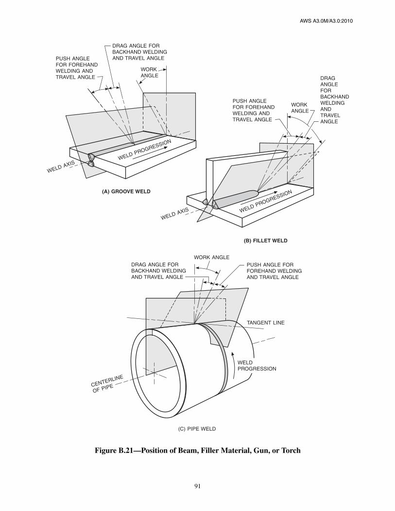
AWS A3.0M/A3.0:2010
91
Figure B.21—Position of Beam, Filler Material, Gun, or Torch
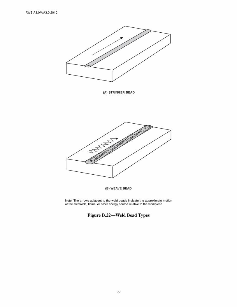
AWS A3.0M/A3.0:2010
92
Note: The arrows adjacent to the weld beads indicate the approximate motionof the electrode, flame, or other energy source relative to the workpiece.
Figure B.22—Weld Bead Types

AWS A3.0M/A3.0:2010
93
Figure B.23—Welding Application Nomenclature

AWS A3.0M/A3.0:2010
94
Figure B.23 (Continued)—Welding Application Nomenclature
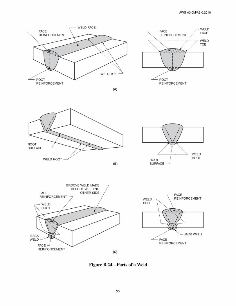
AWS A3.0M/A3.0:2010
95
Figure B.24—Parts of a Weld

AWS A3.0M/A3.0:2010
96
Figure B.24 (Continued)—Parts of a Weld

AWS A3.0M/A3.0:2010
97
Figure B.24 (Continued)—Parts of a Weld

AWS A3.0M/A3.0:2010
98
Figure B.24 (Continued)—Parts of a Weld

AWS A3.0M/A3.0:2010
99
Figure B.24 (Continued)—Parts of a Weld
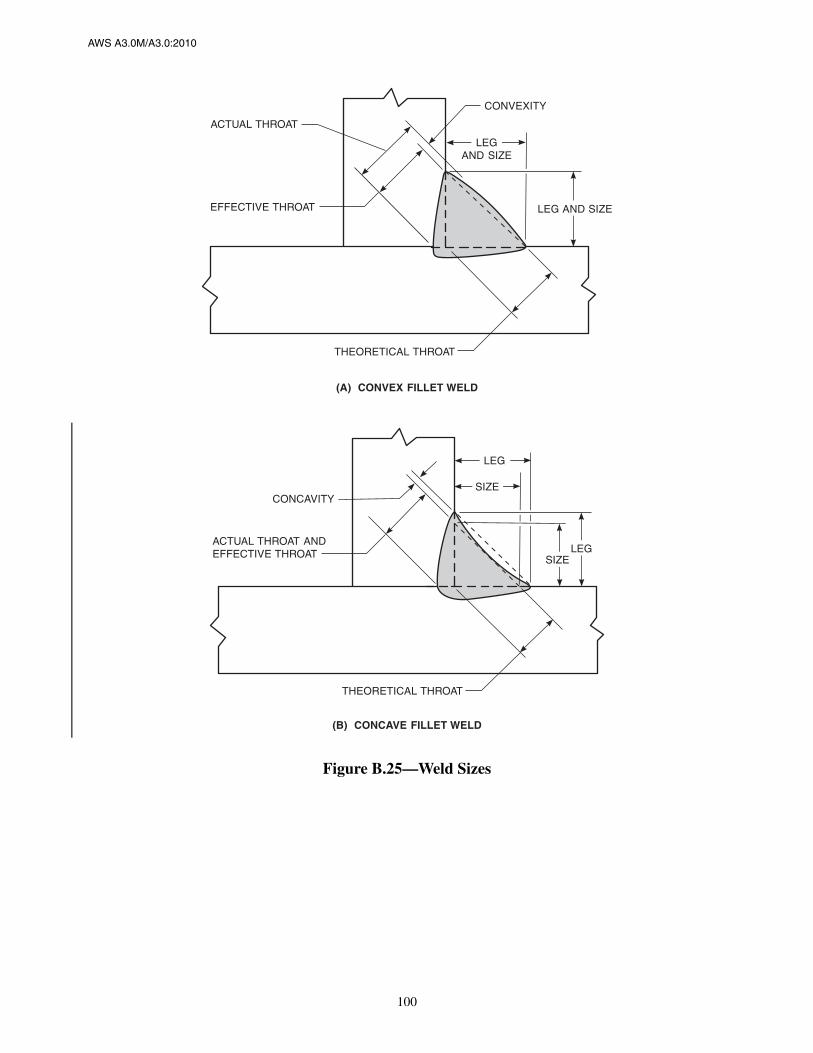
AWS A3.0M/A3.0:2010
100
Figure B.25—Weld Sizes

AWS A3.0M/A3.0:2010
101
Figure B.25 (Continued)—Weld Sizes

AWS A3.0M/A3.0:2010
102
Figure B.25 (Continued)—Weld Sizes

AWS A3.0M/A3.0:2010
103
Figure B.25 (Continued)—Weld Sizes

AWS A3.0M/A3.0:2010
104
Figure B.26—Groove Weld Size and Joint Penetration

AWS A3.0M/A3.0:2010
105
Figure B.26 (Continued)—Groove Weld Size and Joint Penetration

AWS A3.0M/A3.0:2010
106
Figure B.27—Melt-Through and Root Surface Profile

AWS A3.0M/A3.0:2010
107
Figure B.28—Complete Fusion

AWS A3.0M/A3.0:2010
108
Figure B.29—Incomplete Fusion
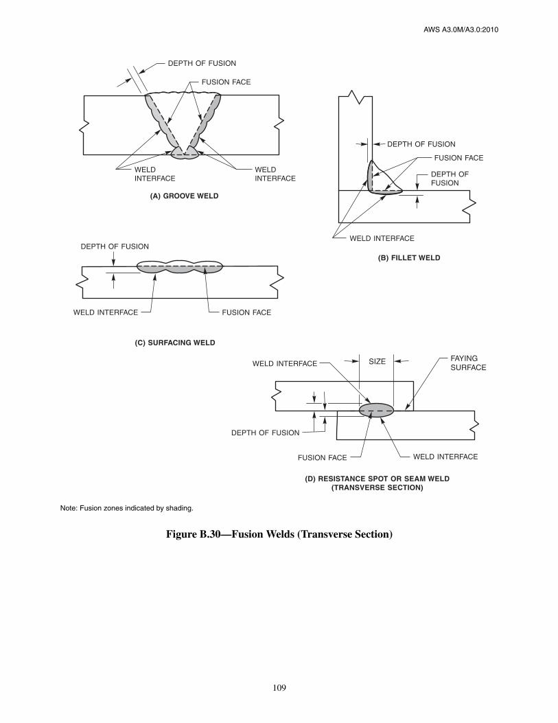
AWS A3.0M/A3.0:2010
109
Note: Fusion zones indicated by shading.
Figure B.30—Fusion Welds (Transverse Section)

AWS A3.0M/A3.0:2010
110
Figure B.30 (Continued)—Fusion Welds (Transverse Section)
Source: Detail F reproduced from AWS C1.1M/C1.1:2000 (R2006), Recommended Practices for ResistanceWelding, Figure 23, Miami: American Welding Society.

AWS A3.0M/A3.0:2010
111
Figure B.31—Joining Without Fusion
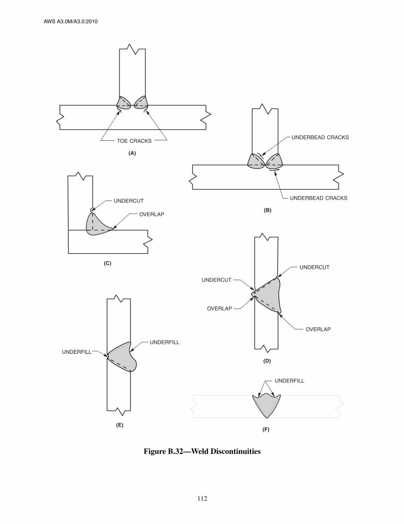
AWS A3.0M/A3.0:2010
112
Figure B.32—Weld Discontinuities
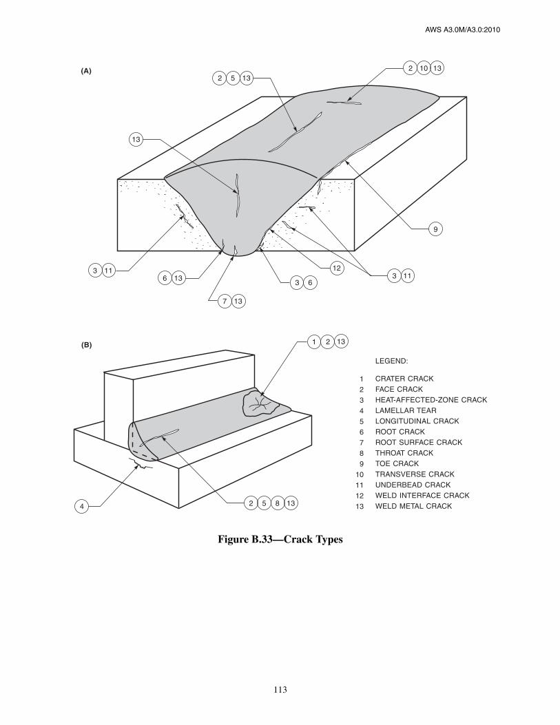
AWS A3.0M/A3.0:2010
113
Figure B.33—Crack Types

AWS A3.0M/A3.0:2010
114
Figure B.34—Welding Current Polarity

AWS A3.0M/A3.0:2010
115
Figure B.35—Plasma Arc Torch Nomenclature
Figure B.36—Gas Tungsten Arc Welding Torch Nomenclature

AWS A3.0M/A3.0:2010
116
Figure B.37—Electroslag Welding Process Nomenclature

AWS A3.0M/A3.0:2010
117
Figure B.38—Gas Metal Arc and Flux Cored Arc Welding Gun Nomenclature

AWS A3.0M/A3.0:2010
118
Figure B.39—Metal Transfer in Gas Metal Arc Welding

AWS A3.0M/A3.0:2010
119
Figure B.40—Oxyacetylene Flame Types

AWS A3.0M/A3.0:2010
120
Figure B.41—Oxygen Cutting
Figure B.42—Filler Metal Packaging

AWS A3.0M/A3.0:2010
121
Figure B.43—Thermal Spraying Surface Preparation

AWS A3.0M/A3.0:2010
122
Figure B.44—Generalized Diagram of Inertia Friction Welding

AWS A3.0M/A3.0:2010
123
Figure B.45—Generalized Diagram of Direct Drive Friction Welding

AWS A3.0M/A3.0:2010
124
Figure B.46—Typical Arrangements for Multiple Spot Welding

AWS A3.0M/A3.0:2010
125
Figure B.47—Typical Arrangements for Single Spot Welds

AWS A3.0M/A3.0:2010
126
Figure B.48—Resistance Welding Current Characteristicsfor Frequency Converter Equipment
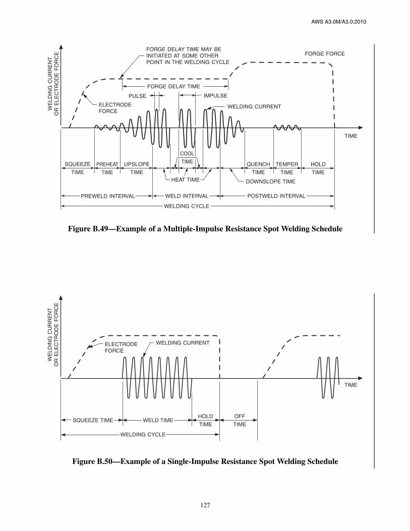
AWS A3.0M/A3.0:2010
127
Figure B.49—Example of a Multiple-Impulse Resistance Spot Welding Schedule
Figure B.50—Example of a Single-Impulse Resistance Spot Welding Schedule

AWS A3.0M/A3.0:2010
128
Source: Reproduced from AWS C1.1M/C1.1:2000 (R2006), Recommended Practices for Resistance Welding, Figure 28, Miami: AmericanWelding Society.
Figure B.51—Electro-Mechanical Synchronization in a Typical Flash Welding Cycle

AWS A3.0M/A3.0:2010
129
Figure B.52—High-Frequency Resistance Welding

AWS A3.0M/A3.0:2010
130
Figure B.52 (Continued)—High-Frequency Resistance Welding

AWS A3.0M/A3.0:2010
131
Figure B.53—Typical GTAW or PAW Program for Automatic Welding
Figure B.54—Typical GMAW, FCAW, and SAW Program for Automatic Welding

This page is intentionally blank.
AWS A3.0M/A3.0:2010
132
AWS A3.0M/A3.0:2010
133
C1. Selection and Construction of Terminology
A3.0 encompasses terms, not adequately defined in thedictionary, directly related to welding or allied fields.Both standard and nonstandard jargon, as well as dialectand vernacular terms, are considered for inclusion inA3.0. This clause presents the Subcommittee policy gov-erning this consideration.
C1.1 Incorporated Terms. Any term which conforms tothe definition given in Clause 3, and
(1) Which does not conflict with other establishedA3.0 terminology;
(2) Whose meaning as related to welding is not clearfrom a combination of dictionary and/or A3.0 definitions(i.e. multiple-word terms). Examples are: automaticwelding, contact tip, root surface, shielding gas, andworkpiece connector.
(3) Process delimited terms have been incorporatedwhere consistent industry usage makes their continueduse preferable.
C1.2 Terms Not Normally Incorporated
(1) Terms which violate fundamental dictates of logicor grammar;
(2) Are adequately defined in the English dictionary;
(3) Terms consisting of word combinations, wherethe definitions of their elements (found in either the dic-tionary or in A3.0) make the meaning of the combinationclear;
(4) In the case of synonyms, the Subcommitteeselects one of those synonyms as the standard term,while the remainder become nonstandard terms;
(5) Iteration of standard terms. Example: The termjoint is defined; other forms such as joints, joining,joined, and join are not. The term weldability is defined;other forms such as weldable and unweldable are not.
C1.3 Format. The format of the presented terms is suchthat:
(1) Only one term is defined in a single location;
(2) Standard terms are printed in boldface type. Theuse of boldface type is restricted to standard terms whenthey are:
(a) The term being defined,
(b) Given in a definition cross-reference,
(c) The standard term given in the definition of anonstandard term. Examples: weld reinforcement, TIGwelding, furnace brazing.
(3) Standard terms are shown in lightface type whenused within a definition, except when included as across-reference.
(4) Multiple word terms are hyphenated at the discre-tion of the Committee based on common application andhistorical precedence.
C1.4 Arrangement
(1) Terms are arranged in accordance with the dictio-nary method. That is, the terms are listed alphabeticallyword-by-word, beginning with the first letter of the firstword and continuing across hyphens and spaces to thesecond and subsequent words.
(2) Terms should not be included as groups; however,if an exception is made, each term within the group isalso listed in alphabetical order.
Annex C (Informative)
Principles of A3.0M/A3.0 StyleThis annex is not part of AWS A3.0M/A3.0:2010, Standard Welding Terms and Definitions
Including Terms for Adhesive Bonding, Brazing, Soldering, Thermal Cutting, and Thermal Spraying,but is included for informational purposes only.

AWS A3.0M/A3.0:2010
134
C1.5 Committee Decisions. For various factors, such asentrenched use, disagreement among our own members,pressure from those with parochial interests, or humanfallibility, the Definitions Subcommittee has to find com-promise between the sometimes incompatible character-istics of good welding terminology. Where there is noclear superiority between competing versions of a giventerm or its definition, the Definitions Subcommittee hasno choice but to make a somewhat arbitrary decision.The significant Definitions Subcommittee decisions arerecorded here to inform the reader as to the logic appliedin arriving at the approved A3.0 terms.
C1.5.1 bonding. The Definitions Subcommittee dis-courages the use of the term “bonding” for “welding.”We reserve the term bonding for the joining and alliedprocesses, where either an adhesive bond or a mechani-cal bond is predominant at the interface created by theprocess actions, i.e., adhesive bonding, brazing, solder-ing, and thermal spraying. When an atomic bondbetween the atoms at that interface is predominant, theresulting joint is called a weld, and the process that pro-duced that joint is called welding, without regard towhether the weld interface is created as a result of fusionor in the solid state. The interatomic bond existingbetween metal atoms at the weld interface of a fusionweld is no different than that at the weld interface of asolidstate weld.
C1.5.2 diffusion welding. Diffusion welding is con-sistent with international custom. The translation of thatjoining process from any language of the industrialnations into English has for many years been diffusionwelding—not diffusion bonding. The replacement by theBritish Standards Institution (Welding Terms and Sym-bols, BS499, Part 1. Glossary for welding, brazing, andthermal cutting, 1983) of diffusion bonding by diffusionwelding means that diffusion welding, rather than “diffu-sion bonding,” is now universally accepted as a part ofstandard welding terminology.
The origin of the term diffusion bonding is unknown, butits widest proliferation may be found in the aircraft andassociated industries. Welds sometime fail—of course,unwelded structures also are not immune to failure—andthe resulting prejudice has been a contributing cause ofwelding not reaching its full potential in aircraft con-struction. It was thought by some that if diffusion weld-ing were given a different name, the aversion to weldingwould be overcome. It was not, but welding terminologyremains plagued by the term diffusion bonding and amultitude of corollary terms spawned by the bonding fad.
C1.5.3 gas tungsten arc welding (or gas metal arcwelding) versus TIG (or MIG). The Definitions Sub-committee prefers the terms gas metal arc welding and
gas tungsten arc welding, with modifiers to denote thevariations of the processes. In this case, we have made anexception and chosen not to join the reputed majority, inthe hope that logic will ultimately prevail. The gas tung-sten arc welding process was originally used with aninert gas as the arc shielding atmosphere. The term tung-sten inert gas (TIG) became popular. The later applica-tion of non-inert, i.e., active, gases for arc shieldingrendered the term TIG inaccurate. To remove that dis-crepancy, the term tungsten active gas (TAG) has beenproposed by some. With that terminology, the welding ofstainless steel with argon is referred to as a “TIG weldingprocess,” and if hydrogen is added to the argon shieldinggas, the welding process becomes “TAG.” If the latter gasmixture is used for welding a noble metal, the weldingprocess would then revert to “TIG.” Thus the name of thewelding process depends not only on the composition ofthe shielding gas but also on the base metal composition.Such terminology is no more logical than making thename of the shielded metal arc welding process depen-dent upon the type of electrode covering and the compo-sition of the base metal. The proponents of TIG cite itssimplicity, brevity, and ease of pronunciation. Tungsteninert gas, by itself, is rather meaningless. Only when theword “welding” is added, is the term complete and maybe legitimately compared with gas tungsten arc welding.The term TIGW then loses some of its cited advantages.
Arguments similar to those made in support of GTAW,also apply to gas metal arc welding (GMAW) versusmetal inert gas welding (MIGW). Both GTAW andGMAW are part of a coherent letter designation systemthat has been developed by the Definitions Subcommit-tee for all of the welding and allied processes. Haphazardchanges cannot be made without damage to the letterdesignation system as a whole. That fact is seldom con-sidered by those of the TIG-MIG school.
C1.5.4 welder. The use of the term welder to indicatethe person who does the welding originated in the earlydays of welding and has been reaffirmed by the Ameri-can Welding Society since the 1969 edition. To distin-guish the welder from the machine used to perform thewelding, the term welding machine was introduced forthe latter. On the other hand, it has been claimed by somethat welding terminology would be improved by substi-tution of the term “welder” for the term “weldingmachine” and the term “weldor” for the term “welder.”That has the advantage of greater simplicity (but notmuch); and the written terms are clearly distinguishable.However, that ignores the spoken language. While a con-scious effort to emphasize the second vowel can makethe difference between “welder” and “weldor” clear, theprecision of enunciation is often not sufficient to clearlyindicate to the listener which is which. No such confu-

AWS A3.0M/A3.0:2010
135
sion is possible with “welder” and “welding machine.” Inaddition, those who pronounce “welder” differently than“weldor” are not conforming with the English language.The two words are, according to the dictionary, phoneti-cally identical.
C1.5.5 workpiece. The use of the term workpiece toindicate the part to be welded, brazed, soldered, thermalcut, or thermal sprayed, has not always been popularlyreceived. Webster’s Third New International Dictionaryoffers a single meaning for the term “workpiece” - thatbeing a piece of work in process of manufacture. Otherterms that could be considered synonymous such as com-ponent, member, and part, include numerous meaningsand usages, most of which do not specify particularmeanings that reference manufacturing.
C2. Definition Style and FormatC2.1 Purpose. Definitions should:
(1) Include as many uses as possible, while stillretaining clarity and accuracy, but should not beextended to every nuance of meaning.
(2) Eliminate unnecessary words.
(3) Have only one clearly applicable definition thataccurately reflects the term’s use in the welding world.
(4) Not be intended to replace portions of textbooksor specifications, but rather, are intended to ensure thatthe meaning of each term used in those documents isclear and is the same for all readers.
C2.2 Essential Elements. The essential elements of aterm and definition are the term, a period, and one suc-cinct and technically correct sentence to convey the factor concept represented by the term. The term and basicdefinition are complete in one sentence when a simpleverb such as “is” or “means” is substituted for the period.The definition does not repeat the complete term. A termand basic definition form a genus-species-differentiaclassical definition whenever possible. Example: liqui-dus. The term liquidus is one species of the genus tem-perature. The remainder of the definition is thedifferentia that distinguishes this species from all otherspecies, e.g., solidus and preheat temperature, within thetemperature genus. A second example: soldering iron.This example is comparable to the first, with “solderingiron” being the species and “soldering tool” the genus.
Letter designations for standard welding processes shallbe included after the standard term and shall be printed inboldface and enclosed in parentheses. Letter designationsfor other standard terminology shall be included after thestandard term and will be enclosed in parentheses but not
printed in boldface. Examples: electroslag welding(ESW), heat-affected zone (HAZ).
When more appropriate, a definition by extension, whichdefines a term by enumeration of its parts or of thespecies for which it is the genus, is used. Example: com-posite electrode.
Supplementary information, in the form of completesentences, may be included after the basic definition.However, developing this into an encyclopedic discus-sion is avoided. Unless required for clarity, handbookinformation and requirements of standards are notincluded. Example: (the last sentence is not acceptable)Ferrite Number (FN). An arbitrary, standardized valuedesignating the ferrite content of an austenitic or duplexferritic-austenitic stainless steel weld metal based on itsmagnetic properties. The term is always a proper nounand is always capitalized. Ferrite Number should not beconfused with percent ferrite; the two are not equivalent.See the latest edition of AWS A4.2, Standard Proceduresfor Calibrating Magnetic Instruments to Measure theDelta Ferrite Content of Austenitic and Duplex Ferritic-Austenitic Stainless Steel Weld Metal.
All cross-references to figures and tables begin with theword, “See.” All cross-references to terms begin with thewords, “See also,” except as explained in C2.3. Cross-references are stated in the order of figures, tables, andterms, which are stated in alphabetical order.
C2.3 Format. Definitions include only defined terms (ineither A3.0 or the dictionary), multiple-word partialterms, primary terms, and complete terms; not secondaryor single-word partial terms.
All standard terms are completely defined, and the defi-nition does not consist of only a cross-reference toanother term, except as follows:
(1) Where context makes the meaning of a partialterm clear, the partial term is defined by cross referenc-ing the complete term.
(2) Example of a single-word partial term: cylinder.See gas cylinder. Example of a multiple-word partialterm: welding torch.
(3) Where two forms of the same term are in com-mon use and both are acceptable, the secondary form isdefined by a cross-reference to the primary form, whichhas a complete definition. Example: weld face.
(4) When the meaning of a term is self evident, but afigure is useful, the term is defined by a cross-referenceto a figure. Example: weld metal crack.
(5) A multiple-word term is stated as it is normallywritten, accompanied by a definition of the basic term as

AWS A3.0M/A3.0:2010
136
a cross-reference to the multiple-word term. Examples:arc welding deposition efficiency, deposition efficiency.
Abbreviations are not used in definitions. This includesletter designations of the welding and allied processes.
Units of measurement are not included in definitions.
The definition of a nonstandard term starts with thephrase, “A nonstandard term for,” when the term has nouse as a standard term, or, with the phrase, “A nonstand-ard term when used for,” when the term is nonstandardfor the stated purpose, but is a standard term when usedfor other purposes. In each case, the introductory phraseis followed by the appropriate standard term or a descrip-tion of the term use. Examples using the first phrase:diffusion bonding, globular arc, and hydrogen brazing.Examples using the second phrase: bottle, lead burning,and metallizing.
Nonstandard terms are not used or cross-referenced indefinitions.
Terms are categorized as either standard or nonstandard.No other designation, such as preferred or nonpreferred,acceptable or nonacceptable, correct or incorrect is used,except that when the misuse of a term may endanger per-sonal safety, the term is identified as both nonstandardand incorrect. Example: ground lead.
A term that has limited and clearly definable applicabil-ity includes the area of applicability, in italic type, pre-ceded by a comma, immediately following the term. Ifeither the term or definition reveals the application area,the italicized expression is omitted. An example of the
former: accelerating potential. Examples of the latter:arc plasma.
No term has more than one definition, except for termsthat may be delimited to more than one application.Example: horizontal welding position. Where a verb iscommonly used and treated as a noun, the term is statedin the form of a gerund (ending in “ing”) and the defini-tion is expressed accordingly. A verb is stated in theinfinitive form and identified as such by placing acomma and the letter v in italic type after the term. Defi-nitions of verbs begin with the word “to” and areexpressed accordingly.
Example: boxing. The continuation of a fillet weldaround a corner of a member as an extension of theprincipal weld.
braze, v. The act of brazing.
A term that is an adjective is identified as such by placinga comma and adj. in italic type after the term. The defini-tion is an adjectival phrase, and is not a complete sen-tence. Example: as-welded, adj.
A term that is a noun is stated in the singular form.
C2.4 Committee Decisions. The word “deposit,” or anyof its derivatives, is used only in connection with theterms filler metal or surfacing metal. Use with such termsas weld metal, weld bead, weld, etc., is nonstandard.
Definitions of terms describing weld conditions shalllimit the use of wording indicating acceptability orrejectability of those conditions to those words necessaryto accurately define those terms.

AWS A3.0M/A3.0:2010
137
New Terms/Definitionsadaptive control process (XXX-AD)armas-solderedassemblyautomatic process (XXX-AU)backup electrodeballing up, brazing and solderingblanket brazingbrazed jointbrazing alloybrazing filler metal pastebrazing foilbrazing fluxbrazing pastebrazing powderbrazing rodbrazing ropebrazing stripbrazing symbolbrazing wirebrazing shimbrazing tapecap, resistance weldingcarbon arc brazing (CAB)carbon arc gouging (CAG)chemical-bath dip brazingcircular electrodecold brazed jointdifferential thermal expansiondissolution, brazingdynamic electrode force, resistance weldingelectrode adapter, resistance weldingelectrode face, resistance weldingelectrode holder, resistance weldingelectrode life, resistance welding
electrode mushrooming, resistance weldingelectrode pickup, resistance weldingelectrode skidding, resistance weldingelectrode tipelectron beam brazing (EBB)expulsion, resistance weldingface feed, brazing and solderingfillet, brazing and solderingflash, arc stud weldingflash, flash weldingflash coat, brazing and solderingflat position, brazingflowability, brazing and solderingfocal spotflux coated rod, brazingflux cored soldering filler metalfreezing pointgas generatorhand solderingheat inputheat input rateheat patternheating patternhybrid weldingincomplete coalescence, solid-state weldingindentation, resistance weldingindirect welding, projection welding, resistance seamwelding, resistance spot weldinginduction coilinduction power sourcejoint brazing procedurejoint remelt temperature, brazing and solderinglaser beam brazing (LBB)liquation, brazingmachine brazingmanual gun, resistance weldingmanual transgun, resistance welding
Annex D (Informative)
Modifications to A3.0M/A3.0 from A3.0:2001This annex is not part of AWS A3.0M/A3.0:2010, Standard Welding Terms and Definitions Including Terms for Adhesive Bonding, Brazing, Soldering, Thermal Cutting, and Thermal Spraying, but is included for informational purposes only.

AWS A3.0M/A3.0:2010
138
manual process (XXX-MA)mechanized process (XXX-ME)metal-bath dip solderingnoncorrosive flux, brazing and solderingoil-bath dip solderingoff timeparallel welding, resistance weldingpaste brazepaste solderpaste soldering filler metalplasma arc gouging (PAG)portable gun, resistance weldingportable transgun, resistance weldingpower densityprecoating, brazing and solderingpreform, brazing and solderingpreheat, v.reactive flux, solderingreflow solderingremelt temperature, brazing and solderingresistance welding timerobot gunrobotic process (XXX-RO)rub solderingsalt-bath dip solderingsandwich brazementsemiautomatic process (XXX-SA)servogunskewed jointskull, brazing and solderingsoldersolder pastesoldering filler metalsoldering filler metal pastesoldering fluxsoldering temperaturesoldermentstandoff distance, explosion weldingstatic electrode force, resistance weldingstopoff, brazing and solderingsusceptorsustained backfiresweat solderingsweatingtheoretical electrode force, resistance weldingthroat area, resistance weldingthroat depth, resistance weldingthroat height, resistance weldingtransfer tapetransgunweld brazingweld gaugewelding fluxwelding flux, submerged arc welding
wetting, brazing and solderingworkpiece connector
Modified Terms/Definitionsabrasion solderingabsorptive lensadaptive controladaptive control brazing (B-AD)adaptive control soldering (S-AD)adaptive control thermal cutting (TC-AD)adaptive control thermal spraying (TS-AD)adaptive control welding (W-AD)as-brazedas-weldedautomaticautomatic brazing (B-AU)automatic soldering (S-AU)automatic thermal cutting (TC-AU)automatic thermal spraying (TS-AU)automatic welding (W-AU)backfirebacking shoebackup, flash and upset weldingbitblock brazing (BB)block sequencebond coat, thermal sprayingbonding forcebraze, n.brazeabilitybraze interfacebrazementbraze welding (BW)brazing (B)brazing filler metalbrazing sheetbrazing techniquebrazing temperaturebrittle nuggetbutt jointchain intermittent weldcoil with supportcoil without supportcold crackcold soldered jointcommutator-controlled weldingcontact resistance, resistance weldingcool time, resistance weldingcopper brazingcorner jointcorona, resistance weldingcovered electrode

AWS A3.0M/A3.0:2010
139
crater crackcross wire weldingcyclediffusion brazing (DFB)dip brazing (DB)dip soldering (DS)direct welding, resistance weldingdrumduty cycleedge jointelectrodeelectrode capelectrode leadelectrode skidelectron beam braze welding (EBBW)erosion, brazingexothermic braze welding (EXBW)exothermic brazing (EXB)extension, resistance weldingfaying surfacefiller metalfit, v.fitupfixtureflash timeflash welding (FW)flashbackflashing actionflood cooling, resistance seam weldingflow brazing (FLB)flow brightening, solderingfluxfollow-up, resistance weldingforge forceforge-delay time, resistance weldingfuel gasfurnace brazing (FB)furnace soldering (FS)gettergoverning metal thickness, resistance weldinghammering, resistance spot weldinghard solderhigh-frequency resistance weldinghigh-frequency seam welding (RSEW-HF)high-frequency upset welding (UW-HF)hold time, projection welding, resistance seam welding,
and resistance spot weldinghot crackinduction brazing (IB)induction welding (IW)inert gasinfrared radiationintergranular penetrationjoint
joint efficiencyjoint geometrykneelap jointlightly coated electrodeliquiduslongitudinal crackmanual, adj.manual brazing (B-MA)manual soldering (S-MA)manual thermal cutting (TC-MA)manual thermal spraying (TS-MA)manual welding (W-MA)mash seam welding (RSEW-MS)mechanized, adj.mechanized brazing (B-ME)mechanized soldering (S-ME)mechanized thermal cutting (TC-ME)mechanized thermal spraying (TS-ME)mechanized welding (W-ME)metal-bath dip brazingmetallic bondmetallurgical bondneutral flamenondestructive examination (NDE)nonsynchronous initiationnuggetnugget sizeopen circuit voltagepaste brazing filler metalplaten, resistance weldingpostweld interval, resistance weldingpreheat, n.preheat temperature, brazing and solderingpreheat temperature, thermal cuttingpreheat temperature, weldingprocedure qualificationprojection weld sizeprojection welding (PW)protective atmospherepulse, resistance weldingpush weldingquench time, resistance weldingrandom intermittent weldsrandom sequencereaction solderingreducing atmospherereflow solderingresistance brazing (RB)resistance soldering (RS)resistance spot welding (RSW)resistance welding (RW)resistance welding controlresistance welding current
AWS A3.0M/A3.0:2010
140
resistance welding dieresistance welding electroderesistance welding gunresistance welding upslope timeresistance welding voltageresistance welding weld timerobotic, adj.robotic brazing (B-RO)robotic soldering (S-RO)robotic thermal cutting (TC-RO)robotic thermal spraying (TS-RO)robotic welding (W-RO)roll spot weldingsalt-bath dip brazingscarf grooveseamseam weldseam weld sizesecondary circuitsemiautomatic, adj.semiautomatic brazing (B-SA)semiautomatic soldering (S-SA)semiautomatic thermal cutting (TC-SA)semiautomatic thermal spraying (TS-SA)semiautomatic welding (W-SA)semiblind jointseries weldingset downsheet separation, resistance weldingshielding gasshrinkage stressshrinkage voidsilver alloy brazingsilver solderingsingle-impulse weldingsoft soldersolder, n.solder interfacesoldering (S)soldering blowpipesoldering gunsoldering ironsolidusspoolspot weldspot weld sizestaggered intermittent weldstep brazingstep solderingstored energy weldingsubstratesurface expulsion, resistance weldingtest couponthermal spray deposit interface
thermal stresstinningtip skidT-jointtoe crackupsetupset timeupset welding (UW)wave soldering (WS)weld bondingweld brazingweld interfaceweld interval, resistance weldingweld symbolwelding techniquewelding transformerwelding wheelweldmentwhippingworkpieceworkpiece lead
Terms/Definitionswith Editorial Changes2FR, pipe3F, plate3G, plate5F, pipe5G, pipe6F, pipe6G, pipe6GR, pipeaccelerating potential, electron beam welding and
cuttingacceptable weldactivated rosin fluxactive flux, submerged arc weldingair acetylene welding (AAW)air carbon arc cutting (CAC-A)alloy flux, submerged arc weldingarc braze welding (ABW)arc cutting (AC)arc forcearc gougingarc plasmaarc stud welding (SW)arc welding (AW)atomic hydrogen welding (AHW)bare electrodebare metal arc welding (BMAW)base material

AWS A3.0M/A3.0:2010
141
base metalbase metal zone (BMZ)blowpipebraze metalbutteringbutting memberbuttoncapillary actioncarbon arc braze welding (CABW)carbon arc brazingcarbon arc cutting (CAC)carbon arc welding (CAW)cascade sequencecladdingcoextrusion welding (CEW)constricted arcconsumable electrodeconsumable insertcontact tipcontinuous wave lasercontinuous weldcord, thermal sprayingcorrosive flux, brazing and solderingcover platedeposited metal, brazing, soldering, and weldingdeposited metal, surfacingdiffusion welding (DFW)double-groove weld, fusion weldingdouble-welded joint, fusion weldingelectrode indentation, resistance weldingelectrogas welding (EGW)electron beam cutting (EBC)electron beam gunelectron beam welding (EBW)electroslag welding (ESW)explosion welding (EXW)ferrule, arc stud weldingfilter platefirecracker weldingfisheyefitterflame spraying operatorflow welding (FLOW)flux cored arc welding (FCAW)flux cutting (OC-F)forge welding (FOW)friction stir welding (FSW)friction upset distancefriction welding (FRW)fused thermal spray depositfusion facefusion weldinggas carbon arc welding (CAW-G)gas metal arc cutting (GMAC)
gas metal arc welding (GMAW)gas tungsten arc cutting (GTAC)gas tungsten arc welding (GTAW)gogglesgradated thermal spray depositheat balanceheat timehermetically sealed containerhigh energy beam cutting (HEBC)high energy beam welding (HEBW)high pulse current, pulsed power weldinghoodhornhot isostatic pressure welding (HIPW)hot pressure welding (HPW)incomplete fusioninfrared brazing (IRB)insulating nozzle, self-shielded flux cored arc weldingjoint recognitionjoint rootjoint trackingjoint typelamellar tearlaserlaser beam air cutting (LBC-A)laser beam braze welding (LBBW)laser beam cutting (LBC)laser beam evaporative cutting (LBC-EV)laser beam inert-gas cutting (LBC-IG)laser beam oxygen cutting (LBC-O)laser beam splitterlaser beam welding (LBW)lasing mediumlevel woundlinear discontinuitylow pulse current, pulsed power weldingmetal electrodemetal powder cutting (OC-P)mixing chambermoving shoemultiport nozzlenarrow groove weldingnonbutting memberorifice gasoscillationoverspray, thermal sprayingoxyacetylene cutting (OFC-A)oxyacetylene welding (OAW)oxyfuel gas cutting (OFC)oxyfuel gas welding (OFW)oxygen arc cutting (OAC)oxygen cutting (OC)oxygen gouging (OG)oxygen lance cutting (OLC)

AWS A3.0M/A3.0:2010
142
oxyhydrogen cutting (OFC-H)oxyhydrogen welding (OHW)oxynatural gas cutting (OFC-N)oxypropane cutting (OFC-P)peel testpenetration-enhancing flux, gas tungsten arc weldingpercussion welding (PEW)plasma arc cutting (PAC)plasma arc welding (PAW)plasma sprayerplaten spacingpostflow timepreheat current, resistance weldingprequalified welding procedure specification (PWPS)pressure gas welding (PGW)random woundreconditioned flux, submerged arc weldingresistance seam welding (RSEW)roll welding (ROW)root beadroot facerough threading, thermal sprayingrunoff weld tabseal-bonding material, thermal sprayingself-fluxing alloy, thermal sprayingseries submerged arc welding (SAW-S)shadow mask, thermal sprayingshielded carbon arc welding (CAW-S)shielded metal arc cutting (SMAC)single welded joint, fusion weldingsingle-groove weld, fusion weldingsingle-port nozzlesmoothing passsolder metalsolid-state welding (SSW)splice membersplit layer techniquespray tab, thermal sprayingstart currentstart timestarting weld tabstationary shoestress-corrosion crackingstubsubmerged arc welding (SAW)surfacing materialsurfacing metalthermal cutterthermal cutting (TC)thermal cutting operatorthermal gouging (TG)thermal spraying deposition efficiencythermite reactionthermite welding (TW)
torch brazing (TB)torch soldering (TS)transformer taptwin carbon arc brazing (TCAB)twin carbon arc welding (CAW-T)ultrasonic welding (USW)unfused flux, submerged arc weldingunmixed zonevacuum brazingvirgin flux, submerged arc weldingwater washweavingweld damweld groove, fusion weldingweld metal zone (WMZ)weld recognitionweld tabweldabilityweldingwelding arcwelding leadswelding tip, oxyfuel gas weldingwork angle, pipe
Terms Changed fromStandard to Nonstandardelectrode tipjoint brazing procedurepaste brazing filler metalpaste soldersweat solderingworkpiece connection
Terms Changed toObsolete or Seldom Usedlightly coated electrode, shielded metal arc weldingshielded carbon arc welding (CAW-S)twin carbon arc welding (CAW-T)
Deleted Terms (Also see New Terms for changes in delimiters)arm, resistance weldingballing upcircular electrode, resistance seam weldingdoped solderdynamic electrode forceelectrode holderelectrode mushrooming

AWS A3.0M/A3.0:2010
143
electrode pickupelectrode tip lifeexpulsionface feedflashflash coatflash off timeflowabilityfocal spot, electron beam welding and cutting, and laser
beam welding and cuttingheat input, arc spot welding, projection welding and
resistance spot weldingheat input, arc weldingheat input rate, arc weldingindentation, projection welding, resistance seam weld-
ing, and resistance spot weldingindirect welding
noncorrosive fluxoff time, resistance weldingparallel weldingprecoatingpreformreaction flux, solderingreflow solderingskullstatic electrode forcestop-offtheoretical electrode forcethroat areathroat depththroat heightweld gagewetting

This page is intentionally blank.
AWS A3.0M/A3.0:2010
144

AWS A3.0M/A3.0:2010
145
E1. IntroductionThe American Welding Society (AWS) Board of Direc-tors has adopted a policy whereby all official interpreta-tions of AWS standards are handled in a formal manner.Under this policy, all interpretations are made by thecommittee that is responsible for the standard. Officialcommunication concerning an interpretation is directedthrough the AWS staff member who works with thatcommittee. The policy requires that all requests for aninterpretation be submitted in writing. Such requests willbe handled as expeditiously as possible, but due to thecomplexity of the work and the procedures that must befollowed, some interpretations may require considerabletime.
E2. ProcedureAll inquiries shall be directed to:
Managing DirectorTechnical Services DivisionAmerican Welding Society550 N.W. LeJeune RoadMiami, FL 33126
All inquiries shall contain the name, address, and affilia-tion of the inquirer, and they shall provide enough infor-mation for the committee to understand the point ofconcern in the inquiry. When the point is not clearlydefined, the inquiry will be returned for clarification. Forefficient handling, all inquiries should be typewritten andin the format specified below.
E2.1 Scope. Each inquiry shall address one single provi-sion of the standard unless the point of the inquiryinvolves two or more interrelated provisions. The provi-sion(s) shall be identified in the scope of the inquiry
along with the edition of the standard that contains theprovision(s) the inquirer is addressing.
E2.2 Purpose of the Inquiry. The purpose of the inquiryshall be stated in this portion of the inquiry. The purposecan be to obtain an interpretation of a standard’s require-ment or to request the revision of a particular provisionin the standard.
E2.3 Content of the Inquiry. The inquiry should beconcise, yet complete, to enable the committee to under-stand the point of the inquiry. Sketches should be usedwhenever appropriate, and all paragraphs, figures, andtables (or annex) that bear on the inquiry shall be cited. Ifthe point of the inquiry is to obtain a revision of the stan-dard, the inquiry shall provide technical justification forthat revision.
E2.4 Proposed Reply. The inquirer should, as a pro-posed reply, state an interpretation of the provision that isthe point of the inquiry or provide the wording for a pro-posed revision, if this is what the inquirer seeks.
E3. Interpretation of Provisions of the Standard
Interpretations of provisions of the standard are made bythe relevant AWS technical committee. The secretary ofthe committee refers all inquiries to the chair of the par-ticular subcommittee that has jurisdiction over the por-tion of the standard addressed by the inquiry. Thesubcommittee reviews the inquiry and the proposed replyto determine what the response to the inquiry should be.Following the subcommittee’s development of theresponse, the inquiry and the response are presented tothe entire committee for review and approval. Uponapproval by the committee, the interpretation is an official
Annex E (Informative)
Guidelines for the Preparation of Technical InquiriesThis annex is not part of AWS A3.0M/A3.0:2010, Standard Welding Terms and Definitions Including Terms for Adhesive Bonding, Brazing, Soldering, Thermal Cutting, and Thermal Spraying, but is included for informational purposes only.

AWS A3.0M/A3.0:2010
146
interpretation of the Society, and the secretary transmitsthe response to the inquirer and to the Welding Journalfor publication.
E4. Publication of InterpretationsAll official interpretations will appear in the WeldingJournal and will be posted on the AWS web site.
E5. Telephone InquiriesTelephone inquiries to AWS Headquarters concerningAWS standards should be limited to questions of a gen-eral nature or to matters directly related to the use of thestandard. The AWS Board Policy Manual requires thatall AWS staff members respond to a telephone requestfor an official interpretation of any AWS standard withthe information that such an interpretation can be
obtained only through a written request. Headquartersstaff cannot provide consulting services. However, thestaff can refer a caller to any of those consultants whosenames are on file at AWS Headquarters.
E6. AWS Technical CommitteesThe activities of AWS technical committees regardinginterpretations are limited strictly to the interpretation ofprovisions of standards prepared by the committees or toconsideration of revisions to existing provisions on thebasis of new data or technology. Neither AWS staff northe committees are in a position to offer interpretive orconsulting services on (1) specific engineering problems,(2) requirements of standards applied to fabrications out-side the scope of the document, or (3) points not specifi-cally covered by the standard. In such cases, the inquirershould seek assistance from a competent engineer expe-rienced in the particular field of interest.

AWS A3.0M/A3.0:2010
147
List of AWS Documents on Arc Welding and Cutting
Designation Title
A2.1-WC Welding Symbol Chart (Wall Size)
A2.1-DC Welding Symbol Chart (Desk Size)
A2.4 Standard Symbols for Welding, Brazing, and Nondestructive Examination
A3.0 Standard Welding Terms and Definitions Including Terms for Brazing, Soldering, Thermal Cutting,and Thermal Spraying

This page is intentionally blank.
AWS A3.0M/A3.0:2010
148