Embed Size (px)
Citation preview
STANDARD SPECIFICATIONS FOR
CIVIL WORKS November 2012
CONTRACT DOCUMENTS
Revision 0
Approved By
Tony Pell
Date
29/11/2012
STANDARD SPECIFICATIONS FOR CIVIL WORKS NOVEMBER 2012
Page 2
CONTENTS Standard Drawings Refer to the City of Kingston website for details. Standard City of Kingston Specifications: Section 5 ...........PROVISION FOR TRAFFIC Section 6 ...........DRAINAGE Section 7 ...........SUBSOIL DRAINAGE Section 8 ............NATURE STRIPS Section 9 ............STORMWATER QUALITY PROTECTION Section 10 ............TOPSOIL Standard Vic Roads Specifications Section 173 .........EXAMINATION AND TESTING OF MATERIALS AND WORKS (last updated July 2003) Section 201 …….SITE CLEARING (last updated July 2000) Section 204 …….EARTHWORKS (last updated July 2006) Section 304......…FLEXIBLE PAVEMENT CONSTRUCTION (last updated February 1995) Section 306 …….CONSTRUCTION OF CEMENT TREATED CRUSHED ROCK SUBBASE PAVEMENT COURSES (last updated July 2006) Section 402 …….REMOVAL OF PAVEMENT BY COLD PLANING
(last updated September 2005) Section 404…….STONE MASTIC ASPHALT (last updated September 2005) Section 407 …….HOT MIX ASPHALT (last updated July 2006) Section 408…….PRIMING, PRIMERSEALING AND SEALING (last updated September 2001) Section 703 …….CAST-IN-PLACE CONCRETE EDGING, PATHS, AND OTHER SURFACINGS (last updated February 1998) Section 724 …….LONG LIFE PAVEMENT MARKINGS - NEW INSTALLATIONS Section 812 …….CRUSHED ROCK AND PLANT MIXED WET - MIX CRUSHED ROCK FOR BASE AND SUB BASE PAVEMENT (last updated July 2006) Section 815 …….CEMENT TREATED CRUSHED ROCK FOR SUBBASE PAVEMENT (last updated July 2002)
STANDARD SPECIFICATIONS FOR CIVIL WORKS NOVEMBER 2012
Page 3
SECTION 5 - PROVISION FOR TRAFFIC
5.1 GENERAL
Unless otherwise specified, the Contractor shall make provision for traffic, including pedestrians, in accordance with this section and the relevant parts of the Vic Roads Worksite Traffic Management (Roadworks Signing) Code of Practice, hereinafter referred to as the Code, or Australian Standard AS 1742.3 "Manual of Uniform Traffic Control Devices". The Contractor shall make such provision for traffic notwithstanding anything contained in the General Conditions of Contract and without derogating in any way from the Contractor's obligations pursuant to the General Conditions of Contract and in particular from the Contractor's obligations pursuant to Clause 15 of the General Conditions of Contract. The Contractor shall submit, before commencing any part of the work, details of the proposed provisions for traffic to be provided during the Contract for review by the Superintendent. The number, type and location of signs and devices shall be not less than the standards set out in the Code as applicable and shall also meet the requirements of this section. Should circumstances arise which are not adequately covered by the Code or this section, the Contractor shall submit alternative proposals to the Superintendent for review prior to works proceeding. Work shall not commence or continue at any location until all appropriate signs and devices such as lamps, barricades, traffic control apparatus and the like are in place, side tracks have been constructed where required and line marking completed where required. At all times when the Contractor's employees are on site, the Contractor shall render immediate assistance without charge to any person whose lawful passage through a work area may be obstructed or made difficult by or as a result of the Contractor's operations. Unless otherwise approved, when work is not being performed on the site, traffic shall not be carried through that works zone or works area on sidetracks, detours or part widths of the existing pavement.
5.2 Contractor’s Representatives
On commencement of work, the Contractor shall advise the Superintendent in writing of the names, addresses and telephone numbers of employees who can be contacted in any emergency under the Contract or undertake the replacement or maintenance of signs and devices. Any proposed changes of representatives, addresses or telephone numbers shall be notified promptly to the Superintendent and confirmed in writing to the Superintendent.
5.3 Signs and Devices
Unless otherwise specified, the Contractor shall supply all signs and devices required to complete the work covered by this section. Signs and devices shall comply with the relevant requirements of the Code together with the following additional requirements: (a) Pavement Markers

STANDARD SPECIFICATIONS FOR CIVIL WORKS NOVEMBER 2012
Page 4
Pavement markers shall comply with the requirements of AS 1906, Retroreflective Materials and Devices for Road Traffic Control Purposes, Part 3 - Raised Pavement Markers (Retroreflective and Non Retroreflective). The adhesive used to fasten them to the pavement shall comply with the requirements of Section 853. Section 853 which forms part of the Contract is not included in this copy of the Specification but will be supplied to the Contractor on request.
(b) Retroreflective Sheeting
Retroreflective sheeting used on any sign or device shall comply with the requirements of AS 1906, Retroreflective Materials and Devices for Road Traffic Control Purposes, Part 1 - Retroreflective Materials, for Class 2 material, except that the coefficient of luminous intensity shall be not less than 50% of the values given in Table 2.2 of AS 1906, Part 1, for each designated colour when tested in the cleaned condition.
(c) Signs
Dirty, illegible, damaged or faded signs shall not be used if there is any doubt that the message or intent of the sign is unclear or confusing to road users. The Contractor shall clean, replace or renew all signs as required to ensure legibility and luminous intensity.
5.4 Storage of Plant When not in use, the Contractor shall be responsible for the safe storage of plant and equipment clear of the travelled path. Wherever possible, plant and equipment shall be stored not less than 3 m from the edge of the traffic path in built up areas and not less than 5 m outside built up areas. If it is not possible to provide such clearance, the plant and equipment shall be moved from the Works area to a suitable storage site or be protected by suitable signs, lights and devices. Plant shall not be store in parking bays or on pedestrian pathways unless the Superintendent gives approval.
5.5 Care of Areas Used By Traffic Both during and at the end of each day's work, the Contractor shall be responsible for ensuring that the pavement shoulders, foot paths and pedestrian walkways being used by traffic within the Works area and all other areas within the Works zone where the Contractor has undertaken work are in a safe and trafficable condition. Any material which has fallen on any travelled path as a result of the Contractor's transportation or other operations and any material stored near the travelled path which could constitute a hazard to traffic shall be removed by the Contractor immediately.
5.6 Access to side Roads and Abutting Property Construction operations shall be conducted in such a manner as to minimise inconvenience to abutting property owners. Unless otherwise specified, access to properties and side roads shall be maintained at all times wherever practicable other than when the works present a traffic hazard or the work would suffer damage as a result of the passage of traffic.

STANDARD SPECIFICATIONS FOR CIVIL WORKS NOVEMBER 2012
Page 5
Where the Contractor proposes to restrict access to abutting properties as a result of the Contractor's operations, the Contractor shall provide a minimum of 24 hours notice to the affected property owner/occupier. Unless otherwise specified, access shall not be denied to any abutting property outside the customary working hours.
5.7 Operations Affecting Traffic
(a) General Unless otherwise specified, the Contractor shall so conduct the operations as to minimise obstruction and inconvenience to the public, and shall not have under construction any greater length or amount of work than can be managed properly with due regard to the convenience of the public. If the intermingling of construction machinery with traffic is unavoidable the intermingling shall be minimised at all times. Unless otherwise specified the Contractor shall:
(i) provide a minimum safe working width for the Contractor's construction plant plus an absolute minimum clearance to the edge of the traffic path of 1.2 m;
(ii) provide a minimum one way clear travel path width for traffic of not less than 2.8 m
for one-way operation and 6 m for two-way operation; (iii) not work on any part of a carriageway during peak traffic flows unless such work is
so conducted that it does not cause any additional delays to traffic than if the work was not done;
(iv) locate the longitudinal joint(s) for pavement construction and/or cold planing works at
either the traffic lane line(s) or at the centre of the traffic lane(s) or as specified in Clause 407.17(c) for asphalt paving.
The shoulder (sealed or unsealed) may be used as part of the travelled path subject to the agreement of the Superintendent.
(b) Earthworks
Unless otherwise approved by the Superintendent, earthworks shall proceed only in areas clear of travelled paths and footpaths. Where construction is being carry out over part of the carriageway width, the following conditions shall apply: Steps or batters within 1.5 m of the travelled path of the carriageway shall be delineated as specified in AS 1742.3. Where the step or batter forms a drop in level of more than 200 mm at a slope steeper than 1 in 6, barricades shall be used in addition to delineation. Where the level difference is in the form of a step or batter of less than 80 mm and is between the travelled paths, such step or batter shall be removed before the close of work each day and the full width of carriageway made
STANDARD SPECIFICATIONS FOR CIVIL WORKS NOVEMBER 2012
Page 6
available to traffic overnight. The removal of such step or batter shall be effected by shaping to a cross fall not steeper than 1 in 10.
(c) Pavement Unless otherwise specified, prior to the close of work each day all steps between layers of unbound pavement material being placed shall be tapered to a slope not steeper than 1 in 10.
(d) Footpaths and Pedestrian Walkways Unless otherwise specified, temporary footpaths or pedestrian walkways within the work zone shall be not less than 1 m wide, shall have a firm, even and free draining surface and shall be free from steps and obstructions. Access to bus stops shall be maintained at all times.
(e) Parking The Contractor shall minimise the impact that construction works has on parking within shopping centre precincts by maximising the number of parking spaces available to patrons at all times for the duration of the contract.
5.8 Provision for Garbage Collection
The Contractor is responsible to provide access for garbage trucks for the collection of household garbage carts on the designated collection days. If access is not provided, the Contractor must arrange to move the carts to a point that is accessible to the garbage collector and once emptied, returned to the house they came from.
5.9 Detours and side tracks (a) Side Tracks HP Traffic shall not be diverted on to any side track until permission to use such side track has
been given by the Superintendent. (b) Detours Unless otherwise specified, traffic shall not be detoured on to roads outside the works zone. Prior to the issue of the Final Certificate, unless otherwise specified, detours and sidetracks used or constructed during the Contract shall be restored to the condition existing at the time of commencement of the work under the Contract. Where the Contractor is responsible for the restoration of detours and sidetracks the Contractor shall produce from the local authorities or landowners concerned clearances in writing stating that such detours and sidetracks have been restored to their satisfaction. Where the City of Kingston as well as the Contractor has some responsibility for the restoration of any detours or sidetracks, the Contractor shall not commence any restoration work until the Contractor has submitted details of the work to be undertaken to the Superintendent for review.
STANDARD SPECIFICATIONS FOR CIVIL WORKS NOVEMBER 2012
Page 7
SECTION 6 - DRAINAGE 6.1 SCOPE OF WORK Drainage includes all work and supply of all material for the excavation and trimming of
trenches, bedding, laying of pipes, cuttings, jointing, connection of all inlets, testing, backfilling, compaction of material in trenches, reinstatement of road pavements, footpaths and nature strips, and the excavation, construction, backfilling, compacting surface finishing and covers for associated concrete structures as specified and shown on the drawings.
6.2 PIPES Pipes specified shall meet the following requirement unless shown otherwise on the drawings or
unless directed otherwise by the Superintendent: (i) Reinforced concrete pipe, Class 2 with rubber ring joints conforming with AS 3902
and AS 4058 (ii) Fibre reinforced concrete pipe, Class 2 with adcol joints conforming with AS 4139 and
AS 4058 (iii) UPVC pipe conforming with AS 1254 - 1991 Pipes will be inspected on the site and in trenches by the Superintendent. Any pipe not
conforming to the standard specification, damaged or rejected by the Superintendent will not be used and shall be removed and replaced by the Contractor at his expense. Pipes shall be new and at least 1 week old with the date of manufacture marked.
All culverts shall be of the box type of approved manufacture and laid to the levels given by the
Superintendent. All joints to be 3 to 1 cement mortar. No culverts shall be covered until same have been approved by the Superintendent.
All pipe lifting holes are to be sealed with a manufactured concrete plug. 6.3 LAYING AND JOINTING Laying shall commence at the low end of all drainage legs. Jointing shall be carried out in accordance with the drawings or as stated in the manufacturer's
specifications. Mortar for jointing shall consist of one part of Portland cement to three parts of fine sand. 6.4 TOLERANCES Pipes shall be laid within + or - 10mm of the design invert level and within + or - 25mm of the
alignment. Any pipes not so conforming may be rejected by the Superintendent and shall be replaced by the Contractor at his expense.
6.5 EXCAVATION The Contractor shall do all excavation of whatever substances encountered to depths required
by the drawings and this specification. Excavated material not required for backfill shall be removed as specified in Section 4.
Excavation shall not be carried out below the required level. Excess excavation below required level shall be backfilled at the Contractor's expense with, sand, gravel or concrete as directed by the Superintendent and thoroughly compacted.

STANDARD SPECIFICATIONS FOR CIVIL WORKS NOVEMBER 2012
Page 8
Unstable soil shall be removed and replaced with crushed rock, which shall be thoroughly
compacted. The Superintendent will determine the depth of removal of unstable soil. No extra payment will be made for removal of unstable soil.
Ground and channels adjacent to all excavations shall be graded to prevent water running in.
The Contractor shall remove by pumping or other means approved by the Superintendent, any water accumulated in the excavation and keep trenches unwatered until the bedding is complete and the pipes laid. The banks of trenches shall be vertical.
Width of trench shall be 150mm minimum and 200mm maximum on each side of the pipe. 6.6 TIMBERING The Contractor shall do all bracing, shoring and timbering necessary to perform and protect the
excavations, as required for safety, as directed by the Superintendent, or to conform to By-Laws or Regulations at his own cost.
6.7 BEDDING Pipes shall be evenly bedded for their full lengths on a continuous cushion of compacted sand.
The thickness of the cushion (bedding) under the pipe shall be not less than 75mm. The trench condition and bedding shall be in accordance with AS 3725 - 1989 "Loads or
Buried Concrete Pipes:3" Type H2 Bedding. 6.8 BACKFILLING Backfilling shall be as specified on the drawings or as follows if not specified on drawings. Backfill material shall be placed evenly and carefully around and over the pipe in 150mm
maximum layers. Each layer shall be thoroughly and carefully rammed until 300mm cover exists over pipe.
The remainder of backfill material shall be placed at optimum moisture content in 150mm
maximum layers. Each layer shall be compacted by mechanical compacting equipment to the approval of the Superintendent.
(a) TRENCHES UNDER ROAD PAVEMENT. Refer to pavement makeup in the drawings. The
crushed rock shall be placed at optimum moisture content, in 150mm maximum layers and mechanically compacted to 95% of the maximum density determined from the A.S. modified compaction test.
The compacting material shall finish level with the adjoining road pavement surface. (b) TRENCHES UNDER VEHICLE CROSSING. Material shall be Class 3 crushed rock. The
crushed rock shall be placed at optimum moisture content, in 150mm maximum layers and mechanically compacted to 95% of the maximum density determined from the A.S. modified compaction test.
(c) TRENCHES UNDER FOOTPATHS. Material shall be Class 3 crushed rock . The crushed
rock shall be placed at optimum moisture content, in 150mm maximum layers and mechanically compacted to 95% of the maximum density determined from the A.S. modified compaction test.
(d) TRENCHES LONGITUDINAL UNDER KERB AND CHANNEL OR EDGE OF
ROAD SEAL Material to the underside of the pavement subbase shall be Class 3 Crushed Rock (Roads Corporation Specification) placed in 150mm layers compacted
STANDARD SPECIFICATIONS FOR CIVIL WORKS NOVEMBER 2012
Page 9
by mechanical equipment to 95% of maximum density determined from the AS 1289 Part E modified compaction test.
TRENCHES LONGITUDINAL WITHIN 1 METER OF KERB AND CHANNEL Material to the underside of the kerb and channel boxing shall be Class 3 Crushed Rock (Roads Corporation Specification) placed in 150mm layers compacted by mechanical equipment to 95% of maximum density determined from the AS 1289 Part E modified compaction test.
(e) NATURE STRIPS. Material for the top 100mm must be specially selected loam. The
Contractor will be responsible to hand rake and re-grass all nature strips to the level existing prior to construction of the drain.
(f) MANHOLES AND PITS. All forms and debris shall be removed and cleared away.
Backfill material shall be supplied, placed and compacted as specified in sub-clauses (a) to (d) above.
(g) ELSE WERE NOT DEFINED ABOVE Material shall be approved sandy loan
material free from clay, large lumps or stones.
6.9 MANHOLES, PITS AND OTHER STRUCTURES 6.10 GENERAL All concrete side entry pits, manholes, junctions, special joints and radial sections shall be
constructed as shown on the drawings, with connection pipes at the levels shown on the drawing or as directed by the Superintendent.
The work shall include connecting up existing pipes, breaking into existing pipes or pits,
making connections and making good any damage to existing work. Covers where and of the type shown on the drawings should be supplied and fixed according to
the manufacturer's approved instructions. All excavation and backfill shall be as before specified for pipe trenches. A bed of fine crushed rock 75mm thick when compacted shall be placed under manholes and
pits. 6.11 STEP IRONS Galvanised mild steel step irons, 22mm diameter shall be shaped and installed in all pits deeper
than 1.0m as per the standard drawings.

STANDARD SPECIFICATIONS FOR CIVIL WORKS NOVEMBER 2012
Page 10
SECTION 7 - SUBSOIL DRAINAGE 7.1 SCOPE OF WORK Subsoil drainage includes all work and supply of all material for the excavation and trimming
of trenches, bedding, laying of pipes, cuttings, jointing, connection of all inlets, testing, backfilling, compaction of material in trenches, reinstatement of road pavements, footpaths and nature strips, and the excavation, construction, backfilling, compacting surface finishing and covers for associated concrete structures as specified and shown on the drawings.
7.2 PIPES All pipes shall be 90mm dia. smooth bore slotted UPVC AG pipes or 100mm dia. corrugated
UPVC or as shown on the drawings or as directed by the Superintendent. Pipes will be inspected on the site and in trenches by the Superintendent. Any pipe not
conforming to the standard specification, damaged or rejected by the Superintendent will not be used and shall be removed and replaced by the Contractor at his expense. Pipes shall be new and at least 1 week old with the date of manufacture marked.
7.3 LAYING AND JOINTING Laying shall commence at the low end of all drainage legs. Jointing shall be carried out in accordance with the drawings or as stated in the manufacturer's
specifications. 7.4 TOLERANCES Pipes shall be laid within + or - 10mm of the design invert level and within + or - 25mm of the
alignment. Any pipes not so conforming may be rejected by the Superintendent and shall be replaced by the Contractor at his expense.
7.5 EXCAVATION The Contractor shall do all excavation of whatever substances encountered to depths required
by the drawings and this specification. Excavated material not required for backfill shall be removed from the site as specified in Section 4.
Excavation shall not be carried out below the required level. Excess excavation below required
level shall be backfilled at the Contractor's expense with, sand, gravel or concrete as directed by the Superintendent and thoroughly compacted.
Unstable soil shall be removed and replaced with crushed rock, which shall be thoroughly
compacted. The Superintendent will determine the depth of removal of unstable soil. No extra payment will be made for removal of unstable soil.
Ground and channels adjacent to all excavations shall be graded to prevent water running in.
The Contractor shall remove by pumping or other means approved by the Superintendent, any water accumulated in the excavation and keep trenches unwatered until the bedding is complete and the pipes laid. The banks of trenches shall be vertical.
Width of trench shall be 50mm minimum and 75mm maximum on each side of the pipe.

STANDARD SPECIFICATIONS FOR CIVIL WORKS NOVEMBER 2012
Page 11
7.6 TIMBERING The Contractor shall do all bracing, shoring and timbering necessary to perform and protect the
excavations, as required for safety, as directed by the Superintendent, or to conform to By-Laws or Regulations at his own cost.
7.7 BEDDING Pipes shall be evenly bedded for their full lengths on a continuous cushion of compacted sand.
The thickness of the cushion (bedding) under the pipe shall be not less than 75mm. 7.7 BACKFILLING Backfill material shall be placed evenly and carefully around and over the pipe in 150mm
maximum layers. Each layer shall be thoroughly and carefully rammed until 300mm cover exists over pipe.
The remainder of backfill material shall be placed at optimum moisture content in 150mm
maximum layers. Each layer shall be compacted by mechanical compacting equipment to the approval of the Superintendent.
(a) TRENCHES UNDER ROAD PAVEMENT. Material shall be 10mm screenings to the under
side of the road pavement. (b) TRENCHES UNDER VEHICLE CROSSING. Material for the top 150mm shall be crushed
rock. All other material shall be 10mm screenings. (c) TRENCHES UNDER FOOTPATHS. Material for the top 75mm shall be crushed rock. All
other materials shall be 10mm screenings. (d) TRENCHES LONGITUDINAL UNDER KERB AND CHANNEL. Material to the underside of
the kerb and channel shall be no fines concrete. (e) NATURE STRIPS. Material for the top 75mm must be specially selected loam. Material
to be 10mm screenings to within 75mm of the surface. The Contractor will be responsible to hand rake and re-grass all nature strips to the level existing prior to construction of the drain.
7.8 SAWCUTTING All concrete work and road pavement must be cut with a circular saw to the satisfaction of the
Superintendent prior to excavation.
STANDARD SPECIFICATIONS FOR CIVIL WORKS NOVEMBER 2012
Page 12
SECTION 8 - NATURE STRIPS The Contractor shall be responsible for filling and trimming nature strips, garden beds, median strips and private property. Where nature strips, garden beds, median strips or private properties are to be filled, it shall be filled with screened sandy loam, free of rocks, weeds or rubble, approved by the Supervising Engineer. All garden beds, median strips or private properties are to be trimmed to a depth of 75mm below the existing surface and backfilled with screened sandy loam free of rocks, weeds and rubble, approved by the Superintendent to the finished surface levels.
All nature strips within the extent of works shall be trimmed to a depth of 75mm below the finished surface level from the front of path to the proposed back of kerb and the nature strip backfilled with screened sandy loam free of rocks, weeds and rubble, approved by the Superintendent so that they are uniformly graded from the front of the footpath to the top of kerb, unless shown otherwise on the drawings. No point on the surface shall lie more than 25 mm below a 3 m straightedge laid on the surface. The finished surface level shall be graded such that it does not hold water. Care is to be taken when trimming around existing trees to avoid damage to their root systems and a minimum of 75mm is to be left over the root system. All nature strips, median strips and private properties shall be seeded by the Contractor at the rate of 40 grams of grass seed per square metre. All nature strips, median strips, garden beds or private properties shall have excess concrete, crushed rock, stones, etc. removed before any filling is to be placed. The filling (sandy loam) which is placed on nature strips, median strips, garden beds or private properties shall be compacted to reduce settlement. The compaction is to be done in 75mm layers and done with a rolled weighting not more than 300 kg/m of width.
All areas seeded by the Contractor are to be maintained by the Contractor. The maintenance is to include re-topsoiling as required and re-seeding nature strips to ensure a full grass cover.

STANDARD SPECIFICATIONS FOR CIVIL WORKS NOVEMBER 2012
Page 13
SECTION 9 – STORMWATER QUALITY PROTECTION This section of the specification sets out the requirements to implement stormwater quality protection measures as part of the construction works. As part of every construction works many pollutants can be mobilised and transported into the stormwater drainage system. These pollutants include sediment, nutrients, spilt fuels, lubricants and other construction waste. These pollutants have the potential to cause both short and long term effects on the stormwater system and ultimately the environment. As part of the requirements for specific stormwater quality protection the contractor is to develop a Stormwater Management Plan (SMP) relating to this project. As part of the development of the SMP the contractor will be required to attend regular fortnightly performance reviews with the Superintendent’s Representative. The meeting will review the contractors compliance with the SMP. Breaches of the SMP will be regarded as a non-conformance of the contract. If these are not remedied, payment for that phase of the contract works will not be processed until they are remedied. Severe non-compliance with the SMP will result in the stoppage of the construction works by Superintendent’s Representative until the issue is resolved and compliance with the SMP is adhered to. 9.1 Stormwater Management Requirements The contractor shall avoid pollution of any watercourse or stormwater drainage system. This is to be done by: - Taking measures necessary to minimise erosion by surface protection of exposed areas, - Control of runoff water, - Control of water entering the system from outside the area - The trapping of sediments These measures shall be detailed in the SMP and where necessary provide additional treatments to conform to all Local Laws, other relevant legislation and as described in the “Protecting Stormwater Quality from Building and construction Sites” guidelines. (A City of Kingston produced publication) The contractor shall make reference to and conform to all requirements of the SMP during all stages of the projects construction and maintenance periods. The contractor is to submit, before commencing any part of the works, full details of the SMP to be implemented during the contract for approval by the Superintendent’s Representative. Possession of the site will not be granted until the Superintendent’s Representative approves the final SMP. Should circumstances arise which are not covered by the SMP, the contractor shall submit an alternative SMP to the Superintendent’s Representative for approval prior to further works proceeding. Works shall not commence or continue at any location until all stormwater quality protection measures specified in the SMP have been implemented. The contractor shall ensure that during the works, following a runoff event, all treatment measures are inspected and any maintenance carried out necessary to meet the requirements of the SMP. The Superintendent’s Representative will monitor the Contractor’s compliance with the specified SMP throughout the duration of the construction phase of the project. Specific aspects of the SMP that will be inspected on site include but are not limited to:

STANDARD SPECIFICATIONS FOR CIVIL WORKS NOVEMBER 2012
Page 14
- That the stormwater quality protection measures have been installed correctly - If any maintenance is required to avoid imminent failure of a protection measure - The site is suitably prepared for any possible storm event. As part of the works it may be required that some or all of the treatment measures may be required to be retained following the completion of the works. Maintenance of these treatments will be the responsibility of the contractor during the maintenance period following practical completion of the construction works. After this period the contractor will be required to remove all treatment measures and all pollutants unless otherwise directed by the Superintendent’s Representative. The contractor is responsible for the collection and disposal of any pollutants collected by all stormwater protection measures in accordance with all statutory requirements. 9.2 Stormwater Management Plan (SMP) A SMP is to contain all aspects of the project’s environmental management and must be prepared and approved by the Superintendent’s Representative prior to any work commencing on the project. Possession of the site will not be granted until the Superintendent’s Representative approves the final SMP. The SMP should be a dynamic document that is reviewed as the works progress in conjunction with the Superintendent’s Representative and is complemented by monitoring of the works throughout the project. Prior to developing the SMP the contractor should undertake a risk assessment of the project to define all aspects that the SMP should address. The purpose of the risk assessment is to identify all environmental risks posed by the project and to prioritise them. Based on the site assessment, project design information and the construction program, a risk assessment of all aspects is to be compiled to form the basis of the SMP. The Superintendent’s Representative will use the risk assessment in the SMP to identify critical aspects of the project for monitoring purposes. 9.2.1 SMP Content A SMP should include, but is not limited to, all aspects of site disturbance, temporary drainage works, erosion and sediment control, construction methods, staging details and site rehabilitation for the duration of the project. The final SMP should include and not be limited to: - Reference to any contract Hold Points related to the stormwater quality protection; - Location and design criteria for stormwater quality protection measures; - Procedures for maintenance of stormwater quality protection measure; - Development of a Risk Schedule and how each item is to be addressed; - Details of the construction sequence for specified stormwater protection measures; - Details of any diversion of uncontaminated runoff around areas to be disturbed when appropriate; - Details of the access points to and from the site, and the stormwater quality protection measures that will be used at these points; - Details of intended stockpiles on the site and the stormwater quality protection measures that will be used at these locations; - Details on how proposed and existing stormwater pipes will be protected from silt during the construction phase;

STANDARD SPECIFICATIONS FOR CIVIL WORKS NOVEMBER 2012
Page 15
- Details of the control of Dust Suppression and Air control on the site and the stormwater quality protection measures that will be used; - Details of how chemical spills will be treated and the stormwater quality protection measures that will be used to control any spills; - Details of how litter will be collected and the stormwater quality protection measures that will be used to control the movement of litter; - Details of the contractors proposed monitoring/inspection program for the stormwater quality protection measures; - Any other relevant information that will allow the Superintendent’s Representative to properly assess the adequacy and relevance of the SMP. It is the responsibility of the contractor to clearly define in the document who is the responsible person for maintaining the SMP measures that have been implemented during the construction phase. The contractor shall advise the Superintendent’s Representative in writing of names, addresses and telephone numbers of employees who can be contacted in an emergency under the contract or undertake the replacement or maintenance of stormwater protection and treatment measures. Any proposed changes of representatives, addresses or telephone numbers shall be notified to the Superintendent’s Representative within 24 hours and confirmed in writing 9.2.2 Monitoring Council will perform monitoring of all on site SMP measures at regular intervals and as per the monitoring/inspection program and the level of risk as detailed in the SMP. Monitoring will also occur at the start of each construction phase and after rainfall events. The contractor shall provide a minimum of 24 hours notice for inspections by the Superintendent’s Representative following the installation of all required stormwater protection measures as per the SMP. The contractor shall comply with any requests from Superintendent’s Representative to alter or improve existing site management measures within 24 hours (or within 2 hours if rain is threatening) of being notified by the Superintendent’s Representative. 9.3 Requirements for Sediment Protection Devices Where the approved SMP requires the following types of devices to be installed to protect the stormwater system from sediment, these devices shall satisfy the following minimum requirements. These devices must be installed where they will not impact on any existing vegetation. 9.3.1 Straw Bales Straw bales can be used to control and prevent erosion from sheet or concentrated stormwater runoff. They are suitable for filtering course sediment and reducing the velocity of sheet flow. Some bales are not suitable in environmentally sensitive areas due to the possibility of unwanted seeds within the bales. Hay bales are not to be used. Bales should be anchored into a trench of at least 75mm depth. The bales should be anchored with stakes driven at least 600mm into the ground. Protection of the existing vegetation must be maintained when installing the straw bales.

STANDARD SPECIFICATIONS FOR CIVIL WORKS NOVEMBER 2012
Page 16
The bales are to be inspected on a regular basis and after each rainfall event that produces any runoff. The bales are to be replaced a maximum of every 3-4 months or more frequently during the wet season. 9.3.2 Sediment Barriers Protecting Stormwater Inlet Pits There are numerous designs of sediment barriers, these barriers are: - Geotextile Sausage Inlet Filter - Fabric Drop Inlet Protection - Sandbag Sediment Barriers - Gravel/Open Concrete Block Filter These are suitable for filtering coarse sediments and are generally used to protect side entry pit inlets, Grate pits or kerb inlet areas to infiltration zones. They are not generally effective in removing fine sediment from stormwater, other measures should be used to remove these fine particles. The sediment barriers are to be constructed to allow ponding to occur upstream of the trap in order to achieve settlement of the particles. The sediment barriers are to be inspected on a regular basis and after each rainfall event that produces any runoff. Sediment is to be removed regularly to ensure the barrier works effectively. The sediment is to be disposed of where it cannot re-enter the stormwater system, it must not be hosed away. 9.3.3 Sediment Fences Sediment fences can be used to control and prevent erosion from sheet or concentrated stormwater runoff and for controlling runoff from stockpiles. They are suitable for filtering course sediment, reducing the velocity of sheet flow to induce settlement of sediment and for controlling sediment runoff close to the source. The Sediment Fences are to be inspected on a regular basis and after each rainfall event that produces any runoff. Sediment is to be removed regularly to ensure the barrier works effectively. 9.4 Handover Report To be nominated by Council on major projects. The covering letter inviting Tenders will state if this clause is to be complied with. At the completion of the construction project and before the project is put on to maintenance the contractor is to generate and provide to the Superintendent’s Representative a formal handover report. Details of this report must be included in the SMP. The basis of the report is to comprise of ongoing issues with the stormwater quality protection, which have been identified during the construction period and may have an impact on the stormwater quality in the future. The handover report must include a signed statement that no environmental information has been withheld from the Superintendent’s Representative.
STANDARD SPECIFICATIONS FOR CIVIL WORKS NOVEMBER 2012
Page 17
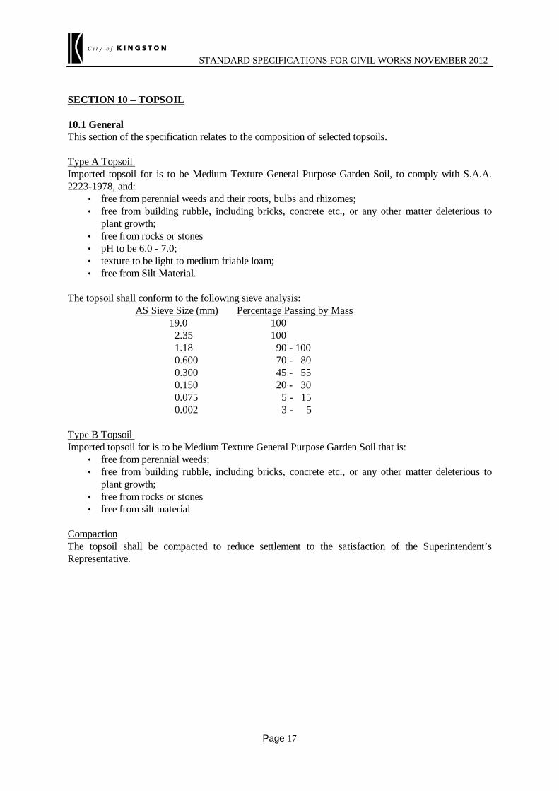
SECTION 10 – TOPSOIL
10.1 General This section of the specification relates to the composition of selected topsoils. Type A Topsoil Imported topsoil for is to be Medium Texture General Purpose Garden Soil, to comply with S.A.A. 2223-1978, and:
• free from perennial weeds and their roots, bulbs and rhizomes; • free from building rubble, including bricks, concrete etc., or any other matter deleterious to
plant growth; • free from rocks or stones • pH to be 6.0 - 7.0; • texture to be light to medium friable loam; • free from Silt Material.
The topsoil shall conform to the following sieve analysis: AS Sieve Size (mm) Percentage Passing by Mass 19.0 100 2.35 100 1.18 90 - 100 0.600 70 - 80 0.300 45 - 55 0.150 20 - 30 0.075 5 - 15 0.002 3 - 5 Type B Topsoil Imported topsoil for is to be Medium Texture General Purpose Garden Soil that is:
• free from perennial weeds; • free from building rubble, including bricks, concrete etc., or any other matter deleterious to
plant growth; • free from rocks or stones • free from silt material
Compaction The topsoil shall be compacted to reduce settlement to the satisfaction of the Superintendent’s Representative.

STANDARD SPECIFICATIONS FOR CIVIL WORKS NOVEMBER 2012
Page 18
SECTION 173 - EXAMINATION AND TESTING OF MATERIALS AND WORK (ROADWORKS) ##This section cross-references Section 180 – is this section included in the specification?: 173.01 GENERAL This section covers some of the requirements for examination and testing of materials and work associated with roadwork construction. Particular examination and testing requirements are separately specified in the relevant sections of the specification. 173.02 LOT TESTING Unless otherwise specified, acceptance of material and work will be based on testing of the material or work in lots. A lot will consist of a single layer, batch or area of like work which has been constructed or produced under essentially uniform conditions and is essentially homogeneous with respect to material and appearance. Unless otherwise specified, the extent of each lot shall not exceed one day's production. Discrete portions of a lot which are non-homogeneous with respect to material and appearance shall be excluded from the lot and shall be either treated as separate lots, or reworked. Where the areas excluded from a lot as non-homogeneous exceed 10% of the total lot area or at other specified percentages of the total lot area, the whole of the lot shall be rejected. 173.03 TEST ROLLING (a) General The test rolling procedure submitted by the Contractor shall include details of when test rolling
will be undertaken, the method of preparing an area for test rolling and the extent of test rolling. Plant which is nominated for use in test rolling procedures shall comply with the following
requirements: (i) Static smooth steel wheeled rollers shall have a mass of not less than 12 tonnes and a
load intensity under either the front or rear wheels of not less than 6 tonnes per metre width of wheel.
(ii) Pneumatic tyred plant shall have a ground contact pressure under either the front or
rear wheels of not less than 450 kPa per tyre. The area over which this ground contact pressure shall be applied shall not be less than 0.035 m² per tyre.
(b) Compliance Compliance with the test rolling requirements shall be when an area withstands test rolling
without visible deformation or springing. 173.04 COMPACTION AND MOISTURE CONTENT TESTING (a) General

STANDARD SPECIFICATIONS FOR CIVIL WORKS NOVEMBER 2012
Page 19
For the purpose of control of moisture content of material and for determination of compaction procedure the following definitions shall apply:
(i) material of nominal size 40 mm or less: material which has 20% or less (by wet mass) retained on a 37.5 mm AS sieve. (ii) material of nominal size greater than 40 mm: material which has more than 20% (by wet mass) retained on a 37.5 mm AS sieve. (b) Definition of Density Ratio for Asphalt and Concrete Pavement Density ratio is defined as follows: (i) Asphalt Pavement The percentage ratio of the field bulk density to the bulk density of the job design mix
when compacted in the laboratory. (ii) Concrete Pavement The percentage ratio of the field bulk density to the mean bulk density of cylinder
specimens taken from the same lot. (c) Characteristic Value of Density Ratio or Moisture Ratio The characteristic value of density ratio or moisture ratio of the lot shall be calculated as
X - 0.92S Error! Switch argument not specified. for six tests per lot where FUN Error! Switch argument not specified. and S are respectively the mean and the standard deviation of the individual density ratio or moisture ratio test values respectively for the lot.
The mean of density ratio or moisture ratio is defined by:
The standard deviation of density ratio or moisture ratio test values is defined by:
where xi, i=1, 2, 3, .....n, is the individual density ratio or moisture ratio test value and n is the
number of tests per lot. (d) Testing Small Areas
x = x
ni=1
n
i∑
S = (x - x )
n - 1i=1
n
i2∑

STANDARD SPECIFICATIONS FOR CIVIL WORKS NOVEMBER 2012
Page 20
For earthworks and pavement construction any lot which has a surface area less than 500 m²
may be treated as a small area. When testing a small area as a lot and where test requirements are based on characteristic value of density ratio, acceptance of the lot shall be based on the mean value of 3 individual tests. In this case the lot will be accepted as far as compaction is concerned if the mean value of the individual tests exceeds by 2.0% or more the appropriate compaction scale requirement for the characteristic value of density ratio for six tests per lot.
(e) Material of Nominal Size Greater than 40 mm Found During Density Testing When acceptance of a lot is specified to be based upon the results of 6 test values, each from a
separate test site within the lot but less than 6 such test values are available due to material from one or more test sites being found during the test process to exceed 40 mm in nominal size the acceptance assessment shall be amended as follows, provided that there remain at least 4 test values. The lot will be accepted as far as compaction is concerned if the mean value of the individual tests exceeds the specified characteristic value of density ratio by 2.0% or more. The assessment test values for re-rolling shall also be increased correspondingly by 2.0% density ratio. If there are less than 4 test values acceptance shall be based on test rolling carried out in accordance with the requirement of this Specification.
When acceptance of a lot is specified to be based upon the mean value of density ratio calculated from 3 test values, each from a separate test site within the lot but less than 3 such test values are available due to material from one or more test sites being found during the test process to exceed 40 mm in nominal size, assessment shall be based on test rolling carried out in accordance with the requirement of this Specification.
(f) Refilling Test Holes The Contractor shall backfill test holes with material of comparable quality to that removed from
test holes during testing. The backfill material shall be compacted in the holes in layers with a suitable compaction device.
(g) Moisture Ratio Determination For material of nominal size greater than 40 mm, moisture ratio shall be determined on that
fraction of the material which passes the 19.0 mm AS sieve. For material of nominal size 40 mm or less, moisture ratio shall be determined on the whole
material, taking into account any adjustment for oversize material as detailed in the relevant test method.
173.05 SURFACE LEVEL TESTING OF PAVER/TRIMMER CONSTRUCTION (a) General The requirements of this clause apply to roadbeds prepared by automatic level control (ALC)
trimmers, granular pavement layers which have been placed using an ALC paver/trimmer or areas which have been placed by other means which are located adjacent to areas constructed

STANDARD SPECIFICATIONS FOR CIVIL WORKS NOVEMBER 2012
Page 21
with ALC trimmers or an ALC paver/trimmer. (b) Surface Level Testing Measurement of level will be made using a level accurate to ±3 mm per 50 m of reading
distance, with levels being recorded to the nearest 1 mm. Separate lots will be established for areas constructed with a paver/trimmer and areas
constructed by other means as well as separate lots for traffic lanes, shoulders and other areas. Within each lot, level measurements will be compared with the corresponding design levels and
individual departures from design, xi calculated as follows:
xi = measured level - design level (mm) The mean of the departures from design level F 5 of n measurements will be determined to the nearest
0.1 mm as follows:
The standard deviation, S, will be determined as follows:
173.06 TESTING OF SURFACE LEVEL AND THICKNESS (a) General The requirements of this Clause apply to areas of completed earthwork formation and subgrade,
pavement layers which have not been constructed using an automatic level control (ALC) trimmer or paver/trimmer and all concrete pavement layers irrespective of the means by which the concrete pavement was constructed.
(b) Surface Level Testing (i) Earthwork Formation The surface level of the finished earthwork formation including table drains, verges
and prepared subgrades shall be checked longitudinally for conformity with the specified requirements at intervals not exceeding 20 m. Level measurements shall be taken and recorded at all changes in gradient, at the edges of prepared subgrades, designated lane lines and at intervals not exceeding 2 m transversely across prepared subgrades.
x = x
ni=1
n
i∑
S = (x - x )
n-1i=1
n
i2∑

STANDARD SPECIFICATIONS FOR CIVIL WORKS NOVEMBER 2012
Page 22
(ii) Pavement Layers (Excluding Asphalt Resurfacing) The surface level of each completed pavement layer shall be checked longitudinally
and transversely for conformity with the specified requirements at intervals not exceeding 20 m in the longitudinal direction. At each location which is checked for longitudinal level conformity, the surface level shall be checked in the transverse direction at all of the following locations:
1. at the edges of the pavement layer; 2. at all changes of gradient across the pavement; 3. at intervals not exceeding 2 m across the pavement. (c) Testing Pavement Layer Thickness The thickness of pavement layers constructed under the Contract shall be determined by taking
the difference between the surface level measurements recorded for each layer in accordance with the requirements of Clause 173.06(b).

STANDARD SPECIFICATIONS FOR CIVIL WORKS NOVEMBER 2012
Page 23
SECTION 201 - SITE CLEARING 201.01 DESCRIPTION This section covers the requirements for clearing and grubbing and for the disposal of the materials produced by clearing and grubbing. 201.02 DEFINITION Clearing and Grubbing Clearing and grubbing is the removal within specified limits of: (a) vegetation such as trees, tree stumps, tree roots, logs, brush, noxious weeds and decayed
vegetable matter; and (b) refuse such as pole stumps, rubbish dumps and sawdust piles resting on or protruding from the
ground surface; and (c) obstructions such as concrete paving, concrete edgings, drainage pits, foundations, fences and
disused structures, but not underground obstructions such as drainage pipes, service conduits and fuel tanks.
201.03 LIMITS OF WORK Unless otherwise specified, the limits of clearing and grubbing shall be: (a) the whole length between the following chainages:
*** ## (b) the whole width between the outside edges of any batters, including any roundings, together with
a further horizontal distance of 1 m beyond the outside edges of batters but not beyond the road reserve boundary or, where catch drains are required, to the outside edges of catch drains;
(c) not more than the width required for completion of the work under the Contract.
201.04 CLEARING Unless otherwise specified, the area within the specified limits shall be cleared of all vegetation, refuse and obstructions down to natural surface. Trees shall be brought down in such manner as to avoid danger to personnel and traffic or damage to other trees, shrubs, structures or property outside the area being cleared or designated to be retained

STANDARD SPECIFICATIONS FOR CIVIL WORKS NOVEMBER 2012
Page 24
within the area being cleared. Where the road passes through Crown Land or State Forest, royalties are payable by the Contractor to the Division of Forests of the Department of Conservation and Environment of Victoria for all timber which in the opinion of the Division of Forests is suitable for milling or for other commercial use. Tree branches extending over the carriageway shall be trimmed to provide a clearance of at least 6 m above the carriageway surface. Where whole branches are to be removed, the Contractor shall use the three cut method which requires: (a) the under cut; (b) the upper cut (further away from the trunk than (a) above) to remove the branch; and (c) the final trim cut which is to be cut close to the main trunk but outside the branch collar. 201.05 GRUBBING In areas where excavation will be made, all vegetation, refuse and obstructions shall be totally grubbed or grubbed to a depth of not less than 0.3 m below the subgrade and batters, which ever is the lesser treatment. In areas to be covered by embankments, all vegetation, refuse and obstructions shall be grubbed to a depth of not less than 0.3 m below the stripped surface or not less than 0.6 m below the finished surface of the subgrade, whichever is the lesser treatment. In areas to be covered by embankments exceeding 1 m in height, foundations may remain if located or cut off not more than 0.4 m above the natural surface but not less than 1 m below subgrade. Pits which are no longer required shall be removed or broken back to a depth not less than 0.3 m below the finished surface of the subgrade. Remaining pipe openings shall be sealed with concrete. Any remnants of pits shall be backfilled with material and compacted to a density ratio of not less than 95%. The calculation of density ratio shall be based on Standard compactive effort. Holes resulting from grubbing shall be backfilled with material similar to the surrounding material and compacted to the same degree as the surrounding material. 201.06 CLEARING AND GRUBBING AT BRIDGE AND CULVERT SITES Unless otherwise shown on the drawings, trees and stumps within 10 m of any portion of a proposed bridge, or proposed culvert having a waterway area greater than 6 m², shall be cleared and grubbed. Clearing and grubbing at bridge and culvert sites shall conform to the other relevant requirements of this section. 201.07 DISPOSAL OF MATERIALS (a) General
Unless otherwise specified any salvageable materials shall become the property of the Contractor. Works under the Contract shall be carried out to wherever possible re-use materials generated from clearing and grubbing operations within the works area. Any materials which cannot be re-used on site shall be removed from the site.
STANDARD SPECIFICATIONS FOR CIVIL WORKS NOVEMBER 2012
Page 25
Disposal of material by burning on site or burying of materials on site shall only be carried out when permitted by the relevant authorities and approved by the Superintendent.
(b) Trees
Tree trunks and large branches shall be removed from the site.
Small tree branches, shrubs and leaves, excluding noxious weeds, shall be disposed of by chipping and mulching to form mulch.
(c) Concrete, Bituminous and other Recyclable Materials The Contractor shall dispose of salvaged concrete, bituminous materials of size greater than
50 mm and other recyclable materials at approved recycling establishments. 201.08 SURVEY MARKS During clearing and grubbing operations, care shall be taken not to disturb any survey marks. 201.09 DAMAGE TO FENCES Any damage to fences shall be repaired immediately by the Contractor to a condition at least equal to that existing before damage and no additional payment will be made for this work.
STANDARD SPECIFICATIONS FOR CIVIL WORKS NOVEMBER 2012
Page 26
SECTION 204 - EARTHWORKS ##This section cross-references Sections 173, 205, 210, 290, 701 and 702 – are they included in the specification?: 204.01 DESCRIPTION This section covers the requirements for forming and grading of earthworks including excavation, placement and compaction of topsoil, Type A, Type B, Type C, permeable, and oversize and unsuitable materials, disposal of surplus materials, and the trimming of batters, surface drains and formation. Rock fills shall be constructed in accordance with Section 205 of the Specification. Geotextiles in earthworks shall be in accordance with Section 210 of the Specification. Lime stabilisation of earthworks shall be in accordance with Section 290 of the Specification. 204.02 DEFINITIONS Batter:
The uniform side slope of a cut or a fill. Batter Point:
The intersection of the batter with the natural surface disregarding any batter rounding. Boxing:
The space above the subgrade to be occupied by the pavement bounded by the subgrade level and the inside faces of the constructed verges, or unsealed shoulders. Capping:
A Type A material of very low permeability used to maintain consistent moisture content of the material below that layer. Catch Drain:
An open cut surface drain above a cut batter or below a fill batter to intercept and divert surface water to drainage outlets. CBR:
California Bearing Ratio. Cut:

STANDARD SPECIFICATIONS FOR CIVIL WORKS NOVEMBER 2012
Page 27
Excavation below the natural surface level after removal of topsoil. Cut Floor Level:
The design level of the formation in a cut after completion of excavation to the underside of any Type A material layer or where Type A material is not required, to the underside of pavement. Fill:
The compacted embankment placed above natural surface level after removal of topsoil. Fill Material:
Fill material include: 204Type A Material – a superior quality material, used principally as structural material and/or
verge material. 205Type B Material – a lesser quality material which does not meet the requirements of Type A,
usually with a specified minimum California Bearing Ratio (CBR) value. 206Type C Material – a lesser quality material which does not meet the requirements of Type A or
Type B material, which may be used in Type C material zones of embankments as indicated on the drawings.
207Rock Fill Material – a material comprised of larger rock and rock fragments which may be used within Type B and Type C material zones at lower levels of high embankments in accordance with Section 205 of the Specification.
208Permeable Fill Material – a self draining material, typically sand or aggregate. Formation:
The horizontal and vertical extent of the surface of the formed earthworks. The completed formation shall include the Type A material layer, verges, batters, batter roundings and table drains. Pavement:
Unless otherwise specified or detailed on the drawings, pavement shall consist of subbase, base and surfacing courses. Silt:
A material with properties below the ‘A line’ on the Plasticity Index / Liquid Limit graph as detailed in AS 1726-1993, Table A1. Structural Material:
A zone of Type A material which is placed at a bridge or a culvert structure or in other areas as specified and/or shown on the drawings. Subgrade:
The section of formation on which pavement and shoulders are constructed. Subgrade Level:
The design level of the formation after completion of subgrade placement/preparation, further defined as follows: 209On Fills – subgrade level is the design level of the top of the Type A material or where Type A

STANDARD SPECIFICATIONS FOR CIVIL WORKS NOVEMBER 2012
Page 28
material is not placed, the top of Type B material. 210In Cuts – subgrade level is the design level of the top of Type A material, or where Type A
material is not placed, the design cut floor level. Surface Drain:
An open drain to collect and drain surface water to drainage outlets. Surplus Material:
Material which is surplus to the total quantity of material required and/or Type C material which is surplus to Type C areas available to complete all earthworks under the Contract. Table Drain:
A surface drain adjacent to the shoulder or verge, generally with invert lower than subgrade level. Topsoil:
The natural surface layer of soil (also known as the A horizon). Unsuitable Material: Material which is soft, excessively wet, unstable or otherwise not suitable for the specified use. Verge: The portion of the formation between the outer edge of the shoulder and the start of the batter slope, or as detailed on the drawings.
204.03 CONFORMITY WITH DRAWINGS
Earthworks shall be finished to conform to the levels, lines, grades and cross sections specified or shown on the drawings within the following limits:
(a) Formation Width and Alignment The widths measured either side of the specified centreline or design line to the tops and toes of cut
batters and fill batters shall be not less than the widths specified or shown on the drawings.
(b) Formation Level and Shape (outside subgrade width, excluding batters) Verges shall be constructed such that they match the finished surface level at the outer edge of
shoulder or pavement, or where installed the level of kerb and channel or concrete edgings. Both prior to and after completion of placement of topsoil, the level at any point on the surface
outside those areas to be paved shall not differ by more than 50 mm from the specified level and the surface shall be free from depressions capable of retaining water. No point on these surfaces shall lie more than 25 mm below a 3 m straightedge laid on the surface.
(c) Boxing Width and Alignment The boxing width shall not be less than specified or shown on the drawings and the edges of
boxing shall not deviate by more than 50 mm from the designed offset from the centreline or design line.
(d) Type A Material The thickness, width and shape of placed Type A material shall not be less than the specified
thickness, width and shape at any point.
(e) Type B Material below Subgrade Level

STANDARD SPECIFICATIONS FOR CIVIL WORKS NOVEMBER 2012
Page 29
The level at any point on the surface of Type B material below subgrade level shall not differ by more than 15 mm above or 30 mm below the specified level.
(f) Subgrade Level and Shape The subgrade level at any point shall not differ by more than 15 mm above or 30 mm below the
specified level, except where random level assessment is specified at subgrade level in the relevant pavement section of the Specification, in which case the requirements of that pavement section shall apply.
Where applicable, random level assessments of the subgrade level shall be undertaken in lots not exceeding 4000 m2 in accordance with Section 173 – Examination and Testing of Materials and Work (Roadworks).
(g) Batter Slope and Shape At any cross section the batter slope shall be not steeper than the slope specified. The batter face
shall be finished to uniform shape.
(h) Batter Line Cut batters shall be constructed so that the batter point is not more than 10% of the batter height
outside the calculated batter line. Fill batters shall be constructed so that the toe of the batter is not more than 10% of the batter
height outside the calculated batter line. Notwithstanding the above, on all sections beneath bridges, and on other sections where it becomes
necessary to confine the lateral spread of the earthworks to closer limits due to site constraints, the tops of cut batters and the toes of fill batters shall be not more than 300 mm outside the calculated batter lines.
(i) Surface Drains Unless otherwise specified surface drain invert levels and side slopes shall be finished to within 50 mm of the specified level at any point and shall be free from depressions capable of retaining water.
204.4 MATERIALS Materials shall meet the requirements described below: (a) Topsoil
Unless otherwise specified, topsoil shall be capable of supporting healthy, full cover of grass growth and shall be free from subsoil, rubbish, contaminants, weeds, pathogens and toxic levels of any element with a pH in the range of 5 - 8. Imported topsoil shall match the characteristics of Site topsoil.
(b) Type A Material
Type A material shall comply with the requirements of Table 204.041 and shall be free of topsoil, deleterious and/or perishable matter.
Material classified as silt, either before or after compaction, is not acceptable as Type A material unless approved by the Superintendent.
*** Table 204.041

STANDARD SPECIFICATIONS FOR CIVIL WORKS NOVEMBER 2012
Page 30
Location and Use
of Type A Material
Physical Properties Limits of Grading (% passing by mass)
Post Compaction Sieve Size AS (mm)
Plasticity Index x % passing
0.425 mm Post Compaction
(max)
Plasticity Index
Range Post Compactio
n Assigned
CBR (min) %
(1)
Swell (max)
%
(1)
Perm- eability (max) m/s (2)
75.0 37.5 4.75 0.425 0.075
Capping Layer
##: <1.5 5 x 10⁻⁹ ##: ##: ##: ##: ##: ##: ##:
Verge Material
##: 1.0 5 x 10⁻⁹ ##: ##: ##: ##: ##: ##: ##:
Structural Material
##: <1.5 ##: ##: ##: ##: ##: ##: ##: ##:
Other Type A Material
##: <1.5 ##: ##: ##: ##: ##: ##: ##: ##:
##: Notes: (1) The Assigned CBR and percentage swell values are to be determined in accordance with
VicRoads Code of Practice 500.20. Sampling for CBR testing shall be undertaken after field compaction.
(2) The permeability value is to be determined on specimens manufactured from that fraction of material which passes a 19.0 mm AS sieve, compacted at optimum moisture content and 98% of maximum dry density as determined by test using standard compactive effort for CBR and swell.
(c) Type B Material
*** Type B material shall have a minimum Assigned CBR of ##:% determined in accordance with VicRoads Code of Practice 500.20, be free of topsoil, deleterious and/or perishable matter and after compaction shall have a maximum particle dimension of not more than:
(i) 150 mm within 400 mm of subgrade level;
(ii) 400 mm at depths greater than 400 mm below subgrade. Unless otherwise approved by the Superintendent sampling for CBR testing shall be undertaken
after field compaction. Material classified as silt, either before or after compaction, is not acceptable as Type B
material unless approved by the Superintendent. (d) Type C Material Type C material shall be capable of being spread in layers of not more than 500 mm and
compacted as specified. (e) Permeable Fill Material

STANDARD SPECIFICATIONS FOR CIVIL WORKS NOVEMBER 2012
Page 31
Permeable fill material shall be a mixture of hard, durable, clean sand, gravel or crushed aggregate complying with the requirements of Table 204.042, which is free of clay balls and perishable matter.
Table 204.042 – Permeable Fill Material
Location Type of Permeable Fill Material
##:Against Structures ##:Grade A4, A5 or A6 (1)
##:Backfill for Open Jointed Pipes
##:
##:Drainage Blanket Material ##:
Notes: (1) Grading requirements are specified in Section 702 of the Specification. (f) Oversize Material Oversize material shall have a maximum particle dimension after compaction not greater than that
specified for the type of material and depth of layer being placed. 204.05 STRIPPING OF TOPSOIL Unless otherwise specified, topsoil shall be stripped from within the width of the formation:
(a) between the limits of the batters as defined by the line through batter points extended to include any rounding and from above any surface and catch drains;
(b) by means which avoid contamination with subsoil and do not increase the extent of unstable areas;
(c) and placed in stockpile or prepared areas. The Contractor shall treat and manage site topsoil before stripping, and after spreading, to remove and/or minimise the spread of weeds and other pathogens and pest organisms throughout the site. Stockpiles shall be maintained in a neat, well shaped state capable of shedding water. Topsoil shall be re-spread as soon as practicable. Stripped surfaces shall be graded to an even self-draining surface. 204.06 SITE EXCAVATION (a) General Site excavation shall be excavation within the limits of the batters, open and underground drainage
and approved borrow areas from within the Site, and shall include the handling of excavated material to the point of disposal.
(b) Catch Drains The Contractor shall, where shown on the drawings or otherwise agreed to by the Superintendent,
construct catch drains for collection and diversion of surface runoff.

STANDARD SPECIFICATIONS FOR CIVIL WORKS NOVEMBER 2012
Page 32
(c) Material Category
HP Prior to commencing excavation in any area and during excavation work the Superintendent and the Contractor shall inspect each type of material encountered and subject to verification by appropriate laboratory testing, agree on the category of the material as described in Clause 204.04.
(d) Excavation Operations The Contractor shall conduct its operations such that the area outside the limits of the excavation
is not unduly disturbed. Any falls or slips of material that occur shall be removed and the area treated to prevent recurrence.
If any area on cut batters becomes unstable or unsafe, the Contractor shall install suitable
measures to restrict access to the area, e.g. the erection of warning signs and fencing. The affected area shall be inspected and assessed by a geotechnical engineer, and made safe prior to excavation proceeding in the affected area.
Oversize material shall be treated in accordance with Clause 204.08. (e) Treatment of Cuttings at Cut Floor Level Where removal of material below the cut floor level is not required, the surface shall be loosened
to a depth of 150 mm and compacted to meet the specified requirements. The material at and below the design cut floor level shall have an Assigned CBR of not less than
that specified for Type B material. The Assigned CBR shall be determined in accordance with VicRoads Code of Practice 500.20 but shall be limited to a maximum Assigned CBR value of 10%.
Where the cut floor on which Type A material or pavement is to be placed is too rocky to trim to
the tolerances specified in Clause 204.03(e), the rocky material shall be ripped to a minimum depth of 150 mm, loosened and broken down to a maximum particle size of 50 mm. Any rocks or boulders larger than 50 mm shall be removed and any resulting depressions shall be backfilled with Class 4 crushed rock and such backfilling together with the loosened material shall be reworked and compacted as specified.
If the Superintendent agrees that the material at or below cut floor level after removal of all loose
material is medium to high strength rock, the Superintendent may agree to allow the rock section to remain subject to all depressions being filled with a fully bound cement treated crushed rock or sand, having a minimum cement content of 3% (by mass). The maximum Assigned CBR of cut floor areas of sound rock shall be limited to 10%.
(f) Treatment of Cut to Fill Zones A bench shall be excavated below all cut to fill zones for the formation width to be occupied by
pavement and verge material to a minimum depth of 600 mm below the design top of Type B material and for a distance of not less than 15 m into the cut and not more than 30 m under the fill from the cut-fill line at the design top of Type B earthworks.
In sideling cut areas the cut shall be excavated to a depth of 600 mm below the design top of

STANDARD SPECIFICATIONS FOR CIVIL WORKS NOVEMBER 2012
Page 33
Type B earthworks level for the full cut width to be occupied by pavement and verge material. (g) Groundwater
HP Where groundwater or seepage is encountered the Contractor shall notify the Superintendent and submit the proposed action to be taken to the Superintendent for review.
The Contractor shall submit any necessary approvals from relevant authorities for the treatment and disposal of this groundwater.
(h) Surface Finish of Cut and Fill Batters
The surface of cut and fill batters to be topsoiled shall be textured by scarifying or horizontal grooving.

STANDARD SPECIFICATIONS FOR CIVIL WORKS NOVEMBER 2012
Page 34
204.07 UNSUITABLE MATERIALS (a) General
Excavation of unsuitable material shall be undertaken such that the extent of unstable areas is not increased.
Unless otherwise specified, material used to replace excavated unsuitable material shall be Type B material.
(b) Cuts
Unsuitable materials below the design floor level of cuts on which pavement subbase or Type A material is to be placed, shall be either treated in situ or excavated and replaced with suitable material as agreed by the Superintendent. All treated areas or replacement material shall be spread and/or compacted to the specified density in layers not exceeding a compacted thickness of 200 mm.
Where material: (i) is unsuitable and does not exceed 150 mm in depth, it shall be treated in situ or excavated
and replaced and no additional payment will be made for this work; (ii) is unsuitable and exceeds 150 mm in depth, it shall be treated in situ or excavated and
replaced. Separate payment if applicable (i.e. if the Contract is a schedule of rates contract or the work is covered by a Provisional Item under a lump sum Contract) will be made for the volume of material below the design cut floor level so treated or excavated and replaced;
(iii) has become unsuitable to any depth due to the Contractor's negligence or use of inappropriate methods it shall be treated in situ or excavated and replaced and no additional payment will be made for this work.
(c) Areas Upon Which Filling is to be Placed After completion of clearing, grubbing and stripping of areas upon which filling is to be placed,
any unsuitable material immediately below these areas shall be treated in situ or be excavated and replaced with suitable material which shall be spread and compacted as specified.
If the contract is a schedule of rates contract or the work is covered by a provisional item under a
lump sum contract, and a separate rate is provided in either the Schedule of Rates or Schedule of Prices, payment will be made for the full volume of material so treated or excavated and replaced except that, where material has become unsuitable due to the Contractor's negligence or use of inappropriate methods, no additional payment will be made for this work.
(d) Treatment of Unsuitable Materials
HP Where unsuitable material is encountered the Contractor shall submit to the Superintendent for review the proposed in situ treatment or extent of excavation.
(e) Fills
Unsuitable materials in fills shall be treated in situ or be excavated and replaced. (f) Stockpiles Material complying with the requirements of Type A, B or C material which is unsuitable for
immediate use due to being over wet may be stockpiled for later use.
STANDARD SPECIFICATIONS FOR CIVIL WORKS NOVEMBER 2012
Page 35
204.08 DISPOSAL OF SURPLUS OR UNUSABLE EXCAVATED MATERIAL No material shall be transported offsite, where such material maybe used in earthworks under the Contract. Unless otherwise specified or approved by the Superintendent any surplus and unusable material shall be disposed of outside the road reserve. 204.09 BORROW EXCAVATION Borrow excavation shall be limited to the quantity of material necessary to complete the work under the Contract and will not be permitted where sufficient suitable material is available from within the limits of site excavation. The Contractor shall obtain all necessary permits and approvals for borrow areas outside the road reservation. Borrow excavations within the road reservation will not be permitted without the prior approval of Superintendent. Where the Superintendent’s approval is obtained the Contractor shall be responsible for obtaining all other necessary permits and approvals prior to the commencement of borrow excavation. 204.10 FILL CONSTRUCTION (a) General Fill construction includes the preparation of areas upon which fills are to be constructed and the
selection, placement, and compaction of material. (b) Areas upon which Fills are to be Constructed Areas upon which fills are to be constructed shall be prepared for test rolling by the Contractor.
The surface of the prepared area shall be test rolled in accordance with Clause 204.12. Any unstable areas detected by test rolling shall be rectified.
Where the height of fill to be placed to top of Type B material level over the stripped surface is
less than 1.0 m, material immediately below the surface exposed after stripping of topsoil or removal of existing pavements shall be scarified to a depth of not less than 150 mm and re-compacted to the specified density ratio for the location and type of material being placed.
Existing pavements under areas upon which fills are to be constructed, that are not required to be
salvaged shall be scarified to a depth of not less than 150 mm and compacted as specified. If groundwater is encountered, the requirements of Clause 204.06(g) shall apply.
HP The Contractor shall not commence placing any fill on the prepared areas until the area has been reviewed by the Superintendent.
(c) Benching Unless otherwise specified, where a fill is to be constructed on steep sideling ground or against an
existing embankment with side slope steeper than 4 horizontally to 1 vertically, benches shall be
STANDARD SPECIFICATIONS FOR CIVIL WORKS NOVEMBER 2012
Page 36
progressively cut over the full area to be covered by new fill. The width of each bench shall be such as to permit safe and effective operation of plant but shall be not less than 1 m.
Material excavated during benching may be used in construction of fills if it meets the
requirements specified in Clause 204.04 for the type of material being placed. (d) Placing of Fill (i) General Fill material shall be placed and spread in uniform layers and shall be compacted to meet
the specified requirements for the location and type of material being placed. Each layer of fill shall be keyed into the layer above by creation of a textured surface. Any rocky material present in a layer of fill shall be uniformly distributed throughout the
layer and the whole shall be compacted to meet specified requirements. During the placement of fill material the surface of each layer shall be kept generally
parallel to the surface of the subgrade. Prior to the cessation of work each day, the top of the fill shall be shaped and compacted to minimise damage resulting from wet weather.
(ii) Type A Material Type A material shall be placed in locations shown on the drawings or, if surplus Type A
material is available, it may be used in locations specified for Type B material. Type A material shall be spread and compacted in layers not exceeding a compacted
thickness of 200 mm. Type A structural material shall be placed in accordance with the requirements of
Clause 204.11. (iii) Type B Material Type B material shall be placed in locations shown on the drawings or if surplus Type B
material is available, it may be used in locations specified for Type C material. Type B material shall be spread and compacted in layers not exceeding a compacted
thickness of 200 mm, unless otherwise specified or approved by the Superintendent. Type B material containing rock with a particle dimension greater than 150 mm shall not be
placed within 200 mm of the design finished surface level of Type B and/or Type C material zones.
The loose thickness of layers of Type B material containing rock shall not exceed 500 mm,
and the maximum particle dimension of the material shall not exceed 80% of the loose thickness of the layer, or 400 mm, whichever is the lesser. Any rock with a maximum particle dimension greater than 80% of the loose thickness of the layer shall be removed.
The material shall be placed and compacted such that voids are completely filled with fine
material. (iv) Type C Material

STANDARD SPECIFICATIONS FOR CIVIL WORKS NOVEMBER 2012
Page 37
Type C material shall be placed in locations shown on the drawings or in other areas approved by the Superintendent.
Type C material shall be spread and compacted in layers not exceeding a compacted
thickness of 300 mm. Where Type C material contains 25% or more of rock by volume, which will not break
down during compaction to meet the maximum particle dimension required for a 300 mm thick layer, the loose thickness of each layer may equal the maximum particle dimension of the rock up to a maximum layer thickness of 500 mm.
Rocks with a maximum particle dimension of less than 500 mm may be placed in Type C
material zones as specified, with sufficient spacing between larger rocks to enable full compaction of the Type C material.
The material shall be placed and compacted such that voids are completely filled with fine
material. 204.11 FILLING AT STRUCTURES (a) General
This clause covers the requirements for the placement and compaction of fill material adjacent to or preparatory to the construction of structures such as bridge abutments, retaining walls, wing walls and large culverts that are not otherwise provided for in Section 701 of the Specification or otherwise specified in the Contract. Such material shall be placed at locations as specified or shown on the drawings.
(b) Fill at Structures
HP No fill shall be placed against or within 3 m of a structure until the foundation for the fill has been reviewed by the Superintendent.
No material shall be placed against concrete within 14 days of casting.
Unless a geo-composite drainage mat is specified as a drainage medium, material to be placed within 300 mm of bridge abutments, retaining walls, wing walls or large culverts shall consist of permeable fill material which meets the requirements of Clause 204.04. The permeable fill material shall be placed in conjunction with the adjacent fill in layers not exceeding 150 mm compacted thickness, and compacted to refusal using hand held mechanical equipment. The bottom of the permeable fill material or any geo-composite drainage mat shall be connected to suitable drainage outfalls by subsurface drainage pipes as shown on the drawings or as otherwise specified.
Unless otherwise specified material to be placed adjacent to permeable fill material or geo-composite drainage mat within 3 m of the face of structures shall be Type A structural material which meets the requirements of Clause 204.04. Such material shall be spread and compacted as specified in horizontal layers not exceeding 150 mm compacted thickness.
Compaction plant shall not be operated within the minimum distances from structures shown in Table 204.111. These minimum distances apply until the fill reaches the level above the top of the structure corresponding to the relevant specified minimum cover.
The difference in level of any fill being placed on opposite sides of a structure or structural

STANDARD SPECIFICATIONS FOR CIVIL WORKS NOVEMBER 2012
Page 38
component shall not exceed H/4 or 500 mm, whichever is the lesser, where H is the height of the structure.
Table 204.111 - Fill at Structures Non
Vibrating Rollers -
Static Weight *
(tonne)
Vibrating Rollers - Total Applied
Force **
(kN)
Minimum Distance from Compaction Plant to Side of
Structures
(m)
Minimum Distance from Compaction
Plant to Abutments, Retaining Walls and
Wing Walls (m)
Minimum Cover over Top of
Culverts
(m)
Less than 2 Less than 20 0.15 0.15 0.15 2 – 5 21 - 50 0.3 0.3 0.15 6 – 10 51 - 100 1.2 1.2 0.4 11 – 20 101 - 200 2.4 1.2 0.4 21 – 35 201 - 350 2.4 or height of
structure (whichever is greater)
1.2 or height of structure
(whichever is greater)
0.7
* Includes vibrating rollers operating in non-vibrating mode. ** Total Applied Force is the sum of the static weight and the vertical component of the centrifugal force. (c) Fill Placed Prior to Erection of Structures Material placed within 3 m of any future structure shown on the drawings shall be Type A structural material unless otherwise specified 204.12 TEST ROLLING Areas upon which fills are to be constructed, all layers of filling, and material within 150 mm of subgrade level in cuts, shall be test rolled in accordance with Section 173 of the Specification. The Superintendent reserves the right to direct the Contractor to undertake further test rolling on any layer prior to it being covered by a successive layer. No additional payment will be made for any requirement to carry out such further test rolling. 204.13 TESTING AND ACCEPTANCE OF COMPACTION AND MOISTURE CONTENT (a) Test Lots
A test lot shall be as defined in Section 173 of the Specification. Notwithstanding the requirements of Section 173, the maximum lot size for Type A material, and Type B material placed within 1.0 m of the design top of Type B material, shall be 4000 m2.
For work to be tested for compliance with Scale A or Scale B compaction requirements, the number of tests per lot shall be six, unless the lot is to be treated as a small lot in accordance with Section 173 of the Specification.
For work to be tested for compliance with Scale C compaction requirements, the number of tests per lot shall be three. The calculation of density ratio and moisture ratio shall be based on laboratory values determined using standard compactive effort.
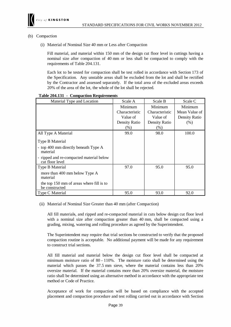
STANDARD SPECIFICATIONS FOR CIVIL WORKS NOVEMBER 2012
Page 39
(b) Compaction
(i) Material of Nominal Size 40 mm or Less after Compaction
Fill material, and material within 150 mm of the design cut floor level in cuttings having a nominal size after compaction of 40 mm or less shall be compacted to comply with the requirements of Table 204.131.
Each lot to be tested for compaction shall be test rolled in accordance with Section 173 of the Specification. Any unstable areas shall be excluded from the lot and shall be rectified by the Contractor and assessed separately. If the total area of the excluded areas exceeds 20% of the area of the lot, the whole of the lot shall be rejected.
Table 204.131 - Compaction Requirements
Material Type and Location Scale A Scale B Scale C Minimum
Characteristic Value of
Density Ratio (%)
Minimum Characteristic
Value of Density Ratio
(%)
Minimum Mean Value of Density Ratio
(%)
All Type A Material
Type B Material - top 400 mm directly beneath Type A
material - ripped and re-compacted material below
cut floor level
99.0 98.0 100.0
Type B Material more than 400 mm below Type A
material the top 150 mm of areas where fill is to
be constructed
97.0 95.0 95.0
Type C Material 95.0 93.0 92.0 (ii) Material of Nominal Size Greater than 40 mm (after Compaction) All fill materials, and ripped and re-compacted material in cuts below design cut floor level
with a nominal size after compaction greater than 40 mm, shall be compacted using a grading, mixing, watering and rolling procedure as agreed by the Superintendent.
The Superintendent may require that trial sections be constructed to verify that the proposed
compaction routine is acceptable. No additional payment will be made for any requirement to construct trial sections.
All fill material and material below the design cut floor level shall be compacted at
minimum moisture ratio of 80 - 110%. The moisture ratio shall be determined using the material which passes the 37.5 mm sieve, where the material contains less than 20% oversize material. If the material contains more than 20% oversize material, the moisture ratio shall be determined using an alternative method in accordance with the appropriate test method or Code of Practice.
Acceptance of work for compaction will be based on compliance with the accepted
placement and compaction procedure and test rolling carried out in accordance with Section

STANDARD SPECIFICATIONS FOR CIVIL WORKS NOVEMBER 2012
Page 40
173 of the Specification. Any unstable areas detected by test rolling shall be rectified. Where unstable areas exceed
20% of the area being test rolled, the whole of the area shall be ripped, re-compacted as specified above, and re-presented for test rolling.
(c) Treatment of Expansive Materials All material with a percentage swell equal to or greater than 2.5% shall be considered as
expansive. All layers of Type A fill placed as a capping layer over expansive Type B or insitu material, and
all layers of expansive Type B fill shall be maintained at a characteristic moisture ratio of not less than 90% for the period between completion of compaction and placement of the overlying layer.
The Contractor may nominate a lesser characteristic moisture ratio for agreement of the
Superintendent if it can demonstrate that complying with the above requirement will result in the material being unstable under a test roll performed in accordance with the requirements of Section 173 of the Specification.
Where the nominal size of material after compaction is greater than 40 mm, the moisture ratio
shall be determined on that material which passes the 19.0 mm sieve, otherwise the moisture ratio shall be determined on the material passing the 37.5 mm sieve or 19.0 mm sieve taking into account oversize material as required by the test method.
(d) Compaction Scales Compactions scales as shown in Table 204.132 shall apply. Table 204.132 - Requirements for Testing and Acceptance of Compaction (Clause 204.13)
Road Chainage Compaction Scale
##: ##: to ##: ##:
204.14 MINIMUM TESTING REQUIREMENTS 204.14 FREQUENCY OF TESTING The Contractor shall carry out testing at a frequency which is sufficient to ensure that the materials and work supplied under the Contract complies with the specified requirements. Notwithstanding this requirement, testing shall be undertaken at a frequency not less than that specified below. (a) Material Properties Materials shall be tested to demonstrate compliance with the material property requirements
specified in Clause 204.04.

STANDARD SPECIFICATIONS FOR CIVIL WORKS NOVEMBER 2012
Page 41
The initial assessment of Assigned CBR and swell of the material shall be carried out in accordance with VicRoads Code of Practice RC500.20. Unless otherwise approved by the Superintendent sampling for CBR testing shall be undertaken after field compaction. Where this testing indicates consistent conformance to the specified requirements for like material and work the Contractor may seek the Superintendent’s agreement to undertake testing at the frequency specified in Table 204.141 for individual CBR and percentage swell tests.
Table 204.141 - Frequency of Testing for Material Properties
Material Properties Material * Frequency of Testing CBR and percentage swell Type A Material 1 test per 2 lots Type B Material placed within the top
400 mm directly beneath Type A material or pavement if there is no Type A layer
1 test per 2 lots
Type B Material ripped and re-compacted below cut floor level
1 test per 2 lots
Type B Material placed 400 – 1000 mm below Type A material or pavement if there is no Type A layer
1 test per 4 lots
Grading Type A Material Type B Material Permeable Fill Material
1 test per lot
Plasticity Index (PI) and calculation of PI x % Passing 0.425 mm
Type A Material 1 test per 2 lots
Liquid Limit (LL) and comparison of PI against LL, (identification of silt)
Type A Material Type B Material
Initial test for each change material or material source
Permeability Type A Material 1 test per 2 lots Maximum Particle Dimension 1
Type B and Type C Material containing rock greater than 150 mm
Every lot
Notes: (1) Visual inspection, random assessment and measurement of larger rock particles. Should any of the individual CBR or swell tests fail to meet the values specified in Table 204.041
then the layer shall be retested and reassessed in accordance with VicRoads Code of Practice RC500.20 and new values shall be provided for Assigned CBR and swell of the material.
If either the newly Assigned CBR and/or swell value is not be in accordance with the requirements
specified in Table 204.041 then the layer and all subsequent material from that source shall be considered as non conforming for that use.
Testing for grading, PI, permeability and maximum particle dimension shall be undertaken at the
frequency specified in Table 204.141 until three consecutive lots of like material and work have achieved the specified requirements. After satisfying this requirement, the Contractor may seek the Superintendent’s agreement to reduce the frequency of testing of subsequent lots to half that specified in Table 204.141.
If the Contractor has obtained the Superintendent’s agreement to reduce the frequency of testing
and any lot fails to achieve the specified requirements, all testing of all subsequent lots shall be undertaken in accordance with Table 204.141 until three consecutive lots of like material and work

STANDARD SPECIFICATIONS FOR CIVIL WORKS NOVEMBER 2012
Page 42
have achieved the specified requirements in the first test. After satisfying this requirement, the Contractor may again reduce the frequency of testing to half that specified in Table 204.141.
If a material source changes, or the properties of a material differ from the material initially tested,
a new testing regime shall be established in accordance with this clause. (b) Compaction and Moisture Content Every lot shall be tested initially to demonstrate compliance with the requirements for compaction
and moisture content. Testing of every lot shall continue until three consecutive lots of like material and work have achieved the specified requirements in the first test. After satisfying this requirement and establishing a compaction procedure to the satisfaction of the Superintendent, the Contractor may seek the Superintendent’s agreement to reduce the frequency of testing of subsequent lots to the minimum requirements specified in Table 204.142.
If the Contractor has obtained the Superintendent’s agreement to test for compaction and moisture
content at the minimum testing frequency and any lot fails to achieve the specified requirements, testing of all subsequent lots shall be undertaken until three consecutive lots of like material and work have achieved the specified requirements in the first test. After satisfying this requirement, the Contractor may submit changes to the compaction procedure for the Superintendent’s review and may again seek approval to reduce the frequency of testing to the minimum requirements.
For the purposes of this sub-clause, small areas as defined in Section 173 of the Specification shall
not be included in the initial consecutive lots tested for compliance, nor any subsequent set of consecutive lots.
Table 204.142 - Minimum Frequency of Testing for Compaction and Moisture Content
Material Acceptable Lot Size in a Single Layer of Work
Minimum Frequency
Type A Material One day's production or 4000 m2, whichever is the lesser
Every second lot of like material and work
Type B Material - ripped and re-compacted
below specified cut floor level
One day's production or 4000 m2, whichever is the lesser
Every second lot of like material and work
- placed within top 1 m beneath Type A or pavement if there is no Type A layer
One day's production or 4000 m2, whichever is the lesser
Every second lot of like material and work
- placed more than 1 m below Type A or pavement if there is no Type A layer
One day’s production Every third lot of like material and work
Type C Material One day's production Every sixth lot of like material and work
204.15 PREPARATION OF SUBGRADE The subgrade surface shall be prepared to level and shape within the tolerances specified in Clause 204.03 (e) to produce a smooth, hard, tightly bound surface, free from depressions capable of holding water.

STANDARD SPECIFICATIONS FOR CIVIL WORKS NOVEMBER 2012
Page 43
Unless otherwise specified, material within 150 mm of the subgrade level shall have a moisture ratio not less than 70% immediately prior to the placement of any pavement layer. Where this material has a swell equal to or greater than 2.5 % the moisture ratio shall be maintained in accordance with Clause 204.13(c). 204.16 TOPSOILING Unless otherwise specified, all unpaved cut and fill areas within the limits of the batters, including batter roundings but excluding cut batters steeper than 1.5 to 1 (horizontal to vertical), and any other area disturbed by the Contractor's operations, shall be topsoiled to the following thicknesses measured normal to the slope:
(a) batters with slopes of 2 to 1 (horizontal to vertical) or steeper - 50 mm minimum;
(b) tree and shrub plantation bed areas other than (a) above - 100 mm minimum;
(c) verges - in areas without kerb and channel or concrete edging strips the depth of topsoil shall vary uniformly from 50 mm at the outside edge of verge to 20 mm deep within 100 mm of the edge of seal or asphalt surface treatment;
(d) all other areas - 75 mm minimum. Topsoil shall be placed and levelled but not compacted except for verge areas, which shall be compacted. Topsoil on batters shall be placed so as to prevent rilling. 204.17 STOCKPILES Stockpiles shall be located in areas clear of drainage paths and not less than 5 m clear of the drip line of existing trees and any fencing or as agreed by the Superintendent. Stockpiles shall be treated to minimise wind and water erosion and weed infestation. All stockpile sites shall be reinstated to match the surrounding area after removal of the stockpile. 204.18 CLEANING DOWN OF MACHINERY All equipment used on the site shall be cleaned down prior to transporting to and from the site to remove all seed, soil, mud and vegetative matter. Cleaning of machinery shall be undertaken in a designated area as specified or as agreed with the Superintendent.

STANDARD SPECIFICATIONS FOR CIVIL WORKS NOVEMBER 2012
Page 44
SECTION 304 - FLEXIBLE PAVEMENT CONSTRUCTION ##This section cross-references Sections 173, 321 and 324 – are they included in the specification?: 304.01 DESCRIPTION This section covers the requirements for the use of gravel, sand, soft or ripped rock, crushed rock or crushed concrete pavement materials, for the construction of pavement courses (including shoulders) other than pavement courses constructed by automatic level control (ALC) paver in which case the requirements of Sections 321 and 324 shall apply. 304.02 CONFORMITY WITH DRAWINGS Pavement courses, each consisting of one or more layers, shall after compaction be finished to smooth and uniform surfaces conforming to the limits for level, line, grade, thickness and cross section shown on the drawings or as specified. (a) Level (i) Gravel, sand and soft or ripped rock material The top of each pavement course shall not differ from the specified level by more than
25 mm. (ii) Crushed material The top of each pavement course shall not differ from the specified level by more than
15 mm. Where pavement is to be constructed to the lip level of kerb and channel, it shall be constructed
flush with the lip of the channel or not more than 5 mm above. (b) Thickness The subbase course at any point shall be not less than the specified thickness by more than
15 mm and where the subbase consists of two or more layers the thickness of the top layer at any point shall be not less than that specified by more than 10 mm.
The base course at any point shall be not less than the specified thickness by more than 10 mm
and where the base consists of two or more layers the thickness of the top layer at any point shall be not less than that specified by more than 5 mm. The average thickness of base over every 100 m section, for the full carriageway width shall be not less than the specified thickness, as determined from measurements taken in accordance with the requirements of Section 173.
The combined thickness of subbase and base courses at any point shall be not less than the
specified thickness by more than 15 mm. (c) Width and Alignment The widths measured on each side from the specified centreline or design line shall not deviate by
more than 50 mm from the designed offset.

STANDARD SPECIFICATIONS FOR CIVIL WORKS NOVEMBER 2012
Page 45
(d) Shape No point on the surface of each layer of base or subbase shall lie more than 10 mm below a 3 m
straightedge laid parallel to the centreline of the pavement or below a template placed at right angles to the centreline.
304.03 MATERIALS Unless otherwise specified, the Contractor shall be responsible for the procurement of sufficient specified material to complete the work. 304.04 ADDITION OF WATER Water added to the pavement material, shall be clean and substantially free from detrimental impurities such as oils, salts, and, alkalis and vegetable substances. 304.05 DELIVERY DOCKETS Where material is scheduled for measurement by loose volume in delivery vehicles or by mass, a delivery docket for each load shall be issued to the Superintendent at the point of delivery. Where material is measured by other means and for Lump Sum Contracts, the Contractor shall make delivery dockets available for inspection on request by the Superintendent. Delivery dockets shall show: (a) name of the supplier, and location of plant; (b) docket number; (c) name of user; (d) project name and location (or contract number); (e) registered number or fleet number of the vehicle; (f) date and time of loading; (g) nature and source of material; (h) empty and loaded masses of the vehicle (where material is scheduled for measurement by mass); (i) loose volume in delivery vehicle.

STANDARD SPECIFICATIONS FOR CIVIL WORKS NOVEMBER 2012
Page 46
304.06 JOINTING Unless otherwise specified, the layout of joints shall conform to the following requirements: (a) Material shall be spread in such a manner as to minimize the number of joints. (b) In any layer, transverse joints in adjoining paver runs shall be offset by not less than 2 m. (c) Transverse joints shall be offset from one layer to the next by not less than 2 m. (d) Longitudinal joints shall be offset from one layer to the next by not less than 150 mm. (e) Longitudinal joints shall be located within 300 mm of the planned position of traffic lanes lines
or within 300 mm of the centre of a traffic lane. The edge of any paver run shall be kept moist until spreading and compaction has been completed in adjacent paver runs. 304.07 REQUIREMENTS FOR TESTING AND ACCEPTANCE OF COMPACTION (a) Material of nominal size 40 mm or less On completion of compaction any segregated areas shall be rectified. Material which will have a nominal size after compaction of 40 mm or less shall be compacted to
comply with the following requirements. The calculation of density ratio shall be based on tests performed using Modified compactive
effort. The work shall be assessed for compliance with Scale A, Scale B or Scale C requirements for testing and acceptance of compaction as specified in Clause 304.11 and as provided in Table 304.071.
A lot shall consist of a single layer of work and its size shall not exceed that given in
Table 304.081. For work to be tested for compliance with Scale A or Scale B requirements, the number of tests
per lot shall be six. For work to be tested for compliance with Scale C requirements, the number of tests per lot shall
be three. All pavement layers shall be compacted to withstand test rolling and shall be test rolled in
accordance with Section 173, prior to acceptance of the layer.

STANDARD SPECIFICATIONS FOR CIVIL WORKS NOVEMBER 2012
Page 47
Table 304.071 - Requirements for Lot Acceptance of Compaction
Scale Characteristic Value of Density Ratio %
Mean Value of Density Ratio %
Assessment
Base Subbase Base Subbase
A1 Not less than 100.0
Not less than 98.0
Accept lot
A2 Not less than 99.0
Not less than 98.0
Accept lot
B Not less than 98.0
Not less than 97.0
Accept lot
C Not less than 100.0
Not less than 98.0
Accept lot
(b) Material of nominal size greater than 40 mm Unless otherwise specified, material shall have during compaction a moisture ratio not less than
85% as determined by test using Modified compactive effort. After completion of compaction of a layer the moisture content of the material in the layer shall be maintained within the range specified until test rolling has been completed.
On completion of compaction, any segregated areas shall be rectified. Unless otherwise specified, material which will have a nominal size after compaction greater
than 40 mm shall be compacted using a grading, mixing, watering and rolling procedure proposed by the Contractor and reviewed by the Superintendent.
The Superintendent may require that trial sections be constructed to verify that the proposed
compaction routine is acceptable. No additional payment will be made for any such request. Acceptance of work as far as compaction is concerned will be based on compliance with the
accepted compaction routine and test rolling carried out in accordance with Section 173. Any unstable areas detected by test rolling shall be rectified by the Contractor. If required by the Superintendent, further test rolling shall be carried out by the Contractor on
the pavement layer prior to being covered by a successive layer. No additional payment will be made for any requirement to carry out such further test rolling.
304.08 MINIMUM TESTING REQUIREMENTS The Contractor shall carry out testing at a frequency which is sufficient to ensure that work performed under the Contract complies with the specified requirements but which is not less than that shown in

STANDARD SPECIFICATIONS FOR CIVIL WORKS NOVEMBER 2012
Page 48
Table 304.081.
*** Table 304.081 - Minimum Frequency of Testing for Compaction
Material Acceptable Lot Size * in a Single Layer of Work
Percentage of Lots to be Tested
(min)
Upper Base 5000 m² or one day's production
Lower Base 5000 m² or one day's production
Subbase 10000 m² or one day's production
Lower Subbase 15000 m² or one day's production
* Where alternative acceptable lot sizes have been specified, the smaller lot size shall apply.
The Contractor shall initially test every lot for acceptance in accordance with the requirements of the Specification. Testing of every lot shall continue until three consecutive lots of like material or work have achieved the specified standard when tested for the first time. The Contractor may reduce the frequency of testing to the minimum testing requirements specified after satisfying the above requirement. If the Contractor has satisfied the above requirement and is testing lots at the minimum frequency and any lot fails to achieve the specified standard, the Contractor shall test all subsequent lots until three consecutive lots of like material or work have achieved the specified standard, at which time the frequency of testing may again be reduced to the minimum requirements. For the purposes of this sub-clause, acceptance of compaction for small areas as defined in Section 173 will not be regarded as satisfying the initial testing requirements stated above. 304.09 PROTECTION OF COMPACTED LAYERS The surface of any compacted layer shall be kept moist, in good order and condition and free from contamination until any subsequent pavement work under the Contract is commenced or the Superintendent accepts and takes responsibility for that part of the Works. 304.10 GRADING OF PAVEMENT MATERIAL AFTER COMPACTION Material shall comply with the relevant grading requirements of Tables 304.101, 304.102 and 304.103 respectively following completion of compaction. Table 304.101 - Grading Requirements for Base Crushed Rock After Compaction
Sieve Size (mm)
Permitted Grading After Compaction
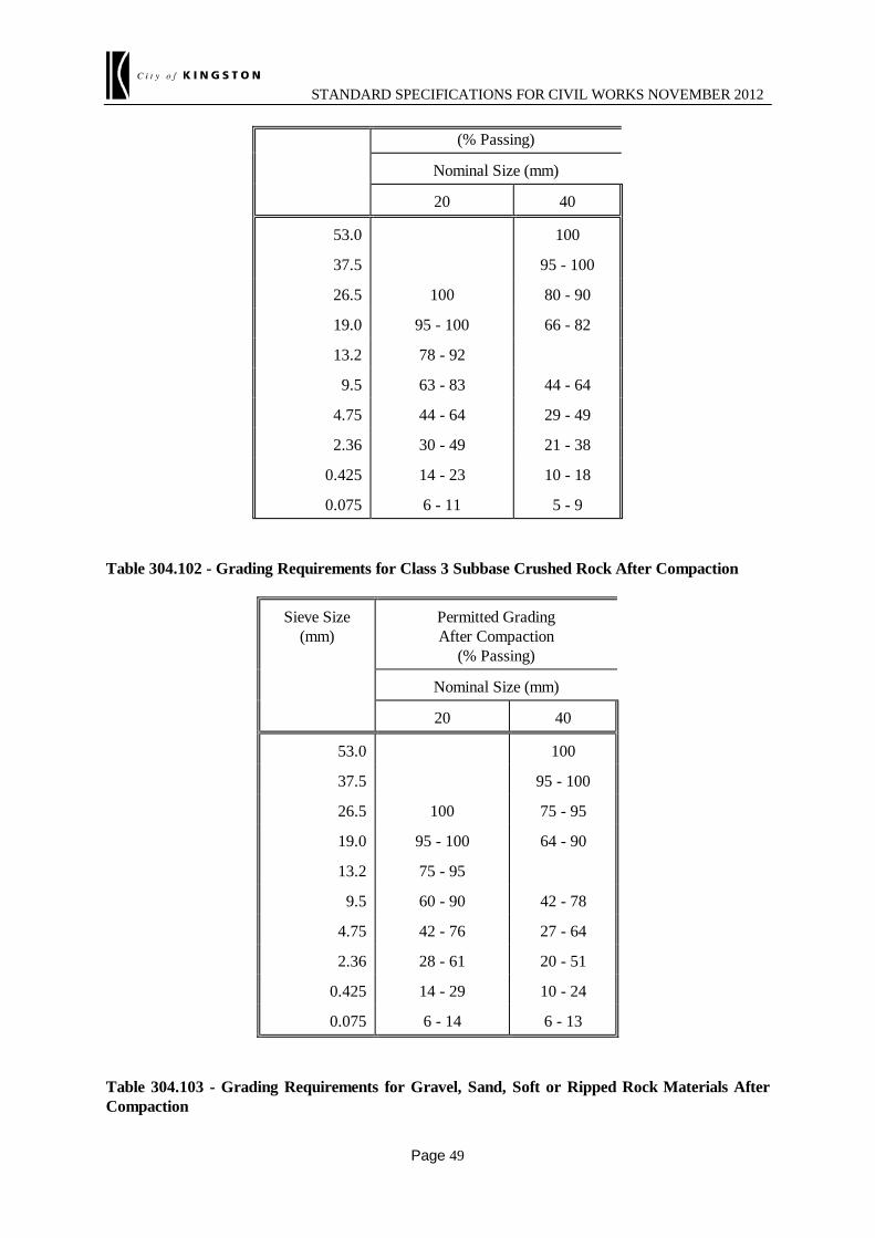
STANDARD SPECIFICATIONS FOR CIVIL WORKS NOVEMBER 2012
Page 49
(% Passing)
Nominal Size (mm)
20 40
53.0 100
37.5 95 - 100
26.5 100 80 - 90
19.0 95 - 100 66 - 82
13.2 78 - 92
9.5 63 - 83 44 - 64
4.75 44 - 64 29 - 49
2.36 30 - 49 21 - 38
0.425 14 - 23 10 - 18
0.075 6 - 11 5 - 9 Table 304.102 - Grading Requirements for Class 3 Subbase Crushed Rock After Compaction
Sieve Size (mm)
Permitted Grading After Compaction
(% Passing)
Nominal Size (mm)
20 40
53.0 100
37.5 95 - 100
26.5 100 75 - 95
19.0 95 - 100 64 - 90
13.2 75 - 95
9.5 60 - 90 42 - 78
4.75 42 - 76 27 - 64
2.36 28 - 61 20 - 51
0.425 14 - 29 10 - 24
0.075 6 - 14 6 - 13
Table 304.103 - Grading Requirements for Gravel, Sand, Soft or Ripped Rock Materials After Compaction
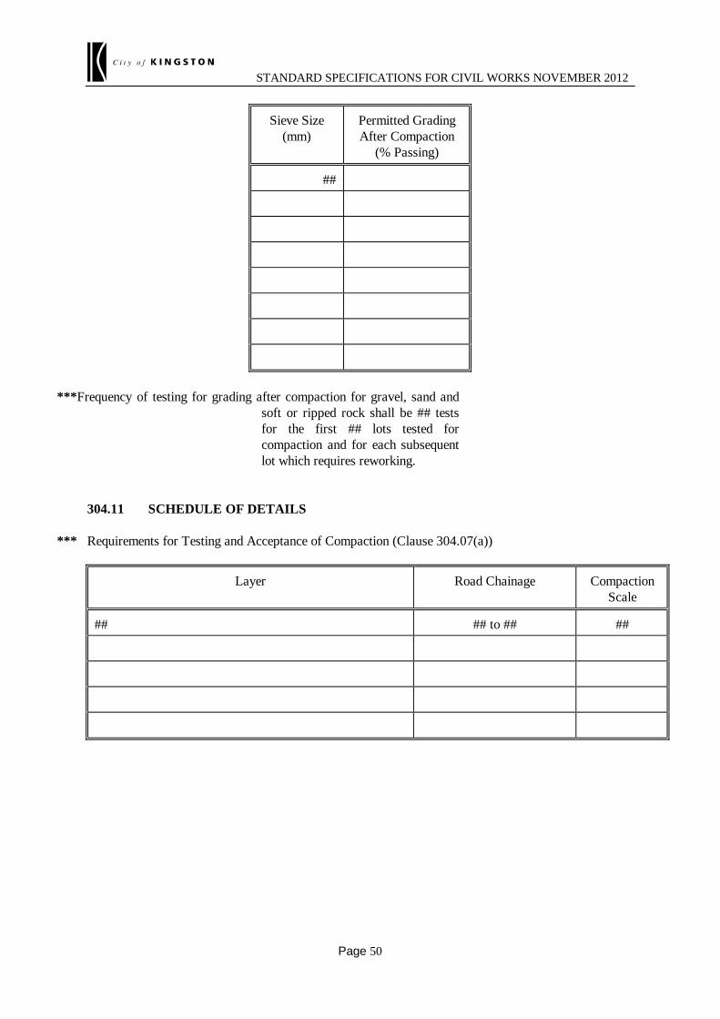
STANDARD SPECIFICATIONS FOR CIVIL WORKS NOVEMBER 2012
Page 50
Sieve Size (mm)
Permitted Grading After Compaction
(% Passing)
##
***Frequency of testing for grading after compaction for gravel, sand and soft or ripped rock shall be ## tests for the first ## lots tested for compaction and for each subsequent lot which requires reworking.
304.11 SCHEDULE OF DETAILS
*** Requirements for Testing and Acceptance of Compaction (Clause 304.07(a))
Layer Road Chainage Compaction Scale
## ## to ## ##

STANDARD SPECIFICATIONS FOR CIVIL WORKS NOVEMBER 2012
Page 51

STANDARD SPECIFICATIONS FOR CIVIL WORKS NOVEMBER 2012
Page 52
SECTION 306 - CONSTRUCTION OF CEMENTITIOUSLY TREATED SUBBASE PAVEMENTSECTION
##This section cross-references Sections 173, 815 and 821 – are they included in the specification?: 306.01 DESCRIPTION This section covers the requirements for the delivery, spreading and compaction of plant mixed crushed rock and recycled crushed concrete for the construction of subbase pavement and treated with cementitous binder to produce a modified or bound subbase. This section is to be read in conjunction with the following sections:
• Section 815 - Cementitiously Treated Crushed Rock for Subbase Pavement
• Section 821 - Cementitiously Treated Crushed Concrete for Subbase Pavement. 306.02 DEFINITIONS Cementitious Binder A cementing agent binds the particles of a granular pavement material together to increase its strength. Cementitious binders include Portland cement Type GP or blended cement Type GB, hydrated lime, quicklime, or a blend of ground granulated blast furnace slag (GGBFS), hydrated lime, fly ash, alkali activated slag or other pozzolanic material supplied in accordance with this specification. Maximum Allowable Working Time The maximum allowable working time for the cementitious binder as specified or as determined in accordance with the relevant Test Method or Code of Practice. Pavement Design Modulus The presumptive modulus used as the basis for the mechanistic design of a bound pavement with a bound cementitiously treated crushed rock or crushed concrete subbase. Working Time The time required to transport, place, compact and trim the pavement layer after the cementitious binder is added at the mixing plant. 306.03 CONFORMITY WITH DRAWINGS Subbase pavement shall be finished to a smooth and uniform surface and shall, after compaction, conform within the following limits to the levels, lines, grades, thicknesses and cross sections as specified or shown on the drawings. (a) Width and Alignment
The width of pavement measured on each side of the specified centreline or design line shall not deviate
by more than 50 mm from the designed offset when measured at a right angle from the centre line or design line.

STANDARD SPECIFICATIONS FOR CIVIL WORKS NOVEMBER 2012
Page 53
(b) Surface Level of Subgrade and Pavement The surface level of the subgrade and pavement courses shall be measured in accordance with the
requirements of Section 173 and every test lot shall meet either Scale A, B or C requirements as specified in Clause 306.12.
The maximum lot size for measurement and assessment of surface level shall be 4000 m2. (i) Scale A and B Surface Level Requirements Each level measurement shall be taken at random locations over the area of the lot in
accordance with the VicRoads Test Method and the number of measurements taken within each lot shall not be less than the number specified in Table 306.031.
The mean surface level and the variation in surface level for the subgrade, and pavement
courses within each lot shall meet the requirements of Table 306.032. Table 306.031 - Minimum Number of Level Measurements per Lot
Scale of Surface Level Measurement
Minimum Number of Measurements Per Lot
Scale A 80
Scale B 40 Table 306.032 -Average Surface Level Tolerances for the Subgrade and Cement Treated
Subbase
Scale of Level Measurement
Subgrade Cement Treated Subbase
x̄ Range (mm)
Max. S (mm)
x̄ Range (mm)
Max. S (mm)
Scale A +5 to –15 12 +4 to -8 8
Scale B +5 to –25 15 +6 to -12 13
Notes: 1. x̄ is the mean value of all level readings taken in the lot 2. S is the standard deviation of all level readings taken in the lot 3. A negative value designates a measured departure below the design level and
positive value designates a surface level above the design level. For Scale A and Scale B level requirements, the Superintendent may agree to accept a lot
which does not conform with the limits of Table 306.032 at a reduced payment, in which case payment for the work will be reduced as shown in Table 306.033. The value of the lot of work shall be calculated from the unit rates for pavement construction as specified in Clause 306.12(b).
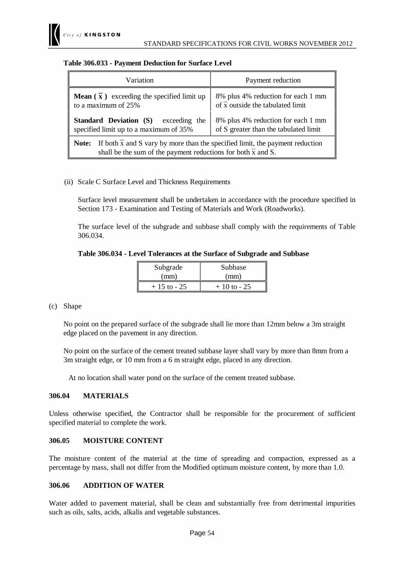
STANDARD SPECIFICATIONS FOR CIVIL WORKS NOVEMBER 2012
Page 54
Table 306.033 - Payment Deduction for Surface Level
Variation Payment reduction
Mean ( x̄ ) exceeding the specified limit up to a maximum of 25%
8% plus 4% reduction for each 1 mm of x̄ outside the tabulated limit
Standard Deviation (S) exceeding the specified limit up to a maximum of 35%
8% plus 4% reduction for each 1 mm of S greater than the tabulated limit
Note: If both x̄ and S vary by more than the specified limit, the payment reduction shall be the sum of the payment reductions for both x̄ and S.
(ii) Scale C Surface Level and Thickness Requirements Surface level measurement shall be undertaken in accordance with the procedure specified in
Section 173 - Examination and Testing of Materials and Work (Roadworks). The surface level of the subgrade and subbase shall comply with the requirements of Table
306.034. Table 306.034 - Level Tolerances at the Surface of Subgrade and Subbase
Subgrade (mm)
Subbase (mm)
+ 15 to - 25 + 10 to - 25 (c) Shape No point on the prepared surface of the subgrade shall lie more than 12mm below a 3m straight
edge placed on the pavement in any direction. No point on the surface of the cement treated subbase layer shall vary by more than 8mm from a
3m straight edge, or 10 mm from a 6 m straight edge, placed in any direction. At no location shall water pond on the surface of the cement treated subbase. 306.04 MATERIALS Unless otherwise specified, the Contractor shall be responsible for the procurement of sufficient specified material to complete the work. 306.05 MOISTURE CONTENT The moisture content of the material at the time of spreading and compaction, expressed as a percentage by mass, shall not differ from the Modified optimum moisture content, by more than 1.0. 306.06 ADDITION OF WATER Water added to pavement material, shall be clean and substantially free from detrimental impurities such as oils, salts, acids, alkalis and vegetable substances.

STANDARD SPECIFICATIONS FOR CIVIL WORKS NOVEMBER 2012
Page 55
Except for the purpose of curing cement treated material in situ, or unless otherwise agreed with the Superintendent, no water shall be added to the cement treated materials in situ or in delivery vehicles. 306.07 DELIVERY (a) Delivery vehicles Delivery vehicles shall have bodies fitted with covers of canvas or other approved material to
prevent loss of moisture during transport. Vehicles used for delivery of material to the hoppers of pavers shall have bodies or discharge equipment which will enable the load to be discharged direct into the hopper without spillage and in such a way that segregation will be minimized.
(b) Delivery dockets Delivery dockets shall show: (i) name of the supplier, and location of plant; (ii) docket number; (iii) name of user; (iv) project name and location (or contract number); (v) registered number or fleet number of the vehicle; (vi) date and time of loading; (vii) nature and source of material; (viii) empty and loaded masses of the vehicle (where material is scheduled for measurement
by mass); (ix) loose volume in delivery vehicle.
Where material is scheduled for measurement by loose volume in delivery vehicles or by mass, a
delivery docket for each load shall be issued to the Superintendent at the point of delivery. Where material is measured by other means and for Lump Sum Contracts, the Contractor shall
make delivery dockets available for inspection on request by the Superintendent. 306.08 JOINTING Where a paver is used, the layout of joints shall conform to the following requirements unless otherwise approved by the Superintendent: (a) Material shall be spread in such a manner as to minimize the number of joints. (b) In any layer, transverse joints in adjoining paver runs shall be offset by not less than 2 m.
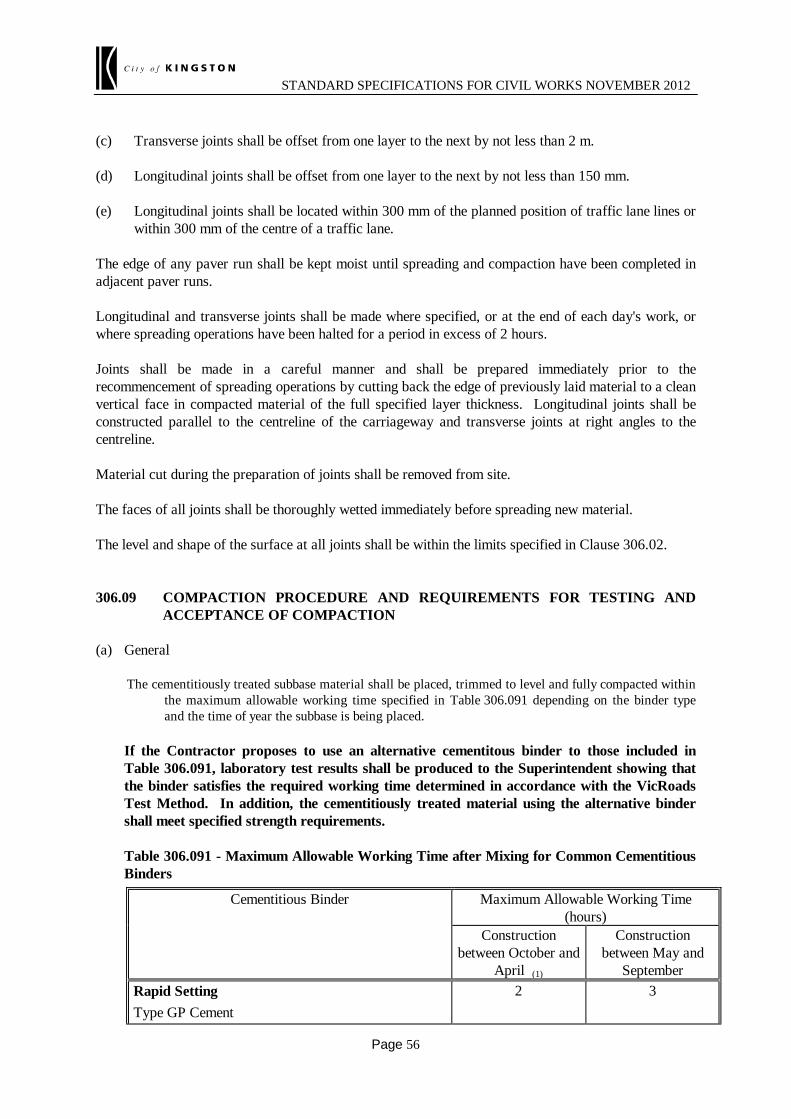
STANDARD SPECIFICATIONS FOR CIVIL WORKS NOVEMBER 2012
Page 56
(c) Transverse joints shall be offset from one layer to the next by not less than 2 m. (d) Longitudinal joints shall be offset from one layer to the next by not less than 150 mm. (e) Longitudinal joints shall be located within 300 mm of the planned position of traffic lane lines or
within 300 mm of the centre of a traffic lane. The edge of any paver run shall be kept moist until spreading and compaction have been completed in adjacent paver runs. Longitudinal and transverse joints shall be made where specified, or at the end of each day's work, or where spreading operations have been halted for a period in excess of 2 hours. Joints shall be made in a careful manner and shall be prepared immediately prior to the recommencement of spreading operations by cutting back the edge of previously laid material to a clean vertical face in compacted material of the full specified layer thickness. Longitudinal joints shall be constructed parallel to the centreline of the carriageway and transverse joints at right angles to the centreline. Material cut during the preparation of joints shall be removed from site. The faces of all joints shall be thoroughly wetted immediately before spreading new material. The level and shape of the surface at all joints shall be within the limits specified in Clause 306.02. 306.09 COMPACTION PROCEDURE AND REQUIREMENTS FOR TESTING AND
ACCEPTANCE OF COMPACTION (a) General
The cementitiously treated subbase material shall be placed, trimmed to level and fully compacted within the maximum allowable working time specified in Table 306.091 depending on the binder type and the time of year the subbase is being placed.
If the Contractor proposes to use an alternative cementitous binder to those included in
Table 306.091, laboratory test results shall be produced to the Superintendent showing that the binder satisfies the required working time determined in accordance with the VicRoads Test Method. In addition, the cementitiously treated material using the alternative binder shall meet specified strength requirements.
Table 306.091 - Maximum Allowable Working Time after Mixing for Common Cementitious
Binders
Cementitious Binder Maximum Allowable Working Time (hours)
Construction between October and
April (1)
Construction between May and
September Rapid Setting Type GP Cement
2 3
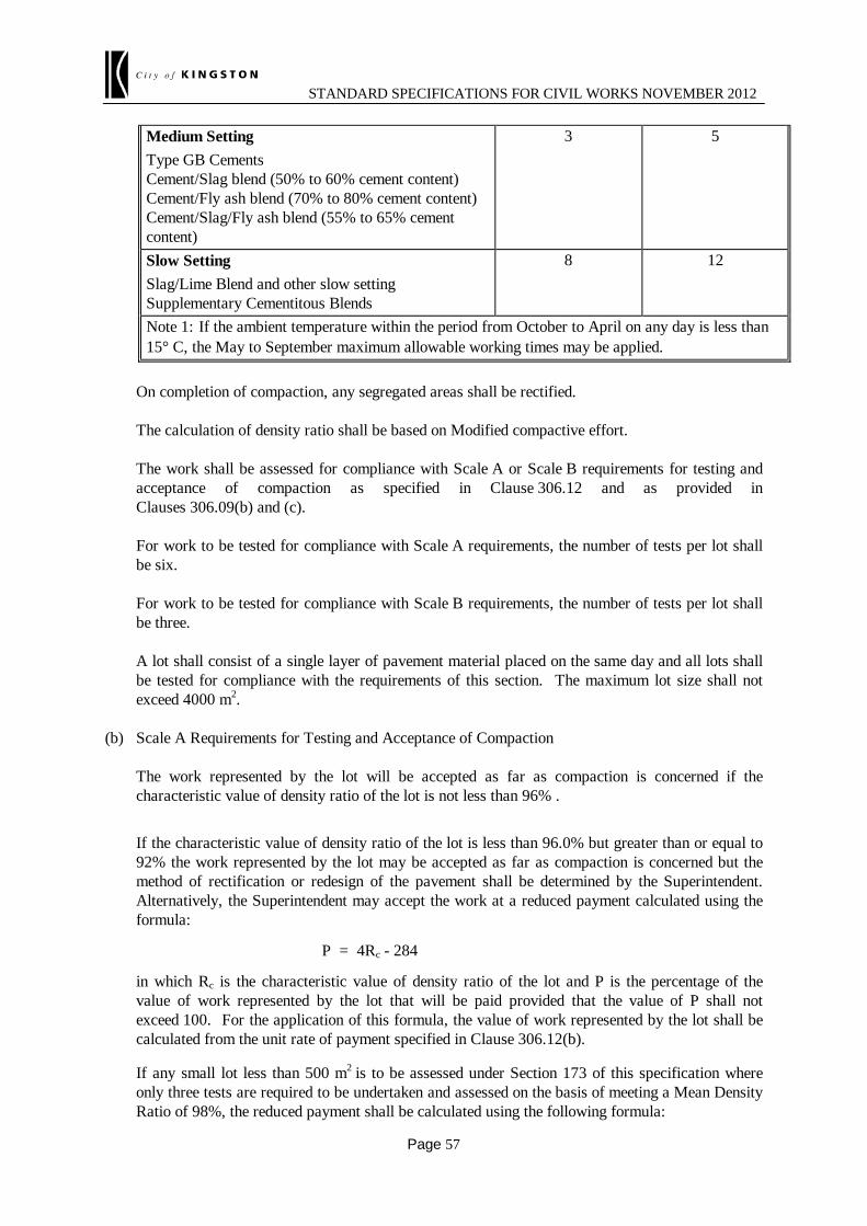
STANDARD SPECIFICATIONS FOR CIVIL WORKS NOVEMBER 2012
Page 57
Medium Setting Type GB Cements Cement/Slag blend (50% to 60% cement content) Cement/Fly ash blend (70% to 80% cement content) Cement/Slag/Fly ash blend (55% to 65% cement content)
3 5
Slow Setting Slag/Lime Blend and other slow setting Supplementary Cementitous Blends
8 12
Note 1: If the ambient temperature within the period from October to April on any day is less than 15° C, the May to September maximum allowable working times may be applied.
On completion of compaction, any segregated areas shall be rectified. The calculation of density ratio shall be based on Modified compactive effort. The work shall be assessed for compliance with Scale A or Scale B requirements for testing and
acceptance of compaction as specified in Clause 306.12 and as provided in Clauses 306.09(b) and (c).
For work to be tested for compliance with Scale A requirements, the number of tests per lot shall
be six. For work to be tested for compliance with Scale B requirements, the number of tests per lot shall
be three. A lot shall consist of a single layer of pavement material placed on the same day and all lots shall
be tested for compliance with the requirements of this section. The maximum lot size shall not exceed 4000 m2.
(b) Scale A Requirements for Testing and Acceptance of Compaction The work represented by the lot will be accepted as far as compaction is concerned if the
characteristic value of density ratio of the lot is not less than 96% . If the characteristic value of density ratio of the lot is less than 96.0% but greater than or equal to
92% the work represented by the lot may be accepted as far as compaction is concerned but the method of rectification or redesign of the pavement shall be determined by the Superintendent. Alternatively, the Superintendent may accept the work at a reduced payment calculated using the formula:
P = 4Rc - 284 in which Rc is the characteristic value of density ratio of the lot and P is the percentage of the
value of work represented by the lot that will be paid provided that the value of P shall not exceed 100. For the application of this formula, the value of work represented by the lot shall be calculated from the unit rate of payment specified in Clause 306.12(b).
If any small lot less than 500 m2 is to be assessed under Section 173 of this specification where
only three tests are required to be undertaken and assessed on the basis of meeting a Mean Density Ratio of 98%, the reduced payment shall be calculated using the following formula:

STANDARD SPECIFICATIONS FOR CIVIL WORKS NOVEMBER 2012
Page 58
P = 4Rm - 292 (c) Scale B Requirements for Testing and Acceptance of Compaction The work represented by the lot will be accepted as far as compaction is concerned if the mean
density ratio for the lot is not less than 96.0%. If the mean of the individual density ratio test values for the lot is less than 96.0%, but greater
than or equal to 92% the work represented by the lot may be accepted as far as compaction is concerned but the method of rectification and/or redesign of the pavement shall be determined by the Superintendent. Alternatively, the Superintendent may accept the work at a reduced rate calculated using the formula:
P = 4Rm - 284 in which Rm is the mean of the individual density ratio test values for the lot and P is percentage of
the value of work represented by the lot that will be paid provided the value of P shall not exceed 100. For the application of this formula the value of work represented by the lot shall be calculated from the unit rate of payment specified in Clause 306.12(b).
306.10 TEST ROLLING Subbase layers shall be so compacted that they are capable of withstanding test rolling in accordance with Section 173, after the material has set. If required by the Superintendent, further test rolling shall be carried out by the Contractor on the pavement layer prior to being covered by a successive layer. No additional payment will be made for any requirement to carry out such further test rolling. 306.11 CURING AND PROTECTION OF COMPACTED LAYERS Unless there are special design and construction conditions specified for placing of multiple layers, cementitiously treated subbase with a pavement design modulus exceeding 500 MPa shall be placed in a single layer. The minimum compacted thickness shall be not less than 100 mm and the maximum compacted thickness shall be no more than 180 mm and constructed within the tolerances specified in Clause 306.03. (a) Pavement Design Modulus of 500 MPa or where no Pavement Design Modulus is Specified The surface of each compacted layer shall be kept moist for a period of 7 days unless covered at
an earlier stage with the succeeding layer or with an approved curing membrane. Construction or other traffic shall not use a compacted layer within 24 hours of placement without
the approval of the Superintendent. The subbase shall be kept in good order and condition and free from contamination. (b) Pavement Design Modulus of 2000 MPa In addition to meeting the requirements of Clause 306.11(a) above, the Contractor shall:
(i) cure the cementitiously treated subbase by maintaining the surface in a moist condition for 7 days;
(ii) prevent construction plant from using the pavement during the 7 day curing period apart from that required to maintain and cure the surface; and

STANDARD SPECIFICATIONS FOR CIVIL WORKS NOVEMBER 2012
Page 59
(iii) after the 7 day curing period, restrict all construction traffic to vehicles with a maximum axle group load of 4 tonne until asphalt base and intermediate courses are placed (priming, primersealing and asphalt placement activities excepted).
(c) Pavement Design Modulus of 3500 MPa In addition to meeting the requirements of Clause 306.11(b) above, the Contractor shall:
(i) Apply a size 7 CRS standard grade emulsion primerseal at a rate of application of 1.5 litres per square metre (0.9 litres per square metre of residual binder) to the cementitiously treated subbase within 12 to 24 hours after completion of compaction. If after 24 hours ambient conditions are such the material has not dried back to less than 80% of the modified optimum moisture content, the primerseal shall be delayed until such time as the moisture content has reduced below 80% of optimum.
Subject to approval by the Superintendent and if weather conditions during the period from October to April inclusive suit priming, a light or very light cut back bitumen primer may be applied to the surface of the of the cement treated material in lieu of the emulsion primerseal. The rate of application of primer shall be a minimum of 0.6 litres per square metre and shall deliver a minimum of 0.3 to 0.4 litres per square metre of residual bitumen to the surface.
Requests by the Contractor to vary the rates of application shall be submitted in writing
to the Superintendent for review. Primersealing shall not be carried out within 12 hours of forecast rain and priming, if
approved for use, shall not be carried out within 24 hours of forecast rain.
The Contractor’s Environmental Management Plan shall include procedures to minimise all risks of damage to the environment associated with priming and primersealing.
(ii) Allow the cement treated subbase to stand and cure for 7 days without trafficking (except for the application of a prime or primerseal); and
(iii) After the 7 days standing period, restrict construction traffic to vehicles with a maximum axle group load of 4 tonne until asphalt base and intermediate courses are placed (priming, primersealing and asphalt placement activities excepted).
306.12 SCHEDULE OF DETAILS
*** (a) Requirements for Testing and Acceptance of Compaction (Clause 306.09)
Location and Chainage Pavement Design
Modulus (MPa)
Scale of Surface Level
Measurement (A, B or C)
Compaction Scale (A or B)
##: ##: ##: ##:
*** (b) Unit rate of payment to be used to calculate the value of the work represented by the lot for application of payment deduction formulae specified in Clauses 306.03(b)(i), and 306.09(b) and (c) shall be $##:/m3.
STANDARD SPECIFICATIONS FOR CIVIL WORKS NOVEMBER 2012
Page 60
SECTION 402 - REMOVAL OF PAVEMENT BY COLD PLANING ##This section cross-references Section 407 – is this section included in the specification?: 402.01 GENERAL This section covers the requirements for removal of pavement by cold planing including the cleaning up, removal and disposal of the excavated materials. 402.02 COLD PLANING Unless otherwise specified or directed by the Superintendent, cold planing shall be carried out in a manner as to leave a uniform surface on a plane parallel with the ultimate finished surface of the pavement as shown on the drawings. Unless otherwise directed, the nominal depth and width of pavement to be removed shall be as specified in Clause 402.06. After planing, no point on the planed surface shall lie more than 15 mm below a 3 m straightedge placed on the planed surface in any direction. In locations where removal and replacement of asphalt or pavement is required on the same day, the rate of cold planing including clean up shall be at a rate consistent with the asphalt replacement process to minimise the pavement area closed to traffic. 402.03 CLEANING UP AND DISPOSAL OF EXCAVATED MATERIAL The planed surface shall be swept clean of all loose material prior to either diverting traffic onto the planed surface or placing asphalt. The excavated material removed from the road shall either become the property of the CITY OF KINGSTON, or the property of the Contractor as specified in Clause 402.06(d) and (e). If the material becomes the property of the CITY OF KINGSTON, the Contractor shall load, transport and stockpile material into a neat pile at the nominated stockpile area. If the material becomes the property of the Contractor, the Contractor shall remove all such material from the site. Prior to opening to traffic, placing asphalt, or leaving the site, the Contractor shall present a clean planed surface. 402.04 ASPHALT REPLACEMENT Where work under the Contract includes replacement of excavated material with asphalt supplied and placed under Section 407, the following requirements shall apply unless otherwise specified or directed: (a) Exposed granular pavement material shall be watered, re-compacted and, where specified, primed
or heavily tack coated, or for larger areas, given a bitumen emulsion primerseal prior to placing

STANDARD SPECIFICATIONS FOR CIVIL WORKS NOVEMBER 2012
Page 61
asphalt.
(b) Prior to opening to traffic, excavated areas shall be filled with hotmix asphalt. All transverse and longitudinal joints shall be constructed as cold joints in accordance with Clause 407.16 and new asphalt shall be compacted flush with the existing pavement in accordance with the requirements of Clause 407.22(a).
(c) In the event of a breakdown in the supply or placing of asphalt in areas to be opened to traffic,
the Contractor shall temporarily backfill or ramp down the cold planed area with cold mixed asphalt or other suitable material which will support traffic loading and provide for the safe passage of traffic. Material so placed shall be removed prior to placing new asphalt as specified and the placing and removal of temporary backfilling shall be at the expense of the Contractor. Temporary ramping shall be carried out to the standards specified in Clause 402.05.
402.05 TEMPORARY RAMPING (a) Longitudinal Edges Any exposed longitudinal edges within the trafficked area shall be ramped down at a slope no
steeper than 5 horizontal to 1 vertical by constructing a temporary wedge of hot mixed or cold mixed asphalt.
(b) Transverse Edges Any exposed transverse edges within the trafficked area shall be ramped down by constructing a
temporary wedge of hot mixed or cold mixed asphalt. Temporary ramping shall not be steeper than 20 horizontal to 1 vertical for traffic speeds of more than 75 km/h or 10 horizontal to 1 vertical for traffic speeds of 75 km/h or less.
(c) Removal of Temporary Ramping Before asphalt replacement, all temporary ramping shall be removed by cutting back along a
straight line to expose a vertical face of fully compacted asphalt at the specified layer depth. 402.06 SCHEDULE OF DETAILS (a) Type of Work (i) Removal of asphalt. (ii) Cutting of tapered longitudinal chases against kerb and channel, median openings, and side
streets. (iii) Cutting of tapered transverse chases. (iv) Excavation of granular pavement material. (v) Profiling of concrete pavement. (vi) Removal and replacement of asphalt in accordance with Section 407 of this specification.

STANDARD SPECIFICATIONS FOR CIVIL WORKS NOVEMBER 2012
Page 62
*** (b) Nominal area and depth of removal: ##: m2 ##: mm (Clause 402.02)
*** (c) Nominal width of removal: ##: m (Clause 402.02)
*** (d) Planed material shall become the property of the [CITY OF KINGSTON] and be stockpiled at ##: (Clause 402.03). (e) Planed material shall become the property of the Contractor and shall be removed from the site
(Clause 402.03).

STANDARD SPECIFICATIONS FOR CIVIL WORKS NOVEMBER 2012
Page 63
SECTION 404 - STONE MASTIC ASPHALT SECTION 404 - STONE MASTIC
ASPHALT ##This section cross-references Section 407 – is this section included in the specification?: 404.01 GENERAL This section shall be read in conjunction with Section 407 - Hot Mix Asphalt and covers special requirements for Size 10 mm and Size 14 mm Stone Mastic Asphalt (SMA) that are in addition to, or override the requirements of Section 407. Stone Mastic Asphalt is a coarse graded asphalt containing a high proportion of binder and added filler with the addition of cellulose fibre or agreed alternative fibre. 404.02 CELLULOSE FIBRE ADDITIVE Cellulose fibre additive shall be non toxic, and supplied in a powdered, fine fibrilled long fibred form manufactured from raw cellulose. Cellulose fibre additive shall have the following properties:
Apparent density - 25-35 g/l
Maximum fibre length - 5000 µm
Average fibre length - 1100 µm
Average fibre thickness - 45 µm Cellulose fibre shall be supplied in strong non-slip polythene bags of equal mass suitable for metered plant mixing, and shall be handled in accordance with the manufacturer's specifications. Cellulose fibre additive may be supplied as a granulated blend of cellulose fibre and bituminous material in pelletised form where it can be added to the mixer at the rate specified in Table 404.062. If it is proposed to use a drum mixing plant, cellulose fibre must be supplied in granular form. 404.03 AGGREGATES Unless otherwise specified, properties of the aggregates used in Stone Mastic Asphalt (SMA) shall comply with the requirements for asphalt Type H as specified in Clause 407.03. 404.04 BINDER Binder used in SMA shall be Class 320 Bitumen as specified in Clause 407.05 unless otherwise specified. 404.05 MIX DESIGN

STANDARD SPECIFICATIONS FOR CIVIL WORKS NOVEMBER 2012
Page 64
The asphalt mix proposed for use shall be registered in accordance with Clause 407.06. The Contractor shall also provide the following information:
(a) Marshall Stability;
(b) the class and test properties of the PMB if proposed;
(c) the results of the Binder Paste Drain Off tests meeting the requirements of Clause 404.06(e) and the selected maximum mixing temperature to avoid excess binder drain off.
The Indirect Tensile Modulus of the mix is not required to be submitted. 404.06 MIX DESIGN REQUIREMENTS (a) The grading of the combined mineral matter in the job mix shall lie within the limits specified in
Table 404.061 below:
Table 404.061 Sieve Size AS (mm)
Percentage Passing (by mass)
Size 10 Mix
Size 14 Mix
19.0
100
100
13.2
100
90-100
9.5
90-100
54-70
6.70
45-65
32-44
4.75
30-50
26-39
2.36
21-31
21-30
1.18
16-25
16-25
0.600
14-22
14-22
0.300
12-19
12-19
0.150
9-15
9-15
0.075
8-12
8-12
(b) The proportions of mineral matter, bitumen and cellulose fibre additive shall lie within the limits
shown in Table 404.062 below:
Table 404.062
Material
Percentage (by total mass of mix)

STANDARD SPECIFICATIONS FOR CIVIL WORKS NOVEMBER 2012
Page 65
Size 10 mm
Size 14 mm
Mineral Matter
93.4 - 92.4
93.4 - 92.4
Bitumen
6.5 - 7.5
6.0 - 7.0
Cellulose Additive
0.3
0.3
(c) Further to the requirements of 407.04 and 407.06, the mix shall contain a minimum of 8% added
filler. (d) The Marshall cylinder test properties (50 blows each face compacted at 160° ±3°) shall comply
with Table 404.063 below:
Table 404.063
Mix Size
(mm)
Stability
(kN) Minimum
Air Voids (%)
Voids in Mineral
Aggregates Minimum
Minimum
Maximum
10
5.5
3.5
5.0
18
14
6.0
3.5
5.0
17
(e) The Asphalt Binder Paste Drain-off test shall be performed at the design binder content to confirm
that excessive binder drainage will not occur. The mass of binder paste drain off shall not exceed 0.3% of the total mass of the sample of mix tested.
404.07 STORAGE OF CELLULOSE FIBRE AT THE MIXING PLANT Cellulose Fibre is dispatched on non-returnable pallets which are stabilized with stretch-film and strapping covered with a waterproof, UV-resistant polyethylene film hood. Undamaged Cellulose Fibre pallets may be stored in the open. Any Cellulose Fibre with damaged protective film, or pallets which have been partly used shall be either covered with a waterproof cover or stored under cover. Individual press packs of Cellulose Fibre shall not be stored in the open. Cellulose Fibres including press packs that have become wet shall not be used. 404.08 MIXING PLANT For proper mixing of SMA with cellulose fibre supplied in pressed packs, only a batch pug mill type mixing plant shall be used.
STANDARD SPECIFICATIONS FOR CIVIL WORKS NOVEMBER 2012
Page 66
404.09 MIXING SEQUENCE Cellulose Fibre press packs shall be added to the mixer during the metered addition of the hot aggregates. Cellulose Fibre press packs shall not be added to the mixer before the aggregates are added. Dry mixing shall continue for a maximum of 5 seconds after the last Cellulose Fibre press pack has been added. Cellulose Fibre press packs shall be added to the aggregates unopened. Binder shall be added after completion of the dry mixing as specified and mixing shall continue for a minimum of 20 seconds or such longer period required to ensure that coarse aggregate particles are fully coated with bitumen and the Cellulose fibres are distributed homogeneously through the mix. 404.10 MIXING AND MIXING TEMPERATURES The temperature of aggregates before mixing shall not exceed 190°C. 404.11 SPREADING The paver screed will compact SMA to a greater degree than the standard mixes. The depth of the layer prior to rolling may only be 5-10% more than the compacted depth as specified. 404.12 COMPACTION Compaction shall commence immediately SMA is placed with a non-vibrating steel drum roller to meet density requirements as specified in Tables 407.211 and 407.212 except that the specified Characteristic Density Ratios may be reduced by one percentage point for SMA. Pneumatic tyred rollers shall not be used.

STANDARD SPECIFICATIONS FOR CIVIL WORKS NOVEMBER 2012
Page 67
SECTION 407 - HOT MIX ASPHALT 407.01 GENERAL This section covers the requirements for the manufacture and placing of asphalt of Types T, V, H, N, L and R and of Sizes 7, 10, 14, 20 and 28. The requirements relate to quality of materials, mix design, supply and placing of the asphalt. 407.02 DEFINITIONS Hot Mix Asphalt (hereinafter referred to as Asphalt) Asphalt is a designed and controlled, dense graded mixture of coarse and fine aggregates, filler and bitumen binder which is mixed, spread and compacted to a uniform dense mass while hot. Asphalt types are designated by the symbols T, V, H, N, L or R. Asphalt Types Asphalt Type L - A light duty asphalt with low air voids and high durability used as wearing course in very
lightly trafficked areas (e.g. residential streets and car parks). Asphalt Type N - A normal duty asphalt suitable for intermediate and wearing courses for light to
moderately trafficked areas. Asphalt Type T - Similar to a Type N mix, but with increased stiffness for use in base, intermediate and
wearing courses in moderate to heavily trafficked areas. Asphalt Type H - Similar to a Type T asphalt, but with higher quality coarse aggregates for use as a wearing
course in very heavily trafficked areas. Asphalt Type V - Similar to Type H asphalt but with higher air voids for improved stability at very heavily
trafficked signalised intersections or roundabouts. Asphalt Type R - Similar to Type T asphalt but with a higher bitumen content for use as a fatigue resistant
base layer in deep strength or full depth asphalt pavements greater than 175 mm deep. Asphalt Base Course Asphalt base course is that part of an asphalt pavement supporting the intermediate and wearing courses. It rests directly on the subgrade or subbase pavement. Asphalt Intermediate Course Asphalt intermediate course is that part of the asphalt pavement immediately under the wearing course. It rests on the asphalt (or granular) base course. Asphalt Regulating Course

STANDARD SPECIFICATIONS FOR CIVIL WORKS NOVEMBER 2012
Page 68
Asphalt regulating course is an asphalt course of variable thickness applied to the road surface to adjust the shape prior to surfacing or re-surfacing. Asphalt Wearing Course Asphalt wearing course is the final part of the pavement upon which the traffic travels except for Open Graded Asphalt (OGA) where the wearing course is the layer beneath the OGA. Asphalt Pavement Asphalt pavement comprises the combined thickness of all asphalt courses as defines in Clause 407.24 or as otherwise specified. Asphalt Course An asphalt course comprises one or more layers of a single asphalt type. Asphalt layer An asphalt layer comprises a single paving run of uniform asphalt. Binder Binder is bitumen or the modified bituminous material used to hold a mixture of aggregates together as a cohesive mass. Bulk Density Bulk density is the mass per unit volume of the compacted mix (expressed in tonnes per cubic metre) where the volume is the gross volume of the mix including the total air voids. Registered Mix An Asphalt mix which has been placed on the VicRoads Asphalt Mix Design Register after the supplier has produced evidence to show that the mix complies with the mix design requirements specified in Clause 407.06. Reclaimed Asphalt Pavement (RAP) Asphalt which has been removed from an existing asphalt pavement, and processed by crushing and/or screening for addition as a component in a registered asphalt mix. Coarse Aggregates Coarse aggregates are aggregates retained on a 4.75 mm AS sieve. Fine Aggregates Fine aggregates are aggregates passing a 4.75 mm AS sieve. Mineral Matter Mineral matter includes coarse and fine aggregates, plus filler. Placing

STANDARD SPECIFICATIONS FOR CIVIL WORKS NOVEMBER 2012
Page 69
Placing is the spreading and compacting of asphalt, including operations necessary for preparation of the surface. Assigned Polished Stone Value The assigned Polished Stone Value is a friction rating derived from Polished Stone Value test results and is assigned to each source on the basis of past test data obtained from testing products. (a) General The combined aggregate mixture shall consist of crushed rock or a mixture of crushed rock and sand.
Aggregates shall consist of clean, hard, durable, angular rock fragments of uniform quality. Sand aggregates shall consist of clean, hard, durable grains free from lumps, clay, mica and foreign
matter. (b) Source Rock Source rock shall comply with the requirements of Section 801 - Source Rock for the Production of
Crushed Rock and Aggregates. (c) Crushed Aggregate Products (i) The Flakiness Index of each separate sized coarse aggregate, with a nominal size of 10 mm or
larger, shall comply with Table 407.031. (ii) Unsound rock and marginal rock in that fraction of the combined mixture retained on a 4.75 mm
AS sieve shall not exceed the relevant percentages specified in Table 407.031. If no facilities exist at the mixing plant to sample the combined mixture, the unsound rock and marginal rock in that fraction of each aggregate retained on a 4.75 mm AS sieve shall not exceed the relevant percentages specified in Table 407.031.
Table 407.031
Type of Asphalt Flakiness Index (%) max
Total of Marginal and Unsound Rock
(% by mass) max
Unsound Rock (% by mass)
max
V and H 35 8 3
T, N, L and R 35 10 5
(d) Crusher Fines Crusher fines shall: (i) consist of a uniformly graded product of separate particles from the crushing of rock which
complies with the requirements of Clause 407.03(b) appropriate to the asphalt type being produced;
(ii) be free from lumps and aggregations; (iii) comply with the grading limits specified in Table 407.032. Table 407.033
Test Value
Degradation Factor - Crusher Fines
min
Plasticity Index max
60 3
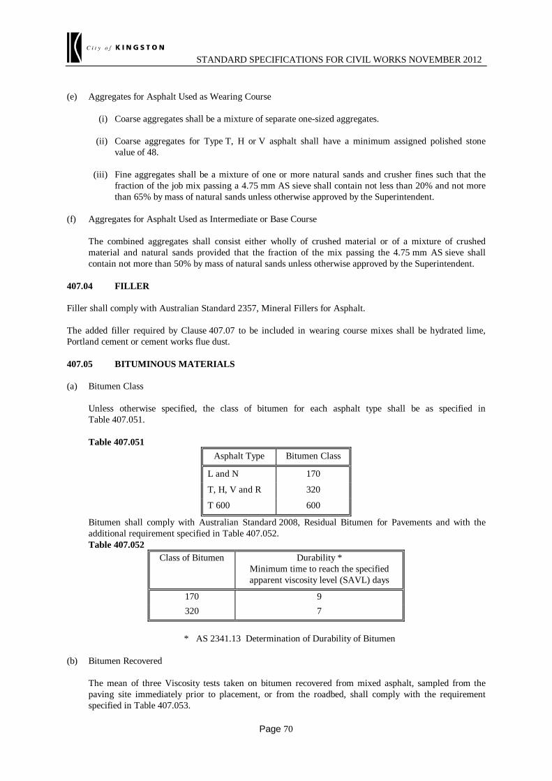
STANDARD SPECIFICATIONS FOR CIVIL WORKS NOVEMBER 2012
Page 70
(e) Aggregates for Asphalt Used as Wearing Course (i) Coarse aggregates shall be a mixture of separate one-sized aggregates. (ii) Coarse aggregates for Type T, H or V asphalt shall have a minimum assigned polished stone
value of 48. (iii) Fine aggregates shall be a mixture of one or more natural sands and crusher fines such that the
fraction of the job mix passing a 4.75 mm AS sieve shall contain not less than 20% and not more than 65% by mass of natural sands unless otherwise approved by the Superintendent.
(f) Aggregates for Asphalt Used as Intermediate or Base Course The combined aggregates shall consist either wholly of crushed material or of a mixture of crushed
material and natural sands provided that the fraction of the mix passing the 4.75 mm AS sieve shall contain not more than 50% by mass of natural sands unless otherwise approved by the Superintendent.
407.04 FILLER Filler shall comply with Australian Standard 2357, Mineral Fillers for Asphalt. The added filler required by Clause 407.07 to be included in wearing course mixes shall be hydrated lime, Portland cement or cement works flue dust. 407.05 BITUMINOUS MATERIALS (a) Bitumen Class Unless otherwise specified, the class of bitumen for each asphalt type shall be as specified in
Table 407.051. Table 407.051
Asphalt Type Bitumen Class
L and N 170
T, H, V and R 320
T 600 600
Bitumen shall comply with Australian Standard 2008, Residual Bitumen for Pavements and with the additional requirement specified in Table 407.052.
Table 407.052 Class of Bitumen Durability *
Minimum time to reach the specified apparent viscosity level (SAVL) days
170 9 320 7
* AS 2341.13 Determination of Durability of Bitumen (b) Bitumen Recovered The mean of three Viscosity tests taken on bitumen recovered from mixed asphalt, sampled from the
paving site immediately prior to placement, or from the roadbed, shall comply with the requirement specified in Table 407.053.

STANDARD SPECIFICATIONS FOR CIVIL WORKS NOVEMBER 2012
Page 71
Table 407.053
Class of Bitumen Viscosity Range at 25°C kPa.s
Wearing Course
Intermediate Course
Base Course
170 200 - 600 200 - 1100 200 - 1600
320 500 - 1600 500 - 2300 500 - 3000
600 - 800 - 3200 800 - 3200
(c) Bitumen Emulsion Bitumen emulsion shall be a cationic rapid setting type manufactured from Class 170 bitumen. It shall
comply with Australian Standard 1160, Bitumen Emulsions for Construction and Maintenance of Pavements. Emulsion diluted with water shall contain a minimum bitumen content of 30%.
(d) Polymer Modified Binder Where polymer modified binder (PMB) is specified the Contractor shall comply with the following
requirements: (i) PMB shall comply with the requirements of the Specification Framework for Polymer Modified
Binders (Austroads APRG Report No. 19, May 1997). (ii) the material shall be handled in accordance with the manufacturer's specification; (iii) a certificate of quality from the manufacturer shall be submitted for each load of PMB received; (iv) the PMB shall be transported and stored in such a manner to avoid contamination.
(a) Where requested by the Superintendent the Contractor shall provide test certificates stating the quality of bitumen used. These certificates shall be issued by a laboratory registered by the National Association of Testing Authorities for the performance of such tests.
407.06 MIX DESIGN The Contractor shall provide all mix designs. VicRoads has established a register of asphalt mixes from asphalt manufacturers who have produced mix designs satisfying the requirements of this clause and 407.07. To apply for registration of an asphalt mix, the information listed below shall be submitted to the Superintendent at least two weeks prior to the proposed date for the commencement of supply of the asphalt. No asphalt shall be supplied until the mix has been registered. The Contractor shall be responsible for the performance of all registered mixes. The Superintendent shall be notified of any proposed changes to the components or proportions of components used in the registered mix. New mix designs shall be carried out: (a) where it is proposed to change the source grading or nature of the components or binders; and (b) when current registered mix designs are more than two years old. For every application to register a mix, the [CITY OF KINGSTON] will notify the Contractor in writing the result of the application within two weeks. The Contractor’s mix identification number shall be recorded on the register to identify the mix. If a registered mix has unsatisfactory handling or field performance, the
STANDARD SPECIFICATIONS FOR CIVIL WORKS NOVEMBER 2012
Page 72
Contractor may request the Superintendent to de-register the mix. Alternatively, the Superintendent may de-register the mix pending a review of the design and immediately advise the Contractor of action taken. A mix containing Polymer Modified Binder substituted for bitumen binder in an existing registered mix is regarded as a new mix and will require separate registration. PMB Asphalt shall have the design binder content increased by 0.3% by mass compared to the bitumen binder mix. The information required in paragraphs (i) to (k) of this clause including the class of PMB proposed shall be submitted when seeking registration of a PMB asphalt mix. The following information shall be submitted for each new mix design: (a) grading test results for each component; (b) proportion of each component in the mix; (c) grading of the mix; (d) unsound and marginal rock content of the coarse aggregate fraction; (e) Flakiness Index of each separate coarse aggregate of size 10 and above; (f) Degradation Factor and Plasticity Index for the crusher fines component; (g) properties, as listed below, determined from tests performed on Marshall cylinders compacted at three
different bitumen contents using Class 170 binder within the range specified in Table 407.072: (i) stability (kN) (ii) flow (mm) (iii) air voids (%) (iv) voids in mineral aggregates (%) (v) bulk density (t/m3) (vi) bitumen film thickness (microns). (h) graphs showing the properties listed in (g), plotted against the respective bitumen contents; (i) supply of five compacted cylinders of Size 14 and Size 20 Type T oven conditioned mixes at the design
binder content to a density of between 96% and 98% Marshall density compacted using the gyratory compaction method;
(j) the supplier and source of binder; (k) supply of three 63.5 ±5 mm x 50 ±5 mm x 400 mm ±5 mm asphalt beams for a Size 20 Type T and
a Size 14 Type T or H mix sawn from a slab compacted using a rolling wheel or segmental wheel compactor to between 96% and 98% Marshall density at the design binder content.
407.07 MIX DESIGN REQUIREMENTS (a) The grading of mineral matter and the proportions of mineral matter and bitumen in the mix after
mixing but before compaction, shall lie within the limits specified in Table 407.071 and 407.072 for each size of asphalt unless otherwise approved by the Superintendent.

STANDARD SPECIFICATIONS FOR CIVIL WORKS NOVEMBER 2012
Page 73
Table 407.071 - Grading of Mineral Matter (including any filler)
Sieve Size AS (mm)
Percentage Passing (by mass)
Size 7 Mix Size 10 Mix Size 14 Mix Size 20 Mix Size 28 Mix
37.5 100
26.5 100 90 - 98
19.0 100 95 - 100 75 - 95
13.2 100 85 - 100 77 - 90 60 - 80
9.5 100 90 - 100 70 - 85 63 - 80 50 - 70
6.70 80 - 100 70 - 90 60 - 75 52 - 65 40 - 60
4.75 70 - 90 58 - 76 50 - 70 45 - 55 35 - 50
2.36 45 - 65 40 - 58 *(40 - 46)
35 - 52 *(35 - 42)
30 - 43 25 - 40
1.18 34 - 55 27 - 48 24 - 40 20 - 35 17 - 33
0.600 22 - 45 17 - 38 15 - 30 *(15 - 26)
14 - 27 12 - 26
0.300 14 - 33 11 - 26 10 - 24 9 - 21 8 - 20
0.150 8 - 18 7 - 18 7 - 16 7 - 15 6 - 14
0.075 5 - 8 4 - 7 4 - 7 3 - 6 3 - 6
Total Mineral Matter
100 100 100 100
* For Asphalt Type T, V, H and N used for wearing course.
Table 407.072 - Proportions of Mineral Matter and Bitumen
Material Percentage (by mass)
Size 7 Mix Size 10 Mix Size 14 Mix Size 20 Mix Size 28 Mix
Mineral Matter 95.0 - 92.5 95.5 - 93.0 95.5 - 93.5 96.0 - 93.5 96.5 - 94.5
Bitumen 5.0 - 7.5 4.5 - 7.0 4.5 - 6.5 4.0 - 6.5 3.5 - 5.5
Total Mix 100 100 100 100 100
(b) The Marshall cylinder test properties of the mix for asphalt Types T, V, H, N and L shall comply with
Tables 407.073 and 407.074 - Asphalt Type T, V, H and N.

STANDARD SPECIFICATIONS FOR CIVIL WORKS NOVEMBER 2012
Page 74
Table 407.073 - Asphalt Type T, V, H, and N
Mix Size (mm)
Stability (kN) min
Flow (mm) Air Voids (%) Voids in Mineral
Aggregate min
Bitumen film
Thickness (micron)
min Type V Type H, N, T
min max min max min max
7 5.5 1.5 3.5 4.9 5.3 17 7.5
10 6.5 1.5 3.5 5.9 6.3 4.9 5.3 17 7.5
14 6.5 1.5 3.5 5.9 6.3 4.9 5.3 16 7.5
20 6.5 1.5 3.5 4.9 5.3 15 7.5
28 6.5 1.5 3.5 - - 4.9 5.3 14 7.5
Asphalt Type R (Size 20) The properties of the mix for asphalt Type R shall be established from the relevant Size 20 Type N mix
with an increase in bitumen content of 1.0% by mass of the total mix. Table 407.074 - Asphalt Type L
Mix Size
(mm)
Stability (kN) min
Flow (mm) Air Voids (%) Voids in Mineral
Aggregates min
Bitumen film Thickness (micron)
min min max min max
7 4.5 1.5 3.5 3.8 4.2 16 8.0
10 5.5 1.5 3.5 3.8 4.2 16 8.0
(c) For wearing course asphalt, and any asphalt containing aggregates of coarse or medium grained acid
igneous rocks (e.g. granite, adamellite, granodiorite, quartz porphyry) shall contain not less than 1% added filler. Where acid igneous aggregates are used in a drum mixing plant, the added filler shall be 1% hydrated lime.

STANDARD SPECIFICATIONS FOR CIVIL WORKS NOVEMBER 2012
Page 75
407.08 PRODUCTION TOLERANCES The production tolerances on the grading aim of the mix before compaction shall be as specified in Table 407.081. Table 407.081
Sieve Size AS (mm)
Tolerance on Percentage Passing (by mass)
Size 7 Mix Size 10 Mix Size 14 Mix Size 20 Mix Size 28 Mix
37.5 Nil Nil Nil Nil Nil
26.5 Nil Nil Nil Nil ±6
19.0 Nil Nil Nil ±6 ±6
13.2 Nil Nil ±6 ±6 ±6
9.5 Nil ±6 ±6 ±6 ±6
6.70 - 4.75 ±6 ±6 ±6 ±6 ±6
2.36 - 0.600 ±5 ±5 ±5 ±5 ±5
0.300 - 0.150 ±3 ±3 ±3 ±3 ±3
0.075 ±1.0 ±1.0 ±1.0 ±1.0 ±1.0
The production tolerances on the grading aim of the mix after compaction shall be as specified in Table 407.081 except that the positive tolerance shall be increased by one percentage point. The tolerance on the bitumen content in the mix shall be ±0.3% of the total mix by mass. 407.09 MIXING AND MIXING TEMPERATURES The temperature of bitumen and aggregates at the mixing plant and the temperature of the asphalt as it is discharged from the mixing plant shall not exceed the limits specified in Table 407.091.
Table 407.091 Material Temperature °C (max)
Bitumen delivered into plant storage 185
Bitumen delivered into mixer 165
Aggregates before mixing 200
Asphalt at discharge from mixing plant 175
The mixing period shall be such that at least 95% of the coarse aggregate particles are fully coated with bitumen. After completion of mixing the moisture content of the mix shall not exceed 0.5%. Asphalt which has been manufactured at temperatures in excess of limits specified in Table 407.091 or which has been stored in an insulated bin for more than 18 hours for Class 170 and 320 bitumen binders (and not more than 4 hours for Class 600 bitumen binder and PMB) shall be rejected and recycled unless the Contractor can demonstrate that excessive binder hardening or a significant change in mix performance properties has not occurred. Material recycled from within the plant may be used in the mix at a proportion not greater than 5% by mass of the total aggregates.

STANDARD SPECIFICATIONS FOR CIVIL WORKS NOVEMBER 2012
Page 76
407.10 ASPHALT RECYCLED FROM RECLAIMED ASPHALT PAVEMENT (a) General Requirements Unless otherwise specified, Reclaimed Asphalt Pavement (RAP) may be re-cycled by adding it to new
asphalt during the mixing process subject to the following requirements: (i) all asphalt containing RAP shall comply with all aspects of Section 407 for the size and type of
asphalt specified for use; (ii) RAP shall consist of milled or excavated asphalt pavement free of foreign material such as
unbound granular base, broken concrete or other contaminants and shall be crushed and screened to a maximum size not exceeding the size of asphalt produced;
(iii) the asphalt manufacturing process shall provide for addition of RAP to a batch plant pugmill or
drum mixer separately from other mix components by a method that avoids damage to the mix by overheating.
(b) Restrictions on the Use of RAP (i) No RAP shall be added to Asphalt Types H, T or V wearing courses or any asphalt containing
Class 600 bitumen or PMB. (ii) Up to 10% of RAP by mass may be added to Type L and N wearing courses. (iii) Up to 20% RAP by mass may be added to Type N and T intermediate courses and Types R and T
base courses. 407.11 FREQUENCY OF INSPECTION AND TESTING AT THE MIXING PLANT The frequency shall not be less than that shown in Table 407.111, except that the Superintendent may agree to a lower frequency where the Contractor has implemented a system of statistical process control and can demonstrate that such lower frequency is adequate to assure the quality of the product. Table 407.111
Checks Required Minimum Frequency
Scrutiny for segregation, uncoated particles, separated bitumen, excess bitumen or overheating before despatch from the plant
Each loaded truck
Temperature of asphalt before despatch from the plant
Each loaded truck or at intervals of 15 minutes if more than one truck is despatched in 15 minutes
Unsound rock content On each day: One test on each component unless certification of specification compliance is received for each delivery to the mixing plant.

STANDARD SPECIFICATIONS FOR CIVIL WORKS NOVEMBER 2012
Page 77
Degradation Factor of crusher fines At monthly intervals
Plasticity Index of crusher fines At monthly intervals
Flakiness Index of coarse aggregate 10 mm and larger
At monthly intervals
Bitumen Content and Full Sieve Analysis of Asphalt (full extraction test)
On each day: One test per 250 tonnes or part thereof of the asphalt plant production on a representative sample taken from a delivery truck
Viscosity of Bitumen Certification of specification compliance for each delivery of bitumen supplied to the mixing plant.
Viscosity at 165°C, Torsional Recovery, and Softening Point of PMB
At weekly intervals: For batches of PMB stored in excess of a week in binder storage tanks at the asphalt plant.
Recovered Binder Viscosity Three tests on samples of asphalt taken from the paving site on the first 500 tonnes of any registered mix which has not been previously supplied to VicRoads. This requirement only applies to Size 14 Type T or H, and Size 20 Types T, R and T600.
The Contractor shall make available for inspection at the plant all work sheets and results of checks carried out. 407.12 RATE OF DELIVERY Asphalt shall be placed at the highest practicable rate in order to minimise the time traffic is disrupted and to avoid intermittent paving. 407.13 AMBIENT CONDITIONS FOR PLACING The surface on which asphalt is to be placed shall be essentially dry and free from puddles. (a) Intermediate and Base Courses Asphalt shall not be placed when the majority of the area to be paved has a surface temperature of less
than 5°C except that asphalt containing Class 600 bitumen or PMB shall not be placed when the majority of area to be paved has a surface temperature less than 10°C.
(b) Wearing Course Wearing course asphalt shall not be placed when the majority of the area to be paved has a surface
temperature of less than 10°C, except that for mixes containing PMB where the majority of the area to be paved has a surface temperature above 15°C.
407.14 SURFACE PREPARATION Prior to tack coating and placing of asphalt, the Contractor shall remove all deleterious material and sweep clean the area upon which asphalt is to be placed. 407.15 TACK COAT A tack coat shall be applied to the cleaned surface on which asphalt is to be placed.
STANDARD SPECIFICATIONS FOR CIVIL WORKS NOVEMBER 2012
Page 78
Tack coat shall consist of cationic bitumen emulsion and shall be applied only to a clean, essentially dry surface, free from puddles. Tack coat shall be sprayed in a uniform film over the entire road surface. Unless otherwise directed, the application rate for bitumen emulsion tack coat shall be 0.15 to 0.3 litres/m2 (60% Bitumen content) or 0.3 to 0.6 litres/m2 (30% bitumen content) except for joints and chases where rates shall be doubled. Before asphalt is placed a period of time sufficient to allow the tack coat to set up and become tacky shall elapse. Any tack coat not covered by asphalt shall be covered with clean grit or sand before the road is opened to traffic. Where asphalt is to be spread over clean, freshly laid asphalt, or over a clean, primed surface, or where the depth of the layer exceeds 50 mm, the Contractor may omit the tack coat unless otherwise directed or specified. 407.16 DELIVERY (a) General Delivery shall only be made during the hours listed for possession of site. Asphalt delivered to the site,
which is segregated, has been overheated, is too cold, contains separated bitumen or uncoated particles which does not comply with the Specification shall be removed from the site at the Contractor's expense.
(b) Delivery Dockets Delivery dockets shall show: (i) name of supplier and location of plant; (ii) docket number; (iii) name of user; (iv) project name and location (or contract number); (v) registered number or fleet number of the vehicle; (vi) date and time of loading; (vii) size and type of asphalt; (viii) empty and loaded mass of the vehicle, or the total of the electronically measured batch weights
printed on the docket; (ix) class of bitumen, or proprietary name of modified binder; (x) temperature of load at mixing plant when measured. Where asphalt is scheduled for measurement by mass, a copy of the delivery docket for each load shall be
given to the Superintendent at the point of delivery, or delivered or mailed to the Superintendent at the end of each day's work.
Where asphalt is measured by other means and for Lump Sum Contracts, the Contractor shall make
delivery dockets available for inspection on request by the Superintendent. 407.17 JOINTS AND JUNCTIONS (a) General The location of all joints shall be planned before work commences to achieve the specified offsets
between layers and the final position of joints in the wearing course.

STANDARD SPECIFICATIONS FOR CIVIL WORKS NOVEMBER 2012
Page 79
The number of joints shall be minimised by adopting good asphalt paving practices. If requested by the Superintendent, the Contractor shall produce drawings showing the location of longitudinal joints of asphalt layers in respect to the traffic lane lines.
All joints shall be well bonded and sealed and the surface across the joint shall meet the requirements of
Clause 407.23(b). Where fresh asphalt is to be placed against the exposed edge of existing asphalt on a longitudinal joint
which has not been placed the same day, or against the exposed edge of a transverse joint where existing asphalt has cooled to below 100°C, it shall be considered a cold joint.
All cold joints between adjacent runs and abutting concrete edges shall be heavily tack coated. Where cold joints are constructed, any loose or poorly compacted existing asphalt on the exposed edge
shall be trimmed back to produce a face of fully compacted asphalt along the exposed edge before fresh asphalt is placed.
(b) Transverse Joints (i) Transverse joints in adjoining paver runs shall be offset by not less than 2 m. (ii) Transverse joints shall be offset from layer to layer by not less than 2 m. (c) Longitudinal Joints (i) Longitudinal joints in the wearing course shall coincide with traffic lane lines. (ii) Longitudinal joints in intermediate and base courses shall be offset from layer to layer by not less
than 150 mm and shall be within 300 mm of the traffic lane line or the centre of traffic lane. (iii) Longitudinal joints shall be parallel to the traffic lanes unless otherwise specified. (iv) Unless otherwise specified, or approved by the Superintendent, hot or warm joints shall be
constructed either by paving in echelon or by matching up all longitudinal joints over the full width of the carriageway each day.
Subject to approval by the Superintendent, a longitudinal joint in the wearing course may be located up to
300 mm from the traffic lane line or the centre of a traffic lane to achieve the minimum clearance between the paver screed and the traffic path of 1.2 metres and the minimum traffic path width of 2.8 metres.
(d) Junctions At junctions where the new asphalt mat is required to match the level of existing pavement surface at the
limits of work, chases shall be cut into the existing pavement. (i) If cold planing is specified, a wedge of asphalt tapering from 0 to a depth of 2.5 times the nominal
size of the asphalt shall be removed from the existing pavement to the minimum width as follows: - side streets and median openings - 600 mm - through carriageways with a speed limit of 75 km/h or less - 3 m - through carriageways with a speed limit of more than 75 km/h - 6 m. (ii) If cold planing is not specified, a 40 mm wide by 20 mm deep chase shall be cut from the existing
pavement and where directed, angled at about six transverse to one longitudinal to the direction of travel.
(e) Treatment of Exposed Edges under Traffic On completion of each day's work and prior to opening to traffic, the following treatment of exposed
edges shall be adopted for asphalt work. (i) Longitudinal Edges
STANDARD SPECIFICATIONS FOR CIVIL WORKS NOVEMBER 2012
Page 80
All longitudinal joints within the trafficked area shall be matched up between paver runs except for a short section required to achieve the minimum offset between transverse joints. Any exposed longitudinal edges within the trafficked area shall be ramped down at a slope of not steeper than 5 horizontal to 1 vertical by constructing a temporary wedge of hot mixed or cold mixed asphalt. In unusual situations such as the sudden onset of inclement weather, a longer length of longitudinal joint may be exposed provided it is ramped down as specified.
(ii) Transverse Edges At the end of the paving run in the transverse direction, the new asphalt mat shall be squared up
to a straight line and ramped down by constructing a temporary wedge of hot mixed or cold mixed asphalt. Temporary ramping shall not be steeper than 20 horizontal to 1 vertical for traffic speeds of more than 75 km/h or 10 horizontal to 1 vertical for traffic speeds of 75 km/h or less.
(iii) Removal of Temporary Ramping Before commencement of each day's work, all temporary ramping shall be removed by cutting
back along a straight line to expose a vertical face of fully compacted asphalt at the specified layer depth.
407.18 COMMENCEMENT OF PLACING
HP The placement of any asphalt layer shall not commence until the consent to proceed is obtained from the Superintendent. 407.19 REGULATING COURSE A regulating course of asphalt of the type and size specified shall be placed for correction of longitudinal and transverse pavement shape so that the resulting surface is parallel with the finished surface. 407.20 SPREADING (a) General Asphalt shall be spread in layers at the compacted thicknesses shown on the drawings or specified. All asphalt shall be spread with an asphalt paver except for small areas where use of a paver is not
practicable. (b) Level Control (i) General Asphalt shall be spread in layers at the compacted thickness specified or shown on the drawings. All asphalt shall be spread with an asphalt paver except for small areas where use of a paver is not
practicable. Unless otherwise specified in Clause 407.24(c), asphalt paver screed levels shall be controlled by a Suitable combination of manual and automatic controls operating from fixed or moving refernces. (ii) Manual Control Manual control is permitted except where automatic level control is specified. The Superintendent may direct that for the wearing course layer on new construction, the paver
screed level controls shall remain at a fixed setting or that a joint matching shoe shall be used. (iii) Automatic Control 1. Fixed Level Control

STANDARD SPECIFICATIONS FOR CIVIL WORKS NOVEMBER 2012
Page 81
Where fixed level control is specified, the paver screed shall be automatically controlled by reference to stringline or other approved system.
2. Moving Reference Control Where moving reference control is specified, both sides of the paver screed shall be
automatically controlled by reference device. Levelling beams shall be supported independently of the paver and provide a minimum of 8 separate contact points over a minimum length of 9 metres.
(c) Spreading by Paver Asphalt shall be spread without tearing or gouging. The Contractor shall conduct spreading operations to ensure that the paver speed matches the rate of
supply so that the number of paving stops are minimised. If the paver is required to stop and asphalt in front of the screed cools to below 120°C, a transverse joint
shall be constructed. For asphalt work carried out on a road to be opened for traffic at the completion of work each day, each
layer of asphalt shall cover the full width of the trafficked area. The requirements of Clause 407.17(e) shall be followed in respect of the treatment required for exposed edges.
(d) Spreading by Hand Hand spreading shall only be used for small awkward areas where it is not practical to use a paver. (e) Echelon Paving Where specified in Clause 407.24(d) two pavers in echelon shall be used in locations where a full
carriageway wider than 6 m is available clear of traffic. Where the width of the mat to be placed in a single paving run exceeds 6.0 metres, two or more pavers
shall be used in echelon. 407.21 COMPACTION Asphalt shall be uniformly compacted to the standards specified in Clause 407.22 as soon as the asphalt has cooled sufficiently to support the roller without undue displacement. 407.22 REQUIREMENTS FOR TESTING AND ACCEPTANCE OF COMPACTION (a) General Work shall be tested and accepted for compaction on either a lot basis as provided in Clause 407.22(b) or
on a procedural basis as provided in Clause 407.22(c). If not otherwise specified or directed, acceptance of compaction where the quantity of the particular size or type of asphalt to be supplied exceeds 300 tonne, shall be on a lot basis. For all other works, acceptance of compaction shall be on a procedural basis.
(b) Testing and Acceptance of Compaction on a Lot Basis A lot presented for testing consists of that part of a particular layer of asphalt which is placed in one day
under uniform conditions and is essentially homogeneous in respect to material and appearance.

STANDARD SPECIFICATIONS FOR CIVIL WORKS NOVEMBER 2012
Page 82
Sites for density testing shall be selected on an essentially random basis provided that no site shall be selected within 200 mm of a joint constructed against a cold edge.
For core sample tests, the layer thickness is the mean thickness of the core samples and for nuclear gauge tests, the layer thickness is the nominal layer thickness.
Asphalt Density Ratio is defined as the percentage ratio of the field bulk density to the assigned bulk
density of the approved laboratory mix design.
The Characteristic Value of Density Ratio is the calculated value of x_
- 0.92S for six tests per lot where x_
and S are respectively the mean and standard deviation of the individual density ratio test values for the lot.
The work represented by a lot of six tests shall be assessed as shown in Table 407.221. Table 407.221
For layers less than 50 mm thickness For layers 50 mm thickness or greater Characteristic Value of the
Density Ratio (Rc)
Assessment Characteristic Value of the
Density Ratio (Rc)
Assessment
94.0% or more Accept lot 96.0% or more Accept lot 91.0% to 93.9% Lot will be accepted at a
reduced rate calculated by P = 10 Rc - 840
91.0% to 95.9% Lot will be accepted at a reduced rate calculated by P = 6 Rc - 476
(Rc) is the Characteristic Value of the density ratio for the lot and (P) is the percentage of the relevant
scheduled rate to be paid which shall not be greater than 100%. Where the Contract is a lump sum Contract the relevant scheduled rate will be that shown in the "Rates
for Variation Purposes" schedule accompanying the lump sum Tender. If no such rate is provided a variation will be considered in accordance with Clause 40.2 of the General Conditions of Contract - Valuation of Variations. Where one or more individual core thicknesses are less than the relevant values shown in Table 407.222, they shall be discarded and the acceptance assessment modified in accordance with Table 407.223 provided that there remain at least 4 test values.
Table 407.222
Size of Asphalt Individual Core Thickness (mm) min
7 14 10 20 14 28 20 40 28 56
Table 407.223
For layers less than 50 mm thickness For layers 50 mm thickness or greater
Mean Value of the Density Ratio
(Rm)
Assessment Mean Value of the Density Ratio
(Rm)
Assessment
95.5% or more Accept lot 97.0% or more Accept lot 92.5% to 95.4% Lot will be accepted at a
reduced rate calculated by P = 10 Rm - 855
92.0% to 95.9% Lot will be accepted at a reduced rate calculated by P = 6 Rm - 482

STANDARD SPECIFICATIONS FOR CIVIL WORKS NOVEMBER 2012
Page 83
(Rm) is the mean of the individual density ratios for the lot and (P) is the percentage of the relevant scheduled rate to be paid which shall not be greater than 100%.
(c) Acceptance of Compaction on a Procedural Basis Acceptance of work as far as compaction is concerned shall be based on the adoption of approved placing
procedures and a density test check plan that provides for a minimum test frequency of 5% of relevant lots to be tested. The test check plan shall provide for additional testing to demonstrate correction of non-conformance. If not otherwise agreed, placing procedures shall be in accordance with Australian Standard AS 2734 Asphalt (Hot-Mixed) Paving - Guide to Good Practice.
407.23 SURFACE FINISH, AND CONFORMITY WITH DRAWINGS AND SPECIFICATION The finished surface of asphalt wearing course shall be of uniform appearance, free of dragged areas, cracks, open textured patches and roller marks. Each asphalt course shall, after final compaction, comply within the following limits to the levels, lines, grades, thicknesses and cross-sections as specified or shown on the Drawings. (a) Level of each Asphalt Course The level of the top of each course shall not differ from the specified level by more than 10 mm, except that where asphalt is placed against kerb and channel the surface at the edge of the wearing course shall be flush with or not more than 5 mm above the lip of the channel unless otherwise specified or shown on the Drawings. (b) Shape No point on the finished surface of the wearing course shall lie more than 4 mm below a 3 m straight
edge laid either parallel to the centreline of the pavement or, except on crowned sections, at right angles to the centreline. For intermediate and base course layers, the distance below the straight edge shall not exceed 6 mm and 10 mm respectively.
(c) Thickness of Asphalt Pavement for New Pavement Construction Where a uniform thickness of new asphalt pavement construction is specified, the mean thickness of a lot
of asphalt shall be not less than the combined thickness of all asphalt courses specified in Clause 407.24 or shown on the Drawings. For the purpose of this clause a lot shall be defined as an area of up to 4000 m2.
(d) Alignment Where asphalt pavement is not placed against a concrete edging, the edge of asphalt layers shall not be
more than 50 mm inside nor more than 100 mm outside, the designed offset from centreline or design line. Within these tolerances, the rate of change of offset of the edge of layer shall not be greater than 25 mm in 10 m.
(e) Width Where asphalt pavement is not placed against a concrete edging, the width of asphalt layers shall not be
less than the design or specified width of layer by more than 50 mm or greater than the design or specified width by more than 100 mm and the average width over any 300 m shall not be less than the design or specified width.

STANDARD SPECIFICATIONS FOR CIVIL WORKS NOVEMBER 2012
Page 84
SECTION 408 – SPRAYED SEAL TREATMENT ##This section cross-references Sections 801, 831 and 832 – are they included in the specification?: 408.01 GENERAL This section covers the requirements for materials, design and application of sprayed seal treatments including priming, primersealing and seals of various types. 408.02 DEFINITIONS Adhesion Agent: A wetting agent designed to promote adhesion of binder or primerbinder to stone. Aggregate Retention: Retention of aggregate particles by the primer binder or binder under normal traffic conditions. The degree of aggregate stripping is measured to assess aggregate retention. Polymer Modified Binder (PMB) A bituminous binder which has been modified by the addition of a polymer or crumb rubber to alter or enhance its properties. Prime: The application of a bituminous primer to a prepared granular pavement base or concrete surface without cover aggregate as a preliminary treatment. Primerseal: The application of a bituminous primerbinder to a prepared granular pavement base with a cover aggregate as a temporary seal treatment. Residual Binder: The volume of bituminous binder at 15° C including the volume of any polymer, granular rubber and flux oil but does not include the volume of any cutter, water, emulsifier or adhesion agent. Sprayed Seal: The sprayed application of bituminous binder to a pavement surface followed by an application of aggregate to form an all weather skid resistant road surfacing. Types of sprayed seals include: - Conventional - where the bituminous binder is Class 170 bitumen; - High Stress Seal (HS Seal), where the bituminous binder is a lightly modified PMB to aid aggregate
retention on heavily trafficked roads; - Strain Alleviating Membrane (SAM Seal), where the bituminous binder is a heavily modified PMB to
treat cracked pavements;
STANDARD SPECIFICATIONS FOR CIVIL WORKS NOVEMBER 2012
Page 85
- A geotextile reinforced seal is a SAM Seal where the bituminous binder is reinforced with a geotextile
fabric to treat cracked pavements. Strain Alleviating Membrane Interlayer (SAMI) A sprayed seal treatment where the bituminous membrane is a highly modified PMB or geotextile reinforced seals applied in advance of an asphalt layer. Surface Enrichment A light application of cutback bitumen or bitumen emulsion to an existing highly textured bituminous surfacing in very low or non-trafficked areas to rejuvenate an existing sprayed seal or asphalt surface. Surface Texture The mean height of aggregate particles above the level of the binder as determined by the VicRoads’ standard test method. 408.03 BITUMINOUS MATERIALS (a) Adhesion Agent Where proposed to be used, the type of adhesion agent and the percentage to be added to the binder,
primerbinder and/or aggregate precoating material shall be subject to the Contractor providing evidence that the proprietary product has satisfactory field performance. Adhesion agent may be added to the aggregate precoating material, binder or both. The strength of adhesion agent shall meet the test requirement of 70% of binder adhesion to stone after immersion in water. When adhesion agent is added to the binder or primerbinder, the total volume of adhesion agent and diluent shall not exceed 1% by mass of the binder.
(b) Aggregate Precoating Material Aggregate precoating material shall be distillate or distillate based product, cutback bitumen, or
proprietary product subject to the Contractor providing evidence that the proprietary product has demonstrated satisfactory field performance for a period of at least three years. Restricted use of untried products on a trial basis shall be subject to the approval of the Superintendent.
(c) Bitumen Bitumen shall be Class 170 complying with the requirements of Australian Standard 2008 - Residual
Bitumen for Pavements. In addition, the minimum time to reach the specified apparent viscosity level shall be 9 days when tested in accordance with Australian Standard 2341.13 - Long Term Effect of Heat and Air on Bitumen.
(d) Bitumen Emulsion Bitumen emulsion of Grade ARS or CRS shall comply with the requirements of Australian
Standard 1160 - Bitumen Emulsion for Construction and Maintenance of Pavements. Any non standard proprietary grades of bitumen emulsion shall be subject to the Contractor providing evidence that the product has demonstrated satisfactory field performance for a period of at least 3 years.
STANDARD SPECIFICATIONS FOR CIVIL WORKS NOVEMBER 2012
Page 86
Restricted use of untried products on a trial basis shall be subject to the approval of the Superintendent. (e) Geotextile Fabric The geotextile fabric used for a geotextile reinforced seal as a SAM Seal or SAMI shall be a non-woven
needle punched fabric with a minimum weight of 135 g/m2 for normal applications. The
geotextile fabric shall have a softening point at least 10ºC above the maximum binder spraying
temperature.
(f) Cutback Bitumen Cutback bitumen shall comply with the requirements of Australian Standard 2157 - Cutback Bitumen, or
an equivalent product subject to the Contractor providing evidence that the proprietary product has demonstrated satisfactory field performance for a period of at least 3 years. Restricted use of untried products on a trial basis shall be subject to the approval of the Superintendent.
(g) Cutter Cutter shall comply with Australian Standard 3568 - Oils for Reducing the Viscosity of Residual
Bitumen for Pavements. Other cutters or methods of temporarily lowering the viscosity of the binder may be used subject to the Contractor providing evidence that such methods or products have demonstrated satisfactory field performance for a period of at least 3 years. Restricted use of untried products on a trial basis shall be subject to the approval of the Superintendent.
(h) Flux Oil Flux oil shall be a heavy flux oil supplied in accordance with Australian Standard 3568 (Table 2) - Oils
for Reducing the Viscosity of Residual Bitumen for Pavements. Flux oil shall be added to the binder for low trafficked roads in accordance with the Austroads (NAASRA) guide - Bituminous Surfacing Sprayed Work, No. NTR-07 dated January 1989. Other materials to achieve equivalent long term softening of the residual binder for low trafficked roads may be used subject to the Contractor providing evidence that the product has demonstrated satisfactory field performance for a period of at least 3 years. Restricted use of untried products on a trial basis shall be subject to the approval of the Superintendent.
(i) Polymer Modified Binder (PMB) The grade of PMB shall comply with the requirements of the Austroads Specification Framework for
Polymer Modified Binders No. APT-04 (2000). Unless otherwise specified in Table 408.141, one of the following Grades of PMB shall be used as
follows: (i) HS Seals Grade S10E, S15E, S35E, or S40R (ii) SAM Seals Grade S20E or S50R
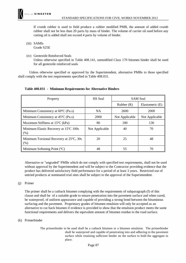
STANDARD SPECIFICATIONS FOR CIVIL WORKS NOVEMBER 2012
Page 87
If crumb rubber is used to field produce a rubber modified PMB, the amount of added crumb rubber shall not be less than 20 parts by mass of binder. The volume of carrier oil used before any cutting oil is added shall not exceed 4 parts by volume of binder.
(iii) SAMIs Grade S25E (iv) Geotextile Reinforced Seals Unless otherwise specified in Table 408.141, unmodified Class 170 bitumen binder shall be used
for all geotextile reinforced seals Unless otherwise specified or approved by the Superintendent, alternative PMBs to those specified shall comply with the test requirements specified in Table 408.031. Table 408.031 - Minimum Requirements for Alternative Binders
Property HS Seal SAM Seal
Rubber (R) Elastomeric (E)
Minimum Consistency at 60ºC (Pa.s) NA 2600 2000
Minimum Consistency at 45ºC (Pa.s) 2000 Not Applicable Not Applicable
Maximum Stiffness at 15ºC (kPa) 80 180 130
Minimum Elastic Recovery at 15ºC 100s (%)
Not Applicable 40 70
Minimum Torsional Recovery at 25ºC, 30s (%)
20 25 48
Minimum Softening Point (ºC) 48 55 70 Alternative or "ungraded" PMBs which do not comply with specified test requirements, shall not be used
without approval by the Superintendent and will be subject to the Contractor providing evidence that the product has delivered satisfactory field performance for a period of at least 3 years. Restricted use of untried products at nominated trial sites shall be subject to the approval of the Superintendent.
(j) Primer The primer shall be a cutback bitumen complying with the requirements of subparagraph (f) of this
clause and shall be of a suitable grade to ensure penetration into the pavement surface and when cured, be waterproof, of uniform appearance and capable of providing a strong bond between the bituminous surfacing and the pavement. Proprietary grades of bitumen emulsion will only be accepted as an alternative to cut back bitumen if evidence is provided to show that the emulsion product meets the same functional requirements and delivers the equivalent amount of bitumen residue to the road surface.
(k) Primerbinder
The primerbinder to be used shall be a cutback bitumen or a bitumen emulsion. The primerbinder shall be waterproof and capable of penetrating into and adhering to the pavement surface while retaining sufficient binder on the surface to hold the aggregate in place.

STANDARD SPECIFICATIONS FOR CIVIL WORKS NOVEMBER 2012
Page 88
408.04 LIMIT OF WORK Unless otherwise specified the Works shall include all existing tapers, bell mouths at intersecting roads, pavement widenings (turn lanes), traffic lanes and sealed shoulders. The limits of work at the start and finish chainages plus the limit in any side road have been marked on the pavement surface. The Superintendent may increase or decrease the limits of work listed in Schedule 1. The Contractor will be notified in writing prior to works commencing on job items of such adjustments to the limits of work and the Contract sum adjusted on a pro-rata basis using the Item price tendered in Schedule 1. Where the change in the limits of work results in a net change of the item price by greater than ±10% the amount in excess of 10% will be treated as a variation under Clause 40 of the General Conditions of Contract. 408.05 AGGREGATE Aggregate shall comply with VicRoads standard specification Sections 801 - Source Rock for the Production of Crushed Rock and Aggregates, Section 831 - Aggregate for Sprayed Bituminous Surfacing, and Section 832 - Sands for Sprayed Bituminous Surfacing. Unless otherwise specified in Table 408.141, the Contractor may either supply plant pre-coated aggregate from the aggregate supplier or field pre-coat aggregate at the stack site. The Contractor shall remove the loose aggregate from the trafficked pavement, within the maximum time limit specified in Table 408.051. Table 408.051 - Maximum Time Limit for Removal of Loose Aggregate from Trafficked Areas
Traffic Volume (AADT) *
Maximum Time Limit
>5000 and all Freeways
Within 8 hours of sealing
>2000 to 5000 Within 24 hours of sealing
>500 to 2000 Within 48 hours of sealing
< 500 Within 5 days of sealing
* Annual Average Daily Traffic - Refer to Table 408.141 for AADT for each Job Item Until loose aggregate is removed from the sealed surface, traffic speed shall be controlled by signing and/or installation of road works speed limits in accordance with the VicRoads Work Site Traffic Management Code of Practice. Loose aggregate shall not be removed until the aggregate has properly bedded down into the binder by either trafficking or additional rolling A rotary broom is permitted to remove loose aggregate from the trafficked areas. Any aggregate swept on to

STANDARD SPECIFICATIONS FOR CIVIL WORKS NOVEMBER 2012
Page 89
sealed shoulders or untrafficked areas of pavement shall be removed by a suction sweeper and transported from the job site to a temporary dump site or final disposal location within 5 days. Any loose aggregate swept into concrete channels, traffic islands, open drains, footpaths, nature strips, or verges shall be removed within 24 hours. The removal of loose aggregate and disposal from site is the responsibility of the Contractor. Unless otherwise specified in Table 408.142, loose aggregate may be temporarily dumped at the stack site. Unless otherwise specified in Table 408.142, all aggregate dumped at the stacksite shall be removed within 4 weeks of completion of the job item. No more than 40 loose stones in any square metre of pavement shall remain after the removal of loose aggregate. Any damage to the seal resulting from removal of loose aggregate, shall be repaired by the Contractor at no cost to VicRoads. 408.06 RATES OF APPLICATION OF BITUMINOUS MATERIAL AND AGGREGATE (a) Design Rates of Application The Contractor shall determine the design rates of application for primer, primerbinder, binder and
aggregate in accordance with the procedures set out in the VicRoads Design Procedure or the current AustRoads Seal Design Procedure.
Unless otherwise specified, all rates of application of bituminous material shall be expressed in litres/m2.
In the case of binder, rates of application shall refer to residual binder at 15°C. Traffic data and estimated rates of application for bituminous material are specified in Table 408.141. At least one week prior to the commencement of work, the Contractor shall submit the design rates
of application for bituminous material and aggregate for review by the Superintendent. (b) Surface Pre-treatment Sprayed pre-treatments to correct variable surface texture shall be carried out if specified in Table
408.141. The acceptance criteria for Surface Texture and Aggregate Loss specified in Tables 408.122 and
408.123 will not be waived for any job item unless either of these requirements are waived in Table 408.141 or elsewhere in the specification. In order to comply with this requirement, the Contractor shall make allowance for the additional cost of any unspecified pre-treatments unless the cost of unspecified pre-treatments is included in Schedule 2 - Rates for Variation Purposes.
If the rates of application are varied from estimated rates as a result of pre-treatments or otherwise,
payment will be adjusted up or down in accordance with the rate submitted in Schedule 1 for Schedule of Rates contracts, or for Lump Sum contracts, Schedule 2 - Rates for Variation Purposes.
(c) Calibration Certificate for Bitumen Sprayers All sprayers used for application of bituminous materials shall have a current Certificate of Calibration
showing compliance with Austroads bitumen sprayer calibration Test Methods and procedures. The Certificate of Calibration shall be renewed every 24 months. If any sprayer has its spray equipment

STANDARD SPECIFICATIONS FOR CIVIL WORKS NOVEMBER 2012
Page 90
overhauled or replaced it shall be issued with a new Certificate of Calibration prior to use. 408.07 COMMENCEMENT OF WORK Within 2 weeks of the Date of Award of Contract the Contractor shall submit to the Superintendent for review the sealing program for the whole of the works. The Contractor shall submit a detailed program of planned sealing jobs for the next 4 weeks under the Contract for review by the Superintendent. The detailed program shall be submitted at least 5 working days in advance of any works shown on that program. The detailed program shall be in bar chart form, including specific jobs to be undertaken with a time scale shown in days. The program shall include planned dates for each sealing job. On the day prior to the works being carried out the Contractor shall provide written confirmation of the works that will be undertaken the following day and obtain agreement from the Superintendent to any variation in the design rates of application to those previously provided under Clause 408.06 (a).
HP Work shall not commence until the Contractor and the Superintendent have agreed that the road surface is ready and fit for surfacing. 408.08 INCLUSION AND DELETION OF JOB ITEMS The Superintendent may cancel any work, subject to notice of cancellation being given 1 week prior to the proposed commencement date. The Contractor will be notified in writing of such deletion and the Contract sum adjusted by the price tendered in Schedule 1 for the job item/s deleted. No additional payment will be made as a result of the deletion of any job item. However, where the deletion of job items results in a contract sum reduction of more than 20% of the original contract sum, the deletion of job items in excess of this amount will be treated as a variation under Clause 40 of the General Conditions of Contract. In the event of aggregate having been delivered to a job stacksite and the job is deleted in accordance with this clause, the cost of the removal of the aggregate and any loss of aggregate shall be treated as a variation under Clause 40 of the General Conditions of Contract. The Superintendent may request the Contractor to undertake additional sealing works at sites not listed in Schedule 1. These works will be treated as a variation under Clause 40 of the General Conditions of Contract. 408.09 REMOVAL OF EXISTING RRPMs As part of the surface preparation the Contractor shall remove and dispose of existing Raised Reflective Pavement Markers (RRPMs) from the site and repair any surface defect caused by such removal prior to sealing. 408.10 MAINTENANCE OF SEALS The Contractor shall be responsible for the monitoring and maintenance of seals from the time of application
STANDARD SPECIFICATIONS FOR CIVIL WORKS NOVEMBER 2012
Page 91
until the end of the defects liability period. The Contractor shall submit a separate procedure for this work not less than 14 days prior to the commencement of sealing work, which shall take into account of the time of year, ambient weather conditions and good construction practice. Monitoring of seals shall include regular and timely inspection of work, management of traffic, and monitoring of any deterioration in the surface condition. The Contractor shall carry out any work necessary to protect and maintain the seal or to effect repairs to any seal failures. Such failures include but are not limited to, potholing, emulsification, flushing, bleeding, fatty areas, aggregate stripping, non-uniform aggregate spreading and streaking of aggregate cover irrespective of the apparent cause of the failure or potential failure.
HP The Contractor shall advise the Superintendent in writing of the proposed treatment to effect the above work or repairs before undertaking the work.
HP Where the treatment for protection or failure of a seal involves the application of a second coat seal, the Contractor shall, in writing, seek the agreement of the Superintendent of the proposed treatment before undertaking the work. Unless approved otherwise by the Superintendent the Contractor shall undertake any necessary repair work within 48 hours of notification by the Superintendent. For urgent repairs the Contractor shall take action to preserve the work and make the road safe within 2 hours of being notified or becoming aware of the problem. Payment will be made for the cost of repairs for failures that are the result of incidents outside the Contractor’s control, including but not limited to, damage caused by oil spills, accidents, vehicle fire or tearing due to heavy braking and skidding. Notwithstanding the provisions of subclause 37.2 of the General Conditions of Contract the Contractor shall carry out all other seal protection work and repairs at its own cost, howsoever the failure or potential failure is caused. 408.11 RECORDS The Contractor shall complete, and forward to the Superintendent, a "Job Completion Report" using the proforma in Section VI, or an equivalent proforma as approved by the Superintendent, for each job item in Schedule 1. The completed form shall be submitted within seven days of completion of sealing each job. The Contractor shall show and certify by initialling each item on the above Job Completion Report the actual status of the item compared to the specified requirement for that item, and sign and date the report prior to forwarding to the Superintendent. The Contractor shall ensure that where a representative of the Superintendent is on site during the works, that officer validates the works as provided on the Job Completion Report. 408.12 ACCEPTANCE OF WORK (a) Rates of Application for Binder and Aggregate
The Contractor shall produce evidence to show that the actual rates of application for the job, or segments of a job with different design rates of application, complies with the design rates of application. Variation between the actual rates and the design rates will be assessed in accordance with Table 408.121.
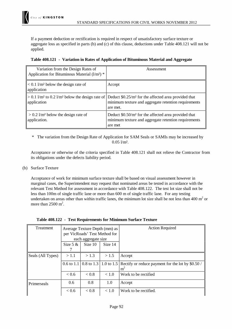
STANDARD SPECIFICATIONS FOR CIVIL WORKS NOVEMBER 2012
Page 92
If a payment deduction or rectification is required in respect of unsatisfactory surface texture or aggregate loss as specified in parts (b) and (c) of this clause, deductions under Table 408.121 will not be applied.
Table 408.121 - Variation in Rates of Application of Bituminous Material and Aggregate
Variation from the Design Rates of
Application for Bituminous Material (l/m²) * Assessment
< 0.1 l/m² below the design rate of application
Accept
> 0.1 l/m² to 0.2 l/m² below the design rate of application
Deduct $0.25/m² for the affected area provided that minimum texture and aggregate retention requirements are met.
> 0.2 l/m² below the design rate of application.
Deduct $0.50/m² for the affected area provided that minimum texture and aggregate retention requirements are met
* The variation from the Design Rate of Application for SAM Seals or SAMIs may be increased by
0.05 l/m². Acceptance or otherwise of the criteria specified in Table 408.121 shall not relieve the Contractor from
its obligations under the defects liability period. (b) Surface Texture Acceptance of work for minimum surface texture shall be based on visual assessment however in
marginal cases, the Superintendent may request that nominated areas be tested in accordance with the relevant Test Method for assessment in accordance with Table 408.122. The test lot size shall not be less than 100m of single traffic lane or more than 600 m of single traffic lane. For any testing undertaken on areas other than within traffic lanes, the minimum lot size shall be not less than 400 m2 or more than 2500 m2.
Table 408.122 - Test Requirements for Minimum Surface Texture Treatment Average Texture Depth (mm) as
per VicRoads’ Test Method for each aggregate size
Action Required
Size 5 & 7
Size 10 Size 14
Seals (All Types) > 1.1 > 1.3 > 1.5 Accept
0.6 to 1.1 0.8 to 1.3 1.0 to 1.5 Rectify or reduce payment for the lot by $0.50 / m2
< 0.6 < 0.8 < 1.0 Work to be rectified
Primerseals 0.6 0.8 1.0 Accept
< 0.6 < 0.8 < 1.0 Work to be rectified.
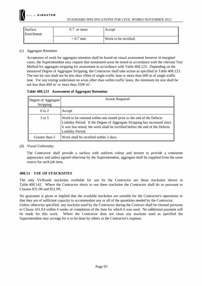
STANDARD SPECIFICATIONS FOR CIVIL WORKS NOVEMBER 2012
Page 93
Surface Enrichment
0.7 or more Accept
< 0.7 mm Work to be rectified.
(c) Aggregate Retention Acceptance of work for aggregate retention shall be based on visual assessment however in marginal
cases, the Superintendent may request that nominated areas be tested in accordance with the relevant Test Method for aggregate stripping for assessment in accordance with Table 408.123. Depending on the measured Degree of Aggregate Stripping, the Contractor shall take action as specified in Table 408.123. The test lot size shall not be less than 100m of single traffic lane or more than 600 m of single traffic lane. For any testing undertaken on areas other than within traffic lanes, the minimum lot size shall be not less than 400 m2 or more than 2500 m2.
Table 408.123 Assessment of Aggregate Retention
Degree of Aggregate Stripping
Action Required
0 to 2 Accept
3 to 5 Work to be retested within one month prior to the end of the Defects Liability Period. If the Degree of Aggregate Stripping has increased since it was last tested, the work shall be rectified before the end of the Defects Liability Period.
Greater than 5 Work shall be rectified within 5 days. (d) Visual Uniformity The Contractor shall provide a surface with uniform colour and texture to provide a consistent
appearance and unless agreed otherwise by the Superintendent, aggregate shall be supplied from the same source for each job item.
408.13 USE OF STACKSITES The only VicRoads stacksites available for use by the Contractor are those stacksites shown in Table 408.142. Where the Contractor elects to use these stacksites the Contractor shall do so pursuant to Clauses 831.08 and 831.09. No guarantee is given or implied that the available stacksites are suitable for the Contractor's operations or that they are of sufficient capacity to accommodate any or all of the quantities needed by the Contractor. Unless otherwise specified, any stacksite used by the Contractor during the Contract shall be cleaned pursuant to Clause 161.E4 within 4 weeks of completion of the item for which it was used. No additional payment will be made for this work. Where the Contractor does not clean any stacksite used as specified the Superintendent may arrange for it to be done by others at the Contractor's expense.

STANDARD SPECIFICATIONS FOR CIVIL WORKS NOVEMBER 2012
*** 408.14 SCHEDULE OF DETAILS If any space is left blank it shall be read as “Not Applicable. Notes on Table 408.141 (1) The map references refer to either the Melway Street Directory or the VicRoads Country Directory. (2) Treatment Type - Prime Only (PO), Primerseal (PS), Prime and Seal (P&S), Final Seal (FS), Reseal (R) (3) Treatment Description - Conventional (C), High Strength Seal (HSS) SAM Seal (SAM), SAMI, Geotextile Reinforced Seal (GRS), Surface Enrichment (SE) (4) Single or Two Application - Single(S) or Double Application (D) of Binder and Aggregate (5) AADT is the Annual Average Daily (24 hr) Traffic and % CVs is the percentage of the AADT that are counted as Commercial Vehicles. (6) Typical "Other Requirements" include: Specific PMB Grade (Cl. 408.03(i)), Aggregate PSV > 48 (Cl. 801.03(d)), Exemption from Surface Texture
Assessment (Cl. 408.12(b)), Surface Pre-treatments required or provided by VicRoads (Cl. 408.06(b)) , Plant pre-coated aggregate (Cl. 408.05)
Table 408.141 - Schedule of Details
Item (refer Sch 1)
Freeway, Highway or Road Name
Map Ref VicRoads/ Melway
Directories
Chainage Approx Length
m
Approx Width
m
Approx Area m2
Treatment Type
(2)
Treat-ment
Descript-ion
(3)
Single or Two Application
(4)
Agg Sizes mm
Min Agg Class (A, B or C)
Traffic Data Estimated Binder Rates
of Appl'n l/m2
Other Requirements (6)
(Requirements in addition to or varying from the Standard Clauses)
Road No.
Map & Ref (1)
24 hr AADT/
Lane (5)
% CV
##Note to author - The following items are examples only. Change text to suit your specification. DELETE THIS ROW BEFORE PRINTING:
1 ##Birchip-Rainbow Road: 5432 100-G7 7.00-8.00 1000 7.4 7400 FS C S 10 B 700 15 1.2 Surface Pre-treatment is required 2 ##Western Highway: 1234 150-B6 2.1 Lane 1 (left lane) 161.0-162.0 1000 3.7 3700 R GRS D 14/7 A 6000 15 1.0 Min. PSV of ##: is required for aggregate 2.2 Lane 2 (middle lane) 161.0-162.0 1000 3.7 3700 R SAM S 14 A 4000 10 1.1 PMB Grade ##: is required 2.3 Lane 3 (right lane) 161.0-162.0 1000 3.7 3700 R HS S 10 B 1000 5 1.2 Plant pre-coated aggregate is required 2.4 Shoulders x 2 161.0-167.0 1000 2.4 4800 R SE S NA C 100 NA 1.4 3 ##Mallee Highway: 2650 11-C3 120-121 1000 7.4 7400 R SAM S 14 B 500 10 1.9 Exempt from Minimum Surface Texture
Requirement

Table 408.142 - Stacksite Locations
Stacksite No.
Map Reference *
Location and General Description Additional Restrictions on Use and Cleaning Up
of Stacksites Map
No. Grid Ref.
##Note to author. The following items are examples only. Change text to suit your specification. DELETE THIS ROW BEFORE PRINTING:
1 100 G8 Birchip-Rainbow Road approx. 9.0 km / north side
Remnant aggregate shall be removed from the stacksite within 2 weeks rather than 4 weeks
N/A Contractor to obtain approval to selected stacksite
* The Map References refer to either the Melway Street Directory or the VicRoads Country Directory
SECTION 703 - CAST-IN-PLACE CONCRETE EDGINGS, PATHS AND OTHER SURFACINGS ##This section cross-references Section 701 – is this section included in the specification?:

STANDARD SPECIFICATIONS FOR CIVIL WORKS 1st OCTOBER 2006
Page 96
703.01 DESCRIPTION This section covers the requirements for the construction of cast-in-place concrete edgings (i.e. kerbs, channels, edge strips, and vehicle and perambulator crossings), footpaths, and median and other surfacing, together with the necessary excavation and backfilling. 703.02 TOLERANCES ON LINE, LEVEL, AND SHAPE All surfaces shall be finished in conformity with the lines, grades, thicknesses and cross sections shown on the drawings or as specified, within the following limits: (a) Footpaths and surfacing shall be shaped to match existing fixtures, e.g. pit covers,
edgings and driveways, within 5 mm. Elsewhere the departure of the finished work from line or level shall not exceed 10 mm at any point, and the rate of change of deviation from line or level shall not exceed 10 mm in 10 m. Except on curves or in shaped areas, the deviation of the finished work from a 3 m straightedge shall not exceed 5 mm at any point.
(b) Section dimensions shall not differ from those shown on the drawings by more than 5 mm
except that overall width shall not exceed the specified width by more than 15 mm; and on dimensions less that 25 mm the tolerance shall be ± 3 mm.
(c) Unless otherwise specified or shown on the drawings, footpaths and surfacing shall be
75 mm thick except that median surfacing within 2 m of the ends of medians shall be 150 mm thick.
(d) Where median surfacing is to be constructed between edge sections of substantially the
same level, the paving shall be crowned to produce a crossfall towards the edges not exceeding 3% nor less than 1%.
703.03 CONCRETE CONSTRUCTION Unless otherwise specified or shown on the drawings, concrete shall be N20 standard strength grade complying with the requirements of AS 1379 - Specification and supply of concrete. Aggregates for the concrete mix shall comply with the requirements as set out in Table 701.021 of Section 701. The construction of the items covered by this section shall comply with the relevant requirements of AS 3600 - Concrete Structures and as specified herein. Concrete used in kerb extrusion machines will not be subject to these compressive strength requirements but shall have a minimum cement content of 280 kg/m3 of finished concrete.
*** 703.04 SETTING OUT [strikeout (a) or (b)] (a) The Contractor shall set out the work in accordance with the drawings. HP The Superintendent will review and confirm the set out. The work shall be
constructed in accordance with the confirmed set out to the line and level specified by the Superintendent.
(b) The work will be set out initially by the Superintendent in accordance with the
alignments, levels, grades, and sections shown on the drawings.
STANDARD SPECIFICATIONS FOR CIVIL WORKS 1st OCTOBER 2006
Page 97
The alignment and level pegs will be indicated to the Contractor on the Site by the
Superintendent prior to the commencement of work. 703.05 PROVISION FOR DRAINAGE DURING CONSTRUCTION Before obstructing any waterway, channel or culvert, the Contractor shall make appropriate provision for its temporary diversion. The Contractor shall make provision for the safe discharge of drainage and stormwater at all times during the construction of the Works. 703.06 HOUSEHOLD DRAINAGE CONNECTIONS Unless otherwise specified, existing household drains which are not connected to underground stormwater drains shall be altered as necessary and connected through the kerbing to drain into the channel. Provision shall be made for connection of future household drains as specified or shown on the drawings or as directed by the Superintendent. 703.07 EXCAVATION The Contractor shall carry out any necessary excavations and disposal of excavated material off site. Where it is necessary to excavate existing pavement in order to construct the section, the excavation shall not extend more than 150 mm from the edge of the adjacent section face. Existing asphalt or bituminous surfacing shall be saw cut for a sufficient depth to produce a neat vertical face.
*** 703.08 BEDDING PREPARATION [strikeout (a) or (b)] (a) Bedding will be supplied, placed and compacted by others. The Contractor shall trim the
bedding to the appropriate levels where necessary and recompact any disturbed areas. Immediately before concrete is placed, the bedding shall be moist but shall have no free
water on the surface. (b) Bedding of crushed rock, gravel or concrete, or other specified material shall be provided
by the Contractor as follows: (i) Edgings Where edgings are constructed over pavement layers, bedding shall be provided
between the pavement layer and the underside of the edging, or the edging thickened to match the pavement layer.
Where edgings are not constructed over pavement layers, bedding shall be not
less than 75 mm compacted thickness. (ii) Footpaths and Surfacing Unless otherwise specified or shown on the drawings not less than 50 mm

STANDARD SPECIFICATIONS FOR CIVIL WORKS 1st OCTOBER 2006
Page 98
compacted thickness. Bedding shall be trimmed to the appropriate levels, moistened as necessary, and firmly
compacted. For footpaths and surfacing the foundation shall be brought true to grade and cross
section as shown on the drawings by filling and excavating as necessary. All soft wet or unstable material shall be removed to a depth of not less than 75 mm below the design level of the underside of the bedding and the
resulting space filled with bedding material moistened and compacted to form a stable foundation.
Immediately before concrete is placed, the bedding shall be moist but shall have no free
water on the surface. 703.09 PROVISION FOR PERMANENT SIGNS Unless otherwise specified sign post sleeves shall be supplied and placed by the Contractor to provide for erection of permanent signs in the areas to be paved. Sleeves shall be placed at the locations shown on the drawings or where directed by the Superintendent. Unless otherwise specified or shown on the drawings, sign post sleeves shall be 100 mm nominal diameter 500 mm long, plugged at one end. They shall be placed vertically in the ground, with the plugged end at the bottom and with the top of the sleeve 15-20 mm above the finished level of the footpath or surfacing and shall be installed before concreting is commenced. Any concrete which falls into the sleeve shall be removed. 703.10 MACHINE EXTRUSION Where an extrusion or slip form machine is used the datum for grade and alignment of the section to be extruded shall be established by the Contractor. Concrete shall be fed to the machine at a uniform rate. The machine shall be so operated as to produce a satisfactorily compacted mass of concrete. Surfaces shall be substantially free from surface pitting larger than 5 mm diameter. Where work using fixed forms is combined with extruded work and similar concrete mixes are used for both, the concrete in the fixed form sections shall be compacted to produce a satisfactory compacted mass of concrete. 703.11 PROFILE TRANSITIONS Where it is necessary to join to an existing section of profile different from that being constructed, the change of profile, unless otherwise specified, shall be made at a constant rate between 10 and 20 mm per metre. Transitions between different profiles being constructed under the Contract shall be made in accordance with the drawings. 703.12 SURFACE FINISH Exposed surfaces shall be treated as follows: (a) Edgings

STANDARD SPECIFICATIONS FOR CIVIL WORKS 1st OCTOBER 2006
Page 99
All edgings shall be rendered and have a steel trowel finish. Rendering shall be applied within 30 minutes of placing or extruding concrete in the
forms. The mortar used shall consist of two parts of fine aggregate, one part of cement, and sufficient water to produce a mix of suitable consistency. The thickness of rendering shall not exceed 3 mm. Exposed surfaces shall be given a steel trowel finish.
(b) Footpaths and Surfacing Fresh concrete shall be compacted and worked until all the coarse aggregate is below the
surface and the mortar comes to the top. It shall then be struck off and finished to grade and cross section with a wooden float to produce a lightly textured non skid surface. All outside edges of slabs and all joints shall be finished with a suitable tool. After finishing, the whole of the work shall present a consistently neat appearance of uniform colour. All arrises shall be sharp and clean, no ragged edges shall be left, and bullnoses shall be regular and of uniform radius. All discoloured concrete shall be cleaned or replaced by the Contractor at no cost to the CITY OF KINGSTON.
703.13 JOINTS Unless otherwise specified, transverse joints shall be constructed at right angles to both the back of edgings and the edge of surfacing. Joints in surfacing shall be opposite joints in adjacent edgings. (a)Edgings (i) Transverse Joints Transverse joints shall be constructed at regular intervals not exceeding 2.5 m.
For extruded edgings this shall be done by a method which does not damage or distort the adjacent surfaces; for edging constructed using fixed forms, templates shall be removed as soon as practicable after finishing the work. The guillotine (for extruded work) or template (for fixed form work) shall cut between 40% and 70% of the area of the section. In both cases the resultant slot in the edging shall be tooled to a depth of 20 mm to produce a neat groove not less than 5 mm wide on the exposed surfaces, following which a vertical cut shall be made through the base of the groove to a depth not less than 50 mm from the surface of the section.
(ii) Expansion Joints Expansion joints shall be placed at junctions with bridges, shall be 15 mm wide
and filled with cork or bituminous impregnated particle board strip extending for the full width and full depth of the edging. The filler shall be placed in position before concrete is placed, and shall be held firmly in position during the placing of the concrete.
(b) Footpaths and Surfacing (i) Expansion Joints Expansion joints shall be placed at intervals not exceeding 12.5 m, on either

STANDARD SPECIFICATIONS FOR CIVIL WORKS 1st OCTOBER 2006
Page 100
side of vehicle crossings, and at junctions with bridges. The expansion joint shall be 15 mm wide and filled with cork or bituminous impregnated particle board strip extending for the full width and full depth of the paving. The filler shall be placed in position before concrete is placed, and shall be held firmly in position during the placing of the concrete.
(ii) Dummy Joints Unless otherwise specified, dummy joints at least 20 mm deep and 5 mm wide
shall be formed with a cutting tool at 2.5 m intervals. (c) Between Edgings and Footpaths and Surfacing Except on narrow medians (less than 2.0 m wide) surfaced full width, bonding between
the surfacing and the edging shall be prevented by painting the back of the edging with bitumen, or by using a strip of bituminous felt material between the edging and the surfacing.
703.14 MARKING OF CONDUIT POSITIONS The positions of any existing conduits passing under edgings shall be marked by a chase in the edging immediately above the conduit together with a suitable identification mark designated by the Superintendent or as specified. 703.15 BACKFILLING AND PAVEMENT RESTORATION Unless otherwise specified, as soon as the concrete has cured sufficiently, topsoil material, free from perishable matter, lumps or balls of clay or other deleterious matter, shall be placed and firmly compacted behind the edging to the level of the top of the edging and to a width not less than 300 mm. Where edging has been constructed alongside an existing pavement part of which has been excavated to permit the construction of the edging and unless otherwise specified or shown on the drawings, the excavated space shall be backfilled to the surface level of the existing pavement. Unless otherwise specified, size 7 or 10 asphalt shall be used for this work.

STANDARD SPECIFICATIONS FOR CIVIL WORKS 1st OCTOBER 2006
Page 101
SECTION 724 - LONGLIFE PAVEMENT MARKINGS - NEW INSTALLATIONS 724.01 GENERAL This section covers the requirements for the supply and application of thermoplastic or cold-applied plastic material and glass beads, and pliant polymer tape for new installations of pavement markings. 724.02 STANDARDS The position and dimensions of pavement markings shall conform to the following standards:
*** (a) AS 1742;
*** (b) VicRoads' Traffic Engineering Manual;
*** (c) the contract drawings. 724.03 DEFINITIONS (a) Linemarking is the term used to define all longitudinal lines such as separation, lane, edge, turn
and continuity lines. (b) Roadmarking is the term used to define all transverse lines and markings such as
Stop/Give Way lines, pedestrian lines, and includes arrows, word, symbol and island markings. (c) Pavement marking is the term used to define all linemarking and roadmarking. 724.04 MATERIALS (a) Thermoplastic Pavement Marking Material Thermoplastic pavement marking material used under this Contract shall comply with the
requirements of Australian Standard AS 4049.2, Thermoplastic Roadmarking Materials, and which is approved by VicRoads.
(b) Cold-applied Plastic Pavement Marking Material Cold-applied plastic pavement marking material used under this Contract shall be a Poly Methyl
Methacrylate resin based pavement marking material conforming with the colour, luminance and bead content requirements of AS 4049.2, Thermoplastic Roadmarking Materials, and which is approved by VicRoads.
(c) Pliant Polymer Pavement Marking Tape Pliant polymer pavement marking tape intended for use under this Contract shall be
commercially available tape approved by VicRoads. (d) Glass Beads Glass beads used for pavement marking shall conform with the requirements described in
Australian Standard AS 2009 "Glass Beads for Traffic Marking" or larger glass beads as approved by VicRoads and shall comply with size distribution requirements of Table 724.041.

STANDARD SPECIFICATIONS FOR CIVIL WORKS 1st OCTOBER 2006
Page 102
Table 724.041 Size Distribution for Glass Beads
Sieve size um
% Passing
% Retained
Drop-On
Glass Beads
E20
Glass Beads
Type 3
Glass Beads
Intermix
Glass Beads
2.36
2.0
1.7
100
1.4
100
95 - 100
1.18
95 - 100
80 - 95
0 - 3
1.0
80 - 95
10 - 40
0.85
100
10 - 40
0 - 5
5 - 20
0.71
0 - 5
0 - 2
0.60
90 - 100
0 - 2
0.42
35 - 75
65 - 95
0.30
15 - 45
0.15
0 - 5
0.75
0 - 1
Pan
0 - 10 724.05 SITE PREPARATION The area to be marked shall be dry and free of laitance, curing compound, dirt, gravel and other loose or deleterious material to enable proper adhesion to the road surface. Longlife material shall not be laid on a road surface if the temperature of the road surface is 5°C or less unless otherwise recommended by the manufacturer. Where the application of a tack coat or primer is not considered appropriate the Contractor shall obtain the approval of the Superintendent to omit such application. 724.06 LAYOUT OF MARKINGS The set out for pavement markings shall be carried out by:
*** (a) the Contractor; in accordance with Clause 724.02.
STANDARD SPECIFICATIONS FOR CIVIL WORKS 1st OCTOBER 2006
Page 103
If set out is carried out by others spotting marks will generally conform with Section 23 of the VicRoads Traffic Engineering Manual, Volume 2. 724.07 APPLICATION OF MARKINGS
HP Application of material shall not commence until the Superintendent has inspected the set out and given consent to proceed, unless an exemption has been granted in writing by the Superintendent. (a) Thermoplastic and Cold Applied Plastic Pavement Marking Material
Thermoplastic material shall be melted for use in accordance with the manufacturer's specification in a heater fitted with a mechanical stirrer.
A thermometer accurate to within ±5°C at the working temperature of the heater shall be used during melting and laying.
Once fluid, thermoplastic shall be used within 6 hours, which may include more than one cycle of heating and cooling to no more than three quarters of the application temperature. The material shall not exceed the manufacturer's application temperature during that time, and shall be discarded after that time if unused.
Cold-applied plastic material shall be prepared for use in accordance with the manufacturer's specification. Material which has cured to the extent that adhesion to the road or of the drop-on glass beads to the plastic will be affected shall not be used.
(b) Pliant Polymer Pavement Marking Tape
Pliant polymer pavement marking tape shall be laid in accordance with the manufacturer's instructions and within the atmospheric and road surface temperature limits recommended by the manufacturer. Where a primer has been used it shall be touch dry before the tape is laid. The precise position of the marking shall be marked in chalk or by other means before the backing paper is removed from the tape.
All backing paper and tape offcuts shall be removed from the site and legally disposed of by the Contractor.
(c) Application of Plastic Material, Pliant Polymer Tape and Glass Beads
Where a primer is required by the manufacturer of plastic material it shall be touch dry before the marking is laid.
All plastic material shall be applied to the road surface by machine using extrusion, screeding, spraying or other techniques or by hand trowelling while the material, road surface and atmospheric temperatures are within the limits recommended by the manufacturer. All linemarking shall be applied using a self-propelled ride-on machine except Statcon centre-lines or unless otherwise specified or approved by the Superintendent.
Glass beads shall be applied to all plastic markings. Glass beads shall be sprinkled or sprayed on to the plastic material while it is in a fluid state immediately after it has been applied to the pavement. The method of application shall ensure retention of the beads on the surface of the plastic material and also within the body of the plastic material in the case of sprayed cold applied plastic processes. The surface beads shall be distributed to give a uniform coverage over the whole surface of the plastic material. Completed markings shall be uniform in appearance, texture, width and thickness and the surface shall be free from blisters, air bubbles, tears, lumps, streaks, overlaps, unbeaded areas, tyre marks or other defects. Edges and cut-offs shall be neat and sharp, and there shall be no visible run-off, overspray, dribbles, splash or spillage on to the surrounding area, or on to parked

STANDARD SPECIFICATIONS FOR CIVIL WORKS 1st OCTOBER 2006
Page 104
or passing vehicles. The Contractor shall be responsible for the cost of removal of pavement marking material from such vehicles. All pavement markings are to be in accordance with the dimensions and spacings as set out in Clause 724.02.
724.08 THICKNESSES AND APPLICATION RATES The applied minimum thickness of plastic materials shall be as follows unless otherwise specified: (a) Thermoplastic
(i) sprayed markings - 2.0 mm minimum thickness with a minimum of 250 gm/m2 of drop-on glass beads retained on the marking surface.
(ii) extruded line markings - 2.0 mm minimum thickness on longitudinal lines
with a minimum of 250 gm/m2 of drop-on glass beads retained on the marking surface. Intermix beads shall be E20 glass beads.
(iii) extruded road markings - 3.0 mm minimum thickness on intersections with
a minimum of 250 gm/m2 of drop-on glass beads retained on the marking surface. Intermix beads shall be E20 glass beads.
(iv) preformed markings - 2.3 mm with a minimum skidding resistance
value of 45 BPN (British Pendulum Number). (b) Cold-applied Plastic
(i) sprayed line markings - 1.0 mm minimum thickness for longitudinal line markings only, sprayed with no intermixed beads and a minimum of 250 gm/m2 of E20 glass beads retained in and on the marking surface.
(ii) sprayed road markings - 2.0 mm minimum thickness for all roadmarkings,
sprayed in two layers with no intermixed beads and a minimum of 250 gm/m2 per layer of E20 glass beads retained in and on the marking surface.
(iii) trowelled, screeded, - 2.0 mm minimum thickness with E20
intermixed beads and a or extruded markings minimum of 250 gm/m2 E20 glass beads retained
on the marking surface. The minimum thickness specified in Clause 724.08(a)(iii) and 724.08(b)(iii) shall be the height above the upper road surface level including glass beads. The Contractor shall allow for any extra material required when placing on coarse chip seals. All other thicknesses shall be as measured on a metal test plate including glass beads, except 724.08(b)(i) and 724.08(b)(ii) where the height of the cold-applied plastic material between the E20 glass beads on the metal plate is to be measured. (c) The applied thickness of pliant polymer pavement marking tape is as supplied.
STANDARD SPECIFICATIONS FOR CIVIL WORKS 1st OCTOBER 2006
Page 105
724.09 PROTECTION OF WORK The Contractor shall be responsible for protecting the work using traffic cones or other means, and ensuring that wet material is not picked up and spread by tyres of passing traffic. If pick-up does occur, the Superintendent may direct that the spread material shall be removed at the Contractor's cost. In such cases the method of removal shall be reviewed by the Superintendent. The Contractor shall be responsible for the cost of removal of plastic roadmarking material from vehicles which have picked it up from the fluid plastic applied by the Contractor. 724.10 TOLERANCES The Contractor shall lay longlife pavement markings so that: (a) the distance between the centreline of the marking and the centreline of the set out mark is less
than 30 mm; and (b) the apparent line of the markings is a smooth, continuous alignment when viewed in the direction
of the line; and (c) the width of completed markings is within ±10 mm of the specified dimensions; and (d) the length of completed stripes and blocks is within +10%, -0% of the specified length; and (e) the gap between all barrier lines is within +20 mm of the required 80 mm gap; and (f) the retained bead application rate is within +100%, -0% of the specified rate. The acceptance of markings outside the above tolerances will be at the discretion of the Superintendent who will determine the extent of reduced payment for out-of-tolerance markings. 724.11 WET WEATHER No payment shall be made for delays caused by wet weather.

STANDARD SPECIFICATIONS FOR CIVIL WORKS 1st OCTOBER 2006
Page 106
SECTION 812 - CRUSHED ROCK FOR BASE AND SUBBASE PAVEMENT ##This section cross-references Sections 304, 801, 818 and 820 – are they included in the specification?: 812.01 DESCRIPTION
This section covers the requirements of crushed rock and plant mixed wet-mix crushed rock for Classes 1 and 2 base of 20 mm nominal size, Class 3 subbase of 20 mm and 40 mm nominal size and for Class 4 crushed rock subbase. The material class, pavement course use and nominal sizes shall be as specified in the special clauses and/or the drawings and/or the schedule.
Products shall be supplied as Plant Mixed Wet Mixed Crushed Rock (PMWMCR) if specified in Clause 812.05(c).
Source rock types from which crushed rock base and subbase may be produced are specified in Section 801 - Source Rock for the Production of Crushed Rock and Aggregates.
Requirements for crushed pyroclastic rocks (Scoria) are covered in Section 818 - Crushed Scoria for Base and Subbase Pavement.
Requirements for recycled crushed concrete are covered in Section 820 - Crushed Concrete for Pavement Subbase.
The construction requirements for unbound flexible pavements incorporating crushed rock are covered in Section 304 - Construction of Unbound Flexible Pavements. 812.02 DEFINITIONS Additive A fine graded clayey sand and/or very fine clayey filler material that may be added to the crushed rock mixture in a small quantity to improve its grading and cohesion and/or to reduce its permeability. Aggregates For the purposes of this specification, fine aggregate shall be the portion of the crushed rock mixture passing the 4.75 mm sieve and coarse aggregates shall be the portion of the crushed rock mixture retained on the 4.75 mm sieve. Assigned Los Angeles Value The assigned Los Angeles Value is a hardness rating derived from Los Angeles Value test results and is assigned to each source by VicRoads on the basis of past test data obtained from testing products. Crushed Rock Crushed rock is composed of rock fragments produced by the crushing and screening of igneous, metamorphic or sedimentary source rock which conforms to the requirements of Section 801 – Source Rock for the Production of Crushed Rock and Aggregates, with or without additives, produced in a controlled manner to close tolerances for grading and plasticity. For the purpose of this specification crushed rock is to be supplied in various in classes broadly defined as follows:
Class 1 is a premium cohesive pavement base material for unbound pavements where a very high standard of surface preparation for a sprayed sealed or thin asphalt surfacing is required. It has a minimum plasticity index requirement and may have additional requirement for maximum permeability when used for heavy duty unbound pavements.
Class 2 is a high quality pavement base material for unbound flexible pavements in locations where a very high standard of surface preparation may not be required. Class 2 crushed rock does not have a minimum plasticity index or a maximum permeability requirement.
STANDARD SPECIFICATIONS FOR CIVIL WORKS 1st OCTOBER 2006
Page 107
Class 3 is a high quality upper subbase material for heavy duty unbound flexible pavements. It may have a minimum permeability requirement to provide positive drainage to the sub-surface drains. Where specified, Class 3 may be used as base for lightly trafficked pavements provided the material produces sufficient cohesive fines during compaction.
Class 4 is a lower subbase material for heavy duty pavements or a subbase material for most other types of pavements. It may have a maximum permeability requirement if used as a capping material.
Plant Mixed Wet-Mix Crushed Rock (PMWMCR) Plant mixed wet-mix crushed rock is a mixture of crushed rock and water, produced at a controlled mixing plant to close tolerances of grading and moisture content based on the modified optimum moisture content of the material. 812.03 SOURCE ROCK Source rock shall comply with the requirements of Section 801 - Source Rock for the Production of Crushed Rock and Aggregates. Material from a quarry shall not be used until the quarry has been investigated by VicRoads in accordance with Code of Practice 500.00 The Superintendent’s approval shall be obtained prior to changing the source of material. 812.04 COMPONENTS (a) Coarse Aggregates Unless otherwise approved by the Superintendent, coarse aggregates shall consist of clean, hard,
durable, angular rock fragments of uniform quality complying with unsound and marginal rock requirements specified in Table 812.052.
(b) Fine Aggregates Unless otherwise approved by the Superintendent, fine aggregates shall consist of clean, hard,
durable, angular rock fragments and quarry fines of uniform quality. All fine aggregates will be accepted as “sound” if produced from the same bench and location
within the source as the coarse aggregates such that on any day, the quality of the fine aggregates are represented by the Unsound and Marginal Rock Content tests undertaken on the coarse aggregates.
If all or part of the fine aggregates are produced from a different bench or location within the
source to that of the coarse aggregates, such that on any day are not represented by the Unsound and Marginal Rock Content tests undertaken on the coarse aggregates or are separately added into the manufacturing process, the combined fraction of fine aggregates shall be tested for Degradation Factor – Crusher Fines at the frequency specified in Table 812.121. The Degradation Factor – Crusher Fines of a sample of the combined fine aggregates prior to mixing in of any additives, shall not be less than 60.
If all or part of the fine aggregates is to be imported from a different source or
manufactured from a different rock type to that of the coarse aggregates, the Contractor shall first obtain approval of the Superintendent prior to use. The Contractor shall provide details of the exact location of the source and nature of the fine aggregates and the proposed percentage by mass to be added to the crushed rock mixture. If approved for use, all imported
STANDARD SPECIFICATIONS FOR CIVIL WORKS 1st OCTOBER 2006
Page 108
fine aggregates produced from igneous and metamorphic rock sources shall have a Degradation Factor – Crusher Fines of not less than 60.
(c) Additives Fine clayey sand or fine clayey filler additives may be incorporated into the crushed rock mixture
to improve its grading and cohesion and/or to reduce its permeability. The total amount of additive permitted shall not exceed 15% of total dry mass of the crushed rock product. If clayey filler is used as all or part of the total additive, the total amount of clayey filler additive shall not exceed 48% of the total dry mass of the crushed rock product. Additives which are non durable or subject to appreciable breakdown will not be permitted.
The Contractor shall obtain approval of the Superintendent to the proposed source, the
nature of additives, and the proposed amounts to be added prior to use. Unless otherwise specified or approved by the Superintendent, additive shall be: (i) supplied and/or processed to conform to the grading and plasticity requirements specified in
Table 812.041; (ii) non-cementitious in nature except for lime added under the provision of Clause 812.05(d); (iii) free of vegetable matter; (iv) screened if necessary to remove all oversize particles, lumps and balls of clay exceeding
10 mm in the case of a clayey sand or exceeding 4 mm in the case of a clayey filler; (v) stored and maintained in a dry and free flowing state and added to the crushed rock as a
separate component at any stage after completion of primary crushing; (vi) distributed into the crushed rock by a method that is capable of verifying that the pre-
determined distribution rate has been achieved; (vii) uniformly mixed through the crushed rock by use of a pug mill unless otherwise approved by
the Superintendent. Table 812.041 – Grading and Plasticity Requirements for Additive
AS Sieve Size (mm) Clayey Sand % Passing by mass
Clayey Filler % Passing by mass
9.5 100 100 4.75 90 - 100 100 2.36 75 - 95 95 - 100 0.425 45 - 65 70 - 100 0.075 30 - 50 50 - 90
Plasticity Index Range 10 - 20 30 - 85 Emerson Class No. (max) No Requirement 6
(d) Blending of Products Containing Coarse Aggregates Two or more crushed products containing coarse aggregates from different sources or rock types
shall not be combined together without prior approval of the Superintendent. Any proposal to blend products containing coarse aggregates from different sources or rock types shall clearly state the proportions by mass retained on each sieve for each rock type that will be used in the blend.
Blending of products containing coarse aggregates shall be subject to the following conditions: (i) all rock types in the blend shall individually comply with the relevant requirements of
Section 801 and unsound and marginal rock content requirements specified in Table 812.05 of this specification for each rock type prior to blending;
(ii) all material to be blended shall be fully crushed and screened to the maximum aggregate size permitted in the product prior to blending;

STANDARD SPECIFICATIONS FOR CIVIL WORKS 1st OCTOBER 2006
Page 109
(iii) all fine aggregates in the blend shall comply with the relevant requirements of Clause 812.04(b);
(iv) if the blend has not been subjected to field placement and compaction, the Contractor shall, prior to general use, prove that the material is capable of consistently meeting all requirements of this specification including the post compaction requirements specified in Section 304;
(v) once a suitable blend has been developed, the total proportions by mass of each rock type in the blend shall not be varied by more than 5% by mass without the approval of the Superintendent.
812.05 PRODUCT (a) Crushed rock shall be free from vegetable matter and lumps or balls of clay and shall comply with
the relevant test requirements of Table 812.051.
*** Table 812.051 - Test Requirements ##(in the table below, delete # symbols and insert required value - if not applicable insert “not applicable”):
Test Test Value
Class 1 Class 2 Class 3 Class 4
Liquid Limit % (max) 30 30 35 40
Plasticity Index (range) 2 - 6 (+) 0 - 6 0 - 10 0 - 20
California Bearing Ratio (%) (min) (++) - - - 15
Flakiness Index (%) (max) 35 35 - -
PI x % passing 0.425 mm sieve (max) - - - 450
Crushed Particles (%) (min) (+++) 60 60 50 -
Permeability (m/sec) (++++) ##: - ##: ##:
(+) Until the post compaction Plasticity Index is known or unless otherwise specified or directed, the Plasticity Index shall initially be targeted to the middle of the range and shall be varied to meet the permeability requirement (if applicable) and post-compaction requirements specified in Section 304.
(++) Value applicable to material passing 19.0 mm sieve: initially at optimum moisture content and 98% of maximum dry density as determined by test using Modified compactive effort, but then soaked for 4 days prior to the CBR test.
(+++) Applicable to crushed river gravels if approved for use.
(++++) Value applicable to material passing 19.0 mm sieve: initially at optimum moisture content and 98% of maximum dry density as determined by test using Modified compactive effort. The Contractor shall provide to the Superintendent, the target grading and Plasticity Index required to satisfy the specified permeability requirement.
(b) Unsound and marginal rock in that fraction of the product retained on a 4.75 mm AS sieve shall
not exceed the percentages specified in Table 812.052. Table 812.052 - Unsound and Marginal Rock Content
Class Total of Marginal and Unsound Rock
% (max)
Unsound Rock % (max)
1 10 5

STANDARD SPECIFICATIONS FOR CIVIL WORKS 1st OCTOBER 2006
Page 110
2 10 7
3 20 10
4 - - (c) For PMWMCR, the aggregates and water shall be mixed in a pug mill unless otherwise approved
by the Superintendent. PMWMCR shall be supplied at the moisture content as nominated by the Contractor to suit the weather conditions and the methods used for spreading and compaction of the material in the roadbed.
PMWC shall be supplied to the roadbed as specified in Table 812.053. If not specified, material
may either be supplied as PMWMCR or as crushed rock.
*** Table 812.053 - Material Permitted to be Supplied as PMWMCR ##(delete all # symbols and insert "yes" as applicable):
Location Material
Class 1 Class 2 Class 3 Class 4 ##: ##: ##: ##: ##:
(d) Sulphide Mineralisation Crushed rock produced from sources identified in the current Quarry Investigation Report as
containing sulphide/ sulphate mineralisation shall not be used unless the fraction of the crushed rock product passing the 2.36 mm AS sieve, complies with the pH and conductivity test requirements specified in Table 812.054.
Table 812.054 - pH and Conductivity Test Requirements
Test Test Value Soil to Water Ratio
pH (units) 6.0 (min) 1 : 2.5
Conductivity (µS/cm) 1500 (max) 1 : 1 Materials that do not comply with the specified requirements of Table 812.054 may be accepted
subject to the approval of the Superintendent. In order to supply material conforming to the requirements of Table 812.054, the Contractor is required to specify the method and amount of hydrated or quick lime to be combined with the product to meet the requirements of Table 812.055.
Table 812.055 - pH of Material after Addition of Lime
Test Test Value
pH (units) 10.0 (minimum)
Where it is intended to stockpile base or subbase crushed rock which contains sulphide
mineralisation exceeding the test values contained in Table 812.054 the lime stabilising agent shall be added at the time of production of the crushed rock and before stockpiling.
(e) Assessment of Plasticity Index (PI)
STANDARD SPECIFICATIONS FOR CIVIL WORKS 1st OCTOBER 2006
Page 111
The PI shall be tested for compliance with the limits specified in Table 812.051 at the frequency specified in Table 812.121 on a representative sample of the material.
812.06 ADDITION OF WATER Water added to the crushed rock shall be clean and substantially free from detrimental impurities such as oils, salts, acids, alkalis and vegetable substances. Water supplied from sources where dissolved salts are known or likely to be present shall be tested for electrical conductivity prior to use. The electrical conductivity shall not be more than 3500 µS/cm. Water sources classified by the relevant Water Authority as potable water shall be exempt from this requirement. 812.07 GRADING OF UNCOMPACTED CRUSHED ROCK AND PMWMCR BASE After completion of production, but before compaction, Class 1 and Class 2 crushed rock and PMWMCR base shall comply with the relevant grading requirements of Tables 812.071 and 812.072 corresponding to the rock type and the assigned Los Angeles Value of the material source. The grading shall not extend from the coarse limit on one sieve to the fine limit on the following sieve or vice versa. Until the post compaction grading is known or unless otherwise specified or directed, the initial target grading shall be at or near the centre of the specified grading envelope. The Contractor shall then develop a target grading capable of meeting the post-compaction grading specified in Section 304. The target grading may be varied from time to time to achieve the specified post-compaction grading. The specified grading limits shall remain unchanged regardless of the target grading. The grading of 20 mm Class 1 or 2 crushed rock base manufactured from an igneous or metamorphic source rock (other than granitic source rock) with an Assigned Los Angeles Value 25 or less shall comply with the requirements of Table 812.071. Table 812.071 - Grading Limits for 20 mm Class 1 or 2 Base for all Rocks (except Granitic
Rocks) with a Los Angeles value of 25 or less
Sieve Size AS (mm)
Test Value before Compaction
Limits of Grading (% Passing by
Mass)
Retained between Sieves
(% by Mass)
26.5
19.0
13.2
9.5
4.75
2.36
0.425
0.075
100
95 - 100
78 - 92
63 - 83
44 - 64
30 - 48
14 - 22
7 - 11
0 - 5
7 - 18
10 - 16
14 - 24
10 - 20
14 - 28
6 - 13
The grading of 20 mm Class 1 or 2 crushed rock base manufactured from an igneous and metamorphic source rock and all granitic source rock and where permitted for use, sedimentary source rock, with an Assigned Los Angeles Value 26 or greater shall comply with the requirements of Table 812.072. Table 812.072 - Grading Limits for 20 mm Class 1 or 2 Base from Granitic Rocks and all
other Rocks with a Los Angeles value of 26 or more
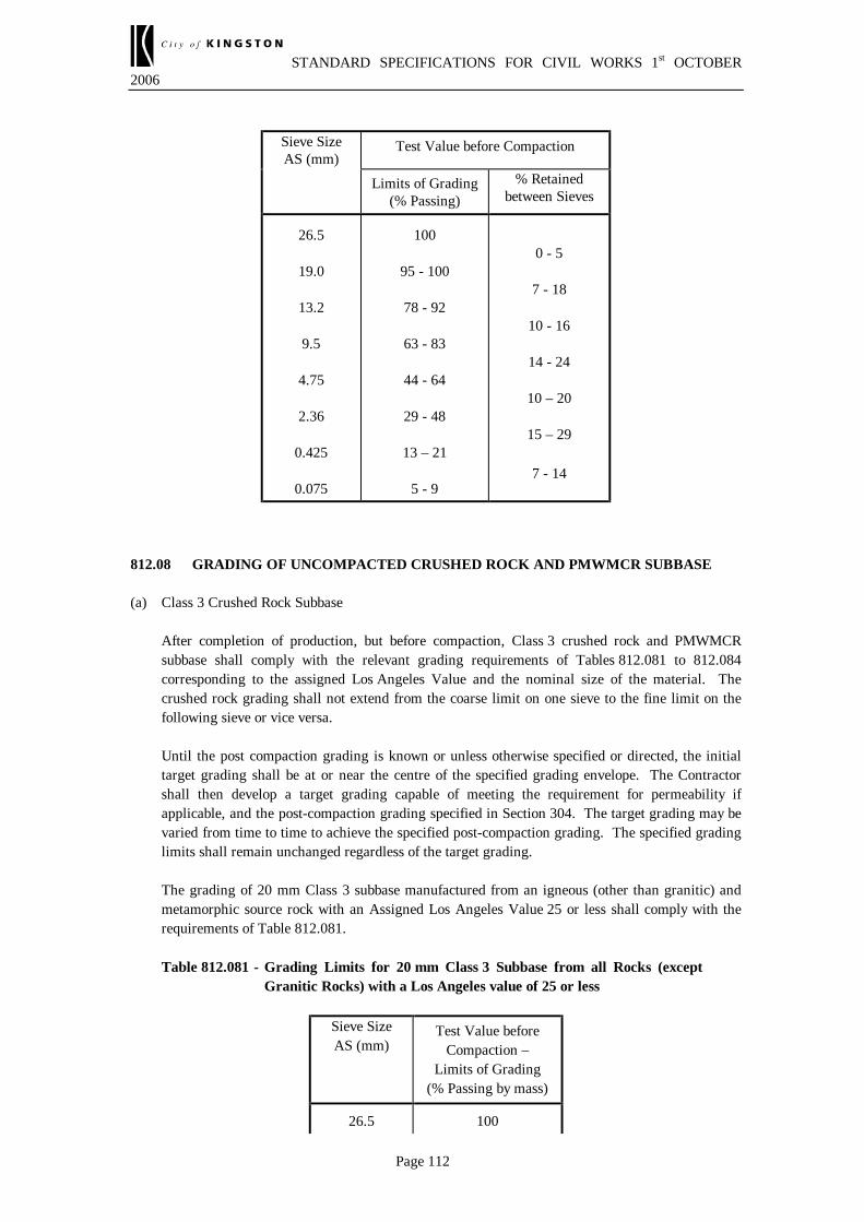
STANDARD SPECIFICATIONS FOR CIVIL WORKS 1st OCTOBER 2006
Page 112
Sieve Size AS (mm)
Test Value before Compaction
Limits of Grading (% Passing)
% Retained between Sieves
26.5
19.0
13.2
9.5
4.75
2.36
0.425
0.075
100
95 - 100
78 - 92
63 - 83
44 - 64
29 - 48
13 – 21
5 - 9
0 - 5
7 - 18
10 - 16
14 - 24
10 – 20
15 – 29
7 - 14
812.08 GRADING OF UNCOMPACTED CRUSHED ROCK AND PMWMCR SUBBASE (a) Class 3 Crushed Rock Subbase After completion of production, but before compaction, Class 3 crushed rock and PMWMCR
subbase shall comply with the relevant grading requirements of Tables 812.081 to 812.084 corresponding to the assigned Los Angeles Value and the nominal size of the material. The crushed rock grading shall not extend from the coarse limit on one sieve to the fine limit on the following sieve or vice versa.
Until the post compaction grading is known or unless otherwise specified or directed, the initial
target grading shall be at or near the centre of the specified grading envelope. The Contractor shall then develop a target grading capable of meeting the requirement for permeability if applicable, and the post-compaction grading specified in Section 304. The target grading may be varied from time to time to achieve the specified post-compaction grading. The specified grading limits shall remain unchanged regardless of the target grading.
The grading of 20 mm Class 3 subbase manufactured from an igneous (other than granitic) and
metamorphic source rock with an Assigned Los Angeles Value 25 or less shall comply with the requirements of Table 812.081.
Table 812.081 - Grading Limits for 20 mm Class 3 Subbase from all Rocks (except
Granitic Rocks) with a Los Angeles value of 25 or less
Sieve Size AS (mm)
Test Value before Compaction –
Limits of Grading (% Passing by mass)
26.5 100

STANDARD SPECIFICATIONS FOR CIVIL WORKS 1st OCTOBER 2006
Page 113
19.0 95 – 100
13.2 75 – 95
9.5 60 – 90
4.75 42 – 76
2.36 28 – 60
0.425 14 – 28
0.075 6 – 13
The grading of 20 mm Class 3 subbase manufactured from an igneous and metamorphic source
rock with an Assigned Los Angeles Value 26 or greater and all sedimentary and granitic source rock shall comply with the requirements of Table 812.082.
Table 812.082 - Grading Limits for 20 mm Class 3 Subbase from Granitic Rocks and
all other Rocks with a Los Angeles value of 26 or more
Sieve Size AS (mm)
Test Value before Compaction –
Limits of Grading (% Passing by mass)
26.5 100
19.0 95 – 100
13.2 75 – 95
9.5 60 – 90
4.75 42 – 76
2.36 28 – 60
0.425 10 – 28
0.075 2 – 10 The grading of 40 mm Class 3 subbase manufactured from an igneous (other than granite) and
metamorphic source rock with an Assigned Los Angeles Value 25 or less shall comply with the requirements of Table 812.083.
Table 812.083 - Grading Limits for 40 mm Class 3 Subbase from all Rocks (except
Granitic Rocks) with a Los Angeles value of 25 or less
Sieve Size AS (mm)
Test Value before Compaction –
Limits of Grading (% Passing by mass)
53.0 100
37.5 95 - 100
26.5 75 - 95
19.0 64 - 90
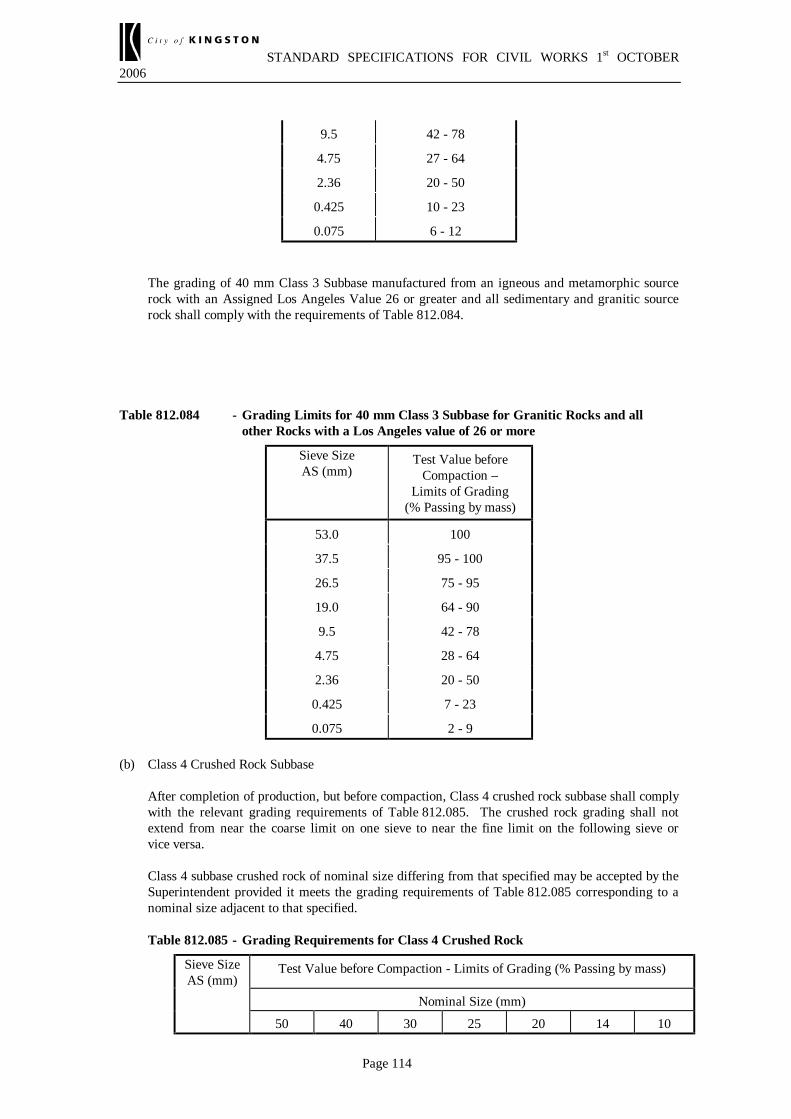
STANDARD SPECIFICATIONS FOR CIVIL WORKS 1st OCTOBER 2006
Page 114
9.5 42 - 78
4.75 27 - 64
2.36 20 - 50
0.425 10 - 23
0.075 6 - 12 The grading of 40 mm Class 3 Subbase manufactured from an igneous and metamorphic source
rock with an Assigned Los Angeles Value 26 or greater and all sedimentary and granitic source rock shall comply with the requirements of Table 812.084.
Table 812.084 - Grading Limits for 40 mm Class 3 Subbase for Granitic Rocks and all other Rocks with a Los Angeles value of 26 or more
Sieve Size AS (mm)
Test Value before Compaction –
Limits of Grading (% Passing by mass)
53.0 100
37.5 95 - 100
26.5 75 - 95
19.0 64 - 90
9.5 42 - 78
4.75 28 - 64
2.36 20 - 50
0.425 7 - 23
0.075 2 - 9 (b) Class 4 Crushed Rock Subbase After completion of production, but before compaction, Class 4 crushed rock subbase shall comply
with the relevant grading requirements of Table 812.085. The crushed rock grading shall not extend from near the coarse limit on one sieve to near the fine limit on the following sieve or vice versa.
Class 4 subbase crushed rock of nominal size differing from that specified may be accepted by the
Superintendent provided it meets the grading requirements of Table 812.085 corresponding to a nominal size adjacent to that specified.
Table 812.085 - Grading Requirements for Class 4 Crushed Rock
Sieve Size AS (mm)
Test Value before Compaction - Limits of Grading (% Passing by mass)
Nominal Size (mm) 50 40 30 25 20 14 10

STANDARD SPECIFICATIONS FOR CIVIL WORKS 1st OCTOBER 2006
Page 115
75.0 100
53.0 100
37.5 100 100
26.5 100
19.0 54-75 64-90 100 100
9.5 48-70 54-75
4.75 42-76 54-75 64-84
2.36
0.425 7-21 7-23 9-24 10-26 10-28 15-32 18-35
0.075 2-10 2-12 2-12 2-13 2-14 6-17 7-18 812.09 MOISTURE CONTENT (a) Crushed Rock Where payment is to be made on a mass basis, the average moisture content of crushed rock at the
plant shall not exceed 4% by mass unless otherwise specified or unless the Contractor has, at the time of tendering, nominated an upper limit of average moisture content greater than 4%. In the latter case the difference between the nominated value and the specified value will be taken into account when tenders are being considered. The average moisture content of crushed rock supplied on any one day will be determined from three samples taken at random on that day. If the average moisture content is greater than that specified or nominated, the material may be rejected. If material is accepted, payment will be made for the mass determined by deducting the calculated mass of excess moisture from the net mass shown on the delivery dockets.
(b) Plant Mixed Wet Mixed Crushed Rock Where the work of the Contract includes supply and delivery only, the moisture content of the
mixture at the point of delivery, expressed as a percentage by mass, shall be within plus 0.5 to minus 1.0 of the target nominated from time to time by the Superintendent.
812.10 MATERIAL SUPPLIED TO STOCKPILE If the Contractor elects or is required to supply PMWMCR or crushed rock to stockpile prior to delivery to the roadbed the following requirements shall be met:
(a) the product, after recovery from the stockpile, complies with this specification;
(b) the stockpile site is clean, adequately paved, and well drained;
(c) if a stockpile is constructed in more than one layer, each layer is fully contained within the area occupied by the upper surface of the preceding layer;
(d) unless otherwise specified or approved by the Superintendent, all crushed rock supplied to stockpile shall have a minimum moisture content of 3.5% by mass unless the stockpile is located
STANDARD SPECIFICATIONS FOR CIVIL WORKS 1st OCTOBER 2006
Page 116
at the supply point for producing PMWMCR;
(e) all PMWMCR delivered to stockpile shall be supplied at a moisture content of not less than the optimum moisture content unless the material is to be wet mixed again prior to delivery to the roadbed where the minimum moisture content in stockpile shall be not less than 3.5% by mass;
(f) the surface of the stockpile shall be kept damp to prevent a net loss of moisture and to minimise the generation of airborne dust.
812.11 HANDLING OF CRUSHED ROCK PRODUCTS Handling of crushed rock including stockpiling and loading of trucks shall be effected in such a manner as to minimise segregation. 812.12 MINIMUM TESTING REQUIREMENTS The Contractor shall test the crushed rock and PMWMCR at such a frequency to ensure that the material consistently complies with specified requirements. The test frequency shall initially not be less than that shown in Table 812.121, except that the test frequency for Grading, Plasticity Index, Unsound Rock Content, pH and Conductivity, and Degradation Factor, may be halved where the most recent 10 test results in succession have met specification requirements. If any subsequent test result fails to meet specification requirements, another test shall be immediately undertaken. If the second test fails the test frequency shall revert to the minimum test frequency specified in Table 812.121 and the Contractor shall not return to half the test frequency until a further 10 successive test results comply with specification requirements.

STANDARD SPECIFICATIONS FOR CIVIL WORKS 1st OCTOBER 2006
Page 117
Table 812.121 - Minimum Frequency of Testing
Test Minimum Frequency of Testing Grading - Final Product - Additives
On each production day - One per 500 tonnes or part thereof On each production day - One per 250 tonne or part thereof of additive used
Unsound Rock Content (+) One per production day of a sample taken from the final product or from individual rock components before blending under the provisions of Clause 812.04(d)
Moisture Content - Crushed Rock (++) - PMWMCR
One per production day On each production day - One per 500 tonnes or part thereof
Plasticity Index Class 1 Base In each production week - One per 2500 tonne or part thereof
Class 2 Base and Classes 3 and 4 Subbase In each production month - One per 5000 tonne or part thereof
California Bearing Ratio (+++) Prior to the commencement of work and at other times when in the opinion of the Superintendent, the nature and/or physical properties of the material have changed
Degradation Factor - Crusher Fines (+) One per 1000 tonne on each production day as required under the provisions of Clause 812.04(b)
Permeability as specified in Table 812.051
Prior to commencement of work and at other times when in the opinion of the Superintendent, the nature and/or physical properties of the material have changed
pH and Conductivity (++++) One per production day Flakiness Index One per production month Crushed Particles (+++++) One per production month (+) Not applicable to Class 4 subbase unless otherwise specified (++) Applicable only when payment is to be made on a mass basis (+++) Applicable to Class 4 subbase (++++) Applicable only to sources identified in the current Quarry Investigation Report as containing
sulphide/sulphate mineralisation (+++++) Applicable to crushed river gravels

STANDARD SPECIFICATIONS FOR CIVIL WORKS 1st OCTOBER 2006
Page 118
SECTION 815 - CEMENT TREATED CRUSHED ROCK FOR SUBBASE
PAVEMENT ##This section cross-references Sections 306, 801 and 821 – are they included in the specification?: 815.01 DESCRIPTION This section covers the requirements for 20 mm nominal size crushed rock subbase produced from source rock of any type and treated with cementitious binder to produce a modified or bound material. The requirements relate to properties of the product. Construction of Cementitiously Treated Subbase Pavement is covered by Section 306. Supply of Cementitiously Treated Crushed Concrete for Subbase Pavement is covered by Section 821. 815.02 DEFINITIONS Assigned Los Angeles Abrasion Loss The assigned Los Angeles Abrasion Loss is a hardness rating derived from Los Angeles Abrasion Loss test results and is assigned to each source by VicRoads on the basis of past test data obtained from testing products. Cementitious Binder A cementing agent that binds the particles of a granular pavement material together to increase its strength. Cementitious binders include Portland cement Type GP or blended cement Type GB, hydrated lime, quicklime, or a blend of ground granulated blast furnace slag (GGBFS), hydrated lime, fly ash, alkali activated slag or other pozzalanic material supplied in accordance with this specification. Cementitiously Treated Crushed Rock Cementitiously treated crushed rock is a mixture of crushed rock fragments, cement and water or crushed rock and sand fragments, cement and water produced at a controlled mixing plant to close tolerances of grading, moisture content and binder content. Fine Aggregates The portion of the crushed rock mixture passing the 4.75 sieve Fly Ash A fine powder of pozzolanic material extracted from the flue emissions produced from the burning of black coal complying with the requirements of AS 3582.1. Pozzolan A very fine graded siliceous or alumino-siliceous material that can be mixed with lime or

STANDARD SPECIFICATIONS FOR CIVIL WORKS 1st OCTOBER 2006
Page 119
Portland cement to form a cementitious material. Slag (Ground Granulated Blast Furnace Slag) Ground Granulated Blast Furnace Slag (GGBFS) complying with the requirements of AS 3582.2 is a pozzolan produced by fine grinding of slag produced as a by product from the smelting of iron ore. 815.03 SOURCE ROCK Source rock shall comply with the requirements of Section 801 - Source Rock for the Production of Crushed Rock and Aggregates. 815.04 COMPONENTS (a) Crushed rock fragments shall consist of clean, hard, durable, angular rock fragments of
uniform quality. The use of crusher fines produced from a quarry, or a location within a quarry,
different from that used for production of that fraction of the crushed rock retained on a 4.75 mm AS sieve shall be subject to approval in writing by the Superintendent to the proposed source and nature of these materials and the proposed amounts to be added.
Crusher fines produced from any igneous or metamorphic rock shall have a Degradation
Factor - Crusher Fines not less than 60. (b) The use of sands and/or filler shall be subject to approval in writing by the
Superintendent to the proposed source and nature of such materials, the proposed amounts to be added and the proposed method of incorporating such materials in the product.
815.05 PRODUCT (a) The cement treated crushed rock shall be free from vegetable matter and lumps or balls of
clay and shall comply with the relevant requirements of Table 815.051.
Table 815.051 Total of Marginal and Unsound Rock %
(max)
Unsound Rock % (max)
20 10
(b) The mixture before the addition of cement shall comply with the requirements of
Table 815.052.
Table 815.052 Test Test Value
Liquid Limit % (max) 35
Plasticity Index (max) 10

STANDARD SPECIFICATIONS FOR CIVIL WORKS 1st OCTOBER 2006
Page 120
815.06 CEMENTITIOUS BINDER (a) Cement Cement shall be Type GP or GB and comply with the requirements of AS 3972-1991 -
Portland and Blended Cements. It shall be stored in weatherproof structures, and any cement damaged by moisture shall not be used.
If Type GB cement is proposed, only the following blends are permitted:
• Cement/Slag Blend (50% to 60% cement content)
• Cement/Fly ash blend (70% to 80% cement content)
• Cement/Slag/Fly ash blend (55% to 65% cement content). (b) Slag/Lime Blends Slag and hydrated lime may be used in blended combination as a slow setting cementitious
binder. The requirements for hydrated lime shall be as specified in Clause 307.04(a)(ii) and (iii) above. Slag used shall be Ground Granulated Blast Furnace Slag (GGBFS) meeting the requirements of AS 3582.2. The Contractor shall nominate the type, brand and source of the GGBFS to be used.
Slag/lime shall be blended uniformly in the ratio of 85% slag to 15% hydrated lime unless
laboratory testing indicates that superior strength of the cementitiously treated crushed rock is achieved by using a different ratio. If the blend is to be varied, the proportion of lime shall not be less than 10%. The Contractor shall provide evidence that the blend ratio has been met for all material supplied to the job. Slag/lime blend shall have a mortar bar 7 day compressive strength of 10 MPa and 28 day mortar bar compressive strength of 16 MPa. The test shall be the same test specified in AS 3972 except that the cement to water ratio shall be adjusted to match the consistency of mortar produced for the compressive strength test for GB cement in accordance with the relevant Australian Standard Test Method.
(c) Slow Cementitious Blends Incorporating Alkali-activated Slag or Fly Ash Special blends of slow setting cementitious stabilising agents incorporating alkali-activated
slag or fly ash which do not meet mortar bar strength requirement specified in AS 3972 may be used subject to the blend satisfying the mortar bar test requirement specified in Clause 815.06(b). The maximum binder working time shall be determined in accordance with the VicRoads Test Method to confirm that the binder is a slow setting binder as specified in Standard Specification Section 306.
Fly ash shall be supplied to meet the requirements of AS 3582.1. 815.07 WATER Where water is added to the product during mixing it shall be clear and substantially free from detrimental impurities such as oils, salts, acids, alkalis and vegetable substances. Water supplied from sources where dissolved salts are known or likely to be present shall be tested for electrical conductivity prior to use. The electrical conductivity, shall not be more than 3500 µS/cm. 815.08 MIXING

STANDARD SPECIFICATIONS FOR CIVIL WORKS 1st OCTOBER 2006
Page 121
The crushed rock, sand (if any), cementitious binder and water shall be mixed by continuous or batch mixing. The mixing period and the time of addition of water shall be such as to produce a uniform mixture of the components. 815.09 GRADING OF CRUSHED ROCK WITHOUT CEMENTITIOUS BINDER The crushed rock, just prior to the addition of cementitious binder, shall comply with the relevant grading requirements of Tables 815.091 and 815.092 corresponding to the Los Angeles Abrasion Loss and the nominal size of the material. The mixture shall not be graded from near the coarse limit in one sieve to the fine limit on the following sieve or vice versa. Initially the target grading shall be at the centre of the grading envelope but the Contractor may vary the target grading within the specified grading limits to optimise the cementitious binder content required to satisfy the Unconfined Compression Strength (UCS) requirements specified in Table 815.101. Regardless of the target grading selected, the production grading shall not extend outside the specified grading limits unless approved by the Superintendent. Table 815.091 - Grading Limits for all Rock Types (except granite rocks) with an
Assigned Los Angeles Abrasion Loss of 26 or less Sieve Size AS (mm)
Test Value before Compaction
Limits of Grading (% Passing)
26.5 100 19.0 95 - 100 13.2 75 - 95 9.5 60 - 90 4.75 42 - 76 2.36 28 - 60
0.425 14 - 28 0.075 6 - 13
Table 815.092 - Grading Limits for all Rock Types with an Assigned Los Angeles
Abrasion Loss 25 or more and all Granite Source Rocks Sieve Size AS (mm)
Test Value before Compaction
Limits of Grading (% Passing)
26.5 100 19.0 95 - 100 13.2 75 - 95 9.5 60 - 90 4.75 42 - 76 2.36 28 - 60
0.425 10 - 28 0.075 2 – 10

STANDARD SPECIFICATIONS FOR CIVIL WORKS 1st OCTOBER 2006
Page 122
815.10 CEMENTITIOUS BINDER CONTENT AND UNCONFINED
COMPRESSION STRENGTH (UCS) REQUIREMENTS (a) Cementitious Binder Content The Contractor shall determine the content of cementitious binder required to meet the
minimum 7 day UCS specified in Table 815.101 using modified compaction. The cementitious binder content may be further increased to allow for the effects of production variability. The binder content so determined shall become the Design Cementitious Binder Content which shall not be less than the minimum cementitious binder content specified in Table 815.101.
Cementitious binder shall be added and mixed into the crushed rock in such a manner as to
produce a uniform binder content. After mixing, the cementitious binder content of the mixture, expressed as a percentage by
mass of the dry crushed rock, shall be within ± 0.3% of the Design Cementitious Binder Content.
(b) Unconfined Compression Test The Contractor shall carry out UCS Testing in accordance with the test frequency specified
in Table 815.141. The UCS test result shall be the mean UCS determined from a pair of specimens in accordance with the Australian Standard Test Method and compacted using modified compactive effort.
For the purposes of UCS testing, one representative sample of fully mixed cementitiously
treated material shall be taken either from the plant or at the point of delivery in accordance with the relevant Test Method and compacted in the mould within two hours of mixing.
The UCS during production shall be assessed on a "rolling average" basis where the
average of the most recent three UCS test results shall not be less than the minimum value specified in Table 815.101.
Table 815.101 - Cementitious Binder Content and Unconfined Compression Strength
Minimum Design Cementitious Binder Content
(% by mass)
Minimum 7 day Mean UCS * (MPa)
Rapid Setting (GP Cement)
Medium Setting
(GB Cement) **
Slow Setting (Supplementary
Cementitious Blends)
3 5 3.5 3 Notes on Table 815.101 * The UCS values specified in this table do not apply to cementitiously treated subbase
with a pavement design modulus in excess of 3500 MPa. Higher Mean UCS values shall apply in this instance either as specified elsewhere or as directed by the Superintendent.

STANDARD SPECIFICATIONS FOR CIVIL WORKS 1st OCTOBER 2006
Page 123
** The following blends of Type GB Cement shall be permitted as medium setting binders: • Cement/Slag Blend (50% to 60% cement content) • Cement/Fly ash blend (70% to 80% cement content) • Cement/Slag/Fly ash blend (55% to 65% cement content) 815.11 MOISTURE CONTENT If the contract is only for supply and delivery of material directly to VicRoads, the moisture content of the mixture at the point of delivery, expressed as a percentage by mass, shall be within plus 0.5 to minus 1.0 of any target value nominated by the Superintendent. 815.12 STOCKPILING OF MIXTURE Cementitiously treated crushed rock shall not be stockpiled. 815.13 HANDLING OF MIXTURE Handling of the mixture, including discharging from mixing plant and loading of trucks shall be effected in such a manner as to minimise segregation. 815.14 MINIMUM TESTING REQUIREMENTS The Contractor shall test the cementitiously treated crushed rock at such a frequency to ensure that all material consistently complies with the specified requirements. The test frequency shall initially not be less than that shown in Table 815.141, except that the frequency may be at half the specified frequency for Grading, Unsound Rock Content, Plasticity Index, and Degradation Factor – Crusher Fines, if a minimum of ten of the most recent test results in succession have met specification requirements. If any subsequent test result fails to meet specification requirements, another test shall be immediately completed. If the second test fails, the test frequency shall revert to the minimum frequency specified in Table 815.141 and the Contractor shall not return to half the test frequency until a further 10 successive test results comply with specification requirements. Table 815.141 - Minimum Frequency of Testing
Test Minimum Frequency of Testing Grading On each production day: 500 tonnes except where total
production on any day less than 100 tonnes. Unsound Rock Content One per production day. Cementitious Binder Content On each production day: one per 250 tonnes except where total
production on any day is less than 100 tonnes. Moisture Content On each production day: one per 500 tonnes or part thereof
except when total production on any day is less than 100 tonnes. Plasticity Index In each month: one per 5000 tonnes or part thereof. Degradation Factor - Crusher Fines
One per production day for crusher fines imported from another source or location within the source to that of the course aggregates.
Mean Unconfined Compression Strength
In each week: one per 2000 tonnes or part thereof. If production in any week is less than 500 tonnes the quantity may be added to the total production in the following week (or weeks) until a total of 500 tonnes is reached.