Embed Size (px)
Citation preview

ROOFING APPLICATION STANDARD (RAS) No. 111
STANDARD REQUIREMENTS FOR ATTACHMENT OF PERIMETER WOOD-BLOCKING AND METAL FLASHING
1 Scope
1.1 This Application Standard provides: 1) the minimum criteria for attachment of perimeter and termination woodblocking; and 2) the minimum criteria for material fabrication and attachment of perimeter metal flashing.
2 Definitions
2.1. For definitions of terms used in this application standard, refer to ASTM D 1079; and the Florida Building Code, Building.
3 Woodblocking Attachment
3.1. Wood blocking shall be attached to resist wind forces, and other loads, as required by Chapter 16 (High Velocity Hurricane Zones) of this code.
3.2 Fastener Value (fv)
3.2.1 Fasteners/anchors which have published withdrawal resistance values, generated from laboratory testing, shall have a margin of safety, as noted in Table 1, below, applied to average laboratory test results.
• Use of published withdrawal resis tance values to determine a fasten er value for a particular applica tion shall be contingent upon the similarity of substrate materials which generated the published val ues in comparison to the substrate material of the actual application.
TABLE 1 MARGINS OF SAFETY FOR LABORATORY WITHDRAWAL
RESISTANCE TESTING
Substrate Margin of Safety
Steel Decking 2:1 Concrete Decking 4:1
Wood Decking 2:1 Gypsum Decking 3:1 Structural Steel 2:1
3.2.2 Alternatively, the Fastener Value may be the result of in situ (on site) testing, in compliance with TAS 105, resulting in a minimum characteristic resistance force which shall be used as the Fastener Value.
3.3 Woodblocking Fastener Spacing
3.3.1 The attachment criteria for wood-blocking shall be 250 plf for perimeter areas and 300 plf for corner areas.
3.3.2 In any event, woodblocking fastener spacing shall not exceed 18 in. o.c.
3.4 Woodblocking Attachment, General Requirements
3.4.1 In recover, or residential wood decks applications, woodblocking thickness may be reduced to 1 in. providing the attachment is in compliance with the provisions of Chapter (High Velocity Hurricane Zones) of the Florida Building Code, Building.
3.4.2 The maximum unsupported overhang of the woodblocking shall not exceed 2 in. If the maximum overhang is employed, the minimum woodblocking dimensions shall be not less than a nominal 2 in. x 8 in. and two rows of fasteners shall be installed in a staggered manner.
3.4.3 A fastener shall be placed within 3 in. of the end of each section of wood-blocking, and a 1/4 in. gap shall be left between each section of woodblocking.
3.4.4 All fastener/anchor heads shall be countersunk or fastener/anchor heads shall be driven flush with the top surface of the woodblocking.
3.4.5 All woodblocking, shall be only salt pressure treated to LP-2 or better, or any decay resistant species.
FLORIDA BUILDING CODE — TEST PROTOCOL HVHZ (RAS) 111.1
(RAS) No. 111
3.4.6 If the woodblocking thickness is greater than that of the insulation a tapered edge shall be installed to create a sloped transition between the insulation and the woodblocking.
3.4.7 All fasteners/anchors used for attachment of woodblocking shall meet the corrosion resistance requirements set forth in Appendix 'E' of TAS 114 for insulation and membrane fasteners (DIN 50018).
3.5 Woodblocking Attachment, Masonry Block
3.5.1 When the masonry block is cast with lightweight aggregate, anchor bolts shall be embedded not less than 6 in. into the second course of block.
3.5.2 If expansion bolts are substituted for anchor bolts, the minimum diameter shall be 3/8 in.
3.5.3 When the width of the woodblocking is greater than 6 in., anchors shall be staggered in two rows across the woodblocking width.
3.6 Woodblocking Attachment, Structural Concrete
3.6.1 Anchors used for woodblocking attachment to structural concrete shall have a minimum diameter (including the minor root diameter) of 0.250 in.; therefore, a threaded concrete anchor or insulation fastener with a nominal 1/4 in. diameter shall not be acceptable.
3.6.2 Powder Actuated (PAT) fastening (Pins and Loads) shall not be an acceptable method of attachment.
3.7 Woodblocking Attachment, Steel Decking
3.7.1 All fasteners shall penetrate the top flange of the steel deck.
3.7.2 When woodblocking is attached parallel to the deck flutes, the steel decking shall be mechanically attached to the structural steel with minimum 1/4 in. diameter self-tapping or self-drilling fasteners with a minimum 5/8 in. diam
eter bearing washer, at a maximum spacing of 7' (seven feet) o.c. prior to the attachment of the woodblocking.
3.7.3 If the steel deck thickness is less than or equal to 22 ga., a withdrawal resistance test, in compliance with TAS 105, shall be conducted to determine compliance with Chapter 16 (High Velocity Hurricane Zones) of this code.
3.8 Woodblocking Attachment, 'Lightweight Decks'
3.8.1 For the purposes of this Section, 'lightweight decks' shall include gypsum, cementitious woodfiber and lightweight insulating concrete decks.
3.8.2 Lightweight decks should not be used as a woodblocking attachment substrate unless:
• The selected woodblocking anchor is fastened to the underside of the deck or attached directly to a structural member.
• The selected woodblocking anchor can achieve an average withdrawal resistance of not less than 450 lbf tested in compliance with TAS 105.
3.8.3 Toggle bolts are not acceptable wood-blocking fasteners.
3.8.4 Fastener spacing for wood blocking shall not exceed 12 inches o.c.
4 Galvanic Action
4.1 Components shall be compatible to minimize the potential for galvanic corrosion. Galvanic corrosion will occur when dissimilar metals come into contact with an electrolyte. An electrolyte is any non-metallic substance (especially liquid) that will conduct electric current. Water is an electrolyte. Metals that are more electro-positive (anodic or least 'noble') and will corrode more easily are at one end of the scale. Those that are more electro-negative (cathodic are more noble) and are more corrosion resistant are at the other end of the scale.
(RAS) 111.2 FLORIDA BUILDING CODE — TEST PROTOCOL HVHZ

4.2 Common metals used in metal roof construction in order of least noble to more noble are as follows:
• Anodic (least noble) • Magnesium • Magnesium Alloys • Zinc • Galvanized Coated Steel • Aluminum 1100 • Alclad • Cadmium • Mild Steel • Wrought Iron • Cast Iron
13% Chromium Stainless Steel (type 410 active.)
• 18-8 Stainless Steel (type 304 active.) • 18-12-3 Stainless Steel (type 316 active.) • Lead / Tin Solder • Lead • Tin • Muntz Metal • Manganese Bronze • Naval Brass • Nickel (active) • 76 Ni-16 Cr-7 Fe alloy (active) • 60 Ni-30 Mo-6 Fe-l Mn • Yellow Brass • Admiralty Brass • Aluminum Brass • Red Brass • Copper • Silicone Bronze • 70:30 Cupro Nickel • G-Bronze • M-Bronze • Silver Solder • Nickel (passive) • 76 Ni-16 Cr-7 Fe alloy (passive) • Monel • 13% Chromium Stainless Steel (type 410
passive) • Titanium • 18-8 Stainless Steel (type 304 passive) • 18-12-3 Stainless Steel (type 316 passive) • Silver • Graphite • Gold • Platinum
Cathodic (more noble)
(RAS) No. 111
4.3 To reduce the occurrence of galvanic corrosion, the following steps shall be taken:
• Do not place metals far apart in the scale in contact with each other. Fasteners shall be of compatible materials.
• The more noble (cathodic) metal may be coated with a suitable paint or non- metal lic coating.
• Do not design drainage from a cathodic to anodic metal even if materials do not make contact. The water will conduct electrical current between the two materials.
• Copper nails shall not be used to attach galvanized steel.
4.4 Flashing Gages
4.4.1 Table 2 lists material thickness requirements based on edge metal component dimensions for roof mean height less than 54 ft. For roof mean height of 54 ft. or greater flashing terminations shall be designed by a professional engineer or registered architect proficient in roofing design. Calculations in compliance Chapter 16 (High Velocity Hurricane Zones) of the Florida Building Code, Building shall be submitted with Section II of the Uniform Building Permit Application to the building official for review.
4.4.2 All edge metal profiles, copings, and coping caps shall comply with Table 2 herein. The maximum vertical (face) dimension listed in Table 2 represents the vertical (face) dimensions where a hook strip is required. Smaller vertical (face) dimension than those listed in Table 2 edge metal profiles and copings of the specified gauge may be used without a hook strip.
FLORIDA BUILDING CODE — TEST PROTOCOL HVHZ (RAS) 111.3

(RAS) No. 111
TABLE 2 HOOK STRIP/CONTINUOUS CLEAT THICKNESS REQUIREMENTS FOR EDGE METAL AND COPINGS FACE DIMENSIONS
GALVANIZED METAL OR STAINLESS STEEL
Min. Component Gage 26 ga 24 ga 22 ga 20 ga 18 ga
Max. Vertical (Face) Flange 4 in. 6 in. 8 in. 10 in. 12 in.
Min. Hook
Strip/Cleat Gage1 24 ga 22 ga 20 ga 18 ga 16 ga
ALUMINUM
Min. Component Gage 0.032 in. 0.032 in. 0.040 in. 0.050 in. 0.060 in. 0.070 in.
Max. Vertical (Face) Flange < 3 in. 3 in. 4 in. 6 in. 8 in. 10 in.
Min. Hook Strip/Cleat Gage
Not Required 0.040 in. 0.050 in. 0.060 in. 0.070 in. 0.080 in.
COPPER
Min. Component Gage 16 oz 16 oz 20 oz 24 oz 32 oz
Max. Vertical (Face) Flange < 3.5 in. 3.5 in. 6 in. 8 in. 10 in.
Min. Hook
Strip/Cleat weight1
Not
Required 20 oz 24 oz 32 oz 48 oz 1 Hook strip shall be one thickness greater than that of the metal profile material, as commercially available.
5 Drip Edge and Gravel Stop
5.1 Minimum attachment shall include horizontal flange attachment with approved minimum 12 ga. annular ring shank nails at a spacing not to exceed 4 in. o.c. in a staggered pattern. Rows shall be approximately 3/4 in. to 1 in. from each edge of the horizontal flange. Nails shall be fabricated from similar or compatible material to the drip edge/gravel stop.
5.2 Installation Requirements
5.2.1 Vertical flange dimensions shall be not less than 1 1/2 in. and the horizontal dimension shall not be less than 2 in. wide. The vertical flange shall be of sufficient length to extend below the sheathing or other member immediately contiguous thereto by not less than 1/2 in. Table 2 herein lists maximum vertical flange dimensions for various drip edge/gravel stop materials.
5.2.2 Drip edge/gravel stop shall be fabricated in lengths not greater than 12 feet. Sections may be joined by one of the two following methods:
• 'Butt-Joint' Method: Drip edge/gravel stop sections shall be installed with a 1/ in.-1/2 in. gap between each section to allow for expansion and contraction of the metal. A back or cover plate shall be installed at each joint with approved sealant applied between the edge component and the back or cover plate.
• 'Overlap' Method: Drip edge/gravel stop sections shall be installed with a minimum 4 in. overlap between each section with a bed of Approved sealant at each overlap. Slotted holes shall be pre-punched in the top metal section to allow for movement.
5.2.3 When a continuous cleat (hook strip) is required and the vertical flange exceeds 7 in., the 'butt-joint' method shall be utilized and a cover plate shall be installed.
(RAS) 111.4 FLORIDA BUILDING CODE — TEST PROTOCOL HVHZ

(RAS) No. 111
FIGURE 1 DETAIL OF 'BUTT-JOINT METHOD FOR ADJACENT DRIP EDGE/GRAVEL STOP SECTIONS
FIGURE 2 EXAMPLE OF RAISED EDGE AT GRAVEL STOP PERIMETER FLASHING
FLORIDA BUILDING CODE — TEST PROTOCOL HVHZ (RAS) 111.5

(RAS) No. 111
NOTE: All metal surfaces receiving hot asphalt or approved flashing cement shall be fully primed with ASTM D 41 primer. ASTM D 41 primer which is in a quick dry formulation is acceptable. All fastener shall be covered with either:
• two layers of 'stripping' or 'flashing' felt set in hot asphalt or approved flashing cement; or,
• a single layer of modified bitumen, torch applied or set in hot asphalt, or approved adhesive.
5.2.4 The continuous cleat (hook strip) shall be nailed or screwed to the vertical face of the woodblocking, or to the vertical face of the structure at a spacing not to exceed 12 in. o.c.
5.2.5 Not withstanding the minimum attachment criteria noted herein, metal edge systems of any dimension may be tested in compliance with RAS 111(A) and RAS 111 (B), the values from which may be submitted with Section II of the Uniform Building Permit Application to the building official for review.
FIGURE 3 EXAMPLE OF PERIMETER FLASHING FOR CONFIGURATIONS INCLUDING A CONTINUOUS CLEAT
(RAS) 111.6 FLORIDA BUILDING CODE —TEST PROTOCOL HVHZ
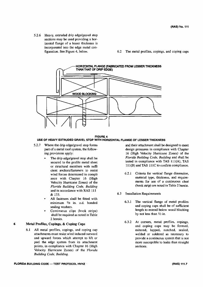
5.2.6 Heavy, extruded drip edge/gravel stop sections may be used providing a horizontal flange of a lesser thickness is incorporated into the edge metal configuration. See Figure 4, below.
(RAS) No. 111
6.2 The metal profiles, copings, and coping caps
FIGURE 4 USE OF HEAVY EXTRUDED GRAVEL STOP WITH HORIZONTAL FLANGE OF LESSER THICKNESS
5.2.7 Where the drip edge/gravel stop forms part of a metal roof system, the following provisions apply:
• The drip edge/gravel stop shall be secured to the profile metal sheet or structural members with suffi cient anchors/fasteners to resist wind forces determined in compli ance with Chapter 16 (High Velocity Hurricane Zones) of the Florida Building Code, Building and in accordance with RAS 111 &133.
• All fasteners shall be fitted with minimum 5/8 in. o.d. bonded sealing washers.
• Continuous clips (hook strips) shall be required as noted in Table 2 herein.
6 Metal Profiles, Copings, & Coping Caps
6.1 All metal profiles, copings, and coping cap attachments must resist wind induced outward and upward forces which attempt to lift or peel the edge system from its attachment points, in compliance with Chapter 16 (High Velocity Hurricane Zones) of the Florida Building Code, Building.
and their attachment shall be designed to meet design pressures in compliance with Chapter 16 (High Velocity Hurricane Zones) of the Florida Building Code, Building and shall be tested in compliance with TAS 111(A), TAS 111(B) and TAS 111C to confirm compliance.
6.2.1 Criteria for vertical flange dimension, material type, thickness, and requirements for use of a continuous cleat (hook strip) are noted in Table 2 herein.
6.3 Installation Requirements
6.3.1 The vertical flange of metal profiles and coping caps shall be of sufficient length to extend below wood blocking by not less than 1/2 in.
6.3.2 At corners, metal profiles, copings, and coping caps may be formed, mitered, lapped, notched, sealed, welded or soldered as necessary to provide a continuous system that is not more susceptible to leaks than straight sections.
FLORIDA BUILDING CODE — TEST PROTOCOL HVHZ (RAS) 111.7

(RAS) No. 111
6.3.3 Minimum attachment shall include attachment of the deck flange to dimensional lumber with approved #12 diameter threaded fasteners fitted with minimum 5/8 in. o.d. stainless steel/neoprene or EPDM bonded sealing washer, having a minimum 0.060 in. gasket thickness, spaced not greater than 18 in. o.c. at perimeter roof areas, and 12 in. o.c. at corner roof areas. Fasteners shall be fabricated from similar or compatible material to that of the metal profile, copings, and coping caps shall be of sufficient length to penetrate the substrate by not less than 3/4 in.
6.3.4 Notwithstanding other requirements set forth in this application standard, one said fastener shall be installed not more than 1 in. from the end of each metal profile section where sections are joined with a splice plate.
6.3.5 For metal profiles copings, and coping cap applications which require a continuous cleat (hook strip), minimum attachment requirements are as follows:
• The cleat shall be attached to the vertical face of the woodblocking using approved 12 ga. annular ring shank nails or # 10 diameter fastener spaced not greater than 10 in. o.c. at perimeter roof areas and 6 in. o.c. at corner roof areas.
• Nails shall be fabricated from similar or compatible material to that of the continuous cleat, shall be of sufficient length to penetrate the substrate by not less than 1 1/4
n and shall have a minimum head size of 5/16 in.
• Nylon or plastic anchors shall no be acceptable.
6.4 Coping Caps
6.4.1 Coping caps shall slope toward the roof.
6.4.2 Coping caps shall be fabricated in lengths not greater than 12 feet. Sections may be joined as described above or using one of the following configurations which eliminate splice plates and overlaps:
6.4.2.1 Standing Seam Configuration
6.4.2.2 The Drive Configuration below allows for use of a thinner material for the drive joint components than that of the coping cap sections.
Counter-flashing
7.1 For material and thickness requirements see Table 2 herein. Alternatively, counter-flashing manufacturers may obtain an NOA.
(RAS) 111.8 FLORIDA BUILDING CODE — TEST PROTOCOL HVHZ

7.2 General Attachment Requirements
7.2.1 Joints in counter-flashings shall be overlapped a minimum of 4 in. (10 mm) or as stated in counter-flashing NOA. Corners shall be mitered and soldered or sealed with an approved sealant.
7.2.2 Counter-flashing attachment points shall be elevated not less than 8 in. above the finished roof surface. Where job conditions do not allow counter flashing to be 8 inches above finished roof surface, the counter flashing may terminate 4 in. above the finished roof surface.
7.2.3 The lower edge of a counter-flashing shall be not less than 1 in. above the top edge of the cant or, when no cant is present, the finished roof surface.
7.2.4 Counter-flashing shall not be a continuous piece across moving wall joints.
7.3 Reglet mounted counter-flashings:
7.3.1 If a reglet mounted counter-flashing is to be used, the joint shall be in accordance with reglet counter-flashing manufacturer's recommendations. The counter-flashing may be held in place by spring action wedges and sealant. Reglets shall not be cut into hollow cells of masonry walls or concrete.
FIGURE 5 EXAMPLE OF REGLET MOUNTED COUNTER-FLASHING
(RAS) No. 111
7.4 For surface mounted reglet-type counter-flashing applications, the following provisions shall apply.
7.4.1 A bead of approved sealant shall be applied at the top edge to create a waterproof seal. Sealant shall be installed in accordance sealant manufacturers published literature. Primer shall be applied to the substrate material when recommended by the sealant manufacturer. Sealant shall have two-point adhesion; to the reglet and to the wall substrate for maximum sealant performance. Bond breaker or backer rod shall be installed where necessary to create two-point adhesion. Refer to the sealant manufacturer's published literature for specific types of bond breaker of backer rods.
7.4.2 Anchors shall provide a minimum characteristic resistance force of 150 lbf, tested in compliance with TAS 105 or an average withdrawal resistance of 150 lbf resulting from laboratory testing after a 2:1 margin of safety is applied. Anchors shall be fitted with a minimum 5/8 in. o.d. bonded sealing washer, having a minimum 0.060 in. gasket thickness, and shall be installed through slotted or oversized holes at a spacing not greater than 8 in. o.c.
7.4.3 Surface mounted flashing shall have a flat surface for flush wall mounting of not less than 1 1/2i in. and not greater than 2 1/2 in. The flashing profile shall include stiffening bends at top and bottom. The total of the two bends shall exceed 90 degrees.
7.4.3.1 When an expansion joint occurs at a base flashing, additional counter-flashing attachment shall include:
• a mechanical lock at a two piece reglet; or,
• a reinforcing bar, of similar or compatible material, at the mechanical attachment point to distribute load.
FLORIDA BUILDING CODE — TEST PROTOCOL HVHZ (RAS) 111.9

(RAS) No. 111
7.5 Stucco Counter-flashing
7.5.1 Stucco counter-flashing, or 'stucco stops', may be fabricated in one- or two- piece configurations or may have an NOA as a roofing component.
7.5.2 Material thickness and dimension requirements shall comply with Table 2 herein. Alternatively, counter-flashing manufacturers may obtain an NOA.
7.5.3 Stucco counter-flashing shall be overlapped a minimum of 4 in. (10mm) or as stated in counter-flashing NOA.
7.5.4 Attachment Requirements
7.5.4.1 Anchors shall provide a minimum characteristic resistance force of 100 lbf, tested in compliance with TAS 105 or an average withdrawal resistance of 100 lbf resulting from laboratory testing after a 2:1 margin of safety is applied. Anchors shall be fabricated from similar or compatible material to that of the stucco counter-flashing and shall be installed through slotted or oversized holes at a spacing not greater than 12 in. o.c.
7.5.4.2 Where the stucco counter-flashing is attached to steel or wood studs, attachment shall be at each stud with a minimum #8 diameter fastener providing provide a minimum characteristic resistance force of 150 lbf, tested in compliance with TAS 105 or an average withdrawal resistance of 150 lbf resulting from laboratory testing after a 2:1 margin of safety is applied.
7.5.5 Stucco counter-flashing attachment points shall be elevated not less than 8" above the finished roof surface. Where job conditions do not allow stucco counter flashing to be 8 inches
above finished roof surface, the counter flashing may terminate 4 in. above the finished roof surface.
7.5.6 The base water shedding layer behind the stucco or siding element shall terminate over top of the vertical leg of the stucco counter-flashing. Vertical leg of the stucco counter-flashing shall be set in a bed of approved mastic prior to mechanical attachment. See Figure 6, below.
8 Metal Panel Flashings (Sill Flashings)
8.1.1 Material thickness and dimension requirements shall comply with Table 2 herein. Alternatively, counter-flashing manufacturers may obtain an NOA.
8.1.2 All metal wall panels shall be closed with a foamed, or other type of compressible, closure strip approved for use with the panel profile in the roof assembly NOA.
8.1.3 Sill flashing may be one- or two-piece flashing forming a panel termination or forming a counter-flashing for a roof system assembly base flashing. Flashing shall be fastened with minimum approved annular ring shank roofing nails at a spacing not to exceed 12 in. o.c.
8.1.4 Weep trays shall have 1/2 in. min. diameter weep holes at a spacing not to exceed 12 in. o.c. The weep holes shall be treated to prevent corrosion.
8.1.5 Metal wall panels may be terminated with similar flashing to those noted herein.
8.1.6 Typical sill flashing configurations are noted in Figure 7, below.
9 Membrane Base Flashing
9.1 Minimum flashing shall consist of a base layer of ASTM D 226, type II; ASTM D 4601, type II; ASTM D 2626 base ply; or ASTM D 4897, bonded to a primed vertical surface with type IV asphalt or an approved cold
(RAS) 111.10 FLORIDA BUILDING CODE — TEST PROTOCOL HVHZ

(RAS) No. 111
FIGURE 6 EXAMPLE OF STUCCO COUNTER-FLASHING
adhesive or flashing cement. The base ply shall be covered with one interply of a like material to the base ply, bonded in type IV asphalt or an approved cold adhesive or flashing cement. The top flashing ply shall be a coated or granule surfaced membrane of a material compatible with the base ply, bonded in type IV asphalt or an approved cold adhesive or flashing cement. The top flashing ply shall have either a granular surface or be coated with an approved aluminized or emulsion coating to meet the fire classification and to resist ultraviolet exposure.
9.2 Membrane base flashings shall be mechanically attached with a continuous metal termination bar at 6 in. o.c to the vertical wall. Such termination bar shall be placed no more than
FLORIDA BUILDING CODE — TEST PROTOCOL HVHZ
11/2 in. down from the upper edge of the membrane flashing. Membrane flashing shall terminate under a metal counter flashing or be finished with a metal surface mounted reglet attached to the wall at a spacing not to exceed 8 in. on center. The reglet shall be weather-proofed with a caulk bead of a suitable type to bond to both the metal reglet and the wall surface.
9.2.1 Anchors shall provide a minimum characteristic resistance force of 150 lbf, tested in compliance with TAS 105 or an average withdrawal resistance of 150 lbf resulting from laboratory testing after a 2:1 margin of safety is applied, and shall be installed through slotted or oversized holes.
(RAS) 111.11

(RAS)No. 111
FIGURE 7 TYPICAL SILL FLASHING CONFIGURATIONS
9.3 Membrane base flashings shall not be less than 8 in. above the finished roof surface. Where job conditions do not allow membrane base flashing to be 8 inches above finished roof surface, the counter flashing may terminate 4 in. above the finished roof surface.
9.4 Membrane base flashings shall be continuous across the transition between the wall and roof.
9.5 All vertical junctions shall be provided with a cant strip. Base flashing shall extend a minimum of 4 in. above the cant strip. Membranes shall not be angled up or down greater than 45° where exposed as part of the waterproofing layer unless specifically detailed in roof assemblies published literature. Published detailed drawings shall be submitted with Section II of the Uniform Building Permit Application to the building official for review.
9.6 In non-asphaltic single-ply roofing installation, metal base flashings or perimeter drip edge/gravel stop may be sealed with proprietary bonding methods, such as coated metal for thermoplastic welding or contact adhe-sives to bond membrane to prepared metal or other surfaces, in accordance with roof assemblies manufacturers published literature. Metal terminations shall be secured in compliance with the provisions herein and in compliance with Chapter 16 (High Velocity Hurricane Zones) of the Florida Building Code, Building.
(RAS) 111.12
9.7 Asphaltic roofing systems may be terminated by multi-ply felts, modified bitumen flashing, or in accordance with roof assemblies manufacturers published literature. When asphaltic systems are bonded to metal, all metal shall be fully primed with ASTM D 41 primer. Metal terminations shall be secured in compliance with the provisions herein and in compliance with Chapter 16 (High Velocity Hurricane Zones) of the Florida Building Code, Building.
10 Termination Bars
10.1 Termination bars may be fabricated in a variety of shapes and profiles and should be fabricated from materials having a high stiffness coefficient to evenly distribute the loads incurred on fasteners. If the termination is a flat bar, the minimum thickness shall be 3/1 in. If the termination bar has a reinforcing angle or rolled edges, thickness may be reduced to 1/8 in. providing the metal profile does not bow between fasteners.
10.1.1 Holes in the termination bar shall be slotted or oversized to allow for dimensional changes in the metal
10.1.2 All termination bars shall be tested for corrosion resistance in compliance with Appendix 'E' of TAS 114. (DIN 50018)
FLORIDA BUILDING CODE — TEST PROTOCOL HVHZ

10.2 Minimum attachment requirements for termination bars shall include the following:
• AH termination bar fasteners or anchors shall have a minimum 1/4 in. diameter. Anchors shall provide a minimum charac teristic resistance force of 180 lbf, tested in compliance with TAS 105 or an aver age withdrawal resistance of 180 lbf resulting from laboratory testing after a 2:1 margin of safety is applied, and shall be installed through slotted or oversized holes at a spacing not greater than 8 in. o.c except as required in section 9.2. At the discretion of the building official a field withdrawal resistance test in compliance with TAS 105 may be required to confirm performance.
• All termination bar fasteners or anchors shall be fabricated from similar or com patible material to that of the termination bar.
• A non ferrous metal bonded sealing wash er shall be installed under the head of each fastener or anchor.
• A continuous bead of approved sealant shall be applied under or at the top edge of the termination bar to prevent water entry.
• Nylon or plastic anchors shall not be acceptable.
11 Metal base flashing
11.1 Metal base flashings shall be fabricated at an angle slightly greater than 90° to create an adequate connection between the vertical leg and the adjoining vertical wall. See Figure 8, below.
11.2 Adhered single-ply or modified bitumen roof system assemblies not requiring a cant may be terminated at a primed, minimum 22 ga. 'L' metal secured to the deck. See Figure 9, below.
11.3 Metal base flashings for metal roofing systems shall comply with requirements of RAS 133 and those listed herein.
(RAS) No. 111
12 Gutters
12.1 Gutters, down spouts, and hold down components shall be secured to resist the load of gravity when full with rainwater in addition to the design wind loads of Chapter 16 (High Velocity Hurricane Zones) of the Florida Building Code, Building.
12.2 Gutters, and down spouts, shall be sized in compliance with Chapter 11 of the Florida Building Code, Plumbing.
12.3 Gutters, down spouts, and hold down components shall be constructed in accordance with the Sheet Metal and Air Conditioning Contractors National Association, Inc. (SMACNA) Architectural Sheet Metal
Manual- 5th edition. In addition to the following requirements:
12.3.1 Gutter joints shall be lapped 4 in. sealed with two rows of approved sealant, and riveted with two rows of closed end rivets offset 1 in. o.c.
12.3.2 Maximum gutter lengths shall not exceed 50-ft. Gutter ends shall not be butted tight to a wall or other obstruction, which may prevent thermal expansion of metal.
FLORIDA BUILDING CODE — TEST PROTOCOL HVHZ (RAS) 111.13

(RAS) No. 111
FIGURE 8 METAL BASE FLASHING CONNECTION WITH VERTICAL WALL
FIGURE 9 EXAMPLE OF ADHERED MEMBRANE ROOF SYSTEM ASSEMBLY TERMINATION
(RAS) 111.14 FLORIDA BUILDING CODE — TEST PROTOCOL HVHZ