Embed Size (px)
Citation preview

5681, 5683, 5684, 5685Standard Platinum
Resistance ThermometerUser’s Guide
Rev. 611901
Hart Scientific

Rev. 611901
Fluke Corporation, Hart Scientific Division799 E. Utah Valley Drive • American Fork, UT 84003-9775 • USAPhone: +1.801.763.1600 • Telefax: +1.801.763.1010E-mail: [email protected]
www.hartscientific.comSubject to change without notice. • Copyright © 2006 • Printed in USA
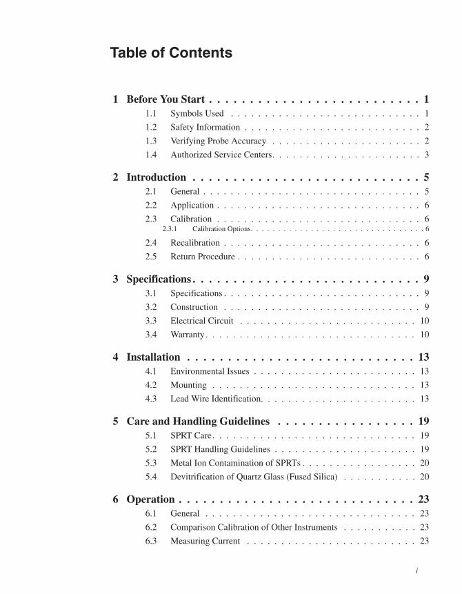
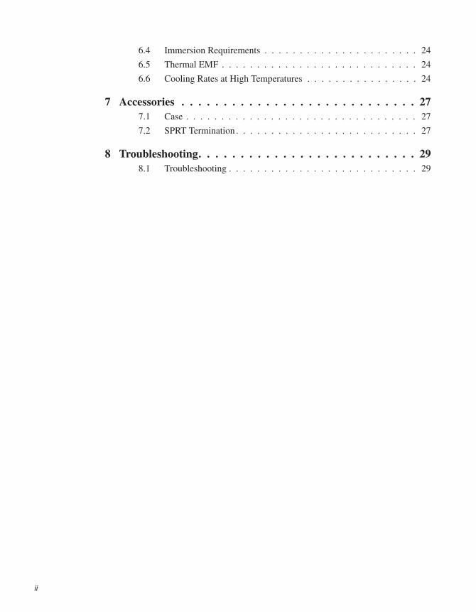
Table of Contents
1 Before You Start . . . . . . . . . . . . . . . . . . . . . . . . . . 11.1 Symbols Used . . . . . . . . . . . . . . . . . . . . . . . . . . . . 1
1.2 Safety Information . . . . . . . . . . . . . . . . . . . . . . . . . . 2
1.3 Verifying Probe Accuracy . . . . . . . . . . . . . . . . . . . . . . 2
1.4 Authorized Service Centers. . . . . . . . . . . . . . . . . . . . . . 3
2 Introduction . . . . . . . . . . . . . . . . . . . . . . . . . . . . 52.1 General . . . . . . . . . . . . . . . . . . . . . . . . . . . . . . . . 5
2.2 Application . . . . . . . . . . . . . . . . . . . . . . . . . . . . . . 6
2.3 Calibration . . . . . . . . . . . . . . . . . . . . . . . . . . . . . . 62.3.1 Calibration Options. . . . . . . . . . . . . . . . . . . . . . . . . . . . . . . . 6
2.4 Recalibration . . . . . . . . . . . . . . . . . . . . . . . . . . . . . 6
2.5 Return Procedure . . . . . . . . . . . . . . . . . . . . . . . . . . . 6
3 Specifications . . . . . . . . . . . . . . . . . . . . . . . . . . . . 93.1 Specifications . . . . . . . . . . . . . . . . . . . . . . . . . . . . . 9
3.2 Construction . . . . . . . . . . . . . . . . . . . . . . . . . . . . . 9
3.3 Electrical Circuit . . . . . . . . . . . . . . . . . . . . . . . . . . 10
3.4 Warranty . . . . . . . . . . . . . . . . . . . . . . . . . . . . . . . 10
4 Installation . . . . . . . . . . . . . . . . . . . . . . . . . . . . 134.1 Environmental Issues . . . . . . . . . . . . . . . . . . . . . . . . 13
4.2 Mounting . . . . . . . . . . . . . . . . . . . . . . . . . . . . . . 13
4.3 Lead Wire Identification. . . . . . . . . . . . . . . . . . . . . . . 13
5 Care and Handling Guidelines . . . . . . . . . . . . . . . . . 195.1 SPRT Care. . . . . . . . . . . . . . . . . . . . . . . . . . . . . . 19
5.2 SPRT Handling Guidelines . . . . . . . . . . . . . . . . . . . . . 19
5.3 Metal Ion Contamination of SPRTs . . . . . . . . . . . . . . . . . 20
5.4 Devitrification of Quartz Glass (Fused Silica) . . . . . . . . . . . 20
6 Operation . . . . . . . . . . . . . . . . . . . . . . . . . . . . . 236.1 General . . . . . . . . . . . . . . . . . . . . . . . . . . . . . . . 23
6.2 Comparison Calibration of Other Instruments . . . . . . . . . . . 23
6.3 Measuring Current . . . . . . . . . . . . . . . . . . . . . . . . . 23
i
6.4 Immersion Requirements . . . . . . . . . . . . . . . . . . . . . . 24
6.5 Thermal EMF . . . . . . . . . . . . . . . . . . . . . . . . . . . . 24
6.6 Cooling Rates at High Temperatures . . . . . . . . . . . . . . . . 24
7 Accessories . . . . . . . . . . . . . . . . . . . . . . . . . . . . 277.1 Case . . . . . . . . . . . . . . . . . . . . . . . . . . . . . . . . . 27
7.2 SPRT Termination . . . . . . . . . . . . . . . . . . . . . . . . . . 27
8 Troubleshooting. . . . . . . . . . . . . . . . . . . . . . . . . . 298.1 Troubleshooting . . . . . . . . . . . . . . . . . . . . . . . . . . . 29
ii

1 Before You Start
1.1 Symbols UsedTable 1 lists the International Electrical Symbols. Some or all of these symbolsmay be used on the instrument or in this manual.
1
1 Before You StartSymbols Used
Symbol Description
AC
AC-DC
Battery
CE
DC
Double Insulated
Electric Shock
Fuse
PE Ground
Hot Surface
Read the User’s Manual
Off
On
Table 1 International Electrical Symbols
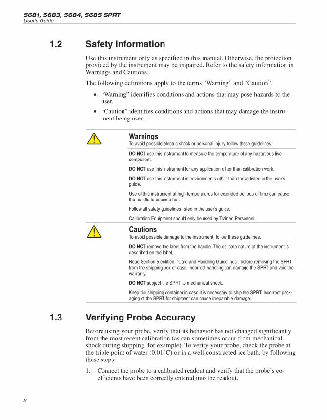
1.2 Safety InformationUse this instrument only as specified in this manual. Otherwise, the protectionprovided by the instrument may be impaired. Refer to the safety information inWarnings and Cautions.
The following definitions apply to the terms “Warning” and “Caution”.
• “Warning” identifies conditions and actions that may pose hazards to theuser.
• “Caution” identifies conditions and actions that may damage the instru-ment being used.
WarningsTo avoid possible electric shock or personal injury, follow these guidelines.
DO NOT use this instrument to measure the temperature of any hazardous livecomponent.
DO NOT use this instrument for any application other than calibration work.
DO NOT use this instrument in environments other than those listed in the user’sguide.
Use of this instrument at high temperatures for extended periods of time can causethe handle to become hot.
Follow all safety guidelines listed in the user’s guide.
Calibration Equipment should only be used by Trained Personnel.
CautionsTo avoid possible damage to the instrument, follow these guidelines.
DO NOT remove the label from the handle. The delicate nature of the instrument isdescribed on the label.
Read Section 5 entitled, “Care and Handling Guidelines”, before removing the SPRTfrom the shipping box or case. Incorrect handling can damage the SPRT and void thewarranty.
DO NOT subject the SPRT to mechanical shock.
Keep the shipping container in case it is necessary to ship the SPRT. Incorrect pack-aging of the SPRT for shipment can cause irreparable damage.
1.3 Verifying Probe AccuracyBefore using your probe, verify that its behavior has not changed significantlyfrom the most recent calibration (as can sometimes occur from mechanicalshock during shipping, for example). To verify your probe, check the probe atthe triple point of water (0.01°C) or in a well-constructed ice bath, by followingthese steps:
1. Connect the probe to a calibrated readout and verify that the probe’s co-efficients have been correctly entered into the readout.
5681, 5683, 5684, 5685 SPRTUser’s Guide
2

2. Properly prepare a triple point of water cell (TPW) or ice bath. (ContactHart Customer Service if unsure how to do this.) A triple of water cell ispreferred. Ice baths should use distilled water and crushed ice in a Dewarflask or thermos bottle. The ratio of ice-to-water should be such that themixture is firm after prepared.
3. Set your readout to read in ohms rather than temperature. Place yourprobe in the TPW or ice bath and allow it to stabilize. (Remember aTPW is at 0.01°C and an ice bath is at 0°C.)
4. If using a TPW cell, compare the resistance value on your readout withthe resistance value at TPW given on the probe’s certificate. If using anice bath, compare the resistance value on your readout with the resis-tance indicated on the certificate for 0°C. (You may have to use theprobe’s temperature versus resistance table and interpolate to get theprobe’s calibrated resistance value at 0°C.)
5. Considering the probe’s uncertainty specification, determine whether ornot it is within tolerance of the data on its most recent certificate of cali-bration. If it is, it may be placed in service. If not, double-check theprobe coefficients in the readout. If they are correct, contact Hart Cus-tomer Service.
Hart recommends that a probe be periodically checked against a standard suchas a triple point of water cell (or well-constructed ice bath if an ITS-90fixed-point standard is not available). The verification interval depends on howthe probe is handled, how and how much it is used, and your documented expe-rience with it. Your probe should also be checked any time you suspect it mayhave received mechanical shock or whenever its accuracy appears suspect.
1.4 Authorized Service CentersPlease contact one of the following authorized Service Centers to coordinateservice on your Hart product:
Fluke Corporation, Hart Scientific Division799 E. Utah Valley Drive
American Fork, UT 84003-9775
USA
Phone: +1.801.763.1600
Telefax: +1.801.763.1010
E-mail: [email protected]
Fluke Nederland B.V.Customer Support Services
Science Park Eindhoven 5108
3
1 Before You StartAuthorized Service Centers

5692 EC Son
NETHERLANDS
Phone: +31-402-675300
Telefax: +31-402-675321
E-mail: [email protected]
Fluke Int'l CorporationService Center - Instrimpex
Room 2301 Sciteck Tower
22 Jianguomenwai Dajie
Chao Yang District
Beijing 100004, PRC
CHINA
Phone: +86-10-6-512-3436
Telefax: +86-10-6-512-3437
E-mail: [email protected]
Fluke South East Asia Pte Ltd.Fluke ASEAN Regional Office
Service Center
60 Alexandra Terrace #03-16
The Comtech (Lobby D)
118502
SINGAPORE
Phone: +65 6799-5588
Telefax: +65 6799-5588
E-mail: [email protected]
When contacting these Service Centers for support, please have the followinginformation available:
• Model Number
• Serial Number
• Complete description of the problem
5681, 5683, 5684, 5685 SPRTUser’s Guide
4

2 Introduction
2.1 GeneralThe Hart Standard Platinum Resistance Thermometer (SPRT) is designed to bethe best primary standard interpolating instrument converting temperature to re-sistance. Hart Scientific offers four models of SPRT probes (5681, 5683, 5684,and 5685). The Model 5681 fused silica sheathed SPRT covers the Interna-tional Temperature Scale of 1990 (ITS-90) range from the Triple Point of Ar-gon (-189°C) to the Freezing Point of Aluminum (660.323°C). The Model5683 fused silica sheathed SPRT covers the ITS-90 range from the Triple Pointof Argon (-189°C) to 450°C. The limited temperature range of the Model 5683allows for unbeatable long-term stability typically less than 0.5mK after 100hours at 450°C. The Models 5684 and 5685 cover high temperature ranges upto 1070°C and can be calibrated at the Freezing Point of Silver (961.78°C).
All four SPRTs are hand constructed at Hart by experts with years of SPRTmanufacturing experience. Each SPRT is carefully annealed at the appropriatetemperatures and precisely tested for stability. Convection prevention discs areused to reduce stem errors caused by thermal radiation. For Models 5681,5683, and 5685 the sensing elements are fabricated using high purity platinumwire wound in a strain free design on a fused silica cross frame. For Model5684, the sensing element is formed from high-purity platinum wire wound bi-
5
2 IntroductionGeneral
Figure 1 Model 5681 Standard Platinum Resistance Thermometer
filarly around a fused silica support. The fused silica sheaths are pressuresealed with a special argon/oxygen mixed gas and fit with a terminal box han-dle with a strain relieved connection to the four wire cable. Gold plated spadelugs terminate the wires.
2.2 ApplicationHart 5680 series thermometers are classified as primary standards. A primarystandard is defined in terms of transfer of the ITS-90 from a standards labora-tory to a customer’s laboratory. Primary standards are calibrated in a standardslab using known intrinsic values. The SPRTs are designed to meet the NationalVoluntary Laboratory Accreditation’s (NVLAP) Level I Accuracy Class.
2.3 CalibrationIn order for any instrument to be used as a standard it must be calibrated. TheSPRTs may be purchased calibrated or non-calibrated. Hart Scientific’s Na-tional Voluntary Laboratory Accreditation Program (NVLAP) has the capabil-ity of performing fixed point of comparison calibrations traceable to NIST. The5681 can be economically calibrated using the comparison method or any oneof several fixed point calibrations matching ITS-90 subranges. Fixed point cali-bration is recommended for the 5683, 5684, and 5685.
2.3.1 Calibration OptionsIn order for the thermometers to make accurate temperature measurements,they must be calibrated. Calibration can be attained through any recognized pri-mary standard laboratory designed to perform temperature calibrations. HartScientific can provide either comparison calibration or fixed-point calibrationsas shown in Table 2.
2.4 RecalibrationThe recalibration of the SPRTs should be scheduled according to the user’scompany Quality Assurance requirements. Normally, an SPRT is recalibratedannually. Unless the SPRT is used only over a limited range, calibration overthe full range of the SPRT (–189°C to 661°C for the 5681, –189°C to 480°Cfor the 5683, and 0°C to 962°C for the 5684 and 5685) is recommended. Forinformation on recalibrating your SPRT, contact Hart Scientific’s CustomerService department for an RMA number and current pricing (see Section 1,Before You Start).
2.5 Return ProcedureNote: Call Hart Scientific’s Customer Service or visit our support page on theworld wide web for an RMA number before shipping.
5681, 5683, 5684, 5685 SPRTUser’s Guide
6
7
2 IntroductionReturn Procedure
SPRT Calibration by ITS-90 Fixed Point
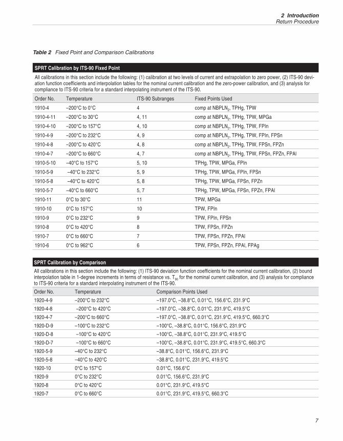
All calibrations in this section include the following: (1) calibration at two levels of current and extrapolation to zero power, (2) ITS-90 devi-ation function coefficients and interpolation tables for the nominal current calibration and the zero-power calibration, and (3) analysis forcompliance to ITS-90 criteria for a standard interpolating instrument of the ITS-90.
Order No. Temperature ITS-90 Subranges Fixed Points Used
1910-4 –200°C to 0°C 4 comp at NBPLN2, TPHg, TPW
1910-4-11 –200°C to 30°C 4, 11 comp at NBPLN2, TPHg, TPW, MPGa
1910-4-10 –200°C to 157°C 4, 10 comp at NBPLN2, TPHg, TPW, FPIn
1910-4-9 –200°C to 232°C 4, 9 comp at NBPLN2, TPHg, TPW, FPIn, FPSn
1910-4-8 –200°C to 420°C 4, 8 comp at NBPLN2, TPHg, TPW, FPSn, FPZn
1910-4-7 –200°C to 660°C 4, 7 comp at NBPLN2, TPHg, TPW, FPSn, FPZn, FPAl
1910-5-10 –40°C to 157°C 5, 10 TPHg, TPW, MPGa, FPIn
1910-5-9 –40°C to 232°C 5, 9 TPHg, TPW, MPGa, FPIn, FPSn
1910-5-8 –40°C to 420°C 5, 8 TPHg, TPW, MPGa, FPSn, FPZn
1910-5-7 –40°C to 660°C 5, 7 TPHg, TPW, MPGa, FPSn, FPZn, FPAl
1910-11 0°C to 30°C 11 TPW, MPGa
1910-10 0°C to 157°C 10 TPW, FPIn
1910-9 0°C to 232°C 9 TPW, FPIn, FPSn
1910-8 0°C to 420°C 8 TPW, FPSn, FPZn
1910-7 0°C to 660°C 7 TPW, FPSn, FPZn, FPAl
1910-6 0°C to 962°C 6 TPW, FPSn, FPZn, FPAl, FPAg
SPRT Calibration by Comparison
All calibrations in this section include the following: (1) ITS-90 deviation function coefficients for the nominal current calibration, (2) boundinterpolation table in 1-degree increments in terms of resistance vs. T90 for the nominal current calibration, and (3) analysis for complianceto ITS-90 criteria for a standard interpolating instrument of the ITS-90.
Order No. Temperature Comparison Points Used
1920-4-9 –200°C to 232°C –197.0°C, –38.8°C, 0.01°C, 156.6°C, 231.9°C
1920-4-8 –200°C to 420°C –197.0°C, –38.8°C, 0.01°C, 231.9°C, 419.5°C
1920-4-7 –200°C to 660°C –197.0°C, –38.8°C, 0.01°C, 231.9°C, 419.5°C, 660.3°C
1920-D-9 –100°C to 232°C –100°C, –38.8°C, 0.01°C, 156.6°C, 231.9°C
1920-D-8 –100°C to 420°C –100°C, –38.8°C, 0.01°C, 231.9°C, 419.5°C
1920-D-7 –100°C to 660°C –100°C, –38.8°C, 0.01°C, 231.9°C, 419.5°C, 660.3°C
1920-5-9 –40°C to 232°C –38.8°C, 0.01°C, 156.6°C, 231.9°C
1920-5-8 –40°C to 420°C –38.8°C, 0.01°C, 231.9°C, 419.5°C
1920-10 0°C to 157°C 0.01°C, 156.6°C
1920-9 0°C to 232°C 0.01°C, 156.6°C, 231.9°C
1920-8 0°C to 420°C 0.01°C, 231.9°C, 419.5°C
1920-7 0°C to 660°C 0.01°C, 231.9°C, 419.5°C, 660.3°C
Table 2 Fixed Point and Comparison Calibrations

Extreme care must be taken in shipping an SPRT. Place the thermometer in thefactory provided protective storage case. Be sure the case is latched securely.Place the protective case in the original manufacturer’s wooden shipping crateor wooden crate with similar dimensions (44 ½ in. x 11 3/4 in. x 11 3/4 in.).Place soft insulation on all sides of the crate to cushion the SPRT against me-chanical shocks. The cover of the crate should be attached with screws. We rec-ommend that you label the crate as extremely fragile. Whether the thermometeris returned for repair or warranty, please include a letter containing the follow-ing information
• Description of the faulty operation and circumstances of failure.
• Complete shipping instructions for the return of the thermometer to thecustomer.
5681, 5683, 5684, 5685 SPRTUser’s Guide
8

3 Specifications
3.1 Specifications
5681 5683 5684 5685
Measuring TemperatureRange
–200°C to 661°C –200°C to 480°C 0°C to 1070°C† 0°C to 1070°C†
Nominal RTPW 25.5Ω 0.25Ω 2.5Ω
Specified Current 1 mA 14.14 mA 5 mA
Resistance Ratio W(302.9146 K) ≥ 1.11807 andW(234.3156 K) ≤ 0.844235
W(302.9146 K) ≥ 1.11807 andW(1234.93 K) ≥ 4.2844
Sensitivity 0.1Ω/°C 0.001Ω/°C 0.01Ω/°C
Drift Rate < 0.002°C/100 hours at661°C
(typically < 0.001°C)
< 0.001°C/100 hours at480°C (0.0005°C typical)
< 0.003°C/100 hours at 1070°C(typically < 0.001°C)
Sensor Support Quartz glass cross Quartz glass strip withnotches
Quartz glass cross
Diameter of Sensor Pt Wire 0.003" (0.07 mm) 0.016" (0.4 mm) 0.008" (0.2 mm)
Protective Sheath Quartz glassDiameter: 0.28" (7 mm)Length: 20.5" (520 mm)
Quartz glassDiameter: 0.28" (7 mm)Length: 26.8" (680 mm)
†The official maximum temperature of an SPRT as a defining interpolation instrument of the ITS-90 is 961.78°C, but these types of SPRTswere found to be stable up to at least 1070°C. The annealing temperature during the stability test was 1085°C. The lower temperature limitof these types of SPRTs can be as low as –200°C. In general, it is suggested that a 25-ohm SPRT be used below 0°C.
3.2 ConstructionConstruction of the 5681, 5683, 5684, and 5685 SPRT is shown in Figure 2 andexplained below.
Model 5681 covers the range from –189°C to 661°C. The 25.5Ω sensor ele-ment is crafted using high purity platinum wire wound in a strain free design ona fused silica cross frame. The 5681 has a sensitivity of 0.1Ω/°C.
Model 5683 covers the range from –189°C to 480°C. The 25.5Ω sensor ele-ment is crafted using high purity platinum wire wound in a strain free design ona fused silica cross frame. The Model 5683 has a sensitivity of 0.1Ω/°C. TheModel 5683 is different from the Model 5681 in the filling gas and manufactureprocedure. The drift rate of the Model 5683 can be decreased to about half ofthat of the Model 5861.
Model 5684 covers the range from 0°C to 1070°C. The 0.25Ω High Tempera-ture Platinum Resistance Thermometer (HTPRT) sensor uses a high purity plat-
9
3 SpecificationsSpecifications
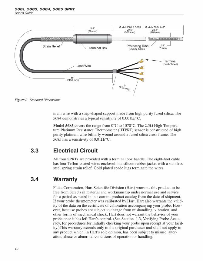
inum wire with a strip-shaped support made from high purity fused silica. The5684 demonstrates a typical sensitivity of 0.001Ω/°C.
Model 5685 covers the range from 0°C to 1070°C. The 2.5Ω High Tempera-ture Platinum Resistance Thermometer (HTPRT) sensor is constructed of highpurity platinum wire bifilarly wound around a fused silica cross frame. The5685 has a sensitivity of 0.01Ω/°C.
3.3 Electrical CircuitAll four SPRTs are provided with a terminal box handle. The eight-foot cablehas four Teflon_coated wires enclosed in a silicon rubber jacket with a stainlesssteel spring strain relief. Gold plated spade lugs terminate the wires.
3.4 WarrantyFluke Corporation, Hart Scientific Division (Hart) warrants this product to befree from defects in material and workmanship under normal use and servicefor a period as stated in our current product catalog from the date of shipment.If your probe thermometer was calibrated by Hart, Hart also warrants the valid-ity of the data on the certificate of calibration accompanying your probe. How-ever, because probes are subject to change from mishandling, vibration, andother forms of mechanical shock, Hart does not warrant the behavior of yourprobe once it has left Hart’s control. (See Section 1.3, Verifying Probe Accu-racy, for procedures for initially checking your probe upon receipt at your facil-ity.)This warranty extends only to the original purchaser and shall not apply toany product which, in Hart’s sole opinion, has been subject to misuse, alter-ation, abuse or abnormal conditions of operation or handling.
5681, 5683, 5684, 5685 SPRTUser’s Guide
10
Figure 2 Standard Dimensions

Software is warranted to operate in accordance with its programmed instruc-tions on appropriate Hart products. It is not warranted to be error free.
Hart’s obligation under this warranty is limited to repair or replacement of aproduct which is returned to Hart within the warranty period and is determined,upon examination by Hart, to be defective. If Hart determines that the defect ormalfunction has been caused by misuse, alteration, abuse or abnormal condi-tions or operation or handling, Hart will repair the product and bill the pur-chaser for the reasonable cost of repair.
To exercise this warranty, the purchaser must forward the product after callingor writing an Authorized Service Center for authorization. Service Centers as-sume NO risk for in-transit damage.
For service or assistance, please contact and Authorized Service Center
THE FOREGOING WARRANTY IS PURCHASER’S SOLE AND EXCLU-SIVE REMEDY AND IS IN LIEU OF ALL OTHER WARRANTIES, EX-PRESS OR IMPLIED, INCLUDING BUT NOT LIMITED TO ANYIMPLIED WARRANTY OR MERCHANTABILITY, OR FITNESS FOR ANYPARTICULAR PURPOSE OR USE. HART SHALL NOT BE LIABLE FORANY SPECIAL, INDIRECT, INCIDENTAL, OR CONSEQUENTIAL DAM-AGES OR LOSS WHETHER IN CONTRACT, TORT, OR OTHERWISE.
11
3 SpecificationsWarranty
4 Installation
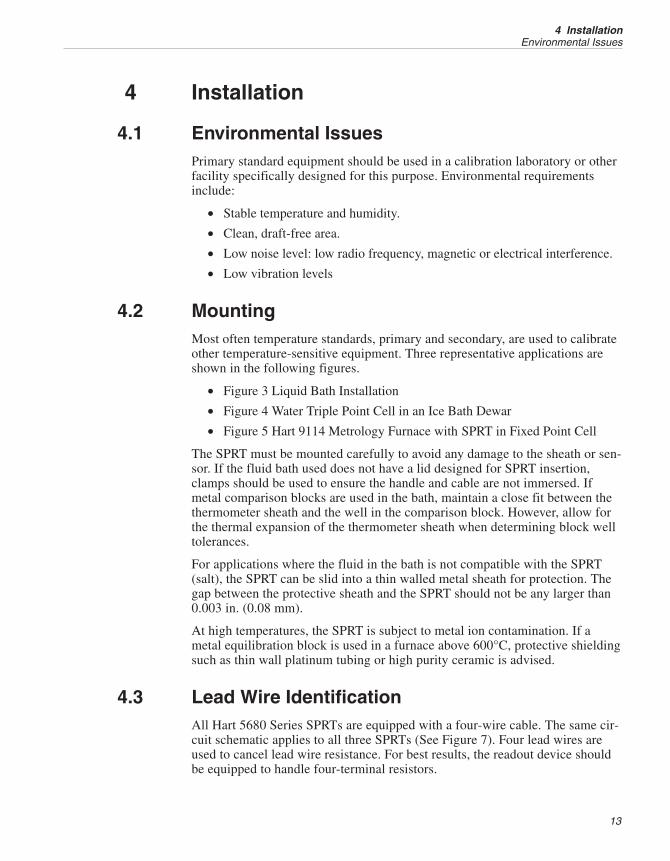
4.1 Environmental IssuesPrimary standard equipment should be used in a calibration laboratory or otherfacility specifically designed for this purpose. Environmental requirementsinclude:
• Stable temperature and humidity.
• Clean, draft-free area.
• Low noise level: low radio frequency, magnetic or electrical interference.
• Low vibration levels
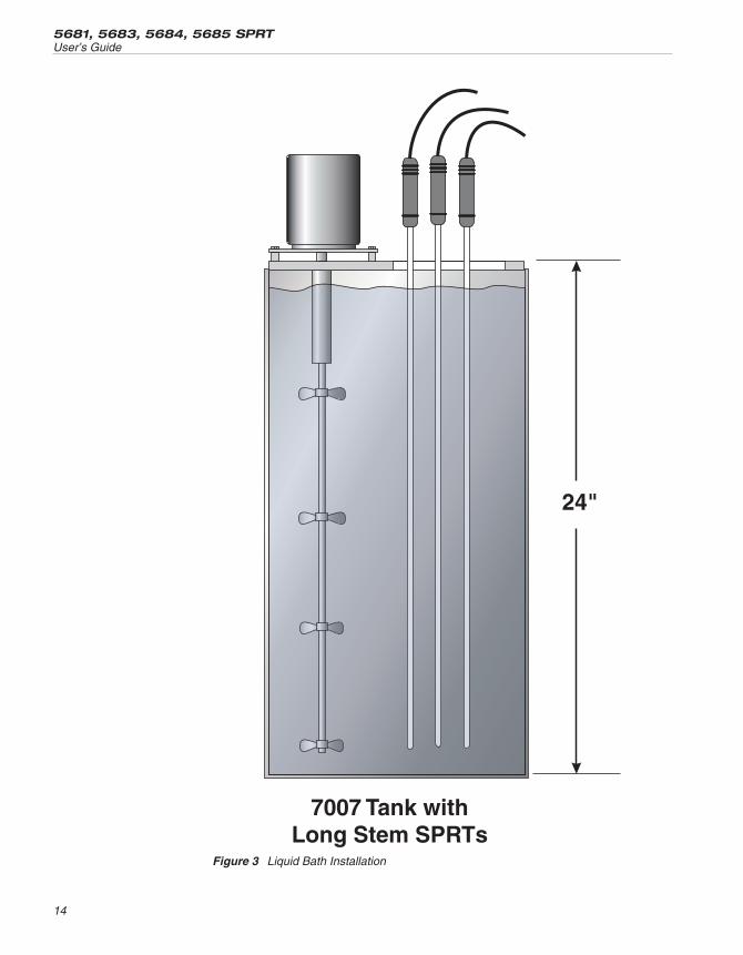
4.2 MountingMost often temperature standards, primary and secondary, are used to calibrateother temperature-sensitive equipment. Three representative applications areshown in the following figures.
• Figure 3 Liquid Bath Installation
• Figure 4 Water Triple Point Cell in an Ice Bath Dewar
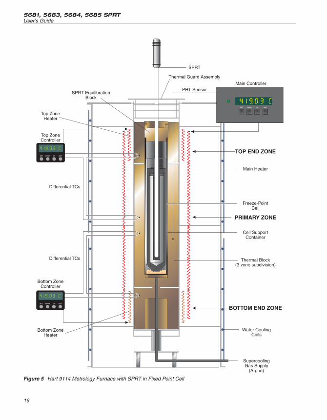
• Figure 5 Hart 9114 Metrology Furnace with SPRT in Fixed Point Cell
The SPRT must be mounted carefully to avoid any damage to the sheath or sen-sor. If the fluid bath used does not have a lid designed for SPRT insertion,clamps should be used to ensure the handle and cable are not immersed. Ifmetal comparison blocks are used in the bath, maintain a close fit between thethermometer sheath and the well in the comparison block. However, allow forthe thermal expansion of the thermometer sheath when determining block welltolerances.
For applications where the fluid in the bath is not compatible with the SPRT(salt), the SPRT can be slid into a thin walled metal sheath for protection. Thegap between the protective sheath and the SPRT should not be any larger than0.003 in. (0.08 mm).
At high temperatures, the SPRT is subject to metal ion contamination. If ametal equilibration block is used in a furnace above 600°C, protective shieldingsuch as thin wall platinum tubing or high purity ceramic is advised.
4.3 Lead Wire IdentificationAll Hart 5680 Series SPRTs are equipped with a four-wire cable. The same cir-cuit schematic applies to all three SPRTs (See Figure 7). Four lead wires areused to cancel lead wire resistance. For best results, the readout device shouldbe equipped to handle four-terminal resistors.
13
4 InstallationEnvironmental Issues
5681, 5683, 5684, 5685 SPRTUser’s Guide
14
Figure 3 Liquid Bath Installation

15
4 InstallationLead Wire Identification
Figure 4 Water Triple Point Cell in an Ice Bath Dewar
5681, 5683, 5684, 5685 SPRTUser’s Guide
16
Figure 5 Hart 9114 Metrology Furnace with SPRT in Fixed Point Cell

The lead wire colors are red, black, white, and blue. Lead wire pairs attached toeach end of the sensor are identified by heat shrink tubing. Red and black wireshave red heat shrink tubing. Blue and white wires have black heat shrink tub-ing. (See Figure 6 for details).
17
4 InstallationLead Wire Identification
Figure 6 SPRT Circuit Schematic

5 Care and Handling Guidelines
Caution: Read before removing the SPRT from the case.
5.1 SPRT CareThe 5680 series Standard Platinum Resistance Thermometers (SPRTs) are ex-tremely delicate instruments. Great care must be taken in handling the SPRTsto maintain calibration accuracy. Vibration or shock may cause the resistance toincrease. A slight tap to the SPRT tip as it is removed from an instrument cancause a change in Rtp as high as 1 mK. At high temperatures, the SPRT may be-come contaminated if inserted into metal blocks. This contamination can effectthe accuracy of the sensor if the contamination invades the sensor changing thepurity of the platinum wire. The fused silica sheath is very fragile and suscepti-ble to contamination. Once a SPRT is contaminated, it can contaminate otherstandards equipment. (Copper contamination shows as red smudged on thesheath.) Any contamination can cause devitrification of the sheath at high tem-peratures. The fused silica sheath should not be handled with bare hands. Cot-ton gloves or other suitable methods should be used in handling the SPRT. Thesheath should always be wiped down with 200 proof Ethyl Alcohol or othersuitable solvent before exposure to high temperatures. Correct handling ofthe SPRT will prolong the life expectancy. When not in use, the SPRT shouldbe stored in the protective case provided by Hart.
5.2 SPRT Handling Guidelines1. DO keep the thermometer as clean as possible. Always remove any fluidfrom the sheath immediately after taking the thermometer from a bath. To re-move any possible contaminants, always wipe the sheath with ethyl alcohol orother solvent before submitting the SPRT to high temperatures.
2. DO immerse the thermometer in the appropriate liquid for the temperaturerange. If a dry block is used, the well diameter should allow the SPRT to com-fortably slip in and out without excess movement. For best results, immerse thethermometer as deep as possible to avoid “stem effect” (the temperature errorcaused by the conduction of heat away from the sensor). Do not submerge thehandles.
3. DO allow sufficient time for the thermometer to stabilize before makingmeasurements. This allows for the best accuracy.
4. DO use the correct drive current with the thermometer to prevent error intemperature or resistance.
5. DO anneal the thermometer at a temperature slightly higher than the maxi-mum temperature at which the thermometer will be used when it has been sub-jected to mechanical or temperature shock. The SPRT should also be annealed
19
5 Care and Handling GuidelinesSPRT Care
before calibration. If the thermometer is annealed in a furnace above 660°C, thefurnace should be base metal free.
6. DO use the protective case provided or other protection when the thermome-ter is not in use.
7. DON’T subject the thermometer to any physical shock or vibration.
8. DON’T subject the thermometer to temperatures above the highest specifiedoperating temperature.
9. DON’T expose the thermometer’s handle or cables to extreme temperatures.
10. DON’T submerge the handle or cable in liquids.
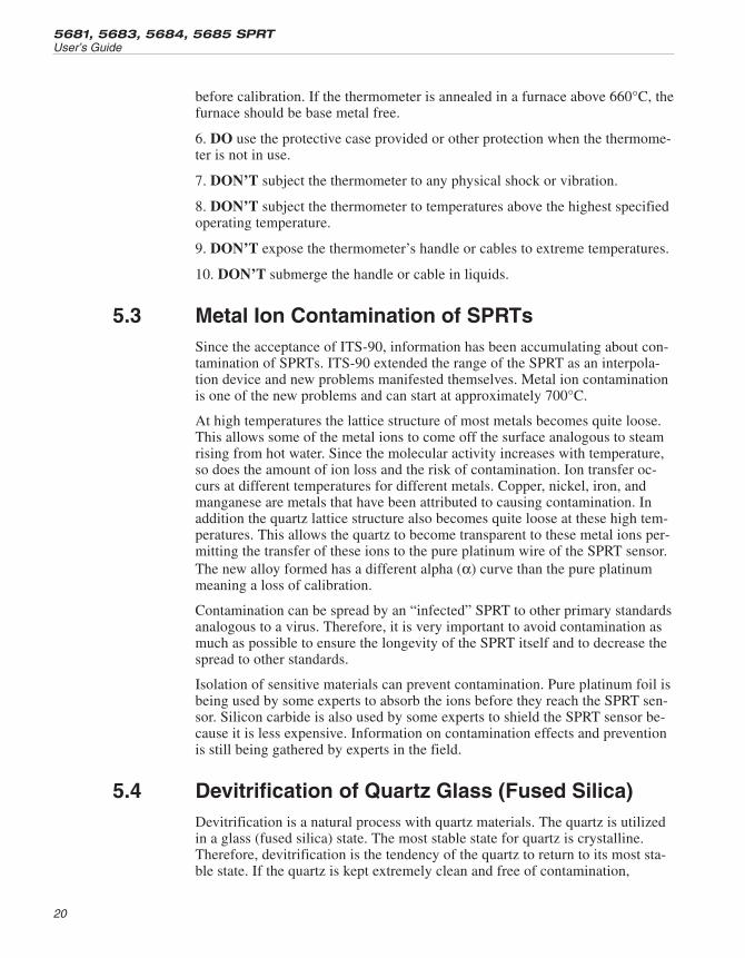
5.3 Metal Ion Contamination of SPRTsSince the acceptance of ITS-90, information has been accumulating about con-tamination of SPRTs. ITS-90 extended the range of the SPRT as an interpola-tion device and new problems manifested themselves. Metal ion contaminationis one of the new problems and can start at approximately 700°C.
At high temperatures the lattice structure of most metals becomes quite loose.This allows some of the metal ions to come off the surface analogous to steamrising from hot water. Since the molecular activity increases with temperature,so does the amount of ion loss and the risk of contamination. Ion transfer oc-curs at different temperatures for different metals. Copper, nickel, iron, andmanganese are metals that have been attributed to causing contamination. Inaddition the quartz lattice structure also becomes quite loose at these high tem-peratures. This allows the quartz to become transparent to these metal ions per-mitting the transfer of these ions to the pure platinum wire of the SPRT sensor.The new alloy formed has a different alpha (α) curve than the pure platinummeaning a loss of calibration.
Contamination can be spread by an “infected” SPRT to other primary standardsanalogous to a virus. Therefore, it is very important to avoid contamination asmuch as possible to ensure the longevity of the SPRT itself and to decrease thespread to other standards.
Isolation of sensitive materials can prevent contamination. Pure platinum foil isbeing used by some experts to absorb the ions before they reach the SPRT sen-sor. Silicon carbide is also used by some experts to shield the SPRT sensor be-cause it is less expensive. Information on contamination effects and preventionis still being gathered by experts in the field.
5.4 Devitrification of Quartz Glass (Fused Silica)Devitrification is a natural process with quartz materials. The quartz is utilizedin a glass (fused silica) state. The most stable state for quartz is crystalline.Therefore, devitrification is the tendency of the quartz to return to its most sta-ble state. If the quartz is kept extremely clean and free of contamination,
5681, 5683, 5684, 5685 SPRTUser’s Guide
20
devitrification will occur only at high temperatures. The process occurs morerapidly and at lower temperatures when the glass has become contaminated byalkaline metals (Na, K, Mg, and Ca). The alkalis found in normal tap water cancause the process to start. There is conflicting opinion among the experts as towhether the process can be stopped. Some say that once the process starts itdoes not stop. Others indicate that once the alkali is removed, the process willstop.
Removal of the devitrification is not practical as it requires drastic measuresand is potentially dangerous to the instrument and/or the user.
Devitrification starts with a dulling or opacity of the quartz. It develops into arough and crumbling surface. Devitrification ultimately weakens theglass/quartz until it breaks or is otherwise no longer useful.
The best cure for contamination and devitrification is prevention. Being awareof the causes and signs of contamination can help the user take the steps neces-sary to control contamination of the SPRT. Keep your SPRT clean and avoidcontact with metals at temperatures above 600°C.
21
5 Care and Handling GuidelinesDevitrification of Quartz Glass (Fused Silica)

6 Operation
6.1 GeneralFor best results, be familiar with the operation of the calibration bath or furnaceand the read-out instrument. Be sure to follow the manufacturer’s instructionsfor the read-out instrument and the calibration bath or furnace.
6.2 Comparison Calibration of Other InstrumentsThe uniformity and stability of the bath and the degree of accuracy required de-termine the number of temperature measurements necessary. However, to fol-low “good” practice procedures, always measure the triple point of water (Rtp)after each temperature measurement. This provides the most accurate measure-ment of the ratio:
WR
Rtt
tp
=
6.3 Measuring CurrentEach SPRT has a specified drive current depending upon the particular sensor.The recommended currents are listed in the specifications for each thermometerand in the following table:
Suggested Drive Currents
Model Resistance Drive Current
5681/5683 25Ω 1 mA
5684 0.25Ω 10 mA
5685 2.5Ω 3 mA
Errors caused by self-heating of the element need to be minimized. Allowingsufficient time for the SPRT to stabilize and the heat to be dispersed into thesurrounding medium will provide the most accurate results.
The Hart testing or calibration certificates provided with the SPRT representdata that has been extrapolated. For example, on Model 5681 measurements aremade at 1 mA and 1.4 mA. These measurements are then extrapolated to zerocurrent. This can be done graphically by plotting i² vs. R and extrapolating tozero power or by using the following equation:
( )R R
i R R
i i0 112
2 1
22
12
= −−
−
where:
R0 = Zero current resistance
23
6 OperationGeneral
R1 = Resistance measured at current i1
R2 = Resistance measured at current i2
6.4 Immersion RequirementsStem effect can cause measurement errors for any thermometer not immersedin the fluid at least six inches. This error is due to heat lost or gained by thesensing element through the thermometer stem. In addition, heat losses occurdue to radiation losses from the sensing element to the housing. Thesand-blasted finish on the quartz sheath is designed to depreciate losses due toradiation piping. Convection prevention discs provide multiple radiation shieldsalong the lead wires. Convection discs and quartz insulation on lead wirescauses some shunt resistance at very high temperatures. However, the effect ofthe shunt resistance is insignificant. Full immersion is recommended in a fur-nace or freeze point cell.
The immersion depth for primary standards is dependent on several factors in-cluding accuracy requirements and type of liquid. Therefore, we recommend an8 inch minimum immersion depth.
The exact immersion depth required can be determined by performing a gradi-ent test taking measurements approximately every 1/2 inch (1.27 cm) untilthere is a significant difference in readings. Allow the thermometer to stabilizeat each new depth. Plot the results to see the stem effect.
6.5 Thermal EMFTwo factors contribute to thermal EMF, chemical consistency and physical con-sistency. Variations in chemical structure due to impurities and discrepancies incrystal structure can contribute to thermal EMF. These factors are minimizedby annealing the full length of wire before construction of the SPRT.
Likewise, connection to extension lead wires and readout instruments can be asource of thermal EMF. The thermal EMF is caused by a difference in tempera-ture between two connections. If the two connections are the same temperature,there will be little or no thermal EMF effects. However, if there is a substantialtemperature difference between connections, the thermal EMF effects will besignificant. Therefore, cover or insulate any exposed bridge or galvanometerterminals to lessen the source of error. The effects of thermal EMF can be can-celed by using an AC bridge or a DC bridge with reversible current.
6.6 Cooling Rates at High TemperaturesThe equilibrium concentration of point defects in the pure platinum wire in-crease exponentially to the increase in temperature. If a high cooling rate (i.e.,removing a SPRT from a high temperature and cooling it to room temperaturein less than a minute) occurs above 500°C, some of the point defects in theplatinum wire become trapped in the crystalline structure causing a slight in-
5681, 5683, 5684, 5685 SPRTUser’s Guide
24

crease in resistance. This slight increase in resistance can be reversed by an-nealing the SPRT. To avoid this problem, slowly cool the SPRT at a rate ofroughly 150°C/hour above 500°C before removing to room temperature.
The SPRT can be safely removed from an instrument at 500°C or less andcooled to room temperature without concern for the cooling rate.
25
6 OperationCooling Rates at High Temperatures
7 Accessories
7.1 CaseThe SPRTS are shipped in a protective case. The SPRT should be stored in thiscase when not in use. The SPRT should be shipped in this case when returning(see Section 2.5, Return Procedure).
7.2 SPRT TerminationThe 5680 series SPRTs are terminated with gold plated lugs.
27
7 AccessoriesCase
8 Troubleshooting
8.1 TroubleshootingIn the event that the probe appears to function abnormally, this section mayhelp to find and solve the problem. Several possible problem conditions are de-scribed along with likely causes and solutions. If a problem arises, please readthis section carefully and attempt to understand and solve the problem. If theprobe seems faulty or the problem cannot otherwise be solved, contact HartScientific Customer Service for assistance (1-801-763-1600). Be sure to havethe model number and serial number of your probe available.
Problem Solution
Data changes Slight mechanical shock can cause temperature errors as much as 2mK.If this is observed, first measure and record the Rtp. Next anneal the SPRT at661°C (5681 only), 480°C (5683), or 975°C (5684 and 5685) overnight (12hours). Measure the Rtp again. The annealing should decrease the Rtp. Repeatthe annealing, Rtp measurement cycle several times. When the Rtp is stable,recalibrate the SPRT. If the Rtp does not stabilize, contact Hart Scientific Cus-tomer Service.
Severe mechanical shock can permanently damage the SPRT. If annealingthe SPRT does not resolve the data change, contact Hart Scientific CustomerService.
Oxidation of the platinum sensor may occur after prolonged use between200 – 450°C. Rtp will show an increase. To reduce the effects of oxidation, an-neal the SPRT at the appropriate temperature as described above. Measurethe Rtp again. Repeat the annealing, Rtp measurement cycle several times. Thisannealing process should return Rtp to within calibration tolerances. If the Rtp iswithin calibration tolerance, the SPRT is usable. If the Rtp is not within calibra-tion tolerance, but it is stable, recalibrate the SPRT.
Data unstable Connection may not be made. If the data is unstable at the Triple Point ofWater (TPW), check the connection first. If this action does not fix the problemcontact Hart Scientific Customer Service. The SPRT may be damaged andneed re-pair.
Electrical noise in the system. If the data is unstable at high temperatures, itmay be due to electrical noise in the system. Reduce the temperature and ob-serve the data. If it is stable, electrical noise is interfering with the measure-ments at high temperatures. Check the grounding of the readout device andthe heat source. A faulty ground on either device could interfere with high tem-perature measurements. A ground lead wire (the fifth wire) of the SPRT mayhelp to reduce electrical noise interference. Be sure the ground lead wire isconnected to an appropriate ground on the readout device.
29
8 TroubleshootingTroubleshooting
Problem Solution
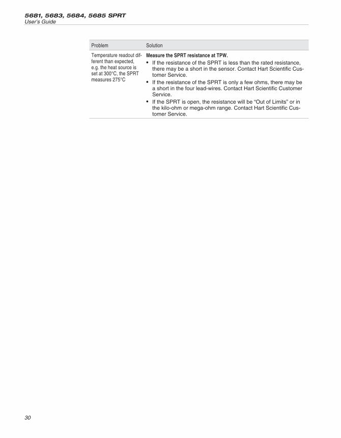
Temperature readout dif-ferent than expected,e.g. the heat source isset at 300°C, the SPRTmeasures 275°C
Measure the SPRT resistance at TPW.• If the resistance of the SPRT is less than the rated resistance,
there may be a short in the sensor. Contact Hart Scientific Cus-tomer Service.
• If the resistance of the SPRT is only a few ohms, there may bea short in the four lead-wires. Contact Hart Scientific CustomerService.
• If the SPRT is open, the resistance will be “Out of Limits” or inthe kilo-ohm or mega-ohm range. Contact Hart Scientific Cus-tomer Service.
5681, 5683, 5684, 5685 SPRTUser’s Guide
30