Embed Size (px)
Citation preview

Standard Partsfor MouldMaking
B2_Formenbau_GB_11_2008.indd 1B2_Formenbau_GB_11_2008.indd 1 08.12.2008 10:17:5108.12.2008 10:17:51

2 · 2
0818
· 20
06 ·
1 Q
B2_Formenbau_GB_11_2008.indd 2B2_Formenbau_GB_11_2008.indd 2 08.12.2008 10:18:0008.12.2008 10:18:00

Index
2 · 2
0819
· 20
06 ·
1 Q
subject to alterations 3
Your Production Partner 4-5
Guide Elements Locating units, round 8 Locating units, flat 8 Compensation Discs 9 Adjusting washers 9 Ejector rods 10 Centering sleeves 11 Guide pillars 12-13 Guide pillars, shouldered 14-17 Locating guide pillars, shouldered 18-21 Guide pillars with flange 22 Guide pillars (diagonal load pillars) 24 Guide sleeves 25 Guide bushes 26 Locating guide bushes 27 Guide bushes, Bronze with Non-Liquid Lubricant 28-32 Angled Guide Gibs, Bronze with Non-Liquid Lubricant 33 Flat Guide Bars, Bronze with Non-Liquid Lubricant 34-35 Ball bearing guides 36 Rectangular guides with rollers 37-38
General Mould Components Socket Head Cap Screws 40-42 Countersunk Head Cap Screws 43 Flat mushroom head screw 44 Setscrews 46 Collar Nuts 46-47 Washers 47 T-Head Bolts 48 Spring,- Fit- and Spacer Units 49 Shoulder Screws 50 Spring Plungers 51-55 Lifting Eyebolts 56-58 Hoisting Snap Links 59 Rotary Safety Eye Bolts 60-61 Precision Dowel Pins 62-65 FIBROZIPP 66
Forming / Demoulding Bolt Guides 68-69 Ejector Pins 70-77 Ejector Sleeves 78-79 Date insert 80-81 Quill holders for core tempering 82 O-rings 83
Gas Springs Mould Line Gas Springs 85-101
Gas Springs Accessories 104-136
Auxiliary Equipment Chemical Tooling Aids 138-139
Representatives 142-143
B2_Formenbau_GB_11_2008.indd 3B2_Formenbau_GB_11_2008.indd 3 08.12.2008 10:18:0008.12.2008 10:18:00

FIBRO - your production partner
4
0·1
7774
·200
5·2
Q
subject to alterations
Hassmersheim plant
Standard Parts
Weinsberg plant
Indexing Tables
From 1962 onwards FIBRO pioneered the design and manufacture of indexing tables and soon gained an enviable reputation.
FIBROTAKT® indexing tables with face gear and ultra-high precision indexing, together with dependable rigidity. Drive options: pneumatic, hydraulic via rack and pinion or electric with worm drive.
FIBROPLAN® NC – indexing tables with backlash adjustment worm drive or torque motor for use in machine tools for universal positioning and round and multi-axis processes (simultaneous operation).
FIBROTOR® revolving tables and indexing tables with positive drive cam, offering very short cycle times even when transporting heavy loads. Mainly used in non-machining applications. Thousands of FIBRO units are in use world-wide as integral key components in high-output machinery.
Today the Standard Parts Division operates fromthe Hassmersheim and Weinsberg works, whichmanufacture a comprehensive range of standard parts and maintain stocks ready for immediate despatch world-wide. The machine tool, mechanical engineering and systems engineering product ranges have been developed to meet the needs of customers.
They include steel die sets, guide elements, oilless guide elements and precision components such as punches and matrixes, special steel compression springs, gas springs, forming materials, metal bonding agents, moulding resins, peripheral equipment for pressing and tool making, tool slides with cam or roller slides and hydraulic cam systems.
FIBRO has become renowned world-wide for itscomprehensive range of products in stock and itsreadiness to deliver.
FIBRO – an internationally successful company.As a market leader in Standard Parts, Rotary Indexing Tables and Automation, FIBRO provides products and solutions to ensure your production keeps moving.So what is the secret of the FIBRO success? Products developed in-house, tailor-made for the market with uncompromising quality.
But good products are not enough on their own.FIBRO combines excellent products, the know-how and service competence of an internationally focused com-pany, matched to the actual needs of customers - wherever they are.
B2_Formenbau_GB_11_2008.indd 4B2_Formenbau_GB_11_2008.indd 4 08.12.2008 10:18:0008.12.2008 10:18:00

5
0·1
7775
·200
5·2
Q
subject to alterations
Automation
FIBRO has been active in the field of automation and robotics since 1974 and offers one of the most com-prehensive ranges in this field. A cleverly designed modular system based on translation units, rotary units, grippers, and guide gantries with trolleys make for easy construction of individual machines and com-plete systems, ranging from simple pick & place units right up to multi-axis robots. These series-manufac-tured modules with electric, pneumatic or hydraulic drive, guarantee both high functional reliability and cost-effective prices.
The modular gantry systems can solve virtually any transporting problem using linear gantries, surface gantries and extension gantries. These systems are being used successfully in many industries world-wide. Applications include linking machine tools (automotive production), tool changing in machining facilities, palletising work pieces, unloading injection moulding dies, PCB feeders, press linking, palletising, stacking, loading and unloading, transporting and fle-xible linking, storage and buffering of work pieces of different sizes.
Since its establishment in 1974 GSA Automation GmbH has developed to become a world market lea-der in the manufacture of handling equipment and transport systems. Over this period GSA has installed over 200 fully automated systems for all the leading automotive and machine tool manufacturers. GSA has been a member of the FIBRO group since 2004.
Our production range consists of linear and surface gantry systems, transport systems such as precision roller guides, accumulating chain conveyors, pal-let accumulating conveyors and flexible decoupling modules,shelf stacking systems and pallet mechanical handling systems.
We can provide our customers with dependable state of the art high performance systems from our stan-dard range. We take complete responsibility for the complete project, starting with designing the solution concepts at the design phase, right through to the final handover of the ready-to-go system.
Hassmersheim plant
FIBRO is customer-focused – world-wide. A well-deve-loped network of sales and service points and strategic partners ensure that help is always at hand. This ensu-res technical advance, world-wide experience in appli-cations and rapid availability of products.
Facts and figures on FIBRO:- founded 1958- approximately 900 staff- 80 representatives and service stations world-wide- branches in France, USA, India, Switzerland and Singapore- ISO 9001:2000 Quality Assurance and VDA 6.4 certification- a company in the LÄPPLE Group
B2_Formenbau_GB_11_2008.indd 5B2_Formenbau_GB_11_2008.indd 5 08.12.2008 10:18:0808.12.2008 10:18:08

subject to alterations
2 · 2
0820
· 20
06 ·
1 Q
6
B2_Formenbau_GB_11_2008.indd 6B2_Formenbau_GB_11_2008.indd 6 08.12.2008 10:18:1108.12.2008 10:18:11

2 · 2
0821
· 20
06 ·
1 Q
subject to alterations
Guide Elements
7
B2_Formenbau_GB_11_2008.indd 7B2_Formenbau_GB_11_2008.indd 7 08.12.2008 10:18:1108.12.2008 10:18:11

11
15°
d1 h6
m 1
md2
l 3l 2
s1
s1
l 1
2442.12. Locating unit, round (without
compensation disc)
Mounting Example
subject to alterations
2 · 2
0822
· 20
06 ·
1 Q
8
Locating units, round 2442.12.Locating units, flat 2442.13.
d1 d2 l1 l2 l3 m m1 s1
12 8 34 6 4 4 4 1714 10 34 7,5 6 5 5 1716 10 34 7,5 6 5 5 1720 15 54 12 9 8 8 2725 20 54 12 10 8 8 2726 20 54 12 10 8 8 2730 25 72 15 14 10 10 3632 25 72 15 14 10 10 3642 35 92 15 18 10 10 46
2442.12. Locating unit, round Description:Conical centring inserts are used to increase repeat accuracy inmould, die and machine-making.
Ordering-code (example):Locating unit, round, two-part = 2442.Conical angle = 15° = 2442.12.d1 = 25 mm = 2442.12.025.l1 = 54 mm = 2442.12.025.054Order No = 2442.12.025.054
v
l 31,5l +0,4
+0,21
1s1s0,50,5
2l2ld H8
e71
d
h61
dmm
t 0,40,4
1,6 1,
6
1,615°
2442.13. Locating unit, flat
d1 d l1 l2 l3 v s1 t m30 4 72 5 10 18 36 5 1042 5 92 6 14 23 46 7 1054 6 112 8 17 30 56 8 1280 8 152 8 27 42 76 11 16
2442.13. Locating unit, flat
Ordering-code (example):Locating unit = 2442.flat = 2442.13.d1 = 42 mm = 2442.13.042.l1 = 92 mm = 2442.13.042.092Order No = 2442.13.042.092
B2_Formenbau_GB_11_2008.indd 8B2_Formenbau_GB_11_2008.indd 8 08.12.2008 10:18:1108.12.2008 10:18:11

subject to alterations 9
2 · 2
0823
· 20
06 ·
1 Q
2442.12.3. Compensation Discs 2442.12.4. Adjusting washers
d1
d
s
1,6
1,6
d ±0,12
d -0,2-0,44
d3
h+
0,2
+0,
1
k±0
,1
2442.12.3. Compensation Discs
d1 s d d1 s d d1 s d d1 s d12 10 4,5 20 9 8,5 26 9 8,5 42 10 10,5 10 10 20 15 20 3014 5 5,5 20 30 10 30 30 10 12,5 14 40 20 19 25 9 10,5 3016 5 6,5 10 40 10 15 50 15 20 32 10 12,5 19 25 20 20 35 30 25 45 40 55 50
2442.12.3. Compensation Discs
Ordering-code (example):Locating unit, round = 2442.12.Compensation Disc = 2442.12.3.d1 = 25 mm = 2442.12.3.025.s = 10 mm = 2442.12.3.025.010Order No = 2442.12.3.025.010
2442.12.4. Adjusting washers
°
d4 d3 d2 h k14 5,5 16 5 3,220 8,5 25,5 9 6,326 8,5 31,5 9 6,330 11 35,5 10 6,342 11 47,5 10 6,3
2442.12.4. Adjusting washers
Ordering-code (example):Locating unit, round = 2442.12.Adjusting washer = 2442.12.4.d4 = 30 mm = 2442.12.4.030Order No = 2442.12.4.030
°
B2_Formenbau_GB_11_2008.indd 9B2_Formenbau_GB_11_2008.indd 9 08.12.2008 10:18:1408.12.2008 10:18:14

l 2 l 4
d2
d2g6
1d
l js12
RZ4
SW
d1 l d2 l2 l4 A/F24 120 M12 25 14 19 140 160 180 200 24030 180 M16 30 16 24 220 260 300
d1 l d2 l2 l4 A/F10 60 M 6 16 9 9 70 80 100 120 14014 60 M 8 16 11 12 70 80 100 120 140 160 18018 100 M10 20 12 14 120 140 160 180 200 220 24020 100 M12 25 14 16 120 140 160 180 200 220 240
subject to alterations10
2 · 2
0824
· 20
06 ·
1 Q
Ejector rods 3300.10.
3300.10. Ejector rods
3300.10. Ejector rods
Ordering-code (example):Ejector rod = 3300.10.d1 = 20 mm = 3300.10.020.l = 140 mm = 3300.10.020.140Order No = 3300.10.020.140
B2_Formenbau_GB_11_2008.indd 10B2_Formenbau_GB_11_2008.indd 10 08.12.2008 10:18:1608.12.2008 10:18:16

+0,
5
l2
l1
l ±0,5
k63
d
j63
d1
d
2d
RZ4
subject to alterations 11
2 · 2
0825
· 20
06 ·
1 Q
3100.04. Centering sleeves
3100.04. Centering sleeves
d3 l d2 d1 l1 l254 60 M20 43 13 4,5 80 120 160 200 240 280
d3 l d2 d1 l1 l214 20 M 6 11 8 2 30 40 50 60 70 80 10020 30 M 8 16 13 2 40 60 80 100 120 140 16026 30 M10 21 13 2,5 40 60 80 100 120 140 160 18030 40 M12 25 13 2,5 60 80 100 120 140 160 180 200 24042 40 M16 33 13 4,5 60 80 100 120 140 160 180 200 220 260 300
3100.04. Centering sleeves
Ordering-code (example):Centering sleeve = 3100.04.d3 = 26 mm = 3100.04.026.l = 30 mm = 3100.04.026.030Order No = 3100.04.026.030
B2_Formenbau_GB_11_2008.indd 11B2_Formenbau_GB_11_2008.indd 11 08.12.2008 10:18:1708.12.2008 10:18:17

l1
l
0,4x45°
k ±0,05
-0,2
4d
h41d
8°
R2
subject to alterations12
3202.12.Guide pillars 3202.13.
3202.12. Guide pillars
d1 l d4 k l112 80 16 4 4 100 12018 120 22 6 7 140 16030 160 36 6 7 200 240
3202.12. Guide pillars
Ordering-code (example):Guide pillar = 3202.13.d1 = 18 mm = 3202.13.018.l = 160 mm = 3202.13.018.160Order No = 3202.13.018.160
2 · 2
0826
· 20
06 ·
1 Q
Ordering-code (example):Guide pillar = 3202.12.d1 = 18 mm = 3202.12.018.l = 160 mm = 3202.12.018.160Order No = 3202.12.018.160
l1
l
h41d
8°
R23
8°
3202.13. Guide pillars
d1 l l112 100 3 12518 125 4 16030 160 6 240
3202.13. Guide pillars
B2_Formenbau_GB_11_2008.indd 12B2_Formenbau_GB_11_2008.indd 12 08.12.2008 10:18:1908.12.2008 10:18:19

subject to alterations 13
3111.10. Guide pillars
RZ 2,5
l
l1
l2
k ±0,2
-0,2
4d
m6
1d
g61d
3111.10. Guide pillars
2 · 2
0827
· 20
06 ·
1 Q
d1 l d4 k l1 l232 160 36 15 7 56 200 240 7640 200 48 15 10 56 240 76 300 9650 200 58 15 10 56 240 76 300 9660 240 68 20 12 76 300 96 360 116
d1 l d4 k l1 l210 40 12 3 4 17 60 80 22 100 2712 60 16 6 7 17 80 22 100 27 120 3614 60 18 8 7 17 80 22 100 27 120 36 140 46 160 16 60 20 8 7 22 80 27 100 120 36 140 46 160 18 80 22 8 7 27 100 120 36 140 46 160 180 56 200 20 80 24 8 7 27 100 120 36 140 46 160 180 56 200 22 100 26 15 7 36 120 46 140 160 56 180 200 76 220 24 100 28 15 7 36 120 46 140 160 56 180 200 76 220 30 160 36 15 7 56 200 240 76
3111.10. Guide pillars
Ordering-code (example):Guide pillar = 3111.10.d1 = 22 mm = 3111.10.022.l = 140 mm = 3111.10.022.140Order No = 3111.10.022.140
B2_Formenbau_GB_11_2008.indd 13B2_Formenbau_GB_11_2008.indd 13 08.12.2008 10:18:2108.12.2008 10:18:21

subject to alterations14
2 · 2
0828
· 20
06 ·
1 Q
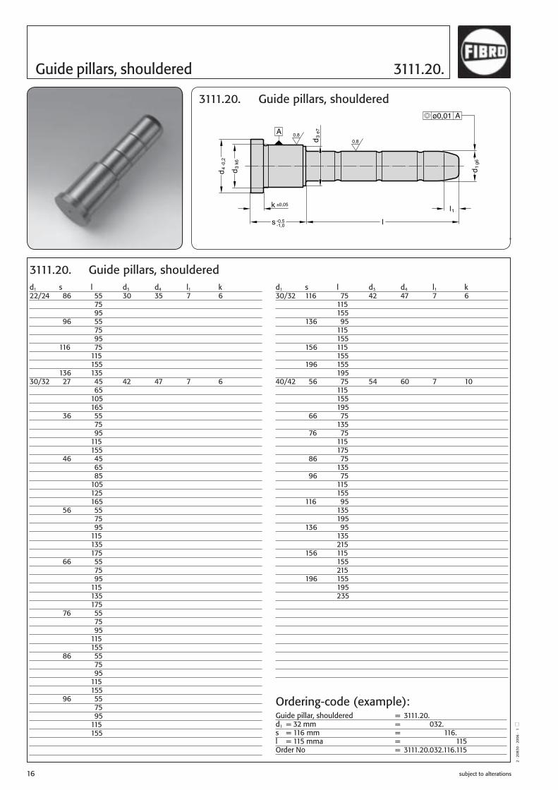
Guide pillars, shouldered 3111.20.
A 0,80,8
-0,2
4d
k63
d
e73
d
g61d
ø0,01 A
k ±0,05
s -0,5-1,0
l1
l
3111.20. Guide pillars, shouldered
d1 s l d3 d4 l1 k14/15 56 20 20 25 7 6 35 55 75 95 66 55 65 95 76 55 95 86 55 95 18/20 22 20 26 31 7 6 35 40 45 50 55 60 65 70 80 85 115 27 20 35 40 45 50 55 60 65 70 80 85 105 125
d1 s l d3 d4 l1 k9/10 12 45 14 16 4 3 17 20 30 35 22 25 35 55 27 25 30 35 50 36 25 35 45 46 30 45 55 75 14/15 22 20 20 25 7 6 35 40 45 50 55 65 70 90 110 27 20 35 40 45 55 65 85 105 36 20 35 40 45 55 65 75 95 46 20 35 45 65 85 105
3111.20. Guide pillars, shouldered
Ordering-code (example):Guide pillar, shouldered = 3111.20.d1 = 14 mm = 3111.20.014.s = 36 mm = 3111.20.014.036.l = 75 mm = 3111.20.014.036.075Order No = 3111.20.014.036.075
B2_Formenbau_GB_11_2008.indd 14B2_Formenbau_GB_11_2008.indd 14 08.12.2008 10:18:2208.12.2008 10:18:22

subject to alterations 15
2 · 2
0829
· 20
06 ·
1 Q
3111.20. Guide pillars, shouldered
A 0,80,8
-0,2
4d
k63
d
e73
d
g61d
ø0,01 A
k ±0,05
s -0,5-1,0
l1
l
3111.20. Guide pillars, shouldered
d1 s l d3 d4 l1 k22/24 36 25 30 35 7 6 45 50 55 60 70 75 80 95 115 135 165 46 25 45 50 60 65 70 80 85 105 125 165 56 25 45 55 75 95 115 165 66 55 75 95 76 25 45 55 75 95 115
d1 s l d3 d4 l1 k 18/20 36 20 26 31 7 3 35 40 45 50 55 60 65 70 75 80 95 115 135 46 20 45 65 85 105 135 165 56 20 26 31 7 6 35 55 75 95 66 55 75 95 76 55 75 95 86 55 75 95 96 55 95 116 115 22/24 27 25 30 35 7 6 45 50 60 65 70 80 85 105 125 165
3111.20. Guide pillars, shouldered
Ordering-code (example):Guide pillar, shouldered = 3111.20.d1 = 24 mm = 3111.20.024.s = 76 mm = 3111.20.024.076.l = 115 mm = 3111.20.024.076.115Order No = 3111.20.024.076.115
B2_Formenbau_GB_11_2008.indd 15B2_Formenbau_GB_11_2008.indd 15 08.12.2008 10:18:2408.12.2008 10:18:24
subject to alterations16
2 · 2
0830
· 20
06 ·
1 Q
Guide pillars, shouldered 3111.20.
A 0,80,8
-0,2
4d
k63
d
e73
d
g61d
ø0,01 A
k ±0,05
s -0,5-1,0
l1
l
3111.20. Guide pillars, shouldered
d1 s l d3 d4 l1 k30/32 116 75 42 47 7 6 115 155 136 95 115 155 156 115 155 196 155 195 40/42 56 75 54 60 7 10 115 155 195 66 75 135 76 75 115 175 86 75 135 96 75 115 155 116 95 135 195 136 95 135 215 156 115 155 215 196 155 195 235
d1 s l d3 d4 l1 k22/24 86 55 30 35 7 6 75 95 96 55 75 95 116 75 115 155 136 135 30/32 27 45 42 47 7 6 65 105 165 36 55 75 95 115 155 46 45 65 85 105 125 165 56 55 75 95 115 135 175 66 55 75 95 115 135 175 76 55 75 95 115 155 86 55 75 95 115 155 96 55 75 95 115 155
3111.20. Guide pillars, shouldered
Ordering-code (example):Guide pillar, shouldered = 3111.20.d1 = 32 mm = 3111.20.032.s = 116 mm = 3111.20.032.116.l = 115 mma = 3111.20.032.116.115Order No = 3111.20.032.116.115
B2_Formenbau_GB_11_2008.indd 16B2_Formenbau_GB_11_2008.indd 16 08.12.2008 10:18:2508.12.2008 10:18:25
subject to alterations 17
2 · 2
0831
· 20
06 ·
1 Q
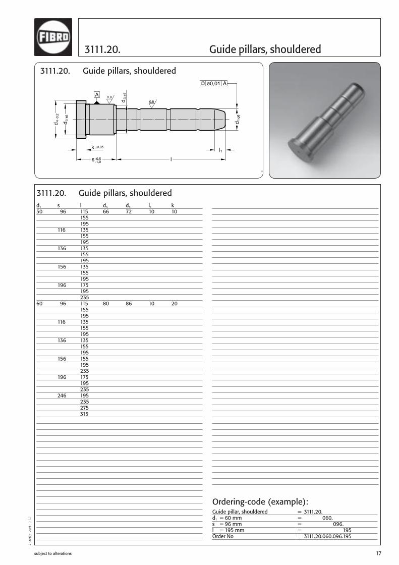
3111.20. Guide pillars, shouldered
A 0,80,8
-0,2
4d
k63
d
e73
d
g61d
ø0,01 A
k ±0,05
s -0,5-1,0
l1
l
3111.20. Guide pillars, shouldered
d1 s l d3 d4 l1 k 50 96 115 66 72 10 10 155 195 116 135 155 195 136 135 155 195 156 135 155 195 196 175 195 235 60 96 115 80 86 10 20 155 195 116 135 155 195 136 135 155 195 156 155 195 235 196 175 195 235 246 195 235 275 315
3111.20. Guide pillars, shouldered
Ordering-code (example):Guide pillar, shouldered = 3111.20.d1 = 60 mm = 3111.20.060.s = 96 mm = 3111.20.060.096.l = 195 mm = 3111.20.060.096.195Order No = 3111.20.060.096.195
B2_Formenbau_GB_11_2008.indd 17B2_Formenbau_GB_11_2008.indd 17 08.12.2008 10:18:2508.12.2008 10:18:25

subject to alterations18
2 · 2
0832
· 20
06 ·
1 Q
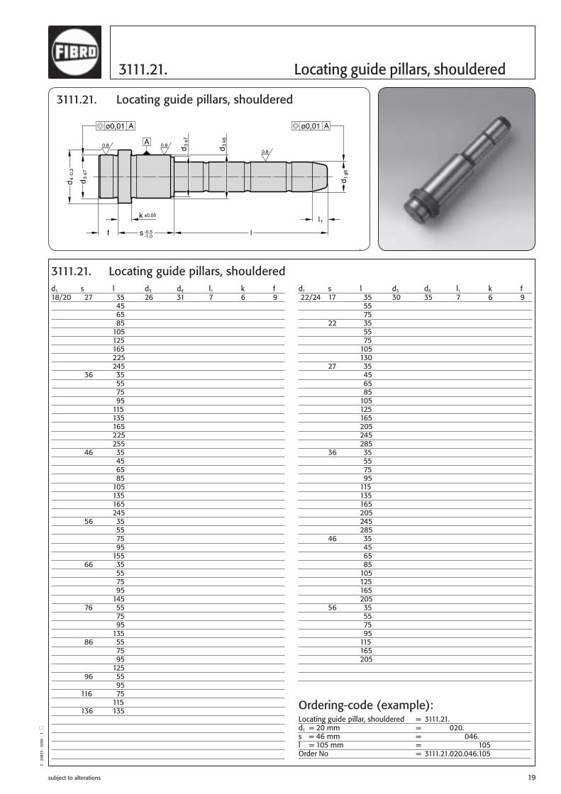
Locating guide pillars, shouldered 3111.21.
k
A0,80,8
0,8
±0,05
f s -0,5-1,0
l1
l
-0,2
4d
e73
d
g61d
k63
d
e73
d
ø0,01 Aø0,01 A
3111.21. Locating guide pillars, shouldered
d1 s l d3 d4 l1 k f 14/15 36 35 20 25 7 6 9 55 75 95 125 155 46 35 45 65 85 105 125 145 56 35 55 75 95 135 66 55 65 95 125 76 55 95 86 55 95 96 55 95 116 75 18/20 17 35 26 31 7 6 9 55 75 120 22 35 45 65 85 115
d1 s l d3 d4 l1 k f 9/10 12 25 14 16 7 3 3 45 65 17 20 25 30 35 50 55 70 75 22 25 35 55 75 95 27 20 25 30 45 50 70 90 36 25 35 45 65 85 46 30 35 45 70 56 35 60 14/15 17 35 20 25 7 6 9 55 75 95 22 30 50 70 90 110 125 150 27 30 45 65 85 105 125 145 165
3111.21. Locating guide pillars, shouldered
Ordering-code (example):Locating guide pillar, shouldered = 3111.21.d1 = 15 mm = 3111.21.015.s = 27 mm = 3111.21.015.027.l = 85 mm = 3111.21.015.027.085Order No = 3111.21.015.027.085
B2_Formenbau_GB_11_2008.indd 18B2_Formenbau_GB_11_2008.indd 18 08.12.2008 10:18:2608.12.2008 10:18:26
subject to alterations 19
2 · 2
0833
· 20
06 ·
1 Q
3111.21. Locating guide pillars, shouldered
k
A0,80,8
0,8
±0,05
f s -0,5-1,0
l1
l
-0,2
4d
e73
d
g61d
k63
d
e73
d
ø0,01 Aø0,01 A
3111.21. Locating guide pillars, shouldered
d1 s l d3 d4 l1 k f 22/24 17 35 30 35 7 6 9 55 75 22 35 55 75 105 130 27 35 45 65 85 105 125 165 205 245 285 36 35 55 75 95 115 135 165 205 245 285 46 35 45 65 85 105 125 165 205 56 35 55 75 95 115 165 205
d1 s l d3 d4 l1 k f 18/20 27 35 26 31 7 6 9 45 65 85 105 125 165 225 245 36 35 55 75 95 115 135 165 225 255 46 35 45 65 85 105 135 165 245 56 35 55 75 95 155 66 35 55 75 95 145 76 55 75 95 135 86 55 75 95 125 96 55 95 116 75 115 136 135
3111.21. Locating guide pillars, shouldered
Ordering-code (example):Locating guide pillar, shouldered = 3111.21.d1 = 20 mm = 3111.21.020.s = 46 mm = 3111.21.020.046.l = 105 mm = 3111.21.020.046.105Order No = 3111.21.020.046.105
B2_Formenbau_GB_11_2008.indd 19B2_Formenbau_GB_11_2008.indd 19 08.12.2008 10:18:2708.12.2008 10:18:27
subject to alterations20
2 · 2
0834
· 20
06 ·
1 Q
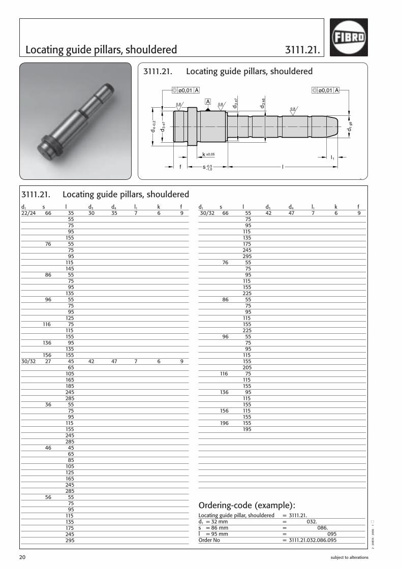
Locating guide pillars, shouldered 3111.21.
k
A0,80,8
0,8
±0,05
f s -0,5-1,0
l1
l
-0,2
4d
e73
d
g61d
k63
d
e73
d
ø0,01 Aø0,01 A
3111.21. Locating guide pillars, shouldered
d1 s l d3 d4 l1 k f 30/32 66 55 42 47 7 6 9 75 95 115 135 175 245 295 76 55 75 95 115 155 225 86 55 75 95 115 155 225 96 55 75 95 115 155 205 116 75 115 155 136 95 115 155 156 115 155 196 155 195
d1 s l d3 d4 l1 k f 22/24 66 35 30 35 7 6 9 55 75 95 155 76 55 75 95 115 145 86 55 75 95 135 96 55 75 95 125 116 75 115 155 136 95 135 156 155 30/32 27 45 42 47 7 6 9 65 105 165 185 245 285 36 55 75 95 115 155 245 285 46 45 65 85 105 125 165 245 285 56 55 75 95 115 135 175 245 295
3111.21. Locating guide pillars, shouldered
Ordering-code (example):Locating guide pillar, shouldered = 3111.21.d1 = 32 mm = 3111.21.032.s = 86 mm = 3111.21.032.086.l = 95 mm = 3111.21.032.086.095Order No = 3111.21.032.086.095
B2_Formenbau_GB_11_2008.indd 20B2_Formenbau_GB_11_2008.indd 20 08.12.2008 10:18:2808.12.2008 10:18:28

subject to alterations 21
2 · 2
0835
· 20
06 ·
1 Q
3111.21. Locating guide pillars, shouldered
k
A0,80,8
0,8
±0,05
f s -0,5-1,0
l1
l
-0,2
4d
e73
d
g61d
k63
d
e73
d
ø0,01 Aø0,01 A
3111.21. Locating guide pillars, shouldered
d1 s l d3 d4 l1 k f 40/42 46 95 54 60 7 10 12 165 56 75 115 155 195 66 75 135 76 75 115 175 86 75 135 96 75 115 155 116 95 135 195 136 95 135 215 156 115 155 215 196 155 195 235 246 165 245
3111.21. Locating guide pillars, shouldered
Ordering-code (example):Locating guide pillar, shouldered = 3111.21.d1 = 42 mm = 3111.21.042.s = 96 mm = 3111.21.042.096.l = 115 mm = 3111.21.042.096.115Order No = 3111.21.042.096.115
B2_Formenbau_GB_11_2008.indd 21B2_Formenbau_GB_11_2008.indd 21 08.12.2008 10:18:2808.12.2008 10:18:28

subject to alterations22
d1 32 40 50 63 80d2 40 50 63 80 100d3 76 92 112 138 170d5 55 68 84 105 130d6 9 11 14 16 18d7 15 18 20 24 26r 1,6 2 2,5 2,5 3r1 4 4 5 6 8 l2 11 13 14 16 20l3 6 6 8 8 10l5 15,1 18,4 22,5 27,4 32,1l6 11 13 14 16 20l7 19 23 28 34 40l8 8 9 10 13 15l9 9 10 12 15 18l10 1,5 1,5 2 3 4l1 ( l) ( l) ( l) ( l) ( l)067 97080 110 116095 125 131 137112 142 148 154 162132 168 174 182 192160 202 210 220190 240 250224 284436 486
Ordering code (example):Guide pillar with flange = 3111.31.d1 = 32 mm = 3111.31.032.l1 = 112 mm = 3111.31.032.112Order no. = 3111.31.032.112
2 · 2
0500
· 20
06 ·
1 ◽
Guide pillars with flange 3111.31.
3111.31. Guide pillars with flange
3111.31. Guide pillars with flangeMaterial:SteelSurface hardness: case hardened 62+2 HRC
Hardness penetration depth: 1.2 mm
Model:Ground
Note:Holding fixture bore H7.Delivery does not include screws.
Fixing:socket head screw DIN EN ISO 4762
M 8 x 20M 10 x 25M 12 x 30M 14 x 35M 16 x 40
should be used
radiussed
B2_Formenbau_GB_11_2008.indd 22B2_Formenbau_GB_11_2008.indd 22 08.12.2008 10:18:2908.12.2008 10:18:29

2 · 2
0519
· 20
06 ·
1 ◽
subject to alterations 23
B2_Formenbau_GB_11_2008.indd 23B2_Formenbau_GB_11_2008.indd 23 08.12.2008 10:18:3108.12.2008 10:18:31

subject to alterations24
2 · 2
0836
· 20
06 ·
1 Q
Guide pillars (diagonal load pillars) 3110.11.
RZ 2,5
l
k -0,2l1
g61d
-0,2
4d
3110.11. Guide pillars (diagonal load pillars)
d1 8 9 10 12 14 15 16 18 20 22 24 30 32 40 50d4 10 12 12 16 18 18 20 22 24 26 28 36 36 48 58k 3 3 3 6 8 8 8 8 8 15 15 15 15 15 15l1 4 4 4 7 7 7 7 7 7 7 7 7 7 10 10
l 40 b b b b b 60 b b b b b b b b b 80 b b b b b b b b b b b 100 b b b b b b b b b b b b b 120 b b b b b b b b b b b b 140 b b b b b b b b 160 b b b b b b b b b b b b180 b b b b b b b 200 b b b b b b b b b220 b b 240 b b b b b b b b300 b b b b b b360 b b b b
3110.11. Guide pillars (diagonal load pillars)
Ordering-code (example):Guide pillar (diagonal load pillar) = 3110.11.d1 = 20 mm = 3110.11.020.l = 180 mm = 3110.11.020.180Order No = 3110.11.020.180
B2_Formenbau_GB_11_2008.indd 24B2_Formenbau_GB_11_2008.indd 24 08.12.2008 10:18:3108.12.2008 10:18:31

subject to alterations 25
2 · 2
0837
· 20
06 ·
1 Q
3100.09. Guide sleeves
l js10
d2g6
1d
RZ4
3100.09. Guide sleeves
d1 10 14 18 24 30d2 6,2 8,3 10,4 12,5 16,5
l 20 b 30 b b 40 b b b 50 b b 60 b b b b 70 b b 80 b b b b b100 b b b b b120 b b b b b140 b b b b b160 b b b b180 b b b b200 b b 220 b b240 b b 260 b300 b
3100.09. Guide sleeves
Ordering-code (example):Guide sleeve = 3100.09.d1 = 10 mm = 3100.09.010.l = 100 mm = 3100.09.010.100Order No = 3100.09.010.100
B2_Formenbau_GB_11_2008.indd 25B2_Formenbau_GB_11_2008.indd 25 08.12.2008 10:18:3308.12.2008 10:18:33

subject to alterations26
2 · 2
0838
· 20
06 ·
1 Q
Guide bushes 3120.40.
A
s -0,5-1,0 s -0,5
-1,0
k ±0,05
l
l-0
,24
d
1d
H7
1d
H7
e73
d
k63
d
+0,
21
d+
0,5
0,8
0,8
ø0,01 A
3120.40. Guide bushes
d1 s l d3 d4 k22/24 116 96 30 35 6 136 96 156 96 30/32 27 27 42 47 6 36 36 46 46 56 56 66 66 76 76 86 86 96 96 116 116 136 116 156 116 176 116 40/42 46 46 54 60 10 56 56 66 66 76 76 86 86 96 96 116 116 136 136 156 136 196 136 246 136 50 76 76 66 72 10 96 96 116 116 136 136 156 136 196 136 60 76 76 80 86 20 96 96 116 116 136 136 156 136 196 136 246 136
d1 s l d3 d4 k9/10 9 9 14 16 3 12 12 17 17 22 22 27 27 36 36 46 46 56 46 66 46 12 17 17 18 23 6 22 22 27 27 36 36 46 46 56 56 14/15 12 12 20 25 6 17 17 22 22 27 27 36 36 46 46 56 56 66 56 76 56 86 56 96 56 16 17 17 22 25 6 22 22 27 27 36 36 46 46 56 56 18/20 17 17 26 31 6 22 22 27 27 36 36 46 46 56 56 66 66 76 76 86 76 96 76 116 76 22/24 17 17 30 35 6 22 22 27 27 36 36 46 46 56 56 66 66 76 76 86 86 96 96
3120.40. Guide bushes
Ordering-code (example):Guide bush = 3120.40.d1 = 32 mm = 3120.40.032.s = 116 mm = 3120.40.032.116Order No = 3120.40.032.116
B2_Formenbau_GB_11_2008.indd 26B2_Formenbau_GB_11_2008.indd 26 08.12.2008 10:18:3408.12.2008 10:18:34

subject to alterations 27
2 · 2
0839
· 20
06 ·
1 Q
3120.42. Locating guide bushes
l (l
A
ø0,01 A ø0,01 A
1
s -0,5
)
-1,0f
k ±0,05
-0,2
4d
e73
d
1d
H7
e73
d
k63
d
3120.42. Locating guide bushes
d1 s l l1 d3 d4 f k 30/32 27 36 36 42 47 9 6 36 45 45 46 55 55 56 65 65 66 75 75 76 85 85 86 95 95 96 105 105 116 125 125 136 116 145 156 116 165 176 116 185 196 116 205 40/42 46 58 58 54 60 12 10 56 68 68 66 78 78 76 88 88 86 98 98 96 108 108 116 128 128 136 136 148 156 136 168 196 136 208 246 136 258
d1 s l l1 d3 d4 f k 9/10 12 15 15 14 16 3 3 17 20 20 22 25 25 27 30 30 36 39 39 46 46 49 56 46 59 66 46 69 14/15 17 26 26 20 25 9 6 22 31 31 27 36 36 36 45 45 46 55 55 56 56 65 66 56 75 76 56 85 86 56 95 96 56 105 116 56 125 18/20 17 26 26 26 31 9 6 22 31 31 27 36 36 36 45 45 46 55 55 56 65 65 66 75 75 76 76 85 86 76 95 96 76 105 116 76 125 136 76 145 22/24 17 26 26 30 35 9 6 22 31 31 27 36 36 36 45 45 46 55 55 56 65 65 66 75 75 76 85 85 86 95 95 96 105 105 116 96 125 136 96 145 156 96 165
3120.42. Locating guide bushes
Ordering-code (example):Locating guide bush = 3120.42.d1 = 24 mm = 3120.42.024.s = 96 mm = 3120.42.024.096Order No = 3120.42.024.096
0,8 0,8
0,8
s -0,5-1,0
l
l1
1d
H7
+0,
21
d+
0,5
B2_Formenbau_GB_11_2008.indd 27B2_Formenbau_GB_11_2008.indd 27 08.12.2008 10:18:3608.12.2008 10:18:36

subject to alterations28
2·9
760
·9·2
°
Oilless Guide Bushes with collar Bronze with Non-Liquid Lubricant, 2087.70.
Material:Bronze with Non-Liquid Lubricant,oilless lubricating.
Note:Fit for receiving bore: H 7.
Direction of MotionEmbedded non-liquid lubricant(section)
2087.70.d1 9 10 14 15 18 20 22 24 30 32 40 42d2 14 20 26 30 42 54d3 16 25 31 35 47 60l3 3 6 6 6 6 10l4 1,5 2 2 3 4 5l5 3 6 8 8 8 12r 0,5 1 2 3 3 3l1 l2 15 12 ● 20 17 ● 23 17 ● 25 17 ● ● 25 22 ● 28 22 ● 30 22 ● ● 30 27 ● 33 27 ● 35 27 ● ● ● 39 36 ● 42 36 ● 44 36 ● ● ● 49 46 ● 52 46 ● 54 46 ● ● ● 58 46 ● 59 56 ● 62 56 ● 64 56 ● ● ● 68 56 ● 69 66 ● 72 66 ● 74 66 ● ● ● 78 66 ● 82 76 ● 84 76 ● ● ● 88 76 ● 92 86 ● 94 86 ● ● ● 98 86 ●104 96 ● ● ●108 96 ●124 116 ● ● ●128 116 ●144 136 ● ●148 136 ●164 156 ●168 156 ●208 196 ●
Ordering-code (example):Guide bush = 2087.70.d1 = 18 mm = 018.l2 = 27 mm = 027Order No = 2087.70.018.027
B2_Formenbau_GB_11_2008.indd 28B2_Formenbau_GB_11_2008.indd 28 08.12.2008 10:18:3708.12.2008 10:18:37

2·1
1230
·9·2
°
subject to alterations 29
Oilless Guide Bushes with collar2087.72. Bronze with Non-Liquid Lubricant,
Material:Bronze with Non-Liquid Lubricant,oilless lubricating.
Note:Fit for receiving bore: H 7.
2087.72. d1 9/10 12 14/15 16 18/20 22/24 25 30/32 40/42 50 60d2 14 18 20 22 26 30 32 42 54 66 80d3 16 23 25 27 31 35 38 47 60 72 86r 0,5 1 1 2 2 3 3 3 3 3 3l3 3 6 6 6 6 6 6 6 10 10 20l4 1,5 2 2 2 2 3 3 4 5 5 5l112 ●17 ● ● ● ● ● ● 22 ● ● ● ● ● ● 27 ● ● ● ● ● ● ● 36 ● ● ● ● ● ● ● 46 ● ● ● ● ● ● ● ● ●56 ● ● ● ● ● ● ● ● ●66 ● ● ● ● ●76 ● ● ● ● ● ●86 ● ● ● ● ●96 ● ● ● ● ●116 ● ● ● ●136 ● ● ●156 ● ● ●196 ● ●
Direction of MotionEmbedded non-liquid lubricant(section)
+0,5
1
)1l
2 x
d1
d3
H7
d1
d2 e7
d2 k6
l 4l 4m
in. 2
x d
1ll2
x d
() 1
r
r
R1 R1
Ø0,01 A
A
l 3
l 3
H7
d1 +0,2
(
2087.72.
Ordering code (Example):Guide bush = 2087.72.d1 = 18 mm = 2087.72.018.l1 = 27 mm = 2087.72.018.027Order No = 2087.72.018.027
B2_Formenbau_GB_11_2008.indd 29B2_Formenbau_GB_11_2008.indd 29 08.12.2008 10:18:3708.12.2008 10:18:37

subject to alterations30
Material:Bronze with Non-Liquid Lubricant,,oilless lubricating.
Note:Fit for receiving bore: H7.
Direction of MotionEmbedded non-liquid lubricant(section)
2087.71.d1 14 15 18 20 22 24 30 32d2 20 26 30 42d3 25 31 35 47r 1 1,5 2 2l1 26 39 49 63l2 17 22 27 36l5 9 17 22 27
Oilless Guide Bushes with collar Bronze with Non-Liquid Lubricant, 2087.71.
2087.71.
A
( l
)
Ø0,01 A
r
r
2
1
d1H7
d2 e7
d3
d2 k6
d2 e7
l 6
5
Ø0,01 A
2l
H7
Ordering-code (example):Guide bush = 2087.71.d1 = 20 mm = 2032.70.020.l2 = 22 mm = 2032.70.020.022Order No = 2087.71.020.022
2·1
0706
·9·3
°
B2_Formenbau_GB_11_2008.indd 30B2_Formenbau_GB_11_2008.indd 30 08.12.2008 10:18:3808.12.2008 10:18:38

subject to alterations 31
3120.70. / 3120.71. d1 8 10 12 13 14 15 16 18 19 20 24 25 28 30 31,5 32 35 38 40 45d2 12 14/15 18 19 20 21 22 24 25 26/28/30 32 32/33/35 38 38/40/42 40 42 44/45 48 50/55 55/56/60r 0,5 0,5 0,5 0,5 0,5 0,75 0,75 0,75 0,75 0,75 0,75 0,75 0,75 0,75 0,75 0,75 0,75 1,5 1,5 1,5l4 2 2 2 2 2 2 2 2 4 4 4 4 4 4 4 4 4 4 4 4l1 8 b b/– 10 b b/b b b b b b 12 b b/– b b b b 15 b b/– b b b b b b –/b/– 16 b b b b b –/b/b – /b/b 20 b/– b b b b b b –/b/b – /b/b b/b/– – /b b/– 25 b b b b b –/b/b – /b/b b/b/– b/b b/b 30 b b b b b –/b/b – /b/b b b/b/– b b b/b b b/b b/b/b 35 b b –/b/b – /b/b b/b/– b/b b/b b/b/b 37 b –/b/– 40 b b b/b/b – /b/b b b/b/– b b b/b b b/b b/b/b 47 b – /b/– 50 –/b/– b/b/b b/b/– b/b b/b b/b/b 60 – /b/– b/b/b b b/b b/b b/b/b 70 b/– –/–/b 77 b b/– 80 b/– –/–/b
3120.70. Guide bushes, bronze with solid lubricant3120.71. Guide bushes, bronze
Material:3120.70. Bronze with solid lubricant, low maintenance.3120.71. Bronze
Note:Recommended holding fixture bore H7.Bushes can be used radially and axially.
Fixing:Connecting with adhesive or if needed secure with threaded pin or flat mushroom head screw 2192.61.
Direction of MotionEmbedded non-liquid lubricant(section)
3120.70.
3120.71.
Ordering-code (example):Guide bush = 3120.70.d1 = 40 mm = 3120.70.040.d2 = 50 mm = 3120.70.040.050l1 = 80 mm = 3120.70.040.050.080Order number = 3120.70.040.050.080
Ordering-code (example):Guide bush = 3120.71.d1 = 40 mm = 3120.71.040.d2 = 50 mm = 3120.71.040.050l1 = 80 mm = 3120.71.040.050.080Order number = 3120.71.040.050.080
2 · 2
1481
· 20
08 ·
1 ◽
B2_Formenbau_GB_11_2008.indd 31B2_Formenbau_GB_11_2008.indd 31 08.12.2008 10:18:3908.12.2008 10:18:39

subject to alterations32
Guide bushes, bronze with solid lubricant 3120.70.Guide bushes, bronze 3120.71.
3120.70.
3120.71.
Material:3120.70. Bronze with solid lubricant, low maintenance.3120.71. Bronze
Note:Recommended holding fixture bore H7.Bushes can be used radially and axially.
Fixing:Connecting with adhesive or if needed secure with threaded pin or flat mushroom head screw 2192.61.
Direction of MotionEmbedded non-liquid lubricant(section)
Ordering-code (example):Guide bush = 3120.70.d1 = 40 mm = 3120.70.040.d2 = 50 mm = 3120.70.040.050l1 = 80 mm = 3120.70.040.050.080Order number = 3120.70.040.050.080
Ordering-code (example):Guide bush = 3120.71.d1 = 40 mm = 3120.71.040.d2 = 50 mm = 3120.71.040.050l1 = 80 mm = 3120.71.040.050.080Order number = 3120.71.040.050.080
3120.70. / 3120.71. d1 50 55 60 63 65 70 75 80 85 90 100 110 120 125 130 140 150 160d2 60/62/65 70 74/75 75 80 85/90 90/95 96/100 100 110 120 130 140 145 150 160 170 180r 1,5 2 2 2 2 2 2 2 2 2 2 2 2 2 2 2 2 2l4 4 4 4 4 4 4 4 4 4 4 4 4 4 4 4 4 4 4l1 30 b/b/b b/b 35 b/b/– b/b b/– 37 40 b/b/b b b/b b/– b/b 47 50 b/b/b b b/b b b/b b/b 60 b/b/b b b/b b b b/b b/b b/b b b 70 b/b/b b b/b b b b/b b/b b/b b b 77 80 b/–/b b/b b b b/b b/b b/b b b b b b 95 b/–/– 100 –/–/b –/b b/– b/b b/b b b b b b b b b b 120 b b/b b b b b b b 130 b 140 –/b b b b 150 b b
2·2
1482
·200
8·1
◽
B2_Formenbau_GB_11_2008.indd 32B2_Formenbau_GB_11_2008.indd 32 08.12.2008 10:18:4008.12.2008 10:18:40

Number ofOrder No Shape b h1 l1 l2 l3 l4 d1 d2 d3 t1 t2 t3 h2 h3 screw holes2962.83.016.012.050 A 16 12 50 34 14 9,5 10 5,5 5 5 5,7 – 11 4 2
016.012.071 A 71 55 35 2016.012.090 B 90 74 54 3
2962.83.020.020.080 A 20 20 80 64 40 12 11 6,6 6 5 6,8 9,5 19 5 2020.020.100 A 100 84 60 2020.020.125 B 125 109 85 3
2962.83.025.032.100 A 25 32 100 80 50 15,5 15 9 8 6 9 19 31 6 2025.032.125 A 125 105 75 2025.032.160 B 160 140 110 3
2962.83.030.050.125 A 30 50 125 95 55 18 18 11 10 7 11 34 49 8 2030.050.160 A 160 130 90 2030.050.200 B 200 170 130 3
subject to alterations 33
2 · 2
0840
· 200
6 ·
1 Q
Angled Guide Gibs2962.83. Bronze with Non-Liquid Lubricant
+0,
7
dd
H7
F7
d
l2 ±0,1
l3 ±0,01
l1-0,2
1
l 4±0
,1
3h 2t
3t
h2 ±0,1
t 1±0
,12
3 g6bd
+1
3
RZ
6,3
RZ 6,3
Form B
Form A
l 4±0
,01
2962.83. Angled Guide Gibs
Ordering-code (example):Angled Guide Gib = 2962.83.b = 16 mm = 2962.83.016.h1 = 12 mm = 2962.83.016.012.l1 = 50 mm = 2962.83.016.012.050Order No = 2962.83.016.012.050
2962.83. Angled Guide Gibs
B2_Formenbau_GB_11_2008.indd 33B2_Formenbau_GB_11_2008.indd 33 08.12.2008 10:18:4008.12.2008 10:18:40
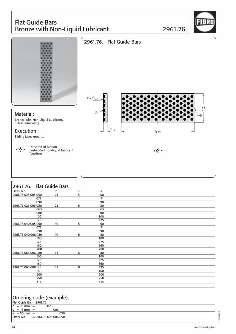
Material:Bronze with Non-Liquid Lubricant,,oilless lubricating.
Execution:Sliding faces ground.
Direction of MotionEmbedded non-liquid lubricant(section)
2961.76. Flat Guide Bars
2961.76.025.005.050 25 5 502961.76.025.005.071 712961.76.025.005.090 902961.76.025.006.050 25 6 502961.76.025.006.063 632961.76.025.006.080 802961.76.025.006.100 1002961.76.025.006.125 1252961.76.040.005.050 40 5 502961.76.040.005.071 712961.76.040.005.090 902961.76.040.006.080 40 6 802961.76.040.006.100 1002961.76.040.006.125 1252961.76.040.006.160 1602961.76.040.006.200 2002961.76.063.006.080 63 6 802961.76.063.006.100 1002961.76.063.006.125 1252961.76.063.006.160 1602961.76.063.008.125 63 8 1252961.76.063.008.160 1602961.76.063.008.200 2002961.76.063.008.250 2502961.76.063.008.315 315
Order No b s a
Ordering-code (example):Flat Guide Bar = 2961.76.b = 25 mm = 2961.76.025.s = 6 mm = 2961.76.025.006.a = 50 mm = 2961.76.025.006.050Order No = 2961.76.025.006.050
2·1
7313
·200
2·1
°
-0,1
-0,2
5b
l1-0,2h k9
RZ 4
2961.76. Flat Guide Bars
Flat Guide BarsBronze with Non-Liquid Lubricant 2961.76.
subject to alterations34
B2_Formenbau_GB_11_2008.indd 34B2_Formenbau_GB_11_2008.indd 34 08.12.2008 10:18:4208.12.2008 10:18:42

subject to alterations 35
Flat Guide Bars2961.77. Bronze with Non-Liquid Lubricant
2·1
7318
·200
2·1
°
0-0,5500
-0,1
-0,2
b
s 0-0,015
2961.77. Flat Guide Bars
Material:Bronze with Non-Liquid Lubricant,,oilless lubricating.
Execution:Sliding faces ground.
Direction of MotionEmbedded non-liquid lubricant(section)
Order No b s l
Ordering-code (example):Flat Guide Bar = 2961.77.b = 25 mm = 2961.77.025.s = 6 mm = 2961.77.025.006.l = 500 mm = 2961.77.025.006.500Order No = 2961.77.025.006.500
2961.77. Flat Guide Bars
2961.77.025.006.500 25 6 5002961.77.040.006.500 40 6 5002961.77.063.008.500 63 8 5002961.77.080.010.500 80 10 500
B2_Formenbau_GB_11_2008.indd 35B2_Formenbau_GB_11_2008.indd 35 08.12.2008 10:18:4208.12.2008 10:18:42

subject to alterations36
2 · 2
0841
· 200
6 ·
1 Q
Ball bearing guides 3120.65.
3120.65. Ball bearing guides
Ordering-code (example):Ball bearing guide = 3120.65.d1 = 18 mm = 3120.65.018.l1 = 56 mm = 3120.65.018.056Order No = 3120.65.018.056
3120.65. Ball bearing guidesd1 l l1 l2 d3 d4 f s2 Strokemax.
12 24 40 2,1 22 26 6 18 50 56 8218 34 45 3 30 35 11 23 44 56 66 71 9630 54 56 4,8 46 52 21 33 32 75 78 95 110
Stro
kem
ax.
B2_Formenbau_GB_11_2008.indd 36B2_Formenbau_GB_11_2008.indd 36 08.12.2008 10:18:4308.12.2008 10:18:43

subject to alterations 37
3131.80.
3131.80. Rectangular guides with rollers
Material:SteelHardness: ~56-58 HRCSurface: burnished
Description:The rectangular guides with rollers guarantee the greatest precisionwhen their mould is moved together. The rectangular guides must always be installed in the outer area of the mould plates to ensure problem-free functionality.The maximum operating temperature is 150°C.Advantages: no play or friction, low maintenance and no lubrication
3131.80. Order No t w a b c d e h r s1 s2 s3 d1 d2 t1
3131.80.032.063 32 63 46 46 27 21 12,1 92 8 9 11 35 15 9 93131.80.040.100 40 100 66 66 36 33 19,5 132 10 13 18 48 20 13,5 13
2·2
1483
·200
8·1
◽
Ordering-code (example):Rectangular guide with rollers = 3131.80.t = 32 mm = 3131.80.032.w = 63 mm = 3131.80.032.063Order number = 3131.80.032.063
B2_Formenbau_GB_11_2008.indd 37B2_Formenbau_GB_11_2008.indd 37 08.12.2008 10:18:4308.12.2008 10:18:43

subject to alterations38
Rectangular guides 3131.40.
3131.40.
Material:Steel with solid lubricantsurface: case hardened 580+40 HV 30Steelsurface: case hardened 700+60 HV 30Operating temperature up to 200°C.
3131.40. Order No l2 b2 l1 r t3 t2 t1 d2 d1 l4 l3 b3 b1
3131.40.022.016.020 22 16 20 6 11 6,8 20 11 6,6 7 15 26 40 .040 40 3131.40.027.020.025 27 20 25 6 13 6,8 22 11 6,6 7 19 31 45 .025 50 3131.40.036.025.032 36 25 32 8 14 6,8 25 11 6,6 9 27 35 50 .050 50 3131.40.046.032.040 46 32 40 8 19 9 32 15 9 11 35 45 63 .080 80 3131.40.056.040.050 56 40 50 10 22 11 36 18 11 15 40 60 85 .100 100 3131.40.066.050.056 66 50 56 10 24 13 40 20 14 18 48 74 100 .112 112
2·2
1484
·200
8·1
◽
Ordering-code (example):Rectangular guide = 3131.40.l2 = 22 mm = 3131.40.022.b2 = 16 mm = 3131.40.022.016.l1 = 40 mm = 3131.40.022.016.040Order no. = 3131.40.022.016.040
B2_Formenbau_GB_11_2008.indd 38B2_Formenbau_GB_11_2008.indd 38 08.12.2008 10:18:4708.12.2008 10:18:47

2 · 2
0842
· 20
06 ·
1 Q
subject to alterations
General Mould Components
39
B2_Formenbau_GB_11_2008.indd 39B2_Formenbau_GB_11_2008.indd 39 08.12.2008 10:18:4908.12.2008 10:18:49

Strength class 8.8
s
d M
1l
lk
subject to alterations40
Socket Head Cap ScrewsDIN 912/ISO 4762 2192.10.
2192.10. Socket Head Cap Screws DIN 912/ISO 4762
2192.10.
2·1
1828
·9·1
°
Ordering-code (example): Socket head cap screw = 2192.10 Thread M8 = .08 Length 50 mm = .050 Order No = 2192.10.08.050
M l l1 d k s 4 12 10 7 4 3 4 16 14 7 4 3 4 20 18 7 4 3 4 25 23 7 4 3 5 20 18 8.5 5 4 5 25 23 8.5 5 4 5 30 22 8.5 5 4 6 16 13 10 6 5 6 20 17 10 6 5 6 25 22 10 6 5 6 30 27 10 6 5 6 35 24 10 6 5 6 40 24 10 6 5 6 45 24 10 6 5 6 50 24 10 6 5 6 55 24 10 6 5 6 60 24 10 6 5 6 70 24 10 6 5 6 80 24 10 6 5 6 90 24 10 6 5 8 16 12 13 8 6 8 20 16 13 8 6 8 25 21 13 8 6 8 30 26 13 8 6 8 35 31 13 8 6 8 40 28 13 8 6 8 45 28 13 8 6 8 50 28 13 8 6 8 60 28 13 8 6 10 16 11 16 10 8 10 20 15 16 10 8 10 25 20 16 10 8 10 30 25 16 10 8 10 35 30 16 10 8 10 40 35 16 10 8 10 50 32 16 10 8 10 60 32 16 10 8 12 25 20 18 12 10 12 30 25 18 12 10 12 35 30 18 12 10 12 40 35 18 12 10 12 45 40 18 12 10 12 50 45 18 12 10 12 70 36 18 12 10 12 80 36 18 12 10
M l l1 d k s 16 30 24 24 16 14 16 35 29 24 16 14 16 40 34 24 16 14 16 45 39 24 16 14 16 50 44 24 16 14 16 55 49 24 16 14 16 60 54 24 16 14 16 100 44 24 16 14 20 50 42 30 20 17 20 60 52 30 20 17 20 70 62 30 20 17 20 90 52 30 20 17 20 120 52 30 20 17 24 60 51 36 24 19 24 70 61 36 24 19 24 80 71 36 24 19 24 120 60 36 24 19 24 140 60 36 24 19 30 140 72 72 20 22
B2_Formenbau_GB_11_2008.indd 40B2_Formenbau_GB_11_2008.indd 40 08.12.2008 10:18:5008.12.2008 10:18:50

subject to alterations 41
2192.12. Socket Head Cap Screws DIN 912/ISO 4762 Strength class 12.9
s
d M
1l
lk
2192.12.
Socket Head Cap Screws2192.12. DIN 912/ISO 4762
Ordering-code (example): Socket head cap screw = 2192.12 Thread M8 = .08 Lenght 100 mm = .100 Order No = 2192.12.08.100 2
·116
17·8
·1 ◽
M l l1 d k s 3 8 6 5.5 3 2.5 4 10 8 7 4 3 6 10 7 10 6 5 6 20 17 10 6 5 6 25 22 10 6 5 6 30 27 10 6 5 6 35 24 10 6 5 6 40 24 10 6 5 6 45 24 10 6 5 6 50 24 10 6 5 6 55 24 10 6 5 6 60 24 10 6 5 6 70 24 10 6 5 6 80 24 10 6 5 6 85 24 10 6 5 6 90 24 10 6 5 6 100 24 10 6 5 6 160 24 10 6 5 6 200 24 10 6 5 8 16 12 13 8 6 8 30 26 13 8 6 8 35 31 13 8 6 8 40 28 13 8 6 8 45 28 13 8 6 8 50 28 13 8 6 8 55 28 13 8 6 8 60 28 13 8 6 8 70 28 13 8 6 8 75 28 13 8 6 8 80 28 13 8 6 8 90 28 13 8 6 8 100 28 13 8 6 8 110 28 13 8 6 8 120 28 13 8 6 10 30 25 16 10 8 10 35 30 16 10 8 10 40 35 16 10 8 10 45 32 16 10 8 10 50 32 16 10 8 10 55 32 16 10 8 10 60 32 16 10 8 10 65 32 16 10 8 10 70 32 16 10 8 10 75 32 16 10 8
M l l1 d k s 10 80 32 16 10 8 10 90 32 16 10 8 10 100 32 16 10 8 10 110 32 16 10 8 10 120 32 16 10 8 10 130 32 16 10 8 10 150 32 16 10 8 10 180 32 16 10 8 10 220 32 16 10 8 12 40 35 18 12 10 12 45 40 18 12 10 12 50 45 18 12 10 12 55 36 18 12 10 12 60 36 18 12 10 12 70 36 18 12 10 12 80 36 18 12 10 12 90 36 18 12 10 12 100 36 18 12 10 12 110 36 18 12 10 12 120 36 18 12 10 12 130 36 18 12 10 12 140 36 18 12 10 12 150 36 18 12 10 12 180 36 18 12 10 12 220 36 18 12 10 16 40 34 24 16 14 16 50 44 24 16 14 16 60 54 24 16 14 16 65 44 24 16 14 16 70 44 24 16 14 16 80 44 24 16 14 16 90 44 24 16 14 16 100 44 24 16 14 16 110 44 24 16 14 16 120 44 24 16 14 16 130 44 24 16 14 16 140 44 24 16 14 16 150 44 24 16 14 16 160 44 24 16 14 16 180 44 24 16 14 16 200 44 24 16 14 16 220 44 24 16 14 16 240 44 24 16 14 16 260 44 24 16 14
M l l1 d k s 16 280 44 24 16 14 16 300 44 24 16 14 20 100 52 30 20 17 20 110 52 30 20 17 20 120 52 30 20 17 20 130 52 30 20 17 20 140 52 30 20 17 20 150 52 30 20 17 20 160 52 30 20 17 20 180 52 30 20 17 20 190 52 30 20 17 20 200 52 30 20 17 20 220 52 30 20 17 20 230 52 30 20 17 20 240 52 30 20 17 20 260 52 30 20 17 20 280 52 30 20 17 20 300 52 30 20 17 24 130 60 36 24 19 24 140 60 36 24 19 24 150 60 36 24 19 24 160 60 36 24 19 24 180 60 36 24 19 24 200 60 36 24 19
B2_Formenbau_GB_11_2008.indd 41B2_Formenbau_GB_11_2008.indd 41 08.12.2008 10:18:5008.12.2008 10:18:50

subject to alterations42
1l
ks
d M
l
Socket Head Cap Screws DIN 7984with low profile head 2192.40.
M I l1 d k s 4 8 5,9 7 2,8 2,5 10 7,9 7 2,8 2,5 12 9,9 7 2,8 2,5 16 13,9 7 2,8 2,5 20 17,9 7 2,8 2,5 25 14 7 2,8 2,5 30 14 7 2,8 2,5 35 14 7 2,8 2,5 40 14 7 2,8 2,5 5 8 5,6 8,5 3,5 3 10 7,6 8,5 3,5 3 12 9,6 8,5 3,5 3 16 13,6 8,5 3,5 3 20 17,6 8,5 3,5 3 25 22,6 8,5 3,5 3 30 16 8,5 3,5 3 35 16 8,5 3,5 3 40 16 8,5 3,5 3 6 10 7 10 4 4 12 9 10 4 4 16 13 10 4 4 20 17 10 4 4 25 22 10 4 4 30 18 10 4 4 35 18 10 4 4 40 18 10 4 4 8 12 8,25 13 5 5 16 12,25 13 5 5 20 16,25 13 5 5 25 21,25 13 5 5 30 26,25 13 5 513 35 22 13 5 5 40 22 13 5 5 45 22 13 5 5 50 22 13 5 5 60 22 13 5 510 20 15,5 16 6 7 25 20,5 16 6 7 30 25,5 16 6 7 60 26 16 6 7 80 26 16 6 7 90 26 16 6 712 30 24,75 18 7 8 35 29,75 18 7 8
2192.40. Socket Head Cap Screws DIN 7984Festigkeitsklasse 8.8 = Code Nr.: 0.
Ordering-code (example):Cap Screw = 2192.DIN 7984 = 2192.4Strength class 8.8 = 2192.40.M10 = 2192.40.10.l = 30 mm = 2192.40.08.030Order No = 2192.40.10.030
2192.40.
2·1
6582
·200
1·1
°
B2_Formenbau_GB_11_2008.indd 42B2_Formenbau_GB_11_2008.indd 42 08.12.2008 10:18:5108.12.2008 10:18:51

subject to alterations 43
2192.30. Countersunk Head Cap Screws DIN 7991/ISO 10642 Strenght class 8.8 = Code Nr. 0. M l lg d k s 3 6 3.2 6 1.7 2 3 8 3.2 6 1.7 2 3 10 3.2 6 1.7 2 4 8 4.4 8 2.3 2.5 5 10 5.2 10 2.8 3 5 12 5.2 10 2.8 3 6 10 6.3 12 3.3 4 6 12 6.3 12 3.3 4 6 16 6.3 12 3.3 4 6 20 6.3 12 3.3 4 6 25 6.3 12 3.3 4 8 16 8.2 16 4.4 5 8 20 8.2 16 4.4 5 8 25 8.2 16 4.4 5 10 20 10 20 5.5 6 10 25 10 20 5.5 6 12 30 11.8 24 6.5 8
l g
90°
d
k
l
M
s
2192.30.
Countersunk Head Cap Screws2192.30. DIN 7991/ISO 10642
2·1
1838
·9·1
°
Ordering Code (example):Countersunk Head Cap Screw = 2192.DIN 7991/ISO 10642 = 2192.3Strenght class 8.8 = 2192.3 0.M8 = 2192.3 0.08.l = 16 mm = 2192.3 0.08.016Order No = 2192.30.08.016
B2_Formenbau_GB_11_2008.indd 43B2_Formenbau_GB_11_2008.indd 43 08.12.2008 10:18:5208.12.2008 10:18:52

subject to alterations44
2 · 2
0520
· 20
06 ·
1 ◽
2192.61.
2192.61. Flat mushroom head screw M l k s c a da d R 6 12 3.2 4 1.2 2 7 13.27 5.6 6 16 3.2 4 1.2 2 7 13.27 5.6 6 20 3.2 4 1.2 2 7 13.27 5.6 8 16 4.3 5 1.5 2.5 9.2 17.77 7.5 8 20 4.3 5 1.5 2.5 9.2 17.77 7.5 8 25 4.3 5 1.5 2.5 9.2 17.77 7.5 10 20 5.3 6 1.75 3 11.2 22.18 10
Ordering-code (example): Flat mushroom head screw = 2192.61 Thread 8 mm = .08 Lenght 16 mm = .016 Order No = 2192.61.08.016
Material:
Strength class 10.9 = Code No. 1.
Flat mushroom head screw 2192.61.
Mounting example
B2_Formenbau_GB_11_2008.indd 44B2_Formenbau_GB_11_2008.indd 44 08.12.2008 10:18:5208.12.2008 10:18:52

2 · 2
0851
· 20
06 ·
1 Q
Änderungen vorbehalten 45
B2_Formenbau_GB_11_2008.indd 45B2_Formenbau_GB_11_2008.indd 45 08.12.2008 10:18:5308.12.2008 10:18:53

subject to alterations46
M e m sM 8 15,0 12 13M10 18,2 15 16M12 20,4 18 18M14 23,8 21 21M16 27,7 24 24M18 31,2 27 27M20 34,6 30 30M22 38,6 33 34M24 41,6 36 36M30 53,1 45 46
Material:Heat-treated
Strength class 8.8
M d2 d3 k lM10 16 30 8 39M12 20 36 10 48M16 25 42 13 55M20 25 50 16 69M24 34 60 20 87
2140.02. Setscrews
2140.02.
Material:Heat-treated
Strength class 10.9
Note:Use washers conforming to DIN 6340.
2140.32.
2140.32. Hexagon Nuts DIN 6330 B
Ordering-code (example):Setscrew = 2140.02.M16 = 2140.02.16Order No = 2140.02.16
2·1
1623
·9·1
°
Setscrews 2140.02. Hexagon Nuts DIN 6330 B 2140.32.
k
3d
Md2
lm
e
s
M
Ordering Code (example):Hexagon Nut, DIN 6330 B = 2140.32.M20 = 2140.32.20Order No = 2140.32.20
B2_Formenbau_GB_11_2008.indd 46B2_Formenbau_GB_11_2008.indd 46 08.12.2008 10:18:5308.12.2008 10:18:53

subject to alterations 47
2140.33. Collar Nuts DIN 63312140.34. Washers DIN 6340
Material:Turned and milled
Heat-treatedStrength class 10.9Thread length 1,53M
Material:Heat-treated
Strength 1200–1400 N/mm2
M d1 d2 sM 8 8,4 23 4M10 10,5 28 4M12 13,0 35 5M14 15,0 40 5M16 17,0 45 6M18 19,0 45 6M20 21,0 50 6M22 23,0 50 8M24 25,0 60 8M30 31,0 68 10
M a d1 e m sM 8 3,5 18 15,0 12 13M10 4,0 22 18,2 15 16M12 25 20,4 18 18M14 4,5 28 23,8 21 21M16 5,0 31 27,7 24 24M18 34 31,2 27 27M20 6,0 37 34,6 30 30M22 40 38,6 33 34M24 45 41,6 36 36M30 6,0 58 53,1 45 46
2140.33. Collar Nuts DIN 6331
2140.33.
2140.34.
2140.34. Washers DIN 6340
Ordering-code (example):Washer DIN 6340 = 2140.34.M10 = 2140.34.10Order No = 2140.34.10
Ordering-code (example):Collar Nut DIN 6331 = 2140.33.M12 = 2140.33.12Order No = 2140.33.12
2·1
1624
·9·1
°
ad
1
m
e
s
M
1d
2d
s
°
°
B2_Formenbau_GB_11_2008.indd 47B2_Formenbau_GB_11_2008.indd 47 08.12.2008 10:18:5408.12.2008 10:18:54

subject to alterations48
Material:Forged, T-slot milled,
rolled thread
M 6 – M12 heat-treated to strength class 10.9
M14 – M24 heat-treated to strength class 8.8
2140.30.
°
a1 a b d1 e k l 8 7,7 22 M 8 13 6 32 35 50 50 8010 9,7 30 M10 15 6 40 45 63 60 10012 11,7 35 M12 18 7 50 40 63 55 80 75 125 120 20014 13,7 35 M12 22 8 50 45 63 55 80 75 125 120 20016 15,7 45 M14 25 9 63 65 100 125 160 150 25016 15,7 45 M16 25 9 63 55 80 65 100 100 160 125 200 150 25018 17,7 45 M16 28 10 63 55 80 65 100 100 160 125 200 150 25020 19,7 55 M20 32 12 80 65 100 85 125 110 160 125 200 150 250 190 31522 21,7 55 M20 35 14 80 65 100 85 125 115 160 125 200 150 250 190 31524 23,7 70 M24 40 16 100 85 125 110 160 125 200 150 250 190 315 240 40028 27,7 70 M24 44 18 100 85 125 110 160 125 200 150 250 190 315 240 40036 35,6 80 M30 54 22 125 110 160 135 200 150 250 200 315 300 500
2140.30. T-Head Bolts DIN 787
Ordering-code (example):T-Head Bolt DIN 787 = 2140.30.d1 = M14 = 2140.30.14.a1 = 16 mm = 2140.30.14.16.l = 160 mm = 2140.30.14.16.160Order No = 2140.30.14.16.160
T-Head Bolts DIN 787 2140.30.
a
1a
bl
k
e
1d
2·1
1622
·9·1
°
B2_Formenbau_GB_11_2008.indd 48B2_Formenbau_GB_11_2008.indd 48 08.12.2008 10:18:5508.12.2008 10:18:55

±0,1
l 1h
h1
l 2
1d h9
3d
2d
d1 10,5 12,5 15,5 17,5 23 d2 M 6 M 8 M 10 M 12 M 16 d3 15,5 19,5 23,5 27,5 34 h1 10,5 13,5 15,5 18,5 24 h1 5,5 l2 6,5 l2 7,5 l2 9,5 l2 11 l2 l1 20 b 35 b 35 25 b 40 30 b 45 b 45 b 50 b 50 35 b 50 b 50 b 55 40 b 55 b 55 b 60 b 60 45 b 60 b 60 b 65 b 65 50 b 65 b 65 b 70 b 70 b 80 55 b 70 b 70 b 75 b 80 60 b 80 b 80 b 80 b 90 b 90 70 b 90 b 90 b 90 b 100 b 100 80 b 100 b 100 b 100 b 110 b 110 90 b 110 b 110 b 110 b 120 b 120 100 b 120 b 120 b 130 b 130 110 b 140 b 140 120 b 140 b 150 b 150 140 b 180 b 180 150 b 180 160 b 200 13 32 65 120 290
subject to alterations 49
244.16. Spring,- Fit- and Spacer Units
2·87
87·7
·2 °
Tigthening torque Nm
Description:These units can be used as an alternative to shoulder screws.
Advantages:Precision length adjustments by way of grinding. The units have many uses – as can be seen from the installation examp-les below.
Execution:Spacer tube: Tensile strength 1200–1300 N/mm2 Outside diameter ground to tolerance h9 Supplied with socket cap screw DIN EN ISO 4762 (12.9)
Note:The units are supplied with a retainingO-ring which must be removed before appli-cation.
remove O-ring before assembly
grou
nd f
inis
h
244.16.Installation Examples
244.16.
Ordering-code (example):Spring,- Fit- and Spacer Unit = 244.16.125.055d1 = 12,5 mm = 244.16.125.055l1 = 55 mm = 244.16.125.055Order No = 244.16.125.055
244.16.
B2_Formenbau_GB_11_2008.indd 49B2_Formenbau_GB_11_2008.indd 49 08.12.2008 10:18:5508.12.2008 10:18:55

d1 6,5 8,5 10 12 16 20 24 d2 M 5 M 6 M 8 M 10 M 12 M 16 M 20 d3 10,5 13,5 16 18 24 30 36 h 4,5 5,5 7 9 11 14 16 s 3,5 4,5 5 6 8 10 12 l2 9,5 11,5 13 16 18 22 27 l1 10 b b 12 b b 16 b b b b 20 b b b b 25 b b b b b 30 b b b b b 35 b b b b b 40 b b b b b b 45 b b b b 50 b b b b b b 55 b b b b 60 b b b b b 65 b b b b 70 b b b b b 80 b b b b b 90 b b b b 100 b b b b 120 b b b 7 13 32 65 120 290 500
subject to alterations50
Execution:Material: High tensile steel, Heat-treated to 12.9 ISO 898-1. Head knurled.
Shoulder Screws 244.17.
2·87
88·7
·2 °
+0,
25l 2
s
h
1d h8
3d
2d
l 1
grou
nd f
inis
h
244.17.Installation Examples
244.17.
Ordering-code (example):Shoulder Screw = 244.17.120.060d1 = 12 mm = 244.17.120.060l1 = 60 mm = 244.17.120.060Order No = 244.17.120.060Tigthening torque Nm
244.17.
B2_Formenbau_GB_11_2008.indd 50B2_Formenbau_GB_11_2008.indd 50 08.12.2008 10:18:5608.12.2008 10:18:56

2471. . 003 M 3 1,5 8 0,4 1,5 3 4,5 004 M 4 2,5 12 0,8 2 8,5 14 005 M 5 3 14 0,9 2,5 8 14 006 M 6 3,5 15 1 3 11 18 008 M 8 4,5 18 1,5 4 18 31 010 M 10 6 23 2 5 24 45 012 M 12 8 26 2,5 6 26 49 016 M 16 10 33 3,5 8 41 86 020 M 20 12 43 4,5 10 56 111 024 M 24 15 48 5,5 12 81 151
2471.03./.33. normal spring force
Spring force in N*Order No d1 d2 l s A/F Start End
* statistical average
2471. . 003 M 3 7 0,4 1,5 3 4,5 004 M 4 9 0,8 2,5 6 14,5 005 M 5 12 0,9 3 8 14 006 M 6 14 1 3,5 11 18 008 M 8 16 1,5 4,5 18 31 010 M 10 19 2 6 24 45 012 M 12 22 2,5 8 26 49 016 M 16 24 3,5 10 41 86 020 M 20 30 4,5 12 56 111 024 M 24 34 5,5 15 81 151
2471.01./.31. normal spring force
Spring force in N*Order No d1 l s d2 Start End
* statistical average
subject to alterations 51
Spring Plungers with Spring Loaded Ball2471.01./.02. 2471.31./.32. with slot 2471.03./.04. 2471.33./.34. with hexagon socket head
2471. . 005 M 5 12 0,9 3 15 22 006 M 6 14 1 3,5 19 28 008 M 8 16 1,5 4,5 36 62 010 M 10 19 2 6 57 104 012 M 12 22 2,5 8 61 110 016 M 16 24 3,5 10 68 142 020 M 20 30 4,5 12 84 166 024 M 24 34 5,5 15 127 237
2471.02./.32. increased spring force
Spring force in N*Order No d1 l s d2 Start End
* statistical average
Material:2471.01. Sleeve: Free-machining steel, burnished Ball: Hardened ball bearing steel Spring: Nirosta2471.02. Sleeve: Free-machining steel, burnished Ball: Hardened ball bearing steel /
ball yellow Spring: Nirosta2471.31. Sleeve: Nirosta 1.4305 Ball: Nirosta hardened Spring: Nirosta2471.32. Sleeve: Nirosta 1.4305 / end of sleeve yellow Ball: Nirosta hardened Spring: Nirosta
Note:For locking and for pressing upwards or downwards. Admissible temperature range: max. 250°C
d2
ls
d1
2471.01./2471.02.2471.31./2471.32.
2·1
1878
·200
0·2
°
2471. . 005 M 5 3 14 0,9 2,5 15 22 006 M 6 3,5 15 1 3 19 28 008 M 8 4,5 18 1,5 4 36 62 010 M 10 6 23 2 5 57 104 012 M 12 8 26 2,5 6 61 110 016 M 16 10 33 3,5 8 68 142 020 M 20 12 43 4,5 10 84 166 024 M 24 15 48 5,5 12 127 237
2471.04./.34. increased spring force
Spring force in N*Order No d1 d2 l s A/F Start End
* statistical average
Material:2471.03. Sleeve: Free-machining steel, burnished Ball: Hardened ball bearing steel Spring: Nirosta2471.04. Sleeve: Free-machining steel, burnished Ball: Hardened ball bearing steel / ball yellow Spring: Nirosta2471.33. Sleeve: Nirosta 1.4305 Ball: Nirosta hardened Spring: Nirosta2471.34. Sleeve: Nirosta 1.4305 / end of sleeve yellow Ball: Nirosta hardened Spring: Nirosta
Note:For locking and for pressing upwards or downwards. Admissible temperature range: max. 250°C
s
d1
l
d2
2471.03./2471.04.2471.33./2471.34.
A/F
B2_Formenbau_GB_11_2008.indd 51B2_Formenbau_GB_11_2008.indd 51 08.12.2008 10:18:5708.12.2008 10:18:57

2472. . 004 M 4 1,8 12 1,5 2 4,5 12,5 005 M 5 2,4 14 2 2,5 5 13 006 M 6 2,7 15 2 3 6 17 008 M 8 3,8 18 2 4 16 33 010 M 10 4,5 23 2,5 5 19 42 012 M 12 6,0 26 3,5 6 22 57 016 M 16 8,5 33 4,5 8 38 78 020 M 20 10,0 43 6,5 10 39 81 024 M 24 13,0 48 8 12 72 155
2472.03./.33. normal spring force
Spring force in N*Order No d1 d2 l s A/F Start End
* statistical average
subject to alterations52
d1
d2
sl
Spring Plungers with Spring Loaded Pin 2472.01./.02.with slot 2472.31./.21./.22.with hexagon socket head 2472.03./.04./.33./.34.
2472.02.005 M 5 2,4 18 2,3 1,5 11 402472.01.006 M 6 2,7 20 2,5 2 15 432472.01.008 M 8 3,5 22 3 2,5 20 752472.01.010 M 10 4 22 3 3 20 752472.01.012 M 12 6 28 4 4 45 1202472.01.016 M 16 7,5 32 5 5 64 1602472.01.020 M 20 10 40 7 6 75 1952472.01.024 M 24 12 52 10 8 75 245
2472.02. increased spring force
Spring force in N*Order No d1 d2 l s A/F Start End
* statistical average
2472. . 003 M 3 1 12 1 0,7 2,0 4 004 M 4 1,5 15 1,5 1,3 4,5 16 005 M 5 2,4 18 2,3 1,5 6,0 19 006 M 6 2,7 20 2,5 2 6,0 19 008 M 8 3,5 22 3 2,5 10 39 010 M 10 4 22 3 3 10 39 012 M 12 6 28 4 4 12 53 016 M 16 7,5 32 5 5 45 100 020 M 20 10 40 7 6 52 125 024 M 24 12 52 10 8 70 170
2472.01./.31./.21./.22. normal spring force
Spring force in N*Order No d1 d2 l s A/F Start End
* statistical average
2·1
1883
·200
0·2
°
Material:2472.01. Sleeve: Free-machining steel, burnished Pin: Free-machining steel hardened, burnished Spring: Nirosta2472.02. Sleeve: Free-machining steel, burnished Pin: Free-machining steel hardened, burnished/
threaded pin shining Spring: Nirosta2472.31. Sleeve: Nirosta 1.4305 Pin: Nirosta 1.4305 Spring: Nirosta2472.21. Sleeve: Free-machining steel, burnished Pin: Delrin white (FOM) Spring: Nirosta2472.22. Sleeve: Nirosta 1.4305 Pin: Delrin white (FOM) Spring: NirostaNote:For locking and for pressing upwards or downwards. Removable with hexagon socket screw key or slotted screwdriver.
2472.01./.02./.31./.21./.22.
2472. . 006 M 6 2,7 15 2 3 11 25 008 M 8 3,8 18 2 4 23 59 010 M 10 4,5 23 2,5 5 20 54 012 M 12 6,0 26 3,5 6 38 96 016 M 16 8,5 33 4,5 8 50 100 020 M 20 10,0 43 6,5 10 52 133 024 M 24 13,0 48 8 12 91 223
2472.04./.34. increased spring force
Spring force in N*Order No d1 d2 l s A/F Start End
* statistical average
Material:2472.03. Sleeve: Free-machining steel, burnished Pin: Free-machining steel hardened, burnished Spring: Nirosta2472.04. Sleeve: Free-machining steel, burnished Pin: Free-machining steel hardened, burnished/
Pin blue galvanised Spring: Nirosta2472.33. Sleeve: Nirosta 1.4305 Pin: Nirosta 1.4305 Spring: Nirosta2472.34. Sleeve: Nirosta 1.4305/end of sleeve yellow Pin: Nirosta 1.4305 Spring: Nirosta
Note:For locking and for pressing upwards or downwards. Admissible temperature range: max. 250°C
s
d2
d1
l
2472.03./.04./33./.34.
A/F
A/F
locking pad
Execution: 2472.31.– d1 = M4 to M20 2472.21.– d1 = M4 to M16 2472.22.– d1 = M4 to M16
B2_Formenbau_GB_11_2008.indd 52B2_Formenbau_GB_11_2008.indd 52 08.12.2008 10:18:5708.12.2008 10:18:57

subject to alterations 53
2472.05. 2472.06. Spring Plungers with Spring Loaded Ball 2472.35. 2472.36. with slot 2471.05. 2471.35. with hexagon socket head
2472. . 006 M 6 2,7 14 2 11 25 008 M 8 3,8 16 2 23 59 010 M 10 4,5 19 2,5 20 54 012 M 12 6,2 22 3,5 38 96 016 M 16 8,5 24 4,5 50 100 020 M 20 10 30 6,5 52 133 024 M 24 13 34 8 91 223
2472.06./.36. increased spring force
Spring force in N*Order No d1 d2 l s Start End
* statistical average
Material:2472.05. Sleeve: Free-machining steel, burnished Pin: Free-machining steel hardened, burnished Spring: Nirosta2472.06. Sleeve: Free-machining steel, burnished Pin: Free-machining steel hardened, burnished/
Pin blue galvanised Spring: Nirosta2472.35. Sleeve: Nirosta 1.4305 Pin: Nirosta 1.4305 Spring: Nirosta2472.36. Sleeve: Nirosta 1.4305 Pin: Nirosta 1.4305/end of sleeve yellow Spring: Nirosta
Note:For locking and for pressing upwards or downwards. Admissible temperature range: max. 250°C
sl
d2
d1
2472.05./2472.06.2472.35./2472.36.
2471. . 006 M 6 14 0,9 3,5 12 17 008 M 8 16 1,5 5 20 35 010 M 10 19 1,9 6 25 45
2471.05./.35.
Spring force in N*Order No d1 l s d2 Start End
* statistical average
Material:2471.05. Sleeve: Delrin blue (POM) Ball: Delrin white (POM) Spring: Nirosta2471.35. Sleeve: Delrin blue (POM) Ball: Nirosta, hardened Spring: Nirosta
Note:For locking and for pressing upwards or downwards. Admissible temperature range: –30°C to +50°C.
d2
ls
d1
2471.05./2471.35.
2472. . 004 M 4 1,8 9 1,5 4,5 12,5 005 M 5 2,4 12 2 5 13,0 006 M 6 2,7 14 2 6 17 008 M 8 3,8 16 2 16 33 010 M 10 4,5 19 2,5 19 42 012 M 12 6,2 22 3,5 22 57 016 M 16 8,5 24 4,5 38 78 020 M 20 10 30 6,5 39 81 024 M 24 13 34 8 72 155
2472.05./.35. normal spring force
Spring force in N*Order No d1 d2 l s Start End
* statistical average
2·1
1888
·200
0·2
°
B2_Formenbau_GB_11_2008.indd 53B2_Formenbau_GB_11_2008.indd 53 08.12.2008 10:18:5808.12.2008 10:18:58

subject to alterations54
s
d1
d2
d3
l 3l 1
l 2
1l
d1
s
d2
d3
2l
2·1
1893
·9·1
°
Spring Plungers 2473.01.straight version with shoulder 2475.01./.02./.03./.04.Thrust pad driver 2472.11.
Material:2473.01.Sleeve: Free-machining steel, burnishedPin: Steel, case hardened, burnishedSpring: Nirosta
Note:For use in toolmaking as forcing pins and spring loaded limit stops. Neither the threaded cartridge nor any of its com-ponents can escape from the mounting. Temperature operating range: max. 250°C
2473.01.
Material:2475.01. Sleeve: Delrin blue (POM) Ball: Delrin white (POM) Spring: Nirosta2475.02. Sleeve: Delrin blue (POM) Ball: Nirosta, hardened Spring: Nirosta2475.03. Sleeve: Brass Ball: Nirosta, hardened Spring: Nirosta2475.04. Sleeve: Nirosta 1.4303 Ball: Nirosta, hardened Spring: Nirosta
Note:For locking and for pressing upwards or downwards.Admissible temperature range: –30°C to +50°C (2475.01./.02.) max. 250°C (2475.03./.04.)
2475.01.2475.02./.03./.04.
2472.11. 003 M 3 004 M 4 005 M 5 006 M 6 008 M 8 010 M 10 012 M 12 016 M 16 020 M 20 024 M 24
2472.11. Thrust pad driver for 2472.01./.02.
Order No for thread
2472.11.0242472.11.003 to 2472.11.020
2475.03./2475.04.
2475.03. 004 4 2,5 4,5 5 1 0,8 2,5 6 005 5 3,5 5,5 6 1 1 3 6,5 006 6 4,5 6,5 7 1 1,6 5,5 11,5 008 8 6 8,5 9 1 1,9 7 12,5
2475.04. 004 4 3 4,6 5 0,9 1 2,5 6 005 5 4 5,6 6 0,9 1,4 3 6,5 006 6 5 6,5 7 1 1,8 5,5 11,5 008 8 6,5 8,5 9 1,1 2,4 7 12,5 010 10 8,5 11 13 1,7 3,3 8,5 18,5 012 12 10 13 16 2,3 4,0 12 26,5
Spring force in N*Order No d1 d2 d3 l1 l2 s Start End
* statistical average
2473.01./2475.01./.02.
2473.01.006 6 2,7 8 20 3,2 6 3,5 10 222473.01.008 8 3,9 10 24 3,2 8 4,5 30 882473.01.010 10 5,9 13 30 4 10 5,5 42 1102473.01.012 12 7,9 16 36 5 12 6,5 50 130
2475. . 004 4 3 4,6 5 1 0,8 2,5 6,5 005 5 4 5,6 6 1 1 4,5 9 006 6 5 6,5 7 1 1,6 6,5 13 008 8 6,5 8,5 9 1 1,9 8 18 010 10 8 11 13,5 1,5 2,4 12 23 012 12 10 13 16 1,5 3,3 13 25
Spring force*Order No d1 d2 d3 l1 l2 l3 s Start End
* statistical average
B2_Formenbau_GB_11_2008.indd 54B2_Formenbau_GB_11_2008.indd 54 08.12.2008 10:18:5908.12.2008 10:18:59

2472.07./.08./.37. Spring force in N*Order No d1 d2 l n s t A/F Start End2472. . 008 M 8 3,8 26 1,5 3 1,4 2,5 9 24 010 M10 4 28 1,5 3,5 1,4 3 15 30 012 M12 6 35 2,7 4 2 4 24 50 016 M16 7,5 40 3,2 5 2,5 5 36 58
2472.08. 008 M 8 3,8 26 1,5 3 1,4 2,5 17 39 010 M10 4 28 1,5 3,5 1,4 3 22 43 012 M12 6 35 2,7 4 2 4 40 80 016 M16 7,5 40 3,2 5 2,5 5 44 113
subject to alterations 55
Spring Plungers2472.07./.08./.37. with hexagon socket head and seal2473.02. straight version with shoulder
Material:2472.07.Sleeve: Free-machining steel, burnishedPin: Free-machining steel hardened, burnishedSpring: Nirosta2472.08.Sleeve: Free-machining steel, burnishedPin: Free-machining steel hardened,
burnished / threaded pin shiningSpring: Nirosta2472.37.Sleeve: Nirosta 1.4305Pin: Nirosta 1.4305Spring: Nirosta
nt
ls
1d
2d2472.07./.08./.37.
Material:2473.02.Sleeve: Nirosta 1.4305Ball: Nirosta hardenedSpring: Nirosta
Note:For locking and for pressing upwards or downwards.Temperature operating range: max. 250°C
sl
d1
d2
2473.02.
2473.02. Spring force in N*Order No d1 d2 l s Start End2473.02.030 3 2 7 0,65 4,5 7,52473.02.035 3,5 2,5 9 0,80 6 14,52473.02.040 4 3 11 0,90 8 142473.02.045 4,5 3,2 12 0,95 9,5 16,52473.02.050 5 3,5 13 1 11 182473.02.055 5,5 4 14 1,20 15,5 252473.02.060 6 4,5 15 1,5 18 31
* statistical average
* statistical average
Note:For locking and for pressing upwards or downwards.The seal prevents the ingress of liquids into the forcing pin.Assembly and dismantling using hexagon socket key and slottedscrewdriver.Temperature operating range: max. -30°C to 80°C
Seal
Setscrewbonded
A/F
2·1
3564
·9·1
°
B2_Formenbau_GB_11_2008.indd 55B2_Formenbau_GB_11_2008.indd 55 08.12.2008 10:19:0008.12.2008 10:19:00

subject to alterations56
Lifting Eyebolts DIN 580 213.10.
3l
2d
1d
3d
h
213.10.DIN 580
2·1
0152
·200
0·4
°
213.10. Lifting Eyebolts DIN 580
Order No d1 d2 d3 h l3 carrying capacity t carrying capacity (45°) t213.10.008 20 36 M 8 18 13 0,14 0,1
010 25 45 M10 22 17 0,23 0,17012 30 54 M12 26 20,5 0,34 0,24016 35 63 M16 30 27 0,7 0,5020 40 72 M20 35 30 1,2 0,86024 50 90 M24 45 36 1,8 1,29030 60 108 M30 55 45 3,2 2,3036 70 126 M36 65 54 4,6 3,3
45°
B2_Formenbau_GB_11_2008.indd 56B2_Formenbau_GB_11_2008.indd 56 08.12.2008 10:19:0108.12.2008 10:19:01

G G G GGGGG
Max. carried load „G“ in tonnes for various types of attachmentType of attachmentArrangement of the suspension pointsNumber of lines 1 1 2 2 2 symmetrical 2 3 and 4 symmetrical 3 and 4Angle of inclination/load direction 0º 90º 0º 90º 0–45º 45–60º asymmetrical 0–45º 45–60º asymmetrical carried load in tonnesOrder No 2131.10.006 0,4 0,8 2131.10.008 0,8 1,6 2131.10.010 1 2 2131.10.012 1,6 3,2 2131.10.014 3 6 2131.10.016 4 8 2131.10.020 6 12 2131.10.024 8 16 2131.10.030 12 24 2131.10.036 16 32 2131.10.042 24 48 2131.10.048 32 64
subject to alterations 57
2131.10. High-Tensile Eyebolts
Order No a b c d M e2131.10.006 35 10 12 25 M 6 252131.10.008 M 82131.10.010 15 M102131.10.012 41 12 18 30 M12 302131.10.014 48 14 21 35 M14 352131.10.016 24 M162131.10.020 55 16 30 40 M20 402131.10.024 70 20 36 50 M24 502131.10.030 85 24 45 60 M30 602131.10.036 130 43 54 90 M36 1002131.10.042 63 M422131.10.048 67 M48
2131.10. High-Tensile Eyebolts
We recommend using types
of stops w
ithout transport
weight information, eye bolt
2131.11., which is a
djustable
in the direction of force!
Note:Material: 1.6541, forged, heavy durty heat-treated.100% electromagnetic crack initiation to EN 1677-1,4 fold security.Format: = octagonal, Grade 8.Colour: = red coloured coded, Grade 8.
Identification: clear indication of permissible load for F2 category critical loads (not permissible for DIN 580).
Minimum srew-in depth: 1 3 M into steel (min. St37) 1,25 3 M into castings (min. GG25) 2 3 M into aluminium 2,5 3 M into aluminium-magnesium
alloys
Description:During use check that the eyebolt is firmly seated!
Rotation during the lifting operation must be avoided.
It will not rotate automatically to the correct load angle.
Not approved for mining applications.
ba
c
d
eM
F1
F2 F2
2131.10.
F1 F2
2·1
5137
·200
0·1
°
B2_Formenbau_GB_11_2008.indd 57B2_Formenbau_GB_11_2008.indd 57 08.12.2008 10:19:0108.12.2008 10:19:01

Order No a b c d e e1 M2131.11.008 34 11 12 25 25 8,5 82131.11.010 34 11 15 25 25 8,5 102131.11.012 42 13 18 30 30 10 122131.11.016 49 15 24 35 35 14 162131.11.020 57 17 30 40 40 16 202131.11.024 69 21 36 48 48 19 242131.11.030 86 26 45 60 60 24 302131.11.036 103 32 54 72 75 29 362131.11.042 120 38 63 82 85 34 422131.11.048 137 43 72 94 100 38 48
subject to alterations
e
e1
Mb
ca
d
360°
F1
F2 F2
Eyebolts, rotatable 2131.11.
2131.11.
Note:Material: 1.6541, forged, heavy duty heat treated. 100% electromagnetic crack initiation to DIN 5691, EN 1677-4, safety factor 4:1.Format: stellate – clearly distinguishable to DIN 580,
eye boltColour: striking, fluorescent pink powder coatingIdentification: clear indication of permissible load for the loading
capacity in the plane of the ring.
Minimum screw-in depth: 1 x M into steel (min. St37) 1.25 x M into castings (min. GG25) 2 x M into aluminium 2.5 x M in into magnesium alloys
Description:During use check that the hexagon socket screw is firmly seated.Can be set for the direction of application so that there is no accidental turning and flipping over. Captive hexagon socket screw. No tools are required as the hexagon socket screw is supplied with a hardened star profile key. The star profile key engages in the hexagon socket. It can be screwed and unscrewed by hand.
Make sure that the ring is free to rotate through 360° when the unit is screwed in.
G G G GGGGG
Max. carried load „G“ in tonnes for various types of attachmentType of attachmentArrangement of the suspension pointsNumber of lines 1 1 2 2 2 2 2 3 and 4 3 and 4 3 and 4Angle of inclination/load direction 0º 90º 0º 90º 0–45º 45–60º asymmetrical 0–45º 45–60º asymmetrical
carried load in tonnesOrder No 2131.11.008 1 0,4 2 0,8 0,56 0,4 0,4 0,84 0,6 0,4 2131.10.010 1 0,4 2 0,8 0,56 0,4 0,4 0,84 0,6 0,4 2131.10.012 2 0,75 4 1,5 1 0,75 0,75 1,6 1,12 0,75 2131.10.016 4 1,5 8 3 2,1 1,5 1,5 3,15 2,25 1,5 2131.10.020 6 2,3 12 4,6 3,22 2,3 2,3 4,83 3,45 2,3 2131.10.024 8 3,2 16 6,4 4,48 3,2 3,2 6,7 4,8 3,2 2131.10.030 12 4,5 24 9 6,3 4,5 4,5 9,4 6,7 4,5 2131.10.036 16 7 32 14 9,8 7 7 14,7 10,5 7 2131.10.042 24 9 48 18 12,6 9 9 18,9 13,5 9 2131.10.048 32 12 64 24 16,8 12 12 25,2 18 12
F1 F2
2·1
5142
·200
3·2
°
2131.11. Eyebolts, rotatable
58
B2_Formenbau_GB_11_2008.indd 58B2_Formenbau_GB_11_2008.indd 58 08.12.2008 10:19:0208.12.2008 10:19:02

subject to alterations 59
G G G GGGGG
Max. carried load „G“ in tonnes for various types of attachment
Type of attachmentArrangement of the suspension pointsNumber of lines 1 1 2 2 2 symmetrical 2 3 and 4 symmetrical 3 and 4Angle of inclination/load direction 0º 90º 0º 90º 0–45º 45–60º asymmetrical 0–45º 45–60º asymmetricalOrder No Thread carried load in tonnes2131.15.008.036 M 8 0,3 0,3 0,6 0,6 0,42 0,3 0,3 0,63 0,45 0,32131.10.010.036 M10 0,63 0,63 1,26 1,26 0,88 0,63 0,63 1,32 0,95 0,632131.10.012.036 M12 1,0 1,0 2,0 2,0 1,4 1,0 1,0 2,1 1,5 1,02131.10.016.036 M16 1,5 1,5 3,0 3,0 2,1 1,5 1,5 3,15 2,25 1,52131.10.020.050 M20 2,5 2,5 5,0 5,0 3,5 2,5 2,5 5,25 3,75 2,52131.10.024.050 M24 4,0 4,0 8,0 8,0 5,6 4,0 4,0 8,4 6,0 4,02131.10.027.065 M27 4,0 4,0 8,0 8,0 5,6 4,0 4,0 8,4 6,0 4,02131.10.030.065 M30 5,0 5,0 10,0 10,0 7,0 5,0 5,0 10,5 7,5 5,02131.10.036.065 M36 7,0 7,0 14,0 14,0 9,8 7,0 7,0 14,7 10,5 7,02131.10.036.080 M36 8,0 8,0 16,0 16,0 11,2 8,0 8,0 16,8 12,0 8,02131.10.042.080 M42 10,0 10,0 20,0 20,0 14,0 10,0 10,0 21,0 15,0 10,02131.10.042.100 M42 15,0 15,0 30,0 30,0 21,0 15,0 15,0 31,5 22,5 15,02131.10.048.100 M48 20,0 20,0 40,0 40,0 28,0 20,0 20,0 42,0 30,0 20,0
2131.15. Hoisting Snap Links - omnidirectional
Description:The hinged unit is free to rotate through 360°, self-align with the direction of pull and folding.Cannot be rotated under full load at 90º to the threaded fixing.Full load bearing capacity in any direction.Complete with a 100% crack-checked outer and inner hexagonal bolt for universal tool use.
rh
n
M ødb
bc
kj
ag ld
te
f
X
2131.15.
View X A/F
2131.15.008.036 0,3 30 54 34 35 40 10 29 11 75 45 40 8 5 13 32 75 24 302131.15.010.036 0,32 30 54 34 36 39 10 29 16 75 45 45 10 6 17 32 75 24 602131.15.012.036 0,33 32 54 34 37 38 10 29 21 75 45 50 12 8 19 32 75 26 1002131.15.016.036 0,55 33 56 36 46 39 13,5 36 24 86 47 60 16 10 24 38 85 30 1502131.15.020.050 1,3 50 82 54 55 55 16,5 43 32 113 64 75 20 12 30 48 110 45 2502131.15.024.050 1,5 50 82 54 58 67 18 43 37 130 78 80 24 14 36 48 125 45 4002131.15.027.065 3,1 60 103 65 78 69 22,5 61 39 151 80 100 27 – 41 67 147 60 4002131.15.030.065 3,3 60 103 65 80 67 22,5 61 49 151 80 110 30 17 46 67 147 60 5002131.15.036.065 3,4 60 103 65 72 74 22,5 55 52 151 80 107 36 – 55 67 146 60 7002131.15.036.080 6,2 77 122 82 100 97 26,5 77 63 205 110 140 36 22 55 87 197 70 8002131.15.042.080 6,7 77 122 82 103 94 26,5 77 73 205 110 150 42 24 65 87 197 70 10002131.15.042.100 11,2 95 156 100 113 109 36 87 63 230 130 150 42 24 65 100 222 85 15002131.15.048.100 11,6 95 156 100 117 105 36 87 73 230 130 160 48 27 75 100 222 95 2000
2131.15. Hoisting Snap Links - omnidirectional Tightening Weight a b c d e f g h j k l M n A/F r t db torqueOrder No kg max. Standard Standard Nm
2·1
5142
·200
3·2
°
B2_Formenbau_GB_11_2008.indd 59B2_Formenbau_GB_11_2008.indd 59 08.12.2008 10:19:0208.12.2008 10:19:02

G G G GGGGG
2131.20.008.013 M 8 0,6 0,3 (0,4) 1,2 0,6 (0,8) 0,42 (0,56) 0,3 (0,4) 0,3 (0,4) 0,63 (0,84) 0,45 (0,6) 0,3 (0,4)2131.10.010.017 M10 0,9 0,45 (0,6) 1,8 0,9 (1,2) 0,63 (0,84) 0,45 (0,6) 0,45 (0,6) 0,95 (1,26) 0,68 (0,9) 0,45 (0,6)
Max. carried load „G“ in tonnes for various types of attachment F3 F1(F2)Type of attachmentArrangement of the suspension pointsNumber of lines 1 1 2 2 2 symmetrical 2 3 and 4 symmetrical 3 and 4Angle of inclination/load direction 0º 90º 0º 90º 0–45º 45–60º asymmetrical 0–45º 45–60º asymmetricalOrder No Thread carried load in tonnes
subject to alterations60
2131.20. 008.013 0,3 8 33 29 30 8 76 13 36 28 010.017 0,45 8 33 29 36 10 78 17 38 30
2131.20. Rotary Safety Eye Bolts, light duty, with ball bearings
Rated carrying capacity in tOrder No F1 a b c d1 d2 e f g A/F
3F
2F
1F
af1)
1d
2de
gb
c a 180°
360°2131.20.
Rotary Safety Eye Bolts light duty, with ball bearings 2131.20.
Description:For loads that are turned and rotated.Mounted on ball-bearings - can be rotated through 360° under load (F3). Cannot be rotated under full load at 90° to the threaded fixing (F1, F2).Can be loaded on all sides if secured at four points.High-strength suspension eye conforming to EN 1677-4, red.1) Other thread lengths available upon request.
Note:Ensure that the bolting surface is flat.
The threaded connection on the transported load must be suitable for transferring forces.
Minimum thread depth:13d2 in steel; 23d2 in auminium;1,253d2 in cast iron (min. GG25); 2,53d2 in aluminium-magnesium alloys.
A/F
max. carrying capacity in t
°
2·1
1848
·9·1
°
B2_Formenbau_GB_11_2008.indd 60B2_Formenbau_GB_11_2008.indd 60 08.12.2008 10:19:0308.12.2008 10:19:03

G G G GGGGG
2131. ... .012 0,63 0,63 1,26 1,26 0,88 0,63 0,63 1,32 0,95 0,632131. ... .016 1,5 1,5 3,0 3,0 2,1 1,5 1,5 3,15 2,25 1,52131. ... .020 2,5 2,5 5,0 5,0 3,5 2,5 2,5 5,25 3,75 2,52131. ... .024 4,0 4,0 8,0 8,0 5,6 4,0 4,0 8,4 6,0 4,02131. ... .030 6,5 5,0 13,0 10,0 7 5 5 10,5 7,5 5,02131. ... .036 10,0 8,0 20,0 16,0 11,2 8,0 8,0 16,8 12,0 8,0
ag
f
md
subject to alterations 61
a
md
gf
c
be
2131.25.
2131.25. Universal-Rotary Safety Eye Bolts with Oval Ring Universal-Rotary Safety Eye Bolts for2131.26. Grade 10 chain
Execution:The first generation of lifting means with double ball bearing for smooth non-jerking action tipping, rotating and turning.Cannot be rotated under full load at 90° to the threaded fixing.The special design avoids damage to lifting elements and the valuable load when turning.For ring hoists, slings, cables, hooks etc.
Note:Universal Rotary Safety Eyebolts for chains: Use only Grade 10 chains.
2·1
8502
·200
3·1
°
A/F
2131.25./.26 Max. carried load „G“ in tonnes for various types of attachment
Type of attachmentArrangement of the suspension pointsNumber of lines 1 1 2 2 2 symmetrical 2 3 and 4 symmetrical 3and 4Angle of inclination/load direction 0º 90º 0º 90º 0–45º 45–60º asymmetrical 0–45º 45–60º asymmetricalOrder No carried load in tonnes
2131.25.
2131.25.012 0,63 9 65 35 40 105 18 41 12 362131.25.016 1,5 11 65 35 46 115 24 50 16 412131.25.020 2,5 13 75 40 61 135 30 61 20 552131.25.024 4,0 16 95 45 78 172 36 77 24 702131.25.030 5,0 21 130 60 95 223 45 93 30 852131.25.036 8,0 24 140 65 100 242 54 102 36 90
Rated load capacityOrder No in tonnes a b c d e f g m A/F
2131.26.
2131.26.012 0,63 4 40 18 41 12 362131.26.016 1,5 6 46 24 50 16 412131.26.020 2,5 8 61 30 61 20 552131.26.024 4,0 10 78 36 77 24 702131.26.030 5,0 13 95 45 93 30 852131.26.036 8,0 16 100 54 102 36 90
Rated load a capacity ChainOrder No in tonnes connection d f g m A/F
2131.26. Supplied with chain.
A/F
B2_Formenbau_GB_11_2008.indd 61B2_Formenbau_GB_11_2008.indd 61 08.12.2008 10:19:0308.12.2008 10:19:03

l 1js
14
15°
r
l 2
r
d1 m5235.1.
subject to alterations62
Precision Dowel Pinssimilar to DIN EN ISO 8734/ISO 8734 235.1.
Material:WS Tough and hard tool steel, wear resistant
over Ø6 mm, case-hardening steelCore strength from 800 up to 1000 N/mm2.
Order No: 235.1.
Hardness: 60±2 HRC Nitrided on request.
Execution:Through-hardened and ground to finest finish.
FIBRO Dowel Pins are manufactured with the exactingrequirements of high class diemaking in mind. WhereasDIN EN ISO 8734 stipulates ISO Class 6 for dowels, weproduce our pins to m5.
235.1. d1 1 1,5 2 2,5 3 4 5 6 8 10 12 14 16 20 l2 0,48 0,62 0,78 0,95 1,1 1,4 1,7 2,1 2,6 3 3,8 3,8 4,7 6 r 1 1,6 2 2,5 3 4 5 6 8 10 12 16 16 20 l1 5 b 6 b b b b b 8 b b b b b b b b 10 b b b b b b b b b 12 b b b b b b b b b 14 b b b b b b b b 16 b b b b b b b b b 18 b b b b b b b b 20 b b b b b b b b b 24 b b b b b b b b b 28 b b b b b b b b b 32 b b b b b b b b b 36 b b b b b b b b b b 40 b b b b b b b b b 45 b b b b b b b b b 50 b b b b b b b b 55 b b b b b b b b b 60 b b b b b b b b b 70 b b b b b b b b 80 b b b b b b b b 90 b b b b b b b 100 b b b b b b b 120 b b b b b b 130 b 140 b b
Ordering-code (example):Dowel Pin = 235.1.d1 = Ø 10 mm = 235.1.1000.l1 = 80 mm = 235.1.1000.080Order No = 235.1.1000.080
2·2
611·
7·2
°
B2_Formenbau_GB_11_2008.indd 62B2_Formenbau_GB_11_2008.indd 62 08.12.2008 10:19:0608.12.2008 10:19:06

2351.1.
l 1js
14
15°
r
l 2
r
d1 m6
subject to alterations 63
Precision Dowel Pins2351.1. similar to DIN EN ISO 8734/ISO 8734
Material:WS Through-hardened and ground to finest finish. Tensile Strength (core) min. 600 N/mm2.
Order No: 2351.1.
Hardness: 60±2 HRC
Execution:Through-hardened and ground to finest finish.
FIBRO Dowel Pins are manufactured with the exactingrequirements of high class diemaking in mind.
2351 .1. d1 1 1,5 2 2,5 3 4 5 6 8 10 12 14 16 20 l2 0,4 0,5 0,6 0,7 0,8 1 1,2 1,5 1,8 2 2,5 2,5 3 4 r 1 1,6 2 2,5 3 4 5 6 8 10 12 16 16 20 l1 4 b b b 5 b b b b b 6 b b b b b b 8 b b b b b b b b 10 b b b b b b b b 12 b b b b b b b b 14 b b b b b b b b 16 b b b b b b b b b 18 b b b b b b b b 20 b b b b b b b b b b 22 b b b b b b b b b 24 b b b b b b b b b b b b 26 b b b b b b b b b b 28 b b b b b b b b b b b 30 b b b b b b b b b b b 32 b b b b b b b b b b b b 36 b b b b b b b b b b 40 b b b b b b b b b b b 45 b b b b b b b b b b 50 b b b b b b b b b b 55 b b b b b b b b 60 b b b b b b b b b b 70 b b b b b b b b b 80 b b b b b b b b b 90 b b b b b b b 100 b b b b b b b 120 b b b b b bOrdering-code (example):
Dowel Pin = 2351.1.d1 = Ø 10 mm = 2351.1.1000.l1 = 80 mm = 2351.1.1000.080Order No = 2351.1.1000.080
2351.1.
2 · 2
0843
· 2
006
· 1
Q
B2_Formenbau_GB_11_2008.indd 63B2_Formenbau_GB_11_2008.indd 63 08.12.2008 10:19:0608.12.2008 10:19:06

subject to alterations64
Precision Dowel Pins with Internal Extracting Thread Shape D similar to DIN EN ISO 8735/ISO 8735 236.1.
2
15°
1t
d1 m5
2d
1ljs
14
r
l
236.1.
Material: Case-hardening steel - core strenght (tensile) 800 - 1000 N/mm2.Order No: 236.1.Hardness: 60±2 HRC Nitrided on request.
Execution:Case-hardened and ground to finest finish.FIBRO Dowel Pins are manufactured with the exacting require-ments of high class diemaking in mind. Whereas DIN EN ISO 8735 stipulates ISO Class 6 for dowels, we produce our pins to m5.
FIBRO Dowels with internal extracting thread deviate from DIN in that they are case-hardened and that a smaller thread is used. This increases the crossection around the threaded hole and thus prevents breaking.
236.1. d1 6 8 10 12 14 16 20 25 d2 M 4 M 5 M 6 M 6 M 8 M 8 M 10 M 16 t1 6 8 10 12 12 16 20 24 l2 2,1 2,6 3 3,8 4 4,7 6 6 r 6 8 10 12 16 16 20 25 l1 16 b 18 b 20 b b 24 b b b 28 b b b b 32 b b b b b b 36 b b b b b b b 40 b b b b b b b 45 b b b b b b b b 50 b b b b b b b b 55 b b b b b b b b 60 b b b b b b b b 70 b b b b b b b 80 b b b b b b b 90 b b b b b b b 100 b b b b b b b 120 b b b b b
Ordering-code (example):Dowel Pin = 236.1.d1 = Ø 12 mm = 236.1.1200.l1 = 100 mm = 236.1.1200.100Order No = 236.1.1200.100
2 · 2
0844
· 20
06 ·
1 Q
B2_Formenbau_GB_11_2008.indd 64B2_Formenbau_GB_11_2008.indd 64 08.12.2008 10:19:0608.12.2008 10:19:06

2361.1. d1 4 5 6 8 10 12 14 16 20 d2 M 3 M 3 M 4 M5 M 6 M 6 M 8 M 8 M 10 t1 4,5 6 6 8 10 10 12 12 16 l2 1,3 1,7 2,1 2,6 3 3,8 4 4,7 6 r 4 5 6 8 10 12 14 16 20 l1 8 b 10 b b 12 b b b 14 b b b 16 b b b b b 18 b b b b b 20 b b b b b b 22 b b 24 b b b b b b 26 b b 28 b b b b b b b 30 b b b b b b b 32 b b b b b b b b 36 b b b b b b b b b 40 b b b b b b b b b 45 b b b b b b b b 50 b b b b b b b b b 55 b b b b b b b b 60 b b b b b b b b 70 b b b b b b b 80 b b b b b b b 90 b b b b b b 100 b b b b b b 120 b b b b b b
2361.1.
d2
l 1js
14
15°
r
l 2
d1 m6
t 1
subject to alterations 65
Precision Dowel Pins with Internal Extracting Thread 2361.1. Form D similar to DIN EN ISO 8735/ISO 8735
2361.1.
Ordering-code (example):Precision Dowel Pin = 2361.1.d1 = Ø 12 mm = 2361.1.1200.l1 = 100 mm = 2361.1.1200.100Order No = 2361.1.1200.100
Material: Case-hardening steel - core strenght (tensile) 800 - 1000 N/mm2.Order No: 2361.1.Hardness: 60±2 HRC Nitrided on request.
Execution:Case-hardened and ground to finest finish.FIBRO Dowel Pins are manufactured with the exacting requirements of high class diemaking in mind. Whereas DIN EN ISO 8735 stipula-tes ISO Class 6 for dowels, we produce our pins to m5.
FIBRO Dowels with internal extracting thread deviate from DIN in that they are case-hardened and that a smaller thread is used. This increases the crossection around the threaded hole and thus pre-vents breaking.
2 · 2
0845
· 20
06 ·
1 Q
B2_Formenbau_GB_11_2008.indd 65B2_Formenbau_GB_11_2008.indd 65 08.12.2008 10:19:0708.12.2008 10:19:07

subject to alterations
2 · 2
0846
· 20
06 ·
1 Q
66
Dowel Pin Extractor ”FIBROZIPP” 236.001
236.001FIBROZIPPExtraction tool for the fast and convinient removal of dowels with internal extracting thread - also for shafts, plugs and other machi-ne components.The tool comes with interchangeable adaptors and screws, to fit all threads from M4 to M10.
Impact Head
Draw Bar
4 Adaptors- M3– M 4– M 5, M 6– M 8, M 10, M 16
Impact Sleeve
InterchangeableExtracting ScrewDIN ISO 4762
Dowel Pin withExtracting Thread
ca. 5
00 m
m
B2_Formenbau_GB_11_2008.indd 66B2_Formenbau_GB_11_2008.indd 66 08.12.2008 10:19:0708.12.2008 10:19:07

2 · 2
0847
· 20
06 ·
1 Q
subject to alterations 67
Forming / Demoulding
B2_Formenbau_GB_11_2008.indd 67B2_Formenbau_GB_11_2008.indd 67 08.12.2008 10:19:0808.12.2008 10:19:08

subject to alterations68
2 · 2
1486
· 20
08 ·
1 ◽
Material:Guide strips: Bronze with solid lubrication bolt fixture: C45, burnished
Description:Profiled guide for individual assembly of inclined bolt guides, low maintenance.
Bolt fixture with rotating bearing for work angle up to max. 30°.
Model 2967.11.ll.00.2 with adjusting mechanism for inclined bolts.
Order socket head screws ISO 4762 separately.
Delivery includes a locking pin as a guide piece anti-twist protection of guide pillar.
2967.11.ll.00.1 / 2967.11.ll.00.2 Socket headOrder No ød w w1 l l1 s h øc ør d1 d2 t t1 e f rh x y srew2967.11.08.00.1 8 24 12 25 – 13 16 20 7 5 8 3,5 – – – – 8 — M 4x102967.11.10.00.1 10 28 14 32 – 17 16 20 8 6 10 3 – – – – 8 — M 5x122967.11.12.00.1 12 31 17 40 – 20 20 25 10 7 12 3,5 – – – – 10 — M 6x162967.11.16.00.1 16 36 21 45 – 24 24 30 14 9 16 5 – – – – 12 — M 8x202967.11.20.00.1 20 43 28 45 – 24 30 40 14 11 20 7 – – – – 15 — M10x252967.11.25.00.1 25 48 33 50 – 26 35 45 14 14 25 8 – – – – 17,5 — M12x302967.11.30.00.1 30 55 38 60 – 30 38 50 16 14 25 7,5 – – – – 19 — M12x302967.11.35.00.1 35 64 44 70 – 34 40 55 18 14 25 8 – – – – 20 — M12x302967.11.40.00.1 40 72 50 80 – 38 43 60 20 18 32 8 – – – – 21,5 — M16x35 2967.11.16.00.2 16 36 21 45 42 24 24 30 14 9 – – 6 14 17 21 12 15 M 8x602967.11.20.00.2 20 43 28 45 45 24 30 40 13 11 – – 6 19 22 21 15 18,5 M10x602967.11.25.00.2 25 48 33 50 49 26 35 45 16 13 – – 7 22 27 21,5 17,5 20,5 M12x702967.11.30.00.2 30 55 38 60 55 30 38 50 18 13 – – 7 27 32 26 19 22 M12x702967.11.35.00.2 35 64 44 70 58 34 40 55 18 14 – – 7 32 36 28 20 23 M12x802967.11.40.00.2 40 72 50 80 60,5 38 43 60 20 17 – – 7 38 41 29 21,5 24,5 M16x90
2967.11.ll.00.2 with adjusting screw
Ordering-code (example):Profiled guide = 2967.11ød = 16 mm = 2967.11.16Slide angle = 0° = 2967.11.16.00with adjusting screw = 2 = 2967.11.16.00.2Order numbera = 2967.11.16.00.2
2967.11.ll.00.1 Standard
Ordering-code (example):Profiled guide = 2967.11ød = 8 mm = 2967.11.08Slide angle = 0° = 2967.11.08.00Standard = 1 = 2967.11.08.00.1Order number = 2967.11.08.00.1
2967.11.ll.00.1Profiled guide for inclined bolt guide 2967.11.ll.00.2

subject to alterations 69
2967.10. Bolt Guides
2967.10.
2967.10.08.010 8 10 33 32 22 30 19 24 20 5 7 8 8 4 3 72967.10.10.018 10 18 45 45 27 40 25 32 30 8 10 10 5 4 92967.10.12.020 12 20 57 50 32 51 31 39 35 7 10 12 11 7 6 112967.10.16.025 16 25 65 65 36 58 38 46 40 8 16 14 9 14,52967.10.20.030 20 30 80 80 42 72 44 56 55 11 12 20 17 11 8 182967.10.25.035 25 35 93 90 50 85 52 66 65 15 15 25 20 14 10 22,52967.10.30.040 30 40 101 100 55 93 60 74 70 30 272967.10.35.045 35 45 120 120 62 110 70 85 80 18 35 322967.10.40.050 40 50 130 135 70 120 80 95 90 40 26 17,5 362967.10.45.055 45 55 140 150 80 130 90 105 110 20 45 40
Order No d Stroke b l h b1 b2 b3 l1 h1 h2 h3 d1 d2 d3 F
100
100
7
7
Application examples:
Ejec
tion
trav
el
Ejec
tion
trav
el
Position afterejection
Mould slide
Home positionmould slide
Core block
Lateral travel
Position afterejection
Ejector plate Home position
Ejector plate
Lateral travelObject
1
d3
h1
l
l 1
b3
h3
ød
ødb2
b
2ødh
2
h
b1±0,1
±0,0
5
H7
A A
B
B
A - A
B - B
H7
2967.10.
H7
F -0,03-0,1
ød
Mountingexample:
max. 30°
Ordering-code (example):Bolt Guide = 2967.10.d = 8 mm = 2967.10.08.Stroke = 10 mm = 2967.10.08.010Order No = 2967.10.08.010Stroke
2·1
8149
·200
3·1
°
B2_Formenbau_GB_11_2008.indd 69B2_Formenbau_GB_11_2008.indd 69 08.12.2008 10:19:0908.12.2008 10:19:09

r
k-0
,05
l 1+
2
g6d1
d2 -0,2
subject to alterations70
237.1. l1 d1 d2 k r 40 63 80 100 125 160 200 250 315 400 500 630 800 1000 1250 1600 1 2,5 1,2 0,2 b b b b b b b 1,1 2,5 1,2 b b b b b b b 1,2 2,5 1,2 b b b b b b b 1,3 3 1,5 b b b b b b b 1,4 3 1,5 b b b b b b b 1,5 3 1,5 b b b b b b b 1,6 b b b b b b b 1,7 3 1,5 b b b b b b b 1,8 3 1,5 b b b b b b b 1,9 3 1,5 b b b b b b 2 4 2 b b b b b b b b b 2,2 b b b b b 2,5 5 0,3 b b b b b b b b b 2,7 b b b b b b 3 6 3 b b b b b b b b b b b 3,2 b b b b b b b 3,5 7 b b b b b b b 3,7 b b b b b b b 4 8 b b b b b b b b b b b 4,2 b b b b b b b 4,5 b b b b b b b 4,7 b b b b b b b 5 10 b b b b b b b b b b b b b 5,2 b b b b b b b b 5,5 b b b b b b b b 6 12 5 0,5 b b b b b b b b b b b b b 6,2 b b b b b b b b b 6,5 b b b b b b b b 7 b b b b b b b b b 8 14 b b b b b b b b b b b b b b b 8,2 b b b b b b b b b b 8,5 b b b b b b b b b 9 b b b b b b b b b 10 16 b b b b b b b b b b b b b b 10,2 b b b b b b b b b 10,5 b b b b b b b b b 11 b b b b b b b 12 18 7 0,8 b b b b b b b b b b b b 12,2 b b b b b b b 12,5 b b b b b b b b b 14 22 b b b b b b b b b b b b 16 b b b b b b b b b b b 18 24 b b b b b b b 20 26 8 1,0 b b b b b b b b b
Hardened Ejector Pins - similar to DIN 1530 Shape A - ISO 6751 237.1.
237.1. Material:WSOrder No: 237.1.Hardness: Shaft 62±2 HRC Head 45±5 HRC
Execution:Similar to DIN 1530 Shape A, Shank hardened and precision ground. Head hot upset-forged.
2·26
12·9
·3 °
Description of FIBRO materials for tool and die components: Standard Parts cata-loguepages E 10–E 11.
Ordering-code (example):Ejector Pin = 237.Material WS = 237.1.d1 = Ø 4,0 mm = 237.1.0400.l1 = 200 mm = 237.1.0400.200Order No = 237.1.0400.200
B2_Formenbau_GB_11_2008.indd 70B2_Formenbau_GB_11_2008.indd 70 08.12.2008 10:19:1008.12.2008 10:19:10

r
k-0
,05
l 1+
2
g6d1
d2 -0,2
subject to alterations 71
Hotwork Precision Ejector Pins -237.8. Nitrided ISO 6751
Material:NWAOrder No: 237.8.Hardness: Shaft* ^950 HV 0,3 Head 45±5 HRCTensile Strength (core) >1400 N/mm2
Execution:DIN ISO 6751Shank nitrided and precision ground.Head hot upset-forged.
* Owing to thinness of nitrided skin, hardness testing on shank restricted to Vickers only. Test load = 3 N max.
l1 d1 d2 k r 100 125 160 200 250 315 400 500 630 800 1000 1,5 3 1,5 0,2 b b b b 2 4 2 b b b b b 2,2 b b b b 2,4 5 2 b b b b b b 2,5 0,3 b b b b b b 2,7 b b b b 2,9 b b b b b b 3 6 3 b b b b b b b b 3,2 b b b b b b b 3,4 b b b b b b 3,5 7 b b b b b b b 3,7 b b b b b b b 3,9 b b b b b b 4 8 b b b b b b b b 4,2 b b b b b b b 4,4 b b b b b b 4,5 b b b b b b b 4,7 b b b b b b 4,9 b b b b b b 5 10 b b b b b b b b b b 5,2 b b b b b b b b 5,4 b b b b b b 5,5 b b b b b b b b 5,7 12 5 b b b b b b 5,9 b b b b b b 6 0,5 b b b b b b b b b b 6,2 b b b b b b b b b 6,5 b b b b b b b b 6,7 b b b b b b 6,9 b b b b b b 7 b b b b b b b b b 7,2 b b b b b b 7,8 b b b b b b 8 14 b b b b b b b b b b b 8,2 b b b b b b b b b b 8,4 b b b b b b 8,5 b b b b b b b b b 9 b b b b b b b b b 9,7 b b b b b b 10 16 b b b b b b b b b b b 10,2 b b b b b b b b b b 10,5 b b b b b b b b b 11 b b b b b b b b b 12 18 7 0,8 b b b b b b b b b b b 12,2 b b b b b b b b b b 12,5 b b b b b b b b b b 14 22 b b b b b b b b b b b 16 b b b b b b b b b b b 18 24 b b b b b b b b b 20 26 8 1,0 b b b b b b b b b 25 32 10 b b b b b b b b 32 40 b b b b b b b b
237.8.
Ordering-code (example):Ejector Pin = 237.Material NWA = 237.8.d1 = Ø 2,50 mm = 237.8.0250.l1 = 160 mm = 237.8.0250.160Order No = 237.8.0250.160
2·2
613
·9·3
°
237.8.
Description of FIBRO materials for tool and die components: Standard Parts cata-logue pages E 10–E 11.
B2_Formenbau_GB_11_2008.indd 71B2_Formenbau_GB_11_2008.indd 71 08.12.2008 10:19:1108.12.2008 10:19:11

l 2-1 -2
60°
-0,2d2
g6d1
k-0
,05
1+
2l
-0,1d3R 0,3
subject to alterations72
Hardened Ejector Pins - similar to DIN 1530 Shape C-ISO 8694 238.1.
238.1.
2·2
614·
7·2
°
Material:WSOrder No: 238.1.Hardness: Shaft 62±2 HRC Head 45±5 HRC
Execution:Similar to DIN 1530 Shape C, Shank hardened and precision ground. Head hot upset-forged.
238.1. l1 63 80 100 125 160 200 d1 d2 d3 k l2 30 32 50 50 63 80 0,8 4 2 2 b b b b b 0,9 b b b b b 1 b b b b b b 1,1 b b b b b b 1,2 b b b b b b 1,3 b b b b b b 1,4 b b b b b b 1,5 6 3 3 b b b b b b 1,6 b b b b b 1,7 b b b b b 1,8 b b b b b 1,9 b b b b b 2 b b b b b 2,1 b b b b 2,2 b b b b b 2,3 b b b b 2,4 b b b b 2,5 b b b b
Ordering-code (example):Ejector Pin = 238.1.0150.125Material WS = 238.1.0150.125d1 = [ 1,5 mm = 238.1.0150.125l1 = 125 mm = 238.1.0150.125Order No = 238.1.0150.125
Description of FIBRO materials for tool and die components:Standard Parts catalogue pages E 10–E 11.
radiussed
B2_Formenbau_GB_11_2008.indd 72B2_Formenbau_GB_11_2008.indd 72 08.12.2008 10:19:1108.12.2008 10:19:11

l 2-1 -2
60°
-0,2d2
g6d1
k-0
,05
1+
2l
-0,1d3R 0,3
subject to alterations 73
Hotwork Precision Ejector Pins 238.8. Nitrided DIN 1530 Shape C-ISO 8694
238.8.
Material:NWAOrder No: 238.8.Hardness: Shaft* ^950 HV 0,3 Head 45±5 HRCTensile Strength (core) >1400 N/mm2
* Owing to thinness of nitrided skin, hardness testing on shank restricted to Vickers only. Test load = 3 N max.
Description of FIBRO materials for tool and die components:Standard Parts catalogue pages E 10–E 11.
Execution:According to DIN 1530 Shape C.Shank precision ground, nitrided. Head hot upset-forged.
l1 63 80 100 125 160 200 d1 d2 d3 k l2 30 32 50 50 63 80 0,8 4 2 2 b b b b b 0,9 b b b b b 1 b b b b b 1,1 b b b b b 1,2 b b b b b 1,3 b b b b b 1,4 b b b b b 1,5 6 3 3 b b b b b b 1,6 b b b b b 1,7 b b b b b 1,8 b b b b b 1,9 b b b b b 2 b b b b b 2,2 b b b b b 2,5 b b b b
238.8.
Ordering-code (example):Ejector Pin = 238.Material NWA = 238.8.d1 = [ 1,5 mm = 238.8.0150.l1 = 125 mm = 238.8.0150.125Order No = 238.8.0150.125
radiussed
2·2
615·
7·2
°
B2_Formenbau_GB_11_2008.indd 73B2_Formenbau_GB_11_2008.indd 73 08.12.2008 10:19:1208.12.2008 10:19:12

2 -0,2d
d1 g6
l 1+
2
+0,
2k
60°
subject to alterations74
Hardened Ejector Pins - Conical Head DIN 1530 Shape D 239.1.
239.1.
Material:WSOrder No: 239.1.Hardness: Shaft 62±2 HRC Head 45±5 HRC
Execution:According to DIN 1530 Shape D, Shank hardened and precision ground.Head hot upset-forged.
239.1. l1 d1 d2 k 40 60 71 80 100 125 160 200 250 0,8 1,4 0,5 b b b b 0,9 1,6 b b b b 1 1,8 b b b b b b b b 1,1 b b b b b 1,2 2 b b b b b 1,25 b b b b 1,3 b b b b b 1,4 2,2 b b b b b 1,5 b b b b b b b b 1,6 2,5 b b b b b 1,7 b b b b b 1,75 2,8 b b b b 1,8 b b b b b 1,9 b b b b b 2 3 b b b b b b b b b 2,1 3,2 b b b b b 2,2 b b b b b b 2,25 b b b b 2,3 3,5 b b b b b 2,4 b b b b b 2,5 b b b b b b b b b 2,6 4 b b b b b 2,7 b b b b b b 2,75 b b b b b 2,8 b b b b b2,9 b b b b b
239.1. l1 d1 d2 k 40 60 71 80 100 125 160 200 250 315 3 4,5 0,5 b b b b b b b b b b 3,1 b b b b b 3,2 b b b b b 3,25 b b b b b 3,5 5,0 b b b b b b b b 3,6 b b b b b 3,75 b b b b 4 5,5 b b b b b b b b b b 4,1 b b b b b 4,2 b b b b b 4,25 b b b b 4,5 6 b b b b b 4,6 b b b b b 5 6,5 b b b b b b b b b b 5,1 b b b b b 5,2 b b b b b 5,25 b b b b 5,5 7 b b b b b b b b b 6 8 b b b b b b b b b b 6,2 8 1 b b b b b b b 6,5 9 1 b b b b b b b b 7 b b b b b b b b 7,5 10 b b b b b b b 8 b b b b b b b b b 8,2 10 b b b b b b 8,5 11 b b b b b b b 9 b b b b b b b 10 12 b b b b b b b b 12 14 b b b b b b b 14 16 1,5 b b b b b b 16 18 b b b b b b
Description of FIBRO materials for tool and die components:Standard Parts catalogue pages E 10–E 11.
Ordering-code (example):Ejector Pin = 239.1.0150.160Material WS = 238.1.0150.160d1 = [ 1,5 mm = 238.1.0150.160l1 = 160 mm = 238.1.0150.160Order No = 239.1.0150.160
2·2
616·
7·2
°
radiussed
B2_Formenbau_GB_11_2008.indd 74B2_Formenbau_GB_11_2008.indd 74 08.12.2008 10:19:1208.12.2008 10:19:12

subject to alterations 75
Hotwork Precision Ejector Pins -239.8. Nitrided - similar to DIN 1530 Shape D
Material:NWAOrder No: 239.8.Hardness: Shaft* ^950 HV 0,3 Head 45±5 HRCTensile Strength (core): >1400 N/mm2
* Owing to thinness of nitrided skin, hardness testing on shank restricted to Vickers only. Test load = 3 N max.
Description of FIBRO materials for tool and die components:Standard Parts catalogue pages E 10–E 11.
239.8. l1 d1 d2 k 100 125 160 200 250 315 3 4,5 0,5 b b b b b 4 5,5 b b b b b b 5 6,5 b b b b b b 6 8 b b b b b b 8 10 1 b b b b b b 10 12 b b b b b b 12 14 b b b b b b 14 16 1,5 b b b b 16 18 b b b b
Ordering-code (example):Ejector Pin = 239.Material NWA = 239.8.d1 = [ 6,0 mm = 239.8.0600.l1 = 160 mm = 239.8.0600.160Order No = 239.8.0600.160
Execution:similar to DIN 1530 Shape D.Shank precision ground, nitrided.Head hot upset-forged.
2 -0,2d
d1 g6
l 1+
2
+0,
2k
60° 239.8.
radiussed
2·2
617·
7·2
°
B2_Formenbau_GB_11_2008.indd 75B2_Formenbau_GB_11_2008.indd 75 08.12.2008 10:19:1308.12.2008 10:19:13

263.1. 4 4,2 4,2 4,2 5 5 5 6 6 6 6 8 8 8 10 10 12 12 8 8 8 8 10 10 10 12 12 12 12 14 14 14 16 16 18 18 3 3 3 3 3 3 3 5 5 5 5 5 5 5 5 5 7 7 0,3 0,3 0,3 0,3 0,3 0,3 0,3 0,5 0,5 0,5 0,5 0,5 0,5 0,5 0,5 0,5 0,8 0,8 1 0,8 1 1,2 1 1,2 1,5 1,0 1,2 1,5 2 1,2 1,5 2 1,5 2 2 2,5 3,5 3,8 3,8 3,8 4,5 4,5 4,5 5,5 5,5 5,5 5,5 7,5 7,5 7,5 9,5 9,5 11,5 11,5
b b b b b b b b b b b b b b b b b b b b b b b b b b b b b b b b b b b b b b b b b b b b b b b b b b b b b b b b b b b b b b b b b b b b b b b b b
Special dimensions a and b available on request.
263.1.d1
d2
kra b
l1 l2 l3 l4 63 30 25 10 80 40 30 10100 50 40 10125 60 50 15160 80 50 30200 100 60 40250 125 60 65315 160 70 85
R10min.
min.R10
l 2-1 -2
k-0
,05
l 3
a -0,025
-0,1d1
r
l 1+
1
d 2 -0,2
a -0,015
l 4 b -0,025
b -0,015
0
0
0
0
263.1.
subject to alterations76
2·2
618·
9·3
°
Blade Precision Ejectors -Hardened 263.1.
Material:WSOrder No: 263.1.Hardness: Shaft 62±2 HRC Head 45±5 HRC
Description of FIBRO materials for tool and die components:Standard Parts catalogue pages E 10–E 11.
Execution:Blade and Shank hardened and precision ground.Head hot upset-forged.
Ordering-code (example):Blade Ejector = 263.Material WS = 263.1.a 3 b = 1,535,5 mm = 263.1.15.055.l1 = 125 mm = 263.1.15.055.125Order No = 263.1.15.055.125
B2_Formenbau_GB_11_2008.indd 76B2_Formenbau_GB_11_2008.indd 76 08.12.2008 10:19:1308.12.2008 10:19:13

subject to alterations 77
Material:NWAOrder No: 263.8.Hardness: Shaft* ^ 950 HV 0,3 Head 45±5 HRCTensile Strength (core): > 1400 N/mm2
* Owing to thinness of nitrided skin, hardness testing on shank restricted to Vickers only. Test load = 3 N max.
Execution:Blade and Shank precision ground and nitrided. Head hot upset-forged.
Description of FIBRO materials for tool and die components:Standard Parts catalogue pages E 10–E 11.
4 4,2 4,2 4,2 5 5 5 6 6 6 6 8 8 8 10 10 12 12 16 16 8 8 8 8 10 10 10 12 12 12 12 14 14 14 16 16 18 18 22 22 3 3 3 3 3 3 3 5 5 5 5 5 5 5 5 5 7 7 7 7 0,3 0,3 0,3 0,3 0,3 0,3 0,3 0,5 0,5 0,5 0,5 0,5 0,5 0,5 0,5 0,5 0,8 0,8 0,8 0,8 1 0,8 1 1,2 1 1,2 1,5 1,0 1,2 1,5 2 1,2 1,5 2 1,5 2 2 2,5 2 2,5 3,5 3,8 3,8 3,8 4,5 4,5 4,5 5,5 5,5 5,5 5,5 7,5 7,5 7,5 9,5 9,5 11,5 11,5 15,5 15,5
b b b b b b b b b b b b b b b b b b b b b b b b b b b b b b b b b b b b b b b b b b b b b b b b b b b b b b b b b b b b b b b b b b b b b b b b b b b b b b b
Ordering-code (example):Blade Ejector = 263.Material NWA = 263.8.a 3 b = 1,0 3 3,5 mm = 263.8.10.035.l1 = 100 mm = 263.8.10.035.100Order No = 263.8.10.035.100
R10min.
min.R10
l 2-1 -2
k-0
,05
l 3
a -0,025
-0,1d1
r
l 1+
1
d 2 -0,2
a -0,015
l 4 b -0,025
b -0,015
0
0
0
0
263.8
Hotwork Blade Precision Ejectors - 263.8. Nitrided
2·2
619
·9·3
°
263.8.d1
d2
krab
l1 l2 l3 l4 63 30 25 5 80 40 30 10100 50 40 10125 60 50 15160 80 50 30200 100 60 40250 125 60 65315 160 70 85400 200 95 105
Special dimensions a and b available on request.
B2_Formenbau_GB_11_2008.indd 77B2_Formenbau_GB_11_2008.indd 77 08.12.2008 10:19:1408.12.2008 10:19:14

-0,0
5
1d g6
+1
l
4d -0,12d -0,2
2l
3d H5
k
1
r
subject to alterations78
2·2
620·
9·3
°
Precision-Ejector Sleeves -Hardened - DIN ISO 8405 264.1.
264.1.
Material:WSOrder No: 264.1.Hardness: Shaft 62±2 HRC Head 45±5 HRC
Description of FIBRO materials for tool and die components:Standard Parts catalogue pages E 10–E 11.
Execution:Body hardened and precision ground on O.D.Head hot upset-forged,Guide bore precision ground and honed.
264.1. l1 d1 d3 d4 d2 k r l2 70 75 80 90 100 125 150 175 200 225 250 275 2,5 1,25 1,6 5 2 0,3 20 b b b b 3 1,5 1,8 6 3 35 b b b b 1,6 1,9 b b b b 4 2 2,4 8 b b b b b b 2,2 b b b b b b 5 2,5 3 10 b b b b b b 2,7 45 b b b b b b 3 3,3 b b b b b b b 3,2 3,5 b b b b b b b 6 3,5 4 12 5 0,5 b b b b b b b 3,7 b b b b b b b 4 4,3 b b b b b b b b b 8 4,2 5 14 b b b b b b b b b 5 5,3 b b b b b b b b b 5,2 5,5 b b b b b b b b b 10 6 6,3 16 b b b b b b b b b 6,2 6,5 b b b b b b b b b 12 8 8,3 20 7 0,8 b b b b b b b b b 8,2 8,5 b b b b b b b b b 14 10 10,3 22 b b b b b b b b b 10,5 11 b b b b b b b b b 16 12 12,3 b b b b b b b b b 12,5 13 b b b b b b b b b
Ordering-code (example):Ejector Sleeve = 264.Material WS = 264.1.d3 = [ 3,2 mm = 264.1.0320.l1 = 150 mm = 264.1.0320.150Order No = 264.1.0320.150
honed
B2_Formenbau_GB_11_2008.indd 78B2_Formenbau_GB_11_2008.indd 78 08.12.2008 10:19:1408.12.2008 10:19:14

-0,0
5
1d g6
+1
l
4d -0,12d -0,2
2l
3d H5
k
1
r
subject to alterations 79
Hotwork Precision Ejector Sleeves - 264.8. Nitrided - DIN ISO 8405
Material:NWAOrder No 264.8.Hardness: Shaft* and Bore ^950 HV 0,3 Head 45±5 HRCTensile Strength (core): >1400 N/mm2
* Owing to thinness of nitrided skin, hardness testing on shank restricted to Vickers only. Test load = 3 N max.
Description of FIBRO materials for tool and die components:Standard Parts catalogue pages E 10–E 11.
Execution:Body nitrided and precision ground on O.D.Head hot upset-forged.Guide bore precision ground and honed.
264.8. l1 d1 d3 d4 d2 k r l2 75 100 125 150 175 200 225 250 275 3 1,5 1,8 6 3 0,3 35 b b b b 1,6 1,9 b b b b 4 2 2,4 8 b b b b 2,2 b b b b 5 2,5 3 10 b b b b 2,7 45 b b b b 3 3,3 b b b b b 3,2 3,5 b b b b b 6 3,5 4 12 5 0,5 b b b b b 3,7 b b b b b 4 4,3 b b b b b b 8 4,2 5 14 b b b b b b 5 5,3 b b b b b b 5,2 5,5 b b b b b b 10 6 6,3 16 b b b b b b b b 6,2 6,5 b b b b b b b b 12 8 8,3 20 7 0,8 b b b b b b b b b 8,2 8,5 b b b b b b b b b 14 10 10,3 22 b b b b b b b b 16 12 12,3 b b b b b b b b
Ordering-code (example):Ejector Sleeve, nitrided = 264.Material NWA = 264.8.d3 = [ 3,2 mm = 264.8.0320.l = 150 mm = 264.8.0320.150Order No = 264.8.0320.150
264.8.
honed
2·2
621·
9·3
°
B2_Formenbau_GB_11_2008.indd 79B2_Formenbau_GB_11_2008.indd 79 08.12.2008 10:19:1508.12.2008 10:19:15

subject to alterations80
Date insert, complete –(standard version)embossed lettering 2280.01.
ød 1H7
l
Installation example:ød 2
ød 1 h6
s
l+0,
1
t
m
2280.01.
d1
d1
2280.01.d1 d2 l m t s a 4 2,5 14 2 2 0,2 0,3 5 3,1 17 3 3 0,2 0,4 6 3,1 17 3 3 0,2 0,4 8 4,6 20 4 4 0,35 0,410 4,6 20 5 4 0,35 0,412 6,4 25 6 6 0,5 0,616 8,4 33 8 8 0,6 0,6
Ordering examples:Date insert, complete = 2280.Standard version = 2280.01.Sleeve diameter d1 = 5 = 2280.01.050.Sleeve with display: Months (1-12) = 2280.01.050.10.Insert with display: Arrow + year(variable) e.g. 2004 = 2280.01.050.10.04Order No = 2280.01.050.10.04
Date insert, Sleeve = 2280.Standard version = 2280.01.Sleeve diameter d1 = 5 = 2280.01.050.Sleeve with display: Months (1-12) = 2280.01.050.10.Sleeve = 2280.01.050.10.1Order No = 2280.01.050.10.1
Date insert, Insert = 2280.Standard version = 2280.01.Sleeve diameter d1 = 5 = 2280.01.050.Sleeve with display: Arrow + year(variable) e.g. 2004 = 2280.01.050.04.Insert = 2280.01.050.04.2Order No = 2280.01.050.04.2
Description:• sleeve with engraving• adjustable insert with display arrow and year
(can be rotated using an ordinary srcrewdriver)• metric thread for fixing• mirror image engraving
Mounting/dismantling:Fixing:Screw in the insert in a clockwise direction until it is flush with the top edge and set to the required position.
Setting:Set the insert by turning clockwise or anti-clockwise. When correctly set, the insert of a stamp with d1 = 6 mm (.060.) is typically a maximum of 0.1 mm above or below the top edge of the sleeve.
Changing:To change the insert turn it anti-clockwise to remove.
Material:1.2767, hardened HRC 54±2, ground
Note:Sleeve and Insert can be ordered separately,see ordering-code examle.
Insert2280.01.xxx.xx.2
Compressionspring
Markingembossed
Embossingdepth a
Sleeve2280.01.xxx.10.1with fixing thread
.10.1 = Sleeve with display: Months (1-12)
.xx.2 = Insert with display: Arrow + year (variable) z. B. für 2004
°
2·1
9403
·200
4·1
°
B2_Formenbau_GB_11_2008.indd 80B2_Formenbau_GB_11_2008.indd 80 08.12.2008 10:19:1508.12.2008 10:19:15

subject to alterations 81
ød 1H7
l
Installation example:
ød 2
ød 1 m6
s
l±0,
05
H7
2280.02.
d1
d1
2280.02.d1 d2 l s a 2,6 1,4 4 0,2 0,3 3 1,5 4 0,2 0,3 4 2,1 5 0,25 0,3 5 3,1 8 0,2 0,4 6 3,1 8 0,2 0,4 8 4,4 10 0,25 0,410 5,2 12 0,35 0,412 6,2 14 0,35 0,6
Ordering examples:Date insert, complete = 2280.short version = 2280.02.Sleeve diameter d1 = 5 = 2280.02.050.Sleeve with display: Months (1-12) = 2280.02.050.10.Insert with display: Arrow + year(variablel) e.g. 2004 = 2280.02.050.10.04Order No = 2280.02.050.10.04
Date insert, Sleeve = 2280.short version = 2280.02.Sleeve diameter d1 = 5 = 2280.02.050.Sleeve with display: Months (1-12) = 2280.02.050.10.Sleeve = 2280.02.050.10.1Order No = 2280.02.050.10.1
Date insert, Insert = 2280.short version = 2280.02.Sleeve diameter d1 = 5 = 2280.02.050.Sleeve with display: Arrow + year(variable) e.g. 2004 = 2280.02.050.04.Insert = 2280.02.050.04.2Order No = 2280.02.050.04.2
Description:• sleeve with engraving• adjustable insert with display arrow and year
(can be rotated using an ordinary srcrewdriver)• metric thread for fixing• mirror image engraving
Mounting/dismantling:Fixing:Screw in the insert in a clockwise direction until it is flush with the top edge and set to the required position.
Setting:Set the insert by turning clockwise or anti-clockwise. When correctly set, the insert of a stamp with d1 = 6 mm (.060.) is typically a maximum of 0.1 mm above or below the top edge of the sleeve.
Changing:To change the insert turn it anti-clockwise to remove.
Material:1.2767, hardened HRC 54±2, ground
Note:Sleeve and Insert can be ordered separately,see ordering-code examle.
Insert2280.02.xxx.xx.2
Compressionspring
Markingembossed
Embossingdepth a
Sleeve2280.02.xxx.10.1
.10.1 = Sleeve with display: Months (1-12)
.xx.2 = Insert with display: Arrow + year (variable) e.g. for 2004
°
Fit
Sett
ing
rang
e
Date insert, complete – (short version)2280.02. embossed lettering
2·1
9408
·200
4·1
°
B2_Formenbau_GB_11_2008.indd 81B2_Formenbau_GB_11_2008.indd 81 08.12.2008 10:19:1608.12.2008 10:19:16

subject to alterations82
2 · 2
1487
· 20
08 ·
1 ◽
Quill holders for core tempering 3820.10.
3820.10.Quill holder for core tempering
Installation options1. Swivelled 2. Swivelled 3. Not swivelled 4. Not swivelled Slider without sealing surfaces Slider with sealing surfaces Slider without sealing surfaces Slider with sealing surfaces
Material:3820.10.Quill holder: stainless steel
Description:The quill holder is preferably used with bolt guide 2967.10. and quills with internal bore for slider tempering. 4 connections make it possible to implement tempering circuits either directly or in series.
3820.10.Order No d d7 d8 d5 b l l1 l2 l3 l43820.01.025.025 25 25 65 22 60 100 26 45 19 133820.01.030.030 30 30 70 27 65 105 31 50 22 14,53820.01.040.040 40 40 80 37 70 115 41 60 28 16,5 Ordering code (example):
Quil holder = 3820.10.d = 25 mm = 025.d7 = 25 mm = 025Order No = 3820.10.025.025
B2_Formenbau_GB_11_2008.indd 82B2_Formenbau_GB_11_2008.indd 82 08.12.2008 10:19:1608.12.2008 10:19:16

subject to alterations 83
3800.01.01.01.Order No d1 d2 for3800.01.01.01.0240.301) 24 3 3820.10.025.0253800.01.01.01.0210.302) 21 33800.01.01.01.0292.301) 29,2 3 3820.10.030.0303800.01.01.01.0260.302) 26 33800.01.01.01.0392.301) 39,2 3 3820.10.040.0403800.01.01.01.0360.302) 36 3
2 · 2
1488
· 20
08 ·
1 ◽
3800.01.01.01. O-rings
Ordering code (example):O-ring = 3800.01.01.01.d1 = 24 mm = 0240.d2 = 3 mm = 30Order No = 3800.01.01.01.0240.30
3800.01.01.01.
Material:Viton® (FPM)
Note:Operating temperature -15°C to +200°C
B2_Formenbau_GB_11_2008.indd 83B2_Formenbau_GB_11_2008.indd 83 08.12.2008 10:19:2108.12.2008 10:19:21

subject to alterations
2 · 2
0848
· 20
06 ·
1 Q
84
B2_Formenbau_GB_11_2008.indd 84B2_Formenbau_GB_11_2008.indd 84 08.12.2008 10:19:2108.12.2008 10:19:21

subject to alterations 85
Mould LineMould LineGas SpringsGas Springs
and Spring Plungersand Spring Plungersfor Mould Makingfor Mould Making
2 . 2
1458
. 20
07 .
1 □
AP P R O VED
9 7 / 2 3 / E C
- Temperatures up to 120°C
- specially developed for mould making
B2_Formenbau_GB_11_2008.indd 85B2_Formenbau_GB_11_2008.indd 85 08.12.2008 10:19:2108.12.2008 10:19:21

subject to alterations
2 · 2
0518
· 20
06 ·
1 ◽
86
FML Gas Springs for Mould Making 3487.
B2_Formenbau_GB_11_2008.indd 86B2_Formenbau_GB_11_2008.indd 86 08.12.2008 10:19:3308.12.2008 10:19:33

2 · 2
0519
· 20
06 ·
1 ◽
subject to alterations 87
All FIBRO Gas Springs meet the requirements of the newnew Pressure Equipment Directive 97/23/EC.
The Pressure Equipment Directive (97/23/EC) has been ratified by the European Parliament and the Council of Europe. The requirements of the Pressure Equipment Directive came into force throughout the EC on 29 May 2002.
The directive defines pressure equipment as vessels, pipework, safety devices and pressure accessories. In terms of the Directive a vessel is a casing which is designed and manufactured to contain fluids under pressure.
It follows from this definition that nitrogen gas springs of all sizes are deemed to be pressure vessels and must in this respect comply with the new Pressure Equipment Directive (97/23/EC) from 29 May 2002
FML Gas Springs3487. for Mould Making
FIBRO Mould Line gas springs (FML)FFIBRO FML gas springs are an ideal supplement to and expansion of the traditional FIBRO product lines of helical, disc and elastomer springs for manufactu-ring tools, devices, moulds and machines.
Gas springs can be used for all applications where lift movements are required in parallel to mould ope-ning.
FIBRO Mould Line gas springs (FML), which were specially developed for mould making, are characte-rised by their high force, small size, long service life and a constant operating temperature of 120°C.Of course, FIBRO FML gas springs are approved as per European Pressure Equipment Directive 97/23/EC (14th GSGV ordinance on pressure vessels). FIBRO FML gas springs are fi lled with nitrogen and do not require any pressure space that is positioned exter-nally or in tool plates. They also require no gas supply lines.In certain special cases, however, monitoring of char-ge pressure in the installed state is required. These may be found in the list of accessory products if nee-ded. As long as all mounting details are laid out with due circumspection, it is no problem at all to remove and install FIBRO FML gas springs.Operating instructions are included with every delive-ry of FIBRO FML gas springs. An application example is shown on page 89.
FunctioningThe pressure medium is a commercially available, environment-friendly nitrogen. FIBRO FML Gas Springs have a standard charge pressure of max. 150 bar.
Pressure Build-Up
In operation the piston rod enters the spring space whose volume is progressively reduced. The resulting pressure rise can be plotted on the Gas Spring Diagram as a multiplication factor. The spring force is the product of initial force times that pressure-rise factor and can therefore be cal-culated easily.
Working TemperatureThe spring temperature should not exceed +120°C.
Charge PressureModification of charge pressure allows varia tion of the force rating and can be predetermined from the spring Diagram.
InstallationFIBRO FML Gas Springs can be used in any instal-lation position. Whether or not external forces act on them when at rest is of no consequence.and can therefore be calculated easily.
B2_Formenbau_GB_11_2008.indd 87B2_Formenbau_GB_11_2008.indd 87 08.12.2008 10:19:3308.12.2008 10:19:33

subject to alterations
2 · 2
0518
· 20
06 ·
1 ◽
88
MaintenanceFIBRO FML gas springs are designed for long-term maintenance-free operation. We recommend lightly oiling the piston rod before using. Sealing and guide elements can be replaced easily in very little time.They are available in a spare parts kit.Each spare parts kit comes with detailed instructions for maintenance of gas springs.
Caution!Gas springs may only be charged with commercial nitrogen gas.
AccessoriesThe range of accessories for gas springs includes faste-ning devices, charging and control units, screw con-nections and lines for setting up compound systems.
Advantages of theFIBRO Mould Line series:● Very little calibration work required in the tool● No lubrication required● No maintenance required for up to 1,000,000 strokes1
● Variably adjustable forces● For mould temperatures of up to 120°C● Approved as per the European Pressure Equipment Directive 97/23/EC (14th GSGV regulation for pressure vessels)● Standard safety features (FIBRO Safer Choice)2
Safety piston rod Excess pressure protection Overstroke protection● A pressure monitoring system makes it possible to recognise an impending failure at an early point (prevention)● No tool breakage if the 2nd separation level is locked (the plate comes to a standstill; after the jam is removed, production can be resumed)● Used worldwide in one million FIBRO gas springs● Cost savings: approximately 60-70% (e.g. compared to a latch-locking unit)
1 At 80°C to 120°C/ 500,000 strokes2 Depending on type of spring
Warning SignsThese are available on request. The signs should be affixed near the springs in as prominent a position as possible.
FML Gas Springs for Mould Making 3487.
Size 35350 mmLanguage Order Nogerman 2480.00.035.050.1english 2480.00.035.050.2french 2480.00.035.050.3italien 2480.00.035.050.4spanish 2480.00.035.050.5
Size 753105 mmlanguage Order Nogerman 2480.00.075.105.1english 2480.00.075.105.2french 2480.00.075.105.3italian 2480.00.075.105.4spanish 2480.00.075.105.5
Size1103150 mmlanguage Order Nogerman 2480.00.110.150.1english 2480.00.110.150.2french 2480.00.110.150.3italian 2480.00.110.150.4spanish 2480.00.110.150.5
B2_Formenbau_GB_11_2008.indd 88B2_Formenbau_GB_11_2008.indd 88 08.12.2008 10:19:3308.12.2008 10:19:33

2 · 2
0519
· 20
06 ·
1 ◽
subject to alterations 89
Installation instructions3487. FML Gas Springs
Mounting examplesMounting possibilities for gas springs are listed below.For additional information on mounting, see the corresponding pages in the catalogue.
OKScrew mounted at the base Screw mounted at the base with 2480.011.
Fastened with 2480.044./045./047.
ok
ok ok
ø+1 +0,5ø
OK
Fastened with 2480.055./057.
ok
Installationprinciple:
B2_Formenbau_GB_11_2008.indd 89B2_Formenbau_GB_11_2008.indd 89 08.12.2008 10:19:3408.12.2008 10:19:34

subject to alterations
2 · 2
0518
· 20
06 ·
1 ◽
90
OK
To achieve the best possible service life and safety for the gas springs, the installationinstructions must be followed. Mounting instructions
max.1,6m/s
bzw.0,5m/s
1)
max. 1,0 m/s
max.150
bar
(20°C)
bzw.180
bar1)
N2
max. 150 bar (20°C) N2
m
max. 120°C
min. 0°C
F
2)
min.
Ü
min. 1-3 mm 1)
1) Overhang with fullyused stroke
● Secure the gas spring in the tool/machine whenever possible using the threaded holes in the base of the spring or clamping elements. Do not exceed the maximum tightening torques for the threads in the base of the gas spring: (M6 = 10 Nm; M8 = 24 Nm; M10 = 45 Nm; M12 =80 Nm)● The threaded hole in the piston rod must not be used for fastening gas spring. It must only used for servicing the gas spring.● Do not use the gas spring in such a way that the piston rod is released abruptly from the position in which it is pressed down (internal damage to the gas spring).● Install the gas spring parallel to the direction of the compression stroke.● The contact surface for activating the piston rod must be perpendicular to the direction of the compression stroke and must be suffi ciently hardened.● The gas spring must not be subjected to any forces acting from the side.● Protect the piston rod against mechanical damage and contact with liquids.● We recommend leaving an unused stroke reserve of 10% of the nominal stroke length or 5 mm.● The maximum charging pressure as a function of the working temperature must not be exceeded. If it is, the safety of the system cannot be guaranteed.● Exceeding the maximum permissible working temperature will reduce the service life of the gas spring signifi cantly.● The surface of the piston rod/piston should be completely charged.
Installation instructions FML Gas Springs 3487.
B2_Formenbau_GB_11_2008.indd 90B2_Formenbau_GB_11_2008.indd 90 08.12.2008 10:19:3608.12.2008 10:19:36

2 · 2
0519
· 20
06 ·
1 ◽
subject to alterations 91
At FIBRO, safety has always been a top priority.Below is what we do to help you provide a safer working environment.
FIBRO Safety Features Advice to Gas Spring Buyers
Pressure Vessel Approval
Safety should have always be a top priority. Therefore, we believe gas springs for metal forming tools should (unless the maximum allowable pressure PS is less than or equal to 0.5 bar) be ordered with the following safety requirements:
1) Piston rods with an integral safety stop.2) Designed, produced and tested according to Pressure Equipment Directive, PED 97/23/EC for a minimum of 2’000’000 full cycles*:
• at highest allowed charging pressure • at highest allowed running temperature • for all specified mounting methods**
**including top mount, Type C Flange Mounts, according to ISO 11901-2
Please Note: Unless the maximum pressure is less than or equal to 0.5 bar, all gas springs produced, sold, installed and/or used within the EU should be designed, produced and tested in accordance with PED 97/23/EC.
FIBRO Gas Springsare designed, producedand tested according toPED 97/23/EC for2’000’000 full cycles*at the highest allowedchraging pressure, thehighest allowed runningtemperature, and for allspecifi ed mountingmethods.
*unless other value stated on the springs
Please note!!! – The safety features mentioned here have notbeen realized for all FIBRO gas springs to date. By consulting the respective data sheets, please make certain you have the accurate safety standard of the gas spring available that you are interested in; otherwise, direct your inquiry to FIBRO GmbH.
Excessive Return SpeedProtection System
ExcessiveReturn Speed
Over-Pressure Protection System
Over-Pressure Condition
FIBRO Over-Pressure Protec-tion System isdesigned to vent excessive gas pressure in a con-trolled manner.
Over-Stroke ProtectionSystem
Over-StrokeCondition
FIBRO has adevelopedunique System.The cylinderwall is designedto deform in apredefi ned way,venting theinternal gaspressure in acontrolledmanner.
Designed forcontrolledgas ventingthrough pistonrods withintegral safetystops andspecially desi-gnedguides.
FML Gas Springs3487. The Safer Choice
– +
B2_Formenbau_GB_11_2008.indd 91B2_Formenbau_GB_11_2008.indd 91 08.12.2008 10:19:4008.12.2008 10:19:40

subject to alterations92
8
Gas springs (spring-loaded plungers)Mould Linewith internal hex 3479.030.
3479.030.
Description:Spring-loaded plungers are used as ejectors, vibra-tion damping bolts, position holding devices and ejector pins in various areas of engineering involving tools, devices, moulds and machines.Assembly is performed with a FIBRO insertion tool (2470.12.010.017.)
Note:The spring cannot be repaired after it is worn. It must be completely replaced.Pressure medium: Nitrogen – N2
max. filling pressure: see table min. filling pressure: 25 bar (20°C)Working temperature: 0°C to +120°Ctemperature-dependent force increase: ±0.3%/°CRecommended max. working temperature Max. filling pressureStrokes/min. range at 20°C in bar20 at 0°C- 80°C 15015 at 80°C-100°C 12510 at 100°C-120°C 115Max. piston speed: 1.0 m/s
3479.030.Initial spring force versus charge pressureand working temperature
3479.030.Spring force Diagram displacement versus stroke rise
Cha
rge
pres
sure
in b
ar
Spring force in daN
Pres
sure
ris
e fa
ctor
Nominal stroke
Stroke in mm
Pressure rise factor accounts for displacement but not external influences!
3479.030.00040.010 10 55 65 020 20 65 85 030 30 75 105 040 40 85 125 050 50 95 145 060 60 105 165 070 70 115 185 080 80 125 205
Longer stroke lengths on request
3479.030.The initial spring force at 150 bar/20°C is42 daN
StrokeOrder no. max. lmin. l
2470.12.010.017
Fixing variants:
2 · 2
1489
· 20
08 ·
1 ◽
2) To order hexagonal nut in addition: 2480.004.00040.1 (M16 x 1.5)
A/F 10 A/F 17
A/F 24
Hexagonal nut2)
AF 10
Valve M6
Threadlock
Stro
kem
ax
B2_Formenbau_GB_11_2008.indd 92B2_Formenbau_GB_11_2008.indd 92 08.12.2008 10:19:4608.12.2008 10:19:46

subject to alterations 93
10
Gas springs (spring-loaded plungers) Mould Line3479.032. with internal hex
3479.032.
Description:Spring-loaded plungers are used as ejectors, vibra-tion damping bolts, position holding devices and ejector pins in various areas of engineering involving tools, devices, moulds and machines.Assembly is performed with a FIBRO insertion tool (2470.12.010.017.)
Note:The spring cannot be repaired after it is worn. It must be completely replaced.Pressure medium: Nitrogen – N2
max. filling pressure: see table min. filling pressure: 25 bar (20°C)Working temperature: 0°C to +120°Ctemperature-dependentforce increase: ±0.3%/°CRecommended max. working temperature Max. filling pressureStrokes/min. range at 20°C in bar20 at 0°C- 80°C 15015 at 80°C-100°C 12510 at 100°C-120°C 115Max. piston speed: 1.0 m/s
3479.032.Initial spring force versus charge pressureand working temperature
3479.032.Spring force Diagram displacement versus stroke rise
Cha
rge
pres
sure
in b
ar
Spring force in daN
Pres
sure
ris
e fa
ctor
Nominal stroke
Stroke in mm
Pressure rise factor accounts for displacement but not external influences!
2 · 2
1490
· 20
08 ·
1 ◽
3479.032.00170.010 10 55 65 020 20 65 85 030 30 75 105 040 40 85 125 050 50 95 145 060 60 105 165 070 70 115 185 080 80 125 205
Longer stroke lengths on request
3479.032.The initial spring force at 150 bar/20°C is170 daN
StrokeOrder no. max. lmin. l
2) To order hexagonal nut in addition: 2480.004.00170
2470.12.010.017
Fixing variants:
A/F 10 A/F 17
A/F 36
Hexagonal nut2)
AF 10
Valve M6
Threadlock
Stro
kem
ax
B2_Formenbau_GB_11_2008.indd 93B2_Formenbau_GB_11_2008.indd 93 08.12.2008 10:19:4708.12.2008 10:19:47

subject to alterations94
Gas springsMould LineFixing variants 3487.12.00300.
Mounting examples:
Note:2) Caution:
Spring force must be absorbed by stop surface!
2480.044.001502)
2480.055.00150
2 · 2
1491
· 20
08 ·
1 ◽
B2_Formenbau_GB_11_2008.indd 94B2_Formenbau_GB_11_2008.indd 94 08.12.2008 10:19:4808.12.2008 10:19:48

subject to alterations 95
Gas springs3487.12.00300. Mould Line
3487.12.00300.
Note:Order No. for spare parts kit:3487.12.00300
Pressure medium: Nitrogen – N2
max. filling pressure: see table min. filling pressure: 25 bar (20°C)Working temperature: 0°C to +120°Ctemperature-dependentforce increase: ±0.3%/°C
Recommended max. working temperature Max. filling pressureStrokes/min. range at 20°C in bar20 at 0°C- 80°C 15015 at 80°C-100°C 12510 at 100°C-120°C 115Max. piston speed: 1.0 m/s
3487.12.00300.Initial spring force versus charge pressureand working temperature
3487.12.00300.Spring force Diagram displacement versus stroke rise
Spring force in daN
Pres
sure
ris
e fa
ctor
Nominal stroke
Stroke in mm
Pressure rise factor accounts for displacement but not external influences!
3487.12.00300.010 10 40 50 013 13 43 56 016 16 46 62 019 19 49 68 025 25 55 80 032 32 62 94 038 38 68 106 050 50 80 130 063 63 93 156 075 75 105 180 080 80 110 190 100* 100 130 230 125* 125 155 280 *On request
3487.12.00300.The initial spring force at 150 bar/20°C is300 daN
StrokeOrder no. max. lmin. l
Cha
rge
pres
sure
in b
ar
2 · 2
492
· 200
8 ·
1 ◽
B2_Formenbau_GB_11_2008.indd 95B2_Formenbau_GB_11_2008.indd 95 08.12.2008 10:19:4908.12.2008 10:19:49

subject to alterations96
Gas springsMould LineFixing variants 3487.12.00500.
Note:2) Caution:
Spring force must be absorbed by stop surface!
2 · 2
1493
· 20
08 ·
1 ◽
2480.055.00250 2480.057.00250
2480.044.002502)
B2_Formenbau_GB_11_2008.indd 96B2_Formenbau_GB_11_2008.indd 96 08.12.2008 10:19:5008.12.2008 10:19:50

97subject to alterations
Gas springs3487.12.00500. Mould Line
3487.12.00500.
Note:Order No. for spare parts kit:3487.12.00500
Pressure medium: Nitrogen – N2
max. filling pressure: see table min. filling pressure: 25 bar (20°C)Working temperature: 0°C to +120°Ctemperature-dependentforce increase: ±0.3%/°C
Recommended max. working temperature Max. filling pressureStrokes/min. range at 20°C in bar20 at 0°C- 80°C 15015 at 80°C-100°C 12510 at 100°C-120°C 115Max. piston speed: 1.0 m/s
3487.12.00500.Initial spring force versus charge pressureand working temperature
3487.12.00500.Spring force Diagram displacement versus stroke rise
Spring force in daN
Pres
sure
ris
e fa
ctor
Nominal stroke
Stroke in mm
Pressure rise factor accounts for displacement but not external influences!
3487.12.00500.010 10 40 50 013 13 43 56 016 16 46 62 019 19 49 68 025 25 55 80 032 32 62 94 038 38 68 106 050 50 80 130 063 63 93 156 075 75 105 180 080 80 110 190 100* 100 130 230 125* 125 155 280 *On request
3487.12.00500.The initial spring force at 150 bar/20°C is500 daN
StrokeOrder no. max. lmin. l
Cha
rge
pres
sure
in b
ar
2 · 2
1494
· 20
08 ·
1 ◽
B2_Formenbau_GB_11_2008.indd 97B2_Formenbau_GB_11_2008.indd 97 08.12.2008 10:19:5008.12.2008 10:19:50

subject to alterations98
Gas springsMould LineFixing variants 3487.12.00750.
Note:2) Caution:
Spring force must be absorbed by stop surface!
2 · 2
1495
· 20
08 ·
1 ◽
2480.011.00500 2480.011.00500.1
2480.055.00500 2480.057.00500
2480.044.005002)
B2_Formenbau_GB_11_2008.indd 98B2_Formenbau_GB_11_2008.indd 98 08.12.2008 10:19:5108.12.2008 10:19:51

subject to alterations 99
Gas springs3487.12.00750. Mould Line
3487.12.00750.
Note:Order No. for spare parts kit:3487.12.00750
Pressure medium: Nitrogen – N2
max. filling pressure: see table min. filling pressure: 25 bar (20°C)Working temperature: 0°C to +120°Ctemperature-dependent force increase: ±0.3%/°C
Recommended max. working temperature Max. filling pressureStrokes/min. range at 20°C in bar20 at 0°C- 80°C 15015 at 80°C-100°C 12510 at 100°C-120°C 115Max. piston speed: 1.0 m/s
3487.12.00750.Initial spring force versus charge pressureand working temperature
3487.12.00750.Spring force Diagram displacement versus stroke rise
Spring force in daN
Pres
sure
ris
e fa
ctor
Nominal stroke
Stroke in mm
Pressure rise factor accounts for displacement but not external influences!
3487.12.00750.010 10 42 52 013 13 45 58 016 16 48 62 019 19 51 70 025 25 57 82 032 32 64 96 038 38 70 108 050 50 82 132 063 63 95 158 075 75 107 182 080 80 112 192 100* 100 132 232 125* 125 157 282 *On request
3487.12.00750.The initial spring force at 150 bar/20°C is750 daN
StrokeOrder no. max. lmin. l
Cha
rge
pres
sure
in b
ar
2 · 2
1496
· 20
08 ·
1 ◽
B2_Formenbau_GB_11_2008.indd 99B2_Formenbau_GB_11_2008.indd 99 08.12.2008 10:19:5108.12.2008 10:19:51
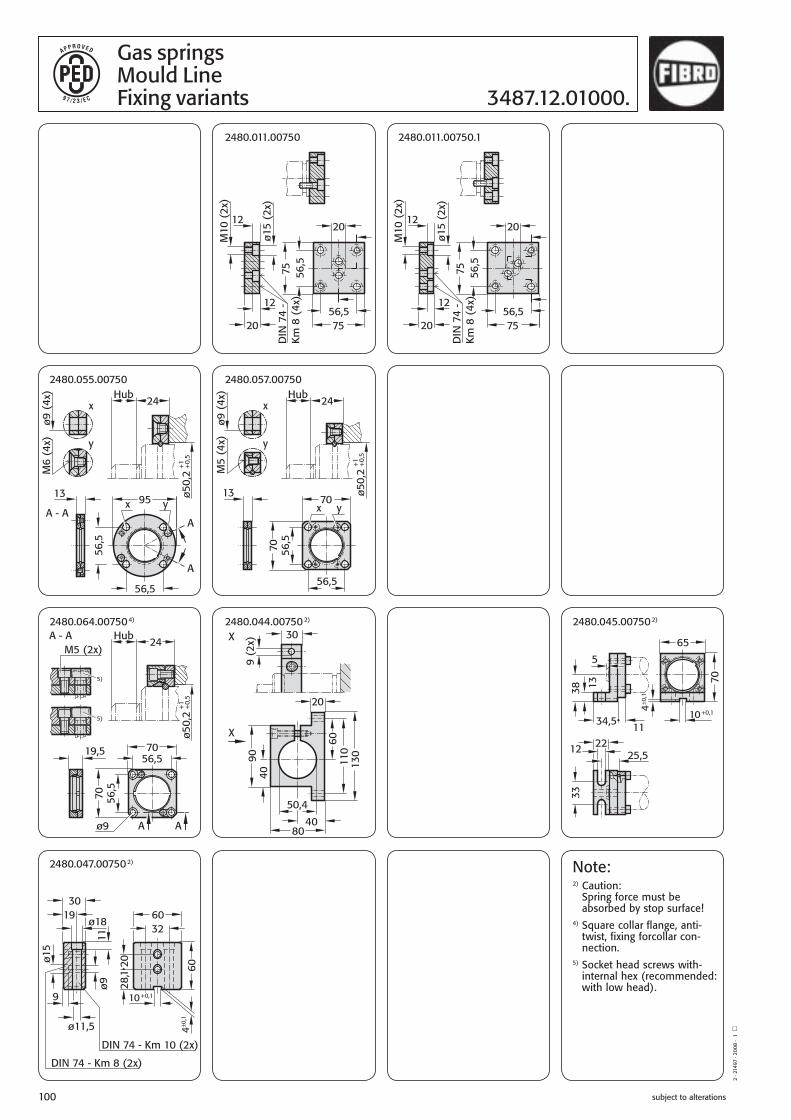
subject to alterations100
Gas springsMould LineFixing variants 3487.12.01000.
Note:2) Caution:
Spring force must be absorbed by stop surface!
4) Square collar flange, anti-twist, fixing forcollar con-nection.
5) Socket head screws with-internal hex (recommended: with low head).
2 · 2
1497
· 20
08 ·
1 ◽
2480.047.007502)
2480.044.007502)2480.064.007504) 2480.045.007502)
2480.055.00750 2480.057.00750
2480.011.00750 2480.011.00750.1
B2_Formenbau_GB_11_2008.indd 100B2_Formenbau_GB_11_2008.indd 100 08.12.2008 10:19:5208.12.2008 10:19:52

subject to alterations 101
Gas springs3487.12.01000. Mould Line
3487.12.01000.
Note:Order No. for spare parts kit:3487.12.01000
Pressure medium: Nitrogen – N2
max. filling pressure: see table min. filling pressure: 25 bar (20°C)Working temperature: 0°C to +120°Ctemperature-dependent force increase: ±0.3%/°C
Recommended max. working temperature Max. filling pressureStrokes/min. range at 20°C in bar20 at 0°C- 80°C 15015 at 80°C-100°C 12510 at 100°C-120°C 115Max. piston speed: 1.0 m/s
3487.12.01000.Initial spring force versus charge pressureand working temperature
3487.12.01000.Spring force Diagram displacement versus stroke rise
Spring force in daN
Pres
sure
ris
e fa
ctor
Nominal stroke
Stroke in mm
Pressure rise factor accounts for displacement but not external influences!
3487.12.01000.013 13 51 64 016 16 54 70 019 19 57 76 025 25 63 88 032 32 70 102 038 38 76 114 050 50 88 138 063 63 101 164 075 75 113 188 080 80 118 198 100* 100 138 238 125* 125 163 288 *On request
3487.12.01000.The initial spring force at 150 bar/20°C is 1000 daN
StrokeOrder no. max. lmin. l
Cha
rge
pres
sure
in b
ar
2 · 2
1498
· 20
08 ·
1 ◽
B2_Formenbau_GB_11_2008.indd 101B2_Formenbau_GB_11_2008.indd 101 08.12.2008 10:19:5308.12.2008 10:19:53

subject to alterations
2 · 2
0518
· 20
06 ·
1 ◽
102
B2_Formenbau_GB_11_2008.indd 102B2_Formenbau_GB_11_2008.indd 102 08.12.2008 10:19:5408.12.2008 10:19:54

subject to alterations 103
Gas SpringsAccessories
B2_Formenbau_GB_11_2008.indd 103B2_Formenbau_GB_11_2008.indd 103 08.12.2008 10:19:5408.12.2008 10:19:54

subject to alterations104
Thrust Pads and 2480.004. 2480.009.Thrust Plates 2480.018. 2480.019.
2480.004. Order No M A/F b l2480.004.06 M6 17 20 62480.004.08 M8 19 22,5 11
Material:Steel 1.1731, case-hardened
2480.009. max. piston rodOrder No diameter a b c d d1 e e1 t2480.009.00250 15 50 25 12 7 11 32 8 72480.009.00500 20 55 30 12 7 11 40 14 72480.009.00500.1* 20 55 32 16 9 15 37 – 102480.009.00750 25 70 35 15 9 15 48 14 92480.009.00750.1* 36 65 50 16 9 15 47 – 102480.009.01500 36 75 50 15 9 15 56 30 92480.009.03000 50 85 60 15 9 15 66 40 92480.009.03000.1* 50 80 60 16 9 15 62 – 102480.009.05000 65 100 80 20 11 18 72 56 112480.009.05000.1* 65 80 80 16 9 15 62 – 102480.009.07500 80 110 100 20 11 18 85 75 112480.009.07500.1* 80 100 100 16 9 15 82 – 10 * to Volvo standard
Material:Steel 1.2842, hardened
2480.004. Thrust Padfor gas springs with M6 and M8 thread in the piston rod
2480.009. Thrust Plate
2480.009. .1 Thrust Plate
Installation Examples: Description:The hardened thrust pad 2480.004. reduces side forces in casesof skew thrust vaces or lateral displacement component.
The hardened thrust plates 2480.009., 2480.018., 2480.019. and 2480.019.45 further helps to protect the gas spring from lateral forces, through reduction of friction - even when used withoutthe thrust pad.
Note:Especially with gas springs of large stroking capacity werecommend the use of the pad plate combination!
case-hardened
A/F
B2_Formenbau_GB_11_2008.indd 104B2_Formenbau_GB_11_2008.indd 104 08.12.2008 10:19:5408.12.2008 10:19:54

subject to alterations 105
Thrust Plates for installation in2480.019.45. small spaces as per CNOMO
+2
e
tc
a +2
e
d
d1
a
2480.018. Thrust Plate2480.019. Thrust Plate
hardened
2480.018./2480.019. max. piston rodOrder No diameter a c d d1 e t2480.018.01500 65 90 12 9 15 64 9 2480.019.00100 15 40 15 9 15 21 102480.019.00100.2* 15 40 15 7 11 24 72480.019.00750 25 56 20 11 18 32 132480.019.03000 50 71 20 11 18 48 132480.019.03000.2* 50 70 15 9 15 50 92480.019.03000.1 80 90 20 11 18 67 132480.019.07500.2* 80 90 15 9 15 70 92480.019.07500 95 140 20 11 18 110 13 * to VDI 3003
Material:Steel 1.2842, hardened
2480.019.45. max. piston rodOrder No Shape diameter a b c d2480.019.45.00750 A 50 70 10,0 50 112480.009.45.01500 A 80 90 10,0 70 112480.009.45.03000 B 95 105 10,0 85 112480.00945..05000 B 95 125 10,0 105 112480.009.45.07500 B 95 150 12,5 125 132480.009.45.10000 B 95 190 12,5 165 13
Material:Steel 1.2842, hardened
2480.019.45.Thrust Plate
Installation Examples: Description:When used together with thrust pad 2480.004., tempered thrust plates 2480.019.045. ensure the best conditions for protectinggas springs. Even without the thrust pad, thrust plates allow for movement between the piston rod and the tool.
Note:Especially with gas springs of large stroking capacity werecommend the use of the pad plate combination!
hardened
B2_Formenbau_GB_11_2008.indd 105B2_Formenbau_GB_11_2008.indd 105 08.12.2008 10:19:5508.12.2008 10:19:55

subject to alterations106
2·1
9427
·200
4·1
°
Gas spring connection systems Introduction
Connecting gas springs in one more systems enables the user to monitor gas spring pressure fromoutside the tool, to adjust it if necessary, to fill it and to drain it. The connector system has many advantages including ease of maintenance, reliability and improvement in the quality of gas sping use in the tool.
FIBRO offers four different systems for hose connections for gas springs: Minimess system, Compressionfitting system, JIC system (24° flare) and Micro connector system. The hoses, screwed connectors andother components are selected to meet the most stringent standards and undergo a series of tests including service life, static seel and robustness after repeated assembly and disassembly.
Recommended application:
Most used system for all gas springs with G1/8 gas connection. Not suitable for use with a pressure reservoir because of the small internal diameter which reduces the flow.
+ Small external diameter of hose 0,5 mm+ Small external diameter of hose 0,5 mm Rmin = 20+ High pressure resistance+ Vibration-proof measurement couplings+ Connector with valve+ No tools needed for connecting hose to adapter, and disconnecting± Swaged non-detachable hose fitting– Not for use with a pressure reservoir
Minimess system 2480.00.23./.24. Page 107–115
Compression fitting system 2480.00.10. Page 116–118
JIC system (24° flare) 2480.00.25./.26. Page 119–121
Micro connector system 2480.00.21./.22. Page 122–125
Technical data:Hose: polyamide 11, black, dimpledHose fitting: free cutting steel, galvanisedMeasurement couplings: free cutting steel, galvanisedAdapter: steel, gunmetal finishMax. pressure: 630 barTemperature range: 0–100°C
Recommended application:
For all gas springs with G1/8 gas connection. Mainly used for self-assembly in small numbers.
+ Assemble on-site system+ Reusable hose fitting+ High pressure resistance± Suitable for connecting to a pressure reservoir under certain conditions– Larger bending radius Rmin = 40– Not suitable for gas springs with M6 connection thread– Extra time required for preparing hose and fitting it
Technical data:Hose: polyurethane/polyamide, black, dimpledHose fittting: steel, galvanisedAdapter: steel, galvanisedMax. pressure: 380 barTemperatur range: 0–100°C
Recommended application:
For all gas springs with G1/8 gas connection. Mainly used for connection to pressure reservoir.
+ Suitable for connecting to a pressure reservoir+ Wide range of connection adapters+ Vibration-proof (O-ring seal)+ High pressure resistance± Swaged non-detachable hose fitting– Larger bending radius Rmin = 40–Not suitable for gas springs with M6 connection thread
Technical data:Hose: polyurethane/polyamide, black, dimpledHose fitting: steel, galvanisedAdapter: steel, galvanisedMax. pressure: 315 barTemperatur range: 0–100°C
Recommended application:
For all gas springs with M6 gas connection. Not suitable for use with a pessure reservoir because of the small internal diameter which reduces the flow..
+ Small external hose diameter: [ 5 mm+ Small bending radius Rmin = 20+ High pressure resistance+ Direct connection in control fitting M8x1 (without gauging coupling)+ Small connection adapter± Swaged non-detachable hose fitting– Not for use with a pressure reservoir– Only suitable for use in some gas spring applications with G1/8 connection thread
Technical data:Hose : polyamide 11, black, dimpledHose fitting: free cutting steel, galvanisedAdapter: steel, galvanisedMax. pressure: 630 barTemperatur range: 0–100°C
B2_Formenbau_GB_11_2008.indd 106B2_Formenbau_GB_11_2008.indd 106 08.12.2008 10:19:5508.12.2008 10:19:55

subject to alterations 107
1
4
3
2
Item Designation Number Order No Comment1 Control fitting 1 2480.00.30.01 Optionally with diaphragm pressure switch 2480.00.30.022 Gauging coupling 4 2480.00.24.01 3 Measuring hose 4 2480.00.23. . Type of connection and length as required4 Gauging coupling 4 2480.00.24.02
Instruction for Hose Assembly Mounting arrangement for gas springs in the Minimess system
Never exceed the maximum pressures and temperatures for the hoses.
Ensure that all hoses and adaptors are perfectly clean prior to assembly.
To be suitable for use with compressed gas the hose sheath must be perforated. We recommend the use of the 24°-cone-hose system for pressure reservoir to ensure an unrestricted gas flow.
Follow the instructions below to ensure functionality and maximum service life for the hose connection:
Refer to DIN 20066 for further details on installing hose connections.
Warning:Any modifications whatsoever to the product are prohibited.
For further information refer to the FIBRO Gas Spring Catalogue, visit www.fibro.com or contact your FIBRO agent.
Example 1:Direct connection for group
Function:Each spring has a direct connection with the control fitting. They are not interconnected and form a pressure zonePage 126
Note:When installing gas springs in the system always remove the valve from the gas spring.
2·1
9422
·200
4·1
°
1Select a hose length to provide a certain amount of play.
2The longitudinal marking on the hose must not be twisted during assembly.
3(3) Use only hose fittings which prevent kinks forming in the hose.
4Any bends in the hose must always have the recommen-ded minimum radius, as detailed in the catalogue.
5The hose must be connected correctly to avoid mechanical damage.
B2_Formenbau_GB_11_2008.indd 107B2_Formenbau_GB_11_2008.indd 107 08.12.2008 10:19:5508.12.2008 10:19:55

subject to alterations108
2·1
8552
·200
3·1
°
Mounting arrangement for gas springs in the Minimess system 2480.
5
3
1
3
2
4
Example 2:Group series connection
Item Designation Number Order No Comment1 Measuring hose 7 2480.00.23. . Type of connection and length as required2 Distributor 1 2480.00.24.33 3 Gauging coupling 13 2480.00.24.01 4 Gauging coupling 1 2480.00.24.025 Control fitting 1 2480.00.31.01
Function:The springs are interconnected and there is just one test line to the control fitting.
Note:When installing gas springs in the system always remove the valve from the gas spring.
B2_Formenbau_GB_11_2008.indd 108B2_Formenbau_GB_11_2008.indd 108 08.12.2008 10:19:5608.12.2008 10:19:56

subject to alterations 109
2·1
8557
·200
3·1
° Mounting arrangement for gas springs 2480. in the Minimess system
1
2
3
4
6
5
Example 3:Multiple connections with independent functioning
Item Designation Number Order No Comment1 Simple adaptor, short 4 2480.00.24.17 Choice of ”long“ or ”very long“ depending on the specific mounting arrangements.2 Gauging coupling 28 2480.00.24.01 3 Multi adapter 12 2480.00.24.11 Choice of ”long“ or ”very long“ depending on the specific mounting arrangements.4 Measuring hose 16 2480.00.23. . Type of connection and length as required5 Multi control fitting 1 2480.00.39.01.004.1 Options: floor or wall mounted6 Gauging coupling 4 2480.00.24.02
Function:Each series of springs has a direct con-nection with the control fitting. By using a common pressure supply the springs can be joined in the fitting so that joint filling/releasing of gas is possible. The gas in each series of springs can also be filled/released or monitored indivi-dually .Page 130.
Note:When installing gas springs always remove the valve from the gas spring.
B2_Formenbau_GB_11_2008.indd 109B2_Formenbau_GB_11_2008.indd 109 08.12.2008 10:19:5608.12.2008 10:19:56

subject to alterations110
1
2
35
4
4
Item Designation Number Order No Comment1 Simple adaptor, short 1 2480.00.24.17 Choice of ”long“ or ”very long“ depending on the specific mounting arrangements.2 Gauging coupling 5 2480.00.24.01 3 Multi adapter 2 2480.00.24.11 Choice of ”long“ or ”very long“ depending on the specific mounting arrangements.4 Measuring hose 3 2480.00.23. . Type of connection and length as required5 Control fitting 1 2480.00.31.01 6 Gauging coupling 1 2480.00.24.02
2·1
8562
·200
3·1
°
Mounting arrangement for gas springs in the Minimess system 2480.
Example 4.1:Group series connection
Example 4.2:Group series connection
Function:The springs are interconnected and there is just one test line to the control fitting.
Note:When installing gas springs always remove the valve from the gas spring.
Function:The springs are interconnected and there is just one test line to the control fitting.
Note:When installing gas springs always remove the valve from the gas spring.
1 2 3 4 5
6
Item Designation Number Order No Comment1 Coupling 1 2480.00.24.31 2 Measuring hose 4 2480.00.23. . Type of connection and length as required3 Control fitting 1 2480.00.31.01 4 Gauging coupling 7 2480.00.24.015 Gauging coupling 1 2480.00.24.02
B2_Formenbau_GB_11_2008.indd 110B2_Formenbau_GB_11_2008.indd 110 08.12.2008 10:19:5608.12.2008 10:19:56

subject to alterations 111
2·1
9318
·200
4·1
° Mounting arrangement for gas springs 2480. in the Minimess system
2
34
1
Example 5:Independent test connection
Function:The springs work independently and have a gauging coupling (2480.00.24.01) with valve.If required the springs can be tested and pressure adjusted indivi-dually. A control fitting (2480.00.31.01) is used for the purpose.Page 126
Item Designation Number Order No Comment1 Gauging coupling 3 2480.00.24.01 2 Measuring hose 1 2480.00.23. . Type of connection and length as required3 Control fitting 1 2480.00.31.01 4 Gauging coupling 1 2480.00.24.02
B2_Formenbau_GB_11_2008.indd 111B2_Formenbau_GB_11_2008.indd 111 08.12.2008 10:19:5708.12.2008 10:19:57

subject to alterations112
2·1
0492
·8·5
°
Gas Spring AccessoriesMinimess – Compound Threaded Joints 2480.00.23.
2480.00.23.01.Order No l*2480.00.23.01. 0200 200 0300 300 0400 400 0500 500 0630 630 0800 800 1000 1000 1200 1200 1500 1500 2000 2000 2500 2500 3000 3000 * other lengths available shortest factory lengths: without antikink protection: 90 mmantikink protection at one end: 150 mmantikink protection at both ends: 300 mm
2480.00.23.03. Order No l*2480.00.23.03. 0200 200 0300 300 0400 400 0500 500 0630 630 0800 800 1000 1000 1200 1200 1500 1500 2000 2000 2500 2500 3000 3000 * other lenghts available shortest factory lengths:without antikink protection: 105 mmantikink protection at one end: 150 mmantikink protection at both ends: 300 mm
2480.00.23.02. Order No l*2480.00.23.02. 0200 200 0300 300 0400 400 0500 500 0630 630 0800 800 1000 1000 1200 1200 1500 1500 2000 2000 2500 2500 3000 3000 * other lengths available shortest factory lengths:without antikink protection: 90 mmantikink protection at one end: 150 mmantikink protection at both ends: 300 mm
2480.00.23.01.Gauging hose –both ends straight
2480.00.23.01.----.1Antikink spiral, at one end
2480.00.23.01.----.2Antikink spiral, at both ends
2480.00.23.03. Gauging hose – one ends90°-angle
2480.00.23.02. Gauging hose – one end straight 90°-angle
2480.00.23.02.----.2Antikink spiral, at both ends
2480.00.23.02.----.1Antikink spiral, at one end, straight
2480.00.23.02.----.3Antikink spiral, at one end, 90°
2480.00.23.03.----.3Antikink spiral, at one end
2480.00.23.03.----.2Antikink spiral, at both ends
B2_Formenbau_GB_11_2008.indd 112B2_Formenbau_GB_11_2008.indd 112 08.12.2008 10:19:5708.12.2008 10:19:57

subject to alterations 113
Gas Spring Accessories2480.00.24. Minimess – Compound Threaded Joints
2·1
0493
·200
7·5
▫
2480.00.24.10 long 2480.00.24.11 short 2480.00.24.12 extra-long Multiple adapter
2480.00.24.13 long 2480.00.24.14 short 2480.00.24.15 extra-long Dual adapter
2480.00.23.12.01 Hose clamp for gauging hose DN2 ([5 mm)
Material: PolyamideNote: Supplied without screws
Note: self-tapping Diameter of hole for self-tapping screw = 3,6 mm
2192.50.04.012self-tapping screwA M4x12 DIN 7516
Note:
The gauging coupling with valve is used in standard permanent con-nections. The valveless gauging coupling is used in systems where changes to the filling pressure are necessary on a regular basis (e.g. die cushions).
2480.00.24.16 long2480.00.24.17 short 2480.00.24.18 extra-longSingel adapter
Gauging coupling
2480.00.24.01 with valve
2480.00.24.03 without valvefor connection to gas spring
Gauging coupling
2480.00.24.02 with valve
2480.00.24.04 without valvefor connection to control fitting
Order No G d A/F l l12480.00.24.01 G 1/8 14 14 22 082480.00.24.02 G 1/4 19 19 21 102480.00.24.03 G 1/8 14 14 22 082480.00.24.04 G 1/4 19 19 21 10
2480.00.23.13.Anti-scuff spiralfor subsequent installation over hoses and tubing
Order No l in mm2480.00.23.13.0001 010002480.00.23.13.0002 020002480.00.23.13.0005 050002480.00.23.13.0010 10000
Inner-Ø 7 mmFor hose/tubingouter-Ø max. 5-25 mmTemperature range -30 °C to +100 °C
Material:PolyamideDescription:The anti-scuff spiral is used to protect against abrasion, is resistant to air, water, oil, hydraulic fluids petrol and other liquids.
B2_Formenbau_GB_11_2008.indd 113B2_Formenbau_GB_11_2008.indd 113 08.12.2008 10:19:5808.12.2008 10:19:58

subject to alterations114
2480.00.24.30 Distributor block G 1/83 ports
2·1
0494
·200
7·9
▫
Gas Spring AccessoriesMinimess – Compound Threaded Joints 2480.00.24.
2480.00.24.33Distributor G 1/814 ports
2480.00.40Charging Adapter
2480.00.24.34Distributor block G 1/84 ports
2480.00.24.31 Distributor block G 1/86 ports
B2_Formenbau_GB_11_2008.indd 114B2_Formenbau_GB_11_2008.indd 114 08.12.2008 10:19:5808.12.2008 10:19:58

subject to alterations 115
Gas Spring Accessories2480.00.24. Minimess – Compound Threaded Joints
2·8
638
·200
0·6
°
2480.00.24.01 Gauging coupling with valve installed
2480.00.24. 10 long 11 short12 extra-long
Multiple adapter with two gauging couplings
Note:When installing or fitting a gauging coupling the valve must be removed from the gas spring.
B2_Formenbau_GB_11_2008.indd 115B2_Formenbau_GB_11_2008.indd 115 08.12.2008 10:19:5908.12.2008 10:19:59

subject to alterations116
2·8
635
·200
0·6
°
Gas Spring AccessoriesCompression Fitting Compound Threaded Joints 2480.00.10.
2480.00.10.01 Direct connector to gas spring
2480.00.10.03 Direct connector to control fitting
2480.00.10.10 angle connector, adjustable
2480.00.10.11 T-connector, adjustable
2480.00.10.12 L-connector, adjustable
B2_Formenbau_GB_11_2008.indd 116B2_Formenbau_GB_11_2008.indd 116 08.12.2008 10:19:5908.12.2008 10:19:59

subject to alterations 117
ø3,
5
34
2·8
636
·200
7·7
▫ Gas Springs Accessoires Compression Fitting2480.00. Compound Threaded Joints
2480.00.54.01 Expansion punch for hosing
2480.00.10.20. High-pressure hose
2480.00.10.21 Hose screw fitting (female)
2480.00.54.02 Vice jaws for holding high-pressure hose
2480.00.54.03 Hose shears
2480.00.10.22 Hose screw fitting (male)
Ordering Code (example): High pressure = 2480.00.10.20.length 10 m = 2480.00.10.20.0010Order No = 2480.00.10.20.0010
A/F 10
2192.50.04.012self-tapping screwA M4x12 DIN 7516
Note: self-tappingDiameter of hole for self-tapping screw = 3.6 mm
Material: PolyamideNote: Supplied without screws
2480.00.23.13.Anti-scuff spiralfor subsequent installation over hoses and tubing
Order No l in mm2480.00.23.13.0001 010002480.00.23.13.0002 020002480.00.23.13.0005 050002480.00.23.13.0010 10000Inner-Ø 7 mmFor hose/tubingouter-Ø max. 5-25 mmTemperature range -30 °C to +100 °C
Material:PolyamideDescription:The anti-scuff spiral is used to protect against abrasion, is resistant to air, water, oil, hydraulic fluids petrol and other liquids.
2480.00.10.20.12.01Hose clamp for gauging hoseDN4 (Ø9 mm)
B2_Formenbau_GB_11_2008.indd 117B2_Formenbau_GB_11_2008.indd 117 08.12.2008 10:20:0008.12.2008 10:20:00
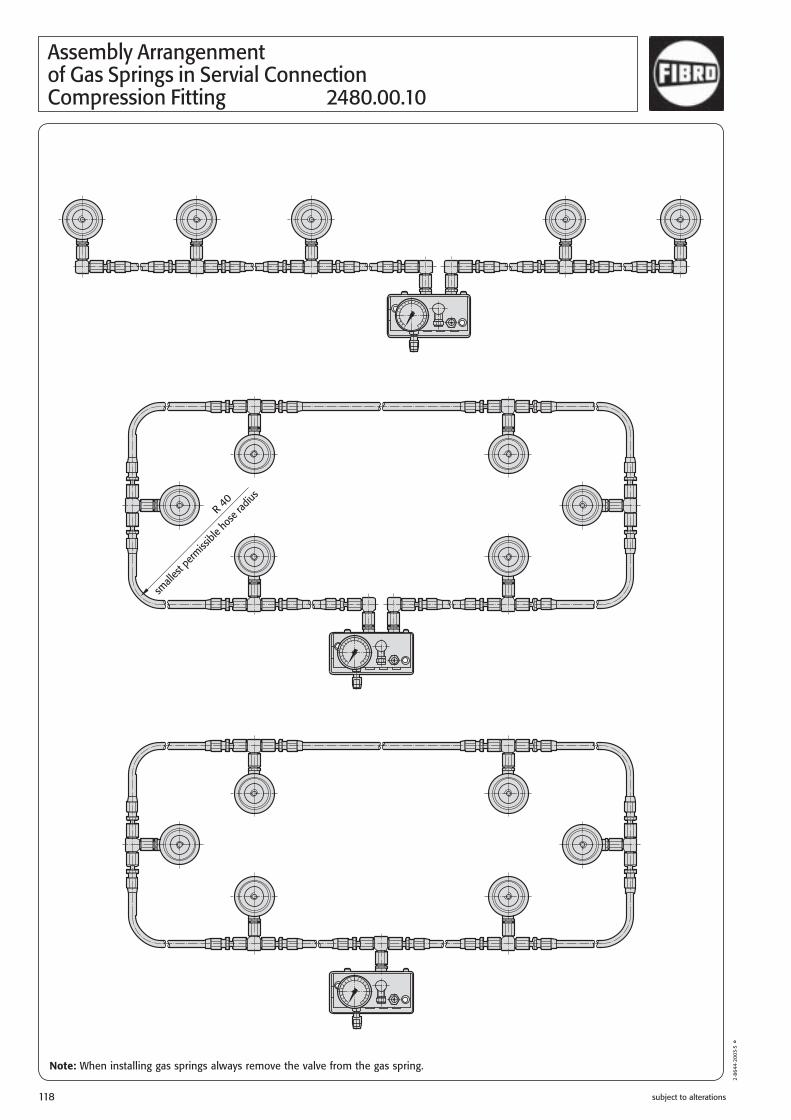
subject to alterations118
Assembly Arrangenmentof Gas Springs in Servial ConnectionCompression Fitting 2480.00.10
2·8
644·
2003
·5 °
Note: When installing gas springs always remove the valve from the gas spring.
B2_Formenbau_GB_11_2008.indd 118B2_Formenbau_GB_11_2008.indd 118 08.12.2008 10:20:0008.12.2008 10:20:00

subject to alterations 119
Gas Spring Accessories 24°-cone-threaded Joints2480.00.26. (DIN 2353 / DIN EN ISO 8434-1)
2480.00.26.03Threaded Joint G1/8
2480.00.26.04Threaded Joint G1/4
2480.00.26.21Adjustable threaded joint45°, complete
2480.00.26.25Adapter straight,hose to hose
2480.00.26.22Adjustable threaded joint90°, complete
2480.00.26.26Adapter, 90°,hose to hose
2480.00.26.23Adjustable L-Coupling,complete
2480.00.26.27Adapter, T,hose to hose
2480.00.26.24Adjustable T-Coupling,complete
2480.00.26.28Adapter, K,hose to hose
2·1
8451
·200
4·2
°
1) Eolastic-Seal ED
2) O-ring
1) Eolastic-Seal ED
2) O-ring 2) O-ring 2) O-ring
B2_Formenbau_GB_11_2008.indd 119B2_Formenbau_GB_11_2008.indd 119 08.12.2008 10:20:0108.12.2008 10:20:01

subject to alterations120
2·1
0456
·200
3·1
°
Gas springs accessoriesConnecting hoses with 24° cone(DIN 2353 / DIN EN ISO 8434-1) 2480.00.25.
Dimension I1 specified in the order, e.g. 765 mm, gives order no 2480.00.25.01.0765
Dimension I1 specified in the order, e.g. 765 mm, gives order no 2480.00.25.02.0765
Dimension I1 specified in the order, e.g. 765 mm, gives order no 2480.00.25.03.0765
Dimension I1 specified in the order, e.g. 765 mm, gives order no 2480.00.25.04.0765
* Shortest factory lengths: 140 mm minimum bending radius R40
Dimension I1 specified in the order, e.g. 765 mm, gives order no 2480.00.25.05.0765
Dimension I1 specified in the order, e.g. 765 mm, gives order no 2480.00.25.06.0765
B2_Formenbau_GB_11_2008.indd 120B2_Formenbau_GB_11_2008.indd 120 08.12.2008 10:20:0108.12.2008 10:20:01

subject to alterations 121
Gas springs accessories Direct connection dimensions2480.00.26. 24°-cone threaded joint (DIN 2353 / DIN EN ISO 8434-1)
Direct connection with 45°-elbow adaptor2480.00.26.21
Direct connection with 90°-elbow adaptor2480.00.26.22
Direct connection with L-coupling2480.00.26.23
Direct connection with T-coupling2480.00.26.24
2·1
8461
·200
7·2
▫
Direct connection hose straight adaptor 2480.00.26.03
Direct connection 45° hose withadaptor 2480.00.26.03
Direct connection 90° hose withadaptor 2480.00.26.03
2192.50.04.012self-tapping screwA M4×12 DIN 7516
Note: self-tapping, Diameter of hole for self-tapping screw = 3,6 mm
Material: PolyamideNote: Supplied without screws
2480.00.25.12.01Hose clamp for gauging hose DN5 ([ 11 mm)
2480.00.23.13.Anti-scuff spiralfor subsequent installation over hoses and tubing
Order No l in mm2480.00.23.13.0001 010002480.00.23.13.0002 020002480.00.23.13.0005 050002480.00.23.13.0010 10000Inner-Ø 7 mmFor hose/tubingouter-Ø max. 5-25 mmTemperature range -30 °C to +100 °C
Material:PolyamideDescription:The anti-scuff spiral is used to protect against abrasion, is resistant to air, water, oil, hydraulic fluids petrol and other liquids.
B2_Formenbau_GB_11_2008.indd 121B2_Formenbau_GB_11_2008.indd 121 08.12.2008 10:20:0208.12.2008 10:20:02

subject to alterations122
2480.00.21.01.Order No l*2480.00.21.01.0200 2002480.00.21.01.0300 3002480.00.21.01.0400 4002480.00.21.01.0500 5002480.00.21.01.0630 6302480.00.21.01.0800 8002480.00.21.01.1000 10002480.00.21.01.1200 12002480.00.21.01.1500 15002480.00.21.01.2000 20002480.00.21.01.2500 25002480.00.21.01.3000 3000 * Other lenghts available in 5 mm steps.Shortest factory length:without antikink protection: 90 mmantikink protection at one end: 150 mmantikink protection at both ends: 300 mm
Gas Spring AccessoriesMicro Compound Threaded Joint 2480.00.21
2480.00.21.01.Micro measuring hose – both ends straight
2480.00.21.01.----.1Antikink spiral, at one end
2480.00.21.01.----.2Antikink spiral, at both ends
2480.00.22.34Micro distributor block M8x1 with 4 ports incl. blanking plugs
2480.00.23.12.01Hose clamp for gauging hose DN2 ([ 5 mm)
Material: Polyamide
Note: Supplied without screws
2192.50.04.012self-tapping screwA M4x12 DIN 7516
Note: self-tappingDiameter of hole for self-tapping screw = 3.6 mm
2·1
7114
·200
7·2
▫
2480.00.23.13.Anti-scuff spiralfor subsequent installation over hoses and tubing
Order No l in mm2480.00.23.13.0001 010002480.00.23.13.0002 020002480.00.23.13.0005 050002480.00.23.13.0010 10000
Inner-Ø 7 mmFor hose/tubingouter-Ø max. 5-25 mmTemperature range -30 °C to +100 °C
Material:PolyamideDescription:The anti-scuff spiral is used to protect against abrasion, is resistant to air, water, oil, hydraulic fluids petrol and other liquids.
B2_Formenbau_GB_11_2008.indd 122B2_Formenbau_GB_11_2008.indd 122 08.12.2008 10:20:0208.12.2008 10:20:02

subject to alterations 123
2480.00.22.14.06Micro-Adapter G1/4-M6connection to 90°-Micro-Single Adapter and to control fitting
2·1
7175
·200
1·1
°
Gas Spring Accessories2480.00.22. Micro Compound Threaded Joint
2480.00.22.0190°-Mico Single Adapter
2480.00.22.02180°-Micro Double Adapter
2480.00.22.0345°-Micro Double Adapter
B2_Formenbau_GB_11_2008.indd 123B2_Formenbau_GB_11_2008.indd 123 08.12.2008 10:20:0308.12.2008 10:20:03

subject to alterations124
Gas Spring AccessoriesMicro Compound Threaded Joint 2480.00.22.
2480.00.22.06.06Micro-Adapter M6-M6for connection to gas spring withsplit clamping flange 2480.022.
2480.00.22.06.08Micro-Adapter M6-M8for connection to gas spring and gauging hose.
2480.00.22.18.06Micro-Adapter G1/8 -M6for connection to gas spring.
2480.00.22.18.08Micro-Adapter G1/8 -M8for connection to gas spring.
2480.00.22.14.08Micro-Adapter G 1/4 -M8Connection to gauging hose and to control fitting.
2·1
7180
·200
1·1
°
2480.00.22.08.06Micro adapter M8-M6 for angled connection to the micro control fitting
B2_Formenbau_GB_11_2008.indd 124B2_Formenbau_GB_11_2008.indd 124 08.12.2008 10:20:0308.12.2008 10:20:03

subject to alterations 125
2·1
7119
·200
1·1
° Micro Control Fitting2480.00.34.01 without pressure relief2480.00.34.03 with pressure relief
2480.00.34.01 without pressure relief2480.00.34.03 with pressure relief
Pressure gauge dial 0-400 bar / 5800 psi
Description:The micro control fitting 2480.00.34.01/03 is used to constantly monitor the charge pressure of one or more Gas Springs (3x5 connections M8x1, top, bottom, back and 1xat the side).
Note:* 2 m long filling hose with rapid
coupling, shutoff valve and gas bottle connector Order no: 2480.00.31.02 (to be ordered separately)
*
B2_Formenbau_GB_11_2008.indd 125B2_Formenbau_GB_11_2008.indd 125 08.12.2008 10:20:0408.12.2008 10:20:04

subject to alterations126
Description:The control fitting 2480.00.31.01 performs the same function as the control armature 2480.00.30.01.
Note:* 2-m long filling hose with rapid coupling,
shutoff valve and gas bottle connector, Order No. 2480.00.31.02(to be ordered separately)
2·9
428
·200
1·7
°
2480.00.30.01 2480.00.30.02 2480.00.30.03 2480.00.30.04Control Fitting for Gas Springs 2480.00.31.01/.06
Description:The control fitting 2480.00.30.01/02/03/04 serves to control the charge presu-re of up to eight connected gas springs.Pressure checks during operation can be effected in two ways:a) by visual monitoring of the gauge dials. b) automatically, by means of diaphragm
pressure switch 248.00.15 The switch will stop the associated machine as soon as the charge pressure drops below the value set.
Note:The shutoff valve may be open or closed during operation.
The closing of the pressure gauge shutoff valve ensures that no pressure peaks from the gas spring act on the pressure gauge.
* 2-m long filling hose with rapid cou-pling, shutoff valve and gas bottle con-nector, Order No. 2480.00.31.02(to be ordered separately)
2480.00.31.01 without pressure switch2480.00.31.06 with pressure switch
2480.00.24.02 (see Page 113)or connector 2480.00.10.03 (see Page 116)or diaphragm pressure switch 2480.00.45.01(see Page 131)
2480.00.30.01 without pressure switch, without pressure relief2480.00.30.02 with pressure switch, without pressure relief2480.00.30.03 without pressure switch, with pressure relief2480.00.30.04 with pressure switch, with pressure relief
rapid coupling fornitrogen supply*
rapid coupling fornitrogen supply*
B2_Formenbau_GB_11_2008.indd 126B2_Formenbau_GB_11_2008.indd 126 08.12.2008 10:20:0408.12.2008 10:20:04

subject to alterations 127
Control fitting without pressure switch,2480.00.30.13 including pressure relief
2480.00.30.13 without pressure switch, including pressure relief 2480.00.30.13
Description:The control fitting 2480.00.30.13 is used to constantly monitor the filling pressure of one or more gas springs. The control fitting is equipped with rapid coupling for nitrogen supply and a bleeder valve. There are three G1/8 ports for simultaneous pres-sure checking at the control fitting.Measuring range from 0 - 400 bar / 5800 psi.
2·1
8158
·200
3·1
°
rapid coupling fornitrogen supply
2480.00.24.02 (see Page 113)or connector 2480.00.10.03 (see Page 116)
B2_Formenbau_GB_11_2008.indd 127B2_Formenbau_GB_11_2008.indd 127 08.12.2008 10:20:0408.12.2008 10:20:04

subject to alterations128
Multiple control fitting 2480.00.39.04.Connection adaptor 2480.00.39.04.00.01
2007
• 1
□
2480.00.39.04.Order no. Qty. l l1 testing units2480.00.39.04.02 2 133.5 44.52480.00.39.04.03 3 178.0 89.02480.00.39.04.04 4 222.5 133.52480.00.39.04.05 5 267.0 178.02480.00.39.04.06 6 311.5 222.52480.00.39.04.08 8 400.5 311.52480.00.39.04.10 10 489.5 400.5
Description:The multiple control fitting is required if it is necessary to check or set the filling pressure of each spring or spring assembly indivi-dually.The filling of the springs is done at a central position using the rapid coupling for nitrogen supply. Each testing unit is provided with three threaded connections for the optional hose connection. The cover protects against mechanical damages.
Note:* For the connection of hose connections G1/8, the adaptor
2480.00.39.04.00.01 must be ordered separately.
2480.00.39.04. Multiple control fitting
2480.00.39.04.00.01 Connection adaptor 7/16-20 UNF – G1/8
Rapid coupling fornitrogen supply*
Connection thread 7/16-20 UNF*for 2480.00.39.04.00.01
Lock valve
Number of testing units
Bleeder valve
Pressure relief
A/F 16
Pressure gauge dial0 to 400 bar
B2_Formenbau_GB_11_2008.indd 128B2_Formenbau_GB_11_2008.indd 128 08.12.2008 10:20:0508.12.2008 10:20:05

subject to alterations 129
2480.00.31.11
Description:The control fitting with pressure relief 2480.00.31.11 (Faure) is used for continuous monitoring of the filling pressure of one or more gas springs (one connection G1/8-M16). During operation the pressure can be checked by visual monitoring of the pressure gauge.
Note:To connect the measuring hose system 2480.00.23, remove M16 connection adapter and screw in the gauging coupling with valve 2480.00.24.01 (to be ordered separately).When installing gas springs always remove the valve from the gas spring.
* 2 m long filling hose with rapid coupling, shut-off valve and gas bottle connector, Order no. 2480.00.31.02 (to be ordered sepa-rately)
2·1
8163
·200
3·1
°
2480.00.31.11 Control fitting with pressure relief
Rapid coupling fornitrogen supply*
B2_Formenbau_GB_11_2008.indd 129B2_Formenbau_GB_11_2008.indd 129 08.12.2008 10:20:0508.12.2008 10:20:05

subject to alterations130
Stacked Control Fitttingsfor individual control 2480.00.39.01.
2·8
463
·9·4
°
2480.00.39.01.
rapid coupling for nitrogen supply* 2 m long filling hose with rapid coupling, shut-off valve and gas bottle
connector, Order No. 2480.00.31.02 (to be ordered separately)
Ordering Code (example):Stacked Control fitting = 2480.00.39.01.5 modules = 005.with floor-mount = 1with wall-mount = 2Order No = 2480.00.39.01.005.1 or 2
Description:Stacked Control fittings are required where it is necessary tocontrol the charge pressure of each gas spring individually. Thefitting models can be stacked together ad libidum.Recharging of any to the spring units connected can be effectedcentrally via the rapid couplings and the appropriate chargingvalves. Each stack is equipped with an input end plate with rapidcoupling, and an end plate sealing off the opposite side. The num-ber of armature modules depends on the number of gas springs inquestion. The stack can be supplied for wall mounting or forinstallation on the floor.
Note:When all charge valves are opened the springs are interconnected with one another.
B2_Formenbau_GB_11_2008.indd 130B2_Formenbau_GB_11_2008.indd 130 08.12.2008 10:20:0608.12.2008 10:20:06

subject to alterations 131
Installation Example:
2480.00.45.10
2480.00.45.01 2480.00.45.02 Diaphragm PressureSwitch
Technical Data of Diaphragm2480.00.45.01switching range, adjustable 20–200 barswitching tolerance ±3–5 baroverpressure protection 300 barvoltage (max.) 250 V2480.00.45.02switching range, adjustable 5–50 barswitching tolerance ±3,0 baroverpressure protection 200 barvoltage (max.) 250 V
Note:for monitoring pressure of single gas springs see adapter 2480.00.45.10
Circuit diagram for diaphragm pressure switch
Description:In conjunction with diaphragm pressure switch 2480.00.45.01 or .02, the adapter 2480.00.45.10 permits the monitoring of the charge pressure: if the pressure drops below a set value, the diaphragmpressure switch operates and emits a signal or stops the machine.
A/F 24
2480.00.45.012480.00.45.02 Diaphragm Pressure Switch 2480.00.45.10 Adapter Block
2·8
639
·8·6
°
Adjustment
B2_Formenbau_GB_11_2008.indd 131B2_Formenbau_GB_11_2008.indd 131 08.12.2008 10:20:0608.12.2008 10:20:06

subject to alterations132
2·8
640
·200
2·7
°
Filling and control fitting 2480.00.32.21Filling hose 2480.00.31.02Cylinder pressure regulator 2480.00.32.07.
Description:The filling and control fitting 2480.00.32.21 is used to fill, vary the pressure setting (e.g. when testing tools) and mea-sure the gas pressure.
The coupling enables the fil-ling hose 2480.00.31.02 to be connected directly to the gas cylinder valve or the pressure regulator.
If the fitting is used solely for checking purposes, a simplified arrangement without the filling hose 2480.00.31.02 is also possible.
The fitting is equipped as standard with an adapter 2480.00.32.10 / 11 (see following page) for connection to various types of gas springs.
Note:2 m long filling hose with quick release coupling, shut-off valve and gas bottle connector, order no. 2480.00.31.02 (order sepa-rately).
Other filling hose lengths to order.
Description:The pressure regulator 2480.00.32.07. is designed for 200 bar connections and for 300 bar gas cylinders.
The filling and control fitting 2480.00.32.21 is connected to the cylinder pressure regula-tor for filling gas springs using filling hose 2480.00.31.02 and connector adaptor 2480.00.32.07.04.
Depending on the type of gas cylinder, the gas cylinder con-nector used can either be the 2480.00.32.07.02 for 200 bar cylinders or the 2480.00.32.07.03 for 300 bar cylinders.
Max. admission pressure 300 barBack pressure 10-200 bar
Other benefits:
• Hasty opening of the gate valve on the filling and con-trol fitting 2480.00.32.21 cannot result in overfilling.
• It is not necessary to have the pressure display of the filling and control fitting 2480.00.32.21 in view.
2480.00.32.07. Gas cylinder pressure regulator
2480.00.31.02 Filling hose
Order No for gas cylinder pressure 200/300 bar2480.00.32.07.01 Pressure regulator2480.00.32.07.02 Gas cylinder connector 200 bar2480.00.32.07.03 Gas cylinder connector 300 bar2480.00.32.07.04 Connector adaptor
Order No for gas cylinder pressure 200 bar2480.00.32.07.01 Pressure regulator2480.00.32.07.02 Gas cylinder connector 200 bar2480.00.32.07.04 Connector adaptor
Order No for gas cylinder pressure 300 bar2480.00.32.07.01 Pressure regulator2480.00.32.07.03 Gas cylinder connector 300 bar2480.00.32.07.04 Connector adaptor
2480.00.32.21 Filling and control fitting
pressuregauge dial
B2_Formenbau_GB_11_2008.indd 132B2_Formenbau_GB_11_2008.indd 132 08.12.2008 10:20:0708.12.2008 10:20:07

subject to alterations 133
2480.00.32.11Charging Adapter for Gas Springs with filling connector thread G1/8
2·1
4563
·200
0·1
°
2480.00.32.10/11 Charging Adapters
2480.00.32.10Charging Adapter for Gas Springs with filling connector thread M6
B2_Formenbau_GB_11_2008.indd 133B2_Formenbau_GB_11_2008.indd 133 08.12.2008 10:20:0708.12.2008 10:20:07

subject to alterations134
2480.00.35.021Analogue display
Description:The dynamometer with mechanical measuring device can be used to test the spring force of gas springs up to 8000 daN.
The dynamometer with digital measuring device can be used to test the spring force of gas springs up to 10 000 daN.
The dynamometer 2480.00.35.021 with analogue display is supplied with three interchangeable pressure measuring nozzles different ranges of values.
Up to 300 daNFrom 300 to 1750 daNFrom 1750 to 8000 daN
The dynamometer 2480.00.35.032 with digital display has a pressure measuring nozzle for forces ranging from 0 to 10 000 daN.
Maximum spring installation height analogous = 700 mm digital = 760 mm
2480.00.35.021Dynamometers 2480.00.35.032for Gas Springs replaces: 2480.00.35.031
2·1
1241
·200
5·3
°
2480.00.35.032Digital display
B2_Formenbau_GB_11_2008.indd 134B2_Formenbau_GB_11_2008.indd 134 08.12.2008 10:20:0708.12.2008 10:20:07

subject to alterations 135
Dynamometers2480.00.35.04 for Gas Springs
2·8
646·
2001
·6 °
2480.00.35.04The dynamometer with digital measuring device can be used to test the spring force of gas springs up to 2000 daN.Max. spring installation height: 488 mm.Max. spring diameter: 150 mm.
2480.00.35.04
B2_Formenbau_GB_11_2008.indd 135B2_Formenbau_GB_11_2008.indd 135 08.12.2008 10:20:1008.12.2008 10:20:10

subject to alterations136
2·1
2594
·200
2·3
°
Toolkits for assembling gas springs 2480.00.50.11
2480.00.50.11Toolkit for all gas springs
The toolkit contains:Pos. Order No Term1 2480.00.50.01.001 Assembly sleeve Mini2 2480.00.50.01.002 Assembly sleeve 002503 2480.00.50.01.003 Assembly sleeve 005003-1 2480.00.50.01.031 Assembly sleeve X500 (2487.12.00500.)4 2480.00.50.01.004 Assembly sleeve 007505 2480.00.50.01.005 Assembly sleeve 015005-1 2480.00.50.01.051 Assembly sleeve X1500 (2487.12.01500.)6 2480.00.50.01.006 Assembly sleeve 030007 2480.00.50.01.007 Assembly sleeve 050008 2480.00.50.01.008 Assembly sleeve 075009 2480.00.50.01.009 Assembly sleeve 1000010-1 2480.00.50.01.101 Circlip tool13 2480.00.50.01.013 T-lever M814-1 2480.00.50.01.141 T-lever M1615 2480.00.50.01.015 T-lever G 1/8”16-1 2480.00.50.01.161 T-lever with heel M617 2480.00.50.01.017 Valve pliers 18 2480.00.50.01.018 Valve tool M619 2480.00.50.01.019 Valve tool G 1/8"29 2480.00.50.01.029 Special valve spanner30 2480.00.50.01.030 Valve tool VG 533 2480.00.50.01.033 Valve tool M6 (2480.00.41.1)34 2480.00.50.01.034 Handle for disassembling M339-1 2480.00.50.01.391 Tool case
Description: Toolkit for assembling and disassembling gas springs.
Note: Read instructions for use before working on it.Every tool can be ordered separately.
1 2 3 3-1 4 55-1
67
89
34
17
29
15
13
18 30 19 33
14-1
10-1
16-1
39-1
2480.00.50.11
B2_Formenbau_GB_11_2008.indd 136B2_Formenbau_GB_11_2008.indd 136 08.12.2008 10:20:1008.12.2008 10:20:10

2 · 2
0849
· 20
06 ·
1 Q
subject to alterations
Auxiliary Equipment
137
B2_Formenbau_GB_11_2008.indd 137B2_Formenbau_GB_11_2008.indd 137 08.12.2008 10:20:1208.12.2008 10:20:12

subject to alterations138
Anaerobic Metal Adhesives 281.243for Securing of Screws 281.270Cleaner 281.706
2·2
238·
2000
·4 °
Rapid-Cleaning SpraySpray Can 400 ml
In order to achieve optimum results in bonding work, the affected surfaces should be throughly cleaned beforehand. LOCTITE 706 Spray removes oil, grease and contamination from treated metal surfaces. Upon evaporation, no residue remains.
281.706LOCTITE 7061 Spray Can
2·8
847·
2000
·4 °
For Screws and NutsFor the securing of screws and bolts with medium bonding strength. Protects against vibrations, corrosion and leakage,up to M 36. Normal hand tools will suffice for dismantling.
Temperature resistant from –55°C to +150°C.Bonding strength 6–14 N/mm2
Contents of Bottle: 50 ml
281.243LOCTITE 243
For Screws and NutsFor the securing of screws and bolts with high bonding strength, also for studs and nuts. Suitable for threads up to M 20. Reliably seals hydraulic/pneumatic lines up to 1/2˝ BSP. Temperature resistant from -55°C to +150°C.Secured parts cannot be dismantled easily.
Seals gaps up to 0.15 mm max..Bonding strength 11–20 N/mm2
Contents of Bottle: 50 ml
281.270LOCTITE 2701
B2_Formenbau_GB_11_2008.indd 138B2_Formenbau_GB_11_2008.indd 138 08.12.2008 10:20:1308.12.2008 10:20:13

subject to alterations 139
280.15 FIBROLIT®- RL, 280.16 280.131 280.23 FIBROLIT®- RS, FIBROLIT®-ARF
2·8
848·
2000
·4 °
280.15 280.16
280.131 280.23
FIBROLIT®-RL Penetration Lubricant SprayAerosol spray can 300 ml
Of enormous penetrating capability, spray deposit enters tiniest joint gaps and thus releases corroded and seized parts such as nuts, bolts and press fits. Acts as long-lasting rust protective and lubricant.
FIBROLIT®-RS Clear Lacquer SprayAerosol spray can 300 ml
Used chiefly as a corrosion-protective lacquer, FIBROLIT®-RS forms a glass-clear deposit that dries quickly. It serves as a practical, expedient means of protecting metal components from rusting and tarnishing.
FIBROLIT®-ARF Marking Out BlueAerosol spray can 300 ml, liquid container 500 ml
A fast-drying marking out blue of outstanding intensity.Colour: dark blueDegrease with FIBROLIT®-EF before application.
B2_Formenbau_GB_11_2008.indd 139B2_Formenbau_GB_11_2008.indd 139 08.12.2008 10:20:1408.12.2008 10:20:14

subject to alterations
2 · 2
0518
· 20
06 ·
1 ◽
140
B2_Formenbau_GB_11_2008.indd 140B2_Formenbau_GB_11_2008.indd 140 08.12.2008 10:20:1608.12.2008 10:20:16

2 · 2
0519
· 20
06 ·
1 ◽
subject to alterations 141
B2_Formenbau_GB_11_2008.indd 141B2_Formenbau_GB_11_2008.indd 141 08.12.2008 10:20:1608.12.2008 10:20:16

DE
Walter Ruff GmbH Postfach 45 0118 · 28295 Bremen Tel. 0421-438 78-0 · Fax 0421-438 78-22 [email protected] · www.praeziruff.dePLZ 21000-29000, 49000
Außendienst Karl-Heinz Keßler Mehlstraße 8 · 33729 Bielefeld Tel. 0521-764 43 · Fax 0521-770 75 58 Mobil 0170-564 34 15 · [email protected] 30000-34000, 37000, 38000
Außendienst Jörg Dyck Walter Ruff GmbH Postfach 45 0118 · 28295 Bremen Tel. 0421-438 78-0 · Fax 0421-438 78-22 Mobil 0173-925 22 43 · [email protected] 06000, 29000-31000, 37000-39000
Außendienst Jürgen Mölling Jupiterstraße 12 · 33739 Bielefeld Tel. 05206-706 38 40 · Fax 05206-91 63 35 87 Mobil-Tel. 0170-576 00 09 [email protected] PLZ 32000, 33000, 48000, 49000
Schwab GmbH Postfach 12 09 · 35323 Mücke Bergwiesenstraße 10 · 35325 Mücke Tel. 06400-80 11 · Fax 06400-80 12PLZ 35000
Ing. Büro für Automation Dirk Ahke VDI Zum Wenzelnberg 2a · 40764 Langenfeld Tel. 02173-270 41-0 · Fax 02173-270 41-30 [email protected] 40000-48000, 50000-53000, 56000-59000
Außendienst Lars Jahncke Flockertsberg 17 · 42653 Solingen Tel. 0212-254 34 62 · Fax 0212-254 33 90 Mobil 0170-763 7125 · [email protected] 42000, 44000-45000, 46000, 58000-59000
Außendienst Hartwig Hennemann Staubenthaler Höhe 79 42369 Wuppertal Tel. 0202-283 17 56 · Fax 0202-759 55 80 Mobil 0175-296 59 30 · [email protected] 40000-42000, 47000, 50000, 52000-53000
Normalien-Zentrale-Siegerland Bernd Kreitzberg Postfach 1132 · 57225 Wilnsdorf Rudersdorfer Straße 18 · 57234 Wilnsdorf Tel. 02739-25 44 · Fax 02739-4116 Mobil-Tel. 0170-274 27 95 [email protected] · www.kreitzberg.dePLZ 51000, 57000
Schlegel & Volk KG Ditmarstraße 7 · 60487 Frankfurt Tel. 069-970 6130 · Fax 069-70714 69 [email protected] · www.schlevo.dePLZ 60000
Außendienst Volker Hottes Erzberger Straße 1 · 64846 Groß-Zimmern Tel. 06071-39 2119 · Fax 06071-39 =2145 Mobil 0171-957 79 89 · [email protected] 53000-56900, 60000-66900
Außendienst Henning Reiner Am Eselsberg 53 · 89075 Ulm Tel. 0731-950 80 544 · Fax 0731-950 80 545 Mobil 0151-11 71 29 75 · [email protected] PLZ 69000, 70000-71000, 73000-74000, 89100-89599
IRS Werkzeugmaschinen GmbH Max-Planck-Straße 39 · 70736 Fellbach Tel. 0711-95 57 20 · Fax 0711-95 57 230 PLZ 70000
Außendienst Peter Finkenbeiner Grüner Weg 2 · 72218 Wildberg Tel. 07054-83 07 · Fax 07054-92 89 59 Mobil 0170-564 31 78 [email protected] 72000, 75000, 77000-79000, 88000-88699
Außendienst Matthias Ehrenfried Steigerwaldstraße 25 · 74172 Neckarsulm Tel. 07132-34 56 90 · Fax 07132-98 94 82 Mobil 0171-864 95 52 · [email protected] 70000-71000, 73000-74000, 97000
Außendienst Manfred Wagner Breslauer Straße 57 · 74372 Sersheim Tel. 07042-350 86 · Fax 07042-37 48 20 Mobil 0170-563 52 30 · [email protected] 70000-73000, 88000-89000
Außendienst Markus Rössl Johann-Strauß-Straße 16/1 · 74906 Bad Rappenau Tel.: 07264-20 64 17 · Fax 07264-20 64 18 Mobil 0160-97 25 23 93 · [email protected] 66800-69000, 74700-76000, 97800-97900, 75000-77000
Hamacher GmbH Postfach 3308 · 78022 VS-Schwenningen Grabenäckerstraße 47 · 78054 VS-Schwenningen Tel. 07720-349 69 · Fax 07720-341 73 [email protected] www.hamacher-normalien.dePLZ 78000
Jugard & Künstner GmbH Landsberger Straße 289/l · 80687 München Tel. 089-546 15 60 · Fax 089-580 27 96 [email protected] www.jugard-kuenstner.dePLZ 80000-87000
Jugard & Künstner GmbH Thomas-Mann-Straße 63 · 90471 Nürnberg Tel. 0911-86 08 11 · Fax 0911-86 08 90 [email protected] www.jugard-kuenstner.dePLZ 90000-97000
HELD Werkzeugmaschinen Präzisionswerkzeuge GmbH Sorge 34 · 07545 Gera Tel. 0365-824 91-0 · Fax 0365-824 91 11 [email protected] · www.held-wzm.dePLZ 07500
Außendienst Stefan Schumann Forstweg 44 · 07570 Weida Tel. 036603-408 02 · Fax 036603-602 37 Mobil 0170-564 51 15 · [email protected] 98000-99000, 01000-09000
AT Rath & Co. Ges. m.b.H. Teiritzstrasse 3 · 2100 Korneuburg
Tel. +43 2262-608 · Fax +43 2262-608-60 [email protected] · www.rath-co.at AU Bruderer Presses Australia Pty. Ltd. 92 Trafalgar Street · Annandale, NSW 2038
Tel. +61-419-400-995 · Fax +61-296-864-809 [email protected] Enmor Tool & Machine Co. Pty. Ltd. Locked Bag 3003 · Annandale, NSW 2038
Tel. +61-249-455-898 · Fax +61-249-479-919 [email protected] BA Oro-Tech trgovina d.o.o. Ulica borcev 1/b · SI-2000 Maribor
Tel. +386 2-426 08 43 · Fax +386 2-426 08 44 [email protected] BE Schiltz S.A. Chaussee de Gand 1034 · 1082 Bruxelles
Tel. +32 2 464 4830 · Fax +32 2 464 4839 [email protected] ZVS Techniek B.V. Grotiuslaan 3 · NL-8024 XM Zwolle
Tel. +31 38-4541 017 · Fax +31 38-4526 777 Mobil +31 6516 10605 [email protected] · www.zvstechniek.nl Doedijns Fluitronics NV/SA Zoning d’Amay Allée II n° 4 · 4540 Amay
Tel. +32 8 551 9696 · Fax +32 8 551 9697 BG Bavaria 2002 EOOD Patriarh Evtimii 10 · 5100 Gorna Orjachoviza
Tel. +359 618 64158 · Fax +359 618 64960 [email protected] · www.bavaria2002.hit.bg FEST-04-EOOD 48 A Bulgaria Bul., App. 17 · 5500 Lovech
Tel. + Fax +359 68 604 970 [email protected] BR Industecnica Equipamentos Industriais Ltda. R. Olívia Guedes Penteado 759 · 04766-001 São Paulo
Tel. +55-11-5548-4333 · Fax +55-11-5522-4400 [email protected] www.industecnica.com.br Prodromus Automacao Modular Av. Gen. Cavalcanti de Albuquerque, 123
Jardim Londrina - CEP 05638-010 · São Paulo - SP Tel. +55-11-3741-0897 · Fax +55-11-3746-7997 [email protected] Ultratec Service Engenharia Comércio e Representações Ltda.
Rua7 de Julho - CEP 04760-070 · São Paulo - SP Tel. +55-11-5523 6239 · Fax +55-11-5523 6239 [email protected] CH FIBRO GmbH Zweigniederlassung Brüggbühlstrasse 70 · 3172 Niederwangen b. Bern
Tel. +41 31-981 07 52 · Fax +41 31-981 07 53 [email protected] · www.fibro.com Brütsch/Rüegger Werkzeuge AG In der Luberzen 1 · 8902 Urdorf
Tel. +41-44 736 63 63 · Fax +41-44 736 63 00 [email protected] · www.b-r.ch CL Bermat S.A. Coyancura 2283, Of. 601 · Casilla 9781 · Santiago
Tel. +56-2-231 88 77 · Fax +56-2-231 42 94 [email protected] · www.bermat.cl CN Forsteppe Precision Engineering (Shanghai) Co., Ltd.
199-3 LuXing Road · Liuzao Town Nanhui County · Shanghai, 201322 Tel. +86-21-68 16 01 69 · Fax +86-21-68 16 01 62 [email protected] FGC Precision (Guangzhou) Ltd. Flat East, 5/F., Block A3, Bei Wei Ind. Area
Western Section, GET · Guangzhou, 510730 Tel. +86-20-82 00 10 27 · Fax +86-20-82 21 75 76 [email protected] CY Militos Trading Ltd. K. Erotokritou & A. Demetriou Ltd.
P.O.B. 27297 · 1643 Nicosia Tel. +357 2-75 12 56 · Fax +357 2-75 22 11 [email protected]
VertretungenRepresentativesReprésentationsRappresentantesRepresentaciones
[email protected] · www.fibro.com
Normalien Standard Parts · Éléments normalisés Normalizzati · Elementos normalizados Postfach 1120 · DE-74851 Hassmersheim August-Laepple-Weg · DE-74855 Hassmersheim Tel. +49(0)6266-73-0*· Fax +49(0)6266-73-237
Rundtische Rotary Tables · Plateaux Diviseurs Tavole rotanti · Mesas divisoras Postfach 1120 · DE-74183 Weinsberg Weidachstrasse 41-43 · DE-74189 Weinsberg Tel. +49(0)7134-73-0*· Fax +49(0)7134-73-120
[email protected] · www.fibro-gsa.com
Automation Automation · Automatisme Automazione · Automatismos Postfach 1120 · DE-74851 Hassmersheim August-Laepple-Weg · DE-74855 Hassmersheim Tel. +49(0)6266-73-0*· Fax +49(0)6266-73-5238
FIBRO GmbH
0 · 1
7782
· 11
/200
8 · 8
6
B2_Formenbau_GB_11_2008.indd 142B2_Formenbau_GB_11_2008.indd 142 08.12.2008 10:20:1708.12.2008 10:20:17

CZ Gore s.r.o. Prístavní 6 · CZ-63500 Brno-Bystrc
Tel. +420 5-41 59 25 18 · Fax +420 5-41 59 25 19 [email protected] · www.gore.cz SK Technik, spol. s r.o. Merhautova 20 · 61300 Brno
Tel. +42 0 545 429 511 · Fax +42 0 545 211 275 [email protected] · www.sktechnik.cz DK EBI A/S Metalbuen 28 · Postbox 79 · 2750 Ballerup
Tel. +45 44-97 81 11 · Fax +45 44-68 06 26 [email protected] · www.ebi.dk Hoff Vakuumteknik Baunegårdsvej 12 · 2820 Gentofte
Tel. +45 3964 1476 · Fax +45 3964 1473 [email protected] · www.hoff-vakuum.dk PMC Technology A/S Klausdalsbrovej 1 · 2860 Søborg
Tel. +45 7021 2121 · Fax +45 7021 2122 [email protected] · www.pmctechnology.dk DZ Pneumacoupe Blida Boufarik 86 Bld. Menad Mohamed · Boufarik, 09400 Blida
Tel. +213 3-47 56 55 · Fax +213 3-47 56 55 [email protected] EE Cle Baltik Oû Piirimäe Street 4 · Tänassilma
76401 Saku County · Harjumaa Tel. +372 680 3532 · Fax +372 668 8679 [email protected] · www.clebaltic.com EG Smeco 68, Abdel Rahman El Raffei St.
11351-Heliopolis West, Cairo Tel. +20 2-620 06 71 · Fax +20 2-620 06 74 [email protected] ES Daunert Máquinas-Herramientas, S. A. C/. Tirso de Molina s/n Esquina C/. Albert Einstein
Polígono Industrial Almeda 08940 Cornellá de Llobregat · Barcelona Tel. +34 93-475 14 80 · Fax +34 93-377 64 64 [email protected] · www.daunert.com FI OY Christer Lindholm Eng. AB Santalantie 25, PL. 66 · 10901 Hanko
Tel. +358(0)207 519 600 Fax +358(0)207 519 619 [email protected] · www.clegroup.eu FR FIBRO France SARL 19/21, rue Jean Lolive · 93170 Bagnolet
B.P. no 129 · 93172 Bagnolet Cedex Tél. +33 1-43-62-18-80 · Fax +33 1-48-59-17-47 [email protected] · www.fibro.com Secteur Franche Comté Codimec SA
Rue des Maurapans · ZAC de Valentin BP no. 3051 · 25046 Bésançon Cedex Tel. +33 3-81-88-83-11 · Fax +33 3-81-88-05-45 GB Bruderer UK Ltd. Unit H, Cradock Road
Luton · Bedfordshire LU4 0JF Tel. +44(0)1582-563 400 Fax +44(0)1582-493 993 [email protected] · www.bruderer-presses.com W. & H. Eves Ltd. Unit 5 The Aviary, Woodgate
Crawley Lane, Kings Bromley Staffordshire DE13 7JF Tel. +44(0)1543-47 34 44 Fax +44(0)1543-47 21 52 [email protected] GR Mek-Maria Koutseris & Co. Pyloy 100 · 10441 Athen
Tel. +30 210-522 05 57 · Fax +30 210-522 12 08 [email protected] · www.mek.com.gr HK Forsteppe Asia Ltd. Unit 207, 2/F · Shing Chuen Industrial Building
25-27 Shing Wan Road Tai Wai, Shatin, N.T., Hong Kong Tel. +852-26 01 13 68 · Fax +852-26 01 16 38 [email protected] · www.forsteppe.com HR Koncar-Alati d.d. Fallerovo Setaliste 22 · 10000 Zagreb
Tel. +385 1 3670 900 · Fax +385 1 3870 932 [email protected] · www.koncar-alati.hr Oro-Tech trgovina d.o.o. Ulica borcev 1/b · SI-2000 Maribor
Tel. +386 2 426 08 43 · Fax +386 2 426 08 44 [email protected] HU Rath & Co. Ges. m.b.H. Teiritzstraße 3 · AT-2100 Korneuburg
Tel. +43 2 262-608 · Fax +43 2 262-608-60 [email protected] · www.rath-co.at ID Pt. Multitanaka Sejahtera Jl, Tanjung Duren Raya 21 A · Jakarta 11370
Tel. +62 21-56 44 741 · Fax +62 21-56 40 720 [email protected] IE Bruderer UK Ltd. Unit H, Cradock Road
Luton · Bedfordshire LU4 0JF Tel. +44(0)1582-563 400 Fax +44(0)1582-493 993 [email protected] · www.bruderer-presses.com
IL A. J. Englander 1980 Ltd. 13 Harechev Street · Tel Aviv 67771
Tel. +972 3-537 36 36 · Fax +972 3-537 33 25 [email protected] · www.englander.co.il IN NN Combined Engineering Agencies Pvt. Ltd. Dr. Ranji Block, First Floor
125 M. G. Road · Secunderabad 500 003 AP Tel. +91 40-2784 42 79 · Fax +91 40-27 84 16 52 [email protected] · www.nncea.com FIBRO India Standard Parts Pvt. Ltd. Plot No. 1, Gat No. 107
at Post: Pirangut, Tal. Mulshi, Dist. Pune 411042 Tel. +91-20-66 75 05 20 · Fax +91-20-66 75 05 24 [email protected] · www.fibro.com Antaral Society Sanganna Dhotre Marg, Ghaneshkhind Road Pune - 411016 Tel. +91 20-25 65 62 39 · Fax +91 20-25 65 64 87 [email protected] · www.fibro.com IR Eximrad Co. 268 Dr. Mofatah Ave. · Tehran 15848
Tel. +98 21-88 8212 03 · Fax +98 21-44 64 46 56 [email protected] IT Millutensil S.R.L. Corso Buenos Aires, 92 · 20124 Milano
Tel. +39 02-29 40 43 90 · Fax +39 02-204 66 77 [email protected] · www.millutensil.com NC Componenti S.R.L. Via F. Raimondo, 11/B
10090 Cascine Vica-Rivoli (TO) Tel. +39 011-957 52 22 · Fax +39 011-957 51 13 [email protected] · www.nccomponenti.it JP Tomita Co. Ltd. 1-18-16, Ohmorinaka, Ohta-ku · Tokio 143
Tel. +81 3-37 65 11 88 · Fax +81 3-37 65 17 13 [email protected] KR Jinsan Commercial Co. Ltd. Rm 103, 12 Dong, Anyang Int‘l.
Circulation Complex #555-9, Hogye-Dong, Dongan-Gu Tel. +82 31 479 3181 · Fax +82 31 479 3180 [email protected] Jinsung Trading Corp. Dong Wo Bldg. 303
#520-2, 2AV Choryang Dong Gu, Pusan Tel. +82 51 466 5462/3 · Fax +82 51 466 5464 [email protected] DSK Service Co., Ltd. #5-3, the 3rd type of apartement factory, 36,
Palryong-dong, Changwon, Kyungnam, Korea Tel. +82 55 237 2100 · Fax +82 55 237 2101 [email protected] Seokyung Engineering Co., Ltd. #807-809, 1st Bldg., Lotte IT Castle, 550-1
Gasan-dong, Geumcheon-gu, Seoul 153-803 Tel. +82 2 2026-7610/-7618 · Fax +82 2 2026-8629 www.seokyung.com LV Cle Baltik Oû Katlakalna 11C · 1073 Riga
Tel. +371 713 9991 · Fax +371 713 9992 [email protected] · www.clebaltic.com MA Chiba Industrie Bd. Mohamed Bouziane Lot 96
Hay My Rachid · Casablanca Tel. +212 22 72 69 83 · Fax +212 22 72 69 83 [email protected] MY FIBRO Asia Pte. Ltd. 121, Genting Lane, #02-02 · Singapore 349572
Tel. +65 68 46 33 03 · Fax +65 68 46 33 02 [email protected] · www.fibro.com NL Jeveka B.V. Postbus 22966 · Keienbergweg 8
1100 DL-Amsterdam · 1101 GB Amsterdam Tel. +31 20-342 03 42 · Fax +31 20-342 03 02 [email protected] · www.jeveka.com ZVS Techniek B.V. Grotiuslaan 3 · 8024 XM Zwolle
Tel. +31 38-4541 017 · Fax +31 38-4526 777 Mobil +31 6516 10605 [email protected] · www.zvstechniek.nl Item Systems B.V. Zwarte Zee 40-42 · 3144 DE Maassluis
Tel. +31 10-593 72 60 · Fax +31 10-592 85 38 [email protected] · www.item-international.com NO Kaspo Maskin AS Hoeggveien 66 · 7489 Trondheim
Tel. +47 73 96 96 00 · Fax +47 73 96 96 01 [email protected] · www.kaspo.no NZ APS Tooling Ltd. 145 Station Road · Penrose · 1006 Auckland 6
Tel. +64 9 579 2208 · Fax +64 9 579 2207 info@apstools .co.nz PE Ing. E. Brammertz S.c.r.l. Av. José Pardo 182 · OF. 905
Apartado 0173 · Miraflores, Lima 18 Tel. +51 1 445 81 78 · Fax +51 1 445 19 31 [email protected] PL Laska Technika Przemyslowa Sp.z.o.o. Towarowa 35 · 43-100 Tychy
Tel. +48 32-326 24 50 · Fax +48 32-326 24 51 [email protected] · www.laska.com.pl
PT Ferrometal Lda. Estrada Manuel Correia Lopes
Rua da Rosita, Lote 12 · Conceição da Abóboda 2785-543 S. Domingos de Rana-Cascais Tel. +351 21-444 71 60 · Fax +351 21-444 71 69 [email protected] Seri Lda. Zona Industrial da Varziela
Av. José Ramos Maia – Lote no 3, Apartado 197 4481-911 Vila do Conde Tel. +351 252 24 85 40 · Fax +351 252 24 85 41 [email protected] RO Daniel Andrei Sibisan Str. Zizinului nr. 8, ap. 21 · Brasov, 500414
Tel. +40 744 44 05 83 · Fax +40 368 78 00 08 [email protected] · www.fibro.com RU CLE Group Ru Ltd. Sofyiskaya Str. 66 · 192289 S. Petersburg
Tel. +7 812 575 1592 · Fax +7 812 324 7388 [email protected] · www.cleru.ru SA Abdullah Yahya Munshi Est P. O. Box 20123 · 21455 Jeddah
Tel. +966 2-652 35 89 · Fax +966 2-652 35 48 [email protected] SE Lideco AB Verkstadsvägen 4 · 51463 Dalstorp
Tel. +46 321 53 03 50 · Fax +46 321 603 77 [email protected] · www.lideco.se Dankab Verktygsmaskiner AB Box 4002 · 18104 Lidingö
Larsbergsvägen 12b · 18139 Lidingö Tel. +46 854 44 03 40 · Fax +46 854 44 03 45 [email protected] · www.dankab.se AB Sigfrid Stenberg Box 914, 571 29 Nässjö
Tel. +46 702 89 59 44 · Fax +46 31 45 60 53 [email protected] · http://stenberg.ntservern.se SG FIBRO Asia Pte. Ltd. 121, Genting Lane, #02-02 · Singapore 349572
Tel. +65 68 46 33 03 · Fax +65 68 46 33 02 [email protected] · www.fibro.com SI Oro-Tech trgovina d.o.o. Ulica borcev 1/b · SI-2000 Maribor
Tel. +386 2 426 08 43 · Fax +386 2 426 08 44 [email protected] SK Dekona s.r.o. Montages et Outillages Buzulucká 3 · 96001 Zvolen
Tel. +421 45 5401 531 · Fax +421 45 5242 603 [email protected] · www.dekona.sk SK Technik, spol. s.r.o. Merhautova 20 · 61300 Brno
Tel. +420 5-45 21 16 66 · Fax +420 5-45 21 12 75 [email protected] · www.sktechnik.cz Gore s.r.o. Prístavní 6 · CZ-63500 Brno-Bystrc
Tel. +420 5-41 59 25 18 · Fax +420 5-41 59 25 19 [email protected] · www.gore.cz TH LuBo (Thailand) Co., Ltd. 777 Moo 15 Soi Thai Prakarn 2
Theparak Road km. 21 Bangsaothong, Samut Prakarn 10540 Tel. +66-2-317-6226 · Fax +66-2-317-6224 [email protected] · www.luboasia.com TR Ender Kesici Ve Teknik · Takimlar Ltd. Sti. Tersane Caddesi No. 16 · 80000 Karaköy/Istanbul
Tel. +90 212-253 26 00 · Fax +90 212-254 57 91 [email protected] · www.enderltd.com Fikret Erdogan ve Ort. Koll. Sti. Otakçilar Cad. No. 56 · 34050 Eyüp-Istanbul
Tel. +90 212-544 87 53 · Fax +90 212-567 99 66 [email protected] TW SunNan Enterprises Co. Ltd. 2F, No. 7, Alley 6, Lane 235 · Pao-Chiao Road
Hsin-Tien City · Taipei Tel. +886 2-29 17 6454 · Fax +886 2-29 11 0398 [email protected] US FIBRO Inc. 139 Harrison Ave. · Rockford, IL 61104
P. O. B. 5924 · Rockford, IL 61125 Tel. +1 815-229 13 00 · Fax +1 815-229 13 03 [email protected] · www.fibro.com YU Andrija Tesic, Dipl. Ing. Partisanska 12/a-II · 11090 Beograd
Tel. +381 11-2338 362 · Fax +381 11-2338 362 [email protected] ZA Herrmann & Herrmann Pty. Ltd. 24, Shaft Road · P. O. B. 13030 · Knights 1413
Tel. +27 11 828 01 00 · Fax +27 11 828 60 21 [email protected] · www.hermstools.com
0 · 1
7783
· 11
/200
8 · 8
6
B2_Formenbau_GB_11_2008.indd 143B2_Formenbau_GB_11_2008.indd 143 08.12.2008 10:20:1908.12.2008 10:20:19

Standard Parts
FIBRO GmbHGeschäftsbereich NormalienAugust-Läpple-WegDE-74851 HaßmersheimPhone +49/6266/73-0Fax +49/6266/73-237info@fi bro.de
FIBRO France SARLDépartement Éléments Normalisés19/21, rue Jean LoliveFR-93170 BagnoletTéléphone +33/1/43 62 18 81Télécopieur +33/1/48 59 17 47info@fi bro.fr
FIBRO Inc.Business Unit Standard Parts139 Harrison AvenueUS-Rockford, IL 61104Phone +1/815/2 29 13 00Fax +1/815/2 29 13 03info@fi broinc.com
FIBRO Asia Pt. Ltd.121 Genting Lane2nd FloorSG-Singapore 349572Phone +65/68/46 33 03Fax +65/68/46 33 02info@fi bro-asia.com
FIBRO INDIA STANDARD PARTS PVT. LTD.Antaral Society, Sanganna Dhotre Marg.Ganeshkhind RoadPune - 411 016
Phone +91 20-25656239Fax +91 20-25656487
www.fi bro.com
11/2
008
© C
opyr
ight
by
FIB
RO G
mbH
Prin
ted
in G
erm
any
on p
aper
ble
ache
d w
ithou
t chl
orin
e Ar
t.-N
r. 2.
1300
.01.
1108
.010
00
B2_Formenbau_GB_11_2008.indd 144B2_Formenbau_GB_11_2008.indd 144 08.12.2008 10:20:2108.12.2008 10:20:21