Embed Size (px)
Citation preview

STANDARD SPECIFICATIONS (US CUSTOMARY UNITS)
VOLUME 3 SECTION 600
CONSTRUCTION AND
MATERIALS
May 1, 2019
50 Wolf Road
Albany, New York 12232
www.dot.ny.gov

INTRODUCTION
This publication has been prepared to provide a compilation of standard requirements, called
Specifications, used by the New York State Department of Transportation for construction
contracts. These specifications are written to the Contractor. They define the Contractor’s
responsibility in meeting each specification, enumerate the Department’s expectations and how
they are going to measure and pay, and explain what the Contractor is expected to provide.
When this publication, entitled Standard Specifications (USC) and dated as shown on the Title
Page, is incorporated by reference into the Department’s construction contracts, it is made a part
of that contract. The requirements stated herein may be revised or amended from time to time by
notes or special specifications or documents of any description that would be furnished as part of
a construction contract.

STATE OF NEW YORK
DEPARTMENT OF TRANSPORTATION ENGINEERING DIVISION Contained herein are:
General Provisions of Contract;
Contract forms of Proposal, Agreement and Bonds;
General Construction Specifications;
Materials of Construction;
Payment Items
Adopted
by
The Commissioner of Transportation
and Short Titled
"STANDARD SPECIFICATIONS" (USC)
Note: While these specifications may be used for general construction work, they have been
compiled in US customary units with particular emphasis placed upon their use for highways,
parkways, bridges and similar work. Necessary modifications of the contents hereof will be
incorporated in the "Contract Documents" covering dissimilar work.

TABLE OF CONTENTS
1 NEW YORK STATE DEPARTMENT OF TRANSPORTATION
Section 600 STANDARD SPECIFICATIONS (USC) May 1, 2019 VOLUME 3
Contents Section 600 ................................................................................................................ 4
INCIDENTAL CONSTRUCTION ........................................................................ 4
SECTION 601 - ARCHITECTURAL PAVEMENTS AND TREATMENTS .................. 4 SECTION 602 - REHABILITATION OF CULVERT AND STORM DRAIN PIPE ....... 5
SECTION 603 - CULVERTS AND STORM DRAINS ................................................. 12
SECTION 604 - DRAINAGE STRUCTURES ............................................................. 19 SECTION 605 - UNDERDRAINS ............................................................................... 25 SECTION 606 - GUIDE RAILING, MEDIAN BARRIER, AND CONCRETE BARRIER
................................................................................................................................... 27 SECTION 607 - FENCES ........................................................................................... 50 SECTION 608 - SIDEWALKS, DRIVEWAYS, BICYCLE PATHS, AND
VEGETATION CONTROL STRIPS .......................................................................... 55
SECTION 609 - CURB AND CURB & GUTTER ........................................................ 64 SECTION 610 - GROUND VEGETATION - PREPARATION, ESTABLISHMENT
AND MANAGEMENT ............................................................................................... 71 SECTION 611 - PLANTING, TRANSPLANTING AND POST PLANTING CARE .... 80
SECTION 612 (VACANT) .......................................................................................... 86 SECTION 613 - WILDLIFE AND ECOLOGY ........................................................... 86 SECTION 614 - PRUNING, IMPROVING AND REMOVING EXISTING
VEGETATION .......................................................................................................... 87 SECTION 615 - LANDSCAPE APPURTENANCES ................................................... 91
SECTION 616 - SOIL BIOENGINEERING ............................................................... 91
SECTION 617 - INVASIVE SPECIES MANAGEMENT .................................... 92 91 SECTION 618 (VACANT) .......................................................................................... 92
SECTION 619 - WORK ZONE TRAFFIC CONTROL ............................................... 92 SECTION 620 - BANK AND CHANNEL PROTECTION ......................................... 144
SECTION 621 - CLEANING CULVERTS, DRAINAGE STRUCTURES AND
EXISTING ROADSIDE SECTIONS ........................................................................ 148 SECTION 622 - BUILDINGS AND MISCELLANEOUS STRUCTURES ................. 151
SECTION 623 - SCREENED GRAVEL, CRUSHED GRAVEL, CRUSHED STONE,
CRUSHED SLAG .................................................................................................... 151 SECTION 624 - PAVED GUTTERS ......................................................................... 152
SECTION 625 - SURVEY OPERATIONS .................................................... 155 154
SECTIONS 626 THRU 628 (VACANT) .................................................................... 166
SECTION 629 - PETROLEUM STORAGE TANK CLOSURE ................................ 166
SECTION 630 - BARRICADES ................................................................................ 171
SECTION 631 (VACANT) ........................................................................................ 172
SECTION 632 (VACANT) ........................................................................................ 172 SECTION 633 - CONDITIONING EXISTING PAVEMENT PRIOR TO HOT MIX
ASPHALT (HMA) OVERLAY ................................................................................. 172 SECTION 634 (VACANT) ........................................................................................ 175
SECTION 635 - CLEANING AND PREPARATION OF PAVEMENT SURFACES FOR
PAVEMENT MARKINGS ....................................................................................... 175
SECTION 636 (VACANT) ........................................................................................ 177

TABLE OF CONTENTS
2 NEW YORK STATE DEPARTMENT OF TRANSPORTATION
Section 600 STANDARD SPECIFICATIONS (USC) May 1, 2019 VOLUME 3
SECTION 637 - ENGINEER’S FIELD OFFICE, LABORATORY AND EQUIPMENT
................................................................................................................................. 177
SECTION 638 - WHITE SYNTHETIC RESIN BINDER CONCRETE ..................... 190 SECTION 639 - CONSTRUCTION CONTRACT MANAGEMENT SYSTEMS
..................................................................................................................... 193 192 SECTION 640 - REFLECTORIZED PAVEMENT MARKING PAINTS .................. 193
SECTION 641 - BRIDGE WASHING ........................................................... 195 194 SECTION 642 - ROADSIDE MAINTENANCE ........................................................ 195
SECTION 643 - NOISE BARRIERS ......................................................................... 195
SECTION 644 - OVERHEAD SIGN STRUCTURES .................................... 196 195
SECTION 645 - SIGNS ................................................................................ 206 205 SECTION 646 - DELINEATORS, REFERENCE MARKERS AND SNOWPLOWING
MARKERS .............................................................................................................. 215 SECTION 647 - REMOVING, STORING, AND RELOCATING SIGNS, SIGN PANEL
ASSEMBLIES, SIGN SUPPORTS, AND FOUNDATIONS ....................................... 217
SECTION 648 - SUBSURFACE EXPLORATIONS ...................................... 221 220 SECTION 649 - AUDIBLE ROADWAY DELINEATORS ........................................ 228
SECTION 650 - TRENCHLESS INSTALLATION OF CASING .............................. 231 SECTION 651 - COMMUNICATION FACILITIES ................................................. 241
SECTION 652 - FURNISHING AND APPLYING SALTS ........................................ 241 SECTION 653 - PAVEMENT RIDE QUALITY(VACANT) ...................................... 242
SECTION 654 - IMPACT ATTENUATORS - PERMANENT ....................... 244 242
SECTION 655 - FRAMES, GRATES AND COVERS ................................... 249 246
SECTION 656 - MISCELLANEOUS METALS ............................................ 250 248 SECTION 657 – PAINTING GALVANIZED AND ALUMINUM SURFACES
..................................................................................................................... 251 249
SECTION 658 - WATER WELLS ................................................................ 255 253
SECTION 659 - TELECOMMUNICATION UTILITIES .............................. 256 253
SECTION 660 - UTILITIES ......................................................................... 256 254
SECTION 661 - ELECTRIC UTILITIES ..................................................... 257 254 SECTION 662 - GAS, OIL & STEAM UTILITIES ....................................... 257 255
SECTION 663 - WATER SUPPLY UTILITIES ............................................ 258 255 SECTION 664 - SANITARY SEWER UTILITIES ........................................ 269 267
SECTION 665 - WATERWAYS ................................................................... 270 267 SECTION 666 (VACANT) ............................................................................ 270 267 SECTION 667 - LOCAL ROAD GRAVEL SURFACE, BASE, AND SUBBASE
COURSES .................................................................................................... 270 268 SECTIONS 668 AND 669 (VACANT) ........................................................... 273 270
SECTION 670 - HIGHWAY LIGHTING SYSTEM ...................................... 273 270
SECTIONS 671 THRU 674 (VACANT) ........................................................ 285 282 SECTION 675 - RAILROAD TRACK AND APPURTENANCES ................. 285 282
SECTIONS 676 THRU 679 (VACANT) ........................................................ 285 283 SECTION 680 - TRAFFIC SIGNALS ........................................................... 285 283
SECTION 681 AND 682 (VACANT) ............................................................. 304 301 SECTION 683 - INTELLIGENT TRANSPORTATION SYSTEMS .............. 304 302 SECTION 684 (VACANT) ............................................................................ 305 302

TABLE OF CONTENTS
3 NEW YORK STATE DEPARTMENT OF TRANSPORTATION
Section 600 STANDARD SPECIFICATIONS (USC) May 1, 2019 VOLUME 3
SECTION 685 - EPOXY REFLECTORIZED PAVEMENT MARKINGS ..... 305 302
SECTION 686 (VACANT) ............................................................................ 308 305 SECTION 687 - THERMOPLASTIC REFLECTORIZED PAVEMENT MARKINGS
..................................................................................................................... 308 305 SECTION 688 - PREFORMED REFLECTORIZED PAVEMENT MARKINGS
..................................................................................................................... 312 309
SECTION 689 (VACANT) ............................................................................ 315 313
SECTION 690 - SPECIALTY WORK .......................................................... 316 313
SECTIONS 691 THRU 695 - (VACANT) ...................................................... 316 313 SECTION 696 - CONTRACTOR CHARGES ............................................... 316 313
SECTION 697 - FIELD CHANGE PAYMENT ............................................. 316 314
SECTION 698 - PRICE ADJUSTMENTS ..................................................... 317 315 SECTION 699 - MOBILIZATION ............................................................... 322 319

4 NEW YORK STATE DEPARTMENT OF TRANSPORTATION Section 600 STANDARD SPECIFICATIONS (USC) May 1, 2019 VOLUME 3
Section 600
INCIDENTAL CONSTRUCTION
SECTION 601 - ARCHITECTURAL PAVEMENTS AND TREATMENTS (Last Revised September 2016)
601-1 DESCRIPTION. This work shall consist of the construction, placing, or applying of architectural
pavements and treatments in accordance with the Contract Documents or as directed by the Engineer.
601-2 MATERIALS. Materials shall conform to the following subsections.
Bituminous Materials 702
Bituminous Tack Coat (SS-1h or CSS-1h) 702-3601
Fine Aggregates 703-01
Mineral Filler 703-08
Precast Concrete Street Pavers 704-23
Water 712-01
601-2.01 Precast Concrete Street Paving.
A. Neoprene-Modified Asphalt Adhesive. Neoprene-Modified Asphalt Adhesive shall consist of
2% neoprene, grade WM1, oxidized asphalt with a R & B softening point of 154° F minimum and a
penetration of 80, and 10% asbestos-free fibers.
B. Polymeric Sand. Polymer modified graded sand designed specifically for filling joints between
pavers. Polymeric sand shall be supplied in clearly labeled sealed packages.
601-3 CONSTRUCTION.
601-3.01 Precast Concrete Street Paving
A. The provisions under §401-3, Construction Details for Plant Mix Pavements - General, shall
apply.
B. The Contractor shall construct the subbase according to the current 601 Standard Sheet(s).
Prior to placing the setting bed, the Contractor shall prepare the subbase surface according to §402-
3.05a.
The bituminous setting bed shall consist of PG binder 64S-22 mixed with fine aggregate
meeting the requirements of §703-01. Alternate PG binder grades may be allowed by the
RME in lieu of PG 64S-22. The PG binder will meet the requirements outlined in Section 702
Bituminous Materials, Table 702-1 Performance-Graded Binders for Paving. The PG binder shall be
7.0% of the total batch weight. The mix shall be heated to approximately 325º F. The compacted
thickness of the bituminous setting bed shall be ¾ inch.
A coating of neoprene-modified asphalt adhesive shall be applied by mopping, squeegeeing or
troweling over the top surface of the setting bed to provide bond under the bricks.
Precast concrete street pavers shall be laid in a 90° herringbone pattern according to the current
601 Standard Sheet(s) to provide a uniformly even surface, with no more than ¼” variation. Joints
shall be 1/8 inch wide (±1/16 inch). No precast concrete street pavers shall be laid when the air
temperature is below 40º F. Joint lines shall not deviate more than ± ½” over 50 feet from string lines.

5 NEW YORK STATE DEPARTMENT OF TRANSPORTATION Section 600 STANDARD SPECIFICATIONS (USC) May 1, 2019 VOLUME 3
The Contractor shall fill gaps at the edges of the paved area with cut pavers or edge units. The
Contractor shall adjust pattern at pavement edges such that cutting of edge pavers is minimized. All
cut pavers subject to tire traffic shall be no less than one-third (1/3) of a whole unit. After pavers are
placed on the adhesive, set them in it with at least one pass of a minimum 300 pound hand roller.
Replace any cracked units with whole units and set them with the hand roller.
Polymeric sand shall be swept over the precast concrete street pavers until the joints are
completely filled. The paver surface shall be swept clean and the joints lightly wetted with water. This
joint filling operation shall not be performed if the air temperature is expected to fall below 40ºF, or
there is an expectation of rain within 4 hours of the completion.
601-4 METHOD OF MEASUREMENT. Architectural pavements and treatments will be measured by
the number of square yards placed.
601-5 BASIS OF PAYMENT. The unit price bid per square yard shall include the cost of all labor,
materials and equipment necessary to satisfactorily complete the work, including setting bed material,
except that any sawcutting of existing pavement, excavation, concrete base, curb, curb and gutter, and
subbase course will be paid for separately.
Payment will be made under:
Item No. Item Pay Unit
601.01 Precast Concrete Street Paving (Bituminous Setting Bed) Square Yard
SECTION 602 - REHABILITATION OF CULVERT AND STORM DRAIN PIPE (Last Revised January 2019)
602-1 DESCRIPTION. Rehabilitate culvert and storm drain pipe in accordance with these
specifications, the contract documents, and as directed by the Engineer.
602-2 MATERIAL REQUIREMENTS.
602-2.01 General. Materials requirements are specified in the following subsections:
Portland Cement Concrete 501
Shotcrete 583
Concrete Repair Material 701-04
Vertical and Overhead Patching Material 701-08
Concrete Repair Material - High Early Strength 701-12
Grout Sand 703-04
Cured in Place Pipe (CIPP) Liner 706-09
Polyvinyl Chloride Pipe (relining) 706-10
(Profile Wall)
(Corrugated)
High Density Polyethylene Pipe (HDPE) (relining) 706-11
(Profile Wall)
(Smooth Wall)
Corrugated Steel Pipe 707-02
(Polymer Coated)
Tunnel Liner Plate (relining) 707-05
Corrugated Structural Steel Plate for Pipe and Pipe Arches and Underpasses 707-09
Anchor Bolts for Corrugated Culverts 707-20
Zinc Chromate Primer 708-04
Bar Reinforcement, Grade 60 709-01

6 NEW YORK STATE DEPARTMENT OF TRANSPORTATION Section 600 STANDARD SPECIFICATIONS (USC) May 1, 2019 VOLUME 3
Wire Fabric for Concrete Reinforcement 709-02
Stud Shear Connectors 709-05
Membrane Curing Compound 711-05
602-2.02 Grout for Annular Space. Design the grout for the annular space between the existing pipe
and new liner pipe in accordance with the pipe Manufacturer’s recommendations. Calculate the required
volume of grout based on the existing culvert/storm drain internal diameter (minus deformations) and the
external diameter of liner pipe. All grout components must appear on the Approved List unless approved
by the Director, Materials Bureau.
602-3 CONSTRUCTION DETAILS. Provide the Engineer, a minimum of 10 days prior to starting of
the work, a written proposal of how the work will be progressed. The proposal shall include dewatering of
the pipe; procedures for maintaining line and grade of the lining pipe, pipe manufacturer’s
recommendations for the assembly of preapproved joints, or joint fusion methods; bracing methods; grout
mix design; and void filing techniques. Such proposals are also required, regardless of the rehabilitation
method, for shotcreting, concrete, and void filling methods.
602-3.01 Existing Pipe Preparation. Dewater, clean and inspect the existing pipe. Determine the
location of and remove obstructions that may prevent proper installation of the paving or lining material.
Inspect small inaccessible pipes, generally less than 48 inches in diameter, using a closed circuit
television and camera to provide a visual inspection. Provide strutting and bracing as required to ensure
stability of the pipe.
602-3.02 Handling & Installing Lining Materials
A. General. Install each run of lining pipe with the same material for the entire run unless otherwise
identified in the contract documents or approved by the Engineer. Do not allow water to flow along
the invert during concrete or fill material placement.
B. Structural Paving of Inverts with Concrete. Apply §603-3.07 Concrete Paving for Corrugated
Structural Plate Pipe with the exception of the following:
• Pave the area along the invert’s periphery, providing concrete cover thickness over the crests of
the corrugations and concrete reinforcement details as indicated on the plans. If welding has been
used to anchor the reinforcement or studs on a galvanized section of the pipe then upon
completion of the anchoring, restore the coating in accordance with §702-02 Corrugated Steel
Pipe, E. Coating Repair. Coating restoration is not required where mechanical anchoring of the
reinforcement has been utilized.
• Use Class D, Class H or Class J concrete for paving of the invert.
C. Lining with Shotcrete. Apply all requirements of Section 583, Shotcrete with the exception of
the following:
• Shotcrete may be used to line concrete pipe, stone arches, and corrugated metal pipes.
• All reinforcement design and details (e.g. spacing, anchoring, etc.) must be indicated on the plans.
If welding has been used to anchor the reinforcement or studs on a galvanized section of the pipe
then upon completion of the anchoring, restore the coating in accordance with §702-02
Corrugated Steel Pipe, E. Coating restoration is not required where mechanical anchoring of the
reinforcement has been utilized.

7 NEW YORK STATE DEPARTMENT OF TRANSPORTATION Section 600 STANDARD SPECIFICATIONS (USC) May 1, 2019 VOLUME 3
• Apply a minimum 2 inch thick shotcrete layer over the crests of the corrugations. The shotcrete
layer limits along the periphery will be indicated on the plans.
D. Lining with Cured in Place Pipe (CIPP) Liner. The CIPP manufacturer’s / installer’s name
shall appear on the Department’s Approved List of Materials and Equipment, Rehabilitation of
Culverts and Storm Drains section.
The CIPP contractor shall provide the Engineer a report with design details and calculations for
determining the minimum required thickness of the cured-in-place-pipe (CIPP) liner, the minimum
internal pressure required to hold the wetted liner tight against the host pipe, and the maximum
allowable internal pressure so as not to damage the wetted liner. All design calculations shall assume
a fully deteriorated host pipe, unless Item 602.37xx, Lining Concrete pipe with Cured in Place Pipe
(CIPP), is specified. All liner installations require the excavation of a resin containment pit to
facilitate the installer’s collection and subsequent disposal of any waste (styrene or non-styrene) and /
or curing water from the jobsite. When the liner curing is completed, the installer will remove all
waste prior to the lined pipe being put back in service. The plans will indicate the size of the
excavation for the resin containment pit. The excavation, temporary storage of the fill and restoration
of the downstream channel will be performed under Section 206-1.02, measured under 206-4.04 and
paid under 206.0201 Trench, Culvert and Structure Excavation – O.G.
Use a resin / liner system meeting the following criteria:
• System consists of one or more layers of flexible needled felt or an equivalent material as
approved by the Materials Bureau.
• Liner is flexible enough to fit irregular pipe sections and able to negotiate pipe bends.
Liner’s surface must be coated with a plastic material compatible with the proposed resin. All
liners containing styrene based resins require the use of a pre liner, to be inserted into the existing
pipe before insertion of the CIPP liner. In addition to the pre liner, single or double sided liners may
be specified in the contract plans, depending on the environmental setting of a particular application.
A thermoset resin and catalyst or an epoxy resin and hardener system, compatible with the
proposed inversion system shall be used. If indicated in the contract documents, a resin containing
less than five percent volatile organic compounds (VOCs) with less than 0.1 percent hazardous air
pollutants (HAPs) and less than 0.1 percent of water quality pollutants as listed in 6 NYCRR Parts
700-705 shall be supplied. If the resin type (styrene or non-styrene) is not specified on the plans, the
installer has the option to select the resin type. Proposed resin shall be compatible with the proposed
inversion process.
Vacuum impregnate the liner with resin. Use a volume of resin capable of filling all voids in the
liner material at nominal thickness and diameter. Adjust this resin volume by adding a minimum of
5% excess resin to allow for changes in resin volume due to polymerization and for any resin
migration into the cracks and joints of the original pipe.
1. Installation. A cured-in-place-pipe (CIPP) liner may be installed into the host pipe by
hydrostatic head, air pressure inversion, or a combination of the two. Do not exceed the
manufacturer recommended maximum pressure to the liner felt fiber during the inversion process.
Pulled in place installations may be allowed if it is indicated on the contract documents or if the
installer is given prior approval by the Director, Materials Bureau.
a. Hydrostatic Head. The standpipe height must be sufficient to maintain at least the
minimum required pressure between the CIPP liner and the existing (host) pipe. The
lower end of the liner must extend beyond the outlet end whenever possible. Where
changes in elevation may create excessive stresses on the liner felt, the use of bulkheads

8 NEW YORK STATE DEPARTMENT OF TRANSPORTATION Section 600 STANDARD SPECIFICATIONS (USC) May 1, 2019 VOLUME 3
may be necessary. Alternative installation methods using a hydrostatic head will be
subject to approval by the Director, Materials Bureau.
b. Air Pressure. The liner may be inverted using air pressure to extend it to the
termination point. The air pressure needs to be adjusted and sustained to a level capable
of holding the liner against the host pipe regardless of the curing method proposed to be
used.
2. Curing. Cure the liner by circulating heated water throughout the section. Uniformly raise
the temperature of the water above the level required to cure the resin. Monitor and record both
the temperature of the curing water exiting the heating source and the temperature of the curing
water returning to the heating source. Monitor and record the observed temperatures by the
remote sensors on the liner-host pipe interfaces, located in the upstream and downstream area of
the pipe. The remote temperature sensors readings will be used for monitoring the progress of
curing and its duration. The minimum curing time is the sum of the minimum recommended
initial and post-curing times as per the liner resin supplier’s recommendations. The onset of the
initial curing approximately occurs when all remote temperature sensors register a temperature
consistent with the “exotherm”, which shall be included in the Manufacturer’s recommendations.
Post-cure the liner at least for the minimum post-curing time and at the minimum post-curing
temperature level, as per the liner Manufacturer’s recommendations. Add post-curing time for
any deviations from the recommended post-curing temperature levels. All resin Manufacturers’
curing proposals require approval by the Director of Materials Bureau prior to its initial use by
the Department. Also, a new curing proposal submission for approval is required if an already
approved liner Manufacturer introduces a new resin formulation and/or a new liner curing method
to a Department contract.
3. Water and Material Management. After post-curing is completed, manage the curing water
so that it does not cause or contribute to a violation of water quality standards to receiving waters
or groundwater 6 NYCRR Part 700-704. In particular, the CIPP Contractor shall note the surface
water quality and groundwater standards at 6 NYCRR Part 703 for pollutants such as styrene and
thermal discharges. The CIPP Contractor shall enquire as to the classification of potential
receiving surface waters in the project location if this information is not provided in the contract
documents.
A. Handling of curing water used in a styrene based thermoset resin liner installation:
1. Collect and transport curing water from the site for reuse within another CIPP
location; and/or
2. Collect the water and dispose or treat at off site facilities. Transport wastewaters
within vehicles that have a waste transporter permit 6NYCRR 364. Off-site
disposal shall be at a publicly owned treatment works or at a disposal facility
permitted to accept the wastewater. The Contractor shall conduct off site treatment
to reduce styrene concentrations to acceptable levels to meet water quality
standards prior to discharge to the receiving waters; and/or
3. Treat wastewater on-site to acceptable styrene and thermal loading and discharge to
receiving waters in accordance with agreements received from the Regional
NYSDEC Office.
B. For curing water from non-styrene based processes, collect water for disposal off-site as
described in A1 and A2 above or discharge on site if it does not contain pollutants that
could cause or contribute to a violation of water quality standards. Reduce temperature
to prevent a violation of the thermal standards to the receiving waters.

9 NEW YORK STATE DEPARTMENT OF TRANSPORTATION Section 600 STANDARD SPECIFICATIONS (USC) May 1, 2019 VOLUME 3
C. Collect any excess resin and any curing materials at the upstream and downstream ends
of the installation for disposal.
D. Record and document quantities of curing water removed from the site. Provide
record/documentation of the reuse and/or disposal facility and quantity disposed of
curing water leaving the site.
After post-curing is completed, cool the liner to a temperature of 100o F prior to relieving the
static head in the inversion standpipe. Cool-down may be accomplished by adding cool water
into the inversion standpipe to replace warm curing water being removed from the liner. Contract
documents may contain restrictions on the temperature of the released curing water or whether
the curing water needs to be removed and treated. Any other proposed liner curing methods will
be subject to the approval of the Director, Materials Bureau.
4. Workmanship / Damage / Defects. The finished pipe liner shall be continuous over the entire
length of an inversion run and be free of dry spots, lifts and delaminations. If any dry spots, lifts
and delaminations exist, remove the liner in those areas. Mark a line 3 feet from both ends of the
distressed area, cut the distressed area out, and replace it at no cost to the Department. If the
Cured-In Place-Pipe (CIPP) liner does not fit against its termination point, seal the space between
the pipe and liner with a resin mixture compatible with the CIPP. The liner may be sampled and
tested for tensile and flexural properties in accordance with ASTM F 1216 at the discretion of the
Department. Failure to meet the designed properties will be a cause for liner rejection.
5. Storm Drain Lateral Connections. Reconnect the existing storm drain lateral connections
after the liner has been cured in place. Use robotic cutting devices to reestablish tie-ins in non-
man accessible pipes.
E. Lining with a new Liner Pipe-General. Before lining, pull or push a single piece of liner pipe
through the existing pipe to verify liner clearance. The liner must be positioned and secured to
facilitate its complete encapsulation by grout.
Follow the Manufacturer's recommendations for handling and assembling the pipe and all
provisions included in the approved written proposal.
When required, reconnect existing storm drain lateral connections by utilizing an open cut
excavation, internal connection or remote installation using robotics. Prior to filling the annular
space, connect and seal all laterals between the new liner pipe and the existing lateral.
Grout the entire annular space. Provide a minimum annular space of 1 inch for grouting between
the new and existing pipes. Provide details on how to hold the liner pipe to line and grade until the
grout has set.
If the volume of the grout used is less than the anticipated (calculated) volume, or an inspection of
the relined culvert indicates that there are voids in the annular space, the Contractor must provide the
EIC with a plan to rehabilitate all identified voids. Depending on the location and size of the voids,
additional grouting may be required in these areas. This may be accomplished by re-grouting in those
areas from within the culvert. The voids must be filled to the satisfaction of the Engineer at no
additional cost to the state. Grout that fills invert and connected voids is covered in the cost for these
items.
1. Lining with High Density Polyethylene Pipe. Prior to lining, follow in its entirety all
provisions of §602-3.02 E. Lining with a new Liner Pipe – General.
Reline with Smooth Wall Polyethylene Pipe or Profile Wall Polyethylene Pipe, as indicated in
the contract documents.
10 NEW YORK STATE DEPARTMENT OF TRANSPORTATION Section 600 STANDARD SPECIFICATIONS (USC) May 1, 2019 VOLUME 3
Install all pipe, fittings, adapters and appurtenances according to the Manufacturer’s
recommendations. Limit joint separations to less than ½ inch between adjoining sections. Field
cuts will be permitted only at the terminal ends. No HDPE pipe sections less than 3 feet long will
be allowed in any lining projects.
Perform all butt fusion, welding and extrusion welding of HDPE pipe in accordance with the
Manufacturer’s recommendation. A Manufacturer’s representative – or an individual trained by
the manufacturer – must be present at all times during any fusion or welding operations.
Alternate joining methods will be subject to approval by the Director, Materials Bureau.
2. Lining with Polyvinyl Chloride Pipe. Prior to lining, follow in its entirety all provisions of
§602-3.02 E. Lining with a new Liner Pipe – General.
Reline with a Profile Wall PVC Pipe or Corrugated Wall PVC Pipe with integral bell and
spigot joints.
The installation proposal for this item to be submitted by the contractor for Departmental
approval should in addition address the following PVC specific issues prior to any work approval
is granted; Whether the PVC liner will be pulled or pushed through the culvert and the type of
pushing or pulling ring/plate to be used; Whether a nose cone or a different device will be used in
this process and how the jacking, pulling or pushing loads on the liner will be monitored in order
to conform to the PVC liner’s Manufacturer’s specifications and guidelines. Include PVC liner’s
Manufacturer’s specifications and guidelines in the submitted for approval proposal. Follow all
Manufacturer’s recommendations during joint assembly operations.
3. Lining with Corrugated Metal Pipe. Reline with Polymer Coated Corrugated Steel Pipe.
Prior to lining, follow in its entirety all provisions of §602-3.02 E. Lining with a new Liner
Pipe – General.
Insert and brace the liner pipe to the specified line and grade, and align adjacent pipe sections
such that port holes, if used, are placed as detailed in the contract plans (Alignment bolts are not
adequate bracing by themselves). Sever all alignment bolts not fully turned out and grind them
flush to the new pipe interior. If port holes are used, provide fittings and plugs compatible with
the delivery equipment. Insert the plugs into the fittings as the operation is completed. Limit joint
separations to ½ inch between adjoining sections. To ensure that grout remains in the annular
space, place internal expanding joint bands with annular corrugations and foam gaskets at each
joint. Before grouting the annular space, brace and strut the bands. Do not obstruct with any
bracing material the flow of grout into the annular space. Remove the bracing, struts and bands
upon completion of this work.
4. Lining with Corrugated Steel Structural Plate Pipe and Pipe Arches with PCC Paved Invert.
Prior to lining, follow in its entirety all provisions of §602-3.02 E. Lining with a new Liner Pipe –
General.
Align adjacent pipe sections such that port holes, if used, are placed as detailed in the contract
plans. If port holes are used, provide port hole fittings and plugs compatible with the delivery
equipment. Insert the plugs into the fittings as the grouting operation is completed. Alignment
bolts are not adequate bracing by themselves. Sever all alignment bolts not fully turned out and
grind them flush to the new pipe interior. Do not obstruct with any bracing material the flow of
grout into the annular space. Once lining with this item has been completed, apply §603-3.07
Concrete Paving for Corrugated Structural Plate Pipe and as indicated in the contract documents.
5. Lining with Steel Tunnel Liner Plate. Prior to lining, follow in its entirety all provisions of
§602-3.02 E. Lining with a new Liner Pipe - General.
Line with tunnel liner plates (double flange). Use a lap type longitudinal seam. Fabricate the
lap to allow a continuous cross section of the plates through the seam. Use an offset depth equal
11 NEW YORK STATE DEPARTMENT OF TRANSPORTATION Section 600 STANDARD SPECIFICATIONS (USC) May 1, 2019 VOLUME 3
to the metal thickness for the full width of plate, including flanges. Drilling, punching or drifting
to correct defects in manufacturing will not be permitted. Plates with improperly punched holes
will be rejected.
Use 5 bolts per 18 inch width of plate in each lapped longitudinal joint and stagger the bolts in
the ridges and valleys. Follow the Manufacturer’s recommendation for circumferential and
longitudinal bolt spacing.
602-3.03 Damaged Pipe and Repair. Repair all damage to the existing host pipe caused that is strictly
obstructing the progress of the relining operation. Repair any damage to the newly installed liner caused
during construction, consistent with recommendations of Section 603- 3.04 Damaged Pipe and Repair.
602-4 METHOD OF MEASUREMENT
602-4.01 Lining with new pipe. This work will be measured as the number of feet along the bottom
centerline, measured to the nearest foot.
602-4.02 Paving inverts. This work shall be measured as the number of square feet determined by the
paved width measured along the pipes interior circumference at the top of the corrugations and the length
along the centerline of the pipe measured to the nearest square foot.
602-4.03 Shotcreting. This work shall be measured as the number of square feet determined by the
shotcreted width measured along the pipes interior circumference at the top of the corrugations and the
length along the centerline of the pipe measured to the nearest square foot.
602-5 BASIS OF PAYMENT. Include the cost of furnishing all labor, materials, and equipment
necessary to complete the work in the unit price bid. Include the cost of all fill material needed to fill the
annular space between the existing pipe and the liner pipe, dewatering and cleaning of existing pipe, and
the removal of any obstructions, intrusions or damaged pipe prior to lining.
For Paving Inverts and Shotcreting, include the cost of furnishing all labor, materials and equipment
necessary to complete the work for the unit price bid and include all necessary preparations such as
dewatering and cleaning to the existing pipe.
For Cured in Place Pipe, include the cost of furnishing all labor, materials and equipment necessary to
complete the work for the price unit bid and include all necessary preparations such as dewatering and
cleaning to the existing pipe, all activities involving water treatment as well as water and waste
transportation and disposal. The excavation for the resin containment pit, temporary storage of the fill and
restoration of the downstream channel will be paid for under 206.04 Trench and Culvert Excavation –
O.G.
Payment will be made under:
Item No. Item Pay Unit
602.2002 Structural Paving of Inverts with Portland Cement Concrete Square Feet
602.2101 Lining Culvert with Shotcrete Square Feet
602.25xx Lining with High Density Polyethylene Pipe Feet
602.26xx Lining with Smooth Wall High Density Polyethylene Pipe Feet
602.27xx Lining with Profile Wall High Density Polyethylene Pipe Feet
602.30xx Lining with Polyvinyl Chloride Pipe Feet
602.36xx Lining with Cured in Place Pipe (CIPP) Feet
602.37xx Lining Concrete pipe with Cured in Place Pipe (CIPP) Feet
602.51xxxx Lining with Corrugated Steel Structural Plate Pipe
with PCC Paved invert Feet
602.53xxxx Lining with Corrugated Steel Structural Plate Pipe Arch

12 NEW YORK STATE DEPARTMENT OF TRANSPORTATION Section 600 STANDARD SPECIFICATIONS (USC) May 1, 2019 VOLUME 3
with PCC Paved invert Feet
602.550101 Lining with Steel Tunnel Liner Plate 10ga Square Feet
602.550102 Lining with Steel Tunnel Liner Plate 8ga Square Feet
602.550103 Lining with Steel Tunnel Liner Plate 7ga Square Feet
602.550104 Lining with Steel Tunnel Liner Plate 5ga Square Feet
602.550105 Lining with Steel Tunnel Liner Plate 3ga Square Feet
602.75xx Lining with Polymer Coated CSP 12ga, (2- 2/3”x1/2”) Feet
602.80xx Lining with Polymer Coated CSP 12ga, (3”x1”) or (5”x1”) Feet
Refer to Contract Proposal for full Item Number and full description.
SECTION 603 - CULVERTS AND STORM DRAINS
603-1 DESCRIPTION. Construct culverts and storm drains in accordance with these specifications, the
contract plans, and the appropriate standard sheets.
603-2 MATERIALS
603-2.01 General. Materials requirements are specified in the following subsections:
Geotextile 207 Corrugated Structural Steel Plate for Pipe,
Portland Cement Concrete 501 Pipe-Arches and Underpasses 707-09
Portland Cement 701-01 Galvanized Steel End Sections 707-10
Masonry Cement 701-02 Aluminum End Sections 707-11
Concrete Repair Material 701-04 Corrugated Aluminum Pipe 707-13
Concrete Repair Material – Corrugated Aluminum Structural
High Early Strength 701-12 Plate for Pipe and Pipe-Arches 707-14
Mortar Sand 703-03 Anchor Bolts for Corrugated Culverts 707-20
Non-Reinforced Concrete Pipe 706-01 Zinc Chromate Primer 708-04
Reinforced Concrete Pipe 706-02 Bar Reinforcement, Grade 60 709-01
Reinforced Concrete Elliptical Pipe 706-03 Wire Fabric for Concrete Reinforcement 709-02
Reinforced Concrete End Sections 706-07 Plastic Coated Fiber Blankets (For Curing) 711-03
Polypropylene Pipe 706-08
Smooth Interior Corrugated Membrane Curing Compound 711-05
Polyethylene Pipe 706-12 Water 712-01
Corrugated Steel Pipe 707-02 Galvanized Coatings and Repair Methods 719-01
Ductile Iron Pipe (Non-Pressure) 707-03
603-3 CONSTRUCTION DETAILS
603-3.01 Excavation. Apply the requirements specified in Section 206, Trench, Culvert and Structure
Excavation, except as modified by the Contract Documents or as directed by the Engineer.
603-3.02 Laying Pipe
A. General. Lay all pipe in close conformity to line and grade having a full, firm and even bearing at
each joint and along the entire length of pipe. Lay all pipe beginning at the downstream end and
progress upstream. Use the same material in each run of pipe unless otherwise directed by the
Engineer.

13 NEW YORK STATE DEPARTMENT OF TRANSPORTATION Section 600 STANDARD SPECIFICATIONS (USC) May 1, 2019 VOLUME 3
B. Handling and Assembly of Pipe. Follow the Manufacturer's instructions or approved Materials
Details except as modified on the Contract Plans or as directed by the Engineer.
C. Bell and Spigot Type Pipe. Lay all pipe with the bells upstream. Where the spigot end of an
existing pipe does not fit the bell end of a new pipe, construct a concrete collar as shown on the
Standard Sheets. Fill the bottom half of the space on the inside of the pipe between the existing
spigot and the new bell with an approved concrete repair material (§701-04 or §701-12). Alternate
designs may be submitted to the Director, Materials Bureau, for approval.
Where the spigot end fits into the bell end and the clearance is so great as to render the
elastomeric gasket or preformed sealer ineffective, join the pipe by caulking a gasket of jute or oakum
into the joint space and then fill with mortar of equal parts of Portland Cement and Mortar Sand or a
preformed or poured caulking compound of a type approved by the Engineer.
D. Round Corrugated Metal Pipe and Pipe-Arches. Place steel or aluminum pipe with longitudinal
seams located at the sides. Place circumferential seams with laps in the downstream direction so flow
of water is directed over instead of under each succeeding downstream section.
E. Corrugated Structural Plate Pipe and Pipe-Arches. Assemble the plates for corrugated steel or
aluminum structural plate pipe and pipe-arches to form the circular pipe or pipe-arch cross section as
defined by the pipe manufacturer.
For metal pipe arches, install the bolts nearest the visible edge of the lapped joint in the valley at
the top of the corner plate of the corrugations. Cover the joint with the top of the corner plate on the
outside of the structure with a geotextile conforming to Geotextile Underdrain from the Department's
Materials Bureau Approved List. Extend the covering a minimum of 12inches beyond each side of
the joint for its entire length. A minimum of 12 inches is required for any longitudinal lap.
F. Polyethylene and Polypropylene Pipe. Handle, store and assemble all pipe in accordance with the
Approved Materials Details except as modified in the Contract Documents or by the Engineer. Joint
misalignment resulting in offsets greater than 1/4 inch or joint separations greater than 1/2 between
adjoining sections of pipe will not be allowed. Field cuts are permitted only at the terminal ends and
with a minimum pipe length of 40 inches.
G. Corrugated Metal End Sections. Assemble all pipe end sections in accordance with the Contract
Documents or as approved by the Engineer.
H. Thickness Measuring Equipment. Prior to laying any pipe, provide the Engineer with equipment
to measure gauge and steel coating thickness. Gauge shall be measured with a micrometer caliper.
Measure steel coating thickness with a Type II Fixed Probe Magnetic Gauge meeting the
requirements of Steel Structures Painting Council Specification SSPC-PA2. When the Engineer
verifies the required gauge and coating thickness the pipe may be laid. Micrometer calipers and Type
II probes shall remain the property of the Contractor.
603-3.03 Bedding and Backfilling Pipe. Apply the standards of Section 203, Select Granular Fill and
the appropriate NYSDOT Standard Sheets. Select Granular Fill used to backfill around aluminum or
aluminum coated pipes will be free of portland cement unless the pipe sections are thoroughly coated with
Zinc Chromate Primer, §708-04 or an equivalent alternative as approved by the Materials Bureau. 100%
of the Select Granular Fill used around Type IR and IIR corrugated aluminum pipe must pass a 2 inch
sieve.
603-3.04 Damaged Pipe and Repair

14 NEW YORK STATE DEPARTMENT OF TRANSPORTATION Section 600 STANDARD SPECIFICATIONS (USC) May 1, 2019 VOLUME 3
A. General. Repair, realign or replace pipe that is damaged or disturbed through any cause occurring
prior to acceptance of the contract. Pipe which is defective, and determined by the Engineer as
unrepairable, will be unacceptable for installation and shall be replaced as directed by the Engineer at
no cost to the State.
B. Concrete Pipe. Repair concrete pipe in accordance with the requirements set forth in §706-02
Reinforced Concrete Pipe. The repairs will be acceptable if they are sound, properly finished and
cured, as determined by the Engineer, and the repaired pipe conforms to the requirements of the
Contract Documents.
C. Damaged Bituminous Coating and Paving. Damage to bituminous coating shall be repaired with
asphalt repair material. The repair material shall appear on the Department's Approved List. Damage
to bituminous paving shall be repaired by an application of the original hot material for areas 2 square
feet or less in each pipe section. Damage to bituminous paving in areas greater than 2 square feet in a
pipe section will be cause for rejection of that section.
D. Polyethylene and Polypropylene Pipe. Polyethylene pipe with damaged ends may be
incorporated into the work at terminal locations provided the damaged portion is totally removed by
the field cut. Repair or replacement of pipe that is disturbed, damaged or misaligned must provide the
same product as a new pipe installation, as determined by the Engineer. After backfilling operations
are complete, inspect the pipe for deflection. No more than 5% deflection of the internal diameter
will be allowed. If this is exceeded, the pipe will be rejected and removed at the Contractors expense.
603-3.05 Field Strutting of Corrugated and Structural Plate Pipe. Field strutting of corrugated metal
pipe and structural plate pipe may be done at the Contractor's option and expense to provide added
protection from construction equipment and other loads during installation, backfilling and filling above
the pipe. The method and scheduling of installation and removal of strutting, must be approved by the
Engineer. Field strutting shall constitute installation of structurally sound timber sills, compression caps
and struts.
603-3.06 Joints
A. Corrugated Metal Pipe. Use corrugated band field connections for corrugated metal pipe and
pipe arch connections. Lap the band on equal portions of each culvert section to be connected. All
connections shall be an approved type, fabricated and installed so that a secure and firm pipe
connection may be readily made in the field. Thoroughly coat all aluminum or aluminum coated field
connections in contact with concrete with Zinc Chromate Primer §708-04 or an equivalent alternative
as approved by the Materials Bureau and permit to dry prior to concrete placement.
B. Structural Plate Pipe. Assemble plates for structural plate pipe and pipe arches with joints
staggered such that not more than three (3) plates come together at any one point. Tighten all nuts for
field or shop assembled plates to at least 150 but not more than 300 ft-lbs of torque, before filling and
backfilling are commenced. Supply the Engineer-in-Charge with an approved torque wrench.
C. Concrete Pipe. For round concrete pipe, use flexible water-tight elastomeric gaskets. For
elliptical pipe and cattle pass use concrete pipe joint sealing compound meeting the requirements of
§705-16. Install all sealants at the time the pipe is being laid to line and grade.
To detect leakage in the finished installation, internal pressure tests will be required in concrete
pipe only when specified in the Contract Documents. If a leakage test is required, use an exfiltration
test between consecutive manholes. Perform the test by filling the pipe with water to a height 24
inches above the top of the pipe at the upstream manhole and allowing the pipe to remain saturated

15 NEW YORK STATE DEPARTMENT OF TRANSPORTATION Section 600 STANDARD SPECIFICATIONS (USC) May 1, 2019 VOLUME 3
for a period of 72 hours prior to checking for leakage. No more than 250 gallons per inch of pipe
diameter per mile in a 24 hour period will be allowed.
Where a culvert or a storm drain system is open at either one or both ends, with or without end
sections, use a minimum of 90 inches. Round pipe less than 24 inches in diameter, elliptical pipe, and
larger diameter round pipe beginning with 66 inch diameter where the weight of the pipe section
requires a shorter length shall have a minimum length of 72 inch.
Shorter sections will be permitted where they are required to obtain an exact length of culvert.
Use of shorter sections requires approval by the Engineer. For closed storm drain systems, drains
having structures such as drop inlets on each end, the length of sections is unspecified.
Connect the first three full sections at the open end(s) of a culvert or storm drain system together
to restrain movement of the sections. A full section is defined as a section with a minimum laying
length of 90 or 72 inches as defined in the preceding paragraph. An end section is considered as the
first section. If a short section is used at the end or within the first three full sections of a culvert,
connect it together with the first three full sections.
Use a device at the springline on each side of the pipe to restrain the sections from movement.
Use a device at least 12 feet in length when using 90 inch minimum length pipe sections and at least
120 inches in length when used with 72 inch minimum length sections. Securely anchor the devices to
the pipe, with minimum slack in the device and the joints. Locate anchoring points a minimum of 18
inches from the end of the pipe sections and the flared end sections. Anchor each end of the device
with a 1 inch diameter bolt with a nut and washer, or its equivalent, through the section wall. Apply
ANSI B 18.2.1, ANSI B 18.2.2 and ANSI B 27.2, Grade A or B respectively for all nuts, bolts, and
washers. For all round pipe 48 inches in diameter and smaller, and/or equivalent diameter elliptical
pipe use a steel strap for the restraining device conforming to ASTM A36 with a minimum width of
2 1/4 inches , 1/4 inch minimum thickness with 1 1/4 inch maximum diameter holes centered 1 1/2
inch from each end. For pipe larger than 48 inches in diameter and for cattle pass, the requirements
for the restraining devices will be shown on the contract plans. Apply the requirements of §719-01,
Galvanized Coatings and Repair Methods: Type I for straps and Type II for nuts, bolts, and washers
for the steel strap and anchoring hardware.
Alternative designs of the restraining device and anchoring hardware will be considered for
approval by the Director of the Materials Bureau if they provide equivalent restraining properties and
durability.
Restraining devices may be placed on either the inside or outside of the pipe. If placed on the
inside, the device shall not protrude from the wall to the degree where flow would be obstructed.
Only cold bending of the restraining device is allowed. Holes in the pipe and end sections required
for the anchor bolts may be drilled in the field.
D. Ductile Iron Pipes. Form joints by caulking a gasket of jute or oakum into the hubs and then
filling with mortar consisting of equal parts of Portland Cement Type I or Type II, Mortar Sand, or at
the Contractor's option, a preformed or poured caulking compound of a type approved by the
Engineer. For sanitary sewer systems, apply the joint requirements of ASTM C425.
E. Polyethylene and Polypropylene Pipe Connections. Manufactured ends shall be used for joint
assemblies; no field cuts are permitted unless approved by the Engineer. No separations greater than
1/2 inch are permitted between adjoining sections of pipe. Use only appropriate fittings for lateral
connections supplied by the pipe manufacturer and shown on the standard sheet, except that the pipe
shall protrude 2 inches into the basin to provide a 45° battered grout seal. Apply the battered grout
seal to both the interior and exterior faces of the basin.
F. Dissimilar Metal Pipe Connections. Use a sleeve gasket when joining corrugated pipe or end
sections to pipes or end sections fabricated of dissimilar metals between the pipe(s) and the coupling

16 NEW YORK STATE DEPARTMENT OF TRANSPORTATION Section 600 STANDARD SPECIFICATIONS (USC) May 1, 2019 VOLUME 3
band. Keep the ends apart, to prevent electrical contact between the dissimilar metals. Apply the
requirements of ASTM A36/A36M for all gaskets.
G. Breaking into Existing Drainage Structures. When breaking into existing drainage structures to
make a pipe connection, remove only the minimum amount of material from the wall of the structure.
After inserting the pipe, fill the cavity between the pipe exterior and the wall of the drainage structure
in accordance with the drainage structure Standard Sheets. Large spaces may be chinked with 704-13
Precast Concrete Driveway and Sidewalk Pavers.
H. Tolerance. A 1/2 inch difference in diameter is allowed when joining round pipes or the spans or
rises of pipe-arches. A 1 1/2 inch difference is allowed in the perimeters. These tolerances may be
attained by proper production control or by match-marking pipe ends.
603-3.07 Concrete Paving for Corrugated Structural Plate Pipe. Place reinforced Portland Cement
Concrete over the inverts of corrugated structural plate pipe where specified and indicated on the Contract
Documents, so as to form a smooth interior. Do not place pavement until the embankment has been
completed over the pipe and settlement has been completed to the satisfaction of the Engineer.
Pave the bottom 25 percent of the inside circumference for round pipe, the bottom 30 percent of the
inside periphery for arch spans of 10 feet 3 inches and shorter and the bottom 35 percent of the inside
periphery for arch spans longer than 10 feet 3 inches unless otherwise specified by the Engineer. A
minimum cover of 4 inches is required over all corrugations. Schedule and conduct the diversion of water
operations prior to and during the placement of pavement in a manner satisfactory to the Engineer. Prior
to placing pavement clean and dry the surfaces to be in contact with concrete to the satisfaction of the
Engineer.
Place the steel fabric reinforcement on the crests of corrugations and securely fasten to the pipe or
pipe-arch by welding or by other methods acceptable to the Engineer. Place the reinforcement to provide
a 4 inch minimum clearance from the edges of concrete and lap 6 inch minimum. Unless otherwise shown
on the plans, the steel fabric reinforcement shall consist of No. 6 gauge wire at 6 inch centers transversely
and longitudinally.
Finish the pavement to a smooth surface acceptable to the Engineer. Within 18 hours after completion
of finishing, protect the surface by either an approved curing cover or an approved membrane curing
compound applied at a minimum rate of 1 gallon per 150 square feet. However, any concrete in the invert
that would be exposed to sunlight must be cured immediately after the finishing operations have been
completed and the surface water has evaporated.
Cure the concrete for a minimum period of 48 hours before water is permitted to flow on the invert.
If the atmospheric temperature is below 45°F, the requirements of 555-3.08C, Provisions for Concreting
in Cold Weather, shall apply.
603-3.08 Relaying Pipe. Carefully remove, clean, preserve, haul and relay pipe as directed by the
Engineer or as called for in the Contract Documents. The relaid pipe shall be true to line and grade, and
have a full, firm, even bearing and be comparable to newly laid pipe. Construct joints of relayed pipe as
specified in §603-3.06. When existing pipe is damaged during removal or relaying, rendering it
unfunctional, replace it with new pipe at no additional cost to the State. Existing pipe which is
determined by the Engineer to be unfit for relaying may be destroyed before removal.
Apply the requirements of §603-3.03 for backfill and placement.
603-3.09 Anchor Bolts. Unless instructed otherwise, use anchor bolts, as specified in §707-20 to anchor
the ends of corrugated metal pipes, and sectional plate arches to either reinforced or plain concrete
headwalls.

17 NEW YORK STATE DEPARTMENT OF TRANSPORTATION Section 600 STANDARD SPECIFICATIONS (USC) May 1, 2019 VOLUME 3
603-3.10 Culvert-End Safety Grates. Culvert-end safety grates shall be fabricated in accordance with
the Standard Sheets.
The grate shall lay flat on the embankment slope, overlap the opening equally on each side, and at the
top as indicated in the contract documents. The Contractor shall perform any necessary excavation,
backfill, and final slope shaping and grading to ensure proper grate support and smooth uniform slopes in
the area surrounding the grate. All disturbed areas will be reestablished to the satisfaction of the
Engineer.
603-4 METHOD OF MEASUREMENT
603-4.01 Pipe. The Engineer will measure the pipe, in feet along the bottom centerline, furnished and
incorporated into the work in accordance with the Contract Documents.
603-4.02 End Sections. The Engineer will count the number of units of each size or diameter furnished
and incorporated into the work in accordance with the Contract Documents.
603-4.03 Relaying Pipe. The Engineer will measure the existing pipe relayed and any new pipe laid and
furnished to replace existing pipe, in feet along the bottom centerline, incorporated into the work in
accordance with the Contract Documents.
603-4.04 Concrete Collars. The Engineer will count the number of concrete collars furnished and
incorporated into the work in accordance with the Contract Documents.
603-4.05 Culvert-End Safety Grates. Culvert-end safety grates will be measured in square feet to the
nearest 0.1 square foot of safety-grate installed, using payment areas shown on the Standard Sheet. For
sizes that are not shown on the Standard Sheet, the area will be computed as the product of the overall
length and width.
603-5 BASIS OF PAYMENT
603-5.01 General. The accepted quantities of all pipe construction and reconstruction will be paid for at
the contract price bid which will include the cost of furnishing all labor, materials and equipment
necessary to complete the work including those joints made with oakum, portland cement and mortar or
poured caulking compounds.
For concrete end sections include the cost of the restraining devices and their installation. If no end
sections are specified and restraining devices are required, include the cost of the restraining devices in
the unit price bid for the pipe. Include the cost of bituminous coating or concrete paving including steel
wire fabric reinforcement, when specified in the unit price bid for the respective pipe items. Include the
cost of breaking into existing drainage structures to connect new pipe in the unit bid price for the
respective pipe items. Include the cost of anchor bolts, when required, in the unit bid price for pipe items.
Progress payment may be made to the extent of 80% of the price bid for pipe items requiring concrete
invert paving when the installation is substantially completed and backfilled to a minimum of 24 inch
over the top of the pipe plus whatever additional cover is necessary to protect the installation from
construction traffic. The remaining 20% will be paid upon completion of the invert paving.
Excavation, granular fill and backfill will be paid for separately under their appropriate items in
Sections 203 and 206, as applicable except include the additional costs necessary for the special gradation
for Backfill Material for Corrugated Aluminum Pipe-Type IR and the additional cost necessary to assure
the backfill material be free of portland cement in the unit bid price for these pipes.
Include the cost of adding water for compaction in the price bid, unless items for furnishing water
equipment and applying water are included in the proposal.
Payment for the geotextile material and its installation is included under the structural pipe arch item.

18 NEW YORK STATE DEPARTMENT OF TRANSPORTATION Section 600 STANDARD SPECIFICATIONS (USC) May 1, 2019 VOLUME 3
603-5.02 End Sections. Include the cost of all labor, materials and equipment necessary to complete the
work as specified in the contract documents. The cost of the restraining devices and their installation,
required for concrete pipe, shall be included in the unit price bid for the end sections.
603-5.03 Concrete Collars. Include the cost of all labor, materials (including concrete repair material)
and equipment necessary to complete the work as specified in the contract documents.
603-5.04 Culvert-End Safety Grates. The unit price bid shall include the cost of all labor, materials,
and equipment necessary to complete the work, including excavation, topsoil, seeding and mulching.
Payment will be made under:
Item No. Item Pay Unit
603.0101 Culvert-End Safety Grate Square Foot
603.0102 Culvert-End Safety Grate (Heavy-Duty) Square Foot
603.02xx Non-Reinforced Concrete Pipe Foot
603.05xxxx Corrugated Steel Pipe (2 2/3 x 1/2) Foot
603.06xxxx Corrugated Steel Pipe Paved Invert (2 2/3 x 1/2) Foot
603.07xxxx Corrugated Steel Pipe Fully Paved (2 2/3 x 1/2) Foot
603.08xxxx Corrugated Steel Pipe Arch (2 2/3 x 1/2) Foot
603.09xxxx Corrugated Steel Pipe Arch, Paved Invert (2 2/3 x 1/2) Foot
603.10xxxx Corrugated Steel Pipe Arch, Fully Paved (2 2/3 x 1/2) Foot
603.11xxxx Corrugated Steel Pipe (3 x 1) or (5 x 1) Foot
603.12xxxx Corrugated Steel Pipe Paved Invert (3 x 1) or (5 x 1) Foot
603.13xxxx Corrugated Steel Pipe Fully Paved (3 x 1) or (5 x 1) Foot
603.14xxxx Corrugated Steel Pipe Arch (3 x 1) or (5 x 1) Foot
603.15xxxx Corrugated Steel Pipe Arch Paved Invert (3 x 1) or (5 x 1) Foot
603.17xxxx Galvanized Steel End Sections Pipe (2 2/3 x 1/2) Each
603.18xxxx Galvanized Steel End Sections Pipe Arch (2 2/3 x 1/2) Each
603.20xxxx Galvanized Steel End Sections Pipe Arch (3 x 1) or (5 x 1) Each
603.23xx Corrugated Structural Steel Plate Pipe (60 - 108 Diam.) Foot
603.24xx Corrugated Structural Steel Plate Pipe (114 - 162 Diam.) Foot
603.25xx Corrugated Structural Steel Plate Pipe (168 - 216 Diam.) Foot
603.26xx Corrugated Structural Steel Plate Pipe (222- 252 Diam.) Foot
603.27xx Corrugated Structural Steel Plate Pipe PCC Paved Invert (60 - 108 Diam.) Foot
603.28xx Corrugated Structural Steel Plate Pipe PCC Paved Invert (114 - 162 Diam.) Foot
603.29xx Corrugated Structural Steel Plate Pipe PCC Paved Invert (168 - 216 Diam.) Foot
603.30xx Corrugated Structural Steel Plate Pipe PCC Paved Invert (222 - 252 Diam.) Foot
603.31xx Corrugated Structural Steel Plate Pipe Arch
(6 feet 1 inch - 20 feet 7 inch span, 9PI, Corner Plate) Foot
603.32xx Corrugated Structural Steel Plate Pipe Arch, PCC Paved Invert
(6 feet 1 inch - 19 feet 8 inch span, 9PI, Corner Plate) Foot
603.35xx Corrugated Structural Steel Plate Underpass Foot
603.40xxxx Round Corrugated Aluminum Pipe (2 2/3 x 1/2) (12 - 30 Diam.) Foot
603.41xxxx Round Corrugated Aluminum Pipe (3 x 1) (36 - 96 Diam.) Foot
603.44xxxx Corrugated Aluminum Structural Plate Pipe (9 x 2 1/2)(60 - 114 Diam.) Foot
603.46xxxx Corrugated Aluminum Structural Plate Pipe (9 x 2 1/2)(120- 180 Diam.) Foot
603.48xxxx Corrugated Aluminum Pipe-Arch
(2 2/3 x 1/2)(17 Span, 13 Rise) to (57 Span, 38 Rise), and
(3 x 1) (60 span, 46 Rise to 95 Span, 67 Rise) Foot
603.50xxxx Corrugated Aluminum Structural Plate Pipe-Arch (9 x 2 1/2)

19 NEW YORK STATE DEPARTMENT OF TRANSPORTATION Section 600 STANDARD SPECIFICATIONS (USC) May 1, 2019 VOLUME 3
(6 ft 1 in Span, 5 ft Rise to 11 ft 5 in Span, 7 ft Rise) Foot
603.52xxxx Corrugated Aluminum Structural Plate Pipe-Arch (9 x 2 1/2)
(12 feet 3 inch Span, 7 feet 3 inch Rise to
19 feet 5 inch Span, 11 feet 11 inch Rise) Foot
603.53xxxx Corrugated Aluminum Pipe, Type IIR Foot
603.54xxxx Corrugated Aluminum End Sections Pipe Each
603.55xxxx Corrugated Aluminum End Sections, Pipe Arch Each
603.56xxxx Corrugated Steel Pipe- Type IR Foot
603.58xxxx Corrugated Aluminum Pipe- Type IR Foot
603.59xxxx Corrugated Steel Pipe- Type IIR Foot
603.60xx Reinforced Concrete Pipe Class III Foot
603.61xx Reinforced Concrete Pipe Class IV Foot
603.62xx Reinforced Concrete Pipe Class V Foot
603.66xx Reinforced Concrete Horizontal Elliptical Pipe Class HE II Foot
603.67xx Reinforced Concrete Horizontal Elliptical Pipe, Class HE III Foot
603.68xx Reinforced Concrete Horizontal Elliptical Pipe, Class HE IV Foot
603.69xx Reinforced Concrete Vertical Elliptical Pipe, Class VE IV Foot
603.70xx Reinforced Concrete Vertical Elliptical Pipe, Class VE V Foot
603.71xx Reinforced Concrete Vertical Elliptical Pipe, Class VE VI Foot
603.72xx Reinforced Concrete Cattle Pass Foot
603.73xx Reinforced Concrete Pipe End Sections Each
603.74xx Reinforced Concrete Pipe Class II Foot
603.77 Concrete Collars Each
603.7802xx Polypropylene Pipe (Optional) -Type S, or Type D Foot
xx= 12, 15, 18, 24, 30, 36, 42, 48, 60 (denoting pipe diameter in inches)
603.80xxxx Corrugated Steel Pipe-Polymer Coated (2 2/3 x 1/2) Foot
603.81xxxx Corrugated Steel Pipe-Polymer Coated Paved Invert (2 2/3 x 1/2) Foot
603.82xxxx Corrugated Steel Pipe-Arch Polymer Coated (2 2/3 x 1/2) Foot
603.83xxxx Corrugated Steel Pipe-Arch Polymer Coated Paved Invert (2 2/3 x 1/2) Foot
603.84xxxx Corrugated Steel Pipe-Polymer Coated (3x1) or (5x1) Foot
603.85xxxx Corrugated Steel Pipe-Polymer Coated Paved Invert (3x1) or (5x1) Foot
603.86xxxx Corrugated Steel Pipe-Arch Polymer Coated (3x1) or (5x1) Foot
603.87xxxx Corrugated Steel Pipe-Arch Polymer Coated Paved Invert (3x1) or (5x1) Foot
603.88xxxx Corrugated Steel Pipe-Aluminum Coated (Type II) (2 2/3 x 1/2) Foot
603.89xxxx Corrugated Steel Pipe-Arch Aluminum Coated(Type II)(2 2/3 x 1/2) Foot
603.90xxxx Corrugated Steel Pipe-Aluminum Coated (Type II)(3x1) or (5x1) Foot
603.91xxxx Corrugated Steel Pipe-Arch Aluminum Coated(Type II)(3x1) or (5x1) Foot
603.92xxxx Corrugated Steel Pipe-Aluminum Coated (Type 2) Type IR Foot
603.93xxxx Corrugated Steel Pipe-Arch Aluminum Coated (Type 2) Type IIR Foot
603.95xx Ductile Iron Pipe Foot
603.96xxxx Smooth Lined Corrugated Aluminum Pipe (2 2/3 x 1/2) Foot
603.97xxxx Smooth Lined Corrugated Aluminum Pipe (3 x 1) Foot
603.98xx Smooth Interior Corrugated Polyethylene Culvert and Storm Drain Pipe Foot
603.99 Relaying Pipe Foot
Refer to Standard Contract Pay Item Catalog for full Item Number and full Description. Numbers in parentheses (without denotation) are
spacing and depth of corrugations in inches.
SECTION 604 - DRAINAGE STRUCTURES

20 NEW YORK STATE DEPARTMENT OF TRANSPORTATION Section 600 STANDARD SPECIFICATIONS (USC) May 1, 2019 VOLUME 3
604-1 DESCRIPTION
604-1.01 General. This work shall consist of the construction or alteration of drainage structures,
manholes, leaching basins and transverse drainage interceptors in accordance with these specifications,
the contract plans and the standard sheets.
604-1.02 Adjustment Rings and Frames for Drainage Structures and Manholes. The Contractor
shall furnish and install prefabricated adjustment rings and frames for drainage structures and manholes.
The extensions shall elevate and support drainage structure grates or manhole covers without the
necessity of removing the original drainage structure frame or manhole casting, when the roadway is
resurfaced.
604-2 MATERIALS
604-2.01 Drainage Structures and Manholes. Materials used for the construction of drainage structures
and manholes shall be as indicated on the plans, and/or Standard Sheets, and shall conform to the
requirements of the following:
Cast-in-Place Concrete - Class A 501
Frames and Grates 655
Concrete Repair Material 701-04
Concrete Grouting Material 701-05
Concrete Repair Material - High Early Strength 701-12
Precast Concrete Driveway and Sidewalk Pavers. 704-13
Premolded Resilient Joint Filler 705-07
Masonry Mortar 705-21
Reinforced Concrete Pipe 706 02
Precast Concrete Drainage Units 706-04
Bar Reinforcement, Grade 60 709-01
Wire Fabric for Concrete Reinforcement 709-02
Cold Drawn Wire for Concrete Reinforcement 709-09
Steps for Manholes 725-02
604-2.02 Transverse Drainage Interceptors. Materials used for the construction of transverse drainage
interceptors shall meet the requirements of §604-2.01, except that bar reinforcement shall meet the
requirements of §709-04, Epoxy Coated Bar Reinforcement, Grade 60.
Transverse drainage interceptors, if precast, shall meet the requirements of §706-04, Precast Concrete
Drainage Units.
Dowels shall be fabricated from epoxy coated bar reinforcement conforming to §709-04.
604-2.03 Leaching Basins. Materials used for the construction of leaching basins shall conform to the
requirements of §604-2.01 and shall be as indicated on the plans. Concrete for precast units shall conform
to the requirements of §706-04, Precast Concrete Drainage Units.
604-2.04 Adjustment Rings and Frames for Drainage Structures and Manholes. Materials for
prefabricated adjustment rings and frames for drainage structures and manholes shall conform to the
following:
Prefabricated Adjustment Rings & Frames for Drainage Units & Manholes 715-13

21 NEW YORK STATE DEPARTMENT OF TRANSPORTATION Section 600 STANDARD SPECIFICATIONS (USC) May 1, 2019 VOLUME 3
604-2.05 Altering Drainage Structures, Leaching Basins and Manholes. Materials for the repair and
alteration of existing structures shall meet the requirements of §604-2.01 and shall be as indicated on the
contract plans. Structures originally constructed with concrete block, common brick or concrete brick
shall be altered with Precast Concrete Driveway and Sidewalk Pavers, §704-13, unless indicated
otherwise on the contract plans.
604-3 CONSTRUCTION DETAILS
604-3.01 Excavation. Excavation shall be in conformance with the Construction Details of §206-3
Trench, Culvert and Structure Excavation.
604-3.02 Concrete Drainage Structures and Manholes. Concrete drainage structures and manholes
shall be constructed in accordance with the requirements of these specifications, the Standard Sheets and
plans. The Contractor shall have the option of erecting either cast-in-place or precast drainage structures
unless specified otherwise. Cast-in-place drainage structures shall be constructed of Class A concrete and
to the requirements of Section 555 Structural Concrete.
The Contractor shall have the option of constructing either a rectangular or circular drainage structure
when such option is specified and allowed in the contract documents. When the circular structure is
selected, it shall conform to the requirements of §706-04 and will require submission of complete
working drawings to the Engineer for review and approval.
Contractor proposed changes to drainage structures shown on the Standard Sheets or on the plans,
other than minor changes approved by the Engineer, shall require submission of complete working
drawings to the Engineer for review and approval.
Unless prohibited in the contract documents, the Contractor shall have the option of reducing the size
of the drainage structure riser above the uppermost pipe entry in accordance with the requirements of the
Standard Sheets. Flat slab reducer designs proposed by the Contractor shall be subject to the review and
approval of the Engineer and shall be accompanied by the following:
1. Working drawings prepared by a Professional Engineer licensed to practice in New York State.
2. The design calculations used in the preparation of the working drawings.
Acceptance of flat slab tops or platforms for flat slab reducer designs will be on the Basis of Proof-of-
Design Test or on the Basis of Rational Design as required by ASTM C478.
604-3.03 Masonry Construction. Masonry construction, when indicated on the plans or standard sheets,
shall consist of concrete pavers laid in full mortar beds. All joints shall be full mortar joints not greater
than 1/2 inch wide. When specified, the outside of the masonry construction shall be plastered with 1/2
inch thick mortar coat.
604-3.04 Leaching Basins. Leaching basins shall be constructed in accordance with these specifications
and the contract plans.
604-3.05 Pipe Entries. All pipe(s) built into the wall(s) of a drainage structure shall be flush with the
inside face of the drainage structure wall and shall project outside a sufficient distance to allow
connection with the adjoining section. The wall knockouts and sealing the space around the pipe shall be
in accordance with the Standard Sheets. The bell of concrete pipe shall be cut off at every pipe entry
where the bell enters the drainage structure.
604-3.06 Steps. Drainage structures steps may be cast or bolted in place during construction, mortared
with a concrete grouting material after the structure is completed or attached by friction locking into
preformed or drilled holes. The steps shall clear all pipes. Steps in risers and conical top sections shall be

22 NEW YORK STATE DEPARTMENT OF TRANSPORTATION Section 600 STANDARD SPECIFICATIONS (USC) May 1, 2019 VOLUME 3
aligned to form a continuous ladder with rungs equally spaced vertically in the completed structure at a
maximum distance of 16 inches. Steps shall be embedded into the walls of the riser or conical top section
a minimum of 3 inches. The rung shall project a minimum clear distance of 4 inches from the walls of the
riser or conical sections measured from the point of embedment.
604-3.07 Frames and Grates. Frames and grates shall be as specified in the contract documents. Frames
located in the top slab or top of the uppermost riser shall be secured and held in place by a minimum of 4
stirrups or studs per frame, welded to the frame near the corners. Parallel bar frames shall contain shear
stud anchors, for the purpose of transferring loads, as required and detailed on the standard sheet for
parallel bar grates and frames. Shear stud anchors, when required, shall replace the frame securing
stirrups or studs.
604-3.08 Altering Drainage Structures, Leaching Basins and Manholes. Reconstruction and
adjustment of existing drainage structures shall be as detailed and specified on the contract plans.
Construction with cast-in-place concrete shall conform to the requirements of Section 555, Structural
Concrete.
Frames, grates and covers to be reused shall be removed, cleaned and reset at the required elevations.
New frames, grates and manhole covers shall be installed when specified. Upon completion, each
structure shall be cleaned of any accumulation of silt, debris or foreign matter of any kind and shall be
kept clear of such accumulation until final acceptance of the work.
604-3.09 Adjustment Rings and Frames for Drainage Structures and Manholes. Prior to the
placement of the surface course and after the placement of the binder course, when required, the
Contractor shall install adjustment rings and frames for manholes and drainage units. The adjustment ring
or frame shall be placed so the manhole cover or drainage unit grate will not protrude above the finished
surface of the pavement.
To assure a firm and secure fit with the adjustment ring or frame, the seat of the existing manhole
casting or drainage unit frame shall be free of all foreign material at the time of installation. The entire
assembly shall be set on the seat of the existing manhole casting or drainage unit frame and the locking
devices shall be tightened evenly. The manhole cover or drainage unit grate shall then be set upon the seat
of the adjustment ring or frame.
The Contractor shall be responsible for insuring that the adjustment rings and frames are compatible
with the existing manhole castings and covers or drainage frames and grates.
All rings or frames shall be protected from displacement caused by traffic maintained on the roadway
or equipment used in the paving operation.
The Contractor shall have the option of removing and resetting the existing manhole casting or
drainage unit frames to the required grade where shown on the plans or approved by the Engineer.
604-3.10 Transverse Drainage Interceptors. This work shall consist of the construction of reinforced
concrete transverse drainage interceptors with frames and grates, and dowels as shown on the plans or
Standard Sheets. Unless specifically designated on the plans and/or in the proposal, the Contractor shall
have the option of constructing cast-in-place or precast transverse drainage interceptors.
A. Cast-in-Place. Cast-in-place transverse drainage interceptors shall conform to the requirements of
Section 555 Structural Concrete. The cast-in-place interceptors shall be constructed so that they have
construction joints at a maximum spacing of 24 feet, unless the Engineer gives written directions
otherwise or a longer length is specified on the plans.
B. Precast Interceptors. Precast interceptors shall be laid in reasonably close conformity to line and
grade and shall have a full, firm and even bearing at each joint and along their entire length.

23 NEW YORK STATE DEPARTMENT OF TRANSPORTATION Section 600 STANDARD SPECIFICATIONS (USC) May 1, 2019 VOLUME 3
They shall be handled and assembled in accordance with the manufacturer's instructions, except
as modified on the plans or by the Engineer's written directions. Six (6) ¼ inch thick Premolded
Resilient Joint Filler shall be placed in the joint between the units, and the lifting hole and dowels
shall be grouted with material conforming to §701-04, §701-05 or §701-12. Underdrain and
Underdrain Filter shall be installed when shown on the plans or directed by the Engineer.
The underdrain pipe shall be installed in accordance with §605-3.01, and the underdrain filter
shall be placed in accordance with §605-3.02 except when the details of either or both are modified
on the plans or by the Engineer's written order.
604-3.11 Backfill. No structure shall be backfilled until all the mortar has completely set. The
requirements of Section 203, Select Granular Fill , shall apply.
604-4 METHOD OF MEASUREMENT
604-4.01 Drainage Structures, Leaching Basins and Manholes. Drainage structures, leaching basins
and manholes will be measured for payment by the number of linear feet of height measured to the
nearest tenth of a foot from the bottom of the base to the top of the masonry, including the top slab.
604-4.02 Transverse Drainage Interceptors
A. Cast-ln-Place. Cast-in-place transverse drainage interceptors will be measured by the actual
length of interceptor placed.
B. Precast. Precast transverse drainage interceptors will be measured by multiplying the number of
whole units by the nominal length of each unit and adding thereto the length of any fractional units
incorporated in the work. The nominal length of the units shall be indicated on the Standard Sheet.
604-4.03 Altering Drainage Structures, Leaching Basins and Manholes. Altering drainage structures,
leaching basins and manholes will be measured by the number of structures altered.
604-4.04 Adjustment Rings and Frames for Drainage Structures and Manholes. This work will be
measured by the number of prefabricated adjustment rings or frames furnished and installed.
604-5 BASIS OF PAYMENT
604-5.01 Drainage Structures, Leaching Basins and Manholes. The unit price bid per linear foot shall
include the cost of all labor, equipment and materials, including bar reinforcement and welded wire
fabric, necessary to complete the work, except the following:
A. Excavation . Excavation will be paid for under Trench and Culvert Excavation.
B. Backfill. Backfill of drainage structures and leaching basins will be paid for under the item(s)
shown in the contract documents.
C. Frames, Covers and Grates. Frames, covers and grates will be paid for under the appropriate
payment items for Frames and Grates in Section 655.
604-5.02 Contractor Options. When the specifications allow the Contractor to substitute a precast
circular drainage unit in lieu of a rectangular drainage unit or the Contractor constructs a flat slab reducer
design under the provisions of §604-3.02, the following basis of payment provisions will apply.

24 NEW YORK STATE DEPARTMENT OF TRANSPORTATION Section 600 STANDARD SPECIFICATIONS (USC) May 1, 2019 VOLUME 3
1. §604-5.0l will apply.
2. Payment for excavation and backfill will be for those quantities determined for the original structure.
3. No adjustments will be made to the unit price bid for the original structure.
604-5.03 Altering Drainage Structures, Leaching Basins and Manholes. The unit price bid for each
shall include the cost of all materials, labor and equipment necessary to satisfactorily complete the work
including all necessary cleaning, excavation, backfill, and replacement of any pavement, shoulder and
sidewalk courses, subcourses, curbs, drives, lawns and any other surface. Frames, covers or grates to be
reused that are broken by the Contractor's operations shall be replaced at the Contractor's expense. New
frames, covers and grates will be paid for under the appropriate payment items for Frames and Grates in
Section 655.
604-5.04 Adjustment Rings and Frames for Drainage Structures and Manholes. The unit price bid
for each adjustment ring or frame shall include the cost of all material, labor and equipment necessary to
satisfactorily install the adjustment rings and frames. If the Contractor elects to reset the existing casting
or frames, the costs of the work involved in the removal and replacement of existing disturbed pavement
shall be included in the price bid for the adjustment rings and frames.
604-5.05 Transverse Drainage Interceptors. The price per linear foot bid for this work shall include the
cost of furnishing all labor, materials and equipment necessary to complete the work, except the
excavation will be paid for under Trench and Culvert Excavation, and the Underdrain and Underdrain
Filter will be paid for under their respective items.
Payment will be made under:
Item No. Item Pay Unit
604.01 Leaching Basin Foot
604.06 Transverse Drainage Interceptors Foot
604.07XXYY Altering Drainage Structures, Leaching Basins and Manholes Each
XX = Region (01 through 11)
YY = Serialized 01 to 99 *
604.10 Prefabricated Adjustment Rings for Manholes Each
604.11 Prefabricated Adjustment Frames for Drainage Structures Each
604.30XXYY Rectangular Drainage Structure Foot
XX = Structure Type **
YY = Frame No. **
604.31XXYY Rectangular Drainage Structure with Round Option Foot
XX = Structure Type **
YY = Frame No. **
604.32XXYY Rectangular Drainage Structure with Concrete Cap Foot
XX = Structure Type **
YY = Frame No. **
604.40XX Round Precast Manhole Foot
XX = Type **
604.50XXYY Special Drainage Structure Foot
XX = Region (01 through 11)
YY = Serialized 01 to 99 * * Serialized number identified structure detailed on the plans.
** Structure type and frame number are as defined on the Drainage Structure Details Standard Sheets and the Grate and Frame
Standard Sheets.

25 NEW YORK STATE DEPARTMENT OF TRANSPORTATION Section 600 STANDARD SPECIFICATIONS (USC) May 1, 2019 VOLUME 3
SECTION 605 - UNDERDRAINS
605-1 DESCRIPTION. The work shall consist of constructing underdrain installations in accordance
with these specifications and in conformity with the lines, grades, and cross-sections shown in the
contract documents.
605-2 MATERIALS
605-2.01 Underdrain Pipe. Underdrain pipe shall meet the requirements of the following subsections of
Section 700 Materials and Manufacturing for the type of pipe specified in the contract documents:
Corrugated Steel Pipe - Type III, 16 gage 707-02
Porous Concrete Pipe Underdrain 706-05
Extra Strength Porous Concrete Pipe Underdrain 706-05
Perforated Corrugated Polyethylene Underdrain Tubing 706-13
Corrugated Aluminum Pipe - Type III, 16 gage 707-13
Perforated Polyvinyl Chloride Underdrain Pipe 706-18
Optional underdrain pipe shall meet the requirements of any of the above at the Contractors option
except that porous concrete pipe shall not be used in an edge of pavement underdrain installation.
605-2.02 Underdrain Filter. The requirements for Underdrain Filter materials are described below. The
procedure for acceptance or rejection of Underdrain Filter materials shall be in conformance with the
procedures contained in the geotechnical control procedure “Procedure for the Control and Quality
Assurance of Granular Materials”. Underdrain Filter material shall meet the requirements of the
following subsections of Section 700 Materials and Manufacturing for the type of underdrain filter
material specified in the contract documents:
A. Underdrain Filter Type I. Provide material meeting the requirements of §733-20 Underdrain
Filter, Type 1.
B. Underdrain Filter Type II. Provide material meeting the requirements of §733-20 Underdrain
Filter, Type 2.
C. Underdrain Filter Type III. Provide material meeting the requirements of §703-07 Concrete Sand.
605-3 CONSTRUCTION DETAILS
605-3.01 Underdrain Pipe. The construction details of Section 603 Culverts and Storm Drains shall
apply. The type of filter material to be used at any location will be as shown in the contract documents. A
carefully leveled and compacted bed of this material shall be prepared just prior to the placement of the
underdrain pipe. The upgrade end of corrugated polyethylene underdrain pipe shall be closed with a solid
plastic cap; the upgrade end of all other types of underdrain pipe shall be closed with a suitable plug.
Unless otherwise shown in the contract documents, the underdrain pipe shall be placed with the
perforations down. In the event that the semi-circular option of the Steel Pipe underdrain is utilized, the
pipe shall be placed such that the flat surface is on the top.
A. Perforated Corrugated Polyethylene Underdrain Tubing and Perforated Polyvinyl
Chloride (PVC) Underdrain Pipe. When these underdrains are daylighted through the side slope they
shall be protected from sunlight by shielding with a minimum 3 ft. long section of corrugated steel or
aluminum pipe at the outlet. The metal pipe for shielding the underdrain shall be of such internal

26 NEW YORK STATE DEPARTMENT OF TRANSPORTATION Section 600 STANDARD SPECIFICATIONS (USC) May 1, 2019 VOLUME 3
diameter to easily slip over the underdrain. For 4 in. and 6 in. diameter underdrains, the metal pipe
shielding the underdrain shall extend a minimum of 6 in. into the ground and overlap the underdrain
by 6 in. For underdrains from 8 in. through 12 in. in diameter, the metal shielding pipe shall extend at
least 12 in. into the ground and overlap the underdrain by 12 in. In no case shall the outlet end of the
underdrain be exposed or extend beyond the end of the metal pipe shielding it. To prevent intrusion of
the filter material into the joint between the metal and underdrains, a reducer fitting shall be placed
over the joint, roofing felt shall be wrapped around the joint, or another method shall be approved by
the Engineer.
Perforated corrugated polyethylene underdrain tubing and perforated PVC underdrain pipe will
melt and burn when exposed to flame. Flame damage or damage by deterioration, crushing or
stretching will be cause for rejection.
B. Corrugated Aluminum Pipe. Do not place grout in contact with aluminum pipe, such as at
drainage inlet structures, including connections, fixtures, etc., unless the aluminum has been
thoroughly coated with Zinc Chromate Primer, §708-04 Zinc Chromate Primer or an equivalent
alternative as approved by the Materials Bureau.
C. Optional Underdrain Pipe. The Contractor shall not intermix types of underdrain in the same run
of pipe.
605-3.02 Underdrain Filter. After the pipe installation has been inspected and approved, Underdrain
Filter shall be loosely placed around and over the pipe to such a depth that, after compaction, Underdrain
Filter shall extend to a level 6 in. above the underdrain pipe or to the next course, whichever is less.
Subsequent lifts of Underdrain Filter shall be no more than 6 in. thick prior to compaction and shall be
compacted by two passes of a vibrating pad or drum type compactor. The remainder of the installation
shall be in accordance with the applicable standard sheet or as indicated in the contract documents.
If the excavation for the underdrain extends outside the payment lines, it shall be backfilled with
Underdrain Filter material installed at the Contractor's expense.
Any contaminated underdrain filter material shall be replaced by the Contractor at no additional cost
to the State.
For corrugated polyethylene underdrain tubing, the filter material shall be placed around and over the
tubing to such a depth that, after compaction, the underdrain filter material shall extend to a level 12 in.
above the underdrain tubing or to the next course, whichever is less. After placement, the surface of the
filter material shall be compacted by three passes of a vibrating pad or drum type compactor. The
remainder of the backfill shall be placed in maximum 2 ft. loose lift thicknesses and compacted by three
passes of a vibrating pad or drum type compactor after the placement of each lift.
In the event that a pipe is not included in this installation, the filter shall be placed in horizontal layers
not exceeding 6 in. in thickness prior to compacting. Each lift shall be compacted by two passes of a
vibrating pad or drum type compactor.
No compaction control tests will be required.
A. Underdrain Filter at Structures. Underdrain filter at structures denotes the installation of
Underdrain Filter, Type I placed behind bridge abutments, walls, and other major structures requiring
positive drainage to relieve large lateral pressures resulting from a saturated backfill. Underdrain
Filter, Type I material shall be placed adjacent to structures in accordance with the contract
documents. The lift thickness for the loose Type I material shall not exceed 6 in. and shall precede the
placement of each lift of the adjacent backfill material. A physical barrier may be used to facilitate
placement of the Underdrain Filter and adjacent backfill. This barrier shall not be left in place and
shall be removed prior to compaction of the material. Each lift of filter material and backfill material
located within a minimum distance of the footing heel projection plus 3 ft. shall be compacted
simultaneously. Compactive effort for this material shall be provided by two passes of a vibratory or

27 NEW YORK STATE DEPARTMENT OF TRANSPORTATION Section 600 STANDARD SPECIFICATIONS (USC) May 1, 2019 VOLUME 3
drum type compactor. Placement and compaction operations shall be conducted in a manner so as to
ensure that the top surface of each lift of Type I filter material shall not be contaminated by the
adjacent backfill materials. No compaction control tests will be required for the Type I filter material.
605-4 METHOD OF MEASUREMENT
605-4.01 Underdrain Pipe. Underdrain pipe will be measured in feet, measured to the nearest whole
foot, installed in accordance with the contract documents.
605-4.02 Underdrain Filter. Underdrain filter material will be measured in cubic yards, measured to the
nearest whole cubic yard, installed between the payment lines shown in the contract documents. A
deduction to the cross sectional area of the underdrain trench will be made for the pipes (based on
nominal diameters) when the combined cross-sectional area exceeds 1.0 sq. ft. No deduction will be made
for the cross-sectional area of an existing facility.
A. Underdrain Filter at Structures. Underdrain filter, Type I material at structures will be
measured in cubic yards, measured to the nearest whole cubic yard, installed between the
payment lines shown in the contract documents. No deduction will be made for the volume
occupied by the underdrain pipe.
605-5 BASIS OF PAYMENT
605-5.01 Underdrain Pipe. The unit price bid per foot shall include the cost of all labor, materials and
equipment necessary to satisfactorily complete the work. The unit price bid per foot for perforated
corrugated polyethylene underdrain tubing and perforated PVC underdrain pipe installations that are
daylighted through the side slope shall include the shield pipe. Excavation, granular fill and backfill will
be paid for separately.
605-5.02 Underdrain Filter. The unit price bid per cubic yard shall include the cost of all labor,
materials and equipment necessary to satisfactorily complete the work. Excavation, granular fill and
backfill will be paid for separately.
Payment will be made under:
Item No. Item Pay Unit
605.04xx Porous Concrete Pipe Underdrain Foot
605.05xx Extra Strength Porous Concrete Pipe Underdrain Foot
605.07xx Corrugated Steel Pipe - Type III Foot
605.08xx Corrugated Aluminum Pipe - Type III Foot
605.0901 Underdrain Filter, Type I Cubic Yard
605.1001 Underdrain Filter, Type II Cubic Yard
605.1101 Underdrain Filter, Type III Cubic Yard
605.15xx Perforated Corrugated Polyethylene Underdrain Tubing Foot
605.16xx Perforated Polyvinyl Chloride Underdrain Pipe Foot
605.17xx Optional Underdrain Pipe Foot
Refer to the Standard Contract Pay Item Catalog for full Item Number and full Description.
SECTION 606 - GUIDE RAILING, MEDIAN BARRIER, AND CONCRETE BARRIER (Last Revised May 1, 20197)

28 NEW YORK STATE DEPARTMENT OF TRANSPORTATION Section 600 STANDARD SPECIFICATIONS (USC) May 1, 2019 VOLUME 3
606-1 DESCRIPTION. This work shall consist of the construction, reconstruction, removal, disposal,
storage, and resetting of highway barrier systems and component parts in accordance with the
specifications, standard sheets, manufacturer’s drawings, manufacturer’s directions and contract
documents to the lines and grades shown on the plans or established by the Engineer.
The types of barrier systems are designated as follows:
Cable Guide Railing and Median Barrier.
Corrugated Beam Guide Railing and Median Barrier
Modified Heavy Post Blocked-Out (HPBO (Mod.)) Corrugated Beam Guide Railing and Median Barrier
Box Beam Guide Railing and Median Barrier
Concrete Barrier
Pier Protection
606-1.01 I-Beam Posts for Existing Highway Barrier. Under this work the Contractor shall furnish and
install I-beam posts and necessary hardware for existing highway barriers in accordance with the plans,
specifications, and as directed by the Engineer.
606-1.02 Guide Railing with Extra Long Posts. Under this work the Contractor shall furnish and install
guide railing of the type specified with extra long (7 foot) posts in accordance with the contract
documents, and as directed by the Engineer.
606-1.03 Retensioning Existing Cable Guide Railing And Median Barrier. Under this work the
Contractor shall retension existing guide rail and median barrier cables in accordance with the Contract
Documents.
606-2 MATERIALS. Materials shall meet the requirements specified in the following subsections of
Section 700-- Materials and Manufacturing and ASTM Specifications:
Concrete Grouting Material 701-05
Anchoring Materials-Chemically Curing 701-07
Precast Concrete Barrier 704-05
Premolded Resilient Joint Filler 705-07
Joint Filler ASTM D1056
Wire Fabric For Concrete Reinforcement 709-02
Epoxy Coated Bar Reinforcement, Grade 60 709-04
Wood and Timber Posts and Timber Blockouts 710-13
Galvanized Steel Barrier Posts 710-14
Corrugated Beam Guide Railing End Terminal
(Energy-Absorbing) 710-17
HPBO (Mod.) Corrugated Beam Guide
Railing End Terminal (Energy-Absorbing) 710-18
HPBO (Mod.) Corrugated Beam Median
Barrier End Terminal (Energy-Absorbing) 710-19
Corrugated Beam Guide Railing
and Median Barrier 710-20
Box Beam Guide Railing and Median Barrier 710-21
Cable Guide Railing and Median Barrier. 710-22
Box Beam End Assembly Type III and Box
Beam Median Barrier End Assembly, Type C 710-24
Plastic and Synthetic Block-Outs

29 NEW YORK STATE DEPARTMENT OF TRANSPORTATION Section 600 STANDARD SPECIFICATIONS (USC) May 1, 2019 VOLUME 3
for Heavy Post Guiderail Systems 710-26
Anchor Bolts for Guide Railing 710-28
Galvanized Coatings And Repair Methods 719-01
Reflective Sheeting 730-05 (Materials Designation 730-05.02)
Paint for Galvanized Surfaces 708-06
Rolled Steel Channels for Continuity Connections ASTM A36
Steel Plates for Continuity Connections ASTM A36
606-2.01 Steel Hardware. Steel posts, plates, channels, stiffeners, block-outs, angles, brackets, slipbases
and other miscellaneous steel hardware not referenced to or specified by §710-14, §710-20, §710-21,
§710-22, §710-24 or other sections of this specification shall be fabricated as shown in the contract plans
and documents from steel meeting the requirements of ASTM A36 unless specified otherwise. All
components shall be galvanized in accordance with §719-01, Type I or II. Components shall be fabricated
prior to galvanizing.
606-2.02 Anchor Bolts. For the purpose of the guide railing specifications, the term anchor bolt will be
used when referring to anchor rods, hooks, or studs.
Unless otherwise specified, anchor bolts embedded or grouted in concrete for securing post and
railing base plates, or transitioning to concrete walls, parapets, and barriers shall meet the requirements of
§710-28.
Anchor bolts embedded in concrete anchorage units for terminating guide rail and median barrier
systems shall have minimum yield and tensile strength meeting the requirements of ASTM F1554 Grade
36.
Anchor bolts, nuts, and washers shall be galvanized in accordance with §719-01, Galvanized
Coatings and Repair Methods, Type II, unless indicated otherwise on the plans or Standard Sheets.
Grout for anchor bolts shall conform to the requirements of §701-07 or §701-05.
606-2.03 Fasteners. Bolts, nuts and washers shall conform to the following, unless specified otherwise
on the plans, standard sheets, manufacturer’s drawings’, or in the contract documents.
Bolts Bolts ASTM A307 Grade A Nuts ASTM A563 Grade A or Better
Washers ASTM F436
Bolts, nuts and washers shall be galvanized in accordance with the provisions of §719-01 Galvanized
Coatings and Repair Methods, Type II.
606-2.04 I-Beam Posts for Existing Highway Barrier. I-beam posts for existing highway barrier
shall conform to the requirements of §710-14 Galvanized Steel Barrier Posts. Posts shall conform
to the details shown on the plans or the latest edition of the standard sheet for the guide railing or median
barrier affected. Hardware (nuts, bolts, “J” bolts, offset beams or block-outs, back up plates, washers, and
shelf angles) necessary shall conform to the requirements of the current specifications and standard sheets
for the highway barrier affected.
606-2.05 Extra Long Guide Rail Posts. Extra long Guide Rail Posts shall conform to the requirements
of §710-14 Galvanized Steel Barrier Posts. The posts shall conform to the details for extra long posts
shown on the standard sheets or plans.
606-2.06 Concrete for End Assembly Anchorage Units. Cast-in-place concrete shall meet the
requirements of Class A Concrete in Section 501 Portland Cement Concrete-General. The Contractor
may submit, for approval by the Director of the Materials Bureau, a mix at least equivalent to the
specified Class A Concrete, with a minimum cement content of 575 lb/cu yd.

30 NEW YORK STATE DEPARTMENT OF TRANSPORTATION Section 600 STANDARD SPECIFICATIONS (USC) May 1, 2019 VOLUME 3
Precast concrete anchorage units, when selected as an alternate to cast-in-place units by the
Contractor, shall meet the requirements of Section 704-03 Precast Concrete-General.
606-2.07 Concrete Barrier
A. Precast Concrete Barrier. The requirements of §704-05 shall apply
B. Cast-in-Place Concrete Barrier. Concrete shall meet the requirements specified for Class A
Concrete in §501, Portland Cement Concrete--General. Reinforcement shall meet the material
requirements §606-2 and be of the type and sizes as indicated on the standard sheets and plans.
C. Machine Formed Concrete Barrier. The concrete shall meet the requirements specified for Class
I Concrete in §501, Portland Cement Concrete--General. Reinforcement shall meet the material
requirements of §606-2 and shall be of the type and sizes as indicated on the standard sheets and
plans.
606-2.08 Resetting Guide Railing, Median Barrier, Anchorage Unit Assemblies and End
Assemblies. The materials comprising the existing system shall be used if they conform to the materials
requirements specified for new guide rail systems and are found to be in satisfactory condition as
determined by the Engineer. The Contractor shall supply all new hardware (splice tongues, plates, nuts,
bolts, washer, etc.) Replacement materials shall meet the material requirements specified for new guide
rail systems. Galvanizing of railing and posts may be repaired in accordance with §719-01, Galvanized
Coatings and Repair Methods. HPBO guide railing and median barrier (pre-2013 design) shall be reset as
detailed in the current standard sheets, including 12 inch block-outs.
606-2.09 HPBO (Mod.) Corrugated Beam Guide Railing and Median Barrier. The material
requirements of §710-20 Corrugated Beam Guide Railing and Median Barrier shall apply except that
posts, block-outs, soil plates, anchor bolts, hardware, and fasteners shall be as detailed on the Standard
Sheets. The Wood and Timber Posts and Timber Block-Outs shall conform to §710-13. The Plastic and
Synthetic Block-Outs for Heavy Post Guiderail Systems shall conform to §710-26.
606-2.10 Corrugated Beam Guide Rail Transition To Bridge Rail, Concrete Barrier and
Concrete Parapets. Corrugated beam rail sections shall conform to the requirements of §710-20 and as
detailed on the Standard Sheets or Bridge Detail Sheets. Thrie beam shall conform to the material
specifications of 710-20 and shall be as detailed on the Standard Sheets.. All remaining material shall
conform to the requirements of §710-23 except that:
A. Steel tubular block-outs and stiffening channels, where specified, shall conform to ASTM A36.
B. All components shall be galvanized in accordance with §719-01 Galvanized Coating and Repair
Methods, Type I or Type II. If required by the plans, the components shall be painted to match the
existing railing. Painting shall be done in accordance with Section 657 except that:
1. Painting with rollers will not be permitted.
2. Spray painting will be allowed only if the components are painted at a location, away from the work
site, acceptable to the Engineer.
C. Shop drawings will not be required. Approval of the system will be made by the Engineer.
606-2.11 Vacant.
606-2.12 Vacant Pier Protection. Half section concrete barrier units shall be precast and conform to the
requirements of §704-05 Precast Concrete Median Barrier. The box beam guide rail shall conform to the
requirements of §710-21 Box Beam Guide Railing and Median Barrier.
31 NEW YORK STATE DEPARTMENT OF TRANSPORTATION Section 600 STANDARD SPECIFICATIONS (USC) May 1, 2019 VOLUME 3
606-2.13 (Vacant)
606-2.14 Transitions Constructed of, or with, Concrete. Concrete transition between concrete
barriers of different shapes and the concrete elements of transitions between metal barriers and concrete
barriers shall conform to §606-2.07 Concrete Barrier, A. Precast Concrete Barrier or, with the permission
of the Engineer, B. Cast-in-Place Concrete Barrier.
606-3 CONSTRUCTION DETAILS
606-3.01 General. All barrier systems and transitions described by these specifications shall be subject
to the following requirements.
A. Inspection of Rail Elements. Immediately prior to erection, the rail elements shall be inspected
for damage. Bends or kinks in the railing, not specifically required by the contract documents, shall
constitute sufficient cause for rejection. Straightening of such bends or kinks will not be allowed.
Erection of all guide rail, median barrier, transitions and connections shall be subject to the
inspection of the Engineer who shall be given all facilities required for a visual inspection of
workmanship and materials.
B. Field Galvanizing For Repair. Field galvanizing repair shall be allowed only when the total
damaged area on each piece or component is less than 2 percent of the coated surface, or 16 square
inches, whichever is less. Any single piece or component with total damaged area greater than the
amount specified above shall be rejected and replaced by the Contractor. Field galvanizing repair
shall be done in accordance with the requirements of the Repair section of §719-01 Galvanized
Coating And Repair Methods.
C. Field Welding. Field welding shall not be permitted unless noted in the contract documents.
When specified, welding shall comply with the requirements of the SCM.
D. Erection. Posts, railing, barrier systems, rail transitions, end assemblies, and anchorage units shall
be erected as specified in the contract plans or manufacturer’s drawings. Where drilling and grouting
is required, Section 586 – Miscellaneous Structural Reconstruction shall apply, unless otherwise
approved. Rail mounting height shall be within +/- 1/4 inch of that indicated on the Standard Sheets
and plans.
Prior to installing guide rail, median barrier, transitions, or end terminals, the Contractor shall
determine the locations of all structures, including underground structures, that may be affected by
the installation. If there are conflicts between the proposed installation and other structures, the
Contractor shall discuss with and recommend to the Engineer alternative locations or types of barrier,
transitions, or end terminals that will not be in conflict with the structure.
Posts and foundation tube(s) shall be driven unless otherwise specified by the Engineer. The
driving shall be accomplished with approved equipment and methods that will leave the posts and
foundation tube(s) in their final position, free of any distortion, burring or other damage. When posts
and foundation tube(s) are driven through asphalt concrete or a bituminous treated material, the
Contractor shall take care to prevent damage to the paved or treated areas. Large holes and voids
caused by driving the posts and foundation tube(s) shall be filled and compacted with a bituminous
treated material or asphalt concrete similar to that damaged. The small area adjacent to the post and
foundation tube(s) disturbed during installation or where gaps exist at the post and foundation tube(s)
after pavement repairs shall be sealed with a bituminous material approved by the Engineer.
As an alternate to driving posts and foundation tube(s) on unpaved medians and where site
conditions are such that driving is not possible, the Contractor shall carefully excavate for all post and
foundation tube(s) holes. Post and foundation tube(s) holes and post and foundation tube(s)

32 NEW YORK STATE DEPARTMENT OF TRANSPORTATION Section 600 STANDARD SPECIFICATIONS (USC) May 1, 2019 VOLUME 3
foundation structures shall be backfilled and backfilled material compacted in accordance with
Section 203, Select Granular Fill .
On structures, concrete anchors, and paved medians, base plates for posts shall be anchored as
shown in the Contract Documents. Alternate construction methods and equipment for drilling and
grouting of holes shall be submitted to the Engineer for approval before operations begin. The work
of installing the guide railing system when it abuts stabilized shoulder courses shall be coordinated
and progressed to provide the least disturbance between the two phases of the work.
All posts shall be aligned to a tolerance of 1/4 inch for plumb and grade line.
Box beam to be installed on a curved alignment shall be shop bent or shop curved in accordance
with Table 606-1.
TABLE 606-1 SHOP BENDING AND SHOP MITERING OF BOX BEAM GUIDE
RAILING AND MEDIAN BARRIER
Barrier Type Shop Bending Required Shop Mitering Required
Box Beam Guide Railing Radius over 20 ft and less than 720 ft Radius of 20 ft or less
Box Beam Median Barrier Radius over 30 ft and less than 1525 ft Radius of 30 ft or less
When shop bending or shop mitering of box beam guide railing or box beam median barrier is
required, the rail element shall be shop-worked to the radius that the barrier will be installed on.
Corrugated beam guide railing and median barrier shall require shop curving if the radius is equal
to or less than 150 feet. When shop curving of corrugated beam is required, the rail element shall be
shop-worked to the radius that the barrier will be installed on.
E. Concrete Anchorage Units. Concrete anchors shall be constructed as detailed on the standard
sheets. Excavation shall meet the requirements of §206-3 of the Standard Specifications. The bottom
of the anchor shall have a full and even bearing on the surface under it. After the concrete anchor is in
place, the excavation shall be backfilled in accordance with Section 203, Select Granular Fill .
F. End Terminals and Assemblies. Installation of all proprietary products shall follow the
manufacturer’s instructions. The following shall apply to end terminals or assemblies to be installed
under this section.
1. Drawings. For end terminals and end assemblies not shown on standard sheets or detailed in
the plans, the Contractor shall submit two copies of the manufacturer’s drawings, modified as
necessary to reflect site conditions, to the Engineer for approval prior to ordering any materials
required under this section. Drawings of parts not detailed on the plans, but which are necessary
to develop the full performance of the end assemblies or terminals shall also be provided. The
Contractor shall commence work of installation of end assemblies or terminals only after
approval of the above mentioned drawings and authorization from the Engineer to do so.
2. Manuals. In addition to the drawings mentioned above, the Contractor shall deliver to the
Engineer two (2) copies of design manuals, installation manuals, parts lists, and maintenance
manuals prepared for each type end terminal or assembly being installed but not shown on the
standard sheet.
3. Coordination with Other Work. The work of furnishing and installing all types of end
assemblies shall be coordinated with the removal of existing impact attenuators or end
assemblies, the installation of guide railing or median barrier, or the installation of the object to
be shielded, so as to minimize the time that motorists are exposed to the possibility of collision

33 NEW YORK STATE DEPARTMENT OF TRANSPORTATION Section 600 STANDARD SPECIFICATIONS (USC) May 1, 2019 VOLUME 3
with the shielded object, unprotected ends of barriers, or incomplete end terminals or assemblies.
Also, the contractor shall minimize exposure of approaching vehicular traffic to the possibility of
impact on the back of the end assembly. Unless modified in the Contract Documents,
minimization shall mean seven (7) or fewer calendar days.
4. Traffic Protection. Traffic protection shall be provided as specified in Section 619 Work Zone
Traffic Control.
5. Reflective Sheeting. End terminals and assemblies which have a vertical face towards
approaching traffic and are located on or closely adjacent to the shoulder shall be provided with
reflective sheeting in accordance with Section 2C.65 of the MUTCD. The yellow and black
stripe widths shall be 4 inches.
606-3.02 Cable Guide Railing and Median Barrier. Beginning with the first post where the rail is
parallel to the edge of pavement, every sixth post in the line of guide rail shall be reflectorized (96 foot
spacing for reflectors) except those posts in the approach terminal and intermediate anchorage area, which
curve away from the shoulder, or used in a median barrier. The reflector and method of attachment shall
be as indicated on the standard sheet.
A. Anchorage Unit Assemblies. After the posts are driven to the specified line and grade,
anchor angles and anchor posts shall be adjusted in the field to provide a full and even bearing on
the underlying surface.
B. Cable Tensioning. The Contractor shall install and tension the cable of guide railing and
median barrier as follows: Properly seat the spring compensation device and then permanently
mark the unloaded position. Complete the assembly of the guide railing and set the compensating
devices to a spring compression of 3 1/2 inches. Leave the springs at this setting for at least 2
weeks, then set them to the proper setting according to temperature from the data in the table on
the standard sheets.
C. Cable Splicing. The Contractor shall install cable splices in the following manner:
Place a splice end over the cable. Twist the cable to separate the three strands. Insert the wedge
into the center of the strands, leaving at least one inch of excess cable, and pull the cable back until
the wedge is snug to the splice. Pound the wedge into the splice. Crimp at least one wire of the
cable over the wedge. Repeat the procedure for the other cable. Connect the two splice ends
together.
606-3.03 Box Beam Guide Railing and Median Barrier. Rail sections for tangent runs shall be at least
18 feet long. Rail splices shall be a minimum of 18 inches from the centerline of any post.
606-3.04 Weak Post and HPBO (Mod.) Corrugated Beam Guide Railing and Median Barrier In the
erection procedures, the free end of the rail element shall not be allowed to swing free and cantilever
around the mounting bolt. The free end shall be supported in a manner approved by the Engineer while
the splice bolts and mounting bolts are fastened. Rail splicing shall be as shown on the Standard Sheets.
A. Weak Post Corrugated Beam Guide Railing and Median Barrier. The rail elements shall be
installed so the weight of the beam rests on the double nutted support bolt before the 5/16 inch
mounting bolts are torqued. Before the final torquing, six of the 5/16 inch mounting bolts in the
installation shall be selected at random and with a suitable torque wrench tightened to failure. The six
readings shall be averaged, the six failed bolts replaced and all the mounting bolts in the installation
torqued to 50% of the average value.

34 NEW YORK STATE DEPARTMENT OF TRANSPORTATION Section 600 STANDARD SPECIFICATIONS (USC) May 1, 2019 VOLUME 3
Support bolts shall be installed on all the guide rail posts except the three posts adjacent to the
anchors.
B. HPBO (Mod.) Corrugated Beam Guide Railing and Median Barrier. HPBO (Mod.) guide
railing shall be erected from the approach-end anchorage unit and downstream along the flow of
traffic.
HPBO (Mod.) median barrier shall be erected from one of the anchorage sections and shall be
completed as the work progresses.
HPBO (Mod.) guide railing and median barrier connections to walls or Concrete Barriers shall
be as specified on the plans or the Standard Sheets.
During non-working hours, no uncompleted anchorage units or heavy posts without rail will
bepermitted to be exposed to traffic on either guide railing or median barrier.
606-3.05 Concrete Barrier. Unless specified otherwise in the contract documents the Contractor shall
have the option of providing precast concrete barrier, cast-in-place concrete barrier, or machine formed
barrier. No intermixing in any run of barrier will be permitted unless shown otherwise in the contract
documents except that precast transition sections and ends may be used with cast-in-place or machine
formed concrete barriers.
Unless otherwise specified, excavation shall be performed in accordance with §206-3. Granular back
fill shall conform to Section 304 and shall match the subbase course type used on the adjacent roadway.
Half section concrete barrier shall be erected with the appropriate back-up posts and continuity plates
as shown on the Standard Sheets and plans.
A. Precast Concrete Barrier
1. Placement. Immediately prior to installation, the Engineer shall inspect the sections for
manufacturing defects or shipment damage. Damaged or defective sections shall be rejected or
repaired in accordance with §704-05. Precast Concrete Barrier, Repair. The sections shall be
placed in accordance with the contract plans and proposals.
2. Vertical Expansion Joint. Sections shall be separated by 1/2 inch nominal joint openings. The
joint opening, at any point in the plane of the joint, shall not vary by more than 1/4 inch.
Premolded Resilient Joint Filler conforming to the requirements of §705-07 or Joint Filler
conforming to the requirements of ASTM D1056 class 2B1 or 2B2 shall be placed in the joint as
shown on the plans, standard sheet or as directed by the Engineer.
3. Dimensional Tolerance.
a. Cross-sectional dimensions shall not vary from the dimensions shown by more than 1/4 inch.
b. The barrier shall not be out of plumb by more than 1/4 inch.
c. Longitudinal dimensions shall not vary from the dimensions shown by more than 1/4 inch per
10 foot of the barrier.
d. When checked with a 10 foot straight edge, irregularities shall not exceed 1/4 inch.
4. Placement Adjacent to Cement Concrete. The barrier shall be separated from cement concrete
pavement or shoulders by a ½” thick (± ⅛”) premolded resilient joint filler meeting §705-07. The
joint filler shall cover the entire pavement/shoulder face. A joint sealant reservoir ¼” - ½” deep
shall be formed or routed in the joint filler. The Contractor shall abrasive blast the barrier and
pavement/shoulder in the reservoir, and seal the joint using material meeting §705-02, Highway
Joint Sealant, Type IV. Sealing shall be done in accordance with the manufacturer’s instructions,
a copy of which shall be provided to the Engineer prior to commencement of work.

35 NEW YORK STATE DEPARTMENT OF TRANSPORTATION Section 600 STANDARD SPECIFICATIONS (USC) May 1, 2019 VOLUME 3
B. Cast-in-Place Concrete Barrier
1. Placing. Cast-in-place concrete barriers and footings shall not extend more than 200 feet
without an expansion joint. The Contractor shall have the option of placing the cast-in-place
concrete barrier with a monolithic cross-section or with a horizontal construction joint at the top
of the footing. When the Contractor elects to cast a separate footing, the horizontal joint details
must conform to those on the Standard Sheets or in the plans, or the Contractor must prepare joint
details and submit them to the Regional Director for approval.
2. Joints
a. Contraction Joints. Cast-in-place concrete barrier shall have contraction joints every 20 feet
in both the footing and the stem. When cast separately, the joints in the stem shall line up
with the joints in the footing. Contraction joints shall be formed in or saw cut normal to the
pavement. The joints shall conform to the dimensions as shown on the plans or Standard
Sheets. If the joints are saw cut, they shall be saw cut as soon as no damage to the concrete
will result, with a maximum time of 2 hours after the forms are removed to avoid early
formation of uncontrolled shrinkage cracks. Clear curing compound shall be promptly
applied to the saw cut.
b. Expansion Joints. Expansion joints shall be formed normal to the pavement with Premolded
Resilient Joint Filler meeting the requirements of §705-07 and shall provide for expansion of
½ inch. The filler material shall be cut to fully cover and conform to the cross section of the
barrier, or to the footer and stem separately if they are cast separately.
In addition to the maximum separation of 200 feet, expansion joints shall be located at all
immovable objects (bridge substructures, etc.), where shown on the plans, and/or as directed
by the Engineer.
c. Construction Joints. When the Contractor’s operations require the use of a construction joint,
one of the two following procedures may be used. However, if operations will not resume
within 24 hours, only method A may be used.
Method A. Construct an expansion joint as detailed in the preceding section.
Method B. After initial set has taken place, remove the end form to expose the concrete.
Roughen the surface to achieve a good interlock and increased bond area when the concrete
operations are resumed. A one-inch strip around the periphery of the end surface should
remain undisturbed to serve as a neat, linear contraction joint. The end surface shall be
covered with several layers of wetted burlap to prevent drying. All reinforcing steel shall
extend beyond the face to provide adequate lapping.
3. Forms. Forms shall be metal and of such construction that there will be minimum interference
to inspection for grade and alignment. Forms shall be braced and secured adequately so that no
discernible displacement from alignment or grade will occur during placement of concrete.
4. Concrete Placing and Vibrating. Concrete shall be placed in the barrier forms in accordance
with the requirements of §555-3.04 Handling and Placing Concrete. Concrete shall be compacted
by means of immersion type mechanical vibrators approved by the Engineer. The vibrator shall
be inserted into the concrete at one foot intervals. The vibrators shall be of size and weight
sufficient to thoroughly vibrate the entire concrete mass without damaging or misaligning the
forms or reinforcement.

36 NEW YORK STATE DEPARTMENT OF TRANSPORTATION Section 600 STANDARD SPECIFICATIONS (USC) May 1, 2019 VOLUME 3
5. Removal of Forms and Finishing Surfaces. Forms shall be left in place for 24 hours or until,
in the judgment of the Engineer, the concrete has sufficiently set so that the forms may be
removed without injury to the barrier. Immediately after the forms have been removed, surfaces
exposed to view shall have all projections and irregularities carefully removed and all cavities
neatly filled with mortar of the proportion used in the concrete. The same brand of cement and the
same kind of fine aggregate shall be used for filling cavities as was used in the original concrete
mix. Surfaces repaired by plastering will not be allowed.
6. Curing. The median barrier shall be cured using a clear curing compound meeting the
requirements of §711-05. The compound shall be sprayed on the concrete surfaces at a rate of 1
gal/ 150 sf within one hour of form removal.7. Reinforcement. The Contractor shall incorporate
reinforcement as indicated on the standard sheets and plans. All reinforcing steel shall be epoxy
coated meeting the requirements of §709-04.
8. Placement Adjacent to Cement Concrete Pavement or Shoulders. The barrier shall be
separated from the cement concrete pavement or shoulder by a 1/2 inch wide vertical joint
extending down to the bottom of the pavement or shoulder. The joint shall be formed with and
contain Premolded Resilient Joint Filler conforming to the requirements of §705-07. A recess of
approximately one inch shall be provided at the top of the joint for installation of a backer rod and
joint sealant. The joint sealant shall be a silicone sealant appearing on the Department’s
Approved List and shall be applied in accordance with the manufacturer’s instructions.
9. Dimensional Tolerance
a. Cross-sectional dimensions shall not vary from the dimensions shown by more than 1/4 inch.
b. The barrier shall not be out of plumb by more than 1/4 inch.
c. Longitudinal dimensions shall not vary from the dimensions shown by more than 1/4 inch per
10 foot of the barrier.
d. When checked with a 10 foot straight edge, irregularities shall not exceed 1/4 inch.
C. Machine Formed Concrete Barrier
1. Weather Limitations. The requirements of §502-3.01 shall apply.
2. Equipment. The slipforming equipment shall be self-propelled and shall be capable of placing,
consolidating and finishing concrete to the proper line and grade. The Engineer may require the
Contractor to demonstrate that the specific equipment proposed for use is capable of satisfactorily
placing the concrete mix. The Contractor shall furnish the manufacturer's data regarding machine
operation to the Engineer.
3. Preparation of the Subbase Course. Before any concrete may be placed, the subbase course
shall be compacted and fine graded to a tolerance of 1/2 inch of the true grade at any
location under the barrier. Whenever possible, as determined by the Engineer, concrete placing
operations shall not begin until the subbase course has been fine graded ahead at least 1000 feet.
4. Reinforcement. The Contractor shall incorporate reinforcement as indicated on the standard
sheets and plans. All reinforcing steel shall be epoxy coated meeting the requirements of §709-04.
5. Placing Operations
37 NEW YORK STATE DEPARTMENT OF TRANSPORTATION Section 600 STANDARD SPECIFICATIONS (USC) May 1, 2019 VOLUME 3
a. Central and Transit Mixed Concrete. The provisions of §501-3.03 C and D shall apply for
Central Mixed and Transit Mixed Concrete respectively, except that water may be added at
the point of deposition to maintain the desired slump. The water addition may be made at any
time after the beginning of the discharge until approximately two-thirds (2/3) of the load, as
determined by the Engineer, has been discharged. After the water addition the concrete shall
be mixed at least 30 revolutions in the mixing range. When the water additions made after
discharge the total number of revolutions shall not be more than 190.
b. Truck Mixed Concrete. The provisions of §501-3.03 E shall apply except that after the
initial slump has been achieved, water may be added to the mixture one additional time to
maintain the desired slump. The water addition may be made anytime after the beginning of
discharge until approximately two-thirds (2/3) of the load, as determined by the Engineer, has
been discharged. After the water addition, the concrete shall be mixed at least 30 revolutions
in the mixing range.
The slipforming equipment shall have as nearly a continuous forward movement as possible
to provide uniform progress with stopping and starting of the equipment held to a minimum. Any
edge slump resulting from slipforming operations in excess of 1/4 inch, as measured from the top
surface of the median barrier, exclusive of edge rounding, shall be corrected before the concrete
has hardened.
Concrete supply shall be sufficient to produce a continuous, completely shaped barrier. If
concrete placement is interrupted for a period of time where the delay will affect the quality and
structural integrity of the barrier, the contractor shall terminate his operations by one of the
following procedures. The Engineer shall determine when the slipform operation is to be
terminated.
Method A. Construct a cast in place expansion joint system as detailed on the standard sheets.
Method B. Remove existing unset concrete to a vertical score line with hand tools. The
vertical surface resulting from the removed concrete shall remain reasonably rough and
unfinished to facilitate interlock and increased bond area when concrete operations are to be
resumed. The vertical surface shall be touched up with hand tools, as directed by the
Engineer, to correct unacceptable voids, tears and lack of consolidation resulting from the
concrete removal. The surface shall be covered with several layers of wet burlap to prevent
drying. All reinforcing steel shall extend beyond the face to provide adequate lapping.
Concreting operations may resume at the terminated face when the terminated portion has
achieved enough rigidity to withstand the sequence of operations it will be subjected to without
sustaining damage. All loose or unacceptable concrete and material shall be removed from the
terminated face as directed by the Engineer. Concrete barrier damaged as a result of the
contractor's operations shall be repaired to the satisfaction of the Engineer.
Termination of slipform operations at the end of the day for an uncompleted run shall be by
method A or B above.
6. Curing. The median barrier shall be cured using a clear curing compound meeting the
requirements of §711-05. The compound shall be sprayed on the concrete surface immediately
following the placing operation at a rate of 1 gal/ 150 sf.
7. Placement Adjacent to Cement Concrete Pavement or Shoulders. The barrier shall be
separated from the cement concrete pavement or shoulder by a 1/2 inch wide vertical joint
extending down to the bottom of the pavement or shoulder. The joint shall be formed with and
38 NEW YORK STATE DEPARTMENT OF TRANSPORTATION Section 600 STANDARD SPECIFICATIONS (USC) May 1, 2019 VOLUME 3
contain Premolded Resilient Joint Filler conforming to the requirements of §705-07. A recess of
approximately one inch shall be provided at the top of the joint for installation of a backer rod and
joint sealant. The joint sealant shall be a silicone sealant appearing on the Department's Approved
List and shall be applied in accordance with the manufacturer's instructions.
8. Contraction Joints. Contraction joints shall be formed or saw cut normal to the pavement. The
spacing shall be every 20 feet, as shown on the plans or as ordered by the Engineer. The joints
shall conform to the dimensions as shown on the plans or standard sheets. If the joints are saw
cut, they shall be saw cut as soon as no damage to the concrete will result, with a maximum time
of 8 hours. The clear curing compound shall be reapplied at the saw cut.
9. Expansion Joints. Machine formed concrete barriers shall not extend more than 400 feet
without an expansion joint. Expansion joints shall be formed normal to the pavement with
Premolded Resilient Joint Filler meeting the requirements of §705-07 and shall provide for
expansion of 1/2 inch. The filler material shall be cut to conform to the cross section of the
barrier.
The expansion joints shall be located at all immovable objects (bridge substructures, etc.),
where shown on the plans, and/or as directed by the Engineer. Expansion joints shall not be
required at regular intervals unless shown on the plans.
10. Tolerances. All concrete barrier produced by this method shall conform to the following
tolerances:
a. Placing Tolerances
(1) Bar Reinforcement Cover 0 to + 1/2 inch.
(2) Width (top) 0 to + 1/4 inch.
(3) Width (base) 0 to + 1/2 inch.
b. Dimensional Tolerance
(1) Cross-sectional dimensions shall not vary from the dimensions shown by more than 1/4
inch.
(2) The barrier shall not be out of plumb by more than 1/4 inch.
(3) Longitudinal dimensions shall not vary from the dimensions shown by more than 1/4 inch
per 10 foot of the barrier.
(4) When checked with a 10 foot straight edge, irregularities shall not exceed 1/4 inch.
11. Defects. Defects are divided into two categories Minor defects and major defects. Minor
defects in the barrier may be repaired in the field. Major defects shall be cause for rejection of the
section, or the section shall be repaired in the manner directed by the Engineer.
a. Minor Defects. Minor defects are defined as holes, honeycombing or spalls which are 6
inches or less, in diameter, and which do not expose the outermost surface of the steel
reinforcement. Surface voids 5/8 inch, or less, in diameter and 1/4 inch, or less, in depth are
not considered defects and they do not require repair.
b. Major Defects. Major defects are defined as:
(1) Any defect which does not meet the definition of a minor defect.
(2) Minor defects which, in aggregate, comprise more than five percent (5%) of the surface
area of the barrier section.

39 NEW YORK STATE DEPARTMENT OF TRANSPORTATION Section 600 STANDARD SPECIFICATIONS (USC) May 1, 2019 VOLUME 3
12. Repair. Repair of hardened concrete shall be as follows:
a. Minor Defect Repair. Repair shall be made with a material meeting the requirements of
§701-04 or §701-12. Methods of repair shall be acceptable to the Engineer. The color of the
repaired portion shall match as nearly as practicable, the color of the surrounding concrete.
Repaired portions shall exactly match shape requirements. The repaired portion shall
withstand a moderate blow from a 16 ounce hammer.
b. Major Defect Repair. Major defect repair shall be preapproved by the Engineer.
13. Hand Finishing. The Contractor shall make provisions to allow hand finishing, when
directed by the Engineer, on all surfaces. Hand finishing, if done shall be done immediately after
the passage of the slipforming equipment. Curing compound shall be applied only after hand
finishing has been completed at any particular location.
14. Transitions and Tapered End Sections. Transitions and tapered end sections shall be either
cast-in-place or precast, at the Contractor’s option.”
606-3.06 Resetting Guide Railing, Median Barrier and Precast Concrete Barrier. The Contractor
shall remove, store, clean and reset railing, posts, and precast concrete barrier as shown on the plans or as
directed by the Engineer. The Contractor shall remove designated existing guide railing, median barrier
and precast concrete barrier and neatly store them at locations approved by the Engineer. The work shall
be done in a workmanlike manner so as to salvage all usable parts. The reset guide railing and/or median
barrier shall be placed in accordance with the requirements of §606-3.01 General and the subsection for
each specific system. Unless otherwise specified by the designer, all existing hardware, i.e., post bolts, J-
bolts, splice bolts, etc., shall be replaced with new hardware.
Cable systems shall be retensioned and all existing splice couplings and wedges shall be replaced. HPBO
guide railing and median barrier (pre-2013 design) shall be reset as detailed in the current standard sheets,
including 12 inch block-outs. The existing block-outs shall become the property of the Contractor.
606-3.07 Resetting Guide Railing and Median Barrier (New Posts). The construction details of §606-
3.06 shall apply, except that the Contractor shall furnish and install new posts and remove the old posts
from the site.
606-3.08 Removing and Storing Guide Railing, Median Barrier, and Precast Concrete Barrier. The
Contractor shall remove designated existing guide railing, median barrier and precast concrete barrier and
neatly store the component parts in separate piles at locations designated for future pick up by Department
forces, or its designee. The work shall be done in a workmanlike manner so as to salvage all usable parts.
Unusable material shall be disposed of by the Contractor.
606-3.09 Removing and Disposing of Guide Railing, Median Barrier, Concrete Barrier, Guide
Posts, Guide Rail Posts, and Median Barrier Posts. The Contractor shall remove designated existing
guide railing, median barrier, concrete barrier, guide posts, guide rail posts, and median barrier posts and
remove them from the site of work. Holes shall be backfilled with a suitable material and compacted in a
manner approved by the Engineer.
606-3.10 I-Beam Posts for Existing Highway Barrier. I-beam posts for existing highway barrier shall
be installed at the locations indicated in the contract documents or where directed by the Engineer. The
driving shall be in accordance with the requirements of §606-3.01 and the applicable standard sheet(s).
All hardware necessary for mounting the rail elements or cable to the post shall be supplied by the

40 NEW YORK STATE DEPARTMENT OF TRANSPORTATION Section 600 STANDARD SPECIFICATIONS (USC) May 1, 2019 VOLUME 3
Contractor. New heavy post block-outs shall be supplied to replace damaged or unusable block-outs.
S3x5.7 posts installed as intermediate posts to reduce post spacing on weak post corrugated beam guide
railing and median barrier and on box beam guide railing shall not be attached to the rail element.
All reflectors, delineators, reference markers, or other items, which are to remain in place, that are
damaged by or during the Contractor's operations shall be replaced by the Contractor.
606-3.11 Retensioning Existing Cable Guide Railing and Median Barrier. Cable guide rail and
median barrier shall be retensioned in accordance with the cable tensioning requirements of §606-3.02.
606-3.12 Resetting Anchorage Unit Assemblies and End Assemblies for Guide Rail and Median
Barrier. The Contractor shall remove, store, clean and reset existing anchorage units and end assemblies
for Guide Railing and Median Barrier as shown on the plans or as directed by the Engineer. The
anchorage units and end assemblies shall be reset and placed in accordance with the requirements of
§606-3.01 General.
Existing concrete anchors and deadman may be left in place and replaced with new ones if the top of
the existing anchor or deadman is at least 6 inches below final grade and the anchor or deadman will not
be an obstruction to other construction.
The Contractor shall take care so reusable parts are not damaged by his operations. Any parts
damaged in handling and placing shall be replaced by the Contractor. Unusable material shall be disposed
of by the Contractor.
Surface areas disturbed during the removal operations shall be reestablished, as nearly as possible, to
match the adjacent surfaces to remain.
606-3.13 Removing and Storing Anchorage Unit Assemblies and End Assemblies for Guide Railing
and Median Barriers. The construction details of §606-3.08 shall apply. However, concrete anchor
blocks shall be completely removed and the resulting holes backfilled. Anchor blocks become the
property of the Contractor and shall be removed from the project.
If the center of the anchor block is inboard from a line six feet beyond the theoretical shoulder break,
the Contractor shall backfill with material meeting the requirements of §733-04 compacted in 6 inch lifts.
If the center of the anchor block is more than six feet past the shoulder break, the backfill material and
compaction shall be replaced in kind, character and condition, compacted in 6 inch lifts.
Other excavation and backfill shall conform to the requirements outlined in §606-3.01E.
Roadway edge drains damaged due to the Contractor’s operations shall be repaired or replaced at no
additional cost to the State.
606-3.14 Removing and Disposing Anchorage Unit Assemblies and End Assemblies for Guide
Railing and Median Barriers. The construction details of §606-3.13 shall apply except the Contractor
shall remove the Anchorage Unit Assemblies and End Assemblies from the site.
606-3.15 Box Beam Guide Rail Transition to Concrete Barrier. The contractor shall construct a guide
rail transition from concrete barrier to box beam guide rail at the locations indicated and as detailed on the
contract plans. The work shall conform to the requirements of §606-3.01.
606-3.16 Corrugated Beam Guide Rail Transition to Bridge Rail, Concrete Barrier and Concrete
Parapets. The contractor shall construct corrugated beam guide transitions to bridge rail, concrete barrier
and/or concrete parapets at the locations and as detailed on the contract plans. The requirements of §606-
3.01 shall apply together with the following: Railing shall be erected so that the rails are parallel to the
roadway, except in those sections where it is necessary to vertically transition the highway barrier to the
bridge railing, or barrier. Bending or curving of rail elements in order to fit alignment requirements in the
field shall not be permitted. The Engineer may order some bending or curving to allow for necessary
minor adjustments. The Contractor shall exercise care in attaching the guide rail to the bridge rail so as

41 NEW YORK STATE DEPARTMENT OF TRANSPORTATION Section 600 STANDARD SPECIFICATIONS (USC) May 1, 2019 VOLUME 3
not to damage the rails, posts, or joints, or splices. Any damage to the material attributable to the
Contractor's operation shall require that the material be repaired, or replaced. The decision to repair, or
replace, shall rest solely with the Engineer.
606-3.17 Vacant.
606-3.18 Vacant Pier Protection. Pier protection shall be installed in accordance with the standard
sheets, contract documents and directions of the Engineer. The half section precast concrete barrier units
shall be backed up with either fully compacted excavated material or steel backup posts except when only
one method is specified or indicated in the contract documents. Steel continuity connections shall be
required on the half section barrier units when back up posts are utilized.
606-3.19 Transitions Constructed of, or with, Concrete. Transitions constructed of concrete and the
concrete elements of transitions constructed of metal components and concrete elements shall be
constructed at the locations indicated in the contract documents, or those indicated by the Engineer, in
accordance with these specifications, the contract documents, and the directions of the Engineer. The
shapes indicated on the Standard Sheets are standard. The Deputy Chief Engineer (Design) will consider
other shapes for approval.
§606-3.05 Concrete Barrier, A. Precast Concrete Barrier and B. Cast-in-Place Concrete Barrier shall
apply.
606-4 METHOD OF MEASUREMENT
606-4.01 Cable, Corrugated Beam or Box Beam Guide Railing and Median Barrier. The quantity to
be measured for payment will be in feet to the nearest foot of guide railing or median barrier installed,
measured along the axis of the railing and between its pay limits as shown on the plans and/or standard
sheets. The quantity to be measured for payment will be in feet to the nearest foot of shop bent or shop
mitered guide railing or median barrier installed. If the guide railing does not terminate at an anchorage
unit, end assembly, or transition to another type of barrier, but is anchored to a structure, the railing will
be measured up to the structure.
606-4.02 Anchorage Units, End Assemblies and Transitions for Guide Railing or Median Barrier.
Anchorage units, end assembly units and transitions between various highway guide railing and median
barrier systems will be measured by the actual number of units installed in accordance with the plans,
standard sheets, manufacturer’s drawings’, manufacturer's directions and/or as directed by the Engineer.
The payment limits for the Box Beam Guide Rail End Assembly Type III and Box Beam Median
Barrier End Assembly, Type C will be separated by a distance of 50 feet extending along the end
assembly from the front of the Nose Assembly to a point 50 feet removed. These payment limits apply
regardless of whether the Type III End Assembly or Type C End Assembly employs crushable fiberglass
elements or beam bursting type mandrels to absorb the energy of the impacting vehicle.
The limits of payment for the Corrugated Beam Guide Railing End Terminal (Energy-Absorbing) will
extend a distance of 100 feet from the outer end of the terminal. At that point, payment will begin for
corrugated beam guide railing.
The limits of payment for HPBO (Mod.) Corrugated BeamGuide Railing End Terminal (Energy-
Absorbing) will extend a distance of 50 feet from the outer end of the terminal. At that point, payment
will begin for heavy post blocked-out corrugated beam guide railing.
The limits of payment for HPBO (Mod.) Corrugated BeamMedian Barrier End Terminal (Energy-
Absorbing) will extend a distance of 50 feet from the outer end of the terminal. At that point, payment
will begin for heavy post blocked-out corrugated beam median barrier.

42 NEW YORK STATE DEPARTMENT OF TRANSPORTATION Section 600 STANDARD SPECIFICATIONS (USC) May 1, 2019 VOLUME 3
606-4.03 Concrete Barrier and Terminal Sections. The quantity of concrete barrier and terminal
sections measured for payment will be the number of feet placed in accordance with the plans and
specifications, measured along the axis of the barrier and between its extreme outer limits, unless
otherwise indicated on the plans or in the proposal.
606-4.04 Resetting Guide Railing, Median Barrier and Precast Concrete Barrier. The quantity of
reset guide railing or median barrier measured for payment will be the number of feet reset in accordance
with the specifications, plans and as directed by the Engineer, exclusive of anchorage units and end
assemblies. If the guide railing is anchored to a structure instead of an anchorage unit or end assembly,
measurement will be made up to the structure. The quantity of reset precast concrete barrier measured for
payment will be the number of feet placed in accordance with the plans and specifications measured along
the axis of the barrier between its extreme outer limits.
606-4.05 Resetting Guide Railing and Median Barrier (New Posts). The Method of Measurement of
§606-4.04 will apply.
606-4.06 Removing and Storing Guide Railing, Median Barrier and Precast Concrete Barrier. The
quantity of removed and stored guide rail and median barrier measured for payment will be the number of
feet removed in accordance with the specifications, plans, and as directed by the Engineer, exclusive of
anchorage units and end assemblies. If the guide rail or median barrier is anchored to a structure,
measurement will be made up to the structure. The quantity of removed and stored precast concrete
barrier measured for payment will be the number of feet removed in accordance with the specifications
and plans, measured along the axis of the barrier between its extreme outer limits.
606-4.07 Removing and Disposing of Guide Railing, Median Barrier and Concrete Barrier. The
quantity of guide rail and median barrier measured for payment will be the number of feet removed and
disposed of in accordance with the specifications, plans, and as directed by the Engineer, exclusive of
anchorage units and end assemblies. The quantity of concrete barrier measured for payment will be the
number of feet removed and disposed of in accordance with the specifications and plans measured along
the axis of the barrier between its extreme outer limits.
606-4.08 Removing and Disposing of Guide Posts, Guide Rail Posts, and Median Barrier Posts. The
quantity to be measured for payment will be the number of posts removed and disposed of in accordance
with the specifications and plans and as directed by the Engineer.
606-4.09 Resetting Anchorage Unit Assemblies and End Assemblies for Guide Railing and Median
Barrier. This work shall be measured by the number of anchorage units and/or end assemblies reset in
accordance with the requirements of the contract documents and in a manner approved by the Engineer.
606-4.10 Removing and Storing or Disposing of Anchorage Unit Assemblies and End Assemblies
for Guide Railing and Median Barrier. This work shall be measured by the number of Anchorage
Units or End Assemblies properly removed and stored for pick up by others or removed and disposed of
in accordance with the contract documents and to the satisfaction of the Engineer.
606-4.11 Retensioning Existing Cable Guide Railing and Median Barrier. Quantity measured for
payment will be the number of sections retensioned. A section shall consist of the length of cable guide
rail or median barrier running between two concrete anchorage units.
606-4.12 Vacant.

43 NEW YORK STATE DEPARTMENT OF TRANSPORTATION Section 600 STANDARD SPECIFICATIONS (USC) May 1, 2019 VOLUME 3
606-4.13 Corrugated Beam Guide Rail Transition to Bridge Rail, Concrete Barrier and Concrete
Parapets. Measurement will be taken as the actual number of transition units installed in accordance
with the plans and specifications.
606-4.14 Box Beam Guide Rail Transition to Concrete Barrier. Measurement will be taken as the actual
number of transition units installed in accordance with the specifications, plans and standard sheets.
606-4.15 Vacant Pier Protection. Pier protection shall be measured by the number of feet measured along
the top centerline of the steel box beam and between the pay limits as shown on the plans and/or standard
sheets.
606-4.16 I-Beam Posts for Existing Highway Barrier. I-beam posts for existing highway barrier will
be measured by the actual number of posts installed in accordance with the contract documents and as
directed by the Engineer.
606-4.17 Transition between Concrete Sections. Transitions will be measured by the actual number of
units installed in accordance with the plans, standard sheets and/or as directed by the Engineer.
TABLE 606-2 PAYMENT FACTORS FOR GUIDE RAIL AND MEDIAN
BARRIER POST SPACING
Payment Factor 1.0 1.1 1.3 1.4 1.6 1.8 1.9
Rail Type Post Spacing Center to Center in Feet & Inches
Cable* 16’ 12’ --- 8’ — --- 4’
Box Beam 6’ --- 3’ --- --- --- ---
Corrugated Beam 12’6” --- --- 6’3” 4’2” --- 3’ 1 1/2”
HPBO (Mod.) Corrugated
Beam 6’3” --- --- --- --- 3’ 1 1/2” ---
* For cable guide rail, the post spacing in the typical approach, terminal sections and typical
intermediate anchorage sections as indicated on the standard sheets, shall have payment factors of 1.0.
606-5 BASIS OF PAYMENT
606-5.01 Guide Railing, Median Barrier, Concrete Barrier and Terminal Sections; Various Types.
The unit price bid per foot for the above work shall include the cost of all labor, equipment and material
necessary to complete the work, including the cost of any repairs required, and the costs of bending any
rail element to the required curvature.
Payment for corrugated guide rail and median barrier, or bent box beam guide rail, will be determined
using the payment factors for the various typical post spacings listed in Table 606-2. Payment will be the
sum of the products obtained by multiplying the unit price bid for a rail or median barrier by the payment
factors listed in Table 606-2 for the relevant post spacings and multiplying each of those products by the
length of rail having that given post spacing.
Payment for mitered box beam and median barrier with 6 foot post spacings will be made at the unit
prices bid. If a reduced post spacing of 3 feet is used for mitered box beam guide rail, the payment will
be determined by multiplying the unit price bid by a payment factor of 1.1for the length installed.
When posts are driven through asphalt concrete or bituminous treated material, any repairs to damage
paved or treated areas shall be at the Contractor's expense. Progress payments will be made when the
metal railing and/or metal barrier is erected in the position and manner indicated on the standard sheets
and in a manner approved by the Engineer, exclusive of bituminous repair and final alignment. Payment
will be made, at the unit price bid, for 90% of the measured quantity erected. The balance of the quantity
44 NEW YORK STATE DEPARTMENT OF TRANSPORTATION Section 600 STANDARD SPECIFICATIONS (USC) May 1, 2019 VOLUME 3
erected will be paid for upon proper repair to the bituminous surfaces and alignment of the metal railing
and/or metal barrier to the specified tolerances.
606-5.02 End Assembly, End Anchorage Units and Transitions for Guide Railing and Median
Barrier. The unit price bid for each end assembly, end anchorage unit or transition shall include the cost
of furnishing all labor, materials and equipment necessary to complete the work, including the necessary
concrete, excavation, backfill, reflectorization, object markers when required at driveways and vehicle
openings, and spring cable assembly (compensating device) and/or steel turnbuckle cable end assembly
required for cable guide rail.
606-5.03 Resetting; Removing and Storing; Removing and Disposing; of Guide Railing, Median
Barrier and Concrete Barrier. The unit price bid per foot for the above work items shall include the
cost of furnishing all labor, equipment and materials necessary to complete the work and restore the
system to full operating capacity.
Any materials damaged due to Contractor's operation shall be replaced by him and the cost shall be
included in the price bid for this item.
Payment for resetting guide rail and median barrier shall include the unit price bid multiplied by the
measured quantity multiplied by the payment factor for the various typical post spacings listed in Table
606-2, except that posts required to reduce the post spacing from the original post spacing shall be paid
for under the appropriate I-beam post for existing highway barrier item.
A. Progress payments for resetting guide rail, median barrier and precast concrete barrier will be made as
follows:
1. 25% of the unit price bid for the quantity of guide rail, median barrier or precast concrete barrier
removed and stored in accordance with the provisions of §606.3-06 Resetting Guide Railing, Median
Barrier and Precast Concrete Barrier.
2. 65% of the unit price bid for the measured quantity of guide railing, median barrier or precast concrete
barrier cleaned and reset in accordance with the provisions of §606-3.06.
3. The balance of the unit price bid for the quantity of the guide railing, median barrier or concrete barrier
will be paid upon repair to the bituminous surfaces damaged by the resetting operations.
B. Progress payments for removing and disposing or storing of guide railing, median barrier or concrete
barrier will be made as follows:
1. 75% of the unit price bid for the measured quantity of guide railing, median barrier or concrete barrier
removed and stored or disposed of as specified.
2. The balance of the unit price bid for the measured quantity of guide railing and/or median barrier
removed and stored or disposed of as specified will be paid when any voids have been backfilled and
disturbed areas are reestablished to the satisfaction of the Engineer.
606-5.04 Removing and Disposing of Guide Posts, Guide Rail Posts and Median Barrier Posts. The
unit price bid per post for the above work items shall include the cost of furnishing all labor, equipment
and material necessary to complete the work.
606-5.05 Resetting; Removing and Storing; Removing and Disposing; of Anchorage Unit
Assemblies and End Assemblies for Guide Railing and Median Barrier. The unit price bid for each
of these items shall include the cost of furnishing all labor, equipment and material necessary to complete
the work including excavation and backfill.
If the Contractor elects to install new concrete anchors, in lieu of removing and resetting the existing
ones, the cost of furnishing and installing the new anchor as well as the cost for necessary adjustments to
the existing one shall be included in the price bid for these items.
45 NEW YORK STATE DEPARTMENT OF TRANSPORTATION Section 600 STANDARD SPECIFICATIONS (USC) May 1, 2019 VOLUME 3
A. Progress payments for resetting anchorage unit assemblies and end assemblies for guide railing and
median barrier will be made as follows:
1. 25% of the unit price bid for the quantity of anchorage unit assemblies and/or end assemblies removed
and stored in accordance with the provisions of §606-3.12 Resetting Anchorage Unit Assemblies and End
Section Assemblies for Guide Railing and Median Barrier.
2. 65% of the unit price bid for the quantity of anchorage unit assemblies and/or end assemblies cleaned
and reset in accordance with the provisions of §606-3.12 Resetting Anchorage Unit Assemblies and End
Section Assemblies for Guide Railing and Median Barrier.
3. The balance of the unit bid price for the quantity of anchorage units assemblies reset upon the
reestablishment of surface areas disturbed.
B. Progress payments for removing and storing or removing and disposing of anchorage unit assemblies
and/or end assemblies for guide railing and/or median barriers will be made as follows:
1. 75% of the unit price bid for the quantity of anchorage unit assemblies and/or end assemblies removed
and stored or disposed of as specified.
2. The balance of the unit price bid for the quantity of anchorage unit assemblies and/or end assemblies
removed and stored or disposed of as specified will be paid upon the establishment of surface areas
disturbed.
606-5.06 Vacant 606-5.07 Corrugated Beam Guide Rail Transition to Bridge Rail, Concrete Barrier
and Concrete Parapets. The unit price bid per guide rail transition shall include the cost of all labor,
materials, and equipment necessary to satisfactorily complete the work, including back-up posts,
connections and hardware.
606-5.08 Box Beam Guide Rail Transition to Concrete Barrier. The unit price bid per guide rail
transition shall include the cost of all labor, equipment, and material necessary to satisfactorily complete
the work, including back-up posts, necessary rail curvature, splices, connections and hardware.
606-5.09 Vacant Pier Protection. The price bid per foot of pier protection shall include the cost of all
labor, materials and equipment necessary to complete the work. The curved box beam guide rail at each
end of the assembly designed for two way traffic and on the approach end of the assembly designed for
one way traffic, and the terminal sections shall be paid for under their own items.
606-5.10 I-Beam Posts for Existing Highway Barrier. The unit price bid for I-beam posts for existing
highway barrier shall include the cost of furnishing all labor equipment and material necessary to
complete the work. Removal of damaged posts and hardware is included in other items of work.
When posts are driven through asphalt concrete or bituminous treated material, any repairs to
damaged paved or treated areas shall be at the Contractor's expense.
606-5.11 Retensioning Existing Gable Guide Railing and Median Barrier. The unit price bid for
retensioning a section of cable guide railing or median barrier shall include the cost of all labor, materials
and equipment necessary to complete the work.
606-5.12 Transition between Concrete Sections. The unit price bid per concrete transition shall include
the cost of all labor, equipment, and material necessary to satisfactorily complete the work, including
back-up posts, connections and hardware.
Payment will be made under:
Item No. Item Pay Unit
606.01 Cable Guide Railing Foot
606.0101 Cable Guide Railing With Extra Long Posts Foot

46 NEW YORK STATE DEPARTMENT OF TRANSPORTATION Section 600 STANDARD SPECIFICATIONS (USC) May 1, 2019 VOLUME 3
606.0201 Anchorage Units for Cable Guide Railing Each
606.03 Cable Median Barrier Foot
606.0310 Anchorage Units for Cable Median Barrier Each
606.10 Box Beam Guide Railing Foot
606.100002 Box Beam Guide Railing (Shop Bent or Shop Mitered) Foot
606.100003 Box Beam Guide Railing (Shop Mitered) Foot
606.1001 Box Beam Guide Railing With Extra Long Posts Foot
606.100102 Box Beam Guide Railing with Extra Long Posts (Shop Bent or Shop Mitered)Foot
606.100103 Box Beam Guide Railing with Extra Long Posts (Shop Mitered) Foot
606.11 Box Beam Median Barrier Foot
606.110002 Box Beam Median Barrier (Shop Bent or Shop Mitered) Foot
606.110003 Box Beam Median Barrier (Shop Mitered) Foot
606.120101 Box Beam End Piece Each
606.120102 Box Beam Guide Railing End Assembly Type I Each
606.120103 Box Beam Guide Railing End Assembly Type I with 18 ft Extension Each
606.120201 Box Beam Guide Railing End Assembly Type IIA Each
606.1203 Box Beam End Assembly Type III Each
606.1401 Box Beam Median Barrier End Assembly, Type A Each
606.1402 Box Beam Median Barrier End Assembly, Type B Each
606.1403 Box Beam Median Barrier End Assembly, Type C Each
606.16 Corrugated Beam Guide Railing Foot
606.160001 Corrugated Beam Guide Railing (Shop Curved) Foot
606.1601 Corrugated Beam Guide Railing With Extra Long Posts Foot
606.160101 Corrugated Beam Guide Railing With Extra Long Posts (Shop Curved) Foot
606.17 Corrugated Beam Median Barrier Foot
606.170001 Corrugated Beam Median Barrier (Shop Curved) Foot
606.18 Modified Weak-Post, Corrugated Beam Guide Rail Foot
606.180001 Modified Weak-Post, Corrugated Beam Guide Rail
(Shop Curved) Foot
606.1801 Modified Weak-Post, Corrugated Beam Guide Rail
With Extra Long Posts Foot
606.180101 Modified Weak-Post, Corrugated Beam Guide Rail
With Extra Long Posts (Shop Curved) Foot
606.22 Anchorage Units for Corrugated Beam Guide Railing Each
606.2201 Anchorage Units for Corrugated Beam Guide Railing
Buried In Back Slope Each
606.23 Anchorage Units for Corrugated Beam Guide Railing
(Driveways, Walkways, and Other Openings) Each
606.24 Anchorage Units for Corrugated Beam Median Barrier Each
606.26 Corrugated Beam Guide Railing End Terminal (Energy-Absorbing) Each
606.27 HPBO (Mod.) Corrugated Beam Guide Railing End Terminal (Energy-Absorbing)
Each
606.2701 HPBO (Mod.) Corrugated Beam Guide Railing Foot
606.270101 HPBO (Mod.) Corrugated Beam Guide Railing (Shop Curved) Foot
606.2702 HPBO (Mod.) Corrugated Beam Guide Railing with Extra Long Posts Foot
606.270201 HPBO (Mod.) Corrugated Beam Guide Railing with Extra Long Posts
(Shop Curved) Foot
606.2703 Anchorage Units for HPBO (Mod.) Corrugated Beam Guide Railing Each
606.2704 Anchorage Units for HPBO (Mod.) Corrugated Beam Guide Railing
Buried in Back Slope Each

47 NEW YORK STATE DEPARTMENT OF TRANSPORTATION Section 600 STANDARD SPECIFICATIONS (USC) May 1, 2019 VOLUME 3
606.28 HPBO (Mod.) Corrugated Beam Median Barrier End Terminal (Energy-Absorbing)
Each
606.2801 HPBO (Mod.) Corrugated Beam Median Barrier Foot
606.280101 HPBO (Mod.) Corrugated Beam Median Barrier (Shop Curved) Foot
606.2802 Anchorage Units for HPBO (Mod.) Corrugated Beam Median Barrier Each
606.3001 Concrete Barrier Type A (Optional) Foot
606.3002 Concrete Barrier Type B (Optional) Foot
606.3003 Concrete Barrier Type C (Optional) Foot
606.3004 Half Section Concrete Barrier (Optional) Foot
606.3011 Concrete Barrier Type A (Precast) Foot
606.3012 Concrete Barrier Type B (Precast) Foot
606.3013 Concrete Barrier Type C (Precast) Foot
606.3014 Half Section Concrete Barrier (Precast) Foot
606.3021 Concrete Barrier Type A (Cast-in-Place) Foot
606.3022 Concrete Barrier Type B (Cast-in Place) Foot
606.3023 Concrete Barrier Type C (Cast-in Place) Foot
606.3024 Half Section Concrete Barrier (Cast-in Place) Foot
606.3031 Concrete Barrier Type A (Machine Formed) Foot
606.3032 Concrete Barrier Type B (Machine Formed) Foot
606.3033 Concrete Barrier Type C (Machine Formed) Foot
606.3034 Half Section Barrier (Machined Formed) Foot
606.3041 Single-Slope Concrete Median Barrier (Optional) Foot
606.3042 Single-Slope Concrete Median Barrier (Precast) Foot
606.3043 Single-Slope Concrete Median Barrier (Cast-in-Place) Foot
606.3044 Single-Slope Concrete Median Barrier (Machine Formed) Foot
606.3051 Single-Slope Concrete Median Barrier - Wide (Optional) Foot
606.3052 Single-Slope Concrete Median Barrier - Wide (Precast) Foot
606.3053 Single-Slope Concrete Median Barrier - Wide (Cast-in-Place) Foot
606.3054 Single-Slope Concrete Median Barrier - Wide (Machine Formed) Foot
606.3061 Single-Slope Concrete Half Section Barrier (Optional) Foot
606.3062 Single-Slope Concrete Half Section Barrier (Precast) Foot
606.3063 Single-Slope Concrete Half Section Barrier (Cast-in-Place) Foot
606.3064 Single-Slope Concrete Half Section Barrier (Machine Formed) Foot
606.4701 I-Beam Posts for Existing Cable Median Barrier Each
606.48 Retensioning Existing Cable Guide railing or Median Barrier Each
606.4801 I-Beam Posts for Existing Cable Guide Railing Each
606.4803 Extra Long I-Beam Posts for Existing Cable Guide Railing Each
606.4805 I-Beam Posts for Existing Corrugated Beam Guide Railing Each
606.4807 Extra Long I-Beam Posts for Existing Corrugated Beam Guide Railing Each
606.4809 I-Beam Posts for Existing Box Beam Guide Railing Each
606.4811 Extra Long I-Beam Posts for Existing Box Beam Guide Railing Each
606.4813 I-Beam Posts for Existing Corrugated Beam Median Barrier Each
606.4815 I-Beam Posts for Existing Box Beam Median Barrier Each
606.4818 I-Beam posts for Existing HPBO (Mod.) Corrugated Beam Guide Railing Each
606.4820 Extra Long I-Beam Posts for Existing HPBO (Mod.)Corrugated Beam
Guide Railing Each
606.4822 I-Beam Posts for Existing HPBO (Mod.) Corrugated Beam Median Barrier Each
606.4824 Extra Long I-Beam Posts for Existing HPBO (Mod.) Corrugated Beam
Median Barrier Each
606.50 Resetting Cable Guide Railing Foot
606.5010 Resetting Cable Median Barrier Foot

48 NEW YORK STATE DEPARTMENT OF TRANSPORTATION Section 600 STANDARD SPECIFICATIONS (USC) May 1, 2019 VOLUME 3
606.5048 Resetting Cable Guide Railing (New Posts) Foot
606.5049 Resetting Cable Median Barrier (New Posts) Foot
606.51 Resetting Corrugated Beam Guide Railing Foot
606.5148 Resetting Corrugated Beam Guide Railing (New Posts) Foot
606.52 Resetting Corrugated Beam Median Barrier Foot
606.5248 Resetting Corrugated Beam Median Barrier (New Posts) Foot
606.53 Resetting Box Beam Guide Railing Foot
606.5348 Resetting Box Beam Guide Railing (New Posts) Foot
606.54 Resetting Box Beam Median Barrier Foot
606.5448 Resetting Box Beam Median Barrier (New Posts) Foot
606.5501 Resetting HPBO Corrugated Beam Guide Railing (New 12 in. Blockouts) Foot
606.5601 Resetting HPBO Corrugated Beam Median Barrier (New 12 in. Blockouts) Foot
606.57 Resetting Precast Concrete Barrier Foot
606.5710 Resetting Precast Concrete Barrier- Half Section Foot
606.58 Resetting HPBO (Mod.) Corrugated Beam Guide Railing Foot
606.5801 Resetting HPBO (Mod.) Corrugated Beam Guide Railing (New Posts) Foot
606.5810 Resetting HPBO (Mod.) Corrugated Beam Median Barrier Foot
606.581001 Resetting HPBO (Mod.) Corrugated Beam Median Barrier (New Posts) Foot
606.5901 Resetting Anchorage Units for Cable Guide railing or Median Barrier Each
606.5910 Resetting Anchorage Units for Corrugated Beam Guide
Railing or Median Barrier Each
606.5920 Resetting Box Beam Guide Railing End Assembly Each
606.5930 Resetting Box Beam Median Barrier End Assembly--Type A Each
606.5931 Resetting Box Beam Median Barrier End Assembly--Type B Each
606.5941 Resetting Anchorage Units for HPBO (Mod.) Corrugated Beam
Guide Railing Each
606.5946 Resetting Anchorage Units for HPBO (Mod.) Corrugated Beam
Median Barrier Each
606.60 Removing and Storing Cable Guide Railing Foot
606.6010 Removing and Storing Cable Median Barrier Foot
606.61 Removing and Storing Corrugated Beam Guide Railing Foot
606.62 Removing and Storing Corrugated Beam Median Barrier Foot
606.63 Removing and Storing Box Beam Guide Railing Foot
606.64 Removing and Storing Box Beam Median Barrier Foot
606.65 Removing and Storing Precast Concrete Barrier Foot
606.6510 Removing and Storing Precast Concrete Barrier-Half Section Foot
606.66 Removing and Storing HPBO (Mod.) Corrugated Beam Guide Railing Foot
606.67 Removing and Storing HPBO (Mod.) Corrugated Beam Median Barrier Foot
606.6910 Removing and Storing Anchorage Units for Corrugated
Beam Guide Railing and Median Barriers Each
606.6911 Removing and Storing Weak- and Heavy-Post Corrugated
Beam Terminals Each
606.6920 Removing and Storing Box Beam Guide Railing End Assembly Each
606.6932 Removing and Storing Box Beam Median Barrier End Assembly-Type C Each
606.6941 Removing and Storing Anchorage Units for HPBO (Mod.)
Corrugated Beam Guide Railing Each
606.6946 Removing and Storing Anchorage Units for HPBO(Mod)
Corrugated Beam Median Barrier Each
606.70 Removing and Disposing Cable Guide Railing Foot
606.7010 Removing and Disposing Cable Median Barrier Foot
49 NEW YORK STATE DEPARTMENT OF TRANSPORTATION Section 600 STANDARD SPECIFICATIONS (USC) May 1, 2019 VOLUME 3
606.71 Removing and Disposing Corrugated Beam Guide Railing Foot
606.7101 Removing and Disposing HPBO (Mod.) Corrugated Beam Guide Railing Foot
606.72 Removing and Disposing Corrugated Beam Median Barrier Foot
606.7201 Removing and Disposing HPBO (Mod.) Corrugated Beam Median Barrier Foot
606.73 Removing and Disposing Box Beam Guide Railing Foot
606.74 Removing and Disposing Box Beam Median Barrier Foot
606.75 Removing and Disposing Concrete Barrier Foot
606.7510 Removing and Disposing Concrete Barrier-Half Section Foot
606.76 Removing and Disposing of Guide Posts, Guide Rail Posts,
and Median Barrier Posts Each
606.79 Removing and Disposing Anchorage Units for Cable Guide railing or
Median Barrier Each
606.7910 Removing and Disposing Anchorage Units for Corrugated Beam
Guide Railing and Median Barrier Each
606.7911 Removing and Disposing Weak- and Heavy-Post Corrugated
Beam Terminals Each
606.7920 Removing and Disposing Box Beam Guide Railing End Assembly Each
606.7930 Removing and Disposing Box Beam Median Barrier End Assembly-Type A Each
606.7931 Removing and Disposing Box Beam Median Barrier
End Assembly--Type B Each
606.7932 Removing and Disposing Box Beam Median Barrier End Assembly-Type C Each
606.7941 Removing and Disposing Anchorage Units for HPBO(Mod)
Corrugated Beam Guide Railing Each
606.7946 Removing and Disposing Anchorage Units for HPBO(Mod)
Corrugated Beam Median Barrier Each
606.8101 Guide Rail Transition Weak-Post Corrugated Beam to Box Beam Guide Rail
(One or Two Way Operation) Each
606.8201 Guide Rail Transition Box Beam to Weak-Post Corrugated Beam Guide Rail
(One Way Only) Each
606.83 Guide Rail Transition Cable to Box Beam
(One or Two Way Operation) Each
606.84 Guide Rail Transition Box Beam to Cable (One Way Only) Each
606.8501 Median Barrier Transition Weak-Post Corrugated Beam to Box Beam Each
606.86 Guide Rail Transition Corrugated Beam to Thrie Beam Each
606.8701 Corrugated Beam Guide Railing Transition Assembly
Two Rail Steel Bridge Railing Each
606.8702 Corrugated Beam Guide Railing Transition Assembly
Four Rail Steel Bridge Railing Each
606.8703 Corrugated Beam Guide Railing Transition Assembly
Discontinuous Steel Bridge Railing Each
606.8704 Corrugated Beam Guide Railing Transition Assembly
Concrete Parapets, or Concrete Barrier Each
606.8801 Box Beam Guide Rail Transition to Concrete Barrier
(One or Two Way Operation) Each
606.8802 Box Beam Guide Rail Transition to Concrete Barrier
(One Way-Trailing End) Each
606.8803 Transition Between Box Beam Guide Rail and Single Slope
Half Section Concrete Barrier (One or Two Way Operation) Each
606.8804 Transition Between Single Slope Half Section Concrete Barrier and
Box Beam Guide Rail (One Way - Trailing End of Barrier) Each
606.8805 Transition Between Box Beam Median Barrier and

50 NEW YORK STATE DEPARTMENT OF TRANSPORTATION Section 600 STANDARD SPECIFICATIONS (USC) May 1, 2019 VOLUME 3
Single Slope Concrete Median Barrier Each
606.8901 Transition: HPBO (Mod.) Corrugated Guide Railing to
Beam Box Beam Guide Railing Each
606.8902 Transition: HPBO (Mod.) Corrugated Beam Guide Railing to
Weak Post Corrugated Beam Guide Railing Each
606.8903 Transition: HPBO (Mod.) Corrugated Beam Guide Railing to
Single Slope Concrete Half Section Barrier Each
606.8904 Transition: HPBO (Mod.) Corrugated Beam Median Barrier to
Beam Box Beam Median Barrier Each
606.8905 Transition: HPBO (Mod.) Corrugated Beam Median Barrier to
Weak Post Corrugated Beam Median Barrier Each
606.8906 Transition: HPBO (Mod.) Corrugated Beam Median Barrier to
Single Slope Concrete Median Barrier Each
606.9001 Transition between Standard (NJ) Concrete Barrier
and Single-Slope Concrete Barrier Each
606.9002 Transition between Wide and Normal Single Slope Concrete
Median Barrier Each
606.9003 Transition between Half-Section and Full-Section Single Each
Slope Concrete Barrier (Left Pocket)
606.9004 Transition between Half-Section and Full-Section Single Each
Slope Concrete Barrier (Right Pocket)
606.9401 Pier Protection (One Way) Foot
606.9402 Pier Protection (Two Way) Foot
SECTION 607 - FENCES
607-1 DESCRIPTION. This work shall consist of furnishing and erecting fencing and metal fence gates
of the type and size, and at the locations shown on the plans or as directed by the Engineer. Construction
of fencing and gates shall be done in accordance with the specifications, the standard sheets, and the
plans, and in reasonable close conformity with the lines and grades shown on the plans or established by
the Engineer.
607-1.01 Fence Types. The fence shall be designated as follows:
Optional Chain Link Fence Type I
Optional Chain Link Fence Type II
Vinyl Coated Chain Link Fence on Plastic Coated Frame
Right-of-Way Fencing
The options for Type I and Type II chain link fences shall be as follows:
TYPE I
Fabric Options Frame Options
Coated Steel Fence Fabric Mischmetal Alloy Coating
(95% Zinc 5% Aluminum- Mischmetal Alloy) (95% Zinc 5% Aluminum)
Galvanized Steel Galvanized Steel
Aluminum Combined Coating on Steel
Aluminum Coated Steel Aluminum
Aluminum Coated Steel
TYPE II

51 NEW YORK STATE DEPARTMENT OF TRANSPORTATION Section 600 STANDARD SPECIFICATIONS (USC) May 1, 2019 VOLUME 3
Fabric Options Frame Options
Coated Steel Fence Fabric Mischmetal Alloy Coating
(95% Zinc 5% Aluminum- Mischmetal Alloy) (95% Zinc 5% Aluminum)
Galvanized Steel Galvanized Steel
Vinyl Coated Steel Combined Coating on Steel
Aluminum Plastic on Steel
Aluminum Coated Steel Aluminum
Aluminum Coated Steel
Fence gates for Type I and Type II optional fences shall be consistent with the fabric and frame
option selected for the contract. Fence frame and fabric selected shall be consistent throughout the
contract except where intermixing is permitted by the Engineer.
607-2 MATERIALS. Materials shall conform to the requirements specified in the following subsections
of Section 700 - Materials and Manufacturing:
Zinc Chromate Primer 708-04
Aluminum Fence Fabric 710-01
Galvanized Steel Fence Fabric 710-02
Vinyl Coated Steel Fence Fabric 710-03
Aluminum Coated Steel Fence Fabric 710-04
Coated Steel Fence Fabric
(95% Zinc 5% Aluminum-Mischmetal Alloy) 710-05
Steel and Iron Posts, Rails, Braces and Fittings
for Chain-Link Fence 710-10
Aluminum Posts, Rails, Braces and Fittings
for Chain-Link Fence 710-11
Plastic Coated Posts, Rails, Braces and Fittings
for Chain-Link Fence 710-12
Right-of-Way Fencing 710-30
607-2.01 Portland Cement Concrete for Bases. Portland Cement concrete used for bases shall be Class
A or C conforming to the requirements of Section 501 Portland Cement Concrete--General except that
requirements for automated batching shall not apply.
607-2.02 Right-of-Way Fencing. The Contractor has the option of using posts and braces fabricated
from either high carbon shapes of steel or pressure treated wood meeting the requirements of §710-30
Right-of-Way Fencing.
607-2.03 Fence Gates. Fence gates for Right-of-Way Fencing shall Conform to the requirements for
Right-of-Way Fence Gates of §710-30. Fence gates for Chain-Link Fence shall conform to the following:
A. Gate Frames. Frames shall be constructed of tubular members welded at all corners or assembled
with corner fittings. Where corner fittings are used gates shall have 3/8 inch nominal diameter truss
rods to prevent sag or twist. Gate leaves shall have vertical intermediate bracing so that no vertical
members are more than 8 feet apart. Gate leaves over 10 feet long shall have a horizontal brace or a
3/8 inch nominal diameter diagonal truss rod. Gate leaves over 16 feet shall have both a horizontal
brace and a 3/8 inch nominal diameter truss rod.

52 NEW YORK STATE DEPARTMENT OF TRANSPORTATION Section 600 STANDARD SPECIFICATIONS (USC) May 1, 2019 VOLUME 3
B. Gate Fabric. Gate fabric shall conform to the requirements of the fabric used in the fence
construction.
C. Gate Hinges. Hinges shall be weldable steel, cast steel or malleable iron 180° offset industrial
type. The hinges shall not twist or turn under the action of the gate. The gates shall be capable of
being opened and closed easily by one person. Hinges shall be galvanized in accordance with §719-
01 Type I.
D. Gate Latches. Latches, stops and keepers shall be provided for all gates. Latches shall have a
plungerbar arranged to engage the center stop, except that single left gate openings with an opening of
less than 10 feet may use a forked latch. Latches shall be arranged for locking and the Contractor
shall provide a lock with triplicate keys for each gate. Center stops shall consist of a device arranged
to be set in concrete and to engage a plunger-bar of the latch of double leaf gates. No stop is required
for single leaf gates. Keepers shall consist of a mechanical device for securing the free end of the gate
when in the full open position.
607-3 CONSTRUCTION DETAILS
607-3.01 General. The Contractor shall perform such clearing and grubbing as may be necessary to
construct the fence to the required grade and alignment.
At locations where breaks in a run of fencing are required, or at intersections with existing fences,
appropriate adjustment in post spacing shall be made to conform to the requirements for the type of
closure indicated.
When the plans require that the posts, braces, or anchors be embedded in concrete, the Contractor
shall install temporary guys or braces as may be required to hold the posts in proper position until such
time as the concrete has set sufficiently to hold the posts. Unless otherwise permitted, no materials shall
be installed on posts or strain placed on guys and bracing set in concrete until seven days have elapsed
from the time of placing the concrete.
All posts shall be set vertically and to the required grade and alignment. Cutting of the tops of the
posts will be allowed only with the approval of the Engineer and under the Engineer's specified
conditions.
Wire or fencing of the size and type required shall be firmly attached to the posts and braces in the
manner indicated. All wire shall be stretched taut and be installed to the required elevations.
At each location where an electric transmission, distribution or secondary line crosses any of the
types of fences covered by these specifications, the Contractor shall furnish and install a ground
conforming to the requirements of Subsection 9 of the National Electric Safety Code.
Fence shall generally follow the contour of the ground, with the bottom of fence fabric no less than 1
inchnor more than 6 inch from the ground surface. Grading shall be performed where necessary to
provide a neat appearance.
Line posts shall be spaced equidistant in the fence line at the spacing shown on the plans, standard
sheets or as directed by the Engineer. End, corner, and intermediate posts shall be placed at the locations
indicated on the plans, standard sheets or as directed by the Engineer, and shall be braced as shown on the
plans or standard sheets. When chain link fence is on a long curve intermediate posts shall be evenly
spaced so that the strain of the fence will not bend the line posts.
All end, corner, and intermediate posts shall be set plumb in concrete bases of the depth and diameter
shown on the plans or standard sheets. The Contractor shall have the option of setting the line posts in
concrete bases or using methods of driving and anchoring specified by the fence manufacturer and
approved by the Engineer.
The concrete bases shall be rough cast in the ground around the posts. The top surfaces shall be
domed to shed water and provide a neat workmanlike appearance when completed. Extensions of up 45
minutes for the allowed time for pouring the concrete will be permitted.

53 NEW YORK STATE DEPARTMENT OF TRANSPORTATION Section 600 STANDARD SPECIFICATIONS (USC) May 1, 2019 VOLUME 3
607-3.02 Chain-Link Fencing with Top Rail. Posts shall be set so they are equidistant with a maximum
of 10 foot centers.
All top rails shall pass through the base of the post caps and shall form a continuous brace from end
to end of each stretch of fence. Top rail lengths shall be joined with sleeve couplings with expansion
sleeves provided at 100 foot intervals. Top rails shall be securely fastened to end posts by means of
approved rail end connectors. Horizontal braces shall be provided at all intermediate posts, midway
between the top rail and ground as shown on the plans or standard sheets.
Diagonal truss rods shall be installed with the horizontal braces as indicated on the plans or standard
sheets.
Fence fabric shall be installed approximately 2 inch above the ground level and securely fastened
along the bottom, and to all braces, top rails, line and pull posts, at the intervals indicated on the standard
sheets by approved methods. The fabric shall be secured to all end, corner and gate posts with stretcher
bars fastened to the posts, with stretcher bands spaced at a maximum of 14 inches and in a manner
permitting adjustment of the fabric tension.
If the Contractor elects the option of using one piece roll-formed sections, the fence fabric shall be
integrally woven into the fabric loops on the end, corner, pull and gate posts. The fabric shall be attached
to the top braces and line posts as shown on the standard sheets.
607-3.03 Chain-Link Fencing with Top Tension Wire. The construction details specified in §607-3.02
Chain Link Fencing with Top Rail shall apply with the following modifications:
A. Top tension wire shall be installed as shown on the plans, standard sheets, or as directed by the
Engineer.
B. All posts shall be spaced equidistant in the fence line on a maximum of 8 foot centers.
C. Additional pull posts shall be placed at locations indicated on the plans or standard sheets. Brace
assemblies shall be installed at each intermediate post as indicated on the plans or standard sheets.
607-3.04 Vinyl Coated Chain-Link Fencing on Plastic Coated Frame. The construction details
specified in §607-3.02 Chain-Link Fencing with Top Rail or §607-3.03 Chain-Link Fencing with Top
Tension Wire shall apply with the following addition:
If any of the resin clad material specified under this item has the protective resin coating damaged so
its effectiveness to prevent corrosion of the base material is impaired, the Contractor shall repair such
parts by applying one coat of an approved compound of a color to match original material.
607-3.05 Aluminum Posts. Aluminum posts shall be set in accordance with requirements pertaining to
fence posts of §607-3.01 General, and §607-3.02 Chain-Link Fencing with Top Rail or §607-3.03 Chain-
Link Fencing with Top Tension Wire and with the following additional requirement: The portions of
aluminum posts that will be in contact with the concrete bases shall be coated with Zinc Chromate Primer
conforming to the requirements of §708-04. The primer shall be thoroughly dry before setting of the post
in the concrete.
607-3.06 Right-of-Way. Fencing posts shall be set plumb and firm to the satisfaction of the Engineer in
properly prepared post holes, as indicated on the plans or standard sheet. The concrete for post holes
where required shall be placed in accordance with the requirements of §607-3.01 General.
All line posts of the type and size shown on the plans or standard sheets shall be placed equidistant in
the fence line. Wood line posts shall be placed on a maximum of 15 foot centers and metal line posts shall
be placed on a maximum of 10 foot centers.
Intermediate posts and post assemblies, end posts, corner posts, approach spans, and bracing shall be
as shown on the plans or standard sheets.

54 NEW YORK STATE DEPARTMENT OF TRANSPORTATION Section 600 STANDARD SPECIFICATIONS (USC) May 1, 2019 VOLUME 3
The woven wire fencing shall be fastened to all steel line posts with at least 5 galvanized wire
fasteners or clamps and to all steel end, intermediate and corner posts with aluminum wire not less than
5/32 inch diameter.
The woven wire fencing shall be fastened to all wood posts with either 1 1/2 inch galvanized or
aluminum staples. The top and bottom wires and every other in-between wires shall be stapled,
alternating the stapling of the in-between wires on successive posts.
607-3.07 Fence Gates. The Contractor shall construct metal fence gates of the type and size as indicated
on the plans or standard sheets, and in the location shown or ordered by the Engineer.
607-4 METHOD OF MEASUREMENT
607-4.01 General. The quantity to be paid for all fencing exclusive of fence gates and fencing of the
types listed in subsequent subsections, will be the number of linear feet of chain-link fencing measured
along the top of fencing, center to center of end posts, properly furnished and installed in accordance with
the plans, specifications, standard sheets and directions of the Engineer. An allowance of 10 feet will be
added for each end post, corner post and pull post installed in accordance with the plans, specifications,
standard sheets and directions of the Engineer.
607-4.02 Right-of-Way Fencing. Right-of-Way Fencing shall be measured as the number of feet along
the top of the fencing from center to center of the end posts, properly furnished and installed in
accordance with the plans, specifications, standard sheets and directions of the Engineer. An allowance of
20 feet will be added for each end post, corner post, intermediate post, and approach post installed in
accordance with the plans, specifications, standard sheets and directions of the Engineer.
607-4.03 Fence Gates. Fence gates shall be measured as the number of complete gates furnished and
erected in accordance with the specifications, plans, standard sheets and directions of the Engineer.
607-5 BASIS OF PAYMENT
607-5.01 General. The unit price bid per linear foot of fencing shall include the cost of furnishing all
labor, materials, tools and equipment necessary to satisfactorily complete the work.
607-5.02 Fence Gates. The unit price bid for each size gate shall cover the cost of furnishing all labor,
materials, tools and equipment necessary to satisfactorily complete the work and shall include all
necessary clearing, grubbing, excavation and disposal, fill, concrete, gates, gate posts, lock, bracing and
all other necessary materials.
Payment will be made under:
Item No. Item Pay Unit
607.051X Vinyl Coated Steel Chain-Link Fencing on Plastic Coated Frame
with Top Rail Foot
607.052X Vinyl Coated Steel Chain-Link Fencing on Plastic Coated Frame
with Top Tension Wire Foot
607.16xx Fence Gate with Vinyl Coated Steel Chain-Link Fencing
on Plastic Coated Frame Each
607.19 Right-of Way Fencing Foot
607.20xx Right-of Way Fence Gates Each
607.30xx Optional Chain-Link Fence, Type I, with Top Rail Foot
607.31xx Optional Chain-Link Fence, Type I, with Top Tension Wire Foot
607.32xx Optional Chain-Link Fence, Type II, with Top Rail Foot

55 NEW YORK STATE DEPARTMENT OF TRANSPORTATION Section 600 STANDARD SPECIFICATIONS (USC) May 1, 2019 VOLUME 3
607.33xx Optional Chain-Link Fence, Type II with Top Tension Wire Foot
607.40xx Optional Fence Gates Each Refer to the Standard Contract Pay Item Catalog for full Item Number and full Description.
SECTION 608 - SIDEWALKS, DRIVEWAYS, BICYCLE PATHS, AND VEGETATION
CONTROL STRIPS (Last Revised January, 2017)
608-1 DESCRIPTION. This work shall consist of the construction of portland cement concrete or hot mix
asphalt sidewalks and driveways; hot mix asphalt bicycle paths and vegetation control strips; precast
concrete paving, brick paving, grouted stone block paving, and detectable warnings on pedestrian facilities
in accordance the contract documents and as directed by the Engineer.
608-2 MATERIALS. Provide materials meeting the requirements specified in the following subsections
of Section 700 - Materials and Manufacturing:
Portland Cement 701-01
Bituminous Materials 702-00
Fine Aggregates 703-01
Coarse Aggregates 703-02
Mortar Sand 703-03
Cushion Sand 703-06
Concrete Sand 703-07
Mineral Filler 703-08
Brick Sidewalk and Driveway Pavers 704-08
Stone Blocks 704-09
Precast Concrete Driveway and Sidewalk Pavers 704-13
Caulking Compound for Structures 705-06
Premolded Resilient Joint Filler 705-07
Masonry Mortar 705-21
Wire Fabric for Concrete Reinforcement 709-02
Fibers for Concrete Reinforcement 711-01
Membrane Curing Compound 711-05
Form Insulating Materials for Winter Concrete 711-07
Admixtures 711-08
Water 712-01
Surface-applied Detectable Warning Units 726-01
Embedded Detectable Warning Units 726-02
608-2.01 Portland Cement Concrete Sidewalks and Driveways.
A. Conventionally Formed Sidewalks and Driveways. Provide concrete meeting the requirements
for Class D in accordance with Section 501 Portland Cement Concrete-General. Provide concrete that
contains an ASTM Type A water-reducing admixture meeting the requirements of §711-08 Admixtures
and provides a minimum of 10% reduction of the design water content from the target mix design for
Class D.

56 NEW YORK STATE DEPARTMENT OF TRANSPORTATION Section 600 STANDARD SPECIFICATIONS (USC) May 1, 2019 VOLUME 3
B. Machine Formed Sidewalks. Provide concrete meeting the requirements for Class J in accordance
with Section 501 Portland Cement Concrete-General with the exception that the mix incorporates
fibers for concrete reinforcement meeting the requirements of §711-01 Fibers for Concrete
Reinforcement.
C. Accelerated Cure Sidewalks and Driveways. Submit a concrete mix design that achieves a
compressive strength of 2,000 psi in less than 24 hours to the Materials Bureau for approval a minimum
of 14 days prior to starting the work. Supply test data indicating that the concrete mix will have a
scaling rating of one or less when tested in accordance with ASTM C672.
D. Reinforcement. Provide welded wire fabric reinforcement made of W2.9 or W3 wire at 6 inch
centers transversely and longitudinally meeting the requirements of §709-02 Wire Fabric for Concrete
Reinforcement. Provide fiber reinforcement meeting the requirements of §711-01 Fibers for Concrete
Reinforcement. Add fiber reinforcement during batching at a rate of 1.5 pounds of fibers per cubic yard
of concrete, using a method approved by the Regional Materials Engineer. Batch a volume of concrete
such that whole standard size bags or packages of fibers are used. Indicate on each delivery ticket the
amount of fibers added to the concrete.
608-2.02 Hot Mix Asphalt (HMA) Sidewalks, Driveways, Bicycle Paths, and Vegetation Control
Strips. Provide a 9.5 mixture for surface course or 19.0 mixture for any course below the surface designed
for < 0.3 million ESALs and produced in accordance with Section 401 using coarse aggregate Type F9.
Use a PG 64S-22 binder to produce the hot mix asphalt. Alternate PG binder grades may be allowed with
the approval of the Regional Materials Engineer.
Do not use polyphosphoric acid (PPA) downstate to modify the PG binder properties for mixtures
containing limestone, limestone as an aggregate blend component, limestone as a constituent in crushed
gravel aggregate, or recycled asphalt pavement (RAP) that includes any limestone. Do not use PPA
downstate as a cross-linking agent for polymer modification of mixtures containing limestone, limestone
as an aggregate blend component, limestone as a constituent in crushed gravel aggregate, or recycled asphalt
pavement (RAP) that includes any limestone. Downstate, as it relates to PG binder is defined as Orange,
Putnam, Rockland, Westchester, Nassau, Suffolk Counties and the City of New York.
Do not use polyphosphoric acid (PPA) upstate to modify the PG binder properties or as a cross-linking
agent for polymer modification, regardless of the type of aggregate. Upstate is defined as all counties not
designated as downstate.
608-2.03 Brick Paved Sidewalks and Driveways. Provide brick pavers meeting the requirements of §704-
08 Brick Pavers, of the size, shape and color specified in the contract documents.
A. Sand Setting Bed. Provide sand for setting bed meet the requirements of §703-06 Cushion Sand.
B. Mortar Setting Bed. Provide mortar for setting bed meeting the requirements of §705-21 Masonry
Mortar.
C. Bituminous Setting Bed. Provide hot mix asphalt for bituminous setting bed consisting of PG 64S-
22 binder mixed with fine aggregate. Use PG binder meeting the requirements of Section 702
Bituminous Materials, Table 702-1 Performance-Graded Binders for Paving. Use a minimum of 7.0%
PGB by batch weight. Alternate PG binder grades may be allowed with the approval of the Regional
Materials Engineer. Heat the mix to approximately 325°F.
Provide neoprene-modified asphalt adhesive consisting of 2% neoprene, grade WM1, oxidized
asphalt with an R & B softening point of 155°F minimum and a penetration of 80, and 10% asbestos-
free fibers.

57 NEW YORK STATE DEPARTMENT OF TRANSPORTATION Section 600 STANDARD SPECIFICATIONS (USC) May 1, 2019 VOLUME 3
D. Sand-Cement Setting Bed. Provide sand-cement mixture for setting bed consisting of 1 part
Portland Cement Type 2 and 6 parts Fine Aggregate, by volume.
608-2.04 Grouted Stone Block Paved Sidewalks and Driveways. Provide stone blocks meeting the
requirements of §704-09 Stone Blocks of the size, shape and color specified in the contract documents.
A. Sand Setting Bed. Provide sand for setting bed meet the requirements of §703-06 Cushion Sand.
B. Mortar Setting Bed. Provide mortar for setting bed meeting the requirements of §705-21 Masonry
Mortar.
C. Sand-Cement Setting Bed. Provide sand-cement mixture for setting bed consisting of 1 part
Portland Cement Type 2 and 6 parts Fine Aggregate, by volume.
608-2.05 Precast Concrete Block Paved Sidewalks and Driveways. Provide precast concrete driveway
and sidewalk pavers meeting the requirements of §704-13 Precast Concrete Driveway and Sidewalk Pavers
of the size, shape and color specified in the contract documents. Provide granular setting bed material
consisting of hard, durable; uncoated particles of soil or rock, free from lumps of clay and all deleterious
substances in accordance with Table 608-1 Granular Material Setting Bed Gradation.
TABLE 608-1 GRANULAR MATERIAL SETTING BED GRADATION
Sieve Size Percent Passing by Weight
1/4 inch 100
# 10 50-85
# 40 20-45
# 200 3-10
608-2.06 Surface-Applied Detectable Warning Units. Provide surface-applied detectable warning units
meeting the requirements of §726-01 Surface-applied Detectable Warning Units of the color specified in
the contract documents. Provide setting bed material and/or surface preparation materials in accordance
with the manufacturer’s recommendations.
608-2.07 Embedded Detectable Warning Units. Provide embedded detectable warning units meeting the
requirements of §726-02 Embedded Detectable Warning Units of the color specified in the contract
documents. Provide setting bed material and/or surface preparation materials in accordance with the
manufacturer’s recommendations.
608-3 CONSTRUCTION DETAILS. Construct all pedestrian facilities in accordance with the
requirements of the Proposed Accessibility Guidelines for Pedestrian Facilities in the Public Right Of Way
(PROWAG). Not all facilities can be designed to meet the current PROWAG design standards. Features
that do not meet PROWAG requirements must be approved by the Department and noted as non standard
features in the contract documents. Chapter 2 of the NYSDOT Highway Design Manual provides direction.
For facilities that cannot meet the current PROWAG design standards, construct facilities to meet the
standards to the greatest extent practicable. Install all work in accordance with the Standard Sheets and the
lines and grades shown in the contract documents. Dimensions shown on the Standard Sheets are the
minimum values in order to be compliant with the PROWAG requirements and for acceptance of the work.
Slopes shown on the Standard Sheets are maximum values for design and layout. Ensure constructed
facilities do not have construction tolerances that result in work that does not meet the PROWAG
requirements.

58 NEW YORK STATE DEPARTMENT OF TRANSPORTATION Section 600 STANDARD SPECIFICATIONS (USC) May 1, 2019 VOLUME 3
608-3.01 Portland Cement Concrete Sidewalks and Driveways. Install concrete sidewalks and
driveways in accordance with Section 501 Portland Cement Concrete- General and the contract documents.
Start concrete placement operations when the ambient air temperature is 40°F or higher, when measured in
the shade, within an accuracy of ± 2°F. Discontinue placement if the ambient air temperature falls below
40°F. Ensure the surface temperature of the base material is 40°F or higher and that the surface does not
have any snow, ice, frost, or standing water on it. Do not place concrete in the rain. Use insulating materials
or heating equipment if necessary to prepare base material before placement begins. Form sidewalks and
driveways conventionally or by machine. Install a premolded resilient joint filler at all joints between
sidewalk and curb, pavement, buildings, or other vertical surfaces, and at all transverse construction joints.
Fill any transverse gaps from ½ inch to 1 inch in width with Caulking Compound for Structures.
Ensure workers installing pedestrian facilities are familiar with the requirements for those facilities
under the Americans with Disabilities Act. Provide an American Concrete Institute (ACI) Certified
Concrete Flatwork Technician to perform all finishing. When the contract includes 10 cubic yards or more
of sidewalk and driveway concrete, provide an ACI Certified Concrete Flatwork Finisher to directly
supervise all finishing. Provide proof of ACI flatwork certification to the Engineer prior to concrete
placement.
A. Conventionally Formed Sidewalks and Driveways. Use concrete forms free from warp and that
extend to the full depth of the sidewalk or driveway. Ensure forms are secured so no displacement will
occur during the placement of concrete.
Use welded wire fabric or fiber reinforcement. At commercial driveways, use welded wire fabric
for both the sidewalk and the driveway, additional fiber reinforcement will be allowed at the
Contractor’s option. When using wire fabric for concrete reinforcement, embed it at mid-depth in the
slab.
Place the concrete in one course to the full depth shown in the contract documents. Immediately
after placement of the concrete, thoroughly compact the concrete with internal mechanical vibrating
equipment. Use internal mechanical vibrators that are adequately powered, capable of transmitting
vibration to the concrete in frequencies of not less than 5,000 vibrations per minute while inserted in
concrete and produce a vibration of sufficient intensity to consolidate the concrete into place without
separation of the ingredients. Insert the vibrating element vertically into the concrete mass at a depth
sufficient to vibrate the entire depth, and then withdraw it completely from the concrete before
advancing to the next point of application. Vibrate at evenly spaced intervals not farther apart than the
radius over which the vibration is visibly effective and at a distance close enough to the forms to
effectively vibrate the surface concrete. Vibrate for a sufficient time duration to accomplish thorough
consolidation and produce dense, smooth surfaces free from aggregate pockets, honeycombing, and air
bubbles. Work the concrete into all angles and corners of the forms, however, avoid over-vibration.
Continue vibration in one place until the concrete has become uniformly plastic, but not to the extent
that pools of laitance are formed. Supplement vibration by working or spading by hand in the corners
and angles of forms and along form surfaces while the concrete is plastic. Do not use vibrators to push
or distribute the concrete laterally.
Use only hand screeding and finishing, do not use mechanical screeding or finishing equipment.
B. Machine Formed Sidewalks. Provide machine forming equipment consisting of a single self-
propelled paver capable of placing, spreading, consolidating, screeding, and finishing the concrete such
that hand finishing is kept to a minimum. Provide equipment guided by a reference system that ensures
the pavement is placed to the specified line, grade, and cross section. Provide a paver equipped with
rigid side forms that laterally support the concrete and minimize edge slumping, a full-width finishing
pan, and attached internal vibrators capable of consolidating the entire concrete placement.
Apply the provisions of §569-3.05 E. Central and Transit Mixed Concrete to maintain desired
slump during the concrete placement. Use fiber reinforcement only, do not use welded wire fabric
reinforcement. Make water additions at the point of deposition in accordance with §569-3.05 E.
59 NEW YORK STATE DEPARTMENT OF TRANSPORTATION Section 600 STANDARD SPECIFICATIONS (USC) May 1, 2019 VOLUME 3
C. Accelerated Cure Sidewalks and Driveways. Use concrete forms free from warp and that extend
to the full depth of the sidewalk or driveway. Ensure forms are secured so no displacement will occur
during the placement of concrete. Use only conventional forming with welded wire fabric
reinforcement embedded at mid-depth in the slab.
Place the concrete in one course to the full depth shown in the contract documents. Immediately
after placement of the concrete, thoroughly compact the concrete with internal mechanical vibrating
equipment. Use internal mechanical vibrators that are adequately powered, capable of transmitting
vibration to the concrete in frequencies of not less than 5,000 vibrations per minute while inserted in
concrete and produce a vibration of sufficient intensity to consolidate the concrete into place without
separation of the ingredients. Insert the vibrating element vertically into the concrete mass at a depth
sufficient to vibrate the entire depth, and then withdraw it completely from the concrete before
advancing to the next point of application. Vibrate at evenly spaced intervals not farther apart than the
radius over which the vibration is visibly effective and at a distance close enough to the forms to
effectively vibrate the surface concrete. Vibrate for a sufficient time duration to accomplish thorough
consolidation and produce dense, smooth surfaces free from aggregate pockets, honeycombing, and air
bubbles. Work the concrete into all angles and corners of the forms, however, avoid over-vibration.
Continue vibration in one place until the concrete has become uniformly plastic, but not to the extent
that pools of laitance are formed. Supplement vibration by working or spading by hand in the corners
and angles of forms and along form surfaces while the concrete is plastic. Do not use vibrators to push
or distribute the concrete laterally.
Use only hand screeding and finishing, do not use mechanical screeding or finishing equipment.
To reduce the time needed to reach the required opening compressive strength, cover the concrete
with form insulating materials such that the concrete curing temperature reaches a minimum of 25°F
above ambient air temperature. Secure the insulation tight to the concrete surface to prevent air
intrusion beneath the insulation. Extend these materials a minimum of 12 inches beyond the edge of
the concrete to prevent air intrusion beneath the insulation. Apply external heat meeting the
requirements of §555-3.08C.2. Provision of External Heat to the concrete at the Contractor's option.
Cast compressive strength cylinders for determining strength gain at the time of placement. Keep
these cylinders insulated with the placement. Break cylinders at times requested by the Contractor until
the minimum compressive strength of 2,000 psi is reached. Submit requests for alternate means to
determine concrete maturity by coordinating cylinder compressive strengths to concrete curing
temperature a minimum of 60 days prior to placement for approval by the Director, Materials Bureau.
D. Finishing. Use only magnesium floats and finishing tools, do not use aluminum or steel. Finish
the concrete to produce a smooth surface and then broom the surface to a uniform slip-resistant texture.
Tool the edges and scored joints of all sidewalk slabs with an edging tool having a 1/4 inch radius.
Score and tool the concrete surface at intervals of 5 feet, a minimum 1/8 inch to a maximum 1/4
inch in width, and to a minimum depth of one-third the total thickness.
E. Curing. Immediately after finishing, and not more than 30 minutes after concrete placement, apply
a clear membrane curing compound that includes a fugitive dye at a rate of 1 gallon per 150 square feet.
Do not apply curing compound in the rain. If rain damages the curing compound before it sets, reapply
curing compound promptly after the concrete surface dries.
Submit requests for alternate means to determine concrete maturity by coordinating cylinder
compressive strengths to concrete curing temperature a minimum of 60 days prior to placement for
approval by the Director, Materials Bureau. If the ambient air temperature is expected to fall below
40°F anytime during the curing period, provide a supply of form insulating materials capable of
maintaining a surface temperature of 55°F at the work site sufficient to cover all concrete placed.
Cure all driveways and sidewalks at driveways for a minimum of 3 days prior to opening to vehicle
traffic. Place form insulating materials as necessary to prevent the newly placed concrete from being

60 NEW YORK STATE DEPARTMENT OF TRANSPORTATION Section 600 STANDARD SPECIFICATIONS (USC) May 1, 2019 VOLUME 3
exposed to ambient air temperatures at the concrete surface below 36°F during the curing period.
Secure and overlap the form insulating materials tight to the concrete surface extending a minimum of
12 inches beyond the edge of the concrete to prevent air intrusion beneath the insulation. Maintain
form insulating materials in place for the curing period. If the ambient air temperature falls below 40°F
anytime during the curing period, cure conventionally formed sidewalks and driveways and machine
formed sidewalks for a minimum of 6 days. If the concrete temperature falls below 32°F or the concrete
is damaged by cold weather, remove and replace it at no additional cost to the State.
Place 4 equally spaced recording surface thermometers between the concrete surface and the
insulating material and 12 inch from the outside edge of concrete for each day’s placement. Do not
subject the concrete to a temperature drop in excess of 50°F during the first 24 hours after removing
the insulation.
If saw cutting is necessary, use diamond blade saws equipped with cutting guides, blade guards,
water cooling systems, dust controls, and cut depth control capable of making straight cuts to the
dimensions required.
608-3.02 Hot Mix Asphalt (HMA) Sidewalks, Driveways, Bicycle Paths, and Vegetation Control
Strips. Install hot mix asphalt sidewalks, driveways, bicycle paths and vegetation control strips in
accordance with the provisions Section 402 Hot Mix Asphalt (HMA) Pavements, the Standard Sheets, and
the contract documents. Place the number of courses and course thicknesses in accordance with Table 608-
2 Hot Mix Asphalt Composition. Place vegetation control strips using a 9.5 mix with a minimum thickness
of 3 inches in one course. Compact hot mix asphalt in accordance with the requirements of §402-3.07D.
80 Series Compaction Method.
TABLE 608-2 HOT MIX ASPHALT COMPOSITION
Total Placed Thickness 9.5 Mix 19.0 Mix Number of Courses
1 1/2 inch 1 1/2 inch 1
2 inch 2 inch 1
3 + inch 1 1/2 inch 1 1/2 + inch 2+
NOTES: 1. For the 19.0 mixture, place a maximum thickness of 3 inches in one pass.
2. A course consists of one or more separate lifts of a hot mix asphalt mixture to attain the indicated thickness.
608-3.03 Brick Paved Sidewalks and Driveways. Install brick pavers to the lines and grades and in the
pattern shown in the contract documents to provide a uniform, even surface. Ensure joints between bricks
are hand tight. Do not install or grout brick pavers in freezing weather. After installation, sweep a dry
mixture of masonry mortar over the brick pavers until the joints are completely filled, and then lightly wet
the joints with water. Clean brick pavers of excess mortar, and finish joints prior to the mortar setting up.
Keep brick paving moist for 4 days after filling the joints with mortar. After the 4 day curing period, remove
remaining mortar film using a light acid wash (10% solution of hydrochloric or muriatic acid) followed by
flushing clean with water or as approved by the Engineer. Avoid the use of acid in areas where runoff could
damage trees or other vegetation.
A. Brick Paved Sidewalks and Driveways (Sand Setting Bed). Lay brick pavers in a properly
compacted 2 inch bed of cushion sand over the subbase or subgrade.
When used over tree pits, install bricks pavers in a 3 inch bed of cushion sand. After installation,
sweep dry cushion sand over the brick pavers until the joints are completely filled. Do not use mortar
to seal brick paver joints in tree pits.
B. Brick Paved Sidewalks and Driveways (Mortar Setting Bed). Lay brick pavers in a mortar setting
bed, a minimum of 1 inch thick over the concrete or bituminous subbase.

61 NEW YORK STATE DEPARTMENT OF TRANSPORTATION Section 600 STANDARD SPECIFICATIONS (USC) May 1, 2019 VOLUME 3
C. Brick Paved Sidewalks and Driveways (Bituminous Setting Bed). Lay brick pavers in a 3/4 inch
thick bituminous setting bed, over a concrete or bituminous subbase. Apply a coating of neoprene-
modified asphalt adhesive by mopping, squeegeeing or troweling over the top surface of the bituminous
setting bed to bond the bricks to the setting bed.
D. Brick Paved Sidewalks and Driveways (Sand-Cement Setting Bed). Lay brick pavers on a 2 inch
thick setting bed of sand-cement over the subbase. Place the sand-cement setting bed not more than 4
hours prior to installing the brick pavers.
E. Brick Paved Sidewalks and Driveways (Optional Concrete Setting Bed). Install brick paver
sidewalks and driveways using one of the following methods, at the Contractor's option:
1. Lay bricks on a setting bed of portland cement concrete while it is still fresh and firmly position
bricks to provide a solid bedding under each brick.
2. Lay bricks in accordance with B. Brick Paved Sidewalks and Driveways (Mortar Setting Bed).
608-3.04 Grouted Stone Block Paved Sidewalks and Driveways. Install grouted stone blocks in the
pattern shown in the contract documents to provide a uniform, even surface. Ensure joints between blocks
are a maximum of 1-1/4 inch. Do not lay or grout blocks in freezing weather. After installation, sweep a
dry mixture of masonry mortar over the stone blocks until the joints are completely filled and then lightly
wet the joints with water. Clean stone blocks of excess mortar, and finish joints prior to the mortar setting
up. Keep grouted stone block paving moist for 4 days after filling the joints with mortar. After the four day
curing period, remove remaining mortar film using a light acid wash (10% ± solution of hydrochloric or
muriatic acid) followed by flushing clean with water, or as approved by the Engineer. Avoid the use of
acid in areas where runoff could damage trees or other vegetation.
A. Grouted Stone Block Paved Sidewalks and Driveways (Sand Setting Bed). Lay blocks in a bed of
cushion sand, 3 inch thick over the subbase or subgrade.
When used over tree pits, install stone blocks in a 1 inch bed of cushion sand. After placement of
blocks, sweep dry cushion sand over the stone blocks until the joints are completely filled. Do not use
mortar to seal stone block joints in tree pits.
B. Grouted Stone Block Paved Sidewalks and Driveways (Mortar Setting Bed). Lay stone blocks in
a mortar setting bed, a minimum of 1 inch thick over the concrete or bituminous subbase.
C. Grouted Stone Block Paved Sidewalks and Driveways (Sand-Cement Setting Bed). Lay stone
blocks on a 2 inch thick setting bed of sand-cement over the subbase. Place the sand-cement setting bed
not more than 4 hours prior to installing the block paving.
D. Grouted Stone Block Paved Sidewalks and Driveways (Optional Concrete Setting Bed). Install
grouted stone block paved sidewalks and driveways using one of the following methods, at the
Contractor's option:
1. Lay stone blocks on a bed of portland cement concrete as specified in the contract documents
while it is still fresh and firmly position blocks to provide a solid bedding under each block.
2. Lay stone blocks in accordance with B. Grouted Stone Block Paved Sidewalks and Driveways
(Mortar Setting Bed).
608-3.05 Precast Concrete Block Paved Sidewalks and Driveways. Install precast concrete driveway
and sidewalk pavers, in the pattern shown in the contract documents to provide a uniform, even surface.

62 NEW YORK STATE DEPARTMENT OF TRANSPORTATION Section 600 STANDARD SPECIFICATIONS (USC) May 1, 2019 VOLUME 3
Lay blocks on a setting bed not to exceed 2 inches of uniformly compacted material placed over the
specified subbase. Install the pavers in accordance with the manufacturer's recommended procedures.
Ensure joints are hand tight unless otherwise specified. Do not lay pavers in freezing weather. After the
pavers are in place, sweep sand joint filler over the pavers until the joints are completely filled.
608-3.06 Surface-Applied Detectable Warning Units. Install surface-applied detectable warning units
on existing curb ramps in accordance with the contract documents and the manufacturer’s recommendations
for environmental conditions, surface preparation, installation procedures, curing procedures, and materials
compatibility. If no color is specified in the contract documents, provide dark gray Federal Standard #36081
or darker. Ensure the detectable warning units provide the required contrast, light-on-dark or dark-on-light,
with the adjacent sidewalk or ramp.
608-3.07 Embedded Detectable Warning Units. Install embedded detectable warning units in plastic
concrete, directly on existing subbase prior to placing concrete, or inlaid on prepared concrete surfaces in
accordance with the contract documents and as directed by the manufacturer. If no color is specified in the
contract documents, provide dark gray Federal Standard #36081 or darker. Ensure the detectable warning
units provide the required contrast, light-on-dark or dark-on-light, with the adjacent sidewalk or ramp.
Follow all applicable manufacturers' recommendations for environmental conditions, surface
preparation, installation procedures, curing procedures, and materials compatibility.
608-4 METHOD OF MEASUREMENT
608-4.01 Portland Cement Concrete Sidewalks and Driveways. The quantity to be measured for
payment will be in cubic yards to the nearest 0.1 cubic yard of concrete installed.
608-4.02 Hot Mix Asphalt (HMA) Sidewalks, Driveways, Bicycle Paths, and Vegetation Control
Strips. The quantity to be measured for payment will be in tons to the nearest 0.01 tons of HMA installed.
Plant Production Quality Adjustments will be measured in Quality Units determined for each day’s
production using the daily Quality Adjustment Factor (QAF) for plant production, determined in
accordance with §401-3.07 Documentation.
608-4.03 Brick Paved Sidewalks and Driveways. The quantity to be measured for payment will be in
square yards to the nearest 0.1 square yard of brick paving installed.
608-4.04 Grouted Stone Block Paved Sidewalks and Driveways. The quantity to be measured for
payment will be in square yards to the nearest 0.1 square yard of stone block paving installed.
608-4.05 Precast Concrete Block Paved Sidewalks and Driveways. The quantity to be measured for
payment will be in square yards to the nearest 0.1 square yard of precast concrete paving installed.
608-4.06 Surface-Applied Detectable Warning Units. The quantity to be measured for payment will be
in square yards to the nearest 0.1 square yard of surface-applied detectable warning units installed.
608-4.07 Embedded Detectable Warning Units. The quantity to be measured for payment will be in
square yards to the nearest 0.1 square yard of embedded detectable warning units installed.
608-5 BASIS OF PAYMENT
608-5.01 Portland Cement Concrete Sidewalks and Driveways. The unit price bid for concrete
sidewalks and driveways shall include the cost of furnishing all labor, materials, and equipment necessary

63 NEW YORK STATE DEPARTMENT OF TRANSPORTATION Section 600 STANDARD SPECIFICATIONS (USC) May 1, 2019 VOLUME 3
to satisfactorily complete the work, including preparing the subgrade, saw cutting and wire fabric
reinforcement. Excavation and subbase course will be paid for separately.
608-5.02 Hot Mix Asphalt (HMA) Sidewalks, Driveways, Bicycle Paths, and Vegetation Control
Strips. The unit price bid for HMA sidewalks, driveways and paths shall include the cost of furnishing all
labor, materials, and equipment necessary to satisfactorily complete the work, including preparing the
subgrade, milling, cleaning surfaces, tack coat, saw cut, truing and leveling courses. Excavation and
subbase course will be paid for separately.
Payment of Quality Adjustments will be made based on the number of Quality Units multiplied by the
fixed index price for Quality Adjustment to HMA Items listed in the contract documents for the quantity
placed on the day the Quality Units represent.
608-5.03 Brick Paved Sidewalks and Driveways. The price bid for brick paved sidewalks and driveways
shall include the cost of furnishing all labor, materials and equipment necessary to satisfactorily complete
the work, including setting bed material. Excavation and subbase course will be paid for separately.
608-5.04 Grouted Stone Block Paved Sidewalks and Driveways. The unit bid for grouted stone block
paved sidewalks and driveways shall include the cost of furnishing all labor, materials and equipment
necessary to satisfactorily complete the work, including setting bed material. Excavation and subbase
course will be paid for separately.
608-5.05 Precast Concrete Block Paved Sidewalks and Driveways. The unit price bid for precast
concrete block paved sidewalks and driveways shall include the cost of all labor, materials and equipment
necessary to satisfactorily complete the work, including setting bed material. Excavation and subbase
course will be paid for separately.
608-5.06 Surface-Applied Detectable Warning Units. The unit price bid for surface-applied detectable
warning units shall include the cost of furnishing all labor, materials, and equipment necessary to
satisfactorily complete the work, including surface preparation.
608-5.07 Embedded Detectable Warning Units. The unit price bid for embedded detectable warning units
shall include the cost of furnishing all labor, materials, and equipment necessary to satisfactorily complete
the work, including bedding material. No adjustment will be made for concrete removed to accommodate
embedded units.
Payment will be made under:
Item No. Item Pay Unit
608.0101 Concrete Sidewalks and Driveways Cubic Yard
608.0102 Accelerated Cure Sidewalks and Driveways Cubic Yard
608.020102 Hot Mix Asphalt (HMA) Sidewalks, Driveways, Bicycle Paths,
and Vegetation Control Strips Ton
608.000013 Plant Production Quality Adjustment to HMA Sidewalk Items Quality Unit
608.03 Brick Paved Sidewalks and Driveways (Sand Setting Bed) Square Yard
608.04 Brick Paved Sidewalks and Driveways (Mortar Setting Bed) Square Yard
608.05 Brick Paved Sidewalks and Driveways (Bituminous Setting Bed) Square Yard
608.06 Brick Paved Sidewalks and Driveways (Sand-Cement Setting Bed) Square Yard
608.07 Brick Paved Sidewalks and Driveways
(Optional Concrete Setting Bed) Square Yard
608.08 Grouted Stone Block Paved Sidewalks and Driveways (Sand Setting Bed)
Square Yard
608.09 Grouted Stone Block Paved Sidewalks and Driveways
64 NEW YORK STATE DEPARTMENT OF TRANSPORTATION Section 600 STANDARD SPECIFICATIONS (USC) May 1, 2019 VOLUME 3
(Mortar Setting Bed) Square Yard
608.10 Grouted Stone Block Paved Sidewalks and Driveways
(Sand-Cement Setting Bed) Square Yard
608.11 Grouted Stone Block Paved Sidewalks and Driveways
(Optional Concrete Setting Bed) Square Yard
608.12 Precast Concrete Block Paved Sidewalks and Driveways
(Granular Material Setting Bed) Square Yard
608.20 Surface-Applied Detectable Warning Units Square Yard
608.21 Embedded Detectable Warning Units Square Yard
SECTION 609 - CURB AND CURB & GUTTER
609-1 DESCRIPTION. Construct and place curb, and curb & gutter, and/or reset curb as indicated in
the Contract Documents or established by the Engineer.
609-2 MATERIALS. The materials shall meet the requirements of the following subsections of Section
700 - Materials and Manufacturing.
Portland Cement, Type II 701-01
Concrete Repair Material 701-04
Concrete Grouting Material 701-05
Anchoring Material - Chemically Curing 701-07
Concrete Repair Material - High Early Strength 701-12
Coarse Aggregate 703-02
Concrete Sand 703-07
Premolded Resilient Joint Filler 705-07
Masonry Mortar 705-21
Stone Curb Anchor Bars 709-07
Quilted Covers (for Curing) 711-02
Plastic Coated Fiber Blankets (for Curing) 711-03
Polyethylene Curing Covers (White Opaque) 711-04
Membrane Curing Compound 711-05
Stone Curb 714-01
Precast Concrete Curb 714-04
Hot Mix Asphalt Curb 714-06
White and Yellow Pavement Marking Paints shall meet the requirements of Section 640 - Reflectorized
Pavement Marking Paints.
609-2.01 (Vacant)
609-2.02 Concrete for Cast-in-Place Concrete Curb and Curb & Gutter.
A. Conventionally Formed Curb and Curb & Gutter. The material requirements, mix preparation
and manufacturing of the concrete shall conform to the requirements for Class A Concrete as
specified in Section 501, Portland Cement Concrete - General.
B. Machine Formed Concrete Curb and Curb & Gutter. Use Class J Concrete as specified in
Section 501, Portland Cement Concrete - General.
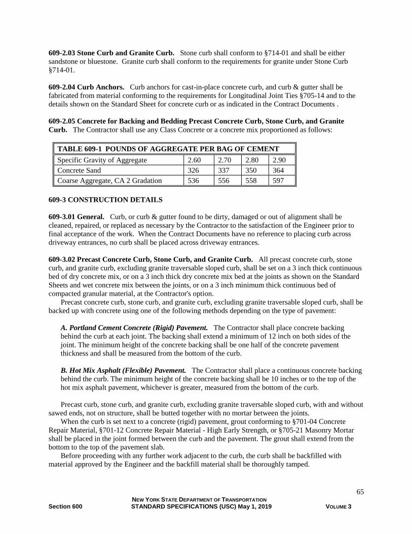
65 NEW YORK STATE DEPARTMENT OF TRANSPORTATION Section 600 STANDARD SPECIFICATIONS (USC) May 1, 2019 VOLUME 3
609-2.03 Stone Curb and Granite Curb. Stone curb shall conform to §714-01 and shall be either
sandstone or bluestone. Granite curb shall conform to the requirements for granite under Stone Curb
§714-01.
609-2.04 Curb Anchors. Curb anchors for cast-in-place concrete curb, and curb & gutter shall be
fabricated from material conforming to the requirements for Longitudinal Joint Ties §705-14 and to the
details shown on the Standard Sheet for concrete curb or as indicated in the Contract Documents .
609-2.05 Concrete for Backing and Bedding Precast Concrete Curb, Stone Curb, and Granite
Curb. The Contractor shall use any Class Concrete or a concrete mix proportioned as follows:
TABLE 609-1 POUNDS OF AGGREGATE PER BAG OF CEMENT
Specific Gravity of Aggregate 2.60 2.70 2.80 2.90
Concrete Sand 326 337 350 364
Coarse Aggregate, CA 2 Gradation 536 556 558 597
609-3 CONSTRUCTION DETAILS
609-3.01 General. Curb, or curb & gutter found to be dirty, damaged or out of alignment shall be
cleaned, repaired, or replaced as necessary by the Contractor to the satisfaction of the Engineer prior to
final acceptance of the work. When the Contract Documents have no reference to placing curb across
driveway entrances, no curb shall be placed across driveway entrances.
609-3.02 Precast Concrete Curb, Stone Curb, and Granite Curb. All precast concrete curb, stone
curb, and granite curb, excluding granite traversable sloped curb, shall be set on a 3 inch thick continuous
bed of dry concrete mix, or on a 3 inch thick dry concrete mix bed at the joints as shown on the Standard
Sheets and wet concrete mix between the joints, or on a 3 inch minimum thick continuous bed of
compacted granular material, at the Contractor's option.
Precast concrete curb, stone curb, and granite curb, excluding granite traversable sloped curb, shall be
backed up with concrete using one of the following methods depending on the type of pavement:
A. Portland Cement Concrete (Rigid) Pavement. The Contractor shall place concrete backing
behind the curb at each joint. The backing shall extend a minimum of 12 inch on both sides of the
joint. The minimum height of the concrete backing shall be one half of the concrete pavement
thickness and shall be measured from the bottom of the curb.
B. Hot Mix Asphalt (Flexible) Pavement. The Contractor shall place a continuous concrete backing
behind the curb. The minimum height of the concrete backing shall be 10 inches or to the top of the
hot mix asphalt pavement, whichever is greater, measured from the bottom of the curb.
Precast curb, stone curb, and granite curb, excluding granite traversable sloped curb, with and without
sawed ends, not on structure, shall be butted together with no mortar between the joints.
When the curb is set next to a concrete (rigid) pavement, grout conforming to §701-04 Concrete
Repair Material, §701-12 Concrete Repair Material - High Early Strength, or §705-21 Masonry Mortar
shall be placed in the joint formed between the curb and the pavement. The grout shall extend from the
bottom to the top of the pavement slab.
Before proceeding with any further work adjacent to the curb, the curb shall be backfilled with
material approved by the Engineer and the backfill material shall be thoroughly tamped.

66 NEW YORK STATE DEPARTMENT OF TRANSPORTATION Section 600 STANDARD SPECIFICATIONS (USC) May 1, 2019 VOLUME 3
609-3.03 Stone Curb and Granite Curb - Bridge Type. The requirements of §609-3.02 shall apply
with the following modifications:
A. Unless special construction details are called for in the Contract Documents, Type A and Type T2
curbs, when on a structures approach, shall be set true to line and grade on a concrete bedding.
B. Types F1, G1, M, R1, R2, S and T1 curbs shall be set in full mortar beds on structures. Excess mortar
which extrudes around the curb shall be struck off flush with the front face of the curb and the top surface
of the roadway.
C. Anchor bars for stone and granite bridge curb shall be installed where and as indicated in the Contract
Documents.
All curb on structures shall be fitted together allowing 1/4 inch full mortared joints finished flush with
exposed curb surfaces. Curb surfaces shall be cleaned of excess mortar to the satisfaction of the
Engineer.
Mortar used for bedding and filling of joints shall conform to §705-21 Masonry Mortar, §701-04
Concrete Repair Material or §701-12 Concrete Repair Material - High Early Strength.
609-3.04 Cast-In-Place Concrete Curb and Curb & Gutter. Cast-in-place concrete curb and curb &
gutter shall either be conventionally formed or machine formed to the size and shape shown on the
Standard Sheets or as indicated in the Contract Documents. If no width is indicated in the Contract
Documents, the width shall be the minimum shown on the Standard Sheet.
Curb anchors, as required on the Standard Sheets or the Contract Documents, shall not be coated with
materials which impair bonding. Curb anchors shall be installed a minimum of 12 inches from the ends
of a pavement slab. Curb anchors for new concrete pavement, when placed simultaneously with pavement
concrete, shall be placed by equipment which can demonstrate to the satisfaction of the Engineer
placement of the anchors in accordance with these specifications. Curb anchors, when not placed
simultaneously with pavement concrete, shall be placed rigidly secured by chairs or other supports to
prevent displacement of the anchors when pavement concrete is placed. Curb anchors for existing
concrete pavement shall be inserted into holes drilled in the side of the existing concrete pavement. The
holes shall be thoroughly cleaned and filled with Concrete Grouting Material §701-05 or Anchoring
Materials - Chemically Curing §701-07 immediately before placing the curb anchor. The curb anchor
shall be securely supported in position until the grout has hardened.
Curing of the curb and curb & gutter shall comply with the requirements of §502-3.11 Curing, except
that a clear membrane curing compound with fugitive dye conforming to the requirements of Membrane
Curing Compound §711-05 may be used in lieu of the white pigmented membrane curing compound.
A. Conventionally Formed Curb and Curb & Gutter
1. Forms. Forms shall be free from warp and of such construction that there will be no
interference to inspection for grade and alignment. All forms shall extend to the full curb depth
and be secured so no displacement will occur during the placement of concrete.
2. Casting Segments. Curb and curb & gutter shall be cast in segments having a uniform length
of approximately 10 feet. The joints between segments shall not exceed 1/4 inch in width. When
curb and curb & gutter is constructed next to concrete pavement, the curb and curb & gutter joints
shall line up with the pavement joints or additional joints shall be provided in the curb and curb &
gutter which line up with the pavement joints.
3. Expansion Joints. Expansion joints shall be 11/16 inches wide and contain Premolded
Resilient Joint Filler §705-07. The filler shall be cut to conform to the cross section of the curb
and curb & gutter.

67 NEW YORK STATE DEPARTMENT OF TRANSPORTATION Section 600 STANDARD SPECIFICATIONS (USC) May 1, 2019 VOLUME 3
Expansion joints shall be located at all immovable objects (bridge structures, etc.), adjacent to
expansion joints in the pavement, and where shown in the Contract Documents or directed by the
Engineer. Expansion joints will not be required at regular intervals unless otherwise shown in the
Contract Documents.
4. Concrete Placing and Vibrating. Concrete shall be placed in the forms in accordance with the
applicable requirements of §555-3.04 and shall be compacted with an immersion type mechanical
vibrator. The vibrator shall be of a size and weight capable of thoroughly vibrating the concrete
without damaging or misaligning the forms. The forms shall be left in place until the concrete has
hardened sufficiently to permit removal without damage to the curb and curb & gutter. The front
form may be removed before the other forms to facilitate finishing the curb and removal of the
joint dividers. After removal of the forms, the exposed faces of the curb and curb & gutter shall
be immediately rubbed to a uniform surface. No plastering will be permitted.
B. Machine Formed Concrete Curb and Curb & Gutter. The equipment proposed for use by the
Contractor shall demonstrate, to the satisfaction of the Engineer, the capability of placing the concrete
in accordance with these specifications.
When machine forming, the Contractor may provide additional width of curb above the minimum
on the Standard Sheets or above the width indicated in the Contract Documents without any other
change in shape or dimension. If additional width is provided by the Contractor, there shall be no
additional cost to the State for the additional width. If the Contract Documents or the Engineer do not
require curb be placed across driveway entrances or there is no reference in the Contract Documents
to placing curb across driveway entrances, the Contractor may continue placing curb across driveway
entrances but the curb placed, excluding transitions, must be cut out and the concrete disposed in a
manner approved by the Engineer.
Any curb and curb & gutter placed outside the tolerance of 1/2 inch of the established line or 1/4
inch of the established grade shall be removed and replaced by the Contractor.
1. Crack Control Joints. Crack control joints shall be formed or saw cut to a width of 1/8 inch
minimum, 1/4 inch maximum and to a depth of 1 1/2 inch. The cut or formed joints shall extend
slightly below the surface of the adjacent pavement and shall be spaced at 10 feet intervals.
When the curb, and curb & gutter is constructed next to concrete pavement, the curb and curb &
gutter joints shall line up with the pavement joints or additional joints shall be provided in the
curb and curb & gutter which line up with the pavement joints. The saw cut or formed joints shall
be left unfilled.
2. Expansion Joints. Expansion joints shall be 11/16 inches wide and contain Premolded
Resilient Joint Filler §705-07. The filler shall be cut to conform to the cross section of the curb
and curb & gutter.
The expansion joints shall be located at all immovable objects (bridge structures, etc.),
adjacent to expansion joints in the pavement, where shown in the Contract Documents , or
directed by the Engineer. Expansion joints shall not be required at regular intervals unless
otherwise shown in the Contract Documents.
609-3.05 Granite Traversable Sloped Curb. Granite traversable sloped curb shall be set on a
continuous trapezoidal shaped wedge bed of dry concrete mix, with 12 inches of wet concrete mix at the
front base and 6 inches at the back top as shown on the Standard Sheets. Granite traversable sloped curb
shall be set such that the front bottom arris line is at the top of pavement and is on a 1 on 3 slope.
A. Portland Cement Concrete (Rigid) Pavement.
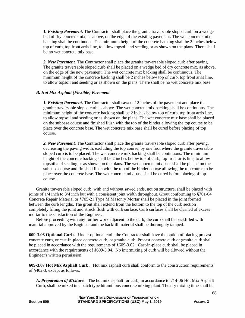
68 NEW YORK STATE DEPARTMENT OF TRANSPORTATION Section 600 STANDARD SPECIFICATIONS (USC) May 1, 2019 VOLUME 3
1. Existing Pavement. The Contractor shall place the granite traversable sloped curb on a wedge
bed of dry concrete mix, as above, on the edge of the existing pavement. The wet concrete mix
backing shall be continuous. The minimum height of the concrete backing shall be 2 inches below
top of curb, top front arris line, to allow topsoil and seeding or as shown on the plans. There shall
be no wet concrete mix base.
2. New Pavement. The Contractor shall place the granite traversable sloped curb after paving.
The granite traversable sloped curb shall be placed on a wedge bed of dry concrete mix, as above,
on the edge of the new pavement. The wet concrete mix backing shall be continuous. The
minimum height of the concrete backing shall be 2 inches below top of curb, top front arris line,
to allow topsoil and seeding or as shown on the plans. There shall be no wet concrete mix base.
B. Hot Mix Asphalt (Flexible) Pavement.
1. Existing Pavement. The Contractor shall sawcut 12 inches of the pavement and place the
granite traversable sloped curb as above. The wet concrete mix backing shall be continuous. The
minimum height of the concrete backing shall be 2 inches below top of curb, top front arris line,
to allow topsoil and seeding or as shown on the plans. The wet concrete mix base shall be placed
on the subbase course and finished flush with the top of the binder allowing the top course to be
place over the concrete base. The wet concrete mix base shall be cured before placing of top
course.
2. New Pavement. The Contractor shall place the granite traversable sloped curb after paving,
decreasing the paving width, excluding the top course, by one foot where the granite traversable
sloped curb is to be placed. The wet concrete mix backing shall be continuous. The minimum
height of the concrete backing shall be 2 inches below top of curb, top front arris line, to allow
topsoil and seeding or as shown on the plans. The wet concrete mix base shall be placed on the
subbase course and finished flush with the top of the binder course allowing the top course to be
place over the concrete base. The wet concrete mix base shall be cured before placing of top
course.
Granite traversable sloped curb, with and without sawed ends, not on structure, shall be placed with
joints of 1/4 inch to 3/4 inch but with a consistent joint width throughout. Grout conforming to §701-04
Concrete Repair Material or §705-21 Type M Masonry Mortar shall be placed in the joint formed
between the curb lengths. The grout shall extend from the bottom to the top of the curb section
completely filling the joint and struck flush with curb surface. Curb surfaces shall be cleaned of excess
mortar to the satisfaction of the Engineer.
Before proceeding with any further work adjacent to the curb, the curb shall be backfilled with
material approved by the Engineer and the backfill material shall be thoroughly tamped.
609-3.06 Optional Curb. Under optional curb, the Contractor shall have the option of placing precast
concrete curb, or cast-in-place concrete curb, or granite curb. Precast concrete curb or granite curb shall
be placed in accordance with the requirements of §609-3.02. Cast-in-place curb shall be placed in
accordance with the requirements of §609-3.04. No intermixing of curb will be allowed without the
Engineer's written permission.
609-3.07 Hot Mix Asphalt Curb. Hot mix asphalt curb shall conform to the construction requirements
of §402-3, except as follows:
A. Preparation of Mixture. The hot mix asphalt for curb, in accordance to 714-06 Hot Mix Asphalt
Curb, shall be mixed in a batch type bituminous concrete mixing plant. The dry mixing time shall be

69 NEW YORK STATE DEPARTMENT OF TRANSPORTATION Section 600 STANDARD SPECIFICATIONS (USC) May 1, 2019 VOLUME 3
a minimum of 15 seconds after the complete introduction of aggregates into the pugmill. The wet
mix time shall be a minimum of 45 seconds.
B. Preparation of Surface. When hot mix asphalt curb is constructed on a freshly laid hot mix
asphalt surface, the surface shall be clean. When curb is to be laid on a cured or aged concrete base,
hot mix asphalt pavement, or performance graded binder treated base, the surface shall be thoroughly
swept and cleaned by compressed air.
The surface shall be thoroughly dried and, immediately prior to placing of the hot mix asphalt
mixture, shall receive a tack coat meeting the requirements of Table 702-8. The tack coat shall be
applied at a rate of 0.05 to 0.15 gallons per square yard. The tack coat shall be prevented from
spreading to areas outside of the area to be occupied by the curb.
C. Placing. Hot mix asphalt curb shall be constructed by machine to the size and shape shown on
the Standard Sheets.
The machine shall be capable of placing the hot mix asphalt in accordance with these
specifications to the satisfaction of the Engineer. Prior to placement, the Contractor shall demonstrate
to the satisfaction of the Engineer the machine meets the following requirements:
1. The machine shall be self propelled and capable of forming curb which is uniform in texture,
shape, and density.
2. The weight and the material extrusion rate of the machine shall be such that the required
compaction is obtained without the machine riding above the bed on which curbing is constructed.
When short sections of hot mix asphalt curb or sections with short radii are required, the Engineer
may permit construction by other means, as long as the resulting curb conforms to the curb produced
by machine.
D. Painted Hot Mix Asphalt Curb. When painted hot mix asphalt curb is specified, it shall be
painted yellow or white in accordance with the MUTCD. The paint shall be placed in accordance
with the following:
1. After a curing period of not less than 72 hours, exposed surfaces of the curbing shall be sprayed or
hand brushed with two coats of pavement marking paint, yellow or white as required. Each coat of
paint shall be applied at the rate of 1 gallon per 200 linear feet of curb.
2. The curb shall be clean and free of all foreign matter before painting. Paint shall be applied only
when the air temperature is above 50°F and rising. Paint shall not be applied when there is
reasonable expectation of rain. In the event the first or final coat of paint is rain damaged, as
determined by the Engineer, the Contractor shall clean and repaint the curb at no additional cost to the
State.
609-3.08 Resetting Curb. Care shall be taken in removing the curb to be reset so that there will be no
unnecessary breakage. All curb damaged in removing, hauling, storing, or resetting shall be replaced by
the Contractor.
The curb shall be reset, in accordance with the requirements of §609-3.02 or §609-3.03 for resetting
bridge type curbs, to the lines and grades specified in the Contract Documents.
609-4 METHOD OF MEASUREMENT. All curb and curb & gutter placed and curb reset under these
specifications will be measured by the number of linear feet, rounded to the nearest foot. The
measurement will be taken along the top front arris line of full height, transition and terminal sections.
The measurement will be taken along the top front arris line of curb reveals across driveway entrances
only when placed and not removed.

70 NEW YORK STATE DEPARTMENT OF TRANSPORTATION Section 600 STANDARD SPECIFICATIONS (USC) May 1, 2019 VOLUME 3
609-5 BASIS OF PAYMENT
609-5.01 Concrete Curb, Curb & Gutter, Stone Curb, Granite Curb, Optional Curb. The unit price
bid per foot shall include the cost of all labor, materials, curb anchors, equipment, sawcutting and
excavation to, in accordance with these specifications, place, backfill, concrete, grout and caulk the curb,
curb & gutter. When select backfill is specified, the select backfill shall be paid under its respective
items. No additional payment will be made to the Contractor when more than the minimum width of curb
is placed. No additional payment will be made to the Contractor when curb is placed across driveway
entrance, to facilitate concrete machine forming operations, and removed.
609-5.02 Stone Curb and Granite Curb - Bridge Type. The unit price bid per foot shall include the
cost of furnishing all labor, equipment, and materials including concrete bedding, mortar for stone and
granite curbs, chemically curing anchoring materials, and stone and granite curb anchors required to bed
and place stone and granite bridge curb, in accordance with these specifications.
609-5.03 Hot Mix Asphalt Curb. The unit price bid per foot shall include the cost of furnishing all
labor, materials, and equipment to prepare the surface for curb placement, and place the curb. If painted
hot mix asphalt curb is specified, the Contractor shall also include the cost of preparing the curb for
painting, furnishing the paint, and applying the paint.
Progress payments will be made after the curb has been constructed to the shape and size shown on
the Standard Sheet and/or plans. Payment will be made, at the unit price bid, for 90% of the quantity
properly constructed exclusive of painting. The balance of the quantity will be paid for upon completion
of the work.
609-5.04 (Vacant)
609-5.05 Resetting Curb. The unit price bid per foot shall include the cost of furnishing all labor,
equipment, and materials to remove, haul, store and reset curb, in accordance with these specifications. In
addition, the unit price shall also include any re-dressing of tops and joints of bridge type curb, as directed
by the Engineer, and replacement of curb damaged by the Contractor's operations.
Payment will be made under:
Item No. Item Pay Unit
609.01 Stone Curb (As Detailed) Foot
609.01XX Stone Curb* (Various Types as indicated) Foot
609.02XX Granite Curb* (Various Types as indicated) Foot
609.03 Granite Bridge Curb (As Detailed) Foot
609.03XX Granite Bridge Curb* (Various Types as indicated) Foot
609.035X Stone Bridge Curb* (Various Types as indicated) Foot
609.04 Cast-in-Place Concrete Curb (As Detailed) Foot
609.04XX Cast-in-Place Concrete Curb* (Various Types as indicated) Foot
609.05 Cast-in-Place Concrete Curb & Gutter (As Detailed) Foot
609.05XX Cast-in-Place Concrete Curb & Gutter* (Various Types as indicated) Foot
609.08XX Precast Concrete Curb* (Various Types as indicated) Foot
609.0901 Optional Curb (Precast Concrete Type PVF150
or Cast-In-Place Concrete Type VF150 or Granite Type C) Foot
609.0902 Optional Curb (Precast Concrete Type PM100
or Cast-In-Place Concrete Type M100 or Granite Type E100) Foot
609.0903 Optional Curb (Precast Concrete Type PT100
or Cast-In-Place Concrete Type T100) Foot

71 NEW YORK STATE DEPARTMENT OF TRANSPORTATION Section 600 STANDARD SPECIFICATIONS (USC) May 1, 2019 VOLUME 3
609.15 Resetting Existing Curb Foot
609.21 Painted Hot Mix Asphalt Curb (As Detailed) Foot
609.21XX Painted Hot Mix Asphalt Curb* (Various Types as indicated) Foot
609.22 Unpainted Hot Mix Asphalt Curb (As Detailed) Foot
609.22XX Unpainted Hot Mix Asphalt Curb* (Various Types as indicated) Foot
* Refer to Standard Pay Item Catalog for full Item Number and Description.
SECTION 610 - GROUND VEGETATION - PREPARATION, ESTABLISHMENT AND
MANAGEMENT
610-1 DESCRIPTION.
610-1.01 Topsoil. This work shall consist of furnishing, screening, storing, stockpiling and placing
topsoil in accordance with the contract documents and as directed by the Engineer.
610-1.02 Preparation of Subsoil for Turf Establishment. This work shall consist of ground preparation
when topsoil is not included in the work prior to establishment of turf in accordance with the contract
documents and as directed by the Engineer.
610-1.03 Turf Establishment. The work shall consist of ground preparation and establishing turf in
accordance with the contract documents and as directed by the Engineer.
610-1.04 Wildflower Seeding. The work shall consist of ground preparation, furnishing and placing
wildflower seeding materials and caring for wildflower areas in accordance with the contract documents
and as directed by the Engineer.
610-1.05 Sod. The work shall consist of ground preparation, furnishing, installing and caring for sod in
accordance with the contract documents and as directed by the Engineer.
610-1.06 Soil Amendments. The work consists of furnishing and placing soil amendments in accordance
with the contract documents and as directed by the Engineer.
610-1.07 Compost. The work consists of furnishing, placing and incorporating compost in accordance
with the contract documents and as directed by the Engineer.
610-1.08 Mulch for Planting. The work consists of furnishing and placing mulch, in accordance with
the contract documents and as directed by the Engineer.
610-1.09 Permeable Weed Control Landscape Fabric. The work consists of furnishing and placing
permeable landscape fabric for weed control, in accordance with the contract documents and as directed
by the Engineer.
610-1.10 Watering Vegetation. This work shall include watering turf, sod, wildflower seeding, trees,
shrubs, ground covers, vines, other plants, and filling portable drip irrigation systems in accordance with
the contract documents and as directed by the Engineer.
610-1.11 Weed Removal. This work shall consist of removal and disposal of all native and non-native
weeds including roots from newly established turf and sod areas, wildflower seeded areas, tree and shrub
pits and plant beds in accordance with the contract documents and as directed by the Engineer.

72 NEW YORK STATE DEPARTMENT OF TRANSPORTATION Section 600 STANDARD SPECIFICATIONS (USC) May 1, 2019 VOLUME 3
610-1.12 Mowing. This work shall consist of mowing newly established seeded or sodded areas
including the removal and disposal of any debris and litter which has accumulated prior to or between
mowings, in accordance with the contract documents and as directed by the Engineer.
610-1.13 Mowing Limits Markers. This work consists of furnishing and installing mowing limit
markers in accordance with the contract documents and as directed by the Engineer.
610-2 MATERIALS
610-2.01 Topsoil. The materials shall meet the requirements of the following subsections of Section 700
Materials and Manufacturing. Excavated material from earthwork operations defined in Section 203
Excavation and Embankment that is unsuitable for embankments but conforms to §713-01 Topsoil is
acceptable.
Topsoil 713-01
610-2.02 Preparation of Subsoil for Turf Establishment. None specified.
610-2.03 Turf Establishment. The materials shall meet the requirements of the following subsections of
Section 700 Materials and Manufacturing.
Water 712-01
Seeds 713-04
Mulch For Turf Establishment and Erosion Control 713-11
Mulch anchorage 713-12
Straw 713-19
610-2.04 Wildflower Seeding. The materials shall meet the requirements of the following subsections of
Section 700 Materials and Manufacturing.
Water 712-01
Seeds 713-04
Mulch For Turf Establishment and Erosion Control 713-11
Mulch anchorage 713-12
Straw 713-19
610-2.05 Sod. The materials shall meet the requirements of the following subsections of Section 700
Materials and Manufacturing.
Water 712-01
Topsoil 713-01
Sod 713-14
610-2.06 Soil Amendment. The materials shall meet the requirements of the following subsections of
Section 700 Materials and Manufacturing.
Water 712-01
Limestone 713-02
Fertilizer 713-03
Mycorrhizal Fungi 713-09
Moisture Retention Additive 713-10
Sulfur 713-17
610-2.07 Compost. The materials shall meet the requirements of the following subsections of Section
700 Materials and Manufacturing.
Compost 713-15

73 NEW YORK STATE DEPARTMENT OF TRANSPORTATION Section 600 STANDARD SPECIFICATIONS (USC) May 1, 2019 VOLUME 3
610-2.08 Mulch for Planting. The materials shall meet the requirements of the following subsections of
Section 700 Materials and Manufacturing.
Mulch for Planting 713-05
610-2.09 Permeable Weed Control Landscape Fabric. The materials shall meet the requirements of the
following subsections of Section 700 Materials and Manufacturing.
Weed Control Barriers 713-18
610-2.10 Watering Vegetation. The materials shall meet the requirements of the following subsections
of Section 700 Materials and Manufacturing.
Water 712-01
610-2.11 Weed Removal. None specified.
610-2.12 Mowing. None specified.
610-2.13 Mowing Limits Markers. The materials shall meet the requirements of the following
subsections of Section 700 Materials and Manufacturing.
Materials for the Protection of Plants 713-08
610-3 CONSTRUCTION DETAILS
610-3.01 Topsoil.
A. General. The subsoil within the areas to be covered by topsoil shall be graded so that the
completed work after the topsoil is placed shall conform to the specified lines and grades. The
Contractor shall scarify or till the surface of the subsoil to a depth of 6 inches before the topsoil is
placed to permit bonding the topsoil with the subsoil. Tillage by disking, harrowing, raking or other
approved methods shall be accomplished in such a manner that depressions and ridges formed by
tillage shall be parallel to the contours.
Topsoil in an unworkable condition due to excessive moisture, frost, or other conditions shall not
be placed until its consistency is workable for spreading. Topsoil shall be placed on the designated
area and spread to the depth specified in the contract documents or a minimum of 4 inches for turf
areas and 3 inches for sod areas.
The finished surface shall be maintained for subsequent contract work such as seeding, sodding,
mulching or planting.
The sites of all stockpiles shall be graded and maintained for subsequent contract work. Surplus
topsoil will become the property of the Contractor.
Roots and top growth of non-native weeds or invasive species that emerge from topsoil stockpiles
or after placement of the topsoil shall be eradicated and disposed of in accordance with §610-3.11
Weed Removal immediately upon emergence. Weed removal, treatment and disposal of invasive
species will be paid for separately.
B. Topsoil – Reuse On-Site Materials. Topsoil stripping shall be completed prior to starting the
general excavation in an area. The Contractor shall take reasonable care that the topsoil is not
contaminated during the stripping and other handling operations.
Topsoil identified for reuse that has a known, established population of invasive species shall be
treated to eliminate the presence of invasive species per §610-3.11 Weed Removal. The invasive
species material shall be disposed appropriately and then the resulting topsoil may be used within the
limits. Treatment and disposal of invasive species will be paid for separately.
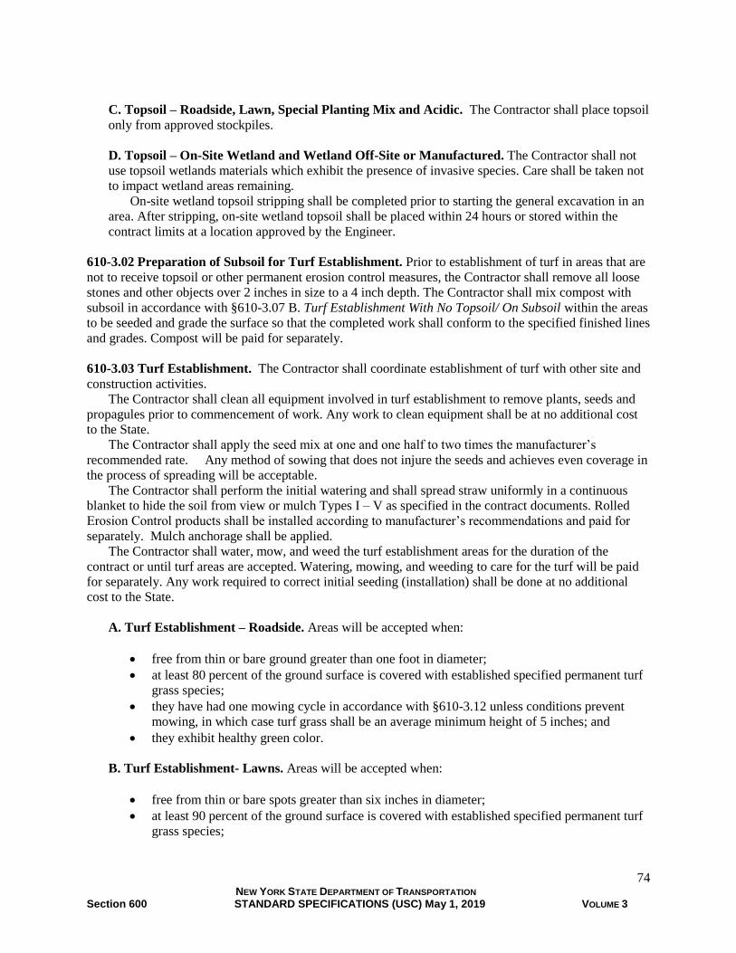
74 NEW YORK STATE DEPARTMENT OF TRANSPORTATION Section 600 STANDARD SPECIFICATIONS (USC) May 1, 2019 VOLUME 3
C. Topsoil – Roadside, Lawn, Special Planting Mix and Acidic. The Contractor shall place topsoil
only from approved stockpiles.
D. Topsoil – On-Site Wetland and Wetland Off-Site or Manufactured. The Contractor shall not
use topsoil wetlands materials which exhibit the presence of invasive species. Care shall be taken not
to impact wetland areas remaining.
On-site wetland topsoil stripping shall be completed prior to starting the general excavation in an
area. After stripping, on-site wetland topsoil shall be placed within 24 hours or stored within the
contract limits at a location approved by the Engineer.
610-3.02 Preparation of Subsoil for Turf Establishment. Prior to establishment of turf in areas that are
not to receive topsoil or other permanent erosion control measures, the Contractor shall remove all loose
stones and other objects over 2 inches in size to a 4 inch depth. The Contractor shall mix compost with
subsoil in accordance with §610-3.07 B. Turf Establishment With No Topsoil/ On Subsoil within the areas
to be seeded and grade the surface so that the completed work shall conform to the specified finished lines
and grades. Compost will be paid for separately.
610-3.03 Turf Establishment. The Contractor shall coordinate establishment of turf with other site and
construction activities.
The Contractor shall clean all equipment involved in turf establishment to remove plants, seeds and
propagules prior to commencement of work. Any work to clean equipment shall be at no additional cost
to the State.
The Contractor shall apply the seed mix at one and one half to two times the manufacturer’s
recommended rate. Any method of sowing that does not injure the seeds and achieves even coverage in
the process of spreading will be acceptable.
The Contractor shall perform the initial watering and shall spread straw uniformly in a continuous
blanket to hide the soil from view or mulch Types I – V as specified in the contract documents. Rolled
Erosion Control products shall be installed according to manufacturer’s recommendations and paid for
separately. Mulch anchorage shall be applied.
The Contractor shall water, mow, and weed the turf establishment areas for the duration of the
contract or until turf areas are accepted. Watering, mowing, and weeding to care for the turf will be paid
for separately. Any work required to correct initial seeding (installation) shall be done at no additional
cost to the State.
A. Turf Establishment – Roadside. Areas will be accepted when:
• free from thin or bare ground greater than one foot in diameter;
• at least 80 percent of the ground surface is covered with established specified permanent turf
grass species;
• they have had one mowing cycle in accordance with §610-3.12 unless conditions prevent
mowing, in which case turf grass shall be an average minimum height of 5 inches; and
• they exhibit healthy green color.
B. Turf Establishment- Lawns. Areas will be accepted when:
• free from thin or bare spots greater than six inches in diameter;
• at least 90 percent of the ground surface is covered with established specified permanent turf
grass species;
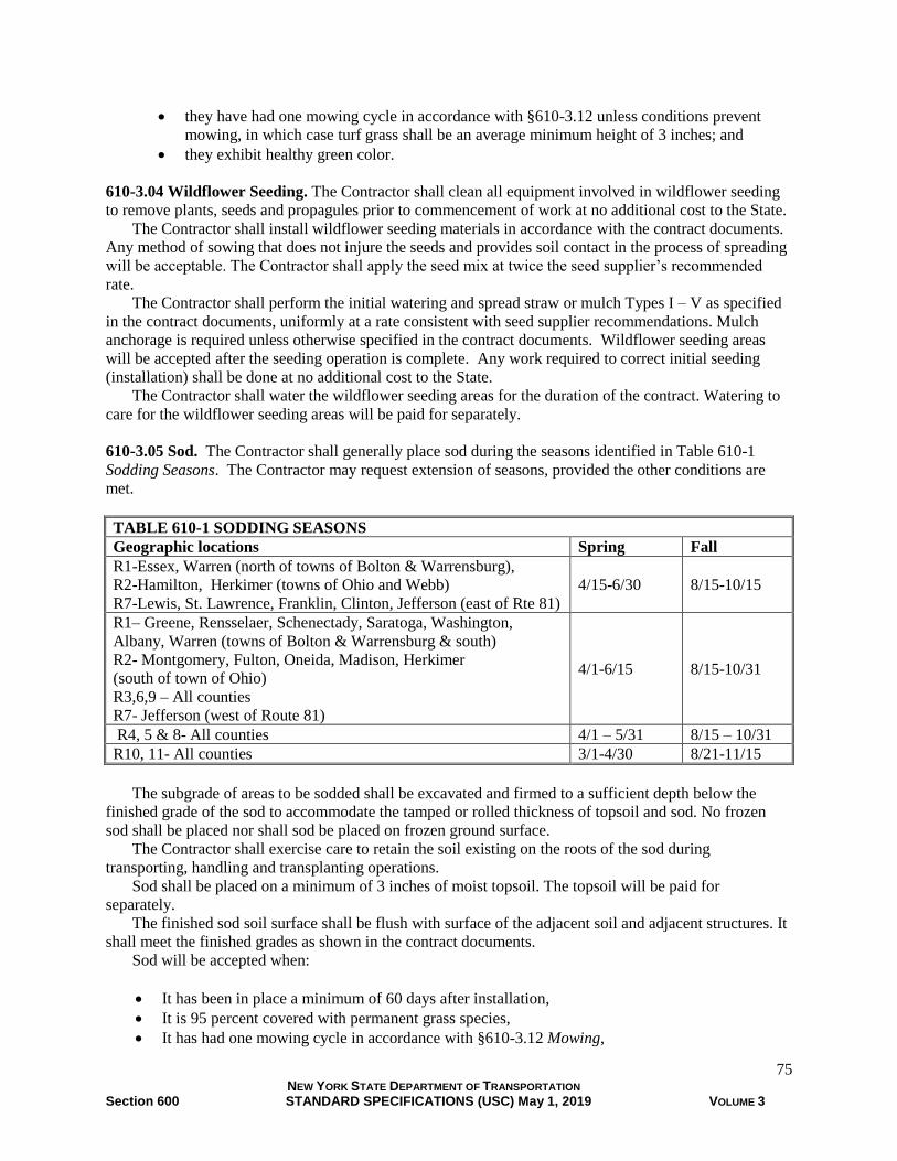
75 NEW YORK STATE DEPARTMENT OF TRANSPORTATION Section 600 STANDARD SPECIFICATIONS (USC) May 1, 2019 VOLUME 3
• they have had one mowing cycle in accordance with §610-3.12 unless conditions prevent
mowing, in which case turf grass shall be an average minimum height of 3 inches; and
• they exhibit healthy green color.
610-3.04 Wildflower Seeding. The Contractor shall clean all equipment involved in wildflower seeding
to remove plants, seeds and propagules prior to commencement of work at no additional cost to the State.
The Contractor shall install wildflower seeding materials in accordance with the contract documents.
Any method of sowing that does not injure the seeds and provides soil contact in the process of spreading
will be acceptable. The Contractor shall apply the seed mix at twice the seed supplier’s recommended
rate.
The Contractor shall perform the initial watering and spread straw or mulch Types I – V as specified
in the contract documents, uniformly at a rate consistent with seed supplier recommendations. Mulch
anchorage is required unless otherwise specified in the contract documents. Wildflower seeding areas
will be accepted after the seeding operation is complete. Any work required to correct initial seeding
(installation) shall be done at no additional cost to the State.
The Contractor shall water the wildflower seeding areas for the duration of the contract. Watering to
care for the wildflower seeding areas will be paid for separately.
610-3.05 Sod. The Contractor shall generally place sod during the seasons identified in Table 610-1
Sodding Seasons. The Contractor may request extension of seasons, provided the other conditions are
met.
TABLE 610-1 SODDING SEASONS
Geographic locations Spring Fall
R1-Essex, Warren (north of towns of Bolton & Warrensburg),
R2-Hamilton, Herkimer (towns of Ohio and Webb)
R7-Lewis, St. Lawrence, Franklin, Clinton, Jefferson (east of Rte 81)
4/15-6/30 8/15-10/15
R1– Greene, Rensselaer, Schenectady, Saratoga, Washington,
Albany, Warren (towns of Bolton & Warrensburg & south)
R2- Montgomery, Fulton, Oneida, Madison, Herkimer
(south of town of Ohio)
R3,6,9 – All counties
R7- Jefferson (west of Route 81)
4/1-6/15 8/15-10/31
R4, 5 & 8- All counties 4/1 – 5/31 8/15 – 10/31
R10, 11- All counties 3/1-4/30 8/21-11/15
The subgrade of areas to be sodded shall be excavated and firmed to a sufficient depth below the
finished grade of the sod to accommodate the tamped or rolled thickness of topsoil and sod. No frozen
sod shall be placed nor shall sod be placed on frozen ground surface.
The Contractor shall exercise care to retain the soil existing on the roots of the sod during
transporting, handling and transplanting operations.
Sod shall be placed on a minimum of 3 inches of moist topsoil. The topsoil will be paid for
separately.
The finished sod soil surface shall be flush with surface of the adjacent soil and adjacent structures. It
shall meet the finished grades as shown in the contract documents.
Sod will be accepted when:
• It has been in place a minimum of 60 days after installation,
• It is 95 percent covered with permanent grass species,
• It has had one mowing cycle in accordance with §610-3.12 Mowing,

76 NEW YORK STATE DEPARTMENT OF TRANSPORTATION Section 600 STANDARD SPECIFICATIONS (USC) May 1, 2019 VOLUME 3
• It exhibits healthy green color,
• It is free from thin, bare or brown spots greater than 6 inches in diameter, and
• It is firmly rooted in the soil.
Sod not meeting the standards for acceptance, shall be re-sodded until a satisfactory turf has been
established, at no additional expense to the State.
The Contractor shall water, mow and weed the sodded areas as necessary until contract final
acceptance. These items will be paid for separately.
610-3.06 Soil Amendments. The Contractor shall place, apply or incorporate fertilizer, limestone,
mycorrhizal fungi, sulfur and/or moisture retention additive where shown in the contract documents.
When mycorrhizal fungi are specified, application rates for turf shall ensure an even distribution of
100,000 propagules minimum per acre for drill seeding and 1,000,000 propagules minimum per acre for
hydroseeding. Application rates for planting and Tree Root Zone Treatment, as well as any other aspects
of distributing and/or incorporating mycorrhizal fungi, shall be in accordance with the manufacturer’s
recommendations.
All other amendments shall be mixed with topsoil prior to placing, spread evenly over the surface of
turf, wildflower or sod areas, applied within shrub saucers or applied over the plant beds as appropriate, at
the rates recommended by the manufacturer or as specified in the contract documents. The method of
application shall ensure an even distribution. When hydraulic application is used, the minimum rate of
water application shall be in accordance with manufacturer’s recommendation.
Trees shall be fertilized using Method No. 1, No. 2 or No. 3 in accordance with the contract
documents.
A. Method No. 1. Holes shall be made in the earth about 18 inches deep and 18 inches apart, and
located in the outer two-thirds (as measured on the radius) of the circular area lying under the limits
of the tree branches. The holes shall be made with a crowbar, soil auger, pneumatic equipment or
other approved tools and care shall be taken to avoid injury to the roots. Fertilizer shall be applied at
the rate specified; placing equal amounts of fertilizer in the lower 12 inches of each hole.
B. Method No. 2. Fertilizer shall be applied to soil’s surface hydraulically at the rate specified with
sufficient water to saturate the soil for the area and depth of the tree roots without creating air
pockets.
C. Method No. 3. Fertilizer rate and method of application shall be as specified in the contract
documents.
610-3.07 Compost.
A. Existing Soil: The Contractor shall spread 2 inches of Compost Type A or E within the limits
shown in the contract documents and tilled into existing soil to a total depth of six inches.
B. Turf Establishment With No Topsoil/ On Subsoil. The Contractor shall spread 2 inches of
Compost Type A, D or E within the limits shown in the contract documents and tilled into subsoil to a
minimum depth of four inches.
C. Turf Establishment With Topsoil. The Contractor shall mix Compost Type A, D or E with
topsoil as specified in the contract documents.
D. Plant Pits or Beds: Compost Type A, D or E shall be applied at a ratio of 1 part compost to 5
parts existing soil.

77 NEW YORK STATE DEPARTMENT OF TRANSPORTATION Section 600 STANDARD SPECIFICATIONS (USC) May 1, 2019 VOLUME 3
610-3.08 Mulch for Planting. The Contractor shall apply mulch consisting of wood chips, pine nuggets
or shredded bark to the surface of the beds and tree pit areas in accordance with the contract documents.
The Contractor shall apply mulch to a uniform depth of 3 inches over the shrub bed and tree pit areas and
2 inches over groundcover beds. The mulch shall be distributed so as to create a smooth, level cover over
the exposed soil. Mulch shall not cover plants or be in contact with tree root flare, tree trunks, and plant
stems.
610-3.09 Permeable Weed Control Landscape Fabric. Areas where landscape fabric is to be installed
shall be smooth, firm, stable and free of rocks, clods, foliage, roots, trash, debris or other material that
will prevent the matting from lying in direct contact with the soil surface.
The landscape fabric shall be placed where shown in the contract documents and as required by the
manufacturer.
610-3.10 Watering Vegetation. The Contractor shall provide water without damage to plants, mulch,
stakes, plant saucers, sod or other areas to be watered. Damage resulting from watering operations shall
be repaired at no additional cost to the State.
Watering shall be applied in accordance with §610-3.03 Turf Establishment, §610-3.04 Wildflower
Seeding, §610-3.05 Sod or §611-3.01 General. Watering for existing vegetation shall be as specified in
the contract documents.
Watering shall be applied at the following rates:
A. Turf, Wildflowers, Sod, Planting Beds. In the absence of 1 inch of rainfall within 5 consecutive
calendar days the Contractor shall water all turf, wildflowers, sod and planting beds once a week to a
depth of 1 inch.
B. Trees and Planting Pits. Between April 1st and November 15th, in the absence of 1 inch of
rainfall within 5 consecutive calendar days, the Contractor shall apply water to trees and planting pits
once per week, except during July and August, when water shall be applied twice per week, with a
minimum of 2 days between applications. Soil saucers or portable drip irrigation systems shall be
filled once per watering.
610-3.11 Weed Removal. The Contractor shall perform weed removal in accordance with the contract
documents. The Contractor shall remove and dispose of weeds including roots prior to flowering and seed
formation by manual, chemical or mechanical means. Any method of weed removal that leaves live roots
in the soil will not be permitted. An appropriately licensed applicator is required for chemical weed
control methods. The Contractor shall ensure the preservation of desirable vegetation. Treatment and
removal of invasive species will be paid for separately.
610-3.12 Mowing. The schedule may be modified to accommodate prevailing or forecast weather
conditions. The Contractor shall be responsible, prior to each mowing, for the removal and disposal of
any debris and litter which has accumulated since the last mowing. Care shall be taken to avoid damage to
existing plant materials.
A. Roadside. The Contractor shall mow all turf establishment areas to a height of 5 inches whenever
growth reaches 8 inches for the duration of the contract. Clippings shall be left in place.
B. Lawns. The Contractor shall mow all turf establishment areas to a height of 3 inches after initial
growth reaches 5 inches, and then mowed to a height of 3 inches whenever a 5 inch height is reached
thereafter for the duration of the contract. Clippings shall be mulched in place.

78 NEW YORK STATE DEPARTMENT OF TRANSPORTATION Section 600 STANDARD SPECIFICATIONS (USC) May 1, 2019 VOLUME 3
C. Sod. The Contractor shall mow all sodded areas to a height of 3 inches after initial growth reaches
5 inches, and then mowed to a height of 3 inches whenever a 5 inch height is reached thereafter for
the duration of the contract. Clippings shall be mulched in place.
610-3.13 Mowing Limits Markers. The Contractor shall install mowing limit markers plumb to a depth
in accordance with the manufacturer’s instruction.
610-4 METHOD OF MEASUREMENT
610-4.01 Topsoil. The quantity to be measured for payment will be in cubic yards of each type of topsoil
measured to the nearest whole cubic yard of topsoil placed, from payment lines shown in the contract
documents.
Cross sectioning, for the purpose of determining quantities for payment, will be employed only where
payment lines are not shown on the Plans and cannot be reasonably established by the Engineer.
610-4.02 Preparation of Subsoil for Turf Establishment. The quantity to be measured for payment
will be in square yards on slope to the nearest whole square yard of subsoil area prepared for turf
establishment.
610-4.03 Turf Establishment. The quantity to be measured for payment will be in square yards on slope
to the nearest whole square yard of turf established.
610-4.04 Wildflower Seeding. The quantity to be measured for payment will be in square yards on slope
to the nearest whole square yard of wildflower seeding.
610-4.05 Sod. The quantity to be measured for payment will be in square yards on slope to the nearest
whole square yard of sod placed.
610-4.06 Soil Amendments. The quantity to be measured for payment will be in pounds to the nearest
whole pound or in gallons to the nearest whole gallon of soil amendments (fertilizer, limestone,
mycorrhizal fungi, sulfur and/or moisture retention additive) applied.
610-4.07 Compost. The quantity to be measured for payment will be in cubic yards to the nearest whole
cubic yard of compost placed or incorporated.
610-4.08 Mulch for Planting. The quantity to be measured for payment will be in cubic yards to the
nearest whole cubic yard of mulch placed.
610-4.09 Permeable Weed Control Landscape Fabric. The quantity to be measured for payment will
be in square yards on slope to the nearest whole square yard.
610-4.10 Watering Vegetation. The quantity to be measured for payment will be in 1000 gallons
(MGal) to the nearest MGal of water applied, determined from approved measuring devices, or by
measurement in tanks or containers of known capacity.
610-4.11 Weed Removal. The quantity to be measured for payment will be in square yards on slope
weeded per occurrence to the nearest whole square yard.
610-4.12 Mowing. The quantity to be measured for payment will be the number of square yards on slope
mowed per occurrence to the nearest whole square yard.

79 NEW YORK STATE DEPARTMENT OF TRANSPORTATION Section 600 STANDARD SPECIFICATIONS (USC) May 1, 2019 VOLUME 3
610-4.13 Mowing Limits Markers. The quantity to be measured for payment will be by the number of
complete markers satisfactorily installed.
610-5 BASIS OF PAYMENT
610-5.01 Topsoil. The unit price bid shall include the cost of all labor, materials and equipment
necessary to satisfactorily complete the work, including the handling, storing, stockpiling, and placement.
610-5.02 Preparation of Subsoil for Turf Establishment. The unit price bid shall include the cost of all
labor, materials and equipment necessary to satisfactorily complete the work
610-5.03 Turf Establishment. The unit price bid shall include the cost of all labor, materials and
equipment including initial water, mulch and mulch anchorage as necessary to satisfactorily complete the
work.
610-5.04 Wildflower Seeding. The unit price bid shall include the cost of all labor, materials and
equipment including initial water, mulch and mulch anchorage necessary to satisfactorily complete the
work.
610-5.05 Sod. The unit price bid shall include the cost of all labor, materials and equipment including
initial water, necessary to complete the work. Topsoil bed placed under the sod shall be paid for
separately.
610-5.06 Soil Amendments. The unit price bid shall include the cost of all labor, materials and
equipment necessary to satisfactorily complete the work, including water for hydraulic application.
610-5.07 Compost. The unit price bid shall include the cost of all labor, materials and equipment
necessary to satisfactorily complete the work
610-5.08 Mulch for Planting. The unit price bid shall include the cost of all labor, materials and
equipment necessary to satisfactorily complete the work.
610-5.09 Permeable Weed Control Landscape Fabric. The unit price bid shall include the cost of all
labor, materials, and equipment necessary to satisfactorily complete the work.
610-5.10 Watering Vegetation. The unit price bid shall include the cost of all labor, materials and
equipment necessary to satisfactorily complete the work.
610-5.11 Weed Removal. The unit price bid shall include the cost of labor, materials, and equipment
necessary to satisfactorily complete the work.
610-5.12 Mowing. The unit price bid shall include the cost of all labor, materials, and equipment
necessary to satisfactorily complete the work.
610-5.13 Mowing Limits Markers. The unit price bid shall include the cost of all labor, materials, and
equipment necessary to satisfactorily complete the work.
Payment will be made under:
Item No. Item Pay Unit
610.0501 Fertilizer Pound

80 NEW YORK STATE DEPARTMENT OF TRANSPORTATION Section 600 STANDARD SPECIFICATIONS (USC) May 1, 2019 VOLUME 3
610.0502 Fertilizer Gallon
610.06 Limestone Pound
610.0701 Mycorrhizal Fungi Pound
610.0702 Mycorrhizal Fungi Gallon
610.08 Moisture Retention Additive Pound
610.0901 Sulfur Pound
610.0902 Sulfur Gallon
610.10 Compost Cubic Yard
610.1101 Mulch for Planting Type A, B & D – Wood Chips and Shredded Bark Cubic Yard
610.1102 Mulch for Planting Type C – USDA-APHIS Protocol Wood Chips Cubic Yard
610.1103 Mulch for Planting Type E – Pine Nugget Cubic Yard
610.1201 Permeable Weed Control Landscape Fabric Square Yard
610.1202 Permeable Weed Control Landscape Fabric with Herbicide Square Yard
610.13 Weed Removal Square Yard
610.1401 Topsoil – Reuse On-Site Materials Cubic Yard
610.1402 Topsoil - Roadside Cubic Yard
610.1403 Topsoil - Lawns Cubic Yard
610.1404 Topsoil - Special Planting Mix Cubic Yard
610.1405 Topsoil – Acidic Cubic Yard
610.1406 Topsoil – On-Site Wetland Materials Cubic Yard
610.1407 Topsoil – Wetland Materials Cubic Yard
610.15 Preparation of Subsoil for Turf Establishment Square Yard
610.1601 Turf Establishment - Roadside Square Yard
610.1602 Turf Establishment -Lawns Square Yard
610.17 Wildflower Seeding Square Yard
610.18 Sodding Square Yard
610.19 Watering Vegetation 1,000 Gallons
610.21 Mowing Square Yard
610.22 Mowing Limits Markers Each
SECTION 611 - PLANTING, TRANSPLANTING AND POST PLANTING CARE
611-1 DESCRIPTION.
611-1.01 General. Vacant
611-1.02 Planting. This work consists of furnishing, and planting trees, shrubs, vines, groundcovers and
other plants in accordance with the contract documents and as directed by the Engineer.
611-1.03 Transplanting. This work consists of transplanting existing plants from existing locations to
new locations in accordance with the contract documents and as directed by the Engineer.
610-1.04 Portable Drip Irrigation System. This work shall consist of furnishing, delivering, placing
and removing Portable Drip Irrigation System (PDIS) for watering around newly planted trees and other
vegetation in accordance with the contract documents and as directed by the Engineer.
611-1.05 Post-Planting Care. This work consists of the care of newly planted and transplanted trees,
shrubs, vines, groundcovers and other plants in accordance with the contract documents and as directed
by the Engineer.
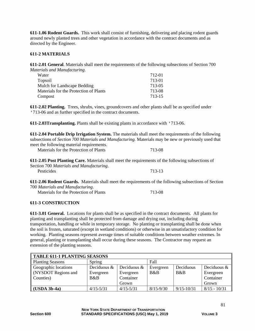
81 NEW YORK STATE DEPARTMENT OF TRANSPORTATION Section 600 STANDARD SPECIFICATIONS (USC) May 1, 2019 VOLUME 3
611-1.06 Rodent Guards. This work shall consist of furnishing, delivering and placing rodent guards
around newly planted trees and other vegetation in accordance with the contract documents and as
directed by the Engineer.
611-2 MATERIALS
611-2.01 General. Materials shall meet the requirements of the following subsections of Section 700
Materials and Manufacturing.
Water 712-01
Topsoil 713-01
Mulch for Landscape Bedding 713-05
Materials for the Protection of Plants 713-08
Compost 713-15
611-2.02 Planting. Trees, shrubs, vines, groundcovers and other plants shall be as specified under
'713-06 and as further specified in the contract documents.
611-2.03Transplanting. Plants shall be existing plants in accordance with '713-06.
611-2.04 Portable Drip Irrigation System. The materials shall meet the requirements of the following
subsections of Section 700 Materials and Manufacturing. Materials may be new or previously used that
meet the following material requirements.
Materials for the Protection of Plants 713-08
611-2.05 Post Planting Care. Materials shall meet the requirements of the following subsections of
Section 700 Materials and Manufacturing.
Pesticides 713-13
611-2.06 Rodent Guards. Materials shall meet the requirements of the following subsections of Section
700 Materials and Manufacturing.
Materials for the Protection of Plants 713-08
611-3 CONSTRUCTION
611-3.01 General. Locations for plants shall be as specified in the contract documents. All plants for
planting and transplanting shall be protected from damage and drying out, including during
transportation, handling or while in temporary storage. No planting or transplanting shall be done when
the soil is frozen, saturated (except in wetland conditions) or otherwise in an unsatisfactory condition for
working. Planting seasons represent average times of suitable conditions between weather extremes. In
general, planting or transplanting shall occur during these seasons. The Contractor may request an
extension of the planting seasons.
TABLE 611-1 PLANTING SEASONS
Planting Seasons Spring Fall
Geographic locations
(NYSDOT Regions and
Counties)
Deciduous &
Evergreen
B&B
Deciduous &
Evergreen
Container
Grown
Evergreen
B&B
Deciduous
B&B
Deciduous &
Evergreen
Container
Grown
(USDA 3b-4a) 4/15-5/31 4/15-5/31 8/15-9/30 9/15-10/31 8/15 - 10/31
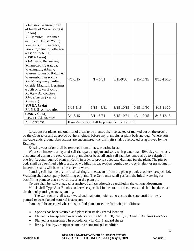
82 NEW YORK STATE DEPARTMENT OF TRANSPORTATION Section 600 STANDARD SPECIFICATIONS (USC) May 1, 2019 VOLUME 3
R1- Essex, Warren (north
of towns of Warrensburg &
Bolton)
R2-Hamilton, Herkimer
(towns of Ohio & Webb)
R7-Lewis, St. Lawrence,
Franklin, Clinton, Jefferson
(east of Route 81)
(USDA 4a-5a)
R1–Greene, Rensselaer,
Schenectady, Saratoga,
Washington, Albany,
Warren (towns of Bolton &
Warrensburg & south)
R2- Montgomery, Fulton,
Oneida, Madison, Herkimer
(south of town of Ohio)
R3,6,9 – All counties
R7- Jefferson (west of
Route 81)
4/1-5/15 4/1 – 5/31 8/15-9/30 9/15-11/15 8/15-11/15
(USDA 5a-6a)
R4, 5 & 8- All counties 3/15-5/15 3/15 – 5/31 8/15-10/15 9/15-11/30 8/15-11/30
(USDA 6b-7a)
R10, 11- All counties 3/1-5/15 3/1 – 5/31 8/15-10/31 10/1-12/15 8/15-12/15
All Locations Bare Root stock shall be planted while dormant
Locations for plants and outlines of areas to be planted shall be staked or marked out on the ground
by the Contractor and approved by the Engineer before any plant pits or plant beds are dug. Where non-
movable underground obstructions are encountered, the plant pits shall be relocated as approved by the
Engineer.
Existing vegetation shall be removed from all new planting beds.
Where an impervious layer of soil (hardpan, fragipan and soils with greater than 20% clay content) is
encountered during the excavation of plant pits or beds, all such soil shall be removed up to a depth of
one foot beyond required plant pit depth in order to provide adequate drainage for the plant. The pits or
beds shall be backfilled with topsoil. Any additional excavation required to properly plant or transplant in
impervious soils will be considered extra work.
Planting soil shall be unamended existing soil excavated from the plant pit unless otherwise specified.
Watering shall accompany backfilling of plant. The Contractor shall perform the initial watering for
backfilling plant so that no voids occur in the plant pit.
No tree shall be staked, guyed or anchored unless otherwise specified in the contract documents.
Mulch shall Type A or B unless otherwise specified in the contract documents and shall be placed at
the time of planting or transplanting.
The Contractor shall water, weed and maintain mulch at no cost to the state until the newly
planted or transplanted material is accepted.
Plants will be accepted when all specified plants meet the following conditions:
• Species has been verified and plant is in its designated location
• Planted or transplanted in accordance with ANSI A 300, Part 1, 2 , 3 and 6 Standard Practices
• Planted or transplanted in accordance with 611 Standard sheets
• living, healthy, unimpaired and in an undamaged condition

83 NEW YORK STATE DEPARTMENT OF TRANSPORTATION Section 600 STANDARD SPECIFICATIONS (USC) May 1, 2019 VOLUME 3
Watering, if specified, shall begin upon acceptance of the planting or transplanting and unless
otherwise specified continue for one year or the duration of the contract, which ever is later. Watering
after acceptance shall be performed as required in Section 610-3.09 Watering Vegetation and paid for
separately. Installation of rodent guards if specified are paid for separately.
Plants that die after acceptance at any time during the contract duration shall be removed and unless
otherwise specified, the surface area shall be restored to the condition of the adjacent surface at no
additional cost to the state.
611-3.02 Planting. The Contractor shall notify the Engineer at least four calendar days before intended
delivery of plants or planting materials to the site. The Contractor shall furnish the Engineer legible
copies of the certificates of inspection of plant materials and documentation for each shipment showing
point of origin, sizes, scientific names, quantities, and kinds of materials supplied.
Planting shall be in accordance with ANSI A300 Part 1, 2 and 3 Standard Practices.
Pruning at the time of planting shall be limited to the removal of dead, conflicting and broken
branches; and to other pruning consistent with good horticultural practice in accordance with ANSI A300
Part 1 Standard Practices.
611-3.03 Transplanting. Transplanting shall be in accordance with ANSI A300 Part 1, 2, 3 and 6
Standard Practices and accomplished by a digging method intended to preserve the root system intact to
the extent practicable. Planting soil shall be unamended existing soil excavated from the plant pit unless
otherwise specified. Transplanted stock shall be pruned prior to transplanting in accordance with ANSI
A300 Part 1 Standard Practices.
The Contractor shall take appropriate measures to avoid damage to plant during the transplanting
operation including:
1. Provide trunk and branch Protection.
2. Treat plant with an anti-desiccant prior to being dug up
3. Protect all roots from drying out.
4. Prune damaged plant roots greater than 1 inch in diameter
Plants shall be set in a vertical position.
Where the contract duration allows plants greater than 6 inch DBH shall be root pruned up to one
year prior to transplanting.
611-3.04 Portable Drip Irrigation System (PDIS). After the requirements for planting under Section
611 Planting, Transplanting and Post Planting Care are completed; the Contractor shall supply and
install the required number and size of PDIS as recommended by the manufacturer for the trees planted.
Watering shall be performed as required in Section 610-3.09 Watering Vegetation and paid for separately.
All PDIS that are damaged and or missing shall be replaced at no added cost to the State.
The Contractor shall remove PDIS in the fall prior to the first frost. The PDIS shall remain the
property of the Contractor.
611-3.05 Post-Planting Care. If specified, the Contractor shall care for planting as needed for one year
following the satisfactory completion of all of the planting and/or transplanting or for the duration of the
contract, which ever is later. The contractor shall prepare and submit a post-planting care work schedule
for approval.
Post-planting care shall consist of:
1. Mulching – with materials to match those used in initial planting, twice to maintain a depth of 3 inches.
2. Weeding - twice

84 NEW YORK STATE DEPARTMENT OF TRANSPORTATION Section 600 STANDARD SPECIFICATIONS (USC) May 1, 2019 VOLUME 3
3. Integrated vegetation and pest management- in the event of threat of serious damage from insects or
diseases the plants shall be treated by preventative or remedial measures.
4. Pruning (ANSI A300 Part 1) - once to prune dead or damaged branches.
5. Maintenance/Replacement/of tree support system if present – once every six months
6. Removal of tree support system if present at the end of the post-planting care period.
7. Removal of rodent guards if present at the end of the post-planting care period
611-3.06 Rodent Guards. Vacant
611-4 METHOD OF MEASUREMENT.
611-4.01 Planting. The quantity to be measured for payment will be the number of plants placed.
611-4.02 Transplanting. The quantity to be measured for payment will be the number of plants placed.
611-4.03 Portable Drip Irrigation System (PDIS). The quantity of PDIS to be measured for payment
will be the number of PDIS placed.
The quantity of Removal of Portable Drip Irrigation System to be measured for payment will be the
number of PDIS removed.
611-4.04 Post-Planting Care. The quantity to be measured for payment will be the number of plants
cared for or nearest whole square yard on slope of plants cared for.
611-4.05 Rodent Guards. The quantity to be measured for payment will be the number of rodent guards
placed.
611-5 BASIS OF PAYMENT.
611-5.01 Planting. The unit price bid for each plant shall include the cost of all labor, materials, and
equipment, including initial watering and mulch, compost, plants and plant protection materials and
topsoil necessary to satisfactorily complete the work.
611-5.02 Transplanting. The unit price bid for each plant shall include the cost of all labor, materials,
and equipment, including initial watering, mulch, compost, plant and plant protection materials and
topsoil necessary to satisfactorily complete the work.
611-5.03 Portable Drip Irrigation System. The unit price bid shall include the cost of all labor,
materials, and equipment, necessary to satisfactorily complete the work.
611-5.04 Post-Planting Care. The unit price bid for each plant shall include the cost of all labor,
materials, and equipment necessary to satisfactorily complete the work. Progress payments for work
satisfactorily performed may be paid at the mid point of the post-planting care in amounts not to exceed
forty percent (40%) of the unit price bid for the respective work.
611-5.05 Rodent Guards. The unit price bid shall include the cost of all labor, materials, and equipment,
necessary to satisfactorily complete the work.
Payment will be made under:
Item No. Item Pay Unit
611.011x Planting - Major Deciduous Trees – size as specified Each
611.012x Planting - Major Deciduous Trees – 1 ¼ inch Caliper Each

85 NEW YORK STATE DEPARTMENT OF TRANSPORTATION Section 600 STANDARD SPECIFICATIONS (USC) May 1, 2019 VOLUME 3
611.013x Planting - Major Deciduous Trees – 1 ½ inch Caliper Each
611.014x Planting - Major Deciduous Trees – 1 ¾ inch Caliper Each
611.015x Planting - Major Deciduous Trees – 2 inch Caliper Each
611.016x Planting - Major Deciduous Trees – 2 ½ inch Caliper Each
611.017x Planting - Major Deciduous Trees – 3 inch Caliper Each
611.018x Planting - Major Deciduous Trees – 3 ½ inch Caliper Each
611.019x Planting - Major Deciduous Trees – 4 inch Caliper Each
611.021x Planting - Minor Deciduous Trees – size as specified Each
611.022x Planting - Minor Deciduous Trees – 3 foot height Each
611.023x Planting - Minor Deciduous Trees – 4 foot height Each
611.024x Planting - Minor Deciduous Trees – 5 foot height Each
611.025x Planting - Minor Deciduous Trees – ¾ inch Caliper Each
611.026x Planting - Minor Deciduous Trees – 1 inch Caliper Each
611.027x Planting - Minor Deciduous Trees – 1 ¼ inch Caliper Each
611.028x Planting - Minor Deciduous Trees – 1 ½ inch Caliper Each
611.029x Planting - Minor Deciduous Trees – 1 ¾ inch Caliper Each
611.020x Planting - Minor Deciduous Trees – 2 inch Caliper Each
611.031x Planting - Coniferous Trees – size as specified Each
611.032x Planting - Coniferous Trees – 2 ½ foot height Each
611.033x Planting - Coniferous Trees – 3 foot height Each
611.034x Planting - Coniferous Trees – 4 foot height Each
611.035x Planting - Coniferous Trees – 5 foot height Each
611.036x Planting - Coniferous Trees – 6 foot height Each
611.037x Planting - Coniferous Trees – 7 foot height Each
611.038x Planting - Coniferous Trees – 8 foot height Each
611.039x Planting - Coniferous Trees – 9 foot height Each
611.041x Planting - Deciduous Shrubs –As Specified Each
611.042x Planting - Deciduous Shrubs – 15 inch Height/Spread Each
611.043x Planting - Deciduous Shrubs – 18 inch Height/Spread Each
611.044x Planting - Deciduous Shrubs – 2 foot Height/Spread Each
611.045x Planting - Deciduous Shrubs – 3 foot Height/Spread Each
611.046x Planting - Deciduous Shrubs – 4 foot Height/Spread Each
611.047x Planting - Deciduous Shrubs – 5 foot Height/Spread Each
611.048x Planting - Deciduous Shrubs – 6foot Height/Spread Each
611.051x Planting - Evergreen Shrubs – As Specified Each
611.052x Planting - Evergreen Shrubs – 15 inch Height/Spread Each
611.053x Planting - Evergreen Shrubs – 18 inch Height/Spread Each
611.054x Planting - Evergreen Shrubs – 2 foot Height/Spread Each
611.055x Planting - Evergreen Shrubs – 2 ½ foot Height/Spread Each
611.056x Planting - Evergreen Shrubs – 3 foot Height/Spread Each
611.057x Planting - Evergreen Shrubs – 3 ½ foot Height/Spread Each
611.058x Planting - Evergreen Shrubs – 4 foot Height/Spread Each
611.059x Planting - Evergreen Shrubs – 5 foot Height/Spread Each
x= Root Specification
1= Ball & Burlap, Field Potted or Field Boxed, 2 = Container or Box Grown,
3 = Bare Root, 4 = In Ground Fabric Bag Grown
611.061y Planting – Vines, Groundcovers – As Specified Each
611.062y Planting – Vines, Groundcovers – Number SP3 Container Each
611.063y Planting – Vines, Groundcovers – Number SP4 Container Each
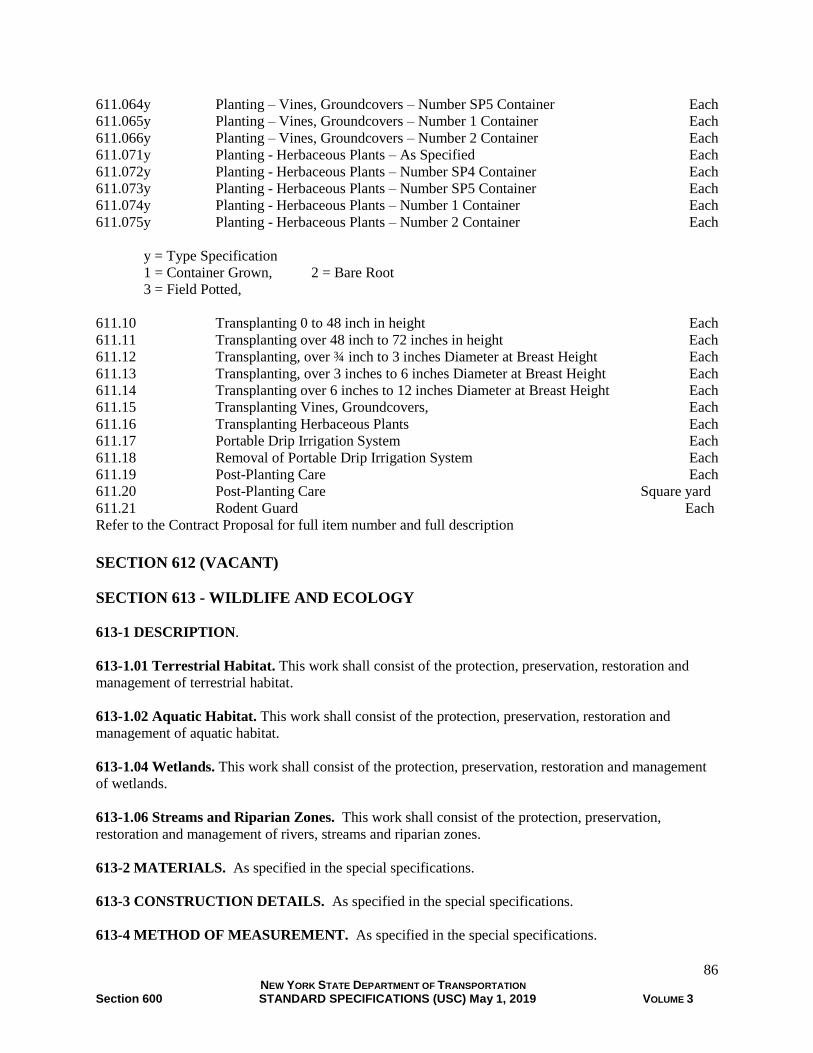
86 NEW YORK STATE DEPARTMENT OF TRANSPORTATION Section 600 STANDARD SPECIFICATIONS (USC) May 1, 2019 VOLUME 3
611.064y Planting – Vines, Groundcovers – Number SP5 Container Each
611.065y Planting – Vines, Groundcovers – Number 1 Container Each
611.066y Planting – Vines, Groundcovers – Number 2 Container Each
611.071y Planting - Herbaceous Plants – As Specified Each
611.072y Planting - Herbaceous Plants – Number SP4 Container Each
611.073y Planting - Herbaceous Plants – Number SP5 Container Each
611.074y Planting - Herbaceous Plants – Number 1 Container Each
611.075y Planting - Herbaceous Plants – Number 2 Container Each
y = Type Specification
1 = Container Grown, 2 = Bare Root
3 = Field Potted,
611.10 Transplanting 0 to 48 inch in height Each
611.11 Transplanting over 48 inch to 72 inches in height Each
611.12 Transplanting, over ¾ inch to 3 inches Diameter at Breast Height Each
611.13 Transplanting, over 3 inches to 6 inches Diameter at Breast Height Each
611.14 Transplanting over 6 inches to 12 inches Diameter at Breast Height Each
611.15 Transplanting Vines, Groundcovers, Each
611.16 Transplanting Herbaceous Plants Each
611.17 Portable Drip Irrigation System Each
611.18 Removal of Portable Drip Irrigation System Each
611.19 Post-Planting Care Each
611.20 Post-Planting Care Square yard
611.21 Rodent Guard Each
Refer to the Contract Proposal for full item number and full description
SECTION 612 (VACANT)
SECTION 613 - WILDLIFE AND ECOLOGY
613-1 DESCRIPTION.
613-1.01 Terrestrial Habitat. This work shall consist of the protection, preservation, restoration and
management of terrestrial habitat.
613-1.02 Aquatic Habitat. This work shall consist of the protection, preservation, restoration and
management of aquatic habitat.
613-1.04 Wetlands. This work shall consist of the protection, preservation, restoration and management
of wetlands.
613-1.06 Streams and Riparian Zones. This work shall consist of the protection, preservation,
restoration and management of rivers, streams and riparian zones.
613-2 MATERIALS. As specified in the special specifications.
613-3 CONSTRUCTION DETAILS. As specified in the special specifications.
613-4 METHOD OF MEASUREMENT. As specified in the special specifications.
87 NEW YORK STATE DEPARTMENT OF TRANSPORTATION Section 600 STANDARD SPECIFICATIONS (USC) May 1, 2019 VOLUME 3
613-5 BASIS OF PAYMENT. As specified in the special specifications.
SECTION 614 - PRUNING, IMPROVING AND REMOVING EXISTING VEGETATION
614-1 DESCRIPTION.
614-1.01 Pruning Existing Trees. This work shall consist of pruning existing trees as shown in the
contract documents and as directed by the Engineer.
614-1.02 Improvement of Vegetated Areas. This work shall consist of cutting, disposing of all wood
and debris, stump removal, or mechanical or chemical treatment of specified trees and woody vegetation
within the area shown in the contract documents and as directed by the Engineer.
614-1.03 Tree Removal. The work shall consist of felling trees over 4 inch in diameter at breast height,
disposing of all wood and debris, and may require topping, stump removal and other work as shown in
the contract documents and as directed by the Engineer.
614-1.04 Existing Stump Removal. The work shall consist of removing existing stumps, disposing of all
wood and debris, as shown in the contract documents and as directed by the Engineer.
614-1.05 Tree Root Zone Treatment (Vertical Mulching/Aeration). This work shall consist of treating
the root zone of trees through aeration and/or mulching of the roots as shown in the contract documents
and as directed by the Engineer.
614-1.06 Tree Root Pruning. This work shall consist of cleanly pruning, existing tree roots severed
during construction operations, typically related to linear excavation, as shown in the contract documents
and as directed by the Engineer.
614-2 MATERIALS
614-2.01 Pruning Existing Trees. The materials shall meet the requirements of the following
subsections of Section 700 Materials and Manufacturing.
Water 712-01
614-2.02 Improvement of Vegetated Areas. The materials shall meet the requirements of the following
subsections of Section 700 Materials and Manufacturing.
Topsoil 713-01
Pesticides 713-13
614-2.03 Tree Removal. The materials shall meet the requirements of the following subsections of
Section 700 Materials and Manufacturing.
Topsoil 713-01
614-2.04 Existing Stump Removal. The materials shall meet the requirements of the following
subsections of Section 700 Materials and Manufacturing.
Topsoil 713-01

88 NEW YORK STATE DEPARTMENT OF TRANSPORTATION Section 600 STANDARD SPECIFICATIONS (USC) May 1, 2019 VOLUME 3
614-2.05 Tree Root Zone Treatment (Vertical Mulching/Aeration). The materials shall meet the
requirements of the following subsections of Section 700 Materials and Manufacturing.
Mortar Sand 703-03
Mycorrhizal Fungi 713-09
Compost 713-15
614-2.06 Tree Root Pruning. The materials shall meet the requirements of the following subsections of
Section 700 Materials and Manufacturing.
Water 712-01
614-3 CONSTRUCTION DETAILS
614-3.01 Pruning Existing Trees
A. Equipment. Workers shall employ accepted tree climbing methods, and shall not climb trees with
climbing spurs. All tools used and methods employed in accordance ANSI A300 Part 1 Standard
Practices, except that no anvil type pruners will be permitted. The cutting surfaces of all tools,
ladders, ropes, soles of workers shoes and other objects coming into contact with the tree shall be
disinfected with a 2% bleach solution and dried completely prior to the start of any work on a tree to
prevent the spread of plant diseases.
B. Pruning. Pruning shall be in accordance ANSI A300 Part 1 Standard Practices. When specified
the quantity of trees as shown in the contract documents shall be pruned so the resulting crown retains
the growth habit of the tree species. Any and all branches interfering with or hindering the healthy
growth of the tree shall be removed. All diseased branches and all dead branches 1 inch or more in
diameter shall be removed. Any branch which may be partly dead, yet has a healthy lateral branch at
least one-third the diameter of the parent branch shall be removed beyond the healthy branch. All
stubs or improper cuts resulting from former pruning shall be removed. All cuts shall be cleanly made
with sharp tools as close to the parent trunk or limb as possible without disturbing the branch bark
ridge or callus collar. All existing nails, spikes, wire, plastic or other materials found driven into or
fastened to the trunk or branches shall be removed or if approved they shall be cut flush in a manner
to permit complete healing over.
614-3.02 Improvement of Vegetated Areas. All trees and shrubs specified for removal will be
designated by the Engineer either by separate marking, marking in sample areas, or otherwise. Unless
otherwise specified, all stumps shall be cut to a height of about 6 inches above the ground. Unless
otherwise specified, an approved herbicide shall be applied to all live stumps in accordance with the
manufacturer's recommendations. An approved dye shall be added to the herbicide mixture to identify
treated stumps and stubble. Where stump removal is specified, all stump holes shall be backfilled with
topsoil, unless otherwise specified in the contract documents, and backfill shall be compacted. Unless
otherwise specified in the contract documents, grass shall be established on stump holes and will be paid
for separately.
Care shall be taken in the felling of trees and the operation of equipment to prevent injury to trees and
shrubs which are to be preserved. All injuries to the limbs, bark and roots of such plants shall be repaired
in accordance with ANSI A300 Part 1 Standard Practices Pruning and ANSI Z133.1 Arboricultural
Operations Safety.
Improvement of vegetated areas shall be completed in any area before any planting, seeding or other
landscape work is begun in that area unless otherwise approved.
All wood, stumps, brush and other debris resulting from the work shall be disposed of as specified in
Section 201 Clearing and Grubbing.
89 NEW YORK STATE DEPARTMENT OF TRANSPORTATION Section 600 STANDARD SPECIFICATIONS (USC) May 1, 2019 VOLUME 3
614-3.03 Tree Removal. No tree shown in the contract documents or listed for removal shall be cut
until it is approved by the Engineer. The contractor shall be responsible to coordinate all work involving
utilities with the respective utility company. All trees shall be topped and limbed before felling unless
otherwise approved. All injuries to the limbs, bark and roots of plants to remain shall be repaired in
accordance with ANSI A300 Standard Practices Pruning and ANSI Z133.1 Arboricultural Operations
Safety.
The Contractor shall field measure all trees at 4 ½ feet above the ground, commonly referred to as
Diameter Breast Height (DBH) before they are cut.
Stumps of trees removed under this item for removal shall be grubbed, cut, ground to the depth of six
inches below grade or as specified in the contract documents. All stump holes shall be backfilled with
topsoil, unless otherwise specified in the contract documents and backfill shall be compacted. Unless
otherwise specified in the contract documents, grass shall be established on stump holes and will be paid
for separately.
614-3.04 Existing Stump Removal. Existing stumps listed for removal in the contract documents shall
be ground to the depth of 6 inches below grade unless otherwise specified in the contract documents.
Stumps shall include all visible wood and roots. Backfill to finished grade with topsoil, unless otherwise
specified in the contract documents. The backfill shall be compacted. Unless otherwise specified in the
contract documents, grass shall be established on stump holes and will be paid for separately.
614-3.05 Tree Root Zone Treatment (Vertical Mulching/Aeration). Locations of work shall include
areas within the dripline or wider root zone of existing trees to be preserved as shown on the contract
documents.
Appropriate drilling tools shall be used for drilling of holes for root zone restoration. Drilling
equipment shall be hand held or light weight devices (no heavy machinery) so as to avoid further impact
to tree roots through compaction.
Holes shall be drilled and existing soil removed within a zone beginning 3 feet from the trunk of the
specified tree and extending to its dripline on an approximately 2 foot x 2 foot grid. Dimensions of holes
or drill size shall be approximately 2 inches in diameter and a minimum of 12 inches deep. Efforts should
be made to minimize drilling through large tree roots (especially near the trunk). When woody roots are
encountered, the drill hole shall be moved to avoid root damage.
The hole shall be completely filled to original grade as follows:
Method 1: with mortar sand
Method 2: with mortar sand amended with Mycorrhizal Fungi.
Method 3: with compost.
Method 4: with compost amended with Mycorrhizal Fungi.
When mycorrhizal fungi are specified, they shall be a dry granular powder specifically designed for
vertical mulching applications. Apply in accordance with the manufacturer’s recommendations at a rate of
3 ounces per hole or when pre-mixed in bulk 5 pounds per cubic yard of sand or compost.
614-3.06 Tree Root Pruning. Existing tree roots greater than 1 inch in diameter, measured at the edge of
excavation, shall be pruned within 24 hours of the time they have been damaged by construction activity.
The severed root shall be pruned at the edge of excavation, or 1 inch beyond the entire damaged portion
of the tree root if damaged root extends beyond the edge of excavation into undisturbed soil. Pruning shall
be in accordance with ANSI A300 Part 1 Standard Practices Pruning and ANSI Z133.1 Arboricultural
Operations Safety. All cuts shall be cleanly made with sharp tools. The cutting surfaces of all tools,
ladders, ropes, soles of workers shoes and other objects coming into contact with the tree roots shall be
washed with a disinfectant at the start of any work on a tree to prevent the spread of plant diseases.

90 NEW YORK STATE DEPARTMENT OF TRANSPORTATION Section 600 STANDARD SPECIFICATIONS (USC) May 1, 2019 VOLUME 3
The excavated area around the existing tree roots shall be backfilled as soon as construction activities
permit with the specified or approved materials. If the excavated area around the existing tree roots is not
backfilled within 24 hours, all roots shall be kept moist, to prevent dessication.
614-4 METHOD OF MEASUREMENT
614-4.01 Pruning Existing Trees. The quantity to be measured for payment will be the number of trees
pruned.
614-4.02 Improvement of Vegetated Areas. The quantity to be measured for payment will be in square
yards measured to the nearest whole square yard of area improved.
614-4.03 Tree Removal. The quantity to be measured for payment will be the number of trees, including
their stumps if specified.
614-4.04 Pre-Existing Stump Removal. The quantity to be measured for payment will be the number of
pre-existing stumps removed.
614-4.05 Tree Root Zone Treatment (Vertical Mulching/Aeration). The quantity to be measured for
payment will be in square yards treated within the zone, measured to the nearest square yard.
614-4.06 Tree Root Pruning. The quantity to be measured for payment will be in feet to the nearest
whole foot, along excavation line.
614-5 BASIS OF PAYMENT
614-5.01 Pruning Existing Trees. The unit price bid shall include the cost of labor, materials, and
equipment necessary to satisfactorily complete the work.
614-5.02 Improvement of Vegetated Areas. The unit price bid shall include the cost of labor, materials,
and equipment necessary to satisfactorily complete the work.
614-5.03 Tree Removal. The unit price bid shall include the cost of labor, materials, and equipment
necessary to satisfactorily complete the work.
When trees are specified in the contract documents for removal, payment for each tree removal will
include removal of the stump.
614-5.04 Existing Stump Removal. The unit price bid shall include the cost of labor, materials, and
equipment necessary to satisfactorily complete the work.
614-5.05 Tree Root Zone Treatment. The unit price bid shall include the cost of labor, materials,
equipment and incidentals necessary to complete the work. Mycorrhizal Fungi and mulch will be paid for
separately.
614-5.06 Tree Root Pruning. The unit price bid shall include the cost of labor, materials, equipment and
incidentals necessary to complete the work.
Payment will be made under:
Item No. Item Pay Unit
614.0411 Care of Trees up to 12” Diam. at Breast Height – Pruning Each
614.0421 Care of Trees Over 12” to 24” Diam. at Breast Height - Pruning Each

91 NEW YORK STATE DEPARTMENT OF TRANSPORTATION Section 600 STANDARD SPECIFICATIONS (USC) May 1, 2019 VOLUME 3
614.0431 Care of Trees Over 24” to 36” Diam. at Breast Height - Pruning Each
614.0441 Care of Trees Over 36” to 48” Diam. at Breast Height – Pruning Each
614.0451 Care of Trees Over 48” to 60” Diam. at Breast Height – Pruning Each
614.0461 Care of Trees Over 60” Diam. at Breast Height – Pruning Each
614.05 Improvement of Vegetated Areas Square Yard
614.0601nn Tree Removal Over 4” to 6” Diam. Breast Height Each
614.0602nn Tree Removal Over 6” to 12” at Breast Height Each
614.0603nn Tree Removal Over 12” to 18” at Breast Height Each
614.0604nn Tree Removal Over 18” to 24” at Breast Height Each
614.0605nn Tree Removal Over 24” to 36” at Breast Height Each
614.0606nn Tree Removal Over 36” to 48” at Breast Height Each
614.0607nn Tree Removal Over 48” to 60” at Breast Height Each
614.0608nn Tree Removal Over 60” to 72” at Breast Height Each
nn = Stump Treatment
01 = Stumps Cut to Above Grade, 02 = Stumps Cut Flush,
03 = Stumps Cut to Below Grade, 04 = Stumps Grubbed
614.0701 Pre-Existing Stump Removal up to 24” diameter at 6 inches above grade Each
614.0702 Pre-Existing Stump Removal over 24” to 48” diameter at 6 inches above grade Each
614.0703 Pre-Existing Stump Removal over 48” diameter at 6 inches above grade Each
614.08 Tree Root Zone Treatment (Vertical Mulching/Aeration) Square Yard
614.09 Tree Root Pruning Feet
SECTION 615 - LANDSCAPE APPURTENANCES
615-1 DESCRIPTION. The work in this section shall include all work required for furnishing, placing,
and/or special construction of landscape appurtenances.
615-2 MATERIALS. As specified in the special specifications.
615-3 CONSTRUCTION DETAILS. As specified in the special specifications.
615-4 METHOD OF MEASUREMENT. As specified in the special specifications.
615-5 BASIS OF PAYMENT. As specified in the special specifications.
SECTION 616 - SOIL BIOENGINEERING
616-1 DESCRIPTION. This section shall include work required for soil bioengineering
616-2 MATERIALS. As specified in the special specifications.
616-3 CONSTRUCTION DETAILS. As specified in the special specifications.
616-4 METHOD OF MEASUREMENT. As specified in the special specifications.
616-5 BASIS OF PAYMENT. As specified in the special specifications.

92 NEW YORK STATE DEPARTMENT OF TRANSPORTATION Section 600 STANDARD SPECIFICATIONS (USC) May 1, 2019 VOLUME 3
SECTION 617 - INVASIVE SPECIES MANAGEMENT
617-1 DESCRIPTION. This work shall consist of the control, eradication and management of invasive
species.
617-2 MATERIALS. As specified in the special specifications.
617-3 CONSTRUCTION DETAILS. As specified in the special specifications.
617-4 METHOD OF MEASUREMENT. As specified in the special specifications.
617-5 BASIS OF PAYMENT. As specified in the special specifications.
SECTION 618 (VACANT)
SECTION 619 - WORK ZONE TRAFFIC CONTROL (Last Revised September, 2017)
619-1 DESCRIPTION
619-1.01 General. Work zone traffic control shall consist of all work necessary to provide for the safe
and efficient movement of traffic through or around work zones, and to protect workers and the public
from damage to person and property which may result, directly or indirectly, from any construction
operations. Work zone traffic control shall be completed under the direction of a trained, competent
person, as shown in the contract documents, the MUTCD and as directed by the Engineer. The duration of
this work shall be from the date any work is started on the contract site, including mobilization of
equipment, signs, offices, and shops until the date of contract final acceptance. Temporary materials and
components that are furnished by the Contractor shall remain the property of the Contractor.
See Figure 619-1 Component Parts of a Typical Highway Work Zone for definitions of terms.
619-1.02 Basic Work Zone Traffic Control. Work shall consist of controlling traffic over a reasonably
smooth traveled way which shall be marked by signs, delineators, channelizing devices, pavement
markings, and other devices as shown in the contract documents or as directed by the Engineer. Work
after sunset and before sunrise shall include additional requirements for nighttime operations including,
but not limited to, a written plan for nighttime operations, additional worker and equipment protection,
additional channelizing devices and contract site patrol.
The Contractor shall conduct its operations to ensure the safety and convenience of travelers and
abutting property owners as well as the safety of all workers on the contract. Travelers include, but may
not be limited to motorists, motorcyclists, bicyclists and pedestrians.
Work shall be scheduled to keep the time and distance that existing pavement is removed or
substantially disturbed to a minimum and consistent with the physical requirements of the contract.
Unless otherwise indicated in the contract documents, the distance over which traffic is maintained on an
unpaved surface shall not exceed 1/2 mile at any one time. During seasonal shutdown periods, no part of
the highway shall be closed to traffic unless provided for in the contract documents, or the Contractor has
submitted and the Engineer has approved a detailed schedule of operations reflecting a proposal to close
the highway to traffic.
Basic work zone traffic control shall include the following:

93 NEW YORK STATE DEPARTMENT OF TRANSPORTATION Section 600 STANDARD SPECIFICATIONS (USC) May 1, 2019 VOLUME 3
A. Surface Condition, Debris, Drainage and Dust Control. Work shall consist of maintaining the
surface condition of the traveled way, including detours, consistent with the preconstruction posted
speed limit; including maintaining positive drainage, dust control and keeping the roadway free from
debris and materials spilled from or tracked by vehicles or equipment. Debris and dust shall be
controlled on all operations.
B. Seasonal Operations and Snow and Ice Control. Work shall consist of maintaining the traveled
way to facilitate safe, efficient travel and permit snow and ice control by others during winter months
and during any period that work is suspended.
C. Maintain Public Access. Work shall consist of maintaining public access to intersecting roads,
residences, business establishments, adjacent property, bus stops and transportation facilities for
vehicles, pedestrians, and bicyclists.
D. Maintain Existing Roadside Signs, Delineators and Markers. Work shall consist of maintaining,
in their existing condition, existing highway signs, delineators, and markers within the contract limits.
E. Maintain Existing Guide Rail, Median Barrier and Bridge Rail. Work shall consist of
maintaining existing traffic barriers and other safety devices, in their existing condition, within the
contract limits.
F. Construction Vehicles and Equipment. Work shall consist of equipping construction vehicles and
equipment with warning lights and reflective markings; and maintenance of vehicles and equipment
in safe operating condition.
G. Barrier/Shadow Vehicles.
1. Barrier Vehicles. Work shall consist of furnishing barrier vehicles to guide traffic and protect
workers in stationary lane and shoulder closures and other stationary temporary traffic control
zones, as shown in the contract documents or as directed by the Engineer.
2. Shadow Vehicles. Work shall consist of furnishing shadow vehicles to guide traffic and to
protect workers in mobile or short duration work zones not protected by stationary lane or
shoulder closures, as shown in the contract documents or as directed by the Engineer.
H. Construction Signs. Work shall consist of furnishing, installing, moving, maintaining,
deactivating, and removing construction signs, including warning lights, as shown in the contract
documents or as directed by the Engineer.
I. Arrow Panels. Work shall consist of furnishing, installing, maintaining, and removing arrow panels
as shown in the contract documents or as directed by the Engineer. Arrow panels are used to warn and
guide traffic when travel lanes are temporarily closed by construction activities.
J. Channelizing Devices. Work shall consist of furnishing, placing, maintaining and removing
channelizing devices, with warning lights where required, including drums, vertical panels,
construction barricades, cones, and temporary tubular markers. Type III construction barricades and
interim tubular markers may be specified under separate pay items.
K. Pavement Edge Drop-Off Protection. Work shall consist of furnishing and maintaining protection
for edge drop-offs adjacent to the pavement or shoulder.

94 NEW YORK STATE DEPARTMENT OF TRANSPORTATION Section 600 STANDARD SPECIFICATIONS (USC) May 1, 2019 VOLUME 3
L. Flagging and Traffic Control. Work shall consist of furnishing the necessary traffic control
equipment and flaggers for adequate traffic control. Portable traffic signal systems authorized by the
Engineer may be utilized only on a highway designated as a Restricted Highway.
M. Maintain Existing Mailboxes. Work shall consist of maintaining postal route mailboxes serviced
from vehicles, in a useable condition and location consistent with U.S. Postal Service requirements.
N. Contract Site Patrol. Work shall consist of furnishing personnel to patrol the contract area as
necessary to ensure conditions on the site are adequate for public safety and convenience at all times.
619-1.03 Basic Work Zone Traffic Control (Daily Operations). Work shall consist of controlling and
protecting traffic during a single work shift as shown in the contract documents, or as directed by the
Engineer. The Contractor will not be required to repair or maintain the surface of the traveled way and
other roadway features not part of the work, except to repair damage resulting from the Contractor’s
operations.
619-1.04 Temporary Business Signs. Work shall consist of furnishing, installing, moving, covering,
maintaining, and removing temporary business signs as shown in the contract documents or as directed by
the Engineer.
619-1.05 Covering or Removal of Pavement Markings. Work shall consist of removing or covering
existing permanent pavement markings, interim pavement markings, and temporary pavement markings
including, but not limited to: edge lines, lane lines, center lines, crosswalks, stop bars, arrows, symbols,
and diagonal markings in gores and medians as shown in the contract documents or as directed by the
Engineer.
619-1.06 Temporary Pavement Markings. Work shall consist of furnishing and applying temporary
pavement markings as shown in the contract documents or as directed by the Engineer. The work for
removable pavement tape, removable wet-night reflective tape, temporary overlay markers and removable
raised pavement markers shall include removal. Temporary pavement markings are intended for use on
any new pavement or milled surface until the subsequent course is placed or interim pavement markings
or final pavement markings are installed.
619-1.07 Interim Pavement Markings. Work shall consist of furnishing, applying, and maintaining,
interim pavement markings as shown in the contract documents or as directed by the Engineer. Interim
pavement markings are intended for use in diversions, temporary pavement realignments and crossovers,
lane shifts and closures, and other traffic patterns associated with construction activities. Interim
pavement markings are intended for use for a given phase or season, for a maximum of 1 year.
619-1.08 Temporary Rumble Strips. Work shall consist of installing, maintaining, and removing
temporary rumble strips at the locations shown in the contract documents or as directed by the Engineer.
619-1.09 Interim Tubular Markers. Work shall consist of furnishing, installing, moving, and
maintaining interim tubular markers attached to the pavement as shown in the contract documents or as
directed by the Engineer. Interim tubular markers are typically used for 2-way, 2-lane freeway work
zones and long-term closures where available width is limited.
619-1.10 Portable Variable Message Signs (PVMS) and Truck Mounted Variable Message Signs
(TMVMS).

95 NEW YORK STATE DEPARTMENT OF TRANSPORTATION Section 600 STANDARD SPECIFICATIONS (USC) May 1, 2019 VOLUME 3
A. Portable Variable Message Signs (PVMS). Work shall consist of furnishing, installing, operating,
maintaining, relocating, and removing PVMS as shown in the contract documents or as directed by the
Engineer. PVMS with a pay unit of each shall be provided for the duration of the contract at the general
locations specified in the contract documents and in accordance with the Special Note Requirements
for Portable Variable Message Signs (PVMS). PVMS with a pay unit of weeks shall be provided at
general locations and durations in accordance with the Special Note Requirements for Portable
Variable Message Signs (PVMS) and the contract documents.
PVMS are intended to supplement other traffic control devices by displaying symbolic or word
messages, but are not to be used alone to replace conventional traffic control devices.
B. Truck Mounted Variable Message Signs (TMVMS). Work shall consist of furnishing, installing,
operating, maintaining and relocating TMVMS as shown in the contract documents or as directed by the
Engineer. TMVMS with a pay unit of each shall be provided for the duration of the contract at the
general locations specified in the contract documents. TMVMS with a pay unit of weeks shall be provided
at general locations and durations in accordance with the Special Note Requirements for Truck Mounted
Variable Message Signs and the contract documents. TMVMS are intended to supplement other traffic
control devices by displaying symbolic or word messages. They may only be used alone to replace
conventional traffic control devices in mobile and short duration work zones or situations of limited
duration.
619-1.11 Type III Construction Barricades. Work shall consist of furnishing, installing, moving,
maintaining, and removing Type III construction barricades, with warning lights where specified, as
shown in the contract documents or as directed by the Engineer.
619-1.12 Temporary Concrete Barrier. Work shall consist of furnishing, installing, moving,
maintaining, and removing temporary concrete barrier, including barrier warning lights and transitions to
and from guide rail where specified, as shown in the contract documents or as directed by the Engineer.
619-1.13 Temporary Glare Screen. Work shall consist of furnishing, installing, moving, maintaining,
and removing glare screen mounted on a concrete barrier as shown in the contract documents or as
directed by the Engineer.
619-1.14 Temporary Impact Attenuator. Work shall consist of furnishing, installing, maintaining,
repairing, moving and removing temporary impact attenuators as shown in the contract documents or as
directed by the Engineer.
619-1.15 Temporary Sand Barrel Arrays. Work shall consist of furnishing, installing, maintaining,
relocating and removing temporary sand barrel arrays as shown in the contract documents or as directed
by the Engineer.
619-1.16 Vehicle Arresting Barrier. Work shall consist of providing vehicle arresting barriers (net-type)
and their anchorages as shown on the Standard Sheets to prevent errant vehicles from entering a closed
work area as shown in the contract documents or as directed by the Engineer.
619-1.17 Maintain or Modify Traffic Signal Equipment. Work shall consist of modifying or
maintaining in proper operation, existing, relocated, modified, or newly installed traffic signals as shown
in the contract documents or as directed by the Engineer.
619-1.18 Temporary Traffic Signals. Work shall consist of furnishing, installing, moving, maintaining,
and removing temporary traffic signals and necessary components as shown in the contract documents or
as directed by the Engineer. Temporary signals shall be installed only on a highway designated as a
Restricted Highway.

96 NEW YORK STATE DEPARTMENT OF TRANSPORTATION Section 600 STANDARD SPECIFICATIONS (USC) May 1, 2019 VOLUME 3
619-1.19 Nighttime Operations. Work shall consist of developing a Nighttime Operations and Lighting
Plan, and furnishing, installing, operating, maintaining, moving and removing lighting equipment for
nighttime construction operations as shown in the contract documents or as directed by the Engineer.
619-1.20 Traffic Control Supervisor. Work shall consist of providing a full-time traffic control
supervisor having adequate training, experience, and authority to implement and maintain all traffic
control operations, as shown in the contract documents or as directed by the Engineer.
619-1.21 Temporary Structures and Approaches. Work shall consist of designing, constructing,
moving, maintaining, and removing temporary structures, and necessary appurtenances, as shown in the
contract documents or as directed by the Engineer. Temporary structures may also include temporary
structural elements added to an existing structure to allow temporary use, or staged removal, of the
structure.
619-1.22 Pavement Patching. Work shall consist of providing and installing pavement patching
materials to maintain pavements open to traffic in acceptable condition as shown in the contract
documents or as directed by the Engineer.
619-1.23 Mailboxes. Work shall consist of relocating or replacing postal route mailboxes and/or mailbox
supports consistent with U.S. Postal Service requirements, as shown in the contract documents or as
directed by the Engineer.

97 NEW YORK STATE DEPARTMENT OF TRANSPORTATION Section 600 STANDARD SPECIFICATIONS (USC) May 1, 2019 VOLUME 3
FIGURE 619-1 COMPONENT PARTS OF A TYPICAL HIGHWAY WORK ZONE

98 NEW YORK STATE DEPARTMENT OF TRANSPORTATION Section 600 STANDARD SPECIFICATIONS (USC) May 1, 2019 VOLUME 3
619-2 MATERIALS.
619-2.01 General. All materials used shall comply with the requirements of the following subsections of
Section 700 Materials and Manufacturing, or as established by this section, the applicable Standard
Sheets, and the contract documents.
Concrete Grouting Material 701-05
Precast Concrete Barrier 704-05
Epoxy Polysulfide Grout 721-03
Traffic Signal Heads 724-04
Removable Raised Pavement Markers 727-02
Epoxy Paint 727-03
Permanent Tape 727-04
Glass Beads for Pavement Markings 727-05
Removable Pavement Tape 727-06
Removable Wet-Night Reflective Tape 727-07
Permanent Wet-Night Reflective Tape 727-08
Traffic Paint 727-09
Drums 729-01
Cones 729-02
Temporary Tubular Markers 729-03
Vertical Panels 729-04
Stop/Slow Paddles 729-05
Type II Construction Barricades 729-07
Type III Construction Barricades 729-08
Temporary Sign Supports 729-09
Temporary Impact Attenuators - Redirective 729-10
Temporary Impact Attenuators - Gating 729-11
Truck-Mounted Impact Attenuators 729-12
Temporary Sand Barrels 729-13
Vehicle Arresting Systems 729-14
Arrow Panels 729-15
Portable Variable-Message Signs 729-16
Temporary Glare Screens 729-17
Warning Lights 729-18
Truck Mounted Variable Message Signs 729-22
Aluminum Sign Panels 730-01
Temporary Plywood Sign Panels 730-02
Temporary Rigid Lightweight Sign Panels 730-03
Reflective Sheeting 730-05
Reflectorized Sheeting Sign Characters (Type IV) 730-12
Reflectorized Sheeting Sign Characters (Type V) 730-13
Temporary Wooden Sign Posts 730-19
Stiffeners, Overhead Brackets and Miscellaneous Hardware 730-22
Fiberglass Reinforced Plastic Sign Panels 730-23
Type A Sign Supports 730-24
Type B Sign Supports 730-25

99 NEW YORK STATE DEPARTMENT OF TRANSPORTATION Section 600 STANDARD SPECIFICATIONS (USC) May 1, 2019 VOLUME 3
619-2.02 Basic Work Zone Traffic Control.
A. Surface Condition, Debris, Drainage and Dust Control. Materials used to repair pavement
surfaces shall be compatible with the pavement. In general, plant-mixed hot mix asphalt is suitable for
all pavement surfaces to be repaired. Material other than plant-mixed hot mix asphalt may be used if
approved by the Engineer.
Environmentally compatible, approved dust palliatives may be used in conformance with any
conditions placed on their use.
B. Seasonal Operations and Snow and Ice Control. (None Specified)
C. Maintain Public Access. (None Specified)
D. Maintain Existing Roadside Signs, Delineators and Markers. All materials used to maintain
existing roadside appurtenances shall be consistent with the features to be maintained.
E. Maintain Existing Guide Rail, Median Barrier and Bridge Rail. All materials used to maintain
existing roadside appurtenances shall be consistent with the features to be maintained.
F. Construction Vehicles and Equipment. All vehicles with a GVWR greater than 10,000 lbs and
with restricted visibility to the rear shall be equipped with an operational audible backup alarm. Any
vehicle with a non-operational backup alarm shall be taken out of service until the alarm is repaired.
All vehicles and equipment within the contract limits and on the roadway shall be equipped with
a rotating amber or flashing Light Emitting Diode (LED) beacon visible from all directions for a
minimum of 1,000 feet during daylight. Flashing LED beacons shall meet the requirements of SAE
J845 Class 2. Strobe lights shall not be used.
All trucks with a GVWR greater than 10,000 lbs shall display a minimum 2 inch wide band of
reflective sheeting on the front, rear and each side. The sheeting need not be continuous, but the sum
of the length of the segments shall be at least one-half the length of the body or trailer. The centerline
of the sheeting shall be between 15 inches and 60 inches above the ground. All other construction
equipment shall display a minimum 2 inch wide band of reflective sheeting on the front and rear (100
square inches per end minimum) as practicable. Reflective markings on construction vehicles and
equipment shall conform to §730-05 Reflective Sheeting ASTM Type III, Type VII or Type IX.
G. Barrier/Shadow Vehicles. Barrier/Shadow vehicles shall weigh a minimum of 18,000 lb and shall
be equipped with a Type B or Type C Arrow Panel. Ballast may be used to bring a lighter vehicle up
to the indicated weight provided the ballast is securely contained within an enclosed body or
otherwise securely fastened to the vehicle such that the ballast will not separate from the vehicle upon
impact. Where the preconstruction posted speed limit is 55 mph or less, barrier/shadow vehicles shall
be equipped with a Test Level-2 truck mounted or trailer mounted impact attenuator. Where the
preconstruction posted speed limit is more than 55 mph, barrier/shadow vehicles shall be equipped
with a Test Level-3 truck mounted or trailer mounted impact attenuator. Impact attenuators meeting
the requirements of NCHRP 350 Test Level 3 are also acceptable as Test Level 2 devices.
Where a barrier vehicle remains stationary for extended periods of time, the Contractor may
utilize a barrier trailer in lieu of a barrier vehicle. A barrier trailer is a trailer that may be detached
from the tow vehicle and that meets barrier vehicle weight, arrow board, attenuator and placement
distance requirements.
H. Construction Signs. Fabrication of all components shall produce a finished sign panel. Holes
may be punched or drilled. Edges shall be smooth and true and free from burrs or ragged breaks.
Sign panels, including face shape, color, dimensions, and characters shall be fabricated using colors,

100 NEW YORK STATE DEPARTMENT OF TRANSPORTATION Section 600 STANDARD SPECIFICATIONS (USC) May 1, 2019 VOLUME 3
character series, character sizes, symbols, route shields and borders as shown in the MUTCD or in the
contract documents.
1. Sign Panels. Modification of sign legends by overlaying an existing legend with a revised
legend, changing a single word or distance, such as changing LEFT to RIGHT or 1000 to 1500
will be permitted if the overlay is a match to the rest of the sign in terms of legend size and type,
sheeting color and reflectivity. The overlay shall be firmly adhered to the underlying panel. Any
such overlays shall provide a visual match to the rest of the sign when viewed from a distance of
100 feet or greater during all periods in which the sign will be used.
a. Rigid Sign Panels. Rigid sign panels shall be aluminum, fiberglass, plywood, or
lightweight plastic. Orange signs on rigid panels shall conform to §730-05 Reflective Sheeting
fluorescent-orange ASTM Type IX (Class E) sheeting. All other colors of construction sign
faces on rigid panels shall conform to §730-05 Reflective Sheeting ASTM Type III (Class B)
sheeting. White characters and borders shall conform to §730-12 Reflectorized Sheeting Sign
Characters (Type IV) or §730-13 Reflectorized Sheeting Sign Characters (Type V). Shields
shall be either demountable or directly applied panels and shall conform to §730-13
Reflectorized Sheeting Sign Characters (Type V). Black sign characters and background shall
be non-reflective and shall conform to §730-13 Reflectorized Sheeting Sign Characters
(Type V).
b. Flexible Sign Panels. Flexible sign panels shall be a solid, fluorescent-orange, durable
elastomeric material. Flexible panels fabricated from mesh will not be allowed. Flexible sign
panels shall be mounted on supports with adequate bracing, so as to minimize flutter and to
support the intended shape of the sign.
2. Mounting Temporary Signs. Temporary sign supports, except those located beyond the
deflection distances of guide rail or temporary barrier as given in Table 619-6 Guide Rail &
Concrete Barrier Standard Deflection Distances or otherwise protected against impact by errant
vehicles, shall meet the following requirements for portable or fixed supports. If rigid diagonal
bracing is used, the high end of the bracing shall face away from approaching traffic. All wood
supports shall be painted white.
a. Portable Temporary Sign Supports. Ballast used to stabilize supports shall be bagged sand
or other suitable material, and shall be located at ground level. Portable supports shall be a
configuration which is NCHRP 350 approved, or be constructed in accordance with a
Standard Sheet(s).
b. Fixed Temporary Sign Supports. The Contractor shall provide NCHRP 350 approved
Type A, Type B or wooden sign posts in accordance with §730-19 Temporary Wooden Sign
Posts, §730-24 Type A Sign Supports, or §730-25 Type B Sign Supports as appropriate.
3. Sign Covers. Covers used to inactivate unneeded construction signs shall be a single dark
color, opaque material containing no wording or images. Rigid covers shall match the size and
shape of the sign panel(s). Fabric sign covers may require more than one layer of fabric to
prevent legibility of the sign being covered. Rigid Lightweight panels used as covers shall meet
the requirements §730-03 Temporary Rigid Lightweight Sign. Signs hinged on the back side of
the sign face to fold at the center and completely cover the sign face may be used.
I. Arrow Panels. Arrow panels shall be in accordance with §729-15 Arrow Panels.

101 NEW YORK STATE DEPARTMENT OF TRANSPORTATION Section 600 STANDARD SPECIFICATIONS (USC) May 1, 2019 VOLUME 3
J. Channelizing Devices. Drums shall be in accordance with §729-01 Drums. Standard cones, tall
cones and extra tall cones shall be in accordance with §729-02 Cones. Temporary tubular markers
shall be in accordance with §729-03 Temporary Tubular Markers. Standard and oversized vertical
panels shall be in accordance with §729-04 Vertical Panels. Type II construction barricades shall be
in accordance with §729-07 Type II Construction Barricades.
K. Pavement Edge Drop-off Protection. (None Specified)
L. Flagging and Traffic Control. Hand signaling devices used to control traffic shall meet the
requirements of the MUTCD. The standard signaling device shall be STOP/SLOW signal paddles in
accordance with §729-05 Stop/Slow Paddles. Red signal flags shall be a minimum of 24 inches x 24
inches. Automated Flagging Assistance Devices shall be in accordance with §729-19 Automated
Flagging Assistance Devices. Portable traffic signals shall be in accordance with §729-20 Portable
Traffic Signals.
M. Maintain Existing Mailboxes. (None Specified)
N. Contract Site Patrol. (None Specified)
619-2.03 Basic Work Zone Traffic Control (Daily Operations). (None Specified)
619-2.04 Temporary Business Signs. Temporary business signs shall conform to the MUTCD. Sign
panels shall be in accordance with '619-2.02H.1. Sign Panels, except that the panels shall be white on a
blue background. Supplemental arrows, as required, shall be white on a blue background (M5-1 to M6-2).
Temporary business signs shall be mounted on temporary sign supports.
619-2.05 Covering or Removal of Pavement Markings. Tape used to cover existing pavement
markings shall be non-reflective, pavement marking masking tape, substantially similar in color to the
pavement surface, in accordance with §727-06 Removable Pavement Tape.
619-2.06 Temporary Pavement Markings. Temporary pavement markings shall consist of removable
raised pavement markers in accordance with §727-02 Removable Raised Pavement Markers, or
removable pavement tape in accordance with §727-06 Removable Pavement Tape, or removable wet-
night reflective tape in accordance with §727-07 Removable Wet-Night Reflective Tape, or traffic paint in
accordance with §727-09 Traffic Paint and §727-05 Glass Beads for Pavement Markings, or temporary
overlay markers in accordance with §729-21 Temporary Overlay Markers.
619-2.07 Interim Pavement Markings. Interim pavement markings shall consist of traffic paint in
accordance with §727-09 Traffic Paint and §727-05 Glass Beads for Pavement Markings, epoxy paint in
accordance with §727-03 Epoxy Paint and §727-05 Glass Beads for Pavement Markings, removable
pavement tape in accordance with §727-06 Removable Pavement Tape, removable wet-night reflective
tape in accordance with §727-07 Removable Wet-Night Reflective Tape. Interim pavement markings shall
be supplemented, where specified, with removable raised pavement markers in accordance with §727-02
Removable Raised Pavement Markers.
619-2.08 Temporary Rumble Strips.
A. Raised Asphalt Rumble Strips. Raised asphalt rumble strips shall be formed from 6.3 or 9.5 hot
mix asphalt. Asphalt Emulsion Tack Coat shall be used to adhere the rumble strip to the existing
pavement.

102 NEW YORK STATE DEPARTMENT OF TRANSPORTATION Section 600 STANDARD SPECIFICATIONS (USC) May 1, 2019 VOLUME 3
B. Raised, Removable-Tape Rumble Strips. Removable-tape rumble strips shall be formed from
black, non-reflectorized, removable pavement-marking tape. Raised, removable-tape rumble strips
shall have a minimum width of 6 inches, measured in the direction of traffic, with sufficient layers of
tape such that each finished rumble strip has a thickness of 3/8 inches ± 1/8 inch.
C. Raised, Preformed Rumble Strips. Raised, preformed rumble strips shall be manufactured
specifically as temporary rumble strips. Raised, preformed rumble strips shall have a minimum width
of 4 inches, measured in the direction of traffic, with a thickness of between ¼ inch and ½ inch.
D. Saw-Cut Rumble Strips. Saw-cut rumble strips shall have a width of 4 inches ± ½ inch measured
in the direction of traffic. The depressions shall have a rectangular cross section with a depth of 3/8
inches ± 1/8 inch.
E. Milled-in Rumble Strips. Milled-in rumble strips shall have a nominal width of 6 inches measured
in the direction of traffic. The depressions shall have a semicircular, concave cross section with a
depth of 3/8 inches ± 1/8 inch.
F. Removing Temporary Rumble Strips. Rumble strip depressions shall be filled in with a 6.3 or a
9.5 hot mix asphalt meeting the requirements of Section 402, Hot Mix Asphalt (HMA) Pavements.
619-2.09 Interim Tubular Markers. Interim tubular markers shall be in accordance with §729-03
Temporary Tubular Markers.
619-2.10 Portable Variable-Message Signs (PVMS) & Truck Mounted Variable Message Signs
(TMVMS). Portable Variable-Message Signs shall be in accordance with §729-16 Portable Variable-
Message Signs (PVMS). Truck Mounted Variable Message Signs (TMVMS) shall be in accordance with
§729-22 Truck Mounted Variable Message Signs. When a TMVMS is used as an arrow board, it shall
comply with 729-15 Arrow Panels.
619-2.11 Type III Construction Barricades. Type III construction barricades shall be fabricated in
accordance with §729-08 Type III Construction Barricades. All barricades used at night shall be equipped
with warning lights in accordance with §729-18 Warning Lights.
619-2.12 Temporary Concrete Barrier. Temporary concrete barrier segments shall be precast concrete
units in accordance with the Standard Sheets or approved Materials Details. All temporary concrete
barrier supplied after January 1, 2015 shall be produced in accordance with the requirements of §704-05
Precast Concrete Barrier, and shall have a legible permanent marking. Temporary concrete barrier
supplied prior to January 1, 2015 which was not produced in accordance with the requirements of §704-
05 Precast Concrete Barrier, shall be material certified in accordance with specific Standard Sheets or
Materials Details used for fabrication.
Warning lights for temporary concrete barrier with warning lights shall be in accordance with
§729-18 Warning Lights. Where warning lights are not required, temporary concrete barrier segments
shall be delineated using reflective panels covered with ASTM Type IX sheeting, approximately 3 x 6
inch, having a minimum area of 18 square inches. Where warning lights are required, barrier need not be
delineated with panels. Reflective pavement marking material applied to the face of the barrier shall not,
by itself, be considered acceptable delineation. Where transitions between Temporary Concrete Barrier
and box beam are required, the box beam shall be in accordance with the requirements of §710-21 Box
Beam Guide Railing and Median Barrier. Where required, the Transition End Pieces shall be precast
concrete units in accordance with the Standard Sheets and shall be produced in accordance with the
requirements of §704-05 Precast Concrete Barrier with a legible permanent marking.

103 NEW YORK STATE DEPARTMENT OF TRANSPORTATION Section 600 STANDARD SPECIFICATIONS (USC) May 1, 2019 VOLUME 3
619-2.13 Temporary Glare Screen. Temporary glare screen shall be in accordance with §729-17
Temporary Glare Screens.
619-2.14 Temporary Impact Attenuator. Temporary impact attenuators shall be in accordance with
§729-10 Temporary Impact Attenuators - Redirective or §729-11 Temporary Impact Attenuators - Gating.
619-2.15 Temporary Sand Barrel Arrays. Temporary sand barrels shall meet the requirements of
§729-13 Temporary Sand Barrels. Sand fill shall meet the material requirements of §703-06 Cushion
Sand or §203-2.02I. Sand Backfill. Deicing material shall meet the requirements of §712-03 Sodium
Chloride.
619-2.16 Vehicle Arresting Barrier (VAB). Vehicle arresting barriers shall meet the requirements of
§729-14 Vehicle Arresting Systems. Portland Cement Concrete used for bases shall be Class A or C,
except that requirements for automated batching shall not apply.
619-2.17 Maintain or Modify Traffic Signal Equipment. All traffic signal hardware, including but not
limited to wire, cable, conduit, pull boxes, switch packs, modules and relays, detectors, signal heads,
poles, and pedestrian push buttons used to maintain proper operation, shall meet the applicable
requirements of Section 680 Traffic Signals. Materials which will be permanently incorporated into the
work shall be in accordance with Section 680 Traffic Signals.
619-2.18 Temporary Traffic Signals. Equipment for temporary traffic signals shall meet the
requirements of Section 680 Traffic Signals, except that used equipment in good operating condition may
be furnished, and for which material certifications are not required. All span wire, inductance-loop wire,
shielded lead-in cable, traffic signal cable, and other wire used for temporary traffic signals shall be new
material. Portable traffic signals shall be in accordance with §729-20 Portable Traffic Signals.
All other equipment for temporary traffic signals shall meet the requirements of Section 680 Traffic
Signals except for the following modifications:
A. Temporary Poles. Temporary timber poles shall be ANSI O5.1, Class 2, treated with an
appropriate waterborne wood preservative. Preservative retention shall be appropriate for the species
when used in ground-contact application.
B. Signal Controller. The signal controller may be either solid-state or electro-mechanical.
C. Traffic Signal Heads. The materials and painting requirements of '724-04 Traffic Signal Heads
shall not apply except that the signal head housing shall be dark green.
D. Conflict Monitor. Means shall be provided to prevent the signal from displaying indications
which will result in two or more conflicting traffic movements being permitted simultaneously.
619-2.19 Nighttime Operations. (None Specified)
619-2.20 Traffic Control Supervisor. (None Specified)
619-2.21 Temporary Structures and Approaches. When specific details and materials are shown in
the contract documents for temporary structures, substitutions or alterations may be permitted if approved
by Deputy Chief Engineer (Structures) (DCES).
When specific details are not shown in the contract documents, the Contractor shall assume all
liability and responsibility for determining that all materials required conform to the AASHTO Standard

104 NEW YORK STATE DEPARTMENT OF TRANSPORTATION Section 600 STANDARD SPECIFICATIONS (USC) May 1, 2019 VOLUME 3
Specifications for Highway Bridges or AASHTO LRFD Bridge Design Specifications, unless otherwise
approved by the DCES. Used material shall not be furnished for fracture-critical members. Mill
certifications shall be provided for all fracture critical material. Excluded from this provision are
pedestrian and pre-engineered (fabricated) proprietary structures.
619-2.22 Pavement Patching. In general, hot mix asphalt (HMA) is suitable for all pavement surfaces.
During winter months when HMA is not available, a bituminous cold-patch material shall be used.
619-2.23 Mailboxes. Materials used shall meet the requirements of the U.S. Postal Service.
619-3 CONSTRUCTION DETAILS
619-3.01 General. The Contractor shall designate a work zone traffic control competent person who has
the primary responsibility and sufficient authority for implementing the work zone traffic control plan and
other safety and mobility aspects as necessary. The Contractor’s work zone traffic control competent
person shall be appropriately experienced and adequately trained in traffic control operations by
recognized training programs, including the American Traffic Safety Services Association (ATSSA)
“Traffic Control Supervisor”, the National Safety Council, unions, or construction industry associations,
or by an individual instructor from such a program in accordance with the level of decisions that the
individual will be required to make, reflecting current industry practices and Department requirements.
The Contractor shall generally maintain a traveled way suitable for moving traffic, in accordance with
the contract documents and ensure construction equipment, vehicles, and materials are safely stored
beyond the clear zone or behind protective barrier during non-working hours so as not to constitute a
hazard to vehicles, bicycles and pedestrians. Construction operations shall be conducted to ensure a
minimum of delay to traffic. Stopping traffic for more than 5 minutes shall not be permitted unless
specifically authorized in the contract documents or in writing by the Engineer. All operations shall be
carried out in a manner that provides workers with safe access to the worksite and protects workers from
moving traffic. The work zone traffic control competent person shall routinely inspect all work zone
traffic control equipment and devices to make sure they are in a safe operating condition in accordance
with §619-3.02N Contract Site Patrol. Unless otherwise noted, temporary items supplied in accordance
with this section shall remain the property of the Contractor.
Where pedestrians are not prohibited from the street or highway, pedestrian traffic shall be
maintained to allow their safe passage as shown in the contract documents. Where sidewalks, walkways,
or shoulders must be temporarily closed to facilitate construction operations, safe pedestrian passage shall
be maintained on at least one side of the roadway at all times, unless other temporary pedestrian
accommodations are provided in the contract documents or are approved by the Engineer. Where
pedestrian access is prohibited, workers shall not cross or enter travel lanes open to traffic.
The requirements in this section refer to posted speed limits. If prevailing or operating speeds for a
highway exceed the preconstruction posted limits, the contract documents may direct the Contractor to
assume that the preconstruction posted speed limits are different than posted.
619-3.02 Basic Work Zone Traffic Control. The Contractor shall control traffic so that a person who
has no knowledge of conditions may safely and with a minimum of discomfort and inconvenience ride,
drive, or walk, day or night, over all or any portion of the highway and/or structure under construction
where traffic is to be maintained.
The Contractor shall cease operations and restore the traveled way to safe operating condition during
any specific periods listed in the contract documents, at such times as traffic renders conditions unsafe to
continue work, and during periods of darkness (before sunrise or after sunset), fog, snow or rain, high
winds, or other inclement weather that renders conditions unsafe to continue work, for either the traveling
public or the workers. The Engineer will determine when traffic or weather conditions render work
operations unsafe.

105 NEW YORK STATE DEPARTMENT OF TRANSPORTATION Section 600 STANDARD SPECIFICATIONS (USC) May 1, 2019 VOLUME 3
A. Surface Condition, Debris, Drainage and Dust Control. The traveled way, sidewalks and
pedestrian walkways shall be kept reasonably smooth and hard at all times, and shall be well drained
and free of potholes, bumps, irregularities, and depressions that hold water. Except when construction
operations necessitate disturbance of the normal surface, the Contractor shall maintain the pavement
surface in such a condition as to permit the safe, comfortable passage of vehicles at the posted speed
limit. A satisfactory riding surface shall be maintained both when work is underway, and when work
is inactive. Special attention shall be given to maintenance of the traveled surface during hours of
inactivity, including nights, weekends, holidays, and the winter season.
Milling operations shall be conducted to prevent pavement runoff from collecting along milled
joints. Bumps and transverse irregularities shall be eliminated to the extent practical. Pavement joints
and milling rebates resulting in longitudinal or transverse vertical faces exceeding 1 inch in height
that would be exposed to traffic during non-work hours shall be sloped or tapered with temporary
patches or shims providing a taper rate in accordance with Table 619-1 Required Treatment for
Transverse Bumps.
Where longitudinal tapered wedge paving joints are used, temporary pavement markings shall be
provided prior to reopening lanes to traffic. The joints may be left open to traffic provided traffic is
not expected to frequently change lanes, and UNEVEN LANES (W8-11) signs are posted in advance
of the condition, posted at each ramp and roadway intersection and repeated every ½ mile,
supplemented with NEXT [X] MILES (W7-3aP) auxiliary signs.
Transverse bumps or vertical faces, unpaved surfaces, milled or grooved pavement, rough
pavement, and other surface irregularities 1 inch or more in height shall be adequately sloped or
tapered, or BUMP (W8-1) or other appropriate warning signs shall be posted in advance of the
condition. A Type 1 Object Marker (OM1-3) or a drum with a flashing warning light shall be
installed on the right side of the roadway at the bump or other condition. On expressways and
freeways, an object marker or a drum with a flashing warning light shall be installed on both sides of
the roadway.
Where traffic will be riding on milled pavement, the Contractor shall install GROOVED
PAVEMENT (W8-15) signs on the approaches. On multilane highways where only one lane in a
direction is milled and multiple lanes are open to traffic, the Contractor shall supplement the
GROOVED PAVEMENT sign with a black on orange LEFT LANE (M5-4), CENTER LANE
(M5-5) or RIGHT LANE (M5-6) panel below the warning sign. Where only an entrance or exit ramp
is milled, the Contractor shall sign the mainline with a GROOVED PAVEMENT sign and a
supplemental ON RAMP (W13-4) panel.
Where both BUMP and GROOVED PAVEMENT signs are warranted, the GROOVED
PAVEMENT sign shall be installed 500 feet upstream of the BUMP sign in non-urban areas, and 300
feet upstream in urban areas. Where the posted speed limit is 45 mph or higher, the Contractor shall
place a portable variable message sign (PVMS) in advance of pavement that has been milled or
grooved and is open to traffic, warning motorcycle riders to use caution. The PVMS will be paid for
separately.
For expressways where the posted speed limit is 45 mph or higher, the Contractor shall not leave
milled or grooved pavement for more than 7 calendar days before placement of the next pavement
course.
The Contractor shall keep the traveled way, sidewalks, and walkways free of construction
materials and foreign objects that fall from vehicles or equipment. Materials spilled by, dropped from,
or tracked by traffic or by any vehicle used in the Contractor’s operations along or across any public
traveled way shall be removed immediately.
The Contractor shall keep all surface drainage facilities operative at all times. Positive drainage
shall be provided at all times, even during grading operations and periods of accumulated plowed
snow, to adequately drain the traveled way and the remainder of the right-of-way areas. Maintaining
positive drainage shall include cleaning of drainage grates on roadway pavements. Cleaning of

106 NEW YORK STATE DEPARTMENT OF TRANSPORTATION Section 600 STANDARD SPECIFICATIONS (USC) May 1, 2019 VOLUME 3
drainage structures and drainage pipes of material not deposited due to the Contractor’s operations
will be paid for separately. Repair of drainage structures will be paid for separately.
Dust control measures shall be applied to control dust resulting from traffic on unpaved surfaces
and from Contractor operations on or adjacent to the roadway. Dust control shall be adequate to
prevent dust which hinders driver visibility or which creates a nuisance condition for property owners
and residents adjacent to the contract. Dusty conditions resulting from the Contractor’s operations
may be corrected by the use of calcium chloride and/or water. If used, water shall be distributed
uniformly using a suitable spray head or spray bar.
TABLE 619-1 REQUIRED TREATMENT FOR TRANSVERSE BUMPS
Height of
Bump (in)
Anticipated Exposure Time
(Calendar Days)
Posted Speed
≤ 45 mph
Posted Speed
> 45 mph
1 to 6 ≤ 7 6:1 10:1
> 7 15:1 30:1
B. Seasonal Operations and Snow and Ice Control. The Contractor shall maintain the traveled way
in such a condition and conduct operations in such a manner that snow and ice may readily be
controlled by others as and when necessary, and in such a manner that proper drainage is provided for
the melting of snow banks resulting from normal plowing. The Contractor will not be responsible for
snow and ice control on the pavement, shoulder, or sidewalks which are not restricted by construction
operations and open to the public
During periods of seasonal shutdown, the traveled way shall be maintained in an acceptable
manner for travel, and all traffic control devices and safety features maintained in a safe, operable
condition. All construction signs and temporary traffic control devices that are not needed during
shutdown periods shall be covered or removed.
C. Maintain Public Access. The Contractor shall provide and maintain at all times safe and adequate
ingress and egress for intersecting roads, residences, business establishments, adjacent properties, bus
stops and other transportation facilities for vehicles, pedestrians and bicycles; at existing or at new
access points, consistent with the work, unless otherwise authorized by the Engineer. Whenever
construction operations disrupt or interfere with normal traffic patterns, intersections, business
establishment access points, and driveways shall be clearly marked using channelizing devices.
A ROAD CLOSED (R11-2) sign on a temporary sign support and Type III construction
barricades with warning lights shall be used whenever an entire roadway or ramp is closed to traffic.
Where pedestrian facilities exist, or where pedestrian traffic is reasonably anticipated, the
Contractor shall maintain pedestrian access on at least one side of the highway or street at all times, in
accordance with the contract documents and the MUTCD. Where an existing pedestrian facility is
disrupted, closed or relocated, the temporary facility shall include accessibility features consistent
with the features in the existing pedestrian facility. Pedestrian access may be provided using existing
pedestrian facilities, temporary sidewalks or walkways, or alternate paths. Where a sidewalk is
closed, it shall be marked with a Type II or Type III construction barricade and a SIDEWALK
CLOSED (R9-9) sign. Advance warning signs and directional guidance shall be provided to direct
pedestrians to alternate paths and crosswalks and to alert motorists. Where bus service is maintained,
the Contractor shall provide suitable areas or locations for the loading and unloading of passengers.
Potentially hazardous areas adjacent to sidewalks, walkways, or other areas used by pedestrians
shall be protected to prevent pedestrian intrusion in accordance with '107-05F. Restricted Areas.
Open sidewalks and walkways shall be maintained and kept smooth and free from holes,
obstructions, and tripping hazards. Surfaces shall consist of pavement, firmly compacted granular
material, or other surfaces noted in the contract documents or approved by the Engineer. The width
of the temporary facility shall match that of the existing facility where practicable. When it is not

107 NEW YORK STATE DEPARTMENT OF TRANSPORTATION Section 600 STANDARD SPECIFICATIONS (USC) May 1, 2019 VOLUME 3
possible to meet the minimum width of 5 ft. for the entire length of the facility, a 5 ft. by 5 ft. passing
space should be provided every 200 ft. Construction materials, vehicles, equipment, debris,
temporary sign supports or other materials shall not be placed or stored on open sidewalks or
walkways unless expressly shown in the contract documents or approved by the Engineer.
Where bicycles are not prohibited from the highway, adequate accommodations for bicyclists
shall be maintained in the travel lanes, on the shoulder, or on alternate paths or facilities.
D. Maintain Existing Roadside Signs, Delineators and Markers. Existing Department authorized
signs, delineators, markers and their supports within the contract limits shall remain under the control
and jurisdiction of the Engineer. Signs not authorized by the Department shall be removed from the
right of way, as directed by the Engineer, in accordance with Section 647 Removing, Storing and
Relocating Signs.
1. Maintenance. Existing signs, delineators, markers and their supports shall be maintained by
the Contractor. Adequate visibility of route markers and directional signing shall be provided for
drivers at all times. If relocation of route markers and directional signing is necessary to
accommodate construction operations, the temporary or new locations shall be subject to
approval by the Engineer. Existing roadside delineators shall be removed or relocated only to the
minimum extent necessary to accommodate the work under the contract. Where contract
operations require the temporary removal of existing delineators to facilitate work operations,
temporary roadside delineation consisting of the existing delineators, temporary delineators, or
channelizing devices shall be in place each night and at any time work operations at that location
are suspended. Temporary devices shall be placed at the outer edge of the shoulder at a spacing
similar to the existing delineator spacing.
2. Storage. Existing signs, delineators, markers, and their supports which directly interfere with
the construction operations shall be removed, stored, protected, cleaned and replaced in
accordance with the contract documents and the provisions of Section 647 Removing, Storing and
Relocating Signs and will be paid for separately. Existing signs, delineators and markers removed
for the Contractor’s convenience shall be stored, cleaned and replaced at no additional cost to the
State. Existing signs, delineators and markers lost or damaged due to negligence of the
Contractor shall be replaced at no additional cost to the State.
E. Maintain Existing Guide Rail, Median Barrier, and Bridge Rail. When construction operations
require the temporary removal of existing bridge rail, guide rail or median barrier; or when existing
rail will be removed and replaced with new rail, the Contractor shall schedule operations to minimize
the time period that rail is not installed. Unless otherwise specified in the contract documents, guide
rail or median barrier shall be replaced or the location otherwise protected within 14 calendar days.
Bridge rail systems shall be maintained in service at all times on any structure on which vehicle
or pedestrian traffic is maintained, unless a temporary barrier is installed, or other means are used to
ensure that vehicles, bicyclists and pedestrians are not exposed to the unprotected edge of a bridge.
During non-work hours when traffic is being maintained on the facility, all temporary ends (free
ends) of guide rail, median barrier and bridge rail shall be temporarily terminated and marked with a
channelizing drum or object marker equipped with a Type A flashing warning light. Corrugated beam
guide rail and median barrier, and heavy-post, blocked-out, corrugated beam guide rail and median
barrier shall be temporarily terminated by having the exposed ends (free ends) dropped to the ground
and pinned. The approach ends of box beam guide rail, median barrier and bridge rail shall be
temporarily terminated with box beam guide rail end assemblies utilizing two splice plates and the
proper number of bolts per connection. No posts for anchorages will be required. Special temporary
splice plates are required to adapt box beam guide rail end assemblies to box beam median barriers.

108 NEW YORK STATE DEPARTMENT OF TRANSPORTATION Section 600 STANDARD SPECIFICATIONS (USC) May 1, 2019 VOLUME 3
During any overnight period when existing guide rail or median barrier is temporarily removed,
the Contractor shall install channelizing devices in the location where the guide rail or median barrier
was removed in accordance with §619-3.02J.6. Removed Existing Guide Rail or Median Barrier.
F. Construction Vehicles and Equipment. All construction vehicles and equipment operating
within the contract limits, whether in the work space, in the traffic space, in spoil areas, in storage
areas, or any other areas under the contract, shall be operated at all times with due consideration for
the safety of the public and workers.
All vehicles and equipment within the contract limits and on the roadway shall operate a rotating
or flashing amber beacon. If visibility of the beacon is blocked by a portion of the vehicle or
equipment, additional beacons shall be provided. Beacons shall be mounted in a manner which does
not cause glare for the driver or operator. Short-term delivery vehicles not equipped with rotating or
flashing amber beacon shall display four-way emergency flashers when in the temporary traffic
control zone.
Other than vehicles registered and meeting all applicable requirements of the NYS Vehicle and
Traffic Law, no construction vehicle or equipment used in the performance of the work shall be
permitted to operate in travel lanes or shoulders open to traffic unless proper traffic control devices
and other safety measures are in place to warn drivers of the presence of the equipment.
On any highway where the posted speed limit is 45 mph or higher, no construction vehicle or
equipment shall operate in a travel lane or shoulder open to and unimpeded by traffic at a speed less
than 15 mph slower than the posted speed limit unless followed by a vehicle equipped with flashing
warning lights and SLOW MOVING VEHICLE (W21-4) sign on the rear.
The Contractor shall ensure that all construction vehicles and equipment are safely stored beyond
the clear zone during non-working hours so as not to constitute a hazard to vehicles and pedestrians,
unless protected by traffic barrier.
G. Barrier Vehicles/Barrier Trailers/Shadow Vehicles.
1. Barrier Vehicles. The Contractor shall provide barrier vehicles to guide traffic and protect
workers at the beginning of stationary shoulder closures, lane closures and other stationary work
zones in accordance with the contract documents.
When located in the taper of a lane closure and another arrow panel is not present, arrow
panels on barrier vehicles shall be operated in the appropriate flashing arrow mode. For all other
applications, arrow panels shall either display the four-corner flashing caution mode, or shall be
turned off. Barrier vehicles should normally be unoccupied, with transmission in gear, parking
brakes set and wheels straight, except when being moved. Barrier trailers should have parking
brakes set and arrow panels shall be operated in the appropriate flashing arrow mode.
Barrier vehicles and barrier trailers shall be moved if necessary as the work progresses. The
placement distance (distance a barrier vehicle or barrier trailer is located in advance of the first
workers or hazard) shall be based on Table 619-2 Placement Distance for Barrier/Shadow
Vehicles.
TABLE 619-2 PLACEMENT DISTANCE FOR BARRIER/SHADOW VEHICLES
Posted Speed Placement Distance (ft)
Limit Barrier Vehicles
(mph) 18,000 lb 24,000 lb
Minimum Maximum Minimum Maximum
> 55 100 200 100 200
45- 55 100 200 80 160
<45 80 160 50 100

109 NEW YORK STATE DEPARTMENT OF TRANSPORTATION Section 600 STANDARD SPECIFICATIONS (USC) May 1, 2019 VOLUME 3
Shadow Vehicles
> 55 230 325 180 280
50 - 55 180 280 150 250
≤ 45 100 200 100 200
2. Shadow Vehicles. For posted speed limits of 30 mph or higher, the Contractor shall provide
shadow vehicles to guide traffic and protect workers conducting mobile or short duration work
operations except where the travel lane is closed to traffic by traffic barriers or by channelizing
devices., including, but not limited to, pavement marking application, pavement marking removal
and sweeping
When located in an open travel lane of a multilane roadway, the shadow vehicle shall display
the flashing arrow panel in the appropriate mode. When located in a travel lane closed by barrier
or channelizing devices, on a shoulder, otherwise not in an open travel lane, or on a two-lane,
two-way roadway, the arrow panel shall either display the four-corner flashing caution mode or
be turned off.
The shadow vehicle shall be moved as necessary to keep pace with the work operations. The
placement distance (distance the shadow vehicle is in advance of the first workers or hazard) shall
be as shown in Table 619-2 Placement Distance for Barrier/Shadow Vehicles.
When mobile or short duration work operations occupy a long distance of a travel lane not
closed to traffic by barrier or channelizing devices, such that traffic may reenter the lane between
work operations, the Contractor shall provide additional shadow vehicles for any gaps in the
operation of 500 ft or more.
H. Construction Signs. The Contractor shall install and maintain construction signs in good
condition to adequately and safely inform and direct motorists, bicyclists and pedestrians. Existing
and construction signs shall indicate actual roadway conditions, and shall be covered, uncovered,
changed, relocated, or removed immediately to reflect current conditions. Construction signs shall be
covered or removed when they no longer indicate actual conditions.
The Contractor shall provide measures to protect workers during placement and removal of
construction signs adequate for the prevailing speed, volume of traffic and roadway geometry where
the work is to occur. Such protection may include, but is not limited to, the use of flaggers, spotters,
and shadow vehicles equipped with truck-mounted or trailer mounted attenuators. Where pedestrian
access is prohibited, workers shall not cross or enter travel lanes open to traffic.
All signs shall be kept clean, mounted at the required height on acceptable supports, and installed
in the proper position, alignment and orientation so as to give maximum visibility. Construction signs
will be evaluated for acceptability in accordance with the American Traffic Safety Services
Association (ATSSA) Quality Guidelines for Work Zone Traffic Control Devices. When auxiliary
panels are mounted above or below a warning or regulatory sign, they shall not cover any part of the
warning or regulatory sign. Signs shall be placed so that each sign is visible at night, at the desired
distance, without being obscured by another sign, existing features on the highway, or foliage. The
faces of stored signs shall not be visible to traffic in any direction, regardless of the orientation of the
sign.
1. Sign Panels. Panels shall be flat and shall not be bowed or warped. Panel shapes shall not be
altered, such as trimming corners of diamond shaped panels. If insufficient clearance exists,
rectangular and/or smaller signs shall be used to obtain proper clearance. Panels with any
wrinkling, delamination, or lack of adhesion of the reflective sheeting or legend will be evaluated
for acceptability in accordance with the American Traffic Safety Services Association (ATSSA)
Quality Guidelines for Work Zone Traffic Control Devices. Signs shall not bear any advertising
message or any other message. A nonretroreflective logo or identifying information of the owner

110 NEW YORK STATE DEPARTMENT OF TRANSPORTATION Section 600 STANDARD SPECIFICATIONS (USC) May 1, 2019 VOLUME 3
may be located on the back of the sign. The logo shall not exceed 1 square foot. The owner
information shall not exceed 2 inches in height.
Flexible, or roll-up, sign panels shall only be used for short-term, daytime use. All flexible
sign panels shall be mounted on supports with adequate bracing, so as to minimize flutter and to
support the intended shape of the sign. Fluorescent-orange colored flexible sign panels shall be
approved by the Engineer prior to and for the duration of their use.
2. Mounting Temporary Signs. Unless otherwise noted in the contract documents or in the
MUTCD, construction signs shall be mounted on a separate support. In cases where construction
signs on an existing support will replace or supplement existing sign(s), they shall be mounted in
accordance with the Standard Sheet(s). The type of temporary sign supports used shall be
selected by the Contractor. Signs that are erected and removed or relocated on a daily basis, or
that must be frequently relocated to adjust to the location of construction operations, may be
mounted on portable temporary sign supports. If rigid diagonal bracing is used, the high end of
the bracing shall face away from approaching traffic. Signs that are to remain at one location may
be supported on fixed temporary sign supports.
Supports for construction signs shielded by barrier or guide rail, and located beyond the
deflection distance described in Table 619-6 Guide Rail and Temporary Concrete Barrier
Standard Deflection Distances are not required to be NCHRP 350 approved.
When not in service, temporary signs mounted on portable temporary sign supports shall be
stored in such a manner and location that they do not interfere with or present a hazard to
vehicular, bicycle or pedestrian traffic. No signs or supports shall be stored on the traveled way,
shoulders or sidewalks during non-working hours. Portable temporary sign supports stored within
the clear zone shall be laid flat such that no part of the support is more than 4 inches above the
ground. No portable temporary sign supports shall be leaned against or overhang the traffic side
of traffic barrier.
All mounting heights are measured from the bottom of the lower sign panel to the nearest
edge of pavement or to the ground directly below the sign, whichever results in a higher
mounting. Rigid sign panels shall have a minimum mounting height of 5 feet, or a minimum
mounting height of 7 feet, where pedestrians or parked vehicles are present. For signs
incorporating an auxiliary panel below the primary panel, the minimum mounting heights shall be
4 feet and 6 feet, respectively. For pedestrian regulatory and guide signs the minimum mounting
height shall be 4 feet.
Flexible panel and lightweight rigid panel signs shall be mounted at the same height as rigid
panel signs, except they may be mounted, when approved by the Engineer, as low as 1 foot when
all the following conditions are met:
a. 1. On two-lane, two-way roadways, or;
2. When signs are placed on the left and right sides of expressways and freeways.
b. Where there will be no parked vehicles to obstruct the view.
c. Where the first warning sign(s) of a work zone warning sign sequence is mounted at a
height of 5 feet or higher, and is located in advance of any flexible signs to alert motorists
that they are entering a temporary traffic control zone.
d. When the lower mounting height does not adversely affect visibility of the sign by
motorists.
3. Sign Covers. Covers for unneeded construction and/or permanent signs shall be attached in
such a manner to cover the entire sign face including auxiliary panels above or below the main
sign panel. The cover shall be firmly attached to the sign in a secure manner using straps, small
hand clamps, small brackets or other means to prevent dislodging. Sign covers shall be

111 NEW YORK STATE DEPARTMENT OF TRANSPORTATION Section 600 STANDARD SPECIFICATIONS (USC) May 1, 2019 VOLUME 3
maintained in good condition to present a neat appearance and minimize distraction to motorists.
Damaged covers which are no longer effective shall be promptly replaced.
Sign covers for permanent signs that are unrelated to work zone traffic control operations will
be paid for separately.
4. State Law Signs. Signs advising motorists of increased fines or license suspension for
speeding within the work zone shall be installed in accordance with the contract documents. The
LICENSE SUSPENDED AFTER TWO WORK ZONE SPEEDING TICKETS (NYR9-11) or the
FINES DOUBLED FOR SPEEDING IN WORK ZONES (NYR9-12) sign shall be posted in
advance of work zones not having a reduced regulatory speed limit. The FINES DOUBLED
FOR SPEEDING IN WORK ZONES (NYR9-12) sign shall be posted in advance of work zones
having a reduced regulatory speed limit. The state law sign shall be installed approximately
1,000 feet upstream of the first construction warning sign on highways with preconstruction
posted speed limits equal to or greater than 45 mph and 300-500 feet upstream of the first
construction warning sign on highways with preconstruction posted speed limits of less than 45
mph. For contracts with multiple work zones, the state law sign shall be installed at the
aforementioned distances upstream of the ROAD WORK NEXT XX MILES (G20-1) sign or at
the contract limits and need not be installed prior to each activity area. If any of the individual
activity areas have a reduced regulatory speed limit, the FINES DOUBLED FOR SPEEDING IN
WORK ZONES shall be used.
5. Special Use Work Zone Signs. Special use work zone signs shall be installed in accordance
with the contract documents.
Reduced regulatory speed limits in work zones shall be posted in accordance with contract
documents with SPEED LIMIT signs (R2-1) supplemented with WORK ZONE plaques (G20-
5aP) of the same width mounted above the speed limit signs. The work zone plaques shall be
placed on the same post and as the speed limit signs. REDUCED SPEED LIMIT AHEAD
sign(s) (W3-5) shall be posted in advance of the first speed limit sign reducing the speed limit in a
work zone.
All reduced regulatory speed limit signs shall be installed on both sides of expressways and
freeways. When traffic is reduced to a single lane, reduced regulatory speed limit signs should be
installed only on the right side of the highway. Reduced regulatory speed limit signs shall be
placed within the work zone activity area at a maximum spacing of ½ mile. Reduced regulatory
speed limit signs shall be completely covered or removed, and preconstruction posted speed limit
signs shall be uncovered or replaced, after a work zone activity area is restored. A work zone
plaque shall not be mounted above preconstruction posted speed limit signs within a work zone.
The END WORK ZONE SPEED LIMIT signs (R2-12) or the preconstruction posted speed
limit sign (R2-1) shall be posted 100 ft beyond the end of a work zone activity area having a
reduced regulatory speed limit. An END HIGHER FINES sign (R2-11) shall be placed 200 feet
beyond the END WORK ZONE SPEED LIMIT sign.
Where shown in the contract documents, the Contractor shall install BE PREPARED TO
STOP (W3-4) signs to inform oncoming traffic of potential stopped, queued or very slow
conditions upstream of advanced warning signs. Multiple signs may be installed and covered for
later use. A PVMS may be used for the sign or as a supplement.
Each BE PREPARED TO STOP sign shall be mounted on a temporary sign support, and
shall be equipped with a pair of orange warning flags. For approaches on expressways and
freeways with three lanes or more, both sides of the approach shall be signed unless the median is
too narrow to fit the sign and the support.
The BE PREPARED TO STOP signs shall be posted approximately ½ mile in advance of the
anticipated end of the queue. If the end of the queue is beyond the sign, the sign location shall be
adjusted for the subsequent work day until the desired advance warning reflects typical conditions

112 NEW YORK STATE DEPARTMENT OF TRANSPORTATION Section 600 STANDARD SPECIFICATIONS (USC) May 1, 2019 VOLUME 3
for that location. If the resulting adjustment places the sign in advance of the first warning sign,
the Contractor shall also furnish and place a ROAD WORK (W20-1) sign approximately 1,000
feet in advance of the BE PREPARED TO STOP signs.
I. Arrow Panels. The Contractor shall provide, operate and maintain arrow panels, also known as
arrow boards, on highways having two or more travel lanes in the same direction, where the posted
speed limit is 40 mph or higher, whenever a lane or lanes are closed to traffic and vehicles are
required to merge with traffic in adjacent lanes. One arrow panel shall be provided for each lane
closed to traffic regardless of the duration. Arrow panels shall be mounted so that the base of the
panel is at least 7 feet above the pavement surface. Arrow panels shall be legible continuously from
any point within the roadway (inclusive of shoulders) from 1,500 feet in advance of the lane closure
taper to the beginning of the lane closure taper. Any arrow panel which cannot provide a sufficiently
bright and clearly legible arrow display at any point within the roadway within the above distance
shall be immediately repaired or replaced.
Arrow panels shall not be used where they would interfere with the operation of a traffic signal or
flasher or where there is an operation controlled by a signal or flagger(s). Arrow panels will not be
permitted for alignment changes or lane diversions where the number of through traffic lanes is not
reduced, or for any application on two-lane, two-way roadways except in the caution mode.
J. Channelizing Devices. Where construction operations obliterate pavement markings, or otherwise
change or disrupt the normal traffic pattern, the Contractor shall use channelizing devices to
physically separate traffic from portions of the roadway not available for travel; to separate traffic
from hazards adjacent to the roadway; to separate opposing or adjacent travel lanes; to mark the
location of hazards within or adjacent to the roadway; and to clearly define the intended travel path
for vehicles, bicycles, and pedestrians. Spacing of devices shall be sufficiently close at all times to
provide clear and adequate guidance to ensure that vehicles, bicycles, and pedestrians follow the
intended travel path. Channelizing device spacing requirements are stated in center-to-center
distances.
Channelizing devices shall be maintained upright, at proper spacing, in proper alignment and
orientation, and kept clean. Channelizing devices used at night shall be retroreflective. Channelizing
devices shall not bear any advertising or other message. A non-retroreflective logo or identifying
information of the owner may be located on the back, base or top of channelizing devices where it
does not obstruct the face, color, or reflectivity. The logo shall not exceed 1 square foot. The owner
information shall not exceed 2 inches in height. The Contractor shall make frequent checks
commensurate with traffic conditions to identify and reset channelizing devices dislodged by traffic.
Deformed or damaged devices and devices that do not maintain appearance, color, and reflectivity
will be evaluated for acceptability in accordance with the American Traffic Safety Services
Association (ATSSA) Quality Guidelines for Work Zone Traffic Control Devices. Ballast and/or
mailboxes shall not be placed on top of a device or at any point above ground level. Ballast rings may
be added to traffic cones, or traffic cones may be doubled, with one cone on top of the other, to serve
as ballast.
One Type A flashing warning light shall be installed on the first channelizing device in each
series of a nightwork shoulder or travel lane closure. One Type A flashing warning light shall be
installed on channelizing devices used to mark the location of hazards in or adjacent to the travel lane,
including, but not limited to, pavement discontinuities, drainage structures, excavations, fixed objects,
and other obstructions and potential hazards remaining at the end of the work shift. Where the
placement of numerous Type A flashing warning lights may present a distraction to motorists,
flashing warning lights may be eliminated at intermediate locations such as driveway entrances or
intersections.

113 NEW YORK STATE DEPARTMENT OF TRANSPORTATION Section 600 STANDARD SPECIFICATIONS (USC) May 1, 2019 VOLUME 3
Cones may be used in work zones where workers are not exposed to traffic, where the cones are
placed to protect the work, and the placement does not create a hazard for traffic. In this application,
cones are not considered channelizing devices.
Channelizing device application is summarized in Table 619-3A Channelizing Device
Application for Short-Term Stationary Work Zones and Table 619-3B Channelizing Device
Application for Intermediate-Term and Long-Term Stationary Work Zones. Where permitted, the
Contractor may opt to substitute interim tubular markers or Type III construction barricades for other
channelizing devices at no additional cost to the State.
1. Tapers. Tapers are defined as a transition area where motorists are redirected out of their
normal path to a new path, including the tapered portion of lane closures, lane shifts, transitions,
crossovers, ramps, intersections, or interchanges. The Contractor shall use drums, oversized
vertical panels, or Type II construction barricades to delineate tapers. The Contractor may also
use standard cones, tall cones, extra tall cones, and vertical panels for short term work zones
during daylight hours only. At stationary work zones where workers are exposed to traffic and
the posted speed limit is 40 mph or more, the spacing between channelizing devices shall not
exceed 40 feet. Where the posted speed limit is less than 40 mph, the spacing between
channelizing devices shall not exceed 20 feet.
2. Traveled Way (Including Lane and Shoulder Closures). The Contractor shall use drums, tall
cones, extra tall cones, vertical panels, oversized vertical panels, or Type II construction
barricades to delineate the traveled way. The Contractor may also use standard cones and vertical
panels for short term work zones during daylight hours only. At stationary work zones, where no
workers are exposed to traffic or no workers are present, the spacing between channelizing
devices shall not exceed 80 feet. At stationary work zones, where workers are exposed to traffic,
the spacing between channelizing devices shall not exceed 40 feet. Where necessary to permit
ingress or egress by construction vehicles, wider gaps may be provided between channelizing
devices, not to exceed the deletion of every fifth device.
At expressway gores, the Contractor shall use drums, tall cones, extra tall cones, oversized
vertical panels, or Type II construction barricades. The Contractor may also use standard cones
and vertical panels for short term work zones (during daylight hours) only. The Contractor may
opt to substitute Type III construction barricades except in locations where they restrict driver
vision. The spacing between channelizing devices shall not exceed 20 feet.
At transverse bumps and other hazards on roadways where the posted speed limit is 40 mph
or less, the Contractor shall use drums, extra tall cones or oversized vertical panels.
Along lane or shoulder closures, where traffic will be traveling adjacent to the closures, two
channelizing devices consisting of tall cones, extra tall cones, drums, vertical panels, oversized
vertical panels or Type II construction barricades shall be placed transversely across each closed
lane and shoulder at maximum 800 feet intervals except in locations where it would interfere with
milling, paving or other ongoing work, to discourage traffic from driving through the closed lane.
The Contractor may also use standard cones for short term work zones (during daytime hours)
only. The Contractor may opt to substitute one Type III construction barricade for two transverse
devices. These transverse devices may be relocated or adjusted as necessary to permit passage of
construction vehicles.
3. Roadway or Pavement Edge. The Contractor shall use drums, tall cones, extra tall cones,
vertical panels, oversized vertical panels, or Type II construction barricades where the work
introduces or exposes hazards within the roadway or at the outside edge of the roadway, and
pavement edge markings or permanent delineators are not installed. The Contractor may opt to
substitute Type III construction barricades. The spacing between channelizing devices shall not

114 NEW YORK STATE DEPARTMENT OF TRANSPORTATION Section 600 STANDARD SPECIFICATIONS (USC) May 1, 2019 VOLUME 3
exceed 200 feet. If barrier is within 4 feet of the nearest travel lane, barrier delineation at a
spacing not exceed 20 feet may be provided in place of channelizing devices.
4. Roadway Intersections and Commercial Driveway Radii. The Contractor shall use drums, or
extra tall cones to delineate roadway intersections and commercial driveways. The Contractor
may also use standard cones, tall cones, and temporary tubular markers for short term work zones
during daylight hours only. The spacing between channelizing devices shall not exceed 6 feet.
Reduced spacing near roadway intersections and commercial driveways may be necessary to
provide clear guidance. Vertical panels, oversized vertical panels, Type II barricades and Type
III barricades shall not be used.
A non-signalized intersecting roadway shall be delineated by a new series of channelizing
devices, and the series will start with one drum equipped with a Type A flashing warning light,
placed along the primary roadway after the intersection.
5. Residential Driveway Radii. The Contractor shall use drums, or extra tall cones to delineate
residential driveways. The Contractor may also use standard cones, tall cones, and temporary
tubular markers for short term work zones during daylight hours only. The spacing between
channelizing devices shall not exceed 6 feet. Reduced spacing near residential driveways may be
necessary to provide clear guidance. Vertical panels, oversized vertical panels, Type II barricades
and Type III barricades shall not be used.
6. Removed Existing Guide Rail or Median Barrier. The Contractor shall use drums, tall cones,
extra tall cones, temporary tubular markers, vertical panels, oversized vertical panels, Type II
construction barricades, Type III construction barricades to delineate the edge of the shoulder or
median in locations where guide rail or median barrier was removed. The spacing between
channelizing devices shall not exceed 80 feet where the shoulder width is 4 feet or greater, and
shall not exceed 40 feet where the shoulder width is less than 4 feet. A minimum of three devices
shall be provided for each individual run of guide rail or median barrier that has been removed.
7. Placing, Maintaining and Removing Channelizing Devices. The Contractor shall take all
necessary precautions to protect the public and workers during the placement, maintenance, and
removal of channelizing devices. Warning signs shall be in place in advance of and prior to the
start of channelizing device placement, and shall remain in place until after the channelizing
devices have been removed.
Channelizing devices shall be set up and removed by properly trained worker(s). The
Contractor shall protect workers during placement and removal of channelizing devices, using
measures adequate for the prevailing speed, volume of traffic and roadway geometry where the
work is to occur. Protection shall include the use of automatic devices or from protected areas of
a vehicle where practicable. Such protection may include, but is not limited to, the use of cone-
setting equipment, cone baskets mounted on work vehicles, flaggers, spotters, and shadow
vehicles equipped with impact attenuators. Workers placing or removing traffic control
channelizing devices onto/from the roadway from the back or side of a moving vehicle shall be
protected by a fall restraint system consisting of side racks, harness and lanyard and/or cone
basket so that a worker cannot fall off the vehicle and strike the pavement. Workers shall be
seated in seats having seatbelts on moving work vehicles when not in the process of placing or
removing channelizing devices.
A shadow vehicle shall protect the channelizing device placement or removal operation on
multi-lane highways, or a vehicle with a side or front cone basket shall meet the requirements of a
shadow vehicle. Vehicles with front mounted cone baskets shall be used only on expressways
and freeways traveling in the same direction as traffic.

115 NEW YORK STATE DEPARTMENT OF TRANSPORTATION Section 600 STANDARD SPECIFICATIONS (USC) May 1, 2019 VOLUME 3
TABLE 619-3A CHANNELIZING DEVICE APPLICATION
FOR SHORT-TERM STATIONARY WORK ZONES
Ma
xim
um
Dev
ice
Sp
aci
ng
(cen
ter
to c
ente
r)
Channelizing Device
Work Zone Provisions
Dru
ms
Sta
nd
ard
Con
es
Ta
ll C
on
es
Ex
tra
Tall
Con
es
Tem
po
rary
Tu
bu
lar
Ma
rker
s
Inte
rim
Tu
bu
lar
Ma
rker
s
Ver
tica
l P
an
els
Ov
ersi
zed
Ver
tica
l P
an
els
Ty
pe
II B
arr
ica
des
Ty
pe
III
Ba
rric
ad
es
Short-Term Stationary Work Zones involve daytime
work that occupies a location for more than one
hour and up to a single daylight period
Shoulder/Merging/Shifting
Tapers
< 40 mph 20 ft. X X X X X X X
≥ 40 mph 40 ft. X X X X X X X
One-Lane Taper for Alternating Two-Way Traffic 20 ft. X X X X X X X
Longitudinal Lane or Shoulder Closure w/Workers
present 40 ft. X X X X X X X
Longitudinal Lane or Shoulder Closure w/No Workers
present 80 ft. X X X X X X X
Freeway / Expressway Gores 20 ft. X X X X X X X O
Marking for Transverse Bumps 1 N/A X2 X2 X2
Transverse Device within Closed Traffic Lane and/or
Shoulder 800 ft X X X X X X X O
Roadway edge exposed with no Edgeline or Permanent
Delineators
200
ft. X X X X X X O
Roadway Intersection or Commercial Driveway Radii 6 ft. X X X X X
Residential Driveway Radii 6 ft X X X X X
Removal of existing guide rail Shoulder width ≥ 4 ft. 80 ft.
X X X X X X X O Shoulder width < 4 ft. 40 ft.
Pavement Drop offs > 2 in. and < 24 in. See Table 619-4
Drop off ≥ 24 in. within 10 ft. of active travel way;
Posted speed ≤ 45 mph; Drop off Length ≤ 100 ft.;
Not to last longer than 1 work shift
20 ft. X X X
Closed Roads N/A X
Closed Sidewalks N/A X X
NOTES: X = Allowed Blank = Not Allowed O = Optional at Contractor's expense
1 - A Type 1 Object Marker may be used in lieu of channelizing device
2 - Channelizing devices shall be equipped with a flashing warning light

116 NEW YORK STATE DEPARTMENT OF TRANSPORTATION Section 600 STANDARD SPECIFICATIONS (USC) May 1, 2019 VOLUME 3
TABLE 619-3B CHANNELIZING DEVICE APPLICATION FOR
INTERMEDIATE-TERM AND LONG-TERM STATIONARY WORK ZONES
Ma
xim
um
Dev
ice
Sp
aci
ng
(cen
ter
to c
ente
r)
Channelizing Device
Work Zone Provisions
Dru
ms
Sta
nd
ard
Con
es
Ta
ll C
on
es
Ex
tra
Tall
Con
es
Tem
po
rary
Tu
bu
lar
Ma
rker
s
Inte
rim
Tu
bu
lar
Ma
rker
s
Ver
tica
l P
an
els
Ov
ersi
zed
Ver
tica
l P
an
els
Ty
pe
II B
arr
ica
des
Ty
pe
III
Ba
rric
ad
es
Intermediate-term and Long-Term Stationary Work
Zones involve work that occupies a location for
more than 1 daylight period or nighttime work that
occupies a location for more than 1 hour
Shoulder/Merging/Shifting Tapers <40 mph 20 ft. X X X
≥ 40 mph 40 ft. X X X
One-Lane Taper for Alternating Two-Way Traffic 20 ft. X X X
Longitudinal Lane or Shoulder Closure w/Workers
Present 40 ft. X X X X X
Longitudinal Lane or Shoulder Closure w/No Workers
Present 80 ft. X X X X X
Freeway / Expressway Gores 20 ft. X X X X X O
Marking for Transverse Bumps 1 N/A X2 X2 X2
Transverse Device within Closed Traffic Lane and/or
Shoulder
800
ft. X X X X X X O
Roadway edge exposed with no Edgeline or Permanent
Delineators
200
ft. X X X X X X O
Roadway Intersection or Commercial Driveway Radii 6 ft. X X
Residential Driveway Radii 6 ft. X X
Removal of existing guide rail shoulder width ≥ 4
ft. 80 ft.
X X X X X X X O shoulder width < 4
ft. 40 ft.
Pavement Drop offs > 2 in. and < 24 in. See Table 619-4
Drop off ≥ 24 in. within 10 ft. of active travel way;
Posted speed ≤45 mph; Drop off Length ≤ 100 ft.;
Not to last longer than 1 work shift
20 ft. X X X
Two-Lane Two-Way Operations on
expressways and freeways at
Crossover
along curves 20 ft. X X X O
along tangents 40 ft.
Two-Lane Two-Way Operations on
expressways and freeways between Crossovers 40 ft. X X X X X X
Closed Roads N/A X
Closed Sidewalks N/A X X
NOTES: X = Allowed Blank = Not Allowed O = Optional at Contractor's expense
1 - A Type 1 Object Marker may be used in lieu of channelizing device.
2 - Channelizing devices shall be equipped with a flashing warning light.
K. Pavement Edge Drop-Off Protection. A drop-off is an abrupt difference in surface elevation of
more than 2 inches at approximately 1V:3H or steeper. In the absence of adequate Traffic Control
Plans in the contract documents, the Contractor shall submit alternate Traffic Control Plans to the

117 NEW YORK STATE DEPARTMENT OF TRANSPORTATION Section 600 STANDARD SPECIFICATIONS (USC) May 1, 2019 VOLUME 3
Engineer for approval at least 30 calendar days prior to proposed work which will create a drop-off of
over 24 inches within 10 feet from the edge of the traveled way for durations longer than one shift.
The Contractor shall provide pavement edge drop-off protection in accordance with Table 619-4
Pavement Edge Drop-Off Protection. Channelizing devices used to mark drop-offs shall be placed, as
practicable, to not reduce the available travel lane width, at the elevation of the open travel lane in
order to provide maximum target value and visibility for motorists.
A drop-off of greater than 24 inches within 10 feet from the edge of the traveled way to remain at
the end of the work shift shall be separated from traffic with temporary or permanent barrier. For
posted speed limit of 45 mph and less, a drop-off of greater than 24 inches within 10 feet from the
edge of the traveled way that is 100 feet or less in length will be allowed with channelizing devices
consisting of drums, extra tall cones or oversized vertical panels only at a maximum spacing of 20
feet for short durations not to exceed one work shift.
Unless otherwise noted in the contract documents, the Contractor shall begin work to eliminate
unprotected drop-offs created by contract work within 7 calendar days of the completion of the work
creating the drop-off. Work shall continue in a timely manner until such time as the unprotected
drop-off condition is eliminated.
Where pavement edge lines are not provided, channelizing devices shall be preceded by a NO
SHOULDER (W8-23) sign, repeated at all ramps and roadway intersections. Signs shall be repeated
every ½ mile and supplemented with a NEXT [X] MILES (W7-3aP) plaque where applicable.
Where pavement edge lines are provided, channelizing devices shall be preceded by SHOULDER
DROP-OFF (W8-17) signs, repeated at all ramps and roadway intersections. Signing shall be repeated
every ½ mile and supplemented with NEXT [X] MILES (W7-3aP) plaque where applicable.
TABLE 619-4 PAVEMENT EDGE DROP-OFF PROTECTION
Drop-Off
Height
Edge Line
Pavement
Markings
Drum
Spacing
(feet)
Vertical
Panel
Spacing
(feet)
Tubular
Marker
Spacing
(feet)
Tall
Cone
Spacing
(feet)
Signs
DROP-OFF AT OR WITHIN SHOULDER AREA
Within 4 ft. from Travel Lane
2 – 6 in. Yes 100 100 N/A N/A Shoulder Drop-off
No 40 40 N/A N/A No Shoulder
6 - 24 in. Yes 40 40 N/A N/A Shoulder Drop-off
No 20 20 N/A N/A No Shoulder
More than 4 ft. from Travel Lane
2 – 6 in. Yes 200 200 100 100 Shoulder Drop-off
No 100 100 40 40 No Shoulder
6 - 24 in. Yes 40 40 N/A N/A Shoulder Drop-off
No 40 40 N/A N/A No Shoulder
DROP-OFF OUTSIDE OF SHOULDER EDGE
Shoulder width ≤ 4 ft.
2 – 6 in. Yes 100 100 N/A N/A Shoulder Drop-off
No 100 100 N/A N/A No Shoulder
6 - 24 in. Yes 40 40 N/A N/A Shoulder Drop-off
No 40 40 N/A N/A No Shoulder
Shoulder width > 4 ft.
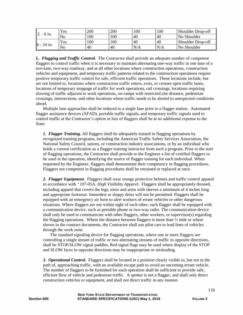
118 NEW YORK STATE DEPARTMENT OF TRANSPORTATION Section 600 STANDARD SPECIFICATIONS (USC) May 1, 2019 VOLUME 3
2 – 6 in. Yes 200 200 100 100 Shoulder Drop-off
No 100 100 40 40 No Shoulder
6 - 24 in. Yes 100 100 40 40 Shoulder Drop-off
No 40 40 N/A N/A No Shoulder
L. Flagging and Traffic Control. The Contractor shall provide an adequate number of competent
flaggers to control traffic when it is necessary to maintain alternating one-way traffic in one lane of a
two-lane, two-way roadway, and at all other locations where construction operations, construction
vehicles and equipment, and temporary traffic patterns related to the construction operations require
positive temporary traffic control for safe, efficient traffic operations. These locations include, but
are not limited to, locations where construction traffic enters, exits, or crosses open traffic lanes,
locations of temporary stoppage of traffic for work operations, rail crossings, locations requiring
slowing of traffic adjacent to work operations, on-ramps with restricted site distance, pedestrian
crossings, intersections, and other locations where traffic needs to be alerted to unexpected conditions
ahead.
Multiple lane approaches shall be reduced to a single lane prior to a flagger station. Automated
flagger assistance devices (AFAD), portable traffic signals, and temporary traffic signals used to
control traffic at the Contractor’s option in lieu of flaggers shall be at no additional expense to the
State.
1. Flagger Training. All flaggers shall be adequately trained in flagging operations by
recognized training programs, including the American Traffic Safety Services Association, the
National Safety Council, unions, or construction industry associations, or by an individual who
holds a current certification as a flagger training instructor from such a program. Prior to the start
of flagging operations, the Contractor shall provide to the Engineer a list of certified flaggers to
be used in the operation, identifying the source of flagger training for each individual. When
requested by the Engineer, flaggers shall demonstrate their competency in flagging procedures.
Flaggers not competent in flagging procedures shall be retrained or replaced at once.
2. Flagger Equipment. Flaggers shall wear orange protective helmets and traffic control apparel
in accordance with '107-05A. High Visibility Apparel. Flaggers shall be appropriately dressed,
including apparel that covers the legs, torso and arms with sleeves a minimum of 4 inches long
and appropriate footwear. Immodest or sloppy dress will not be permitted. Flaggers shall be
equipped with an emergency air horn to alert workers of errant vehicles or other dangerous
situations. Where flaggers are not within sight of each other, each flagger shall be equipped with
a communication device, such as portable phone or two-way radio. The communication device
shall only be used to communicate with other flaggers, other workers, or supervisor(s) regarding
the flagging operations. Where the distance between flaggers is more than ½ mile or where
shown in the contract documents, the Contractor shall use pilot cars to lead lines of vehicles
through the work zone.
The standard signaling device for flagging operations, where one or more flaggers are
controlling a single stream of traffic or two alternating streams of traffic in opposite directions,
shall be STOP/SLOW signal paddles. Red signal flags may be used where display of the STOP
and SLOW faces in opposite directions may be inappropriate or misleading.
3. Operational Control. Flaggers shall be located in a position clearly visible to, but not in the
path of, approaching traffic, with an available escape path to avoid an oncoming errant vehicle.
The number of flaggers to be furnished for each operation shall be sufficient to provide safe,
efficient flow of vehicle and pedestrian traffic. A spotter is not a flagger, and shall only direct
construction vehicles or equipment, and shall not direct traffic in any manner.

119 NEW YORK STATE DEPARTMENT OF TRANSPORTATION Section 600 STANDARD SPECIFICATIONS (USC) May 1, 2019 VOLUME 3
Work zones utilizing flaggers shall comply with the Standard Sheet for flagger operation and
a Flagger symbol (W20-7) sign shall be provided in advance of each flagger.
For control of alternating one-way traffic, one flagger shall be provided at each end of the
one-way section, with additional flaggers provided to control traffic entering the one-way section
from intermediate intersections and major commercial driveways. Where the length of the one-
way section is less than 150 feet, the posted speed limit is less than 40 mph, traffic volumes are
such that queues do not develop, and sight distances are adequate, the Contractor may request
approval from the Engineer to use a single flagger.
For intersection control, at least one flagger shall be provided for each intersection approach.
Where traffic speeds and/or volumes are unusually low, and adequate sight distance is available,
such that safe operations can be ensured with fewer flaggers, the Contractor may request approval
from the Engineer to use fewer flaggers. When flagging at an intersection with a traffic signal, the
signal shall be turned off unless directed otherwise by the Engineer.
The Contractor shall provide enhanced flagger stations consisting of a Flag Tree (6F.57) and
additional cones at all approaches to flaggers, in accordance with the Standard Sheet, in order to
provide effective advanced warning to motorists. Flag Trees shall display a minimum of 3 orange
warning flags, with the flags mounted such that the lowest corners of the flags are at a minimum
height of 8 feet. On roadways with posted speed limits less than 40 mph, in locations having
obstructed traffic flow, such as those having controlled intersections along the approach or
approaches, where conditions do not permit placing the devices in a manner that will provide
effective advanced warning to motorists, enhanced flagger stations need not be provided.
Flaggers shall be alert at all times, and shall not stand with their backs to approaching traffic.
Flaggers shall only direct traffic to stop, to slow or to proceed, using hand signals to supplement
the signaling device in accordance with the flagging procedures shown in the MUTCD. Flaggers
shall be provided periodic breaks (minimum 15 minutes every 4 hours) throughout the work day,
with competent substitutes provided during breaks to maintain continuous coverage of the
flagging operation.
A spotter shall be provided at all locations where construction vehicles or equipment must
back across or into open travel lanes, sidewalks, or pedestrian walkways. A spotter shall only
direct construction vehicles or equipment, and shall not direct traffic in any manner.
For ongoing flagging operations at a specific location, the Contractor may request approval
from the Engineer to substitute portable traffic signals in lieu of flaggers.
4. Automated Flagging Assistance Devices (AFAD). AFADs are devices to control traffic
through work zones remotely by a single flagger at a central location or at one end of the work
zone.
A minimum of 7 calendar days prior to initial deployment of the AFAD system, the
Contractor shall submit a traffic control plan to the Engineer, for review and approval, detailing
AFAD operation including a list of competent flaggers trained to operate the AFAD. AFADs
shall be used only on two-lane two-way or single lane one-way roadways. AFADs shall not be
used where there are intersections and/or commercial driveways or where construction operations
within the controlled highway segment frequently disrupt traffic flow. Appropriate flagger
apparel and equipment shall be maintained near each AFAD to facilitate flagging in the event of a
malfunction or operational need due to frequent disruptions of traffic flow. The Contractor shall
immediately provide traffic control with flaggers if a AFAD malfunctions; fails to properly or
adequately control traffic; creates congestion, queues or gridlock which cannot be remedied by
timely on-site adjustments to the signal operation; or is otherwise inadequate.
A competent flagger, who has been trained on the operation of the AFAD, shall operate and
not leave the AFAD(s) unattended at any time. The flagger shall have an unobstructed view of
the AFAD(s) and approaching traffic in both directions at all times. The distance between
AFADs shall not exceed ½ mile. Work zones utilizing AFADs shall comply with the Standard
120 NEW YORK STATE DEPARTMENT OF TRANSPORTATION Section 600 STANDARD SPECIFICATIONS (USC) May 1, 2019 VOLUME 3
Sheet for flagger operation on a 2-lane 2-way roadway, where the AFAD is used in lieu of a
flagger and a BE PREPARED TO STOP sign (W3-4) is to be used in lieu of the Flagger symbol
sign. Red/Yellow lens AFAD shall have a STOP HERE ON RED (R10-6) sign installed on the
right-hand shoulder at least 8 ft in advance of the AFAD where vehicles are expected to stop.
A portable traffic signal may be used, at the Contractor’s option, as an AFAD. A Signal
Ahead symbol (W3-3) sign shall replace the Flagger symbol sign. An 18 inch wide removable
stop line with a STOP HERE ON RED (R10-6) sign shall be installed at intended stopping point.
The Engineer may waive the requirement for a stop line if the roadway is unpaved or it is
otherwise impractical to install a stop line and the STOP HERE ON RED sign is in place.
When the work no longer necessitates use of the AFAD or portable traffic signal, the units
shall be removed or turned off and moved out of view from the traveled way.
M. Maintain Existing Mailboxes. The Contractor shall not move any mailbox which contains mail.
The Contractor will advise the owner to remove mail before the box is moved. Mailboxes shall be
mounted, either permanently or temporarily, on a post. Before acceptance of the work, any mailbox
which has been disturbed or moved shall be restored by the Contractor at a location consistent with
the requirements of the U.S. Postal Service and the contract documents.
N. Contract Site Patrol. The Contractor shall provide adequate personnel and supervision to conduct
operations and patrol the contract site to ensure that conditions are adequate for public safety and
convenience at all times. The Contractor shall patrol the site as often as necessary during working and
non-working hours to adjust and maintain signs, channelizing devices, and other traffic control
devices and safety features.
619-3.03 Basic Work Zone Traffic Control (Daily Operations). The Contractor shall control traffic in
accordance with §619-3.02 Basic Work Zone Traffic Control paragraphs A. Surface Condition; C.
Maintain Public Access; D. Maintain Existing Roadside Signs; F. Construction Vehicles; G.
Barrier/Shadow Vehicles; H. Construction Signs; I. Arrow Panels; J. Channelizing Devices; L. Flagging;
M. Maintaining Existing Mailboxes; and O. Portable Traffic Signals so that a person who has no
knowledge of conditions may safely and with a minimum of discomfort and inconvenience drive, ride, or
walk, during the day or at night, over all or any portion of the highway and/or structure under construction
where traffic is to be maintained. The Contractor will not be required to repair or maintain the roadway
except to repair any damages resulting from its operations.
The Contractor shall cease operations and clear the traveled way, shoulders, and clear zones of all
obstructions including traffic control devices, construction equipment, and materials at the end of each
work shift.
619-3.04 Temporary Business Signs. The Contractor shall provide temporary business signs (NYI8-4)
mounted on temporary sign supports to identify business entrances in accordance with the contract
documents. Entrances shall be identified by only a single sign. Temporary business signs shall be
mounted at a minimum height of 7 feet, and at a location that will guide traffic seeking access to the
business, but where they will not interfere with traffic flow or other traffic control devices.
619-3.05 Covering or Removal of Pavement Markings. The Contractor shall remove or cover existing
permanent pavement markings, interim pavement markings and temporary pavement markings, as
indicated in the contract documents or directed by the Engineer, to accommodate traffic pattern changes
by covering the markings with preformed removable pavement marking masking tape, or by removing the
markings. Masking tape shall be placed in blocks to prevent the underlying shape of pavement marking
symbols or letters from being confused with existing markings.
121 NEW YORK STATE DEPARTMENT OF TRANSPORTATION Section 600 STANDARD SPECIFICATIONS (USC) May 1, 2019 VOLUME 3
A. Removal of Pavement Markings. The removal method will be at the Contractor’s option, subject
to its ability to achieve satisfactory results. Removal shall be completed prior to the installation of
temporary pavement markings or interim pavement markings. Grinding to remove pavement
markings will typically remove 1/8 to ¼ inch of pavement surface. Prior to installation, the
existing marking and adjacent pavement shall be cleaned of debris by compressed air or sweeping.
B. Masking Pavement Markings. Removable pavement marking masking tape shall be installed in
accordance with the manufacturer’s written instructions. Prior to installation, the existing pavement
marking and adjacent pavement shall be cleaned by compressed air, sweeping, or other means
adequate to remove debris, but that does not result in damage to the existing pavement marking. The
width of the removable pavement marking masking tape shall be sufficient to completely cover the
existing pavement marking.
The masking tape shall firmly adhere to the entire length and width of the existing pavement
marking to be covered. The Contractor shall maintain the tape for the duration of its use. Any tape
that is loosened, removed, or that fails to retain its original matte finish, or that for any other reason
fails to obliterate the existing pavement marking shall be replaced immediately, at no additional
expense to the State.
When the covered pavement markings are to be restored to service, masking tape shall be
removed. Temporary adhesive residues will be allowed to remain, providing that the existing
pavement marking visibility is not impaired.
Any damage to the existing pavement markings or to the pavement surface that results from the
removal of the masking tape shall be repaired at no additional cost to the State. If the existing
marking cannot be repaired satisfactorily, the Contractor shall remove damaged pavement markings
completely and/or replace the pavement section at no additional cost to the State.
619-3.06 Temporary Pavement Markings. The Contractor shall install and maintain temporary
pavement markings in accordance with the contract documents, using patterns and colors shown in the
MUTCD to establish temporary traffic pattern(s) during construction on any pavement, including milled or
grooved surface, resurfaced, new pavement, or other paved surface without pavement markings, for a
maximum of 14 calendar days.
Within 14 calendar days after placement, the Contractor shall either (1) install the succeeding
pavement course or (2) install the remaining temporary pavement markings including edge lines, stop
bars, and simple crosswalks, with no hatching. Pavements which will be open to traffic shall be properly
marked before being opened, before nightfall, or before the end of the work day, whichever is soonest,
except areas that are open during the work shift and delineated with channelizing devices or flaggers.
Traffic paint need not be removed before placing a subsequent course. Removable pavement tape,
removable wet-night reflective tape, temporary overlay markers and removable raised pavement markers
shall be removed before placing a subsequent course at no additional cost to the State.
Temporary pavement marking stripes shall be a minimum of 4 inches in width. Temporary pavement
markings shall be applied to a clean, dry pavement in accordance with the manufacturer’s
recommendations. Hatch lines and symbols will not be required as temporary pavement markings unless
required by the contract documents.
Traffic paint pavement markings shall be applied at a minimum wet film thickness of 20 mil,
immediately followed by an application of glass beads, at a rate of 6 lb/gal of paint.
Where specified, removable raised pavement markers shall be used to supplement line pavement
markings. The raised markers shall not be a substitute for line pavement markings, letters or symbols.
Removable raised pavement markers spaced every 5 feet may be used to supplement line pavement
markings. Two removable raised pavement markers spaced at each end of the 2 foot marking may be
used to supplement a 2 foot broken line pavement marking.
If unanticipated weather or other conditions prevent the application of temporary pavement markings,
the Contractor shall apply 2 foot removable pavement tape markings or temporary overlay markers at 40
122 NEW YORK STATE DEPARTMENT OF TRANSPORTATION Section 600 STANDARD SPECIFICATIONS (USC) May 1, 2019 VOLUME 3
foot spaces at no additional cost to the State, for a maximum of 3 days until such time as temporary
pavement markings may be applied, or the next pavement course is installed.
A. Divided Highways. On freeways, expressways and parkways, the Contractor shall install broken
lines a minimum of 2 feet long at 40 foot spacing to separate traffic lanes in the same direction. The
Contractor shall install solid edge lines for a minimum of 100 feet on either side of the apex of a gore.
B. Undivided Multilane Highways. On three or more lane highways, and two or more lane
highways with center two way left turn lanes, the Contractor shall install white broken lines a
minimum of 2 feet long at 40 foot spacing to separate traffic flows in the same direction, and partial
barrier or full barrier centerline to separate traffic flows in opposite directions.
C. Two-Lane, Two-Way Highways. For two-lane, two-way highways, the Contractor shall install a
temporary pavement markings consisting of full barrier centerline markings in no passing zones and 2
foot broken line markings at 40 foot spacing in passing zones.
Two-lane, two-way highways may for a maximum of 3 days have the centerline marked with
yellow 2 foot by 4 inch removable pavement tape or yellow temporary overlay markers at 40 foot
spaces with NO CENTER STRIPE (W8-12) signs and DO NOT PASS (R4-1) signs at no additional
cost to the State. A NO CENTER STRIPE sign shall be installed in advance of the area marked with
yellow 2 foot removable pavement tape markings or temporary overlay markers, as well as after
major intersections and after major traffic generators within the area marked with the removable
pavement tape markings or temporary overlay markings. A DO NOT PASS sign shall be installed
within 100 feet of the beginning of the area with the removable pavement tape markings or temporary
overlay markers, and a second DO NOT PASS sign shall be installed within 1,100 feet of the first DO
NOT PASS sign and subsequent DO NOT PASS sign(s) shall not exceed 3,000 feet spacing. On an
approach without centerline pavement markings where passing will not be permitted, a black on
orange NO PASSING ZONE (W14-3) pennant shaped sign shall be installed on that approach. Full
barrier, partial barrier or broken line temporary centerline pavement markings shall be placed within
three calendar days.
619-3.07 Interim Pavement Markings. Work shall consist of furnishing, applying, and maintaining
interim pavement markings as shown in the contract documents or as directed by the Engineer. The work
for removable tape, removable wet-night reflective tape, temporary overlay markers and removable raised
pavement markers shall include removal. Interim pavement markings are intended for use in diversions,
temporary pavement realignments and crossovers, lane shifts and closures, and other traffic patterns
associated with construction activities. Interim pavement markings are intended for use for a given phase
or season, for a maximum of 1 year.
A. Installation. Interim pavement markings shall be applied to a clean, dry pavement in accordance
with the manufacturer’s recommendations. Interim pavement markings on roadways open to traffic
shall be applied in the direction of traffic. Traffic paint and epoxy paint pavement markings shall be
applied at a minimum wet film thickness of 20 mils, immediately followed by an application of glass
beads at a rate of 6 lb/gal of paint.
Painted markings may be supplemented with removable raised pavement markers. Removable
raised pavement markers shall be spaced at 5 feet to supplement a solid line, and 4 markers spaced
shall be used to supplement a 10 foot segment of broken line. When used to supplement a solid or
broken line, markers shall be spaced a maximum of 80 feet on tangents and a maximum of 40 feet for
curves with a radius less than 2,800 feet. Removable raised pavement markers shall not be used alone
to simulate interim pavement markings.

123 NEW YORK STATE DEPARTMENT OF TRANSPORTATION Section 600 STANDARD SPECIFICATIONS (USC) May 1, 2019 VOLUME 3
B. Maintenance/Replacement. Traffic paint or removable tape shall be replaced upon (1) abrasion
of the line such that more than 10 percent of the underlying pavement is visible within any 300 feet
segment of line or (2) loss of more than 2 consecutive skip lines or (3) loss of more than 50 feet of
continuous line or (4) failure of any line to be clearly visible at night under low-beam headlamp
illumination when viewed from a distance of 200 feet.
Missing removable raised pavement markers shall be replaced upon (1) loss of more than 10
percent of the markers within a 300 feet long segment of line or (2) loss of more than 3 consecutive
markers or (3) failure of any line to be clearly visible at night under low-beam headlamp illumination
when viewed from a distance of 200 feet.
The Contractor will not be responsible for damage or loss caused by snowplowing. In the event
that such pavement markings are damaged or lost, the Engineer will determine whether to replace the
lost pavement markings in kind or with other marking materials. Separate payment will be made for
pavement markings replaced, or installed due to damage or loss caused by snowplowing.
619-3.08 Temporary Rumble Strips. The Contractor shall install temporary rumble strips in three sets
of 6-strip patterns with 10 foot between individual strips. The type of strip installed will be at the
Contractor’s option, except that sawcut or milled-in strips shall not be installed on new top course
surfaces or existing surfaces that will not be paved over. Where there is no usable shoulder, or the
shoulder is less than 3 feet wide, the rumble strips should be ended 3 feet short of the edge of usable
pavement. On curbed roadways, rumble strips should end a minimum of 3 feet from the curb in order not
to interfere with drainage. Rumble strips shall typically be placed in advance of each of the last three
long-term advance warning signs such that drivers are alerted in time to see and read the signs. Rumble
strips will typically be installed for a minimum of one week.
A. Raised Asphalt Rumble Strips. The roadway surface on which the rumble strips are to be
attached shall be dry, free of surface contaminants such as dust or oil, and thoroughly swept with a
stiff broom. The surface temperature of the pavement shall be 45°F or greater unless otherwise
authorized by the Engineer. The pavement surface shall be cleaned with compressed air just prior to
tack coating and subsequent installation of the rumble strips. The strips shall be formed using a
rumble strip paver (drag box) pulled transversely across the pavement, or by hand placement between
forms fixed to the pavement. If forms are used, they shall be removed prior to compaction of the
asphalt mixture. Compaction shall be accomplished using a plate tamper or a static roller. Raised
asphalt rumble strips shall have a width of 6 to 9 inches, measured in the direction of traffic, and have
a final compacted thickness of 3/8 inch ± 1/8 inch.
B. Raised Removable Tape Rumble Strips. Raised removable tape rumble strips shall be formed by
applying one or more layers of removable preformed pavement marking masking tape. The tape shall
be applied to a clean, dry pavement surface in accordance with the manufacturer’s recommendations.
The pavement surface shall be swept or cleaned with compressed air just prior to application of the
tape.
C. Raised, Preformed Rumble Strips. Raised preformed rumble strips shall be applied to a clean, dry
pavement surface in accordance with the manufacturer’s recommendations. The pavement surface
shall be swept or cleaned with compressed air just prior to application of the strip.
D. Saw-cut Rumble Strips. Saw-cut rumble strips shall be saw cut into existing pavement using wet
cutting methods. The blade or blades shall be of such configuration that the desired dimensions of the
saw cut can be made with one pass. No spacers between blades will be allowed.
Before a travel lane with saw-cut rumble strips is reopened to traffic, the pavement shall be
cleaned by sweeping, flushing, or with a stream of compressed air. Sawing slurry from the wet-
sawing process shall be flushed from the pavement surface immediately.

124 NEW YORK STATE DEPARTMENT OF TRANSPORTATION Section 600 STANDARD SPECIFICATIONS (USC) May 1, 2019 VOLUME 3
E. Milled-in Rumble Strips. Milled-in rumble strips shall be milled into existing pavement using a
rotary-type cutting head with a maximum nominal outside diameter of 24 inches. The cutting head
shall be on its own suspension system, independent from that of the power unit, to allow the head to
align itself with the slope of the pavement and/or any irregularities in the pavement surface. The
pattern of cutting tips on the head shall be arranged to produce a relatively smooth cut with no more
than 3/32 inches between peaks and valleys. Prior to beginning work, the Contractor shall
demonstrate to the Engineer the ability to achieve the desired surface without tearing or snagging the
pavement.
Before a travel lane with milled-in rumble strips is reopened to traffic, the pavement shall be
cleaned by sweeping, flushing, or with a stream of compressed air.
F. Removing Temporary Rumble Strips. The Contractor shall either completely remove raised
rumble strips from the pavement or fill in the depressions from saw-cut or milled-in rumble strips
prior to the start of the winter plowing season, prior to the placement of successive pavement courses,
or as directed by the Engineer. Any damage to the pavement surface resulting from the removal of
raised rumble strips shall be repaired at no additional cost to the State.
Rumble strip depressions shall be filled in with hot mix asphalt. Before they are filled, the
depressions shall be cleaned by sweeping, flushing, or with a stream of compressed air, and coated
with Asphalt Emulsion Tack Coat. The rumble strips shall be overfilled slightly and compacted using
a plate tamper or static roller so that the final compacted surface is flush with the existing pavement.
619-3.09 Interim Tubular Markers. The Contractor shall install interim tubular markers in accordance
with the contract documents. The Contractor shall attach interim tubular markers to the pavement in a
manner that prevents them from being moved or dislodged by traffic. Interim tubular markers shall be
installed on pavement that has been cleaned to remove pavement markings, oil, dirt, or other debris or
substances that may interfere with a proper bond. Attachment to the pavement shall be by mechanical
fastener or by adhesive, in accordance with the manufacturer’s recommendations. Bonding agents shall be
of sufficient amount or size to ensure proper bonding of the base to the pavement.
Interim tubular markers removed or damaged by the Contractor’s operations or by traffic shall be
replaced immediately, so that positive separation is maintained between opposing lanes of traffic at all
times. Damaged reflective sheeting on interim tubular markers shall be replaced before nightfall as
necessary to maintain adequate visibility of the markers. In cases where only isolated individual markers
are lost or damaged, and adequate visibility is maintained by the remaining markers, replacement will not
be required until more than 3 consecutive markers, or 25 percent of all markers within ½ mile have been
damaged or lost. The replacement of markers damaged or lost by traffic, where the Contractor has
demonstrated reasonable effort to collect the costs from the person(s) responsible for damage will be
considered extra work.
619-3.10 Portable Variable Message Signs (PVMS) and Truck Mounted Variable Message Signs
(TMVMS). The Contractor shall provide, operate and maintain PVMS & TMVMS as indicated in the
contract documents until the progress of work no longer requires their use. The Contractor shall relocate or
reorient PVMS with a pay unit of each, if necessary, up to 4 times per year as conditions dictate, at no
additional cost to the State. The Contractor shall provide, operate and maintain PVMS with a pay unit of
weeks at the general locations and duration stated in the contract documents and in accordance with the
Special Note Requirements for Portable Variable Message Signs (PVMS). There shall be no extra payment
due for each relocation or reorientation of TMVMS. On the PVMS & TMVMS, the message to be displayed
shall be as required by the contract documents and may change on a daily basis or more frequently as
conditions dictate. NYSDOT’s Variable Message Sign Guidelines shall be reviewed to ensure compliance
with Chapter 5 - Messages.
125 NEW YORK STATE DEPARTMENT OF TRANSPORTATION Section 600 STANDARD SPECIFICATIONS (USC) May 1, 2019 VOLUME 3
If the contract requires a NTCIP compliant PVMS, the Contractor shall provide the Engineer with the
model, manufacture date and manufacturer of the NTCIP compliant PVMS the Contractor plans to use from
the Approved List. After delivery to the work site, the Contractor shall allow the Regional Transportation
Management Center (TMC) to conduct operations and communications tests on one or more samples
supplied by the Contractor. The testing will determine if the proposed PVMS meets the TMC’s operational
requirements by demonstrating remote communications to and from the TMC using NTCIP compliant
operating software. TMVMS do not require NTCIP compliant communications. The message to be
displayed shall be as required by the contract documents or as directed by the Engineer.
PVMS specified with cellular communications shall be equipped with control software compatible with
the current computer operating system used in the Engineer’s Field Office. PVMS with Cellular
Communications Option shall have cellular telephone service provided by the Contractor. The Contractor
shall supply the Engineer with two copies of operating instructions for the PVMS and the control software.
The Contractor shall supply the Engineer with a copy of control software a minimum of 14 calendar days
prior to installation of the first unit. Electronic copies of software instructions are acceptable.
PVMS shall be placed so that the base of the message panel is at least 7 feet above the adjacent
pavement surface and aligned to provide optimum viewing by approaching motorists. The Contractor shall
supply the Engineer with an accurate log of the text of all messages and times messages were displayed
monthly, not later than the 15th of the following month. The log of messages may be either a listing in a
manual register or printouts from the control software. The Contractor shall inform the Engineer of PVMS
and TMVMS locations and update as they are relocated and removed.
The PVMS shall be protected from unauthorized use. All cabinet doors shall be secured and/or padlocked,
and default manufacturer’s passwords shall be changed. Additional security measures shall be
implemented as needed.
619-3.11 Type III Construction Barricades. Type III construction barricades shall be installed at all
locations where a highway, bridge, ramp, or other segment of the roadway is closed to traffic. Type III
construction barricades shall be maintained upright, in proper alignment and orientation. If ballast is used
to maintain alignment and position of the barricade, it shall consist of dry sand contained in a closed
waterproof bag, and shall be placed at ground level.
Barricade rails shall be oriented such that the stripes slope downward toward the side on which
traffic is to pass. If traffic may pass to either side, adjacent barricades shall be arranged such that the
stripes slope downward toward each side starting at the center. Where no passage is intended or
permitted, the stripes shall slope downward toward the center of the barricade or barricades.
At night, each Type III construction barricade used to close a roadway, a segment of a roadway or a
sidewalk shall be equipped with one flashing warning light.
619-3.12 Temporary Concrete Barrier. The Engineer will inspect temporary concrete barrier segments
upon delivery to the contract. Any barrier segment having damage and/or defects in the concrete and/or
joint connections will be rejected if the performance of the barrier may be affected.
Temporary concrete barrier segments shall be fastened together with connection keys to form a
continuous string. When joined together, the barrier segments shall form a smooth and continuous
barrier. Any segments damaged or misaligned shall be corrected or replaced.
Tapered end sections shall not be used in traversable medians, gores, and other areas where impacts
on a tapered end section could allow vehicles to penetrate into opposing or adjacent lanes of traffic.
Where the posted speed limit is 45 mph or higher, a temporary impact attenuator or temporary sand barrel
array shall be provided on approach ends of temporary concrete barrier when the offset from the edge of
the traveled way to end of the barrier is less than 12 feet, and will be paid for separately.
Temporary delineation shall be provided with each segment of temporary concrete barrier in
accordance with the Standard Sheet. When temporary glare screen is attached to the barrier, temporary
delineation shall be mounted such that its visibility is not blocked by the glare screen.

126 NEW YORK STATE DEPARTMENT OF TRANSPORTATION Section 600 STANDARD SPECIFICATIONS (USC) May 1, 2019 VOLUME 3
Where space is available, approach ends of the barrier string shall be flared away from the traveled
way at the taper rate shown in Table 619-5 Flare Rates for Positive Barrier and terminated in a tapered
end section, embedded in a slope, or otherwise protected against impact by errant vehicles.
The Contractor shall install unpinned temporary concrete barrier where indicated in the contract
documents, with one segment at either end of the string pinned using a minimum of four pins on the
construction, or non-traffic side, and with the segment immediately adjacent to the pinned segment,
towards the center of the string, pinned using two pins on the construction side. Where pins extend above
the top surface of the barrier anchor recess, they shall be capped.
The Contractor shall install pinned temporary concrete barrier where indicated in the contract
documents, with each segment pinned with a minimum of 4 pins on the construction, or non-traffic side,
side in order to reduce movement of temporary concrete barrier on structures and in other locations where
limited deflection is desired. Where an unpinned portion of a barrier string is connected to a pinned string
in the direction of approaching traffic, the barrier segment immediately prior to the pinned segment shall
be pinned using two pins on the construction side.
TABLE 619-5 FLARE RATES FOR POSITIVE BARRIER
POSTED PRECONSTRUCTION SPEED LIMIT (mph) 30 40 50 55 65
TEMPORARY CONCRETE BARRIER 8:1 11:1 14:1 16:1 20:1
BOX BEAM OR HEAVY POST CORRUGATED BEAM 7:1 9:1 11:1 12:1 15:1
TABLE 619-6 GUIDE RAIL AND TEMPORARY CONCRETE BARRIER
STANDARD* DEFLECTION DISTANCES
BARRIER TYPE POST SPACING
(ft)
DEFLECTION
DISTANCES (ft)
CABLE
GUIDE RAIL
16 11.0
12 9.5
8 8.0
4 7.0
CORRUGATED W-BEAM
(WEAK POST)
GUIDE RAIL
12.5 8.0
6.25 6.0
4.16 5.0
CORRUGATED W-BEAM
(HEAVY POST BLOCKED OUT)
6.25 4.0
3.12 2.0
BOX BEAM
GUIDE RAIL
6.0 5.0
3.0 4.0
CORRUGATED W-BEAM
(WEAK POST)
MEDIAN BARRIER
12.5 7.0
6.25 5.0
CORRUGATED W-BEAM
(HEAVY POST)
MEDIAN BARRIER
6.25
2.0
BOX BEAM
MEDIAN BARRIER 6.0 3.0
TEMPORARY CONCRETE BARRIER
UNPINNED
STIFFENED WITH BOX BEAM
PINNED
Not Applicable
3.3**
2.2**
0.8**
127 NEW YORK STATE DEPARTMENT OF TRANSPORTATION Section 600 STANDARD SPECIFICATIONS (USC) May 1, 2019 VOLUME 3
* Note: Standard Deflection is caused by a 4400 lb test vehicle traveling 62mph impacting the barrier at a
25° angle.
** Note: MASH Standard Deflection caused by 5000 lb test vehicle traveling 62mph impacting the barrier
at a 25° angle.
The Contractor shall install temporary concrete barrier stiffened with box beam where indicated in the
contract documents, in accordance with the Standard Sheet, in order to reduce deflection of temporary
concrete barrier on structures and in other locations where limited deflection is desired. Temporary
concrete barrier stiffened with box beam shall be installed at least 50 feet prior to, be continuous through,
and extend at least 50 feet beyond the area requiring limited deflection wherever practicable. Where
space limits extending the string of barrier stiffened with box beam, one segment at either end of the
string shall be pinned with 4 pins on the construction, or non-traffic, side and the segment immediately
adjacent to the pinned segment, towards the center of the string, shall be pinned using a minimum of two
pins on the construction side.
The Contractor shall install pinned temporary concrete barrier stiffened with box beam where
indicated in the contract documents, with each segment pinned with a minimum of 4 pins, on the
construction, or non-traffic side, side.
Pins shall have the following minimum pin embedment lengths:
• Bridge Decks and Cement Concrete Pavement 5 in.
• Flexible Pavement 18 in.
• Unpaved Areas 30 in.
After removal of the barrier, holes created in the surface to pin the barrier shall be filled, unless that
area will be further disturbed. Holes in flexible pavement or unpaved areas shall be filled with material
consistent with the subbase, base and surface material. Holes in portland cement concrete pavement or
structural decks shall be filled with material meeting the requirements of §701-05 Concrete Grout
Material or §721-03 Epoxy Polysulfide Grout.
A. Barrier Without Warning Lights. Where warning lights for temporary concrete barrier are not
required, the Contractor shall provide and maintain delineation on the temporary concrete barrier. The
delineation shall be maintained visible and free of dirt and snow, including during shutdown periods.
The maximum spacing of delineation shall be 20 feet.
B. Barrier With Warning Lights. Type C warning lights shall be provided on temporary concrete
barrier with warning lights. The maximum spacing of warning lights shall be 40 feet in tangents and
20 feet in curves with radii less than 2,800 feet. Warning lights shall be attached to the barrier so that
the lights remain securely in place and so that the attachment minimizes damage to the barrier.
All warning lights shall be kept clean, properly aligned and in operating condition. Batteries shall
be replaced as necessary to maintain adequate visibility of the warning lights at night.
Where channelizing devices with Type A flashing warning lights are not provided immediately
preceding a run of barrier to be marked with warning lights, the first warning light on that run of
barrier shall be a Type A warning light.
C. Box Beam Guide Rail to Temporary Concrete Barrier Transition. Where required, the Contractor
shall install the Transition from Box Beam to Flared Temporary Concrete Barrier or the Transition
from Box Beam to Unflared Temporary Concrete Barrier in accordance with the details shown on the
Standard Sheets. With the approval of the Engineer, the Contractor may choose to switch options, at
no additional cost to the State.
Where the Contractor elects or is required to bolt the box beam to the face of the Temporary Concrete
Barrier, the pieces of box beam thus bolted shall be removed from the job and become the Contractor’s

128 NEW YORK STATE DEPARTMENT OF TRANSPORTATION Section 600 STANDARD SPECIFICATIONS (USC) May 1, 2019 VOLUME 3
property when the Temporary Concrete Barrier is removed. The Contractor shall replace any box beam
having holes in its face with new pieces of box beam, as needed. After removal of the Temporary
Concrete Barrier, any rail and posts removed to facilitate placement of the Temporary Concrete Barrier
transition shall be promptly replaced with new posts and new or acceptable reset box beam guide rail.
When an unflared box to Temporary Concrete Barrier transition is removed, the heavy posts,
blockouts, rub rail, and Transition End Piece and associated hardware shall become the property of the
Contractor and shall be removed from the project before its completion.
D. Temporary Concrete Barrier to Box Beam Guide Rail Transition. Where required, the Contractor
shall install Temporary Concrete Barrier Face to Box Beam Transition or Back of Temporary Concrete
Barrier Back to Box Beam Transition in accordance with the details shown on the Standard Sheets.
When the box beam is mounted to the traffic-side face, a tapered box beam end piece shall be used.
When the box beam is behind the Temporary Concrete Barrier, the Contractor shall bolt to the
Temporary Concrete Barrier or shall provide an overlap of box beam extending upstream past four
segments of the downstream end of the Temporary Concrete Barrier.
When box beam is required to be bolted to the Temporary Concrete Barrier, or the Contractor elects
to do so, the necessary positions for the bolts shall be located on the Temporary Concrete Barrier and
drilled in the field. The pieces of box beam thus bolted shall be removed from the job and become
the Contractor’s property when the Temporary Concrete Barrier is removed. The Contractor shall
replace any box beam having holes in its face with new pieces of box beam, as needed. After
removal of the Temporary Concrete Barrier, any rail and posts removed to facilitate placement of the
Temporary Concrete Barrier transition shall be promptly replaced with new posts and new or
acceptable reset box beam guide rail.
619-3.13 Temporary Glare Screen. Temporary glare screen shall be installed in accordance with the
manufacturer’s instructions. All components of the glare screen shall be maintained in a safe and
functional condition. Damaged components shall be repaired or replaced.
If blades are utilized, the blades shall be spaced and angled to provide approximately a 22 headlight
cutoff angle. The screen shall not overhang the face of the barrier and shall not cover delineation or lights.
The screen shall be kept plumb and properly positioned on the barrier, with reflectorization securely
affixed to the screen. Cleaning of the reflectorization shall be by a method that does not damage the
paddles, reflectorization or barrier, and is not hazardous to traffic.
The Contractor shall remove and dispose of the temporary glare screen upon completion of the
contract or when it is no longer required. Upon removal of the temporary glare screen, there shall be no
protrusions remaining on the top face of the barrier. Bolt holes or other damage to permanent barrier
from glare screen installation shall be repaired by the Contractor at no additional cost to the State.
619-3.14 Temporary Impact Attenuator. The Contractor shall install temporary impact attenuators in
accordance with the contract documents, the manufacturer’s instructions and materials details. The
Contractor shall provide the Engineer a copy of the manufacturer’s materials details and installation
instructions a minimum of 7 calendar days prior to use, to allow verification of the attenuator supplied
and proper installation. The selection of the manufacturer and model of temporary impact attenuator shall
be at the Contractor’s option, provided the attenuator supplied is of the type indicated, gating or
redirective; shields the hazard; and fits in the location without encroachment into travel lanes or required
offsets.
The Contractor shall maintain temporary impact attenuators for continuous operation. If an attenuator
is out of operation, the Contractor shall immediately mark the hazard with drums, vertical panels and or
extra tall cones until repairs are made or a new attenuator is installed. The Contractor shall promptly
begin repairs to damaged attenuators, and shall complete repairs to a damaged attenuator or mitigate the
hazard within 1 work day. Attenuators damaged beyond repair shall be replaced within 3 work days.

129 NEW YORK STATE DEPARTMENT OF TRANSPORTATION Section 600 STANDARD SPECIFICATIONS (USC) May 1, 2019 VOLUME 3
When temporary impact attenuators are removed or moved to another location, the Contractor shall
restore the location to match the surrounding area.
619-3.15 Temporary Sand Barrel Arrays. The Contractor shall install sand barrel arrays in accordance
with the patterns shown on the Standard Sheet or a NCHRP 350 approved pattern and fill the barrels with
sand to provide the desired module weight, plus or minus 5 percent. Units that will be in use between
November 1 and March 31 shall have sodium chloride, as dry rock salt, equal to 3% - 5% by weight of
the sand, thoroughly mixed into the sand to prevent freezing. The sand shall be placed in the modules
loose, not in bags or sacks. If the contract documents indicate that the site necessitates securing of the
modules, the work shall be performed as recommended by the manufacturer.
The Contractor shall maintain sand barrel arrays for continuous 24 hour operation. If an array is out
of operation, the Contractor shall immediately mark the hazard with drums, vertical panels and or extra
tall cones until repairs are made or new module(s) are installed. The Contractor shall promptly begin
repairs to damaged arrays, and shall complete repairs to a damaged array or mitigate the hazard within
one work day.
619-3.16 Vehicle Arresting Barrier (VAB). Vehicle arresting barriers (VAB) shall be installed in
accordance with the contract documents and the manufacturer's instructions and materials details. The
Contractor shall provide the Engineer a copy of the manufacturer’s materials details and installation
instructions a minimum of 5 work days prior to use, to allow verification of the barrier supplied and
proper installation. The deceleration area behind the VAB shall be kept clear of workers, vehicles or
stored materials. The Contractor shall provide for periodic surveillance of each VAB by workers or by
electronic device.
The Contractor shall maintain vehicle arresting barrier for continuous operation. If a barrier is out of
operation, the entire barrier shall be restored within 4 hours after the incident, or prior to the next shift the
barrier will be used. No work may be progressed in an unprotected area, and the hazard shall be
eliminated or minimized, until restorations have been completed.
The VAB, except anchorages, shall be dismantled and removed prior to reopening the road to traffic.
After the last day of use, if directed by the Engineer, temporary anchorages shall be removed and
disturbed areas shall be restored to match the surrounding area.
619-3.17 Maintain or Modify Traffic Signal Equipment. Traffic signals shall be maintained in proper
operation, including the maintenance of all features of the traffic signal operation in effect and operating
at the time any work begins on the contract. Traffic-actuated phases shall remain actuated, and signals
operating within signal systems shall remain coordinated with the remainder of the system unless
otherwise approved by the Engineer. Except for emergencies, no changes in the signal operation or timing
shall be made without prior approval by the Engineer. If emergency conditions dictate a change in the
operation, the Engineer shall be notified by the start of the next work day. Unless otherwise approved by
the Engineer, an altered signal operation must be returned to the original signal operation within 24 hours.
The Contractor shall maintain in operation all equipment including signal heads, supports, cable,
wiring, span-wire-mounted signing, controllers, master controllers, detector systems, conflict and current
monitors, relays, switch packs, and all other accessory and necessary equipment. Maintenance shall also
include the repair and replacement of existing detector loops, paid for separately.
The Contractor shall have capable traffic signal repair personnel on call 24 hours a day, seven days a
week, and shall provide to the Engineer a single telephone number for contacting them. If for any reason a
signal is not functioning properly, the Contractor shall commence work on the signal within 2 hours of
notification. If directed by the Engineer, the Contractor shall notify the appropriate police agency for
traffic control operations. If the police agency cannot or will not provide traffic control, the Contractor
shall provide flaggers at locations specified by the Engineer within the 2-hour time period. The Contractor
shall continue the flagger services until the signal is in proper operation. A flagger warning (W20-7 or
W20-7a) sign shall be used on all approaches to an intersection controlled by flaggers.

130 NEW YORK STATE DEPARTMENT OF TRANSPORTATION Section 600 STANDARD SPECIFICATIONS (USC) May 1, 2019 VOLUME 3
If the malfunction is in the equipment supplied by the State, due to an area wide power outage, or due
to a localized power outage beyond the Contractor’s control, the Contractor shall notify the Engineer and,
if directed by the Engineer, provide flaggers until the malfunction is corrected or State personnel take
over. Such flagging operations in excess of 4 hours for the first call and for any subsequent call will be
considered extra work.
The Contractor shall provide the Engineer, on a monthly basis, with a record of all maintenance calls
received and responded to, as well as a record of all corrective action taken by the Contractor.
A. Requirement A. The Contractor shall maintain in proper operation the indicated existing,
relocated, modified, and newly installed signals in accordance with the contract documents. If such
signals are to be removed, the Contractor shall be responsible for operation and maintenance until the
signals are removed. The Contractor shall be responsible for their continuous operation except for
reasonable shutdown periods authorized by the Engineer during relocation and transfer operations.
B. Requirement B. The State shall assume operation and maintenance responsibility for the signal
from the Contractor following successful completion by the Contractor of the installation
/modification testing as required by Section 680 Traffic Signals. The six month warranty/guarantee
period shall be measured from the day the State assumes maintenance responsibility.
C. Requirement C. At relocated, modified or newly installed signals, the Department will assume
responsibility for the following items after successful testing as required by Section 680 Traffic
Signals has been completed. Assumption of the below listed responsibilities by the State will not
relieve the Contractor of the responsibility for operation and maintenance of the signal. At existing
microcomputer controlled traffic signals, the Department will be responsible for the following items:
1. Supply and maintenance of the microcomputer assembly and software.
2. Programming of the microcomputer furnished by the State.
3. Operation or timing changes directed by the Engineer.
4. Normal (no abuse or vandalism) equipment failures of existing, relocated, modified or new
traffic signal equipment furnished by the State.
D. Modify Traffic Signal Equipment. Where the Contractor is required to temporarily modify or
relocate existing traffic signals because of construction operations, all existing equipment, fittings,
wire, cable, conduit, and related materials shall be reinstalled and extended where necessary.
Temporary timber poles, guys, and related material shall be furnished and installed where necessary.
619-3.18 Temporary Traffic Signals. The Contractor shall install temporary traffic signals in
accordance with the contract documents and the MUTCD. The Contractor shall maintain traffic signal
systems, including traffic detectors, in proper operation until approved removal, and be responsible for its
continuous 24-hour operation except for reasonable shutdown during relocation and transfer operations.
Substitution of temporary traffic signals for flaggers shall be at no additional cost to the State.
If for any reason a signal does not function as required, the Contractor shall commence repair work
on this signal within 2 hours after notification of a malfunction. In the event flashing operation occurs, all
signal faces shall show flashing red indications. Flashing operation of a signal is considered a
malfunction. The Contractor shall provide an adequate number of flaggers to control traffic at each
malfunctioning traffic signal, in accordance with '619-3.02L. Flagging and Traffic Control until the
signal is restored to proper operation.
If the malfunction is due to an area wide power outage or due to a localized power outage beyond the
Contractor’s control, the Contractor shall notify the Engineer and, if directed by the Engineer, provide
flaggers until the malfunction is corrected or State personnel take over. Flagging operations in excess of 4
hours for the first maintenance call shall be paid for as extra work.

131 NEW YORK STATE DEPARTMENT OF TRANSPORTATION Section 600 STANDARD SPECIFICATIONS (USC) May 1, 2019 VOLUME 3
619-3.19 Nighttime Operations. Work occurring after sunset and before sunrise will be considered
nighttime operations. All workers involved in nighttime operations shall wear protective helmets and
nighttime apparel in accordance with §107-05A. High Visibility Apparel at all times.
Vehicles operating on the pavement of a closed roadway or travel lane shall display four-way flashers
or rotating amber beacons at all times. Vehicles using headlights, except for rollers and vehicles retrieving
channelizing devices, shall travel facing in the same direction as adjacent traffic in order to avoid glare
and confusion to drivers.
The Contractor shall meet the following additional requirements for work zone traffic control during
nighttime operations.
A. Nighttime Operations and Lighting Plan. Thirty days prior to the start of nighttime operations,
the Contractor shall submit a written Nighttime Operations and Lighting Plan to the Engineer for
approval. The plan shall detail all aspects of the traffic control setup, the functions, responsibilities
and identities of the nighttime traffic control competent person and other details as necessary. It shall
include a contingency plan identifying foreseeable problems and emergencies that may arise, and the
approach that will be used to address them. This plan shall be revised and updated by the Contractor
as necessary during the progress of the work to accommodate conditions on the contract.
The Contractor shall submit a Nighttime Operations and Lighting Plan to the Engineer, at a scale
and printed size similar to the contract plans and appropriate to adequately describe the work,
including the following:
• Layout showing location of light towers, including typical spacing, lateral placement and
mounting height, and clearly show the location of all lights necessary for all work to be done
at night.
• Description of light towers to be used and electrical power source.
• Specific technical details on all lighting equipment, including brand names, model numbers,
power rating and photometric data.
• Details of any hoods, louvers, shields or other means to be used to control glare.
• Attachment and mounting details for lights to be attached to equipment.
• Lighting calculations confirming that the illumination requirements will be met by the layout.
The Contractor shall maintain a supply of emergency flares for use in the event of unanticipated
situations such as traffic accidents, equipment breakdowns, failure of lighting equipment, etc.
B. Lighting for Nighttime Operations. Prior to the first night of nighttime operations, the Contractor
shall set up and operate the lighting equipment at night as a trial run to demonstrate its ability to
establish a safe, properly illuminated, nighttime operation. The Contractor shall furnish the Engineer
with a photometer, capable of measuring the level of illumination, for use as necessary to check the
adequacy of illumination throughout nighttime operations.
1. Equipment. The Contractor shall supply all lighting equipment required to provide a work
zone safe for the workers and traffic. Material and/or equipment shall be in good operating
condition and in compliance with applicable safety and design codes.
a. Light Towers. Light towers shall be provided as a primary means of illumination, and shall
provide Level I illumination throughout the work space. They may be supplemented to the
extent necessary by lighting fixtures mounted on construction equipment to provide Level II
or Level III illumination where required for paving, milling and similar moving operations.
Light towers shall be sturdy and free-standing without the aid of guy wires or bracing, and
132 NEW YORK STATE DEPARTMENT OF TRANSPORTATION Section 600 STANDARD SPECIFICATIONS (USC) May 1, 2019 VOLUME 3
shall be capable of being moved as necessary to keep pace with construction operations.
Light towers shall be positioned to minimize the risk of being impacted by traffic on the
roadway or by construction traffic or equipment.
b. Light Towers on Paving, Milling, and Finishing Machines. If needed to supplement
portable and/or trailer-mounted light towers, towers shall be affixed to paving, milling, and
finishing machines to provide the required level of illumination for the specified distance in
front of and behind the machine. Luminaires shall be aimed and adjusted to provide uniform
illumination with a maximum uniformity ratio of 5:1. The hopper, auger, and screed areas of
pavers and the operator’s controls on all machines shall be uniformly illuminated.
c. Construction Equipment Lights. All construction equipment, including rollers, backhoes,
loaders, and other equipment operating in areas not illuminated to a minimum of Level I
Illumination, shall be equipped with a minimum of two 500 watt flood lights facing in each
direction to provide a minimum of 1 foot-candle of horizontal illumination measured 60 feet
in front of and behind the equipment. In areas illuminated to a minimum of Level I,
construction equipment may move unescorted. In non-illuminated areas, construction
equipment shall be equipped with conventional vehicle headlights, shall be illuminated with
flood lights on the vehicle, or shall be escorted to permit safe movement. Headlights shall not
be permitted as the sole means of illumination while working.
d. Equipment Mounting. The Contractor shall provide suitable brackets and hardware to
mount lighting fixtures and generators on machines and equipment. Mountings shall be
designed so that light fixtures can be aimed and positioned as necessary to reduce glare and to
provide the required illumination. Mounting brackets and fixtures shall not interfere with the
equipment operator or any overhead structures, and shall provide for secure connection of the
fixtures with minimum vibration.
e. Portable Generators. The Contractor shall provide portable generators to furnish adequate
power to operate all required lighting equipment. Fuel tank capacity and availability of fuel
on site shall be sufficient to permit uninterrupted operation throughout the planned shift.
Adequate switches shall be provided to control the various lights. All wiring shall be
weatherproof and installed in accordance with 29 CFR 1926 Subpart K. All power sources
shall be equipped with a Ground-Fault Circuit Interrupter.
2. Illumination Requirements. Tower-mounted luminaires, whether fixed, portable, trailer-
mounted, or equipment-mounted, shall be of sufficient wattage and/or quantity to provide the
required level of illumination and uniformity over the area of operation while minimizing glare.
The uniformity of illumination, defined as the ratio of the average illumination to the
minimum illumination over an area requiring an indicated illumination level, shall not exceed 5:1.
Illumination levels on approach roadways should be increased sequentially to prevent motorists
from becoming disoriented by rapid changes from full dark to very bright conditions.
Existing street and highway lighting shall not eliminate the need for the Contractor to provide
lighting. Consideration will be given to the amount of illumination provided by existing lights in
determining the wattage and/or quantity of lights to be provided. Such consideration shall be
presented in the Contractor’s lighting plan. In the event of any failure of the lighting system,
nighttime operation(s) shall be discontinued until the required level of illumination is restored.
a. Level I (5 foot-candles). Level I illumination shall be provided for all areas of general
construction operations to include all work operations by Contractors personnel, including
work zone traffic control set-up and operations, staging, excavation, cleaning and sweeping,

133 NEW YORK STATE DEPARTMENT OF TRANSPORTATION Section 600 STANDARD SPECIFICATIONS (USC) May 1, 2019 VOLUME 3
pavement marking, spoil disposal, landscaping, planting and seeding, layout and
measurements ahead of the actual work, borrow areas, spoil areas, and truck cleanout areas.
Level I illumination shall be provided near the beginning of lane closure tapers and at road
closures for nighttime work zones, including the setup and removal of the closure tapers.
Level I illumination shall be provided a minimum of 400 feet ahead and 800 feet behind a
paving or milling machine, or for the entire area of concrete placement or pavement work if
less than this distance. This area shall be extended as necessary to incorporate all vehicle and
equipment operations associated with the paving operation.
The only exception to the requirement for Level I illumination throughout the area of
construction operations is that finish rollers can work beyond the area of Level I illumination
using floodlights mounted on the roller.
b. Level II (10 foot-candles). Level II illumination shall be provided for flagging stations,
asphalt paving, milling, and concrete placement and/or removal operations, including bridge
decks, 50 feet ahead of and 100 feet behind a paving or milling machine.
c. Level III (20 foot-candles). Level III illumination shall be provided for pavement or
structural crack filling, joint repair, pavement patching and repairs, installation of signal
equipment or other electrical/mechanical equipment, and other tasks involving fine details or
intricate parts and equipment.
3. Glare Control. All lighting shall be designed, installed, and operated to avoid glare that
affects traffic on the roadway or that causes annoyance or discomfort for residences adjoining the
roadway. The Contractor shall locate and aim lighting fixtures to provide the required level of
illumination and uniformity in the work zone without the creation of objectionable glare. The
Engineer will determine when glare exceeds acceptable levels, either for traffic or for adjoining
residences.
The Contractor shall provide shields, visors or louvers on luminaires as necessary to reduce
objectionable levels of glare. As a minimum, the following requirements shall be met to avoid
objectionable glare on roadways open to traffic in either direction:
- Tower-mounted luminaires shall be aimed either generally parallel or perpendicular to
the roadway.
- Luminaires shall be aimed such that the angle between the center of the beam axis and
the vertical mounting pole is no greater than 45o.
- No luminaires shall be permitted that provide a luminous intensity greater than 20,000
candelas at an angle of 72o above the vertical.
- Except where prevented by overhead utilities or structures, towers shall be extended to
their full working height when in use to reduce glare and provide uniform illumination.
619-3.20 Traffic Control Supervisor. When indicated in the contract documents, the Contractor shall
provide a dedicated traffic control supervisor having adequate training, experience, and authority to
implement and maintain all traffic control operations. The traffic control supervisor shall not be assigned
other duties that interfere with performance as a traffic control supervisor.
The traffic control supervisor shall be adequately trained in traffic control operations by recognized
training programs, including the American Traffic Safety Services Association “Traffic Control
Supervisor”, the National Safety Council, unions, or construction industry associations, or by an
individual instructor from such a program. Traffic control supervisors not competent to the satisfaction of
the Engineer shall be replaced immediately.
During setup and removal of lane closures and other traffic control setups, the traffic control
supervisor shall be assisted by additional workers as necessary. The traffic control supervisor shall patrol

134 NEW YORK STATE DEPARTMENT OF TRANSPORTATION Section 600 STANDARD SPECIFICATIONS (USC) May 1, 2019 VOLUME 3
the contract area to ensure that conditions on the site are adequate for public safety and convenience at all
times, to monitor worker safety from intrusions into the work area, and to ensure that the work adheres to
the provisions for work zone traffic control. The traffic control supervisor shall ensure signs, channelizing
devices, barricades, barrier, impact attenuators and other traffic control devices are adjusted and
maintained as necessary. The Contractor shall provide workers to install, maintain, adjust, and remove
traffic control devices as required by the work operations.
When the work does not require closure of an active lane, roadway, or ramp; when no construction
operations occur within 30 feet of active traffic lanes; and when there is no delivery of materials or
equipment; the Engineer may waive the requirements for a traffic control supervisor.
619-3.21 Temporary Structures and Approaches. The Contractor shall design, construct, maintain
and remove temporary structures and their approaches, or move and remove existing structures to provide
temporary structures along with their temporary approaches. The Contractor shall install temporary
approaches, including necessary earth support structures, in such a manner and sequence that interference
with and inconvenience to the traveling public and the abutting owners is kept to a minimum. The
Contractor shall be responsible for the workmanship, upkeep, and safety of all temporary structures and
approaches. All fabrication shall conform to the AASHTO Standard Specifications for Highway Bridges,
Division II or AASHTO LRFD Bridge Construction Specifications, except as modified herein.
Fabrication shall be performed by an AISC Category III-Certified Fabricator. Plans and design
computations shall bear the stamp and signature of a Professional Engineer.
When specific details are not included in the contract documents, or when the Contractor receives
approval to vary from the contract documents, the Contractor shall design all elements of the temporary
structure and approaches including the railing system. Design shall be done in conformance with the
NYSDOT Load and Resistance Factor Design (LRFD) Bridge Design Specifications, except that the only
design live load shall be HL-93. Alternatively, the design shall be in conformance with the NYSDOT
Standard Specifications for Highway Bridges, except that the minimum design live load shall be HS 20.
The bridge rail shall be designed for a minimum of TL-2.
Any structure that is expected to be in service for more than 5 years, shall be designed as a permanent
structure according to the NYSDOT Load and Resistance Factor Design (LRFD) Bridge Design
Specifications, including the Permit Vehicle and seismic loading.
Load rating calculations for the temporary structure shall be submitted to the DCES. Load ratings
shall be computed based on Load Factor Design (LFD) or Allowable Stress Design (ASD), and shall be
based on an HS-20 loading. Additionally, if the structure is designed using the NYSDOT LRFD
specifications, load ratings shall also be computed by the Load and Resistance Factor Rating (LRFR)
method. LRFR ratings shall be shown at the Inventory and Operating levels as rating factors of the
AASHTO HL-93 live load. All Load Ratings shall be calculated in accordance with the AASHTO
Manual for Bridge Evaluation.
Prior to beginning construction of any temporary structure designed by the Contractor, the Contractor
shall submit detailed plans and calculations to the DCES for review and approval in accordance with
§585-3.02 Working Drawings. Such review, however, shall not relieve the Contractor of the responsibility
for the adequacy and design of such temporary structures and approaches. If the Contractor proposes to
construct with used materials, the Contractor's Professional Engineer shall submit with the plans the
method for documenting that all primary member material meets the physical properties required by the
design. In the absence of record plans or other valid documentation for the used materials, physical testing
shall be performed. Excluded from this provision are proprietary structures. All welding required for the
fabrication of temporary steel structures shall be performed in accordance with the provisions of the NYS
Steel Construction Manual. Complete penetration groove welds in primary members shall be
radiographed as described therein. The DCES reserves the right to perform in-process fabrication
inspection. The Contractor shall notify the DCES of the fabrication schedule 7 calendar days prior to
commencement of fabrication.

135 NEW YORK STATE DEPARTMENT OF TRANSPORTATION Section 600 STANDARD SPECIFICATIONS (USC) May 1, 2019 VOLUME 3
Prior to opening a temporary structure to traffic, the structure shall be inspected by a Professional
Engineer who shall certify in writing to the Engineer that the structure was constructed in accordance with
the design. The Contractor shall have the temporary structure inspected, under the direction of a
Professional Engineer, by a person familiar with bridge construction at least once a month. On or before
each anniversary of the opening of a temporary structure that has been open to traffic for one year or
more, the structure shall be inspected by a Professional Engineer, who shall certify in writing that:
1. The plans of the structure, including its foundations, have been reviewed.
2. A hands-on inspection of the structure has been performed in accordance with the latest edition of
the NYSDOT Bridge Inspection Manual by an inspection team whose leader is a Professional
Engineer and who was present for the inspection.
3. A detailed inspection of those areas of the structure critical to its integrity has been performed.
4. The structure is currently adequate for its design loads.
A signed and stamped copy of the inspection results shall be provided to the Engineer within one
week of the inspection.
619-3.22 Pavement Patching. The Contractor shall place paving materials suitable to provide
temporary pavement patches on paved surfaces where vehicular, bicycle or pedestrian traffic is to be
maintained, including the traveled way, shoulders, sidewalks, and other paved surfaces damaged by
traffic or environmental factors and not by Contractor operations. During periods of active work on the
contract, the Contractor shall complete needed patches on a daily basis. During periods of winter
shutdown, the Contractor shall inspect the contract on a regular basis, and pavement patches shall be
installed as needed.
The Contractor shall place pavement patches to provide a relatively smooth, uniform driving surface
suitable for safe travel at the posted speed limit. Pavement patches shall be placed to repair surface
irregularities including, but not limited to, holes, depressions, cracks and uneven joints. Areas to be
patched shall be adequately cleaned and tack-coated if necessary, and patching material shall be
thoroughly compacted by hand or by roller.
619-3.23 Mailboxes. In the event the original mounting post has been lost, damaged, is unusable, or is
not consistent with U.S. Postal Service requirements, the Contractor shall furnish and install a new
mounting post and/or mailbox with mounting post at the designated location and at the proper height in
accordance with the requirements of the U.S. Postal Service.
619-4 METHOD OF MEASUREMENT
619-4.01 General. (None Specified.)
619-4.02 Basic Work Zone Traffic Control. The work under basic work zone traffic control will be
measured for payment on a lump sum basis.
619-4.03 Basic Work Zone Traffic Control (Daily Operations). The work under basic work zone
traffic control (daily operations) will be measured for payment on a lump sum basis.
619-4.04 Temporary Business Signs. The quantity to be measured for payment will be in square feet to
the nearest 0.1 square feet of business signs installed.
619-4.05 Covering or Removal of Pavement Markings. The quantity to be measured for payment will
be in feet to the nearest whole foot along the centerline of the pavement stripes covered or removed. No
measurement will be made for the gaps between broken and dotted line segments. If preformed tape is
used to cover an existing line, payment will be based on the width of the line covered. Measurement for
covering or removal of striping with a width greater than 4 inches will be made by the following method:

136 NEW YORK STATE DEPARTMENT OF TRANSPORTATION Section 600 STANDARD SPECIFICATIONS (USC) May 1, 2019 VOLUME 3
Width of Striping (in) x Number of Feet
4 (in)
Letters and symbols will be measured by each unit covered or removed. A unit will consist of one
letter or one symbol except that a double-headed arrow will be measured as two units and triple headed
arrow will be measured as three units. Example: "SCHOOL" would be measured as six units. Each R in a
railroad crossing marking will be measured as a single unit, but the "X" will be measured by the number
of feet of 4 inch stripe.
619-4.06 Temporary Pavement Markings. The quantity to be measured for payment will be in feet to
the nearest whole foot along the centerline of the pavement stripes installed, and will be based on a 4 inch
wide stripe. No measurement will be made for the length of skips in the dashed line. Measurement for
installation of striping with a width greater than 4 inches will be made by the following method:
Width of Striping (in) x Number of Feet
4 (in)
619-4.07 Interim Pavement Markings. The quantity to be measured for payment will be in feet to the
nearest whole foot along the centerline of the pavement stripes installed, and will be based on a 4 inch
wide stripe. No measurement will be made for the length of skips in the dashed line. Measurement for
installation of striping with a width greater than 4 inches will be made by the following method:
Width of Striping (in) x Number of Feet
4 (in)
Letters and symbols will be measured by each unit installed. A unit will consist of one letter or one
symbol except that a double-headed arrow will be measured as two units and triple headed arrow will be
measured as three units. Example: “SCHOOL” would be measured as six units. Each R in a railroad
crossing marking will be measured as a single unit, but the “X” will be measured by the number of feet of
4 inch stripe.
619-4.08 Temporary Rumble Strips. The quantity to be measured for payment will be in feet to the
nearest whole foot of individual temporary rumble strip installed, measured transverse to the direction of
traffic flow.
619-4.09 Interim Tubular Markers. The quantity to be measured for payment will be the number of
interim tubular markers installed.
619-4.10 Portable Variable-Message Signs (PVMS) and Truck Mounted Variable Message Signs
(TMVMS). The quantity of PVMS or TMVMS with a pay unit of each to be measured for payment will be the
number of signs provided. The quantity of PVMS or TMVMS with a pay unit of weeks to be measured for payment
will be in weeks to the nearest whole week.
619-4.11 Type III Construction Barricades. The quantity to be measured for payment will be the
number of barricade units installed.
619-4.12 Temporary Concrete Barrier. The quantity to be measured for payment of temporary
concrete barrier will be in feet to the nearest foot along the centerline of temporary concrete barrier
installed.

137 NEW YORK STATE DEPARTMENT OF TRANSPORTATION Section 600 STANDARD SPECIFICATIONS (USC) May 1, 2019 VOLUME 3
The quantity to be measured for payment of pinned temporary concrete barrier will be in feet to the
nearest foot along the centerline of pinned temporary concrete barrier installed.
The quantity to be measured for payment of temporary concrete barrier stiffened with box beam
will be in feet to the nearest foot along the centerline of temporary concrete barrier stiffened with box
beam installed.
The quantity to be measured for payment of temporary concrete barrier with barrier warning lights
installed will be in feet to the nearest foot along the centerline of temporary concrete barrier installed.
The quantity to be measured for payment of Box Beam to Flared Temporary Concrete Barrier
Transition will be the number of such transitions installed.
The quantity to be measured for payment of Box Beam to Unflared Temporary Concrete Barrier
Transition will be the number of such transitions installed.
The quantity to be measured for payment of Temporary Concrete Barrier Face to Box Beam
Transition will be the number of such transitions installed.
The quantity to be measured for payment of Temporary Concrete Barrier Back to Box Beam
Transition will be the number of such transitions installed.
619-4.13 Temporary Glare Screen. The quantity to be measured for payment will be in feet to the
nearest whole foot along the length of the temporary glare screen installed.
619-4.14 Temporary Impact Attenuator. The quantity to be measured for payment will be the number
of temporary impact attenuators installed.
619-4.15 Temporary Sand Barrel Arrays. The quantity to be measured for payment will be the
number of individual sand barrel modules installed.
619-4.16 Vehicle Arresting Barrier. The quantity to be measured for payment will be the number of
barriers installed.
619-4.17 Maintain or Modify Traffic Signal Equipment. The quantity of signalized intersections
maintained to be measured for payment will be in months to the nearest 1/4 month. The quantity of
traffic signal equipment modified to be measured for payment will be on an each location basis.
619-4.18 Temporary Traffic Signals. The work under temporary traffic signals will be measured for
payment on an each location basis.
619-4.19 Nighttime Operations. The work under nighttime operations will be measured for payment on
a lump sum basis.
619-4.20 Traffic Control Supervisor. The work under traffic control supervisor will be measured for
payment on a monthly basis to the nearest 1/4 month.
619-4.21 Temporary Structures and Approaches. The quantity to be measured for payment will be
the number of temporary structures and approaches installed.
619-4.22 Pavement Patching. The quantity to be measured for payment will be in cubic yards to the
nearest 0.1 cubic yard of pavement patching installed.
619-4.23 Mailboxes. The quantity to be measured for payment will be the number of mailboxes
installed.
619-5 BASIS OF PAYMENT

138 NEW YORK STATE DEPARTMENT OF TRANSPORTATION Section 600 STANDARD SPECIFICATIONS (USC) May 1, 2019 VOLUME 3
619-5.01 General. The price bid shall include all labor, materials and equipment necessary to complete
the work. No payment will be made for damage caused by vehicle accidents, vandalism, or any other
similar causes.
A. Non-Payment. For each calendar day during which there are substantial deficiencies in
compliance with the requirements of this section, no payment will be made under basic work zone
traffic control. The amount of such calendar day nonpayment will be deducted from monies due the
Contractor in accordance with Table 619-7 Basic Work Zone Traffic Control Nonpayment.
TABLE 619-7 BASIC WORK ZONE TRAFFIC CONTROL NON-PAYMENT
Original Contract Amount Nonpayment
Amount From More Than To and Including
$ 0 $ 500,000 $ 200
$ 500,000 $ 2,000,000 $ 400
$ 2,000,000 $ 5,000,000 $ 500
$ 5,000,000 $ 10,000,000 $ 750
$ 10,000,000 $ 20,000,000 $ 1,000
$ 20,000,000 ----- $ 3,000
B. Liquidated Damages. If the Contractor fails to adequately correct substantial cited deficiencies
within 24 hours of notification by the Engineer for any item under this section, or those deficiencies
reoccur on a subsequent, but not necessarily concurrent calendar day, liquidated damages will be
assessed for each calendar day or part thereof in addition to non-payment for deficiencies.
C. Major Non-Conformance. Where major non-conformance with the requirements of this
specification is noted by the Engineer, and prompt Contractor compliance is deemed not to be
obtainable, the Engineer may stop contract work.
Where major non-conformance with the requirements of this specification is noted by the
Engineer, and the Contractor fails to correct deficiencies for a period of 24 hours, the Department
may correct the adverse conditions by any means deemed appropriate, and will deduct the cost of the
corrective work from any monies due the Contractor. The cost of this corrective work will be in
addition to the non-payment for basic work zone traffic control, non-payment of any other items of
work under this section and liquidated damages assessed.
619-5.02 Basic Work Zone Traffic Control. The lump sum price bid for basic work zone traffic
control shall include all labor, materials and equipment necessary to complete the work. Construction
signs; arrow panels; warning lights on signs, barricades and channelizing devices; the cost of temporarily
terminating guide rail, median barrier, or bridge rail during non-work hours; work required to maintain
drainage facilities during construction operations; and dust control shall be included in the lump sum
price bid for basic work zone traffic control. Removal of debris from drainage features that was present
at the time of contract award shall be paid for separately.
Progress payments will be made at 20 percent of the lump sum price bid when 10 percent of the
contract work, excluding basic work zone traffic control, contingency items and mobilization, has been
completed. The remaining 80 percent will be paid in subsequent contract payments, in proportion to the
amount of other contract work completed, less any non-payment for deficient work zone traffic control. If
the contract completion date is extended, no additional payment will be made for basic work zone traffic
control.
139 NEW YORK STATE DEPARTMENT OF TRANSPORTATION Section 600 STANDARD SPECIFICATIONS (USC) May 1, 2019 VOLUME 3
619-5.03 Basic Work Zone Traffic Control (Daily Operations). The lump sum price bid for basic
work zone traffic control (daily operations) shall include all labor, materials and equipment necessary to
complete the work. Construction signs; arrow panels; warning lights on signs, barricades and
channelizing devices; and the cost of temporarily terminating guide rail, median barrier, or bridge rail
during non-work hours; shall be included in the lump sum price bid for basic work zone traffic control
(daily operations).
Progress payments will be made at 20 percent of the lump sum price bid when 10 percent of the
contract work, excluding basic work zone traffic control, contingency items and mobilization, has been
completed. The remaining 80 percent will be paid in subsequent contract payments, in proportion to the
amount of other contract work completed, less any non-payment for deficient work zone traffic control. If
the contract completion date is extended, no additional payment will be made for basic work zone traffic
control.
619-5.04 Business Signs. The unit price bid for temporary business signs shall include the cost of labor,
materials and equipment necessary to complete the work, including sign supports.
619-5.05 Covering or Removal of Pavement Markings. The unit price bid for the covering or removal
of pavement markings shall include the cost of all labor, materials and equipment necessary to complete
the work, including the costs of any repairs or replacement of damaged pavement or existing pavement
markings resulting from pavement marking removal operations.
619-5.06 Temporary Pavement Markings. The unit price bid for temporary pavement markings shall
include the cost of furnishing all labor, materials and equipment necessary to complete the work.
Payment shall be provided each time temporary pavement markings are first applied on a pavement
course in accordance with the contract requirements.
No additional payment shall be provided for the installation of construction signs, temporary
delineators, and channelizing devices necessitated by the Contractor’s failure to place temporary
pavement markings before the pavement is opened to traffic, or for temporary roadside pavement
channelization, until edge lines are placed. No additional payment shall be provided for markings required
because the Contractor failed to place the next pavement course or the final pavement markings within 14
calendar days.
619-5.07 Interim Pavement Markings. The unit price bid for interim pavement markings shall include
the cost of furnishing all labor, materials and equipment necessary to complete the work. The work to
remove traffic paint or epoxy paint will be paid for separately.
619-5.08 Temporary Rumble Strips. The unit price bid for temporary rumble strips shall include the
cost of all labor, materials and equipment necessary to complete the work. Payment will include the cost
of pavement cleaning, asphalt concrete, and other materials used to form or fill in the rumble strips, and
tack coat. On multiyear contracts where it is desired to have rumble strips in place for more than one
construction season, the rumble strips will be paid for separately each year they are installed.
619-5.09 Interim Tubular Markers. The unit price bid for interim tubular markers shall include the
cost of furnishing all labor, materials and equipment necessary to complete the work, including removal
and the cost of replacing damaged markers. Interim tubular markers that are in satisfactory condition may
be relocated. When interim tubular markers are relocated, payment will be made for another interim
tubular marker.
619-5.10 Portable Variable-Message Signs (PVMS) and Truck Mounted Variable Message Signs
(TMVMS). The unit price bid for PVMS or TMVMS shall include the cost of all labor, materials, testing
and equipment necessary to complete the work, including cellular telephone service initial start-up and

140 NEW YORK STATE DEPARTMENT OF TRANSPORTATION Section 600 STANDARD SPECIFICATIONS (USC) May 1, 2019 VOLUME 3
monthly charges for the cellular communications option. The TMVMS does not require cellular
communications service.
Progress payments for PVMS or TMVMS with a pay unit of each will be made for 90 percent of the
unit price bid when each unit has been satisfactorily installed and is operational at the first location. The
remaining 10 percent will be paid upon removal.
619-5.11 Type III Construction Barricades. The unit price bid for Type III construction barricades
shall include all labor, materials and equipment necessary to complete the work, including lighting when
required. When barricades are relocated or the diagonal stripes are changed to allow traffic to pass on the
other side of the barricade, additional payment will be made for another barricade. Movements of the
barricade from one side of the roadway to the other side, movements within 100 feet of the initial
location, or daily replacement to approximately the same location, not requiring any change in the
diagonal stripes, will not be considered as relocation and will not be paid for as additional barricades.
No payment will be made for Type III construction barricades used at the option of the Contractor in
lieu of channelizing devices.
619-5.12 Temporary Concrete Barrier. The unit price bid for temporary concrete barrier shall include
all labor, materials and equipment necessary to satisfactorily complete the work, including any required
connection devices, end treatments, end section pinning, temporary delineation and repair of pavement
after removal of temporary concrete barrier. Temporary impact attenuators, if required, will be paid for
separately. When temporary concrete barriers are relocated, except movements necessary to maintain,
realign, or replace damaged units and daily relocation of segments to allow access to the work area which
are restored at the end of the work shift, additional payment will be made for additional length of
temporary concrete barrier.
The unit price bid for pinned temporary concrete barrier shall include the cost of furnishing all labor,
materials, and equipment necessary to satisfactorily complete the work, including pinning.
The unit price bid for temporary concrete barrier stiffened with box beam shall include the cost of
furnishing all labor, materials, and equipment necessary to satisfactorily complete the work, including the
box beam.
The unit price bid for temporary concrete barrier with warning lights shall include the cost of
furnishing all labor, materials, equipment, and electrical power necessary to complete the work. Should a
barrier that is equipped with warning lights be moved to a new location where temporary concrete barrier
with warning lights is required, payment will be made for additional length of temporary concrete barrier
with warning lights.
The unit price bid for Box Beam to Flared Temporary Concrete Barrier Transition shall include the
cost of furnishing all labor, materials, and equipment necessary to satisfactorily complete the work,
including removal and replacement or resetting of existing rail: placement and removal of the temporary
berm; seeding of the disturbed area; and replacement of rail with holes in its face. No separate payment
will be made for box beam used to provide an overlap.
The unit price bid for Box Beam to Unflared Temporary Concrete Barrier Transition shall include the
cost of furnishing all labor, materials, and equipment necessary to satisfactorily complete the work,
including removal and replacement or resetting of existing rail: furnishing of Transition End Pieces, rub
rail heavy posts and blockouts; and replacement of rail with holes in its face.
The unit price bid for Temporary Concrete Barrier Face to Box Beam Transition shall include the cost
of furnishing all labor, materials, and equipment necessary to satisfactorily complete the work, including
removal and replacement or resetting of existing rail and furnishing of box beam tapered end piece.
The unit price bid for Temporary Concrete Barrier Back to Box Beam Transition shall include the cost of
furnishing all labor, materials, and equipment necessary to complete the work, including removal and
replacement or resetting of existing rail and replacement of rail with holes in its face. No separate
payment will be made for box beam used to provide an overlap.
Progress payments will be made at the unit price bid for 90 percent of the quantity, after placement
and demonstration of satisfactory operation. The remaining 10 percent will be paid upon removal. No

141 NEW YORK STATE DEPARTMENT OF TRANSPORTATION Section 600 STANDARD SPECIFICATIONS (USC) May 1, 2019 VOLUME 3
payment will be made for temporary concrete barrier installed at the Contractor’s option, required solely
due to a delay caused by the Contractor’s operations, or installed to protect pavement edge drop-offs,
unless required in the contract documents.
619-5.13 Temporary Glare Screen. The unit price bid for temporary glare screen shall include all
labor, materials and equipment necessary to complete the work. When glare screens are relocated, except
movements necessary to maintain, realign, or replace damaged units and daily relocation of temporary
concrete barrier segments with glare screen attached to allow access to the work area which are restored
at the end of the work shift, additional payment will be made for the length of glare screen relocated. No
payment will be made for repair or replacement of damaged components.
619-5.14 Temporary Impact Attenuator. The unit price bid shall include the cost of all labor,
materials, and equipment necessary to complete the work, including the connection to temporary or
existing barrier, the back-up system, the pad, if indicated, and any excavation or backfill. When
attenuators are relocated, payment will be made for a new temporary impact attenuator, except minor
movements within a site, such as movements to maintain, realign, or adjust an attenuator. No payment
will be made to repair, restore or replace an attenuator damaged by public traffic or by the Contractor’s
operations.
619-5.15 Temporary Sand Barrel Arrays. The unit price bid for temporary sand barrel arrays shall
include the cost of all labor, materials and equipment necessary to complete the work, including the cost
of the sand fill and salt additive. Replacement of individual modules damaged by public traffic will be
paid for at the unit price bid for each temporary sand barrel. Relocation of barrels to a new location will
be paid for as a new installation.
619-5.16 Vehicle Arresting Barrier. The unit price bid for vehicle arresting barrier shall include the
cost of all labor, materials and equipment necessary to complete the work. No payment will be made to
repair, restore or replace an attenuator damaged by public traffic or by the Contractor’s operations.
619-5.17 Maintain or Modify Traffic Signal Equipment. The unit price bid for maintaining traffic
signal equipment shall include the cost of all labor, materials and equipment necessary to perform the
work, with the exception of inductance loop replacement, if necessary, which will be paid for separately.
The cost of the electric power shall be the responsibility of the original maintaining agency. No payment
will be made during any period for which the Contractor has been granted an extension of time with
engineering charges.
The unit price bid for modifying traffic signal equipment per location shall include the cost of all
labor, materials and equipment necessary to perform the work.
619-5.18 Temporary Traffic Signals. The unit price bid for temporary traffic signals per location shall
include the cost of all labor, materials and equipment necessary to complete the work, including the cost
of electric power necessary to operate the signal until its removal is approved or directed by the Engineer.
A location may be an intersection, a work zone with two or more signal faces interconnected and
operating together, or other limits as defined in the contract documents. Portable or temporary traffic
signals used at the Contractor’s option in lieu of flaggers shall be included in the lump sum price bid for
basic work zone traffic control.
Progress payments will be made at 50 percent of the unit price bid for each location after installation
and demonstration of satisfactory operation. The remaining 50 percent will be paid in progress payments
per week of temporary traffic signal provided. The amount of such weekly payment will be determined by
dividing 50 percent of the unit price bid by the number of weeks the temporary traffic signal is to remain
in operation, as shown on the approved progress schedule.

142 NEW YORK STATE DEPARTMENT OF TRANSPORTATION Section 600 STANDARD SPECIFICATIONS (USC) May 1, 2019 VOLUME 3
619-5.19 Nighttime Operations. The lump sum price bid for portable lighting shall include all labor,
materials and equipment necessary to complete the work.
Progress payments will be made based on the lump sum price bid as follows: 20 percent when the
Nighttime Operations and Lighting Plan has been accepted and satisfactory lighting of nighttime
operations has begun; the remaining 80 percent will be paid in progress payments per week of nighttime
operations completed. The amount of such weekly payment will be determined by dividing 80 percent of
the lump sum amount bid by the number of weeks of nighttime operations in the approved Nighttime
Operations and Lighting Plan.
619-5.20 Traffic Control Supervisor. The unit price bid for traffic control supervisor shall include the
cost of furnishing all labor, materials, equipment, training and direct supervision necessary to provide and
support the activities of a traffic control supervisor.
619-5.21 Temporary Structures and Approaches. The unit price bid for temporary structures and
approaches shall include the cost of all labor, materials and equipment necessary to complete the work
including design preparation. Two temporary structures separated by a portion of an existing structure
greater than 3 feet in length will be paid for as two separate structures.
Progress payments will be made at the unit price bid for 90 percent of the quantity after the temporary
structures and approaches are complete and operable. The remaining 10 percent will be paid upon
removal.
619-5.22 Pavement Patching. The unit price bid for pavement patching shall include the cost of
furnishing all labor, materials and equipment necessary to patch pavement during periods of winter
shutdown when work on the contract is inactive, or when hot mix asphalt material is not available,
including mobilization of work crews and work zone traffic control.
The cost of all work associated with providing and installing suitable pavement patching materials to
maintain pavements open to traffic in acceptable condition when work on the contract is active, or when
hot mix asphalt material is available, will be paid under a hot mix asphalt sidewalk item if that item is in
the contract, or alternatively, under a top course paving item, regardless of the material actually used.
619-5.23 Mailboxes. The unit price bid for mailboxes shall include all labor, materials and equipment
necessary to complete the work. Only one payment for each mailbox will be made regardless of the
number of times it is moved or replaced and shall be made when the mailbox has been placed in its final
location. Where multiple mailboxes are installed on a single post, payment will be based upon the number
of individual mailboxes so installed.
Payment will be made under:
Item No. Item Pay Unit
619.01 Basic Work Zone Traffic Control Lump Sum
619.0101 Basic Work Zone Traffic Control (Daily Operations) Lump Sum
619.04 Type III Construction Barricades Each
619.06nn Temporary Structures and Approaches Each
619.0701 Temporary Business Signs Square Feet
619.0801xx Remove Pavement Marking Stripes Feet
619.0802xx Remove Pavement Marking Letters or Symbols Each
xx = Material
01 = Traffic Paint,
02 = Epoxy Paint,
06 = Permanent Pavement Tape
619.0803 Cover Existing Pavement Marking Stripes (Removable Tape) Feet

143 NEW YORK STATE DEPARTMENT OF TRANSPORTATION Section 600 STANDARD SPECIFICATIONS (USC) May 1, 2019 VOLUME 3
619.0804 Cover Existing Pavement Marking Letters or Symbols (Removable Tape) Each
619.09xx Temporary Pavement Markings, Stripes Feet
xx = Material
01= Traffic Paint,
03= Removable Tape,
04= Removable Wet Reflective Tape,
619.1001xx Interim Pavement Markings, Stripes Feet
619.1002xx Interim Pavement Markings, Symbols Each
619.1003xx Interim Pavement Markings, Letters Each
xx = Material
01= Traffic Paint,
02= Epoxy Paint,
03= Removable Tape,
04= Removable Wet Reflective Tape,
05= Traffic Paint Supplemented with Raised Markers
619.1105XY Portable Variable Message Sign (PVMS) Standard size - Full Matrix (LED) Each
619.1106XY Portable Variable Message Sign (PVMS) Standard size - Full Matrix (LED) Week
619.1107XY Portable Variable Message Sign (PVMS) Large size - Full Matrix (LED) Each
619.1108XY Portable Variable Message Sign (PVMS) Large size - Full Matrix (LED) Week
619.1109XY Portable Variable Message Sign (PVMS) Small size - Full Matrix (LED) Each
619.1110XY Portable Variable Message Sign (PVMS) Small size - Full Matrix (LED) Week
619.1111XY Portable Variable Message Sign (PVMS) Standard size –
Line or character matrix (LED) Each
619.1112XY Portable Variable Message Sign (PVMS) Standard size –
Line or character matrix (LED) Week
XY = Options
X= Equipment Options Y= Cellular Communication Options
1 = No optional equipment specified 1 = No Cellular Communications required
2= Radar 2 = Cellular Communications
3= CCTV Camera 3 = Cellular Communication with NTCIP compliance
4= Radar & CCTV Camera
619.1113 Truck Mounted Variable Message Signs (TMVMS) Each
619.1114 Truck Mounted Variable Message Signs (TMVMS) Week
619.12 Temporary Glare Screen Feet
619.13nn Temporary Traffic Signals Each Location
619.1611 Maintain Traffic Signal Equipment (Requirement A) Intersection Month
619.1612 Maintain Traffic Signal Equipment (Requirement B) Intersection Month
619.1613 Maintain Traffic Signal Equipment (Requirement C) Intersection Month
619.1614nn Modify Existing Traffic Signal Equipment (Temporary) Each Location
619.1701 Temporary Concrete Barrier (Unpinned) Feet
619.1702 Temporary Concrete Barrier (Unpinned) with Warning Lights Feet
619.1703 Temporary Concrete Barrier (Pinned) Feet
619.1704 Temporary Concrete Barrier (Pinned) with Warning Lights Feet
619.1705 Temporary Concrete Barrier (Stiffened with Box Beam) Feet
619.1706 Temporary Concrete Barrier (Stiffened with Box Beam) with Warning Lights Feet
619.1707 Temporary Concrete Barrier (Stiffened with Box Beam and Pinned) Feet

144 NEW YORK STATE DEPARTMENT OF TRANSPORTATION Section 600 STANDARD SPECIFICATIONS (USC) May 1, 2019 VOLUME 3
619.1708 Temporary Concrete Barrier (Stiffened with Box Beam and Pinned)
with Warning Lights Feet
619.1720 Box Beam to Flared Temporary Concrete Barrier Transition Each
619.1721 Box Beam to Unflared Temporary Concrete Barrier Transition Each
619.1722 Temporary Concrete Barrier Face to Box Beam Transition Each
619.1723 Temporary Concrete Barrier Back to Box Beam Transition Each
619.1802 Temporary Impact Attenuator - Redirective (Test Level 2) Each
619.1803 Temporary Impact Attenuator - Redirective (Test Level 3) Each
619.1812 Temporary Impact Attenuator - Gating (Test Level 2) Each
619.1813 Temporary Impact Attenuator - Gating (Test Level 3) Each
619.20 Interim Tubular Markers Each
619.21 Temporary Sand Barrel Module Each
619.22 Temporary Rumble Strips Feet
619.23 Vehicle Arresting Barrier Each
619.24 Nighttime Operations Lump Sum
619.25 Traffic Control Supervisor Month
619.26 Pavement Patching, Winter Cubic Yards
619.27 Mailboxes Each
SECTION 620 - BANK AND CHANNEL PROTECTION (Last Revised May 1, 2019)
620-1 DESCRIPTION. This work shall consist of furnishing all labor, equipment, and materials to place
a protective covering of erosion-resistant material in the locations indicated in the contract documents or
as directed by the Engineer. The work shall be done in accordance with these specifications and in
conformity with the lines, grades, thicknesses, and typical sections shown in the contract documents or
established by the Engineer.
620-1.01 Vacant.
620-1.02 Stone Filling. Stone filling shall consist of a layer of well graded stone.
620-1.03 Dry Rip-Rap. Dry rip-rap shall consist of a fitted layer of shaped and graded stone.
620-1.04 Grouted Rip-Rap. Grouted rip-rap shall consist of a layer of stone, similar to dry rip-rap, with
the spaces between the stones filled with cement grout.
620-1.05 Bedding Material. Bedding material shall consist of a layer of granular material placed to
prevent underlying finer material from passing into and through the stone filling or rip-rap.
620-1.06 Concrete Block Paving. Concrete block paving shall consist of concrete blocks placed on
embankment slopes under structures as protection against erosion.
620-1.07 Gabions. Gabions shall consist of open wire mesh baskets, filled with stones.
620-2 MATERIALS
620-2.01 General. The requirements for bank and channel protection materials are described below. The
procedure for acceptance or rejection of stone filling and rip-rap materials shall be in conformance with
the procedures contained in the geotechnical control procedure “Procedure for the Control of Stone
Filling and Rip-Rap Items”.
145 NEW YORK STATE DEPARTMENT OF TRANSPORTATION Section 600 STANDARD SPECIFICATIONS (USC) May 1, 2019 VOLUME 3
620-2.02 Stone Filling. Provide material meeting the requirements of §733-21 Stone Filling for the type
of stone filling specified in the contract documents.
620-2.03 Dry Rip-Rap. Provide material meeting the requirements of §733-22 Rip-Rap, except for §733-
22D Grout.
620-2.04 Grouted Rip-Rap. Provide material meeting the requirements of §733-22 Rip-Rap.
620-2.05 Bedding Material. Bedding material shall meet the requirements of the following subsections of Section
700 Materials and Manufacturing for the type of bedding material specified in the contract documents:
A. Bedding Material Type 1. Provide material meeting the requirements of §733-23 Bedding
Material Type 1.
B. Bedding Material Type 2. Provide material meeting the requirements of §733-23 Bedding
Material Type 2.
Bedding Material. Provide material meeting the requirements of §733-23 Bedding Material.
620-2.06 Concrete Block Paving. Provide concrete blocks meeting the requirements of §704-04
Concrete Block (Slope Paving). The blocks shall conform to the dimensions identified in Table 620-1
Concrete Block Dimensions:
TABLE 620-1 CONCRETE BLOCK DIMENSIONS
Nominal Dimension Standard Dimension
Length 16 to 20 in. 15 ⅝ to 19 ⅝ in. (± ⅛ in.)
Thickness 6 in. (solid) 5 ⅝ in. (± ⅛ in.)
Width 8 in. 7 ⅝ in. (± ⅛ in.)
The size of block used shall be consistent throughout any continuously paved area, and only one
nominal length shall be used in any contract. All units shall be sound and free from cracks or other defects
that would interfere with the proper placing of the blocks or impair the strength, permanence and
appearance of the construction.
Cushion sand for concrete block paving shall meet the requirements of §703-06 Cushion Sand. Grout,
where used, shall conform to Table 620-2 Concrete Block Grout Requirements.
TABLE 620-2 CONCRETE BLOCK GROUT REQUIREMENTS
Material Subsection Grout Mix
Portland Cement Type 2 §701-01 1 part
Mortar Sand §703-03 2 parts
620-2.07 Gabions. Provide materials meeting the requirements of §712-15 Gabions.
620-3 CONSTRUCTION DETAILS
620-3.01 General. The ground surface on which bank or channel protection is to be placed shall be free
of brush, trees, stumps, and other objectionable material and shall be dressed to a smooth surface. All soft
or spongy material shall be removed to the depth shown in the contract documents and replaced with
approved material. Filled areas shall be compacted in accordance with applicable provisions of Section

146 NEW YORK STATE DEPARTMENT OF TRANSPORTATION Section 600 STANDARD SPECIFICATIONS (USC) May 1, 2019 VOLUME 3
203. Protection for structure foundations shall be provided as early as the foundation construction permits.
The type of protection shall be placed in accordance with these specifications and the contract documents.
620-3.02 Stone Filling. Stone filling shall be placed in a manner that will produce a reasonable well-
graded mass of stone with smaller stone fragments filling the space between the larger ones, so as to
result in the minimum practicable percentage of voids. The final section of stone filling shall be in
conformance with the lines, grades, and thicknesses shown in the contract documents. Stone filling used
for bank or channel protection shall be placed to its full course thickness in one operation, unless
specified in the special provisions, and in such a manner that the underlying material will not be displaced
or worked into the layer of stone filling. Placement of stone upon finished bedding material, when used,
shall be carefully controlled to avoid disruption and damage to the layer of bedding material. The stone
shall be so placed and distributed that there will be no pockets of uniform size material.
The desired distribution of the various sizes of stone throughout the mass shall be obtained by
selective loading of the material at the quarry or other source; by controlled dumping of successive loads
during final placing; or by other methods of placement which will produce the specified results.
Rearranging of individual stones by mechanical equipment or by hand will be required to the extent
necessary to secure the specified results. When stone filling is dumped under water, methods shall be used
that will minimize segregation.
620-3.03 Dry Rip-Rap. The stones shall be placed so that the dimension approximately equal to the layer
thickness is perpendicular to the slope surface and that the weight of the stone is carried by the underlying
material and not by the adjacent stones. On slopes, the largest stones shall be placed at the bottom of the
slope. The dry rip-rap shall be properly aligned and placed so as to minimize void spaces between the
adjacent stones. The spaces between the stones shall be filled with spalls of suitable size.
620-3.04 Grouted Rip-Rap. The procedure of placing the stones shall be the same as described in §620-
3.03 Dry Rip-Rap except that the space between stones shall be filled with grout rather than spalls.
Material upon which the grouted rip-rap is laid shall not be allowed to occupy the space between the
stones.
When the stones are in place, the spaces between them shall be completely filled with grout and the
surface of the stones cleaned to remove accumulation of grout. Rip-rap shall not be grouted in freezing
weather. The grouted rip-rap shall be kept moist for seven days after grouting. A suitable curing
compound may be employed, if approved by the Engineer.
The Engineer may direct that occasional spaces be left ungrouted for relief of hydrostatic pressure.
The ungrouted spaces shall be chinked with spalls of suitable size.
620-3.05 Bedding Material. Where called for in the contract documents, stone filling and dry rip-rap
shall be placed on bedding material. The bedding material shall be placed on the prepared area to the full
specified thickness of each layer in one operation, using methods which will not cause segregation of
particle sizes. Contamination of bedding material by natural soils or other materials shall be prevented.
Bedding material that becomes contaminated shall be removed and replaced with uncontaminated
bedding material at no additional cost to the State.
620-3.06 Concrete Block Paving. Blocks shall be laid on a 3 in. bed of cushion sand in running bond
with the long dimension transverse to the slope and all joints tight. Blocks shall be set slightly higher than
their final position and carefully hand tamped into their final position to provide a uniformly even surface
and solid bedding under each block.
In the areas where grouting is called for, the block shall be laid in running bond with the length
parallel to the slope and with ¼ in. joints. Following the laying of blocks, in the area to be grouted,
sufficient mortar sand shall be spread over the surface and swept into the joints to fill the latter to 4 in.

147 NEW YORK STATE DEPARTMENT OF TRANSPORTATION Section 600 STANDARD SPECIFICATIONS (USC) May 1, 2019 VOLUME 3
from the surface. The block shall be wetted before any grout is placed. The joints shall be filled with
grout from the bottom flush with the top of the block.
After grouting has been completed and the grout has sufficiently hardened, the blocks shall be wetted,
covered and cured with curing covers for the first seven days after grouting. Grout shall not be poured
during freezing weather.
620-3.07 Gabions. Each gabion unit shall be assembled by binding together all vertical edges with wire
ties on approximately 6 in. spacing or by a continuous piece of connecting wire stitched around the
vertical edges with a coil about every 4 in. Empty gabion units shall be set to line and grade as shown in
the contract documents. For structural integrity, wire ties or connecting wire shall be used to join the
gabions together along the perimeter of all contact surfaces according to the manufacturer's instructions.
Internal tie wires shall be uniformly spaced and securely fastened in each outside cell of the structure in
accordance with the manufacturer's instructions or where ordered by the Engineer. When gabions are
being placed as slope protection, the cross-connecting wire may be deleted if directed by the Engineer.
A fence stretcher, chain fall, or iron rod may be used to stretch the wire baskets and hold alignment.
The gabions shall be filled with stone, carefully placed by hand or machine, to ensure alignment and
avoid bulges with a minimum of voids. After a gabion has been filled, the lid shall be bent over until it
meets the side and edges. The lid shall then be secured to the sides, ends, and diaphragms with wire ties
or connective wire in the same manner described above for assembly.
620-4 METHOD OF MEASUREMENT
620-4.01 General. Vacant.
620-4.02 Stone Filling. Stone filling will be measured in cubic yards, measured to the nearest whole
cubic yard, computed from the payment lines shown in the contract documents.
620-4.03 Dry Rip-Rap. Dry rip-rap will be measured in cubic yards, measured to the nearest whole cubic
yard, computed from the payment lines shown in the contract documents.
620-4.04 Grouted Rip-Rap. Grouted rip-rap will be measured in cubic yards, measured to the nearest
whole cubic yard, computed from the payment lines shown in the contract documents.
620-4.05 Bedding Material. Bedding material will be measured in cubic yards, measured to the nearest
whole cubic yard, computed from the payment lines shown in the contract documents.
620-4.06 Concrete Block Paving. Concrete block paving will be measured in square yards, measured to
the nearest whole square yard, computed from the payment lines shown in the contract documents.
620-4.07 Gabions. Gabions will be measured in cubic yards, measured to the nearest whole cubic yard,
computed from the payment lines shown in the contract documents.
620-5 BASIS OF PAYMENT
620-5.01 General. Vacant.
620-5.02 Stone Filling. The unit price bid shall include the costs of furnishing all labor, material and
equipment necessary to complete the work except that any necessary excavation will be paid for
separately.

148 NEW YORK STATE DEPARTMENT OF TRANSPORTATION Section 600 STANDARD SPECIFICATIONS (USC) May 1, 2019 VOLUME 3
620-5.03 Dry Rip-Rap. The unit price bid shall include the costs of furnishing all labor, material and
equipment necessary to complete the work except that any necessary excavation will be paid for
separately.
620-5.04 Grouted Rip-Rap. The unit price bid shall include the costs of furnishing all labor, material and
equipment necessary to complete the work except that any necessary excavation will be paid for
separately.
620-5.05 Bedding Material. The unit price bid shall include the costs of furnishing all labor, material and
equipment necessary to complete the work except that any necessary excavation will be paid for
separately.
620-5.06 Concrete Block Paving. The unit price bid shall include the costs of furnishing all labor,
material and equipment necessary to complete the work except that any necessary excavation will be paid
for separately.
620-5.07 Gabions. The unit price bid shall include the costs of furnishing all labor, material and
equipment necessary to complete the work except that any necessary excavation will be paid for
separately.
Payment will be made under:
Item No. Item Pay Unit
620.02 Stone Filling (Fine) Cubic Yard
620.03 Stone Filling (Light) Cubic Yard
620.04 Stone Filling (Medium) Cubic Yard
620.05 Stone Filling (Heavy) Cubic Yard
620.06 Dry Rip-Rap Cubic Yard
620.07 Grouted Rip-Rap Cubic Yard
620.0801 Bedding Material, Type 1 Cubic Yard
620.0802 Bedding Material, Type 2 Cubic Yard
620.09 Concrete Block Paving Square Yard
620.10 Galvanized Gabions Cubic Yard
620.11 P.V.C. Coated Galvanized Gabions Cubic Yard
620.02 Stone Filling (Fine) Cubic Yard
620.03 Stone Filling (Light) Cubic Yard
620.04 Stone Filling (Medium) Cubic Yard
620.05 Stone Filling (Heavy) Cubic Yard
620.06 Dry Rip-Rap Cubic Yard
620.07 Grouted Rip-Rap Cubic Yard
620.08 Bedding Material Cubic Yard
620.09 Concrete Block Paving Square Yard
620.10 Galvanized Gabions Cubic Yard
620.11 P.V.C. Coated Galvanized Gabions Cubic Yard
SECTION 621 - CLEANING CULVERTS, DRAINAGE STRUCTURES AND EXISTING
ROADSIDE SECTIONS
621-1 DESCRIPTION
149 NEW YORK STATE DEPARTMENT OF TRANSPORTATION Section 600 STANDARD SPECIFICATIONS (USC) May 1, 2019 VOLUME 3
621-1.01 General. This work shall consist of cleaning and keeping clean, existing culverts, closed
drainage systems, drainage structures, and existing roadside sections as shown in the contract documents.
621-1.02 Definitions. The following general definitions shall be used in conjunction with this section:
1. Culvert. A culvert is defined as an enclosed channel open at both ends carrying water from a
stream or water course through an artificial barrier such as a roadway embankment.
2. Closed Drainage System. A closed drainage system is a collection system for stormwater runoff
that carries water to a discharge point. A closed drainage system consists of enclosed channel(s)
closed at either one or both ends by a drainage structure, and may include intermediate drainage
structures at junction points.
3. Drainage Structure. A drainage structure includes catch basins, manholes, drop inlets, leaching
basins and similar structures that collect and/or redirect runoff water.
4. Materials Removed. Materials removed have been presumed not to include non-hazardous
industrial waste or hazardous waste in accordance with §107-10 Managing Surplus Material and
Waste.
5. Clean and Keeping Clean. Clean and keeping clean is the activity of removing accumulated
sediment, debris, and vegetation which impedes the flow of water to maintain a proper drainage
path and re-establish the design capacity.
6. Graded Surfaces. Grading surfaces entails forming and trimming surfaces to the lines and grades
shown in the contract documents.
621-2 MATERIALS. None specified.
621-3 CONSTRUCTION DETAILS
621-3.01. General. Provide appropriate control and discharge practices for all water throughout the
cleaning process. Include methods and schedules to be consistent with the soil erosion and sediment
control plan in accordance with §209-3.01 General and perform all work in accordance with §107-12
Water Quality Protection.
621-3.02. Cleaning Culverts. Culvert locations identified in the contract documents shall be cleaned.
Materials removed shall be disposed of in accordance with §203-3.02 B. Disposal of Surplus Excavated
Materials. Removal of contaminated material shall be disposed of in accordance with Section 205
Contaminated Soil.
It is not guaranteed that placement of surplus materials of spoil will be allowed within the right of
way. Additionally, disposal of turbid water generated via the cleaning process shall be subject to
appropriate environmental regulations.
621-3.03 Cleaning Closed Drainage System. Closed drainage systems identified in the contract
documents shall be cleaned. Materials removed shall be disposed of in accordance with §203-3.02 B.
Disposal of Surplus Excavated Materials. Removal of contaminated material shall be disposed of in
accordance with Section 205 Contaminated Soil.
It is not guaranteed that placement of surplus materials of spoil will be allowed within the right of
way. Additionally, disposal of turbid water generated via the cleaning process shall be subject to
appropriate environmental regulations.

150 NEW YORK STATE DEPARTMENT OF TRANSPORTATION Section 600 STANDARD SPECIFICATIONS (USC) May 1, 2019 VOLUME 3
621-3.04 Cleaning Drainage Structures. Drainage structures identified in the contract documents shall
be cleaned. Materials removed shall be disposed of in accordance with §203-3.02 B. Disposal of Surplus
Excavated Materials. Removal of contaminated material shall be disposed of in accordance with Section
205 Contaminated Soil.
It is not guaranteed that placement of surplus materials of spoil will be allowed within the right of
way. Additionally, disposal of turbid water generated via the cleaning process shall be subject to
appropriate environmental regulations.
621-3.05 Cleaning, Grading and Shaping Existing Roadside Section. The Contractor shall remove
earth, turf, brush and debris, or provide necessary fill material to restore adequate roadside drainage.
Ditches shall be shaped as shown in the contract documents. Material removed shall be disposed of in
conformance with the provisions of §203-3.02 B. Disposal of Surplus Excavated Materials. Removal of
contaminated material shall be disposed of in accordance with Section 205 Contaminated Soil.
The Contractor shall protect all fences, markers, culverts, underground structures, utilities and other
appurtenances adjacent to the work area. Any damaged facilities and/or disturbed areas shall be replaced
in kind at no additional cost to the state.
621-4 METHOD OF MEASUREMENT
621-4.01. General. None specified.
621-4.02. Cleaning Culverts. Cleaning culverts will be measured in linear feet of culvert cleaned,
measured along the invert, to the nearest foot. Multiple barrel culverts will be measured along each
individual barrel.
621-4.03 Cleaning Closed Drainage System. Cleaning closed drainage systems will be measured in
linear feet of pipe cleaned, measured along the invert of the pipe, from the inside wall surface of the
drainage structure to the inside wall surface of the next drainage structure, measured to the nearest foot.
621-4.04 Cleaning Drainage Structures. Cleaning drainage structures will be measured as the number
of drainage structures cleaned.
621-4.05 Cleaning, Grading and Shaping Existing Roadside Section. Cleaning, grading, and shaping
existing roadside section will be measured as the number of linear feet along the edge of the adjacent
roadway.
621-5 BASIS OF PAYMENT
621-5.01. General. None specified.
621-5.02. Cleaning Culverts. The unit price bid shall include the cost of all labor, materials, and
equipment necessary to satisfactorily complete the work including the cost of managing and disposing the
materials used to clean and the materials removed from the culverts. Payment for cleaning culverts will be
made only for those facilities designated in the contract documents. Only one payment for each length of
facility will be made regardless of the number of times it is cleaned.
621-5.03 Cleaning Closed Drainage System. The unit price bid shall include the cost of all labor,
materials, and equipment necessary to satisfactorily complete the work including the cost of managing
and disposing the materials used to clean and the materials removed from the closed drainage system.
Payment for cleaning closed drainage systems will be made only for those facilities designated in the

151 NEW YORK STATE DEPARTMENT OF TRANSPORTATION Section 600 STANDARD SPECIFICATIONS (USC) May 1, 2019 VOLUME 3
contract documents. Only one payment for each facility will be made regardless of the number of times it
is cleaned. Cleaning intermediate drainage structures at junction points within a closed drainage system
shall be paid for under its respective item.
621-5.04 Cleaning Drainage Structures. The unit price bid for each shall include the cost of all labor,
materials and equipment necessary to satisfactorily complete the work including the cost of managing and
disposing the materials used to clean and the materials removed from the drainage structures. Payment for
cleaning drainage structures will be made only for those facilities designated in the contract documents.
Only one payment for each facility will be made regardless of the number of times it is cleaned.
621-5.05 Cleaning, Grading and Shaping Existing Roadside Section. The unit price bid shall include
the costs of furnishing all labor, material and equipment necessary to complete the work including the
cost of disposing the materials removed from the roadside section and/or fill material to restore the shape.
Payment will be made under:
Item No. Item Pay Unit
621.01 Cleaning Culverts with Span of 50 in. or Less Linear Foot
621.02 Cleaning Culverts with Span of More Than 50 in. Linear Foot
621.03 Cleaning Closed Drainage Systems Linear Foot
621.04 Cleaning Drainage Structures Each
621.05 Clean, Grade and Shape Existing Roadside Section Linear Foot
621.11 Cleaning Culverts (Contaminated Material) with Span of 50 in. or Less Linear Foot
621.12 Cleaning Culverts (Contaminated Material) with Span of More Than 50 in. Linear Foot
621.13 Cleaning Closed Drainage Systems (Contaminated Material) Linear Foot
621.14 Cleaning Drainage Structures (Contaminated Material) Each
621.15 Clean (Contaminated Material), Grade and Shape Existing Roadside Section Linear Foot
SECTION 622 - BUILDINGS AND MISCELLANEOUS STRUCTURES
622-1 DESCRIPTION. This work shall consist of special construction, reconstruction and maintenance
of rest areas/comfort stations; pump houses; elevators; shade structures & canopies; construction,
furnishing and placing bus shelters, kiosks and other miscellaneous structures.
622-2 MATERIALS. Materials shall be as specified in the special specifications.
622-3 CONSTRUCTION DETAILS. As specified in the special specifications.
622-4 METHOD OF MEASUREMENT. As specified in the special specifications.
622-5 BASIS OF PAYMENT. As specified in the special specifications.
SECTION 623 - SCREENED GRAVEL, CRUSHED GRAVEL, CRUSHED STONE,
CRUSHED SLAG
623-1 DESCRIPTION. This work shall consist of furnishing and placing, as shown on the plans or
directed by the Engineer, screened gravel, crushed gravel, crushed stone, or crushed slag.

§623
152 NEW YORK STATE DEPARTMENT OF TRANSPORTATION Section 600 STANDARD SPECIFICATIONS (USC) May 1, 2019 VOLUME 3
623-2 MATERIALS. The materials shall meet the requirements of §703-02, Coarse Aggregates, unless
otherwise indicated, and shall be furnished in the sizes or combination of sizes indicated on the plans or
ordered by the Engineer.
623-3 CONSTRUCTION DETAILS. Screened gravel, crushed gravel, crushed stone or crushed slag
shall be placed as shown on the plans or as directed by the Engineer.
623-4 METHOD OF MEASUREMENT
623-4.01 Measurement by Weight. The quantity to be paid for shall be the number of tons, loose
measure, incorporated into the work conforming to the requirements of these specifications and in
accordance with the lines, grades, and cross-sections shown on the plans or as directed by the Engineer.
623-4.02 In-Place Measure. The quantity to be paid for shall be the number of cubic yards of material
placed, measured in the completed work, within the payment lines, as shown on the plans or as ordered by
the Engineer.
623-5 BASIS OF PAYMENT. The unit price bid shall include costs of all labor, material and
equipment necessary to properly complete the work.
Payment will be made under:
Item No. Item Pay Unit
623.01 Screened Gravel (By Weight) Ton
623.02 Crushed Gravel (By Weight) Ton
623.03 Crushed Stone (By Weight) Ton
623.04 Crushed Slag (By Weight) Ton
623.10 Screened Gravel (In-Place Measure) Cubic Yard
623.11 Crushed Gravel (In-Place Measure) Cubic Yard
623.12 Crushed Stone (In-Place Measure) Cubic Yard
623.13 Crushed Slag(In-Place Measure) Cubic Yard
SECTION 624 - PAVED GUTTERS
624-1 DESCRIPTION. This work shall consist of the construction of Hot Mix Asphalt, precast,
conventionally formed or machine formed Portland Cement concrete, or cobblestone gutters in
accordance with these specifications and in reasonably close conformity with the lines and grades
indicated in the Contract Documents and/or as directed by the Engineer.
624-2 MATERIALS
624-2.01 Hot Mix Asphalt Gutters. The materials for hot mix asphalt gutters shall meet the
requirements specified for a 9.5 mixture designed for <0.3 million Equivalent Single Axle Loads, ESALs
using coarse aggregate Type F9.
624-2.02 Conventionally Formed Concrete Gutters. The materials and manufacture of concrete for
this work shall meet the requirements for Class A concrete specified in Section 501 Portland Cement
Concrete - General.
624-2.03 Precast Concrete Gutters. Precast concrete gutters shall comply with the requirements of
§714-07, Precast Concrete Gutters.

153 NEW YORK STATE DEPARTMENT OF TRANSPORTATION Section 600 STANDARD SPECIFICATIONS (USC) May 1, 2019 VOLUME 3
624-2.04 Cobble Gutters. Cobble gutters shall be made of rounded “Hardheads,” 6 inch to 10 inch in
diameter.
624-2.05 Machine Formed Concrete Gutter. The material requirements, mix preparation and
manufacturing of concrete shall comply with the requirements for Class I concrete, as specified in Section
501 Portland Cement Concrete-General.
624-3 CONSTRUCTION DETAILS
624-3.01 Hot Mix Asphalt Gutters. Except as provided below, the construction requirements shall meet
those of §402-3, Construction Details for Hot Mix Asphalt (HMA) Pavements.
A. Preparation of Bed. The location of the gutter shall be properly excavated and graded to conform
with the gutter cross-section and line and grade. The excavated area shall be firm and dry before
laying the gutter.
B. Placing. The Hot Mix Asphalt may be placed by handwork or by a paving machine approved by
the Engineer. The gutter shall be uniform in texture, shape and density. The asphalt may be placed in
a single layer providing that the section, line and grade after compaction are determined satisfactory
by the Engineer.
C. Sealing. After compaction, the finished surface of the gutter shall be sealed by an application of
bituminous material, Material Designation 702-3001, in the quantity and manner directed by the
Engineer.
624-3.02 Conventionally Formed or Machine Formed Concrete Gutters. Concrete gutters shall be
either conventionally formed or machine formed to the size and shape shown on the Standard Sheets.
A. Conventionally Formed Gutters.
1. General. Unless otherwise indicated, concrete gutters shall be constructed in 8 foot sections of
the shapes and types shown on the plans and/or Standard Sheet with 1/4 inch joints between
sections. The gutter may be constructed in alternate sections, 24 hours to elapse before the
construction of the intermediate sections. Excess concrete shall be screeded off perpendicular to
the line of the gutter.
All construction joints shall be poured full with material meeting the requirements of Material
Designation 702-0700, Miscellaneous Asphalt Cement or §705-02 Highway Joint Sealants, Type
IV.
2. Curing. Curing of the gutters shall comply with the requirements of §502-3.11, Curing.
Minimum curing periods for the various types of curing materials shall comply with the
requirements of Table 502-3. A clear membrane curing compound may be used in lieu of a white-
pigmented membrane curing compound.
B. Machine Formed Gutter. The machine forming requirements of concrete curb as specified under
§609-3.04 shall apply except that crack control joints, 1/4 inch wide, shall be formed or scored every
8 feet to depths sufficient to produce weakened planes in the concrete. All crack control joints shall
be filled flush with material meeting the requirements of Material Designation 702-0700,
Miscellaneous Asphalt Cement or §705-02 Highway Joint Sealants, Type IV.

154 NEW YORK STATE DEPARTMENT OF TRANSPORTATION Section 600 STANDARD SPECIFICATIONS (USC) May 1, 2019 VOLUME 3
624-3.03 Precast Concrete Gutters. The location of the gutter shall be excavated and graded to conform
with the gutter cross-section and line and grade. Gutter sections shall be placed to line and grade on a firm
and dry subgrade.
All joints shall be poured full with material meeting the requirements of Material Designation 702-
0700, Miscellaneous Asphalt Cement or §705-02 Highway Joint Sealants, Type IV.
624-3.04 Cobble Gutters. The largest stones shall be selected and set along the inner edge and the center
of the gutter. All stones shall be embedded in mortar composed of one part Type 1 or 2 cement, §701-01,
and two parts of §703-07, Concrete Sand. All stone shall be laid to line and grade, with close joints, by
skilled workmen using regular paving tools. The stones shall then be thoroughly rammed in place and
brought to a uniform surface.
The joints shall be made of the same mortar as described above. The mortar shall completely fill the
joints after being tamped.
624-4 METHOD OF MEASUREMENT
624-4.01 Hot Mix Asphalt Gutters. The quantity of asphalt gutters to be paid for will be measured by
the number of tons of Hot Mix Asphalt furnished and placed in accordance with the Contract Documents
and/or as directed by the Engineer. Quality payment adjustments will be measured as outlined in §402-4,
Method of Measurement.
624-4.02 Conventionally Formed or Machine Formed Concrete Gutters. The quantity to be paid for
under this work will be the number of square feet of exposed surface of concrete gutters placed in
accordance with the Contract Documents and/or as directed by the Engineer. No reduction in the number
of square feet will be made to account for drainage structure frames and grates, or any other obstruction
placed within the gutter section.
624-4.03 Precast Concrete Gutters. The quantity to be paid for under this item will be the number of
feet of gutter (laying length) placed in the work in accordance with the Contract Documents and/or as
directed by the Engineer.
624-4.04 Cobble Gutters. The quantity of cobble gutters to be paid for under this work will be the
number of square feet of exposed surface laid in accordance with the Contract Documents and/or as
directed by the Engineer.
624-5 BASIS OF PAYMENT
624-5.01 Hot Mix Asphalt Gutters. The unit price bid per ton of Hot Mix Asphalt shall include the cost
of furnishing all materials including the asphalt cement, the mixing, transporting, grading, placing, rolling
and all equipment and labor necessary to complete the work including all necessary excavation below the
finished surface, exclusive of any undercutting or excavation for special bedding materials. Payment of
Quality Units will be made based on the Index Price listed in the Contract Documents . The index price
shown in the itemized proposal for each Quality Unit shall be considered the price bid. The unit (index)
price is not to be altered in any manner by the bidder. Should the bidder alter the amount shown, the
altered figure will be disregarded and the original price will be used to determine the total amount bid for
the Contract.
624-5.02 Conventionally Formed or Machine Formed Concrete Gutters. The unit price bid shall
include the cost of furnishing all labor, materials and equipment necessary to complete the work including
all necessary excavation below the finished surface exclusive of any undercutting or excavation for
special bedding materials.

155 NEW YORK STATE DEPARTMENT OF TRANSPORTATION Section 600 STANDARD SPECIFICATIONS (USC) May 1, 2019 VOLUME 3
624-5.03 Precast Concrete Gutters. The provisions of §624-5.02 shall apply.
624-5.04 Cobble Gutters. The provisions of §624-5.02 shall apply.
Payment will be made under:
Item No. Item Pay Unit
624.01XX Conventionally Formed or Machine Formed Concrete Gutters Square Foot
624.020101 Hot Mix Asphalt Gutter Ton
624.020110 Plant Production Quality Adjustment to 624.020101 Quality Unit
624.020601 Hot Mix Asphalt Gutters, as Detailed Ton
624.020610 Plant Production Quality Adjustment to 624.020601 Quality Unit
624.03XX Precast Concrete Gutters Foot
624.0401 Cobble Gutters Square Foot
Refer to the Standard Contract Pay Item Catalog for full Item Number and full Description.
SECTION 625 - SURVEY OPERATIONS (Last Revised May, 2018)
625-1 DESCRIPTION
625-1.01 General.
Some survey work is required be completed under the direction of a Land Surveyor or Professional
Engineer in accordance with the professional license requirements contained in NYS Education Law.
625-1.02 Survey Operations.
This work shall consist of providing all necessary survey work to establish, spatially position, and
verify the locations of existing and proposed terrain features and measure quantities of items in
accordance with the contract documents or as directed by the Engineer. This work includes but is not
limited to the establishment, reestablishment or localization of primary and secondary control, the
stakeout or layout of proposed features, the initialization, calibration and navigation of automated
equipment operations, the location or verification of existing terrain or of constructed features, the
verification of geospatial data for proposed construction work and the coordination and sharing of
engineering data with the Department or other contract stakeholders.
625-1.03 Right of Way Markers.
This work shall consist of furnishing, installing and certifying right of way markers at the positions
described on the right of way appropriation maps, in accordance with the contract documents and the
Standard Sheet.
625-1.04 Permanent Survey Markers.
This work shall consist of furnishing, installing, and certifying permanent survey markers in
accordance with the details shown on the appropriate Standard Sheet.
625-1.05 Supplemental Site Survey.
This work shall consist of providing all necessary field survey and terrain mapping necessary to
locate, spatially position, verify and digitally map the locations of existing above or below ground terrain
features as described in the contract documents or as directed by the Engineer. The limits of this
supplemental survey will be described in the contract documents.

156 NEW YORK STATE DEPARTMENT OF TRANSPORTATION Section 600 STANDARD SPECIFICATIONS (USC) May 1, 2019 VOLUME 3
625-1.06 GPS Inspection Units.
This work shall consist of furnishing, configuring, installing, maintaining and removing Global
Positioning System (GPS) units as needed for use by the Engineer and their inspection staff, including the
training of the Engineer and their representatives on the use of the GPS units provided.
625-2 MATERIALS
625-2.01 General. None specified.
625-2.02 Survey Operations. None specified.
625-2.03 Right of Way Markers.
A. Concrete Right of Way Markers.
Concrete ROW Markers shall conform to the requirements of §712-05 Precast Concrete Right-of-
Way Markers, and shall be in accordance with the details shown on the Standard Sheet.
B. Steel Pin and Cap Right of Way Markers.
Reinforcing steel used for the shank shall conform to ASTM A615, Grade 300 or Grade 420. It
shall be epoxy coated for its entire length in accordance with §705-14 Longitudinal Joint Ties or
§709-04 Epoxy Coated Bar Reinforcement.
The cap shall be aluminum or a corrosion resistant aluminum alloy. The cap shall weigh a
minimum of 50 grams and fasten to the shank by means of threading or force fitting.
A commercial grade silicone sealant shall be used between the cap and the shank.
Steel Pin and Cap-Type Markers shall be anchored into rock using Concrete Grouting Material
meeting the requirements of §701-05 Concrete Grouting Material.
625-2.04 Permanent Survey Markers. The concrete shall meet the requirements of Class A Concrete in
Section 501 Portland Cement Concrete--General, except that the requirements for inspection facilities,
automated batching controls and recordation do not apply. The batching, mixing and curing methods and
the inspection facilities shall meet the approval of the Department. The Contractor may submit for
approval by Director, Materials Bureau, a mix at least equivalent to Class A Concrete. The Contractor
has the option to use precast permanent survey markers in place of cast in place units. Precast units shall
meet §712-24.
625-2.05 Supplemental Site Survey. None specified.
625-2.06 GPS Inspection Units.
Each GPS Unit shall include all necessary components, communication devices, integrated antennae
and receiver, controller and/or data collector, cables, software, operating manuals, attachments, and
fastening hardware to meet the minimum requirements described below.
A. All GPS Inspection Units.
1. All GPS units provided for a single contract shall be of the same model and manufacturer; and
shall include, and be licensed to operate, the same versions of GPS planning software, data
collection software, navigation software, stakeout software and post processing software. All
software provided (including firmware) shall be the most current available from the manufacturer
at the time of delivery of the GPS units. GPS units should be of the same manufacturer as those
used by the Contractor. GPS units shall not be more than 2 years old from the date of

157 NEW YORK STATE DEPARTMENT OF TRANSPORTATION Section 600 STANDARD SPECIFICATIONS (USC) May 1, 2019 VOLUME 3
manufacturing to the time of delivery. To verify the age of the GPS units, the Contractor shall
provide a dated copy of the manufacturer’s receipt(s) for the purchase, lease or rental of the units.
2. GPS units shall include both standard USB cable and Bluetooth wireless technology for data
transfer.
3. Data shall be capable of being copied onto or from a removable industry standard data storage
card (eg: secure digital SD Card). Each GPS Unit shall include 2 data storage cards, each with a
minimum capacity of 4 GB.
4. GPS units shall include the ability to import/export and display point and alignment data
which is in XML format, and also import graphics files which are in DGN or DXF format.
5. GPS units shall have an internal, or modular, rechargeable battery system capable of operating
a minimum of 8 hours (may include interchangeable batteries), including the battery charger.
6. GPS units shall include a hard or soft shell carry case, and all appropriate operation manuals.
B. Survey Grade GPS Inspection Units.
1. GPS units shall be equipped to receive Global Positioning System (GPS), GLONASS and
GNSS position data.
2. GPS units shall be equipped to receive, and be capable of utilizing, Real Time Kinematics
(RTK) correctional data (current version of RTCM format) through internet protocol as provided
from the NYS Continuously Operating Reference System (NYS CORS) Network. This shall
include all necessary communication devices, repeaters and systems, data service plans and
communications to meet the minimum required accuracy and not exceed a 2 second latency at the
rover. Whichever communication method is utilized by the Contractor to broadcast the NYS
CORS RTK correctional data, the Contractor shall ensure that the RTK data shall be available at
all locations across the entire contract site during all hours of construction and inspection
operations.
3. GPS units shall include the capability to “localize” both the horizontal and vertical control to
local project monumentation (also known as calibrate), while utilizing RTK corrections from a
reference network.
4. GPS units shall include either an integrated or modular communication device capable of
receiving RTK correctional data to satisfy the requirement of using NYS CORS RTK corrections.
5. GPS units shall have the ability to display the number of satellites tracked at any one time, and
indicate the accuracy quality of each measurement relative to the strength of signals, and the
GDOP (Geometric Dilution of Precision).
6. GPS Unit shall include dual frequency receivers.
7. Minimum Required Kinematic Accuracy relative to primary project control (CORS):
Horizontal: 0.033 ft + 1.0 ppm; Vertical: 0.065 ft + 1.0 ppm
8. All necessary hardware and software shall be included (including communication drivers) to
connect the GPS unit to a Department provided Tablet PC and communicate/exchange positional
data with Bentley™ OnSite software. Firmware used on the GPS unit shall be verified as
interoperable with Bentley™ OnSite software. If the firmware cannot be verified as being
interoperable with Bentley™ OnSite, the next older version may be used.
9. The data controller shall permit the user to program and store multiple configurations (also
known as user preferences) prior to the actual field measurements. Configurations shall be
capable of being stored and recalled in the field.
10. GPS units shall include one fixed height rover rod of 6.56 feet in length, one attachable bipod
which is compatible with the rover rod, and one topo shoe.
11. A GPS unit set up to operate as a base station shall include all necessary additional cables,
hardware, fasteners or accessories necessary to install it in a fixed semi-permanent location, . will
not be considered as a rover unit, and therefore will not require a rover rod, a bi-pod, or a topo
shoe.

158 NEW YORK STATE DEPARTMENT OF TRANSPORTATION Section 600 STANDARD SPECIFICATIONS (USC) May 1, 2019 VOLUME 3
C. Mapping Grade GPS Inspection Units.
1. Minimum Required Kinematic Accuracy: less than 3.0 feet in real time.
2. GPS units shall also provide standard support for the Wide Area Augmentation System
(WAAS) position correction services.
625-3 CONSTRUCTION DETAILS
625-3.01 General.
A. Professional Responsibilities.
The following types of Survey Operations shall be completed by the Contractor under the
direction of a Land Surveyor. This requirement is directly or indirectly associated with the
professional license requirements contained in Article 145 of the NYS Education Law.
1. Establishment, reestablishment or localization of primary or secondary control which shall be
used for:
a. Establishing boundaries of new right of way appropriated for this contract.
b. Location of property or highway boundary markers.
c. Tie measurements to, or resetting of control points.
2. Location or resetting of existing highway and property boundary markers by reference ties to
or from contract control to protect their integrity.
3. Establishment or certification of location of right of way markers and permanent survey
markers.
The following types of Survey Operations shall be completed by the Contractor under the direction of
either a Land Surveyor or Professional Engineer.
1. Establishment, reestablishment or localization of primary or secondary control which shall be
used for:
a. Establishing location for horizontal or vertical roadway alignment.
b. Establishing location for the horizontal or vertical alignment of a structure.
c. Establishing or localizing reference base station for Global Positioning System (GPS)
control work.
2 Establishing new horizontal or vertical roadway alignment in the field from contract control
either by conventional stakeout methods or by use of automated equipment operations.
B. Survey/Engineering Geospatial Data.
All establishments or reestablishment of contract primary or secondary control, and the survey
collection of terrain data shall be performed in accordance with the standards and procedures required
in the Department’s Land Surveying Standards and Procedures Manual. The Contractor shall
incorporate the NYS CORS network into contract control to facilitate the use of GPS survey within
the site and on the same datum by other project stakeholders, or to align with other adjacent projects.
When the Department provides electronic copies of engineering data to the Contractor, files
should follow the standard file naming conventions listed in Appendix 14 of the Department’s Project
Development Manual.
1. Existing Terrain Data. When an existing digital terrain model was developed during design
and provided for construction purposes, and possibly updated during construction by
supplemental survey, the Department and Contractor shall use that information as a basis from

159 NEW YORK STATE DEPARTMENT OF TRANSPORTATION Section 600 STANDARD SPECIFICATIONS (USC) May 1, 2019 VOLUME 3
which to develop contract pay item quantities. The Contractor shall consider all existing terrain
data supplied by the Department as being within acceptable tolerances, except where changes or
additions have been approved by the Engineer. If the Contractor questions the accuracy of the
existing terrain data provided, the Contractor may verify any or all portion(s) of the existing
terrain model, at no additional cost to the State, in accordance with §105-10 Survey and Stakeout.
All exceptions or discrepancies found with the supplied existing terrain data shall be brought to
the attention of the Engineer, in writing, and terrain data modifications shall be mutually agreed
upon and shared with both parties prior to beginning construction operations within those areas
being modified. Changes to existing terrain data will not be accepted by the Department where
existing terrain is verified to be within Departmental accepted positional tolerances in accordance
with the Department’s Land Surveying Standards and Procedures Manual, or after the Contractor
has disturbed the existing ground surface.
2. Proposed Data. When proposed digital terrain models (or surfaces), proposed alignments and
proposed graphics were developed during design and provided for construction purposes, or
revised during construction due to site changes or redesign, the Department and Contractor shall
use that information from which to position and compute applicable contract pay item quantities
and to field verify positional locations of constructed items. When the Contractor and
Department agree to utilize the proposed digital terrain data (surface), alignments or graphics the
Contractor shall first review its consistency with all other contract information, and review for
any perceived physical conflicts or inconsistencies of information prior to using the data in the
field for any construction purpose. All exceptions or discrepancies with the supplied data shall be
brought to the attention of the Engineer, in writing, and terrain data, alignment or graphics
modifications shall be approved by the Engineer prior to beginning construction operations within
those areas being modified. All approved changes shall be shared electronically with both the
Department and the Contractor, and both parties shall acknowledge acceptance of such changes
before beginning the work.
When proposed digital terrain model (or surfaces), alignments or graphics are not provided
by the Department, the Contractor may choose to develop their own terrain model surfaces from
the contract plans to facilitate their use of Automated Machine Guidance, at no additional cost to
the State. A request by the Contractor to use Automated Machine Guidance shall be made as part
of the Contract Control Plan. The Contractor developed terrain model surfaces shall be shared
with the Engineer in a Department accepted format prior to beginning construction operations.
Generation of proposed terrain model surfaces or other electronic engineering data does not
constitute a redesign of the project, and the Contractor retains all responsibility to complete the
work in accordance with the engineering intent conveyed in the contract documents unless
otherwise agreed to in writing by the Engineer.
625-3.02 Survey Operations.
All Survey Operations shall follow either Traditional Survey Stakeout or Automated Stakeout and
Automated Machine Guidance Operations, or a combination of both, for the establishment, positioning,
equipment guidance or verification of construction items. The proposed method shall be approved by the
Engineer as part of the Contract Control Plan prior to beginning any field construction operations. Both
methods include the same basic requirements that: (1) both parties (Contractor and Department) utilize
the same contract control, the same existing terrain data, and the same proposed feature data; (2) both
parties utilize the same accuracy and tolerance limits; and (3) both parties utilize equivalent survey
verification techniques to ensure that field features are constructed as proposed.
The Contractor shall establish the center line of bearings for all bridge abutments and piers, by setting
offset hubs or reference points, so located and protected to ensure they remain undisturbed until such time
as they are no longer needed. The Contractor shall mark the location of anchor bolts to be installed,
establish the elevation of bearing surfaces and check bearing plates to ensure installation at their proper
160 NEW YORK STATE DEPARTMENT OF TRANSPORTATION Section 600 STANDARD SPECIFICATIONS (USC) May 1, 2019 VOLUME 3
elevation. Before the erection of structural steel or concrete beams the Contractor shall verify the
locations, both vertically and horizontally, of all bearings and the distances between associated bearings.
Control used to establish center line of bearings shall be included in the contract control plan.
On contracts which include proposed and existing roadway alignments and profiles, the Contractor
shall verify the roadway tie-in locations of where existing and proposed alignments meet prior to
beginning construction operations and report the results to the Engineer. This requirement is intended to
verify that no changes have occurred to the existing roadway and that the proposed design is buildable as
designed.
A. Contract Control Plan.
The Contractor shall develop and submit a Contract Control Plan for all contracts which include
the contract pay item for Survey Operations. Contract control includes all statewide or local primary
and secondary horizontal and vertical control which will be used for the geospatial positioning of
work items. Upon the Contractor’s completion of initial survey reconnaissance and control
verification, but prior to beginning primary field operations, the Contractor shall submit a Contract
Control Plan document which is to be signed and sealed by a Land Surveyor or Professional Engineer
in accordance with §625-3.01.A Professional Responsibilities, for acceptance by the Engineer. The
Contract Control Plan shall include the below listed required control information and follow the
acceptance procedure.
All revisions or additions to contract control for the purpose of stakeout or layout of proposed
work items shall be provided in writing to the Engineer prior to beginning that revised portion of
stakeout or layout work.
1. Acceptance Procedure.
a. The Contractor shall document required information and submit electronically to the
Engineer at least 10 work days prior to beginning field operations.
b. The Engineer will coordinate review with the Regional Land Surveyor and provide
comments.
c. Upon acceptance of the procedure by the Engineer, the Contractor shall submit 2 signed
and sealed copies to the Engineer.
2. Control Information.
The Contractor shall list the following control information (tabular format is acceptable):
a. All contract control shown in the contract documents or in the Survey Control Report.
Note: The NYS CORS Network provides primary control for most Department contracts.
b. The following elements shall be submitted for all contract control points or benchmarks:
(1) Recovered in the field and did it appear undisturbed?
(2) Contract indicated coordinate or elevation.
(3) Field determined coordinate or elevation.
(4) Contractor adjusted coordinate or elevation, if necessary.
(5) Point or benchmark intended to be used for construction purposes.
c. Adjustment method is used to balance or adjust the control (ex: Compass Rule for
Baseline or Calibration Report for GPS, etc). Attach a copy of the adjustment/calibration
report.
d. Control network diagram (drawn to a legible scale) with roadways indicated.
e. New York State Plane Coordinate System (NYSPCS) Zone utilized.
f. Horizontal Datum used.
g. Vertical Datum used.

161 NEW YORK STATE DEPARTMENT OF TRANSPORTATION Section 600 STANDARD SPECIFICATIONS (USC) May 1, 2019 VOLUME 3
h. Combined Factor used to account for the ellipsoidal reduction factor and the grid scale
factor.
i. Additional (new) control is anticipated to be needed and where will they be set?
j. When a GPS base station(s) is utilized on a project either for inspection or stakeout,
provide the determined coordinate and elevation value of the station, and the datum
differential from that localized value to a NYS CORS determined value.
3. Methods or Procedures.
The Contractor shall document and provide the following survey information on methods or
procedures to be used:
a. Survey method used to verify the control (ex: Total Station, GPS/RTK, Auto Level, etc).
b. Survey method(s) used to stakeout which types of proposed features.
c. Survey method(s) used to stakeout proposed ROW Markers.
d. Survey method used for stakeout of proposed bridge structures (if applicable). How will
control be set up and maintained around the bridge(s)?
e. Proposed manufacturer, model and software version for GPS Inspection Units.
f. Automated Machine Guidance (AMG) proposed for use on this contract.
g. Type and frequency of quality control measures included to maintain the proper
calibration and adjustment of the AMG systems.
h. If GPS will be used for stakeout or for AMG, will the NYS CORS Network be used as its
reference network or will base station(s) be used?
i. If a base station is to be used, describe the mounting location, attachment technique, and
instrumental protection included which ensures a sound and reliable reference station will be
provided.
B. Traditional Survey Stakeout.
The Contractor shall field locate all features to be constructed from survey control points which
are identified in the Contract Control Plan. Any error, apparent discrepancy or absence in the data
shown or required to appropriately accomplish the stakeout survey shall be referred to the Engineer
immediately for interpretation when such is observed or required.
The Contractor shall place two offset stakes or references points along the center line at
maximum intervals of 50 feet and at such intermediate locations as required to determine location and
direction. From computations and measurements made by the Contractor, these stakes shall be
clearly and legibly marked with the center line station number, offset and cut or fill from which the
establishment of the centerline location and elevation can be determined. If markings become
illegible for any reason the markings shall be restored by the Contractor. The Contractor shall locate
and place all cut, fill, slope, fine grade, or other stakes and points for the proper progress of the work
with a maximum station spacing of 50 feet. All control points shall be properly protected and flagged
for easy identification.
The Contractor shall be responsible for the accuracy of the work and shall maintain all applicable
reference points, stakes, etc. Damaged or destroyed reference points or bench marks made
inaccessible by the progress of the construction shall be replaced or transferred by the Contractor. All
control points shall be referenced by ties (4 minimum) to specific points on acceptable objects and
recorded. Any alterations or revisions in the ties shall be so noted and the information furnished to
the Engineer. All stakeout survey work related to highway control shall be referenced to the control
line (or survey baseline) shown in the contract documents. Computations and survey notes necessary
to establish the position of the work from control points, shall be made and maintained in a neat,
legible and acceptable format by the Contractor. Computations, survey notes and other survey
information shall be made available to the Engineer within 3 work days from the request. The
Engineer may check all or any portion of the stakeout survey work or notes made by the Contractor.

162 NEW YORK STATE DEPARTMENT OF TRANSPORTATION Section 600 STANDARD SPECIFICATIONS (USC) May 1, 2019 VOLUME 3
Such checking by the Engineer shall not relieve the Contractor of any responsibilities for the accuracy
or completeness of the work.
C. Automated Stakeout and Automated Machine Guidance Operations.
Should the Contractor choose automated methods for the establishment, layout, measurement,
equipment guidance or verification of work to be constructed, they shall submit their proposed
automated methods including quality control measures as part of their contract control plan for
acceptance by the Engineer. When utilizing these methods, all horizontal and vertical survey control,
roadway alignment control, existing terrain data and proposed design engineering data shall be
shared/exchanged electronically and kept current between the Contractor and the Engineer. All
original version files of electronic contract data shall be maintained and stored by the Department.
Prior to beginning field operations, the Contractor and Engineer shall mutually determine acceptable
uses of and procedures for the technology being used, and how data can be exchanged for use in
stakeout, automated machine operations, positional verification, quantity measurements and
calculations. All record copies of engineering data shall be stored and shared in Department accepted
standard formats, and shall be derived primarily from the original electronic data, when provided by
the Department.
Automated survey operations have a high reliance on accurate control networks from which to
make measurements, establish positions, and verify geospatial locations of features. Therefore, a
strong contract control network in the field which is consistent with the project control used during
the design of the contract is essential to the successful use of these technologies with the proposed
digital terrain model and alignments. Consistent and well designed site calibration (localization) for
all automated machine guidance, as described above under Contract Control Plan, is required to
ensure the quality of the contract deliverables. The Contract Control Plan is intended to document
which local horizontal and vertical control will be will be used for calibration during construction
operations and how that calibration or adjustment will be maintained along the entire contract length.
Continued incorporation of NYS CORS Network is essential to maintaining the integrity of positional
locations and elevations of features.
The Engineer may perform quality assurance verifications of feature positions at any time during
the contract. Dimensional tolerances shall hold a higher order of precedence than positional
tolerances, but both may require verification. Quality assurance activities by the Engineer will not
relieve the Contractor of any responsibilities for the quality control of the accuracy or completeness
of the work.
The Department’s verification of the positional locations of features, calculation and merging of
supplemental terrain data surfaces, and the measurement and calculation for quantity payments will
be performed using Department standard software. Both the Contractor and the Department shall
utilize the following standards: (1) All terrain data collected for the purpose of being used for or
merged with Department provided terrain data for the calculation of pay quantities shall be delivered
in a format and correctly display in accordance with the current Departmental CADD Standards. (2)
The Department will maintain record copies of electronic data files which will be available to the
Contractor using the Department’s designated file management system or other method. This will
ensure that both parties utilize the same credible data from which to establish locations and measure
quantities. The Department will provide all available CADD resource files for use by the Contractor.
The Contractor may choose to introduce an additional new automated survey method or
technology which involves a new technique for positioning features, measuring quantities, or
verifying constructed locations. The quality and accuracy of this data produced by this method shall
be demonstrated to the Engineer, for acceptance, by a comparison of this method to previously
accepted techniques over a mutually agreed upon portion of the work. The new technology shall
meet or exceed the quality and accuracy results provided by previously accepted techniques, and the
Engineer shall make the final determination as to the acceptability of its use based on the resulting
performance, cost savings, safety and effectiveness of the operation. Previous uses of this same

163 NEW YORK STATE DEPARTMENT OF TRANSPORTATION Section 600 STANDARD SPECIFICATIONS (USC) May 1, 2019 VOLUME 3
method on other contracts or by other contractors are not acceptable evidence of a technology’s
viability, due to inherent variations in operator’s experience levels, data availability, changing field
conditions and differing technologies.
625-3.03 Right of Way Markers.
The Contractor shall verify with the Engineer that it has the most current vested Right of Way
Acquisition Maps to determine the geospatial positions of all proposed right of way markers. Right of
way markers are indicated in the contract for approximate locations and quantities, and shall not be
positioned according to the contract information, but rather by the positions shown for the equivalent
points on the ROW Maps.
Right of way marker locations shall be determined under the direction of a Land Surveyor from a
closed traverse or GPS network which is included in the contract control plan and in accordance with
Federal Geographic Data Committee (FGCC) C2-II, Second-Order, Class II (1 part in 20,000) accuracy,
ensuring a local accuracy of 0.065 ft as described in the Department’s Land Surveying Standards and
Procedures Manual.
The Contractor shall install right of way markers at the station/offset positions specified on the vested
Right of Way Acquisition Maps in accordance with the Standard Sheets to within an absolute positional
tolerance of 0.065 ft relative to the primary project control network.
The Land Surveyor shall certify the as-built location of each installed right of way marker on
certification forms provided by the Engineer, including contract information, and control line station and
offset (proposed and as-built) to the marker. The record location of all right of way markers shall be
recorded to the nearest 0.01 ft and reflect as-built coordinates from a closed traverse or GPS network
which is included in the contract control plan and in accordance with FGCC C2-II, Second-Order, Class II
(1 part in 20,000) accuracy.
Prior to placing the cap on a steel pin right of way marker, the cap shall be filled 2/3 full of silicone
sealant and then fastened to the bar by threading or by force fit. During the driving operation for the steel
pin right of way marker, the lettering on the cap shall be protected by the use of a metal sleeve or cushion
block. The marker shall be driven so that the cap is flush with the ground surface.
625-3.04 Permanent Survey Markers.
The Contractor shall install permanent survey markers in accordance with the standard sheet at locations
described in the contract documents and approved by the Engineer prior to installation. The Engineer will
provide the Contractor with the sequential numbering required on the permanent survey marker caps in
coordination with the Regional Land Surveyor.
When precast permanent survey markers are used, one of the following special excavation and backfill
methods shall be used to insure stability. Within undisturbed areas, Method A or Method B may be used.
Within disturbed areas, only Method B shall be used.
• Method A. The excavation shall allow a minimum clearance of 6 inches around the precast
permanent survey marker to be backfilled with concrete meeting the requirements of §501-2.02,
Class A. For backfill purposes, small construction mixers will be permitted.
• Method B. The excavation shall allow a minimum clearance around the precast unit compatible
with the compaction equipment used. The clear area shall be backfilled with Select Granular Fill
in accordance with §203-2.06 Select Granular Fill, and compacted in accordance with §203-3.06
Select Granular Fill.
The Contractor shall provide the as-built location of each installed permanent survey marker on certification
forms provided by the Engineer, including contract information, as-built NYSPCS values, control line and
centerline station and offset to the marker, distance and direction to adjacent markers, the elevation of the
marker, and a sketch which shows the relative positions to the control line points, four physical ties to the

164 NEW YORK STATE DEPARTMENT OF TRANSPORTATION Section 600 STANDARD SPECIFICATIONS (USC) May 1, 2019 VOLUME 3
markers, and a north arrow. The certification form shall be sealed and signed by a licensed Land Surveyor.
The record location of all permanent survey markers shall be recorded to the nearest 0.01 ft and reflect as-
built coordinates from a closed traverse or GPS network which is included in the contract control plan and
in accordance with FGCC C2-II, Second-Order, Class II (1 part in 20,000) accuracy as described in the
Department’s “Land Surveying Standards and Procedures Manual.”
625-3.05 Supplemental Site Survey.
The Contractor shall perform supplemental site survey work in accordance with §625-3.01 General
and §625-3.02. Survey Operations. The limits of the survey and mapping and the need for property line
or right of way determination shall be as described in the Special Note entitled Supplemental Site Survey
Requirements. Changes to the contract established limits by the Engineer shall be considered changes to
the scope of work. The work shall include:
1. The Engineer shall determine what level of detailed information may need to be added to the
Contract Control Plan for a supplemental site survey. Significant additional requirements will be
considered extra work.
2. For new locations, a minimum of 3 inter-visible horizontal control points and 2 benchmarks shall
be set at each site.
3. All survey control and terrain data collection shall be performed in accordance with the standards
and procedures required in the Department’s Land Surveying Standards and Procedures Manual.
4. Survey shall include all readily identifiable surface and subsurface utilities, including, but not
limited to drainage, sanitary, water supply, gas, electric and telephone. The Contractor shall contact
the appropriate one call center to identify all underground utilities so they can be marked in the field
at each site prior to survey.
5. If property or right of way markers are found inside of or within 30 ft of the survey limits, they
shall be located and described as part of the survey.
6. For traffic signal intersection work, elevations of above-ground utilities at the poles and at sag
points shall be provided for primary and secondary electric lines, telephone lines and cable television
lines. Utility poles shall be identified, including pole numbers. The next pole by number, and next
manhole or valve. Sign inventory shall include only a type designation (e.g. stop sign, no parking
sign, etc.) without MUTCD code, or a brief description of a private sign.
7. For underground utility surveys, the horizontal positions and vertical elevations of all exposed
public and private utilities within the described limits shall be located, mapped and appropriately
identified by the Contractor according to the utility’s identification. Horizontal positions and vertical
elevations shall be determined from project control to within 2 inches of its absolute location. Linear
utilities shall be located at all bend or angle points, junctions or termini, and at a spacing of no more
than 50 feet.
8. Copies of original survey field data, tie diagrams, and control diagrams shall be provided in
Department accepted formats.
9. All terrain mapping deliverables (DGN & DTM) shall conform to the requirements included in
Chapter 20 and 22 of the Department’s Highway Design Manual.
10. File naming convention shall conform to standards listed in Appendix 14 of the Department’s
Project Development Manual.
625-3.06 GPS Inspection Units.
The Contractor shall furnish, configure, install, maintain and remove the GPS units, and provide the
Engineer and/or their representatives with training on the operation of the GPS units. The Contractor
shall ensure all GPS units are fully operational and training has been provided before construction begins.
All projects shall utilize the NYS CORS as the spatial reference datum network from which RTK
corrections are derived. The Contractor shall choose which communication technique and devices will be

165 NEW YORK STATE DEPARTMENT OF TRANSPORTATION Section 600 STANDARD SPECIFICATIONS (USC) May 1, 2019 VOLUME 3
used which will insure the consistent and reliable delivery of RTK correctional data from the NYS CORS
to the GPS units. When geographic location or lack of a reliable communications network prohibits the
use of the NYS CORS, the Engineer may approve the use of a Survey Grade GPS Inspection unit as a
base station in place of the NYS CORS, which will be paid for separately. The Contractor shall semi-
permanently mount the base station in a stable and secure location where it shall not be disturbed by
construction activities nor be easily damaged by vandalism and where it shall be capable of providing
radio signal coverage over the entire contract area. If the base station cannot broadcast a signal that
covers the entire site, the Contractor shall provide adequate repeater radios or other communications. A
GPS unit installed as a base station for inspection operations shall only be moved with the approval of the
Engineer.
The GPS units shall be maintained and remain in service until either: (a) a maximum of one week
after the Engineer requests its removal in writing, or (b) the State relinquishes the Engineer=s Field
Office. The Contractor shall maintain all GPS units and software in good working condition and shall
provide replacement due to breakdown, damage, or theft within 2 work days. The Contractor shall retain
ownership of all supplied GPS units at the end of the contract.
A. GPS Training Provisions.
1. For all GPS units, the Engineer and/or their representatives shall be provided with a minimum
of one 8 hour training session for GPS localization/calibration of the contract site.
2. For all Survey Grade GPS units, the Engineer and/or their representatives shall be provided
with a minimum of two separate 8 hour minimum training sessions on the use and operation of
the GPS units during the first year of the contract. One of these two sessions shall occur within
one week of delivery of GPS units to the site. The second of the two classes shall occur upon the
request of the Engineer. One additional 8 hour minimum training session shall be provided
during each additional contract year that the GPS units are in service.
3. For all Mapping Grade GPS units, the Engineer and/or their representatives shall be provided
with a minimum of one training session during the first year of the contract, being at least 8 hours
in length, and to occur within one week of delivery of GPS units to the site. This training shall be
separate from the Survey Grade GPS Unit training.
4. All training shall be performed by a manufacturer-verified trainer who is approved by the
Engineer. The training shall occur at the Engineer’s Field Office or at a location agreed to by the
Engineer.
625-4 METHOD OF MEASUREMENT
625-4.01 General. (Vacant)
625-4.02 Survey Operations. This work will be measured on a lump sum basis.
625-4.03 Right of Way Markers. The quantity to be measured for payment will be the number of right
of way markers installed.
625-4.04 Permanent Survey Markers. The quantity to be measured for payment will be the number of
permanent survey markers installed.
625-4.05 Supplemental Site Survey. This work will be measured on a lump sum basis for each site
location.
625-4.06 GPS Inspection Units. The quantity to be measured for payment will be the number of GPS
Inspection units provided.
166 NEW YORK STATE DEPARTMENT OF TRANSPORTATION Section 600 STANDARD SPECIFICATIONS (USC) May 1, 2019 VOLUME 3
625-5 BASIS OF PAYMENT
625-5.01 General. (Vacant)
625-5.02 Survey Operations. The price bid shall include the cost of furnishing all labor, materials and
equipment necessary to satisfactorily complete the work, including preparation of the contract control
plan. Progress payments will be made in proportion to the amount of work completed.
625-5.03 Right of Way Markers. The unit price bid shall include the cost of furnishing all labor,
materials, and equipment necessary to satisfactorily complete the work. Payment will be made after the
complete and proper installation of the marker, receipt of the certification form by the Engineer, and after
approval of the certification by the Regional Land Surveyor.
625-5.04 Permanent Survey Markers. The unit price bid shall include the cost of furnishing all labor,
materials, and equipment necessary to satisfactorily complete the work. Payment will be made after the
complete and proper installation of the marker, receipt of the certification form by the Engineer, and after
approval of the certification by the Regional Land Surveyor.
625-5.05 Supplemental Site Survey. The price bid shall include the cost of furnishing all labor,
materials and equipment necessary to satisfactorily complete the work. Payment will be made upon the
satisfactory submission of the completed and certified mapping deliverables. Substantive additions to the
work limits described in the contract will be considered extra work.
625-5.06 GPS Inspection Units. The unit price bid shall include the cost of labor, materials and
equipment necessary to satisfactorily complete the work, including the cost of the required training and
necessary maintenance.
Payment will be made under:
Item No. Item Pay Unit
625.01 Survey Operations Lump Sum
625.03 Concrete Right of Way Markers Type H (High) Each
625.04 Concrete Right of Way Markers Type L (Low) Each
625.05 Steel Pin and Cap Right of Way Markers Each
625.06 Permanent Survey Markers Each
625.07nnnn Supplemental Site Survey Lump Sum
625.11nnnn Survey Grade GPS Inspection Unit Each
625.12nnnn Mapping Grade GPS Inspection Unit Each
SECTIONS 626 THRU 628 (VACANT)
SECTION 629 - PETROLEUM STORAGE TANK CLOSURE (Last Revised January, 2017)
629-1 DESCRIPTION
629-1.01 General. This work shall consist of emptying, purging/inerting, cleaning, removing, and
disposing of petroleum storage tanks; endpoint sample collection and analysis; and proper documentation
of the work in accordance with the contract documents and as directed by the Engineer.

167 NEW YORK STATE DEPARTMENT OF TRANSPORTATION Section 600 STANDARD SPECIFICATIONS (USC) May 1, 2019 VOLUME 3
629-2 MATERIALS (Not Specified)
629-3 CONSTRUCTION DETAILS
629-3.01 General. All petroleum storage tanks shall be closed in accordance with the requirements of the
NYS Department of Environmental Conservation (NYSDEC), as well as local fire and police agencies.
NYSDEC shall be notified prior to the initiation of tank closure activities. For instances where tanks that
have not been identified during the design process are discovered during construction, NYSDEC shall be
notified as soon as possible after discovery of the tank(s). If evidence of a petroleum spill that was not
previously reported is discovered during construction, the contractor shall call the NYSDEC Spills
Hotline at 1 (800) 457-7362, within two hours of discovering the spill.
Excavation shall be performed in accordance with Section 206 Trench, Culvert and Structure
Excavation. Segregation and stockpiling of contaminated soils shall be performed in accordance with
Section 205 Contaminated Soil. If specified in the contract documents, or at the request of the
Department in instances where tanks are not discovered until after construction has begun, the Contractor
shall provide field organic vapor monitoring in accordance with §205-3.03 Field Organic Vapor
Monitoring in the following instances: contaminated soil is present; there is a potential for nuisance
petroleum odors; or if the work is being performed in close proximity to residences, schools, or other
sensitive receptors.
The Contractor shall provide a schedule for tank closure activities to the Engineer a minimum of 35
calendar days prior to commencing work, except for when previously unidentified tanks are discovered
during construction and the work will take place in less than 35 calendar days. In such instances, the
Contractor shall notify the Engineer immediately upon discovery of the tank(s). The Department will
notify appropriate NYSDEC personnel at least 30 calendar days prior to tank closure activities, except for
when previously unidentified tanks are discovered as described above. In such instances, the Department
will notify NYSDEC as soon as possible after discovery of the tank(s).
629-3.02 Removal/Disposal of Liquids from Petroleum Storage Tanks. Before the removal of any
tank begins, it shall first be rendered free of product and water. All liquids shall be disposed of in
accordance with §107-10 Managing Surplus Material and Waste. Product shall be managed with a
preference toward recycling or beneficial reuse when such options are available. Liquids shall be
transported to the disposal/recycling facility only by appropriately permitted haulers. During the removal
operation (including cutting the tank open to remove product, if necessary) the following restrictions shall
apply:
1. The work area shall be secured by, at a minimum, erecting a 4 foot construction fence to create an
25 foot controlled access perimeter around the tank pit and posting signs stating “Authorized
Personnel Only” or equivalent. This perimeter shall be maintained until the tank has been
disposed of and the tank pit has been backfilled.
2. All open-flame and spark producing equipment within the area shall be shut down.
3. All electrical and internal combustion equipment, unless it is designed to be “explosion proof” or
“intrinsically safe”, shall be removed from the work area.
4. Only “non-sparking” tools shall be used.
5. Static electricity shall be controlled.
6. Smoking shall be prohibited in the work area.
629-3.03 Petroleum Storage Tank Closure. Tank closures shall consist of all of the following
components, unless specifically noted in the contract documents.
A. Project Safety and Health. The Contractor shall ensure that all personnel directly involved in tank
closure activities have been trained in conformance with the requirements of 29 CFR 1910.120 and
168 NEW YORK STATE DEPARTMENT OF TRANSPORTATION Section 600 STANDARD SPECIFICATIONS (USC) May 1, 2019 VOLUME 3
1926.65 (referred to hereafter as 1910.120). There shall be at least one person on site who has
supervisor training as per 29 CFR 1910.120(E)(4) during all tank closure activities. The Project
Safety and Health Plan (PSHP) required by §107-05B shall also meet the requirements of 29 CFR
1910.120 (b) (4).
B. Tank Atmosphere Monitoring. The contractor shall use a combustible gas indicator (CGI) or an
explosion meter and an oxygen meter to monitor the tank atmosphere.
C. Tank Purging/Inerting. The Contractor shall make the tank atmosphere safe by purging the
flammable vapors from the confined space to below 5% of the lower explosive limit (LEL) and,
unless positive ventilation is used, the oxygen level is below 7%. Care shall be exercised to ensure
that purging/inerting is completed before proceeding with tank cleaning and cutting. The Contractor
shall purge/inert the tank atmosphere by using one of the following methods:
1. Dry Ice. The Contractor shall add dry ice (1.5 lb per 100 gallons of tank capacity) into the
tank. The dry ice shall be crushed and distributed evenly over the greatest possible area of the
tank interior. As the dry ice vaporizes flammable vapors will flow out of the tank, therefore, the
Contractor shall observe all safety precautions regarding flammable vapors.
2. Carbon Dioxide. The Contractor shall add carbon dioxide gas directly into the tank to purge
flammable vapors. A minimum of one, fully charged, 75 lb cylinder of carbon dioxide gas per
2,000 gallons of tank volume shall be used. Care shall be exercised to prevent buildup of any
static charge. The nozzle shall be bonded or grounded and the gas introduced slowly to reduce
static.
3. Nitrogen. The Contractor shall add nitrogen gas directly into the tank to purge flammable
vapors. Vapors within the storage tank must be displaced with an amount of nitrogen gas equal to
or greater than the volume of the tank atmosphere. Care shall be exercised to prevent buildup of
any static charge. The nozzle shall be bonded or grounded and the gas introduced slowly to
reduce static.
4. Positive Ventilation. With prior written approval from the Engineer, the Contractor may use
positive ventilation to purge flammable vapors from a tank using an air eductor. If performed
improperly, this can be a very dangerous procedure and is not recommended for on-site purging
of flammable vapors especially in high density urban areas.
D. Tank Removal. Regardless of the method selected to purge/inert the tank atmosphere, removal
work shall not start until the readings from the CGI or explosion meter indicate that a safe and non-
explosive tank atmosphere has been achieved as evidenced by readings less than 5% of the LEL at all
elevations within the tank and if dry ice, carbon dioxide, or nitrogen are used to purge/inert the tank,
readings from the oxygen meter indicate that an atmosphere of less than 7% oxygen is present
throughout the tank. Removal work shall be progressed diligently without interruption until its
completion. The CGI or explosion meter shall be used to take subsequent readings continuously as
work is progressing. If any reading indicates an atmosphere with greater than 10% of the LEL is
present, or the LEL is rising steadily, work shall cease and purging/inerting shall be repeated. Tank-
related piping and connecting lines shall either be disconnected and removed or securely capped and
plugged.
The tank shall be removed from the tank pit and placed on 6 mil minimum plastic sheeting with
the vents aligned at the top of the tank (the 12 o’clock position). The tank shall be blocked or
chocked in order to prevent rolling.

169 NEW YORK STATE DEPARTMENT OF TRANSPORTATION Section 600 STANDARD SPECIFICATIONS (USC) May 1, 2019 VOLUME 3
Contaminated soil, if present in or around the tank, shall be handled and managed in accordance
with provisions found in Section 205 Contaminated Soil.
E. Tank Interior Cleaning and Tank Cutting. Immediately after the tank has been removed from
the ground and a safe atmosphere is confirmed, the tank shall be cut open with non-sparking
equipment. Two large holes shall be made in the tank to allow for cross ventilation. The tank shall
then be fully ventilated until the CGI or explosion meter indicates an atmosphere with less than 5% of
the LEL and an oxygen concentration between 19.5% and 21.5% is present. All remaining sludge
and residue shall be removed by vacuuming, non-flammable solvent washing, or sweeping with dry
absorbents. The Contractor shall permit only trained and properly equipped personnel to enter the
tank. Permit-required confined space entry procedures in accordance with 29 CFR 1910.120 shall be
used for all tank entries. All product, product-soaked sorbents, cleaning solvents, and water
generated by the operation, shall be transported by a hauler permitted under 6 NYCRR 364 and,
disposed of in accordance with the waste disposal regulations of the receiving state.
In instances where there is insufficient work area available to safely perform tank interior
cleaning and cutting on-site, the Engineer may permit the Contractor to move the tank to an
alternative location for interior cleaning and cutting. Uncleaned tanks shall be transported only by
transporters permitted under 6 NYCRR 364. Prior to transporting an uncleaned tank, all holes shall be
plugged and the tank shall be placarded according to USDOT regulation 49 CFR 172.500. The tank
shall be vented by means of a 1/8 inch hole in one of the plugs. The tank shall be securely fastened to
the transporting vehicle, and oriented so that the plug with the hole in it is uppermost on the tank.
F. Documentation. Tank closure activities shall be documented both in written format and
photographically. The Contractor shall document the number of tanks, tank capacities, tank types
(i.e., steel, fiberglass, etc.) and conditions (i.e., sound, corroded but intact, leaking, etc.), products
stored in tanks, soil conditions, presence/absence of field indications of soil/groundwater
contamination, tank removal, and all subsequent tank closure activities until the tank has been loaded
and secured for transportation off-site. The Engineer shall also be provided with copies of any chain-
of-custody forms, laboratory reports, and documentation of the final disposition of the tank and any
contaminated soil that was removed. When tank closure activities have been completed, the
Department will submit a Tank Closure Report which includes all relevant documentation, including
laboratory reports and tank disposal documents, to NYSDEC.
G. Tank Exterior Cleaning and Tank Disposal. All tanks shall be cleaned of all soil, residue and
product clinging to their exterior surfaces prior to being transported off-site. All contaminated soil,
product, cleaning solvents, and water generated by the operation, shall be transported by a transporter
permitted under 6 NYCRR 364 and, disposed of in accordance with §107-10 Managing Surplus
Material and Waste. A tank that has been rendered free of product and cleaned is considered scrap,
and shall be recycled or disposed of by the Contractor.
H. Backfilling. After the completion of endpoint sampling and documentation activities which
require the tank pit to remain open, the Contractor shall backfill any resulting holes and trenches with
suitable material.
629-3.04 Endpoint Sample Collection and Analysis. NYSDEC personnel, if present during tank
closure activities, may advise the Engineer that endpoint samples are not required in order to obtain tank
closure. If NYSDEC personnel are not on-site during tank closure, or if NYSDEC personnel are on site
and suggest that endpoint samples will be required in order to obtain tank closure, endpoint samples shall
be collected as follows:
After contaminated soil, if present, is removed to the extent practicable, a person, whose
qualifications have been submitted in accordance with §205-3.01 B. 3. Sampling Plan, shall collect a total

170 NEW YORK STATE DEPARTMENT OF TRANSPORTATION Section 600 STANDARD SPECIFICATIONS (USC) May 1, 2019 VOLUME 3
of five composite samples from the tank pit. A composite sample is defined as a sample composited from
individual grab samples collected on an areal or cross sectional basis. Each composite sample shall be
made up of equal volumes of grab samples collected in an identical manner. One composite sample shall
be collected from each of the side walls at a distance approximately one third up from the bottom of the
pit and one composite sample shall be collected from the bottom of the pit. Samples shall be collected
into properly labeled laboratory provided glassware, which shall then be placed into re-sealable plastic
bags and stored in a cooler with ice. The contractor shall deliver the samples, in accordance with
appropriate chain-of-custody procedures and sample hold-times, to a NYS Department of Health
Environmental Laboratory Approval Program (ELAP) Certified laboratory for the following analyses:
A. Confirmed Gasoline Tanks: Submit samples for analysis of volatile organic compounds (VOCs)
by USEPA Method 8260 (STARS list compounds + MTBE).
B. Fuel Oil/Diesel/Suspect Gasoline Tanks: Submit samples for analysis of VOCs by USEPA
Method 8260 (STARS list compounds + MTBE) and for analysis of polycyclic aromatic
hydrocarbons (PAHs), also referred to as base/neutrals (B/N’s), by USEPA Method 8270.
C. Waste Oil Tanks: Submit samples for analysis of VOCs by USEPA Method 8260 + MTBE, semi-
volatile organic compounds (SVOCs) by USEPA Method 8270, RCRA Metals by USEPA Methods
6010 and 7471, and for polychlorinated biphenyls (PCBs) using USEPA Method 8082.
D. Tanks Containing Other Products: Submit samples for analyses specified in the contract
documents. For previously unidentified tanks containing products other than gasoline, #2 fuel-
oil/diesel, or waste oil that are discovered during construction, the Contractor shall contact NYSDEC
for the appropriate analytical methods.
The Contractor shall provide the Engineer with a copy of the completed chain-of-custody form
before the samples are taken off-site for delivery to the laboratory, and a copy of the laboratory report
within 14 calendar days of sample collection.
629-4 METHOD OF MEASUREMENT
629-4.01 General. (Vacant)
629-4.02 Removal/Disposal of Liquids from Petroleum Storage Tanks. The quantity of
removed/disposed of liquids to be measured for payment will be in gallons, measured to the nearest whole
gallon. The Contractor shall provide disposal receipts from an approved facility that accepts the material
to verify the quantity disposed.
629-4.03 Petroleum Storage Tank Closure. The quantity of tanks closed to be measured for payment
will be the number of tanks within the indicated size range closed.
629-4.04 Endpoint Sample Collection and Analysis. The quantity to be measured for payment will be
the number of samples collected and analyzed according to the specified methods.
629-5 BASIS OF PAYMENT.
629-5.01 General. Soil Handling, Field Organic Vapor Monitoring other than within the tank
atmosphere, and removing and disposing of contaminated soil, except soil contaminated during the tank
removal operations, will be paid for separately.

171 NEW YORK STATE DEPARTMENT OF TRANSPORTATION Section 600 STANDARD SPECIFICATIONS (USC) May 1, 2019 VOLUME 3
629-5.02 Removal/Disposal of Liquids from Petroleum Storage Tanks. The unit price bid shall
include the cost of all labor, materials, and equipment necessary to satisfactorily complete the work,
including laboratory analyses required for the proper disposal of the liquids. The maximum amount of
payment will be the unit bid price multiplied by the capacity of the tank.
629-5.03 Petroleum Storage Tank Closure. The unit price bid shall include the cost of all labor,
materials, and equipment necessary to satisfactorily complete the work, not including excavation and
backfill.
Progress payments of 50% of the unit price bid will be paid after the tank removal has been
completed, a completed Form HC 629 Tank Closure Form and, if endpoint samples were required, a
completed chain of custody form showing that the samples were delivered to the laboratory. The
remaining percentage will be paid after the Department has received from the Contractor all remaining
documentation necessary for the Department to submit a complete Tank Closure Report to NYSDEC,
including: invoices confirming the final disposition of: the tank, any liquids removed from the tank, any
wastes generated during tank cleaning, and any contaminated soil that was removed; and, if endpoint
samples were required, a final laboratory report.
629-5.04 Endpoint Sample Collection and Analysis. The unit price bid shall include the cost of all
labor, materials, and equipment necessary to satisfactorily complete the work. Payment will be made
after all analytical data has been received by the Department, and a Department representative has
reviewed the data to verify that it is correct.
Payment will be made under:
Item No. Item Pay Unit
629.01 Removal/Disposal of Liquids from Petroleum Tanks Gallon
629.02xx Petroleum Storage Tank Closure (various size ranges) Each
629.0301 Endpoint Sample Collection and Analysis (Confirmed Gasoline Tanks) Each
629.0302 Endpoint Sample Collection and Analysis (Fuel Oil/Diesel/Suspect Gasoline) Each
629.0303 Endpoint Sample Collection and Analysis (Waste Oil Parameters) Each
629.0304 Endpoint Sample Collection and Analysis (Other Product Parameters) Each
NOTE: xx -see Pay Item Catalog or Proposal for complete description.
SECTION 630 - BARRICADES
630-1 DESCRIPTION. This work shall consist of furnishing and erecting in accordance with the
appropriate standard sheet, permanent type barricades for highway or highway-railroad installations at the
locations indicated on the plans or as directed by the Engineer.
630-2 MATERIALS. Materials shall meet the requirements of the following subsections of Section 700
- Materials and Manufacturing.
Wood Posts 710-13
Galvanized Steel Barrier Posts 710-14
Corrugated Beam Guide Railing and Median Barrier 710-20
Reflective Sheeting 730-05
630-2.01 Barricades (All Permanent Types). Rails shall conform to §710-20 Corrugated Beam Guide
Railing and Median Barrier, and to the details indicated on the appropriate standard sheet.
172 NEW YORK STATE DEPARTMENT OF TRANSPORTATION Section 600 STANDARD SPECIFICATIONS (USC) May 1, 2019 VOLUME 3
Posts shall be steel W6x15 or wood 6 x 8 inch (nominal) as indicated in the proposal and in
accordance with the details shown on the appropriate standard sheet for Highway Barrier and Highway
Railroad Barricade. All metal posts shall conform to §710-14 Galvanized Steel Barrier Posts.
630-3 CONSTRUCTION DETAILS
630-3.01 Barricades (All Permanent Types). Posts shall be set as shown on the plans, the applicable
standard sheet, or as directed by the Engineer, and shall be set true to the line and grade and on a firmly
tamped base.
Rails shall be erected in such a manner as to produce a smooth appearance, and approximately parallel
with the grade of the ground surface. Bolts shall be drawn tight and shall extend 1/4 to 1/2 inch beyond
the nuts unless otherwise permitted by the Engineer.
630-4 METHOD OF MEASUREMENT
630-4.01 Barricades (All Permanent Types). The quantity to be measured for payment under this work
will be the number of feet of barricade outside to outside of end posts plus an allowance of
4 feet for each complete terminal assembly including all rails as specified on the plans.
630-5 BASIS OF PAYMENT
630-5.01 Barricades (All Permanent Types). The unit price bid per foot shall include the cost of all
labor, equipment and material necessary to complete the work including inspection and testing
information required as well as painting, excavating and backfilling. Any required signs will be paid for
separately under the appropriate payment item.
Payment will be made under:
Item No. Item Pay Unit
630.01 Barricade (Steel Posts) Foot
630.02 Barricade (Wood Posts) Foot
SECTION 631 (VACANT)
SECTION 632 (VACANT)
SECTION 633 - CONDITIONING EXISTING PAVEMENT PRIOR TO HOT MIX
ASPHALT (HMA) OVERLAY
633-1 DESCRIPTION. Cleaning, sealing, and filling joints and cracks in the existing pavement,
removal and repair of deteriorated pavement sections, stress-relieving pavement repairs, and cleaning the
existing pavement and shoulders prior to the application of a new HMA course.
633-2 MATERIALS. Use materials conforming to the requirements of the specifications listed below:
Hot Mix Asphalt True & Leveling 401 and 402
Hot Mix Asphalt Shim 401
Asphalt Filler 702-0700 (Table702-2, Miscellaneous Asphalt Cements)
Anionic or Cationic Asphalt Emulsion 702
Fine Aggregate 703-01
173 NEW YORK STATE DEPARTMENT OF TRANSPORTATION Section 600 STANDARD SPECIFICATIONS (USC) May 1, 2019 VOLUME 3
633-3 CONSTRUCTION DETAILS
633-3.01 Cleaning Existing Pavement and/or Shoulders. Clean existing pavement and shoulder
surfaces to be overlaid, including ruts and depressions, by the use of mechanical sweepers, hand brooms,
or other means until the surfaces are free of all material which might interfere with the bond between the
overlay material and the existing surfaces. All cleaning equipment shall be approved by the Engineer
prior to use.
Remove all debris from the pavement and shoulders surfaces and dispose of in an appropriate
manner. Keep the pavement and shoulders clean until the overlay operations are completed. Cleaning of
shoulders is required only when the shoulder surface is constructed of Portland Cement Concrete (PCC),
Hot Mix Asphalt (HMA) or a surface treatment thereon.
633-3.02 Cleaning, Sealing and/or Filling Joints and Cracks. If the existing pavement requires stress
relieving repairs, complete these repairs in accordance with §633-3.05, Stress Relieving Pavement
Repairs, prior to joint and crack repair work.
Use a compressed air stream of at least 80 psi gage measured at the source, to clean all unsealed and
inadequately sealed joints and cracks. Clean all joints and cracks in the pavement of all dirt and loose
material to a depth equal to a minimum of twice the crack or joint width, by holding the cleaning jet 1
inch above the pavement surface. Old joint and crack sealer remaining after such cleaning operation need
not be removed. Keep the joint and cracks clean until the sealing, filling, and paving operations are
completed.
Joints and cracks less than 1/4 inch are not required to be cleaned or sealed. Seal joints and cracks in
the existing pavement from 1/4 to 1 inch wide with an asphalt filler. To ensure that space will be
available for expansion of the asphalt filler when the HMA is paved over the joint or crack, do not fill the
joint or crack completely to the surface. Blot with fine aggregate, if required, to prevent tracking the
bituminous material over the pavement surface.
Fill joints and cracks greater than 1 inch wide with HMA Shim or an approved cold, plant-mixed
stockpile patching material.
633-3.03 Removal and Repair of Deteriorated HMA Pavement Sections. Remove and dispose of
deteriorated HMA pavements to sound material, such that all excavated sides are vertical. Use a chipping
hammer meeting the requirements of §580-3.02, Removal of Structural Concrete, a milling machine
equipped with a means to suppress airborne particles, or by other appropriate means. If a chipping
hammer is used, first sawcut the pavement around the perimeter of the designated repair area to the
anticipated repair depth.
Clean and dry all surfaces exposed from removal operation such that they are clean and free of dust
and debris. Uniformly apply asphalt emulsion to these surfaces and place the HMA in the repair areas
only when the ambient temperature is 45°F or greater. The minimum HMA placement temperature shall
be 250°F.
If the total depth of the patch is greater than 3 inches, compact the HMA in multiple lifts of
approximately equal thickness with a maximum lift of 3 inches. When placing HMA in multiple lifts,
thoroughly compact the lower lifts with a mechanical tamper. For the top lift, thoroughly compact with a
roller meeting the requirements of §402-3.04, Rollers, or a small vibratory roller approved by the
Engineer. Slightly overfill the patch with HMA such that the resulting patch is dense, smooth, and no
more than 1/4 inch above the existing surface.
633-3.04 Removal and Repair of Loose, Broken, or Spalled PCC Pavement Sections. Remove loose,
broken, or spalled PCC pavements to sound material, but not exceeding a depth of 3 inches. Use a
chipping hammer meeting the requirements of §580-3.02, Removal of Structural Concrete, a milling
machine equipped with a means to suppress airborne particles, or by other appropriate means. If a
chipping hammer is used, first sawcut the pavement around the perimeter of the designated repair area to

174 NEW YORK STATE DEPARTMENT OF TRANSPORTATION Section 600 STANDARD SPECIFICATIONS (USC) May 1, 2019 VOLUME 3
the anticipated repair depth not to exceed 3 inches. Dispose of all the removed PCC material in an
appropriate manner.
Clean and dry all surfaces exposed from removal operation such that they are clean and free of dust
and debris. Uniformly apply asphalt emulsion to these surfaces and place the HMA in the repair areas
only when the ambient temperature is 45°F or greater. The minimum HMA placement temperature shall
be 250°F.
If the total depth of the patch is greater than 3 inches, compact the HMA in multiple lifts of
approximately equal thickness with a maximum lift of 3 inches. When placing HMA in multiple lifts,
thoroughly compact the lower lifts with a mechanical tamper. For the top lift, thoroughly compact with a
roller meeting the requirements of §402-3.04, Rollers, or a small vibratory roller approved by the
Engineer. Slightly overfill the patch with HMA such that the resulting patch is dense, smooth, and no
more than 1/4 inch above the existing surface.
633-3.05 Stress Relieving Pavement Repairs. Unless indicated otherwise in the contract documents, the
pressure relief joint shall be a minimum of 15 feet longitudinally and the full width of the pavement,
including the curb, and gutter, if any. If an existing transverse joint is within the pressure relief joint
repair, remove the existing transverse joint by a minimum of 12 inches. Saw cut the transverse lines of the
designated repair area full depth to produce a neat cut. Remove the PCC pavements with minimum
disturbance to the subbase. Dispose of all the removed PCC material in an appropriate manner.
Level and recompact the subbase, prior to the placement of the HMA.
Clean and dry all surfaces exposed from removal operation such that they are clean and free of dust
and debris. Uniformly apply asphalt emulsion to these surfaces and place the HMA in the repair areas
only when the ambient temperature is 45°F or greater. The minimum HMA placement temperature shall
be 250°F.
Compact the HMA in multiple lifts of approximately equal thickness with a maximum lift of 3
inches. Thoroughly compact each lift with a roller meeting the requirements of §402-3.04, Rollers, or a
small vibratory roller approved by the Engineer. Slightly overfill the patch with HMA such that the
resulting patch is dense, smooth, and no more than 1/4 inch above the existing surface.
633-4 METHOD OF MEASUREMENT
633-4.01 Cleaning Existing Pavement and/or Shoulders. The quantity measured will be the number of
square yards of existing pavement and/or shoulder surfaces cleaned.
633-4.02 Cleaning, Sealing, and/or Filling Cracks. The quantity measured will be on a lump-sum basis
for work satisfactorily completed.
633- 4.03 Cleaning, Sealing, and/or Filling Joints. The quantity measured will be on a linear feet basis
for work satisfactorily completed.
633-4.04 Removal and Repair of Deteriorated HMA Pavement Sections. The quantity measured will
be the number of square yards of existing pavement surface removed and repaired.
633-4.05 Removal and Repair of Loose, Broken, or Spalled PCC Pavement Sections. The quantity
measured will be the number of square yards of existing pavement surface removed and repaired.
633-4.06 Stress Relieving Pavement Repairs. The quantity measured will be the number of square yards
of existing pavement surface removed and repaired.
633-5 BASIS OF PAYMENT
175 NEW YORK STATE DEPARTMENT OF TRANSPORTATION Section 600 STANDARD SPECIFICATIONS (USC) May 1, 2019 VOLUME 3
633-5.01 Cleaning Existing Pavement and/or Shoulders. The unit price bid for this work shall include
the cost of all labor, materials, and equipment necessary to complete the work.
633-5.02 Cleaning, Sealing, and/or Filling Cracks. The lump sum price bid for this item shall include
the cost of all labor, materials, and equipment necessary to complete the work.
633-5.03 Cleaning, Sealing and/or Filling Joints. The unit price bid for this item shall include the cost
of all labor, materials, and equipment necessary to complete the work.
633-5.04 Removal and Repair of Deteriorated HMA Pavement Sections. The unit price bid for this
work shall include the cost of all labor, materials, and equipment necessary to complete the work.
633-5.05 Removal and Repair of Loose, Broken, or Spalled PCC Pavement Sections. The unit price
bid for this work shall include the cost of all labor, materials, and equipment necessary to complete the
work.
633-5.06 Stress Relieving Pavement Repairs. The unit price bid for this work shall include the cost of
all labor, materials, and equipment necessary to complete the work.
Payment will be made under:
Item No. Item Pay Unit
633.11 Cleaning Existing Pavement and/or Shoulder Square Yards
633.12 Cleaning, Sealing and/or Filling Cracks Lump Sum
633.13 Cleaning, Sealing and/or Filling Joints Linear Foot
633.14 Removal and Repair of Deteriorated HMA Pavement Square Yards
633.15 Removal and Repair of Loose, Broken, or Spalled PCC Pavement Square Yards
633.16 Stress Relieving Pavement Repairs Square Yards
SECTION 634 (VACANT)
SECTION 635 - CLEANING AND PREPARATION OF PAVEMENT SURFACES FOR
PAVEMENT MARKINGS
635-1 DESCRIPTION. This work shall consist of cleaning and preparing portland cement and
bituminous pavement surfaces for the application of reflectorized pavement marking materials. Examples
of pavement markings requiring this item include, but are not limited to, reflectorized thermoplastic,
preformed, and epoxy type marking materials.
635-2 MATERIALS. Materials and equipment for cleaning and preparing pavement surfaces may be
selected by the Contractor, except that they will be approved by the Engineer and shall conform to all
applicable Local, State or Federal law, regulation or codes.
635-3 CONSTRUCTION DETAILS
635-3.01 General. The work required to clean and prepare pavement surfaces shall be performed in
accordance with these specifications, the contract documents and to the satisfaction of the Engineer.
Before any work is begun, a schedule of operations shall be submitted for the approval of the Engineer.
When the work is conducted under traffic, the Contractor shall supply all necessary flags, markers, signs,
and other devices to maintain and protect traffic.

176 NEW YORK STATE DEPARTMENT OF TRANSPORTATION Section 600 STANDARD SPECIFICATIONS (USC) May 1, 2019 VOLUME 3
Whenever grinding, waterblasting, dry sandblasting or other operations are performed, the work shall
be conducted in such a manner that the finished pavement surface is not damaged or left in a pattern that
will mislead or misdirect the motorist. When these operations are completed the pavement surface shall
first be power broomed and then blown off with compressed air to remove residue and debris resulting
from the cleaning work. All such debris that remains on the roadway, including broken parts from
cleaning equipment, shall be removed and disposed of in a manner satisfactory to the Engineer.
The Contractor shall conduct removal and cleaning work in such a manner as to minimize airborne
dust, and similar debris so as to prevent a hazard to motor vehicle operation or nuisance to property.
Care shall be taken on bituminous and portland cement concrete surfaces when performing removal
and cleaning work to prevent damage to transverse and longitudinal joint sealers.
Unless otherwise specified in the contract documents the area(s) and quantity of cleaning work will
be determined by the Engineer at the job site when the contract is in progress. In addition the Engineer
will have the authority of increasing the work area as the project continues.
635-3.02 Limits of Work. Cleaning and surface preparation work shall be confined to the surface area
specified for the application of pavement marking materials; or the surface area of existing pavement
markings that are specified for removal on the plans, or as directed by the Engineer.
Surface preparation work includes cleaning for lines or cleaning for letters and symbols. Lines will
be meant to include: broken line; dotted line; channelizing line; barrier lines; stop lines; crosswalk line
and crossbars.
When lines are cleaned, the area of preparation will be the width of the new pavement marking, or
existing line, plus 1 inch on each side. When letters and symbols are cleaned the area of preparation will
be sufficiently large to accommodate the new marking, or to remove the existing marking.
635-3.03 Cleaning Concrete Curing Compounds. On new portland cement concrete pavements,
cleaning operations shall not begin until a minimum of 30 days after the placement of concrete. All new
concrete pavements shall be cleaned by either sandblasting or water blasting. When water blasting is
performed, pavement markings shall be applied no sooner than 24 hours after the blasting has been
completed.
The extent of the blasting work shall be to clean and prepare the concrete surface such that:
A. There is no visible evidence of curing compound on the peaks of the textured concrete surface.
B. There are no heavy puddled deposits of curing compound in the valleys of the textured concrete
surface.
C. All remaining curing compound is intact; all loose and flaking material is removed.
D. The peaks of the textured pavement surface are rounded in profile and free of sharp edges and
irregularities.
635-3.04 Cleaning Existing Pavement Markings. Existing pavement markings shall be cleaned for the
purpose of:
A. Preparing the pavement surface for the application of new pavement markings in the same location as
the existing markings.
B. To remove existing markings that are in good condition which, if allowed to remain, will interfere
with or otherwise conflict with newly applied marking patterns.
It shall be understood that in this context cleaning means the removal of an existing marking. It is not
intended that all deteriorated existing pavement markings be removed. Example: If a new marking is
applied to an unmarked “gap” in a broken line and the existing broken line pattern is worn or deteriorated,
as determined by the Engineer, to the extent that it is not misleading or confusing to the motorist, the
existing markings do not require removal.

177 NEW YORK STATE DEPARTMENT OF TRANSPORTATION Section 600 STANDARD SPECIFICATIONS (USC) May 1, 2019 VOLUME 3
Pavement markings shall be cleaned to the extent that 95% to 100% of the existing marking is
removed. Removal operations shall be conducted in such a manner that no more than moderate color
and/or surface texture change results on the surrounding pavement surface. When waterblasting is
performed, pavement markings shall be applied no sooner than 24 hours after the blasting has been
completed. Waterblasting shall not be allowed for cleaning markings requiring replacement within the
same day as removal as specified under §635-3.05.
The determination of acceptable removal will be made by judgement of the Engineer and will be
guided by the Department's pictorial standards of acceptable marking removal. Pictorial standards are
available from the Materials Bureau.
635-3.05 Replacement of Pavement Markings. The Contractor shall not remove existing pavement
markings and leave the highway unmarked overnight.
635-4 METHOD OF MEASUREMENT. Surface cleaning and preparation of pavement surfaces for
lines will be measured in feet along the centerline of the prepared surface and will be based on a nominal
4 inches wide line. Measurement for cleaning surfaces for line widths greater than the nominal 4 inches
will be made by the following method:
Nominal Existing Width of Line (inches) x Length (feet)
4 (inches)
No payment will be made for the additional 1 inch of cleaning on each side of the line required by
§635-3.02.
No payment will be made for cleaning the number of feet of unmarked gaps between broken or dotted
line segments.
Cleaning and preparation of letters and symbols on pavement surfaces will be measured by each unit
cleaned. A unit will consist of one letter or one symbol. Example: “STOP” would be measured as four
units.
The Engineer will adjust the quantities of these items as required to meet field conditions. This may
result in substantial increases or decreases of the proposal quantities.
635-5 BASIS OF PAYMENT. The accepted quantities of cleaned pavement surface will be paid for at
the contract unit price, which shall include the cost of furnishing all labor, materials and equipment to
satisfactorily complete the work. The cost of maintaining and protecting traffic during the cleaning work
will be included in the price bid. No payment will be made under this item for the removal of pavement
markings required under §635-3.05.
Payment will be made under:
Item No. Item Pay Unit
635.0103 Cleaning and Preparation of Pavement Surfaces-Lines Feet
635.0203 Cleaning and Preparation of Pavement Surfaces-Letters Each
635.0303 Cleaning and Preparation of Pavement Surfaces-Symbols Each
SECTION 636 (VACANT)
SECTION 637 - ENGINEER’S FIELD OFFICE, LABORATORY AND EQUIPMENT (Last Revised May, 2017)
637-1 DESCRIPTION. This work shall consist of providing, furnishing and maintaining an Engineer’s
Field Office and a Field Laboratory in good working condition and appearance for the exclusive use of,
and occupancy by the inspection staff. The buildings shall be habitable environments, readily accessible

178 NEW YORK STATE DEPARTMENT OF TRANSPORTATION Section 600 STANDARD SPECIFICATIONS (USC) May 1, 2019 VOLUME 3
to the public and free of any recognizable health or safety hazards. The work shall also consist of
providing and maintaining equipment for use by the inspection staff.
637-1.01 Engineer’s Field Office. This work shall consist of providing for the Engineer’s use a building,
or a portion thereof, or a modular trailer of a specified type erected at a location approved by the
Engineer.
637-1.02 Field Laboratory. This work shall consist of providing a Field Laboratory for soils and
materials testing at a location approved by the Engineer.
637-1.03 Concrete Cylinder Curing Box. This work shall consist of providing a concrete cylinder
curing box.
637-1.04 Digital Camcorder. This work shall consist of providing and maintaining a fully operational
digital camcorder system.
637-1.05 Rain Gauge. This work shall consist of providing and maintaining a wireless rain gauge
system.
637-1.06 Inspection Vehicle. This work shall consist of providing and maintaining motor vehicle(s) for
exclusive use by the Engineer and the Inspection Staff.
637-1.07 Inspection Boat. This work shall consist of providing and maintaining a motorized boat for
exclusive use by the Engineer and the Inspection Staff.
637-1.08 Office Technology Supplies. This work shall consist of providing technology-related materials
and supplies for use by the inspection staff.
637-1.09 Construction Testing Supplies - Consumables. This work shall consist of providing
consumable testing supplies to be used by inspection staff.
637-1.10 Partnering Workshop. This work shall consist of a partnering workshop coordinated and
facilitated by an independent facilitator. The Department and the Contractor will share the cost of the
partnering workshop equally.
637-2 MATERIALS.
637-2.01 Engineer’s Field Office. The Engineer’s Field Office shall be within a secured, weatherproof
building or mobile trailer. If two or more mobile trailer units are provided, they shall be joined with
weatherproof connections. Mobile trailers shall be in new or like new condition. The Contractor may
furnish equivalent facilities in an existing building, provided that the building is located to provide
convenient service. The Contractor shall supply the Engineer with a copy of the Certificate of Occupancy
for the existing building.
The Engineer’s Field Office shall be in accordance with the requirements of the New York State
Uniform Fire Prevention and Building Code, 19 NYCRR, and any applicable local codes.
The electrical system shall be able to continuously operate all equipment and be provided with
adequate receptacles. To accommodate computer equipment, the field office shall be provided with a
dedicated 20 amp electrical service and a vacant floor-to-ceiling area with a 3 foot x 3 foot footprint along
a wall for the installation of a computer hardware rack/cabinet. Electric light shall be provided by non
glare-type luminaries to provide a minimum illumination level of 100 foot-candles at desk-height level.
An ambient air temperature of 70°F ±5°F shall be maintained.

179 NEW YORK STATE DEPARTMENT OF TRANSPORTATION Section 600 STANDARD SPECIFICATIONS (USC) May 1, 2019 VOLUME 3
Fire extinguishers and smoke and carbon monoxide detectors shall be provided and installed.
The Engineer’s Field Office shall be partitioned to provide separate rooms, defined as either “small”
or “large”, with adjoining doors. Table 637-1 below contains the minimum area requirements for each of
the office types.
TABLE 637-1 ENGINEER’S FIELD OFFICE AREA REQUIREMENTS
Physical Requirement Engineer’s Field Office Type
1 2 3 4 5
Min. total floor area (sf) 530 860 1300 2500 2700
Min. number of small rooms 2 3 2 3 6
Min. floor area of small rooms (sf) 100 100 120 150 175
Min. number of large rooms 1 1 2 2 2
A. Potable Water. From a local municipal water supply, certified well or bottled with a
heating/refrigerator unit to provide hot and cold water. An exterior frost-free hose bib shall be
provided in a location adjacent to the Engineer’s Field Office. The hose bib need not be installed on a
potable water line, and if the water in the line is not potable, it shall be clearly marked as such.
B. Restroom. A separately enclosed room, lockable from the inside, that is properly ventilated and in
compliance with applicable sanitary codes. The Contractor shall provide all lavatory amenities,
necessary paper and soap products, hot and cold running water and a toilet. The toilet shall be flush-
type where sanitary facilities are available, and a type approved by the Engineer prior to installation
where sanitary facilities are not available. The minimum required number of restrooms to be
provided is specified in Table 637-2.
C. Parking Area. The Contractor shall provide and/or construct paved or hard surfaced (gravel or
bankrun material) secure parking area with dedicated parking spaces adjacent to the Engineer’s Field
Office. Each parking space shall be 9 feet by 18 feet, and the minimum required number of spaces to
be provided is specified in Table 637-2.
D. Field Office Signs. The sign panel material shall be aluminum, fiberglass, plywood or
lightweight plastic. The sign sheeting shall be ASTM Type III. The sign panel shall be 36 inches
high by 48 inches wide with white legend on green background with the phrases as positioned and
described below. If erected at a location where the sign might be struck by an errant vehicle, the sign
support shall be a breakaway type.
The letters in the phrase ”FIELD OFFICE” shall be 6 inches C series with the top of the letters 6
inches below the top of the panel. The letters in the phrase “ENGINEER-IN-CHARGE” shall be 6
inches B series with the top of the letters 18 inches below the top of the panel. The letters in the
phrase “N.Y.S. DEPT. OF TRANSPORTATION” shall be 1 1/2 inches E series with the top of the
letters 30 inches below the top of the panel. All phrases shall be centered horizontally on the panel.
If the Engineer’s Field Office is not located within or adjacent to the contract limits, two
additional signs shall be displayed conspicuously within the contract limits. The signs shall be
similar to the above description, except that they shall be 48 inches high by 64 inches wide and have
an additional bottom line of text containing the street address of the Engineer’s Field Office. The
letters in the street address shall be 6 inch B series with the top of the letters 36 inches below the top
of the panel and centered horizontally on the panel.
E. Mailbox. Standard mailbox (with post if necessary) or post office box meeting the requirements of
the U.S. Postal Service.

180 NEW YORK STATE DEPARTMENT OF TRANSPORTATION Section 600 STANDARD SPECIFICATIONS (USC) May 1, 2019 VOLUME 3
F. Telephone and Answering System. A separate telephone and answering system for the exclusive
use of the inspection staff. The minimum required number of telephone voice lines to be provided is
specified in Table 637-2 (these lines are in addition to the separate line to be provided for the
facsimile machine, and one of these lines must be made available for remote troubleshooting of
computer equipment, if necessary). The telephone and answering system shall provide the ability to
answer all voice lines from each voice line, transfer calls to all voice lines and be equipped with a
single, dedicated answering system.
A minimum of one telephone shall be cordless and a minimum of one telephone shall be
equipped with speaker and conference call capability. The remaining telephones, at least one per
required voice line, shall be extension telephones with minimum 25 foot long cords. The answering
system shall be capable of recording outgoing messages up to 60 seconds long and receiving a
minimum of 40 incoming messages of 60 seconds duration. The system must include automated
voice marking of time and day of each message received and provide a message mark so that new
messages may be played back without erasing old messages. The system shall include remote
programming of playback, backspace, and outgoing message re-record and allow for the retrieval of
messages without a remote control unit.
G. Facsimile Machine. Plain paper laser or inkjet facsimile machine with a dedicated telephone line.
The machine shall be capable of sending and printing a maximum paper size of 8 1/2 x 14 inches,
have a minimum 20 page memory storage, a minimum 20-sheet document feeder, a minimum 50-
sheet paper capacity, transmit at least 6 pages per minute and have an autodial/redial with a minimum
of 50 phone number memory. The machine shall be capable of storing and printing outgoing message
confirmation information and printing the sender’s name, fax number and page number on incoming
faxes.
H. Photocopier. Heavy duty, electric, dry-process photocopying machine. The machine shall be
capable of duplex copying paper sizes of 8 1/2 x 11 inches, 8 1/2 x 14 inches and 11 x 17 inches, and
have separate trays for each paper size. It shall have a document feeder, collator and the capability to
reduce/enlarge copies between each paper size. One (1) case (5,000 sheets, 20 lb, white) of each
paper size shall be provided as initial stock.
I. Paper Shredder. Automatic start, heavy duty cross-cut paper shredder. The shredder shall be able
to receive 8 1/2 inch wide paper and shred a minimum of 15 sheets simultaneously along with CDs
and staples.
J. Pencil Sharpener. Manual or electric pencil sharpener, minimum 1 per room.
K. Exterior Bulletin Board. An installed 4 foot x 8 foot weatherproof bulletin board in front of or
adjacent to the Engineer’s Field Office. The bulletin board may be attached to an outside wall of the
office. The location selected must be handicapped accessible and clearly visible.
L. Interior Bulletin Board. An installed, wall-mounted 4 foot x 6 foot bulletin board made of cork or
similar material in a large room, and one 2 foot x 4 foot wall mounted bulletin board installed per
room.
M. Dry Erase Board. Installed, wall-mounted 2 foot x 4 foot dry erase boards, minimum one per
room.

181 NEW YORK STATE DEPARTMENT OF TRANSPORTATION Section 600 STANDARD SPECIFICATIONS (USC) May 1, 2019 VOLUME 3
N. Storage Locker. Metal or wood storage locker with shelves, a tumbler lock and 2 keys for the
storage of survey, GPS and testing equipment. The total locker space footprint provided shall be a
minimum of 9 square feet with a minimum height of 6 feet.
O. Fire Resistant Cabinet. Fire resistant, legal size filing cabinet with locks and 2 keys each,
meeting the requirements of ANSI/UL Standard 72 for Insulated Filing Devices, Class 350-1 hour.
Each office shall be provided with two 2-drawer cabinets, and the required number of additional 4-
drawer cabinets as specified in Table 637-2.
P. Bookcase. Self-standing, 3-shelf metal or wood bookcase, approximately 4 feet high, 4 feet wide
and 1 foot deep. The minimum required number of bookcases to be provided is specified in Table
637-2.
Q. Wastebasket. Minimum 7 gallon wastebasket, minimum one per desk.
R. Refrigerator. Electric, top-freezer type providing a minimum storage space of 15 cubic feet for
Engineer’s Field Office Types 1 and 2, and a minimum storage space of 21 cubic feet for Types 3, 4
and 5.
S. Kitchenette. To include a minimum 1 cubic foot, 1,300 watt microwave oven, a sink with hot and
cold running water with minimum dimensions of 15 inch x 15 inch x 6 inch deep, usable counter
space with minimum dimensions of 5 feet long x 2 feet deep and cabinet space with minimum
dimensions of 5 feet long x 1 1/2 feet deep x 2 1/2 feet high. If the water in the sink is not potable, it
shall be clearly marked as such.
T. Stove. Electric, propane or bottle gas stove with a minimum of two burners adequate for rapid
drying of soil samples, including fuel or electrical supply. A stove is required when a separate Field
Laboratory is not included.
U. First Aid Kit. A Type III kit in accordance with ANSI Z308.1 Minimum Requirements for
Workplace First Aid Kits. The minimum number of first aid kits to be provided is specified in Table
637-2.
V. Thermometer. A minimum-maximum thermometer displaying in degrees Fahrenheit and mounted
with an external probe to give the temperature both indoors and outdoors.
W. Coat Rack. A metal or wood coat rack or closet capable of holding at least 4 coats. The
minimum required number of coat racks to be provided is specified in Table 637-2. A single coat
rack may be provided as long as it holds the minimum number of coats as per Table 637-2.
X. Office Desk and Chair. Fully assembled freestanding office desks and chairs. Each desk shall
have a 5 feet long by 2 1/2 feet wide work surface and a height of 30 inches, at least 2 lockable
drawers and include an adjustable shelf approximately 1 foot wide and no less than 2 1/2 feet long.
Each desk shall also be provided with an adjustable chair with arms, 5 legs with casters and be
adjustable from approximately 16 inches to 24 inches in height. Each desk shall have a dedicated
electrical outlet receptacle. The required number of office desks and chairs to be provided is
specified in Table 637-2.
Y. Office/Conference Table. Commercial-grade rectangular table with weather/spill resistant top a
minimum of 8 feet long by 2 1/2 feet wide by 30 inches high. The minimum required number of
office/conference tables to be provided is specified in Table 637-2.

182 NEW YORK STATE DEPARTMENT OF TRANSPORTATION Section 600 STANDARD SPECIFICATIONS (USC) May 1, 2019 VOLUME 3
Z. Folding Chair. Commercial-grade, folding steel chair with approximate overall dimensions of 30
inches high by 19 inches wide by 21 inches deep. The minimum required number of folding chairs to
be provided is specified in Table 637-2.
AA. Drafting Table. Adjustable height, tilting top drafting table with brackets and legs and
approximate dimensions of 6 feet long by 3 feet wide by 3 feet high. The minimum required number
of drafting tables to be provided is specified in Table 637-2.
TABLE 637-2 ENGINEER’S FIELD OFFICE FURNISHING REQUIREMENTS
Furnishing Description Required Number per Engineer’s Field Office Type
1 2 3 4 5
Restrooms 1 1 2 2 3
Parking spaces 6 8 12 18 22
Telephone voice lines 2 3 4 6 8
Telephone line for facsimile 1 1 1 1 1
Fire resistant cabinets (4-drawer) 2 3 4 6 8
Bookcases 5 7 10 12 16
First aid kits 1 1 1 2 2
Coat racks 1 2 3 4 5
Office desks and chairs 4 8 12 18 22
Office/conference tables 2 2 3 4 5
Folding chairs 4 6 8 10 15
Drafting tables 1 1 2 3 3
Drafting stools 2 2 4 6 6
Vertical plan filing racks 1 1 2 3 8
Roll file units 1 1 1 2 4
BB. Drafting Stools. Adjustable height stool with backrest. The minimum required number of
drafting stools to be provided is specified in Table 637-2.
CC. Vertical Plan Filing Rack. Constructed of metal, capable of hanging up to 12 sets of plan
drawings up to 3 feet x 4 feet in size, 12 hanging clamps included. The minimum required number of
vertical plan filing racks to be provided is specified in Table 637-2.
DD. Roll File Unit. Twelve (12) compartments, each measuring approximately 6 inches x 6 inches.
The minimum required number of roll file units to be provided is specified in Table 637-2.
637-2.02 Field Laboratory. The Field Laboratory shall be a secured, weatherproof room, building or
mobile structure not less than 100 square foot floor area in size. The floor covering shall be linoleum, tile
or other serviceable finish. A local exhaust system shall be provided. An ambient air temperature of
70°F ±10°F shall be maintained. The Contractor may furnish equivalent facilities in an existing building,
provided that the building is located to provide convenient service. The Contractor shall supply the
Engineer with a copy of the Certificate of Occupancy for the existing building.
The Field Laboratory shall be in accordance with the requirements of the New York State Uniform
Fire Prevention and Building Code, 19 NYCRR, and any applicable local codes.

183 NEW YORK STATE DEPARTMENT OF TRANSPORTATION Section 600 STANDARD SPECIFICATIONS (USC) May 1, 2019 VOLUME 3
The electrical system shall be able to continuously operate all equipment and be provided with
adequate receptacles. Where an electric hotplate or stove is provided, service shall be increased over 20
amperes by an amount equal to the rating of the device provided.
The Field Laboratory shall be sufficiently anchored to prevent damage from vibration caused by the
laboratory equipment.
Fire extinguishers and smoke and carbon monoxide detectors shall be provided and installed.
A. Potable Water. From an existing system or from an external 55 gallon (minimum) gravity-feed
storage tank connected to the sink faucet and refilled as necessary.
B. Sink. A sink at least 36 inches long by 24 inches wide by 18 inches deep, equipped with water
faucet and drain line.
C. Counter. A work counter next to sink at least 24 inches long by 24 inches wide.
D. Cabinet. A storage cabinet or locker at east 2 feet square by 6 feet high, equipped with at least 4
shelves, a lock and 2 keys.
E. Table. A heavy duty work table not less than 8 feet long by 2 1/2 feet wide by 3 feet high.
F. Pedestal. A heavy wooden block for soil compaction tests, nominally 10 inches square by 12
inches high.
G. Stove. As specified in §637-2.01U.
H. Office Desk and Chair. As specified in §637-2.01Y.
637-2.03 Concrete Cylinder Curing Box. The concrete cylinder curing box shall be constructed of non
corroding materials. A moisture proof seal shall be provided between the lid and body of the box.
Provision for automatic control of water temperature to 72°F ±5°F shall be made when the box is located
in an uncontrolled environment. A bimetallic thermometer shall be inserted with its sensing element in
the storage water. The thermometer shall be capable of being read from the outside without opening the
box. The thermometer shall have minimum gradations of 1°F and shall be protected from damage.
Electric utility connections shall be made in a lockable switch box securely attached to the outside of the
curing box.
A rustproof wire or metal rack shall be set above the bottom of the box to support cylinders in an
upright position. The rack and all temperature control elements shall be positioned to allow free
circulation of water around the cylinders. A combination hose connection and drain shall be provided at
the lower front edge of the box so that it may be drained or water may be circulated. A drain shall also be
provided on the box in such a position that when open will drain water to within 1 inch over the top of the
cylinders. All areas of the box shall be easily drained and accessible for cleaning.
The concrete cylinder curing box shall be capable of maintaining the required water temperature
through an ambient air temperature range of -10°F to +100°F. The box shall be capable of holding a
minimum of nineteen (19) 6 inch x 12 inch cylinders. When filled with water, the box shall not leak
enough so that the cylinders are exposed.
637-2.04 Digital Camcorder. The digital camcorder shall meet the requirements below. All necessary
hardware, cables, operating manuals, and other pertinent media for all the components shall be provided,
including connecting the camera to the office computer system. The camera must be able to download
the video to a computer without any proprietary software having to be installed on the computer. The
equipment shall be no more than one (1) year old. To verify the age of the equipment, the Contractor

184 NEW YORK STATE DEPARTMENT OF TRANSPORTATION Section 600 STANDARD SPECIFICATIONS (USC) May 1, 2019 VOLUME 3
shall provide the Engineer with a dated copy of the receipt(s) for the purchase of the equipment. Once
equipment has been provided, it does not require replacement, as long as it is serviceable.
• Records video in .avi and/or .mpg format
• Autofocus operation
• 2 1/2 inch LCD screen and optical viewfinder
• Equipped with Electronic Image Stabilization
• Low-light recording capable
• Time/date stamp on recording
• AC adapter and all cables and connections necessary for computer interface
• Two rechargeable batteries (Lithium-Ion or NiMH) and charging unit
• Recording media to store 180 minutes of video footage
• Soft storage/carry case with shoulder strap
637-2.05 Rain Gauge. The wireless rain gauge system shall meet the requirements below. All necessary
mounting materials and hardware, operating manuals and other pertinent media for the components shall
be provided.
• Wireless remote transmission from outdoor weatherproof rainfall sensor to indoor display unit
• Self-emptying tipping bucket
• Display daily rainfall information and at least 9 day historical rainfall records
• Two sets of rechargeable batteries for each component and charging unit
• No computer software shall be necessary for rain gauge operation or rainfall data storage/viewing
637-2.06 Inspection Vehicle. The vehicles(s) provided shall not be over 4 years old or have over 35,000
miles on the odometer as of the delivery date. The supplied vehicle(s) shall be of such durability to carry
occupants and equipment over rough terrain and contain sufficient weather protection for both the
occupants and equipment. The vehicle(s) shall have sufficient cargo capacity to carry the equipment
necessary for the work. The vehicle(s) shall be properly registered, maintained (including repairs, tires,
lubrication, fuel, washing, etc.), and be provided with an owner’s policy of liability insurance in
conformance with §107-06B. Insurance Requirements. The vehicle(s) shall be equipped with or meet the
following minimum specifications:
• Manufacturer’s Standard 4 or 6 cylinder engine
• Automatic transmission
• Manufacturer’s Standard 4 wheel drive or all-wheel drive
• Power steering
• Air conditioning
• Manufacturer’s base level interior option
• Left, right and center mirrors
• Roof mount flashing yellow light
• All Standard Manufacturer equipment and accessories including spare tire, jack, owner’s manual, etc.
shall be included with the vehicle(s), along with vehicle registration and insurance cards
637-2.07 Inspection Boat. The boat provided shall comply with the following minimum requirements:
• All required capacity, maximum horsepower, and identification plates shall be affixed in the manner
required by Coast Guard regulations.

185 NEW YORK STATE DEPARTMENT OF TRANSPORTATION Section 600 STANDARD SPECIFICATIONS (USC) May 1, 2019 VOLUME 3
• The motor’s horsepower shall meet the rated requirements of the boat and be equipped with a
forward, neutral, and reverse. The power train shall be equipped with an interlock so that the engine
may not be started in gear. U.S. Coast Guard-approved fuel tanks shall be provided.
• All equipment required by Coast Guard regulations shall be provided for the boat. The equipment
shall include, but not be limited to, the following:
• Class B-1 fire extinguisher
• Life jackets for all persons aboard
• One anchor, Danforth-type or Navy stockless, suitable for the specified boat
• Bailing device
• Power operated whistle or horn
• Visual distress signals
• Means for accessing work sites not accessible from land from the water (piers, floating
equipment, etc.)
• Registration, licenses, and other legal requirements for boat operation shall be obtained by the
Contractor and kept current by the Contractor for the length of time the boat is in operation.
• Dockage facilities shall be maintained by the Contractor and shall be constructed (if necessary) so
that easy access to the boat is provided at all times under all tidal conditions.
• The Contractor shall maintain the boat in good, clean condition at all times as required. Fuel tanks
shall be maintained full at all times.
A. Inspection Boat – Type A
• Boat lengths up to and including 18 feet
• The boat will be operated by an appropriately trained and certified member of the inspection staff.
B. Inspection Boat – Type B
• Boat lengths in excess of 18 feet
• An appropriately trained, certified and licensed operator shall be provided.
637-2.08 Office Technology Supplies. Materials as specified in the bid documents or by the Engineer.
637-2.09 Construction Testing Supplies – Consumables. Consumable testing materials as specified by
the Engineer.
637-2.10 Partnering Workshop. None specified.
637-3 CONSTRUCTION DETAILS. The equipment, with the exception of the office technology
supplies, shall be maintained by, and remain the property of, the Contractor.
637-3.01 Engineer’s Field Office. The Contractor shall be responsible, until use and occupancy is
relinquished by the State, for any and all damage, direct or indirect, of whatever nature, occurring to the
property of the State and property of the inspection staff which is kept in the Engineer's Field Office. The
Engineer will provide the Contractor with a detailed list of items kept in the office, with corresponding
dollar values, and will provide the Contractor with updates when something on the list changes. Non-
State-owned property shall only be those items used in the performance of contract-related work
activities. Such property shall be replaced within 30 days of the reported damages and would include any
loss caused by, but not limited to, fire, theft, vandalism or malicious mischief. The Contractor shall not
be responsible for items kept in the Engineer's Field Office that are not on this list.

186 NEW YORK STATE DEPARTMENT OF TRANSPORTATION Section 600 STANDARD SPECIFICATIONS (USC) May 1, 2019 VOLUME 3
The Contractor shall install the Engineer’s Field Office sign at a location approved by the Engineer.
If the Engineer’s Field Office is not located within or adjacent to the contract limits, two (2) additional
signs shall be displayed conspicuously within the contract limits in locations directed by the Engineer.
The Engineer’s Field Office shall be fully equipped and made available for use and occupancy by the
inspection staff prior to the start of any contract work, and shall be made available after contract final
acceptance as directed in writing by the Regional Construction Engineer.
All furniture and equipment shall be fully assembled, operational, clean and serviceable. The
Engineer’s Field Office shall be cleaned weekly or more often if required, and the timing of the cleaning
operations shall be coordinated with the Engineer. The Contractor shall remove and dispose of all
rubbish generated in the office and shall keep the office free from pests. The Contractor shall remove
snow from all areas subject to vehicular circulation and parking.
After completion, all portable buildings or trailers, fencing, surfacing and utilities shall be removed
from the location and the areas cleaned, loamed and restored as required.
637-3.02 Field Laboratory. The Contractor shall be responsible for any and all damage, direct or
indirect, of whatever nature, occurring to the property of the State which is kept in the Field Laboratory.
The Engineer will provide the Contractor with a detailed list of items kept in the laboratory, with
corresponding dollar values, and will provide the Contractor with updates when something on the list
changes. Non-State-owned property shall only be those items used in the performance of contract-related
work activities. Such property shall be replaced within 30 days of the reported damages and would
include any loss caused by, but not limited to, fire, theft, vandalism or malicious mischief. The
Contractor shall not be responsible for items kept in the Field Laboratory that are not on this list.
The Field Laboratory shall be fully equipped and made available for use and occupancy by the
inspection staff prior to the start of any contract work. Such use and occupancy shall be made available
after contract final acceptance as directed in writing by the Regional Construction Engineer.
All furniture and equipment shall be fully assembled, operational, clean and serviceable. The Field
Laboratory shall be cleaned weekly or more often if required, and the timing of the cleaning operations
shall be coordinated with the Engineer. The Contractor shall remove and dispose of all rubbish generated
in the laboratory and shall keep the laboratory free from pests.
After completion, all portable buildings or trailers, fencing, surfacing and utilities shall be removed
from the location, the areas cleaned, loamed and restored as required.
637-3.03 Concrete Cylinder Curing Box. Prior to the placement of any structural concrete, the
Contractor shall furnish the Engineer a concrete cylinder curing box and 2 locks with 2 keys for each
lock. The locks shall fit each securing latch of the curing box. This concrete cylinder curing box shall
remain exclusively available to the Engineer at a location approved by the Engineer. The Contractor shall
provide and maintain all necessary utility connections to operate the curing box.
637-3.04 Digital Camcorder. The Contractor shall provide and maintain a digital camcorder system for
the exclusive use of Department personnel and their authorized representatives. The digital camcorder
shall be fully operational prior to the start of any contract work and the Contractor shall supply qualified
instruction to the inspection staff regarding proper equipment operation. The Contractor shall provide
replacement, due to breakdown, damage, loss, or theft within 24 hours of notification. The State may
retain ownership of any data storage media, data storage containers and consumables.
637-3.05 Rain Gauge. The Contractor shall provide, install and maintain the wireless rain gauge system
in accordance with the manufacturer’s instructions in a location approved by the Engineer. The
Contractor shall make the system fully operational in a timely manner, at a minimum, prior to any soil
disturbance at the site. The Contractor shall provide replacement due to breakdown, damage, loss, or
theft within 24 hours of notification.

187 NEW YORK STATE DEPARTMENT OF TRANSPORTATION Section 600 STANDARD SPECIFICATIONS (USC) May 1, 2019 VOLUME 3
637-3.06 Inspection Vehicle. Prior to the start of any contract work, the Contractor shall make the
inspection vehicle(s) available for inspection by the Engineer. The Contractor shall make arrangements
for delivery to the site on the date specified by the Engineer. The vehicle(s) will be driven by the
Engineer and other personnel authorized by the Engineer possessing a valid driver’s license.
The Contractor shall provide fuel, oil, proper maintenance, tires, and replacement parts as required to
keep the vehicle(s) in safe operating condition, and undertake all repairs, including repairs arising from
the vandalism, accidents or other damages. The Contractor shall either establish an account at a local gas
station or provide the inspection staff with the monetary means to fuel the vehicles. If any vehicle
requires maintenance or repairs which cannot be completed on the same day, a comparable replacement
vehicle shall be provided while the vehicle is out of service. If the vehicle is lost or stolen, the Contractor
shall replace the vehicle within 5 work days with a comparable vehicle.
637-3.07 Inspection Boat. The Contractor shall furnish the boat (and operator for Type B Inspection
Boats) within 5 work days after written notification by the Engineer, and the boat (and operator for Type
B Inspection Boats) shall, thereafter, be available at all times to the Engineer and other personnel
authorized by the Engineer.
637-3.08 Office Technology Supplies. The Contractor shall provide office technology-related supplies
for the exclusive use of Department personnel and their authorized representatives. The supplies shall be
provided within 2 work days of the Engineer’s request, unless the Engineer agrees to a longer delivery
time. The Department shall retain ownership of the technology-related materials and supplies.
637-3.09 Construction Testing Supplies - Consumables. The Contractor shall provide consumable
testing materials for the exclusive use of Department personnel and their authorized representatives. The
supplies shall be provided within 5 work days of the Engineer’s request, unless the Engineer agrees to a
longer delivery time. The Department shall retain ownership of the consumable testing materials, both
materials used and those materials unused for which the Contractor has been paid, at the completion of
the contract.
637-3.10 Partnering Workshop. The Contractor and the Regional Construction Engineer will jointly
select a facilitator and a location for the workshop. A list of potential facilitators is available from the
Department. The facilitator shall present a one to two day Partnering Workshop for this contract between
the time of award and the start of work. For long duration, multi year projects, a subsequent follow-up
workshop may be convened, with the agreement of the Contractor and the Regional Construction
Engineer, at an appropriate point during the progression of the work. The associated costs for this
subsequent workshop will be reimbursed under this item.
637-4 METHOD OF MEASUREMENT
637-4.01 Engineer’s Field Office. The Engineer’s Field Office will be measured for payment as the
number of months satisfactorily provided, measured to the nearest 0.25 months.
637-4.02 Field Laboratory. The Field Laboratory will be measured for payment as the number of units
satisfactorily provided.
637-4.03 Concrete Cylinder Curing Box. The concrete cylinder curing boxes will be measured for
payment as the number of units furnished and installed.
637-4.04 Digital Camcorder. The digital camcorder will be measured for payment on a fixed price
Dollars-Cents pay unit basis.

188 NEW YORK STATE DEPARTMENT OF TRANSPORTATION Section 600 STANDARD SPECIFICATIONS (USC) May 1, 2019 VOLUME 3
637-4.05 Rain Gauge. The rain gauge will be measured for payment as the number of units furnished
and installed.
637-4.06 Inspection Vehicle. The inspection vehicle(s) will be measured for payment on a monthly
basis, measured to the nearest 0.25 months.
637-4.07 Inspection Boat. The inspection boat will be measured for payment on a monthly basis,
measured to the nearest 0.25 months.
637-4.08 Office Technology Supplies. Office technology supplies will be measured for payment on a
fixed price Dollars-Cents pay unit basis.
637-4.09 Construction Testing Supplies – Consumables. Construction testing supplies will be
measured for payment on a fixed price Dollars-Cents pay unit basis.
637-4.10 Partnering Workshop. The Partnering Workshop will be measured for payment on a Dollars-
Cents pay unit basis.
637-5 BASIS OF PAYMENT. For the items to be paid on a Dollars-Cents pay unit basis, the total cost
shown in the itemized proposal will be considered the price bid even though payment will be made only
for actual equipment and materials supplied. The unit price amount is not to be altered in any manner by
the bidder. Should the bidder alter the amount shown, the altered figure will be disregarded, and the
original price will be used to determine the total amount bid for the contract.
637-5.01 Engineer’s Field Office. The unit price bid per month for the Engineer’s Field Office shall
include the cost of all labor, materials and equipment necessary to complete the work including property
rental, utility charges and incidental expenses. Payment will be made for each month of availability for
occupancy by the Engineer and inspection field staff.
No payment will be made under Engineer's Field Office for each calendar day during which there are
deficiencies in compliance with these requirements. The first calendar day shall commence 24 hours after
notice to the Contractor of such a deficiency. This nonpayment shall be deducted from the next contract
payment. The amount of such calendar day nonpayment will be determined by dividing the unit price bid
per month by 30.
If the cited deficiencies exceeds 72 hours or is permitted to recur, liquidated damages will be assessed
at 20% of the rate shown in Table 108-1 Schedule of Liquidated Damages of §108-03 Failure to
Complete Work on Time for each subsequent calendar day or part thereof that the cited deficiency
resulting in nonpayment is not corrected.
Monthly payments may be terminated prior to contract final acceptance by written notification by the
Regional Construction Engineer that such office will no longer be required on the contract. Payment for
each month's occupancy of the Engineer’s Field Office after the date of contract final acceptance will be
made as part of the final contract payment. Failure of the Contractor to supply documentation required to
complete the final estimate may result in nonpayment during this delaying period.
During periods of contract extension of time where Engineering Charges are assessed, no payment
will be made for occupancy and services, except that payment for each month's occupancy after the date
of final acceptance will be made as part of the final estimate.
637-5.02 Field Laboratory. The unit price bid for each Field Laboratory shall include the cost of
furnishing all labor, materials and equipment necessary to complete the work including property rental,
utility charges and incidental expenses.
Payment will be made for each Field Laboratory when it has been placed on the work site and is fully
operational.

189 NEW YORK STATE DEPARTMENT OF TRANSPORTATION Section 600 STANDARD SPECIFICATIONS (USC) May 1, 2019 VOLUME 3
637-5.03 Concrete Cylinder Curing Box. The unit price bid for each concrete cylinder curing box shall
include the cost of all labor, materials and equipment necessary to complete the work including property
rental, relocation, repair or replacement, painting, cleaning, maintenance, and utility charges.
637-5.04 Digital Camcorder. The digital camcorder is a “draw down” item. As materials are supplied,
the receipts for the materials shall be submitted to the Engineer. The Contractor will be reimbursed for
receipted costs of materials plus 5% for profit and overhead (“materials” includes all labor, materials and
equipment, including services to furnish, maintain, and remove all of the components of the digital
camcorder system).
If new equipment is not provided, the Engineer will determine a reasonable cost for the equipment.
The Contractor shall provide a copy of the original receipt for the equipment to assist the Engineer in
assessing the current value of the equipment. Used equipment less than one (1) year old shall be assessed
at no more than 50% of the original receipted cost. Equipment over one (1) year old shall not be
considered for approval.
637-5.05 Rain Gauge. The unit price bid for each rain gauge shall include the cost of furnishing all labor,
materials and equipment necessary to complete the work including installing and maintaining all
components of the wireless rain gauge system.
Payment will be made for the rain gauge when it has been installed and is fully operational.
637-5.06 Inspection Vehicle. The unit price bid per month shall include all costs in connection with
furnishing properly registered vehicles, maintaining the vehicles (including repairs, tires, lubrication, fuel,
washing, etc.), and providing an owner’s policy of liability insurance for the vehicles in conformance with
§107-06B. A deduction of 1/30 of a month will be made for each 24-hour period, or portion thereof,
during which the vehicle is unavailable to the Engineer, or personnel authorized by the Engineer,
regardless of the reason for the vehicle's unavailability. When directed in writing by the Engineer,
payment for each month of use after the date of acceptance will be made as part of the final estimate.
Payment will begin the first month the vehicle is furnished and made available for use. Monthly
payments may be terminated on a specified date prior to acceptance of the Contract by written notification
by the Engineer that the vehicle will no longer be required.
637-5.07 Inspection Boat. The unit price bid per month shall include the cost of furnishing all labor,
fuel, maintenance, repairs, registration permits, the operator (for Type B Inspection Boats), and other
necessary incidentals for operation of the boat. A deduction of 1/30 of a month will be made for each 24-
hour period, or portion thereof, during which the boat is unavailable to the Engineer, or personnel
authorized by the Engineer, regardless of the reason for the boat's unavailability. When directed in
writing by the Engineer, payment for each month of boat use after the date of acceptance will be made as
part of the final estimate. Payment will begin the first month the boat is furnished and made available for
use. Monthly payments may be terminated on a specified date prior to acceptance of the Contract by
written notification by the Engineer that the boat will no longer be required.
637-5.08 Office Technology Supplies. Office technology supplies is a “draw down” item. As the
materials are supplied, the receipts shall be submitted to the Engineer. The Contractor will be reimbursed
for receipted costs of materials plus 5% for profit and overhead (“materials” includes all labor, materials
and equipment, including services and service contracts provided).
637-5.09 Construction Testing Supplies – Consumables. Construction testing supplies is a “draw-
down” item. As the materials are supplied, the receipts shall be submitted to the Engineer. The
Contractor will be reimbursed for receipted costs of materials plus 5% for profit and overhead
(“materials” includes all labor, materials and equipment, including delivery charges from vendor sources).
190 NEW YORK STATE DEPARTMENT OF TRANSPORTATION Section 600 STANDARD SPECIFICATIONS (USC) May 1, 2019 VOLUME 3
637-5.10 Partnering Workshop. The Department will reimburse the Contractor for 50% of the costs for
the facilitator and the facility upon submission of original receipts. Receipted costs eligible for 50%
reimbursement include the fee for the facilitator and the costs for the facilitator’s travel and expenses;
associated workshop costs such as charges for the rental of the meeting room, required audio/visual
equipment and any handouts, notes or workshop materials. The costs for travel, lodging, meals and
salaries of workshop attendees, other than those of the facilitator, will not be eligible for reimbursement
under this item.
Payment will be made under:
Item No. Item Pay Unit
637.01 Field Laboratory Each
637.03 Concrete Cylinder Curing Box Each
637.11 Engineer’s Field Office – Type 1 Month
637.12 Engineer’s Field Office – Type 2 Month
637.13 Engineer’s Field Office – Type 3 Month
637.14 Engineer’s Field Office – Type 4 Month
637.15 Engineer’s Field Office – Type 5 Month
637.25 Digital Camcorder Dollars-Cents
637.26 Rain Gauge Each
637.32 Inspection Boat - Type A Month
637.33 Inspection Boat - Type B Month
637.34 Office Technology and Supplies Dollars-Cents
637.35 Partnering Workshop Dollars-Cents
637.36 Construction Testing supplies – Consumables Dollars-Cents
SECTION 638 - WHITE SYNTHETIC RESIN BINDER CONCRETE
638-1 DESCRIPTION. This work shall consist of the construction of white synthetic resin binder
concrete pavement in accordance with these specifications and in reasonably close conformity with lines
and grades shown on the plans or established by the Engineer.
638-2 MATERIALS. The materials shall meet the requirements of §402-2, Materials, except as
modified below.
638-2.01 Aggregates. The requirements of §703-05, Fine Aggregate for White Portland Cement
Concrete, shall apply except that the gradation shall meet the general limits described in §638-2.05, Mix
Design. A sample of the white aggregate will be obtained by the Department from the stockpile located
at the mixing plant and submitted to the Materials Bureau at least 10 days prior to the production of the
mix for color approval by the Director, Materials Bureau. Unless otherwise approved by the Regional
Director, the material shall be stockpiled in advance and in sufficient quantity to complete the work. Any
additions to the stockpile or apparent contamination of the aggregate, as determined by the Engineer, will
require submission of samples to the Materials Bureau for evaluation and approval by the Director,
Materials Bureau.
638-2.02 Mineral Filler. Mineral Filler, if required in the mix to meet gradation requirements shall be
hydrated lime.
638-2.03 Binder. The binder shall conform to the requirements of §702-70. The synthetic resin binder
shall be supplied by a manufacturer appearing on the Department's Approved List of Synthetic Resins.
When the one component binder is used, the binder shall be available 10 days prior to production of the

191 NEW YORK STATE DEPARTMENT OF TRANSPORTATION Section 600 STANDARD SPECIFICATIONS (USC) May 1, 2019 VOLUME 3
mix so representative samples of the binder can be obtained by the Engineer and tested by the Materials
Bureau for conformance to §702-70.
638-2.04 Pigment. The pigment shall conform to the requirements of §712-16, Pigment for Colored
Synthetic Resin Binder Concrete.
638-2.05 Mix Design. The job mix formula stating the proposed aggregate gradation, binder and pigment
contents shall be prepared by the synthetic resin binder concrete producer according to the requirements
of §401-2.01, Hot Mix Asphalt Designs, except for the modifications in this specification.
The general limits for the mix are as follows:
Sieve Size General Limits (1)
% Passing
Job Mix
% Tolerance
1/4 inch
1/8 inch
No. 20
No. 40
No. 80
No. 200
100
90–100
42–68
20–50
10–22
6–12
0
±5
±7
±6
±3
±2
Synthetic Binder Content (2)
Pigment (1,3)
Mix and Placing Temperature
7.0–8.0
2.3–2.7
250°F –325°F
_____
_____
_____
NOTES:
1. Based on total aggregate weight.
2. Based on total mix weight.
3. The pigment shall be considered as mineral filler passing the No. 200 sieve.
638-2.06 Tack Coat. The tack coat shall be supplied by a manufacturer appearing on the Department's
Approved List of Synthetic Resins. The tack coat shall conform to the requirements of §702-71. The
tack coat material shall be available 10 days prior to production of the mix so representative samples of
the tack coat can be obtained by the Engineer and tested by the Materials Bureau for conformance of
§702-71.
638-3 CONSTRUCTION DETAILS. Except as provided in this specification, the construction
requirements shall meet those of §402-3, Hot Mix Asphalt (HMA) Pavements - Construction Details.
638-3.01 Weather Limitations. The requirements for top course mixes in §402-3.01, Weather and
Seasonal Limitations, shall apply.
638-3.02 Preparation of Mixture. The mixing plant shall meet the requirements of §401-3.08 unless
otherwise approved by the Director, Materials Bureau. Before the pugmill is allowed to produce white
synthetic resin binder concrete, it shall be thoroughly cleaned by charging a minimum of two (2)
successive batches of hot dry aggregate into the pugmill and mixing each batch for a minimum of four (4)
minutes. In addition, the first batch of white synthetic resin binder concrete produced, after a change from
normal asphalt concrete production, shall not be incorporated into the work. Such batches shall be at least
fifty (50) percent of the rated pugmill capacity. This batch may also be used for the first material passed
through the paver as described in §638-3.04, Paving. The white aggregate shall be introduced into the
pugmill, between the limits of 250°F to 350°F and the temperature of the synthetic resin binder (one
component) shall be maintained between the limits of 260°F and 300°F. When the binder is added
directly into the pugmill in cold, prepackaged units (two components), the temperature of the aggregate
may be increased accordingly to meet the specified mix temperature, but shall not exceed 425°F. For

192 NEW YORK STATE DEPARTMENT OF TRANSPORTATION Section 600 STANDARD SPECIFICATIONS (USC) May 1, 2019 VOLUME 3
either method of binder addition, the resulting mix temperature shall be in the range of 250°F to 325°F.
The pigment, resin chips, plasticizing oil and hydrated lime shall be added to the pugmill in whole
bag units. If the pigment and/or hydrated lime is not delivered from the manufacturers as whole units, the
Contractor may weigh and repackage in a manner approved by the Engineer so that the pigment and/or
hydrated lime may be added as whole units. The hydrated lime may be added in a manner approved by
the Engineer, if difficulties are encountered in maintaining the specified mix temperature when adding the
hydrated lime directly to the pugmill.
Batching and mixing requirements for the White Synthetic Resin Binder Concrete are as follows:
A. One Component Binder. After the hot aggregate is discharged into the pugmill, add the pigment
and hydrated lime in whole bag units as required and dry mix for a minimum of 15 seconds. After the
dry mix the synthetic resin binder should be added and wet mixed for a minimum of 45 seconds.
B. Two Component Binder. After the hot aggregate is discharged into the pugmill add resin chips in
whole bag units as required. This should be immediately followed by the addition of the hydrated
lime in whole bag units and dry mixed for 30 seconds. Following the dry mix add the plasticizing oil
and pigment in whole bag units in that order and wet mix for 30 seconds after all components are in
the pugmill.
Any increase in pigment content above that specified on the job mix formula for the convenience
of mixing shall be made at no additional cost to the Department. The pigment content may be
increased within the general limits, as directed by the Engineer, to obtain a satisfactory color during
production.
638-3.03 Preparation of Surface. All surfaces to be paved shall be thoroughly cleaned of all foreign
material, including membrane curing compound of Portland Cement concrete pavement, prior to the
placing of the pavement. A tack coat, consisting of a uniform application of rapid curing synthetic resin
liquid, §702-71, shall be applied at a uniform rate between 0.03 to 0.05 gallons per square yard over the
areas to be paved. The tack coat shall be applied with either a paint roller or spray unit to assure uniform
application. The tack coat shall not be poured onto the pavement surface for application. After the tack
coat application, curing time shall be sufficient to permit the coating to become tacky before paving. No
traffic shall be permitted on the tack coated surface.
638-3.04 Paving. The mix shall be laid between the temperatures of 250°F to 325°F as specified by the
Engineer. All areas of uniform width of 4 feet or more shall be paved with an approved paving machine.
Areas of narrow or variable width may be placed without a paver but in a manner approved by the
Engineer. All paving edges shall be formed in a manner approved by the Engineer to obtain a true edge.
The equipment including trucks, paving machine rollers and tools which come in contact with the white
synthetic resin binder concrete shall be thoroughly cleaned before use. In addition, the paving machine
shall be cleaned of excess asphalt by spraying with solvent. This shall be directly followed by the passage
and subsequent wastage of at least one (1) ton of the white material. The material may be from the same
batch used to clean the pugmill.
638-3.05 Compaction. Provisions of §402-3.07 Compaction shall apply except that a minimum of two
passes of a nominal 10 ton steel wheel tandem roller shall be used for compaction. The edge forms shall
be removed prior to applying the second roller pass. This shall be done as expeditiously as possible so
that the second roller pass is completed while the mat is still hot. Forms used for the formation of
transverse drainage troughs shall be kept in place until the completion of all rolling operations. Narrow
areas which are subject to overstressing with a 10 ton roller may be rolled with a small roller as approved
by the Engineer. The paving edge forms shall be removed prior to applying the final roller pass with the

193 NEW YORK STATE DEPARTMENT OF TRANSPORTATION Section 600 STANDARD SPECIFICATIONS (USC) May 1, 2019 VOLUME 3
small roller as previously described for the 10 ton rollers. The use of a pneumatic tire roller will not be
required for this item.
638-4 METHOD OF MEASUREMENT. The quantity of white synthetic resin binder concrete shall be
measured by the number of tons of compacted material in place.
638-5 BASIS OF PAYMENT. The unit price bid per ton of white synthetic resin binder concrete shall
include the cost of all materials, equipment and labor necessary to complete the work including the
synthetic resin binder, pigment and tack coat.
Payment will be made under:
Item No. Item Pay Unit
638.0104 White Synthetic Resin Binder Concrete Ton
SECTION 639 - CONSTRUCTION CONTRACT MANAGEMENT SYSTEMS
639-1 DESCRIPTION. The work in this section shall include work required for construction contract
management systems.
639-2 MATERIALS. Materials shall be as specified in the special specifications.
639-3 CONSTRUCTION DETAILS. The extent of work and construction requirements will be
covered by special specifications in the contract documents.
639-4 METHOD OF MEASUREMENT. As specified in the special specifications.
639-5 BASIS OF PAYMENT. As specified in the special specifications.
SECTION 640 - REFLECTORIZED PAVEMENT MARKING PAINTS
640-1 DESCRIPTION. Under this work, the Contractor shall furnish and apply painted reflectorized
pavement marking paint at the locations and in accordance with the patterns indicated on the plans or as
directed by the Engineer, and in accordance with the MUTCD and these specifications.
640-2 MATERIALS. Reflectorized pavement marking paints shall be selected from the Department’s
Approved List of White and Yellow Reflectorized Pavement Marking Paints. Project acceptance will be
based on the appearance of an approved brand name on the container label.
All paints shall conform to Federal, State, and local air pollution regulations, including those for the
control (emission) of volatile organic compounds (VOC) as established by the U.S. Environmental
Protection Agency, and the New York State Department of Environmental Conservation.
Reflective glass beads shall conform to §727-05 Glass Beads for Reflectorized Pavement Marking
Paints.
Details for obtaining Approved List status are available from the Materials Bureau.
640-3 CONSTRUCTION DETAILS
640-3.01 General. All pavement markings and patterns shall be placed as shown in the contract
documents and in accordance with the MUTCD.

194 NEW YORK STATE DEPARTMENT OF TRANSPORTATION Section 600 STANDARD SPECIFICATIONS (USC) May 1, 2019 VOLUME 3
Before any pavement marking work is begun a schedule of operations shall be submitted to and
approved by the Engineer.
When pavement markings are applied under traffic, the Contractor shall provide all the necessary
flags, signs, cones, shadow vehicles, flashing arrow boards, etc. to maintain and protect traffic, to protect
the work operation, and to protect the painted pavement markings until thoroughly dry and serviceable.
No additional payment will be made for these items. The application of pavement markings shall be done
in the general direction of traffic. Striping against the direction of normal flow of traffic shall not be
allowed.
The Contractor shall be responsible for cleaning the pavement, to the satisfaction of the Engineer, of
dust, dirt, and other foreign material which may be detrimental to the adhesion of the paint film.
When necessary, the Contractor shall establish marking line points at 30 feet intervals throughout the
length of the pavement or as directed by the Engineer.
The Contractor shall be responsible for removing, to the satisfaction of the Engineer, all tracking
marks, spilled paint, and paint applied in unauthorized areas.
640-3.02 Application of Pavement Markings. At the time of paint application, the pavement surface
and ambient temperature shall not be less than 50°F, the relative humidity shall not exceed 85%, and the
pavement surface shall be dry. Traffic paint shall not be applied during periods of rain or if rain is
imminent. Waterborne traffic paint shall not be applied if rain is expected within 4 hours after application.
Paint shall be applied in strict accordance with the manufacturer’s recommendations for use. In no
case shall the paint be heated above 150°F.
The painted pavement markings shall be uniformly applied to the pavement surface at the minimum
specified wet film thickness. Immediately following paint application, reflective glass beads shall be
uniformly applied to the wet paint film at the rate of 6 lb/gal of paint. The applied pavement markings
shall have clean-cut edges and true and smooth alignment.
On pavements where traffic is to be maintained and the final marking pattern is known, traffic paint
shall be applied before the end of the work shift. If the Contractor is unable to apply final pavement
markings and traffic is to be maintained, then removable pavement markings offset from the final
pavement markings shall be installed in accordance with Section 619 Work Zone Traffic Control at no
additional cost to the State.
640-4 METHOD OF MEASUREMENT. Pavement striping will be measured in feet along the
centerline of the pavement stripe and shall be based on a 4 inches wide stripe. Measurement for striping
with a plan width greater or less than the basic 4 inches as shown in the contract documents or as directed
by the Engineer, will be made by the following method:
Plan Width of Striping (inches) x Feet
4 inches
No payment will be made for the number of feet of gaps in between the dashed lines. Letters and
symbols will be measured by each unit applied. A unit will consist of one letter or one symbol.
Examples: “SCHOOL” will be measured as six units. Double and triple headed arrows will each be
measured as a single unit. The “X” in railroad grade crossing markings (MUTCD figure 263-33) will be
measured by feet of 4 inch stripe.
640-5 BASIS OF PAYMENT. The accepted quantities of pavement markings will be paid for at the
contract unit price bid, which shall include the cost of furnishing all labor, materials, and equipment to
satisfactorily complete the work. The cost for maintaining and protecting traffic during the painting
operations shall be included in the price bid. The application of Short-Term Pavement Markings,
necessitated by the Contractor’s failure to apply the required Reflectorized Pavement Marking Paints,
shall be at no additional cost to the State.

195 NEW YORK STATE DEPARTMENT OF TRANSPORTATION Section 600 STANDARD SPECIFICATIONS (USC) May 1, 2019 VOLUME 3
Payment will be made under:
Item No. Item Pay Unit
640.10 White Paint Reflectorized Pavement Stripes – 15 mils Feet
640.11 Yellow Paint Reflectorized Pavement Stripes - 15 mils Feet
640.12 White Paint Reflectorized Pavement Letters - 15 mils Each
640.13 White Paint Reflectorized Pavement Symbols - 15 mils Each
640.20 White Paint Reflectorized Pavement Stripes – 20 mils Feet
640.21 Yellow Paint Reflectorized Pavement Stripes - 20 mils Feet
640.22 White Paint Reflectorized Pavement Letters - 20 mils Each
640.23 White Paint Reflectorized Pavement Symbols - 20 mils Each
SECTION 641 - BRIDGE WASHING
641-1 DESCRIPTION. The work in this section shall include work required for bridge washing.
641-2 MATERIALS. Materials shall be as specified in the special specifications.
641-3 CONSTRUCTION DETAILS. The extent of work and construction requirements will be
covered by special specifications in the contract documents.
641-4 METHOD OF MEASUREMENT. As specified in the special specifications.
641-5 BASIS OF PAYMENT. As specified in the special specifications.
SECTION 642 - ROADSIDE MAINTENANCE
642-1 DESCRIPTION. The work in this section shall include work required for roadside maintenance.
Examples of the type of work are mowing, litter pick up, cleaning and shaping ditches. Work involving
slope repair, asphalt patching, culvert repairs, etc shall be specified in other sections.
642-2 MATERIALS. Materials shall be as specified in the special specifications.
642-3 CONSTRUCTION DETAILS. The extent of work and construction requirements will be
covered by special specifications in the contract documents.
642-4 METHOD OF MEASUREMENT. As specified in the special specifications.
642-5 BASIS OF PAYMENT. As specified in the special specifications.
SECTION 643 - NOISE BARRIERS
643-1 DESCRIPTION. The work in this section shall include work involved with construction of noise
barriers.
643-2 MATERIALS. Materials shall be as specified in the special specifications.

196 NEW YORK STATE DEPARTMENT OF TRANSPORTATION Section 600 STANDARD SPECIFICATIONS (USC) May 1, 2019 VOLUME 3
643-3 CONSTRUCTION DETAILS. The extent of work and construction requirements will be
covered by special specifications in the contract documents.
643-4 METHOD OF MEASUREMENT. As specified in the special specifications.
643-5 BASIS OF PAYMENT. As specified in the special specifications.
SECTION 644 - OVERHEAD SIGN STRUCTURES
644-1 DESCRIPTION
644-1.01 General. Under this work the Contractor shall fabricate, furnish and erect sign structures for
overhead signs in accordance with the contract documents.
The Contractor shall notify the Deputy Chief Engineer, Structures (DCES) of the name and address of
the fabricator of all overhead sign structures in accordance with §106-01 Sources of Supply.
644-1.02 Definitions. Overhead Sign Structures (OSS) are structures with vertical supports and
horizontal arms or chords used to support signs over any portion of the roadway, including the shoulders.
Span Wire Assemblies supporting overhead signs, and structures supporting both traffic signal equipment
and overhead signs are covered under Section 680, Traffic Signals. Bridge fascia mounted signs, where
the signage is intended for the under roadway, are also not covered in this Section.
OSS are classified into the following three standard types (See Figure 644-1).
A. Single Arm Cantilever. Single (horizontal) arm supported by a single (vertical) post.
B. Trussed Arm Cantilever. Two trussed arms supported by a single post. (If the arms are not trussed,
the structure shall be classified as Non-Standard).
C. Span. Single span, four-chord (quad-chord) superstructure supported by trussed end posts.
OSS that fall outside these categories are Non-Standard. This includes butterfly structures, multi-
span structures, structures that are a combination of span and cantilevers, and all other overhead sign
structures not included in §644-1.02.
644-2 MATERIALS
644-2.01 Steel for Sign Structures. Steel for component parts of sign structures shall meet the
requirements of the New York State Steel Construction Manual and the following:
All material greater than 1/2 inch thick shall meet the Charpy V-Notch toughness requirements of
§715-01, Structural Steel. Chords, cantilevered arms, end posts, base plates, end and face plates for
cantilever arm to post connections, and flange splice plates shall be considered main members.
Diagonals, struts and gusset or tab plates shall be considered secondary members. Upon receipt at the
fabrication plant, all main member material shall be traceable to a mill test report and traceability shall be
maintained throughout the duration of the fabrication.
All main member material thickness shall be a minimum of 1/4 inch.

197 NEW YORK STATE DEPARTMENT OF TRANSPORTATION Section 600 STANDARD SPECIFICATIONS (USC) May 1, 2019 VOLUME 3
Single-Arm
Cantilever
Structure
Single-Arm
Butterfly
Structure
Trussed-Arm
Cantilever
Structure
Trussed-Arm
Butterfly Structure
Single Span Structure

198 NEW YORK STATE DEPARTMENT OF TRANSPORTATION Section 600 STANDARD SPECIFICATIONS (USC) May 1, 2019 VOLUME 3
FIGURE 644-1
A. Pipe. Pipe shall meet the requirements of one of the following specifications:
ASTM A53, Welded and Seamless Steel Pipe, Grade B, Type E or S.
ASTM A500, Welded and Seamless Steel Pipe, Grade B (Rounds Only)
ASTM A252, Welded and Seamless Steel Pipe, Grade 2 or 3, provided that the chemical
certifications meet the requirements for ASTM A53, Grade B, Type E or S.
API 5L American Petroleum Institute Specification 5L, Grade B
In addition to the above material requirements, all pipe used for welded applications shall have a
maximum Carbon Equivalency (CE) of 0.40 using the following equation:
CE = %C + %Mn/6 + %Cu/40 + %Ni/20 + %Cr/10 - %Mo/50 - %V/10
B. Structural Steel. Structural steel for structural shapes, plates, and bars shall meet the requirements
of §715-01, Structural Steel, and the ASTM Specification noted on the contract documents. Cutting
and drilling shall be done in such a manner that the resulting surfaces are free from any gouges or
burrs.
End Frame
Combination Span and Cantilever
Multi-Span Structure
199 NEW YORK STATE DEPARTMENT OF TRANSPORTATION Section 600 STANDARD SPECIFICATIONS (USC) May 1, 2019 VOLUME 3
C. Anchor Bolts, Nuts and Washers. Anchor bolts, nuts and washers shall meet the requirements of
the following:
ASTM F1554, Grade 55 with Supplementary Requirement S4, Charpy Impact Requirement
Anchor bolts, nuts, and washers shall be galvanized in accordance with the requirements of
Materials Detail 719-01 Type II, Galvanized Coatings and Repair Methods - Zinc Coating (Hot Dip)
on Iron and Steel Hardware. Anchor bolts shall be the Unified Course Thread Series with Class 2A
threads, and shall be galvanized full length. Nuts shall be Grade A, Heavy Hex.
D. High Strength Steel Bolts, Nuts and Washers. Bolted steel connections shall be made with bolts,
nuts and washers meeting the material requirements of §715-14, High Strength Bolts, Nuts and
Washers, and the galvanizing requirements of §719-01, Galvanized Coatings and Repair Methods.
Additionally, the Contractor shall provide documentation that the zinc coated fastener assemblies
have satisfied the requirements of ASTM A325 Section 6.2, R.C. testing.
Fasteners in main members shall be sampled and tested in accordance with Section 1001.5 of the
New York State Steel Construction Manual, with the exception that the waiver for lot sizes less than
20 bolts shall not apply.
E. U-Bolts. U-Bolts shall conform to material specification ASTM F1554, Grade 36,and shall be
galvanized in accordance with the requirements of Type II of §719-01, Galvanized Coatings and
Repair Methods.
F. Galvanizing. All steel shall be galvanized in accordance with §719-01 Type I, except as noted
above in §644-2.01 C, D & E. Galvanizing shall provide a minimum coating of 3.9 mils. All
welding, cutting and drilling shall be done prior to galvanization, and all bolting shall be done after
galvanization, except as approved by the Engineer.
G. Acceptance. All steel furnished shall be documented in accordance with the requirements of
§715-01 Basis of Acceptance.
644-2.02 Concrete. All overhead sign structure foundations shall meet the requirements of Class A
concrete in Section 501, Portland Cement Concrete - General. The Contractor may submit, for approval
by Director, Materials Bureau, a mix at least equivalent to the specified Class A Concrete.
All precast concrete overhead sign structure foundations shall meet the requirements of §704-03,
Precast Concrete - General.
644-3 CONSTRUCTION DETAILS
644-3.01 Drawings. Shop drawings shall be required for all OSS in the contract documents. The
Contractor must submit shop drawings in accordance with the requirements of Section 2 in the New York
State Steel Construction Manual.
644-3.02 Fabrication. All fabrication shall be performed in accordance with the requirements of the New
York State Steel Construction Manual.
A. Storage of Materials. Structural material shall be stored in a manner that will protect the materials
from deformation, surface deterioration and accumulations of dirt, oil, or other foreign matter.

200 NEW YORK STATE DEPARTMENT OF TRANSPORTATION Section 600 STANDARD SPECIFICATIONS (USC) May 1, 2019 VOLUME 3
B. Straightening Materials. Prior to fabrication in the shop, all deformed structural materials shall
be properly straightened by methods which are non-injurious. Sharp kinks and bends, and deep dents
shall be cause for rejection.
C. Anchor Bolts. Where anchor bolts have been or are being set under a separate contract, the
Contractor shall check the size, location, and spacing of anchor bolts before fabricating the structure.
D. Pole Markings. A Sign Structure Identification Number (SIN) shall be attached to the post using
white numbers on a green background. The background shall be Green, Class A, Engineer Grade
reflective sheeting as described in §730-05, Reflective Sheeting, and shall be 12 inches wide by 6
inches high, with the corners cut to a 1 1/2 inch radius. The numbers shall be cut out from White,
Class A, Engineer Grade reflective sheeting and shall be 3 inches high. The sheeting and numbers
shall be applied in accordance with the manufacturer’s recommendations. The numbers shall be
placed on the right near post, 45 degrees from the viewing direction of traffic, approximately 6 feet
above the base plate, so as to be visible to the traveling public. For structures spanning more than one
direction of traffic, or structures that span non-contiguous travel lanes, two posts shall be marked to
facilitate identification by inspectors.
The following information shall be stamped into the base plate in 1/2 inch letters to such a depth
as to be clearly visible through subsequent galvanizing:
Required Information Example
Manufacturer’s name or logo ABC Fabricating
Month and year of manufacture 06/2003
D Number D123456
SIN Number SIN 12345
For span type structures the marked base plate shall correspond to the marked posts, except that
only one end of the span must be marked.
E. High Strength Bolts. Each bolt shall be furnished with a galvanized flat washer installed under
the turned element. All connections shall be made by first tightening all nuts and bolts sufficiently to
bring all components into full contact with each other. After full contact has been achieved, all
connections shall be brought to a condition beyond snug tight as required by Table 1001.3b of the
New York State Steel Construction Manual.
Fasteners shall be inspected after installation in accordance with Section 1001.4 of the New York
State Steel Construction Manual. The inspection shall apply to a minimum of 10% of the connections
randomly throughout the entire span of the structure.
All holes for high strength bolts in main members shall be made in accordance with Section 613
of the New York State Steel Construction Manual. This requirement also includes all secondary
members that are welded to main members.
F. Quality. Fabricators shall be certified in accordance with the American Institute of Steel
Construction’s Quality Certification Program in the Simple Steel Bridge Structures Category, or an
equivalent program acceptable to the DCES.
G. Inspection. Provisions for shop inspection shall be in accordance with the New York State Steel
Construction Manual.
H. Assembly. All OSS shall be fully assembled in the fabrication shop to ensure proper fitup.

201 NEW YORK STATE DEPARTMENT OF TRANSPORTATION Section 600 STANDARD SPECIFICATIONS (USC) May 1, 2019 VOLUME 3
I. Acceptance For Shipping. Each section of a sign structure shall bear the QA inspector’s mark of
acceptance prior to shipping.
644-3.03 Transportation. Sign structures (including posts and post assemblies) shall be shipped by flat
bed trailer or other similar means. Structures shall be shimmed, braced, blocked, and tied down to
prevent distortion or other damage from occurring during transportation. The use of any device which
does not support the member for its entire length, as described below, shall not be permitted. This
prohibition includes, but is not limited to, dolly wheels and pole trailers.
Sections less than 50 feet in length shall be, at a minimum, supported at the midspan and end points.
Sections 50 feet and longer shall be, at a minimum, supported at the ends and at the quarter points.
Adhering to these requirements does not relieve the Contractor of the responsibility for damage to the
structure en route.
644-3.04 Excavation. All excavation shall conform to Section 206, Trench, Culvert and Structure
Excavation.
Excavation shall not be performed until immediately before installation of the footings, or any other
appurtenances. The excavated material shall be placed in a location or locations selected by the
Contractor so as to cause the least inconvenience to vehicular and pedestrian traffic and to avoid
interference with surface drainage. All surplus excavated material shall be removed and disposed of by
the Contractor as specified in Section 203, Disposal of Surplus Excavated Material
Excavation shall be backfilled as specified in Section 203, Select Structure Fill The outline of all
areas to be removed in sidewalks, driveways, and pavement shall be saw cut to a depth of at least 3 inches
prior to removal. Cuts shall be neat and true along score lines with no shatter outside the removal area.
Damaged saw cut areas shall be recut.
Pavement, shoulder, sidewalks, curbs, driveways, lawns, plants and other such features shall be
replaced in kind with material of equal quality or as shown in the contract documents. For transverse
sidewalk, curb or gutter cuts in concrete the entire square or section shall be removed and replaced with
the same kind and quality of material. For longitudinal cuts in concrete sidewalks only the area removed
between sawcuts shall be replaced unless specified otherwise in the contract documents.
Whenever a part of a square or slab of existing concrete sidewalk, curb, gutter or driveway is broken
or damaged by this work, the entire square, section or slab shall be removed and replaced with the same
kind and quality of material, at no additional cost to the State.
644-3.05 Concrete Foundations. Foundations shall be constructed as shown in the contract documents.
The Contractor shall establish the location and elevation of foundation, prior to the start of construction,
based on the information shown in the contract documents and data derived from field surveys. Locations
and elevations will be verified by the Engineer prior to the start of construction.
The Contractor has the option, unless specifically disallowed in the contract documents, to use either
Drilled Shafts or Rectangular Footings for Overhead Sign Structures, if both types are detailed in the
contract plans. When both foundation types are detailed and permitted, the Department has prepared the
contract documents based on the presumed less expensive foundation type. If the Contractor elects to
change from one type of foundation to the other under this option, it shall be done at no additional cost to
the State. The Contractor shall notify the Engineer of the decision to change foundation type.
Excavation for these items shall be as specified in §644-3.04. All concreting operations shall
conform to Section 555, Structural Concrete. Reinforcing steel shall conform to Section 556, Reinforcing
Steel for Concrete Structures.
The allowable tolerance from verticality for the drilled shaft or pedestal shall be 2.5%. The allowable
tolerance for the top of shaft elevation or pedestal elevation shall be + 1/4 inch, -0 inch.
Stripping of forms and subsequent loading of foundations shall be in accordance with §555-3, in
Table 555-4, under “Pier Columns”. Placing the sign panels on an overhead sign structure is assumed to
be equivalent to placing superstructure loads on a bridge.
202 NEW YORK STATE DEPARTMENT OF TRANSPORTATION Section 600 STANDARD SPECIFICATIONS (USC) May 1, 2019 VOLUME 3
A. Drilled Shafts for Overhead Sign Structures. Work under this item shall consist of the layout and
construction of Drilled Shaft foundations for Overhead Sign Structures. This work may require rock
drilling, installing rock sockets, dewatering, the use of temporary casing, slurry, or other means
necessary to keep the hole open. Formwork shall be required for the portion of the shaft above
finished grade.
Holes for drilled shafts shall be pre-augered. Precaution shall be taken to protect the holes from
collapse. Holes shall contain no free water, nor any loose material at the time of concrete placement.
The holes shall be filled with Class A concrete placed in direct contact with the soil. Casing, if used,
shall be removed prior to concrete placement. Precast shafts shall not be permitted.
B. Rectangular Footings for Overhead Sign Structures. Work under this item shall consist of the
layout and construction of conventional rectangular spread footings, either cast-in-place or precast.
This work may require the use of protective sheeting.
644-3.06 Erection of Sign Structures
A. Methods and Equipment. Before starting work, the Contractor shall submit details of the method
of erection and types of equipment he proposes to use, to the Engineer for review and approval.
Approval shall not relieve the Contractor of the responsibility for the safety of the methods or
equipment, or for damage to the structures due to overloading.
B. Handling and Storage. Structural members shall be loaded, moved, and unloaded in a manner
that prevents stresses in excess of those provided for by the structure design. Permanent distortion, or
other damage attributable to the Contractor's operations, shall be cause for rejection.
Members stored either in the fabricator's storage area, or at the work site, or at other storage
areas, shall be supported off the ground in a manner that will not allow distortion, or other damage to
occur.
C. Lifting. Erection of overhead sign structures shall be done in accordance with §107-05P. Lifting.
Lift Plans are required, and shall be provided in accordance with §107-05P.3. Nylon slings, or an
equivalent approved by the Engineer, shall be used for all lift operations. Picking points for the
superstructure portion of span type OSS shall be made at the panel points that are closest to the third
points of the span, in order to ensure that no members are overstressed during lift operations. Two
picking points, one at each end, shall be used for the superstructure portion of cantilever OSS.
Picking shall be made by wrapping the entire cross section of the structure. When alternate pick
points are used, supporting calculations shall be submitted in accordance with §107-05P.5. Lift
Operations. However, lifting by chains or by individual members shall not be permitted.
D. Field Inspection. All sign structures shall be visibly inspected, and components shall be clean
prior to erection. Damage that is attributable to the Contractor's operations shall be cause for
rejection. Damage includes, but is not limited to, bends, kinks, dents, cracks and pits. Rejected
structures, or components, shall be removed from the work site and repaired, or replaced as required
by the DCES All work relating to the repair or replacement, of defective structures, or components,
shall be done at no additional cost to the State.
E. Anchor Bolts. The following procedure shall be used for placing and tightening anchor bolts:
1. Anchor bolts shall be carefully set to the proper location, alignment, and elevation by using
templates. Templates shall be as detailed in the contract documents, and shall be used at both the top
and bottom of the anchor bolt pattern. Bottom templates shall be cast into the footing. Top templates

203 NEW YORK STATE DEPARTMENT OF TRANSPORTATION Section 600 STANDARD SPECIFICATIONS (USC) May 1, 2019 VOLUME 3
shall be placed near the top of the anchor bolts so as not to interfere with concrete operations, and
shall be left in place for 24 hours after concrete placement. Undamaged top templates may be reused.
2. Anchor bolts shall be set vertical, within 2.5%, and shall not be realigned by bending to fit the
base plate. Anchor bolts that do not fit the base plate, or anchor bolts that are more than 2.5% out of
plumb, shall be rejected. The Contractor may propose a remediation method for rejected anchor
bolts, subject to the approval of the Engineer. Rejected anchor bolts, and the concrete they are
embedded in shall be replaced by new materials at no cost to the State.
3. The exposed portion of the anchor bolts shall be cleaned with a wire brush. The leveling nuts
and washers under the base plate shall be threaded onto the anchor bolts, leaving a gap between the
top of concrete and the bottom of the leveling nuts of no more than one anchor bolt diameter, and no
less than 3/8 inch.
4. The post(s) alone, without the arms attached, shall be placed on the leveled anchor bolts and
washers. Posts shall not be raked back to account for camber. The base plate shall bear directly and
evenly on the washers and leveling nuts.
5. Beeswax, or the equivalent, shall be applied to the bearing face and the threads inside the top nut.
The top anchor bolt nuts and washers shall then be placed and tightened by hand. All cleaning and
lubricating shall be done immediately prior to nut placement and tightening. Top nuts and leveling
nuts shall be checked for full bearing against the base plate, and any loose nuts shall be tightened by
hand. The top nuts shall then be snug tightened using 20 - 30% of the torque values listed in Table
644-1. The snugging sequence shall be as shown in Figure 644-2. The leveling nuts shall then be
similarly checked for snug tightness, using 20 - 30% of the values listed in Table 644-1.
6. Fully tighten all top nuts according to the torques listed in Table 644-1. The tightening sequence
shall be as shown in Figure 644-2. There shall be no rotation of the leveling nut during this
procedure.
7. An additional nut shall be installed and tightened against the top nut to lock the installation. This
lock nut shall be prepared and tightened as defined in 5.) and 6.) above. There shall be no rotation of
the lower top nut during this procedure.
TABLE 644-1
Anchor Bolt Size
(English) Required Torque (±5%) (ft-lbs)
1 ½ 650
1 ¾ 1,000
2 1,500
2 ¼ 2,200
2 ½ 3,000

204 NEW YORK STATE DEPARTMENT OF TRANSPORTATION Section 600 STANDARD SPECIFICATIONS (USC) May 1, 2019 VOLUME 3
FIGURE 644-2
F. Bolting. Bolted steel connections shall be made with bolts, nuts and washers meeting the material
requirements of §715-14, High Strength Bolts, Nuts and Washers, and the galvanizing requirements
of §719-01, Galvanized Coatings and Repair Methods. Each bolt shall be furnished with a galvanized
flat washer installed under the turned element. All connections shall be made by first tightening all
nuts and bolts sufficiently to bring all components into full contact with each other. Any gaps
between the faying surfaces after snug tightening that exceed 1/16 inch shall not be considered in full
contact and shall be cause for rejection. The Contractor may propose remediation measures subject
to approval by the DCES. Rejected components shall be replaced or repaired at no cost to the State.
Bolts shall not be fully tightened before said tolerances are checked. After full contact has been
achieved, all connections shall be brought to a condition beyond snug tight as required by Table
1001.3b of the New York State Steel Construction Manual.
Fasteners shall be inspected after installation in accordance with Section 1001.4 of the New York
State Steel Construction Manual.
G. Welding. Field welding shall not be permitted on any part of the structure, except as approved by
the DCES.
H. Galvanized Metal Repair. The Contractor shall repair any damage to galvanized surfaces in
conformance with the field repair requirements specified in §719-01, Galvanized Coatings and Repair
Methods, except that zinc paint applied by the spray method shall not be permitted.
644-4 METHOD OF MEASUREMENT
644-4.01 Sign Structure. The work will be measured as the number of sign structures installed without
sign panels.
644-4.02 Drilled Shafts for Overhead Sign Structures. The payment quantity shall be the concrete
volume shown for the shaft in the table in the contract documents, multiplied by the number of drilled
Anchor Bolt Star Pattern Tightening Sequence
6 Bolt Pattern 8 Bolt Pattern

205 NEW YORK STATE DEPARTMENT OF TRANSPORTATION Section 600 STANDARD SPECIFICATIONS (USC) May 1, 2019 VOLUME 3
shafts in the contract, unless the Engineer orders a modification to the details shown in the contract
documents. If the Engineer orders a modification to the details shown in the contract documents, the
payment quantity shall be the volume of concrete ordered by the Engineer. If the Engineer orders a
change from a drilled shaft to a rectangular footing, an order-on-contract shall be negotiated. No
adjustment shall be made for the Contractor's election to use a rectangular footing, unless the Engineer
orders a change to the details shown in the contract documents.
644-4.03 Rectangular Footing for Overhead Sign Structures. The payment quantity shall be the
concrete volume shown for the footing and pedestal in the table in the contract documents, multiplied by
the number of footings in the contract, unless the Engineer orders a modification to the details shown in
the contract documents. If the Engineer orders a modification to the details shown in the contract
documents, the payment quantity shall be the volume of concrete ordered by the Engineer. If the
Engineer orders a change from a rectangular footing to a drilled shaft, an order-on-contract shall be
negotiated. No adjustment shall be made for the Contractor’s election to use a drilled shaft, unless the
Engineer orders a change to the details shown in the contract documents.
644-4.04 Anchor Bolts. The payment quantity shall be the mass shown in the anchor bolt table in the
contract documents times the number of bolts installed.
644-5 BASIS OF PAYMENT
644-5.01 Sign Structure. The unit price bid for each structure for supporting sign panels shall be
compensation in full for fabricating, furnishing and erecting the structure complete as specified including
upright support(s), span and/or cantilever arm or truss assemblies, diagonal bracing, all necessary
hardware, nuts, bolts, and washers, and all other material, equipment and labor necessary to properly
complete the work as shown in the contract documents and called for in the specifications. Footings and
anchor bolts shall be paid for under separate items or will be furnished by others.
The cost of all shop drawings, prints and reproducible prints required by the New York State Steel
Construction Manual shall be included in the unit price bid for this item.
644-5.02 Foundations for Overhead Sign Structures. The unit price bid per cubic yard shall include
the excavation, any protective system(s) required to ensure the safety of the workers and the public,
dewatering, backfill (select granular backfill or concrete), formwork, concrete, bar reinforcement for
concrete, excavation and backfilling of test holes, conduit and fittings, restoration of surfaces in kind,
disposal of excess excavated material, and saw cutting.
644-5.03 Anchor Bolts. The unit price bid pound shall include the furnishing and installing the anchor
bolts and all necessary hardware, including galvanizing, as shown in the contract documents and called
for in the specifications. This includes the anchor bolts, all templates used to ensure the proper alignment
of the anchor bolt system, all nuts, and all washers necessary to complete the work as shown in the
contract documents.
Payment will be made under:
Item No. Item Pay Unit
644.11 Anchor Bolts Pound
644.20 Drilled Shaft for Overhead Sign Structures Cubic Yard
644.30 Rectangular Footing for Overhead Sign Structures Cubic Yard
644.41xxyy Single Arm Cantilever Sign Structure Each
644.42xxyy Trussed Arm Cantilever Sign Structure Each
644.43xxyy Single Span Sign Structure Each
644.44nn Non-Standard Sign Structure Each

206 NEW YORK STATE DEPARTMENT OF TRANSPORTATION Section 600 STANDARD SPECIFICATIONS (USC) May 1, 2019 VOLUME 3
NOTE:
1. xx, yy and nn denote serialized pay items. See §101-02, Definition of Terms, under “Specifications”.
2. xx denotes span or arm length in yards. For Single Arm and Trussed Arm Cantilever Sign Structures, xx varies from 04 to
16 in whole number increments. For Single Span Sign Structures, xx varies from 15 to 65 in 5 yard increments.
3. yy denotes sign area in square yards. For Single Arm Cantilever Sign Structures, yy is 03, 05 or 08 square yards.. For
Trussed Arm Cantilever Sign Structures, yy varies from 05 to 30 in 5 square yard increments. For Single Span Sign Structures,
yy varies from 30 to 90 in 30 square yard increments.
SECTION 645 - SIGNS
645-1 DESCRIPTION. This work shall consist of fabricating, installing and covering traffic sign
panels, sign support systems, sign posts, and illuminated sign panels in accordance with the contract
documents, standard sheets, the MUTCD and as directed by the Engineer.
645-1.01 Definitions. The following definitions shall apply to all work equipment and materials included
under this section:
1. Sign Face - the side of a sign panel with reflective sheeting attached.
2. Sign Face Layout - a dimensional representation of the sheeting mounted on the sign panel.
3. Sign Panel - a uniform sheet of aluminum or fiberglass reinforced plastic with reflective sheeting
mounted on it. It may be constructed with or without additional sheets of aluminum or fiberglass
reinforced plastic attached on the larger sheet. Multiple sheets of aluminum or fiberglass reinforced
plastic may be used provided the sheets are of a uniform material and thickness and not separated.
4. Sign Panel Assembly - a group of contiguous sign panels with a maximum separation of 6 inches.
5. Sign Support System - the apparatus a sign panel is mounted.
645-2 MATERIALS
645-2.01 General. Materials shall meet the requirements of the following subsections of Section 700
Materials and Manufacturing:
Wood Preservative - Water Borne 708-31
Stress Graded Timber and Lumber 712-14
Stainless Steel Connecting Products 715-16
Rubber Impregnated Woven Cotton-Polyester Fabric 728-01
Rubber Impregnated Random Fiber Pad 728-02
Aluminum Sign Panels 730-01
Reflective Sheeting 730-05
Reflectorized Sheeting Sign Characters (Type IV) 730-12
Reflectorized Sheeting Sign Characters (Type V) 730-13
Stiffeners, Overhead Brackets, and Miscellaneous Hardware 730-22
Fiberglass Reinforced Plastic Sign Panels 730-23
Type A Sign Supports 730-24
Type B Sign Posts 730-25
Breakaway Bases and Hinge Assemblies 730-26
U-Bolts ASTM F1554, Grade 36
645-2.02 Sign Panels. Fabrication of all components shall produce a finished sign panel. Holes may be
punched or drilled. Edges shall be smooth and true and free from burrs or ragged breaks. Sign panels
shall be fabricated as shown on the standard sheets. Details for signs that are not shown on the standard
sheets shall be similar to the closest shown sign blank size. All sign panels shall be clearly marked in the
lower right corner on the back of the sign panel to show the Contract Number and the installation date

207 NEW YORK STATE DEPARTMENT OF TRANSPORTATION Section 600 STANDARD SPECIFICATIONS (USC) May 1, 2019 VOLUME 3
(month/year). Markings shall be a minimum of 1 inch high and shall be permanently engraved, labels
attached with pressure-sensitive adhesives, marked with an indelible ink or paint, or established by
another method approved by the Engineer. U-Bolts used to attach sign panels to overhead sign structures
shall be Type II galvanized in accordance with '719-01 Galvanized Coatings and Repair Methods.
A. Ground-Mounted Sign Panels.
1. Ground-Mounted Sign Panels without Z-bars. Ground-Mounted signs without Z-bars shall
be 10 gauge thick meeting the requirements of '730-01 Aluminum Sign Panels. Or 0.135 inch
thick meeting the requirements of '730-23 Fiberglass Reinforced Plastic Sign Panels for sign
panels up to 4 feet x 4 feet.
2. Ground-Mounted Sign Panels less than or equal to 30 square feet (with Z-bars). Ground-
Mounted signs with Z-bars less than or equal to 30 square feet shall be 10 gauge thick meeting
the requirements of '730-01 Aluminum Sign Panels. Or 0.135 inch thick, meeting the
requirements of '730-23 Fiberglass Reinforced Plastic Sign Panels for sign panels up to 4 feet x
4 feet.
3. Ground-Mounted Sign Panels greater than 30 square feet (with Z-bars). Sign panels for
Ground-Mounted Sign Panels greater than 30 square feet shall be 8 gauge thick meeting the
requirements of '730-01 Aluminum Sign Panels.
B. Overhead-Mounted Sign Panels. Sign panels for Overhead-Mounted Sign Panels shall be 8
gauge thick meeting the requirements of '730-01 Aluminum Sign Panels.
C. Sign Panels with Multiple Sheeting types. The panel thickness for sign panels with multiple types
of sheeting types shall be determined using the total area of the sign panel, and meet the materials
requirements above.
D. Reflective Sheeting. Reflective sheeting materials used on sign panels shall conform to the
requirements of '730-05 Reflective Sheeting. Type I (Class A) sheeting may be used on tourist and
motorist services signs. Type III (Class B) sheeting shall be used on regulatory, warning, route
marker, and guidance signs unless specified otherwise below.
Type I (Class A) sheeting shall be used whenever brown reflective sheeting is specified, and may
be processed by a sign fabricator in its shop. The legend for a sign with brown background shall be
made by applying cut-out letters or symbols of Type I (Class A) yellow sheeting.
1. High-Visibility Sheeting. Signs with the following MUTCD codes shall be fabricated using
Type IX (Class E) sheeting: R1-1, R1-2, R1-4, R1-5, R3-1, R3-2, R3-4, R3-18, R5-1, and R5-1a.
2. High-Visibility Fluorescent Yellow Sheeting. Signs with the following MUTCD codes shall
be fabricated using Type IX (Class E) fluorescent yellow sheeting for the yellow portion of the
sign face, and the appropriate nonfluorescent Type IX (Class E) color for the remainder of the
sign face: E11-1, E11-1a, E11-1b, E11-1c W1-6, W1-7, and W1-8.
3. High-Visibility Fluorescent Yellow-Green Sheeting. Signs with the following MUTCD codes
shall also be fabricated using Type IX (Class E) fluorescent yellow-green sheeting for the yellow
portion of the sign face, and the appropriate nonfluorescent Type IX (Class E) color for the
remainder of the sign face: NYR2-7, NYR2-8, S1-1, S3-1, S4-3, S4-5, W11-1, W11-2, W11-9,
W15-1, W16-1, and W16-7p. In addition, signs with the following MUTCD codes mounted on

208 NEW YORK STATE DEPARTMENT OF TRANSPORTATION Section 600 STANDARD SPECIFICATIONS (USC) May 1, 2019 VOLUME 3
the same support system shall also be fabricated using Type IX (Class E) fluorescent yellow-
green sheeting for the yellow portion of the sign face, and the appropriate nonfluorescent Type IX
(Class E) color for the remainder of the sign face: W16-2, W16-2a, W16-3, W16-3a, W16-4, and
W16-9p.
E. Sheeting Sign Characters. Characters include letters, numerals, route shields, symbols, and
borders. Characters shall be the size, series and color specified in the MUTCD and as specified in the
contract documents. Only Type IV or Type V Characters, as appropriate, shall be used. White legends
and borders shall be formed with directly-applied Type IV Characters. Interstate shields for signs
shall be either demountable panels or directly-applied panels with Type V reverse-screened
characters. Sign face characters and background shall be reflective, but black portions of a sign face
shall not be reflective.
F. Sign Face Layouts. Sign face shape, color, dimensions, and characters shall be in accordance
with:
1. Manual on Uniform Traffic Control Devices for Streets and Highways (FHWA).
2. New York State Supplement to the National Manual on Uniform Traffic Control
Devices for Streets and Highways
3. Standard Highway Signs Book – (FHWA)
After contract award, two copies of non-standard sign face layouts will be provided to the
Contractor. The Contractor shall verify dimensions on the sign face layouts prior to fabrication.
(Standard sign face layouts for MUTCD codes without the prefix NY are shown in the Standard
Highway Signs Book written by the Federal Highway Administration.)
G. Sign Structure Bearing Pads. Type A Sign Structure Bearing Pads shall be made from Rubber
Impregnated Woven Cotton-Polyester Fabric. Type B Sign Structure Bearing Pads shall be made
from Rubber Impregnated Random Fiber Pad
645-2.03 Type A Sign Posts. Type A sign posts shall be selected from the Department's Approved List
of Type A Sign Supports. The standard strength (i.e., moment capacity) of a Type A sign post shall be
2100 ft-lbs, although weaker or stronger posts may be substituted.
A. Type A Sign Posts With Extra Embedment. Type A sign posts with extra embedment (more
than 39 inches) shall meet the requirements of the Materials Details for Type A sign Supports.
B. Soil Plates for Type A Sign Posts. Type A sign posts with soil plates shall meet the requirements
of the Materials Details for Type A Sign Supports.
C. High-Capacity Type A Sign Posts. High-Capacity Type A sign posts are defined as any Type A
sign post system shown in the Materials Details for Type A Sign Supports that has a total combined
capacity for the entire two- or three-post system higher than 7800 ft-lbs. The Contractor shall
calculate the design moment of the sign panel, and select an appropriate High-Capacity Type A sign
post system capable of resisting that moment, subject to the Engineer=s approval.
645-2.04 Type B Sign Posts. Type B sign posts shall be fabricated in accordance with the requirements
of '730-25 Type B Sign Posts.
A. Rustic Type B Sign Posts. Rustic Type B sign posts shall be ungalvanized weathering steel
meeting the requirements of ASTM A588 or A242.

209 NEW YORK STATE DEPARTMENT OF TRANSPORTATION Section 600 STANDARD SPECIFICATIONS (USC) May 1, 2019 VOLUME 3
B. Breakaway Bases and Hinge Assemblies. Breakaway bases and hinge assemblies shall be
fabricated in accordance with the requirements of '730-26 Breakaway Bases and Hinge Assemblies.
645-2.05 Concrete Foundations. Cast-in-place concrete for foundations shall meet the requirements of
Class A concrete in Section 501, Portland Cement Concrete-General. Precast concrete foundations shall
meet the requirements of '704-06 Precast Concrete Cribbing. The batching, mixing and curing methods,
and the inspection facilities shall meet the approval of the Department. The Contractor may submit a mix
at least equivalent to Class A Concrete for approval by the Engineer.
645-2.06 Breakaway Wooden Sign Posts. Breakaway wooden sign posts shall be either Grade 2
Southern Yellow Pine or Grade 2 Douglas Fir-Larch, surfaced four side (S4S) as designated by the
National Design Specification (NDS) for Wood Construction, and meeting the requirements of '712-14
Stress Graded Timber and Lumber. The bending stress (Modulus of Rupture) shall not be less than
3900 psi using the clear wood properties of ASTM D2555. Posts shall be pressure treated in accordance
with '708-31 Wood Preservative - Water Borne, dried to a maximum moisture content of 15% before and
after pressure treating. The embedded portion of each post shall be sealed to 2 inches above the ground
surface or above the steel tube insert, with a heavy coat (12 mil dry film thickness) of an emulsified
asphalt conforming to AASHTO M140.
All 3 1/2 inch x 5 1/2 inch posts shall have two 1 1/2 inch diameter breakaway holes drilled through
the center of the post parallel to the sign face 4 inches and 18 inches above grade and filled with flexible
caulk. All 5 1/2 inch x 7 1/2 inch posts shall have two 3 inch diameter breakaway holes drilled through
the center of the post parallel to the sign face 4 inches and 18 inches above grade and filled with flexible
caulk. Nails and fasteners shall be stainless steel meeting the requirements of '715-16. Cuts and holes
made at the contract site shall be field treated with copper naphthenate having a minimum 2% metallic
solution, in accordance with AWPA Standard M4. Breakaway holes shall be field treated with copper
naphthenate before filling with flexible caulk.
645-2.07 Pole-Mounted Sign Support System. Bands, brackets, hardware, and fasteners necessary to
mount a sign panel or a sign panel assembly on traffic signal poles, street lighting poles or other poles
shall be stainless steel. Bands shall be a minimum of 0.75 inch x 0.02 inch. Other methods of attachment
may be substituted with prior written approval of the Engineer. A sign panel assembly is defined as a
group of contiguous sign panels with a maximum separation of 6 inches.
645-2.08 Illuminated Signs. Illuminated Sign Panels shall be aluminum alloy 8 gauge thick meeting the
requirements of '730-01, Aluminum Sign Panels. All materials necessary to illuminate the sign panels
shall be as shown in the contract documents.
645-2.09 Sign Covering Material. (Vacant.)
645-3 CONSTRUCTION DETAILS
645-3.01 General. Sign panels, overhead panels, overhead vertical brackets, vertical and horizontal
Z-bars, sign support systems, sign posts, breakaway bases and hinge assemblies, and foundations for
Type B sign posts shall be constructed in accordance with the contract documents, standard sheets,
MUTCD and materials details. Sign locations shown in the contract documents are approximate, and the
exact location for each sign will be approved by the Engineer in the field.
The Contractor shall erect new signs and remove existing signs in such a manner that the traveling
public is provided all necessary regulatory, warning, and guidance information at all times. Certain items
may be designated to be performed prior to other items of work.

210 NEW YORK STATE DEPARTMENT OF TRANSPORTATION Section 600 STANDARD SPECIFICATIONS (USC) May 1, 2019 VOLUME 3
An inspection of installed signs will be made in the daylight for color, reflectivity, location, vertical
post alignment, visibility, and appearance. The installed signs will also be inspected at night for color,
orientation and reflectivity, traits which will be more conspicuous at night.
A. Wind Loads. The wind pressures given on the standard sheets have been calculated according to
the procedure in the AASHTO Standard Specifications for Structural Supports for Highway Signs,
Luminaires, and Traffic Signals (1994). All wind loading shall be adjusted for height, drag, and
gusting in accordance with AASHTO's Standard Specifications for Structural Supports for Highway
Signs, Luminaires, and Traffic Signals (1994). Allowable sign areas shall be reduced when the sign
centroid height is at an elevated site condition (e.g., an overpass) where the influence of the ground
on the wind is reduced. For example, a sign centroid between 29 feet and 49 feet above the existing
ground would result in a 37.5% increase in wind pressure (refer to the section “Loads” in
aforementioned AASHTO Specifications).
TABLE 645-1 WIND LOAD CRITERIA
Region
Wind
Velocity
(mph)
Wind Pressure
at Panel Centroid
14.0 ft
(psf)
Wind Pressure
at Panel Centroid >
14.0 ft
(psf)
Type A
Post
1, 2, 6, 8, and 9 60 14.4 19.2
3, 4, 5, 7, 10, and 11 70 20.4 25.2
Type B
Post
1, 2, 6, 8, and 9 70 NA 25.2
3, 4, 5, 7, 10, and 11 80 NA 33.6
NOTE: Panel centroid height measured above the surrounding terrain.
645-3.02 Sign Panels. Sign panels shall be installed as shown on the standard sheets or as shown in the
contract documents. Layout of sign panels and assemblies shall be as shown in the contract documents.
Aluminum Overhead Mounted Sign Panels shall be separated from steel overhead sign structures in order
to prevent corrosion by a Type A Sign Structure Bearing Pad or a Type B Sign Structure Bearing Pad as
shown in the contract documents.
645-3.03 Type A Sign Posts. The Contractor shall install Type A sign posts individually or in groups to
provide the required moment resistance. Type A sign posts with Extra Embedment, and Soil Plates for
Type A sign post, shall be installed where extra embedment depth and/or soil plates are required. High-
Capacity Type A sign posts shall also be installed where extra moment capacity is required.
The number of Type A sign posts indicated in the contract documents is based on the information
available during design. The number and strength of Type A sign posts installed shall be based on
conditions at the final sign location approved by the Engineer. The Contractor shall determine the
required moment resistance for the Type A sign post(s) due to the wind loads indicated in '645-3.01A.
Wind Loads, and propose an appropriate number and strength of Type A sign posts for the approval
of the Engineer. The Contractor shall submit the approved Materials Details, and any computations, to
the Engineer, and install the required number of Type A sign posts subject to the following criteria:
1. For signs with a nominal width greater than 30 inches, at least two posts are required, except that the
nominal 30 inch x 30 inch diamond panel and the nominal 36 inch wide "YIELD" panel require only one
post.
2. The maximum number of posts installed within a 7 foot path shall be as described on the approved
Materials Details.

211 NEW YORK STATE DEPARTMENT OF TRANSPORTATION Section 600 STANDARD SPECIFICATIONS (USC) May 1, 2019 VOLUME 3
3. For single flanged channel post installations only, the required moment resistance for the post shall be
increased by 25% to account for torsional shear. The Materials Details include this adjustment.
645-3.04 Type B Sign Posts. The Contractor shall install Type B sign posts, breakaway bases, hinge
assemblies and foundations in accordance with the details shown on the standard sheets or the
manufacturer's approved materials details.
The Type B sign post type, size and number shown in the contract documents are based on the
information available during design. The sign post type, size and number to be installed by the
Contractor shall be based on conditions at the final location approved by the Engineer. The Contractor
shall determine the required moment resistance for the Type B sign post(s) based on the wind loads
indicated in '645-3.01A. Wind Loads and verify the sign post type, size, number, hinge capacity and 7
feet wheel path criteria for the approval of the Engineer. The Contractor shall submit any computations to
the Engineer.
The Contractor may install breakaway type bases under the contract pay item for nonbreakaway type
posts provided that nonslotted hinge plates are used on both flanges and the installation is outside the
clear zone or otherwise protected.
A. Rustic Type B Sign Posts. Rustic Type B sign posts shall be installed in the same manner as
Type B sign posts.
B. Breakaway Bases and Hinge Assemblies. Breakaway bases and hinge assemblies shall be
installed in accordance with the standard sheets or the manufacturer's approved materials details.
When breakaway bases and hinge assemblies are used with rustic Type B sign posts, the
breakaway bases and hinge assemblies shall be installed as follows:
1. The front (approach) flange hinge plate of rustic Type B sign posts shall be installed as shown on
the contract drawings, except that an additional galvanized steel flat washer shall be installed on all
four bolts between each post and the slotted hinge plate to assure proper slippage.
2. All miscellaneous visible galvanized steel hardware, except in the vicinity of the hinge plate slots,
shall be painted with Weathered Brown Guide Rail Paint.
645-3.05 Concrete Foundations. Concrete foundations shall be constructed in accordance with the
Materials Detail Sheets and contract documents. Upon completion of the sign installation the Contractor
shall restore the area to its original state.
TABLE 645-2 ALLOWABLE SIGN AREAS (SF) ON 2 BREAKAWAY WOODEN POSTS
Wooden
Post
Section
(inches)
Embedment (ft)
60 mph Wind Velocity 70 mph Wind Velocity
Height to Panel Centroid (ft) Height to Panel Centroid (ft)
6.0 8.0 10.0 12.0 6.0 8.0 10.0 12.0
3.5 x 3.5 5.0 14.6 11.0 8.7 7.3 10.3 7.7 6.1 5.2
3.5 x 5.5 6.0 35.1 26.3 21.1 17.5 24.7 18.6 14.8 12.4
5.5 x 7.5 7.0 93.1 69.7 55.8 46.5 65.6 49.3 39.4 32.8
NOTE: For 1 post, reduce allowable sign areas by 60%.
For 3 posts, increase allowable sign areas by 50%.
For 3 posts, separate outer posts by more than 8 feet.
645-3.06 Breakaway Wooden Sign Posts. Breakaway wooden sign posts shall be installed in
accordance with Table 645-2, Allowable Sign Areas on 2 Breakaway Wooden Posts and Materials Details.

212 NEW YORK STATE DEPARTMENT OF TRANSPORTATION Section 600 STANDARD SPECIFICATIONS (USC) May 1, 2019 VOLUME 3
Each sign stringer to post attachment shall be bolted completely through the post using two 3/8 inch
diameter stainless steel bolts with nuts and washers. Posts shall use a concrete foundation as noted in
Subsection 645-2.05 in this specification, with a steel tube insert or be backfilled with compacted cushion
sand or stone screening, as noted in the Materials Detail Sheets and contract documents.
645-3.07 Pole-Mounted Sign Support System. Pole-Mounted Sign Support System, as defined in 645-
2.07, shall be firmly attached to the pole in accordance with the standard sheets and/or manufacturer's
instructions.
A. Panels without Z-bar stiffeners:
Sign panels less than or equal to 18 inches wide, shall be attached to the pole with at least two
bands. Sign panels less than or equal to 18 inches wide and longer than 30 inches, shall be
attached to the pole with at least three bands.
B. Panels and assemblies with Z-bar stiffeners:
Sign panels greater than 18 inches wide and sign panel assemblies shall be banded to the pole at
each horizontal Z-bar stiffener, as shown on the standard sheets.
Sign Panels mounted with this type of sign support shall not be greater than 48 inches wide, and shall not
be greater than 60 inches in height. Sign panel assemblies mounted with this type of sign support shall not
be greater than 48 inches wide.
645-3.08 Illuminated Signs. Illuminated sign panels shall be installed as shown in the contract
documents. All work on the illumination system shall be performed in accordance with the National
Electrical Code and the requirements of the local utility. Electrical circuits shall be tested by the
Contractor for insulation resistance and ground resistance in accordance with the requirements below.
Testing equipment shall be supplied by the Contractor and the tests shall be performed in the presence
of the Engineer.
A. Insulation Resistance Test. Each circuit including ballasts and protective devices shall be
insulation tested using an insulation tester according to manufacturers instructions. The Contractor
shall compute a polarization index by dividing a ten-minute reading by a one-minute reading. The
polarization index shall be greater than 4.0 for acceptance of new circuits, and greater than 2.0 for
acceptance of existing circuits. The lighting system shall be properly grounded and disconnected
while this test is conducted.
B. Ground Resistance Test. A ground test shall be performed by the Contractor using an earth tester
with resolution to a minimum of 0.1 ohm. The test shall be performed, and the results interpreted,
according to manufacturer's instructions. Readings of 5.0 ohms or less will be required for
acceptance.
C. Functional Test. After satisfactory completion of all other tests, a functional test shall be
performed consisting of not less than ten consecutive days of satisfactory operation. If unsatisfactory
performance of any component of the lighting system is discovered during this time, the condition
shall be corrected and the Engineer may require the test repeated until ten days of continuous
satisfactory operation is obtained.
Temporary shutdowns caused by power interruption or vehicle impact will not constitute
discontinuity of the functional test.
645-3.09 Covering Signs. (Vacant.)

213 NEW YORK STATE DEPARTMENT OF TRANSPORTATION Section 600 STANDARD SPECIFICATIONS (USC) May 1, 2019 VOLUME 3
645-4 METHOD OF MEASUREMENT
645-4.01 General. (Vacant)
645-4.02 Sign Panels. The work will be measured as the number of square feet measured to the nearest
0.1 square feet of sign panel satisfactorily installed.
The area of each panel will be measured as the area shown on the standard sheets. For sign panels not
shown on the standard sheets, the area will be measured as the product of length and width, with no
reduction for rounded corners. When sign panels are mounted back-to-back, each panel face will be
measured separately.
A. Panels with Multiple Sheeting types. Panels with multiple types of sheeting will be measured as
the number of square feet measured to the nearest 0.1 square feet for each of the types of sheeting
applied to the sign panel. The sum of the all the areas of the sheeting types measured shall equal the
total area of the sign panel measured as the product of length and width.
645-4.03 Type A Sign Posts. The work will be measured as the number of Type A sign posts required,
which is the greater of either:
1. The number of posts required based on the width of the sign; or,
2. The number of posts of standard strength (2100 ft-lbs moment capacity) required to resist the moment
due to wind load.
A. Type A Sign Posts With Extra Embedment. The work will be measured as the number of Type
A sign posts with extra embedment satisfactorily installed with these modified bases.
B. Soil Plates for Type A Sign Posts. The work will be measured as the number of soil plates for
Type A sign posts satisfactorily installed on either standard Type A sign posts, or on Type A sign
posts with extra embedment.
C. High-Capacity Type A Sign Posts. The work will be measured as the number of high-capacity
Type A sign posts satisfactorily installed. Post systems in which two posts are combined to function
as a single post, such as the back-to-back flanged channel or the telescoping square tube, are
measured as one post.
645-4.04 Type B Sign Posts and Rustic Type B Sign Posts. The work will be measured as the number
of Type B sign posts or rustic Type B sign posts satisfactorily installed. When the Engineer directs that a
different size Type B sign post be installed at a location that is called for in the contract documents, and
there is no contract pay item in the contract for the directed post, the original quantity shall be multiplied
by the following factor: lb/ft of directed post divided by lb/ft of original post.
645-4.05 Concrete Foundations. The work will be measured as the number of concrete foundations for
Type A Sign Posts, High-Capacity Type A Sign Posts, or Breakaway Wooden Sign Posts with steel tube
inserts satisfactorily installed.
645-4.06 Breakaway Wooden Sign Posts. The work will be measured as the number of breakaway
wooden sign posts satisfactorily installed.
645-4.07 Pole-Mounted Sign Support System. The work will be measured as the number of pole-
mounted sign support systems satisfactorily installed.

214 NEW YORK STATE DEPARTMENT OF TRANSPORTATION Section 600 STANDARD SPECIFICATIONS (USC) May 1, 2019 VOLUME 3
645-4.08 Illuminated Sign Panels. The work will be measured as the number of square feet measured
to the nearest 0.1 square feet of illuminated sign panel satisfactorily installed.
645-4.09 Covering Sign Panels. (Vacant).
645-5 BASIS OF PAYMENT
645-5.01 General. The unit price bid for all items shall include the cost of furnishing all labor,
materials, and equipment necessary to complete the work.
645-5.02 Sign Panels. The unit price bid for sign panels shall include the panels, sheeting, horizontal
and vertical stiffeners (Z-Bars), vertical overhead brackets to mount sign panels to overhead structures,
and fasteners and miscellaneous hardware necessary to complete the work. The cost of sign panels that
are to become part of larger signs (e.g., route shields on large guide signs) shall be included in the unit
price bid for the main panel.
A. Panels with Multiple Sheeting types. Panels with multiple types of sheeting will be paid
separately under their respective contract pay items.
645-5.03 Type A Sign Posts. The unit price bid for Type A sign posts, Type A sign posts with extra
embedment, soil plates for Type A sign posts, and high-capacity Type A sign posts shall include the cost
of furnishing all labor, materials and equipment necessary to complete the work.
645-5.04 Type B Sign Posts. The unit price bid for Type B sign posts shall include the posts, breakaway
base and hinge assemblies, and concrete footings. Breakaway bases provided in lieu of nonbreakaway
posts at the Contractor's option will be paid for at the bid price for nonbreakaway bases.
645-5.05 Concrete Foundations. The unit price bid for Concrete Footing for Type A, High-Capacity
Type A or Breakaway Wooden Sign Posts with steel tube inserts shall include the cost of furnishing all
labor, materials and equipment necessary to install the footing and hardware.
645-5.06 Breakaway Wooden Sign Posts. The unit price bid for breakaway wooden sign posts shall
include the posts and backfill if required.
645-5.07 Pole-Mounted Sign Support System. The unit bid price for each pole-mounted sign support
system shall include the cost of furnishing all labor, materials and equipment necessary to install the sign
panel or sign panel assembly on a pole, regardless of the number of bands used.
New or relocated sign panels or sign panel assemblies and any required Z-bar stiffeners will be paid
under their respective items.
645-5.08 Illuminated Sign Panels. The unit price bid for illuminated sign panels shall include the work
required under '645-5.02 Sign Panels, and all luminaires, bulbs, ballasts, wiring, conduit, and fittings
from a point just above the footing to the most extreme luminaire. The unit price bid for illuminated sign
panels shall also include the cost to energize and test the illuminated sign panel. The cost of energy
necessary to illuminate sign panels before final contract acceptance shall be borne by the Contractor. The
cost of controllers will be paid separately.
645-5.09 Covering Sign Panels. (Vacant.)Payment will be made under:
Item No. Item Pay Unit
645.5101 Ground-Mounted Sign Panels without Z-bars Square Foot
645.5102 Ground-Mounted Sign Panels less than or equal to 30 SF with Z-bars Square Foot

215 NEW YORK STATE DEPARTMENT OF TRANSPORTATION Section 600 STANDARD SPECIFICATIONS (USC) May 1, 2019 VOLUME 3
645.5103 Ground-Mounted Sign Panels greater than 30 SF with Z-bars Square Foot
645.5201 Ground-Mounted Sign Panels without Z-bars, High-Visibility Sheeting Square Foot
645.5202 Ground-Mounted Sign Panels less than or equal to 30 SF with Z-bars,
High-Visibility Sheeting Square Foot
645.5203 Ground-Mounted Sign Panels greater than 30 SF with Z-bars,
High-Visibility Sheeting Square Foot
645.61 Overhead Sign Panels Square Foot
645.62 Overhead Sign Panels with High-Visibility Sheeting Square Foot
645.76 Illuminated Sign Panels Square Foot
645.81 Type A Sign Posts Each
645.8104 Type A Sign Posts with Extra Embedment Each
645.8105 Soil Plate for Type A Sign Post Each
645.8106 High-Capacity Type A Sign Posts Each
645.8107 Concrete Footing for Type A, High-Capacity Type A or
Breakaway Wooden Sign Posts With Steel Tube Inserts Each
645.82 Breakaway Wooden Sign Posts Each
645.8XYYZZ Type B Sign Posts Each
X Appearance YY Section ZZ Base
3 Galvanized 01 S3x5.7 01 Nonbreakaway
4 Rustic 02 W6x9 02 BidirectionalBreakaway
03 W6x12 03 Omnidirectional Breakaway
04 W8x15
05 W10x19
06 W10x22
07 W12x26
08 W14x34
645.85 Pole-Mounted Sign Support System (Band Mounting) Each
SECTION 646 - DELINEATORS, REFERENCE MARKERS AND SNOWPLOWING
MARKERS
646-1 DESCRIPTION. Furnish and install delineators, reference markers and snowplowing markers in
accordance with the MUTCD, contract documents and as directed by the Engineer.
646-1.01 Delineators. Delineators are retroreflective sheeting applied to panels mounted on posts or
applied to flexible units, which are installed along the highway to serve as driving aids.
646-1.02 Reference Markers. Reference markers are panels with a legend, placed at approximately 528
ft (1/10 mile) intervals along the highway, to provide a numerical location reference.
646-1.03 Snowplowing Markers and Supplementary Snowplowing Markers. Snowplowing markers
and supplementary snowplowing markers are reflective units installed along the highway to identify
guiderail sections for snowplow operators.
646-2 MATERIALS.
Galvanized Coating and Repair Methods 719-01
Aluminum Sign Panels 730-01
Reflective Sheeting 730-05
Delineator, Reference Marker and Snowplowing Marker Posts 730-20

216 NEW YORK STATE DEPARTMENT OF TRANSPORTATION Section 600 STANDARD SPECIFICATIONS (USC) May 1, 2019 VOLUME 3
Flexible Delineator Posts 730-21
Stiffeners, Overhead Brackets and Miscellaneous Hardware 730-22
646-2.01 Posts. Galvanized steel posts as shown on the standard sheets and used for mounting panels.
646-2.02 Panels. Panels for backing of retro-reflective sheeting and installed on a post or other structure.
Holes may be punched or drilled. Edges shall be smooth and true and free from burrs or ragged breaks.
Panels shall be fabricated as shown on the standard sheets.
646-2.03 Flexible Delineator Posts. Plastic or other polymer units with retroreflective sheeting applied
directly to the surface of the flexible delineator and installed directly along a highway.
646-2.04 Retro-Reflective Material.
Delineators 730-05.05 ASTM Type IX (Class E)
Snowplowing Markers,
Supplementary Snowplowing Markers,
and Reference Markers
730-05.02 ASTM Type III (Class B), 730-05.03 ASTM
Type V (Class C) or 730-05.05 ASTM Type IX (Class
E)
On any one contract all of the delineators must be fabricated from the same material, all of the
snowplowing markers and supplementary snowplowing markers must be fabricated from the same
material and all of the reference markers must be fabricated from the same material but the material may
differ between the delineators, the snowplowing markers, the supplementary snowplowing markers and
the reference markers.
646-2.05 Fasteners. Stainless steel, galvanized steel or aluminum as shown on the standard sheets.
646-2.06 Brackets. Aluminum alloy, galvanized steel or polycarbonate as shown on the standard sheets.
646-2.07 Corrosion Protection. Provide and use either an approved mastic or ⅛ inch thick plastic pad
placed between aluminum and steel to prevent dissimilar metals from coming in direct contact with each
other.
646-3 CONSTRUCTION DETAILS
646-3.01 Fabrication. Delineators, reference markers, snowplowing markers, and supplementary
snowplowing markers fabricated as shown on the standard sheets. Fabricate reference markers with
legend content as shown on the contract documents.
646-3.02 Installation. Install at the locations and spacing as shown on the contract documents or as
ordered by the Engineer. Directional orientation, arrangement, number and color of reflector units, at any
given location shall be as shown on the contract documents.
Install reference markers at approximately 528 ft (1/10 mile) intervals along the highway on new
construction, at existing locations for replacement units, or as ordered by the Engineer. The Contractor
will be given the location of each marker.
Install flexible delineator posts as per the manufacturer’s recommendations and as directed by the
Engineer.
Erect delineator, reference marker and snowplowing/supplemental snowplowing marker panels on
posts, brackets, existing posts and structures in the manner shown on the standard sheets.

217 NEW YORK STATE DEPARTMENT OF TRANSPORTATION Section 600 STANDARD SPECIFICATIONS (USC) May 1, 2019 VOLUME 3
After the installation, an inspection by the Engineer will be made in the day time for proper location,
line and grade, vertical post alignment and visibility. A night inspection will also be performed to
evaluate orientation, retroreflectivity and defects more conspicuous at night. Correct all apparent defects
disclosed after the day and night inspections at no additional cost to the State
When panels are installed on walls, bridges, existing posts, poles or structures, do not damage the
appearance or structural features of the existing facilities. Repair or replace all damaged features to the
satisfaction of the Engineer and at no additional cost to the State.
646-3.03 Panel Relocation. Carefully remove panels to be relocated and stockpile them in a safe above
ground location as shown in the Contract documents or at a location satisfactory to the Engineer. Protect
the panels, including the retroreflective sheeting, from damage. Replace all damaged panels at no cost to
the State.
Remove and dispose of all existing posts and/or hardware used only for the support of the existing
panels. Removed posts shall become the property of the Contractor and shall be removed from the work
site in a neat and skillful manner.
Re-erect relocated panels on new posts, brackets, or bands at the locations specified in the contract
documents or as directed by the Engineer.
646-4 METHOD OF MEASUREMENT. Delineators, reference markers, snowplowing markers,
supplementary snowplowing markers, flexible delineator posts, posts and brackets will be measured as
the number of complete panels, brackets and posts installed. In the event a section of highway is under
construction by others and reference markers cannot be installed, they will be measured as the number of
marker panels and posts furnished only. Relocated panels will be measured as the number of panels
relocated.
646-5 BASIS OF PAYMENT. The unit price bid shall include the cost of all materials, equipment and
labor necessary to satisfactorily complete the work. Cost of mounting hardware will be included with the
cost of the panels.
Payment will be made under:
Item No. Item Pay Unit
646.21 Reference Marker Panel Each
646.22 Delineator, Snowplowing Marker, Supplementary Snowplowing
Marker Panels Each
646.23 Large Delineator, Large Snowplowing Marker, Large Supplementary
Snowplowing Marker Panel Each
646.24 Reference Marker, Delineator, Snowplowing Marker,
Supplementary Snowplowing Marker Panels Relocation Each
646.31 Steel Post, 1.1 lb/ft Each
646.32 Steel Post, 2.0 lb/ft Each
646.40 Flexible Delineator, Single Unit, One Way Each
646.41 Flexible Delineator, Single Unit, Back to Back Each
646.42 Flexible Delineator, Double Unit Each
646.50 Brackets for Barrier and Multidirectional Mounting Each
SECTION 647 - REMOVING, STORING, AND RELOCATING SIGNS, SIGN PANEL
ASSEMBLIES, SIGN SUPPORTS, AND FOUNDATIONS
647-1 DESCRIPTION. This work shall consist of removing and disposing, storing, and relocating
individual sign panels, sign panel assemblies, sign supports, and sign support foundations.

218 NEW YORK STATE DEPARTMENT OF TRANSPORTATION Section 600 STANDARD SPECIFICATIONS (USC) May 1, 2019 VOLUME 3
647-1.01 Definition. Sign Panel Assembly – a group of contiguous sign panels attached by means of
bars, on the same sign support(s).
647-2 MATERIALS. All new materials used shall comply with the requirements of §644, or 645 as
applicable.
647-3 CONSTRUCTION DETAILS
647-3.01 General. Sign panels, sign panel assemblies, sign supports, and sign support foundations shall
be removed, stored, or relocated in accordance with the contract documents, standard sheets, MUTCD
and materials details. Sign locations in the contract documents are approximate.
647-3.02 Remove and Dispose Overhead Sign Structures. Removal of overhead sign structures shall be
done in accordance with §644-3.06 A.
Lifting of overhead sign structures shall be done in accordance with §107-05P. Lifting. Lift Plans are
required.
No lifting shall be permitted over traffic.
Designated sign structures and any attached pole-mounted sign panel assemblies or overhead signs
requiring disposal, but not relocation or storage, shall become the property of the Contractor and shall be
removed from the work site.
All concrete sign footings shall be removed to a minimum depth of 1 foot below existing ground and
shall be restored to match the surrounding area to the satisfaction of the engineer.
Any work to relocate or remove and store existing sign panels from the overhead sign structure is
performed under a separate item.
647-3.03 Relocate Overhead Sign Panel, Sign Panel Assembly. Overhead sign panels or sign panel
assemblies shall be removed from the overhead sign structure by removing the bolts or other attachment
device from the structure. Care shall be exercised in removing the sign, sign panel assembly to prevent
damage to any part of the reflectorized sign face or characters and to the existing stringers or stiffeners.
Any part damaged by the Contractor’s operations shall be replaced by the Contractor at no additional cost
to the State. Signs, sign panel assemblies shall be reinstalled in accordance with §645-.3. All hardware,
steel angles, and bearing pads needed to reattach the sign panel, sign panel assembly to the relocated sign
shall be new. Existing stringers and stiffeners shall remain attached to the sign panel(s).
647-3.04 Remove and Store Overhead Sign Panel, Sign Panel Assembly. Overhead sign panels or sign
panel assemblies shall be removed from the existing overhead structure by removing the bolts or other
attachment device from the support structure. Care shall be exercised in removing the sign, sign panel
assembly to prevent damage to any part of the reflectorized sign face or characters and to the existing
stringers, structure or stiffeners. Signs shall be transported to the storage location(s) identified in the
contract documents. Any part damaged by the Contractor’s operations shall be replaced by the Contractor
at no additional cost to the State.
647-3.05 Remove and Dispose Overhead Sign Panel, Sign Panel Assembly. Overhead sign panels or
sign panel assemblies shall be removed from the site and shall become the property of the contractor.
Care shall be exercised to prevent damage to the sign structure or sign supports.
647-3.06 Relocation of Ground-Mounted Sign Panel, Sign Panel Assembly Ground-mounted sign
panels, sign panel assemblies shall be detached from the support structure or posts by removing the bolts
or other attachment device from the support structure or posts. Care shall be exercised in removing the
sign, sign panel assembly to prevent damage to any part of the reflectorized sign face or characters and to

219 NEW YORK STATE DEPARTMENT OF TRANSPORTATION Section 600 STANDARD SPECIFICATIONS (USC) May 1, 2019 VOLUME 3
the existing stringers or stiffeners. The existing stringers and stiffeners shall remain attached to the sign
panel(s). Any part damaged by the Contractor’s operations shall be replaced by the Contractor at no
additional cost to the State. Signs, sign panel assemblies shall be reinstalled in accordance with §645-3 on
new posts and foundations. All hardware used to attach the sign panel(s), sign panel assembly to the
post(s) shall be new.
647-3.07 Remove and Store Ground-Mounted Sign Panel, Sign Panel Assembly. Ground-mounted
sign panels, sign panel assemblies shall be detached from the support structure or posts by removing the
bolts or other attachment device from the support structure or posts. Care shall be exercised in removing
the sign, sign panel assembly to prevent damage to any part of the reflectorized sign face or characters
and to the existing stringers or stiffeners. Care shall also be exercised to avoid damage to any structures or
supports that will not be removed. Signs shall be transported to the storage location(s) identified in the
contract documents. Any part damaged by the Contractor’s operations shall be replaced by the Contractor
at no additional cost to the State.
647-3.08 Remove and Dispose Ground-Mounted Sign Panel, Sign Panel Assembly. Existing ground-
mounted sign panels, sign panel assemblies shall be detached from the posts by removing the bolts or
other attachment device from the posts. Ground-mounted sign panels, sign panel assemblies shall be
removed from the site and become the property of the contractor. Care shall be exercised to prevent
damage to the sign structure or sign supports.
647-3.09 Remove and Dispose Ground-Mounted Sign Panel, Sign Panel Assembly, Type A Sign
Supports and Foundations. Existing ground-mounted sign panels, sign panel assemblies and/or Type A
sign supports shall be removed from the site and become the property of the contractor. Type A sign post
foundations shall be completely removed. The disturbed area shall be restored to match the surrounding
area to the satisfaction of the Engineer.
647-3.10 Remove and Dispose High-Capacity Type A and Type B Ground-Mounted Sign Supports
and Foundations. Existing ground-mounted sign supports and/or foundations shall be removed from the
site and become the property of the Contractor. High-Capacity Type A sign post foundations shall be
completely removed. Type B footings shall either be completely removed or shall be cut to a depth of at
least 1 foot below existing ground. Backfilling and surfacing shall be performed to match the surrounding
area to the satisfaction of the Engineer.
647-4 METHOD OF MEASUREMENT.
647-4.01 General. The size of sign panels, sign panel assemblies shall be measured as the product of
overall width and height equaling a number of square feet and rounded to the nearest square foot.
Overall width for sign panel assemblies shall be measured as the total width neglecting spaces
between sign panels.
Vertical spaces less than one foot between panels, or sign panel assemblies shall be included in the
calculation of overall height. For vertical spaces one foot or more, the panel, sign panel assembly heights
shall be measured separately. The total area shall be the sum of the individual areas measured.
When ground-mounted sign panels, sign panel assemblies are mounted back to back, only the larger
side shall be measured when the entire structure is to be removed. When one or both of two back to back
panels are relocated or removed and stored, separate panel measurements shall be made.
647-4.02 Remove and Dispose Overhead Sign Structures. The work will be measured as the number of
overhead sign structures completely removed and disposed, including any overhead sign panels that are
also to be removed and disposed.

220 NEW YORK STATE DEPARTMENT OF TRANSPORTATION Section 600 STANDARD SPECIFICATIONS (USC) May 1, 2019 VOLUME 3
647-4.03 Relocate Overhead Sign Panel, Sign Panel Assembly. The work will be measured as the
number of overhead sign panels, sign panel assemblies relocated.
647-4.04 Remove and Store Overhead Sign Panel, Sign Panel Assembly. The work will be measured
as the number of overhead sign panels, sign panel assemblies removed and stored.
647-4.05 Remove and Dispose Overhead Sign Panel, Sign Panel Assembly. The work will be
measured as the number of overhead sign panels, sign panel assemblies removed and disposed from
structures or supports that will not be removed.
647-4.06 Relocation of Ground-Mounted Sign Panel, Sign Panel Assembly. The work will be
measured as the number of ground-mounted sign panels, sign panel assemblies relocated.
647-4.07 Remove and Store Ground-Mounted Sign Panel, Sign Panel Assembly. The work will be
measured as the number of ground-mounted sign panels, sign panel assemblies removed and stored.
647-4.08 Remove and Dispose Ground-Mounted Sign Panel, Sign Panel Assembly. The work will be
measured as the number of ground-mounted sign panels, sign panel assemblies removed and disposed.
647-4.09 Remove and Dispose Ground-Mounted Sign Panel, Sign Panel Assembly, Type A Sign
Supports and Foundations. The work will be measured as the number of ground-mounted sign panels,
sign panel assemblies and foundations removed and disposed.
647-4.10 Remove and Dispose High-Capacity Type A and Type B Ground-Mounted Sign Supports
and Foundations. The work will be measured as the number of ground-mounted sign supports and
foundations removed and disposed.
647-5 BASIS OF PAYMENT. The unit price bid for removing, storing, and relocating signs shall be
compensation in full for the furnishing of all labor, equipment and materials necessary to complete the
work.
No additional payment will be made for the restoration of surfaces when foundations are removed.
Payment for new sign supports, and foundations will be made under separate pay items.
Payment will be made under:
Item No. Item Pay Unit
647.20 Removal of Cantilever Overhead Sign Panel(s), Structure, and Foundations Each
647.21 Removal of Single Span Overhead Sign Panel(s), Structure, and Foundations Each
647.22 Removal of Multi-Span Overhead Sign Panel(s), Structure, and Foundations Each
647.23 Relocate Overhead Sign Panel, Sign Panel Assembly Each
647.24 Remove and Store Overhead Sign Panel, Sign Panel Assembly Each
647.25 Remove and Dispose Overhead Sign Panel, Sign Panel Assembly Each
647.31 Relocate Sign Panel, Sign Panel Assembly Size I (Under 30 Square Feet) Each
647.32 Relocate Sign Panel, Sign Panel Assembly Size II (30-100 Square Feet) Each
647.33 Relocate Sign Panel, Sign Panel Assembly Size III (Over 100 Square Feet) Each
647.41 Remove and Store Sign Panel, Sign Panel Assembly Size I (Under 30 Square Feet) Each
647.42 Remove and Store Sign Panel, Sign Panel Assembly Size II (30-100 Square Feet) Each
647.43 Remove and Store Sign Panel, Sign Panel Assembly Size III (Over 100 Square Feet) Each
647.51 Remove and Dispose Sign Panel, Sign Panel Assembly Size I (Under 30 Square Feet) Each
647.52 Remove and Dispose Sign Panel, Sign Panel Assembly Size II (30-100 Square Feet) Each
647.53 Remove and Dispose Sign Panel, Sign Panel Assembly Size III (Over 100 Square Feet) Each
221 NEW YORK STATE DEPARTMENT OF TRANSPORTATION Section 600 STANDARD SPECIFICATIONS (USC) May 1, 2019 VOLUME 3
647.61 Remove and Dispose Signs, Ground Mounted Type A Sign Supports and Foundations Each
- Size I (Under 30 Square Feet)
647.62 Remove and Dispose Signs, Ground Mounted Type A Sign Supports and Foundations Each
- Size II (30-100 Square Feet)
647.63 Remove and Dispose Signs, Ground Mounted Type A Sign Supports and Foundations Each
- Size III (Over 100 Square Feet)
647.64 Remove and Dispose High Capacity Type A Ground Mounted Sign Support and Each
Foundation
647.65 Remove and Dispose Type B Ground Mounted Sign Support and Foundation Each
SECTION 648 - SUBSURFACE EXPLORATIONS
648-1 DESCRIPTION. This work shall consist of furnishing equipment, drilling for soil and rock
samples, and preparing a driller's log in accordance with these specifications and the direction of the
Engineer.
648-2 MATERIALS. Materials for this work shall meet the requirements of the following Subsections
of Section 700 - Materials and Manufacturing:
Drill Rigs 732-01
Drive Pipe 732-02
Casing 732-03
Samplers 732-04
Thin-Walled Sample Tubes 732-05
Coring Bits 732-06
Sample Storage Bags 732-07
Sample Jars 732-08
Jar Cartons 732-09
Boulder and Rock Core Boxes 732-10
Open Well Piezometers 732-11
Grout 732-12
648-3 CONSTRUCTION DETAILS
648-3.01 General. This work shall consist of furnishing equipment, clearing of all drill holes in
accordance with New York State Department of Public Service Rule 753, drilling for soil and rock
samples, back filling all drill holes to the satisfaction of the Engineer, and preparing a driller's log in
accordance with these specifications. Any proposed variation from the methods and techniques in the
specifications shall be submitted in writing by the Contractor to the Engineer who shall forward the
proposal to the Director of the Geotechnical Engineering Bureau for review. Approval, if granted, will be
based on the decision of the Director of the Geotechnical Engineering Bureau as to the capabilities of the
proposed variation to provide satisfactory samples and subsurface information. If granted, this approval
will remain in force only so long as all conditions set forth in the approval are met and satisfactory results
are obtained. In the event unsatisfactory results are obtained, the approval will be withdrawn and all
remaining work shall be completed in accordance with this specification. Boring work shall not
commence until all equipment stated in the proposal is on the project and approved. In addition, the
following shall apply:
A. Furnishing Equipment for Making Borings. The Contractor shall furnish the number of drill
rigs, conforming to §732-01, stated in the proposal or work order, maintain this equipment, and

222 NEW YORK STATE DEPARTMENT OF TRANSPORTATION Section 600 STANDARD SPECIFICATIONS (USC) May 1, 2019 VOLUME 3
remove it from the site at the time indicated by the Engineer. All equipment shall be acceptable to the
Engineer.
B. Driller's Logs. The forms for the driller's logs, Form 282e, will be furnished by the State and
shall have the following information legibly printed on them by the Contractor:
Region
County
Contractor Name
Contract Number
Project Identification Number (PIN)
Project Name
Date Started and Finished
Hole Number
Weight and Fall of Hammer (Casing)
Weight and Fall of Hammer (Sampler)
Casing and Sampler Size
Inspector Name (Regional Geotechnical Engineer on Log)
Structure Name/Number
Penetration Records (Blows on Casing, Drive Pipe and Sampler)
Sample numbers
Groundwater Data
Depth at which drill water was first used
Depth at which groundwater was first encountered
Depth to groundwater at the beginning and end of each day's operation
Rock Core
Length of Run
Percent Recovery
Number of Pieces
Depth Core Obtained
Size of Core Obtained
Type of Core Barrel
All pertinent remarks and comments
The hole designation on the final log and sample containers should reflect the actual method of
progressing the hole. Any change in hole designation (due to an alternate hole progression method)
shall be forwarded to the Engineer in writing in a timely manner.
Provide all measurements and dimensions in U.S. Customary units on the final log.
Ensure that the completed driller's log is signed by the drill rig operator, the drill rig inspector,
and the Chief Inspector.
Deliver the samples and a copy of the completed driller's log to the location indicated in the
Contract documents, between the hours of 8:00 A.M. and 3:00 P.M., within five working days
following completion of the hole, except holidays. In addition, deliver another copy of the completed
driller's log to the Departmental Geotechnical Engineer. Submit the original copy of the completed
driller's log to the Engineer.
C. Groundwater Determinations. The level at which groundwater is first encountered in the borings
shall be noted. Water level readings shall be taken at the end of each day after the last sample has
been taken and the sample and rods have been removed. No soil shall be left in the casing at the end

223 NEW YORK STATE DEPARTMENT OF TRANSPORTATION Section 600 STANDARD SPECIFICATIONS (USC) May 1, 2019 VOLUME 3
of the day. Do not fill the casing with water unless there is a need to compensate for a condition such
as running sand. Measure and record the change in water level when resuming work. Capped borings
shall be vented. Groundwater levels shall be measured before and after the casing or drive pipe is
pulled. Each water level reading shall be recorded showing the date and time the reading was made,
the depth of the drive pipe or casing, and the depth to water. Any loss or gain of water in the boring,
except that caused by deliberately introducing water and/or inserting or removing tools, shall be
recorded. This record shall show the date and time the loss or gain is noted, the depth of the casing
and the depth to water. The height of artesian rise shall be recorded.
All water level readings and related data shall be recorded on the boring logs under “Remarks”.
If necessary, additional forms shall be used for recording groundwater data.
Artesian pressures shall be permanently sealed at the elevation at which they were encountered.
This seal shall be satisfactory to the Engineer before casing is removed from the hole.
648-3.02 Split Barrel Samples
A. Progressing the Hole. The hole shall be progressed by advancing flush-joint casing, flush-
coupled casing, or extra-strength drive pipe by driving or drilling, or where permitted, by a drilling
mud process or by using a hollow flight auger. When driven casing is used a 300-lb ( 3 percent)
hammer falling freely 18 inches shall be used. Actuate the hammer by means of a rope and cathead,
or by automatic hammer, when casing or drive pipe is driven.
Casing refusal shall be considered as 300 blows for less than 12 inches of penetration. When
refusal is encountered, the casing shall be cleaned and a sample shall be attempted, if no sample is
recovered, coring will commence.
Prior to sampling, the drill hole shall be cleaned to the sampling elevation by using equipment
that will not disturb the material to be sampled. Bottom discharge bits, including samplers, will not
be allowed. A roller bit may be used as a clean out tool if it is of a type that deflects water to the
sides rather than downward into the material to be sampled. The Engineer may order a new roller bit
at any time he deems the one in use to be unacceptable. “N” size drill rods or larger shall be used in 3
inch or larger inside diameter casing.
The Engineer shall be advised of the time of the last sampling operation so he may be present
when the hole is measured for payment purposes.
B. Sampling. Samples shall be taken at every change in stratum, but in no case at intervals greater
than 5 feet. Continuous sampling may be directed by the Engineer. The sampler shall be placed on
the bottom of the cleaned out hole and then driven 18 inches with a 300-lb ( ±3 percent) hammer
falling freely 18 inches. Actuate the hammer by means of a rope and cathead, or by automatic
hammer. When the Standard Penetration Test (SPT) is required, use equipment and procedures
conforming to ASTM D1586-84, except as modified by this specification.
The number of blows required to drive the sampler each increment of 6 inches shall be recorded.
If refusal is encountered before the desired sample length is attained, and the sampler proves to have
no recovery, the sampler shall be removed from the hole and core drilling started; however, if refusal
is encountered and the material retained represents the best obtainable sample as determined by the
Engineer, the hole may be progressed to the next sample elevation or change in soil strata. Refusal
shall be 50 hammer blows for less than 6 inches of penetration for the 300-lb hammer. When the SPT
is used, refusal shall be as defined in ASTM D1586-84.
When a recovery of less than 6 inches of sample in a split barrel sampler is retrieved, the sampler
shall be re-driven at the same elevation in an attempt to obtain more material. Only the first set of
blows shall be recorded on the boring log, but a note shall be included under “Remarks” indicating
that a second sampling attempt was made. The Engineer may direct that a basket or other spring type
retainer be used on any or all sampling attempts. Flap or trap valves will only be used when
specifically directed by the Engineer. When sampling material below the water table, the hole shall

224 NEW YORK STATE DEPARTMENT OF TRANSPORTATION Section 600 STANDARD SPECIFICATIONS (USC) May 1, 2019 VOLUME 3
be kept full of fluid during the removal of tools to prevent flowback, unless otherwise directed by the
Engineer.
All samples, regardless of the amount of recovery, shall become the property of the State and
shall be packaged, transported and delivered in accordance with this specification.
C. Marking, Packaging and Transporting Sample. Samples shall be placed in tied plastic storage
bags placed in jars conforming to §732-08 in such a manner so as to maintain the natural structure of
the sample. The jar shall be labeled to show the project name, PIN, sample number, hole number, and
the depths from which the sample was taken. Jars shall be placed in cartons conforming to §732-09.
Samples must be protected from freezing or extreme heat. The samples shall be delivered by the
Contractor to the location indicated in the Contract documents between the hours of 8:00 A.M. and
3:00 P.M., within five working days following completion of the hole, excepting holidays.
If samples are not delivered in a timely manner, work will be suspended until the samples have
been delivered as required by the contract.
D. Acceptance. Samples having less than 6 inches of recovery or more than 2 inches of wash
material will be considered unacceptable unless, in the judgment of the Engineer, the actual recovery
represents the best sample obtainable. All samples shall become the property of the State.
648-3.03 Thin-Walled Tube Samples
A. Progressing the Hole. The hole shall be a minimum of 4 inches in diameter. Drilling mud may
be used if permitted in writing by the Engineer. Hollow stem augers will not be allowed. The hole
shall be cleaned using methods and equipment which will not disturb the soil to be sampled. Bottom
discharge bits, including samplers, will not be allowed.
The 2 inches of soil directly above the sampling elevation shall be removed with a clean-out jet
auger without the use of water. “N” size drill rod or larger shall be used.
B. Sampling. Thin-walled tube samples shall be taken in the strata designated by the Engineer.
Samples shall be recovered with a stationary piston type sampler or a hydraulically operated piston
sampler, modified to accept the thin-walled tubes specified in §732-05. Samplers with piston rods
extending to the ground surface must be provided with clamps which positively lock the piston
against upward travel during lowering of the sampler until the sampling depth is reached. During the
press the piston rods shall be locked in a stationary position to eliminate any movements either up or
down. In addition, the sampler shall also be provided with positive locks to secure the piston rods
prior to removal of the sampler after penetration.
At the elevation to be sampled, the tube shall be pressed into the soil with a continuous motion a
distance of 18 inches. Care must be taken to allow air and water to flow freely through the vent thus
preventing compression of the soil sample. After pressing to the required depth and waiting for 5
minutes, the sampler shall be carefully rotated and removed from the hole.
During the removal of the sampler the hole shall be kept full of fluid. Before the thin-walled tube
is removed from the piston, the piston rod shall be backed off to admit air past the flattened threads to
break the vacuum. For other approved types of equipment, the necessary vacuum breaking measures
shall be taken. The length of sample in the tube and also the distance pressed, shall be measured and
recorded.
Should a thin-walled sample not be retained, a 2 inch driven sample shall be taken.
The bottom of the sample shall be carefully squared off at least 1 inch back from the end of the
tube and a wax seal, approximately 1 inch thick, shall be poured in the bottom end of the tube. The
soil at the top of the tube shall be carefully squared off and a wax seal, approximately 1/2 inch thick,
shall be poured. Any space remaining between the top or bottom of the sample tube and the wax seal
shall be filled with sawdust or paper after the wax has hardened. Wax will be furnished by the

225 NEW YORK STATE DEPARTMENT OF TRANSPORTATION Section 600 STANDARD SPECIFICATIONS (USC) May 1, 2019 VOLUME 3
Geotechnical Engineering Bureau. The ends of the tubes shall be sealed with snugly fitting plastic
caps which shall be secured in place with friction tape. Wax shall not be placed on the outside of the
tube. Labels shall be placed on the tube below center and secured with strips of tape.
C. Marking, Packaging and Transporting Samples. Thin-walled tubes shall be labeled to show the
Project Identification Number, Location, hole number, sample number, and depths from which the
sample was taken. The samples shall be handled, stored and transported using care to prevent the
samples from being subjected to freezing, drying, jarring and any other disturbance. The tubes
properly packaged shall be stored and transported in an upright position at all times. The tubes shall
be delivered by the Contractor to:
New York State Department of Transportation
Laboratories
State Campus, Building 7
1220 Washington Avenue
Albany, New York 12206
between the hours of 8:00 A.M. and 3:00 P.M., within five working days after obtaining the tubes,
excepting holidays.
D. Acceptance. Thin-walled tubes having less than 12 inches of undisturbed recovery will be
unacceptable for payment unless in the judgment of the Engineer, based on a recommendation by the
Director of the Geotechnical Engineering Bureau, the actual recovery represents the best available.
Thin-walled tubes which have been frozen will be unacceptable for payment. Samples that are not
taken in accordance with the specification, or that are not properly sealed, or transported may be
rejected.
648-3.04 Rock Core Samples
A. Progressing the Hole. The hole shall be progressed through the overburden in accordance with
§648-3.02A until refusal is encountered. Continuous core drilling shall then be progressed in
boulders and ledge rock at locations and to depths determined by the Engineer.
B. Sampling. Core shall be drilled using a double tube, swivel type core barrel. If at any time the
core barrel is withdrawn more than 1 1/4 inches, the core barrel shall be removed from the hole and
the core removed from the barrel.
C. Marking, Packaging and Transporting Samples. Rock cores shall be labeled in accordance with
the current Geotechnical Engineering Bureau Drawing entitled “Proper Labeling of Rock Cores.”
They shall be placed in core boxes constructed in accordance with the current Geotechnical
Engineering Bureau Drawing entitled “Core Box - AX, BX, HX, NX Sizes” and delivered to the
Department's Regional Office or to a location designated in the proposal within two weeks after
completion of the hole.
D. Acceptance. Rock core recoveries of less than 85 percent of each run will be considered
unacceptable unless, in the judgment of the Engineer, all obtainable state-of-the-art equipment and
methods have been used and actual recovery represents the best obtainable.
648-3.05 Open Well Piezometer

226 NEW YORK STATE DEPARTMENT OF TRANSPORTATION Section 600 STANDARD SPECIFICATIONS (USC) May 1, 2019 VOLUME 3
A. Progressing the Hole. A 4 inch nominal diameter cased drill hole shall be progressed to the depth
specified on the contract documents. Equipment conforming to the requirements contained in §732-01
shall be used.
B. Installing the Well Pipe. The open well piezometer shall be assembled to form a continuous pipe
as recommended by the manufacturer or as directed by the Engineer. The open well piezometer shall
be placed in the hole as shown in the Open Well Piezometer drawing to the elevation or depth
specified in the contract documents or as directed by the Engineer. No grout, debris or other foreign
material shall enter the PVC pipe during the installation.
C. (Vacant)
D. Placing the Bentonite Seal. After the final sand placement the steel casing shall be withdrawn an
additional 12 inches. and the bentonite pellets placed to form a 12 inch thick seal.
E. Grouting and Casing Removal. The hole shall be grouted from the bottom using the mix found at
the end of this subsection or in proportions approved by the Engineer. The contractor shall withdraw
the casing. As the casing is being withdrawn, the level of grout shall be maintained within 5 feet of
the top of the hole at all times. The PVC pipe shall not be allowed to move vertically while
withdrawing the casing.
COMPONENT NYSDOT SPECIFICATION
REQ.
PROPORTION BY
VOL.
PORTLAND CEMENT TYPE 1
OR 2 §701-01 2 PARTS
WATER §712-01 12 PARTS
BENTONITE (ground to pass a No.
200 sieve) N/A 1 PART
F. Finishing. Wait 18 hours for the grout to cure. If the grout bleeds or shrinks, the hole shall be
backfilled with sand to within 12 inches of the top of the hole. The manhole shall be mortared over
the top of the open well piezometer as shown in Open Well Piezometer drawing.
648-3.06 Bore Hole Grouting. Prior to placing the grout, the sides of the boring shall be supported to
the satisfaction of the Engineer using casing or some other positive means. The Contractor shall mix the
grout in the following proportions, by volume:
BENTONITE 1 PART
DRY CEMENT 12 PARTS
WATER 18 PARTS
or in proportions approved by the Engineer. After the boring is cleaned out, a grout pipe shall be placed to
the bottom of the hole and grout pumped through the pipe to completely fill the boring for the full depth
of the boring. After grouting, the casing shall be removed, and the boring topped off with grout.
All mixing and placing operations shall be performed to the satisfaction of the Engineer.
227 NEW YORK STATE DEPARTMENT OF TRANSPORTATION Section 600 STANDARD SPECIFICATIONS (USC) May 1, 2019 VOLUME 3
648-4 METHOD OF MEASUREMENT
648-4.01 Furnishing Equipment for Making Borings. The quantities to be paid for will be the number
of drill rigs, including barges, platforms and support vessels where required on water, specified in the
proposal or work order, and for additional drill rigs ordered on the project by the Engineer. Payment will
not be made for any drill rig that does not work at least 75 percent of the total working time computed
from the date of actual commencement of the work to the final completion date, except for additional drill
rigs ordered to the project by the Engineer.
648-4.02 Split Barrel Sample. The quantity to be paid for will be the number of acceptable samples
obtained.
648-4.03 Thin-Walled Tube Sample. The quantity to be paid for will be the number of acceptable
samples obtained.
648-4.04 Rock Core Drilling. The quantity to be paid for will be the number of linear feet drilled from
which acceptable core was obtained. Measurement for payment shall be made in the presence of the
Engineer.
648-4.05 Drill Hole (2 1/2 inch and 4 inch diameter). The quantity to be paid for will be the number of
linear feet of boring progressed in overburden, less a deduction equal to the specified sampling interval
for each unacceptable sample. Measurement shall be made from the surface elevation where the boring
starts (including top of bridge deck or the water surface if working from a floating platform) at each hole.
Measurement for payment shall be made in the presence of the Engineer.
648-4.06 Open Well Piezometer. The quantity to be paid for will be the number of linear feet of PVC
pipe satisfactorily installed in accordance with this specification, measured from the top of the pipe to the
bottom of the slotted screen.
648-4.07 Bore Hole Grouting (2 1/2 inch and 4 inch diameter). The quantity to be paid for will be the
number of linear feet of drill hole grouted in accordance with these specifications.
648-5 BASIS OF PAYMENT
648-5.01 Furnishing Equipment for Making Borings (on land or water). The unit price bid for each
drill rig shall include the cost of all labor, materials and equipment including barges, platforms and
support vessels necessary to furnish, transport and maintain the drill rig, and dismantling and removing
the equipment.
648-5.02 Split Barrel Sample. The unit price bid per sample shall include the cost of all labor, material
and equipment necessary to obtain, mark, package and deliver the sample. The jars, cartons and samples
shall become the property of the State.
648-5.03 Thin-Walled Tube Sample. The unit price bid per sample shall include the cost of all labor,
materials and equipment necessary to obtain, mark, package and deliver the sample. The tubes and
samples shall become the property of the State.
648-5.04 Rock Core Drilling. The unit price bid per foot shall include the cost of all labor, material and
equipment necessary to obtain, mark, package and deliver the samples. The core boxes shall become the
property of the State.

228 NEW YORK STATE DEPARTMENT OF TRANSPORTATION Section 600 STANDARD SPECIFICATIONS (USC) May 1, 2019 VOLUME 3
648-5.05 Drill Hole (2 1/2 inch and 4 inch diameter). The unit price bid per foot shall include the cost
of all labor, clearing of all drill holes in accordance to New York State Department of Public Service Rule
753, and material and equipment used to progress the hole from which an acceptable sample or samples
were obtained and acceptably recorded on a driller's log. The unit price bid shall be based on 50 foot
incremental depths as follows:
0 - 50 feet 50 - 100 feet 100 - 150 feet 150 - 200 feet over 200 feet
648-5.06 Open Well Piezometer. The unit price bid for this item shall include the cost of all labor,
materials and equipment necessary to satisfactorily install and protect the open well piezometer. The
Contractor will receive full payment after the open well piezometer has been approved by the Engineer.
648-5.07 Bore Hole Grouting (2 1/2 inch and 4 inch diameter). The unit price bid for grouting borings
shall include the cost of furnishing all labor, materials and equipment necessary to complete the work as
required by these specifications. The cost for progressing the boring will be paid under its appropriate
item.
Payment will be made under:
Item No. Item Pay Unit
648.01 Drill Hole, 2 1/2 inch diameter 0 to 50 feet Depth Range Foot
648.02 Drill Hole, 2 1/2 inch diameter 50 to 100 feet Depth Range Foot
648.03 Drill Hole, 2 1/2 inch diameter 100 to 150 feet Depth Range Foot
648.04 Drill Hole, 2 1/2 inch diameter 150 to 200 feet Depth Range Foot
648.05 Drill Hole, 2 1/2 inch diameter greater than 200 feet Depth Range Foot
648.06 Drill Hole, 4 inch diameter 0 to 50 feet Depth Range Foot
648.07 Drill Hole, 4 inch diameter 50 to 100 feet Depth Range Foot
648.08 Drill Hole, 4 inch diameter 100 to 150 feet Depth Range Foot
648.09 Drill Hole, 4 inch diameter 150 to 200 feet Depth Range Foot
648.10 Drill Hole, 4 inch diameter greater than 200 feet Depth Range Foot
648.11 Split Barrel Sample Each
648.12 Thin-Walled Tube Sample Each
648.13 Rock Core Drilling AX Foot
648.14 Rock Core Drilling BX Foot
648.15 Rock Core Drilling NX Foot
648.16 Rock Core Drilling HX Foot
648.17 Furnishing Equipment for making Borings Each
648.18 Furnishing Equipment for making Borings on water Each
648.19 Furn. Equip. for making Borings on water using stationary platform Each
648.20 Open Well Piezometer Foot
648.21 Grouting 2 1/2 inch Bore Hole Foot
648.22 Grouting 4 inch Bore Hole Foot
SECTION 649 - AUDIBLE ROADWAY DELINEATORS (Last Revised January, 2017)
649-1 DESCRIPTION. Audible delineators are depressions placed on the road surface to serve as
driving aids. This work shall consist of installing audible roadway delineators where indicated on the
contract documents.
649-2 MATERIALS. None specified.

229 NEW YORK STATE DEPARTMENT OF TRANSPORTATION Section 600 STANDARD SPECIFICATIONS (USC) May 1, 2019 VOLUME 3
649-3 CONSTRUCTION DETAILS
Milled-In Audible Roadway Delineators (MIARDs).
A. Equipment. The construction equipment shall include a rotary type cutting head capable of
cutting the MIARD depressions to the dimensions and at the spacing indicated on the Standard
Sheets. The pattern of cutting tips on the head shall be arranged to produce a relatively smooth
cut with approximately 1/16 inch between peaks and valleys. Prior to beginning full production
work on asphalt shoulders, the Contractor shall demonstrate to the Engineer the ability to achieve
the desired surface without tearing or snagging the asphalt to be milled.
The cutting head shall be on its own suspension system, independent from that of the power
unit, to allow the head to align itself with the slope of the shoulder and/or any irregularities in the
shoulder surface. The cutting tool shall be equipped with guides or a guidance system, clearly
visible to the operator, to provide for consistent alignment of each MIARD at the offsets from
traveled way indicated on the project plans. Where directed by the Plans or EIC to mill in
MIARDs in areas marked with crosshatching, the spacing of the MIARDs shall be adjusted to
minimize damage to the markings. No milling shall be done within 4 inches of transverse joints.
B. Installation and Dimensions. The finished MIARDs shall conform to the dimensions and
spacing shown on the Standard Sheets. The milling machine shall be capable of grinding to
within 3 feet of an obstruction. The offset from traveled way may be changed at the EIC's
discretion.
At the end of each working day, the Contractor shall remove all equipment to a location
where it does not present a hazard to traffic. The pavement shall be cleaned by sweeping and the
work area shall be reopened to traffic. The milled material shall be thoroughly removed from the
shoulders. In uncurbed areas, the millings may be swept off the shoulder to serve as shoulder
back-up material. In curbed areas, millings shall be removed from the project and disposed of in
an acceptable manner.
Centerline Audible Roadway Delineators (CARDs).
A. Scheduling and Coordination. Because of the need to promptly replace pavement markings
and reopen the highway to traffic, milling of CARDs shall not be conducted when conditions
would not allow pavement markings to be placed soon after. To facilitate prompt placement of
pavement markings by either the Department’s pavement marking crews or the Contractor as
indicated in the contract documents, all work shall be done between April 1 and November 30
Downstate (in the counties of Dutchess, Orange, Rockland, Putnam, Westchester, Nassau,
Suffolk, and the City of New York) and between May 1 and October 31 Upstate (all other
counties). If the contract documents indicate that pavement markings will be installed by the
Department, the Contractor shall inform the Engineer of the planned work schedule and the
Engineer will coordinate with the Department’s pavement marking crew chief. If the contract
documents indicate that pavement markings will be installed by the Contractor, pavement
markings shall be installed within three calendar days, measuring from the date on which the
markings at that point were first removed. Gaps: Prior to milling, the Contractor shall obtain EIC
approval on where CARDs are to be installed and where gaps are to be included.
B. Timing of CARD Placements. New asphalt pavement should be allowed to harden for at least 24
hours before CARDs are milled in, so that the milling machine does not tear the asphalt and so
that asphalt does not build up on the cutters. Temporary Pavement Markings, in conformance
with Section 619-3.06, shall be installed during this hardening period. If tape is used, it shall be

230 NEW YORK STATE DEPARTMENT OF TRANSPORTATION Section 600 STANDARD SPECIFICATIONS (USC) May 1, 2019 VOLUME 3
removed before milling commences. After the CARDs have been milled and the millings have
been removed, the permanent pavement markings can be installed.
C. Equipment. The construction equipment shall include a rotary type cutting head capable of
cutting the CARD depressions to the dimensions and at the spacing indicated on the Standard
Sheets. The pattern of cutting tips on the head shall be arranged to produce a relatively smooth
cut with approximately 1/16 inch between peaks and valleys. Prior to beginning full production
work, the contractor shall demonstrate to the Engineer the ability to achieve the desired surface
without tearing or snagging the asphalt.
The cutting head shall be on its own suspension system, independent from that of the power
unit, to allow the head to align itself with the slope of the pavement and/or any irregularities in
the surface. The cutting tool shall be equipped with guides or a guidance system, clearly visible to
the operator, to provide for consistent alignment of each CARD relative to the centerline
markings.
D. Installation and Dimensions. The Contractor shall provide Work Zone Traffic Control as
indicated in the contract documents.
CARDs shall be installed within the limits indicated in the contract documents. Unless
indicated otherwise in the contract documents, CARDs shall be centered on the middle of the
centerline marking pattern. No milling shall be done within 4 inches of sawn and sealed
transverse joints. CARDs shall not be carried through any intersection where the CARD’s
direction of travel is controlled by a yield sign, stop sign, or traffic light, or would encounter
crosswalks. In those instances, the CARD shall stop before any stop line or crosswalk. CARDs
shall not be carried through any crosswalks or across any concrete bridge deck or concrete culvert
surface. Treatment for left turn lanes shall be as shown on the Standard Sheets.
At the end of each working day, the Contractor shall remove all equipment to a location
where it does not present a hazard to traffic. The pavement shall be cleaned by sweeping and the
work area shall be reopened to traffic. Millings shall be thoroughly removed from the work area
and disposed of in an acceptable manner.
Secondary Highway Audible Roadway Delineators (SHARDs).
A. Equipment. The construction equipment shall include a rotary type cutting head capable of
cutting the SHARD depressions to the dimensions and at the spacing indicated on the Standard
Sheets. The pattern of cutting tips on the head shall be arranged to produce a relatively smooth
cut with approximately 1/16 inch between peaks and valleys. Prior to beginning full production
work involving asphalt pavement, the Contractor shall demonstrate to the Engineer the ability to
achieve the desired surface without tearing or snagging the asphalt.
The cutting head shall be on its own suspension system, independent from that of the power
unit, to allow the head to align itself with the slope of the pavement and/or any irregularities in
the shoulder surface. The cutting tool shall be equipped with guides or a guidance system, clearly
visible to the operator, to provide for consistent alignment of each SHARD.
B. Installation and Dimensions. The Contractor shall provide Work Zone Traffic Control as
indicated in the contract documents.
SHARDs shall be installed within the limits indicated in the contract documents unless the
limits are adjusted by the Engineer to meet existing field conditions. No milling shall be done
within 4 inches of sawn and sealed transverse joints or longitudinal joints. SHARDs shall not be
installed on bridge decks, concrete culvert surfaces, through crosswalks, through highway
intersections, across commercial driveways, or as identified on the Plans or designated by the
Engineer. SHARDs shall not be milled in over deteriorating pavement. Instead, the SHARDs

231 NEW YORK STATE DEPARTMENT OF TRANSPORTATION Section 600 STANDARD SPECIFICATIONS (USC) May 1, 2019 VOLUME 3
should be placed 4 inches away from the deterioration, provided the remaining shoulder width is
at least 3’-6” and the length of that reduced width does not exceed 100 feet for any given
deteriorated area. Where the line of SHARDs must be moved away from traffic, the transition
should, to the extent practicable, be gently flared to maintain a smooth line.
As the work progresses, any portions of the shoulder or pavement that will accommodate
traffic during the construction effort shall be cleaned by sweeping or flushing and the work area
shall be reopened to traffic. At the end of each working day, the Contractor shall remove all
equipment to a location where it does not present a hazard to traffic. The milled material shall be
thoroughly removed from the shoulders. In areas with curbs or adjacent lawns or businesses,
millings shall be removed from the project and disposed of in an acceptable manner. In uncurbed
areas with no adjacent lawns or businesses, the millings may be swept off the shoulder to serve as
shoulder back-up material.
649-4 METHOD OF MEASUREMENT. Audible Roadway Delineators will be measured as the sum of
the lengths in linear feet of the individual segments where audible roadway delineators have been
satisfactorily installed.
For milled-in audible roadway delineators, lengths will be measured along the inside edge of the
shoulder from the center of the first milled-in audible roadway delineator in a segment to the center of the
last milled-in audible roadway delineator in that segment. Where milled-in audible roadway delineators
are provided on more than one shoulder, lengths will be measured separately for each segment and added
to the sum. Individual gaps and exclusions under 100 feet in length will be included in segments
identified for payment. Individual gaps and exclusions 100 feet or more in length will be excluded from
segments identified for payment.
For centerline audible roadway delineators, lengths will be measured along the centerline of the
CARDs from the center of the first centerline audible roadway delineator in a segment to the center of the
last centerline audible roadway delineator in that segment. Individual gaps and exclusions under 100 feet
in length will be included in segments identified for payment. Individual gaps and exclusions 100 feet or
more in length will be excluded from segments identified for payment.
For secondary highway audible roadway delineators, lengths will be measured along the outside edge
of the SHARDs from the center of the first SHARD to the center of the last SHARD. Individual gaps and
exclusions under 300 feet in length will be included in segments identified for payment. Individual gaps
and exclusions 300 feet or more in length will be excluded from segments identified for payment.
649-5 BASIS OF PAYMENT. The unit price bid shall include the cost of all materials, equipment and
labor necessary to satisfactorily complete the work.
Payment will be made under:
Item No. Item Pay Unit
649.01 Milled-In Audible Roadway Delineators (MIARDs) Linear Foot
649.11 Centerline Audible Roadway Delineators (CARDs) Linear Foot
649.21 Secondary Highway Audible Roadway Delineators (SHARDs) Linear Foot
SECTION 650 - TRENCHLESS INSTALLATION OF CASING
650-1 DESCRIPTION. Under this work the Contractor shall furnish and install a casing by trenchless
installation methods in accordance with the contract documents and as directed by the Engineer. The
casing length, type, and size shall be as indicated in the contract documents. Acceptable methods of
trenchless installation include Auger Boring, Slurry Boring, Pipe Jacking, Microtunneling, or Horizontal
Directional Drilling. Pipe Ramming or Soil Compaction methods will not be allowed. For an installation
under a railroad, methods which leave an uncased bore hole through the embankment will not be allowed.

232 NEW YORK STATE DEPARTMENT OF TRANSPORTATION Section 600 STANDARD SPECIFICATIONS (USC) May 1, 2019 VOLUME 3
650-1.01 Definitions. The following definitions were obtained from the NCHRP Synthesis 242
Trenchless Installation of Conduits Beneath Roadways.
A. Auger Boring (AB). A technique that forms a bore hole from a drive shaft to a reception shaft by
means of a rotating cutting head. Spoil is transported back to the drive shaft by helical-wound auger
flights rotating inside a steel casing that is being jacked in place simultaneously. AB may provide
limited tracking and steering capability. It does not provide continuous support to the excavation face.
AB is typically a 2-stage process (i.e., casing installation and product pipe installation).
B. Slurry Boring (SB). A technique that forms a bore hole from a drive shaft to a reception shaft by
means of a drill bit and drill tubing (stem). A drilling fluid (i.e., bentonite slurry, water, or air
pressure) is used to facilitate the drilling process by keeping the drill bit clean and aiding with spoil
removal. It is a 2-stage process. Typically, an unsupported horizontal hole is produced in the first
stage. The pipe is installed in the second stage.
C. Pipe Jacking (PJ). A technique for installing a prefabricated pipe through the ground from a
drive shaft to a reception shaft. The pipe is propelled by jacks located in the drive shaft. The jacking
force is transmitted through the pipe to the face of the PJ excavation. The excavation is accomplished,
and the spoil is transported out of the jacking pipe and shaft manually or mechanically. Both the
excavation and spoil removal processes require workers to be inside the pipe during the jacking
operation.
D. Microtunneling (MT). A remotely controlled, guided pipe-jacking process that provides
continuous support to the excavation face. The guidance system usually consists of a laser mounted in
the drive shaft communicating a reference line to a target mounted inside the MT machine’s
articulated steering head. The MT process provides ability to control excavation face stability by
applying mechanical or fluid pressure to counterbalance the earth and hydrostatic pressures.
E. Horizontal Directional Drilling (HDD). A 2-stage process that consists of drilling a small
diameter pilot directional hole along a predetermined path and then developing the pilot hole into a
suitable bore hole that will accommodate the desired utility and then pulling the utility into place. The
HDD process provides the ability to track the location of the drill bit and steer it during the drilling
process. The vertical profile of the bore hole is typically in the shape of an arc entrapping drilling
fluid to form a slurry pathway rather than an open hole. This entrapped slurry provides continuous
support to the bore hole.
F. Utility Tunneling (UT). A 2-stage process in which a temporary ground support system is
constructed to permit the installation of a utility. The temporary tunnel liner is installed as the tunnel
is constructed. Workers are required inside the tunnel to perform the excavation and/or spoil removal.
The excavation can be accomplished manually or mechanically.
650-2 MATERIALS.
650-2.01 Casing.
A. General. Casing shall be of sufficient length and type and size as indicated on the contract
documents.
B. Pipe Jacking or Utility Tunneling Cutting Shield. For a Pipe Jacking or Utility Tunneling
operation, provide a steel cutting shield or poling plates designed to support the anticipated loading.

233 NEW YORK STATE DEPARTMENT OF TRANSPORTATION Section 600 STANDARD SPECIFICATIONS (USC) May 1, 2019 VOLUME 3
The design shall allow for the attachment of temporary louvers in case collapsible soil conditions are
encountered.
1. Full Tunnel Shield. The advancing face shall be provided with a hood extending not more
than 20” beyond the face and extending around no less than the upper two-thirds of the
circumference. It shall be of sufficient length to permit the installation of at least one complete
ring of liner plates within the shield before it is advanced for the installation of the next ring of
liner plates. It shall conform to and not exceed the outside dimensions of the pipe being installed
by more than 1” at any point on the periphery, unless otherwise approved. It shall be adequately
braced and provided with necessary appurtenances for completely bulkheading the face.
2. Partial Tunnel Shield. The advancing face shall be provided with a hood extending not more
than 20” beyond the face and extending around no less than the upper one-third of the
circumference. It shall conform to and not exceed the outside dimensions of the pipe being
installed by more than 1” at any point on the periphery, unless otherwise approved.
3. Poling Plates. Poling plates shall be designed to support the ground outside the bounds of the
tunnel through beam action. The beam action shall be capable of extending not more than 20”
beyond the face and extending around no less than the upper one-third of the circumference. The
poling plates shall conform to the configuration of the pipe being installed.
C. Utility Tunneling Liner Plates. For a Utility Tunneling operation, provide tunnel liner plates
designed to support the anticipated loading. When a shield is used, the tunnel lining shall be designed
to withstand the thrust from jacking the shield.
1. Steel Tunnel Liner Plates. Provide tunnel liner plates manufactured from steel meeting the
metallurgic requirements of ASTM A569 with the following mechanical properties before cold
forming:
● Minimum tensile strength: 42,000 psi.
● Minimum yield strength: 28,000 psi.
● Elongation, 2”: 30%.
Tunnel liner plates shall be 2-flange with a minimum 0.209” thickness or 4-flange with a
minimum 0.239” thickness. The nominal diameter shall be as indicated in the contract documents.
Actual liner plate thickness shall be determined by the Contractor.
All tunnel liner plates shall be formed to provide circumferential flanged joints. Longitudinal
joints may be flanged or offset lap seam type. All plates shall be punched for bolting on both
longitudinal and circumferential seams or joints. Bolt spacing in circumferential flanges shall be
in accordance with the manufacturer’s standard spacing and shall be a multiple of the plate length
so the plates having the same curvatures will be interchangeable and will permit staggering of the
longitudinal seams. Bolt spacing at flanged longitudinal seams shall be in accordance with the
manufacturer’s standard spacing. For lapped longitudinal seams, bolt size and spacing shall be in
accordance with the manufacturer’s standard but not less than the required to meet the
longitudinal seam strength requirements of AASHTO Standard Specifications for Highway
Bridges, Section 15 Steel Tunnel Liner Plates.
All liner plates in the tunnel shall be the same type, and shall be interchangeable.
Liner plates shall be hot-dip galvanized in accordance with ASTM A123.
Bolts and nuts shall be not less than 5/8” in diameter. The bolts and nuts shall conform to
ASTM A307 Grade A with rolled threads on bolts. Circumferential seam bolts shall conform to
ASTM A307 or better.
234 NEW YORK STATE DEPARTMENT OF TRANSPORTATION Section 600 STANDARD SPECIFICATIONS (USC) May 1, 2019 VOLUME 3
Grout holes shall be 2” minimum diameter tapped couplings welded into place over holes cut
in the liner plate. Provide a minimum of three grout holes, one every ring alternating 10, 12 and 2
o’clock position. Grout holes shall be provided with steel or iron threaded plugs.
2. Precast Concrete Tunnel Liner Plates. Precast concrete tunnel liner plates shall conform to
the details shown in the contract documents and requirements of AASHTO Standard
Specifications for Highway Bridges, Section 8 Concrete Structures. If such details are not
provided, the Contractor may elect to propose the use of precast concrete liner plates.
650-2.02 Filler Material.
A. Controlled Low Strength Material (CLSM). Fill any abandoned borings with controlled low
strength material (CLSM) (no fly ash) meeting the requirements of Section 204.
B. Grout. Fill any voids/ annular space between the casing and excavated boring with grout
meeting the following requirements:
Material Subsection
Portland Cement, Type 1 or 2 701-01
Grout Sand 703-04
Water 712-01
Bentonite (Optional)
Bentonite Additives
There are no material requirements for bentonite, except that
it shall be supplied in powdered form.
650-2.03 Equipment. Furnish equipment of adequate capacity and power to install the casing by
trenchless installation methods. Supplement each rig with the necessary auxiliaries, appurtenances, tools,
and other equipment required for proper operation. Tunnels may be excavated manually or by the use of
tunnel boring machines (TBM's or "moles").
A. Safety Equipment for Tunnel Entry.
For safe personnel entry to the confined space,
● Provide a four gas meter atmospheric testing device, including oxygen, explosive gases,
hydrogen sulfide and carbon monoxide. Testing equipment shall be calibrated as required by
manufacturer and be in proper working condition.
● Provide mechanical ventilation (portable blower with flexible duct work) to purge the
confined space and provide continuous ventilation.
● Provide body harness, life line, and mechanical retrieval equipment. If the confined space
working environment has obstructions or turns such that mechanical retrieval equipment is not
practical or creates more of a hazard, on-site rescue shall be immediately available prior to entry.
650-3 CONSTRUCTION DETAILS
650-3.01 Approval. Construction drawings, showing the proposed method and procedure of trenchless
installation, construction of entrance and exit pits, and schedule of activities required to perform all
trenchless installations indicated in the contract documents shall be submitted to the Engineer for
approval before work on the trenchless installation operation is started. Approval of construction
drawings shall not relieve the Contractor’s responsibility to perform the work without damage to existing
facilities. Field conditions may require changes in the approved drawings and such changes shall be
subject to the approval of the Engineer. Approval will remain in force only as long as all conditions set
forth in the approval are met and satisfactory results are obtained. In the event that unsatisfactory results
235 NEW YORK STATE DEPARTMENT OF TRANSPORTATION Section 600 STANDARD SPECIFICATIONS (USC) May 1, 2019 VOLUME 3
and/or damage occurs, the Contractor shall stabilize the area and stop work, modify the methods of
installation, and submit them for review and approval.
Clear all drill hole(s) and path locations in accordance with 16 NYCRR 753 Protection of
Underground Facilities. For an installation under a railroad, additionally contact the railroad company to
identify the location of railroad underground facilities and the company’s additional requirements
pertaining to the method of installation.
Install casing of the length(s), size(s), and type(s) specified in the contract documents to the
alignment(s) and profile(s) shown on the plans. For an installation under a railroad, work shall be carried
out under the joint supervision of the Department and the railroad company, in accordance with §105-09
Work Affecting Railroads.
A. Trenchless Installation Under Railroad. Construction drawings, methods, work and necessary
precautions related to trenchless installation under a railroad shall be submitted to, meet the
requirements of, and have the approval of the Chief Engineer of the railroad company. No work shall
commence until such approval has been received from the railroad company.
B. Submittal. Do not start work prior to receiving the Engineer’s written approval. Approval will be
based on the decision of the Deputy Chief Engineer for Technical Services (DCETS) as to the
acceptability of the proposed work plan and any variations to provide satisfactory installation of the
casing and avoid damage to the surrounding area and/or structure(s)/utilities. Installation of casing
under railroads shall be jointly approved by the Department and the railroad company.
Information in this work plan shall include, but not be limited to, the following: 1. General.
a. Qualifications of the Contractor showing that all trenchless installation operations will be
performed by a competent driller who has successfully installed casing on two projects in
the past five (5) years, of similar size and type shown on the plans, via the proposed
trenchless method. Completed projects with details of the types of installations, owner
contact names, and telephone numbers shall be included.
b. Designed drill path indicating compliance with the contract documents. Unless otherwise
indicated in the contract documents or directed by the Engineer, the minimum separation
below the existing road surface and the top of casing shall be 5 feet. The minimum
separation between the final ground surface and the top of pipe outside the pavement area
shall be 3 feet.
c. Equipment list including make and model number and specifications (catalog cuts) of all
major equipment proposed for use. The Contractor is responsible for the final
determination of the drill rig size based on the length and depth of the actual runs, the
subsurface conditions expected, etc.
d. Monitoring plan for the proposed path of the casing installation, including location of
monitoring points and surveying intervals.
e. Method for CLSM placement, including CLSM mix design, used for abandoning a
boring.
f. Method for grouting (e.g. grout hole locations, attachment of grout tube to outer
circumference of casing, grid pattern for ground surface approach, etc.), including grout
mix design, used for filling voids/ annular space between the casing and excavated
boring.
g. For instances where a utility is to be installed in the casing, method of installation and
identification of the material to be placed between the casing and the utility carrier pipe.
The material shall be nonconductive and retain its insulating properties during long-term
submergence in water.

236 NEW YORK STATE DEPARTMENT OF TRANSPORTATION Section 600 STANDARD SPECIFICATIONS (USC) May 1, 2019 VOLUME 3
2. Auger Boring.
a. Plan showing the work zone equipment configuration at the ends of the bore(s), staging
areas, storage areas, cuttings and pit spoil-handling areas, and final placement areas.
b. Boring procedure, thrust block design, tooling for drilling. Include details on the
mechanical device that will prevent the cutting head from protruding ahead of casing and
the need for a cutting shield at the head of casing.
c. Design of entrance and exit pits including shoring elements, type, depth, bracing size, etc.
All flexible wall-system designs that are part of the construction submittal shall be
stamped by a licensed and currently registered New York State Professional Engineer and
shall be done in accordance with the procedures contained in the appropriate
Departmental publication, Geotechnical Design Procedure for Flexible Wall Systems
(GDP-11). This publication is available upon request to the Regional Director or the
Director, Geotechnical Engineering Bureau (DGEB).
d. Steering (e.g. articulated steering head) and tracking equipment (e.g. sonde transmitter &
receiver, water level line, etc.), procedures, and proposed locations requiring surface or
subsurface access.
3. Slurry Boring.
a. Plan showing the work zone equipment configuration at the ends of the bore(s), staging
areas, storage areas, location of slurry, cuttings and pit spoil-handling areas, and final
placement areas.
b. Boring procedure, tooling for drilling, water source for drilling operations, method to
control slurry.
c. If pit launched, design of entrance and exit pits including shoring elements, type, depth,
bracing size, etc. All flexible wall-system designs that are part of the construction
submittal shall be stamped by a licensed and currently registered New York State
Professional Engineer and shall be done in accordance with the procedures contained in
the appropriate Departmental publication, Geotechnical Design Procedure for Flexible
Wall Systems (GDP-11). This publication is available upon request to the Regional
Director or the DGEB.
d. Materials list including bentonite and bentonite additives proposed for use on the project,
along with material safety data sheets for all other materials used in the trenchless
installation method.
e. Steering (e.g. articulated steering head) and tracking equipment (e.g. sonde transmitter &
receiver, water level line, electromagnetic down-hole navigational system, etc.),
procedures and proposed locations requiring surface or subsurface access.
4. Pipe Jacking.
a. Plan showing the work zone equipment configuration at the ends of the bore(s), staging
areas, storage areas, location of slurry for pipe lubrication, cuttings and pit spoil-handling
areas, and final placement areas.
b. Boring procedure, thrust block design, tooling for drilling, verification that size and type
of casing can withstand installation stresses and method to verify that installed casing is
acceptable. Include details on the cutting shield at the head of casing and type of soil
conveyance system to be utilized (e.g. wheeled carts, belt conveyor, slurry system, auger
system, vacuum extraction system).

237 NEW YORK STATE DEPARTMENT OF TRANSPORTATION Section 600 STANDARD SPECIFICATIONS (USC) May 1, 2019 VOLUME 3
c. Design of entrance and exit pits including shoring elements, type, depth, bracing size, etc.
All flexible wall-system designs that are part of the construction submittal shall be
stamped by a licensed and currently registered New York State Professional Engineer and
shall be done in accordance with the procedures contained in the appropriate
Departmental publication, Geotechnical Design Procedure for Flexible Wall Systems
(GDP-11). This publication is available upon request to the Regional Director or the
DGEB.
d. Materials list including bentonite and bentonite additives proposed for pipe lubrication,
along with material safety data sheets for all other materials used in the trenchless
installation method.
e. Steering and tracking equipment (e.g. laser & survey tools), procedures and proposed
locations requiring surface or subsurface access.
f. Outline of work in accordance with §107.05 Safety and Health Requirements, R.
Confined Spaces and a written confined space plan (addresses prevention of unauthorized
entry, type of hazard, work practices, monitoring, provision for attendant, duties of
employees, rescue and emergency medical services, multi-employer operations, and
provisions for review procedures).
5. Microtunneling.
a. Plan showing the work zone equipment configuration at the ends of the bore(s), staging
areas, storage areas, location of slurry for pipe lubrication, cuttings and pit spoil-handling
areas, and final placement areas.
b. Boring procedure, thrust block design, tooling for drilling, verification that size and type
of casing can withstand installation stresses and method to verify that installed casing is
acceptable. Include details on spoil removal system and controlling ground conditions via
earth pressure balance at the face of the microtunneling boring machine (MTBM) (i.e.
slurry or auger).
c. Design of entrance and exit pits including shoring elements, type, depth, bracing size, etc.
All flexible wall-system designs that are part of the construction submittal shall be
stamped by a licensed and currently registered New York State Professional Engineer and
shall be done in accordance with the procedures contained in the appropriate
Departmental publication, Geotechnical Design Procedure for Flexible Wall Systems
(GDP-11). This publication is available upon request to the Regional Director or the
DGEB.
d. Materials list including bentonite and bentonite additives proposed for use on the project,
along with material safety data sheets for all other materials used in the trenchless
installation method.
e. Steering and tracking equipment (e.g. laser & survey tools), procedures and proposed
locations requiring surface or subsurface access.
6. Horizontal Directional Drilling.
a. Plan showing the work zone equipment configuration at the ends of the bore(s), staging
areas, storage areas, location of slurry, cuttings and pit spoil-handling areas, and final
placement areas.
b. Boring procedure, tooling for drilling, water source for drilling operations, method to
control slurry.
c. If pit launched, design of entrance and exit pits including shoring elements, type, depth,
bracing size, etc. All flexible wall-system designs that are part of the construction
submittal shall be stamped by a licensed and currently registered New York State

238 NEW YORK STATE DEPARTMENT OF TRANSPORTATION Section 600 STANDARD SPECIFICATIONS (USC) May 1, 2019 VOLUME 3
Professional Engineer and shall be done in accordance with the procedures contained in
the appropriate Departmental publication, Geotechnical Design Procedure for Flexible
Wall Systems (GDP-11). This publication is available upon request to the Regional
Director or the DGEB.
d. Materials list including bentonite and bentonite additives proposed for use on the project,
along with material safety data sheets for all other materials used in the trenchless
installation method.
e. Steering (e.g. offset jets incorporated into a direction sensing and steering head) and
tracking equipment (e.g. sonde transmitter & receiver, electromagnetic down-hole
navigational system, etc.), procedures and proposed locations requiring surface or
subsurface access.
7. Utility Tunneling.
a. Plan showing the work zone equipment configuration at the ends of the bore(s), staging
areas, storage areas, cuttings and pit spoil-handling areas, and final placement areas.
b. Boring procedure and tooling for tunneling. Include details on how to control the tunnel
face (i.e. design calculations for a full tunnel shield or poling plates) and type of soil
conveyance system to be utilized (e.g. wheeled carts, belt conveyor, auger system,
vacuum extraction system).
c. Design of entrance and exit pits including shoring elements, type, depth, bracing size, etc.
All flexible wall-system designs that are part of the construction submittal shall be
stamped by a licensed and currently registered New York State Professional Engineer and
shall be done in accordance with the procedures contained in the appropriate
Departmental publication, Geotechnical Design Procedure for Flexible Wall Systems
(GDP-11). This publication is available upon request to the Regional Director or the
DGEB.
d. Steering and tracking equipment (e.g. laser & survey tools), procedures and proposed
locations requiring surface or subsurface access.
e. Outline of work in accordance with §107.05 Safety and Health Requirements, R.
Confined Spaces and a written confined space plan (addresses prevention of unauthorized
entry, type of hazard, work practices, monitoring, provision for attendant, duties of
employees, rescue and emergency medical services, multi-employer operations, and
provisions for review procedures).
f. Engage the services of a professional engineer currently registered in the State of New
York to provide the design of the Utility Tunnel.
i. Steel tunnel liner plate(s) shall be designed in accordance with AASHTO Standard
Specifications for Highway Bridges, Section 15 Steel Tunnel Liner Plates. The
design of the tunnel shall incorporate the combined effects of live and dead loads,
hydrostatic loads, and loads, both temporary and permanent caused by the
Contractor’s methods of construction. The design shall meet the following minimum
criteria:
● Tunnel liner design shall meet the following minimum factors of safety:
● Minimum Stiffness: 3.0.
● Critical Buckling: 2.0.
● Seam Strength: 3.0.
ii. Precast concrete tunnel liner plate(s) shall be designed in accordance with AASHTO
Standard Specifications for Highway Bridges, Section 8 Concrete Structures. The
design of the tunnel shall incorporate the combined effects of live and dead loads,
hydrostatic loads, and loads, both temporary and permanent caused by the
Contractor’s methods of construction. Submit working drawings and design
239 NEW YORK STATE DEPARTMENT OF TRANSPORTATION Section 600 STANDARD SPECIFICATIONS (USC) May 1, 2019 VOLUME 3
calculations including descriptions of materials to be used, plate dimensions,
reinforcement details, connecting details, and erection procedures.
650-3.02 Trenchless Installation Procedures. Shore entrance and exit pits in accordance with the
approved design.
Adequately protect any utilities located within the thrust block’s zone of influence.
Survey the existing ground surface along the proposed path of casing installation prior to the start of
work to set baseline data. Establish survey points in accordance with the approved design to determine
presence/extent of ground movements.
A. Installation. Install the casing as follows:
1. The alignment of the casing shall conform to the following requirements:
● Choose the ground entry and exit angles such that the casing can be installed along the
alignment and profile indicated on the contract plans.
● The entrance point(s) and exit point(s) shall be approved by the Engineer and physically
located in the field by the Contractor.
● The exit point shall be no more than ±1% of the bore length left or right of the location
marked in the field.
● The vertical depth, as specified in the contract documents, is the depth to which the
casing shall be installed.
2. Direct all drilling operations using steering and tracking systems capable of producing the
required alignment within an allowable accuracy of ±1% of the bore length. Maintain the grade
within 2 inches throughout the bore length. The steering control system shall provide an angle of
inclination reading and the direction in which the cutting tool is pointing. Provide access to the
Engineer at all times to all measuring or gauging devices used for the drilling operations,
including drilling logs maintained by the Contractor.
3. Closely monitor the trenchless installation process to eliminate ground movements. If ground
movements occur, stop work and immediately stabilize the area of concern. If it is determined
during the installation process that the proposed lines and grades for the casing cannot be
achieved, stop work. The Contractor shall then modify the methods of installation and submit
them for review and approval as stated in §650-3.01.Approval. Corrective stabilization actions
are at the Contractor’s expense.
4. In the event that the drill hole must be abandoned before completion of the installation or the
installation is out of tolerance, fill the abandoned drill hole with CLSM to prevent subsidence.
Start pumping from the farthest point of progression of the abandoned drill hole back to the
surface to eliminate encapsulating voids. The progression and restoration of the abandoned drill
hole by CLSM placement will be at the Contractor’s expense. The location of the new drill hole
shall be approved by the DCETS prior to progression of the operation as per §650-3.01.
Approval.
5. For larger diameter casings, several passes with progressively larger cutting tools is allowable
for producing the appropriate bore hole diameter.
6. For entry into casing by personnel:
● Provide confined space training prior to entry, when there is a change in operations, or
when deviation in policy occurs.
● Entry Supervisor shall verify the requirements of the Entry Permit, ensure means of
rescue are readily available, cancels or terminates entry as required, removes unauthorized
personnel, and periodically monitors the Pipe Jacking operation for conformance.
● Attendant shall maintain accurate account of authorized entrants, remains at entry site
until relieved by another attendant or until work is complete, monitors conditions around

240 NEW YORK STATE DEPARTMENT OF TRANSPORTATION Section 600 STANDARD SPECIFICATIONS (USC) May 1, 2019 VOLUME 3
space and maintains communication with entrant(s), and performs non-entry rescue or
summons rescue and medical services, as needed.
● Entrant(s) shall properly use required equipment, maintain communication with
Attendant, and evacuate if emergency occurs.
● Confined spaces shall be monitored for oxygen, carbon monoxide, and explosive gases
before and during entry. When organic material is present, hydrogen sulfide levels will be
tested. Testing shall be conducted from top down as space allows at various levels. Test
results shall be recorded on the permit. Entry shall not be made or the space shall be vacated
when:
● Oxygen levels are less than 19% or greater than 23%; or
● Explosive gases are greater than 10% of lower explosion limit; or
● Toxic gases greater than permissible exposure limits; or
• Carbon Monoxide levels are greater than 35 ppm; or
• Hydrogen Sulfide levels are greater than 10 ppm.
● Excavation shall not be advanced beyond the edge of the hood, except in rock, or with
extreme care, to remove obstructions.
7. Grout voids/ annular space between the casing and excavated boring in accordance with the
methods approved in the submittal process as stated in §650-3.01.Approval.
8. For instances where a utility is to be installed in the casing, place the utility carrier pipe
within the casing such that they are electrically insulated from each other.
B. Trenchless Installation Records. After completion of the casing installation(s), submit to the
Engineer the installation records detailing the As-Built location of the casing(s).
C. Trenchless Installation Under Railroad. Rail hangers shall be installed in accordance with the
Temporary Track Support System item prior to the trenchless installation operation if required by the
railroad company. In instances where unforeseen ground movements have occurred as a result of the
trenchless installation operation, the rail hangers will not be removed by railroad forces until all
ground movements of the embankment have been stabilized by the Contractor to the satisfaction of
the railroad company.
650-3.03 Subsidence. The Contractor shall be held responsible for surface subsidence and damage or
disturbance to adjacent property and facilities that may result from the construction methods. In case
loose material is encountered and cave-ins occur or are anticipated, all trenchless installations shall be
discontinued, approved shoring shall be provided and all voids filled either by pressure grouting or other
approved methods before installations is continued.
Field conditions may require that the actual trenchless installation operations be continued without
interruption in order to prevent undermining the roadway or the railroad roadbed and tracks. Should the
Engineer permit interruption of trenchless installation operations in these instances, the Contractor shall
provide bulkheads and dewatering measures as approved by the Engineer.
650-3.04 Railroad Responsibility. Any settlement or upheaval of the railroad tracks resulting from the
casing installation and occurring within one year from the date the work is completed, will be corrected
by the railroad company.
650-4 METHOD OF MEASUREMENT. The quantity to be paid for under this work will be the
number of feet of casing, measured to the nearest foot, satisfactorily installed to the required length,
grade, and alignment in accordance with the contract documents and as directed by the Engineer.
650-5 BASIS OF PAYMENT

241 NEW YORK STATE DEPARTMENT OF TRANSPORTATION Section 600 STANDARD SPECIFICATIONS (USC) May 1, 2019 VOLUME 3
650-5.01 General. The unit price bid per linear foot shall include the cost of furnishing all labor,
materials, and equipment (including dewatering if required) necessary to satisfactorily complete the work.
Rail hangers (if required) shall be furnished, installed, and removed as called for in the Temporary
Track Support System item included in the contract documents. This work will be paid for separately.
Costs incurred by the railroad company to correct settlement or upheaval of the railroad tracks
resulting from the casing installation and occurring within one year from the date of work is completed,
will be reimbursed to the railroad company directly by the State at no cost to the Contractor.
Surveying for the presence/extent of ground movements during the trenchless installation shall be
paid for separately.
Payment will be made under:
Item No. Item Pay Unit
650.10XX Trenchless Installation of Casing Under Highway Foot
with a diameter less than or equal to 24”. 650.11XX Trenchless Installation of Casing Under Highway Foot
with a diameter greater than 24” and less than or equal to 42”. 650.12XX Trenchless Installation of Casing Under Highway Foot
with a diameter greater than 42”. 650.20XX Trenchless Installation of Casing Under Railroad Foot
with a diameter less than or equal to 24”. 650.21XX Trenchless Installation of Casing Under Railroad Foot
with diameter greater than 24” and less than or equal to 42”. 650.22XX Trenchless Installation of Casing Under Railroad Foot
with a diameter greater than 42”. NOTE: XX denotes casing diameter size.
SECTION 651 - COMMUNICATION FACILITIES
651-1 DESCRIPTION. The work in this section shall include special construction of communication
facilities which are required for outside agencies such as police and fire departments.
The construction details for this work will be covered by special provisions in the contract
documents.
SECTION 652 - FURNISHING AND APPLYING SALTS
652-1 DESCRIPTION. Under this work the Contractor shall furnish and apply salt for soil
stabilization, as a dust palliative or for other purposes as specified.
652-2 MATERIALS. Materials for this work shall conform to the requirements of the following
subsections of Section 700 - Materials and Manufacturing:
Calcium Chloride 712-02
Sodium Chloride 712-03
652-3 CONSTRUCTION DETAILS
652-3.01 Stabilized Gravel Surface Course. The Contractor shall apply salt for stabilization in
accordance with the construction details specified in §411-3.
242 NEW YORK STATE DEPARTMENT OF TRANSPORTATION Section 600 STANDARD SPECIFICATIONS (USC) May 1, 2019 VOLUME 3
652-3.02 Dust Control. The Contractor shall apply salt on the highway to control dust at the locations
and during periods as the Engineer may direct. The salt shall be applied on the dampened road surface by
means of approved line spreader or equal equipment. An approved sprinkler or other approved method
may be used to dampen the road surface. The recommended application rates for calcium chloride are as
follows:
1 1/2 pounds per square yard per application
4 1/10 pounds per square yard per year
652-4 METHOD OF MEASUREMENT. Salt shall be measured by the number of the tons furnished
and applied.
652-5 BASIS OF PAYMENT. The unit price bid per ton shall include all labor, material and equipment
necessary to complete the work including necessary water to dampen the road surface.
Payment will be made under:
Item No. Item Pay Unit
652.01 Furnishing and Applying Calcium Chloride Ton
652.02 Furnishing and Applying Sodium Chloride Ton
SECTION 653 PAVEMENT RIDE QUALITY(VACANT) (New Section May, 2019)
653-1 DESCRIPTION. Collect and report pavement ride quality data from PCC (Portland Cement
Concrete) and/or HMA (Hot Mix Asphalt) pavements.
653-2 MATERIALS AND EQUIPMENT. Use a Department certified inertial profiler and operator
certified in accordance with Materials Method 653. Provide a copy of the certification letter to the
Engineer before data collection.
653-3 CONSTRUCTION DETAILS.
653-3.01 Pavement Ride Quality (PRQ) Data Collection. PRQ data consists of the longitudinal profile
of the pavement.
Perform PRQ data collection when the pavement can be opened to construction traffic and/or after
corrective actions, such as diamond grinding, have been completed. Perform three PRQ tests per lane in
accordance with Materials Method 653.
Notify the Engineer before PRQ testing takes place. Submit ride quality results to The Engineer in
accordance with Materials Method 653 within 45 days of completion of paving.
Submit results to the Engineer in accordance to Materials Method 653.
After the data is analyzed, calculate the corresponding quality units.
653-3.02 Corrective Action.
Correct all 0.1-mile sections that fail to meet the requirements of Tables 653-1 and 653-2.
Perform PRQ testing again where corrective actions were performed to ensure that the International
Roughness Index (IRI) values are below the values noted above. Perform additional corrective work until
the IRI are below the above values.
A. Diamond Grinding: Diamond grind areas in accordance with Section 505 Diamond Grinding. All
grinding must be performed for the full width of the driving lane.

243 NEW YORK STATE DEPARTMENT OF TRANSPORTATION Section 600 STANDARD SPECIFICATIONS (USC) May 1, 2019 VOLUME 3
1. HMA Pavement: The total amount of grinding can not be more than 5% of the lane-miles.
The surface texture after diamond grinding is acceptable and no additional texturing is
required.
2. PCC Pavement: If more than 20% of the reporting segment is ground for any reason,
diamond grind 95%, minimum, of the entire reporting segment.
B. Remove and Replace:
1. HMA Pavement: Perform corrective work by removing and replacing to the depth
necessary to correct the deviations.
2. PCC Pavement: Perform corrective work by removing and replacing full depth sections
as necessary.
653-4 METHOD OF MEASUREMENT.
The quantity to be measured for payment will be in quality units.
Quality Unit Calculation. PRQ pay adjustments will be based on Total Quality Units (TQU). Total
Quality Units is the summation of the IRI Quality Units (IRIQU) and the Localized Roughness Quality
Units (LRQU):
TQU = (IRIQU) + (LRQU)
A. International Roughness Index Quality Units (IRIQU)
• Determine Quality Units for each PRQ lot using Table 653-01 for HMA Pavements and
Table 653-02 for PCC Pavements and Materials Method 653.
• For PRQ lots of a length different from 528 ft, adjust the number of Quality Units as
follows:
IRIQU = Quality Units from appropriate table x (Length of PRQ lot (ft)/528(ft))
• Determine the total number of IRI Quality Units for the project by summing the Quality
Units from all PRQ lots.
Table 653-01
Determination of IRI Quality Units (IRIQU) for HMA Pavements
Level 1 Level 2
PRQ lot IRI
(in/mile) Quality Units
PRQ lot IRI
(in/mile) Quality Units
≤45 8 ≤50 4
46-59 (60-IRI)*0.5 51-64 (65-IRI)*0.25
60-74 0 65-79 0
75-90 (74-IRI) 80-95 (79-IRI)*0.5
>90 Corrective action >95 Corrective action
Table 653-02
Determination of IRI Quality Units (IRIQU) for PCC Pavements
Level 1 Level 2

244 NEW YORK STATE DEPARTMENT OF TRANSPORTATION Section 600 STANDARD SPECIFICATIONS (USC) May 1, 2019 VOLUME 3
PRQ lot IRI
(in/mile) Quality Units
PRQ lot IRI
(in/mile) Quality Units
≤50 8 ≤57 4
51-64 (65-IRI)*0.5 58-64 (65-IRI)*0.5
65-79 0 65-79 0
80-95 (79-IRI) 80-95 (79-IRI)*0.5
>95 Corrective action >95 Corrective action
B. Localized Roughness Measurement (LRQU)
• Determine the localized roughness lane lot percentage based on Materials Method 653
Localized Roughness Summary Report. Calculate the Localized Roughness Quality
Units (LRQU) based on the following equation:
LRQU = lane percentage * total quality units in contract * (-2)
653-5 BASIS OF PAYMENT.
Include the cost of all labor and equipment necessary to satisfactorily complete the work. Payment of
Quality Adjustments will be made based on the number of Quality Units multiplied by the fixed price for
Quality Adjustment Items listed in the contract documents for the quantity placed on the day the Quality
Units represent.
Payment will be made under:
Item No. Item Pay Unit
653.1010 Pavement Ride Quality Adjustment to HMA Level 1 Quality Unit
653.1020 Pavement Ride Quality Adjustment to HMA Level 2 Quality Unit
653.2010 Pavement Ride Quality Adjustment to PCC Level 1 Quality Unit
653.2020 Pavement Ride Quality Adjustment to PCC Level 2 Quality Unit
SECTION 654 - IMPACT ATTENUATORS - PERMANENT (Last Revised May, 2019)
654-1 DESCRIPTION.
654-1.01 General. The work shall consist of furnishing and installing; removing and disposing;
removing and storing; and relocating; impact attenuators, and installing foundations for impact
attenuators, in accordance with the contract documents, the working drawings, and as directed by the
Engineer.
654-1.02 Inertial Barrier Modules. An impact attenuator consisting of sand-filled modules (barrels) set
in an array for site hazard protection.
654-1.03 Expendable Impact Attenuator. Impact attenuator which requires extensive repair, or
replacement, to return the unit to its full operating capacity.
654-1.04 Reusable Impact Attenuator. Impact attenuator which requires minimal or no repair to return
the unit to its full functional capability.
654-1.045 Concrete Foundation for Impact Attenuator. A new concrete foundation on which an
attenuator is placed or, if required, anchored.

245 NEW YORK STATE DEPARTMENT OF TRANSPORTATION Section 600 STANDARD SPECIFICATIONS (USC) May 1, 2019 VOLUME 3
654-1.056 Transition Piece(s). Components of the attenuator system that are designed to connect
between the attenuator and the shielded object in such a manner as to prevent an impacting vehicle from
snagging on the shielded object. Not all installations require a transition piece and some transition pieces
must be capable of handling opposite direction impacts.
654-2 MATERIALS. Materials shall conform to the following subsections of Section 700 Materials and
Manufacturing:
Class A Concrete 501-2
Concrete Grouting Material 701-05
Anchoring Material- Chemically Curing 701-07
Precast Concrete 704-03
Epoxy Coated Bar Reinforcement, Grade 420 709-04
Expendable Impact Attenuator 712-06
Inertial Barrier Modules 712-07
Reusable Impact Attenuator 712-08
Galvanized Coating and Repair Methods 719-01
Anchor Bolts, Nuts and Washers 723-60
Traffic Paint (White) 727-09
Aluminum Sign Panels 730-01
Reflective Sheeting 730-05
654-3 CONSTRUCTION DETAILS.
654-3.01 General.
A. Drawings: Manufacturer’s drawings, modified as necessary to reflect site conditions, will be
referred to as “working drawings.” Working drawings will take precedence over manufacturer’s
drawings. Working drawings shall show attenuator system: supports, transition pieces, connections,
miscellaneous parts, concrete or steel back-up structure, and anchorages not detailed in the plans, but
which are necessary to develop the full performance of the impact attenuator. Attenuator mounting
surface or foundation slab details and limits, will be shown in the working drawings. Any component
not supplied by the manufacturer will be labeled as “PROVIDED BY OTHERS”. A minimum of 7
calendar days prior to beginning work, the Contractor shall submit three (3) copies of working
drawings to the Engineer. The submission shall include the manufacturer’s certification that
modifications made to manufacturer’s drawings reflecting site conditions will not impair the
satisfactory performance of the impact attenuator as designed and tested under NCHRP requirements.
All aspects of the working drawings shall be implemented in the field, including any alterations of the
concrete barrier or other obstruction being shielded.
B. Manuals. A minimum of 7 calendar days prior to beginning work, the Contractor shall deliver to
the Engineer 3 copies of design manuals, installation manuals, parts lists, and maintenance manuals
prepared for each type of impact attenuator being installed.
C. Coordination with Other Work. Coordinate the work under this section with removal and
installation of shielded objects, barriers and guide rail in such manner as to limit the exposure of
vehicular traffic to potential hazards to no more than 7 calendar days.
D. Excavation. Necessary excavation shall be performed in accordance with Section 203 Excavation
and Embankment. Where the perimeter of the foundation slab will not be adjacent to pavement, the
limit of excavation shall be 2 feet outside of the slab and forming shall be used. Where the perimeter
of the foundation slab will be adjacent to pavement that is to remain in place, the limits of excavation

246 NEW YORK STATE DEPARTMENT OF TRANSPORTATION Section 600 STANDARD SPECIFICATIONS (USC) May 1, 2019 VOLUME 3
shall be the limits of the foundation slab and the existing pavement shall be saw cut full depth prior to
removal of the pavement and performance of the excavation work. Sawcutting and excavation shall
be included in the cost of the foundation.
E. Anchorages. The impact attenuator shall be anchored to the new foundation slab or existing
concrete foundation as shown on the working drawings. Anchor bolts and studs not cast integrally
into the new foundation slab shall be anchored with approved concrete expansion anchors, concrete
grouting material, or approved chemically curing anchoring material. Such anchor bolts or studs shall
be set into holes drilled with rotary impact drills of the size recommended by the manufacturer of the
anchor. Core drills will not be acceptable. Care shall be taken that anchor studs projecting from the
surface and exposed to foot or wheeled traffic be well marked or protected.
A backup structure, if required by the manufacturer, shall be installed as indicated in the
approved Materials Details or working drawings.
F. Transitions. The Contractor shall install the appropriate standard transition piece(s). If a
transition is needed, but there is no standard transition design, a manufacturer’s approved special
transition piece, subject to the Engineer’s approval, shall be furnished and installed. Refer to §654-
3.01A for submittal requirements.
G. Directionality. When the contract documents indicate that an attenuator must handle two-way
traffic, rather than diverging traffic, the Contractor shall supply an attenuator that is approved for the
two-way traffic.
H. Reflectorization. ASTM Type III (Class B), Type V (Class C), or Type IX (Class E) sheeting
directly applied to plastic or aluminum sheeting, or other lightweight rigid material, shall be affixed to
the front cylinder, module, or front face of the impact attenuator. The pattern and color of the
reflectorization shall be as indicated in the contract documents.
If no dimensions are provided, the panel shall be approximately square with a minimum of 18 inches
on a side (24 inches on Inertial Barrier Modules). Whenever approaching traffic is allowed to pass on
both sides of the unit, the pattern shall be upward pointing v-shaped striping, 4 inches wide, alternating
between reflectorized yellow and opaque non-reflectorized black stripes, as indicated for Type 3 Object
Markers in the MUTCD.
When traffic will be permitted on only one side, the pattern shall be diagonal 4 inch stripes,
downward sloping to the side on which traffic is to be permitted.
654-3.02 Inertial Barrier Modules. The Contractor shall install Inertial Barrier Modules of the size and
number required at the locations, and to the configurations, indicated in the contract documents. The
Contractor shall also paint and label the layout pattern and weights on paved surfaces using traffic or
other durable paint. The weight shall be marked. When either indicated in the contract documents or
when the modules are placed on a bridge deck on any slope exceeding 6%, the 200 lb units shall be
restrained from movement and overturning (vandalism) by mechanical means.
654-3.03 Reusable Impact Attenuators. The Contractor shall install Reusable Impact Attenuators on
existing or new foundations, in accordance with the contract documents and the working drawings.
654-3.034 Expendable Impact Attenuators. The Contractor shall install Expendable Impact
Attenuators on existing or new foundations, as indicated on the contract documents and the working
drawings.
247 NEW YORK STATE DEPARTMENT OF TRANSPORTATION Section 600 STANDARD SPECIFICATIONS (USC) May 1, 2019 VOLUME 3
654-3.045 Concrete Foundation. When the existing concrete pavement is not sufficient to meet the
anchorage requirements or there is not an adequate existing foundation, the Contractor shall remove the
existing pavement and construct a reinforced concrete foundation slab and back-up structure to the
dimensions indicated in the working drawings. The foundation slab shall be not less than the thickness
indicated on the working drawings, or 8 inches, whichever is greatest.
The concrete shall be batched in accordance with Section 501 Portland Cement Concrete. If
accelerators are needed, the Contractor shall submit the concrete mix design to the Materials Bureau for
prior approval. The concrete shall be formed (when necessary), placed, and cured in accordance with
Section 502 Portland Cement Concrete Pavement. The surface shall be hand finished.
The size, length, and bending details of reinforcement shall be as shown in the foundation slab details
in the working drawings. The minimum allowable reinforcing shall be epoxy-coated #5 bars, with
longitudinal spacing 16 inches on centers, and cross bar spacing 6 feet on centers. Longitudinal bars shall
be placed such that they will not be cut during anchorage installation.
If foundation slab removal is specified, voids resulting from the removal of foundation slabs shall be
filled with compacted suitable material or compacted granular material, or other designated material as
specified in the contract documents or by the Engineer.
The excavated section of pavement between the new foundation slab and the limits of excavation
shall be restored to the full height of the surrounding sound pavement.
654-3.056 Removal and Disposal. The Contractor shall remove impact attenuators of the indicated type,
and if required the associated foundation slabs, from their existing locations. Upon removal, the impact
attenuators and foundation slabs shall become the property of the Contractor. If foundation slab removal
is specified, voids resulting from the removal of foundation slabs shall be filled with compacted suitable
material or compacted granular material, or other designated material as specified in the contract
documents or by the Engineer.
If the slab is to remain in place, holes in and other damage to the surfaces underlying the impact
attenuator shall be repaired. Anchor bolts or studs that are no longer required or usable shall be removed
or cut off flush with the surface.
654-3.067 Removal and Storage. The Contractor shall remove impact attenuators of the indicated type
from their existing locations in a manner that preserves their condition. The impact attenuators shall
remain the property of the State, and the Contractor shall store and protect them in a manner that
preserves their condition at locations within the contract limits. Parts damaged by the Contractor’s
activities shall be replaced with like parts in satisfactory condition or repaired at no cost to the State.
If the slab is to remain in place, holes in and other damage to the surfaces underlying the impact
attenuator shall be repaired. Anchor bolts or studs that are no longer required or usable shall be removed
or cut off flush with the surface.
654-3.078 Relocate. The Contractor shall remove impact attenuators of the indicated type from their
existing locations in a manner that preserves their condition, and reinstall them at the same location or
install them at another designated location. The impact attenuators shall remain the property of the State
during the course of the work.
If required, the Contractor shall construct a new foundation slab. The cost of the new foundations will
be paid for separately. If intermediate storage is required during the relocation, the Contractor shall store
and protect impact attenuators. Damaged parts shall be replaced with like parts in satisfactory condition or
be repaired at no cost to the State. The cost of replacing or repairing parts having pre-existing damage
will be considered Extra Work.
If the original slab is to remain in place, holes in and other damage to the surfaces underlying the
impact attenuator shall be repaired. Anchor bolts or studs that are no longer required or usable shall be
removed or cut off flush with the surface.

248 NEW YORK STATE DEPARTMENT OF TRANSPORTATION Section 600 STANDARD SPECIFICATIONS (USC) May 1, 2019 VOLUME 3
654-4 METHOD OF MEASUREMENT.
654-4.01 General. (VACANT)
654-4.02 Inertial Barrier Modules. The quantity to be measured for payment will be the number of
inertial barrier modules installed.
654-4.03 Expendable Impact Attenuator. The quantity to be measured for payment will be the number
of expendable impact attenuators installed.
654-4.04 Reusable Impact Attenuator. The quantity to be measured for payment will be the number of
reusable impact attenuators installed.
654-4.045 Concrete Foundation for Impact Attenuator. The quantity to be measured for payment will
be in cubic yards of reinforced concrete foundation installed.
654-4.056 Remove and Dispose. The quantity to be measured for payment will be the number of impact
attenuators removed.
654-4.067 Remove and Store. The quantity to be measured for payment will be the number of impact
attenuators removed.
654-4.078 Relocate. The quantity to be measured for payment will be the number of impact attenuators
relocated.
654-5 BASIS OF PAYMENT.
654-5.01 General. The unit prices bid for the work described in this section shall include the cost of all
labor, materials, and equipment necessary to satisfactorily perform the work.
Pavement restoration: Pavement restoration will be paid for separately under the contract pay items
for Truing and Leveling. If there are no contract pay items for Truing and Leveling, then pavement
restoration will be paid under the contract pay item for the top course of hot mix asphalt. If no contract
pay items exist in the contract for paving items, then no separate payment for pavement restoration will be
made.
Payment will be made under:
Item No. Item Pay Unit
654.01xx Inertial Barrier Module, ___ Pounds Each
xx =01 for 200 lb units; 02 for 400 lb units; 03 for 700 lb units; 04 for 1400 lb units;
05 for 2100 lb units.
654.05 Concrete Foundation for Impact Attenuators Cubic Yards
654.06 Drill and Grout Anchoring System into Existing Foundation Each
654.0701 Remove and Dispose Impact Attenuator Systems Each
654.0702 Remove and Store Impact Attenuator Each
654.08 Relocate Impact Attenuator Each
654.5020 Expendable Impact Attenuator , TL 2, ≤ 2 ft Obstruction Width Each
654.5022 Expendable Impact Attenuator , TL 2, > 2 ft up to 5 ft Obstruction Width Each
654.5025 Expendable Impact Attenuator , TL 2, > 5 ft Obstruction Width Each
654.5030 Expendable Impact Attenuator , TL 3, ≤ 2 ft Obstruction Width Each
654.5032 Expendable Impact Attenuator , TL 3, > 2 ft up to 5 ft Obstruction Width Each

249 NEW YORK STATE DEPARTMENT OF TRANSPORTATION Section 600 STANDARD SPECIFICATIONS (USC) May 1, 2019 VOLUME 3
654.5035 Expendable Impact Attenuator , TL 3, > 5 ft Obstruction Width Each
654.5120 Reusable Impact Attenuator , TL 2, ≤ 2 ft Obstruction Width Each
654.5122 Reusable Impact Attenuator , TL 2, > 2 ft up to 5 ft Obstruction Width Each
654.5125 Reusable Impact Attenuator , TL 2, > 5 ft Obstruction Width Each
654.5130 Reusable Impact Attenuator , TL 3, ≤ 2 ft Obstruction Width Each
654.5132 Reusable Impact Attenuator , TL 3, > 2 ft up to 5 ft Obstruction Width Each
654.5135 Reusable Impact Attenuator , TL 3, > 5 ft Obstruction Width Each
SECTION 655 - FRAMES, GRATES AND COVERS
655-1 DESCRIPTION. This work shall consist of furnishing and placing frames, grates, covers and
curb boxes for drainage structures as shown on the plans or as directed by the Engineer.
655-2 MATERIALS
655-2.01 Castings. All cast gratings, covers, frames and curb boxes manufactured in conformance to the
Standard Sheets “Cast Manhole Frames, Grates and Covers”, or “Cast Frames and Curb Boxes and
Welded Frames”, or “Telescoping Manhole Casting & Ring” shall meet the requirements of §715-05 Iron
Castings, Class No. 30B or Class No. 35B. All other gratings, covers, frames and curb boxes shall meet
the requirements of §715-02, Steel Castings, Grade N-1; or §715-07, Proof-Loaded Iron Castings; or
§715-09, Malleable Iron Castings, Grade 32510, at the Contractor's option. No substitutions will be
allowed.
655-2.02 Fabricated Articles. All frames, grates and appurtenant parts shall be fabricated from steel
conforming to ASTM A36, AISI Grade 1020 Steel, AISI Grade 1025 Steel, or ASTM A529 Gr. 50,
except that the longitudinal bars for grates G1, G2, G3, 10 PCB, 11 PCB and 12 PCB shall meet the
requirements of ASTM A529, Gr. 50. The Contractor shall submit mill certifications, to the Engineer, for
ASTM A529, Gr.50. Welding or splicing by welding of any member of the frame or grate, other than the
welds shown on the standard sheets, plans, approved shop drawings, approved Materials Details, or in the
proposal will not be permitted. Galvanizing shall be in accordance with §719-01 Type I, unless indicated
otherwise.
Welding shall comply with the requirements specified in the New York State Steel Construction
Manual, except that radiographic inspection will not be required.
655-3 CONSTRUCTION DETAILS
655-3.01 Frames and Grates. Frames, covers and grates shall be placed true to line and grade. Covers,
grates and frames shall make firm, full and even bearing on their respective underlying surfaces and shall
be non-rocking under the influence of traffic or other loads. On all frames, the Contractor shall have the
option of drilling and tapping holes or drilling holes in and welding nuts to the bottom of the frame to
facilitate the stud bolts used to hold down the grate. Alternate forms of locking will be approved by the
office of Design.
Unless otherwise specified, the hole shall be drilled and tapped or the nut welded to the frame before
any galvanizing. The threads shall be tapped sufficiently oversize to conform to the dimensions for coarse
thread with class 2B tolerances prescribed in the American National Standards for Unified Screw
Threads, ANSI Bi.1., after galvanizing.
655-3.02 Field Repairs for Improperly Fitting Systems. The Contractor may propose to the Engineer
reasonable field repair procedures for improperly fitting castings. No field repairs of improperly fitting
fabricated frames and grates shall be allowed. Field repairs may include grinding and/or proper welding

250 NEW YORK STATE DEPARTMENT OF TRANSPORTATION Section 600 STANDARD SPECIFICATIONS (USC) May 1, 2019 VOLUME 3
techniques for the materials involved. Repairs that involve welding shall be allowed only on steel
castings, and not on iron, and only with prior approval of the DCES. Implemented repairs must result in
systems whose constituent parts have full, uniform and even bearing contact on their respective
underlying surfaces and that do not rock or move under the influence of traffic and other loads. All such
repairs must be completely satisfactory to the Engineer or the work will be rejected. All repairs shall be
done at no cost to the State.
655-4 METHOD OF MEASUREMENT
655-4.01 Frames and Grates. The quantity to be measured for payment will be the number of frames
and grates satisfactorily installed.
655-5 BASIS OF PAYMENT
655-5.01 Frames and Grates. The unit price bid for each frame and grate shall include the cost of
furnishing all labor, materials and equipment necessary to satisfactorily complete the work, including the
cost of any field repair work for improperly fitting castings or to render the frame and grate non-rocking.
Payment will be made under:
Item No. Item Description Pay Unit
655.0701 Cast Frame F1, Mountable Curb Box CM1 & Reticuline Grate G1 Each
655.0702 Cast Frame F2, Mountable Curb Box CM2 & Reticuline Grate G2 Each
655.0703 Cast Frame F3, Mountable Curb Box CM3 & Reticuline Grate G3 Each
655.0704 Cast Frame F1, UnMountable Curb Box CU1 & Reticuline Grate G1 Each
655.0705 Cast Frame F2, UnMountable Curb Box CU2 & Reticuline Grate G2 Each
655.0706 Cast Frame F3, UnMountable Curb Box CU3 & Reticuline Grate G3 Each
655.0801 Cast Frame F1, Mountable Curb Box CM1 & Parallel Bar Grate 6 PCB Each
655.0802 Cast Frame F2, Mountable Curb Box CM2 & Parallel Bar Grate 7 PCB Each
655.0803 Cast Frame F3, Mountable Curb Box CM3 & Parallel Bar Grate 8 PCB Each
655.0804 Cast Frame F1, UnMountable Curb Box CU1 & Parallel Bar Grate 6 PCB Each
655.0805 Cast Frame F2, UnMountable Curb Box CU2 & Parallel Bar Grate 7 PCB Each
655.0806 Cast Frame F3, UnMountable Curb Box CU3 & Parallel Bar Grate 8 PCB Each
655.0901 Parallel Bar Frame 10 PCB & Parallel Bar Grate 10 PCB Each
655.0902 Parallel Bar Frame 11 PCB & Parallel Bar Grate 11 PCB Each
655.0903 Parallel Bar Frame 12 PCB & Parallel Bar Grate 12 PCB Each
655.1003 Welded Frame & Rectangular Grate 3 Each
655.1006 Welded Frame & Rectangular Grate 6 Each
655.1011 Welded Frame & Rectangular Grate 11 Each
655.1016 Welded Frame & Rectangular Grate 16 Each
655.1022 Welded Frame & Rectangular Grate 22 Each
655.1103 Welded Frame & Reticuline Grate 3 Each
655.1106 Welded Frame & Reticuline Grate 6 Each
655.1111 Welded Frame & Reticuline Grate 11 Each
655.1116 Welded Frame & Reticuline Grate 16 Each
655.1122 Welded Frame & Reticuline Grate 22 Each
655.1201 Manhole Frame & Grate Each
655.1202 Manhole Frame & Cover Each
655.1301 Telescoping Manhole Frame & Grate Each
655.1302 Telescoping Manhole Frame & Cover Each
SECTION 656 - MISCELLANEOUS METALS

251 NEW YORK STATE DEPARTMENT OF TRANSPORTATION Section 600 STANDARD SPECIFICATIONS (USC) May 1, 2019 VOLUME 3
656-1 DESCRIPTION. This work shall consist of furnishing and placing all metal component parts in
accordance with the specifications which are not included in other items of work and which are
specifically identified on the plans to be reimbursed at the unit bid price for Miscellaneous Metals.
656-2 MATERIALS. Metals required for this work shall meet the requirements of the following
Subsections of Section 700 - Materials and Manufacturing:
Castings, Forgings, and Metals (As Specified) 715
Miscellaneous Metals and Plastics (As Specified) 725
656-3 CONSTRUCTION DETAILS
656-3.01 Drawings. Shop drawings shall be prepared, approved and distributed in accordance with the
provisions of the SCM. When applicable, the manufacturer's specification data sheet (catalog clip) may be
furnished in lieu of shop drawings. The Engineer may waive the shop drawing requirement for any non-
welded component part that can be fabricated directly from the details shown on the plans.
656-3.02 Welding. Welding shall comply with the requirements specified in the New York State Steel
Construction Manual.
656-3.03 Galvanizing. When materials for this work are to be galvanized, the process and spelter coating
shall conform to the requirements of §719-01, Galvanized Coatings and Repair Methods.
656-3.04 Painting. All unembedded metal except castings shall be painted in accordance with Section
574, Localized Painting of Structural Steel. Galvanized material shall be painted in accordance with
Section 657.
656-4 METHOD OF MEASUREMENT. Payment for this work shall be measured by the number of
pounds of metal furnished and placed in accordance with the plans and specifications.
656-5 BASIS OF PAYMENT. The unit price bid per pound shall include all labor, materials and
equipment necessary to complete the work.
Payment will be made under:
Item No. Item Pay Unit
656.01 Miscellaneous Metals Pound
SECTION 657 – PAINTING GALVANIZED AND ALUMINUM SURFACES (Last Revised May, 2018)
657-1 DESCRIPTION. This work shall consist of painting galvanized and aluminum surfaces that have
not been previously painted.
657-2 MATERIALS
657-2.01 Paint for Use on Galvanized Surfaces. Material for this work shall meet the requirements of
§708-06 Paint for Galvanized Surfaces.

252 NEW YORK STATE DEPARTMENT OF TRANSPORTATION Section 600 STANDARD SPECIFICATIONS (USC) May 1, 2019 VOLUME 3
657-2.02 Paint for Use on Aluminum Surfaces. Material for this work shall meet the requirements of
§708-07 Paint for Aluminum Surfaces.
657-2.03 Paints.
A. Product Data. At least five work days prior to the start of work, the Contractor shall supply the
Engineer with one copy of the paint manufacturer’s current product data and safety data sheet for
each coat to be applied. If manufacturer’s recommendations are more restrictive or require additional
effort not defined in this specification, then the manufacturer’s recommendations shall be followed.
B. Storage. Paint in storage shall be protected from damage and maintained in accordance with
manufacturer’s recommendations. Paint will be considered in storage if it is onsite for more than 8
hours prior to application.
C. Color. The color of the primer will be the Contractor’s option; however, it shall contrast with the
underlying substrate. The color of the topcoat shall be in accordance with the contract documents or
defined by §708-05. A ‘Rustic’ color shall be Weathered Brown.
D. Shelf Life. Any container of paint more than 12 months old based on the date of manufacture
shall not be used. Paint arriving at the work site shall be in new, unopened containers and labeled
with the manufacturer’s name, product name, component part, batch number, color, and date of
manufacture.
657-2.04 Water for Pressure Washing. Potable water shall be used.
657-2.05 Abrasive for Brush-Off Blasting Galvanizing Surfaces. Abrasive size shall range between 8
and 20 mils, and shall have a Mohs hardness of 5 or less. Steel grit, steel shot, or copper slag shall not be
used.
657-2.06 Paint Inspection Equipment. The Contractor shall ensure that the Engineer is supplied and
maintained with the following equipment in good working order, prior to the start of work:
• One bound copy of the Steel Structures Painting Council Surface Preparation Standard SSPC-SP 1
“Solvent Cleaning”.
• One bound copy of the Steel Structures Painting Council Surface Preparation Specification SSPC-SP
16 “Brush-Off Blast Cleaning of Coated and Uncoated Galvanized Steel, Stainless Steels, and Non-
Ferrous Metals”.
• One bound copy of the Steel Structures Painting Council SSPC-PA 2, Paint Application Standard No.
2 ”Procedure for Determining Conformance to Dry Coating Thickness Requirements”.
• ASTM A123 Standard Specification for Zinc (Hot-Dipped Galvanized) Coatings on Iron and Steel
Products.
• ASTM D4417 Standard Test Methods for Field Measurement of Surface Profile of Blast Cleaned
Steel.
• ASTM D4285 Standard Test Method for Indicating Oil or Water in Compressed Air.
• One Air Thermometer, pocket type, 10°F to 110°F.
• One Magnetic Dry-Film Thickness Gauge, Type 2 (fixed probe).
• Two Wet-Film Thickness Gauges, Prong-Type, capable of measuring 1 mil to 10 mils in 1 mil
increments.
• Sling Psychrometer and US Weather Bureau Psychrometric Tables.
• Profile micrometer with coarse replica tape.

253 NEW YORK STATE DEPARTMENT OF TRANSPORTATION Section 600 STANDARD SPECIFICATIONS (USC) May 1, 2019 VOLUME 3
All equipment will be returned to the Contractor upon completion of the work.
657-3 CONSTRUCTION DETAILS
657-3.01 Classification and Surface Preparation of Surfaces. A surface will be considered weathered
if the galvanizing has been uncoated and exposed to a well-ventilated environment for a minimum of two
years. A surface will be considered new if it was galvanized less than two years ago.
A. Weathered Galvanized Surfaces. All surfaces to be painted shall be pressure washed using
equipment operating at a minimum pressure of 1450 psi, a water temperature of 185°F to 200°F, and
a minimum flow of 4 gallons/minute. The nozzle shall be held at a distance of 6 inches to 12 inches
from the surface.
When the washing is completed, the cleaned surfaces shall be free of dust, dirt, oil and grease,
animal waste, salts, and other debris. Oil and grease shall be removed by solvent cleaning as
described in SSPC-SP 1. The areas shall be pressure washed again following this cleaning.
B. Newly Galvanized Surfaces. All surfaces to be painted shall be pressure washed using
equipment operating at a minimum pressure of 3000 psi, and a minimum flow of 4 gallons/minute.
The nozzle shall be held at a distance of 6 inches to 12 inches from the surface.
When the washing is completed, the cleaned surfaces shall be free of dust, dirt, oil and grease,
animal waste, salts, and other debris. Oil and grease shall be removed by solvent cleaning as
described in SSPC-SP 1. The areas shall be pressure washed again following this cleaning.
Once cleaned and allowed to dry, all galvanized surfaces shall receive an abrasive brush-off blast
per SSPC-SP 16, using clean compressed air. The Contractor shall verify the compressed air
cleanliness with a white blotter test in accordance with ASTM D4285 at least once per shift.
The brush-off blast shall remove zinc oxides from the galvanizing as well as etch the surface to
impart an anchor profile of 1 to 1 ½ mils. The resultant anchor profile shall be confirmed by
measuring using profile tape and a spring-loaded micrometer in accordance with ASTM D4417.
The brush-off blast shall be performed in a manner that does not result in debonding or flaking of the
galvanizing. The brush-off blast shall not remove excessive amounts of zinc from the galvanized
surface. The initial thickness of the galvanizing prior to brush-off blasting shall be established using
a magnetic thickness gauge in accordance with ASTM A123. If the brush-off blast results in a 15%
or greater loss of galvanized coating, the article shall be rejected. If an article is rejected, the
Contractor shall strip, re-galvanize and brush-off blast it to conform to the requirements of this
specification at no additional cost to the State.
After brush-off blasting, the galvanized surfaces shall be thoroughly blown down with clean
compressed air to remove all blast residue. Any sharp, protruding defects in the galvanized surface
such as that commonly found on edges and holes shall be removed using hand tools.
Brush-off blasting shall be completed no more than 1 hour prior to paint application. If more than
1 hour elapses prior to priming, the galvanized surfaces shall be re-blasted at no additional cost to the
State. If re-blasted, the item shall not have lost 15% or more of its original galvanized coating
thickness.
C. Aluminum Surfaces. All surfaces to be painted shall be pressure washed using equipment
operating at a minimum pressure of 3000 psi, and a minimum flow of 4 gallons/minute. The nozzle
shall be held at a distance of 6 inches to 12 inches from the surface.
When the washing is completed, the cleaned surfaces shall be free of dust, dirt, oil and grease,
animal waste, salts, and other debris. Oil and grease shall be removed by solvent cleaning in
accordance with SSPC-SP 1. The areas shall be pressure washed again following this cleaning.
254 NEW YORK STATE DEPARTMENT OF TRANSPORTATION Section 600 STANDARD SPECIFICATIONS (USC) May 1, 2019 VOLUME 3
Once cleaned and allowed to dry, all aluminum surfaces shall receive an abrasive brush-off blast
in accordance with SSPC-SP 16. All compressed air used to satisfy the requirements of this
specification shall be clean. The cleanliness shall be verified with a white blotter test in accordance
with ASTM D4285 at least once per shift.
The brush-off blast shall remove aluminum oxides as well as etch the surface. The brush-off
blast shall impart a minimum anchor profile of 1 mil as measured using profile tape and a spring-
loaded micrometer in accordance with ASTM D4417.
After brush-off blasting, the aluminum surfaces shall be thoroughly blown down with clean
compressed air to remove all blast residue.
Brush-off blasting shall be completed no more than 1 hour prior to paint application. If more than
1 hour elapses prior to priming, the aluminum surfaces shall be re-blasted at no additional cost to the
State.
657-3.02 Painting.
A. Atmospheric Conditions. Paint shall be applied only when surface and ambient temperatures
are greater than or equal to 40°F and rising, and less than or equal to 100°F. If the temperature range
listed on the manufacturer’s product data sheet is more restrictive, the manufacturer’s temperature
range shall be used. No paint shall be applied unless the receiving surface is absolutely dry.
Paint shall not be applied when the relative humidity is more than 85% or the surface temperature
is less than 5°F above the dew point. If the manufacturer’s requirements are more restrictive then
they shall be followed.
Paint shall not be applied if ambient conditions are expected to become unfavorable prior to the
paint drying “To Handle”, in accordance with the manufacturer’s product data sheet.
B. Mixing Paint. Paint shall be thoroughly mixed with mechanical mixers in accordance with the
manufacturer’s recommendations. After mixing, the bottom of the container shall be free of any
unmixed pigment prior to use. The paint shall be periodically re-mixed if recommended by the
manufacturer.
C. Solvents and Thinners. Paint may be thinned if recommended by the manufacturer and
approved by the Engineer. The paint shall not be thinned where the resulting VOC level exceeds the
maximum allowable limit set by 6 NYCRR Part 205 for industrial maintenance coatings. The
manufacturer shall advise the Contractor and Engineer as to the maximum amount of thinner allowed.
The Contractor shall not use unauthorized solvents and thinners, or excess amounts of solvents
and thinners. Paint thinned excessively or incorrectly shall be removed at no additional cost to the
State. The use of accelerator additives is prohibited.
D. Paint Application. The Contractor shall not begin painting until cleaned surfaces have been
inspected. The Contractor shall also provide sufficient time for the work to be inspected at each stage
of paint application. The item(s) shall cure in an environment that is free of airborne dust and dirt
until the paint is dry to handle. Paint may be applied using brush or roller, unless otherwise indicated
by the contract documents. All paint shall be applied to produce a uniform, even coating free of runs,
sags, drips, ridges or other defects. Areas exhibiting these defects shall be re-cleaned at no additional
cost to the State.
Brushes and rollers used to apply the paint must be of a quality to produce a smooth uniform
coating and not leave fibers in the coating. The roller nap length shall be limited in accordance with
the paint manufacturer’s recommendation.
If the surface becomes contaminated before paint is applied, or if more than 1 hour elapses after
brush-off blasting prior to priming, the surface preparation shall be redone at no additional cost to the
State.
255 NEW YORK STATE DEPARTMENT OF TRANSPORTATION Section 600 STANDARD SPECIFICATIONS (USC) May 1, 2019 VOLUME 3
E. Paint Film Thickness. The Contractor shall apply paint to produce the specified dry film
thickness in accordance with the paint manufacturer’s product data sheet.
The dry film thickness over galvanized steel shall be determined in accordance with SSPC-PA 2
using a Type 2 fixed-probe magnetic gauge. The gauge shall be properly calibrated over the
galvanized steel surface in accordance with the manufacturer’s recommendation prior to paint
application.
The dry film thickness over aluminum surfaces will be estimated using a wet film thickness
gauge.
Areas failing to meet the specified minimum dry film thickness shall be overcoated with the same
type of paint to produce the required dry film thickness. The overcoating shall be performed within
the paint manufacturer’s specified recoat window.
657-3.03 Repair of Damaged Areas. The Contractor shall remove all visible dirt, grease, and other
foreign matter by pressure washing and solvent cleaning in accordance with SSPC-SP 1 as needed. Areas
exhibiting damaged or deteriorated paint not extending to the aluminum or zinc metal substrate shall be
hand or power tool cleaned as necessary to remove damaged or deteriorated, loosely adhered paint, until
the paint does not lift when scraped with a dull putty knife. All edges of paint surrounding the repair area
shall be tightly adherent and feathered. These edges and the surrounding painted surfaces to receive a
repair topcoat(s) shall be abraded to provide a suitable anchor profile for the paint.
Areas that exhibit damage of the paint system down to the metal substrate shall be cleaned with
vacuum-shrouded tools to SSPC-SP 16, minimizing zinc galvanizing removal, and shall exhibit a suitable
anchor profile for the primer paint. All surrounding structure that has been previously painted in the shop
shall be protected from damage during the cleaning operation. Repairs shall be smoothly transitioned into
surrounding new paint.
Areas of the structure exhibiting damage not extending down to the metal substrate shall be repainted
with a finish coat only. Damage extending to the metal substrate shall be repainted with primer and finish
coat. These coats of paint shall be applied at a dry film thickness as recommended by the paint
manufacturer for such repair application.
657-4 METHOD OF MEASUREMENT. The unit of measurement for this work is lump sum.
657-5 BASIS OF PAYMENT. The unit price bid shall include the cost of all labor, materials, and
equipment necessary to satisfactorily complete the work.
657-5.01 Progress Payments. Progress payments will be made based on the ratio of area cleaned and
painted to the total area to be painted as described in the contract documents.
Payment will be made under:
Item No. Item Pay Unit
657.01nnnn Painting Weathered Galvanized Surfaces Lump Sum
657.02nnnn Painting Newly Galvanized Surfaces Lump Sum
657.03nnnn Painting Aluminum Surfaces Lump Sum *nnnn Serialized number identified structure detailed in contract documents.
SECTION 658 - WATER WELLS
658-1 DESCRIPTION. The work in this section shall include work required for well drilling

256 NEW YORK STATE DEPARTMENT OF TRANSPORTATION Section 600 STANDARD SPECIFICATIONS (USC) May 1, 2019 VOLUME 3
658-2 MATERIALS. Materials shall be as specified in the special specifications.
658-3 CONSTRUCTION DETAILS. The extent of work and construction requirements will be
covered by special specifications in the contract documents.
658-4 METHOD OF MEASUREMENT. As specified in the special specifications.
658-5 BASIS OF PAYMENT. As specified in the special specifications.
SECTION 659 - TELECOMMUNICATION UTILITIES
659-1 DESCRIPTION. The work in this section shall include special construction required for
telecommunications service utilities, including telephone, cellular telephone and cable television that are
publicly, privately or cooperatively owned. The extent of work and construction specifications will be
covered by special provisions in the contract documents.
659-2 MATERIALS. Materials shall meet the requirements specified by the respective utility company.
659-3 CONSTRUCTION DETAILS
659-3.01 General. The installation and testing procedures shall conform to the requirements specified
by the utility company.
659-3.02 Schedule of Work. Work shall be scheduled for minimum interruption of service and must
meet the approval of the utility company and the Engineer. A specified advance notice period must be
given to the utility company and Engineer prior to interruption of services for construction.
659-3.03 Excavation. The requirements specified in Section 206, Trench, Culvert and Structure
Excavation, shall apply.
659-3.04 Backfill. The requirements specified in Section 203, Select Granular Fill , shall apply.
659-4 METHOD OF MEASUREMENT. As specified in the special specifications.
659-5 BASIS OF PAYMENT. As specified in the special specifications.
SECTION 660 - UTILITIES
660-1 DESCRIPTION. The work in this section shall include special construction required for service
utilities that are publicly, privately or cooperatively owned. The extent of work, and construction
specifications will be covered by special provisions in the contract documents.
660-2 MATERIALS. Materials shall meet the requirements specified by the respective utility company.
660-3 CONSTRUCTION DETAILS
660-3.01 General. The installation and testing procedures shall conform to the requirements specified by
the utility company.

257 NEW YORK STATE DEPARTMENT OF TRANSPORTATION Section 600 STANDARD SPECIFICATIONS (USC) May 1, 2019 VOLUME 3
660-3.02 Schedule of Work. Work shall be scheduled for minimum interruption of service and must
meet the approval of the utility company and the Engineer. A specified, advance notice, period must be
given to the utility company and Engineer prior to interruption of services for construction.
660-3.03 Excavation. The requirements specified in Section 206, Trench, Culvert and Structure
Excavation, shall apply.
660-3.04 Backfilling. The requirements specified in Section 203, Select Granular Fill , shall apply.
660-4 METHOD OF MEASUREMENT. As specified in the special specifications.
660-5 BASIS OF PAYMENT. As specified in the special specifications.
SECTION 661 - ELECTRIC UTILITIES
661-1 DESCRIPTION. The work in this section shall include special construction required for electric
service utilities that are publicly, privately or cooperatively owned. The extent of work and construction
specifications will be covered by special provisions in the contract documents.
661-2 MATERIALS. Materials shall meet the requirements specified by the respective electric utility
company.
661-3 CONSTRUCTION DETAILS
661-3.01 General. The installation and testing procedures shall conform to the requirements specified
by the electric utility company.
661-3.02 Schedule of Work. Work shall be scheduled for minimum interruption of service and must
meet the approval of the utility company and the Engineer. A specified advance notice period must be
given to the utility company and Engineer prior to interruption of services for construction.
661-3.03 Excavation. The requirements specified in Section 206, Trench, Culvert and Structure
Excavation, shall apply.
661-3.04 Backfill. The requirements specified in Section 203, Select Granular Fill , shall apply.
661-4 METHOD OF MEASUREMENT. As specified in the special specifications.
661-5 BASIS OF PAYMENT. As specified in the special specifications.
SECTION 662 - GAS, OIL & STEAM UTILITIES
662-1 DESCRIPTION. The work in this section shall include special construction required for gas, oil
and steam service utilities that are publicly, privately or cooperatively owned. The extent of work and
construction specifications will be covered by special provisions in the contract documents.
662-2 MATERIALS. Materials shall meet the requirements specified by the respective utility company.
662-3 CONSTRUCTION DETAILS

258 NEW YORK STATE DEPARTMENT OF TRANSPORTATION Section 600 STANDARD SPECIFICATIONS (USC) May 1, 2019 VOLUME 3
662-3.01 General. The installation and testing procedures shall conform to the requirements specified
by the utility company.
662-3.02 Schedule of Work. Work shall be scheduled for minimum interruption of service and must
meet the approval of the utility company and the Engineer. A specified, advance notice period must be
given to the utility company and Engineer prior to interruption of services for construction.
662-3.03 Excavation. The requirements specified in Section 206, Trench, Culvert and Structure
Excavation, shall apply.
662-3.04 Backfill. The requirements specified in Section 203, Select Granular Fill , shall apply.
662-4 METHOD OF MEASUREMENT. As specified in the special specifications.
662-5 BASIS OF PAYMENT. As specified in the special specifications.
SECTION 663 - WATER SUPPLY UTILITIES
663-1 DESCRIPTION. This work shall consist of the construction or reconstruction of water supply
utilities in accordance with these specifications, the contract documents and the standard sheets.
663-2 MATERIALS
663-2.01 General. Materials requirements are specified in the following subsections:
Portland Cement Concrete 501
Reinforced Concrete Pipe Classes II, III, IV, V 706-02
Prefabricated Adjustment Rings, Frames and Utility
Valve Risers for Drainage Units, Manholes and Utilities 715-13
High Strength Bolts, Nuts and Washers 715-14
Pins and Rollers 715-15
Stainless Steel Connecting Products 715-16
Ductile Iron Water Pipe, Fittings and Encasement 722-01
Steel Water Pipe and Fittings 722-02
Concrete Water Pipe 722-03
Water Valves and Hydrants 722-04
Plastic Water Pipe and Fittings 722-05
Water Service Pipe, Service Valves and Fittings 722-06
Wedge Type Mechanical Restraint Glands 722-07
Insulation for Water Mains 722-08
Steel Pipe ASTM A53
Materials for water systems shall meet the appropriate American Water Works Association (AWWA)
standards and American National Standards Institute (ANSI) specifications, except as modified by these
specifications. Asbestos cement pipe or lead tipped gaskets shall not be used. The materials provided
shall meet the requirements specified in the “Owner Requirements for Water Mains and Appurtenances”.
663-2.02 Concrete. All concrete for thrust blocks and cradles for water mains shall meet the
requirements of Class A Concrete in Section 501, Portland Cement Concrete General, except that the

259 NEW YORK STATE DEPARTMENT OF TRANSPORTATION Section 600 STANDARD SPECIFICATIONS (USC) May 1, 2019 VOLUME 3
requirements for inspection facilities, automated batching controls and recordation will not apply. Class
A concrete for thrust blocks and cradles, or other concrete that comes into contact with ductile iron or cast
iron materials for water mains, including pipe, fittings, hydrants, valves and valve boxes shall not contain
fly ash. The batching, mixing and curing methods and the inspection facilities shall meet the approval of
the Department, or its representative. The Contractor may submit, for approval by Director, Materials
Bureau, a mix at least equivalent to the specified Class A Concrete.
663-3 CONSTRUCTION DETAILS
663-3.01 General. All work shall be done in accordance with applicable AWWA standards, the plans
and specifications, and shall be completed to the satisfaction of the Engineer. Owner requirements will be
specified in the contract documents under the special notes “Owner Requirements for Water Mains and
Appurtenances”. The Contractor shall make all necessary arrangements, obtain all local permits, and pay
all charges as required to satisfy the requirements and regulations of the system Owner. Any required
health agency permits will be obtained by the system Owner. The local fire department shall be notified
by the Contractor a minimum of forty-eight (48) hours prior to interruption of service to any existing
hydrant and within twenty-four (24) hours after a hydrant is placed into service. The Contractor shall
notify the Owner, in writing, of any hydrant installed with the drain hole plugged.
The locations of the existing mains as shown on the contract plans are often approximate, as indicated
by the underground utility quality level designation. Where new water main connections, not including
service connections of 2 inch diameter pipe and smaller, to existing facilities are proposed, existing utility
type, size and/or condition shall be determined by excavating test pits prior to the start of installation.
The Contractor shall submit details for connecting existing pipe(s) to the proposed main(s) and drawings
or catalog cuts of water pipes and appurtenances comprising the work to the Engineer, with sufficient
time to allow for local approval, prior to ordering materials. At any time pipe laying is not in progress,
the open ends of the working pipe shall be kept plugged and watertight with plugs, stoppers or other
means acceptable to the Engineer.
The Engineer shall be notified immediately of the discovery of any suspected asbestos-containing
water supply utilities not identified in the contract documents. Any asbestos-containing water supply
utility not identified in the contract documents and encountered during the work shall not be disturbed.
No cutting, grinding or any disturbance of asbestos-containing utility shall be performed under the items
in this section.
663-3.02 Removals. Removal of existing water main shall include the removal of all appurtenances and
fittings within the trench excavation width for that size pipe as shown on the standard sheets, except that
an existing concrete thrust block need not be removed unless its presence will interfere with proposed
work. Existing items requiring removal and disposal shall become the property of the Contractor and
shall be removed from the work site to the satisfaction of the Engineer. Existing items requiring removal
and storage shall be removed and stored by the Contractor for pick up by the Owner. The Contractor
shall exercise care in removing items to be stored to prevent damage. Unusable or unwanted material
shall be disposed of by the Contractor. Removal of an existing water service connection shall include the
removal of the service pipe from the main to the highway boundary or other location(s) shown in the
contract documents and the removal of the curb stop and curb box. Unless otherwise noted in the Owner
requirements, corporation stops shall be removed and the hole plugged with a solid brass or iron plug.
Disturbance of asbestos-containing water supply utility requires use of a New York State Department
of Labor (NYSDOL) licensed contractor using NYSDOL certified asbestos handlers. Removal of
asbestos-containing water supply utility encountered during excavation or exploration shall not be
performed under the removal items contained in this section.
260 NEW YORK STATE DEPARTMENT OF TRANSPORTATION Section 600 STANDARD SPECIFICATIONS (USC) May 1, 2019 VOLUME 3
663-3.03 Shutdowns. A shutdown of any portion of a water system to make connections to existing
mains shall be made with the consent of the system Owner. Approvals for shutting off a water service
shall be obtained from the Engineer. The Contractor shall give a minimum of forty-eight (48) hours
notice to each customer prior to interruption of service, unless the system Owner requires a longer
notification period. Such notice may be provided by posting a written notice at the entrance to the
building from the street. When a residential service is to be interrupted for more than eight (8) hours, the
Contractor shall, when directed by the Engineer, provide a temporary water service. When a commercial
service is to be interrupted for more than 60 minutes during the establishment’s normal business hours,
the Contractor shall, when directed by the Engineer, provide a temporary water service. A temporary
water service shall be required only when specified in the plans, or when directed by the Engineer, and
will then be paid for under the Temporary Water Service item.
663-3.04 Excavation and Backfill. Unless modified by contract documents, the requirements of
section 206 Trench, Culvert and Structure Excavation shall apply except for trench widths for
which the standard sheet – “Water Main Pipe Installation Details” shall apply. The payment
width of trench excavation shall be as shown on the standard sheet for this section. Bell holes shall be
excavated no larger than required to allow joint assembly and to allow the pipe to lay flat in the trench.
Trenches for pipe sizes from 3 to 24 inch diameter shall provide a minimum of 6 inch clearance to rocks
or boulders and trenches for pipe sizes from 30 to 64 inch diameter shall provide a minimum of 9 inch
clearance to rocks or boulders. Longitudinal excavation and backfill limits shall be 3 feet beyond the
connection or termination point with an existing main, and 2 feet beyond the barrel of a hydrant.
The Contractor shall meet the requirements of Section 203, Select Granular Fill . Materials
containing fly ash or slag, including Controlled Low Strength Material that contains flyash, shall not be
used as backfill or allowed to come into contact with ductile iron or cast iron materials for water mains,
including pipe, fittings, hydrants, valves and valve boxes. Bedding and embedment material used for
backfill around plastic pipe shall have a maximum particle size of 3/4 inch.
663-3.05 Thrust Restraint. Thrust forces produced in water mains at changes in direction or size shall
be restrained in order to keep the main intact. Thrust restraint may be provided by restrained joints,
retainer glands, thrust blocks or tie rods, as required by the Owner. The minimum required thrust block
areas and volumes shown on the standard sheet are for a standard water system test pressure, soil bearing
capacity and soil unit weight. These values shall be adjusted for higher water system test pressure
requirements or different soil conditions in the field. The Contractor shall be responsible for providing the
proper size and type of thrust restraint, based on the standard sheets, the Owner requirements and the
contract plans. Thrust restraint for sizes larger than 24 inch diameter pipe will be designed on a case by
case basis, and will be shown in the contract documents.
663-3.06 Pipe.
A. General. Pipe shall be laid in close conformity to line and grade having a full, firm and even
bearing at each joint and along the entire length of pipe. Pressurized pipe need not be laid with the
bells upstream. Only gaskets certified by the Manufacturer for use with the type of pipe or fitting
installed shall be used. Existing gray iron pipe shall be cut with an abrasive pipe saw, rotary wheel
cutter, guillotine pipe saw, milling wheel saw or a hydraulic squeeze cutter. The Contractor shall
repair, realign or replace pipe that is damaged or disturbed through any cause occurring prior to
acceptance of the contract. Pipe which is defective from any cause, including damage caused by
handling and determined by the Engineer to not be repairable, will be unacceptable for installation
and shall be replaced as directed by the Engineer at no cost to the State.

261 NEW YORK STATE DEPARTMENT OF TRANSPORTATION Section 600 STANDARD SPECIFICATIONS (USC) May 1, 2019 VOLUME 3
B. Ductile Iron Cement Lined Water Pipe. Ductile iron water mains shall be installed in accordance
with AWWA Standard C600.
Unless otherwise noted in the Owners requirements, ductile iron pipe up to 12 inch diameter shall
be pressure class 350 or thicker, and the cement lining shall be 1/16 inch thick.
Unless otherwise noted in the Owners requirements, ductile iron pipe from 14 to 24 inch diameter
shall be pressure class 250 or thicker, and the cement lining shall be 3/32 inch thick. Unless
otherwise noted in the Owners requirements, ductile iron pipe from 30 to 64 inch diameter shall be
pressure class 250 or thicker and the cement lining shall be 1/8 inch thick. Ductile iron pipe joints
shall be installed with deflections not exceeding that listed in the table on the standard sheet. Ductile
iron pipe selected for cutting shall be field gauged in order to ensure that after smoothing and
beveling (if required), the cut end will provide a sound joint. Ductile iron pipe shall be cut with an
abrasive pipe saw, rotary wheel cutter, guillotine pipe saw or milling wheel saw. Ductile iron pipe
shall be cut with an oxyacetylene torch only when recommended by the Manufacturer and approved
by the Engineer. Cut ends and rough edges shall be ground smooth. Cut ends shall be beveled if
using push-on joints. The Contractor shall ensure that the cement mortar lining of ductile iron pipe is
not damaged during cutting operations.
C. Steel Water Pipe. Steel water pipe shall be installed in accordance with the contract documents
and the Owner requirements. Steel pipe may be cut with an abrasive pipe saw, rotary wheel cutter,
guillotine pipe saw or milling wheel saw. Steel pipe shall be welded in accordance with AWWA
Standards and with the provisions of the “NYS Steel Construction Manual”. Fittings for steel pipe
shall be shop fabricated in accordance with AWWA Standard C208. Linings and coatings shall be
installed in accordance with the appropriate AWWA Standard for the specified material.
D. Concrete Water Pipe. Concrete water pipe shall be installed in accordance with the contract
documents and the Owner requirements.
E. Plastic Water Pipe. Plastic water mains shall be installed in accordance with AWWA Standard
C605. Unless otherwise noted in the Owners requirements, plastic water pipe shall be pressure class
150. Plastic water pipe may be cut with a hand saw, circular saw or similar equipment. After cutting
plastic water pipe, ends shall be smoothed or beveled similar to factory ends to provide sound joint
connections.
Plastic water pipe shall be re-marked with an insertion line to allow proper joint make-up. Unless
otherwise noted in the Owners requirements, plastic water pipe shall be installed with a coated tracing
wire above the pipe to facilitate location. A portion of the wire shall be stripped and firmly connected
to valves, hydrants, corporation stop and curb stops to provide electrical connectivity.
F. Bridge Mounted Water Pipe. Water pipe shall be installed on a bridge in accordance with the
contract plans. This shall include, but is not limited to, expansion devices, rollers, chairs, connectors,
insulation, insulation covering and sleeves.
G. Handling and Assembly of Pipe. Pipe and fittings shall be inspected prior to placement. The
inside of pipe, fittings and existing water mains shall be kept free of dirt and foreign material. If dirt
or potentially contaminated water has entered the inside of a water main, the main shall be cleaned
and disinfected prior to placement to facilitate the disinfection process on the completed installation.
Pipe and fittings shall be lowered into place, and shall not be rolled, dropped or allowed to fall into a
trench or pit.
663-3.07 Polyethylene Encasement and Insulation.

262 NEW YORK STATE DEPARTMENT OF TRANSPORTATION Section 600 STANDARD SPECIFICATIONS (USC) May 1, 2019 VOLUME 3
A. Polyethylene Encasement. When called for in the contract documents, ductile-iron pipe shall be
polyethylene encased in accordance with the methods outlined in AWWA Standard C105.
B. Insulation for Buried Water Pipe. When called for in the contract documents, insulation shall be
installed in accordance with the contract plans and the Manufacturer’s recommendations. Insulation
for underground installation shall use appropriate material or be covered with an appropriate
waterproof jacket or insulator, as specified in the Owner requirements.
663-3.08 Valves & Valve Boxes.
A. General. Valves shall have an asphaltic or epoxy coating as required under AWWA Standard
C509 or C515. Valves shall open in the direction specified in the Owner requirements. Valves shall
be lowered into place, and shall not be rolled, dropped or allowed to fall into a trench or pit. Valves
shall not be lifted or moved by the valve stem.
B. Valve Installation. Valves shall be installed where shown on the contract plan during the
progress of the pipe laying. Valves shall be laid with full, firm and even bearing. Bearing shall be
provided by concrete blocks, or a minimum of 6 inches of well-compacted granular fill or crushed
stone, as required in the Owner requirements or as shown on the plans.
C. Handling of Removed or Relocated Valves. All valves shown on the plans to be removed or
relocated shall be carefully detached, cleaned and stored in locations acceptable to the Engineer
within the job site. The Contractor shall take special precautions to prevent damage to the valve
during disconnection, movement and reinstallation.
D. Valve Relocation. Valves shall be removed from the existing location, checked, all foreign
material removed from the interior and placed in operating condition before reinstallation. Exterior
rust and corrosion shall be removed and the valve exterior recoated with an asphaltic coating prior to
installation.
E. Valve Boxes. Unless otherwise noted in the Owner requirements, valve boxes shall be slide type
adjustable, set plumb over the center of the valve and to the proper grade. Any valve box which has
moved sufficiently from the original position so as to prevent the application of the valve key shall be
reset by the Contractor at no additional cost to the State. New valve box covers shall be cast with the
word “WATER” on the top as a means of identification.
663-3.09 Hydrants.
A. General. Each hydrant shall include bonnet, upper barrel, lower barrel and shoe with all internal
operating parts. Hydrants shall be dry-barrel, traffic type, incorporating a frangible connection on the
hydrant barrel or at the groundline joint and on the operating rod. The outside of the hydrant upper
barrel shall be painted with a minimum of one coat of primer and one finish coat of industrial enamel
in the color noted in the Owner requirements or to match existing hydrants if not noted. Unless
otherwise noted in the Owner requirements, all hydrants shall have a 5 inch diameter main valve and
be equipped with a 4 1/2 NST steamer nozzle and two 2 1/2 NST hose nozzles. Non-operational
hydrants shall be bagged or covered, in a manner acceptable to the Engineer, until they are tested and
placed in service.
B. Hydrant Installation. Hydrants shall be installed during the laying of pipe. Hydrants shall be
restrained, typically from the main to the hydrant shoe, using one of the methods outlined under
§663-3.05 “Thrust Restraint”. Hydrants shall be set plumb at the proposed locations. The groundline

263 NEW YORK STATE DEPARTMENT OF TRANSPORTATION Section 600 STANDARD SPECIFICATIONS (USC) May 1, 2019 VOLUME 3
marked on the hydrant, or identified by the manufacturer using an offset from a point on the hydrant,
shall be within 1 inch above or below finished grade. The hydrant shall be installed so that no portion
of the lower barrel, (that portion remaining if the hydrant top is broken off) extends more than 4
inches above grade. The measurement will be taken over a 5 feet horizontal span when a change in
grade occurs within 5 feet of the hydrant. Hydrant drainage material meeting the specifications of
§703-02, Table 703-4, Size Designation 1 or 2, shall be placed around the hydrant at the drip location
(1/4 cubic yard minimum) to drain the barrel, except as noted on the standard sheets or the contract
plans. Hydrant barrels shall be rotated so that the steamer nozzle is facing the roadway, unless
otherwise noted in the contract documents.
C. Handling of Removed or Relocated Hydrants. All hydrants shown on the plans to be removed or
relocated shall be carefully detached, cleaned and stored in locations designated by the Engineer
within the job site. The Contractor shall take special precautions to prevent damage to the hydrant
assembly during disconnection, movement and reinstallation.
D. Hydrant Relocation. Hydrants shall be removed from the existing location, checked, all foreign
material removed from the interior of the barrel and placed in operating condition before
reinstallation. Exterior rust and corrosion shall be removed and the hydrant repainted the color
specified by the Owner prior to reinstallation. When the hydrant is ready for service, the hydrant
shall be opened and closed to verify that all parts are in working condition. The barrel interior shall
be inspected for proper drainage after reinstallation is completed.
663-3.10 Hydrant Fenders. Fenders shall be installed where shown on the contract plans, in accordance
with the standard sheets.
663-3.11 Dry Hydrants. Dry hydrants shall be furnished and installed in accordance with the contract
documents.
663-3.12 Tapping Sleeve, Valve & Valve Boxes and Line Stop & Tapping Fittings. Fittings shall be
installed in accordance with the Manufacturers recommendations. All valves shall be installed in
accordance with the requirements of §663-3.08.
663-3.13 Bolted, Sleeve Type Couplings. All couplings shall meet the requirements of AWWA
Standard C219.
663-3.14 Iron Water Main Fittings. All fittings shall be compact ductile iron (AWWA C153) unless
specifically required otherwise in the Owner requirements. When approved by the Owner, the Contractor
may provide a comparable full body fitting (AWWA C110) when not specifically required.
663-3.15 Wedge Type Mechanical Restraint Glands. Glands shall be installed in accordance with the
Manufacturer’s recommendations, using break away wedge bolts. If a gland needs to be moved or
adjusted, the Contractor shall reinstall the wedges using a torque indicating wrench to within the torque
range recommended by the Manufacturer.
663-3.16 High Deflection Restrained Joint Fittings. All fittings shall be compact ductile iron (AWWA
C153) unless specifically required otherwise in the Owner requirements.
663-3.17 Water Service Connections. A water service connection shall include the installation of
everything, except water service pipe, required to provide a connection from a main to a customer at the
highway boundary, including corporation stop, curb stop, curb box, tapping sleeve or saddle, if required,
and all necessary fittings.

264 NEW YORK STATE DEPARTMENT OF TRANSPORTATION Section 600 STANDARD SPECIFICATIONS (USC) May 1, 2019 VOLUME 3
Taps should be a minimum of 24 inches from a pipe end. Multiple taps should be a minimum of 18
inches apart, measured along the axis of the main. If taps are made at the 2 or 10 o’clock positions, the
Contractor shall ensure that the high point in the water service pipe meets the minimum cover
requirement. Taps greater than 2 inch diameter shall be made using a tapping sleeve and valve.
For ductile iron pipe, unless otherwise noted in the Owner requirements, maximum allowable direct
tap sizes shall be as shown in Table 663-1. For plastic pipe, unless otherwise noted in the Owner
requirements, taps up to 1 inch diameter may be directly tapped into a main, and taps from 1 1/4 to 2 inch
diameter shall be tapped using a tapping saddle.
TABLE 663-1 MAXIMUM ALLOWABLE DIRECT TAP
SIZE FOR DUCTILE IRON PIPE (inches)
Pipe Size
(inches)
Pressure Class
250 300 350
4 -- – 3/4
6 -- -- 1
8 -- -- 1
10 -- -- 1
12 -- -- 1-1/4
14 1-1/4 1-1/2 1-1/2
16 1-1/2 2 2
18 2 2 2
20 2 2 2
24 2 2 2
NOTE: All thickness class sizes of ductile iron pipe may be direct tapped.
Unless otherwise noted in the Owner requirements, water service pipe shall be Type K copper.
Unless otherwise noted in the Owner requirements, polyethylene water service pipe shall be installed with
a coated tracing wire to facilitate location. A portion of the wire shall be stripped and firmly connected to
the corporation stop and the curb stop to provide electrical connectivity.
The Contractor will have the option to install water service pipe using boring, drilling or other
trenchless method. Trenchless installation shall be performed in a manner acceptable to the Engineer.
Water service pipe installed using a trenchless method shall be installed in a single length free of
couplings or other fittings over that length.
663-3.18 Water Meter Pits, Type A. All pits shall be furnished in accordance with details in the
contract documents and the Owner requirements. Type A pits are concrete or masonry structures capable
of holding water meters and valves, and allow personnel entry for service and repair. Unless otherwise
noted in the Owner requirements, meters to be installed in water meter pits will be supplied by the Owner
at no cost to the Contractor or to the State.
663-3.19 Water Meter Pits, Type B. All pits shall be furnished and installed in accordance with the
standard sheets and the Owner requirements. Unless otherwise noted in the Owner requirements, meters
to be installed in water meter pits will be supplied by the Owner at no cost to the Contractor or to the
State.
663-3.20 Temporary Water Service for Water Main Installation. The Contractor shall, when called
for in the contract documents or directed by the Engineer, provide temporary water service to customers
265 NEW YORK STATE DEPARTMENT OF TRANSPORTATION Section 600 STANDARD SPECIFICATIONS (USC) May 1, 2019 VOLUME 3
during interruptions caused by water main work. The service may be provided by temporary piping or
other method approved by the Engineer.
663-3.21 Adjust Valve Box Elevation. Prior to the placement of the top course and after the placement
of the binder course, when required, the Contractor shall install adjustment rings or frames for valve
boxes. The Contractor shall be responsible for ensuring that the adjustment rings or frames are compatible
with the existing valve boxes. The adjustment ring or frame shall be placed so the valve box cover will
not protrude above the finished surface of the pavement, and is no more than 3/16 inche below finished
grade. The Contractor shall have the option of resetting the existing valve box to the required grade.
To ensure a firm and secure fit with the adjustment ring or frame, the seat of the existing valve box
shall be free of all foreign material at the time of installation. The entire assembly shall be set on the seat
of the existing valve box and secured. The valve box cover shall then be set upon the seat of the
adjustment ring or frame. All rings or frames shall be protected from displacement caused by traffic
maintained on the roadway or equipment used in the paving operation.
663-3.22 Disconnect and Cap Existing Water Main. Existing water main shall be disconnected and
capped in accordance with the contract documents.
663-3.23 Hydrostatic Testing. Hydrostatic pressure and leakage tests shall be performed in accordance
with AWWA C600. Prior to formal testing, the mains shall be thoroughly flushed. Hydrostatic pressure
and leakage tests shall be made on installations (water mains, valves, fittings, etc.) having diameters
larger than 2 inches. The testing shall include any filling points, sampling points or other appurtenances
required to conduct the tests. The total leakage per day shall not exceed the amounts allowable under
AWWA C600. Unless otherwise noted in the Owner requirements, the system shall be subjected to the
pressure/leakage test with water under a hydrostatic pressure of 150 psi for two (2) hours.
663-3.24 Disinfection. Upon completion of all water supply related construction, all mains, valves,
hydrants and other appurtenances built under this contract shall be flushed, disinfected and tested for
bacteriological quality in accordance with AWWA C651. Tablets shall not be used for chlorination of
solvent welded plastic or screwed-joint steel pipe due to danger of fire or explosion from the reaction of
joint compounds with calcium hypochlorite.
663-4 METHOD OF MEASUREMENT
663-4.01 Water Pipe. The quantity to be measured for payment will be in feet of laying length to the
nearest 1/2 foot. The measurement for pipe will not include the length of fittings.
663-4.02 Water Service Pipe. The quantity to be measured for payment will be in feet of laying length
to the nearest whole foot. The measurement for pipe will not include the length of fittings.
663-4.03 Steel Pipe Bends and Fittings. Steel pipe bends and fittings will be measured in feet of
equivalent lengths of steel pipe, to the nearest 1/2 foot. The length of bends will be the length of the
circular arc using the angle of the bend and the radius of bend used to make the desired connection. The
length of special fittings for steel pipe will be the length along the centerline from an intersecting
centerline, as in a tee or wye. The lengths may be measured for different diameters on a tee or wye
having legs of unequal diameter. Refer to AWWA Standard C208, Figure 1 and Table 1 for lengths.
663-4.04 Bridge Mounted Water Pipe. The quantity to be measured for payment will be in feet to the
nearest 1/2 foot from a point 5 feet behind the back surface of each structure abutment or backwall, or to
points indicated in the contract documents for installations that do not pass through an abutment or
backwall.

266 NEW YORK STATE DEPARTMENT OF TRANSPORTATION Section 600 STANDARD SPECIFICATIONS (USC) May 1, 2019 VOLUME 3
663-4.05 Valve & Valve Boxes. The quantity to be measured for payment will be the number of units of
each size furnished and incorporated into the work in accordance with the contract documents.
663-4.06 Hydrants. The quantity to be measured for payment will be the number of units furnished and
incorporated into the work in accordance with the contract documents.
663-4.07 Hydrant Fenders. The quantity to be measured for payment will be the number of fenders
furnished and incorporated into the work in accordance with the contract documents.
663-4.08 Dry Hydrants. The quantity to be measured for payment will be the number of dry hydrants,
including all necessary pipe and fittings furnished and incorporated into the work in accordance with the
contract documents.
663-4.09 Tapping Sleeve, Valve & Valve Boxes; Line Stop and Tapping Fittings; and Bolted, Sleeve
Type Couplings. The quantity to be measured for payment will be the number of units of each size
furnished and incorporated into the work in accordance with the contract documents.
663-4.10 Iron Water Main Fittings. The quantity to be measured for payment will be the bare weight
of fittings installed, as listed in AWWA Standard C110 or C153, as applicable. Total contract quantity
will be measured to the nearest whole pound. No measurement will be made for the weight of gaskets,
other appurtenant hardware, retainer glands provided solely for thrust restraint or thrust restraints rods.
The quantity measured for payment for fittings not listed in the AWWA Standards will be based upon
Manufacturer certifications.
663-4.11 Wedge Type Mechanical Restraint Glands and High Deflection Restrained Joint Fittings.
The quantity to be measured for payment will be the number of units furnished and incorporated into the
work in accordance with the contract documents.
663-4.12 Polyethylene Encasement for Water Mains and Insulation for Water Mains. The quantity
to be measured for payment will be the number of feet along the pipe axis measured to the nearest whole
foot furnished and incorporated into the work in accordance with the contract documents.
663-4.13 Water Service Connections and Curb Stop & Curb Box. The quantity to be measured for
payment will be the number of complete units furnished and incorporated into the work in accordance
with the contract documents.
663-4.14 Water Meter Pits, Type A and Water Meter Pits, Type B. The quantity to be measured for
payment will be the number of complete units furnished and incorporated into the work in accordance
with the contract documents.
663-4.15 Temporary Water Service for Water Main Installation. Payment for Temporary Water
Service for Water Main Installation will be made on a lump sum basis.
663-4.16 Relocate Existing Water Valve & Valve Box, Relocate Existing Hydrant Assembly and
Relocate Existing Curb Stop & Curb Box. The quantity to be measured for payment will be the
number of units of each relocated in accordance with the contract documents.
663-4.17 Adjust Existing Valve Box Elevation, Adjust Existing Hydrant Elevation and Adjust
Existing Curb Box Elevation. The quantity to be measured for payment will be the number of units of
each adjusted in accordance with the contract documents.

267 NEW YORK STATE DEPARTMENT OF TRANSPORTATION Section 600 STANDARD SPECIFICATIONS (USC) May 1, 2019 VOLUME 3
663-4.18 Disconnect and Cap Existing Water Main. The quantity to be measured for payment will be
the number of mains disconnected and capped in accordance with the contract documents.
663-4.19 Remove and Dispose of Existing Water Main. The quantity to be measured for payment will
be in feet along the pipe axis measured to the nearest whole foot in accordance with the contract
documents.
663-4.20 Remove and Dispose of Existing Water Valve & Valve Box and Remove and Dispose of
Existing Hydrant. The quantity to be measured for payment will be the number of units removed and
disposed of in accordance with the contract documents.
663-4.21 Remove and Dispose of Existing Water Service Connection. The quantity to be measured
for payment will be the number of units removed and disposed of in accordance with the contract
documents.
663-4.22 Remove and Store Existing Water Valve & Valve Box and Remove and Store Existing
Hydrant. The quantity to be measured for payment will be the number of units removed and stored in
accordance with the contract documents.
663-5 BASIS OF PAYMENT
663-5.01 General. The unit price bid shall include the cost of all materials, labor and equipment
necessary to complete the work, except that test pits, excavation and backfill will be paid for separately.
Unless otherwise noted in the contract documents, payment for thrust restraint shall be included in the
price bid for pipe and appurtenances. No additional payment will be made for permits, cutting existing
mains, thrust restraint, disinfection or testing. Progress payments for installed or relocated items will be
made at the unit bid price for 80 percent of the quantity installed, when the installation is completed and
backfilled to a minimum of 2 feet over the top of the pipe plus additional cover required to protect the
installation from vehicular and construction traffic. The remaining 20 percent will be paid for when
required testing and disinfection of the system has been satisfactorily completed.
663-5.02 Steel Pipe Bends and Fittings. The payment for steel pipe bends and fittings will be made
under the steel water pipe item for equivalent lengths of steel pipe. The payment item for a reducer will be
based on the larger diameter.
663-5.03 Bridge Mounted Water Pipe. The unit price bid shall include the cost of all labor, materials
and equipment necessary to complete the work, including, but not limited to, expansion devices, rollers,
chairs, connectors, insulation, insulation covering and sleeves, except that structural utility support
members will be paid for under a structural steel item.
663-5.04 Water Service Pipe. The unit price bid for plastic pipe and polyethylene water service pipe
will include the installation of tracing wire, if required. If the Contractor opts to install water service pipe
using a trenchless method, excavation and backfill will be paid for as if the standard installation method
had been used. No additional payment will be made for surface restoration not required due to use of
trenchless installation.
663-5.05 Hydrants. The unit price bid for each hydrant shall include a length or lengths of anchor pipe,
installed at any point between the main and the hydrant up to 6 1 /2 feet long at no additional cost to the
State. Hydrant drainage material will be included in the payment for each hydrant at no additional cost to
the State.
268 NEW YORK STATE DEPARTMENT OF TRANSPORTATION Section 600 STANDARD SPECIFICATIONS (USC) May 1, 2019 VOLUME 3
663-5.06 Hydrant Fenders. The unit price bid shall include the cost of all labor, materials and
equipment necessary to complete the work. The work shall include excavation for the fenders,
installation and backfill. The excavation for the concrete collars and slabs and the concrete required will
be paid for separately.
663-5.07 Bolted, Sleeve Type Couplings. If a bolted coupling is used to join two different diameters of
pipe, the payment item will be based on the larger size.
663-5.08 Iron Water Main Fittings. Payment for a full body (AWWA C110) fitting provided but not
required will be the weight of a similar compact (AWWA C153) fitting. The payment item for a fitting
with different size connections will be based on the largest diameter size on that fitting (i.e. a 12 x 4 inch
diameter Tee will be in the 10 - 16 inch diameter range).
663-5.09 Water Service Connections. Payment for a water service connection will include the cost of
all labor, materials and equipment necessary to complete the installation of everything required to provide
a connection from a main to a customer at the highway boundary, including corporation stop, curb stop,
curb box, tapping sleeve or saddle, if required, and all necessary fittings, except the service pipe, which
will be paid for separately.
663-5.10 Water Meter Pits. The unit price bid shall include the cost of all labor, materials, including
meter pit lids, covers and steps, and equipment necessary to complete the work.
663-5.11 Relocate Existing Hydrant. The unit price bid for each hydrant relocation shall include a
length of lateral pipe up to 6 1/2 feet long, installed at any point between the main and the hydrant and
hydrant drainage material at no additional cost to the State.
663-5.12 Adjust Existing Valve Box Elevation and Adjust Existing Curb Box Elevation. If the
Contractor elects to reset the existing valve box, the costs of the work involved in the removal and
replacement of existing disturbed pavement shall be included in the bid price for adjustment of the valve
box.
663-5.13 Adjust Existing Hydrant Elevation. The unit price bid for each hydrant elevation adjustment
shall include the cost of any barrel extensions required to complete the work at no additional cost to the
State.
663-5.14 Disconnect and Cap Existing Water Main. Any fittings required to complete the work will
be paid for separately.
Payment will be made under:
Item No. Item Pay Unit
663.01xx Ductile Iron Cement Lined Water Pipe Foot
663.02xx Steel Water Pipe Foot
663.03xx Concrete Water Pipe Foot
663.04xx Plastic Water Pipe Foot
663.05xx Bridge Mounted Water Pipe Foot
663.06zz Copper Water Service Pipe Foot
663.07zz Polyethylene Water Service Pipe Foot
663.08zz Steel Water Service Pipe Foot
663.10xx Resilient Wedge Valve & Valve Box Each
663.11xx Butterfly Valve & Valve Box Each

269 NEW YORK STATE DEPARTMENT OF TRANSPORTATION Section 600 STANDARD SPECIFICATIONS (USC) May 1, 2019 VOLUME 3
663.12xx Double Disk Gate Valve & Valve Box Each
663.13nn Hydrant Each
663.14 Hydrant Fender Each
663.15nn Dry Hydrant Each
663.16xxyy Tapping Sleeve, Valve & Valve Box Assembly Each
663.17xx Line Stop Fitting Each
663.18xx Bolted, Sleeve Type Coupling Each
663.2001 Iron Water Main Fittings (3 - 8 inch diameter) Pound
663.2002 Iron Water Main Fittings (10 - 16 inch diameter) Pound
663.2003 Iron Water Main Fittings (18 inch diameter and larger) Pound
663.21xx Wedge Type Mechanical Restraint Glands (xx inch diameter) Each
663.22xx High Deflection Restrained Joint Fitting (xx inch diameter) Each
663.23xx Polyethylene Encasement for Water Pipe Foot
663.24xxgg Insulation for Buried Water Pipe (xx inch diameter
with gg Thick Insulation) Foot
663.25zz Water Service Connection Each
663.26zz Curb Stop & Curb Box Each
663.27nn Water Meter Pit, Type A Each
663.28nn Water Meter Pit, Type B Each
663.29nn Temporary Water Service for Water Main Installation Lump Sum
663.30 Relocate Existing Water Valve & Valve Box Each
663.31 Relocate Existing Hydrant Each
663.32 Relocate Existing Curb Stop & Curb Box Each
663.33 Adjust Existing Valve Box Elevation Each
663.34 Adjust Existing Hydrant Elevation Each
663.35 Adjust Existing Curb Box Elevation Each
663.40 Disconnect and Cap Existing Water Main Each
663.41xx Remove and Dispose of Existing Water Main Foot
663.42 Remove and Dispose of Existing Water Valve & Valve Box Each
663.43 Remove and Dispose of Existing Hydrant Each
663.44 Remove and Dispose of Existing Water Service Connection Each
663.45 Remove and Store Existing Water Valve & Valve Box Each
663.46 Remove and Store Existing Hydrant Each
663.47 Remove and Store Existing Curb Stop & Curb Box Each
gg = Insulation Thickness Code
nn = Serialized item
xx = diameter, inches
yy = diameter, inches
zz = Water Service Size, 01 = 1/2”, 02 = 5/8” (not available in steel), 03= 3/4”,
04 = 1”, 05 = 1-1/4”, 06 = 1-1/2”, 07 = 2”
SECTION 664 - SANITARY SEWER UTILITIES
664-1 DESCRIPTION. The work in this section shall include special construction required for sanitary
sewer utilities that are publicly, privately or cooperatively owned. The extent of work and construction
specifications will be covered by special provisions in the contract documents.
664-2 MATERIALS. Materials shall meet the requirements specified by the respective utility company.
664-3 CONSTRUCTION DETAILS

270 NEW YORK STATE DEPARTMENT OF TRANSPORTATION Section 600 STANDARD SPECIFICATIONS (USC) May 1, 2019 VOLUME 3
664-3.01 General. The installation and testing procedures shall conform to the requirements specified
by the utility company.
664-3.02 Schedule of Work. Work shall be scheduled for minimum interruption of service and must
meet the approval of the utility company and the Engineer. A specified advance notice period must be
given to the utility company and Engineer prior to interruption of services for construction.
664-3.03 Excavation. The requirements of section 206 Trench, Culvert and Structure Excavation
shall apply except for trench widths for which standard sheet “Sanitary Sewer Main Pipe
Installation Details” shall apply.
664-3.04 Backfill. The requirements specified in Section 203, Select Granular Fill , shall apply.
664-4 METHOD OF MEASUREMENT. As specified in the special specifications.
664-5 BASIS OF PAYMENT. As specified in the special specifications.
SECTION 665 - WATERWAYS
665-1 DESCRIPTION. The work in this section shall include special construction required for the New
York State Canal Corporation.
The extent of work, material required, construction details, method of measurement and basis of
payment will be covered by special provisions in the contract documents.
SECTION 666 (VACANT)
SECTION 667 - LOCAL ROAD GRAVEL SURFACE, BASE, AND SUBBASE COURSES (Last Revised September, 2016)
667-1 DESCRIPTION.
667-1.01 General. The work consists of furnishing, placing and compacting gravel surface, base and
subbase courses in conformity with the lines, grades, thicknesses and typical sections shown on the plans,
or as determined by field conditions and ordered in writing by the municipality.
667-1.02 Material Types. Provide materials as specified by the following options.
Surface Course. Surface quality material with a maximum particle size of 1 inch.
Base Course. Base quality material with a maximum particle size of 2 inches.
Subbase Course. Subbase quality material with a maximum particle size of 3 inches.
667-2 MATERIALS.
667-2.01 Test and Control Methods. All tests shall be performed by laboratories accredited under the
AASHTO accreditation program. Materials tests and quality control methods pertaining to the work of
this section will be performed in conformance with the procedures contained in the appropriate New York
State Department of Transportation (NYSDOT) and/or American Association of State Highway and

271 NEW YORK STATE DEPARTMENT OF TRANSPORTATION Section 600 STANDARD SPECIFICATIONS (USC) May 1, 2019 VOLUME 3
Transportation Officials (AASHTO) publications which are current on the date of advertisement of bids.
667-2.02 Materials Requirements. Provide materials for road gravel surface, base, and subbase courses
that consist of Sand and Gravel, approved Blast Furnace Slag or Stone that meet the requirements
contained herein. Provide materials well graded from coarse to fine, and free from organic or other
deleterious materials. Any gravel material will be rejected if it is determined to contain any unsound or
deleterious materials.
A. Gradation. Perform sieve analysis in accordance with the AASHTO procedures T 27, T 88 or T
311. Report the following sieves for all tests: # 200, # 40, ¼ inch, ½ inch, ¾ inch, 1 inch, 1 ½ inch, 2
inch, 3 inch.
Provide material meeting the gradation limits from Table 667-1.
B. Soundness. Material for local road gravel surface, base, and subbase courses will be accepted on
the basis of Magnesium sulfate Soundness Loss after four (4) cycles performed according to
NYSDOT procedures and Table 667-2.
C. Plasticity. Determine plasticity using the following method:
1. Plasticity Index. The Plasticity Index of the material passing the #40 mesh sieve shall meet the
values in Table 667-2. Determine plasticity using AASHTO tests T 89 or T 90.
TABLE 667-1 PERCENT PASSING BY WEIGHT OF GRAVEL MATERIALS
Sieve (U.S. sieve) Material Type
Surface Base Subbase
3" 100
2" 100 -
1.5" 85-100 70-100
1" 100 - -
3/4" 85-100 - -
1/4" 50-75 30-50 30-55
#40 15-35 5-20 5-25
#200 8-15 0-5 0-8
TABLE 667-2 TEST AND CONTROL LIMITS OF GRAVEL MATERIALS
Material Properties Material Type
Surface Base Subbase
Maximum Soundness loss (%) 20 20 25
Plasticity Index 2-9 0-5 0-8
D. Elongated Particles. Not more than 30 percent, by weight, of the particles retained on a ½ inch
sieve shall consist of flat or elongated particles. A flat or elongated particle is defined herein as one
which has its greatest dimension more than 3 times its least dimension. Acceptance for this
272 NEW YORK STATE DEPARTMENT OF TRANSPORTATION Section 600 STANDARD SPECIFICATIONS (USC) May 1, 2019 VOLUME 3
requirement will normally be based on a visual inspection. When the municipality elects to test for
this requirement, material with a percentage greater than 30 will be rejected.
E. Fractured Faces. When the municipality elects to test for this requirement, Surface Course
material shall have at least two fractured faces on 50 percent of the stone particles larger than ½ inch
or at least one fractured face on 75 percent of the particles larger than ½ inch. Base Course material
shall have at least one fractured face on 50 percent of the stone particles larger than ½ inch.
667-2.03 Stockpiling. Stockpile all material in accordance with the geotechnical control procedure
“Procedure for the Control and Quality Assurance of Granular Materials”.
667-3 CONSTRUCTION DETAILS.
667-3.01 General. Use uniform gravel types and materials between the roadbed limits.
667-3.02 Placement.
A. Place the upper course material on the grade in a manner to minimize segregation, using equipment
and procedures approved by the Municipality. Do not perform uncontrolled spreading from piles dumped
on the grade.
B. The maximum compacted layer thickness is 15 inches, or as shown on the plans. In confined areas as
defined by the Municipality the maximum compacted layer thickness is 6 inches. The minimum loose lift
thickness is 1.5 times the maximum particle size.
667-3.03 Compaction. When the moisture content is within the limits for proper compaction, compact
the material in accordance with the requirements of Section 203, Compaction. Density tests are not
required for the acceptance of these courses. If a subbase course has been disturbed by frost action prior
to placing the next course, recompact the layer.
667-3.04 Traffic and Contamination. The movement of highway traffic over the final surface of the
base or subbase may be permitted at locations designated by, and under such restrictions as directed by
the Municipality, provided such movements take place prior to the final finishing of this course to the
specified tolerance. The movement of construction equipment on this course may be permitted at
locations designated by and under such restrictions as directed by the Municipality.
No payment will be made for furnishing, placing, maintaining, removing and disposing any protective
layer. Include the cost thereof in the price bid.
If a layer is damaged or mixed with the subgrade or any other material due to the Contractor’s
operation, remove such material and replace it with the appropriate material at no additional cost to the
Municipality.
667-3.05 Tolerance.
A. Surface and Base Course. Place material so that after compaction the top surface of the course does
not extend more than ¼ inch above nor more than ¼ inch below true grade for the course at any location.
B. Subbase Course. Place material so that after compaction the top surface of the course does not extend
more than ½ inch above nor more than ½ inch below true grade for the course at any location.
667-4 METHOD OF MEASUREMENT. The quantity is the number of cubic yards of material,
computed from payment lines shown on the plans or, where changes has been ordered, from payment
lines established by the Municipality.

273 NEW YORK STATE DEPARTMENT OF TRANSPORTATION Section 600 STANDARD SPECIFICATIONS (USC) May 1, 2019 VOLUME 3
667-5 BASIS OF PAYMENT. The unit price bid for this work includes the cost of furnishing all labor,
material and equipment necessary to complete the work. Include the cost of adding water in the price bid
unless the items for furnishing and applying water are included in the contract. No direct payment will be
made for losses of material resulting from compaction, foundation settlement, erosion, or any other cause.
Include the cost of such losses in the price bid for this item. No deductions will be made for the volumes
occupied by manholes, catch basins and other such objects.
Progress payments will be made after each Type course has been properly placed and compacted.
Payment will be made at the unit price bid for seventy-five (75) percent of the quantity. The balance of
the quantity will be paid for after the final finishing to the required tolerance and just prior to the placing
of the next course or Type.
Payment will be made under:
Item No. Item Pay Unit
667.01 Local Road Gravel Surface Course Cubic Yard
667.02 Local Road Gravel Base Course Cubic Yard
667.03 Local Road Gravel Subbase Course Cubic Yard
SECTIONS 668 AND 669 (VACANT)
SECTION 670 - HIGHWAY LIGHTING SYSTEM
670-1 DESCRIPTION. This work shall consist of furnishing and installing an operating highway
lighting system in accordance with the plans, standard sheets, and specifications or as directed by the
Engineer.
Where not specifically covered on the plans, specifications, or special provisions, all equipment shall
be installed according to the manufacturer's published recommendations.
Included in this work is the furnishing and installing of metal light standards, breakaway transformer
bases, arms, luminaires, lamps, electrical conductors, fittings, minor miscellaneous components (pole line
hardware, insulators, etc.), concrete foundations, pull boxes and all other materials necessary for
operating and controlling the highway lighting system. Also included is the removal, relocation, storage,
and/or disposal of the above materials.
670-2 MATERIALS. All electrical equipment shall conform to the EEI, NEMA, ANSI and ASTM
Standards. All material shall conform to the latest requirements of the “National Electrical Code”, herein
referred to as the “Code”; the rules of the New York State Public Service Commission; local power
company requirements and any local ordinances which may apply. Differences in standards or code
requirements shall be resolved as determined by the Engineer.
The materials used in the construction of lighting systems shall meet the requirements of the
following subsections of Section 700- Materials and Manufacturing:
Aluminum Light Standards and Arms 723-01
High Mast Pole, Head Frame Assembly
with Luminaire Ring and Lowering Device 723-02
Portable Power Drive for High Mast Luminaire
Lowering System 723-03
Anchor Base (Aluminum) 723-10
Breakaway Transformer Base (Aluminum) 723-15
Rigid Plastic Conduit 723-19
Metal Steel Conduit, Zinc Coated 723-20

274 NEW YORK STATE DEPARTMENT OF TRANSPORTATION Section 600 STANDARD SPECIFICATIONS (USC) May 1, 2019 VOLUME 3
P.V.C. Coated Galvanized Steel Conduit 723-23
Flexible Liquid-Tight Steel Conduit 723-24
High Pressure Sodium Vapor Luminaires (Standard Mount) 723-27
Low Pressure Sodium Vapor Luminaires (Underbridge Mount) 723-28
High Pressure Sodium Vapor Luminaires (Underbridge Mount) 723-29
Mercury Vapor Luminaires (Standard Mount) 723-30
Mercury Vapor Luminaires (Underbridge Mount) 723-31
Cast Iron Junction Box 723-40
Precast Reinforced Concrete Foundations and Pullboxes 723-45
Photoelectric Control 723-50
Anchor Bolts 723-60
Single Conductor Cable 723-70
Single Conductor Direct Burial Cable 723-71
Ground Wire 723-75
Rubber Impregnated Woven Cotton-Polyester Fabric 728-01
Rubber Impregnated Random Fiber Pad 728-02
All cast-in-place concrete base, foundations and pullboxes shall conform to the requirements of
Section 501, Portland Cement Concrete - General, except that the requirements for inspection facilities,
automated batching control and recordation do not apply. The concrete shall be Class A concrete for
structures unless otherwise specified. The batching, mixing and curing methods, and the inspection
facilities shall meet the approval of the Department or its representative. The Contractor may submit for
approval by Director, Materials Bureau, a mix at least equivalent to the specified Class A Concrete.
All precast concrete bases and foundations shall meet the requirements of §723-45 Precast Reinforced
Concrete Foundations and Pullboxes. Anchor bolts encased in concrete foundations shall meet the
requirements of §723-60, and shall be set by template.
All concrete bases, foundations and pullboxes shall conform to the dimensions and details shown on
the plans, standard sheets and specifications.
Materials will be subject to inspection at any time during the contract. Failure of the Engineer to note
faulty material or faulty installation during construction will not relieve the Contractor of responsibility
for removing or replacing such materials or redoing work which may fail to pass any of the Engineer's
inspections of this work.
670-2.01 Conduit. Couplings, condulets, adaptors and bends shall be made from the same material as the
conduit, unless otherwise indicated on the plans or directed by the Engineer.
670-2.02 Pullboxes. Pullboxes shall be cast-in-place or precast concrete units. Precast concrete units
shown on the contract drawings for rectangular or circular pullboxes will be acceptable if they are of
sufficient interior volume required under the pay item. If no drawings are given, the details shown on the
Standard Sheet “Pullbox, Conduit and Ground Rod Installation Details” shall apply.
670-2.03 Luminaires. Luminaires shall be suitable for severe vibrations up to 3 G's, and lamp supports
shall be provided if the lamp is horizontally mounted.
670-3 CONSTRUCTION DETAILS
670-3.01 Plans. The Contractor shall study the plans and details and use them as a guide in determining
the location of the highway lighting equipment. Any discrepancies in the contract documents shall be
resolved with the Engineer before any materials are ordered. Additionally, the manufacturer or supplier
of the lighting equipment shall also use the plans to clearly label what each component part is or where it
is to be installed.

275 NEW YORK STATE DEPARTMENT OF TRANSPORTATION Section 600 STANDARD SPECIFICATIONS (USC) May 1, 2019 VOLUME 3
All installation shall conform to the latest EEI, NEMA, ANSI and ASTM standards. In addition
workmanship shall conform to the latest requirements of the Code; the rules of the New York State Public
Service Commission; local power company requirements and any local ordinances which may apply.
Any work performed within the boundaries of New York City shall also be in accordance with the
latest version of “Division of Street Lighting Specifications”. Differences in standards or code
requirements shall be resolved as determined by the Engineer.
670-3.02 Shop Drawings. The Contractor shall submit five copies of the Manufacturer's Shop
Drawings to the Engineer for approval. High Mast Lighting drawings will be approved by DCES. These
drawings shall cover the following items and be submitted at least ten working days prior to ordering the
light standards, breakaway transformer bases, arms, precast concrete foundations and high mast poles,
head assemblies and lowering devices. The shop drawings shall be neatly drawn and clearly legible.
For luminaires and photoelectric controls, catalog cuts may be submitted to the Engineer.
670-3.03 Excavation and Miscellaneous Work. All excavation shall be performed in accordance with
Section 206 Trench, Culvert and Structure Excavation, including the protection of workers and the
public. Cuts in roadways, sidewalk surfaces and driveways shall be done in a neat manner, so as to cause
the least possible damage. Sawcutting will be required unless otherwise shown on the plans or directed
by the Engineer.
Excavation shall not be performed until immediately before installation of the conduit, direct burial
cable or any other appurtenances.
The excavated material will be placed in a location or locations approved by the Engineer. These
locations shall be selected by the Contractor so as to cause the least inconvenience to vehicular and
pedestrian traffic and to cause the minimum interference with the surface drainage.
All surplus excavated material shall be removed and disposed of by the Contractor as specified in
Section 203, Disposal of Surplus Excavated Material. Excavations shall be backfilled as specified in
Section 203, Select Granular Fill After backfilling, the location shall be maintained to the satisfaction of
the Engineer until permanent repairs are made.
Pavement or structure courses shall be replaced as specified in §206-3.02, Replacement of Pavement
Structure Courses, except that in concrete sidewalks, the complete sidewalk panel shall be removed and
replaced.
670-3.04 Foundations. Locations of concrete foundations for light standards shown on the plans are
approximate only and the exact location will be determined in the field. The Contractor has the option to
use precast foundations in place of cast-in-place foundations for light standards. However, precast
foundations shall not be allowed for high mast systems.
All excavation necessary for constructing or installing a lamppost foundation shall be performed in
conformance to §670-3.03.
When cast-in-place concrete foundations can be constructed in undisturbed soil, as determined by the
Engineer, the concrete shall be poured in direct contact with the earth. Forms shall not be used unless the
excavation is oversize or where neat limits must be maintained. The top 12 to 20 inches shall be formed
as specified on the plans or as directed by the Engineer. Care shall be taken to construct the tops of all
foundations so they are level and true to line and grade. Anchor bolts shall be set by template, as ordered
by the Engineer.
When cast-in-place concrete foundations are to be constructed in soil that will not support a vertical
cut, the foundations shall be formed. When forms are used, the foundations shall be backfilled and
compacted allowing sufficient room for the compaction equipment selected.
Where unstable soil is encountered, permanent support shall be used. This can include driving
sheeting, augering in a pipe section, or any other method acceptable to the engineer.
When precast foundations are used, the size of the precast foundation shall not be less than that
shown on the plans or standard sheet for cast-in-place foundations. They are only to be used in

276 NEW YORK STATE DEPARTMENT OF TRANSPORTATION Section 600 STANDARD SPECIFICATIONS (USC) May 1, 2019 VOLUME 3
conjunction with one of the following special excavation and backfill methods to insure foundation
stability:
Method A. The excavation shall allow a minimum clearance of 6 inches around the precast
foundation to be backfilled with concrete meeting the requirements of §501-2.02, Class A. For
backfill purposes, small construction mixers will be permitted.
Method B. The excavation shall allow a minimum clearance around the precast unit compatible with the
compaction equipment used. The clear area shall be backfilled with Select Granular Fill in accordance
with §203-2.06 Select Granular Fill, and compacted in accordance with §203-3.06 Select Granular Fill.
Method A or Method B can be used in undisturbed areas. Only Method B is to be used in disturbed
areas.
670-3.05 Grounding. A 10 foot by 5/8 inch diameter, copperclad ground rod shall be driven near each
foundation, maintaining at least 2 inch of cover, or through selected pullboxes where metal conduit is
used. The ground rod shall be electrically connected to the base of the pole with a No. 6 soft drawn bare
stranded copper ground wire. A copperclad groundwire clamp shall be used to attach the ground wire to
the ground rod.
Where a 10 foot ground rod cannot be driven, or is insufficient to provide adequate grounding (see
§670-3.16), alternate methods shall be used as shown on the plans or ordered by the Engineer. Such
alternate methods can include changing the ground rod length or location, or connecting the ground wire
to some other grounded object.
670-3.06 Light Standards, Breakaway Transformer Bases and Arms. Each metal light standard shall
be set vertically (within 1° of plumb) on a foundation or anchorage, employing approved shims when
necessary, either with or without a transformer base as shown on the plans or in the proposal. The
transformer base, or the anchor base when a transformer base is not used, shall be securely bolted to the
anchorage by the anchor bolts previously set.
The individual light standards shall be identified as required by the responsible maintenance agency
and as shown on the plans.
Each arm shall be mounted on the shaft so the luminaire will be at the proper mounting height as
shown on the plans. The mounting height shall be measured from the center of the light source to the
pavement. The arms shall be in a plane perpendicular to the roadway. The Contractor, in conjunction
with the Engineer, shall determine the necessary elevation data for fabricating the light standard with the
correct mounting height.
A Number 8 Gauge galvanized steel or 1/4 inch nylon rope drag line shall be furnished and installed
running from the terminal strip area in the luminaire to the anchor base or box where the power
distribution cable is or will be installed. This drag line shall be securely anchored at each end, and
removed only after the cables are installed.
The protective wrapping shall not be removed from any of the shafts or arms until the Engineer
instructs the Contractor to do so.
670-3.07 Conduit. Underground conduit shall be either zinc coated metal steel conduit, PVC coated
galvanized steel, rigid plastic, or flexible liquid-tight steel conduit, as indicated on the plans, and shall be
carefully laid in trenches prepared to receive them. Unless indicated otherwise, conduits in exposed areas,
when attached to the outside of structures, such as underdeck installations, shall be PVC coated
galvanized steel conduit installed as shown on the plans or in a manner approved by the Engineer. Hot
dipped, galvanized or non-rusting alloy steel clamps shall be provided to support the conduit at intervals
not exceeding 4 feet or as directed by the Engineer.
Underground conduit installations shall have a minimum cover of 18 inches except under roadways,
where the minimum cover shall be 24 inches. The conduit shall be laid on a uniform grade to allow any

277 NEW YORK STATE DEPARTMENT OF TRANSPORTATION Section 600 STANDARD SPECIFICATIONS (USC) May 1, 2019 VOLUME 3
condensation to drain to pull boxes or “T” drains, as detailed on the Standard Sheet “Pullbox, Conduit and
Ground Rod Installation Details”. Where uniform grades cannot be maintained, “T” drains shall be
installed where directed by the Engineer. Conduit shall be backfilled in accordance with Section 203,
Select Granular Fill However, in rock excavations, a bedding of selected backfill must be placed and
tamped before laying the conduit.
All bends in the conduit shall be made without kinking, flattening or appreciably reducing the internal
diameter of the conduit. A hydraulic or power pipe bender shall be employed, unless a template is used,
for all bends in steel conduit. No bends will be accepted for exposed conduit which shows any evidence
of destruction of the protective coating.
Where conduits terminate at pullboxes, the Contractor shall break into the pullbox and seal, usually
with mortar, the remainder of the hole(s) in a manner acceptable to the Engineer. Sealed bonding
bushings shall be provided at each conduit outlet in boxes. Bushing caps, to prevent entry of dirt and
refuse prior to pulling cables, shall be placed on all conduit ends. Outlet boxes with conduits properly
connected shall be accurately located according to the plans and securely fastened.
All conduits installed shall be tested for clear bore and correct installation by the Contractor using a
ball mandrel, brush and snake before the installation will be accepted. Two short wire brushes shall be
included in the mandrel assembly. Snaking of conduits shall be done by the Contractor in the presence of
the Engineer. Any conduit which rejects the mandrel shall be cleared and the Contractor shall bear all
costs to replace defective conduit and restore surface to original condition.
Numbers or letters shall be assigned to the various conduit runs, and as they test clear, they shall be
identified by a brass tag, no less than 1 1/4 inch in diameter, attached by means of No. 20 AWG brass
wire. All conduit terminations in pole bases or pull boxes shall be tagged.
As the conduit runs test clear, a record shall be kept under the heading of “Empty Conduits Tested,
Left Clear, Tagged and Capped,” showing conduit designation, diameter, location, date tested and by
whom. When completed, this record shall be signed by the Electrical Inspector and submitted in triplicate
for approval. This record shall be entered on the Record Drawings.
All empty conduit and duct openings after test, shall be capped or plugged by the Contractor as
directed. After a conduit is properly installed and cleaned, the Contractor shall furnish and install in each
conduit run a No. 10 AWG galvanized steel drag line or nylon or polypropylene rope, with a tensile
strength of at least 500 pounds, leaving at least 3 feet of extra line in each pull box, transformer base, or
other terminus. If cable is not pulled through the conduit within thirty days, the steel drag shall be
grounded to a suitable grounding device at each end of the circuit.
All metallic connections shall be tight to assure continuity of ground bondings.
Conduit shall be placed under existing pavement by approved jacking or boring methods and as
directed by the Engineer. The jacking or boring pit shall be located beyond the outside shoulder keeping
at least 2 feet clear of the edge of shoulder. Jacking pits will not be permitted in the median, but receiving
pits may be dug in grass medians after the jacking is completed if permitted on the plans or by the
Engineer.
670-3.08 Pullboxes. Cast-in-place or precast concrete pullboxes shall be constructed at the locations and
to the dimensions shown in the plans, standard sheets, specifications, or proposal.
Excavations for pullboxes shall be performed in accordance with the requirements of §206-3,
Construction Details for Trench, Culvert and Structure Excavation, and included in this item.
Frames and covers shall be furnished and placed on each pullbox. They shall be placed true to line
and grade and make full and even bearing on the pullbox.
The frames and covers shall be of the design and detail shown in the plans, standard sheets,
specifications or proposal. Frames and covers which do not fit together properly, are warped or rock, will
be rejected by the Engineer. Any material rejected by the Engineer, will be removed from the site by the
Contractor.
No pullbox shall be backfilled until all cement concrete has sufficiently hardened and forms, if any,
have been removed.

278 NEW YORK STATE DEPARTMENT OF TRANSPORTATION Section 600 STANDARD SPECIFICATIONS (USC) May 1, 2019 VOLUME 3
The requirements of Section 203, Select Granular Fill, shall apply.
670-3.09 Junction Boxes. Cast iron junction boxes shall be installed at the locations shown on the plans.
For surface mounting, the boxes shall be securely bolted to brackets as detailed on the plans. For
installation where boxes are embedded in cement concrete, the boxes shall be set with the covers flush
with the surface.
All hardware used in conjunction with mounting of these boxes shall be rust and corrosion resistant.
670-3.10 Luminaires. Luminaires of the type and wattage specified, complete with all components shall
be installed where shown on the plans standard sheets, or proposal or where directed by the Engineer. All
necessary field adjustments required to achieve the specified light distribution shall be performed as
directed by the Engineer.
A. Standard Mounting. Luminaires shall be installed on light standard mast arms with the vertical
axis perpendicular to the roadway and the longitudinal axis parallel to the roadway centerline. The
luminaires shall be installed, though not necessarily powered, immediately after the mast arms are
connected to the shaft. Otherwise, vibration dampeners shall be used until the luminaires are
installed.
B. Underbridge Mounting. Luminaires of the type and wattage specified shall be installed on wall
mounts or outlet box studs.
Self-contained underbridge luminaires complete with all specified ballasts, and any other
appurtenances necessary shall be installed according to manufacturers written instructions, as shown
on the plans, as specified in the proposal or as directed by the Engineer.
670-3.11 Photoelectric Control. Photoelectric controls shall be installed at the locations shown on the
plans, preferably facing north, and properly adjusted to energize the luminaires at the specified
illumination levels.
670-3.12 Single Conductor Cable and Single Conductor Direct Burial Cable. Wire installation shall
not start until raceways and boxes have been cleared of all foreign matter and all other operations of the
work which are likely to damage the conductors have been completed. The National Electric Code Rules
shall be observed regarding installation of wire and cable.
Unless otherwise specified, splices will be permitted only in pullboxes, junction boxes, utility
manholes, luminaires, transformer bases, and lamppost hand holes. All conductor runs between units of
equipment shall be without splices. Conductors in control cabinets shall not be spliced.
All splices shall be capable of satisfactory operation under continuous submersion in water. Multiple
conductors shall be spliced and insulated to provide a watertight joint and to prevent absorption of
moisture by the conductors.
Moisture shall be excluded from the joint during the splicing operation and the work shall be done in
dry weather or under shelter. Perspiration from the splicer's hand should be wiped off with dry material.
All materials and tools involved in the splicing process shall be kept dry.
One of the following methods shall be used for making a watertight and electrically insulated splice:
Method No. 1. The outer covering and insulation shall be removed from each conductor for a
minimum length necessary for the use of a pressure release crimping tool. The conductor ends shall
be bared and jointed with a seamless, solderless type sleeve connector of the same AWG size as the
conductor being spliced, using a pressure release crimping tool designed for the size connector being
used. After crimping the sleeve connector shall maintain proper contact with both conductors around
the circumferences of the splice and along the length of the sleeve.

279 NEW YORK STATE DEPARTMENT OF TRANSPORTATION Section 600 STANDARD SPECIFICATIONS (USC) May 1, 2019 VOLUME 3
The portion of each conductor where insulation has been removed, and the sleeve connector, shall
be reinsulated using a coat of fast drying sealing agent of electrical grade, wrapped tightly with
overlapping layers of rubber tape, a second coat of the sealing agent applied, and then wrapped tightly
with overlapping layers of polyvinylchloride tape.
The sealing agent and tape shall extend at least 1 inch onto the undisturbed insulation of each
conductor. Sufficient layers of tape shall be applied to equal 1.5 times the thickness of the original
insulation.
Rejacketing the cable shall be accomplished in a similar manner as described above except that
the sealing agent and tape shall extend at least 4 inches onto the undisturbed outer covering of each
cable.
Individual splices in each conductor shall be staggered to minimize the outside diameter of the
splice.
Method No. 2. All of the requirements for splicing, specified in Method No. 1, shall apply, except
that the completed splice including sleeve connector and the portion of each conductor where the
insulation has been removed, shall be reinsulated and the conductor rejacketed by using an acceptable
mold poured full with a two component dielectric epoxy resin. The resin shall not require external
heating to produce satisfactory pouring consistency.
670-3.13 Ground Cable. Ground cable shall be installed where and as detailed on the plans or as
directed by the Engineer.
670-3.14 Regulations. All work shall be done in accordance with latest edition of the national electrical
safety codes, rules and regulations of the State authorities having jurisdiction over such work, and
regulations of the utility companies where the work is being installed. Where differences or discrepancies
occur, the most stringent requirements shall apply.
670-3.15 Prosecution of Work. All work shall be done by qualified and experienced mechanics of each
labor class, as determined by the Engineer. All work shall be inspected and approved by the Engineer
before concealment.
670-3.16 Tests. The Contractor shall conduct all tests, in the presence of the Engineer. The equipment
required for each test shall be supplied by the Contractor, along with the equipment manufacturer's
written instructions describing how to perform the test. The following tests shall be performed by the
Contractor, at the time directed by the Engineer, prior to acceptance of the work:
A. Insulation Test. Each circuit with associated ballasts and protective devices shall be insulation
tested using an insulation tester connected according to manufacturers instructions. A polarization
index shall be computed by dividing a ten minute reading by a one minute reading. The polarization
index shall be greater than four (4) for acceptance of new circuits, and greater than two (2) for
acceptance of existing circuits. The lighting system shall be properly grounded and disconnected
while this test is taking place.
B. Ground Test. A ground test shall be performed by the Contractor using an earth tester with
resolution to at least a tenth of an ohm. The test shall be performed, and the results interpreted,
according to manufacturer's instructions. Readings of five ohms or less will be required for
acceptance. Additional grounding methods satisfactory to the Engineer may be necessary until the
installation can pass the ground test.
C. Functional Test. After satisfactory completion of all other tests, a functional test shall be
performed consisting of not less than ten consecutive days of satisfactory operation. If unsatisfactory
280 NEW YORK STATE DEPARTMENT OF TRANSPORTATION Section 600 STANDARD SPECIFICATIONS (USC) May 1, 2019 VOLUME 3
performance of any component of the lighting system is discovered during this time, the condition
shall be corrected and the Engineer may require the test repeated until ten days of continuous
satisfactory operation is obtained.
Temporary shut downs caused by power interruption or vehicle impact shall not constitute
discontinuity of the functional test.
670-3.17 Coordination with Utility Company. The Contractor shall be responsible for all coordination
with and between the utility company.
The Contractor shall make all necessary arrangements with the utility company for the required
electrical services necessary for the energizing of a temporary lighting installation and barricade lighting.
The Contractor shall comply with the utility company regulations. The utility company will connect
and disconnect the power as required. When an entry into a service manhole or attachment to any utility
company pole is required, the Contractor shall notify the utility company sufficiently in advance, and
under no condition shall the Contractor enter any utility company owned manhole or place an attachment
to a utility company owned pole without an agreement with the utility company.
The service points shown on the plans are approximate only and the Contractor shall determine the
exact location from the serving utility company.
When called for in the contract documents the Contractor shall make arrangements with the local
utility company to complete the service connections.
670-3.18 Removal and Disposal, or Storage, of Lighting Equipment. Existing lighting equipment
designated for storage shall be carefully removed from their present locations by disconnecting the
conductors, unbolting the mast arm(s) and luminaire(s) and detaching the shaft (and transformer base)
from the anchor bolts. The work shall be performed in a manner acceptable to the Engineer. Component
parts designated for storage shall be neatly stored and protected during storage at locations and in a
manner as approved by the Engineer. Standards designated for removal and disposal shall be disposed of
by the contractor in a manner approved by the Engineer within the directed time period after removal
from their original location. The concrete lamppost foundations shall be cut free of the attached trenched
conduits and shall be removed by the Contractor from the job site. The hole resulting from removing the
foundation shall be filled with an approved material and compacted as directed by the Engineer.
670-3.19 Relocation of Lighting Equipment. Lighting equipment designated for relocation shall be
detached and stored as per §670-3.18, reinstalled and successfully retested at the new location. The
complete relocation shall take place in one work shift unless otherwise shown on the plans or ordered by
the Engineer.
Where bracket arms and luminaires are to be relocated onto other utility poles, the down leads shall
also be relocated, or replaced in kind if necessary, AOBE. (Down leads include small sections of conduit
or wood molding, wires and fuses connecting the secondary power supply line to the luminaire.) The
bracket arm shall be attached to the pole with hardware similar to existing. The Contractor shall also
relocate the epoxied strap used where the bracket arm is located above telephone lines.
Any part of the bracket arm, luminaire, or down lead damaged during removal or reinstallation shall
be replaced or repaired to the satisfaction of the Engineer.
670-3.20 High Mast Pole, Head Frame Assembly and Lowering System. The high mast steel pole,
head frame assembly and lowering system shall be installed in accordance with the manufacturer's
recommendations, or as directed by the Engineer. With each installation a Manufacturer's instructional
manual shall be furnished in each pole base. This manual shall include, but not be limited to the
following details:
1. Raise and lower assembly instructions
2. Operating instructions

281 NEW YORK STATE DEPARTMENT OF TRANSPORTATION Section 600 STANDARD SPECIFICATIONS (USC) May 1, 2019 VOLUME 3
3. Maintenance instructions
4. Attachments
Additionally, the luminaire ring with all luminaires installed shall be lowered and raised five (5)
times, at least twice in the coldest part of the winter and twice in the hottest part of the summer, if
possible, to test functionability. These test dates shall be determined by the Engineer. Failure to lower or
rise properly will be means for rejection of the assembly.
670-3.21 Portable Power Drive for High Mast Luminaire Lowering System. The portable power
drive shall be used to raise and lower the luminaire ring as described above, and be delivered in good
condition to the location shown on the plans upon acceptance of the high mast system.
670-4 METHOD OF MEASUREMENT
670-4.01 Foundations. Lighting standard foundations will be measured as the number of complete units
installed in accordance with the plans, specifications or as directed by the Engineer.
670-4.02 Light Standards. Light standards will be measured as each standard of the type specified,
complete, in place, in accordance with plans, specifications or as directed by the Engineer.
670-4.03 Arms. Arms of the type and length specified will be measured by the number of units
furnished and installed on the respective light standards (or wood poles) according to the plans,
specifications or as directed by the Engineer.
670-4.04 Breakaway Transformer Base. Breakaway transformer bases will be measured as the number
furnished and installed in accordance with the plans, specifications or as directed by the Engineer.
670-4.05 Conduit. Conduit will be measured by the linear foot along the axis of the conduit, of the type
and size specified, installed according to the plans, proposal, or as directed by the Engineer.
Measurement shall include all couplings, condulets, adaptors and bends.
670-4.06 Pullboxes. Pullboxes, including frames and covers, will be measured as the number furnished
and installed in accordance with the plans, specifications or as directed by the Engineer.
670-4.07 Junction Box. Cast iron junction boxes will be measured as the number of each size furnished
and installed in accordance with the plans, specifications or as directed by the Engineer.
670-4.08 Luminaires. Luminaires of the type and wattage specified will be measured by the number of
units furnished and installed according to the plans, specifications or as directed by the Engineer.
670-4.09 Photoelectric Controls. Photoelectric controls will be measured as each control furnished and
installed in accordance with the plans, specifications or as directed by the Engineer.
670-4.10 Single Conductor Cable and Direct Burial Cable. Single Conductor Cable wire will be
measured for payment by the number of linear feet of single conductor of each size actually installed in
accordance with the plans and specifications or as directed by the Engineer.
670-4.11 Ground Wire. Ground wire will be measured for payment by the number of linear foot of
ground wire installed in accordance with the plans and specifications or as directed by the Engineer.

282 NEW YORK STATE DEPARTMENT OF TRANSPORTATION Section 600 STANDARD SPECIFICATIONS (USC) May 1, 2019 VOLUME 3
670-4.12 Removal of Lighting Equipment. The removal of lighting equipment will be measured by the
number of light standards (including bracket arms and luminaires), or foundations, removed from the site
and stored or disposed of as ordered by the Engineer.
670-4.13 Relocation of Lighting Equipment. The relocation of lighting equipment will be measured by
the number of specified units removed and reinstalled at the new location.
670-4.14 High Mast Pole, Head Frame and Lowering Assembly. High mast steel pole, head frame
assembly and lowering system will be measured by the number of complete units furnished and installed
in accordance with the contact documents.
670-4.15 Portable Power Drive for High Mast Luminaire Lowering System. The portable power
drive for high mast luminaire lowering system will be measured by the number of complete units
delivered.
670-5 BASIS OF PAYMENT
670-5.01 General. The Contractor shall pay all fees and expenses for testing, service connections,
licenses, electrical energy and any other cost he may incur in constructing the highway illumination
system, except that the cost of electrical energy used for public benefit prior to the completion of the
contract will be borne by the State, when such operation is directed by the Engineer in writing. The cost
of all minor miscellaneous components shall be included in the price bid for the various lighting items.
670-5.02 Foundations. The unit price for each lighting standard foundation shall include the cost of all
labor and materials necessary to complete the work, including conduit elbows, grounding system, anchor
bolts, all appurtenances, excavation, special fill, and any protective system(s) required to ensure the safety
of the workers and the public.
670-5.03 Light Standards. The unit bid for each light standard shall include the cost of all labor and
other materials necessary to complete the work.
670-5.04 Arms. The unit price bid for each arm of the type and length specified shall include the cost of
the arm, appropriate down leads and all labor and other materials necessary to install it on the designated
light standard or wood pole shown on the plans.
670-5.05 Breakaway Transformer Bases. The unit price bid for each breakaway transformer base shall
include the cost of the breakaway transformer base and all labor and other materials necessary to install it
where shown on the plans.
670-5.06 Conduit. The unit price bid per linear foot shall include the conduit and all labor and other
materials necessary to complete the work, including couplings, condulets, adaptors or bends. Excavation
and backfill for conduit shall be paid for separately under the item for Conduit Excavation and Backfill or
as indicated.
670-5.07 Pullbox. The unit price bid for each pullbox shall include the cost of all excavation, backfill,
frames, covers, labor, equipment, and other materials necessary to complete the work.
670-5.08 Junction Box. The unit price bid per each junction box shall include the cost of furnishing and
installing cast iron junction boxes, and all labor, equipment and any other material necessary to complete
the work.

283 NEW YORK STATE DEPARTMENT OF TRANSPORTATION Section 600 STANDARD SPECIFICATIONS (USC) May 1, 2019 VOLUME 3
670-5.09 Luminaires
A. Standard Mount. The unit price bid for each standard mount luminaire shall include the cost of
the luminaire of the type specified, labor and other material necessary to complete the work.
B. Underbridge Mount. The unit price bid for each underbridge luminaire shall include the cost of
the underbridge luminaire of the type specified, complete with mounting hardware, and all labor and
other materials necessary to complete the work.
670-5.10 Photoelectric Controls. The unit price bid for each control shall include the cost of all labor,
equipment and any materials necessary to complete the work.
670-5.11 Single Conductor Cable and Direct Burial Cable. The unit price bid per linear foot shall
include the cost of furnishing all labor, materials, and equipment to satisfactorily complete the work.
Cable from the pole base to the luminaire, or from the overhead power source to the luminaire, will be
included in the light standard item or bracket arm item.
670-5.12 Ground Wire. The unit price bid per linear foot shall include the cost of furnishing all labor,
materials, and equipment to satisfactorily complete the work.
670-5.13 Remove and Store Lighting Equipment. The unit price bid for removing and storing lighting
equipment shall include the cost of all labor, materials and equipment necessary to complete the work.
Removing concrete foundations will be paid for under its appropriate item.
670-5.14 Remove and Dispose of Lighting Equipment. The unit price bid for removing and disposing
lighting equipment shall include the cost of all labor, materials and equipment necessary to complete the
work. Removing concrete foundations will be paid for under its appropriate item.
670-5.15 Relocate Lighting Equipment. The unit price bid for relocating the lighting equipment shall
include the cost of all labor, materials and equipment necessary to complete the work. Installing new
concrete foundations will be paid for under their appropriate items. New conductors and conduit, where
necessary, will also be paid for separately.
670-5.16 High Mast Pole, Head Frame Assembly, and Lowering System. The price bid shall include
the furnishing of all labor, materials, and equipment necessary to complete the work. The luminaires will
be paid for separately.
670-5.17 Portable Power Drive for High Mast Luminaire Lowering System. The price bid shall
include the entire power drive assembly, and winch if necessary, delivered to the location indicated on the
plans or directed by the Engineer.
Payment will be made under:
Item No. Item Pay Unit
670.01XX Foundation for Light Standards Each
XX = Foundation Length in whole feet.
670.11XX Aluminum Light Standards for Single Member or Truss Arm(s) Each
XX =Mounting Height in feet (26, 30, 36, 40, 43, 46, 53)
670.12XX Aluminum Single Member Bracket Arm Each
XX = Arm Length in feet (4, 6, 8, 10)
670.13XX Aluminum Trussed Arm Each
XX = Arm Length in feet (10, 12, 15, 18, 20)

284 NEW YORK STATE DEPARTMENT OF TRANSPORTATION Section 600 STANDARD SPECIFICATIONS (USC) May 1, 2019 VOLUME 3
670.14XX Aluminum Bracket Arm, Wood Pole Mounted Each
XX = Arm Length in feet (6, 8, 12, 15, 18)
670.15XX Aluminum Light Standard for Single Davit Arm Each
XX = Mounting height in feet (30, 36, 40, 43, 46, 53)
670.16XX Aluminum Light Standard for Double Davit Arms Each
XX = Mounting height in feet (30, 36, 43, 46, 53)
670.17XX Aluminum Davit Arm Each
XX = Arm Length in feet (6, 12, 15, 18, 20)
670.0XXXZZ High Mast Pole, Head Frame Assembly with Luminaire Ring
and Lowering Device Each
XXX = Height of pole in feet (100, 120, 150)
ZZ = Number of luminaire tenons (03, 04, 05, 06, 08, 10, 12)
670.010001 Portable Power Drive for High Mast Luminaire Lowering System Each
670.19 Breakaway Transformer Base (Aluminum) Each
670.20XX Galvanized Steel Conduit Foot
XX= 01 02 03 04 05 06 07 08
INCHES= 3/4 1 2 3 4 5 1 ½ 1 ¼
670.23XX Galvanized Steel Plastic Coated Conduit Foot
XX= 01 02 03 04 05 06 07 08 09 10 11 12
INCHES= 1/2 3/4 1 1¼ 1½ 2 2½ 3 3½ 4 5 6
670.25XX Flexible Conduit Foot
XX= 01 02 03 04 05 06 07
INCHES= 3/4 1 1¼ 1½ 2 3 4
670.26XX Rigid Plastic Conduit Foot
XX= 01 02 03 04 05 06
INCHES= 1 2 3 4 5 6
670.3001 Pullboxes less than 5 cubic feet, inside volume (Lighting) Each
670.3006 Pullboxes 5 to 7 1/2 cubic feet, inside volume (Lighting) Each
670.3010 Pullboxes over 7 1/2 to 10 cubic feet, inside volume (Lighting) Each
670.3020 Pullboxes over 10 to 15 cubic feet, inside volume (Lighting) Each
670.3030 Pullboxes over 15 cubic feet , inside volume (Lighting) Each
670.40 Cast Iron Junction Boxes Each
670.50TCWW Luminaire Each
T= Type of Lamp and Mounting:
1=High Pressure Sodium Vapor, Std. Mount; 2=High Pressure Sodium Vapor, Underbridge Mt.;
3=Low Pressure Sodium Vapor, Underbridge Mt.; 4=Mercury Vapor, Std Mount;
5=Mercury Vapor, Underbridge Mount
C= Cutoff Characteristics
1=Short, Cutoff; 2=Medium, Semi-cutoff; 3=Long, Non-cutoff;
4=Medium, Cutoff; 5= Long, Semi-cutoff; 6=Medium, Non-cutoff; 7=Short, Non-cutoff
8=Short, Full Cutoff; 9=Medium, Full Cutoff
WW= Wattages
03=35 watts; 05=50 watts; 07=70 watts;15=150 watts;
20=200 watts 25=250 watts;40=400 watts; 01=1000 watts;
55=55 watts; 09=90 watts; 10=100 watts; 13=135 watts; 17=175 watts; 70=700 watts
670.60 Photoelectric Controls Each
670.70XX Single Conductor Cable Foot
XX = 02 03 04 05 06 07 10 20 30 40
Gage = 2 4 6 8 10 12 1/0 2/0 3/0 4/0
670.71XX Single Conductor Direct Burial Cable Foot
XX = 01 02 03 04 05 06 07

285 NEW YORK STATE DEPARTMENT OF TRANSPORTATION Section 600 STANDARD SPECIFICATIONS (USC) May 1, 2019 VOLUME 3
Gage = 4/0 2/0 1/0 2 6 10 12
670.7501 Ground Wire No. 6 AWG. Foot
670.80 Remove and Store Lamppost Assembly Each
670.81 Remove and Dispose of Lamppost Assembly Each
670.82 Remove Lamppost Foundation Each
670.90 Relocate Lamppost Assembly Each
670.91 Relocate Bracket Arm With Luminaire Each
SECTIONS 671 THRU 674 (VACANT)
SECTION 675 - RAILROAD TRACK AND APPURTENANCES
675-1 DESCRIPTION. The work in this section shall include work required for railroad track and
appurtenances.
675-2 MATERIALS. Materials shall be as specified in the special specifications.
675-3 CONSTRUCTION DETAILS. The extent of work and construction requirements will be
covered by special specifications in the contract documents.
675-4 METHOD OF MEASUREMENT. As specified in the special specifications.
675-5 BASIS OF PAYMENT. As specified in the special specifications.
SECTIONS 676 THRU 679 (VACANT)
SECTION 680 - TRAFFIC SIGNALS (Last Revised May 1, 2019)
680-1 DESCRIPTION
680-1.01 Work. This work shall consist of furnishing and installing new traffic signal equipment, in
accordance with the plans, specifications, standard sheets, or directions of the Engineer.
680-1.02 Definitions. The following definitions shall apply to all work, equipment, and materials
included under this section:
1. Actuation - The operation of any type of detector.
2. Controller - That part of a controller assembly which performs the basic timing and logic functions.
3. Controller Assembly - The complete assembly for controlling the operation of a traffic signal,
consisting of a controller together with all auxiliary equipment, housed in a weatherproof cabinet or
cabinets.
4. Cycle Length - The time in seconds required for one complete signal cycle.
5. Detector - A device for indicating the passage or presence of vehicles or pedestrians.

286 NEW YORK STATE DEPARTMENT OF TRANSPORTATION Section 600 STANDARD SPECIFICATIONS (USC) May 1, 2019 VOLUME 3
6. Inductance Loop Detector - A detector consisting of a wire loop embedded in the roadway surface
connected to an electronic device that is capable of sensing the passage or presence of either moving or
stationary vehicles by a change in the electrical inductance characteristics of the wire loop.
7. Interval - That part or parts of a signal cycle during which signal indications do not change.
8. Phase - That part of a signal cycle allocated to any traffic movement receiving the right of way or to
any combination of traffic movement receiving the right of way simultaneously during one or more
intervals. Each phase shall consist of at least one green interval and one yellow clearance interval.
9. Signal Cycle - A complete sequence of signal indications.
10. Signal Face - That part of a signal head provided for controlling traffic in a single direction and
consisting of one or more signal sections. Turning indications may be included in a signal face.
11. Signal Head - An assembly containing one or more signal faces which may be designated accordingly
as one-way, two-way, etc.
12. Signal Indication - The illumination of a traffic signal lens or equivalent device, or a combination of
several lenses or equivalent devices at the same time.
13. Signal Section - A complete unit for illuminating a lens consisting of a housing, lens, reflector, lamp
receptacle, and lamp.
14. Type I Traffic Signal Section. A Type I Traffic Signal Section is a standard or polycarbonate traffic
signal section without reflector, reflector ring, lens, and lamp receptacle.
15. Type I Pedestrian Signal Section. A Type I Pedestrian Signal Section is a standard or polycarbonate
pedestrian signal section without reflector, lens, and lamp receptacle.
680-2 MATERIALS
680-2.01 Traffic Signal Equipment. The specific components used in the construction of new traffic
signal systems shall meet the requirements of the following subsections included under Section 700-
Materials and Manufacturing:
Bar Reinforcement, Grade 60 709-01
Iron Castings 715-05
Breakaway Transformer Base 723-15
Rigid Plastic Conduit 723-19
Metal Steel Conduit, Zinc Coated 723-20
P.V.C. Coated Galvanized Steel Conduit 723-23
Flexible Liquid-Tight Steel Conduit 723-24
Cast Iron Junction Boxes 723-40
Precast Reinforced Concrete Pullboxes 723-45
Signal Cable 724-01
Span Wire 724-02
Traffic Signal Poles 724-03
Traffic Signal Heads 724-04
Shielded Communication Cable 724-08
Signal Cable with Integral Messenger 724-09
Shielded Communication Cable with Integral Messenger 724-10
Fire Pre-emption Tell Tale Light 724-15
Inductance Loop Wire 724-20
Shielded Lead-in Cable 724-21
Roadway Loop Embedding Sealer 724-22
Pedestrian Push Button and Sign 724-23
Fiberoptic Pedestrian Signal Heads 724-04
Fiberoptic Dual Indication Arrow 724-04
Strobing Signal Indication 724-04

287 NEW YORK STATE DEPARTMENT OF TRANSPORTATION Section 600 STANDARD SPECIFICATIONS (USC) May 1, 2019 VOLUME 3
LED Traffic Signal Modules 724-04
LED Pedestrian Signal Modules 724-04
680-2.02 Concrete. All cast-in-place pullboxes, signal pole foundations and controller cabinet bases
shall meet the requirements of Class A concrete in section 501, Portland Cement Concrete General,
except that the requirements for inspection facilities, automated batching controls and recordation do not
apply. The batching, mixing and curing methods and the inspection facilities shall meet the approval of
the Department or its representative. The Contractor may submit, for approval by Director, Materials
Bureau, a mix at least equivalent to the specified Class A Concrete.
All precast concrete pullboxes, signal pole foundations and controller cabinet bases shall meet the
requirements of §723-45 Precast Reinforced Concrete Pullboxes.
680-2.03 Messenger Wire. Messenger wire shall meet the requirements of §724-02 Span Wire.
680-2.04 Guy Wire. Guy wire shall meet the requirements of §724-02 Span Wire.
680-2.05 Pullbox Frames and Covers. Frames and covers shall meet the requirements of §715-05 Iron
Castings.
680-3 CONSTRUCTION DETAILS
680-3.01 Equipment List and Drawings. Unless otherwise waived, the Contractor shall submit to the
Regional Director within 30 days following the award of contract, detailed specifications, catalog cuts,
parts list, instruction sheets, and shop drawings of equipment and materials which he proposes to install.
680-3.02 (Vacant)
680-3.03 Negotiations with Utility Company. The Contractor shall be responsible for all negotiations
involving utility companies.
The Contractor shall comply with utility company regulations.
When a entry into a service manhole or attachment to any utility company pole is required, the
Contractor shall notify the utility company sufficiently in advance. Entry into a service manhole or
attachment to any pole shall not be made without the presence of a utility company representative if the
utility company so requires. The service points shown on the plans are approximate only and the
Contractor shall determine the exact location from the serving utility company.
The Contractor shall make arrangements with the local utility company to complete the service
connection.
680-3.04 Underground Facilities. The Contractor shall locate all existing underground facilities in
accordance with the provisions of Industrial Code Rule 753. It shall be the Contractors responsibility to
satisfy himself as to existing conditions and to protect and support in a suitable manner all underground
facilities encountered during the trenching and excavating operations. The Contractor shall repair any
damage to these lines caused by his operations, and if the nature of the damage is such as to endanger the
operations of these services and utilities and the necessary repairs are not immediately made by the
Contractor, the work may be performed by the State or other Contractor and the cost thereof charged
against the Contractor.
680-3.05 Test Holes. Prior to excavating for pole placement and after locating all existing underground
facilities, the Contractor shall dig a test hole or holes at the proposed location of each pole. If
obstructions are encountered the Contractor shall properly backfill the test hole and move to a new
location as directed by the Engineer.
288 NEW YORK STATE DEPARTMENT OF TRANSPORTATION Section 600 STANDARD SPECIFICATIONS (USC) May 1, 2019 VOLUME 3
680-3.06 Work Sites. The Contractor shall perform all work within the work site in a workmanlike
manner and in accordance with U.S. Department of Labor's Occupational Safety and Health Standards.
The sites of the work and adjacent premises shall be kept as free from material, debris and rubbish as
is practicable. All such material or debris that accumulates during the work shall be removed by the
Contractor as the work progresses.
Neither the materials excavated, nor the materials used, shall be placed so as to prevent access to any
fire hydrants, water valves, manholes, police call boxes or fire alarm boxes.
680-3.07 Schedule of Work. The Contractor shall notify the local power company at least 72 hours (or
as required by the company) in advance of the time that the individual installation is complete and ready
for operation in order that taps may be made by the power company to distribution lines.
Upon completion of a signal installation the signal may be placed in service prior to the completion of
other installations or the signal head may be covered. The Contractor shall place the signal in operation or
cover the head as directed by the Engineer.
When the traffic signal is placed in operation, it shall be operated in accordance with timing schedules
to be supplied by the Department.
680-3.08 Contractor Responsibility with Utilities. All attachments to utility company poles shall be
made in accordance with the specifications and subject to the inspection of the utility companies owning
the poles. The height of all proposed attachments above the ground and their locations on the poles shall
be in accordance with the plans, standard sheets or as directed by the Engineer and shall meet the
approval of the utility companies owning the poles.
The Contractor shall protect all property and materials of the utility companies and shall be
responsible for the repair or replacement of any damaged material or property. In the event that the point
of attachment or location of the risers is such that the risers interfere with or do not provide proper
clearance with existing utility company attachments, the Engineer, in consultation with the utility
companies owning the poles, shall make the necessary adjustments in heights and location to eliminate
such interference.
680-3.09 Excavation. All excavation shall be performed in accordance with Section 206 Trench, Culvert
and Structure Excavation, including the protection of workers and the public.
Excavation shall not be performed until immediately before installation of the conduit, direct burial
cable, footings, pullboxes or any other appurtenances. The excavated material shall be placed in a location
or locations approved by the Engineer. These locations shall be selected by the Contractor so as to cause
the least inconvenience to vehicular and pedestrian traffic and to cause the minimum interference with the
surface drainage. All surplus excavated material shall be removed and disposed of by the Contractor as
specified in Section 203, Disposal of Surplus Excavated Material.
Excavation shall be backfilled as specified in Section 203, Select Granular Fill After backfilling, the
excavation shall be kept well filled and maintained in a smooth and well drained condition until
permanent repairs are made.
The outline of all areas to be removed in sidewalks, driveways, and pavement shall be saw cut to a
depth of at least 3 inches prior to removing the sidewalk, driveway or pavement. Cuts shall be neat and
true along score lines with no shatter outside the removal area. Damaged saw cut areas shall be recut.
Pavement, shoulder, sidewalks, curbs, driveways, lawns, plants and other such features shall be
replaced in kind with material of equal quality or as shown on the plans, standard sheets or as directed by
the Engineer.
Whenever a part of a square or slab of existing concrete sidewalk, curb, gutter or driveway is broken
or damaged, the entire square, section or slab shall be removed and replaced with the same kind and
quality of material.

289 NEW YORK STATE DEPARTMENT OF TRANSPORTATION Section 600 STANDARD SPECIFICATIONS (USC) May 1, 2019 VOLUME 3
For transverse sidewalk, curb or gutter cuts in concrete the entire square or section shall be removed
and replaced with the same kind and quality of material. For longitudinal cuts in concrete sidewalks only
the area removed between sawcuts shall be replaced unless specified otherwise on the plans.
680-3.10 Pole Excavation and Concrete Foundation. Foundations shall be constructed as shown in the
contract documents or as directed by the Engineer. However, the Contractor has the option to use either
Cast-in-Place or Precast Concrete foundations for the signal poles.
If the Contractor elects to install a cast-in-place foundation, the signal pole may be installed on the
foundation three (3) days after concrete placement. However, the span wire and signal heads may not be
installed until the concrete cylinder strength reaches at least 2200 psi. Therefore, the Contractor shall
assist the Engineer in making a sufficient number of test cylinders of the foundation concrete, store these
cylinders at the location directed by the Engineer, and transport these cylinders to the State testing facility
in order to install the traffic signal as soon as possible.
If the Engineer requests the submittal of design computations for one or more signal poles, the
Contractor shall not start construction of the foundations for those signal poles until the Engineer's review
of the submittal is completed. The Engineer will have twenty (20) working days to review the design
computation for one signal pole, and an additional two (2) working days for each additional signal pole.
For those poles on which a traffic signal cabinet will be mounted, the Contractor shall orient the pole
foundation to align the signal cabinet and cabinet wiring access hole as specified on the plans. If no
orientation is specified on the plans, the Contractor shall orient the signal cabinet and cabinet wiring
access hole 180° from the span wire or load attachment to the pole, unless otherwise directed by the
Engineer. The Contractor shall notify the Engineer three (3) working days in advance of doing any pole
foundation work and provide the intended pole orientation.
680-3.11 Poles. Poles shall be erected as specified on the plans, standard sheets and as directed by the
Engineer.
Pole and signal locations shown on the contract plans shall be field checked for any condition that
may affect their placement, where changes are necessary the exact location will be determined by the
Engineer.
When field conditions require a change in pole position from that shown in the contract plans, the
pole length requirements may vary. It shall be the Contractor’s responsibility to verify pole length before
ordering poles.
Pole erection shall include installation of mast arms and lighting arms and attachment of fittings as
specified on the plans and standard sheets as follows:
1. Anchor bolt covers if specified.
2. Weatherheads and couplings as required.
3. Service bracket.
4. Pole cap and mast arm end caps.
5. Cabinet mounting fittings, plates, brackets as needed for the cabinet being installed.
6. Reinforced couplings for wire entrances to cabinets.
7. Galvanized eyebolt, nuts and washers for attaching span wire assembly.
8. Galvanized pole clamps with eyes for attaching tether wires.
In addition, the Engineer may require the contractor to submit, at any time, design computations for
any or all of the traffic signal poles in the contract. The design computations must be approved, stamped
and signed by a professional engineer licensed in New York State. The Engineer shall have twenty (20)
working days to review the design computations for one traffic signal pole, and an additional two (2) days
for each additional signal pole.
290 NEW YORK STATE DEPARTMENT OF TRANSPORTATION Section 600 STANDARD SPECIFICATIONS (USC) May 1, 2019 VOLUME 3
If the Engineer’s review of a pole's design indicates a problem(s) exists, the Contractor will be
notified within the time allotted for the review. In these cases a meeting will be held between the
Engineer and the Contractor to resolve the Engineer's concerns.
680-3.12 Grounding. A copper clad ground rod, ground wire and fittings shall be installed as shown on
the plans, standard sheets or as directed by the Engineer. The ground system shall be electrically
connected to the grounding terminal on the pole or controller cabinet.
The ground system when completed shall be tested in accordance with §680-3.32. If the requirements
of this test are not met, additional ground rods, ground rod extensions, electrical bonding of metallic
conduit or other grounding measures may be required as directed by the Engineer.
680-3.13 Conduit and Direct Burial Cable. Conduit and direct burial cable shall be installed as
specified on the plans, standard sheets or as directed by the Engineer. Underground conduit and direct
burial cable installations shall have a minimum cover of 18 inches except under roadways, where the
minimum cover shall be 24 inches unless specified otherwise on the plans, or standard sheets. The conduit
shall be laid on a uniform grade to allow any condensation to drain to pull boxes or “T” drains. Conduit
shall be backfilled in accordance with Section 203, Select Granular Fill In rock excavations a bedding of
select backfill must be placed and tamped before laying the conduit.
Conduit may be placed under pavement by jacking or boring methods approved by the Engineer.
Pavement may not be disturbed without permission of the Engineer. In the event obstructions are
encountered, small test holes may be cut in the pavement upon approval of the Engineer. Jacking or
boring pits shall be kept 2 feet clear of the edge of pavement and shoulder whenever possible. Excavation
for jacking or boring pits shall be in accordance with §680-3.09 Excavation.
Conduit or direct burial cable may be placed by machine methods approved by the Engineer.
All bends in conduit shall be made without kinking, flattening or appreciably reducing the internal
diameter of the conduit. A hydraulic or power pipe bender shall be employed for all bends in steel
conduit. Any evidence of destruction of the protective coating will be cause for rejection. All connections
in metallic conduit shall be tight. Ends of conduit shall be reamed to remove burrs and rough edges.
Conduit ends in pullboxes, junction boxes, cabinet, etc. shall be equipped with insulating bushings.
All conduits installed shall be tested for clear bore and correct installation by the Contractor in the
presence of the Engineer.
All empty conduit after testing shall be immediately sealed by the Contractor.
After a conduit is properly installed, the Contractor shall furnish and install in each conduit run a No.
10AWG galvanized steel drag wire or nylon or polypropylene rope with a tensile strength of at least 500
lb. At least 3 feet of extra wire or rope shall be left at each end.
680-3.14 Pullboxes. Pullboxes shall be constructed and installed in accordance with the details specified
on the standard sheets or as directed by the Engineer.
Cast iron frames and covers shall be furnished and placed on each pullbox. They shall be set in mortar
and placed true to line and grade and make full and even bearing on the underlying construction surface.
The frame and cover shall be as shown on the standard sheet. Frames and covers which do not fit
together properly, will be rejected by the Engineer and shall be removed from the site.
680-3.15 Signal Control Cable and Shielded Communication Cable. Cable shall be installed to form
a continuous circuit between the proper equipment terminals. All terminal connections shall be made
with approved solderless lugs of the proper size using a crimping tool that is self-releasing when proper
compression has been applied. Only connectors that provide continuity and physical contact around the
circumference of the connector and conductor shall be used.
During installation of the cable, the Contractor shall take care not to damage conductors, insulation,
or outer covering. The length of cable installed shall not cause excessive stress on the conductors or any
part of the cable.

291 NEW YORK STATE DEPARTMENT OF TRANSPORTATION Section 600 STANDARD SPECIFICATIONS (USC) May 1, 2019 VOLUME 3
An insert lubricant approved by the Engineer shall be used in placing cable in conduit. Cable shall be
pulled into conduit by hand and the use of winches or other power actuated pulling equipment will not be
permitted.
At least 3 feet but not more than 5 feet of slack shall be left for each cable at each pullbox or junction
box. Short bends of cable shall be avoided inside pullboxes. Cable in pullboxes or junction boxes shall
not cross over any other cables already in place nor block any conduit. All cable shall be identified as to
function in each pullbox, junction box or cabinet by the use of aluminum or brass cable markers. If a wire
numbering system is used for identification, the key to the system shall be placed along with the wiring
diagram in the controller cabinet.
Conductors in controller cabinets shall be dressed neatly with tie wraps. Spare conductors shall be
taped and coiled neatly in the bottom of the cabinet. Ends of spare conductors shall be taped. Field wiring
entering controller cabinets shall be identified as to function.
Splices in shielded communication cable will not be allowed between equipment terminals. Where
cable is installed on span wire, or messengers, it shall be supported at intervals not greater than 15 inches
by messenger rings, stainless steel cable straps or other non-corrosive metal lashing approved by the
Engineer. Taping and plastic cable ties will not be permitted.
Integral messenger cable shall be installed in accordance with the details specified on the standard
sheets or as directed by the Engineer.
When integral messenger cable is installed on utility company poles, the Contractor shall make all
arrangements with the utility company for the installation. The Contractor shall observe all utility
company requirements for attachments to poles and clearances with utility wires. The Contractor shall
notify the utility company prior to start of the work and observe the utility company requirements for
accomplishment of the work.
All necessary hardware used with integral messenger cable shall develop the full breaking strength of
the integral messenger wire. Poles at each end and at each change of direction shall be guyed as specified
on the plans or directed by the Engineer. When installed on utility company poles, guys shall be installed
as directed by the utility company.
680-3.16 Cable Splices. Unless otherwise specified, cable splices will be permitted only in pullboxes,
junction boxes, utility manholes, and at traffic signal heads. All cable runs between units of equipment
shall be without splices unless shown on the plans or authorized by the Engineer. Conductors in
controller cabinets shall not be spliced. Splices in overhead cable, when necessary, shall be made with the
approval of, and as specified by the Engineer.
All splices shall be capable of satisfactory operation under continuous submersion in water. Multi-
conductor cables shall be spliced and insulated to provide a watertight joint and to prevent absorption of
moisture by the cable.
Moisture shall be excluded from the joint during the splicing operation and the work shall be done in
dry weather or under shelter. Perspiration from the splicer's hand should be wiped off with dry material.
All materials and tools involved in the splicing process shall be kept dry.
One of the following methods shall be used for making a watertight and electrically insulated splice:
Method No. 1. The outer covering and insulation shall be removed from each conductor for a
minimum length necessary for the use of a pressure release crimping tool. The conductor ends shall
be bared and joined with a seamless, solderless type sleeve connector of the same AWG size as the
conductor being spliced, using a pressure release crimping tool designed for the size connector being
used. After crimping the sleeve connector shall maintain proper contact with both conductors around
the circumference of the splice and along the length of the sleeve.
The portion of each conductor where insulation has been removed, and the sleeve connector, shall
be reinsulated using a coat of fast drying sealing agent of electrical grade, wrapped tightly with
overlapping layers of rubber tape, a second coat of the sealing agent applied, and then wrapped tightly
with overlapping layers of polyvinylchloride tape.

292 NEW YORK STATE DEPARTMENT OF TRANSPORTATION Section 600 STANDARD SPECIFICATIONS (USC) May 1, 2019 VOLUME 3
The sealing agent and tape shall extend at least 1 inch onto the undisturbed insulation of each
conductor. Sufficient layers of tape shall be applied to equal 1.5 times the thickness of the original
insulation.
Rejacketing the cable shall be accomplished in a similar manner as described above except that
the sealing agent and tape shall extend at least 4 inches onto the undisturbed outer covering of each
cable.
Individual splices in each conductor shall be staggered to minimize the outside diameter of the
spliced cable.
Method No. 2. All of the requirements for splicing. specified in Method No. l. shall apply. except
that the completed splice including sleeve connector and the portion of each conductor where the
insulation has been removed. shall be reinsulated and the cable rejacketed by using an acceptable
mold poured full with a two component electrical insulating resin approved by the Engineer. The
resin shall not require external heating to produce satisfactory pouring consistency.
680-3.17 Span Wire Assembly. Span wire assemblies including necessary hardware shall be installed
and constructed in accordance with the details on the standard sheets or as directed by the Engineer.
Span wire assemblies shall be either single span wire, dual span wire with upper tether or dual span
wire with lower tether as specified on the plans.
The Contractor shall determine the span and tether wire diameter based upon pole design load using
the table on the standard sheets. All necessary hardware for attaching span and tether wires to the poles
shall develop the full breaking strength of the span or tether wire with which it is used, except that
breakaway links for lower tether wires shall develop the strength specified on the standard sheets.
Sag shall be adjusted so that it is a minimum of 5 percent of the span when the traffic signal system,
including overhead signs, is complete.
The Contractor shall determine the length of suspension and tether wire required to span the distance
between poles, allow sufficient length for fastening and sag and after adjustments, make the whole
assembly consistent with the plans, standard sheets or as directed by the Engineer.
680-3.18 Messenger Assembly. The messenger shall be installed in accordance with the details on the
standard sheets or as directed by the Engineer.
When a messenger is installed on utility company poles the Contractor shall make all arrangements
with the utility company for the installation. The Contractor shall observe all utility company
requirements for attachments to poles and clearance with utility wires. The Contractor shall notify the
utility company prior to the start of the work and observe the utility company requirements for
accomplishment of the work.
All necessary hardware used with the messenger assembly shall develop the full breaking strength of
the messenger strand. Poles at each end and at each change of direction along the run of messenger shall
be guyed as specified on the plans or directed by the Engineer. When installed on utility company poles,
guys shall be installed where required by the utility company. The signal control cable shall be fastened
to the messenger at intervals not greater than 16 inches by messenger rings, stainless steel cable straps or
other non-corrosive metal lashings approved by the Engineer. Taping and plastic cable bands will not be
permitted.
680-3.19 Guy Assembly. Guys shall be installed and constructed in accordance with the details on the
standard sheets or as directed by the Engineer. Guys on utility company poles shall meet the utility
company requirements.
Excavation for the anchor shall be of the minimum width possible to accept the unexpanded anchor.
All backfill shall be compacted.

293 NEW YORK STATE DEPARTMENT OF TRANSPORTATION Section 600 STANDARD SPECIFICATIONS (USC) May 1, 2019 VOLUME 3
680-3.20 Riser Assembly. Risers and weatherheads shall be installed and constructed in accordance
with the details on the standard sheets or as directed by the Engineer. Risers on utility company poles
shall meet the utility company requirements.
680-3.21 Signal Heads. Signal heads shall be installed as specified on the plans, standard sheets or as
directed by the Engineer. Each signal head shall be assembled from signal sections and brackets in the
configuration specified on the plans. Signal heads shall be properly aligned to the satisfaction of the
Engineer. All mounting hardware shall be securely tightened to prevent loosening by the wind.
Until signal heads are placed in operation they shall be bagged with opaque or other material, as
approved by the Engineer, that is adequately secured in a neat and orderly manner.
Optically programmed signal heads shall be installed, directed and veiled in accordance with the
manufacturer's instructions, plans, standard sheets and the Engineer's visibility requirements. Each
section of the signal shall be masked with prescribed materials in an acceptable and skillful manner.
LED Traffic or Pedestrian Signal Modules, which are supplied by the State, shall be installed in new
or existing traffic or pedestrian signal heads as shown on the plans or as ordered by the Engineer. When
the Contractor is required to furnish the LED module, unless otherwise waived, the Contractor shall
submit to the Regional Director within 30 days following the award of contract, detailed specifications
and catalog cuts of the equipment he/she proposes to install. In either case, the Contractor shall first
remove any existing components necessary to install the LED modules, and the removed components
shall remain the property of the State.
680-3.22 Wiring Color Code. The following wire color code system, unless otherwise shown on the
plans, shall be used for wiring signal heads:
A. Through C. (Vacant)
D. 1 Through 8 Phases
1. Priority of assigning signal phases, overlaps and double clearances to Groupings of Color - Coded
Wire for Signal Heads:
PRIORITY FUNCTION
PRIORITY FUNCTION
1 Phase 5 8 Phase 4
2 Phase 1 9 Overlap No. 1
3 Phase 6 10 Overlap No. 2
4 Phase 2 11 Overlap No. 3
5 Phase 7 12 Overlap No. 4
6 Phase 3 13 Double Clearance No. 1
7 Phase 8 14 Double Clearance No. 2
2. Groupings of color coded wire for signal heads:
GROUP
NUMBER
INDICATIO
N
WIRE COLOR
CODE*
GROUP
NUMBER
INDICATIO
N
WIRE COLOR
CODE*
1
Red 14/19C-1-R
4
Red 14/19C-1-B/R
Yellow 14/19C-1-0 Yellow 14/19C-1-O/R
Green 14/19C-1-G Green 14/19C-1-BL/R
Ground Wire 14/19C-1-W Ground Wire 14/19C-1-W/R

294 NEW YORK STATE DEPARTMENT OF TRANSPORTATION Section 600 STANDARD SPECIFICATIONS (USC) May 1, 2019 VOLUME 3
2
Red 14/19C-1-R/B
5
Red 14/19C-2-R
Yellow 14/19C-1-O/B Yellow 14/19C-2-O
Green 14/19C-1-G/B Green 14/19C-2-G
Ground Wire 14/19C-1-W/B Ground Wire 14/19C-2-W
3
Red 14/19C-1-R/W
6
Red 14/19C-2-R/B
Yellow 14/19C-1-BL/W Yellow 14/19C-2-O/B
Green 14/19C-1-G/W Green 14/19C-2-G/B
Ground Wire 14/19C-1-B/W Ground Wire 14/19C-2-W/B
GROUP
NUMBER
INDICATIO
N
WIRE COLOR
CODE*
GROUP
NUMBER
INDICATIO
N
WIRE COLOR
CODE*
7
Red 14/19C-2-R/W
11
Red 14/19C-3-R/W
Yellow 14/19C-2-BL/W Yellow 14/19C-3-BL/W
Green 14/19C-2-G/W Green 14/19C-3-G/W
Ground Wire 14/19C-2-B/W Ground Wire 14/19C-3-B/W
8
Red 14/19C-2-B/R
12
Red 14/19C-3-B/R
Yellow 14/19C-2-O/R Yellow 14/19C-3-O/R
Green 14/19C-2-BL/R Green 14/19C-3-BL/R
Ground Wire 14/19C-2-W/R Ground Wire 14/19C-3-W/R
9
Red 14/19C-3-R
13
Red 14/10C-1-R
Yellow 14/19C-3-O Yellow 14/10C-1-O
Green 14/19C-3-G Green 14/10C-1-G
Ground Wire 14/19C-3-W Ground Wire 14/10C-1-W
10
Red 14/19C-3-R/B
14
Red 14/10C-1-R/B
Yellow 14/19C-3-O/B Yellow 14/10C-1-O/B
Green 14/19C-3-G/B Green 14/10C-1-G/B
Ground Wire 14/19C-3-W/B Ground Wire 14/10C-1-W/B
E. Groupings of Color Coded Wire for Preempts (Blue Light) and Pedestrian Signals:
1. Preempts (Blue Light).
WIRE COLOR CODE INDICATION
14/2C-1-B Blue Light
14/2C-1-W Ground Wire
2. Pedestrians Signals.
PED
NUMBER
WIRE COLOR
CODE* INDICATION
PED
NUMBER
WIRE COLOR
CODE* INDICATION
1
14/5C-1-P/R DONT WALK
3
14/5C-3-P/R DONT WALK
14/5C-1-P/G WALK 14/5C-3-P/G WALK
14/5C-1-P/B Switch Wire 14/5C-3-P/B Switch Wire
14/5C-1-P/O Switch Wire 14/5C-3-P/O Switch Wire
14/5C-1-P/W Ground Wire 14/5C-3-P/W Ground Wire

295 NEW YORK STATE DEPARTMENT OF TRANSPORTATION Section 600 STANDARD SPECIFICATIONS (USC) May 1, 2019 VOLUME 3
2
14/5C-2-P/R DONT WALK
4
14/5C-4-P/R DONT WALK
14/5C-2-P/G WALK 14/5C-4-P/G WALK
14/5C-2-P/B Switch Wire 14/5C-4-P/B Switch Wire
14/5C-2-P/O Switch Wire 14/5C-4-P/O Switch Wire
14/5C-2-P/W Ground Wire 14/5C-4-P/W Ground Wire
* Key for Wire Color Code:
XX / XXC - X - X / X
AWG No. of Cable No. Color Tracer
Conductors For the Given of Wire Color
Conductor Size
Colors: R-Red, O-Orange, G-Green, BL-Blue, W-White, B-Black.
F. Notes:
The following steps should be used to determine the appropriate color coded wiring for a given signal
installation:
1. Determine which functions are used in the signal operation.
2. Assign the color coded wire to the functions used in numerical order according to the priority
given to the function .
3. Use the minimum number of conductors required to maintain the color code.
EXAMPLE: Signal X is a four phase signal
Step No.1-- Phase 1, 5, 6, 4, and an overlap of Phase 6 + 4 is used in the Signal operation.
Step No. 2-- Priority Function Color Coded Group No.
1 5 1
2 1 2
3 6 3
8 4 4
9 Overlap No. 1 5
Step No.3-- Use one 19 conductor cable and one five conductor cable
680-3.23 Pedestrian Push Button and Sign. The push button and sign shall be installed and constructed
in accordance with the details specified on the standard sheets. Push button and sign shall be installed on
either an existing pole, a newly installed signal pole or on its own post and footing as specified on the
plans.
The orientation shall be convenient to pedestrians intending to cross the street controlled by the push
button at the marked or obvious crosswalk.
680-3.24 Fire Pre-Emption Tell Tale Light. The Tell Tale Light shall be installed in accordance with
details on the standard sheets or as directed by the Engineer.
The light shall be wired in such a manner as to simultaneously display a blue light during the
emergency pre-emption interval and at other times remain unlighted. It shall be oriented in the position
which provides the best view to the emergency equipment approach roadway.

296 NEW YORK STATE DEPARTMENT OF TRANSPORTATION Section 600 STANDARD SPECIFICATIONS (USC) May 1, 2019 VOLUME 3
680-3.25 Flashing Beacon Sign Assembly. The flashing beacon sign assembly shall be constructed as
shown on the plans, and standard sheets. It shall be installed on either an existing sign and post or a new
pole as specified on the plans.
The sign panel shall be constructed in accordance with the appropriate subsections of Section 645,
Signs. The flashing beacon signal heads and solid state flasher and cabinet shall be installed as shown on
the standard sheets.
When not mounted behind guiderail, the pole shall be equipped with an approved breakaway base or
transformer base fabricated in accordance with §723-15.01--Breakaway Transformer Base (Aluminum).
680-3.26 Inductance Loop Installation. Loops shall be installed in accordance with the details specified
on the plans, Standard Sheets or as directed by the Engineer. Loop dimensions shall be as specified on the
plans.
Pullboxes, conduits and curb cuts shall be completed before beginning the loop installation.
The loop shall be outlined on the pavement to conform to the specified configuration. A power saw
and wet cutting techniques shall be used to cut a slot in the pavement. Dry cutting techniques shall be
used if directed by the Engineer and with appropriate measures to safeguard nearby vehicle and
pedestrian traffic. The cut shall be 3/8 inch in width and the depth specified on the standard sheets. The
corners shall be cored, drilled or chipped out as shown on the standard sheets. Sharp edges in the corners
shall be smoothed. All saw cuts and corners shall be of the same depth.
Immediately after sawing by either wet or dry methods, the slot and pavement shall be flushed with
pressurized clean water to remove the saw slurry, dust or other cutting debris. Filtered compressed air
shall be used to remove all dust and moisture from the slot. If the slot is damp, do not proceed with the
installation until it is dry. Hot air may be used to dry the saw slot.
At the edge of pavement or curb a 1 inch minimum diameter, Metal Steel Conduit, Zinc Coated,
Flexible Liquid-Tight Steel Conduit or Rigid Plastic Conduit shall be installed between the pavement and
pullbox in accordance with details specified on the standard sheets. The curb or pavement shall be cut or
scored to leave a permanent mark to show where the conduit runs under the curb or pavement.
The loop wire shall be installed starting at the roadside pullbox, passed around the loop for the
specified number of turns and brought back to the pullbox. Splices shall not be permitted outside the
pullbox. The wire shall be depressed in the slot without the use of sharp objects which might damage the
wire insulation.
The loop shall be held in place every 2 feet with 1 inch (approximate) strips of rubber, neoprene,
flexible tubing or foam backer rod as approved by the Engineer. These hold down strips shall be left in
place when the slot is filled with Roadway Loop Embedding Sealer.
The pair of loop wires between the edge of pavement and the splice to the shielded lead-in cable in
the pullbox shall be twisted together with at least five turns per 1 foot.
The splice between the loop wires (twisted pair) and the shielded lead-in cable shall be moisture proof
and shall have a dielectric strength at least equal to that of the original insulation.
The bared conductor ends shall be either twisted and soldered or joined using an uninsulated, size
coded solderless type connector of the correct size using an appropriate crimping tool. The splice shall be
reinsulated in accordance with §680-3.16 Cable Splices, Method No. I except that heat shrinkage
polyolefin tubing may be used as an alternate to the rubber tape; also, the first layer of PVC tape and
sealing agent shall be extended as needed to cover a minimum of 1 inch of the inductance loop wire tube.
The polyolefin tubing shall be at least as thick as the original insulation. Upon completion of the
reinsulating, a final waterproof coating shall be applied over the entire splice.
The loop wires (twisted pair) and the splice to the shielded lead-in cable with the pullbox shall be
held by wire hangers as near as possible to the top of the box in order to prevent their immersion in water.
The shielded lead-in cable shall be continuous (no splices) from the splice to the loop wires to the
controller cabinet terminals. The drain or ground wire in the shielded cable shall be grounded at the
controller cabinet terminals only.

297 NEW YORK STATE DEPARTMENT OF TRANSPORTATION Section 600 STANDARD SPECIFICATIONS (USC) May 1, 2019 VOLUME 3
The completed loop installation including the shielded lead-in to the controller cabinet shall have a
minimum of 50 megohms leakage resistance to ground. This resistance shall be tested before the loop is
sealed in the pavement and after the splice is made between the loop wires (twisted pair) and shielded lead-
in. Resistance to ground shall be tested in accordance with the Insulation Resistance Test in §680-3.32.
When it is determined that the resistance to ground requirements are met, the slot shall be filled with
Roadway Loop Embedding Sealer. The pavement temperature shall be at least 40°F and rising before the
sealer is placed. All work involving the sealer shall be done in compliance with the manufacturer's
specifications. When the loop embedding sealer has set sufficiently to open the loop to traffic, but the
surface remains tacky, the loop may be dusted with cement dust to facilitate opening the loop to traffic.
680-3.27 Concrete Base for Controller Cabinet. Bases shall be installed and constructed in accordance
with the details specified on the standard sheets. Bases shall be either pre-cast or cast-in-place. Anchor
bolts shall be placed in the footing at the proper location. Conduits shall be installed in the footing as
required by the plans.
Where the base is installed in unpaved areas a work pad shall be constructed in front of the cabinet
door.
Excavation shall be in accordance with §680-3.09, Excavation.
680-3.28 Power Meter Base. At each power source, the Contractor shall provide 6 feet of slack in the
traffic signal cable used for power supply and neatly coil this slack within the controller cabinet.
The Contractor shall install a meter base as shown on the standard sheets or as ordered by the
Engineer. The meter base will be furnished by the utility company. The additional length of power cable
in the controller cabinet shall be extended through the cabinet wall into the meter base and back to the
controller circuit breaker. All meter base fittings shall be weather tight.
680-3.29 Overhead Traffic Signs. Sign and mounting brackets shall be installed as shown on the plans
and standard sheets. Signs shall be aligned to the satisfaction of the Engineer.
Sign Panels shall be aluminum and constructed in accordance with the appropriate subsections of
section 645-Signs.
680-3.30 Field Galvanizing. All abrasions of galvanized steel due to handling equipment, erection, etc.,
and all points of attachment, shall be field repaired as specified in §719-01--Galvanized Coatings and
Repair Methods.
680-3.31 Cast Iron Junction Boxes. Junction boxes shall be installed at the locations and according to
the details on the plans or as directed by the Engineer. Dimensions shall be as shown on the plans.
680-3.32 Tests. The Contractor shall perform all tests described herein in the presence of the Engineer
or his representative. Testing equipment shall be supplied by the Contractor.
Prior to placing a signal in operation, the Contractor shall perform the following tests:
A. Continuity Test. Each circuit shall be tested for continuity.
B. Ground Test. All traffic signal grounding systems when completed in place shall have a resistance
to ground of not more than that shown in the table below as determined in the following manner:
1. Temporarily connect a 10 ampere load between the AC + side of the equipment cabinet fuse and
the ground system. It should be assured that the power company applied voltage is 120 volts AC at
the time of the test.
2. Disconnect the power company AC neutral from the ground system.
3. Connect a voltmeter between the power company AC neutral and the ground system.

298 NEW YORK STATE DEPARTMENT OF TRANSPORTATION Section 600 STANDARD SPECIFICATIONS (USC) May 1, 2019 VOLUME 3
Controller Voltmeter Equivalent
Installed Reading (Volts) Resistance (Ohms)
2 Phase 20 2.0
Model 170 Microcomputer 20 2.0
All others 10 1.0
If the voltmeter reading is higher than the appropriate voltage shown in the above table under the
10 ampere load, the grounding system has an unacceptable resistance to ground. Additional
grounding, including electrical bonding of underground metallic conduit, may be necessary in order
to meet the requirements of this test.
C. Insulation Resistance Test. An insulation resistance test at 500 volts DC shall be made on each
circuit between the circuit and ground. The insulation resistance shall not be less than 10 megohms on
each circuit except that inductive loop detector circuits shall have an insulation resistance of not less
than 50 megohms.
The insulation resistance test shall not be performed on magnetometer sensing elements. Splices
in the pullbox adjacent to the magnetometer sensing elements shall not be made prior to performing
an insulation resistance test on the lead-in conductors between the pullbox and the controller cabinet
field terminals.
D. Functional Test. After satisfactory completion of all other tests, a functional test of the traffic
signal control equipment shall be performed to demonstrate that every part of the signal system
operates in accordance with the plans, specifications and to the satisfaction of the Engineer. The
functional test for each signal system shall consist of not less than ten days of continuous satisfactory
operation. If unsatisfactory performance of the system components is discovered during this time, the
condition shall be corrected and the test repeated until ten days of continuous satisfactory operation is
obtained.
Functional tests shall not begin on a Friday or on the day before a legal holiday. On the day the
functional test begins, initial turn-on shall be made between the hours of 9:00 am and 2:00 pm unless
otherwise ordered by the Engineer. Prior to turn-on all signal control equipment required for signal
system shall be installed and ready for operation including pedestrian signal indications, pedestrian
signs and push buttons, and vehicle detectors. All louvers, visors, and signal heads shall be directed to
provide maximum visibility.
Temporary shut downs caused by power interruption or traffic accidents shall not constitute
discontinuity of the functional test.
680-3.33 Fiberoptic Pedestrian Signal Heads. Fiberoptic pedestrian signal heads shall be installed
according to the requirements of §680-3.21 Signal Heads.
680-3.34 Fiberoptic Dual Indication Arrow. Fiberoptic dual indication arrows shall be installed
according to the requirements of §680-3.21 Signal Heads.
680-3.35 Strobing Signal Section. Strobing Signal Sections shall be installed according to the
requirements of §680-3.21 Signal Heads.
680-3.36 LED Traffic Signal Module. LED Traffic Signal Modules shall be installed in Type I Traffic
Signal Sections according to the requirements of §680-3.21 Signal Heads.
680-3.37 LED Pedestrian Signal Module. LED Pedestrian Signal Modules shall be installed in Type I
Pedestrian Signal Section according to the requirements of §680-3.21 Signal Heads.
299 NEW YORK STATE DEPARTMENT OF TRANSPORTATION Section 600 STANDARD SPECIFICATIONS (USC) May 1, 2019 VOLUME 3
680-4 METHOD OF MEASUREMENT
680-4.01 Each Unit. The following items will be measured for payment as the number of each unit
furnished and installed in accordance with the contract documents or as directed by the Engineer:
Span Wire Assembly Traffic Signal Section
Guy Assembly Strobing Signal Indication
Pedestrian Signal Section Traffic Signal Bracket Assembly
Pullbox Traffic Signal Disconnect Hanger
Cast Iron Junction Box Riser Assembly
Controller Assembly Component Traffic Signal Pole
Fire Pre-Emption Tell Tale Light Overhead Sign Assembly
Concrete Base for Controller Cabinet Flashing Beacon Sign Assembly
Fiberoptic Dual Indication Arrow Fiberoptic Pedestrian Signal Section
LED Pedestrian Signal Module LED Traffic Signal Module
Type I Pedestrian Signal Section Type I Traffic Signal Section
Pedestrian Push Button and Sign
680-4.02 Linear Foot Measurements. The following items will be measured for payment as the
number of feet actually installed in accordance with the contract documents or as directed by the
Engineer:
Inductance Loop Wire Shielded Communication Cable
Shielded Lead-ln Cable Signal Cable with Integral Messenger
Inductance Loop Installation Shielded Communication Cable w/ Integral Messenger
Messenger Assembly Conduit
Signal Cable
Inductance loop wire shall be the actual number of feet of wire used and left in place. Measurement of
inductance loop installation shall be the number of feet of pavement sawcut.
680-4.03 Pole Excavation and Concrete Foundation. The payment quantity of pole excavation and
concrete foundation shall be the number of cubic yard of concrete shown in the table on the standard sheet
for Traffic Signal Pole Foundations for the specified footing size. No adjustment will be made when the
Contractor elects to install a square footing. When a square footing is specified on the plans, the payment
quantity shown in the table will be multiplied by a factor of 1.3.
680-4.04 Conduit Jacking or Boring. The quantity of conduit jacking or boring shall be the number of
linear feet as computed from the payment limits specified in the contract documents.
680-5 BASIS OF PAYMENT
680-5.01 General. The unit price bid for all items of work encompassed by this Section shall include the
furnishing of all labor, materials, tools, equipment, safety requirements as determined by U.S. Department
of Labor's Occupational Safety and Health Standards, and incidentals as necessary to complete the work
of the item installed in place and performing all tests to the satisfaction of the Engineer. No direct
payment will be made for the installation of the power service connection and meter base but the cost
shall be covered in the various traffic signal items. Items with additional provisions are as follows:
680-5.02 Pedestrian Signal Section. The unit price bid for each section shall include one “WALK” and
one “DONT WALK” indication, and all necessary internal wiring, visor(s) and lamp(s).

300 NEW YORK STATE DEPARTMENT OF TRANSPORTATION Section 600 STANDARD SPECIFICATIONS (USC) May 1, 2019 VOLUME 3
680-5.03 Pedestrian Signal Bracket Assembly. The unit price bid for each bracket assembly shall
include the bracket, fittings, wiring of the head assembly and installation.
680-5.04 Pole Excavation and Concrete Foundation. The unit price bid per cubic yard shall include
the excavation, any protective system(s) required to ensure the safety of the workers and the public,
backfill (select granular backfill or concrete), form work, concrete, bar reinforcement for concrete,
excavation and backfilling of test holes, conduit bends and fittings, restoration of surfaces in kind, and
sawcutting.
Progress payments will be made at the unit price bid for 80 percent of the quantity for each
foundation properly installed except for the mesh installation and restoration. The remaining 20 percent
will be paid for upon satisfactory completion of each footing.
680-5.05 Pullbox. The unit price bid for each pullbox shall include all concrete, reinforcing steel,
crushed stone or gravel, extensions, sawcutting, excavation, backfill, frames, covers, restoration of
surfaces and incidentals as required.
680-5.06 Conduit. The unit price bid shall include all handling, cutting, bending, fitting, capping,
painting, testing, furnishing and placing pull lines, condulets and concrete inserts, expansion and
incidental fittings as required. Conduit bends and fittings in concrete footings will be paid for under the
respective footing item. Conduit excavation and backfill and jacking or boring will be paid for under their
respective items.
680-5.07 Inductance Loop Installation. The unit price bid per linear foot shall include the cost of all
pavement sawing and drilling, loop embedding sealer, and pavement cut-outs. Inductance Loop Wire,
pullboxes, Shielded lead-in Cable, Vehicle Detector Inductance Loop, Conduit, and Conduit Excavation
and Backfill shall be paid under their respective items.
680-5.08 Controller Assembly. The unit price bid for each component of the Controller Assembly shall
include all labor, material and equipment necessary to complete the work. The cost of the necessary
grounding system shall be included in the unit price bid for the controller assembly components.
Progress payments will be made in the following manner:
Sixty-five percent of the bid price of each component will be paid after it is installed and ready for
testing.
Twenty-five percent of the bid price will be paid after satisfactory completion of all tests required by
these specifications, including the function test for ten days of continuous satisfactory operation of the
traffic signal system at each signalized location.
The remaining ten percent will be paid when all the traffic signals in the contract are functioning to
the satisfaction of the Engineer.
680-5.09 Fire Pre-Emption Tell Tale Light. The unit price bid shall include the light fixture, bulb,
nipple, guard, and all attachments and fittings as required.
680-5.10 Concrete Base for Controller Cabinet. The unit price bid for each base shall include the cost
of all sawcutting, excavation, backfill, form work, restoration of surfaces, concrete, test holes, conduit
bends and fittings, and concrete work pad.
680-5.11 Pedestrian Push Button and Sign. The unit price bid shall include the push button, sign,
mounting hardware, pole drilling, and necessary fittings as required. Where the push button and sign is
installed on its own post the unit price shall also include the cost of the post, sawcutting, excavation,
backfill, concrete, restoration of surfaces, and conduit bend and fittings.

301 NEW YORK STATE DEPARTMENT OF TRANSPORTATION Section 600 STANDARD SPECIFICATIONS (USC) May 1, 2019 VOLUME 3
680-5.12 Jacking or Boring. The unit price bid per foot shall include excavation, backfilling for jacking
or boring pits; test holes; and restoration of surfaces in kind.
680-5.13 Signal Cable and Shielded Communication Cable. The unit price bid per foot shall include
the connectors, lashing or messenger rings or plastic cable bands, splices when permitted, testing, cable
markers, and incidental fittings for the cable connected in place.
680-5.14 Signal Cable with Integral Messenger and Shielded Communication Cable with Integral
Messenger. The unit price bid per foot shall include connectors, splices when permitted, testing, cable
markers, hardware and fittings to attach the cable to the pole and other incidentals for the cable connected
in place.
680-5.15 Traffic Signal Sections. The unit price bid shall include housing, visors, lamps, lenses and
incidentals to make an individual signal head section.
680-5.16 Traffic Signal Bracket Assembly. The unit price bid shall include all brackets, elbows, arms
and fittings to attach the signal to span wire, pole and mast arm. It shall include all labor and materials to
assemble the individual signal sections and brackets to form a complete signal head including internal
wiring and installation on the span wire, pole and mast arm.
680-5.17 Traffic Signal Disconnect Hanger. The unit price bid shall include the disconnect hanger,
wiring to the signal head and signal cable and installation on the signal head.
680-5.18 Traffic Signal Poles. The unit price bid for each pole shall include all the items specified in
§680-3.11 and the necessary grounding system, anchor bolts, mast arms, lighting arms, pole assembly and
erections, and field galvanizing as required. Breakaway transformer bases when specified shall be
included in the price bid for each pole.
680-5.19 Overhead Sign Assembly. The unit price bid shall include the mounting brackets attaching
the sign to signal head, span wire, pole, and mast arm, sign panel and incidental hardware and fittings.
680-5.20 Flashing Beacon Sign Assembly. The unit price bid shall include the flashing beacon signal
head, two circuit flasher and cabinet, sign panel and mounting brackets and all other necessary hardware.
The cost of the pole and pole excavation and concrete foundation will be paid for under their respective
items. The cost of any necessary breakaway base shall be included in the cost of the pole.
680-5.21 LED Traffic Signal Module. The unit price bid shall include the LED module, the removal of
existing components if necessary, and installation of the LED module on the signal head.
680-5.22 LED Pedestrian Signal Module. The unit price bid shall include the LED module, the
removal of existing components if necessary, and installation of the LED module on the pedestrian signal
head.
680-5.23 Type I Traffic Signal Section. The unit price bid shall include housing, door, visor and
incidentals to make an individual Type I Signal Head Section.
680-5.24 Type I Pedestrian Signal Section. The unit price bid shall include housing, door, visor and
incidentals to make an individual Type I Pedestrian Signal Section.
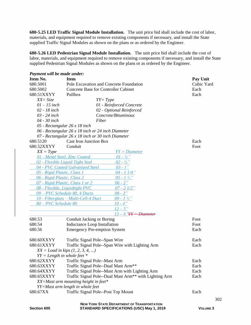
302 NEW YORK STATE DEPARTMENT OF TRANSPORTATION Section 600 STANDARD SPECIFICATIONS (USC) May 1, 2019 VOLUME 3
680-5.25 LED Traffic Signal Module Installation. The unit price bid shall include the cost of labor,
materials, and equipment required to remove existing components if necessary, and install the State
supplied Traffic Signal Modules as shown on the plans or as ordered by the Engineer.
680-5.26 LED Pedestrian Signal Module Installation. The unit price bid shall include the cost of
labor, materials, and equipment required to remove existing components if necessary, and install the State
supplied Pedestrian Signal Modules as shown on the plans or as ordered by the Engineer.
Payment will be made under:
Item No. Item Pay Unit
680.5001 Pole Excavation and Concrete Foundation Cubic Yard
680.5002 Concrete Base for Controller Cabinet Each
680.51XXYY Pullbox Each
XX= Size YY= Type
01 – 15 inch 01 - Reinforced Concrete
02 - 18 inch 02 - Optional Reinforced
03 - 24 inch Concrete/Bituminous
04 - 30 inch Fiber
05 - Rectangular 26 x 18 inch
06 - Rectangular 26 x 18 inch or 24 inch Diameter
07 - Rectangular 26 x 18 inch or 30 inch Diameter
680.5120 Cast Iron Junction Box Each
680.52XXYY Conduit Foot
XX = Type YY = Diameter
01 - Metal Steel, Zinc Coated 01 - ½”
02 - Flexible Liquid Tight Seal 02 - ¾”
04 - PVC Coated Galvanized Steel 03 - 1”
05 - Rigid Plastic, Class 1 04 - 1 1/4”
06 - Rigid Plastic, Class 2 05 - 1 ½”
07 - Rigid Plastic, Class 1 or 2 06 - 2”
08 - Flexible, Liquidtight PVC 07 - 2 1/2”
09 – PVC Schedule 80, 4 Ducts 08 - 3”
10 - Fiberglass – Multi-Cell-4 Duct 09 - 3 ½”
80 – PVC Schedule 80 10 - 4”
12 – 5”
13 – 6”YY = Diameter
680.53 Conduit Jacking or Boring Foot
680.54 Inductance Loop Installation Foot
680.56 Emergency Pre-emption System Each
680.60XXYY Traffic Signal Pole--Span Wire Each
680.61XXYY Traffic Signal Pole--Span Wire with Lighting Arm Each
XX = Load in kips (1, 2, 3, 4, ...)
YY = Length in whole feet *
680.62XXYY Traffic Signal Pole--Mast Arm Each
680.63XXYY Traffic Signal Pole--Dual Mast Arm** Each
680.64XXYY Traffic Signal Pole--Mast Arm with Lighting Arm Each
680.65XXYY Traffic Signal Pole--Dual Mast Arm** with Lighting Arm Each
XX=Mast arm mounting height in feet*
YY=Mast arm length in whole feet
680.67XX Traffic Signal Pole--Post Top Mount Each

303 NEW YORK STATE DEPARTMENT OF TRANSPORTATION Section 600 STANDARD SPECIFICATIONS (USC) May 1, 2019 VOLUME 3
680.68XX Traffic Signal Pole--Bracket Mount Each
680.69XX Traffic Signal Pole Bracket Mount with Lighting Arm Each
XX=Mounting height in feet*
680.7001 Single Span Wire Assembly Each
680.7002 Dual Span Wire Assembly with Upper Tether Wire Each
680.7003 Dual Span Wire Assembly with Lower Tether Wire Each
680.7004 Messenger Assembly Foot
680.7005 Guy Assembly Each
680.700602 Riser Assembly, 1/2 inch Diameter Each
680.700603 Riser Assembly, 1 inch Diameter Each
680.700604 Riser Assembly, 1 1/2 inch Diameter Each
680.700606 Riser Assembly, 2 inch Diameter Each
680.700607 Riser Assembly, 2 1/2 inch Diameter Each
680.700608 Riser Assembly, 3 inch Diameter Each
680.700609 Riser Assembly, 3 1/2 inch Diameter Each
680.700610 Riser Assembly, 4 inch Diameter Each
680.700612 Riser Assembly, 5 inch Diameter Each
680.700613 Riser Assembly, 6 inch Diameter Each
680.71 Shielded Lead-in Cable Foot
680.72 Inductance Loop Wire Foot
680.73XXYY Signal Cable Foot
680.74XXYY Signal Cable with Integral Messenger Foot
XX = Number of Conductors
YY = Wire Gauge
680.75XXYY Shielded Communication Cable Foot
680.76XXYY Shielded Communication Cable with Integral Messenger Foot
XX = Number of Pairs
YY = Wire Gauge
680.810101 Traffic Signal Module - 12 inch, Red Ball, LED Each
680.810102 Traffic Signal Module - 12 inch, Red Arrow, LED Each
680.810103 Traffic Signal Module-12 inch Yellow Ball, LED Each
680.810104 Traffic Signal Module-12 inch Yellow Arrow, LED Each
680.810105 Traffic Signal Module - 12 inch, Green Ball, LED Each
680.810106 Traffic Signal Module - 12 inch, Green Arrow, LED Each
680.810107 Traffic Signal Section - Type I, 12 inch Each
680.810108 Traffic Signal Module - 12 inch,
Bi-Modal Yellow/Green Arrows , LED Each
680.8102 Traffic Signal Section, Optically Programmed - 12 inch Each
680.810301 Traffic Signal Module - 8 inch, Red Ball, LED Each
680.810302 Traffic Signal Module - 8 inch, Red Arrow, LED Each
680.810303 Traffic Signal Module- 8 inch Yellow Ball, LED Each
680.810304 Traffic Signal Module- 8 inch Yellow Arrow, LED Each
680.810305 Traffic Signal Module - 8 inch, Green Ball, LED Each
680.810306 Traffic Signal Module - 8 inch, Green Arrow, LED Each
680.810307 Traffic Signal Section - Type I, 8 inch Each
680.810308 Install Ball/Arrow LED Traffic Signal Module Each
680.810601 Traffic Signal Section - Polycarbonate, Type I, 12 inch Each
680.810701 Traffic Signal Section - Polycarbonate, Type I, 8 inch Each

304 NEW YORK STATE DEPARTMENT OF TRANSPORTATION Section 600 STANDARD SPECIFICATIONS (USC) May 1, 2019 VOLUME 3
680.8111 Traffic Signal Bracket Assembly 1 Way Each
680.8112 Traffic Signal Bracket Assembly 2 Way Each
680.8113 Traffic Signal Bracket Assembly 3 Way Each
680.8114 Traffic Signal Bracket Assembly 4 Way Each
680.8115 Traffic Signal Bracket Assembly 5 Way Each
680.8120 Traffic Signal Disconnect Hanger Each
680.813101 Pedestrian Signal Module - 12 inch, Hand Symbol, LED Each
680.813102 Pedestrian Signal Module - 12 inch by 12 inch MAN LED Each
680.813103 Pedestrian Signal Section - Type I, 12 inch Each
680.813104 Install LED Pedestrian Signal Module Each
680.813105 Pedestrian Signal Module - 12 inch,
Bi-Modal Hand/Man Symbols, LED Each
680.813106 Pedestrian Signal Section - Polycarbonate, Type I, 12 inch Each
680.813107 Pedestrian Signal Module – 16 inch by 18 inch
Bi-Modal HAND/MAN LED Each
680.813108 Pedestrian Signal Section, Type I - for 16 inch by 18 inch
LED module Each
680.813109 Pedestrian Signal Section - Polycarbonate, Type I-
for 16 inch by 18 inch LED module Each
680.8141 Pedestrian Signal Bracket Mount Assembly Each
680.8142 Pedestrian Signal Post Top Mount Assembly Each
680.82XX Overhead Sign Assembly Each
XX = Type
680.8220 Flashing Beacon Sign Assembly Each
680.8225 Pedestrian Push Button and Sign - without Post Each
680.8226 Pedestrian Push Button and Sign - with Post Each
680.8230 Fire Pre-Emption Tell Tale Light Each
NOTE: SEE PAY ITEM CATALOG FOR ITEM NUMBERS CONTAINING VARIABLES.
* Mast arm mounting heights, and span wire pole length and load, are as defined on the `Standard Traffic Signal Poles' standard
sheets and in §724-03, Traffic Signal Poles. The nominal luminaire mounting height and span shall be as indicated on the plans.
** The mast arm length and mounting height indicated by the item number is for only one of the mast arms. The other mast arm
length and mounting height shall be as indicated on the plans.
SECTION 681 AND 682 (VACANT)
SECTION 683 - INTELLIGENT TRANSPORTATION SYSTEMS
683-1 DESCRIPTION. The work in this section shall include work required for intelligent
transportation systems.
683-2 MATERIALS. Materials shall be as specified in the special specifications.
683-3 CONSTRUCTION DETAILS. The extent of work and construction requirements will be
covered by special specifications in the contract documents.
683-4 METHOD OF MEASUREMENT. As specified in the special specifications.
305 NEW YORK STATE DEPARTMENT OF TRANSPORTATION Section 600 STANDARD SPECIFICATIONS (USC) May 1, 2019 VOLUME 3
683-5 BASIS OF PAYMENT. As specified in the special specifications.
SECTION 684 (VACANT)
SECTION 685 - EPOXY REFLECTORIZED PAVEMENT MARKINGS
685-1 DESCRIPTION. Under this work, the Contractor shall furnish and apply epoxy reflectorized
pavement markings at the location and in accordance with patterns indicated on the plans or as ordered by
the Engineer, and in conformance with the MUTCD and these specifications.
The epoxy marking material should be hot–applied by spray methods onto bituminous and portland
cement concrete pavement surfaces at the thickness and width shown on the Contract Documents.
Following an application of glass beads, the cured epoxy marking shall be an adherent reflectorized
stripe.
685-2 MATERIALS. Materials shall conform to the requirements of §727-03 White and Yellow Epoxy
Reflectorized Pavement Markings.
685-3 CONSTRUCTION DETAILS
685-3.01 General. All pavement markings and patterns shall be placed as shown on the Contract
Documents and in accordance with the MUTCD.
Before any pavement marking work is begun, a schedule of operations shall be submitted for the
approval of the Regional Director and his/her authorized representative.
At least five (5) days prior to starting striping, the Contractor shall provide the Engineer with the
epoxy manufacturer's written instructions for use. These instructions shall include, but not be limited to,
material mixing ratios and application temperatures.
When pavement markings are applied under traffic, the Contractor shall provide all necessary flags,
markers, signs, etc. in accordance with the MUTCD to maintain and protect traffic, and to protect
marking operations and the markings until thoroughly set.
The application of pavement markings shall be done in the general direction of traffic. Striping
against the direction of traffic flow shall not be allowed.
The Contractor shall be responsible for removing, to the satisfaction of the Engineer, all tracking
marks, spilled epoxy, and epoxy markings applied in unauthorized areas.
When necessary the Contractor shall establish marking line points at 30 feet intervals throughout the
length of the pavement or as directed by the Engineer.
685-3.02 Atmospheric Conditions. Epoxy pavement markings shall only be applied during conditions
of dry weather and on substantially dry pavement surfaces. At the time of installation the pavement
surface temperature shall be minimum of 50°F and the ambient temperature shall be a minimum of 50°F
and rising. The Engineer shall be the sole determiner as to when atmospheric conditions and pavement
surface conditions are such to produce satisfactory results.
685-3.03 Surface Preparation. The Contractor shall clean the pavement and existing durable markings
to the satisfaction of the Engineer.
Surface cleaning and preparation work shall be performed only in the area of the epoxy markings
application.
306 NEW YORK STATE DEPARTMENT OF TRANSPORTATION Section 600 STANDARD SPECIFICATIONS (USC) May 1, 2019 VOLUME 3
At the time of application, all pavement surfaces and existing durable markings shall be free of oil,
dirt, dust, grease and similar foreign materials. The cost of cleaning these contaminants shall be included
in the bid price of this item.
In addition, concrete curing compounds on new portland cement concrete surfaces and existing
painted pavement markings on both concrete and bituminous pavement surfaces shall be cleaned and paid
for in accordance with Section 635, Cleaning and Preparation of Pavement Surfaces for Pavement
Markings.
685-3.04 Epoxy Applicating Equipment. Mobile applicating equipment for the placement of epoxy
reflectorized pavement markings shall be approved by the Director (Materials Bureau) prior to the start of
work.
In general, a mobile applicator shall be a truck mounted, self–contained pavement marking machine,
specifically designed to apply epoxy resin materials and reflective glass spheres in continuous and skip–
line patterns. The applicating equipment shall be maneuverable to the extent that straight lines can be
followed and normal curves can be made in true arc. In addition, the truck mounted unit shall be
provided with accessories to allow for the marking of legends, symbols, crosswalks, and other special
patterns.
At any time throughout the duration of the project, the Contractor shall provide free access to his
epoxy applicating equipment for inspection by the Engineer or his authorized representative.
The Engineer may approve the use of a portable applicator in lieu of mobile truck mounted
accessories for use in applying special markings only, provided such equipment can demonstrate
satisfactory application of reflectorized epoxy markings in accordance with these specifications. The
applicating equipment shall be capable of installing a minimum of 100,000 feet of epoxy reflectorized
pavement markings in an eight hour day and shall include the following features:
1. Individual tanks for the storage of Part A and Part B of the epoxy resin and for the storage of reflective
glass spheres.
2. Heating equipment of sufficient capacity to maintain the individual epoxy resin components at the
manufacturer's recommended temperature for spray application.
3. Glass bead dispensing equipment and the capacity of applying the spheres a minimum rate of 20 lb/gal
of epoxy resin composition.
4. Metering devices or pressure gauges on the proportioning pumps, positioned to be readily visible to the
Engineer.
5. All necessary spray equipment, mixers, compressors, and other appurtenances for the placement of
epoxy reflectorized pavement markings in a simultaneous sequence of operations as described in §685-
3.05 Application of Epoxy Reflectorized Pavement Markings.
685-3.05 Application of Epoxy Reflectorized Pavement Markings. Epoxy reflectorized pavement
markings shall be placed at the width, thickness, and pattern designated by the Contract Documents.
Marking operations shall not begin until applicable surface preparation work is completed and
approved by the Engineer, and the atmospheric conditions and pavement surface temperature are
acceptable to the Engineer.
Pavement markings shall be applied by the following simultaneous operation:
1. The pavement surface is air-blasted to remove dirt and residues.
2. The epoxy resin, mixed and heated in accordance with the manufacturer's recommendations, is
uniformly hot-sprayed onto the pavement surface at the minimum specified thickness.
3. Reflective glass spheres are injected into, or dropped onto, the liquid epoxy marking at a minimum rate
of 20 lb/gal of epoxy resin.

307 NEW YORK STATE DEPARTMENT OF TRANSPORTATION Section 600 STANDARD SPECIFICATIONS (USC) May 1, 2019 VOLUME 3
685-3.06 Defective Epoxy Pavement Markings. Epoxy reflectorized pavement markings, which after
application and curing are determined by the Engineer to be defective and not in conformance with this
specification, shall be repaired. Repair of defective markings shall be the responsibility of the Contractor
and shall be performed to the satisfaction of the Engineer as follows:
1. Insufficient film thickness and line width; insufficient glass bead coverage or inadequate glass bead
retention.
Repair Method. Prepare the surface of the defective epoxy marking by grinding or blast cleaning. No
other cleaning methods will be allowed. Surface preparation shall be performed to the extent that a
substantial amount of the reflective glass spheres are removed and a roughened epoxy marking surface
remains. Immediately after surface preparation remove loose particles and foreign debris by brooming or
blasting with compressed air. Repair shall be made by restriping over the cleaned surface in accordance
with the requirements of this specification and at the full thickness indicated on the Contract Documents.
2. Uncured or discolored epoxy*; insufficient bond (to pavement surface or existing durable marking).
Repair Method. The defective epoxy marking shall be completely removed and cleaned to the
underlying pavement surface in accordance with the requirements of Section 635 - Cleaning and
Preparation of Pavement Surfaces, at the Contractor's expense. The extent of removal shall be the
defective area plus any adjacent epoxy pavement marking material extending three feet in any direction.
After surface preparation work is complete, repair shall be made by reapplying epoxy over the cleaned
pavement surface in accordance with the requirements of this specification. *Uncured epoxy shall be defined as applied material that fails to cure (dry) in accordance with requirements of §727–03
MATERIAL REQUIREMENTS, A., 2.0 paragraph d. Drying Time (Field); or applied material that fails to cure (dry) within a
reasonable time period under actual field conditions, as defined by the Engineer. *Discoloration shall be defined as localized areas or patches of brown, grayish or black colored epoxy marking material. These
areas often occur in a cyclic pattern and often are not visible until several days or weeks after markings are applied.
Other defects not noted above, but determined by the Engineer to need repair, shall be repaired or
replaced as directed by and to the satisfaction of the Engineer.
All work in conjunction with the repair or replacement of defective epoxy reflectorized pavement
markings shall be performed by the Contractor at no additional cost to the State.
685-4 METHOD OF MEASUREMENT. Pavement striping will be measured in feet along the
centerline of the pavement stripe and will be based on a 4 inch wide stripe. Measurement for striping
with a plan width greater or less than the basic 4 inches as shown on the plans or directed by the Engineer,
will be made by the following method:
Plan Width of Striping (inches) x Feet
4 inches
Letters and symbols will be measured by each unit applied. A unit will consist of one letter or one
symbol. Example: “SCHOOL” would be paid as six units. Double and triple headed arrows will be
measured as a single unit, but the “X” in railroad grade crossing markings (MUTCD Figure 8B-6) will be
measured by feet of 4 inch stripe.
685-5 BASIS OF PAYMENT. The accepted quantities of markings will be paid for at the contract unit
price, which shall include the cost of furnishing labor, materials and equipment to satisfactorily complete
the work. The cost for maintaining and protecting traffic during the marking operations shall be included
in the price bid. The cost of removal of concrete curing compounds and existing pavement markings will
be paid under separate items and are not included in this item.
No payment will be made for the repair or replacement of defective epoxy reflectorized pavement
markings.
No payment will be made for the number of feet of skips in the dashed line.

308 NEW YORK STATE DEPARTMENT OF TRANSPORTATION Section 600 STANDARD SPECIFICATIONS (USC) May 1, 2019 VOLUME 3
Payment will be made under:
Item No. Item Pay Unit
685.01 White Epoxy Reflectorized Pavement Stripes – 15 mils Feet
685.02 Yellow Epoxy Reflectorized Pavement Stripes – 15 mils Feet
685.03 White Epoxy Reflectorized Pavement Letters – 15 mils Each
685.04 White Epoxy Reflectorized Pavement Symbols – 15 mils Each
685.11 White Epoxy Reflectorized Pavement Stripes – 20 mils Feet
685.12 Yellow Epoxy Reflectorized Pavement Stripes – 20 mils Feet
685.13 White Epoxy Reflectorized Pavement Letters – 20 mils Each
685.14 White Epoxy Reflectorized Pavement Symbols – 20 mils Each
SECTION 686 (VACANT)
SECTION 687 - THERMOPLASTIC REFLECTORIZED PAVEMENT MARKINGS
687-1 DESCRIPTION. Under this work, the Contractor shall furnish and apply thermoplastic
reflectorized pavement markings at the location and in accordance with patterns indicated on the plans or
as ordered by the Engineer, and in conformance with the MUTCD and these specifications.
The thermoplastic pavement marking compound shall be extruded in a molten state onto the
pavement surface. Following surface application of glass beads and upon cooling to normal pavement
temperatures, the resultant marking shall be an adherent reflectorized stripe of the specified thickness and
width that is capable of resisting deformation by traffic.
687-2 MATERIALS. Materials shall conform to the requirements of §727-01 White and Yellow
Thermoplastic Reflectorized Pavement Markings.
687-3 CONSTRUCTION DETAILS
687-3.01 Equipment General. Thermoplastic applicating equipment shall be approved by the Engineer
prior to the start of work.
Unless otherwise approved by the D.C.E.C., all projects specifying quantities greater than 65,000 feet
of longitudinal pavement marking lines will be striped using only mobile applicating equipment for the
longitudinal lines. Longitudinal pavement marking lines are Broken Lines (skipline), Edge Lines, Barrier
Lines, and Solid Lines as defined by the MUTCD Portable applicating equipment will be acceptable for
placing all other markings on these projects.
Thermoplastic material shall be applied to the pavement surface by the extrusion method, wherein
one side of the shaping die is the pavement and the other three sides are contained by, or are part of,
suitable equipment for maintaining the temperature and controlling the flow of material (Note 1.)
Note 1. Alternate types of extrusion devices may be considered acceptable for use upon prior approval by
the Materials Bureau. Requests for approval of alternate extrusion applicating equipment shall be made
to the Materials Bureau by the Contractor/Manufacturer at least 90 days prior to its date of intended use.
Detailed requirements and procedures for the acceptance of alternate equipment are available from the
Materials Bureau.
For heating the thermoplastic composition, the application equipment shall include a melting kettle(s)
of such capacity as to allow for continuous marking operations. The melting kettle(s) may be mounted on
a separate “supply” vehicle or included as part of the mobile applicating equipment. The kettle(s) shall be
capable of heating the thermoplastic composition temperatures greater than 400°F. The heating
mechanism shall be by means of a thermostatically controlled heat transfer medium. Heating of the

309 NEW YORK STATE DEPARTMENT OF TRANSPORTATION Section 600 STANDARD SPECIFICATIONS (USC) May 1, 2019 VOLUME 3
composition by direct flame will not be allowed. Material temperature gauges shall be visible at both
ends of the kettle(s).
Application equipment shall be constructed to provide continuous mixing and agitation of the
material. Conveying parts of the equipment between the main material reservoir and the extrusion shoe(s)
shall be so constructed as to prevent accumulation and clogging. All parts of the equipment which come
into contact with the material shall be so constructed so as to be easily accessible and exposable for
cleaning and maintenance. The equipment shall be constructed so that all mixing and conveying parts up
to and including the extrusion shoe(s), maintain the material at the required plastic temperature.
The applicating equipment shall be so constructed as to insure continuous uniformity in the
dimensions of the stripe. The applicator shall provide a means for cleanly cutting off stripe ends squarely
and shall provide a method of applying “skip” lines. The equipment shall be capable of applying varying
widths of traffic markings.
The applicator shall be equipped with a drop-on type bead dispenser capable of uniformly dispensing
reflective glass spheres at controlled rates of flow.
The bead dispenser shall be automatically operated in such a manner that it will only dispense beads
while the composition is being applied.
Applicating equipment shall be mobile and maneuverable to the extent that straight lines can be
followed and normal curves can be made in a true arc.
Applicators shall be equipped and constructed in such a manner as to satisfy the requirements of the
National Board of Fire Underwriters and the appropriate agencies of the State of New York.
The equipment used for the placement of thermoplastic pavement markings shall be two general
types: mobile applicator and portable applicator.
687-3.02 Mobile Applicating Equipment. The mobile applicator shall be defined as a truck mounted,
self-contained pavement marking machine that is capable of hot applying thermoplastic by the extrusion
method. The unit shall be equipped to apply the thermoplastic material at temperatures exceeding 400°F,
and at the widths and thicknesses specified herein. The mobile unit shall be capable of operating
continuously and of installing a minimum of 20,000 feet of longitudinal markings in an 8–hour day.
The mobile unit shall be equipped with a melting kettle(s) or materials storage reservoir(s) of such
capacity as to allow for continuous marking operations. The kettle(s) or reservoirs shall be capable of
heating or holding the thermoplastic composition at temperatures greater than 400°F.
The mobile unit shall be equipped with an extrusion shoe(s), and shall be capable of marking edgeline
and centerline stripes. The extrusion shoe(s) shall be closed, heat jacketed or suitably insulated unit; shall
hold the molten thermoplastic at a temperature greater than 400°F; and shall be capable of extruding a
line between 3 to 8 inches in width; and at a thickness of not less than 1/8 inch nor more than 3/16 inch,
and of generally uniform cross section. Material temperature gauges shall be affixed or incorporated in
the extrusion shoe in such a manner as to be visible, and capable of monitoring the composition
temperature throughout the marking operation.
The mobile unit shall be equipped with an electronic and programmable line pattern control system,
or mechanical control system, so as to be capable of applying skip or solid lines in any sequence, and
through any extrusion shoe in any cycle length.
687-3.03 Portable Applicating Equipment. The portable applicator shall be defined as hand operated
equipment, specifically designed for placing thermoplastic installations such as crosswalks; stop bars;
legends; arrows; and short lengths of lane, edge, and centerlines. The portable applicator shall be capable
of applying thermoplastic pavement markings by the extrusion method. It is intended that the portable
applicator will be loaded with hot thermoplastic composition from the melting kettle(s). The portable
applicator shall be equipped with all the necessary components, including a materials storage reservoir,
bead dispenser, extrusion shoe, and heating accessories, so as to be capable of holding the molten
thermoplastic at temperatures greater than 400°F, of extruding a line of from 3 to 8 inches in width, and in
thickness of not less than 1/8 inch nor more than 3/16 inch and of generally uniform cross–section.

310 NEW YORK STATE DEPARTMENT OF TRANSPORTATION Section 600 STANDARD SPECIFICATIONS (USC) May 1, 2019 VOLUME 3
Material temperature gauges shall be affixed or incorporated in the extrusion shoe in such a manner as to
be visible, and capable of monitoring the composition temperature throughout the marking operation.
687-3.04 Application General. All pavement markings shall be placed as shown on the plans and in
accordance with the MUTCD.
Before any pavement marking work is begun, a schedule of operations shall be submitted for the
approval of the Regional Director or his authorized representative.
When pavement markings are applied under traffic the Contractor shall provide all necessary flags,
markers, signs, etc. to maintain and protect traffic; and to protect marking operations and the markings
until thoroughly set.
The application of pavement markings shall be done in the general direction of traffic. Striping
against the direction of traffic flow shall not be allowed.
The Contractor shall be responsible for removing, to the satisfaction of the Engineer, tracking marks,
spilled thermoplastic or thermoplastic applied in unauthorized areas.
When necessary, the Contractor shall establish marking line points at 30 feet intervals throughout the
length of pavement or as directed by the Engineer.
687-3.05 Atmospheric Conditions. Thermoplastic pavement markings shall be placed upon dry
pavement surfaces. At the time of installation the pavement surface temperature shall be a minimum of
55°F and the ambient temperatures shall be a minimum of 50°F and rising. The Engineer will determine
when atmospheric conditions are such to produce satisfactory results (Note 2).
Note 2. To comply with the 55°F pavement surface temperature requirement, it will benefit the
Contractor to schedule striping work for seasons of warm weather when possible. In cooler conditions,
striping operations may be coordinated with bituminous paving work to take advantage of residual heat,
providing that the ambient temperature requirements of §687-3.05 are still met.
687-3.06 Materials Application Requirements
A. Thermoplastic Primer. All pavement surfaces shall be primed except that on new bituminous
pavements, when the thermoplastic pavement markings are applied within the same calendar year as
the completion of paving operations, primer shall not be required.
The primer shall be either a one-component or a two-component, cold or hot applied material of
the type recommended by the manufacturer of the thermoplastic pavement marking material. At least
five working days prior to the start of thermoplastic application, the Contractor shall provide the
Engineer with the manufacturer's written instructions for primer application. The application of the
primer shall be performed in accordance with the manufacturer's written recommendations which
shall include the method of application, the application rate, and the drying time.
B. Thermoplastic Composition.
1. Application Temperature - thermoplastic composition shall be applied at temperatures no
lower than 400°F at the point of deposition. For purposes of these specifications, the point of
deposition shall be defined as within the extrusion shoe.
2. Extruded Markings - all extruded markings shall be applied at the specified width, and at a
thickness of not less than 1/8 inch nor more than 3/16 inch.
C. Reflective Glass Spheres (for Drop-On). Immediately following application, reflective glass
spheres shall be dropped onto the molten thermoplastic marking at the rate of 1 lb per 20 square feet
of composition.
311 NEW YORK STATE DEPARTMENT OF TRANSPORTATION Section 600 STANDARD SPECIFICATIONS (USC) May 1, 2019 VOLUME 3
687-3.07 Surface Cleaning and Preparation of Pavement. The Contractor shall be responsible for
cleaning the pavement surface to the satisfaction of the Engineer.
Surface cleaning and preparation work shall be performed only in the area of the thermoplastic
markings application.
At the time of application all pavement surfaces shall be free of oil dirt, dust, grease and similar
foreign materials. The cost of cleaning these contaminants shall be included in the bid price of this item.
In addition, concrete curing compounds on new Portland Cement concrete surfaces; and existing
pavement markings on both concrete and bituminous pavement surfaces shall be cleaned and paid for
under separate items.
687-3.08 Application of Thermoplastic Pavement Markings. All special markings, cross walks, stop
bars, legends, arrows, and similar patterns shall be placed with a portable applicator. Unless otherwise
specified in the contract documents all center line, skip line, edge line and other longitudinal type
markings may be applied with either a portable or a mobile applicator.
When the surface preparation work has been completed, if applicable, the bituminous and/or concrete
pavement surface shall be primed according to the manufacturer's written instructions. Primer shall not
be required on new bituminous pavement surfaces that are completed within the same calendar year as the
thermoplastic marking application. The primer shall be spray applied onto the pavement surface and
allowed to dry according to the manufacturer's written instructions. Pavement surfaces that are primed
and not striped with thermoplastic within the required drying time or within the same work day shall be
re-primed.
After the primer has dried, the thermoplastic shall be applied at composition temperatures no lower
than 400°F at the point of deposition. Immediately after installation of the thermoplastic, drop-on
reflective glass spheres shall be mechanically applied such that the spheres are held by and embedded in
the surface of the molten composition.
687-4 METHOD OF MEASUREMENT. Pavement striping will be measured by linear foot along the
centerline of the pavement stripe, and will be based on a 4 inch wide stripe. Measurement for striping
with a plan width greater or less than the basic 4 inch as shown on the plans or as directed by the
Engineer, will be made by the following method:
Plan Width of Striping (inches) x Feet
4 inches
No payment will be made for the number of feet of skips in the dashed line.
Letters and symbols will be measured by each unit applied. A unit will consist of one letter or
symbol. Example: “SCHOOL” would be measured as six units. Double and triple headed arrows will be
measured as a single unit, but the “X” in railroad grade crossing markings (MUTCD Figure 8B-6) will be
measured by feet of 4 inch stripe.
687-5 BASIS OF PAYMENT. The accepted quantities of markings will be paid for at the contract unit
price, which shall include the cost of furnishing all labor, materials and equipment to satisfactorily
complete the work. The cost for maintaining and protecting traffic during the marking operations shall be
included in the price bid. The cost of removal of concrete curing compounds and existing pavement
markings will be paid under separate items and are not included in this item.
Payment will be made under:
Item No. Item Pay Unit
687.0101 White Thermoplastic Reflectorized Pavement Stripes Feet
687.0201 Yellow Thermoplastic Reflectorized Pavement Stripes Feet

312 NEW YORK STATE DEPARTMENT OF TRANSPORTATION Section 600 STANDARD SPECIFICATIONS (USC) May 1, 2019 VOLUME 3
687.0301 White Thermoplastic Reflectorized Pavement Letters Each
687.0401 White Thermoplastic Reflectorized Pavement Symbols Each
SECTION 688 - PREFORMED REFLECTORIZED PAVEMENT MARKINGS
688-1 DESCRIPTION. Under this work, the Contractor shall furnish and apply preformed reflectorized
pavement markings at the location and in accordance with patterns indicated on the plans or as ordered by
the Engineer, and in conformance with the MUTCD and these specifications.
The preformed reflectorized pavement marking shall be applied on new and existing bituminous and
portland cement concrete surfaces by hand and mechanical methods. The resultant marking shall be an
adherent reflectorized stripe that is capable of molding itself to the contours of the pavement surface and
of resisting deformation by traffic.
688-2 MATERIALS. Materials shall conform to the requirements of §727-04 White and Yellow
Reflectorized Pavement Markings.
688-3 CONSTRUCTION DETAILS
688-3.01 General. All pavement markings and patterns shall be placed as shown on the plans and in
accordance with the MUTCD.
Before any pavement marking work is begun, a schedule of operations shall be submitted for the
approval of the Regional Director or his authorized representative.
At least five (5) days prior to the start of work, the Contractor shall provide the Engineer with the
manufacturer's written instructions for the application of preformed marking and primer materials.
When pavement markings are applied under traffic, the Contractor shall supply all necessary flags,
markers, signs, and other devices, to maintain traffic and to protect the markings until set.
The application of pavement markings shall be done in the general direction of traffic. Striping
against the direction of traffic flow will not be allowed without prior approval of the Engineer.
The Contractor shall be responsible for removing, to the satisfaction of the Engineer, preformed
markings applied in unauthorized areas.
When required by the Engineer, the Contractor shall establish marking line points at 30 feet intervals
throughout the length of the pavement or as directed by the Engineer.
688-3.02 Application Methods. Preformed pavement markings shall be applied by the following
methods. The installation of markings on the project may be performed simultaneously by more than one
method.
A. During Bituminous Paving Operations. Preformed markings shall be applied on newly paved
bituminous surfaces after finish rolling is complete.
B. On Completed Pavements. Preformed markings shall be applied on new and existing bituminous
and portland cement concrete pavement surfaces as prescribed in §688–3.03 Weather and Seasonal
Limitations.
688-3.03 Weather and Seasonal Limitations. The Engineer shall determine as to when temperature and
pavement surface conditions are such as to produce satisfactory results.
Preformed pavement markings shall be placed upon dry pavement surfaces; pavements exposed to
rain or wet conditions shall be allowed to thoroughly dry before marking application.
Preformed markings applied in conjunction with §688–3.02A, During Bituminous Paving Operations,
shall only be placed within the seasonal limitations of Standard Specification §402-3.01. The bituminous
313 NEW YORK STATE DEPARTMENT OF TRANSPORTATION Section 600 STANDARD SPECIFICATIONS (USC) May 1, 2019 VOLUME 3
pavement surface temperature shall, at all times, be the controlling temperature at which preformed
markings are placed, and shall be between 100°F and 170°F.
Preformed markings applied in conjunction with §688–3.02B, on completed pavements, shall be
applied within the seasonal limitations of Table 688-1, Temperature and Seasonal Requirements. The
pavement surface and ambient air temperatures in Table 688-1 shall, in all cases, be the controlling
temperatures at which preformed markings are placed. Marking application work shall be discontinued
when temperatures fall below the specified requirements.
TABLE 688-1 TEMPERATURE AND SEASONAL REQUIREMENTS
(§688–3.02b. ON COMPLETED PAVEMENTS)
Geographic Location Pavement Surface
Temperature
Ambient Air
Temperature Allowable Installation Dates
Regions 1, 2, 3, 4, 5, 6, 7 & 9
(All Counties)
Region 8 (Ulster County only)
70°F, Min. 60°F, Min. May 15 to September 1
Regions 8 & 10 (except Ulster
County) 70°F, Min. 60°F, Min. May 15 to September 15
Region 11 70°F, Min. 60°F, Min. May 1 to September 30
NOTES:
1. Surface temperatures shall be measured on the pavement surface where the preformed markings are to be placed. The
controlling temperature shall be the average of three temperature readings taken at locations 100± feet apart.
2. Ambient air temperatures shall be measured in the shade.
688-3.04 Mechanical Applicating Equipment. Mechanical applicating equipment for the placement of
preformed pavement marking stripes shall be of the type recommended by the manufacturer of the
preformed material. All applicating equipment shall be approved by the Engineer prior to the start of
work.
688-3.05 Rollers. Preformed markings applied in conjunction with §688-3.02a, during bituminous
paving operations, shall be rolled into place with compaction equipment meeting the requirements of
Standard Specification §402-3.04. Vibratory roller models shall operate in a 'static' mode.
Preformed markings applied in conjunction with §688-3.02B., On Completed Pavements, shall be
rolled into place using steel shell or pneumatic rubber–tired roller equipment approved by the Engineer.
Steel wheel rollers shall weigh a minimum of 200 lbs on each axle. Pneumatic rubber–tired rollers shall
exert a minimum tire compression on the pavement of 28 psi. Hand rollers or rubber tired vehicles (e.g.
pick–up truck) meeting the above requirements may be suitable for use.
688-3.06 Primer Requirements. When required, primer or adhesive shall be used for marking
applications in accordance with the written recommendations of the manufacturer of the preformed
marking material.
Primer materials shall be placed at the application rate and by the application methods recommended
by the manufacturer.
When primer is applied, the area of application shall be at least the width or dimension, of the new
preformed marking, plus one inch on each side.
688-3.07 Surface Cleaning and Preparation of Pavement Surfaces. The Contractor shall be
responsible for cleaning the pavement surface to the satisfaction of the Engineer.
Surface cleaning and preparation work shall be performed only in the area of the preformed markings
application.
At the time of application, all pavement surfaces shall be free of oil, dirt, dust, grease and similar
foreign materials. The cost of cleaning these contaminants shall be included in the bid price of this item.

314 NEW YORK STATE DEPARTMENT OF TRANSPORTATION Section 600 STANDARD SPECIFICATIONS (USC) May 1, 2019 VOLUME 3
In addition, concrete curing compounds on new portland cement concrete surfaces and existing
pavement markings on both concrete and bituminous pavement surfaces shall be removed and paid for
under separate items.
688-3.08 Application of Preformed Reflectorized Pavement Markings. Unless otherwise approved by
the Engineer, all longitudinal lines shall be applied using mechanical applicating equipment. Transverse
and special marking patterns may be applied by hand or mechanical methods.
Preformed marking operations shall not begin until after the pavement surface has been cleaned and
prepared.
Preformed stripes shall not be applied over longitudinal paving joints or over the point of transition
between the pavement surface and adjoining shoulder. The placement of stripes in the area of transition
shall be either on the pavement or on the shoulder, as directed by the Engineer.
No roller shall operate in excess of 3.0 mph. One roller pass shall be defined as one movement of the
roller over any point of the preformed marking, in the direction of the marking application.
A. Application During Bituminous Paving Operations. The application of preformed markings shall
not begin until finish rolling of the new bituminous pavement is complete.
At the time of marking application, the surface temperature of the new bituminous pavement shall
be between 100°F and 170°F. The Contractor shall coordinate paving and preformed marking
operations to conform with surface temperature requirements.
Immediately after finish rolling is complete, the preformed marking shall be applied on the new
bituminous surface. Traces of water or other residue from finish rolling operations shall first be
removed. Immediately after its placement, the preformed marking shall be adhered to the warm
pavement surface by rolling. Rollers shall make a minimum one pass, and operate in the same
direction that the marking was applied. Diagonal, reverse or crosswise rolling will not be allowed.
The minimum one pass may be increased by the Engineer if, in his opinion, the desired adherence is
not obtained.
B. Application on Completed Pavements. The application of preformed markings shall only be
performed within the limitations of §688–3.03 Weather and Seasonal Limitations.
If required by the manufacturer, primer and adhesive activators shall be applied and allowed to
dry in accordance with the instructions of the manufacturer of the preformed material.
The preformed marking shall be placed on the pavement surface and adhered by rolling. Rollers
shall make a minimum of one pass, and operate in the same direction that the marking was applied.
Diagonal, reverse or crosswise rolling will not be allowed. The minimum one pass may be increased
by the Engineer if, in his opinion, the desired adherence is not obtained.
688-4 METHOD OF MEASUREMENT. Pavement striping will be measured by feet along the
centerline of the pavement stripe and will be based on a 4 inch wide stripe.
The preformed pavement markings will be inspected during and following installation to determine
conformance with this specification. In addition, they will be inspected following a performance period
that will extend for 180 calendar days following both their installation and opening of the roadway to
traffic.
Within 15 consecutive calendar days after the end of the 180 day performance period, a final
performance inspection will be made by the Engineer. If this inspection discloses any work, in whole or
in part, as not being visibly intact and serviceable to the following extent, the Contractor shall completely
repair or replace such work:
A. Broken Line. 90 percent measured longitudinally of the total length of all broken lines in any 500
feet long pavement section.
315 NEW YORK STATE DEPARTMENT OF TRANSPORTATION Section 600 STANDARD SPECIFICATIONS (USC) May 1, 2019 VOLUME 3
B. Dotted Line. 50 percent measured longitudinally of the total length of all dotted lines in any 100
feet long pavement section.
C. Solid Line and Edge Line. 90 percent measured longitudinally of the total length of solid line or
edge line in any 500 feet long pavement section.
D. Channelizing Line, Stop Line, Crosswalk Lines, Clearance Line and Crossbars, Hatch Lines,
Letters and Symbols. 90 percent by area of any individual line, letter or symbol.
When required all repair or replacement work shall be performed in accordance with this
specification and completed within 60 calendar days of the earliest allowable installation date as specified
in Table 1, for that location. The Engineer shall determine the limits or quantity of preformed to be
repaired or replaced.
Upon completion of the final performance inspection, or after satisfactory completion of any
necessary corrections, the Engineer will, within 10 calendar days, notify the Contractor in writing, of the
date of such final performance inspection and release the Contractor from further performance
responsibility.
Pavement striping on–going projects will be measured as the total of the striping applied, if after the
final 180 day performance period, damage to the striping is not in excess of that specified (e.g. If 95% of
the edgeline striping is intact in a 500 feet pavement section, the edgeline will be measured as the full 500
feet of applied marking. No deduction will be made for the damaged 5% (25 feet) of striping).
Measurement for striping with a plan width greater or less than the basic 4 inches as shown on the
plans or as directed by the Engineer, will be made by the following method:
Plan Width of Striping (inches) x Feet
4 inches
No payment will be made for the number of feet of gaps between broken or dotted line segments.
Letters and symbols will be measured by each unit applied. A unit will consist of one letter or one
symbol. Example: “SCHOOL” would be measured as six units.
Double and triple headed arrows will be measured as a single unit, but the “X” in railroad grade
crossing markings (MUTCD Figure 8B-6) will be measured by feet of 4 inch stripe.
688-5 BASIS OF PAYMENT. The accepted quantities of markings will be paid for at the contract unit
price, which shall include the cost of furnishing all labor, materials and equipment to satisfactorily
complete the work. The cost of cleaning pavement surfaces of oil, dirt, dust, grease and similar foreign
materials shall be included in the price bid. The cost of removal of concrete curing compounds and
existing pavement markings will be paid under separate items and are not included in this item.
Payment will be made under:
Item No. Item Pay Unit
688.01 White Preformed Reflectorized Pavement Stripes Feet
688.02 Yellow Preformed Reflectorized Pavement Stripes Feet
688.03 White Preformed Reflectorized Pavement Letters Each
688.04 White Preformed Reflectorized Pavement Symbols Each
SECTION 689 (VACANT)

316 NEW YORK STATE DEPARTMENT OF TRANSPORTATION Section 600 STANDARD SPECIFICATIONS (USC) May 1, 2019 VOLUME 3
SECTION 690 - SPECIALTY WORK
690-1 DESCRIPTION. The work in this section shall include specialty work required for transportation
projects.
690-2 MATERIALS. Materials shall be as specified in the special specifications.
690-3 CONSTRUCTION DETAILS. The extent of work and construction requirements will be
covered by special specifications in the contract documents.
690-4 METHOD OF MEASUREMENT. As specified in the special specifications.
690-5 BASIS OF PAYMENT. As specified in the special specifications.
SECTIONS 691 THRU 695 - (VACANT)
SECTION 696 - CONTRACTOR CHARGES
696-1 DESCRIPTION. This section will provide for the accounting of charges assessed against the
Contractor in accordance with the contract documents.
696-2 MATERIALS. None specified.
696-3 CONSTRUCTION DETAILS. The Department may assess the Contractor charges for
Engineering Charges and/or Liquidated Damages against monies due the Contractor in accordance with
§108-03 Failure to Complete Work On Time, or may make other charges in accordance with the contract.
These charges will be assessed using the contract pay items in this section.
696-4 METHOD OF MEASUREMENT. These contract pay items will not be shown in the itemized
proposal. Contractor charges will be measured on a Dollars-Cents basis.
696-5 BASIS OF PAYMENT. Should the Contractor be assessed charges, the amounts will be
accounted for using the contract pay items in this section. Assessed charges will be deducted from a
contract payment processed after the determination that charges will be made, or, if the Contractor is not
due monies sufficient to recover the assessed charges, the State may utilize other methods of recovery.
Payment will be made under:
Item No. Item Pay Unit
696.01 Engineering Charges Dollars Cents
696.02 Liquidated Damages Dollars Cents
696.03 Contractor Charges – Other Dollars Cents
SECTION 697 - FIELD CHANGE PAYMENT
697-1 DESCRIPTION

317 NEW YORK STATE DEPARTMENT OF TRANSPORTATION Section 600 STANDARD SPECIFICATIONS (USC) May 1, 2019 VOLUME 3
697-1.01 General. The Field Change Payment (FCP) provides a contract contingency allowance for the
timely payment of authorized extra work that was completed to fulfill the intent of the contract
documents.
697-1.02 Eligible Work. Only the following extra work will be eligible for FCP item payments:
1. Work within the scope of the contract.
2. Completed additional quantities of existing contract items of work processed as unit bid prices:
Up to 200% of original contract quantity for Minor Items of work.
More than 200% of a Minor Item original contract quantity that results in an increase less than
$1,000.00 from the original contract amount.
Up to 125% of original contract quantity for Major Items of work.
3. Completed additional quantities of existing contract items that have exceeded the threshold quantities,
but have unit bid prices that are acceptable by comparison to the Weighted Average Awarded Prices or
the Average of the Three Lowest Bidders.
4. Completed additional quantities of existing contract items that have exceeded the threshold quantities,
which requires the use of new item numbers, and renegotiated prices that are acceptable by comparison to
the Weighted Average Awarded Prices or the Average of the Three Lowest Bidders.
5. Completed quantities of new contract items of work with Agreed Prices that are acceptable by
comparison to the Weighted Average Awarded Prices.
6. Fuel, Asphalt, or Steel Adjustment items calculated for eligible work completed.
697-2 MATERIALS. None specified.
697-3 CONSTRUCTION DETAILS. None specified.
697-4 METHOD OF MEASUREMENT. The unit price shown in the proposal for this item will be
considered as the unit price bid and shall not be altered in any manner. Should the amount shown be
altered, the figure entered will be disregarded and the original unit price will be used to determine the
total amount bid for the contract.
697-5 BASIS OF PAYMENT. All work to be paid under the FCP item must receive prior authorization
in conformance with §104-02 Changes, Contingencies, Extra Work and Deductions. Disputed work,
force account work, work associated with §104-10 Value Engineering Change Proposals, or payments for
time-related provisions are not eligible for FCP item payment.
FCP item payments will be determined from the quantities and unit prices of eligible work that have
been completed. Work for which FCP item payments are processed will be paid in accordance with the
specifications governing the work.
Prior to processing the final agreement, the FCP item payments will be reconciled through an Order-
on-Contract, such that the amount of FCP item payments is converted to the corresponding quantities of
the pertinent contract pay items. When the amount of FCP item payments is transferred to the appropriate
items, the remaining amount of FCP funds will be deleted.
Payment will be made under:
Item No. Item Pay Unit
697.03 Field Change Payment (FCP) Dollars-Cents
SECTION 698 - PRICE ADJUSTMENTS (Last Revised September, 2016)
318 NEW YORK STATE DEPARTMENT OF TRANSPORTATION Section 600 STANDARD SPECIFICATIONS (USC) May 1, 2019 VOLUME 3
698-1 DESCRIPTION. This section will provide for additional compensation to the Contractor for
increases, or repayment by the Contractor for decreases, in the price of asphalt, fuel, or steel/iron
products.
698-1.01 Asphalt Price Adjustment. This item will enable the Department to make price adjustments to
account for changes in asphalt prices. Price adjustments will be made for eligible work listed in the
contract proposal.
698-1.02 Fuel Price Adjustment. This item will enable the Department to make price adjustments to
account for changes in fuel prices. Price adjustments will be made for eligible work listed in the contract
proposal.
698-1.03 Steel/Iron Price Adjustment. This item will enable the Department to make price adjustments
to account for changes in steel/iron product prices for materials eligible and identified by the Contractor
which will be permanently incorporated into the work.
698-2 MATERIALS. None specified.
698-3 CONSTRUCTION DETAILS. No adjustment will be provided for any new or additional work
paid for by force account. Additional quantities of existing contract pay items at original bid prices will
be considered eligible work. Additional work added by agreed price will be considered eligible work.
Work performed by the Contractor at its own expense will not be eligible for price adjustment.
The monthly average asphalt prices, monthly average fuel prices, steel cost basis and steel index
values will be posted in the Engineering Bulletin entitled Fuel, Asphalt and Steel Price Adjustments.
If eligible items are installed after the contract completion date, when an extension of time without
the assessment of engineering charges and/or liquidated damages is approved, the monthly average posted
price or monthly steel index value will be used to compute price adjustments.
If eligible items are installed after the contract completion date, when an extension of time was
approved with the assessment of engineering charges and/or liquidated damages, the monthly average
posted price or monthly steel index in effect on the last contract completion date without the assessment
of engineering charges and/or liquidated damages, or the value for the month of installation/purchase,
whichever is less, will be used to compute price adjustments.
698-3.01 Asphalt Price Adjustment. The asphalt price adjustment will be based solely on the price
changes for asphalt as determined by the formulas below. No adjustment will be made if the monthly
average posted price is within $15.00 of the asphalt index price. No consideration will be given to the
situation where an individual supplier's price exceeds the monthly average posted price.
A. Prices. The asphalt index price and the monthly average posted price are defined as follows:
1. Asphalt Index Price. The asphalt index price is a price per ton of Performance Graded Binder
(PGB) used solely as a basis from which to compute asphalt price adjustments. The asphalt index
price for original contract bid price items and additional work at the original contract bid price
will be the monthly average posted price for the month of the bid letting. The asphalt index price
for additional work at agreed price will be the monthly average posted price for the month the
agreed price was submitted to the Engineer.
2. Monthly Average Posted Price. The average terminal price for unmodified PG 64S-22
binder, without anti-stripping agent, determined by the Department, based on prices of
approved primary sources of PGB.

319 NEW YORK STATE DEPARTMENT OF TRANSPORTATION Section 600 STANDARD SPECIFICATIONS (USC) May 1, 2019 VOLUME 3
B. Quantity. The quantity of asphalt in tons considered for adjustment will be determined by
multiplying the quantity of eligible work completed by the conversion factors listed in the Special
Note entitled Asphalt Price Adjustment.
C. Adjustment. Asphalt price adjustment will be based on the following formulas:
1. When price increases: Price Adjustment = (Quantity of Asphalt) x (Monthly Average Posted
Price - PGB Index Price - $15.00)
2. When price decreases: Price Adjustment = (Quantity of Asphalt) x (Monthly Average Posted
Price - PGB Index Price + $15.00)
698-3.02 Fuel Price Adjustment. The fuel price adjustment will be based solely on the price changes for
fuel as determined by the formulas below. No adjustment will be made if the monthly average posted
price is within $0.10 per gallon of the fuel index price. No consideration will be given to the situation
where an individual supplier's price exceeds the monthly average posted price,
A. Prices. The fuel index price and the monthly average posted price are defined as follows:
1. Fuel Index Price. A price per gallon of fuel used solely as a basis from which to compute fuel
price adjustments. The fuel index price for original contract bid price items and additional work at
the original contract bid price will be the monthly average posted price for the month of the bid
letting. The fuel index price for additional work at agreed price will be the monthly average
posted price for the month the agreed price was submitted to the Engineer.
2. Monthly Average Posted Price. An average refinery or terminal price based on prices for ultra
low sulfur diesel (ULSD) and gasoline.
B. Quantity. The quantity of fuel in gallons considered for adjustment will be determined by
multiplying the quantity of eligible work completed by the fuel usage factor listed in the Special Note
entitled Fuel Price Adjustment.
C. Adjustment. Fuel price adjustment will be based on the following formulas:
1. When price increases: Price Adjustment = (Quantity of Fuel) x (Monthly Average Posted
Price - Fuel Index Price - $0.10)
2. When price decreases: Price Adjustment = (Quantity of Fuel) x (Monthly Average Posted
Price - Fuel Index Price + $0.10)
698-3.03 Steel/Iron Price Adjustment. Within 30 calendar days after award, the Contractor shall
provide the Engineer with a list of materials to which the Contractor opts to apply the steel price
adjustment, identifying the materials by groups of similar material content within a core (3 digit) contract
pay item (e.g. 564 Structural Steel or 603.05xxxx Corrugated Steel Pipe). For each material listed, the
Contractor shall also identify the parties whose relationship establishes the invoice date. If the two parties
are known, they shall be identified by name. If the two parties are not known, they shall be identified by
role (Contractor, Subcontractor, Material Supplier, Fabricator, Manufacturer, Mill, etc.). Different parties
may be identified for individual or groups of contract pay items for the purposes of establishing an
invoice date. If the Contractor does not provide a list of materials to which to apply the steel price
adjustment, no steel price adjustment will be made.

320 NEW YORK STATE DEPARTMENT OF TRANSPORTATION Section 600 STANDARD SPECIFICATIONS (USC) May 1, 2019 VOLUME 3
If the percentage change for a given month does not exceed 5% plus or minus, from the benchmark
steel index, no adjustments will be made for materials invoiced that month. For lump sum or each items
that are assembled from numerous components, such as overhead sign structures, the percentage change
will be determined for the assembled contract pay item using the month that the largest value of materials
were invoiced. For unit price items such as guiderail that are assembled from numerous components, the
percentage change will be determined for a given quantity of the contract pay item using the month that
the largest value of component materials for that quantity of the contract pay item were invoiced.
The weight of the steel and/or iron shall exclude minor appurtenances individually weighing less than
5 lbs (i.e., nuts, bolts, washers, etc.). Precast or prestressed concrete items shall have total reinforcing
steel weight listed on the approved shop drawings. The following sources shall be used, in declining order
of precedence, to determine the weight of steel/iron: Department established weights of steel/iron by
contract pay item per pay unit; approved shop drawings; verified shipping documents; contract
documents; Standard Sheets; industry standards (i.e., AISC Manual of Steel Construction, AWWA
Standards, etc.); and manufacturer’s data.
A. Indexes and Prices. Adjustments are based on the Producer Price Index (PPI) for Semifinished
Steel Mill Products (WPU 101702). PPI values are published by the US Department of Labor,
Bureau of Labor Statistics (BLS). Recent PPI values are posted on the Office of Construction website
at www.dot.ny.gov. A complete listing of PPI values can be found on the BLS website at
http://data.bls.gov/PDQ/outside.jsp?survey=wp. The Cost Basis, Benchmark Steel Index, Monthly
Steel Index, and the Percentage Change are defined as follows:
1. Cost Basis (CB). An average price of steel products in dollars per ton used solely as a cost
basis from which to compute steel/iron price adjustments. The cost basis for original contract bid
price items and additional work at the original contract bid price will be the cost basis listed for
the month of the bid letting. The cost basis for additional work at agreed price will be the value of
the cost basis for the month the agreed price was submitted to the Engineer.
2. Benchmark Steel Index (BI). The benchmark steel index for original contract bid price items
and additional work at the original contract bid price will be the value of the preliminary PPI for
the month of the bid letting. The benchmark steel index for additional work at agreed price will
be the value of the preliminary PPI for the month the agreed price was submitted to the Engineer.
3. Monthly Steel Index (MI). Value of the preliminary PPI for the month the material is
invoiced. If a preliminary PPI is not posted for a given month, the value will be the average of
the preceding and following months that are posted.
4. Percent Change. The percent change in any given month will be determined as follows:
100xBI
BIMIChangePercentage
B. Quantity. The quantity of steel and/or iron for adjustment for each core (3-digit) contract pay item
number (e.g., 564 – Structural Steel) will be measured to the nearest 0.1 Tons.
1. Percent Change Greater Than +5%. If the Percentage Change is greater than +5% from the
benchmark steel index, Price Adjustments will be made for materials invoiced that month. The
Contractor shall provide the Engineer a detailed list of the weight of eligible materials within 60
calendar days after installation, including: the contract pay item, the weight of steel/iron, the
month(s) of invoice, the source used to determine the weight, and if requested by the Engineer,
copies of invoices to verify the month of invoice.

321 NEW YORK STATE DEPARTMENT OF TRANSPORTATION Section 600 STANDARD SPECIFICATIONS (USC) May 1, 2019 VOLUME 3
2. Percent Change -5% to +5%. If the Percentage Change is between -5% and +5%, inclusive,
from the benchmark steel index, no adjustments will be made for materials invoiced that month.
3. Percent Change Lower Than -5%. If the Percentage Change is lower than -5% from the
benchmark steel index, a Price Adjustment will be charged to the Contractor for materials
invoiced that month. The Contractor shall provide the Engineer a detailed list of the weight of
eligible materials within 60 calendar days after installation, including: the contract pay item, the
weight of steel/iron, the month(s) of invoice, the source used to determine the weight, and copies
of invoices to verify the month of invoice.
C. Adjustment. Steel/Iron price adjustment will be made for the materials which the Contractor opted
to apply the steel price adjustment, based on the following formulas:
1. When price increases:
Price Adjustment QtyCBBI
BIMI
05.0
2. When price decreases:
Price Adjustment QtyCBBI
BIMI
05.0
698-4 METHOD OF MEASUREMENT. 698-4.01 Asphalt Price Adjustment. Asphalt price
adjustments will be measured on a Dollar Cents basis.
698-4.02 Fuel Price Adjustment. Fuel price adjustments will be measured on a Dollar Cents basis.
698-4.03 Steel/Iron Price Adjustment. Steel/Iron price adjustments will be measured on a Dollar Cents
basis.
698-5 BASIS OF PAYMENT. The unit price shown in the itemized proposal will be considered the unit
price bid, although actual payment will be calculated based on changes in posted material prices. Should
the amount shown be altered, the altered figures will be disregarded and the original price will be used to
determine the total contract bid amount.
If price adjustments are based on estimated material quantities, and a revision to the estimated
material quantity is made in a subsequent or final estimate, an appropriate addition or deduction will be
made to the price adjustment previously calculated. The addition or deduction will be based on the
adjustment factors initially used to calculate the price adjustment. If the installation dates of the revised
material quantity cannot be determined, the addition or deduction will be based on the adjustment factors
in effect during the last month in which any portion of the material quantity was installed.
698-5.01 Asphalt Price Adjustment. The asphalt price adjustment will be based on the monthly
average posted price in effect at the time the work is completed, calculated using the price adjustment
formula described above.
698-5.02 Fuel Price Adjustment. The fuel price adjustment will be based on the monthly average
posted price in effect at the time the work is completed, calculated using the price adjustment formula
described above.
322 NEW YORK STATE DEPARTMENT OF TRANSPORTATION Section 600 STANDARD SPECIFICATIONS (USC) May 1, 2019 VOLUME 3
698-5.03 Steel/Iron Price Adjustment. The steel/iron price adjustment will be based on the monthly
steel index in effect at the time of invoice between the two parties previously identified by the Contractor,
calculated using the price adjustment formula described above.
Payment will be made under:
Item No. Item Pay Unit
698.04 Asphalt Price Adjustment Dollars Cents
698.05 Fuel Price Adjustment Dollars Cents
698.06 Steel/Iron Price Adjustment Dollars Cents
SECTION 699 - MOBILIZATION
699-1 DESCRIPTION. Under this work the Contractor shall provide necessary bonds, insurance, and
prefinancing and shall set up his necessary general plant, including shops, storage areas, office and such
sanitary and other facilities as are required by local or state law or regulation.
699-2 MATERIALS. Such materials as required for mobilization and that are not to be part of the
completed contract shall be as determined by the Contractor, except that they shall conform to any
pertinent local or State Law, regulation or code.
699-3 CONSTRUCTION DETAILS. The work required to provide the above facilities and service for
mobilization shall be done in a safe and workmanlike manner and shall conform with any pertinent local
or State Law, regulation or code. Good housekeeping consistent with safety shall be maintained.
699-4 METHOD OF MEASUREMENT. Payment for mobilization will be made on a lump sum basis.
699-5 BASIS OF PAYMENT. The amount bid for mobilization shall not exceed four percent (4%) of
the total contract bid price excluding the bid price for mobilization. Should the bidder exceed the
foregoing four percent (4%), the Department will make the necessary adjustment to determine the total
amount bid based on the arithmetically correct proposal.
The amount bid shall include the furnishing and maintaining of services and facilities noted under
§699-1 DESCRIPTION, to the extent and at the time the Contractor deems them necessary for his
operations, consistent with the requirements of this work and the respective contract.
The amount bid shall be payable to the Contractor with the first contract payment made for other
contract work.
Payment will be made under:
Item No. Item Pay Unit
699.040001 Mobilization Lump Sum