Embed Size (px)
Citation preview

SUPPLEMENTAL STANDARDS FOR SEWER AND WATER (SW)
STANDARD CONTRACT DOCUMENTS FOR MUNICIPAL CONSTRUCTION PROJECTS | 2018 EDITION 134
STANDARD DRAWINGS FOR SEWER AND WATER
Volume 3 of the Ontario Provincial Standard Drawings (OPSD), and the current City of London
Standard Drawings, are amended as follows:
SUPERSEDED / DELETED AMENDED / NEW / CURRENT
OPSD City of
London
Dated Title of
Drawing
City of
London
Dated Title of Drawing
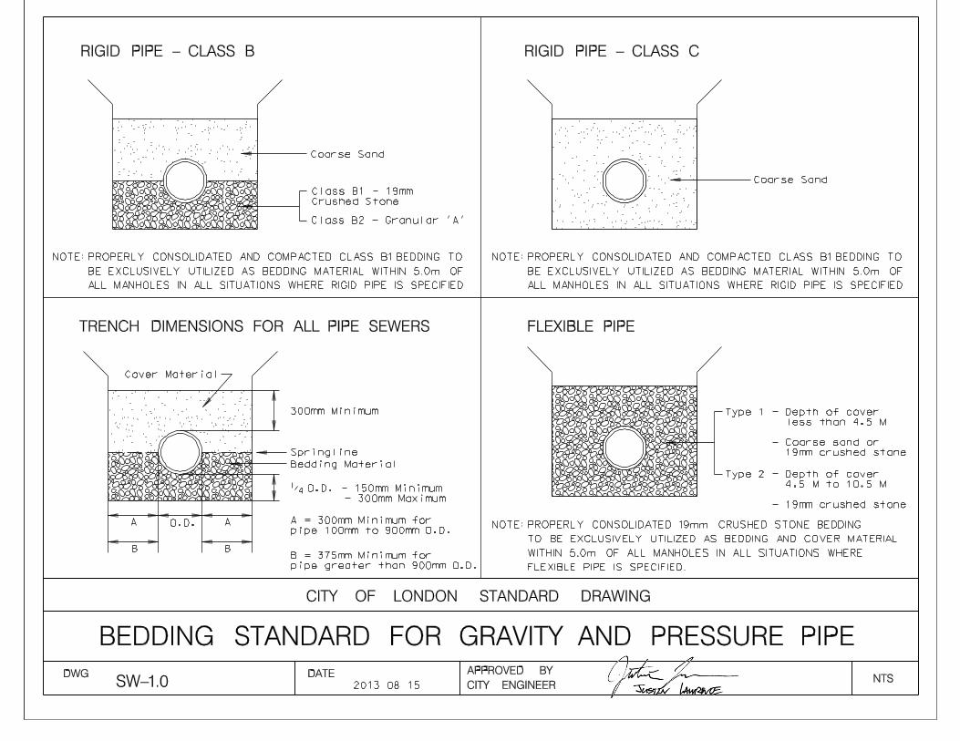
- SW-1 2000-02-29 Bedding
Standard For
Gravity And
Pressure Pipe
SW-1.0 2013-08-15 Bedding Standard For
Gravity And Pressure Pipe
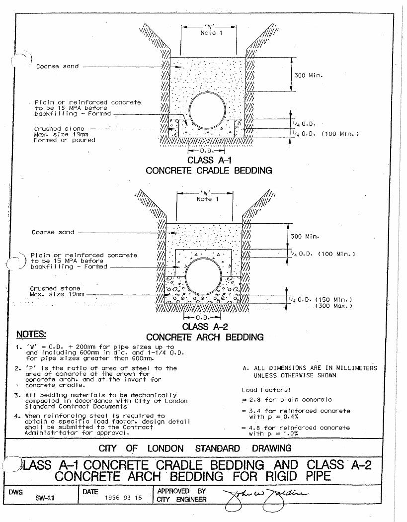
- - - - SW-1.1 1996-03-15 Concrete Bedding For
Rigid Pipe
1003.01 - 1988-12-01 Manhole Drop
Structure - Tee
- - -
1003.02 - 1988-12-01 Manhole Drop
Structure Wye
- - -
- SW-2.0 1998-03-01 Manhole Drop
Structure - Wye
SW-2.0 2004-11-01 Maintenance Drop
Structure Wye
SW-2.5 1999-01-30 Safety Platform Aluminium
- SW-3.0 2000-02-29
600X840
Precast
Concrete Curb
Inlet Catch
Basin
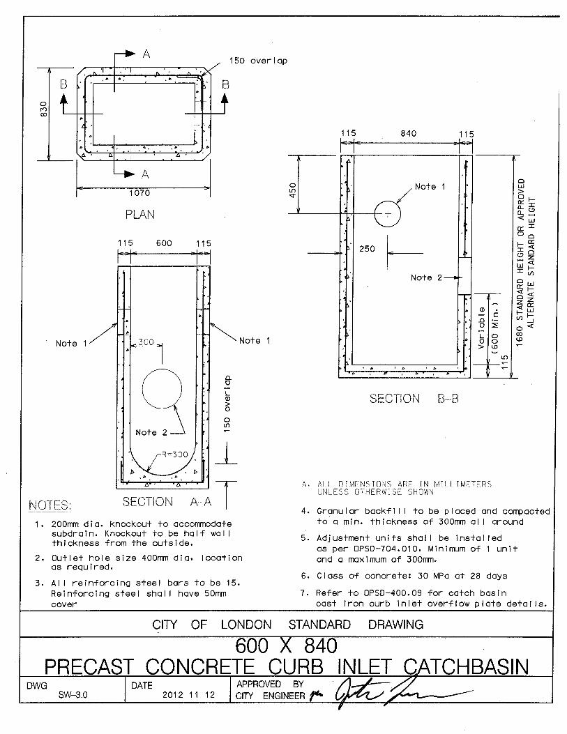
SW-3.0 2012-11-12
600X840 Precast Concrete
Curb Inlet Catch basin
SW-3.1 2012-11-12
Catch basin
Pipe Subdrain
Detail
SW-3.1 2013-11-01 Catch Basin Pipe Subdrain
Detail
- SW-4.0 1998-03-01 Precast
Concrete Catch
Basin in
Manhole
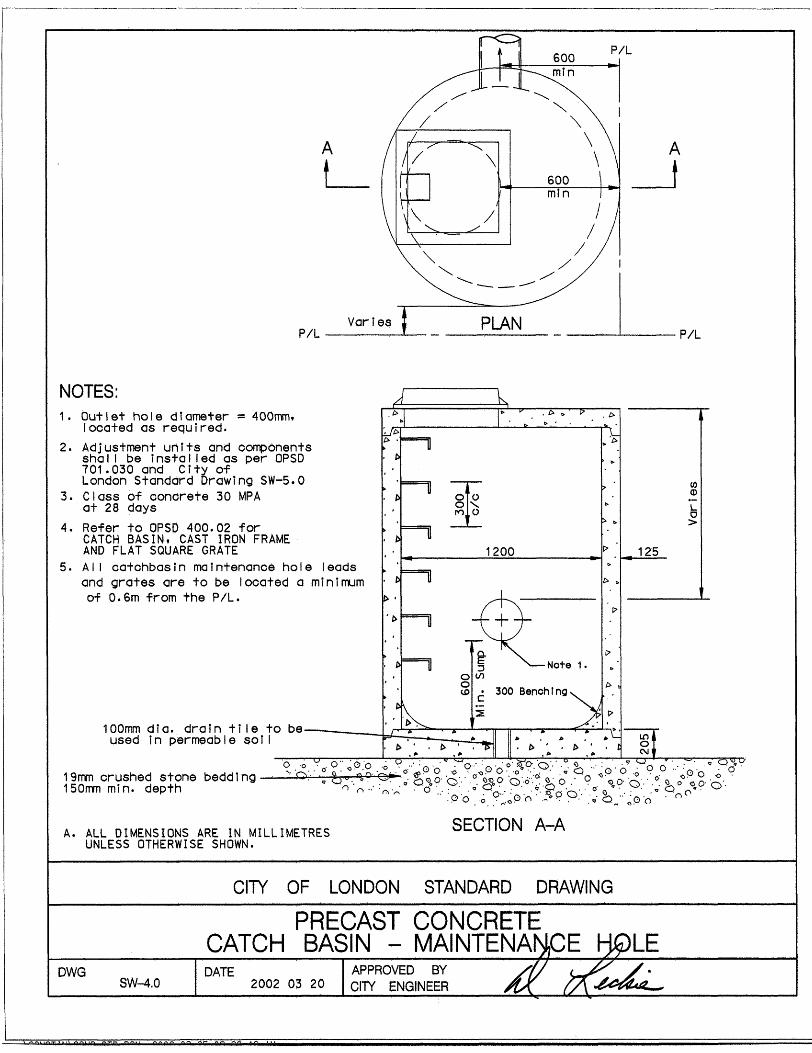
SW-4.0 2002-03-20 Precast Concrete Catch
Basin Maintenance Hole
- SW-5.0 1998-03-01 Manhole
Adjustment Unit
Detail
SW-5.0 2013-08-15 Maintenance Hole
Adjustment Unit Detail
SUPPLEMENTAL STANDARDS FOR SEWER AND WATER (SW)
STANDARD CONTRACT DOCUMENTS FOR MUNICIPAL CONSTRUCTION PROJECTS | 2018 EDITION 135
SUPERSEDED / DELETED AMENDED / NEW / CURRENT
OPSD City of
London
Dated Title of
Drawing
City of
London
Dated Title of Drawing
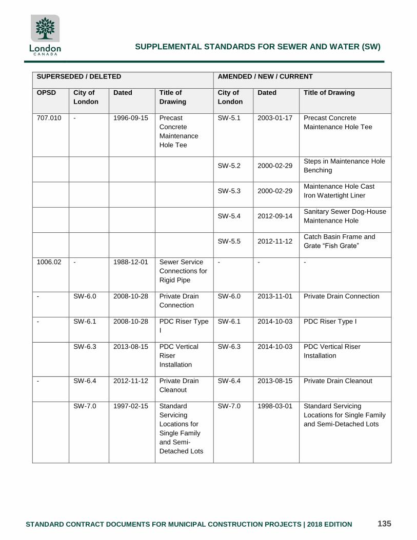
707.010 - 1996-09-15 Precast
Concrete
Maintenance
Hole Tee
SW-5.1 2003-01-17 Precast Concrete
Maintenance Hole Tee
SW-5.2 2000-02-29 Steps in Maintenance Hole
Benching
SW-5.3 2000-02-29 Maintenance Hole Cast
Iron Watertight Liner
SW-5.4 2012-09-14 Sanitary Sewer Dog-House
Maintenance Hole
SW-5.5 2012-11-12 Catch Basin Frame and
Grate “Fish Grate”
1006.02 - 1988-12-01 Sewer Service
Connections for
Rigid Pipe
- - -
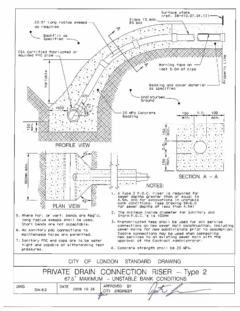
- SW-6.0 2008-10-28 Private Drain
Connection
SW-6.0 2013-11-01 Private Drain Connection
- SW-6.1 2008-10-28 PDC Riser Type
I
SW-6.1 2014-10-03 PDC Riser Type I
SW-6.3 2013-08-15 PDC Vertical
Riser
Installation
SW-6.3 2014-10-03 PDC Vertical Riser
Installation
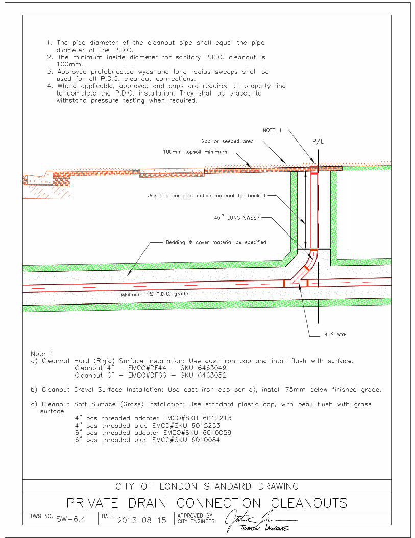
- SW-6.4 2012-11-12 Private Drain
Cleanout
SW-6.4 2013-08-15 Private Drain Cleanout
SW-7.0 1997-02-15 Standard
Servicing
Locations for
Single Family
and Semi-
Detached Lots
SW-7.0 1998-03-01 Standard Servicing
Locations for Single Family
and Semi-Detached Lots

SUPPLEMENTAL STANDARDS FOR SEWER AND WATER (SW)
STANDARD CONTRACT DOCUMENTS FOR MUNICIPAL CONSTRUCTION PROJECTS | 2018 EDITION 136
SUPERSEDED / DELETED AMENDED / NEW / CURRENT
OPSD City of
London
Dated Title of
Drawing
City of
London
Dated Title of Drawing
- UCC-1M 2002-05-23
Included in
the UCC
Manual
Standard Utility
Locations For
All Streets
W-CS-1
sheet 1
2009-10-26
Standard
Hydrant and
Valve
Installation
W-CS-1
Sheet 1
2014-09-23 Standard Hydrant And
Valve Installation
W-CS-1
Sheet 2
2014-09-23 Tracer Wire Installation
W-CS-2
Sheet 1
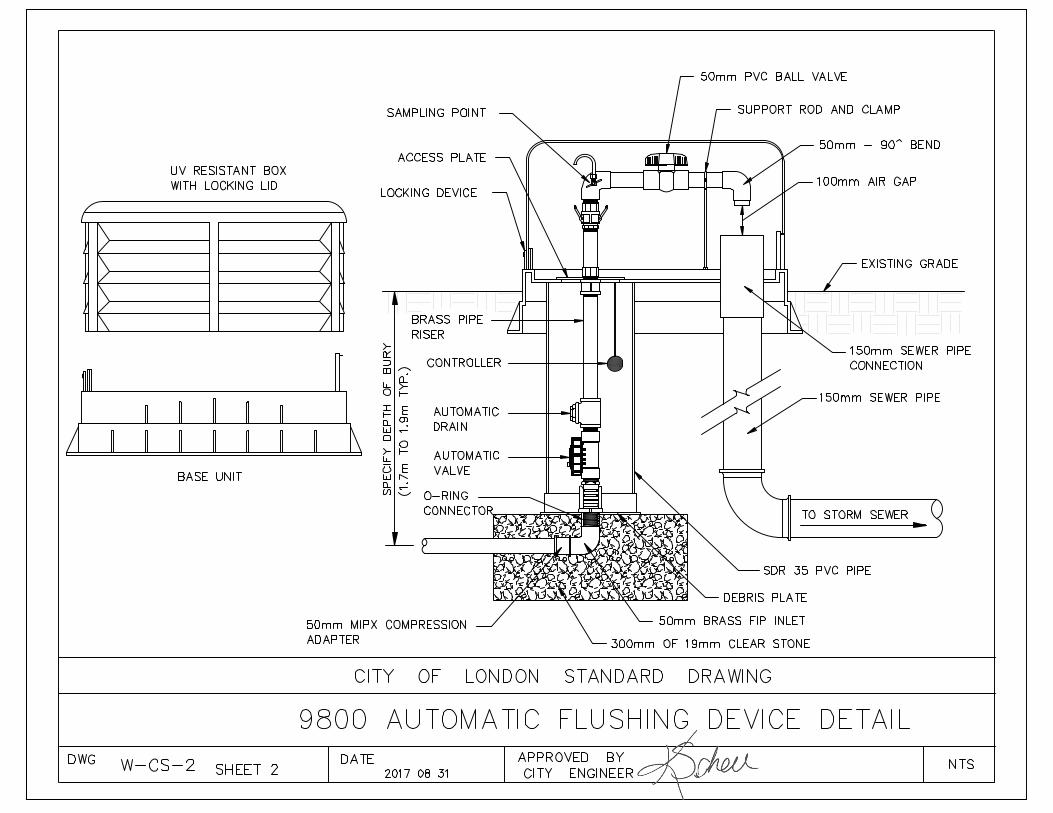
2017-08-31 Metered Automatic
Flushing Device
WCS-2
Sheet 2
2017-08-31 9800 Automatic Flushing
Device Detail
W-CS-2
Sheet 3
2017-08-31 Note for Designers With
Regard to Automatic
Flushing Devices
Discharge Rates
W-CS-5 1999-01-31
Standard 50mm
Blow Off
Installation
W-CS-5 2006-11-06
Standard 50mm Blow Off
Installation
W-CS-6 1999-01-31 Standard Valve
Rod Extension
for 40mm and
Larger Valves
W-CS-6 2006-11-06 Standard Valve Rod
Extension Piece For 40mm
And Larger Valves
W-CS-7 2000-02-29 Standard
Installation of
16mm Water
Meter
W-CS-7 2004-11-01 Standard Installation Of
16mm Water Meter
SUPPLEMENTAL STANDARDS FOR SEWER AND WATER (SW)
STANDARD CONTRACT DOCUMENTS FOR MUNICIPAL CONSTRUCTION PROJECTS | 2018 EDITION 137
SUPERSEDED / DELETED AMENDED / NEW / CURRENT
OPSD City of
London
Dated Title of
Drawing
City of
London
Dated Title of Drawing
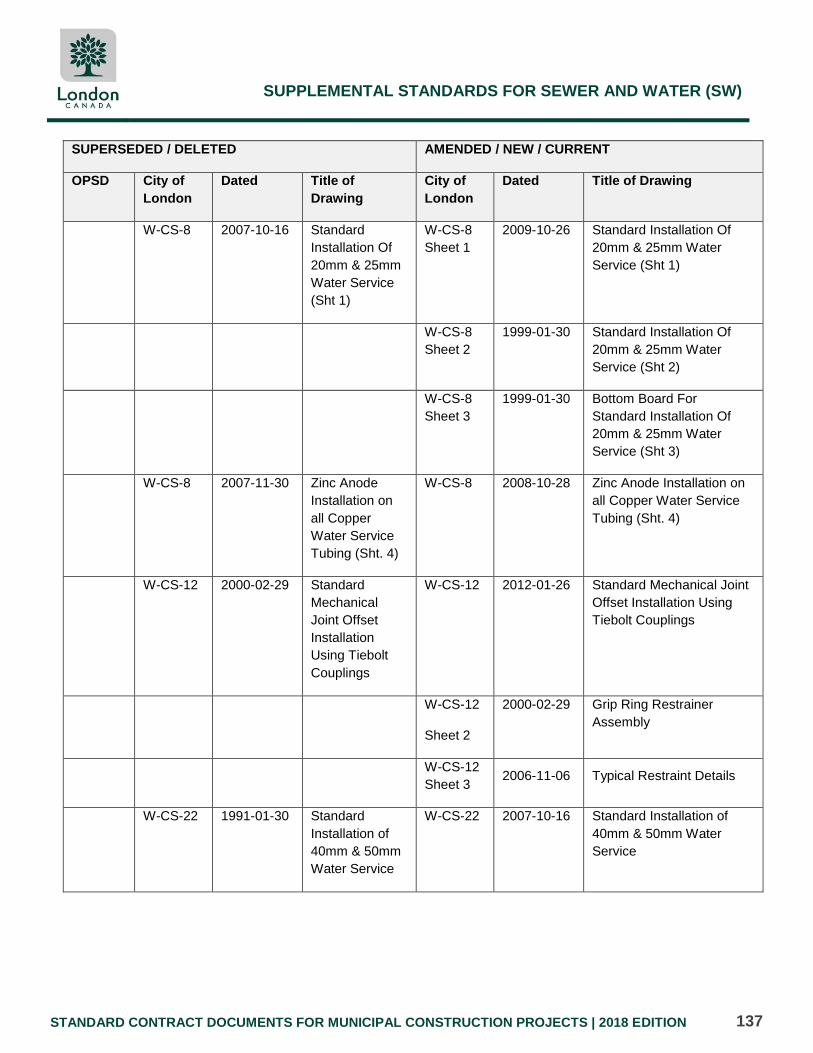
W-CS-8 2007-10-16
Standard
Installation Of
20mm & 25mm
Water Service
(Sht 1)
W-CS-8
Sheet 1
2009-10-26
Standard Installation Of
20mm & 25mm Water
Service (Sht 1)
W-CS-8
Sheet 2
1999-01-30 Standard Installation Of
20mm & 25mm Water
Service (Sht 2)
W-CS-8
Sheet 3
1999-01-30 Bottom Board For
Standard Installation Of
20mm & 25mm Water
Service (Sht 3)
W-CS-8 2007-11-30 Zinc Anode
Installation on
all Copper
Water Service
Tubing (Sht. 4)
W-CS-8 2008-10-28 Zinc Anode Installation on
all Copper Water Service
Tubing (Sht. 4)
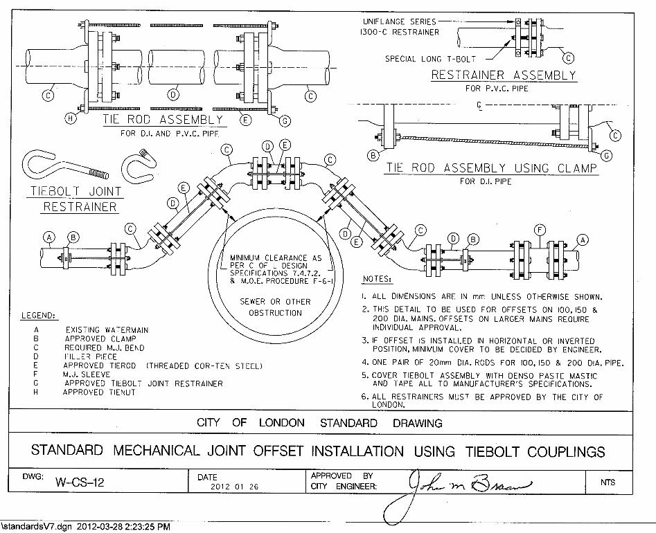
W-CS-12 2000-02-29 Standard
Mechanical
Joint Offset
Installation
Using Tiebolt
Couplings
W-CS-12 2012-01-26 Standard Mechanical Joint
Offset Installation Using
Tiebolt Couplings
W-CS-12
Sheet 2
2000-02-29 Grip Ring Restrainer
Assembly
W-CS-12
Sheet 3 2006-11-06 Typical Restraint Details
W-CS-22 1991-01-30 Standard
Installation of
40mm & 50mm
Water Service
W-CS-22 2007-10-16 Standard Installation of
40mm & 50mm Water
Service

SUPPLEMENTAL STANDARDS FOR SEWER AND WATER (SW)
STANDARD CONTRACT DOCUMENTS FOR MUNICIPAL CONSTRUCTION PROJECTS | 2018 EDITION 138
SUPERSEDED / DELETED AMENDED / NEW / CURRENT
OPSD City of
London
Dated Title of
Drawing
City of
London
Dated Title of Drawing
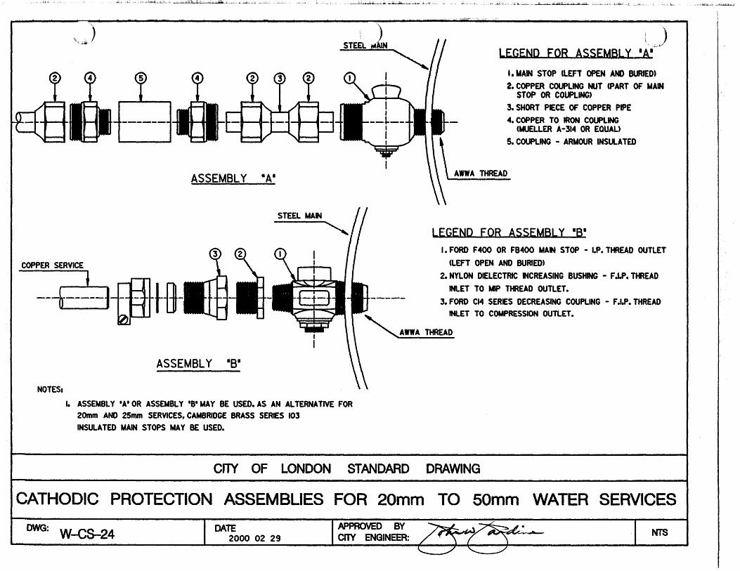
W-CS-24 2000-02-29 Cathodic Protection
Assemblies for 20mm to
50mm Water Service
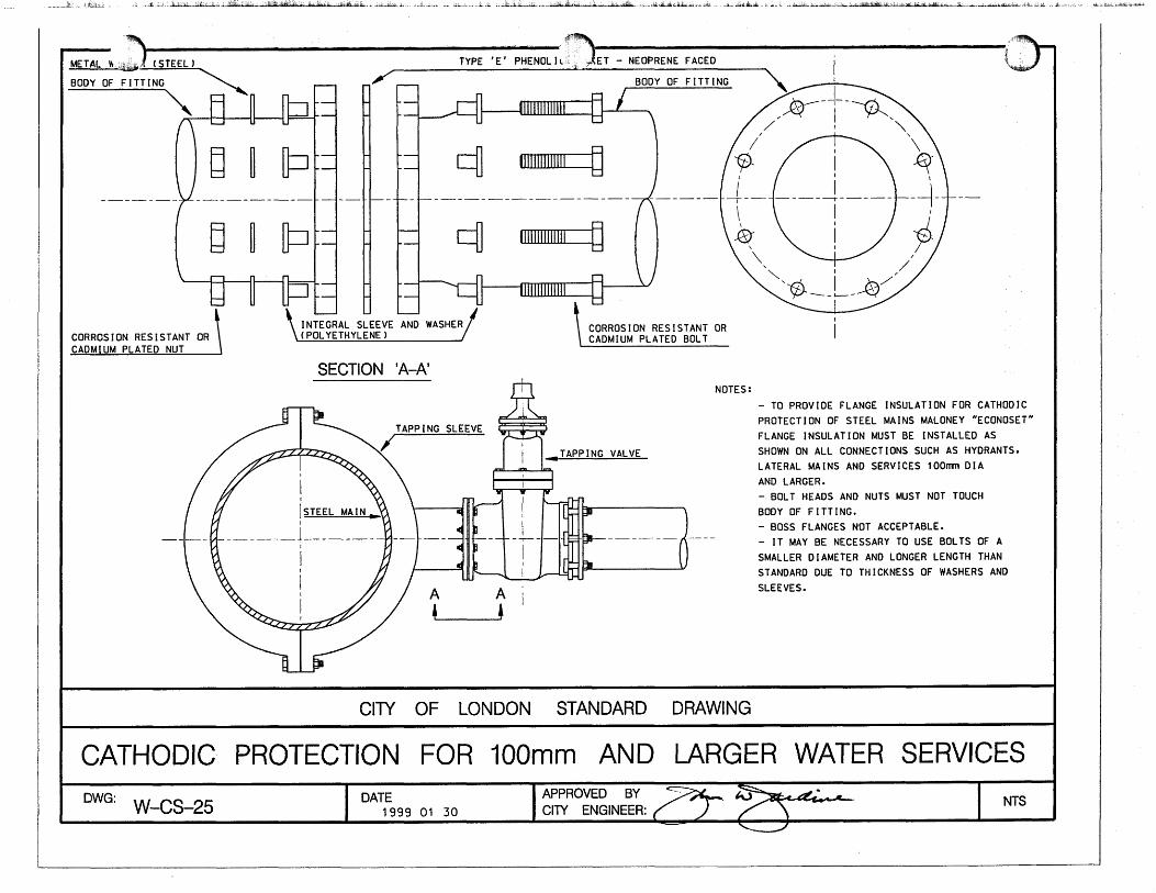
W-CS-25 1999-01-30 Cathotic Protection for
100mm and Larger Water
Services
W-CS-30
Sheet 1
1991-01-30 Typical Installation for
20mm, 40mm, and 50mm
Disc Type Water
Meter(Sheet 1)
W-CS-30
Sheet 2
1999-01-30 Typical Turbine Water
Meter Installation for 75mm
to 200mm
W-CS-31
Sheet 1
2004-11-01
Schematic Layout of
100mm and Larger Service
W-CS-43
Sheet 1
2004-11-01 Typical Thrust
Blocks for
Watermains
Sheet 1
W-CS-43
Sheet 2 2004-11-01
Typical Vertical
Thrust Blocks
For Watermains
(sheet 2)
W-CS-43
Sheet 3 2004-11-01
Typical Thrust
Blocks for
Watermains
(sheet 3)
W-CS-45 1999-01-30
Standard Location for
Water Valves at
Intersections With 9.0m
and 10.5m Curb Radii
W-CS-51 1999-01-30 Standard City of London
737mm Frame and Cover

SUPPLEMENTAL STANDARDS FOR SEWER AND WATER (SW)
STANDARD CONTRACT DOCUMENTS FOR MUNICIPAL CONSTRUCTION PROJECTS | 2018 EDITION 139
SUPERSEDED / DELETED AMENDED / NEW / CURRENT
OPSD City of
London
Dated Title of
Drawing
City of
London
Dated Title of Drawing
W-CS-60 1999-01-30 Sterilizing Mains
W-CS-66 2004-11-01 Typical Service Entrances
100mm to 200mm
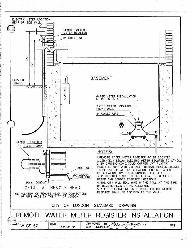
W-CS-67 1985-03-07 Remote Water
Meter Register
Installation
W-CS-67 1999-01-30 Remote Water Meter
Register Installation
W-CS-68 2012-01-26 Insulation of
Shallow Mains
and Offsets
W-CS-68 2015-11-03 Insulation of Watermain
and Offsets (Protection
from Freezing)
W-CS-69
Sheet 1
2003-09-16 450mm and Up
Typical
Watermain
Support Detail
for Utility
Crossings
Using Open Cut
Construction
W-CS-69
Sheet 1
2012-10-01 450mm and Up Typical
Watermain Support Detail
for Utility Crossings Using
Open Cut Construction
W-CS-69
Sheet 2
2003-09-16 Typical
Reinstatement /
Bedding Details
for 450mm and
Up Watermain
Support
W-CS-69
Sheet 2
2012-10-01 Typical Reinstatement /
Bedding Details for 450mm
and Up Watermain Support
W-CS-69
Sheet 3
2003-09-16 General
Submission and
Design
Requirements
for Watermain
Support and
Bedding /
Reinstatement
W-CS-69
Sheet 3
2010-10-01 General Submission and
Design Requirements for
Watermain Support and
Bedding / Reinstatement
W-CS-70 2009-11-20 Valve Box on Chambers

SUPPLEMENTAL STANDARDS FOR SEWER AND WATER (SW)
STANDARD CONTRACT DOCUMENTS FOR MUNICIPAL CONSTRUCTION PROJECTS | 2018 EDITION 140
SUPERSEDED / DELETED AMENDED / NEW / CURRENT
OPSD City of
London
Dated Title of
Drawing
City of
London
Dated Title of Drawing
W-CS-71 2012-01-26 Metered
Irrigation
System and
Backflow
Prevention
Assembly
W-CS-71 2014-09-24 Metered Irrigation System
and Backflow Prevention
Assembly
W-CS-72 2014-09-24 Casing Detail
W-CS-74 2014-09-24 Typical Air Valve Chamber
W-CS-75
Sheet 1
2017-09-27 Check Valve Chamber
(Plan View)
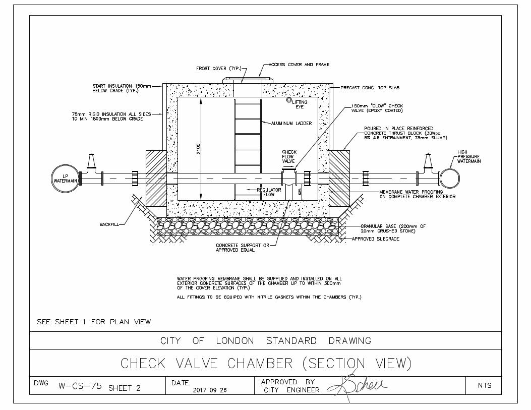
W-CS-75
Sheet 2
2017-09-26 Check Valve Chamber
(Section View)
.COarse sand
Plein or reinforced concrete_to be 15 MPA beforebackf;lling - Formed
Crushed stoneMax. size 19mmFormed or poured
CLASS A-1CONCRETE CRADLE BEDDING
11/4 0. D.b40.D. (100 Min,)
Coarse sGnd
Plain or reinforced concretetobe 15 MPA beforebackfilling - Formed
Crushed stoneMax. size 19ram
NOTES:1. ’W’ = O..D. + 200mm for pipe sizes up to
and including 600mm in dia. and 1-1/40.D.for pipe sizes greater than 60On, n;
2. ’P’ is the ratio of area of steel to theGrea of concrete at the crown forconcrete oroh. and at the invert for
, concrete cradle.
3. All b~dding materials to be mechanicallycompacted in Occordence with City of LondonStandurd Contract Documents
a. When reinforcing steel is required toobtaih ~ specifio load factor, design detailshall be submitted to the ContractAdministrtotor for epprov~l.
A. ALL DIMENSIONS.ARE IN MILLIMETERSUNLESS OTHERWISE SHOWN
Load Factors:
~ 2.8 for plain concrete
= 3.4 for reinforced concretewi.th p =.0,4%
= 4.8 f.or reinforced concretewith p = 1,0%
CiTY OF LONDON STANDARD DRAWING
.>~LASS A-1 CONCRETE CRADLE BEDDING AND CLASS A-2CONCRETE ARCH BEDDING FOR RIGID PIPE
1996 05 15 crfY ENGINEER

A. ALL DIMENSIONS ARE IN MILLIMETERSUNLESS OTHERWISE SHOWN
~I. Drop structure to be completely
, iI encased In a minimum 150m o4 20I MPa concrete and secured to the
~"-’~~ marnfenance hole wlfh 450mm long,/ .~-J-’---’~-L~ "~ 13rl~ d I a threaded rods and
/ ~ ~ ~ both ~Ide~ Of
" / / / 2.. For plpe sewer slzes 200~/ / / ~o 4SO~ (inslde pipe
~ ~ / / dlc~fer) DI = D2 . For pipe~ [ /" / sewer slzes equal fo
~ ~ ~/ / greater than 525~ DIQ.~ ~V / D2 = 450~ D)
~~ 3. Drop ~@ruoture~ ~hell be" ~ I oon~fruofeQ ~en the
I I ......... In Invert elevQflon~ between thei I~ OUIL~I ff~ff~i I I upBTreQm Qnd out let ~ewerB in! ~ I the ~ImfenQnoe hol
IV ~ greaeer @han BOOm for sanlfary,
I 6~ewers and 900~ ~or storm
~~" 50 sewers.
P~N I’’~ 4. When ~he difference In elevation~ o between the upstream t nver$ and
,~ , , ..... ~ the top oP the benching exceeds~
~ ~" ,~ 1.50m, an addif!onal se~ O~ sfep~~ r~ ,~~ ~ are required adjaoen~
z ~ ’ , , ", ~’,--~ ..... ~ "-" ’ ’ ’ ’ be located ~0 avoid confllo~ wlfh
’,,,,.
Aooess fo ~infenonoe hal.- ~ n ) be above the benchlng pl
~ ~ ~ ,. ’ 90 Bend
SECTION A-A PO
CITY OF LONDON STANDARD DRAWING
....... MAINTENANCE ’ DROP STRUCTURE ....................
DWG DATESW-2.0
WYE
2004 11 01 , /CITY EN.GINEER,, d(.4~

m
u)
-J
U
a
I- W f3
I
Q
W
m
0
u)
M
-
00 0
M
00 (c
0
- M
a, N c
C 3 0
S
v)
Q)
v)
3
L
Q) c
t 0
v)
v)
Q)
C
J
v) L
Q)
t
a, E
L 0
v) L
a, t
.- -
0
t
a,
Q)
n
/ -I U
a
I- W
f3
- 0
O
C
.m
a ul
.- 4
r
4'
Y
4
-
4
I 4
y. D
a> 4
v)
0.
D
4
4
.,
8 4
-
oL
loo
oo
oo
oo
1 3
s
-2
w *-
Q) a
n-
9)
-a 0
-v
)
I: 00
(0
cn
v)
v)
L O
Q)
Q)OCO
- v
)-
t
N
c*
0-
IC
ov
Q
3
tI
U
c *L
.- u- 0
0
LO
U
ct
o
I t
mt
a
-Q
)C
. a . 1 Y a n
I- W
+ +
.- .- Q
) c>
LL
Q)Q
) O
Ot
L
cn 'c
) t
u)
.-
o wa
t
Q)c
Lo Q
) W
E 0.- o
c
E
OO
OC
I IC
- -
0.-
t
-Lo
- Q
)O
QU
I
Em
.-- 0
-
LM
cn
- 0
Q)rro
Lo
E
-c
no
+ u
) MCOLC
a0 oao*-
03
tQ
)o
w
at n
-C
Q)
a
la -- O
L
an
t 0- u
t o
+ w
to
sc
n
EL cv)
v) a
tov
)v) a
c
+a L
Em
0
.O 9)
* Q
) OJO*-
Q) *
+UEt
or +30OU
cv
.- o
oc
---v)-
-xu--- 0-
E WE%
LWECCC
0
oQ
)*--o
c
v)
8 i:Z';a,->c.- a
aa
na
t-
OQ
) >
OQ
) C
- J La
t
00
CL
00
I
a I
a
z
0
Y
I- o
W
v,
ma
v, W
I- O
z a
m
On
wL
Lu
t+,.r.| -/ 1 50 over lop
I I l*o I
| 1070 I
115 840 115ffi
l=ìll "'t,ll lFË
ËlSECTION B_B
PLAN
115 600 115ffim,ffi IJK/ |]'f;\ |[1 :*"*"'tlt /
lll q||]E
ffi+sEc¡oN;
I
Note 1
1. 200mm dîo. knockout fo occonrnodolesubdroin. Knockout to be holf wol I
thickness from the outsÌde.2. Ouflet hole size 400mm dio. locofion
os required.3. Al I reÌnforcing sfeel bors To be 15.
Reinforcíng steel shol I hove 50rnm
cover
A. ALL DIMENS]ONS ARE IN MILLlMETTRSUNLESS OTHERW]5I SHOWN
4. Gronulor bocKfi I I to Þe ploced cnd compccfedto o min. thicKness of 300nm ol I oround
5. Adjustment un¡ts shcl I be instol ledcs per 0PSD-704.010. Minimum of 1 unitand o moximum of 300nm.
6. Closs of concrete: 30 MPo ot 28 doys
7, Refer fo 0PSD-400.09 for cafch bosîncost iron curb înlel overflow plote detoi ls.
NOI"ES:
ctry OF LONDON STANDARD DRAWING
ti00 x 840PRECAST CONCRETE CURB INLET CATCHBASIN
DWGsw-3,0
DATE2012 11 12
APPHOVED BY
ctw Et.lelrurrn /d. t)ã4

NOTES:
DWG DATE sw-4.0 2002 03 20
- PLAN - -P/L Varies 1
P/L
g& APPROVED BY CITY ENGINEER
1 . Out le t ho le diameter = 400m.
2. Adjustment u r l l t s and components located as required.
s h a l l be i n s t a l l e d as Der OPSD 701.030 and C i t y of London Standard Drawi ng SW-5 0
3. Class of concrete 30 MPA
4 . Refer t o OPSD 400.02 f o r
AND FLAT SQUARE GRATE 5. A l l catchbasin maintenance hole leads
and grates are t o be located a minimum
a t 28 days
CATCH BASIN, CAST IRON FRAME
of 0.6m from the P/L.
100m dia. d r a i n t i l e used i n permeable so
19rm crushed stone bedding 15Omm m i n . depth
A. ALL DIMENSIONS ARE IN MILLIMETRES UNLESS OTHERWISE SHOWN.
SECTION A-A
CITY OF LONDON STANDARD DRAWING


I n
DWG SW-5.1
i kl 2 O O m d i a4
KJ- DATE APPROVED BY 2003 01 17 CITY ENGINEER y e " d - -
Balance of maintenance hole according to OPSD-701.010
Reinforcing 50mn min lap weld and connection grouted with non-shrink
I
SECTION B - B
mrtar SECTION A - A
1 Spacing of mointenance hole steps to be 300m c/c. NoTES:2 Sewer pipe accdording to CAN/CSA A-257.2. class to match that of higher class adjcent pipe,
3 Steps are required to within 450mn above the invert for storm sewers only. 4 No connections are to be constructed into maintenance hole tee's ( ie sewers. C.B. 's
A Bedding for MH tee similar to pipe bedding either slde of tee. B Tee section bell or spigot as required.
C Granular backfill to be placed to a minimum thickness of 300mn all around the maintenance
and POC's 1.
hole tee. D Minirmm steel in connection must equal1 area of steel in pipe. E Sanitary maintenance hole tees require a safety landing within 1.5m of crown for testing.
F The minimum clearance between the safety landing [ within 1.5M of crown 1 and the first
G A l l dimensions are nominal. H A l l dimensions are in millimetres or metres unless otherwise shown.
and maintenance operations.
safety landing above is a minimum 2.0m.

Handhold constructionshall complywith OPSD 405.010Section A - A
o~ Steps to comply
with OPSD 405,010and 405.020
~ ,, 300
14 ~ 2L%00 F --~
DETAIL A
HandholdSee Detail
SHOWN-1800mm PIPEBENCHED ~ CROWN. .--~~
Max height ....._ /4so ~ .............. ,.71~ ..... ~
FACE VIEW HDLE~
1. Step8 are required fn benching for pipe diameter8a ) Greater than 900rrrn - benching to springl Inc, BENCHING SECTIONb ) Greater than or equal to 450mm - benching to crown,
2, Handholds 8hall be constructed in accordance with DETAIL ’A’,
3, Handholds are required ~or pipe diameters greater than or equal toto 1500mm die when benching to crown.
4, Additional handholdsbe required for pipe diametersGreater than 1950mm - benching to crown,
5, Step dimensions are typical
6. Maintenance hole 8tap8 shall be Ioaated to ~vo[dconflict with an Inlettfng or out tatting sewer pipe,Access to maintenance hole must be above benching pie+form,
A. All dl~ensions are in millfmetreeunless otherwise shown,
CITY OF LONDONSTANDARD DRAWINGI I ILl r I I I II j I I i , ] , ,,[ ........ ], , ....... ~1 ii ~1 iiiii : ...... ........ ..................................
STEPS IN MAINTENANCE HOLE BENCHINGDWG DATE
8W-&2.......... ~PPRovED ’BY ............ ................
2000 02 29 pITY ENGINEER ~::: ..../~ . ..... / .... .................... ................

DWG DATE APPROVED BY
800 8
R = 150m tYP
- 18 mn d i a hole for 16 m brass or s ta in less s tee l cap screw
2 lugs (op t i ona l ) typ i ca I c
f / 4 0 0
27
f - FRAME PLAN
633 I, 624 38 d i a m X
1 4 mn deep
13mn d i a bar handle cast in PIAN VIEW
51 6
I I * 287 4 216 L r f+R=l9 m 575 667 800
SECTION A - A
M
4 L
SECTION C - C sta in less s tee l cap 4 - 1 6 m d i a brass or
x 57 long
Rubber ’--
washer
2 m rubber gasket NOTE : SECTION D - D
SECTION B - B A l l dimensions are in millimetres or metres un I ess otherwise shown.
CITY OF LONDON STANDARD DRAWING P
I CAST AND SQUARE FRAME.

DOG HOUSEMA I NTENANCE
HOLESTRUCTURE
BARREL
CONCRE TECOLLAR
Exìsting sewer Íust becut of the sÞring-l ine
ocross ful I înternolHOLE PROFILE
w¡drh or structure
SOUARE FORMED CONCRETE COLLAREx+end ouf 300nm olong existing seweroncl 225nm oround borrel orch open¡ng
o-SeeNofes4&8
FLOW->
FLOWCHANNEL
EXISTINGSEWER BASE
'DOG HOUSE" MAINTENANCEB
SECTION 'A_A'
1 200rm MIN
CONCRETE COLLAR
REMOVE TOP HALF OF EX. PIPE AFTER
FLOW+ MAINTENANCE HOLE IS CONSTRUCTEDOR FORM NEAT CI{ANNEL AS SPECIFIEDSIZE OF OPENING TO FITEXISTING SEYIER PLUS 75nm
REINFORC¡NGAS SPEC IF IED
I 50ÍmMI
19rm CRUSHED STONEBEDDING. MIN 150rm
POURED IN PLACE CONCRETE BASE PRECAST CONCRETE BASE
NoTES ùtrt/ I ll.Jl\ tt-t'l . The doghouse rnoinlenonce hole Íìoy only be usecl for plocing o new rnointenonce hole on on exísf ing
sonifory or storm line when instollotion of o s+ondord rno¡ntenonce hole is not Þroc+icol.2. All mo¡ntenonce hole coñponents ore +o rnee+ oPSD 70'l .3. Al I benching ¡s fo meet 0PSD 701.21.4. Al I poured ¡n ploce concrefe to be 30 MPo.5. Concre+e bond¡ng ogen+ mrs+ be opÞlied +o oll in+erfoces of precost to cost-¡n-Þloce concrete.6. Full +¡me inspec+ion sholl be provided by +he consul+ing eng¡neer during insfollo+ion of
this s+ruc+ure ond +he consultonf sholl provicle written cer+ifÌcofion of ¡ns+ollot¡on to theCity of London. The strucfure rrust no+ be bockf ¡lled for minirnrm 24 hr ofter consfruc+ion tool low for secondory inspec+¡on os required
7. The top of +he existing nrcinline sewer rrusf be fully removed from springline ocrossthe ful I ïn+ernol wï<lth of the structure.
8. A curved ïn+ernol orch form rrus+ be used during collor concre+e fill. No brÎcK. mor+or ordebris is to be used in ploce of consol ¡doted concrete oround the Þipe or in the col lor.The col lor. under pípe f¡ I I ond benching rrusf be construc+ed in one continuous pour.
z=
A
I
I
I
I c0L
I
I
I
t..t-l-il"i,lt
I A:{l
Þ'"iË'
FLOVJÞ¡
l-.' I lp',¡L
SECTION 'B-B'
SANITARY SEWER'DOG HOUSE' MAINTENANCE HOLE

2snm xlctt LÈrrentt'lo -
-l*l-,r* 1-"J
SECTION IAI-IA'
25lfm HIGII LETTERING( TYP ICAL )
I
/
SECTION 'B'-'B'
rAnAr
t*l r* | "-l H l'ëi *ffiSECTION 'C'-'C' SECTION 'D'_'D'
A. ALL DII/ENSIONS ARE 1N lvllLLIlvlETERSUNLISS OTHERW]St SHOWN
81
-ffi\-Krlt!ry&N3
NË9ø HINGE PIN
DETAIL ADETAIL B
CIry OF LONDON STANDARD DRAWING
CATCH BASIN FRAME AND GRATE,FISH GRATE'
2012 11 12


Note 2
C/L LOT
,.! I .I "
STREET
I
SINGLEC/L COMMONPARTY WALL
No~e 2Lguilding Area
! Dwell~ng Dwelling!I Uni Unit
STREET ¯
..... .’:..:: :$EM!~D,._ETACHED ’
INote 2
Note 2
NOTES:1. External bul I d ing setbacks to ref I cot
current app I i cab I e zon i ng by- Iaws
2. Internal buildi.ng setbacks to reflectcurrent applicable zoning by-laws
3. If the building area is located on the oppositeside of zero lot line lot, then show theservices in reversed location (ie S~nitaryand Storm)
4. Storm PB.C’s are required except where exemptby the dPalnage by-law
o
A~
STM. P.D.C. - storm Private Drain ConnectionSAN. P.D.C. - Sanitary Private Drain ConnectionW.S. - Water Service
ALL DIMENSIONS ARE IN METERSUNLESS OTHERWISE SHOWN.
Note 2
C/L OFBUILDING AREA
Building Area Note 1¯
STREET
STREET
SINGLE CORNERLOTC/L COMMONPARTY WALL
Note 2 I.. Bu i I d i ng Area Note I
I-Dwel Iing Dwel IingUnit Unit
3.0 3.4 3.4 3.0.
2.5; 2.5
0.9
C/L ~ LOT
Note 1 & 21. Buiidlng Area
ol
Note
SINGLE ZERO LOT LINE
CITY OF LONDONSTANDARD DRAWING
~I DW~
STANDARD SERVICING .LOCATIONS FORSINGLE ,FAMILY AND SEMI/q~~TACHED LOTS.
IDATeAPPROVED BYe. - / //~_~~~ ’
SW-7.0 . 1998 03 O~I CITY ENGINEI~ ~ <


G.I. P~ug or Cep(;rode
0. I. Coupling
G.I. Stand Pipe
I. Elbow
BWG. W-CS-22 for Service Rod & Porte
Curb Velve - With inlet cnd Butletinside I,P. Threod
M. Jo Flat Cap (Drilledend Tepped 50)~
50 G.I. Pipe 50 Bress Nipple
BoardSee Dwg. W-CS-8 Sht. 5
NOTES :
1. All dimensions are in millimeters unless otherwise shown.
2. All concrete to be min. 20mpo. compressive strength.3~ Polyethylene Bond Breaker to be used between concrete end fittings.4. Mechenical thrust restroint required os per section 701.07.21
Main
100 Min. Bedding
CITY OF LONDON STANDARD DRAWING
DWG: W-CS-5
STANDARD 50mmI 2006 11 06
DATE
BLOW OFFAPPROVED BYCITY ENGINEER:
INSTALLATION
I NTS

T
63
TOP VIEW
I-- 60 LI-- VARIES - LONG ENOUGH TO EXTEND WITHIN 150 ~1~ 120TO 300 FROM VALVE BOX COVERI 31301
40 I.D. STANDARD BLACK PIPEAVAILABLE FROM CITY
VALVE ROD FOR 40mm VALVES AND LARGER
SQUARE~
END VIEW
~--~OPERATING NUT TO REMAINSECURED TO VALVE
DETAIL - OPERATING NUT TYPICAL SECTION
NOTES
ALL DIMENSIONS ARE IN mm UNLESS OTHERWISE SHOWN.
2 CUSTOMER CAN PICK UP COMPLETED EXTENSION RODSFROM THE CITY STORES DEPARTMENT.
3 RODS WILL BE PROVIDED IN 150 INCREMENTS FROM600mm TO 1200~a’n.
DWG: W-CS-6
CITY OF LONDON STANDARD DRAWING
STANDARDFOR
DATE
VALVE40mm2006 11 06
ROD EXTENSION PIECE& LARGER VALVES
CITY ENGINEER: I NTS

NOTE:
1. REFER TO W-CS-67 FOR DETAILSOF REMOTE WATER METERREGISTER INSTALLATION.
VALVE BY OWNER---.m2. NO GROUNDING ALLOWED ~ , ~.~..~
ON WATER METER
~
METER SEAL.~~~~_
F~.~----16rnrnWATER METER
~
ANGLE METER VALVE STOP ~SUPPLIED BY CITY ~ I | BRASS NUT AND
/¯ IN OU~kll~J~-~-l-r’~
WATER PIPE OR m: APPROVED SERVICE
MATERIAL=,,.,
~
CITY OF LONDON STANDARD DRAWING, , ,, , , , ,
STANDARD INSTALLATION OF 16mm WATER METERDWG: W-CS-7 DATE APPROVED BY
2004 11 01 CITY ENGINEER: NTS
REV 2004 02 25


SERVICEBOX (C,I,) 1400TO 1700
~/’ .,,
I,,,SER, VICE BOX BASE
ADJUST TO GRADE USING25 BLACK IRON NIPPLE AVAILABLE COVER (C;I,)~
SERVICE BOX - AS ABOVE WITH EXTENSION IN VARIOUS LENGTHS --~
25 BLACK IRON COUPLING f Z----BRASS
COTTER PIN - BRASSPLUG
SERVICE R~)D - STAINLESS STEEL/NOTES.-
I, ALLDIMENSIONS ARE IN mm UNLESS OTHERWISE SHOWN,2, CURB BOX MUST BE INSTALLED SQUARELY OVER CURB STOP AND
BOTTOM BOARD,3, SERVICE ROD MUST BE AT LEAST 300mm BELOW GRADE AND NO MORE THAN
900mm BELOW GRADE AND MUST BE OPERABLE WITH A 1400 KEY-WHENINSTALLAT.IONOFSERVlCE BOX AND EXTENSION PIECE IS COMPLETED,
¯ .
BRASS PLUG - WITH 20ram PENTAOON HEAD
CITY OF LONDON STANDARD DRAWING
STANDARD INSTALLATION OF 20mm AND 25mm WATER SERVICES,
lllIl II I I ) II II ! i. I i I II I
DWG: W-CS-8 SHT. 21999 01 30 . CITY ENGINEER: NTS
I

184
BOTTOM BOARD CONSTRUCTED FROM38mm x 184mrn CEDAR AND 16rrrn-x 38rrrn
~SPRUCE INSTALLED AS A BASE FORCURB STOPS AND SERVICE BOXES AS PERW~CS-8, SHT, 1 & W-CS-5,
AO O
A
75mm DIA, FOR 25mrn SERVICEPOSITION F.OR 64rrrn DIA, FOR20mm SERVICE
20mmDIA.
PLAN VIEW
[DWG:
SECTION "A-A"
NOTE : ALL ..D. !MENS IONS ARE I N..!tinUNLESS OTHERWISE NOTED,
CITY OF LONDON. S"FANDARD DRAWING
BOTTOM BOARD FOR STANDARD INSTALLATIONOF 20mm. & 25mm WATER SERVICES
W-CS-8 SHT. 31DATE
1999 01 30NTS

Eo
@m
ROD ASSEMBLY
UNIFLANGE SERIESI3OO-C RESTRAINER
SPECIAL LONG
RESTRAINER ASSEMBLYFOR P.V.C. PIPE
FOR D.I. PIPE
NOTES:
I. ALL DIMENSIONS ARE IN mm UNLESS OTHERWISE SHOWN.
2. THIS DETAIL TO BE USED FOR OFFSETS ON IOO, I5O &2OO DIA. MAINS. OFFSETS ON LARGER MAINS REOUIREINDIVIDUAL APPROVAL.
3. IF OFFSET IS INSTALLED IN HORIZONTAL OR INVERTEDPOSIÏION, MINIMUM COVER TO BE DECIDED BY ENGINEER.
4. ONE PAIR 0F 20mm DlA. RODS FOR 100, 150 & 200 DtA. P|PE.
5. COVER TIEBOLT ASSEMBLY WITH DENSO PASTE MASTICAND TAPE ALL TO MANUFACTURER'S SPECIFICATIONS.
6. ALL RESTRAINERS MUST BE APPROVED BY THE CITY OFLONDON.
c\^óTIEBOL T JOINT
LEGEND:
AB
C
D
E
F
G
H
RES T RAINER
EXISTING WATERMAINÂPPROVED CLAMPREOUIRED M.J. BENDFILLER PIECEAPPROVED TIERODM.J. SLEEVEAPPROVED TIEBOLTAPPROVED TIENUT
(THREADED COR-TEN STEEL)
JOINT RESTRAINER
FOR D.I. AND P.V.C. PIPE
MINIMUM CLEARANCE ASPERCOFLDESIGNSPECTFtCATT0NS 7.4.7.2.& M.O.E. PROCEDURE F-6-I
SEWER OR OTHER
OBSTRUCTION
TIE ROD ASSEMBLY USING CLAMP
CITY OF LONDON STANDARD DRAWING
STANDARD MECHANICAL JOINT OFFSET INSTALI-ATION USING TIEBOLT COUPLINGS
...\standardsW.dgn 2012-03-28 2:23:25 PM
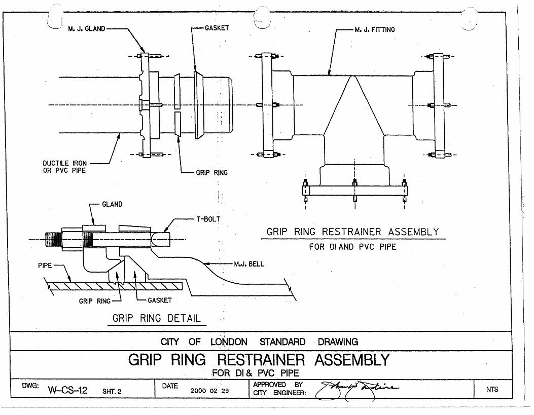
DUCTILE IRONOR PVC PIPE
GLAND
GRIP RiNG~ .
T-BOLT
GRIP RING RESTRAINER ASSEMBLY
FOR D.IAND PVC PIPE
PIPE M,J. BELL
GRIP RING GASKET.,,,
GRIP RING DETAIL
CITY OF LONDONSTANDARD.DRAWING¯
................................. GRIP ....RING."~ESTRAiNERASSEMBLY..I
If ,lJIII II I I I I I.. I Jlllll ~11 I .I I L JJ III I II . II|l. ~111 I I Illl I IIII I
¯
..FOR DI & PVC PIPE_H I ,~, Ill I Ill , ,11, , " jl, , ,1, I ,, ,. J, I1,, IIIII I JIll 1, ,
DWG:W--CS--12 SliT. 2DATE 2000 02 29
CITY ENGINEER: NTS

A) VALVES UP TO 300ram (IN LINE)
I_ 250mm TO 3OOmm = 30.Om
100mm TO 200ram = 20.0m
~E CUT TO PLACE VALVE IN PROPER LOCATION (TYP.) /
(~)~~ALL VALVES MUST BE
6m (~ RESTRAINED AS NOTED~ INCLUDING ANY JOINTS
I ! WTHIN THE DISTANCE250ram TO 300ram = 30.Ore INDICATED.lOOmm TO 200ram = 20.Ore
B) DEAD ENDS UP TO 300mm
C) BENDS UP TO 300mm
6m4.Ore
D) ALL FITTINGS UP TO 300ram
6m 6m
4.0m ~ ~
250mm TO 300ram = 30.Om _ ~’lOOmm TO 200ram =/20.Ore
6m
4.Ore ~]
Com
ALL DEAD ENDS MUST BERESTRAINED AS NOTEDINCLUDING ANY JOINTSWTHIN THE DISTANCEINDICATED.
ANY JOINT WITHIN 4.0mOF THE BEND SHALL BERESTRAINED.
6m
ALL FITTINGS MUST BERESTRAINED INCLUDINGANY JOINTS WITHIN 4.0m.
(~ = RESTRAINT
DRAWING
DWG: W-CS-12 Sheet 3
CITY OF LONDON STANDARD
TYPICAL RESTRAINT
2006 11 06 CITY ENGINEER:
DETAILSNTS

NOTES:I. ALL DIMESIONS ARE IN mm UNLESS OTHERWISE SHOWN.2. MAIN STOPS SHALL BE SPACED ON MAIN NOT CLOSERTHAN ~50.. IF MAIN IS PVC TAPS SHALL NOT BE ON ACOMMON LINE PARALLEL TO THE AXIS OF THE PIPE ANDNO CLOSER THAN 450 FROM THE SPIGOT END OF PIPE.
3. A~V JOINT MADE IN SERVICE PIPE SHALL BE MADE WITHAPPROVED COUPLINGS.4. NO JOINTS SHALL BE MADE UNDER PAVEMENT.
5. APPROVED SERVICE SADDLES MUST BE USED TOTAP ALb 40rnm & 50mm MAIN STOPS INTO ALLTYPES OF PIPE.
SEE SECTION ’A-A’
¯ IWATER MAIN
~~DDUBLE STRAP (SHOWN)
OR BROAD BAND SERVICESADDLE WITH 40 OR 50rrm
TYPE ’K’ COPPER TUBING
CURB STOP-OR BALL VALVECOMPRESSIONOR FLARED (SHOWN)INLET AND OUTLET,
PLAN
NOTE: SERVICE PLATE TO BE INSTALLED ONBLDG. SHOWING MEASUREMENT TO VALVE
4.6m
~ SEE w~s-6 SHT. 2 I
.,~_ ~ _,~ ~
VAR I E S
SEE DETAIL ’C’DN W-CS-B SHT. 1
5.SKo ZINC ANODESEE W-CS-8 SHT. 4
SECTION VIEW
BRASS COTTER PIN
TYPE ’K’ COPPER TUBING
40 OR 50mmFLARED (SHOWN)OR COMPRESSION OUTLETMAIN STOP /
THREAD
TO BE VERYWELL COMPACTED
SECTION ’A-A’
SEE W-CS-8 SHT. 3
DETAIL ’D’
CiTY OF LONDON STANDARD DRAWING
STANDARD INSTALLATION OF 40mm AND 50mm WATER SERVICESDWG: W-CS-22 IDA~ 200Y-10-16
APPROVED BYCITY ENGINEER: NTS
d I- O z
n
a
W 0
LL
W z
W
E
P 0
W z I I-
% 2
-I 0
2
w I
p.
W
W
>- c
-
i-t- Z
J
VI -0
VIW
W
I- -I
0
--I
VI
3
0-
LIZ
ou
4
ao
I-m
aa
zn
an
o
a
I I
II
I
I
I I
I a
f, I
I I
I i
, I
I I ,&I JW
V
IJ
I
>
I I
vi-
-
w
.
I

MIN, CLEARANCE TO WALL.OR ANY IMMOVABLE OBJECT
TOP VIEW
’TYPICAL INSTALLATION
:-’~-- BY-PASS VALVEIN SHUT POSITION
¯ (SEALED BY CITY)0
I. A,LL 40mm. METERS AND LARGER AND ANY METERS SUPPLYING MORE THANONE CUSTOMER REOUIRE A BY-PASS UNLESS OTHERWISE APPROVED BY ENGINEERING;UNLESS. THE CONDITIONS OUTLINED IN 4.6.1 EXIST, A 25mm METER INSTALLATIONDOES NOT REQUIRE A BY-PASS,
2, METER AND BY’-PAS~ PIPING TO BE EQUAL SIZE.3. ALL DIMENSIONS ARE EXPRE.SSED IN mm UNLESS OTHERWISE NOTED.4. SOLD~RED COPPER PIPE AND FITTINGS MAY BE USED.
l~0we: W-CS-30 sa-r.-~ I
LONDON STANDARD
25mm, 40ram, & 50mm
DRAWING
DISC TYPE WATER
DAYE!
APPROVED BY19S9 O1 30
CITY’. , ENGINEER~__~____~.) .
METER

NoL__.II. " ,,ALL DIMENSIONS ARE IN mm UNLESS SHOWN OTHERWISE.FLANGED FITTINGS ARE REQUIRED FOR ALL METERS.
MINIMUM SIZE OF VALVING & BYPASS PIPING TO BE ’EQUAL TO METER SIZE. ALL VALVES, PIPING, FITTINGS& SUPPORTS TO BE SUPPLIED & AND INSTALLED. BY OWNER
COMPOUND
75" 305 431
,100 356 508
150 458 610
200 508 NA
B ’B ..... ~ E F
$~A~DAR~!~IREFLOWI ,750 150
I000 200
300229 683 1500
254 796 2000 400
ALL CHECK VALVES, BACKFLOW PREVENTION, PRESSURE ’. ’REDUCINO VALVES~ ETC. RUST BE .INSTALLED AFTER THEBY-PASS W, HEN F IREFLOWS ARE METERED. " BY-PASS VALVE " .¯
: IN SHUT POSITION~
’ALL METERS ARE TO BE INSTALLED HORIZONTALLY UNLESS (SEALED BY CITY}APPROVED OTHERWI.SE BY ENOINEER,ING. " x ’ " ’
INSTALLATION¯ INDICATES THE MIN. SPACE REQUIREMENTS: ~~’
IN A MECHANICAL OR METERED ROOM. MIN. CLEARANCE FROM - ~,~ ~==~. ’ ’
t
VI~TAULIC COUPLING~ FLOOROR fIN I-FLANGE CONNECT I ON -
CITY OF LONDON STANDARD DRAWING
’ TYPICAL TURBINE’ WATER .METER INSTALLATION" "FOR 75mm TO 200mm
DATE ,, APPROVED BYW-CS-30 . SHm. 2 1999 01 30 CITY ENGINEER: "
DWG: NTS

TO STANDPIPE AND/OR TO STANDPIPE AND/OR
VALVE- RISING-- STEM PREFERRED SEE NOTE 3_ BACKFLOW PREVENTER
SEE NOTE 3= (M~ -
BLDG, WALL-z~/> ...... ~,/~’~~ BLDG, WALL -t-~/~--/> ........ ’ .... ~>-- BLDG, WALL
-"--~ POST INDICATOR VALVE -/ I IF REQ’D BY UNDERWRITERSOR OWNER,
_ ~-I 300ST. LINE
_~-I 300ST. LINE
_---T--x-~n--------ST.__L--vLINE
IF TS&V USED AT / IF TS&V USED AT / IF TS&V USED ATMAIN.} / MAIN.) / MAIN.}
,/---T,,Vco, ,N ,EE CO, ,N ,EE
_ _ MAIN-- -- MAIN --L’~ MAIN
DOMESTIC SERVICE STANDPIPE AND/OR SPRINKLER.SERVICE LTS&V OR CUT IN TEE(SEE NOTE
NOTES: DOMESTIC SERVICE TAKEN OFF
1. ALL DIMENSIONS ARE IN mm UNLESS OTHERWISE SHOWN, STANDP IPE AND/OR SPR I NKLER SERV ICE2. THE DOMESTIC WATER MAY BE TAKEN FROM THE SPRINKLER
SERVICE AND/OR THE STANDPIPE SERVICE INSIDE THE BUILDINGIF APPROVED BY FIRE UNDERWRITERS. IF NOT, THE DOMESTICSERVICE SHALL BE INSTALLED TO THE MAIN AS SHOWN WITH B. FOR DuM~STICSERVICE,THEBACKFLOW
PREVENTER SHALL BE INSTALLEDA MINIMUM OF 500mmSEPARATION FROM THE FIRE SERVICE.DOWNSTREAM OF THE METER/BYPASS
5, DOMESTIC VALVES, METER AND BY-PASS, IF BY-PASS IS REQUIRED, ASSEMBLY.SHALL BE IMMEDIATELY INSIDE THE STRUCTURE WALL. VALVESARE PREFERRED TO BE RISING STEM. SEE DWG. W-CS-50.
4. CONTROL AND CHECK VALVES DN FIRE SERVICES SHALLBE ASREQUIRED BY ONTARIO BUILDING CODE.
5. IF THE SERVICE IS OFF A SERVICE MAIN, A TAPPINGSLEEVEANDVALVE OR A TEE AND VALVE SHALL BE INSTALLEDATTHESERVICE MAIN.
B. SEESHEET 2 FOR DETAILS DF SERVICE.?. FOR BACKFLOW PREVENTER REQUIREMENTS REFER TO
ONTARIO PLUMBING CODE.
CITY OF LONDON STANDARD DRAWING, ,,, , , , ,
SCHEMATIC LAYOUT OF 100mm AND LARGER SERVICESDWG: W-CS-31 SliT. 1 DATE NTS
2004 11 01 CITY ENGINEER: ~ ...... ’
REV 20O4 02 25

SEEDWG NO. W-CS-BBFORENTRANCE DETAI~S
UNI-FLANGES MAYBE USED INSIDE ONLY
~POST INDICATOR VALVEOR NO VALVE IF O. S. & Y, M d TEE OB TAPPINGVALVEUSED"INSIDEBLDG. SLEEVE & VALVE .
I
-
" VALVE (NOT REQ’D IFTAPPING SLEEVE & VALVEOR TEE & VALVE IS USED
: T AT MAIN)
IOTES
ALL DIMENSIONS ARE IN n-rn UNLESS SHOWN OTHERWISE
SEESHEET I FOR TYPICAL SERVICE LAYOUTS
FIRE AND DOMESTIC LINES WILL TERMINATEWITHFLANGED ENDS INSIDE BUILDING.
ALL FI.TTINGS OUTSIDE BUILDING SHALL BE M. J.CAST IRON.
IF THE SERVICEIS OFF A SERVICE MAIN ATAPPING SLEEVE& AND VALVE OR TEE ANDVALVE SHALL BE INSTALLED AT THE SERV,I.CE MAIN..
--~------M~IN ORSERVICE MAIN
~--THRUSTBLOCK
CITY OF LONDON STANDARD DRAWING
TYPICAL DETAILS oF lOOmm & LARGER SERVICEDWG: W-CS-31 SHT. 2 DATE
1999 01 30 CITY ENGINEF_~ , ..,).. (,,,,~..~ NTS

\ *"., PROPERTY L I N E 11
WATER V A L V E t- 1-.11.11-111 f 1 - 1 1 1 - m - m - m
WATER M A I N (STANDARD LOCATION) t
CURB
\
ROADWAY
NOTES: T H I S STANDARD MAY NOT APPLY I F CURBS ARE MORE THAN 5.8m FROM PROPERTY L I N E . THE OBJECTIVE I S TO PREVENT VALVES FROM B E I N G INSTALLED I N THE GUTTER.
CITY OF LONDON STANDARD DRAWING
STANDARD LOCATION FOR WATER VALVES AT INTERSECTIONS WITH 9.0m & 10.5m CURB RADII
NTS APPROVED BY CITY ENGINEER: DWG w-cs-45 DATE 1999 01 30

al
m W
Sb
L--
LZ 1
az
..

- N
cn N
4
a
a
W z
I- z 0
0
-I
n
a
E 2 E 0
z
v)
-I
n
2 W
I-
5
a
W
W
Y
a
m
v)
v)
a
a1
3
30
O
I
I L
V
VO
CV
CV W
E
ZZ
W
IC
I-
I
-a
1-3
v)
a-r
v)a
k
wJ
a
-la
Ia
+
no
0
-LL
Zv)
ww
E
Kc3
LE
V)
00
-L
Q
W
-mz
>
wo
w
w
v)J
O
-I
03 W
I-z
>
130-
0v
)W
E
0
I-ww
3
aa
r z-l
-0
-l
WI--B
oa
OI-
a
aI-0
k-a
m
an
- o
a
az
z
a--
za
a
Lo
n
005
-I
I-z
ww
-I
*E
L
L-
WL
I3
W
ZZ
E
WS
IO
LL
I- -I-
-I.
JZ
LL
-W
LL
3x0
I- 2
3
-00
mo
o
m
az-l
za
m
N
n
W
v) 3
W
0
I-
v)
W
a 3
v)
W r W
I-
I- 0
0
-J -I
3: v)
z
I-
z 0
0
v)
I- o
W
E
0-
m
a
a
- E! - n 2 E
a
h
W
E
z 0 . m
- N
u- IC
7
0
m
U
Lo a3 M
v
0
0
U
7
M
N
N
CD u-
Q-
N
cn v)
z
I-
3I
W
ZLL
0
Z Z
*
W
W
c3c3
Cn
-W
O(3
v)
LI
E
003
a
IW
I-
ZW
c
3h
-I z
c
WI-
I-
0
m>LL oz
WE
>
Z3
E
Ta
m
Em
I
-0
w
v)w
az
a
on
az
az
o
aa
aa
a
--Ia
wa
w
aa
z
-in
k
aw
a
0-I
+I-a
a
zc
-m
n--l
a3
-l
a-
oza
a
JW
-
-0
330
0C
-l
a-v
) I
-z
v
)W-
z-
--la
TA
W
W
I-WZ
i oi--T
:
CO
Z-
lI
0
x0
003
00
W
ac
I>
I
I-IC-
-
I
3
I- 0
i- z 0
0
W
(3 z
0
-I
0
a
t; a
n
a
nv)
ZJ
a
2
ww
>I-
I
I
I-W
--I
I-+
o
m
zs
00
00
-2
>
wa
BE a
3
I-m
no
oa
a+
a
-w
>I
-I -IX
ZE
r
LL
W
I->
-3
W
YQ
I-W
Y
I- 0.
OSL
ao
za
a
aw
=t, nv)
T
03 a 0
c-
CD
Q-
v
c-
0
m
M
IC IC
c-
u- Lo M
a3 0
&
W
I-
r 0
-I I
0
0
a
>
I
z
W z
E 0
-I I
0
W
-I
-I
>
I- z
W
0
W a 0
IC
z
0
W
I/)
n
c-(
n
m
a
a a
0-
4
a
n
a
m
v)
- W
c3
v)
0
a
n
+
0
u- 0
c
0
0
M
0
M
V’
0
a
N
0
N
Ln
0
a3 IC
0
m
AI
N
CD M
M
u- Ln
u- N
IC
c-
a3 7
0
0
(v
0
M
N
-
0
M
-
Ln v
M
-
Lo cn 7
0
CD u-
0
m c
0
CD N
E
W
z
I- z 0
0
z 0
v)
z
I- 3
0
w
a
>
I- W
LL
v,
W
I- O
z
n
a
F3 a
a
a
Lo
0
0
-7-
cn N
-
Ln
N
-
03 Lo
-
0
Ln
-
IC
03
-
LD
IC
-
-
a.
v)
W
I- O
Z

250mm MIN. WHENMETER TO BEINSTALLED AND 150mmIF NO METER
¯
¯
UNI-FLANGE OR KWlK FLANGEMAY BE USED ABOVE FLOOR ONSTEEL AND DUCTILE IRON PIPE--
F FINISHED FLOOR
INSIDEOF WALL
STAND PIPE
FLANGED TO PLAIN END PIPE
55mmx 55mm x 6mmANGLE IRON, BOTHSIDES
16mm ROD ON IOOmm SERVICES,20ram ROD ON 150ram SERVICESAND OVER, RODDED BOTH SIDES
OUTSIDE
EDUCTILE
INSIDE
FOOTING
UNDER FOOTING INSTALLATION
THROUGH WALL INSTALLATIONSEE TIE BOLT DETAILS ON W-CS-1290°M.J. BEND
THRUST BLOCK POUREDAGAINST UNDISTURBEDSOIL
NOTES:FOR THE PURPOSE OF IDENTIFYING THE PIPE MATERIALWERE. PLASTIC WATER PIPE IS USED UNDERGROUND FOR ASERVICE PIPE, THE END OF THE PIPE INSIDE THE BUILDINGSHALL BE BROUGHT ABOVE GROUND FOR A DISTANCE NOT LESSTHAN 300mm AND NOT GREATER THAN 450mm IN ACCORDANCEWITH THE ONTARIO BUILDING CODE.
ALL DIMENSIONS ARE SHOWN IN mmUNLESS OTHERWISE SHOWN.
CITY OF LONDON STANDARD DRAWING
DWG: W-CS-66 JDATE
TYPICAL SERVICE ENTRANCESlOOmm TO 200mm
I APPROVED BYI CITY ENGINEER: //,~/~.,~,;;.
NTS
REV 2004 02 25
I ELECTRIC METER LOCATION
E 09 c
FINISHED GRADE
/&kJ I I 1 - I -
, ,_ ,_
I &. I I I I I I I I I I I I --; V
I, v 1
V
V - G
V
1
L O
0 0 0 0
-
BASEMENT
WATER METER INSTALLATION - WATER METER LOCATION FRONT WALL
Im COILED WIRE
V . .
v v
- * G V
V . .
v v
- * G V
V . .
v v
v b
V - .
\?-; B 50mm CONDUIT
DETAIL AT REMOTE HEAD INSTALLATION OF REMOTE HEAD AND CONNECTIONS
OF WIRE MADE BY THE CITY OF LONDON
NOTES: U LREMOTE WATER METER REGISTER TO BE LOCATED IMMEDIATELY BELOW ELECTRIC METER SECURED TO STACK 2.20 GAUGE-3 COND. SOLID COPPER LVT PLASTIC INSULATED WIRE WITH OVERALL THERMAL PLASTIC JACKET TO BE USED IN ALL INSTALLATIONS UNDER 90m.FOR INSTALLATIONS OVER 90m. CONTACT THE CITY. 3.Im OF COILED WIRE TO BE LEFT AT BOTH WATER METER AND REMOTE REGISTER LOCATIONS. 4. THE CITY WILL SEAL WIRE IN THE WALL AT THE TIME OF REMOTE REGISTER INSTALLATION. 5. WHERE ELECTRIC METER IS RECESSED, THE REMOTE REGISTER SHALL BE SECURED TO THE WALL.
CITY OF LONDON STANDARD DRAWING
"I\ REMOTE WATER METER REGISTER INSTALLATION

INSULATION TO EXTEND UNTiL MAINFINISHED GRADE HAS 1.7m OF NATURAL COVER
VAVVVAAVSTYROFOAM HI—BRAND INSULATIONOR EQUIVALENT
I I I I I I I I = I I I I I I I I I
EMIN. 150mm
BEND —
MAIN
OBSTRUCTION:BEND I CULVERT, LARGE
STORM SEWER, CATCH BASIN LEADSOVER 450mm,PEDESTRIAN TUNNEL,ETC.
SAME PROCEDURE WiLL APPLY TO
NOTES: OFFSETS SHOWN ON DWG. W-CS—12
ALL DIMENSIONS ARE IN mm UNLESS SHOWN OThERWiSE.
2. MINIMUM COMPRESSIVE STRENGTH OF INSULATION TO BE690kpa. INSULATION SHALL BE INSTALLED IN THICKNESSREQUIRED, IN STRICT ACCORDANCE WITH THE INSULATIONMANUFACTURER’S DIRECTIONS. INSULATION SHALL BE INSTALLEDOVER 150mm OF FINE GRANULAR FILL SCREEDED SMOOTH.
BUTT INSULATION TIGHTLY TOGETHER WITHOUT GAPS, STAGGEREND JOINTS IF MORE THAN ONE LAYER USED.
TO HOLD IN PLACE, SKEWER INSULA11ON BOARD TO GROUNDWITH 200mm HARDWOOD SKEWERS, MIN. 6mm DIA. AND 200mmLONG. 2 SKEWERS PER BOARD.
IF 2 LAYERS OF INSULATION ARE USED, SKEWER ONLY THE TOPLAYER THROUGH THE FIRST LAYER USING A SKEWER 150mm
_______________ _______________
LONGER THAN THE COMBINED THICKNESS OF THE 2 LAYERS OFINSULATION. INSERT SKEWERS AT APPROXIMATELY 30’ ANGLE.
3. IF PIPE IS PVC, OFFSET MUST BE MADE USINGW—CS—12 DETAIL.
4. MIN. CLEARANCE AS PER C OF L DESIGN SPECIFICATIONS7.4.7.2. AND M.O.E. PROCEDURE F—6—1.
5. IT SHOULD BE NOTED THAT ThIS DETAIL FOR INSULATION IS FORPROTECTION FROM FREEZING. THIS DETAIL IS NOT TO BE USED FOR
_______ _______ _______ _______
PROTECTION FROM HOT SOURCES SUCH AS LONDON DISTRICTENERGY INFRASTRUCTURE.
CITY OF LONDON STANDARD DRAWING
(PROTECTION FROM FREEZINC)
INSULATON OF WATERMAINS AND OFFSETSDWG W—CS—68 DATE 2015 10 29 IPTOVGINBEYER: ii] JL NTS
A
B
Ci
MIN. 450mm /SEE NOTE #4
C2L
ELEVATION OF JOINT DEFLECTION OFFSET FINISHED GRADE
W (MIN.)=1.22m
PLACE AT LEAST 200mm OF FINE GRANULAR FILL OVER INSULATIONBEFORE USING COMPACTION EQUIPMENT.
SECTION “A — A”
INSULATION INSULATIONTHICKNESS WIDTH
0(m) T(mm) B(m) W(m)0.60 75 0.45 2.44
0.75 75 0.60 1.63
0.90 50 0.75 1.54
1.09 50 0.90 1.22
1.20 25
1.35 25
1.50 25

Label max distance between supportsAdditional supports eachside of pipe joint andat each end of excavation
Detail support systemtypically hardwoodlumber blocking boltedtogether, with steel bearingplate attached.
Min 1.0m from edge oftrench
Level ground ./undisturbed surfaceor if disturbed, to be compacted to 100%
=tS.P.M.D.D. and soil bearing capacityto be measured '=l
Specify how to attachsupport roads to beam
Existing WatermainVerify &label depth
ïrench box ifappropriate.
Proposed pipe tocross existing wm.label elevation ofpipe invert
TYPICAL SUPPORT CROSS SECTION
SEE DRAWING W_CS-69,-SHEET 3 FOR REQUIREMENTS
Specify support spacing,maximum 1.0m OC
chains are notacceptable.
il-r r-Trenching to complywith M.O.L. guidelines.
CITY OF LONDON STANDARD DRAWING
450mm AND UP TYPICAL WATERMAIN
FOR UTILITY CROSSINGS USING OPEN
SUPPORT DETAIL
CUT CONSTRUCTION
DWG: W-CS-og sHEEr 1
2012-10-11 8:46:52 AM

Min 1.0m from edge of trench
Level ground /undisturbed surfaceor if disturbed, to be compacted to 100%S.P.M.D.D. and soil bearing capacityto be measured
Existing Watermain
Cut into side slopes0.6m in order to placeunshrinkable fill
Granular beddingto be installed toCity of London Standards.
Proposed pipe tocross existing wm.label elevation ofpipe invert.
WPICAL REINSTATEMENT /BEDDING DETAIL CROSS SECTION
SEE DRAWING W-CS-69,_SHEET 3 FOR REQUIREMENTS
Existing ground
Trenching to complywith M.O.L. guidelines,
Verify &lableldepth
The watermain shall be protected by the following:
- When crossing under or over the watermain there must be aminimum separation of at least 0.6m between the outsidediameters of the crossing pipes.
- A minimum 5.0m length of pipe shall be centered at the pointof crossing so that the watermain joints will be equidistanceand as far as possible from the sewer or PDC. Crossing mustbe absolute minimum 2.0m from watermain joint.
- All construction methods including excavation and backfillcompaction within 0.6m of existing watermain shall be done byhand.
It should be noted that the support structure is to remain in
place until the watermain is fully supported by the reinstated
bedding (i.e, until SMPa unshrinkable fill is cured, provide bondbreak).
=l
Unshrinkable fill, minimum0.6m below existing pipeup to centreline. Depth ofunshrinkable fillto bedetermined based onsize of existing wm,
CITY OF LONDON STANDARD DRAWING
TYPICAL REINSTATEMENT /BEDDING DETAILFOR 450mm AND UP WATERMAIN SUPPORT
...\standardsV7 .dgn 2012-10-1 1 8:48:22 AM
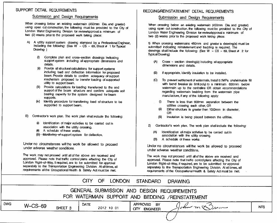
SUPPORT DETAIL REQUIREMENTS
Submission and Design Requirements
When crossing below an existing watermain (450mm Dia. and greater)using open cut construction, the following must be provided to the City ofLondon Water Engineering Division for revierar-âpprovala minimum oftwo (2) weeks prior to the proposed work taking place:
A) ô lrtit,V supportsystem drawing stamped by a professional Engineer,including the following: (See W - CS - 69.Sheet# l forTypiõalDrawing )
(D Complete plan and cross-section drawings indicatingsupport system including allappropriate dimensions anddetails.
(ii) Provide allstructuralcalculations forsupportsyslemsincluding load and deflection informat¡on for proposedbeam. Provide delails to confirm adequacy of supportmechanism proposed to transferloading ofsupportedutility to support beam.
(¡iD Provide calculations for loading transferred to the endsupportofthe beam structure and confirm adequate soilbearing capacity forthe system designed forbeamsupports.
(iv) ldenti! procedure fortransfening load ofstruclure to besupported to support beâm.
B) Contractor's work plan. The work plan shall include the following:
(D ldentification of maior act¡vit¡es to be canied out inassociation with the utility crossing.
(i¡) A schedule of these works.
ffivffioring-€f support system for deflection.
Under no circumstances willthe work be allowed to proceedunder adverse weather conditions.
The work may notproceed until allofthe above are received andapproved. Please note that traffic control plans affecting the City ofLondon Right-of-Way, il required, are to be submitted for approvalseparately to the Transportation Engineering DMsion. Atalltimes,allrequirements of the Occupational Health & Safety Act must be met.
BEDDINGAEINSTATEMENT DETAIL REQUIREMENTS
Submission and Design Requirements
When crossing below an ex¡sting watormain (450mm Dia. and greater)using open cut construct¡on, the following must be provided to the City ofLondon Water Engineering Division for revieurâpprovala minimum oftwo (2) weeks prior to the proposed work taking placei
1) When cross¡ng watermains 450mm and greater a drawing(s) must besubmitted indicating reinstatement and bedding is required. Thedrawings shall include the following: (See W - CS - 69, Sheet # 2 forTypical Drawing)
(A) Cross - section drawing(s) including allappropriatedimensions and details.
(B) lf appropriate, identifo insulation to be installed.
(C) To prevent settlement of wate¡main, install0.TMPa unshrinkable fillwith bond breaker (ie 6mil poly) to a minimum 600mm b€lowwatermain up to the centreline OR obtain recommendationsregarding watermain bedding from the watermain pipemanufacture, if any of the following apply:
(i) There is less than 600mm separation between theutilities crossing each other, OR
(¡D Either structure is greater than 1000mm in diameter,OR
(iii) lnsulation is being placed between the utilities.
2) Contractor's work plan. The work plan shall include the following:
(A) ldentif¡cation of major actMties to be carried out inassociation with the utilþ crossing.
(B) A schedule ofthese works.
Under no circumstances willthe work be allowed to proceedunder adverse weather conditions.
The work may not proceed until allof the above are received andapproved. Please note that traffic controlplans affecting the City ofLondon Right-of-Way, if required, are to be submitted for approvalseparately to the Transportation Engineering Division. Atalltimes, allrequirements of the Occupational Health & Safety Act must be met.
LONDON STANDARD DRAWING
GENERAL SUBMISSION AND DESIGN REQUIREMENTSFOR WATERMAIN SUPPORT AND BEDDING /REINSTATEMENT
20'l 2-1 0-29 1 0:35:52 AM

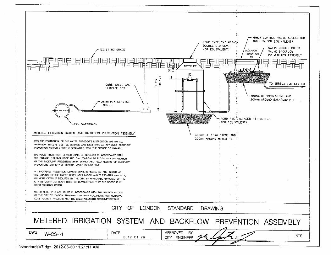
FORD TYPE "W" I{ABASHDOUBLE LID COVER(OR EOUIVALENT)
ARMOR CONTROL VALVE ACCESS BOXAND LID (OR EOUIVALENT)
EXISTING GRADEWAITS DOUBLE CHECKVALVE BACKFLOVIPREVENTION ASSEMBLY
PREVENTION
PIT
CURB VALVE ANDSERVICE BOX
25fÍm PEX SERVICE( MIN. )
TO IRRIGATION SYSTEM
300nm 0F 1 gnfn SToNE AND2o0nm AROUND BACKFLoVI PIT
FORD PVC CYLINDER PIT SETTER
EX. WAÏERMAIN(OR EOUIVALENT}
ME]-ERED IHRIGATION SYSTEM AND BACKFLOW PREVENTION ASSEMBLY 300nm 0F lgrlm]ST0NE ANE
2oofin AROUND METER PITFOR fHE PROTECTION OF ]HÊ WATER PURVÉYOB'S DISTRIBUTION SYS'TEM, ALLIRRIGATION SYSTEIVS MUST BE METERED AND MUST IIAVE AN APPROVED BACKFLOWPBEVENÎION ASSEMBLY THAT IS COMPATBLE WTH THE DEGREE OF HAZARD.
BACKFLOW PREVENTION DEVICES SI.{ALL BE INSIALLED IN ACCORDANCE WITÞi
THE ONIARIO BUILDING CODE AND CAN /CAS-864 SEI'.ECTION AND INSTALUTIONOF-IIIE BACKFLOW PREVENTERS /MAINTEMNCE ANO FIELD TESTING OF BACKFLOWPREVENÍEBS AND CMY OF LONDON WATER BY-{AW W€,
ALL BACKFLOW PRÉVENTION DEVICES SHALL BE INSPECIED AND IESIED ATTHÉ Ð(PENSE OF THE OWNER, UPON INSTAUÂÏON, AND THEREAFTER ANNUAI-LY, '
OB MORE OFIEN IF REQUIRED BY-THE CITY, BY PEBSONNEL APPROVED BY THECffI TO CARRY OUT SUCH IESTS TO DEMONS'IRATE 'THAT THE DEVICE IS IN
GOOD WORKING ORDER.
WAIER MEIER PITS ARE TO BE IN ACCORDANCE WTH 'ÍHE SECI|ON ,t41,0S.22
OF THE CITY OF LONDON STANDARD CONTRACT DOCUMENTS FOR MUNICIPALCONSTRUCTION PROJECTS AND THE MANUFACTURER'S RECOMMENDATIONS.
LONDON STANDARD DRAWING
METERED IRRIGATION SYSTEM AND BACKFLOW PREVENTION ASSEMBLYDWG w-cs-71
2012-03-3011:21:11 AM