Embed Size (px)
Citation preview

I I STANDARD DESBGN FOR USBNG
RAILCAR SUBFRAMES AS SUPERSTRUCTURES FOR TEMPORARY BRIDGES ON FOREST ROADS
IN BRITBSH COLUMBIA
Allan H. Bradley, R.P.F. Vera Pronker, P.Eng.
October 1994

STANDARD DESIGN FOR USING RAILCAR SUBFRAMES
ASSUPERSTRUCTURES FOR TEMPORARY BRIDGES ON
FOREST ROADS IN BRITISH COLUMBIA
Allan H. Bradley, R.P.F. Vera Pronker, P.Eng.
FOREST ENGINEERING RESEARCH INSTITUTE OF CANADA Western Division
2601 East Mall Vancouver, British Columbia
V6T 124 Tel. 604-228-1 555 Fax. 604-228-0999
FERIC Special Report No. SR-98
October 1994
Keywordr: Temporary bridges, Railcar bridges, Bridge design.
8 Copyright 1994, Forest Engineering Research Institute of Canada ISSN 0381-7733
4

Abstract This report describes a standard design for using railcar subframes as superstructures for temporary bridges on forest roads in British Columbia The design was prepared by the British Columbia Ministry of Forests in response to a need for a standard design acceptable to both government and the British Columbia forest industry. The Forest Engineering Research Institute of Canada (FERIC) facilitated initial discussions and assisted in the development of the standard design. The design assumptions and specifications are detailed. A comparison with alternative superstructures finds the standard design railcar superstructure to be cost competitive.
Acknowledgements The authors thank the following people, whose assistance and expertise were instrumental to the preparation of this report: Bert Argent, P.Eng., Vancouver Forest Region, British Columbia Ministry of Forests; and Lloyd Daniel, Me- chanical Department, BC Rail Ltd.
Authors Allan Bradley obtained a B.A.Sc. degree in civil engineering and a B.S.F. degree in forest harvesting from the Univer- sity of British Columbia. He joined ~ R I C in 1988 and is currently a Researcher in the Transportation and Mainte- nance Group. His areas of interest are variable tire inflation technology, bridge design, and road construction and maintenance. Allan is a Registered Professional Forester in British Columbia.
Vera Pronker, P.Eng., is a bridge engineer with the British Columbia Ministry of Forests in Victoria. She has exten- sive consulting experience, and currently works with the rehabilitation and appraisal of existing structures, and the design of new structures.
Disclaimer The report is published solely to disseminate information to FERIC members. It is not intended as an endorsement or approval by FERIC of any product or service to the exclusion of others that may be suitable.
To Obtain Copies of the Standard Design A copy of the standard design can be requested from: Engineering Section, Timber Harvesting Branch, British Colum- bia Ministry of Forests, 1450 Government Street, Victoria, British Columbia, V8W 3E7. Tel. 604-387-5024. Fax. 604-387-6445. Bridge designers should periodically check with the BCMOF Engineering Section in Victoria to en- sure that their copies of the standard design are current.
i i

Table of Contents
Page
Abstract Acknowledgements Authors DiSClaimer To Obtain Copies of the Standard Design summary
INTRODUCTION
DESIGN METHOD Development of the Standard Design Applying the Standard Design Universal Design Specifications Standard Design Specifications Quality Assurance, Approval, and Inspection Procedures
COST ANALYSES
CONCLUSIONS
RECOMMENDATIONS
BIBLIOGRAPHY
APPENDIX I Standard Design: Railcar Subfiame Superstructure for Forest Road Bridges
APPENDIX II Cost Analyses
1
6
7
7
7
9
13
i i i
List of Tables
1 Crosstie Schedule
Page
5
1
2
3
List of Figures
One of the f ist railcar subframe bridges constructed according to the standard design specifications: built by Wakiwa Construction Ltd. for the BCMOF in 1993
bulkhead flat car. Schematic and cross section of a typical Railwest
Detail of crosstie attachment.
Page
1
2 5
i v
Summary Many railcar bridges have been installed on forest roads in British Columbia in the last ten years. However, most of these bridges rely on local expertise and judgement for their reliability, rather than on designs by professional engineers. As a result, a wide variety of designs and con- figurations are now in service, each with a unique, and in many cases unknown, load-carrying capacity.
The use of railcar subframes as superstructures for tem- porary forest road bridges has spread, and the British Co- lumbia Ministry of Forests (BCMOF) has become in- creasingly concerned about associated safety and liabil- ity implications, particularly as standards are lacking about employing ‘used’ steel as structural material. De- bate between the forest industry and the BCMOF over the use of railcar subframes demonstrated the need for clearly defined standards for selecting railcar subframes and building railcar bridges.
In March 199 1, the Forest Engineering Research Insti- tute of Canada ( m e ) began a project to formulate stand- ad superstructure designs for railcar bridges, and to write and publish a project report containing the final design. The Engineering Section of the BCMOF’s Timber Har- vesting Branch agreed to create and distribute the super- structure design. It is based on railcar subframes avail- able from BC Rail Ltd. and is just one example of an acceptable design.
Railcar subframes must be selected with care, with par- ticular attention being given to railcar origin and condi- tion. Selected subframes must be approved for use as su-
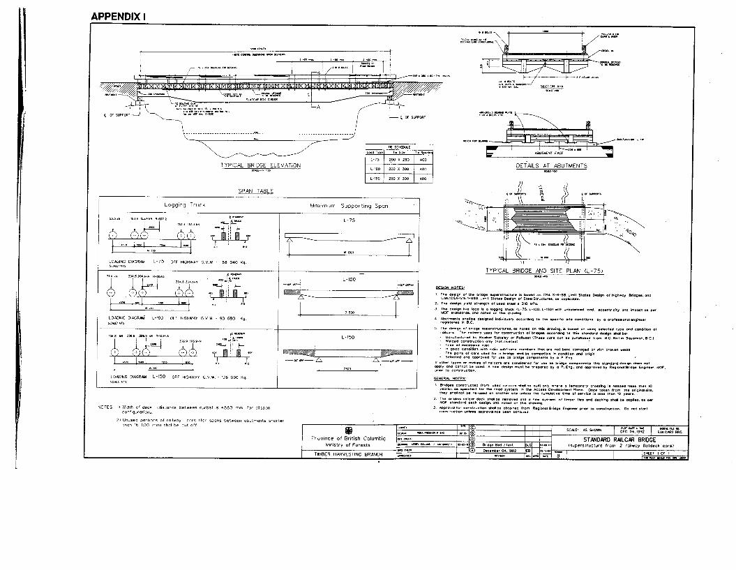
perstructure components by a professional engineer. The standard design specifies superstructure span, width, clearance, and design life; however, bridge abutments vary with site conditions and must be designed sepa- rately. The railcar bridge standard design features two structurally unmodified railcar subframes placed side- by-side. Maximum bridge spans of 16.0m, 13.5 m, and 7.5 m are specified for L-75, L-100, and L-150 traffic loadings, respectively. A detailed drawing showing site plan and elevation, with high water level, soffit clear- ance, and a detailed plan of abutments, must be submit- ted to the BCMOF for approval, prior to construction.
The BCMOF 1993 Engineering Manual was the first to identify ‘used’ steel as an acceptable structural ma- terial. With this, and the development of the standard design, forest bridge builders are now able to utilize low- cost used steel components, such as railcar subframes, in bridges. The assumptions and specifications of the standard design meet the applicable Canadian standards and are provided here as design aids.
A comparison of the construction costs of superstruc- tures found that a standard design railcar superstruc- ture may be expected to have an in-place cost that is competitive with most comparable temporary forest bridge superstructures. However, a comparison of the overall costs of railcar superstructures with temporary and permanent superstructures over a 40-year period re- vealed that the high cost of maintaining and rebuilding standard design railcar superstructures over the long term makes them uneconomically less attractive for use in permanent crossings.
INTRODUCTION Traditionally, in British Columbia, log-stringer bridges have been the most economical solution for temporary crossings of streams by forest roads. However, bridge loading requirements have increased withlarger vehicle weights, while the availability of large-diameter stringer logs has diminished. As a result, a need has developed for alternative superstructure materials for temporary forest bridges.
One alternative gaining acceptance with the forest indus- try in British Columbia is subframes from used railcars. Used railcar subframes are readily available and inex- pensive. Many railcar bridges have been built in the last ten years by forest industry users. However, most of the these rely on local expertise and judgement for reliabil- ity, rather than on designs by professional engineers. As a result, a wide variety of designs and configurations are now in service, each with a unique, and in many cases unknown, load-carrying capacity.
As the use of railcv subframes in forest road bridges has spread, the British Columbia Ministry of Forests (BCMOF) has become increasingly concerned about associated safety and liability implications, particularly as standards are lacking about employing ‘used’ steel as structural material. Debate between the forest indus- try and BCMOF over the use of railcar subframes dem- onstrated the need for clearly defined standards for se- lecting railcar subframes, and building railcar bridges. In March 1991, Fletcher Challenge Canada Limited, West Fraser Mills La., Forest Engineering Research In- stitute of Canada (FERIC), and the Engineering Section of BCMOF’s Timber Harvesting Branch agreed that the BCMOF would create and distribute a standard design for using railcar subframes as bridge superstructures, and FERIC would assist in formulating design specifica- tions as required and publish a report.
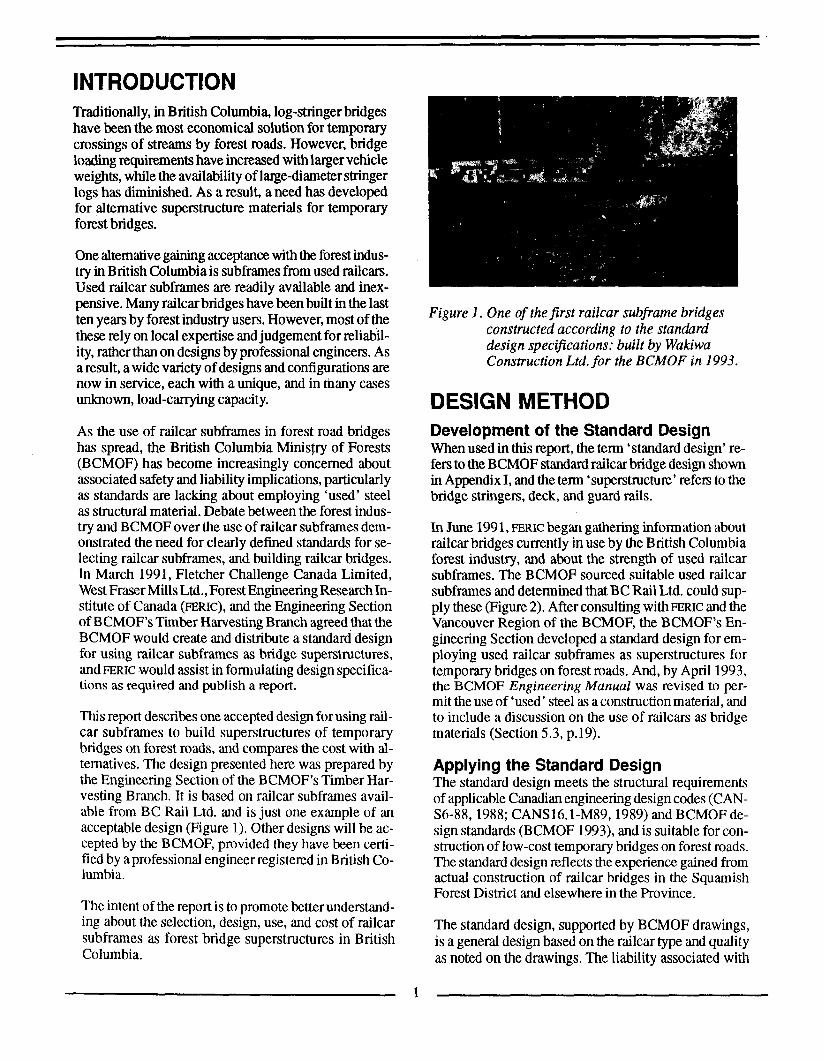
This report describes one accepted design for using rail- car subframes to build superstructures of temporary bridges on forest roads, and compares the cost with al- ternatives. The design presented here was prepared by the Engineering Section of the BCMOF’s Timber Har- vesting Branch. It is based on railcar subframes avail- able from BC Rail Ltd. and is just one example of an acceptable design (Figure 1). Other designs will be ac- cepted by the BCMOF, provided they have been certi- fied by aprofessional engineer registered in British Co- lumbia.
The intent of the report is to promote better understand- ing about the selection, design, use, and cost of railcar subframes as forest bridge superstructures in British Columbia.
Figure I . One of the first railcar subframe bridges constructed according to the standard design specifications: built by Wakiwa Construction Ltd. for the BCMOF in 1993.
DESIGN METHOD Development of the Standard Design When used in this report, the term ‘standard design’ re- fers to the BCMOF standard railcar bridge design shown in Appendix I, and the term ‘superstructure’ refers to the bridge stringers, deck, and guard rails.
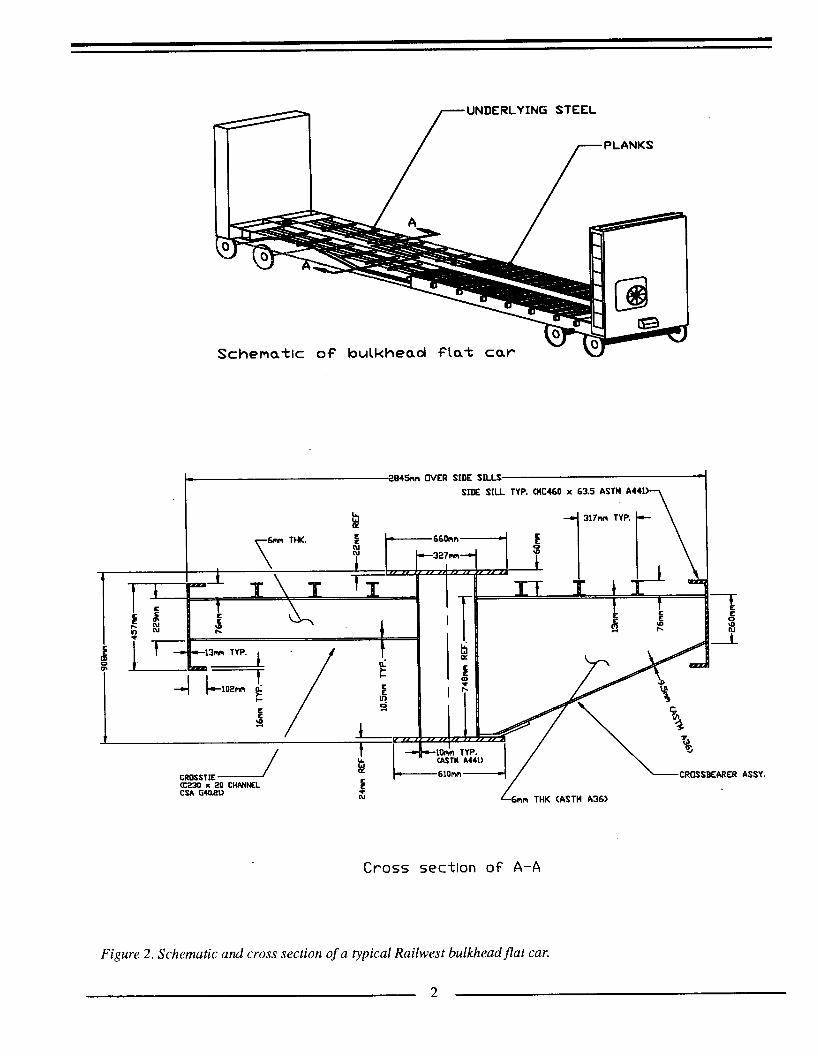
In June 199 1, FERIC began gathering information about railcar bridges currently in use by the British Columbia forest industry, and about the strength of used railcar subframes. The BCMOF sourced suitable used railcar subframes and determined that BC Rail Ltd. could sup- ply these (Figure 2). After consulting with ERIC and the Vancouver Region of the BCMOF, the BCMOF’s En- gineering Section developed a standard design for em- ploying used railcar subframes as superstructures for temporary bridges on forest roads. And, by April 1993, the BCMOF Engineering Manual was revised to per- mit the use of ‘used’ steel as aconstruction material, and to include a discussion on the use of railcars as bridge materials (Section 5.3, p.19).
Applying the Standard Design The standard design meets the structural requirements of applicable Canadian engineering design codes (CAN- S6-88, 1988; CANS16.l-M89, 1989) and BCMOF de- sign standards (BCMOF 1993), and is suitable for con- struction of low-cost temporary bridges on forest roads. The standard design reflects the experience gained from actual construction of railcar bridges in the Squamish Forest District and elsewhere in the Province.
The standard design, supported by BCMOF drawings, is a general design based on the railcar type and quality as noted on the drawings. The liability associated with
1
UNDERLYING STEEL
I- 2845nn WER SIDE SILLS t
P 1 3 1 7 ~ TYP.
SIDE SILL TYP. CUC460 x 63.5 ASTM A44
ASSY.
Cross section o f A-A
Figure 2. Schematic and cross section of a typical Railwest bulkheadflat car.
2

the content of the standard design rests with the BCMOF. However, responsibility for the overall bridge design rests with the design engineer retained to prepare gen- eral scheme drawings and foundations.
There are limitations on the use of any generic design, and the standard design described here is no different. In some instances it would be inappropriate to use the standard design. Fit, if a bridge is to be built from rail- cars of different dimensions or origin than those used in the standard design, or for a different purpose or of dif- ferent geometry, the standard design does not apply. In such situations a design must be prepared by an experi- enced professional engineer and approved by a BCMOF Regional Bridge/Structures Engineer prior to construc- tion. Secondly, existing railcar bridges must be assessed and load-rated on an individual basis, and cannot be judged by the specifications of the standard design.
Universal Design Specifications The following design specifications for loads, load dis- tribution, design code, and material stresses are univer- sally valid, and apply to all forest bridge designs employ- ing railcar subframes.
1. Steel Design Stresses. Section resistance. The precise determination of the structural strength of a used railcar subframe is ex- tremely difficult because of the railcar’s unknown load- ing history. Therefore, the following conservative strength estimate for used steel (as per CAN3S16.1- M89:5-2.2 (1989), was adopted for the standard design:
Yield strength (Fy) of unidentified steel = 210 h4Pa.
If the designer would l i e to consider steel stresses higher than this, formal material testing would have to support hisher opinion. The number of tests and the interpreta- tion of the test results should be done according to Com- mentary to Clause 12, CAN-S6-88 (1988).
Main railcar box-girders. Designers are advised that only the subframes’ main box-girders are of structural value in designing the main bridge girders.
Structural defects. The standard design requires bridge builders to use only subframes with box-girders that have no structural defects, e.g. bends, cutouts, cuts, or exces- sive rust. Only the area of the box-girder section that can be ascertained to actually cany the load can be used. Where applicable, minor rust allowance should be de- ducted.
2. Design Loads. Vehicle eccentricity and load imbalance. The standard drawings (see Appendix I) show BCMOF design traffic
loading, which assumes a 400-mm vehicle eccentricity and a 604% side-to-side loading imbalance.
Single-lane bridge. It is assumed that only one vehicle would be on the bridge at any one time.
Design factors. Design loads include impact, and are factored -ding to CAN-S.6-88 (1988):
Dead Load Factor = 1.2 Live Load Factor = 1.6 Impact Factor = 1.3
Fatigue stresses. Fatigue stresses were not considered because the railcars are expected to be used as tempo- rary bridges in forestry applications (i.e. low-volume applications).
Standard Design Specifications 1. Design Life. Because the condition of the railcar bridge subframes may change significantly over long periods, railcar bridges must be considered only for‘tem- porary’ use (i.e. up to ten years). An inspection program, similar to that required for other temporary bridges, must be implemented and the condition of the bridge assessed every two years.
2. Maximum Spans. The longest clear span between abutments for L-75 or lighter log-hauling trucks is 16.0 m (see Appendix I). Bridges designed for L-100 logging trucks have a maximum span of 13.5 m, and those de- signed for L-150 trucks have a maximum span of 7.5 m. For each load category (L-75, L-100, and L-150), the span can be less than the specified maximum. For spans of less than 16.0 m, the unused portions of the railcar subframes should be cut off.
3. Bridge Width. The standard design bridge consists of two subframes placed side by side and having an over- all width of 5.70 m. The bridge is designed for one lane of traffic with adeck width between curbs of 4.88 m (see Appendix I).
Subframes may be joined together, or left unconnected. If the subframes are joined together, they will display less differential deflection under load. The connection should be made with type 3, A235, M20 bolts spaced at 600 mm along the adjacent side channels.
Some builders of dual-railcar bridges prefer not to join the railcar subframes because some subframes have many stake pockets along their sides. These stake pock- ets must be removed if the subframes are to be bolted together. Also, handling the two 2.85-m wide subframes separately facilitates both preconstruction at a shop fa- cility and transportation on public highways. Finally,
3

subframes can be used independently as access bridges for light truck traffic.
4. Highwater Foundations and Clearance. Founda- tions do not form part of the standard design, and must be designed individually according to local site condi- tions. The most impo&int site-specific variables that may change from crossing to crossing are: clearance required under the bridge soffit (depending on local high water flood levels), and foundation conditions.
The minimum high water clearance, based upon a 50- year flood, must not be less than 1.50 m and may need to be more depending on local conditions. Refer to Chap ter 5 of the BCMOF Engineering Manual (1993) for more information.
The superstructure detailed on the standard drawings can be used with many types of abutments, including tim- ber cribs and concrete blocks. Detail of the bearing plate- to-abutment arrangement is shown in Appendix I. If there is any doubt about the ability of the underlying soils to support a spread footing, or about the stability of the crib abutment, it is recommended that athorough investiga- tion be conducted by a qualified soil specialist.
5. Railcar Type. The 16.6-m long bulkhead flat car subframes considered as bridge components in the stand- ard design are manufactured by Hawker Siddeley Canada Inc. or Railwest Manufacturing Company (Fig- ure 2). If a bridge is to be built from subframes of dif- ferent dimensions or origin, or for a different purpose, or with a different geometry or loading than in the stand- ard design, the same procedures that apply to other bridges on forest roads in British Columbia must be fol- lowed. Information and/or approval for construction procedures can be obtained from the BCMOF Regional Bridge/Structures Engineer. As well, use of riveted subframes in a ‘custom’ design is acceptable as long as a professional engineer prepares and certifies the design, based on stress values obtained through material test- ing results.
Railcar subframes appropriate for use with this stand- ard design are available from BC Rail Ltd. Arrangements should be made through, or further information is avail- able from, BC Rail Ltd.’s asset disposal agent.
BC Rail Ltd. is currently offering Hawker Siddeley Canada Inc. and/or Railwest Manufacturing Company bulkhead flat cars, subject to availability, for $2500 each, all taxes extra (FOB Squamish, or Prince George), less wheel truck sets, couplers, and brakes. Buyers must ar- range for the removal of wheel truck sets, couplers, and brakes. However, currently all bulkhead flatcars from Hart Siding are sold with bulkheads, wheel truck sets,
couplers, and brakes removed at no extra charge. For $500.1000 extra, the railcars will be delivered to any BC Rail Ltd. siding for off loading by the buyer.
6. Railcar Dead Load. The weight of the Hawker Siddeley or Railwest railcar subframes, calculated in the design using aunit weight of steel equal to 77 kN/m3, is estimated to be 18 t when stripped of bulkheads, wheel truck sets, couplers, brakes, and wood deck. The design also accounts for the dimensional changes in the cross section of the main girder along the car’s length (see the superstructure elevation in Appendix I).
7. Inspection and Approval of Railcar Subfiames. All railcar subframes considered for use with the standard design must be inspected and approved, prior to bridge construction, by a professional engineer registered in British Columbia. The engineer will inspect and approve for use as bridge components only subframes with the following qualities:
bulkhead flat car configuration manufactured by Hawker Siddeley Canada Inc. or Railwest Manufacturing Company welded construction only (i.e. riveted construction is not acceptable because the interior condition of riveted connections cannot be visually assessed) free from excessive rust in good condition, having main subframe members that are not bent, damaged, or do not have broken welds
Railcars that were discarded for reasons other than struc- tural damage should be selected. When this is not possi- ble, railcars should be carefully inspected to determine the extent of structural damage in light of the above se- lection criteria. The two most common types of damage that lead rail companies to discard bulkhead flat cars are leaning bulkheads, and bent or missing crossbearers. These types of damage commonly result from load shift- ing and derailments. Outward leaning bulkheads may have bent the ends of the subframe girders at the gusset attachment points. This is usually not a concern for rail- car bridges, however, because the bent sections are cut off on all but the longest (L-75 rated) spans. As only the main box-girder of the subframe is capable of carrying the wheel loads of L-75 log trucks, the condition of crossbearers is not critical in bridge applications. A subframe may also show signs of metal fatigue. The in- specting engineer should look closely for fatigue crack- ing, particularly where the railcar’s wheel truck sets at- tach to its main girders.
The pairs of subframes selected for a bridge must be compatible in condition and made by the same manu- facturer. Subframes with substantially different amounts of rust and damage should not be paired together.

8. Preparing Railcar Subkames for Installation. Prior to installation, the railcar subframes must be stripped of all additional components and assemblies such as bulk- heads, rods, wires, and wheel trucksets. Ifthe subframes are to be joined together, the stake pockets previously used to mount wooden stakes must be removed from the two mating sides.
All original decking must be removed despite its condi- tion, and a regular bridge deck reconstructed with new grade one or two Douglas-fir crossties and decking. Keeping the original decking is not permitted as it may promote rot through the collection of soil and moisture, and it obscures viewing of the new crossties and deck- ing from underneath. Use of pressure-treated wood com- ponents is not specified by the standard design; however, longer service life of the decking can be expected if treated materials are used.
Table 1 . Crosstie Schedule
'Ihe crosstie schedule is shown in Table 1. Crossties shall be placed at 400 mm on-centre and fastened to the subframe girders with crosstie bolting clips at every fourth crosstie. The crosstiebolting clips should be 150 mm x 150 mm x 6 mm angle (350AT or 350W steel), and welded or bolted to the main box-girder every 1600 mm (i.e. at every 4th crosstie). The crossties should be attached to the tie clips with M16 bolts, washers, and hex nuts, as shown in Figure 3.
Quality Assurance, Approval, and Inspection Procedures 1. Quality Assurance. A person or company intending to build a bridge with railcar subframes should define the exact type and condition of subframe required and deal only with suppliers qualified to provide the subframes as specified. It is the responsibility of the pm- ponent to arrange for a professional engineer to inspect
Load rating Crossties
Size Spacing (width x height) (centre-to-centre)
(mm) (mm)
L-75
L-100
L-150
200 x 250
200 x 300
250 x 300
400
400
400
hole
Figure 3. Detail of crosstie attachment.
5
the subframes prior to construction, and to certify that all the design requirements have been met.
Field construction staff should be provided with con- struction specifications based upon the standard design. An as-built inspection should be conducted to ensure adherence to design specifications. For each new bridge, documentation should be kept of the origin of the subframes, the approval for construction by the BCMOF Regional Bridge/Structures Engineer, and the as-built drawings (BCMOF 1993).
2. BCMOF Approval Process. To include the construc- tion costs of a railcar bridge in stumpage appraisal, a licensee must first obtain BCMOF approval to build the bridge. Use of the standard design should streamline the approval process and reduce the design costs of the struc- ture. However, the standard design is for the bridge su- perstructure only. Foundations vary with soil and hydro- logic conditions, and must therefore be designed indi- vidually. A detailed drawing showing site plan and el- evation, with high water level, soffit clearance and a detailed plan of abutments, must be submitted to a BCMOF Regional Bridge/ Structures Engineer for ap- proval, prior to construction (BCMOF 1993). Railcar bridges are appraised by the BCMOF as ‘temporary’- that is, equivalent to log-stringer bridges, regardless of actual cost overruns beyond that value.
3. Bridge Inspection. Some risk is inherent with the use of used railcar subframes as bridge superstructures be- cause the degree of steel fatigue i n m d in milway serv- ice is unknown. The risk of failure due to fatigue crack- ing can be reduced, however, through the incorporation of appropriate safety factors in the design, careful and thorough inspection, and strict adherence to the design specifications. However, even these m e w s do not fully guarantee that the used steel will not develop fatigue cracks in-service. For this reason, it is required that a thorough visual inspection of the railcar bridge be con- ducted every two years, as is the practise for other tem- porary bridges. When inspecting the subframes for cracks, particular attention should be paid to the por- tion of the subframe resting on the abutment and the previous attachment points of the railcar wheel truck sets.
COST ANALYSES The cost of constructing a forest road bridge using rail- car subframes as superstructures is influenced by a va- riety of factors, many of which are site specific. For this reason, this report estimates only superstructure-related costs and the reader is directed to compute overall bridge costs according to local conditions.
The analyses include a cost for the log stringers based upon 1994 market value. A comparison of the construc- tion costs of four different temporary bridge supentruc- tures (railcar subframe, log-stringer, gravel-over-log stringer, and steel-girder) is presented in Appendix II. A second analysis, comparing the construCtion and main- tenance costs anticipated over 40 years for four bridge superstructures (railcar subframe, log-stringer, steel- girder with both wood and concrete deck) also appears in Appendix II.
Analyses of construction costs indicate that a standard design railcar subframe superstructure is competitive with comparable temporary log-stringer and steel-girder superstructures (see Tables 11-A, 11-B, 11-C, and 11-D). A 6.1-m long standard design railcar superstructure is estimated to cost $17 100, or approximately $2800 per metre of span. A 12.2-m long standard design railcar su- perstructure is estimated to cost $20 700, or approxi- mately $1700 per metre of span. The difference in cost of $1 100 per metre may be attributable to the economies of scale possible with longer spans. Gravel-over log- stringer superstructures were estimated to cost approxi- mately $9500 less than the other three superstructures because of their reduced material requirements and con- struction simplicity. Shorter life spans and concerns about stream degradation during removal, in addition to a general shortage of appropriately sized logs, however, may limit opportunities for use of gravel-over log- stringer bridges.
The second analysis, conducted to compare the costs of various superstructure alternatives having different life spans and maintenance requirements, found that the 10- year life of the standard design railcar superstructure makes it uneconomic when compared to permanent steel- girder superstructures. Over the @year period, the costs of the superstructures, expressed in 1994 dollars, were: standard design railcar subframe, $58 172; log-stringer, $80 443; steel-girder with wooden deck, $35 137; and steel-girder with concrete/asphalt deck, $33 056. The sig- nificant difference in costs over 40 years is largely due to the expense incurred in replacing the temporary su- perstructures every 10 years. In fact, for the first 10-year period, the overall cost of the standard design railcar su- perstructure is $3100-10 300 less than the alternatives over the same time period.
The cost of maintaining a superstructure throughout its life influences overall costs and these should be consid- ered when deciding between superstructure alternatives. For example, over the 40-year period, repairs to the wooden deck on the steel superstructure made it almost $2100 more costly than the concrete and asphaltdecked steel superstructure.
6

CONCLUSIONS The Engineering Section of the BCMOF Timber Har- vesting Branch, in consultation with m ~ c and the for- est industry, developed a standard design for using rail- car subframes as bridge superstructures. The standard design meets the structural requirements of applicable Canadiandesign codes (CAN3-Sl6.1-MS9: 5-22,1989; CAN-S6-88, 1988) and of the BCMOF Engineering Manual (1993), and is suitable for constructing low-cost, temporary bridges on forest roads in British Columbia. The liability associated with the content of the standard design rests with the BCMOF. However, responsibility for the overall bridge design rests with the design engi- neer retained to prepare general scheme drawings and foundations.
The standard design, supported by BCMOF drawings, is a general design based on the railcar type and quality as noted in the drawings. It features two structurally un- modified subframes placed side-by-side, and permits maximum bridge spans of 16.0 m, 13.5 m, and 7.5 m for L-75, L-100, and L-150 traffic loadings, respec- tively. The standard bridge design is for bridge super- structures only, as the foundations and general design scheme depend on individual site conditions.
With the decrease in availability of large diameter stringer logs, railcar subframes will likely continue to be a popular alternative for temporary forest bridges. Use of the standard design will eliminate the safety and li- ability concerns present with non-engineered railcar bridges. The standard design also addresses the concern of increasing vehicle weights through its provision for a variety of load ratings.
The standard design is just one example of an accept- able railcar subframe superstructure design. Other de- signs are also acceptable to BCMOFpmvided they have been prepared by a professional engineer who is regis- tered in British Columbia. The standard design does not apply to superstructures built with railcar subframes of different dimensions or origin than specified, nor to su- perstructures built with a different purpose or geometry. The standard design may not be used to load rate or as- sess an existing railcar bridge.
Through the inclusion of 'used' steel as a structural material inthe BCMOF 1993Engineering Manual, and the development of the standard design described in this report, forest bridge builders are now able to utilize low- cost used steel components, such as railcar subframes, in bridges. The design assumptions and specifications included in this report meet the applicable standards and have been provided as design aids.
A standad design railcar superstructure may be expected to have an in-place construction cost that is competitive with most comparable temporary forest bridge super- structures. The high costs of maintaining and rebuild- ing a standard design railcar superstructure over the long term make it uneconomical for use in permanent cross- ings.
RECOMMENDATIONS The standard design described in this report could be made more versatile by including a wider variety of rail- cartypes and bridge configurations. Consideration could be given to including railcars used by Canadian Pacific Railways Limited and Canadian National Railways in a revised standard design, thereby accessing a much larger pool of surplus railcars and a national rail net- work for their delivery.
After sufficient numbers of standard design railcar bridges are in service, a review of bridge performance should be made to identify any necessary design modi- fications and investigate the question of bridge life ex- pectancy.
BIBLIOGRAPHY Canadian Standards Association. 1989. Steel Structures
For Buildings - Limit States Design. Rexdale, On- tario. CSA Standard CAN3-S16.1-M89. 146pp.
Canadian Standards Association. 1988. Design ofIfigh- way Bridges. Rexdale, Ontario. CSA Standard CAN- S6-88. 3 0 2 ~ ~ .
British Columbia Ministry of Forests. 1993. Engineer- ing Manual. Victoria. 42pp.
Nagy, M.M.; Trebett, J.T.; Wellbum, G.V. 1980. Log Bridge Construction Handbook. FERIC, Vancouver. Handbook NO. HB-3.421 pp.
Province of British Columbia; B.C. Hydro and Power Authority; B.C. Rail Ltd. 1993. Equipment Rental Rate Guide 1993-1994. Victoria. 99pp.
7

APPENDIX I Standard Design: Railcar Subframe
Superstructure for Forest Road Bridges
9
Illirm (SL-1) NVld 311s ONV 33CIlt18 lV3ldAi
OOt
00.
I,* llJI 6n 089 06 - M A 3 hVMH3IH dd0 001-1 .!L(f)Via 3N101101
1
OOC X 051 05,-1
ooc x 001 ooL-7 (X., WWnl
NOllVA313 330188 lV3ldAl
I XlaN3ddV

APPENDIX II Cost Analyses
13
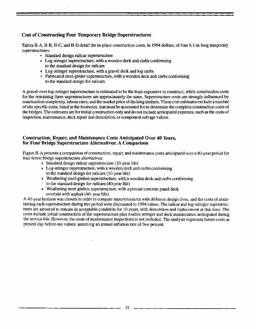
Cost of Constructing Four Temporary Bridge Superstructures
Tables 11-A, 11-B, 11-C, and TI-D detail the in-place construction costs, in 1994 dollars, of four 6.1-m long temporary superstructures:
Standard design railcar superstructure Log-stringer superstructure, with a wooden deck and curbs conforming to the standard design for railcars Log-stringer superstructure, with a gravel deck and log curbs Fabricated steel-girder superstructure, with a wooden deck and curbs conforming to the standard design for railcars
A gravel-over log-stringer superstructure is estimated to be the least expensive to construct, while construction costs for the remaining three superstructures are approximately the same. Superstructure costs are strongly influenced by construction complexity, labour rates, and the market price of decking timbers. These cost estimates exclude anumber of site specific costs, listed in the footnotes, that must be accounted for to determine the complete construction costs of the bridges. The estimates are for initial construction only and do not include anticipated expenses, such as the costs of inspection, maintenance, deck repair and demolition, or component salvage values.
Construction, Repair, and Maintenance Costs Anticipated Over 40 Years, for Four Bridge Superstructure Alternatives: A Comparison
Figure 11-A presents a comparison of construction, repair, and maintenance costs anticipated over a40-year period for four forest bridge superstructure alternatives:
Standard design railcar superstructure (10-year life) Log-stringer superstructure, with a wooden deck and curbs conforming to the standard design for railcars (10-year life) Weathering steel-girders superstructure, with a wooden deck and curbs conforming to the standard design for railcars (40-year life) Weathering steel-girders superstructure, with a precast concrete panel deck overlaid with asphalt (40- year life)
A 40-year horizon was chosen in order to compare superstructures with different design lives, and the costs of main- taining each superstructure during this period were discounted to 1994 values. The railcar and log-stringer superstruc- tures are assumed to remain in acceptable condition for 10 years, with demolition and replacement at that time. The costs include initial construction of the superstructure plus routine stringer and deck maintenance anticipated during the service life. However, the costs of maintenance inspections is not included. The analysis expresses future costs as present day before-tax values, assuming an annual inflation rate of five percent.
15
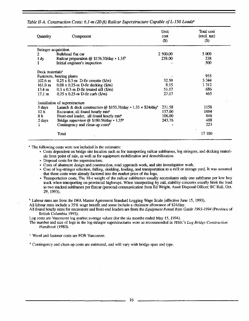
Table 11-A. Construction Costs: 6.1 -m (20-f) Railcar Superstructure Capable of L-150 Loads"
Unit Total cost Quantity Component cost (excl. tax)
($) ($)
Stringer acquisition 2 Bulkhead flat car 1 dY 1 Initial engineer's inspection
Deck materials" Fasteners, bearing plates 102.6 m 161.0 m 13.4 m 17.1 m
Railcar preparation @ $176.30/day 1.35b
0.25 x 0.3-m D-fir crosstie ($/m) 0.08 x 0.25-m D-fir decking ($/m) 0.3 x 0.3-m D-fir treated sill ($/m) 0.25 x 0.25-m D-fir curb ($/m)
2 500.00 238.00
32.59 8.15
51.17 27.17
Installation of superstructure 5 days Launch & deck construction @ $153.76/day 1.35 + $24/dayb 231.58 12 h Excavator, all found hourly rate 157.00
2 days Bridge supervisor @ $180.56/day 1.35b 243.16 1 Contingency and clean-up costsd
8 h Front-end loader, all found hourly rate 106.00
Total
5 0 0 0 238 500
955 3 344 1312
686 465
1158 1884 848 488 223
17 100
a The following costs were not included in the estimates: Costs dependent on bridge site location such as for transporting railcar subframes, log stringers, and decking materi-
Disposal costs for the superstructure. Costs of abutment design and construction, road approach work, and site investigation work. Cost of log-stringer selection, falling, skidding, loading, and transportation to a mill or storage yard. It was assumed that these costs were already factored into the market price of the logs. Transportation costs. The 18-t weight of the railcar subframes usually necessitates only one subframe per low boy truck when transporting on provincial highways. When transporting by rail, stability concerns usually limit the load to two stacked subframes per flatcar (personal communication from Ed Wright, Asset Disposal Officer, BC Rail, Oct. 29, 1993).
als from point of sale, as well as for equipment mobilization and demobilization.
Labour rates are firom the IWA Master Agreement Standard Logging Wage Scale (effective June 15,1993). All labour rates include a 35% wage benefit and some include a chainsaw allowance of $24/day. All found hourly rates for excavators and front-end loaders are from the Equipment Rental Rate Guide 1993-1 994 (Province of
Log costs are Vancouver log market average values (for the six months ended May 15, 1994). The number and size of logs in the log-stringer superstructures were as recommended in FERIC'S Log Bridge Construction
British Columbia 1993).
Handbook (1980).
Wood and fastener costs are FOB Vancouver.
Contingency and clean-up costs are estimated, and will vary with bridge span and type.
16

Table 11-B. Construction Costs: 6.1 -m (20-ft) Log-StringerlWood Deck Superstructure Capable of L150 Loads” ~ ~~ ~ ~
Quantity Component Unit cost (8
Total cost (excl. tax)
($)
Stringer acquisition 7 3 days
Deck materialsd 2
91.5 m 134.2 m
8.0 x 0.61-m dia. F-grade spruce stringer @ $460/m3 Peeling stringers @ $148.88/day 1.35b
8.0 x 0.46-m dia H-grade hemlock curb log @ $86/m3 Fasteners’ 0.2 x 0.2-m D-fir crosstie ($/m) 0.08 x 0.25-m D-fir decking ($/m)
Installation of superstructure 8 h 2 days 4 days 4 days 1 Contingency and clean-up costsd
Excavator, all found hourly rate Place stringers @ $153.76/day 1.35 + $24/dayb Deck construction @ %153.76/day 1.35 + $24/dayb Bridge supervisor @ $180.56/day 1.35b
Total
1075.44 201.00
114.34
32.59 8.15
157 .00 231.58 231.58 243.76
7 528 603
229 218
2 982 1094
1 256 463 926 975 326
16 600
ad See Table II-A footnotes.
Table 11-C. Construction Costs: 6.1 -m (20-jt) Log-StringerlGravel-Over Superstructure Capable of L-150 Loads”
Unit Total cost Quantity Component cost (excl. tax)
($1 ($)
Stringer acquisition 7
Deck materials 2 114.34 22 m3 2 1.74 22 m Wwe rope ($/my 9.32 12 m Filter cloth @ $12/lineal metre 12.42
8.0 x 0.66-m dia. F-grade cedar stringer @ $203/m3 555.60
8.0 x 0.46-m dia H-grade hemlock curb log @ $86/m3 0.6-m deep gravel, in-place on bridge ($/m3)
3 889
229 478 205 149
Installation of superstructure 8 h Excavator, all found hourly rate 157.00 1256
2.5 days Bridge supervisor @ $180.56/day 1.35b 243.76 609 2.5 days Deck construction @ $153.76/day 1.35 + $%/dayb 23 1.58 579
1 Contingency and clean-up costsd 206
Total 7 600 ~ ~-
a-d See Table II-A footnotes.
17

Table 11-D. Construction Costs: 6.1 -m (209) Fabricated SteeNWood Decked Superstructure Capable of L150 Loads"
Unit Total cost Quantity Component cost (excl. tax)
($) 6) Stringer acquisition
Fabricated steel girders 7 200
Deck materials
91.5 m 134.2 m 13.4 m 17.1 m
Fasteners, bearing plates' 0.25 x 0.3-m D-fir crosstie ($/m) 0.08 x 0.25-m D-fir decking ($/m) 0.3 x 0.3-m D-fir treated sill ($/m) 0.25 x 0.25-m D-fir curb ($/m)
95 1 32.59 2 982 8.15 1094
51.17 686 27.17 465
Install superstructure 5 days Launch & deck construction @ $153.76/day 1.35 + $24/dayb 231.58 1158 13 h Excavator, all found hourly rate 157.00 2 041 2 days Bridge supervisor @ $180.56/day 1.35b 243.76 488 1 Contingency and clean-up costsd 23 5
Total 17 300
a-d See Table II-A footnotes.
18

20000 I I I I 0 10 20 30
Time (years) 40
Figure 11-A. Superstructure cost comparison for 12.2-m L-75 forest bridges."
Assumptions: Standard Design Railcar Superstructure. The railcars are assumed to be used for 10 years. After 10 years, the superstructure is removed, disposed of, and replaced with successive railcar superstructures, each assumed to last 10 years. Every 5 years, wear planking in the wheel paths is replaced at a cost of $1800. Log-Stringer Superstructure, with a Wooden Deck and Curbs Conforming to the Standard Design for Rail- cars. The log stringers are assumed to require replacement after 10 years necessitating replacement of the en- tire superstructure. Every 5 years, wear planking in the wheel paths is replaced at a cost of $1800. The cost of superstructure removal and disposal is assumed to be $2000, given that removal occurs when new stringers are placed. Weathering Steel-Girders Superstructure, with a Wooden Deck and Curbs Conforming to the Standard De- sign for Railcars. The weathering steel girders are assumed to last 40 years and require no maintenance. Deck- ing consists of pressure-treated Douglas-fn having a life of 25 years and a replacement cost of $13 000. Every 5 years, wear planking in the wheel paths is replaced at a cost of $1800. Weathering Steel-Girders Superstrucutre, with a Precast Concrete Panel Deck Overlain with Asphalt. The weathering steel girders are assumed to last 40 years and require no maintenenace. Decking consists of precast concrete panels overlaid with asphaltic concrete 6.5-cm deep, which is assumed to require patching every four years at a cost of $1500.
19