Embed Size (px)
Citation preview

JRRDJRRD Volume 48, Number 7, 2011
Pages 839–850
Journal of Rehabil itation Research & Development
Stance control knee mechanism for lower-limb support in hybrid neuroprosthesis
Curtis S. To, PhD;1* Rudi Kobetic, MS;1 Thomas C. Bulea, MS;2 Musa L. Audu, PhD;2 John R. Schnellenberger, MS;1 Gilles Pinault, MD;1 Ronald J. Triolo, PhD1–31Louis Stokes Cleveland Department of Veterans Affairs Medical Center, Cleveland, OH; Departments of 2Biomedical Engineering and 3Orthopaedics, Case Western Reserve University, Cleveland, OH
Abstract—A hydraulic stance control knee mechanism (SCKM) was developed to fully support the knee against flexion during stance and allow uninhibited motion during swing for individu-als with paraplegia using functional neuromuscular stimulation (FNS) for gait assistance. The SCKM was optimized for maxi-mum locking torque for body-weight support and minimum resistance when allowing for free knee motion. Ipsilateral and contralateral position and fo rce feedback were used to control the SCKM. Through bench and nondisabled testing, the SCKM was shown to be capable of supporting up to 70 N-m, require no more than 13% of the torque achievable with FNS to facilitate free motion, and responsively and repeatedly unlock under an applied flexion knee torque of up to 49 N-m. Preliminary tests of the SCKM with an individual with paraplegia demonstrated that it could support the body and maintain knee extension during stance without the stimulation of t he knee extensor muscles. This was achieved without adversely affecting gait, and knee stability was comparable to gait assisted by knee extensor stimu-lation during stance.
Key words: assistive technology, closed-loop control, exoskele-ton, functional neuromuscular stimulation, gait, hybrid neuropros-thesis, hydraulics, orthosis, paraplegia, rehabilitation engineering, spinal cord injury.
INTRODUCTION
A considerable effort has been made to dev elop and integrate a controllable knee mechanism in lower-limb bracing that supports the knee during the stance phase of gait and allows for free movement during swing. These stance control knee mechanis ms (SCKMs) have utilized a myriad of design approaches, including bail lock ing [1], pin locking [2–4], a ratchet/pawl [5–6], cam locking [7], belt clamping [8], hydraulics [9], a magnetic particle brake [10], a w rap-spring clutch [11], a dog clutch via circular ratchet plates [12], a roller clutch [3], lever lock-ing, and spring stiffness switching [13]. Many of these mechanisms are di fficult to unlock under load [3 ,8,14], which may be necessary duri ng the transition from the stance phase to the swing phase of gait. Users with weak or fatigued knee extensors may have difficulty extending the knee to unload the join t to unlock the mechanism.
Abbreviations: AFO = ankle-foot orthosis, FNS = functional neuromuscular stimulation, FSKC = finite state knee controller , FSR = force sensitive resistor, HNP = hybrid neuroprosthesis, IRGO = isocentric reciprocal gait orthosis, KAFO = knee-ankle-foot orthosis, SCI = spinal cord injury, SCKM = stance control knee mechanism, UECU = Universal External Control Unit.*Address all co rrespondence to Curtis S. T o, PhD; 2 700 Greenstone Boulevard, Apt 1404, Auburn Hills, MI 48326; 216-401-6444. Email: [email protected]:10.1682/JRRD.2010.07.0135
839

840
JRRD, Volume 48, Number 7, 2011
This is also a problem when bracing is combined with functional neuromuscular stimulation (FNS) in a hybrid neuroprosthesis (HNP) [15] for gait assistance in individ-uals with par aplegia [2]. The commercially ava ilable SCKMs do not provide sufficient control for this user population because they either require consistent full extension or a pre set orientation of the thigh to operate. Others only lock at discrete angles [14], which may result in a minimal degree of un supported knee flexion after locking and thus complicate the contralateral swing leg clearance.
The objective of this st udy was to develop a new SCKM to provide improved reliability and functionality over existing mechanisms specifically for individuals with spinal cord injury (S CI) whose gait is powered by electrical stimulation of th eir paralyzed muscles. This article describes the development of the knee mecha-nism—from the design concept, through bench testing, to safety testing with nondisabled in dividuals—and the effectiveness of s tance knee control during walking in paraplegia [16].
DESIGN
ObjectiveThe objective of the SCKM is to fully support the
knee during standing and the stance phases of gait while allowing unhindered knee movement during stepping. The primary goal is to e liminate the need for muscle activity during static load su pporting tasks or to reduce the duty cycle of electrical stimulation to the knee exten-sor muscles in an HNP sys tem. This should delay the onset of fatigue by prolonging the rest period s between successive contractions [10] and, therefore, extend oper-ating times and walking dist ances. Consequently, the SCKM was specified to have high mechanical impedance during stance to prevent falling from knee collapse or buckling resulting in insuf ficient foot-to-floor clearance of the contralateral leg during swing. On the other hand, low mechanical im pedance is critical during swing to minimize the torq ue generated by electrical stimulation of the paralyzed muscle s necessary to drive the mecha-nism and the reby reduce muscle fatigue. Finall y, the SCKM must be capable of transitioning between states of high and low impedance responsively and consistently according to the dynamic requirements of gait.
Conceptual Mechanism DesignThe design of the SCKM consis ts of a miniature
hydraulic system attached across the knee joint to the thigh and leg up rights of the knee-ankle-foot orthosis (KAFO) via revolute joints in a four-bar linkage arrange-ment for linear-to-rotary transmission (Figure 1). A two-way, two-position, normally closed solenoid valve inline between the ports of a single rod, double-acting hydraulic cylinder locks the knee mechanism without consuming power. The mechanism was designed to be locked only against knee flexion. Knee extension, c orresponding to cylinder extension, can cause the pressure at port A rela-tive to port B to exceed the valve cracking pre ssure, which forces the valve to open and thereby ineffective to lock against extension.
A single-acting, spring-loaded cylinder was employed as an accumulator to take up the fluid volume of the pis-ton rod when flow is directed from the blind to the ro d
Figure 1.Schematic of hydr aulic stance c ontrol knee mechanism. A = valve output port, B = valve input port.
841
TO et al. Stance control knee mechanism
side of the cylinder during knee flexion. The accumulator also affects system behavior during knee extension. With an unpowered (closed) valve, fluid will flow into the accumulator as the cylinder extends, decreasing the pres-sure and increasing the volume (due to the expansion of existing air bubbles) of the system blind side. Conse -quently, the knee mechanism cannot ef fectively lock against flexion until the resting volume of the blind side is restored. The accumulator keeps the differential pressure across the valve below the cracking pressure when an unpowered knee mechanism is extending, preventing the valve from openin g passively. Since th e hydraulic fluid must be transferred to th e blind side to ef fectively lock against knee flexion, feedback control must be used to open the solenoid valve during knee extension.
Component Selection, Optimization, and Fabrication The design goal was to maximize the locking torque
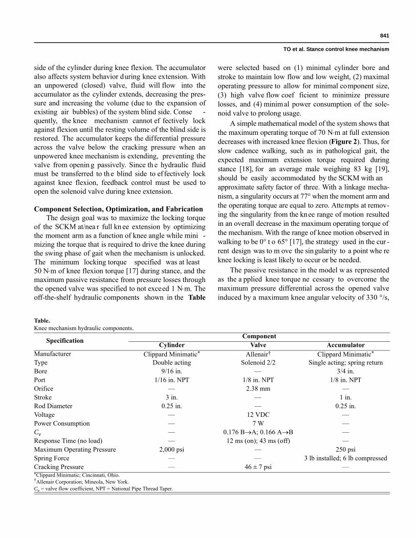
of the SCKM at/nea r full kn ee extension by optimizing the moment arm as a function of knee angle while mini -mizing the torque that is required to drive the knee during the swing phase of gait when the mechanism is unlocked. The minimum locking torque specified was at least 50 Nm of knee flexion torque [17] during stance, and the maximum passive resistance from pressure losses through the opened valve was specified to not exceed 1 Nm. The off-the-shelf hydraulic components shown in the Table
were selected based on (1) minimal cylinder bore and stroke to maintain low flow and low weight, (2) maximal operating pressure to allow for minimal component size, (3) high valve flow coef ficient to minimize pressure losses, and (4) minim al power consumption of the sole-noid valve to prolong usage.
A simple mathematical model of the system shows that the maximum operating torque of 70 Nm at full extension decreases with increased knee flexion (Figure 2). Thus, for slow cadence walking, such as in pathological gait, the expected maximum extension torque required during stance [18], for an average male weighing 83 kg [19], should be easily accommodated by the SCKM with an approximate safety factor of three. With a linkage mecha-nism, a singularity occurs at 77° when the moment arm and the operating torque are equal to zero. Attempts at remov-ing the singularity from the knee range of motion resulted in an overall decrease in the maximum operating torque of the mechanism. With the range of knee motion observed in walking to be 0° t o 65° [17], the strategy used in the cur -rent design was to m ove the singularity to a point whe re knee locking is least likely to occur or be needed.
The passive resistance in the model w as represented as the a pplied knee torque ne cessary to overcome the maximum pressure differential across the opened valve induced by a maximum knee angular velocity of 330 °/s,
Table.Knee mechanism hydraulic components.
Specification ComponentCylinder Valve Accumulator
Manufacturer Clippard Minimatic* Allenair† Clippard Minimatic*
Type Double acting Solenoid 2/2 Single acting; spring returnBore 9/16 in. — 3/4 in.Port 1/16 in. NPT 1/8 in. NPT 1/8 in. NPTOrifice — 2.38 mm —Stroke 3 in. — 1 in.Rod Diameter 0.25 in. — 0.25 in.Voltage — 12 VDC —Power Consumption — 7 W —Cv — 0.176 BA; 0.166 AB —Response Time (no load) — 12 ms (on); 43 ms (off) —Maximum Operating Pressure 2,000 psi — 250 psiSpring Force — — 3 lb installed; 6 lb compressedCracking Pressure — 46 ± 7 psi —*Clippard Minimatic; Cincinnati, Ohio.†Allenair Corporation; Mineola, New York.Cv = valve flow coefficient, NPT = National Pipe Thread Taper.

842
JRRD, Volume 48, Number 7, 2011
which is characteristic of nondisabled gait with a trunk-hip-knee-ankle-foot orthosis (with all jo int constraints freed in the sagittal plane). Since the maximum angular velocity of the knee typically occurs at approximately 30° of knee flexion during swing [17], the maximum pas-sive resistance contributed by the energy losses through the valve has been constrained to approximately 1 Nm (Figure 2).
The SCKM attached to the KAFO, as shown in Figure 3, weighs approximately 3.3 kg (7.3 lb). Hydrau-lic oil, ISO VG 46, was used as the fluid media. A Rey-nolds number of 721 calc ulated at an estimated maximum internal fluid velocity of 13.92 m/s indicates laminar flow. The stru ctural components of th e KAFO were fabricated from a combination of 60 61 and 6063 aluminum alloy and 4142 and galvanized low-c arbon steel alloys. The range of motion of the SCKM in flexion was limited to 106° by the off-the-shelf clevis compo -nents used to simplify construction. A mechanical exten-sion stop was incorporated to prevent hyperextension of the knee. The KAFO was made adjustable for fitting dif-ferent users. Hydraulic quick-release nipples wereinstalled at each cylinder port for pressure measurements and system fluid priming. Th e normally closed solenoid valve has an override lever for manual operation of the valve during test or emergency conditions. Custom cir -cuitry was developed to drive the valves for a pair of SCKMs. A 12 VDC (volts of direct current) supply, boost
converted from a Sony NP-F970 47.5 Wh lithium ionrechargeable battery (Sony Corporation; Tokyo, Japan), was used to power the bilateral SCKMs.
Closed-Loop Controller DesignA closed-loop controller was developed to unlock the
SCKM during the swing phase of gait and lock the mech-anism in extension during stance. The controller was designed as a finite state machine based on feedback sig-nals including (1) contralateral knee valve state control signal, (2) contralateral forefoot and heel ground contact, (3) ipsilateral heel ground contact, (4) ipsilateral knee angle, (5) ipsilateral knee angular velocity, and (6) a syn -chronization signal from the baseline muscle stimulation pattern. The finite state kne e controller (FSKC) and data acquisition software were developed and implemented in
Figure 2.Design parameters of stance control knee mechanism as function of knee joint angle. Max = maximum.
Figure 3.Computer-aided design representation of stance control knee mechanism.
843
TO et al. Stance control knee mechanism
the MATLAB/Simulink/xPC Target real-time environ-ment (The Mathworks, Inc; Natick, Massachusetts).
Sensors for Signal FeedbackFeedback control signals for forefoot and heel contact
were detected by forc e sensitive resistors (FSR) (B&L Engineering; Santa Ana , California) emb edded in thesoles of the shoes to measure foot-to-floor contact under the first metatarsal, great toe, fifth metatarsal, and heel of each foot. The knee angle was measured with a precision rotary potentiometer (Vishay Spectrol; Malvern, Pennsyl-vania) and angular velocity was obtained by signal differ-entiation. All sensors were connected to custom-designed signal processing circuitry and 12 VDC power supply. All signals were sampled at a frequency of 200 Hz and low-pass filtered through software. The potentiometer signal was low-pass filtered (5th-order Butterworth) at a c utoff frequency of 10 Hz and the FSR signals were low-pass filtered (7th-order Butterworth) at a cutof f frequency o f 20 Hz.
Finite State Knee ControllerThe finite state machine uses four rules that can act
independently or mutually to unlock the SCKM for flex -ion. The thresholds for th e FSKC were determined empirically during bench and human testing.
Rule 1 stat es that while the knee is flexed and extending, the mechanism is unlocked. An extending knee is indica ted by an a ngular velocity under a preset threshold (extension is negative). This threshold was set to be two standard deviations above the steady state angular velocity signal at –6 °/s. The knee can extend even in a locked state since the rod side of the s ystem is always open to the accumulator. The knee flexion is detected by two thresholds—the input knee a ngle must have extended below a first threshold (=3°) for the knee to be considered fully extended and flexed beyond a sec-ond threshold (=13°) for the knee to be consider flexed—to accommodate the mechanical compliance of the SCKM when locked and loaded in flexion. Rule 1 was established to prevent SCKM extension when the valve is unpowered, which can compromise the responsiveness of the device locking against flexion.
Rule 2 states that the SCKM unlocks if all three condi-tions are met: (1) the contralateral knee valve is closed unless the contralateral knee is extending and the valve is open to meet conditions of Rule 1; (2) the ipsilateral heel is off the ground (i.e., FSR is low), indicating either terminal
stance or preswing; and (3) either the contralateral forefoot or heel is in contact with the ground (i.e., FSR is high), indicating stance. Rule 2 coordinates locking/unlocking of the SCKM with gait events.
Rule 3 states that the SCKM mus t be unlocked dur-ing the swing phase of gait initiated by the timing signal from the preprogrammed stimulation pattern of the ips i-lateral knee flexors and extens ors muscle during swing. Rule 3 wa s established to prevent the knee mechanism from locking (due to Rule 2) during mid swing in th e event of foot drag resulting in a high FSR signal.
Rule 4 states that once the stimulation pattern signal is low, the SCKM is unlocked until the knee has returned to a fully extended position (as determined by knee angle thresholds of Rule 1) or if both Rule 1 and Rule 2 dictate that locking should occur.
EXPERIMENTAL METHODS
The performance of th e prototype SCKM was first characterized in bench test ing to verify the design crite -ria. Testing on three nondisabled individuals w as con-ducted to validate the system response. The effectiveness of SCKM to support the knee during stance and allow the knee to move freely during swing when driven by electri-cal stimulation of the paralyzed muscles was teste d in one individual with paraplegia implanted with a multi-channel FNS system [20].
System CharacterizationBench testing was conducted on the SCKM to
(1) quantify the passive resistan ce with respect to angular velocity, (2) verify that the mechanism can resist at least 50 Nm of flexion torque at/near full extension, (3) test whether the knee mechanism can reliably unlock under relatively high loads, and (4) quantify the mechanical com-pliance of knee flexion when the knee mechanism is locked. All bench testing was comp leted with the SCKM, as represented in Figure 3, secured to the actuator of a Bio-dex System 3 (Biodex Medical Systems, Inc; Shirley, New York) robotic dyn amometer. In additio n to the feedback sensor and valve control signals, torque was collected from the dynamometer, and cylinder blind and rod side pressures were measured with pressure transducers (Gems Sensors & Controls; Plainville, Connecticut) installed via the quick-release couplers. The dynamometer torque and cylinder pressure signals were low-pass filtered at a cutof f

844
JRRD, Volume 48, Number 7, 2011
frequency of 10 Hz (5th-ord er Butterworth) and 2 0 Hz(7th-order Butterworth), respectively. The experime ntal setup limited the range of motion of the SCKM to 90°.
Passive ResistancePassive resistance of th e knee mechanism a ctuated
by the dynamometer was measured at angular velocities, ranging from 5 °/s to 150 °/s. The inertial component of the measured torque necessary to accelerate the mass of the dynamometer attachment and mechanism was sub-tracted from the total measured torque to obtain the pas-sive resistance torque.
Dynamic CharacterizationThe dynamometer was set to apply a dif ferent maxi-
mum torque for each trial to test locking torque, unlocking response, and mechanical compliance. The mechanical compliance is the change in knee angle into flexion from the angle in which the valve of the mechanism transitioned to a closed state. The flexion torque contributed by gravity (12 Nm), from the mass of th e dynamometer attachment and SCKM, was added to the measured torque applied by the dynamometer to determine the total applied torque to the locked SCKM.
Clinical Evaluation
Study ParticipantsThe reliability of the FSKC for controlli ng the
SCKM was first evaluated with three nondisabled indi-viduals with an average we ight of 69 ± 2 kg. The proto -type HNP system consisting of FNS to the hip, knee, and ankle musculature combined with bila teral SCKMs was evaluated in a participant with thoracic SCI (T9, Ameri-can Spinal Injury Association A). He was 1.57 m tall and weighed 70 kg. He had receiv ed 24 percutaneous intra-muscular electrodes targeting the hip flexors [21] (tensor fasciae latae, sartorius, and iliopsoas), hip extensors (pos-terior portion of adductor magnus, hamstrings, and glu-teus maximus), knee flexors (gracilis and sartorius), knee extensors (vastus medialis, lateralis, and intermedius), ankle dorsiflexors (tibialis anterior), and ankle plantar flexors (gastrocnemius and soleus). He had been using his FNS-only system for exercise and wa lking with standby assist for more than 24 years. User-specific mus-cle stimulation patterns were set up for standing up, sit-ting down, and walking [22].
EvaluationThe SCKMs were installed on an isocentric recipro-
cating gait orthosis (IRGO) custom fitted to each partici-pant (Figure 4). This orthosis weighed approximately 11 kg. For the participant with paraplegia, the IRGO was configured to reciprocally couple hip flexion with con-tralateral hip extens ion, thus maintaining upright trunk posture [23]. The ankle-foot orthosis (AFO) constrained the ankle joint to neutral. Donning of the IRGO consisted of fastening a strap across the lower torso, pelvis, and just below the knee and we aring the shoes, with e mbedded
Figure 4.Individual wearing pair of stance control knee mechanisms.
845
TO et al. Stance control knee mechanism
FSRs insole, over the AFOs while the participant was seated in a chair.
A target/host system was used to implement the HNP controller and collect data. The target computer ran an xPC Target kernel that faci litated the real-t ime imple-mentation of the FSKC, FNS, and data acquisition. Since no FNS w as needed for nond isabled volunteers, only Rule 1 and Rule 2 of the FSKC were implemented to control the SCKM. The target computer was equipped with data acquisition boards (National Instruments; Aus-tin, Texas) for sensor signal acquisition and the output of control states to the exoskeleton. All communication between the tar get PC and exoskeleton was at a fre -quency of 200 Hz. The host computer ran a MATLAB-based graphical user interface developed to simplify the building, calibration, implementation, and testing of the target application.
The muscle stimulator unit, the Universal E xternal Control Unit (UECU), delivered the FNS to drive li mb motion [24]. The UECU contained two 12-channel stimu-lation output boards. The stimuli were bip hasic charge-balanced asymmetric pulses with the sti mulus current amplitude set at 20 mA. The target PC sent the instanta-neous stimulus pulse width and interpulse interval param-eters to the UE CU. Baseline stimulus patterns were used to activate the muscles for the hip and ankle joi nts while the stimulus to the knee extensors was modulated from the baseline stimulation. Electrical stimulation for each con-secutive step was manually triggered by the user via a fin-ger switch.
Load cells (AMTI, Inc ; Watertown, Massachusetts) were integrated into each handle of a two wheel rollator to measure the vertical component of the forces applied by the upper limbs during gait. The load cell signals were low-pass filtered online (7th-order Butterworth) at a cut-off frequency of 20 Hz. A pressure transducer attached at each side of the valve measured the pressure differential, which along with the instantaneous geometry of the SCKM, was used to c alculate the applied torque on the SCKM. Gait parameter s were determined through the motion capture of markers, positioned on the participant and exoskeleton, using the Vicon MX40 (Vicon, Inc; Oxford, UK) motion analysis system. Average speed was determined from tracking of the forward velocity of a marker positioned approximately at the participant’s cen-ter of mass. Step length was determined by measuring the distance between calcaneous markers upon heel strike.
Cadence was determined by averaging the dura tion of each step.
The participants walked w ith the exoskeleton along an 8-meter walkway. All participants walked with a two-wheel rollator and a spotter f or safety. Additionally, the participant impaired by SCI walked with the knee exten-sor stimulation either turned off during stance, to deter-mine whether the SCKM was capable of fully supporting the knee, or turned on (i.e., baseline stimulation) during stance, as a control case. Each case was randomized over six trials. Approximately 20 strides were analyzed for each case. Analysis of va riance with 95 perc ent confi-dence (p < 0.05) determined sta tistically significant dif-ferences in user ef fort and gait para meters between stance supported by only the SCKM versus stance sup-ported by stimulated muscles.
RESULTS
System Characterization
Passive ResistanceFor all angular velocities, the mean passive resis-
tance torque magnitude did not exceed 2.0 Nm in flexion and 1.0 Nm in extension. A statistical difference in resis-tance was found betwee n flexion and extension ( p < 0.001). The passive resistance is larger in flexion because the accumulator pressure op poses SCKM flexion but assists in extension due to the volume differential between cylinder sides. In flexion, passive resistance was independent of angular velocity. In the extension, passive resistance was independent of angular velocities up to 120 °/s ( p = 0.35). However , a statistical dif ference in resistance was found between the low angular velocities and 150 °/s ( p < 0.001). Extr apolated from first-order least squares regressions, the mean applied passive resis-tance was 2.1 Nm and 0.9 Nm at a maximum knee angular velocity of 350 °/s [17] for flexion and extension, respectively.
Dynamic ParametersA maximum flexion torque of 71 Nm was applied on
the locked SCKM. The duration to unlock the SCKM by opening the valve was appro ximately 0.2 s with a valve pressure differential of up to 700 psi correspo nding to a flexion torque of 49 Nm at full extension. When unloaded,
846
JRRD, Volume 48, Number 7, 2011
the SCKM required only 12 ms to unlock; however, once loaded, it required a minimum of 180 ms to unlock.
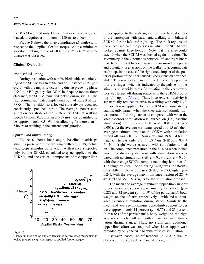
Figure 5 shows the knee compliance ( angle) with respect to the applied flexion torque. At th e minimum specified locking torque of 50 Nm, 2.5° to 4.5° of com-pliance was observed.
Clinical Evaluation
Nondisabled TestingDuring evaluation with nondisabled subjects, unlock-
ing of the SCKM began at the end of midstance (38% gait cycle) with the majority occurring during preswing phase (49% to 64% gait cy cle). With inadequate foot-to-floo r clearance, the SCKM remained locked during swing. This shortcoming motivated implementation of Rule 3 of the FSKC. The transition to a locked state always occurred consistently upon heel strike. The average power con-sumption per stride of the bilateral SCKMs at walking speeds between 0.22 m/s an d 0.67 m/s was quantified to be approximately 8.5 W, thus allowing for more than 5 hours of walking in the current configuration.
Spinal Cord Injury TestingFigure 6 shows knee angle, baseline quadriceps
stimulus pulse width for walking with only FNS, actual quadriceps stimulus pulse width with st ance supported only by th e SCKM, calculated torq ue applied to the SCKMs, and the vertica l component of th e upper-limb
forces applied to the walking aid for three typical strides of the participant with paraplegia walking with bilateral SCKMs for the left and right legs. The thick regions on the curves indicate the periods in which the SCKM wa s locked against knee flexion. Note that the knee could extend when the SCKM was locked against flexion. The asymmetry in the kinematics between left and right knees may be attributed to both variations in muscle response and voluntary user actions on the walker to accommodate each step. In the case of the right knee, impact of the pos-terior portion of the heel caused hyperextension after heel strike. This was less apparent in the left knee. Step initia-tion via finger switch is indicated by the puls es in the stimulus pulse width plots. Stimulation to the knee exten-sors was turned off during stance with the SCKM provid-ing full support (Video). Thus, knee extensor activity is substantially reduced relative to walking with only FNS. Flexion torque applied to the SCKM was consi stently significantly larger when the knee extensor stimulation was turned off during stance as compared with when the knee extensor stimulation was turned on (i .e., baseline stimulation) during stance (le ft: p < 0 .001; right: p < 0.001). At the average wa lking speed of 0.15 m/s the average maximum torque on the SCKM with stimulation turned off was 9.0 ± 2.6 Nm (left) and 19.8 ± 4.6 Nm (right), whereas only 2.8 ± 1.0 Nm (left) an d 8.4 ± 6.1 Nm (right) were measured with stimulation turned on. The compliance measured in the SCKM when locked was not statistically different with stimulation as com -pared with no stimulation (left: p = 0.29; right: p = 0.36), with the average SCKM complia nce being less than 1°. The range of knee motion during swing was not statisti-cally different between cases (left: p = 0.83; right: p = 0.24), with the average maximum knee flexion of 28° ± 4° (left) and 36° ± 5° (right) for the stimulation off case.
The mean and average maximum upper-limb support forces over stride s were approximate ly 12 perc ent (p = 0.28) and 32 percent (p = 0.19) of the participant’s body weight on the left arm, respectively , with and without knee extensor stimulation during stance. Similarly, the mean and average maximum upper-limb support forces were approximately 11 percent (p = 0.77) and 23 percent (p = 0.65) of the participant’ s body weight on the right arm, respectively, with and without knee extensor stimu -lation during stance. Thus, no significant additional upper-limb effort was required when knee support wa s provided by only the SCKM with muscles stimulation.
Between cases, no dif ferences (p > 0.05) we re observed in speed, cadence, and step length.
Figure 5.Change in knee flexion angle when stance control knee mechanism is locked (compliance) with respect to applied flexion torque.

847
TO et al. Stance control knee mechanism
DISCUSSION AND CONCLUSIONS
The results show the feasibility of utilizing a hydrau-lic approach in the development of a controllable mecha-nism for providing knee stability during stance when restoring gait after paralysis from SCI. The design objec-tives of this hydraulic SCKM were to (1) fully support the knee in extension during stance, (2) allow for unimpeded knee flexion during sw ing, and (3) consistently unlock under an applied flexion load. The development of the SCKM consisted of the simulation and optimization of the conceptual design, bench testing to verify design specifi-cations, nondisabled testing to confirm operational response and safety, and system validation on a user with paraplegia.
The design specifications were verified through bench testing. First, the SCKM wa s capable of supporting more than 50 Nm of applied flexion torque with less than 5° of
mechanical compliance. S econd, the average passiveresistance of the SCKM wa s less than 2 N m and 1 Nm, respectively, during flexion and extension. For this passive resistance during gait to be overcome, approximately 13 percent of knee flexion and only 1 p ercent of the knee extension torque generated by FNS was requ ired [22]. Finally, SCKM was sh own to have improved on existing designs in that it was capable of consistently unlocking under an applied flexion torque of up to 49 Nm.
Evaluation of the prototype HNP with bilateral SCKMs with an individual with paraplegia demonstrated that the SCKM was capable of fully supporting the user during the stance phase of gait without the need for electri-cal stimulation of knee exte nsors or additional arm sup -port. No statis tical differences were observed in the mechanism compliance, upper-limb effort, gait speed, cadence, and step length between walking with knee
Figure 6. Knee angle, baseline quadriceps stimulus pulse width for walking with only functional neuromuscular stimulation (FNS), actual stimulus pulse width with only stance control knee mechanism (SCKM) supporting knee during stance, calculated torque resisted by SCKMs, and upper-limb forces (Fz) applied to walker represented as percentage body weight (% BW) for three strides. Step trigger pulses are indicated in stimulus pulse width plots.

848
JRRD, Volume 48, Number 7, 2011
extensor stimulation during stance and SCKM on ly sup-ported stance without knee extensor stimulation.
The modest knee range of motion observed with the individual with paraplegia relative to nondisabled gait may be c ontributed to weak knee flexors, mechanism passive resistance, and/or me chanism mass [17]. The torque generated by the knee flexors can be augmented by the addition of an activ e component to the SCKM. This would, howe ver, increase system ma ss and power consumption. The passive resistance as quantified in this study was only from the energy losses within the hydrau-lics. Future work will focus on examining the influence of the mass and inertial forces of the SCKM on knee joint kinematics. Currently, the hydraulics comprise 26 per-cent (=0.85 kg) of the to tal mass of the SCKM and KAFO. Thus, structura l components of the mechanism (i.e., uprights, mounting brackets, an d AFO) weig h approximately 2.48 kg. Whe n these structural compo-nents were fabricated, the mass and overall mass distribu-tion over the limb were not pri ncipal considerations. Many of the se parts we re overengineered using stee l alloys to as sure structural integrity and safety during mechanical load testing and human evaluation. Full opti-mization of the SCKM in relation to the materials utilized and mass distribution to minimize inertial effects has yet to be accomplished. To fully take advantage of the reduc-tion in muscle activity as a result of the SCKM, future research will focus on the effect of system mass on the energy costs. The objective is to understand whether the energy saved from reducing muscle activity outweighs the energy lost from moving the mass of the SCKM and whether this net saved energy is functionally relevant in positively affecting walking distance and duration. As a portable controller has yet to be developed, the use of the SCKM was confined to the la boratory. Future work will focus on minimizing the we ight and geome try of the SCKM as well as the development of a wearable/portable control unit to perform metabolic and walk-to-fatigue studies outside the laboratory.
The development of the hydraulic knee mechanism from conception to implementation was expedited by use of a simplified transmission solution. This compromise reduced the range of motion in which the mechanism can effectively support the user. Future work will include the selection of an optimal tran smission type. A rack-and-pinion solution could facilita te a constant moment arm with respect to knee angle . Thus, the cons traint could support against a high torque at any angle in which the knee is locked. However, the gears may increase the size
and weight of the device. Another solution may be to use a more complex linkage or a cam design to optimize the profile of the moment arm with respect to the knee angle. Similar to the current design, larger moment arms will occur at small knee angles that require high impe dance while smaller moment arms will occur at lar ger knee angles coincident with high angular velocities during gait to minimize mechanism passive resistance. With this approach, a larger cylinder bore c an be used to inc rease the maximum operating tor que without subst antially increasing passive resistance.
ACKNOWLEDGMENTS
Author Contributions:Study concept and design: C. S. To, R. Kobetic, R. J. Triolo.Acquisition of data: C. S. To, R. Kobetic, T. C. Bulea, J. R. Schnellenberger, M. L. Audu.Analysis and interpretation of data: C. S. To, R. Kobetic, T. C. Bulea, M. L. Audu.Drafting of manuscript: C. S. To, R. Kobetic.Critical revision of manuscript for important intellectual content:C. S. To, R. Kobetic, T. C. Bulea, M. L. Audu, R. J. Triolo.Statistical analysis: C. S. To.Obtained funding: R. Kobetic, R. J. Triolo.Administrative, technical, or material support: T. C. Bulea,J. R. Schnellenberger, M. L. Audu, G . Pinault.Study supervision: R. Kobetic, R. J. Triolo.Financial Disclosures: The authors have declared that no competing interests exist.Funding/Support: This material was based on work supported in part by the Department of Veterans Affairs, Rehabilitation Research and Development Service (grant A6404R) and the Department of Defense, Congressionally Directed Medical Research Program (grant PR043074).Additional Contributions: We thank Drs. Robert F. Kirsch, Patrick E. Crago, and Roger D. Quinn for their advice and contributions. Dr. To is currently working at Chrysler Group, LLC, Auburn Hills, Michigan.Institutional Review: All volunteers signed a consent form approved by the institutional review board of the Louis Stokes Cleveland Department of Veterans Affairs Medical Center.Participant Follow-Up: The authors plan to inform participants of the publication of this study.
REFERENCES
1. Lehmann JF, Stonebridge JB. Kn ee lock device for knee ankle orthoses for spinal cord injured patients: An evalua-tion. Arch Phys Med Rehabil. 1978;59(5):207–11.[PMID: 655831]

849
TO et al. Stance control knee mechanism
2. Kagaya H, Shimada Y, Sato K, Sato M, Iizuka K, Obinata G . An electrical knee lock system for functional electrical stimulation. Arch Phys Med Rehabil. 1996;77(9):870–73.[PMID: 8822676]DOI:10.1016/S0003-9993(96)90272-5
3. Harrison R, Lemaire E, Jeffreys Y, Goudreau L. Design and pilot testing of an orthotic stance-phase control knee joint. Orthopadie Technik. 2001;3:2–4.
4. Kim G , Kang S, Kang S, Ryu J, Mun M, Kim K. Unlock-able knee joint mechanism for powered gait orthosis. Int J Precision Eng Manufacturing. 2009;10(3):83–89.DOI:10.1007/s12541-009-0051-y
5. Van Leederdam NG , Kunst EE. New UTX-swing orthosis: Normal gait and safe standing. Orthopadie Technik. 1999;50: 506–15.
6. Nijenbanning G , Goudsmit JA, inventors. Gravity operated locking hinge. United States patent US 20,030,153,854. 2003 Aug 14.
7. Hatton BJ, Hatton DL, W allace ZG , inventors. Articulating knee supports. United States patent US 6,635,024. 2003 Oct 21.
8. Yakimovich T, Kofman J, Lemaire ED. Design and evalua-tion of a stance-control knee-ankle-foot orthosis knee joint. IEEE Trans Neur Syst Rehabil Eng. 2006;14(3):361–69.[PMID: 17009496]DOI:10.1109/TNSRE.2006.881578
9. McGhee RB, Tomovic R, Yang PY, MacLean IC. An experi-mental study of a sensor-controlled external knee lockin g system. IEEE Trans Biomed Eng. 1978;25(2):195–99.[PMID: 640706]DOI:10.1109/TBME.1978.326247
10. Goldfarb M, D urfee WK. Design of a cont rolled-brake orthosis for FES-aided gait. IEEE Trans Rehabil Eng. 1996; 4(1):13–24. [PMID: 8798068]DOI:10.1109/86.486053
11. Irby SE, Kaufman KR, Wirta RW, Sutherland DH. Optimi-zation and application of a wrap-spring clutch to a dynamic knee-ankle-foot orthosis. IEEE Trans Rehabil Eng. 199 9; 7(2):130–34. [PMID: 10391582]DOI:10.1109/86.769402
12. Sclater N, Chironis NP. Mechanisms and mechanical devices sourcebook. 3rd ed. New York (NY): McGraw-Hill; 2001.
13. Moreno JC, Brunetti F, Rocon E, Pons JL. Immediate effects of a controllable knee a nkle foot orthosis for func-tional compensation of gait in patients with proximal leg weakness. Med Biol Eng Comput. 2007;46(1):43–53.[PMID: 17926076]
14. Yakimovich T, Lemaire ED, Kofman J. Engineering design review of stance-control knee-ankle-foot orthoses. J Reha-bil Res Dev. 2009;46(2):257–67. [PMID: 19533539]DOI:10.1682/JRRD.2008.02.0024
15. Marsolais EB, Ko betic R, Polando G , Ferguson K, Tash-man S, Gau dio R, Nan durkar S, Lehn eis HR. Th e Case
Western Reserve University hybrid gait orthosis. J Spinal Cord Med. 2000;23(2):100–108. [PMID: 10914350]
16. To CS. Closed-loop control and variable constraint mecha-nisms of a hybrid neuroprosthesis to restore gait after spi-nal cord inj ury [dissertation]. [Cleveland (OH)]: Case Western Reserve University; 2010.
17. Perry J. Gai t analysis: Normal and pathological function. Thorofare (NJ): SLACK; 1992. p. 91–92.
18. Winter DA. The biomechanics and motor control of human gait: Normal, elderly and pathological. 2nd ed. Waterloo (Canada): Waterloo Press; 1991.
19. Human weight [Internet]. [updated 2011 Apr 15; cited 2010 Nov 20]. Available from: http://www.articleworld.org/index.php/Human_weight
20. Agarwal S, Ko betic R, Nand urkar S, Marsolais EB. Func-tional electrical stimulation for walking in para-plegia: 17-year follow-up of 2 cases. J Spinal Cord Med. 2003;26(1): 86–91. [PMID: 12830975]
21. Nandurkar S, Marsol ais EB, Ko betic R. Percu taneous implantation of iliopsoas for functional neuromuscular stimulation. Clin Orthop Relat Res. 2001;(389):210–17.[PMID: 11501813]DOI:10.1097/00003086-200108000-00030
22. Kobetic R, Marsolais EB. Synthesis of paraplegic gait with multichannel functional neuromuscular stimulation. IEEE Trans Rehabil Eng. 1994;2(2):66–79.DOI:10.1097/00003086-200108000-00030
23. Dall PM, Müller B, Stallard I, Edwards J, Granat MH. The functional use of the reciprocal hip mechanism during gait for paraplegic patients walking in the Louisiana State Uni-versity Reciprocating Gait Orthosis. Prosthet Orthot Int. 1999;23(2):152–62. [PMID: 10493143]
24. Trier S, Vrabec T, Weisgarber J. Using functional electrical stimulation to restore movement to individuals with neuro-muscular disabilities. MATLAB Digest: Academic Edition. 2008. p. 1–4.
Submitted for publication July 20, 2010. Accepted in revised form January 20, 2011.
This article and any supplementary material should be cited as follows:To CS, Kobetic R, Bulea TC, Audu ML, Schnellenberger JR, Pinault G , Triolo RJ. Stance control knee mechanism for lower-limb support in hybrid neuroprosthesis. J Reha-bil Res Dev. 2011;48(7):839–50.DOI:10.1682/JRRD.2010.07.0135ResearcherID: Curtis S. To, PhD: C-8101-2011.


![Microprocessor-controlled Lower Limb Prostheses1].pdfLower limb prostheses are designed to replace the normal function of the knee and/or ankle. Microprocessor-controlled lower limb](https://img.dokumen.tips/doc/110x75/5e7cc4d758b12e78f474a9a9/microprocessor-controlled-lower-limb-prostheses-1pdf-lower-limb-prostheses-are.jpg)