Embed Size (px)
Citation preview

StairBiz Manual - CNCv9.00.0
© StairBiz Software Pty Ltd 1999 - 2019
This manual is part of the StairBiz Program and is subject to the StairBiz End User License Agreement.
If you do not have a copy of this license agreement, please contact us.
If you do not agree to all the terms and conditions contained in the End User License Agreement you may not evaluate or use
the StairBiz Program or this manual.
2
Table of contents
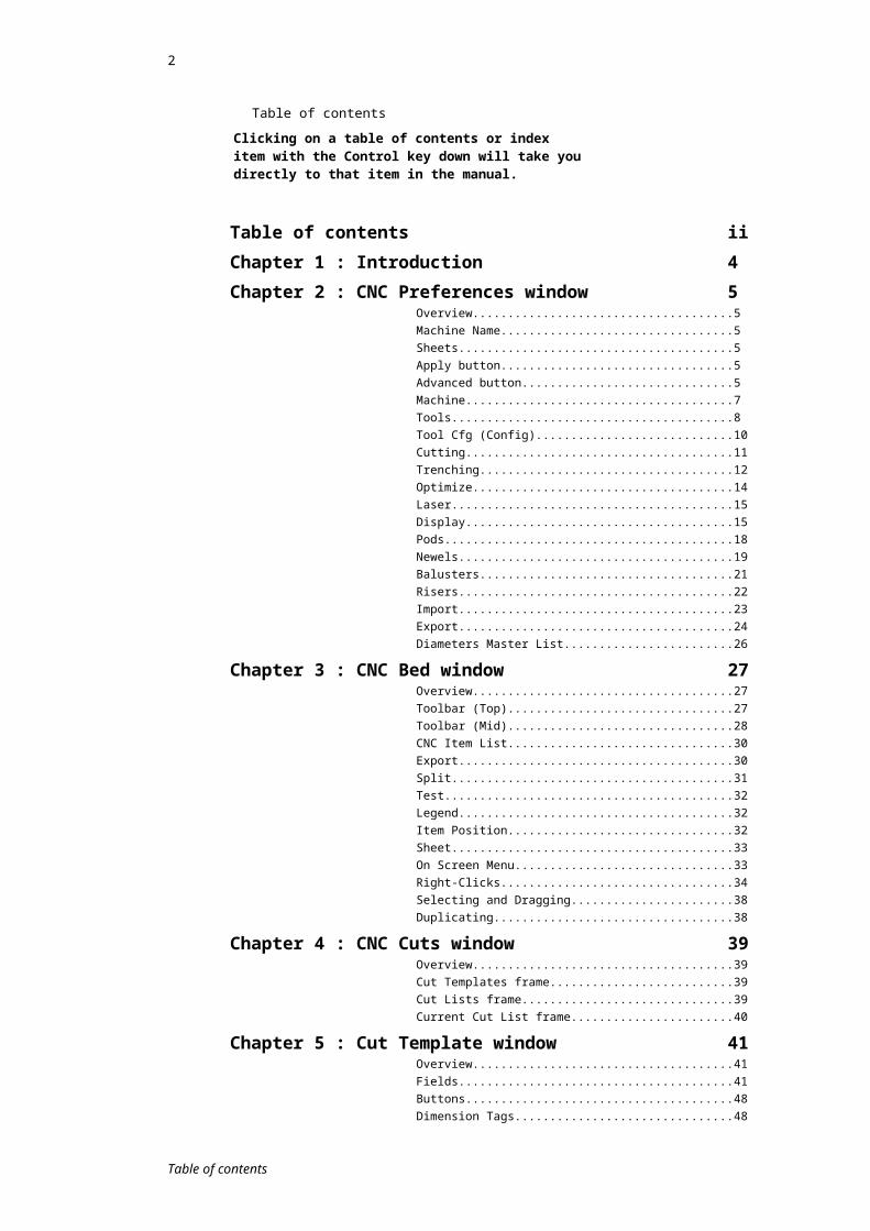
Clicking on a table of contents or index item with the Control key down will take you directly to that item in the manual.
Table of contents iiChapter 1 : Introduction 4Chapter 2 : CNC Preferences window 5
Overview.................................................................................5Machine Name........................................................................5Sheets.....................................................................................5Apply button............................................................................5Advanced button.....................................................................5Machine...................................................................................7Tools.......................................................................................8Tool Cfg (Config).....................................................................10Cutting.....................................................................................11Trenching................................................................................12Optimize..................................................................................14Laser.......................................................................................15Display....................................................................................15Pods........................................................................................18Newels....................................................................................19Balusters.................................................................................21Risers......................................................................................22Import......................................................................................23Export......................................................................................24Diameters Master List.............................................................26
Chapter 3 : CNC Bed window 27Overview.................................................................................27Toolbar (Top)..........................................................................27Toolbar (Mid)...........................................................................28CNC Item List..........................................................................30Export......................................................................................30Split.........................................................................................31Test.........................................................................................32Legend....................................................................................32Item Position...........................................................................32Sheet.......................................................................................33On Screen Menu.....................................................................33Right-Clicks.............................................................................34Selecting and Dragging...........................................................38Duplicating..............................................................................38
Chapter 4 : CNC Cuts window 39Overview.................................................................................39Cut Templates frame...............................................................39Cut Lists frame........................................................................39Current Cut List frame.............................................................40
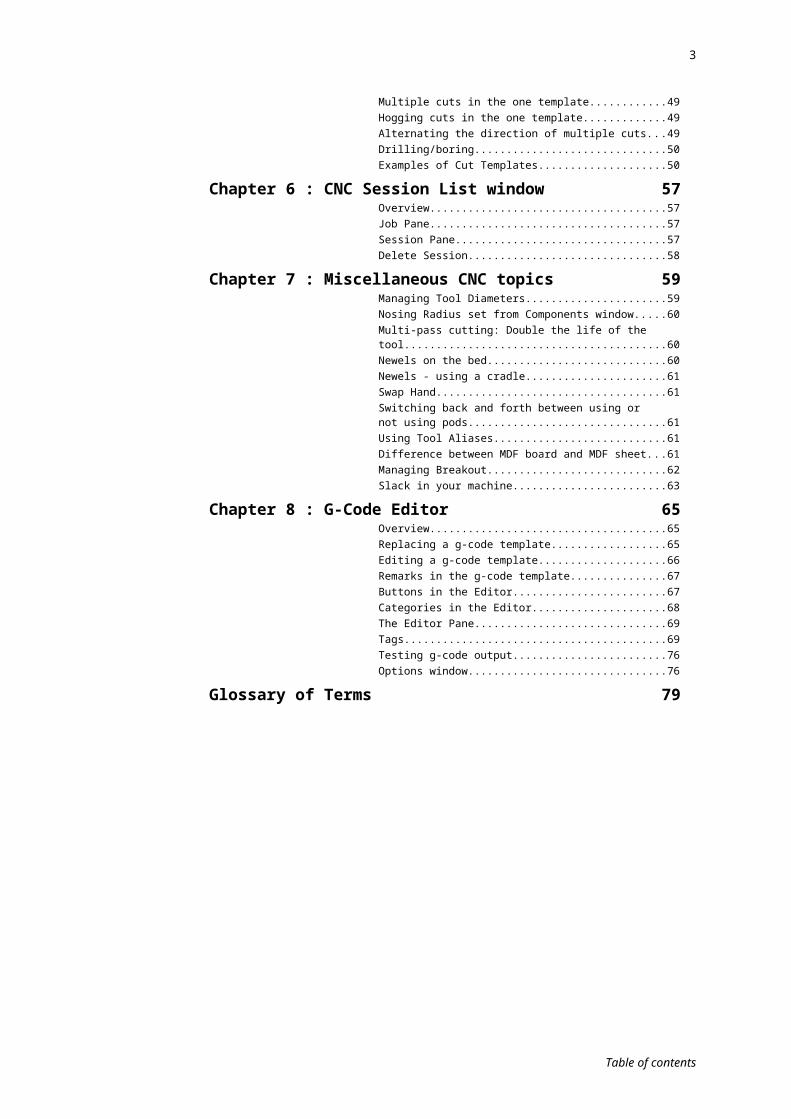
Chapter 5 : Cut Template window 41Overview.................................................................................41Fields.......................................................................................41Buttons....................................................................................48Dimension Tags......................................................................48Multiple cuts in the one template.............................................49Hogging cuts in the one template............................................49Alternating the direction of multiple cuts..................................49Drilling/boring..........................................................................50Examples of Cut Templates....................................................50
Chapter 6 : CNC Session List window 57Overview.................................................................................57Job Pane.................................................................................57
Table of contents
3
Session Pane..........................................................................57Delete Session........................................................................58
Chapter 7 : Miscellaneous CNC topics 59Managing Tool Diameters.......................................................59Nosing Radius set from Components window.........................60Multi-pass cutting: Double the life of the tool...........................60Newels on the bed...................................................................60Newels - using a cradle...........................................................61Swap Hand..............................................................................61Switching back and forth between using or not using pods........................................................................................61Using Tool Aliases...................................................................61Difference between MDF board and MDF sheet.....................61Managing Breakout.................................................................62Slack in your machine.............................................................63
Chapter 8 : G-Code Editor 65Overview.................................................................................65Replacing a g-code template...................................................65Editing a g-code template........................................................66Remarks in the g-code template..............................................67Buttons in the Editor................................................................67Categories in the Editor...........................................................68The Editor Pane......................................................................69Tags........................................................................................69Testing g-code output..............................................................76Options window.......................................................................76
Glossary of Terms 79
Table of contents
4
Chapter 1 : Introduction
This manual is used in conjunction with the StairBiz Users Manual.Note that the responsibility is yours to ensure that the settings in StairBiz for your particular CNC machine are accurate and appropriate.
The most critical settings relate to the Z depths of your tools in the file you export to the machine, and until you are completely satisfied that these are under all circumstances accurate and will cause no damage to your machine they should always be checked manually (by opening the g-code file and checking all Z depths specified in the g-code).
Other critical settings relate to the paths generated, and again it is your responsibility to check those paths (X, Y and Z) to ensure that they are accurate and appropriate, and that there are no obstacles in their way.
If you do not understand how to check these (or any other aspect of the g-code file) you must consult with your machine’s manufacturer.
Before using StairBiz to process CNC you must accept that StairBiz Software Pty Ltd and it’s agents and consultants have no liability for any damage to your machine or components. If you do not accept this please contact your StairBiz representative.
Chapter 1 : Introduction

5
Chapter 2 : CNC Preferences window
Overview
From: CNC menu ; Preferences menu-item.
The CNC Preferences window allows you to define the behavior of the CNC window and can define settings for one or more CNC Machines.
Machine NameThe CNC preferences shown in all the tabs in this window are specific to one machine (i.e. the machine shown in the Machine Name pull-down).
However, StairBiz can output to any number of CNC machines, and therefore gives you the option to create and edit the settings for different machines in this window. With multiple machines, the machine (and its preferences) that are applied to the sessions on the CNC Bed can be selected in the Machine pull-down menu in the CNC Bed window.
The Machine Name setting lets you select which Machine your current CNC Preferences apply to. If you are only using one machine, you can leave this set at Default. If you wish to create an additional machine, or rename, duplicate or delete the current machine, click on the Add/Delete/Rename button to open the CNC Machines window.
SheetsThe Sheets text box allows you to define the sizes of MDF sheets that can be placed on your CNC bed. Click on the Sheets text box, and type in the dimensions for each sheet that you will be working with. Press Enter to move to a new line for each sheet.
The format for each sheet should be Length x Width x Thickness. For example: 96x48x1 would define a sheet that is 8 foot by 4 foot and 1 inch thick.
These sheet sizes can be selected from the CNC Bed Window and are shown on the CNC Bed.
See also Difference between MDF board and MDF sheet.
Apply buttonThis button will apply the current preference settings to the components currently on the CNC Bed. This is useful if (for example) you have just changed a tool size and wish to see the update to the tool path.
Chapter 2 : CNC Preferences window

6
Advanced buttonFrom this button you can import and export the CNC Prefs window for a particular machine, import a file containing information that StairBiz can use to manufacture pods for a flat-bed machine, and manage g-code templates (the driver that provides and interface between StairBiz and your particular machine).
Export machine settings to fileExports the settings (field values) from all tabs of the CNC Prefs window for the current machine to a file with the extension “.sbm”. By default the file is saved in your C:/StairBiz Program/CNC GT Editor/G-Code Templates folder. This file is only useful for importing back in to the current machine, and would normally only be used by StairBiz support to export a file to send to you (which you could then import). It might also be useful if you wanted to send StairBiz support your machine settings for evaluation.
This also exports the Cut List associated with this machine as shown at the top of the CNC Bed window.
It does not include the g-code template – see further below to export this.
Import machine settings from fileImports the settings for all tabs of the CNC Prefs window and the Cut List (as shown at the top of the CNC Bed window) for the current machine from a file with the extension “.sbm”. It is used where StairBiz support sends you the file for a “typical” Preferences window for your particular machine. StairBiz expects to find this file in your C:/StairBiz Program/CNC GT Editor/G-Code Templates folder.
Note that even where StairBiz sends you such a file to assist you in setting up a CNC Prefs window for your machine, there is still work for you to do (for example, we would not know your machine dimensions, tool id’s, diameters etc. Note that the responsibility is yours to ensure that the settings in your CNC Prefs window are accurate and appropriate for your particular machine. The critical settings relate to the Z depths of your tools in the file you export to the machine, and until you are completely satisfied that these are under all circumstances accurate and will cause no damage to your machine they should always be checked manually (by opening the g-code file and checking all Z depths specified in the g-code). If you do not understand how to check these (or any other aspect of the g-code file) then you must consult with your machine’s manufacturer.
Post all CNC Prefs to ServerIf you work on a StairBiz network, and more than one person uses the CNC window, and you make changes to the CNC Prefs window, you need to post those changes to the server so that they are available to the other users. Other users are refreshed with these changes the next time they connect to the StairBiz server (i.e. they need to disconnect and re-connect in order to upload the changes from the server).
You will need to have Permissions set to access this menu-item.
Manage g-code templatesStairBiz uses G-Code Templates to create the correct NC Code for your particular CNC machine. These templates can be created by StairBiz consultants or by a third party using the CNC GT Editor (an external program included with the StairBiz installation and located in the folder C:/StairBiz Program / CNC GT Editor).
During your initial installation, your StairBiz consultant will probably set up you g-code template for you. If you need to do it yourself, or if you are sent a g-code template update, this is how …
1) StairBiz will send you the appropriate g-code template (a file with the extension “sbg”). This template should be placed in the following folder: C:/StairBiz Program/CNC GT Editor/G-Code Templates. Any existing sbg files in this folder should be trashed (this is not critical, but is best to avoid confusion).
2) Click the Advanced button in the CNC Prefs window, and select Manage g-code templates to open the G-code Templates window.
>> Manage g-code templates
Chapter 2 : CNC Preferences window

7
In this window the “.sbg” file will be shown in the list on the left. Templates previously imported will be shown in the list on the right.
3) In the list of previously imported templates (on the right), select each template not
needed (one at a time) and click the Remove button. This is not critical, but is best to avoid confusion.
4) From the list of g-code template files currently in C:/StairBiz Program / CNC GT Editor / G-Code Templates (i.e. the list on the left), select the appropriate template (i.e. the one we sent you), then click the Import button. You can import a file (from the left) with the same name that has previously been imported (on the right), but understand that this will overwrite the existing template. You would need to do this if you or someone else has made a change to the G-Code template and you want StairBiz to be aware of that change.
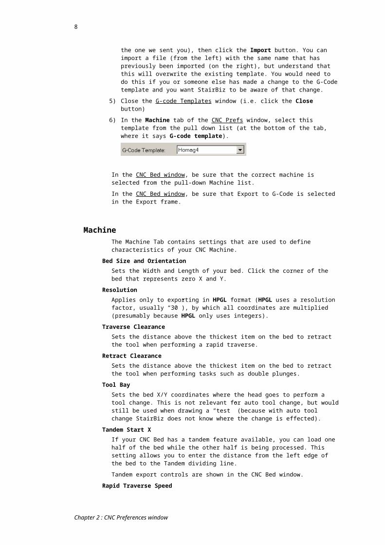
5) Close the G-code Templates window (i.e. click the Close button)
6) In the Machine tab of the CNC Prefs window, select this template from the pull down list (at the bottom of the tab, where it says G-code template).
In the CNC Bed window, be sure that the correct machine is selected from the pull-down Machine list.
In the CNC Bed window, be sure that Export to G-Code is selected in the Export frame.
MachineThe Machine Tab contains settings that are used to define characteristics of your CNC Machine.
Bed Size and OrientationSets the Width and Length of your bed. Click the corner of the bed that represents zero X and Y.
ResolutionApplies only to exporting in HPGL format (HPGL uses a resolution factor, usually “30”), by which all coordinates are multiplied (presumably because HPGL only uses integers).
Traverse ClearanceSets the distance above the thickest item on the bed to retract the tool when performing a rapid traverse.
Retract ClearanceSets the distance above the thickest item on the bed to retract the tool when performing tasks such as double plunges.
Tool BaySets the bed X/Y coordinates where the head goes to perform a tool change. This is not relevant for auto tool change, but would still be used when drawing a “test” (because with auto tool change StairBiz does not know where the change is effected).
Tandem Start XIf your CNC Bed has a tandem feature available, you can load one half of the bed while the other half is being processed. This setting allows you to enter the distance from the left edge of the bed to the Tandem dividing line.
Tandem export controls are shown in the CNC Bed window.
Rapid Traverse Speed
Chapter 2 : CNC Preferences window
8
The speed of rapid traverse, measured in whatever units your machine requires.
Z- ZeroDefines how StairBiz will calculate zero for the Z Axis. Select Bed Surface to treat the top of the bed as zero. Select Actual Material Surface to specify the top of the thickest piece of material on the bed (as calculated by StairBiz) as zero. Select Nominal Material Surface to specify a hypothetical timber thickness as zero (useful if using a chock to calibrate Z-zero). If using this option, also enter the hypothetical thickness.
G-Code TemplateStairBiz uses G-Code Templates to create the correct NC Code for your particular CNC Machine. These templates can be created by StairBiz consultants or by a third party using the CNC GT Editor (an external program included with the StairBiz installation and located in the CNC GT Editor folder).
Select the relevant G-Code Template from this list. This list contains all G-Code templates that you have imported into StairBiz.
See also “Advanced button/ Manage g-code templates”
ToolsStairBiz requires certain information about the tools that are available for CNC Sessions. To add a new tool, click the Add button. To delete a tool, select it in the list on the left and click the Delete button.1 Means the value is only relevant if the machine reads the value from the g-code that StairBiz exports (the alternative is that the value is set at the machine consul by the operator). Whether or not the such values are needed varies from machine to machine – if you’re not sure, contact StairBiz support.2 Means the format of the value is as per the machine’s documentation. The field is a text field and you can enter anything you like (not a numeric field expecting only a number). For example, feed rate could be in mm per second or meters per minute (or some other variation) – StairBiz inserts the value into the g-code exactly as you enter it here.
Tool ID 2: The name by which StairBiz knows this tool, or anything you like in the case of a manual tool change (e.g. “1” or “T1” or “BF705” etc).
Tool ID for Export 2: Optional. The Tool ID you want to use in the g-code when you export a session (i.e. the tool ID your machine is expecting).
The idea of this is that you can have multiple tools, all with a different Tool ID but with a common Tool ID Export. This means that you can set up different properties for these seemingly different tools (e.g. different multi-pass settings), and refer to whichever in the Tools Config tab, but when it comes down to the export each of these tools have the same name (make sure they each have the same diameter).
All references to tool ID’s in StairBiz will show the Tool ID (not the Tool ID Export – it only shows up in g-code).
If the Tool ID Export field is blank, StairBiz uses the existing Tool ID by default.
If Tool ID Export is used you can optionally enter the word “Parent” as the Tool Diameter, in which case StairBiz will get the tool diameter for this tool from the parent tool (i.e. the tool specified in the Tool ID Export field. This saves you having to change the diameter of an alias tool when the diameter of the parent tool changes (i.e. when you have sharpened it).
Diameter: The actual diameter of the tool.
StairBiz always exports the centre of the path (the g-code StairBiz exports turns off the machine’s XY compensations – they have already been done by StairBiz). If you sharpen the tool, you will need to change the diameter in StairBiz. Also see Miscellaneous CNC topics; Managing Tool Diameters.
Chapter 2 : CNC Preferences window

9
If Tool ID Export is used you can optionally enter the word “Parent” as the Tool Diameter - see note under that heading.
Note that where you are using multiple machines that may share tools with the same ToolId, you can set tool diameters in a master list, such that when you sharpen this tool you only have to change the diameter in one place. See “Diameters Master List”
Feed Rate 1,2: the feed rate (speed) of the head when cutting or trenching.
Plunge 1,2: the rate of plunge to use for this tool.
RPM 1,2: the rotation (spin) speed of the spindle (normally revolutions per minute).
Length Z-Offset 1: Mainly used only where the controller does not automatically adjust (Z-compensate) for the different length of the tools, in which case the tool used to calibrate the Z for the machine would have an adjustment of zero and all other tools would be adjusted by the difference in length. This way do you not need to do a z-calibration (material surface) on each tool change.
A positive value will set the tool higher.
Another use for this is where (for example) your newels are held by clamps rather than pods, and the clamps are a different height than the pods. Here you could set up a separate (dummy) tool for newel routing which includes the Z-Offset (being the difference between the pod height and the clamp height). You could then use Tool ID for Export to reference the actual tool.
X-Offset 1: all X-coordinates for this tool in the g-code will be offset by this dimension – normally only used for multi-head machines where the controller does not make the compensation.
Y-Offset 1: See X-Offset.
Motor ID 1,2: Mainly used where the machine has more than one motor and the controller does not read the motor id from the tool used.
It is also possible to use the Motor Id as the Tool Id (this is done in the g-code template by StairBiz support). This is useful where you want a single tool to have different properties (e.g. feed rate). For example, Tool 1 and Tool 2 could have different properties, but a common Motor Id. If we use the motor id as the tool id in the g-code template, the controller reads the two tools as being the same but having different properties.
Description 2: Anything you like to describe the tool (StairBiz does not normally use this in the g-code).
Tool Type: This tells StairBiz how the tool is to be used.
Vertical Router; A vertical tool that can cut in any X,Y direction without need of a C-axis.
Vertical Saw; A vertical tool that can cut in any X,Y direction only with a C-axis set to the direction of the cut.
Vertical Drill; A vertical tool that can cut only in the Z-direction by plunging and retracting.
Horizontal Router; A horizontal tool that can cut in any X,Y,Z direction. It needs a C-axis.
Horizontal Drill; A horizontal tool that can only plunge and retract in the direction of the C-axis.
Dovetail Cutter; Same as a vertical router, but StairBiz takes special care when plunging not to spoil the line of the cut at the material surface.
Chapter 2 : CNC Preferences window

10
Direction: The rotation of the spindle (at the time of writing StairBiz does not support counter-clockwise).
Max Depth: The maximum depth that this tool is allowed to cut at one time – from this StairBiz calculates how many runs is required to make the full cut.
Let machine handle it: When you set a Max Depth (see previous setting) StairBiz generates multiple paths of the appropriate depth. There is the option of letting the post processor or machine (if they have the capability) handle the “stepping” for the multi-pass cuts. You can do this on a tool-by-tool basis by ticking the Let machine handle it checkbox.
With this ticked, StairBiz sends only one path (being the full depth), and the g-code template can intercept an #MD ("Tool Max Depth") tag (which gives the value of the maximum depth, otherwise sets to zero). Note that if you are not competent in editing g-code templates, you will need our help in effect this (simply ticking the “Let machine handle it” will not do anything).
The plus side of this feature is that post-processors can sometimes (rarely) be a little smarter than StairBiz in that they normally don’t treat their own milti-step paths as separate paths (so that the tool does not retract between each pass). For things like rounded tenons it would be good. However, in some cases it would perhaps not be appropriate (e.g. for finish cuts, you lose the “Multi-pass Offset feature – see below).
Multi-pass Offset: When using Max Depth and requiring more than one pass to make the full cut, this moves the all but last cut away from the face (by the distance entered) so that the last cut will be clean (i.e. will clean up any ridges left by the previous cuts).
Z-Limits Min/MaxHere you can (and should) set a value for the Min and Max allowable Z values of each tool (to help protect your machine and your tools). If you try to export a file where a tool has Z values less than the minimum or more than the maximum, you will alerted (and StairBiz will change the Z value to be within range, just in case you still inadvertently use the file). When you get such an alert your must not use the file (the alert will indicate this).
Unlike the Z-Limit Alarm values set in the G-Code Template, these values are always relative to the bed surface (Z-Zero for the purposes of this vet), and positive is UP. In other words, the vet is on the Z values shown in the Tool legend at the top of the CNC Bed window.
It is recommended you set these (at the bottom of the Tool tab of the CNC Prefs window) for each tool. They are there to protect you from your own mistakes, but also from potential StairBiz bugs.
If you leave one or both fields blank, StairBiz interprets that to mean "no vetting" for that value. This is different from a zero (which means a "Z" value of zero).
Tool Cfg (Config)This tab defines what tools are to be used in what circumstances.
A - StandardDefines the tools to be used for GRAINED timber for the categories shown. A grained timber is one with Grain set to “Y” in the Timbers window.
These setting only apply where there is no overriding setting for the same category in C–Custom.
In any category is set to ‘Undefined’, the tool specified in the ‘All Other Cuts’ category will be used.
B – Non GrainedSame as above, but applies to non-grained timbers (e.g. MDF).
Chapter 2 : CNC Preferences window
11
C – CustomOverrides settings in A and B for specific timbers. For example, you may want to use different tools for hardwood and softwood.
CuttingCut Clearance above bottom
Specifies the distance above the bottom of the material that the tool should plunge to. StairBiz uses this to set the tool depth. A value of “1” will cut to 1 inch above the bottom of the material. A value of “-0.5” will cut to 0.5 inches BELOW the bottom of the material.
Sawtooth String applies only to the outline cut of a sawtooth string.
Glue-ups applies only to the internal cuts of a winder glue-up setout (as shown in the Tread Glue-up view sheet for Method 1 glue-ups). See Setout window/ Glue-ups/ Treads Method 2.
Double Cut: If thickness more thanSelect this option and fill in the value if you wish for a double cut to be made when the material thickness is greater than the specified value.
First of double cut : Clearance above bottomSpecifies the distance above the bottom of the material that the tool should plunge to on it’s first cut in a double cut scenario.
Lead-in margin: SheetThe distance from the edge of a component outline at which the tool should plunge in order to avoid bottom breakout from spoiling the component. It applies only when using MDF Material.
Lead-in margin: BoardThe distance from the edge of a component outline at which the tool should plunge in order to avoid bottom breakout from spoiling the component. It applies only when using non-MDF Material.
Treads; Cut line of noseSelect this option when you wish for the line of the nosing of treads to be cut. This applies only to material which is not MDF Sheet. If the material is MDF Sheet, StairBiz will always cut the line of the nosing.
See also Difference between MDF board and MDF sheet.
Cut string top edgeSelect this option when you wish to cut the top edge (the side where the nosings are) of strings. This applies only to material which is not MDF Sheet. If the material is MDF Sheet, StairBiz will always cut the top edge. This is useful where clamping is required. Where the string is a continuous string, the top edge is considered to be the top edge of the straight-flight part of the string (the top edge of the winder part will still be cut). For sawtooth strings, see next heading.
See also Difference between MDF board and MDF sheet.
Cut sawtooth string top edgeThe same as the previous paragraph, but applies to a sawtooth string.
Cut string bottom edgeSelect this option when you wish to cut the bottom edge (the side opposite the nosings) of strings. This applies only to material which is not MDF Sheet. If the material is MDF Sheet, StairBiz will always cut the bottom edge. This is useful where clamping is required. Where the string is a continuous string, the bottom edge is considered to be the bottom edge of the straight-flight part of the string (the bottom edge of the winder part will still be cut).
Start string cuts on undersideWhen cutting the entire perimeter of strings, StairBiz may start (and therefore finish) the cut on the top side of the string. If using pods, twisting breakout can cause a problem as an end-cut falls. Tick this to always start (and therefore finish) such cuts on the underside of the string.
Sawtooth Relief Cut
Chapter 2 : CNC Preferences window
12
With this ticked, for standard sawtooth string outline cuts StairBiz will extend the cut at the back of the tread by the amount of the tool radius, such that a "round" is not left in the corner and the tread can sit right up against the riser cut.
Double PlungeSelect this option when you wish for the tool to be plunged into the material with two separate movements. This is useful when using a spiral cutter which is not designed to remove excess material.
[Not yet enabled ***]
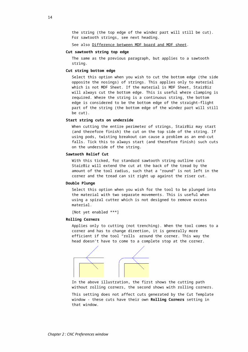
Rolling CornersApplies only to cutting (not trenching). When the tool comes to a corner and has to change direction, it is generally more efficient if the tool “rolls” around the corner. This way the head doesn’t have to come to a complete stop at the corner.
In the above illustration, the first shows the cutting path without rolling corners, the second shows with rolling corners.
This setting does not affect cuts generated by the Cut Template window - these cuts have their own Rolling Corners setting in that window.
TrenchingTrenching Passes
This setting allows you to choose how many passes StairBiz will make with the tool when trenching a tread into a string. You can choose 2, 3 or 5, or you can choose Auto to have StairBiz calculate the optimum (the least number of passes that will not leave islands).
Lead-in MarginThe distance from the edge of a component outline at which the tool should plunge before beginning the trench cuts.
WedgesHere you can specify the size of wedges that you will be using. StairBiz uses this information to calculate the cut pattern when trenching strings.
Enter in the Length of each wedge, along with the width of the Thin End and the Thick End. Do this for Tread wedges, Riser wedges and Landing wedges.
In the case of TREAD wedges, the Length and Thick End of the wedge are nominal – they are used only to calculate an angle from the thin end of the wedge.
In the case of LANDING wedges, the Length and Thick End of the wedge are not nominal – they are actual.
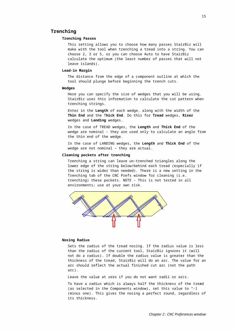
Cleaning pockets after trenchingTrenching a string can leave un-trenched triangles along the lower edge of the string below/behind each tread (especially if the string is wider than needed). There is a new setting in the Trenching tab of the CNC Prefs window for cleaning (i.e. trenching) these pockets. NOTE – This is not tested in all environments; use at your own risk.
Chapter 2 : CNC Preferences window

13
Nosing RadiusSets the radius of the tread nosing. If the radius value is less than the radius of the current tool, StairBiz ignores it (will not do a radius). If double the radius value is greater than the thickness of the tread, StairBiz will do an arc. The value for an arc should reflect the actual finished cut arc (not the path arc).
Leave the value at zero if you do not want radii or arcs.
To have a radius which is always half the thickness of the tread (as selected in the Components window), set this value to “-1” (minus one). This gives the nosing a perfect round, regardless of its thickness.
The nosing radius set here can be overridden by a Custom category selection in the Components window – see Nosing Radius set from Components window.
Check for OverrideWith this ticked, you can override the nose radius with a value specified in a Custom Category selected in the Components window.
See: Nosing Radius set from Components window
Lengthen Nose byAllows you to manually extend the nose of treads by this amount. We have no idea what it would be used for!
Use Straight LinesSome CNC machines can have an issue with a very small radius (and a nosing radius can involve a very small path radius), so this gives you the option of breaking your arc up into a serious of straight lines.
Line SegmentsWhen Use Straight Lines, this sets the number of lines used for a nosing arc (around 6 is normal).
Open Rise: No nose radiusApplies only to open riser strings. Cancels the nosing radius.
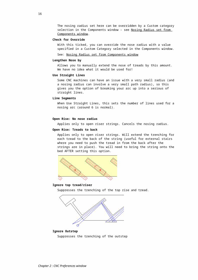
Open Rise: Treads to backApplies only to open riser strings. Will extend the trenching for each tread to the back of the string (useful for external stairs where you need to push the tread in from the back after the strings are in place). You will need to bring the string onto the bed AFTER setting this option.
Ignore top tread/riserSuppresses the trenching of the top rise and tread.
Ignore OutstepSuppresses the trenching of the outstep
Chapter 2 : CNC Preferences window
14
.
Curved Strings: Concave side onlyOnly trenches the concave string of a curved flight
Trench from outside to insideBy default, for 3 and 5 pass trenching, StairBiz trenches from the centre of the tread around towards the outside of the tread. This is to avoid the formation of islands which can break off and clog your extraction system. Tick this to trench from outside to inside (it might offer more stability for the tool while doing the important outside edges).
Top Rise Only (No Outstep)Extend Top
Applies only for closed rise flight and not trenching the outstep:
Sets the distance from the BOTTOM of the (non-trenched) outstep to the TOP of the riser trench. If you set a negative distance, the distance will be the distance DOWN from the TOP of the outstep.
Method 2Applies only for closed rise flight and not trenching the outstep: This option sets the width of the trench for the top riser the same as the thickness of the riser. Note that this does not apply to a splayed riser or an open rise flight.
Open Rise Mortise ReductionThis relates to reducing the size of the rectangle trenched into stringers for open riser treads. It may be useful where you create a tenon on the ends of the treads.
Vertical: The vertical reduction; the dimension applies to each of the top and bottom.
Horizontal: The vertical reduction; the dimension applies to each of the front and back.
Set both to zero for no reduction.
OptimizeWhen generating the final cut sequence, certain settings can be used to optimize the amount of overall travel that your CNC machine uses to perform the job. The following settings are available to control this behavior:
Use traverse and tool change optimizationIf this item is selected, StairBiz will perform all cuts with a given tool before moving on to cuts that require a different tool. The sequence of each cut will be selected to minimize the amount of head travel required.
Process one item at a timeIf this item is selected, StairBiz will process each component on the CNC bed, one at a time. This sequence is determined by the order in which the user placed components on the bed.
Use manual item sequenceUse this option to further define the order that components are processed. In the CNC Window you can use the right-click > Bring to Front or Send to Back menu items to control the component sequence. To view the cut manual sequence in the CNC Window, be sure Show Order has been selected.
Trench/Cut SequenceUse this option to select the order of trenching versus cutting. You can perform all Trenching before any Cuts, or all Cuts before any Trenching.
Chapter 2 : CNC Preferences window
15
Note that these settings are overridden by your use of a Cut List (in which case the Cut List controls the sequence).
LaserLasers can be used for positioning items on the bed.
The laser file projects all items at the same time.
Always export Laser means that for each session export, a corresponding laser export file is automatically generated.
Laser Adjust X/Y and Laser Scale X/Y allows you to calibrate the output if your laser software does not support its own calibration.
These calibration adjustments assumes that the laser is calibrated to the bed surface. Most modern lasers have their own calibration software, in which case these are redundant – leave at zero.
Laser Height is the height of the laser above the bed.
If this is set to zero, StairBiz will assume that you want the item outlines projected un-adjusted at the level of the bed surface, regardless of the thickness of those items.
If non-zero StairBiz will adjust the outlines to correspond with the material surface of each item - thus the laser outline is correct at the SURFACE of each individual item on the bed, regardless of its position or thickness.
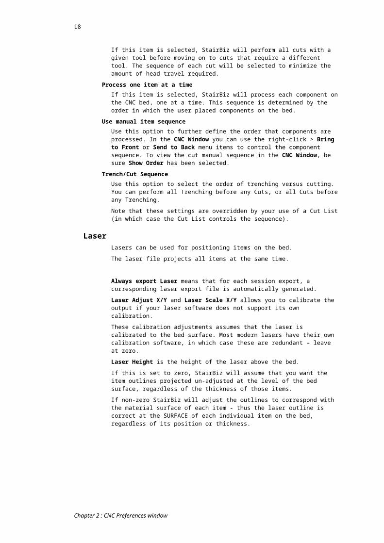
The blue rectangle represents and item on the bed. The black dot is the laser. The green dots indicate the laser path exported by StairBiz. The red dots indicate the laser outline at material surface.
Note that if the laser projection is being managed by your CNC’s controller, it may be automatically adjusting the projected outlines based on its knowledge of the current material surface. If this is the case leave this setting at zero. Note that this would normally only be possible if the laser g-code was embedded into the primary g-code export (rather than a separate file).
G-Code Template is the C-Code template used to generate the appropriate g-codes for your laser software/hardware. It is created using the G-Code Template Editor. Note that in the Options window in the G-Code Template Editor, ‘For Laser’ must be ticked (otherwise StairBiz will abort the laser export).
DisplayThis tab allows you to define visual elements that can be useful in laying out your CNC bed. Bases, Grids, and Fixtures can be displayed on the CNC bed. Each of these settings accept as many items as you wish to define.
Note; In older versions of this window, it's possible that if you are working in metric the dimensions might be shown in imperial, or vice versa; Contact John for the quick fix.
BasesYou can have as many virtual bases displayed on the CNC Bed as you wish. These would probably correspond with bases marked or set on the machine bed. The name, position and alignment of bases are set with the following syntax:
Chapter 2 : CNC Preferences window
16
BaseName, X, Y, AlignmentDon't use base name "Bx".
Don't start a base name with "D" unless it's a dowel.
Don't start a base name with "N" unless it's a newel.
For example:
B1,12,12,BL : a base called “B1” at 12,12 to which components on the bed will bottom/left align.
B2,12,24,TL : a base called “B2” at 12,24 to which components on the bed will top/left align.
B3,48,12,BR : a base called “B3” at 48,12 to which components on the bed will bottom/right align.
B4,48,24,TR : a base called “B4” at 48,24 to which components on the bed will top/right align.
Bases will only display on the CNC Bed when the Show Bases menu item has been checked in the CNC Window.
To send a component to a base on the CNC Bed, select the component, choose the base from the popup list, and click the Go button. A shortcut to sending components to bases 1 to 9 in the bases list is to press the Alt-1 to Alt-9 keys. To send items to bases 10 to 19 hold the CONTROL key down and press the Alt-1 to Alt-9 keys.
Newel basesYou can create special "Newel" bases by having an ordinary base name start with "N" (upper case). So, for example, bases called N1, N2, N3 etc. would be considered as newel bases.
Newel bases function like any other base, except that when a newel is bought onto the bed it will go to the first newel base not currently used. So if you bring a second newel onto the bed, and the first one is already used, the newel will go to the second newel base. You can have as many newel bases as you want. If you have more newels on the bed than you have newel bases, the excess newels will go (as normally) to Base 1. All this is useful where you use special clamps (at particular locations) just for newels.
NOTE that if, in the Export tab of the CNC Prefs window, Auto export one file per piece is ticked and Allow Multiple Newels is not ticked and Maintain current positions is not ticked, newel bases are ignored – all items will go to Base 1 for export.
Base Dowels (for fences):StairBiz can also show/drill dowels to be used as fences on the bed. These dowels are linked to your bases when you add two additional parameters to the syntax for bases in your base list, as follows:
B1,12,12,BL,3,1In this case the first four parameters define your base. The last two parameters are the numbers of dowels in the X direction and the number in the Y direction.
Note that fence dowels linked to your bases are always offset from the base in the correct direction (according to the orientation of the base) by the amount of the radius of the dowel (as defined by the tool which drills them – see below), such that the dowel does in fact create a correct fence relative to your base (this does not apply to individual dowels not linked to bases).
Also see Show Dowels (below).
Individual Dowels:You can also show and/or drill individual dowel holes (used for fences, calibration or anything else) on the bed, using the following syntax:
D,8,8 : show a dowel at X=8, Y=8
Chapter 2 : CNC Preferences window

17
For example you could drill a hole at zero/zero on your bed using “D,0,0” (good for finding where StairBiz thinks your zero/zero is on the actual bed).
Also see Show Dowels (below).
Show DowelsThe dowel holes mentioned above will only be displayed on the bed if the Show Dowels checkbox is ticked, the Drill tool has a tool id selected, and Show Bases is selected in the CNC Bed window.
Offset is the distance from the base for Base dowels in both the X and Y direction. It does not apply to individual dowels not linked to bases.
Depth is the depth the dowel holes are drilled into the sacrificial sheet.
Drill tool is the tool id for the drilling, which also sets the diameter of dowels shown on the bed in StairBiz. Drill Dowels sends the dowel holes to the bed such that StairBiz will drill these dowels on the actual bed (click the Export button in the CNC Bed window in the normal way to generate the g-code file for this drill session). The CNC Bed window must be open. Note that your G-Code Template must contain the commands for drilling (contact StairBiz support if you are not sure).
GridsYou can display any number of pre-defined grids on the CNC Bed.
To set up these grids, use the following syntax:
GridName, XAlignmentAndInterval, YalignmentAndInterval, [SnapOrientation], [StartOffsetX], [StartOffsetY]Parameters shown in brackets are optional (and you do not use the brackets in the syntax). If you omit an optional paramater, but include a parameter after it, you must still use the correct number of commas up the the last included parameter.
For Example:
G1,L24,T0,BL: a grid called “G1” which has vertical lines every 24 inches starting from the left ("L") and no horizontal lines (0=No Y Interval). The “BL” (Bottom/Left) orientation means that components will snap their bottom/left edges to this grid (when dragged and dropped with the SHIFT key held down).
G2,R36,B12,TR: a grid called “G2” which has vertical lines every 36 inches ("R" means starting from the right) and horizontal lines every 12 inches ("B" means starting from the bottom). Components will snap their top/right edges to this grid.
G2,R36,B12,TR,6,4: same as above, but the grid starts 6 inches from the right and 4 inches from the bottom.
Grids will only display on the CNC Bed when the Show Grids menu item has been checked in the CNC Window.
FixturesYou can display a representation for any number of fixtures (e.g. clamps, suction pods, fences) on the CNC Bed. To set these fixtures up, use the following syntax:
Name, X, Y, Color, [Width], [Height], [Shape], [Pod], [X-Repeat], [Spacing]Items in [brackets] are optional.
For Example:
C1,24,24,B: a clamp called “C1” which is located at X=24, Y=24 and will display in Blue.
C2,96,24,R: a fixture called “C2” which is located at X=96, Y=24 and will display in Red.
Valid colors are X (black), R (red), B (blue), G (green), Y (yellow), C (cyan), M (magenta), A (grey). You may append the letter “O” to the color to draw the fixture as a dotted outline (e.g. “RO” draws the fixture as a red dotted outline).
Width and Height are optional. If not specified, StairBiz will use the default Wth/Ht from those fields elsewhere in the window.
Shape is optional – if set to “C” the shape is a circle, if set to “D” it is diamond, otherwise it is rectangular. For a circle, StairBiz uses the Width parameter as the radius,
Chapter 2 : CNC Preferences window
18
and Height is ignored. The diamond is like a square with both sides determined by Width (Height is not applicable), then rotated 45 degrees around centre X/Y.
Pod indicates to StairBiz that this is a pod (rather than a clamp) and as such StairBiz has the capacity to actually manufacture your pods, plugs and cavities (this is a separate topic – contact StairBiz support for more information).
X-Repeat is used where you want StairBiz to draw multiple pods in the X direction. Enter a number.
Spacing is the distance between the centers of replications.
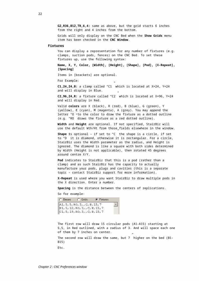
So for example:
The first row will draw 15 circular pods (A1-A15) starting at 5,5, in Red outlined, with a radius of 3. And will space each one of them by 7 inches on center.
The second row will draw the same, but 7” higher on the bed (B1-B15)
Etc.
Fixtures will only display on the CNC Bed when the Show Fixtures menu item has been checked in the CNC Window.
Show Grid CoordsWhen showing grids on the bed, show the coords of each line in the grid.
Fixtures Under ItemsWith this ticked, items on the bed are drawn over the top of fixtures, rather than vice versa.
Centre Fixture LabelsDraw the label which identifies each fixture in the middle of the fixture (rather than offset from it).
Fixture Wth/HtThe default width and height of fixtures as shown on the bed (used only if the Width and Height are not specified with the fixture). The starting Y point of the fixture is the Y point closest to the Y origin of the bed. The fixture will then extend by the value in Ht (height) away from the bed’s Y origin. The width will extend to the right.
Show Decimal InchesIf you work in imperial measurements, it's neater to show all these dimensions (including the dimensions in the Sheets field) in decimal inches (the default display mode). However, if you want to edit or see these dimensions in your preferred format, un-tick this check-box.
Glue-ups to BaseWhen ticked, and you send a string showing glue-up boards to a base, the glue-up edges (rather than the string edges) will align to the base.
PodsUse Arms with Pods
Use arms and pods on the StairBiz CNC Bed (according to the values given in this tab). You will need to right-click the bed and select Show Pods.
Pod Width & HeightThere is provision for three sizes – you can change between sizes by right-clicking the pod on the CNC bed.
Pod Bevel LengthThe pods on the CNC bed window have beveled (angled) corners. You can change the size of these bevels (or set to zero) here.
Chapter 2 : CNC Preferences window

19
Use surface pods and raise the cuts byAllows you to switch back and forth between using (or not) a Z offset for tool heights. Useful when you sometimes use pods and other times not (i.e. place pieces directly on the bed surface) without recalibrating your z-zero.
See Apply only to GCode Tag (below) for the effect of this setting.
Apply only when 'Show Pods'The previous setting only applies if “Show Pods” is selected in the CNC Bed window.
Apply only when 'Show Fixtures'The previous setting only applies if “Show Fixures” is selected in the CNC Bed window.
Apply only to GCode TagApples subject to the previous three settings.
The surface pod height normally adjusts all Z’s output to the g-code file. However, with this ticked only TWO tags are affected:
#PZ (Surface Pod Height)
#LN (Material thickness plus Surface Pod Height) - an alternate to #LN
NewelsNOTE: After changes in this tab you should re-import any newels already on the bed (because some of these settings are applied only at that time).
Riser – Extra Trench BelowIf you want the riser trenching to extend down below the bottom of the tread below it, enter the extra distance here.
Trench Risers to Back of NewelWith this ticked, StairBiz will trench the riser all the way to the back of the newel so that during installation you can bring the riser in from the back.
Enter a Maximum distance to limit the width of this riser trench.
String Mortises – Extend Y by tool radiusWith this ticked, StairBiz will extend the top of bottom of a string mortise trench by the amount of the tool radius. You would use this only if you do not do rounded tenons on your strings, and is designed to allow the non-rounded tenon to enter the mortise without rounding by hand.
Tread Trench Extra DepthWith this ticked, for ease of installation StairBiz will extend the depth of the trenching for treads (not risers) into the newels under some circumstances, as follows:
Top newel; in the face of the newel where the outstep nosing is, the back of the tread BELOW this nosing will be routed deeper (so that you don't need to notch the back of the tread around the newel).
Bottom newel; in the face of the newel where the nosing is, the nosing will be routed deeper (so that you don't need to notch the front of the tread around the newel).
Top tread in landing newel; in the face of the newel where the nosing of the tread is.
Bottom tread in landing newel; in the face of the newel where the riser above it is.
Kite tread in landing newel (i.e. the second tread of a 3-kite winder); in the face of the newel where the riser above it is.
Which Newels:This gives you some control over which type of newel the extra depth applies to. Enter up to four characters as follows: “T” = top newels; “B” = bottom newels; “L” = corner landing newels; “O” means all other newels (other than T, B and L). For example, “BL” means that the extra depth will only apply to bottom and corner landing newels. By default, only “L” (corner landing newels) apply – change as required.
Max Depth:
Chapter 2 : CNC Preferences window
20
This gives you some control over the depth of the extra trenching. Enter “0” for the trenching to go to the centre of the string (normally but not always centre of newel). Enter some other value to limit the depth.
Disable Extra Depth:If you have this feature enabled (as discussed above), but you want it to NOT apply to a specific newel on the bed, you can right-click that newel and select "Disable Extra Depth".
V-Groove Tool ID (V-Cut)The riser above a kite tread (i.e. above the second tread of a 3-kite winder) sometimes comes into the newel at an obtuse angle. Because the trench for this riser is square, it can be difficult to fit the riser to the newel.
For ease of fitting, StairBiz can use a bevel (“V”) tool to run a single path down the face of this riser. This path is in the face of the newel BEHIND the riser (so it assumes the riser is reasonably close to the back of the newel).
To activate this feature, simply enter a tool ID for the bevel tool.
Note that the standard trenching for this riser still applies (in the above example into face 1).
The depth of the bevel tool corresponds with the standard depth of the riser trenches. The bevel cutter is assumed to be 45 degrees, so that a 30 degree riser (i.e. the riser under the nosing of the kite tread) will have more than enough room (15 degrees more than enough).
NOTE that this path is a CUT (not a TRENCH) so you must be exporting cuts to see it on the CNC bed.
Auto export all four facesWhen exporting newels, this instructs StairBiz to export all four faces of each newel, each face separated by a pause. Allow File Appending (see Export tab) must be ticked.
When turning newels on the bed, if the bottom of the newel is closer to the Zero-X of your bed the newel top is turned towards you, otherwise is it turned away from you.
Note that when you bring a newel onto the bed, StairBiz calculates which face would be the most efficient to start with (considering the direction of the rolling). It is always the first face after a blank face (if a blank face exists). This way if there are blank faces, they will always be last faces when rolling the newel (as StairBiz has to do automatically to export all four faces). StairBiz will stop rolling and end the export when there are no more worked faces remaining on any newel on the bed.
Note that if you manually roll the newel in the CNC Bed window (to a face other than the one StairBiz sets automatically when you import it onto the bed), the face now showing will be the first face exported. In this case you may end of with a situation where the exported file has blank faces BETWEEN worked faces (i.e. two or more pauses in a row with no workings between them). There is nothing wrong with this – it’s simply inefficient (you have to roll more than you really need to).
Chapter 2 : CNC Preferences window

21
Note that if you want to see ALL FOUR faces of the newel at the same time, bring the newel onto the bed while holding down the CONTROL key. This is for checking only – do NOT export this.
Template ThicknessYour CNC machine might not have enough “throat” (height) to allow the processing of newels. However, you might still like to cut templates for the newels (i.e. each face of a newel cut out on a much thinner sheet of MDF). In which case set Template Thickness to the thickness of the MDF sheet - that's all that's needed.
The newel in the Components List in the CNC Bed window will still show the actual thickness of the newel (not the template thickness), however, the entire newel export will assume the thickness of the template.
The tool Z will be as per Cut clearance above bottom for All Others (see the Cutting tab)
Auto export of all 4 faces will be switched off (the four faces will always be included, side by side).
The tool used will be same as for trenching a newel.
StairBiz does not cut around the entire newel outline - it just does enough for you to position the template accurately over the newel blank. This is because:
It would create too much sawdust The structure for any single newel face can become too flimsy It creates a more solid template from which to hand-rout.
If you have multiple newel bases marked on the StairBiz bed (i.e. bases whose name begins with an “N”), StairBiz will use them each in turn. If you have only one newel base, StairBiz will place the first face on that base and will place subsequent faces offset from it. If there are no newel bases, the first face will be at zero.
Newel Top Is …Where is the reference point for the newel on the bed. StairBiz can show the top of the newel (as seen on the bed) as any of these three options. For example, if “Top of Lower Flat” is selected, the newel as shown on the bed will be from the bottom of the newel up to the top of the lower flat.
X/Y OffsetSome CNC machines can have a special “zone” (position or stop) on the bed specifically for newels. To save you having to reposition the newel after bringing it in to zero/zero on the bed, you can set the X/Y offset for this special position, and StairBiz will add these distances to all coordinates for all newels exported..
3 Sided Newel RoutingTells StairBiz to calculate the newel routing such that three faces of the newel can be processed without turning the newel. This only applies to certain machines (which must be at least 4 axis), so consult with StairBiz before using this feature.
Newel SidesWhen three sided newel routing, this is the tool to use on the two vertical faces (must be a horizontal router).
BalustersTrench/Drill for balusters into rail/plate only applies is there is not a plow in the rail/plate (according to the Plow Depth property in the Style window).
Baluster Dowel DrillingDrill/Trench: Drill will bore dowel holes for balusters into sawtooth treads. Trench will trench a rectangle to correspond with the bottom of the baluster. If the baluster is round, and 'Trench' is ticked, StairBiz will do nothing.
Only when flipped: Relates only to treads. You want the above drilling (not trenching) only when the tread is flipped (i.e. so you can drill the baluster holes from beneath the treads, so that you groove the riser at the same time).
Treads: Drill/Trench sawtooth treads for balusters.
Chapter 2 : CNC Preferences window
22
Balconyplate: Drill/Trench balcony plate for balusters.
Handrail: Drill/Trench LEVEL handrail for balusters.
Tool: Select the tool for the drilling/trenching. For drilling it may be a vertical router or a drill. For trenching it must be a vertical router.
Finish: Relates only to trenching; You can specify a tool (presumably with a small diameter) to do a final perimeter cut to clean the inside corners.
Dowel Diameter: Relates to drilling; This may be larger than the tool diameter, in which case (if the tool is a vertical router) StairBiz will perform a pocket drill. See Use Job Settings (below).
Dowel Depth: The depth of the hole. See Use Job Settings (below).
Baluster Trench Inset: Place a value here to reduce the trench rectangle all around by this amount. For example, if the baluster is 40x40mm and this value is “5” then StairBiz will trench a rectangle 30x30mm.
Use Job Settings: If ticked, it works as follows:
BalconyPlate and ShoeRail:Allow the baluster drilling/trenching even if there is a plow in the plate/rail.
If the plate/rail has a plow depth, use it for the drill/trench depth.
If there if no plow, and 'Pin Bottom' is ticked in the baluster style window, use "Bottom Pin Length" from the Setout window (Balusters) for the drill/trench depth.
If drilling, the drill diam comes from the CNC Prefs window.
Handrail:Allow the baluster drilling/trenching even if there is a plow in the handrail.
If the handrail has a plow depth, use it for the drill/trench depth.
If drilling for a pin top baluster, use 'Pin Top Diam' from the baluster style window as the drill diameter.
Treads/Winders:If trenching, use 'Sawtooth Baluster Into Tread' (~73 in Balusters) from the Setout window for the trench depth.
If drilling, use 'Bottom Pin Length' (~19) from the Setout window for the drill depth.
NOTE:If some condition was not specifically mentioned above, then StairBiz uses the depth and/or diameter shown in the CNC Prefs window.
If any of the above values is zero, then StairBiz uses the depth and/or diameter shown in the CNC Prefs window.
If 'Use Job Settings' is NOT ticked ...If a rail or plate has a plow, do not drill/trench.
If the component does NOT have a plow, drill/trench using the depth and diameter in the CNC Prefs window.
Baluster Pin-top DrillingThis relates to drilling holes for the tops of pin-top baluster into level handrail.
Drilling Tool: Select the tool for the drilling. It may be a horizontal router or a drill.
Drill Pin-tops: Tick this to drill for pin-tops
RisersNotch Riser Top/Botom of Sawtooth end; Horiz Length
These dimensions relate to notching of sawtooth risers. They will only apply if the riser is sawtooth. The level of the bottom of the upper notch is the underside of the tread
Chapter 2 : CNC Preferences window
23
above (i.e. it allows for the groove in the tread). The level of the top of the lower notch is the top of the tread below.
CNC Set winder risers backIn the CNC category of the Miscellaneous Defaults window there is an item “Set winder risers back”. For the purposes of strings on the CNC bed only, StairBiz will move the winder risers of a split or kite landing back (away from the nosing) by this amount. This may be useful if you want to behave as if these risers are not trenched (i.e. the riser will now butt up to the face of the string).
This feature is not supported – we do not vet that the value you use is appropriate for any particular job.
ImportTreads
Upside DownTreads will come onto the bed already flipped upside down (so that you can include the riser groove in a single session).
Rotate TreadsThe angle of rotation. Zero is horizontal to the right, and angles run clockwise from there.
Angle is at NoseTick that the angle specified is for the nose of the tread (otherwise it is for the back of the tread).
Same for Winders (non-sheet)Tick that you also want these setting to apply to winders (if they are not MDF sheet, in which case they come into the bed as they are in the stair, and you can rotate one or all manually if necessary).
OtherRisers Upside Down
Risers will come onto the bed already flipped upside down (perhaps you routinely do workings on the back face).
Rotate Box Strings 180Box strings will arrive on the bed rotated 180 degrees to normal.
Rotate Sawtooth Strings 180Sawtooth strings will arrive on the bed rotated 180 degrees to normal.
Resolve MDF board/sheet conflictsSee Difference between MDF board and MDF sheet.
Alert MDF board/sheet conflictsSee Difference between MDF board and MDF sheet.
Bezier Curve Resolution / Angle ToleranceWhen exporting CNC G-code, Bezier curves are exported as a series of short lines. You have control over this Bezier curve resolution (i.e. how smooth the curve is).
To see the effects of this resolution on the bed, click the Point-To-Point dimension tool while holding down the CONTROL key (repeat this to cancel it).
Chapter 2 : CNC Preferences window
24
Bezier Curve Resolution sets the distance between samples of the curve. A value of 1mm (0.04” or 3/64”), which is recommended, samples the curve (i.e. calculates a point on the curve) each this amount.
Bezier Curve Angle Tolerance is the minimum angle (off the in-line) required before StairBiz inserts a new point. A value of 1 degree (recommended) means that if the angle formed between two sample points and a point half way between these two sample points is less then 1 degree then StairBiz skips the point – the result is more points for tighter areas of the curve and less points where the curve is more flat.
ExportThe settings in this tab control how the G-Code file will be created.
Main Export FolderAllows you to set a default path to the folder you want g-code files exported to. Either type in the path, or (recommended) use the Browse button to set the path.
NOTE: If the path is a network path prefixed with “\\” (for example “\\Factory\Jobs”, and this path isn’t available (e.g. this network computer is not switched on), the Microsoft operating system can take a long time (e.g. 30 seconds to a minute or two) to establish that the path isn’t available. This can sometimes appear as if your computer has “hung”. Be patient. One solution for this is to map a drive (e.g. “X” or some other letter) to the “\\Factory” computer, and then set the export folder to point to this drive letter. Windows can determine instantly if this drive is available or not, so there is no delay when it is not.
Create Job FolderWith this ticked StairBiz will (on the very first export for the current job) auto-create a sub-folder within the default CNC Files folder. It will auto-name this folder according to the settings in Job Folder Format, which works in the same way as auto-naming for the CNC files. For example, you could set to auto-name the sub-folder as the Job Name or Quote Number for the current job. Your CNC files for the current job will save to this folder by default (you can change it in the Save dialog window if you like). This folder path is saved with the current job - if you open the job at a later date to export more items, those items will, by default, continue to save to that same folder. In other words, everything exported for that job will save to that sub-folder.
NOTE: As discussed above, when you export a job's CNC for the first time, and if Create Job Folder is ticked, the folder where you saved that file is remembered by the job - thereafter that job will use that folder. So if you change the Main Export Folder or Job Folder Format settings in the Export tab of the CNC Prefs window, don't expect that change to apply to a currently open job or previous job if that job has already exported CNC using Create Job Folder. If you want to change such a folder, you must select a new folder in the Save dialog window when exporting the next file - your changed folder will be remembered by that job for future exports.
Relative PathAdvanced - the following applies to very few users:
When the abovementioned Create job folder checkbox is ticked, StairBiz will create a job folder for each job in which to save its CNC files. The path of this folder is saved with the job, so that subsequent CNC exports for that job go to the same folder.
A problem can arise where you have multiple machines, each with their own (different) default folder for saving CNC files, and you want each such folder to have its own copy of the Job folder. In which case tick this checkbox.
Job Folder FormatWorks in the same way as the following Export File Name Format, but applied to the above Create Job Folder.
Export File Name FormatOptional. Sets the default name for any g-code file being created (exported) from the CNC Bed window. Enter one or more tags for the elements that you wish to be included in the default file name (%JN for Job Name, %JU for Job Number, %SN for Session Number and/or %RG for the rise and go). E.g. “%JN %JU” would create the default file name “Smith Constructions 1055” (where Smith Constructions is the current job name and 1055 if the current job number).
Chapter 2 : CNC Preferences window

25
The %RG tag includes the rise and go in the form “R180G240”. If there is more than one rise or go in the design, “R~G~” is returned. If the floor to floor has not been set, “R?” is returned for the rise, which will be rejected by Windows as an illegal file name.
Next Session NumberSets the next session number. Session numbers are automatically incremented on each g-code export. They can be used as or part of the default g-code file name, and they can be inserted into the g-code file at appropriated places as required (using tags in the G-Code Template Editor).
Allow File AppendingIf this option is set, StairBiz will enable the “Export and Leave Open” and Append and Leave Open” export options. This allows you to export multiple sessions within a single file (separated by a pause). Some machine don’t allow this – consult StairBiz support.
Auto Export One File per Piece With this set, StairBiz will batch-export every item on the bed in a single file for each item. Even newel faces will be exported one face at a time, each to a separate file (export of EACH face of a newel only applies when Auto Export of All 4 Sides in the Newels tab is ticked, otherwise only the CURRENT face of each newel on the bed is exported).
StairBiz will present the 'Save As' dialog window for each export, but if you've got appropriate default settings for file names (see Export tab of the CNC Prefs window) a simple click on "Save" for each should do it. The %ID (item description) tag may be useful (newel descriptions will include the face number; strings will include the prefix "Stg").
It doesn't matter where you place items on the bed - they will all be automatically moved to your Base 1 prior to export (however, see next heading).
If you want your g-code output to show the bed size as the size of the single item, see the heading after next.
Maintain Current Positions In relation to Auto Export One File per Piece, each item on the bed is normally automatically sent to the first base prior to export. To stop that, tick this button.
Allow Multiple Newels This checkbox relates to the abovementioned Auto Export One File per Piece.
With this ticked, all newels located on special newel bases (bases with a name starting with “N” – see elsewhere) will be exported as if a single piece. So, for example, if you have two newels on two newel bases, the first (top) face of both will be exported in a single file, the second face of both will be exported in a second file, and so on. All this is especially useful where you have multiple clamps that can handle multiple newels at a time. Newels not located on a special newel base are ignored.
With this NOT ticked, each newel is treated as a single piece.
Append all newel faces This checkbox relates to the abovementioned Auto Export One File per Piece.
With this ticked, each newel will have ALL faces exported at the same time, as if a single piece, each face separated by a pause. This works with or without Allow Multiple Newels (see above). NOTE that you must have ‘Auto Export all 4 faces’ ticked (in the Newels tab) for this checkbox to be an option.
With this NOT ticked, each roll of the newel or newels on the bed is treated as a separate piece (i.e. to a different file).
One ‘Save’ prompt only This checkbox relates to the abovementioned Auto Export One File per Piece.
With this checkbox ticked, StairBiz will present the 'Save As' dialog window for only the very first piece being exported – the auto export of all other items on the bed will assume the same folder and only the file name will change to reflect your default file-name settings.
With this checkbox NOT ticked, StairBiz will present the 'Save As' dialog window for each file being exported.
Chapter 2 : CNC Preferences window

26
Either way, your default file name would benefit from the %ID (item description) tag; newel descriptions will include the face number; strings will include the prefix "Stg").
Use Extents for Bed SizeSome CNC machines expect only a single piece (usually sheet) on the bed at one time. To get around this, StairBiz tells your CNC machine that the piece on the bed is the size of the bed (so that we can load up multiple pieces and treat it as a single piece). That works fine in 99% of cases. If you want StairBiz to tell your machine that the piece on the bed is the same size as a bounding rectangle (the smallest rectangle bounding all pieces on the bed, with one corner of the rectangle at zero/zero of the bed), then tick this checkbox. Note that this would generally only be useful if a piece on the bed was at zero/zero.
Don’t allow exporting without Floor to Floor Set & Warn for other AlertsWith this set, if you try to export with the design’s floor-to-floor in “Float” mode (i.e. not yet set to a specific value), StairBiz will not allow the export.
Post Process Command LineThis allows you to run a third-part program following each export (for example, files for some Morbidelli machines need to be converted to Xialog code). Consult StairBiz support
Diameters Master ListBelow the Sheets list is a checkbox called Show Diam Master. Ticking this shows a list of all tools in all machines. Here you may OPTIONALLY enter a tool diam for any or all of the tools listed.
In the Tools tab of the CNC Prefs window, you may OPTIONALLY enter the word “Master” as a tool diameter. This tells StairBiz to get the tool diameter for this tool from the Master List.
This may be useful where the same tool is used in multiple machines – when you sharpen this tool you only have to change the diameter in one place.
Note that in the case of an alias tool (a tool which uses Tool ID for Export), “Parent” can point to a tool that has “Master” as its tool diameter - see Tool ID for Export.
Chapter 2 : CNC Preferences window

27
Chapter 3 : CNC Bed window
OverviewFrom: CNC menu ; Show Bed menu-item.
The CNC Bed window allows components for the current job to be dragged onto a simulation of the machine bed, arranged and manipulated, then exported to the CNC machine.
Note that any information presented by StairBiz about any CNC machine supplied by any manufacturer needs to be checked against that manufacturer’s documentation. If in doubt, contact the manufacturer of the machine.
Note also that, whereas every effort is made by StairBiz Software to generate CNC files that will not damage a CNC machine or cause peripheral damage or injury, and will process the material as intended, the responsibility lies with the user of StairBiz to test each exported file prior to use and satisfy himself that the file is suitable for the machine, the work environment and the task.
Toolbar (Top) Show or hide On-screen Menu
The On-screen menu is displayed to the left of the CNC Bed, and provides access to menu items that are normally accessed by right-clicking on the CNC Bed or on items on the bed. This menu can be hidden by clicking on this toolbar button.
Show or hide Item ListThe CNC Item list is displayed in the upper left corner of the CNC Bed Window. It contains a list of items from your design that can be added to the CNC Session. If you wish to show or hide this list, you can use this toolbar button to do so.
Machine (popup list)The Machine popup list allows you to select which set of Machine Preferences to use for the components and cut paths on the CNC Bed. The items in this list correspond to the Machine Name values available in the CNC Preferences window.
Display CNC Machine PrefsClick this toolbar button to open the CNC Preferences window for the current machine (as set by the Machine popup list).
Chapter 3 : CNC Bed window

28
Session Template (popup list)A Session template allows you to save the current layout of the CNC Bed with the job, and then re-load the bed exactly the same at some later date. You can have as many CNC Session templates as you would like, allowing you to save multiple layouts with each job. This list on the toolbar displays which Session Template you are currently viewing. By default this is set to [None], indicating that the current bed layout will not be saved with the job.
Session templates save such things as item ID, position, rotation and flip status etc. They do not save the item itself, so that (for example) if in the Design window you add a tread to a string, or change it’s go or rise, when the session template places that item on the bed it will come in it’s changed state (while maintaining position, rotation etc.).
Session Template menu:New Empty Session Layout: Create a new template. You will be prompted for a template name. You can accept the default sequence number, or type a new name. Each job can have as many individual session templates as you would like (or none if you don’t need them).
Save Session Layout: Saves the current template with the current bed layout.
Save Layout As: Saves a copy of the current template with the current bed layout. You will be prompted for a name.
Delete Session Layout: Removes the current CNC Session Template from the job.
When you open a job with session templates saved, by default the Session Template will show [None]. To layout the bed according to a particular session template, select that template.
Session Templates: Job vs Global Above we have discussed Job session templates. You can also save session templates independently of any one job (called a Global Session Template). Global session templates are available for any and all jobs.
Although Global Session Templates relate to no particular job, for obvious reasons there needs to be some correlation between the job you used to create the template and the job current at the time of using the template. For example, if you save the winders of an L-Shape stair in a global template, then evoke that template for a single straight flight, you’re not going to get your winders. Similarly, if you save 16 treads in a template, then evoke that template for a 4 tread stair, you’ll only get the fours treads. For this reason you should be mindful of the name you give to your templates (they should reflect what’s workable).
The global templates are saved with the CNC Prefs window (no particular machine, so if you a running multiple machines that are substantially different you might need to save the template using a name that indicates which machine it relates to).
To toggle between Global and Job session templates, click the toggle button to the left of the “Job Template” label in the toolbar.
Cut ListAllows you to select a cut list, which is a list of specific “special” cuts to apply to the current bed items.
See CNC Cuts window.
Opens the cut list menu.
Toolbar (Mid) Lock item(s)
Locks the currently selected items so that they can’t move.
Flip HorizontalClick on this toolbar button to flip the current component Horizontally.
To swap the hand of all items currently on the bed, hold the CONTROL key down while clicking this button - see Chapter 7/ Swap Hand
Chapter 3 : CNC Bed window

29
Flip VerticalClick on this toolbar button to flip the current component Vertically.
Roll NewelRolls the currently selected newel to the next face. This is generally not necessary as StairBiz brings newels onto the bed with the most appropriate face already up, but it can be useful to check all faces.
Another method to check all faces at the same time is to hold the CONTROL key down while you bring the newel onto the bed – all four faces will be imported (this is just for checking – do NOT export this)
Rotate Next FaceRotates the currently selected item clockwise to the next closest of 0, 90, 180 or 270 degrees. This means that you can use this tool to get any item edge (longer than 80mm) to align vertically or horizontally.
Rotate ClockwiseClick this toolbar button to rotate the currently selected component clockwise by the amount in the Rotate Value textbox to the right.
To rotate a group of items on the bed, select the group, then rotate while holding the CONTROL key down. The entire group will rotate around the centre of the group.
Rotate Counter-clockwiseClick this toolbar button to rotate the currently selected component counter-clockwise by the amount in the Rotate Value textbox to the right.
For group rotate, see previous heading
Zoom / UnZoomClick this toolbar button and drag a rectangle bounding the area of the drawing you want to expand – that part of the drawing will expand to fill the design-area of the window (perhaps with some adjustment if the dragged rectangle is not the same proportion as the design-area).
Click it again to revert to normal scale.
Holding the CONTROL key down while clicking the Zoom button will expand the drawing by 10% each time. Holding the CONTROL and SHIFT keys down while clicking the Zoom button will reduce the drawing by 10% each time.
SHORT-CUT: To zoom in, click-drag using the mouse-wheel (if your mouse has one). To zoom out, single-click the mouse wheel.
Dimension : Line to LineClick this toolbar button to display a dimension that goes from line to line. The start point of the dimension is the closest imaginary point on the closest line to the clicked start point. The end point of the dimension is the intersection of the line closest to the clicked end point with an imaginary line starting at the start point and at right angles to the start line.
Dimension : Point to PointClick this toolbar button to display a dimension that goes from point to point. The start point of the dimension is the line-end closest to the clicked start point. The end point of the dimension is the line-end closest to the clicked end point.
Dimension : Line to PointClick this toolbar button to display a dimension that goes from line to point. The start point of the dimension is the line-end closest to the clicked start point. The end point of the dimension is the intersection of the line closest to the clicked end point with an imaginary line starting at the start point and at right angles to the end line.
Chapter 3 : CNC Bed window

30
Re-apply Machine PreferencesClick this toolbar button to re-apply the current CNC Preferences to the components on the bed. This may be useful if you change preference values while components are on the bed.
CNC Item ListThe CNC Item list is displayed in the upper left corner of the CNC Bed Window (if it is selected the yellow Show or Hide Item List toolbar button at the top-left of the window). It contains a list of all components that can be placed on the CNC Bed in the current job. The status column for each component will show “–“ if the component is not on the bed, or “Bed“ if the component has been placed on the bed. This column can also show “Done“ if the component has been marked as done (See Component Clicks below).
When the list is visible you can double click on a list item to place that item on the bed. When the component is first added to the bed it will be sent to the first Base that is defined in the CNC Preferences window under the Display tab.
After a component is placed on the bed, it can be moved using click and drag with your mouse, or positioned and rotated or flipped using the tools described below. To remove a component from the bed, see Put Back Item or Put Back All below. When a component on the bed is clicked, the corresponding item will be highlighted in the list.
To hide this list, making room for the other CNC Bed tools, deselect the Show or Hide Item List toolbar button described above.
You can close the job and open another job, and return to the CNC Bed Window, and all previous items will still be on the bed as you left them. Using this technique it is possible to combine items from several jobs into a single CNC Session.
ExportExporting allows you to create a file containing g-code information about the components and/or cut paths on the CNC Bed. When a job has been laid out on the CNC Bed Window, you must perform an export to make the file available for your CNC Machine.
Print OptionSelecting this option instructs StairBiz to print the current bed (as shown on your screen) to your printer at the time of each Export. This printout includes preference and other useful information about the session and the items in it.
Save to Session List OptionSelecting this option instructs StairBiz to save a detailed report of the export session that can be viewed later in the CNC Session List window (under the CNC menu).
This option will only work if there is currently a job loaded and the job is subsequently saved, as the session list information is saved with the job.
See the section entitled CNC Session List Window for more information.
Outlines OptionSelect Outlines if you wish for the component polygon outlines to be included in the Export.
Cuts OptionSelect Cuts if you wish to include cut paths in the Exported file. This applies to G-Code formatted export files (See Export Type below).
Trench OptionSelect Trench if you wish to include trenching paths in the Exported file. This applies to G-Code formatted export files (See Export Type below).
Export TypeYou can Export to DXF (An industry standard geometry description file which can be imported into most CAD programs) or to a G-Code formatted text file. To select the type of export, click on the Export Type popup list and choose the type you wish.
Chapter 3 : CNC Bed window

31
If you choose Export to G-Code, StairBiz will use the G-Code Template setting from the CNC Preferences window to determine the format and settings for the G-Code file that is created.
Export ButtonsWhen you are ready to create the Export file, click one of these 4 buttons (each described below). A window will open prompting you for the location and name of the file to be created. The default name for the export file will be created by StairBiz based on your settings in the CNC Preferences window under the File tab.
If you are creating a G-Code file for your CNC Machine, the format of the G-Code will be determined by your choice of G-Code Templates in the CNC Preferences window under the Machine tab.
Export and Close ButtonThis button will behave as described above, and will include both a header and a footer (a full export). Use this for sending a single session to a single file.
Export and Leave Open ButtonThis button will behave the same as the Export and Close Button, but it will not include a footer. This is used when you wish to send multiple sessions to a single file, separated by a pause (if your machine has a g-code pause command). Use this button as the first step, then modify the layout of the bed and click one of the following buttons to add additional sessions to the previous file.
Append and Leave Open ButtonThis button will export a file the same as the previous buttons but it will not include a header or a footer. Use this as the second (or more) export when you are sending multiple sessions to a single file. This button will only appear if you have done a previous Export and Leave Open session.
Append and Close ButtonThis button will export a file the same as the previous buttons but it will not include a header. Use this as the last export when you are sending multiple sessions to a single file. After you use this button, the first two buttons (Export and Close, and Export and Leave Open) will become visible again.
Tandem L / R OptionsSelect one of these two options if you wish to view or export one of the two sides of a tandem bed. It is not possible to select both options at the same time.
If you select Tandem L (Left), the items on the bed will be exported relative to the left edge of the bed.
If you select Tandem R (Right), the items on the bed will be exported relative to the Tandem Start X setting in the CNC Preferences Window.
SplitSplit (sometimes called “indexing”) allows you to process over-length items in up to five sessions. First you rout up to a certain point, the machine pauses while you move the item down by a specified amount, then the machine resumes, etc.
Split AtSets the distance from the zero-X of the bed to where the routing will stop when exporting the left of the split. StairBiz draws this line on the bed (marked “S”).
ResumeSets the distance from the zero-X of the bed to where the routing will resume when exporting the right of the split. StairBiz draws this line on the bed (marked “R”).
The Split line must always be to the Right of the Resume line (StairBiz warns the user if otherwise). In other words, we always shift pieces to the left regardless of bed orientation. So if the orientation is left sided, the Split dimension should be larger than the resume dimension. The opposite is true for Right oriented beds.
Chapter 3 : CNC Bed window

32
L1, R2, R3 etc.
L1 exports the left of the split line. R2 shifts the pieces on the table to the left by the amount indicated by the blue dimension (the shift amount). The shift amount is the calculated difference between the Split and Resume lines. The cutting resumes at the resume line, and again stop if they hit the split line again, as if we're cutting within a window. R3 shifts the pieces to the left again and continues, allowing up to 5 working areas. Clicking L1 or turning off split puts the pieces back where they were. The layout printing shows the shifted pieces for each export so the operator can see where to adjust for pods etc.
Dovetail cuttersThe dovetail tool is respected and never plunged into or pulled out of a string.
For the best result the split line should pass cleanly through a path as shown (see illustration below) and never through the triangles on the back of the string, otherwise the dovetail logic sometimes gets confused.
TestTest Button
Performs an emulation of the session as it would happen on the machine bed. You will see a green line that simulates the movement of the tool in a retracted position. You will see a thick line in the color of the tools on the legend (see below) to simulate the cutting of the material. Note that this test is not testing the actual g-code that is exported to the machine – you still need to satisfy yourself that g-code is as required.
Clear ButtonClears the test results. This can also be used to stop the current test run and refresh the drawing.
Test Speed SliderSets the speed of the test run and can be adjusted while a test run is in progress (either click-drag the slider, or click to the left or right of the slider).
LegendThe CNC Bed Window displays a legend to show each unique type of cut that is involved in the current CNC Session, and the corresponding color used to represent that cut. A cut is considered to be unique if it uses a different tool and/or a different cut depth than other cuts on the bed.
The Legend displays a color for the cut (which corresponds to the color used on the CNC Bed to represent the cut), followed by the Tool ID, the direction of tool spin (C=Clockwise A=Anti-clockwise), and finally the cut depth.
Item PositionBase Positioning
Bases can be defined in the CNC Preferences window under the Display tab, and will be listed in the Bases Popup list.
Chapter 3 : CNC Bed window

33
There are various ways to send a component to a base. First select the component (or group of components), and then:
Press the ALT key plus a number (1-9 and 0) to send the component to any of the first ten bases in the list; or
Press the CONTROL key plus a number (1-9 and 0) to send the component to bases 11 to 19; or
If you are not currently displaying grids, and if you hold the SHIFT key while dragging a component with your mouse, the component will snap to the closest base (considering the orientation of that base); or
Select the base from the popup list, then click on the Go Button next to the Bases Popup list.
The component will then be positioned as defined by the Base (e.g. by it’s Top/Left corner etc).
To display all bases, see the Right-Clicks section below.
If bases are not currently being shown, you can hold down the Ctrl key while clicking on the Go Button to toggle the display of the current base.
Coordinate PositioningComponents can be positioned on the bed by clicking and dragging with the mouse. But for precise positioning, you can also type in the exact coordinates in the X / Y coordinate text boxes, then click the corresponding Go Button to send the current component to that location.
GridsStairBiz allows you to define Grids in the CNC Preferences window under the Display tab. These grids can be used for quick and easy positioning of component on the bed.
If the Grids Popup List shows [None], then component can be moved around freely without any constraints.
If a grid is selected in the Grids Popup List, any component you move will “Snap” to the grid as it has been defined provided you are holding down the SHIFT key (e.g. If the grid is G1,L12,T12, the component will snap to the top left edge that corresponds with the nearest grid line).
To see the grids drawn on the bed, select the Show Grids menu item as described in the Bed Clicks section below.
NudgingTo move a component by a predefined amount, you can use the arrow keys on your keyboard. Each press of an arrow key will move the currently selected component in the specified direction by 2mm (approx 1/12 inch). Pressing the Shift key while pressing an arrow key will move the component in the specified direction by the amount entered in the Nudge field.
SheetPos
Holds the X and Y coordinates of the position of a sheet placed on the bed as the result of a sheet selection from the popup list. The sheet can then be moved around the bed (if necessary) by dragging it with the mouse.
To remove a sheet from the bed, choose None from the popup list.
Sheet Selection Popup listLists all available sheets (as defined in the CNC Preferences window), and allows one or None to be selected to appear on the bed.
Base ButtonClick this button to send the current sheet to the base that is currently displayed in the Bases Popup list.
On Screen MenuThe On-screen menu is displayed to the left of the CNC Bed (if the On Screen Menu toolbar button is selected), and provides access to menu items that are normally
Chapter 3 : CNC Bed window

34
accessed by right-clicking on the CNC Bed or on items on the bed. This menu can be hidden by clicking on the toolbar button described above.
Right-ClicksOverview
There are several tasks in the CNC Bed Window that can be accessed from Right-Click menus. To access these menus you can either Right-Click on a blank part of the bed to display tasks that are general to the bed, or on a component that is on the bed to display tasks that are specific to that component.
An alternate method is to left-click on the component, and the same menu items that would have been displayed in a pop-up menu will be displayed in the menu-pane near the top right hand side of the CNC Bed Window.
Bed ClicksThe following menu items are available by right-clicking on an empty spot on the bed.
Put Back AllRemoves all components from the CNC Bed, and puts them back in the Component List described above in the List section.
Done AllMarks all components that are on the CNC Bed as Done in the List described above in the List section.
Show OutlinesDisplays the finished outline of all components on the bed (in black).
Show Cut PathsDisplays the center of cut paths for all components on the bed.
Show Trench PathsDisplays the center of trench paths for all components on the bed that require trenching.
Show DirectionsDisplays a circle at the plunge point of all cut paths, and an arrow on all cut paths indicating the direction of the path.
Show OrderDisplays a number that indicates the order for each component on the bed. This sequence number is associated with the options in the Optimize tab of the CNC Preferences window.
To change the order of a component, see the Bring to Front, or Send to Back description below.
Show GridsDisplays the current grid. See Grids above.
Show BasesDisplays all bases as defined in the CNC Preferences window under the Display tab. See Base Positioning above.
Show FixturesDisplays all fixtures as defined in the CNC Preferences window under the Display tab.
Show NosesDisplays a circle around noses on outlines of treads.
Show Off-Bed ItemsAllows you to hide/show items that are currently off the main bed.
Show Item LabelsAllows you to hide/show item labels on each component.
Show Item NotesAllows you to hide/show item notes on each component (Item notes can be set/edited by right-clicking an item and selecting 'Edit Item Notes'..
Show Pods
Chapter 3 : CNC Bed window
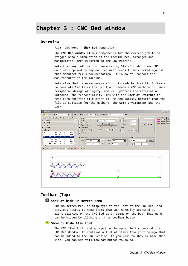
35
Allows you to hide/show pods as set up in the Pods tab of the CNC Prefs window.
Import Objects From DXFAllows you to import a foreign DXF file. The file must contain at least one layer containing a single entity of type “LWPOLYLINE” (if it contains more than one layer, StairBiz will prompt you to choose which one). StairBiz will also give you the option to set a thickness.
StairBiz does not currently recognise any entity other than “LWPOLYLINE”.
Paste Copied WellYou can create a polygon shape in the Well Design mode of the Design window, and copy it. Subsequently you can paste this polygon into the CNC bed for cutting. StairBiz will also give you the option to set a thickness.
Set Export RemarkAllows you to set a remark that will be placed in your exported g-code file according to the relevant tag (#ER) set in the G-Code Template Editor.
Re-apply PrefsRe-applies the current CNC Preferences to the components on the bed (useful if they have changed while items are on the bed).
Component ClicksThe following menu items are available by right-clicking on a component on the bed.
Put Back ItemReturns a component to the list and removes it from the bed. See List above.
Done ItemMarks a component as done. See List above.
Edit Item NoteOpens a window where you can enter or change a comment or note. This note is shown with the relevant item in both the bed print-out sheet and the CNC Session List.
Right-click a blank space and select 'Show Item Notes' to display the item notes on the bed.
The note does not save with the job unless you create a Job Session Template or have “Save to Session List” ticked (in which case it will be saved in the relevant session template or session list).
Flip HorizontalFlips the currently selected component horizontally on the bed.
Flip VerticalFlips the currently selected component vertically on the bed.
Rotate CRotates the currently selected component clockwise by the amount in the Rotate Value textbox described above.
Rotate ARotates the currently selected component anti-clockwise by the amount in the Rotate Value textbox described above.
IF MULTIPLE ITEMS SELECTED:Align Tops
Aligns the tops of all selected with the top-most item.
Align BottomsAligns the bottoms of all selected with the bottom-most item.
Align LeftsAligns the lefts of all selected with the left-most item.
Align RightsAligns the rights of all selected with the right-most item.
Space Up
Chapter 3 : CNC Bed window
36
StairBiz locates the bottom-most item and then vertically spaces all other items above it. The space between each item is that shown in the Nudge field (or the tool diameter if “T” is shown in the Nudge field).
Space DownStairBiz locates the top-most item and then vertically spaces all other items below it. The space between each item is that shown in the Nudge field (or the tool diameter if “T” is shown in the Nudge field).
Space LeftStairBiz locates the right-most item and then horizontally spaces all other items to the left of it. The space between each item is that shown in the Nudge field (or the tool diameter if “T” is shown in the Nudge field).
Space RightStairBiz locates the left-most item and then horizontally spaces all other items to the right of it. The space between each item is that shown in the Nudge field (or the tool diameter if “T” is shown in the Nudge field).
IF A SINGLE ITEM SELECTED:Bring to Front
Sets the component sequence value to 1. See Use manual item sequence in the CNC Preferences window below.
Send to BackSets the component sequence value so that it is the last in the list. See Use manual item sequence in the CNC Preferences window below.
Adjust Cut Starting PointApplies only if cutting the entire outline, and applies only to standard StairBiz outline cuts (not cut templates); Shows the indexes of the item polygon, and allows you to enter a number being where you would prefer the cut path to start.
IF A STRING:Cut Top Edge
Used to override the default setting in the CNC Preferences window (Cutting tab).
Instructs StairBiz to cut the top edge (the side where the nosings are) of the selected string. This applies only to material which is not MDF Sheet. If the material is MDF Sheet, StairBiz will always cut the top edge. This is useful where clamping is required. Where the string is a continuous string, the top edge is considered to be the top edge of the straight-flight part of the string (the top edge of the winder part will still be cut).
See also Difference between MDF board and MDF sheet.
Cut Bottom EdgeUsed to override the default setting in the CNC Preferences window (Cutting tab).
Instructs StairBiz to cut the bottom edge (the side opposite the nosings) of the selected string. This applies only to material which is not MDF Sheet. If the material is MDF Sheet, StairBiz will always cut the bottom edge. This is useful where clamping is required. Where the string is a continuous string, the bottom edge is considered to be the bottom edge of the straight-flight part of the string (the bottom edge of the winder part will still be cut).
See also Difference between MDF board and MDF sheet.
Cut Hi EndOnly applies if not cutting the string top or bottom edges; Allows you to turn on or off the cutting of the high-end of the string.
Cut Lo EndOnly applies if not cutting the string top or bottom edges; Allows you to turn on or off the cutting of the low-end of the string.
Hybrid StringWhere you have a closed string, but you want it to be sawtooth for one or more of treads up from the bottom, this is a (not very elegant) way to achieve it. You will be prompted to enter the number of treads, then StairBiz will add the necessary cuts.
Open Rise: Treads to Back
Chapter 3 : CNC Bed window
37
There is a setting in the CNC Prefs window (Trenching tab) to extend the trenching of open rise treads to the back of the string (so you can push the treads in from the back – perhaps useful for external stairs). This menu-allows you to over-ride the default setting on a string-by-string basis.
Split StringSelect this menu-item to split a string horizontally into two separate strings, with the vertical split line being at the point of the click. Split strings cannot use cut templates and can only be cut around the entire perimeter.
When splitting strings, be sure to split away from a nosing radius, and preferably not through the riser paths.
Don’t Trench Top RiseApplies only is non-sawtooth. Don’t trench the top riser of the string. This may be useful for installing if the riser is added after the stair is positioned, or if the top trimmer acts as a riser.
Don’t Trench OutstepApplies only is non-sawtooth. Don’t trench the outstep. This may be useful for installing if the riser is added after the stair is positioned.
ALL ITEMS:Split Item
Select this menu-item to split an item horizontally into two separate items, with the vertical split line being at the point of the click. Split items cannot use cut templates and can only be cut around the entire perimeter.
Cut NoseApplies only to treads. My default, whether or not the nose of a tread is cut comes from that setting in the CNC Prefs window. Here you can override that setting on a tread-by-tread basis.
Reverse Main Edge DirectionFor outline cuts, StairBiz attempts to set the direction of the cut paths in such a way as to minimize feathering (the tool lifting the grain). If this doesn’t work out for you, you can reverse the direction here. It only applies if at least one main edge is being cut.
Apply Extra CutsIf you have a Cut List selected, StairBiz will normally apply the relevant cuts to all relevant items on the bed. If there’s an item you want excluded you can tick this menu-item.
Cut Depth OverrideShows a dialog box where you can enter a standard outline cut depth different from the one determined by your CNC Prefs window.
Trench Depth OverrideSame as above, but applies to string trenching.
EC:Numbered OutlinesIf you have set up one or more ‘Numbered Outline’ cut templates, you can apply one to the clicked item. See ‘Numbered Outline’ in Cut Templates (below).
In the window that opens, enter the following, each separated by a comma:
Code: The ID of the ‘Numbered Outline’ cut template (as entered in the Cut Template window at the top-left.
Direction: The direction of the path. If you don’t like the direction that ‘+’ gives you, enter ‘-‘ for the opposite direction.
Start: The item on the bed will show polygon index numbers. Enter the number where you want the path to start.
End: Enter the polygon index number where you want the path to end.
Start Offset: Optional. The lead-in distance for the start of the path. A negative amount will make the path shorter.
End Offset: Optional. The lead-out distance for the end of the path. A negative amount will make the path shorter.
Chapter 3 : CNC Bed window
38
If this distance is prefixed with a "L" (length) then instead StairBiz will set the end of the path as being this distance from the start of the path. There must only be a single straight path (no turns or curve).
Suppress TrenchingApplies only to strings. Do not trench this string. To turn off ALL trenching it’s easier to use the setting near the Export button.
DXF Layer NumberWhen exporting DXF, you can assign layers to each different component on the bed.
GrainIf an item is being cut from grained timber, StairBiz already knows it and by default this item will be ticked. You can override this setting by selecting MDF Board or MDF Sheet. This affects the way StairBiz calculates the cut paths.
MDF BoardIf an item is being cut from MDF board, StairBiz already knows it and by default this item will be ticked. You can override this setting by selecting Grain or MDF Sheet. This affects the way StairBiz calculates the cut paths.
See also Difference between MDF board and MDF sheet.
MDF SheetIf an item is being cut from MDF sheet, StairBiz already knows it and by default this item will be ticked. You can override this setting by selecting Grain or MDF Board. This affects the way StairBiz calculates the cut paths.
See also Difference between MDF board and MDF sheet.
Copy OutlineCopies the outline polygon of the selected item. From here you can open the Well Design window, right-click and select “Paste Copied Outline”. You can then edit the polygon in the usual way (as per wells). Then right-click any line of the polygon and select “Copy Outline”. Open the CNC Bed window, right-click on the bed and select “Paste Copied Outline”. You will need to enter a thickness (a copied outline loses all information about itself except the shape of the polygon).
Selecting and DraggingTo move components around the bed, click on the component and drag it to the desired location. If Show Grids is enabled and you hold down the SHIFT key, the item will “snap” to the nearest grid line. You can also move a Sheet by clicking and dragging on the item.
You can select multiple items and manipulate them as a group. Hold down the Control key while clicking on items adds or removes them from the selection group. You can also hold down Control and click and drag a rectangle around the items on the bed that you want to add to your selection.
Once you have multiple items selected, you can move them together as a group, or send them to a base as a group (they will stay spaced as they were before selection). You can also Put Back the group, rotate, snap to grid, or nearly any other task.
Duplicating
This toolbar button duplicates (clones) the selected item(s) on the CNC Bed. They are pasted to their current locations. After copying the item(s) you can drag or move them with the keyboard arrows. This, combined with the Group Select feature will make nesting of multiple items (such as side nosings) much easier to perform.
Chapter 3 : CNC Bed window
39
Chapter 4 : CNC Cuts window
Overview
From: Cut List pull-down in CNC window.
Here you can specify extra cuts and drilling for items on the CNC Bed. Examples are cuts for riser grooves, nosing profiles, sawtooth string riser bevels, rail and plate profiling, rough cuts, dowels for positioning sawtooth treads on the string, etc.
The CNC Cuts window is specific to the current machine (i.e. the current CNC Preferences window). In other words, any cuts created from this window, and the Cut List pull-down at the top of the CNC Bed window, are only available to the current machine. There are a variety of Copy/Paste and Export/Import functions to move Cut Templates between machines (between CNC Prefs).
Like your CNC Preferences, these cut lists are saved in your StairBiz Jobs.mdb file (not your StairBiz Defaults.mdb).
There are three frames in this window (Cut Lists, Current Cut List and Cut Templates). Each have their own heading as follows:
Cut Templates frameHere you can create, edit and delete individual cuts (called cut templates). The list on the right contains all cut templates you have created.
ButtonsNew; Opens the CNC Cut Template window with a new cut template.
Duplicate; Duplicates the currently selected cut template and opens the CNC Cut Template window for the duplicate, ready for changing (you will at least need to change the name).
Edit; Opens the CNC Cut Template window for the currently selected cut template, ready for viewing or editing.
Delete; Deletes the currently selected cut template. To delete ALL cut templates hold down the CONTROL and SHIFT keys when clicking this button.
Copy; Copies the single currently selected Cut Template (i.e. from the list on the left), ready to paste it into any other Cut Templates list (even for a different machine)
Paste; Opens the Cut Template window with a new template and pastes the previously copied cut template into it, ready for editing.
Cut Lists frameOnce you have created one of more cut templates, you can list them in a Cut List. A Cut List is a list of the cut templates you wish to apply to items on the bed, in the order in which you want them processed.
ButtonsNew; Creates a new cut list and allows you to name it. The new cut list will be selectable from the Cut List pull-down in the CNC Bed window.
Rename; allows you to rename an existing cut list.
Delete; deletes the current cut list (but not the cut templates it lists). To delete ALL cut lists hold down the CONTROL and SHIFT keys when clicking this button.
Duplicate; the equivalent of Save As – saves the current cut list with a different name, after which you can add or delete cut templates as required.
Copy/Paste
Overview:
The Copy/Paste buttons at the far RIGHT of the window (i.e. to the right of the Cut Templates list) allow you to copy a SINGLE Cut Template from the current list and paste
Chapter 4 : CNC Cuts window
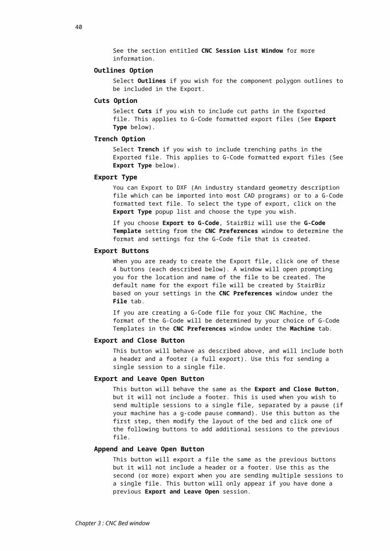
40
it into any other Cut Templates list (even for a different machine) – see further below for more information.
THESE Copy/Paste buttons (i.e. in this Cut Lists frame at the top-left of the window) allow you to copy MULTIPLE Cut Templates (i.e. all those in the current Cut List - the list on the left) and paste them into any other Cut list (even for a different machine).
Copy; Copies the current Cut List (i.e. the list on the left). Each Cut Template shown in this list will also be copied (from the list on the right).
Paste; Overwrites the current Cut List (i.e. the list on the left) with the copied Cut List. It adds all Cut Templates contained in this list to the Cut Templates list (i.e. to the list on the right). A Paste will not in any way affect your existing Cut Templates (i.e. those in the list on the right). If a pasted Cut Template has the same name as an existing Cut Template, you will be prompted to change the name.
Export; Has the same functionality as the above "Copy", but instead saves the Cut List to a file (the default folder is "StairBiz Program/Defaults/Spreadsheets").
Import; Has the same functionality as the above "Paste", but instead imports the Cut List from a previously exported file.
Current Cut List frameA Cut List is a list of the cut templates you wish to apply to items on the bed. The Current Cut List shows the list currently selected in Cut Lists.
ButtonsAdd Cut; Adds the selected item from the Cut Templates list to the current Cut List.
Add Pause; Adds a CNC machine pause to the current Cut List. The machine will pause between the cut above and below this item in the list.
Add Outline; Adds a standard (StairBiz generated) outline cut to the current Cut List. In the absence of this item, StairBiz will not process the standard outline cut.
Add Trenching; Adds the standard (StairBiz generated) string trenching paths to the current Cut List. In the absence of this item, StairBiz will STILL process the standard string trenching, but will do so before any other cut templates, with the following provision: If there is a Standard Outline cut in the list, the sequence of the trenching (relative to the standard outline cut) will be according to the relevant settings in the Optimize tab of the CNC Prefs window. If there is no Standard Outline cut in the list, the trenching will be processed before any other cuts.
Remove Cut; Removes the currently selected item from the current Cut List. Deleting a cut does not delete the actual cut template – it just removes it from the list.
Move Up/ Down; Moves the currently selected item in the Cut List up or down relative to the other items in the list.
TicksYou can tick or untick items in the Current Cut List. If an item is un-ticked, it will not be processed.
Chapter 4 : CNC Cuts window
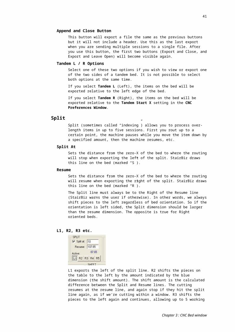
41
Chapter 5 : Cut Template window
OverviewFrom: CNC Cuts window (which is opened from the CNC window) - click New, Duplicate, Edit or Paste buttons at the far right of the window.
NOTE: StairBiz cannot start a cut exactly at the start of an arc, so it adds a tiny (almost unnoticeable) straight section before the start. Under normal circumstances this has no consequence, but if you’re dealing with arcs and are cutting INSIDE of a component, this might have undesired consequences. Check these situations carefully.
FieldsName:
Enter the name of the cut
Category: The category of a cut determines what component is cut and where on that component.
Sometimes it’s easier to digest (and select from) these categories in a separate window – click the small (un-named) button to the right of the pull-down list.
The categories are as follows:
BalconyplateLines following the two lateral edges of a balconyplate (not the ends). Useful for cutting and profiling (especially curved balconyplate).
Balconyplate InsideSame as Balconyplate, but inside edge only.
Balconyplate OutsideSame as Balconyplate, but outside edge only.
Concave Point CutA short line running into the point of a concave corner. Useful (when using a small diameter tool) for making smaller the radius of the corner.
Cove ProfileFollows the profiled edge(s) of a cove.
Fittings :
It is possible to CNC the outline of upeases and overeases. This functionality is a small part of a future “Fittings” module which will be an optional (chargeable) module, so this current feature is a “Preview” only (you can’t get upset when we release it as a chargeable module).
Only upeases and overeases as supported for now.
For the following: "Fitting Ease Outline", "Fitting Ease Top", "Fitting Ease Bottom" and "Fitting Ease Ends", the usual Lead-In and Lead-Out are replaced with Extend Start and Extend End. You settings for these will extend the start/end of the ease. If the "Extend as Arc" checkbox is set, the extension settings will be in degrees and the top and bottom arcs of the fitting will be extended as arcs by this many degrees. If the "Extend as Arc" checkbox is NOT set, the extension settings will be lengths and the top and bottom arcs of the fitting will be extended as straight lines of the lengths set.
Item OutlineThe outline of all items on the bed. Suitable for rough cutting.
Newel Mortise Dowels and String Tenon DowelsDrills holes for dowels into the tenon of a string and the corresponding mortise in a newel (the dowels hold the string tenon in the newel mortise). By default the drilling for the mortise dowels is on the inside of the newel – if you need it from the outside right-click the newel in the Design window and select ‘Outside Drilling...’ (this setting saves
Chapter 5 : Cut Template window
42
with your unit templates and jobs). See Examples of Extra Cuts (below, which also shows how to customize the position of these dowels for individual strings).
Newel Mortise DrillDrills a hole at the four corners of a mortise where a string tenon comes into a newel. It is offset by the diameter of the tool. There is a check-box to include mortise drilling where a rail tenon comes into a newel.
Newel ProfileThis cut allows you to create tool paths on a newel. The paths are applied to each face of the newel.
The Code field holds a number which tells StairBiz which is the reference line on the newel which you wish to cut (with or without an offset). The numbers are such that you can include multiple reference lines by adding the numbers together.
Note that a chamfered newel can be represented as such in the Elevations window by using a negative length for acorns and/or turnings in the newel’s Style window.
TOP
1 Top edge of newel (the top of the newel is as shown on the bed, according to the CNC Preference for showing newels on the bed).
FULL NEWEL:
2 Right side, top to bottom
4 Left side, top to bottom
ACORN:
8 Bottom edge; right to left
16 Right side, top to bottom
32 Left side, top to bottom
UPPER FLAT:
64 Bottom edge; right to left
128 Right side, top to bottom
256 Left side, top to bottom
TURNING:
512 Bottom edge; right to left
1024 Right side, top to bottom
2048 Left side, top to bottom
BOTTOM:
4096 Bottom edge of newel
Numbered OutlineLines following the outline of an item, where the user can select which points along the item to start and end at on an item by item basis. It is useful for creating ad-hoc paths on an item-by-item basis for unusual situations.
You must enter a Code (any text you like) at the top-left of the window – StairBiz uses this code to determine which Numbered Outline cut you wish to apply to an item on the bed.
To apply Numbered Outline cut to an item on the bed, the Cut Template must be included in a currently selected Cut List (as usual). Right-click on the item and select EC Numbered Outlines. The format you need to enter is as follows (separate each with a comma):
Code: The code you entered in the Cut Templates window for this cut (if you have multiple Numbered Outline cuts in the Cut List, this is how StairBiz knows which one you are setting).
Direction: Enter “+” to proceed in the same direction as the outline cut, or “-“ to proceed in the opposite direction.
Chapter 5 : Cut Template window

43
Start: Which poly index is the start of this path – you will see the indexes printed on the outline poly on the CNC bed.
End: Which poly index is the end of this path.
StartOffset: A lead-in distance at the start of the path.
EndOffset: A lead-out distance at the end of the path.
RailLines following the two lateral edges of a handrail. Useful for profiling or trenching a plow (especially curved rail).
Riser Edge BottomThe bottom edge of a riser.
Riser Edge TopThe top edge of a riser.
Riser Ends SawtoothA line following the end of each riser where the end of the riser terminates at a sawtooth string. Useful for doing miter cuts (or variations thereof) to marry into the string and/or fret.
ShoerailLines following the two lateral edges of a shoerail. Useful for profiling or trenching a plow (especially curved shoerail).
SideNose Back EndA line following the back-end edge of a sidenose.
SideNose OutsideA line following the single outside edge of a sidenose (not including the back end).
SideNose ProfileA line following the profiled edges of a sidenose (i.e. the outside edge and the back end).
String Bullnose Tread NotchImagine a string (with no bottom newel) coming down to a bullnose tread, and extending slightly into the back of that bullnose tread (such that the vertical end at the bottom of the string must be notched to accommodate the back of the tread). This cut does that notch in the vertical end of the string. See Examples of Cut Templates.
It is most useful where the back of the bullnose radius is in line with the back of the tread.
The rear of this notch has a nose radius (to correspond to the nose radius at the back of the bullnose radius of the tread.
String Edge (multi) BottomA line following the entire bottom edge of the string. Useful for creating a rebate to clean up the trenching, or a rebate for soffit lining, or a decorative profile of some kind. Because this cut can contain multiple paths (levels, hockey etc.) it is not suitable for saw cuts.
String Edge (multi) TopSame as above, but applied to the top edge.
String Edge (single) BottomA single line following the bottom edge of the string (the main string if a hockey). Useful for creating a rebate to clean up the trenching, or a rebate for soffit lining, or a decorative profile of some kind. For hockey strings and levels, in many cases this cut is not appropriate (see ‘String Edge (multi)’)
String Edge (single) TopSame as above, but applied to the top edge.
String End (inline vert) Hi
Chapter 5 : Cut Template window
44
A line following the hi-end of string having a vertical join with another string and the two strings are in-line. Useful for different methods of joining the two strings together.
String End (inline vert) LoSame as previous, but applies to the lo-end of the string.
String End Vertical (optional newel) HiA line following the vertical line of the hi end of the string where there is a fixed newel. It will always be a single-line cut (a vertical line in-line with the furthest point on the string). If you wish to restrict this cut to only those string ends butting a fixed newel, tick the “Requires Newel” checkbox.
String End Vertical (optional newel) LoSame as above but at low end of the string.
String End Vertical (optional newel) Hi/LoBoth of the above.
String Ends ExactRouts the exact outline of the hi and low string ends, regardless of your standard cut settings.
String RebateA line following the vertical end of a string at a corner that has been set (in the String Setout window) to have a Rebate. There are eight categories for String Rebate. In the category names, the suffix “M” means Male (i.e. the end of the string is the tenon part of the rebate), “F” means female (i.e. the end of the string is the mortise part of the rebate), and an additional suffix of “R” means a reverse corner (e.g. an inside landing corner, which, when routing the male end on the bed, would need the string OUTSIDE face-up, as opposed to a normal corner where to rout the male end would need the string INSIDE face-up). See Examples of Cut Templates/ String Rebate (below).
String Safety Bar OutlineDoes a perimeter cut for safety bar trenching in strings (most likely used with a small-diameter tool to square-up inside corners).
If you always run this cut in conjunction with the String Trench Open-Rise Outline cut, you do not need to create a separate cut template - use that cut template and tick the "Include SafeBar " checkbox.
String Sawtooth RiserA line following the vertical line of each riser in a sawtooth string. Useful for beveling the riser cut to marry with a mitered riser.
String Sawtooth TreadA line following the horizontal line of each tread in a sawtooth string. Useful for creating drilling for dowels used to position the treads on the string.
String Tenon DowelsSee Newel Mortise Dowels (above).
String Tenon ReductionsA line or lines following the end of the tenon of a string (i.e. a tenon that corresponds with a mortise in a newel) where the tenon has a reduction in the X plane (which corresponds with the Z plane when lying on the CNC bed). This cut can be achieved on one side only when using a vertical router, or on both sides when using a 4 or 5-axis machine and a tool set to the Hoz Router category and a G-Code template set up for such cuts (i.e. in doubt, check with support). For 4 axis operation the path created and shown in the CNC bed window indicates the END of the Hoz Router tool (StairBiz assumes the CNC controller makes the tool length adjustment). As such, the path shown when you do a test run in the CNC bed window is not an exactly accurate depiction of what happens at the machine (i.e. a test run shows the path at the end of the tool as if it were a vertical router). Also see Multi-cut Depth Steps (below). Also see String Tenon Reductions Round.
String Tenon Reductions RoundSame as String Tenon Reductions (above) when using a horizontal router (which is mandatory), except that the top and bottom edges of the tenon are rounded to fit
Chapter 5 : Cut Template window

45
snuggly into the mortise (assuming the mortise has rounded corners because it was trenched with a router).
String Tread/Rise OutlineA line following the outline of each tread top, nose and riser face in a closed riser string.
String Tread/Rise Outline 2Same as above but ignores the tread nosing (so follows the line of the tread and riser).
String Trench Anti-BreakoutMay be useful where you are not trimming or rebating the bottoms of strings, and, when using brittle timbers or for other reasons, you are getting excess breakout along the bottom of the string caused by the trenching.
This template creates a series of short cuts at the intersection of either the riser face or tread top (depending on where the problem is) with the bottom edge of the string, sufficient to prevent the breakout.
The ‘Cut Lateral Offset’ for this cut is used only for a minor adjustment to the position of the cut (at zero, StairBiz will make the cut exactly where it needs to be).
For very brittle timbers or very high feed rates, tick the “Highest Level” checkbox. This causes StairBiz to do both riser line and tread line in certain cases.
Note that for the Z-Cut field it may be useful to use the ‘%TZ’ tag (being the depth that the treads trench into the strings).
Be sure to sequence this cut (in the CNC Cuts window) higher than the trenching (you can click the Add Trenching button to definitively sequence the trenching).
String Trench Curved ScribeTwo lines shallow scribed into a curved string to indicate the position of the nose/rise in preparation for subsequent manual trenching after lamination. They are scribed where the back/bottom of tread/riser meet.
String Trench NosingA line following the line of the nosing of each tread in a box string. Note that this cut ignores any radius (see next cut).
String Trench Nosing RadiusA line following the radius of the nosing. Useful for using a smaller tool diameter to reduce the radius of the nosing in the string.
String Trench Open-Rise OutlineA line following the outline of each tread in an open riser string. Useful for creating trenching for the open rise tread where that trenching is reduced from the normal size (i.e. tenon the treads into the string). Here you would switch off normal trenching.
Tick the "Include SafeBar" checkbox to include safety bars.
String Whole OutlineA line following the whole outline of the string. Useful for doing rough cuts prior to the final (normal) cut. It differs from Item Outline in that it only applies to strings.
Tread BackA line following the back of each tread. Useful for creating a tongue for marrying into a groove in the riser.
Tread Back Open RiseA line following the back of each tread where there is no riser above the tread.
Tread Ends Open RiseA line following the end of a tread where there is no riser above the tread.
Tread Ends SawtoothA line following the end of a tread where that end marries with a sawtooth string. For example, useful for creating a bullnose on the tread end to replace a side-nosing.
Note that this category the Direction field allows From Nose and From Back of Tread (in addition to the standard directions).
Chapter 5 : Cut Template window

46
Tread nosingA line following the nosing of a tread. Useful for profiling a nosing, especially for curved-nosing treads and bullnose treads. Be sure to use a Lead In/Out Lateral Offset (Dims D and E) when using this cut for profiling the nosing – if the tread is a bullnose, and the bullnose part of the tread runs straight into the back edge of the tread, there isn’t really an end of the nose, and to retract at the end of the nose may damage both tread and tool.
To set up multiple Tread Nosing templates based on different tread thicknesses, see Vet Component Thickness (Fields heading, below).
Tread RiserTrenching for the riser groove in the underside of the tread. It is largely automatic – the only values required are the lead-in/out, and ‘Extra Riser Thickness’ – if you want the groove to be wider than the thickness of the riser, set the extra width here
Direction: If the cut is generally diagonal to the grain, these determines whether the direction of the cut if with the direction or against the grain direction. If the cut is parallel to the grain then with can be used to reverse the direction of the path.
Tool: Select the tool appropriate for the cut. The tool must be already in your Tools list in the CNC Preferences window and its properties must be set.
Side: If Top, StairBiz will only process this cut if the component on the bed is top up. If Bottom, StairBiz will only process this cut if the component on the bed is top down (flipped).
Z-Zero: Determines where the ZCut is measured from. Material surface – the ZCut is measured from the top of the piece. Bed Surface – the ZCut is measured from the bottom of the piece. Half Mat Surface – the ZCut is measured from half way between the top and bottom of the piece.
Z-Cut: Determines the height above or below the Z-Zero of the calibrated Z of the tool for this cut. Positive is always UP (e.g. 0.75 would set the tool 0.75 ABOVE the Z-Zero for this cut). Negative is always DOWN (i.e. BELOW). This is true regardless of the positive/negative settings of your machine (StairBiz does the conversion if necessary).
Z-Cut can not be a tag (it must be a dimension).
Z-Retract: Determines the height above the material surface (ALWAYS the material surface) of the retraction of the tool when the single cut template generates a series of non-contiguous cuts or drills. Positive is UP (e.g. 0.75 would retract the tool 0.75 ABOVE the material surface).
Cut Lateral Offset: Click the Show Legend button. Thereafter this button toggles between Show Legend and Show Tags. Both will help you determine this and the following settings. In the legend, the letters (A, B, C etc.) correspond to the same letters shown to the right of each of the following settings.
The lateral offset is the distance from the line indicated by the Category to the CENTRE of the tool path. Generally a positive distance moves away from the centre of the component and a negative distance is the opposite. Note that StairBiz applies no compensations for the selected tool radius – the centre of the path is determine entirely by this setting (although you can use a combination of tags and/or numbers – see Dimensions Tags below).
Note that there is a tag for tool radius (%TR).
Note that you can include multiple cuts in the one template, each with a different Lateral Offset – see Multiple Cuts in the One Template (Below)
Lead In/Out(1):
Chapter 5 : Cut Template window
47
Determines the dimensions B and C shown in the legend. Negative numbers may also be used. If set to zero, the cut will start and end at the start and end of the line determined by Category. For example, for Tread Nosing you can imagine the yellow “Item” in the legend as being a tread, with the upper edge being the nosing of the tread.
This value can be a tag – see Dimensions Tags below.
Note that you can include multiple cuts in the one template, each with a different Lead-in – see Multiple Cuts in the One Template (Below)
Lead In/Out(2): Optional. Determines the dimensions D and E shown in the legend. Must be positive numbers. This can be useful for profiling tools that need to plunge/retract away from the cut, where the A/B dimensions are insufficient or unreliable.
Be sure to use this with Tread Nosing cuts (when profiling the nosing) – if the tread is a bullnose, and the bullnose part of the tread runs straight into the back edge of the tread, there isn’t really an end of the nose, and to retract at the end of the nose may damage both tread and tool.
Lead In/Out(2) Angle: Optional. Determines the angle of D and E shown in the legend. The “F” in the illustration is 90 degrees. The “G” is 135 degrees.
You can get Lead In/Out(3) and Lead In/Out(3) Angle etc. by appending additional values to those in Lead In/Out(2) and Lead In/Out(2) Angle, using a semicolon between values, as follows
Multi-cut Depth Steps: Used only for horizontal tools. It determines the maximum depth of horizontal cuts for String tenon reductions. For example, “1” would give 3 routs in a 2.5” horizontal depth.
Respect Maximum DepthWith this ticked, the cut you are specifying will respect the tool's Maximum Depth property (as set in the Tools pane of the CNC Preferences window).
Note that the tool's Multi-pass Offset does not apply in these cases.
This does not apply to Horizontal Routers - for String Round Tenons and String Tenon Reductions (with a horizontal router) the Multi-cut Depth Steps property (see above) applies instead.
Note that Drilling also respects the drill tool's Maximum Depth setting.
Pocket Hole Diameter: Used for drilling on the horizontal (4 axis). It allows you to bore horizontal holes of specific diameters using a router that may be less than that diameter. Use of this parameter will cause the category Horizontal Drill in the G-Code template to be used instead of a standard drill category. You must have commands in the g-code template capable of supporting this feature – best to contact StairBiz Support.
Vet Component Thickness: If there is a non-zero value here, StairBiz will check to see if the value is the same as the component thickness on the bed, and will only apply the cut if it is.
For example, for a Tread Nosing cut, you could set up two templates, one with 32 mm in this field and a nosing tool suitable for 32mm treads, and another with 40 mm in this field and a nosing tool suitable for 40mm treads. The first would apply only to 32mm treads and the second would apply only to 40mm treads.
Chapter 5 : Cut Template window
48
Rolling CornersThis creates a radius where two straight paths intersect, allowing the tool to "roll" around the corner rather than coming to a stop for a sudden change in direction. It is only used where the cutting face is not affected.
Please TEST (for both a right hand and left hand stair) your particular application of rolling corners on the StairBiz bed prior to running on your machine - it is not possible for us to test each possible application.
Note that standard outline cuts have their own 'generic' Rolling Corners setting - see CNC Prefs window.
ButtonsShow Legend / Show Tags
Shows the legend and tags that will help you understand/apply many of the above settings. The Show Tags button only appears after you click Show Legend, and the two toggle thereafter.
ApplyWill apply your settings/changes to items already on the bed, so that you can see the effect without closing this window.
OKSaves your settings/changes, and closes the window.
CancelCloses the window without saving any changes you have made since opening the window.
Dimension TagsRelates to some fields (ZCut, Cut Lateral Offset, Lead In and Lead Out) in this window that require dimensions. A dimension tag is a dimension that gets its value from some other setting or property. In all cases where you can enter dimensions, you can optionally enter tags.
The tags available are as follows
%NR Nose to Riser face (i.e. standard nosing). Zero for splayed risers.
%SN Sidenose to String (outside of sidenose to outside of cut string). Zero when non-sawtooth. Applies to strings, treads and risers.
%ST String Thickness (as shown in Components window). Applies to strings, treads and risers.
%S2 1/2 String Thickness (midway through the depth of the string). Applies to strings, treads and risers.
%S3 Thickness of the string above this string. Applies only to strings (mostly used for rebates at a corner).
%S4 Thickness of the string below this string. Applies only to strings (mostly used for rebates at a corner).
%RD String rebate depth as set in the job's Setout window. Applies only to strings (mostly used for rebates at a corner).
%FT Fret thickness (zero when no fret or non-mitered fret). Applies to strings, treads and risers.
%TT Tread Thickness (as shown in Components window)
%T2 1/2 Tread Thickness (midway through the depth of the tread)
%RT Riser Thickness (as shown in Components window)
%TR Tool Radius (of the selected tool, as shown in the Tools tab of the CNC Prefs window)
%TD Tool Diameter (of the selected tool, as shown in the Tools tab of the CNC Prefs window)
%TZ The depth that the treads trench into the strings.
Chapter 5 : Cut Template window

49
Tags relating to string thickness and fret thickness will apply to the relevant side when used for tread end and riser end cuts.
Tag expressionsIn the above-mentioned three fields, you can use tags and dimensions in expressions (i.e. addition, subtraction, multiplication and division).
For example:
%NR+2 would give a dimension of the nosing plus 2 inches (or mm).
%TR+%TD would give a dimension of the tool radius plus the tool diameter.
%TR+%TD*#2 would give a dimension of the tool radius plus the tool diameter multiplied by two. Note that for the purposes of multiplication and division, integers must be prefixed with a “#” (otherwise they are treated as dimensions and would give the wrong result).
Multiple cuts in the one templateWhere you want multiple cuts (or drills) and the only the difference between them is the Cut Lateral Offset or the Lead-In, you can achieve this in a single template, as follows:
In either the Cut Lateral Offset field (A) or the Lead-In field (B), but NEVER BOTH fields at the same time …
1) You can separate multiple dimensions with a pipe character (“|”) to give absolute dimensions from the reference line.
For example (for Cut Lateral Offset):
“20|40|60” would give you three cuts at 20, 40 and 60mm (offsets from the reference line).
“%TR|%TR+%TD|%TR+%TD*#2” would give you three cuts at ToolRadius, ToolRadius + ToolDiam, and ToolRadius + ToolDiam x 2 (offsets from the reference line).
2) You can separate multiple dimensions with an exclamation character (“!”) to give an absolute dimension from the reference line for the first dimension and relative dimensions from the previous line for the others.
For example (for Cut Lateral Offset):
“20!10!10” would give you three cuts at 20, 30 and 40mm (offsets from the reference line).
“%TR!%TD!%TD” would give you three cuts at ToolRadius, ToolRadius + ToolDiam, and ToolRadius + ToolDiam x 2 (offsets from the reference line).
NOTE that multiple lead-ins would probably only apply for drilling holes.
Hogging cuts in the one templateIn the case ONLY of the Cut Lateral Offset, you can specify a start offset and an end offset and tell StairBiz to hog out between those two cuts with as many cuts as are required based on the diameter of the tool. To do this enter a “>” between the two dimensions.
For example (for Cut Lateral Offset):
“10>70” would do a cut at 10 and a cut at 70 (offsets from the reference line), then do as many more cuts as are required to hog out between the two.
Another example in the case of a “Tread Nosing” category cut template, the following Cut Lateral Offset would re-surface an entire 265mm wide tread:
“-%TR>-265+%TR”
Alternating the direction of multiple cutsYou can alternate the direction of multiple cuts by adding a “~” anywhere within the field.
For example:
Chapter 5 : Cut Template window

50
“10>70~” would do the first cut (at 70mm) using the direction set in the Cut Template, then for each subsequent cut would alternate the direction.
This saves long rapid traverses where appropriate.
Note that you should not use alternate directions where the LeadIn and the LeadOut dimensions are different (otherwise you get a staggered effect and the cuts will be wrong).
Drilling/boringYou can bore a hole using a drill (if you select a ‘Drill’ tool, in which case the diameter of the hole will be the same as the tool), or by selecting a ‘Router’ tool and specifying the “Pocket Diameter” in the template.
The centre of the hole will always be at the very START of the first path in the cut you create in the Cut Template (any lead-outs are redundant). So, for example, if your cut has a lead-in, it will be at the start of the lead in (i.e. either at the start of the “B” dimension, or the start of the “D” dimension if “D” and “F” are set). In other words, only dimensions A, B, D and angle F are ever relevant.
To reference the bore from the OTHER end of the reference line, set the opposite direction in the Direction pull-down (still only lead-ins apply – lead-outs are irrelevant).
Examples of Cut TemplatesThe list of possibilities for cut templates is limitless. Following are some examples:
Drilling for screws for open rise treads
Note; Above dimensions are in mm
There are two possibilities for the tool; you can use a Drill tool, or you can use a Vertical Router tool (in which case you will need to specify the Pocket Drill Diameter).
Drilling for dowels for MDF treadsSame as above (with a single dimension for Cut Lateral Offset), but use something like the following for Lead In.
Chapter 5 : Cut Template window

51
Newel Mortise Dowels and String Tenon Dowels Your G-Code template must be set up for drilling (if in doubt, check with support).
Drilling for such dowels only applies if there is a vertical tenon reduction. The exception is where a sawtooth string does not have a reduction at the point where the top or bottom tread meets the end of the string, or where the tenon hits the floor prior to a reduction.
Z-Cut in the above example (of a Newel Mortise Dowel) drills to within 20mm of the bottom of the newel.
Customizing tenon drilling for individual stringsThe Cut Template for drilling these dowels has fixed offset dimensions (which apply to all string ends). You are able to override the fixed settings for individual string ends. In the String Setout window, select the Edit Dowels check-box in the left panel. Edit the offsets as required for that particular string end. These settings save with the job, unit templates and stair templates. Note that they save for the particular context of the string end (to see the context, in the Elevations pane of the Design window select the Show Join Type menu-item). If you think you set the override, but then later find that they are not set (i.e. all zeros), it’s because the Join Type (i.e. the context) of the string end has changed – set again for the new context as required. Join Types are listed in the Users Manual, Chapter 13/ String Setout window/ The joins in detail.
String Rebates Used at a corner that has been set (in the String Setout window) to have a Rebate. Normally you would also set a Rebate Depth in the Setout window (Strings category), but this is not mandatory (for example you may be using this Rebate tag to do dowels or biscuits etc. for this joint, and you might not want the string lengths to be adjusted for the rebate).
Chapter 5 : Cut Template window
52
The numbers shown in the following illustrations correspond to the numbers shown for each string category below. In the category names, the suffix “M” means Male, “F” means female, and a additional suffix of “R” means a reverse corner (where you need the string’s inside face DOWN in order to process the joint, e.g. an inside landing corner).
NOTE that in the String Setout window in StairBiz, when selecting a rebate joint you have the option of “Lower Rebates” or “Higher Rebates”. This terminology can be confusing, because we applied the concept of “Lower Butts” and “Higher Butts” to rebates. In other words, we say the “Lower Butts” or the “Lower Rebates” if the lower string is the one that doesn’t make it to the corner. The “Upper Butts” or the “Upper Rebates” if the upper string is the one that doesn’t make it to the corner.
2. StgRebateHiEndM
4. StgRebateHiEndF
3. StgRebateLoEndM
1. StgRebateLoEndF
6. StgRebateHiEndMR
8. StgRebateHiEndFR
7. StgRebateLoEndMR
5. StgRebateLoEndFR
For example, to do #1 (StgRebateLoEndF):
Z-Zero is set to "%RD" meaning the rebate depth as set in the Job's Setout window.
Cut Offset: There are two cuts set here; one before the "!" and one after, with the "!" telling StairBiz that the second cut is offset from the first cut (a pipe "|" would have indicated that the second cut is relative to the reference line rather than the first cut). The %S4 tag is the thickness of the string below (because it might not be the same thickness as the string being worked on) and the "%TR" is the tool radius (so here we get a cut at the edge of the rebate). The second cut has an offset from the first of the tool diameter (%TD)..
Chapter 5 : Cut Template window

53
Sidenose nosing (integral)
String Trench Anti-Breakout
Chapter 5 : Cut Template window

54
String Bullnose Tread NotchImagine a string (with no bottom newel) coming down to a bullnose tread, and extending slightly into the back of that bullnose tread. The arrow (below) shows the notch that this cut creates.
If the back of the bullnose bulb is in line with the back of the tread (as in the above plan-view example), StairBiz will put a nosing radius at the back of the notch (to correspond to the nose radius at the back of the bulb of the bullnose tread). Otherwise there will be no nosing radius.
It would be usual to set 'ZZero' as the Bed Surface and 'ZZero to Tool Bottom' as the (negative) distance below the Bed Surface (so that you cut all the way through the string).
LeadIn = Starting distance in front of the vertical of the string.
LeadOut = Use this to extend the notch further back (i.e. past the face of the rise above).
Most other properties are not relevant.
Sawtooth Flush (treads/risers sit inside)
Normally the outline of a sawtooth string follows the underside of the treads and the back of the risers. You can make it follow the top of the treads and the front of the risers (such that the treads/risers sit WITHIN the string) see the Setout window Sawtooth Flush (treads/risers sit inside).
You can also set the sawtooth outline to extend ABOVE the treads and in FRONT of the risers (to provide a rebated key for a sawtooth shoerail).
In either case, to trench a rebate into this string to house the treads/risers, you can use the Sawtooth Riser and Sawtooth Tread categories of the Cut Templates window.
For the Treads, set the CutOffset to "-%TT + %TR ! %TD"; this will give you two appropriate cuts for each tread.
For the Risers, set the CutOffset to "-%RT + %TR ! %TD"; this will give you two appropriate cuts for each riser (provided it is not a splayed riser).
Chapter 5 : Cut Template window
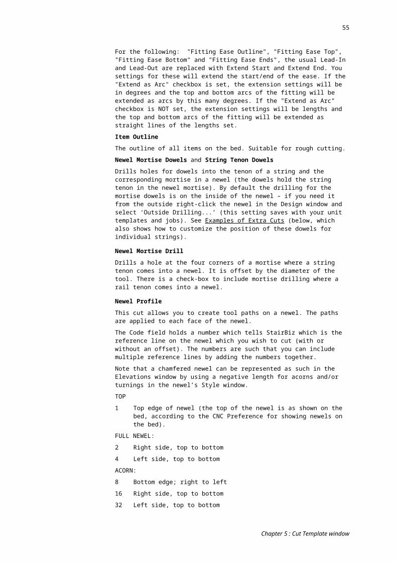
55
Recess for steel plate under treads
Lead In and Lead Out are 300mm in from the ends of the treads, so you'll have to do a calculation for that to get the length correct.
You'll need to change the Cut Offset dimensions to get the correct initial and final offset from the nose of the tread. The %TR are there to account for the tool radius, so the dimensions you use instead of -100 and -200 are outside (total hog) dimensions.
Square NosingsIf there is no radius on the tread nosings, you may wish to "square-up" the round in the trenching in the string with a small-diameter tool, like as follows:
Chapter 5 : Cut Template window
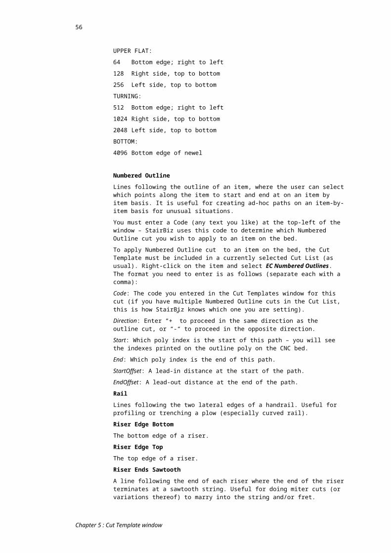
56
First, in CNC Preferences (Trenching) set the Nosing Radius to zero. Then ...
Chapter 5 : Cut Template window
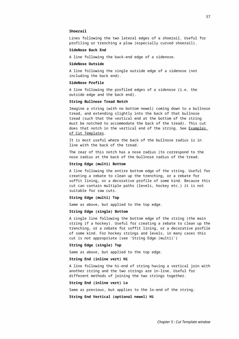
57
Chapter 6 : CNC Session List window
OverviewFrom : CNC menu ; Session List menu-item
The CNC Session List window is very similar to the Directory window, but it contains an extra area or pane on the bottom that lists various information about any CNC Sessions that were exported for a given job.
Job PaneThe top half of this window lists all of the jobs currently available. You will find that this portion of the window functions exactly the same as the Directory Window. Please see the section entitled Directory Window for an explanation of how to use the Job Pane.
Like the Directory Window, you can also set up views which allow you to customize the column layout of the Job Pane. The Views you set up in this window are independent of the views set up in the Directory Window.
The most appropriate view of this pane would probably show “Requires CNC” as the first column (see Details window), and this column would probably be grouped (see Show Group Panel in the Directory window). The second column would probably be “CNC Scheduled Date” (see Details window), and would also probably be grouped. Other columns are up to you.
Session PaneThe bottom half of this window is called the Session Pane, and contains a listing of all the CNC Sessions that were exported with the Save to Session List option set (See CNC Bed Window under Export for an explanation of this option).
You can resize this pane by placing your mouse cursor between the Job Pane and the Session Pane. When you do, your cursor will change to up/down arrows. At this time you can click and drag to make the Session Pane bigger or smaller.
When you select a Job in the Job Pane, the Session Pane will fill up with information about each exported CNC Session for that job. If the selected job has no CNC Sessions, the Session Pane will remain empty.
There are several columns in the Session Pane. They are each described below.
Done
Chapter 6 : CNC Session List window

58
This column shows a checkbox for each CNC session. You can check or uncheck this box by double clicking on the row for the CNC session. This can be useful for indicating if a CNC Session has been processed on the machine or not. This information is saved with the job and can be viewed from any computer in the network.
File NameThis column shows the name of the file that was created when the CNC session was exported. The file will be found in the \StairBiz Program\CNC Files folder on the computer where the export took place.
Job NameThis column shows the name of the job where the CNC session was created.
ExportedThis column shows the date of the session export.
PauseThis column shows a pause number for each session. If only 1 export was performed for a session, this column will show a 0 (zero). Each subsequent append (See Export under the CNC Bed Window topic for more explanation of exporting and appending) will contain the next higher number.
ToolsThis column shows the Tool ID for each tool used and the diameter of the tool as defined in the CNC Preferences window for the CNC Machine used.
Sheet SizeIf a sheet was placed on the bed during the CNC Session Export, it will be displayed in this column.
ItemsThis column lists each of the items that were to be cut in this CNC Session. The material, size and location on the bed will be displayed with each item.
Delete SessionThis toolbar button allows you to select a CNC Session and delete the record from the job.
Chapter 6 : CNC Session List window

59
Chapter 7 : Miscellaneous CNC topics
Managing Tool DiametersStairBiz always exports the CENTRE of the tool path (and uses g-code to switch off X/Y compensation at your machine). There are good reasons why this is a better system then exporting outlines and letting your machine do the compensations (mainly related to the degree of control we have in reducing breakout, in particular for trenching). The drawback is that the tool diameters in the CNC Prefs window and the tool diameters on the machine must match. Below are a variety of ways to circumvent the inconvenience:
Export g-code just prior to using it:Obviously the optimal solution is to export each CNC session just prior to running the session. Further, it is optimal (but not critical) that the CNC operator is responsible for this. It is often easier for him to manage the entire situation than it is to work out which g-code file to use for what job. Note that he will not need a full StairBiz license to do this – a StairBiz Lite license is all he needs.
Job Session Templates:If necessary, the office can lay out the bed, and instead of exporting to g-code file, save the layout in a job session template instead. A job session templates saves the positions, rotations and flips each item on the bed, then this is saved with the job. You can have as many job session templates as you like for any one job, and you can name each whatever you like. When it comes time to process the job, open the job, open the CNC Bed window, and select the appropriate session template – the bed is automatically laid out accordingly. Simply click the “Export” button. This can be done by either the office or the CNC operator (better the CNC operator).
Global Session Templates:For many jobs, it might be convenient to use global session templates directly, or global session templates can be used to lay out the bed, then that layout can be saved in a job session template.
Session List:The Session List allows you to manage CNC sessions. It won’t help the problem of changing tool diameter subsequent to exporting g-code files, but it will help you to manage that situation and know precisely which files are affected.
Directory window:If a Session List approach is not appropriate, you can use a purpose View of the Directory window, including columns for “Needs CNC”, “CNC Date” and “CNC Done”. This is useful anyway, but in particular when exporting g-code just prior to processing it.
Multiple cutters – same diameter:You could maintain half a dozen spiral cutters (all the same diam) and use all of them before sharpening all of them at the same time (to a consistent diameter). This way you could go for months certain that the tool diameters are correct.
Multiple cutters – different diameters:You could have tool slots in your tool changer for a variety of tool diameters (e.g. 16mm, 15.5mm, 15mm etc, being various stages of a 16mm tool being sharpened). You create these different tools in StairBiz (with different IDs). When you sharpen the tools, you swap them around in your tool changer so that the same Tool Id always has the same diameter. Thus whatever tool is selected in the Prefs window to do a job will always be guaranteed of being correct when that job gets to the bed, even if the g-code file was exported months ago. The trick is to periodically change the “active” tool for cutting/trenching in the CNC Prefs window so that each tool gets its fair share of use (and thus sharpening).
Master Tool List:Use the Master Tool list to manage tool diameters. This will only be useful where you have set up for multiple virtual machines in the CNC Prefs window, where those multiple virtual machines are for the one actual machine (but contain different settings for
Chapter 7 : Miscellaneous CNC topics
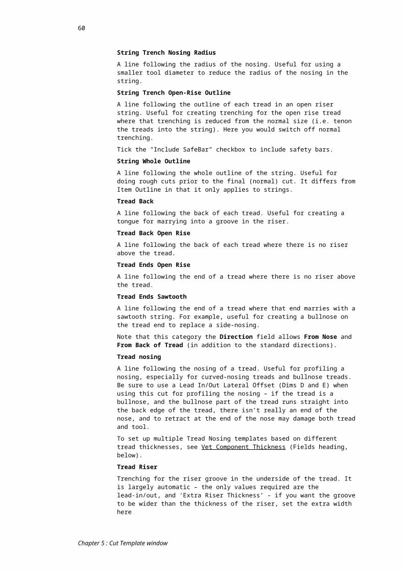
60
different scenarios). This way, when you change the diameter of one tool it changes it for all machines that use that tool.
Extend tool life:Obviously using high quality tools with appropriate RMP and feed rates (to cut down on heat and vibration) will add to the life of the tool - in some cases up to four times as much. Thus tool diameters need adjusting less often.
Finishing Tool:It is easy to set StairBiz up such that all cuts and trenching can be done with a rough cutter, slightly out from the finished face, then finished off with a finishing cutter. The rough cutters do all the work (and get blunt, and constantly need resharpening), but the finishing cutter does very little work, can have much less burning and vibration, and last very much longer. Thus the cutter that really matters stays the same diameter for a long time.
Another possibility is multi-pass cutting – see next heading
Nosing Radius set from Components windowThe Nosing Radius set in the Trenching tab of the CNC Prefs window can be overridden by a Custom category selection in the Components window.
In the Custom Category window (Defaults menu) create a new (or use an existing) category:
It doesn't matter what the category is, or what the Piggy Back category is.
It doesn't matter what ELSE this category might or might not do or be used for.
If you MIGHT want this category to set a nosing radius override, set something like...
Label Dimension 1 = "Tag for Nose Radius"
Label Dimension 2 = "Nose Radius"
In the Style window (Defaults menu) for this category, create some (or use some existing) Styles for this custom category.
Set Dimension 1 ("Tag for Nose Radius") = 889 mm (or 35 inches). This is just a tag - it tells StairBiz this is a nosing radius override.
Set Dimension 2 ("Nose Radius") = the radius of the nosing
In the CNC Preferences window (Trenching tab, Nosing category), tick the Check for Override checkbox.
If ticked, StairBiz will LOOK for an override. If none is found then it reverts to the current setting for Nosing Radius.
Multi-pass cutting: Double the life of the toolThe following applies only to pod machines:
Imagine that a tread is 20mm thick, and you cut the outline using two passes. The first pass uses the bottom 10mm of the tool, and the second pass uses the bottom 10mm of the tool. The bottom 10mm of the tool wears out rather quickly.
Now imagine that you set the “Cut Clearance Above Bottom” to -10mm such that the final pass would cut 10mm below the surface of the bed. Now the first pass uses the bottom 10mm of the tool, and the second pass uses the part of the tool between 10mm and 20mm from the bottom.
You’ve just doubled the life of this tool.
Newels on the bedTurning newels on the bed:
When turning newels on the bed, if the bottom of the newel is closer to the Zero-X of your bed the newel top is turned towards you, otherwise is it turned away from you
Chapter 7 : Miscellaneous CNC topics
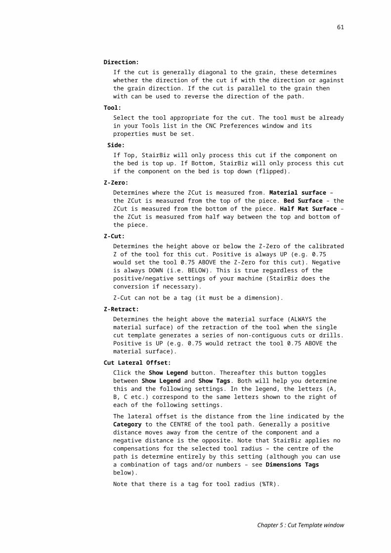
61
Risers:If the front face of a riser don't intersect the newel face, StairBiz will not rout the newel for that riser. The reason is that these situations can get very complex and we'd rather play it safe (and no-one gets to see any mess caused by a hand finish).
Newels - using a cradleLet’s say you sit your newels in a cradle, and the cradle sits on your bed (or on pods). You can set up a tool that automatically takes into account the thickness of the cradle (even when you also have non-newel items on the bed), as follows:
In the CNC Prefs window create a new tool with the same properties as you normally use for trenching newels, however, set the Length/Z Offset = depth of cradle. Use the Tool Id Alias to point to the same tool id.
In the Tool Cfg (Tool Configuration) tab of the CNC Prefs window, in the "A" group, select this tool for Newel Trenching.
Now, when trenching newels, StairBiz will lift the tool up by the depth of the cradle.
Swap HandWhere you have items (from the current job) on the CNC bed, you can swap the hand of them (i.e. to the opposite hand, just as if in the Design window you had flipped the entire design horizontally then re-put the items on the bed). Note that this only works when all items on the bed are from the same job (you will be alerted if they are not). Select any item on the bed, then click the bed's "Flip Horizontal" toolbar button while holding the Control key down - everything on the bed takes on the opposite hand to the current design.
Note that you can only do this once for items currently on the bed, because to evoke this StairBiz does indeed temporarily flip the Design window (and then, after replacing the items on the bed, flips it back to how it was), so that if you do it again with the flipped items you get exactly the same result (i.e. the opposite hand to the current design).
If (in the unlikely event) you do want to flip items on the bed back to their original hand, remove them and manually re-place them. Another way would be to create a session template out of what's on the bed, remove the items, then evoke that session template (items will come back in with their original hand).
Switching back and forth between using or not using podsThere is a setting in the Pods tab of the CNC Prefs window; Use surface pods and raise the cuts by. Set the value, then you can tick or un-tick the checkbox to apply the Z offset or not.
Using Tool AliasesStairBiz requires each tool to have a unique ID. Normally this is the ToolId, but in some cases, you might frequently swap out tools in the same tool changer spot. For example you might put in a 1/4" cutter in spot #2 from time to time, but at other times keep a 5/8" cutter in the same spot. Each time you do this, you would need to change the tool information in CNC Prefs window.
A solution is to use the Tool ID for Export field in the Tools tab of the CNC Prefs window as the actual ToolId, and then you could have multiple ToolIds with this same Tool ID for Export. For example, this method would allow you to have a tool 21 and a tool 22, each with a Tool ID for Export of 2. Then you just nominate a different tool for the job (21 or 22 from StairBiz's point of view but both refer to 2 on the tool changer).
Another reason for using this is to allow you to have two copies of the same tool in StairBiz but with different feed rates, plunge rates, RPM or any other properties.
Difference between MDF board and MDF sheetIn the Timbers window, a timber can be set to “Grain” = yes or no. StairBiz assumes that a timber with no grain is the equivalent of MDF (i.e. it has no grain direction).
Chapter 7 : Miscellaneous CNC topics
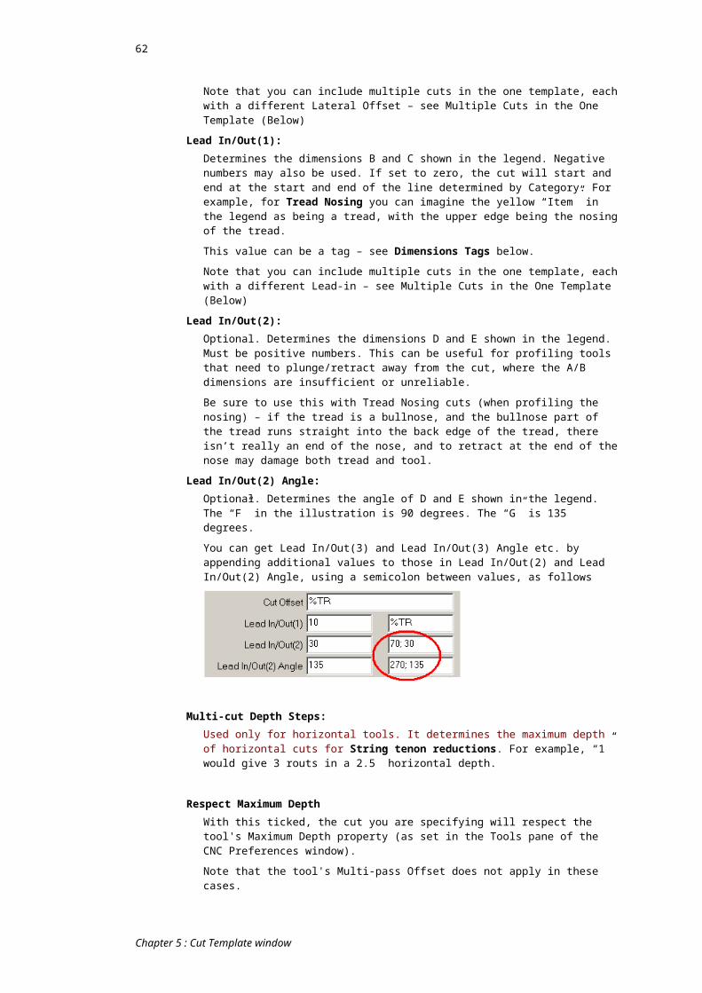
62
In the Components window, if a component is assigned a timber with no grain, if the width of the component (as shown in the Components window – not the actual width in the Design) is greater than 400mm (15.7 inches) then StairBiz assumes that for the purposes of processing that component on the bed an MDF sheet will be used. If it is less than 400mm, an MDF board will be used.
The difference is important - StairBiz uses a different cut path sequence depending whether a component on the bed is of MDF sheet or MDF board (you can see this by right-clicking the component on the bed and selecting MDF Sheet or MDF Board – this overrides the components inherent setting).
A confusion arises when you have placed an MDF sheet on the bed (from the Sheets pull-down menu), and then put an MDF board component on the bed. StairBiz cannot be sure whether you want to process the MDF board component as if it were an MDF sheet (and vice versa).
In the CNC Prefs window (Cutting tab) …
If Resolve MDF board/sheet conflicts is ticked, if an MDF board is on the bed when there is an MDF sheet on the bed, StairBiz will process the board using a sheet cut pattern. If an MDF sheet is not on the bed StairBiz will process all MDF items as if they were MDF board.
If Alert MDF board/sheet conflicts is ticked, StairBiz will alert you first and you can decide.
Managing BreakoutOver the years we’ve put a lot of work into reducing breakout as much as is possible in most cases. It’s probably not perfected, but to be honest we get very few complaints these days which would suggest that most people have got it figured. Below are some suggestions:
Some people follow string trenching with a rebate cut to clean up breakout at the bottom edge of the string.
This rebate can also be used for lining the stair where necessary. StairBiz can do this automatically using a Cut Template.
Obviously if the timber is brittle, breakout will be worse, but the real bottom line for breakout is “pushing vs. cutting”.
If the tool is pushing faster than it’s cutting, there will be breakout. If the tool is cutting faster than it’s pushing, there will be tool burn (resulting in reduced tool life). The trick is to get the balance right for the particular timber being cut (StairBiz has features to assist in this).
The factors that affect pushing vs. cutting are:
Tool diameter; if excessive breakout try switching to a smaller diameter tool. I would suggest 16 to 18mm would be the maximum for trenching brittle timber (less if the following don’t appear to help).
Feed rate; if excessive breakout try slowing this down
Tool RPM (which is also affected by the diameter of the tool) ; if excessive breakout try varying this
Tool sharpness (and quality); reserve a very sharp tool for brittle timbers
Chapter 7 : Miscellaneous CNC topics
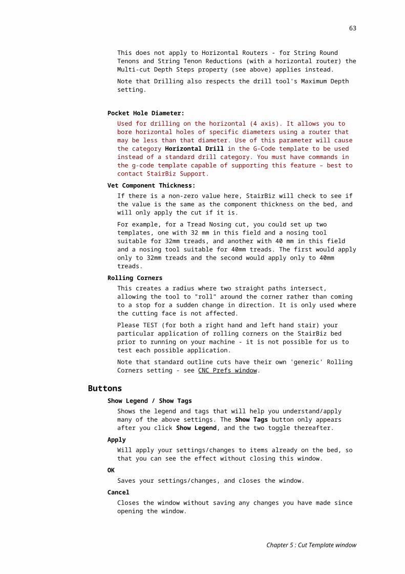
63
There is a delicate balance between all these things that affect not only breakout but the life of your tool. We have known companies to double or triple their tool life by finally getting this balance right.
Slack in your machineFrom the bed, to the gantry, to the head/tool - at every place where you have differential movement between two different parts of the machine system, or even "flex" in one part of the machine, there is potential for "slack" (i.e. the tool tip is not EXACTLY where it should be at any given time). This manifests especially in radii, where the tool goes around the various radii, being pulled into or pushed away from the changing grain directions, and all the time trying to overshoot the direction of the path. It is also perhaps most obvious in how far in the tread wedges will hammer in (i.e. generally the wedges will go in further on one string that the opposite string).
Every time this slack becomes obvious, it's inevitable that the user will blame the StairBiz "math". Every time, it has turned out to be "slack" in the machine (it's a difficult thing for many people to accept).
Note that slack can manifest quite dramatically. The extent of it can be surprising.
Factors that affect slack: The machine (more so in cheaper, weaker or older machines - you get what you pay
for)
Machine servicing (more so in machines that need things tightened up)
The type of material (more so in grained material than in MDF).
The feed rate (more so at faster feed rates, because the head wants to overshoot changes in direction)
The diameter of the tool (more so in larger diameters that have a bigger grabbing effect through varying grain directions)
The sharpness of the tool (more so when the tool is blunt, because the timber is offering more resistance to the tool)
The grain direction relative to the direction of the tool (which is why it manifests more during an arc cut - the grain direction is changing along the path, which is changing the pushing/pulling effect).
Ways to test for slack:If you think the StairBiz math is wrong, try routing just one millimetre into a piece of MDF at very slow speed using a sharp, small diameter tool. Note that if you have worm gear wear, the slack will manifest even in this test when changing path direction.
Ways to try and prevent how it manifests: Get the machine serviced, slow the feed rate (especially for arcs), use a smaller
diameter tool, and keep the tools sharp.
Do multi-step cutting (i.e. a series of cuts of increasing depths to ultimately cut through).
Do two cuts, the first slightly off the final line, the second exactly on it so that this final cut is taking away very little meat. For trenching, you might set a "dummy" tool diameter to cause the cutting to be slightly off the final outline, then use a cut template with a smaller diameter to "clean" the outline. For cutting, you can use cut templates to do a similar thing.
Try changing the "Use climb cut" setting (CNC Prefs/ Trenching) and see if that makes a difference.
Try changing the "Trench from Inside to Outside" setting (CNC Prefs/ Trenching) and see if that makes a difference.
Try changing the "Wall Side Wedge Adjust" setting (CNC Prefs/ Trenching).
Chapter 7 : Miscellaneous CNC topics

64
Chapter 7 : Miscellaneous CNC topics

65
Chapter 8 : G-Code Editor
OverviewFrom : CNC Preferences window ; Advanced button; Manage G-Code Templates; Edit, and you can also open this application directly from C:\StairBiz Program\CNC GT Editor\ StairBiz GT Editor.exe
The StairBiz GT Editor (G-Code Template Editor) allows you to create new g-code templates or modify existing ones. It is a stand-alone application. A g-code template is like a driver – it converts the information and paths in the CNC window into a g-code file that can be read and understood by your machine’s post processor.
Under normal circumstances the StairBiz support staff use this to create a template for your machine, however it’s good to know a little about how it works so that you can tweak it yourself if required.
Replacing a g-code templateIf we send you a new g-code template to replace an existing template, following are the steps for installing it into StairBiz:
1) The file we send you will have an ‘sbg’ extension. Put it in your G-Code Templates folder. This folder in located at C:\StairBiz Program\CNC GT Editor\G-Code Templates. If there is an existing file of the same name, you will be asked if you want to replace the existing – the answer is yes.
2) Open the CNC Prefs window and click the Advanced button at the bottom-right of the window.
3) Select Manage G-Code Templates4) In the G-Code Templates window that opens, there are two lists. The list on the
right shows the templates currently held within StairBiz. The list on the left shows the templates held as files in the folder mentioned above (and will include the file you placed in it). In the list on the left, select the file we sent you.
5) Click the Import button. If the g-code template already exists on the right, you will be asked if you want to overwrite it (say Yes). Close this window.
6) If this g-code template is not the same name as the one selected in the Machine tab of CNC Prefs window, select it in that window.
Chapter 8 : G-Code Editor

66
Editing a g-code templateThere is a specific sequence to follow to edit a g-code template. In summary, you must edit the file version of the template, save it, then import it back in to StairBiz (replacing the existing), as follows:
1) Open the CNC Prefs window and click the Advanced button at the bottom-right of the window.
2) Select Manage G-Code Templates3) In the G-Code Templates window that opens, there are two lists. The list on the
right shows the templates currently held within StairBiz. The list on the left shows the templates held as a file in the following folder:
C:\StairBiz Program\CNC GT Editor\G-Code Templates
You can only edit a file version of the template, so…
If you are sure that the template held within StairBiz (list on right) came from one of the files shown in the list on the left, the remainder of step 3 is optional (you may go straight to step 4), otherwise …
Select the template from the list on the RIGHT and click the Export button. If this template exists on the left, you will be asked if you want to overwrite it (say Yes). This creates (or overwrites) the file version of the template.
4) Select the template in the list on the left and click the Edit button.
5) The G-Code Template Editor window opens. Edit the file as required (see details below).
6) Save the template.
7) Close the G-Code Template Editor.
8) You must now import the edited file back in to StairBiz. Select the file you just edited from the list on the left and click the Import button. If the g-code template already exists on the right, you will be asked if you want to overwrite it (say Yes).
Chapter 8 : G-Code Editor
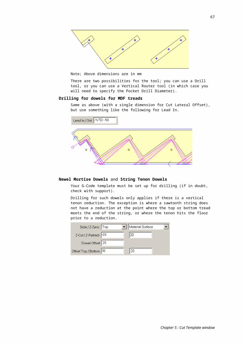
67
9) You’re done. Close the G-Code Templates window.
Remarks in the g-code templateThere are various ways to include remarks (i.e. your own personal comments) in the g-code template:
Strip this rem prefixIn the Options window, in the File category, there is a field called Strip this rem prefix. You can prefix remarks in your g-code editor with whatever character you type here, and they will not appear in the final exported file.
Note that normally this rem prefix only applies if it is as the very start of the line. To apply anywhere the on the line, suffix it a “+” (StairBiz will not show the “+”).
Line Double DashAnything on a line which follows a double dash (“-- “) will not appear in the exported g-code file (including the double dash).
Block RemarkAnything (all lines) which follow a forward-slash double dash (“/-- “) will not appear in the exported g-code file until “--/” is encountered.
Export RemarkThis is not really an editor remark – it is used to insert something into the exported g-code file on an export-by-export basis.
Use the #ER tag (File category). In the CNC Bed window right-click on the bed and select ‘Set Export Remark’. Your entered remark will then replace the #ER tag in the exported g-code.
Also see: Testing g-code output for a way to include remarks in a g-code export.
Buttons in the EditorThe following buttons determine what’s shown in the main edit pane of the window.
EditorShows the editor, where you can create a g-code template.
All Tags UsedLists all tags used in all sections of your g-code template. You cannot edit.
All Cats (with rems)Shows your text for all categories in a single window. Includes remarks. You cannot edit.
All Cats (no rems)Shows your text for all categories in a single window. Excludes remarks. You cannot edit.
HistoryShows the history of amendments for the template (as posted in the Version window). This is for StairBiz staff only (because it may contain references to specific clients). You need a password to view it.
NotesView and/or edit notes regarding the template generally (as apposed to notes relating to specific parts of the template, which should be done as remarks). After adding or amending notes, click the “Post” button to save the notes.
Chapter 8 : G-Code Editor
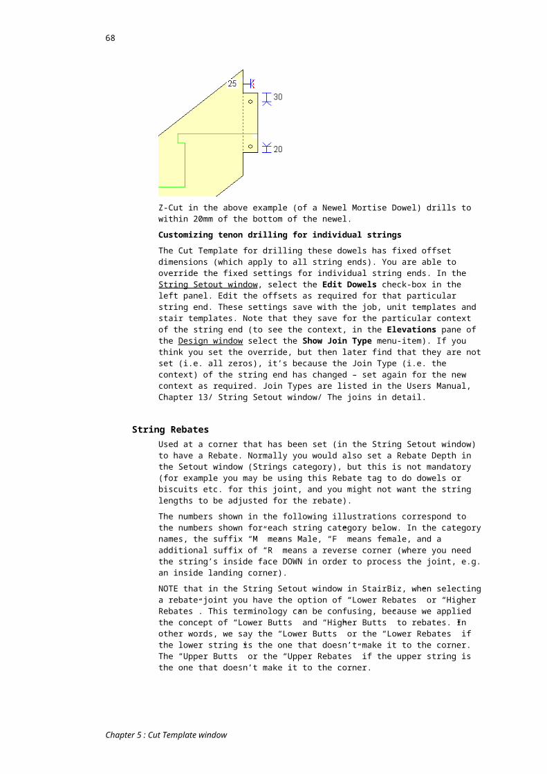
68
G-CodeAllows you to select a g-code file (as exported from StairBiz) for viewing. The main feature here is that your Tabs setting is recognised. Note that remarks can be included in a g-code export (for testing purposes only) – see Testing g-code output.VersionOpens the Version window. All g-code template file names should follow the format outlined in this Version window, and this should be adjusted for each change to the template. This leaves a “version trail” which makes it easier to identify and distinguish between different templates (for the sake of good management). See the separate G-Code Template Editor manual (developers only).
Categories in the EditorCategories are shown in the list at the top (above the editor). When you click on a sub-category (the lines below each category heading) the editor for that sub-category opens in the area below the category list.
Each of the categories relates to a particular function of your final g-code file. For example in the Category 1 (Header) section you write the g-code that always goes at the top of every g-code file; in the Category 2 section you write the code that will specify a tool change followed by a rapid traverse to the start of the first cut path (after the tool change) followed by setting the Z for this path.
1) Header (start of session)
HSS Header (start of session)
2) Tool change; rapid traverse; set Z; then
TSS Vertical Router; Straight
TDR Vertical Drill
TSC Vertical Saw
THS Horizontal Router; Straight
THD Horizontal Drill
T5R 5 Axis Router
3) No tool change; rapid traverse; set Z; then
RSS Vertical Router; Straight
RDR Vertical Drill
RSC Vertical Saw
RHS Horizontal Router; Straight
RHD Horizontal Drill
R5R 5 Axis Router
4) Follow on (no tool change; no rapid traverse; no change in Z)
FSS Vertical Router; Straight
FRC Vertical Router; Arc clockwise
FRA Vertical Router; Arc anti-clockwise
FHS Horizontal Router; Straight
FHC Horizontal Router; Arc clockwise
FHA Horizontal Router; Arc anti-clockwise
FHD Horizontal Drill
F5R 5 Axis Router
5) Special Categories
SVP Vertical Pocket; for creating round holes with a spiral cutter on machines that support this
Chapter 8 : G-Code Editor
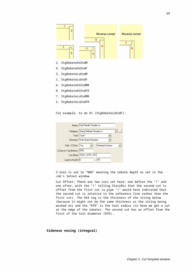
69
SEA For Each Active Arm (with Active Pods will run this category)
SEP For Each Active Pod (will run this category)
S5F 5 Axis Tool Finish - after a 5 axis tool is done, prior to a tool change or at end of run
SEV For each VRP (Vertical Rotated Plane); This code is resolved for each vertical rotated plane and inserted at the point of a #EP tag.
6) Pause (to be followed by Resume)
PAU Pause (to be followed by Resume)
7) Footer (end of session)
E0S Footer (end of session)
The Editor PaneThe main editor pane is below the category list. It is just a basic text editor (like Notepad) with some enhanced features. There is a separate editor for each subcategory. You type in the editor just like you would type into a word processor. The editor for each sub-category holds the g-code template for that sub-category.
TagsTags are shown in the list on the left.
Tags are dynamic variables. If anything in the g-code is always the same regardless of the session being run, then you simply type it in the editor. If something in the g-code changes from session to session then this requires StairBiz to insert the actual value on a session-by-session basis (i.e. dynamically). Tags are used as placeholders for these dynamic variables. StairBiz gets the values for these tags from the CNC Prefs window or from the components on the bed.
Tags can be inserted by either by typing them (prefixed with a #), or by inserting the cursor where you want the tag and double clicking on the relevant tag in the Tags list. When you click on a valid tag in the editor it will be highlighted in the Tags list.
A list of all tags, and a brief explanation, follows:
Terminology: A “segment” is a single line, arc or point. It may be in isolation, or may be one of several in a contiguous (polygon) series.
A “path” is one or more segments in a contiguous (polygon) series.
A “session” is created by a click of any one of the export buttons. There may be more than one session in a g-code file if the ‘Append’ feature was used, or in the case of exporting the other three sides of any newels.
Conditional Tags: Conditional tags (see below) can be placed at the start of a line of code to determine whether the line will be executed. For example, if a line of code starts with #C1 (First Tool Change), that line of code will only be executed the first time StairBiz processes category 2 (tool change) code. In subsequent calls to this category (i.e. on subsequent tool changes) this line of code will be ignored.
There must not be any spaces before a conditional tag.
NOT Conditional Tags: Conditional tags followed by a '!' cause a NOT logic to be used. For example, “#AG!” will be true if the arc is NOT greater than 180 degrees.
Conditions may be applied to blocks (multi-lines) of code:The start must be the conditional tag followed by a "[". For example "#F3[".
The end must be the conditional tag followed by a "]". For example "#F3]".
There cannot be any other code on the same line as a conditional start or end tag, although they can be followed by remarks.
Chapter 8 : G-Code Editor

70
Conditional blocks must start and end in the SAME sub-category of the g-code template.
Last Updated 18Apr09 (StairBiz v9.22)Arms/Pods
AP Active Pod Count (total active pods for all arms)
AX Arm X Coordinate (of current arm according to Arm Counter - see “PA”)
AY Pod Y Coordinate (of current pod according to Pod Counter - see “PA” and “PY”)
PA Pod/Arm Begin Line; Increments the Arm Counter and resets Pod Counter to zero
PX Next Pod X Coordinate; The position of the current arm (according to Arm Counter – see “PA”), including any arm X offset specified in the G-Code Options window.
PY Next Pod Y Coordinate; Increments the Pod Counter (see “PA”) for the current arm, then gives the position of this pod, including any pod Y offset specified in the G-Code Options window.
BedBL Bed Length; As shown in the Prefs window (Machine tab)
BW Bed Width; As shown in the Prefs window (Machine tab)
SA Bed Split Shift Amount; The difference between the Split and Resume lines when the Split button is ticked in the Bed window.
Conditional (see notes above)AG True if the arc is greater than 180 degrees; May be useful in category 4 arcs.
AV True if there are any RVPs (rotated vertical planes).
EO True if ‘Export Outlines’ is ticked in the CNC Bed window.
FT First Tool Change; True the first time StairBiz processes category 2 (Tool Change) code. False in subsequent calls to this category (i.e. on subsequent tool changes).
NT True if the current path required a new tool.
F2 True if working on the front face (as apposed to the top face) for 3-4 axis processing. At the moment this probably only applies to 3-sided newels. It is assumed we are not using RVPs.
F3 Same as above, but for back face
F4 Same as above, but for left face
F5 Same as above, but for right face
F6 True if working on an RVP (rotated vertical plane).
FV True for the first RVP (rotated vertical plane) path. It assumes that all RVPs come after processing the top plane.
If there are no RVPs, then this tag returns True in the Footer section of the G-code Template.
HL Horizontal Router Moving Left. True if the tool is traveling to the left while looking from the top of the tool to the bottom. Necessary for 4 axis machining so that the controller knows which side of the cut to put the horizontal router gearbox.
IP Is Any Pauses (in entire file). Note that this does not recognise pauses generated from a PAUSE item in a Cut List. It applies only if there are newels on bed whose last three faces are to be exported with pauses, or "Export and leave open" or "Append" Exports types. See also “NE”
LP Last segment in path sequence. True if the current segment is the only segment in the path or is the last in a series of contiguous segments in the path.
Chapter 8 : G-Code Editor

71
O1 True if G-Code Option #1 (or whatever name you’ve give that label), as shown in the Export frame of the CNC Bed window, is ticked.
O2 Same as above, but for Option #2
NE True if there are newels on the bed whose last three faces are to be exported with pauses. See also “IP”.
NP True if no pauses yet (File Appends); I.e. True before the first time you export using the Append button for the session.
SB True if Bed is currently Split; (see Split button in Bed window)
SS Single-segment path (there is only one segment in the current path).
ST Square Traverse; True if there is a Square Traverse setting in the Prefs window (Machine tab).
T1 Use only in the “For Each Pod” category. Is the relevant pod a “Type 1” pod (you set the type by right-clicking on the pod; you set the size for each type in the Pods tab of the CNC Prefs window).
T2 Same as above, but for Type 2.
T3 Same as above, but for Type 3.
TF Tandem Full Conditional; True if neither Tandem button is ticked in Bed window.
TL Tandem Left Conditional; True if the Left Tandem button is ticked in Bed window.
TR Tandem Right Conditional; True if the Right Tandem button is ticked in Bed window.
VC True if Plane Index for this path not the same as for the previous path.
ZC Change in Z with no change in X/Y; During a Follow-on cut, if the current cut sequence should cause the Z position to change without moving the X/Y then this is True. This allows a cut to have ‘vertical steps’ in the path.
IT IsTrue; Is the Boolean tag True. Also see BT and BF (for setting the boolean tag to true or false). You can use the BT, BF and IT tags any way you like. For example, if your g-code has to programatically turn the spindle on and off, you might need to track it: each time you turn the spindle on, set the BT tag; each time you turn it off, set the BF tag; each time you need to know if it’s on or off, refer to the IT conditional tag.
RV A Rout Vertical operation (e.g. in a “5-Axis” g-code template category, to rout to a more specific category)
RH A Rout Horizontal operation (e.g. ditto)
DV A Drill Vertical operation (e.g. ditto)
DH A Drill Horizontal operation (e.g. ditto)
CoordsA1 Arc Degrees Start
A2 Arc Degrees End (Always CCW)
AB B Angle. Not currently supported.
AC C Angle. This is the direction of the cut and can be used for Saw cuts etc.
AR Arc Radius; the radius of an arc; may be useful in category 4 Arcs.
AS Arc Sweep Absolute Angle; the sweep of an arc, in positive degrees regardless of whether the sweep in CW or CCW. See also SD.
BG Bulge. Used to define an arc (usually in a polygon segment). If the line segment connecting the vertices would have length d, and the perpendicular distance from the midpoint of that segment to the arc is h, then the magnitude of the BULGE is (2 * h / d). The sign is negative if the arc from the first vertex to the second is clockwise. A semicircle thus has a bulge of 1 (or -1).
DP Depth of Pocket. Used for post-processors that can generate a pocket cut path with just a few parameters.
Chapter 8 : G-Code Editor
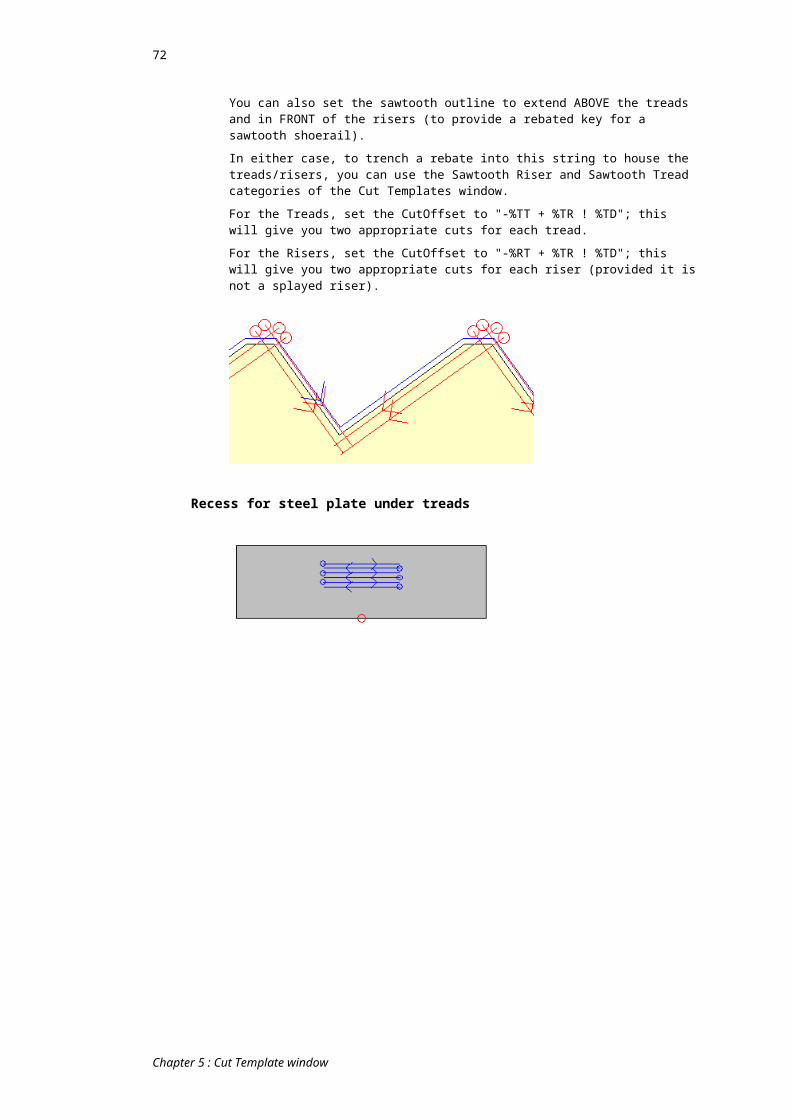
72
HD Horizontal Depth. Used for Horizontal drilling to determine how far the tool should plunge horizontally into the material. (Note that horizontal routs must use Z1 and Z2 because technically they could be different).
PD Pocket Diameter. Used for post-processors that can generate a pocket cut path with just a few parameters. If the drill is not a pocket, this will return the Tool Diameter.
PR Pocket Radius. Same as Pocket Diameter, but half the value. If the drill is not a pocket, this will return the tool radius.
SD Arc Sweep Angle; the sweep of an arc, in degrees. If the sweep is CW then the value is positive. If the sweep is CCW then the value is negative. If the “C-Angle Negative is Clockwise” check-box (G-Code Options window; see below) is ticked then the positive and negative are swapped.
SY Safe Y for Square traverse; If there is a Square Traverse setting in the Prefs window (Machine tab) then this is the closest Y value to the current tool location that can be used for performing a traverse in the X direction.
TX Tandem Start X; The X distance from the start of the bed to the start of the tandem (Prefs window; Machine tab).
X1 X Coord start of path; The X-coord of the start of a cut path immediately after a rapid traverse (i.e. the end of the rapid traverse).
X2 X Coord end of path; The X-coord of the end of every cut path.
XO X Offset to Radius Center; The distance in the X direction from the start of an arc to the centre of that arc.
XP X Coord end of Previous path; The X-coord of the end of the cut path immediately prior to this one.
XR X Centre of Radius; The X-coord of the centre of the radius for arc paths.
XT Toolbay X Coordinate; The X-coord of the tool bay as shown in Prefs window (Machine tab); May be useful for sending the head to a certain place for a manual tool-change, or manually sending it home during a pause or at the end of a session.
Y1 Y Coord start of path; See X1.
Y2 Y Coord end of path; See X2.
Y3 Y Coord start of path - Distance from lower face, negative=into face
Y4 Y Coord end of path - Distance from lower face, negative=into face
Y5 Y Coord start of path - Distance from upper face, negative=into face
Y6 Y Coord end of path - Distance from upper face, negative=into face
YO Y Offset to Radius Center; See XO.
YP Y Coord end of Previous path; See XP.
YR Y Centre of Radius; See XR.
YT Toolbay Y Coordinates; See XT.
Z1 Z Coord start of path; The distance from the Z reference point (as determined in the Prefs window - Machine tab) to the Z for the start of this path. Its sign (positive/negative) is determined by the Z-Direction setting in the G-Code Options window (see below). Surface pod height (see Pods tab of CNC Prefs window) is accounted for if applicable.
Z2 Z Coord end of path; See Z1, but relates to end of path. Used for Z interpolation.
Z3 Z Coord start of path - From bottom of material, Positive=up
Z4 Z Coord end of path - From bottom of material, Positive=up
ZD Z Coord start of path; Redundant – use Z1 instead.
ZM Z Material Top; The distance from the Z reference point to the top of the piece. See notes in Z1.
Chapter 8 : G-Code Editor

73
ZP Z Peck distance (not currently supported).
ZR Z Level of Retract. The distance from the Z reference point to a safe level of retract between multiple drills in a single series. See notes in Z1.
ZS Z Rapid Traverse (Safe); The distance from the Z reference point to the level of safe rapid traverse (calculated from the top of the thickest piece on the bed using based on the Traverse Clearance setting in Prefs window; Machine tab).
CountersI1 Increment the Number 1 variable.
I2 Increment the Number 2 variable.
I3 Increment Number 3
I4 Increment Number 4
N1 Number 1 – A variable that can be used as a counter. Useful when a processor needs to know the sequence number of any cut or piece.
N2 Number 2 – A second variable that can be used as a counter.
N3 Number 3
N4 Number 4
R1 Reset Number 1 to zero.
R2 Reset Number 2 to zero.
R3 Reset Number 3 to zero
R4 Reset Number 4 to zero
BT Set Boolean tag to True (also see BF and IT)
BF Set Boolean tag to False (also see BT and IT)
DateDD Date; Today’s date (e.g. “6/6/2005”)
The standard “short” date format (as per your computer’s local date format settings) is used by default. If you require a different specific format, you may set it by appending the “#DD” with the format contained within square brackets. For example; “#DD[dd/mm/yyyy]”.
DT Time (e.g. “01:28 PM”)
DW Day of week (e.g. “Tuesday”)
File#- Insert '#' symbol here (a way to insert a hash in the G-Code without the editor
thinking it's a tag).
ER Export Remark. This can be set by the user in the CNC Bed window by right-clicking on the bed and selecting ‘Set Export Remark’. This comment can then be displayed in the G-Code with this tag.
FE File Extension; The extension to the exported file, including the period (e.g. “.plt”)
FN File Name; The name you give to the exported file (e.g. “Smith”)
FP File Path; Where you saved the exported file to (e.g. “C:\StairBiz Program\ \CNC Files\”)
FS File Session Number; The incremented session number of the exported file (see Prefs window; Files tab; Next Session Number button).
JobJB Job Name; The name of the job open at the time the file was exported.
JN Job Number; The job number of the job open at the time the file was exported.
Chapter 8 : G-Code Editor
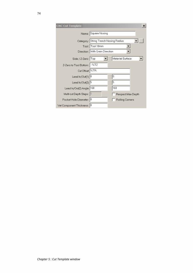
74
LC Laser Code; Run the laser g-code template specified in the CNC Prefs window and insert all output starting at the current line in the main g-code file.
PN Pause Number; Zero prior to the first time you export using the Append button; incremented for each append thereafter.
LineBK Blank Line; Generates a blank line in the exported g-code. StairBiz normally
deletes all blank lines when executing the editor (i.e. blank lines in the editor don’t normally show up in the exported g-code), so use this to specify that a blank line is needed.
You can also use the BK tag on a line with another tag such that if the other tag resolves to nothing you will retain a blank line. An example of this is where you use the JB (job name) tag on a line with no other text, but at the time of export the job name has not be set – if in this case you want to retain a blank line ALSO use the BK tag on that same line.
EA Export Alert. Generates an alert if the tag is encountered during an export of the g-code. It’s useful for when you haven’t completed something in your template, and want to be warned if that code is used. You can append the tag with an alert message within square brackets. For example:
#EA[Code for a pause not yet done] EC Element Count. Returns the total number of segments (lines & arcs) in the
current path.
EI Element Index (0 based). Returns an index number for the current segment (see “EC”).
NM Line Number; Generates a line number with is incremented according to Line Numbers Increment setting in the Options window (see below).
PC Path Count. Returns the total number of cut paths in this session (see definition of “session” above).
PI Path Index (1 based). Returns an index number for the current cut path (within Path Count – see “PC” above).
PB Same as "PI" above, but reversed (instead of 1,2,3, ... 27 it will be 27, 26, 25 ... 1).
SC Substitute category; Means do not use this g-code category, but instead substitute the g-code category specified within the following square brackets; e.g. #SC[TSS]. This is useful where the code in a particular category is identical to that in some other category, and saves you having to repeat it.
GT G-Code Template; Insert at this point the resolved g-code from the g-code template specified within the following square brackets; e.g. #GT[Biesse B 22]. The specified g-code template must have been imported into StairBiz.
This is very similar to the #LC tag, where the laser code is inserted, but in this case it can refer to any imported template.
PieceEX Extents X. Returns the furthest used X-distance from the 0,0 point on the bed.
Some processors require this.
EY Extents Y. Same as EX but in the Y direction.
LM Pieces Max Depth; The maximum depth of all pieces on the bed at the time of the export. If surface pods are used, they are disregarded (see LN).
LN Same as LM, but if surface pods are used and currently apply (see Pods tab of CNC Prefs window), the pod height is added to the value. In other words, the max depth is measured from the bed surface rather than the pod surface. Useful for when you don't recalibrate z-zero when applying pods.
LX Piece Length; The actual length (X-direction) of the piece being processed.
LY Piece Width; The actual width (Y-direction) of the piece being processed.
LZ Piece Depth; The actual depth (Z-direction) of the piece being processed.
Chapter 8 : G-Code Editor
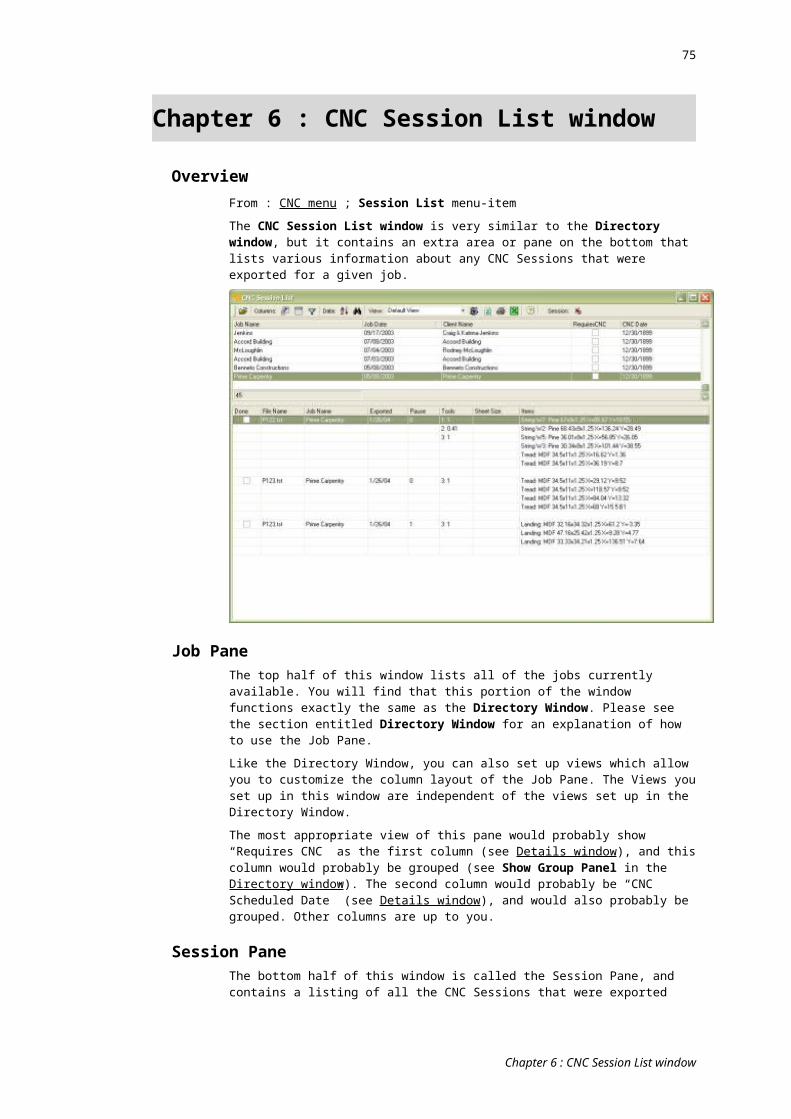
75
NS Nominal Material Surface; The value shown in the Prefs window (Machine tab) for Nominal Material Surface.
OX X Offset (distance) from corner of bed to same corner on current piece
OY Y Offset (distance) from corner of bed to same corner on current piece
ToolTC Tool Comment; From the Description field (Prefs window, Tools tab) for the
current tool.
TD Tool Diam; From the Diameter field (Prefs window, Tools tab) for the current tool.
TI Tool Id; From the Tool Id field (Prefs window, Tools tab) for the current tool.
TM Tool Motor ID; From the Motor Id field (Prefs window, Tools tab) for the current tool.
TT Tool Tag (as set in the Tools pane of the CNC Prefs window for each tool)
RVP (Rotated Vertical Plane)A rotated vertical plane is a rectangular vertical plane on which some work need to be done. It generally corresponds to an edge of the piece on the bed. It is called “rotated” because, in plan view, it may be at any angle (for non-rotated vertical planes see #Y3, #Y4, #Y5, #Y6 and #F2,3,4,5 …).
The following values define the plane. They are all in plan view, regular X/Y bed coordinates.
A RVP can be used when doing horizontal cutting and drilling into the sides of components. It requires a 4 or 5-axis machine. It is mostly used with machines that do not accept the standard X/Y/Z (top plane) coordinate system for such work (in particular, the ability to set the “C” angle in standard g-code).
Also see the Conditional tag #AV (True if any RVPs), #FV (True if first RVP path) and #F6 (True if working on an RVP).
The values in this RVP section have nothing to do with the workings (paths) on a RVP (which, after the plane is un-inclined, un-rotated, and moved it to the zero/zero of the bed, are defined by the usual X/Y coordinates shown in the Coords section of this chapter).
‘---------
The following two points define the plane, in plan view – one point at either end of the actual plane.
X7 X Coord Start of the plane.
Y7 Y Coord Start of the plane.
X8 X Coord End of the plane.
Y8 Y Coord End of the plane.
‘---------
The following two points also define the plane, in plan view – one point at either end of the actual plane but then each extended (moved) to the perimeter of the bed.
XA X Coord Start of the plane (at bed perimeter).
YA Y Coord Start of the plane (at bed perimeter).
XB X Coord End of the plane (at bed perimeter).
YB Y Coord End of the plane (at bed perimeter).
‘---------
PL The length of the actual plane along the bed surface in plan view.
PP The length of the plane along the bed surface extending to the perimeters of the bed (i.e. the distance between XA/YA and XB/YB)
PH The height of the plane – always the same as the thickest item on the bed.
Chapter 8 : G-Code Editor

76
RP Rotation (angle) of the plane along bed surface. Zero is to the right (along the X-axis); 90 degrees is clock-wise towards the front of the bed (unless offset by the C-Angle offset setting; also see Plane Rotate Angle Negative is Clockwise and Rotation Angle Offset).
‘---------
VI Vertical Plane Index. Valid only in the RVP and SEV categories of the template. Each rotated vertical plane is given an index (from 1 to n). The index as returned here is that number plus the “Plane Index Offset” value set in the Options window of the template Editor.
‘---------
EP Insert ‘For Each Plane’; Inserts, at the point of the tag, the code in the “SEV” category of the editor for each RVP. This is useful when planes need to be defined prior to their use (e.g. in the Header section). Do not have any other code on this line (remarks are OK).
This tag accepts an optional Plane Index Offset. For example “#EP[4]” will add 4 to the Plane Index returned for any #VI tag used in the “SEV” category of the G-code Template Editor. This is in addition to any RVP Plane Index Offset setting in the Options window of the template editor.
VelocityVF Feed Velocity; From the Feed Rate field (Prefs window, Tools tab) for the current
tool.
VP Plunge Velocity; From the Plunge field (Prefs window, Tools tab) for the current tool.
VR Safe Rapid Velocity; From the Rapid Traverse Speed field (Prefs window, Machine tab).
VS Spin Velocity (RPM) ; From the RPM field (Prefs window, Tools tab) for the current tool.
Testing g-code outputIf you want to export g-code without removing the remarks (for testing purposes), hold the CONTROL key down while you click the Export button in the StairBiz CNC Bed window. Add the following values and enter the number when prompted:
1 = retain machine remarks (see Options window)2 = retain line remarks (“--“)4 = retain block remarks (“/--“)
Options windowOpen the Options window from the toolbar button .
This window contains more settings that affect the way StairBiz exports g-code.
FileFile Extension; The extension to the file name that is preferred by the machine’s post processor (e.g. “plt”). There is no need for the period.
No Spaces in File Name; Some post processors cannot read a file that contains spaces. With this ticked StairBiz automatically replaces spaces with underscores (e.g. “The_Smith_Job”).
Max characters in full file path; This optionally sets a maximum number of characters in the full path of the file being exported (some machines have a limit). StairBiz will alert you when this is exceeded, although it will allow the export and will not truncate your path (you’ll have to fix this yourself).
Output Binary File; Replaces the CRLF (Carriage-Return Line-Feed) at the end of each line with a LF (Line-Feed) only, essentially making the file binary (rarely used these days).
Chapter 8 : G-Code Editor

77
For Laser; This tells StairBiz that this template is only for generating laser positioning files.
Strip this rem prefix; If you want to make comments or remarks in your g-code editor you can prefix such remarks with whatever character you type here. When StairBiz encounters this character in your g-code, it removes the character and everything on the line after the character (for the purposes of generating a g-code file – it doesn’t remove them from the template). Note that StairBiz has a “built-in” comment designator – you can use a double dash (--) to achieve the same thing.
Note that normally this rem prefix only applies if it is as the very start of the line. To apply anywhere the on line, tick the Anywhere box.
Line NumbersIncrement; Used to determine the increment of each #NM (line number) tag. StairBiz will use this value for the first #NM tag, then increment the value for each subsequent #NM tag by this amount.
Leading Zeros; If ticked, StairBiz will add leading zeros to your line number values such that the total number of characters of a line number is the number you enter here.
CoordinatesExport Inches; If you post processor is expecting coordinates in inches (always decimal inches) then tick this box.
Z-Direction; Z’s exported are always from the Z reference point set in the Prefs window (Machine tab). This tells StairBiz whether those Z dimensions are negative or positive if the Z is above the reference point.
XYZ Offsets; Use this only if you want all X, Y and/or Z dimensions to have an offset (i.e. a fixed amount added or subtracted to every dimension).
Decimal Accuracy; The maximum number of numerals after the decimal point for each dimension in the g-code file.
Trailing Zeros; Set this if you want StairBiz to make up the decimal accuracy with trailing zeros. For example, if the dimension is “7.2” and you have a decimal accuracy of “2” then StairBiz will add a zero (“7.20”).
Always Use Decimal; If this is ticked, and Trailing Zeros is not ticked, then StairBiz will add a decimal point even when there are no decimal places in the dimension. For example “7” becomes “7.”.
Include Static X/Y; Most post processors don’t require a X parameter shown in the code if the previous X parameter was identical, Same with Y. With this ticked, StairBiz will include the parameter even if the same as the previous. (Note; At the moment StairBiz is acting as if this is ticked, even when it is not).
Radius: Offset From Start; When the centre of an arc radius is expressed as an X/Y offset, normally these offsets are from the point at the end of the arc. If you require them expressed as offset from the start of the arc, tick this.
X-Axis: Negative Quadrant; Set this when your machine uses a negative value for X dimensions. Some machines with moving tables require special adjustments in the X value in this situation.
Use Z-Limit Alarm; Tick this is you want StairBiz to vet all g-code files before export to be sure that there are no Z values outside of the two values you enter in the “Z Absolute Limit” fields. The first field is the minimum value; the second is the maximum value.
The Z value which is vetted is the value actually shown in the g-code file (i.e. after all adjustments by StairBiz). If a Z value is less than the minimum, StairBiz will reset the value to that minimum and alert you. If a Z value is more than the maximum, StairBiz will reset the value to that maximum and alert you.
There are two sets of these values – one for vertical tool applications and one for horizontal tool applications.
Note that RVP (Rotated Vertical Plane) applications are not vetted.
Note that this vet has certain limitations. The Z values tested are AS EXPORTED, i.e. they are the values you would see if you opened the g-code file. Many machines have z-zero as the materials surface, so that whether or not the Z was violating the machine’s physical limits would change for different piece thicknesses. For a more useful test see the similar settings in the Tools tab of the CNC Preferences window (for each tool).
Chapter 8 : G-Code Editor
78
C-Angle Negative is Clockwise; Tells StairBiz that your machine treats a clockwise rotation of the C-axis as negative (otherwise it is positive).
C-Angle Offset; StairBiz treats C-angle zero as East (to the right). If your machine treats it differently then enter the difference between the StairBiz zero angle and your machine’s zero angle./ StairBiz will add the difference to it’s C-Angles on export.
RVPs (Rotated Vertical Planes - 4 axis):RVPs (rotated vertical planes) are used for machines that need horizontal router, horizontal drill, and 5-axis work to be assigned to planes. Basically you describe a plane, then flatten the plane onto the bed surface and rotate it to a zero orientation, then give all working coordinates in the standard X/Y/Z coordinate system within this flattened plane. RVPs are normally used in cases where you cannot directly specify the C-axis rotation in the g-code.
Use RVPs for Hoz Router; Tells StairBiz you need to use RVPs for horizontal routing (using the Horizontal Router section of the g-code template).
Use RVPs for Hoz Drill; Tells StairBiz you need to use RVPs for horizontal drilling (using the Horizontal Drill section of the g-code template).
Priority Optimize By Plane; Tells StairBiz to sort all paths by plane (as the priority sort) prior to an export. Thus all top plane paths will be processed first, following by other planes in order.
Rotation Angle Negative is Clockwise; Tells StairBiz that your machine treats a clockwise rotation of the vertical plane as negative (otherwise it is positive).
Rotation Angle Offset; StairBiz treats angle zero as East (to the right). If your machine treats it differently then enter the difference between the StairBiz zero angle and your machine’s zero angle./ StairBiz will add the difference to the RVP angles on export.
Top Plane Number; The number (ID) of the top surface plane (normally zero or 1).
RVP Plane Index Offset; Often a machine reserves certain plane numbers for the top, front, back, left and right planes (an sometimes some others). As such specially created angled planes must have an ID higher than the reserved plane numbers. StairBiz will add this Index Offset to all such special angled planes (RVPs).
Export After Pause Using This Template:Some post processors can’t handle a pause (e.g. those that read g-code into a CAD-type program). Normally in such cases there is the option for the g-code to specify a separate ISO g-code file for further (non-CAD) processing. This field allows you to specify a separate g-code template to handle such “post-pause” ASO g-code.
This feature was designed for the export of newel faces (the ones after the first face, which are all separated by a pause). It is not intended for other types of pauses.
Editor PreferencesTab Position (Characters); This sets a single tab position, measured in characters from the beginning of the line. It applies to all text in the editor. It is saved with the template (unlike font and font-size etc which are saved in the registry). It is intended for remarks appearing at the end of g-code lines.
Chapter 8 : G-Code Editor
79
Glossary of Terms
CNCComputer numeric controlled. Usually relates to computer controlled point-to-point router tables.
CNC fileA file exported from the CNC Bed window which can be imported by a CNC machine (or a CNC post-processor program prior to being sent to a CNC machine). These files contain g-codes. They are normally stored in the CNC Files folder.
cut pathThe centre of the CNC path cutting the outline (full depth) of a component
machine bedThe bed of the actual CNC machine, as opposed to the emulated bed in the CNC Bed window.
path patternThe pattern of the CNC cut and trench paths for the particular circumstance.
StairBiz bedThe emulated CNC bed as seen in StairBiz in the CNC Bed window, as opposed to the bed of the actual CNC machine.
trench pathThe centre of the CNC path trenching treads and risers on a string
Glossary of Terms