Embed Size (px)
Citation preview
STABILIZATION OF THE EXTERNAL TANK FOR USE AS A LARGE SPACE PLATFORM
W. D. Kelly -Triton Systems, DBA Houston, Texas
Abstract Use of magnetic passive dampers is recommended to stabilize the Space Shuttle External Tank in free flight for on-orbit applications. Longitudinal alignment along the radius vector allows for gravity gradient passive stabilization, but, without a damping mechanism, there is no inherent means of eliminating disturbance accelerations and buildup of pendular motions lead to spin or tumbling. Review of previous magnetic, passive dampers is provided drawing from the Long Duration Exposure Facility (LDEF) flight and Space Station program studies for early assembly flights. Basic physical models of the damper-spacecraft combination are discussed; damper capabilities and limitations. Peliminary damper design analysis is demonstrated.
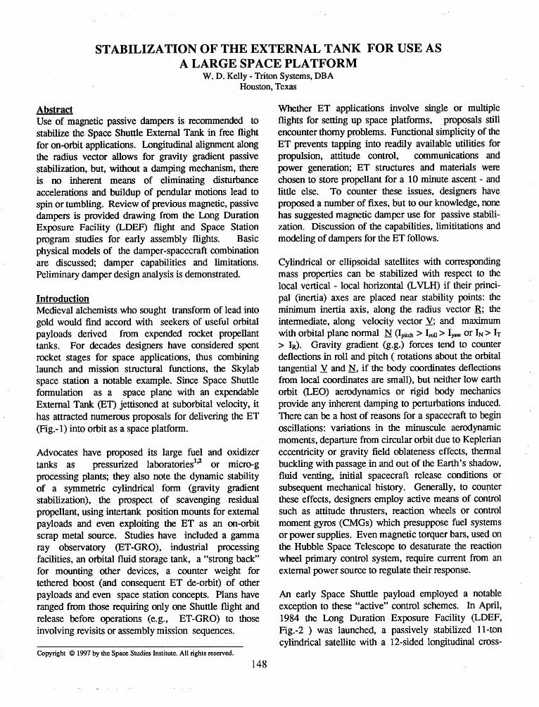
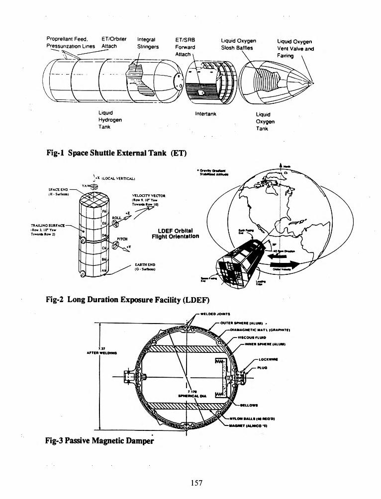
Introduction Medieval alchemists who sought transform of lead into gold would find accord with seekers of useful orbital payloads derived from expended rocket propellant tanks. For decades designers have considered spent rocket stages for space applications, thus combining launch and mission structural functions, the Skylab space station a notable example. Since Space Shuttle formulation as a space plane with an expendable External Tank (ET) jettisoned at suborbital velocity, it has attracted numerous proposals for delivering the ET (Fig.-1) into orbit as a space platform.
Advocates have proposed its large fuel and oxidizer tanks as pressurized laboratories1.2 or micro-g processing plants; they also note the dynamic stability of a symmetric cylindrical form (gravity gradient stabilization), the prospect of scavenging residual propellant, using intertank position mounts for external payloads and even exploiting the ET as an on-orbit scrap metal source. Studies have included a gamma ray observatory (ET -GRO), industrial processing facilities, an orbital fluid storage tank, a "strong back" for mounting other devices, a counter weight for tethered boost (and consequent ET de-orbit) of other payloads and even space station concepts. Plans have ranged from those requiring only one Shuttle flight and release before operations (e.g., ET-GRO) to those involving revisits or assembly mission sequences.
Copyright @ 1997 by the Space Studies Institute. All rights reserved.
148
Whether ET applications involve single or multiple flights for setting up space platforms, proposals still encounter thorny problems. Functional simplicity of the ET prevents tapping into readily available utilities for propulsion, attitude control, communications and power generation; ET structures and materials were chosen to store propellant for a 1 0 minute ascent - and little else. To counter these issues, designers have proposed a number of fixes, but to our knowledge, oone has suggested magnetic damper use for passive stabilization. Discussion of the capabilities, limititations and modeling of dampers for the ET follows.
Cylindrical or ellipsoidal satellites with corresponding mass properties can be stabilized with respect to the local vertical - local horizontal (L VLH) if their principal (inertia) axes are placed near stability points: the minimum inertia axis, along the radius vector R; the intermediate, along velocity vector Y; and maximum with orbital plane normal N (I pitch > Irou > Iyaw or IN > h > IR). Gravity gradient (g.g.) forces tend to counter deflections in roll and pitch ( rotations about the orbital tangential Y and N. if the body coordinates deflections from local coordinates are small), but neither low earth orbit (LEO) aerodynamics or rigid body mechanics provide any inherent damping to perturbations induced. There can be a host of reasons for a spacecraft to begin oscillations: variations in the minuscule aerodynamic moments, departure from circular orbit due to Keplerian eccentricity or gravity field oblateness effects, thermal buckling with passage in and out of the Earth's shadow, fluid venting, initial spacecraft release conditions or subsequent mechanical history. Generally, to COU{lter these effects, designers employ active means of control such as attitude thrusters, reaction wheels or control moment gyros (CMGs) which presuppose fuel systems or power supplies. Even magnetic torquer bars, used on the Hubble Space Telescope to desaturate the reaction wheel primary control system, require current from an external power source to regulate their response.
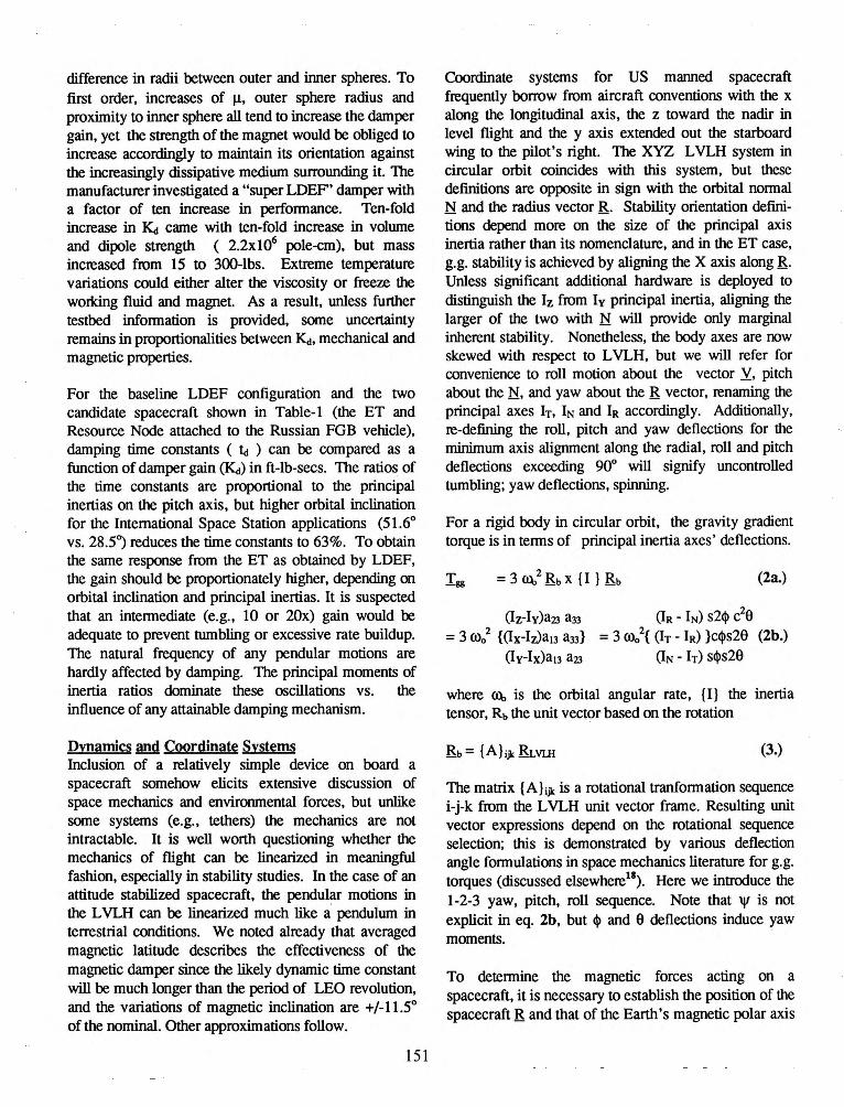
An early Space Shuttle payload employed a notable exception to these "active" control schemes. In April, 1984 the Long Duration Exposure Facility (LDEF, Fig.-2 ) was launched, a passively stabilized 11-ton cylindrical satellite with a 12-sided longitudinal cross-

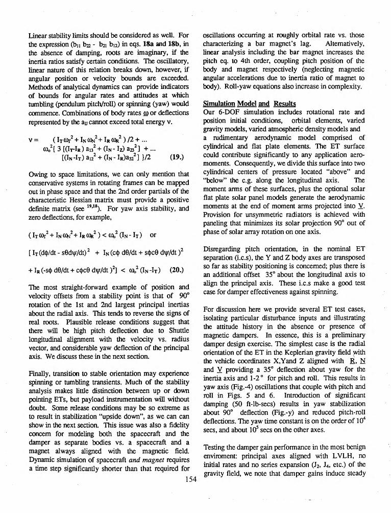
section. 111is satellite orbited for several years in LEO without tumbling or accumulating large angular rates until January 1990 ( STS-32) retrieval. The presence of large bar magnets embedded in one of two concentric spheres accounted for its stability; the cluster positioned itself in alignment, (described in 3·') with the terrestrial magnetic field, impeded by a viscous fluid layer between the two spherical shells (Fig.-3). From the perspective of the spacecraft, if the magnetic damper is sized appropriately, perturbing accelerations and motions from the L VLH are damped and eventually decay. A terrestrial analog to a spacecraft with a passive magnetic damper would be a ship with an anchor that simply impedes its tendency to drift by dragging on a muddy sea bottom; the anchor does not really "anchor" the ship in this case, but slows it down.
Beside application to LDEF, this stabilization method was extensively studied for the first Space Station Freedom assembly flight; perhaps for several flights if power and control were unavailable and the application proved effective. During these studies, means were developed to determine the size of the magnetic dampers required and simulate their performance on orbit at various levels of fidelity. The author participated in the Space Station control studies as well as several earlier, unrelated ET applications studies7 in which dampers were not considered. He sees no reason that LDEF and Space Station experience can not be applied to the ET stabilization problem. For that matter, magnetic dampers would probably work as effectively on other spent upper stages (e.g., Titan, Ariane or Proton), if similar applications were proposed.
In the summer of 1986, this analyst and several colleagues8
"10 examined tentative schemes for passive
stabilization of early Space Station assembly flights, concluding that magnetic passive dampers were the best means available. Subsequent analyses drew on the earlier LDEF work of Old Dominion University researchers Heinbockel and Breedlove3
'4 as well as Dr.
Karen Castle's preceding LDEF contractor work at the Johnson Space Center. We first assessed damper gain requirements with root locus stability analyses, then developed 6-degree of freedom simulations of spacecraft damper control. Our initial simulations employed simple cylinder and plate aerodynamics and a dipole model of terrestrial magnetism without offset from the earth's center, but inclined to the axis of rotation11
• Later simulations included a detailed geophysical field model and aerodynamics closely based on CAD modeling12
• Pilot-in-the-loop flight simulator
149
runs modeled thruster plume impingement effects of the Orbiter separation maneuver as well as residual rates from separation with the Shuttle Remote Manipulator System (RMS)13
• Finally, studies were undertaken to determine the effect of modeling both the spacecraft and the field tracking magnet. Once again, a root locus concept was developed as well as detailed dynamic simulations 14,
15•
The dynamic simulations noted above involve various levels of fidelity, but analyses with preliminary design tools are just as important as detailed configuration examinations. There are hardware limitations in constructing stiff magnetic damper systems, but in theory a magnetic damper could become so tight that it would align the vehicle with the magnetic pole. At lower gains steady state errors could also be very high, precluding the use of mission-oriented instrumentation, or else the action of seeking magnetic alignment could induce resonant oscillations of exactly the sort which mission planners sought to avoid. Root locus plots, for example, identify suitable control gains, elimininating need for global search with 6-DOF simulation. Formulation of the linearized system in the Laplace domain gives an indication of time dependent behavior based on initial conditions. Lyapunov stability analysis, based on Lagrangian and Hamiltonian dynamics, determines initial deflection and rate bounds for tumbling or spinning about a point of stability. If rate and position stability limits can be determined from this analysis, deployment conditions for a passively stabilized spacecraft can be stipulated.
Early studies indicated that inclination effects tended to correspond to averaged magnetic latitude, since the the earth-fixed (but skewed) magnetic axis presented a varied incidence angle with respect to the satellite's plane over a day's rotation, disregarding nodal regression. With a nominal dipole 11.5° offset from the rotational axis, effective magnetic inclination varies above and below equatorial inclination by the same amount. Positions near the magnetic field equator reduce the damper's effectiveness.
It is possible to do only limited analysis of forcing functions without digital simulation. Atmospheric density variations in LEO can be attributed to latitude, altitude, solar extreme UV flux and geomagnetic variations in response to solar flares. If satellite cross sections change significantly with deflections, the effect of density variations can have differing effects on drag. Initially, for Space Station, we simulated spacecraft

with symmetric and simple geometric fonns; we later discovered protuberances such as radiators broke the symmetry about the yaw axis, resulting in significant yaw-roll coupling motions generated by aerodynamic torque variations. Significant offsets of inertia axes from external geometries due to internal mass distributions introduced moment arms about the center of mass and asymmetric centers of pressure for port and starboard, zenith and nadir cross-sections of the vehicle. If there are significant discrepancies between the location and shape of the inertial ellipsoid (gravity gradient torques) and the surface contours (aerodynamic torques), a new balance of forces must be struck (e.g., Torque Equilibrium Attitude -1EA ) or disturbance torques will continually toss the vehicle about.
Hardware Descriptions Application of magnetic dampers to spacecraft depends on hardware issues: the technology for manufacturing the appropriate dampers, and the mass properties of the overall spacecraft to be stabilized. The nature of an ET application is largely conjecture, but initially the mass properties of an empty ET separated from the Orbiter will dominate dynamical considerations.
The External Tank is 154.2 ft tall and 27.5 ft in diameter and contains propellant for the Shuttle engines (SSMEs). The main components of the ET are a liquid Oz tank, located in the forward position, an aft liquid Hz tank and the intertank connecting the two. The intertank provides space for instrumentation plus attachment structures for the forward ends of the solid rocket boosters (SRBs). The ET carries 1,589,000-lbs of propellant. The Hz tank is 2.5 times larger than the Oz tank, but the Oz/Hz load is 6:1 by weight. Tank structure is skin-stringer; thennal protection covering the tank exterior maintains propellant at cryogenic temperatures during the launch sequence and the 8.5 minute powered ascent. Feed lines to the SSMEs trail down the ET's side from the Oz tank and protude fonn the base of the Hz tank. Attach structures connect the Orbiter to the ET near the base feed lines and at the intertank. Active control mechanisms are located on the Orbiter.
Table-1 includes mass properties from16 for STS-44, a flight that used the nominal light weight tank design rather than the initial test flight version or the anticipated aluminum-lithium design (several tons heavier or lighter respectively). Note that Shuttle weight on this mission is 334,376.2-lbs prior to separation and 255,811 just after. This indicates an
150
expected 12,037 lbs of fluid to remain in the propellant tanks and lines, based on physical pumping constraints and margins to assure nominal targets. Note also, that the lxz product of inertia for the ET is high relative to the longitudinallxx moment of inertia value.
WEF was a 12-sided cylindrical, gravity-stabilized spacecraft host to 57 experiments, several characterizing the meteoroid and orbital-debris environment for the nominal9-month mission (see Table-2). As a result of LDEFs 5.7 year exposure time and heightened interest in the debris collisional threat, the entire spacecraft on retrieval was studied as a meteoroid and orbital-debris detector. Due to gravity-gradient orbital stabilization, the same general surfaces pointed into the velocity vector during the entire mission; its large exposed surface area ( -130 mz) provided LEO particulate environment data, including directionality effects for both natural and man-made particles.
LDEF's viscous magnetic damper was contained in a spherical dome, fabricated from 1/32 inch thick 6061-T6 aluminum alloy sheet attached to a cylindrical base with aluminum screws. The cylindrical housing is a
. fiberglass structure, covered with aluminum tape, inside and outside, to meet thennal control requirements. The mounting plate material is 6061-T6 aluminum alloy, with the top and bottom surfaces also covered by aluminum tape. A thennistor mounted in the top center of the dome provided house keeping data. The assembled damper housing, with the damper inside, was mounted to a space end frame with stainless steel fasteners.
The aluminum-nickel-cobalt LDEF magnets exhibited a 2.2x 10⁵ pole-em magnetic dipole moment ( presumed strength coefficent of Alnico is 8; new materials17 such as NdFeB reach 30-45). Mechanical characteristics are approximate, but correspond to 1 ft-lb-sec damping capability in English units, if entered into a 2nd order mass-spring-damper system (one source: 5 Newton-msecs or .37631 slug-ftz-secs). This coefficient is dimensionally similar to angular momentum, but corresponds to torque divided by angular rate in radians/sec. Damper gain in a deployed system can be controlled by the number and quality of dampers. For an individual damper
(1.)
where Jl. is the fluid viscosity between spheres, ro is the radius of the outer damper sphere, and Eo is the
difference in radii between outer and inner spheres. To first order, increases of J.l, outer sphere radius and proximity to inner sphere all tend to increase the damper gain, yet the strength of the magnet would be obliged to increase accordingly to maintain its orientation against the increasingly dissipative medium surrounding it. The manufacturer investigated a "super LDEF' damper with a factor of ten increase in performance. Ten-fold increase in K.! came with ten-fold increase in volume and dipole strength ( 2.2xl06 pole-em), but mass increased from 15 to 300-lbs. Extreme temperature variations could either alter the viscosity or freeze the worldng fluid and magnet. As a result, unless further testbed information is provided, some uncertainty remains in proportionalities between K.!. mechanical and magnetic properties.
For the baseline LDEF configuration and the two candidate spacecraft shown in Table-t (the ET and Resource Node attached to the Russian FGB vehicle), damping time constants ( t.J ) can be compared as a function of damper gain (K.J) in ft-lb-secs. The ratios of the time constants are proportional to the principal inertias on the pitch axis, but higher orbital inclination for the International Space Station applications (51.6° vs. 28.5) reduces the time constants to 63%. To obtain the same response from the ET as obtained by LDEF, the gain should be proportionately higher, depending on orbital inclination and principal inertias. It is suspected that an intermediate (e.g., 10 or 20x) gain would be adequate to prevent tumbling or excessive rate buildup. The natural frequency of any pendular motions are hardly affected by damping. The principal moments of inertia ratios dominate these oscillations vs. the influence of any attainable damping mechanism.
Dvnamics and Coordinate Systems Inclusion of a relatively simple device on board a spacecraft somehow elicits extensive discussion of space mechanics and environmental forces, but unlike some systems (e.g., tethers) the mechanics are not intractable. It is well worth questioning whether the mechanics of flight can be linearized in meaningful fashion, especially in stability studies. In the case of an attitude stabilized spacecraft, the pendular motions in the L VLH can be linearized much like a pendulum in terrestrial conditions. We noted already that averaged magnetic latitude describes the effectiveness of the magnetic damper since the likely dynamic time constant will be much longer than the period of LEO revolution, and the variations of magnetic inclination are +/-11.5° of the nominal. Other approximations follow.
151
Coordinate systems for US manned spacecraft frequently borrow from aircraft conventions with the x along the longitudinal axis, the z toward the nadir in level flight and the y axis extended out the starboard wing to the pilot's right. The XYZ L VLH system in circular orbit coincides with this system, but these definitions are opposite in sign with the orbital normal N and the radius vector R. Stability orientation definitions depend more on the size of the principal axis inertia rather than its nomenclature, and in the ET case, g. g. stability is achieved by aligning the X axis along R. Unless significant additional hardware is deployed to distinguish the Iz from Iv principal inertia, aligning the larger of the two with N will provide only marginal inherent stability. Nonetheless, the body axes are now skewed with respect to L VLH, but we will refer for convenience to roll motion about the vector y, pitch about the N. and yaw about the R vector, renaming the principal axes h. IN and IR accordingly. Additionally, re-defining the roll, pitch and yaw deflections for the minimum axis alignment along the radial, roll and pitch deflections exceeding 90° will signify uncontrolled tumbling; yaw deflections, spinning.
For a rigid body in circular orbit, the gravity gradient torque is in terms of principal inertia axes' deflections.
(Iz-lv)a23 a33 = 3 ro/ {(lx-Iz)aiJ a33}
(I v-Ix)al3 a23
(2a.)
(IR - IN) s24> c29 = 3 roo2
{ (IT- IR) }c4>s2e (2b.) (IN- h) s4>s2e
where ~ is the orbital angular rate, {I} the inertia tensor, Rb the unit vector based on the rotation
(3.)
The matrix {A};J< is a rotational tranformation sequence i-j-k from the L VLH unit vector frame. Resulting unit vector expressions depend on the rotational sequence selection; this is demonstrated by various deflection angle formulations in space mechanics literature for g. g. torques (discussed elsewhere11
). Here we introduce the 1-2-3 yaw, pitch, roll sequence. Note that 'I' is not explicit in eq. 2b, but 4> and e deflections induce yaw moments.
To determine the magnetic forces acting on a spacecraft, it is necessary to establish the position of the spacecraft Rand that of the Earth's magnetic polar axis

Nn,(t) in inertial space. In the celestial sphere, angles analogous to terrestrial latitude and longitude define both vectors: declination o and right ascension a, with subscripts M and R denoting magnetic pole and radius vectors respectively. Below, c and s denote cosine and sine.
(4.)
(5.)
The damper motions are affected by the size of the magnetic torque term AT d· This term originates in the interaction of the local terrestrial magnetic field strength with the intrinsic magnetic dipole of the bar magnet.
~eT eN J.ldlT JlN; BR BT BN
(6a.)
Td = abs( Jl B) sin eM (6b.)
Where eM iS due tO the displaced OrientatiOn Of the bar magnet from the terrestrial field lines.
The transformation from an L VLH orbital position frame to the inertial Cartesian coordinate frame with which eq. 3 corresponds ( a 3-rotation matrix based on ascending node n, orbit inclination i, and circular arc along the orbital path from the ascending e*) is shown ineq. 7. Thus, unit vectors of the radius, horizontal or tranverse velocity and normal to the orbital plane (eR , ~. eN) can be defined in terms of the transformation matrix of eq. 7 with the orbital angular parameters defining the difference between .R(t) and NM(t) in eq. 8.
I
[ J] K
= (cilc9*-silci s9*)
{ (silc9*+eilcis9*) (si s9*)
( -cilsq*-silcic9*) ( -sils9*+eilcic9*) (si c9*)
(silsi) (-cilsi) } (ci)
(7.)
c(il-a.M) c~ c9* - c(il+a.M)ci c~ s9* + si s~ s9* (8.)
Transformation of inertia matrix {I} to principal body axes and inertias with deflections involves solution of the inertial tensor eigenvalue problem. Stability alignment at IR. h , IN with initial coordinate axis deflections from LVLH to \jf0 , <l>o and 90 depends on the selection of matrix {A};.ik as will the nature of the linearized equations of motion.
In the homogeneous linearized angular motion equations, we note the (possible) uncoupling of roll-yaw motions (9b&c) from the pitch plane (9a).
[IN s2 + sin <l>m K.! s + 3 ~ 2 (h - IR)] 9(t) = 0 (9a.)
[ (h - IN + IR )~ - 1/3 sin2 <l>m K.! ]s \jl(t) = 0 (9b.)
] s <l>(t) + ...
152
Transformations between time dependent and Laplace s- domain functions give specific solutions to equations of motion in terms of initial angular positon and rate.
+ [(h- IN+ IR)~ -1/3 sin2 <l>m K.J ] 'l'o (lOb.)
[(h- IN+ IR) ~- l/3sin2 <l>m K.!] s<l>(s) + .. .
IR (s 'Vo + d 'Vo /dt) + 2/3sin2 <l>m K.J \jl0 +
(tOe.)

Thus, linearized equations for a rigid body on-orbit
uncouple a 2nd order pitch [8(s) or 9(t)] equation from the 4th order roll-yaw equations. Solutions of 2nd and 4th order systems in the s-plane have roots of the form
(s + cr; + j ~;)(s + cr;- j ~;) = s2 + 2~~; s + ~;2 (11.)
where j = --1-1; OM , the natural frequency mode i; and
~. the characteristic damping of the resulting system.
For oscillatory systems with 0 < ~< 1, the homogeneous roots take the form
(12.)
Thus, the pitch plane roots for non-zero damping have a real part, and an imainary part, if h>IR.
X { 1- (sin <l>m Kai /((h- IR) IN ]} 05 (13.)
The pitch angle function dependencies become
9(t) = f( t, <l>m. Ka. eo. d9./dt, (h- IR)!IN) (14.)
Asswning that the principal inertia about the radius vector is the minimwn and that the gain Ka is a quantity smaller than the inertias, the pitch motions are oscillatory, damped only by the magnetic gain Ka.
8(s) = { IN(S eo- dOJdt) + sin <l>m K.! Oo} ...
8(s)IIN = 9os/ {[ s+ ~ ~ + j ~(1- ~2 )0"5 ] •••.
[ s+ ~ ~ _ j ~(1 _ ~2 )o.5] } + ....
[sin $m Ka 9./IN)/{ ( S+ ~ ~+ j ~(1- ~2 )0"5 ) •••
... [ s+~ ~- j ~(1 - ~2 )0·5 ]} (1Sb.)
With Cl\1 = ~(1 - ~2 )05 , converting back to the tdomain
O(t) =eo [Cl\l]exp(- ~ ~ t){coS(Cl\1 t) + ...
[ (d9./dt)- sin <l>m Ka OJ IN] sin(Cl\1 t) /Cl\1} (16.)
The roll-yaw axis formulation is more complex, but amenable to the same analytical techniques adapted to
153
simultaneous linear differential equations. Conversion from the time domain to the Laplace domain establishes the role of the initial positions and rates. The resulting transfer function determinant in combination with the substitutions employed with Cramer's Rule define
Laplace s-domain functions for <l>(s) and 'l'(s). Conversion of the two sets of expressions to the time domain from the series of terms with the common 4th order denominators results in expressions of the form
<l>(s) C1 ( $0 , 'lf0 , d$./dt, d'lf./dt) } [ ] = (17.)
'l'(s) c2 ( <l>o. 'l'o· d$./dt, d'lf./dt)
Forcing functions independent of attitude (e.g., a pounding device, thermal excitations, orbital eccentricity) can be represented more easily, simply as functions of time. Paradoxically, the damping in the linearized equations exists only if there is a magnetic field forcing function with time dependence related to orbital revolution and
nodal regression (Q(t)). We expect --1 [(IN-IR)Ih ]and --1
[(IN-h)IIR] related roll and yaw motions with respect to
orbital rate ~-
It is difficult to include aerodynamics in this linearized equation, unless the geometry of the vehicle is extremely
simple. Deflections of 9,$ and 'I' from the L VLH result in changed projections of plates or cylinders in Y. even if panels do not articulate. For a cylinder resembling the ET near its vacuum stability point, aero-moments on fue cylindrical cross sections above and below the e.g. are likely to be unequal. LEO aerodynamics generally are modeled without damping forces based on free molecular flow dynamics. If the aerodynamics are largely in the pitch plane, gravity gradient torques will counter deflections, and the aero-moments themselves
will decrease with the cosine of a - which is not satisfactory for linear analysis. The presence of solar panels or radiators on ET applications could complicate the aerodynamics depending on their arrangement. At this point 6-DOF simulation of on-orbit dynamics are in order for most spacecraft for significant aero moments.
Linear stability limits should be considered as well. For the expression Cbu bzz - ih1 b12) in eqs. 18a and 18b, in the absence of damping, roots are imaginary, if the inertia ratios satisfy certain conditions. The oscillatory, linear nature of this relation breaks down, however, if angular position or velocity bounds are exceeded. Methods of analytical dynamics can provide indicators of bounds for angular rates and attitudes at which tumbling (pendulum pitch/roll) or spinning (yaw) would commence. Combinations of body rates .ro or deflections represented by the au cannot exceed total energy v.
V= (lyrol+INO~l+IR~2 )/2+ ... OOo2
{ 3 [(1,.-IR) a1l + (IN- lz) a23 2 ) + ... [(IN-h) a1l +(IN- IR)aJlJ }/2 (19.)
Owing to space limitations, we can only mention that conservative systems in rotating frames can be mapped out in phase space and that the 2nd order partials of the characteristic Hessian matrix must provide a positive definite matrix (see 19
'18
). For yaw axis stability, and zero deflections, for example,
(I 2 I 2 2 2 T ror + N CQ.I + IR ~ ) < <.Q, (lw ly) or
[ h (d(j>/dt - sSd\jl/dt) 2 + IN (c$ dS/dt + sq>ca d\jl/dt )2
+ IR (-sq> dS/dt + cq>ca d\jl/dt )2] < <.Q,
2 (IN -ly) (20.)
The most straight-forward example of position and velocity offsets from a stability point is that of 90° rotation of the 1st and 2nd largest principal inertias about the radial axis. This tends to reverse the signs of real roots. Plausible release conditions suggest that there will be high pitch deflection due to Shuttle longitudinal alignment with the velocity vs. radius vector, and considerable yaw deflection of the principal axis. We discuss these in the next section.
Fmally, transition to stable orientation may experience spinning or tumbling transients. Much of the stability analysis makes little distinction between up or down pointing ETs, but payload instrumentation will without doubt. Some release conditions may be so extreme as to result in stabilization "upside down", as we can can show in the next section. This issue was also a fidelity concern for modeling both the spacecraft and the damper as separate bodies vs. a spacecraft and a magnet always aligned with the magnetic field. Dynamic simulation of spacecraft and magnet requires a time step significantly shorter than that required for
154
oscillal!ions occurring at rooghly orbital rate vs. tllose characterizing a bar magnet's lag. Alternatively, linear analysis including the bar magnet increases the pitch eq. to 4th order, coupling pitch position of the body and magnet respectively (neglecting magnetic angular accelerations due to inertia ratio of magnet to body). Roll-yaw equations also increase in complexity.
Simulation Model and Results Our 6-DOF simulation includes rotational rate and position initial conditions, orbital elements, varied gravity models, varied atmospheric density models and a rudimentary aerodynamic model comprised of cylindrical and flat plate elements. The ET surface could contribute significantly to any application aeromoments. Consequently, we divide this surface into two cylindrical centers of pressure located "above" and "below" the e.g. along the longitudinal axis . The moment arms of these surfaces, plus the optional solar flat plate solar panel models generate the aerodynamic moments at the end of moment arms projected into Y. Provision for unsymmetric radiators is achieved with paneling that minimizes its solar projection 90° out of phase of solar array rotation on one axis.
Disregarding pitch orientation, in the nominal ET separation (i.c.s), theY and Z body axes are transposed so far as stability positioning is concerned; plus there is an additional offset 35° about the longitudinal axis to align the principal axis. These i.c.s make a good test case for damper effectiveness against spinning.
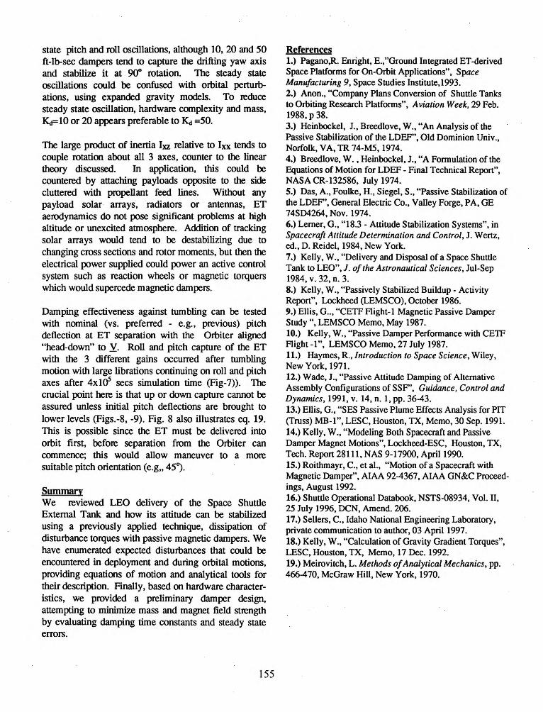
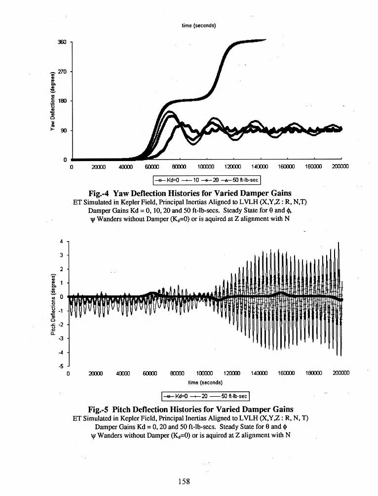
For discussion here we provide several ET test cases, isolating particular disturbance inputs and illustrating the attitude history in the absence or presence of magnetic dampers. In essence, this is a preliminary damper design exercise. The simplest case is the radial orientation of the ET in the Keplerian gravity field with the vehicle coordinates X,Yand Z aligned with R. N and Y providing a 35° deflection about yaw for the inertia axis and 1-2 o for pitch and roll. This results in yaw axis (Fig.-4) oscillations that couple with pitch and roll in Figs. 5 and 6. Introduction of significant damping (50 ft-lb-secs) results in yaw stabilization about 90° deflection (Fig.-y) and reduced pitch-roll deflections. The yaw time constant is on the order of 10
4
sees, and about lOS sees on the other axes.
Testing the damper gain performance in the most benign enviroment: principal axes aligned with LVLH, no initial rates and no series expansion (h. h etc.) of the gravity field, we note that damper gains induce steady
state pitch and roll oscillations, although 10, 20 and 50 ft-lb-sec dampers tend to capture the drifting yaw axis and stabilize it at 90° rotation. The steady state oscillations could be confused with orbital perturbations, using expanded gravity models. To reduce steady state oscillation, hardware complexity and mass, ~= 10 or 20 appears preferable to ~ =50.
The large product of inertia lxz relative to lxx tends to couple rotation about all 3 axes, counter to the linear theory discussed. In application, this could be countered by attaching payloads opposite to the side cluttered with propellant feed lines. Without any payload solar arrays, radiators or antennas, ET aerodynamics do not pose significant problems at high altitude or unexcited atmosphere. Addition of tracking solar arrays would tend to be destabilizing due to changing cross sections and rotor moments, but then the electrical power supplied could power an active control system such as reaction wheels or magnetic torquers which would supercede magnetic dampers.
Damping effectiveness against tumbling can be tested with nominal (vs. preferred - e.g., previous) pitch deflection at ET separation with the Orbiter aligned "head-down" to Y. Roll and pitch capture of the ET with the 3 different gains occurred after tumbling motion with large librations continuing on roll and pitch axes after 4x10S sees simulation time (Fig-7)). The crucial point here is that up or down capture cannot be assured unless initial pitch deflections are brought to lower levels (Figs.-8, -9). Fig. 8 also illustrates eq. 19. This is possible since the ET must be delivered into orbit first, before separation from the Orbiter can commence; this would allow maneuver to a more suitable pitch orientation (e.g, 45}.
Summary We reviewed LEO delivery of the Space Shuttle External Tank and how its attitude can be stabilized using a previously applied technique, dissipation of disturbance torques with passive magnetic dampers. We have enumerated expected disturbances that could be encountered in deployment and during orbital motions, providing equations of motion and analytical tools for their description. Finally, based on hardware characteristics, we provided a preliminary damper design, attempting to minimize mass and magnet field strength by evaluating damping time constants and steady state errors.
155
References 1.) Pagano,R. Enright, E.,"Ground Integrated ET-derived Space Platforms for On-Orbit Applications", Space Manufacturing 9, Space Studies Institute,1993. 2.) Anon., "Company Plans Conversion of Shuttle Tanks to Orbiting Research Platforms", Aviation Week, 29 Feb. 1988, p 38. 3.) Heinbockel, J. , Breedlove, W., "An Analysis of the Passive Stabilization of the LDEF", Old Dominion Univ., Norfolk, VA, TR 74-M5, 1974. 4.) Breedlove, W. , Heinbockel, J., "A Formulation of the Equations of Motion for LDEF- Final Technical Report", NASA CR-132586, July 1974. 5.) Das, A., Foulke, H., Siegel, S., "Passive Stabilization of the LDEF', General Electric Co., Valley Forge, PA, GE 74SD4264, Nov. 1974. 6.) Lerner, G., "18.3- Attitude Stabilization Systems", in Spacecraft Attitude Determination and Control, J. Wertz, ed., D. Reidel, 1984, New York. 7.) Kelly, W., "Delivery and Disposal of a Space Shuttle Tank to LEO", J. of the Astronautical Sciences, Jul-Sep 1984, v. 32, n. 3. 8.) Kelly, W., "Passively Stabilized Buildup- Activity Report", Lockheed (LEMSCO), October 1986. 9.) Ellis, G .. , "CETF Aight-1 Magnetic Passive Damper Study", LEMSCO Memo, May 1987. 10.) Kelly, W., "Passive Damper Performance with CETF Aight -1", LEMSCO Memo, 27 July 1987. 11.) Haymes, R., Introduction to Space Science, Wiley, New York, 1971. 12.) Wade, J., "Passive Attitude Damping of Alternative Assembly Configurations of SSF', Guidance, Control and Dynamics, 1991, v. 14, n. 1, pp. 36-43. 13.) Ellis, G., "SES Passive Plume Effects Analysis for PIT (Truss) MB-1", LESC, Houston, TX, Memo, 30 Sep. 1991. 14.) Kelly, W., "Modeling Both Spacecraft and Passive Damper Magnet Motions", Lockheed-ESC, Houston, TX, Tech. Report 28111, NAS 9-17900, April1990. 15.) Roithmayr, C., et al., "Motion of a Spacecraft with Magnetic Damper", AIAA 92-4367, AIAA GN&C Proceedings, August 1992. 16.) Shuttle Operational Databook, NSTS-08934, Vol. II, 25 July 1996, DCN, Amend. 206. 17.) Sellers, C., Idaho National Engineering Laboratory, private communication to author, 03 April1997. 18.) Kelly, W., "Calculation of Gravity Gradient Torques", LESC, Houston, TX, Memo, 17 Dec. 1992. 19.) Meirovitch, L. Methods of Analytical Mechanics, pp. 466-470, McGraw Hill, New York, 1970.
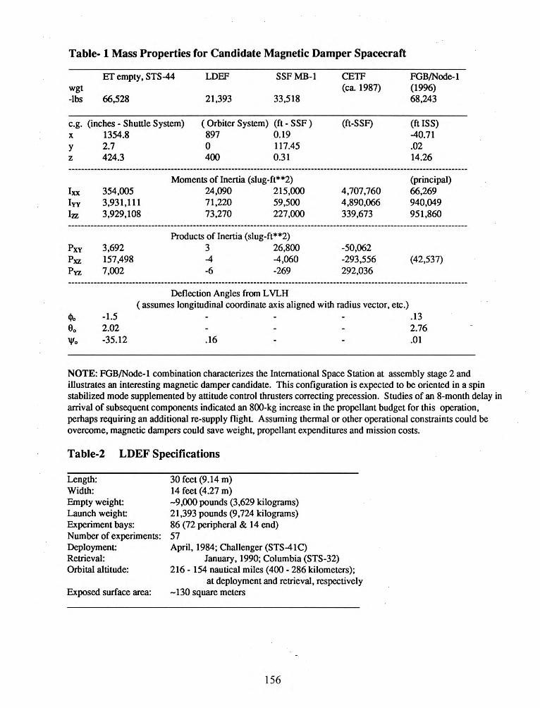
Table- l Mass Properties for Candidate Magnetic Damper Spacecraft
ETempty, STS-44 LDEF SSFMB-1 CETF wgt (ca. 1987) -lbs 66,528 21,393 33,518
e.g. (inches - Shuttle System) ( Orbiter System) (ft - SSF) {ft-SSF) X
y z
lxx lyy
12Z
Pxy Pxz Pyz
1354.8 2.7 424.3
354,005 3,931,111 3,929,108
3,692 157,498 7,002
897 0.19 0 117.45 400 0.31
Moments of Inertia (slug-ft**2) 24,090 215,000 71,220 59,500 73,270 227,000
Products of Inertia (slug-ft**2) 3 26,800 -4 -4,060 -6 -269
Deflection Angles from L VLH
4,707,760 4,890,066 339,673
-50,062 -293,556 292,036
(assumes longitudinal coordinate axis aligned with radius vector, etc.)
FGB/Node-1 (1996) 68,243
(ft ISS) -40.71 .02 14.26
(principal) 66,269 940,049 951,860
(42,537)
.13 2.76
-1.5 2.02 -35.12 .16 .01
NOTE: FGB/Node-1 combination characterizes the International Space Station at assembly stage 2 and illustrates an interesting magnetic damper candidate. This configuration is expected to be oriented in a spin stabilized mode supplemented by attitude control thrusters correcting precession. Studies of an 8-month delay in arrival of subsequent components indicated an 800-kg increase in the propellant budget for this operation, perhaps requiring an additional re-supply flight Assuming thermal or other operational constraints could be overcome, magnetic dampers could save weight, propellant expenditures and mission costs.
Table-2 LDEF Specifications
Length: Width: Empty weight: Launch weight Experiment bays: Number of experiments: Deployment: Retrieval: Orbital altitude:
Exposed surface area:
30 feet (9.14 m) 14 feet (4.27 m) -9,000 pounds (3,629 kilograms) 21,393 pounds (9,724 kilograms) 86 (72 peripheral & 14 end) 57 April, 1984; Challenger (STS-41C)
January, 1990; Columbia (STS-32) 216- 154 nautical miles (400- 286 kilometers);
at deployment and retrieval, respectively -130 square meters
156
Proprellant Feed. ET!Orb1ter Pressunzauon L1nes Attach
Integral Stringers - ------:~..:::: - -----~· f==:::::_;2::::::
liQUid Hydrogen Tank
ETISAB
Fig-1 Space Shuttle External Tank (ET)
lntertank
liquid Oxygen Slosh Sallies
'. .~ <LOCAL VUTICALI
._..,_ ,, __
TIIAIUN<l SUUAC! •Row J. llr Ytw To.,.rclllow l)
VUOCITY VECTOa CRow t , IQ- Y••
T?~
LDEF Orbltll Flight Orlentetlon
Fig-2 Long Duration Exposure Facility (LDEF)
Fig-3 Passive Magnetic Damper
157
liquid Oxygen Tank
liquid Oxygen Vent Valve and
360
~270 "' CD I!! ... CD
~
"' a 18J 'ti CD
'ii 0
l >- 90
time (seconds)
o._ _____ _
0
0 20000 40000 6(XOJ ffXXX) 100000 120000 140000 1GOO:XJ 1 80000 200000
l-e-Kci=O --+-10 --+--20 --tr--50 ft-lb-sec I Fig.-4 Yaw Deflection Histories for Varied Damper Gains
ET Simulated in Kepler Field, Principal Inertias Aligned to L VLH (X,Y :z: R, N,T) Damper Gains Kd = 0, 10, 20 and 50 ft-lb-secs. Steady State fore and cjl, 'I' Wanders without Damper (Kd=O) or is aquired at Z alignment with N
40000 00000 100000 120000 140000 160000 1 ffXXX) 200000
time (seconds)
1--Kd=O --+- 20 -50 ft-lb-sec I Fig.-5 Pitch Deflection Histories for Varied Damper Gains
ET Simulated in Kepler Field, Principal Inertias Aligned to LVLH (X,Y,Z: R, N, T) Damper Gains Kd = 0, 20 and 50 ft-lb-secs. Steady State fore and q,
'I' Wanders without Damper (Kd=O) or is aquired at Z alignment with N
158

..,. a> e C) a> ~ ., c 0 ·n a>
00: a>
0
1.2
.0.4
.0.6
.0.8 o 20000 40000 so:m acxm 1cxmo 120000 14CXXXJ 1 so:m 180000 2cxm0
1000
BOO
600
400
200
0
·200
·400
-600
·BOO
-1000
time (seconds)
1-a-Kd=O -+-20 -5011-lb-sec I
Fig.-6 Roll Deflection Histories for Varied Damper Gains ET Simulated in Kepler Field, Principal Inertias Aligned to L VLH (X, Y :Z : R, N, n
Damper Gains Kd = 0, 20 and 50 ft-lb-secs. Steady State fore and <1>
0
'I' Wanders without Damper (Kd=O) or is aquired at Z alignment with N
50000 100000 150000 2CXXXJO
time (seconds)
j-a-Kd=10 Theta -+-Phi --Psi I
300000
Fig.-7 Nominal ET -Separation with Kd =10 ft-lb-sec Ef Simulated in Kepler Field, Release dominated by-85° Pitch Deflection
159

-700
350
:Dl
250 'Ci)
~200 "" Ql -a ';;150 .!:! ti Ql 100 q::: Q)
0
50
0
-50 0
0.15
Kd•SO . Bo•BS deg Kd•lO . Bo•BS deg
0.1 Kd•lO . Bo•45 deg
-0.15 -600 -500 -400 -200 -100 0
Pitch Deflection (degrees)
I--Kd=10, THETAo=45, -+-Kd=SO, THETAo=85 --Kd=10 THETAo=85 degl
Fig.-8 Pitch Phase Plane, Varied Kct and Release Attitude ET Release with X axis and -85° (Nominal) and 45° Deflection from R
1<.! = 10 and 50 ft-lb-secs, 144,000-sec Time Histories
100000
Kd=10 t=O, Theta =45
1500ll 200000
t ime (seconds)
1--Theta -Phi -+-Psi I
Fig.-9 ET -Separation with Kd =10 ft-Ib-sec, So =45° ET Simulated in Kepler Field
160
100
350000 400000