Embed Size (px)
Citation preview
ST800 Installation, Commissioning and Maintenance
Siemens Mobility, Traffic Solutions Sopers Lane Poole Dorset BH17 7ER SYSTEM/PROJECT/PRODUCT: ST800
SIEMENS ST800
INSTALLATION
COMMISSIONING AND MAINTENANCE
HANDBOOK
APPROVED: Dave Martin
FUNCTION: Engineering Manager
Issue : Change Ref : Date : 1 18/08/1998 2 311079 26/01/1999 3 311780 01/04/2000 4 TS000254 01/03/2001 5 TS000525 03/01/2002 6 TS003042 06/02/2006 7 TS003304 15/08/2006 8 TS004417 25/03/2008 9 TS005125 01/07/2009
© Siemens plc. 1998 - 2009 All rights reserved. The information contained herein is the property of Siemens plc and is supplied without liability for errors or omissions. No part may be reproduced or used except as authorised by contract or other written permission. The copyright and the foregoing restriction on reproduction and use extend to all media in which the information may be embodied.

ST800 Installation, Commissioning and Maintenance
SAFETY WARNING
HEALTH AND SAFETY AT WORK DISCONNECT ALL POWER TO THE CABINET BEFORE REMOVING OR INSTALLING ANY EQUIPMENT INTO THE CABINET. Safety of Maintenance Personnel
In the interests of health and safety, when using or servicing this equipment the following instructions must be noted and adhered to: (i) Only skilled or instructed personnel with relevant technical knowledge and
experience, who are also familiar with the safety procedures required when dealing with modern electrical/electronic equipment are to be allowed to use and/or work on the equipment. All work shall be performed in accordance with the Electricity at Work Regulations 1989.
(ii) Such personnel must take heed of all relevant notes, cautions and warnings in
this Handbook, the ST800 Controller General Handbook and any other Document or Handbook associated with the equipment including, but not restricted to, the following:
(a) The equipment must be correctly connected to the specified incoming
power supply. (b) The equipment must be disconnected/isolated from the incoming
power supply before removing any protective covers or working on any part from which the protective covers have been removed.
(c) This equipment contains a Lithium battery that must be disposed of in a
safe manner. If in doubt as to the correct procedure refer to the Siemens instructions CP No. 526.
(iii) Any power tools must be regularly inspected and tested.
(iv) Any ladders used must be inspected before use to ensure they are sound and
not damaged.
When using a ladder, before climbing it, ensure that it is erected properly and is not liable to collapse or move. If using a ladder near a carriageway ensure that the area is properly coned and signed.
(v) Any personnel working on site must wear the appropriate protective clothing,
e.g. reflective vests, etc.
In the event of any person working elsewhere on the junction the Mains Supply to the controller must be switched off and the master switch locked in the ‘off’ position.

ST800 Installation, Commissioning and Maintenance
In countries where both sides of the incoming supply are above earth potential, the Master Switch or Circuit Breaker on the rear of the controller should be opened, since the Controller Switch on the front of the controller does not isolate both sides of the supply. When re-commissioning signals, the following sequence is recommended:
1. Switch OFF the controller at the main switch 2. Switch ON the lamps on-off switch on the manual panel 3. Switch ON the controller at the main switch.
WARNING
To isolate the equipment, the master switch must be in the
“Off” position.
Removal of the Electricity Board Fuse or Switching the Controller or the Manual Panel Signals On/Off switch to
“Off” does not guarantee isolation of the equipment.
Safety Warning - Lithium Battery This equipment contains a Lithium battery. Do not short circuit, recharge, puncture, take apart, incinerate, crush, immerse, force discharge or expose to temperatures above the declared operating temperature range of the product, otherwise there is a risk of fire or explosion. Batteries should be handled and stored carefully to avoid short circuits. Do not store in disorderly fashion, or allow metal objects to be mixed with stored batteries. Keep batteries between -30°C and 35°C for prolonged storage. The batteries are sealed units which are not hazardous when used according to these recommendations. Do not breathe vapours or touch any internal material with bare hands. Battery disposal method should be in accordance with local, state and government regulations. In many countries, batteries should not be disposed of into ordinary household waste. They must be recycled properly to protect the environment and to cut down on the waste of precious resources.

ST800 Installation, Commissioning and Maintenance
Safety of Road Users
It is important that all personnel are aware of the dangers to road users that could arise during repair and maintenance of traffic control equipment. Ensure that the junction area is coned and signed as necessary to warn motorists and pedestrians of any dangers and to help protect the personnel working on the site. Whilst repairing signals which are in an "all-out" condition, care must be taken to ensure that no spurious signals are lit during testing which could mislead drivers or pedestrians. Particular care is required where pedestrian audible devices are installed, to ensure that no false indications are given during, for example, cable testing. Personnel should also ensure the safety of pedestrians, especially children, who may come into contact with parts of the controller or signal poles.
These controllers require specific configuration to enable them to function
correctly when installed. The configuration process is a complex activity should only be carried out by persons who are adequately trained, have a full understanding of the needs of the county or region where the controller is to be used and are experienced in the tasks to be undertaken.

ST800 Installation, Commissioning and Maintenance
TABLE OF CONTENTS
1. INTRODUCTION.................................................................................................... 8 1.1 PURPOSE..................................................................................................................................... 8 1.2 SCOPE .......................................................................................................................................... 8 1.3 OTHER DOCUMENTS.................................................................................................................. 9 1.4 DEFINITIONS.............................................................................................................................. 10 1.5 ABBREVIATIONS........................................................................................................................ 11 1.6 RECOMMENDED TOOLS AND EQUIPMENT........................................................................... 11
2. HARDWARE OVERVIEW.................................................................................... 13 2.1 THE CONTROLLER.................................................................................................................... 13 2.2 THE NEW ST800P AND ST800SE............................................................................................. 14 2.3 MAIN PROCESSOR PCB LEDS................................................................................................. 14 2.4 CONTROLLER START-UP SEQUENCE ................................................................................... 15 2.5 DIFFERENCES BETWEEN THE ST800 AND THE T400 .......................................................... 16 2.6 REPLACEMENT OF PCBS......................................................................................................... 17
2.6.1 Safety Requirements ......................................................................................................... 17 2.6.2 General Requirements....................................................................................................... 17 2.6.3 Access to PCBs in ST800 Outercase................................................................................ 17 2.6.4 Access to PCBs in T400 or T200 Outercase..................................................................... 18 2.6.5 Replacement of Main Processor PCB ............................................................................... 18 2.6.6 Replacement of Lamp Switch PCB.................................................................................... 18 2.6.7 Replacement of the Manual Panel PCB ............................................................................ 19 2.6.8 Replacement of Expansion I/O PCB.................................................................................. 19 2.6.9 Replacement of SDE/SA PCB........................................................................................... 19
2.7 REPLACING COMPONENTS OTHER THAN PCBS ................................................................. 19
3. INSTALLATION AND COMMISSIONING PROCEDURE FOR ST800................ 20 3.1 PRE-INSTALLATION CHECKS .................................................................................................. 20 3.2 CONTROLLER PREPARATION................................................................................................. 21 3.3 SITE SUITABILITY...................................................................................................................... 22 3.4 RECOMMENDED ORDER OF INSTALLATION ........................................................................ 23 3.5 REMOVAL OF CONTROLLER ELECTRONICS ........................................................................ 23 3.6 REMOVAL OF STOOL FROM OUTERCASE ............................................................................ 23 3.7 REMOVAL OF CET BARS.......................................................................................................... 23 3.8 INSTALLATION OF STOOL........................................................................................................ 24 3.9 CABLE ROUTING ....................................................................................................................... 25 3.10 CABLING TO THE CONTROLLER........................................................................................... 26 3.11 REGULATORY SIGNS MONITORING..................................................................................... 27 3.12 INSTALLATION OF CET BARS................................................................................................ 28 3.13 ON SITE CABLE TESTING....................................................................................................... 28 3.14 SEALING THE BASE OF THE CONTROLLER OUTERCASE ................................................ 28 3.15 INSTALLATION TO EXISTING OR SEPARATELY INSTALLED STOOL................................ 29 3.16 TERMINATE THE CABLES ...................................................................................................... 29 3.17 REFITTING THE CONTROLLER ELECTRONICS................................................................... 29 3.18 PCB SWITCHES, LINKS AND FIRMWARE ............................................................................. 30
3.18.1 PCB Switch Set-up .......................................................................................................... 31 3.19 ON SITE CONTROLLER TESTING.......................................................................................... 32 3.20 FITTING THE CONTROLLER INTO ALTERNATIVE CABINETS............................................ 33 3.21 INSTALLATION AND COMMISSIONING STEPS FOR ST800P AND ST800SE .................... 35
3.21.1 New PROMs and EPLDs................................................................................................. 35 3.22 PEDESTRIAN AUDIBLE/TACTILE INDICATIONS................................................................... 37
3.22.1 Non-Switched Audibles/Tactiles ...................................................................................... 37 3.22.2 Switched Audibles/Tactiles .............................................................................................. 38 3.22.3 Switched Mains Voltage Pedestrian Audibles (Export Only)........................................... 38 3.22.4 Dual Level Audibles ......................................................................................................... 38
4. ROUTINE MAINTENANCE PROCEDURES........................................................ 43

ST800 Installation, Commissioning and Maintenance
4.1 ROUTINE INSPECTION OF SIGNAL EQUIPMENT .................................................................. 43 4.2 ROUTINE INSPECTION AND ELECTRICAL TESTING OF CONTROLLER............................. 43 4.3 ROUTINE SETUP CHECK.......................................................................................................... 45
5. FAULT FINDING.................................................................................................. 46 5.1 FAULT FINDING STARTING FROM THE SYMPTOMS ............................................................ 46
5.1.1 Fault Symptoms No Longer Apparent ............................................................................... 47 5.1.2 All Traffic Lights Off - Summary......................................................................................... 48 5.1.3 All Traffic Lights Off - Detail ............................................................................................... 48 5.1.4 One Lamp (Or Lamp Group) Not Lighting - Summary ...................................................... 50 5.1.5 One Lamp (Or Lamp Group) Not Lighting - Detail............................................................. 52 5.1.6 One Lamp (Or Group Of Lamps) Always Lit - Summary................................................... 55 5.1.7 One Lamp (Or Group Of Lamps) Always Lit - Detail ......................................................... 56 5.1.8 Lamp (Or Lamp Group) Lighting At Wrong Time - Summary............................................ 57 5.1.9 Lamp (Or Lamp Group) Lighting At Wrong Time - Detail .................................................. 59 5.1.10 Signals Not Dimming During Darkness - Summary ........................................................ 60 5.1.11 Signals Not Dimming During Darkness - Detail............................................................... 62 5.1.12 Signals Dim During Daylight - Summary ......................................................................... 64 5.1.13 Signals Dim During Daylight - Detail ............................................................................... 65 5.1.14 Signals Cycling Dim-Bright-Dim Etc. - Summary............................................................. 67 5.1.15 Signals Cycling Dim-Bright-Dim Etc. - Detail................................................................... 69 5.1.16 Signals Not Changing At All, i.e. Stuck - Summary ......................................................... 71 5.1.17 Signals Not Changing At All, i.e. Stuck - Detail ............................................................... 74 5.1.18 Signals Not Changing to Green on an Approach - Summary.......................................... 79 5.1.19 Signals Not Changing to Green on an Approach - Detail................................................ 82 5.1.20 Signals Changing Too Slowly - Summary ....................................................................... 85 5.1.21 Signals Changing Too Slowly - Detail ............................................................................. 88 5.1.22 Signals Changing Too Quickly - Summary...................................................................... 92 5.1.23 Signals Changing Too Quickly - Detail ............................................................................ 94 5.1.24 Faulty Input - Summary ................................................................................................... 97 5.1.25 Faulty Output - Summary............................................................................................... 101 5.1.26 Cabinet Alarm/Detector Fault Monitor - Summary......................................................... 103 5.1.27 Controller Not Running Required/Expected Mode ........................................................ 104 5.1.28 Intermittent Faults/Problem Sites................................................................................... 107 5.1.29 Controller Faults with Handset Plugged in Handset Port .............................................. 107
5.2 FAULT FINDING STARTING FROM THE FAULT INDICATIONS ........................................... 108 5.3 INDICATORS FOR FAULT DIAGNOSIS .................................................................................. 109
5.3.1 Lamp Switch PCB............................................................................................................ 110 5.3.2 Main Processor PCB ....................................................................................................... 110 5.3.3 Cabinet Alarm Indicator ................................................................................................... 110 5.3.4 Manual Panel LEDs ......................................................................................................... 111
5.4 CONTROLLER MANUAL PANEL SWITCHES AND PUSH-BUTTONS .................................. 112 5.4.1 Signals On/Off Switch...................................................................................................... 112 5.4.2 Lamp Test Key................................................................................................................. 112 5.4.3 DFM Reset Pushbutton (If configured) ............................................................................ 113 5.4.4 Lamp Dim Override Switch (If configured)....................................................................... 113 5.4.5 Stage Select Pushbuttons (All Red, 1 - 7) ....................................................................... 113 5.4.6 Mode Select Pushbuttons (Manual, VA, Fixed Time, Etc) .............................................. 113 5.4.7 Level 3 Access Switch ..................................................................................................... 113 5.4.8 Expansion I/O Rotary Switch ........................................................................................... 113 5.4.9 SDE/SA PCB Soundmark Rotary Switch ........................................................................ 113 5.4.10 Master Switch ................................................................................................................ 114 5.4.11 Controller Switch............................................................................................................ 114
5.5 SITE VISITS .............................................................................................................................. 114 5.5.1 On Receipt of a Fault Report ........................................................................................... 114 5.5.2 Before Going to a Site...................................................................................................... 115 5.5.3 On Arrival at the Site........................................................................................................ 115 5.5.4 Logging/Recording Faults and Visits ............................................................................... 115 5.5.5 Before Leaving Site.......................................................................................................... 116
5.6 ST800 FAULT RECORD SHEET.............................................................................................. 117

ST800 Installation, Commissioning and Maintenance
6. THE SELF-TEST FACILITY............................................................................... 120 6.1 INTRODUCTION....................................................................................................................... 120 6.2 SELF-TEST PART ONE............................................................................................................ 121 6.3 SELF-TEST PART TWO ........................................................................................................... 124 6.4 CONNECTIONS TO PCBS....................................................................................................... 130 6.5 CONNECTIONS TO A FOUR PHASE ST800P LAMP SWITCH PCB ..................................... 132
7. HANDBOOK OMISSIONS/PERSONAL NOTES............................................... 133
8. PART NUMBERS AND SPARES LIST ............................................................. 135 8.1 PART NUMBERS...................................................................................................................... 135 8.2 SPARES LIST ........................................................................................................................... 136
8.2.1 Fuses ............................................................................................................................... 136 8.2.2 Battery.............................................................................................................................. 136 8.2.3 Other Spares.................................................................................................................... 137
8.3 FUSE RATINGS........................................................................................................................ 138
Table of Figures
FIGURE 1 - ST800 19 INCH RACK...................................................................................................... 13 FIGURE 2 - ST800P CONTROLLER.................................................................................................... 14 FIGURE 3 - PROCESSOR PCB LEDS ................................................................................................ 15 FIGURE 4 - ST800 CONTROLLER...................................................................................................... 21 FIGURE 5 - STOOL INSTALLATION ................................................................................................... 25 FIGURE 6 - TERMINATION OF ARMOURED CABLE TO CET BAR.................................................. 27 FIGURE 7 - CPU PCB .......................................................................................................................... 30 FIGURE 8 - LAMP SWITCH PCB......................................................................................................... 31 FIGURE 9 - CPU PCB SWITCH SETTINGS........................................................................................ 32 FIGURE 10 - LAMP SWITCH PCB SWITCH SETTINGS .................................................................... 32 FIGURE 11 - FIRMWARE PROM AND EPLDS ................................................................................... 36 FIGURE 12 - PEDESTRIAN AUDIBLE INDICATION (SIGNAL HEAD MOUNTING) .......................... 39 FIGURE 13 - PEDESTRIAN TACTILE INDICATION (UNSWITCHED) ............................................... 40 FIGURE 14 - PEDESTRIAN AUDIBLE INDICATION (CONTROLLER MOUNTING).......................... 41 FIGURE 15 - PEDESTRIAN TACTILE INDICATION (SWITCHED)..................................................... 42 LAST PAGE........................................................................................................... 138

ST800 Installation, Commissioning and Maintenance
1. INTRODUCTION
1.1 PURPOSE
The purpose of this handbook is to describe the procedures for the Installation, Commissioning and Maintenance of the ST800 Controller and to provide guidance on routine maintenance and fault finding on an ST800 Traffic Controller. For further details of the application of the ST800 Controller refer to:
667/HB/27000/000 ST800 Controller General Handbook
667/HH/27000/000 ST800 Controller Handset Handbook
667/HB/20168/000 ST800 Configurator Handbook IC4
667/HB/32921/007 Handbook Supplement for monitoring Helios CLS (NLM) LED Signals using the “LED Lamp Switch”
1.2 SCOPE
This Installation, Commissioning and Maintenance Handbook is written for the ST800 Traffic Controller and is made up of the sections described below. Section 1 – Introduction: This is a basic resume of the purpose of the handbook, its issue state, other documents referenced and definitions of commonly used phrases and abbreviations. Section 2 – Hardware Overview: This section contains reference information such as hardware descriptions. It also details the precautions to be taken and notes to be made when changing/replacing PCBs. Section 3 – Installation and Commissioning Procedure: Describes how to carry out an installation from initial inspection to final commissioning of the controller on site. Section 4 – Routine Maintenance procedures: Details the recommended actions to be taken at periodic inspections and recommended periodic electrical tests. Section 5 – Fault Finding procedures: Details procedures to guide an Engineer from initial inspection when first arriving at a site with a fault, to locating the fault to a particular replaceable module. It also contains useful details that an engineer should be familiar with before carrying out any maintenance. Covers actions to be performed before visiting the site, record keeping and actions to be taken before leaving the site. Section 6 – Self-Tests:
ST800 Installation, Commissioning and Maintenance
Details the self-test facility, used to check the hardware fitted to the controller. Section 7 – Handbook Omissions/Personal Notes: Contains a section where handbook omissions/personal notes may be entered. Section 8 – Part Numbers and Spares List This section gives the STCL part numbers for the components making up an ST800, a list of spares that may be kept for maintenance visits and ordered for replacement from Siemens Poole, including the fuses used in the Controller.
1.3 OTHER DOCUMENTS
The following is essential for anyone undertaking first line maintenance on the ST800.
667/HH/27000/000 ST800/ST700 CONTROLLER HANDSET HANDBOOK This provides details of how to access the controller handset port through which the user communicates with the controller. The following other documents may be useful, particularly if other equipment is being used.
667/HB/27000/000 ST800 CONTROLLER GENERAL HANDBOOK 667/XE/27000/000 ST800 DRAWINGS 667/DJ/27000/000 ST800 FORMS HANDBOOK 667/HE/20661/000 INSTALLATION GENERAL PRINCIPLES 667/HE/20663/000 DETECTOR INFORMATION HANDBOOK 667/HE/20664/000 INSTALLATION GENERAL TESTING HANDBOOK 667/HE/20665/000 ABOVE GROUND DETECTORS 667/SD/17279/001 CABLE TEST SPECIFICATION

ST800 Installation, Commissioning and Maintenance
1.4 DEFINITIONS
Bit
Binary digit (i.e. `0' or `1')
Byte
Eight bit data array (i.e. bits 0-7, and 8-15 are bytes)
Configuration data (also referred to as customers data) and site specification
Data supplied by the customer as to how the controller is to function. It is recommended that the ST800 Forms Handbook be used as the blank form for this.
Configuration EPROM
This contains all of the specific data for the site and gives the controller its personality, e.g. contains number of phases, types of phases, phases in stages, timings, etc. The EPROM goes on the Main Processor PCB. It has the part number: DT *** ### $$ where DT is equivalent to 667/1/16 *** is a three-digit identifier. ### is the variant number and is specific to the particular junction. $$ is the issue number of the configuration. The part number of the above PROM would be 667/1/16***/### at issue $$
EM Controller identification number (ElectroMatic).
Firmware EPROM This goes on the Main Processor PCB.
STS (Site to Scale)
This is a scale drawing of the intersection including controller position, detector loop positions and specification, cable routing and poles with signal head arrangements.
Word
Two-byte data array (i.e. bits 0-15 constitutes a data word)
Works Specification
Document produced by Siemens, which details the hardware required for the controller and includes Site Data, usually in the form of a printout of the data entered on the configurator.

ST800 Installation, Commissioning and Maintenance
1.5 ABBREVIATIONS
AC Alternating Current CLF Cableless Linking Facility CLU Cableless Linking Unit CPU Central Processing Unit CRC Cyclic Redundancy Code DC Direct Current DFM Detector Fault Monitor EPROM Erasable Programmable Read Only Memory HI High Intensity IC4 ST800 Configurator I/O Input/Output KOP Kit of Parts LED Light Emitting Diode OMU Outstation Monitor Unit OTU Outstation Transmission Unit PCB Printed Circuit Board PDU Power Distribution Unit PROM Programmable Read Only Memory PSU Power Supply Unit RAM Random Access Memory RCD Residual Current Device RMS Root Mean Square RTC Real Time Clock SA Speed Assessment SDE Speed Discrimination Equipment STCL Siemens Traffic Controls Limited UTC Urban Traffic Control VA Vehicle Actuated
1.6 RECOMMENDED TOOLS AND EQUIPMENT
It is recommended that the tools and equipment listed here should be acquired before attempting installation of the ST800 Traffic Controller. The ST800 cabinet doors require a special tool to release the screwlocks at the top and bottom corner. Note that the key lock should be opened before the screw locks to aid operation and vice versa when closing the cabinet. TITLE PART NUMBER 'T'-KEY Screw Lock 667/2/20234/000 Key - Yale 900 (manual Access door) 667/4/13651/000 Key - S18 (main doors centre lock) 4/MC 289 Crimp tool 999/4/44083/000 Crimp removal tool 999/4/44082/000 Small Hammer 4/TL0003

ST800 Installation, Commissioning and Maintenance
Dusting Brush 4/TL0007 5mm Socket 4/TL0019 5.5mm Socket 4/TL0020 8mm Socket 4/TL0022 10mm Socket 4/TL0024 T-Bar 4/TL0025 8" Extension 4/TL0026 Centre Punch 4/TL0027 Mole Grips 4/TL0028 Junior Hacksaw 4/TL0029 Soldering Iron 4/TL0038 No.1 Pozi Screwdriver (Insulated) 4/TL0041 No.2 Pozi Screwdriver (Insulated) 4/TL0042 No.3 Pozi Screwdriver (Insulated) Terminal Screwdriver (Insulated) 4/TL0044 Electrical Screwdriver (Insulated) 4/TL0045 10” Screwdriver 4/TL0047 Electrician's Pliers 4/TL0050 Side Cutters 4/TL0051 Snipe Nose Pliers 4/TL0053 7mm Socket 4/TL0069 6" Screwdriver (Insulated) 4/TL0085 Small Side Cutters 4/TL0086 Lump Hammer 4/TL0087 Tool Box 4/TL0089 Stanley Knife 4/TL0091 Crow Bar 4/TL0092 Jokari Knife 4/TL0095 Hacksaw 4/TL0096 Ring Spanner, 5/8 X3/8 4/TL0098 Scissors 4/TL0114 Spirit Level 4/TL0129 7mm Combination or Open ended Spanner 8mm Combination or Open ended Spanner 10mm Combination or Open ended Spanner 17mm Combination or Open ended Spanner 4/TL0133 Wire Strippers 4/TL0142 Portable Gas Soldering Iron 4/TL0144 Tool Belt 4/TL0153 Tool Case 4/TL0154 RIVET GUN (suitable for M4 Rivets) 4/TL0219 No.1 Pozi Screwdriver 10" long 4/TL0231 Hose Clip Driver 4/TL0318 IC insertion/extractor tool. 4/ST1244 17mm Socket, extension and driver Socket Set 1/4" drive (Typically BH04-2420) Manual Panel Gasket 667/7/27129/000 Main Door Seal and Stool Sealant Strip 667/4/04026/023 Base sealant - Robnorganic PX212ZF 992/4/00216/000

ST800 Installation, Commissioning and Maintenance
2. HARDWARE OVERVIEW
2.1 THE CONTROLLER
The picture below shows the ST800 controller 19-inch rack. The left-hand part of the rack contains the power distribution unit (PDU) that contains the logic power supply, the lamp supply relays, the maintenance sockets and the controller’s power off/on switch. Situated in the middle are the four Lamp Switch PCBs, connected together, and to the main processor PCB, by the phase bus ribbon cable connectors across the front. Connectors on the back of the rack provide the mains connections to the Lamp Switch PCBs. Each Lamp Switch PCB can control up to eight phases, giving a total capability of 32 phases, with the first PCB being the one closest to the main processor (i.e. on the right), with phase A at the top. This leaves space to the right of the main processor PCB for any external I/O, SDE/SA, or integral TC12 OTU PCBs. These PCBs are the same as those used on the T400 and thus are connected to the main processor using an extended system bus cable that runs along the back.
ST800SIEMENS
T
EXTERNAL I/OCARDS, ETC.
CONTROLLERPOWER SWITCH
POWERDISTRIBUTION
UNIT
HANDSETCONNECTOR
LEVEL 3 BUTTON
LEDs
MAINPROCESSOR
CARD
LAMP SWITCHCARDS
Figure 1 - ST800 19 inch Rack
Note that a standard UK PDU is shown although other variations of the PDU are available.

ST800 Installation, Commissioning and Maintenance
A pictorial view of the Main Processor and Lamp Switch PCBs is given in Figure 7 and Figure 8.
2.2 THE NEW ST800P AND ST800SE
These controllers are smaller four or eight phase versions of the larger 32 phase ST800. The ST800P is intended for use as a stand-alone pedestrian crossing traffic controller, i.e. at a stand-alone Pelican, Puffin or Toucan crossing to meet TR0141C.
ST800PSIEMENS
T
ST800PDISTRIBUTION
UNIT
EXPANSIONI/O CARD
MAINPROCESSOR
CARD
FOUR PHASEST800P LAMPSWITCH CARD
Figure 2 - ST800P Controller
The ST800SE is a small export controller. It uses the same 11” rack as the ST800P but uses a different PDU and its Lamp Switch PCBs do not include any lamp monitoring.
2.3 MAIN PROCESSOR PCB LEDS
There are four LED indicators on the front of the main processor PCB as shown in Figure 3. The top one is green and is labelled ‘PP’ for power present. This LED flashes giving a heartbeat indication that the controller is running normally. If it does not illuminate, there is no power to the main processor PCB. Check that the controller is powered and that the power connector is inserted into the back of the processor PCB. The other three LEDs are red and identify various fault conditions. The top red LED is labelled ‘SE’ for system error. This illuminates during the power-up sequence and then extinguishes when the controller is running normally with no faults present in its fault log.

ST800 Installation, Commissioning and Maintenance
The middle red LED is labelled ‘BE’ for bus error. This LED should only illuminate if the processor has problems executing the firmware, e.g. when the firmware PROM is missing. The bottom red LED is labelled ‘WD’ for watchdog. This LED is illuminated when the hardware watchdog circuit times-out. Note that when the firmware detects a serious fault, it extinguishes the signals and deliberately stops ‘kicking’ the hardware watchdog so that it times-out and reinforces the signals’ off condition.
PP - Power Present(Heartbeat)
SE - System Error
BE - Bus Error
WD - Watchdog
LP4 - Green
LP3 - Red
LP2 - Red
LP1 - Red
MAIN PROCESSOR BOARD
Figure 3 - Processor PCB LEDs
2.4 CONTROLLER START-UP SEQUENCE
When the controller is initially powered up, it performs various internal checks before starting normal operation. While these checks are being performed, the green heartbeat LED flickers and the red system error LED remains on. If these tests fail then it would point to a serious fault on the main processor PCB and the PCB should be replaced. The error message is repeatedly written to the handset display at 1200 baud, and no other handset operations can take place:
RAM FAULT for RAM read/write test fail DPR RAM FAULT for RAM read/write test fail (Dual Port RAM) PRG PROM FAULT for program PROM fail CFG PROM FAULT for configuration PROM fail* XTL FAULT for CPU and RTC crystal check fail
* Note that the controller only produces this error message on power-up if it needs to load the data from the configuration PROM into RAM, e.g. on first time power-up or when the data in the RAM has become corrupt. If the contents of RAM are correct,

ST800 Installation, Commissioning and Maintenance
then a fault with the configuration PROM is entered into the fault log in the usual way. See the ST800 Controller Handset Handbook for further details. In addition to the above internal checks, the controller goes on to check the contents of its battery backed RAM, e.g. the fault log and checksum on the timings data, before attempting to switch on the signals. Once the controller is running normally, it extinguishes the red system error LED and the green heartbeat LED starts flashing. If the red system error LED remains illuminated, then a handset can be connected and the fault log checked to see what errors exist. The fault log is described in the ST800 Controller Handset Handbook.
2.5 DIFFERENCES BETWEEN THE ST800 AND THE T400
For those people familiar with a Type 400 traffic controller, the following points in particular should be noted. • The operation of the ST800’s handset port has been modified slightly.
Firstly, the handset port can operate at either 1200, 9600 or 19200 baud and thus <return> must be pressed a number of times when a handset is first connected so that controller can automatically determine which baud rate is being used.
Secondly, the controller assumes that the handset can display up to 20 characters, thus allowing it to display more information, such as the time and the date on one line. See the ST800 Controller Handset Handbook for further details.
• Most of the facilities are very similar to those available on the T400, except that
they can be applied to 32 phases and stages.
One noticeable exception is CLF which now uses an explicit cycle time and the ‘plan times’ specify offsets within the cycle, i.e. at time ‘x’, rather than ‘durations’, i.e. for ‘x’ seconds, which when summed up gave the ‘cycle’ time.
Also, lamp monitoring is now fully integral (note that the lamp monitoring transformers are built in to the Lamp Switch PCBs) with the controller main processor providing the facility directly.
The ST800 includes a fault log with 64 fault log flags like that on the T400 (although the meaning of some faults have had to change) as well as an all-new historic time-stamped log which records the time and date that faults occurred and were cleared. See the ST800 Controller Handset Handbook for further details.
• The ST800 does not illuminate the signals on first time power-up, but always logs
memory faults and keeps the signals switched off until these fault log entries have been cleared. This is to ensure that the controller never brings on the

ST800 Installation, Commissioning and Maintenance
signals after reloading the data from the configuration PROM, since this data may need to be changed using the handset first.
• Also, to avoid losing information changed using the handset, the initialisation
commands (TKE, LRN, and CNN) can only be used to initialise a controller when a new configuration PROM has been plugged in. Entering the commands without changing the configuration PROM has no effect.
2.6 REPLACEMENT OF PCBS
This section covers removal and fitting of printed circuit boards in the ST800. Also described are procedures to ensure that the PCB functions correctly when fitted (e.g. PROM fitting).
2.6.1 Safety Requirements
Before replacing any fuses, PCBs etc., IT IS ESSENTIAL THAT THE POWER TO THE CONTROLLER IS ISOLATED. See the Safety Warning on page 2 for details. Failure to isolate the supply before changing parts may result in damage to the controller.
2.6.2 General Requirements
When replacing PCBs the original PCB should be inspected and the following points checked: (a) Check the connectors on the PCB. Are any pins bent, broken or damaged in any
way? If there are, make a note of the PCB and pin number in the controller visit logbook as the backplane may have been damaged.
(b) Check any ICs that are mounted in sockets and ensure they are the correct ones
for the position and are securely fitted. Refer to the works specification.
A problem with a loose fitting IC or use of an incorrect one can usually be rectified easily without having to fit a replacement PCB.
(c) Do not forget to record the replacement in the Controller Visit Logbook.
2.6.3 Access to PCBs in ST800 Outercase
The logic boards have connectors at their rear edge linked to various parts of the system. In order to gain access to the rear of the logic boards, it is first necessary to swing out the ST800 Rack Assembly. Release this by undoing two screws at the right hand edge of the frame and swinging out the assembly. Having done this there is room to reach round to the back of the logic boards to deal with the ribbon cables.
ST800 Installation, Commissioning and Maintenance
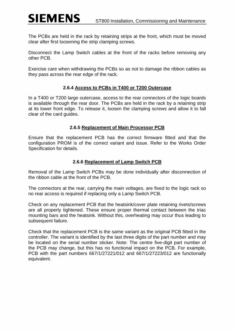
The PCBs are held in the rack by retaining strips at the front, which must be moved clear after first loosening the strip clamping screws. Disconnect the Lamp Switch cables at the front of the racks before removing any other PCB. Exercise care when withdrawing the PCBs so as not to damage the ribbon cables as they pass across the rear edge of the rack.
2.6.4 Access to PCBs in T400 or T200 Outercase
In a T400 or T200 large outercase, access to the rear connectors of the logic boards is available through the rear door. The PCBs are held in the rack by a retaining strip at its lower front edge. To release it, loosen the clamping screws and allow it to fall clear of the card guides.
2.6.5 Replacement of Main Processor PCB
Ensure that the replacement PCB has the correct firmware fitted and that the configuration PROM is of the correct variant and issue. Refer to the Works Order Specification for details.
2.6.6 Replacement of Lamp Switch PCB
Removal of the Lamp Switch PCBs may be done individually after disconnection of the ribbon cable at the front of the PCB. The connectors at the rear, carrying the main voltages, are fixed to the logic rack so no rear access is required if replacing only a Lamp Switch PCB. Check on any replacement PCB that the heatsink/cover plate retaining rivets/screws are all properly tightened. These ensure proper thermal contact between the triac mounting bars and the heatsink. Without this, overheating may occur thus leading to subsequent failure. Check that the replacement PCB is the same variant as the original PCB fitted in the controller. The variant is identified by the last three digits of the part number and may be located on the serial number sticker. Note: The centre five-digit part number of the PCB may change, but this has no functional impact on the PCB. For example, PCB with the part numbers 667/1/27221/012 and 667/1/27223/012 are functionally equivalent.

ST800 Installation, Commissioning and Maintenance
2.6.7 Replacement of the Manual Panel PCB
First unplug the cable connecting the panel to the Main Processor PCB. (Rear connector). The panel is retained by a number of screws to the main cabinet assembly. (Mounting methods may vary in different cabinets). After removal of these screws the panel may remain stuck in place by the gasket. Ease the panel away from the housing, gradually working from one corner taking care not to scratch or otherwise damage it. The replacement panel should be mounted with a new gasket to prevent water ingress. After fitting, reconnect the cable to the Main Processor PCB. An Internal Manual panel (where fitted) can be removed directly by removal of the screws holding it to the 19 inch panel; it may be easier to remove the 19 inch panel from the rack first. No sealing is required on refitting.
2.6.8 Replacement of Expansion I/O PCB
Removal of the Expansion I/O PCBs may be done individually after disconnection of the rear expansion bus ribbon cable from the processor PCB and the Berg input/output connectors.
2.6.9 Replacement of SDE/SA PCB
Removal of the SDE/SA PCB is achieved exactly as for the Expansion I/O PCB above.
2.7 REPLACING COMPONENTS OTHER THAN PCBS
When replacing any components (including PCBs) only approved spares may be used. Use of any other components may invalidate the Type Approval of the equipment. See Section 8 for details of approved spares.

ST800 Installation, Commissioning and Maintenance
3. INSTALLATION AND COMMISSIONING PROCEDURE FOR ST800
Refer to section 3.20 for rack based controllers installed into other traffic controller cases. Refer to the Handbook Supplement 667/HB/32921/007 if Helios CLS (NLM) LED Signals are fitted with a ‘LED Lamp Switch’ PCB.
3.1 PRE-INSTALLATION CHECKS
The following checks should be carried out at the depot and again at the roadside, with the exception of the pre-installation self-test that can only be carried out at the depot. The controller should be visually inspected to check for any damage that may have occurred in transit, e.g. cabinet damage, dents and scratches. Check the security of all internal wiring and PCB fixings, including all nuts and screws. HARDWARE CHECK Check against the Works Specification that: - The correct PCBs and kit (including the Configuration PROM) have been supplied
and fitted correctly. - The appropriate links have been made on the PCBs. All fuses are fitted and are of
the correct ratings - The correct interconnection cabling within the controller has been installed, e.g.
Detectors to controller, OTU to controller, etc. - The dimming transformer tapings have been set to the correct voltages.
1. The Pink lead marked TXL always connects to the voltage tap appropriate to the supply voltage. This is stated in the Works Specification
2. The Pink lead marked DIM connects to the dim tapping as stated in the Works
Specification. 3. The Blue lead not marked connects to the neutral connection on the
transformer Once the hardware has been checked as above, it is recommended that a controller self-test be run (see section 6) before leaving the depot.

ST800 Installation, Commissioning and Maintenance
3.2 CONTROLLER PREPARATION
Controllers are normally delivered from the factory in a fully assembled and tested state. However to aid the installation of the controller, the internal equipment has been designed to be readily removable.
ALL POWER TO THE CONTROLLER MUST BE DISCONNECTED BEFORE ANY ATTEMPT IS MADE TO REMOVE THE INTERNAL COMPONENTS OF THE CONTROLLER. Figure 4 - ST800 Controller
TYPICAL FRONT VIEW OF CABINET(with door removed)
TOP VIEW OF CABINET(with top and door removed at controller rack level)
Scrap view showing manualpanel door which is insetwithin cabinet main door
Manual Panel
Controller Rack (6U)(Fully equipped)
1st Termination panel (withtermination blocks for 16
signal groups and I/O)
2nd Termination panel (foradditional 16 phases plus spare
termination blocks)
Detector Rack (3U) with fourcards shown
(up to 14 cards possible)
Swinging equipment frame(Allows access to rear of
equipment by opening frame)
Master Switch Panel
Ground Level
General Termination panel layout
MainsLow voltage
Cable connections fromback of rack to termination
panels (general layout).High and low voltage runsare kept separate as far as
possible
Controller Stool
ST800SIEMENS
Position for second DetectorRack or other equipment (3U)
Space for additionalequipment, eg OTU (5U)
Dimming Transformer(if dimming is required)
Transformer facilities panel
ST800 Installation, Commissioning and Maintenance
3.3 SITE SUITABILITY
The controller outercase is installed to suit local conditions, but subject to the following limitations.
(i) The position of the controller is as shown on the relevant site plan, STS. (ii) No part of the controller is less than 457mm (18 inches) from the kerbside
unless agreed with the customer.
When it is necessary to site the controller less than 2 metres from the outer edge of the kerb, the access doors and panels should not open over or toward the carriageway. Where no pedestrian guard rails are fitted, then a clearance of at least 600mm shall be left between the outercase and kerb edge so that guard rails may be installed at a later date without the need to disturb the controller installation.
(iii) The controller door(s) should be easily accessible and not extend over the
roadway or obstruct the footpath when opened. The door describes an arc of approx. 710mm radius from the left-hand front corner. Note that the controller door swings open through 180°.
(iv) Any person having control over the junction, whether manual control or test
box simulation, MUST have a good view of the intersection. (v) When the controller is to be located on unmade ground (e.g. a grass verge) it
is recommended that paving slabs or a concrete standing be provided at ground level under all access doors and panels. The hard standing shall extend a minimum distance of 900mm away from the main doors, extending the full width of the case, and at least 800mm away from the side of the case with a flap, again extending the full width of that side.
Customers may specify particular requirements. The door of the controller must have ground clearance of at least 30mm over its whole opening arc. On completion of the outercase installation it is recommended that a concrete or brick plinth be built around the exposed root to retain the base sand and seal within the case area and to secure the outercase root base properly.

ST800 Installation, Commissioning and Maintenance
3.4 RECOMMENDED ORDER OF INSTALLATION
Remove controller electronics – section 3.5 Remove the stool from the case, if not already separate – section 3.6 Remove the CET bars from the stool – section 3.7 Install the stool into the ground – section 3.8 Pull the cables into position – sections 3.9 and 3.10 Fit the CET bars and terminate the armour to the CET connectors – section 3.12 Test the cables – section 3.13 In-fill the stool and seal the base – section 3.14 Fit the cabinet - section 3.15 Terminate the cables – section 3.16 Refit the electronics – section 3.17 Check PCB links, switches and firmware – section 3.18
3.5 REMOVAL OF CONTROLLER ELECTRONICS
Ensure the Master Switch is in the OFF position Remove all PCBs and the Mains Distribution Unit from the rack. Swing the rack forward and unscrew the retaining bolts for the back plate of the rack. Tie this plate to a convenient point on the rear face of the cabinet. Lift off the complete rack assembly from the hinge pins. The controller outercase is now ready for installation.
3.6 REMOVAL OF STOOL FROM OUTERCASE
This action may not be necessary as some controllers are delivered to site with the stool already separate from the outercase ready for installation. If they are assembled, separate the stool by removing its four nuts, bolts and washers and lift the rest of the assembly off the stool. The recommended method of installation is to install the stool without any CET bars or Master Switch Panel. As an alternative the outercase, stool and CET bar(s) only may be installed as a complete assembly. However, firstly the outercase and stool must be separated to fit the seal (Section 3.15).
3.7 REMOVAL OF CET BARS
The CET bars are fitted to the outercase by nuts, bolts and washers, which should be removed and stored with the bars.

ST800 Installation, Commissioning and Maintenance
3.8 INSTALLATION OF STOOL
A hole should be dug and a flagstone at least 900mm x 600mm embedded securely at the bottom of the hole. Refer to Figure 5 for the general method of installation and dimensions. Ensure that enough clearance is left around the stool to enable the fitting of the CET bars and outercase fixings. If the controller is being installed on a slope, allowance must be made for the opening of the door adjacent to the uphill side. See section 3.3 for details. The controller stool is placed in the centre of the flagstone with the top surface between 50 and 75 mm above the final ground level. It is essential that the stool be fitted the correct way round with the holes to the front, as shown in Figure 5. Adjustment may be required to ensure that the outercase sides are vertical; this should be checked using a spirit level. Mix up a stiff mixture of concrete (mix: 1 cement, 3 sand, 4 coarse aggregate (20mm) with no excess water) and cover the flagstone to a height approximately 100mm (4") above the bottom of the stool. The concrete must be sloped to provide a run up for the cables. Any cables already entering the pit must be held away from the wet concrete. Where there is a risk of freezing, then a suitable antifreeze additive shall be incorporated in the concrete mix to ensure proper curing.

ST800 Installation, Commissioning and Maintenance
Figure 5 - Stool Installation
50 - 75mm
Flagstone(Securely embedded at
bottom of hole)
Stool
Concrete
100mm approx.
Sand Infill
Base Sealant
350mm approx.
View from Top of Stool
Door Side
Note. Orientation of holes forcabinet mounting
New surface
Concretefillet
Seal
3.9 CABLE ROUTING
The following guidelines apply when the ST800 controller is installed in the ST800 case or any other controller case. Wiring runs should be made neatly and routed to allow enough spare cables for possible changes/additions at a later date. See 667/GA/27000/000 for cable routing. Spare cores are to be bundled and routed to a convenient position clear of the mains. The ends are to be insulated to make the loom secured. Spare cores of ELV cables are to be loomed separately to the cores of LV cables. Note: normally spare cores are earthed at the end furthest from the controller. If cable idents are required then these are fitted to cores before termination.

ST800 Installation, Commissioning and Maintenance
3.10 CABLING TO THE CONTROLLER
All cables into the controller should be fed into the outercase as close to their termination positions as possible. This is to prevent unnecessary damage being caused should any cables need to be moved once they are in place. Care must be taken not to obstruct the Electricity Supply Company cut out with any cabling. The outer sheathing must be stripped to expose the armouring. It is suggested that between 15mm and 30mm of the inner sheathing Is left above the CET bar. A further conductor length must also be allowed, sufficient to reach the terminal blocks via the proper routing. The cable is inserted in the CET ring and the armoured wires are bent outwards and down against the ring. A hose clip is then placed over the armoured wires and tightened up. The cable sleeve must be stripped from the armouring approx. 0 to 2mm below the level of the CET ring. See Figure 6 for details. The inner sheathing is removed to expose the individual leads, which are connected to associated terminals, leaving sufficient spare length for re-making off the ends should this become necessary. Unused leads should be left with sufficient length to enable them to be connected to any terminal should this subsequently become necessary. When the detector loop tails have been terminated, the connection to the detector backplane must be made with wires twisted together as pairs. Ensure that individual pairs connect only to the same detector. See also the Detector Information Handbook.

ST800 Installation, Commissioning and Maintenance
Figure 6 - Termination of Armoured Cable to CET Bar
Cores
Ident
Stud
Nut
CET Bar
Inner Insulation
Ident(Alternative position)
Incoming Cable
SIDE VIEW
Earthing Band667/2/02348/000
Wormdrive Hose Clip991/4/01375/028
PLAN VIEW
(Armouring not shown atfront of ring for clarity)
Cables must be identified as to their destinations. Additional Idents may be required on specific contracts.
3.11 REGULATORY SIGNS MONITORING
The controller comes equipped and wired with a lamp monitoring sensor as standard that can monitor up to 7 regulatory signs. If the junction contains more than 7 signs in total then additional current monitoring sensors must be fitted and the feeds to the signs split so that not more than 7 signs are monitored through one sensor.

ST800 Installation, Commissioning and Maintenance
The red wire from the sensors should be connected to the ‘Sens’ inputs at the rear of the first lamp switch PCB (see section 6.4), Sens33 is the first monitoring channel, Sens34 is the second etc. If more than 28 signs are present, additional sensors may be added to the second lamp switch PCB (if fitted). The white wires should be joined together and connected to the ‘COMMON’ input (pin b16 of the connector).
3.12 INSTALLATION OF CET BARS
The CET bars should be refitted with the site cables installed clamped to the CET connectors. The ST800 can be fitted with either 3 bar kits for a 16 phase wired controller or 5 bar kits for controllers of more than 16 phases. The CET bars mount on the controller stool. The stool has five positions onto which the two bars can be fitted. Each bar has 6 holes for fixing cables. This means that up to 60 cables can be fixed in the controller.
3 CET bar kits = 36 cables total (8/16 phase controller) 5 CET bar kits = 60 cables total (24/32 phase controller)
Refer to Drawing 667/GA/27000/000 for further details of fitting.
3.13 ON SITE CABLE TESTING
When all the cables have been terminated onto the CET bar they should be checked and tested as defined in the General Testing handbook. On completion of these tests the controller can be in-filled as per Figure 5, taking care that the compacted sand is at ground level when finished.
3.14 SEALING THE BASE OF THE CONTROLLER OUTERCASE
To prevent condensation in the Controller the outercase base must be sealed as soon as possible after the Controller has been installed. If any of the cables were replaced or moved during the installation of the controller then the sand in-filling must be made good before the sealing compound is introduced. NOTE: The in filling must be brought to ground level or above and compacted. Make sure that the sand is level or slightly sloped down where it meets the cables so that it will not prevent the sealant meeting the cable.

ST800 Installation, Commissioning and Maintenance
The sealant should be poured all around the cables and to a height which, when the sealant is set, gives a total covering not less than 6.5mm thick over the base of the controller. This is to prevent the ingress of moisture. Approx. 2Kg of Robnorganic PX212ZF or similar base seal epoxy should be adequate. A concrete fillet around the outside of the stool may be completed before or after the epoxy sealing to suit site conditions. Refer to Figure 5 for general method of in-fill, sealing and concrete fillet.
3.15 INSTALLATION TO EXISTING OR SEPARATELY INSTALLED STOOL
If the controller outercase was not installed with the mounting stool then it should be done as follows: Clean the top surface of the stool and the lower surface of the outercase that will be in contact when the outercase is fitted. Apply a strip of PVC sealant (667/4/04026/023) to the top surface of the stool. The controller outercase is installed on to the stool by lowering it onto the stool and fitting the four retaining bolts. When fitting the outercase onto the stool, take care to ensure that all cables are in the correct position with regard to the CET bar. This is to avoid possible damage or extra effort being required when moving the cables to their correct position once the outercase has been secured.
3.16 TERMINATE THE CABLES
Signal and Detector terminations to the controller should be as per the Works Specification, leaving sufficient spare wire to enable joints to be remade when necessary. The 'Pair' cable used for connection from the loops should be terminated using the appropriate kit (part number 667/1/15854/000).
3.17 REFITTING THE CONTROLLER ELECTRONICS
When refitting the controller into the outercase it is essential that every care be taken not to damage either the cables or the controller itself. The ST800 Rack Assembly should be fitted in the reverse manner to how it was removed i.e. bolt the rack back panel in place and refit all PCBs. Reconnect the manual panel cable.

ST800 Installation, Commissioning and Maintenance
3.18 PCB SWITCHES, LINKS AND FIRMWARE
Before the controller is switched on, the set-up switches and links on the CPU and lamp switch PCBs must be checked to ensure they are set correctly. Also the firmware should be checked to ensure the correct version is fitted. The switch and link settings are mainly related to the hardware fail flash facility; their locations and option selections are shown in Figure 7 to Figure 10. An overview of each PCB is given below:
Figure 7 - CPU PCB
1 32
16 17
Prom Pin – Socket Pin 1 ---------- 3 14 -------- 16
Configuration Prom (28 pin)
Phase BusProcessor
Phase Bus Firmware (PB815)
(PB820)EPLD1
(PB821)EPLD2 Main Processor
Firmware (PB800)
Configuration PROM socket
MainProcessor
Input protection Fuse(500ma)Ram Back-Up battery
FRONT
Handset Fuse (500ma)
Phase Bus Connector
Extended System Bus Connector
Manual Panel Connector
I/O Connector (Dual stacked)*
Power ConnectorRS232 Handset
port
Power OK System Error
Bus Error Watch dog
Modem Port
Hardware fail flash selection
* Inputs are on ‘Inner’ connector Outputs are on ‘Outer’ connector
Power fail signal source
32 pin
Position of the Configuration PROM in the Configuration PROM Socket
Pins 1, 2, 31 & 32 of socket not used
ST800 Installation, Commissioning and Maintenance
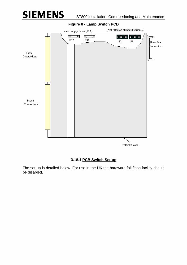
Figure 8 - Lamp Switch PCB
Phase BusConnector
PhaseConnections
PhaseConnections
S1S2
(Not fitted on all board variants)
FS1FS2
Lamp Supply Fuses (10A)
Heatsink Cover
3.18.1 PCB Switch Set-up
The set-up is detailed below. For use in the UK the hardware fail flash facility should be disabled.

ST800 Installation, Commissioning and Maintenance
Figure 9 - CPU PCB Switch Settings
12
3 4
5 6 7 8
X34
X31
3 2 1
3 2 1
Power Fail Source Link 2-3 External Link 1-2 Internal (Link 2-3 must always be selected)
Fail Flash Enabled Link 2-3 Disabled Link 1-2 Enabled (Link 2-3 must always be selected for UK use)
ON OFF
Flash ‘ON’ time 50Hz 60Hz
+320ms if Off +267ms if Off +160ms if Off +133ms if Off +80ms if Off +66ms if Off +40ms if Off +33ms if Off
All 0n = 40ms All On = 33ms
ON OFF
Flash ‘OFF’ time 50Hz 60Hz
+320ms if Off +267ms if Off +160ms if Off +133ms if Off+80ms if Off +66ms if Off +40ms if Off +33ms if Off
All On = 40ms All On = 33ms
Flash Rate Selection Flash rate depends on mains frequency Minimum flash period is 40ms (50Hz) & 33ms (60Hz)To ‘add’, turn Off appropriate switch
Figure 10 - Lamp Switch PCB Switch Settings If Fail flash is enabled the choice of Red or Amber aspects to be flashed for each phase is set on the lamp switch PCBs
3.19 ON SITE CONTROLLER TESTING
It is suggested that the controller is wired in place and then a self-test performed with small value fuses fitted. This illuminates each colour on each phase in turn for approximately 20 milliseconds. If there is any short in the cables the low value fuse should protect the circuits. Connect a suitable handset to the 25-way connector on the Main Processor PCB. This can have a display width between 14 and 80. The controller is defaulted to work with a display width of 20 characters, but handset command WID can change this. Open the manual panel door and set the Signals ON/OFF switch to off.
A B C D A B C D
RED AMBE RED AMBE
E F G H E F G H Phase:-
S1 S2
O
OF
1 2 3 4 5 6 7 8 1 2 3 4 5 6 7 8
ST800 Installation, Commissioning and Maintenance
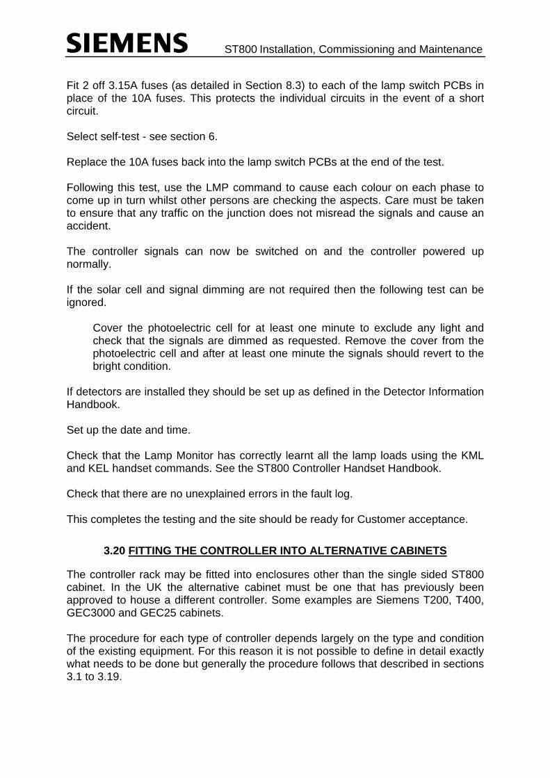
Fit 2 off 3.15A fuses (as detailed in Section 8.3) to each of the lamp switch PCBs in place of the 10A fuses. This protects the individual circuits in the event of a short circuit. Select self-test - see section 6. Replace the 10A fuses back into the lamp switch PCBs at the end of the test. Following this test, use the LMP command to cause each colour on each phase to come up in turn whilst other persons are checking the aspects. Care must be taken to ensure that any traffic on the junction does not misread the signals and cause an accident. The controller signals can now be switched on and the controller powered up normally. If the solar cell and signal dimming are not required then the following test can be ignored.
Cover the photoelectric cell for at least one minute to exclude any light and check that the signals are dimmed as requested. Remove the cover from the photoelectric cell and after at least one minute the signals should revert to the bright condition.
If detectors are installed they should be set up as defined in the Detector Information Handbook. Set up the date and time. Check that the Lamp Monitor has correctly learnt all the lamp loads using the KML and KEL handset commands. See the ST800 Controller Handset Handbook. Check that there are no unexplained errors in the fault log. This completes the testing and the site should be ready for Customer acceptance.
3.20 FITTING THE CONTROLLER INTO ALTERNATIVE CABINETS
The controller rack may be fitted into enclosures other than the single sided ST800 cabinet. In the UK the alternative cabinet must be one that has previously been approved to house a different controller. Some examples are Siemens T200, T400, GEC3000 and GEC25 cabinets. The procedure for each type of controller depends largely on the type and condition of the existing equipment. For this reason it is not possible to define in detail exactly what needs to be done but generally the procedure follows that described in sections 3.1 to 3.19.

ST800 Installation, Commissioning and Maintenance
For some cabinets additional kits of parts are available. These provide brackets and other equipment that may be helpful during the installation. The standard controller items are used with these kits and are listed in the ST800 shopping list (667/KM/27000/000). Refer to Siemens Poole for the latest copy. Kits for the following are available. (These are being augmented all the time so please contact Siemens Poole for updates to this list):
T400 cabinet Kit 667/1/27040/000 If replacing an existing T400, then the following can generally be re-used:
• T400 I/O and SDE PCBs and I/O cabling.
• T400 manual panel and dimming transformer (if it has sufficient lamp current capacity).
AN ST800 rack with PDU, CPU and Lamp Switch PCBs is the minimum additional requirement.
GEC 3000/25 Kit 667/1/27040/001 The existing street termination blocks and panel may be re-used if in good condition. GEC type detectors should be replaced.
Ferranti Mk 1 Double Outercase
Kit 667/1/27040/002 The existing street termination blocks may be re-used if in good condition. Ferranti type detectors should be replaced.
Plessey T70/T90 Kit 667/1/27040/004 If replacing an existing T70 or T90, then the dimming transformer may be re-used (if it has sufficient lamp current capacity). The existing Street Phase termination blocks may be re-used if in good condition. The termination panel may be re-used in the T90 if it is in good condition.
T200 cabinet Kit 667/1/27040/005 If replacing an existing T200, then the dimming transformer may be re-used (if it has sufficient lamp current capacity). The existing Street Phase termination blocks and panel may be re-used if in good condition.
GEC CX Case Kit 667/1/27040/006
Ferranti Mk.II Kit 667/1/27040/007
TCUG Case Refer to Poole - Kit 667/1/27040/010
ST800 Installation, Commissioning and Maintenance
3.21 INSTALLATION AND COMMISSIONING STEPS FOR ST800P AND ST800SE
The ST800P and ST800SE controllers are installed in the same way as a standard ST800 controller and therefore the procedures described above should be followed once the following sections have been read and understood. a) The firmware has been up-issued and new EPLDs are required for the ST800P
and ST800SE, see section 3.21.1. b) The self-test has been modified for this latest issue of the firmware, see ‘Self-Test
Facility’ in the ST800 Controller General Handbook. c) The connections to the back of the four phase ST800P lamp switch PCB differ
from those on a standard eight phase lamp switch PCB, see section 6.5. d) The ST800P normally has its configuration loaded serial through the handset port
so no configuration PROM is fitted. See ‘Standalone Pedestrian Controller’s Configuration Data’ in the ST800 Controller Handset Handbook. As an alternative, a configuration PROM may be fitted and the controller initialised to start the controller. The PROM may then be removed for use at another site.
e) The red lamp monitoring set-up of the ST800P has two built in red channels for
each vehicle phase, see ‘Lamp Monitoring’ in the ST800 Controller General Handbook.
As with the T400 Pelican, the ST800P stand-alone pedestrian controller needs to be customised on the street using the handset before the signals are switched on; see the ST800 Controller Handset Handbook. The special instructions on the configuration printout detail what the default configuration provides and what may require changing. Also note that some new fault log entries have been added and some existing entries modified for this new issue of firmware. Any new or modified fault log entries are listed in the ST800 Controller Handset Handbook.
3.21.1 New PROMs and EPLDs
Before switching the controller on for the first time, check that the correct firmware PROM and the correct EPLDs are fitted to the main processor PCB. The socket for the configuration PROM should not be used as the configuration data is normally loaded through the handset port from a PC (see ‘Loading Standalone Configuration Data’ in the ST800 Controller Handset Handbook).

ST800 Installation, Commissioning and Maintenance
Figure 11 - Firmware PROM and EPLDs
PB815000 02
PB800000 06
PB821121 01
PB820000 01 Configuration EPROM
(Usually Left Empty)
Phase BusProcessorFirmware(Unchanged)
WDBESEPP
EPLD1(Unchanged)
EPLD2(See Below)
EmptySocket
MainProcessorFirmware
3.21.1.1 Firmware PROMs
The main processor firmware must be PB800 issue 6 or later (‘PB800 000 06’ on the label and ‘PIC:PB800 ISS 6’ on the handset) in order to function with four phase lamp switch PCBs and to provide the new stand-alone pedestrian facilities. The Phase Bus Processor firmware has not been modified and so should still be PB815 issue 2 (‘PB815 000 02’ on the label and ‘SIC:PB800 ISS 2’ on the handset).
3.21.1.2 EPLDs
Until now, most ST800 CPU PCBs have been fitted with the original /000 variants of the PB820 and PB821 EPLDs. However, a number of variants of the PB821 EPLD2 have been produced to limit the facilities that an ST800 is allowed to run. The handset command ‘PLD’ displays the variant of EPLD2 currently fitted and a short description. Self-test also displays this information on the handset.
Part Number Handset Display Facilities Enabled 667/1/12821/000 PLD:000 LMU Lamp monitoring but not integral SDE 667/1/12821/101 PLD:101 BASIC Neither lamp monitoring nor integral SDE667/1/12821/102 PLD:102 LMU+SDE Lamp monitoring and integral SDE 667/1/12821/121 PLD:121 SINGLE PED Single stand-alone ped. stream only 667/1/12821/122 PLD:122 PED ONLY Multiple stand-alone ped. streams only. For example, the original ST800 EPLD2 was variant /000 which enabled lamp monitoring, hence the display ‘PLD:000 LMU’, whereas the PLD variant /102 also enables integral SDE, hence the display ‘PLD:102 LMU+SDE’.

ST800 Installation, Commissioning and Maintenance
ST800P stand-alone pedestrian traffic controllers are, by default, shipped with EPLD2 variant /121 which only allows the controller to be used as a single pedestrian crossing. Even if the configuration contains two streams, which the default configurations do, the controller automatically disables the second stream and runs just a single pedestrian crossing if EPLD2 variant /121 is fitted. To run two or more* pedestrian streams, the /121 variant EPLD2 must be replaced with a /122 variant EPLD2. Both the EPLD2 variants /121 and /122 allow integral SDE/SA. Therefore, if the original /000 variant is still fitted which does not permit the use of integral SDE/SA but which is enabled by default in the stand-alone configurations then the controller reports a compatibility fault and does not illuminate the signals. Similarly, if EPLD2 variants /121 or /122 are fitted to a controller which has one or more intersection streams configured, then a compatibility fault is logged as these variants do not allow any intersection streams. * More than two pedestrian streams would exceed the capabilities of the
ST800P platform. However, up to eight pedestrian streams can be configured on IC4 and provided by the original ST800 controller.
3.22 PEDESTRIAN AUDIBLE/TACTILE INDICATIONS
3.22.1 Non-Switched Audibles/Tactiles
For equipment required call for 667/1/27006/000. Audible units recommended and supplied by STCL that meet this requirement are: Sonalert Mallory SC628P, Highland Electronics type SC628P and Roxborough type SPCI535A4
Audible: 667/4/04785/000 Highland Electronics type SC628P* and Roxborough type SPCI535A4 (* was Sonalert Mallory SC628P)
Tactile: 667/7/17390/000 (Pelican) Radix RS250 or RS252 667/7/17390/001 (Intersection) Radix RS251 or RS252
Items Required: KOP for Signal Head mounted Audible/Tactile Drive 667/1/15799/000 KOP to add Audio Ind to Push Button Unit 667/1/15292/000 Note: If the dimmed supply voltage is 120V, 140V or 160V then the Sonalert Mallory SC628P audible indicator can be used as specified above. An alternative used by other companies is the Bleeptone A.P. Bessom RS/1 18V, which can only be used at 160V dimming.

ST800 Installation, Commissioning and Maintenance
It is recommended that all units on one supply are the same type. The items are connected as shown in the circuits in Figure 12 and Figure 13. The connections to the transformer are via single to dual Faston terminals. Note: It is a requirement in the U.K. that audible signals may only be used if the pedestrian phase runs with no vehicle phases and is accompanied by the Red Lamp Monitoring facility.
3.22.2 Switched Audibles/Tactiles
(DRIVE CIRCUIT MUST BE MOUNTED INSIDE THE CONTROLLER)
This facility provides the power unit to supply one group of four Audible/Tactile Indicators during Pedestrian Green time using a high current output, see Figure 14 and Figure 15. This may be increased to 16 units if 3 more kits are added. The supply to the Audible/Tactile can be switched off while the pedestrian green is still illuminated, to terminate them before the end of the pedestrian green or during the flashing green clearance period for example, by utilising a Controller output. Note that the ‘Radix System RS250’ Tactile Unit is used if the Tactiles are to be switched since this provides an input for a steady DC voltage. Unswitched Tactiles can use the ‘RS251’ Tactile Unit. The ‘RS252’ Tactile Unit can be used in either situation and is ‘configured’ by the use of a link.
3.22.3 Switched Mains Voltage Pedestrian Audibles (Export Only)
Items required: Audio Switching Kit of Parts 667/1/21470/000 (Although this was designed for
the 400 it may also be used for the ST800) In certain export markets (presently Hong Kong) the Pedestrian Audible units are powered from mains voltage, namely the pedestrian phase green man supply and red man supply. When connected to the green and red man supplies the Audible units give high rate audible clicks as a signal during the green man and lower rate audible clicks as a signal during the red man. The supplies to these units may be taken via relay contacts to allow the audio to be switched off at a certain time of day.
3.22.4 Dual Level Audibles
Items required: Kit Of Parts to add secondary buzzer 667/1/15292/000 The audible indication can be Dual Level. The audibles only change state during the vehicle green period. Dual level audible operation is enabled via the handset. The changeover relay required for the switching is located on the first I/O expansion board. Switching

ST800 Installation, Commissioning and Maintenance
between the two levels is achieved using the event timetable. Note that when using just the Loud audible indication, this I/O line can be used to switch the audible output On/Off. See Figure 14. On/Off control is effected as above or via the CPU output lines. The CPU line method must be used if no expansion board is fitted. Output bits controlling the change over relay, the On/Off relay and terminal block connections are specified in the Works Specification. Figure 12 - Pedestrian Audible Indication (Signal Head Mounting)
(See Figure 14 if the Audibles are to be switched on/off by the controller)
240V(if dim,
160V etc.)
12V(or 8V etc)
5Abridge rectifier
667/1/15799/000
10kΩ resistor fitted whenthere is no lamp load on
the transformer, e.g. on ashort wait pole.
100μF 25VAudio unit in wait
indicator box
Wait Indicator BoxPedestrian Signal Head
Pedestrian Green (not flashing)

ST800 Installation, Commissioning and Maintenance
Figure 13 - Pedestrian Tactile Indication (Unswitched) (See Figure 15 if the Tactiles are to be switched on/off by the controller)
Tactile Power UnitRS251 or RS252
240V(if dim
160V etc.)
12V(or 8V etc)
Wait Indicator Box
Pedestrian Signal Head
Tactile Unit
Pedestrian Green Man (not flashing)

ST800 Installation, Commissioning and Maintenance
Figure 14 - Pedestrian Audible Indication (Controller Mounting) (See Figure 12 if the Audibles do not need to be switched on/off by the controller)
240V(if dim
160V etc.)
12V(or 8Vetc)
5Abridge rectifier
667/1/15799/000
10kΩ resistor
100μF 25V Audio units in waitindicator box(4 units max.)
Wait Indicator BoxesController
PedestrianGreen Drive
22Ω resistor
Controller outputcontact for switching
audibles on/off.(22Ω contact
protection resistor)
Extra circuits may be added up to a maximum of 4 in total.Each circuit can drive up to 4 audibles.
Note that each of the circuits above can drive up to four Audible Units (as shown above in Figure 14) or control up to four Tactile Power Supplies (as shown in Figure
15) or a mixture of audibles and tactiles up to a total of four.

ST800 Installation, Commissioning and Maintenance
Figure 15 - Pedestrian Tactile Indication (Switched) (See Figure 13 if the tactiles do not need to be switched on/off by the controller)
5Abridge rectifier
667/1/15799/000
10kΩ resistor
100μF 25V
240V(if dim
160V etc.)
Inside Controller Cabinet
22Ω resistor
12V(or 8Vetc)
Controller outputcontact for switching
tactiles on/off.(22Ω contact
protection resistor)
Wait IndicatorBoxes
PedestrianGreen Drive
Extra circuits may be added up to a maximum of 4 in total.Each circuit may control up to 4 Tactile Power Supplies
Signal Heads
PedestrianGreen Drive
Tactile Units(in wait boxes)
PedestrianGreen Drive
TactilePowerSupplyRS250
orRS252
TactilePowerSupplyRS250
orRS252
PedestrianGreen Drive
PedestrianGreen Drive
TactilePowerSupplyRS250
orRS252
TactilePowerSupplyRS250
orRS252
Note that each of the circuits above can control up to four Tactile Power Supplies (as shown in Figure 15 above) or drive up to four Audible Units directly (as shown in
Figure 14) or a mixture of tactiles and audibles up to a total of four.
ST800 Installation, Commissioning and Maintenance
4. ROUTINE MAINTENANCE PROCEDURES
This section contains a list of checks to be performed at an ST800 installation on a regular basis (normally annually) If for any reason the power is switched off to the controller then a total installation megger test should be carried out as defined in the General Testing Handbook.
4.1 ROUTINE INSPECTION OF SIGNAL EQUIPMENT
Check all signal heads/aspects for damage and take any necessary corrective action. Check all signal heads for correct alignment with their respective approaches. Check all pole top cable connections; ensure that they are sound, secure and not seriously corroded. Check that all top caps are fitted and are not damaged. Check that all poles are secure in the ground and are not leaning or damaged.
4.2 ROUTINE INSPECTION AND ELECTRICAL TESTING OF CONTROLLER
It is suggested that these procedures be performed in the order listed. Examine the outercase for serious damage. The outercase would normally only be replaced if it has been damaged to the extent that its security has been breached or that water or dirt is entering. Open the main door and the manual panel door, check that the screw-locks, lock and hinges operate freely. Inspect the door and lock, and check the lock and catch-plate for security. Replace or tighten as necessary. Lubricate as necessary with good quality penetrating type oil. Note: The key lock must not be operated unless the screw locks are tight, i.e. Unlock the case before undoing the screw lock and only lock the case after tightening the screw locks. Inspect the main door seal and manual panel gasket, ensuring they are intact and in the correct position. Replace as necessary ensuring that the surface is clean before fitting. Check the manual panel for any damage and replace if necessary. Check that all functions operate correctly. Press the lamp test keypad and check that all LEDs are operational. Ensure that no fault indications are showing. If any faults are revealed refer to the fault-finding procedures in section 5.3.
ST800 Installation, Commissioning and Maintenance
The following tests will result in the signals extinguishing. • Test the 300 mA RCD (if fitted) by pressing the test button. The breaker should
operate immediately. • Check the termination panel(s) and master switch panel within the controller and
ensure that there are no loose fixings, or damage to these panels. Tighten any loose fixings and carry out any repairs that are necessary.
• Check the logic rack(s) and other assemblies within the controller are securely
fixed. Retighten loose fixings as necessary. • Check that all fuses are secure in their holders. It is strongly recommended that
the controller supply is isolated before any fuses are checked. • Check wiring and cableforms, particularly ribbon cables for damage. Repair if
necessary. • The battery on the main processor PCB must be replaced if it has failed. Any
replacement battery should be suitably marked with an appropriate date label. Having done this, the controller records should be updated accordingly.
The following tests require the controller to be powered and running normally. • Tests of the Voltage Drop of Neutral Conductors. This test should be carried out
during each periodic/annual inspection as a simple check of neutral cables, which can also provide a good indication of the state of the intersection cabling.
(i) Take a digital multimeter or voltmeter and set it to measure 240V AC (RMS).
(ii) Select a phase and wait until its green has just terminated. Measure the
voltage between the controller neutral and the green feed; the voltage should be no greater than 4V (RMS) throughout the controller’s cycle, except when the phase next goes to green voltage. If the voltage between the green feed and neutral is greater than 4V then do the following:
Check all joints in the appropriate neutral cable run, ensure that they are all tight and none are seriously corroded. Replace or tighten them as necessary. Re-test the cable If the fault still persists then: Increase the number of conductors/cable cores used for the neutral. Re-test the cable to ensure that corrective action taken has removed the problem.

ST800 Installation, Commissioning and Maintenance
• With the handset, check that all inputs used are operating correctly. • Test the maintenance socket RCD by pressing the test button. The breaker
should operate immediately. The following checks should be carried out before leaving the site. • Check the cabinet door seals are intact and in the correct positions. Replace as
necessary ensuring the surface is clean before fitting. • Inspect the cabinet base seal. If damaged, the affected area should be filled with
sand and re-sealed. For details see section 3.8
4.3 ROUTINE SETUP CHECK
Check that the real time clock is set correctly as described in the ST800 Controller Handset Handbook. Use the time of day (TOD) command to check that the real time clock is running the correct time. A true measurement of the accuracy of the real time clock can only be gained if the clock with which it is compared has been accurately set up. It is essential that the time be compared with an adjacent controller using a clock that has been synchronised to that controller within the last 30 minutes.

ST800 Installation, Commissioning and Maintenance
5. FAULT FINDING
This section contains information to assist in location and diagnosis of faults.
5.1 FAULT FINDING STARTING FROM THE SYMPTOMS
WARNING: Care must be taken when conducting tests on a controller with mains supply connected to it. Having first recorded any fault indications in the controller visit log and fault record sheet (section 5.6) proceed with the following. Below is a list of symptoms produced by controller faults. Against each one of them is the number of the subsection to which you must refer for the relevant fault finding procedure. There are summary procedures for all of the faults listed and where is it felt additional detail will be of benefit, there is also a detailed procedure. In the detailed procedures where the summary information has not been expanded upon, the wording `As Summary' will be found above the text. Signals Lighting Incorrectly: See sub-section There no longer appears to be a fault 5.1.1 All traffic lights OFF 5.1.2 ) One lamp (or group of lamps) not lighting 5.1.4 ) One lamp (or group of lamps) always lit 5.1.6 ) see One lamp (or group of lamps) lighting at the ) also wrong time 5.1.8 ) 5.1.1 Signals not dimming during darkness 5.1.10 ) Signals dim during daylight 5.1.12 ) Signals cycling dim-bright-dim etc. 5.1.14 ) Signals Changing Incorrectly: Signals not changing at all, i.e. stuck 5.1.16 ) Signals not changing to green on one approach 5.1.18 ) see Signals changing too slowly 5.1.20 ) also Signals changing too quickly 5.1.22 ) 5.1.1 Others Faulty Input 5.1.24 ) see Faulty Output 5.1.25 ) also Cabinet Alarm/Detector Fault Monitor 5.1.26 ) 5.1.1 Controller not running required/expected mode 5.1.27 Intermittent Faults/Problem Sites 5.1.28 Controller Faults with Handset Plugged in/ Handset Port Faults 5.1.29
ST800 Installation, Commissioning and Maintenance
5.1.1 Fault Symptoms No Longer Apparent
5.1.1.1 This procedure should be followed if, on arrival at the site, the fault symptoms described in the fault report are no longer apparent or no positive fault has been found after having followed another fault procedure.
5.1.1.2 Have you just followed another fault-finding procedure, which has resulted in no positive fault being found?
YES - Continue at 5.1.1.4 NO - Continue at 5.1.1.3
5.1.1.3 Are there any of the LEDs on the Main Processor PCB illuminated which would indicate the controller has detected a fault?
YES - It is recommended that you move to section 5.1.1.3 and continue to fault find starting from the fault indications.
NO - Continue at 5.1.1.4
5.1.1.4 Check the signal sequence on the street and on the Lamp Switch LEDs looking for irregularities.
5.1.1.5 Check that the controller operates correctly for the particular mode that it is in. If the controller is capable of working VA but is not currently in V.A. mode, then it is recommended that, if possible, it should be tested in the VA mode to check that it is responding to demands correctly and serving all phases.
5.1.1.6 Perform the electrical test specified in section 5.4.1.
5.1.1.7 Inspect the controller to ensure that all of the retrospective modifications required on the controller and facilities have been carried out.
Check all of the following headed sub sections. 1. Racking 2. PSU 3. PCBs
Main Processor PCB Expansion I/O PCB Lamp Switch PCBs Manual panel

ST800 Installation, Commissioning and Maintenance
5.1.2 All Traffic Lights Off - Summary
5.1.2.1 Are there any fault indications illuminated in the controller (i.e. Main Processor LEDs)?
NO YES | | | | | | | Continue at section 5.2 | starting from fault
| indications |
5.1.2.2 Check to see if there are any indications of power in the controller, e.g. LEDs illuminated
NO YES | | | | | | | Continue at 5.1.2.4 | |
5.1.2.3 Locate reason for loss of supply
5.1.2.4 Locate reason for signals off when mains supply on
5.1.3 All Traffic Lights Off - Detail
5.1.3.1 Are there any of the LEDs on the Main Processor PCB illuminated?
YES - It is recommended that you move to section 5.2 and continue to fault find starting from fault indications.
NO - Continue at 5.1.3.3.
5.1.3.2 Check to see if there are any indications of power on the controller. Are there any LEDs on (illuminated)? Press the lamp test button, do any of the manual panel indicators illuminate or does the cabinet alarm lamp illuminate?
YES - There is power/mains supply reaching the controller, move to 5.1.3.4 NO - There is no power, continue at 5.1.3.4

ST800 Installation, Commissioning and Maintenance
5.1.3.3 Check the following:
(a) Check all D.C. supplies.
(b) Check local area to see if there is a general power failure. (NB: This may have been checked before on receipt of the fault report). (c) Master switch and controller switch to see if either has been switched OFF. If either is OFF, then check as to why they are OFF. (d) If an RCD is fitted in series with controllers power supply, check to see if it has tripped. If it has then look for reason for trip, this may require an insulation test to be carried out with respect to earth. (e) Check mains supply continuity throughout the controller referring to 667/DA/27000/etc, and using a meter set to measure the relevant mains supply voltage. If any fuses are ruptured investigate the reason for their rupture in the following manner: Switch off the mains supply switch which immediately precedes the ruptured fuse. Using a meter set to measure resistance check for a low resistance between live and neutral or live and earth. If a low resistance is found then referring to 667/DA/27000/etc disconnect circuits until the elimination fault is found. If a varistor is fitted check that this has not gone permanently short-circuit. If no low resistance can be found, check for signs of arcing within power supply and wiring on termination panel.
5.1.3.4 Check the following:
Check lamp supply
(a) NB: Normally if lamp supply has failed there is the fault log entry FLF17: If there is no entry in FLF17 it is unlikely that lamp supply is at fault. To check lamps supply further do as follows. Using a meter set to measure mains supply voltage and circuit diagram 667/DA/27000/etc check for supply at various points. (a) Check to see if the signals ON/OFF switch on the manual panel is in the OFF position. If it is check to see if there is any reason for the signals to be OFF (e.g. road works, previous cable fault, local emergency). Do not switch the signals ON until any reason for them to be OFF is cleared or no reason can be found.

ST800 Installation, Commissioning and Maintenance
When everything above has been checked switch the signals ON and observe signal operation. (d) Is the controller part-time working? If it is, check to see if the conditions for switching to part time (signals OFF) are being satisfied. Example: Real time clock may be incorrect or queue detectors may not be working. (e) Check to see if there is any special conditioning which can switch the signals OFF. Check to see if the conditions for switching the signals OFF are specified correctly and are being satisfied. (f) If signals are OFF and signals ON/OFF switch is requesting them to be ON check using Handset and `ENG' code `MANCND' (ENG63 0, 1, 2). If the value displayed in bit 7 of ENG63 2 is zero, then the manual panel switch is being seen as off, even if it in the `on' position. Then check for faulty switch or wiring (wiring from switch to manual panel PCB and manual panel to Main Processor PCB).
5.1.4 One Lamp (Or Lamp Group) Not Lighting - Summary
5.1.4.1 Are there any fault indications in the controller?
NO YES | | | | | 5.2 |
5.1.4.2 Do Lamp Switch LEDs indicate that the lamp(s) should be illuminated?
NO YES | | | | | 5.1.4.11 | Check phase driver | PCB wiring and | signal heads. |
5.1.4.3 Is the fault all aspects of a certain colour stuck `ON' or `OFF' (i.e. all yellows on or off) when they should not be, possibly whilst other aspects are switching normally.
AND
ST800 Installation, Commissioning and Maintenance
5.1.4.4 Do the lamp(s) require demands or special conditions to illuminate the
NO YES | | | | | 5.1.4.6
5.1.4.5 Replace Lamp Switch Kit
Check configuration data/works specification
5.1.4.6 Do lamps require only a demand to illuminate them?
NO YES | | | | | 5.1.4.8 |
5.1.4.7 Special conditioning required
Check to see if conditions are satisfied. Does lamp light? If not replace Lamp Switch Kit(s).
5.1.4.8 Are the necessary inputs being activated to generate the demands?
NO YES | | | | | 5.1.4.10
5.1.4.9 Inputs are not being activated.
Check: a) Detector and associated wiring b) Pushbutton and associated wiring c) Wiring input terminal block to buffer board d) Replace Expansion I/O PCB
5.1.4.10 Inputs are being activated.
Check: a) If demands inserted b) If input disabled (DET command) c) Configuration data/works specification with regards to demands/inputs

ST800 Installation, Commissioning and Maintenance
5.1.4.11 Lamp Switch PCBs indicate that lamp should be illuminated.
Check: Lamp Switch PCB, controller wiring, intersection cabling, pole top connections, signal head transformers, lamp holders and lamps.
5.1.5 One Lamp (Or Lamp Group) Not Lighting - Detail
5.1.5.1 Are there any of the LEDs on the Main Processor PCB illuminated, which would indicate the controller has detected a fault?
YES - It is recommended that you move to section 5.2 and continue to fault-find starting from fault indications.
NO - Continue at 5.1.5.2
5.1.5.2 Does the Lamp Switch PCB(s) indicate that the lamp(s) should be on, i.e. is the appropriate LED(s) on the Lamp Switch PCB(s) illuminated?
YES - Continue at 5.1.5.11. NO - Continue at 5.1.5.3.
5.1.5.3 Is the fault all aspects of a certain colour stuck `ON' or `OFF' (i.e. all yellows ON or OFF) when they should not be, possibly whilst other aspects are switching normally.
AND Is the controller configured for part time/standby mode. NO - Continue at 5.1.5.4. YES - See also 5.2.
5.1.5.4 Do the lamp(s)/Signal(s) in question require demands or other special conditions for them to illuminate?
YES - They require demands or special conditions - continue at 5.1.5.6. NO - The lamp(s) should be illuminating, continue at 5.1.5.5.
5.1.5.5 The lamp(s) do not require any demands or special conditioning to illuminate so check the following:
(a) Replace the Lamp Switch kit and re-check, starting at 5.1.5.2.

ST800 Installation, Commissioning and Maintenance
(b) Check configuration data/works specifications for any special lamp
sequence requirements.
5.1.5.6 Do the lamps only require a demand to illuminate them?
YES - They only require a demand, continue at 5.1.5.8. NO - They require special conditioning, continue at 5.1.5.7.
5.1.5.7 Special conditioning required to illuminate the lamps, check the following:
(a) Check as to whether the special conditions required to illuminate the lamps are satisfied. If they are not then try and simulate the conditions. If/when the conditions are satisfied, check as to whether or not the Lamp Switch PCB is now indicating that the lamp should be on, if it is check that the signals on the street are also on. If they are not, continue at 5.2. (b) If, even when the conditions are satisfied, the Lamp Switch PCB does not indicate that the lamp(s) should be illuminated replace the Lamp Switch kit and re-start at 5.1.5.7 again.
5.1.5.8 Demands are required to illuminate the particular lamp(s) in question. Check the following:
Are the inputs necessary to generate the demands being activated? Using the handset and the command `IOP' check the relevant inputs. The inputs should be active when vehicles pass over the loops, or pushbuttons are pressed. NO - Continue at 5.1.5.9. YES - Continue at 5.1.5.10.
5.1.5.9 Check the following items as necessary:
(a) Detector unit, detector wiring and detector loop (b) Pushbutton and its associated wiring (c) The wiring between the input terminal blocks and Expansion PCB(s) (d) Replace Expansion PCB(s) and check to see if fault clears (start again
at 5.1.5.8). (e) When demands are being inserted correctly, re-start at 5.1.5.2.

ST800 Installation, Commissioning and Maintenance
5.1.5.10 Inputs are being activated, check the following to see if demands are being inserted.
(a) Using the handset, check that the required phase demand is being inserted using `SPH' command.
If a demand is being inserted do the following:
(i) Replace the Lamp Switch kit and re-start at 5.1.5.2. (ii) Replace the Expansion I/O PCB
(b) If demands are not being inserted, check to see if the input(s) is
disabled by using handset and the `DET' command with the relevant DET number; DET should be = 2 for normal use. Another way of checking this is to use the `ENG' codes for `GPIN1' and `GPIN0'. If the values displayed by these codes do not change for the particular port and bit then it is either set permanently active or inactive. Enter the command `BAS=1' first, to change the display given by the `ENG' codes into binary form.
(c) Check the configuration data/works specification to ensure that correct
input is being checked and demand that which is expected is actually configured.
5.1.5.11 Lamp Switch PCB indicates that lamp should be illuminated, check the following:
(a) Check to see if the Lamp Switch PCB is working, e.g. using a meter set to measure the appropriate mains supply voltage. Check if there is mains voltage on the lamp drive output. If there is not replace Lamp Switch kit and re-check if lamp is illuminating. (N.B. Before replacing the Lamp Switch PCB it is advisable to test the wiring to ensure that there is no cable fault which may have caused the PCB fault.)
(b) Check the continuity of the wiring from the output of the Lamp Switch
PCB to the signal heads. (c) Check the pole top connections. (d) Check the signal heads: Transformers, lamp holders and lamps. WARNING Care must be taken when conducting any tests with mains supply connected to the controller. Where possible a test method should be used which does not require mains connected to the controller.

ST800 Installation, Commissioning and Maintenance
5.1.6 One Lamp (Or Group Of Lamps) Always Lit - Summary
5.1.6.1 Are there any fault indications in the controller?
NO YES | | | | | 5.2 | |
5.1.6.2 Do the Lamp Switch PCB LEDs indicate that the lamp(s) should be on?
NO YES | | | | | 5.1.6.7 | |
5.1.6.3 Is the fault all aspects of a certain colour stuck `ON' or `OFF' (i.e. all yellows on or off) when they should not be, possibly whilst other aspects are switching normally?
AND Is the controller configured for part-time/Standby? NO YES | | | | | See also 5.2 |
5.1.6.4 Disconnect all external wires from the relevant phase output terminal.
Is there continuously a voltage present between the output terminal and neutral return which is greater than 49V? (NB: 48V RMS is considered the voltage at which a signal is deemed to be ON). (I.e. check output of Lamp Switch PCB). NO YES | | | | | 5.1.6.6 |

ST800 Installation, Commissioning and Maintenance
5.1.6.5 Check pole top connections and external cables for short circuits and/or poor insulation. Check connectivity/continuity of associated neutral.
5.1.6.6 Replace the relevant Lamp Switch kit and reconnect external cables.
5.1.6.7 The Lamp Switch is showing that the lamp should be on.
Check configuration data and works specification for any reason/explanation. If none then replace Lamp Switch kit.
5.1.7 One Lamp (Or Group Of Lamps) Always Lit - Detail
5.1.7.1 Are there any of the LEDs on the Main Processor PCB illuminated which would indicate the controller has detected a fault?
YES - It is recommended that you move to section 5.2 and continue to fault find starting from the fault indications. NO - Continue at 5.1.7.2.
5.1.7.2 Do the LEDs on the relevant Lamp Switch PCB(s) indicate that the lamp(s) should be on:
YES - Continue at 5.1.7.5. NO - Continue at 5.1.7.3.
5.1.7.3 Is the fault all aspects of a certain colour stuck `ON' or `OFF' (i.e. all yellows ON or OFF) when they should not be, possibly whilst other aspects are switching normally?
AND Is the controller configured for part-time/Standby mode? NO - Continue at 5.1.7.4. YES - See also 5.2.
5.1.7.4 Disconnect all external wires from the relevant phase output terminal(s), (care must be taken because, if it is a cable fault, then the cable cores may be at mains supply potential). Using a meter set to measure mains supply voltage measure the voltage between the relevant phase output terminal(s) and neutral. Does the voltage permanently exceed 48V (NB: 48V RMS is

ST800 Installation, Commissioning and Maintenance
considered to be the voltage at which a signal is visible and deemed to be ON).
NO YES | | | | | 5.1.7.6 |
5.1.7.5 Possible cable fault
(a) Check pole top connections and external cables for short circuits and/or poor insulation. With the controller disconnected from the mains supply (i.e. master switch open), short circuits may be found using a meter set to measure resistance and checking core to core.
The insulation should be tested. (b) Also check the connectivity/continuity of the neutral cables for the
particular poles/signal heads. Use method described in test specification 667/SD/17279/001 `Loop resistance of cable conductors, post to controller' it must be less than 1 ohm. A visual inspection of pole top connections etc. is also worthwhile.
5.1.7.6 Replace the relevant Lamp Switch kit, reconnect the external cables and check that the lamp is no longer permanently lit and is lighting at the required point in the signal sequence.
5.1.7.7 The Lamp Switch PCB is showing that the lamp should be on.
Check the configuration data and works specification to see if there is a valid reason for the lamp(s) to be permanently lit, e.g. same phase in every stage, special conditioning requires it to be permanently illuminated, etc. If there is no valid reason for the lamp to be permanently illuminated then replace the Lamp Switch kit and check to see if the lamp(s) are still permanently lit.
5.1.8 Lamp (Or Lamp Group) Lighting At Wrong Time - Summary
5.1.8.1 Are there any fault indications in the controller?
NO YES | | | | | 5.2 |

ST800 Installation, Commissioning and Maintenance
5.1.8.2 Do the Lamp Switch PCB LEDs show the correct signal sequence?
NO YES | | | | | 5.1.8.5 |
5.1.8.3 Check the configuration data and Works Specification to see if this sequence is a special requirement.
NO YES | | | | | No Fault |
5.1.8.4 Replace the Lamp Switch kit(s) and check as to whether or not the fault has been cleared.
5.1.8.5 Is the fault all aspects of a certain colour flashing (i.e. all yellows flashing) when they should not be, possibly whilst other aspects are switching normally?
AND Is the controller either configured for part-time/standby modes or configured for fail flashing? NO YES | | | | | 5.2 |
5.1.8.6 Measure the voltage between disconnected cable cores and neutral. Does a voltage of greater than 48V RMS appear on any cable cores. (NB: 48V RMS is considered the voltage at which a signal is deemed to be ON)?
NO YES | | | | | 5.1.8.9
5.1.8.7 Measure the voltage between each output terminal and neutral (return). Is there, at any time, a voltage in excess of 48V RMS? (NB: 48V RMS is considered the voltage at which a signal is deemed to be ON.)
NO YES | |

ST800 Installation, Commissioning and Maintenance
| | | 5.1.8.8 Fault appears to have cleared. (See 5.1.1.)
5.1.8.8 Replace the Lamp Switch kit and check to see if fault has cleared.
5.1.8.9 The fault appears to be in the cable, check cable.
5.1.9 Lamp (Or Lamp Group) Lighting At Wrong Time - Detail
5.1.9.1 Are there any of the LEDs on the Main Processor PCB illuminated which would indicate that the controller has detected a fault?
YES - It is recommended that you move to 5.2 and continue fault-finding starting from the fault indications.
NO - Continue at 5.1.9.2.
5.1.9.2 Do the LEDs on the relevant Lamp Switch PCB(s) show the correct signal sequence?
YES - Continue at 5.1.9.4. NO - Continue at 5.1.9.3.
5.1.9.3 Check the configuration data and works specification. Is the sequence being shown the correct one and/or is it the required sequence?
YES - No fault NO - Continue at 5.1.9.4.
5.1.9.4 Replace the Lamp Switch kit(s) and check as to whether or not the fault has been cleared.
5.1.9.5 Is the fault all aspects of a certain colour flashing (i.e. All yellows flashing) when they should not be, possibly whilst other aspects are switching normally?
AND Is the controller configured for part-time/standby mode? NO - Continue at 5.1.9.6.

ST800 Installation, Commissioning and Maintenance
YES - Continue at 5.2.
5.1.9.6 Disconnect all external wires from the relevant phase output terminal(s). (Care must be taken because if it is a cable fault, then the cable cores may be at mains supply potential). Using a meter set to measure mains supply voltage measure the voltage between each of the disconnected cable cores and neutral. Does the voltage ever exceed 48V RMS? (NB: 49V RMS is considered to be the voltage at which a signal is visible and deemed to be ON).
YES - Continue at 5.1.9.9. NO - Continue at 5.1.9.7.
5.1.9.7 Using a meter set to measure mains supply voltage, measure the between the relevant phase output terminal(s) and neutral.
Do any of the output terminals have a voltage of greater than 48V RMS when they should not have? i.e. when the output(s) is not requested to be `ON' by the Lamp Switch PCB. YES - Continue at 5.1.9.8. NO - Fault symptoms are no longer apparent continue at 5.1.1.
5.1.9.8 Replace the Lamp Switch kit and check to see if the fault has cleared.
5.1.9.9 Refer to the cable test specification 667/SD/17279/001. Firstly check the continuity of the cable cores to and from solar cell following the procedure described as `Loop resistance of cable conductors post to controller'.
Then check for short circuits and/or poor insulation between cable cores to and from the solar cell and between cable cores associated with the solar cell and other cores in the same cable: Use the procedure `Insulation testing of signal cabling'. An insulation test meter usually produces 500V or more. Ensure cable cores are disconnected from any devices/circuits that may be damaged by the high voltages used.
5.1.10 Signals Not Dimming During Darkness - Summary
5.1.10.1 Are there any fault indications in the controller?
NO YES | |

ST800 Installation, Commissioning and Maintenance
| | | 5.2 |
5.1.10.2 Is dimming being overridden by UTC or manual panel dim override switch?
NO YES | | | | | 5.1.10.10 |
5.1.10.3 Is there mains supply voltage between `live reg sig' terminal and neutral terminal?
NO YES | | | | | 5.1.10.5 |
5.1.10.4 Check and replace the Regulatory Signs fuse as necessary.
5.1.10.5 With the solar cell covered or during hours of darkness is there mains supply voltage on the solar cell input (requesting dim state)? (Measure voltage between solar cell input terminal and neutral terminal).
NO YES | | | | | 5.1.10.7 |
5.1.10.6 Replace solar cell and re-check; if still no mains supply voltage check external wiring to and from the solar cell.
5.1.10.7 The mains supply voltage `dim request signal' is reaching the controller from the solar cell. Is the controller dimming?
NO YES | | | | | 5.1.10.9 |
5.1.10.8 Check all of the following:
(a) Check the wiring from the solar cell input terminal block to the first Lamp Switch PCB.

ST800 Installation, Commissioning and Maintenance
(b) Check the mechanical relays for signs of burning, arcing or welding. If any signs of electrical damage replace the mechanical relays and the solid state relay.
(c) Check wiring to mechanical relays to ensure no wires has fallen off.
5.1.10.9 Check the siting of the solar cell to ensure that light from street lighting does not prevent solar cell operating.
5.1.10.10 If UTC is overriding dimming, inform UTC centre. (This may be a requirement of the UTC centre or an OTU fault).
If dimming is being overridden by manual panel dim override switch, check the following to see if there is a reason. (a) Are mechanical relays and/or solid state relay damaged or not
working? (b) Is there a permanent dim request from solar cell? (c) Does controller permanently dim if override removed? (If yes, see
5.1.12). If no reason can be found for the dimming to be permanently overridden switch override switch to `Normal' and check that signals are all right.
5.1.11 Signals Not Dimming During Darkness - Detail
5.1.11.1 Are there any of the LEDs on the Main Processor PCB illuminated which would indicate that the controller has detected a fault?
YES - It is recommended that you move to 5.2 and continue fault finding starting from the fault indications.
NO - Continue at 5.1.11.2. .
5.1.11.2 If a UTC facility is provided check the works specification to see if a dim override facility is provided. If so check the state of the dim override bit using the handset and the `IOP' command to examine the appropriate input port.
To determine if dimming is being overridden by the manual panel switch check condition of appropriate `dim/bright confirm' LED on manual panel. Is dimming being overridden by UTC or manual panel dim override switch? YES - Continue at 5.1.11.10.

ST800 Installation, Commissioning and Maintenance
NO - Continue at 5.1.11.3.
5.1.11.3 Check to see if there is mains supply voltage between `Solar Cell supply terminal and neutral terminal. (The solar cell is connected to the `Live supply', and when the light is low, returns the mains supply voltage to the controllers solar cell input, which senses it and dims the signals.
Is mains supply voltage present at solar cell supply terminal? YES - Continue at 5.1.11.5. NO - Continue at 5.1.11.4. .
5.1.11.4 Check the solar supply fuse and replace as necessary. Re-check to see if mains supply now present at solar cell supply terminal.
5.1.11.5 No further detail; see summary.
Does solar cell operate as expected? YES - Continue at 5.1.11.7. NO - Continue at 5.1.11.6.
5.1.11.6 Replace solar cell and re-check to see if dim request is now reaching the controller. If it is not, check continuity of cable both to the solar cell and from it, see cable test specification 667/SD/17279/001: Use method described as `Loop Resistance of cable conductors post to controller'. The wires either have to be disconnected from the controller or the mains supply removed from the controller, i.e. controller switched `off'.
5.1.11.7 No further detail, as summary. A request to dim is being received. Is the controller dimming?
YES - continue at 5.1.11.9. NO - continue at 5.1.11.8.
5.1.11.8 Check all of the following:
(a) Check the wiring from the solar cell input on the terminal block to the Lamp Switch PCB. This may be done by checking with a meter set to measure mains supply voltage or the same sort of check may be made with the controller isolated from the mains supply using a meter set to measure resistance.

ST800 Installation, Commissioning and Maintenance
(b) Replace first Lamp Switch kit as stated in summary. (c) If relays do not change state during power up sequence then check
wiring to connector on the back of the Mains Distribution Assembly to ensure continuity between it and the Main Processor PCB (which drives the relays).
A meter set to measure resistance may be used to prove continuity if controller is isolated from mains supply; check using circuit diagram 667/DA/27000/etc.
5.1.11.9 As summary, check siting of the solar cell with respect to street lighting.
5.1.11.10 If dimming is being overridden by UTC inform UTC centre (this may be a requirement of the UTC centre or an OTU fault).
To further check the UTC dim override input, see section 5.1.24. If dimming is being overridden by manual panel dim override switch then check the following to see if there is a reason. (a) Connections to the back of the Mains Distribution Assembly. (b) Does controller permanently dim if override removed? If it does, see
section 5.1.12 for fault finding. Clear fault before returning manual panel dim override switch to normal position.
(c) Check controller visit log book to see if details of any previous visits
have a bearing on the situation. If no reason can be found for the dimming to be permanently overridden, return manual panel dim override switch to normal position and check that signals dim correctly and operate correctly. If all other tests prove fruitless, replace Main Processor PCB.
5.1.12 Signals Dim During Daylight - Summary
5.1.12.1 Are there any fault indications in the controller?
NO YES | | | | | 5.2

ST800 Installation, Commissioning and Maintenance
5.1.12.2 Is the controller dim at present?
NO YES | | | 5.1.12.4
5.1.12.3 Cover Solar Cell and check that controller dims within 1.5 seconds. If it dims then no fault, if it does not go to section 5.1.10.
5.1.12.4 Is there mains supply voltage on the Solar Cell input (requesting dim state)? (Using a meter, measure voltage between solar cell input terminal and neutral terminal.)
NO YES | | | 5.1.12.6 |
5.1.12.5 Do the following:
(a) Replace solar cell and re-check to see if dimming now operates correctly.
(b) If solar cell OK or replacement makes no difference, check all external
wiring for the solar cell.
5.1.12.6 Do the following:
(a) Check the wiring and connections to the back of the Mains Distribution Assembly.
(b) Replace the first Lamp Switch kit and re-check to see if dimming now
operates correctly. (c) Replace the Mains Distribution Assembly.
If all other actions prove fruitless, replace Main Processor PCB.
5.1.13 Signals Dim During Daylight - Detail
5.1.13.1 Do any of the LEDs on the Main Processor PCB indicate that the controller has detected a fault?
YES - It is recommended that you move to 5.2 and continue fault-finding starting from the fault indications.
NO - Continue at 5.1.13.2
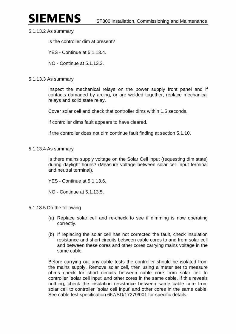
ST800 Installation, Commissioning and Maintenance
5.1.13.2 As summary
Is the controller dim at present? YES - Continue at 5.1.13.4. NO - Continue at 5.1.13.3.
5.1.13.3 As summary
Inspect the mechanical relays on the power supply front panel and if contacts damaged by arcing, or are welded together, replace mechanical relays and solid state relay. Cover solar cell and check that controller dims within 1.5 seconds. If controller dims fault appears to have cleared. If the controller does not dim continue fault finding at section 5.1.10.
5.1.13.4 As summary
Is there mains supply voltage on the Solar Cell input (requesting dim state) during daylight hours? (Measure voltage between solar cell input terminal and neutral terminal). YES - Continue at 5.1.13.6. NO - Continue at 5.1.13.5.
5.1.13.5 Do the following
(a) Replace solar cell and re-check to see if dimming is now operating correctly.
(b) If replacing the solar cell has not corrected the fault, check insulation
resistance and short circuits between cable cores to and from solar cell and between these cores and other cores carrying mains voltage in the same cable.
Before carrying out any cable tests the controller should be isolated from the mains supply. Remove solar cell, then using a meter set to measure ohms check for short circuits between cable core from solar cell to controller `solar cell input' and other cores in the same cable. If this reveals nothing, check the insulation resistance between same cable core from solar cell to controller `solar cell input' and other cores in the same cable. See cable test specification 667/SD/17279/001 for specific details.

ST800 Installation, Commissioning and Maintenance
(NB: Insulation testing usually involves high voltages and care should be taken when applying these high voltages to controller cables to ensure that there is no danger of high voltages being applied to circuits which may be damaged by them, e.g. solar cell itself).
5.1.13.6 Do the following
(a) Inspect the wiring and connections at the back of the Mains Distribution Assembly.
(b) Replace first Lamp Switch kit as stated in summary. (c) If the relays have been operating then there should be no need to do
the following. (d) Check the wiring to the Mains Distribution Assembly to ensure continuity
between it and the Main Processor PCB (which drives the relays). A meter set to measure resistance may be used to prove continuity if controller is isolated from mains supply. Check using circuit diagram 667/DA/20200/etc. If this seems OK then change the Mains Distribution Assembly. If all other tests prove fruitless, replace Main Processor PCB.
5.1.14 Signals Cycling Dim-Bright-Dim Etc. - Summary
5.1.14.1 Are there any fault indications in the controller?
NO YES | | | | | 5.2 |
5.1.14.2 Is there an intermittent mains supply voltage on the solar cell input (causing controller to alternate dim to bright)? Using a meter measure voltage between solar cell input terminal and neutral terminal.
NO YES | | | | | 5.1.14.6 |
5.1.14.3 Is there permanent mains supply voltage on the solar cell input?
NO YES | |

ST800 Installation, Commissioning and Maintenance
| | | 5.1.14.5 |
5.1.14.4 Do the following:
(a) Replace the first Lamp Switch kit and re-check to see if dimming now operates correctly.
(b) Replace the Main Processor PCB and re-check to see if dimming now
operates correctly. (c) Check wiring to the back of the Mains Distribution Assembly to ensure
that there is no intermittent connections.
5.1.14.5 There is a permanent mains supply voltage on the solar cell input, i.e. permanent dim request. Do the following:
(a) An intermittent dim override signal may be causing the problem. If the dim-bright-dim cycle is regular check UTC facility to see if dim
override is provided, if it is, check dim override bit. It UTC override not causing problem replace manual panel PCB and re-check to see if fault cleared.
If the dim-bright-dim cycle is irregular check manual panel dim override
switch and wiring from manual panel switch to manual panel PCB. (b) Note that if permanent dim request should not be present then once
dim-bright cycling has been cleared, continue at 5.1.13.6. (c) If fault still exists continue at 5.1.14.4.
5.1.14.6 Intermittent dim request from solar cell. Do the following:
(a) Replace solar cell and re-check to see if dimming now operates correctly.
(b) If solar cell ok or replacement makes no difference, check all external
wiring for the solar cell. If all other tests prove fruitless, replace Main Processor PCB.
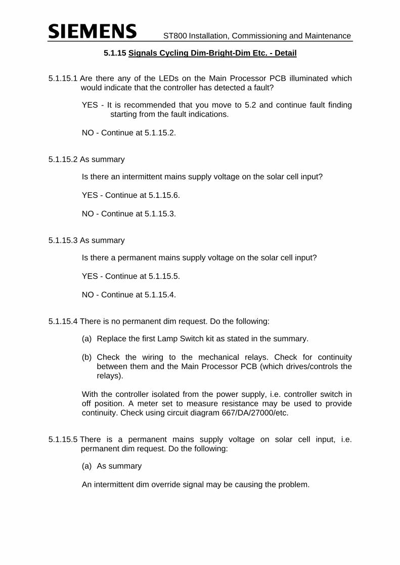
ST800 Installation, Commissioning and Maintenance
5.1.15 Signals Cycling Dim-Bright-Dim Etc. - Detail
5.1.15.1 Are there any of the LEDs on the Main Processor PCB illuminated which would indicate that the controller has detected a fault?
YES - It is recommended that you move to 5.2 and continue fault finding starting from the fault indications.
NO - Continue at 5.1.15.2.
5.1.15.2 As summary
Is there an intermittent mains supply voltage on the solar cell input? YES - Continue at 5.1.15.6. NO - Continue at 5.1.15.3.
5.1.15.3 As summary
Is there a permanent mains supply voltage on the solar cell input? YES - Continue at 5.1.15.5. NO - Continue at 5.1.15.4.
5.1.15.4 There is no permanent dim request. Do the following:
(a) Replace the first Lamp Switch kit as stated in the summary. (b) Check the wiring to the mechanical relays. Check for continuity
between them and the Main Processor PCB (which drives/controls the relays).
With the controller isolated from the power supply, i.e. controller switch in off position. A meter set to measure resistance may be used to provide continuity. Check using circuit diagram 667/DA/27000/etc.
5.1.15.5 There is a permanent mains supply voltage on solar cell input, i.e. permanent dim request. Do the following:
(a) As summary An intermittent dim override signal may be causing the problem.

ST800 Installation, Commissioning and Maintenance
If the dim-bright-dim cycle is regular then check to see if a UTC facility is provided and whether it has a dim override `bit'. If it has a dim override bit check its operation using the handset and `IOP' command for the appropriate input port. For fault finding on an input, see section 5.1.24. If there is no UTC or no dim override bit then replace the manual panel PCB and re-check to see if the fault has cleared. If the dim-bright-dim cycle is irregular check the manual panel dim override switch to Main Processor PCB wiring. (b) As summary Note that if the permanent dim request should not be present then once the dim-bright cycling has been cleared, continue at 5.1.13.6. (c) As summary If fault still exists continue at 5.1.15.4.
5.1.15.6 Intermittent dim request from solar cell. Do the following:
(a) As summary Replace solar cell and re-check to see if dimming now operates correctly. (b) If replacing the solar cell does not clear the fault then check the cabling
to and from the solar cell. The controller must be isolated from the mains supply first, and the cable cores to and from the solar cell disconnected at the controller end. Using the cable test specification 667/SD/17279/001. Firstly, check the continuity of the cable cores to and from solar cell follow procedure described as "Loop resistance of cable conductors post to controller". Then check for short circuits and/or poor insulation between cable cores to and from the solar cell and between cable cores associated with the solar cell and other cores in the same cable, use the procedure `Insulation testing of signal cabling'. An insulation test meter usually produces 500V or more. Ensure cable cores are disconnected from any devices/circuits, which may be damaged by the high voltages used, e.g. remove solar cell. If all other tests prove fruitless, replace Main Processor PCB.

ST800 Installation, Commissioning and Maintenance
5.1.16 Signals Not Changing At All, i.e. Stuck - Summary
5.1.16.1 Are there any fault indications in the controller?
NO YES | | | | | 5.2 |
5.1.16.2 Has the controller been left in manual mode? Check mode select switch on manual panel.
NO YES | | | | | 5.1.16.4 |
5.1.16.3 What mode is the controller in?
Manual continue at 5.1.16.6 VA continue at 5.1.16.7 CLF continue at 5.1.16.10 UTC continue at 5.1.16.11 FT continue at 5.1.16.12 Priority hurry call continue at 5.1.16.13
5.1.16.4 Switch mode select to `Normal'. Check again to see if controller is now operating normally.
5.1.16.5 This section details areas that should be investigated if checking the controller mode detailed in 5.1.16.3 does not reveal a fault.
(a) Prohibited moves (b) Incorrect configuration of termination Type 1 phases (c) Incorrect configuration of appearance Type 1 & 3 phases (d) Incorrect configuration of deleted phases (e) Manual panel (f) Expansion I/O PCB (g) Main Processor PCB
5.1.16.6 To arrive at this point the mode selection switch is not selecting manual, but the controller is operating in manual mode.
Do the following: (a) Check manual panel mode select inputs by confirming that the correct
led lights when a mode button is pressed to determine if switch is faulty or the fault is in the wiring between the manual panel and the Main

ST800 Installation, Commissioning and Maintenance
Processor PCB. Replace panel if necessary and re-check to see if controller is now cycling correctly.
(b) Replace manual panel and re-connect ribbon cable to Main Processor
PCB. Re-check to see if controller is now cycling correctly.
5.1.16.7 VA Mode:
Using the handset, check to see if demands are being entered for any of the phases NO YES | | | | | 5.1.16.9 |
5.1.16.8 No demands for any phases
Do the following: (a) Check to see if +24V supply is reaching Main Processor and
Expansion I/O PCBs. NB: +24V is derived from the termination blocks. Also, check to see if fuses are intact on Expansion PCBs: If they are not, check PCB and external wiring for fault which caused fuse to rupture.
(b) Replace Expansion I/O PCB and re-check to see if controller is now
cycling. (c) If, after having checked (a) and (b) above the controller is still not
cycling continue at 5.1.16.5.
5.1.16.9 Phases are being demanded but controller not cycling.
Do the following: (a) Check to ensure that those phases being demanded opposed the
phase currently at green. (b) Continue at 5.1.16.5 if (a) above has not revealed a fault.
5.1.16.10 CLF Mode:
Do the following: (a) Using handset check group times for all plans to see if there are any
excessive group times which may be making it appear that the signals are sticking. If any times are deemed to be excessive or different to works specification, the customer should then be consulted to check if the times are as required.
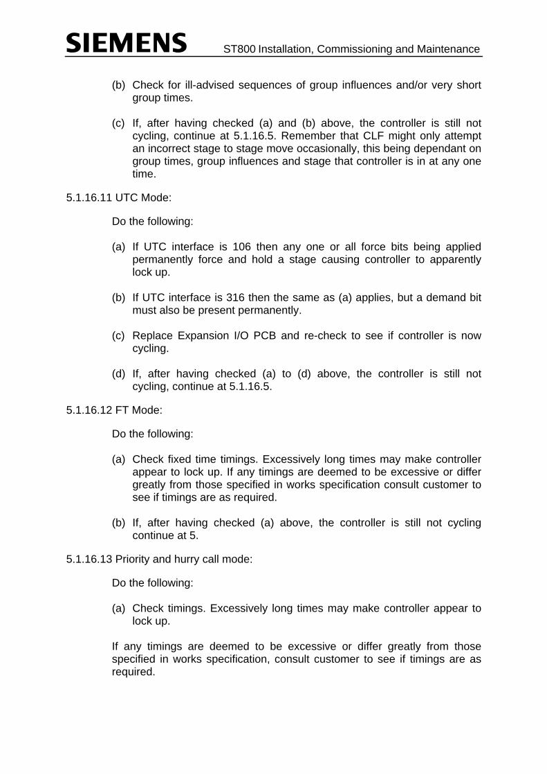
ST800 Installation, Commissioning and Maintenance
(b) Check for ill-advised sequences of group influences and/or very short
group times. (c) If, after having checked (a) and (b) above, the controller is still not
cycling, continue at 5.1.16.5. Remember that CLF might only attempt an incorrect stage to stage move occasionally, this being dependant on group times, group influences and stage that controller is in at any one time.
5.1.16.11 UTC Mode:
Do the following: (a) If UTC interface is 106 then any one or all force bits being applied
permanently force and hold a stage causing controller to apparently lock up.
(b) If UTC interface is 316 then the same as (a) applies, but a demand bit
must also be present permanently. (c) Replace Expansion I/O PCB and re-check to see if controller is now
cycling. (d) If, after having checked (a) to (d) above, the controller is still not
cycling, continue at 5.1.16.5.
5.1.16.12 FT Mode:
Do the following: (a) Check fixed time timings. Excessively long times may make controller
appear to lock up. If any timings are deemed to be excessive or differ greatly from those specified in works specification consult customer to see if timings are as required.
(b) If, after having checked (a) above, the controller is still not cycling
continue at 5.
5.1.16.13 Priority and hurry call mode:
Do the following: (a) Check timings. Excessively long times may make controller appear to
lock up. If any timings are deemed to be excessive or differ greatly from those specified in works specification, consult customer to see if timings are as required.
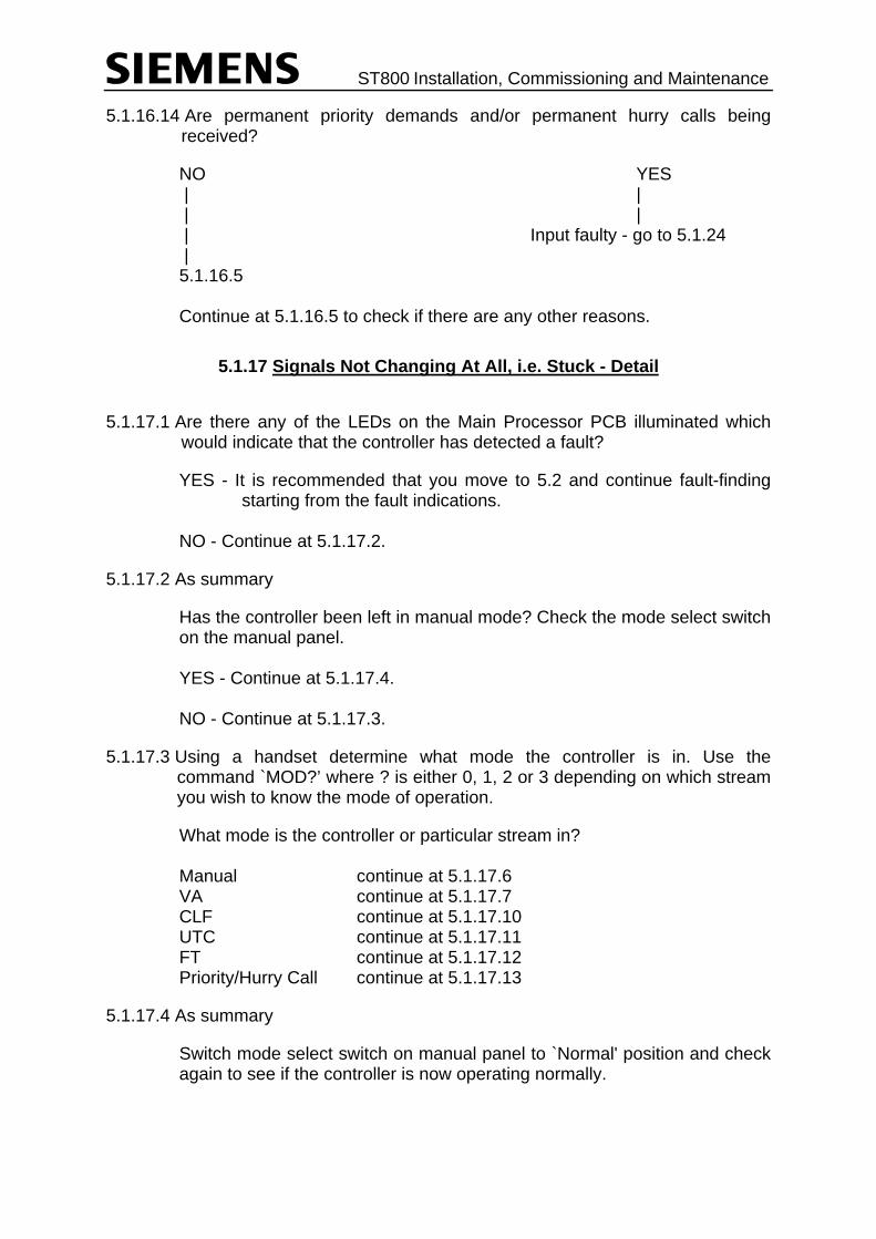
ST800 Installation, Commissioning and Maintenance
5.1.16.14 Are permanent priority demands and/or permanent hurry calls being received?
NO YES | | | | | Input faulty - go to 5.1.24 | 5.1.16.5 Continue at 5.1.16.5 to check if there are any other reasons.
5.1.17 Signals Not Changing At All, i.e. Stuck - Detail
5.1.17.1 Are there any of the LEDs on the Main Processor PCB illuminated which would indicate that the controller has detected a fault?
YES - It is recommended that you move to 5.2 and continue fault-finding starting from the fault indications.
NO - Continue at 5.1.17.2.
5.1.17.2 As summary
Has the controller been left in manual mode? Check the mode select switch on the manual panel. YES - Continue at 5.1.17.4. NO - Continue at 5.1.17.3.
5.1.17.3 Using a handset determine what mode the controller is in. Use the command `MOD?’ where ? is either 0, 1, 2 or 3 depending on which stream you wish to know the mode of operation.
What mode is the controller or particular stream in? Manual continue at 5.1.17.6 VA continue at 5.1.17.7 CLF continue at 5.1.17.10 UTC continue at 5.1.17.11 FT continue at 5.1.17.12 Priority/Hurry Call continue at 5.1.17.13
5.1.17.4 As summary
Switch mode select switch on manual panel to `Normal' position and check again to see if the controller is now operating normally.
ST800 Installation, Commissioning and Maintenance
5.1.17.5 The following are general reasons that may cause a controller to lock-up.
(a) If a prohibited stage to stage move is being attempted the controller locks up unless an alternative move is given or the move is made an `IGNORE' move (for details on move constraints see the ST800 Controller General Handbook).
Check that any move being attempted is not just/only prohibited. Check Prohibited, Alternative and Ignore moves configured. A controller may get out of a potential lock-up if between the stage that it is leaving and the one to which it wishes to go but cannot, there are other stages to which it can move when demands arise. However, it is recommended that wherever possible, either an `ignore' move or an `alternative' move be used. (b) Phases with appearance TYPE 1: If a phase which terminates when an associated phase gains right-of-way has an intergreen configured between itself and the associated phase, then when the controller comes to make a move where the phase should be terminated by the associated phase the controller locks up. Check for this situation. (c) Phases with appearance TYPES 1 & 3: If a phase has either an appearance type 1 or 3 then a demand can exist for the phase during the stage in which the phase appears without the phase appearing. Then because the controller cannot skip a demanded phase the controller cannot leave this current stage and the controller appears to lock up. If handset command PMV = 1 controller may lock up it should be set to 0, i.e. PMV = 0. Check for this situation. (d) Deleting phases: (Phases and stages may be deleted by master time clock or special conditioning). The controller does not allow a stage with a demanded phase to be skipped. Therefore, if a phase is deleted and a demand is subsequently received for it the demand cannot be honoured by the phase and the stage in which the phase would normally appear cannot be skipped. This may cause the controller to lock if it gets to a situation where it would want to skip the stage. Demands are normally cleared out and further demands prevented using special conditioning, if a phase is deleted. Check for this situation. (N.B. The above also applies to deleted stages if the stage being deleted has a phase in it, which appears in no other stage, or stage demands are being used.)

ST800 Installation, Commissioning and Maintenance
(e) Replace the manual panel and re-check to see if fault has cleared. (f) Replace the Expansion I/O PCB and re-check to see if fault has
cleared. (g) Replace the Main Processor PCB and re-check to see if fault cleared.
5.1.17.6 As summary
To arrive at this point the mode selection switch is not selecting manual but the controller is operating in manual mode. Do the following: (a) Check the operation of the mode select switch by confirming that the
correct LED lights when the mode button is pressed and the wiring between the Main Processor PCB and the manual panel.
(b) As summary Replace manual panel. Re-check to see if controller is now cycling correctly and in correct mode.
5.1.17.7 As summary
VA Mode: Using the handset check to see if demands are being entered for any of the phases. Use the `SPH' command, i.e. SPHA gives you the status of phase A. Are demands entered for any phases? YES - Continue at 5.1.17.9. NO - Continue at 5.1.17.8.
5.1.17.8 As summary
No demands for any phases Do the following: (a) Check inputs to see if they are operating correctly. Although the
summary details two areas to check it is recommended that procedure 5.1.24 be used to diagnose faults with inputs.
(b) As (a) above

ST800 Installation, Commissioning and Maintenance
(c) If after checking the inputs and ensuring that they operate correctly the controller still locks up in VA mode, continue at 5.1.17.5.
5.1.17.9 Phases are being demanded but controller is still not cycling.
Do the following: (a) Check to ensure that those phases being demanded oppose the
phases that are currently at green. (NB Check especially carefully where one detector extends one phase
and demands another). If phases do not oppose each other, demands for one do not start the maximum timer of the phase with extensions; thus the max timer does not time out and the controller apparently locks-up.
(b) Now continue at 5.1.17.5 if (a) above has not revealed a fault.
5.1.17.10 CLF Mode:
Do the following: (a) As Summary Using a handset check group times for all plans to see if there are any
excessive group times which may make it appear that the signals are sticking or any group times which differ from the works specification. Any timings which differ from the works specification should be noted in the controllers `visits log book' if a visiting engineer changed them.
Any timings over which there is doubt should be checked with the
customer to ensure they are as required. (b) Check for ill advised sequences of group influences and/or very short
group times, either of which can cause the controller to lag behind the group changes and in certain situations make it appear that the controller has locked up. For example,
If a CLF plan were simply to move stage 1 to 2 to 3 and the minimum
times for each stage were 30 seconds, 15 seconds and 15 seconds respectively, then if the group times were
immediate move to Stage 1 30 seconds immediate move to Stage 2 10 seconds immediate move to Stage 3 10 seconds it is feasible that the immediate moves to 2 and 3 could be used up
during the minimum green of Stage 1, thus for one cycle it would appear to stick in Stage 1.

ST800 Installation, Commissioning and Maintenance
(NB: It is recommended that group times be a minimum of the longest minimum green in the stage to which the move is intended and the longest intergreen to that same stage).
Similarly, if the move 1 to 2 was prohibited and the alternative was 1 to
3 and the CLF plan was constructed to move 1 to 2 to 3, by the time the controller had moved 1 to 3 the move to 2 would have changed into a move to 3 and thus stage 2 would always be missed.
It is very rare that the above situations arise, once controller has been
acceptance tested and installed. (c) As summary If, after having checked (a) and (b) above, the controller is still not
cycling, continue at 5.1.17.5, remembering that CLF might only attempt an incorrect stage to stage move occasionally, this being dependant on group times, group influences and stage that controller is in at any one time.
5.1.17.11 UTC Mode
Do the following: (a) As summary If UTC interface is 106 then any one or all force bits being applied
permanently force and hold a stage causing controller to apparently lock up.
Check input port to which the UTC force bits are connected using the
handset and `IOP' command for the appropriate port. If an input bit appears to be faulty, fault-find using procedure 5.1.24.
(b) As summary If UTC interface is 316 then the same as (a) above applies with the
addition that a demand bit must also be present permanently. Check input ports to which the UTC force bits and demand bits are
connected using the handset and `IOP' command for the appropriate port. If an input bit appears to be faulty, fault-find using procedure 5.1.24
(c) As summary If after having checked (a) and (b) above, the controller is still not
cycling, continue at 5.1.17.5.
5.1.17.12 FT Mode
Do the following: (a) As summary
ST800 Installation, Commissioning and Maintenance
Check fixed time timings, excessively long timings may make the
controller appear to lock up. Any timings which differ from the works specification should be noted in
the controllers `visit log book' if a visiting engineer changed them. Any timings over which there is doubt should be checked with the
customer to ensure they are as required. (b) As summary If after having checked (a) above the controller is still not cycling, continue at 5.1.17.5.
5.1.17.13 Priority/Emergency Vehicle and Hurry Call mode
Do the following: (a) Check timings associated with the particular mode, excessively long
times may make the controller appear to lock up. Any timings which differ from the works specification should be noted in
the controller `visit log book' if a visiting engineer has changed them. Any timings over which there is doubt should be checked with the
customer to ensure they are as required. Continue at 5.1.17.4.
5.1.17.14 As summary
Are permanent priority demands and/or permanent hurry calls being received? YES: Continue at 5.1.24. Check to see if the input is faulty NO: Continue at 5.1.17.5. Check to see if there are any other reasons for the controller to lock.
5.1.18 Signals Not Changing to Green on an Approach - Summary
5.1.18.1 Are there any fault indications in the controller?
NO YES | | | | | 5.2 |
ST800 Installation, Commissioning and Maintenance
5.1.18.2 Does the appropriate Lamp Switch PCB indicate that phase is going to green?
NO YES | | | | | Lamp Switch or cable fault. |
5.1.18.3 Is the phase a fixed phase in a stage?
NO YES | | | | | 5.1.18.12 |
5.1.18.4 Are demands being inserted for the phase?
NO YES | | | | | 5.1.18.6 |
5.1.18.5 Check appropriate input to see why demands are not being inserted.
5.1.18.6 Is phase deleted or prevented for any reason?
NO YES | | | | | 5.1.18.9 |
5.1.18.7 Is phase or stage in which it appears being skipped due to priority demands or hurry calls?
NO YES | | | | | 5.1.18.8 | 5.1.1
5.1.18.8 Check appropriate input to see if priority demands and/or hurry calls are valid.
NO YES | | | |

ST800 Installation, Commissioning and Maintenance
| No fault | 5.1.24 Check for fault in input system
5.1.18.9 Check reason/conditions for deletion/prevention of phase, are they valid?
NO YES | | | | | 5.1.18.11 |
5.1.18.10 Correct any invalid parameters, e.g. real time clock, input, etc. Check that phase now appears.
5.1.18.11 If possible alter the conditions deleting/preventing the phase and check that it can appear.
5.1.18.12 Is the stage in which the phase appears running?
NO YES | | | | | 5.1.18.4 | Check for reasons as to why stage is not running, i.e. following:
(a) Prohibited and alternative moves (b) Skipped due to priority demands and/or hurry calls (c) Stage deleted or prevented.
5.1.18.13 Do the following:
(a) Replace associated Lamp Switch kit. Re-check to see if phase now cycling correctly.
5.1.18.14 Do the following:
(a) Replace Lamp Switch kit. Re-check to see if phase now cycling. (b) Check for cable fault
ST800 Installation, Commissioning and Maintenance
5.1.19 Signals Not Changing to Green on an Approach - Detail
5.1.19.1 Are there any of the LEDs on the Main Processor PCB illuminated which would indicate that the controller has detected a fault?
YES - It is recommended that you move to 5.2 and continue fault finding starting from the fault indications. NO - Continue at 5.1.19.2.
5.1.19.2 As summary
Does the appropriate Lamp Switch PCB indicate that phase is going to green? YES - Continue at 5.1.19.5. Check for Lamp Switch or cable fault NO - Continue at 5.1.19.3.
5.1.19.3 Check in works specification. Is the phase a fixed phase in a stage?
YES - Continue at 5.1.19.12. NO - Continue at 5.1.19.4.
5.1.19.4 Using a handset and the `SPH' command, check to see if demands are being inserted for the phase.
Are demands being inserted for the phase? YES - Continue at 5.1.19.6. NO - Continue at 5.1.19.5.
5.1.19.5 Check the appropriate input to see why demands are not being inserted.
Firstly, find the signal name that provides the demand for the phase. This is shown in the works specification, e.g. `AXYZ' demands phase A. Then find out which port and input bit the signal (e.g. AXYZ) has been allocated to. Then to fault-find on the input use procedure 5.1.24.
5.1.19.6 To determine whether or not the phase or stage in which it appears is being deleted or prevented the handset can be used along with the Engineering code ENG 15 (for the mnemonic `FZREST'). Refer to the ST800 Controller Handset Handbook for more details.
Is phase or stage in which it appears deleted or prevented? YES - Continue at 5.1.19.9. NO - Continue at 5.1.19.7.

ST800 Installation, Commissioning and Maintenance
5.1.19.7 To determine if the stage in which the phase appears is being skipped due to Priority demands, Emergency demands or Hurry calls, firstly determine if stage is skipped. This can be done using the handset command `CST' which displays the current stage, where parallel stage streams are available the commands CST0 (for stream 0), CST1 (first stream 1), CST2 (for stream 2) and CST3 (for stream 3) etc.
Watch the controller cycle through the stages. It should be evident if the stage is being skipped. When it can be seen that a stage is skipped use the handset to check what mode the controller/stage stream is in. The command `MOD' is used. See the ST800 Controller Handset Handbook for further details on handset commands. Is phase or stage in which it appears being skipped due to priority demands, Emergency vehicle demands or Hurry calls? YES - Continue at 5.1.19.8 NO - Continue at 5.1.1
5.1.19.8 Check the input that is generating the priority demand, Emergency vehicle demand or Hurry call.
Firstly, find the signal name that provides the priority demand, Emergency vehicle demand or Hurry call (shown in the works specification). Again referring to the works specification, find which port and input bit the signal has been allocated to. Then, to check the input, use procedure 5.1.24.
5.1.19.9 Check the reasons/conditions for deletion/prevention of phase or stage in which it appears.
Do the following: (a) A phase/stage can be deleted by timeswitch parameters, therefore,
check the works specification to see if controller has been configured with such a facility.
If the controller has such a facility check real time clock to see if phase/stage should be currently deleted, `TOD' command. If real time clock is incorrect, reset the real time clock. If real time clock is correct then check timetable using `TSW' command. (See the ST800 Controller Handset Handbook for further details on handset commands).
ST800 Installation, Commissioning and Maintenance
(NB occasionally, a phase may also be deleted from special conditioning. Therefore, if timeswitch does not appear to be deleting phase/stage check special conditioning). (b) A phase/stage can be prevented from conditioning, therefore, check
the special conditioning and the reasons/conditions for prevention. Are the reasons/conditions for the phase/stage deletion/prevention valid (i.e. is real time clock correct, are conditions for special conditioning correct)? YES - Continue at 5.1.19.11. NO - Continue at 5.1.19.10.
5.1.19.10 As summary
Correct any invalid parameters, e.g. real time clock, inputs to special conditioning, etc. Check that phase now appears.
5.1.19.11 As summary
If possible, alter the conditions deleting/preventing the phase/stage such that phase/stage should no longer be deleted/prevented and check that phase now appears.
5.1.19.12 As summary
To determine if the stage in which the phase appears is running use a handset and command `CST'; the handset displays the current stage number. (NB: Where parallel stage streams are available there is a `CST' command for each stream CST0, CST1, CST2, etc.). Watch the handset display for a couple of cycles of the controller it is evident if the stage is running or not. Is the stage in which the phase appears running? YES - Continue at 5.1.19.14. NO - Continue at 5.1.19.13.
5.1.19.13 Check for reasons as to why the stage is not running.
Check following: (a) Prohibited and alternative moves. Check to see what prohibited, Ignore and alternative moves there are when going to the particular stage concerned.
ST800 Installation, Commissioning and Maintenance
Check to see what the last stage is which precedes (in cyclic order) the non-running stage. Is the controller making a valid move when it skips the stage? If it is not then determine what needs to be changed to obtain correct operation. If it is then consult customer and question as to whether or not the prohibited, ignore, alternative moves are correct. (b) Check to see if stage is skipped due to priority demands, see section
5.1.19.7. (c) Check to see if stage is not running due to deletion or prevention, see
section 5.1.19.9.
5.1.19.14 Stage in which phase appears is running but phase not going to green.
(a) As summary (b) As summary Replace associated Lamp Switch kit and re-check to see if phase now cycling correctly.
5.1.19.15 Lamp Switch PCB indicates that phase is cycling.
Do the following:
(a) As summary Replace associated Lamp Switch kit and re-check to see if phase now
cycling correctly. (b) Perform `Insulation' test and `Loop resistance of cable conductors post
to controller' tests as specified in 667/SD/17279/001. First isolate the controller from the mains supply (i.e. switch `off' controller switch) and disconnect the cables to be tested from the controller as necessary.
5.1.20 Signals Changing Too Slowly - Summary
5.1.20.1 Are there any fault indications in the controller?
NO YES | | | | | 5.2 |

ST800 Installation, Commissioning and Maintenance
5.1.20.2 What mode is the controller running?
VA Continue at 5.1.20.3 CLF Continue at 5.1.20.4 FT Continue at 5.1.20.5 Priority/Hurry Call Continue at 5.1.20.6 If after having completed checks for the mode of operation no fault can be found, check through the general reasons for slow signal response at 5.1.20.7.
5.1.20.3 VA Mode:
The controller is in the VA mode and cycling too slowly. Do the following: (a) Check to see if any phases have permanent extension. If any phases have permanent extensions, check appropriate input,
see 5.1.24. (b) Check to see if any phases are not receiving demands from the
appropriate call detectors. If a particular call detector is not inserting demands, check appropriate input, see 5.1.24.
(c) Check extension times. If any times seem excessive or are different to
the works specification, check in controller visit log book to see if timing has been changed and/or check with customer to see if timing is as required.
5.1.20.4 CLF Mode:
The controller is in CLF mode and cycling too slowly. Do the following: (a) Check to ensure that, for all stages to which there are demand
dependant moves, all phases in those stages are receiving demands from the appropriate detectors.
If any demand dependant stages have phases that are not receiving
demands, check appropriate input. See 5.1.24. (b) Check group times. If any seem excessive or are different to the works
specification, check in controller visit log book to see if timing has changed and/or check with customer to see if timing is as required.
5.1.20.5 FT Mode:
The controller is operating in FT mode and cycling too slowly.
ST800 Installation, Commissioning and Maintenance
(a) Check fixed times. If any seem excessive or are different to the works specification, check in controller visit log book to see if timing has changed and/or check with customer to see if timing is as required.
5.1.20.6 Priority/Hurry Call Mode:
The controller is in Priority or Hurry Call mode and cycling too slowly. (a) Are priority demands being received? If not check appropriate input,
see 5.1.24. (b) Is a priority inhibit timer running which is inhibiting priority unit? (c) Are hurry calls being received? If not check appropriate input, see
5.1.24. (d) Is the hurry calls prevent timer running thus preventing the hurry call?
5.1.20.7 General Reasons for Slow Signal Changing:
(a) Check minimum green times and intergreen times. If any seen excessive or are different to the works specification, check in controller visit log book to see if timing has changed and/or confirm with customer that timing is as required.
(b) Extend all red: Check as to whether or not an extend all red facility is
provided on the controller. If it is then check to see if controller is always running to maximum all red and/or receiving permanent extensions which make it run to its maximum.
(c) Phase delays: Check to see if there are any phase delays during the
stage to stage move(s) which may explain delay in changing. Check timings for delays.
(d) SDE/SA facility: Check as to whether or not an SDE or SA facility is
provided on the controller. If it is, check to see if extra clearance period is always being inserted.
(e) Lamp monitor unit: Check as to whether the controller is equipped to
receive inputs from a lamp monitor. (Normally part time signals or controllers that have pedestrian movements with audible or tactile indicators). If these inputs are active (open circuit) the cabinet alarm lamp flashes and the controller introduces extra all red during certain stage to stage moves, i.e. extend the intergreens.
(f) If possible try and determine what mode the controller was expected to
be in when fault was reported. It is possible that the slow response may be due to the controller being in a higher mode than that expected, e.g. if UTC was higher than VA a motorist may be reporting a slow response to their approaching the signals due to UTC sequence.

ST800 Installation, Commissioning and Maintenance
5.1.21 Signals Changing Too Slowly - Detail
5.1.21.1 Are there any of the LEDs on the Main Processor PCB illuminated which would indicate that the controller has detected a fault?
YES - It is recommended that you move to 5.2 and continue fault-finding starting from the fault indications. NO - continue at 5.1.21.2.
5.1.21.2 As Summary
What mode is the controller operating in? VA continue at 5.1.21.3 CLF continue at 5.1.21.4 FT continue at 5.1.21.5 Priority/Emergency Vehicle/Hurry Call continue at 5.1.21.6 If after having completed checks for the mode of operation, no fault can be found, check through the general reasons for slow signal response. Continue at 5.1.21.7.
5.1.21.3 VA Mode:
The controller is in the VA mode and cycling too slowly. Do the following: (a) Check to see if any phases have permanent extension. To check to see if any phases have permanent extensions use the handset and the `SPH' command. Example SPHA gives the status for phase A and bit 1 = 1 indicates extension timing for the phase. Note `SPH' only shows the extension timing whilst the phase is at green. If this is insufficient then determine from the works specification which signals provide extensions (e.g. AXYZ extends phase A) and to what input port and bit the signals have been allocated. The `IOP' command can then be used to view the status of the input ports to see if any of the inputs are permanently active. Continue at 5.1.24 to fault find an input. If any phases have permanent extensions check appropriate input, see 5.1.24.
ST800 Installation, Commissioning and Maintenance
(b) Check to see if any phases are not receiving demands from the appropriate call detectors. To check to see if any phases are not being demanded, use the same procedure as in (a) above. Bit 0 of the `SPH' command indicates if the phase is being demanded.
If demands are not being inserted by a particular call detector check
appropriate input, see 5.1.24. (c) As summary Check extension times. If any times seen excessive or are different to
the works specification, check in controller visit log book to see if timing has been changed and/or check with customer to see if timing is as required.
5.1.21.4 CLF Mode:
The controller is in CLF mode and cycling too slowly. Do the following: (a) Check to ensure that, for all stages to which there are demand
dependant moves, all phases in those stages are receiving demands from the appropriate detectors.
To check to see if phases are being demanded use the handset and the `SPH' command. EXAMPLE SPH A gives the status for phase A and bit 0=1 indicates a demand (when phase not at green). However, if it is preferred the input port which has the detector inputs which create the demands can be examined using the IOP command to check that the inputs are being operated when a vehicle crosses the demand loops. If any demand dependant stages have phases that are not receiving demands, check appropriate input, see 5.1.24. (b) As Summary Check group times. If any seem excessive or are different to the works specification, check in controller visit log book to see if timing has changed and/or check with customer to see if timing is as required.
5.1.21.5 FT Mode
The controller is operating in FT Mode and cycling too slowly. (a) As Summary

ST800 Installation, Commissioning and Maintenance
Check fixed times. If any seem excessive or are different to the works specification, check in controller visit log book to see if timing has changed and/or check with customer to see if timing is as required.
5.1.21.6 Priority/Hurry Call Mode:
The controller is in Priority or Hurry call mode and cycling too slowly. (a) Are priority demands being received? If not check appropriate input,
see 5.1.24. Checking to see if priority demands are being received is a difficult task as generally, a special unit is required to insert priority demands. If one such unit (usually attached to the underside of a vehicle) is available insertion of demands can be checked, by passing the unit over the loop of a priority detector unit and checking with the handset and command `PDS' that the demand/extension is being entered. (Note: The commands `PVU & PVP' may also be used, but these only give the status information for a single priority input/phase respectively and, therefore, the operation of all priority units cannot be seen all at once). (b) Is a priority inhibit timer running which is inhibiting priority unit. To check to see if any priority units are being inhibited by priority inhibit timers use a handset and the command `PIU'. This indicates what units are being inhibited. (c) Are hurry calls being received, if not check appropriate input. See
5.1.24. Firstly, determine if the hurry call input is operating correctly. Using the works specification, find out what input bit on what port the hurry call input is. Check to see if, when activated the input responds correctly. Use the appropriate `IOP' command to view the operation of the input. (NOTE: If the sender unit (e.g. push button) is too far away to make the testing of the input feasible, then the input should be forced to its active state, i.e. if input is active open circuit, disconnect input wire, if input is active, short circuit connect input to controller 0V). If after this the input appears faulty, go to section 5.1.24. (d) Is the hurry calls prevent timer running, thus preventing the hurry call? If the input is operating correctly, check the status of the hurry call, use a handset and the command `SHC' for the appropriate hurry call, i.e. 0 or 1. Below are the possible status displays and their meaning.

ST800 Installation, Commissioning and Maintenance
0 = Either input not going active or if input is going active, then hurry must be prevented by hurry call prevent timer. 3 = Timing hurry call delay period 1 = Requesting hurry call stage but not yet in hurry call stage. (Note: If hurry call status remains = 1 for a long time, the controller may be in a higher priority mode which the hurry call mode cannot override. Alternatively, a higher priority Hurry Call (Hurry Call 0) may be operational if Hurry Call status being viewed is for Hurry call 1 as Hurry Call 1 cannot override Hurry Call 0). 2 = Timing hurry call hold period Therefore, if input operates correctly but hurry call status remains at 0 then hurry call prevent timer active. (e) Check hurry call delay timers. If either delay times seem excessive or
are different to the works specification, check in controller `visit log book' to see if timing has been changed by an engineer and/or check with customer that timing is as required.
5.1.21.7 General reasons for slow signal changing:
(a) Check minimum green times and intergreen times. If any seem excessive or are different to the works specification, check in controller `visit log book' to see if timing has changed and/or confirm with customer that timing is as required.
(b) As Summary Extend all Red: Check as to whether or not an extend all red facility is
provided on the controller. If it is, then check to see if controller s always running to maximum all red and/or receiving permanent extensions that make it run to its maximum.
To check to see if there is a permanent hold intergreen request, use a handset and the engineering code for the mnemonic `HLDREQ'. This displays 255 or FF if a hold intergreen request is present. Refer to the ST800 Controller Handset Handbook for more details. Similar to above, the engineering code for the mnemonic `HLDON' can be used to determine if there are any hold intergreens currently being applied. (c) Phase delays: Check to see if there are any phase delays during the
stage to stage move(s) which may explain delay in changing. Check timings for delays.

ST800 Installation, Commissioning and Maintenance
A check to see if there are phase delays occurring can be performed using a handset and the `SPH' command. Example SPH A gives the status for phase A and bit 5=1 indicates that a lagging or leading phase delay is being timed. (d) SDE/SA facility: Check as to whether or not an SDE or SA facility is
provided on the controller. If it is check to see if extra clearance period is always being inserted.
To check to see if an extra clearance period is being inserted, use a handset and the command `SCI'. There is also an `SCR' command that indicates if requests are present for the extra clearance period, and provides as display as above. (e) As Summary If possible try and determine what mode the controller was expected to be in when fault was reported. It is possible that the slow response may be due to the controller being in a higher mode than that expected, e.g. if UTC was higher than VA a motorist may be reporting a slow response to their approaching the signal due to UTC sequence. It is also possible that the reason for introducing the mode is not occurring, i.e. it is not reaching the expected mode because: UTC bits are not being actioned Hurry Calls are not being actioned Emergency vehicle demands are not being actioned Real Time Clock is not introducing CLF etc. If the intended mode is known, any reasons for not attaining the mode should be investigated.
5.1.22 Signals Changing Too Quickly - Summary
5.1.22.1 Are there any fault indications in the controller?
NO YES | | | | | 5.2 |
5.1.22.2 What mode is the controller running?
VA continue at 5.1.22.3 CLF continue at 5.1.22.4 FT continue at 5.1.22.5

ST800 Installation, Commissioning and Maintenance
Priority/Hurry Call continue at 5.1.22.6 If after having completed checks for the mode of operation no fault can be found, check through the general reason for quick signal changing continue at 5.1.22.7.
5.1.22.3 VA Mode:
The controller is operating in the VA mode and cycling too quickly. Do the following: (a) Check to see if any phases are not receiving extensions when their
associated extension loops are occupied. If any are not receiving extensions, check appropriate input. See
5.1.24. (b) Check extension times. If any times seem too short or are different
from works specification, check in controller `visit log book' to see if timing has been changed and/or check with customer to see if timing is as required.
5.1.22.4 CLF Mode:
The controller is operating in the CLF mode and cycling too quickly. Do the following: (a) Check Group times. If any seem too short or are different to the works
specification, check in the controller `visit log book' to see if timing has been changed and/or check with customer to see if timing is as required.
5.1.22.5 FT Mode:
The controller is operating in the FT mode and cycling too quickly. (a) Check fixed times. If any seem too short or are different to the works
specification, check in the controller `visit log book' to see if timing has been changed and/or check with customer to see if timing is as required.
5.1.22.6 Priority/Hurry Call mode:
The controller is in Priority or Hurry Call mode and cycling too quickly. (a) Are priority extensions being received? If not check appropriate input,
see 5.1.24. (b) Check priority extension times. If any seem too short or are different to
the works specification, check in the controller `visit log book' to see if

ST800 Installation, Commissioning and Maintenance
timing has been changed and/or check with customer too if timing is as required.
(c) Check Hurry Call hold time, to ensure that it is running and is of correct
duration. If either hurry call hold period seems too short or is different to the works specification, check in the controller `visit log book' to see if timing has been changed and/or check with customer to see if timing is as required.
5.1.22.7 General reasons as to why signals might change too quickly:
(a) Check minimum green times and intergreen times. If any seem too short or are different to the works specification, check in the controller `visit log book' to see if timing has been changed and/or check with customer that timing is as required.
(b) Extend all red: Check as to whether or not an extend all red facility is
provided on the controller. If it is, check to see if extension requests are being received (e.g. when extension loops are occupied). If not check all red extension time and maximum time, also check appropriate input. See 5.1.24.
(c) SDE/SA facility: Check as to whether or not an SDE or SA facility is
provided. If it is check as to whether or not SDE/SA hardware is inserting speed extensions and extra clearance periods when necessary. If not, check the SDE/SA system. (See detail for this sub-section).
(d) If possible, try and determine what mode the controller was expected to
be in when the fault was reported. It is possible that the quick response may be due to the controller being in a higher priority mode than that expected, e.g. If CLF is a higher priority than VA, a motorist may be reporting a fast response due to CLF force signals away from green and disregarding vehicle extensions.
5.1.23 Signals Changing Too Quickly - Detail
5.1.23.1 Are there any of the LEDs on the Main Processor PCB illuminated which would indicate that the controller has detected a fault?
YES - It is recommended that you move to 5.2 and continue fault-finding starting from the fault indications. NO - Continue at 5.1.23.2.
5.1.23.2 What mode is the controller operating in?
VA continue at 5.1.23.3 CLF continue at 5.1.23.4 FT continue at 5.1.23.5

ST800 Installation, Commissioning and Maintenance
Priority, Emergency Vehicle or Hurry Call Mode continue at 5.1.23.6 If, after having completed checks for the mode of operation, no fault can be found, check through the general reasons for quick signal changing. Continue at 5.1.23.7.
5.1.23.3 VA Mode:
The controller is operating in the VA mode and cycling too quickly. Do the following: (a) As summary Check to see if any phases are not receiving extensions when their
associated extension loops are occupied. To check to see if any phases have extensions use the handset and the `SPH' command. Example SPHA gives the status for Phase A and bit 1 = 1 indicates and extension timing for the phase. Note `SPH' only shows the extension timing whilst the phase is at green. If this is insufficient, then determine from the works specification which signals provide extensions (e.g. AXYZ extends phase A) and to what input port and bit the signals have been allocated. The `IOP' command can then be used to view the status of the input ports to see if any of the inputs are not responding to vehicles crossing the loops. Continue at 5.1.24 to fault-find an input. If any are not receiving extensions check appropriate input, see 5.1.24. (b) Check extension times. If any times seem too short or are different
from works specification, check in controller `visit log book' to see if timing has been changed and/or check with customer to see if timing is as required.
5.1.23.4 CLF Mode:
The controller is operating in the CLF mode and cycling too quickly. Do the following: (a) As summary Check Group times. If any seem too short or are different to the works
specification, check in the controller `visit log book' to see if timing has been changed and/or check with customer to see if timing is as required.

ST800 Installation, Commissioning and Maintenance
5.1.23.5 FT Mode:
The controller is operating in the FT mode and cycling too quickly. (a) As summary Check Fixed times. If any seem too short or are different to the works
specification, check in the controller `visit log book' to see if timing has been changed and/or check with customer to see if timing is as required.
5.1.23.6 Priority/Hurry Call Mode:
The controller is in Priority or Hurry Call mode and cycling too quickly. (a) Are priority extensions being received, if not check appropriate input,
see 5.1.24. To check to see if priority extensions are being received is a difficult
task as generally a special unit is required to insert priority demands or extensions. If one such unit (usually attached to the underside of a vehicle) is available insertion of extensions can be checked, by passing the unit over the loop of a priority detector unit and checking with the handset and command `PDS' that the demand/extension is being entered.
(Note: The commands `PVU & PVP' may also be used, but these only
give the status information for a single priority input/phase respectively and, therefore, the operation of all priority units cannot be seen all at once).
(b) As summary Check Priority Extension times. If any seem too short or are different to
the works specification, check in the controller `visit log book' to see if timing has been changed and/or check with customer to see if timing is as required.
(c) As summary Check Hurry Call hold time, to ensure that it is running and is of correct
duration. If either hurry call hold period seems too short or is different to the works specification, check in the controller `visit log book' to see if timing has been changed and/or check with customer to see if timing is as required.
5.1.23.7 General reasons as to why signals might change too quickly:
(a) As summary Check minimum green times and intergreen times. If any seem too
short or are different from the works specification, check in the controller `visit log book' to see if timing has been changed and/or check with customer that timing is as required.

ST800 Installation, Commissioning and Maintenance
(b) Extend all red: Check as to whether or not an extend all red facility is provided on the controller. If it is, check to see if extension requests are being received (e.g. when extension loops are occupied). If not, check all red extension time and maximum time, also check appropriate input, see section 5.1.24.
To check to see if there are any intergreen hold requests use a
handset and the engineering code for the mnemonic `HLDREQ', this displays 255 or FF if a hold intergreen request is present.
Similar to above, the engineering code for the mnemonic `HLDON' can
be used to determine if there are any hold intergreens currently being applied.
(c) SDE/SA facility: Check as to whether or not an SDE or SA facility is
provided. If it is, check as to whether or not SDE/SA hardware is inserting speed extensions and extra clearance periods when necessary. If not, check the SDE/SA system. (see detail for this sub-section).
To check to see if a speed extension is being inserted, use a handset
and the command `SEA'. (d) As summary If possible, try to determine what mode the controller was expected to
be in when the fault was reported. It is possible that the quick response may be due to the controller being in a higher priority mode than that expected, e.g. if CLF is a higher priority than VA a motorist may be reporting a fast response due to CLF force signals away from green and disregarding vehicle extensions.
5.1.24 Faulty Input - Summary
5.1.24.1 Check input using handset and `DET' command for appropriate input, if set to `1' or `0' then permanently enabled or disabled, if set to `2' then normal operation.
Is input permanently enabled or disabled? NO YES | | | | | 5.1.24.11 |
5.1.24.2 Is the input permanently active?
NO YES | |

ST800 Installation, Commissioning and Maintenance
| | | 5.1.24.9 |
5.1.24.3 Is the input permanently inactive?
NO YES | | | | | 5.1.24.6 |
5.1.24.4 Input is changing state but its action is still faulty.
NO YES | | | | | 5.1.24.5 | No fault
5.1.24.5 Input is changing state but its action is still faulty.
Do the following: (a) Check the operation of the sending unit generating the input signal,
e.g. detector, etc. (b) Check that the active state of the sending unit’s output matches the
active state expected by the controllers input.
5.1.24.6 The input is permanently inactive
Force input at controller to active state. Does controller I/O indicate that input is now active? NO YES | | | | | 5.1.24.10 |
5.1.24.7 With input forced active I/O still does not indicate that it is active. Do the following:
(a) If input active state is short circuit (e.g. closed contacts), check that +24V supply is reaching Main Processor and Expansion PCBs, check also fuse on Expansion PCB F1.
(b) Again, if input active state is short circuit (e.g. closed contacts), check
continuity of 0V wiring.

ST800 Installation, Commissioning and Maintenance
(c) Continue at 5.1.24.10.
5.1.24.8 The input is permanently active.
Force input at controller to inactive state. Does controller I/O indicate that input is now inactive? NO YES | | | | | Cable fault or Sender | Unit fault |
5.1.24.9 With input forced inactive I/O still does not indicate that it is inactive.
Do the following: (a) Check in works specification to see if any entries in the controller
timetable set any input(s) permanently active. If there are, check to see if real time clock is correct. If it is not, then
reset the real time clock. If real time clock is correct, check time against timetable to see if input
should be switched permanently active. If it should not then investigate timetable in controller using `TSW'
command. (b) If input active state is open circuit (e.g. open contact) check that +24V
supply is reaching Main Processor and Expansion PCBs. Also check the fuse on Expansion PCB F1.
(c) Again, if input active state is open circuit (e.g. open contacts) check
continuity of 0V wiring. (d) Continue at 5.1.24.10.
5.1.24.10 Fault is external to the controller logic.
Do the following: (a) Check in works specification to see if any entries in the controller
timetable set any input(s) permanently inactive. If there are, check to see if real time clock is correct. If it is not then
reset the real time clock.

ST800 Installation, Commissioning and Maintenance
If real time clock is correct check time against timetable to see if input should be switched permanently inactive.
If it should not, then investigate timetable in controller using `TSW'
command. (b) Check wiring between input terminal block and sender unit (e.g.
detector, push button, etc) checks for short circuit between cores and open circuit connections. Check also that appropriate cable cores are connected to the correct terminals on sender unit.
(c) Check operation of the sender unit. If faulty, replace and re-check to see if input operating correctly. (d) If sender unit is a vehicle detector, check loop. (i) Replace appropriate Expansion PCB and re-check to see if input(s)
are now operating correctly. (ii) If input is SDE or SA ASSESSOR 0-7 check fuse FS1 on SDE/SA
PCB.* If fuse ruptured, investigate reason for rupture. When any corrective action necessary has been taken replace fuse and re-check to see if input(s) now operating correctly.
*(N.B. Check the fuse by measuring voltage on either side of fuse. DO
NOT use a meter on ohms range, as this is likely to rupture fuse). If fuse is not ruptured, replace SDE/SA PCB and re-check to see if
input(s) now operating correctly. (e) If input is standard I/O then replace appropriate Expansion I/O PCB
and re-check to see if input(s) now operating correctly. (f) Check wire associated with input that is in cable form between input
terminal block and Expansion PCB. Check for short circuit to 0V and continuity between terminal block and Expansion PCB.
5.1.24.11 Input is either permanently disabled or enabled.
Check to see if there is a reason for input to be permanently enabled or disabled. Check in controller visit log book. (NB: If input is a detector input and input is set = `1' then there may be a loop fault as this is a method of getting the controller to function normally if a detector is inoperative). If reasons for input being permanently disabled or enabled is no longer valid, e.g. loop has been repaired, then set input to `Normal' operation and re-check to see if input is now operating correctly.

ST800 Installation, Commissioning and Maintenance
5.1.25 Faulty Output - Summary
5.1.25.1 Disconnect wires from appropriate controller output terminals. Check output. Is it operating as expected?
NO YES | | | | | 5.1.25.12 |
5.1.25.2 Check output using handset and `DET' command for appropriate output, if set to `1' or `0' then output is either permanently short circuit or open circuit respectively, if set to `2' then normal operation.
Is output permanently enabled or disabled? NO YES | | | | | 5.1.25.11 |
5.1.25.3 Is the output permanently Open Circuit O/C (>100K ohms)? (DET = 0)
NO YES | | | | 5.1.25.6 |
5.1.25.4 Is the output permanently Short Circuit (180 ohms or less)? (DET = 1)
NO YES | | | | | 5.1.25.6 |
5.1.25.5 Output is changing state but its action is still faulty:
(a) If output is controlled from special conditioning check that conditions for output to be inactive or active are being met correctly.
(b) If output is controlled by controller functions/process, e.g. UTC reply
bits check operation of controller. (c) Check for intermittent connections in the following cables and their
attendant joints.

ST800 Installation, Commissioning and Maintenance
Expansion Bus ribbon cable. Cableform between Expansion PCB and output terminal block. Any cable between output terminal block and receiving unit, e.g. OTU. (d) Replace Expansion I/O PCB and re-check to see if output is now
working correctly.
5.1.25.6 Output is either permanently open circuit or short circuit. Force the output of the controller into the opposite state to the one in which it is stuck.
Is the output now in the opposite state to the one in which it was stuck? NO YES | | | | | 5.1.25.10 |
5.1.25.7 Fault is in I/O System
Are all outputs of controller affected or all outputs on one PCB? NO YES | | | | | 5.1.25.9 |
5.1.25.8 Check faulty output(s)
Do the following: (a) Check in works specification to see if any entries in the controller time
table set any output(s) permanently active or inactive. If there are, check to see if real time clock is correct, if it is not then reset the real time clock.
If real time clock is correct, check time against timetable to see if input
should be switched permanently active or inactive. If it should not, then investigate timetable in controller using `TSW'
command. (c) Replace the Expansion I/O PCB and re-check to see if the output is
now in forced state. (d) Check wire associated with input that is in cableform between output
terminal block and Expansion PCB. Check for short circuit between the two output terminals and continuity between terminal block and Expansion PCB.

ST800 Installation, Commissioning and Maintenance
5.1.25.9 All outputs on controller faulty or all on one Expansion PCB faulty.
Do the following:
(a) Replace the Expansion I/O PCB and re-check to see if the output is now in forced state.
(b) Check wire associated with input that is in cable form between output
terminal block and Expansion PCB. Check for short circuit between the two output terminals and continuity between terminal block and Expansion PCB.
5.1.25.10 Output can be forced to operate correctly so fault must be in function driving it.
Do the following: (a) If output is driven from special conditioning, check conditioning to see if
conditions are met. If conditions are not true, try to make the conditions true and check that output operates as required.
(b) If output is driven by a controller function, e.g. UTC green confirm reply
bits check controller functions which operates the output.
5.1.25.11 Outputs have been set either permanently short circuit or open circuit using handset command `DET'.
This is unusual and it should be checked that there is no valid reason for this situation. If no valid reason can be found set output to `Normal' operation (appropriate `DET' command = 2) and check that output performs as required.
5.1.25.12 Fault is between controller output terminal and receiving unit.
Check cabling between controller and receiving unit for short circuits and intermittent connections.
5.1.26 Cabinet Alarm/Detector Fault Monitor - Summary
5.1.26.1 Is the Cabinet alarm lamp flashing?
NO YES | | | | | 5.1.26.5 |
5.1.26.2 Was DFM fault reported by an OMU?
NO YES

ST800 Installation, Commissioning and Maintenance
| | | | | 5.1.26.4 |
5.1.26.3 Check fault log to determine what detectors are at fault. If detector fault cannot be rectified immediately use `accept detector fault' facility on the controller. Do not reset DFM as this causes a repeat alarm.
If fault log does not indicate that any loops are at fault or accepting detector fault does not clear cabinet alarm, check special conditioning to see if cabinet alarm lamp is used to indicate any special conditions.
5.1.26.4 If detector fault was reported by an OMU the engineer attending site should be familiar with OMU operation. It is possible that the fault is a repeat of an already existing fault, and to prevent fault reports being repeated until the fault is fixed requires knowledge of the OMU.
5.1.26.5 If cabinet alarm lamps is flashing.
Do the following: (a) Check to see if LMU facility is configured. If LMU is configured then
replace failed lamps and clear fault. (b) If LMU facility not configured check special conditioning to see if
cabinet alarm lamp is used to indicate any special conditions. If it is check conditions which illuminate cabinet alarm lamp.
5.1.27 Controller Not Running Required/Expected Mode
5.1.27.1 Are there any fault indications in the controller?
NO YES | | | | | 5.2 |
5.1.27.2 What mode is the controller running. Below are reasons as to why a mode may be overriding another and also why a mode may not be running when it should.
Before proceeding check as to where the relevant modes over which there is doubt are in the mode priority table, in the configuration data/works specification. By studying where the modes are in relation to each other in this table, it can be decided if one is overriding the other or that one is not running because the conditions that introduce it are not correct.

ST800 Installation, Commissioning and Maintenance
Reasons for being in a particular mode are given in 5.1.27.3 (i.e. reasons for overriding another mode). Reasons for not being in a mode are given in 5.1.27.4.
5.1.27.3 (a) If the controller is in the VA mode check mode indicated on manual panel.
(b) If the controller is in the FT mode check mode indicated on manual panel.
(c) If the controller is in CLF mode, check time of day, i.e. real time clock.
If incorrect reset the real time clock. (d) If the controller is in UTC mode check for force bits present. Check
inputs (see ). (NB Force bits may be applied from special conditioning. Therefore,
checks conditioning if no force bits are being applied from OTU etc). (e) If the controller is in priority mode, check for priority demands present.
Check inputs (see 5.1.24). (NB Priority demands may be applied from special conditioning.
Therefore, checks conditioning if no priority demands are being applied from external source).
(f) If the controller is in Emergency Vehicle mode, check for emergency
vehicle demands present. Check inputs (see 5.1.24). (NB Emergency vehicle demands may be applied from special
conditioning. Therefore, checks conditioning if no priority demands are being applied from external source).
(g) If the controller is in hurry call mode, check for hurry call request
present. Check inputs (see 5.1.24). (NB Hurry call requests may be applied from special conditioning.
Therefore check conditioning if no hurry call requests are being applied from external source).
(h) If the controller is in the Part time mode, check real time clock. If it is
incorrect reset the real time clock. If part time is controlled by special conditioning (e.g. flow and queue detectors) check condition required to switch to part time (Signals OFF).
5.1.27.4 (a) If the controller is not in the VA mode then:
Check the operation of the mode select buttons if using them.
Check to see if VA is being overridden, i.e. that current mode of operation has a higher priority than VA.
(b) If the controller is not in FT mode then:
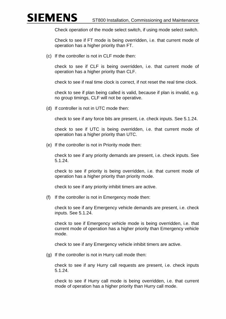
ST800 Installation, Commissioning and Maintenance
Check operation of the mode select switch, if using mode select switch. Check to see if FT mode is being overridden, i.e. that current mode of
operation has a higher priority than FT. (c) If the controller is not in CLF mode then: check to see if CLF is being overridden, i.e. that current mode of
operation has a higher priority than CLF. check to see if real time clock is correct, if not reset the real time clock. check to see if plan being called is valid, because if plan is invalid, e.g.
no group timings, CLF will not be operative. (d) If controller is not in UTC mode then: check to see if any force bits are present, i.e. check inputs. See 5.1.24. check to see if UTC is being overridden, i.e. that current mode of
operation has a higher priority than UTC. (e) If the controller is not in Priority mode then: check to see if any priority demands are present, i.e. check inputs. See
5.1.24. check to see if priority is being overridden, i.e. that current mode of
operation has a higher priority than priority mode. check to see if any priority inhibit timers are active. (f) If the controller is not in Emergency mode then: check to see if any Emergency vehicle demands are present, i.e. check
inputs. See 5.1.24. check to see if Emergency vehicle mode is being overridden, i.e. that
current mode of operation has a higher priority than Emergency vehicle mode.
check to see if any Emergency vehicle inhibit timers are active. (g) If the controller is not in Hurry call mode then: check to see if any Hurry call requests are present, i.e. check inputs
5.1.24. check to see if Hurry call mode is being overridden, i.e. that current
mode of operation has a higher priority than Hurry call mode.

ST800 Installation, Commissioning and Maintenance
check to see if either Hurry call prevent timers are running. (h) If the controller is not in part time mode then: check real time clock. If it is incorrect reset the real time clock. If part time is controlled by special conditioning (e.g. flow and queue
detectors) then: check that conditions required to switch to part time are present, if they
are not, take any necessary corrective actions.
5.1.28 Intermittent Faults/Problem Sites
If a site has an intermittent fault or a fault which keeps repeating then first the appropriate procedure for the fault should be followed as most paths have more than one suggested area to check for the fault. If the fault is still intermittent, do the following:
(a) Gently - try and move/flex each PCB whilst in situ to check for any
intermittent connections. If any intermittent connections are found, replace appropriate PCB. (b) Gently move cables and wiring looms to check for any intermittent
connections. (c) Switch controller `off' and withdraw all PCBs. Check security of any ICs
mounted in sockets; namely firmware PROM, configuration PROM and conflict PROM on the Main Processor PCB.
Re-fit PCBs and re-check operation of controller.
5.1.29 Controller Faults with Handset Plugged in Handset Port
5.1.29.1 If the handset does not operate correctly when plugged into the handset port on Main Processor PCB, do the following:
(a) Check the +12V supply on Main Processor DC power connector. (b) Check that there is a +5V supply on pins 9 and 10 of the handset
socket (0V is on pins 1, 7, 18 and 19). With the handset plugged in check the ripple voltage on 5V supply.
(This is the supply that powers those handsets that do not have their
own supplies.)

ST800 Installation, Commissioning and Maintenance
To fully investigate, this supply may require the use of an oscilloscope. (c) Switch off controller and withdraw Main Processor PCB. Check security
of ICs mounted in sockets of the above PCB. If no loose ICs are found, replace Main Processor PCB.
(d) Replace Main Processor PCB and re-check to see if handset now
operates correctly.
5.2 FAULT FINDING STARTING FROM THE FAULT INDICATIONS
Look at the LEDs on the front of the Main Processor PCB and proceed as indicated in the table below. There are four LEDs on the front edge of the PCB. These are:
COLOUR FUNCTION
Power Present Green This LED flashes giving a heartbeat indication that
the firmware is running normally. If this is not flashing and no other LED is illuminated then check that the power supply is providing 5V to the Main Processor PCB. Inspect any devices with sockets on the Main Processor PCB for good connection. Replace the PCB if necessary.
System Error Red This illuminates during the power-up sequence and then is normally extinguished when the controller is running normally with no faults present in its fault log. If lit check for entries in the controller fault log. Refer to the ST800 Controller Handset Handbook for details on the Fault Log entries.
Bus Error Red This LED should only illuminate if the processor has problems executing the firmware, e.g. when the firmware PROM is missing. Inspect any devices with sockets on the Main Processor PCB for good connection. Replace the PCB if necessary.

ST800 Installation, Commissioning and Maintenance
COLOUR FUNCTION
Watchdog Fail Red This LED is illuminated when the hardware watchdog circuit times-out which occurs when the micro-processor has had to stop processing. Note that when the firmware detects a serious fault, it extinguishes the lights and stops ‘kicking’ the hardware watchdog deliberately so that it times-out and also keeps the lights off. This is normally the result of another fault that has switched the controller `OFF'. If there are any other fault indications or entries in the fault log these should be investigated first. Refer to the ST800 Controller Handset Handbook for details on the Fault Log entries. (a) Switch off controller and withdraw Main Processor PCB. Check security of ICs mounted in sockets in PCB. (b) If handset allows no access, check +5V; it may be necessary to use an oscilloscope. (c) Check all DC voltages in controller to ensure they are within tolerances and any ripple is within allowed limit.* (d) If, after investigating the other faults, this indicator still illuminates, or if there were no other faults indicated then replace the Main Processor. When replacing the Main Processor PCB ensure that PCB issue and firmware are correct. Note that all handset settings are lost and the controller must be re-initialised.
* Note that if the detectors are powered from the controller 24v dc that the available current is limited, depending on the number of controller pcbs fitted. Refer to the table in the General Handbook 667/HB/27000 sect 2.3.5 for details.
5.3 INDICATORS FOR FAULT DIAGNOSIS
The following is a list of indicators in the ST800 controller that assist in the location and diagnosis of a fault. The state of each of these indicators should be noted on arrival at a site before doing anything else.

ST800 Installation, Commissioning and Maintenance
5.3.1 Lamp Switch PCB
Each Lamp Switch PCB is equipped with 8 sets of red, amber and green LEDs indicating the state of the phase it controls. It should be remembered that for pedestrian phases, the amber channel is used for the pedestrian wait indicator, and hence may be lit for relatively long periods giving the false impression of being stuck red and amber.
5.3.2 Main Processor PCB
There are four LEDs on the front edge of the PCB. These are: COLOUR FUNCTION
Power Present Green This LED flashes giving a heartbeat
indication that the firmware is running normally.
System Error Red This illuminates during the power-up sequence and then is normally extinguished when the controller is running normally with no faults present in its fault log.
Bus Error Red This LED should only illuminate if the processor has problems executing the firmware, e.g. when the firmware PROM is missing.
Watchdog Fail Red This LED is illuminated when the hardware watchdog circuit times-out. Note that when the firmware detects a serious fault, it extinguishes the lights and stops ‘kicking’ the hardware watchdog deliberately so that it times-out and also keeps the lights off.
5.3.3 Cabinet Alarm Indicator
The LED (behind the manual access door lens) is normally lit when the controller has identified a detector fault. On installations that operate on a Part Time basis, or where audible indicators are provided for pedestrians, the controller is equipped with Red Lamp Monitoring facilities. The LED flashes when a single lamp failure has been detected. (The requirement for the lamp to flash overrides any requirement to illuminate it continuously). In some installations, the Cabinet Alarm may also be lit for other reasons - refer to the Works Specification.
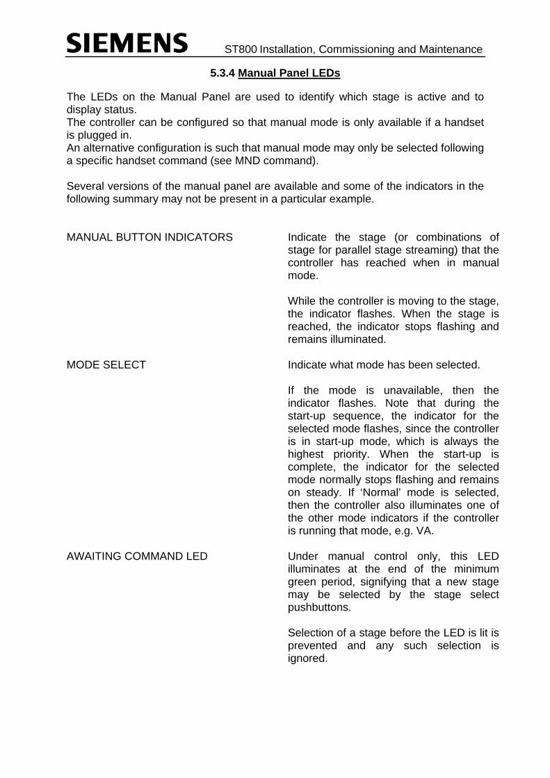
ST800 Installation, Commissioning and Maintenance
5.3.4 Manual Panel LEDs
The LEDs on the Manual Panel are used to identify which stage is active and to display status. The controller can be configured so that manual mode is only available if a handset is plugged in. An alternative configuration is such that manual mode may only be selected following a specific handset command (see MND command). Several versions of the manual panel are available and some of the indicators in the following summary may not be present in a particular example. MANUAL BUTTON INDICATORS Indicate the stage (or combinations of
stage for parallel stage streaming) that the controller has reached when in manual mode. While the controller is moving to the stage, the indicator flashes. When the stage is reached, the indicator stops flashing and remains illuminated.
MODE SELECT Indicate what mode has been selected. If the mode is unavailable, then the indicator flashes. Note that during the start-up sequence, the indicator for the selected mode flashes, since the controller is in start-up mode, which is always the highest priority. When the start-up is complete, the indicator for the selected mode normally stops flashing and remains on steady. If ‘Normal’ mode is selected, then the controller also illuminates one of the other mode indicators if the controller is running that mode, e.g. VA.
AWAITING COMMAND LED Under manual control only, this LED illuminates at the end of the minimum green period, signifying that a new stage may be selected by the stage select pushbuttons. Selection of a stage before the LED is lit is prevented and any such selection is ignored.

ST800 Installation, Commissioning and Maintenance
PROHIBITED MOVE LED This LED illuminates if a prohibited stage to stage movement is attempted while under manual control. It remains illuminated for three seconds or until a permitted move is made.
HURRY CALL (AUX 4) LED Illuminates during all modes of control when there is a hurry call being serviced, or can be configured for an auxiliary function.
HIGHER PRIORITY (AUX 5) LED
Illuminates during all modes of control when there is a higher priority mode active such as UTC Control, or can be configured for an auxiliary function.
AUX 1 - AUX 3 LEDs These LEDs can be configured to display auxiliary functions active such as Dim Override.
5.4 CONTROLLER MANUAL PANEL SWITCHES AND PUSH-BUTTONS
5.4.1 Signals On/Off Switch
The mains supply to the phase switch PCBs is removed immediately OFF is selected on the SIGNALS OFF/ON switch extinguishing the signals. CARE SHOULD BE TAKEN TO ENSURE SAFE TRAFFIC CONDITIONS BEFORE OPERATING THE SWITCH. With the OFF position selected normal microprocessor control operations continue and the phase selections being implemented can be observed on the Lamp Switch indicators. When the switch is returned to the ON position, the signals turn on in the required switch on sequence.
5.4.2 Lamp Test Key
A key on the manual panel enables the indicators on the panel, including the Cabinet Alarm Lamp, to be checked.
When the key is depressed, all LEDs on the Manual Panel should light. The lamp test is carried out under software control, and although correct results indicate that the processor is communicating with the manual panel, it does not guarantee that no faults are present.
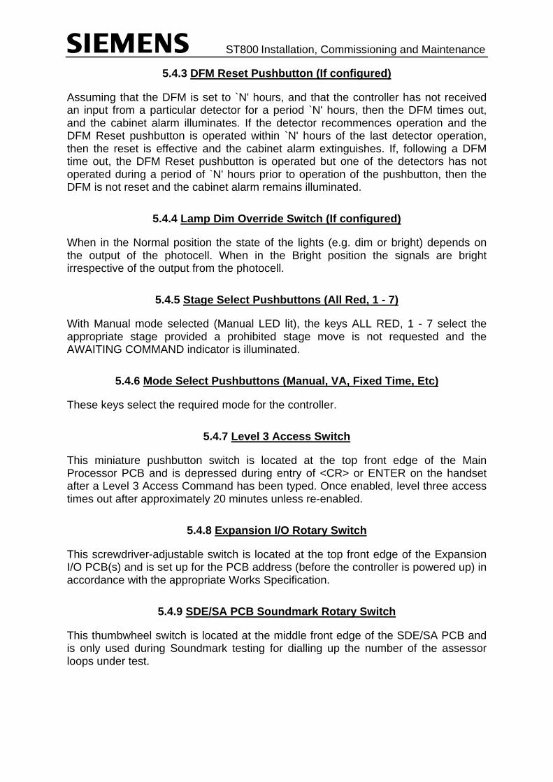
ST800 Installation, Commissioning and Maintenance
5.4.3 DFM Reset Pushbutton (If configured)
Assuming that the DFM is set to `N' hours, and that the controller has not received an input from a particular detector for a period `N' hours, then the DFM times out, and the cabinet alarm illuminates. If the detector recommences operation and the DFM Reset pushbutton is operated within `N' hours of the last detector operation, then the reset is effective and the cabinet alarm extinguishes. If, following a DFM time out, the DFM Reset pushbutton is operated but one of the detectors has not operated during a period of `N' hours prior to operation of the pushbutton, then the DFM is not reset and the cabinet alarm remains illuminated.
5.4.4 Lamp Dim Override Switch (If configured)
When in the Normal position the state of the lights (e.g. dim or bright) depends on the output of the photocell. When in the Bright position the signals are bright irrespective of the output from the photocell.
5.4.5 Stage Select Pushbuttons (All Red, 1 - 7)
With Manual mode selected (Manual LED lit), the keys ALL RED, 1 - 7 select the appropriate stage provided a prohibited stage move is not requested and the AWAITING COMMAND indicator is illuminated.
5.4.6 Mode Select Pushbuttons (Manual, VA, Fixed Time, Etc)
These keys select the required mode for the controller.
5.4.7 Level 3 Access Switch
This miniature pushbutton switch is located at the top front edge of the Main Processor PCB and is depressed during entry of <CR> or ENTER on the handset after a Level 3 Access Command has been typed. Once enabled, level three access times out after approximately 20 minutes unless re-enabled.
5.4.8 Expansion I/O Rotary Switch
This screwdriver-adjustable switch is located at the top front edge of the Expansion I/O PCB(s) and is set up for the PCB address (before the controller is powered up) in accordance with the appropriate Works Specification.
5.4.9 SDE/SA PCB Soundmark Rotary Switch
This thumbwheel switch is located at the middle front edge of the SDE/SA PCB and is only used during Soundmark testing for dialling up the number of the assessor loops under test.

ST800 Installation, Commissioning and Maintenance
5.4.10 Master Switch
This removes the mains supply from the entire controller when opened, i.e. switched off. Depending on cabinet installation this is normally mounted on a panel at the bottom of the controller.
5.4.11 Controller Switch
This is normally included in the mains distribution unit and removes power from the equipment rack and equipment powered from it. This is a single pole switch so does not provide safety isolation. Also note that the maintenance socket is still powered when the controller switch is off.
5.5 SITE VISITS
This section provides a reminder of considerations to be made before visiting a site, and actions to be taken on site and before leaving.
5.5.1 On Receipt of a Fault Report
When a fault report is received it is recommended that the following are checked: (a) Is the fault a repeat one; i.e. is the fault and its cause known from previous visit.
Why was the controller left faulty? Can it now be cleared? I.e. are the resources now available to clear it; if so go to site. If not, make an appropriate note in the fault recording system, or on your fault report.
(b) If the report is DFM, i.e. detector fault, check to see if a fault is known to exist on
the site, especially if the fault is reported by an OMU as it may be a repeat alarm for a fault which has already been reported. Because, unlike the controller, most OMUs cannot be made to ignore faulty loops which have already been reported and, therefore, continue to raise the alarm.
(c) If the controller is under UTC control, check with UTC centre to ensure that the
fault report is not a result of any problem with the UTC, e.g. OTU may be out of action or faulty.
(d) If the Signal State is reported as being All Out, All Red or not giving right-of-way
to one approach try and check with the local authority/police as to whether or not they know of a requirement for the signals to be in this state.
(e) Before leaving for the site check that after clearance of the fault the controller can
be re-commissioned and switched on again, in some cases the local authority may require the signals left off.

ST800 Installation, Commissioning and Maintenance
5.5.2 Before Going to a Site
Before leaving for a site visit, it is recommended that the following be checked: (a) Check that you have the correct equipment and sufficient spares to do the job
you are going out to do. See spares list in section 8.2. (b) Check that all your spares are good; i.e. check that the replacement PCBs have
labels with test and inspection stamps on them. Ensure that none of the PCBs have labels on them that would indicate that they are suspect or have been removed from a faulty site.
(c) Check that you have sufficient copies of the fault record sheets for the visit.
5.5.3 On Arrival at the Site
If the visit is to install additional equipment or perform an annual inspection then proceed with the installation or inspection procedure. If the visit is to investigate a reported fault then on arrival at the site proceed as follows: Check all signal heads to see what signals are being shown to the road users, if any. Open the controller door. Now complete the fault record sheet (Section 5.6) which provides a record of the situation before anything is done which might change the fault indications. Make a visual inspection of all of the wiring and PCBs. Check controller `visit log book' to see if any previous visits/faults are similar, as previous actions may have a bearing on this visit. Now proceed with the fault diagnosis using sections 5.1 and/or 5.2. If you wish to start fault finding using the symptoms as a basis, go to section 5.1. If you wish to start fault finding using the fault indications as a basis, go to section 5.2. NB: It is recommended that, if there are fault indications, that they be used as a basis for the fault finding and a start be made at section 5.2.
5.5.4 Logging/Recording Faults and Visits
Controller Visit Log Book Every controller should have a log book. It should be a small book that is usually stored in the document pocket affixed to the controller door. On every visit the visiting Engineer should write down in the log book the date, his name, reason for visit and actions taken. For example, the reasons for the visit may be a fault report, routine inspection, fitting of new equipment, adjustment of timings, etc. The actions taken may be PCB or unit replaced, timing adjusted, new equipment fitted, etc. This information is essential for the next Engineer who may visit the site so that he can see what has happened previously and helps to reduce duplication of effort.

ST800 Installation, Commissioning and Maintenance
The requirement to fill in the visit log book also applies to Local Authority Staff. The maintenance organisation cannot be held responsible for any problems arising from neglect of this responsibility. Fault Record Sheet It is recommended that a fault record sheet is used if there is no automated method of recording and storing fault details. In section 5.6 there is a Fault Record sheet which should be filled out every time a controller that has a fault is visited. It is essential that this information is recorded on arrival, before doing anything else, so that the original state of the faulty controller is known. This sheet can then be kept at a central point and provides a detailed fault history for the controller. If a controller is exhibiting intermittent/repeat faults then a copy of the fault record sheet should be left in the controller to allow visiting engineers (on site) to study the previous fault symptoms and look for any pattern to the fault.
5.5.5 Before Leaving Site
Below is a list of checks to make before leaving site. (a) Is the master time clock fully operational, check using the handset command
`MTS' ensure that none of the following bits are set 2, 3, 5 or 7 as these bits indicate a fault.
(b) Check current plan. If CLF is configured, use handset command `CPL', is it the
one that is expected, bearing in mind time of day? (c) CLF and timetable can be re-synchronised with the real time clock using handset
command `CCP'.
Reset any data that has been set up for testing, e.g. permanent demands or extensions PHD, PHE.
(d) If all inputs can be reset to normal operation, i.e. none have been set to provide
permanent signals due to faulty inputs, then use DET0 = 99 to reset all inputs to normal operation.
(e) Should manual control be enabled, use handset command `MND' to enable or
disable manual. (f) If all faults have been investigated the fault log may be cleared using RFL = 1. (g) Ensure the visit is accurately recorded in the controller's `visit log book'. It should
contain reason for visit, action taken (i.e. PCB changed etc.) and any follow up action required or details of what actions are required should the fault re-occur.
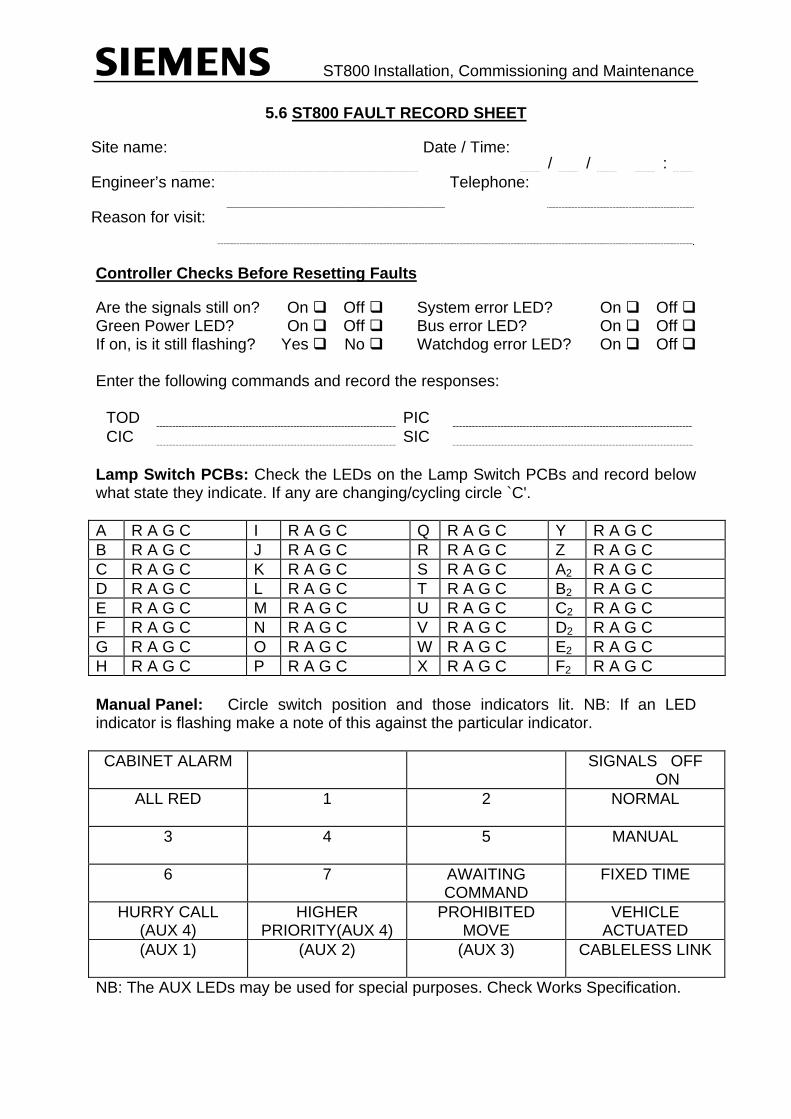
ST800 Installation, Commissioning and Maintenance
5.6 ST800 FAULT RECORD SHEET
Site name: Date / Time: / / :
Engineer’s name: Telephone:
Reason for visit:
Controller Checks Before Resetting Faults
Are the signals still on? On Off System error LED? On Off Green Power LED? On Off Bus error LED? On Off If on, is it still flashing? Yes No Watchdog error LED? On Off Enter the following commands and record the responses:
TOD PIC CIC SIC
Lamp Switch PCBs: Check the LEDs on the Lamp Switch PCBs and record below what state they indicate. If any are changing/cycling circle `C'. A R A G C I R A G C Q R A G C Y R A G C B R A G C J R A G C R R A G C Z R A G C C R A G C K R A G C S R A G C A2 R A G C D R A G C L R A G C T R A G C B2 R A G C E R A G C M R A G C U R A G C C2 R A G C F R A G C N R A G C V R A G C D2 R A G C G R A G C O R A G C W R A G C E2 R A G C H R A G C P R A G C X R A G C F2 R A G C Manual Panel: Circle switch position and those indicators lit. NB: If an LED indicator is flashing make a note of this against the particular indicator. CABINET ALARM SIGNALS OFF
ON ALL RED 1 2 NORMAL
3 4 5 MANUAL
6 7 AWAITING
COMMAND FIXED TIME
HURRY CALL
(AUX 4) HIGHER
PRIORITY(AUX 4) PROHIBITED
MOVE VEHICLE
ACTUATED (AUX 1) (AUX 2) (AUX 3) CABLELESS LINK
NB: The AUX LEDs may be used for special purposes. Check Works Specification.

ST800 Installation, Commissioning and Maintenance
Fault Log: Type ‘FFS’ and use the ‘+’ key to scroll through the currently active fault log flags until ‘FFS END OF LOG’ is displayed.
FFS
+
+
+
Type ‘FDS’ and use the ‘+’ key to scroll through the currently active fault log data until ‘FDS END OF LOG’ is displayed:
If FFS 55 was set, i.e. if ‘FFS 55:255 LAMP’ was displayed, then enter ‘KLD’ and use the ‘+’ key to scroll through the lamp faults until ‘KLD END OF LOG’ is displayed: Examine the lamps around the junction: Replace any lamps which have been correctly reported as failed by KLD, tick the associated box and check that the fault is automatically cleared after about 10 seconds. If no lamp fault can be found on the junction for the displayed phase and colour, put a cross in the box and refer to the ‘lamp monitor’ section of the ‘Information Sheets’.
s a:nnW p/ccccc
Serial Numbers If the controller’s power needs to be switched off in order to fix/clear the fault(s), then this opportunity can be taken to record the PCB issues and serial numbers of the ST800 PCBs. Record the issue states and serial numbers of the main processor PCB, the power distribution PCB and all the Lamp Switch PCBs fitted.
CPU: Power: L/S #0: L/S #1: L/S #2: L/S #3:
Controller Checks After Clearing Fault-

ST800 Installation, Commissioning and Maintenance
Are the signals on? Yes No Is the green Power Present LED flashing? Yes No Is the red system error LED off? Yes No Is the lamp monitor learnt? (i.e. ‘KML:Complete’) Yes No Is the time/date set-up correctly? Yes No Use ‘LOG’ to look back through the historic rolling log and record the last few events. Press ‘SP’ (space) and then the ‘+’ key to view the latest few records:
Date Time Event(s)
Record any relevant information in the controller’s paper fault log and record below the date, time and reason for the previous visit as described in the log:
Any another comments?

ST800 Installation, Commissioning and Maintenance
6. THE SELF-TEST FACILITY
6.1 INTRODUCTION
The self-test facility can be used to check the hardware fitted to the controller, even without a configuration loaded. It has been designed for use in both the factory by production and on the street by installation/ maintenance engineers. Self-test is initiated by holding down the level 3 access button while switching the controller’s power on. The button should be released once the green heartbeat LED starts to flash. The green heartbeat LED continues to flash during the self-test unless a fault is detected when the red system error LED illuminates. A 20 character by 4 line handset connected displays information about the checks it is performing, such as the firmware issue and the lamp supply voltage, both dim and bright, and details any faults found. Self-test performs the checks detailed on the following pages and reports the error messages shown if faults have been detected. While the self-test is running, the manual panel can be checked. Pressing each button on the panel should illuminate the associated LED. To distinguish this from normal operation, the LED flashes at a fast rate while the button is depressed. Note that the ‘Lamp Test’ button illuminates all the LEDs, as it does for normal operation. To test the signals on/off switch and the cabinet alarm LED, switching the switch to the signals ‘on’ position illuminates the cabinet alarm. Switching it to the ‘off’ position extinguishes the cabinet alarm indicator. Note that the signals on/off switch does not affect the self-test in any other way. • Resolving problems with Lamp Switch PCBs and triacs: When various tests fail, the handset may display information such as:
V/Mons Off...Failed ← identifies the test which has failed
R-00000000+00000400 ← outputs from the red voltage monitors
A-00000000+00000000 ← outputs from the amber voltage monitors
G-00000400+00000000 ← outputs from the green voltage monitors -ve Peak +ve Peak
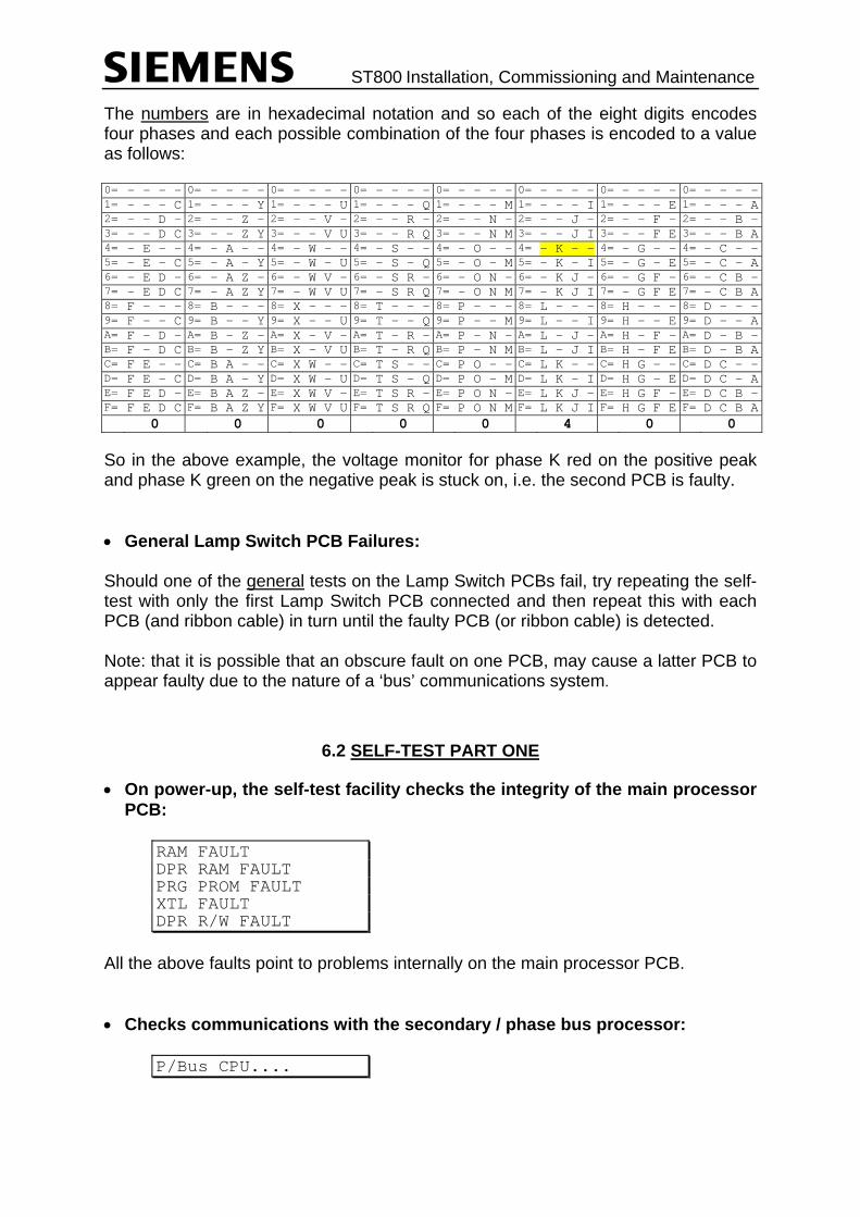
ST800 Installation, Commissioning and Maintenance
The numbers are in hexadecimal notation and so each of the eight digits encodes four phases and each possible combination of the four phases is encoded to a value as follows: 0= - - - - 0= - - - - 0= - - - - 0= - - - - 0= - - - - 0= - - - - 0= - - - - 0= - - - -1= - - - C 1= - - - Y 1= - - - U 1= - - - Q 1= - - - M 1= - - - I 1= - - - E 1= - - - A2= - - D - 2= - - Z - 2= - - V - 2= - - R - 2= - - N - 2= - - J - 2= - - F - 2= - - B -3= - - D C 3= - - Z Y 3= - - V U 3= - - R Q 3= - - N M 3= - - J I 3= - - F E 3= - - B A4= - E - - 4= - A - - 4= - W - - 4= - S - - 4= - O - - 4= - K - - 4= - G - - 4= - C - -5= - E – C 5= - A – Y 5= - W – U 5= - S – Q 5= - O – M 5= - K – I 5= - G – E 5= - C – A6= - E D - 6= - A Z - 6= - W V - 6= - S R - 6= - O N - 6= - K J - 6= - G F - 6= - C B -7= - E D C 7= - A Z Y 7= - W V U 7= - S R Q 7= - O N M 7= - K J I 7= - G F E 7= - C B A8= F - - - 8= B - - - 8= X - - - 8= T - - - 8= P - - - 8= L - - - 8= H - - - 8= D - - -9= F - - C 9= B - - Y 9= X - - U 9= T - - Q 9= P - - M 9= L - - I 9= H - - E 9= D - - AA= F – D - A= B – Z - A= X – V - A= T – R - A= P – N - A= L – J - A= H – F - A= D – B -B= F – D C B= B – Z Y B= X – V U B= T – R Q B= P – N M B= L – J I B= H – F E B= D – B AC= F E - - C= B A - - C= X W - - C= T S - - C= P O - - C= L K - - C= H G - - C= D C - -D= F E – C D= B A – Y D= X W – U D= T S – Q D= P O – M D= L K – I D= H G – E D= D C – AE= F E D - E= B A Z - E= X W V - E= T S R - E= P O N - E= L K J - E= H G F - E= D C B -F= F E D C F= B A Z Y F= X W V U F= T S R Q F= P O N M F= L K J I F= H G F E F= D C B A 0 0 0 0 0 4 0 0
So in the above example, the voltage monitor for phase K red on the positive peak and phase K green on the negative peak is stuck on, i.e. the second PCB is faulty. • General Lamp Switch PCB Failures: Should one of the general tests on the Lamp Switch PCBs fail, try repeating the self-test with only the first Lamp Switch PCB connected and then repeat this with each PCB (and ribbon cable) in turn until the faulty PCB (or ribbon cable) is detected. Note: that it is possible that an obscure fault on one PCB, may cause a latter PCB to appear faulty due to the nature of a ‘bus’ communications system.
6.2 SELF-TEST PART ONE
• On power-up, the self-test facility checks the integrity of the main processor PCB:
RAM FAULT DPR RAM FAULT PRG PROM FAULT XTL FAULT DPR R/W FAULT
All the above faults point to problems internally on the main processor PCB. • Checks communications with the secondary / phase bus processor:
P/Bus CPU....

ST800 Installation, Commissioning and Maintenance
If the processor cannot be detected, the self-test waits indefinitely at this point with the red system error LED illuminated. Check that the processor and its firmware are fitted. • Examines the Lamp Switch PCBs to see how many are fitted:
No L/S Cards Found No PCBs were detected, check the ribbon cable.
Bad L/S Cards Found e.g. if the first and third PCBs are detected, but not the second. • Detects Four Phase Lamp Switch Cards: The controller self-test also automatically detects whether each lamp switch card is equipped with either four or eight phases. When displaying each amber LED on each card in sequence at the end of Part 1, it only illuminates the four amber LEDs on a four phase lamp switch card. If an eight phase card appears as a four phase card to the self-test, then the bottom four LEDs on the card do not illuminate. This must be checked visually by the operator, so it is vitally important that all the amber LEDs on all the lamp switch cards are seen to illuminate in sequence before the button is pressed again to continue the self-test. If a four phase card appears as an eight phase card to the self-test, then this fault is recognised when the self-test attempts to pulse the triacs and check the monitors on the bottom four phases during Self-Test Part 2. Note that the controller can currently only support one four phase lamp switch card and it must be the only card fitted or the last card fitted after a number of eight phase cards. The self-test shuts down (as does normal operation - see FLF 44) if a bad combination of lamp switch cards is detected. • Waits for ZXO synchronisation and checks the mains frequency:
ZXO Sync'd... If the phase bus processor cannot synchronise to the mains zero cross-over signal, e.g. because the ZXO wires are not connected to the back of the first Lamp Switch PCB, then self-test waits indefinitely at this point with the red system error LED illuminated.

ST800 Installation, Commissioning and Maintenance
Mains Freq Error If the mains frequency is more than 5% out from either 50Hz or 60Hz. • Checks all the ADC test voltages on all of the Lamp Switch PCBs:
ADC Tests....Failed ADC Test Readings 0.0V 2.5V 5.0V B0+ nnnn nnnn nnnn B0- nnnn nnnn nnnn ... .... .... ....
If the test fails, then the readings from each PCB, taken at both the positive and negative mains peaks for each of the three test voltages (0V, 2.5V and 5V) are displayed on the handset. Ideally the values should be 0, 512 and 1024, so try replacing any PCBs with readings which are very different. If all the readings appear too high or too low, particularly the 2.5V readings, then this may point to a problem with the 5V logic supply. Also see 667/HB/32921/007 if “LED Lamp Switch” Cards are fitted. • Checks that the lamp supply and voltage monitors are detecting no mains:
L/Supply Off=240V L/Supply Stuck On
If a lamp supply is being detected, then this implies that the lamp supply relays are all switched on (very unlikely) or the lamp supply monitoring transformer (in the PDU) or its connection to the first Lamp Switch PCB is incorrect.
V/Mons Off...Failed R-00000000+00000400 A-00000000+00000000 G-00000400+00000000
If any of the voltage monitors appear to be detecting mains, even though the lamp supply and all the triacs are switched off, then this implies a problem with the hardware on one or more of the Lamp Switch PCBs. • Initialises the phase bus processor:
P/Bus Init... LS/Card Fault (Lat) Bad L/S Cards
Once initialised, the phase bus processor performs more thorough checks on the Lamp Switch PCBs and may detect faults. These tests check the data lines and

ST800 Installation, Commissioning and Maintenance
board select lines using test latches on each PCB ‘(Lat)’, the address lines to each PCB ‘(Adr)’ and the ADC test voltages ‘(ADC)’. If more than one test fails, then ‘Bad L/S Cards’ is displayed instead. • Checks the monitor validation signal:
M/V Test.....Failed Mon Val Failed
The monitor validation signal is generated by the main processor and travels down the phase bus cables to each of the Lamp Switch PCBs, so a failure is probably due to a faulty Lamp Switch PCB. • Step 1 Complete, Start Step 2: At this point, the self-test has successfully checked-out the logic side of all the Lamp Switch PCBs that it has found. It then displays a scrolling diagonal line on the amber LEDs on these Lamp Switch PCBs to prove that it can address all the PCBs correctly and to show that the first part of the self-test is complete. If no LEDs illuminate on one of the Lamp Switch Cards, switch off the controller and investigate; the controller has not detected that card. In the scrolling pattern, on each Lamp Switch Card, either one or two amber LEDs are illuminated at a time. On “LED Lamp Switch” Cards (see 667/HB/32921/007), two LEDs are illuminated at the same time in pattern. On all other variants, only one amber LED is illuminated at a time. This pattern remains until the operator presses the level 3 button to confirm that the pattern is scrolling correctly on all the PCBs fitted and that the self-test may switch on the lamp supply and continue its tests.
6.3 SELF-TEST PART TWO
Caution It is essential that the correct number of Lamp Switch
PCBs have been detected at this point as following this, the self-test starts applying mains to the signals
Therefore, check that the diagonal scrolling pattern illuminates all the amber LEDs on all the lamp switch cards fitted. After the level 3 button is pressed, self-test switches on the lamp supply.

ST800 Installation, Commissioning and Maintenance
Towards the end of this second sequence of tests, it tests all the triacs by switching each one on in turn for a very short period of time. If standard HI 12V halogen lamps are used (with a transformer in the signal heads), then this pulse is not seen on the street and so the signals need not be covered. However it may be possible to see the pulse on lamps that are not driven by any transformer, i.e. that run directly off the 240V.
If in doubt, all non-HI signal heads, i.e. 240V lamps, should be covered before proceeding any further with the self-test.
• Self-test switches on the lamp supply and then checks that the voltage
monitors still show no mains (triacs still switched off):
V/Mons Off...Failed R-00000000+00000400 A-00000000+00000000 G-00000400+00000000
If any of the voltage monitors appear to be detecting mains, it would imply that those triacs are not holding off the mains and those Lamp Switch PCBs should be replaced. • L/S Monitor Reversed: The wires from the lamp supply monitor transformer in the PDU to the first Lamp Switch PCB (LSupp) are connected the wrong way round.
ZXO Wires Reversed
The ZXO wires from the PDU to the first Lamp Switch PCB are connected the wrong way round.
L/S Monitor Fault The lamp supply can be detected on the voltage monitors, but no signal is present from the lamp supply monitoring transformer. Check the transformer and its connections.
L/Supply Failure
No lamp supply has been detected by the lamp supply monitoring transformer but further investigations by the self-test facility cannot determine the cause. Check the lamp supply circuits relays, fuses, etc., in and around the PDU.

ST800 Installation, Commissioning and Maintenance
• Checks that each lamp supply relay can switch off the lamp supply
independently:
SSR Fault Relay A Fault Relay B Fault
Failure of any of these tests implies that the relay is not switching off, i.e. that it is either welded closed or the control signals from the main processor PCB are stuck active.
If the self-test terminates and the controller starts up normally when it attempts to test the SSR*, the power supply may be overloaded. Check the number of detector PCBs for example. See Section 2 of the ST800
Controller General Handbook. * It is easy to tell when the self-test checks the SSR, since it briefly illuminates all the LEDs on all the Lamp Switch PCBs. • Checks that the dimming relay is functioning:
Dimming Fault A fault is only logged on the dimming relay if the dim lamp supply is more than 75% of the normal lamp supply, i.e. that the dimming relay seems to have no effect on the lamp supply. If dimming is not required, then no link should be fitted between the dim input and the dim output on the back of the PDU. If dimming is configured as not present, i.e. KDP is set to zero, then the controller simply never attempts to switch to dim. Note that this test does not fail if there is no dim lamp supply, e.g. if no dimming transformer is fitted, since self-test may be performed on the just the controller rack. Therefore, the dim voltage should be checked manually, e.g.
Dim L/Supply=160V • Checks all of the triacs in turn by applying a very short pulse to each
phase’s colour:
A/Red:Extra Sigs On R-00000001+00000001 A-00000001+00000001 G-00000001+00000001
Tip!

ST800 Installation, Commissioning and Maintenance
A fault is logged if extra signals are detected as on when one particular aspect is pulsed. This would normally imply a short-circuit in the street cabling or an open neutral connection.
No Voltages On... R-00000F00+00000F00 A-00000F00+00000F00 G-00000F00+00000F00
A fault is also logged if no voltages were detected, e.g. when one of the fuses on one of the Lamp Switch PCBs has blown. • Checks the Lamp Supply arrangement: The self-test checks the lamp supply arrangement of the controller after checking each lamp supply relay and each triac and monitor circuit. With the SSR and relay A switched on but with relay B switched off, it pulses a selection of triacs to check that the lamp supply to all the triacs on all of the cards has been removed:
Checking Lamp Supply Arrangement: RelayB:All Sigs Off
If any voltage monitors detect lamp supply during this test then the self-test shuts down and displays the fault on the handset, e.g. if Phase A Red detects voltage:
Relay B Off But... R-00000000+00000001 A-00000000+00000000 G-00000000+00000000
It then switches relay B back on and switches off relay A instead and again pulses a selection of triacs and checks which, if any, still have lamp supply. From this, the controller can determine whether the wiring on the back of the rack is set-up for ‘fail to black-out’ only, i.e. for UK use, or whether it is wired for ‘fail to flashing’, i.e. for export. If the rack is set-up for ‘fail to black-out’ then relay A also switches off the lamp supply to all the triacs on all of the cards, i.e. only the ‘green supply’ from the power distribution unit (which can be switched off by any of the lamp supply relays) is passed to the lamp switch cards. If this is the case, then this result is displayed on the handset and the self-test continues as before:
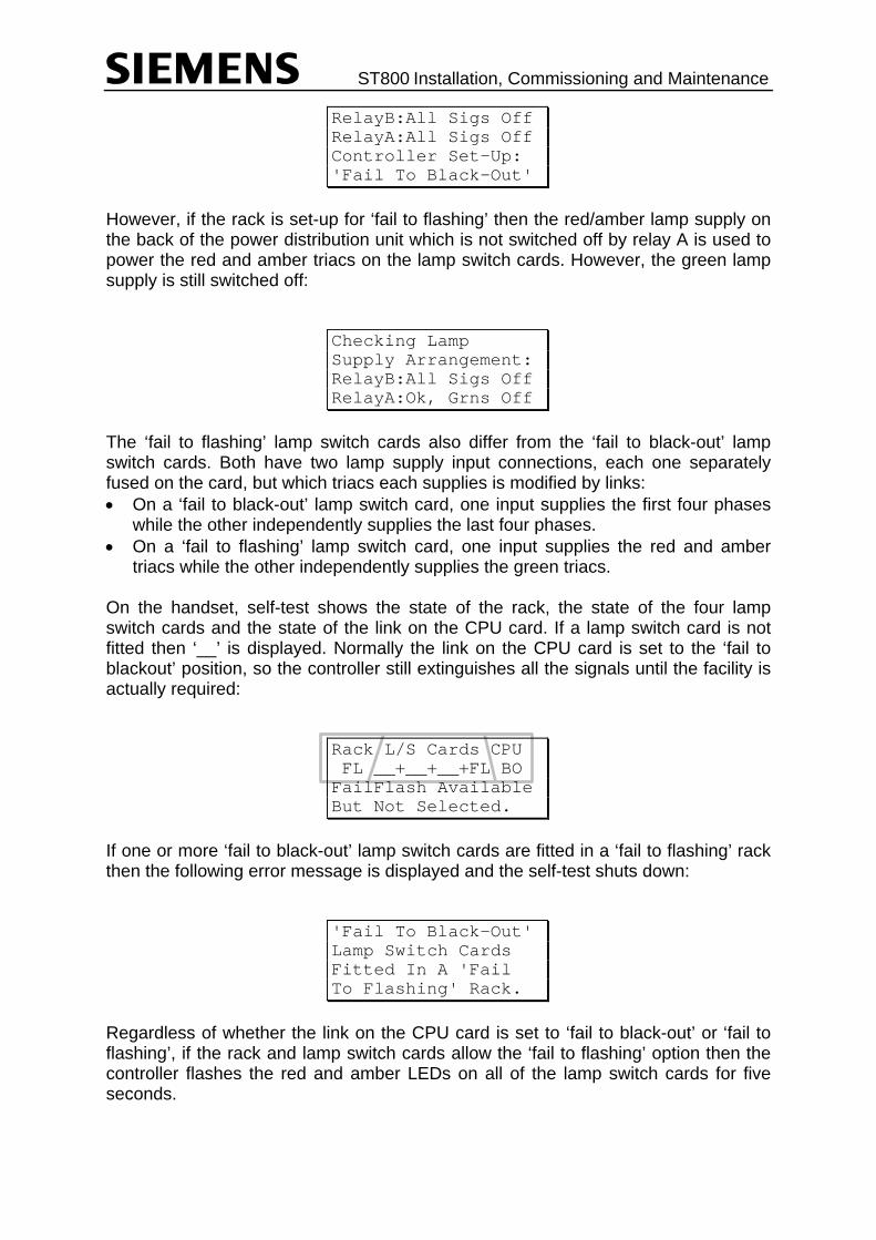
ST800 Installation, Commissioning and Maintenance
RelayB:All Sigs Off RelayA:All Sigs Off Controller Set-Up: 'Fail To Black-Out'
However, if the rack is set-up for ‘fail to flashing’ then the red/amber lamp supply on the back of the power distribution unit which is not switched off by relay A is used to power the red and amber triacs on the lamp switch cards. However, the green lamp supply is still switched off:
Checking Lamp Supply Arrangement: RelayB:All Sigs Off RelayA:Ok, Grns Off
The ‘fail to flashing’ lamp switch cards also differ from the ‘fail to black-out’ lamp switch cards. Both have two lamp supply input connections, each one separately fused on the card, but which triacs each supplies is modified by links: • On a ‘fail to black-out’ lamp switch card, one input supplies the first four phases
while the other independently supplies the last four phases. • On a ‘fail to flashing’ lamp switch card, one input supplies the red and amber
triacs while the other independently supplies the green triacs. On the handset, self-test shows the state of the rack, the state of the four lamp switch cards and the state of the link on the CPU card. If a lamp switch card is not fitted then ‘__’ is displayed. Normally the link on the CPU card is set to the ‘fail to blackout’ position, so the controller still extinguishes all the signals until the facility is actually required:
Rack L/S Cards CPU FL __+__+__+FL BO FailFlash Available But Not Selected.
If one or more ‘fail to black-out’ lamp switch cards are fitted in a ‘fail to flashing’ rack then the following error message is displayed and the self-test shuts down:
'Fail To Black-Out' Lamp Switch Cards Fitted In A 'Fail To Flashing' Rack.
Regardless of whether the link on the CPU card is set to ‘fail to black-out’ or ‘fail to flashing’, if the rack and lamp switch cards allow the ‘fail to flashing’ option then the controller flashes the red and amber LEDs on all of the lamp switch cards for five seconds.

ST800 Installation, Commissioning and Maintenance
At the end of the test, the self-test switches off the lamp supply and displays a multicoloured scrolling pattern on the Lamp Switch PCB LEDs to show that all the tests have passed successfully. It also illuminates a number of amber LEDs on the first phase card to show which PCBs on the extended system bus have been detected by the controller. A full list is displayed on the handset. However, if a four phase card is fitted in the first position, then the information which used to appear on the bottom four amber LEDs is displayed on the top four red LEDs instead, as shown below:
Eight Phase Card Four Phase Card R - R Integral OTU Found
A A CPU Card Found A A CPU Card Found G - G - R - R Integral OMU Found
B A I/O Card 0 Found B A I/O Card 0 Found G - G - R - R SDE/SA Card Found
C A I/O Card 1 Found C A I/O Card 1 Found G - G - R - R -
D A I/O Card 2 Found D A I/O Card 2 Found G - G -
R - E A Integral OTU Found G - R -
F A Integral OMU Found G - R -
G A SDE/SA Card Found G - R -
H A - G -
After a few seconds, self-test repeats the tests from section 6.3, allowing the controller to be soak tested.
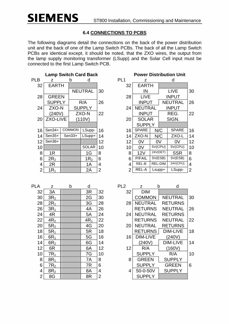
ST800 Installation, Commissioning and Maintenance
6.4 CONNECTIONS TO PCBS
The following diagrams detail the connections on the back of the power distribution unit and the back of one of the Lamp Switch PCBs. The back of all the Lamp Switch PCBs are identical except, it should be noted, that the ZXO wires, the output from the lamp supply monitoring transformer (LSupp) and the Solar Cell input must be connected to the first Lamp Switch PCB.
Lamp Switch Card Back Power Distribution Unit PLB z b d PL1 z d
32 EARTH 32 EARTH NEUTRAL 30 IN LIVE 30
28 GREEN 28 LIVE INPUT SUPPLY R/A 26 INPUT NEUTRAL 26
24 ZXO-N SUPPLY 24 NEUTRAL INPUT (240V) ZXO-N 22 INPUT REG. 22
20 ZXO-LIVE (110V) 20 SOLAR SIGN. SUPPLY
16 Sen34+ COMMON LSupp- 16 16 SPARE N/C SPARE 16 14 Sen35+ Sen33+ LSupp+ 14 14 ZXO-N N/C ZXO-L 14 12 Sen36+ 12 12 0V 0V 0V 12 10 SOLAR 10 10 0V 5V(CPU) 5V(CPU) 10 8 1R 1G 8 8 12V 24V(DET) SSR 8 6 2R2 1R2 6 6 P/FAIL 5V(ESB) 5V(ESB) 6 4 2R 1A 4 4 REL-B REL-DIM 24V(CPU) 4 2 1R1 2A 2 2 REL-A Lsupp+ LSupp- 2
PLA z b d PL2 z b d
32 3A 3R 32 32 DIM 30 3R2 2G 30 COMMON NEUTRAL 30 28 2R1 3G 28 28 NEUTRAL RETURNS 26 3R1 4A 26 RETURNS NEUTRAL 26 24 4R 5A 24 24 NEUTRAL RETURNS 22 4R2 4R1 22 RETURNS NEUTRAL 22 20 5R2 4G 20 20 NEUTRAL RETURNS 18 5R1 5R 18 RETURNS DIM-LIVE 18 16 6R1 5G 16 16 DIM-LIVE (240V) 14 6R2 6G 14 (240V) DIM-LIVE 14 12 6R 6A 12 12 R/A (160V) 10 7R1 7G 10 SUPPLY R/A 10 8 8R1 7A 8 8 GREEN SUPPLY 6 7R2 7R 6 SUPPLY GREEN 6 4 8R2 8A 4 4 50-0-50V SUPPLY 2 8G 8R 2 SUPPLY

ST800 Installation, Commissioning and Maintenance
The following diagram shows the connections in the power connector on the back of the Main Processor PCB. Any signal name preceded with an exclamation mark (‘!’) is active-low, i.e. 0V is the active state. The values in brackets, e.g. (24V), show the normal voltages expected on the plug in order that it can be checked.
Main Processor Card Rear Power Connector 1 0V 5V
CPU 9
2 0V 5V CPU
10
3 0V 5V ESB
11
4 24V Det
5V ESB
12
5 0V Det
!Rel/A(24V)
13
6 !SSR (24V)
!Rel/B(24V)
14
7 !Dim (24V)
Low Batt
15
8 !P/Fail(5V)
P/Fail (0V)
16
CPU Card →
The Phase cables come from Lamp Switch connectors on the back of the ST800 Rack Assembly. There are 4 connectors, one for each 8 phases. Connector 1 is the connector nearest the Main Processor and caters for Phases A to H.

ST800 Installation, Commissioning and Maintenance
6.5 CONNECTIONS TO A FOUR PHASE ST800P LAMP SWITCH PCB
The following diagrams detail the connections on the back of the PDU and the back of a four-phase ST800P Lamp Switch PCB. For the connections on the back of the four phase ST800SE PCBs, refer to the normal eight phase PCB diagrams in section 6.4 above, ignoring the outputs for phases 5 to 8.
ST800P Lamp Switch Power Distribution Unit PLB z b d PL1 z b d
32 EARTH 32 EARTH NEUTRAL 30 IN LIVE 30
28 5-8 or GRN 28 LIVE INPUT SUPPLY 1-4 or R/A 26 INPUT NEUTRAL 26
24 ZXO-N SUPPLY 24 NEUTRAL INPUT (240V) ZXO-N 22 INPUT REG. 22
20 ZXO-LIVE (110V) 20 SOLAR SIGN. SUPPLY
16 Sen34+ COMMON LSupp- 16 16 SPARE N/C SPARE 16 14 Sen35+ Sen33+ LSupp+ 14 14 ZXO-N N/C ZXO-L 14 12 Sen36+ 12 12 0V 0V 0V 12 10 SOLAR 10 10 0V CPU 5V CPU 5V 10
8 V1 R0 V1 Grn 8 8 12V DET 24V SSR 8 6 - - 6 6 P/FAIL ESB 5V ESB 5V 6 4 P1 RM V1 Amb 4 4 REL-B REL-DIM CPU 24V 4 2 - P1 WT 2 2 REL-A LSupp+ LSupp- 2
PLA z b d PL2 z b d
32 V2 Amb V2 R0 32 32 DIM 30 - P1 GM 30 COMMON NEUTRAL 30 28 - V2 Grn 28 28 NEUTRAL RETURNS 26 - P2 WT 26 RETURNS NEUTRAL 26 24 P2 RM - 24 24 NEUTRAL RETURNS 22 - - 22 RETURNS NEUTRAL 22 20 - P2 GM 20 20 NEUTRAL RETURNS 18 - V1 R1 18 RETURNS DIM-LIVE 18 16 - - 16 16 DIM-LIVE (240V) 14 - - 14 (240V) DIM-LIVE 14 12 V1 R2 - 12 12 R/A only (160V) 10 - - 10 SUPPLY R/A only 10
8 - - 8 8 ALL or GRN SUPPLY 6 - V2 R1 6 SUPPLY ALL or GRN 6 4 - - 4 4 50-0-50V SUPPLY 2 - V2 R2 2 SUPPLY
Stream 1 Stream 2 Wire Colour Connection Monitoring On
Card V1 R0 V2 R0 Orange Vehicle Red None V1 R1 V2 R1 Red Vehicle Red 1st RLM Channel V1 R2 V2 R2 Pink Vehicle Red 2nd RLM Channel
V1 Amb V2 Amb Slate Vehicle Amber None V1 Grn V2 Grn Green Vehicle Green None P1 RM P2 RM Red Ped. Red Man None P1 WT P2 WT Yellow Ped. Wait
Indicator None
P1 GM P2 GM Green Ped. Green Man None

ST800 Installation, Commissioning and Maintenance
7. HANDBOOK OMISSIONS/PERSONAL NOTES
This handbook cannot be deemed to be all encompassing as everyone has different experiences of faults and different techniques for finding faults. Therefore, this section has been provided in which any faults experienced by an engineer which are not mentioned in this handbook can be noted along with the technique used to find the fault. Any personal techniques used to find other faults that may differ from those techniques described in this manual might also be noted in this section, If the engineer feels that they should be added to the handbook, this should be noted. Either or both of the following sheets should be completed and sent to: The Traffic Engineering Department (Traffic Controller Section) Siemens Traffic Controls Ltd Sopers Lane Poole Dorset BH17 7ER England For consideration and addition if applicable. Engineer ____________________________ Date ____________________________ Address ____________________________ ____________________________ Fault Symptoms Rolling Log Contents Fault Flags and Data Contents

ST800 Installation, Commissioning and Maintenance
ENGINEER ________________________ Date ________________________ Address ________________________ ________________________ Actual Fault Technique used to find fault Other Observations and Notes

ST800 Installation, Commissioning and Maintenance
8. PART NUMBERS AND SPARES LIST
Use of components other than those listed, or modifications or enhancements that have not been authorised by Siemens Traffic Controls Limited may invalidate the warranty or safety of this product.
8.1 PART NUMBERS
Listed below are all the currently available parts that can be used to make up an ST800. For an up to date list see the ST800 Shopping List (667/KM/27000/000). Description Part Number 8 Phase Cabinet UK wired 16 phase 667/1/27000/001 24 Phase Cabinet UK wired 32 phase 667/1/27000/002 MEC Cabinet 667/1/27000/090 8 Phase Cabinet Export wired 16 phase 667/1/27000/101 24 Phase Cabinet Export wired 32 phase 667/1/27000/102 16 Phase Cabinet Export 667/1/27000/111 32 Phase Cabinet Export 667/1/27000/112 Ped in ST800 Cabinet 667/1/27000/301 ST800 PS Mounted in T400S Outercase 667/1/27000/340 8 Phase UK wired 16 Phase Rack Assembly 667/1/27001/001 24 Phase UK wired 32 Phase Rack Assembly 667/1/27001/002 8 Phase Export wired 16 Phase Rack Assembly 667/1/27001/101 24 Phase UK wired 32 Phase Rack Assembly 667/1/27001/102 16 Phase Export Rack 667/1/27001/111 4 Phase 1 Stream Pedestrian Rack 667/1/27001/300 ST800SE Export Intersection Controller 667/1/27001/310 Lamp Switch Kit UK 667/1/27002/000 Lamp Switch Kit Export 667/1/27002/100 Expansion I/O Kit 667/1/27003/000 Integral OTU Kit 667/1/27004/000 SDE Facility Kit 667/1/27005/000 Audible Supply Kit 667/1/27006/000 2 Stream Pedestrian Kit 667/1/27012/000 GPS Module Mod Kit 667/1/27014/000 Cuckoo Kit – T400 667/1/27040/000 Cuckoo Kit – GEC3000/GEC25 667/1/27040/001 Cuckoo Kit – Ferranti Mk1 Double Case 667/1/27040/002 Cuckoo Kit – T70/T90 667/1/27040/004 Cuckoo Kit – T200 667/1/27040/005 Cuckoo Kit – GEC CX 667/1/27040/006 Cuckoo Kit – Ferranti Mk2 667/1/27040/007 Cuckoo Kit – TCUG 667/1/27040/010 Manual Panel (Intersection Controller) 667/1/27056/001

ST800 Installation, Commissioning and Maintenance
Manual Panel (Ped Full Panel) 667/1/27056/002 Manual Panel (Blank) 667/1/27056/050 Manual Panel Signals On/Off only Assembly 667/1/27056/300 Manual Panel Signals On/Off and DFM Assembly 667/1/27056/301 Dimming Assembly 1.0kVA 667/1/27084/000 Dimming Assembly 1.5kVA 667/1/27084/001 Dimming Assembly 2.0kVA 667/1/27084/002 Dimming Assembly 3.0kVA 667/1/27084/003 Sao Paulo Transformer Kit 667/1/27084/005 DFM Lens Kit 667/1/27104/000 Manual Panel RS232 Kit 667/1/27110/000 300mA RCD Kit 667/1/27117/000 Lightning Suppression Kit 667/1/27118/000 30A Controller Kit 667/1/27130/000 Kit Termination Detector Cable 667/1/15854/000 Detector Single Backplane Kit 667/1/15990/003 T400/500 Controller Mounted 24V AC Supply 667/1/20292/008 T400 L & S 48V Wait Drive Kit 667/1/21029/001 Gas Plinth 667/1/21150/002 Mounting for T400 Stool 667/1/21150/010 27C Yale Door Lock Kit 667/1/21384/000 Yale Lock Barrel Protec 667/1/21498/000 Locking Kit 667/1/21923/001 Controller Handset 667/4/13296/000 Current Monitoring Transformer 667/7/25171/000
8.2 SPARES LIST
In addition to the spares listed below, many of the parts listed in section 8.1 may be ordered as replacement items. Contact Siemens Poole for details.
8.2.1 Fuses
Description STCL Part Number 0.5A Fuse 518/4/90285/004 10A HRC Cartridge Fuse 518/4/90352/004 45A HRC Cartridge Fuse 518/4/90637/003 5A HRC Cartridge Fuse 518/4/90638/000 30A HRC Cartridge Fuse 518/4/90638/005 5A HRC Cartridge Fuse 516/4/97022/003 3.15A Fuse 518/4/97020/115 160mA QB 250V Fuse 518/4/90285/020 10A Ceramic Fuse 518/4/97056/010
8.2.2 Battery
3V Lithium Battery 418/4/39829/000

ST800 Installation, Commissioning and Maintenance
8.2.3 Other Spares
ST800 8 phase No Mon Lamp Switch Kit 667/1/27002/003 ST800 4 phase No Mon Lamp Switch Kit 667/1/27002/403 Additional Audible Bridge Rectifier Kit 667/1/27006/001 T400 Dual Level Audio Cableform 667/1/20241/006 Additional Termination Kit 667/1/27083/000 RKA 27B Yale Door Lock Kit 667/1/21384/001 Spare Processor PCB 667/1/27023/001 Mains Distribution Assembly 30A Controller 667/1/27052/030 Mains Distribution Assembly Standard UK Intersection 667/1/27052/110 Mains Distribution Assembly Pedestrian 667/1/27052/300 Mains Distribution Assembly Export 667/1/27052/301 ST4R Detector 667/1/27663/000 11” Detector Rack 667/1/20690/000 19” Detector Rack 667/1/20690/001 Telephone Kit (Lightning Protection) 667/1/26271/000 Basic OMU 667/1/28850/000 Free standing basic OMU Cable Kit 667/1/28852/000 Free standing I/O Expansion Kit 667/1/28853/000 Sietag Processor Expansion Kit 667/1/28856/000 0141 Cable link for Peek TLC3, C3000 and Microsense 667/1/26579/001 0141 Cable link for Microsense 667/1/26579/002 Basic MOVA Kit 667/1/28851/000 Free standing MOVA Kit 667/1/28855/000 GSM Modification Kit 667/1/26598/010 Radio Clock Kit 667/7/28191/000 OMU/OTU Supply Kit 667/1/20244/000 OMU/OTU Supply Kit Double 667/1/20244/001 Low Voltage Output Cable 667/1/26589/000 GEC Type 25 Relay Kit 667/1/17544/000 Special Brackets to mount OMU in T125 Case 667/1/25077/000 Kent - Regulatory Sign Supply Kit 667/1/20324/000 Kent - Solar Cell Supply Kit 667/1/20325/000 Kent - ‘Computer Control’ Manual Panel label 667/1/20645/101 'T'-KEY Screw Lock 667/2/20234/000 Key - Yale 900 (manual access door) 667/4/13651/000 Manual Panel Gasket 667/7/27129/000 Sealant strip PVC 20mm wide 667/4/04026/023 Base sealant - Robnorganic PX212ZF (or similar) 992/4/00216/000 Key - S18 (main doors centre lock) 4/MC 289 24V Standard Detector 4/AGD036 24V PIR Stopline 4/AGD020 24V Ped On Crossing 4/AGD021 24V Ped Kerbside 4/AGD028 24V Single Lane Traffic Detector 4/AGD033 Controller Handset (Techterm) 4/TL0859

ST800 Installation, Commissioning and Maintenance
8.3 FUSE RATINGS
The following table lists the fuses fitted in the controller. Fuses should only be replaced with ones of similar rating and type.
Electricity Company Cut-out The Max size of this fuse should not exceed 100A (without reference to Poole) maximum prospective short circuit current must not exceed 16,000A. Rating depends on application but 45A minimum is recommended up to 20A load
Master Switch Fuse 518/4/90637/003
45A HRC cartridge fuse to BS1361 on Master Switch panel
Aux. Supply Fuse e.g. OTU/OMU 518/4/90638/000
5A HRC cartridge fuse to BS1361 on Master Switch panel
Controller Switch Fuse 518/4/90638/005
30A HRC cartridge fuse to BS1361 on the front of the PDU.
Regulatory Signs Fuse 518/4/90352/004
10A cartridge fuse to BS88 on the front of the PDU.
Maintenance Socket Fuse 516/4/97022/003
5A cartridge fuse to BS1362 marked ‘MAINT’ on Mains Distribution PCB
Solar Cell Fuse 516/4/97022/003
5A cartridge fuse to BS1362 marked ‘Solar’ on the Mains Distribution PCB.
Lamp Switch PCB Fuse 518/4/97056/010
Two 10A Mains fuses per Lamp Switch PCB (FS1 & FS2) - One fuse for each 4 phases. (If used for export with fail flashing, then one fuse is for all the greens and the other fuse is for all the reds and yellows.)
CPU Fuse 518/4/90285/004
Two 500mA fuses - Input protection fuse (F2) and Handset Fuse (F3)
TEST Lamp Switch PCB Fuse 518/4/97020/115
Two 3.15A fuses used for initial testing on a rewired junction for self-test. (See section 6)
Expansion I/O PCB Fuse 518/4/90285/020
160mA QB 250V fuse
SDE SA PCB Fuse 518/4/90285/020
160mA QB 250V fuse
LAST PAGE OF THE ST800 INSTALLATION, COMMISSIONING AND
MAINTENANCE HANDBOOK