Embed Size (px)
Citation preview

ST7000 Installation

AutohelmAutohelmAutohelmAutohelm®®®®


Contents 1. System Description 2 4. Calibration 34 1.1.1 Course Computer 3 4.1 Recommended Settings 34 1.1.2 Control Unit 3 4.2 Calibration Mode 34 1.1.3 Fluxgate Compass 3 4.3 Adjusting Calibration 35 1.1.4 Rudder Reference Transducer 4 4.4 Display Contrast Adjustment 37 1.1.5 Auxiliary Alarm 4 4.5 Permanent Watch Alarm 38 1.1.6 Masthead Transducer 4 4.6 Recorded Calibration Settings 38 1.1.7 Type CR Interface Unit 5 4.7 Rudder and Rate Gain Tables 38 1.2 Drive Systems 6 1.2.1 Rotary Drive 6 5. Initial Sea Trials 39 1.2.2 Linear Drive 7 5.1 Automatic Deviation Correction 39 1.2.3 Hydraulic Drive 8 5.2 First Sea Trials 39 1.2.4 Constant Running Power Pack 9 5.3 Response Control 39 1.2.5 Sterndrive 11 5.4 Automatic Trim Control 40 5.5 Rudder Gain Adjustment 2. Installation 12 (Displacement craft) 40 2.1.1 Course Computer 12 5.6 Rudder Gain adjustment 2.1.2 Control Unit 13 (High Speed Planing Craft) 41 2.1.3 Fluxgate Compass 13 5.7 Manual overide 2.1.4 Rudder Reference Transducer 14 (Sterndrive Actuators only) 41 2.1.5 Auxiliary Alarm 15 5.8 Rate Gain Adjustment 41 2.1.6 Masthead Transducer 16 5.9 Compass Alignment 42 2.2 Drive Systems 16 2.2.1 Rotary Drive 16 6. Track Control 43 2.2.2 Linear Drive 18 6.1 Functional Test 43 2.2.3 Hydraulic Drive 19 6.2 Operating Hints 43 2.2.4 Stern Drive 22 2.3 Cabling and Power Supplies 26 7. Windvane Control (Sail Only) 45 2.3.1 Signal Cabling 26 2.3.2 Connection to other SeaTalk Units 27 2.3.3 NMEA Input 28 2.3.4 D.C. Power Supplies and Drive Unit 28 2.3.5 Type CR Installations 30 2.3.6 Stern Drive Actuator 31 3. Functional Test 32 3.1 Switch On 32 3.2 Rudder Angle Sense 32 3.3 Mechanical Test (Manual Steering) 32 3.4 Rudder Angle Alignment 32 3.5 Operating Sense 32 3.6 Rudder Deadband 32 3.7 Mechanical Test (Autopilot Steering) 32 3.8 Mechanical Test – Sterndrive
(Autopilot steering) 33
3.9 Rudder Angle Limit 33

1
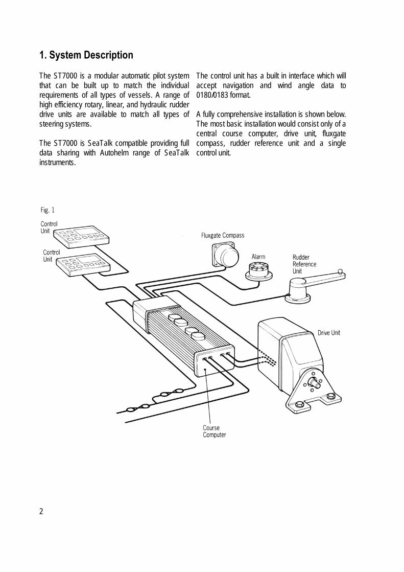
1. System Description The ST7000 is a modular automatic pilot system that can be built up to match the individual requirements of all types of vessels. A range of high efficiency rotary, linear, and hydraulic rudder drive units are available to match all types of steering systems. The ST7000 is SeaTalk compatible providing full data sharing with Autohelm range of SeaTalk instruments.
The control unit has a built in interface which will accept navigation and wind angle data to 0180/0183 format. A fully comprehensive installation is shown below. The most basic installation would consist only of a central course computer, drive unit, fluxgate compass, rudder reference unit and a single control unit.
2
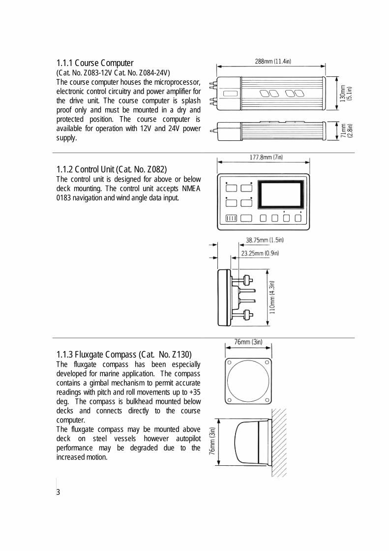
1.1.1 Course Computer (Cat. No. Z083-12V Cat. No. Z084-24V) The course computer houses the microprocessor, electronic control circuitry and power amplifier for the drive unit. The course computer is splash proof only and must be mounted in a dry and protected position. The course computer is available for operation with 12V and 24V power supply. 1.1.2 Control Unit (Cat. No. Z082) The control unit is designed for above or below deck mounting. The control unit accepts NMEA 0183 navigation and wind angle data input.
1.1.3 Fluxgate Compass (Cat. No. Z130) The fluxgate compass has been especially developed for marine application. The compass contains a gimbal mechanism to permit accurate readings with pitch and roll movements up to +35 deg. The compass is bulkhead mounted below decks and connects directly to the course computer. The fluxgate compass may be mounted above deck on steel vessels however autopilot performance may be degraded due to the increased motion.
3

1.1.4 Rudder Reference Transducer (Cat. No. Z131) The rudder reference transducer provides the course computer with a precise rudder position. It is mounted on a suitable base adjacent to the rudder stock. The interconnecting cable connects directly to the course computer connector unit.
1.1.5 Auxiliary Alarm (Cat. No. Z035) The autopilot is provided with an automatic off course alarm system which sounds from all control units and provides sufficient audible warning under most conditions. In cases where a high power alarm is necessary, an auxiliary alarm can be fitted. The auxiliary alarm is connected to the main connector unit via a two core cable.
1.1.6 Masthead Transducer (Sail Only) (Cat. No. Z080) If the installation does not include an Autohelm ST50 Wind Instrument the masthead transducer can be connected directly to the course computer to supply wind angle information.
4

1.1.7 Type CR Interface Unit (Cat. No. Z085) A standard ST7000 course computer can be connected to the solenoids on a constant running hydraulic power pack using the Type CR Interface Unit. The unit also provides connections to energise a solenoid operated bypass valve if required.
5

1.2 Drive Systems The ST7000 offers a choice of Mechanical or Hydraulic Drive Units. All vessels with hydraulic steering will require a hydraulic drive unit (see section 1.2.3). Mechanical steering systems may be driven with either a rotary or linear drive unit. If space permits the linear drive unit provides the simplest installation by connecting directly to the rudder stock tiller arm. It may also be used to power steer the vessel if steering linkage failure occurs. 1.2.1 Rotary Drive Units The Autohelm Rotary Drive Units provide smooth powerful steering commands with virtually silent operation. A rugged electric motor drives a precision epicyclic gearbox via a high tensile belt drive. An electronic clutch is totally fail-safe yet transmits high torque loads with no slippage. The drive units can be mounted in any attitude simplifying installation.
6
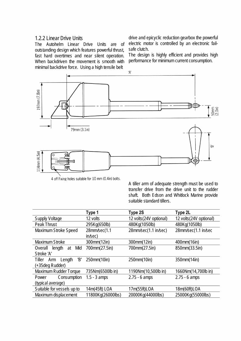
1.2.2 Linear Drive Units The Autohelm Linear Drive Units are of outstanding design which features powerful thrust, fast hard overtimes and near silent operation. When backdriven the movement is smooth with minimal backdrive force. Using a high tensile belt
drive and epicyclic reduction gearbox the powerful electric motor is controlled by an electronic fail-safe clutch. The design is highly efficient and provides high performance for minimum current consumption.
A tiller arm of adequate strength must be used to transfer drive from the drive unit to the rudder shaft. Both Edson and Whitlock Marine provide suitable standard tillers.
Type 1 Type 2S Type 2L Supply Voltage 12 volts 12 volts(24V optional) 12 volts(24V optional) Peak Thrust 295Kg(650lb) 480Kg(1050lb) 480Kg(1050lb) Maximum Stroke Speed 28mm/sec(1.1
in/sec) 28mm/sec(1.1 in/sec) 28mm/sec(1.1 in/sec
Maximum Stroke 300mm(12in) 300mm(12in) 400mm(16in) Overall length at Mid Stroke 'A'
700mm(27.5in) 700mm(27.5in) 850mm(33.5in)
Tiller Arm Length 'B' (+35deg Rudder)
250mm(10in) 250mm(10in) 350mm(14in)
Maximum Rudder Torque 735Nm(6500lb in) 1190Nm(10,500lb in) 1660Nm(14,700lb in) Power Consumption (typical average)
1.5 - 3 amps 2.75 - 6 amps 2.75 - 6 amps
Suitable for vessels up to 14m(45ft) LOA 17m(55ft)LOA 18m(60ft)LOA Maximum displacement 11800Kg(26000lbs) 20000Kg(44000lbs) 25000Kg(55000lbs)
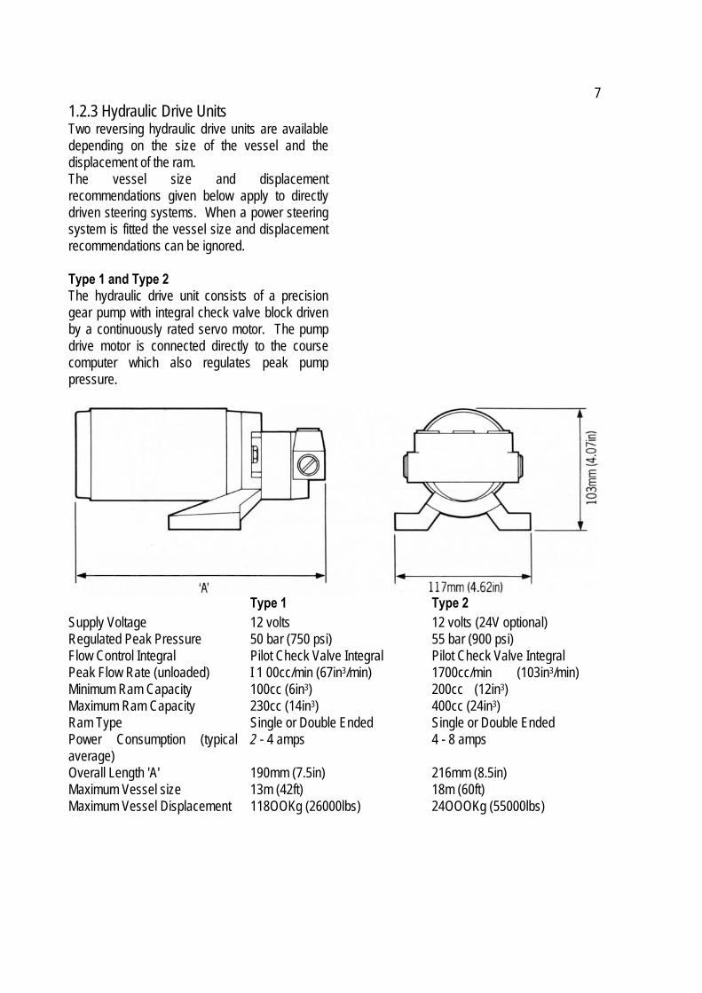
7 1.2.3 Hydraulic Drive Units Two reversing hydraulic drive units are available depending on the size of the vessel and the displacement of the ram. The vessel size and displacement recommendations given below apply to directly driven steering systems. When a power steering system is fitted the vessel size and displacement recommendations can be ignored. Type 1 and Type 2 The hydraulic drive unit consists of a precision gear pump with integral check valve block driven by a continuously rated servo motor. The pump drive motor is connected directly to the course computer which also regulates peak pump pressure.
Type 1 Type 2 Supply Voltage 12 volts 12 volts (24V optional) Regulated Peak Pressure 50 bar (750 psi) 55 bar (900 psi) Flow Control Integral Pilot Check Valve Integral Pilot Check Valve Integral Peak Flow Rate (unloaded) I 1 00cc/min (67in3/min) 1700cc/min (103in3/min) Minimum Ram Capacity 100cc (6in3) 200cc (12in3) Maximum Ram Capacity 230cc (14in3) 400cc (24in3) Ram Type Single or Double Ended Single or Double Ended Power Consumption (typical average)
2 - 4 amps 4 - 8 amps
Overall Length 'A' 190mm (7.5in) 216mm (8.5in) Maximum Vessel size 13m (42ft) 18m (60ft) Maximum Vessel Displacement 118OOKg (26000lbs) 24OOOKg (55000lbs)

8

1.2.4 Constant Running Power Pack When steering loads require a ram capacity above 400cc (24in3) the Autohelm Constant Running Power pack provides the ideal autopilot drive system. Hydraulic fluid is provided from a self contained reservoir and flow to the steering ram is controlled by integral solenoid operated valves. For the most rugged and demanding steering applications the Autohelm Constant Running Power pack is the optimum solution. Used with a solenoid operated bypass valve and separate hydraulic ram this system is recommended for heavy duty applications on large mechanically steered vessels.
Type CR1 Type CR2 Supply Voltage 12 volts (24V optional) 12 volts (24V optional) Regulated Peak Pressure 50 bar (750 psi) 50 bar (750 psi) Peak Flow Rate (unloaded) 3000cc/min (180in3/min) 4500cc/min (270in3/min) Minimum Ram Capacity 400cc (24in3) 750cc (46in3) Maximum Ram Capacity 750cc (46in3) 1500cc (92in3) Ram Type Single or Double Ended Single or Double Ended
9

Power Pack Selection (Constant Running) Hydraulic power pack selection depends on the vessels overall length and the displacement of the steering cylinder. Using figure 2 establish the target hardover time for your vessel. This is combined with the steering cylinder displacement in figure 3 to select the appropriate hydraulic power pack.
Note: If power packs other than the Autohelm models are used with the ST7000 the following solenoid specifications must comply- Pull in Voltage - less than 8V (16v for 24v systems) Drop out Voltage - greater than 2V Operating Current - less than 5A The Solenoid Voltage must be the same as the course computer.
10

Specifications
Description Size
Hardover/Hardover time (unloaded)
8.8 secs
Stroke 190mm(7.5in)
Power Consumption(Typical average)
1.5 - 3 amps
1.2.5 Sterndrive The Sterndrive Actuator must only be used on sterndrives with cable operated power assisted steering. The drive unit operates the power steering valve identically to the steering cable. A clutch disengages the drive unit to allow manual steering when the autopilot is disengaged. Two installation kits are available to allow connection to different engine manufacturers equipment. Maximum Thrust 150 Kgf (330lbs)
Cat. No. Manufacturer D129 Volvo Penta D137 Mercruiser/OMC/Yamaha
11

2. Installation 2.1.1 Course Computer Mounting Position - Below Deck The course computer should be positioned in a dry protected area of the vessel free from high operating temperatures and excessive vibration. It can be mounted in any attitude. Care must be taken to allow at least 150mm (6in) clearance all round to aid heat dissipation from the power amplifier in the unit. Do not mount in the engine room. Do not position the course computer so that it will: • Receive any direct water splash/spray (from
Bilge/Hatch etc). • Be liable to physical damage from heavy
items.
Mounting Instructions • Remove Terminal box lid (Fig. 4). • Unscrew two internal thumb retaining nuts
(Fig. 4). • Unplug terminal box and mounting spine. • Position terminal box and mounting spine in
correct location, mark off and pilot drill for the 5 self-tapping screws supplied (Fig. 5).
• Screw terminal box and mounting spine into place.
• Plug course computer unit to terminal box. Retighten thumb retaining screws.
The course computer is now ready for wiring (see 2.3).
• Be covered by other equipment or onboard gear.
• Be close to major sources of transmitted energy (Generators/SSB radios, Aerial Cables etc).
12

2.1.2 Control Unit The control units must be mounted close to the steering stations and are designed for above or below deck installation. Position them where they are:- • Reasonably well protected from physical
damage. • At least 230mm (9in) from a compass. • At least 500mm (20in) from radio receiving
equipment. • Accessible from behind to secure in place and
run cables. Note: The back cover is designed to breath through a duct in the cable boss to prevent moisture accumulation. Direct exposure of the rear of the control unit to water must be avoided. Mounting Procedure (Fig. 6) The mounting surface must be smooth and flat. Use the template provided to mark the centres of the two fixing holes and central boss. Note: Adjacent instruments should have a 6mm (1/4in) separation to allow room for the protective covers. • Drill to 4mm (5/32in) diameter. • Use 50mm (2in) diameter cutter to drill the
hole for the central boss 1. • Screw the two fixing studs 2 into the back
cover.
Pass the cable tails through the central hole and secure the instrument with the thumb nuts provided 3. (A sealing gasket 4 is already attached to the back cover). 2.1.3 Fluxgate Compass The fluxgate compass may be attached to a convenient vertical surface using the self tapping screws provided (Fig. 7).
Correct positioning of the fluxgate is crucial if ultimate performance from the autopilot installation is to be achieved. The fluxgate should ideally be positioned as near as possible to the pitch and roll centre of the vessel in order to gimbal disturbance (Fig. 8).
13

It is very important to ensure that the fluxgate is positioned at least 0.8m (2ft 6in) away from the vessel's steering compass in order to avoid deviation of both compasses. The fluxgate must also be positioned as far away as possible from
large iron masses, such as the engine and other magnetic devices which may cause deviation and reduce the sensitivity of the sensor. If any doubt exists over magnetic suitability of the chosen site, the position may be surveyed using a simple hand bearing compass. The hand bearing compass should be fixed in the chosen position and the vessel swung through 360 deg. Relative differences in reading between the hand bearing compass and the vessel's main steering compass should ideally not exceed 10 deg. on any heading. Installation Precautions Correct installation of the course computer and fluxgate compass is vital to the successful performance of the ST7000. 2.1.4 Rudder Reference Transducer The rudder reference unit must be mounted on a suitable base adjacent to the rudder stock (Fig.9) using the self tapping screws provided. The base height must ensure correct vertical alignment of the rudder reference unit arm and tiller arm. If it is more convenient, the rudder reference unit may be mounted upside down (logo downwards), but if this is done, the red and green wires must be reversed in the connector unit.
The rudder reference unit has a built in spring to remove any free play in the linkage to the tiller. This gives very precise rudder position.
14

The rudder reference arm movement is limited to ± 60 deg. Care must be taken during installation to ensure the rudder reference arm is opposite the cable entry when the rudder is amidships. Failure to do this could result in damage if the rudder reference arm is driven onto its end stops by the steering system (Fig. 10).
Control Dimensions It is important to ensure that the dimensions set out in Fig. 11 are within the limits set and the tiller arm and rudder reference arm are parallel to each other.
With the rudder amidships, the rudder reference arm should be opposite the cable entry and at 90 deg. to the connecting bar. Minor adjustment can be made by slackening off the 3 securing screws and rotating the transducer body. The tiller pin must be positioned within the limits shown in Fig. 11. Ideally dimension A should be 140mm (5.5in). However, changing this within the limits shown will not degrade the autopilot performance but will slightly alter the scaling of the rudder angle display on the control unit. The tiller pin is secured to the tiller arm using the self tapping screws provided, Cut the studding X (Fig. 11) to length and screw on the lock nuts Y (Fig. 11) and ball pin sockets. The sockets can then be pressed onto the pins. Move the rudder from side to side to ensure the linkage is free from any obstruction at all rudder angles. 2.1.5 Auxiliary Alarm The auxiliary alarm unit is waterproof and may therefore be mounted in any position. The alarm unit is supplied with a terminal block to connect a two core interconnection cable to the course computer. A 22mm (7m/8in) hole should be bored through the mounting panel/deck to pass through the two way connector block and interconnecting cable (Fig. 12). Finally, the alarm unit should be screwed into position using the four self tapping screws provided. A foam seal on the alarm mounting flange will ensure a watertight joint to the mounting surface.
15

2.1.6 Masthead Transducer (Sail only) Installation (Fig. 13) • With the threaded end of the mounting block I
facing forward, mark the position for the 2 self tapping screws.
• Drill the holes using the 4.0mm (5/32in) drill bit supplied.
• Attach the mounting block using sealing compound.
• Tighten the locking ring 3 very securely. Cabling • Cut the cable with sufficient length to route
from the mounting block to the below deck junction box.
• Feed the cable (30m (100 ft) supplied) down the mast. If the mast is deck stepped the cable should be passed through the deck and sealed using a proprietary gland fitting.
• Connect the cable to the junction box supplied close to its entry to the vessel to allow mast unstepping.
• Route the remainder of the cable back to the course computer connector box and connect to AUX 1 terminal.
Note: Do not connect the yellow core. This should be cut back and insulated.
2.2 Drive Systems 2.2.1 Rotary Drive Unit The rotary drive unit is coupled to the steering mechanism by a chain drive. Most steering gear manufacturers supply special autopilot drive attachments and many include this facility as standard. Having selected the position for attachment of the autopilot drive chain it is necessary to determine the chain reduction ratio. Count the number of turns of the steering gears' shaft (this is the driven sprocket) when the rudder is driven from hardover to hardover. Use Fig. 14 to determine the sprocket sizes required. These reduction ratios will provide good steering performance for most vessels with approximately 10 second and 14 second Hardover-Hardover times for the Type I and Type 2 drive units respectively. If the vessel is thought to have unusual steering characteristics, Raymarine's Product Support Department or one of our authorised representatives should be contacted for advice. Standard 3/8" or 1/2" pitch chain is recommended for the chain drive and the drive sprocket ideally should not have less than 15 teeth. Bore and keyway dimensions for the drive unit sprocket are detailed in Fig. 15. It is essential that these bore and keyway dimensions are strictly adhered to. All sprockets must be keyed and grub screwed to their shaft and finally secured with 'Loctite'.
16

The drive unit is mounted by bolting to a substantial frame member (Fig. 16). The mounting foot is secured to the drive unit by four equally spaced caphead screws and may be
rotated through 90 deg. to provide a more convenient mounting position if required (Fig. 17). In some cases, it may be necessary to fabricate a special frame to mount the drive unit., It should be noted that chain tension can exceed 230Kgs (500lbs) and thus an extremely rigid mounting structure is vital to maintain good chain alignment. Installation failures can occur in this area and it is desirable to 'over engineer' the drive unit mounting. All fastenings should be secured by lock washers. Provision must also be made for chain adjustment which is most easily achieved by removable shims placed under the mounting foot or by elongated clearance holes in the mounting frame as illustrated in Figs. 16 and 17.
17

Both sprockets must be accurately aligned to run in the same plane and correct alignment must be carefully checked by means of a straight edge. The gearbox may be mounted in any convenient attitude. In addition, the drive sprocket may face any direction since steering sense can be corrected when the installation is complete by reversing the polarity of the drive motor connection (see section 3.3). Finally, the chain should be tensioned until it is just tight and contributes negligible lost motion to the drive system. Total lost motion between the driven sprocket attached to the steering system and the rudder stock should not exceed 2% of total movement under any circumstances. If lost motion exceeds this level it must be corrected, otherwise steering performance will be impaired. Having completed the drive unit installation, turn the steering wheel from hardover to hardover and check that the chain and sprockets driving the actuator move freely and in alignment. 2.2.2 Linear Drive Unit (Fig. 18) The linear drive unit couples directly to the rudder stock at the tiller arm radius given below— Drive Unit Tiller Radius (B) Type 1 (Z039) 250mm (10in) Type 2S (Z058,Z059) 250mm (10in) Type 2L (Z029, Z032) 360mm (14in) It is preferable to couple the linear drive unit to the rudder stock via an independent tiller arm
(Edson and Whitlock offer a standard fitting). In certain cases, however, it may be possible to couple the pushrod to the same tiller arm or rudder quadrant employed by the main steering linkage. It is important to note that the linear drive system can exert a thrust of over 50OKgs (1000lbs). If any doubt exists about the strength of the existing tiller arm or rudder quadrant the steering gear manufacturer must be consulted. When siting the linear drive unit, the following points should be noted:- • The drive unit mounting bracket may be
attached to any horizontal or vertical surface. If necessary the drive unit may be mounted upside down.
• The ball end fitting will allow up to 5 deg. misalignment between the pushrod and tiller arm plane of rotation. Accurate angular alignment is extremely important and under no circumstances should the above limit be exceeded.
• The drive unit must be at right angles to the tiller arm when the tiller is amidships (Fig. 18).
18
The mounting bracket should be bolted to a substantial frame number. Always over engineer to ensure reliability and maintenance of correct alignment. Installation The pushrod ball end must be attached to the tiller arm using the fixing bolt supplied with its flange positioned between the ball end and the tiller arm (Fig. 19). It is vitally important that the lock washer supplied is used and that the nut is fully tightened. The mounting bracket should be attached with four stainless steel M10 bolts with locknuts or lock washers. Having installed the drive unit turn the steering wheel from hardover to hardover and check that:- • no part of the drive unit fouls the vessels'
structure. • the mechanical limit stop on the vessels'
steering system is reached before the actuator reaches its mechanical limit.
• angular movement of the ball end fitting is less that 5 deg.
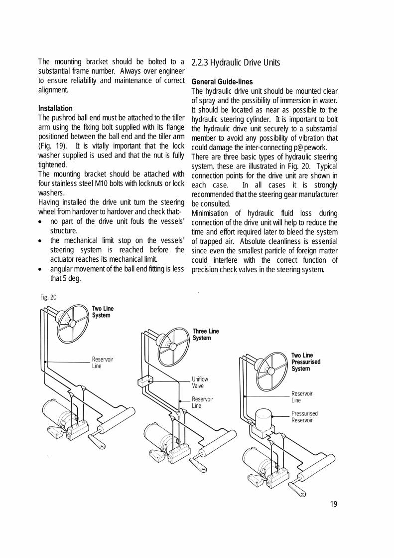
2.2.3 Hydraulic Drive Units General Guide-lines The hydraulic drive unit should be mounted clear of spray and the possibility of immersion in water. It should be located as near as possible to the hydraulic steering cylinder. It is important to bolt the hydraulic drive unit securely to a substantial member to avoid any possibility of vibration that could damage the inter-connecting p@pework. There are three basic types of hydraulic steering system, these are illustrated in Fig. 20. Typical connection points for the drive unit are shown in each case. In all cases it is strongly recommended that the steering gear manufacturer be consulted. Minimisation of hydraulic fluid loss during connection of the drive unit will help to reduce the time and effort required later to bleed the system of trapped air. Absolute cleanliness is essential since even the smallest particle of foreign matter could interfere with the correct function of precision check valves in the steering system.
19
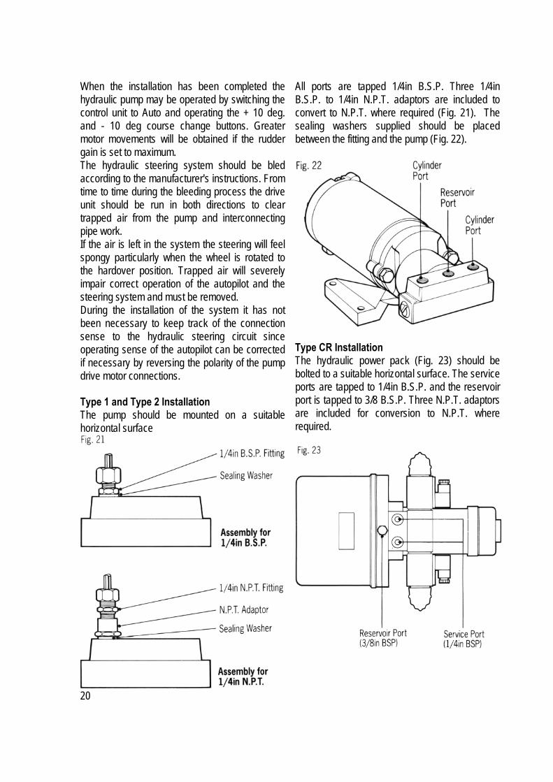
When the installation has been completed the hydraulic pump may be operated by switching the control unit to Auto and operating the + 10 deg. and - 10 deg course change buttons. Greater motor movements will be obtained if the rudder gain is set to maximum. The hydraulic steering system should be bled according to the manufacturer's instructions. From time to time during the bleeding process the drive unit should be run in both directions to clear trapped air from the pump and interconnecting pipe work. If the air is left in the system the steering will feel spongy particularly when the wheel is rotated to the hardover position. Trapped air will severely impair correct operation of the autopilot and the steering system and must be removed. During the installation of the system it has not been necessary to keep track of the connection sense to the hydraulic steering circuit since operating sense of the autopilot can be corrected if necessary by reversing the polarity of the pump drive motor connections. Type 1 and Type 2 Installation The pump should be mounted on a suitable horizontal surface
All ports are tapped 1/4in B.S.P. Three 1/4in B.S.P. to 1/4in N.P.T. adaptors are included to convert to N.P.T. where required (Fig. 21). The sealing washers supplied should be placed between the fitting and the pump (Fig. 22).
Type CR Installation The hydraulic power pack (Fig. 23) should be bolted to a suitable horizontal surface. The service ports are tapped to 1/4in B.S.P. and the reservoir port is tapped to 3/8 B.S.P. Three N.P.T. adaptors are included for conversion to N.P.T. where required.
20

Bypass Valve (Cat. No. Z079) (Fig. 25) If the autopilot operated hydraulic cylinder is independent of the manual steering system a solenoid operated bypass valve should be fitted to allow the cylinder to backdrive when manual steering. The bypass valve should be connected to the 'bypass' connector on the Type CR Interface Unit. The bypass valve Fig. 24 should be fitted between the autopilot steering cylinder ports and will normally be de-energised to allow the cylinder to backdrive. When the autopilot is engaged, the valve is energised by the Type CR Interface to allow the autopilot steering cylinder to drive the rudder. If the steering cylinder is unbalanced (single ended) the reservoir connection must be connected to the reservoir
below the oil level (Fig. 25) to enable excess oil to be returned and made up to the reservoir. Note • The bypass valve voltage must be matched to
the course computer supply voltage i.e. 12V or 24V.
• If the bypass valve is used on systems with a reversing gear pump (i.e. without the type CR Interface Unit) a 5 amp relay should be used to energise the bypass valve. The relay should have a 12V coil, taking less than 500ma and be driven by the clutch output on the course computer connector unit.
21

2.2.4 Stern Drive Actuator The drive unit can be fitted to power assisted stern drive systems made by Volvo Penta, Mercruiser, OMC and Yamaha. A different installation kit is required for each manufacturer Volvo Penta Installation (Using D129 Kit, Fig. 26) The stern drive actuator should be connected to the centre hole on the tiller arm. On twin engine installations this is the position used to connect the engine tie bar to link the two tiller arms.
Installation • Push the mounting bracket behind the
steering cable sliding the location pins either side (top and bottom) of the Volvo power steering block (Fig. 27).
• Ensuring that the bracket clamp is correctly orientated (larger diameter towards engine) place the bracket clamp between the valve block and cable clamp nut and attach with the four hexagonal bolts supplied. Tighten the four bolts evenly until the bracket is securely located (Fig. 27).
22

• Uncouple the engine tie bar from the outdrive
tiller arm by bending back the lock tabs and removing the cotter pin. This should be replaced with the multi-engine adaptor pin, ensuring that it is secured properly with a split pin* (Fig.28) (on single engine installation, fit the single engine adaptor pin in the vacant middle hole in the tiller arm).
• Attach the drive unit to the bracket using the long cotter pin and split pin provided. The small spring clip can then be used to attach the drive unit to the adaptor pin (Fig. 28).
• Slowly turn the steering system from hard over to hard over. It is most important that the drive unit and the adaptor pin bracket do not touch any part of the engine or steering system.
23

Mercruiser Installation (Using DI 37 Kit) (Also OMC &Yamaha) The drive unit should be mounted onto the tiller end block and the pushrod connected to the cable end sheath via a custom mounting bracket. The first stage of installation is to fit the custom bracket:- Mercruiser Bracket Mounting Kit (D137)
Installation • Remove locating pin attaching cable rod to
tiller end block and slide the drive unit 'C' bracket over the end block.
• Secure by pushing the supplied clevis pin upwards through the drive unit 'C' bracket, end block and cable rod end.
• Secure the assembly by inserting the split pin through the drive 'C' bracket (Fig.30).
• With the helm turned hard to port, assemble the adaptor pin bracket and bracket clamp onto the cable end sheath using the 2 socket head bolts provided. This should be positioned 165mm (6.5in) from the drive unit 'C' bracket clevis pin. Make sure the adaptor pin bracket points upwards. (See Figs. 30, 31 & 32).
• Position the drive unit pushrod over the top of the adaptor pin and secure with the spring clip (Figs. 30 & 32).
Slowly turn the steering system from hard over to hard over. It is most important that the drive unit and the adaptor pin bracket do not touch any part of the engine or steering system.
24
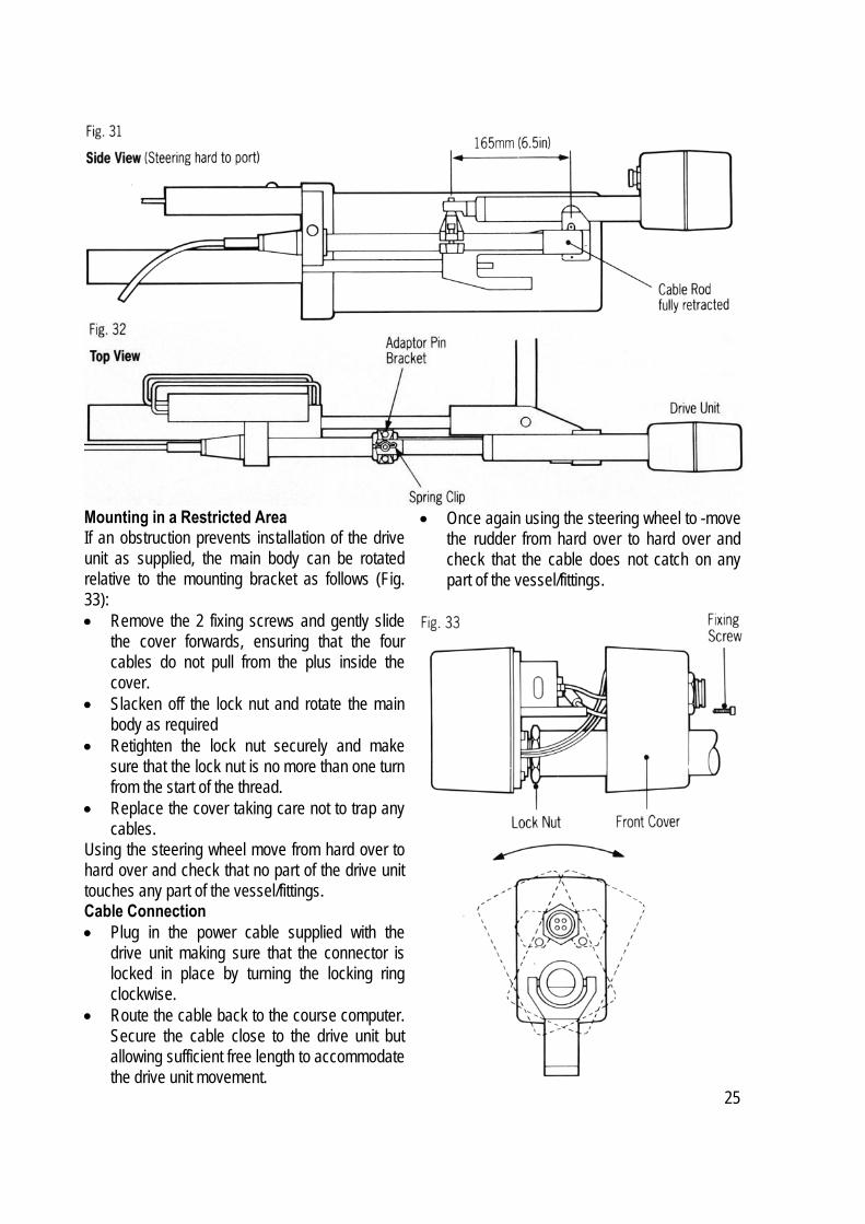
Mounting in a Restricted Area If an obstruction prevents installation of the drive unit as supplied, the main body can be rotated relative to the mounting bracket as follows (Fig. 33): • Remove the 2 fixing screws and gently slide
the cover forwards, ensuring that the four cables do not pull from the plus inside the cover.
• Slacken off the lock nut and rotate the main body as required
• Retighten the lock nut securely and make sure that the lock nut is no more than one turn from the start of the thread.
• Replace the cover taking care not to trap any cables.
Using the steering wheel move from hard over to hard over and check that no part of the drive unit touches any part of the vessel/fittings. Cable Connection • Plug in the power cable supplied with the
drive unit making sure that the connector is locked in place by turning the locking ring clockwise.
• Route the cable back to the course computer. Secure the cable close to the drive unit but allowing sufficient free length to accommodate the drive unit movement.
• Once again using the steering wheel to -move the rudder from hard over to hard over and check that the cable does not catch on any part of the vessel/fittings.
25

2.3 Cabling and Power Supplies 2.3.1 Signal Cabling System Components Cable connections for all components are shown schematically in Fig. 1. All components, other than the Actuator motor, connect to the course computer connector unit where they are
permanently wired to connector blocks mounted on a central printed circuit board (Fig. 34).The 6m (20ft) cable with the 3 pin connector at one end is used to connect the first control unit to the course computer. Additional units are connected using SeaTalk cable either to the first control unit (see 2.3.2) or to the second SeaTalk connector block (BUS 2) on the connector unit.
26

Where additional cables have to be brought into the connector unit, the blanking discs (Fig. 35) should be pressed out and replaced with the rubber grommets supplied. After cutting the interconnecting cable to length (Fig. 36), it may be passed through the inserted rubber grommet and prepared for connection to the relevant connector block (Fig. 34). Each connector block is clearly identified on the printed circuit board and each wire position is identified by coloured dots which match the individual wire colours. The cable screen should be connected to terminals identified by a white dot. Each peripheral unit is supplied with 6m (20ft) of interconnecting cable. Additional cabling can be supplied in 12m (40ft) cut lengths as follows:- Cat. No. Used On D086 Alarm and Clutch (Two core unscreened) M083 (Complete reel) Fluxgate Compass D088 (Four core screened) M085 (complete reel) The total length of interconnecting cable to the fluxgate should not exceed 20m (60ft). If it is necessary to exceed the above maximum length recommendation, please consult Raymarine's Product Support Department for specific advice. In general the length of interconnecting cables should be kept to an absolute minimum to reduce the possibility of interference by other electronic equipment.
All cables should be run at least 1 m (3ft) from existing cables carrying radio frequency or pulsed signals, and should be clamped at 0.5m (1.5ft) intervals. 2.3.2 Connection to other SeaTalk Units All Autopilot Control Units and SeaTalk instruments receive both power and information from the SeaTalk bus (Fig. 37). Each instrument has two SeaTalk connectors (3 pin) on short 1 50mm (6in) tails to allow adjacent units to simply plug together. Separated units are connected using the SeaTalk Extension cable (Cat. No D131). This is supplied with a SeaTalk connector fitted to each end and with a junction box to rejoin the cable if it is cut to ease routing or for shortening.
27

If preferred, any 2 core screen cable which has the following specification may be used in the place of the SeaTalk cable. Minimum Copper AreaScreen 0.5mm2 2 Cores 0.5mm2
2.3.4 D.C. Power Supplies and Drive Unit connections. The ST7000 requires two D.C. power supplies, one, a heavy duty supply (which connects via spade connectors to the end of the course computer) and secondly a light duty supply (which connects into the course computer connector box). Flexible connection tails fitted with insulated spade connectors are supplied with the course computer to connect the heavy duty power supply (Blue and Brown) and drive unit motor connections (Red and Black). All four flexible wire tails are pre-connected to a four-way heavy duty terminal block for Connection to the main power cabling. Similarly, the drive unit is supplied with flexible tails for the motor power connection (Red and Black). Before commencing power cabling, all interconnecting terminal block should be screwed into a position where they will remain dry and protected. When planning the position of me course computer (ref.2.1.1), it is important to reduce the overall length of heavy power cable between the drive unit and the vessel's central power distribution panel to a minimum. Excessive lengths will generate losses in the cable and will reduce system performance. In addition, the cable length between the course computer and drive unit must be less than 5m (I 6ft). Having sited the course computer, measure the total cable length between the drive unit and the vessel's central distribution panel and select the appropriate cable size from the table below depending on the drive unit used. Type 1 Drive Units Total Cable Length
Cable Type
Copper Area
Cable Gauge
Up to 7m 50/0.25 2.5mm2 14 AWG Up to 10M 56/0.3 4.0mm2 12 AWG Up to 16m 84/0.3 6.0mm2 10 AWG
28
Type 2 Drive Units Total Cable Length
Cable Type
Copper Area
Cable Gauge
Up to 7m 56/0.3 4.0mm2 12 AWG Up to 10m 84/0.3 6.0mm2 10 AWG Up to 16m 84/0.4 10.0mm2 7 AWG
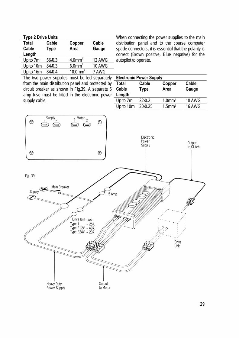
When connecting the power supplies to the main distribution panel and to the course computer spade connectors, it is essential that the polarity is correct (Brown positive, Blue negative) for the autopilot to operate.
Electronic Power Supply Total Cable Length
Cable Type
Copper Area
Cable Gauge
Up to 7m 32/0.2 1.0mm2 18 AWG Up to 10m 30/0.25 1.5mm2 16 AWG
The two power supplies must be led separately from the main distribution panel and protected by circuit breaker as shown in Fig.39. A separate 5 amp fuse must be fitted in the electronic power supply cable.
29
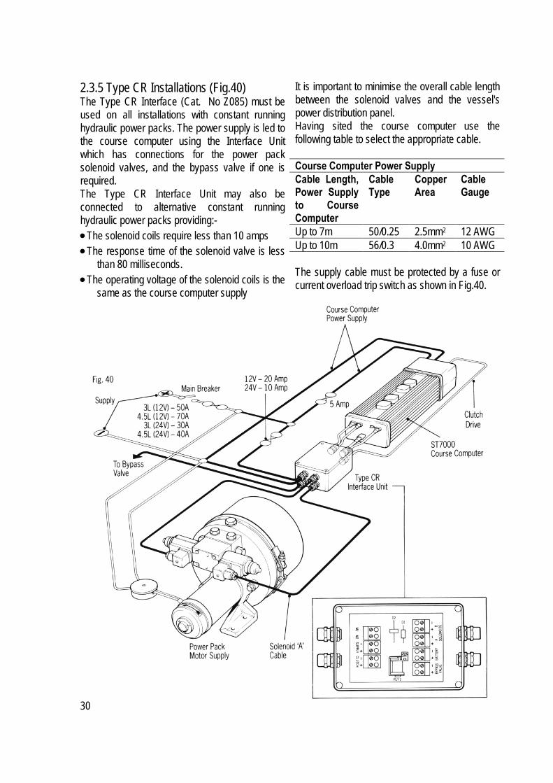
It is important to minimise the overall cable length between the solenoid valves and the vessel's power distribution panel. Having sited the course computer use the following table to select the appropriate cable. Course Computer Power Supply Cable Length, Power Supply to Course Computer
Cable Type
Copper Area
Cable Gauge
Up to 7m 50/0.25 2.5mm2 12 AWG Up to 10m 56/0.3 4.0mm2 10 AWG
2.3.5 Type CR Installations (Fig.40) The Type CR Interface (Cat. No Z085) must be used on all installations with constant running hydraulic power packs. The power supply is led to the course computer using the Interface Unit which has connections for the power pack solenoid valves, and the bypass valve if one is required. The Type CR Interface Unit may also be connected to alternative constant running hydraulic power packs providing:- • The solenoid coils require less than 10 amps • The response time of the solenoid valve is less
than 80 milliseconds. • The operating voltage of the solenoid coils is the
same as the course computer supply
The supply cable must be protected by a fuse or current overload trip switch as shown in Fig.40.
30

Solenoid Valve Power Supply Cable Length, Course computer to Power Pack
Cable Type
Copper Area
Cable Gauge
Up to 7m 50/0.25 2.5mm2 12 AWGUp to 12m 56/0.3 4.0mm2 10 AWGUp to 17m 84/0.3 6.0mm2 8 AWG The solenoid valve connectors can only accept cable up to 2.5mm2 copper area. If larger cable is required a 0.5m tail of 2.5mm2 cable should be used to wire to the connectors. Hydraulic Power Pack Motor The power supply to the motor of the constant running hydraulic power pack should be connected to the vessel's central distribution panel using cable selected from the following table. Cable Length
Cable Type
Copper Area
Cable Gauge
Up to 5m 84/0.3 6mm2 8 AWG Up to 8m 84/0.4 10mm2 7 AWG
An isolator switch and circuit breaker (Fig 40) should be installed to supply power to the complete system. The lighter power supply leads for the electronic power supply and solenoid drive amplifier should be independently fused (see Fig. 40). 2.3.6 Sterndrive Installations The stern drive actuator is supplied with 6m (20ft) of 4 core cable. The blue and brown cores are fitted with spade connectors (Fig. 41) and should be connected to 'motor 1' and 'motor 2' course computer spade connectors. The remaining two cores (red and black) drive the actuator clutch and should be connected into the connector box.
31

3. Functional Test The following functional test and set up procedures must be carried out before sea trials are attempted. 3.1 Switch on Switch on the electrical supply from the main panel. All control units will emit a short beep tone and display 'ST7000'. Within 2 seconds Standby will be displayed to indicate the computer is active and the autopilot is in Standby mode. 3.2 Rudder Angle Sense Moving the wheel to produce a turn to starboard should move the rudder angle display to the right:-
If the display moves in the opposite direction the red and green wires of the rudder reference transducer should be reversed. 3.3 Mechanical Test (Manual Steering) The steering system and drive unit/rudder reference unit should be carefully inspected and the following points checked using the steering wheel to drive the vessel's steering from hardover to hardover. • The steering system reaches the Rudder End
Stops before the Drive Actuator reaches its end stops (Linear/Stern Drive).
• No part of the Autopilot Drive System fouls any part of the steering system or vessel's structure through full travel (all drives),
• The mechanical alignment of the drive unit is as specified in this manual (Linear/Stern Drive).
• The mechanical alignment of the Rudder Reference Unit is as specified in this manual (all drives).
• All connecting wires are secured clear of the bilge and cannot foul any part of the steering system. Any connectors are tightly secured (all drives).
• All securing bolts are fully tightened and mechanical locking arrangements as specified are in place (all drives).
3.4 Rudder Angle Alignment With the rudder amidships, check that the rudder angle display reads zero. Any misalignment must be removed by rotating the rudder reference transducer within the slots in the body. 3.5 Operating Sense The operating sense of the autopilot can be checked as follows:- • Push Auto. • Push + 10 which should move the rudder a
few degrees to produce a turn to starboard. If the rudder moves hardover to port the motor connections between the course computer and drive unit should be reversed.
3.6 Rudder Deadband The factory preset rudder deadband level (see 4-1) will provide stable rudder positioning on most steering systems. On some steering systems where a rotary or hydraulic drive unit is sited a long way from the rudder, slight instability may occur. This can be removed by increasing the 'damping' level (see 4.3). Any increase should be minimised as it will reduce the autopilots course keeping accuracy. 3.7 Mechanical Test (Autopilot Steering) Rotary/Linear/Hydraulic Drives Warning: When the steering system is being moved manually or under drive from the autopilot do not touch any part of the system. The forces exerted are considerable and could cause injury. • Push Auto. • Push the + 10 button repeatedly to drive the
rudder hardover onto end stops (Note: May require increasing the rudder limit (see 4.3)).
• Ensure the drive unit mounting shows no sign of movement.
32

• For hydraulic systems ensure there is no seepage of hydraulic fluid and that the steering ram moves smoothly.
• Repeat using the - 10 button to drive the rudder hardover to the opposite end stop.
Current Limit and Cutout When the rudder is driven onto end stops drive will be cut out after a few seconds. This is normal. Drive will only be restored if the rudder moves away from the end stop or if drive is required in the opposite direction. 3.8 Mechanical Test - Stern Drive (Autopilot Steering) It is recommended that the 'Auto Release' facility is used when the Autohelm mechanical stern drive actuator is installed. This is selected and tested as follows: • Select 'Auto Release' in calibration mode (see
4.3) • Select 'Auto Release '1’ (ON). • Exit calibration mode. Manually drive the
steering hardover to starboard. • With the vessel's engines running engage
Auto and with repeated presses of the - 10 button drive the steering to the opposite lock (Port).
• The autopilot should drive the steering onto the end stops, sound an alarm whilst displaying the Release message and then revert to Standby.
• Re-engage the autopilot (Auto) and repeat the above driving the steering hard to starboard using the + 10 button.
• The autopilot should again drive onto the endstop, alarm/display Release and return to standby.
Note: If the ST7000 sounds the alarm and displays 'Release' before reaching the opposite lock carefully check the vessel's steering system for any stiffness or mechanical jamming. If the condition persists set the 'Auto Release' function to "off" and contact the Product Support Department at Raymarine for further advice.
Warning • The 'Auto Release' function should always be
set to "off" if using any drive unit other than a stern drive actuator.
• Auto Release is not available in drive level 4. 3.9 Rudder Angle Limit (All Drive Units) Having checked the correct functioning of the drive unit and the appropriate End Stop Cutout/Auto Release function the programmable rudder angle unit should be set. The rudder angle limit sets the maximum angle to which the autopilot will move the rudder. This should be set to just less than the vessel's mechanical limit stop to avoid putting the steering system under unnecessary load. Using the rudder angle display record maximum rudder angle in both directions and set up the rudder angle limit in calibration mode (see 4.3) to 5 degrees less than the minimum angle recorded.
33
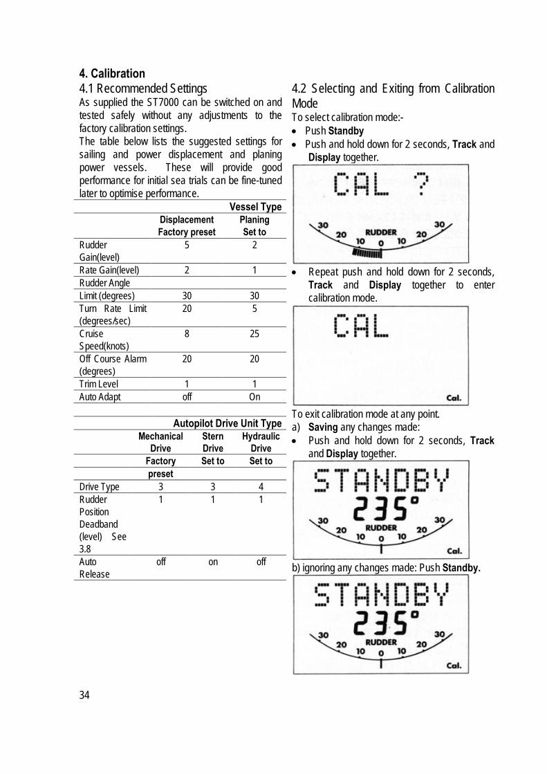
4. Calibration 4.1 Recommended Settings As supplied the ST7000 can be switched on and tested safely without any adjustments to the factory calibration settings. The table below lists the suggested settings for sailing and power displacement and planing power vessels. These will provide good performance for initial sea trials can be fine-tuned later to optimise performance.
Vessel Type Displacement Planing Factory preset Set to Rudder Gain(level)
5 2
Rate Gain(level) 2 1 Rudder Angle Limit (degrees) 30 30 Turn Rate Limit (degrees/sec)
20 5
Cruise Speed(knots)
8 25
Off Course Alarm (degrees)
20 20
Trim Level 1 1 Auto Adapt off On
Autopilot Drive Unit Type Mechanical
Drive Stern Drive
Hydraulic Drive
Factory Set to Set to preset Drive Type 3 3 4 Rudder Position Deadband (level) See 3.8
1 1 1
Auto Release
off on off
4.2 Selecting and Exiting from Calibration Mode To select calibration mode:- • Push Standby • Push and hold down for 2 seconds, Track and
Display together.
• Repeat push and hold down for 2 seconds,
Track and Display together to enter calibration mode.
To exit calibration mode at any point. a) Saving any changes made: • Push and hold down for 2 seconds, Track
and Display together.
b) ignoring any changes made: Push Standby.
34

4.3 Adjusting Calibration In calibration mode, the display button is used to scroll through the menu. The displayed value is adjusted using the Response buttons (hold button down for fast scroll).
• Rudder Gain, levels 1 to 9 (see 5.5 & 5.6)
• Rate Gain, levels 1 to 9 (see 5.8) (Counter
Rudder)
• Rudder Angle Limit, 15 to 40 deg. (see 3.4).
• Rate of Turn Limit, 5 to 20 deg./sec
• Cruise Speed, for Track mode operation, 4 to
60 knots
35

• Off-Course Alarm, 15 to 40 deg. Angle
• Automatic Trim (see 5.4).
• Remote Control Identifier (For Future Use)
• Manual Steering Lever Type
• Autopilot Drive Unit Type
• Rudder Position Deadband (levels 1 to 9),
(See 3.6)
36

• Northerly/Southerly Heading Instability
Select Hemisphere 0 (OFF) N (North) S (South)
Enter Local Latitude using Response Keys. A typical display in the Northern Hemisphere would be:
and in the Southern Hemisphere
• Auto Release (see 3.8 & 5.7)
OFF 1 = ON The Auto Release facility is designed to provide Emergency Manual Override when used with the Autohelm Stern Drive Actuator. For all other Drive Systems Auto Release must be selected "OFF". 4.4 Display Contrast Adjustment The LCD Contrast can be adjusted to suit a wide range of control unit viewing angles. • Push display and track together momentarily.
• Push response ▲ to increase contrast (suits
viewing from below). • Push response ▼ to decrease contrast (suits
viewing from above). Adjust the display for optimum viewing. • Push display and track together momentarily
to store selection and return to previous operating mode.
37

4.7 Rudder and Rate Gain Tables • Rudder Gain Level Value 1 0.1 2 0.14 3 0.19 4 0.25 5 0.35 6 0.47 7 0.65
If the 'CAL' display reappears at any stage during calibration mode please press Display to advance to the next menu level
8 0.88 9 1.2 • Rate Gain (Seconds) Level Value 1 0.2 2 0.24 3 0.3
4.5 Permanent Watch Alarm (SFIA) If the permanent watch alarm is required, please contact Raymarine's Product Support Department or authorised dealer for details. 4.6 Recording Calibration Settings Having fine-tuned the calibration settings during initial sea trials, record them in the following table for future reference. 4 0.37 Setting 5 0.45 Rudder Gain 6 0.55 Rate Gain 7 0.67 Rudder Limit 8 0.82 Turn Limit 9 1.0 Cruise Speed Off Course Automatic Trim Manual Type Drive Damping Auto Adapt Auto Release
Once calibration has been carried out, further adjustment can be made at any time.
38

5. Initial Sea Trials Initial sea trials should be carried out in calm conditions with plenty of sea room. As the vessel will be constantly changing heading it is very important to maintain a constant look out. Before sea trials:- • Carry out the functional test (section 3) to verify
that the autopilot is operating correctly and that you are familiar with all of its controls.
• If a planing vessel, check that the rudder gain is set to 2 and turn rate limit to 5 degrees as recommended in section 4.1. The lower turn rate limit is very important for safety at planing speeds where large course changes can otherwise produce violent turns.
• If the system has a hydraulic drive unit set up the drive type to 4 (see 4.1).
• Read the Operating Manual. 5.1 Automatic Deviation Correction The ST7000 will correct the fluxgate compass for any deviating magnetic fields. This should be carried out in calm conditions preferably in flat water. • To select compass adjust Push and hold
Standby for 1 second.
• Keeping boat speed below 2 knots, turn the
vessel slowly so that it takes at least 3 minutes to complete 360 deg. Keep turning until the display changes to show the amount of deviation the autopilot has corrected:-
Note: If the amount exceeds 15 deg., it is recommended the fluxgate should be re-sited. • Use the course change buttons to adjust the
displayed heading until it agrees with the steering compass or a known transit bearing. Note: 000˚ is always followed by off. This will suppress the display of compass and automatic headings on the control unit.
• To exit compass adjust and store the compass settings push and hold Standby for 1 second.
• To exit compass adjust without saving any new settings push Standby momentarily.
5.2 First Sea Trials • Hold the course steady for 5 to 10 seconds. • Press Auto to lock onto the current heading. • In calm conditions a perfectly constant
heading will be maintained. • Alter course to port and starboard in multiple
increments of 1 and 10 degrees from any control unit. Course changes should be prompt and without any sign of overshooting.
• Press Standby to disengage the autopilot for return to hand steering.
5.3 Response Control There are three response levels to provide tighter than normal course keeping when restricted sea room requires. Select each level in turn and observe the autopilot activity. Level 1 - Automatic Sea State Control This provides the optimum compromise between power consumption and course keeping accuracy and is suitable for most situations. The automatic sea state control can be observed during the sea trial. When the autopilot is initially engaged in Auto mode the autopilot will respond to all pitch and roll movements. During the first minute of operation, it will be noticed that repetitive movements of the vessel are gradually neglected until finally the autopilot will respond only to true variations in course.
39

To ensure precise course adjustments the sea state control is automatically reset whenever a 10 deg. course change is selected. Level 2 - Automatic Sea State Inhibit Where increased course keeping accuracy is required the automatic sea state control can be inhibited by moving to response level 2. Autopilot activity and therefore power consumption will be increased. Level 3 - Automatic Sea State Inhibit - Counter Rudder Where maximum course keeping accuracy is required move to response level 3. This introduces counter rudder (rate) to increase @e natural damping of the vessel. On power craft level 3 is useful at slow speed where the natural damping of the vessel is reduced. Autopilot activity and therefore power consumption will be at a maximum. The minimum response level necessary to achieve the desired course keeping should be used to reduce power consumption and autopilot wear and tear. 5.4 Automatic Trim Control The ST7000 automatically corrects for trim. No adjustment of the pilot is necessary. After each course change the Automatic Trim is cancelled and the ST7000 will re-establish the correct trim for the new heading. It should be noted that if a large course change is keyed in (greater than 60 deg.) the autopilot will not assume the final selected course immediately. The vessel will come to within say 10 deg. of the desired course and will only settle onto course when the Automatic Trim has been full established. This may take up to two minutes. It is recommended the following procedure is adopted for large course changes. • Note required new heading. • Select Stand by and steer manually. • Bring vessel onto new heading. • Select Auto and let vessel settle onto course. • Bring to final course with 1 deg. course
change increments.
It is sound seamanship to make major course changes only whilst steering manually. In this way any obstructions or other vessels may be cleared properly and due account taken of the changed wind and sea conditions on the new heading prior to engaging the autopilot. Important Note If the automatic trim control is switched off (see section 4.3), regular checks on the vessels heading should be made as changes in standing helm will change the course steered by the autopilot. 5.5 Rudder Gain Adjustment (Displacement Craft) The rudder gain level recommended in Section 4.1 will provide stable control for initial sea trials. However, vessels can vary widely in their response to the helm, and further adjustment to the rudder gain may improve the autopilots steering characteristics. Setting up rudder gain should be carried out with Response level 1. An excessively high rudder control setting results in oversteer which can be recognised by the vessel swinging from side to side of the automatic heading accompanied by excessive rudder movement. In addition, distinct overshoot will be observed when the course is changed. This condition can be corrected by reducing the rudder setting. Similarly, an insufficient rudder control setting results in understeer which gives sluggish steering performance and is particularly apparent when changing course. This is corrected by increasing the rudder setting. These tendencies are most easily recognised in calm sea conditions where wave action does not mask basic steering performance. The rudder control setting is not over critical and should be set to the lowest setting consistent with accurate course keeping. This will minimise actuator movements and hence reduce power consumption and wear and tear generally. Typically if at cruising speed a course change of 40 deg. results in an overshoot of between 2 and 5 deg., the rudder gain is correctly adjusted.
40

5.6 Rudder Gain Adjustment (High Speed Planing Craft) It is particularly important that the Rudder Gain is correctly set on high speed craft. Incorrect adjustment will lead to poor steering performance and is a dangerous condition at high speed. Adjust as follows: Optimum Setting • Set to Rudder Gain for optimum steering
performance at the vessels normal cruising speed.
• Push and hold down both Response keys together for 1 second to gain access to Rudder Gain, Adjust either side of the calibrated setting to provide optimum autopilot steering.
Auto Adapt It is recommended that for high speed craft the Auto Adapt facility is selected. This automatically reduces the effects of Northerly/Southerly heading instability. This feature is selected in calibration by entering the vessel's operating latitude (see 4.3). When selected it automatically adjusts the Rudder Gain depending on heading removing the need for manual adjustment. Warning: If Auto Adapt is not selected manual adjustment of rudder gain is normally required when going from Northerly to Southerly headings or vice versa. Failure to do so can lead to poor course keeping. Adjustment with Speed • Due to the significant differences in dynamic
stability between planing and non-planing conditions most high speed craft require Rudder Gain adjustment when going from planing to displacement speeds or vice versa. The required adjustment can be achieved automatically or manually.
• When the ST7000 is used with the speed input from an Autohelm ST50 SPEED or TRIDATA instrument the Rudder Gain is automatically adjusted with boat speed. After setting the gain at planing speed no further manual adjustment should be required.
• If no ST50 speed input is available manual adjustment should be carried out to the Rudder Gain setting via the Response keys (see 'optimum setting') adjusting as follows: • Speed decreases from planing to
displacement - increase gain by 1 or 2 levels.
• Speed increases from displacement to planing
- decrease gain by 1 or 2 levels. Warning: The manual gain adjustment must be made after reducing from planing to displacement speed and before increasing from displacement to planing speed. 5.7 Manual Override (Sterndrive Actuators only) Manual override is selected during calibration using the Auto Release option. It must only be used on installations fitted with the stern drive actuator. When it has been selected, the ST7000 can be overridden to allow hand steering by turning the steering wheel. This will return the ST7000 to Standby and sound the control unit buzzer for 10 seconds. There is a slight delay before the ST7000 will return to Standby. Excessive force is not required and will not reduce this delay. With the ST7000 in Auto and clear of obstruction turn the steering wheel to observe the manual override. Repeat two or three times until you are confident with its operation. The manual override is intended for emergency use only. The ST7000 should normally be disengaged by pushing the Standby button on the control unit. 5.8 Rate Gain Adjustment (Counter Rudder) Counter rudder increases the natural yaw damping of the vessel and at the expense of increased autopilot activity, will generally provide improved course keeping accuracy.
41

5.9 Compass Alignment If it is necessary to change Compass Alignment without carrying out the Automatic Deviation Correction proceed as follows:- • Push and hold Standby for 1 second to
select compass adjust mode. • Push Display once to bypass Automatic
Deviation Correction • Use the course change buttons to adjust the
heading displayed • To exit compass adjust and store the new
setting push and hold Standby for 1 second • To exit compass adjust without saving the
new setting push Standby momentarily • To confirm the alignment procedure has been
correctly carried out, switch off power, switch back on and check displayed heading. Repeat the alignment procedure if incorrect.
42

6. Track Control Track control allows the ST7000 to maintain track between two waypoints entered on a GPS, Decca, Loran or satellite Navigation System. The Navigation System must have a suitable autopilot output which at minimum transmits cross track error to one of the following formats. NMEA 0180 – Simple Format NMEA 0183 – XTE
XTR APA APB RMB
If the navigation system transmits the correct NMEA 0183 sentences (shown below), the autopilot will receive and display bearing to waypoint, distance to waypoint and waypoint number. NMEA 0183 Sentence Headers
Bearing to Waypoint
Distance to Waypoint
Waypoint Number
APB WDR APB BPI WDC APA
BWR BPI BPI BWC BWR BWR BER BWC WDR BEC BER BWC RMB BEC WDC
RMB RMB BOD WCV BER BEC
6.1 Functional Test Before attempting sea trials confirm that the control unit is receiving navigation data by using the Display to bring it up on the control unit LCD. Note: If the data is not being received it is impossible to select Track Mode.
6.2 Operating Hints Basic Principles The control unit accepts cross track error data from the Navigation System and computes course changes to maintain the desired track. It is primarily designed to keep a vessel on track, automatically compensating for tidal streams and leeway. To obtain best performance in the track following mode the track should be manually acquired by steering the vessel to within 0.1nm of track and then bringing the heading to within 5 deg. Of the bearing to the next waypoint before pressing the Track button.
Under most conditions the Track control will hold the track to within 0.05nm (300ft) or better. The autopilot takes account of vessel speed when computing course changes to ensure optimum performance over a wide range of vessel speeds. If an Autohelm ST50 Speed or Tridata instrument is connected to control unit will use measured speed, otherwise the cruise speed entered during calibration will be used.
43

Waypoint Advance If your navigation receiver transmits valid waypoint number and bearing to waypoint NMEA headers (see table) it is possible to advance from one waypoint to the next by simply pressing the Track button. As the vessel passes the target waypoint the navigation receiver should select, manually or automatically, the next target waypoint. The ST7000 will detect and display the bearing to the new waypoint whilst sounding an alarm to indicate waypoint arrival. Note: While the waypoint advance alarm is sounding, track control is stopped and the ST7000 will maintain the current heading, Once it is considered safe to turn onto the new track press the Track button once. This will cancel the waypoint arrival alarm and steer the boat towards the next waypoint. Limitations Although there is no need to fully understand the details of the track keeping algorithm, it is very important to understand its limitations to obtain the best performance from the Track control. The most significant of these limitations is imposed if NMEA 0180 cross track error data is transmitted by the Radio Navigation Receiver. This data is restricted to +0.30nm, which means that even if the vessel were 5 miles to starboard of track, the transmitted data would still be 0.30nm, Attempts to engage Track control beyond the 0.30nm limit will lead to excessive overshoots and can result in the vessel circling. For this reason the alarm code is displayed (see operating handbook) whenever the cross track error exceeds 0.30nm The requirement to remain within 0.30nm of track also limits the maximum allowable angular error between the track course and the vessel's heading. If the angular error is too great, the Track control will be unable to cancel it within the 0.30nm limit leading to the problems outlined above. The NMEA 0183 format transmits cross track error data up to 9.99nm and enables the Track control to operate with larger cross track errors. However, the alarm code will still be
displayed in case there are navigational hazards close to the intended track. Low Speed Operation Operating the 'rack control at low speeds requires more care as the effect of tidal streams is far more significant than at higher speeds. In general terms, providing the tidal flow is less than 35% of the vessel speed no noticeable difference will occur, in the performance of the Track control. However, extra care should be taken to ensure that the vessel is as close as possible to track, and that the direction made good over the ground is as close as possible to the direction of the next waypoint before engaging Track control. Under these circumstances positive positional checks at regular intervals are vital especially if navigational hazards are close. Dodges Full control remains available from all control units when the autopilot is in Track control. Dodges are accomplished by simply selecting the desired course change on the Autohelm keypad. Once the hazard has been avoided the course change selected for the dodge manoeuvre should be cancelled by selecting an equal course change in the opposite direction. Provided the vessel remains within 0.1nm of track there is no need to steer back towards the track. Safety Passage making in Track control removes the chores of compensation for wind and tidal drift and will aid precise navigation. It is most important however to maintain an accurate log with regular plots and to verify the computed position read from the Radio Navigation Receiver with a dead reckoned position from recording the average course steered and the distance logged. In open water such plots should be at least hourly and more frequent in confined waters or when potential hazards are near. Local variations in radio signal quality and changes in the tidal stream will produce deviations from the desired track. When setting
44
up waypoints, remember that deviations will occur, and thoroughly check along each track and to 0.5nm each side to ensure that there are no hazards within the zone. Always confirm the position given by the Radio Navigation Receiver using an easily identifiable fixed object at the start of a passage to check and enable compensation to be made for fixed positional errors. The use of Radio Navigation control will enable accurate track keeping even in complex navigational situations. It cannot remove the responsibility of the skipper to ensure the safety of his vessel at all times by careful navigation and frequent position checks.
7. Windvane Control (Sail Only)
Windvane Control allows the ST7000 to maintain an apparent wind angle, There are two methods of supplying the ST7000 with wind angle:- • Using the NMEA 0183 output from another
manufacturers instrument system and connecting it to the ST7000 control unit.
Note. The NMEA 0183 output must transmit VWR (Relative wind bearing). • Using an Autohelm ST50 wind instrument
connected using the SeaTalk bus. The ST7000 uses Wind Trim to eliminate the effects of turbulence and short term wind variations and provide smooth precise performance under windvane with minimum power consumption. Wind Trim uses the fluxgate compass as the primary heading reference, and as changes in the apparent wind angle occur the compass heading is adjusted to maintain the original apparent wind angle.
Operating Hints Wind Trim adjusts the compass course over a minute period, providing optimum response for offshore conditions where genuine shifts in wind direction occur gradually. In gusty and unsteady inshore conditions it is best to sail a few degrees further off the wind so that changes in apparent wind direction can be tolerated. It is also important to ensure that the amount of standing helm is minimised by careful sail trim and positioning of the mainsheet traveller. It is recommended that the headsail and mainsail are reefed a little early rather than too late.
45

46

47

44321/5 48


Raymarine Ltd. Anchorage Park Portsmouth Hampshire PO3 5TD UK Tel +44 23 9269 3611 Fax +44 23 9269 4642
www.raymarine.com


