Embed Size (px)
Citation preview
SOUNDFIELD
ST450 PortableMicrophone System
User GuideVersion 1.01
System comprises:
• ST450 Microphone • ST450 Control Unit• HW3010 Shockmount • 5 Metre 12 pin Lemo Mic Cable (Mic to Controller)
• B-Format & Stereo Output Cables • External DC Power Supply
SoundField ST450 User Guide
Safety Information Page 2
SAFETY INFORMATION
• This equipment must be EARTHED.
• Only suitably trained personnel should service this equipment.
• Please read and take note of all warning and informative labels.
• Before starting any servicing operation, this equipment must be isolated from the AC supply (mains) by removing the incoming IEC mains connector.
• Fuses should only be replaced with ones of the same type and rating as that indicated.
• Operate only in a clean, dry and pollutant-free environment.
• Do not operate in an explosive atmosphere.
• Do not allow any liquid or solid objects to enter the equipment. Should this accidentally occur then immediately switch off the unit and contact your service agent.
• Do not allow ventilation slots to be blocked.
Cleaning
For cleaning the front panels of the equipment we recommend anti-static screen cleaner sprayedonto a soft cloth to dampen it only.
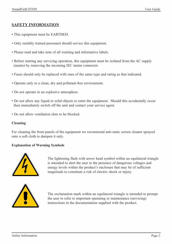
Explanation of Warning Symbols
The lightening flash with arrow head symbol within an equilateral triangleis intended to alert the user to the presence of dangerous voltages andenergy levels within the product’s enclosure that may be of sufficientmagnitude to constitute a risk of electric shock or injury.
The exclamation mark within an equilateral triangle is intended to promptthe user to refer to important operating or maintenance (servicing)instructions in the documentation supplied with the product.
SoundField ST450 User Guide
Table of Contents Page 3
TABLE OF CONTENTS
SoundField History - - - - - - 4
Introduction - - - - - - - 5
How Does it Work? - - - - - - 6-7
Controls - - - - - - - 8-10
Rycote Assembly Instructions - - - - - 11-14
ST450 Shockmount - - - - - - 15
Recording B-Format for Surround Post-Production - - 16
Surround Post-Production: Part One: The Surround Zone Software - 17
Surround Post-Production: Part Two: The SP451 Surround Processor - 18
Rechargeable Battery Procedure - - - - - 19
Warranty - - - - - - - 20
Shipping and Quality Assurance - - - - - 21
Wiring Details - - - - - - - 22-23
Technical Specifications - - - - - - 24
Accessories - - - - - - - 25-26
SoundField ST450 User Guide
SoundField History Page 4
SOUNDFIELD HISTORY
In 1933, British scientist Alan Blumlein was issued a patent that stands today as alandmark in the development of stereophonic recording and reproduction. Among itsnumerous declarations, it defined the basis for all coincident microphone techniques,including the Mid/Side and crossed bidirectional configurations. (The latter, in fact, iscommonly referred to as a “Blumlein Stereo” pair.) In the 1970s, British mathematiciansMichael Gerzon, Peter Craven and colleagues expanded upon the stereo conceptspioneered by Blumlein to develop the concept of a microphone system that couldreproduce a full three-dimensional soundfield. Both Blumlein and Gerzon realised thatonly when a soundwave is captured at a single point in space can it be reproducedfaithfully and without the phase distortion anomalies inherent in spaced microphonetechniques.
Early SoundField prototype models were developed using Gerzon’s theory inconjunction with the National Research Development Corporation of Great Britain andCalrec Audio. Chief Designer at Calrec, Ken Farrar, and colleagues played a leading rolein turning Gerzon’s theory into a real product and Ken Farrar’s contribution was laterrecognised by his appointment as a Fellow of the Institution of Electrical Engineers(F.I.E.E.). In 1993, the company SoundField Ltd. was formed specifically to manufactureand further develop the range of products and their application in both stereo and multi-channel audio environments. SoundField Ltd. is the owner of all patent and intellectualproperty rights relating to SoundField Technology.
Today, the SoundField range enjoys a reputation as the ultimate microphones forrecording both stereo and the new developing multi-channel surround formats. Theseunique microphones employ a patented tetrahedral array of closely spaced subcardioidcapsules to capture the complete three-dimensional soundfield at a single point in space.This single point source pick-up principle avoids all of the time - or phase-relatedanomalies generated by spaced microphone arrays. Thus, surround recordings made withSoundField microphones can be collapsed to stereo - or stereo recordings to mono -without the phase problems that result in “comb-filtering” (phase cancellation)distortions. Furthermore, a single point source system is the only one that allows a trulyphase coherent sub-channel to be derived. Spaced microphone arrays are unable to bereduced without introducing significant phase errors unless some of the microphonesignals are discarded, which consequently results in loss of essential audio information.
SoundField ST450 User Guide
Introduction Page 5
INTRODUCTION
The ST450 Portable Microphone System has been specifically developed for location recording andin the design process both the microphone and control unit have been considerably ‘downsized’ incomparison to all other previously available SoundField models. The ST450 simultaneouslyprovides both surround and stereo soundscapes and its big advantage over alternative methods isthat the multi-channel audio it generates from a ‘single point’ source is completely phase coherent.This enables the recordist to collapse the surround to stereo or mono without loss of information,frequency imbalance or any of the other phase problems associated with spaced microphones ormulti capsule ‘dummy head’ arrangements.
The ST450 can be powered by either battery or mains electricity and the microphone can be used atclose quarters on a hand held boom or alternatively situated up to 200 metres from the control uniton the relevant SoundField mic extension cables (see accessories on pages 25-26). The ability toadjust all microphone parameters remotely from such a long distance is invaluable in situationswhere the microphone is placed in an area which is difficult to access.
The ST450 is connected to the control unit by a single lightweight multiway cable which deliversthe four individual capsule signals to the control unit and carries the necessary power back to themicrophone. A small heating element is located in the microphone head to keep the capsulescondensation-free under normal operating conditions. The ST450 control unit outputs stereoLeft/Right, M/S and four channels of SoundField B-Format called W, X, Y and Z which is thesurround information. All outputs are at balanced line level.
The ST450 is designed to function as either a variable pattern single (mono) microphone, a variablepattern, variable width, coincident stereo microphone array or to generate full surround from thefour B-Format outputs which will then be decoded into 5.1 by the Surround Zone post-productionsoftware, DSF-3 Digital Surround Processor or analogue SP451 Surround Processor. This isachieved using four sub-cardioid capsules set in a regular tetrahedron, and by adding or subtractingthe outputs from these four capsules in different proportions, it is possible to derive all possiblepolar patterns from omni, through cardioids to figure-of-eights.
For surround sound recording the recordist should use the four B-Format output signals. Thesecontain the three dimensional information (Height, Width, Depth) required for all current and futuresurround sound formats. The B-Format signals can be de-coded into surround by the SurroundZone post-production software, which outputs six discrete channels (Left, Centre, Right, SurroundLeft, Surround Right and Sub Bass). The Surround Zone software also provides full surround andstereo re-mixing enabling adjustment of Polar Patterns, End-fire or Side Address pick-up, Width,Rotate, Tilt, Zoom and all other microphone parameters. The B-format signals can also be decodedinto surround with the hardware digital DSF-3 1U processor and the analogue SP451 1U processor.
Please note: To maintain a high quality audio performance the ST450 microphone employs studiograde condensor capsules - in environments of high moisture and humidity (or other extremeweather conditions) their performance may be temporarily affected.
SoundField ST450 User Guide
How Does It Work? Page 6
HOW DOES IT WORK?
SoundField B-Format
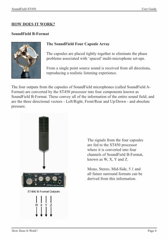
The SoundField Four Capsule Array
The capsules are placed tightly together to eliminate the phaseproblems associated with ‘spaced’ multi-microphone set-ups.
From a single point source sound is received from all directions,reproducing a realistic listening experience.
The signals from the four capsulesare fed to the ST450 processorwhere it is converted into fourchannels of SoundField B-Format,known as W, X, Y and Z.
Mono, Stereo, Mid-Side, 5.1 andall future surround formats can bederived from this information.
The four outputs from the capsules of SoundField microphones (called SoundField A-Format) are converted by the ST450 processor into four components known asSoundField B-Format. These convey all of the information of the entire sound field, andare the three directional vectors - Left/Right, Front/Rear and Up/Down - and absolutepressure.
SoundField ST450 User Guide
How Does It Work? Page 7
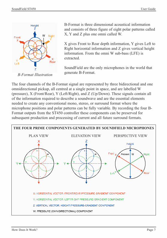
B-Format Illustration
B-Format is three dimensional acoustical informationand consists of three figure of eight polar patterns calledX, Y and Z plus one omni called W.
X gives Front to Rear depth information, Y gives Left toRight horizontal information and Z gives vertical heightinformation. From the omni W sub-bass (LFE) isextracted.
SoundField are the only microphones in the world thatgenerate B-Format.
The four channels of the B-Format signal are represented by three bidirectional and oneomnidirectional pickup, all centred at a single point in space, and are labelled W(pressure), X (Front/Rear), Y (Left/Right), and Z (Up/Down). These signals contain allof the information required to describe a soundwave and are the essential elementsneeded to create any conventional mono, stereo, or surround format where themicrophone positions and polar patterns can be fully variable. By recording the four B-Format outputs from the ST450 controller these components can be preserved forsubsequent production and processing of current and all future surround formats.
THE FOUR PRIME COMPONENTS GENERATED BY SOUNDFIELD MICROPHONES
PLAN VIEW ELEVATION VIEW PERSPECTIVE VIEW
SoundField ST450 User Guide
Controls Page 8
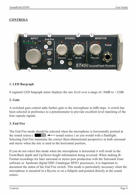
CONTROLS
1
1. LED Bargraph
8 segment LED bargraph meter displays the mic level over a range of -30dB to +12dB.
2. Gain
A switched gain control adds further gain to the microphone in 6dB steps. A switch hasbeen selected in preference to a potentiometer to provide excellent level matching of thefour capsule signals.
3. End Fire
The End Fire mode should be selected when the microphone is horizontally pointed atthe sound source ( sound source ) as you would with a flashlight.Selecting End Fire maintains the correct three-dimensional perspective in both surroundand stereo when the mic is used in the horizontal position.
If you do not select this mode when the microphone is horizontal it will result in theFront/Back depth and Up/Down height information being reversed. When making B-Format recordings for later surround or stereo post production with the Surround Zonesoftware or hardware digital DSF-3/analogue SP451 processors, it is important todocument the status of the End Fire switch. This mode is particularly necessary when themicrophone is mounted in a Rycote or on a fishpole and pointed directly at the soundsource.
2
3
4
5
6
7
8 9

SoundField ST450 User Guide
Controls Page 9
4. Invert
The Invert mode maintains the correct three-dimensional perspective in both surroundand stereo when the microphone is suspended upside down above the sound source. ( )Not selecting this mode with the mic suspended will result in the Left/Right widthinformation and Up/Down height information being reversed. It is important to documentthe status of the Invert switch when making B-Format recordings for later postproduction.
5. Hi-Pass
100Hz hi-pass filter is available to attenuate unwanted low frequency rumble or windnoise. PLEASE NOTE: THE HI-PASS FILTER IS ACTIVE ACROSS BOTH THESTEREO AND B-FORMAT OUTPUTS.
6. Pattern
The Polar Pattern control is continuously variable ranging from Omni through Sub-Cardioid, Cardioid, Hyper-Cardioid to Figure-of-eight and sets the polar patterns used forthe stereo pair.
7. Mid Side
When the Mid/Side switch is engaged the stereo outputs will be M/S encoded. The Leftoutput channel provides the Mid signal and the Right output channel provides the Sidesignal.
8. Width
Offers continuous adjustment of the stereo width from mono (‘0’) through to wide anglestereo (‘10’).
9. Headphone Monitoring
Front panel headphone monitoring is provided with a continuously variable volumecontrol. The headphone section monitors the Left/Right stereo output. Connection is via astereo 1/4 inch jack socket (TRS) and is for use with headphones having an impedance of100 ohms or greater.
SoundField ST450 User Guide
Controls Page 10
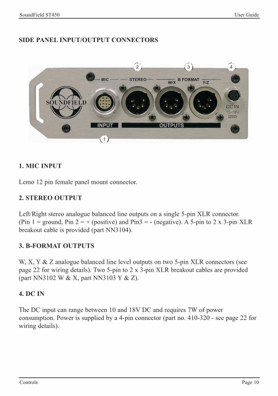
SIDE PANEL INPUT/OUTPUT CONNECTORS
1. MIC INPUT
Lemo 12 pin female panel mount connector.
2. STEREO OUTPUT
Left/Right stereo analogue balanced line outputs on a single 5-pin XLR connector.(Pin 1 = ground, Pin 2 = + (positive) and Pin3 = - (negative). A 5-pin to 2 x 3-pin XLRbreakout cable is provided (part NN3104).
3. B-FORMAT OUTPUTS
W, X, Y & Z analogue balanced line level outputs on two 5-pin XLR connectors (seepage 22 for wiring details). Two 5-pin to 2 x 3-pin XLR breakout cables are provided(part NN3102 W & X, part NN3103 Y & Z).
4. DC IN
The DC input can range between 10 and 18V DC and requires 7W of powerconsumption. Power is supplied by a 4-pin connector (part no. 410-320 - see page 22 forwiring details).
1
2 3 4
SoundField ST450 User Guide
Rycote Assembly Instructions Page 11
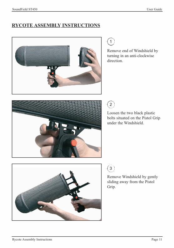
RYCOTE ASSEMBLY INSTRUCTIONS
1
Remove end of Windshield byturning in an anti-clockwisedirection.
2
Loosen the two black plasticbolts situated on the Pistol Gripunder the Windshield.
3
Remove Windshield by gentlysliding away from the PistolGrip.
SoundField ST450 User Guide
Rycote Assembly Instructions Page 12
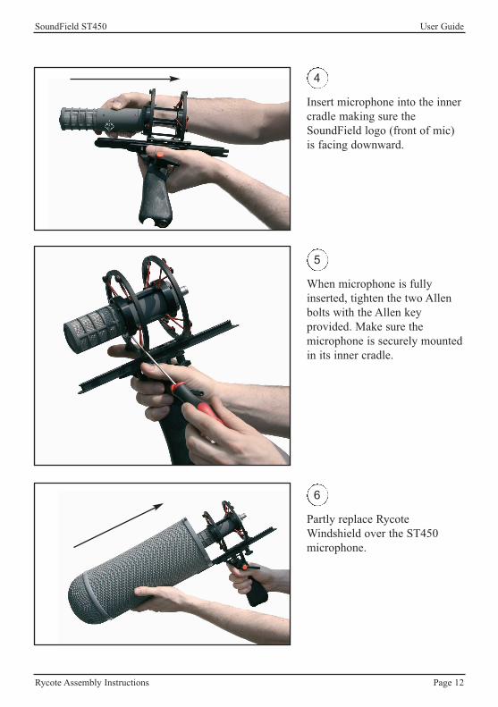
4
Insert microphone into the innercradle making sure theSoundField logo (front of mic)is facing downward.
5
When microphone is fullyinserted, tighten the two Allenbolts with the Allen keyprovided. Make sure themicrophone is securely mountedin its inner cradle.
6
Partly replace RycoteWindshield over the ST450microphone.
SoundField ST450 User Guide
Rycote Assembly Instructions Page 13
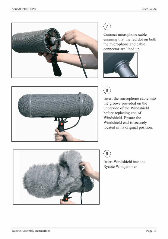
7
Connect microphone cableensuring that the red dot on boththe microphone and cableconnector are lined up.
8
Insert the microphone cable intothe groove provided on theunderside of the Windshieldbefore replacing end ofWindshield. Ensure theWindshield end is securelylocated in its original position.
9
Insert Windshield into theRycote Windjammer.
SoundField ST450 User Guide
Rycote Assembly Instructions Page 14
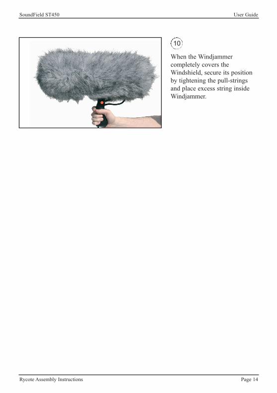
10
When the Windjammercompletely covers theWindshield, secure its positionby tightening the pull-stringsand place excess string insideWindjammer.
SoundField ST450 User Guide
ST450 Shockmount Page 15
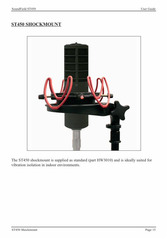
ST450 SHOCKMOUNT
The ST450 shockmount is supplied as standard (part HW3010) and is ideally suited forvibration isolation in indoor environments.
SoundField ST450 User Guide
Recording B-Format For Surround Post-Production Page 16
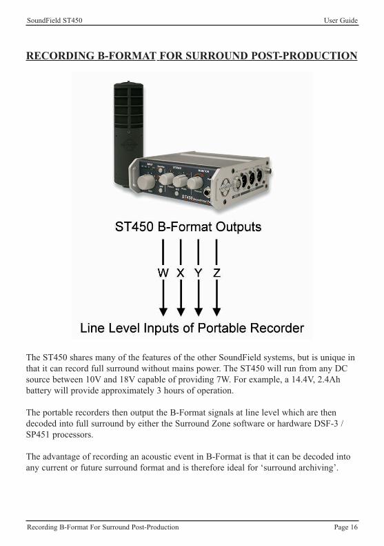
RECORDING B-FORMAT FOR SURROUND POST-PRODUCTION
The ST450 shares many of the features of the other SoundField systems, but is unique inthat it can record full surround without mains power. The ST450 will run from any DCsource between 10V and 18V capable of providing 7W. For example, a 14.4V, 2.4Ahbattery will provide approximately 3 hours of operation.
The portable recorders then output the B-Format signals at line level which are thendecoded into full surround by either the Surround Zone software or hardware DSF-3 /SP451 processors.
The advantage of recording an acoustic event in B-Format is that it can be decoded intoany current or future surround format and is therefore ideal for ‘surround archiving’.
SoundField ST450 User Guide
Surround Post-Production Part One: Surround Zone Software Page 17
SURROUND POST-PRODUCTION PART ONE: THE SOUNDFIELD SURROUND ZONE SOFTWARE
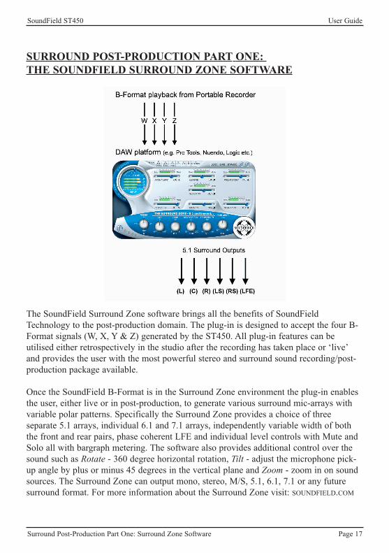
The SoundField Surround Zone software brings all the benefits of SoundFieldTechnology to the post-production domain. The plug-in is designed to accept the four B-Format signals (W, X, Y & Z) generated by the ST450. All plug-in features can beutilised either retrospectively in the studio after the recording has taken place or ‘live’and provides the user with the most powerful stereo and surround sound recording/post-production package available.
Once the SoundField B-Format is in the Surround Zone environment the plug-in enablesthe user, either live or in post-production, to generate various surround mic-arrays withvariable polar patterns. Specifically the Surround Zone provides a choice of threeseparate 5.1 arrays, individual 6.1 and 7.1 arrays, independently variable width of boththe front and rear pairs, phase coherent LFE and individual level controls with Mute andSolo all with bargraph metering. The software also provides additional control over thesound such as Rotate - 360 degree horizontal rotation, Tilt - adjust the microphone pick-up angle by plus or minus 45 degrees in the vertical plane and Zoom - zoom in on soundsources. The Surround Zone can output mono, stereo, M/S, 5.1, 6.1, 7.1 or any futuresurround format. For more information about the Surround Zone visit: SOUNDFIELD.COM
SoundField ST450 User Guide
Surround Post-Production Part Two: SP451 Surround Processor Page 18
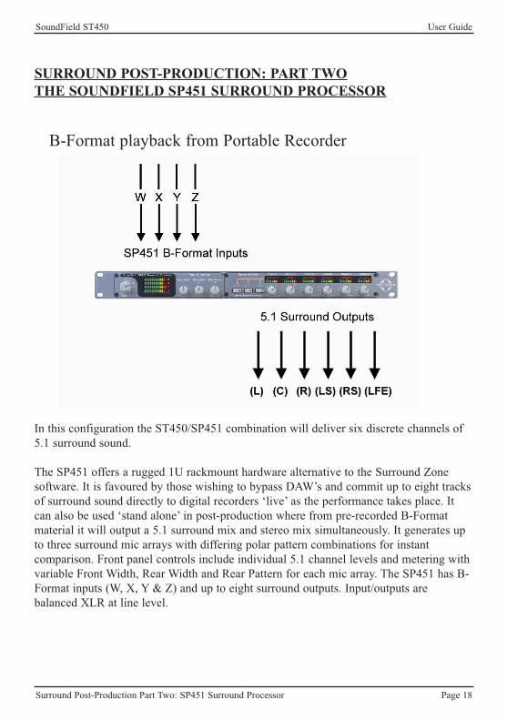
SURROUND POST-PRODUCTION: PART TWOTHE SOUNDFIELD SP451 SURROUND PROCESSOR
In this configuration the ST450/SP451 combination will deliver six discrete channels of5.1 surround sound.
The SP451 offers a rugged 1U rackmount hardware alternative to the Surround Zonesoftware. It is favoured by those wishing to bypass DAW’s and commit up to eight tracksof surround sound directly to digital recorders ‘live’ as the performance takes place. Itcan also be used ‘stand alone’ in post-production where from pre-recorded B-Formatmaterial it will output a 5.1 surround mix and stereo mix simultaneously. It generates upto three surround mic arrays with differing polar pattern combinations for instantcomparison. Front panel controls include individual 5.1 channel levels and metering withvariable Front Width, Rear Width and Rear Pattern for each mic array. The SP451 has B-Format inputs (W, X, Y & Z) and up to eight surround outputs. Input/outputs arebalanced XLR at line level.
B-Format playback from Portable Recorder

SoundField ST450 User Guide
Rechargeable Battery Procedure Page 19
RECHARGEABLE BATTERY PROCEDURE FOR ST450(See Accessories on pages 25-26, part no. ST450/BATT-KIT)
BATTERY LIFEA fully charged battery (part no. 800-002) will provide approximately 3 hours ofoperation under normal operating conditions.
CHARGING INSTRUCTIONS
1. Place the battery in the correct direction and make sure that the battery is fitted tightly into the charger and the metal points.
2. Connect the charger with the supplied power supply.
3. The indicator shows “Red” when the battery is charging and “Green” when the batteryis fully charged.
4. Unplug the charger before taking out the battery.
SoundField ST450 User Guide
Warranty Page 20
WARRANTY
Limited LiabilitySOUNDFIELD LTD., HEREIN AFTER KNOWN AS THE MANUFACTURER, GUARANTEESTHIS EQUIPMENT FROM DEFECTS IN MATERIAL AND WORKMANSHIP UNDERNORMAL USE AND SERVICE FOR A PERIOD OF ONE YEAR. THIS GUARANTEEEXTENDS TO THE ORIGINAL PURCHASER ONLY AND DOES NOT APPLY TO FUSES ORANY PRODUCT OR PARTS SUBJECTED TO MISUSE, NEGLECT, ACCIDENT ORABNORMAL CONDITIONS OF OPERATION. THE GUARANTEE BEGINS ON THE DATEOF DELIVERY TO THE ACTUAL PURCHASER OR TO HIS AUTHORISED AGENT ORCARRIER. IN THE EVENT OF FAILURE OF A PRODUCT COVERED BY THISGUARANTEE, THE MANUFACTURER OR THEIR CERTIFIED REPRESENTATIVES WILLREPAIR AND CALIBRATE EQUIPMENT RETURNED PREPAID TO AN AUTHORISEDSERVICE FACILITY WITHIN ONE YEAR OF THE ORIGINAL PURCHASE AND PROVIDEDTHAT THE GUARANTORS EXAMINATION DISCLOSES TO ITS SATISFACTION THAT THEPRODUCT WAS DEFECTIVE, EQUIPMENT UNDER THIS GUARANTEE WILL BEREPAIRED OR REPLACED WITHOUT CHARGE. ANY FAULT THAT HAS BEEN CAUSEDBY MISUSE, NEGLECT, ACCIDENT, ACT OF GOD, WAR OR CIVIL INSURRECTION;ALTERATION OR REPAIR BY UNAUTHORISED PERSONAL; OPERATION FROM ANINCORRECT POWER SOURCE OR ABNORMAL CONDITIONS OF OPERATION, WILL NOTFALL UNDER THIS GUARANTEE. HOWEVER, AN ESTIMATE OF THE COST OF THEREPAIR WORK WILL BE SUBMITTED BEFORE WORK IS STARTED. THEMANUFACTURER SHALL NOT BE RESPONSIBLE FOR ANY LOSS OR DAMAGE, DIRECTOR CONSEQUENTIAL, RESULTING FROM MACHINE FAILURE OR THE INABILITY OFTHE PRODUCT TO PERFORM. THE MANUFACTURER SHALL NOT BE RESPONSIBLEFOR ANY DAMAGE OR LOSS DURING SHIPMENT TO AND FROM THE FACTORY OR ITSDESIGNATED SERVICE FACILITY. THIS GUARANTEE IS IN LIEU OF ALL OTHERGUARANTEES, EXPRESSED OR IMPLIED, AND OF ANY OTHER LIABILITIES ON THEMANUFACTURERS PART. THE MANUFACTURER DOES NOT AUTHORISE ANYONE TOMAKE ANY GUARANTEE OR ASSUME ANY LIABILITY NOT STRICTLY INACCORDANCE WITH THE ABOVE. THE MANUFACTURER RESERVES THE RIGHT TOMAKE CHANGES OR IMPROVEMENT IN THE DESIGN AND CONSTRUCTION OF THISUNIT WITHOUT OBLIGATION TO MAKE SUCH CHANGES OR IMPROVEMENTS IN THEPURCHASER’S UNIT. ANY DISPUTE ARISING FROM THIS WARRANTY SHALL BESUBJECT TO THE LAWS OF ENGLAND.
What to do if a fault is found
If a fault develops in the unit, notify SoundField Ltd. or their nearest service facilitygiving full details of the difficulty. On receipt of this information, service or shippinginstructions will be forwarded to you. No equipment should be returned under thewarranty without prior consent from SoundField Ltd. or their authorised representative.
SoundField ST450 User Guide
Shipping and Quality Assurance Page 21
SHIPPING AND QUALITY ASSURANCE
Authorised returns should be prepaid and must be insured. All SoundField products arepackaged in specially designed containers for the best possible protection. If the unit isreturned the original container should be used. If this is not possible, a new container canbe obtained from SoundField Ltd.; please specify the model number when requesting anew container. If the specially designed container is not used ensure that a suitable rigidcontainer of adequate size is used, wrap the instrument in paper and surround it with agood thickness of shock absorbing material.
Claim for damage during transitThe instrument should be thoroughly inspected immediately upon delivery to thepurchaser. If the instrument is damaged in any way a claim should be filed with thecarrier immediately. A quotation to repair shipment damage can be obtained fromSoundField Ltd or their certified representative. Final claims and negotiations with thecarrier must be completed by the customer.
Applications problemsSoundField Ltd. will be happy to answer any applications questions to enhance your useof this equipment. Please address all correspondence to:
SoundField Ltd.Charlotte Street Business CentreCharlotte StreetWakefieldWest YorkshireWF1 1UHENGLANDTel: +44 (0) 1924 201089Fax: +44 (0) 1924 290460email: [email protected]
Quality Assurance and Service PolicyOver the years SoundField products have gained an enviable reputation for their qualityof design, performance and reliability, however, in the unlikely event that problems areencountered with this unit, please contact SoundField Service at the appropriate addressabove or alternatively inform one of our world wide network of distributors who will beable to assist with any of your queries.
SoundField ST450 User Guide
Wiring Details Page 22
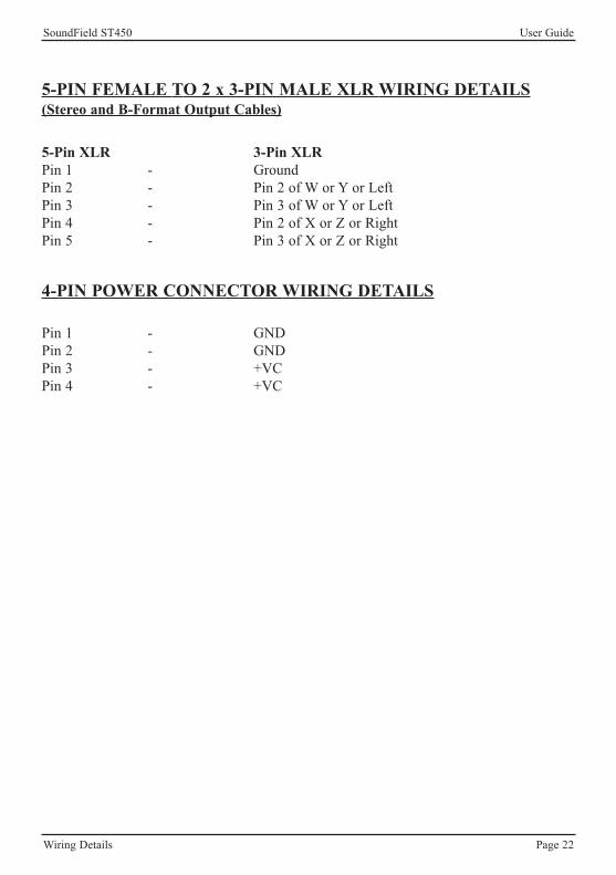
5-Pin XLR 3-Pin XLRPin 1 - GroundPin 2 - Pin 2 of W or Y or LeftPin 3 - Pin 3 of W or Y or LeftPin 4 - Pin 2 of X or Z or RightPin 5 - Pin 3 of X or Z or Right
5-PIN FEMALE TO 2 x 3-PIN MALE XLR WIRING DETAILS(Stereo and B-Format Output Cables)
Pin 1 - GNDPin 2 - GNDPin 3 - +VCPin 4 - +VC
4-PIN POWER CONNECTOR WIRING DETAILS

SoundField ST450 User Guide
Wiring Details Page 23
12 Pin Male 12 Pin Female
Pin 1 - LB (+) - Pin 1Pin 2 - LB (-) - Pin 2Pin 3 - RB (+) - Pin 3Pin 4 - RB (-) - Pin 4Pin 5 - RF (+) - Pin 5Pin 6 - RF (-) - Pin 6Pin 7 - LF (+) - Pin 7Pin 8 - LF (-) - Pin 8Pin 9 - Voltage GND - Pin 9Pin 10 - -V - Pin 10Pin 11 - +V - Pin 11Pin 12 - Signal GND - Pin 12
SOUNDFIELD COLOUR CODING
Pin 1 - WhitePin 2 - PurplePin 3 - GreyPin 4 - PinkPin 5 - GreenPin 6 - YellowPin 7 - RedPin 8 - BluePin 9 - BlackPin 10 - BrownPin 11 - OrangePin 12 - Screen (plus link to connector chassis)
Important Note: Use colour coding as above as some wires have a different number ofstrands.
12 PIN CONNECTOR WIRING DETAILS FOR MIC CABLES
SoundField ST450 User Guide
Technical Specification Page 24
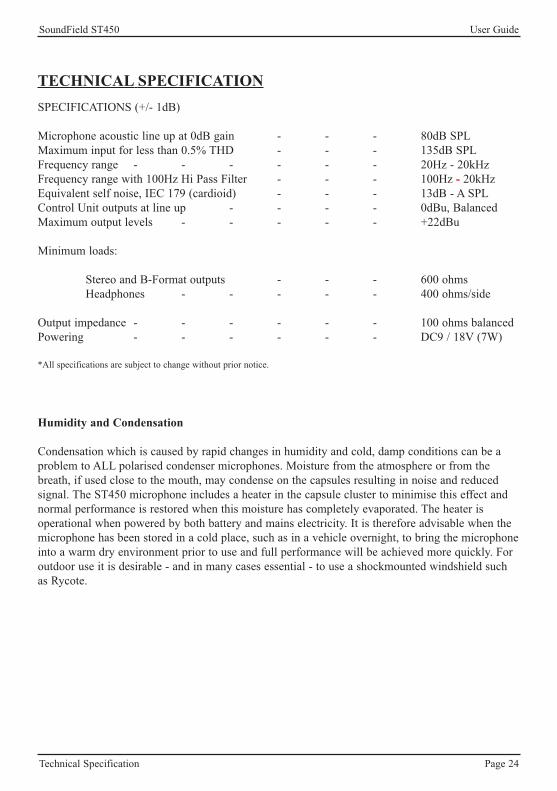
TECHNICAL SPECIFICATIONSPECIFICATIONS (+/- 1dB)
Microphone acoustic line up at 0dB gain - - - 80dB SPLMaximum input for less than 0.5% THD - - - 135dB SPLFrequency range - - - - - - 20Hz - 20kHzFrequency range with 100Hz Hi Pass Filter - - - 100Hz - 20kHzEquivalent self noise, IEC 179 (cardioid) - - - 13dB - A SPLControl Unit outputs at line up - - - - 0dBu, BalancedMaximum output levels - - - - - +22dBu
Minimum loads:
Stereo and B-Format outputs - - - 600 ohmsHeadphones - - - - - 400 ohms/side
Output impedance - - - - - - 100 ohms balancedPowering - - - - - - DC9 / 18V (7W)
*All specifications are subject to change without prior notice.
Humidity and Condensation
Condensation which is caused by rapid changes in humidity and cold, damp conditions can be aproblem to ALL polarised condenser microphones. Moisture from the atmosphere or from thebreath, if used close to the mouth, may condense on the capsules resulting in noise and reducedsignal. The ST450 microphone includes a heater in the capsule cluster to minimise this effect andnormal performance is restored when this moisture has completely evaporated. The heater isoperational when powered by both battery and mains electricity. It is therefore advisable when themicrophone has been stored in a cold place, such as in a vehicle overnight, to bring the microphoneinto a warm dry environment prior to use and full performance will be achieved more quickly. Foroutdoor use it is desirable - and in many cases essential - to use a shockmounted windshield suchas Rycote.

SoundField ST450 User Guide
ST450 Accessories Page 25
ST450 Accessories Part No.
ST450 Compact Rycote Kit ST450/RY/CComprising: Pistol Grip with Suspension • Mic Inner Cradle
105mm diameter Windshield • Rycote WindjammerRycote Anti-vibration Mic cable
ST450 Standard Rycote Kit ST450/RY/SComprising: Pistol Grip with Suspension • Mic Inner Cradle
140mm diameter Windshield • Rycote Anti-vibration Mic cable
ST450 Battery Kit ST450/BATT-KITComprising: Rechargeable Battery • Battery Charger
Battery Power connection cable • Power Adapter
CablesST450 5 Metre Microphone Cable - Lemo Connectors NN3001ST450 10 Metre Microphone Cable - Lemo Connectors NN3002ST450 20 Metre Microphone Cable - Lemo Connectors NN3003ST450 50 Metre Microphone Cable on Drum - Lemo Connectors NN3004ST450 100 Metre Microphone Cable on Drum - Lemo Connectors NN3005SoundField Microphone Cable per Metre 310-353Battery Power Connection Cable (4 pin Hirose to 4 pin Hirose connector) NN8185Rycote Anti-vibration Mic Cable NN9203
Connectors12 pin Lemo Male In line Connector 410-30112 pin Lemo Female In line Connector 410-3024 pin Hirose In Line ST450 Power Connector 410-320
ShockmountST450 Shock Mount System - complete HW3010
Batteries & ChargersRechargeable Battery 800-002Battery Charger (for 800-002) 810-002Regulated 12V Power Adapter - 2 x Hirose outputs, on/off switch DV-AUX2SBattery Power Connection Cable (4 pin Hirose to 4 pin Hirose connector) NN8185
Power SupplyReplacement ST450 Mains Power Supply ST450/PSU

SoundField ST450 User Guide
ST450 Accessories Page 26
ST450 Accessories Part No.
RycoteStandard RycotePistol Grip with Suspension 430-385ST350 Mic Inner Cradle to fit 430-385 440-183140mm diameter Windshield 430-384Rycote Anti-vibration Mic Cable NN9203Rycote Windjammer 430-398
Optional Accessory:High Wind Cover 430-400
RycoteCompact Rycote Pistol Grip with Suspension 420-380Mic Inner Cradle to fit 420-380 440-183105mm diameter Windshield 420-381Rycote Anti-vibration Mic cable NN9203Rycote Windjammer 430-397
Optional Accessory:High Wind Cover 430-399

SoundField ST450 User Guide
Notes

SoundField ST450 User Guide
Notes