Embed Size (px)
Citation preview

ST-PCS7BMS

© Siemens AG 2010 - Subject to modificationsIndustry Sector
2010-11-04 Slide 2/139ST-PCS7BMS
Supplementary
FINISH
Safety life cycle
Burner basics
Contact References HFCC Speaker Aims Timetable
General
General Two-Day-Workshop Timetable – First day
09:00 – 10:30 Basics and principles of a burner management system
10:30 – 10:45 Coffee Break10:45 – 11:15 Basics and principles of a burner
management system11:15 – 12:00 Safety Life Cycle – Phase 1,
(Risk Assessment)12:00 – 13:00 Lunch13:00 – 14:30 Safety Life Cycle – Phase 2/3,
(Allocation & Specification)14:30– 14:45 Coffee Break14:45 – 16:00 Safety Life Cycle – Phase 4,
(Design & Planning - Hardware)
16:00 End of first day
© Siemens AG 2010 - Subject to modificationsIndustry Sector
2010-11-04 Slide 3/139ST-PCS7BMS
Supplementary
FINISH
Safety life cycle
Burner basics
Contact References HFCC Speaker Aims Timetable
General
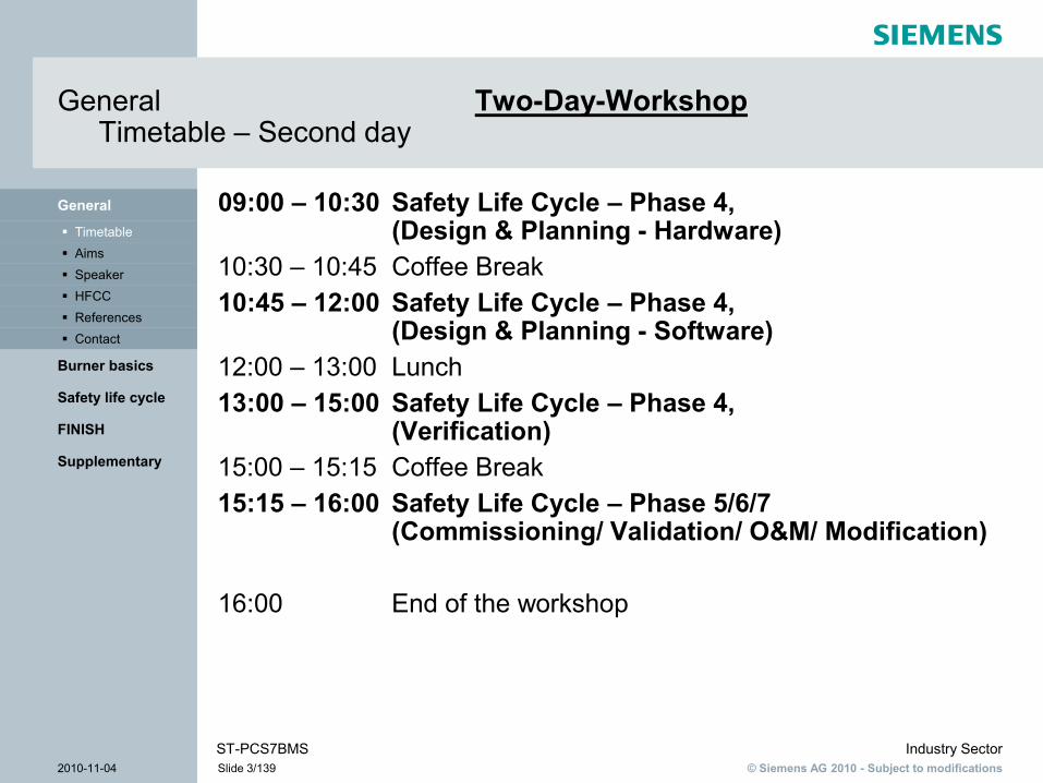
General Two-Day-Workshop Timetable – Second day
09:00 – 10:30 Safety Life Cycle – Phase 4,(Design & Planning - Hardware)
10:30 – 10:45 Coffee Break10:45 – 12:00 Safety Life Cycle – Phase 4,
(Design & Planning - Software)12:00 – 13:00 Lunch13:00 – 15:00 Safety Life Cycle – Phase 4,
(Verification)15:00 – 15:15 Coffee Break15:15 – 16:00 Safety Life Cycle – Phase 5/6/7
(Commissioning/ Validation/ O&M/ Modification)
16:00 End of the workshop

© Siemens AG 2010 - Subject to modificationsIndustry Sector
2010-11-04 Slide 4/139ST-PCS7BMS
Supplementary
FINISH
Safety life cycle
Burner basics
Contact References HFCC Speaker Aims Timetable
General
General One-Day-WorkshopTimetable
09:00 – 10:30 Basics and principles of a burner management system
10:30 – 10:45 Coffee Break10:45 – 11:15 Basics and principles of a burner
management system11:15 – 11:30 Safety Life Cycle – Phase 1,
(Risk Assessment)11:30 – 12:00 Safety Life Cycle – Phase 2/3,
(Allocation & Specification)12:00 – 13:00 Lunch13:00 – 14:30 Safety Life Cycle – Phase 4,
(Design & Planning - Software)14:30 – 14:45 Coffee Break14:45 – 16:00 Safety Life Cycle – Phase 4,
(Verification)
16:00 End of workshop
© Siemens AG 2010 - Subject to modificationsIndustry Sector
2010-11-04 Slide 5/139ST-PCS7BMS
Supplementary
FINISH
Safety life cycle
Burner basics
Contact References HFCC Speaker Aims Timetable
General
GeneralAims
To give participants Basic knowledge of what a "burner management system" entails Knowledge of relevant standards and directives (e.g. EN 746-2)
To familiarize participants with The safety life cycle of a burner management system Solutions for common HW tasks (e.g. flame detectors) Typical SW solutions (e.g. blocks, safety matrix, etc.)
To provide participants with These solutions for use as templates to follow in their daily work

© Siemens AG 2010 - Subject to modificationsIndustry Sector
2010-11-04 Slide 6/139ST-PCS7BMS
Supplementary
FINISH
Safety life cycle
Burner basics
Contact References HFCC Speaker Aims Timetable
General
GeneralSpeaker: Mathias Rebling
Mathias Rebling
+49 (0)911 962 1183 - office
90451 Nuremberg, Germany
www.siemens.com/safety-services
Member of the Competence Centre for failsafe and fault tolerant Systems
2005 – 2006 Development of concepts for gas-air mixture control with Simatic S7 F
2006 Philippines - Commissioning of a coal/oil-fired power plant
2007 onward Support for the "fail-safe function blocks for burner management systems" function package for SIMATIC F
- Customer training
- Commissioning
- Provision of advice to customers
2008 onward Support for functional safety services
- Support for risk analyses
- Design of safety functions
- Verification activities
- Safety consulting
- Standards training

© Siemens AG 2010 - Subject to modificationsIndustry Sector
2010-11-04 Slide 7/139ST-PCS7BMS
Supplementary
FINISH
Safety life cycle
Burner basics
Contact References HFCC Speaker Aims Timetable
General
GeneralCompetence Centre for failsafe and fault tolerant systems
We are supporting you worldwide due your usage of high-available and failsafe automation systems.
S5-155H
S5-115H
S5-95F
S5-115F
S7-400H
S7-400F/FH
S7-300F
Betreiber Hersteller Betreiber
Fertigungs-Planung
Angebots-Erstellung Engineering Fertigung /
InbetriebnahmeProduktion/
InstandhaltungModernisierung/
Erweiterung
Entwurf und Planung
Instandhaltung
Verifikation
Programmierung und Inbetriebnahmeunterstützung
Validerung ModernisierungSystematische Unterstützung bei der Gefährdungs- und Risikobeurteilung
Safety Consulting
Siemens Functional Safety Services
Functional Safety Services
© Siemens AG 2010 - Subject to modificationsIndustry Sector
2010-11-04 Slide 8/139ST-PCS7BMS
Supplementary
FINISH
Safety life cycle
Burner basics
Contact References HFCC Speaker Aims Timetable
General
GeneralCompetence Centre for failsafe and fault tolerant systems
Project SupportWe are providing support for conceptual preparation due to installation of your safety related application.Our engineers and specialists are on hand for all questions about safety technology.
Field ServiceFor emergency maintenance at your H&F-SIMATIC Systems there is special trained personnel available - worldwide!
WorkshopsWorkshops for H&F-Systems - also specially suited for your plant ratio will be performed by our skilled employees.Gladly we are travelling therefore to you!

© Siemens AG 2010 - Subject to modificationsIndustry Sector
2010-11-04 Slide 9/139ST-PCS7BMS
Supplementary
FINISH
Safety life cycle
Burner basics
Contact References HFCC Speaker Aims Timetable
General
GeneralStadtwerke Duisburg AG - (Municipal utilities of the city of Duisburg)
Use of failsafe Function Blocks for Burner Technology
Application:
Six burners on three boilers with a total power of 27 MW, controlled by the function blocks, generate heating water in a district heating station.
The heating station is used within the district heating network on demand if the heating power that is generated in the power and heat supply station is not enough.
The heating station can be run with gas and oil.

© Siemens AG 2010 - Subject to modificationsIndustry Sector
2010-11-04 Slide 10/139ST-PCS7BMS
Supplementary
FINISH
Safety life cycle
Burner basics
Contact References HFCC Speaker Aims Timetable
General
GeneralWintershall AG - crude oil plant at Barnsdorf
Use of failsafe Function Blocks for Burner Technology
Application:
Six Burners, with a total power of 70 MW, controlled by the failsafe function blocks for burner technology, generate Steam that is pumped into oil-saturated ground to force oil sludge to surface.

© Siemens AG 2010 - Subject to modificationsIndustry Sector
2010-11-04 Slide 11/139ST-PCS7BMS
Supplementary
FINISH
Safety life cycle
Burner basics
Contact References HFCC Speaker Aims Timetable
General
GeneralPower Plant „Mindanao“ (Philippines)
Project Support for Burner Applications of HFCC Commissioning of the S7-400HF based Burner Management -
and Boiler Protection System
Services of the HFCC: Support during commissioning Training and Supervision of operating personnel on site Discussions during approval with TÜV

© Siemens AG 2010 - Subject to modificationsIndustry Sector
2010-11-04 Slide 12/139ST-PCS7BMS
Supplementary
FINISH
Safety life cycle
Burner basics
Contact References HFCC Speaker Aims Timetable
General
GeneralOil Rig „Huldra“ (Norway)
Project Support for Burner Applications of HFCC Commissioning of the Oil Rig: „Emergency-Shut-Down“ and „Fire
and Gas Protection System“
Services of the HFCC: Support during the programming of the plant- control Support during installation of failsafe components and optimization of the
plant offshore

© Siemens AG 2010 - Subject to modificationsIndustry Sector
2010-11-04 Slide 13/139ST-PCS7BMS
Supplementary
FINISH
Safety life cycle
Burner basics
Contact References HFCC Speaker Aims Timetable
General
GeneralOil Rig „Huldra“ (Norway)
Failsafe Communication ofS7-400F-Systems via radio

© Siemens AG 2010 - Subject to modificationsIndustry Sector
2010-11-04 Slide 14/139ST-PCS7BMS
Supplementary
FINISH
Safety life cycle
Burner basics
Contact References HFCC Speaker Aims Timetable
General
GeneralContact
HF Competence CentreI IS IN PS2Tel.: +49(911) 895 4759mailto: [email protected]
Functional Safety ServicesTel.: +49(911) 962 1183
mailto: [email protected]
SIMATIC Customer Support:I IA AS CS1Tel.: +49 (0)180 5050222Fax.: +49 (0)180 5050223mailto: [email protected]://support.automation.siemens.com

© Siemens AG 2010 - Subject to modificationsIndustry Sector
2010-11-04 Slide 15/139ST-PCS7BMS
Supplementary
FINISH
Safety life cycle
Summary Process Safety
Harmonized standards
Rollback Other regulations Functional Safety Gas burner EN 746 Risks Definitions Terms
Burner basics
General
Burner basics

© Siemens AG 2010 - Subject to modificationsIndustry Sector
2010-11-04 Slide 16/139ST-PCS7BMS
Supplementary
FINISH
Safety life cycle
Summary Process Safety
Harmonized standards
Rollback Other regulations Functional Safety Gas burner EN 746 Risks Definitions Terms
Burner basics
General
Burner basics Terms
SIS = Safety Instrumented SystemBPCS = Basic Process Control System
SISSIF 1 … SIF n
BPCS
Other control
systems e.g. for
package units or
MCC
Process
e. g. Boiler
Burner

© Siemens AG 2010 - Subject to modificationsIndustry Sector
2010-11-04 Slide 17/139ST-PCS7BMS
Supplementary
FINISH
Safety life cycle
Summary Process Safety
Harmonized standards
Rollback Other regulations Functional Safety Gas burner EN 746 Risks Definitions Terms
Burner basics
General
Burner basicsWhat is machinery?
Machinery is:
„An assembly, fitted with [...] a drive system other than directly applied human [...] effort, consisting of linked parts [...], at least one of which moves, and which are joined together for a specific application*According to 2006/42/EC
© Siemens AG 2010 - Subject to modificationsIndustry Sector
2010-11-04 Slide 18/139ST-PCS7BMS
Supplementary
FINISH
Safety life cycle
Summary Process Safety
Harmonized standards
Rollback Other regulations Functional Safety Gas burner EN 746 Risks Definitions Terms
Burner basics
General
Burner basicsWhat is a burner? Machinery?
Generally, a burner is machinery and, as such, falls under the scope of the Machinery Directive
A device for converting chemical energy into thermal energy By burning gaseous, liquid, or solid fuels
But a burner is also An assembly, fitted with a drive system (e.g. fan) With linked parts Of which, generally, at least one is moveable (e.g. valves) For the purpose of generating heat

© Siemens AG 2010 - Subject to modificationsIndustry Sector
2010-11-04 Slide 19/139ST-PCS7BMS
Supplementary
FINISH
Safety life cycle
Summary Process Safety
Harmonized standards
Rollback Other regulations Functional Safety Gas burner EN 746 Risks Definitions Terms
Burner basics
General
Burner basicsWhat is a burner? A part of a process plant?
This machinery is used in different kinds of applications, such as:
Process Plants Paper Machines Cement Machines ect.
A burner– as machinery - can also be part of a process plant
But which requirements regarding burners do exist?

© Siemens AG 2010 - Subject to modificationsIndustry Sector
2010-11-04 Slide 20/139ST-PCS7BMS
Supplementary
FINISH
Safety life cycle
Summary Process Safety
Harmonized standards
Rollback Other regulations Functional Safety Gas burner EN 746 Risks Definitions Terms
Burner basics
General
Burner basicsAs machinery, the machinery directive is obligatory for burners
As a directive from EU, the MD is law in every member state
2006/42/EC Annex I (obligatory)Essential health and safety requirements relating to the design and construction of machinery General principles

© Siemens AG 2010 - Subject to modificationsIndustry Sector
2010-11-04 Slide 21/139ST-PCS7BMS
Supplementary
FINISH
Safety life cycle
Summary Process Safety
Harmonized standards
Rollback Other regulations Functional Safety Gas burner EN 746 Risks Definitions Terms
Burner basics
General
Burner basicsIdentification of hazards resulting from machinery
Risk must be reduced to construct the burner in a safe way
The Machinery Directive stipulates that a risk assessment must be carried out for all types of machinery.
To identify hazards To minimize risk
The essential Health and Safety Requirements are also given by the Machinery Directive
In Annex I

© Siemens AG 2010 - Subject to modificationsIndustry Sector
2010-11-04 Slide 22/139ST-PCS7BMS
Information regarding the risks resulting from a burner and the measures for reducing it can be found in the C- Norm:
EN 746 - Industrial thermoprocessing equipment
EN 746-1: Common safety requirements for industrial thermoprocessingequipment
EN 746-2: Safety requirements for combustion and fuel handling systems(in this workshop only gas burners)
…
Supplementary
FINISH
Safety life cycle
Summary Process Safety
Harmonized standards
Rollback Other regulations Functional Safety Gas burner EN 746 Risks Definitions Terms
Burner basics
General
Burner basicsHarmonized Standards help to reduce risks in a appropriate way
EN 746-2 defines the principle of operation of a burner management system

© Siemens AG 2010 - Subject to modificationsIndustry Sector
2010-11-04 Slide 23/139ST-PCS7BMS
Supplementary
FINISH
Safety life cycle
Summary Process Safety
Harmonized standards
Rollback Other regulations Functional Safety Gas burner EN 746 Risks Definitions Terms
Burner basics
General
Burner basics Basic Assumptions & Definitions
To apply EN 746-2 the following scenario must be given Machine is only operated and maintained by trained personnel Equipment is not creating any potential explosive atmosphere Equipment is located in ventilated environment No bypassing of safety equipment* Gas supply is always under control of two automatic shut-off
valves in series
Definitions: IThE = Industrial Thermoprocessing Equipment lock-out, non volatile = safety shutdown, reset only manually
*Wording as per EN 746-2: By-passes shall not be fitted in parallel with any item of safety equipmentUse of EN 746-2 is only allowed on this basis

© Siemens AG 2010 - Subject to modificationsIndustry Sector
2010-11-04 Slide 24/139ST-PCS7BMS
Supplementary
FINISH
Safety life cycle
Summary Process Safety
Harmonized standards
Rollback Other regulations Functional Safety
TemperatureFlameStartupRatio ControlPre-purgeFlue gasGas pressureAir flowValve
Gas burner EN 746 Risks Definitions Terms
Burner basics
General
Burner basicsCombustion plant - Gas burner
Fuel Burner
Primary air
Furnace
Flame detector
Temperature sensor
O2 measuring device
P

© Siemens AG 2010 - Subject to modificationsIndustry Sector
2010-11-04 Slide 25/139ST-PCS7BMS
Supplementary
FINISH
Safety life cycle
Summary Process Safety
Harmonized standards
Rollback Other regulations Functional Safety
TemperatureFlameStartupRatio ControlPre-purgeFlue gasGas pressureAir flow
Valve Gas burner EN 746 Risks Definitions Terms
Burner basics
General
Burner basics Valve proofing
P

© Siemens AG 2010 - Subject to modificationsIndustry Sector
2010-11-04 Slide 26/139ST-PCS7BMS
Supplementary
FINISH
Safety life cycle
Summary Process Safety
Harmonized standards
Rollback Other regulations Functional Safety
TemperatureFlameStartupRatio ControlPre-purgeFlue gasGas pressureAir flow
Valve Gas burner EN 746 Risks Definitions Terms
Burner basics
General
Burner basics Valve proofing
How the valve proofing test works
Monitoring of pressure rise
Monitoring of pressure drop
Filling

© Siemens AG 2010 - Subject to modificationsIndustry Sector
2010-11-04 Slide 27/139ST-PCS7BMS
Supplementary
FINISH
Safety life cycle
Summary Process Safety
Harmonized standards
Rollback Other regulations Functional Safety
TemperatureFlameStartupRatio ControlPre-purgeFlue gasGas pressureAir flow
Valve Gas burner EN 746 Risks Definitions Terms
Burner basics
General
Burner basics Valve proofing
Why is it required to perform a valve proofing test? The safety shut-off valves might be leaky Gas can leak into the combustion chamber pre-purge would be ineffective when gas is flowing into the chamber
What is the intention of the valve proofing test? Failed Valve proofing test shall prevent the system start-up
If the burner capacity exceeds 1,200 kW*
When shall the valve proofing test be carried out? After shut down (preventing the next start up) Before start-up (stopping the current start-up)
*Wording as per EN 746-2: Automatic shut-off valves controlling capacities greater than 1,200 kW

© Siemens AG 2010 - Subject to modificationsIndustry Sector
2010-11-04 Slide 28/139ST-PCS7BMS
Supplementary
FINISH
Safety life cycle
Summary Process Safety
Harmonized standards
Rollback Other regulations Functional Safety
TemperatureFlameStartupRatio ControlPre-purgeFlue gasGas pressure
Air flowValve
Gas burner EN 746 Risks Definitions Terms
Burner basics
General
Burner basics Supervision of air flow or pressure
P/FP/F

© Siemens AG 2010 - Subject to modificationsIndustry Sector
2010-11-04 Slide 29/139ST-PCS7BMS
Supplementary
FINISH
Safety life cycle
Summary Process Safety
Harmonized standards
Rollback Other regulations Functional Safety
TemperatureFlameStartupRatio ControlPre-purgeFlue gasGas pressure
Air flowValve
Gas burner EN 746 Risks Definitions Terms
Burner basics
General
Burner basics Supervision of air flow or pressure
When is it essential to carry out air flow monitoring? If forced or induced draught burners are used During pre-purge, ignition and operation If the temperature is below 750 C at the coldest spot in the chamber
What is the purpose of air flow monitoring? To ensure sufficient air during pre-purge is carried out To prevent startup if there is inadequate air flow To shut the burner down if there is inadequate air flow
How must the air flow supervision be checked Check for “no flow” state prior to start-up

© Siemens AG 2010 - Subject to modificationsIndustry Sector
2010-11-04 Slide 30/139ST-PCS7BMS
Supplementary
FINISH
Safety life cycle
Summary Process Safety
Harmonized standards
Rollback Other regulations Functional Safety
TemperatureFlameStartupRatio ControlPre-purgeFlue gasGas pressure
Air flowValve
Gas burner EN 746 Risks Definitions Terms
Burner basics
General
Burner basics Supervision of air flow or pressure
How must the air flow supervision be carried out? By flow detectors or By pressure detectors
Special requirements for monitoring devices? Air pressure detectors shall comply with EN 1854

© Siemens AG 2010 - Subject to modificationsIndustry Sector
2010-11-04 Slide 31/139ST-PCS7BMS
Supplementary
FINISH
Safety life cycle
Summary Process Safety
Harmonized standards
Rollback Other regulations Functional Safety
TemperatureFlameStartupRatio ControlPre-purgeFlue gas
Gas pressureAir flowValve
Gas burner EN 746 Risks Definitions Terms
Burner basics
General
Burner basics Gas pressure protection
P/F

© Siemens AG 2010 - Subject to modificationsIndustry Sector
2010-11-04 Slide 32/139ST-PCS7BMS
Supplementary
FINISH
Safety life cycle
Summary Process Safety
Harmonized standards
Rollback Other regulations Functional Safety
TemperatureFlameStartupRatio ControlPre-purgeFlue gas
Gas pressureAir flowValve
Gas burner EN 746 Risks Definitions Terms
Burner basics
General
Burner basics Gas pressure protection
What different types of pressure protection systems do exist? Low gas protection High gas protection
Intention of low / high gas protection? Prevent start-up or cause safety lockout in case of pressure falling below / exceeding a pre-determined value
Special requirements for monitoring devices? Gas pressure detectors shall comply with EN 1854
When must a low / high gas protection be added ? Low gas protection always High gas protection always except e.g. capacity below 600kW
(see 5.2.2.5.2.2 )

© Siemens AG 2010 - Subject to modificationsIndustry Sector
2010-11-04 Slide 33/139ST-PCS7BMS
Supplementary
FINISH
Safety life cycle
Summary Process Safety
Harmonized standards
Rollback Other regulations Functional Safety
TemperatureFlameStartupRatio Control
Pre-purgeFlue gasGas pressureAir flowValve
Gas burner EN 746 Risks Definitions Terms
Burner basics
General
Burner basics Pre-purge
P/F

© Siemens AG 2010 - Subject to modificationsIndustry Sector
2010-11-04 Slide 34/139ST-PCS7BMS
Supplementary
FINISH
Safety life cycle
Summary Process Safety
Harmonized standards
Rollback Other regulations Functional Safety
TemperatureFlameStartupRatio Control
Pre-purgeFlue gasGas pressureAir flowValve
Gas burner EN 746 Risks Definitions Terms
Burner basics
General
Burner basics Pre-purge
Why is it required to perform a pre-purge? A potentially-explosive mixture may be present in the combustion
chamber
How long must the pre-purge be carried out? In general, five complete air changes of the combustion chamber/
connected spaces and flue duct will suffice
When is it required to carry out a a pre-purge? Before every startup after a shutdown on faults

© Siemens AG 2010 - Subject to modificationsIndustry Sector
2010-11-04 Slide 35/139ST-PCS7BMS
Supplementary
FINISH
Safety life cycle
Summary Process Safety
Harmonized standards
Rollback Other regulations Functional Safety
TemperatureFlameStartupRatio Control
Pre-purgeFlue gasGas pressureAir flowValve
Gas burner EN 746 Risks Definitions Terms
Burner basics
General
Burner basics Pre-purge
When shall pre-purge be omitted? If presence of free oxygen*
can be a risk shall affect the equipment shall affect the product quality
When the combustion chamber is proved to be above 750 C
* Among others valve proofing system required

© Siemens AG 2010 - Subject to modificationsIndustry Sector
2010-11-04 Slide 36/139ST-PCS7BMS
Supplementary
FINISH
Safety life cycle
Summary Process Safety
Harmonized standards
Rollback Other regulations Functional Safety
TemperatureFlameStartup
Ratio ControlPre-purgeFlue gasGas pressureAir flowValve
Gas burner EN 746 Risks Definitions Terms
Burner basics
General
Burner basicsAir/gas fuel ratio
P/F

© Siemens AG 2010 - Subject to modificationsIndustry Sector
2010-11-04 Slide 37/139ST-PCS7BMS
Supplementary
FINISH
Safety life cycle
Summary Process Safety
Harmonized standards
Rollback Other regulations Functional Safety
TemperatureFlameStartup
Ratio ControlPre-purgeFlue gasGas pressureAir flowValve
Gas burner EN 746 Risks Definitions Terms
Burner basics
General
Burner basicsAir/gas fuel ratio
What hazards could arise as a result of gas-air mixture control?
Mixture is too lean Sufficient excess of air Good dilution Flame goes out No hazard
Mixture is too rich Not enough oxygen Flame goes out Excess of gas Reignition Deflagration hazard
To reduce the risk, prevent a lack of air

© Siemens AG 2010 - Subject to modificationsIndustry Sector
2010-11-04 Slide 38/139ST-PCS7BMS
Supplementary
FINISH
Safety life cycle
Summary Process Safety
Harmonized standards
Rollback Other regulations Functional Safety
TemperatureFlameStartup
Ratio ControlPre-purgeFlue gasGas pressureAir flowValve
Gas burner EN 746 Risks Definitions Terms
Burner basics
General
Burner basicsAir/gas fuel ratio
Why is it required to control the Air/gas fuel ratio? To ensure that Air mass flow rate is always in ratio with the gas mass
flow rate (no lack of air)
Which value must the ration have It needs not to be the same value at all operational conditions
Which action must be performed in case of a malfunction or defect The system shall tend towards higher excess air proceed lockout if the air/gas ratio results in an unsafe condition
Are there other standards for Air/gas fuel ratio controls EN 12067-1 for EN 12078 for pneumatic gas/air ratio controls if
applicable EN 12067-2 for Electronic gas/air ratio controls if applicable

© Siemens AG 2010 - Subject to modificationsIndustry Sector
2010-11-04 Slide 39/139ST-PCS7BMS
Supplementary
FINISH
Safety life cycle
Summary Process Safety
Harmonized standards
Rollback Other regulations Functional Safety
TemperatureFlameStartup
Ratio ControlPre-purgeFlue gasGas pressureAir flowValve
Gas burner EN 746 Risks Definitions Terms
Burner basics
General
Burner basics Electronic gas-air ratio control in accordance with 12067-2
Actuator feedback Actuator output feedback
Process feedback
Position b Speed Flow/∆P P Gas/air ratio
Flame Flue gas
Actuator Air
valve X X X X X X
Fan X a X X
Actuator Gas
valve X X X
pressure regulator
X X
At least 2 feedbacks (1 gas, 1 air) required c At least 1 feedback required c
a Proof of air flow cannot rely on fan rotation alone (for exact wording see EN 12067-2, table 1)b A feedback signal which is directly related to the mechanical part of the actuator.c The two actuator feedbacks and the process feedback are alternatives.
Control allowed to be outside of defined range for max. 3 s

© Siemens AG 2010 - Subject to modificationsIndustry Sector
2010-11-04 Slide 40/139ST-PCS7BMS
Supplementary
FINISH
Safety life cycle
Summary Process Safety
Harmonized standards
Rollback Other regulations Functional Safety
TemperatureFlame
StartupRatio ControlPre-purgeFlue gasGas pressureAir flowValve
Gas burner EN 746 Risks Definitions Terms
Burner basics
General
Burner basics Start-up and ignition
P/F
© Siemens AG 2010 - Subject to modificationsIndustry Sector
2010-11-04 Slide 41/139ST-PCS7BMS
Supplementary
FINISH
Safety life cycle
Summary Process Safety
Harmonized standards
Rollback Other regulations Functional Safety
TemperatureFlame
StartupRatio ControlPre-purgeFlue gasGas pressureAir flowValve
Gas burner EN 746 Risks Definitions Terms
Burner basics
General
Burner basics Start-up and ignition
Start- up Proving equipment (air / gas) has been successfully tested All relevant interlocks have been proved to be in correct position
Ignition pre-purge has just been completed The energy released during the start-up of the burner is limited If burner is ignited by a pilot, gas supply to main burner is shut during
pre-purge and ignition Automatic shut-off valves of main burner open only when pilot burner
flame has been proved

© Siemens AG 2010 - Subject to modificationsIndustry Sector
2010-11-04 Slide 42/139ST-PCS7BMS
Supplementary
FINISH
Safety life cycle
Summary Process Safety
Harmonized standards
Rollback Other regulations Functional Safety
TemperatureFlame
StartupRatio ControlPre-purgeFlue gasGas pressureAir flowValve
Gas burner EN 746 Risks Definitions Terms
Burner basics
General
Burner basics Start-up and ignition
Ignition sequence Activation of the pilot burner Pilot valves open Ignition transformer activated Wait for feedback from flame detector No Feedback within safety time lockout
Else: Activation of the main burner Main gas valves open Wait for feedback from flame detector No Feedback within safety time lockout
Else: Operation

© Siemens AG 2010 - Subject to modificationsIndustry Sector
2010-11-04 Slide 43/139ST-PCS7BMS
Supplementary
FINISH
Safety life cycle
Summary Process Safety
Harmonized standards
Rollback Other regulations Functional Safety
TemperatureFlame
StartupRatio ControlPre-purgeFlue gasGas pressureAir flowValve
Gas burner EN 746 Risks Definitions Terms
Burner basics
General
Burner basics Start-up and ignition
Maximum safety times for natural draught burners, operating in open air*:
Burner input ratekW
Safety times
Total closing times
1) Thermoelectric flame supervision device (EN 125)
up to and including 70 60 45
2) Flame supervision device other than thermoelectric (EN 298)
up to and including 70 above70 up to and including 360 above 360*a
10105
1033
*a Ignition at a rate of 33 % of the burner input rating with a maximum of 350 kW.
*as per EN 746-2:2010, chapter 5.2.5.3.4.2, table 1

© Siemens AG 2010 - Subject to modificationsIndustry Sector
2010-11-04 Slide 44/139ST-PCS7BMS
Supplementary
FINISH
Safety life cycle
Summary Process Safety
Harmonized standards
Rollback Other regulations Functional Safety
TemperatureFlame
StartupRatio ControlPre-purgeFlue gasGas pressureAir flowValve
Gas burner EN 746 Risks Definitions Terms
Burner basics
General
Burner basics Start-up and ignition
Maximum safety times for natural draught burners, operating in combustion chamber
Burner input ratekW
Safety times
Total closing times
1) Thermoelectric flame supervision device (EN 125)
up to and including 2,5 60 45
2) Flame supervision device other than thermoelectric (EN 298)
up to and including 70 above70 up to and including 360 above 360*a
10105
1033
*a Ignition at a rate of 33 % of the burner input rating with a maximum of 350 kW.
*as per EN 746-2:2010, chapter 5.2.5.3.4.2, table 2

© Siemens AG 2010 - Subject to modificationsIndustry Sector
2010-11-04 Slide 45/139ST-PCS7BMS
Supplementary
FINISH
Safety life cycle
Summary Process Safety
Harmonized standards
Rollback Other regulations Functional Safety
TemperatureFlame
StartupRatio ControlPre-purgeFlue gasGas pressureAir flowValve
Gas burner EN 746 Risks Definitions Terms
Burner basics
General
Burner basics Start-up and ignition
Maximum safety times for forced and inducted draught burners
\Direct main
burner ignition at full rate
Direct main burner ignition at reduced rate with slow opening valves
Direct main burner ignition at reduced rate with by-pass start gas
supply
Main burner ignition with independent pilot burner
Pilot burner ignition
(QST ≤ 0.1*QF max)
Main burner ignition
Rate QF max
Safety time tS Safety time tS Rate QSTSafety time
tSFirst safety time
tS1
Second safety time tS2
kW s s kW s s s≤ 70 5 5 ≤ 70 5 5 5
>70≤120 3 3
≤ 70 55 3>70
≤120 3
>120≤360
not allowedexept as
described below3
≤ 70 5
5
3 with slow opening valves
or tS * QS < 150%(max. tS = 3s)
>70≤120 3
>120≤360 not allowed
>360 not allowed not allowedQST = 120 kW ortS * QS < 100%(max tS = 3s)
5 (QST ≤ 70 kW) QST = 180 kW or tS * QS < 150%(max. tS = 3s)3 (QST > 70 kW)
QF max = maximum main burner input rate in kilowatts, QST = start input rate in kilowattsQS = maximum start input rate expressed as a percentage of (QS = QST / QF max), tS = safety time in seconds
*as per EN 746-2:2010, chapter 5.2.5.3.4.2, table 3 – (modified, sign “%” added)

© Siemens AG 2010 - Subject to modificationsIndustry Sector
2010-11-04 Slide 46/139ST-PCS7BMS
Supplementary
FINISH
Safety life cycle
Summary Process Safety
Harmonized standards
Rollback Other regulations Functional Safety
Temperature Flame
StartupRatio ControlPre-purgeFlue gasGas pressureAir flowValve
Gas burner EN 746 Risks Definitions Terms
Burner basics
General
Burner basics Flame monitoring
P/F
© Siemens AG 2010 - Subject to modificationsIndustry Sector
2010-11-04 Slide 47/139ST-PCS7BMS
Supplementary
FINISH
Safety life cycle
Summary Process Safety
Harmonized standards
Rollback Other regulations Functional Safety
Temperature Flame
StartupRatio ControlPre-purgeFlue gasGas pressureAir flowValve
Gas burner EN 746 Risks Definitions Terms
Burner basics
General
Burner basics Flame monitoring
When is it essential to carry out flame monitoring? Always
How is flame monitoring to be carried out? By means of a flame sensor (UV, IR, ionization) By means of high temperature monitoring
What is the purpose of the flame monitoring device? To close the fuel feed line if ignition does not take place during startup To close the fuel feed line if the flame extinguishes during operation

© Siemens AG 2010 - Subject to modificationsIndustry Sector
2010-11-04 Slide 48/139ST-PCS7BMS
Supplementary
FINISH
Safety life cycle
Summary Process Safety
Harmonized standards
Rollback Other regulations Functional Safety
Temperature Flame
StartupRatio ControlPre-purgeFlue gasGas pressureAir flowValve
Gas burner EN 746 Risks Definitions Terms
Burner basics
General
Burner basics Flame monitoring
How many flame detectors do I need? One is absolutely essential The rest depends on the fuels used or on the required SIL/ PL
When do I need to provide separate flame monitoring for the ignition burner and the main burner?
If the ignition burner runs continuously

© Siemens AG 2010 - Subject to modificationsIndustry Sector
2010-11-04 Slide 49/139ST-PCS7BMS
Supplementary
FINISH
Safety life cycle
Summary Process Safety
Harmonized standards
Rollback Other regulations Functional Safety Temperature
FlameStartupRatio ControlPre-purgeFlue gasGas pressureAir flowValve
Gas burner EN 746 Risks Definitions Terms
Burner basics
General
Burner basics Temperature monitoring
P/F

© Siemens AG 2010 - Subject to modificationsIndustry Sector
2010-11-04 Slide 50/139ST-PCS7BMS
Supplementary
FINISH
Safety life cycle
Summary Process Safety
Harmonized standards
Rollback Other regulations Functional Safety Temperature
FlameStartupRatio ControlPre-purgeFlue gasGas pressureAir flowValve
Gas burner EN 746 Risks Definitions Terms
Burner basics
General
Burner basics Temperature monitoring
When does temperature monitoring have to be carried out? If necessary by procedural reasons If the temperature in the combustion chamber exceeds 750 C and no
flame detectors are used (high temperature equipment)
What must be taken into account when using high temperature equipment During startup if processing chamber wall temperature is below 750 C
supervision either by automatic burner control or by operator If carried out by operator, immediate corrective action must be possible If temperature can drop below 750 C within one hour, acoustical and
visual alarm necessary

© Siemens AG 2010 - Subject to modificationsIndustry Sector
2010-11-04 Slide 51/139ST-PCS7BMS
Supplementary
FINISH
Safety life cycle
Summary Process Safety
Harmonized standards
Rollback Other regulations Functional Safety Gas burner EN 746 Risks Definitions Terms
Burner basics
General
Burner basics Design requirements for el. control & protective equipment
To ensure safety in the system, automatic burner controls shall comply to EN 298.
In addition the following general requirements must be adhered Electrical equipment shall comply with EN 60204-1 Techniques for avoiding systematic faults shall be applied In safety devices, techniques for controlling both, systematic and random
faults during operation shall be applied Signals coming from the safety circuit shall only be doubled when free of
interference

© Siemens AG 2010 - Subject to modificationsIndustry Sector
2010-11-04 Slide 52/139ST-PCS7BMS
Supplementary
FINISH
Safety life cycle
Summary Process Safety
Harmonized standards
Rollback Other regulations Functional Safety Gas burner EN 746 Risks Definitions Terms
Burner basics
General
Burner basics Functional Safety in BMS Systems
New chapter in EN 746-2:2010: 5.7.2 Requirements for Safety Systems
Options possible since now: Use of automatic burner control systes with compliance to
corresponding product standards no SIL/PL necessary
Use of PLCs and or no special burner equipment SIL/PL necessary

© Siemens AG 2010 - Subject to modificationsIndustry Sector
2010-11-04 Slide 53/139ST-PCS7BMS
Supplementary
FINISH
Safety life cycle
Summary Process Safety
Harmonized standards
Rollback Other regulations Functional Safety Gas burner EN 746 Risks Definitions Terms
Burner basics
General
Burner basics Other standards
Information regarding the risks resulting from a burner and the measures for reducing it can be found in:
EN 746-1: Common safety requirements for industrial thermoprocessing equipment
EN 746-2: Safety requirements for combustion and fuel handling systems …
Information regarding the risks resulting from a burner and the measures for reducing it can be found in:
EN 746-1: Common safety requirements for industrial thermoprocessingequipment
EN 746-2: Safety requirements for combustion and fuel handling systems …
Other standards are also affecting the architecture: EN 298 - Automatic gas burner control systems for gas burners and gas
burning appliances with or without fans EN 50156-1 - Electrical equipment for furnaces and ancillary equipment EN 676 - Automatic forced draught burners for gaseous fuels

© Siemens AG 2010 - Subject to modificationsIndustry Sector
2010-11-04 Slide 54/139ST-PCS7BMS
Supplementary
FINISH
Safety life cycle
Summary Process Safety
Harmonized standards
Rollback Other regulations Functional Safety Gas burner EN 746 Risks Definitions Terms
Burner basics
General
Burner basics Rollback
A burner is: A machine according to the Machinery Directive A part of a process plant A hazardous location therein An item of equipment controlled by a PLC
For this equipment, risks must be reduced in an adequate way Therefore harmonized standards like EN 746-2 must be used
But what are harmonized standards

© Siemens AG 2010 - Subject to modificationsIndustry Sector
2010-11-04 Slide 55/139ST-PCS7BMS
Supplementary
FINISH
Safety life cycle
Summary Process Safety
Harmonized standards
Rollback Other regulations Functional Safety Gas burner EN 746 Risks Definitions Terms
Burner basics
General
Article 7 paragraph 2 of MD 2006/42/EC
…To comply to the MD
Burner basics What are harmonized standards and why use them?

© Siemens AG 2010 - Subject to modificationsIndustry Sector
2010-11-04 Slide 56/139ST-PCS7BMS
Supplementary
FINISH
Safety life cycle
Summary Process Safety
Harmonized standards
Rollback Other regulations Functional Safety Gas burner EN 746 Risks Definitions Terms
Burner basics
General
Burner basics Harmonized standards
http://www.newapproach.org/Directives/DirectiveList.asp

© Siemens AG 2010 - Subject to modificationsIndustry Sector
2010-11-04 Slide 57/139ST-PCS7BMS
Supplementary
FINISH
Safety life cycle
Summary Process Safety
Harmonized standards
Rollback Other regulations Functional Safety Gas burner EN 746 Risks Definitions Terms
Burner basics
General
Burner basics Standards harmonized under MD

© Siemens AG 2010 - Subject to modificationsIndustry Sector
2010-11-04 Slide 58/139ST-PCS7BMS
Supplementary
FINISH
Safety life cycle
Summary Process Safety
Harmonized standards
Rollback Other regulations Functional Safety Gas burner EN 746 Risks Definitions Terms
Burner basics
General
Burner basics Functional Safety in BMS Applications
How to proof functional safety? EN 746-2:2010 requires SIL / PL conformity if no product-relevant
standard is used (e.g. EN 298) SIL / PL must be proven according to either EN 62061 or EN ISO 13849-1 Theses standards only know “High Demand Mode”
What about using BMS Systems in a Process Plant with “Low Demand Requirements”?
OR EN 61511 OR EN 62061
Proof by using EN ISO 13849-1

© Siemens AG 2010 - Subject to modificationsIndustry Sector
2010-11-04 Slide 59/139ST-PCS7BMS
Supplementary
FINISH
Safety life cycle
Summary Process Safety
Harmonized standards
Rollback Other regulations Functional Safety Gas burner EN 746 Risks Definitions Terms
Burner basics
General
IEC 61508
IEC 62061 ISO 13849
Manufacturing industry
Focu
sPr
oduc
t mak
erFo
cus
Inte
grat
or
Burner basics Low Demand Requirements in BMS
EN 61508 as generic standard for functional safety knows both, low and high demand mode

© Siemens AG 2010 - Subject to modificationsIndustry Sector
2010-11-04 Slide 60/139ST-PCS7BMS
Supplementary
FINISH
Safety life cycle
Summary Process Safety
Harmonized standards
Rollback Other regulations Functional Safety Gas burner EN 746 Risks Definitions Terms
Burner basics
General
IEC 61508
IEC 62061 ISO 13849IEC 61511
process- industry
Manufacturing industry
Focu
sPr
oduc
t mak
erFo
cus
Inte
grat
or
Burner basics Low Demand Requirements in BMS
But EN 61511 handles Functional Safety in the Process Industry (with low demand requirements)

© Siemens AG 2010 - Subject to modificationsIndustry Sector
2010-11-04 Slide 61/139ST-PCS7BMS
Supplementary
FINISH
Safety life cycle
Summary Process Safety
Harmonized standards
Rollback Other regulations Functional Safety Gas burner EN 746 Risks Definitions Terms
Burner basics
General
Burner basics Low Demand Requirements in BMS
This means if Low Demand Requirements do exist: Proof of functional safety is provided via EN 61511 and VDE/VDI 2180 EN 61511 is also state of the art (for the process industry) But EN 61511 is not harmonized under MD
But if 61511 is used, BPCS and SIS must be separated

© Siemens AG 2010 - Subject to modificationsIndustry Sector
2010-11-04 Slide 62/139ST-PCS7BMS
Supplementary
FINISH
Safety life cycle
Summary Process Safety
Harmonized standards
Rollback Other regulations Functional Safety Gas burner EN 746 Risks Definitions Terms
Burner basics
General
Burner basics Summary
A burner is: Machinery Which can be used in a process plant There are standards which Describe the correct function of a burner (e.g. EN 746-2) Set requirements for the architecture of a burner management system (EN 298) Require a SIL / PL according to EN 62016 or EN ISO 13849-1
But if the burner is part of an process plant and if “Low Demand Requirements” do exist:
Proof of functional safety is provided via EN 61511 and VDE/VDI 2180

© Siemens AG 2010 - Subject to modificationsIndustry Sector
2010-11-04 Slide 63/139ST-PCS7BMS
Supplementary
FINISH
Safety life cycle
Summary Process Safety
Harmonized standards
Rollback Other regulations Functional Safety Gas burner EN 746 Risks Definitions Terms
Burner basics
General
Burner basics Summary
EU directives and standards, which can among others have impact on BMS design with PLCs (standards not necessarily harmonized):
Focus for use
Machine safetyFocus for use
Process safetyMachinery Directive 2006/42/EC
Pressure Equipment Directive 97/23/ECATEX Directive 94/9/EC ATEX
Electromagnetic compatibility 2004/108/EC
Appliances burning gaseous fuels 90/396/EECEN 746-1 – Industrial thermoprocessing equipment -
Common safety requirements for industrial thermoprocessing equipment;
EN 61511 - Functional safety –Safety instrumented systems for the process industry sector
EN 746-2 – Industrial thermoprocessing equipment - Safety requirements for combustion and fuel handling systems
VDI/VDE 2180 - Safeguarding of industrial process plantsby means of process control engineering
EN 676 - Automatic forced draught burners for gaseous fuels
EN 12067-2 Gas/air ratio controls for gas burners and gas burning appliances - Part 2: Electronic types
EN 298 - Automatic gas burner control systems for gas burners and gas burning appliances with or without fans
EN 50156-1 - Electrical equipment for furnaces and ancillary equipment – Part 1: Requirements for application design and
installation*
*See Safety Lifecycle 2

© Siemens AG 2010 - Subject to modificationsIndustry Sector
2010-11-04 Slide 64/139ST-PCS7BMS
Supplementary
FINISH
Phase 5/6/7 Phase 4 Phase 3 Phase 2 Phase 1
V- ModelSafety PlanFunctional Safety
General
Safety life cycle
Burner basics
General
Safety life cycle of a burner management systemGeneral

© Siemens AG 2010 - Subject to modificationsIndustry Sector
2010-11-04 Slide 65/139ST-PCS7BMS
Supplementary
FINISH
Phase 5/6/7 Phase 4 Phase 3 Phase 2 Phase 1
V- ModelSafety Plan
Functional Safety General
Safety life cycle
Burner basics
General
Safety life cycle of a burner management systemGeneral – Functional Safety
Aims: Definition of the management actions required to achieve functional
safety aims (without general measures for health and safety in the work place)
Measures: Set up a safety management system Carry out a risk and hazards assessment Appraise and verify functional safety
© Siemens AG 2010 - Subject to modificationsIndustry Sector
2010-11-04 Slide 66/139ST-PCS7BMS
Supplementary
FINISH
Phase 5/6/7 Phase 4 Phase 3 Phase 2 Phase 1
V- Model Safety Plan
Functional Safety General
Safety life cycle
Burner basics
General
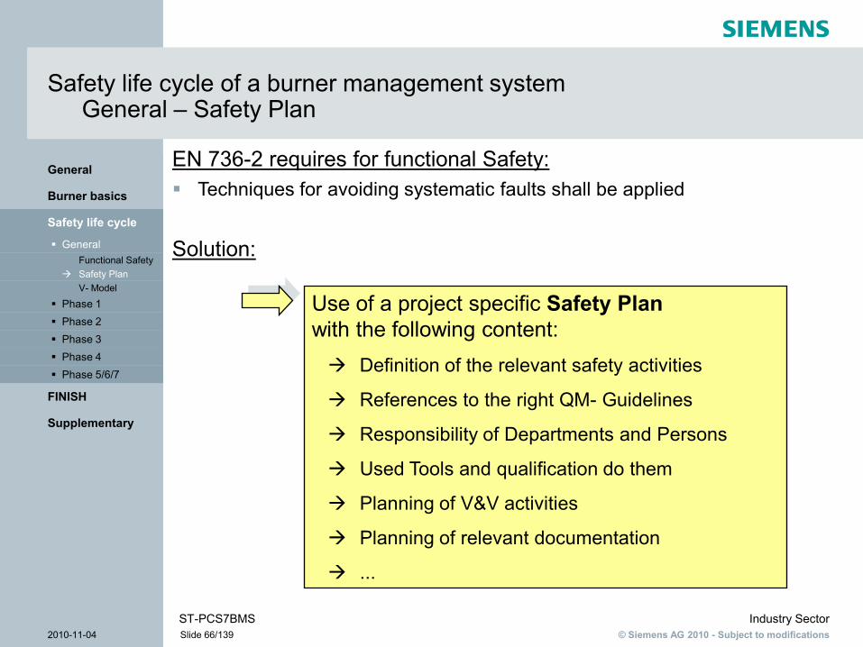
Safety life cycle of a burner management systemGeneral – Safety Plan
EN 736-2 requires for functional Safety: Techniques for avoiding systematic faults shall be applied
Solution:
Use of a project specific Safety Planwith the following content: Definition of the relevant safety activities
References to the right QM- Guidelines
Responsibility of Departments and Persons
Used Tools and qualification do them
Planning of V&V activities
Planning of relevant documentation
...

© Siemens AG 2010 - Subject to modificationsIndustry Sector
2010-11-04 Slide 67/139ST-PCS7BMS
Supplementary
FINISH
Phase 5/6/7 Phase 4 Phase 3 Phase 2 Phase 1 V- Model
Safety PlanFunctional Safety
General
Safety life cycle
Burner basics
General
Safety life cycle of a burner management systemGeneral – V-Model

© Siemens AG 2010 - Subject to modificationsIndustry Sector
2010-11-04 Slide 68/139ST-PCS7BMS
Supplementary
FINISH
Phase 5/6/7 Phase 4 Phase 3 Phase 2
HAZOPMethodsProcedurePlant life cycleCauses of failureProtection layersPhilosophyAimRisk Assessment
Phase 1 General
Safety life cycle
Burner basics
General
Safety life cycle of a burner management systemPhase 1 - Hazard and risk assessment

© Siemens AG 2010 - Subject to modificationsIndustry Sector
2010-11-04 Slide 69/139ST-PCS7BMS
Supplementary
FINISH
Phase 5/6/7 Phase 4 Phase 3 Phase 2
HAZOPMethodsProcedurePlant life cycleCauses of failureProtection layersPhilosophyAim
Risk Assessment Phase 1 General
Safety life cycle
Burner basics
General
Safety life cycle of a burner management system
Analysis Implementation Operation
Risk Assessment
Allocation
Specification
Design and Planning
Commissioning and Validation
Operation & Maintenance
Modification and Decommissioning
Simplified Lifecycle

© Siemens AG 2010 - Subject to modificationsIndustry Sector
2010-11-04 Slide 70/139ST-PCS7BMS
Supplementary
FINISH
Phase 5/6/7 Phase 4 Phase 3 Phase 2
HAZOPMethodsProcedurePlant life cycleCauses of failureProtection layersPhilosophy
AimRisk Assessment
Phase 1 General
Safety life cycle
Burner basics
General
Phase 1 – Risk analysisAim of safety engineering
Necessary to reduce the technical process risk caused by hazardous events to a tolerable level. Protection required for:
EmployeesThe general public
Optional:Commercial assetsEnvironment

© Siemens AG 2010 - Subject to modificationsIndustry Sector
2010-11-04 Slide 71/139ST-PCS7BMS
Supplementary
FINISH
Phase 5/6/7 Phase 4 Phase 3 Phase 2
HAZOPMethodsProcedurePlant life cycleCauses of failureProtection layers
PhilosophyAimRisk Assessment
Phase 1 General
Safety life cycle
Burner basics
General
Phase 1 – Risk analysisPhilosophy
Risk is the probability of the occurrence of an unwanted event
multiplied by the extent of the damage The opposite of risk is safety
(in the sense of: freedom from unacceptable risks)
The tolerable risk is influenced by the perceived values of the company and by
political factors.

© Siemens AG 2010 - Subject to modificationsIndustry Sector
2010-11-04 Slide 72/139ST-PCS7BMS
Supplementary
FINISH
Phase 5/6/7 Phase 4 Phase 3 Phase 2
HAZOPMethodsProcedurePlant life cycleCauses of failureProtection layers
PhilosophyAimRisk Assessment
Phase 1 General
Safety life cycle
Burner basics
General
Phase 1 – Risk analysis Risk reduction
Other measures for minimizing risk
Risk of a technical installation
Tolerable risk
Ris
k
“Zero risk” is unachievable
Changed process design
Safety systems

© Siemens AG 2010 - Subject to modificationsIndustry Sector
2010-11-04 Slide 73/139ST-PCS7BMS
Supplementary
FINISH
Phase 5/6/7 Phase 4 Phase 3 Phase 2
HAZOPMethodsProcedurePlant life cycleCauses of failure
Protection layersPhilosophyAimRisk Assessment
Phase 1 General
Safety life cycle
Burner basics
General
Phase 1 – Risk analysisProtection layers for risk reduction
Plant staff intervene
Safety system(automatic)
Basicautoma-tion
Pressure-reliefvalve,bursting disc
Drip trays
Active protection
Passive protection
Catastrophe protectionCatastrophe protection
Safety instrumentedsystem (SIS)
Processvalue
Process alarm
Normal performance
Process control system
Safetyshutdown

© Siemens AG 2010 - Subject to modificationsIndustry Sector
2010-11-04 Slide 74/139ST-PCS7BMS
Supplementary
FINISH
Phase 5/6/7 Phase 4 Phase 3 Phase 2
HAZOPMethodsProcedurePlant life cycle
Causes of failureProtection layersPhilosophyAimRisk Assessment
Phase 1 General
Safety life cycle
Burner basics
General
Phase 1 – Risk analysisCauses of failure in the case of SIS
Specification 44.1%
Planning & implementation
14.7%Installation &
commissioning5.9%
Operation &maintenance
14.7%
Changes aftercommissioning
20.6%
Note: Based on 34 investigated incidents in the UKHealth and Safety Executive (GB): Out of control. Why control systems go wrong and how to preventfailure. HSE Books 1995

© Siemens AG 2010 - Subject to modificationsIndustry Sector
2010-11-04 Slide 75/139ST-PCS7BMS
Supplementary
FINISH
Phase 5/6/7 Phase 4 Phase 3 Phase 2
HAZOPMethodsProcedure
Plant life cycleCauses of failureProtection layersPhilosophyAimRisk Assessment
Phase 1 General
Safety life cycle
Burner basics
General
Phase 1 – Risk analysisPlant life cycle
Causes of failure
Staff qualifications
Technicalrequirements
Safety management
+
+
Plant life cycle
Specification
Planning & implementation
Changes after commissioning
Installation & commissioning
Operation & maintenance
Analysis

© Siemens AG 2010 - Subject to modificationsIndustry Sector
2010-11-04 Slide 76/139ST-PCS7BMS
Supplementary
FINISH
Phase 5/6/7 Phase 4 Phase 3 Phase 2
HAZOPMethods
ProcedurePlant life cycleCauses of failureProtection layersPhilosophyAimRisk Assessment
Phase 1 General
Safety life cycle
Burner basics
General
Phase 1 – Risk analysis General procedure
Relevant for startup, uninterrupted duty, shutdown, maintenance, operator interventions, failure of auxiliary power
It is carried out by an interdisciplinary team with the necessary specialist disciplines
Presentation by an experienced expert is often advisable
Procedure1. Determination of hazards2. Determination of the chain of events for the hazard trigger3. Evaluation of the process risk (effects and probabilities in
qualitative or quantitative form)4. Determination of the required safety functions for the reduction
of the risk5. Definition of which safety instrumented functions are necessary
and determination of the SIL

© Siemens AG 2010 - Subject to modificationsIndustry Sector
2010-11-04 Slide 77/139ST-PCS7BMS
Supplementary
FINISH
Phase 5/6/7 Phase 4 Phase 3 Phase 2
HAZOP Methods
ProcedurePlant life cycleCauses of failureProtection layersPhilosophyAimRisk Assessment
Phase 1 General
Safety life cycle
Burner basics
General
Phase 1 – Risk analysisQualitative methods employed
Safety discussions Checklists What-if analyses HAZOP (also PAAG method) FMEA (Failure Mode and Effects Analysis) Cause and effect analysis

© Siemens AG 2010 - Subject to modificationsIndustry Sector
2010-11-04 Slide 78/139ST-PCS7BMS
Supplementary
FINISH
Phase 5/6/7 Phase 4 Phase 3 Phase 2 HAZOP
MethodsProcedurePlant life cycleCauses of failureProtection layersPhilosophyAimRisk Assessment
Phase 1 General
Safety life cycle
Burner basics
General
Phase 1 – Risk analysisHazard and operability (HAZOP) analysis
Assessment of Deviations Causes Effects Counter Action
Systematic search: deviation = keyword + parameter Keywords: not/none, more, less, other, inverse
Parameters: flow, temperature, pressure, amalgamate,composition, liquid level, dosing quantity

© Siemens AG 2010 - Subject to modificationsIndustry Sector
2010-11-04 Slide 79/139ST-PCS7BMS
Supplementary
FINISH
Phase 5/6/7 Phase 4 Phase 3 Phase 2 HAZOP
MethodsProcedurePlant life cycleCauses of failureProtection layersPhilosophyAimRisk Assessment
Phase 1 General
Safety life cycle
Burner basics
General
Phase 1 – Risk analysisHazard and operability (HAZOP) analysis
Deviation Loss / instability of the flameCause: Insufficient gas pressureEffect: Flame is lost, out coming gas is not burned and can
accumulate in the chamber, re-ignition and explosions are possible at local hotspots in the chamber
Counter Action: Pressure supervision monitors for pressure low. Associated BMS closes gas valves if flame is lost within 3s (cf. EN 746-2 chart 3).
Operating Mode: Low-temperature mode, Shut down
By: HAZOPExpert
Ref # P&ID #’s
© Siemens AG 2010 - Subject to modificationsIndustry Sector
2010-11-04 Slide 80/139ST-PCS7BMS
Supplementary
FINISH
Phase 5/6/7 Phase 4 Phase 3 Phase 2 HAZOP
MethodsProcedurePlant life cycleCauses of failureProtection layersPhilosophyAimRisk Assessment
Phase 1 General
Safety life cycle
Burner basics
General
Phase 1 – Risk analysisPractical example
Burner management system

© Siemens AG 2010 - Subject to modificationsIndustry Sector
2010-11-04 Slide 81/139ST-PCS7BMS
Supplementary
FINISH
Phase 5/6/7 Phase 4 Phase 3
Risk GraphLOPAMethodesDetermining SILSILAllocation
Phase 2 Phase 1 General
Safety life cycle
Burner basics
General
Safety life cycle of a burner management systemPhase 2 – Allocation of Safety Functions to Protection Layers

© Siemens AG 2010 - Subject to modificationsIndustry Sector
2010-11-04 Slide 82/139ST-PCS7BMS
Supplementary
FINISH
Phase 5/6/7 Phase 4 Phase 3
Risk GraphLOPAMethodesDetermining SILSIL
Allocation Phase 2 Phase 1 General
Safety life cycle
Burner basics
General
Safety life cycle of a burner management system
Analysis Implementation Operation
Risk Assessment
Allocation
Specification
Design and Planning
Commissioning and Validation
Operation & Maintenance
Modification and Decommissioning
Simplified Lifecycle

© Siemens AG 2010 - Subject to modificationsIndustry Sector
2010-11-04 Slide 83/139ST-PCS7BMS
Supplementary
FINISH
Phase 5/6/7 Phase 4 Phase 3
Risk GraphLOPAMethodes
Determining SILSILAllocation
Phase 2 Phase 1 General
Safety life cycle
Burner basics
General
Phase 2 – Assignment of safety functions to protection layers Selection of a method for determining the required SIL
There is a series of options for defining the required safety integrity level.
The selection of a method for a particular application depends on many factors, for example: The complexity of the application; Official directives; The type of risk and the necessary risk minimization; The experience and skills of the persons entrusted with the work; Knowledge of the parameters influencing the risk

© Siemens AG 2010 - Subject to modificationsIndustry Sector
2010-11-04 Slide 84/139ST-PCS7BMS
Supplementary
FINISH
Phase 5/6/7 Phase 4 Phase 3
Risk GraphLOPA
MethodesDetermining SILSILAllocation
Phase 2 Phase 1 General
Safety life cycle
Burner basics
General
Phase 2 – Assignment of safety functions to protection layers Selection of a method for determining the required SIL
Examples of methods used Partially quantitative method Matrix method for the protection layers Calibrated risk graph (partially qualitative) Analysis of the protection layers (LOPA) Risk graph according to EN 50156-1 (qualitative)
There are sometimes company-specific modifications to these methods
© Siemens AG 2010 - Subject to modificationsIndustry Sector
2010-11-04 Slide 85/139ST-PCS7BMS
Supplementary
FINISH
Phase 5/6/7 Phase 4 Phase 3
Risk Graph LOPA
MethodesDetermining SILSILAllocation
Phase 2 Phase 1 General
Safety life cycle
Burner basics
General
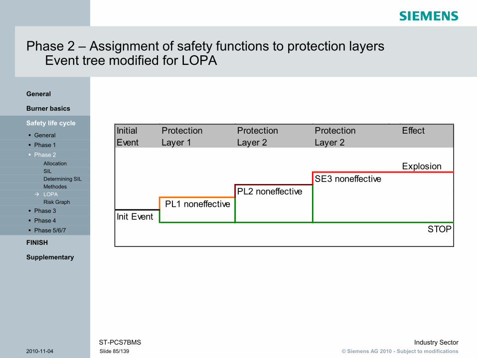
Phase 2 – Assignment of safety functions to protection layers Event tree modified for LOPA
Initial Protection Protection Protection EffectEvent Layer 1 Layer 2 Layer 2
ExplosionSE3 noneffective
PL2 noneffective PL1 noneffective
Init EventSTOP

© Siemens AG 2010 - Subject to modificationsIndustry Sector
2010-11-04 Slide 86/139ST-PCS7BMS
Supplementary
FINISH
Phase 5/6/7 Phase 4 Phase 3
Risk Graph LOPA
MethodesDetermining SILSILAllocation
Phase 2 Phase 1 General
Safety life cycle
Burner basics
General
Phase 2 – Assignment of safety functions to protection layers Example LOPA with event tree
Preparation for Exercise:Carry out a LOPA by using the event tree for the example of the HAZOP with the following assumptions
The burner runs uncontinuously The operator reacts on alarms and stops the process Is the process out of control a ESD is carried out
automatically (Pressure low - shutdown) As additional measure a low gas pressure protection
device is installed

© Siemens AG 2010 - Subject to modificationsIndustry Sector
2010-11-04 Slide 87/139ST-PCS7BMS
Supplementary
FINISH
Phase 5/6/7 Phase 4 Phase 3
Risk Graph LOPA
MethodesDetermining SILSILAllocation
Phase 2 Phase 1 General
Safety life cycle
Burner basics
General
Phase 2 – Assignment of safety functions to protection layers Example LOPA with quantification
Exercise:Quantify the evaluated event tree!The following failure rates shall be used
“Pressure low” happens in average every two years (Failure rate is 0.5 / year)
The probability of failure on demand of the Protection Layers was evaluated as follows: Burner in operation (50% of the year) PFD = 0,5 Operator response failure PFD = 0,1 ESD Failure PFD = 0,1 Failure of the low pressure protection device PFD = 0,07
PFD = Probability of Failure on Demand

© Siemens AG 2010 - Subject to modificationsIndustry Sector
2010-11-04 Slide 88/139ST-PCS7BMS
Supplementary
FINISH
Phase 5/6/7 Phase 4 Phase 3
Risk Graph LOPA
MethodesDetermining SILSILAllocation
Phase 2 Phase 1 General
Safety life cycle
Burner basics
General
Phase 2 – Assignment of safety functions to protection layersSolution LOPA with event tree
Initial Event PL 1 PL 2 PL 3 PL 4 EffectGas pressure Burner Operator Pressure low gas pressure Explosionlow running reaction low ESD protection device
no effect

© Siemens AG 2010 - Subject to modificationsIndustry Sector
2010-11-04 Slide 89/139ST-PCS7BMS
Supplementary
FINISH
Phase 5/6/7 Phase 4 Phase 3
Risk Graph LOPA
MethodesDetermining SILSILAllocation
Phase 2 Phase 1 General
Safety life cycle
Burner basics
General
Phase 2 – Assignment of safety functions to protection layers Solution LOPA with quantification
F = 0.5 /yr * 0.5 * 0.1 * 0.1 * 0.07 = 1.75 x 10⁻⁴/yr
1 explosion in 5714 years !F = Frequency of unwanted event (Explosion)
Initial Event PL 1 PL 2 PL 3 PL 4 EffectGas pressure Burner Operator Pressure low gas pressure Explosionlow running reaction low ESD protection device
1.75E-040.07
0.10.1
0.50.5 / yr
no effect

© Siemens AG 2010 - Subject to modificationsIndustry Sector
2010-11-04 Slide 90/139ST-PCS7BMS
Supplementary
FINISH
Phase 5/6/7 Phase 4 Phase 3
Risk Graph LOPA
MethodesDetermining SILSILAllocation
Phase 2 Phase 1 General
Safety life cycle
Burner basics
General
Phase 2 – Assignment of safety functions to protection layers Allocation of SIL to safety functions
The Safety Integrity Level (SIL) describes the requiered risk reduction of safety-related functions (SIF = Safety Instrumented Function)
Safety Integrity Level
Probability of failure on demand (PFD) (Low Demand mode)
Risk reduction Factor = 1/PFD
SIL 4
SIL 3
SIL 2
SIL 1
>=10-5 to <10-4
>=10-4 to <10-3
>=10-3 to <10-2
>=10-2 to <10-1
100000 to 10000
10000 to 1000
1000 to 100
100 to 10

© Siemens AG 2010 - Subject to modificationsIndustry Sector
2010-11-04 Slide 91/139ST-PCS7BMS
Supplementary
FINISH
Phase 5/6/7 Phase 4 Phase 3
Risk Graph LOPA
MethodesDetermining SILSILAllocation
Phase 2 Phase 1 General
Safety life cycle
Burner basics
General
Phase 2 – Assignment of safety functions to protection layers SIL- Allocation from quantitative LOPA
Accepted risk is known (e.g.. 1x10⁻⁵ / year)Attention: only for LOW DEMAND MODE (Process Plants)Example:
Initial Event PL 1 PL 2 PL 3 PL 4 EffectGas pressure Burner Operator Pressure low gas pressure Acceptedlow running reaction low ESD protection device Risk
1,00E-050.07
X0.1
0.50.5 / yr
no effect

© Siemens AG 2010 - Subject to modificationsIndustry Sector
2010-11-04 Slide 92/139ST-PCS7BMS
Supplementary
FINISH
Phase 5/6/7 Phase 4 Phase 3
Risk Graph LOPA
MethodesDetermining SILSILAllocation
Phase 2 Phase 1 General
Safety life cycle
Burner basics
General
Phase 2 – Assignment of safety functions to protection layers SIL- Allocation from quantitative LOPA
Burner in run PFD1 = 0,5
Operator reaction PFD2 = 0,1
Pressure LOW ESD PFD3 = X
Measures for risk reduction
Pressure to low R = 0,5 / year
with potential danger of explosion
TolerableRisk
F = 1 x 10 -5 / year
Low pressure protection device PFD4 = 0,07

© Siemens AG 2010 - Subject to modificationsIndustry Sector
2010-11-04 Slide 93/139ST-PCS7BMS
Supplementary
FINISH
Phase 5/6/7 Phase 4 Phase 3
Risk Graph LOPA
MethodesDetermining SILSILAllocation
Phase 2 Phase 1 General
Safety life cycle
Burner basics
General
Phase 2 – Assignment of safety functions to protection layers SIL- Allocation from quantitative LOPA
The required probability of failure on demand of the used SIF can be calculated with the following formula:
F ≥ R x PFD1 x PFD2 x PFD3 x PFD4
In solution for PFD3:PFD3 ≤ F / (R x PFD1 x PFD2 x PFD4):
PFD3 ≤ (1x10⁻⁵ / year) / (0,5 /year x 0,5 x 0,1 x 0,07)PFD3 ≤ 0,006
According to SIL allocation table for safety related functions, this SIF must reach SIL2

© Siemens AG 2010 - Subject to modificationsIndustry Sector
2010-11-04 Slide 94/139ST-PCS7BMS
Supplementary
FINISH
Phase 5/6/7 Phase 4 Phase 3 Risk Graph
LOPAMethodesDetermining SILSILAllocation
Phase 2 Phase 1 General
Safety life cycle
Burner basics
General
Phase 2 – Assignment of safety functions to protection layers Selection of a method for determining the required SIL
Examples of methods used Partially quantitative method Matrix method for the protection layers Calibrated risk graph (partially qualitative) Analysis of the protection layers (LOPA) Risk graph according to EN 50156-1 (qualitative)
There are sometimes company-specific modifications to these methods
© Siemens AG 2010 - Subject to modificationsIndustry Sector
2010-11-04 Slide 95/139ST-PCS7BMS
Supplementary
FINISH
Phase 5/6/7 Phase 4 Phase 3 Risk Graph
LOPAMethodesDetermining SILSILAllocation
Phase 2 Phase 1 General
Safety life cycle
Burner basics
General
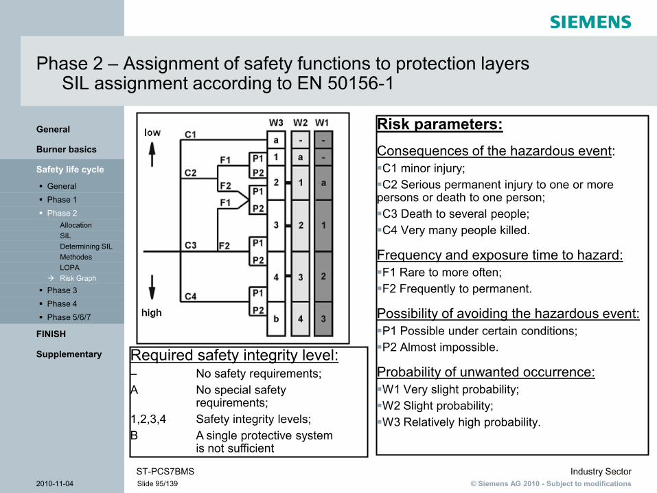
Phase 2 – Assignment of safety functions to protection layers SIL assignment according to EN 50156-1
Required safety integrity level:– No safety requirements;A No special safety
requirements;1,2,3,4 Safety integrity levels;B A single protective system
is not sufficient
Risk parameters:Consequences of the hazardous event:C1 minor injury;C2 Serious permanent injury to one or more persons or death to one person;C3 Death to several people;C4 Very many people killed.
Frequency and exposure time to hazard:F1 Rare to more often;F2 Frequently to permanent.
Possibility of avoiding the hazardous event:P1 Possible under certain conditions;P2 Almost impossible.
Probability of unwanted occurrence:W1 Very slight probability;W2 Slight probability;W3 Relatively high probability.

© Siemens AG 2010 - Subject to modificationsIndustry Sector
2010-11-04 Slide 96/139ST-PCS7BMS
Supplementary
FINISH
Phase 5/6/7 Phase 4 Phase 3 Risk Graph
LOPAMethodesDetermining SILSILAllocation
Phase 2 Phase 1 General
Safety life cycle
Burner basics
General
Phase 2 – Assignment of safety functions to protection layers Practical example
Burner management systemTeamwork

© Siemens AG 2010 - Subject to modificationsIndustry Sector
2010-11-04 Slide 97/139ST-PCS7BMS
Supplementary
FINISH
Phase 5/6/7 Phase 4
ProcedureRequirementsSpecification
Phase 3 Phase 2 Phase 1 General
Safety life cycle
Burner basics
General
Safety life cycle of a burner management systemPhase 3 - Specification of the safety requirements for the SIS
© Siemens AG 2010 - Subject to modificationsIndustry Sector
2010-11-04 Slide 98/139ST-PCS7BMS
Supplementary
FINISH
Phase 5/6/7 Phase 4
ProcedureRequirements
Specification Phase 3 Phase 2 Phase 1 General
Safety life cycle
Burner basics
General
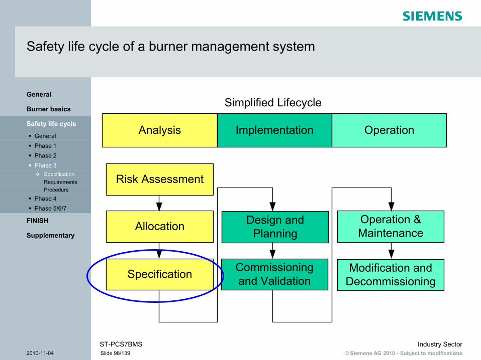
Safety life cycle of a burner management system
Analysis Implementation Operation
Risk Assessment
Allocation
Specification
Design and Planning
Commissioning and Validation
Operation & Maintenance
Modification and Decommissioning
Simplified Lifecycle

© Siemens AG 2010 - Subject to modificationsIndustry Sector
2010-11-04 Slide 99/139ST-PCS7BMS
Supplementary
FINISH
Phase 5/6/7 Phase 4
Procedure Requirements
Specification Phase 3 Phase 2 Phase 1 General
Safety life cycle
Burner basics
General
Phase 3 – Specification of the safety requirementsGeneral
Safety requirements specification
Requirements for thesafety function
Requirements forsafety integrity
All requirements which are necessary for the design of the SIFs are to be specified.
These requirements form the basis for subsequent validation (on site).

© Siemens AG 2010 - Subject to modificationsIndustry Sector
2010-11-04 Slide 100/139ST-PCS7BMS
Supplementary
FINISH
Phase 5/6/7 Phase 4
Procedure Requirements
Specification Phase 3 Phase 2 Phase 1 General
Safety life cycle
Burner basics
General
Phase 3 – Specification of the safety requirementsRequirements for the safety function (1)
Description of the safety instrumented functions
P&I schematic, cause & effect diagrams, prose text
Definition of the “safe state”
Definition of safe process states to be achieved by the safety instrumented functions
Required response time for the achievement of the safe state
Required cycle times
Description of measurement signals and limit values
Instrument lists, alarm and switching point lists
Necessary criteria for the fulfillment of the safety instrumented function
For example, sealed closure of valves
© Siemens AG 2010 - Subject to modificationsIndustry Sector
2010-11-04 Slide 101/139ST-PCS7BMS
Supplementary
FINISH
Phase 5/6/7 Phase 4
Procedure Requirements
Specification Phase 3 Phase 2 Phase 1 General
Safety life cycle
Burner basics
General
Phase 3 – Specification of the safety requirementsRequirements for the safety function (2)
Company requirements
E.g. special modes of operation
Interfaces to other company facilities
E.g. protocols
Potential combinations which can lead to dangerous states
Extreme values of all environmental conditions
EMC,
EX-zone,
IP protection
etc.

© Siemens AG 2010 - Subject to modificationsIndustry Sector
2010-11-04 Slide 102/139ST-PCS7BMS
Supplementary
FINISH
Phase 5/6/7 Phase 4
Procedure Requirements
Specification Phase 3 Phase 2 Phase 1 General
Safety life cycle
Burner basics
General
Phase 3 – Specification of the safety requirementsRequirements for safety integrity
Safety integrity level (SIL) per safety instrumented function
Estimated demand rate of safety instrumented functions and their triggers
Requirements for proof test intervals (proof test interval T1)
Average repair time (MTTR = Mean Time To Repair)

© Siemens AG 2010 - Subject to modificationsIndustry Sector
2010-11-04 Slide 103/139ST-PCS7BMS
Supplementary
FINISH
Phase 5/6/7 Phase 4 Procedure
RequirementsSpecification
Phase 3 Phase 2 Phase 1 General
Safety life cycle
Burner basics
General
Phase 3 – Specification of the safety requirementsProcedure
The SRS is generally described by means of several documents. The relevant procedure is as follows: Specification of all parameters relating to each SIF in a
“General SRS”. Specification of the SIF-specific parameters as a result
of the SIL allocation. Description of the functionality in the cause & effect diagram
(C&E)

© Siemens AG 2010 - Subject to modificationsIndustry Sector
2010-11-04 Slide 104/139ST-PCS7BMS
Supplementary
FINISH
Phase 5/6/7VerificationSoftwareHardwareDesign & Planning
Phase 4 Phase 3 Phase 2 Phase 1 General
Safety life cycle
Burner basics
General
Safety life cycle of a burner management systemPhase 4 - Design and planning of the SIS

© Siemens AG 2010 - Subject to modificationsIndustry Sector
2010-11-04 Slide 105/139ST-PCS7BMS
Supplementary
FINISH
Phase 5/6/7VerificationSoftwareHardware
Design & Planning Phase 4 Phase 3 Phase 2 Phase 1 General
Safety life cycle
Burner basics
General
Analysis Implementation Operation
Risk Assessment
Allocation
Specification
Design and Planning
Commissioning and Validation
Operation & Maintenance
Modification and Decommissioning
Simplified Lifecycle
Safety life cycle of a burner management system

© Siemens AG 2010 - Subject to modificationsIndustry Sector
2010-11-04 Slide 106/139ST-PCS7BMS
Supplementary
FINISH
Phase 5/6/7VerificationSoftware
HardwareDesign & Planning
Phase 4 Phase 3 Phase 2 Phase 1 General
Safety life cycle
Burner basics
General
Phase 4 - Design and planning of the SISTypical HW applications
Similar to most process plants: Temperature Pressure Flow Quick-acting shut-off valves, e.g. "double block and bleed" valves Combination of control and shut-off valves
In addition e.g. : Monitoring of the burner flame by means of the flame detector Supervision of Gas/Air ratio, e.g. by measuring the gas / air supply and
calculation Manual burner stop, e.g. emergency shutdown by an operator from the
control room

© Siemens AG 2010 - Subject to modificationsIndustry Sector
2010-11-04 Slide 107/139ST-PCS7BMS
Supplementary
FINISH
Phase 5/6/7VerificationSoftware
HardwareDesign & Planning
Phase 4 Phase 3 Phase 2 Phase 1 General
Safety life cycle
Burner basics
General
Phase 4 - Design and planning of the SISImplementation of the examples - HW
Model solution, burner management system Monitoring of the burner flame - flame detector Monitoring of the fresh-air intake using a flow measuring
device Shut-off, by two safety valves

© Siemens AG 2010 - Subject to modificationsIndustry Sector
2010-11-04 Slide 108/139ST-PCS7BMS
Supplementary
FINISH
Phase 5/6/7VerificationSoftware
HardwareDesign & Planning
Phase 4 Phase 3 Phase 2 Phase 1 General
Safety life cycle
Burner basics
General
Phase 4 - Design and planning of the SISImplementation of the examples - HW
Additional conditions EX zone 1 -20 – 40 C Industrial environment High availability > 100 safety-related I/Os Distance > 100 m between I/O AND CPU

© Siemens AG 2010 - Subject to modificationsIndustry Sector
2010-11-04 Slide 109/139ST-PCS7BMS
Supplementary
FINISH
Phase 5/6/7Verification
SoftwareHardwareDesign & Planning
Phase 4 Phase 3 Phase 2 Phase 1 General
Safety life cycle
Burner basics
General
Phase 4 - Design and planning of the SIS Implementation of the examples - SW
Failsafe Function Blocks for Burner Technology

© Siemens AG 2010 - Subject to modificationsIndustry Sector
2010-11-04 Slide 110/139ST-PCS7BMS
Supplementary
FINISH
Phase 5/6/7 Verification
SoftwareHardwareDesign & Planning
Phase 4 Phase 3 Phase 2 Phase 1 General
Safety life cycle
Burner basics
General
Phase 4 - Design and planning of the SISVerification - Overview
Selection of equipment to be used and setup of the device configuration
Determination of the key architecture values(HFT, SFF, proven in use)
Values OK according to SIL?
SRS
Re-
desi
gn
No

© Siemens AG 2010 - Subject to modificationsIndustry Sector
2010-11-04 Slide 111/139ST-PCS7BMS
Supplementary
FINISH
Phase 5/6/7 Verification
SoftwareHardwareDesign & Planning
Phase 4 Phase 3 Phase 2 Phase 1 General
Safety life cycle
Burner basics
General
Phase 4 - Development and planning of SISVerification - Step 1: Verification of the SIF architecture
The following parameters are to be identified Hardware fault tolerance (HFT) Safe failure fraction (SFF) Proven in use argumentation

© Siemens AG 2010 - Subject to modificationsIndustry Sector
2010-11-04 Slide 112/139ST-PCS7BMS
Supplementary
FINISH
Phase 5/6/7 Verification
SoftwareHardwareDesign & Planning
Phase 4 Phase 3 Phase 2 Phase 1 General
Safety life cycle
Burner basics
General
Phase 4 - Development and planning of SISVerification - Step 1: Verification of the SIF architecture
Safe failure Fractions describes the rate of safe failures : λS (Rate of all “safe” failures) λSD (rate of all “safe detected” failures) λSU (rate of all “safe undetected” failures)
λD (Rate of all "dangerous” failures) λDD (Rate of all “dangerous detected” failures) λDU (Rate of all “dangerous undetected” failures)
Failure-free operation
λSDλSUλDDλDU
safedangerous
∑ ∑ ∑∑ ∑
+++
=DUDDS
DDSSFF
λλλλλ
SFF = Safe Failure Fraction

© Siemens AG 2010 - Subject to modificationsIndustry Sector
2010-11-04 Slide 113/139ST-PCS7BMS
Supplementary
FINISH
Phase 5/6/7 Verification
SoftwareHardwareDesign & Planning
Phase 4 Phase 3 Phase 2 Phase 1 General
Safety life cycle
Burner basics
General
Phase 4 - Development and planning of SISVerification - Step 1: Verification of the SIF architecture
Hardware fault tolerance refers to the capability of a hardware unit to continue performing a required function even under fault conditions
In this context:Hardware fault tolerance N = N + 1 hardware faults may
result in the loss of the relevant safety function.
Example:Measuring 2oo3 3-2 = HFT = 1! Two hardware faults result in the loss of the relevant safety functionMeasuring 1oo3 3-1 = HFT = 2! Three hardware fault result in the loss of the relevant safety function

© Siemens AG 2010 - Subject to modificationsIndustry Sector
2010-11-04 Slide 114/139ST-PCS7BMS
Supplementary
FINISH
Phase 5/6/7 Verification
SoftwareHardwareDesign & Planning
Phase 4 Phase 3 Phase 2 Phase 1 General
Safety life cycle
Burner basics
General
Phase 4 - Development and planning of SISVerification - Step 1: Verification of the SIF architecture
SIL Minimum HFT1 02 13 24 Spezielle Anforderungen nach IEC 61508
The minimum HFT may be reduced by 1 if evidence can be provided that:
The hardware has been selected on the basis of previous usage
Only process-related parameters can be set on the device
Setting of process-related parameters is protected (e.g. by a jumper or similar)
(as per IEC 61511-1, Table 6)
"Proven in use"
Requirements of the system architecture of sensors, actuators, non-PE logic systems as per IEC 61511

© Siemens AG 2010 - Subject to modificationsIndustry Sector
2010-11-04 Slide 115/139ST-PCS7BMS
Supplementary
FINISH
Phase 5/6/7 Verification
SoftwareHardwareDesign & Planning
Phase 4 Phase 3 Phase 2 Phase 1 General
Safety life cycle
Burner basics
General
Phase 4 - Development and planning of SISVerification - Step 1: Verification of the SIF architecture
(as per IEC 61511-1, Table 5)
bei SFF < 60% bei SFF < 90% bei SFF ≥ 90%1 1 0 02 2 1 03 3 2 14
SIL Minimum HFT
Spezielle Anforderungen siehe IEC 61508
Remark
As the SFF for complex controllers can only be determined by the manufacturer, the recommendation is to use certified systems whose values have been determined within the context of a certification process.
Requirements of the system architecture of PE logic systems as per IEC 61511

© Siemens AG 2010 - Subject to modificationsIndustry Sector
2010-11-04 Slide 116/139ST-PCS7BMS
Supplementary
FINISH
Phase 5/6/7 Verification
SoftwareHardwareDesign & Planning
Phase 4 Phase 3 Phase 2 Phase 1 General
Safety life cycle
Burner basics
General
Phase 4 - Development and planning of SISVerification - Step 1: Verification of the SIF architecture
IEC 61508-2, Section 7.4.3.1.1/Tab. 2 & 3
Subsystem type A: Simple subsystems, 100% of whose fault modes are known Example: Pressure switch, solenoid valve, etc.
Subsystem type B: Complex subsystems, whose potential fault modes are not 100%
known. These subsystems generally include microprocessors and software.
Example: PLC, smart transmitter, etc.
Alternative: Use of the table from IEC 61508
Typ A Typ B N = 0 N = 1 N = 2--- 0% ...< 60% --- SIL1 SIL2
0% ...< 60% 60% ...< 90% SIL1 SIL2 SIL360% ...< 90% 90% ...< 99% SIL2 SIL3 SIL4
? 90% ? 99% SIL3 SIL4 SIL4
Safe Failure Fraction Hardware Fehler Toleranz N

© Siemens AG 2010 - Subject to modificationsIndustry Sector
2010-11-04 Slide 117/139ST-PCS7BMS
Supplementary
FINISH
Phase 5/6/7 Verification
SoftwareHardwareDesign & Planning
Phase 4 Phase 3 Phase 2 Phase 1 General
Safety life cycle
Burner basics
General
Phase 4 - Design and planning of the SISVerification - Overview
Selection of equipment to be used and setup of the device configuration
Determination of the key architecture values(HFT, SFF, proven in use)
Values OK according to SIL?
Determination of the probabilities of failure(PFD, PFH)
SRS
Values OK according to SIL?
HW design verified
Re-
desi
gn
No
Yes
Re-
desi
gn
No
Yes

© Siemens AG 2010 - Subject to modificationsIndustry Sector
2010-11-04 Slide 118/139ST-PCS7BMS
Supplementary
FINISH
Phase 5/6/7 Verification
SoftwareHardwareDesign & Planning
Phase 4 Phase 3 Phase 2 Phase 1 General
Safety life cycle
Burner basics
General
Phase 4 - Development and planning of SISVerification - Step 2: Verification of the permitted probability of failure
The following parameters need to be determined per SIF: Fault rates λ (safe, dangerous) or PFD/PFH Proof test interval T1 Common cause influence β Mean time to repair, MTTR

© Siemens AG 2010 - Subject to modificationsIndustry Sector
2010-11-04 Slide 119/139ST-PCS7BMS
Supplementary
FINISH
Phase 5/6/7 Verification
SoftwareHardwareDesign & Planning
Phase 4 Phase 3 Phase 2 Phase 1 General
Safety life cycle
Burner basics
General
Phase 4 - Development and planning of SISVerification - Step 2: Verification of the permitted probability of failure
Target values to be achieved:
Low demand mode of operation SIF demand not more than once per year and not more than
twice the frequency of the proof tests High or continuous demand mode of operation
SIF demand more than once per year or more than twice the frequency of the proof tests
"low demand":Probability of Failure on
Demand PFD1 < 10-1 < 10-5 = 10.000 Fit2 < 10-2 < 10-6 = 1000 Fit3 < 10-3 < 10-7 = 100 Fit4 < 10-4 < 10-8 = 10 Fit
SIL Probability of Failure per Hour PFH
"high demand":
(1 Fit = 1x10⁻⁹ /h)

© Siemens AG 2010 - Subject to modificationsIndustry Sector
2010-11-04 Slide 120/139ST-PCS7BMS
Supplementary
FINISH
Phase 5/6/7 Verification
SoftwareHardwareDesign & Planning
Phase 4 Phase 3 Phase 2 Phase 1 General
Safety life cycle
Burner basics
General
Phase 4 - Development and planning of SISVerification - Step 2: Verification of the permitted probability of failure
Procedure Identification of the devices used and collection of the following
parameters Fault rates, typ. (or direct PFD/PFH) Alternatively, "proven in use" documentation for field devices
Calculation of PFD/PFH for the devices used based on the various structures (1oo1, 1oo2, 2oo3, etc.)
Calculation of the PFD/PFH for the respective subsystem (sensor, logic, actuator) per SIF
Checking the computed results against the target values

© Siemens AG 2010 - Subject to modificationsIndustry Sector
2010-11-04 Slide 121/139ST-PCS7BMS
Supplementary
FINISH
Modification & Decomissioning
Operation & Maintenance
Commissioning & Validation
Phase 5/6/7 Phase 4 Phase 3 Phase 2 Phase 1 General
Safety life cycle
Burner basics
General
Safety life cycle of a burner management systemPhase 5/6/7 – Commissioning, Maintenance and Decommissioning

© Siemens AG 2010 - Subject to modificationsIndustry Sector
2010-11-04 Slide 122/139ST-PCS7BMS
Supplementary
FINISH
Modification & Decomissioning
Operation & Maintenance
Commissioning & Validation
Phase 5/6/7 Phase 4 Phase 3 Phase 2 Phase 1 General
Safety life cycle
Burner basics
General
Analysis Implementation Operation
Risk Assessment
Allocation
Specification
Design and Planning
Commissioning and Validation
Operation & Maintenance
Modification and Decommissioning
Simplified Lifecycle
Safety life cycle of a burner management system
© Siemens AG 2010 - Subject to modificationsIndustry Sector
2010-11-04 Slide 123/139ST-PCS7BMS
Supplementary
FINISH
Modification & Decomissioning
Operation & Maintenance
Commissioning & Validation
Phase 5/6/7 Phase 4 Phase 3 Phase 2 Phase 1 General
Safety life cycle
Burner basics
General
Safety life cycle of a burner management systemRequirements - Assembly, commissioning,
Definition of the relevant safety activities References to the right QM- Guidelines Responsibility of Departments and Persons Used Tools and qualification do them Planning of V&V activities Planning of relevant documentation
Safety Plan “Assembly”
© Siemens AG 2010 - Subject to modificationsIndustry Sector
2010-11-04 Slide 124/139ST-PCS7BMS
Supplementary
FINISH
Modification & Decomissioning
Operation & Maintenance
Commissioning & Validation
Phase 5/6/7 Phase 4 Phase 3 Phase 2 Phase 1 General
Safety life cycle
Burner basics
General
Safety life cycle of a burner management systemAspects - Operation and maintenance
The required safety-relevant availability and reliability must remain in the system during the whole operation The operational aspects which have been defined during planning
(education of personnel) must be kept The maintenance points, defined in planning phase (e. g. Proof
Test) must be carried out Every activity must be scheduled and documented
Recommendations and requirements from manuals must be used
© Siemens AG 2010 - Subject to modificationsIndustry Sector
2010-11-04 Slide 125/139ST-PCS7BMS
Supplementary
FINISH
Modification & Decomissioning
Operation & Maintenance
Commissioning & Validation
Phase 5/6/7 Phase 4 Phase 3 Phase 2 Phase 1 General
Safety life cycle
Burner basics
General
Safety life cycle of a burner management systemModification
Each change in a SIF must only be done after an impact analysis In addition to the impact, the risk of that change must be evaulated The evaluations must be checked by a verifier Therefore Responsibilities must be clearly declared The Changes must be documented Description of the change Basis of the change Possible hazards the change can result in How is the (regression)-tests carried out Which documents are influenced by the change
Management of Change

© Siemens AG 2010 - Subject to modificationsIndustry Sector
2010-11-04 Slide 126/139ST-PCS7BMS
Supplementary
FINISH
Modification & Decomissioning
Operation & Maintenance
Commissioning & Validation
Phase 5/6/7 Phase 4 Phase 3 Phase 2 Phase 1 General
Safety life cycle
Burner basics
General
Safety life cycle of a burner management systemModification
Different safety requirements
Modification of EUC
Changes in law
Operational requirements
Modification -Requests
Systematic failures
Knowledge about incidents
Impact analysis
Impact Report
Acceptance of modification
Back to relevant Phase of safety
lifecycle
Risk assessment

© Siemens AG 2010 - Subject to modificationsIndustry Sector
2010-11-04 Slide 127/139ST-PCS7BMS
Supplementary
FINISH
Safety life cycle
Burner basics
General
ST-PCS7BMS
Name: Mathias Rebling
Department: Siemens AG, Industry Sector
Address: Colmberger Str. 2
90451 Nürnberg
Mail: [email protected]
Thank youhttp://support.automation.siemens.com/WW/view/de/16887335

Supplementary Information

© Siemens AG 2010 - Subject to modificationsIndustry Sector
2010-11-04 Slide 129/139ST-PCS7BMS
Phase 2 -Riskgraph VDE/VDI 2180
Safety life cycle
Supplementary
FINISH
Safety life cycle
Burner basics
General
Safety life cycle of a burner management systemPhase 2 – Allocation of Safety Functions to Protection Layers

© Siemens AG 2010 - Subject to modificationsIndustry Sector
2010-11-04 Slide 130/139ST-PCS7BMS
Phase 2 -Riskgraph VDE/VDI 2180
Safety life cycle
Supplementary
FINISH
Safety life cycle
Burner basics
General
Safety life cycle of a burner management system
Analysis Implementation Operation
Risk Assessment
Allocation
Specification
Design and Planning
Commissioning and Validation
Operation & Maintenance
Modification and Decommissioning
Simplified Lifecycle
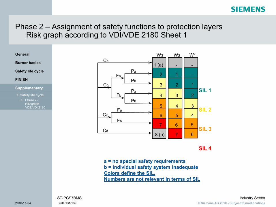
© Siemens AG 2010 - Subject to modificationsIndustry Sector
2010-11-04 Slide 131/139ST-PCS7BMS
Phase 2 -Riskgraph VDE/VDI 2180
Safety life cycle
Supplementary
FINISH
Safety life cycle
Burner basics
General
Phase 2 – Assignment of safety functions to protection layersRisk graph according to VDI/VDE 2180 Sheet 1
a = no special safety requirementsb = individual safety system inadequateColors define the SIL,Numbers are not relevant in terms of SIL
W3 W2 W1Ca
Cb
Cc
Cd
Fa
FbPa
1 (a)
2
3
4
5
6Fb
Fa
7
8 (b)
-
1
2
3
4
5
6
7
-
-
1
2
3
4
5
6
Pb
Pa
Pb
SIL 1
SIL 2
SIL 3
SIL 4

© Siemens AG 2010 - Subject to modificationsIndustry Sector
2010-11-04 Slide 132/139ST-PCS7BMS
Phase 2 -Riskgraph VDE/VDI 2180
Safety life cycle
Supplementary
FINISH
Safety life cycle
Burner basics
General
Phase 2 – Assignment of safety functions to protection layersRisk graph according to VDI/VDE 2180 Sheet 1
Risk parameters Classification Comment
Effect (C) C1
C2
C3
C4
Slight injury to persons
Serious, permanent injury to one or more persons; death of a person
Death of several persons
Catastrophic effects, many deaths
1 This classification has been created for injuries and deaths. Alternative classifications would have to be developed for damage to the environment or to assets.

© Siemens AG 2010 - Subject to modificationsIndustry Sector
2010-11-04 Slide 133/139ST-PCS7BMS
Phase 2 -Riskgraph VDE/VDI 2180
Safety life cycle
Supplementary
FINISH
Safety life cycle
Burner basics
General
Phase 2 – Assignment of safety functions to protection layersRisk graph according to VDI/VDE 2180 Sheet 1
Risk parameters Classification Comment
Frequency of presence in the hazardous area multiplied by the duration of presence (F)
F1
F2
Seldom to frequent presence in the hazardous zone
Frequent to constant presence in the hazardous zone
2 See comment 1 above

© Siemens AG 2010 - Subject to modificationsIndustry Sector
2010-11-04 Slide 134/139ST-PCS7BMS
Phase 2 -Riskgraph VDE/VDI 2180
Safety life cycle
Supplementary
FINISH
Safety life cycle
Burner basics
General
Phase 2 – Assignment of safety functions to protection layersRisk graph according to VDI/VDE 2180 Sheet 1
Risk parameters Classification Comment
Possibility of avoiding the effects of the hazardous event (P)
P1
P2
Possible under particular conditions
Almost impossible
3 This parameter takes into account:– Operation of the system(constantly monitored – by a trained or untrained person – or not constantly monitored);– Speed of development of the hazardous event (sudden, fast, or slow);– Simple hazard recognition (for example, immediate detection, discovered with or without technical means);– Prevention of the hazardous event (for example, escape route possible, impossible, or possible under certain conditions);– Available experience (of the same or a similar process, or no experience).
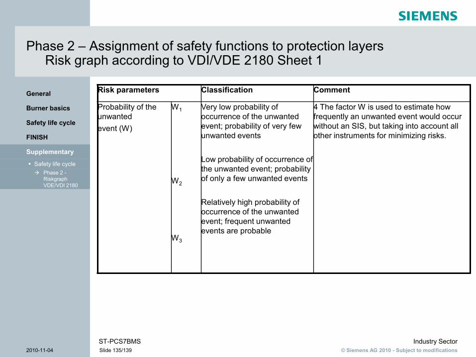
© Siemens AG 2010 - Subject to modificationsIndustry Sector
2010-11-04 Slide 135/139ST-PCS7BMS
Phase 2 -Riskgraph VDE/VDI 2180
Safety life cycle
Supplementary
FINISH
Safety life cycle
Burner basics
General
Phase 2 – Assignment of safety functions to protection layersRisk graph according to VDI/VDE 2180 Sheet 1
Risk parameters Classification Comment
Probability of the unwantedevent (W)
W1
W2
W3
Very low probability of occurrence of the unwanted event; probability of very few unwanted events
Low probability of occurrence of the unwanted event; probability of only a few unwanted events
Relatively high probability of occurrence of the unwanted event; frequent unwanted events are probable
4 The factor W is used to estimate how frequently an unwanted event would occur without an SIS, but taking into account all other instruments for minimizing risks.