Embed Size (px)
Citation preview

International Journal of Scientific Research and Innovative Technology Vol. 1 No. 3; October 2014
1Mohammed M. Alsamhari ,lecturer of fixed prosthodontic, Thamar university, Yemen
2 Mohamed Adel Anwar Abdelaziz, lecturer of fixed prosthodontic, Assiut university, Egypt
3 Jihan F. Younis ,professor of fixed prosthodontic ,Ain shams university, Egypt
4Tarek S. Morsi professor and head of fixed prosthodontic, Ain shams university, Egypt 83
SStrain Analysis of Zirconium Fpds with Pier
Abutments Using Different Designs
Mohammed M. Alsamhari (1); Abdelaziz M. A.(2); Jihan F. Younis (3) and Tarek S. Morsi(4)
Abstract
Statement of problem: in some patients, the pattern of missing teeth may require theuse of a fixed
partial denture (FPD) with an intermediate (pier) abutment, information is needed regarding the
biomechanical behavior and best (FPD) design as treatment option.
Purpose: This study was aimed to examine the effect of three different bridge designs with pier abutment
on strain analysis of Zirconia Bridges after aging process (cyclic loading and acid storage). The three
different designs were: fixed-fixed bridge with rigid connector,fixed-fixed bridge with non- rigid
connector and fixed-free Bridge.
Material and methods: A total of 30 all-ceramic zirconia bridges were constructed and divided
according to bridge design in to three groups (10 bridges each);fixed-fixed design(10 samples), non-
rigid design (10 samples),and cantilever design (10 samples).Each groupwas made to measure;1 strain
gauge analysis at 300 N, 2 strain gauge analysis at fractureload.
Results: One way Analysis of Variance (ANOVA) was used to compare between
three types of designs. Tukey’s post-hoc test was used for pair-wise comparison betweenthe means when
ANOVA test is significant. The test reveal that fixed-fixed design groupshowed equal distribution of
strain while the non rigid design decrease the strain in the distalof the pier abutment but it concentrate
it in the mesial of the posterior abutment.
Conclusion: the fixed-fixed design showed the equal strain distribution when it is used to restore
maxillary 5-unit FPD with pier abutment.
Keywords: Strain, Zirconia, Pier Abutment, Bridge Design
Introduction
If an edentulous space occurs on both sides of a tooth, it will create a lone, free standing isolated tooth
which is known as a Pier Abutment. So, the Pier
Abutment can be defined as it is a lone, free standing isolated tooth or, it is the intermediate or middle
abutmentA
Statement of the Problems of the Pier Abutment:
The problems which might arise with the pier abutment teeth are: Stress Distribution and Movement of
Abutment Teeth, Bone and Periodontal Investing
Structures, Lack of Parallelism between Abutment Teeth, Size, Shape and Location of Abutment Teeth,
Size and Shape of the Pulp of Abutment Teeth and
Vitality of Abutment Teeth.B

International Journal of Scientific Research and Innovative Technology Vol. 1 No. 3; October 2014
1Mohammed M. Alsamhari ,lecturer of fixed prosthodontic, Thamar university, Yemen
2 Mohamed Adel Anwar Abdelaziz, lecturer of fixed prosthodontic, Assiut university, Egypt
3 Jihan F. Younis ,professor of fixed prosthodontic ,Ain shams university, Egypt
4Tarek S. Morsi professor and head of fixed prosthodontic, Ain shams university, Egypt 84
Landry et al., 1987,Csimulated a mandibular 5-unit FPD retained by a canine, second premolar, and
second molar. Three types of FPDS made of type III gold alloy were fabricated: (1) Non-rigid connector
at the distal aspect of the second premolar, (2) non-rigid connector at the distal aspect of the canine, and
(3) all-rigid connectors. Each unit of the FPD was loaded separately with a force of 30 psi, perpendicular
to the alveolar crest. The amount and pattern of stress fringes were recorded at 15 zones around the roots
of the abutment teeth. The results showed that when the rigid framework was loaded, the stresses were
more evenly distributed among the abutment teeth.
Moreover, when a terminal abutment was loaded, low-grade stress fringes were seen around the apex of
the opposite terminal abutment. The authors stated that the low shear stresses observed at the terminal
abutments question the high tensile stresses that were suggested in the presence of an intermediate
abutment and as a cause of retainer failure. When the anterior segment of an FPD containing a nonrigid
connector was loaded, the abutments located anterior to the attachment experienced high compressive
stress, while only minimal stress was noted at the apices of the posterior abutments.
When the compressive force was applied to a tooth containing a non-rigid connector, the highest stresses
were noted at the apex of that tooth. These were higher in magnitude than the stress that developed when
the tooth was loaded while incorporated in arigid framework.
Standlee and Caputo., 1988 ,Dsimulated the same clinical situation of a mandibular 5-unit FPD with a
pier. Simulated tissues were made of different plastic materials. Three types of FPD frameworks were
constructed from a non-precious alloy (Biocast Rx, Jeneric Gold): (1) all-rigid connectors, (2) precision
Attachment at the mesial of the premolar abutment, and (3) precision attachment at the distal of the
premolar abutment.
Vertical loads of 30 lb. were applied separately to each retainer and pontic. The stress induced fringe
patterns were recorded by a camera and the vertical displacement of each tooth was measured with a dial
gauge.
It was found that no matter where the rigid framework was loaded, some degree of apical stress was
noted around all abutment teeth and all showed some apical displacement.
The authors conclude: “There was no evidence that the premolar abutment acted as a fulcrum.”The
experiment also showed that when a non-rigid connector was incorporated into the framework, the stress
to the abutments at the loaded side increased while the stress to the abutments on the unloadedside
decreased.
Moulding et al., 1992,E examined a similar setup of a mandibular 5-unit FPD with a pier through a
photoelastic model, using different materials. Six FPD designs made of palladium-silver alloy were
fabricated: (1) all-rigid connectors, (2) non-rigidconnector at the distal aspect of the canine, (3) non-rigid
connector at the mesial aspect of the pier retainer, (4) non-rigid connector at the distal of thepier retainer
(keyway within the retainer), (5) nonrigidconnector at the distal of the pier retainer (keyattached to the
pier and keyway within the pontic ofthe first molar), and (6) non-rigid connector at themesial aspect of
the second molar.
Each unit of the FPD was subjected individuallyto a loading force of 198 N and the stress fringes in13
areas around the roots of the abutment teeth wererecorded by a camera. When the rigid frameworkwas
loaded at the canine, stress was noticed at theapex of the canine, second premolar, and to a smallerextent
at the apices of the second molar. Loadingthe second premolar caused stress fringes to appearat the
apices of all abutment teeth. Loading of the second molar produced high stresses at its apices,less stress
at the apex of the second premolar, and no stress at all around the whole surface area of the canine. The

International Journal of Scientific Research and Innovative Technology Vol. 1 No. 3; October 2014
1Mohammed M. Alsamhari ,lecturer of fixed prosthodontic, Thamar university, Yemen
2 Mohamed Adel Anwar Abdelaziz, lecturer of fixed prosthodontic, Assiut university, Egypt
3 Jihan F. Younis ,professor of fixed prosthodontic ,Ain shams university, Egypt
4Tarek S. Morsi professor and head of fixed prosthodontic, Ain shams university, Egypt 85
authors concluded that the rigid FPD distributed stresses vertically and evenly. When a non-rigid
connector was placed at the pier and thepier was loaded, the highest stress concentrationdeveloped
around its root, due to the inability of thenon-rigid framework to effectively transfer the loadto the
terminal abutments. The authors concluded that the results supported Markley, who proposed that stress
should be broken at either terminal abutment so that loads centered on the pier are partially distributed to
theterminal abutments.
Ziada et al., 1998,F investigated the stress patterns that develop in an anterior 5-unit resin bonded fixed
partial denture (RBFPD) with a pier.
The model consisted of a simulated maxillary canine, central incisor, and the contralateral lateral incisor.
The simulated teeth were constructed at a size 2.5_ larger than their anatomic size to assist in the
visual resolution of the stress patterns. Loading was performed simultaneously over the 2 pontics and the
stress fringes were recorded from the adhesive layer of the RBFPD (no data are provided on the
magnitude of force used). The results show that stresses were concentrated over the entire surface of the
cement layer of the pier retainer. The authors therefore conclude that the design of an RBFPD with a
pier should be avoided due to increased risk for debonding of the pier retainer.
The complex behavior and stress distribution patterns of enamel, dentin, pulp, and cementum that
comprise a tooth cannot be duplicated by a simplistic model. The nonlinear behavior of the periodontal
ligament (PDL) also cannot be simulated. Nonetheless, it should be considered that no study on a
posterior 5-unit FPD with a pier has demonstrated a fulcrum effect of the pier abutment, while all of
them have demonstrated increased stresses on the pier when loaded while bearing a non-rigid connector.
Selcuk et al., 2008,Gevaluated stress distribution, by means of finite element method (FEM), the effects
of rigid and non-rigid design types on for
5-unit FPDs with pier abutments. A 3-dimensional cross-section FEM model (SAP 2000) simulating a
5-unit metal ceramic FPD with a pier abutment with rigid or non-rigid designs (connector location at the
mesial region of the second molar, at the distal region of the second premolar, at the mesial region of the
second premolar, and at the distal region of the canine) was developed. In the model, the canine, second
premolar, and second molar served as abutments. A supporting periodontal ligament and alveolar bone
(cortical and trabecular) were modeled. A 50-N static vertical occlusal load wasapplied on the cusp of
each abutment to calculatethe stress distributions. Three different types of loadwere evaluated: loading
of all cusps to simulatemaximum centric occlusion contacts, loading ofthe canine to simulate a single
anterior contact,and loading of the second molar to simulate aposterior contact. They found that the
analysis ofthe von Mises stress values revealed that maximumstress concentrations were located at the
load areasfor all models. Also, for all models, the higheststress values were located at connectors
andcervical regions of abutment teeth, especially atthe pier abutment, they concluded that The area
ofmaximum stress concentration at the pier abutmentwas decreased by the use of a non-rigid connectorat
the distal region of the second premolar, Becausethe pier abutment used in rigid FPDs can act as
afulcrum, the restoration of a terminal abutment maybecome loose. When fabricating a 5-unit FPD
fromthe maxillary canine to second molar with a pierabutment, the use of a non-rigid connector at
thedistal of the second premolar may reduce potentiallyexcessive stress concentration on the pier
abutment.
In some patients, the pattern of missing teethmay require the use of an FPD with a pier
abutment.Restoration of 2 missing teeth and an intermediatepier abutment with a rigid FPD is not an

International Journal of Scientific Research and Innovative Technology Vol. 1 No. 3; October 2014
1Mohammed M. Alsamhari ,lecturer of fixed prosthodontic, Thamar university, Yemen
2 Mohamed Adel Anwar Abdelaziz, lecturer of fixed prosthodontic, Assiut university, Egypt
3 Jihan F. Younis ,professor of fixed prosthodontic ,Ain shams university, Egypt
4Tarek S. Morsi professor and head of fixed prosthodontic, Ain shams university, Egypt 86
ideal treatment. When an occlusal load is applied tothe retainer on the abutment tooth at one end of
anFPD with a pier abutment, the pier abutment mayact as a fulcrum. Thus, tensile forces may then
begenerated between the retainer and abutment at theother end of the restoration. Anterior or
posteriorabutments may experience extrusive forces duringfulcrum action, and resultant tensile force
atthe retainer to-abutment interface5 may result inpotential loss of retention for these restorations.
It has been reported that rigid FPDs with pierabutments are associated with higher debondingrates than
short-span prostheses.
Adams3Hadvised placing one non-rigidconnector at the distal side of the pier, and ifdesired, adding one
more at the distal of the anteriorretainer. The authors did not provide reasoning fortheir
recommendations. the use of a non-rigid connector in aposterior 5-unit FPD with a pier is
contraindicatedin some situations: (1) if the abutment teeth presentsignificant mobility; (2) if the span
between theabutments is longer than 1 tooth, because the stressestransferred to the abutment tooth under
the solderedretainer would be destructive; and (3) if the distalretainer and pontic are opposed by a
removablepartial denture or an edentulous ridge while the 2anterior retainers are opposed by natural
dentition,possibly allowing the distal terminal abutment tosupraerupt.
Accepting the principle of evidence baseddentistry, it seems warranted to critically review
thedocumentation behind a concept that is addressed inseveral textbooks.
Material and Methods
A right maxillary first premolar and first molarwere removed from the upper arch of an acrylictypodent.
The socket of the upper lateral was closedwith pink modeling wax to simulate an edentulousarea of a
missing first premolar and first molarbounded by maxillary right canine, second premolar(pier), and
second molar acrylic teeth. Each toothwas prepared to receive a full coverage all-ceramicretainer.
A total of 30 all-ceramic zirconia bridges were constructed using (MAD/MAM manualy
aiadeddesign/manualy aided milling zirconzhan; Bruneck,Italy) and divided according to bridge design
in tothree groups(10 bridges each);fixed-fixed design(10samples) figure 2,non-rigid design (10
samples)figure 1,and cantilever design (10 samples).analysis at 300 N, and strain gauge analysis at
fracture load.
The fitting surface of the retainers were sandblasted with 50 ìm AL2O3 at maximum pressure of 2.5 bar
for 30 seconds at an approximate distance 2 cm.
Thirty epoxy resin (Chemapoxy 150 Transparent) casts were fabricated by introducing the polymerizing
resin into a polyvinylsiloxane mold (KERR Extrude Medium) of the master dies. The adhesive resin
Metacem was used for cementation of the restorations. The restorations were seated slowly with gentle
finger pressure then seated in the lower compartment of cement loading device under (1.5 Kg) load for
one minute. Excess luting material was removed with sponge pellets immediately, and each cement
surface/margin was light cured for 40 seconds.
The samples were subjected to aging process as they were stored in acidic medium (citric acid) with pH.
6 and cyclic loading (wet type) for 500,000 cycles with forces ranges from 5-50 N.

International Journal of Scientific Research and Innovative Technology Vol. 1 No. 3; October 2014
1Mohammed M. Alsamhari ,lecturer of fixed prosthodontic, Thamar university, Yemen
2 Mohamed Adel Anwar Abdelaziz, lecturer of fixed prosthodontic, Assiut university, Egypt
3 Jihan F. Younis ,professor of fixed prosthodontic ,Ain shams university, Egypt
4Tarek S. Morsi professor and head of fixed prosthodontic, Ain shams university, Egypt 87
The samples were subjected to vertical loading using a universal-testing machine (LIoyd Instrument LR
5K). The cross-head speed was 0.5 mm/min. the very first discontinuity resulting from an early crack,
debonding or catastrophic failure of bridge and/or die was detected. 4 KYOWA strain gauges were
bonded at four points; point A, at lingual –mesial surface of the distal retainer, point B, at lingual –distal
surface of the pier retainer, point C, at lingual –mesial surface of the pier retainer, point D, at lingual –
mesial surface of the anterior retainer using strain gauge cement. The strain induced in the samples
during 300 N and till fracture load was measured by a KYOWA strain meter.
Results
Data of this study were presented as mean as mean and standard deviation (SD) values. Data were
explored for normality using test of normality. A low significance value (less than 0.05) of test indicates
that the distribution of the data differs significantly from a normal distribution. Strain data showed a
normal distribution so parametric tests were used for the comparisons. One way Analysis of Variance
(ANOVA) was used to compare between three types of designs. Tukey’s post-hoc test was used for
pairwise comparison between the means when ANOVA test is significant.
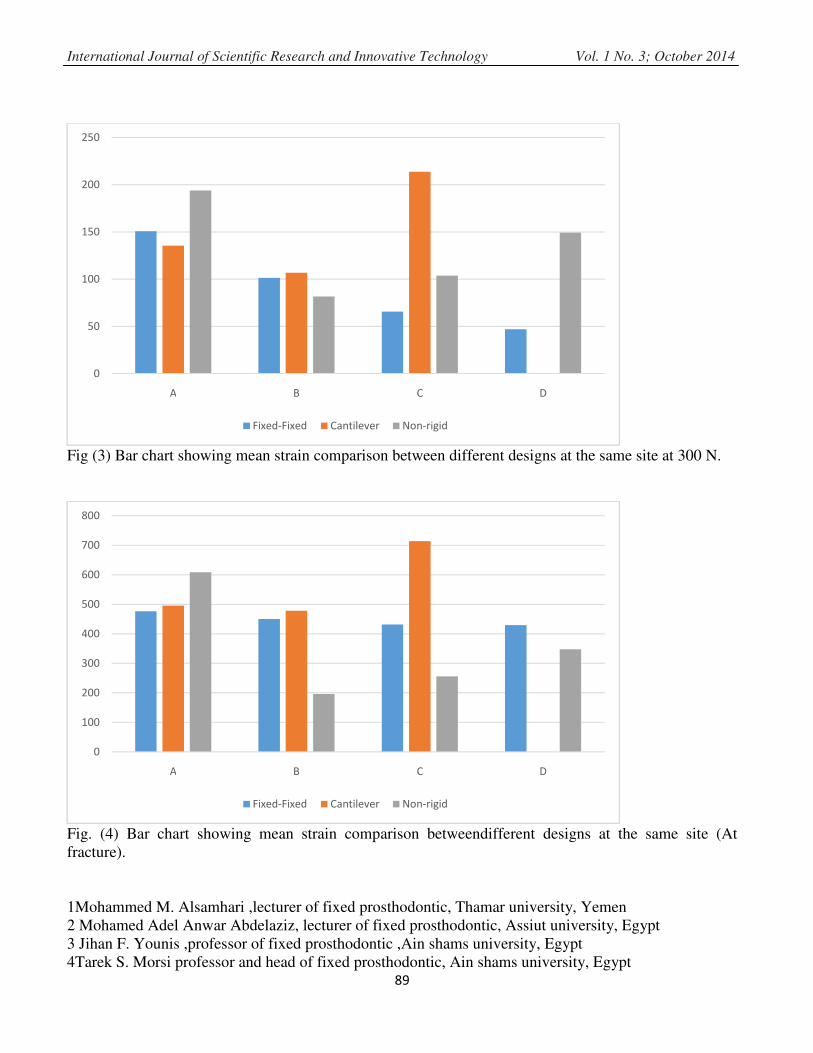
At A Site: the Non-rigid design at 300N showed mean strain value (193.8) statistically significant
highest mean. While the Cantilevered design showed mean strain value (135.6) statistically
notsignificant lowest mean strain with the mean strain of the Fixed-Fixed design (150.8).
Fig. (1) Photograph showing zirconia FPD with non-rigid Connector
Fig. (2) Photograph showing zirconia FPD with rigid connector

International Journal of Scientific Research and Innovative Technology Vol. 1 No. 3; October 2014
1Mohammed M. Alsamhari ,lecturer of fixed prosthodontic, Thamar university, Yemen
2 Mohamed Adel Anwar Abdelaziz, lecturer of fixed prosthodontic, Assiut university, Egypt
3 Jihan F. Younis ,professor of fixed prosthodontic ,Ain shams university, Egypt
4Tarek S. Morsi professor and head of fixed prosthodontic, Ain shams university, Egypt 88
At B Site: the Non-rigid design at 300N showed mean strain value (81.6) statistically significant lowest
mean. While the Fixed-Fixed design showed mean strain value (101.4) statistically not significant
lowest mean strain with the mean strain of the Cantilevered design (106.8).
At C Site: the Cantilevered design at 300N showed mean strain value (213.8) statistically significant
highest mean. This is followed by the Non-rigid design with mean strain value (103.8).The Fixed-Fixed
design showed the lowest mean strain value (65.6)
At D Site: the Non-rigid design at 300N showed mean strain value (149.2) statistically significant
highest mean. While the Fixed-Fixed design showed lowest mean strain value (47.0) statistically
significant higher mean strain.
At A Site: the Non-rigid design at fracture showed mean strain value (608.6) statistically significant
highest mean. This is followed by the Cantilevered design with mean strain value (495.4).the Fixed-
Fixed design showed the lowest mean strain value (467.6).
Table 1: Results of ANOVA and Tukey�s test for strain comparison between different designs at
the same site (at 300 N) (in µm �m)
Design
Site
300N
Fixed-Fixed Cantilevered Non-Rigid P-value
Mean SD Mean SD Mean SD
A 150.80 a 9.039 135.60
a 8.264 193.80
b 11.432 <0.001*
B 101.40a
8.444 106.80a 7.463 81.60
b 8.142 0.001*
C 65.60a
8.562 213.80b
10.663 103.80c
8.408 <0.001*
D 47.00a 5.831 NP NP 149.20
b 5.263 <0.001*
*Significant at P≤ 0.05, Means with different latters in the same raw are statistically significant different
according to Tukey҆s Test.
Table 2: Results of ANOVA and Tukey s test for strain comparison between different designs at
the same site (at fracture) (in µm m)
Design
Site
Fracture
Fixed-Fixed Cantilevered Non-Rigid P-value
Mean SD Mean SD Mean SD
A 467.60a 14.153 495.40
b 38.598 608.60
c 26.054 <0.001*
B 450.20a 20.765 478.20
a 64.267 195.60
b 17.813 <0.001*
C 431.80a 19.486 713.80
b 11.756 256.00
c 29.351 <0.001*
D 429.60a
14.792 NP NP 347.80b
20.620 <0.001*
*: Significant at P≤ 0.05, Means with different latters in the same row are statistically significant
different according to Tukey s Test.
International Journal of Scientific Research and Innovative Technology Vol. 1 No. 3; October 2014
1Mohammed M. Alsamhari ,lecturer of fixed prosthodontic, Thamar university, Yemen
2 Mohamed Adel Anwar Abdelaziz, lecturer of fixed prosthodontic, Assiut university, Egypt
3 Jihan F. Younis ,professor of fixed prosthodontic ,Ain shams university, Egypt
4Tarek S. Morsi professor and head of fixed prosthodontic, Ain shams university, Egypt 89
Fig (3) Bar chart showing mean strain comparison between different designs at the same site at 300 N.
Fig. (4) Bar chart showing mean strain comparison betweendifferent designs at the same site (At
fracture).
0
50
100
150
200
250
A B C D
Fixed-Fixed Cantilever Non-rigid
0
100
200
300
400
500
600
700
800
A B C D
Fixed-Fixed Cantilever Non-rigid

International Journal of Scientific Research and Innovative Technology Vol. 1 No. 3; October 2014
1Mohammed M. Alsamhari ,lecturer of fixed prosthodontic, Thamar university, Yemen
2 Mohamed Adel Anwar Abdelaziz, lecturer of fixed prosthodontic, Assiut university, Egypt
3 Jihan F. Younis ,professor of fixed prosthodontic ,Ain shams university, Egypt
4Tarek S. Morsi professor and head of fixed prosthodontic, Ain shams university, Egypt 90
At B Site: the Non-rigid design at fracture showed mean strain value (195.6) statistically significant
lowest mean. While the Cantilevered design showed the highest mean strain value (478.2) statistically
not significant with the mean strain of the Fixed-Fixed design (450.2
At C Site: the Cantilevered design at fracture showed mean strain value (713.8) statistically significant
highest mean. This is followed by the Fixed-Fixed design with mean strain value (431.8). the Non-rigid
design showed the lowest mean strain value (256.0).
At D Site: the Fixed-Fixed design at 300N showed mean strain value (429.6) statistically significant
highest mean. While the Non-rigid design showed lowest mean strain value (347.8) statistically
significant higher mean strain.
For Fixed-Fixed design: the A site showed the statistically significant highest mean strain (150.8). this is
followed by the B site (101.4), C site (65.6). the D site showed the statistically significant lowest mean
strain (47.0).
For Cantilever design: the C site showed the statistically significant highest mean strain (213.8). this is
followed by the A site (135.6).the B site showed the statistically significant lowest mean strain (106.8).
For Non-rigid design: the A site showed the statistically significant highest mean strain (193.8). this is
followed by the D site (149.2), C site (103.8). the B site showed the statistically significant lowest mean
strain (81.6).
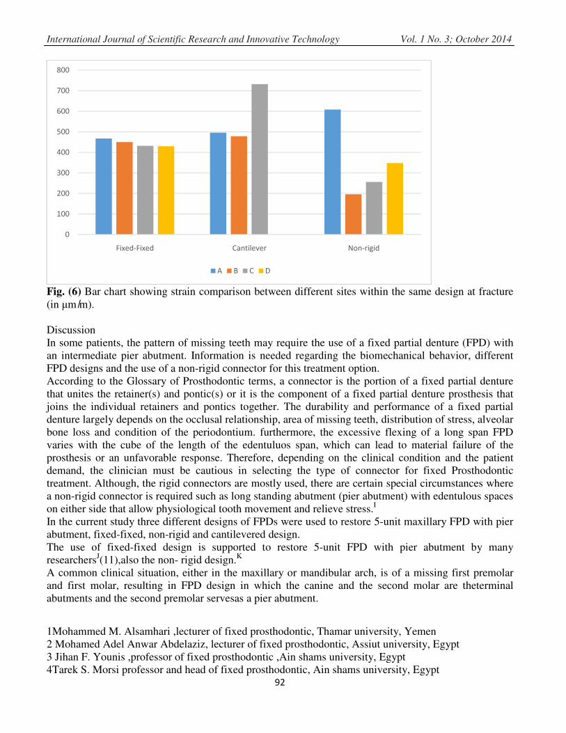
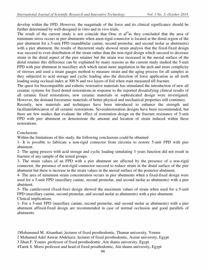
For Fixed-Fixed design: the A site showed thestatistically significant highest mean strain (467.6). this is
followed by the B site (450.2), C site (431.8). the D site showed the statistically significant lowest mean
strain (429.6).there was no statistically significant different between C site and D site.
For Cantilever design: the C site showed the statistically significant highest mean strain (713.8). this is
followed by the A site (495.4).the B site showed the statistically significant lowest mean strain (478.2).
There was no statistically significant different between A site and B site.
For Non-rigid design: the A site showed the statistically significant highest mean strain (608.6). this is
followed by the D site (347.8), C site (256.0).
the B site showed the statistically significant lowest mean strain (195.6).
Table 3: Results of ANOVA and Tukey�s test for strain comparison between different sites within
the same design at 300 N (in µm �m)
Design
Site
300N
Fixed-Fixed cantilevered Non-Rigid
Mean SD Mean SD Mean SD
A 150.80 a 9.039 135.60
a 8.264 193.80
a 11.432
B 101.40b
8.444 106.80b 7.463 81.60
b 8.142
C 65.60c
8.562 213.80c
10.663 103.80c
8.408
D 47.00d 5.831 NP NP 149.20
d 5.263
P-value 0.011* <0.001* <0.001*
*Significant at P≤ 0.05, Means with different latters in the same column are statistically significant
different according to Tukey�s Test.

International Journal of Scientific Resear
1Mohammed M. Alsamhari ,lecturer o
2 Mohamed Adel Anwar Abdelaziz, l
3 Jihan F. Younis ,professor of fixed p
4Tarek S. Morsi professor and head o
Table 4: Results of ANOVA and Tuke
the same design at fracture (in µm
Design
Site
Fracture
Fixed-Fixed
Mean SD
A 467.60a 14.153
B 450.20ab
20.765
C 431.80b 19.486
D 429.60b
14.792
P-value <0.001*
*Significant at P≤ 0.05, Means with
different according to Tukey�s Test.
Fig. (5) Bar chart showing strain com
µm �m).
150.8
135.6
101.4
65.6
47
0
50
100
150
200
250
Fixed-Fixed
arch and Innovative Technology Vol. 1
r of fixed prosthodontic, Thamar university, Yem
, lecturer of fixed prosthodontic, Assiut university
d prosthodontic ,Ain shams university, Egypt
of fixed prosthodontic, Ain shams university, Eg91
A and Tukey�s test for strain comparison between diffe
m �m)
cantilevered Non-Rigid
Mean SD Mean SD
495.40a 38.598 608.60
a 26.054
478.20a 64.267 195.60
b 17.813
713.80b
11.756 256.00c
29.351
NP NP 347.80d
20.620
<0.001* <0.001*
ith different latters in the same column are stat
mparison between different sites within the same
135.6
193.8
106.8
81.6
213.8
103.8
149.2
Cantilever Non-rigid
A B C D
1 No. 3; October 2014
men
ity, Egypt
gypt
etween different sites within
tatistically significant
e design at 300 N (in
International Journal of Scientific Research and Innovative Technology Vol. 1 No. 3; October 2014
1Mohammed M. Alsamhari ,lecturer of fixed prosthodontic, Thamar university, Yemen
2 Mohamed Adel Anwar Abdelaziz, lecturer of fixed prosthodontic, Assiut university, Egypt
3 Jihan F. Younis ,professor of fixed prosthodontic ,Ain shams university, Egypt
4Tarek S. Morsi professor and head of fixed prosthodontic, Ain shams university, Egypt 92
Fig. (6) Bar chart showing strain comparison between different sites within the same design at fracture
(in µm ̸m).
Discussion
In some patients, the pattern of missing teeth may require the use of a fixed partial denture (FPD) with
an intermediate pier abutment. Information is needed regarding the biomechanical behavior, different
FPD designs and the use of a non-rigid connector for this treatment option.
According to the Glossary of Prosthodontic terms, a connector is the portion of a fixed partial denture
that unites the retainer(s) and pontic(s) or it is the component of a fixed partial denture prosthesis that
joins the individual retainers and pontics together. The durability and performance of a fixed partial
denture largely depends on the occlusal relationship, area of missing teeth, distribution of stress, alveolar
bone loss and condition of the periodontium. furthermore, the excessive flexing of a long span FPD
varies with the cube of the length of the edentuluos span, which can lead to material failure of the
prosthesis or an unfavorable response. Therefore, depending on the clinical condition and the patient
demand, the clinician must be cautious in selecting the type of connector for fixed Prosthodontic
treatment. Although, the rigid connectors are mostly used, there are certain special circumstances where
a non-rigid connector is required such as long standing abutment (pier abutment) with edentulous spaces
on either side that allow physiological tooth movement and relieve stress.I
In the current study three different designs of FPDs were used to restore 5-unit maxillary FPD with pier
abutment, fixed-fixed, non-rigid and cantilevered design.
The use of fixed-fixed design is supported to restore 5-unit FPD with pier abutment by many
researchersJ(11),also the non- rigid design.
K
A common clinical situation, either in the maxillary or mandibular arch, is of a missing first premolar
and first molar, resulting in FPD design in which the canine and the second molar are theterminal
abutments and the second premolar servesas a pier abutment.
0
100
200
300
400
500
600
700
800
Fixed-Fixed Cantilever Non-rigid
A B C D

International Journal of Scientific Research and Innovative Technology Vol. 1 No. 3; October 2014
1Mohammed M. Alsamhari ,lecturer of fixed prosthodontic, Thamar university, Yemen
2 Mohamed Adel Anwar Abdelaziz, lecturer of fixed prosthodontic, Assiut university, Egypt
3 Jihan F. Younis ,professor of fixed prosthodontic ,Ain shams university, Egypt
4Tarek S. Morsi professor and head of fixed prosthodontic, Ain shams university, Egypt 93
It has been postulated that the tendency of the terminal abutments to intrude during function results in a
teetering movement, where the pier acts as a fulcrum. This movement will eventually result in
debonding of the less retentive terminal retainer, namely the canine, and inevitably the failure of the
prosthesis.L In order to overcome this potential risk, the use of non-rigid connectors has been
advised.M
,N
In the current study anon-rigid connector is placed in the distal aspect of the pier retainer this is
supported by many researchers as Shillingburg et al determined that the patrix of a non-rigid connector
(either a precision or semi-precision attachment) should be placed at the distal aspect of the pier retainer
and the matrix in the distal ponticAM
. He assumed that this would nullify the fulcrum effect, and that the
matrix portion of the attachment would be seated firmly in place when pressure was applied distally to
the pier, due to the mesial movement of the distal abutment.
However, Moulding B suggested that the nonrigid connector should be placed on one of the terminal
retainers, and emphasized that it should not be placed at the pier abutment because this would subject
the relatively weak premolar abutment to extreme loads. GillM
recommended placing nonrigid
connectors at one side or both sides of the pier abutment.
AdamsD advised placing one non-rigid connector at the distal side of the pier, and if desired, adding one
more at the distal of the anterior retainer. The authors did not provide reasoning for their
recommendations.
In the current study strain analysis showed that the fixed-fixed design was succeed to evendistribution of
the strain rather than the non-rigid design which succeed to decrease strain in the distal aspect of the pier
retainer but the strain was increased in the mesial surface of the distal retainerthese results is agreed by
Standlee and CaputoDsimulated the same clinical situation of a mandibular 5-unit FPD with a pier.
Simulated tissues were made of different plastic materials. Three types of FPD frameworks were
constructed from a nonprecious alloy (Biocast Rx,Jeneric Gold): (1) allrigid connectors, (2) precision
attachment at the mesial of the premolar abutment, and (3) precision attachment at the distal of the
premolar abutment.
Vertical loads of 30 lb were applied separately to each retainer and pontic. The stress induced fringe
patterns were recorded by a camera and the vertical displacement of each tooth was measured with a dial
gauge.
It was found that no matter where the rigid framework was loaded, some degree of apical stress was
noted around all abutment teeth and all showed some apical displacement.
The authors conclude: “There was no evidence that the premolar abutment acted as a fulcrum.”
The experiment also showed that when a non-rigid connector was incorporated into the framework, the
stress to the abutments at the loaded side increased while the stress to the abutments on the unloaded
side decreased.
The result of the current study not substantiated the theory that the pier abutment is acting like fulcrum
as the strain values were evenly distributed in the four measured points of the fixed-fixed design while
the non-rigid design showed more strain values in the mesial surface of the posterior retainer these result
is in agreement with those of Savion et al K as they concluded that The assumption of increased risk for
debonding of the canine retainer in a 5-unit FPD with a pier due to the pier abutment acting as a fulcrum
is not substantiated by any in vitro experiments, clinical observations, or mathematical analysis.
They also concluded that the potential hazardfor debonding is related to the development of extrusive
reactive forces at the canine retainer as the first molar pontic is loaded, due to the flexural forces that
International Journal of Scientific Research and Innovative Technology Vol. 1 No. 3; October 2014
1Mohammed M. Alsamhari ,lecturer of fixed prosthodontic, Thamar university, Yemen
2 Mohamed Adel Anwar Abdelaziz, lecturer of fixed prosthodontic, Assiut university, Egypt
3 Jihan F. Younis ,professor of fixed prosthodontic ,Ain shams university, Egypt
4Tarek S. Morsi professor and head of fixed prosthodontic, Ain shams university, Egypt 94
develop within the FPD. However, the magnitude of the force and its clinical significance should be
further determined by well-designed in vitro and in vivo trials.
The result of the current study is not coincide that Oruc et alGas they concluded that the area of
minimum stress occurs in pier abutments when anon-rigid connector is located at the distal region of the
pier abutment for a 5-unit FPD (mandibular canine, second premolar, and second molar as abutments)
with a pier abutment, the results of thecurrent study showed strain analysis that the fixed-fixed design
was succeed to even distribution of the strain rather than the non-rigid design which succeed to decrease
strain in the distal aspect of the pier retainer but the strain was increased in the mesial surface of the
distal retainer this difference can be explained by many reasons as the current study studied the 5-unit
FPD with pier abutment in maxillary arch which mean more angulation in the arch and more complicity
of stresses and used a strain gauges method to measure strain and the aging process for all samples as
they subjected to acid storage and cyclic loading also the direction of force application as all teeth
loading using occlusal index at 300 N and two layers of foil when stain measured till fracture.
The quest for biocompatible and esthetic restorative materials has stimulated the introduction of new all
ceramic systems for fixed dental restorations.in response to the reported dissatisfying clinical results of
all ceramic fixed restorations, new ceramic materials or sophisticated design were investigated.
However, the demand forceramic materials of better physical and mechanical properties still continues.
Recently, new materials and techniques have been introduced to enhance the strength and
facilitatefabrication of all ceramic restorations. Severalrestoration designs have been recommended, but
there are few studies that evaluate the effect of restoration design on the fracture resistance of 5-unit
FPD with pier abutment or demonstrate the amount and location of strain induced within these
restorations.
Conclusions
Within the limitations of this study, the following conclusions could be obtained
1- It is possible to fabricate a non-rigid connector from zirconia to restore 5-unit FPD with pier
abutment.
2- The aging process with acid storage and cyclic loading simulating 3 years function did not result in
fracture of any sample of the tested groups.
3- The strain values of an FPD with a pier abutment are affected by the presence of a non-rigid
connector, the presence of non-rigid connector succeed to reduce strain in the distal surface of the pier
abutment but there is increase in the strain values in the mesial surface of the posterior abutment.
4- The area of minimum strain concentration occurs in pier abutments when a fixed-fixed design were
used for a 5-unit FPD (maxillary canine, second premolar, and second molar as abutments) with a pier
abutment.
5- The cantilevered (fixed-free) design showed the maximum values of strain when used for a 5-unit
FPD (maxillary canine, second premolar, and second molar as abutments) with a pier abutment.
Clinical implications
1- For a 5-unit FPD (maxillary canine, second premolar, and second molar as abutments) with a pier
abutment affixed-fixed design are recommended in case of normal occlusion and good parallels of
abutments.

International Journal of Scientific Research and Innovative Technology Vol. 1 No. 3; October 2014
1Mohammed M. Alsamhari ,lecturer of fixed prosthodontic, Thamar university, Yemen
2 Mohamed Adel Anwar Abdelaziz, lecturer of fixed prosthodontic, Assiut university, Egypt
3 Jihan F. Younis ,professor of fixed prosthodontic ,Ain shams university, Egypt
4Tarek S. Morsi professor and head of fixed prosthodontic, Ain shams university, Egypt 95
2- For a 5-unit FPD (maxillary canine, second premolar, and second molar as abutments) with a pier
abutment with lack parallels of the abutment, zirconium non-rigid connector could be promising
solution.
3- The development of zirconia non-rigidconnector provide an esthetic alternative when used in the
treatment of the edentuluos cases with pier abutment.
References
1. Shillingburg HT. Fundamentals of fixed prosthodontics. In. 3 ed.: Quintessence; 2012, 96-98
2. Moulding MB, Holland GA, Sulik WD. An alternative orientation of nonrigid connectors in fixed
partial dentures. The Journal of Prosthetic Dentistry 1992;68(2):236-238.
3. Landry KE, Johnson PF, Parks VJ, Pelleu GB, Jr. A photoelastic study to determine the location of
the nonrigid connector in a five-unit intermediate abutment prosthesis. J Prosthet Dent 1987;57(4):454-
457.
4. Sutherland JK, Holland GA, Sluder TB ,White JT. A photoelastic analysis of the stress distribution in
bone supporting fixed partial dentures of rigid and nonrigid design. J Prosthet Dent 1980;44(6):616-623.
5. Moulding MB, Holland GA, Sulik WD. An alternative orientation of nonrigid connectors in fixed
partial dentures. J Prosthet Dent 1992;68(2):236-238.
6. Ziada HM, Orr JF, Benington IC. Photoelastic stress analysis in a pier retainer of an anterior resin-
bonded fixed partial denture. The Journal of Prosthetic Dentistry
1998;80(6):661-665.
7. Oruc S, Eraslan O, Tukay HA, Atay A. Stress analysis of effects of nonrigid connectors on fixed
partial dentures with pier abutments. J Prosthet Dent 2008;99(3):185-192.
8. Lawson S. Environmental degradation of zirconia ceramics. Journal of the European Ceramic Society
1995;15(6):485-502.
9. Cales B, Stefani Y, Lilley E. Long-term in vivo and in vitro aging of a zirconia ceramic used in
orthopaedy. Journal of biomedical materials research 1994;28(5):619-624.
10. Rosenstiel SF LM, Fujiomoto J. contemporery fixed prosthodontics. 2001;3rd edition:673-696.
11. Savion I, Saucier CL, Rues S, Sadan A, Blatz M. The pier abutment: a review of the literature and a
suggested mathematical model. Quintessence international 2006;37(5):345-352.
12. Hannink RHJ, Kelly PM, Muddle BC. Transformation Toughening in Zirconia-Containing
Ceramics. Journal of the American Ceramic Society 2000;83(3):461-487.
13. Chopra D. REHABILITATION OF A PIER ABUTMENT. In.: Guident; 2012.
14. Deville S, Chevalier J, Gremillard L. Influence of surface finish and residual stresses on the ageing
sensitivity of biomedical grade zirconia. Biomaterials 200627(10):2186- 2192.
AA
Shillingburg HT. Fundamentals of fixed prosthodontics. In. 3 ed.: Quintessence; 2012, 96-98.
BMoulding MB, Holland GA, Sulik WD. An alternative orientation of nonrigid connectors in fixed
partial dentures. The Journal of Prosthetic Dentistry 1992;68(2):236-238.
CLandry KE, Johnson PF, Parks VJ, Pelleu GB, Jr. A photoelastic study to determine the location of the
nonrigid connector in a five-unit intermediate abutment prosthesis. J Prosthet Dent 1987;57(4):454-457.

International Journal of Scientific Research and Innovative Technology Vol. 1 No. 3; October 2014
1Mohammed M. Alsamhari ,lecturer of fixed prosthodontic, Thamar university, Yemen
2 Mohamed Adel Anwar Abdelaziz, lecturer of fixed prosthodontic, Assiut university, Egypt
3 Jihan F. Younis ,professor of fixed prosthodontic ,Ain shams university, Egypt
4Tarek S. Morsi professor and head of fixed prosthodontic, Ain shams university, Egypt 96
DSutherland JK, Holland GA, Sluder TB ,White JT. A photoelastic analysis of the stress distribution in
bone supporting fixed partial dentures of rigid and nonrigid design. J Prosthet Dent 1980;44(6):616-623.
E. Moulding MB, Holland GA, Sulik WD. An alternative orientation of nonrigid connectors in fixed
partial dentures. J Prosthet Dent 1992;68(2):236-238.
FZiada HM, Orr JF, Benington IC. Photoelastic stress analysis in a pier retainer of an anterior resin-
bonded fixed partial denture. The Journal of Prosthetic Dentistry
1998;80(6):661-665.
GOruc S, Eraslan O, Tukay HA, Atay A. Stress analysis of effects of nonrigid connectors on fixed
partial dentures with pier abutments. J Prosthet Dent 2008;99(3):185-192.
HLawson S. Environmental degradation of zirconia ceramics. Journal of the European Ceramic Society
1995;15(6):485-502.
ICales B, Stefani Y, Lilley E. Long-term in vivo and in vitro aging of a zirconia ceramic used in
orthopaedy. Journal of biomedical materials research 1994;28(5):619-624.
JRosenstiel SF LM, Fujiomoto J. contemporery fixed prosthodontics. 2001;3rd edition:673-696.
KSavion I, Saucier CL, Rues S, Sadan A, Blatz M. The pier abutment: a review of the literature and a
suggested mathematical model. Quintessence international 2006;37(5):345-352.
L. Hannink RHJ, Kelly PM, Muddle BC. Transformation Toughening in Zirconia-Containing
Ceramics. Journal of the American Ceramic Society 2000;83(3):461-487.
M
Chopra D. REHABILITATION OF A PIER ABUTMENT. In.: Guident; 2012.
NDeville S, Chevalier J, Gremillard L. Influence of surface finish and residual stresses on the ageing
sensitivity of biomedical grade zirconia. Biomaterials 200627(10):2186- 2192.