Embed Size (px)
Citation preview

Service Training
Commercial Vehicles
Self-study programme 464
The Amarok - Powertrain and drive concept
Design and function

2
S464_002
The self-study programme presents the design and function of new developments!The content will not be updated.
Current testing, setting and repair instructions can be found in the provided service literature.
Importantnote
With the Amarok, Volkswagen Commercial Vehicles is deliberately and self-assuredly taking part in the global
trend towards multifunctional vehicles.
As such, the company is making consistent use of its extensive experience in manufacturing vehicles with both rear and front-wheel drive. The newly developed drive concept offers outstanding driving properties. Comfortable handling and operation similar to a passenger car are features of the Amarok. Magnificent assistance
is given for everyday use through a range of support systems in order to provide road safety and handling benefits when offroad.
In all cases and in all variants, the Amarok can be used both onroad and for heavy-duty offroad use. Depending on use, the four-wheel drive version of the Amarok is available either with permanently or non-permanently engaged four-wheel drive. The Amarok is also available in a standard version with rear-wheel drive. The entire
driveline of the Amarok is a new development and has been specifically adapted for use as a commercial vehicle.
Please also refer to self-study programme no. 463
"The Amarok".
3
Introduction . . . . . . . . . . . . . . . . . . . . . . . . . . . . . . . . . . . . . . . . . . . . . . . . . . . . . 4Four-wheel drive development at Volkswagen Commercial Vehicles . . . . . . . 4The drive concept of the Amarok . . . . . . . . . . . . . . . . . . . . . . . . . . . . . . . . . . . . 6The driveline . . . . . . . . . . . . . . . . . . . . . . . . . . . . . . . . . . . . . . . . . . . . . . . . . . . . . 8
Operation . . . . . . . . . . . . . . . . . . . . . . . . . . . . . . . . . . . . . . . . . . . . . . . . . . . . . 10The operation . . . . . . . . . . . . . . . . . . . . . . . . . . . . . . . . . . . . . . . . . . . . . . . . . . . . 10The offroad drive programme . . . . . . . . . . . . . . . . . . . . . . . . . . . . . . . . . . . . . . . 14
6-speed manual gearbox 0C6 . . . . . . . . . . . . . . . . . . . . . . . . . . . . . . . . . . . . 16The 6-speed manual gearbox . . . . . . . . . . . . . . . . . . . . . . . . . . . . . . . . . . . . . . 16The gearbox structure and function . . . . . . . . . . . . . . . . . . . . . . . . . . . . . . . . . 18The gearbox sectional view . . . . . . . . . . . . . . . . . . . . . . . . . . . . . . . . . . . . . . . . 20The powerflow . . . . . . . . . . . . . . . . . . . . . . . . . . . . . . . . . . . . . . . . . . . . . . . . . . . 26The external selector mechanism . . . . . . . . . . . . . . . . . . . . . . . . . . . . . . . . . . . 28The internal selector mechanism . . . . . . . . . . . . . . . . . . . . . . . . . . . . . . . . . . . . 30
Transfer box . . . . . . . . . . . . . . . . . . . . . . . . . . . . . . . . . . . . . . . . . . . . . . . . . . . 32The non-permanently engaged four-wheel drive with transfer box 0C7 . . . 32The transfer box with limited-slip interaxle differential 0BU . . . . . . . . . . . . . . 46
Rear final drive 0CC . . . . . . . . . . . . . . . . . . . . . . . . . . . . . . . . . . . . . . . . . . . . . 48The rear final drive 0CC . . . . . . . . . . . . . . . . . . . . . . . . . . . . . . . . . . . . . . . . . . . 48
Front final drive 0C1 . . . . . . . . . . . . . . . . . . . . . . . . . . . . . . . . . . . . . . . . . . . . . 55The front final drive 0C1 . . . . . . . . . . . . . . . . . . . . . . . . . . . . . . . . . . . . . . . . . . . 55
Test your knowledge . . . . . . . . . . . . . . . . . . . . . . . . . . . . . . . . . . . . . . . . . . . . 58
At a glance

4
Introduction
T4 syncrofrom 1993
T3 syncrofrom 1985
LT1 4x4from 1983
Volkswagen Commercial Vehicles began to manufacture four-wheel drive vehicles in-house in 1983 in the form of the LT1 4x4.
This was an early response to the desire for as wide a range of vehicle applications as possible – from driving on smooth roads through to use on very difficult ground.
The four-wheel drive is better able to overcome traction problems when used in sports applications and, in particular, as a commercial vehicle.
Four-wheel drive development at Volkswagen Commercial Vehicles

5
S464_051
T5 4MOTIONfrom 2004
Caddy 4MOTION from 2009
Amarok 4MOTION from 2010
Volkswagen Commercial Vehicles markets vehicles all over the world, therefore the company is used to taking account of special conditions, such as in remote areas and difficult open ground – four-wheel drive represents an ideal solution for this.

6
S464_058
Introduction
The drive concept of the AmarokThe drive concept of the Amarok offers 3 different drive variants.
The Amarok's powertrain is efficiently supported by intelligent vehicle dynamics programmes.
Vehicle dynamics programmes
The Amarok is equipped with the following vehicle dynamics programmes:
● ABS (as standard)● TCS (as standard)
MSR (as standard)
EDL (as standard)● ESP
● Offroad drive programme (as standard)
● Hill-descent assist● Hill-hold assist
7
S464_005
S464_074
S464_006
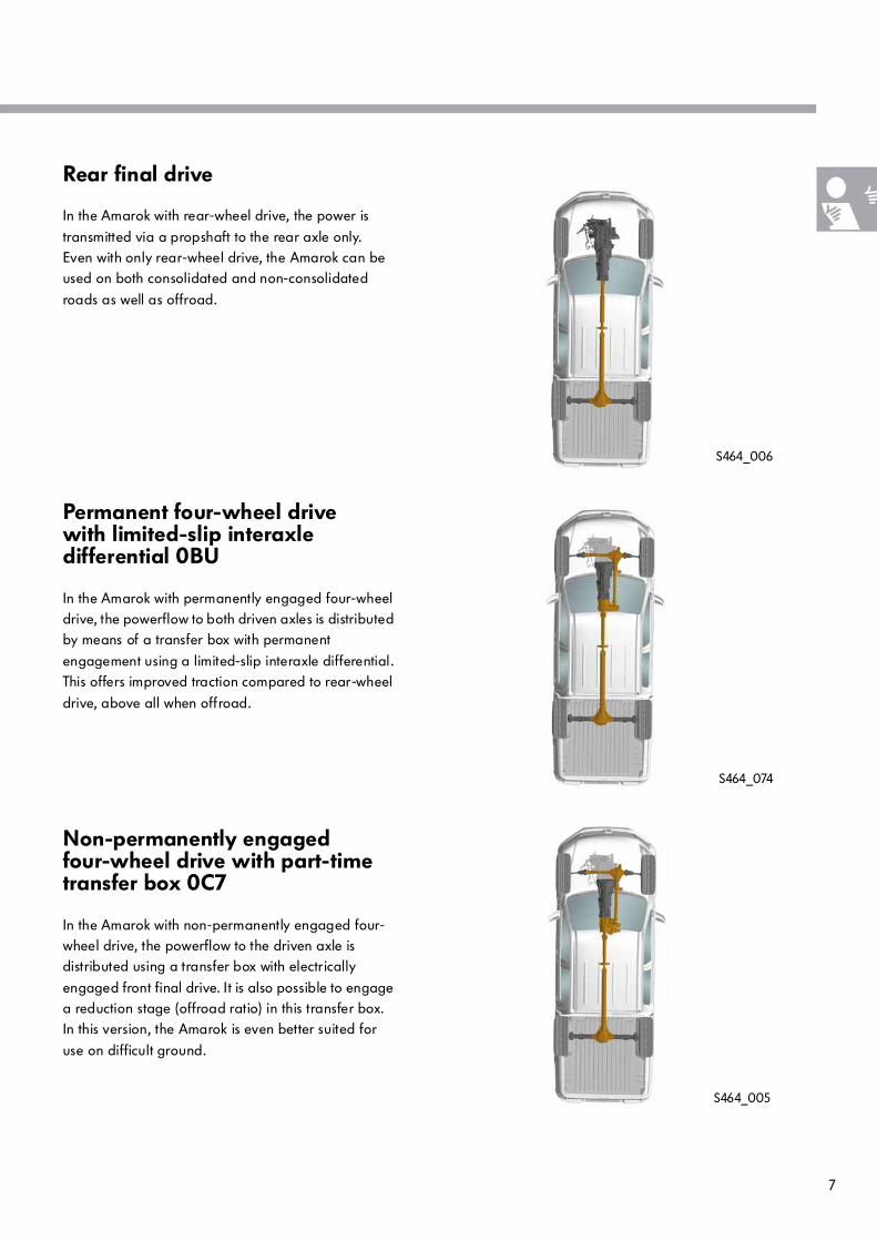
Permanent four-wheel drive with limited-slip interaxle differential 0BU
In the Amarok with permanently engaged four-wheel drive, the powerflow to both driven axles is distributed by means of a transfer box with permanent
engagement using a limited-slip interaxle differential.This offers improved traction compared to rear-wheel
drive, above all when offroad.
Non-permanently engaged four-wheel drive with part-time transfer box 0C7
In the Amarok with non-permanently engaged four-wheel drive, the powerflow to the driven axle is distributed using a transfer box with electrically
engaged front final drive. It is also possible to engage a reduction stage (offroad ratio) in this transfer box.In this version, the Amarok is even better suited for
use on difficult ground.
Rear final drive
In the Amarok with rear-wheel drive, the power is
transmitted via a propshaft to the rear axle only.Even with only rear-wheel drive, the Amarok can be used on both consolidated and non-consolidated
roads as well as offroad.
8
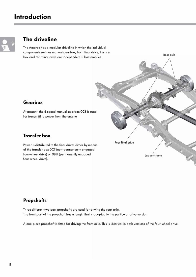
The drivelineThe Amarok has a modular driveline in which the individual components such as manual gearbox, front final drive, transfer
box and rear final drive are independent subassemblies.
Introduction
Propshafts
Three different two-part propshafts are used for driving the rear axle.
The front part of the propshaft has a length that is adapted to the particular drive version.
A one-piece propshaft is fitted for driving the front axle. This is identical in both versions of the four-wheel drive.
Rear final drive
Rear axle
Ladder frame
Gearbox
At present, the 6-speed manual gearbox 0C6 is used
for transmitting power from the engine
Transfer box
Power is distributed to the final drives either by means of the transfer box 0C7 (non-permanently engaged
four-wheel drive) or 0BU (permanently engaged four-wheel drive).

9
S464_007
Transfer box
6-speed manual gearbox
Front final drive
Front propshaft
Rear propshaft
Rear final drive, front final drive
The rear final drive 0CC arranged in a symmetrical installation position is used for driving the rear axle. The rear axle differential can be locked up.
The front final drive 0C1 is used for driving the front axle, and is available in two different designs. The front final drive is asymmetrically arranged.
The illustration shows the drivetrain with non-permanently engaged four-wheel drive.
10
S464_049
Operation
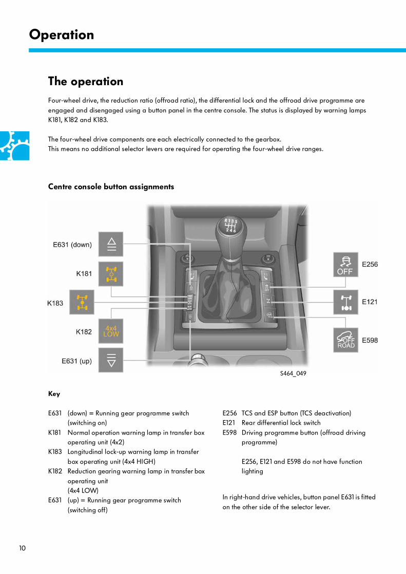
E256 TCS and ESP button (TCS deactivation)E121 Rear differential lock switch
E598 Driving programme button (offroad driving programme)
E256, E121 and E598 do not have function lighting
The operation Four-wheel drive, the reduction ratio (offroad ratio), the differential lock and the offroad drive programme are
engaged and disengaged using a button panel in the centre console. The status is displayed by warning lamps K181, K182 and K183.
The four-wheel drive components are each electrically connected to the gearbox. This means no additional selector levers are required for operating the four-wheel drive ranges.
Key
E631 (down) = Running gear programme switch (switching on)
K181 Normal operation warning lamp in transfer box operating unit (4x2)
K183 Longitudinal lock-up warning lamp in transfer
box operating unit (4x4 HIGH)K182 Reduction gearing warning lamp in transfer box
operating unit (4x4 LOW)
E631 (up) = Running gear programme switch
(switching off)
Centre console button assignments
In right-hand drive vehicles, button panel E631 is fitted
on the other side of the selector lever.
11
S464_050
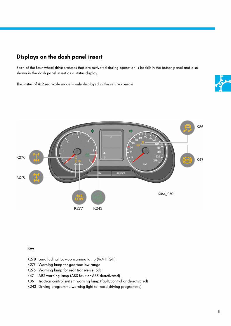
Displays on the dash panel insert
Each of the four-wheel drive statuses that are activated during operation is backlit in the button panel and also shown in the dash panel insert as a status display.
The status of 4x2 rear-axle mode is only displayed in the centre console.
Key
K278 Longitudinal lock-up warning lamp (4x4 HIGH)K277 Warning lamp for gearbox low rangeK276 Warning lamp for rear transverse lock
K47 ABS warning lamp (ABS fault or ABS deactivated)K86 Traction control system warning lamp (fault, control or deactivated)K243 Driving programme warning light (offroad driving programme)

12
Four-wheel drive 4x4 HIGH
Display in the dash panel insert
Offroad range 4x4 LOW
Display in the dash panel insert
… four-wheel drive is engaged (interaxle lock engaged)
… four-wheel drive is engaged and LOW reduction ratio engaged
S464_077
S464_079
Operation
Switch-on conditions
● Terminal 15 "ON"● E631 (up) pressed > 0.5 s● Can be engaged at any vehicle speed
● No undervoltage● No relevant error memory entry
Switch-off conditions
● Terminal 15 "ON"● E631 (down) pressed > 0.5 s● Can be switched off at any vehicle speed
● No undervoltage● No relevant error memory entry
Switch-on conditions
● Engine speed < 1500 rpm● E631 (up) pressed > 0.5 s● Vehicle speed v < 1 km/h
● 4x4 HIGH engaged● No undervoltage● No relevant error memory entry
Switch-off conditions
● Engine speed < 1500 rpm● E631 (down) pressed > 0.5 s● Vehicle speed v < 1 km/h
● No undervoltage● No relevant error memory entry

13
Differential lock
Display in the dash panel insert
… differential lock engaged
S464_081
The following applies to all variants 4x4 HIGH, 4x4 LOW and for the differential lock with regard to operation
The driver's request for engaging the required four-wheel drive range is stored for 10 s. If the required activation conditions are met within this period then the four-wheel drive ranges 4x4 HIGH, 4x4 LOW and the differential lock
are engaged. Operating comfort is therefore improved.
ABS/ESP system statuses
ABS/ESP control is retained during four-wheel drive operation (4x4 HIGH and 4x4 LOW) in all equipment variants of the Amarok. In vehicles with non-permanently engaged four-wheel drive, ABS/ESP control is deactivated when the
differential lock is engaged. The mechanical link-up between the two axles (4x4 HIGH/4x4 LOW) and the additional link-up between the two rear wheels means that individual ABS/ESP control for individual wheels is no longer possible. Deactivation is displayed by warning lamps K86 and K47 in the dash panel insert. In vehicles with
permanently engaged four-wheel drive, the ABS/ESP function is also retained when the differential lock is engaged.
Switch-on conditions
● Engine running● E121 pressed > 0.5 s● Can be engaged at any vehicle speed
● No undervoltage● No relevant error memory entry● With non-permanently engaged four-wheel drive:
Four-wheel drive range 4x4 LOW engaged
Switch-off conditions
● Button pressed > 0.5 s (E121)● Can be switched off at any vehicle speed● 30 s follow-on operation after tl. 15 "OFF".
If the engine stalls whilst driving with the differential lock engaged, the lock remains engaged for a period of 30 seconds after tl. 15
"OFF". This means restarting and moving off are possible with the lock engaged. As a result, driving comfort is increased when driving offroad.
14
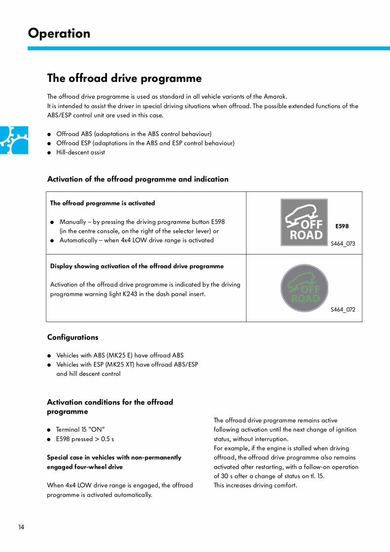
The offroad programme is activated
● Manually – by pressing the driving programme button E598 (in the centre console, on the right of the selector lever) or
● Automatically – when 4x4 LOW drive range is activated
Display showing activation of the offroad drive programme
Activation of the offroad drive programme is indicated by the driving
programme warning light K243 in the dash panel insert.
S464_073
S464_072
E598
Operation
The offroad drive programmeThe offroad drive programme is used as standard in all vehicle variants of the Amarok.
It is intended to assist the driver in special driving situations when offroad. The possible extended functions of the ABS/ESP control unit are used in this case.
● Offroad ABS (adaptations in the ABS control behaviour)● Offroad ESP (adaptations in the ABS and ESP control behaviour)● Hill-descent assist
Configurations
● Vehicles with ABS (MK25 E) have offroad ABS● Vehicles with ESP (MK25 XT) have offroad ABS/ESP
and hill descent control
The offroad drive programme remains active following activation until the next change of ignition
status, without interruption.For example, if the engine is stalled when driving offroad, the offroad drive programme also remains
activated after restarting, with a follow-on operation of 30 s after a change of status on tl. 15. This increases driving comfort.
Activation conditions for the offroad programme
● Terminal 15 "ON"
● E598 pressed > 0.5 s
Special case in vehicles with non-permanently engaged four-wheel drive
When 4x4 LOW drive range is engaged, the offroad
programme is activated automatically.
Activation of the offroad programme and indication

15
Features of the offroad drive programme
Offroad ABS
Vehicles with offroad ABS can brake better on unconsolidated ground such as sand and gravel.
In ABS control, the pressure buildup and pressure holding phases are extended. The depressurisation is shorter and takes place later. This means wheel slip
can occur in each control phase, thereby building up a skid wedge of loose material in front of the wheels.
The skid wedge brakes the vehicle additionally and shortens the braking distance depending on the composition of the ground.
For more information about the basic
function of the hill-descent assist, refer to self-study programme 374 "Slip control and assistance systems".
Offroad ESP
Vehicles with ESP have adapted ESP control behaviour as well as offroad ABS in order to improve traction:
● ESP intervenes somewhat later at speeds below 50 km/h when the vehicle is understeering.
● ESP intervenes somewhat later at speeds below 70 km/h when the vehicle is oversteering.
● ASR intervenes somewhat later at speeds below
70 km/h.
Switch-on conditions for hill-descent assist
● E598 pressed > 0.5 s
● Special feature with non-permanently engaged four-wheel drive: automatic activation in 4x4 LOW
● Engine running
● Slope forwards > 10 %, reverse > 8 %● Vehicle speed v < 30 km/h (> 30 km/h change to
standby mode)
● Driver brakes less than the downslope force● Accelerator pedal is not pressed
Hill-descent assist
The hill-descent assist makes descending steep hills more straightforward and more controllable. It limits the speed
by active brake intervention at all 4 wheel brakes using the ESP hydraulics. It keeps the speed constant after the vehicle has started its descent. The driver can increase or reduce the speed at any time using the accelerator and brakes. The hill-descent assist adjusts speed within its control range between 2 and max. 30 km/h. The system
functions when driving forwards and in reverse.
Special information about using offroad ABS can be
found in the owner's manual.
S464_076
Skid wedge
16
S464_052
S464_062
6-speed manual gearbox 0C6
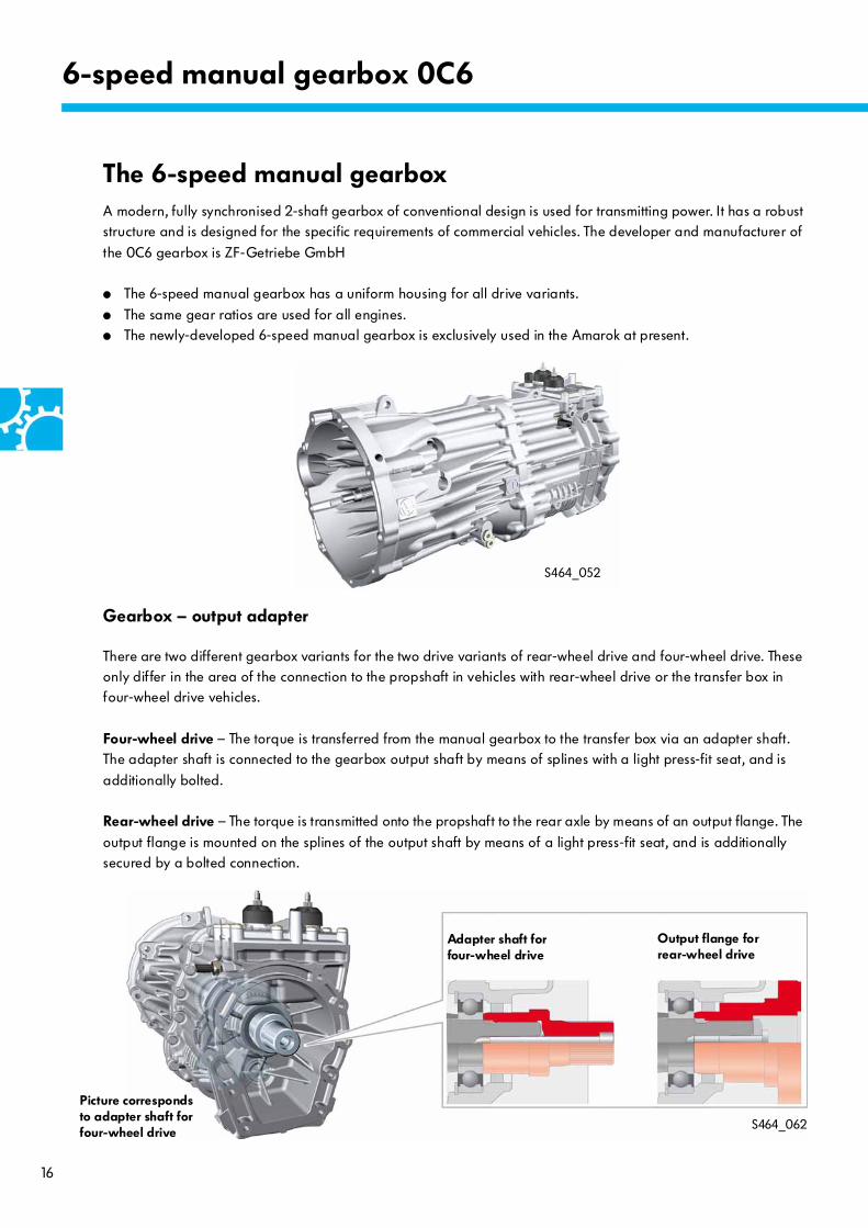
The 6-speed manual gearboxA modern, fully synchronised 2-shaft gearbox of conventional design is used for transmitting power. It has a robust structure and is designed for the specific requirements of commercial vehicles. The developer and manufacturer of
the 0C6 gearbox is ZF-Getriebe GmbH
● The 6-speed manual gearbox has a uniform housing for all drive variants.
● The same gear ratios are used for all engines.● The newly-developed 6-speed manual gearbox is exclusively used in the Amarok at present.
Gearbox – output adapter
There are two different gearbox variants for the two drive variants of rear-wheel drive and four-wheel drive. These only differ in the area of the connection to the propshaft in vehicles with rear-wheel drive or the transfer box in four-wheel drive vehicles.
Four-wheel drive – The torque is transferred from the manual gearbox to the transfer box via an adapter shaft. The adapter shaft is connected to the gearbox output shaft by means of splines with a light press-fit seat, and is
additionally bolted.
Rear-wheel drive – The torque is transmitted onto the propshaft to the rear axle by means of an output flange. The
output flange is mounted on the splines of the output shaft by means of a light press-fit seat, and is additionally secured by a bolted connection.
Picture corresponds to adapter shaft for four-wheel drive
Adapter shaft forfour-wheel drive
Output flange for rear-wheel drive
17
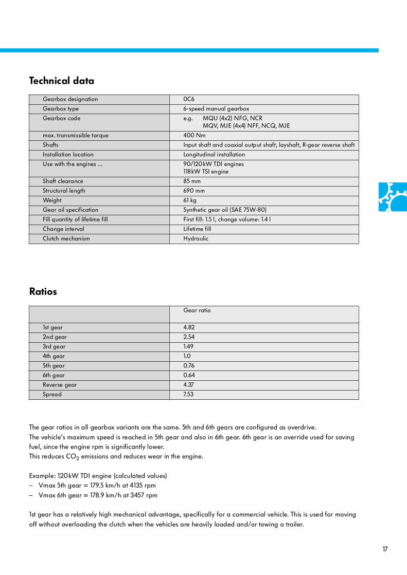
The gear ratios in all gearbox variants are the same. 5th and 6th gears are configured as overdrive.
The vehicle's maximum speed is reached in 5th gear and also in 6th gear. 6th gear is an override used for saving fuel, since the engine rpm is significantly lower. This reduces CO2 emissions and reduces wear in the engine.
Example: 120kW TDI engine (calculated values)– Vmax 5th gear = 179.5 km/h at 4135 rpm
– Vmax 6th gear = 178.9 km/h at 3457 rpm
1st gear has a relatively high mechanical advantage, specifically for a commercial vehicle. This is used for moving
off without overloading the clutch when the vehicles are heavily loaded and/or towing a trailer.
Gearbox designation 0C6
Gearbox type 6-speed manual gearbox
Gearbox code e.g. MQU (4x2) NFG, NCRMQV, MJE (4x4) NFF, NCQ, MJE
max. transmissible torque 400 Nm
Shafts Input shaft and coaxial output shaft, layshaft, R-gear reverse shaft
Installation location Longitudinal installation
Use with the engines … 90/120kW TDI engines118kW TSI engine
Shaft clearance 85 mm
Structural length 690 mm
Weight 61 kg
Gear oil specification Synthetic gear oil (SAE 75W-80)
Fill quantity of lifetime fill First fill: 1.5 l, change volume: 1.4 l
Change interval Lifetime fill
Clutch mechanism Hydraulic
Technical data
Gear ratio
1st gear 4.82
2nd gear 2.54
3rd gear 1.49
4th gear 1.0
5th gear 0.76
6th gear 0.64
Reverse gear 4.37
Spread 7.53
Ratios

18
The gearbox structure and functionThe two-part gearbox housing is made from aluminium diecastings.
6-speed manual gearbox 0C6
Input shaft
Housing flange for connection to the engine
Layshaft Oil filler plug
Oil drain plug
Centre selector shaft
Front gearbox housing

19
Reversing light switch F4
Reversing light switch F4 is activated by means of a ramp. The ramp is attached to the reverse gear
selector fork. The reversing lights are activated directly by F4. The signal from reversing light switch F4 is also
supplied to the onboard supply control unit J519.
S464_018
Selector module
Ventilation
Ramp for F4
Selector fork for R gear
Reversing light switch F4
Rear gearbox housing
R gear reverse shaft
Output shaft
The oil level with a correct oil fill is below the bottom edge of the thread for the oil filler plug.
Follow the information in ELSA regarding the oil fill and checking.
Housing flange for transfer box
20
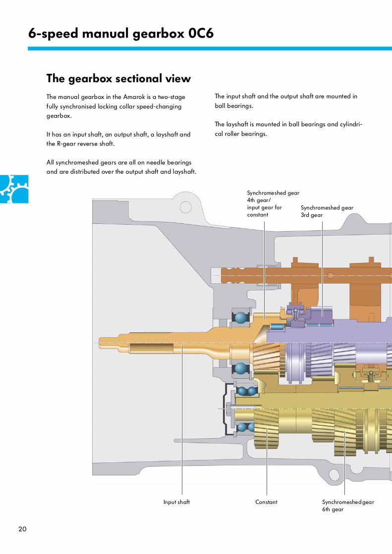
The gearbox sectional viewThe manual gearbox in the Amarok is a two-stage
fully synchronised locking collar speed-changing gearbox.
It has an input shaft, an output shaft, a layshaft and the R-gear reverse shaft.
All synchromeshed gears are all on needle bearings and are distributed over the output shaft and layshaft.
The input shaft and the output shaft are mounted in
ball bearings.
The layshaft is mounted in ball bearings and cylindri-
cal roller bearings.
6-speed manual gearbox 0C6
Synchromeshed gear 4th gear/input gear for constant
Constant
Synchromeshed gear 3rd gear
Synchromeshed gear 6th gear
Input shaft
21
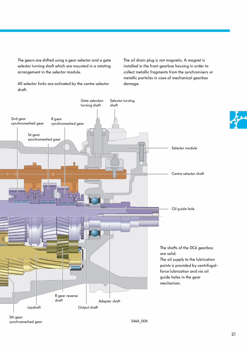
The gears are shifted using a gear selector and a gate selector turning shaft which are mounted in a rotating
arrangement in the selector module.
All selector forks are activated by the centre selector
shaft.
The oil drain plug is not magnetic. A magnet is installed in the front gearbox housing in order to
collect metallic fragments from the synchronisers or metallic particles in case of mechanical gearbox damage.
S464_0045th gear synchromeshed gear
2nd gear synchromeshed gear
1st gear synchromeshed gear
Layshaft Output shaft
R gear synchromeshed gear
Centre selector shaft
Gate selection turning shaft
Selector turning shaft
Selector module
Oil guide hole
The shafts of the 0C6 gearbox are solid.The oil supply to the lubrication
points is provided by centrifugal-force lubrication and via oil guide holes in the gear
mechanism.
R gear reverse shaft Adapter shaft
22
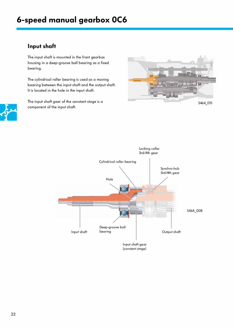
Input shaft
The input shaft is mounted in the front gearbox
housing in a deep-groove ball bearing as a fixed bearing.
The cylindrical roller bearing is used as a moving bearing between the input shaft and the output shaft. It is located in the hole in the input shaft.
The input shaft gear of the constant stage is a component of the input shaft.
S464_008
S464_015
6-speed manual gearbox 0C6
Input shaft
Input shaft gear(constant stage)
Deep-groove ball bearing
Locking collar3rd/4th gear
Cylindrical roller bearing
Synchro-hub3rd/4th gear
Output shaft
Hole

23
Output shaft
The output shaft has a deep-groove ball bearing as its
fixed bearing, which is mounted in the rear gearbox housing. The cylindrical roller bearing is used as a moving bearing between the input shaft and the
output shaft.
The fixed gears of the 5th and 6th gear are
components of the output shaft. The synchromeshed gears of 1st, 2nd, 3rd and reverse gears are mounted on needle bearings, allowing them to rotate freely.
These synchromeshed gears are also referred to as idler gears – they rotate constantly with the corresponding fixed gears.
The synchro-hubs of 1st/2nd and 3rd/4th gears are firmly connected to the output shaft by means of
splines. It is a special feature that the synchromeshed gear and synchro-hub of the reverse gear form one structural unit. The clutch splines of reverse gear are
connected to the output shaft in a non-rotating arrangement via splines.
S464_009
S464_016
It is only when a gear is engaged that the synchromeshed gears are firmly connected to the output shaft by means of the locking collar and
corresponding synchro-hub, thereby allowing them to transmit torque.
3rd gear synchromeshed gear
Locking collar3rd/4th gear
Synchro-hub3rd/4th gear
Synchromeshed gear4th gear/
constant input gear
1st gear synchromeshed gear
2nd gear synchromeshed gear
1st/2nd gear synchro-hub
R-gear synchromeshed gear with synchro-hub
Locking collar1st/2nd gear
R gear locking collar
Output shaft
R gear clutch splines
Deep-groove ball bearingCylindrical roller bearing
Input shaft 6th gear fixed gear 5th gear fixed gear
24
6-speed manual gearbox 0C6
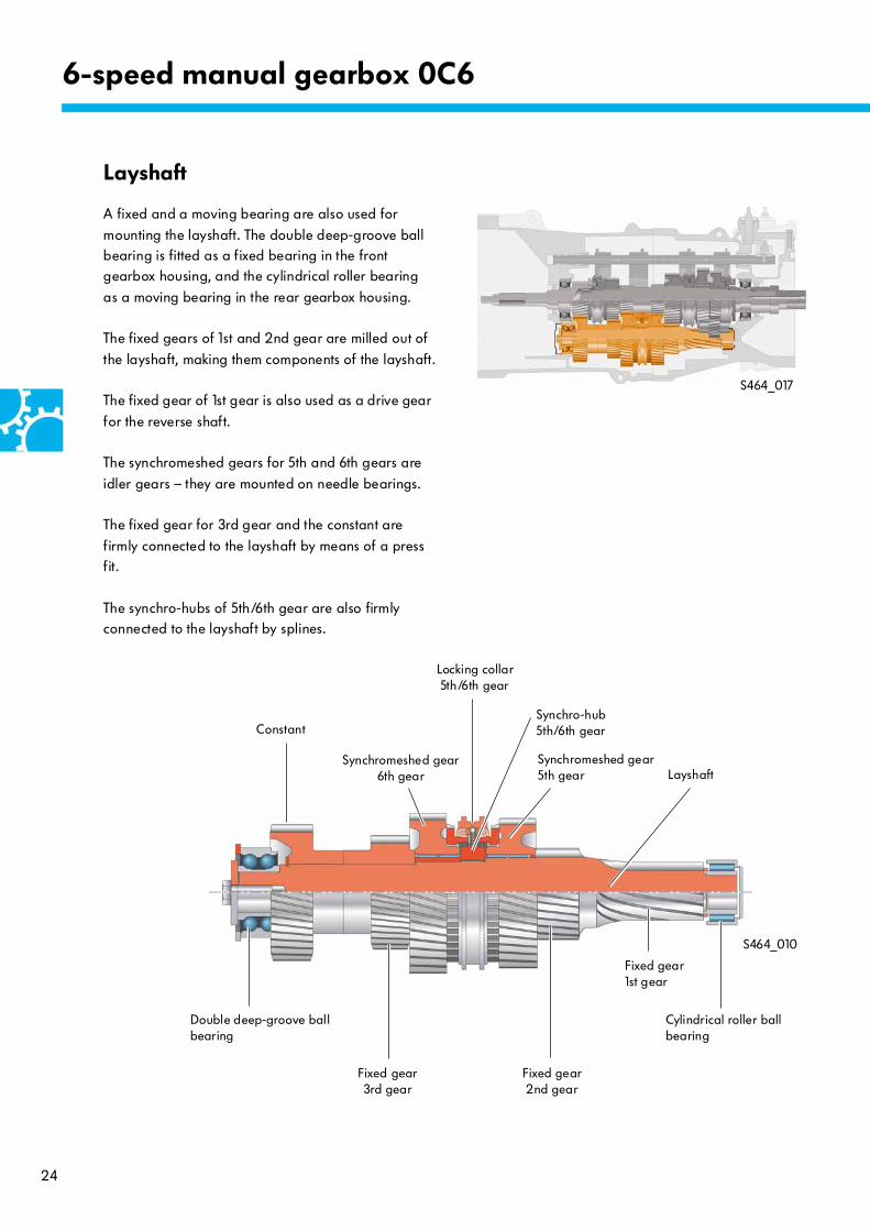
Layshaft
A fixed and a moving bearing are also used for
mounting the layshaft. The double deep-groove ball bearing is fitted as a fixed bearing in the front gearbox housing, and the cylindrical roller bearing
as a moving bearing in the rear gearbox housing.
The fixed gears of 1st and 2nd gear are milled out of
the layshaft, making them components of the layshaft.
The fixed gear of 1st gear is also used as a drive gear
for the reverse shaft.
The synchromeshed gears for 5th and 6th gears are
idler gears – they are mounted on needle bearings.
The fixed gear for 3rd gear and the constant are
firmly connected to the layshaft by means of a press fit.
The synchro-hubs of 5th/6th gear are also firmly connected to the layshaft by splines.
S464_010
S464_017
Synchromeshed gear6th gear
Fixed gear3rd gear
Locking collar5th/6th gear
Synchro-hub5th/6th gear
Cylindrical roller ball bearing
LayshaftSynchromeshed gear5th gear
Constant
Double deep-groove ball bearing
Fixed gear2nd gear
Fixed gear1st gear

25
S464_066
S464_065
Synchronisation
Due to the design conditions and different dimensions of the gears which need to be synchronised with one
another, different synchronisation variants are used in the manual gearbox.Both bonded and brazed sintered powder linings are used.
Single synchronisation with bonded sintered powder lining
This synchronisation is used in the 3rd/4th gear – 5th/6th gear and R gear.
Locking collar
Synchro-hub
Synchro-ring
Clutch splines
Thrust piece
Illustration shows example of 4th gear
1st/2nd gear – double synchronisation with brazed sintered powder linings
This synchronisation is used with 1st/2nd gear.
Locking collar
Thrust piece
Synchro-hub
Clutch splines
Illustration shows example of 1st gear
Synchro-ring with locking splines
Intermediate ring
Inner ring
26
6-speed manual gearbox 0C6
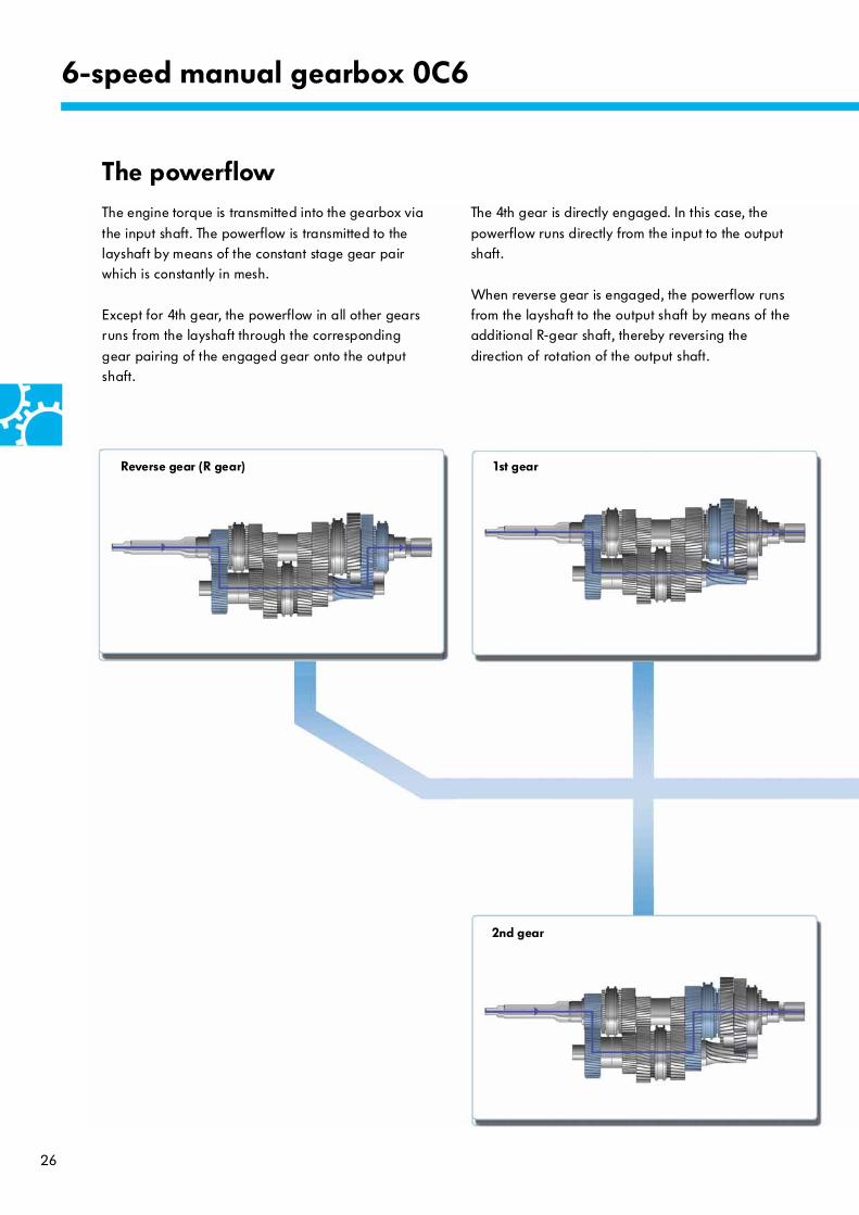
The powerflowThe engine torque is transmitted into the gearbox via
the input shaft. The powerflow is transmitted to the layshaft by means of the constant stage gear pair which is constantly in mesh.
Except for 4th gear, the powerflow in all other gears runs from the layshaft through the corresponding
gear pairing of the engaged gear onto the output shaft.
Reverse gear (R gear)
The 4th gear is directly engaged. In this case, the
powerflow runs directly from the input to the output shaft.
When reverse gear is engaged, the powerflow runs from the layshaft to the output shaft by means of the additional R-gear shaft, thereby reversing the
direction of rotation of the output shaft.
1st gear
2nd gear
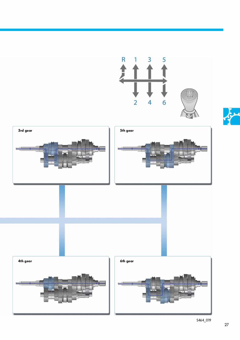
27S464_019
3rd gear 5th gear
4th gear 6th gear

28
The external selector mechanismThe design of the selector mechanism with coupling
rod represents a new development for Volkswagen.
S464_046
6-speed manual gearbox 0C6
Selector rod for gate selection
Selector rod for gear selection
Selector lever
Relay lever with damping weight
Relay lever
Selector housing bottom part
The gearshift positions are transmitted to the selector unit of the gearbox by means of two separate selector rods …
… through the
● selector rod for gear selection and the ● selector rod for gate selection
Coupling rod
Coupling rod
Selector housing top part

29
S464_087
S464_103
Rear view – in driving direction
Decoupling of selector lever
The coupling rod is used for decoupling the selector lever from the gearbox. It presents vibrations from being
transmitted to the selector lever. This design measures increases operating comfort when driving.
The coupling rod keeps the shaft of the gearshift kinematics at a constant distance from the gearbox at all times. During the gearshift procedure, all
movements of the gearshift kinematics take place via this shaft.
Vibrations and load change-dependent relative movements of the drivetrain are compensated for by relative movement of the gearshift kinematics shaft –
due to the connection via the coupling rod.
The selector mechanism always remains free from
vibration and feedback of engine/gearbox movements
Structure and function
The coupling rod is rigidly connected to the gearbox at the front end by means of a holding pin. At the rear end, it is connected to the gearshift kinematics in the
selector housing by means of a rocker. The rocker is mounted on both sides in the selector housing upper part.
Selector lever
Selector lever guide
Gate selector axis of rotation
Rocker
Gearshift kinematics shaft
Axis of rotationRocker
Gearshift kinematics shaft
Axis of rotationRocker
Selector housing top part
Selector lever guide
Rocker mounting in the selector housing top part
Rocker

30
S464_054
6-speed manual gearbox 0C6
The internal selector mechanism
Structure and function
The gear selector and gate selector turning shafts are mounted in the gearshift module in a rotating arrangement.
Both turning shafts engage in the centre selector shaft via the central driver by means of a lever mechanism.
The centre selector shaft is mounted in Teflon plain bearings and is connected to all selector forks whilst still being
able to rotate. The selector turning shaft pushes the centre selector shaft axially in both directions, thereby engaging both the gears in one gate. A selector fork is allocated to each selector finger.
The gate selection turning shaft rotates the centre selector shaft radially in both directions, thereby selecting the gate. The centre selector shaft as well as the selector turning shaft and gate selection turning shaft are mounted in Teflon-coated plain bearings.
Gate selection turning shaft
Locking barSelector module
Selector turning shaft
Locking – radial centre selector shaft position (neutral position in relation to 3rd/4th gear)
Selector forkR gear
Selector fork1st/2nd gear
Selector fork5th/6th gear
Selector fork3rd/4th gear
Centre selector shaft
Gearshift finger
Central driver

31
S464_055
3rd/4th gear selector fork
Locking – axial position of the centre selector shaft
Driver pin
Locking bar
Reversing light switch F4Selector fork lock
5th/6th gear selector fork
1st/2nd gear selector fork
R gear selector fork
Guide plate
Selector turning shaft Gate selection turning shaft
Gearshift finger
Centre selector shaft
The locking bar is mounted on the centre selector shaft in a rotating arrangement – it cannot be moved axially. The locking bar is moved as well when the gate is selected, by means of the driver pin that is firmly connected to the
centre selector shaft. The locking bar has mechanical coding and there is also coding on the selector forks in order to ensure sequential engagement of the individual gears. A guide plate on the central driver provides additional mechanical coding for the gearshift procedure.
32
Transfer box
Non-permanently engaged four-wheel drive
Mechanical structure
● Newly developed transfer box● Robust structure● Specifically designed for offroad use
● Offroad range (reduction stage) for all gear stages
● Integration of the system into vehicle dynamics
programme● Input torque distribution:
Even force distribution by rigid connection
between front and rear axles● Weight = 34 kg● Oil fill volume 1.25 l
● The developer and manufacturer of the transfer box 0C7 is Magna powertrain
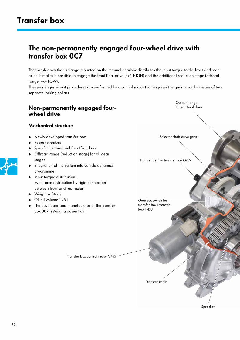
The transfer box that is flange-mounted on the manual gearbox distributes the input torque to the front and rear axles. It makes it possible to engage the front final drive (4x4 HIGH) and the additional reduction stage (offroad range, 4x4 LOW).
The gear engagement procedures are performed by a control motor that engages the gear ratios by means of two separate locking collars.
Output flangeto rear final drive
Selector shaft drive gear
Hall sender for transfer box G759
Gearbox switch for transfer box interaxle lock F438
Transfer box control motor V455
Transfer chain
Sprocket
The non-permanently engaged four-wheel drive with transfer box 0C7

33
S464_012
S464_039
Input from main gearbox
Output to front final drive
Output to rear final drive
Oil pump
Gearshift sprocket
Ventilation
Input from main gearbox
Reduction stage (offroad range)
Main shaft
Output shaft to front final drive
Selector shaft

34
Rear final drive 4x2
Mode of function
Transfer box
S464_014
Locking collar 4x4 LOW
Locking collar4x4 HIGH
Input splines for oil pump Gearshift sprocketPlanetary gearbox
Input splinesSun gear
The gearshift sprocket is mounted on the main shaft and can rotate freely.
The 4x4 LOW locking collar is firmly connected to the main shaft by means of its internal splines, and forms
a unit with the dog teeth.
The main shaft is a shaft that has been drilled through hollow. The main shaft is used for accommodating the
gearshift sprocket, both locking collars for 4x4 HIGH and 4x4 LOW and the propshaft flange.In addition, the drive splines for the oil pump are on
the main shaft.
Ring gear
Selector fork 4x4 HIGH
Selector fork 4x4 LOW
Dog teethLocking collar 4x4 LOW
Powerflow
Output shaft to front final drive
Sun gear output splines
Transfer chain
Sprocket
Main shaft
Selector shaft
Selector shaft input gear
Output flange to rear final drive
Roll pin4x4 LOW
35
S464_090
S464_091
S464_092
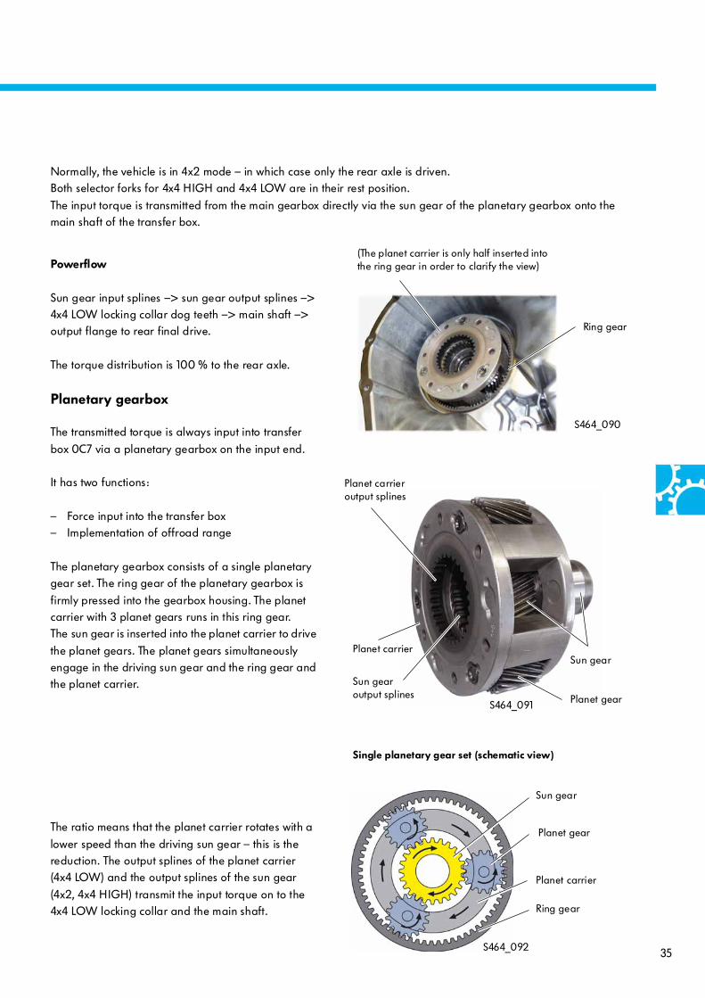
Powerflow
Sun gear input splines –> sun gear output splines –> 4x4 LOW locking collar dog teeth –> main shaft –> output flange to rear final drive.
The torque distribution is 100 % to the rear axle.
Planetary gearbox
The transmitted torque is always input into transfer
box 0C7 via a planetary gearbox on the input end.
It has two functions:
– Force input into the transfer box– Implementation of offroad range
The planetary gearbox consists of a single planetary gear set. The ring gear of the planetary gearbox is
firmly pressed into the gearbox housing. The planet carrier with 3 planet gears runs in this ring gear. The sun gear is inserted into the planet carrier to drive
the planet gears. The planet gears simultaneously engage in the driving sun gear and the ring gear and the planet carrier.
Normally, the vehicle is in 4x2 mode – in which case only the rear axle is driven.Both selector forks for 4x4 HIGH and 4x4 LOW are in their rest position.
The input torque is transmitted from the main gearbox directly via the sun gear of the planetary gearbox onto the main shaft of the transfer box.
The ratio means that the planet carrier rotates with a
lower speed than the driving sun gear – this is the reduction. The output splines of the planet carrier (4x4 LOW) and the output splines of the sun gear
(4x2, 4x4 HIGH) transmit the input torque on to the 4x4 LOW locking collar and the main shaft.
Sun gear
(The planet carrier is only half inserted into the ring gear in order to clarify the view)
Ring gear
Planet carrier
Planet gear
Sun gear
Planet gear
Ring gear
Planet carrier
Sun gear output splines
Planet carrier output splines
Single planetary gear set (schematic view)

36
Four-wheel drive 4x4 HIGH
Engaging
S464_068
Transfer box
In order to engage 4x4 mode, the transfer box control motor V455 is energised by the transfer box control
unit J646 with a pulse-width modulated signal. The motor rotates the selector shaft via the input gear through 90° clockwise. When this happens, the
4x4 HIGH roll pin firmly connected to the selector shaft pushes the 4x4 HIGH selector fork towards the gearshift sprocket by means of a control ramp.
4x4 mode is activated by the 4x4 HIGH locking collar being moved along the straight-splined dog teeth of the gearshift sprocket. The gearshift sprocket is now in
a fixed rotating connection with the main shaft.
Powerflow
Sun gear input splines –> sun gear output splines –> 4x4 LOW locking collar dog teeth –> main shaft –> output flange to rear final drive/gearshift sprocket –>
transfer chain –> sprocket –> Output shaft to front final drive.
4x4 mode represents a 100% interaxle lock between the front axle and rear axle. As a result, the input torque is evenly distributed
between the front and rear axles.
Tooth spacing – small
Tooth spacing – large Locking collar 4x4 LOW
Input splinesSun gear
Gearshift sprocket
Locking collar4x4 HIGH
Planetary gearbox
Ring gear
Return spring
Roll pin 4x4 HIGH
Selector fork 4x4 HIGH
Powerflow
Input shaft to front final drive
Dog teethLocking collar 4x4 LOW
Sun gear output splines
Main shaft
Transfer chain
Sprocket
Roll pin 4x4 LOW
Selector shaft
Output flange to rear final drive
Selector shaft input gear

37
The gearshift procedure is not synchronised.
4x4 mode can be engaged at any driving speed. During driving, there can in some cases be very small rotation speed differences between the front and rear axles (due to slip, the road surface, different tyre wear, etc.).
To facilitate engaging 4x4 mode whilst driving, the tooth pitch on the dog teeth of the gearshift sprocket is twice as large as that of the main shaft. When 4x4 mode is engaged, this system means there is an idle travel in the
powerflow to the front final drive amounting to a few degrees of angle. This idle travel is not a fault, nor does it lead to any restrictions in driving comfort or impairments in the durability of the transfer box.
Static friction means that the locking collar remains in its position when 4x4 mode is deactivated. As soon as the tension has been dissipated by a load change or
change of steering direction during driving, the selector fork is moved back to the 4x2 position subsequently by the return spring.
Disengaging
The shift back to 4x2 mode is performed by the
control motor for the interaxle lock turning the selector shaft through about 90° anticlockwise. The selector fork is pushed back into the 4x2 position solely by the
effect of the return spring in this case.
Due to the driving situation, torque wind-up can occur in the driveline in 4x4 mode under certain circumstances. This tension cannot be dissipated when
driving on ground that does not permit wheel slip. The tension leads to increased static friction between the locking collar and the dog teeth of the gearshift
sprocket.

38
Offroad range 4x4 LOW
Engaging
Transfer box
S464_069
To engage 4x4 LOW offroad range, the transfer box
control motor V455 is energised by the transfer box control unit J646 with a pulse-width modulated signal. The motor turns the selector shaft starting from 4x4
HIGH position via the input gear through about 120 – 130° clockwise. When this happens, the 4x4 LOW roll pin that is firmly connected to the selector shaft
pushes the 4x4 LOW selector fork into 4x4 LOW position via the guide plate. (The roll pin can no longer be seen in this engagement position – it is
now covered, on the rear of the guide plate.)
The system design means that the reduction can only
be engaged after 4x4 HIGH has been engaged.
The gearshift procedure is not synchronised, and is
only possible when the vehicle is stationary.
Powerflow
Sun gear input splines –> planetary gearbox –> planet carrier output splines –> 4x4 LOW locking
collar dog teeth –> main shaft –> output flange to rear final drive/gearshift sprocket –> transfer chain –> sprocket –> output shaft to front final drive.
The ratio of the reduction stage (offroad range) is i = 2.72 in all vehicles.
Main shaft
Locking collar 4x4 LOW Gearshift sprocket
Input splinesSun gear
Output flangeto rear final drive
Planetary gearbox
Ring gear
Selector fork 4x4 LOW
Adjusting spring
Powerflow
Guide plate Output shaft to front final drive
Roll pin 4x4 LOW:the position indicated corresponds to the 4x4 HIGH position
Planet carrier output splines
Selector shaft input gearDog teethLocking collar 4x4 LOW
39
Disengaging
To switch back to 4x4 HIGH, the control motor for the interaxle lock rotates the selector shaft anticlockwise back to the 4x4 HIGH position. The selector fork is moved back along the gate guide into its initial position in this case. The
powerflow is now direct from the sun gear to the main shaft without a reduction.
Adjusting spring
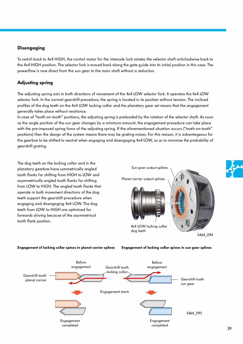
The adjusting spring acts in both directions of movement of the 4x4 LOW selector fork. It operates the 4x4 LOW selector fork. In the normal gearshift procedure, the spring is located in its position without tension. The inclined
profiles of the dog teeth on the 4x4 LOW locking collar and the planetary gear set means that the engagement generally takes place without resistance.In case of "tooth-on-tooth" positions, the adjusting spring is preloaded by the rotation of the selector shaft. As soon
as the angle position of the sun gear changes by a minimum amount, the engagement procedure can take place with the pre-imposed spring force of the adjusting spring. If the aforementioned situation occurs ("tooth-on-tooth" positions) then the design of the system means there may be grating noises. For this reason, it is advantageous for
the gearbox to be shifted to neutral when engaging and disengaging 4x4 LOW, so as to minimise the probability of gearshift grating.
S464_094
S464_095
The dog teeth on the locking collar and in the planetary gearbox have symmetrically angled
tooth flanks for shifting from HIGH to LOW and asymmetrically angled tooth flanks for shifting from LOW to HIGH. The angled tooth flanks that
operate in both movement directions of the dog teeth support the gearshift procedure when engaging and disengaging 4x4 LOW. The dog
teeth from LOW to HIGH are optimised for forwards driving because of the asymmetrical tooth flank position.
Planet carrier output splines
Sun gear output splines
Engagement of locking collar spines in planet carrier splines Engagement of locking collar spines in sun gear splines
4x4 LOW locking collar dog teeth
Gearshift toothplanet carrier
Gearshift tooth locking collar
Gearshift tooth sun gear
Before engagement
Engagement starts
Engagement completed
Before engagement
Engagement completed
40
S464_071
S464_096
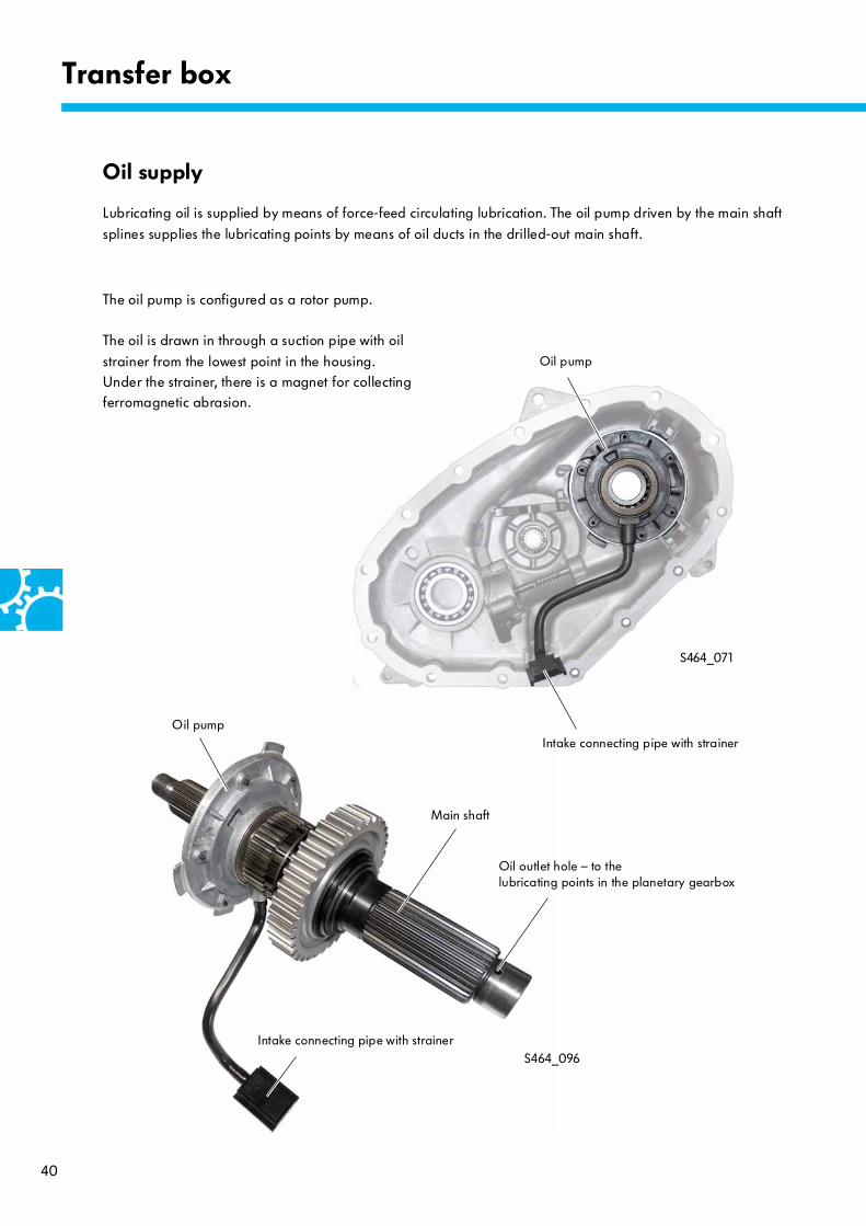
The oil pump is configured as a rotor pump.
The oil is drawn in through a suction pipe with oil
strainer from the lowest point in the housing. Under the strainer, there is a magnet for collecting ferromagnetic abrasion.
Transfer box
Oil supply
Lubricating oil is supplied by means of force-feed circulating lubrication. The oil pump driven by the main shaft
splines supplies the lubricating points by means of oil ducts in the drilled-out main shaft.
Oil outlet hole – to the lubricating points in the planetary gearbox
Main shaft
Oil pump
Intake connecting pipe with strainerOil pump
Intake connecting pipe with strainer

41
Selector shaft drive
The transfer box control motor V455 bolted onto the
gearbox housing is connected to the input worm. The input worm rotates the input gear of the selector shaft via spur gearing.
S464_086
S464_070
S464_097
Transfer box control motor V455
Task
The control motor rotates the selector shaft
mechanically in order to engage the required drive mode, 4x2, 4x4 or 4x4 LOW.
Mode of function
The control motor operates as a permanent magnet electric motor, in which case the motor is controlled via a PWM signal from the transfer box control unit
J646.
Effects in case of failure
● Fault entry in error memory● Flashing warning lamp in dash panel insert● No gearshift procedure possible any longer
● The transfer box remains in the position that was last engaged.
Transfer box control motor V455
Input gear with spur gearing
Input worm
Output to input worm
Transfer box control motor V455Transfer box control motor V455
42
S464_098
S464_085
Transfer box
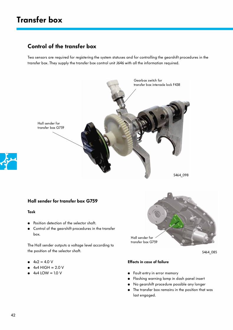
Control of the transfer box
Two sensors are required for registering the system statuses and for controlling the gearshift procedures in the
transfer box. They supply the transfer box control unit J646 with all the information required.
Gearbox switch fortransfer box interaxle lock F438
Hall sender for transfer box G759
Hall sender for transfer box G759
Task
● Position detection of the selector shaft.● Control of the gearshift procedures in the transfer
box.
The Hall sender outputs a voltage level according to
the position of the selector shaft.
● 4x2 = 4.0 V
● 4x4 HIGH = 2.0 V● 4x4 LOW = 1.0 V
Effects in case of failure
● Fault entry in error memory● Flashing warning lamp in dash panel insert
● No gearshift procedure possible any longer● The transfer box remains in the position that was
last engaged.
Hall sender for transfer box G759

43
Mode of function
The sensor operates using the Hall principle.
The input link of the rotation sensor is connected to the
selector shaft by means of an opening. A permanent magnet acts on the sensor shaft, and produces fluctuations in the magnetic field in the sensor during
rotation.
The sensor electronics evaluate the signal changes
and provides the control unit with an analogue voltage that is dependent on the turn angle.
S464_102
S464_099
The Hall sender for transfer box G759 is bolted on in the rear housing of the transfer box. 3 asymmetrically
arranged securing bolts, a coding lug and the asymmetrical position of the input link mean that the Hall sender cannot be installed in a twisted position.
Hall sender for transfer box G759
Sensor electronics
Coding lug
Input link
Sensor shaft
Opening
Selector shaft
Sensor electronics

44
Transfer box
Mode of function
The gearbox switch F438 operates as a simple
mechanical button. It is controlled by a ramp on the 4x4 HIGH selector fork.
The switch is open in 4x2 mode.
Task
● Sensing the actual position of the 4x4 selector fork, i.e. whether four-wheel drive really is disengaged and the selector fork is in the 4x2 position.
● In addition, the control logic of the longitudinal lock-up warning lamp K278 is controlled by means of the gearbox switch for transfer box interaxle
lock F438. Warning lamp K278 is no longer activated when the transfer box has completed the gearshift procedure into 4x2 more.
Effects in case of failure
● Fault entry in error memory● Flashing warning lamp in dash panel insert● No functional restrictions for four-wheel drive.
Gearbox switch for transfer box interaxle lock F438
S464_084
S464_101
Selector fork 4x4 HIGH
F438
Gearbox switch for transfer box interaxle lock F438
45
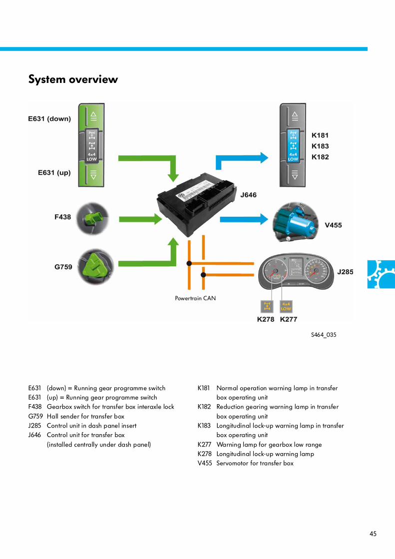
System overview
S464_035
E631 (down) = Running gear programme switchE631 (up) = Running gear programme switchF438 Gearbox switch for transfer box interaxle lock
G759 Hall sender for transfer boxJ285 Control unit in dash panel insertJ646 Control unit for transfer box
(installed centrally under dash panel)
K181 Normal operation warning lamp in transfer box operating unit
K182 Reduction gearing warning lamp in transfer
box operating unitK183 Longitudinal lock-up warning lamp in transfer
box operating unit
K277 Warning lamp for gearbox low rangeK278 Longitudinal lock-up warning lamp V455 Servomotor for transfer box
Powertrain CAN

46
Transfer box
Technical features
● Modern "four-wheel drive" technology in the Amarok
● Sturdy system operating purely mechanically● Suitable for onroad and offroad use● Permanent four-wheel drive
● Differential compensation between the front and rear axles
● Limited-slip interaxle differential with
basic distribution of the input torque (when driving without slip on the front and rear axles): front axle = 40 %, rear axle = 60 %
Variable torque distribution: front axle = 20 – 60 %, rear axle = 40 – 80 %
● Integration in vehicle dynamics programmes
● Full ESP suitability in four-wheel drive and locked-up rear axle differential
● Weight 23 kg
S464_013
The transfer box with limited-slip interaxle differential 0BUThe design of the transfer box with limited-slip interaxle differential is based on the transfer box of the Audi Q7 and
the Touareg 2011. It has been adapted for use in the Amarok.
S464_038
Limited-slip interaxle differential
Input shaft
Output flange to rear final drive
Transfer chain
Ventilation
Drive frommain gearbox
Output to rear final drive
Output to front final drive
Output shaft to front final drive
Oil collector with oil guide
47
S464_023
S464_045
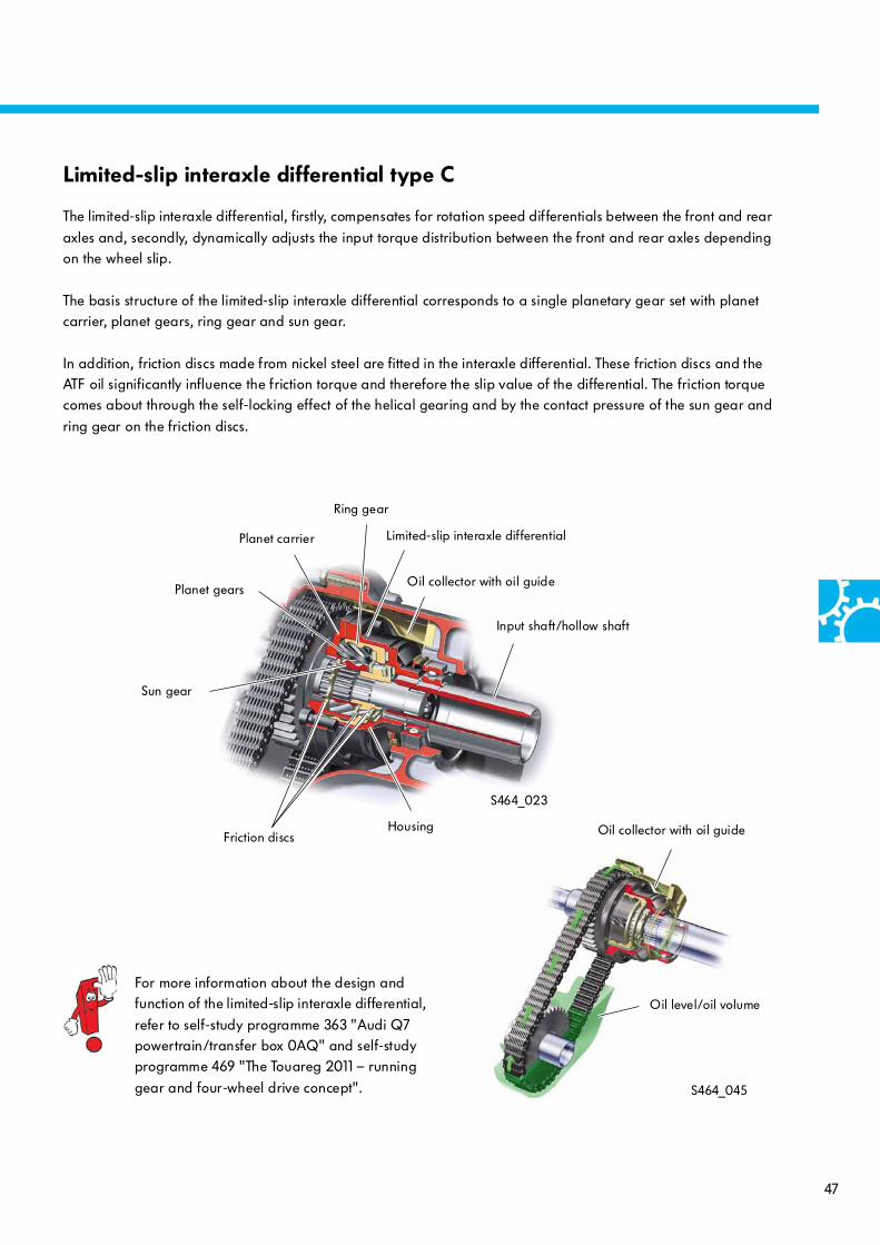
For more information about the design and function of the limited-slip interaxle differential,
refer to self-study programme 363 "Audi Q7 powertrain/transfer box 0AQ" and self-study programme 469 "The Touareg 2011 – running
gear and four-wheel drive concept".
Limited-slip interaxle differential type C
The limited-slip interaxle differential, firstly, compensates for rotation speed differentials between the front and rear
axles and, secondly, dynamically adjusts the input torque distribution between the front and rear axles depending on the wheel slip.
The basis structure of the limited-slip interaxle differential corresponds to a single planetary gear set with planet carrier, planet gears, ring gear and sun gear.
In addition, friction discs made from nickel steel are fitted in the interaxle differential. These friction discs and the ATF oil significantly influence the friction torque and therefore the slip value of the differential. The friction torque comes about through the self-locking effect of the helical gearing and by the contact pressure of the sun gear and
ring gear on the friction discs.
Limited-slip interaxle differential
Oil collector with oil guide
Input shaft/hollow shaft
Planet carrier
Oil collector with oil guide
Oil level/oil volume
Friction discsHousing
Ring gear
Planet gears
Sun gear

48
Rear final drive 0CC
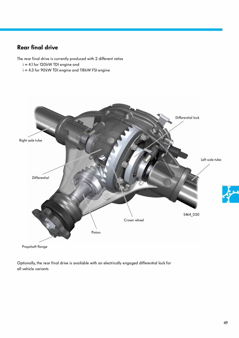
The rear final drive 0CCThe rear final drive in the Amarok drives via a newly
developed rigid axle with leaf suspension and drum brakes.
This axle represents a basic design feature for all variants of the Amarok.
Manufacturer and developer:American Axle & Manufacturing
S464_040
Advantages of the rigid axle:
– Wheel guidance with constant toe and camber over the entire suspension travel– No reduction in ground clearance in compression travel
– Large load volume– Robust design
Rear final drive
Propshaft flange
Ventilation
49
S464_020
Differential lock
Crown wheel
Right axle tube
Left axle tube
Propshaft flange
Optionally, the rear final drive is available with an electrically engaged differential lock for
all vehicle variants
Rear final drive
The rear final drive is currently produced with 2 different ratios
i = 4.1 for 120kW TDI engine andi = 4.3 for 90kW TDI engine and 118kW FSI engine
Differential
Pinion

50
1617
20
1512
1314
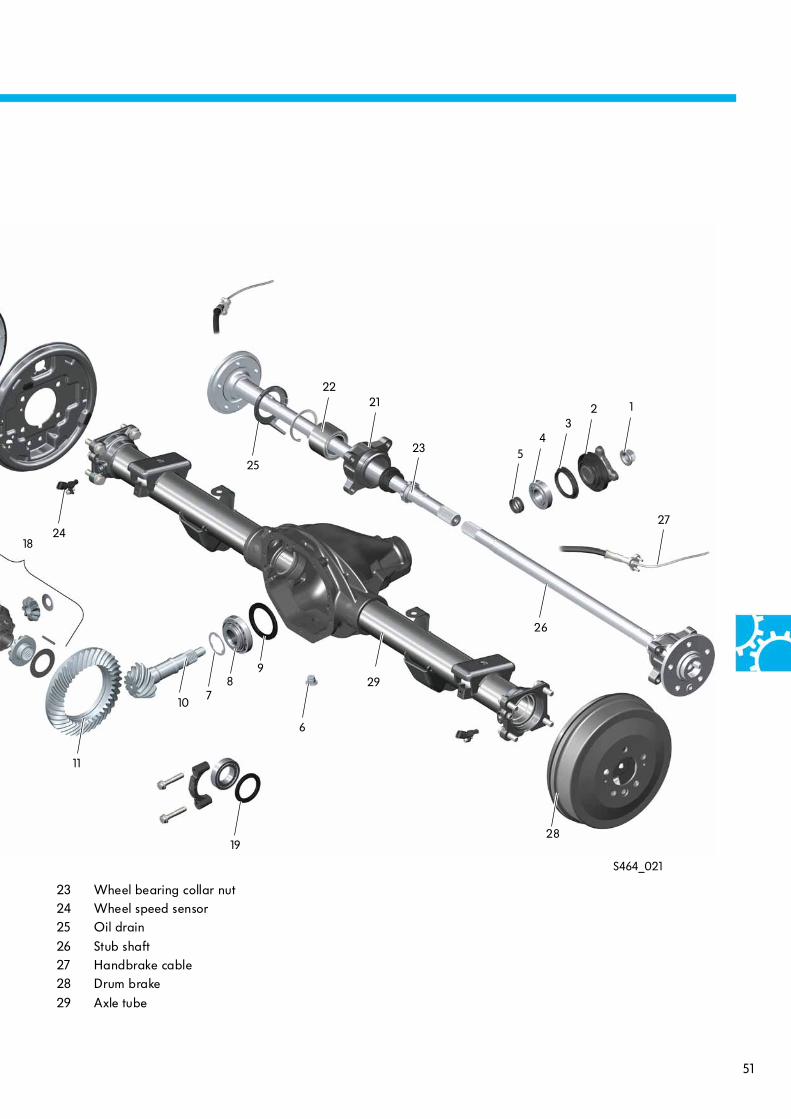
Rear final drive 0CC
Component overview
The final drive housing is positioned in the centre of
the axle and is made from grey cast iron. The axle tubes are made of a steel tube and are welded onto the final drive housing. The stub shafts are solid
shafts.
The position of the pinion in relation to the crown
wheel is set using a shim behind the inner bearing of the pinion. The bearing preload for the pinion is set using a ram sleeve.
The oil filler plug is located in the housing cover. Only vehicles with a differential lock have an oil drain plug
fitted.
Venting is provided by a hose into the ladder frame.
1 Pinion collar nut
2 Propshaft flange3 Shaft oil seal4 External tapered roller bearing
5 Ram sleeve6 Oil drain plug7 Thrust washer
8 Inner tapered roller bearing9 Shim10 Pinion
11 Crown wheel12 Housing cover seal13 Housing cover
14 Oil filler plug15 Bolt
16 Bolt17 Bearing support18 Differential with housing
19 Shim20 Differential lock21 Wheel hub
22 Wheel bearing
51
S464_021
24
19
6
87
10
11
26
27
2221
23 54
32 1
25
9
28
29
18
23 Wheel bearing collar nut24 Wheel speed sensor25 Oil drain
26 Stub shaft27 Handbrake cable28 Drum brake
29 Axle tube
52
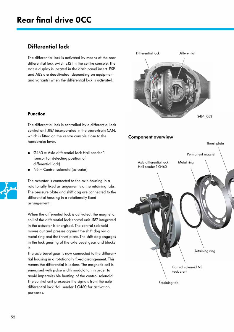
Differential lock
The differential lock is activated by means of the rear
differential lock switch E121 in the centre console. The status display is located in the dash panel insert. ESP and ABS are deactivated (depending on equipment
and variants) when the differential lock is activated.
Function
The differential lock is controlled by a differential lock
control unit J187 incorporated in the powertrain CAN, which is fitted on the centre console close to the handbrake lever.
● G460 = Axle differential lock Hall sender 1(sensor for detecting position of
differential lock)● N5 = Control solenoid (actuator)
The actuator is connected to the axle housing in a rotationally fixed arrangement via the retaining tabs.
The pressure plate and shift dog are connected to the differential housing in a rotationally fixed arrangement.
When the differential lock is activated, the magnetic coil of the differential lock control unit J187 integrated
in the actuator is energised. The control solenoid moves out and presses against the shift dog via a metal ring and the thrust plate. The shift dog engages
in the lock gearing of the axle bevel gear and blocks it. The axle bevel gear is now connected to the differen-
tial housing in a rotationally fixed arrangement. This means the differential is locked. The magnetic coil is energised with pulse width modulation in order to
avoid impermissible heating of the control solenoid. The control unit processes the signals from the axle differential lock Hall sender 1 G460 for activation
purposes.
S464_053
Rear final drive 0CC
Component overview
Axle differential lock Hall sender 1 G460
Control solenoid N5(actuator)
Thrust plate
Retaining tab
Differential lock Differential
Retaining ring
Metal ring
Permanent magnet
53
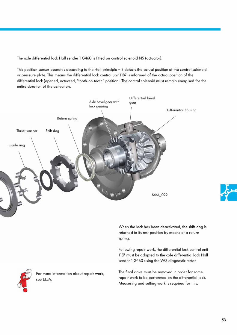
S464_022
When the lock has been deactivated, the shift dog is
returned to its rest position by means of a return spring.
Following repair work, the differential lock control unit J187 must be adapted to the axle differential lock Hall sender 1 G460 using the VAS diagnostic tester.
The final drive must be removed in order for some repair work to be performed on the differential lock.
Measuring and setting work is required for this.
Axle bevel gear with lock gearing
Differential bevel gear
Shift dog
Differential housing
Return spring
Guide ring
Thrust washer
For more information about repair work,
see ELSA.
The axle differential lock Hall sender 1 G460 is fitted on control solenoid N5 (actuator).
This position sensor operates according to the Hall principle – it detects the actual position of the control solenoid or pressure plate. This means the differential lock control unit J187 is informed of the actual position of the
differential lock (opened, actuated, "tooth-on-tooth" position). The control solenoid must remain energised for the entire duration of the activation.

54
S464_067
Rear final drive 0CC
E121 Rear differential lock switchG460 Axle differential lock Hall sender 1 J187 Differential lock control unit
J285 Control unit in dash panel insertK276 Warning lamp for rear transverse lockN5 Control solenoid
System overview – differential lock
Powertrain CAN
55
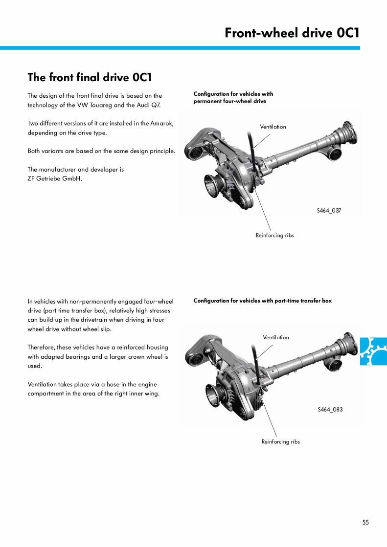
S464_083
S464_037
Front-wheel drive 0C1
The front final drive 0C1The design of the front final drive is based on the
technology of the VW Touareg and the Audi Q7.
Two different versions of it are installed in the Amarok,
depending on the drive type.
Both variants are based on the same design principle.
The manufacturer and developer is ZF Getriebe GmbH.
Ventilation
Reinforcing ribs
In vehicles with non-permanently engaged four-wheel drive (part time transfer box), relatively high stresses can build up in the drivetrain when driving in four-
wheel drive without wheel slip.
Therefore, these vehicles have a reinforced housing
with adapted bearings and a larger crown wheel is used.
Ventilation takes place via a hose in the engine compartment in the area of the right inner wing.
Configuration for vehicles with permanent four-wheel drive
Configuration for vehicles with part-time transfer box
Reinforcing ribs
Ventilation
56
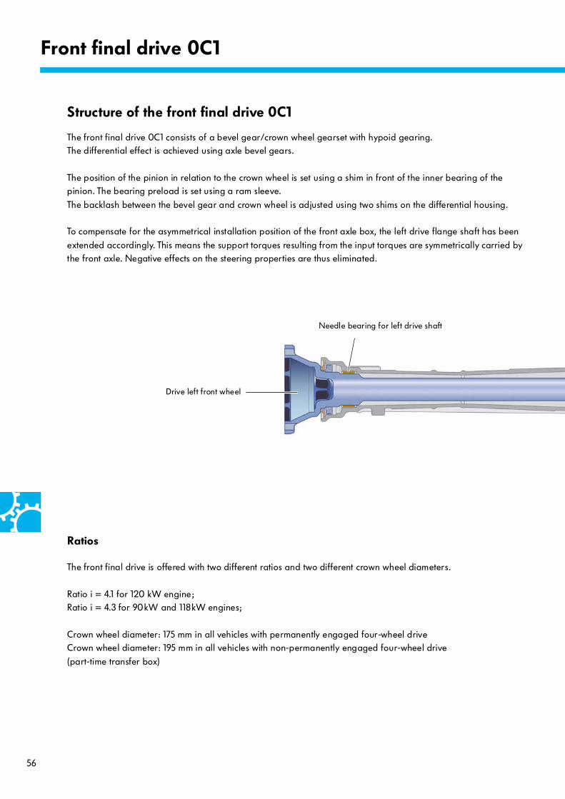
Front final drive 0C1
Drive left front wheel
The front final drive 0C1 consists of a bevel gear/crown wheel gearset with hypoid gearing. The differential effect is achieved using axle bevel gears.
The position of the pinion in relation to the crown wheel is set using a shim in front of the inner bearing of the pinion. The bearing preload is set using a ram sleeve.
The backlash between the bevel gear and crown wheel is adjusted using two shims on the differential housing.
To compensate for the asymmetrical installation position of the front axle box, the left drive flange shaft has been
extended accordingly. This means the support torques resulting from the input torques are symmetrically carried by the front axle. Negative effects on the steering properties are thus eliminated.
Needle bearing for left drive shaft
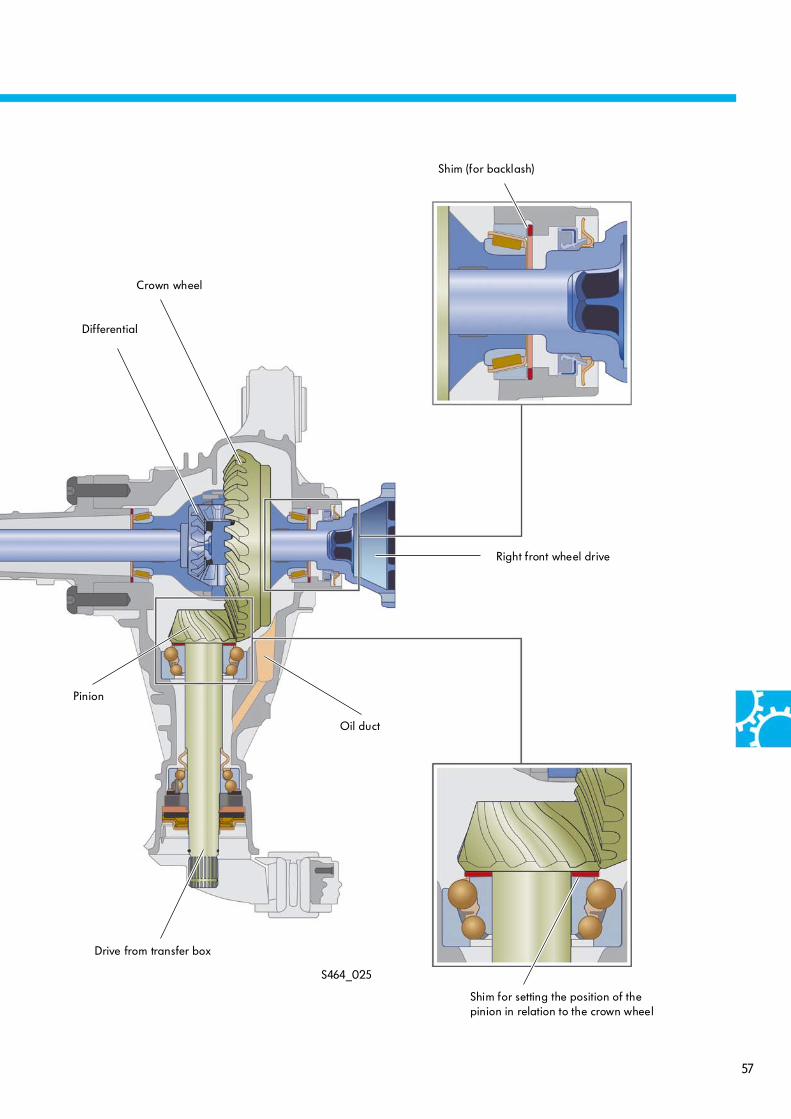
Structure of the front final drive 0C1
Ratios
The front final drive is offered with two different ratios and two different crown wheel diameters.
Ratio i = 4.1 for 120 kW engine;Ratio i = 4.3 for 90kW and 118kW engines;
Crown wheel diameter: 175 mm in all vehicles with permanently engaged four-wheel drive Crown wheel diameter: 195 mm in all vehicles with non-permanently engaged four-wheel drive
(part-time transfer box)
57
S464_025
Drive from transfer box
Pinion
Crown wheel
Differential
Right front wheel drive
Shim for setting the position of the pinion in relation to the crown wheel
Shim (for backlash)
Oil duct

58
Test your knowledge
Which answer is correct?
One or more of the model answers could be correct.
1. Under what conditions can the 4x4 LOW offroad range be engaged?The following engagement conditions must be met:
a) Engine speed < 1500 rpm, can be engaged at any driving speed, 4x4 HIGH four-wheel drive engaged
b) Engine speed < 1500 rpm, driving speed < 1 km/h, 4x4 HIGH four-wheel drive engaged
c) Engine speed < 1500 rpm, 4x4 HIGH four-wheel drive engaged, differential lock engaged
2. What features apply to the offroad drive programme?
a) The control behaviour of the ABS is adapted. The pressure buildup and pressure holding phases are extended. The depressurisation is shorter and takes place later.
b) The control behaviour of the ABS is adapted. The pressure buildup and pressure holding phases are shortened. The depressurisation is longer and takes place earlier.
c) The control behaviour of the ABS is unchanged. The ASR and EDL control is adapted.
3. What is the task of the adapter shaft in the manual gearbox 0C6?
a) The rear axle in vehicles without four-wheel drive function is driven via the adapter shaft.
b) The drive torque is transferred from the engine to the manual gearbox via the adapter shaft.
c) The drive torque is transferred from the manual gearbox to the transfer box via the adapter shaft.
4. What is the special feature of R gear in the manual gearbox 0C6?
a) There is no reverse shaft in the manual gearbox 0C6. 2nd gear is used for the reversal of the direction of
rotation.
b) The synchromeshed gear and synchro-hub of the R gear form one structural unit.
c) The R gear is not synchronised.

59
5. Which statement regarding the selector mechanism of the manual gearbox 0C6 is correct?
a) The coupling rod always keeps the axis of rotation of the gearshift kinematics at the same distance from the gearbox.
b) The coupling rod engages reverse gear.
c) The coupling rod prevents several gears from being engaged at the same time.
6. What is the gearshift procedure in the non-permanently engaged four-wheel drive 0C1?
a) The return spring holds the 4x4 LOW selector fork firmly in its rest position.
b) In the gearshift procedure from 4x4 HIGH to 4x2 mode, the 4x4 HIGH selector fork is exclusively moved by the force of the return spring.
c) In the gearshift procedure from 4x4 LOW to 4x2 HIGH, the 4x4 LOW selector fork is exclusively moved by the force of the return spring.
7. The Hall sender for transfer box G759 ...
a) … senses the position of the selector shaft and controls the gearshift procedures in the transfer box.
b) … registers the output speed of the transfer box and prevents four-wheel drive from being engaged if there
are speed differences between the front and rear axles.
c) … only registers the position of the selector shaft in 4x2 mode.
8. How does the differential lock function in the rear final drive 0CC?
a) The control solenoid N5 operates the multi-disc clutch for blocking the differential.
b) The control solenoid N5 keeps the axle bevel gear fixed in position inductively due to its magnetic field.
c) The control solenoid N5 operates the shift dog via the thrust plate in order to block the axle bevel gear
Answers 1. b); 2. a); 3. c); 4. b); 5. a); 6. b); 7. a); 8. c
464
© VOLKSWAGEN AG, WolfsburgAll rights reserved. Subject to technical modifications.000.2812.37.20 Technical status 07.2010
Volkswagen AG After Sales Qualifizierung Service Training VSQ-1 Brieffach 1995 D-38436 Wolfsburg
❀ This paper was manufactured using pulp bleached without the use of chlorine.