Embed Size (px)
Citation preview

Security Products
SSG 5 Hardware Installation and Configuration Guide
Juniper Networks, Inc.
1194 North Mathilda Avenue
Sunnyvale, CA 94089
USA
408-745-2000
www.juniper.net
Part Number: 530-015647-01, Revision 02

2
Copyright Notice
Copyright © 2006 Juniper Networks, Inc. All rights reserved.
Juniper Networks and the Juniper Networks logo are registered trademarks of Juniper Networks, Inc. in the United States and other countries. All other trademarks, service marks, registered trademarks, or registered service marks in this document are the property of Juniper Networks or their respective owners. All specifications are subject to change without notice. Juniper Networks assumes no responsibility for any inaccuracies in this document or for any obligation to update information in this document. Juniper Networks reserves the right to change, modify, transfer, or otherwise revise this publication without notice.
FCC Statement
The following information is for FCC compliance of Class A devices: This equipment has been tested and found to comply with the limits for a Class A digital device, pursuant to part 15 of the FCC rules. These limits are designed to provide reasonable protection against harmful interference when the equipment is operated in a commercial environment. The equipment generates, uses, and can radiate radio-frequency energy and, if not installed and used in accordance with the instruction manual, may cause harmful interference to radio communications. Operation of this equipment in a residential area is likely to cause harmful interference, in which case users will be required to correct the interference at their own expense.
The following information is for FCC compliance of Class B devices: The equipment described in this manual generates and may radiate radio-frequency energy. If it is not installed in accordance with Juniper Networks’ installation instructions, it may cause interference with radio and television reception. This equipment has been tested and found to comply with the limits for a Class B digital device in accordance with the specifications in part 15 of the FCC rules. These specifications are designed to provide reasonable protection against such interference in a residential installation. However, there is no guarantee that interference will not occur in a particular installation.
If this equipment does cause harmful interference to radio or television reception, which can be determined by turning the equipment off and on, the user is encouraged to try to correct the interference by one or more of the following measures:
Reorient or relocate the receiving antenna.
Increase the separation between the equipment and receiver.
Consult the dealer or an experienced radio/TV technician for help.
Connect the equipment to an outlet on a circuit different from that to which the receiver is connected.
Caution: Changes or modifications to this product could void the user's warranty and authority to operate this device.
Disclaimer
THE SOFTWARE LICENSE AND LIMITED WARRANTY FOR THE ACCOMPANYING PRODUCT ARE SET FORTH IN THE INFORMATION PACKET THAT SHIPPED WITH THE PRODUCT AND ARE INCORPORATED HEREIN BY THIS REFERENCE. IF YOU ARE UNABLE TO LOCATE THE SOFTWARE LICENSE OR LIMITED WARRANTY, CONTACT YOUR JUNIPER NETWORKS REPRESENTATIVE FOR A COPY.
English
Table of Contents
About This Guide 5
Organization ....................................................................................................6WebUI Conventions .........................................................................................6CLI Conventions...............................................................................................7Obtaining Documentation and Technical Support ............................................8
Chapter 1 Hardware Overview 9
Port and Power Connectors .............................................................................9Front Panel ....................................................................................................10
System Status LEDs .................................................................................10Port Descriptions ...........................................................................................12
Ethernet Ports ...................................................................................12Console Port .....................................................................................12AUX Port...........................................................................................13
Back Panel .....................................................................................................13Power Adapter.........................................................................................13Radio Transceiver....................................................................................14Grounding Lug.........................................................................................14Antennae Types.......................................................................................14USB Port ..................................................................................................14
Chapter 2 Installing and Connecting the Device 17
Before You Begin ...........................................................................................18Installing Equipment ......................................................................................18Connecting Interface Cables to a Device ........................................................19Connecting the Power....................................................................................20Connecting a Device to a Network .................................................................20
Connecting a Device to an Untrusted Network ........................................20Ethernet Ports ...................................................................................21Serial (AUX/Console) Ports ................................................................21WAN Ports ........................................................................................21
Connecting a Device to an Internal Network or Workstation ...................22Ethernet Ports ...................................................................................22Wireless Antennae ............................................................................22
Table of Contents 3

4
SSG 5 Hardware Installation and Configuration Guide
Chapter 3 Configuring the Device 23
Accessing a Device.........................................................................................24Using a Console Connection ....................................................................24Using the WebUI .....................................................................................25Using Telnet ............................................................................................26
Default Device Settings ..................................................................................27Basic Device Configuration ............................................................................29
Root Admin Name and Password ............................................................29Date and Time.........................................................................................30Bridge Group Interfaces ...........................................................................30Administrative Access .............................................................................31Management Services..............................................................................31Hostname and Domain Name .................................................................32Default Route...........................................................................................32Management Interface Address ...............................................................32Backup Untrust Interface Configuration...................................................33
Basic Wireless Configuration..........................................................................33WAN Configuration ........................................................................................37
ISDN Interface .........................................................................................37V.92 Modem Interface .............................................................................38
Basic Firewall Protections ..............................................................................39Verifying External Connectivity......................................................................39Resetting a Device to Factory Defaults ...........................................................40
Chapter 4 Servicing the Device 41
Required Tools and Parts ...............................................................................41Upgrading Memory ........................................................................................41
Appendix A Specifications 45
Physical..........................................................................................................45Electrical ........................................................................................................45Environmental Tolerance ...............................................................................46Certifications..................................................................................................46
Safety ......................................................................................................46EMC Emissions........................................................................................46EMC Immunity ........................................................................................46ETSI.........................................................................................................47
Connectors.....................................................................................................47
Appendix B Initial Configuration Wizard 49
Index.......................................................................................................................... 63
Table of Contents

English
About This Guide
The Juniper Networks Secure Services Gateway (SSG) 5 device is an integrated router and firewall platform that provides Internet Protocol Security (IPSec) virtual private network (VPN) and firewall services for a branch office or a retail outlet.
Juniper Networks offers six models of the SSG 5 device:
SSG 5 Serial
SSG 5 Serial-WLAN
SSG 5 V.92
SSG 5 V.92-WLAN
SSG 5 ISDN
SSG 5 ISDN-WLAN
All SSG 5 devices support a universal serial bus (USB) host module. The devices also provide protocol conversions between local area networks (LANs) and wide area networks (WANs), and three of the models support wireless local area networks (WLANs).
NOTE: The configuration instructions and examples in this document are based on the functionality of a device running ScreenOS 5.4. Your device might function differently depending on the ScreenOS version you are running. For the latest device documentation, refer to the Juniper Networks Technical Publications website at http://www.juniper.net/techpubs/hardware. To see which ScreenOS versions are currently available for your device, refer to the Juniper Networks Support website at http://www.juniper.net/customers/support/.
5

SSG 5 Hardware Installation and Configuration Guide
6
Organization
This guide contains the following sections:
Chapter 1, “Hardware Overview,” describes the chassis and components for an SSG 5 device.
Chapter 2, “Installing and Connecting the Device,” describes how to mount an SSG 5 device and how to connect it to your network.
Chapter 3, “Configuring the Device,” describes how to configure and manage an SSG 5 device and how to perform some basic configuration tasks.
Chapter 4, “Servicing the Device,” describes service and maintenance procedures for the SSG 5 device.
Appendix A, “Specifications,” provides general system specifications for the SSG 5 device.
Appendix B, “Initial Configuration Wizard,” provides detailed information about using the Initial Configuration Wizard (ICW) for an SSG 5 device.
WebUI Conventions
To perform a task with the WebUI, you first navigate to the appropriate dialog box, where you then define objects and set parameters. A chevron ( > ) shows the navigational sequence through the WebUI, which you follow by clicking menu options and links. The set of instructions for each task is divided into navigational path and configuration settings.
The following figure lists the path to the address configuration dialog box with the following sample configuration settings:
Objects > Addresses > List > New: Enter the following, then click OK:
Address Name: addr_1IP Address/Domain Name:
IP/Netmask: (select), 10.2.2.5/32Zone: Untrust
Organization

English
Figure 1: Navigational Path and Configuration Settings
CLI Conventions
The following conventions are used to present the syntax of CLI commands in examples and in text.
In examples:
Anything inside square brackets [ ] is optional.
Anything inside braces { } is required.
If there is more than one choice, each choice is separated by a pipe ( | ). For example:
set interface { ethernet1 | ethernet2 | ethernet3 } manage
means “set the management options for the ethernet1, the ethernet2, or the ethernet3 interface.”
Variables are in italic type:
set admin user name1 password xyz
In text:
Commands are in boldface type.
Variables are in italic type.
NOTE: When entering a keyword, you need to type only enough letters to identify the word uniquely. For example, typing set adm u kath j12fmt54 is enough to enter the command set admin user kathleen j12fmt54. Although you can use this shortcut when entering commands, all the commands documented here are presented in their entirety.
CLI Conventions 7

SSG 5 Hardware Installation and Configuration Guide
8
Obtaining Documentation and Technical Support
To obtain technical documentation for any Juniper Networks product, visit www.juniper.net/techpubs/.
For technical support, open a support case using the Case Manager link at http://www.juniper.net/support/ or call 1-888-314-JTAC (within the United States) or 1-408-745-9500 (outside the United States).
If you find any errors or omissions in this document, please contact us at the following email address:
Obtaining Documentation and Technical Support
English
Chapter 1
Hardware Overview
This chapter provides detailed descriptions of the SSG 5 chassis and its components. It contains the following sections:
“Port and Power Connectors” on page 9
“Front Panel” on page 10
“Back Panel” on page 13
Port and Power Connectors
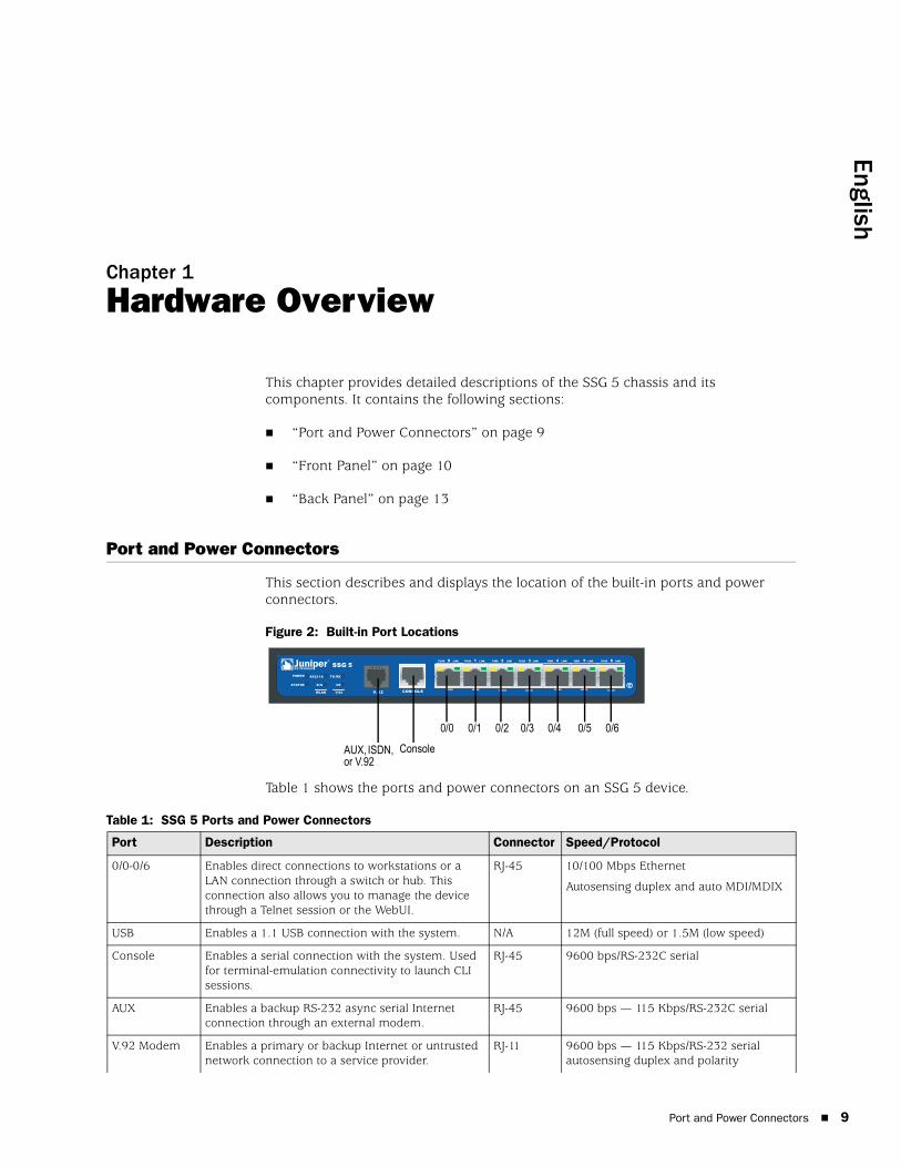
This section describes and displays the location of the built-in ports and power connectors.
Figure 2: Built-in Port Locations
Table 1 shows the ports and power connectors on an SSG 5 device.
Table 1: SSG 5 Ports and Power Connectors
SSG 5
V.92
STATUS
POWER
CONSOLE
TX /RX
CD
0 1 2 3 4 5 6TX/RX LINK TX/RX LINK TX/RX LINK TX/RX LINK TX/RX LINK TX/RX LINK TX/RX LINK
10/100 10/100 10/100 10/100 10/100 10/100 10/100
B /G
WLAN V.92
802.11A
0/60/50/40/30/20/10/0
ConsoleAUX, ISDN, or V.92
Port Description Connector Speed/Protocol
0/0-0/6 Enables direct connections to workstations or a LAN connection through a switch or hub. This connection also allows you to manage the device through a Telnet session or the WebUI.
RJ-45 10/100 Mbps Ethernet
Autosensing duplex and auto MDI/MDIX
USB Enables a 1.1 USB connection with the system. N/A 12M (full speed) or 1.5M (low speed)
Console Enables a serial connection with the system. Used for terminal-emulation connectivity to launch CLI sessions.
RJ-45 9600 bps/RS-232C serial
AUX Enables a backup RS-232 async serial Internet connection through an external modem.
RJ-45 9600 bps — 115 Kbps/RS-232C serial
V.92 Modem Enables a primary or backup Internet or untrusted network connection to a service provider.
RJ-11 9600 bps — 115 Kbps/RS-232 serial autosensing duplex and polarity
Port and Power Connectors 9

SSG 5 Hardware Installation and Configuration Guide
10
Front Panel
This section describes the following elements on the front panel of an SSG 5 device:
System Status LEDs
Port Descriptions
System Status LEDsThe system status LEDs display information about critical device functions. Figure 3 illustrates the position of each status LED on the front of the SSG 5 V.92-WLAN device. The system LEDs differ depending on the version of the SSG 5 device.
Figure 3: Status LEDs
When the system powers up, the POWER LED changes from off to blinking green, and the STATUS LED changes in the following sequence: red, green, blinking green. Startup takes approximately two minutes to complete. If you want to turn the system off and on again, we recommend you wait a few seconds between shutting it down and powering it back up. Table 2 provides the type, name, color, status, and description of each system status LED.
Table 2: Status LED Descriptions
ISDN Enables the ISDN line to be used as the untrust or backup interface. (S/T)
RJ-45 B-channels at 64 Kbps
Leased line at 128 Kbps
Antenna A & B (SSG 5-WLAN)
Enables a direct connection to workstations in the vicinity of a wireless radio connection.
RPSMA 802.11a (54 Mbps on 5GHz radio band)
802.11b (11 Mbps on 2.4 GHz radio band)
802.11g (54 Mbps on 2.4 GHz radio band)
802.11 superG (108 Mbps on 2.4 GHz and 5GHz radio bands)
Port Description Connector Speed/Protocol
Type Name Color State Description
POWER Green On steadily Indicates that the system is receiving power.
Off Indicates that the system is not receiving power.
Red On steadily Indicates that the device is not operating normally.
Off Indicates that the device is operating normally.
Front Panel

English
STATUS Green On steadily Indicates that the system is starting or performing diagnostics.
Blinking Indicates that the device is operating normally.
Red Blinking Indicates that there was an error detected.
ISDN devices
CH B1 Green On steadily Indicates that B-Channel 1 is active.
Off Indicates that B-Channel 1 is not active.
CH B2 Green On steadily Indicates that B-Channel 2 is active.
Off Indicates that B-Channel 2 is not active.
V.92 devices
HOOK Green On steadily Indicates that the link is active.
Off Indicates that the serial interface is not in service.
TX/RX Green Blinking Indicates that traffic is passing through.
Off Indicates that no traffic is passing through.
WLAN devices
802.11A Green On steadily Indicates that a wireless connection is established but there is no link activity.
Blinking Indicates that a wireless connection is established. The baud rate is proportional to the link activity.
Off Indicates that there is no wireless connection established.
B/G Green On steadily Indicates that a wireless connection is established but there is no link activity.
Blinking Indicates that a wireless connection is established. The baud rate is proportional to the link activity.
Off Indicates that there is no wireless connection established.
Type Name Color State Description
Front Panel 11

SSG 5 Hardware Installation and Configuration Guide
12
Port Descriptions
This section explains the purpose and function of the following:
Ethernet Ports
Console Port
AUX Port
Ethernet PortsSeven 10/100 Ethernet ports provide LAN connections to hubs, switches, local servers, and workstations. You can also designate an Ethernet port for management traffic. The ports are labeled 0/0 through 0/6. See “Default Device Settings” on page 27 for the default zone bindings for each Ethernet port.
When configuring one of these ports, reference the interface name that corresponds to the location of the port. From left to right on the front panel, the interface names for the ports are ethernet0/0 through ethernet0/6.
Figure 4 displays the location of the LEDs on each Ethernet port.
Figure 4: Activity Link LEDs
Table 3 describes the Ethernet port LEDs.
Table 3: Ethernet Port LEDs
Console PortThe Console port is an RJ-45 serial port wired as data circuit-terminating equipment (DCE) that can be used for local administration. Use a straight-through cable when using a terminal connection and a crossover cable when connecting to another DCE device. An RJ-45 to DB-9 adapter is supplied.
See “Connectors” on page 47 for the RJ-45 connector pinouts.
Name Color Status Description
LINK Green On steadily
Off
Port is online.
Port is offline.
TX/RX Green Blinking
Off
Traffic is passing through. The baud rate is proportional to the link activity.
Port might be on but is not receiving data.
LINKTX/RX
Port Descriptions

English
AUX PortThe auxiliary (AUX) port is an RJ-45 serial port wired as data terminal equipment (DTE) that can be connected to a modem to allow remote administration. We do not recommend using this port for regular remote administration. The AUX port is typically assigned to be the backup serial interface. The baud rate is adjustable from 9600 bps to 115200 bps and requires hardware flow control. Use a straight-through cable when connecting to a modem and a crossover cable when connecting to another DTE device.
See “Connectors” on page 47 for the RJ-45 connector pinouts.
Back Panel
This section describes the following elements on the back panel of an SSG 5 device:
Power Adapter
Radio Transceiver
Grounding Lug
Antennae Types
USB Port
Figure 5: Back Panel of an SSG 5 Device
Power AdapterThe POWER LED on the front panel of a device either glows green or is off. Green indicates correct function, and off indicates power-adapter failure or that the device is off.
NOTE: Only the SSG 5-WLAN devices have the antennae connectors.
RESETDC POWER
LOCK
USBSD FLASHB A5V A4
Power adapter
USB host moduleGrounding
lug
Reset pinhole
Antenna AAntenna B
Back Panel 13

SSG 5 Hardware Installation and Configuration Guide
14
Radio TransceiverThe SSG 5-WLAN devices contain two wireless connectivity radio transceivers, which support 802.11a/b/g standards. The first transceiver (WLAN 0) uses the 2.4 GHz radio band, which supports the 802.11b standard at 11 Mbps and the 802.11g at 54 Mbps. The second radio transceiver (WLAN 1) uses the 5GHz radio band, which supports the 802.11a standard at 54 Mbps. The two radio bands can work simultaneously. For information on configuring the wireless radio band, see “Basic Wireless Configuration” on page 33.
Grounding LugA one-hole grounding lug is provided on the rear of the chassis to connect the device to earth ground (see Figure 5).
To ground the device before connecting power, you connect a grounding cable to earth ground and then attach the cable to the lug on the rear of the chassis.
Antennae TypesThe SSG 5-WLAN devices support three types of custom-built radio antennae:
Diversity antennae — The diversity antennae provide 2dBi directional coverage and a fairly uniform level of signal strength within the area of coverage and are suitable for most installations. This type of antennae is shipped with the device.
External omnidirectional antenna — The external antenna provides 2dBi omnidirectional coverage. Unlike diversity antennae, which function as a pair, an external antenna operates to eliminate an echo effect that can sometimes occur from slightly delayed characteristics in signal reception when two are in use.
External directional antenna — The external directional antenna provides 2dBi unidirectional coverage and is appropriate for locations like hallways and outer walls (with the antenna facing inward).
USB PortThe USB port on the back panel of an SSG 5 device accepts a universal serial bus (USB) storage device or USB storage device adapter with a compact-flash disk installed, as defined in the CompactFlash Specification published by the CompactFlash Association. When the USB storage device is installed and configured, it automatically acts as a secondary boot device if the primary compact-flash disk fails on startup.
The USB port allows file transfers such as device configurations, user certifications, and update version images between an external USB storage device and the internal flash storage located in the security device. The USB port supports USB 1.1 specification at either low speed (1.5M) or full speed (12M) file transfer.
Back Panel
English
To transfer files between the USB storage device and an SSG 5, perform the following steps:
1. Insert the USB storage device into the USB port on the security device.
2. Save the files from the USB storage device to the internal flash storage on the device with the save {software | config | image-key} from usb filename to flash CLI command.
3. Before removing the USB storage device, stop the USB port with the exec usb-device stop CLI command.
4. It is now safe to remove the USB storage device.
If you want to delete a file from the USB storage device, use the delete file usb:/filename CLI command.
If you want to view the saved file information on the USB storage device or internal flash storage, use the get file CLI command.
Back Panel 15

SSG 5 Hardware Installation and Configuration Guide
16
Back Panel
English
Chapter 2
Installing and Connecting the Device
This chapter describes how to mount an SSG 5 device and connect cables and power to the device. This chapter contains the following sections:
“Before You Begin” on page 18
“Installing Equipment” on page 18
“Connecting Interface Cables to a Device” on page 19
“Connecting the Power” on page 20
“Connecting a Device to a Network” on page 20
NOTE: For safety warnings and instructions, refer to the Juniper Networks Security Products Safety Guide. Before working on any equipment, you should be aware of the hazards involved with electrical circuitry and familiar with standard practices for preventing accidents.
17

SSG 5 Hardware Installation and Configuration Guide
18
Before You Begin
The location of the chassis, the layout of the mounting equipment, and the security of your wiring room are crucial for proper system operation.
Observing the following precautions can prevent shutdowns, equipment failures, and injuries:
Before installation, always check that the power supply is disconnected from any power source.
Ensure that the room in which you operate the device has adequate air circulation and that the room temperature does not exceed 104° F (40° C).
Do not place the device in an equipment-rack frame that blocks an intake or exhaust port. Ensure that enclosed racks have fans and louvered sides.
Correct these hazardous conditions before any installation: moist or wet floors, leaks, ungrounded or frayed power cables, or missing safety grounds.
Installing Equipment
You can front-mount, wall-mount, or desk-mount an SSG 5 device. The mounting kits may be purchased separately.
To mount an SSG 5 device, you need a number-2 phillips screwdriver (not provided) and screws that are compatible with the equipment rack (included in the kit).
To rack-mount an SSG 5 device, perform the following steps:
1. Unscrew the mounting brackets on the tray with a phillips screwdriver.
2. Align the bottom of the device with the base holes on the tray.
3. Pull the device forward to lock it in the base holes on the tray.
4. Using the screws, attach the mounting brackets to the device and the tray.
5. Place the power supply in the supply holder, then plug the power adapter into the device.
WARNING: To prevent abuse and intrusion by unauthorized personnel, install the SSG 5 device in a secure environment.
NOTE: When mounting a device, make sure that it is within reach of the power outlet.
NOTE: SSG 5-WLAN users with the optional antennae need to remove the existing antennae, then connect the new antenna through the side hole.
Before You Begin

English
6. To install a second SSG 5 device, repeat steps 1 through 5, then continue.
Figure 6: SSG 5 Rack-mount
7. Mount the tray on the rack with the provided screws.
8. Plug in the power supply to the power outlet.
To desk-mount an SSG 5 device, perform the following steps:
1. Attach the desktop stand to the side of the device. We recommend using the side closest to the power adapter.
2. Place the mounted device on the desktop.
Figure 7: SSG 5 Desk-mount
3. Plug in the power adapter and connect the power supply to the power outlet.
Connecting Interface Cables to a Device
To connect interface cables to the device, perform the following steps:
1. Have ready a length of the type of cable used by the interface.
2. Insert the cable connector into the cable connector port on the device.
3. Arrange the cable as follows to prevent it from dislodging or developing stress points:
a. Secure the cable so that it is not supporting its own weight as it hangs to the floor.
b. Place excess cable out of the way in a neatly coiled loop.
c. Place fasteners on the loop to help maintain its shape.
Power Supply Holder
Power Supply Holder
Connecting Interface Cables to a Device 19

SSG 5 Hardware Installation and Configuration Guide
20
Connecting the Power
To connect the power to a device, perform the following steps:
1. Plug the DC-connector end of the power cable into the DC-power receptacle on the back of the device.
2. Plug the AC-adapter end of the power cable into an AC-power source.
Connecting a Device to a Network
The SSG 5 devices provide firewall and general security for networks when it is placed between internal networks and the untrusted network. This section describes the following:
Connecting a Device to an Untrusted Network
Connecting a Device to an Internal Network or Workstation
Connecting a Device to an Untrusted NetworkYou can connect your SSG 5 device to an untrusted network in one of the following ways:
Ethernet Ports
Serial (AUX/Console) Ports
WAN Ports
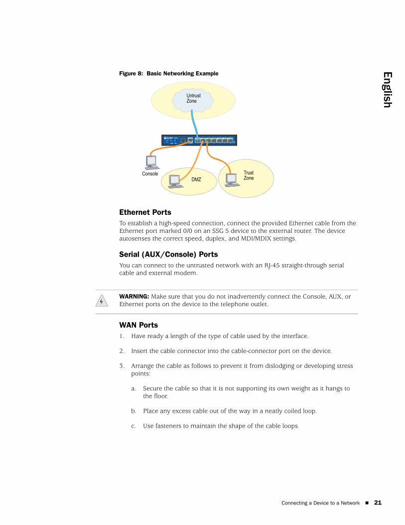
Figure 8 shows the SSG 5 with basic network cabling connections with the 10/100 Ethernet ports cabled as follows:
The port labeled 0/0 (ethernet0/0 interface) is connected to the untrust network.
The port labeled 0/1 (ethernet0/1 interface) is connected to a workstation in the DMZ security zone.
The port labeled 0/2 (bgroup0 interface) is connected to a workstation in the Trust security zone.
The Console port is connected to a serial terminal for management access.
WARNING: We recommend using a surge protector for the power connection.
Connecting the Power
English
Figure 8: Basic Networking Example
Ethernet PortsTo establish a high-speed connection, connect the provided Ethernet cable from the Ethernet port marked 0/0 on an SSG 5 device to the external router. The device autosenses the correct speed, duplex, and MDI/MDIX settings.
Serial (AUX/Console) PortsYou can connect to the untrusted network with an RJ-45 straight-through serial cable and external modem.
WAN Ports1. Have ready a length of the type of cable used by the interface.
2. Insert the cable connector into the cable-connector port on the device.
3. Arrange the cable as follows to prevent it from dislodging or developing stress points:
a. Secure the cable so that it is not supporting its own weight as it hangs to the floor.
b. Place any excess cable out of the way in a neatly coiled loop.
c. Use fasteners to maintain the shape of the cable loops.
SSG 5
V.92
STATUS
POWER
CONSOLE
TX /RX
CD
0 1 2 3 4 5 6TX/RX LINK TX/RX LINK TX/RX LINK TX/RX LINK TX/RX LINK TX/RX LINK TX/RX LINK
10/100 10/100 10/100 10/100 10/100 10/100 10/100
B /G
WLAN V.92
802.11A
Callouts
Untrust Zone
ConsoleDMZ
Trust Zone
WARNING: Make sure that you do not inadvertently connect the Console, AUX, or Ethernet ports on the device to the telephone outlet.
Connecting a Device to a Network 21

SSG 5 Hardware Installation and Configuration Guide
22
Connecting a Device to an Internal Network or WorkstationYou can connect your local area network (LAN) or workstation with the Ethernet and/or wireless interfaces.
Ethernet PortsAn SSG 5 device contains seven Ethernet ports. You can use one or more of these ports to connect to LANs through switches or hubs. You can also connect one or all of the ports directly to workstations, eliminating the need for a hub or switch. You can use either crossover or straight-through cables to connect the Ethernet ports to other devices. See “Default Device Settings” on page 27 for the default interface-to-zone bindings.
Wireless AntennaeIf you are using the wireless interface, you need to connect the provided antennae on the device. If you have the standard 2dB diversity antennae, use screws to attach them onto the posts marked A and B at the back of the device. Bend each antenna at its elbows, making sure not to put pressure on the bulkhead connectors.
Figure 9: SSG 5-WLAN Antennae Location
If you are using the optional external antenna, follow the connection instructions that came with that antenna.
RESETDC POWER
LOCK
USBSD FLASHB A5V A4
Bulkhead connectorBulkhead connector
Antenna B Antenna A
Connecting a Device to a Network

English
Chapter 3
Configuring the Device
ScreenOS software is preinstalled on the SSG 5 devices. When the device is powered on, it is ready to be configured. While the device has a default factory configuration that allows you to initially connect to the device, you need to perform further configuration for your specific network requirements.
This chapter contains the following sections:
“Accessing a Device” on page 24
“Default Device Settings” on page 27
“Basic Device Configuration” on page 29
“Basic Wireless Configuration” on page 33
“WAN Configuration” on page 37
“Basic Firewall Protections” on page 39
“Verifying External Connectivity” on page 39
“Resetting a Device to Factory Defaults” on page 40
NOTE: After you configure a device and verify connectivity through the remote network, you must register your product at www.juniper.net/support/ so certain ScreenOS services, such as Deep Inspection Signature Service and Antivirus (purchased separately), can be activated on the device. After registering your product, use the WebUI to obtain the subscription for the service. For more information about registering your product and obtaining subscriptions for specific services, refer to the Fundamentals volume of the Concepts & Examples ScreenOS Reference Guide for the ScreenOS version running on the device.
23

SSG 5 Hardware Installation and Configuration Guide
24
Accessing a Device
You can configure and manage an SSG 5 device in several ways:
Console: The Console port on the device allows you to access the device through a serial cable connected to your workstation or terminal. To configure the device, you enter ScreenOS Command Line Interface (CLI) commands on your terminal or in a terminal-emulation program on your workstation.
WebUI: The ScreenOS Web User Interface (WebUI) is a graphical interface available through a browser. To initially use the WebUI, the workstation on which you run the browser must be on the same subnetwork as the device. You can also access the WebUI through a secure server using Secure Sockets Layer (SSL) with secure HTTP (S-HTTP).
Telnet/SSH: Telnet and SSH are applications that allow you to access devices through an IP network. To configure the device, you enter ScreenOS CLI commands in a Telnet session from your workstation. For more information, refer to the Administration volume of the Concepts & Examples ScreenOS Reference Guide.
NetScreen-Security Manager: NetScreen-Security Manager is a Juniper Networks enterprise-level management application that enables you to control and manage Juniper Networks firewall/IPSec VPN devices. For instructions on how to manage your device with NetScreen-Security Manager, refer to the NetScreen-Security Manager Administrator’s Guide.
Using a Console Connection
To establish a console connection, perform the following steps:
1. Plug the female end of the supplied DB-9 adapter into the serial port of your workstation. (Be sure that the DB-9 is inserted properly and secured.) Figure 10 shows the type of DB-9 connector that is needed.
Figure 10: DB-9 Adapter
2. Plug the male end of the RJ-45 CAT5 serial cable into the Console port on the SSG 5. (Be sure that the other end of the CAT5 cable is inserted properly and secured in the DB-9 adapter.)
NOTE: Use a straight-through RJ-45 CAT5 serial cable with a male RJ-45 connector to plug into the Console port on the device.
RJ-45 jack
DB-9 adapter
RJ-45 cable
Accessing a Device

English
3. Launch a serial terminal-emulation program on your workstation. The required settings to launch a console session are as follows:
Baud rate: 9600
Parity: None
Data bits: 8
Stop bit: 1
Flow Control: None
4. If you have not yet changed the default username and password, enter netscreen at both the login and password prompts. (Use lowercase letters only. The login and password fields are both case-sensitive.)
For information on how to configure the device with the CLI commands, refer to the Concepts & Examples ScreenOS Reference Guide.
5. (Optional) By default, the console times out and terminates automatically after 10 minutes of idle time. To remove the timeout, enter set console timeout 0.
Using the WebUITo use the WebUI, the workstation from which you are managing the device must initially be on the same subnetwork as the device. To access the device with the WebUI, perform the following steps:
1. Connect your workstation to the 0/2 — 0/6 port (bgroup0 interface in the Trust zone) on the device.
2. Ensure that your workstation is configured for Dynamic Host Configuration Protocol (DHCP) or is statically configured with an IP address in the 192.168.1.0/24 subnet.
3. Launch your browser, enter the IP address for the bgroup0 interface (the default IP address is 192.168.1.1/24), then press Enter.
The WebUI application displays the login prompt as shown in Figure 11.
NOTE: When the device is accessed through the WebUI the first time, the Initial Configuration Wizard (ICW) appears. If you decide to use the ICW to configure your device, see “Initial Configuration Wizard” on page 49.
Accessing a Device 25

SSG 5 Hardware Installation and Configuration Guide
26
Figure 11: WebUI Login Prompt
4. If you have not yet changed the default login for the admin name and password, enter netscreen at both the login and password prompts. (Use lowercase letters only. The login and password fields are both case-sensitive.)
Using TelnetTo establish a Telnet connection, perform the following steps:
1. Connect your workstation to the 0/2 — 0/6 port (bgroup0 interface in the Trust zone) on the device.
2. Ensure that your workstation is configured for DHCP or is statically configured with an IP address in the 192.168.1.0/24 subnet.
3. Start a Telnet client application to the IP address for the bgroup0 interface (the default IP address is 192.168.1.1). For example, enter telnet 192.168.1.1.
The Telnet application displays the login prompt.
4. If you have not yet changed the default user name and password, enter netscreen at both the login and password prompts. (Use lowercase letters only. The login and password fields are both case-sensitive.)
5. (Optional) By default, the console times out and terminates automatically after 10 minutes of idle time. To remove the timeout, enter set console timeout 0.
Accessing a Device
English
Default Device Settings
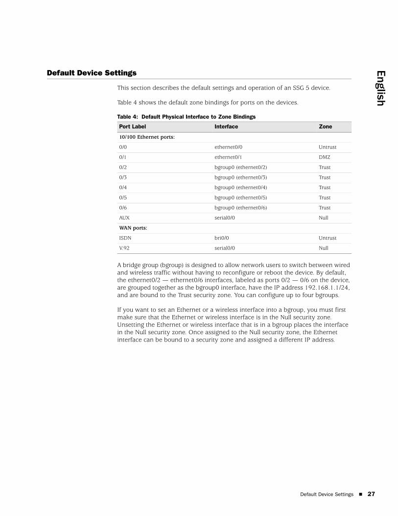
This section describes the default settings and operation of an SSG 5 device.
Table 4 shows the default zone bindings for ports on the devices.
Table 4: Default Physical Interface to Zone Bindings
A bridge group (bgroup) is designed to allow network users to switch between wired and wireless traffic without having to reconfigure or reboot the device. By default, the ethernet0/2 — ethernet0/6 interfaces, labeled as ports 0/2 — 0/6 on the device, are grouped together as the bgroup0 interface, have the IP address 192.168.1.1/24, and are bound to the Trust security zone. You can configure up to four bgroups.
If you want to set an Ethernet or a wireless interface into a bgroup, you must first make sure that the Ethernet or wireless interface is in the Null security zone. Unsetting the Ethernet or wireless interface that is in a bgroup places the interface in the Null security zone. Once assigned to the Null security zone, the Ethernet interface can be bound to a security zone and assigned a different IP address.
Port Label Interface Zone
10/100 Ethernet ports:
0/0 ethernet0/0 Untrust
0/1 ethernet0/1 DMZ
0/2 bgroup0 (ethernet0/2) Trust
0/3 bgroup0 (ethernet0/3) Trust
0/4 bgroup0 (ethernet0/4) Trust
0/5 bgroup0 (ethernet0/5) Trust
0/6 bgroup0 (ethernet0/6) Trust
AUX serial0/0 Null
WAN ports:
ISDN bri0/0 Untrust
V.92 serial0/0 Null
Default Device Settings 27

SSG 5 Hardware Installation and Configuration Guide
28
To unset ethernet0/3 from bgroup0 and assign it to the Trust zone with a static IP address of 192.168.3.1/24, use the WebUI or CLI as follows:
WebUI
Network > Interfaces > List > Edit (bgroup0) > Bind Port: Deselect ethernet0/3, then click Apply.
List > Edit (ethernet0/3): Enter the following, then click Apply:
Zone Name: Trust (select)IP Address/Netmask: 192.168.3.1/24
CLI
unset interface bgroup0 port ethernet0/3set interface ethernet0/3 zone trustset interface ethernet0/3 ip 192.168.3.1/24save
Table 5: Wireless and Logical Interface Bindings
You can change the default IP address on the bgroup0 interface to match the addresses on your LAN and WLAN. For configuring a wireless interface to a bgroup, see “Basic Wireless Configuration” on page 33.
For additional bgroup information and examples, refer to the Concepts & Examples ScreenOS Reference Guide.
There are no other default IP addresses configured on other Ethernet or wireless interfaces on a device; you need to assign IP addresses to the other interfaces, including the WAN interfaces.
SSG 5-WLAN Interface Zone
Wireless Interface
Specifies a wireless interface, which is configurable to operate on 2.4G and/or 5G radio
wireless0/0 (default IP address is 192.168.2.1/24).
Trust
wireless0/1-0/3. Null
Logical Interfaces
Layer-2 interface vlan1 specifies the logical interfaces used for management and VPN traffic termination while the device is in Transparent mode.
N/A
Tunnel interfaces tunnel.n specifies a logical tunnel interface. This interface is for VPN traffic.
N/A
NOTE: The bgroup interface does not work in Transparent mode when it contains a wireless interface.
Default Device Settings

English
Basic Device Configuration
This section describes the following basic configuration settings:
Root Admin Name and Password
Date and Time
Bridge Group Interfaces
Administrative Access
Management Services
Hostname and Domain Name
Default Route
Management Interface Address
Backup Untrust Interface Configuration
Root Admin Name and PasswordThe root admin user has complete privileges for configuring an SSG 5 device. We recommend that you change the default root admin name and password (both netscreen) immediately.
To change the root admin name and password, use the WebUI or CLI as follows:
WebUI
Configuration > Admin > Administrators > Edit (for the Administrator Name): Enter the following, then click OK:
Administrator Name:Old Password: netscreenNew Password:Confirm New Password:
CLI
set admin name nameset admin password pswd_strsave
NOTE: Passwords are not displayed in the WebUI.
Basic Device Configuration 29

SSG 5 Hardware Installation and Configuration Guide
30
Date and TimeThe time set on an SSG 5 device affects events such as the setup of VPN tunnels. The easiest way to set the date and time on the device is to use the WebUI to synchronize the device system clock with the workstation clock.
To configure the date and time on a device, use the WebUI or CLI as follows:
WebUI
1. Configuration > Date/Time: Click the Sync Clock with Client button.
A pop-up message prompts you to specify if you have enabled the daylight saving time option on your workstation clock.
2. Click Yes to synchronize the system clock and adjust it according to daylight saving time or click No to synchronize the system clock without adjusting for daylight saving time.
You can also use the set clock CLI command in a Telnet or Console session to manually enter the date and time for the device.
Bridge Group InterfacesBy default, the SSG 5 device has Ethernet interfaces ethernet0/2—ethernet0/4 grouped together in the Trust security zone. Grouping interfaces sets interfaces in one subnet. You can unset an interface from a group and assign it to a different security zone. Interfaces must be in the Null security zone before they can be assigned to a group. To place a grouped interface in the Null security zone, use the unset interface interface port interface CLI command.
The SSG 5-WLAN devices allow Ethernet and wireless interfaces to be grouped under one subnet.
To configure a group with Ethernet and wireless interfaces, use the WebUI or CLI as follows:
WebUI
Network > Interfaces > List > Edit (bgroup0) > Bind Port: deselect ethernet0/3 and ethernet0/4, then click Apply.
Edit (bgroup1) > Bind Port: Select ethernet0/3, ethernet0/4, and wireless0/2, then click Apply.
>Basic: Enter the following, then click Apply:
Zone Name: DMZ (select)IP Address/Netmask: 10.0.0.1/24
NOTE: Only wireless and Ethernet interfaces can be set in a bgroup.
Basic Device Configuration
English
CLI
unset interface bgroup0 port ethernet0/3unset interface bgroup0 port ethernet0/4set interface bgroup1 port ethernet0/3set interface bgroup1 port ethernet0/4set interface bgroup1 port wireless0/2set interface bgroup1 zone DMZset interface bgroup1 ip 10.0.0.1/24save
Administrative AccessBy default, anyone in your network can manage a device if they know the login and password. To configure the device to be managed only from a specific host on your network, use the WebUI or CLI as follows:
WebUI
Configuration > Admin > Permitted IPs: Enter the following, then click Add:
IP Address/Netmask: ip_addr/mask
CLI
set admin manager-ip ip_addr/masksave
Management ServicesScreenOS provides services for configuring and managing the device, such as SNMP, SSL, and SSH, which you can enable on a per-interface basis. To configure the management services on the device, use the WebUI or CLI as follows:
WebUI
Network > Interfaces > List > Edit (for ethernet0/0): Under Management Services, select or clear the management services you want to use on the interface, then click Apply.
CLI
set interface ethernet0/0 manage webunset interface ethernet0/0 manage snmpsave
Basic Device Configuration 31

SSG 5 Hardware Installation and Configuration Guide
32
Hostname and Domain NameThe domain name defines the network or subnetwork that the device belongs to, while the hostname refers to a specific device. The hostname and domain name together uniquely identify the device in the network. To configure the hostname and domain name on a device, use the WebUI or CLI as follows:
WebUI
Network > DNS > Host: Enter the following, then click Apply:
Host Name: nameDomain Name: name
CLI
set hostname nameset domain namesave
Default RouteThe default route is a static route used to direct packets addressed to networks that are not explicitly listed in the routing table. If a packet arrives at the device with an address for which the device does not have routing information, the device sends the packet to the destination specified by the default route. To configure the default route on the device, use the WebUI or CLI as follows:
WebUI
Network > Routing > Destination > New (trust-vr): Enter the following, then click OK:
IP Address/Netmask: 0.0.0.0/0.0.0.0Next Hop
Gateway: (select)Interface: ethernet0/2 (select)Gateway IP Address: ip_addr
CLIset route 0.0.0.0/0 interface ethernet0/2 gateway ip_addrsave
Management Interface AddressThe Trust interface has the default IP address 192.168.1.1/24 and is configured for management services. If you connect the 0/2—0/4 port on the device to a workstation, you can configure the device from a workstation in the 192.168.1.1/24 subnetwork using a management service such as Telnet.
You can change the default IP address on the Trust interface. For example, you might want to change the interface to match IP addresses that already exist on your LAN.
Basic Device Configuration

English
Backup Untrust Interface ConfigurationThe SSG 5 device allows you to configure a backup interface for untrust failover. To set a backup interface for untrust failover, perform the following steps:
1. Set the backup interface in the Null security zone with the unset interface interface [ port interface ] CLI command.
2. Bind the backup interface to the same security zone as the primary interface with the set interface interface zone zone_name CLI command.
To set the ethernet0/4 interface as the backup interface to the ethernet0/0 interface, use the WebUI or CLI as follows:
WebUI
Network > Interfaces > Backup > Enter the following, then click Apply.
Primary: ethernet0/0Backup: ethernet0/4Type: track-ip (select)
CLI
unset interface bgroup0 port ethernet0/4set interface ethernet0/4 zone untrustset interface ethernet0/0 backup interface ethernet0/4 type track-ipsave
Basic Wireless Configuration
This section provides information for configuring the wireless interface on the SSG 5-WLAN device. Wireless networks consist of names referred to as Service Set Identifiers (SSIDs). Specifying SSIDs allows you to have multiple wireless networks reside in the same location without interfering with each other. An SSID name can have a maximum of 32 characters. If a space is part of the SSID name string, then the string must be enclosed with quotation marks. Once the SSID name is set, more SSID attributes can be configured. To use the wireless local area network (WLAN) capabilities on the device, you must configure at least one SSID and bind it to a wireless interface.
The SSG 5-WLAN device allows you to create up to 16 SSIDs, but only 4 of them can be used simultaneously. You can configure the device to use the 4 SSIDs on either one of the transceivers or split the use on both (for example, 3 SSIDs assigned to WLAN 0 and 1 SSID assigned to WLAN 1). Use the set interface wireless_interface wlan { 0 | 1 | both } CLI command to set the radio transceivers on the SSG 5-WLAN device. Figure 12 shows the default configuration for the SSG 5-WLAN device.
Once you have set an SSID to the wireless0/0 interface, you can access the device using the default wireless0/0 interface IP address in the steps described in “Accessing a Device” on page 24.
NOTE: The primary and backup interfaces must be in the same security zone. One primary interface has only one backup interface, and one backup interface has only one primary interface.
Basic Wireless Configuration 33

SSG 5 Hardware Installation and Configuration Guide
34
Figure 12: Default SSG 5-WLAN Configuration
By default, the wireless0/0 interface is configured with the IP address 192.168.2.1/24. All wireless clients that need to connect to the Trust zone must have an IP address in the wireless subnetwork. You can also configure the device to use DHCP to automatically assign IP addresses in the 192.168.2.1/24 subnetwork to your devices.
By default, the wireless0/1 – wireless0/3 interfaces are defined as Null and do not have IP addresses assigned to them. If you want to use any of the other wireless interfaces, you must configure an IP address for it, assign an SSID to it, and bind it to a security zone. Table 6 displays the wireless authentication and encryption methods.
NOTE: If you are operating the SSG 5-WLAN device in a country other than the United States, Japan, Canada, China, Taiwan, Korea, Israel, or Singapore, then you must use the set wlan country-code CLI command or set it on the Wireless > General Settings WebUI page before a WLAN connection can be established. This command sets the selectable channel range and the transmit power level.
If your regional code is ETSI, you must set the correct country code that meets your local radio spectrum regulations.
SSG 5
V.92
STATUS
POWER
CONSOLE
TX /RX
CD
0 1 2 3 4 5 6TX/RX LINK TX/RX LINK TX/RX LINK TX/RX LINK TX/RX LINK TX/RX LINK TX/RX LINK
10/100 10/100 10/100 10/100 10/100 10/100 10/100
B /G
WLAN V.92
802.11A
Callouts
CalloutsUntrust Zone
Trust Zone
wireless0/0
Console
Basic Wireless Configuration

English
Table 6: Wireless Authentication and Encryption Options
Refer to the Concepts & Examples ScreenOS Reference Guide for configuration examples, SSID attributes, and CLI commands relating to wireless security configurations.
To configure a wireless interface for basic connectivity, use the WebUI or CLI as follows:
WebUI
1. Set the WLAN country code and IP address.
Wireless > General Settings > Select the following, then click Apply:
Country code: Select your codeIP Address/Netmask: ip_add/netmask
2. Set the SSID.
Wireless > SSID > New: Enter the following, then click OK:
SSID: Authentication: Encryption: Wireless Interface Binding:
3. (Optional) set the WEP key.
SSID > WEP Keys: Select the key ID, then click Apply.
4. Set the WLAN mode.
Network > Interfaces > List > Edit (wireless interface): Select Both for the WLAN mode, then click Apply.
5. Activate wireless changes.
Wireless > General Settings > Click Activate Changes.
Authentication Encryption
Open Allows any wireless client to access the device
Shared-key WEP shared-key
WPA-PSK AES/TKIP with pre-shared key
WPA AES/TKIP with key from RADIUS server
WPA2-PSK 802.11i compliant with a pre-shared key
WPA2 802.11i compliant with a RADIUS server
WPA-Auto-PSK Allows WPA and WPA2 type with pre-shared key
WPA-Auto Allows WPA and WPA2 type with RADIUS server
802.1x WEP with key from RADIUS server
Basic Wireless Configuration 35

SSG 5 Hardware Installation and Configuration Guide
36
CLI
1. Set the WLAN country code and IP address.
set wlan country-code { code_id }set interface wireless_interface ip ip_addr/netmask
2. Set the SSID.
set ssid name name_strset ssid name_str authentication auth_type encryption encryption_typeset ssid name_str interface interface(optional) set ssid name_str key-id number
3. Set the WLAN mode.
set interface wireless_interface wlan both
4. Activate wireless changes.
saveexec wlan reactivate
You can set an SSID to operate in the same subnet as the wired subnet. This action allows clients to work in either interface without having to reconnect in another subnet.
To set an Ethernet and a wireless interface to the same bridge-group interface, use the WebUI or CLI:
WebUI
Network > Interfaces > List > Edit (bgroup_name) > Bind Port: Select the wireless and ethernet interfaces, then click Apply.
CLI
set interface bgroup_name port wireless_interfaceset interface bgroup_name port ethernet_interface
NOTE: Bgroup_name can be bgroup0—bgroup3.
Ethernet_interface can be ethernet0/0—ethernet0/6.
Wireless_interface can be wireless0/0—wireless0/3.
If a wireless interface is configured, then you need to reactivate the WLAN with the exec wlan reactivate CLI command or click Activate Changes on the Wireless > General Settings WebUI page.
Basic Wireless Configuration

English
WAN Configuration
This section explains how to configure the following WAN interfaces:
ISDN Interface
V.92 Modem Interface
ISDN InterfaceIntegrated Services Digital Network (ISDN) is a set of standards for digital transmission over different media created by the Consultative Committee for International Telegraphy and Telephone (CCITT) and International Telecommunications Union (ITU). As a dial-on-demand service, it has fast call setup and low latency as well as the ability to carry high-quality voice, data, and video transmissions. ISDN is also a circuit-switched service that can be used on both multipoint and point-to-point connections. ISDN provides a service router with a multilink Point-to-Point Protocol (PPP) connection for network interfaces. The ISDN interface is usually configured as the backup interface of the Ethernet interface to access external networks.
To configure the ISDN interface, use the WebUI or CLI:
WebUI
Network > Interfaces > List > Edit (bri0/0): Enter or select the following, then click OK:
BRI Mode: Dial Using BRIPrimary Number: 123456WAN Encapsulation: PPPPPP Profile: isdnprofile
CLI
set interface bri0/0 dialer-enableset interface bri0/0 primary-number "123456"set interface bri0/0 encap pppset interface bri0/0 ppp profile isdnprofilesave
To configure the ISDN interface as the backup interface, see “Backup Untrust Interface Configuration” on page 33.
For more information on how to configure the ISDN interface, refer to the Concepts & Examples ScreenOS Reference Guide.
WAN Configuration 37

SSG 5 Hardware Installation and Configuration Guide
38
V.92 Modem InterfaceThe V.92 interface provides an internal analog modem to establish a PPP connection to a service provider. You can configure the serial interface as a primary or backup interface, which is used in case of interface failover.
To configure the V.92 interface, use the WebUI or CLI:
WebUI
Network > Interfaces > List > Edit (for serial0/0): Enter the following, then click OK:
Zone Name: untrust (select)
ISP: Enter the following, then click OK:
ISP Name: isp_juniperPrimary Number: 1234567Login Name: juniperLogin Password: juniper
Modem: Enter the following, then click OK:
Modem Name: mod1Init String: AT&FS7=255S32=6Active Modem setting
Inactivity Timeout: 20
CLI
set interface serial0/0 zone untrustset interface serial0/0 modem isp isp_juniper account login juniper password juniperset interface serial0/0 modem isp isp_juniper primary-number 1234567set interface serial0/0 modem idle-time 20set interface serial0/0 modem settings mod1 init-strings AT&FS7=255S32=6set interface serial0/0 modem settings mod1 active
For information on how to configure the V.92 modem interface, refer to the Concepts & Examples ScreenOS Reference Guide.
NOTE: The V.92 interface does not work in Transparent mode.
WAN Configuration

English
Basic Firewall Protections
The devices are configured with a default policy that permits workstations in the Trust zone of your network to access any resource in the Untrust security zone, while outside computers are not allowed to access or start sessions with your workstations. You can configure policies that direct the device to permit outside computers to start specific kinds of sessions with your computers. For information about creating or modifying policies, refer to the Concepts & Examples ScreenOS Reference Guide.
The SSG 5 device provides various detection methods and defense mechanisms to combat probes and attacks aimed at compromising or harming a network or network resource:
ScreenOS SCREEN options secure a zone by inspecting, and then allowing or denying, all connection attempts that require crossing an interface to that zone. For example, you can apply port-scan protection on the Untrust zone to stop a source from a remote network from trying to identify services to target for further attacks.
The device applies firewall policies, which can contain content-filtering and Intrusion Detection and Prevention (IDP) components, to the traffic that passes the SCREEN filters from one zone to another. By default, no traffic is permitted to pass through the device from one zone to another. To permit traffic to cross the device from one zone to another, you must create a policy that overrides the default behavior.
To set ScreenOS SCREEN options for a zone, use the WebUI or CLI as follows:
WebUI
Screening > Screen: Select the zone to which the options apply. Select the SCREEN options that you want, then click Apply:
CLI
set zone zone screen optionsave
For more information about configuring the network-security options available in ScreenOS, see the Attack Detection and Defense Mechanisms volume in the Concepts & Examples ScreenOS Reference Guide.
Verifying External Connectivity
To verify that workstations in your network can access resources on the Internet, start a browser from any workstation in the network and enter the following URL: www.juniper.net.
Basic Firewall Protections 39

SSG 5 Hardware Installation and Configuration Guide
40
Resetting a Device to Factory Defaults
If you lose the admin password, you can reset the device to its default settings. This action destroys any existing configurations but restores access to the device.
You can restore the device to its default settings in one of the following ways:
Using a Console connection. For further information, see the Administration volume of the Concepts & Examples ScreenOS Reference Guide.
Using the reset pinhole on the back panel of the device, as described in the next section.
You can reset the device and restore the factory default settings by pressing the reset pinhole. To perform this operation, you need to either view the device status LEDs on the front panel or start a Console session as described in Using a Console Connection on page 24.
To use the reset pinhole to reset and restore the default settings, perform the following steps:
1. Locate the reset pinhole on the rear panel. Using a thin, firm wire (such as a paperclip), push the pinhole for four to six seconds and then release.
The STATUS LED blinks red. A message on the console states that erasure of the configuration has started and the system sends an SNMP/SYSLOG alert.
2. Wait for one to two seconds.
After the first reset, the STATUS LED blinks green; the device is now waiting for the second reset. The Console message now states that the device is waiting for a second confirmation.
3. Push the reset pinhole again for four to six seconds.
The Console message verifies the second reset. The STATUS LED glows red for one-half second and then returns to the blinking green state.
The device then resets to its original factory settings. When the device resets, the STATUS LED glows red for one-half second and then glows green. The console displays device-bootup messages. The system generates SNMP and SYSLOG alerts to configured SYSLOG or SNMP trap hosts.
After the device has rebooted, the console displays the login prompt for the device. The STATUS LED blinks green. The login and password are netscreen.
If you do not follow the complete sequence, the reset process cancels without any configuration change and the Console message states that the erasure of the configuration is aborted. The STATUS LED returns to blinking green. If the device did not reset, an SNMP alert is sent to confirm the failure.
WARNING: Resetting the device deletes all existing configuration settings and disables all existing firewall and VPN services.
Resetting a Device to Factory Defaults

English
Chapter 4
Servicing the Device
This chapter describes service and maintenance procedures for an SSG 5 device. It contains the following sections:
“Required Tools and Parts” on this page
“Upgrading Memory” on this page
Required Tools and Parts
To replace a component on an SSG 5 device, you need the following tools and parts:
Electrostatic discharge (ESD) grounding wrist strap
Phillips screwdriver, 1/8-inch
Upgrading Memory
You can upgrade an SSG 5 device from a 128 MB dual in-line memorymodule (DIMM) dynamic random access memory (DRAM) to a 256 MB DIMM DRAM.
To upgrade the memory on an SSG 5 device, do the following:
1. Attach an ESD grounding strap to your bare wrist and connect the strap to the ESD point on the chassis or to an outside ESD point if the device is disconnected from earth ground.
2. Unplug the AC cord from the power outlet.
3. Turn over the device so that its top is lying on a flat surface.
NOTE: For safety warnings and instructions, refer to the Juniper Networks Security Products Safety Guide. The instructions in the guide warn you about situations that could cause bodily injury. Before working on any equipment, you should be aware of the hazards involved with electrical circuitry and be familiar with standard practices for preventing accidents.
Required Tools and Parts 41

SSG 5 Hardware Installation and Configuration Guide
42
4. Use a phillips screwdriver to remove the screws from the memory-card cover. Keep the screws nearby for use when securing the cover later.
5. Remove the memory-card cover.
Figure 13: Bottom of Device
6. Release the 128 MB DIMM DRAM by pressing your thumbs outward on the locking tabs on each side of the module so that the tabs move away from the module.
Figure 14: Unlocking the Memory Module
7. Grip the long edge of the memory module and slide it out. Set it aside.
Upgrading Memory

English
Figure 15: Removing Module Slots
8. Insert the 256 MB DIMM DRAM into the slot. Exerting even pressure with both thumbs upon the upper edge of the module, press the module downward until the locking tabs click into position.
Figure 16: Inserting the Memory Module
9. Place the memory-card cover over the slot.
10. Use the phillips screwdriver to tighten the screws, securing the cover to the device.
Upgrading Memory 43

SSG 5 Hardware Installation and Configuration Guide
44
Upgrading Memory
English
Appendix A
Specifications
This appendix provides general system specifications for the SSG 5 device. It contains the following sections:
“Physical” on this page
“Electrical” on this page
“Environmental Tolerance” on page 46
“Certifications” on page 46
“Connectors” on page 47
Physical
Table 7: SSG 5 Physical Specifications
Electrical
Table 8: SSG 5 Electrical Specifications
Description Value
Chassis dimensions 222.5 mm x 143.4 mm x 35 mm. With rubber feet, the system is 40 mm (1.6 inches) tall.
(8.8 inches X 5.6 inches X 1.4 inches).
Device weight 960g (2.1 lbs).
Item Specification
DC input voltage 5.5V
DC system current rating 4 Amps
Physical 45

SSG 5 Hardware Installation and Configuration Guide
46
Environmental Tolerance
Table 9: SSG 5 Environmental Tolerance
Certifications
SafetyCAN/CSA-C22.2 No. 60950-1-03/UL 60950-1 Third Edition, Safety of Information Technology Equipment
EN 60950-1:2001+A11, Safety of Information Technology Equipment
IEC 60950-1:2001 First Edition, Safety of Information Technology Equipment
EMC EmissionsFCC Part 15 Class B (USA)
EN 55022 Class B (Europe)
AS 3548 Class B (Australia)
VCCI Class B (Japan)
EMC ImmunityEN 55024
EN-61000-3-2 Power Line Harmonics
EN-61000-3-3 Power Line Harmonics
EN-61000-4-2 ESD
EN-61000-4-3 Radiated Immunity
EN-61000-4-4 EFT
EN-61000-4-5 Surge
EN-61000-4-6 Low Frequency Common Immunity
EN-61000-4-11 Voltage Dips and Sags
Description Value
Altitude No performance degradation to 6,600 ft (2,000 m)
Relative humidity Normal operation ensured in relative humidity range of 5 to 90 percent, noncondensing
Temperature Normal operation ensured in temperature range of 32°F (0°C) to 104°F (40°C)
Nonoperating storage temperature in shipping carton: -40°F (-40°C) to 158°F (70°C)
Environmental Tolerance
English
ETSIEuropean Telecommunications Standards Institute (ETSI) EN-3000386-2: Telecommunication Network Equipment. Electromagnetic Compatibility Requirements; (equipment category-Other than telecommunication centers)
Connectors
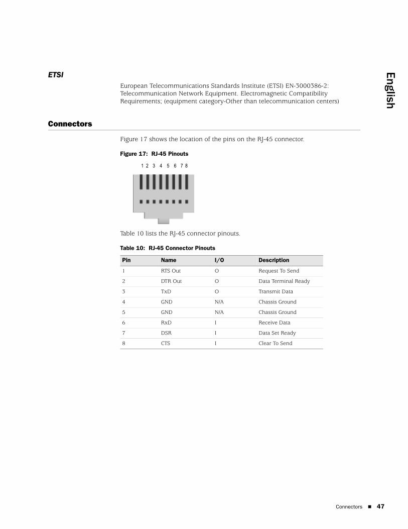
Figure 17 shows the location of the pins on the RJ-45 connector.
Figure 17: RJ-45 Pinouts
Table 10 lists the RJ-45 connector pinouts.
Table 10: RJ-45 Connector Pinouts
Pin Name I/O Description
1 RTS Out O Request To Send
2 DTR Out O Data Terminal Ready
3 TxD O Transmit Data
4 GND N/A Chassis Ground
5 GND N/A Chassis Ground
6 RxD I Receive Data
7 DSR I Data Set Ready
8 CTS I Clear To Send
1 2 3 4 5 6 7 8
Connectors 47

SSG 5 Hardware Installation and Configuration Guide
48
Figure 18 shows the location of the pins on the DB-9 female connector.
Figure 18: DB-9 Female Connector
Table 11 provides the DB-9 connector pinouts.
Table 11: DB-9 Connector Pinouts
Pin Name I/O Description
1 DCD I Carrier Detect
2 RxD I Receive Data
3 TxD O Transmit Data
4 DTR O Data Terminal Ready
5 GND N/A Signal Ground
6 DSR I Data Set Ready
7 RTS O Request To Send
8 CTS I Clear To Send
9 RING I Ring Indicator
Connectors

English
Appendix B
Initial Configuration Wizard
This appendix provides detailed information about the Initial Configuration Wizard (ICW) for an SSG 5 device.
After you have physically connected your device to the network, you can use the ICW to configure the interfaces that are installed on your device.
This section describes the following ICW windows:
1. Rapid Deployment Window on page 50
2. Administrator Login Window on page 50
3. WLAN Access Point Window on page 51
4. Physical Interface Window on page 51
5. ISDN Interface Windows on page 52
6. V.92 Modem Interface Window on page 54
7. Eth0/0 Interface (Untrust Zone) Window on page 55
8. Eth0/1 Interface (DMZ Zone) Window on page 56
9. Bgroup0 Interface (Trust Zone) Window on page 56
10. Wireless0/0 Interface (Trust Zone) Window on page 58
11. Interface Summary Window on page 60
12. Physical Ethernet DHCP Interface Window on page 60
13. Wireless DHCP Interface Window on page 61
14. Confirmation Window on page 61
49

SSG 5 Hardware Installation and Configuration Guide
50
1. Rapid Deployment Window
Figure 19: Rapid Deployment Window
If your network uses NetScreen-Security Manager (NSM), you can use a Rapid Deployment configlet to automatically configure the device. Obtain a configlet from your NSM administrator, select Yes, select Load Configlet from:, browse to the file location, then click Next. The configlet sets up the device for you, so you don’t need to use the following steps to configure the device.
If you want to bypass the ICW and go directly to the WebUI, select the last option, then click Next.
If you are not using a configlet to configure the device and want to use the ICW, select the first option, then click Next. The ICW Welcome screen appears. Click Next. The Administrator Login window appears.
2. Administrator Login WindowEnter a new administrator login name and password, then click Next.
Figure 20: Administrator Login Window

English
3. WLAN Access Point WindowIf you are using the device in the WORLD or ETSI regulatory domain, you must choose a country code. Select the appropriate option, then click Next.
Figure 21: Country Code Window
4. Physical Interface WindowOn the interface-to-zone bindings screen, you set the interface to which you want to bind the Untrust security zone. Bgroup0 is prebound to the Trust security zone. Ethernet0/1 is bound to the DMZ security zone but is optional.
Figure 22: Physical Interface Window
After binding an interface to a zone, you can configure the interface. The configuration windows displayed after this point depend on which SSG 5 device you are using as part of your network. To continue configuring your device with the ICW, click Next.
51

SSG 5 Hardware Installation and Configuration Guide
52
5. ISDN Interface WindowsIf you have one of the ISDN devices, a Physical Layer tab window similar to the following is displayed.
Figure 23: ISDN Physical Layer Tab Window
Table 12: Fields in ISDN Physical Layer Tab Window
Field Description
Switch Type Sets the service provider switch type:
att5e: At&T 5ESS
ntdms100: Nortel DMS 100
ins-net: NTT INS-Net
etsi: European variants
ni1: National ISDN-1
SPID1 Service Provider ID, usually a seven-digit telephone number with some optional numbers. Only the DMS-100 and NI1 switch types require SPIDs. The DMS-100 switch type has two SPIDs assigned, one for each B-channel.
SPID2 Back up service provider ID.
TEI Negotiation Specifies when to negotiate TEI, either at startup or on the first call. Typically this setting is used for ISDN service offerings in Europe and connections to DMS-100 switches that are designed to initiate TEI negotiation.
Calling Number The ISDN network billing number.
Sending Complete checkbox Enables sending of complete information to outgoing setup message. Usually only used in Hong Kong and Taiwan.
English
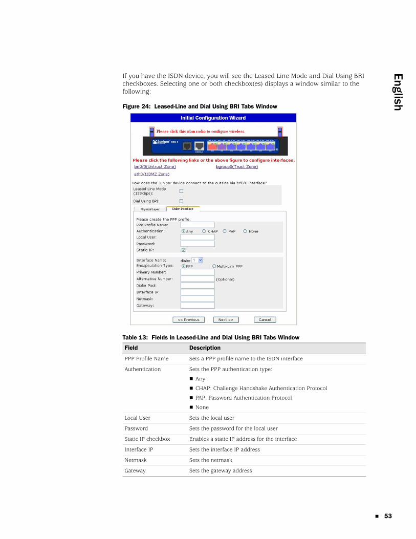
If you have the ISDN device, you will see the Leased Line Mode and Dial Using BRI checkboxes. Selecting one or both checkbox(es) displays a window similar to the following:
Figure 24: Leased-Line and Dial Using BRI Tabs Window
Table 13: Fields in Leased-Line and Dial Using BRI Tabs Window
Field Description
PPP Profile Name Sets a PPP profile name to the ISDN interface
Authentication Sets the PPP authentication type:
Any
CHAP: Challenge Handshake Authentication Protocol
PAP: Password Authentication Protocol
None
Local User Sets the local user
Password Sets the password for the local user
Static IP checkbox Enables a static IP address for the interface
Interface IP Sets the interface IP address
Netmask Sets the netmask
Gateway Sets the gateway address
53

SSG 5 Hardware Installation and Configuration Guide
54
6. V.92 Modem Interface WindowIf you have one of the V.92 devices, the following window is displayed:
Figure 25: V.92 Modem Interface Window
Table 14: Fields in V.92 Modem Interface Window
Field Description
Modem Name Sets the name for the modem interface
Init Strings Sets the initialization string for the modem
ISP Name Assigns a name to the service provider
Primary Number Specifies the phone number to access the service provider
Alternative Number (optional) Specifies an alternative phone number to access the service provider if the primary number does not connect
Login Name Sets the login name for the service provider account
Password Sets the password for the login name

English
7. Eth0/0 Interface (Untrust Zone) WindowThe Untrust zone interface can have a static or a dynamic IP address assigned via DHCP or PPPoE. Insert the necessary information, then click Next.
Figure 26: Eth0/0 Interface Window
Table 15: Fields in Eth0/0 Interface Window
Field Description
Dynamic IP via DHCP Enables the device to receive an IP address for the Untrust zone interface from a service provider.
Dynamic IP via PPPoE Enables the device to act as a PPPoE client, receiving an IP address for the Untrust zone interface from a service provider. Enter the username and password assigned by the service provider.
Static IP Assigns a unique and fixed IP address to the Untrust zone interface. Enter the Untrust zone interface IP address, netmask, and gateway.
55

SSG 5 Hardware Installation and Configuration Guide
56
8. Eth0/1 Interface (DMZ Zone) WindowThe DMZ interface can have a static or a dynamic IP address assigned via DHCP. Insert the necessary information, then click Next.
Figure 27: Eth0/1 Interface Window
Table 16: Fields in Ethernet0/1 Interface Window
9. Bgroup0 Interface (Trust Zone) WindowThe Trust zone interface can have a static or a dynamic IP address assigned via DHCP. Insert the desired information, then click Next.
The default interface IP address is 192.168.1.1 with a netmask of 255.255.255.0 or 24.
Field Description
Dynamic IP via DHCP Enables the device to receive an IP address for the DMZ interface from a service provider.
Static IP Assigns a unique and fixed IP address to the DMZ interface. Enter the DMZ interface IP address and netmask.
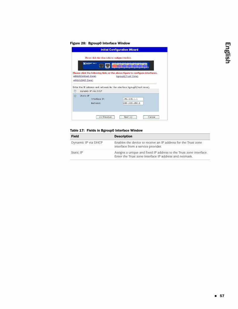
English
Figure 28: Bgroup0 Interface Window
Table 17: Fields in Bgroup0 Interface Window
Field Description
Dynamic IP via DHCP Enables the device to receive an IP address for the Trust zone interface from a service provider.
Static IP Assigns a unique and fixed IP address to the Trust zone interface. Enter the Trust zone interface IP address and netmask.
57

SSG 5 Hardware Installation and Configuration Guide
58
10. Wireless0/0 Interface (Trust Zone) WindowIf you have one of the SSG 5-WLAN devices, you must set a Service Set Identifier (SSID) before the wireless0/0 interface can be activated. For detailed instructions about configuring your wireless interface(s), refer to the Concepts & Examples ScreenOS Reference Guide.
Figure 29: Wireless0/0 Interface Window

English
Table 18: Fields in Wireless0/0 Interface Window
After you have configured the WAN interfaces, you will see the Interface Summary window.
Field Description
Wlan Mode Sets the WLAN radio mode:
5G (802.11a)
2.4G (802.11b/g)
Both (802.11a/b/g)
SSID Sets the SSID name.
Authentication and Encryption Sets the WLAN interface authentication and encryption:
Open authentication, the default, allows anyone to access the device. There is no encryption for this authentication option.
WPA Pre-Shared Key authentication sets the Pre-Shared Key (PSK) or passphrase that must be entered when accessing a wireless connection. You can choose to enter a HEX or an ASCII value for the PSK. A HEX PSK must be a 256-bit (64-text character) HEX value. An ASCII passphrase must be 8 to 63 text characters. You must select Temporal Key Integrity Protocol (TKIP) or Advanced Encryption Standard (AES) as the encryption type for this option, or select Auto to allow either option.
WPA2 Pre-Shared Key.
WPA Auto Pre-Shared Key.
Interface IP Sets the WLAN interface IP address.
Netmask Sets the WLAN interface netmask.
59

SSG 5 Hardware Installation and Configuration Guide
60
11. Interface Summary WindowCheck your interface configuration, then click Next when ready to proceed. The Physical Ethernet DHCP Interface window appears.
12. Physical Ethernet DHCP Interface WindowSelect Yes to enable your device to assign IP addresses to your wired network via DHCP. Enter the IP address range that you want your device to assign to clients using your network.

English
13. Wireless DHCP Interface WindowSelect Yes to enable your device to assign IP addresses to your wireless network via DHCP. Enter the IP address range that you want your device to assign to clients using your network.
14. Confirmation WindowConfirm your device configuration and change as needed. Click Next to save, reboot the device, and run the configuration.
After you click Next, the device reboots with the saved system configuration. The WebUI login prompt appears. For information on how to access the device using the WebUI, refer to “Using the WebUI” on page 25.
61

SSG 5 Hardware Installation and Configuration Guide
62

English
Index
Bbackup interface to Untrust zone ................................33Ccables
basic network connections.....................................20configuration
admin name and password....................................29administrative access ..............................................31backup untrust interface.........................................33bridge groups (bgroup)............................................30date and time ...........................................................30default route .............................................................32host and domain name...........................................32management address..............................................32management services .............................................31USB ............................................................................14WAN interfaces ........................................................37wireless and Ethernet combined ...........................36wireless authentication and encryption................34
connection, basic network ...........................................20
Ddefault IP addresses ......................................................28
Mmanagement
through a console ....................................................24through a Telnet connection ..................................26through the WebUI ..................................................25
management services ...................................................31memory upgrade procedure ........................................41
Rradio transceivers
WLAN 0.....................................................................14WLAN 1.....................................................................14
reset pinhole, using .......................................................40
UUntrust zone, configuring backup interface ...............33
Wwireless
antennae ...................................................................22using the default interface ......................................22
Index 63

64
SSG 5 Hardware Installation and Configuration Guide
Index

Français
Table des matières
À propos du présent guide 5
Organisation ....................................................................................................6Conventions de l’interface utilisateur Web.......................................................6Conventions CLI...............................................................................................7Obtention de la documentation et d’une assistance technique.........................8
Chapitre 1 Présentation matérielle 9
Ports et connecteurs d’alimentation.................................................................9Panneau avant ...............................................................................................10
DEL d’état système..................................................................................10Descriptions des ports....................................................................................12
Ports Ethernet ...................................................................................12Port Console .....................................................................................12Port AUX...........................................................................................13
Panneau arrière .............................................................................................13Adaptateur électrique ..............................................................................13Émetteur-récepteur radio.........................................................................14Œillet du câble de mise à la terre.............................................................14Types d’antennes ....................................................................................14Port USB..................................................................................................14
Chapitre 2 Installation et connexion de l’appareil 17
Avant-propos .................................................................................................18Installation de l’équipement...........................................................................18Connexion des câbles d’interface à un appareil .............................................19Connexion de l’alimentation ..........................................................................20Connexion de l’appareil à un réseau ..............................................................20
Connexion de l’appareil à un réseau non sécurisé ...................................20Ports Ethernet ...................................................................................21Ports série (AUX/Console) .................................................................21Ports de réseau étendu......................................................................21
Connexion de l’appareil à un réseau interne ou un poste de travail .........22Ports Ethernet ...................................................................................22Antennes sans fil...............................................................................22
Chapitre 3 Configuration de l’appareil 23
Accès à l’appareil ...........................................................................................24Utilisation d’une connexion de console ...................................................24Utilisation de l’interface utilisateur Web ..................................................25Utilisation de Telnet.................................................................................26
Paramètres par défaut de l’appareil ...............................................................27
Table des matières 3

4
Guide d’installation et de configuration du matériel SSG 5
Configuration de base de l’appareil ................................................................29Nom et mot de passe de l’administrateur racine .....................................29Date et heure...........................................................................................30Interfaces du groupe pont........................................................................30Accès administratif ..................................................................................31Services de gestion ..................................................................................31Nom d’hôte et nom de domaine..............................................................32Route par défaut......................................................................................32Adresse de l’interface de gestion .............................................................32Configuration de l’interface non sécurisée secondaire .............................33
Configuration sans fil de base ........................................................................33Configuration du réseau étendu .....................................................................37
Interface RNIS .........................................................................................37Interface à modem V.92..........................................................................38
Protections pare-feu de base ..........................................................................39Vérification de la connectivité externe ...........................................................39Restauration des paramètres par défaut de l’appareil ....................................40
Chapitre 4 Entretien de l’appareil 43
Pièces et outils nécessaires ............................................................................43Mise à niveau de la mémoire .........................................................................43
Annexe A Spécifications 47
Spécifications physiques ................................................................................47Spécifications électriques ...............................................................................47Tolérance environnementale..........................................................................48Homologations...............................................................................................48
Sécurité ...................................................................................................48Émissions CEM........................................................................................48Immunité CEM ........................................................................................48ETSI.........................................................................................................49
Connecteurs...................................................................................................49
Annexe B Initial Configuration Wizard 51
Index.......................................................................................................................... 65
Table des matières

Français
À propos du présent guide
L’appareil Secure Services Gateway (SSG) 5 de Juniper Networks est une plate-forme de routeur et de pare-feu intégrée qui offre des services de pare-feu et de réseau privé virtuel IPSec (Internet Protocol Security) à une succursale ou un point de vente.
Juniper Networks propose six modèles de SSG 5 :
SSG 5 Serial
SSG 5 Serial-WLAN
SSG 5 V.92
SSG 5 V.92-WLAN
SSG 5 ISDN
SSG 5 ISDN-WLAN
Tous les appareils SSG 5 prennent en charge un module hôte USB (universal serial bus). Les appareils proposent également des conversions de protocoles entre les réseaux locaux et les réseaux étendus et trois des modèles prennent en charge les réseaux locaux sans fil.
REMARQUE : les exemples et instructions de configuration du présent document sont basés sur les fonctionnalités d’un appareil exécutant ScreenOS 5.4. Selon la version de ScreenOS exécutée, il est possible que votre appareil fonctionne différemment. Pour obtenir la dernière documentation de l’appareil, consultez le site Web de Juniper Networks Technical Publications à l’adresse http://www.juniper.net/techpubs/hardware. Pour connaître les versions de ScreenOS actuellement disponibles pour votre appareil, reportez-vous au site Web de l’assistance de Juniper Networks à l’adresse http://www.juniper.net/customers/support/.
5
Guide d’installation et de configuration du matériel SSG 5
6
Organisation
Le présent guide présente les sections suivantes :
Chapitre 1, « Présentation matérielle, » détaille le châssis et les composants d’un appareil SSG 5.
Chapitre 2, « Installation et connexion de l’appareil, » détaille le montage d’un appareil SSG 5 et sa connexion au réseau.
Chapitre 3, « Configuration de l’appareil, » détaille la configuration et la gestion d’un appareil SSG 5, ainsi que les procédures d’exécution de tâches de configuration de base.
Chapitre 4, « Entretien de l’appareil, » détaille les procédures d’entretien et de maintenance des appareils SSG 5.
Annexe A, « Spécifications, » détaille les spécifications système générales des appareils SSG 5.
Annexe B, « Initial Configuration Wizard, » fournit des informations détaillées au sujet de l’utilisation de l’Initial Configuration Wizard (Assistant de configuration initiale) avec un appareil SSG 5.
Conventions de l’interface utilisateur Web
Pour procéder à une tâche à l’aide de l’interface utilisateur Web, vous devez d’abord accéder à la boîte de dialogue adaptée, dans laquelle vous pouvez ensuite définir les objets et les paramètres. Un chevron (>) indique la séquence de navigation dans l’interface utilisateur Web, séquence que vous suivez en cliquant sur les options de menu et les liens. L’ensemble d’instructions correspondant à chaque tâche est divisé de la manière suivante : un chemin de navigation et des paramètres de configuration.
La figure suivante indique le chemin vers la boîte de dialogue de configuration des adresses, avec les paramètres de configuration suivants :
Objects > Addresses > List > New : saisissez les informations suivantes, puis cliquez sur OK :
Address Name: addr_1IP Address/Domain Name:
IP/Netmask: (sélection), 10.2.2.5/32Zone: Untrust
Organisation

Français
Figure 1 : chemin de navigation et paramètres de configuration
Conventions CLI
Les conventions suivantes sont utilisées pour présenter la syntaxe des commandes CLI dans les exemples et dans le texte.
Dans les exemples :
Les informations présentées entre crochets [ ] sont facultatives.
Les informations présentées entre accolades { } sont obligatoires.
Si plusieurs choix sont possibles, ils sont séparés par un trait vertical ( | ). Par exemple :
set interface { ethernet1 | ethernet2 | ethernet3 } manage
signifie « définir les options de gestion de l’interface ethernet1, ethernet2 ou ethernet3 ».
Les variables sont en italique :
set admin user nom1 password xyz
Dans le texte :
Les commandes sont en gras.
Les variables sont en italique.
REMARQUE : lors de la saisie d’un mot-clé, vous pouvez ne saisir que ses premiers caractères à condition qu’ils permettent d’identifier le mot de manière unique. Par exemple, pour entrer la commande set admin user kathleen j12fmt54, il vous suffit de saisir set adm u kath j12fmt54. Vous pouvez utiliser ce système de saisie rapide pour les commandes. Les commandes détaillées dans cette documentation sont cependant proposées dans leur version intégrale.
Conventions CLI 7

Guide d’installation et de configuration du matériel SSG 5
8
Obtention de la documentation et d’une assistance technique
Pour obtenir de la documentation technique relative à un des produits Juniper Networks, consultez le site www.juniper.net/techpubs/.
Si vous souhaitez obtenir une assistance technique, ouvrez un dossier d’assistance à l’aide du lien Case Manager disponible à l’adresse http://www.juniper.net/support/ ou contactez le 1-888-314-JTAC (aux États-Unis) ou le 1-408-745-9500 (hors des États-Unis).
Si vous trouvez des erreurs ou des omissions dans le présent document, veuillez nous contacter à l’adresse électronique suivante :
Obtention de la documentation et d’une assistance technique

Français
Chapitre 1
Présentation matérielle
Ce chapitre fournit des descriptions détaillées du châssis et des composants de l’appareil SSG 5. Il présente les sections suivantes :
« Ports et connecteurs d’alimentation », page 9
« Panneau avant », page 10
« Panneau arrière », page 13
Ports et connecteurs d’alimentation
Cette section détaille et affiche l’emplacement des connecteurs d’alimentation et des ports intégrés.
Figure 2 : emplacements des ports intégrés
Le Tableau 1 présente les ports et les connecteurs d’alimentation d’un appareil SSG 5.
Tableau 1 : ports et connecteurs d’alimentation d’un appareil SSG 5
SSG 5
V.92
STATUS
POWER
CONSOLE
TX /RX
CD
0 1 2 3 4 5 6TX/RX LINK TX/RX LINK TX/RX LINK TX/RX LINK TX/RX LINK TX/RX LINK TX/RX LINK
10/100 10/100 10/100 10/100 10/100 10/100 10/100
B /G
WLAN V.92
802.11A
0/60/50/40/30/20/10/0
ConsoleAUX, RNIS ou V.92
Port Description Connecteur Vitesse/protocole
0/0-0/6 Permet d’établir une connexion directe avec des postes de travail ou une connexion à un réseau local par l’intermédiaire d’un commutateur ou d’un hub. Cette connexion permet également de gérer l’appareil par l’intermédiaire d’une session Telnet ou de l’interface utilisateur Web.
RJ-45 Ethernet 10/100 Mbits/s
Détection automatique du mode duplex et MDI/MDIX automatique
USB Permet d’établir une connexion USB 1.1 avec le système.
S/O 12M (pleine vitesse) ou 1,5M (vitesse réduite)
Console Permet d’établir une connexion série avec le système. Utilisé pour la connectivité d’émulation du terminal dans le cadre du lancement de sessions CLI.
RJ-45 9 600 bits/s/RS-232C série
Ports et connecteurs d’alimentation 9

Guide d’installation et de configuration du matériel SSG 5
10
Panneau avant
Cette section détaille les éléments suivants du panneau avant d’un appareil SSG 5 :
DEL d’état système
Descriptions des ports
DEL d’état systèmeLes DEL d’état système affichent des informations relatives aux fonctions essentielles de l’appareil. La Figure 3 illustre la position de chaque DEL d’état sur le panneau avant de l’appareil SSG 5 V.92-WLAN. Les DEL système varient en fonction de la version de l’appareil SSG 5.
Figure 3 : DEL d’état
Au démarrage du système, la DEL d’alimentation (POWER) se met à clignoter en vert et la DEL d’état (STATUS) change selon la séquence suivante : rouge, vert, clignotant en vert. Le démarrage nécessite environ deux minutes. Si vous souhaitez mettre le système hors tension, puis de nouveau sous tension, nous vous recommandons d’attendre quelques secondes entre l’arrêt et le redémarrage. Le Tableau 2 présente le type, le nom, la couleur, l’état et la description de chaque DEL d’état système.
AUX Permet d’établir une connexion série asynchrone RS-232 secondaire à Internet par l’intermédiaire d’un modem externe.
RJ-45 9 600 bits/s – 115 Kbits/s/RS-232C série
Modem V.92 Permet d’établir une connexion principale ou secondaire à un fournisseur de services via Internet ou un réseau non sécurisé.
RJ-11 9 600 bits/s – 115 Kbits/s/RS-232 série, détection automatique du mode duplex et de la polarité
RNIS Permet d’utiliser la ligne RNIS comme interface non sécurisée ou secondaire (S/T).
RJ-45 Canaux B à 64 Kbits/s
Ligne louée à 128 Kbits/s
Antennes A et B (SSG 5-WLAN)
Permet d’établir une connexion directe avec des postes de travail se trouvant à proximité d’une connexion radio sans fil.
RPSMA 802.11a (54 Mbits/s sur une bande de signaux radioélectriques de 5 GHz)
802.11b (11 Mbits/s sur une bande de signaux radioélectriques de 2,4 GHz)
802.11g (54 Mbits/s sur une bande de signaux radioélectriques de 2,4 GHz)
802.11 superG (108 Mbits/s sur des bandes de signaux radioélectriques de 2,4 et 5 GHz)
Port Description Connecteur Vitesse/protocole
Panneau avant

Français
Tableau 2 : descriptions des DEL d’état
Type Nom Couleur État Description
POWER Vert Allumée Indique que le système est sous tension.
Éteinte Indique que le système n’est pas sous tension.
Rouge Allumée Indique que l’appareil ne fonctionne pas normalement.
Éteinte Indique que l’appareil fonctionne normalement.
STATUS Vert Allumée Indique que le système est en cours de démarrage ou procède à des diagnostics.
Clignotante Indique que l’appareil fonctionne normalement.
Rouge Clignotante Indique qu’une erreur a été détectée.
Appareils RNIS
CH B1 (CANAL B1)
Vert Allumée Indique que le canal B 1 est actif.
Éteinte Indique que le canal B 1 n’est pas actif.
CH B2 (CANAL B2)
Vert Allumée Indique que le canal B 2 est actif.
Éteinte Indique que le canal B 2 n’est pas actif.
Appareils V.92
HOOK (CONNEXION)
Vert Allumée Indique que la liaison est active.
Éteinte Indique que l’interface série n’est pas en fonctionnement.
TX/RX Vert Clignotante Indique que le trafic est en cours de transfert.
Éteinte Indique que le trafic n’est pas en cours de transfert.
Appareils de réseau étendu
802.11A Vert Allumée Indique qu’une connexion sans fil est établie mais qu’il n’y a pas d’activité de liaison.
Clignotante Indique qu’une connexion sans fil est établie. Le débit en bauds est proportionnel à l’activité de la liaison.
Éteinte Indique qu’aucune connexion sans fil n’a été établie.
B/G Vert Allumée Indique qu’une connexion sans fil est établie mais qu’il n’y a pas d’activité de liaison.
Clignotante Indique qu’une connexion sans fil est établie. Le débit en bauds est proportionnel à l’activité de la liaison.
Éteinte Indique qu’aucune connexion sans fil n’a été établie.
Panneau avant 11

Guide d’installation et de configuration du matériel SSG 5
12
Descriptions des ports
Cette section détaille l’objectif et le fonctionnement des éléments suivants :
Ports Ethernet
Port Console
Port AUX
Ports EthernetSept ports Ethernet 10/100 permettent d’établir des connexions de réseau local à des hubs, commutateurs, serveurs locaux et postes de travail. Vous pouvez également utiliser un port Ethernet dans le cadre de la gestion du trafic. Les ports sont numérotés de 0/0 à 0/6. Reportez-vous à la section « Paramètres par défaut de l’appareil », page 27 pour connaître les liaisons de zone par défaut de chaque port Ethernet.
Lors de la configuration d’un de ces ports, reportez-vous au nom d’interface correspondant à l’emplacement du port. Les noms d’interface des ports sont numérotés, de gauche à droite sur le panneau avant, de ethernet0/0 à ethernet0/6.
La Figure 4 affiche l’emplacement des DEL de chaque port Ethernet.
Figure 4 : DEL de liaison d’activité
Le Tableau 3 détaille les DEL des ports Ethernet.
Tableau 3 : DEL des ports Ethernet
Port ConsoleLe port Console est un port série RJ-45 câblé comme un équipement de terminaison de circuit de données et qui peut être utilisé dans le cadre de l’administration locale. Utilisez un câble direct lors de la connexion à un terminal et un câble de raccords croisés lors de la connexion à un autre équipement de terminaison de circuit de données. Un adaptateur RJ-45/DB-9 est fourni.
Reportez-vous à la section « Connecteurs », page 49 pour les schémas de brochage des connecteurs RJ-45.
Nom Couleur État Description
LINK Vert Allumée
Éteinte
Le port est en ligne.
Le port est hors ligne.
TX/RX Vert Clignotante
Éteinte
Le trafic est en cours de transfert. Le débit en bauds est proportionnel à l’activité de la liaison.
Il est possible que le port soit actif, il ne reçoit cependant pas de données.
LINK (LIAISON)TX/RX
Descriptions des ports

Français
Port AUXLe port auxiliaire (AUX) est un port série RJ-45 câblé comme un équipement terminal de traitement de données et qui peut être connecté à un modem de manière à permettre l’administration à distance. Nous ne vous recommandons pas d’utiliser ce port dans le cadre de l’administration à distance normale. Le port AUX est généralement attribué à l’interface série secondaire. Le débit en bauds peut être compris entre 9 600 et 115 200 bits/s et nécessite un contrôle de flux matériel. Utilisez un câble direct lors de la connexion à un modem et un câble de raccords croisés lors de la connexion à un autre équipement terminal de traitement de données.
Reportez-vous à la section « Connecteurs », page 49 pour les schémas de brochage des connecteurs RJ-45.
Panneau arrière
Cette section détaille les éléments suivants du panneau arrière d’un appareil SSG 5 :
Adaptateur électrique
Émetteur-récepteur radio
Œillet du câble de mise à la terre
Types d’antennes
Port USB
Figure 5 : panneau arrière d’un appareil SSG 5
Adaptateur électriqueLa DEL POWER située sur le panneau avant de l’appareil est allumée en vert ou éteinte. L’allumage en vert indique un fonctionnement correct, l’extinction de la DEL indique une anomalie de l’adaptateur électrique ou que l’appareil est éteint.
REMARQUE : seuls les appareils SSG 5-WLAN disposent de connecteurs à antenne.
RESETDC POWER
LOCK
USBSD FLASHB A5V A4
Adaptateur électrique
Module hôte USBŒillet du câble de
mise à la terre
Trou d’épingle de réinitialisation
Antenne AAntenne B
Panneau arrière 13

Guide d’installation et de configuration du matériel SSG 5
14
Émetteur-récepteur radioLes appareils SSG 5-WLAN disposent de deux émetteurs-récepteurs radio à connectivité sans fil, qui prennent en charge les normes 802.11a/b/g. Le premier émetteur-récepteur (WLAN 0) utilise la bande de signaux radioélectriques de 2,4 GHz, qui prend en charge la norme 802.11b à 11 Mbit/s et la norme 802.11g à 54 Mbit/s. Le deuxième émetteur-récepteur (WLAN 1) utilise la bande de signaux radioélectriques de 5 GHz, qui prend en charge la norme 802.11a à 54 Mbit/s. Les deux bandes de signaux radioélectriques peuvent fonctionner simultanément. Pour plus d’informations au sujet de la configuration de la bande de signaux radioélectriques sans fil, reportez-vous à la section « Configuration sans fil de base », page 33.
Œillet du câble de mise à la terreL’arrière du châssis est équipé d’un œillet de mise à la terre qui permet de relier l’appareil à la terre (reportez-vous à la Figure 5).
Pour mettre l’appareil à la terre avant de raccorder l’alimentation, vous devez connecter un câble de mise à la terre à la terre, puis fixer le câble à l’œillet situé à l’arrière du châssis.
Types d’antennesLes appareils SSG 5-WLAN prennent en charge trois types d’antennes radio spéciales :
Antennes de diversité — les antennes de diversité présentent une couverture bidirectionnelle de 2 dBi et un niveau relativement uniforme d’intensité du signal au sein de la zone de couverture. Elles sont adaptées à la plupart des installations. Ce type d’antennes est livré avec l’appareil.
Antenne omnidirectionnelle externe — l’antenne externe dispose d’une couverture omnidirectionnelle de 2 dBi. Contrairement aux antennes de diversité, qui fonctionnent par paire, l’antenne externe supprime l’effet d’écho qui est parfois généré par des caractéristiques de réception du signal légèrement retardées lors de l’utilisation de deux antennes.
Antenne directionnelle externe — l’antenne directionnelle externe dispose d’une couverture unidirectionnelle de 2 dBi et est adaptée aux lieux tels que les couloirs et les murs extérieurs (avec l’antenne orientée vers l’intérieur).
Port USBLe port USB situé sur le panneau arrière de l’appareil SSG 5 accepte les périphériques de stockage USB (universal serial bus) ou les adaptateurs de périphériques de stockage USB avec disque CompactFlash intégré, comme indiqué dans la Spécification CompactFlash publiée par la CompactFlash Association. Lorsque le périphérique de stockage USB est installé et configuré, il sert automatiquement d’appareil de démarrage secondaire en cas d’anomalie du disque CompactFlash principal lors du démarrage.
Panneau arrière

Français
Le port USB permet de transférer des fichiers, tels que des configurations de l’appareil ou des certifications utilisateur, et de mettre les images des versions à jour entre un périphérique de stockage USB externe et l’emplacement de stockage Flash interne, situé dans l’appareil de sécurité. Le port USB prend en charge la spécification USB 1.1 lorsque le transfert de fichiers a lieu à faible vitesse (1,5M) ou à vitesse élevée (12M).
Procédez comme suit pour transférer des fichiers entre le périphérique de stockage USB et l’appareil SSG 5 :
1. Insérez le périphérique de stockage USB dans le port USB de l’appareil de sécurité.
2. Enregistrez les fichiers du périphérique de stockage USB dans l’emplacement de stockage Flash interne de l’appareil à l’aide de la commande CLI save {software | config | image-key} from usb nomdefichier to flash.
3. Avant de retirer le périphérique de stockage USB, arrêtez le port USB à l’aide de la commande CLI exec usb-device stop.
4. Vous pouvez désormais retirer le périphérique de stockage USB en toute sécurité.
Si vous souhaitez supprimer un fichier du périphérique de stockage USB, utilisez la commande CLI delete file usb:/nomdefichier.
Si vous souhaitez afficher les informations relatives aux fichiers enregistrés sur le périphérique de stockage USB ou au niveau de l’emplacement de stockage Flash interne, utilisez la commande CLI get file.
Panneau arrière 15

Guide d’installation et de configuration du matériel SSG 5
16
Panneau arrière
Français
Chapitre 2
Installation et connexion de l’appareil
Ce chapitre détaille la procédure de montage de l’appareil SSG 5 et de connexion des câbles et de l’alimentation à l’appareil. Ce chapitre présente les sections suivantes :
« Avant-propos », page 18
« Installation de l’équipement », page 18
« Connexion des câbles d’interface à un appareil », page 19
« Connexion de l’alimentation », page 20
« Connexion de l’appareil à un réseau », page 20
REMARQUE : pour les instructions et consignes de sécurité, reportez-vous au manuel Juniper Networks Security Products Safety Guide. Avant de travailler sur les équipements, vous devez vous renseigner au sujet des risques présentés par les circuits électriques et vous familiariser avec les pratiques standard de prévention des accidents.
17

Guide d’installation et de configuration du matériel SSG 5
18
Avant-propos
L’emplacement du châssis, la disposition de l’équipement de montage et la sécurité de votre local électrique sont essentiels au bon fonctionnement du système.
Afin de prévenir toute blessure corporelle et d’éviter toute défaillance ou panne du matériel, prennez les précautions suivantes :
Avant installation, vérifiez toujours que le bloc d’alimentation n’est raccordé à aucune source d’alimentation.
Assurez-vous que la pièce dans laquelle vous utilisez l’appareil présente une ventilation adaptée et que la température de la pièce ne dépasse pas 40 °C (104 °F).
Ne placez pas l’appareil dans une baie d’installation de matériel qui obstrue les orifices d’entrée et d’échappement de l’air. Assurez-vous que les baies fermées disposent de ventilateurs et de fentes sur les côtés.
Rectifiez les situations à risques suivantes avant toute installation : sols humides ou mouillés, fuites, câbles d’alimentation non mis à la terre ou dénudés ou absence de mise à la terre de sécurité.
Installation de l’équipement
Vous pouvez installer les appareils SSG 5 de manière frontale, sur un mur ou sur un bureau. Les kits de montage sont disponibles séparément.
Dans le cadre de l’installation d’un appareil SSG 5, un tournevis cruciforme numéro 2 (non fourni) et des vis compatibles avec la baie de matériel (incluses dans le kit) sont nécessaires.
Procédez comme suit pour installer un appareil SSG 5 dans une baie :
1. Dévissez les supports de montage du plateau à l’aide d’un tournevis cruciforme.
2. Alignez la partie inférieure de l’appareil sur les orifices de base du plateau.
3. Tirez l’appareil pour l’enclencher dans les orifices de base du plateau.
AVERTISSEMENT : pour empêcher tout abus ou toute intrusion de personnes non autorisées, installez l’appareil SSG 5 dans un environnement sécurisé.
REMARQUE : lors de l’installation d’un appareil, assurez-vous qu’il se trouve à portée de la prise électrique.
REMARQUE : les utilisateurs de l’appareil SSG 5-WLAN disposant d’antennes en option doivent retirer les antennes existantes, puis raccorder la nouvelle antenne via l’orifice latéral.
Avant-propos

Français
4. Fixez les supports de montage sur l’appareil et le plateau à l’aide des vis.
5. Placez le bloc d’alimentation dans le support de bloc d’alimentation, puis branchez l’adaptateur électrique dans l’appareil.
6. Pour installer un deuxième appareil SSG 5, répétez les étapes 1 à 5, puis poursuivez.
Figure 6 : montage en baie de l’appareil SSG 5
7. Installez le plateau sur la baie à l’aide des vis fournies.
8. Branchez le bloc d’alimentation dans la prise électrique.
Procédez comme suit pour installer un appareil SSG 5 sur un bureau :
1. Fixez le support du bureau sur le côté de l’appareil. Nous vous recommandons d’utiliser le côté situé le plus près de l’adaptateur électrique.
2. Placez l’appareil installé sur le bureau.
Figure 7 : installation de l’appareil SSG 5 sur un bureau
3. Branchez l’adaptateur électrique et raccordez le bloc d’alimentation à une prise électrique.
Connexion des câbles d’interface à un appareil
Procédez comme suit pour connecter les câbles d’interface à l’appareil :
1. Préparez une certaine longueur du type de câble utilisé par l’interface.
2. Insérez le connecteur de câble dans le port de connecteur de câble de l’appareil.
3. Disposez le câble de la manière suivante afin d’éviter qu’il ne se détache ou qu’il ne développe des points de tension :
Support de bloc d’alimentation
Support de bloc d’alimentation
Connexion des câbles d’interface à un appareil 19

Guide d’installation et de configuration du matériel SSG 5
20
a. Fixez le câble de manière à ce qu’il ne soutienne pas son propre poids lorsqu’il est suspendu.
b. Placez le surplus de câble dans une boucle bien enroulée de manière à ce que le câble ne soit pas gênant.
c. Placez des éléments de fixation sur la boucle de manière à ce qu’elle conserve sa forme.
Connexion de l’alimentation
Procédez comme suit pour raccorder l’appareil à l’alimentation :
1. Insérez la fiche CC située à l’extrémité du câble d’alimentation dans la prise d’alimentation CC située à l’arrière de l’appareil.
2. Branchez la fiche CA située à l’autre extrémité du câble d’alimentation dans une source d’alimentation CA.
Connexion de l’appareil à un réseau
Lorsqu’ils sont placés entre les réseaux internes et le réseau non sécurisé, les appareils SSG 5 assurent des fonctions de pare-feu et de sécurité générale conçues pour les réseaux. Cette section détaille les éléments suivants :
Connexion de l’appareil à un réseau non sécurisé
Connexion de l’appareil à un réseau interne ou un poste de travail
Connexion de l’appareil à un réseau non sécuriséVous pouvez connecter l’appareil SSG 5 à un réseau non sécurisé de l’une des manières suivantes :
Ports Ethernet
Ports série (AUX/Console)
Ports de réseau étendu
La Figure 8 présente l’appareil SSG 5 avec les connexions de câblage réseau de base lorsque les ports Ethernet 10/100 sont reliés de la manière suivante :
Le port portant la mention 0/0 (interface ethernet0/0) est connecté au réseau non sécurisé.
Le port portant la mention 0/1 (interface ethernet0/1) est connecté à un poste de travail de la zone de sécurité DMZ.
AVERTISSEMENT : nous vous recommandons d’installer un dispositif de protection contre les surtensions sur votre branchement électrique.
Connexion de l’alimentation

Français
Le port portant la mention 0/2 (interface bgroup0) est connecté à un poste de travail de la zone de sécurité Trust.
Le port Console est connecté à un terminal série afin de permettre l’accès aux fonctions de gestion.
Figure 8 : exemple de mise en réseau de base
Ports EthernetAfin d’établir une connexion à haut débit, reliez le port Ethernet portant la mention 0/0 d’un appareil SSG 5 au routeur externe à l’aide du câble Ethernet fourni. L’appareil détecte automatiquement les paramètres de vitesse, du mode duplex et MDI/MDIX corrects.
Ports série (AUX/Console)Vous pouvez vous connecter au réseau non sécurisé à l’aide d’un câble série RJ-45 direct et d’un modem externe.
Ports de réseau étendu1. Préparez une certaine longueur du type de câble utilisé par l’interface.
2. Insérez le connecteur de câble dans le port de connecteur de câble de l’appareil.
3. Disposez le câble de la manière suivante afin d’éviter qu’il ne se détache ou qu’il ne développe des points de tension :
a. Fixez le câble de manière à ce qu’il ne soutienne pas son propre poids lorsqu’il est suspendu.
b. Placez le surplus de câble dans une boucle bien enroulée de manière à ce que le câble ne soit pas gênant.
c. Utilisez des éléments de fixation pour maintenir la forme des boucles de câble.
SSG 5
V.92
STATUS
POWER
CONSOLE
TX /RX
CD
0 1 2 3 4 5 6TX/RX LINK TX/RX LINK TX/RX LINK TX/RX LINK TX/RX LINK TX/RX LINK TX/RX LINK
10/100 10/100 10/100 10/100 10/100 10/100 10/100
B /G
WLAN V.92
802.11A
Callouts
Zone Untrust
ConsoleDMZ
Zone Trust
AVERTISSEMENT : veillez à ne pas connecter par inadvertance les ports Console, AUX ou Ethernet de l’appareil à la prise de téléphone.
Connexion de l’appareil à un réseau 21

Guide d’installation et de configuration du matériel SSG 5
22
Connexion de l’appareil à un réseau interne ou un poste de travailVous pouvez connecter votre réseau local ou votre poste de travail à l’aide des interfaces Ethernet et/ou sans fil.
Ports EthernetLes appareils SSG 5 disposent de sept ports Ethernet. Vous pouvez utiliser un ou plusieurs de ces ports pour connecter l’appareil à des réseaux locaux via des commutateurs ou des hubs. Vous pouvez également connecter directement l’un ou tous les ports aux postes de travail et éliminer ainsi la nécessité d’utiliser un hub ou un commutateur. Pour connecter les ports Ethernet à d’autres appareils, vous pouvez utiliser des câbles de raccord croisés ou des câbles directs. Reportez-vous à la section « Paramètres par défaut de l’appareil », page 27 pour consulter les liaisons interface/zone par défaut.
Antennes sans filSi vous utilisez l’interface sans fil, vous devez connecter les antennes fournies à l’appareil. Si vous disposez des antennes de diversité 2 dB standard, fixez-les sur les montants A et B situés à l’arrière de l’appareil à l’aide de vis. Courbez les antennes au niveau des coudes, en veillant à ne pas appuyer sur les répartiteurs de câblage.
Figure 9 : emplacement des antennes de l’appareil SSG 5-WLAN
Si vous utilisez l’antenne externe en option, suivez les instructions de connexion fournies avec l’antenne.
RESETDC POWER
LOCK
USBSD FLASHB A5V A4
Répartiteur de câblageRépartiteur de câblage
Antenne B Antenne A
Connexion de l’appareil à un réseau

Français
Chapitre 3
Configuration de l’appareil
Le logiciel ScreenOS est installé de manière préalable dans les appareils SSG 5. Lors de la mise sous tension de l’appareil, ce dernier est prêt à être configuré. L’appareil dispose d’une configuration par défaut définie en usine qui permet de procéder à la connexion initiale de l’appareil. Une configuration supplémentaire adaptée à vos exigences réseau spécifiques est cependant nécessaire.
Ce chapitre présente les sections suivantes :
« Accès à l’appareil », page 24
« Paramètres par défaut de l’appareil », page 27
« Configuration de base de l’appareil », page 29
« Configuration sans fil de base », page 33
« Configuration du réseau étendu », page 37
« Protections pare-feu de base », page 39
« Vérification de la connectivité externe », page 39
« Restauration des paramètres par défaut de l’appareil », page 40
REMARQUE : une fois l’appareil configuré et la connectivité vérifiée via le réseau distant, vous devez enregistrer le produit à l’adresse www.juniper.net/support/ de manière à ce que certains services ScreenOS, tels que le service de signatures Deep Inspection et l’antivirus (disponibles séparément), puissent être activés dans l’appareil. Une fois votre produit enregistré, utilisez l’interface utilisateur Web pour obtenir un abonnement au service de votre choix. Pour plus d’informations au sujet de l’enregistrement de votre produit et de l’obtention d’abonnements pour des services spécifiques, reportez-vous au volume Fundamentals du manuel Concepts & Examples ScreenOS Reference Guide correspondant à la version de ScreenOS exécutée dans l’appareil.
23

Guide d’installation et de configuration du matériel SSG 5
24
Accès à l’appareil
Vous pouvez configurer et gérer un appareil SSG 5 de différentes manières :
Console : le port Console de l’appareil permet d’accéder à l’unité par l’intermédiaire d’un câble série connecté à votre poste de travail ou terminal. Pour configurer l’appareil, saisissez des commandes CLI (interface de ligne de commande) ScreenOS sur votre terminal ou dans un programme d’émulation de terminal exécuté sur votre poste de travail.
Interface utilisateur Web : l’interface utilisateur Web de ScreenOS est une interface graphique disponible par l’intermédiaire d’un navigateur. Dans le cadre de l’utilisation initiale de l’interface utilisateur Web, le poste de travail sur lequel vous exécutez le navigateur doit être situé dans le même sous-réseau que l’appareil. Vous pouvez également accéder à l’interface utilisateur Web par l’intermédiaire d’un serveur sécurisé utilisant le protocole (SSL) avec un protocole HTTP sécurisé (S-HTTP).
Telnet/SSH : Telnet et SSH sont des applications permettant d’accéder à des appareils par l’intermédiaire d’un réseau IP. Pour configurer l’appareil, saisissez des commandes CLI (interface de ligne de commande) ScreenOS dans une session Telnet depuis votre poste de travail. Pour plus d’informations, reportez-vous au volume Administration du manuel Concepts & Examples ScreenOS Reference Guide.
NetScreen-Security Manager : NetScreen-Security Manager est une application de gestion de Juniper Networks à l’échelle des entreprises qui permet de contrôler et de gérer les appareils de réseau privé virtuel IPSec/de pare-feu de Juniper Networks. Pour obtenir des instructions relatives à la procédure de gestion de l’appareil à l’aide de NetScreen-Security Manager, reportez-vous au manuel NetScreen-Security Manager Administrator’s Guide.
Utilisation d’une connexion de console
Procédez comme suit pour établir une connexion de console :
1. Connectez la fiche femelle de l’adaptateur DB-9 fourni au port série de votre poste de travail (veillez à ce que le connecteur DB-9 soit inséré correctement et fermement). La Figure10 illustre le type de connecteur DB-9 nécessaire.
REMARQUE : utilisez un câble série RJ-45 direct de catégorie 5 avec un connecteur RJ-45 mâle lors de la connexion au port Console de l’appareil.
Accès à l’appareil

Français
Figure 10 : adaptateur DB-9
2. Connectez la fiche mâle du câble série RJ-45 de catégorie 5 au port Console de l’appareil SSG 5 (veillez à ce que l’autre fiche du câble de catégorie 5 soit insérée correctement et fermement dans l’adaptateur DB-9).
3. Lancez un programme d’émulation de terminal série sur votre poste de travail. Les paramètres nécessaires au lancement d’une session de console sont les suivants :
Débit (en bauds) : 9600
Parité : aucune
Bits de données : 8
Bit d’arrêt : 1
Contrôle de flux : aucun
4. Si vous n’avez pas encore modifié les nom d’utilisateur et mot de passe par défaut, saisissez netscreen aux invites de connexion et de mot de passe (n’utilisez que des lettres minuscules, les champs du nom de connexion et du mot de passe respectent tous deux la casse).
Pour obtenir des informations relatives à la configuration de l’appareil à l’aide des commandes CLI, reportez-vous au manuel Concepts & Examples ScreenOS Reference Guide.
5. (Facultatif) Par défaut, la session de la console arrive à expiration et s’arrête automatiquement après 10 minutes d’inactivité. Pour désactiver le délai d’expiration, saisissez set console timeout 0.
Utilisation de l’interface utilisateur WebDans le cadre de l’utilisation de l’interface utilisateur Web, le poste de travail à partir duquel vous gérez l’appareil doit initialement être situé dans le même sous-réseau que l’appareil. Procédez comme suit pour accéder à l’appareil à l’aide de l’interface utilisateur Web :
1. Connectez le poste de travail au port 0/2 — 0/6 (interface bgroup0 de la zone Trust) de l’appareil.
2. Assurez-vous que le poste de travail est configuré pour le protocole DHCP (Dynamic Host Configuration Protocol) ou est configuré de manière statique avec une adresse IP du sous-réseau 192.168.1.0/24.
Prise RJ-45
Adaptateur DB-9
Câble RJ-45
Accès à l’appareil 25

Guide d’installation et de configuration du matériel SSG 5
26
3. Lancez le navigateur, saisissez l’adresse IP de l’interface bgroup0 (l’adresse IP par défaut est 192.168.1.1/24), puis appuyez sur Entrée.
L’interface utilisateur Web affiche l’invite de connexion représentée à la Figure 11.
Figure 11 : invite de connexion de l’interface utilisateur Web
4. Si vous n’avez pas encore modifié les nom d’administrateur et mot de passe par défaut, saisissez netscreen aux invites de connexion et de mot de passe (n’utilisez que des lettres minuscules, les champs du nom de connexion et du mot de passe respectent tous deux la casse).
Utilisation de TelnetProcédez comme suit pour établir une connexion Telnet :
1. Connectez le poste de travail au port 0/2 — 0/6 (interface bgroup0 de la zone Trust) de l’appareil.
2. Assurez-vous que le poste de travail est configuré pour le protocole DHCP ou est configuré de manière statique avec une adresse IP du sous-réseau 192.168.1.0/24.
3. Démarrez une application cliente Telnet sur l’adresse IP de l’interface bgroup0 (l’adresse IP par défaut est 192.168.1.1). Saisissez, par exemple, telnet 192.168.1.1.
L’application Telnet affiche l’invite de connexion.
4. Si vous n’avez pas encore modifié les nom d’utilisateur et mot de passe par défaut, saisissez netscreen aux invites de connexion et de mot de passe (n’utilisez que des lettres minuscules, les champs du nom de connexion et du mot de passe respectent tous deux la casse).
5. (Facultatif) Par défaut, la session de la console arrive à expiration et s’arrête automatiquement après 10 minutes d’inactivité. Pour désactiver le délai d’expiration, saisissez set console timeout 0.
REMARQUE : si vous accédez pour la première fois à l’appareil par l’intermédiaire de l’interface utilisateur Web, l’Initial Configuration Wizard (Assistant de configuration initiale) apparaît. Si vous souhaitez configurer l’appareil à l’aide de l’Initial Configuration Wizard, reportez-vous à la section « Initial Configuration Wizard », page 51.
Accès à l’appareil

Français
Paramètres par défaut de l’appareil
Cette section détaille les paramètres par défaut et le fonctionnement d’un appareil SSG 5.
Le Tableau 4 présente les liaisons de zones par défaut des ports des appareils.
Tableau 4 : interface physique par défaut des liaisons de zones
Le groupe pont (bgroup) permet aux utilisateurs réseau de commuter entre le trafic câblé et le trafic sans fil sans devoir reconfigurer ou redémarrer l’appareil. Par défaut, les interfaces ethernet0/2 — ethernet0/6, portant les mentions ports 0/2 — 0/6 sur l’appareil, sont regroupées en tant qu’interface bgroup0, disposent de l’adresse IP 192.168.1.1/24 et sont reliées à la zone de sécurité Trust. Vous pouvez configurer un maximum de quatre groupes bgroup.
Si vous souhaitez placer une interface Ethernet ou sans fil dans un groupe bgroup, vous devez d’abord vous assurer que l’interface Ethernet ou sans fil se trouve dans la zone de sécurité Null. Si vous retirez l’interface Ethernet ou sans fil du groupe bgroup, elle est placée dans la zone de sécurité Null. Une fois attribuée à la zone de sécurité Null, l’interface Ethernet peut être reliée à une zone de sécurité et une autre adresse ID peut lui être attribuée.
Mention attribuée au port Interface Zone
Ports Ethernet 10/100 :
0/0 ethernet0/0 Untrust
0/1 ethernet0/1 DMZ
0/2 bgroup0 (ethernet0/2) Trust
0/3 bgroup0 (ethernet0/3) Trust
0/4 bgroup0 (ethernet0/4) Trust
0/5 bgroup0 (ethernet0/5) Trust
0/6 bgroup0 (ethernet0/6) Trust
AUX serial0/0 Null
Ports de réseau étendu :
RNIS bri0/0 Untrust
V.92 serial0/0 Null
Paramètres par défaut de l’appareil 27

Guide d’installation et de configuration du matériel SSG 5
28
Pour retirer l’interface ethernet0/3 du groupe bgroup0 et la placer dans la zone Trust avec l’adresse IP statique 192.168.3.1/24, utilisez l’interface utilisateur Web ou les commandes CLI de la manière suivante :
WebUI
Network > Interfaces > List > Edit (bgroup0) > Bind Port : désélectionnez ethernet0/3, puis cliquez sur Apply.
List > Edit (ethernet0/3) : saisissez les informations suivantes, puis cliquez sur Apply :
Zone Name: Trust (sélection)IP Address/Netmask: 192.168.3.1/24
CLI
unset interface bgroup0 port ethernet0/3set interface ethernet0/3 zone trustset interface ethernet0/3 ip 192.168.3.1/24save
Tableau 5 : liaisons des interfaces sans fil et des interfaces logiques
Vous pouvez modifier l’adresse IP par défaut de l’interface bgroup0 conformément aux adresses de votre réseau local et de votre réseau local sans fil. Pour configurer l’interface sans fil d’un groupe bgroup, reportez-vous à la section « Configuration sans fil de base », page 33.
Pour obtenir des informations supplémentaires au sujet du groupe bgroup et des exemples, reportez-vous au manuel Concepts & Examples ScreenOS Reference Guide.
Aucune autre adresse IP par défaut n’est configurée sur les autres interfaces Ethernet ou sans fil de l’appareil. Vous devez définir les adresses IP des autres interfaces, interfaces de réseau étendu incluses.
SSG 5-WLAN Interface Zone
Interface sans fil
Définit une interface sans fil qui peut être configurée de manière à fonctionner sur des bandes de signaux radioélectriques de 2,4 G et/ou 5 G.
wireless0/0 (l’adresse IP par défaut est 192.168.2.1/24)
Trust
wireless0/1-0/3. Null
Interfaces logiques
Interface de couche 2 vlan1 fait référence aux interfaces logiques utilisées pour la gestion et l’arrêt de trafic du réseau privé virtuel lorsque l’appareil est en mode transparent.
S/O
Interfaces tunnel tunnel.n fait référence à une interface tunnel logique. Cette interface est destinée au trafic de réseau privé virtuel.
S/O
REMARQUE : l’interface bgroup ne fonctionne pas en mode transparent lorsqu’elle inclut une interface sans fil.
Paramètres par défaut de l’appareil

Français
Configuration de base de l’appareil
Cette section détaille les paramètres de configuration de base suivants :
Nom et mot de passe de l’administrateur racine
Date et heure
Interfaces du groupe pont
Accès administratif
Services de gestion
Nom d’hôte et nom de domaine
Route par défaut
Adresse de l’interface de gestion
Configuration de l’interface non sécurisée secondaire
Nom et mot de passe de l’administrateur racineL’administrateur racine dispose de tous les droits nécessaires à la configuration des appareils SSG 5. Nous vous recommandons de modifier immédiatement le nom et le mot de passe par défaut de l’administrateur racine (tous deux netscreen).
Pour modifier le nom et le mot de passe de l’administrateur racine, utilisez l’interface utilisateur Web ou les commandes CLI de la manière suivante :
WebUI
Configuration > Admin > Administrators > Edit (pour le nom de l’administrateur) : saisissez les informations suivantes, puis cliquez sur OK :
Administrator Name:Old Password: netscreenNew Password:Confirm New Password:
CLI
set admin name nomset admin password motdepassesave
REMARQUE : les mots de passe ne sont pas affichés dans l’interface utilisateur Web.
Configuration de base de l’appareil 29

Guide d’installation et de configuration du matériel SSG 5
30
Date et heureL’heure définie dans un appareil SSG 5 affecte des événements tels que la configuration des tunnels de réseau privé virtuel. Le moyen le plus simple pour régler la date et l’heure de l’appareil consiste à utiliser l’interface utilisateur Web pour synchroniser l’horloge système de l’appareil sur l’horloge du poste de travail.
Pour configurer la date et l’heure d’un appareil, utilisez l’interface utilisateur Web ou les commandes CLI de la manière suivante :
WebUI
1. Configuration > Date/Time : cliquez sur le bouton Sync Clock with Client.
Un message contextuel s’affiche, invitant à préciser si l’option de passage à l’heure d’été a été activée au niveau de l’horloge de votre poste de travail.
2. Cliquez sur Yes pour synchroniser l’horloge système et la régler en tenant compte de l’heure d’été ou sur No pour synchroniser l’horloge système sans tenir compte de l’heure d’été.
Vous pouvez également utiliser la commande CLI set clock dans une session Telnet ou de console afin de saisir manuellement la date et l’heure de l’appareil.
Interfaces du groupe pontPar défaut, l’appareil SSG 5 dispose des interfaces Ethernet ethernet0/2—ethernet0/4, regroupées dans la zone de sécurité Trust. Le fait de regrouper les interfaces les place dans un sous-réseau. Vous pouvez retirer une interface d’un groupe et l’affecter à une autre zone de sécurité. Avant d’être affectées à un groupe, les interfaces doivent se trouver dans la zone de sécurité Null. Pour placer une interface regroupée dans la zone de sécurité Null, utilisez la commande CLI unset interface interface port interface.
Les appareils SSG 5-WLAN permettent de regrouper des interfaces Ethernet et sans fil dans un même sous-réseau.
Pour configurer un groupe disposant d’interfaces Ethernet et sans fil, utilisez l’interface utilisateur Web ou les commandes CLI de la manière suivante :
WebUI
Network > Interfaces > List > Edit (bgroup0) > Bind Port : désélectionnez ethernet0/3 et ethernet0/4, puis cliquez sur Apply.
Edit (bgroup1) > Bind Port : sélectionnez ethernet0/3, ethernet0/4 et wireless0/2, puis cliquez sur Apply.
>Basic : saisissez les informations suivantes, puis cliquez sur Apply :
Zone Name: DMZ (sélection)IP Address/Netmask: 10.0.0.1/24
REMARQUE : seules les interfaces Ethernet et sans fil peuvent être placées dans un groupe bgroup.
Configuration de base de l’appareil

Français
CLI
unset interface bgroup0 port ethernet0/3unset interface bgroup0 port ethernet0/4set interface bgroup1 port ethernet0/3set interface bgroup1 port ethernet0/4set interface bgroup1 port wireless0/2set interface bgroup1 zone DMZset interface bgroup1 ip 10.0.0.1/24save
Accès administratifPar défaut, tous les utilisateurs connectés à votre réseau peuvent gérer l’appareil dès lors qu’ils en connaissent le nom de connexion et le mot de passe. Pour configurer l’appareil de manière à ce qu’il ne puisse être géré qu’à partir d’un hôte spécifique du réseau, utilisez l’interface utilisateur Web ou les commandes CLI de la manière suivante :
WebUI
Configuration > Admin > Permitted IPs : saisissez les informations suivantes, puis cliquez sur Add :
IP Address/Netmask: adr_ip/masque
CLI
set admin manager-ip adr_ip/masquesave
Services de gestionScreenOS propose des services de configuration et de gestion de l’appareil, tels que SNMP, SSL et SSH, que vous pouvez activer en fonction de l’interface. Pour configurer les services de gestion de l’appareil, utilisez l’interface utilisateur Web ou les commandes CLI de la manière suivante :
WebUI
Network > Interfaces > List > Edit (pour l’interface ethernet0/0) : sous Management Services, activez les services de gestion à utiliser dans l’interface, puis cliquez sur Apply.
CLI
set interface ethernet0/0 manage webunset interface ethernet0/0 manage snmpsave
Configuration de base de l’appareil 31

Guide d’installation et de configuration du matériel SSG 5
32
Nom d’hôte et nom de domaineLe nom de domaine définit le réseau ou le sous-réseau auquel appartient l’appareil tandis que le nom d’hôte fait référence à un appareil spécifique. Le nom d’hôte et le nom de domaine permettent d’identifier ensemble de manière unique l’appareil au sein du réseau. Pour configurer le nom d’hôte et le nom de domaine d’un appareil, utilisez l’interface utilisateur Web ou les commandes CLI de la manière suivante :
WebUI
Network > DNS > Host : saisissez les informations suivantes, puis cliquez sur Apply :
Host Name: nomDomain Name: nom
CLI
set hostname nomset domain nomsave
Route par défautLa route par défaut est une route statique utilisée pour diriger les paquets adressés à des réseaux qui ne figurent pas de manière explicite dans le tableau de routage. Si un paquet arrive dans l’appareil et dispose d’une adresse pour laquelle l’appareil ne dispose d’aucune information de routage, ce dernier envoie le paquet à la destination définie par la route par défaut. Pour configurer la route par défaut de l’appareil, utilisez l’interface utilisateur Web ou les commandes CLI de la manière suivante :
WebUI
Network > Routing > Destination > New (trust-vr) : saisissez les informations suivantes, puis cliquez sur OK :
IP Address/Netmask: 0.0.0.0/0.0.0.0Next Hop
Gateway: (sélection)Interface: ethernet0/2 (sélection)Gateway IP Address: adr_ip
CLIset route 0.0.0.0/0 interface ethernet0/2 gateway adr_ipsave
Adresse de l’interface de gestionL’interface Trust dispose de l’adresse IP par défaut 192.168.1.1/24 et est configurée pour les services de gestion. Si vous connectez les ports 0/2—0/4 de l’appareil à un poste de travail, vous pouvez configurer l’appareil à partir d’un poste de travail du sous-réseau 192.168.1.1/24, à l’aide d’un service de gestion tel que Telnet.
Vous pouvez modifier l’adresse IP par défaut de l’interface Trust. Vous pouvez, par exemple, modifier l’interface conformément aux adresses IP qui existent déjà sur le réseau local.
Configuration de base de l’appareil

Français
Configuration de l’interface non sécurisée secondaireL’appareil SSG 5 permet de configurer une interface secondaire en cas de défaillance de l’interface non sécurisée. Procédez comme suit pour définir une interface secondaire, utilisée en cas de défaillance de l’interface non sécurisée :
1. Placez l’interface secondaire dans la zone de sécurité Null à l’aide de la commande CLI unset interface interface [ port interface ].
2. Reliez l’interface secondaire à la même zone de sécurité que l’interface principale à l’aide de la commande CLI set interface interface zone nom_zone.
Pour définir l’interface ethernet0/4 comme interface secondaire de l’interface ethernet0/0, utilisez l’interface utilisateur Web ou les commandes CLI de la manière suivante :
WebUI
Network > Interfaces > Backup > : saisissez les informations suivantes, puis cliquez sur Apply.
Primary: ethernet0/0Backup: ethernet0/4Type: track-ip (sélection)
CLI
unset interface bgroup0 port ethernet0/4set interface ethernet0/4 zone untrustset interface ethernet0/0 backup interface ethernet0/4 type track-ipsave
Configuration sans fil de base
Cette section fournit des informations relatives à la configuration de l’interface sans fil de l’appareil SSG 5-WLAN. Les réseaux sans fil sont désignés par des noms SSID (Service Set Identifiers). La définition des SSID permet de disposer de plusieurs réseaux sans fil au même emplacement sans que ceux-ci n’interfèrent les uns avec les autres. Un nom SSID peut compter un maximum de 32 caractères. Si le nom SSID inclut une espace, la chaîne de caractères doit être placée entre guillemets. Une fois le nom SSID défini, vous pouvez configurer d’autres attributs SSID. Pour bénéficier des capacités de réseau local sans fil de l’appareil, vous devez configurer au moins un SSID et le relier à une interface sans fil.
L’appareil SSG 5-WLAN permet de créer un maximum de 16 SSID. Cependant, seuls quatre peuvent être utilisés simultanément. Vous pouvez configurer l’appareil de manière à ce que les quatre SSID soient utilisés dans le même émetteur-récepteur ou répartir l’utilisation entre les deux émetteurs-récepteurs (trois SSID attribués au
REMARQUE : l’interface principale et l’interface secondaire doivent se trouver dans la même zone de sécurité. L’interface principale ne dispose que d’une seule interface secondaire et l’interface secondaire que d’une seule interface principale.
Configuration sans fil de base 33

Guide d’installation et de configuration du matériel SSG 5
34
réseau local sans fil 0 et un SSID attribué au réseau local sans fil 1, par exemple). Utilisez la commande CLI set interface interface_sans_fil wlan { 0 | 1 | both } pour régler les émetteurs-récepteurs radio de l’appareil SSG 5-WLAN. La Figure 12 présente la configuration par défaut de l’appareil SSG 5-WLAN.
Une fois un SSID défini sur l’interface wireless0/0, vous pouvez accéder à l’appareil à l’aide de l’adresse IP par défaut de l’interface wireless0/0 (voir les étapes de la section « Accès à l’appareil », page 24).
Figure 12 : configuration par défaut de l’appareil SSG 5-WLAN
L’interface wireless0/0 est configurée par défaut avec l’adresse IP 192.168.2.1/24. Tous les clients sans fil qui doivent se connecter à la zone Trust doivent disposer d’une adresse IP au sein du sous-réseau sans fil. Vous pouvez également configurer l’appareil de manière à ce qu’il utilise le protocole DHCP pour attribuer automatiquement à vos appareils des adresses IP au sein du sous-réseau 192.168.2.1/24.
Par défaut, les interfaces wireless0/1 – wireless0/3 sont définies comme Null et ne disposent d’aucune adresse IP. Si vous souhaitez utiliser une des autres interfaces sans fil, vous devez configurer une adresse IP pour l’interface, lui attribuer un SSID et la relier à une zone de sécurité. Le Tableau 6 présente les méthodes de chiffrement et d’authentification sans fil.
REMARQUE : si vous utilisez l’appareil SSG 5-WLAN dans un pays autre que les États-Unis, le Japon, le Canada, la Chine, Taïwan, la Corée, Israël ou Singapour, vous devez utiliser la commande CLI set wlan country-code ou la définir dans la page Wireless > General Settings de l’interface utilisateur WebUI avant de pouvoir établir une connexion du type réseau local sans fil. Cette commande définit la plage de canaux disponibles et le niveau de puissance émise.
Si le code de votre région est ETSI, vous devez définir le code national adapté aux réglementations locales en matière de spectre des radiofréquences.
SSG 5
V.92
STATUS
POWER
CONSOLE
TX /RX
CD
0 1 2 3 4 5 6TX/RX LINK TX/RX LINK TX/RX LINK TX/RX LINK TX/RX LINK TX/RX LINK TX/RX LINK
10/100 10/100 10/100 10/100 10/100 10/100 10/100
B /G
WLAN V.92
802.11A
Callouts
CalloutsZone Untrust
Zone Trust
wireless0/0
Console
Configuration sans fil de base

Français
Tableau 6 : options de chiffrement et d’authentification sans fil
Pour obtenir des exemples de configuration, ainsi que des informations sur les attributs SSID et les commandes CLI relatives aux configurations de sécurité sans fil, reportez-vous au manuel Concepts & Examples ScreenOS Reference Guide.
Pour configurer une interface sans fil dans le cadre de la connectivité de base, utilisez l’interface utilisateur Web ou les commandes CLI de la manière suivante :
WebUI
1. Définissez le code national et l’adresse IP du réseau local sans fil.
Wireless > General Settings > sélectionnez les éléments suivants, puis cliquez sur Apply :
Country code: sélection de votre codeIP Address/Netmask: adr_ip/masque_réseau
2. Définissez le SSID.
Wireless > SSID > New : saisissez les informations suivantes, puis cliquez sur OK :
SSID: Authentication: Encryption: Wireless Interface Binding:
3. (Facultatif) Définissez la clé WEP.
SSID > WEP Keys : sélectionnez l’identifiant de la clé, puis cliquez sur Apply.
4. Définissez le mode du réseau local sans fil.
Network > Interfaces > List > Edit (interface sans fil) : sélectionnez Both pour le mode du réseau local sans fil, puis cliquez sur Apply.
5. Activez les modifications apportées à l’interface sans fil.
Wireless > General Settings > cliquez sur Activate Changes.
Authentification Chiffrement
Ouverte Permet à n’importe quel client sans fil d’accéder à l’appareil.
Clé partagée Clé partagée WEP
WPA-PSK AES/TKIP avec une clé partagée au préalable
WPA AES/TKIP avec une clé du serveur RADIUS
WPA2-PSK Compatible 802.11i avec une clé partagée au préalable
WPA2 Compatible 802.11i avec un serveur RADIUS
WPA-Auto-PSK Type WPA ou WPA2 avec une clé partagée au préalable
WPA-Auto Type WPA ou WPA2 avec un serveur RADIUS
802.1x WEP avec une clé du serveur RADIUS
Configuration sans fil de base 35

Guide d’installation et de configuration du matériel SSG 5
36
CLI
1. Définissez le code national et l’adresse IP du réseau local sans fil.
set wlan country-code { code_id }set interface interface_sansfil ip adr_ip/masque_réseau
2. Définissez le SSID.
set ssid name nomset ssid name_str authentication type_auth encryption type_chiffrementset ssid nom interface interface(Facultatif) set ssid nom key-id numéro
3. Définissez le mode du réseau local sans fil.
set interface interface_sansfil wlan both
4. Activez les modifications apportées à l’interface sans fil.
saveexec wlan reactivate
Vous pouvez configurer le SSID de manière à ce qu’il fonctionne au sein du même sous-réseau que le sous-réseau câblé. Cette action permet aux clients de travailler dans une interface ou de l’autre sans devoir se connecter à un autre sous-réseau.
Pour placer une interface Ethernet et une interface sans fil dans la même interface de groupe pont, utilisez l’interface utilisateur Web ou les commandes CLI :
WebUI
Network > Interfaces > List > Edit (nom_bgroup) > Bind Port : sélectionnez les interfaces sans fil et Ethernet, puis cliquez sur Apply.
CLI
set interface nom_bgroup port interface_sansfilset interface nom_bgroup port interface_ethernet
REMARQUE : nom_bgroup peut être bgroup0—bgroup3.
interface_ethernet peut être ethernet0/0—ethernet0/6.
interface_sansfil peut être wireless0/0—wireless0/3.
Si une interface sans fil est configurée, vous devez réactiver le réseau local sans fil à l’aide de la commande CLI exec wlan reactivate ou cliquer sur Activate Changes dans la page Wireless > General Settings de l’interface utilisateur Web.
Configuration sans fil de base

Français
Configuration du réseau étendu
Cette section indique comment configurer les interfaces de réseau étendu suivantes :
Interface RNIS
Interface à modem V.92
Interface RNISLe réseau numérique à intégration de services (RNIS) est un ensemble de normes pour la transmission numérique via différents supports créées par le CCITT (Consultative Committee for International Telegraphy and Telephone) et l’ITU (International Telecommunications Union). En tant que service de connexion à la demande, il dispose d’un temps d’établissement des communications réduit et d’un faible délai de transit. Il est également en mesure de procéder à des transmissions de vidéos, de données et de la voix de haute qualité. Le RNIS est également un service de commutation de circuits qui peut être utilisé pour les connexions point à point et connexions à points multiples. Le RNIS propose un routeur de services avec une connexion PPP (Point-to-Point Protocol) à liaisons multiples pour les interfaces réseau. L’interface RNIS est généralement configurée en tant qu’interface secondaire de l’interface Ethernet permettant d’accéder à des réseaux externes.
Pour configurer l’interface RNIS, utilisez l’interface utilisateur Web ou les commandes CLI :
WebUI
Network > Interfaces > List > Edit (bri0/0) : saisissez ou sélectionnez les éléments suivants, puis cliquez sur OK :
BRI Mode: Dial Using BRIPrimary Number: 123456WAN Encapsulation: PPPPPP Profile: isdnprofile
CLI
set interface bri0/0 dialer-enableset interface bri0/0 primary-number "123456"set interface bri0/0 encap pppset interface bri0/0 ppp profile isdnprofilesave
Pour configurer l’interface RNIS en tant qu’interface secondaire, reportez-vous à la section « Configuration de l’interface non sécurisée secondaire », page 33.
Pour plus d’informations au sujet de la configuration de l’interface RNIS, reportez-vous au manuel Concepts & Examples ScreenOS Reference Guide.
Configuration du réseau étendu 37
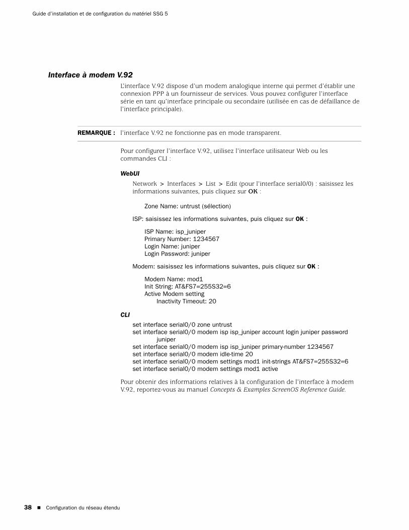
Guide d’installation et de configuration du matériel SSG 5
38
Interface à modem V.92L’interface V.92 dispose d’un modem analogique interne qui permet d’établir une connexion PPP à un fournisseur de services. Vous pouvez configurer l’interface série en tant qu’interface principale ou secondaire (utilisée en cas de défaillance de l’interface principale).
Pour configurer l’interface V.92, utilisez l’interface utilisateur Web ou les commandes CLI :
WebUI
Network > Interfaces > List > Edit (pour l’interface serial0/0) : saisissez les informations suivantes, puis cliquez sur OK :
Zone Name: untrust (sélection)
ISP: saisissez les informations suivantes, puis cliquez sur OK :
ISP Name: isp_juniperPrimary Number: 1234567Login Name: juniperLogin Password: juniper
Modem: saisissez les informations suivantes, puis cliquez sur OK :
Modem Name: mod1Init String: AT&FS7=255S32=6Active Modem setting
Inactivity Timeout: 20
CLI
set interface serial0/0 zone untrustset interface serial0/0 modem isp isp_juniper account login juniper password
juniperset interface serial0/0 modem isp isp_juniper primary-number 1234567set interface serial0/0 modem idle-time 20set interface serial0/0 modem settings mod1 init-strings AT&FS7=255S32=6set interface serial0/0 modem settings mod1 active
Pour obtenir des informations relatives à la configuration de l’interface à modem V.92, reportez-vous au manuel Concepts & Examples ScreenOS Reference Guide.
REMARQUE : l’interface V.92 ne fonctionne pas en mode transparent.
Configuration du réseau étendu

Français
Protections pare-feu de base
Les appareils sont configurés avec une règle par défaut qui permet aux postes de travail qui se trouvent dans la zone Trust de votre réseau d’accéder aux ressources de la zone de sécurité Untrust alors que les ordinateurs extérieurs à votre réseau ne sont pas autorisés à accéder ou à démarrer des sessions à l’aide de vos postes de travail. Vous pouvez configurer des règles de sécurité de façon à ce que l’appareil autorise les ordinateurs extérieurs à votre réseau à initier des sessions de type spécifique avec vos ordinateurs. Pour obtenir des informations au sujet de la création ou de la modification des règles, reportez-vous au manuel Concepts & Examples ScreenOS Reference Guide.
L’appareil SSG 5 dispose de différentes méthodes de détection et de différents mécanismes de défense pour lutter contre les vérifications et attaques dont l’objectif est de compromettre ou de nuire à un réseau ou à une ressource du réseau :
Les options SCREEN de ScreenOS sécurisent une zone en vérifiant, puis en autorisant ou en refusant, l’ensemble des tentatives de connexion qui nécessitent le transit vers la zone en question par l’intermédiaire d’une interface. Vous pouvez, par exemple, activer une protection par interrogation des ports dans la zone Untrust de manière à empêcher la source d’un réseau distant d’identifier les services à cibler en vue de futures attaques.
L’appareil applique des règles de pare-feu, qui peuvent inclure des composants de filtrage du contenu et de détection et de prévention des intrusions, au trafic qui passe d’une zone à l’autre via les filtres SCREEN. Par défaut, aucun trafic n’est autorisé à passer d’une zone à l’autre par l’intermédiaire de l’appareil. Pour autoriser le passage du trafic d’une zone à l’autre par l’intermédiaire de l’appareil, vous devez créer une règle qui annule le comportement par défaut.
Pour définir les options SCREEN de ScreenOS d’une zone, utilisez l’interface utilisateur Web ou les commandes CLI de la manière suivante :
WebUI
Screening > Screen : sélectionnez la zone à laquelle les options s’appliquent. Sélectionnez les options SCREEN souhaitées, puis cliquez sur Apply.
CLI
set zone zone screen optionsave
Pour plus d’informations au sujet de la configuration des options de sécurité réseau disponibles sous ScreenOS, reportez-vous au volume Attack Detection and Defense Mechanisms du manuel Concepts & Examples ScreenOS Reference Guide.
Vérification de la connectivité externe
Afin de vérifier que les postes de travail connectés à votre réseau sont en mesure d’accéder aux ressources sur Internet, lancez un navigateur sur n’importe quel poste de travail connecté à votre réseau et saisissez l’adresse URL suivante : www.juniper.net.
Protections pare-feu de base 39

Guide d’installation et de configuration du matériel SSG 5
40
Restauration des paramètres par défaut de l’appareil
Si vous égarez votre mot de passe d’administrateur, vous pouvez restaurer les paramètres par défaut de l’appareil. Cette action écrase les configurations existantes mais restaure l’accès à l’appareil.
Procédez de l’une des manières suivantes pour restaurer les paramètres par défaut de l’appareil :
À l’aide d’une connexion de console. Pour plus d’informations, reportez-vous au volume Administration du manuel Concepts & Examples ScreenOS Reference Guide.
Par l’intermédiaire du trou d’épingle de réinitialisation situé sur le panneau arrière de l’appareil, comme décrit dans la section suivante.
Vous pouvez réinitialiser l’appareil et en restaurer les paramètres par défaut en appuyant sur le bouton situé dans le trou d’épingle de réinitialisation. Pour effectuer cette opération, vous devez soit consulter les DEL d’état situées sur le panneau avant de l’appareil, soit ouvrir une session de console comme indiqué dans la section Utilisation d’une connexion de console page 24.
Procédez comme suit pour réinitialiser l’appareil et restaurer les paramètres par défaut à l’aide du trou d’épingle de réinitialisation :
1. Repérez le trou d’épingle de réinitialisation situé sur le panneau arrière de l’appareil. En utilisant un fil de fer fin et rigide (un trombone déplié, par exemple), appuyez sur le bouton situé dans le trou d’épingle pendant quatre à six secondes, puis relâchez-le.
La DEL STATUS clignote en rouge. Un message s’affiche sur la console, indiquant que la suppression de la configuration a commencé, et le système transmet une alerte SNMP/SYSLOG.
2. Patientez une à deux secondes.
Après la première réinitialisation, la DEL STATUS clignote en vert, l’appareil attend maintenant la deuxième réinitialisation. Le message de la console indique maintenant que l’unité attend une deuxième confirmation.
3. Appuyez de nouveau sur le bouton situé dans le trou d’épingle de réinitialisation pendant quatre à six secondes.
Le message de la console valide la seconde réinitialisation. La DEL STATUS s’allume en rouge pendant une demi-seconde, puis retourne à l’état clignotant vert.
AVERTISSEMENT : la réinitialisation de l’appareil supprime tous les paramètres de configuration existants et désactive les services de pare-feu et de réseau privé virtuel existants.
Restauration des paramètres par défaut de l’appareil

Français
L’appareil est maintenant réinitialisé et ses paramètres par défaut ont été restaurés. Lorsque l’appareil se réinitialise, la DEL STATUS s’allume en rouge pendant une demi-seconde, puis s’allume en vert. La console affiche les messages d’amorçage de l’appareil. Le système génère des alertes SNMP et SYSLOG aux hôtes de déroutements SYSLOG ou SNMP configurés.
Une fois l’appareil redémarré, la console affiche l’invite de connexion à l’appareil. La DEL STATUS clignote en vert. Le nom de connexion et le mot de passe sont netscreen.
Si vous ne suivez pas la procédure entière, le processus de réinitialisation s’interrompt et le message affiché sur la console indique que l’effacement de la configuration est annulé. La DEL STATUS clignote de nouveau en vert. Si l’appareil n’a pas été réinitialisé, une alerte SNMP est transmise afin de confirmer l’échec de la procédure.
Restauration des paramètres par défaut de l’appareil 41

Guide d’installation et de configuration du matériel SSG 5
42
Restauration des paramètres par défaut de l’appareil
Français
Chapitre 4
Entretien de l’appareil
Ce chapitre détaille les procédures d’entretien et de maintenance des appareils SSG 5. Il présente les sections suivantes :
« Pièces et outils nécessaires », cette page
« Mise à niveau de la mémoire », cette page
Pièces et outils nécessaires
Pour remplacer un composant de l’appareil SSG 5, vous devez disposer des pièces et outils suivants :
Bracelet de mise à la terre contre les décharges électrostatiques
Tournevis cruciforme, 1/8 po
Mise à niveau de la mémoire
Vous pouvez procéder à la mise à niveau d’un appareil SSG 5 d’une mémoire vive
dynamique à module de mémoire à double rangée de connexions de 128 Moà 256 Mo.
Procédez comme suit pour mettre la mémoire d’un appareil SSG 5 à niveau :
1. Fixez un bracelet de mise à la terre contre les décharges électrostatiques sur votre poignet nu et raccordez le bracelet au point de décharge électrostatique du châssis ou à un point de décharge électrostatique extérieur (si l’appareil n’est pas mis à la terre).
2. Débranchez le cordon CA de la prise électrique.
REMARQUE : pour connaître les instructions et consignes de sécurité, reportez-vous au manuel Juniper Networks Security Products Safety Guide. Les instructions du manuel vous mettent en garde vis-à-vis des situations susceptibles d’entraîner des blessures. Avant de travailler sur les équipements, vous devez vous renseigner au sujet des risques présentés par les circuits électriques et vous familiariser avec les pratiques standard de prévention des accidents.
Pièces et outils nécessaires 43

Guide d’installation et de configuration du matériel SSG 5
44
3. Retournez l’appareil de manière à ce que sa partie supérieure repose sur une surface plane.
4. Retirez les vis du couvercle de la carte mémoire à l’aide d’un tournevis cruciforme. Conservez les vis à proximité de vous afin de pouvoir remettre le couvercle en place par la suite.
5. Retirez le couvercle de la carte mémoire.
Figure 13 : partie inférieure de l’appareil
6. Retirez la mémoire vive dynamique à module de mémoire à double rangée de connexions de 128 Mo en plaçant les pouces sur la partie extérieure des onglets de verrouillage situés de chaque côté du module de manière à les libérer du module.
Figure 14 : déverrouillage du module de mémoire
7. Saisissez par le côté long le module de mémoire et faites glisser le module vers l’extérieur. Mettez le module de côté.
Mise à niveau de la mémoire

Français
Figure 15 : dépose du module
8. Insérez la mémoire vive dynamique à module de mémoire à double rangée de connexions de 256 Mo dans le connecteur. À l’aide des deux pouces, exercez une pression uniforme sur la partie supérieure du module, puis appuyez sur le module jusqu’à ce que les onglets de verrouillage s’enclenchent.
Figure 16 : insertion du module de mémoire
9. Replacez le couvercle de la carte mémoire sur le connecteur.
10. Fixez le couvercle sur l’appareil en serrant les vis à l’aide du tournevis cruciforme.
Mise à niveau de la mémoire 45

Guide d’installation et de configuration du matériel SSG 5
46
Mise à niveau de la mémoire
Français
Annexe A
Spécifications
Cette annexe détaille les spécifications système générales de l’appareil SSG 5. Elle présente les sections suivantes :
« Spécifications physiques », cette page
« Spécifications électriques », cette page
« Tolérance environnementale », page 48
« Homologations », page 48
« Connecteurs », page 49
Spécifications physiques
Tableau 7 : spécifications physiques de l’appareil SSG 5
Spécifications électriques
Tableau 8 : spécifications électriques de l’appareil SSG 5
Description Valeur
Dimensions du châssis 222,5 mm x 143,4 mm x 35 mm. Avec les pieds en caoutchouc, la hauteur du système est de 40 mm (1,6 po).
(8,8 po x 5,6 po x 1,4 po)
Poids de l’appareil 960 g (2,1 lb)
Élément Spécification
Tension d’entrée CC 5,5 V
Courant nominal système CC 4 A
Spécifications physiques 47

Guide d’installation et de configuration du matériel SSG 5
48
Tolérance environnementale
Tableau 9 : tolérance environnementale de l’appareil SSG 5
Homologations
SécuritéCAN/CSA-C22.2 n°60950-1-03/UL 60950-1 troisième édition, sécurité des équipements informatiques
EN 60950-1:2001+A11, sécurité des équipements informatiques
IEC 60950-1:2001 première édition, sécurité des équipements informatiques
Émissions CEMFCC article 15 catégorie B (États-Unis)
EN 55022 catégorie B (Europe)
AS 3548 catégorie B (Australie)
VCCI catégorie B (Japon)
Immunité CEMEN 55024
EN-61000-3-2, harmonique des lignes électriques
EN-61000-3-3, harmonique des lignes électriques
EN-61000-4-2, immunité aux décharges électrostatiques
EN-61000-4-3, immunité aux rayonnements électromagnétiques
EN-61000-4-4, immunité aux transitoires rapides en salves
EN-61000-4-5, immunité à l’onde de choc (foudre)
EN-61000-4-6, immunité commune aux basses fréquences
EN-61000-4-11, immunité aux creux et variations de tension
Description Valeur
Altitude Aucune baisse de performances jusqu’à 2 000 mètres (6 600 pi)
Humidité relative Fonctionnement normal garanti avec une plage d’humidité relative comprise entre 5 et 90 %, sans condensation
Température Fonctionnement normal garanti avec une plage de températures comprise entre 0 °C (32 °F) et 40 °C (104 °F)
Température de stockage dans le carton d’expédition : -40 °C (-40 °F) à 70 °C (158 °F)
Tolérance environnementale

Français
ETSIEN-3000386-2 ETSI (European Telecommunications Standards Institute) : équipements des réseaux de télécommunication. Exigences en matière de compatibilité électromagnétique, (catégorie d’équipements - autre que les centres de télécommunication)
Connecteurs
La Figure 17 indique l’emplacement des broches sur le connecteur RJ-45.
Figure 17 : schémas de brochage RJ-45
Le Tableau 10 répertorie les broches des connecteurs RJ-45.
Tableau 10 : broches des connecteurs RJ-45
Broche Nom E/S Description
1 RTS Out S Demande d’émission
2 DTR Out S Terminal prêt
3 TxD S Transmission de données
4 GND S/O Mise à la terre du châssis
5 GND S/O Mise à la terre du châssis
6 RxD E Réception de données
7 DSR E Modem prêt
8 CTS E Prêt à émettre
1 2 3 4 5 6 7 8
Connecteurs 49

Guide d’installation et de configuration du matériel SSG 5
50
La Figure 18 indique l’emplacement des broches sur le connecteur femelle DB-9.
Figure 18 : connecteur femelle DB-9
Le Tableau 11 répertorie les broches des connecteurs DB-9.
Tableau 11 : broches des connecteurs DB-9
Broche Nom E/S Description
1 DCD E Détection de porteuse
2 RxD E Réception de données
3 TxD S Transmission de données
4 DTR S Terminal prêt
5 GND S/O Mise à la terre du signal
6 DSR E Modem prêt
7 RTS S Demande d’émission
8 CTS E Prêt à émettre
9 RING E Indicateur d’appel
Connecteurs

Français
Annexe B
Initial Configuration Wizard
Cette annexe fournit des informations détaillées au sujet de l’Initial Configuration Wizard (Assistant de configuration initiale) d’un appareil SSG 5.
Une fois l’appareil physiquement connecté au réseau, vous pouvez utiliser l’Initial Configuration Wizard pour configurer les interfaces installées sur l’appareil.
Cette section présente les fenêtres suivantes de l’Initial Configuration Wizard :
1. Fenêtre de déploiement rapide page 52
2. Fenêtre de connexion de l’administrateur page 52
3. Fenêtre du point d’accès au réseau local sans fil page 53
4. Fenêtre de l’interface physique page 53
5. Fenêtres de l’interface RNIS page 54
6. Fenêtre de l’interface à modem V.92 page 56
7. Fenêtre de l’interface eth0/0 (zone Untrust) page 57
8. Fenêtre de l’interface eth0/1 (zone DMZ) page 58
9. Fenêtre de l’interface bgroup0 (zone Trust) page 58
10. Fenêtre de l’interface wireless0/0 (zone Trust) page 60
11. Fenêtre du récapitulatif de l’interface page 62
12. Fenêtre de l’interface DHCP Ethernet physique page 62
13. Fenêtre de l’interface DHCP sans fil page 63
14. Fenêtre de confirmation page 63
51

Guide d’installation et de configuration du matériel SSG 5
52
1. Fenêtre de déploiement rapide
Figure 19 : fenêtre de déploiement rapide
Si le réseau utilise NetScreen-Security Manager (NSM), vous pouvez configurer automatiquement l’appareil à l’aide d’un configlet de déploiement rapide. Demandez un configlet à votre administrateur NSM, sélectionnez Yes, sélectionnez Load Configlet from:, accédez à l’emplacement du fichier, puis cliquez sur Next. Le configlet procède à la configuration de l’appareil à votre place, il ne vous est donc pas nécessaire d’utiliser la procédure suivante pour configurer l’appareil.
Si vous souhaitez contourner l’Initial Configuration Wizard et accéder directement à l’interface utilisateur Web, sélectionnez la dernière option, puis cliquez sur Next.
Si vous ne configurez pas l’appareil à l’aide d’un configlet et souhaitez utiliser l’Initial Configuration Wizard, sélectionnez la première option, puis cliquez sur Next. L’écran de bienvenue de l’Initial Configuration Wizard s’affiche. Cliquez sur Next. La fenêtre de connexion de l’administrateur s’affiche.
2. Fenêtre de connexion de l’administrateurSaisissez un nouveau nom et un nouveau mot de passe d’administrateur, puis cliquez sur Next.
Figure 20 : fenêtre de connexion de l’administrateur

Français
3. Fenêtre du point d’accès au réseau local sans filSi vous utilisez l’appareil dans le domaine réglementaire WORLD ou ETSI, vous devez sélectionner un code national. Sélectionnez l’option adaptée, puis cliquez sur Next.
Figure 21 : fenêtre du code national
4. Fenêtre de l’interface physiqueDans l’écran des liaisons interface/zone, sélectionnez l’interface à laquelle vous souhaitez relier la zone de sécurité Untrust. Le groupe bgroup0 est préalablement relié à la zone de sécurité Trust. L’interface ethernet0/1 est reliée à la zone de sécurité DMZ mais est facultative.
Figure 22 : fenêtre de l’interface physique
Une fois l’interface reliée à une zone, vous pouvez la configurer. Les fenêtres de configuration affichées à partir de là varient en fonction de l’appareil SSG 5 utilisé dans le cadre de votre réseau. Pour poursuivre la configuration de l’appareil à l’aide de l’Initial Configuration Wizard, cliquez sur Next.
53
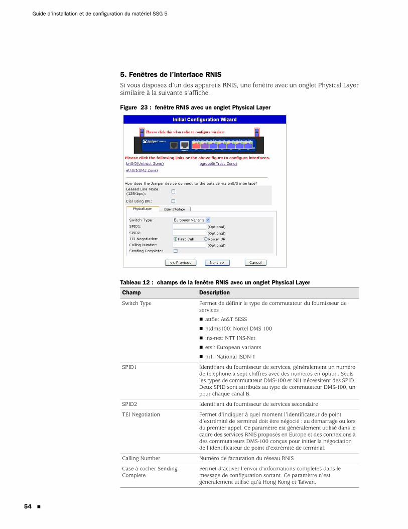
Guide d’installation et de configuration du matériel SSG 5
54
5. Fenêtres de l’interface RNISSi vous disposez d’un des appareils RNIS, une fenêtre avec un onglet Physical Layer similaire à la suivante s’affiche.
Figure 23 : fenêtre RNIS avec un onglet Physical Layer
Tableau 12 : champs de la fenêtre RNIS avec un onglet Physical Layer
Champ Description
Switch Type Permet de définir le type de commutateur du fournisseur de services :
att5e: At&T 5ESS
ntdms100: Nortel DMS 100
ins-net: NTT INS-Net
etsi: European variants
ni1: National ISDN-1
SPID1 Identifiant du fournisseur de services, généralement un numéro de téléphone à sept chiffres avec des numéros en option. Seuls les types de commutateur DMS-100 et NI1 nécessitent des SPID. Deux SPID sont attribués au type de commutateur DMS-100, un pour chaque canal B.
SPID2 Identifiant du fournisseur de services secondaire
TEI Negotiation Permet d’indiquer à quel moment l’identificateur de point d’extrémité de terminal doit être négocié : au démarrage ou lors du premier appel. Ce paramètre est généralement utilisé dans le cadre des services RNIS proposés en Europe et des connexions à des commutateurs DMS-100 conçus pour initier la négociation de l’identificateur de point d’extrémité de terminal.
Calling Number Numéro de facturation du réseau RNIS
Case à cocher Sending Complete
Permet d’activer l’envoi d’informations complètes dans le message de configuration sortant. Ce paramètre n’est généralement utilisé qu’à Hong Kong et Taïwan.

Français
Si vous disposez d’un appareil RNIS, les cases à cocher Leased Line Mode et Dial Using BRI apparaissent. Le fait de sélectionner une ou les deux cases à cocher affiche une fenêtre similaire à la suivante :
Figure 24 : fenêtre avec les onglets Leased-Line et Dial Using BRI
Tableau 13 : champs de la fenêtre avec les onglets Leased-Line et Dial Using BRI
Champ Description
PPP Profile Name Permet de définir un nom de profil PPP dans l’interface RNIS.
Authentication Permet de définir le type d’authentification PPP :
Any
CHAP : Challenge Handshake Authentication Protocol
PAP : Password Authentication Protocol
None
Local User Permet de définir l’utilisateur local.
Password Permet de définir le mot de passe de l’utilisateur local.
Case à cocher Static IP Permet d’activer une adresse IP statique pour l’interface.
Interface IP Permet de définir l’adresse IP de l’interface.
Netmask Permet de définir le masque de réseau.
Gateway Permet de définir l’adresse de la passerelle.
55

Guide d’installation et de configuration du matériel SSG 5
56
6. Fenêtre de l’interface à modem V.92Si vous disposez de l’un des appareils V.92, la fenêtre suivante s’affiche :
Figure 25 : fenêtre de l’interface à modem V.92
Tableau 14 : Champ de la fenêtre de l’interface à modem V.92
Champ Description
Modem Name Permet de définir le nom de l’interface à modem.
Init Strings Permet de définir la chaîne de caractères d’initialisation du modem.
ISP Name Permet d’attribuer un nom au fournisseur de services.
Primary Number Permet de définir le numéro de téléphone permettant d’accéder au fournisseur de services.
Alternative Number (facultatif) Permet de définir un autre numéro de téléphone permettant d’accéder au fournisseur de services en cas d’absence de connexion du numéro principal.
Login Name Permet de définir le nom de connexion du compte du fournisseur de services.
Password Permet de définir le mot de passe correspondant au nom de connexion.

Français
7. Fenêtre de l’interface eth0/0 (zone Untrust)L’interface de la zone Untrust peut disposer d’une adresse IP statique ou dynamique, attribuée via le protocole DHCP ou PPPoE. Insérez les informations nécessaires, puis cliquez sur Next.
Figure 26 : fenêtre de l’interface eth0/0
Tableau 15 : champs de la fenêtre de l’interface eth0/0
Champ Description
Dynamic IP via DHCP Permet à l’appareil de recevoir une adresse IP pour l’interface de la zone Untrust par l’intermédiaire d’un fournisseur de services.
Dynamic IP via PPPoE Permet à l’appareil d’agir en tant que client PPPoE et de recevoir une adresse IP pour l’interface de la zone Untrust par l’intermédiaire d’un fournisseur de services. Saisissez le nom d’utilisateur et le mot de passe attribués par le fournisseur de services.
Static IP Permet d’attribuer une adresse IP fixe et unique à l’interface de la zone Untrust. Définissez l’adresse IP, le masque de réseau et la passerelle de l’interface de la zone Untrust.
57

Guide d’installation et de configuration du matériel SSG 5
58
8. Fenêtre de l’interface eth0/1 (zone DMZ)L’interface DMZ peut disposer d’une adresse IP statique ou dynamique, attribuée via le protocole DHCP. Insérez les informations nécessaires, puis cliquez sur Next.
Figure 27 : fenêtre de l’interface eth0/1
Tableau 16 : champs de la fenêtre de l’interface ethernet0/1
9. Fenêtre de l’interface bgroup0 (zone Trust)L’interface de la zone Trust peut disposer d’une adresse IP statique ou dynamique, attribuée via le protocole DHCP. Insérez les informations souhaitées, puis cliquez sur Next.
L’adresse IP par défaut de l’interface est 192.168.1.1, avec le masque de réseau 255.255.255.0 ou 24.
Champ Description
Dynamic IP via DHCP Permet à l’appareil de recevoir une adresse IP pour l’interface DMZ par l’intermédiaire d’un fournisseur de services.
Static IP Permet d’attribuer une adresse IP fixe et unique à l’interface DMZ. Définissez l’adresse IP et le masque de réseau de l’interface DMZ.
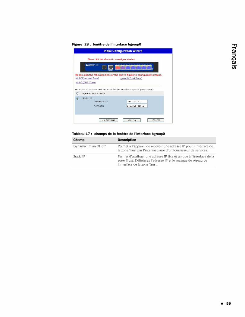
Français
Figure 28 : fenêtre de l’interface bgroup0
Tableau 17 : champs de la fenêtre de l’interface bgroup0
Champ Description
Dynamic IP via DHCP Permet à l’appareil de recevoir une adresse IP pour l’interface de la zone Trust par l’intermédiaire d’un fournisseur de services.
Static IP Permet d’attribuer une adresse IP fixe et unique à l’interface de la zone Trust. Définissez l’adresse IP et le masque de réseau de l’interface de la zone Trust.
59

Guide d’installation et de configuration du matériel SSG 5
60
10. Fenêtre de l’interface wireless0/0 (zone Trust)Si vous disposez d’un des appareils SSG 5-WLAN, vous devez définir un SSID (Service Set Identifier) avant d’activer l’interface wireless0/0. Pour obtenir des instructions détaillées relatives à la configuration de la ou des interfaces sans fil, reportez-vous au manuel Concepts & Examples ScreenOS Reference Guide.
Figure 29 : fenêtre de l’interface wireless0/0

Français
Tableau 18 : champs de la fenêtre de l’interface wireless0/0
Une fois les interfaces du réseau étendu configurées, la fenêtre du récapitulatif de l’interface s’affiche.
Champ Description
Wlan Mode Définissez le mode radio du réseau local sans fil :
5G (802.11a)
2.4G (802.11b/g)
Both (802.11a/b/g)
SSID Permet de définir le nom SSID.
Authentification and Encryption Permet de définir le mode d’authentification et de chiffrement de l’interface du réseau local sans fil :
L’authentification Open, valeur par défaut, permet à n’importe qui d’accéder à l’appareil. Il n’existe pas de chiffrement pour cette option d’authentification.
L’authentification WPA Pre-Shared Key définit la clé partagée au préalable ou la phrase de passe qui doit être saisie lors de l’établissement d’une connexion sans fil. Vous pouvez saisir une valeur hexadécimale ou ASCII pour la clé partagée au préalable. Une clé hexadécimale partagée au préalable doit correspondre à une valeur hexadécimale de 256 bits (64 caractères). Une phrase de passe ASCII doit comprendre entre 8 et 63 caractères. Vous devez sélectionner le protocole TKIP (Temporal Key Integrity Protocol) ou AES (Advanced Encryption Standard) comme type de chiffrement pour cette option ou sélectionner Auto pour activer une des options.
WPA2 Pre-Shared Key
WPA Auto Pre-Shared Key
Interface IP Permet de définir l’adresse IP de l’interface du réseau local sans fil.
Netmask Permet de définir le masque de réseau de l’interface du réseau local sans fil.
61

Guide d’installation et de configuration du matériel SSG 5
62
11. Fenêtre du récapitulatif de l’interfaceVérifiez la configuration de l’interface, puis cliquez sur Next lorsque vous êtes prêt à poursuivre. La fenêtre de l’interface DHCP Ethernet physique s’affiche.
Figure 30 : fenêtre du récapitulatif de l’interface
12. Fenêtre de l’interface DHCP Ethernet physiqueSélectionnez Yes pour permettre à votre appareil d’attribuer des adresses IP à votre réseau câblé via le protocole DHCP. Saisissez la plage d’adresses IP que votre appareil doit attribuer aux clients à l’aide de votre réseau.
Figure 31 : fenêtre de l’interface DHCP Ethernet physique

Français
13. Fenêtre de l’interface DHCP sans filSélectionnez Yes pour permettre à votre appareil d’attribuer des adresses IP à votre réseau sans fil via le protocole DHCP. Saisissez la plage d’adresses IP que votre appareil doit attribuer aux clients à l’aide de votre réseau.
Figure 32 : fenêtre de l’interface DHCP sans fil
14. Fenêtre de confirmationVérifiez la configuration de votre appareil et apportez aux modifications nécessaires. Cliquez sur Next pour procéder à l’enregistrement, au redémarrage de l’appareil et à l’exécution de la configuration.
Figure 33 : fenêtre de confirmation
Lorsque vous cliquez sur Next, l’appareil redémarre avec la configuration système enregistrée. L’invite de connexion de l’interface utilisateur Web s’affiche. Pour obtenir des informations relatives à la procédure d’accès à l’appareil à l’aide de l’interface utilisateur Web, reportez-vous à la section “Utilisation de l’interface utilisateur Web », page 25.
63

Guide d’installation et de configuration du matériel SSG 5
64

Français
Index
Aadresses IP par défaut...................................................28Ccâbles
connexions réseau de base ....................................20configuration
accès administratif ..................................................31adresse de gestion ...................................................32association sans fil et Ethernet ..............................36chiffrement et authentification sans fil .................34date et heure ............................................................30groupes ponts (bgroup) ...........................................30hôte et nom de domaine ........................................32interface non sécurisée secondaire .......................33interfaces de réseau étendu ...................................37nom et mot de passe de l’administrateur.............29route par défaut .......................................................32services de gestion ..................................................31USB ............................................................................14
connexion, réseau de base...........................................20
Eémetteurs-récepteurs radio
WLAN 0.....................................................................14WLAN 1.....................................................................14
Ggestion
par l’intermédiaire d’une connexion Telnet.........26par l’intermédiaire d’une console..........................24par l’intermédiaire de l’interface utilisateur
Web ........................................................................25
Iinterface secondaire vers zone Untrust ......................33
Pprocédure de mise à niveau de la mémoire...............43
Ssans fil
antennes ...................................................................22utilisation de l’interface par défaut........................22
services de gestion ........................................................31
Ttrou d’épingle de réinitialisation, utilisation...............40
Zzone Untrust, configuration d’une interface
secondaire ...................................................................33
Index 65

66
SSG 5 Hardware Installation and Configuration Guide
Index

Deutsch
Inhaltsverzeichnis
Zu diesem Handbuch 5
Organisation ....................................................................................................6WebUI-Konventionen.......................................................................................6Konventionen für die CLI .................................................................................7Abrufen von Dokumentationen und technischem Support...............................8
Kapitel 1 Hardware – Überblick 9
Verbindungs- und Netzanschlüsse....................................................................9Bedienfeld......................................................................................................10
Systemstatus-LEDs ..................................................................................10Anschlüsse – Beschreibungen ........................................................................12
Ethernet-Anschlüsse..........................................................................12Konsolenanschluss............................................................................12AUX-Anschluss ..................................................................................13
Rückseite .......................................................................................................13Stromadapter ..........................................................................................13Funktransceiver.......................................................................................14Erdungsansatz .........................................................................................14Antennentypen........................................................................................14USB-Anschluss .........................................................................................14
Kapitel 2 Installieren und Anschließen des Geräts 17
Einleitung.......................................................................................................18Installieren der Geräte....................................................................................18Anschließen von Schnittstellenkabeln an ein Gerät ........................................20Anschließen der Stromversorgung .................................................................20Anschließen eines Geräts an ein Netzwerk.....................................................20
Anschließen des Geräts an ein nicht vertrauenswürdiges Netzwerk.........20Ethernet-Anschlüsse..........................................................................21Serielle (AUX-/Konsol-) Anschlüsse ....................................................21WAN-Anschlüsse ...............................................................................22
Anschließen des Geräts an ein internes Netzwerk oder eine Arbeitsstation....................................................................................22Ethernet-Anschlüsse..........................................................................22Wireless-Antennen............................................................................22
Kapitel 3 Konfigurieren des Geräts 25
Zugriff auf das Gerät ......................................................................................26Verwenden einer Konsolenverbindung....................................................26Verwenden der WebUI ............................................................................27Verwenden von Telnet.............................................................................28
Standardmäßige Geräteeinstellungen .............................................................29
Inhaltsverzeichnis 3
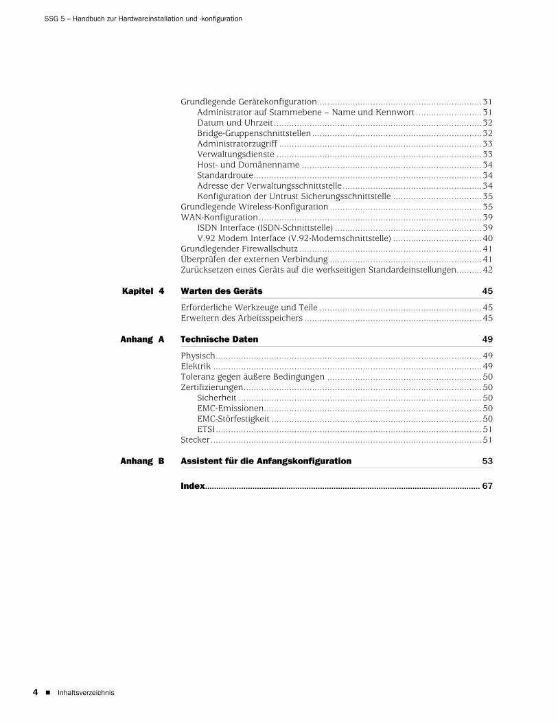
4
SSG 5 – Handbuch zur Hardwareinstallation und -konfiguration
Grundlegende Gerätekonfiguration.................................................................31Administrator auf Stammebene – Name und Kennwort ..........................31Datum und Uhrzeit ..................................................................................32Bridge-Gruppenschnittstellen...................................................................32Administratorzugriff ................................................................................33Verwaltungsdienste .................................................................................33Host- und Domänenname .......................................................................34Standardroute..........................................................................................34Adresse der Verwaltungsschnittstelle.......................................................34Konfiguration der Untrust Sicherungsschnittstelle ...................................35
Grundlegende Wireless-Konfiguration ............................................................35WAN-Konfiguration........................................................................................39
ISDN Interface (ISDN-Schnittstelle) ..........................................................39V.92 Modem Interface (V.92-Modemschnittstelle) ...................................40
Grundlegender Firewallschutz ........................................................................41Überprüfen der externen Verbindung ............................................................41Zurücksetzen eines Geräts auf die werkseitigen Standardeinstellungen..........42
Kapitel 4 Warten des Geräts 45
Erforderliche Werkzeuge und Teile ................................................................45Erweitern des Arbeitsspeichers ......................................................................45
Anhang A Technische Daten 49
Physisch.........................................................................................................49Elektrik ..........................................................................................................49Toleranz gegen äußere Bedingungen .............................................................50Zertifizierungen..............................................................................................50
Sicherheit ................................................................................................50EMC-Emissionen......................................................................................50EMC-Störfestigkeit ...................................................................................50ETSI.........................................................................................................51
Stecker...........................................................................................................51
Anhang B Assistent für die Anfangskonfiguration 53
Index.......................................................................................................................... 67
Inhaltsverzeichnis

Deutsch
Zu diesem Handbuch
Das Secure Services Gateway (SSG) 5-Gerät von Juniper Networks ist eine integrierte Router- und Firewallplattform, die Zweigstellen oder Einzelhandelsgeschäften Internet Protocol Security (IPSec) Virtual Private Network (VPN)- und Firewalldienste bietet.
Juniper Networks bietet sechs Ausführungen des SSG 5-Geräts an:
SSG 5 Serial
SSG 5 Serial-WLAN
SSG 5 V.92
SSG 5 V.92-WLAN
SSG 5 ISDN
SSG 5 ISDN-WLAN
Alle SSG 5-Geräte unterstützen ein Universal Serial Bus (USB)-Hostmodul. Die Geräte ermöglichen zudem Protokollkonvertierungen zwischen Local Area Networks (LANs) und Wide Area Networks (WANs); drei der Modelle unterstützen Wireless Local Area Networks (WLANs).
HINWEIS: Die Konfigurationsanweisungen und Beispiele in diesem Dokument basieren auf den Funktionen eines Geräts, auf dem ScreenOS 5.4 ausgeführt wird. Die Funktionsweise Ihres Gerätes unterscheidet sich möglicherweise abhängig von der verwendeten ScreenOS-Version. Die aktuellsten Gerätedokumentationen erhalten Sie auf der Juniper Networks-Website für technische Veröffentlichungen unter http://www.juniper.net/techpubs/hardware. Die derzeit für Ihr Gerät verfügbaren ScreenOS-Versionen werden auf der Juniper Networks-Supportwebsite unter http://www.juniper.net/customers/support/ angezeigt.
5

SSG 5 – Handbuch zur Hardwareinstallation und -konfiguration
6
Organisation
Dieses Handbuch ist in folgende Abschnitte gegliedert:
Kapitel 1, Unter “Hardware – Überblick,” werden das Gehäuse und die Komponenten eines SSG 5-Geräts beschrieben.
Kapitel 2, Unter “Installieren und Anschließen des Geräts,” wird die Montage eines SSG 5-Geräts und die Herstellung einer Verbindung zu einem Netzwerk beschrieben.
Kapitel 3, Unter “Konfigurieren des Geräts,” wird die Konfiguration und die Verwaltung eines SSG 5-Geräts sowie die Durchführung einiger grundlegender Konfigurationsaufgaben beschrieben.
Kapitel 4, Unter “Warten des Geräts,” werden die Wartungsmaßnahmen für SSG 5-Geräte erläutert.
Anhang A, Unter “Technische Daten,” finden Sie allgemeine technische Systemdaten für SSG 5-Geräte.
Anhang B, Unter “Assistent für die Anfangskonfiguration,” erhalten Sie detaillierte Informationen zur Verwendung des Assistenten für die Anfangskonfiguration (Initial Configuration Wizard, ICW) für SSG 5-Geräte.
WebUI-Konventionen
Navigieren Sie zum Ausführen einer Aufgabe mit der WebUI zuerst zum entsprechenden Dialogfeld, um dort Objekte zu definieren und Parameter festzulegen. Ein Rechtspfeil ( > ) zeigt die Schritte bei der Navigation durch die WebUI an, die durch Klicken auf Menüoptionen und Links ausgeführt werden. Die Anweisungen für jede Aufgabe werden in die Navigationspfad- und Konfigurationseinstellungen unterteilt.
Die folgende Abbildung zeigt den Pfad zum Adressenkonfigurations-Dialogfeld mit den folgenden Beispielkonfigurationseinstellungen:
Objects > Addresses > List > New: Geben Sie Folgendes ein, und klicken Sie dann auf OK:
Address Name: addr_1IP Address/Domain Name:
IP/Netmask: (select), 10.2.2.5/32Zone: Untrust
Organisation

Deutsch
Abbildung 1: Navigationspfad- und Konfigurationseinstellungen
Konventionen für die CLI
Die folgenden Konventionen dienen zur Darstellung der Syntax der Befehlszeilenbefehle in Beispielen und Text.
In Beispielen:
Alle Angaben in eckigen Klammern [ ] sind optional.
Alle Angaben in geschwungenen Klammern { } sind erforderlich.
Wenn mehreren Optionen möglich sind, sind diese durch einen senkrechten Strich ( | ) voneinander getrennt. Beispiel:
set interface { ethernet1 | ethernet2 | ethernet3 } manage
Dies bedeutet „Verwaltungsoptionen für die Schnittstelle ethernet1, ethernet2 oder ethernet3 einstellen“.
Variablen werden kursiv dargestellt.
set admin user name1 password xyz
In Text:
Befehle werden fett dargestellt.
Variablen werden kursiv dargestellt.
HINWEIS: Beim Eingeben eines Schlüsselworts müssen Sie nur so viele Buchstaben eingeben wie zur eindeutigen Identifizierung des Wortes erforderlich sind. Die Eingabe set adm u kath j12fmt54 ist z. B. ausreichend für den Befehl set admin user kathleen j12fmt54. Obwohl solche Abkürzungen zum Eingeben von Befehlen verwendet werden können, sind alle in diesem Handbuch dokumentierten Befehle vollständig dargestellt.
Konventionen für die CLI 7

SSG 5 – Handbuch zur Hardwareinstallation und -konfiguration
8
Abrufen von Dokumentationen und technischem Support
Technische Dokumentationen für Juniper Networks-Produkte stehen Ihnen auf unserer Website unter www.juniper.net/techpubs/ zur Verfügung.
Um technischen Support anzufordern, eröffnen Sie einen Support-Fall (Support Case) mit Hilfe des Links „Case Manager“ unter http://www.juniper.net/support/ , oder rufen Sie uns unter 1-888-314-JTAC (innerhalb der Vereinigten Staaten) oder unter +001-408-745-9500 (außerhalb der Vereinigten Staaten) an.
Wenn Sie Fehler oder Auslassungen in diesem Dokument entdecken, schreiben Sie an folgende E-Mail-Adresse:
Abrufen von Dokumentationen und technischem Support
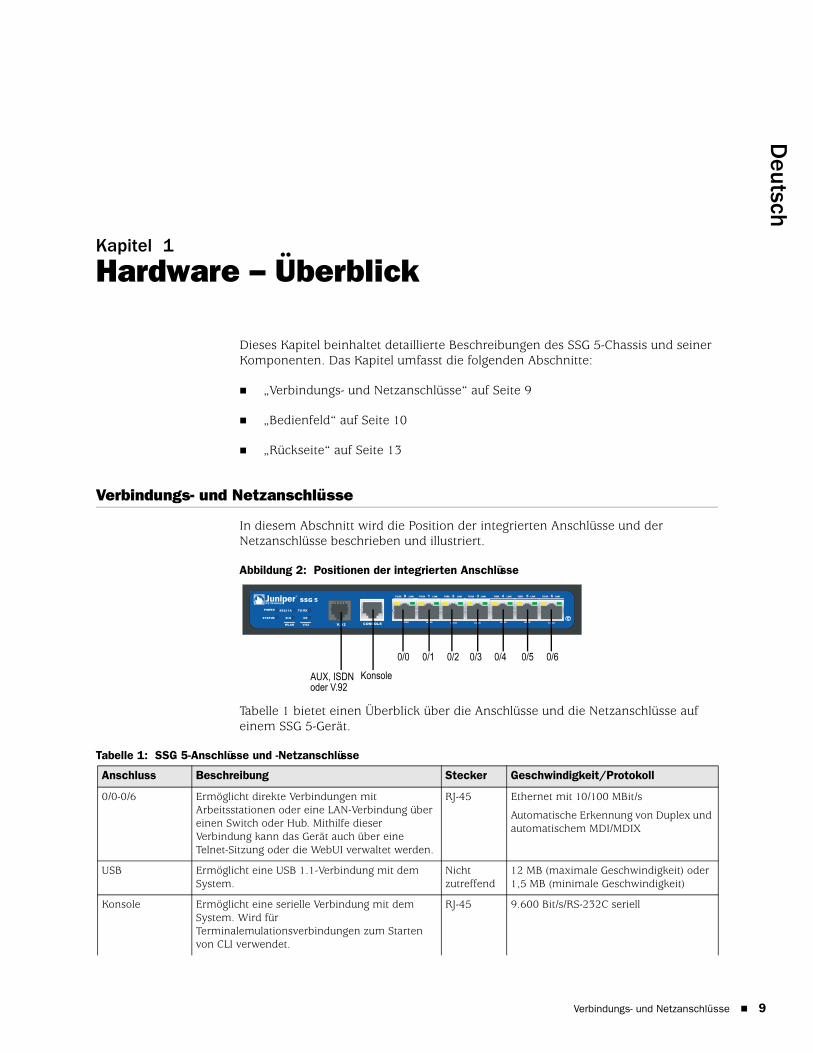
Deutsch
Kapitel 1
Hardware – Überblick
Dieses Kapitel beinhaltet detaillierte Beschreibungen des SSG 5-Chassis und seiner Komponenten. Das Kapitel umfasst die folgenden Abschnitte:
„Verbindungs- und Netzanschlüsse“ auf Seite 9
„Bedienfeld“ auf Seite 10
„Rückseite“ auf Seite 13
Verbindungs- und Netzanschlüsse
In diesem Abschnitt wird die Position der integrierten Anschlüsse und der Netzanschlüsse beschrieben und illustriert.
Abbildung 2: Positionen der integrierten Anschlüsse
Tabelle 1 bietet einen Überblick über die Anschlüsse und die Netzanschlüsse auf einem SSG 5-Gerät.
Tabelle 1: SSG 5-Anschlüsse und -Netzanschlüsse
SSG 5
V.92
STATUS
POWER
CONSOLE
TX /RX
CD
0 1 2 3 4 5 6TX/RX LINK TX/RX LINK TX/RX LINK TX/RX LINK TX/RX LINK TX/RX LINK TX/RX LINK
10/100 10/100 10/100 10/100 10/100 10/100 10/100
B /G
WLAN V.92
802.11A
0/60/50/40/30/20/10/0
KonsoleAUX, ISDN oder V.92
Anschluss Beschreibung Stecker Geschwindigkeit/Protokoll
0/0-0/6 Ermöglicht direkte Verbindungen mit Arbeitsstationen oder eine LAN-Verbindung über einen Switch oder Hub. Mithilfe dieser Verbindung kann das Gerät auch über eine Telnet-Sitzung oder die WebUI verwaltet werden.
RJ-45 Ethernet mit 10/100 MBit/s
Automatische Erkennung von Duplex und automatischem MDI/MDIX
USB Ermöglicht eine USB 1.1-Verbindung mit dem System.
Nicht zutreffend
12 MB (maximale Geschwindigkeit) oder 1,5 MB (minimale Geschwindigkeit)
Konsole Ermöglicht eine serielle Verbindung mit dem System. Wird für Terminalemulationsverbindungen zum Starten von CLI verwendet.
RJ-45 9.600 Bit/s/RS-232C seriell
Verbindungs- und Netzanschlüsse 9

SSG 5 – Handbuch zur Hardwareinstallation und -konfiguration
10
Bedienfeld
In diesem Abschnitt werden die folgenden Elemente auf dem Bedienfeld eines SSG 5-Geräts beschrieben:
Systemstatus-LEDs
Anschlüsse – Beschreibungen
Systemstatus-LEDsDie Systemstatus-LEDs zeigen Informationen zu wichtigen Gerätefunktionen an. Abbildung 3 zeigt die Position jeder Status-LED auf der Vorderseite des SSG 5 V.92-WLAN-Geräts. Die System-LEDs unterscheiden sich abhängig von der Version des SSG 5-Geräts.
Abbildung 3: Status-LEDs
Beim Hochfahren des Systems blinkt die Strom-LED grün, und die Status-LED wechselt in dieser Abfolge: Rot, Grün, grün blinkend. Der Startvorgang nimmt etwa zwei Minuten in Anspruch. Möchten Sie das System aus- und anschließend wieder einschalten, wird empfohlen, nach dem Herunterfahren einige Sekunden zu warten, bevor das System wieder hochgefahren wird. Tabelle 2 beinhaltet den Typ, den Namen, die Farbe, den Status und die Beschreibung jeder Systemstatus-LED.
AUX Ermöglicht eine asynchrone serielle RS-232-Sicherungsverbindung zum Internet über ein externes Modem.
RJ-45 9.600 Bit/s-115 KBit/s/RS-232C seriell
V.92-Modem Ermöglicht eine Primär- oder Sicherungsverbindung zum Internet bzw. eine nicht vertrauenswürdige Netzwerkverbindung zu einem Dienstanbieter.
RJ-11 9.600 Bit/s-115 KBit/s/RS-232, serielle automatische Erkennung von Duplex und Polarität
ISDN Ermöglicht die Verwendung der ISDN-Leitung als Untrust oder Sicherungsschnittstelle. (S/T)
RJ-45 B-Kanäle mit 64 KBit/s
Geleaste Leitung mit 128 KBit/s
Antenne A und B (SSG 5-WLAN)
Ermöglicht eine direkte Verbindung mit Arbeitsstationen in der Nähe einer Wireless-Funkverbindung.
RPSMA 802.11a (54 MBit/s bei Nutzung eines Frequenzbandes von 5 GHz)
802.11b (11 MBit/s bei Nutzung eines Frequenzbandes von 4 GHz)
802.11g (54 MBit/s bei Nutzung eines Frequenzbereichs von 2,4 GHz)
802.11 superG (108 MBit/s bei Nutzung eines Frequenzbandes von 2,4 GHz und 5 GHz)
Anschluss Beschreibung Stecker Geschwindigkeit/Protokoll
Bedienfeld

Deutsch
Tabelle 2: Status-LED – Beschreibungen
Typ Name Farbe Status Beschreibung
POWER Grün Ständig leuchtend
Das System wird mit Strom versorgt.
Aus Das System wird nicht mit Strom versorgt.
Rot Ständig leuchtend
Das Gerät funktioniert nicht ordnungsgemäß.
Aus Das Gerät funktioniert ordnungsgemäß.
STATUS Grün Ständig leuchtend
Das System wird gestartet, oder es führt eine Diagnose durch.
Blinkend Das Gerät funktioniert ordnungsgemäß.
Rot Blinkend Ein Fehler wurde festgestellt.
ISDN-Geräte CH B1 Grün Ständig leuchtend
B-Kanal 1 ist aktiv.
Aus B-Kanal 1 ist nicht aktiv.
CH B2 Grün Ständig leuchtend
B-Kanal 2 ist aktiv.
Aus B-Kanal 2 ist nicht aktiv.
V.92-Geräte HOOK Grün Ständig leuchtend
Die Verbindung ist aktiv.
Aus Die serielle Schnittstelle ist außer Betrieb.
TX/RX Grün Blinkend Datenverkehr wird übertragen.
Aus Es wird kein Datenverkehr übertragen.
WLAN-Geräte 802.11A Grün Ständig leuchtend
Die Wireless-Verbindung ist hergestellt, aber es liegt keine Verbindungsaktivität vor.
Blinkend Eine Wireless-Verbindung ist hergestellt. Die Baudrate verhält sich proportional zur Verbindungsaktivität.
Aus Es ist keine Wireless-Verbindung hergestellt.
B/G Grün Ständig leuchtend
Die Wireless-Verbindung ist hergestellt, aber es liegt keine Verbindungsaktivität vor.
Blinkend Eine Wireless-Verbindung ist hergestellt. Die Baudrate verhält sich proportional zur Verbindungsaktivität.
Aus Es ist keine Wireless-Verbindung hergestellt.
Bedienfeld 11

SSG 5 – Handbuch zur Hardwareinstallation und -konfiguration
12
Anschlüsse – Beschreibungen
In diesem Abschnitt werden der Zweck und die Funktion folgender Elemente erläutert:
Ethernet-Anschlüsse
Konsolenanschluss
AUX-Anschluss
Ethernet-AnschlüsseSieben 10/100-Ethernet-Anschlüsse ermöglichen LAN-Verbindungen zu Hubs, Switches, lokalen Servern und Arbeitsstationen. Zudem kann ein Ethernet-Anschluss für Verwaltungsdatenverkehr zugewiesen werden. Die Anschlüsse sind fortlaufend mit 0/0 bis 0/6 beschriftet. Unter „Standardmäßige Geräteeinstellungen“ auf Seite 29 erhalten Sie Informationen zu den standardmäßigen Zonenbindungen für jeden Ethernet-Anschluss.
Achten Sie bei der Konfiguration eines dieser Anschlüsse auf den Schnittstellennamen, der der Position des Anschlusses entspricht. Auf dem Bedienfeld werden die Schnittstellennamen für die Anschlüsse von links nach rechts fortlaufend mit ethernet0/0 bis ethernet0/6 beschriftet.
Abbildung 4 zeigt die Position der LEDs auf jedem Ethernet-Anschluss an.
Abbildung 4: Activity Link-LEDs
Tabelle 3 zeigt die Ethernet-Anschluss-LEDs an.
Tabelle 3: Ethernet-Anschluss-LEDs
KonsolenanschlussBeim Konsolenanschluss handelt es sich um einen seriellen RJ-45-Anschluss, der als zur lokalen Verwaltung verwendbares Data Circuit Terminating Equipment (DCE) verkabelt ist. Verwenden Sie bei einem Klemmanschluss ein Durchgangskabel und ein Crossoverkabel, wenn Sie eine Verbindung zu einem anderen DCE-Gerät herstellen. Ein Adapter für RJ-45 auf DB-9 wird mitgeliefert.
Informationen zu den Kontaktanordnungen der RJ-45-Stecker erhalten Sie unter „Stecker“ auf Seite 51.
Name Farbe Status Beschreibung
LINK Grün Ständig leuchtend
Aus
Anschluss ist online.
Anschluss ist offline.
TX/RX Grün Blinkend
Aus
Datenverkehr wird weitergeleitet. Die Baudrate verhält sich proportional zur Verbindungsaktivität.
Der Anschluss ist möglicherweise aktiviert, empfängt jedoch keine Daten.
LINKTX/RX
Anschlüsse – Beschreibungen

Deutsch
AUX-AnschlussDer Auxiliary (AUX)-Anschluss ist ein serieller RJ-45-Anschluss, der als Data Terminal Equipment (DTE) verkabelt ist. Durch Anschluss an ein Modem ist DTE für die Remoteverwaltung verwendbar. Dieser Anschluss sollte nicht regelmäßig für Remoteverwaltung verwendet werden. Der AUX-Anschluss wird normalerweise als serielle Sicherungsschnittstelle zugewiesen. Die Baudrate kann auf einen Wert zwischen 9.600 Bit/s und 115.200 Bit/s eingestellt werden und erfordert eine Hardwareflusssteuerung. Verwenden Sie beim Anschluss an ein Modem ein Durchgangskabel und beim Anschluss an ein anderes DTE-Gerät ein Crossoverkabel.
Informationen zu den RJ-45-Kontaktanordnungen der Stecker erhalten Sie unter „Stecker“ auf Seite 51.
Rückseite
In diesem Abschnitt werden die folgenden Elemente auf der Rückseite eines SSG 5-Geräts beschrieben:
Stromadapter
Funktransceiver
Erdungsansatz
Antennentypen
USB-Anschluss
Abbildung 5: Rückseite eines SSG 5-Geräts
StromadapterDie Strom-LED auf dem Bedienfeld eines Geräts leuchtet entweder grün oder ist ausgeschaltet. Grün zeigt eine ordnungsgemäße Funktion an, wohingegen eine nicht leuchtende Strom-LED auf einen Stromadapterausfall oder auf den ausgeschalteten Zustand des Geräts hinweist.
HINWEIS: Nur die SSG 5-WLAN-Geräte verfügen über Antennenanschlüsse.
RESETDC POWER
LOCK
USBSD FLASHB A5V A4
Stromadapter
USB-HostmodulErdungsansatz
Reset-Stiftloch
Antenne AAntenne B
Rückseite 13

SSG 5 – Handbuch zur Hardwareinstallation und -konfiguration
14
FunktransceiverDie SSG 5-WLAN-Geräte beinhalten zwei Funktransceiver für Wireless-Verbindungen, die 802.11a/b/g-Standards unterstützen. Der erste Transceiver (WLAN 0) verwendet das 2,4 GHz-Frequenzband, das den 802.11b-Standard bei 11 MBit/s und den 802.11g-Standard bei 54 MBit/s unterstützt. Der zweite Funktransceiver (WLAN 1) verwendet das 5 GHz-Frequenzband, das den 802.11a-Standard bei 54 MBit/s unterstützt. Die zwei Funkbereiche können gleichzeitig genutzt werden. Informationen zur Konfiguration des Wireless-Frequenzbands erhalten Sie unter „Grundlegende Wireless-Konfiguration“ auf Seite 35.
ErdungsansatzAuf der Rückseite des Chassis ist ein Ein-Loch-Erdungsansatz vorhanden, über den das Gerät geerdet wird (siehe Abbildung 5).
Stellen Sie mit einem Erdungskabel eine Erdung her, und bringen Sie anschließend das Kabel am Ansatz auf der Rückseite des Chassis an, um das Gerät vor Herstellung der Stromverbindung zu erden.
AntennentypenDie SSG 5-WLAN-Geräte unterstützen drei Typen von speziell angefertigten Funkantennen:
Doppelantennen – Die Doppelantennen ermöglichen eine Richtfunkübertragung mit 2 dBi und eine im Wesentlichen einheitliche Signalstärke im Bereich der Funkübertragung und sind für die meisten Installationen geeignet. Dieser Antennentyp wird zusammen mit dem Gerät geliefert.
Externe Rundstrahlantenne – Die externe Antenne ermöglicht eine Rundstrahlübertragung mit 2 dBi. Im Gegensatz zu Doppelantennen, die paarweise eingesetzt werden, beseitigt eine externe Antenne Echoeffekte, die bei Verwendung von zwei Antennen gelegentlich aufgrund eines leicht verzögerten Signalempfangs auftreten.
Externe Richtantenne – Die externe Richtantenne ermöglicht eine Funkübertragung mit 2 dBi in eine Richtung und ist für Orte wie Gänge und Außenmauern (dabei ist die Antenne nach innen gerichtet) geeignet.
USB-AnschlussDer USB-Anschluss auf der Rückseite eines SSG 5-Geräts nimmt ein Universal Serial Bus (USB)-Speichergerät oder einen USB-Speichergeräteadapter auf, in dem ein Compact Flash-Datenträger installiert ist (siehe Definition in den von der CompactFlash Association veröffentlichten technischen Angaben zu CompactFlash. Ist das USB-Speichergerät installiert und konfiguriert, fungiert es automatisch als sekundäres Startgerät, falls beim Start ein Fehler beim primären Compact Flash-Datenträger auftritt.
Rückseite

Deutsch
Der USB-Anschluss ermöglicht Dateiübertragungen wie Gerätekonfigurationen, Benutzerzertifizierungen und die Aktualisierung von Versionsabbildern zwischen einem externen USB-Speichergerät und dem internen Flashspeicher im Sicherheitsgerät. Der USB-Anschluss unterstützt eine Dateiübertragung mit USB 1.1 entweder bei minimaler (1,5 MB) oder maximaler Geschwindigkeit (12 MB).
Führen Sie zur Übertragung von Dateien zwischen dem USB-Speichergerät und einem SSG 5 die folgenden Schritte aus:
1. Stecken Sie das USB-Speichergerät in den USB-Anschluss auf dem Sicherheitsgerät.
2. Speichern Sie die auf dem USB-Speichergerät enthaltenen Dateien mit dem Befehlszeilenbefehl save {software config | image-key} from usb filename to flash auf den internen Flashspeicher des Geräts.
3. Trennen Sie das USB-Speichergerät vor dem Entfernen mit dem Befehlszeilenbefehl exec usb-device stop vom USB-Anschluss.
4. Das USB-Speichergerät kann nun entfernt werden.
Möchten Sie vom USB-Speichergerät eine Datei löschen, verwenden Sie den Befehlszeilenbefehl delete file usb:/filename.
Möchten Sie Informationen zu den auf dem USB-Gerät oder dem internen Flashspeicher gespeicherten Dateien anzeigen, verwenden Sie den Befehlszeilenbefehl get file.
Rückseite 15

SSG 5 – Handbuch zur Hardwareinstallation und -konfiguration
16
Rückseite
Deutsch
Kapitel 2
Installieren und Anschließen des Geräts
In diesem Kapitel wird die Montage eines SSG 5-Geräts sowie das Anschließen von Kabeln und der Stromversorgung an das Gerät beschrieben. Dieses Kapitel ist in folgende Abschnitte gegliedert:
„Einleitung“ auf Seite 18
„Installieren der Geräte“ auf Seite 18
„Anschließen von Schnittstellenkabeln an ein Gerät“ auf Seite 20
„Anschließen der Stromversorgung“ auf Seite 20
„Anschließen eines Geräts an ein Netzwerk“ auf Seite 20
HINWEIS: Sicherheitshinweise und Anweisungen finden Sie im Security Products Safety Guide von Juniper Networks. Bevor Sie mit Geräten arbeiten, informieren Sie sich über die Gefahren, die beim Umgang mit elektrischen Komponenten bestehen. Machen Sie sich außerdem mit den gängigen Vorkehrungen zur Vermeidung von Unfällen vertraut.
17

SSG 5 – Handbuch zur Hardwareinstallation und -konfiguration
18
Einleitung
Die Position des Chassis, die Reihenfolge bei der Verwendung der Montagegeräte und die Sicherheit des Kabelraums sind für eine ordnungsgemäße des Systems von entscheidender Bedeutung.
Durch Einhalten der folgenden Vorischtsmaßnahmen können das Herunterfahren des Geräts sowie Gerätefehler und Verletzungen verhindert werden:
Überprüfen Sie vor jeder Installation, ob das Netzteil von allen Stromquellen getrennt ist.
Stellen Sie sicher, dass der Raum, in dem das Gerät betrieben werden soll, ausreichend belüftet ist und dass die Raumtemperatur 40° C (104° F) nicht übersteigt.
Stellen Sie das Gerät nicht in einem Gerätegestellrahmen auf, durch den die Ein- und Auslassöffnungen blockiert werden. Ein geschlossenes Gestell muss über Lüfter und Lüftungsschlitze verfügen.
Beseitigen Sie vor jeder Installation die folgenden gefährlichen Umgebungsbedingungen: Feuchte oder nasse Böden, Lecks, ungeerdete oder schadhafte Netzkabel sowie Steckdosen ohne ausreichende Erdung.
Installieren der Geräte
Für ein SSG 5-Gerät ist eine Front-, Wand- oder Schreibtischmontage möglich. Die Montagekits können einzeln gekauft werden.
Zum Montieren eines SSG 5-Geräts werden ein Kreuzschlitzschraubenzieher mittlerer Größe (nicht im Lieferumfang enthalten) und Schrauben benötigt, die mit dem Gerätegestell kompatibel sind (im Kit enthalten).
Führen Sie für die Gestellmontage eines SSG 5-Geräts die folgenden Schritte aus:
1. Lösen Sie mit einem Kreuzschlitzschraubenzieher die Haltebügel auf der Halterung.
WARNHINWEIS: Installieren Sie das SSG 5-Gerät in einer sicheren Umgebung, um einem Missbrauch und dem Eindringen Unbefugter in den Raum vorzubeugen.
HINWEIS: Stellen Sie beim Montieren eines Geräts sicher, dass sich dieses nah genug an der Steckdose befindet.
HINWEIS: SSG 5-WLAN-Benutzer, die über die optionalen Antennen verfügen, müssen vorhandene Antennen entfernen und daraufhin die neue Antenne anschließen, indem sie das entsprechende Kabel durch die seitliche Öffnung führen.
Einleitung

Deutsch
2. Richten Sie die Unterseite des Gerät an den unteren Öffnungen der Halterung aus.
3. Ziehen Sie das Gerät nach vorn, um es in den unteren Öffnungen der Halterung zu verankern.
4. Fixieren Sie die Haltebügel mithilfe der Schrauben am Gerät und an der Halterung.
5. Setzen Sie das Netzteil in den Netzteilhalter ein, und schließen Sie den Stromadapter an das Gerät an.
6. Wiederholen Sie zum Installieren eines zweiten SSG 5-Geräts die Schritte 1 bis 5, und fahren Sie anschließend fort.
Abbildung 6: SSG 5-Gestellmontage
7. Montieren Sie die Halterung mit den mitgelieferten Schrauben auf dem Gestell.
8. Stecken Sie das Netzteil in die Steckdose.
Führen Sie für die Schreibtischmontage eines SSG 5-Geräts die folgenden Schritte aus:
1. Befestigen Sie die Vorrichtung zum Aufstellen auf dem Schreibtisch am Gerät. Verwenden Sie am besten die Seite, die dem Stromadapter am nächsten liegt.
2. Stellen Sie das montierte Gerät auf den Schreibtisch.
Abbildung 7: SSG 5-Schreibtischmontage
3. Stecken Sie den Stromadapter ein, und schließen Sie das Netzteil an die Steckdose an.
Netzteilhalter
Netzteilhalter
Installieren der Geräte 19

SSG 5 – Handbuch zur Hardwareinstallation und -konfiguration
20
Anschließen von Schnittstellenkabeln an ein Gerät
Führen Sie zum Anschließen von Schnittstellenkabeln an das Gerät die folgenden Schritte aus:
1. Sie benötigen die für die Schnittstelle erforderliche Kabelart in ausreichender Länge.
2. Verbinden Sie den Kabelstecker mit dem entspechenden Anschluss am Gerät.
3. Ordnen Sie das Kabel folgendermaßen an, um ein Herausgleiten des Kabels oder das Entstehen von Belastungsstellen zu verhindern:
a. Bringen Sie das Kabel so an, dass es beim Herunterhängen nicht sein eigenes Gewicht stützen muss.
b. Ist noch überschüssige Kabellänge vorhanden, legen Sie das Kabel sorgfältig zu einer Schleife zusammen, und räumen Sie es beiseite.
c. Fixieren Sie die Schleife mit Klemmen.
Anschließen der Stromversorgung
Führen Sie zum Herstellen einer Stromversorgung für das Gerät die folgenden Schritte aus:
1. Schließen Sie den Gleichstromstecker des Netzkabels an die Gleichstromnetzbuchse auf der Rückseite des Geräts an.
2. Schließen Sie den Wechselstromadapter des Netzkabels an eine Wechselstromquelle an.
Anschließen eines Geräts an ein Netzwerk
Die SSG 5-Geräte bieten eine Firewall und allgemeine Sicherheitsfunktionen für Ihre Netzwerke, wenn es zwischen internen Netzwerken und dem nicht vertrauenswürdigen Netzwerk platziert wird. In diesem Abschnitt werden insbesondere die folgenden Themen behandelt:
Anschließen des Geräts an ein nicht vertrauenswürdiges Netzwerk
Anschließen des Geräts an ein internes Netzwerk oder eine Arbeitsstation
Anschließen des Geräts an ein nicht vertrauenswürdiges NetzwerkFolgende Möglichkeiten stehen zum Anschluss des SSG 5-Geräts an ein nicht vertrauenswürdiges Netzwerk zur Verfügung:
WARNHINWEIS: Wir empfehlen die Verwendung eines Überspannungsschutzes für die Stromverbindung.
Anschließen von Schnittstellenkabeln an ein Gerät

Deutsch
Ethernet-Anschlüsse
Serielle (AUX-/Konsol-) Anschlüsse
WAN-Anschlüsse
Abbildung 8 zeigt das SSG 5 mit den grundlegenden Netzwerkkabelverbindungen. Die 10/100-Ethernet-Anschlüsse sind dabei folgendermaßen verkabelt:
Der mit „0/0“ gekennzeichnete Anschluss (Ethernet0/0-Schnittstelle) ist mit dem nicht vertrauenswürdigen Netzwerk verbunden.
Der mit „0/1“ gekennzeichnete Anschluss (ethernet0/1-Schnittstelle) ist mit einer Arbeitsstation in der DMZ-Sicherheitszone verbunden.
Der mit „0/2“ gekennzeichnete Anschluss (bgroup0-Schnittstelle) ist mit einer Arbeitsstation in der Trust Sicherheitszone verbunden.
Der Konsolenanschluss ist zur Gewährleistung des Verwaltungszugriffs mit einem seriellen Terminal verbunden.
Abbildung 8: Grundlegender Netzwerkbetrieb – Beispiel
Ethernet-AnschlüsseSchließen Sie zum Herstellen einer Hochgeschwindigkeitsverbindung das mitgelieferte Ethernet-Kabel für den Ethernet-Anschluss „0/0“ auf einem SSG 5-Gerät an den externen Router an. Das Gerät erkennt automatisch die erforderliche Geschwindigkeit, den Duplex und die MDI/MDIX-Einstellungen.
Serielle (AUX-/Konsol-) AnschlüsseEine Verbindung mit einem nicht vertrauenswürdigen Netzwerk kann mit einem seriellen RJ-45-Durchgangskabel und einem externen Modem hergestellt werden.
SSG 5
V.92
STATUS
POWER
CONSOLE
TX /RX
CD
0 1 2 3 4 5 6TX/RX LINK TX/RX LINK TX/RX LINK TX/RX LINK TX/RX LINK TX/RX LINK TX/RX LINK
10/100 10/100 10/100 10/100 10/100 10/100 10/100
B /G
WLAN V.92
802.11A
Callouts
Untrust Zone
KonsoleDMZ
Trust Zone
WARNHINWEIS: Schließen Sie nicht versehentlich die Konsolen-, AUX- oder Ethernet-Anschlüsse des Geräts an der Telefonanschlussdose an.
Anschließen eines Geräts an ein Netzwerk 21

SSG 5 – Handbuch zur Hardwareinstallation und -konfiguration
22
WAN-Anschlüsse1. Sie benötigen die für die Schnittstelle erforderliche Kabelart in ausreichender
Länge.
2. Verbinden Sie den Kabelstecker mit dem entspechenden Anschluss auf dem Gerät.
3. Ordnen Sie das Kabel folgendermaßen an, um ein Herausgleiten des Kabels oder das Entstehen von Stresspunkten zu verhindern:
a. Bringen Sie das Kabel so an, dass es beim Herunterhängen nicht sein eigenes Gewicht stützen muss.
b. Ist noch überschüssige Kabellänge vorhanden, legen Sie das Kabel sorgfältig zu einer Schleife zusammen, und räumen Sie diese beiseite.
c. Fixieren Sie die Kabel mithilfe von Klemmen.
Anschließen des Geräts an ein internes Netzwerk oder eine ArbeitsstationEin Local Area Network (LAN) oder eine Arbeitsstation kann mit den Ethernet- und/oder den Wireless-Schnittstellen verbunden werden.
Ethernet-AnschlüsseEin SSG 5-Gerät verfügt über sieben Ethernet-Anschlüsse. Sie können mindestens einen dieser Anschlüsse für die Herstellung einer Verbindung zu LANs über Switches oder Hubs verwenden. Die Anschlüsse können jedoch auch ohne Hubs oder Switches direkt mit Arbeitsstationen verbunden werden. Zum Anschließen der Ethernet-Anschlüsse an andere Geräte können Crossover- oder Durchgangskabel verwendet werden. Informationen zu den standardmäßigen Schnittstelle-zu-Zone-Bindungen erhalten Sie unter „Standardmäßige Geräteeinstellungen“ auf Seite 29.
Wireless-AntennenWenn Sie die Wireless-Schnittstelle verwenden, müssen Sie die mitgelieferten Antennen am Gerät anschließen. Wenn Sie über die standardmäßigen 2 dB-Doppelantennen verfügen, schrauben Sie diese an den mit A und B gekennzeichneten Anschlüssen auf der Geräterückseite fest. Biegen Sie jede Antenne jeweils am Gelenk, ohne dabei Druck auf die Stecker auszuüben.
Anschließen eines Geräts an ein Netzwerk
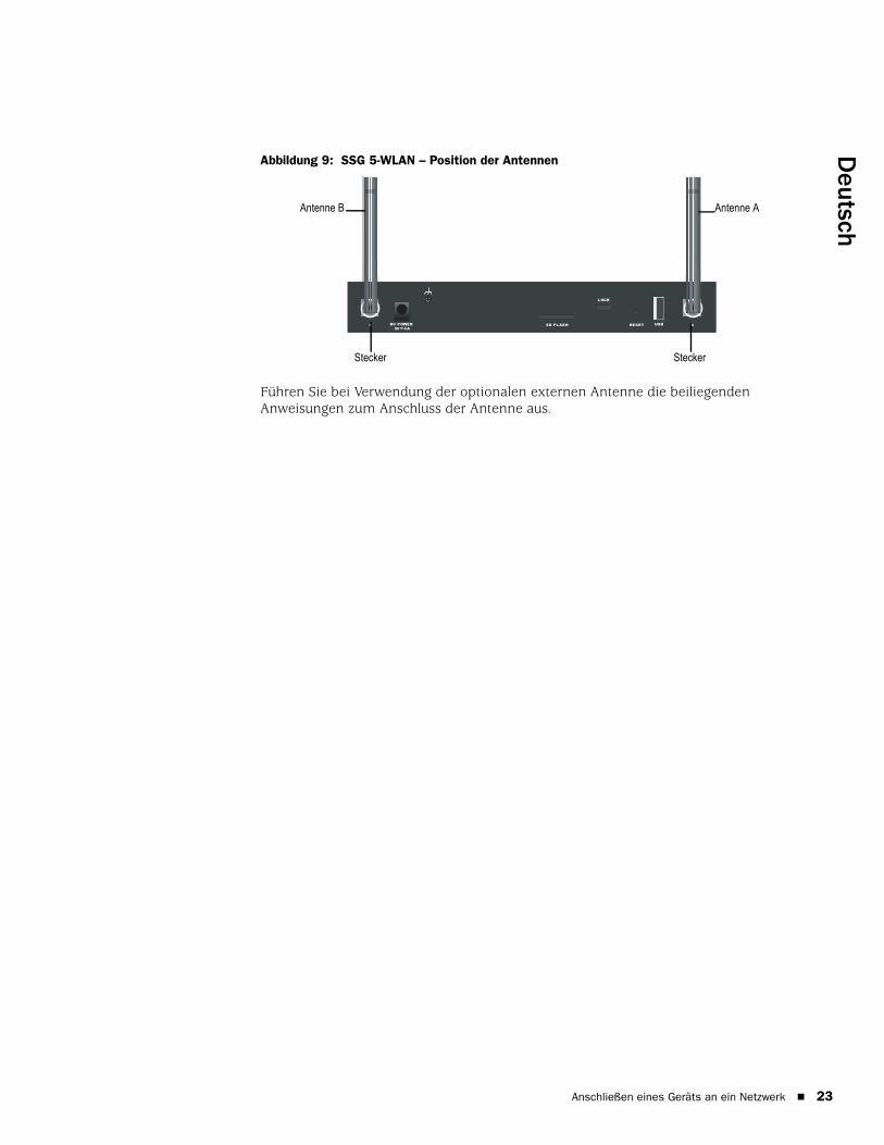
Deutsch
Abbildung 9: SSG 5-WLAN – Position der Antennen
Führen Sie bei Verwendung der optionalen externen Antenne die beiliegenden Anweisungen zum Anschluss der Antenne aus.
RESETDC POWER
LOCK
USBSD FLASHB A5V A4
SteckerStecker
Antenne B Antenne A
Anschließen eines Geräts an ein Netzwerk 23

SSG 5 – Handbuch zur Hardwareinstallation und -konfiguration
24
Anschließen eines Geräts an ein Netzwerk
Deutsch
Kapitel 3
Konfigurieren des Geräts
Die ScreenOS-Software ist auf den SSG 5-Geräten vorinstalliert. Das Gerät wird in eingeschaltetem Zustand konfiguriert. Das Gerät verfügt über eine standardmäßige werkseitige Konfiguration, die den Erstanschluss an das Gerät ermöglicht. Für Ihre speziellen Netzwerkanforderungen müssen Sie jedoch eine Konfigurationen vornehmen.
Dieses Kapitel ist in folgende Abschnitte gegliedert:
„Zugriff auf das Gerät“ auf Seite 26
„Standardmäßige Geräteeinstellungen“ auf Seite 29
„Grundlegende Gerätekonfiguration“ auf Seite 31
„Grundlegende Wireless-Konfiguration“ auf Seite 35
„WAN-Konfiguration“ auf Seite 39
„Grundlegender Firewallschutz“ auf Seite 41
„Überprüfen der externen Verbindung“ auf Seite 41
„Zurücksetzen eines Geräts auf die werkseitigen Standardeinstellungen“ auf Seite 42
HINWEIS: Nach der Konfiguration eines Geräts und der Überprüfung der Verbindung über das Remotenetzwerk, muss das Produkt unter www.juniper.net/support/ registriert werden, damit bestimmte ScreenOS-Dienste, wie z.B. der Deep Inspection-Signaturdienst und der Virenschutz (einzeln erhältlich) auf dem Gerät aktiviert werden. Nach der Registrierung des Produkts abonnieren Sie den Dienst über die WebUI. Weitere Informationen zur Produktregistrierung und zum Abonnieren bestimmter Dienste erhalten Sie im Band Grundlagen des Concepts & Examples ScreenOS Reference Guide für die auf dem Gerät installierte ScreenOS-Version.
25

SSG 5 – Handbuch zur Hardwareinstallation und -konfiguration
26
Zugriff auf das Gerät
Ein SSG 5-Gerät kann auf verschiedene Arten konfiguriert werden:
Konsole: Der Konsolenanschluss am Gerät ermöglicht Ihnen den Zugriff auf das Gerät über ein serielles an die Arbeitsstation oder das Terminal angeschlossenes Kabel. Zum Konfigurieren des Geräts geben Sie am Terminal oder in einem Terminalemulationsprogramm auf Ihrer Arbeitsstation ScreenOS-Befehlszeilenbefehle ein.
WebUI: Bei der ScreenOS-Webbenutzerschnittstelle (WebUI) handelt es sich um eine über einen Browser verfügbare grafische Schnittstelle. Zur Erstverwendung der WebUI muss sich die Arbeitsstation, auf der der Browser ausgeführt wird, im selben Subnetz wie das Gerät befinden. Der Zugriff auf die WebUI über einen sicheren Server kann auch unter Verwendung von Secure Sockets Layer (SSL) mit Secure HTTP (S-HTTP) erfolgen.
Telnet/SSH: Telnet und SSH sind Anwendungen, die Ihnen den Zugriff auf Geräte über ein IP-Netzwerk ermöglichen. Zum Konfigurieren des Geräts geben Sie in einer Telnet-Sitzung an Ihrer Arbeitsstation ScreenOS-Befehlszeilenbefehle ein. Weitere Informationen erhalten Sie im Band Verwaltung des Concepts & Examples ScreenOS Reference Guide.
NetScreen-Security Manager: NetScreen-Security Manager ist eine von Juniper Networks entwickelte Verwaltungsanwendung für Unternehmen, mit der Firewall-/IPSec VPN-Geräte von Juniper Networks gesteuert und verwaltet werden. Anweisungen zur Verwaltung des Geräts mithilfe von NetScreen-Security Manager erhalten Sie im NetScreen-Security Manager-Administratorhandbuch.
Verwenden einer Konsolenverbindung
Führen Sie zum Herstellen einer Konsolenverbindung die folgenden Schritte aus:
1. Schließen Sie den Buchsenstecker des mitgelieferten DB-9-Adapters an den seriellen Anschluss der Arbeitsstation an. (Der DB-9-Stecker muss ordnungsgemäß eingesteckt und gesichert sein.) Abbildung 10 zeigt den erforderlichen DB-9-Stecker.
HINWEIS: Verwenden Sie ein serielles RJ-45 CAT5-Durchgangskabel mit einem RJ-45-Stecker, um eine Verbindung mit dem Konsolenanschluss am Gerät herzustellen.
Zugriff auf das Gerät

Deutsch
Abbildung 10: DB-9-Adapter
2. Schließen Sie den Stecker des seriellen RJ-45 CAT5-Kabels am Konsolenanschluss am SSG 5 an. (Das andere Ende des CAT5-Kabels muss ordnungsgemäß an den DB-9-Adapter angeschlossen und gesichert sein.)
3. Starten Sie auf der Arbeitsstation ein serielles Terminalemulationsprogramm. Folgende Einstellungen sind zum Starten einer Konsolensitzung erforderlich:
Baudrate: 9600
Parität: Keine
Datenbits: 8
Stoppbit: 1
Flusssteuerung: Keine
4. Wenn Sie den Standardbenutzernamen und das Standardkennwort noch nicht geändert haben, geben Sie bei den Eingabeaufforderungen „login“ und „password“ netscreen ein. (Verwenden Sie nur Kleinbuchstaben. Für die Felder „login“ und „password“ muss die Groß-/Kleinschreibung beachtet werden.)
Informationen zur Konfiguration des Geräts mithilfe der Befehlszeilenbefehle erhalten Sie im Concepts & Examples ScreenOS Reference Guide.
5. Standardmäßig tritt an der Konsole eine Zeitüberschreitung auf, und sie wird automatisch nach 10 Minuten ausbleibender Aktivität beendet (optional). Geben Sie zum Entfernen der Zeitüberschreitung set console timeout 0 ein.
Verwenden der WebUIZur Verwendung der WebUI muss sich die Arbeitsstation, von der aus das Gerät verwaltet wird, zunächst im selben Subnetz wie das Gerät befinden. Führen Sie zum Zugriff auf das Gerät mit der WebUI die folgenden Schritte aus:
1. Stellen Sie für die Arbeitsstation eine Verbindung zum 0/2-0/6-Anschluss am Gerät her (bgroup0-Schnittstelle in der Trust Zone).
2. Stellen Sie sicher, dass die Arbeitsstation für Dynamic Host Configuration Protocol (DHCP) oder statisch mit einer IP-Adresse im Subnetz 192.168.1.0/24 konfiguriert ist.
3. Starten Sie den Browser, geben Sie die IP-Adresse für die bgroup0-Schnittstelle ein (die standardmäßige IP-Adresse lautet 192.168.1.1/24), und drücken Sie anschließend die ENTER.
RJ-45-Buchse
DB-9-Adapter
RJ-45-Kabel
Zugriff auf das Gerät 27
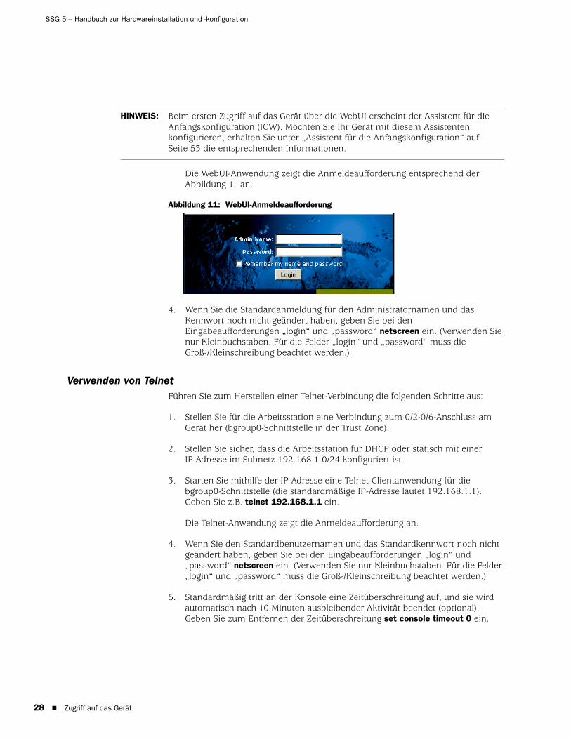
SSG 5 – Handbuch zur Hardwareinstallation und -konfiguration
28
Die WebUI-Anwendung zeigt die Anmeldeaufforderung entsprechend der Abbildung 11 an.
Abbildung 11: WebUI-Anmeldeaufforderung
4. Wenn Sie die Standardanmeldung für den Administratornamen und das Kennwort noch nicht geändert haben, geben Sie bei den Eingabeaufforderungen „login“ und „password“ netscreen ein. (Verwenden Sie nur Kleinbuchstaben. Für die Felder „login“ und „password“ muss die Groß-/Kleinschreibung beachtet werden.)
Verwenden von TelnetFühren Sie zum Herstellen einer Telnet-Verbindung die folgenden Schritte aus:
1. Stellen Sie für die Arbeitsstation eine Verbindung zum 0/2-0/6-Anschluss am Gerät her (bgroup0-Schnittstelle in der Trust Zone).
2. Stellen Sie sicher, dass die Arbeitsstation für DHCP oder statisch mit einer IP-Adresse im Subnetz 192.168.1.0/24 konfiguriert ist.
3. Starten Sie mithilfe der IP-Adresse eine Telnet-Clientanwendung für die bgroup0-Schnittstelle (die standardmäßige IP-Adresse lautet 192.168.1.1). Geben Sie z.B. telnet 192.168.1.1 ein.
Die Telnet-Anwendung zeigt die Anmeldeaufforderung an.
4. Wenn Sie den Standardbenutzernamen und das Standardkennwort noch nicht geändert haben, geben Sie bei den Eingabeaufforderungen „login“ und „password“ netscreen ein. (Verwenden Sie nur Kleinbuchstaben. Für die Felder „login“ und „password“ muss die Groß-/Kleinschreibung beachtet werden.)
5. Standardmäßig tritt an der Konsole eine Zeitüberschreitung auf, und sie wird automatisch nach 10 Minuten ausbleibender Aktivität beendet (optional). Geben Sie zum Entfernen der Zeitüberschreitung set console timeout 0 ein.
HINWEIS: Beim ersten Zugriff auf das Gerät über die WebUI erscheint der Assistent für die Anfangskonfiguration (ICW). Möchten Sie Ihr Gerät mit diesem Assistenten konfigurieren, erhalten Sie unter „Assistent für die Anfangskonfiguration“ auf Seite 53 die entsprechenden Informationen.
Zugriff auf das Gerät

Deutsch
Standardmäßige Geräteeinstellungen
In diesem Abschnitt werden die standardmäßigen Einstellungen und der Betrieb eines SSG 5-Geräts erläutert.
Tabelle 4 zeigt die standardmäßigen Zonenbindungen für Anschlüsse an den Geräten.
Tabelle 4: Standardmäßige physi kalische Schnittstelle zu Zonenbindungen
Eine Bridge-Gruppe (bgroup) ermöglicht Netzwerkbenutzern das Wechseln zwischen per Kabel und drahtlos übertragenem Datenverkehr ohne Neukonfiguration oder Neustart des Geräts. Standardmäßig sind die ethernet0/2-ethernet0/6-Schnittstellen (die am Gerät als Anschlüsse 0/2-0/6 gekennzeichnet sind) zusammen als bgroup0-Schnittstelle gruppiert. Zudem verfügen die Schnittstellen über die IP-Adresse 192.168.1.1/24 und sind an die Trust Sicherheitszone gebunden. Bis zu vier bgroups können konfiguriert werden.
Soll eine Ethernet- oder Wireless-Schnittstelle in einer bgroup eingerichtet werden, muss sich die Ethernet- oder Wireless-Schnittstelle in der Null Sicherheitszone befinden. Nach dem Löschen der sich in einer bgroup befindenden Ethernet- bzw. Wireless-Schnittstelle wird die Schnittstelle in der Null Sicherheitszone angeordnet. Nach Zuweisung zur Null Sicherheitszone kann die Ethernet-Schnittstelle an eine Sicherheitszone gebunden und einer anderen IP-Adresse zugewiesen werden.
Anschlussbeschriftung Schnittstelle Zone
10/100-Ethernet-Anschlüsse:
0/0 ethernet0/0 Untrust
0/1 ethernet0/1 DMZ
0/2 bgroup0 (ethernet0/2) Trust
0/3 bgroup0 (ethernet0/3) Trust
0/4 bgroup0 (ethernet0/4) Trust
0/5 bgroup0 (ethernet0/5) Trust
0/6 bgroup0 (ethernet0/6) Trust
AUX serial0/0 Null
WAN-Anschlüsse:
ISDN bri0/0 Untrust
V.92 serial0/0 Null
Standardmäßige Geräteeinstellungen 29

SSG 5 – Handbuch zur Hardwareinstallation und -konfiguration
30
Verwenden Sie die WebUI oder die CLI folgendermaßen, um ethernet0/3 aus bgroup0 zu löschen und diese Schnittstelle mit der statischen IP-Adresse 192.168.3.1/24 der Trust Zone zuzuweisen:
WebUI
Network > Interfaces > List > Edit (bgroup0) > Bind Port: Deaktivieren Sie ethernet0/3, und klicken Sie anschließend auf Apply.
List > Edit (ethernet0/3): Geben Sie Folgendes ein, und klicken Sie dann auf Apply:
Zone Name: Trust (select)IP Address/Netmask: 192.168.3.1/24
CLI
unset interface bgroup0 port ethernet0/3set interface ethernet0/3 zone trustset interface ethernet0/3 ip 192.168.3.1/24save
Tabelle 5: Wireless-Bindungen und Bindungen für logische Schnittstellen
Die Standard-IP-Adresse auf der bgroup0-Schnittstelle kann so geändert werden, dass sie den Adressen im LAN und WLAN entspricht. Unter „Grundlegende Wireless-Konfiguration“ auf Seite 35 erhalten Sie Informationen zur Konfiguration einer Wireless-Schnittstelle für eine bgroup.
Zusätzliche Informationen und Beispiele zu bgroup erhalten Sie im Concepts & Examples ScreenOS Reference Guide.
Auf anderen Ethernet- oder Wireless-Schnittstellen auf einem Gerät sind keine anderen Standard-IP-Adressen konfiguriert; IP-Adressen müssen den anderen Schnittstellen (einschließlich der WAN-Schnittstellen) zugewiesen werden.
SSG 5-WLAN Schnittstelle Zone
Wireless-Schnittstelle
Gibt eine Wireless-Schnittstelle an, die für den Betrieb in einem Frequenzband mit 2,4 GHz und/oder 5 GHz konfiguriert werden kann.
wireless0/0 (die Standard-IP-Adresse lautet 192.168.2.1/24).
Trust
wireless0/1-0/3. Null
Logische Schnittstellen
Layer-2-Schnittstelle vlan1 gibt die für die Verwaltung und die VPN-Datenverkehrbeendigung verwendeten logischen Schnittstellen an, während sich das Gerät im transparenten Modus befindet.
Nicht zutreffend
Tunnelschnittstellen Tunnel.n gibt eine logische Tunnelschnittstelle an. Diese Schnittstelle ist für VPN-Datenverkehr vorgesehen.
Nicht zutreffend
HINWEIS: Die bgroup-Schnittstelle ist im transparenten Modus nicht verwendbar, wenn darin eine Wireless-Schnittstelle enthalten ist.
Standardmäßige Geräteeinstellungen

Deutsch
Grundlegende Gerätekonfiguration
In diesem Abschnitt werden folgende grundlegene Konfigurationseinstellungen beschrieben:
Administrator auf Stammebene – Name und Kennwort
Datum und Uhrzeit
Bridge-Gruppenschnittstellen
Administratorzugriff
Verwaltungsdienste
Host- und Domänenname
Standardroute
Adresse der Verwaltungsschnittstelle
Konfiguration der Untrust Sicherungsschnittstelle
Administrator auf Stammebene – Name und KennwortDer als Administrator auf Stammebene angemeldete Benutzer verfügt über vollständige Berechtigungen für die Konfiguration eines SSG 5-Geräts. Es wird empfohlen, den Standardnamen und das Kennwort des Administrators auf Stammebene umgehend zu ändern (beides netscreen).
Verwenden Sie zum Ändern des Namens und des Kennworts für den Administrator auf Stammebene die WebUI oder die CLI folgendermaßen:
WebUI
Configuration > Admin > Administrators > Edit (für den Administratornamen): Geben Sie Folgendes ein, und klicken Sie dann auf OK:
Administrator Name:Old Password: netscreenNew Password:Confirm New Password:
CLI
set admin name nameset admin password pswd_strsave
HINWEIS: Kennwörter werden auf der WebUI nicht angezeigt.
Grundlegende Gerätekonfiguration 31

SSG 5 – Handbuch zur Hardwareinstallation und -konfiguration
32
Datum und UhrzeitDie auf einem SSG 5-Gerät festgelegte Uhrzeit beeinflusst Ereignisse wie die Einrichtung von VPN-Tunnels. Die einfachste Möglichkeit zum Festlegen des Datums und der Uhrzeit im Gerät besteht darin, über die WebUI die Gerätesystemuhr mit der Arbeitsstatsionsuhr zu synchronisieren.
Verwenden Sie die WebUI oder die CLI folgendermaßen, um das Datum und die Uhrzeit auf einem Gerät zu konfigurieren:
WebUI
1. Configuration > Date/Time: Klicken Sie auf die Schaltfläche Sync Clock with Client.
Sie werden gefragt, ob Sie die Sommer-/Winterzeitoption auf Ihrer Arbeitsstation aktiviert haben.
2. Klicken Sie auf Yes, um die Systemuhr zu synchronisieren und entsprechend der Sommer-/Winterzeit anzupassen, oder klicken sie auf No, um die Systemuhr ohne Anpassung für die Sommer-/Winterzeit zu synchronisieren.
Sie können auch den Befehlszeilenbefehl set clock in einer Telnet- oder Konsolensitzung verwenden, um das Datum und die Uhrzeit für das Gerät manuell einzugeben.
Bridge-GruppenschnittstellenStandardmäßig verfügt das SSG 5-Gerät über die in der Trust Sicherheitszone zusammengruppierten Ethernet-Schnittstellen vom Typ ethernet0/2-ethernet0/4. Durch Gruppieren der Schnittstellen werden diese in einem Subnetz angeordnet. Eine Schnittstelle kann aus einer Gruppe gelöscht und einer anderen Sicherheitszone zugewiesen werden. Schnittstellen müssen sich in der Null Sicherheitszone befinden, bevor sie einer Gruppe zugewiesen werden können. Verwenden Sie zum Anordnen einer gruppierten Schnittstelle in der Null Sicherheitszone den Befehlszeilenbefehl unset interface interface port interface.
Die SSG 5-WLAN-Geräte ermöglichen die Gruppierung von Ethernet- und Wireless-Schnittstellen unter einem Subnetz.
Verwenden Sie die WebUI oder die CLI folgendermaßen, um eine Gruppe mit Ethernet- und Wireless-Schnittstellen zu konfigurieren:
WebUI
Network > Interfaces > List > Edit (bgroup0) > Bind Port: Deaktivieren Sie ethernet0/3 und ethernet0/4, und klicken Sie anschließend auf Apply.
Edit (bgroup1) > Bind Port: Wählen Sie ethernet0/3, ethernet0/4 und wireless0/2 aus, und klicken Sie anschließend auf Apply.
HINWEIS: In einer bgroup können nur Wireless- und Ethernet-Schnittstellen festgelegt werden.
Grundlegende Gerätekonfiguration
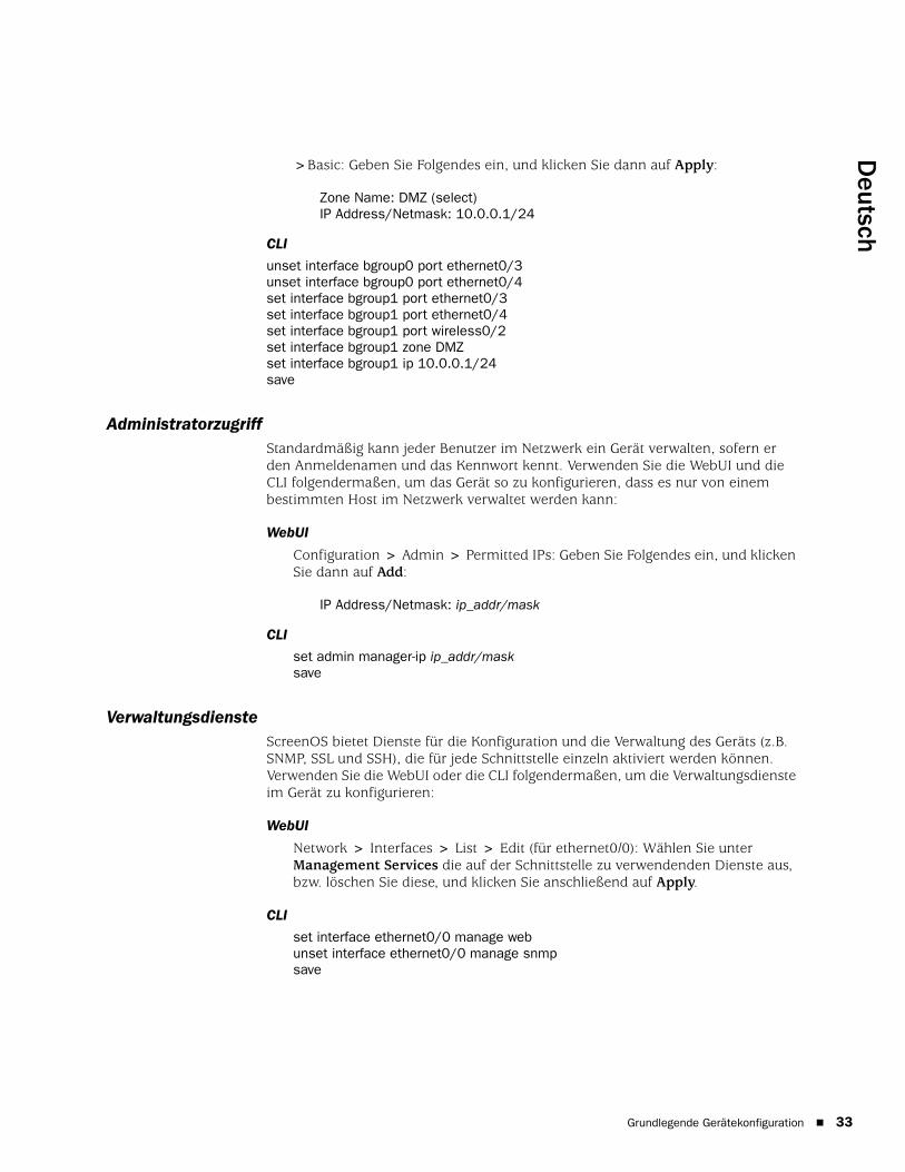
Deutsch
>Basic: Geben Sie Folgendes ein, und klicken Sie dann auf Apply:
Zone Name: DMZ (select)IP Address/Netmask: 10.0.0.1/24
CLI
unset interface bgroup0 port ethernet0/3unset interface bgroup0 port ethernet0/4set interface bgroup1 port ethernet0/3set interface bgroup1 port ethernet0/4set interface bgroup1 port wireless0/2set interface bgroup1 zone DMZset interface bgroup1 ip 10.0.0.1/24save
AdministratorzugriffStandardmäßig kann jeder Benutzer im Netzwerk ein Gerät verwalten, sofern er den Anmeldenamen und das Kennwort kennt. Verwenden Sie die WebUI und die CLI folgendermaßen, um das Gerät so zu konfigurieren, dass es nur von einem bestimmten Host im Netzwerk verwaltet werden kann:
WebUI
Configuration > Admin > Permitted IPs: Geben Sie Folgendes ein, und klicken Sie dann auf Add:
IP Address/Netmask: ip_addr/mask
CLI
set admin manager-ip ip_addr/masksave
VerwaltungsdiensteScreenOS bietet Dienste für die Konfiguration und die Verwaltung des Geräts (z.B. SNMP, SSL und SSH), die für jede Schnittstelle einzeln aktiviert werden können. Verwenden Sie die WebUI oder die CLI folgendermaßen, um die Verwaltungsdienste im Gerät zu konfigurieren:
WebUI
Network > Interfaces > List > Edit (für ethernet0/0): Wählen Sie unter Management Services die auf der Schnittstelle zu verwendenden Dienste aus, bzw. löschen Sie diese, und klicken Sie anschließend auf Apply.
CLI
set interface ethernet0/0 manage webunset interface ethernet0/0 manage snmpsave
Grundlegende Gerätekonfiguration 33

SSG 5 – Handbuch zur Hardwareinstallation und -konfiguration
34
Host- und DomänennameDer Domänenname definiert das Netzwerk oder das Subnetzwerk, zu dem das Gerät gehört, wohingegen sich der Hostname auf ein bestimmtes Gerät bezieht. Anhand des Hostnamens und des Domänennamens wird das Gerät im Netzwerk eindeutig identifiziert. Verwenden Sie die WebUI oder die CLI folgendermaßen, um den Host- und den Domännenamen auf einem Gerät zu konfigurieren:
WebUI
Network> DNS > Host: Geben Sie Folgendes ein, und klicken Sie dann auf Apply:
Host Name: nameDomain Name: name
CLI
set hostname nameset domain namesave
StandardrouteBei der Standardroute handelt es sich um eine statische Route, über die Pakete weitergeleitet werden, die an nicht ausdrücklich in der Routentabelle aufgeführte Netzwerke adressiert sind. Geht ein Paket beim Gerät mit einer Adresse ein, für die dem Gerät keine Routeninformationen vorliegen, sendet das Gerät das Paket an das von der Standardroute angegebene Ziel. Verwenden Sie die WebUI oder die CLI folgendermaßen, um die Standardroute auf dem Gerät zu konfigurieren:
WebUI
Network > Routing > Destination > New (trust-vr): Geben Sie Folgendes ein, und klicken Sie dann auf OK:
IP Address/Netmask: 0.0.0.0/0.0.0.0Next Hop
Gateway: (select)Interface: ethernet0/2 (ausgewählt)Gateway IP Address: ip_addr
CLI
set route 0.0.0.0/0 interface ethernet0/2 gateway ip_addrsave
Adresse der VerwaltungsschnittstelleDie Trust Schnittstelle besitzt die Standard-IP-Adresse 192.168.1.1/24 und ist für die Verwaltungsdienste konfiguriert. Wird der 0/2-0/4-Anschluss am Gerät mit einer Arbeitsstation verbunden, kann das Gerät über eine Arbeitsstation im Subnetzwerk 192.168.1.1/24 mithilfe eines Verwaltungsdienstes wie Telnet konfiguriert werden.
Die Standard-IP-Adresse kann auf der Trust Schnittstelle geändert werden. Möglicherweise möchten Sie die Schnittstelle ändern, um die Übereinstimmung mit den bereits im LAN vorhandenen IP-Adressen zu gewährleisten.
Grundlegende Gerätekonfiguration

Deutsch
Konfiguration der Untrust SicherungsschnittstelleDas SSG 5-Gerät ermöglicht die Konfiguration einer Sicherungsschnittstelle für einen nicht vertrauenswürdigen Failover. Führen Sie zum Festlegen der Sicherungsschnittstelle bei Auftreten eines nicht vertrauenswürdigen Failovers folgende Schritte aus:
1. Legen Sie die Sicherungsschnittstelle in der Null Sicherheitszone mithilfe des Befehlszeilenbefehls unset interface interface [ port interface ] fest.
2. Binden Sie mithilfe des Befehlszeilenbefehls set interface interface zone zone_name die Sicherungsschnittstelle an dieselbe Sicherheitszone wie die Primärschnittstelle.
Zum Festlegen der ethernet0/4-Schnittstelle als Sicherungsschnittstelle für die ethernet0/0-Schnittstelle muss die WebUI oder die CLI folgendermaßen verwendet werden:
WebUI
Network > Interfaces > Backup > – Geben Sie Folgendes ein, und klicken Sie anschließend auf Apply.
Primary: ethernet0/0Backup: ethernet0/4Type: track-ip (select)
CLI
unset interface bgroup0 port ethernet0/4set interface ethernet0/4 zone untrustset interface ethernet0/0 backup interface ethernet0/4 type track-ipsave
Grundlegende Wireless-Konfiguration
In diesem Abschnitt finden Sie Informationen zur Konfiguration der Wireless-Schnittstelle am SSG 5-WLAN-Gerät. Wireless-Netzwerke (Drahtlosnetzwerke) bestehen aus Namen, die als Service Set Identifiers (SSIDs) bezeichnet werden. Das Festlegen von SSIDs ermöglicht das Anordnen von mehreren Wireless-Netzwerken am selben Ort, ohne dass es zu Konflikten kommt. Ein SSID-Name darf aus maximal 32 Zeichen bestehen. Ist ein Leerzeichen Teil des SSID-Namens, muss die Zeichenfolge in Anführungszeichen gesetzt werden. Sobald der SSID-Name festgelegt ist, können weitere SSID-Attribute konfiguriert werden. Zur Verwendung von Wireless Local Area Network (WLAN)-Funktionen am Gerät muss zumindest eine SSID konfiguriert und an eine Wireless-Schnittstelle gebunden werden.
HINWEIS: Die Primär- und Sicherungsschnittstellen müssen sich in derselben Sicherheitszone befinden. Eine Primärschnittstelle verfügt nur über eine Sicherungsschnittstelle und umgekehrt.
Grundlegende Wireless-Konfiguration 35

SSG 5 – Handbuch zur Hardwareinstallation und -konfiguration
36
Das SSG 5-WLAN-Gerät ermöglicht das Erstellen von bis zu 16 SSIDs, von denen jedoch nur vier gleichzeitig verwendet werden können. Das Gerät kann für die Verwendung der vier 4 SSIDs auf einem der Transceiver oder für das Aufteilen der Verwendung auf beide Transceiver (z.B. drei WLAN 0 zugewiesene SSIDs und eine WLAN 1 zugewiesene SSID) konfiguriert werden. Legen Sie die Funktransceiver am SSG 5-WLAN-Gerät mit dem Befehlszeilenbefehl set interface wireless_interface wlan { 0 | 1 | both } fest. Abbildung 12 zeigt die Standardkonfiguration für das SSG 5-WLAN-Gerät.
Sobald Sie eine SSID für die wireless0/0-Schnittstelle festgelegt haben, können Sie mithilfe der standardmäßigen IP-Adresse der wireless0/0-Schnittstelle auf das Gerät zugreifen (schrittweise Anleitungen hierzu finden Sie unter „Zugriff auf das Gerät“ auf Seite 26).
Abbildung 12: Standardmäßig e SSG 5-WLAN-Konfiguration
Standardmäßig wird die wireless0/0-Schnittstelle mit der IP-Adresse 192.168.2.1/24 konfiguriert. Alle Wireless-Clients, für die eine Verbindung zur Trust Zone hergestellt werden muss, benötigen eine IP-Adresse im Wireless-Subnetzwerk. Das Gerät kann auch so konfiguriert werden, dass das Gerät mit DHCP Ihren Geräten automatisch IP-Adressen im Subnetzwerk 192.168.2.1/24 zuweist.
Standardmäßig werden die wireless0/1-wireless0/3-Schnittstellen als Null definiert. Den Schnittstellen sind keine IP-Adressen zugewiesen. Möchten Sie eine beliebige der anderen Wireless-Schnittstellen verwenden, müssen Sie für die Schnittstelle eine IP-Adresse konfigurieren, dieser eine SSID zuweisen und sie an eine Sicherheitszone binden. In Tabelle 6 sind die Methoden zur Wireless-Authentifizierung und –Verschlüsselung aufgeführt.
HINWEIS: Wird das SSG 5-WLAN-Gerät außerhalb Japans, Kanadas, Chinas, Taiwans, Koreas, Israels, Singapurs oder der Vereinigten Staaten betrieben, benötigen Sie den Befehlszeilenbefehl set wlan country-code, oder Sie müssen das Gerät auf der Wireless-WebUI-Seite > General Settings einrichten, um eine WLAN-Verbindung herstellen zu können. Durch diesen Befehl wird der auswählbare Kanalbereich und die Übertragungsleistung festgelegt.
Lautet Ihr Regionalcode ETSI, muss der korrekte Ländercode festgelegt werden, der den örtlichen Bestimmungen zu Funkbereichen entspricht.
SSG 5
V.92
STATUS
POWER
CONSOLE
TX /RX
CD
0 1 2 3 4 5 6TX/RX LINK TX/RX LINK TX/RX LINK TX/RX LINK TX/RX LINK TX/RX LINK TX/RX LINK
10/100 10/100 10/100 10/100 10/100 10/100 10/100
B /G
WLAN V.92
802.11A
Callouts
CalloutsUntrust Zone
Trust Zone
wireless0/0
Konsole
Grundlegende Wireless-Konfiguration

Deutsch
Tabelle 6: Optionen für Wirele ss-Authentifizierung und Verschlüsselung
Im Concepts & Examples ScreenOS Reference Guide finden Sie Konfigurationsbeispiele, SSID-Attribute und Befehlszeilenbefehle bzgl. Wireless-Sicherheitskonfigurationen.
Verwenden Sie die WebUI oder die CLI folgendermaßen, um eine Wireless-Schnittstelle für grundlegende Verbindung zu konfigurieren:
WebUI
1. Legen Sie den WLAN-Ländercode und die IP-Adresse fest.
Wireless > General Settings > Wählen Sie Folgendes aus, und klicken Sie anschließend auf Apply:
Country code: Select your code (Code auswählen)IP Address/Netmask: ip_add/netmask
2. Legen Sie die SSID fest.
Wireless > SSID > New: Geben Sie Folgendes ein, und klicken Sie dann auf OK:
SSID: Authentication: Encryption: Wireless Interface Binding:
3. Legen Sie den WEP-Schlüssel fest (optional).
SSID > WEP Keys: Wählen Sie die Schlüssel-ID aus, und klicken Sie anschließend auf Apply:
4. Legen Sie den WLAN-Modus fest.
Network > Interfaces > List > Edit (Wireless-Schnittstelle): Wählen Sie für den WLAN-Modus Both aus, und klicken Sie anschließend auf Apply.
5. Aktivieren Sie die Änderungen für die Wireless-Einstellungen.
Wireless > General Settings > Klicken Sie auf Activate Changes.
Authentifizierung Verschlüsselung
Offen Ermöglicht einem beliebigen Wireless-Client den Zugriff auf das Gerät.
Shared-key WEP shared-key
WPA-PSK AES/TKIP mit Pre-Shared Key
WPA AES/TKIP mit Schlüssel von RADIUS-Server
WPA2-PSK 802.11i-kompatibel mit einem Pre-Shared Key
WPA2 802.11i-kompatibel mit einem RADIUS-Server
WPA-Auto-PSK Lässt einen WPA- und einen WPA2-Typ mit Pre-Shared Key zu.
WPA-Auto Lässt einen WPA- und einen WPA2-Typ mit RADIUS-Server zu.
802.1x WEP mit Schlüssel von RADIUS-Server
Grundlegende Wireless-Konfiguration 37

SSG 5 – Handbuch zur Hardwareinstallation und -konfiguration
38
CLI
1. Legen Sie den WLAN-Ländercode und die IP-Adresse fest.
set wlan country-code { code_id }set interface wireless_interface ip ip_addr/netmask
2. Legen Sie die SSID fest.
set ssid name name_strset ssid name_str authentication auth_type encryption encryption_typeset ssid name_str interface interface(optional) set ssid name_str key-id number
3. Legen Sie den WLAN-Modus fest.
set interface wireless_interface wlan both
4. Aktivieren Sie die Änderungen für die Wireless-Einstellungen.
saveexec wlan reactivate
Eine SSID kann so konfiguriert werden, dass er im selben Subnetz wie das verkabelte Subnetz arbeitet. Dadurch haben Clients die Möglichkeit, ohne Wiederherstellen einer Verbindung in einem anderen Subnetz auf beiden Schnittstellen zu arbeiten.
Verwenden Sie zum Festlegen einer Ethernet- und einer Wireless-Schnittstelle für dieselbe Bridge-Gruppenschnittstelle die WebUI oder die CLI:
WebUI
Network > Interfaces > List > Edit (bgroup_name) >Bind Port: Wählen Sie die Wireless- und die Ethernet-Schnittstellen aus, und klicken Sie anschließend auf Apply:
CLI
set interface bgroup_name port wireless_interfaceset interface bgroup_name port ethernet_interface
HINWEIS: Bgroup_name kann bgroup0-bgroup3 sein.
Ethernet_interface kann ethernet0/0-ethernet0/6 sein.
Wireless_interface kann wireless0/0-wireless0/3 sein.
Ist eine Wireless-Schnittstelle konfiguriert, muss das WLAN mit dem Befehlszeilenbefehl exec wlan reactivate neu aktiviert werden. Alternativ dazu können Sie auch auf der WebUI-Seite „Wireless > General Settings“ auf Activate Changes klicken.
Grundlegende Wireless-Konfiguration

Deutsch
WAN-Konfiguration
In diesem Abschnitt wird die Konfiguration der folgenden WAN-Schnittstellen erläutert:
ISDN Interface (ISDN-Schnittstelle)
V.92 Modem Interface (V.92-Modemschnittstelle)
ISDN Interface (ISDN-Schnittstelle)Bei Integrated Services Digital Network (ISDN) handelt es sich um Standards für die digitale Übertragung über verschiedene vom Consultative Committee for International Telegraphy and Telephone (CCITT) und von der International Telecommunications Union (ITU) erstellte Medien. Als Dial-on-Demand-Dienst bietet ISDN einen schnellen Verbindungsaufbau sowie niedrige Latenz und ermöglicht zudem hochwertige Sprach-, Daten- und Videoübertragungen. ISDN ist überdies ein leitungsvermittelter Dienst, der sowohl für Multipoint- als auch auf Point-to-Point-Verbindungen verwendet werden kann. ISDN bietet einen Dienstrouter mit einer Multilink Point-to-Point Protocol (PPP)-Verbindung für Netzwerkschnittstellen. Die ISDN-Schnittstelle wird normalerweise zum Zugriff auf externe Netzwerke als Sicherungsschnittstelle der Ethernet-Schnittstelle konfiguriert.
Verwenden Sie zum Konfigurieren der ISDN-Schnittstelle die WebUI oder die CLI:
WebUI
Network > Interfaces > List > Edit (bri0/0): Geben Sie Folgendes ein (bzw. wählen Sie Folgendes aus), und klicken Sie dann auf OK:
BRI-Mode: Dial Using BRIPrimary Number: 123456WAN Encapsulation: PPPPPP Profile: isdnprofile
CLI
set interface bri0/0 dialer-enableset interface bri0/0 primary-number "123456"set interface bri0/0 encap pppset interface bri0/0 ppp profile isdnprofilesave
Informationen zum Konfigurieren der ISDN-Schnittstelle als Sicherungsschnittstelle erhalten Sie unter „Konfiguration der Untrust Sicherungsschnittstelle“ auf Seite 35.
Weitere Informationen zur Konfiguration der ISDN-Schnittstelle erhalten Sie im Concepts & Examples ScreenOS Reference Guide.
WAN-Konfiguration 39

SSG 5 – Handbuch zur Hardwareinstallation und -konfiguration
40
V.92 Modem Interface (V.92-Modemschnittstelle)Die V.92-Schnittstelle verfügt über ein internes analoges Modem zum Herstellen einer PPP-Verbindung zu einem Dienstanbieter. Die serielle Schnittstelle kann als Primär- oder Sicherungsschnittstelle konfiguriert werden, die beim Failover einer Schnittstelle verwendet wird.
Verwenden Sie zum Konfigurieren der V.92-Schnittstelle die WebUI oder die CLI:
WebUI
Network > Interfaces > List > Edit (für serial0/0): Geben Sie Folgendes ein, und klicken Sie dann auf OK:
Zone Name: untrust (select)
ISP: Geben Sie Folgendes ein, und klicken Sie dann auf OK:
ISP Name: isp_juniperPrimary Number: 1234567Login Name: juniperLogin Password: juniper
Modem: Geben Sie Folgendes ein, und klicken Sie dann auf OK:
Modem Name: mod1Init String: AT&FS7=255S32=6Active Modem setting
Inactivity Timeout: 20
CLI
set interface serial0/0 zone untrustset interface serial0/0 modem isp isp_juniper account login juniper password juniperset interface serial0/0 modem isp isp_juniper primary-number 1234567set interface serial0/0 modem idle-time 20set interface serial0/0 modem settings mod1 init-strings AT&FS7=255S32=6set interface serial0/0 modem settings mod1 active
Weitere Informationen zur Konfiguration der V.92-Modemschnittstelle erhalten Sie im Concepts & Examples ScreenOS Reference Guide.
HINWEIS: Die V.92-Schnittstelle funktioniert im transparenten Modus nicht.
WAN-Konfiguration

Deutsch
Grundlegender Firewallschutz
Die Geräte werden mit einer Standardrichtlinie konfiguriert, die Arbeitsstationen in der Trust Zone des Netzwerks den Zugriff auf eine beliebige Ressource in der Untrust Sicherheitszone gestattet, wohingegen externe Computer mit den Arbeitsstationen nicht auf Sitzungen zugreifen oder diese starten dürfen. Sie können Richtlinien konfigurieren, damit das Gerät externen Computern das Starten bestimmter Sitzungstypen mit Ihren Computern erlaubt. Informationen zum Erstellen oder Ändern von Richtlinien erhalten Sie im Concepts & Examples ScreenOS Reference Guide.
Das SSG 5-Gerät bietet verschiedene Erkennungsmethoden und Verteidigungsmechanismen zur Bekämpfung von Spionage und Angriffen, durch die ein Netzwerk oder eine Netzwerkressource gefährdet oder beschädigt werden soll.
Die ScreenOS SCREEN-Optionen sichern eine Zone, indem sie alle über eine Schnittstelle laufenden Verbindungsversuche zu dieser Zone überprüfen und dann zulassen oder verweigern. Sie können in der Untrust Zone z.B. einen Port-Scan-Schutz anwenden, um eine Quelle aus einem Remotenetzwerk am Erkennen von Diensten zu hindern, die u.U. Gegenstand weiterer Angriffe werden sollen.
Das Gerät wendet Firewallrichtlinien, die ggf. Komponenten für Inhaltsfilterung und Eindringungserkennung und -verhinderung (Intrusion Detection and Prevention, IDP) beinhalten, für den Datenverkehr an, der zonenübergreifend die SCREEN-Filter durchläuft. Standardmäßig darf durch das Gerät kein Datenverkehr zonenübergreifend geleitet werden. Erstellen Sie eine Richtlinie zum Deaktivieren des Standardverhaltens, um Datenverkehr ein zonenübergreifendes Durchlaufen des Geräts zu gestatten.
Legen Sie ScreenOS SCREEN-Optionen für eine Zone folgendermaßen mithilfe der WebUI oder der CLI fest:
WebUI
Screening > Screen: Wählen Sie die Zone aus, für die die Optionen Gültigkeit besitzen. Wählen Sie die gewünschten SCREEN-Optionen aus, und klicken Sie anschließend auf Apply:
CLI
set zone zone screen optionsave
Weitere Informationen zum Konfigurieren der in ScreenOS verfügbaren Netzwerksicherheitsoptionen erhalten Sie im Band Attack Detection and Defense Mechanisms im Concepts & Examples ScreenOS Reference Guide.
Überprüfen der externen Verbindung
Um zu überprüfen, ob die Arbeitsstationen in Ihrem Netzwerk auf Ressourcen im Internet zugreifen können, starten Sie auf einer Arbeitsstation im Netzwerk einen Browser, und geben Sie den folgenden URL ein: www.juniper.net.
Grundlegender Firewallschutz 41

SSG 5 – Handbuch zur Hardwareinstallation und -konfiguration
42
Zurücksetzen eines Geräts auf die werkseitigen Standardeinstellungen
Wenn Sie das Administratorkennwort verlieren oder vergessen, können Sie das Gerät auf die Standardeinstellungen zurücksetzen. Dadurch gehen alle vorhandenen Konfigurationen verloren, der Zugriff auf das Gerät ist jedoch wieder möglich.
Zum Wiederherstellen der Standardeinstellungen des Geräts stehen Ihnen folgende Methoden zur Auswahl:
Verwenden einer Konsolenverbindung. Weitere Informationen erhalten Sie im Band Verwaltung des Concepts & Examples ScreenOS Reference Guide.
Verwenden des Reset-Stiftlochs an der Rückseite des Geräts wie im folgenden Abschnitt beschrieben.
Sie können das Gerät zurücksetzen und die werkseitigen Standardeinstellungen wiederherstellen, indem Sie das Reset-Stiftloch betätigen. Hierzu müssen Sie entweder die Gerätestatus-LEDs am Bedienfeld überprüfen oder wie in Verwenden einer Konsolenverbindung auf Seite 26 beschrieben eine Konsolensitzung starten.
Führen Sie zum Zurücksetzen und Wiederherstellen der Standardeinstellungen mithilfe des Reset-Stifts die folgenden Schritte aus:
1. Machen Sie das Reset-Stiftloch an der Rückseite des Geräts ausfindig. Drücken Sie einen dünnen festen Draht (z.B. eine Büroklammer) vier bis sechs Sekunden lang in das Stiftloch.
Die Status-LED blinkt rot. Durch eine Meldung auf der Konsole wird angezeigt, dass die Löschung der Konfiguration gestartet wurde, und das System sendet eine SNMP/SYSLOG-Benachrichtigung.
2. Warten Sie ein bis zwei Sekunden.
Nach dem ersten Zurücksetzen blinkt die Status-LED grün. Das Gerät wartet jetzt auf das zweite Zurücksetzen. In der Konsolenmeldung werden Sie nun darauf hingewiesen, dass das Gerät auf eine zweite Bestätigung wartet.
3. Betätigen Sie das Reset-Stiftloch erneut vier bis sechs Sekunden lang.
Die Konsolenmeldung überprüft die zweite Zurücksetzung. Die Status-LED leuchtet kurz rot auf und blinkt anschließend wieder grün.
Das Gerät wird dann auf seine ursprünglichen Werkseinstellungen zurückgesetzt. Beim Zurücksetzen des Geräts leuchtet die Status-LED kurz rot auf und leuchtet anschließend wieder grün. Die Konsole zeigt Gerätestartmeldungen an. Das System sendet SNMP- und SYSLOG-Benachrichtigungen an konfigurierte SYSLOG- oder SNMP-Trap-Hosts.
WARNHINWEIS: Durch das Zurücksetzen des Geräts werden alle vorhandenen Konfigurationseinstellungen gelöscht und alle vorhandenen Firewall- und VPN-Dienste deaktiviert.
Zurücksetzen eines Geräts auf die werkseitigen Standardeinstellungen

Deutsch
Nachdem das Gerät neu gestartet wurde, zeigt die Konsole die Anmeldeaufforderung für das Gerät an. Die Status-LED blinkt grün. Der Anmeldename und das Kennwort lauten netscreen.
Wenn Sie nicht die vollständige Zurücksetzsequenz ausführen, wird der Vorgang ohne Konfigurationsänderung abgebrochen, und in der Konsolenmeldung werden Sie darauf hingewiesen, dass die Löschung der Konfiguration abgebrochen wird. Die Status-LED blinkt dann wieder grün. Wenn das Gerät nicht zurückgesetzt wurde, wird zur Bestätigung dieses Fehlers eine SNMP-Benachrichtigung gesendet.
Zurücksetzen eines Geräts auf die werkseitigen Standardeinstellungen 43

SSG 5 – Handbuch zur Hardwareinstallation und -konfiguration
44
Zurücksetzen eines Geräts auf die werkseitigen Standardeinstellungen
Deutsch
Kapitel 4
Warten des Geräts
In diesem Kapitel werden die Wartungsmaßnahmen für SSG 5-Geräte erläutert. Das Kapitel umfasst die folgenden Abschnitte:
„Erforderliche Werkzeuge und Teile“ auf dieser Seite
„Erweitern des Arbeitsspeichers“ auf dieser Seite
Erforderliche Werkzeuge und Teile
Zum Ersetzen einer Komponente eines SSG 5-Geräts benötigen Sie folgende Werkzeuge und Teile:
Erdungsarmband zum Schutz vor elektrostatischer Entladung (Electrostatic Discharge, ESD)
Kreuzschlitzschraubenzieher 3 mm (1/8-Zoll)
Erweitern des Arbeitsspeichers
Der einem SSG 5-Gerät zur Verfügung stehende 128 MB umfassende Arbeitsspeicher mit zwei Kontaktreihen (Dual Inline Memory) ist erweiterbar. Dual Inline Memory Module (DIMM) Dynamic Random Access Memory (DRAM) auf 256 MB DIMM DRAM.
Gehen Sie zum Erweitern des Arbeitsspeichers eines SSG 5-Geräts folgendermaßen vor:
1. Schnallen Sie zum Schutz vor elektrostatischer Entladung ein Erdungsband um Ihr Handgelenk, und stellen Sie eine Verbindung zwischen dem Band und dem ESD-Punkt auf dem Chassis oder einem externen ESD-Punkt her, falls das Gerät nicht geerdet ist.
HINWEIS: Sicherheitshinweise und Anweisungen finden Sie im Security Products Safety Guide von Juniper Networks. Dieses Handbuch enthält Informationen zu Situationen, die zu Verletzungen führen können. Bevor Sie mit der Arbeit an Geräten beginnen, informieren Sie sich über die Gefahren, die beim Umgang mit elektrischen Komponenten bestehen. Machen Sie sich außerdem mit den gängigen Vorkehrungen zur Vermeidung von Unfällen vertraut.
Erforderliche Werkzeuge und Teile 45

SSG 5 – Handbuch zur Hardwareinstallation und -konfiguration
46
2. Stecken Sie das Wechselstromkabel aus.
3. Drehen Sie das Gerät um, damit die Oberseite auf einem ebenen Untergrund liegt.
4. Entfernen Sie die Schrauben mit einem Kreuzschlitzschraubenzieher von der Speicherkartenabdeckung. Legen Sie die Schrauben neben sich ab, um damit später wieder die Abdeckung zu fixieren.
5. Entfernen Sie die Speicherkartenabdeckung.
Abbildung 13: Unterseite des Geräts
6. Drücken Sie auf jeder Seite des Moduls mit den Daumen außen auf die Sperrriegel. Diese gleiten daraufhin vom Modul weg, und Sie können den 128 MB DIMM DRAM entnehmen.
Abbildung 14: Entriegeln des Arbeitsspeichermoduls
7. Ergreifen Sie die lange Kante des Arbeitsspeichermoduls, und lassen Sie dieses herausgleiten. Legen Sie das Modul neben sich ab.
Erweitern des Arbeitsspeichers

Deutsch
Abbildung 15: Entfernen der Modulsteckplätze
8. Setzen Sie den 256 MB DIMM DRAM in den Steckplatz ein. Üben Sie mit beiden Daumen einen gleichmäßigen Druck auf die obere Kante des Moduls aus, und drücken Sie das Modul nach unten, bis die Sperrriegel in der vorgesehenen Position einrasten.
Abbildung 16: Einsetzen des Arbeitsspeichermoduls
9. Platzieren Sie die Speicherkartenabdeckung über dem Steckplatz.
10. Ziehen Sie die Schrauben mit einem Kreuzschlitzschraubenzieher fest, und fixieren Sie die Abdeckung am Gerät.
Erweitern des Arbeitsspeichers 47

SSG 5 – Handbuch zur Hardwareinstallation und -konfiguration
48
Erweitern des Arbeitsspeichers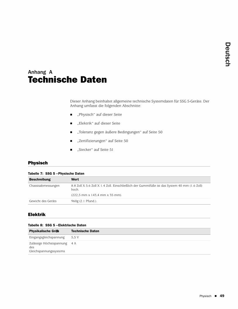
Deutsch
Anhang A
Technische Daten
Dieser Anhang beinhaltet allgemeine technische Systemdaten für SSG 5-Geräte. Der Anhang umfasst die folgenden Abschnitte:
„Physisch“ auf dieser Seite
„Elektrik“ auf dieser Seite
„Toleranz gegen äußere Bedingungen“ auf Seite 50
„Zertifizierungen“ auf Seite 50
„Stecker“ auf Seite 51
Physisch
Tabelle 7: SSG 5 – Physische Daten
Elektrik
Tabelle 8: SSG 5 – Elektrische Daten
Beschreibung Wert
Chassisabmessungen 8.8 Zoll X 5.6 Zoll X 1.4 Zoll. Einschließlich der Gummifüße ist das System 40 mm (1.6 Zoll) hoch.
(222,5 mm x 143,4 mm x 35 mm).
Gewicht des Geräts 960g (2.1 Pfund.).
Physikalische Größe Technische Daten
Eingangsgleichspannung 5,5 V
Zulässige Höchstspannung des Gleichspannungssystems
4 A
Physisch 49

SSG 5 – Handbuch zur Hardwareinstallation und -konfiguration
50
Toleranz gegen äußere Bedingungen
Tabelle 9: SSG – Toleran z gegen äußere Bedingungen
Zertifizierungen
SicherheitCAN/CSA-C22.2 Nr. 60950-1-03/UL 60950-1 Dritte Ausgabe, Sicherheit von Informationstechnologiegeräten
EN 60950-1:2001+A11, Sicherheit von Informationstechnologiegeräten
IEC 60950-1:2001 Erste Ausgabe, Sicherheit von Informationstechnologiegeräten
EMC-EmissionenFCC Teil 15 Klasse B (USA)
EN 55022 Klasse B (Europa)
AS 3548 Klasse B (Australien)
VCCI Klasse B (Japan)
EMC-StörfestigkeitEN 55024
EN-61000-3-2 – Netzoberwellen
EN-61000-3-3 – Netzoberwellen
EN-61000-4-2 – ESD (elektrostatische Entladung)
EN-61000-4-3 – Störfestigkeit gegen Strahlung
EN-61000-4-4 – EFT (Electrical Fast Transients, schnelle transiente Störgrößen)
EN-61000-4-5 – Stoßspannungen
EN-61000-4-6 – Allgemeine Störfestigkeit gegen niedrige Frequenzen
EN-61000-4-11 – Spannungseinbrüche und -schwankungen
Beschreibung Wert
Höhe über NN Keine Beeinträchtigung der Leistung bis zu einer Höhe von 6,600 ft (2,000 m)
Relative Luftfeuchtigkeit Bei einer relativen Luftfeuchtigkeit zwischen 5 und 90 Prozent (nicht kondensierend) ist eine ordnungsgemäße Funktion gesichert.
Temperatur In einem Temperaturbereich zwischen 32°F (0°C) und 104°F (40°C) ist eine ordnungsgemäße Funktion sichergestellt.
Zulässiger Temperaturbereich für die Lagerung des Geräts: -40°F (-40°C) bis 158°F (70°C)
Toleranz gegen äußere Bedingungen
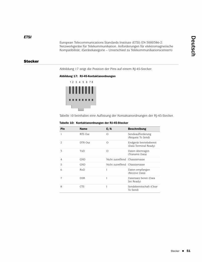
Deutsch
ETSIEuropean Telecommunications Standards Institute (ETSI) EN-3000386-2: Netzwerkgeräte für Telekommunikation. Anforderungen für elektromagnetische Kompatibilität; (Gerätekategorie – Unterschied zu Telekommunikationscentern)
Stecker
Abbildung 17 zeigt die Position der Pins auf einem RJ-45-Stecker.
Abbildung 17: RJ-45-Kontaktanordnungen
Tabelle 10 beinhaltet eine Auflistung der Kontaktanordnungen der RJ-45-Stecker.
Tabelle 10: Kontaktanordnungen der RJ-45-Stecker
Pin Name E/A Beschreibung
1 RTS Out O Sendeaufforderung (Request To Send)
2 DTR Out O Endgerät betriebsbereit (Data Terminal Ready)
3 TxD O Daten übertragen (Transmit Data)
4 GND Nicht zutreffend Chassismasse
5 GND Nicht zutreffend Chassismasse
6 RxD I Daten empfangen (Receive Data)
7 DSR I Datensatz bereit (Data Set Ready)
8 CTS I Sendebereitschaft (Clear To Send)
1 2 3 4 5 6 7 8
Stecker 51

SSG 5 – Handbuch zur Hardwareinstallation und -konfiguration
52
Abbildung 18 zeigt die Position der Pins auf einer DB-9-Buchse.
Abbildung 18: DB-9-Buchse
Tabelle 11 beinhaltet eine Auflistung der Kontaktanordnungen der DB-9-Stecker.
Tabelle 11: Kontaktanordnungen der DB-9-Stecker
Pin Name E/A Beschreibung
1 DCD I Trägersignal erkannt (Carrier Detect)
2 RxD I Daten empfangen (Receive Data)
3 TxD O Daten übertragen (Transmit Data)
4 DTR O Endgerät betriebsbereit (Data Terminal Ready)
5 GND Nicht zutreffend Signalerde (Signal Ground)
6 DSR I Datensatz bereit (Data Set Ready)
7 RTS O Sendeaufforderung (Request To Send)
8 CTS I Sendebereitschaft (Clear To Send)
9 RING I Anrufanzeige (Ring Indicator)
Stecker

Deutsch
Anhang B
Assistent für die Anfangskonfiguration
Dieser Anhang beinhaltet detaillierte Informationen zum Assistenten für die Anfangskonfiguration (Initial Configuration Wizard, ICW) für SSG 5-Geräte.
Verwenden Sie nach dem Anschluss des Geräts an das Netzwerk den ICW zur Konfiguration der auf dem Gerät installierten Schnittstellen.
In diesem Abschnitt werden die folgenden ICW-Fenster beschrieben:
1. Fenster für die Schnellkonfiguration auf Seite 54
2. Fenster für die Administratoranmeldung auf Seite 54
3. Fenster für den WLAN-Zugriffspunkt auf Seite 55
4. Fenster für die Konfiguration der physischen Schnittstelle auf Seite 55
5. Fenster für die ISDN-Schnittstelle auf Seite 56
6. Fenster für die Konfiguration der V.92-Modemschnittstelle auf Seite 58
7. Eth0/0 Interface (Untrust Zone) – Fenster auf Seite 59
8. Fenster für die Konfiguration der Eth0/1-Schnittstelle (DMZ-Zone) auf Seite 60
9. Fenster für die Konfiguration der Bgroup0-Schnittstelle (Trust Zone) auf Seite 60
10. Fenster für die Konfiguration der Wireless0/0-Schnittstelle (Trust Zone) auf Seite 62
11. Fenster für die Schnittstellenzusammenfassung auf Seite 64
12. Fenster für die Konfiguration der physischen Ethernet-DHCP-Schnittstelle auf Seite 64
13. Fenster für die Konfiguration der Wireless-DHCP-Schnittstelle auf Seite 65
14. Bestätigungsfenster auf Seite 65
53

SSG 5 – Handbuch zur Hardwareinstallation und -konfiguration
54
1. Fenster für die Schnellkonfiguration
Abbildung 19: Fenster für die Schnellkonfiguration
Arbeitet das Netzwerk mit NetScreen-Security Manager (NSM) kann das Configlet für die Schnellkonfiguration zur automatischen Konfiguration des Geräts eingesetzt werden. Besorgen Sie sich beim NSM-Administrator ein Configlet, wählen Sie Yes, Load Configlet from:, und navigieren Sie zum Speicherort der Datei. Klicken Sie anschließend auf Next. Das Configlet richtet das Gerät für Sie ein, sodass Sie zum Konfigurieren des Geräts die folgenden Schritte nicht ausführen müssen.
Wenn Sie den ICW umgehen und direkt zur WebUI wechseln möchten, wählen Sie die letzte Option, und klicken Sie anschließend auf Next.
Wenn Sie zum Konfigurieren des Geräts kein Configlet, sondern den ICW verwenden möchten, wählen Sie die erste Option, und klicken Sie anschließend auf Next. Die ICW-Willkommensseite wird angezeigt. Klicken Sie auf Next. Das Fenster für die Administratoranmeldung wird angezeigt.
2. Fenster für die AdministratoranmeldungGeben Sie einen neuen Administratoranmeldenamen und ein neues Kennwort ein, und klicken Sie auf Next.
Abbildung 20: Fenster für die Administratoranmeldung

Deutsch
3. Fenster für den WLAN-ZugriffspunktBei Verwendung des Geräts in der Regulierungsdomäne WORLD oder ETSI müssen Sie einen Ländercode auswählen. Wählen Sie die entsprechende Option, und klicken Sie anschließend auf Next.
Abbildung 21: Fenster für die Konfiguration des Ländercodes
4. Fenster für die Konfiguration der physischen SchnittstelleAuf dem Bildschirm für Schnittstellen-Zonenbindungen legen Sie die Schnittstelle fest, an die die Untrust Sicherheitszone gebunden werden soll. Bgroup0 ist vorab an die Trust Sicherheitszone gebunden. Ethernet0/1 ist an die DMZ-Sicherheitszone gebunden, dabei jedoch optional.
Abbildung 22: Fenster für die Angabe der physischen Schnittstelle
Sie können nach dem Binden einer Schnittstelle an eine Zone die Schnittstelle konfigurieren. Welches Konfigurationsfenster anschließend angezeigt wird, hängt davon ab, welches SSG 5-Gerät in Ihrem Netzwerk verwendet wird. Klicken Sie zum Fortsetzen der Konfiguration mithilfe des ICW auf Next.
55

SSG 5 – Handbuch zur Hardwareinstallation und -konfiguration
56
5. Fenster für die ISDN-SchnittstelleBesitzen Sie ein ISDN-Gerät, wird ein mit dem folgenden Fenster vergleichbares Fenster mit der Registerkarte für physische Ebenen angezeigt.
Abbildung 23: Fenster für die Konfig uration der ISDN-Schnittstelle – Registerkarte „Physical Layer“
Tabelle 12: Felder auf der Registerkarte „Physical Layer“ im Fenster für die Konfiguration der ISDN-Schnittstelle
Feld Beschreibung
Switch Type Legt den Vermittlungstyp des Dienstanbieters fest:
att5e: At&T 5ESS
ntdms100: Nortel DMS 100
ins-net: NTT INS-Net
etsi: European variants
ni1: National ISDN-1
SPID1 Dienstanbieter-ID, normalerweise eine siebenstellige Telefonnummer mit einigen optionalen Nummern. Nur für die Vermittlungstypen DMS-100 und NI1 sind SPIDs erforderlich. Dem Vermittlungstyp DMS-100 sind zwei SPIDs zugewiesen, einer für jeden B-Kanal.
SPID2 Sicherungs-ID für Dienstanbieter.
TEI Negotiation Gibt an, wann die TEI ausgehandelt werden soll (beim Start oder beim ersten Anruf). Diese Einstellung wird normalerweise für ISDN-Dienstangebote in Europa und für Verbindungen zu DMS-100-Switches verwendet, die für das Initialisieren der TEI-Aushandlung vorgesehen sind.
Calling Number Die Rechnungsnummer für das ISDN-Netzwerk.
Sending Complete Checkbox Ermöglicht das Senden vollständiger Informationen an ausgehende Installationsmeldung. Wird normalerweise nur in Hongkong und Taiwan verwendet.

Deutsch
Besitzen Sie ein ISDN-Gerät, werden die Kontrollkästchen Leased Line Mode und Dial Using BRI angezeigt. Durch Aktivieren von einem oder beiden Kontrollkästchen wird ein dem folgenden Fenster ähnelndes Fenster angezeigt:
Abbildung 24: Fenster mit den Registerkarten „Leased-Line“ und „Dial Using BRI“
Tabelle 13: Felder im Fenster mit den Registerkarten „Leased-Line“ und „Dial Using BRI“
Feld Beschreibung
PPP Profile Name Legt für die ISDN-Schnittstelle einen PPP-Profilnamen fest.
Authentication Legt den PPP-Authentifizierungstyp fest:
Any
CHAP: Challenge Handshake Authentication Protocol
PAP: Password Authentication Protocol
None
Local User Legt den lokalen Benutzer fest.
Password Legt das Kennwort für den lokalen Benutzer fest.
Static IP Checkbox Aktiviert eine statische IP-Adresse für die Schnittstelle.
Interface IP Legt die IP-Adresse für die Schnittstelle fest.
Netmask Legt die Netzmaske fest.
Gateway Legt die Gateway-Adresse fest.
57

SSG 5 – Handbuch zur Hardwareinstallation und -konfiguration
58
6. Fenster für die Konfigurat ion der V.92-ModemschnittstelleBesitzen Sie ein V.92-Gerät, wird folgendes Fenster angezeigt:
Abbildung 25: Fenster für die Konfiguration der V.92-Modemschnittstelle
Tabelle 14: Felder im Fenster für die Konfiguration der V.92-Modemschnittstelle
Feld Beschreibung
Modem Name Legt den Namen für die Modemschnittstelle fest.
Init Strings Legt die Initialisierungszeichenfolge für das Modem fest.
ISP Name Weist dem Dienstanbieter einen Namen zu.
Primary Number Gibt die Telefonnummer zum Zugreifen auf den Dienstanbieter an.
Alternative Number (optional) Gibt eine alternative Telefonnummer zum Zugreifen auf den Dienstanbieter an, wenn mithilfe der primären Nummer keine Verbindung hergestellt werden kann.
Login Name Legt den Anmeldenamen für das Dienstanbieterkonto fest.
Password Legt das Kennwort für den Anmeldenamen fest.

Deutsch
7. Eth0/0 Interface (Untrust Zone) – FensterDer Schnittstelle der Untrust Zone kann über DHCP oder PPPoE eine statische oder dynamische IP-Adresse zugewiesen werden. Geben Sie die erforderlichen Informationen ein, und klicken Sie anschließend auf Next.
Abbildung 26: Eth0/0 Interface – Fenster
Tabelle 15: Felder im Fenster „Eth0/0 Interface“
Feld Beschreibung
Dynamic IP via DHCP Ermöglicht den Empfang einer IP-Adresse für die Schnittstelle der Untrust Zone von einem Dienstanbieter.
Dynamic IP via PPPoE Das Gerät kann als PPPoE-Client fungieren und empfängt eine IP-Adresse für die Schnittstelle der Untrust Zone von einem Dienstanbieter. Geben Sie den vom Dienstanbieter zugewiesenen Benutzernamen und das zugewiesene Kennwort ein.
Static IP Weist der Schnittstelle der Untrust Zone eine eindeutige und feste IP-Adresse zu. Geben Sie die IP-Adresse der Schnittstelle der Untrust Zone, die Netzmaske und das Gateway ein.
59

SSG 5 – Handbuch zur Hardwareinstallation und -konfiguration
60
8. Fenster für die Konfiguration der Eth0/1-Schnittstelle (DMZ-Zone)Der DMZ-Schnittstelle kann über DHCP eine statische oder dynamische IP-Adresse zugewiesen werden. Geben Sie die erforderlichen Informationen ein, und klicken Sie anschließend auf Next.
Abbildung 27: Fenster für die Konfiguration der Eth0/1-Schnittstelle
Tabelle 16: Felder im Fenster für die Konfiguration der Ethernet0/1-Schnittstelle
9. Fenster für die Konfiguration der Bgroup0-Schnittstelle (Trust Zone)Der Schnittstelle der Trust Zone kann über DHCP eine statische oder eine dynamische IP-Adresse zugewiesen werden. Geben Sie die gewünschten Informationen ein, und klicken Sie anschließend auf Next.
Die Standard-IP-Adresse für Schnittstellen ist 192.168.1.1, und die Netzmaske lautet 255.255.255.0 oder 24.
Feld Beschreibung
Dynamic IP via DHCP Ermöglicht den Empfang einer IP-Adresse für die DMZ-Schnittstelle von einem Dienstanbieter.
Static IP Weist der DMZ-Schnittstelle eine eindeutige und feste IP-Adresse zu. Geben Sie die IP-Adresse der DMZ-Schnittstelle und eine Netzmaske ein.

Deutsch
Abbildung 28: Fenster für die Konfiguration der Bgroup0-Schnittstelle
Tabelle 17: Felder im Fenster für die Konfiguration der Bgroup0-Schnittstelle
Feld Beschreibung
Dynamic IP via DHCP Ermöglicht den Empfang einer IP-Adresse für die Schnittstelle der Trust Zone von einem Dienstanbieter.
Static IP Weist der Schnittstelle der Trust Zone eine eindeutige und feste IP-Adresse zu. Geben Sie die IP-Adresse der Schnittstelle der Trust Zone und eine Netzmaske ein.
61

SSG 5 – Handbuch zur Hardwareinstallation und -konfiguration
62
10. Fenster für die Konfiguration der Wireless0/0-Schnittstelle (Trust Zone)Besitzen Sie ein SSG 5-WLAN-Gerät, müssen Sie vor dem Aktivieren der wireless0/0-Schnittstelle eine Service Set Identifier (SSID) festlegen. Detaillierte Anweisungen zum Konfigurieren der Wireless-Schnittstellen finden Sie im Concepts & Examples ScreenOS Reference Guide.
Abbildung 29: Fenster für die Konfiguration der Wireless0/0-Schnittstelle

Deutsch
Tabelle 18: Felder im Fenster für die Konfiguration der Wireless0/0-Schnittstelle
Nach dem Konfigurieren der WAN-Schnittstellen wird das Fenster für die Schnittstellenzusammenfassung angezeigt.
Feld Beschreibung
Wlan Mode Legt den WLAN-Funkmodus fest:
5G (802.11a)
2.4G (802.11b/g)
Both (802.11a/b/g)
SSID Legt den SSID-Namen fest.
Authentication and Encryption Legt die Authentifizierung und Verschlüsselung der WLAN-Schnittstelle fest:
Mit der Standardeinstellung Open für die Authentifizierung kann jeder auf das Gerät zugreifen. Für diese Authentifizierungsoption steht keine Verschlüsselung zur Verfügung.
Der Authentifizierungstyp WPA Pre-Shared Key legt den Pre-Shared Key (PSK) oder die Passphrase fest, der bzw. die beim Zugreifen auf eine Wireless-Verbindung eingegeben werden muss. Für den PSK können Sie einen HEX- oder ASCII-Wert eingeben. Für einen HEX PSK muss ein 256-Bit-HEX-Wert (64 Textzeichen) eingegeben werden. Eine ASCII-Passphrase muss zwischen 8 und 63 Textzeichen enthalten. Als Verschlüsselungstyp für diese Option muss Temporal Key Integrity Protocol (TKIP) oder Advanced Encryption Standard (AES) ausgewählt werden. Wählen Sie alternativ Auto aus, um beide Optionen zuzulassen.
WPA2 Pre-Shared Key
WPA Auto Pre-Shared Key
Interface IP Legt die IP-Adresse für die WLAN-Schnittstelle fest.
Netmask Legt die Netzmaske für die WLAN-Schnittstelle fest.
63
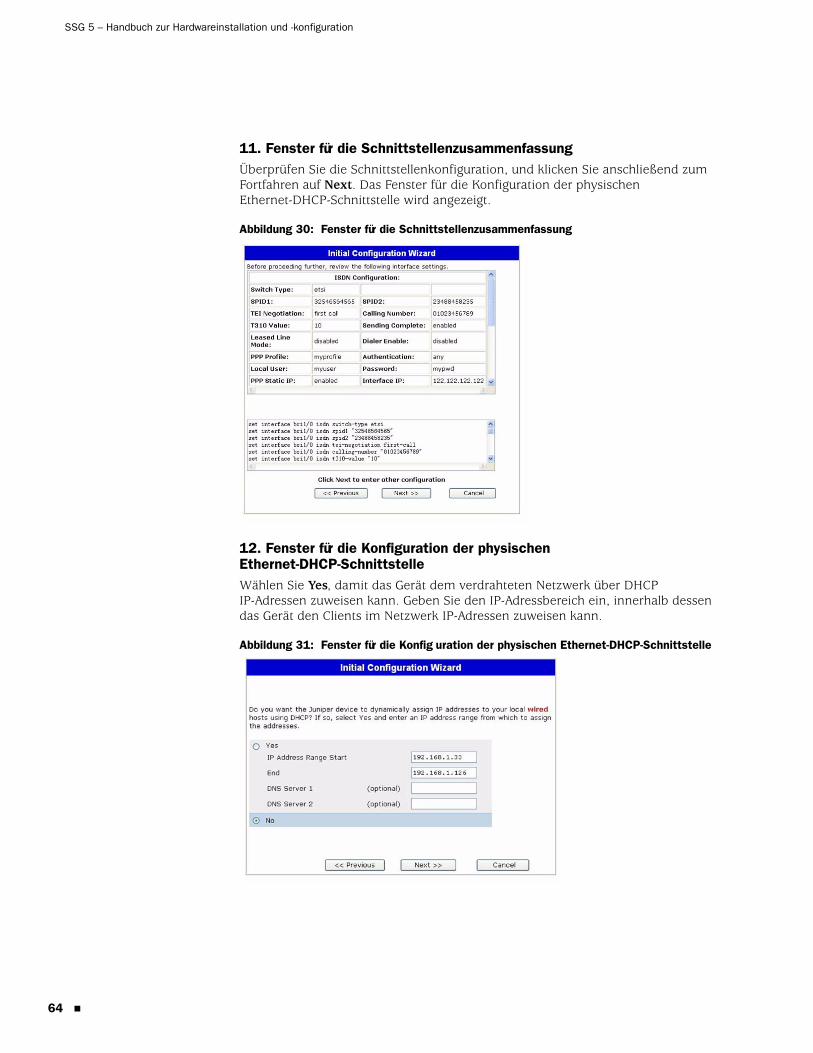
SSG 5 – Handbuch zur Hardwareinstallation und -konfiguration
64
11. Fenster für die SchnittstellenzusammenfassungÜberprüfen Sie die Schnittstellenkonfiguration, und klicken Sie anschließend zum Fortfahren auf Next. Das Fenster für die Konfiguration der physischen Ethernet-DHCP-Schnittstelle wird angezeigt.
Abbildung 30: Fenster für die Schnittstellenzusammenfassung
12. Fenster für die Konfiguration der physischen Ethernet-DHCP-SchnittstelleWählen Sie Yes, damit das Gerät dem verdrahteten Netzwerk über DHCP IP-Adressen zuweisen kann. Geben Sie den IP-Adressbereich ein, innerhalb dessen das Gerät den Clients im Netzwerk IP-Adressen zuweisen kann.
Abbildung 31: Fenster für die Konfig uration der physischen Ethernet-DHCP-Schnittstelle

Deutsch
13. Fenster für die Konfiguration der Wireless-DHCP-SchnittstelleWählen Sie Yes, damit das Gerät dem Wireless-Netzwerk über DHCP IP-Adressen zuweisen kann. Geben Sie den IP-Adressbereich ein, innerhalb dessen das Gerät den Clients im Netzwerk IP-Adressen zuweisen kann.
Abbildung 32: Fenster für die Konfiguration der Wireless-DHCP-Schnittstelle
14. BestätigungsfensterBestätigen Sie die Gerätekonfiguration, und nehmen Sie ggf. Änderungen vor. Klicken Sie zum Speichern auf Next, starten Sie das Gerät neu, und führen Sie anschließend die Konfiguration aus.
Abbildung 33: Bestätigungsfenster
Das Gerät wird nach dem Klicken auf Next mit der gespeicherten Systemkonfiguration neu gestartet. Die WebUI-Anmeldeaufforderung wird angezeigt. Informationen zum Zugreifen auf das Gerät mithilfe der WebUI finden Sie unter “Verwenden der WebUI“ auf Seite 27.
65

SSG 5 – Handbuch zur Hardwareinstallation und -konfiguration
66

Deutsch
Index
FFunktransceiverWLAN 0.....................................................................14WLAN 1.....................................................................14
KKabel
Grundlegende Netzwerkverbindungen .................21Konfiguration
Administratorname und -kennwort.......................31Administratorzugriff ................................................33Bridge-Gruppen (bgroup) ........................................32Datum und Uhrzeit ..................................................32Host- und Domänenname ......................................34Standardroute...........................................................34Untrust Sicherungsschnittstelle..............................35USB............................................................................14Verwaltungsadresse.................................................34Verwaltungsdienste .................................................33WAN-Schnittstellen..................................................39Wireless und Ethernet (kombiniert) ......................38Wireless-Authentifizierung und
-Verschlüsselung ...................................................36
RReset-Stiftloch, Verwenden ..........................................42
SSicherungsschnittstelle für die Untrust Zone .............35Standard-IP-Adressen....................................................30
UUntrust Zone, Konfigurieren einer
Sicherungsschnittstelle...............................................35
VVerbindung, Basisnetzwerk..........................................21Verwaltung
über die WebUI........................................................27über eine Konsole....................................................26über eine Telnet-Verbindung..................................28
Verwaltungsdienste .......................................................33Vorgehensweise beim Erweitern des
Arbeitsspeichers..........................................................45
WWireless
Antennen ..................................................................22Verwenden der Standardschnittstelle ...................22
Index 67

68
SSG 5 – Handbuch zur Hardwareinstallation und -konfiguration
Index

Español
Contenido
Acerca de este manual 5
Organización....................................................................................................6Convenciones de la interfaz gráfica (WebUI) ....................................................6Convenciones CLI ............................................................................................7Cómo obtener documentación y soporte técnico .............................................8
Capítulo 1 Presentación del hardware 9
Conectores de alimentación y puertos .............................................................9Panel frontal ..................................................................................................10
LED de estado del sistema.......................................................................10Descripciones de los puertos..........................................................................12
Puertos ethernet................................................................................12Puerto de la consola..........................................................................12Puerto AUX .......................................................................................13
Panel trasero..................................................................................................13Adaptador de alimentación......................................................................13Transceptor de radio ...............................................................................14Terminador de conexión a tierra .............................................................14Tipos de antenas .....................................................................................14Puerto USB ..............................................................................................14
Capítulo 2 Instalación y conexión del dispositivo 17
Antes de empezar ..........................................................................................18Equipo de instalación.....................................................................................18Conexión de los cables de la interfaz a un dispositivo....................................19Conexión de la alimentación..........................................................................20Conexión de un dispositivo a una red ............................................................20
Conexión del dispositivo a una red no fiable ...........................................20Puertos ethernet................................................................................21Puertos serie (AUX/consola) ..............................................................21Puertos WAN ....................................................................................21
Conexión del dispositivo a una red interna o a estación de trabajo .........22Puertos ethernet................................................................................22Antenas inalámbricas........................................................................22
Capítulo 3 Configuración del dispositivo 23
Acceso al dispositivo ......................................................................................24Utilización de una conexión de consola ...................................................24Utilización de la WebUI ...........................................................................25Utilización de Telnet ................................................................................26
Ajustes predeterminados del dispositivo ........................................................27
Contenido 3
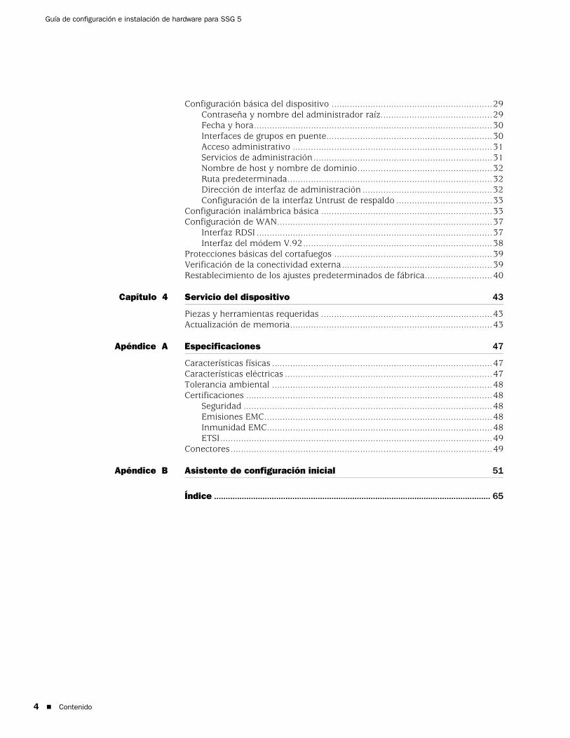
4
Guía de configuración e instalación de hardware para SSG 5
Configuración básica del dispositivo ..............................................................29Contraseña y nombre del administrador raíz...........................................29Fecha y hora............................................................................................30Interfaces de grupos en puente................................................................30Acceso administrativo .............................................................................31Servicios de administración.....................................................................31Nombre de host y nombre de dominio....................................................32Ruta predeterminada...............................................................................32Dirección de interfaz de administración ..................................................32Configuración de la interfaz Untrust de respaldo .....................................33
Configuración inalámbrica básica ..................................................................33Configuración de WAN...................................................................................37
Interfaz RDSI ...........................................................................................37Interfaz del módem V.92.........................................................................38
Protecciones básicas del cortafuegos .............................................................39Verificación de la conectividad externa..........................................................39Restablecimiento de los ajustes predeterminados de fábrica..........................40
Capítulo 4 Servicio del dispositivo 43
Piezas y herramientas requeridas ..................................................................43Actualización de memoria..............................................................................43
Apéndice A Especificaciones 47
Características físicas .....................................................................................47Características eléctricas ................................................................................47Tolerancia ambiental .....................................................................................48Certificaciones ...............................................................................................48
Seguridad ................................................................................................48Emisiones EMC........................................................................................48Inmunidad EMC.......................................................................................48ETSI.........................................................................................................49
Conectores.....................................................................................................49
Apéndice B Asistente de configuración inicial 51
Índice ........................................................................................................................ 65
Contenido

Español
Acerca de este manual
El dispositivo de la puerta de enlace de servicios seguros (SSG) 5 de Juniper Networks es una plataforma de cortafuegos y enrutador integrada que proporciona una red privada virtual (VPN) de seguridad de protocolo de Internet (IPSec) y servicios de cortafuegos para una sucursal o establecimiento minorista.
Juniper Networks ofrece seis modelos del dispositivo SSG 5:
SSG 5 Serie
SSG 5 Serie-WLAN
SSG 5 V.92
SSG 5 V.92-WLAN
SSG 5 ISDN
SSG 5 ISDN-WLAN
Todos los dispositivos SSG 5 admiten un módulo de host de bus de serie universal (USB). Los dispositivos también proporcionan conversiones de protocolo entre redes de área local (LAN) y redes de área extensa (WAN) y tres de los modelos admiten redes de área local inalámbricas (WLAN).
NOTA: Los ejemplos e instrucciones de configuración incluidos en este documento se basan en la funcionalidad de un dispositivo que ejecuta ScreenOS 5.4. Es posible que su dispositivo funcione diferente dependiendo de la versión de ScreenOS instalada. Para obtener la última documentación del dispositivo, consulte el sitio Web de publicaciones técnicas de Juniper Networks en http://www.juniper.net/techpubs/hardware. Para ver qué versiones de ScreenOS están disponibles actualmente para su dispositivo, consulte el sitio Web de soporte de Juniper Networks en http://www.juniper.net/customers/support/.
5
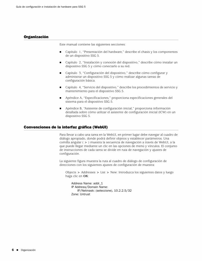
Guía de configuración e instalación de hardware para SSG 5
6
Organización
Este manual contiene las siguientes secciones:
Capítulo 1, “Presentación del hardware,” describe el chasis y los componentes de un dispositivo SSG 5.
Capítulo 2, “Instalación y conexión del dispositivo,” describe cómo instalar un dispositivo SSG 5 y cómo conectarlo a su red.
Capítulo 3, “Configuración del dispositivo,” describe cómo configurar y administrar un dispositivo SSG 5 y cómo realizar algunas tareas de configuración básica.
Capítulo 4, “Servicio del dispositivo,” describe los procedimientos de servicio y mantenimiento para el dispositivo SSG 5.
Apéndice A, “Especificaciones,” proporciona especificaciones generales del sistema para el dispositivo SSG 5.
Apéndice B, “Asistente de configuración inicial,” proporciona información detallada sobre cómo utilizar el asistente de configuración inicial (ICW) en un dispositivo SSG 5.
Convenciones de la interfaz gráfica (WebUI)
Para llevar a cabo una tarea en la WebUI, en primer lugar debe navegar al cuadro de diálogo apropiado, donde podrá definir objetos y establecer parámetros. Una comilla angular ( > ) muestra la secuencia de navegación a través de WebUI, a la que puede llegar mediante un clic en las opciones de menú y vínculos. El conjunto de instrucciones de cada tarea se divide en ruta de navegación y ajustes de configuración.
La siguiente figura muestra la ruta al cuadro de diálogo de configuración de direcciones con los siguientes ajustes de configuración de muestra:
Objects > Addresses > List > New: Introduzca los siguientes datos y luego haga clic en OK:
Address Name: addr_1IP Address/Domain Name:
IP/Netmask: (seleccione), 10.2.2.5/32Zone: Untrust
Organización

Español
Figura 1: Ruta de navegación y ajustes de configuración
Convenciones CLI
Las siguientes convenciones se utilizan para presentar la sintaxis de los comandos CLI en ejemplos y dentro del texto.
En ejemplos:
Los elementos entre corchetes [ ] son opcionales.
Los elementos entre llaves { } son obligatorios.
Si existen dos o más opciones, aparecerán separadas entre sí por barras verticales ( | ). Por ejemplo:
set interface { ethernet1 | ethernet2 | ethernet3 } manage
significa “establecer las opciones de administración de la interfaz ethernet1, ethernet2 o ethernet3”.
Las variables aparecen en cursiva:
set admin user nombre1 password xyz
En texto:
Los comandos aparecen en negrita.
Las variables aparecen en cursiva.
NOTA: Para introducir palabras clave, debe introducir los primeros caracteres para identificar la palabra de forma inequívoca. Por ejemplo, es suficiente introducir set adm u kath j12fmt54 para que el sistema reconozca el comando set admin user kathleen j12fmt54. Aunque este método se puede utilizar para introducir comandos, en la presente documentación todos ellos se presentan en su forma original.
Convenciones CLI 7

Guía de configuración e instalación de hardware para SSG 5
8
Cómo obtener documentación y soporte técnico
Para obtener documentación técnica sobre cualquier producto de Juniper Networks, visite www.juniper.net/techpubs/.
Para obtener soporte técnico, abra un expediente de soporte utilizando el vínculo “Case Manager” en la página web http://www.juniper.net/support/ o llame al teléfono 1-888-314-JTAC (si llama desde los EE.UU.) o al +1-408-745-9500 (si llama desde fuera de los EE.UU.).
Si encuentra algún error u omisión en este documento, póngase en contacto con nosotros a través de la siguiente dirección de correo electrónico:
Cómo obtener documentación y soporte técnico

Español
Capítulo 1
Presentación del hardware
En este capítulo se describe de forma detallada el chasis SSG 5 y sus componentes. Incluye las siguientes secciones:
“Conectores de alimentación y puertos” en la página 9
“Panel frontal” en la página 10
“Panel trasero” en la página 13
Conectores de alimentación y puertos
Esta sección describe e indica la ubicación de los conectores de alimentación y puertos incorporados.
Figura 2: Ubicaciones de puertos incorporados
La Tabla 1 muestra los puertos y conectores de alimentación de un dispositivo SSG 5.
Tabla 1: Conectores de alimentación y puertos SSG 5
SSG 5
V.92
STATUS
POWER
CONSOLE
TX /RX
CD
0 1 2 3 4 5 6TX/RX LINK TX/RX LINK TX/RX LINK TX/RX LINK TX/RX LINK TX/RX LINK TX/RX LINK
10/100 10/100 10/100 10/100 10/100 10/100 10/100
B /G
WLAN V.92
802.11A
0/60/50/40/30/20/10/0
ConsolaAUX, RDSI o V.92
Puerto Descripción Conector Velocidad/protocolo
0/0-0/6 Permite conectar directamente estaciones de trabajo o una LAN a través de un conmutador o concentrador. Esta conexión también permite manejar el dispositivo a través de una sesión Telnet o de la WebUI.
RJ-45 Ethernet 10/100 Mbps
Detección automática de dúplex y auto MDI/MDIX
USB Permite la conexión 1.1 USB con el sistema. N/A 12 M (velocidad completa) ó 1,5 M (velocidad baja)
Consola Permite la conexión serie con el sistema. Utilizada en la conectividad de emulación de terminal para ejecutar sesiones de CLI.
RJ-45 Serie 9600 bps/RS-232C
AUX Permite una conexión a Internet serie asíncrona RS-232 de respaldo a través de un módem externo.
RJ-45 Serie 9600 bps — 115 Kbps/RS-232C
Conectores de alimentación y puertos 9

Guía de configuración e instalación de hardware para SSG 5
10
Panel frontal
Esta sección describe los siguientes elementos en el panel frontal de un dispositivo SSG 5:
LED de estado del sistema
Descripciones de los puertos
LED de estado del sistemaLos LED de estado del sistema muestran información sobre funciones fundamentales del dispositivo. La Figura 3 ilustra la posición de cada LED de estado en la parte delantera del dispositivo SSG 5 V.92-WLAN. Los LED del sistema difieren dependiendo de la versión del dispositivo SSG 5.
Figura 3: LED de estado
Cuando el sistema enciende, el LED POWER (alimentación) cambia de apagado a verde intermitente y el LED STATUS (estado) cambia en la siguiente secuencia: rojo, verde, verde intermitente. El inicio toma aproximadamente dos minutos para completarse. Si desea apagar y encender el sistema de nuevo, le recomendamos que espere unos segundos mientras lo apaga y lo vuelve a encender. La Tabla 2 proporciona el tipo, nombre, color, estado y descripción de cada LED de estado del sistema.
Módem V.92 Permite una conexión de red no fiable o Internet de respaldo o principal con un proveedor de servicio
RJ-11 Detección automática de polaridad y dúplex serie 9600 bps — 115 Kbps/RS-232
ISDN Permite el uso de la línea RDSI como interfaz untrust o de respaldo. (S/T)
RJ-45 Canales B a 64 Kbps
Línea arrendada a 128 Kbps
Antena A y B (SSG 5-WLAN)
Permite conectar directamente estaciones de trabajo próximas a una conexión de radio inalámbrica.
RPSMA 802.11a (54 Mbps en una banda de radio de 5 GHz)
802.11b (11 Mbps en una banda de radio de 2,4 GHz)
802.11g (54 Mbps en una banda de radio de 2,4 GHz)
802.11 superG (108 Mbps en bandas de radio de 2,4 GHz y 5 GHz)
Puerto Descripción Conector Velocidad/protocolo
Panel frontal

Español
Tabla 2: Descripciones de LED de estado
Tipo Nombre Color Estado Descripción
POWER (alimentación)
Verde Encendido sin parpadear
Indica que el sistema recibe alimentación.
Apagado Indica que el sistema no está recibiendo alimentación.
Rojo Encendido sin parpadear
Indica que el dispositivo no está funcionando normalmente.
Apagado Indica que el dispositivo está funcionando normalmente.
STATUS (estado)
Verde Encendido sin parpadear
Indica que el sistema está arrancando o realizando diagnósticos.
Parpadeo Indica que el dispositivo está funcionando normalmente.
Rojo Parpadeo Indica que se detectó un error.
Dispositivos RDSI
CH B1 Verde Encendido sin parpadear
Indica que el canal B 1 está activo.
Apagado Indica que el canal B 1 no está activo.
CH B2 Verde Encendido sin parpadear
Indica que el canal B 2 está activo.
Apagado Indica que el canal B 2 no está activo.
Dispositivos V.92
HOOK (conexión)
Verde Encendido sin parpadear
Indica que la conexión está activa.
Apagado Indica que la interfaz serie no está en servicio.
TX/RX Verde Parpadeo Indica que el tráfico está pasando.
Apagado Indica que el tráfico no está pasando.
Dispositivos WLAN
802.11A Verde Encendido sin parpadear
Indica que se ha establecido una conexión inalámbrica pero no hay actividad de conexión.
Parpadeo Indica que se ha establecido una conexión inalámbrica. La velocidad de transmisión es proporcional a la actividad de la conexión.
Apagado Indica que no se ha establecido una conexión inalámbrica.
B/G Verde Encendido sin parpadear
Indica que se ha establecido una conexión inalámbrica pero no hay actividad de conexión.
Parpadeo Indica que se ha establecido una conexión inalámbrica. La velocidad de transmisión es proporcional a la actividad de la conexión.
Apagado Indica que no se ha establecido una conexión inalámbrica.
Panel frontal 11

Guía de configuración e instalación de hardware para SSG 5
12
Descripciones de los puertos
En esta sección se explica el propósito y función de los siguientes puertos:
Puertos ethernet
Puerto de la consola
Puerto AUX
Puertos ethernetSiete puertos de Ethernet 10/100 proporcionan conexiones LAN a concentradores, conmutadores, servidores locales y estaciones de trabajo. También puede designar un puerto Ethernet para el tráfico administrativo. Los puertos están etiquetados 0/0 a 0/6. Consulte “Ajustes predeterminados del dispositivo” en la página 27 para obtener los enlaces de zona predeterminados para cada puerto Ethernet.
Al configurar uno de estos puertos, haga referencia al nombre de interfaz que corresponde a la ubicación del puerto. De izquierda a derecha en el panel frontal, los nombres de interfaz de los puertos son ethernet0/0 a ethernet0/6.
La Figura 4 muestra la ubicación de los LED en cada puerto Ethernet.
Figura 4: LED de actividad de conexión
La Tabla 3 describe los LED del puerto Ethernet.
Tabla 3: LED del puerto Ethernet
Puerto de la consolaEl puerto de la consola es un puerto serie RJ-45 cableado como equipo de terminación de circuitos de datos (DCE) que se puede utilizar para la administración local. Utilícelo como un cable directo al utilizar una conexión de terminal y un cable de conexión directa al conectarse a otro dispositivo DCE. Se proporciona un adaptador RJ-45 a DB-9.
Consulte “Conectores” en la página 49 para obtener información sobre las patillas de salida del conector RJ-45.
Nombre Color Estado Descripción
CONEXIÓN Verde Encendido sin parpadear
Apagado
El puerto está en línea.
El puerto está fuera de línea.
TX/RX Verde Parpadeo
Apagado
El tráfico está pasando. La velocidad de transmisión es proporcional a la actividad de la conexión.
El puerto podría estar encendido, pero no recibe datos.
CONEXIÓNTX/RX
Descripciones de los puertos
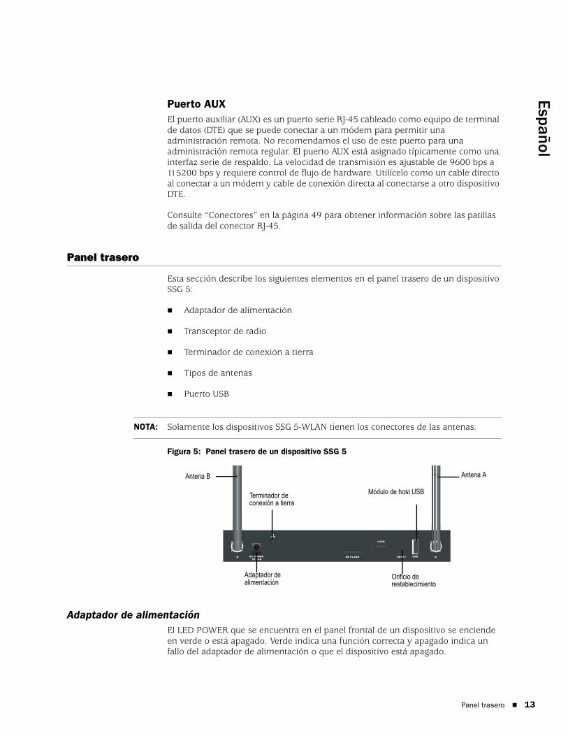
Español
Puerto AUXEl puerto auxiliar (AUX) es un puerto serie RJ-45 cableado como equipo de terminal de datos (DTE) que se puede conectar a un módem para permitir una administración remota. No recomendamos el uso de este puerto para una administración remota regular. El puerto AUX está asignado típicamente como una interfaz serie de respaldo. La velocidad de transmisión es ajustable de 9600 bps a 115200 bps y requiere control de flujo de hardware. Utilícelo como un cable directo al conectar a un módem y cable de conexión directa al conectarse a otro dispositivo DTE.
Consulte “Conectores” en la página 49 para obtener información sobre las patillas de salida del conector RJ-45.
Panel trasero
Esta sección describe los siguientes elementos en el panel trasero de un dispositivo SSG 5:
Adaptador de alimentación
Transceptor de radio
Terminador de conexión a tierra
Tipos de antenas
Puerto USB
Figura 5: Panel trasero de un dispositivo SSG 5
Adaptador de alimentaciónEl LED POWER que se encuentra en el panel frontal de un dispositivo se enciende en verde o está apagado. Verde indica una función correcta y apagado indica un fallo del adaptador de alimentación o que el dispositivo está apagado.
NOTA: Solamente los dispositivos SSG 5-WLAN tienen los conectores de las antenas.
RESETDC POWER
LOCK
USBSD FLASHB A5V A4
Adaptador de alimentación
Módulo de host USBTerminador de conexión a tierra
Orificio de restablecimiento
Antena AAntena B
Panel trasero 13

Guía de configuración e instalación de hardware para SSG 5
14
Transceptor de radioLos dispositivos SSG 5-WLAN contienen dos transceptores de radio de conectividad inalámbrica, que admiten las normas 802.11a/b/g. El primer transceptor (WLAN 0) utiliza la banda de radio 2,4 GHz, que admite la norma 802.11b a 11 Mbps y la norma 802.11g a 54 Mbps. El segundo transceptor de radio (WLAN 1) utiliza una banda de radio de 5 GHz que admite la norma 802.11a a 54 Mbps. Las dos bandas de radio pueden funcionar simultáneamente. Para obtener más información sobre la configuración de la banda de radio inalámbrica, consulte “Configuración inalámbrica básica” en la página 33.
Terminador de conexión a tierraUn terminador de conexión a tierra de un agujero se proporciona en la parte trasera del chasis para conectar el dispositivo a tierra (consulte la Figura 5).
Para conectar a tierra el dispositivo antes de conectar la alimentación, conecte un cable de conexión a tierra a tierra y después conecte el cable al terminador en la parte trasera del chasis.
Tipos de antenasLos dispositivos SSG 5-WLAN admiten tres tipos de antenas de radio fabricada de acuerdo con las especificaciones del cliente.
Antenas de diversidad: Las antenas de diversidad proporcionan una cobertura direccional 2dBi y un nivel bastante uniforme de fuerza de la señal dentro del área de cobertura y son adecuadas para la mayoría de instalaciones. Este tipo de antenas se envía con el dispositivo.
Antena omnidireccional externa: a antena externa proporciona 2dBi de cobertura omnidireccional. A diferencia de las antenas de diversidad, que funciona como un par, una antena externa funciona para eliminar un efecto de eco que puede ocurrir algunas veces por causa de características de un leve retardo en la recepción de la señal cuando hay dos en uso.
Antena direccional externa: La antena direccional externa proporciona cobertura unidireccional 2dBi y es apropiada para ubicaciones como corredores o paredes exteriores (con la antena orientada hacia adentro).
Puerto USBEl puerto USB que se encuentra en el panel trasero de un dispositivo SSG 5 acepta un dispositivo de almacenamiento de bus serie universal (USB) o un adaptador de dispositivo de almacenamiento USB con un disco flash compacto instalado, como se define en la Especificación de CompactFlash publicada por la Asociación CompactFlash. Cuando el dispositivo de almacenamiento USB está instalado y configurado, éste automáticamente actúa como un dispositivo de inicio secundario si el disco flash compacto principal falla al inicio.
Panel trasero

Español
El puerto USB permite transferencias de archivos como configuraciones de dispositivo, certificaciones de usuario e imágenes de versión de actualización entre un dispositivo de almacenamiento USB externo y el almacenamiento flash interno ubicado en el dispositivo de seguridad. El puerto USB admite la especificación USB 1.1 en cualquier transferencia de archivos de velocidad baja (1,5 M) o velocidad completa (12 M).
Para transferir archivos entre el dispositivo de almacenamiento USB y un SSG 5, realice los siguientes pasos:
1. Inserte el dispositivo de almacenamiento USB en el puerto USB en el dispositivo de seguridad.
2. Guarde los archivos del dispositivo de almacenamiento USB en el almacenamiento flash interno por medio del comando CLI save {software | config | image-key} from usb nombrearchivo to flash.
3. Antes de retirar el dispositivo de almacenamiento USB, detenga el puerto USB con el comando CLI exec usb-device stop.
4. Ahora es seguro retirar el dispositivo de almacenamiento USB.
Si desea borrar un archivo del dispositivo de almacenamiento USB, utilice el comando CLI delete file usb:/nombrearchivo.
Si desea ver la información de archivos guardados en el dispositivo de almacenamiento USB o en el almacenamiento flash interno, utilice el comando de CLI get file.
Panel trasero 15

Guía de configuración e instalación de hardware para SSG 5
16
Panel trasero
Español
Capítulo 2
Instalación y conexión del dispositivo
Este capítulo describe cómo instalar un dispositivo SSG 5 y conectar los cables y alimentación al dispositivo. Este capítulo consta de las siguientes secciones:
“Antes de empezar” en la página 18
“Equipo de instalación” en la página 18
“Conexión de los cables de la interfaz a un dispositivo” en la página 19
“Conexión de la alimentación” en la página 20
“Conexión de un dispositivo a una red” en la página 20
NOTA: Para obtener información sobre las advertencias e instrucciones de seguridad, consulte el Manual de seguridad de productos Juniper Networks. Antes de utilizar cualquier equipo, debe tener en cuenta los peligros que entraña el sistema de circuitos eléctricos y familiarizarse con las prácticas habituales de prevención de accidentes.
17

Guía de configuración e instalación de hardware para SSG 5
18
Antes de empezar
La ubicación del chasis, el diseño del equipo de montaje y la seguridad de su sala de cableado son muy importantes para el funcionamiento correcto del sistema.
El cumplimiento de las siguientes precauciones puede evitar apagones, fallos de equipo y lesiones:
Antes de la instalación, revise siempre que el suministro de alimentación esté desconectado de cualquier fuente de alimentación.
Asegúrese que la habitación en la que utilizará el dispositivo tenga circulación de aire adecuada y que la temperatura del cuarto no exceda 104°F (40C°).
No coloque el dispositivo en un soporte para bastidor de equipo que bloquee un puerto de escape o entrada. Asegúrese de que los bastidores tengan ventiladores y lados con rejillas.
Corrija estas condiciones peligrosas antes de realizar cualquier instalación: Pisos húmedos o mojados, fugas, cables eléctricos pelados o sin conexión a tierra o falta de tomas de tierra de seguridad.
Equipo de instalación
Puede instalar un dispositivo SSG 5 en un bastidor, en una pared o en un escritorio. Los kits de montaje se pueden comprar por separado.
Para instalar un dispositivo SSG 5, necesita un destornillador phillips número 2 (no incluido) y tornillos que sean compatibles con el bastidor del equipo (incluidos en el kit).
Para instalar un dispositivo SSG 5 en un bastidor, realice los siguientes pasos:
1. Desatornille los soportes de montaje de la bandeja con un destornillador phillips.
2. Alinee la parte inferior del dispositivo con los orificios de base de la bandeja.
3. Tire eel dispositivo hacia adelante para bloquearlo en los orificios de base de la bandeja.
ADVERTENCIA: Para evitar el abuso e intrusión de personal no autorizado, instale el dispositivo SSG 5 en un ambiente seguro.
NOTA: Al instalar un dispositivo, asegúrese que esté dentro del alcance de una toma de corriente.
NOTA: Los usuarios de SSG 5-WLAN con las antenas opcionales deben retirar la antena existente, luego deben conectar la nueva antena a través del orificio lateral.
Antes de empezar
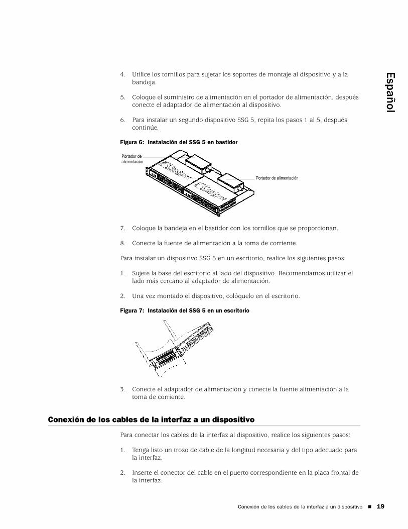
Español
4. Utilice los tornillos para sujetar los soportes de montaje al dispositivo y a la bandeja.
5. Coloque el suministro de alimentación en el portador de alimentación, después conecte el adaptador de alimentación al dispositivo.
6. Para instalar un segundo dispositivo SSG 5, repita los pasos 1 al 5, después continúe.
Figura 6: Instalación del SSG 5 en bastidor
7. Coloque la bandeja en el bastidor con los tornillos que se proporcionan.
8. Conecte la fuente de alimentación a la toma de corriente.
Para instalar un dispositivo SSG 5 en un escritorio, realice los siguientes pasos:
1. Sujete la base del escritorio al lado del dispositivo. Recomendamos utilizar el lado más cercano al adaptador de alimentación.
2. Una vez montado el dispositivo, colóquelo en el escritorio.
Figura 7: Instalación del SSG 5 en un escritorio
3. Conecte el adaptador de alimentación y conecte la fuente alimentación a la toma de corriente.
Conexión de los cables de la interfaz a un dispositivo
Para conectar los cables de la interfaz al dispositivo, realice los siguientes pasos:
1. Tenga listo un trozo de cable de la longitud necesaria y del tipo adecuado para la interfaz.
2. Inserte el conector del cable en el puerto correspondiente en la placa frontal de la interfaz.
Portador de alimentación
Portador de alimentación
Conexión de los cables de la interfaz a un dispositivo 19

Guía de configuración e instalación de hardware para SSG 5
20
3. Coloque el cable de la siguiente manera para evitar que se desprenda o se desarrollen puntos de tensión:
a. Asegure el cable de manera que no sostenga su propio peso mientras cuelga hacia el suelo.
b. Quite de enmedio el cable sobrante en un bucle bien enrollado.
c. Coloque bridas en el bucle para ayudar a mantener su forma.
Conexión de la alimentación
Para conectar la alimentación al dispositivo, realice los siguientes pasos:
1. Enchufe el extremo del conector de CC del cable de alimentación al receptáculo de alimentación CC en la parte posterior del dispositivo.
2. Conecte el extremo del adaptador de CA del cable de alimentación a la fuente de alimentación de CA.
Conexión de un dispositivo a una red
El dispositivo SSG 5 proporciona protección de cortafuegos y seguridad general para las redes cuando se coloca entre las redes internas y la red no fiable. En esta sección se describe lo siguiente:
Conexión del dispositivo a una red no fiable
Conexión del dispositivo a una red interna o a estación de trabajo
Conexión del dispositivo a una red no fiablePuede conectar su dispositivo SSG 5 a una red no fiable de una de las siguientes maneras:
Puertos ethernet
Puertos serie (AUX/consola)
Puertos WAN
La Figura 8 muestra el SSG 5 con conexiones de cableado de red básicas con los puertos de Ethernet 10/100 cableados de la siguiente manera:
El puerto etiquetado 0/0 (interfaz ethernet 0/0) está conectado a la red no fiable.
El puerto etiquetado 0/1 (interfaz ethernet 0/1) está conectado a una estación de trabajo en la zona de seguridad DMZ.
ADVERTENCIA: Recomendamos utilizar un protector contra sobretensiones en la conexión de alimentación.
Conexión de la alimentación
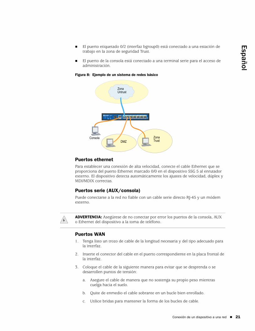
Español
El puerto etiquetado 0/2 (interfaz bgroup0) está conectado a una estación de trabajo en la zona de seguridad Trust.
El puerto de la consola está conectado a una terminal serie para el acceso de administración.
Figura 8: Ejemplo de un sistema de redes básico
Puertos ethernetPara establecer una conexión de alta velocidad, conecte el cable Ethernet que se proporciona del puerto Ethernet marcado 0/0 en el dispositivo SSG 5 al enrutador externo. El dispositivo detecta automáticamente los ajustes de velocidad, dúplex y MDI/MDIX correctas.
Puertos serie (AUX/consola)Puede conectarse a la red no fiable con un cable serie directo RJ-45 y un módem externo.
Puertos WAN1. Tenga listo un trozo de cable de la longitud necesaria y del tipo adecuado para
la interfaz.
2. Inserte el conector del cable en el puerto correspondiente en la placa frontal de la interfaz.
3. Coloque el cable de la siguiente manera para evitar que se desprenda o se desarrollen puntos de tensión:
a. Asegure el cable de manera que no sostenga su propio peso mientras cuelga hacia el suelo.
b. Quite de enmedio el cable sobrante en un bucle bien enrollado.
c. Utilice bridas para mantener la forma de los bucles de cable.
SSG 5
V.92
STATUS
POWER
CONSOLE
TX /RX
CD
0 1 2 3 4 5 6TX/RX LINK TX/RX LINK TX/RX LINK TX/RX LINK TX/RX LINK TX/RX LINK TX/RX LINK
10/100 10/100 10/100 10/100 10/100 10/100 10/100
B /G
WLAN V.92
802.11A
Callouts
Zona Untrust
ConsolaDMZ
Zona Trust
ADVERTENCIA: Asegúrese de no conectar por error los puertos de la consola, AUX o Ethernet del dispositivo a la toma de teléfono.
Conexión de un dispositivo a una red 21

Guía de configuración e instalación de hardware para SSG 5
22
Conexión del dispositivo a una red interna o a estación de trabajoPuede conectar su red de área local (LAN) o estación de trabajo con las interfaces Ethernet o inalámbrica.
Puertos ethernetUn dispositivo SSG 5 contiene siete puertos Ethernet. Puede utilizar uno o varios de estos puertos para conectarse a redes LAN mediante conmutadores o concentradores. También es posible conectar uno o todos los puertos directamente a estaciones de trabajo, sin tener que utilizar un conmutador o un concentrador. Puede utilizar cables cruzados o directos para conectar los puertos Ethernet a otros dispositivos. Consulte “Ajustes predeterminados del dispositivo” en la página 27 para obtener los enlaces de interfaz a zona predeterminados.
Antenas inalámbricasSi utiliza la interfaz inalámbrica, deberá conectar las antenas proporcionadas del dispositivo. Si dispone de las antenas de diversidad 2dB estándar, utilice tornillos para sujetarlas a los postes marcados A y B en la parte posterior del dispositivo. Doble cada antena por su parte curva, teniendo cuidado de no ejercer presión sobre los conectores de mamparo.
Figura 9: Ubicación de las antenas SSG 5-WLAN
Si está utilizando la antena externa opcional, siga las instrucciones de conexión incluidas con esa antena.
RESETDC POWER
LOCK
USBSD FLASHB A5V A4
Conector de mamparoConector de mamparo
Antena B Antena A
Conexión de un dispositivo a una red

Español
Capítulo 3
Configuración del dispositivo
El software de ScreenOS viene ya instalado en los dispositivos SSG 5. Cuando el dispositivo se enciende, está ya listo para configurarse. Si bien el dispositivo tiene una configuración de fábrica predeterminada que permite su conexión inicial, es necesario configurar otros ajustes para cumplir con los requisitos específicos de su red.
Este capítulo consta de las siguientes secciones:
“Acceso al dispositivo” en la página 24
“Ajustes predeterminados del dispositivo” en la página 27
“Configuración básica del dispositivo” en la página 29
“Configuración inalámbrica básica” en la página 33
“Configuración de WAN” en la página 37
“Protecciones básicas del cortafuegos” en la página 39
“Verificación de la conectividad externa” en la página 39
“Restablecimiento de los ajustes predeterminados de fábrica” en la página 40
NOTA: Después de que configure un dispositivo y verifique la conectividad a través de la red remota, deberá registrar su producto en www.juniper.net/support/ para que en el dispositivo se puedan activar determinados servicios de ScreenOS, tales como servicio de inspección detallada de firmas y antivirus (se adquieren por separado). Después de registrar el producto, utilice la WebUI para obtener la suscripción al servicio. Para obtener más información acerca del registro de su producto y obtención de las suscripciones para los servicios específicos, consulte el volumen Fundamentos del Manual de referencia de ScreenOS: Conceptos y ejemplos para la versión de ScreenOS que se ejecuta en el dispositivo.
23

Guía de configuración e instalación de hardware para SSG 5
24
Acceso al dispositivo
Puede configurar y administrar el dispositivo SSG 5 de diversas formas:
Consola: El puerto de consola del dispositivo le permite acceder al dispositivo a través de un cable serie conectado a su estación de trabajo o terminal. Para configurar el dispositivo, debe introducir los comandos de la interfaz de línea de comandos (CLI) de ScreenOS en su terminal o en un programa de emulación de terminal de la estación de trabajo.
WebUI: La interfaz del usuario Web (WebUI) de ScreenOS es una interfaz gráfica que está disponible a través de un explorador. Para utilizar inicialmente la WebUI, la estación de trabajo donde usa el explorador debe estar en la misma subred que el dispositivo. También puede obtener acceso a WebUI a través de un servidor seguro utilizando el nivel de sockets seguro (SSL) con HTTP seguro (S-HTTP).
Telnet/SSH: Telnet y SSH son aplicaciones que le permiten acceder a dispositivos a través de una red IP. Para configurar el dispositivo, introduzca los comandos de la CLI de ScreenOS en una sesión Telnet desde la estación de trabajo. Para obtener más información, consulte el volumen Administración del Manual de referencia de ScreenOS: Conceptos y ejemplos.
NetScreen-Security Manager: NetScreen-Security Manager es una aplicación de administración a nivel corporativo de Juniper Networks que le permite controlar y administrar el cortafuegos de Juniper Networks/dispositivos VPN IPSec. Para obtener las instrucciones sobre la manera de administrar su dispositivo con NetScreen-Security Manager, consulte el Manual del administrador de NetScreen-Security Manager.
Utilización de una conexión de consola
Para establecer una conexión de consola, realice los siguientes pasos:
1. Inserte el conector hembra del adaptador DB-9 proporcionado en el puerto serie de su estación de trabajo. (Asegúrese de que el DB-9 esté debidamente colocado y fijo.) La Figura 10 muestra el tipo de conector DB-9 que se requiere.
Figura 10: Adaptador DB-9
2. Conecte el conector macho del cable serie RJ-45 CAT5 en el puerto de la consola del SSG 5. (Asegúrese de que el otro extremo del cable CAT5 esté debidamente colocado y fijo al adaptador DB-9.)
NOTA: Utilice un cable serie directo RJ-45 CAT5 con un conector macho RJ-45 para conectarlo al puerto de la consola del dispositivo.
Conector RJ-45
Adaptador DB-9
Cable RJ-45
Acceso al dispositivo

Español
3. Inicie un programa de emulación de terminal serie en su estación de trabajo. Los ajustes requeridos para iniciar una sesión de consola son los siguientes:
Velocidad de transferencia: 9600
Paridad: Ninguno
Bits de datos: 8
Bit de parada: 1
Control de flujo: Ninguno
4. Si todavía no ha modificado el nombre de usuario y la contraseña predeterminados, escriba netscreen en los campos login y password. (Utilice sólo letras en minúscula. Los campos login y password distinguen entre mayúsculas y minúsculas).
Para obtener información sobre la manera de configurar el dispositivo con los comandos CLI, consulte el Manual de referencia de ScreenOS: Conceptos y ejemplos.
5. (Opcional) De forma predeterminada, el tiempo de espera de la consola vence y se termina automáticamente después de 10 minutos de tiempo de inactividad. Para eliminar el tiempo de espera, introduzca set console timeout 0.
Utilización de la WebUIPara utilizar la WebUI, la estación de trabajo desde donde maneja el dispositivo debe estar en la misma subred que el dispositivo inicialmente. Para acceder al dispositivo con la WebUI, lleve a cabo los pasos siguientes:
1. Conecte su estación de trabajo al puerto 0/2 — 0/6 (interfaz bgroup0 en la zona Trust) del dispositivo.
2. Asegúrese de que su estación de trabajo esté configurada para el protocolo de configuración dinámica de host (DHCP) o configurada estáticamente con una dirección IP en la subred 192.168.1.0/24.
3. Inicie el explorador, introduzca la dirección IP para la interfaz bgroup0 (la dirección IP predeterminada es 192.168.1.1/24), luego presione Enter.
La aplicación de WebUI muestra el mensaje de solicitud de inicio de sesión como aparece en la Figura 11.
NOTA: Cuando accede por primera vez al dispositivo a través de la WebUI, aparece el asistente de configuración inicial (ICW). Si decide utilizar el ICW para configurar su dispositivo, consulte “Asistente de configuración inicial” en la página 51.
Acceso al dispositivo 25

Guía de configuración e instalación de hardware para SSG 5
26
Figura 11: Mensaje de solicitud de inicio de sesión de WebUI
4. Si todavía no ha modificado el inicio de sesión predeterminado para el nombre de administrador y la contraseña, escriba netscreen en los campos login y password. (Utilice sólo letras en minúscula. Los campos login y password distinguen entre mayúsculas y minúsculas).
Utilización de TelnetPara establecer una conexión de Telnet, realice los siguientes pasos:
1. Conecte su estación de trabajo al puerto 0/2 — 0/6 (interfaz bgroup0 en la zona Trust) del dispositivo.
2. Asegúrese de que su estación de trabajo esté configurada para DHCP o configurada estáticamente con una dirección IP en la subred 192.168.1.0/24.
3. Inicie una aplicación de cliente Telnet en la dirección IP para la interfaz bgroup0 (la dirección IP predeterminada es 192.168.1.1). Por ejemplo, introduzca telnet 192.168.1.1.
La aplicación Telnet muestra el mensaje de solicitud de inicio de sesión.
4. Si todavía no ha modificado el nombre de usuario y la contraseña predeterminados, escriba netscreen en los campos login y password. (Utilice sólo letras en minúscula. Los campos login y password distinguen entre mayúsculas y minúsculas).
5. (Opcional) De forma predeterminada, el tiempo de espera de la consola vence y se termina automáticamente después de 10 minutos de tiempo de inactividad. Para eliminar el tiempo de espera, introduzca set console timeout 0.
Acceso al dispositivo

Español
Ajustes predeterminados del dispositivo
Esta sección describe los ajustes predeterminados y el funcionamiento de un dispositivo SSG 5.
La Tabla 4 muestra los enlaces de zona predeterminados para los puertos de los dispositivos.
Tabla 4: Interfaz física predeterminada a enlaces de zona
Los grupos puente (bgroup) están diseñados para permitir que los usuarios de la red cambien entre el tráfico inalámbrico y el tráfico con cable sin tener que reconfigurar o reiniciar el dispositivo. De manera predeterminada, las interfaces ethernet0/2 — ethernet0/6, etiquetadas como puertos 0/2 — 0/6 en el dispositivo, están agrupadas juntas como la interfaz bgroup0, tienen la dirección IP 192.168.1.1/24 y están enlazadas a la zona de seguridad Trust. Puede configurar hasta cuatro bgroups.
Si desea configurar una interfaz Ethernet o inalámbrica en un bgroup, primero debe asegurarse de que la interfaz Ethernet o inalámbrica esté en la zona de seguridad Null. Al desactivar la interfaz Ethernet o inalámbrica que está en un bgroup, la interfaz se coloca en la zona de seguridad Null. Una vez asignada a la zona de seguridad Null, la interfaz Ethernet se puede enlazar a una zona de seguridad y asignar a una dirección IP diferente.
Etiqueta de puerto Interfaz Zona
Puertos Ethernet 10/100:
0/0 ethernet0/0 Untrust
0/1 ethernet0/1 DMZ
0/2 bgroup0 (ethernet0/2) Trust
0/3 bgroup0 (ethernet0/3) Trust
0/4 bgroup0 (ethernet0/4) Trust
0/5 bgroup0 (ethernet0/5) Trust
0/6 bgroup0 (ethernet0/6) Trust
AUX serial0/0 Null
Puertos WAN:
ISDN bri0/0 Untrust
V.92 serial0/0 Null
Ajustes predeterminados del dispositivo 27

Guía de configuración e instalación de hardware para SSG 5
28
Para desactivar ethernet0/3 del bgroup0 y asignarlo a la zona Trust con una dirección IP estática de 192.168.3.1/24, utilice la WebUI o CLI como sigue:
WebUI
Network > Interfaces > List > Edit (bgroup0) > Bind Port: Anule la selección ethernet0/3, luego haga clic en Apply.
List > Edit (ethernet0/3): Introduzca los siguientes datos, luego haga clic en Apply:
Zone Name: Trust (seleccione)IP Address/Netmask: 192.168.3.1/24
CLI
unset interface bgroup0 port ethernet0/3set interface ethernet0/3 zone trustset interface ethernet0/3 ip 192.168.3.1/24save
Tabla 5: Enlaces de interfaz inalámbrica y lógica
Puede cambiar la dirección IP predeterminada en la interfaz bgroup0 para que coincida con las direcciones de su red LAN y WLAN. Para realizar la configuración de una interfaz inalámbrica en un bgroup, consulte “Configuración inalámbrica básica” en la página 33.
Para obtener información adicional sobre bgroup y algunos ejemplos, consulte el Manual de referencia de ScreenOS: Conceptos y ejemplos.
No hay otras direcciones IP predeterminadas, configuradas en otras interfaces Ethernet o inalámbricas en un dispositivo; debe asignar las direcciones IP a las demás interfaces, incluso las interfaces WAN.
SSG 5-WLAN Interfaz Zona
Interfaz inalámbrica
Especifica una interfaz inalámbrica, la cual se puede configurar para que funcione en radio 2,4 G o 5 G
wireless0/0 (la dirección IP predeterminada es 192.168.2.1/24).
Trust
wireless0/1-0/3. Null
Interfaces lógicas
Interfaz de capa 2 vlan1 especifica las interfaces lógicas que se utilizan para la administración y terminación del tráfico VPN mientras el dispositivo está en el modo transparente.
N/A
Interfaces de túnel tunnel.n especifica una interfaz de túnel lógica. Esta interfaz sirve para el tráfico VPN.
N/A
NOTA: La interfaz de bgroup no funciona en el modo transparente cuando cuenta con una interfaz inalámbrica.
Ajustes predeterminados del dispositivo

Español
Configuración básica del dispositivo
Esta sección describe los siguientes ajustes de configuración básica:
Contraseña y nombre del administrador raíz
Fecha y hora
Interfaces de grupos en puente
Acceso administrativo
Servicios de administración
Nombre de host y nombre de dominio
Ruta predeterminada
Dirección de interfaz de administración
Configuración de la interfaz Untrust de respaldo
Contraseña y nombre del administrador raízEl usuario administrador raíz tiene privilegios completos para la configuración de un dispositivo SSG 5. Le recomendamos que cambie de inmediato el nombre del administrador raíz y contraseña predeterminados (ambos netscreen).
Para cambiar el nombre del administrador raíz y la contraseña, utilice WebUI o CLI como se muestra a continuación:
WebUI
Configuration > Admin > Administrators > Edit (para el nombre del administrador): Introduzca los siguientes datos y haga clic en OK:
Administrator Name:Old Password: netscreenNew Password:Confirm New Password:
CLI
set admin name nombreset admin password contraseñasave
NOTA: Las contraseñas no se muestran en la WebUI.
Configuración básica del dispositivo 29
Guía de configuración e instalación de hardware para SSG 5
30
Fecha y horaLa hora establecida en un dispositivo SSG 5 afecta los eventos tales como la configuración de los túneles de VPN. La manera más fácil de configurar la fecha y hora en el dispositivo es utilizar la WebUI para sincronizar el reloj del sistema del dispositivo con el reloj de la estación de trabajo.
Para configurar la fecha y hora en un dispositivo, utilice WebUI o CLI como se muestra a continuación:
WebUI
1. Configuration > Date/Time: Haga clic en el botón Sync Clock with Client.
Aparecerá un mensaje emergente solicitándole que especifique si tiene habilitada la opción del horario de verano en el reloj de la estación de trabajo.
2. Haga clic en Yes para sincronizar el reloj del sistema y ajustarlo según el horario de verano o bien en No para sincronizarlo sin el ajuste de horario de verano.
También puede utilizar el comando CLI set clock en una sesión Telnet o de consola para introducir manualmente la fecha y la hora para el dispositivo.
Interfaces de grupos en puenteDe forma predeterminada, el dispositivo SSG 5 tiene agrupadas las interfaces Ethernet ethernet0/2—ethernet0/4 en la zona de seguridad Trust. Las interfaces agrupadas se establecen en una subred. Puede desactivar una interfaz de un grupo y asignarla a una zona de seguridad diferente. Las interfaces deben estar en la zona de seguridad Null antes que se puedan asignar a un grupo. Para colocar una interfaz agrupada en la la zona de seguridad Null, utilice el comando CLI unset interface interfaz port interfaz.
Los dispositivos SSG 5-WLAN permiten que las interfaces Ethernet e inalámbricas se agrupen en una subred.
Para configurar un grupo con interfaces Ethernet e inalámbricas, utilice WebUI o CLI como sigue:
WebUI
Network > Interfaces > List > Edit (bgroup0) > Bind Port: anule la selección ethernet0/3 y ethernet0/4, luego haga clic en Apply.
Edit (bgroup1) > Bind Port: Seleccione ethernet0/3, ethernet0/4 y wireless0/2, luego haga clic en Apply.
>Basic: Introduzca los siguientes datos, luego haga clic en Apply:
Zone Name: DMZ (seleccione)IP Address/Netmask: 10.0.0.1/24
NOTA: Sólo las interfaces inalámbricas y de Ethernet se pueden configurar en un bgroup.
Configuración básica del dispositivo

Español
CLI
unset interface bgroup0 port ethernet0/3unset interface bgroup0 port ethernet0/4set interface bgroup1 port ethernet0/3set interface bgroup1 port ethernet0/4set interface bgroup1 port wireless0/2set interface bgroup1 zone DMZset interface bgroup1 ip 10.0.0.1/24save
Acceso administrativoDe forma predeterminada, todos los usuarios de la red pueden administrar un dispositivo siempre que conozcan el inicio de sesión y la contraseña. Para configurar el dispositivo para poderlo manejar sólo desde un host específico en su red, utilice la WebUI o CLI como sigue:
WebUI
Configuration > Admin > Permitted IPs: Introduzca los siguientes datos y haga clic en Add:
IP Address/Netmask: dir_ip/máscara
CLI
set admin manager-ip dir_ip/máscarasave
Servicios de administraciónScreenOS proporciona servicios para configurar y administrar el dispositivo, tales como SNMP, SSL y SSH, que es posible habilitar por interfaz. Para configurar los servicios de administración en el dispositivo, utilice WebUI o CLI como se muestra a continuación:
WebUI
Network > Interfaces > List > Edit (para ethernet0/0): En Management Services, seleccione o borre los servicios de administración que desea utilizar en la interfaz, luego haga clic en Apply.
CLI
set interface ethernet0/0 manage webunset interface ethernet0/0 manage snmpsave
Configuración básica del dispositivo 31

Guía de configuración e instalación de hardware para SSG 5
32
Nombre de host y nombre de dominioEl nombre del dominio define la red o subred a la cual pertenece el dispositivo, mientras que el nombre de host se refiere a un dispositivo específico. El nombre de host y nombre de dominio identifican de manera única al dispositivo en la red. Para configurar el nombre de host y nombre de dominio en un dispositivo, utilice WebUI o CLI como se muestra a continuación:
WebUI
Network > DNS > Host: Introduzca los siguientes datos, luego haga clic en Apply:
Host Name: nombreDomain Name: nombre
CLI
set hostname nombreset domain nombresave
Ruta predeterminadaLa ruta predeterminada es una ruta estática que se utiliza para dirigir los paquetes a las redes que no están explícitamente enumeradas en la tabla de enrutamiento. Si un paquete llega al dispositivo con una dirección para la cual el dispositivo no tiene información de enrutamiento, el dispositivo envía el paquete al destino especificado por la ruta predeterminada. Para configurar la ruta predeterminada en el dispositivo, utilice WebUI o CLI como se muestra a continuación:
WebUI
Network > Routing > Destination > New (trust-vr): Introduzca los siguientes datos y haga clic en OK:
IP Address/Netmask: 0.0.0.0/0.0.0.0Next Hop
Gateway: (seleccione)Interface: ethernet0/2 (seleccione)Gateway IP Address: dir_ip
CLIset route 0.0.0.0/0 interface ethernet0/2 gateway dir_ipsave
Dirección de interfaz de administraciónLa interfaz Trust tiene la dirección IP predeterminada 192.168.1.1/24 y está configurada para los servicios de administración. Si conecta el puerto 0/2—0/4 del dispositivo a una estación de trabajo, puede configurar el dispositivo de una estación de trabajo en la subred 192.168.1.1/24 utilizando un servicio de administración tal como Telnet.
Puede cambiar la dirección IP predeterminada en la interfaz Trust. Por ejemplo, tal vez desee cambiar la interfaz para que coincida con las direcciones IP ya existentes en LAN.
Configuración básica del dispositivo

Español
Configuración de la interfaz Untrust de respaldoEl dispositivo SSG 5 e permite configurar una interfaz de respaldo en caso de fallo de untrust. Para establecer una interfaz de respaldo en caso de fallo de untrust, lleve a cabo los siguientes pasos:
1. Configure la interfaz de respaldo en la zona de seguridad Null con el comando CLI unset interface interfaz [ port interfaz ].
2. Enlace la interfaz de respaldo a la misma zona de seguridad como la interfaz principal con el comando CLI set interface interfaz zone nombre_zona.
Para configurar la interfaz ethernet0/4 como la interfaz de respaldo para la interfaz ethernet0/0, utilice la WebUI o CLI como se muestra a continuación:
WebUI
Network > Interfaces > Backup > Introduzca los siguientes datos, luego haga clic en Apply.
Primary: ethernet0/0Backup: ethernet0/4Type: track-ip (seleccione)
CLI
unset interface bgroup0 port ethernet0/4set interface ethernet0/4 zone untrustset interface ethernet0/0 backup interface ethernet0/4 type track-ipsave
Configuración inalámbrica básica
En esta sección se proporciona información para la configuración de la interfaz inalámbrica del dispositivo SSG 5-WLAN. Las redes inalámbricas están formadas por nombres conocidos como identificadores de conjunto de servicios (SSID). Al especificar los SSID, esto le permite tener varias redes inalámbricas en la misma ubicación sin que éstas interfieran entre sí. Un nombre de SSID puede tener un máximo de 32 caracteres. Si un espacio es parte de la cadena de nombres de SSID, entonces la cadena se debe colocar entre comillas. Una vez definido el nombre del SSID, se pueden configurar más atributos SSID. Para utilizar las capacidades de la red de área local inalámbrica (WLAN) en el dispositivo, debe configurar por lo menos un SSID y enlazarlo a una interfaz inalámbrica.
El dispositivo SSG 5-WLAN le permite crear hasta 16 SSID, pero sólo 4 de ellos se pueden utilizar simultáneamente. Puede configurar el dispositivo para utilizar los 4 SSID en cualquiera de los transceptores o dividir su uso en ambos (por ejemplo, 3 SSID asignados a WLAN 0 y 1 SSID asignado a WLAN 1). Utilice el comando CLI set interface interfaz_inalámbrica wlan { 0 | 1 | both } para configurar los transceptores de radio en el dispositivo SSG 5-WLAN. La Figura 12 muestra la configuración predeterminada para el dispositivo SSG 5-WLAN.
NOTA: Las interfaces principal y de respaldo deben estar en la misma zona de seguridad. Una interfaz principal tiene sólo una interfaz de respaldo y una interfaz de respaldo únicamente tiene una interfaz principal.
Configuración inalámbrica básica 33

Guía de configuración e instalación de hardware para SSG 5
34
Una vez que ha definido un SSID para la interfaz wireless0/0, puede acceder al dispositivo mediante la dirección IP de la interfaz wireless0/0 predeterminada descrita en los pasos proporcionados en “Acceso al dispositivo” en la página 24.
Figura 12: Configuración predeterminada de SSG 5-WLAN
De manera predeterminada, la interfaz wireless0/0 está configurada con la dirección IP 192.168.2.1/24. Todos los clientes que utilizan servicios inalámbricos y que necesiten conectarse a la zona Trust, deben tener una dirección IP en la subred inalámbrica. También puede configurar el dispositivo para utilizar DHCP con el fin de que asigne direcciones IP de forma automática en la subred 192.168.2.1/24 a sus dispositivos.
De manera predeterminada, las interfaces wireless0/1 – wireless0/3 están definidas como Null y no tienen direcciones IP asignadas. Si desea utilizar cualquiera de las otras interfaces inalámbricas, debe configurar una dirección IP para ello, asignarle un SSID y enlazarla a una zona de seguridad. La Tabla 6 muestra la autenticación inalámbrica y los métodos de encriptación.
NOTA: Si está utilizando el dispositivo SSG 5-WLAN en un país que no es Estados Unidos, Japón, Canadá, China, Taiwán, Corea, Israel o Singapur, entonces debe utilizar el comando CLI set wlan country-code o configurarlo en la página de WebUI Wireless > General Settings antes que se pueda establecer una conexión WLAN. Este comando ajusta el intervalo de canales que se pueden seleccionar y el nivel de potencia de la transmisión.
Si su código regional es ETSI, debe configurar el código de país correcto que cumple con las normativas de espectro de radio local.
SSG 5
V.92
STATUS
POWER
CONSOLE
TX /RX
CD
0 1 2 3 4 5 6TX/RX LINK TX/RX LINK TX/RX LINK TX/RX LINK TX/RX LINK TX/RX LINK TX/RX LINK
10/100 10/100 10/100 10/100 10/100 10/100 10/100
B /G
WLAN V.92
802.11A
Callouts
CalloutsZona Untrust
Zona Trust
wireless0/0
Consola
Configuración inalámbrica básica

Español
Tabla 6: Opciones de autenticación inalámbrica y encriptación
Consulte el Manual de referencia de ScreenOS: Conceptos y ejemplos para ver ejemplos de configuración, atributos de SSID y comandos de CLI relacionados con las configuraciones de seguridad inalámbrica.
Para configurar una interfaz inalámbrica para la conectividad básica, utilice WebUI o CLI como se muestra a continuación:
WebUI
1. Configure el código de país de WLAN y la dirección IP.
Wireless > General Settings > Seleccione los siguientes datos, luego haga clic en Apply:
Country code: Select your codeIP Address/Netmask: ip_add/netmask
2. Configure SSID.
Wireless > SSID > New: Introduzca los siguientes datos y haga clic en OK:
SSID: Authentication: Encryption: Wireless Interface Binding:
3. (Opcional) configure la clave WEP.
SSID > WEP Keys: Seleccione la ID de clave, luego haga clic en Apply.
4. Configure el modo WLAN.
Network > Interfaces > List > Edit (interfaz inalámbrica): Seleccione Both para el modo WLAN, luego haga clic en Apply.
5. Active los cambios inalámbricos.
Wireless > General Settings > Click Activate Changes.
Authentication Encriptación
Open Permite que cualquier cliente que utiliza el servicio inalámbrico tenga acceso al dispositivo
Shared-key Clave compartida de WEP
WPA-PSK AES/TKIP con clave previamente compartida
WPA AES/TKIP con clave del servidor RADIUS
WPA2-PSK 802.11i compatible con una clave previamente compartida
WPA2 802.11i compatible con un servidor RADIUS
WPA-Auto-PSK Permite usar WPA y WPA2 con la clave previamente compartida
WPA-Auto Permite usar el tipo WPA y WPA2 con el servidor RADIUS
802.1x WEP con clave del servidor RADIUS
Configuración inalámbrica básica 35

Guía de configuración e instalación de hardware para SSG 5
36
CLI
1. Configure el código de país de WLAN y la dirección IP.
set wlan country-code { id_código }set interface interfaz_inalámbrica ip dir_ip/netmask
2. Configure SSID.
set ssid name cadena_nombreset ssid cadena_nombre authentication tipo_autenticación encryption
tipo_encriptaciónset ssid cadena_nombre interfazinterfaz(opcional) set ssid cadena_nombre key-id número
3. Configure el modo WLAN.
set interface interfaz_inalámbrica wlan both
4. Active los cambios inalámbricos.
saveexec wlan reactivate
Puede configurar un SSID para que funcione en la misma subred que la subred con cables. Esta acción permite a los clientes trabajar en una interfaz sin tener que volver a conectarse a otra subred.
Para establecer una interfaz inalámbrica y Ethernet para la misma interfaz de grupo en puente, utilice WebUI o CLI:
WebUI
Network > Interfaces > List > Edit (nombre_bgroup) > Bind Port: Seleccione las interfaces inalámbrica y Ethernet, luego haga clic en Apply.
CLI
set interface nombre_bgroup port interfaz_inalámbricaset interface nombre_bgroup port interfaz_ethernet
NOTA: El Nombre_bgroup puede ser bgroup0—bgroup3.
La Interfaz_ethernet puede ser ethernet0/0—ethernet0/6.
La Interfaz_inalámbrica puede ser wireless0/0—wireless0/3.
Si configura una interfaz inalámbrica, luego deberá reactivar la WLAN con el comando CLI exec wlan reactivate o hacer clic en Activate Changes en la página de WebUI Wireless > General Settings.
Configuración inalámbrica básica

Español
Configuración de WAN
Esta sección explica cómo configurar las siguientes interfaces de WAN:
Interfaz RDSI
Interfaz del módem V.92
Interfaz RDSILas redes digitales de servicios integrados (RDSI) son un conjunto de normas para la transmisión digital a través de medios diferentes creadas por el Comité Consultivo para la Telegrafía y Telefonía Internacional (CCITT) y la Unión Internacional de Telecomunicaciones (ITU). Como un servicio de acceso telefónico de demanda, tiene configuración de llamada rápida y latencia baja así como la capacidad de transmitir voz, datos y transmisiones de vídeo de alta calidad. La RDSI también es un servicio conmutado de circuitos que se puede utilizar tanto en conexiones multipunto como de punto a punto. La RDSI proporciona un enrutador de servicio con una conexión múltiple del protocolo de punto a punto (PPP) para las interfaces de red. La interfaz RDSI generalmente se configura como la interfaz de respaldo de la interfaz Ethernet para acceder a las redes externas.
Para configurar la interfaz RDSI, utilice la WebUI o CLI:
WebUI
Network > Interfaces > List > Edit (bri0/0): Introduzca o seleccione los siguientes datos, luego haga clic en OK:
BRI Mode: Dial Using BRIPrimary Number: 123456WAN Encapsulation: PPPPPP Profile: isdnprofile
CLI
set interface bri0/0 dialer-enableset interface bri0/0 primary-number "123456"set interface bri0/0 encap pppset interface bri0/0 ppp profile isdnprofilesave
Para configurar la interfaz RDSI como la interfaz de respaldo, consulte “Configuración de la interfaz Untrust de respaldo” en la página 33.
Para obtener más información sobre la manera de configurar la interfaz RDSI, consulte el Manual de referencia de ScreenOS: Conceptos y ejemplos.
Configuración de WAN 37

Guía de configuración e instalación de hardware para SSG 5
38
Interfaz del módem V.92La interfaz V.92 proporciona un módem anlógico interno para establecer una conexión PPP con un proveedor de servicios. Puede configurar la interfaz serie como una interfaz principal o de respaldo, la cual se utiliza si ocurre un cambio por fallo de la interfaz.
Para configurar la interfaz V.92, utilice la WebUI o CLI:
WebUI
Network > Interfaces > List > Edit (para serial0/0): Introduzca los siguientes datos y haga clic en OK:
Zone Name: untrust (seleccione)
ISP: Introduzca los siguientes datos y haga clic en OK:
ISP Name: isp_juniperPrimary Number: 1234567Login Name: juniperLogin Password: juniper
Modem: Introduzca los siguientes datos y haga clic en OK:
Modem Name: mod1Init String: AT&FS7=255S32=6Active Modem setting
Inactivity Timeout: 20
CLI
set interface serial0/0 zone untrustset interface serial0/0 modem isp isp_juniper account login juniper password juniperset interface serial0/0 modem isp isp_juniper primary-number 1234567set interface serial0/0 modem idle-time 20set interface serial0/0 modem settings mod1 init-strings AT&FS7=255S32=6set interface serial0/0 modem settings mod1 active
Para obtener información sobre la manera de configurar la interfaz de módem V.92, consulte el Manual de referencia de ScreenOS: Conceptos y ejemplos.
NOTA: La interfaz V.92 no funciona en el modo transparente.
Configuración de WAN

Español
Protecciones básicas del cortafuegos
Los dispositivos están configurados con una directiva predeterminada que permite utilizar estaciones de trabajo en la zona Trust de su red para acceder a cualquier recurso en la zona de seguridad Untrust, mientras que los equipos externos no cuentan con el permiso para acceder o iniciar sesiones con sus estaciones de trabajo. Puede configurar directivas que obliguen al dispositivo a permitir que los equipos externos inicien determinado tipo de sesiones con los equipos de la red. Para obtener información sobre la manera de crear o modificar las directivas, consulte el Manual de referencia de ScreenOS: Conceptos y ejemplos.
El dispositivo SSG 5 proporciona varios métodos de detección y mecanismos de defensa para combatir rastreos y ataques con los que se pretende comprometer o dañar una red o un recurso de red:
Las opciones SCREEN de ScreenOS aseguran una zona inspeccionando y luego permitiendo o rechazando todo intento de conexión que necesite atravesar una interfaz enlazada a dicha zona. Por ejemplo, puede aplicar la protección de análisis de puertos a la zona Untrust para detener un origen desde una red remota que intenta identificar servicios con el fin de llevar a cabo ataques futuros.
El dispositivo aplica directivas de cortafuegos, que pueden contener componentes para el filtrado de contenidos y la detección así como prevención de intrusiones (IDP), al tráfico que pasa por los filtros SCREEN de una zona a otra. De manera predeterminada, no se permite que ningún tráfico pase por el dispositivo de una zona a otra. Para permitir que el tráfico pase por el dispositivo de una zona a otra, debe crear una directiva que anule el comportamiento predeterminado.
Para configurar las opciones SCREEN de ScreenOS para una zona, utilice la WebUI o CLI como se muestra a continuación:
WebUI
Screening > Screen: Seleccione la zona para la cual se aplican las opciones. Seleccione las opciones SCREEN que desee, luego haga clic en Apply:
CLI
set zone zona screen opciónsave
Para obtener más información sobre cómo configurar las opciones de seguridad de red disponibles en ScreenOS, consulte el volumen Detección de ataque y mecanismos de defensa en el Manual de referencia de ScreenOS: Conceptos y ejemplos.
Verificación de la conectividad externa
Para verificar que las estaciones de trabajo de la red pueden acceder a los recursos de Internet, inicie un explorador desde cualquier estación de la red e introduzca la siguiente URL: www.juniper.net.
Protecciones básicas del cortafuegos 39
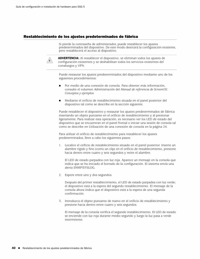
Guía de configuración e instalación de hardware para SSG 5
40
Restablecimiento de los ajustes predeterminados de fábrica
Si pierde la contraseña de administrador, puede restablecer los ajustes predeterminados del dispositivo. De este modo destruirá la configuración existente, pero restablecerá el acceso al dispositivo.
Puede restaurar los ajustes predeterminados del dispositivo mediante uno de los siguientes procedimientos:
Por medio de una conexión de consola. Para obtener más información, consulte el volumen Administración del Manual de referencia de ScreenOS: Conceptos y ejemplos.
Mediante el orificio de restablecimiento situada en el panel posterior del dispositivo tal como se describe en la sección siguiente.
Puede restablecer el dispositivo y restaurar los ajustes predeterminados de fábrica insertando un objeto punzante en el orificio de restablecimiento y al presionar ligeramente. Para realizar esta operación, es necesario ver los LED de estado del dispositivo que se encuentran en el panel frontal o iniciar una sesión de consola tal como se describe en Utilización de una conexión de consola en la página 24.
Para utilizar el orificio de restablecimiento para restablecer los ajustes predeterminados, lleve a cabo los siguientes pasos:
1. Localice el orificio de restablecimiento situado en el panel posterior. Inserte un alambre rígido y fino (como un clip) en el orificio de restablecimiento, presione hacia dentro entre cuatro y seis segundos y retire el alambre.
El LED de estado parpadea con luz roja. Aparece un mensaje en la consola que indica que se ha iniciado el borrado de la configuración. El sistema envía una alerta SNMP/SYSLOG.
2. Espere entre uno y dos segundos.
Después del primer restablecimiento, el LED de estado parpadea con luz verde; el dispositivo está a la espera del segundo restablecimiento. El mensaje de la consola ahora indica que el dispositivo está a la espera de una segunda confirmación.
3. Introduzca el objeto punzante de nuevo en el orificio de restablecimiento y presione hacia dentro entre cuatro y seis segundos.
El mensaje de la consola verifica el segundo restablecimiento. El LED de estado se enciende con luz roja durante medio segundo y luego la luz pasa a verde intermitente.
ADVERTENCIA: Al restablecer el dispositivo, se eliminan todos los ajustes de configuración existentes y se deshabilitan todos los servicios existentes del cortafuegos y VPN.
Restablecimiento de los ajustes predeterminados de fábrica

Español
Luego, se restablecen los ajustes originales de fábrica del dispositivo. Cuando el dispositivo se restablece, el LED de estado se enciende con luz roja durante medio segundo y luego la luz pasa a verde. La consola muestra los mensajes de arranque del dispositivo. El sistema genera alarmas SNMP y SYSLOG y las envía a los host de captura SNMP o SYSLOG configurados.
Una vez reiniciado el dispositivo, la consola muestra el mensaje de solicitud de inicio de sesión del dispositivo. El LED de estado parpadea con luz verde. El inicio de sesión y la contraseña son netscreen.
Si no sigue la secuencia completa, el proceso de restablecimiento se cancelará sin que se realice ningún cambio en la configuración. El mensaje de la consola indicará que se ha cancelado el borrado de la configuración. El LED de estado pasará a verde intermitente. Si el dispositivo no se restableció, se enviará una alerta SNMP para confirmar la falla.
Restablecimiento de los ajustes predeterminados de fábrica 41

Guía de configuración e instalación de hardware para SSG 5
42
Restablecimiento de los ajustes predeterminados de fábrica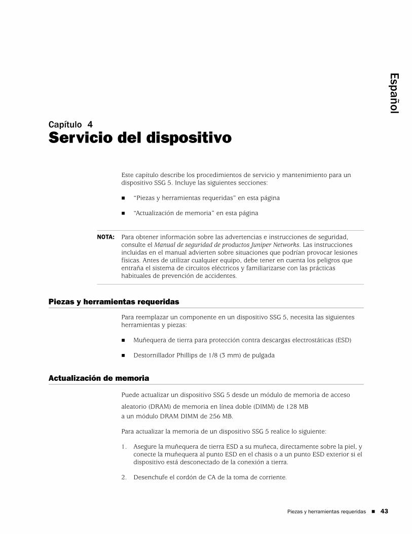
Español
Capítulo 4
Servicio del dispositivo
Este capítulo describe los procedimientos de servicio y mantenimiento para un dispositivo SSG 5. Incluye las siguientes secciones:
“Piezas y herramientas requeridas” en esta página
“Actualización de memoria” en esta página
Piezas y herramientas requeridas
Para reemplazar un componente en un dispositivo SSG 5, necesita las siguientes herramientas y piezas:
Muñequera de tierra para protección contra descargas electrostáticas (ESD)
Destornillador Phillips de 1/8 (3 mm) de pulgada
Actualización de memoria
Puede actualizar un dispositivo SSG 5 desde un módulo de memoria de acceso
aleatorio (DRAM) de memoria en línea doble (DIMM) de 128 MBa un módulo DRAM DIMM de 256 MB.
Para actualizar la memoria de un dispositivo SSG 5 realice lo siguiente:
1. Asegure la muñequera de tierra ESD a su muñeca, directamente sobre la piel, y conecte la muñequera al punto ESD en el chasis o a un punto ESD exterior si el dispositivo está desconectado de la conexión a tierra.
2. Desenchufe el cordón de CA de la toma de corriente.
NOTA: Para obtener información sobre las advertencias e instrucciones de seguridad, consulte el Manual de seguridad de productos Juniper Networks. Las instrucciones incluidas en el manual advierten sobre situaciones que podrían provocar lesiones físicas. Antes de utilizar cualquier equipo, debe tener en cuenta los peligros que entraña el sistema de circuitos eléctricos y familiarizarse con las prácticas habituales de prevención de accidentes.
Piezas y herramientas requeridas 43

Guía de configuración e instalación de hardware para SSG 5
44
3. Voltee el dispositivo de manera que la parte superior esté sobre una superficie plana.
4. Utilice un destornillador Phillips para retirar los tornillos de la cubierta de la tarjeta de memoria. Mantenga los tornillos cerca para usarlos cuando asegure la cubierta más adelante.
5. Retire la cubierta de la tarjeta de memoria.
Figura 13: Parte inferior del dispositivo
6. Libere la DIMM DRAM de 128 MB presionando con los pulgares hacia afuera en las lengüetas de bloqueo de cada lado del módulo de manera que las lengüetas se salgan del módulo.
Figura 14: Desbloqueo del módulo de memoria
7. Agarre el borde largo del módulo de memoria y deslícelo hacia afuera. Colóquelo a un lado.
Actualización de memoria

Español
Figura 15: Extracción de las ranuras del módulo
8. Introduzca la DIMM DRAM de 256 MB en la ranura. Aplicando presión uniforme con los pulgares en el borde superior del módulo, presione el módulo hacia abajo hasta que las lengüetas de bloqueo traben en su lugar.
Figura 16: Introducción del módulo de memoria
9. Coloque la cubierta de la tarjeta de memoria en la ranura.
10. Utilice el destornillador Phillips para apretar los tornillos y asegure la cubierta al dispositivo.
Actualización de memoria 45

Guía de configuración e instalación de hardware para SSG 5
46
Actualización de memoria
Español
Apéndice A
Especificaciones
En este apéndice se muestran las especificaciones generales del sistema del dispositivo SSG 5. Incluye las siguientes secciones:
“Características físicas” en esta página
“Características eléctricas” en esta página
“Tolerancia ambiental” en la página 48
“Certificaciones” en la página 48
“Conectores” en la página 49
Características físicas
Tabla 7: Especificaciones físicas del SSG 5
Características eléctricas
Tabla 8: Especificaciones eléctricas del SSG 5
Descripción Valor
Dimensiones del chasis 8,8 pulgadas X 5,6 pulgadas X 1,4 pulgadas. Con la base de caucho, el sistema mide 1,6 pulgadas (40 mm) de alto.
(222,5 mm x 143,4 mm x 35 mm.).
Peso del dispositivo 2,1 libras (960 gramos).
Elemento Especificaciones
Voltaje de entrada CC 5,5 V
Clasificación de corriente del sistema CC
4 amp
Características físicas 47

Guía de configuración e instalación de hardware para SSG 5
48
Tolerancia ambiental
Tabla 9: Tolerancia ambiental del SSG 5
Certificaciones
SeguridadCAN/CSA-C22.2 No. 60950-1-03/UL 60950-1 Tercera edición, Seguridad del equipo de tecnología de información
EN 60950-1:2001+A11, Seguridad del equipo de tecnología de información
EN 60950-1:2001, Primera edición, Seguridad del equipo de tecnología de información
Emisiones EMCFCC Parte 15 Clase B (EE.UU.)
EN 55022 Clase B (Europa)
AS 3548 Clase B (Australia)
VCCI Clase B (Japón)
Inmunidad EMCEN 55024
Armónica de la línea de alimentación EN-61000-3-2
Armónica de la línea de alimentación EN-61000-3-3
EN-61000-4-2 ESD
Inmunidad irradiada EN-61000-4-3
EN-61000-4-4 EFT
Sobretensión EN-61000-4-5
Inmunidad común de baja frecuencia EN-61000-4-6
Caídas y pérdidas de voltaje EN-61000-4-11
Descripción Valor
Altitud No hay degradación de rendimiento a 6.600 pies (2.000 m)
Humedad relativa El funcionamiento normal está garantizado en un rango de humedad relativa de 5 a 90 por ciento, sin condensación
Temperatura El funcionamiento normal está garantizado en un rango de temperatura de 32°F (0°C) a 104°F (40°C)
Temperatura de almacenamiento sin funcionamiento en el embalaje para transporte: -40°F (-40°C) a 158°F (70°C)
Tolerancia ambiental

Español
ETSIInstituto Europeo de Normas en Telecomunicaciones (ETSI) EN-3000386-2: Equipo de red de telecomunicación. Requisitos de compatibilidad electromagnética; (categoría del equipo-Distinto a centro de telecomunicación)
Conectores
La Figura 17 muestra la ubicación de las patillas del conector RJ-45.
Figura 17: Patillas de salida RJ-45
La Tabla 10 enumera las patillas de salida del conector RJ-45.
Tabla 10: Patillas de salida del conector RJ-45
Patilla Nombre E/S Descripción
1 Salida RTS S Solicitud para enviar
2 Salida DTR S Terminal de datos lista
3 TxD S Transmisión de datos
4 GND N/A Tierra del chasis
5 GND N/A Tierra del chasis
6 RxD E Recepción de datos
7 DSR E Datos listos
8 CTS E Listo para enviar
1 2 3 4 5 6 7 8
Conectores 49

Guía de configuración e instalación de hardware para SSG 5
50
La Figura 18 muestra la ubicación de las patillas del conector hembra DB-9.
Figura 18: Conector hembra DB-9
La Tabla 11 proporciona las patillas de salida del conector DB-9.
Tabla 11: Patillas de salida del conector DB-9
Patilla Nombre E/S Descripción
1 DCD E Detección de portadora
2 RxD E Recepción de datos
3 TxD S Transmisión de datos
4 DTR S Terminal de datos lista
5 GND N/A Tierra de la señal
6 DSR E Datos listos
7 RTS S Solicitud para enviar
8 CTS E Listo para enviar
9 RING E Indicador de llamada
Conectores
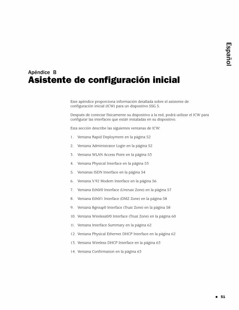
Español
Apéndice B
Asistente de configuración inicial
Este apéndice proporciona información detallada sobre el asistente de configuración inicial (ICW) para un dispositivo SSG 5.
Después de conectar físicamente su dispositivo a la red, podrá utilizar el ICW para configurar las interfaces que están instaladas en su dispositivo.
Esta sección describe las siguientes ventanas de ICW:
1. Ventana Rapid Deployment en la página 52
2. Ventana Administrator Login en la página 52
3. Ventana WLAN Access Point en la página 53
4. Ventana Physical Interface en la página 53
5. Ventanas ISDN Interface en la página 54
6. Ventana V.92 Modem Interface en la página 56
7. Ventana Eth0/0 Interface (Untrust Zone) en la página 57
8. Ventana Eth0/1 Interface (DMZ Zone) en la página 58
9. Ventana Bgroup0 Interface (Trust Zone) en la página 58
10. Ventana Wireless0/0 Interface (Trust Zone) en la página 60
11. Ventana Interface Summary en la página 62
12. Ventana Physical Ethernet DHCP Interface en la página 62
13. Ventana Wireless DHCP Interface en la página 63
14. Ventana Confirmation en la página 63
51

Guía de configuración e instalación de hardware para SSG 5
52
1. Ventana Rapid Deployment
Figura 19: Ventana Rapid Deployment
Si su red utiliza NetScreen-Security Manager (NSM), puede utilizar un configlet de implementación rápida para configurar el dispositivo automáticamente. Obtenga un configlet de su administrador NSM, seleccione Yes, seleccione Load Configlet from:, busque la ubicación del archivo y luego haga clic en Next. El configlet configura el dispositivo para usted, de manera que no es necesario que utilice los siguientes pasos para configurarlo.
Si no desea utilizar el ICW sino ir directamente a la WebUI, seleccione la última opción, luego haga clic en Next.
Si no utiliza un configlet para configurar el dispositivo y desea utilizar el ICW, seleccione la primera opción, luego haga clic en Next. Aparece la pantalla ICW Welcome. Haga clic en Next. Aparece la ventana Administrator Login.
2. Ventana Administrator LoginIntroduzca un nuevo nombre de inicio de sesión de administrador y contraseña, luego haga clic en Next.
Figura 20: Ventana Administrator Login

Español
3. Ventana WLAN Access PointSi utiliza el dispositivo en el dominio regulador WORLD o ETSI, debe escoger un código de país. Seleccione la opción adecuada, luego haga clic en Next.
Figura 21: Ventana Country Code
4. Ventana Physical InterfaceEn la pantalla de enlaces de interfaz a zona, establecerá la interfaz en la que desea enlazar la zona de seguridad Untrust. El Bgroup0 viene ya enlazado a la zona de seguridad Trust. Ethernet0/1 está enlazada a la zona de seguridad DMZ, pero esto es opcional.
Figura 22: Ventana Physical Interface
Después de enlazar una interfaz a una zona, podrá configurar la interfaz. Las ventanas de configuración que aparecen después de este punto dependen del dispositivo SSG 5 que utilice como parte de su red. Para continuar con la configuración de su dispositivo con el ICW, haga clic en Next.
53

Guía de configuración e instalación de hardware para SSG 5
54
5. Ventanas ISDN InterfaceSi tiene uno de los dispositivos RDSI, aparecerá una ventana con la ficha Physical Layer similar a la siguiente.
Figura 23: Ventana ISDN, ficha Physical Layer
Tabla 12: Campos de la ventana ISDN, ficha Physical Layer
Campo Descripción
Switch Type Establece el tipo de conmutador del proveedor de servicio:
att5e: At&T 5ESS
ntdms100: Nortel DMS 100
ins-net: NTT INS-Net
etsi: European variants
ni1: National ISDN-1
SPID1 Un ID del proveedor de servicios es, por lo general, un número telefónico de siete dígitos con algunos números opcionales. Únicamente los tipos de conmutador DMS-100 y NI1 requieren SPID. El tipo de conmutador DMS-100 tiene dos SPID asignados, uno para cada canal B.
SPID2 ID del proveedor de servicio de respaldo.
TEI Negotiation Especifica cuándo negociar TEI, ya sea al inicio o en la primera llamada. Normalmente, este ajuste se utiliza para las ofertas del servicio RDSI en Europa y conexiones a conmutadores DMS-100 que están designados para iniciar la negociación TEI.
Calling Number El número de facturación de la red RDSI.
Sending Complete Checkbox Habilita el envío de información completa al mensaje de configuración saliente. Por lo general sólo se utiliza en Hong Kong y Taiwán.

Español
Si tiene el dispositivo RDSI, verá las casillas de verificación Leased Line Mode y Dial Using BRI. Si selecciona una o ambas casillas de verificación, aparece una ventana similar a la siguiente:
Figura 24: Ventana Leased-Line y fichas Dial Using BRI Tabs
Tabla 13: Campos de la ventana Leased-Line y fichas Dial Using BRI Tabs
Campo Descripción
PPP Profile Name Establece un nombre de perfil PPP en la interfaz RDSI
Authentication Establece el tipo de autenticación PPP:
Any (cualquiera)
CHAP: Protocolo de autenticación de establecimiento de conexión por desafío
PAP: Protocolo de autenticación de contraseña
None (ninguna)
Local User Establece el usuario local
Password Establece la contraseña del usuario local
Static IP Checkbox Habilita una dirección IP estática para la interfaz
Interface IP Establece la dirección IP de la interfaz
Netmask Establece la máscara de red
Gateway Establece la dirección de la puerta de enlace
55

Guía de configuración e instalación de hardware para SSG 5
56
6. Ventana V.92 Modem InterfaceSi tiene uno de los dispositivos V.92, aparece la siguiente ventana:
Figura 25: Ventana V.92 Modem Interface
Tabla 14: Campos de la ventana V.92 Modem Interface
Campo Descripción
Modem Name Establece el nombre para la interfaz de módem
Init Strings Establece la cadena de inicialización para el módem
ISP Name Asigna un nombre al proveedor de servicios
Primary Number Especifica el número telefónico para obtener acceso al proveedor de servicios
Alternative Number (optional) Especifica un número telefónico alternativo para obtener acceso al proveedor de servicios si el número principal no conecta
Login Name Establece el nombre de inicio de sesión para la cuenta del proveedor de servicios
Password Establece la contraseña para el nombre de inicio de sesión

Español
7. Ventana Eth0/0 Interface (Untrust Zone) La interfaz de la zona Untrust puede tener una dirección IP estática o dinámica asignada a través de DHCP o PPPoE. Inserte la información necesaria, luego haga clic en Next.
Figura 26: Ventana Eth0/0 Interface
Tabla 15: Campos de la ventana Eth0/0 Interface
Campo Descripción
Dynamic IP via DHCP Habilita el dispositivo para que reciba una dirección IP para la interfaz de zona Untrust desde un proveedor de servicios.
Dynamic IP via PPPoE Habilita el dispositivo para que actúe como un cliente PPPoE, recibiendo una dirección IP para la interfaz de zona Untrust desde un proveedor de servicios. Introduzca el nombre de usuario y la contraseña que le asignó el proveedor de servicios.
Static IP Asigna una dirección IP única y fija a la interfaz de zona Untrust. Introduzca la dirección IP de interfaz de zona Untrust, máscara de red y puerta de enlace.
57

Guía de configuración e instalación de hardware para SSG 5
58
8. Ventana Eth0/1 Interface (DMZ Zone)La interfaz DMZ puede tener una dirección IP estática o dinámica asignada a través de DHCP. Inserte la información necesaria, luego haga clic en Next.
Figura 27: Ventana Eth0/1 Interface
Tabla 16: Campos de la ventana Ethernet0/1 Interface
9. Ventana Bgroup0 Interface (Trust Zone)La interfaz de la zona Trust puede tener una dirección IP estática o dinámica asignada a través de DHCP. Inserte la información deseada, luego haga clic en Next.
La dirección IP de la interfaz predeterminada es 192.168.1.1 con una máscara de red de 255.255.255.0 ó 24.
Campo Descripción
Dynamic IP via DHCP Habilita el dispositivo para que reciba una dirección IP para la interfaz DMZ desde un proveedor de servicios.
Static IP Asigna una dirección IP única y fija a la interfaz DMZ. Introduzca la dirección IP de la interfaz DMZ y máscara de red.

Español
Figura 28: Ventana Bgroup0 Interface
Tabla 17: Campos de la ventana Bgroup0 Interface
Campo Descripción
Dynamic IP via DHCP Habilita el dispositivo para que reciba una dirección IP para la interfaz de zona Trust desde un proveedor de servicios.
Static IP Asigna una dirección IP única y fija a la interfaz de zona Trust. Introduzca la dirección IP de interfaz de zona Trust y máscara de red.
59

Guía de configuración e instalación de hardware para SSG 5
60
10. Ventana Wireless0/0 Interface (Trust Zone)Si tiene uno de los dispositivos SSG 5-WLAN, debe establecer un identificador de conjunto de servicios (SSID) antes que la interfaz wireless0/0 se pueda activar. Para obtener instrucciones detalladas acerca de la configuración de sus interfaces inalámbricas, consulte el Manual de referencia de ScreenOS: Conceptos y ejemplos.
Figura 29: Ventana Wireless0/0 Interface

Español
Tabla 18: Campos de la ventana Wireless0/0 Interface
Después de configurar las interfaces WAN, verá la ventana Interface Summary.
Campo Descripción
Wlan Mode Configura el modo de radio WLAN:
5 G (802.11a)
2,4 G (802.11b/g)
Ambos (802.11a/b/g)
SSID Establece el nombre de SSID.
Authentication and Encryption Establece la autenticación y encriptación de la interfaz WLAN:
La autenticación open, el ajuste predeterminado, permite que cualquiera tenga acceso al dispositivo. No hay encriptación para esta opción de autenticación.
La autenticación de WPA Pre-Shared Key establece la clave previamente compartida (PSK) o contraseña que debe introducir al acceder a una conexión inalámbrica. Puede elegir introducir un valor HEX o ASCII para la PSK. Una PSK HEX debe ser un valor HEX de 256 bits (64 caracteres de texto). Una contraseña ASCII debe tener de 8 a 63 caracteres de texto. Debe seleccionar el protocolo de integridad de clave temporal (TKIP) o el estándar de encriptación avanzada (AES) como el tipo de encriptación para esta opción o seleccione Auto para utilizar cualquiera de las opciones.
Clave previamente compartida WPA2.
Clave previamente compartida automática WPA.
Interface IP Establece la dirección IP de la interfaz WLAN.
Netmask Establece la máscara de red de la interfaz WLAN.
61

Guía de configuración e instalación de hardware para SSG 5
62
11. Ventana Interface SummaryRevise la configuración de su interfaz, luego haga clic en Next cuando esté listo para continuar. Aparece la ventana Physical Ethernet DHCP Interface.
Figura 30: Ventana Interface Summary
12. Ventana Physical Ethernet DHCP InterfaceSeleccione Yes para que su dispositivo pueda asignar direcciones IP a su red de cables a través de DHCP. Introduzca el rango de dirección IP que desea que su dispositivo asigne a los clientes que utilizan su red.
Figura 31: Ventana Physical Ethernet DHCP Interface

Español
13. Ventana Wireless DHCP Interface Seleccione Yes para que su dispositivo pueda asignar direcciones IP a su red inalámbrica a través de DHCP. Introduzca el rango de dirección IP que desea que su dispositivo asigne a los clientes que utilizan su red.
Figura 32: Ventana Wireless DHCP Interface
14. Ventana ConfirmationConfirma la configuración de su dispositivo y permite cambiarla según sea necesario. Haga clic en Next para guardar, reiniciar el dispositivo y ejecutar la configuración.
Figura 33: Ventana Confirmation
Después de hacer clic en Next, el dispositivo reinicia con la configuración del sistema almacenada. Aparece el mensaje de petición de inicio de sesión de WebUI. Para obtener información sobre la manera de obtener acceso al dispositivo utilizando la WebUI, consulte “Utilización de la WebUI” en la página 25.
63

Guía de configuración e instalación de hardware para SSG 5
64

Español
Índice
AActualización de memoria, procedimiento ................43Administracióna través de la WebUI ...............................................25a través de una conexión de Telnet ......................26a través de una consola ..........................................24
CCables
conexiones de red básica .......................................20Conexión, red básica ....................................................20Configuración
acceso administrativo .............................................31autenticación inalámbrica y encriptación.............34dirección de administración...................................32fecha y hora..............................................................30grupos en puente (bgroup) .....................................30inalámbrica y Ethernet combinadas .....................36interfaces WAN ........................................................37interfaz untrust de respaldo ...................................33nombre de administrador y contraseña ...............29nombre de host y dominio.....................................32ruta predeterminada ...............................................32servicios de administración....................................31USB ............................................................................14
DDirecciones IP predeterminadas .................................28
IInalámbrico
antenas......................................................................22con la interfaz predeterminada..............................22
Interfaz de respaldo en la zona Untrust......................33
OOrificio de restablecimiento, uso.................................40
SServicios de administración .........................................31
TTransceptores de radio
WLAN 0.....................................................................14WLAN 1.....................................................................14
ZZona Untrust, configuración de la interfaz
de respaldo ..................................................................33
Índice 65

66
Guía de configuración e instalación de hardware para SSG 5
Índice

日本語
目次
本ガイドについて 5
構成 ............................................................................................................6WebUI 使用上の注意 ..................................................................................6CLI 使用上の注意 ........................................................................................7ドキュメントとテクニカルサポートの問い合わせ .......................................7
第 1 章 ハードウェアの概要 9
ポートと電源のコネクタ .............................................................................9フロントパネル.........................................................................................10
システムステータス LED ....................................................................10ポート ......................................................................................................12
イーサネットポート .....................................................................12コンソールポート .........................................................................13AUX ポート ..................................................................................13
バックパネル ............................................................................................13電源アダプタ ......................................................................................14無線トランシーバ ...............................................................................14接地ラグ.............................................................................................14アンテナのタイプ ...............................................................................14USB ポート .........................................................................................14
第 2 章 SSG 5 の取り付けと接続 17
使用準備 ...................................................................................................17機器の設置................................................................................................18SSG 5 とインターフェースケーブルの接続 ................................................19電源の接続................................................................................................19ネットワークと SSG 5 の接続 ...................................................................19
SSG 5 と Untrust ネットワークの接続 ................................................20イーサネットポート .....................................................................20シリアル(AUX/ コンソール)ポート ...........................................20WAN ポート .................................................................................21
SSG 5 と内部ネットワークまたはワークステーションとの接続 ...........21イーサネットポート .....................................................................21ワイヤレスアンテナ .....................................................................21
目次 3

4
SSG 5 ハードウェアの取り付けと構成ガイド
第 3 章 SSG 5 の構成 23
SSG 5 のアクセス......................................................................................24コンソール接続の使用 ........................................................................24WebUI の使用.....................................................................................25Telnet の使用......................................................................................26
SSG 5 のデフォルト設定 ...........................................................................26SSG 5 の基本構成......................................................................................28
ルート管理者名とパスワード ..............................................................29日付と時刻 .........................................................................................29ブリッジグループインターフェース....................................................30管理アクセス ......................................................................................30管理サービス ......................................................................................31ホスト名とドメイン名 ........................................................................31デフォルトルート ...............................................................................31管理インターフェースのアドレス .......................................................32バックアップ Untrust インターフェースの構成 ...................................32
基本ワイヤレス構成 ..................................................................................33WAN 構成.................................................................................................36
ISDN インターフェース ......................................................................36V.92 モデム インターフェース............................................................36
基本的ファイアウォール保護 ....................................................................37外部との接続性の確認 ..............................................................................38SSG 5 の出荷時のデフォルト設定へのリセット .........................................38
第 4 章 SSG 5 の点検 41
必要なツールとパーツ ..............................................................................41メモリのアップグレード ...........................................................................41
付録 A 仕様 45
物理的仕様................................................................................................45電気的仕様................................................................................................45環境耐性 ...................................................................................................46保証 ..........................................................................................................46
安全性 ................................................................................................46EMC エミッション..............................................................................46EMC(イミュニティ)..........................................................................46ETSI ...................................................................................................47
コネクタ ...................................................................................................47
付録 B Initial Configuration Wizard(初期構成ウィザード) 49
索引 .......................................................................................................63
目次

日本語
本ガイドについて
Juniper Networks Secure Services Gateway (SSG) 5 は統合ルーター / ファイアウォールプラットフォームであり、支店や販売店向けのインターネットプロトコルセキュリティ(IPSec)仮想プライベートネットワーク(VPN)とファイアウォールサービスを提供します。
SSG 5 には、次の 6 つのモデルがあります。
SSG 5 Serial
SSG 5 Serial-WLAN
SSG 5 V.92
SSG 5 V.92-WLAN
SSG 5 ISDN
SSG 5 ISDN-WLAN
どの SSG 5 モデルもユニバーサルシリアルバス(USB)ホストモジュールをサポートします。 どの SSG 5 モデルもローカルエリアネットワーク(LAN)とワイドエリアネットワーク(WAN)間のプロトコル変換もサポートしています。内 3 モデルはワイヤレスローカルエリアネットワーク(WLAN)をサポートしています。
メモ : 本書で紹介する構成手順と例では、ScreenOS 5.4 で SSG 5 を実行したときの機能を基準としています。 使用する ScreenOS バージョンによっては、SSG 5 の機能が異なることがあります。 SSG 5 の 新ドキュメントについては、http://www.juniper.net/techpubs/hardware の Juniper Networks Technical Publications Web サイトを参照してください。 お手元の SSG 5 に、使用できるどの ScreenOS バージョンについては、http://www.juniper.net/customers/support/ の Juniper Networks Support Web サイトを参照してください。
5
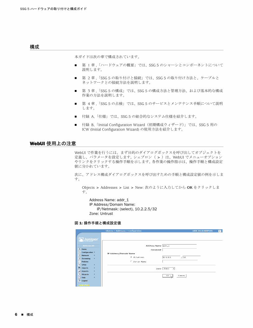
SSG 5 ハードウェアの取り付けと構成ガイド
6
構成
本ガイドは次の章で構成されています。
第 1 章 ,「ハードウェアの概要」では、SSG 5 のシャーシとコンポーネントについて説明します。
第 2 章 ,「SSG 5 の取り付けと接続」では、SSG 5 の取り付け方法と、ケーブルとネットワークとの接続方法を説明します。
第 3 章 ,「SSG 5 の構成」では、SSG 5 の構成方法と管理方法、および基本的な構成作業の方法を説明します。
第 4 章 ,「SSG 5 の点検」では、SSG 5 のサービスとメンテナンス手順について説明します。
付録 A,「仕様」では、SSG 5 の総合的なシステム仕様を紹介します。
付録 B,「Initial Configuration Wizard(初期構成ウィザード)」では、SSG 5 用の ICW (Initial Configuration Wizard) の使用方法を紹介します。
WebUI 使用上の注意
WebUI で作業を行うには、まず目的のダイアログボックスを呼び出してオブジェクトを定義し、パラメータを設定します。 シェブロン( > )は、WebUI でメニューオプションやリンクをクリックする操作手順を示します。 各作業の操作指示は、操作手順と構成設定値に分かれています。
次に、アドレス構成ダイアログボックスを呼び出すための手順と構成設定値の例を示します。
Objects > Addresses > List > New: 次のように入力してから OK をクリックします。
Address Name: addr_1IP Address/Domain Name:
IP/Netmask: (select), 10.2.2.5/32Zone: Untrust
図 1: 操作手順と構成設定値
構成

日本語
CLI 使用上の注意
次の規則は、例や本文中で CLI コマンド構文を使用するときの表記に適用します。
例では、次のように表記します。
角括弧 [ ] 内はすべてオプションです。
中括弧 { } 内はすべて必須です。
選択肢が複数ある場合、選択肢同士はパイプ( | )で区切ります。 例:
set interface { ethernet1 | ethernet2 | ethernet3 } manage
は、「ethernet 1、ethernet 2、または ethernet 3 インターフェースの管理オプションを設定する」という意味です。
変数は斜体で表示します。
set admin user name1 password xyz
本文では、次のように表記します。
コマンドは太字で表記します。
変数は斜体で表記します。
ドキュメントとテクニカルサポートの問い合わせ
Juniper Networks 製品のテクニカルドキュメントの入手方法については、www.juniper.net/techpubs/ を参照してください。
テクニカルサポートについては、http://www.juniper.net/support/ にある Case Manager リンクでサポート事例を開くか、1-888-314-JTAC(米国内)または 1-408-745-9500(その他の国)までお問い合わせください。
本書に間違いや欠落があった場合は、次の E メールアドレスまでお知らせください。
メモ : キーワードは、一意の識別に必要なだけの文字数を入力すればあとは省略できます。 たとえば、コマンド set admin user kathleen j12fmt54 は、set adm u kath j12fmt54 と入力するだけですべて画面に表示されます。 コマンド入力にはこのショートカットが使用できますが、本書で紹介するコマンドはすべて完全な形式で記載しています。
CLI 使用上の注意 7

SSG 5 ハードウェアの取り付けと構成ガイド
8
ドキュメントとテクニカルサポートの問い合わせ
日本語
第 1 章
ハードウェアの概要
本章では、SSG 5 シャーシとそのコンポーネントについて解説します。 本章は、次の節で構成されています。
9 ページの「ポートと電源のコネクタ」
10 ページの「フロントパネル」
13 ページの「バックパネル」
ポートと電源のコネクタ
本節では、内蔵ポートと電源のコネクタの解説とともにその配置を示します。
図 2: 内蔵ポートの配置
表 1 は、SSG 5 のポートと電源コネクタです。
図 1: SSG 5 のポートと電源コネクタ
SSG 5
V.92
STATUS
POWER
CONSOLE
TX /RX
CD
0 1 2 3 4 5 6TX/RX LINK TX/RX LINK TX/RX LINK TX/RX LINK TX/RX LINK TX/RX LINK TX/RX LINK
10/100 10/100 10/100 10/100 10/100 10/100 10/100
B /G
WLAN V.92
802.11A
0/60/50/40/30/20/10/0
コンソールAUX、ISDN または V.92
ポート 説明 コネクタ 速度 / プロトコル
0/0-0/6 ワークステーションとの直接接続またはスイッチや
ハブ経由の LAN 接続用のポートです。 このポートで
は Telnet セッションや WebUI で SSG 5 を管理する
こともできます。
RJ-45 10/100 Mbps イーサネット
オートセンシング全二重と自動 MDI/MDIX
USB システムとの 1.1 USB 接続用のポートです。 該当なし 12M(全速時)または 1.5M(低速時 )
コンソール システムとのシリアル接続用のポートです。 CLI セッ
ションを起動するターミナルエミュレーション接続
に使用します。
RJ-45 9600 bps/RS-232C シリアル
AUX 外部モデム経由によるバックアップ RS-232 非同期
シリアルインターネット接続用のポートです。
RJ-45 9600 bps — 115 Kbps/RS-232C シリアル
ポートと電源のコネクタ 9
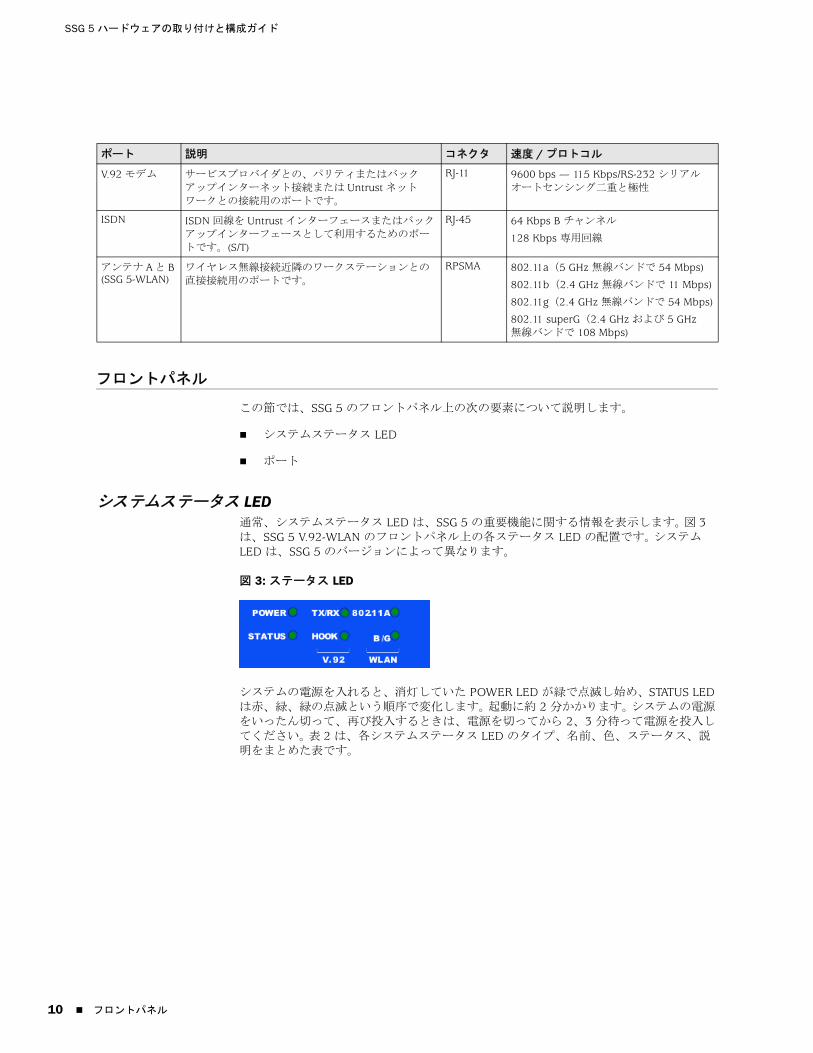
SSG 5 ハードウェアの取り付けと構成ガイド
10
フロントパネル
この節では、SSG 5 のフロントパネル上の次の要素について説明します。
システムステータス LED
ポート
システムステータス LED通常、システムステータス LED は、SSG 5 の重要機能に関する情報を表示します。 図 3 は、SSG 5 V.92-WLAN のフロントパネル上の各ステータス LED の配置です。 システム LED は、SSG 5 のバージョンによって異なります。
図 3: ステータス LED
システムの電源を入れると、消灯していた POWER LED が緑で点滅し始め、STATUS LED は赤、緑、緑の点滅という順序で変化します。 起動に約 2 分かかります。 システムの電源をいったん切って、再び投入するときは、電源を切ってから 2、3 分待って電源を投入してください。 表 2 は、各システムステータス LED のタイプ、名前、色、ステータス、説明をまとめた表です。
V.92 モデム サービスプロバイダとの、パリティまたはバック
アップインターネット接続または Untrust ネット
ワークとの接続用のポートです。
RJ-11 9600 bps — 115 Kbps/RS-232 シリアル
オートセンシング二重と極性
ISDN ISDN 回線を Untrust インターフェースまたはバック
アップインターフェースとして利用するためのポー
トです。(S/T)
RJ-45 64 Kbps B チャンネル
128 Kbps 専用回線
アンテナ A と B (SSG 5-WLAN)
ワイヤレス無線接続近隣のワークステーションとの
直接接続用のポートです。
RPSMA 802.11a(5 GHz 無線バンドで 54 Mbps)
802.11b(2.4 GHz 無線バンドで 11 Mbps)
802.11g(2.4 GHz 無線バンドで 54 Mbps)
802.11 superG(2.4 GHz および 5 GHz 無線バンドで 108 Mbps)
ポート 説明 コネクタ 速度 / プロトコル
フロントパネル
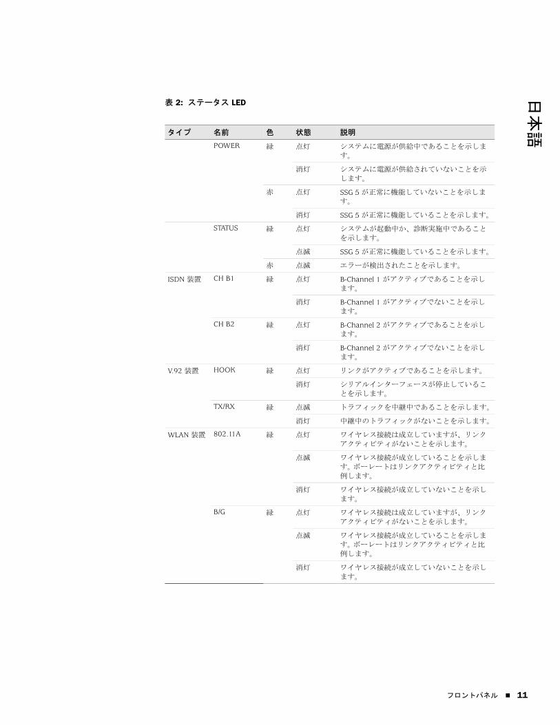
日本語
表 2: ステータス LED
タイプ 名前 色 状態 説明
POWER 緑 点灯 システムに電源が供給中であることを示しま
す。
消灯 システムに電源が供給されていないことを示
します。
赤 点灯 SSG 5 が正常に機能していないことを示しま
す。
消灯 SSG 5 が正常に機能していることを示します。
STATUS 緑 点灯 システムが起動中か、診断実施中であること
を示します。
点滅 SSG 5 が正常に機能していることを示します。
赤 点滅 エラーが検出されたことを示します。
ISDN 装置 CH B1 緑 点灯 B-Channel 1 がアクティブであることを示し
ます。
消灯 B-Channel 1 がアクティブでないことを示し
ます。
CH B2 緑 点灯 B-Channel 2 がアクティブであることを示し
ます。
消灯 B-Channel 2 がアクティブでないことを示し
ます。
V.92 装置 HOOK 緑 点灯 リンクがアクティブであることを示します。
消灯 シリアルインターフェースが停止しているこ
とを示します。
TX/RX 緑 点滅 トラフィックを中継中であることを示します。
消灯 中継中のトラフィックがないことを示します。
WLAN 装置 802.11A 緑 点灯 ワイヤレス接続は成立していますが、リンク
アクティビティがないことを示します。
点滅 ワイヤレス接続が成立していることを示しま
す。 ボーレートはリンクアクティビティと比
例します。
消灯 ワイヤレス接続が成立していないことを示し
ます。
B/G 緑 点灯 ワイヤレス接続は成立していますが、リンク
アクティビティがないことを示します。
点滅 ワイヤレス接続が成立していることを示しま
す。 ボーレートはリンクアクティビティと比
例します。
消灯 ワイヤレス接続が成立していないことを示し
ます。
フロントパネル 11
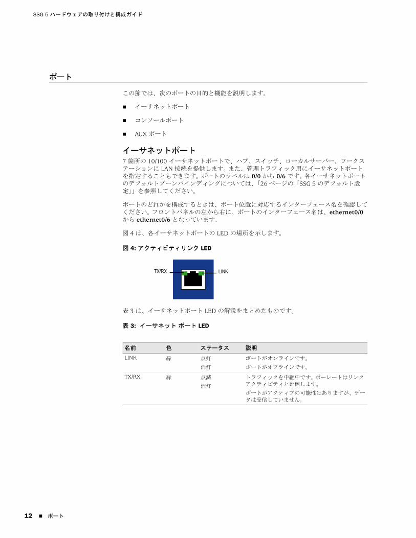
SSG 5 ハードウェアの取り付けと構成ガイド
12
ポート
この節では、次のポートの目的と機能を説明します。
イーサネットポート
コンソールポート
AUX ポート
イーサネットポート7 箇所の 10/100 イーサネットポートで、ハブ、スイッチ、ローカルサーバー、ワークステーションに LAN 接続を提供します。 また、管理トラフィック用にイーサネットポートを指定することもできます。 ポートのラベルは 0/0 から 0/6 です。 各イーサネットポートのデフォルトゾーンバインディングについては、「26 ページの「SSG 5 のデフォルト設定」」を参照してください。
ポートのどれかを構成するときは、ポート位置に対応するインターフェース名を確認してください。 フロントパネルの左から右に、ポートのインターフェース名は、ethernet0/0 から ethernet0/6 となっています。
図 4 は、各イーサネットポートの LED の場所を示します。
図 4: アクティビティリンク LED
表 3 は、イーサネットポート LED の解説をまとめたものです。
表 3: イーサネット ポート LED
名前 色 ステータス 説明
LINK 緑 点灯
消灯
ポートがオンラインです。
ポートがオフラインです。
TX/RX 緑 点滅
消灯
トラフィックを中継中です。 ボーレートはリンク
アクティビティと比例します。
ポートがアクティブの可能性はありますが、デー
タは受信していません。
LINKTX/RX
ポート

日本語
コンソールポートコンソールポートは、ローカル管理に使用できるデータ回路終端装置(DCE)として配線した RJ-45 シリアルポートです。 ターミナル接続にはストレートケーブルを使用し、別の DCE 装置を追加するときはクロスオーバーケーブルを使用してください。 RJ-45 対 DB-9 のアダプタを用意しています。
RJ-45 コネクタのピン配列については、47 ページの「コネクタ」 を参照してください。
AUX ポート補助(AUX)ポートは、RJ-45 シリアルポートです。リモート管理のためにモデムに接続できるデータターミナル装置(DTE)として配線されています。 通常のリモート管理には、このポートを使用しないでください。 AUX ポートは通常バックアップシリアルインターフェースとして割り当てます。 ボーレートは、9600 bps から 115200 bps の範囲で調節できます。ハードウェアフロー制御が必要です。 モデムに接続するときはストレートケーブルを使用し、別の DTE 装置を追加するときはクロスオーバーケーブルを使用してください。
RJ-45 コネクタのピン配列については、47 ページの「コネクタ」 を参照してください。
バックパネル
この節では、SSG5 のバックパネル上の次の要素について説明します。
電源アダプタ
無線トランシーバ
接地ラグ
アンテナのタイプ
USB ポート
図 5: SSG 5 のバックパネル
メモ : アンテナコネクタがあるのは、SSG 5-WLAN だけです。
RESETDC POWER
LOCK
USBSD FLASHB A5V A4
電源アダプタ
USB ホストモジュール接地ラグ
リセットスイッチ
アンテナ Aアンテナ B
バックパネル 13

SSG 5 ハードウェアの取り付けと構成ガイド
14
電源アダプタSSG 5 のフロントパネルの POWER LED のステータスは、緑に点灯しているか消灯しているかのいずれかです。 緑に点灯しているときは正常に機能していることを示し、消灯しているときは電源アダプタに障害があるか、SSG 5 の電源が入っていないことを示します。
無線トランシーバSSG 5-WLAN には、2 基のワイヤレス接続無線トランシーバが組み込まれており、802.11a/b/g の各標準に準拠しています。 初のトランシーバ(WLAN 0)は 2.4 GHz 無線バンドを使用します。これは、11 Mbps で 802.11b 標準に、54 Mbps で 802.11g 標準に準拠しています。 第 2 の無線トランシーバ(WLAN1)は、5 GHz 無線バンドを使用します。これは、54 Mbps で 802.11a 標準に準拠しています。 2 つの無線バンドは同時に機能できます。 ワイヤレス無線バンドの構成方法については、「33 ページの「基本ワイヤレス構成」を参照してください。
接地ラグシャーシのバックパネルにはワンホール接地ラグがあり、これで SSG 5 をアース接地に接続します(図 5 参照 )。
電源投入前に SSG 5 を接地するには、接地ケーブルをアース接地に接続し、シャーシのバックパネルのラグにケーブルを接続します。
アンテナのタイプSSG 5-WLAN は、3 つの タイプのカスタムビルド無線アンテナをサポートしています。
ダイバーシティーアンテナ — ダイバーシティーアンテナは 2dBi の指向性有効範囲を備え、範囲内では極めて均一レベルの信号強度を発揮でき、ほとんどのインストレーションに 適です。 SSG 5 に同梱のアンテナはこのタイプです。
外部無指向性アンテナ — この外部アンテナは 2dBi の無指向性有効範囲を備えています。 ペアで使用するダイバーシティーアンテナとは異なり、2 つのタイプのアンテナの使用時の外部アンテナの目的は信号受信時の若干の遅延特性に起因するエコー効果を排除することです。
外部指向性アンテナ — 外部指向性アンテナは、2dBi の単一指向性の有効範囲を備えています。通路や外壁のある場所に 適です(アンテナは内側に向けます )。
USB ポートCompactFlash Association が公開している CompactFlash Specification に定められているように、SSG 5 のバックパネルの USB ポートには、ユニバーサルシリアルバス(USB)ストレージデバイスまたはコンパクトフラッシュディスクをインストールした USB ストレージアダプタを接続します。 USB ストレージデバイスをインストールして構成しておけば、スタートアップ時にプライマリコンパクトフラッシュディスクに障害が発生しても、USB ストレージデバイスは自動的にセカンダリブートデバイスとして機能します。
USB ポートでは、外部 USB ストレージデバイスとセキュリティデバイス内にある内部フラッシュストレージ間で、デバイス構成、ユーザー認証、アップデートバージョンイメージなどのファイルを転送できます。 USB ポートは、低速(1.5M)と全速(12M)のいずれのファイル転送でも USB 1.1 仕様をサポートしています。
バックパネル
日本語
USB ストレージデバイスと SSG 5 間のファイル転送手順を次に示します。
1. セキュリティデバイスの USB ポートに USB ストレージデバイスを挿入します。
2. save {software | config | image-key} from usb filename to flash CLI コマンドで、USB ストレージデバイスから SSG 20 の内部フラッシュストレージにファイルを保存します。
3. USB ストレージデバイスを取り外す前に、exec usb-device stop CLI コマンドで USB ポートを停止します。
4. これで安全に USB ストレージデバイスを取り出すことができます。
USB ストレージデバイスからファイルを削除するときは、delete file usb:/filename CLI コマンドを使用します。
USB ストレージデバイスまたは内部フラッシュストレージに保存してあるファイル情報を表示するには、get file CLI コマンドを使用します。
バックパネル 15

SSG 5 ハードウェアの取り付けと構成ガイド
16
バックパネル
日本語
第 2 章
SSG 5 の取り付けと接続
本章では、SSG 5 の取り付け方法と、ケーブルや電源の接続方法を説明します。 本章は、次の節で構成されています。
17 ページの「使用準備」
18 ページの「機器の設置」
19 ページの「SSG 5 とインターフェースケーブルの接続」
19 ページの「電源の接続」
19 ページの「ネットワークと SSG 5 の接続」
使用準備
システムを正しく運用するためには、シャーシの位置、監視装置の配置、配線室のセキュリティが重要です。
システムのシャットダウン、機器の障害、けがを防ぐため、次の注意事項に従ってください。
設置前には、電源が入っていないことを確認してください。
SSG 5 を設置する部屋は、適切な換気があり、部屋の温度が 104° F (40° C) を超えないことを確認してください。
吸気ポートや排気ポートがふさがれるおそれのある機器ラックフレームに SSG 5 を設置しないでください。 密閉型ラックの場合はファンがあり、側面にルーバーがあることを確認してください。
湿気のある床面や濡れた床面、漏電、接地されていない電源ケーブルやすり切れた電源ケーブル、安全用接地の欠落など、危険な状態は修復しておいてください。
メモ : 安全上の注意と手順については、Juniper Networks Security Products Safety Guide を参照してください。 機器の操作にあたっては、電気回路にともなう危険性をよく認識し、事故防止のための一般的な対策を理解しておいてください。
警告 : 誤用や無用な者の侵入を防ぐため、SSG 5 は安全な環境に設置してください。
使用準備 17

SSG 5 ハードウェアの取り付けと構成ガイド
18
機器の設置
SSG 5 の取り付け方法には、壁面取り付け、机上取り付けがあります。 取り付けキットは別途販売です。
SSG 5 の取り付けには、プラスドライバの 2 番(未同梱)と、機器ラック(キットに同梱)と互換性のあるネジが必要です。
SSG 5 をラックに取り付けるには、次の手順に従ってください。
1. トレイのマウンティングブラケットのネジをプラスドライバでゆるめます。
2. SSG 5-WLAN の底をトレイの底穴に合わせます。
3. SSG 5-WLAN を前に引いて、トレイの底穴にロックします。
4. ネジでマウンティングブラケットを SSG 5-WLAN とトレイに固定します。
5. 電源ホルダに電源を置き、SSG 5-WLAN に電源アダプタを差し込みます。
6. 次の SSG 5 を取り付ける場合は、手順 1 から手順 5 を繰り返し、作業を続けます。
図 6: SSG 5 のラック取り付け
7. 同梱のネジでラックにトレイを取り付けます。
8. 電源コンセントに電源を差し込みます。
SSG 5 を机上取り付けするには、次の手順に従ってください。
1. デスクトップスタンドを SSG 5 の側面に取り付けます。 その際、電源アダプタに近い側面を使用してください。
2. デスクトップに SSG 5 を置きます。
メモ : SSG 5 の取り付けは、電源コンセントが手の届く範囲にあることを確認して行ってください。.
メモ : SSG 5-WLAN でオプションのアンテナを使用する場合は、既存のアンテナを取り外し、横穴から新しいアンテナを接続してください。
電源ホルダ
電源ホルダ
機器の設置

日本語
図 7: SSG 5 の机上取り付け
3. 電源アダプタを差し込み、電源を電源コンセントに接続します。
SSG 5 とインターフェースケーブルの接続
電源は次の手順で SSG 5 に接続します。
1. インターフェースに使用する所定の長さのケーブルを用意します。
2. SSG 5 のケーブルコネクタポートにケーブルコネクタを挿入します。
3. ケーブルが外れたり、ストレスポイントができないように、次の手順でケーブルを固定します。
a. ケーブルが床に垂れて自重がかからないようケーブルを固定します。
b. 余分な長さのケーブルはコイルに巻いて整理します。
c. ケーブルループが崩れないようファスナで固定します。
電源の接続
電源は次の手順で SSG 5 に接続します。
1. 電源ケーブルの DC コネクタ側を SSG 5 背後の DC 電源コンセントに差し込みます。
2. 電源ケーブルの AC アダプタ側を AC 電源コンセントに差し込みます。
ネットワークと SSG 5 の接続
SSG 5 には、内部ネットワークと Untrust ネットワーク間に配置するときのファイアウォール機能と、一般的な対ネットワークセキュリティ機能があります。 この節の内容を次に示します。
SSG 5 と Untrust ネットワークの接続
SSG 5 と内部ネットワークまたはワークステーションとの接続
警告 : 電源接続にはサージ保安器を使用してください。
SSG 5 とインターフェースケーブルの接続 19
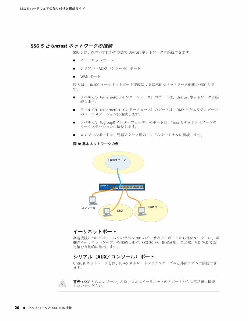
SSG 5 ハードウェアの取り付けと構成ガイド
20
SSG 5 と Untrust ネットワークの接続SSG 5 は、次のいずれかの方法で Untrust ネットワークに接続できます。
イーサネットポート
シリアル(AUX/ コンソール)ポート
WAN ポート
図 8 は、10/100 イーサネットポート接続による基本的なネットワーク配線の SSG 5 です。
ラベル 0/0(ethernet0/0 インターフェース)のポートは、Untrust ネットワークに接続します。
ラベル 0/1(ethernet0/1 インターフェース)のポートは、DMZ セキュリティゾーンのワークステーションに接続します。
ラベル 0/2(bgroup0 インターフェース)のポートは、Trust セキュリティゾーンのワークステーションに接続します。
コンソールポートは、管理アクセス用のシリアルターミナルに接続します。
図 8: 基本ネットワークの例
イーサネットポート高速接続については、SSG 5 のラベル 0/0 のイーサネットポートから外部ルーターに、同梱のイーサネットケーブルを接続します。 SSG 20 が、指定速度、全二重、MDI/MDIX 設定値を自動的に検出します。
シリアル(AUX/ コンソール)ポートUntrust ネットワークとは、RJ-45 ストレートシリアルケーブルと外部モデムで接続できます。
SSG 5
V.92
STATUS
POWER
CONSOLE
TX /RX
CD
0 1 2 3 4 5 6TX/RX LINK TX/RX LINK TX/RX LINK TX/RX LINK TX/RX LINK TX/RX LINK TX/RX LINK
10/100 10/100 10/100 10/100 10/100 10/100 10/100
B /G
WLAN V.92
802.11A
Callouts
Untrust ゾーン
コンソールDMZ
Trust ゾーン
警告 : SSG 5 のコンソール、AUX、またはイーサネットの各ポートからは電話線に接続しないでください。
ネットワークと SSG 5 の接続

日本語
WAN ポート1. インターフェースに使用する所定の長さのケーブルを用意します。
2. SSG 5 のケーブルコネクタポートにケーブルコネクタを挿入します。
3. ケーブルが外れたり、ストレスポイントができないように、次の手順でケーブルを固定します。
a. ケーブルが床に垂れて自重がかからないような状態にケーブルを固定します。
b. 余分な長さのケーブルはコイルに巻いて整理します。
c. ケーブルループが崩れないよう、ファスナで固定します。
SSG 5 と内部ネットワークまたはワークステーションとの接続ローカルエリアネットワーク(LAN)やワークステーションは、イーサネットとワイヤレスインターフェースのいずれかまたは両方に接続できます。
イーサネットポートSSG 5 にはイーサネットポートが 7 つあります。 スイッチやハブ経由で LAN との接続には、これらのポートを 1 つまたは複数使用できます。 ハブやスイッチを介せずに、これらポートの 1 つまたはすべてをワークステーションに直接接続することもできます。 クロスケーブルとストレートケーブルのどちらでも、イーサネットポートと他の装置は接続できます。 デフォルトのゾーン対インターフェースのバインドについては、26 ページの「SSG 5 のデフォルト設定」を参照してください。
ワイヤレスアンテナワイヤレスインターフェースを使用する場合、SSG 5 に同梱のアンテナを接続してください。 標準 2dB ダイバーシティーアンテナが手元にある場合は、SSG 5 背面のマーク A と B のポストにねじ止めしてください。 バルクヘッドコネクタに圧力がかからないよう、アンテナを L 字形に曲げます。
図 9: SSG 5-WLAN アンテナの位置
オプションの外部アンテナを使用する場合は、そのアンテナに同梱の接続指示に従ってください。
RESETDC POWER
LOCK
USBSD FLASHB A5V A4
バルクヘッドコネクタバルクヘッドコネクタ
アンテナ B アンテナ A
ネットワークと SSG 5 の接続 21

SSG 5 ハードウェアの取り付けと構成ガイド
22
ネットワークと SSG 5 の接続
日本語
第 3 章
SSG 5 の構成
SSG 5 には、出荷時に ScreenOS ソフトウェアがインストールされています。 SSG 5 の電源を入れると、構成準備が整います。 SSG 5 では、SSG 5 との初期接続のためのデフォルト構成を出荷時に済ませていますが、使用するネットワークの要件に応じて追加構成をする必要があります。
本章は、次の節で構成されています。
24 ページの「SSG 5 のアクセス」
26 ページの「SSG 5 のデフォルト設定」
28 ページの「SSG 5 の基本構成」
33 ページの「基本ワイヤレス構成」
36 ページの「WAN 構成」
37 ページの「基本的ファイアウォール保護」
38 ページの「外部との接続性の確認」
38 ページの「SSG 5 の出荷時のデフォルト設定へのリセット」
メモ : SSG 5 を構成し、リモートネットワークによる接続ができることを確認したら、www.juniper.net/support/ で製品を登録してください。SSG 5 で、Deep Inspection Signature Service と アンチウィルスソフトウェア(別途購入)などの ScreenOS サービスを受けるためです。 製品を登録したら、WebUI でサービスを申し込みます。 製品の登録とサービスの申込みの詳細については、使用する SSG 5 で実行するバージョンの ScreenOS に対応する概念と用例 ScreenOS リファレンス ガイドの「基本」の部を参照してください。
23

SSG 5 ハードウェアの取り付けと構成ガイド
24
SSG 5 のアクセス
SSG 5 には、次の構成方法や管理方法があります。
コンソール : SSG 5 のコンソールポートからは、ワークステーションやターミナルに接続したシリアルケーブル経由で SSG 5 をアクセスできます。 SSG 5 を構成するには、ターミナルから、またはワークステーションで実行しているターミナルエミュレーションプログラムから ScreenOS コマンドラインインターフェース(CLI)コマンドを入力します。
WebUI: ScreenOS Web ユーザーインターフェース(WebUI)は、ブラウザで使用できるグラフィカルインターフェースです。 初めて WebUI を使用するときは、ブラウザを実行するワークステーションを、SSG 5 と同じサブネットワークに接続してください。 WebUI は、セキュア HTTP(S-HTTP)によるセキュアソケットレイヤー (SSL)を利用してセキュアサーバーでもアクセスできます。
Telnet/SSH: Telnet と SSH は、IP ネットワークで SSG 5 をアクセスできるアプリケーションです。 SSG 5 を構成するには、ワークステーションから Telnet セッションで ScreenOS CLI コマンドを入力します。 詳細については、概念と用例 ScreenOS リファレンス ガイドの「管理」の部を参照してください。
NetScreen-Security Manager: NetScreen-Security Manager は、Juniper Networks ファイアウォール /IPSec VPN の構成、管理を行うための Juniper Networks 業務用管理アプリケーションです。 NetScreen-Security Manager による SSG 5 の管理方法については、NetScreen-Security Manager 2004 Administrator’s Guide を参照してください。
コンソール接続の使用
コンソールは次の手順で接続します。
1. 同梱の DB-9 アダプタのメス側をワークステーションのシリアルポートに差し込みます (DB-9 は正しく、確実に差し込んでください )。 図 10 は、使用するタイプの DB-9 コネクタです。
図 10: DB-9 アダプタ
2. SSG 5 のコンソールポートにシリアルケーブルの RJ-45 オス側を差し込みます (CAT5 ケーブルのもう一方の端は、正しく、確実に、DB-9 アダプタに差し込んでください)。
メモ : SSG 5 のコンソールポートとの接続には、オス RJ-45 コネクタ付きのストレート RJ-45 CAT5 シリアルケーブルを使用します。
RJ-45 ジャック
DB-9 アダプタ
RJ-45 ケーブル
SSG 5 のアクセス

日本語
3. ワークステーションでシリアルターミナルエミュレーションプログラムを起動します コンソールセッションの開始に必要な設定は次のとおりです。
ボーレート : 9600
パリティ : なし
データビット : 8
ストップビット : 1
フロー制御 : なし
4. デフォルトのユーザー名とパスワードを変更していない場合は、ログインおよびパスワードプロンプトの両方で netscreen と入力します ( 小文字以外使用しないでください。 ログインフィールドとパスワードフィールドのいずれも、大文字小文字を区別します)。
CLI コマンドによる SSG 5 の構成方法については、概念と用例 ScreenOS リファレンス ガイドを参照してください。
5. (オプション)アイドルタイムが 10 分続くとコンソールはデフォルトでタイムアウトになり、自動的に終了します。 タイムアウトの設定を削除するには、set console timeout 0 と入力します。
WebUI の使用WebUI を使用するには、SSG 5 と同じサブネットワークに、SSG 5 を管理するワークステーションを配置してください。 WebUI で SSG 5 をアクセスするには、次のように操作します。
1. SSG 5 の 0/2 — 0/6 ポート(Trust ゾーンの bgroup0 インターフェース)にワークステーションを接続します。
2. ワークステーションが動的ホスト構成プロトコル(DHCP)対応で構成されているか、192.168.1.0/24 サブネットの IP アドレスで静的に構成されていることを確認します。
3. ブラウザを起動して bgroup0 インターフェースの IP アドレス(デフォルト IP アドレスは 192.168.1.1/24)を入力し、Enter を押します。
WebUI アプリケーションでは、図 11 のようにログインプロンプトが表示されます。
図 11: WebUI ログインプロンプト
メモ : WebUI による初めての SSG 5 のアクセスでは、Initial Configuration Wizard(ICW)が表示されます。 ICW で SSG 5 を構成する場合は、49 ページの「Initial Configuration Wizard(初期構成ウィザード)」 を参照してください。
SSG 5 のアクセス 25
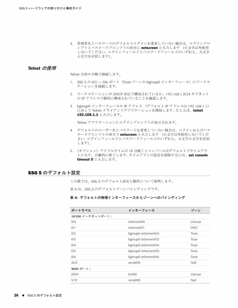
SSG 5 ハードウェアの取り付けと構成ガイド
26
4. 管理者名とパスワードのデフォルトログインを変更していない場合は、ログインプロンプトとパスワードプロンプトの両方に netscreen と入力します (小文字以外使用しないでください。 ログインフィールドとパスワードフィールドのいずれも、大文字小文字を区別します)。
Telnet の使用Telnet は次の手順で接続します。
1. SSG 5 の 0/2 — 0/6 ポート(Trust ゾーンの bgroup0 インターフェース)にワークステーションを接続します。
2. ワークステーションが DHCP 対応で構成されているか、192.168.1.0/24 サブネットの IP アドレスで静的に構成されていることを確認します。
3. bgroup0 インターフェースの IP アドレス (デフォルト IP アドレスは 192.168.1.1)に対して Telnet クライアントアプリケーションを開始します。 たとえば、telnet 192.168.1.1 と入力します。
Telnet アプリケーションにログインプロンプトが表示されます。
4. デフォルトのユーザー名とパスワードを変更していない場合は、ログインおよびパスワードプロンプトの両方で netscreen と入力します (小文字以外使用しないでください。 ログインフィールドとパスワードフィールドのいずれも、大文字小文字を区別します)。
5. (オプション)アイドルタイムが 10 分続くとコンソールはデフォルトでタイムアウトになり、自動的に終了します。 タイムアウトの設定を削除するには、set console timeout 0 と入力します。
SSG 5 のデフォルト設定
この節では、SSG 5 のデフォルト設定と動作について説明します。
表 4 は、SSG 5 のデフォルトゾーンバインディングです。
表 4: デフォルトの物理インターフェースからゾーンへのバインディング
ポートラベル インターフェース ゾーン
10/100 イーサネットポート :
0/0 ethernet0/0 Untrust
0/1 ethernet0/1 DMZ
0/2 bgroup0 (ethernet0/2) Trust
0/3 bgroup0 (ethernet0/3) Trust
0/4 bgroup0 (ethernet0/4) Trust
0/5 bgroup0 (ethernet0/5) Trust
0/6 bgroup0 (ethernet0/6) Trust
AUX serial0/0 Null
WAN ポート :
ISDN bri0/0 Untrust
V.92 serial0/0 Null
SSG 5 のデフォルト設定
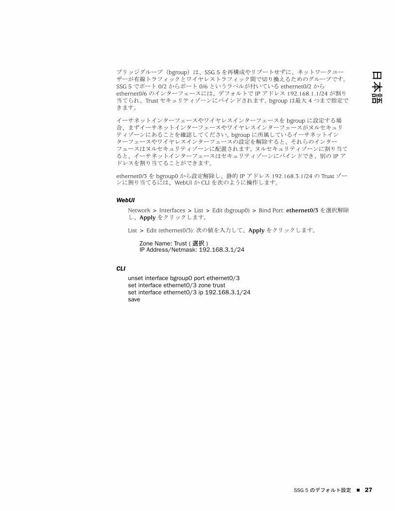
日本語
ブリッジグループ(bgroup)は、SSG 5 を再構成やリブートせずに、ネットワークユーザーが有線トラフィックとワイヤレストラフィック間で切り換えるためのグループです。 SSG 5 でポート 0/2 からポート 0/6 というラベルが付いている ethernet0/2 から ethernet0/6 のインターフェースには、デフォルトで IP アドレス 192.168.1.1/24 が割り当てられ、Trust セキュリティゾーンにバインドされます。 bgroup は 大 4 つまで指定できます。
イーサネットインターフェースやワイヤレスインターフェースを bgroup に設定する場合、まずイーサネットインターフェースやワイヤレスインターフェースがヌルセキュリティゾーンにあることを確認してください。 bgroup に所属しているイーサネットインターフェースやワイヤレスインターフェースの設定を解除すると、それらのインターフェースはヌルセキュリティゾーンに配置されます。 ヌルセキュリティゾーンに割り当てると、イーサネットインターフェースはセキュリティゾーンにバインドでき、別の IP アドレスを割り当てることができます。
ethernet0/3 を bgroup0 から設定解除し、静的 IP アドレス 192.168.3.1/24 の Trust ゾーンに割り当てるには、WebUI か CLI を次のように操作します。
WebUI
Network > Interfaces > List > Edit (bgroup0) > Bind Port: ethernet0/3 を選択解除し、Apply をクリックします。
List > Edit (ethernet0/3): 次の値を入力して、Apply をクリックします。
Zone Name: Trust ( 選択 )IP Address/Netmask: 192.168.3.1/24
CLI
unset interface bgroup0 port ethernet0/3set interface ethernet0/3 zone trustset interface ethernet0/3 ip 192.168.3.1/24save
SSG 5 のデフォルト設定 27

SSG 5 ハードウェアの取り付けと構成ガイド
28
表 5: ワイヤレスインターフェースと論理インターフェースのバインディング
bgroup0 インターフェースのデフォルト IP アドレスは、LAN や WLAN のアドレスに合わせて変更できます。 bgroup に対するワイヤレスインターフェースの構成方法については、「33 ページの「基本ワイヤレス構成」」を参照してください。
bgroup の詳細と例については、概念と用例 ScreenOS リファレンス ガイドを参照してください。
SSG 5 の他のイーサネットインターフェースやワイヤレスインターフェースにはデフォルト IP アドレスは構成されていません。WAN インターフェースをはじめ、他のインターフェースには IP アドレスを割り当ててください。
SSG 5 の基本構成
この節では、次の基本構成設定について説明します。
ルート管理者名とパスワード
日付と時刻
ブリッジグループインターフェース
管理アクセス
管理サービス
ホスト名とドメイン名
デフォルトルート
管理インターフェースのアドレス
バックアップ Untrust インターフェースの構成
SSG 5-WLAN インターフェース ゾーン
ワイヤレスインターフェース
ワイヤレスインターフェースを指定しま
す。2.4 G と 5 G 無線の両方またはいずれ
かで動作する構成が可能です。
wireless0/0(デフォルト IP アドレス
は 192.168.2.1/24)Trust
wireless0/1-0/3. Null
論理インターフェース
レイヤー 2 インターフェース vlan1 は、SSG 5 がトランスペアレン
ト モードのときに、管理と VPN トラ
フィックの終了に使用する論理イン
ターフェースを指定します。
該当なし
トンネルインターフェース tunnel.n は、論理トンネルインター
フェースを指定します。 このインター
フェースは、VPN トラフィック用で
す。
該当なし
メモ : ワイヤレスインターフェースを構成した bgroup インターフェースはトランスペアレントモードでは機能しません。
SSG 5 の基本構成

日本語
ルート管理者名とパスワードルート管理者には、SSG 5 の構成に必要なすべての管理権限があります。 デフォルトのルート管理者名とパスワード(いずれも netscreen)はすみやかに変更してください。
ルート管理者名とパスワードを変更するには、WebUI か CLI を次のように操作します。
WebUI
Configuration > Admin > Administrators > Edit (Administrator Name): 次のように入力してから OK をクリックします。
Administrator Name:Old Password: netscreenNew Password:Confirm New Password:
CLI
set admin name nameset admin password pswd_strsave
日付と時刻SSG 5 で設定した時刻は VPN トンネルのセットアップなどさまざまなイベントに反映されます。 日付と時刻は、WebUI で SSG 5 のシステムクロックをワークステーションクロックに同期すればで簡単に SSG 5 に設定できます。
SSG 5 に日付と時刻を設定するには、WebUI か CLI を次のように操作します。
WebUI
1. Configuration > Date/Time: Sync Clock with Client ボタンをクリックします。
ワークステーションクロックで夏時間オプションを有効にしたかどうかの指定を求めるポップアップメッセージが表示されます。
2. Yes をクリックすると、夏時間に合わせてシステムクロックを同期化します。No をクリックすると、夏時間との調整なしでシステムクロックを同期化します。
また、Telnet またはコンソールセッションで set clock CLI コマンドを使用して、手動で日付と時間を設定することもできます。
メモ : WebUI にパスワードは表示されません。
SSG 5 の基本構成 29

SSG 5 ハードウェアの取り付けと構成ガイド
30
ブリッジグループインターフェースデフォルトで、SSG 5 では、イーサネットインターフェース ethernet0/2 から ethernet0/4 が Trust セキュリティゾーンにグループとしてまとめられています。 グループ化したインターフェースは、1 つのサブネットになります。 グループのインターフェースをグループから取り出して、別のセキュリティゾーンに割り当てることもできます。 グループに割り当てられるのはヌルセキュリティゾーンのインターフェースだけです。 グループ化したインターフェースをヌルセキュリティゾーンに配置するには、unset interface interface port interface CLI コマンドを使用します。
SSG 5-WLAN では、イーサネットインターフェースとワイヤレスインターフェースを 1 サブネットとしてグループにまとめることができます。
イーサネットインターフェースとワイヤレスインターフェースでグループを構成するには、WebUI か CLI を次のように操作します。
WebUI
Network > Interfaces > List > Edit (bgroup0) > Bind Port: ethernet0/3 と ethernet0/4 の選択を解除し、Apply をクリックします。
Edit (bgroup1) > Bind Port: ethernet0/3、ethernet0/4、wireless0/2 を選択し、Apply をクリックします。
> Basic: 次の値を入力して、Apply をクリックします。
Zone Name: DMZ ( 選択 )IP Address/Netmask: 10.0.0.1/24
CLI
unset interface bgroup0 port ethernet0/3unset interface bgroup0 port ethernet0/4set interface bgroup1 port ethernet0/3set interface bgroup1 port ethernet0/4set interface bgroup1 port wireless0/2set interface bgroup1 zone DMZset interface bgroup1 ip 10.0.0.1/24save
管理アクセスデフォルトでは、ログインとパスワードがわかっていれば、ネットワークの誰でも SSG 5 を管理できます。 SSG 5 を管理できるホストを、ネットワークの特定のホストに限定するには、WebUI か CLI を次のように操作します。
WebUI
Configuration > Admin > Permitted IPs: 次のように入力してから Add をクリックします。
IP Address/Netmask: ip_addr/mask
bgroup のグループにまとめられるのはワイヤレスインターフェースとイーサネットインターフェースだけです。
SSG 5 の基本構成

日本語
CLI
set admin manager-ip ip_addr/masksave
管理サービスScreenOS には、SNMP、SSL、SSH など、SSG 5 の構成と管理のためのサービス機能があり、これらはインターフェース単位で有効にできます。 SSG 5 で管理サービスを構成するには、WebUI か CLI を次のように操作します。
WebUI
Network > Interfaces > List > Edit (ethernet0/0): Management Services で、インターフェースで使用する管理サービスを選択するか、選択解除し、Apply をクリックします。
CLI
set interface ethernet0/0 manage webunset interface ethernet0/0 manage snmpsave
ホスト名とドメイン名ドメイン名は、SSG 5 が所属するネットワークやサブネットワークを定義します。ホスト名は特定の SSG 5 の名前です。 ホスト名とドメイン名を組み合わせるとネットワークの SSG 5 を一意で識別できます。 SSG 5 にホスト名とドメイン名を構成するには、WebUI か CLI を次のように操作します。
WebUI
Network > DNS > Host: 次の値を入力して、Apply をクリックします。
Host Name: 名前Domain Name: 名前
CLI
set hostname 名前set domain 名前save
デフォルトルートデフォルトルートとは、ルーティングテーブルに明示的にリストされていないネットワークにアドレス指定されたパケットのパスを示す静的ルートです。 SSG 5 にルーティング情報がないアドレスを持ったパケットが SSG 5 に到着すると、SSG 5 はデフォルトルートで指定された宛先にそのパケットを送信します。 SSG 5 でデフォルトルートを構成するには、WebUI か CLI を次のように操作します。
WebUI
Network > Routing > Destination > New (trust-vr): 次のように入力してから OK をクリックします。
IP Address/Netmask: 0.0.0.0/0.0.0.0Next Hop
SSG 5 の基本構成 31
SSG 5 ハードウェアの取り付けと構成ガイド
32
Gateway: ( 選択 )Interface: ethernet0/2 ( 選択 )Gateway IP Address: IP アドレス
CLI
set route 0.0.0.0/0 interface ethernet0/2 gateway IP アドレスsave
管理インターフェースのアドレスTrust インターフェースには、デフォルト IP アドレス 192.168.1.1/24 が割り当てられており、管理サービス用に構成されています。 装置の 0/2 — 0/4 ポートをワークステーションに接続すると、Telnet などの管理サービスを利用して、192.168.1.1/24 サブネットワークでワークステーションから装置を構成できます。
Trust インターフェースのデフォルト IP アドレスは変更できます。 たとえば、LAN 上の既存の IP アドレスがある場合、そのアドレスに合わせて、インターフェースを変更できます。
バックアップ Untrust インターフェースの構成SSG 5 では、Untrust フェイルオーバ用のバックアップインターフェースを構成できます。 Untrust フェイルオーバ用のバックアップインターフェースは、次の手順で設定します。
1. unset interface interface [port interface] CLI コマンドでヌルセキュリティゾーンにバックアップインターフェースを設定します。
2. set interface interface zone zone_name CLI コマンドで、同じセキュリティゾーンにプライマリインターフェースとしてバックアップインターフェースをバインドします。
ethernet0/0 インターフェースに ethernet0/4 インターフェースをバックアップインターフェースとして設定するには、次のように WebUI か CLI を使用します。
WebUI
Network > Interfaces > Backup > 次の値を入力し、Apply をクリックします。
Primary: ethernet0/0Backup: ethernet0/4Type: track-ip (ëIëš)
CLI
unset interface bgroup0 port ethernet0/4set interface ethernet0/4 zone untrustset interface ethernet0/0 backup interface ethernet0/4 type track-ipsave
メモ : プライマリインターフェースとバックアップインターフェースは同じセキュリティゾーンに構成してください。 1 つのプライマリインターフェースに割り当てられるバックアップインターフェースは 1 つだけであり、バックアップインターフェース 1 つにつきプライマリインターフェースは 1 つしか割り当てられません。
SSG 5 の基本構成

日本語
基本ワイヤレス構成
この節では、SSG 5-WLAN におけるワイヤレスインターフェースの構成方法について説明します。 ワイヤレスネットワークは、SSIDs (Service Set Identifiers) として参照される名前で構成されています。 SSID を指定すると、同じロケーションに複数のワイヤレスネットワークを配置しても互いに干渉することがありません。 SSID 名は 長 32 文字です。 SSID 名にスペースがある場合、名前は引用符で囲んでください。 SSID 名を設定すると、さらに SSID 属性を構成できます。 SSG 5 で WLAN(ワイヤレスローカルエリアネットワーク)機能を使用するには、少なくとも SSID を 1 つ構成し、それをワイヤレスインターフェースにバインドしてください。
SSG 5-WLAN では、 大 16 の SSID を作成できますが、同時に使用できるのはその内の 4 つだけです。 SSG 5-WLAN では、1 台のトランシーバで 4 つすべての SSID を使用する構成と、両方に分けた構成が可能です(例 : 3 つの SSID を WLAN 0 に割り当て、1 つの SSID を WLAN 1 に割り当てるなど)。 SSG 5-WLAN に無線トランシーバの設定には、set interface wireless_interface wlan {0 | 1 | both} CLI コマンドを使用します。 図 12 は、SSG 5-WLAN のデフォルト構成です。
wireless0/0 インターフェースに SSID を設定すれば、「24 ページの「SSG 5 のアクセス」」の手順に従ってデフォルトの wireless0/0 インターフェース IP アドレスで SSG 5-WLAN をアクセスできます。
図 12: デフォルト SSG 5-WLAN 構成
メモ : 米国、日本、カナダ、中国、台湾、韓国、イスラエル、シンガポール以外で SSG 5-WLAN を使用する場合は、set wlan country-code CLI コマンドを実行するか、Wireless > General Settings WebUI ページで設定しないと WLAN 接続はできません。 このコマンドでは、チャネルの選択範囲と送信出力レベルを設定できます。
地域コードが ETSI の場合、ローカル電波スペクトル規制に応じた国コードを設定してください。
SSG 5
V.92
STATUS
POWER
CONSOLE
TX /RX
CD
0 1 2 3 4 5 6TX/RX LINK TX/RX LINK TX/RX LINK TX/RX LINK TX/RX LINK TX/RX LINK TX/RX LINK
10/100 10/100 10/100 10/100 10/100 10/100 10/100
B /G
WLAN V.92
802.11A
Callouts
CalloutsUntrustゾーン
Trustゾーン
wireless0/0
コンソール
基本ワイヤレス構成 33

SSG 5 ハードウェアの取り付けと構成ガイド
34
デフォルトで、wireless0/0 インターフェースの構成は IP アドレス 192.168.2.1/24 になっています。 Trust ゾーンに接続する必要のあるワイヤレスクライアントはいずれもワイヤレスサブネットワークに IP アドレスを登録しておく必要があります。 SSG 5 は DHCP で自動的に 192.168.2.1/24 サブネットワークにおける IP アドレスを他の SSG 5 に割り当てる構成も可能です。
デフォルトで、wireless0/1 インターフェースから wireless0/3 インターフェースはヌルに定義され、IP アドレスは割り当てられません。 他のワイヤレスインターフェースのどれかを使用する場合は、その IP アドレスを構成し、SSID を割り当てて、セキュリティゾーンにバインドしてください。 表 6 は、ワイヤレス認証と暗号化の方式をまとめたものです。
表 6: ワイヤレス認証と暗号化オプション
構成例、SSID 属性、ワイヤレスセキュリティ構成に関する CLI コマンドについては、概念と用例 ScreenOS リファレンス ガイドを参照してください。
ワイヤレスインターフェースを基本接続に構成するには、WebUI か CLI を次のように操作します。
WebUI
1. WLAN 国コードと IP アドレスを設定します。
Wireless > General Settings > 次のように選択して、Apply をクリックします。
Country code: コードを選択します。IP Address/Netmask: ip_add/netmask
2. SSID を設定します。
Wireless > SSID > New: 次のように入力してから OK をクリックします。
SSID: Authentication: Encryption: Wireless Interface Binding:
3. (オプション)WEP 鍵を設定します。
SSID > WEP Keys: 以下を選択して Apply をクリックします。
4. WLAN モードを設定します。
認証 暗号化
Open すべてのワイヤレスクライアントで SSG 5 をアクセ
ス可能
Shared Key WEP 共有鍵
WPA-PSK AES/TKIP(事前共有鍵使用)
WPA AES/TKIP (RADIUS サーバーの鍵使用 )
WPA2-PSK 802.11i 事前共有鍵準拠
WPA2 802.11i RADIUS サーバー準拠
WPA-Auto-PSK WPA と WPA2(事前共有鍵使用)が可能
WPA-Auto WPA と WPA2(RADIUS サーバー使用)が可能
802.1x WEP(RADIUS サーバーの鍵使用)
基本ワイヤレス構成

日本語
Network > Interfaces > List > Edit(ワイヤレスインターフェース): WLAN モードに Both を選択し、Apply をクリックします。
5. ワイヤレス変更を有効にします。
Wireless > General Settings > Activate Changes をクリックします。
CLI
1. WLAN 国コードと IP アドレスを設定します。
set wlan country-code { code_id }set interface wireless_interface ip ip_addr/netmask
2. SSID を設定します。
set ssid name name_strset ssid name_str authentication auth_type encryption encryption_typeset ssid name_str interface interface
(オプション)set ssid name_str key-id number
3. WLAN モードを設定します。
set interface wireless_interface wlan both
4. ワイヤレス変更を有効にします。
saveexec wlan reactivate
同じサブネットで有線サブネットとして機能するよう SSID を設定できます。 こうしておけば、別のサブネットに接続を切り換えなくてもどちらのインターフェースでもクライアントを使用できます。
同じブリッジグループインターフェースにイーサネットとワイヤレスインターフェースを設定するには、WebUI か CLI で次のように操作します。
WebUI
Network > Interfaces > List > Edit (bgroup_name) > Bind Port: ワイヤレスインターフェースとイーサネットインターフェースを選択し、Apply をクリックします。
CLI
set interface bgroup_name port wireless_interfaceset interface bgroup_name port ethernet_interface
Bgroup_name に指定できる値の範囲は、bgroup0 から bgroup3 です。
Ethernet_interface に指定できる値の範囲は、ethernet0/0 から ethernet0/6 です。
Wireless_interface に指定できる値の範囲は、wireless0/0 から wireless0/3 です。
ワイヤレスインターフェースを構成した場合は、exec wlan reactivate CLI コマンドで WLAN を有効にするか、Wireless > General Settings WebUI ページの Activate Changes をクリックしてください。
基本ワイヤレス構成 35

SSG 5 ハードウェアの取り付けと構成ガイド
36
WAN 構成
この節では、次の WAN インターフェースの構成方法を説明します。
ISDN インターフェース
V.92 モデム インターフェース
ISDN インターフェース統合サービスデジタル網(ISDN)は、国際電信電話諮問委員会(CCITT)と国際電気通信連合(ITU)が作成した、各種メディアによるデジタル通信のための標準です。 ダイヤルオンデマンドサービスとして、ISDN は呼の設定が高速で待ち時間は短く、同時に高品質の音声、データ、ビデオ送信に対応します。 ISDN はまた、マルチポイント接続とポイントツーポイント接続の両方で利用できる、回線交換サービスです。 ISDN は、サービスルーターにマルチリンクポイントツーポイントプロトコル(PPP)接続を提供します。 ISDN インターフェースは、通常、イーサネットインターフェースのバックアップインターフェースとして構成して外部ネットワークをアクセスします。
ISDN インターフェースを設定するには、WebUI または CLI を使用します。
WebUI
Network > Interfaces > List > Edit (bri0/0): 次の値を入力するか選択して OK をクリックします。
BRI Mode: Dial Using BRIPrimary Number: 123456WAN Encapsulation: PPPPPP Profile: isdnprofile
CLI
set interface bri0/0 dialer-enableset interface bri0/0 primary-number "123456"set interface bri0/0 encap pppset interface bri0/0 ppp profile isdnprofilesave
バックアップインターフェースとして ISDN インターフェースを構成するには、「32 ページの「バックアップ Untrust インターフェースの構成」」を参照してください。
ISDN インターフェースの構成方法の詳細については、概念と用例 ScreenOS リファレンス ガイドを参照してください。
V.92 モデム インターフェースV.92 インターフェースには内蔵アナログモデムがあり、サービスプロバイダと PPP 接続ができます。 シリアルインターフェースはプライマリインターフェースまたはバックアップインターフェースに構成でき、インタフェースフェイルオーバ時に使用できます。
メモ : V.92 インターフェースはトランスペアレントモードでは機能しません。
WAN 構成

日本語
V.92 インターフェースを設定するには、WebUI または CLI を使用します。
WebUI
Network > Interfaces > List > Edit (serial0/0): 次のように入力してから OK をクリックします。
Zone Name: untrust ( 選択 )
ISP: 次のように入力してから OK をクリックします。
ISP Name: isp_juniperPrimary Number: 1234567Login Name: juniperLogin Password: juniper
Modem: 次のように入力してから OK をクリックします。
Modem Name: mod1Init String: AT&FS7=255S32=6Active Modem setting
Inactivity Timeout: 20
CLI
set interface serial0/0 zone untrustset interface serial0/0 modem isp isp_juniper account login juniper password juniperset interface serial0/0 modem isp isp_juniper primary-number 1234567set interface serial0/0 modem idle-time 20set interface serial0/0 modem settings mod1 init-strings AT&FS7=255S32=6set interface serial0/0 modem settings mod1 active
V.92 モデム インターフェースの構成方法については、概念と用例 ScreenOS リファレンス ガイドを参照してください。
基本的ファイアウォール保護
SSG 5 は、デフォルトポリシーで構成してあります。このポリシーでは、ネットワーク上の Trust ゾーン内のワークステーションには Untrust セキュリティゾーンのどのリソースでもアクセスできますが、外部コンピュータはそのワークステーションをアクセスしたり、ワークステーションでセッションを開始することはできません。 使用コンピュータとの特定のセッションを外部コンピュータから開始できるように SSG 5 に指示するポリシーを構成できます。 ポリシーの作成や変更については、概念と用例 ScreenOS リファレンス ガイドを参照してください。
ネットワークやネットワークリソースに脅威や害を与える目的の探査や攻撃に対抗するため、SSG 5 には各種の検出機能や防御機構が備わっています。
ScreenOS SCREEN オプションでは、ゾーンとのインターフェース経由で接続しようとするアクセスをすべて検査して、許可か拒否で対応しててゾーンを保護します。 たとえば、Untrust ゾーンにポートスキャン保護を適用して、リモートネットワークのソースがサービスを特定して攻撃するのを防ぐことができます。
基本的ファイアウォール保護 37
SSG 5 ハードウェアの取り付けと構成ガイド
38
SSG 5 では、SCREEN フィルタをゾーン間を移動するトラフィックにファイアウォールポリシーを適用します。このポリシーではコンテンツフィルタリングコンポーネントや IDP(Intrusion Detection and Prevention)コンポーネントを使用できます。 デフォルトでは、トラフィックはゾーン間を移動できません。 ゾーン間の移動で SSG 5 の通過をトラフィックに許可する場合は、デフォルト動作をオーバライドするポリシーを作成してください。
ゾーンに ScreenOS SCREEN オプションを設定するには、次のように WebUI または CLI を操作します。
WebUI
Screening > Screen: オプションを適用するゾーンを選択します。 目的の SCREEN オプションを選択し、Apply をクリックします。
CLI
set zone zone screen optionsave
ScreenOS で使用できるネットワークセキュリティオプションの構成方法の詳細については、概念と用例 ScreenOS リファレンス ガイドの攻撃の検出と防衛機能 を参照してください。
外部との接続性の確認
ネットワークのワークステーションがインターネットのリソースをアクセスできるかどうかを確認するには、ネットワークの任意のワークステーションからブラウザを起動し、URL: www.juniper.net を入力します。
SSG 5 の出荷時のデフォルト設定へのリセット
管理者パスワードがわからなくなったときは、SSG 5 をデフォルト設定にリセットしてください。 既存の構成情報は失われますが、ブロックされていた SSG 5 のアクセスが解除されます。
SSG 5 のデフォルト設定値は、次のいずれの方法で復元できます。
コンソール接続による方法。 詳細については、概念と用例 ScreenOS リファレンス ガイドの管理の部を参照してください。
次の節の説明に従って、SSG 5 背面パネルのリセットスイッチを操作する。
警告 : SSG 5 をリセットすると、既存構成の設定値がすべて削除され、既存のファイアウォールと VPN サービスが無効になります。
外部との接続性の確認

日本語
リセットスイッチを押すと SSG 5 がリセットされて工場出荷時のデフォルト設定値になります。 この操作では、正面パネルの SSG 5 のステータス LED を確認するか、コンソール接続の使用 ページ 24 の説明に従ってコンソールセッションを開始します。
リセットスイッチでリセットしてデフォルト設定値を復元するには、次のように操作します。
1. リセットスイッチは背面パネルにあります。 細くて固い針金(ゼムクリップなど)で小さな穴の奥のスイッチを 4 ~ 6 秒間押して離します。
ステータス LED が赤く点滅します。 構成の消去プロセスが開始したことを知らせるメッセージがコンソールに表示されます。システムは SNMP/SYSLOG 警報を送信します。
2. 1 ~ 2 秒間待ちます。
初のリセットが済むと、ステータス LED が緑に点滅して、SSG 5 で次のリセット準備が整ったことを知らせます。 コンソールでは SSG 5 が次の確認を待機中である旨のメッセージが表示されます。
3. 再度リセットスイッチを 4 ~ 6 秒押します。
コンソールメッセージが 2 度目のリセットの実行を知らせます。 ステータス LED が半秒間、赤く点灯してから、緑の点滅状態に戻ります。
SSG 5 の設定は、工場出荷時の値にリセットされます。 SSG 5 がリセットすると、ステータス LED は半秒間、赤く点灯してから、緑の点灯状態に戻ります。 コンソールには、SSG 5 の起動メッセージが表示されます。 システムでは構成された SYSLOG または SNMP のトラップホストに SNMP と SYSLOG の警報を生成します。
SSG 5 が再起動すると、コンソールには SSG 5 のログインプロンプトが表示されます。 ステータス LED が緑で点滅します。 ログインとパスワードはいずれも netscreen です。
すべての手順を終了しないと、構成の変更なしでリセットプロセスがキャンセルされ、コンソールには構成の消去が中止された旨のメッセージが表示されます。 ステータス LED は緑の点滅に戻ります。 SSG 5 がリセットされなかった場合、障害を知らせる SNMP 警報が送信されます。
SSG 5 の出荷時のデフォルト設定へのリセット 39

SSG 5 ハードウェアの取り付けと構成ガイド
40
SSG 5 の出荷時のデフォルト設定へのリセット
日本語
第 4 章
SSG 5 の点検
本章では、SSG 5 のサービスとメンテナンス手順について説明します。 本章は、以下の節で構成されています。
本ページの「必要なツールとパーツ」
本ページの「メモリのアップグレード」
必要なツールとパーツ
SSG 5 の机上取り付けには、次のツールとパーツが必要です。
静電放電(ESD)接地リストストラップ
1/8 in. プラスドライバ
メモリのアップグレード
SSG 5 は、128 MB DIMM(デュアルインラインメモリモジュール)からアップグレードできます。
DRAM(ダイナミックランダムアクセスメモリ)から 256 MB DIMM DRAM にアップグレードできます。
SSG 5 のメモリをアップグレードするには、次の手順に従ってください。
1. ESD 接地ストラップを手首に直に装着し、シャーシの ESD ポイントか外部 ESD ポイント(SSG 5 をアース接地から切り離している場合)にストラップをつなぎます。
2. 電源コンセントから AC コードを切り離します。
3. SSG 5 をひっくり返して天板側から作業面に置きます。
4. メモリカードカバーのネジをプラスドライバで外します。 あとでカバーを固定するときのためにネジは手近に保管します。
5. メモリカードカバーを取り外します。
メモ : 安全上の注意事項と対応手順については、Juniper Networks Security Products Safety Guide を参照してください。 このガイドには、身体に危害が及ぶ恐れのある状況に関する注意事項をまとめています。 機器の操作にあたっては、電気回路にともなう危険性をよく認識し、事故防止のための一般的な対策を理解しておいてください。
必要なツールとパーツ 41

SSG 5 ハードウェアの取り付けと構成ガイド
42
図 13: SSG 5 の底面
6. モジュール両側のロック タブを親指で外側に押してタブをモジュールから外して 128 MB DIMM DRAM を取り外します。
図 14: メモリモジュールのロック解除
7. メモリモジュールの長辺を持って取り出します。 脇によけておきます。
図 15: モジュールスロットの取り外し
8. スロットに 256 MB DIMM DRAM を挿入します。 モジュールの上端に親指を当てて、ロック タブが所定の位置にカチッとはまるまで均等な力でモジュールを押し下げます。
メモリのアップグレード

日本語
図 16: メモリモジュールの挿入
9. スロットをメモリカードカバーでふさぎます。
10. プラスドライバでネジを締め、SSG 5 にカバーを固定します。
メモリのアップグレード 43

SSG 5 ハードウェアの取り付けと構成ガイド
44
メモリのアップグレード
日本語
付録 A
仕様
本付録では、SSG 5 の総合的なシステム仕様を紹介します。 本章は、以下の節で構成されています。
本ページの「物理的仕様」
本ページの「電気的仕様」
46 ページの「環境耐性」
46 ページの「保証」
47 ページの「コネクタ」
物理的仕様
図 7: SSG 5 物理的仕様
電気的仕様
図 8: SSG 5 電気的仕様
説明 値
シャーシ寸法 222.5 mm x 143.4 mm x 35 mm. ゴム足付き、システム高 40 mm(1.6 in.)(8.8 inches X 5.6 inches X 1.4 inches).
重量 960g (2.1 lbs)
項目 仕様
DC 入力電圧 5.5V
DC システム定格電流 4 Amps
物理的仕様 45

SSG 5 ハードウェアの取り付けと構成ガイド
46
環境耐性
図 9: SSG 5 の環境耐性
保証
安全性CAN/CSA-C22.2 No. 60950-1-03/UL 60950-1 Third Edition, Safety of Information Technology Equipment
EN 60950-1:2001+A11, Safety of Information Technology Equipment
IEC 60950-1:2001 First Edition, Safety of Information Technology Equipment
EMC エミッションFCC パート 15 クラス B(合衆国)
EN 55022 クラス B(ヨーロッパ)
AS 3548 クラス B(オーストラリア)
VCCI クラス B(日本)
EMC(イミュニティ)EN 55024
EN-61000-3-2 Power Line Harmonics
EN-61000-3-3 Power Line Harmonics
EN-61000-4-2 ESD
EN-61000-4-3 Radiated Immunity
EN-61000-4-4 EFT
EN-61000-4-5 Surge
EN-61000-4-6 Low Frequency Common Immunity
EN-61000-4-11 Voltage Dips and Sags
説明 値
高度 大 6,600 ft (2,000 m) までパフォーマンス低下なし
相対湿度 相対湿度 5 ~ 90 パーセントの範囲で正常動作を保証。結露なきこと。
温度 気温 32°F (0°C) ~ 104°F (40°C) の範囲で正常動作を保証。
発送用段ボール格納時の非動作時温度 : -40°F (-40°C) to 158°F (70°C)
環境耐性

日本語
ETSI欧州電気通信標準化機構 (ETSI) EN-3000386-2: 電気通信網機器 電磁適合性(機器カテゴリ。電気通信センターを除く)
コネクタ
図 17 は、使用する DB-45 コネクタのピン配列です。
図 17: RJ-45 ピン配列
表 10 は、RJ-45 コネクタのピン配列です。
表 10: RJ-45 コネクタピン配列
ピン 名前 I/O 説明
1 RTS 出力 O 送信要求
2 DTR 出力 O データターミナル準備完
了
3 TxD O データ送信
4 接地 該当なし シャーシ接地
5 接地 該当なし シャーシ接地
6 RxD I データ受信
7 DSR I データセット準備完了
8 CTS I 送信クリア
1 2 3 4 5 6 7 8
コネクタ 47

SSG 5 ハードウェアの取り付けと構成ガイド
48
図 18 は、DB-9 メスコネクタのピン配列です。
図 18: DB-9 メスコネクタ
表 11 は、DB-9 コネクタのピン配列です。
表 11: DB-9 コネクタピン配列
ピン 名前 I/O 説明
1 DCD I 搬送波検出
2 RxD I データ受信
3 TxD O データ送信
4 DTR O データターミナル準備完
了
5 接地 該当なし 接地信号
6 DSR I データセット準備完了
7 RTS O 送信要求
8 CTS I 送信クリア
9 RING I リングインジケータ
コネクタ

日本語
(
付録 B
Initial Configuration Wizard初期構成ウィザード)
本付録では、SSG 5 用の ICW(Initial Configuration Wizard、初期構成ウィザード)について解説します。
ネットワークに SSG 5 を物理的に接続すると、SSG 5 にインストールしたインターフェースを ICW で構成できます。
この節では、次の ICW について解説します。
1. 50 ページの Rapid Deployment ウィンドウ
2. 50 ページの Administrator Login ウィンドウ
3. 51 ページの WLAN Access Point ウィンドウ
4. 51 ページの Physical Interface ウィンドウ
5. 52 ページの ISDN Interface ウィンドウ
6. 54 ページの V.92 Modem Interface インターフェース
7. 55 ページの Eth0/0 Interface (Untrust Zone) ウィンドウ
8. 56 ページの Eth0/1 Interface (DMZ Zone) ウィンドウ
9. 57 ページの Bgroup0 Interface (Trust Zone) ウィンドウ
10. 58 ページの Wireless0/0 Interface (Trust Zone) ウィンドウ
11. 60 ページの Interface Summary ウィンドウ
12. 60 ページの Physical Ethernet DHCP Interface ウィンドウ
13. 61 ページの Wireless DHCP Interface ウィンドウ
14. 61 ページの Confirmation ウィンドウ
49

SSG 5 ハードウェアの取り付けと構成ガイド
50
1. Rapid Deployment ウィンドウ
図 19: Rapid Deployment ウィンドウ
ネットワークで NetScreen-Security Manager(NSM)を使用していれば、SSG 5 はラピッドデプロイメントコンフィギュレットで自動的に構成できます。 NSM 管理者からコンフィギュレットを入手し、Yes を選択し、Load Configlet from: を選択し、ファイルロケーションまでブラウズして、Next をクリックします。 コンフィギュレットは、次の手順で SSG 5 を構成しなくてすむよう、ユーザーに代わって SSG 5 を構成してくれます。
ICW を使用せずに WebUI を直接呼び出した場合は、 後のオプションを選択して Next をクリックします。
SSG 5 の構成にコンフィギュレットを使用せず、ICW を使用する場合は、 初のオプションを選択し、Next をクリックします。 ICW Welcome 画面が表示されます。 Next をクリックします。 Administrator Login ウィンドウが表示されます。
2. Administrator Login ウィンドウ
新しい管理者ログイン名とパスワードを入力し、Next をクリックします。
図 20: Administrator Login ウィンドウ

日本語
3. WLAN Access Point ウィンドウ
WORLD または ETSI の規制ドメインを使用する場合は国コードを選択してください。 該当するオプションを選択し、Next をクリックします。
図 21: Country Code ウィンドウ
4. Physical Interface ウィンドウ
インターフェースツーゾーンバインディング画面で、Untrust セキュリティゾーンをバインドするインターフェースを設定します。 Bgroup0 は Trust セキュリティゾーンにバインド済みです。 Ethernet0/1 は、DMZ セキュリティゾーンにバインドされていますが、これはオプションです。
図 22: Physical Interface ウィンドウ
インターフェースをゾーンにバインドしたら、インターフェースを構成できます。 以後表示される構成ウィンドウは、ネットワークで使用している SSG 5 がどれかによって異なります。 ICW で SSG 5 の構成を続けるには、Next をクリックします。
51

SSG 5 ハードウェアの取り付けと構成ガイド
52
5. ISDN Interface ウィンドウ
ISDN 装置を使用していると、Physical Layer tab ウィンドウが表示されます。
図 23: ISDN Physical Layer Tab ウィンドウ
表 12: ISDN Physical Layer Tab ウィンドウのフィールド
フィールド 説明
Switch Type サービスプロバイダのスイッチタイプを設定します。
att5e: At&T 5ESS
ntdms100: Nortel DMS 100
ins-net: NTT INS-Net
etsi: European variants
ni1: National ISDN-1
SPID1 サービスプロバイダ ID は通常、オプションの番号を追加した 7 桁の電話番号です。 SPID が必要なのは、DMS-100 と NI1 のス
イッチタイプだけです。 DMS-100 スイッチタイプには、2 つの SPID が B チャネルに 1 つずつ割り当てられます。
SPID2 バックアップサービスプロバイダ ID
TEI Negotiation スタートアップ時と 初の呼のどちらで TEI のネゴシエーション
を行うかを指定します。 通常、この設定は、ヨーロッパの ISDN サービスと、TEI ネゴシエーションを開始する DMS-100 スイッチ
との接続に使用します。
Calling Number ISDN ネットワークビリング番号
Sending Complete checkbox 発信セットアップメッセージに全情報の送信を有効にします。 通常、香港や台湾以外では使用しません。

日本語
ISDN 装置を使用している場合、Leased Line Mode チェックボックスと Dial Using BRI チェックボックスが表示されます。 どちらかまたは両方のチェックボックスを選択すると、次のようなウィンドウが表示されます。
図 24: Leased-Line and Dial Using BRI Tabs ウィンドウ
表 13: Leased-Line and Dial Using BRI Tabs のフィールド
フィールド 説明
PPP Profile Name ISDN インターフェースに PPP プロファイル名を設定します。
Authentication PPP 認証タイプを設定します。
Any
CHAP: チャレンジハンドシェイク式認証プロトコル
PAP: パスワード認証プロトコル
なし
Local User ローカルユーザーを設定します。
Password ローカルユーザーのパスワードを設定します。
Static IP checkbox インターフェースの静的 IP アドレスを有効にします。
Interface IP インターフェースの IP アドレスを設定します
Netmask ネットマスクを設定します。
Gateway ゲートウェイアドレスを設定します
53

SSG 5 ハードウェアの取り付けと構成ガイド
54
6. V.92 Modem Interface インターフェース
V.92 装置のいずれかを使用していると、次のウィンドウが表示されます。
図 25: V.92 Modem Interface ウィンドウ
表 14: Modem Interface ウィンドウのフィールド
フィールド 説明
Modem Name モデムインタフェース名を設定します。
Init String モデムの初期化文字列を設定します。
ISP Name サービスプロバイダに名前を割り当てます。
Primary Number サービスプロバイダをアクセスするための電話番号を指定しま
す。
Alternative Number プライマリ番号で接続できない場合にサービスプロバイダをア
クセスするための代替電話番号を指定します。
Login Name サービスプロバイダアカウントのログイン名を設定します。
Password ログイン名のパスワードを設定します。
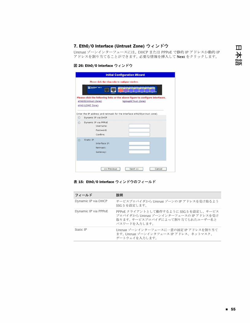
日本語
7. Eth0/0 Interface (Untrust Zone) ウィンドウ
Untrust ゾーンインターフェースには、DHCP または PPPoE で静的 IP アドレスか動的 IP アドレスを割り当てることができます。 必要な情報を挿入して Next をクリックします。
図 26: Eth0/0 Interface ウィンドウ
表 15: Eth0/0 Interface ウィンドウのフィールド
フィールド 説明
Dynamic IP via DHCP サービスプロバイダから Untrust ゾーンの IP アドレスを受け取るよう SSG 5 を設定します。
Dynamic IP via PPPoE PPPoE クライアントとして動作するように SSG 5 を設定し、サービス
プロバイダから Untrust ゾーンインターフェースの IP アドレスを受け
取ります。 サービスプロバイダによって割り当てられたユーザー名と
パスワードを入力します。
Static IP Untrust ゾーンインターフェースに一意の固定 IP アドレスを割り当て
ます。 Untrust ゾーンインタフェース IP アドレス、ネットマスク、
ゲートウェイを入力します。
55

SSG 5 ハードウェアの取り付けと構成ガイド
56
8. Eth0/1 Interface (DMZ Zone) ウィンドウ
DMZ インターフェースには、DHCP で動的 IP アドレスを割り当てることができます。 必要な情報を挿入して Next をクリックします。
図 27: Eth0/1 Interface ウィンドウ
表 16: Ethernet0/1 Interface ウィンドウのフィールド
フィールド 説明
Dynamic IP via DHCP サービスプロバイダから DMZ インターフェースの IP アドレスを受
け取るよう SSG 5 を設定します。
Static IP DMZ インターフェースに一意の固定 IP アドレスを割り当てます。 DMZ インタフェース IP アドレスとネットマスクを入力します。

日本語
9. Bgroup0 Interface (Trust Zone) ウィンドウ
bgroup0 インターフェースには、DHCP で動的 IP アドレスを割り当てることができます。 目的の情報を挿入して Next をクリックします。
デフォルトインターフェース IP アドレスは、192.168.1.1 です。ネットマスクは 255.255.255.0 か 24 です。
図 28: Bgroup0 Interface ウィンドウ
表 17: Bgroup0 Interface ウィンドウのフィールド
フィールド 説明
Dynamic IP via DHCP サービスプロバイダから Trustゾーンの IP アドレスを受け取るよう SSG 5 を設定します。
Static IP Trust ゾーンインターフェースに一意の固定 IP アドレスを割り当て
ます。 Trust ゾーンインタフェース IP アドレスとネットマスクを入
力します。
57

SSG 5 ハードウェアの取り付けと構成ガイド
58
10. Wireless0/0 Interface (Trust Zone) ウィンドウ
SSG 5-WLAN を 1 台でも接続している場合は、サービスセット識別子(SSID)を設定しないと wireless0/0 インターフェースを起動できません。 ワイヤレスインターフェースの構成方法の詳細については、『概念と用例 ScreenOS リファレンス ガイド』を参照してください。
図 29: Wireless0/0 Interface ウィンドウ
表 18: Wireless0/0 Interface ウィンドウのフィールド
フィールド 説明
Wlan Mode WLAN 無線モードを設定します。
5 G (802.11a)
2.4 G (802.11b/g)
両方 (802.11a/b/g)
SSID SSID 名を設定します。
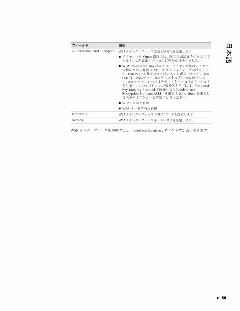
日本語
WAN インターフェースを構成すると、Interface Summary ウィンドウが表示されます。
Authentication and Encryption WLAN インターフェース認証と暗号化を設定します。
デフォルトの Open 認証では、誰でも SSG 5 をアクセスできます。 この認証オプションに暗号化はありません。
WPA Pre-Shared Key 認証では、ワイヤレス接続のアクセス時に事前共有鍵(PSK)またはパスフレーズを設定します。 PSK の HEX 値か ASCII 値の入力を選択できます。 HEX PSK は、256 ビット(64 テキスト文字)HEX 値とします。 ASCII パスフレーズはテキスト文字 8 文字から 63 文字とします。 このオプションの暗号化タイプには、Temporal Key Integrity Protocol(TKIP)または Advanced Encryption Standard (AES)を選択するか、Auto を選択して両方のオプションを有効にしてください。
WPA2 事前共有鍵
WPA オート事前共有鍵
Interface IP WLAN インターフェースの IP アドレスを設定します
Netmask WLAN インターフェースネットマスクを設定します。
フィールド 説明
59

SSG 5 ハードウェアの取り付けと構成ガイド
60
11. Interface Summary ウィンドウ
インターフェース構成を確認し、問題がなければ Next をクリックします。 Physical Ethernet DHCP ウィンドウが表示されます。
図 30: Interface Summary ウィンドウ
12. Physical Ethernet DHCP Interface ウィンドウ
Yes を選択します。これで、SSG 5 から DHCP 経由で有線ネットワークに IP アドレスを設定できます。 ネットワークを使用するクライアントに SSG 5 で割り当てる IP アドレスの範囲を入力します。
図 31: Physical Ethernet DHCP Interface ウィンドウ

日本語
13. Wireless DHCP Interface ウィンドウ
Yes を選択します。これで、SSG 5 から DHCP 経由でワイヤレスネットワークに IP アドレスを設定できます。 ネットワークを使用するクライアントに SSG 5 で割り当てる IP アドレスの範囲を入力します。
図 32: Wireless DHCP Interface ウィンドウ
14. Confirmation ウィンドウ
必要に応じて、SSG 5 の構成と変更結果を確認します。 Next をクリックして構成や変更結果を保存し、SSG 5 をリブートして構成を実行します。
図 33: Confirmation ウィンドウ
Next をクリックすると、保存したシステム構成で SSG 5 がリブートします。 WebUI ログインプロンプトが現れます。 WebUI による SSG 5 のアクセス方法については、「25 ページの「WebUI の使用」」を参照してください。
61

SSG 5 ハードウェアの取り付けと構成ガイド
62

日本語
索引
UUntrust ゾーンにバックアップインターフェース ...........32Untrust ゾーン、バックアップインターフェースの構成 32か管理
WebUI で ...................................................................25Telnet 接続による ......................................................26コンソールによる ......................................................24
管理サービス ...................................................................31
けケーブル
基本ネットワーク接続 ...............................................20
こ構成
USB ............................................................................14WAN インターフェース.............................................36デフォルトルート ......................................................31ブリッジグループ(bgroup).....................................30管理アクセス .............................................................30管理アドレス .............................................................32管理サービス .............................................................31管理者名とパスワード ...............................................29バックアップ Untrust インターフェース...................32日付と時刻 .................................................................29ホストとドメイン名...................................................31ワイヤレスとイーサネットの組み合わせ ..................35ワイヤレス認証と暗号化 ...........................................34
せ接続、基本ネットワーク .................................................20
てデフォルト IP アドレス ...................................................28
む無線トランシーバ
WLAN 0......................................................................14WLAN 1......................................................................14
めメモリのアップグレード手順 ..........................................41
りリセットスイッチ、使用 .................................................39
わワイヤレス
アンテナ .....................................................................21デフォルトインターフェースの使用..........................21
索引 63

64
SSG 5 Hardware Installation and Configuration Guide
索引

简体中文
目录
关于本指南 5
组织结构 ..........................................................................................................6WebUI 约定 .....................................................................................................6CLI 约定 ...........................................................................................................7获取文档和技术支持 ........................................................................................7
第 1 章 硬件概述 9
端口和电源连接器 ...........................................................................................9前面板 ...........................................................................................................10
系统状态 LED ..........................................................................................10端口说明 ........................................................................................................12
以太网端口 .......................................................................................12控制台端口 .......................................................................................12AUX 端口 ..........................................................................................13
后面板 ...........................................................................................................13电源适配器..............................................................................................13无线电收发器 ..........................................................................................14接地片 .....................................................................................................14天线类型 .................................................................................................14USB 端口 .................................................................................................14
第 2 章 安装和连接设备 15
准备工作 ........................................................................................................16安装设备 ........................................................................................................16将接口电缆连接到设备 ..................................................................................17连接电源 ........................................................................................................18将设备连接到网络 .........................................................................................18
将设备连接到不可信网络 ........................................................................18以太网端口 .......................................................................................19串行 (AUX/ 控制台 ) 端口 ..................................................................19WAN 端口 .........................................................................................19
将设备连接到内部网络或工作站 .............................................................20以太网端口 .......................................................................................20无线天线 ...........................................................................................20
目录 3

4
SSG 5 硬件安装和配置指南
第 3 章 配置设备 21
访问设备 ........................................................................................................22使用控制台连接.......................................................................................22使用 WebUI .............................................................................................23使用 Telnet ..............................................................................................24
缺省设备设置.................................................................................................24基本设备配置.................................................................................................26
根 Admin 名称和密码..............................................................................26日期和时间..............................................................................................27桥接组接口..............................................................................................27管理存取 .................................................................................................28管理服务 .................................................................................................28主机名和域名 ..........................................................................................28缺省路由 .................................................................................................29管理接口地址 ..........................................................................................29备份 Untrust 接口配置.............................................................................29
基本无线配置.................................................................................................30WAN 配置 ......................................................................................................33
ISDN 接口................................................................................................33V.92 调制解调器接口 ..............................................................................34
基本防火墙保护 .............................................................................................35验证外部连通性 .............................................................................................35将设备重置为出厂缺省值...............................................................................36
第 4 章 维护设备 37
需要的工具和部件 .........................................................................................37升级内存 ........................................................................................................37
附录 A 规格 41
物理 ...............................................................................................................41电气 ...............................................................................................................41环境忍耐力 ....................................................................................................42证书 ...............................................................................................................42
安全.........................................................................................................42EMC 辐射 ................................................................................................42EMC 抗扰度.............................................................................................42ETSI.........................................................................................................43
连接器 ...........................................................................................................43
附录 B 初始配置向导 45
索引 ............................................................................................................................ 59
目录

简体中文
关于本指南
Juniper Networks 安全服务网关 (SSG) 5 设备是一种集成路由器和防火墙平台,可为分公司或零售渠道提供“互联网协议安全”(IPSec)、“虚拟专用网”(VPN) 和防火墙服务。
Juniper Networks 提供六种型号的 SSG 5 设备 :
SSG 5 串行
SSG 5 串行 WLAN
SSG 5 V.92
SSG 5 V.92-WLAN
SSG 5 ISDN
SSG 5 ISDN-WLAN
所有 SSG 5 设备都支持通用串行总线 (USB) 主机模块。这些设备还提供局域网 (LAN) 和广域网 (WAN) 之间的协议转换,其中三种型号支持无线局域网 (WLAN)。
注意 : 本文档中的配置说明和范例均指运行 ScreenOS 5.4 的设备所具有的功能。根据运行的 ScreenOS 版本的不同,设备的功能也可能有所不同。有关最新设备文档的信息,请参阅 Juniper Networks 技术出版物网站 http://www.juniper.net/techpubs/hardware。要查看设备当前可用的 ScreenOS 版本,请访问 Juniper Networks 支持网站 http://www.juniper.net/customers/support/。
5
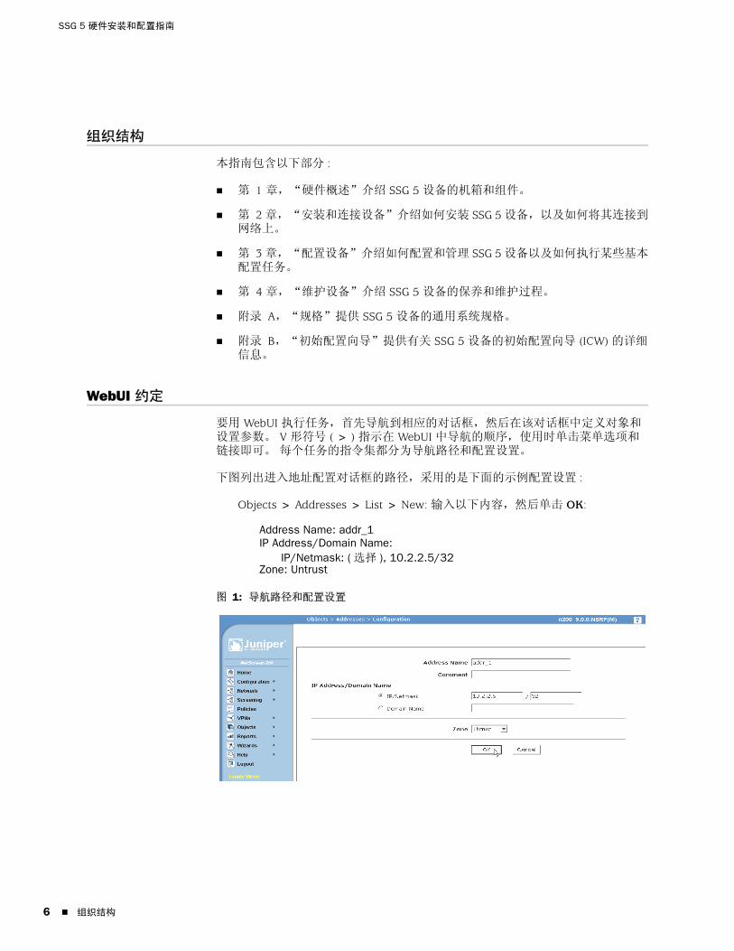
SSG 5 硬件安装和配置指南
6
组织结构
本指南包含以下部分 :
第 1 章,“硬件概述”介绍 SSG 5 设备的机箱和组件。
第 2 章,“安装和连接设备”介绍如何安装 SSG 5 设备,以及如何将其连接到网络上。
第 3 章,“配置设备”介绍如何配置和管理 SSG 5 设备以及如何执行某些基本配置任务。
第 4 章,“维护设备”介绍 SSG 5 设备的保养和维护过程。
附录 A,“规格”提供 SSG 5 设备的通用系统规格。
附录 B,“初始配置向导”提供有关 SSG 5 设备的初始配置向导 (ICW) 的详细信息。
WebUI 约定
要用 WebUI 执行任务,首先导航到相应的对话框,然后在该对话框中定义对象和设置参数。 V 形符号 ( > ) 指示在 WebUI 中导航的顺序,使用时单击菜单选项和链接即可。 每个任务的指令集都分为导航路径和配置设置。
下图列出进入地址配置对话框的路径,采用的是下面的示例配置设置 :
Objects > Addresses > List > New: 输入以下内容,然后单击 OK:
Address Name: addr_1IP Address/Domain Name:
IP/Netmask: ( 选择 ), 10.2.2.5/32Zone: Untrust
图 1: 导航路径和配置设置
组织结构

简体中文
CLI 约定
在范例和文本中出现 CLI 命令的语法时,使用下列约定。
在范例中 :
在中括号 [ ] 中的任何内容都是可选的。
大括号 { } 中的任何内容都是必需项。
如果有多个选项,则使用竖线 ( | ) 分隔每个选项。 例如 :
set interface { ethernet1 | ethernet2 | ethernet3 } manage
意思就是“设置 ethernet1、ethernet2 或 ethernet3 接口的管理选项”。
变量为斜体形式 :
set admin user name1 password xyz
在文本中 :
命令为粗体形式。
变量为斜体形式。
获取文档和技术支持
要获取任何 Juniper Networks 产品的技术文档,请访问 www.juniper.net/techpubs/。
要获取技术支持,请使用 http://www.juniper.net/support/ 中的 Case Manager 链接打开支持案例,还可拨打电话 1-888-314-JTAC ( 美国国内 ) 或 1-408-745-9500 ( 美国以外 )。
如果在本文档中发现任何错误或遗漏,请通过下面的电子邮件地址与我们联系 :
注意 : 输入关键字时,只需键入足以唯一标识相关单词的字母即可。 例如,要输入命令 set admin user kathleen j12fmt54,只需输入 set adm u kath j12fmt54。 尽管输入命令时可以使用此捷径,但本文所述的所有命令都以完整的方式提供。
CLI 约定 7

SSG 5 硬件安装和配置指南
8
获取文档和技术支持
简体中文
第 1 章
硬件概述
本章提供了有关 SSG 5 机箱及其组件的详细说明。其中包括以下部分 :
第 9 页上的“端口和电源连接器”
第 10 页上的“前面板”
第 13 页上的“后面板”
端口和电源连接器
本节介绍和显示内置端口和电源连接器的位置。
图 2: 内置端口位置
SSG 5
V.92
STATUS
POWER
CONSOLE
TX /RX
CD
0 1 2 3 4 5 6TX/RX LINK TX/RX LINK TX/RX LINK TX/RX LINK TX/RX LINK TX/RX LINK TX/RX LINK
10/100 10/100 10/100 10/100 10/100 10/100 10/100
B /G
WLAN V.92
802.11A
0/60/50/40/30/20/10/0
控制台AUX、ISDN 或 V.92
端口和电源连接器 9

SSG 5 硬件安装和配置指南
10
表 1 显示了 SSG 5 设备上的端口和电源连接器。
表 1: SSG 5 端口和电源连接器
前面板
本节介绍 SSG 5 设备前面板上的以下元素 :
系统状态 LED
端口说明
系统状态 LED系统状态 LED 显示有关主要设备功能的信息。图 3 说明了 SSG 5 V.92-WLAN 设备前面板上各状态 LED 的位置。系统 LED 根据 SSG 5 设备的版本而有所不同。
图 3: 状态 LED
端口 说明 连接器 速度 / 协议
0/0-0/6 通过交换机或集线器实现至工作站的直接连接或 LAN 连接。此连接也可通过 Telnet 会话或 WebUI 来管理设备。
RJ-45 10/100 Mbps 以太网
自动检测双工和自动 MDI/MDIX
USB 实现与系统之间的 1.1 USB 连接。 不适用 12M ( 全速 ) 或 1.5M ( 低速 )
控制台 实现与系统之间的串行连接。用于终端仿真连接以启动 CLI 会话。
RJ-45 9600 bps/RS-232C 串行
AUX 通过外部调制解调器实现备份 RS-232 异步串行互联网连接。
RJ-45 9600 bps - 115 Kbps/RS-232C 串行
V.92 调制解调器
实现到服务提供商的主要互联网连接或备份互联网连接,或者主要不可信网络连接或备份不可信网络连接。
RJ-11 9600 bps - 115 Kbps/RS-232 串行自动检测双工和极性
ISDN 可将 ISDN 线路用作不可信或备份接口。(S/T) RJ-45 B 信道为 64 Kbps
租用线路为 128 Kbps
天线 A 和天线 B (SSG 5-WLAN)
在无线电连接附近实现到工作站的直接连接。 RPSMA 802.11a ( 无线电波段为 5 GHz 时传输速度为 54 Mbps)
802.11b ( 无线电波段为 2.4 GHz 时传输速度为 11 Mbps)
802.11g ( 无线电波段为 2.4 GHz 时传输速度为 54 Mbps)
802.11 superG (无线电波段为 2.4 GHz 和 5 GHz 时传输速度为 108 Mbps)
前面板

简体中文
启动系统后,POWER LED 从关闭状态变为闪烁绿色状态,而 STATUS LED 则按以下顺序发生变化 : 红色、绿色、闪烁绿色。完成启动这一过程大约需要两分钟时间。如果要在关闭系统后重新启动系统,建议在关闭之后和重新启动之前稍候几秒。表 2 提供了各系统状态 LED 的类型、名称、颜色、状态和说明。
表 2: 状态 LED 说明
类型 名称 颜色 状态 说明
POWER 绿色 始终为开 表示系统已通电。
关 表示系统没有通电。
红色 始终为开 表示设备未正常运行。
关 表示设备正常运行。
STATUS 绿色 始终为开 表示系统正在启动或正在执行诊断。
闪烁 表示设备正常运行。
红色 闪烁 表示检测到错误。
ISDN 设备 CH B1 绿色 始终为开 表示 B 信道 1 处于活动状态。
关 表示 B 信道 1 处于非活动状态。
CH B2 绿色 始终为开 表示 B 信道 2 处于活动状态。
关 表示 B 信道 2 处于非活动状态。
V.92 设备 HOOK 绿色 始终为开 表示链接处于活动状态。
关 表示串行接口处于非服务状态。
TX/RX 绿色 闪烁 表示正在交换信息流。
关 表示没有交换信息流。
WLAN 设备 802.11A 绿色 始终为开 表示已建立无线连接,但无链接活动。
闪烁 表示已建立无线连接。波特率与链接活动成比例。
关 表示未建立无线连接。
B/G 绿色 始终为开 表示已建立无线连接,但无链接活动。
闪烁 表示已建立无线连接。波特率与链接活动成比例。
关 表示未建立无线连接。
前面板 11

SSG 5 硬件安装和配置指南
12
端口说明
本节介绍以下端口的目的和功能 :
以太网端口
控制台端口
AUX 端口
以太网端口
七个 10/100 以太网端口提供了到集线器、交换机、本地服务器和工作站的 LAN 连接。也可指定一个以太网端口来管理信息流。各端口被标记为 0/0 到 0/6。有关各以太网端口缺省区段绑定的信息,请参阅第 24 页上的“缺省设备设置”。
配置各端口时,请参考与端口位置相对应的接口名称。前面板上从左至右,端口的接口名称依次为 ethernet0/0 到 ethernet0/6。
图 4 显示了各以太网端口上 LED 的位置。
图 4: 活动链接 LED
表 3 介绍以太网端口 LED。
表 3: 以太网端口 LED
控制台端口
控制台端口为 RJ-45 串行端口,将充当数据电路终端设备 (DCE),用于进行本地管理。进行终端连接时,请使用直通电缆;连接到另一 DCE 设备时,请使用交叉电缆。提供了 RJ-45 到 DB-9 适配器。
有关 RJ-45 连接器插脚引线的信息,请参阅第 43 页上的“连接器”。
名称 颜色 状态 说明
LINK 绿色 始终为开
关
端口在线。
端口离线。
TX/RX 绿色 闪烁
关
信息流正在通过。波特率与链接活动成比例。
端口可能正在使用中,但并未接收数据。
LINKTX/RX
端口说明

简体中文
AUX 端口
辅助 (AUX) 端口为 RJ-45 串行端口,将充当数据终端设备 (DTE),通过将其连接到调制调解器可实现远程管理。建议不要将此端口用于进行日常远程管理。通常将 AUX 端口指定为备份串行接口。可以调节波特率,范围从 9600 bps 到 115200 bps,并且需要使用硬件流程控制。连接到调制解调器时,请使用直通电缆;连接到另一 DTE 设备时,请使用交叉电缆。
有关 RJ-45 连接器插脚引线的信息,请参阅第 43 页上的“连接器”。
后面板
本节介绍 SSG 5 设备后面板上的以下元素 :
电源适配器
无线电收发器
接地片
天线类型
USB 端口
图 5: SSG 5 设备的后面板
电源适配器设备前面板上的 POWER LED 呈绿色或为关闭状态。绿色表示运行正常,关闭表示电源适配器故障或设备处于关闭状态。
注意 : 仅 SSG 5-WLAN 设备有天线连接器。
RESETDC POWER
LOCK
USBSD FLASHB A5V A4
电源适配器
USB 主机模块
接地片
重置针孔
天线 A天线 B
后面板 13

SSG 5 硬件安装和配置指南
14
无线电收发器SSG 5-WLAN 设备包含两个具有无线连通性的无线电收发器,这些收发器支持 802.11a/b/g 标准。第一个收发器 (WLAN 0) 使用 2.4 GHz 无线电波段,它在传输速度为 11 Mbps 时支持 802.11b 标准,在传输速度为 54 Mbps 时支持 802.11g 标准。第二个无线电收发器 (WLAN1) 使用 5 GHz 无线电波段,它在传输速度为 54 Mbps 时支持 802.11a 标准。两个无线电波段可以同时使用。有关配置无线电波段的信息,请参阅第 30 页上的“基本无线配置”。
接地片机箱后部提供一个单孔接地片,可使用此接地片将设备接地 ( 请参阅图 5)。
要在连接电源前将设备接地,请将接地电缆连接到地面,然后将电缆连接到机箱后部的接地片上。
天线类型SSG 5-WLAN 设备支持三种类型的定制无线电天线 :
分集天线 - 分集天线可提供 2dBi 定向覆盖,并且覆盖区域内的信号强度电平相当均衡,适合大部分安装。设备随带有此类天线。
外部全向天线 - 外部天线可提供 2dBi 全向覆盖。与成对运行的分集天线不同,外部天线用于消除某些时候在使用两个天线时由信号的些微延迟特性所产生的回波效应。
外部定向天线 - 外部定向天线可提供 2dBi 单向覆盖,适合安装在诸如走廊和外墙之类的位置 ( 天线朝内 )。
USB 端口SSG 5 设备后面板上的 USB 端口接受安装有袖珍闪存盘的通用串行总线 (USB) 存储设备或 USB 存储设备适配器 ( 如 CompactFlash 协会发布的 CompactFlash 规格中所定义 )。安装和配置 USB 存储设备后,它会在主袖珍闪存盘无法启动时自动充当第二启动设备。
USB 端口允许文件在外部 USB 存储设备与安全设备中的内部闪存之间传输各种数据,如设备配置、用户证书和更新版本映像等信息。USB 端口在低速 (1.5M) 或全速 (12M) 文件传输时均支持 USB 1.1 规格。
要在 USB 存储设备和 SSG 5 之间传输文件,请执行以下步骤 :
1. 将 USB 存储设备插入安全设备上的 USB 端口中。
2. 使用 save {software | config | image-key} from usb 文件名 to flash CLI 命令将文件从 USB 存储设备保存到设备的内部闪存中。
3. 取出 USB 存储设备前,使用 exec usb-device stop CLI 命令停止 USB 端口。
4. 现在可安全取出 USB 存储设备。
如果要从 USB 存储设备删除文件,请使用 delete file usb:/ 文件名 CLI 命令。
如果要查看 USB 存储设备或内部闪存上保存的文件信息,请使用 get file CLI 命令。
后面板

简体中文
第 2 章
安装和连接设备
本章介绍如何安装 SSG 5 设备以及如何将电缆和电源连接到本设备。其中包括以下各节 :
第 16 页上的“准备工作”
第 16 页上的“安装设备”
第 17 页上的“将接口电缆连接到设备”
第 18 页上的“连接电源”
第 18 页上的“将设备连接到网络”
注意 : 有关安全警告和说明,请参阅 Juniper Networks Security Products Safety Guide。在使用任何设备之前,应注意由电路引发的危险以及熟悉标准操作以防止意外事故的发生。
15
SSG 5 硬件安装和配置指南
16
准备工作
机箱位置、安装设备的布局以及布线间的安全对于系统的正常运行而言均至关重要。
遵守以下预防措施可防止出现关机、设备故障以及人身伤害 :
安装前,请务必确定此设备电源与任何电源断开连接。
确保运行设备的房间保持良好的通风状况,并且室温不超过 104 °F (40 °C)。
请勿将设备放置在会阻塞设备进气口或排气口的设备机架中。确保封闭式机架具有风扇且各面装有百叶窗板。
执行任何安装前,请改善并消除以下危险状况 : 地面潮湿、存在渗漏、电缆未接地或已磨损,或者未进行安全接地。
安装设备
可以前置安装、壁式安装或桌面安装的方式安装 SSG 5 设备。可单独购买安装套件。
要安装 SSG 5 设备,您需要一个 2 号十字螺丝起子 ( 未提供 ) 和若干与设备机架相匹配的螺丝 ( 已包括在套件中 )。
要以机架安装的方式安装 SSG 5 设备,请执行以下步骤 :
1. 用十字螺丝起子松开底盘的安装支架。
2. 将设备底部和底盘的基准孔对齐。
3. 前拉设备将其锁入底盘的基准孔里。
4. 使用螺丝将安装支架连接到设备和底盘上。
5. 将电源放入电源支架,然后将电源适配器插入设备。
6. 要安装第二个 SSG 5 设备,请重复步骤 1 到 5,然后继续。
警告 : 为防止未经授权人员的误用和侵入,应将 SSG 5 设备安装在安全的环境中。
注意 : 安装设备时,请确保可将此设备连接到电源插座。
注意 : 拥有可选天线的 SSG 5-WLAN 用户必须移除现有的天线,然后通过侧孔连接新的天线。
准备工作

简体中文
图 6: SSG 5 机架安装
7. 使用提供的螺丝将底盘安装到机架上。
8. 将电源插入电源插座。
要以桌面安装的方式安装 SSG 5 设备,请执行以下步骤 :
1. 将桌面支架安装到设备一侧。建议使用靠近电源适配器的一侧。
2. 将装有桌面支架的设备放置在桌面上。
图 7: SSG 5 桌面安装
3. 插入电源适配器,并将电源连接到电源插座。
将接口电缆连接到设备
要将接口电缆连接到设备,请执行以下步骤 :
1. 准备一段适用于接口的电缆。
2. 将电缆连接器插入设备的电缆连接器端口中。
3. 按以下方式排列电缆以防止其移动或成为受力点 :
a. 固定电缆,使其在悬挂到地板时不用承受其自身的重量。
b. 将多余电缆整齐地盘绕成圆环状。
c. 将紧固件放在环上以保持其形状。
电源支架
电源支架
将接口电缆连接到设备 17

SSG 5 硬件安装和配置指南
18
连接电源
要将电源连接到设备,请执行以下步骤 :
1. 将电缆的 DC 连接器端插入设备后面的 DC 电源插座。
2. 将电缆的 AC 适配器端插入 AC 电源。
将设备连接到网络
当将 SSG 5 设备放置在内部网络和不可信网络之间时,它可为网络提供防火墙和通用安全保障。本节介绍以下内容 :
将设备连接到不可信网络
将设备连接到内部网络或工作站
将设备连接到不可信网络可通过以下方法中的一种将 SSG 5 设备连接到不可信网络 :
以太网端口
串行 (AUX/ 控制台 ) 端口
WAN 端口
图 8 显示了带有基本网络电缆连接的 SSG 5,其中 10/100 以太网端口的电缆连接方式如下 :
将标记为 0/0 的端口 (ethernet0/0 接口 ) 连接到不可信网络。
将标记为 0/1 的端口 (ethernet0/1 接口 ) 连接到 DMZ 安全区段中的工作站。
将标记为 0/2 的端口 (bgroup0 接口 ) 连接到 Trust 安全区段中的工作站。
将控制台端口连接到串行终端以进行管理访问。
警告 : 建议将电涌保护器用于电源连接。
连接电源
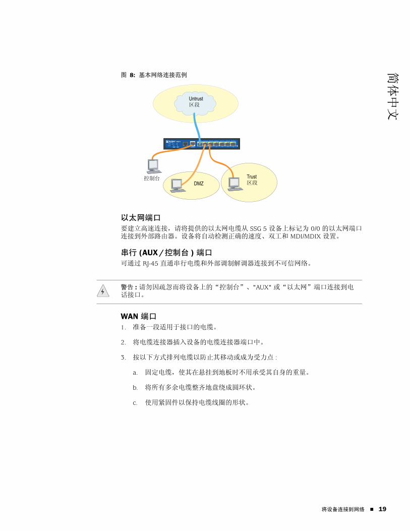
简体中文
图 8: 基本网络连接范例
以太网端口
要建立高速连接,请将提供的以太网电缆从 SSG 5 设备上标记为 0/0 的以太网端口连接到外部路由器。设备将自动检测正确的速度、双工和 MDI/MDIX 设置。
串行 (AUX/控制台 ) 端口
可通过 RJ-45 直通串行电缆和外部调制解调器连接到不可信网络。
WAN 端口
1. 准备一段适用于接口的电缆。
2. 将电缆连接器插入设备的电缆连接器端口中。
3. 按以下方式排列电缆以防止其移动或成为受力点 :
a. 固定电缆,使其在悬挂到地板时不用承受其自身的重量。
b. 将所有多余电缆整齐地盘绕成圆环状。
c. 使用紧固件以保持电缆线圈的形状。
SSG 5
V.92
STATUS
POWER
CONSOLE
TX /RX
CD
0 1 2 3 4 5 6TX/RX LINK TX/RX LINK TX/RX LINK TX/RX LINK TX/RX LINK TX/RX LINK TX/RX LINK
10/100 10/100 10/100 10/100 10/100 10/100 10/100
B /G
WLAN V.92
802.11A
Callouts
Untrust 区段
控制台DMZ
Trust 区段
警告 : 请勿因疏忽而将设备上的“控制台”、"AUX" 或“以太网”端口连接到电话接口。
将设备连接到网络 19

SSG 5 硬件安装和配置指南
20
将设备连接到内部网络或工作站可将局域网 (LAN) 或工作站与以太网和 / 或无线接口相连。
以太网端口
SSG 5 设备包含七个以太网端口。可使用这些端口中的一个或多个通过交换机或集线器连接到 LAN。也可以直接将一个或所有的端口连接到工作站,从而消除对集线器或交换机的需求。可使用交叉电缆或直通电缆将以太网端口连接到其它设备。有关缺省接口到区段绑定的信息,请参阅第 24 页上的“缺省设备设置”。
无线天线
如果要使用无线接口,需连接所提供的设备上的天线。如果有标准 2dB 分集天线,请使用螺丝将它们安装到设备背面标记为 A 和 B 的接头上。在各天线弯曲处顺势弯曲,以免使隔板连接器受压。
图 9: SSG 5-WLAN 天线位置
如果要使用可选的外部天线,请遵循此天线附带的连接说明。
RESETDC POWER
LOCK
USBSD FLASHB A5V A4
隔板连接器隔板连接器
天线 B 天线 A
将设备连接到网络

简体中文
第 3 章
配置设备
SSG 5 设备上已经预先安装了 ScreenOS 软件。打开设备电源后,即可对其进行配置。尽管设备有缺省的出厂配置,可以先连接到设备,但需要进行进一步配置以满足特定的网络需求。
本章包括以下各节 :
第 22 页上的“访问设备”
第 24 页上的“缺省设备设置”
第 26 页上的“基本设备配置”
第 30 页上的“基本无线配置”
第 33 页上的“WAN 配置”
第 35 页上的“基本防火墙保护”
第 35 页上的“验证外部连通性”
第 36 页上的“将设备重置为出厂缺省值”
注意 : 在配置设备并通过远程网络验证连通性后,必须在 www.juniper.net/support/ 上注册产品,以便能在设备中激活某些 ScreenOS 服务,如深入检查签名服务和防病毒 ( 单独购买 )。在注册完产品之后,使用 WebUI 获得对服务的预订。有关注册产品和获得对特定服务的预订的详细信息,请参阅设备上运行的 ScreenOS 版本的概念与范例 ScreenOS 参考指南中的基本原理卷。
21
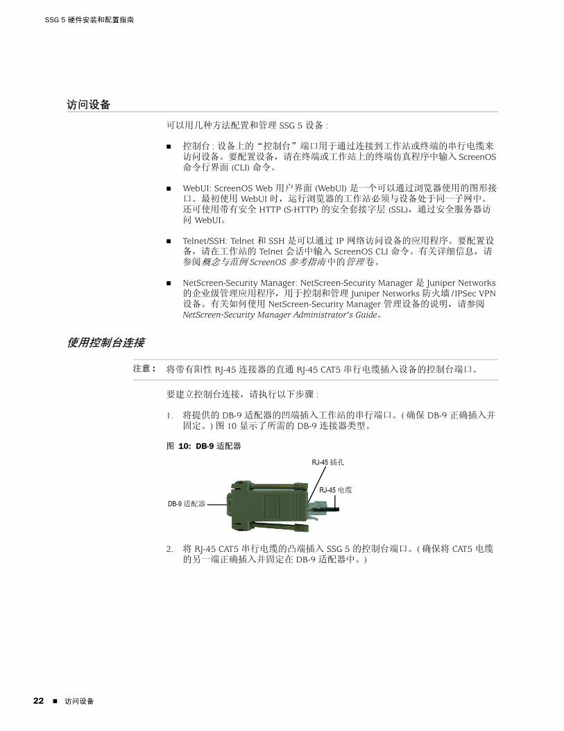
SSG 5 硬件安装和配置指南
22
访问设备
可以用几种方法配置和管理 SSG 5 设备 :
控制台 : 设备上的“控制台”端口用于通过连接到工作站或终端的串行电缆来访问设备。要配置设备,请在终端或工作站上的终端仿真程序中输入 ScreenOS 命令行界面 (CLI) 命令。
WebUI: ScreenOS Web 用户界面 (WebUI) 是一个可以通过浏览器使用的图形接口。最初使用 WebUI 时,运行浏览器的工作站必须与设备处于同一子网中。还可使用带有安全 HTTP (S-HTTP) 的安全套接字层 (SSL),通过安全服务器访问 WebUI。
Telnet/SSH: Telnet 和 SSH 是可以通过 IP 网络访问设备的应用程序。要配置设备,请在工作站的 Telnet 会话中输入 ScreenOS CLI 命令。有关详细信息,请参阅概念与范例 ScreenOS 参考指南中的管理卷。
NetScreen-Security Manager: NetScreen-Security Manager 是 Juniper Networks 的企业级管理应用程序,用于控制和管理 Juniper Networks 防火墙 /IPSec VPN 设备。有关如何使用 NetScreen-Security Manager 管理设备的说明,请参阅 NetScreen-Security Manager Administrator's Guide。
使用控制台连接
要建立控制台连接,请执行以下步骤 :
1. 将提供的 DB-9 适配器的凹端插入工作站的串行端口。( 确保 DB-9 正确插入并固定。) 图 10 显示了所需的 DB-9 连接器类型。
图 10: DB-9 适配器
2. 将 RJ-45 CAT5 串行电缆的凸端插入 SSG 5 的控制台端口。( 确保将 CAT5 电缆的另一端正确插入并固定在 DB-9 适配器中。)
注意 : 将带有阳性 RJ-45 连接器的直通 RJ-45 CAT5 串行电缆插入设备的控制台端口。
RJ-45 插孔
DB-9 适配器
RJ-45 电缆
访问设备

简体中文
3. 在工作站上启动串行终端仿真程序。启动控制台会话需要如下设置 :
波特率 : 9600
奇偶 : None
数据位 : 8
停止位 : 1
流量控制 : None
4. 如果尚未更改缺省的用户名和密码,请在登录名和密码提示中都输入 netscreen。( 仅使用小写字母。登录名和密码字段都区分大小写。)
有关如何使用 CLI 命令配置设备的信息,请参阅概念与范例 ScreenOS 参考指南。
5. ( 可选 ) 在缺省情况下,空闲时间超过 10 分钟后控制台将超时并自动终止。要清除超时,请输入 set console timeout 0。
使用 WebUI要使用 WebUI,用于管理设备的工作站最初必须与设备处于同一子网中。要使用 WebUI 访问设备,请执行以下步骤 :
1. 将工作站连接到设备上的 0/2 - 0/6 端口 (Trust 区段中的 bgroup0 接口 )。
2. 确保工作站配置为“动态主机配置协议”(DHCP) 或静态配置为 192.168.1.0/24 子网中的 IP 地址。
3. 启动浏览器,为 bgroup0 接口输入 IP 地址 ( 缺省 IP 地址为 192.168.1.1/24),然后按 Enter。
WebUI 应用程序将显示如图 11 所示的登录提示。
图 11: WebUI 登录提示
4. 如果尚未更改 admin 名称和密码的缺省登录,请在登录名和密码提示中都输入 netscreen。( 仅使用小写字母。登录名和密码字段都区分大小写。)
注意 : 第一次通过 WebUI 访问设备时,会出现初始配置向导 (ICW)。如果决定使用 ICW 配置设备,请参阅第 45 页上的“初始配置向导”。
访问设备 23

SSG 5 硬件安装和配置指南
24
使用 Telnet要建立 Telnet 连接,请执行以下步骤 :
1. 将工作站连接到设备上的 0/2 - 0/6 端口 (Trust 区段中的 bgroup0 接口 )。
2. 确保工作站配置为 DHCP 或静态配置为 192.168.1.0/24 子网中的 IP 地址。
3. 启动 Telnet 客户端应用程序至 bgroup0 接口的 IP 地址 ( 缺省 IP 地址为 192.168.1.1)。例如,输入 telnet 192.168.1.1。
Telnet 应用程序显示登录提示。
4. 如果尚未更改缺省的用户名和密码,请在登录名和密码提示中都输入 netscreen。( 仅使用小写字母。登录名和密码字段都区分大小写。)
5. ( 可选 ) 在缺省情况下,空闲时间超过 10 分钟后控制台将超时并自动终止。要清除超时,请输入 set console timeout 0。
缺省设备设置
本节介绍 SSG 5 设备的缺省设置和操作。
表 4 显示了设备端口的缺省区段绑定。
表 4: 缺省物理接口到区段的绑定
桥接组 (bgroup) 旨在让网络用户可以在有线和无线信息流间进行切换,而不必重新配置或重新启动设备。在缺省情况下,ethernet0/2 - ethernet0/6 接口 ( 在设备上标记为端口 0/2 - 0/6) 被组合为 bgroup0 接口,其 IP 地址为 192.168.1.1/24,且被绑定到 Trust 安全区段。最多可配置四个 bgroup。
如果要将以太网或无线接口设置在 bgroup 中,必须先确保以太网或无线接口处于 Null 安全区段。取消设置 bgroup 中的以太网或无线接口会将接口置于 Null 安全区段中。将以太网接口分配到 Null 安全区段后,即可将其绑定到某一安全区段并分配不同的 IP 地址。
端口标签 接口 区段
10/100 以太网端口 :
0/0 ethernet0/0 Untrust
0/1 ethernet0/1 DMZ
0/2 bgroup0 (ethernet0/2) Trust
0/3 bgroup0 (ethernet0/3) Trust
0/4 bgroup0 (ethernet0/4) Trust
0/5 bgroup0 (ethernet0/5) Trust
0/6 bgroup0 (ethernet0/6) Trust
AUX serial0/0 Null
WAN 端口 :
ISDN bri0/0 Untrust
V.92 serial0/0 Null
缺省设备设置

简体中文
要取消设置 bgroup0 中的 ethernet0/3,并将其分配到静态 IP 地址为 192.168.3.1/24 的 Trust 区段,请按以下所述使用 WebUI 或 CLI:
WebUI
Network > Interfaces > List > Edit (bgroup0) > Bind Port: 取消选择 ethernet0/3,然后单击 Apply。
List > Edit (ethernet0/3): 输入以下内容,然后单击 Apply:
Zone Name: Trust ( 选择 )IP Address/Netmask: 192.168.3.1/24
CLI
unset interface bgroup0 port ethernet0/3set interface ethernet0/3 zone trustset interface ethernet0/3 ip 192.168.3.1/24save
表 5: 无线和逻辑接口绑定
可以更改 bgroup0 接口的缺省 IP 地址,以匹配 LAN 和 WLAN 上的地址。有关将无线接口配置到 bgroup 的信息,请参阅第 30 页上的“基本无线配置”。
有关 bgroup 的其它信息和范例,请参阅概念与范例 ScreenOS 参考指南。
设备上的其它以太网或无线接口没有配置其它缺省 IP 地址;需要为其它接口 ( 包括 WAN 接口 ) 分配 IP 地址。
SSG 5-WLAN 接口 区段
无线接口
指定一个可配置使用 2.4G 和 / 或 5 G 无线电的无线接口
wireless0/0 ( 缺省 IP 地址为 192.168.2.1/24)。
Trust
wireless0/1-0/3。 Null
逻辑接口
第 2 层接口 在设备处于透明模式时,vlan1 指定用于管理和 VPN 信息流终止的逻辑接口。
不适用
通道接口 tunnel.n 指定一个逻辑通道接口。此接口用于 VPN 信息流。
不适用
注意 : 在 bgroup 接口包含无线接口时,在透明模式下将不起作用。
缺省设备设置 25

SSG 5 硬件安装和配置指南
26
基本设备配置
本节介绍以下基本配置设置 :
根 Admin 名称和密码
日期和时间
桥接组接口
管理存取
管理服务
主机名和域名
缺省路由
管理接口地址
备份 Untrust 接口配置
根 Admin 名称和密码根 admin 用户拥有配置 SSG 5 设备的全部权限。我们建议立即更改缺省根 admin 名称和密码 ( 均为 netscreen)。
要更改根 admin 名称和密码,请按以下所述使用 WebUI 或 CLI:
WebUI
Configuration > Admin > Administrators > Edit ( 对于管理员名称 ): 输入以下内容,然后单击 OK:
Administrator Name:Old Password: netscreenNew Password:Confirm New Password:
CLI
set admin name 名称set admin password 密码字串save
注意 : WebUI 中不会显示密码。
基本设备配置
简体中文
日期和时间SSG 5 设备上设置的时间会影响事件,如 VPN 通道的设置。设置设备的日期和时间的最简单的方法,就是利用 WebUI 同步设备系统时钟和工作站时钟。
要配置设备的日期和时间,请按以下所述使用 WebUI 或 CLI:
WebUI
1. Configuration > Date/Time: 单击 Sync Clock with Client 按钮。
会弹出一条消息,提示您指定是否已在工作站时钟上启用了夏令时选项。
2. 单击 Yes 将同步系统时钟,并根据夏令时调整时钟,或单击 No 只同步系统时钟,不根据夏令时对其进行调整。
还可使用 Telnet 或控制台会话中的 set clock CLI 命令,手动输入设备的日期和时间。
桥接组接口在缺省情况下,SSG 5 设备将以太网接口 ethernet0/2 - ethernet0/4 一起组合在 Trust 安全区段中。组合接口会将接口设置在一个子网内。可以对组中的接口取消设置,并将其分配到不同的安全区段。将接口分配到某个组之前,它们必须已在 Null 安全区段中。要将已分组的接口置于 Null 安全区段中,请使用 unset interface 接口 port 接口 CLI 命令。
SSG 5-WLAN 设备可将以太网和无线接口组合在一个子网中。
要为某个组配置以太网和无线接口,请按以下所述使用 WebUI 或 CLI:
WebUI
Network > Interfaces > List > Edit (bgroup0) > Bind Port: 取消选择 ethernet0/3 和 ethernet0/4,然后单击 Apply。
Edit (bgroup1) > Bind Port: 选择 ethernet0/3、ethernet0/4 和 wireless0/2,然后单击 Apply。
> Basic: 输入以下内容,然后单击 Apply:
Zone Name: DMZ ( 选择 )IP Address/Netmask: 10.0.0.1/24
注意 : 在 bgroup 组内只能设置无线和以太网接口。
基本设备配置 27

SSG 5 硬件安装和配置指南
28
CLI
unset interface bgroup0 port ethernet0/3unset interface bgroup0 port ethernet0/4set interface bgroup1 port ethernet0/3set interface bgroup1 port ethernet0/4set interface bgroup1 port wireless0/2set interface bgroup1 zone DMZset interface bgroup1 ip 10.0.0.1/24save
管理存取在缺省情况下,如果知道登录名和密码,网络中的任何用户都可以管理设备。要将设备配置为仅通过网络上的指定主机进行管理,请按以下所述使用 WebUI 或 CLI:
WebUI
Configuration > Admin > Permitted IPs: 输入以下内容,然后单击 Add:
IP Address/Netmask: ip 地址 / 掩码
CLI
set admin manager-ip ip 地址 / 掩码save
管理服务ScreenOS 提供了配置和管理设备的服务,如 SNMP、SSL 和 SSH,可以根据接口启用相应的服务。要配置设备的管理服务,请按以下所述使用 WebUI 或 CLI:
WebUI
Network > Interfaces > List > Edit ( 对于 ethernet0/0): 在 Management Services 下,选择或清除要在接口上使用的管理服务,然后单击 Apply。
CLI
set interface ethernet0/0 manage webunset interface ethernet0/0 manage snmpsave
主机名和域名域名定义设备所属的网络或子网,而主机名则表示特定的设备。主机名和域名一起,唯一标识网络中的设备。要配置设备的主机名和域名,请按以下所述使用 WebUI 或 CLI:
WebUI
Network > DNS > Host: 输入以下内容,然后单击 Apply:
Host Name: 名称Domain Name: 名称
CLI
set hostname 名称set domain 名称save
基本设备配置

简体中文
缺省路由缺省路由是一个静态路由,用于将数据包引至未在路由表中明确列出的网络。数据包到达设备时,如果设备未包含该设备地址的路由信息,设备会将数据包发送到缺省路由指定的目标。要配置设备的缺省路由,请按以下所述使用 WebUI 或 CLI:
WebUI
Network > Routing > Destination > New (trust-vr): 输入以下内容,然后单击 OK:
IP Address/Netmask: 0.0.0.0/0.0.0.0Next Hop
Gateway: ( 选择 )Interface: ethernet0/2 ( 选择 )Gateway IP Address: ip 地址
CLIset route 0.0.0.0/0 interface ethernet0/2 gateway ip 地址save
管理接口地址Trust 接口的缺省 IP 地址为 192.168.1.1/24,且配置用于管理服务。如果将设备的 0/2 - 0/4 端口连接到工作站,则可使用管理服务 ( 如 Telnet),通过 192.168.1.1/24 子网中的工作站配置设备。
可更改 Trust 接口的缺省 IP 地址。例如,您可能要更改接口以匹配 LAN 中现有的 IP 地址。
备份 Untrust 接口配置SSG 5 设备可以为不可信的故障切换配置备份接口。要为不可信的故障切换设置备份接口,请执行以下步骤 :
1. 使用 unset interface 接口 [port 接口 ] CLI 命令,在 Null 安全区段中设置备份接口。
2. 使用 set interface 接口 zone 区段名称 CLI 命令,将备份接口绑定到与主接口相同的安全区段。
注意 : 主接口和备份接口必须在相同的安全区段中。一个主接口只能有一个备份接口,同样,一个备份接口也只能有一个主接口。
基本设备配置 29

SSG 5 硬件安装和配置指南
30
要将 ethernet0/4 接口设置为 ethernet0/0 接口的备份接口,请按以下所述使用 WebUI 或 CLI:
WebUI
Network > Interfaces > Backup > 输入以下内容,然后单击 Apply。
Primary: ethernet0/0Backup: ethernet0/4Type: track-ip ( 选择 )
CLI
unset interface bgroup0 port ethernet0/4set interface ethernet0/4 zone untrustset interface ethernet0/0 backup interface ethernet0/4 type track-ipsave
基本无线配置
本节提供有关在 SSG 5-WLAN 设备上配置无线接口的信息。无线网络由称为服务集标识符 (SSID) 的名称组成。指定 SSID 可将多个无线网络驻留在同一位置,而不会互相干扰。SSID 名称最多可包含 32 个字符。如果 SSID 名称字符串包含有空格,则必须将该字符串用引号括起来。设置 SSID 名称后,即可配置更多的 SSID 属性。要使用设备的无线局域网 (WLAN) 功能,至少必须配置一个 SSID 并将其绑定到无线接口。
SSG 5-WLAN 设备最多可创建 16 个 SSID,但只能同时使用其中 4 个。可配置设备以使用任一收发器上的 4 个 SSID,或在两个收发器上使用 (例如,分配给 WLAN 0 的 3 个 SSID 和分配给 WLAN 1 的 1 个 SSID)。使用 set interface 无线接口 wlan {0 | 1 | both} CLI 命令设置 SSG 5-WLAN 设备的无线电收发器。图 12 显示了 SSG 5-WLAN 设备的缺省配置。
设置 wireless0/0 接口的 SSID 后,即可按照第 22 页上的“访问设备”中介绍的步骤,使用缺省的 wireless0/0 接口 IP 地址访问设备。
注意 : 如果您在美国、日本、加拿大、中国、中国台湾、韩国、以色列或新加坡以外的国家 / 地区使用 SSG 5-WLAN 设备,则必须使用 set wlan country-code CLI 命令或在 Wireless > General Settings WebUI 页面上对其进行设置,然后才能建立 WLAN 连接。此命令设置可选的通道范围和传输功率电平。
如果您的区段代码为 ETSI,则必须设置满足本地无线电频谱规定的正确的国家 / 地区代码。
基本无线配置
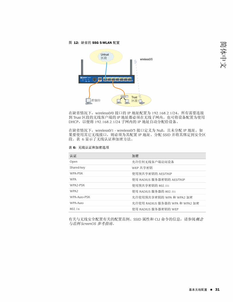
简体中文
图 12: 缺省的 SSG 5-WLAN 配置
在缺省情况下,wireless0/0 接口的 IP 地址配置为 192.168.2.1/24。所有需要连接到 Trust 区段的无线客户端的 IP 地址都必须在无线子网内。也可将设备配置为使用 DHCP,以便将 192.168.2.1/24 子网内的 IP 地址自动分配给设备。
在缺省情况下,wireless0/1 - wireless0/3 接口定义为 Null,且未分配 IP 地址。如果要使用其它无线接口,则必须为其配置 IP 地址、分配 SSID 并将其绑定到安全区段。表 6 显示了无线认证和加密方法。
表 6: 无线认证和加密选项
有关与无线安全配置有关的配置范例、SSID 属性和 CLI 命令的信息,请参阅概念与范例 ScreenOS 参考指南。
认证 加密
Open 允许任何无线客户端访问设备
Shared-key WEP 共享密钥
WPA-PSK 使用预共享密钥的 AES/TKIP
WPA 使用 RADIUS 服务器密钥的 AES/TKIP
WPA2-PSK 使用预共享密钥的 802.11i
WPA2 使用 RADIUS 服务器的 802.11i
WPA-Auto-PSK 允许使用预共享密钥的 WPA 和 WPA2 加密
WPA-Auto 允许使用 RADIUS 服务器的 WPA 和 WPA2 加密
802.1x 使用 RADIUS 服务器密钥的 WEP
SSG 5
V.92
STATUS
POWER
CONSOLE
TX /RX
CD
0 1 2 3 4 5 6TX/RX LINK TX/RX LINK TX/RX LINK TX/RX LINK TX/RX LINK TX/RX LINK TX/RX LINK
10/100 10/100 10/100 10/100 10/100 10/100 10/100
B /G
WLAN V.92
802.11A
Callouts
CalloutsUntrust 区段
Trust 区段
wireless0/0
控制台
基本无线配置 31

SSG 5 硬件安装和配置指南
32
要配置无线接口以实现基本连通性,请按以下所述使用 WebUI 或 CLI:
WebUI
1. 设置 WLAN 国家 / 地区代码和 IP 地址。
Wireless > General Settings > 选择以下内容,然后单击 Apply:
Country code: 选择您的代码IP Address/Netmask: ip 地址 / 网络掩码
2. 设置 SSID。
Wireless > SSID > New: 输入以下内容,然后单击 OK:
SSID:Authentication:Encryption:Wireless Interface Binding:
3. ( 可选 ) 设置 WEP 密钥。
SSID > WEP Keys: 选择密钥 ID,然后单击 Apply。
4. 设置 WLAN 模式。
Network > Interfaces > List > Edit ( 无线接口 ): 对于 WLAN 模式,选择 Both,然后单击 Apply。
5. 激活无线更改。
Wireless > General Settings > 单击 Activate Changes。
CLI
1. 设置 WLAN 国家 / 地区代码和 IP 地址。
set wlan country-code { code_id }set interface 无线接口 ip ip 地址 / 网络掩码
2. 设置 SSID。
set ssid name 名称字串set ssid 名称字串 authentication 认证类型 encryption 加密类型set ssid 名称字串 interface 接口( 可选 ) set ssid 名称字串 key-id 编号
3. 设置 WLAN 模式。
set interface 无线接口 wlan both
4. 激活无线更改。
saveexec wlan reactivate
可以设置 SSID,以便与有线子网在同一子网中使用。此操作让客户端可使用任一接口,而不必重新连接另一子网。
基本无线配置

简体中文
要将以太网和无线接口设置到同一桥接组接口,请使用 WebUI 或 CLI:
WebUI
Network > Interfaces > List > Edit ( 桥接组名称 ) > Bind Port: 选择无线接口和以太网接口,然后单击 Apply。
CLI
set interface 桥接组名称 port 无线接口set interface 桥接组名称 port 以太网接口
WAN 配置
本节介绍如何配置以下 WAN 接口 :
ISDN 接口
V.92 调制解调器接口
ISDN 接口“集成服务数字网络”(ISDN) 是在“国际电报电话咨询委员会”(CCITT) 和“国际电信联盟”(ITU) 创建的不同媒体上进行数字传输的一组标准。作为一项按需拨号服务,它具有快速呼叫设置和低延迟时间,以及传输高质量语音、数据和视频的能力。ISDN 还是一种电路交换服务,可用于多点和点对点连接。ISDN 为服务路由器的网络接口提供了一种多链路点对点协议 (PPP) 连接。ISDN 接口通常配置为以太网接口的备份接口以访问外部网络。
要配置 ISDN 接口,请使用 WebUI 或 CLI:
WebUI
Network > Interfaces > List > Edit (bri0/0): 输入或选择以下内容,然后单击 OK:
BRI Mode: Dial Using BRIPrimary Number: 123456WAN Encapsulation: PPPPPP Profile: isdnprofile
CLI
set interface bri0/0 dialer-enableset interface bri0/0 primary-number "123456"set interface bri0/0 encap pppset interface bri0/0 ppp profile isdnprofilesave
注意 : 桥接组名称可以是 bgroup0-bgroup3。
以太网接口可以是 ethernet0/0-ethernet0/6。
无线接口可以是 wireless0/0-wireless0/3。
如果配置了无线接口,则需要使用 exec wlan reactivate CLI 命令或单击 Wireless > General Settings WebUI 页面上的 Activate Changes 来重新激活 WLAN。
WAN 配置 33

SSG 5 硬件安装和配置指南
34
要将 ISDN 接口配置为备份接口,请参阅第 29 页上的“备份 Untrust 接口配置”。
有关如何配置 ISDN 接口的详细信息,请参阅概念与范例 ScreenOS 参考指南。
V.92 调制解调器接口V.92 接口提供了一个内部模拟调制解调器,可以与服务提供商建立 PPP 连接。可将串行接口配置为主接口或备份接口,备份接口在接口出现故障切换时使用。
要配置 V.92 接口,请使用 WebUI 或 CLI:
WebUI
Network > Interfaces > List > Edit (对于 serial0/0): 输入以下内容,然后单击 OK:
Zone Name: Untrust ( 选择 )
ISP: 输入以下内容,然后单击 OK:
ISP Name: isp_juniperPrimary Number: 1234567Login Name: juniperLogin Password: juniper
Modem: 输入以下内容,然后单击 OK:
Modem Name: mod1Init String: AT&FS7=255S32=6Active Modem setting
Inactivity Timeout: 20
CLI
set interface serial0/0 zone untrustset interface serial0/0 modem isp isp_juniper account login juniper password juniperset interface serial0/0 modem isp isp_juniper primary-number 1234567set interface serial0/0 modem idle-time 20set interface serial0/0 modem settings mod1 init-strings AT&FS7=255S32=6set interface serial0/0 modem settings mod1 active
有关如何配置 V.92 调制解调器接口的信息,请参阅概念与范例 ScreenOS 参考指南。
注意 : V.92 接口在透明模式下不起作用。
WAN 配置

简体中文
基本防火墙保护
设备配置的缺省策略允许网络中 Trust 区段的工作站访问 Untrust 安全区段的所有资源,但不允许外部计算机访问或启动工作站的会话。可以配置指导设备的策略,允许外部计算机启动与计算机的特定种类的会话。有关创建或修改策略的信息,请参阅概念与范例 ScreenOS 参考指南。
SSG 5 设备提供了各种检测方法和防御机制,以对抗旨在破坏或损害网络或网络资源的探查和攻击 :
ScreenOS SCREEN 选项用于保护区段的安全,具体做法是先检查要求经过该区段的某一接口的所有连接尝试,然后予以准许或拒绝。例如,可以将端口扫描保护应用于 Untrust 区段,以阻止远程网络的源试图识别服务以进一步进行攻击。
设备对从一个区段到另一个区段传递 SCREEN 过滤器的信息流应用防火墙策略 ( 这些策略可能包含内容过滤和入侵检测及防护 (IDP) 组件 )。在缺省情况下,不允许通过设备从一个区段到另一个区段传递信息流。要允许通过设备从一个区段到另一个区段传递信息流,必须创建一个覆盖缺省行为的策略。
要设置区段的 ScreenOS SCREEN 选项,请按以下所述使用 WebUI 或 CLI:
WebUI
Screening > Screen: 选择要应用选项的区段。选择所需的 SCREEN 选项,然后单击 Apply:
CLI
set zone 区段 screen 选项save
有关配置 ScreenOS 中可用的网络安全选项的详细信息,请参阅概念与范例 ScreenOS 参考指南中的攻击检测和防御机制卷。
验证外部连通性
要验证网络中的工作站能否访问互联网中的资源,请从网络中的任何工作站启动浏览器并输入以下的 URL: www.juniper.net。
基本防火墙保护 35
SSG 5 硬件安装和配置指南
36
将设备重置为出厂缺省值
如果丢失了 admin 密码,可以将设备重置为其缺省设置。此操作会破坏现有的所有配置,但可恢复对设备的访问。
可以使用以下任一方式将设备恢复为其缺省设置 :
使用控制台连接。有关详细信息,请参阅概念与范例 ScreenOS 参考指南中的管理卷。
使用设备后面板上的重置针孔,如下一节所述。
按压重置针孔可以重置设备并恢复出厂缺省设置。要执行此操作,需要查看前面板上的设备状态 LED 或启动控制台会话,如第 22 页上的使用控制台连接中所述。
要使用重置针孔来重置和恢复缺省设置,请执行以下步骤 :
1. 找到后面板上的重置针孔。使用又细又硬的金属丝 ( 例如回形针 ),推压针孔四至六秒然后松开。
STATUS LED 闪烁红色。控制台上的消息表明已经开始删除配置并且系统发出一个 SNMP/SYSLOG 警示。
2. 等待一至二秒。
在第一次重置之后,STATUS LED 闪烁绿色,设备正等待第二次重置。控制台消息现在表明设备正等待第二次确认。
3. 再次推压重置针孔四至六秒。
控制台消息验证第二次重置。STATUS LED 亮红色半秒,然后返回到闪烁绿色状态。
然后,设备重置为其原始的出厂设置。设备重置后,STATUS LED 亮红色半秒,然后亮绿色。控制台显示设备启动信息。系统产生 SNMP 和 SYSLOG 警示,发给已配置的 SYSLOG 或 SNMP 陷阱主机。
设备重新启动后,控制台显示设备的登录提示。STATUS LED 闪烁绿色。登录名和密码为 netscreen。
如果不遵循完整的程序,重置过程会取消且不更改任何配置,同时控制台消息表明已中止删除配置。STATUS LED 返回到闪烁绿色状态。如果设备没有重置,则会发送 SNMP 警示以确认失败。
警告 : 重置设备会删除所有现有的配置设置并关闭现有的所有防火墙和 VPN 服务。
将设备重置为出厂缺省值

简体中文
第 4 章
维护设备
本章介绍 SSG 5 设备的保养和维护过程。其中包括以下部分 :
本页上的“需要的工具和部件”
本页上的“升级内存”
需要的工具和部件
要更换 SSG 5 设备上的组件,需要使用以下工具和部件 :
静电放电 (ESD) 接地腕带
1/8 英寸的十字螺丝起子
升级内存
可以将 SSG 5 设备从 128 MB 双列直插式内存模块 (DIMM) 动态随机存取内存 (DRAM) 升级为 256 MB DIMM DRAM。
要升级 SSG 5 设备的内存,请执行以下步骤 :
1. 如果设备未接地,请将 ESD 接地腕带绑到露出的手腕上,然后将此腕带与机箱上的 ESD 点或外部 ESD 点相连。
2. 从电源插座上拔下交流电源线。
3. 翻转设备,以便将其顶部放置在平整表面上。
4. 使用十字螺丝起子移除内存卡盖上的螺丝。将螺丝放在手边,以便稍后固定盖子时取用。
5. 移除内存卡盖。
注意 : 有关安全警告和说明,请参阅 Juniper Networks Security Products Safety Guide。此指南中的说明警告您哪些情况可能会造成人身伤害。在使用任何设备之前,应注意由电路引发的危险以及熟悉标准操作以防止意外事故的发生。
需要的工具和部件 37
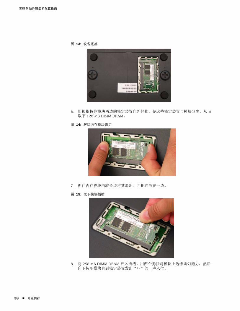
SSG 5 硬件安装和配置指南
38
图 13: 设备底部
6. 用拇指按住模块两边的锁定装置向外轻推,使这些锁定装置与模块分离,从而取下 128 MB DIMM DRAM。
图 14: 解除内存模块锁定
7. 抓住内存模块的较长边将其滑出。并把它放在一边。
图 15: 取下模块插槽
8. 将 256 MB DIMM DRAM 插入插槽。用两个拇指对模块上边缘均 施力,然后向下按压模块直到锁定装置发出“咔”的一声入位。
升级内存

简体中文
图 16: 插入内存模块
9. 将内存卡盖放置在插槽上。
10. 使用十字螺丝起子拧紧螺丝,从而固定设备盖。
升级内存 39

SSG 5 硬件安装和配置指南
40
升级内存
简体中文
附录 A
规格
本附录提供 SSG 5 设备的通用系统规格。其中包括以下部分 :
本页上的“物理”
本页上的“电气”
第 42 页上的“环境忍耐力”
第 42 页上的“证书”
第 43 页上的“连接器”
物理
表 7: SSG 5 物理规格
电气
表 8: SSG 5 电气规格
说明 值
机箱尺寸 222.5 mm x 143.4 mm x 35 mm。加上橡胶脚垫,系统的高度为 40 mm (1.6 英寸 )。
(8.8 英寸 X 5.6 英寸 X 1.4 英寸 )。
设备重量 960g (2.1 磅 )。
项目 规格
DC 输入电压 5.5V
DC 系统额定电流 4 A
物理 41

SSG 5 硬件安装和配置指南
42
环境忍耐力
表 9: SSG 5 环境忍耐力
证书
安全CAN/CSA-C22.2 No. 60950-1-03/UL 60950-1 第三版,信息技术设备的安全性
EN 60950-1:2001+A11,信息技术设备的安全
IEC 60950-1:2001 第一版,信息技术设备的安全
EMC 辐射FCC Part 15 Class B ( 美国 )
EN 55022 Class B ( 欧洲 )
AS 3548 Class B ( 澳大利亚 )
VCCI Class B ( 日本 )
EMC 抗扰度EN 55024
EN-61000-3-2 电源线谐波
EN-61000-3-3 电源线谐波
EN-61000-4-2 ESD
EN-61000-4-3 辐射抗扰度
EN-61000-4-4 EFT
EN-61000-4-5 电涌
EN-61000-4-6 低频通用抗扰度
EN-61000-4-11 电压骤降与凹陷
说明 值
高度 6,600 英尺 (2,000 m) 以下性能稳定
相对湿度 相对湿度为 5% - 90% ( 非冷凝 ) 时可确保正常运行
温度 温度为 32°F (0°C) - 104°F (40°C) 时可确保正常运行
集装箱中非工作存储温度 : -40°F (-40°C) - 158°F (70°C)
环境忍耐力
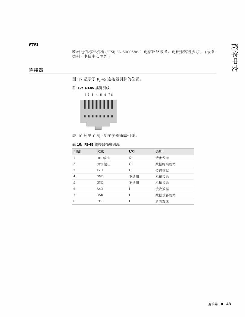
简体中文
ETSI欧洲电信标准机构 (ETSI) EN-3000386-2: 电信网络设备。电磁兼容性要求; ( 设备类别 - 电信中心除外 )
连接器
图 17 显示了 RJ-45 连接器引脚的位置。
图 17: RJ-45 插脚引线
表 10 列出了 RJ-45 连接器插脚引线。
表 10: RJ-45 连接器插脚引线
引脚 名称 I/O 说明
1 RTS 输出 O 请求发送
2 DTR 输出 O 数据终端就绪
3 TxD O 传输数据
4 GND 不适用 机箱接地
5 GND 不适用 机箱接地
6 RxD I 接收数据
7 DSR I 数据设备就绪
8 CTS I 清除发送
1 2 3 4 5 6 7 8
连接器 43

SSG 5 硬件安装和配置指南
44
图 18 显示了 DB-9 凹连接器引脚的位置。
图 18: DB-9 凹连接器
表 11 提供 DB-9 连接器插脚引线。
表 11: DB-9 连接器插脚引线
引脚 名称 I/O 说明
1 DCD I 载波检测
2 RxD I 接收数据
3 TxD O 传输数据
4 DTR O 数据终端就绪
5 GND 不适用 信号接地
6 DSR I 数据设备就绪
7 RTS O 请求发送
8 CTS I 清除发送
9 RING I 振铃指示器
连接器

简体中文
附录 B
初始配置向导
本附录提供 SSG 5 设备初始配置向导 (ICW) 的详细信息。
将设备实际连接到网络后,便可使用 ICW 来配置已安装在本设备上的接口。
本节介绍以下 ICW 窗口 :
1. 第 46 页上的快速部署窗口
2. 第 46 页上的管理员登录窗口
3. 第 47 页上的 WLAN 接入点窗口
4. 第 47 页上的物理接口窗口
5. 第 48 页上的 ISDN 接口窗口
6. 第 50 页上的 V.92 调制解调器接口窗口
7. 第 51 页上的 Eth0/0 接口 (Untrust 区段 ) 窗口
8. 第 52 页上的 Eth0/1 接口 (DMZ 区段 ) 窗口
9. 第 52 页上的 Bgroup0 接口 (Trust 区段 ) 窗口
10. 第 54 页上的 Wireless0/0 接口 (Trust 区段 ) 窗口
11. 第 55 页上的接口汇总窗口
12. 第 56 页上的物理以太网 DHCP 接口窗口
13. 第 56 页上的无线 DHCP 接口窗口
14. 第 57 页上的确认窗口
45

SSG 5 硬件安装和配置指南
46
1. 快速部署窗口
图 19: 快速部署窗口
如果网络使用 NetScreen-Security Manager (NSM),则可使用快速部署 configlet 以自动配置设备。从 NSM 管理员处获得 configlet,选择 Yes,选择 Load Configlet from:,浏览文件位置,然后单击 Next。configlet 会为您设置设备,因此无需执行以下步骤来配置设备。
如果要绕过 ICW 直接转到 WebUI,请选择最后一个选项,然后单击 Next。
如果不使用 configlet 而要使用 ICW 来配置设备,请选择第一个选项,然后单击 Next。出现 ICW 欢迎屏幕。单击 Next。出现管理员登录窗口。
2. 管理员登录窗口
输入新的管理员登录名和密码,然后单击 Next。
图 20: 管理员登录窗口

简体中文
3. WLAN 接入点窗口
如果使用 WORLD 或 ETSI 调节域中的设备,则必须选择一个国家 / 地区代码。选择相应选项,然后单击 Next。
图 21: 国家 / 地区代码窗口
4. 物理接口窗口
在接口到区段绑定屏幕中,设置要绑定到 Untrust 安全区段的接口。Bgroup0 已被预绑定到 Trust 安全区段。Ethernet0/1 已被绑定到 DMZ 安全区段,但还可选择绑定其它接口。
图 22: 物理接口窗口
将接口绑定到区段后,便可配置此接口。此后显示的配置窗口取决于用作网络组成部分的 SSG 5 设备。要使用 ICW 继续配置设备,请单击 Next。
47

SSG 5 硬件安装和配置指南
48
5. ISDN 接口窗口
如果有 ISDN 设备,则会显示与下图相似的 Physical Layer 选项卡窗口。
图 23: ISDN Physical Layer 选项卡窗口
表 12: ISDN Physical Layer 选项卡窗口中的字段
字段 说明
Switch Type 设置服务提供商的交换机类型 :
att5e: At&T 5ESS
ntdms100: Nortel DMS 100
ins-net: NTT INS-Net
etsi: European variants
ni1: National ISDN-1
SPID1 服务提供商 ID,通常是带有若干可选数字的七位电话号码。只有 DMS-100 和 NI1 交换机类型要求输入 SPID。DMS-100 交换机类型有两个分配的 SPID,每个 B 信道分别对应一个 SPID。
SPID2 服务提供商备份 ID。
TEI Negotiation 指定何时协商 TEI,或在启动时进行协商或在第一次呼叫时进行协商。通常在欧洲提供 ISDN 服务和连接到用于发起 TEI 协商的 DMS-100 交换机时使用此类设置。
Calling Number ISDN 网络帐号。
Sending Complete 复选框 启用将完整信息发送到外向设置消息。通常仅在中国香港特别行政区和中国台湾地区使用。

简体中文
如果有 ISDN 设备,将看见 Leased Line Mode 和 Dial Using BRI 复选框。选择一个或两个复选框,将显示与下图相似的窗口 :
图 24: Leased-Line 和 Dial Using BRI 选项卡窗口
表 13: Leased-Line 和 Dial Using BRI 选项卡窗口中的字段
字段 说明
PPP Profile Name 设置 ISDN 接口的 PPP 配置文件的文件名
Authentication 设置 PPP 认证类型 :
Any
CHAP: 质询握手认证协议
PAP: 密码认证协议
None
Local User 设置本地用户
Password 设置本地用户的密码
Static IP 复选框 启用接口的静态 IP 地址
Interface IP 设置接口的 IP 地址
Netmask 设置网络掩码
Gateway 设置网关地址
49

SSG 5 硬件安装和配置指南
50
6. V.92 调制解调器接口窗口
如果有 V.92 设备,将显示以下窗口 :
图 25: V.92 调制解调器接口窗口
表 14: V.92 调制解调器接口窗口中的字段
字段 说明
Modem Name 设置调制解调器接口的名称
Init Strings 设置调制解调器的初始化字符串
ISP Name 为服务提供商分配名称
Primary Number 指定用于访问服务提供商的电话号码
Alternative Number (optional) 指定主号无法接通时的备选电话号码以访问服务提供商
Login Name 设置服务提供商帐户的登录名
Password 设置登录名的密码
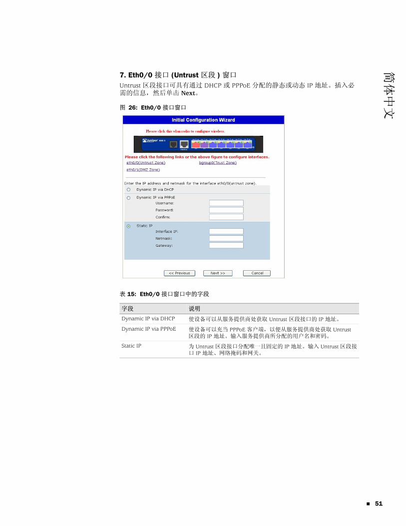
简体中文
7. Eth0/0 接口 (Untrust 区段 ) 窗口
Untrust 区段接口可具有通过 DHCP 或 PPPoE 分配的静态或动态 IP 地址。插入必需的信息,然后单击 Next。
图 26: Eth0/0 接口窗口
表 15: Eth0/0 接口窗口中的字段
字段 说明
Dynamic IP via DHCP 使设备可以从服务提供商处获取 Untrust 区段接口的 IP 地址。
Dynamic IP via PPPoE 使设备可以充当 PPPoE 客户端,以便从服务提供商处获取 Untrust 区段的 IP 地址。输入服务提供商所分配的用户名和密码。
Static IP 为 Untrust 区段接口分配唯一且固定的 IP 地址。输入 Untrust 区段接口 IP 地址、网络掩码和网关。
51

SSG 5 硬件安装和配置指南
52
8. Eth0/1 接口 (DMZ 区段 ) 窗口
DMZ 接口可具有通过 DHCP 分配的静态或动态的 IP 地址。插入必需的信息,然后单击 Next。
图 27: Eth0/1 接口窗口
表 16: Ethernet0/1 接口窗口中的字段
9. Bgroup0 接口 (Trust 区段 ) 窗口
Trust 区段接口可具有通过 DHCP 分配的静态或动态的 IP 地址。插入所需的信息,然后单击 Next。
缺省接口 IP 地址为 192.168.1.1,网络掩码为 255.255.255.0 或 24。
字段 说明
Dynamic IP via DHCP 使设备可以从服务提供商处获取 DMZ 接口的 IP 地址。
Static IP 为 DMZ 接口分配唯一且固定的 IP 地址。输入 DMZ 接口 IP 地址和网络掩码。

简体中文
图 28: Bgroup0 接口窗口
表 17: Bgroup0 接口窗口中的字段
字段 说明
Dynamic IP via DHCP 使设备可以从服务提供商处获取 Trust 区段接口的 IP 地址。
Static IP 为 Trust 区段接口分配唯一且固定的 IP 地址。输入 Trust 区段接口 IP 地址和网络掩码。
53

SSG 5 硬件安装和配置指南
54
10. Wireless0/0 接口 (Trust 区段 ) 窗口
如果有 SSG 5-WLAN 设备,则必须先设置服务集标识符 (SSID),否则将无法激活 wireless0/0 接口。有关配置无线接口的详细说明,请参阅概念与范例 ScreenOS 参考指南。
图 29: Wireless0/0 接口窗口

简体中文
表 18: Wireless0/0 接口窗口中的字段
配置 WAN 接口以后,将显示接口汇总窗口。
11. 接口汇总窗口
检查接口配置,准备好继续后,单击 Next。出现物理以太网 DHCP 接口窗口。
图 30: 接口汇总窗口
字段 说明
Wlan Mode 设置 WLAN 无线模式 :
5G (802.11a)
2.4G (802.11b/g)
Both (802.11a/b/g)
SSID 设置 SSID 名称。
Authentication and Encryption 设置 WLAN 接口认证和加密 :
Open 认证为缺省设置,在这种情况下允许任何人访问设备。对此认证选项无需进行加密处理。
WPA Pre-Shared Key 认证设置访问无线连接时必须输入的预共享密钥 (PSK) 或密码短语。可以选择输入 HEX 或 PSK 的 ASCII 值。HEX PSK 必须是一个 256 位 (64 个文本字符 ) 的 HEX 值。ASCII 密码短语必须是 8 到 63 个文本字符。必须选择“临时密钥完整性协议”(TKIP) 或“高级加密标准”(AES) 作为此选项的加密类型,或者选择 Auto 以允许使用任一选项。
WPA2 预共享密钥。
WPA 自动预共享密钥。
Interface IP 设置 WLAN 接口 IP 地址。
Netmask 设置 WLAN 接口网络掩码。
55

SSG 5 硬件安装和配置指南
56
12. 物理以太网 DHCP 接口窗口
选择 Yes 启动设备以通过 DHCP 为有线网络分配 IP 地址。输入 IP 地址范围 ( 设备会将这些 IP 地址分配给正在使用您的网络的客户端 )。
图 31: 物理以太网 DHCP 接口窗口
13. 无线 DHCP 接口窗口
选择 Yes 启动设备以通过 DHCP 为无线网络分配 IP 地址。输入 IP 地址范围 ( 设备会将这些 IP 地址分配给正在使用您的网络的客户端 )。
图 32: 无线 DHCP 接口窗口

简体中文
14. 确认窗口
根据需要确认设备配置和更改。单击 Next 保存、重新启动设备和运行配置。
图 33: 确认窗口
单击 Next 后,设备将以保存的系统配置重新启动。出现 WebUI 登录提示。有关如何使用 WebUI 访问设备的信息,请参阅第 23 页上的“使用 WebUI”。
57

SSG 5 硬件安装和配置指南
58

简体中文
索引
C重置针孔,使用 .............................................................36D电缆
基本网络连接 ...........................................................18
G管理
通过 Telnet 连接 ......................................................24通过 WebUI ..............................................................23通过控制台 ...............................................................22
管理服务 .........................................................................28
J将接口备份到 Untrust 区段 ..........................................29
L连接,基本网络 .............................................................18
N内存升级步骤 .................................................................37
P配置
admin 名称和密码 ...................................................26备份不可信接口 .......................................................29管理存取 ...................................................................28管理地址 ...................................................................29管理服务 ...................................................................28桥接组 (bgroup) .......................................................27缺省路由 ...................................................................29日期和时间 ...............................................................27USB............................................................................14WAN 接口 .................................................................33无线接口和以太网组合 ...........................................33无线认证和加密 .......................................................31主机名和域名 ...........................................................28
Q缺省 IP 地址 ...................................................................25
UUntrust 区段,配置备份接口 .......................................29
W无线
使用缺省接口 ...........................................................20天线 ...........................................................................20
无线电收发器WLAN 0.....................................................................14WLAN 1.....................................................................14
索引 59

60
SSG 5 硬件安装和配置指南
索引

繁體中文
目錄
關於本指南 5
組織 .................................................................................................................6WebUI 慣例 .....................................................................................................6CLI 慣例 ...........................................................................................................7獲取文件和技術支援 ........................................................................................7
第 1 章 硬體綜述 9
連接埠和電源連接器 ......................................................................................10前面板 ...........................................................................................................10
系統狀態 LED ..........................................................................................11連接埠說明 ....................................................................................................12
乙太網路連接埠 ................................................................................12主控台連接埠....................................................................................12AUX 連接埠 ......................................................................................13
後面板 ...........................................................................................................13電源配接卡..............................................................................................13無線電收發機 ..........................................................................................14接地插孔 .................................................................................................14天線類型 .................................................................................................14USB 連接埠..............................................................................................14
第 2 章 安裝及連接裝置 17
開始之前 ........................................................................................................18安裝設備 ........................................................................................................18將介面纜線連接到裝置 ..................................................................................19連接電源 ........................................................................................................20將裝置連接到網路 .........................................................................................20
將裝置連接到不信任的網路.....................................................................20乙太網路連接埠 ................................................................................21序列 (AUX/ 主控台 ) 連接埠...............................................................21WAN 連接埠 .....................................................................................21
將裝置連接到內部網路或工作站 .............................................................22乙太網路連接埠 ................................................................................22無線天線 ...........................................................................................22
目錄 3

4
SSG 5 硬體安裝與組態指南
第 3 章 組態裝置 23
存取裝置 ........................................................................................................24使用主控台連接.......................................................................................24使用 WebUI .............................................................................................25使用 Telnet ..............................................................................................26
預設裝置設定.................................................................................................26基本裝置組態.................................................................................................28
根管理名稱及密碼 ...................................................................................28日期與時間..............................................................................................29橋接群組介面 ..........................................................................................29管理式存取..............................................................................................30管理服務 .................................................................................................30主機名稱及網域名稱 ...............................................................................30預設路由 .................................................................................................31管理介面位址 ..........................................................................................31備份 Untrust 介面組態.............................................................................31
基本無線組態.................................................................................................32WAN 組態 ......................................................................................................35
ISDN 介面................................................................................................35V.92 數據機介面......................................................................................36
基本防火牆保護 .............................................................................................37驗證外部連接性 .............................................................................................37將裝置重設為出廠預設設定 ...........................................................................38
第 4 章 維修裝置 39
必要工具及零件 .............................................................................................39升級記憶體 ....................................................................................................39
附錄 A 規格 43
實體 ...............................................................................................................43電器設備 ........................................................................................................43環境容忍度 ....................................................................................................44憑證 ...............................................................................................................44
安全.........................................................................................................44EMC 輻射 ................................................................................................44EMC 耐受性.............................................................................................44ETSI.........................................................................................................45
連接器 ...........................................................................................................45
附錄 B 初始組態精靈 47
索引 ............................................................................................................................ 61
目錄

繁體中文
關於本指南
Juniper Networks Secure Services Gateway (SSG) 5 裝置是一個整合的路由器及防火牆平台,能夠為分支機構或零售商店提供「網際網路通訊協定安全性」(IPSec) 虛擬私人網路 (VPN) 及防火牆服務。
Juniper Networks 提供六種機型的 SSG 5 裝置 :
SSG 5 Serial
SSG 5 Serial-WLAN
SSG 5 V.92
SSG 5 V.92-WLAN
SSG 5 ISDN
SSG 5 ISDN-WLAN
所有 SSG 5 裝置均支援「通用序列匯流排」(USB) 主機模組。 裝置也提供「區域網路」(LAN) 與「廣域網路」(WAN) 之間的通訊協定對話,且三種機型支援「無線區域網路」(WLAN)。
注意 : 文件中的組態說明和範例是根據執行 ScreenOS 5.4 之裝置的功能。 您的裝置的功能可能與文件中所描述的不同,這視您所執行的 ScreenOS 版本而定。 如需最新的裝置文件,請造訪 Juniper Networks Technical Publications 網站 : http://www.juniper.net/techpubs/hardware。 若要了解目前適用於您裝置的 ScreenOS 版本,請造訪 Juniper Networks Support 網站 : http://www.juniper.net/customers/support/。
5

SSG 5 硬體安裝與組態指南
6
組織
本指南包括下列各節 :
第 1 章,「硬體綜述」說明 SSG 5 裝置的機架和元件。
第 2 章,「安裝及連接裝置」說明裝載 SSG 5 裝置的方法及如何將其連接至您的網路。
第 3 章,「組態裝置」說明組態並管理 SSG 5 裝置的方法及執行某些基本組態工作的方法。
第 4 章,「維修裝置」說明 SSG 5 裝置的維修和維護程序。
附錄 A,「規格」提供 SSG 5 裝置的通用系統規格。
附錄 B,「初始組態精靈」提供有關使用 SSG 5 裝置的 Initial Configuration Wizard ( 初始組態精靈,ICW) 的詳細資訊。
WebUI 慣例
如要用 WebUI 執行任務,必須先瀏覽到相應的對話方塊,然後在該對話方塊中定義物件和設定參數。 尖角符號 ( > ) 表示 WebUI 中的瀏覽順序,您可按一下功能表選項及連結來依循該順序。 每個任務的說明集分為瀏覽路徑及組態設定兩個部分。
下圖列出了前往具有以下範例組態設定之位址組態對話方塊的路徑 :
Objects > Addresses > List > New: 輸入以下內容,然後按一下 OK:
Address Name: addr_1IP Address/Domain Name:
IP/Netmask: ( 選擇 ), 10.2.2.5/32Zone: Untrust
圖 1: 瀏覽路徑與組態設定
組織

繁體中文
CLI 慣例
下列慣例用於在範例及文字中呈現 CLI 指令語法。
在範例中 :
在中括弧 [ ] 中的任何內容都是選擇性的。
在大括弧 { } 中的任何內容都是必需的。
如果選項不止一個,則使用導線 ( | ) 分隔每個選項。 例如 :
set interface { ethernet1 | ethernet2 | ethernet3 } manage
意味著「設定 ethernet1、ethernet2 或 ethernet3 介面的管理選項」。
變數以斜體方式顯示 :
set admin user name1 password xyz
在文字中 :
指令以粗體方式顯示。
變數以斜體方式顯示。
獲取文件和技術支援
要獲得任何 Juniper Networks 產品的技術文件,請造訪 www.juniper.net/techpubs/。
如需技術支援,請使用 http://www.juniper.net/support/ 的 Case Manager 連結來開啟一個支援案例,或電洽 1-888-314-JTAC ( 美國境內 ) 或 1-408-745-9500 ( 美國境外 )。
如果在本文件中發現任何錯誤或遺漏,請用下面的電子郵件位址與我們連絡 :
注意 : 輸入關鍵字時,您需鍵入足以唯一識別單詞的字母。 例如,若要輸入指令 set admin user kathleen j12fmt54,只要鍵入 set adm u kath j12fmt54 即可。 儘管輸入指令時可以使用此捷徑,本文所述的所有指令都以其完整形式呈現。
CLI 慣例 7

SSG 5 硬體安裝與組態指南
8
獲取文件和技術支援
繁體中文
第 1 章
硬體綜述
本章提供 SSG 5 機架及其元件的詳細說明。 本章包含下列各節 :
第 10 頁上的「連接埠和電源連接器」
第 10 頁上的「前面板」
第 13 頁上的「後面板」
9

SSG 5 硬體安裝與組態指南
10
連接埠和電源連接器
本節說明並顯示內建連接埠及電源連接器的位置。
圖 2: 內建連接埠的位置
表 1 顯示 SSG 5 裝置上的連接埠和電源連接器。
表 1: SSG 5 連接埠和電源連接器
前面板
本節說明 SSG 5 裝置前面板上的下列元素 :
系統狀態 LED
連接埠說明
SSG 5
V.92
STATUS
POWER
CONSOLE
TX /RX
CD
0 1 2 3 4 5 6TX/RX LINK TX/RX LINK TX/RX LINK TX/RX LINK TX/RX LINK TX/RX LINK TX/RX LINK
10/100 10/100 10/100 10/100 10/100 10/100 10/100
B /G
WLAN V.92
802.11A
0/60/50/40/30/20/10/0
主控台AUX、ISDN 或 V.92
連接埠 說明 連接器 速度 / 通訊協定
0/0-0/6 透過交換機或集線器啟用至工作站的直接連接或 LAN 連接。 此連接也可讓您透過 Telnet 會話或 WebUI 來管理裝置。
RJ-45 10/100 Mbps 乙太網路
自動感應雙工及自動 MDI/MDIX
USB 啟用與系統的 1.1 USB 連接。 N/A 12M ( 全速 ) 或 1.5M ( 低速 )
主控台 啟用與系統之間的系列連接。 用於終端模擬連接,以啟動 CLI 會話。
RJ-45 9600 bps/RS-232C 序列
AUX 透過外部數據機啟用備份 RS-232 非同步序列網際網路連接。
RJ-45 9600 bps - 115 Kbps/RS-232C 序列
V.92 數據機 啟用與服務提供者的主要或備份網際網路或不受信任的網路連接。
RJ-11 9600 bps - 115 Kbps/RS-232 序列自動感應雙工及極性
ISDN 啟用 ISDN 線路作為 Untrust 或備份介面。 (S/T) RJ-45 速度為 64 Kbps 的 B 通道
速度為 128 Kbps 的租借線路
天線 A 與 B (SSG 5-WLAN)
允許直接連接到無線電連接的鄰近的工作站。 RPSMA 802.11a (54 Mbps,無線電頻為 5 GHz)
802.11b (11 Mbps,無線電頻為 2.4 GHz)
802.11g (54 Mbps,無線電頻為 2.4 GHz)
802.11 superG (108 Mbps,無線電頻為 2.4 GHz 及 5 GHz)
連接埠和電源連接器
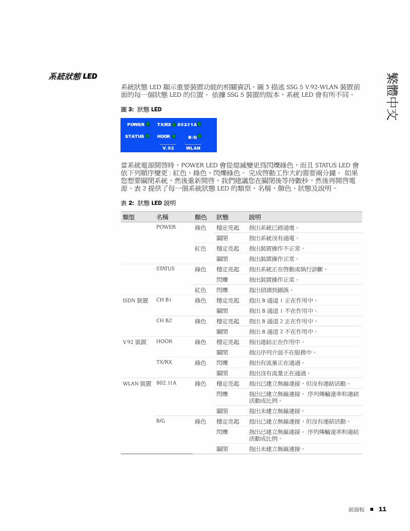
繁體中文
系統狀態 LED系統狀態 LED 顯示重要裝置功能的相關資訊。圖 3 描述 SSG 5 V.92-WLAN 裝置前面的每一個狀態 LED 的位置。 依據 SSG 5 裝置的版本,系統 LED 會有所不同。
圖 3: 狀態 LED
當系統電源開啟時,POWER LED 會從熄滅變更為閃爍綠色,而且 STATUS LED 會依下列順序變更 : 紅色、綠色、閃爍綠色。 完成啟動工作大約需要兩分鐘。 如果您想要關閉系統,然後重新開啟,我們建議您在關閉後等待數秒,然後再開啟電源。表 2 提供了每一個系統狀態 LED 的類型、名稱、顏色、狀態及說明。
表 2: 狀態 LED 說明
類型 名稱 顏色 狀態 說明
POWER 綠色 穩定亮起 指出系統已經通電。
關閉 指出系統沒有通電。
紅色 穩定亮起 指出裝置操作不正常。
關閉 指出裝置操作正常。
STATUS 綠色 穩定亮起 指出系統正在啟動或執行診斷。
閃爍 指出裝置操作正常。
紅色 閃爍 指出偵測到錯誤。
ISDN 裝置 CH B1 綠色 穩定亮起 指出 B 通道 1 正在作用中。
關閉 指出 B 通道 1 不在作用中。
CH B2 綠色 穩定亮起 指出 B 通道 2 正在作用中。
關閉 指出 B 通道 2 不在作用中。
V.92 裝置 HOOK 綠色 穩定亮起 指出連結正在作用中。
關閉 指出序列介面不在服務中。
TX/RX 綠色 閃爍 指出有流量正在通過。
關閉 指出沒有流量正在通過。
WLAN 裝置 802.11A 綠色 穩定亮起 指出已建立無線連接,但沒有連結活動。
閃爍 指出已建立無線連接。 序列傳輸速率和連結活動成比例。
關閉 指出未建立無線連接。
B/G 綠色 穩定亮起 指出已建立無線連接,但沒有連結活動。
閃爍 指出已建立無線連接。 序列傳輸速率和連結活動成比例。
關閉 指出未建立無線連接。
前面板 11
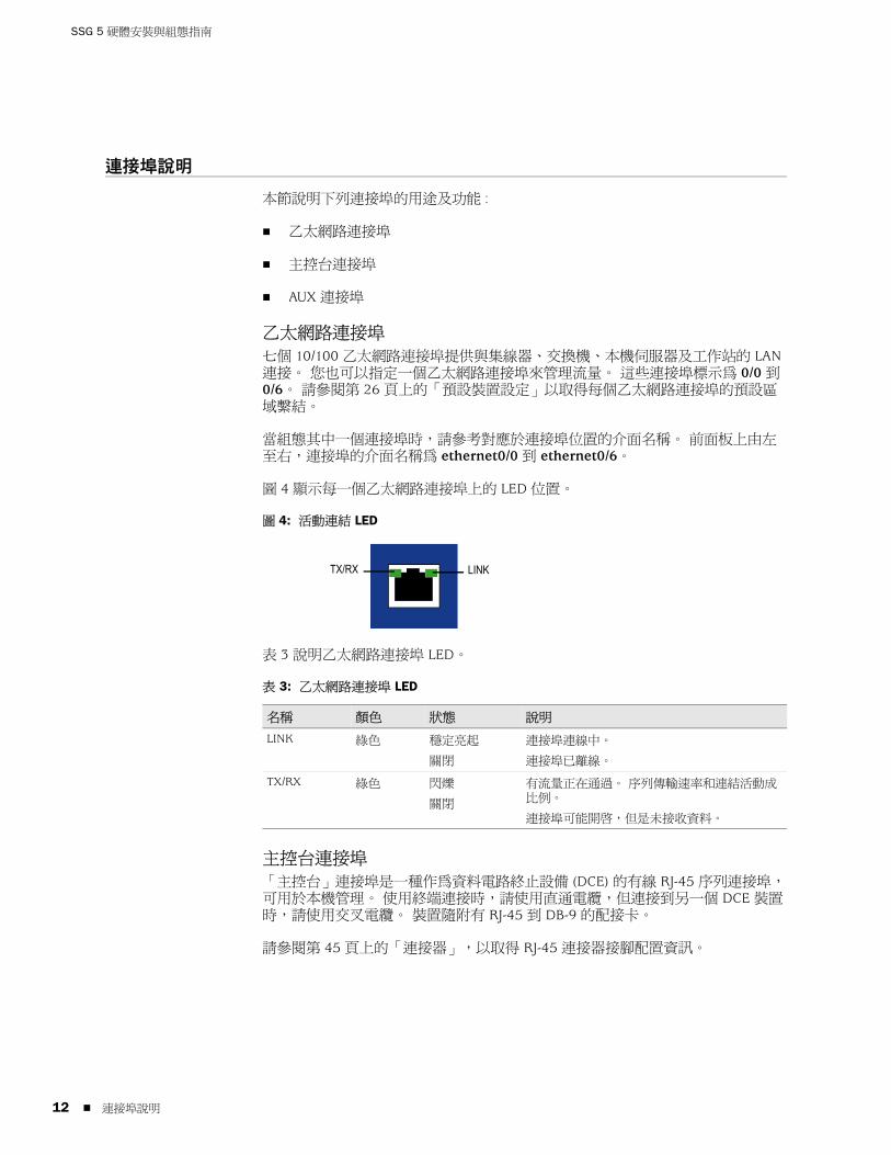
SSG 5 硬體安裝與組態指南
12
連接埠說明
本節說明下列連接埠的用途及功能 :
乙太網路連接埠
主控台連接埠
AUX 連接埠
乙太網路連接埠
七個 10/100 乙太網路連接埠提供與集線器、交換機、本機伺服器及工作站的 LAN 連接。 您也可以指定一個乙太網路連接埠來管理流量。 這些連接埠標示為 0/0 到 0/6。 請參閱第 26 頁上的「預設裝置設定」以取得每個乙太網路連接埠的預設區域繫結。
當組態其中一個連接埠時,請參考對應於連接埠位置的介面名稱。 前面板上由左至右,連接埠的介面名稱為 ethernet0/0 到 ethernet0/6。
圖 4 顯示每一個乙太網路連接埠上的 LED 位置。
圖 4: 活動連結 LED
表 3 說明乙太網路連接埠 LED。
表 3: 乙太網路連接埠 LED
主控台連接埠
「主控台」連接埠是一種作為資料電路終止設備 (DCE) 的有線 RJ-45 序列連接埠,可用於本機管理。 使用終端連接時,請使用直通電纜,但連接到另一個 DCE 裝置時,請使用交叉電纜。 裝置隨附有 RJ-45 到 DB-9 的配接卡。
請參閱第 45 頁上的「連接器」,以取得 RJ-45 連接器接腳配置資訊。
名稱 顏色 狀態 說明
LINK 綠色 穩定亮起
關閉
連接埠連線中。
連接埠已離線。
TX/RX 綠色 閃爍
關閉
有流量正在通過。 序列傳輸速率和連結活動成比例。
連接埠可能開啟,但是未接收資料。
LINKTX/RX
連接埠說明

繁體中文
AUX 連接埠
附屬 (AUX) 連接埠是一種作為資料終止設備 (DTE) 的有線 RJ-45 序列連接埠,可連接到數據機以允許遠端管理。 我們不建議使用此連接埠進行一般遠端管理。 通常,是將 AUX 連接埠指派為備份序列介面。 序列傳輸速率是可調的,範圍為 9600 bps 至 115200 bps,而且需要由硬體進行流量控制。 連接到數據機時,請使用直通電纜,但連接到另一個 DTE 裝置時,請使用交叉電纜。
請參閱第 45 頁上的「連接器」,以取得 RJ-45 連接器接腳配置資訊。
後面板
本節說明 SSG 5 裝置後面板上的下列元素 :
電源配接卡
無線電收發機
接地插孔
天線類型
USB 連接埠
圖 5: SSG 5 裝置的後面板
電源配接卡裝置前面板上的 POWER LED 不是發出綠光,就是熄滅。 綠光指出運作正常,而熄滅則指出電源配接卡失敗或裝置關閉。
注意 : 僅 SSG 5-WLAN 裝置具有天線連接器。
RESETDC POWER
LOCK
USBSD FLASHB A5V A4
電源配接卡
USB 主機模組接地
插孔
重設針孔
天線 A天線 B
後面板 13

SSG 5 硬體安裝與組態指南
14
無線電收發機SSG 5-WLAN 裝置包含兩個支援 802.11a/b/g 標準的無線連接無線電收發機。 第一個收發機 (WLAN 0) 使用 2.4 GHz 無線電頻寬,支援速度為 11 Mbps 的 802.11b 標準及速度為 54 Mbps 的 802.11g 標準。 第二個無線電收發機 (WLAN 1) 使用 5 GHz 無線電頻寬,支援速度為 54 Mbps 的 802.11a 標準。 這兩個無線電頻寬可同時運作。 有關組態無線電頻寬的資訊,請參閱第 32 頁上的「基本無線組態」。
接地插孔單孔接地插孔在機架後面,用來將裝置接地 ( 請參閱圖 5)。
若要在連接電源之前將裝置接地,請將接地纜線接地,然後將纜線連接到機架後面的插孔。
天線類型SSG 5-WLAN 裝置支援三種類型的自建無線天線 :
分集天線 - 分集天線具有 2dBi 方向覆蓋範圍,並在覆蓋區域內提供相當一致的訊號強度,因此適用於大部份安裝。 裝置出廠時隨附有此類型的天線。
外部全向天線 - 外部天線提供 2dBi 全向覆蓋範圍。 不同於成對運作的分集天線,外部天線的目的是消除使用兩個天線時,因訊號接收中輕微延遲的特性而偶爾發生的回音效果。
外部方向天線 - 外部方向天線提供 2dBi 單向覆蓋範圍,因此適用於如走廊及外牆的位置 ( 天線面向內 )。
USB 連接埠SSG 5 裝置後面板上的 USB 連接埠接受安裝有 Compact-Flash 磁碟的通用序列匯流排 (USB) 儲存裝置或 USB 儲存裝置配接卡,CompactFlash Association 發佈的 CompactFlash Specification 中對其有詳細定義。 安裝並組態 USB 儲存裝置後,如果主要的 Compact-Flash 磁碟無法啟動,它會自動充當次要啟動裝置。
USB 連接埠允許在外部 USB 儲存裝置與位於安全裝置內部的快閃儲存區之間傳送檔案,例如裝置組態、使用者憑證及更新版本影像。 USB 連接埠支援 USB 1.1 規格,其檔案傳送速度可以是低速 (1.5M) 或全速 (12M)。
後面板

繁體中文
若要在 USB 儲存裝置與 SSG 5 之間傳送檔案,請執行下列步驟 :
1. 將 USB 儲存裝置插入安全裝置上的 USB 連接埠。
2. 利用 save {software | config | image-key} from usb 檔案名稱 to flash CLI 指令,將檔案從 USB 儲存裝置儲存到裝置上的內部快閃儲存區。
3. 移除 USB 儲存裝置之前,請利用 exec usb-device stop CLI 指令,停止 USB 連接埠。
4. 現在可以安全移除 USB 儲存裝置。
如果想要從 USB 儲存裝置刪除檔案,請使用 delete file usb:/ 檔案名稱 CLI 指令。
如果想要檢視 USB 儲存裝置或內部快閃儲存區上儲存的檔案資訊,請使用 get file CLI 指令。
後面板 15

SSG 5 硬體安裝與組態指南
16
後面板
繁體中文
第 2 章
安裝及連接裝置
本章說明如何安裝 SSG 5 裝置,並將纜線及電源連接到裝置。 本章包括下列各節 :
第 18 頁上的「開始之前」
第 18 頁上的「安裝設備」
第 19 頁上的「將介面纜線連接到裝置」
第 20 頁上的「連接電源」
第 20 頁上的「將裝置連接到網路」
注意 : 有關安全警告和說明,請參閱 Juniper Networks Security Products Safety Guide。 在使用任何設備之前,請注意由電路引發的危險以及熟悉標準操作以防止意外事故的發生。
17

SSG 5 硬體安裝與組態指南
18
開始之前
機架的位置、安裝設備的配置,以及有線空間的安全性對於能否適當操作系統有決定性的影響。
遵守下列預防措施可以防止關機、設備故障及傷害 :
安裝之前,一定要檢查電源供應器是否與任何電源中斷連接。
確定您操作裝置的房間有足夠的空氣流通,而且室溫不超過 104° F (40° C)。
不要將裝置放在阻塞通風口或排氣管的設備安裝框架中。 確定安裝的機櫃有風扇,而且兩側設有百葉窗。
開始安裝之前,請改善這些危險狀況 : 潮濕地板、漏電、未接地或磨損的電纜,或遺失安全接地線。
安裝設備
您可以對 SSG 5 裝置採用正面安裝、牆上安裝或桌上安裝。 安裝套件可以另外購買。
若要安裝 SSG 5 裝置,您需要 2 號十字螺絲起子 ( 未提供 ) 及與設備機櫃相容的螺絲 ( 附在套件中 )。
若要在機櫃中安裝 SSG 5 裝置,請執行下列步驟 :
1. 利用十字螺絲起子旋出底盤上的裝載托架。
2. 將裝置的底部與底盤上的底座孔對齊。
3. 將裝置向前拉,將其鎖定在底盤的底座孔中。
4. 使用螺絲將裝載托架固定至裝置和底盤。
5. 將電源供應器置於電源支架中,然後將電源轉接器插入裝置中。
警告 : 若要防止未授權人員的濫用及侵入,請在安全環境中安裝 SSG5 裝置。
注意 : 安裝裝置時,請確定它在電源插座的範圍內。
注意 : 要使用選用天線的 SSG 5-WLAN 使用者,需要移除現有的天線,然後經由側邊孔連接新的天線。
開始之前

繁體中文
6. 若要安裝第二個 SSG 5 裝置,請重複步驟 1 到步驟 5,然後繼續。
圖 6: SSG 5 機櫃安裝
7. 利用所提供的螺絲,在機櫃上安裝底盤。
8. 將電源供應器插入電源插座。
若要桌上安裝 SSG 5 裝置,請執行下列步驟 :
1. 將桌上支架連接到裝置的一側。 我們建議使用最接近電源轉接器的那一側。
2. 將已安裝的裝置放在桌上。
圖 7: SSG 5 桌上安裝
3. 插入電源轉接器,然後將電源供應器連接到電源插座。
將介面纜線連接到裝置
若要將介面纜線連接至裝置,請執行下列步驟 :
1. 準備好介面所使用之纜線類型的長度。
2. 將纜線連接器插入裝置上的纜線連接器連接埠。
3. 依如下方式排列纜線,以防止它移動或遭受壓力 :
a. 固定住纜線,以便它垂下到地板時不會承受自身的重量。
b. 將多餘的纜線整齊地捲成圈收好。
c. 將固定物置於圈上以保持其形狀。
電源供應器支架
電源供應器支架
將介面纜線連接到裝置 19

SSG 5 硬體安裝與組態指南
20
連接電源
若要將電源連接到裝置,請執行下列步驟 :
1. 將電源線的 DC 連接器端插入設備背面的 DC 電源插座。
2. 將電源線的 AC 轉接器端插入 AC 電源。
將裝置連接到網路
當 SSG 5 裝置放在內部網路與不信任的網路之間時,它會對網路提供防火牆及一般安全性。 本節介紹下列內容 :
將裝置連接到不信任的網路
將裝置連接到內部網路或工作站
將裝置連接到不信任的網路您可以利用以下任何一種方法,將 SSG 5 裝置連接到不信任的網路 :
乙太網路連接埠
序列 (AUX/ 主控台 ) 連接埠
WAN 連接埠
圖 8 顯示了 SSG 5 的基本網路佈線連接,其中 10/100 乙太網路連接埠的連線方式如下 :
標示為 0/0 (ethernet0/0 介面 ) 的連接埠連接到不信任的網路。
標示為 0/1 (ethernet0/1 介面 ) 的連接埠連接到 DMZ 安全區中的工作站。
標示為 0/2 (bgroup0 介面 ) 的連接埠連接到 Trust 安全區中的工作站。
「主控台」連接埠連接到序列終端機以管理存取。
警告 : 我們建議將電湧保護器用於電源連接。
連接電源

繁體中文
圖 8: 基本網路範例
乙太網路連接埠
若要建立高速連接,請將所提供的乙太網路纜線從 SSG 5 裝置上標示為 0/0 的乙太網路連接埠連接到外部路由器。 裝置會自動感應正確的速度、雙工及 MDI/MDIX 設定。
序列 (AUX/ 主控台 ) 連接埠
您可以利用 RJ-45 直通序列纜線及外部數據機,連接到不信任的網路。
WAN 連接埠
1. 準備好介面所使用之纜線類型的長度。
2. 將纜線連接器插入裝置上的纜線連接器連接埠。
3. 依如下方式排列纜線,以防止它移動或遭受壓力 :
a. 固定住纜線,以便它垂下到地板時不會承受自身的重量。
b. 將任何多餘的纜線整齊地捲成圈收好。
c. 使用固定器來維持纜線圓圈的形狀。
SSG 5
V.92
STATUS
POWER
CONSOLE
TX /RX
CD
0 1 2 3 4 5 6TX/RX LINK TX/RX LINK TX/RX LINK TX/RX LINK TX/RX LINK TX/RX LINK TX/RX LINK
10/100 10/100 10/100 10/100 10/100 10/100 10/100
B /G
WLAN V.92
802.11A
Callouts
Untrust 區域
主控台DMZ
Trust 區域
警告 : 確定您未不慎地將裝置上的主控台、AUX 或乙太網路連接埠連接到電話插座。
將裝置連接到網路 21

SSG 5 硬體安裝與組態指南
22
將裝置連接到內部網路或工作站您可以利用乙太網路及 / 或無線介面,連接區域網路 (LAN) 或工作站。
乙太網路連接埠
SSG 5 裝置包含七個乙太網路連接埠。 您可以使用其中一個或多個連接埠,透過交換機或集線器來連接到 LAN。 也可以直接將一個或所有的連接埠連接到工作站,排除集線器或切換機的需求。 您可以使用交叉電纜或直通電纜,將乙太網路連接埠連接到其他裝置。 請參閱第 26 頁上的「預設裝置設定」,以取得預設的介面至區域繫結的相關資訊。
無線天線
如果您是使用無線介面,您需要連接裝置上所提供的天線。 如果您有標準 2dB 分集天線,請使用螺絲將它們連接到裝置背面標示為 A 及 B 的柱子。 使每一個天線在其彎頭處轉彎,如此可確定不會對隔板連接器加壓。
圖 9: SSG 5-WLAN 天線位置
如果您是使用選購的外部天線,請遵循天線所附的連接指示。
RESETDC POWER
LOCK
USBSD FLASHB A5V A4
隔板連接器隔板連接器
天線 B 天線 A
將裝置連接到網路

繁體中文
第 3 章
組態裝置
ScreenOS 軟體會預先安裝在 SSG 5 裝置上。 當開啟裝置電源時,它已準備好進行組態。 裝置具有預設出廠組態,可讓您最初連接到裝置,您需要針對特定的網路需求執行進一步的組態。
本章包括下列各節 :
第 24 頁上的「存取裝置」
第 26 頁上的「預設裝置設定」
第 28 頁上的「基本裝置組態」
第 32 頁上的「基本無線組態」
第 35 頁上的「WAN 組態」
第 37 頁上的「基本防火牆保護」
第 37 頁上的「驗證外部連接性」
第 38 頁上的「將裝置重設為出廠預設設定」
注意 : 在組態裝置並透過遠端網路來驗證連接之後,您必須在 www.juniper.net/support/ 註冊您的產品,以便可以在裝置上啟動某些 ScreenOS 服務,例如深入檢查簽名服務及防病毒 ( 另外購買 )。 在註冊完產品之後,請使用 WebUI 獲得對服務的訂閱。 如需註冊產品及訂閱特定服務的相關資訊,請參閱適用於裝置上所執行之 ScreenOS 版本的「概念與範例 ScreenOS 參考指南」中的「基本原理」一卷。
23

SSG 5 硬體安裝與組態指南
24
存取裝置
您可以利用數種方法來組態及管理 SSG 5 裝置 :
主控台 : 裝置上的「主控台」連接埠用於透過連接到工作站或終端機的序列電纜來存取裝置。 若要組態裝置,請在終端機或工作站上的終端模擬程式中輸入 ScreenOS 指令行介面 (CLI) 指令。
WebUI:「ScreenOS Web 使用者介面」(WebUI) 是一種可透過瀏覽器使用的圖形式介面。 若要開始使用 WebUI,您執行瀏覽器的工作站必須與裝置位於同一個子網路上。 您也可以使用「安全通訊端階層」 (SSL) 與安全 HTTP (S-HTTP) 搭配,透過安全伺服器來存取 WebUI。
Telnet/SSH: Telnet 及 SSH 是可讓您透過 IP 網路存取裝置的應用程式。 若要組態裝置,您可以從工作站在 Telnet 會話中輸入 ScreenOS CLI 指令。 如需詳細資訊,請參閱「概念與範例 ScreenOS 參考指南」的「管理」一卷。
NetScreen-Security Manager: NetScreen-Security Manager 是 Juniper Networks 企業級管理應用程式,可讓您控制及管理 Juniper Networks 防火牆 /IPSec VPN 裝置。 如需如何利用 NetScreen-Security Manager 管理裝置的說明,請參閱 NetScreen-Security Manager Administrator's Guide。
使用主控台連接
若要建立主控台連接,請執行下列步驟 :
1. 將所提供的 DB-9 配接卡的母端插入工作站的序列連接埠。 ( 確定 DB-9 已適當地插入並固定住。) 圖 10 顯示所需的 DB-9 連接器類型。
圖 10: DB-9 配接卡
2. 將 RJ-45 CAT5 序列纜線的公端插入 SSG 5 上的「主控台」連接埠。( 確定 CAT5 纜線的另一端已適當地插入並固定在 DB-9 配接卡 )。
注意 : 使用帶有公 RJ-45 連接器的直通 RJ-45 CAT5 序列纜線,插入裝置上的「主控台」連接埠。
RJ-45 插座
DB-9 配接卡
RJ-45 纜線
存取裝置

繁體中文
3. 在工作站上啟動序列終端模擬程式。 啟動主控台會話所需的設定如下 :
Baud rate: 9600
Parity: None
Data bits: 8
Stop bit: 1
Flow Control: None
4. 若您尚未變更預設使用者名稱和密碼,請在登入和密碼提示處輸入 netscreen。 ( 僅使用小寫字母。 登入和密碼欄位都會區分大小寫。)
如需如何利用 CLI 指令來組態裝置的相關資訊,請參閱「概念與範例 ScreenOS 參考指南」。
5. ( 選擇性 ) 依預設,主控台會在閒置 10 分鐘之後逾時並自動終止。 若要移除逾時,請輸入 set console timeout 0。
使用 WebUI若要使用 WebUI,您從中管理裝置的工作站最初必須與裝置位於同一個子網路上。 若要利用 WebUI 存取裝置,請執行下列步驟 :
1. 將工作站連接到裝置上的 0/2 - 0/6 連接埠 (Trust 區域中的 bgroup0 介面 )。
2. 確定工作站是針對「動態主機組態通訊」(DHCP) 而組態的,或利用 192.168.1.0/24 子網路中的 IP 位址,以靜態方式組態的。
3. 啟動瀏覽器、輸入 bgroup0 介面的 IP 位址 ( 預設 IP 位址為 192.168.1.1/24),然後按 Enter。
WebUI 應用程式會顯示登入提示,如圖 11 中所示。
圖 11: WebUI 登入提示
4. 如果您尚未變更管理名稱及密碼的預設登入,請在登入及密碼提示中同時輸入 netscreen。 ( 僅使用小寫字母。 登入和密碼欄位都會區分大小寫。)
注意 : 第一次透過 WebUI 存取裝置時,初始組態精靈 (ICW) 就會出現。 如果決定要使用 ICW 來組態裝置,請參閱第 47 頁上的「初始組態精靈」。
存取裝置 25

SSG 5 硬體安裝與組態指南
26
使用 Telnet若要建立 Telnet 連接,請執行下列步驟 :
1. 將工作站連接到裝置上的 0/2 - 0/6 連接埠 (Trust 區域中的 bgroup0 介面 )。
2. 確定工作站是針對 DHCP 而組態的,或利用 192.168.1.0/24 子網路中的 IP 位址,以靜態方式組態的。
3. 將 Telnet 用戶端應用程式啟動到 bgroup0 介面的 IP 位址 ( 預設 IP 位址為 192.168.1.1)。 例如,請輸入 telnet 192.168.1.1。
Telnet 應用程式會顯示登入提示。
4. 若您尚未變更預設使用者名稱和密碼,請在登入和密碼提示處輸入 netscreen。 ( 僅使用小寫字母。 登入和密碼欄位都會區分大小寫。)
5. ( 選擇性 ) 依預設,主控台會在閒置 10 分鐘之後逾時並自動終止。 若要移除逾時,請輸入 set console timeout 0。
預設裝置設定
本節介紹 SSG 5 裝置的預設設定及操作。
表 4 顯示裝置上連接埠的預設區域繫結。
表 4: 預設實體介面到區域繫結
橋接群組 (bgroup) 是設計來允許網路使用者不需重新組態或重新啟動裝置,便可在有線及無線流量之間切換。 依預設,ethernet0/2 - ethernet0/6 介面 ( 裝置上標示為 0/2 - 0/6 的連接埠 ) 會一起群組成 bgroup0 介面,IP 位址為 192.168.1.1/24,並且會繫結到 Trust 安全區。 您最多可以組態四個 bgroup。
連接埠標籤 介面 區域
10/100 乙太網路連接埠 :
0/0 ethernet0/0 Untrust
0/1 ethernet0/1 DMZ
0/2 bgroup0 (ethernet0/2) Trust
0/3 bgroup0 (ethernet0/3) Trust
0/4 bgroup0 (ethernet0/4) Trust
0/5 bgroup0 (ethernet0/5) Trust
0/6 bgroup0 (ethernet0/6) Trust
AUX serial0/0 Null
WAN 連接埠 :
ISDN bri0/0 Untrust
V.92 serial0/0 Null
預設裝置設定

繁體中文
如果您想要將乙太網路或無線介面設定為 bgroup,首先您必須確定乙太網路或無線介面位於 Null 安全區中。 取消設定位於 bgroup 的乙太網路或無線介面會將介面置於 Null 安全區。 一旦指派給 Null 安全區,乙太網路介面便可以繫結到安全區並指派其他 IP 位址。
若要從 bgroup0 取消設定 ethernet0/3,並將它指派給靜態 IP 位址為 192.168.3.1/24 的 Trust 區域,請使用 WebUI 或 CLI,如下所示 :
WebUI
Network > Interfaces > List > Edit (bgroup0) > Bind Port: 取消選擇 ethernet0/3,然後按一下 Apply。
List > Edit (ethernet0/3): 輸入下面的內容,然後按一下 Apply:
Zone Name: Trust ( 選擇 )IP Address/Netmask: 192.168.3.1/24
CLI
unset interface bgroup0 port ethernet0/3set interface ethernet0/3 zone trustset interface ethernet0/3 ip 192.168.3.1/24save
表 5: 無線及邏輯介面繫結
您可以變更 bgroup0 介面上的預設 IP 位址,以符合 LAN 與 WLAN 上的位址。 如需有關組態 bgroup 的無線介面的相關資訊,請參閱第 32 頁上的「基本無線組態」。
如需其他 bgroup 資訊及範例,請參閱「概念與範例 ScreenOS 參考指南」。
在裝置上的其他乙太網路或無線介面上未組態任何其他預設 IP 位址;您需要指派 IP 位址給其他介面,包括 WAN 介面。
SSG 5-WLAN 介面 區域
無線介面
指定可以組態為以 2.4 G 及 / 或 5 G 無線電運作的無線介面
wireless0/0 ( 預設 IP 位址為 192.168.2.1/24)。
Trust
wireless0/1-0/3。 Null
邏輯介面
第 2 層介面 vlan1 指定當裝置處於「透通」模式時用於管理及終止 VPN 通訊流量的邏輯介面。
N/A
通道介面 tunnel.n 指定邏輯通道介面。 此介面用於 VPN 通訊流量。
N/A
注意 : 當 bgroup 介面包含無線介面時,它無法在「透通」模式中運作。
預設裝置設定 27

SSG 5 硬體安裝與組態指南
28
基本裝置組態
本節說明下列基本組態設定 :
根管理名稱及密碼
日期與時間
橋接群組介面
管理式存取
管理服務
主機名稱及網域名稱
預設路由
管理介面位址
備份 Untrust 介面組態
根管理名稱及密碼根管理使用者具有組態 SSG 5 裝置的完整權限。 我們建議您立即變更預設根管理名稱及密碼 ( 兩者皆為 netscreen)。
若要變更根管理名稱及密碼,請使用 WebUI 或 CLI,如下所示 :
WebUI
Configuration > Admin > Administrators > Edit ( 針對管理員名稱 ): 輸入以下內容,然後按一下 OK:
Administrator Name:Old Password: netscreenNew Password:Confirm New Password:
CLI
set admin name 名稱set admin password 密碼字串save
注意 : 密碼不會顯示在 WebUI 中。
基本裝置組態

繁體中文
日期與時間SSG 5 裝置上設定的時間會影響如設定 VPN 通道之類的事件。 在裝置上設定日期及時間的最簡單方式,就是使用 WebUI 將裝置系統時鐘與工作站時鐘同步。
若要組態裝置上的日期與時間,請使用 WebUI 或 CLI,如下所示 :
WebUI
1. Configuration > Date/Time: 按一下 Sync Clock with Client 按鈕。
彈出的訊息會提示您指定是否已在工作站時鐘上啟用了夏令時間選項。
2. 按一下 Yes 以同步化系統時鐘並根據夏令時間調整,或是按 No 以同步化系統時鐘而不根據夏令時間調整。
您也可以在 Telnet 或「主控台」會話中使用 set clock CLI 指令來手動輸入裝置的日期及時間。
橋接群組介面依預設,SSG 5 裝置的乙太網路介面 ethernet0/2 - ethernet0/4 會在 Trust 安全區中群組在一起。 群組介面可設定某個子網路的介面。 您可以從群組取消設定介面,然後將它指派給不同的安全區。 介面必須位於 Null 安全區,然後才能指派給群組。 若要將群組的介面置於 Null 安全區,請使用 unset interface 介面 port 介面 CLI 指令。
SSG 5-WLAN 裝置可讓乙太網路與無線介面群組在某個子網路之下。
若要利用乙太網路及無線介面來組態群組,請使用 WebUI 或 CLI,如下所示 :
WebUI
Network > Interfaces > List > Edit (bgroup0) > Bind Port: 取消選擇 ethernet0/3 及 ethernet0/4,然後按一下 Apply。
Edit (bgroup1) > Bind Port: 選擇 ethernet0/3、ethernet0/4 及 wireless0/2,然後按一下 Apply。
> 基本 : 輸入下面的內容,然後按一下 Apply:
Zone Name: DMZ ( 選擇 )IP Address/Netmask: 10.0.0.1/24
CLI
unset interface bgroup0 port ethernet0/3unset interface bgroup0 port ethernet0/4set interface bgroup1 port ethernet0/3set interface bgroup1 port ethernet0/4set interface bgroup1 port wireless0/2set interface bgroup1 zone DMZset interface bgroup1 ip 10.0.0.1/24save
注意 : 只有無線及乙太網路介面才能在 bgroup 中設定。
基本裝置組態 29
SSG 5 硬體安裝與組態指南
30
管理式存取依預設,如果知道登入和密碼,網路中的任何使用者都可以管理裝置。 若要將裝置組態為只能從您網路上特定主機進行管理,請使用 WebUI 或 CLI,如下所示 :
WebUI
Configuration > Admin > Permitted IPs: 輸入下面的內容,然後按一下 Add:
IP Address/Netmask: ip 位址 / 遮罩
CLI
set admin manager-ip ip 位址 / 遮罩save
管理服務ScreenOS 提供用於組態及管理裝置的服務,例如 SNMP、SSL 及 SSH,您可以個別介面為基礎來啟用這些服務。 若要組態裝置上的管理服務,請使用 WebUI 或 CLI,如下所示 :
WebUI
Network > Interfaces > List > Edit ( 針對 ethernet0/0): 在 Management Services 下,選擇或取消選擇您要在介面上使用的管理服務,然後按一下 Apply。
CLI
set interface ethernet0/0 manage webunset interface ethernet0/0 manage snmpsave
主機名稱及網域名稱網域名稱定義裝置所屬的網路或子網路,而主機名稱則代表特定裝置。 主機名稱及網域名稱合起來可唯一識別網路中的裝置。 若要組態裝置上的主機名稱及網域名稱,請使用 WebUI 或 CLI,如下所示 :
WebUI
Network > DNS > Host: 輸入下面的內容,然後按一下 Apply:
Host Name: 名稱Domain Name: 名稱
CLI
set hostname 名稱set domain 名稱save
基本裝置組態

繁體中文
預設路由預設路由是一種靜態路由,用來引導定址到未在路由設定表中明確列出之網路的封包。 如果封包扺達之裝置不具有該裝置路由設定資訊的位址,則裝置會將封包傳送到預設路由指定的目的地。 若要組態裝置上的預設路由,請使用 WebUI 或 CLI,如下所示 :
WebUI
Network > Routing > Destination > New (trust-vr): 輸入以下內容,然後按一下 OK:
IP Address/Netmask: 0.0.0.0/0.0.0.0Next Hop
Gateway: ( 選擇 )Interface: ethernet0/2 ( 選擇 )Gateway IP Address: ip 位址
CLIset route 0.0.0.0/0 interface ethernet0/2 gateway ip 位址save
管理介面位址Trust 介面具有預設 IP 位址 192.168.1.1/24,而且是針對管理服務而組態的。 如果將裝置上的 0/2 - 0/4 連接埠連接到工作站,您可以使用如 Telnet 的管理服務,從 192.168.1.1/24 子網路中的工作站組態裝置。
您可以變更 Trust 介面上的預設 IP 位址。 例如,您可能想要變更介面,以符合已存在於 LAN 上的 IP 位址。
備份 Untrust 介面組態SSG 5 device 可讓您組態不信任故障後移轉的備份介面。 若要設定不信任故障後移轉的備份介面,請執行下列步驟 :
1. 利用 unset interface 介面 [ port 介面 ] CLI 指令,在 Null 安全區中設定備份介面。
2. 利用 set interface 介面 zone 區域名稱 CLI 指令,將備份介面繫結到與主要介面相同的安全區。
若要將 ethernet0/4 介面設定為 ethernet0/0 介面的備份介面,請使用 WebUI 或 CLI,如下所示 :
WebUI
Network > Interfaces > Backup > 請輸入下列的內容,然後按一下 Apply。
Primary: ethernet0/0Backup: ethernet0/4Type: track-ip ( 選擇 )
注意 : 主要與備份介面必須位於相同的安全區。 一個主要介面只能有一個備份介面,而一個備份介面也只能有一個主要介面。
基本裝置組態 31

SSG 5 硬體安裝與組態指南
32
CLI
unset interface bgroup0 port ethernet0/4set interface ethernet0/4 zone untrustset interface ethernet0/0 backup interface ethernet0/4 type track-ipsave
基本無線組態
本節提供在 SSG 5-WLAN 裝置上組態無線介面的資訊。 無線網路由所稱的「服務集識別碼」(SSID) 組成。 指定 SSID 可讓您具有多個位於相同位置且彼此不會干擾的無線網路。 SSID 名稱最多可有 32 個字元。 如果 SSID 名稱字串包含空格,則字串必須以引號括住。 一旦設定了 SSID 名稱,則可組態更多的 SSID 屬性。 若要使用裝置上的無線區域網路 (WLAN) 功能,您必須組態至少一個 SSID,並將之繫結至無線介面。
SSG 5-WLAN 裝置可讓您最多建立 16 個 SSID,但是只能同時使用其中 4 個。 您可以組態裝置,從而使任意一個收發機使用 4 個 SSID,或分開在兩個收發機上使用 ( 例如,3 個 SSID 指派給 WLAN 0,而 1 個 SSID 指派給 WLAN 1)。 使用 set interface 無線介面 wlan { 0 | 1 | both } CLI 指令,設定 SSG 5-WLAN 裝置上的無線電收發機。圖 12 顯示 SSG 5-WLAN 裝置的預設組態。
一旦您對 wireless0/0 介面設定了 SSID,您可以利用第 24 頁上的「存取裝置」中說明的步驟使用預設 wireless0/0 介面 IP 位址存取裝置。
圖 12: 預設 SSG 5-WLAN 組態
依預設,wireless0/0 介面是利用 IP 位址 192.168.2.1/24 來組態。所有需要連接到 Trust 區域的無線用戶端都必須具有該無線子網路中的 IP 位址。 您也可以組態裝置,使用 DHCP 將 192.168.2.1/24 子網路中的 IP 位址自動指派給裝置。
注意 : 如果是在美國、日本、加拿大、中國大陸、台灣地區、韓國、以色列或新加坡以外的國家操作 SSG 5-WLAN 裝置,則您必須使用 set wlan country-code CLI 指令,或在 Wireless > General Settings WebUI 頁面上設定它,然後才能建立 WLAN 連接。 此指令會設定可選擇的通道範圍及傳輸電源層級。
如果您的地區碼為 ETSI,則您必須設定正確的國碼以符合當地的無線電頻譜規定。
SSG 5
V.92
STATUS
POWER
CONSOLE
TX /RX
CD
0 1 2 3 4 5 6TX/RX LINK TX/RX LINK TX/RX LINK TX/RX LINK TX/RX LINK TX/RX LINK TX/RX LINK
10/100 10/100 10/100 10/100 10/100 10/100 10/100
B /G
WLAN V.92
802.11A
Callouts
CalloutsUntrust 區域
Trust 區域
wireless0/0
主控台
基本無線組態

繁體中文
依預設,wireless0/1 - wireless0/3 介面會定義為 Null,而且不會指派 IP 位址給它們。 如果想要使用任何其他的無線介面,您必須為它組態 IP 位址、指派 SSID,然後將它繫結到安全區。表 6 顯示了無線驗證及加密方法。
表 6: 無線驗證和加密選項
請參閱「概念與範例 ScreenOS 參考指南」,以取得與無線安全性組態相關的組態範例、SSID 屬性及 CLI 指令。
若要組態基本連接的無線介面,請使用 WebUI 或 CLI,如下所示 :
WebUI
1. 設定 WLAN 國碼及 IP 位址。
Wireless > General Settings > 選擇以下內容,然後按一下 Apply:
Country code: 選擇您的國碼IP Address/Netmask: ip 位址 / 網絡遮罩
2. 設定 SSID。
Wireless > SSID > New: 輸入以下內容,然後按一下 OK:
SSID:Authentication:Encryption:Wireless Interface Binding:
3. ( 選擇性 ) 設定 WEP 金鑰。
SSID > WEP Keys: 選取金鑰 ID,然後按一下 Apply。
4. 設定 WLAN 模式。
Network > Interfaces > List > Edit ( 無線介面 ): 選擇 Both 作為 WLAN 模式,然後按一下 Apply。
5. 啟動無線變更。
Wireless > General Settings > 按一下 Activate Changes。
驗證 加密
Open 允許任何無線用戶端存取裝置
Shared-key WEP 共享金鑰
WPA-PSK AES/TKIP ( 具有預先共享的金鑰 )
WPA AES/TKIP ( 具有來自 RADIUS 伺服器的金鑰 )
WPA2-PSK 802.11i ( 符合預先共享的金鑰 )
WPA2 802.11i ( 符合 RADIUS 伺服器 )
WPA-Auto-PSK 允許具有預先共享之金鑰的 WPA 及 WPA2 類型
WPA-Auto 允許具有 RADIUS 伺服器的 WPA 及 WPA2 類型
802.1x WEP ( 具有來自 RADIUS 伺服器的金鑰 )
基本無線組態 33

SSG 5 硬體安裝與組態指南
34
CLI
1. 設定 WLAN 國碼及 IP 位址。
set wlan country-code { code_id }set interface 無線介面 ip ip 位址 / 網絡遮罩
2. 設定 SSID。
set ssid name 名稱字串set ssid 名稱字串 authentication 驗證類型 encryption 加密類型set ssid 名稱字串 interface 介面( 選擇性 ) set ssid 名稱字串 key-id 編號
3. 設定 WLAN 模式。
set interface 無線介面 wlan both
4. 啟動無線變更。
saveexec wlan reactivate
您可以設定一個 SSID,以便在與有線子網路相同的子網路中進行操作。 此動作允許用戶端在任一介面中運作,不需在另一個子網路中重新連接。
若要將乙太網路及無線介面設定為相同的橋接群組介面,請使用 WebUI 或 CLI:
WebUI
Network > Interfaces > List > Edit ( 橋接群組名稱 ) > Bind Port: 選擇無線及乙太網路介面,然後按一下 Apply。
CLI
set interface 橋接群組名稱 port 無線介面set interface 橋接群組名稱 port 乙太網路介面
注意 : 橋接群組名稱可以是 bgroup0-bgroup3。
乙太網路介面可以是 ethernet0/0-ethernet0/6。
無線介面可以是 wireless0/0-wireless0/3。
如果組態了無線介面,則您需要利用 exec wlan reactivate CLI 指令,或在 Wireless > General Settings WebUI 頁面上按一下 Activate Changes 來重新啟動 WLAN。
基本無線組態

繁體中文
WAN 組態
本節說明組態下列 WAN 介面的方法 :
ISDN 介面
V.92 數據機介面
ISDN 介面「整合服務數位網路」(ISDN) 是由「國際電報電話諮詢委員會」(CCITT) 及「國際電信聯盟」(ITU) 建立的在不同媒體間進行數位傳輸的一組標準。 作為隨選撥接服務,它具有快速呼叫設定及低延遲的特點,並且能夠支援高品質語音、資料及視訊傳輸。 ISDN 也是電路交換服務,可以用於多點及點對點連接。 ISDN 提供具有多連結「點對點通訊協定」(PPP) 連接的服務路由器給網路介面。 ISDN 介面通常會組態為乙太網路介面的備份介面,以存取外部網路。
若要組態 ISDN 介面,請使用 WebUI 或 CLI:
WebUI
Network > Interfaces > List > Edit (bri0/0): 輸入或選擇下面的內容,然後按一下 OK:
BRI Mode: Dial Using BRIPrimary Number: 123456WAN Encapsulation: PPPPPP Profile: isdnprofile
CLI
set interface bri0/0 dialer-enableset interface bri0/0 primary-number "123456"set interface bri0/0 encap pppset interface bri0/0 ppp profile isdnprofilesave
若要將 ISDN 介面組態為備份介面,請參閱第 31 頁上的「備份 Untrust 介面組態」。
如需如何組態 ISDN 介面的相關資訊,請參閱「概念與範例 ScreenOS 參考指南」。
WAN 組態 35

SSG 5 硬體安裝與組態指南
36
V.92 數據機介面V.92 介面提供內部類比數據機,用於建立與服務提供者的 PPP 連接。 您可以將序列介面組態為在發生介面故障後移轉時使用的主要或備份介面。
若要組態 V.92 介面,請使用 WebUI 或 CLI:
WebUI
Network > Interfaces > List > Edit ( 針對 serial0/0): 輸入以下內容,然後按一下 OK:
Zone Name: untrust ( 選擇 )
ISP: 輸入以下內容,然後按一下 OK:
ISP Name: isp_juniperPrimary Number: 1234567Login Name: juniperLogin Password: juniper
Modem: 輸入以下內容,然後按一下 OK:
Modem Name: mod1Init String: AT&FS7=255S32=6Active Modem setting
Inactivity Timeout: 20
CLI
set interface serial0/0 zone untrustset interface serial0/0 modem isp isp_juniper account login juniper password juniperset interface serial0/0 modem isp isp_juniper primary-number 1234567set interface serial0/0 modem idle-time 20set interface serial0/0 modem settings mod1 init-strings AT&FS7=255S32=6set interface serial0/0 modem settings mod1 active
如需如何組態 V.92 數據機介面的相關資訊,請參閱「概念與範例 ScreenOS 參考指南」。
注意 : V.92 介面不會在「透通」模式中運作。
WAN 組態

繁體中文
基本防火牆保護
裝置是以預設政策來組態的,此政策許可您網路的 Trust 區域中的工作站存取 Untrust 安全區中的任何資源,但不允許外面的電腦利用您的工作站來存取或啟動會話。 可以組態政策指導裝置允許外部電腦啟動網路中電腦具有的特定種類的階段作業。 如需建立或修改政策的相關資訊,請參閱「概念與範例 ScreenOS 參考指南」。
SSG 5 裝置提供各種偵測方法及防禦機制,以對抗意圖危及或傷害網路或網路資源的探查及攻擊 :
ScreenOS SCREEN 選項用於保護區域的安全,做法是先檢查要求跨越該區域之介面的所有連接嘗試,然後予以允許或拒絕。 例如,您可以在 Untrust 區域應用連接埠掃描保護,阻止來自遠端網路的來源識別作為未來攻擊目標的服務。
裝置會將防火牆政策 ( 可以包含內容篩選及「侵入偵測與預防」(IDP) 元件 ) 應用到將 SCREEN 篩選器從某個區域傳遞到另一個區域的流量。 依預設,不許可任何流量通過裝置從某個區域傳遞到另一個區域。 若要許可流量跨越裝置從某個區域到另一個區域,您必須建立一個政策來覆寫預設行為。
若要設定區域的 ScreenOS SCREEN 選項,請使用 WebUI 或 CLI,如下所示 :
WebUI
Screening > Screen: 選擇選項應用的區域。 選擇您想要的 SCREEN 選項,然後按一下 Apply:
CLI
set zone 區域 screen 選項save
如需有關組態 ScreenOS 中可用之網路安全性選項的資訊,請參閱「概念與範例 ScreenOS 參考指南」中的「攻擊偵測與防禦機制」一卷。
驗證外部連接性
若要驗證網路中的工作站能否存取網際網路上的資源,請從網路中的任何工作站啟動瀏覽器並輸入以下的 URL: www.juniper.net。
基本防火牆保護 37

SSG 5 硬體安裝與組態指南
38
將裝置重設為出廠預設設定
如果遺失了管理密碼,可以將裝置重設為預設設定。 這會破壞任何現有的組態,但可復原對裝置的存取。
可以使用以下方式中的一種復原裝置到預設設定 :
使用主控台連接。 如需相關資訊,請參閱「概念與範例 ScreenOS 參考指南」中的「管理」一卷。
使用裝置後面板上的重設針孔,如以下一節所述。
按壓重設針孔可以重設裝置並復原出廠預設設定。 若要執行此操作,需要檢視前面板上的裝置狀態 LED,或依 第 24 頁上的「使用主控台連接」所述來啟動「主控台」會話。
若要使用重設針孔來重設及還原預設設定,請執行下列步驟 :
1. 找到後面板上的重設針孔。 使用又細又硬的金屬絲(例如迴紋針),推壓針孔四至六秒然後鬆開。
STATUS LED 閃爍紅色。 「主控台」上的訊息聲明已經開始刪除組態,而且系統發出一個 SNMP/SYSLOG 警示。
2. 等待一至二秒。
在第一次重設之後,STATUS LED 閃爍綠色;裝置現在正等待第二次重設。 「主控台」訊息現在聲明裝置正等待第二次確認。
3. 再次推壓重設針孔四至六秒。
「主控台」訊息會驗證第二次重設。 STATUS LED 發出紅光半秒,然後返回到閃爍綠色狀態。
然後,裝置重設為原始的出廠設定。 當裝置重設時,STATUS LED 會發出紅光半秒,然後發出綠光。 主控台會顯示裝置啟動訊息。 系統產生 SNMP 和 SYSLOG 警示,發給已組態的 SYSLOG 或 SNMP 回報主機。
在裝置重新啟動之後,主控台會顯示裝置的登入提示。 STATUS LED 閃爍綠色。 登入及密碼皆是 netscreen。
如果不遵循完整的順序,重設過程會取消且不變更任何組態,同時主控台訊息聲明已中止刪除組態。 STATUS LED 返回到閃爍綠色狀態。 如果裝置沒有重設,則會傳送 SNMP 警示以確認失敗。
警告 : 重設裝置會刪除所有現有的組態設定,並且會停用所有現有的防火牆及 VPN 服務。
將裝置重設為出廠預設設定

繁體中文
第 4 章
維修裝置
本章說明 SSG 5 裝置的維修及維護程序。 本章包含下列各節 :
本頁上的「必要工具及零件」
本頁上的「升級記憶體」
必要工具及零件
若要更換 SSG 5 裝置上的元件,您需要下列工具及零件 :
消除靜電 (ESD) 接地腕帶
飛利浦十字螺絲起子,1/8 英吋
升級記憶體
您可從一個 128 MB 雙直列記憶體升級 SSG 5 裝置
模組 (DIMM) 動態隨機存取記憶體 (DRAM) 至一個 256 MB DIMM DRAM。
若要升級 SSG 5 裝置上的記憶體,請執行下列步驟 :
1. 將 ESD 接地腕帶戴到您的手腕,然後將腕帶連接到機架上的 ESD 點,或連接到外面 ESD 點 ( 如果裝置已與接地線中斷連接的話 )。
2. 從電源插座拔下 AC 電源線。
3. 將裝置翻面,以將其頂部放在平坦的表面上。
4. 使用十字螺絲起子移除記憶體卡蓋的螺絲。 將螺絲放在旁邊,以供稍後鎖緊蓋子時使用。
注意 : 有關安全警告及指示,請參閱 Juniper Networks Security Products Safety Guide。 此指南中的指示警告您哪些情況可能會造成人身傷害。 在使用任何設備之前,請注意由電路引發的危險以及熟悉標準操作以防止意外事故的發生。
必要工具及零件 39

SSG 5 硬體安裝與組態指南
40
5. 移除記憶體卡蓋
圖 13: 裝置底部
6. 在模組每一側的鎖片上以姆指向外壓,讓鎖片移出模組,以拆除 128 MB DIMM DRAM。
圖 14: 解除鎖定記憶體模組
7. 抓住記憶體模組的長邊,然後將它滑出。 將它放在一旁。
圖 15: 移除模組插槽
升級記憶體
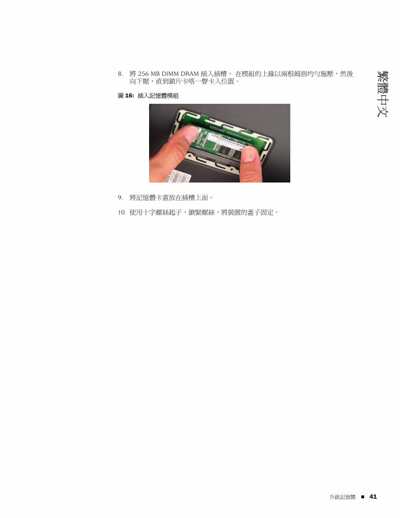
繁體中文
8. 將 256 MB DIMM DRAM 插入插槽。 在模組的上緣以兩根姆指均勻施壓,然後向下壓,直到鎖片卡嗒一聲卡入位置。
圖 16: 插入記憶體模組
9. 將記憶體卡蓋放在插槽上面。
10. 使用十字螺絲起子,鎖緊螺絲,將裝置的蓋子固定。
升級記憶體 41

SSG 5 硬體安裝與組態指南
42
升級記憶體
繁體中文
附錄 A
規格
本附錄提供 SSG 5 裝置的通用系統規格。 本章包含下列各節 :
本頁上的「實體」
本頁上的「電器設備」
第 44 頁上的「環境容忍度」
第 44 頁上的「憑證」
第 45 頁上的「連接器」
實體
表 7: SSG 5 實體規格
電器設備
表 8: SSG 5 電器設備規格
說明 值
機架尺寸 222.5 公釐 x 143.4 公釐 x 35 公釐。加上橡膠腳墊,系統為 40 公釐 (1.6 英吋 ) 高。
(8.8 英吋 X 5.6 英吋 X 1.4 英吋 )。
裝置重量 960 公克 (2.1 磅 )。
項目 規格
DC 輸入電壓 5.5 伏特
DC 系統電流 4 安培
實體 43

SSG 5 硬體安裝與組態指南
44
環境容忍度
表 9: SSG 5 環境容忍度
憑證
安全CAN/CSA-C22.2 No. 60950-1-03/UL 60950-1 Third Edition, Safety of Information Technology Equipment
EN 60950-1:2001+A11, Safety of Information Technology Equipment
IEC 60950-1:2001 First Edition, Safety of Information Technology Equipment
EMC 輻射FCC 第 15 部分 B 類 ( 美國 )
EN 55022 B 類 ( 歐洲 )
AS 3548 B 類 ( 澳洲 )
VCCI B 類 ( 日本 )
EMC 耐受性EN 55024
EN-61000-3-2 Power Line Harmonics
EN-61000-3-3 Power Line Harmonics
EN-61000-4-2 ESD
EN-61000-4-3 Radiated Immunity
EN-61000-4-4 EFT
EN-61000-4-5 Surge
EN-61000-4-6 Low Frequency Common Immunity
EN-61000-4-11 Voltage Dips and Sags
說明 值
高度 6,600 英尺 (2,000 公尺 ) 以下無效能損失
相對濕度 確保正常操作的相對濕度範圍是 5% 到 90%,無凝結
溫度 確保正常操作的溫度範圍是 32°F (0°C) 到 104°F (40°C)
出貨紙箱中非操作儲存溫度 : -40°F (-40°C) 到 158°F (70°C)
環境容忍度

繁體中文
ETSI歐洲電信標準協會 (ETSI) EN-3000386-2: Telecommunication Network Equipment ( 電信網路設備 )。 電磁相容性要求;( 設備類別 - 非電信中心 )
連接器
圖 17 顯示 RJ-45 連接器上接腳的位置。
圖 17: RJ-45 接腳配置
表 10 列出 RJ-45 連接器接腳配置。
表 10: RJ-45 連接器接腳配置
接腳 名稱 I/O 說明
1 RTS Out O 要求傳送
2 DTR Out O 資料終端備妥
3 TxD O 傳輸資料
4 GND 不適用 機架接地
5 GND 不適用 機架接地
6 RxD I 接收資料
7 DSR I 資料備妥
8 CTS I 允許傳送
1 2 3 4 5 6 7 8
連接器 45
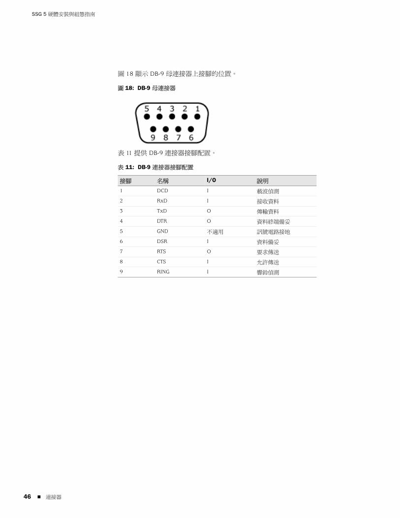
SSG 5 硬體安裝與組態指南
46
圖 18 顯示 DB-9 母連接器上接腳的位置。
圖 18: DB-9 母連接器
表 11 提供 DB-9 連接器接腳配置。
表 11: DB-9 連接器接腳配置
接腳 名稱 I/O 說明
1 DCD I 載波偵測
2 RxD I 接收資料
3 TxD O 傳輸資料
4 DTR O 資料終端備妥
5 GND 不適用 訊號電路接地
6 DSR I 資料備妥
7 RTS O 要求傳送
8 CTS I 允許傳送
9 RING I 響鈴偵測
連接器

繁體中文
附錄 B
初始組態精靈
本附錄提供有關使用 SSG 5 裝置的 Initial Configuration Wizard ( 初始組態精靈,ICW) 的詳細資訊。
當您的裝置實際連接至網路後,您可使用 ICW 來組態已安裝於您裝置上的介面。
本節說明下列 ICW 視窗 :
1. 第 48 頁上的「Rapid Deployment 視窗」
2. 第 48 頁上的「Administrator Login 視窗」
3. 第 49 頁上的「WLAN Access Point 視窗」
4. 第 49 頁上的「Physical Interface 視窗」
5. 第 50 頁上的「ISDN Interface 視窗」
6. 第 52 頁上的「V.92 Modem Interface 視窗」
7. 第 53 頁上的「Eth0/0 介面 (Untrust 區域 ) 視窗」
8. 第 54 頁上的「Eth0/1 介面 (DMZ 區域 ) 視窗」
9. 第 55 頁上的「Bgroup0 介面 (Trust 區域 ) 視窗」
10. 第 56 頁上的「Wireless0/0 介面 (Trust 區域 ) 視窗」
11. 第 58 頁上的「Interface Summary 視窗」
12. 第 58 頁上的「Physical Ethernet DHCP Interface 視窗」
13. 第 59 頁上的「Wireless DHCP Interface 視窗」
14. 第 59 頁上的「Confirmation 視窗」
47

SSG 5 硬體安裝與組態指南
48
1. Rapid Deployment 視窗
圖 19: Rapid Deployment 視窗
您的網路若使用 NetScreen-Security Manager (NSM),則您可使用 Rapid Deployment configlet 自動組態裝置。 若要從 NSM 管理員處取得一個 configlet,請選取 Yes,再選取 Load Configlet from:,瀏覽至檔案位置,然後按一下 Next。 configlet 會為您設定裝置,因此您不需要使用下列步驟組態裝置。
若您要略過 ICW,直接轉至 WebUI,請選取最後一個選項,然後按一下 Next。
若您沒有使用 configlet 來組態裝置,而是要使用 ICW,請選取第一個選項,然後按一下 Next。 ICW Welcome 畫面隨即出現。 按一下 Next。 Administrator Login 視窗隨即出現。
2. Administrator Login 視窗
輸入新的管理員登入名稱和密碼,然後按一下 Next。
圖 20: Administrator Login 視窗
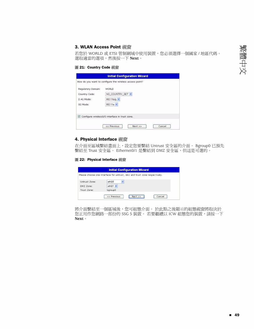
繁體中文
3. WLAN Access Point 視窗
若您於 WORLD 或 ETSI 管制網域中使用裝置,您必須選擇一個國家 / 地區代碼。 選取適當的選項,然後按一下 Next。
圖 21: Country Code 視窗
4. Physical Interface 視窗
在介面至區域繫結畫面上,設定您要繫結 Untrust 安全區的介面。 Bgroup0 已預先繫結至 Trust 安全區。 Ethernet0/1 是繫結到 DMZ 安全區,但這是可選的。
圖 22: Physical Interface 視窗
將介面繫結至一個區域後,您可組態介面。 於此點之後顯示的組態視窗將取決於您正用作您網路一部份的 SSG 5 裝置。 若要繼續以 ICW 組態您的裝置,請按一下 Next。
49

SSG 5 硬體安裝與組態指南
50
5. ISDN Interface 視窗
若您具有其中一個 ISDN 裝置,將顯示一個類似於下方所顯示視窗的 Physical Layer 標籤視窗。
圖 23: ISDN Physical Layer 標籤視窗
表 12: ISDN Physical Layer 標籤視窗中的欄位
欄位 說明
Switch Type 設定服務供應商交換機類型 :
att5e: At&T 5ESS
ntdms100: Nortel DMS 100
ins-net: NTT INS-Net
etsi: European variants
ni1: National ISDN-1
SPID1 服務供應商 ID,通常是一個含選用數字的 7 位數電話號碼。 只有 DMS-100 和 NI1 交換機類型需要 SPID。 DMS-100 交換機類型指派了兩個 SPID,每個 B 通道都有一個。
SPID2 備份服務供應商 ID。
TEI Negotiation 指定交涉 TEI 的時間,是在啟動時還是在第一次呼叫時。 此設定通常用於歐洲的 ISDN 服務產品,以及設計來初始化 TEI 交涉的 DMS-100 交換機連接。
Calling Number ISDN 網路請款號碼。
Sending Complete 核取方塊 啟用傳送完整資訊至向外設定訊息。 通常僅使用於香港和台灣地區。

繁體中文
若您有 ISDN 裝置,您將會看到 Leased Line Mode 和 Dial Using BRI 核取方塊。 選取一或兩個核取方塊會顯示類似於如下的視窗 :
圖 24: Leased-Line 和 Dial Using BRI 標籤視窗
表 13: Leased-Line 和 Dial Using BRI 標籤視窗中的欄位
欄位 說明
PPP Profile Name 對 ISDN 介面設定 PPP 設定檔的名稱
Authentication 設定 PPP 驗證類型 :
Any
CHAP: 詢問交握式驗證通訊協定
PAP: 密碼驗證通訊協定
None
Local User 設定本機使用者
Password 設定本機使用者的密碼
Static IP 核取方塊 啟用介面的靜態 IP 位址
Interface IP 設定介面 IP 位址
Netmask 設定網路遮罩
Gateway 設定閘道位址
51

SSG 5 硬體安裝與組態指南
52
6. V.92 Modem Interface 視窗
若您有一個 V.92 裝置,會顯示下列視窗 :
圖 25: V.92 Modem Interface 視窗
表 14: V.92 Modem Interface 視窗中的欄位
欄位 說明
Modem Name 設定數據機介面的名稱
Init Strings 設定數據機的初始化字串
ISP Name 對服務供應商指派一個名稱
Primary Number 指定電話號碼以存取服務供應商
Alternative Number ( 選用 ) 若主號碼沒有連接,請指定替代的電話號碼以存取服務供應商
Login Name 設定服務供應商帳戶的登入名稱
Password 設定登入名稱的密碼
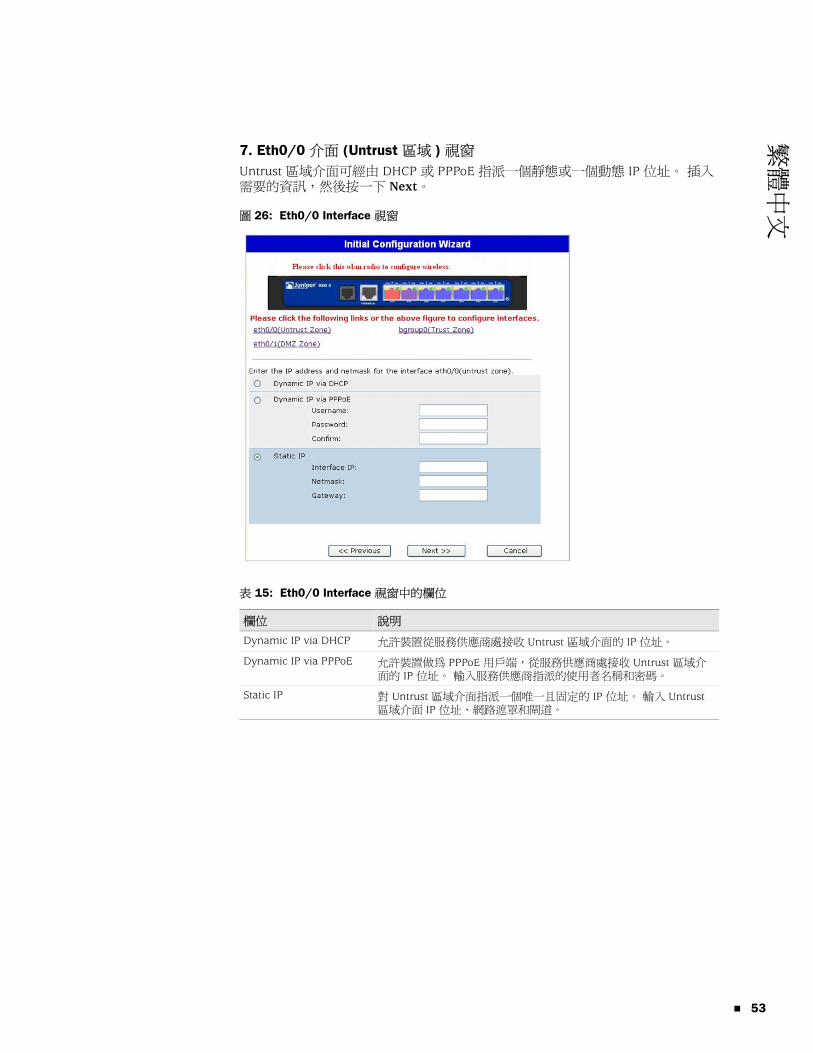
繁體中文
7. Eth0/0 介面 (Untrust 區域 ) 視窗
Untrust 區域介面可經由 DHCP 或 PPPoE 指派一個靜態或一個動態 IP 位址。 插入需要的資訊,然後按一下 Next。
圖 26: Eth0/0 Interface 視窗
表 15: Eth0/0 Interface 視窗中的欄位
欄位 說明
Dynamic IP via DHCP 允許裝置從服務供應商處接收 Untrust 區域介面的 IP 位址。
Dynamic IP via PPPoE 允許裝置做為 PPPoE 用戶端,從服務供應商處接收 Untrust 區域介面的 IP 位址。 輸入服務供應商指派的使用者名稱和密碼。
Static IP 對 Untrust 區域介面指派一個唯一且固定的 IP 位址。 輸入 Untrust 區域介面 IP 位址、網路遮罩和閘道。
53

SSG 5 硬體安裝與組態指南
54
8. Eth0/1 介面 (DMZ 區域 ) 視窗
DMZ 介面可經由 DHCP 指派一個靜態或一個動態 IP 位址。 插入需要的資訊,然後按一下 Next。
圖 27: Eth0/1 Interface 視窗
表 16: Ethernet0/1 Interface 視窗中的欄位
欄位 說明
Dynamic IP via DHCP 允許裝置從服務供應商處接收 DMZ 介面的 IP 位址。
Static IP 對 DMZ 介面指派一個唯一且固定的 IP 位址。 輸入 DMZ 介面 IP 位址和網路遮罩。

繁體中文
9. Bgroup0 介面 (Trust 區域 ) 視窗
Trust 區域介面可經由 DHCP 指派一個靜態或一個動態 IP 位址。 插入所需的資訊,然後按一下 Next。
預設介面 IP 位址為 192.168.1.1,網路遮罩為 255.255.255.0 或 24。
圖 28: Bgroup0 Interface 視窗
表 17: Bgroup0 Interface 視窗中的欄位
欄位 說明
Dynamic IP via DHCP 允許裝置從服務供應商處接收 Trust 區域介面的 IP 位址。
Static IP 對 Trust 區域介面指派一個唯一且固定的 IP 位址。 輸入 Trust 區域介面 IP 位址和網路遮罩。
55

SSG 5 硬體安裝與組態指南
56
10. Wireless0/0 介面 (Trust 區域 ) 視窗
若您有一個 SSG 5-WLAN 裝置,您必須先設定服務集識別碼 (SSID),才可啟動 wireless0/0 介面。 如需有關組態無線介面的詳細說明,請參閱「概念與範例 ScreenOS 參考指南」。
圖 29: Wireless0/0 Interface 視窗
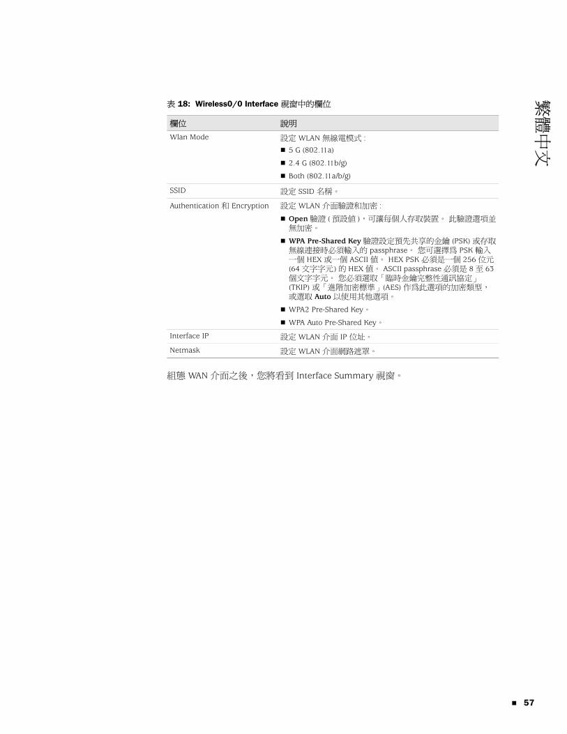
繁體中文
表 18: Wireless0/0 Interface 視窗中的欄位
組態 WAN 介面之後,您將看到 Interface Summary 視窗。
欄位 說明
Wlan Mode 設定 WLAN 無線電模式 :
5 G (802.11a)
2.4 G (802.11b/g)
Both (802.11a/b/g)
SSID 設定 SSID 名稱。
Authentication 和 Encryption 設定 WLAN 介面驗證和加密 :
Open 驗證 ( 預設值 ),可讓每個人存取裝置。 此驗證選項並無加密。
WPA Pre-Shared Key 驗證設定預先共享的金鑰 (PSK) 或存取無線連接時必須輸入的 passphrase。 您可選擇為 PSK 輸入一個 HEX 或一個 ASCII 值。 HEX PSK 必須是一個 256 位元 (64 文字字元 ) 的 HEX 值。 ASCII passphrase 必須是 8 至 63 個文字字元。 您必須選取「臨時金鑰完整性通訊協定」(TKIP) 或「進階加密標準」(AES) 作為此選項的加密類型,或選取 Auto 以使用其他選項。
WPA2 Pre-Shared Key。
WPA Auto Pre-Shared Key。
Interface IP 設定 WLAN 介面 IP 位址。
Netmask 設定 WLAN 介面網路遮罩。
57

SSG 5 硬體安裝與組態指南
58
11. Interface Summary 視窗
檢查您的介面組態,然後當準備好繼續時,按一下 Next。 Physical Ethernet DHCP Interface 視窗隨即出現。
圖 30: Interface Summary 視窗
12. Physical Ethernet DHCP Interface 視窗
選取 Yes 以允許裝置透過 DHCP 對有線網路指派 IP 位址。 輸入您要裝置指派給使用您網路之用戶端的 IP 位址範圍。
圖 31: Physical Ethernet DHCP Interface 視窗

繁體中文
13. Wireless DHCP Interface 視窗
選取 Yes 以允許裝置透過 DHCP 對無線網路指派 IP 位址。 輸入您要裝置指派給使用您網路之用戶端的 IP 位址範圍。
圖 32: Wireless DHCP Interface 視窗
14. Confirmation 視窗
確認您的裝置組態,並依需要進行變更。 按一下 Next 進行儲存、重新啟動裝置並執行組態。
圖 33: Confirmation 視窗
按一下 Next 之後,裝置會以儲存的系統組態重新啟動。 WebUI 登入提示隨即出現。 如需有關使用 WebUI 來存取裝置之方法的資訊,請參閱第 25 頁上的「 使用 WebUI」。
59

SSG 5 硬體安裝與組態指南
60

繁體中文
索引
UUntrust 區域,組態備份介面 .......................................31九畫重設針孔,使用 .............................................................38
十畫記憶體升級程序 .............................................................39
十一畫組態
USB............................................................................14WAN 介面 .................................................................35日期與時間 ...............................................................29主機及網域名稱 .......................................................30備份 Untrust 介面 ....................................................31無線驗證和加密 .......................................................33結合的無線及乙太網路 ...........................................34預設路由 ...................................................................31管理名稱及密碼 .......................................................28管理式存取 ...............................................................30管理位址 ...................................................................31管理服務 ...................................................................30橋接群組 (bgroup) ...................................................29
連接,基本網路 .............................................................20
十二畫備份介面到 Untrust 區域 ..............................................31無線
天線 ...........................................................................22使用預設介面 ...........................................................22
無線電收發機WLAN 0.....................................................................14WLAN 1.....................................................................14
十三畫預設 IP 位址 ...................................................................27
十四畫管理
透過 Telnet 連接 ......................................................26透過 WebUI ..............................................................25透過主控台 ...............................................................24
管理服務 .........................................................................30
二十五畫以上纜線
基本網路連接 ...........................................................20
索引 61

62
SSG 5 硬體安裝與組態指南
索引