Embed Size (px)
Citation preview
SSC-332
GUIDE FOR SHIP
STRUCTURAL INSPECTIONS
‘his dmnnent has &en”approvedfor public release and Sd~ ils
diminution is unlimited
.1
SHIP STRUCTURE COMMITTEE
1990

SHIP STRUCTURE COMMllTEE
THE SHIP STRUCTURE COMMllTEE is constituted to prosecute a research program to improve the hull structure ofships and other mmfne structures by an extension of knowledge pertaining 10 design, materials and methods of construction.
RADM J. D. Sipes, USCG, (Chairman)Chief, Otice of Marine Safety,
Securii and Environmental ProtectionU. S. Coast Guard
Mr. Alexander MalakhoffDirector, Structural Integrity
Subgroup (SEA 55YjNaval Sea Systems Command
Dr. Donald 14Senior Vice PresidentAmerican Bureau of Shipping
Mr. H. T. HalterAssociate Administrator for Ship-
building and Ship OperationsMaritime Administration
Mr. Thomas W. AllenEngineering Officer (N7)Military Sealift Command
CDR Michael K Parrnelee, USCG,SecretW, Ship Structure CommitteeU. S. Coast Guard
CONTRACTING OFFICER TECHNICAL REPRESENTATIVES
Mr. William J. Siekierka Mr. Greg D. WoodsSEA55Y3 SEA55Y3Naval Sea systems Command Naval Sea Systems Command
SHIP STRUCTURE SUBCOMMllTEE
THE SHIP STRUCTURE SUBCOMMITTEE acts for the Ship Structure Commitfee on technical maners by providingtechnical coordinating for the determination of goals and objectives of the program, and by evaluating and interpretingthe results in terms of structural design, construction and operation.
U. S, COAST GUARD
Dr. John S. Spencer (Chairman)CAPT T. E. ThompsonMr. David L. MotherwayCDR Mark E. Nell
~ OMMAND
Mr. Robent A. SielskiMr. Charles L, NullMr. W, Thomas PackardMr. Allen H. Engle
JvllLITARY SEALl~ COMMAND
Mr. Glenn M. AsheMr. Michael W, ToumaMr. Albetl J. AttermeyerMr. Jeffery E. Beach
AMER ICAN BUREAU OF SHIPPING
Mr. John F. ConIonMr. Stephen G. ArntsonMr. William M. HanzalekMr. Philip G, Rynn
MARITIMFADMINISTRATION
Mr. Frederick SeiboldMr. Norman 0, HammerMr. Chao H. LinDr. Wailer M, Maclean
SHIP STRUCTURE SUBCOMMl~EE LIAISON MEMBERS
II @ICr7A=iT HJARrl ACADFM Y ~
LT Bruce MustainMr. Alexander B. Stavovy
4J. S, MERCHA NT MARINE ACADEMYNATIONAL ACADEMY OF SCIENCES
Dr. C. B, Kim CTURES
U. S. NAVAL ACADEMY Mr. Stanley G, Stiansen
Dr. Ramswar Bhattacharyya SOCl~ OF NAVAL ARCHITECTS ANDMARINE ENGINEERS-
~ MllTFr
Dr. William SandbergDr. W. R. Porter
WoAMERICAN IRON AND STEEL INSTITUTE
ING RESEA RCH COUNCILMr. Alexander D. Wilson
Dr. Glen W. Oyler
Mambar Agmchs:
Unit& Stares Coast GuadNaval ~a Systems &mma.d
Matiimo Administr8thAmsrbur Bwvau of sh~i~
Mihty SeaM &mmad
ShipStructure
CommitteeAnInteragemyAdviaofyCommltlee
Dedicatedtothe Inpmvwnant of MarineStIUC(IJres
August2, 1990
*w, Sh@ tiro CommkheUs. @aSt Gud (G-M’rH)2100- Strsat S.w.Wmhingbn, D.C. 2059WOOI
PH: (2@) 297-FM @W) 2S7a
SSC-332SR-1289
GUIDE FOR SHIPSTRUCTURAL INSPECTION
The importance of thorough inspections and appropriate inspectiontechniques cannot be overemphasized. In this era when oldervessels are continuing in semice longer and newer vessels arebeing designed with lighter scantlings and higher strengthsteels, it is particularly important that the effects ofcorrosion, fatigue and general service be adequately consideredduring initial construction and subsequent condition surveys. Itis intended that this report provide guidance to those involvedin the structural inspection of commercial and naval ships.
?%s%=-~~ SIPE~
Rear Admiral, U. S. Coast GuardChairman, Ship Structure Committee


TechnicalReportDocumentation pa9e
1. Report No. 2. Government Accession No.
SSC-332 I4. Title nnd Subtitle
Guide For Ship Structural Inspection
Nedret S. Basar& VictorW. Jovino
9. Performing Organization Name end Addre*s
M. Rosenblatt & Son, Inc.350 Broadway
,New York, NY 10013
12. Sponsoring Age.cY/4ame and Address
Ship Structure Committeec/o U.S. Coast Guard (G-M)2100 Second Street, SW ~Washington, D.C. 20593
3. Recipient’s Catalog Ne.
5. Report Date
1985
6. Performing Drgonizatio” Code
~ Performing Organization Report No.
SR 128910. Work Unit No. (TRAIS)
11. Contractor Gront No.
DTCG-23-C-2003613. Type of Report and Period Covered
Final Report
14. Sponsoring A9gncY Code
G-M
15. supplementary Notes
16. Abstruet
$, Based on surveys and interviews conducted in several commercial shipbuildi-
ng yards, a guide for ship structural inspections is developed for use by marine
I people involved in designing, building, accepting, and operating ships.
A balanced and sufficient amount of inspection activities is prescribedfor all stages of a ship’s life from the onset of design process through construc-
tion tO the final operational years in service
17. Key Words 16. Distribution Stat*mont Available from:Crack Fracture Damage
I
National Technical Information ServiceInspection Defect Nondestructive Springfield, VA 22151 orDetails Distribution Examination Marine Technical Information FacilityStructures Failure Welds National Maritime Research Center
Kings Point, NY 10024-169919. Security Classif. (of this report) 20. SccuritYClassil. (of this page) 21. No. of Pages 22. Price
UNCLASSIFIED UNCLASSIFIED 46
FermDOT F 1700.7 (8-72) Reproduction of eomplctedpoge authorized
i

METMC CONVERSIONfACTO#lS
lHUGIM
lENGTH
inclms “2.sln9t 20
ytis 0.smihs 1.s
AnfaAREA
Mhss [W2ithl)
~e 29prods 0.4Btit *O 0.s
Wmn a4
VOLUME VOIUW
“1
. I (,, 0 1,54 l . . ..i...,, t,, “** ● mat , ,,, w,.m,q.mm Hnd* *M,M IAIC*. $.”. MmNice. roll, ?W.U,”*, J *u,l@i. & w,+Oti. h,<. SI.Z5. 20 c“lalwJ Mu. Cbl.lo:?w
METRIC CONVERSION FACTORS
TABLE OF CONTENTS
AbstractList of Illustrations
1.0 Introduction
2.0 Objective
3.0 Factors Affecting Ships’ Structural Integrity
3.1 Hull Girder3.2 Damage vs. Collapse3.3 Structural Details
4.0 Unified Concept for Ship Structural Inspections
4.1 General4.2 Inspection Considerate”
4.2.1 Inspectability4.2.2 Redundancy
ons During Des”gn Stages
4.2.3 Critically Stessed Areas4.2.4 Inspectio; Plan
4.3 Inspection Activities During Construction
4.3.1 Owners’ Needs4.3.2 Receipt Inspection of Materials4.3.3 In-Process Inspections
a. Visual Inspectionsb. Dimensional Accuracyc. Alignment and Fairnessd. Weld Inspections and Non-Destructive Examinationse. Final Structural Surveys and Tightness Tests
4.3.4 Common Structural Deficiencies4.3.5 Recording/Reporting/Evaluation Procedures
a. Documentation of Inspection Activitiesb. Dissemination of Inspection Results
4.3.6 Development of “Structure Condition Record”4.3.7 Preparation of “In-Service Inspection Program
Page
iiv
1
3
4
478
9
99
9
::10
12
121213
1314151616
1717
1717
2223
-iii-

4.4 In-Service Inspections
4.4.1 General4.4.2 Crew Inspections4.4.3 Periodic Inspection by Classification Societies4.4.4 Repair and Conversion Inspections4.4.5 Maintaining and Updating the
Structure Condition Report
ReferencesAcknowledgementShip Structural Inspection Terminology and Abbreviations
23
2324252532
333435
-iv-
Em!E
1
2
3
4
5
6
7
8
9
10
11
12
13
14
15
16
17
18
19
20
21
22
24
24
TABLE 1
LIST OF ILLUSTRATIONS
Title
Nomenclature for Transversely Framed Ships
Nomenclature for Longitudinally Framed Ships
Sample Midships Section
Bulkhead Misalignment
Misalignment of Butt Connections
Excessive Gap Between Members
Stiffener Tilt
Distance Between Butt Weld and Scallop
Distance Between Adjacent Butt Welds
Distance Between Butt Weld and Fillet Weld
Distortion of Beams, Frames, Stiffeners
Distortion in Panel Stiffeners
Deformation of Plate
Horizontal Stringer in Wing Tanks
Transverse Frame at Side Shell
Transverse Frame at Side Shell
Side Shell Longitudinal Fracture
Combined Progressive Shell Plate and Transverse WebFrame Fracture
Fracture in Bottom Transverse Web
Fracture in Longitudinal Intercostal Girder
Buckling of Centerline Girder
Typical Bottom Shell Loss Patterns
Center Girder Cracking
Typial Bottom Longitudinal Cracking
Inspection Checklist for Primary Structures
Page
5
5
6
18
18
19
20
20
20
20
21
21
21
26
27
27
27
27
28
28
28
29
30
31
11
-v-

-—-, --- ...

1.0 INTRODUCTION
All shipyards conduct extensive inspections on newly constructed ships’structures during various stages of the building program with the purpose ofassuring a structurally sound ship capable of withstanding the operational andenvironmental loads to be imposed on it during. its service life.
The ideal materials, scantlings, and configuration of the structure aredetermined by the structural designer and depicted in the contract designdrawings and specifications. However, the compliance of the constructed vesselwith the ideal design depends on the following factors:
o The degree of attention paid during the detail design stage toinspection requirements,
o The degree of redundancy provided in the detail design,
o The care exercised in procuring and installing proper structuralmaterials,
o The existence or lack of flaws in the materials actually installed,
o The effectiveness of inspection activities,
o The efficiency with which any structural deficiencies found throughinspections are resolved and repaired.
During the course of a study for the Ship Structure Committee undercontract to the U.S. Coast Guard (l)*, the authorsshipbuilding yards in the United States with thestructural inspection practices and interviewinginspections during construction.
Additionally, five existing ships were
had visited five commercialobjective of surveying shipthe personnel involved in
visited during limitedavailabilities in several shipyards with the purpose of attending periodicalstructural inspections being performed and interviewing the AB$ surveyors andUSCG inspectors involved in these activities.
The results obtained from these investigations were carefully analyzed,current inspection practices and weaknesses thereof noted, and areas ofstructural inspection activities in need of improvement identified.
It Is recognized that these results are based on surveys made in only alimited number of shipyards and as such they do not reflect the practices of allU.S. commercial shipyards. However, it can reasonably be expected that anyshipyard will have at least some of the deficiencies observed and will thereforebenefit from a compilation wherein guidelines and procedures are contained toassist in formulating improved ship structural inspection practices.
Detailed findings from the surveys are presented in (1). The present“guide” is a slightly expanded and “stand-alone” version of Chapter 5 of thatreport.
*Numbers in parentheses denote similarly numbered references at the end of report.
-1-

The objective of developing a guide is further discussed in Section 2. InSection 3, a brief compilation on ship structural integrity and factorsaffecting it is presented.
The concept for and the contents of a guide for ship structural inspectionare contained in Section 4.
Listings of references cited and definitions of terminology andabbreviations used in the text are included at the end of the guide.
-2-

2.0 OBJECTIVE
The construction process of any ship must be complemented with inspectionsand”examinations to ensure compliance of the “as-built” vessel with its originaldesign in regard to structures, materials, machinery, equipment, systems, andoutfitting.
This “Guide” includes consideration of inspections for ship structures fromthe initiation of the design process to the end of the vessel’s useful servicelife. Its objective is to provide, for use by all marine people involved inship structural inspections, a thorough document recommending corrective actionfor typical deficiencies or deviations.
Through proper understanding and application of these procedures andmethods by the structural inspectors:
o minor and major deviations can be detected early in the constructionprocess;
o appropriate corrective measures can be accomplished so as not to allowan accumulation of defects;
o costly rework which would have otherwise been required can be avoided;
o an “as-built” structural history of the vessel can be prepared on thebasis of which future in-service inspection results can be evaluated;
o the structural integrity can be maintained by performing periodic in-service inspections and correcting any deficiencies found before theycan progress to levels sufficient to cause failure of the parts or ofthe complete hull girder.
-3-
3.0 FACTORS AFFECTING SHIPS’ STRUCTURAL INTEGRITY
The term “structural integrity” as used here is intended to convey theemployment of structural design, material utilization, and fabricationtechnologies in the production of a ship.
The completeness and accuracy of the design procedures used in developingthe ship’s structure will obviously play a major role on the soundness of theend product. Utilization of materials of proper type and grade, and free offlaws, to satisfy the design requirements will also greatly affect structuralintegrity. Having as much, if not greater, influence on the final product’sperformance ,are the methods and techniques used in fabricating and inspectingthe structure.
A majority of present day ship structural designs are developed on thebasis of a combination of “safe-life” and “fail-safe” approaches. A “safe-life”design implies that the structure will not fail, at least in terms of failuredue to crack initiation and growth, during its lifetime. A “fail-safe” design,on the other hand, assumes periodic inspections during the structure’s lifetime,and implies the detection and repair or renewal of any parts of a structure thatdevelop flaws.
The design process is an iterative one, and consists basically of theadoption of a geometry, analysis of the response of this geometry to the appliedloads, evaluation of this response against an established norm, and recycling ofthe process until acceptable responses are obtained.
In investigating the longitudinal strength of the ship being designed,conventional or deterministic methods have mostly been employed to date. Inrecent years, however, probabilistic structural design approaches are beingwidely studied especially toward application for the design of the ship’slongitudinal hull girder. A probabilistic structural design analyzes theuncertainties associated with ship hull strength and develops expressions forstructural reliability.
In order to better understand the philosophy behind the inspectionrequirements, an explanation of the functions of the shi~ structural com~onentsand potential failure modes is presented here.
3.1 Hull Girder
The main functions of a ship’s hull girderenvelope, to support local hydrostatic loads, andapplied on the structure. These functions areelements that constitute the hull qirder. Fiaures
are to act as a watertightto resist the bending loadsprovided by the structural1 and 2 show re~resentative
structural elements normally found-in the bot~om structure of transversely andlongitudinally framed ships, respectively. The bottom structure, together withthe side shell and the strength deck acts as a box girder (Figure 3) to providethe required strength for structural integrity.
The loads imposed on the structure create in-plane compression, tension andshear stresses which may cause excessive permanent deformations due to localyielding or buckling (from compressive and/or shear loads) and cracks due to
-4-
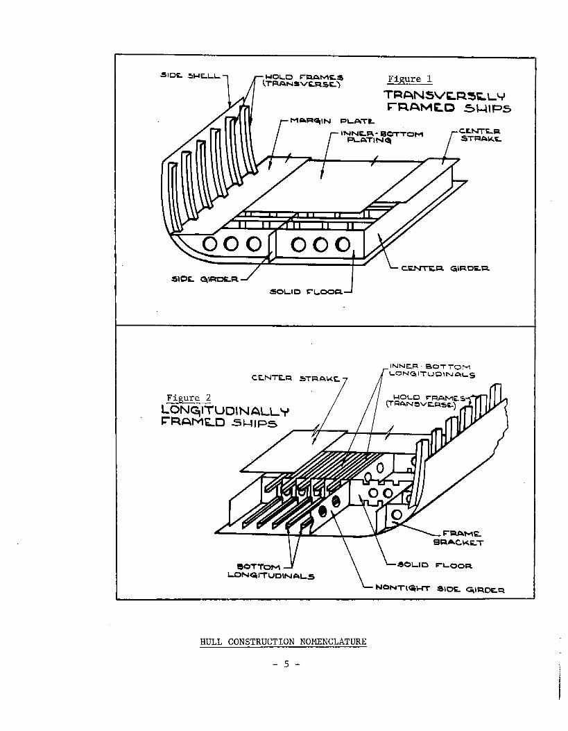
HULL CONSTRUCTION NOMENCLATURE
-5-

I
WE-S FL
8KT R
I =Vu
i
1II
I
#L 1
FEi-
‘-
/ ‘ax
Figure 3: SAMTLE MIDSHIP SECTION
-6-
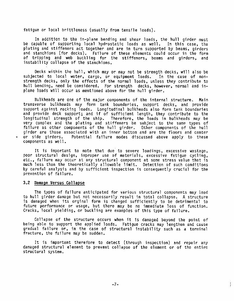
fatigue or local brittleness (usually from tensile loads).
In addition to the in-plane bending and shear loads, the hull girder must
be capable of supporting local hydrostatic loads as well. In this case, theplating and stiffeners act together and are in turn supported by beams, girdersand stanchions (for decks). Failure of these elements could occur in the formof tripping and web buckling for the stiffeners, beams and girders, andinstability collapse of the stanchions.
Decks within the hull, which may or may not be strength decks, will also besubjected to local water, cargo, or equipment loads. In the case of non-strength decks, only the effects of the normal loads, unless they contribute tohull bending, need be considered. For strength decks, however, normal and in-plane loads will occur as mentioned above for the hull girder.
Bulkheads are one of the major components of the internal structure. Maintransverse bulkheads may form tank boundaries, support decks, and providesupport against racking loads. Longitudinal bulkheads also form tank boundariesand provide deck support; and if of sufficient length, they contribute to thelongitudinal strength of the ship. Therefore, the loads in bulkheads may bevery complex and the plating and stiffeners be subject to the same types offailure as other components of the hull girder. Other components of the hullgirder are those associated with an inner bottom and are the floors and centeror side girders. Potential failure modes discussed above apply to thesecomponents as well.
It is important to note that due to severe loadings, excessive wastage,poor structural design, improper use of materials, excessive fatigue cycling,etc., failure may occur at any structural component at some stress value that ismuch less than the theoretically allowable limit. Detection of such conditionsby careful analysis and by sufficient inspection is consequently crucial for theprevention of failure.
3.2 Damaqe Versus Collapse
The types of failure anticipated for various structural components may leadto hull girder damage but not necessarily result in total collapse. A structureis damaged when its orginal form is changed sufficiently to be detrimental tofuture performance or usage, but there may be no immediate loss of function.Cracks, local yielding, or buckling are examples of this type of failure.
Collapse of the structure occurs when it is damaged beyond the point ofbeing able to support the applied loads. Fatigue cracks may lengthen and causegradual failure or, in the case of structural instability such as a terminalfracture, the failure may be sudden.
It is important therefore to detect (through inspection) and repair anydamaged structural element to prevent collapse of the element or of the entirestructural system.
-7-

3.3 Structural Details
Longitudinal hull girder design, using deterministic and/or probabilisticapproaches, establishes the strength requirements and therefore the scantlingsof primary structural elements. Equally important, from the standpoint ofintegrity of a ship’s structure, however, is the design of structural details.
Structural details represent a considerable portion of the hullconstruction cost and are very often the source of cracks leading to hull girderdamage.
The key to the design of sound structural details is to provide structuralcontinuity, minimize stress concentration effects, and to specify weldingprocedures compatible with the materials. These measures will have the effectof minimizing crack initiation potential.
In an earlier Ship Structure Committee project (2), structural detailscommon to many ships were surveyed to determine the effectiveness of variousgeometrical configurations that have been used for similiar shipboardconditions. Data from sound and failed details were gathered to providefeedback to the designer for analyzing the causes of failures. No conclusionswere reached regarding any specific detail variations since many occurred only afew times, but some of these showed no signs of failure and may be considered aspreferred details.
It has been demonstrated that it is feasible to utilize finite elementstructural analysis techniques in the development of structural details. Thistechnique is found to be an efficient and cost effective approach fordetermining the feasibility and integrity of structural details. By utilizingthis technique, the high cost of repairs due to cracking or failure may bereduced (3). Not all structural details require a rigorous analysis, but thosesuspected of high stress concentrations and those which are repeated many timesshould be investigated.
-8-

4.0 UNIFIED CONCEPT FOR SHIP STRUCTURAL INSPECTIONS
4.1 General
A “unified” inspection concept is defined as that which covers all stagesof a ship’s operating life as well as its design and construction periods.
For each stage, the extent of and the procedures for inspections to beperformed should be established. The purpose of inspections is to assess thecapability of the structure to remain safe until the next inspection period andto accomplish any necessary corrective measures to maintain this capability.
The extent of structural inspections required will always be greatlyaffected by cost and time considerations. In actual practice, it will beimpractical, if not impossible, to execute “perfect” inspections. However, evenif the “perfect” 1evel ,of inspection cannot be obtained, thesurveyors/inspectors involved in ship structural inspections must try to conductjust the sufficient amount of inspection without going to unnecessary extremes.
4.2 Inspection Considerations During Design Stages
The design of a ship’s structures is generally accomplished by means of atrial and error approach. The objective is to arrive at redundant, inspectable,and fail-safe structures. In order to assure these objectives, the designersmust take the following inspection related criteria into consideration duringthe design stages:
o inspectability of structural elements both during fabrication and duringin-service inspections;
o provision of redundant structures;
o identification of critically stressed parts of structures;
o determination of standard tolerances and acceptable levels for structuraldeviations on the basis of how they affect the structural performance.
4.2.1 Inspectability
During preparation of detailed structural drawings, special attentionshould be directed to providing easy access to all parts and especiallycritically stressed areas of structure for the purpose of inspections. Specificprecautions that may be taken are:
o adoption of greater spacing for members to facilitate access,
o avoiding “blind” spots in the structural arrangements,
o providing permanently installed access plates or holes for enteringtightly arranged structures.
-9-
The general philosophy sometimes favored in shipyards that “if it can bebuilt, it can be inspected” should be abandoned and the extra attention needed

to provide inspectability should be given.
Precautions can also be taken and slight modifications or additions made tothe structure during design stages to provide inspectability of those structuralitems that will be subjected to periodical in-service inspections. These maytake the form of properly spacing stringers, bulkhead stiffeners, etc. orinstalling permanent rungs for use in climbing by inspectors to enable them toreach otherwise uninspectable areas. The need to install costly staging duringin-service inspections may be avoided by this precaution.
The main objective is to make sure that the structural design facilitatesin-service inspections rather than hampers them. Toward this goal, a thoroughreview of the detail structural design drawings must be undertaken prior toreleasing them to the production department for fabrication.
4.2.2 Redundancy
Inspectability will also be aided by the provision of redundant structures.A redundant structure can be obtained by providing more than one member to servethe same function or to share the same load. By this measure, the probabilityof total failure due to the failure of a single element will be much reduced ifnot eliminated depending on the degree of redundancy provided. When more thanone member exists to take up the same loading, then finding damage in one memberwill point out the need to carefully inspect other redundant members.
4.2.3 Critically Stressed Areas
The analyses and investigations performed during the structural designdevelopment will indicate that some areas or elements of a ship’s hull girderwill be subjected to higher stresses than others even though the “higherstresses” are still within allowable limits. Yet it will be found impracticaland uneconomical to increase the scantlings of these elements further.
Such areas or elements are termed “critically stressed areas” and theyshould receive special attention during inspection activities. They should beidentified on the inspection plans and specific inspection requirements given.
4.2.4 Inspection Plan
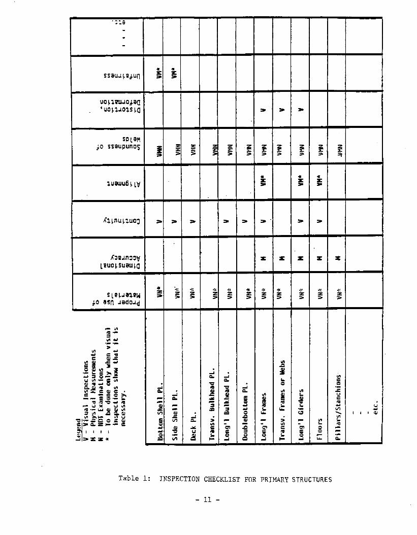
On the basis of analyses and investigations performed during design stages,an “Inspection Plan” should be prepared for the vessel to be constructed. The“plan” should provide accessibility instructions for parts to be inspected andidentify the critically stressed areas as determined from stress analyses. Inaddition, it should contain a listing of all structural elements to be inspectedand the type and extent of inspections for each. A typical summary checklistfor primary strength members is given in Table 1. This list should be amplifiedto cover all primary, secondary, and detail structures as applicable to thespecific ship to be constructed.
Also to be included in the inspection plan is a listing of or a referenceto the applicable standard structural tolerances and acceptable levels ofdeviation from these standards.
-1o-
..s
.
sPlaf!do ssaupunos
●
.
w
x s
Table 1: INSPECTION CHECKLIST FOR PRIMARY STRUCTURES
-11-
Many compilations of such tolerancevarious shipbuilding countries. Basedshipowner and the requirements imposed by
standards now exist and are in use inon the desires of the prospectivethe desiqn, the designer should decide
on “the acceptable tolerance levels and either-adopt one ‘of the existingcompilations or modify it to suit his purposes for use in negotiations with theprospective shipyard prior to signing a construction contract. Guidance onstandard tolerances and acceptable deviations can be obtained from references(4) through (9). Most of these publications also contain recommended repair andcorrective action procedures for major deviations from acceptable levels. Theserecommendations may be used as a baseline in determining the specific correctiveaction procedures to be adopted for the specific ship to be constructed.
4.3 Inspection Activities During Construction
Inspection is a costly activity. By specifying inspections in excess ofwhat is necessary to ensure structural integrity of the completed vessel, anextra heavy cost burden may be imposed on the shipyards, and therefore on theowners. On the other hand, by specifying and then conducting an insufficientamount of inspection, some deficiencies in the structures may remain undetectedand may result in repair or renewal operations much costlier than the pre-planned inspections. Accordingly, the need to arrive at a reasonably balancedlevel of inspection among the parties concerned, i.e. the shipowner, shipyard,classification society, and the designer, is apparent.
The intent of this guide is not to set any stringent requirements for thestructural inspections of any particular ship. The following suggestions forvarious inspection considerations, types/methods/frequencies of inspections, andprocedures, are presented for the purpose of making available for review and usea broad set of guidelines to be used in the preparation of a specific inspectionprogram for the construction of a particular ship.
4.3.1 Owner’s’Needs
The owner of a vessel may need and may wish to have conducted certaininspection activities and corrective measures which the shipyard may considerunnecessary or uncalled for from a structural strength viewpoint. A simpleexample is the desire of the owner of a high speed container ship to have allsurface imperfections on the exterior hull plating (such as burrs, scars,spatter, etc) removed even though these do not affect the ship’s structuralintegrity and may be considered “cosmetic” repair. However such removal isimportant for the shipowner since it will reduce the vessel’s drag and hence itsfuel consumption.
The owner may also have a preference for the type and extent of non-destructive examinations (NDE) to be employed in construction inspections.
All such needs expressed by the owner should be discussed by the partiesinvolved and agreed procedures should be made a part of the constructioninspection program.
4.3.2 Receipt Inspection of Materials
It is desirable to have all steel and aluminum “structural materials
-12-

inspected upon arrival at the shipyard’sbecomes a matter of increasing costs.requirements to be in effect duringestablished on the basis of a cost/benefit
Specific defects to look for are:
receiving area. However, this againTherefore, the “receipt inspection”the construction period should betrade-off.
o deviations from nominal dimensions
o surface defects such as excessive pitting and flaking on plate and shapematerials,
o laminations on plates,
o deviations from the specified type or grade.
In order to detect these defects, visual inspections must be made and mustbe complemented when necessary by measurements for dimensional accuracy and byultrasonic examinations to detect laminations as necessary. Recommendedtolerance standards and repair procedures for defects in excess of allowablelevels are contained in references 4, 5, and 6. By reviewing these references,the minimum receipt inspection requirements should be established and includedin the ship’s construction inspection program.
4.3.3 In Process Inspections
In-process inspections should be performed by the production departmentsupervisors as a “self-inspection” activity and by the quality assurancedepartment inspectors for the purpose of assuring adequate control of qualityduring the ship construction process.
The specified procedures, methods, and organizational roles may varydepending on the shipyard where the construction will take place and on the typeand size of the vessel to be constructed. In any case, however, the followingparticular inspection functions must be accomplished during particular stages ofconstruction.
a. Visual Inspections
Visual inspections during subassembly, assembly, and erection stages shouldbe directed to carefully examining the structure with specific attention to thefollowing:
o Completeness: To make sure that all of the major structural members onthe subassembly/assembly/modul e/ship are in place as required by thedetail design drawing.
o Materials Used: To verify that only the correct materials as specifiedby the detail design drawings are used. Material identification colorcodes or markings can be used for this verification.
o Accuracy: To pin-point apparent deviations from specified dimensionswith the purpose of assuring that subassemblies and assemblies fit to-
-13-

gether. A pre-planned dimensional control program is necessary toaccomplish this.
o Joint Preparation: To ensure accuracy in fit-up, root openings,alignment of members, cleanliness, removal of slag, bevelling, etc.
o Weld Layout: To determine that weld sizescontinuous and/or intermittent welds are beingthe detail design drawings.
o Fairness: To observe any apparent unfairness inthe purpose of requiring fairness measurements if necessary.
are correct andused in accordance
the completed unit
thatwith
with
o Structural Details: To verify compliance with detail design drawings ofstructural details such as clearance cutouts, collars, brackets,stiffener end connections, etc.
o Supports/Braces: To verify that an. adequate quantity andsupports, braces, and lifting pads are provided and properlyuse in moving and handling the unit without damagingdisturbing its alignment.
quality oflocated forit and/or
o General Workmanship: To see that the completed structural unit is freeof discontinuities, undercuts, sharp ragged edges, nicks or other damagewhich may initiate or propogate cracks causing total failure of thestructure; to verify that all temporary fabrication/erection attachmentsthat are not required during later stages of construction are properlyremoved.
Specific guidelines for use in judging the acceptability of the structureson the basis of visual inspections are the detail structural drawings,construction specifications, and the inspection plan prepared during the designprocess. A lot still depends on the knowledge and experience of the inspector.Whenever the inspector is in doubt as to the acceptability of any part withregard to any inspection criterion, he should refer to the standard tolerancesand acceptable deviations contained in references (4), (5), (7) or those thatmay be included in the ship’s inspection plan, and if he considers it necessaryto have physical measurements or NDE examinations made, he should request such.
b. Dimensional Accuracy
Dimensional control activities should cover all stages of construction frommold loft to launching.
O Mold Loft: Loft sheets, roll molds, furnace molds, and battens shouldbe inspected for dimensional conformance and for completeness of detailwith the latest revised detail structural drawings. Steel tapes used inlayouts and measurements should also be periodically inspected foraccuracy.
o Plate Shop and Numerically Controlled Burning Area: In order to verifyconformance with detail structural plans, the following should be in-spected during plate preparation:
-14-

orientation of plate with respect to the molded line
centerline of the ship should be used as a master reference line andcenter punching of frames, buttocks, and waterlines should beinspected for dimensional accuracy;
spacings and angularities of structural members
it must be verified that a sufficient final cut allowance isprovided;
-after the final cut, bevels and collars, final dimensions,alignment, and fairness should be inspected.
o Subassembly/Assembly/Erection Areas: During panel and subassemblyfabrication, assembly/unit/module construction, and erection processesin platen areas, pre-outfitting areas, and in building basins orshipways, the following dimensional accuracy inspections should beaccomplished:
orientation of plate with regard to the molded lines,
spacing and dimensions of frames, stiffeners, girders, headers,etc.,
alignment and fairness, conformance of welds with detail plans andspecifications,
squareness and distortion,
ship’s principal dimensions (length, beam, depth),
declivity and straightness of keel,
c. Alignment and Fairness
Excessive misalignment in structures may cause stress concentrations andmay therefore lead to failure. Accordingly, alignment inspections must be madeduring all stages of construction and any excessive (i.e. beyond acceptablelevels) deviations should be noted, recorded, and reported for research as toits root cause so that appropriate corrective measures can be determined.
Essentially, the alignment measurements for plate edges and structuralshapes should be made, after welding, on the following:
o shell assemblies including transverse and longitudinal framing andfloors,
o longitudinal and transverse bulkhead assemblies,
o strength decks.
Alignment inspections should also be made on secondary structures such as
-15-

foundations, masts, rudders, tanks, trunks, etc.
The standard tolerances and acceptable levels for misalignment of variousstructural members are contained in references (4), (5), and (7).
The fairness of the plating and frames, beams, stiffeners, etc. should bechecked and maintained within acceptable tolerances. Any unfairness found tobepermissible should result in a generally fair curve across the plating panel orother structural members.
d. Weld Inspections and Non-Destructive Examinations
Weld inspections consist of visual surveys, physical measurements and x- .ray and/or ultrasonic examinations.
Weld inspections should be performed in the “as-welded” condition of thestructure. The weld to be inspected must be clean and all slag must-be removed.Simple tools such as a ruler, throat gauge, undercut gauge, or a fillet leggauge shold be used in measurements to support visual examinations.
Visual examinations should be directed toward the detection of thefollowing possible weld defects or deficiencies:
o Errors in weld size per drawings
o Lack of fusion (NDE when necessary)
o Undercuts
o Deviations from weld contour
o Fissures, cracks, or crack-like indications (NDE)
o Porosity (NDE)
o Failure to wrap around fillet welds
o Visible evidence of arc strikes
o Sharp or ragged edges
o Excessive slag
Non-destructive examinations should be performed as specified in thebuilding specifications, as further detailed in the “design inspection plan”,and as contained in the “construction inspection program” and its accompanyingfield sketches agreed to by the shipowners, shipyard, and classification societysurveyors.
Tolerance standards and levels of acceptance for welding defects shownabove are contained, as are all other structural standards, in (4), (5), and(7).
-16-

Methods, procedures, evaluation, and other requirements for NDE are givenin (6), (10), (11) and (12) among others.
e. Final Structural Surveys and Tightness Tests
Final structural surveys should be accomplished prior to completion of anyunit, module, or the complete erection on the shipway. For all in-processinspections, but specifically for the joint final structural surveys, thepreparation of the structure for inspection is very important.
When the unit is called out for final structural survey, all structureshould be visually inspected for completeness of all work including attachments,penetrations, and all permanent access fittings and closures.
Tanks, compartments, cofferdams, and void spaces should be tested fortightness to prevent the spreading of flooding, fire, and gases. Tightnesschecks can be accomplished by means of hose tests, air pressure tests, orhydrostatic tests. Tests should be carried out in accordance with a“compartment testing diagram” to be prepared by the Engineering Department.
4.3.4 ConnnonStructural Deficiencies
Many shipyards already have “in-house” publications for use in identifyingmost frequently encountered structural deficiencies and recommended correctivemeasures. Publicly available documents also exist for this purpose; some of thereferences which contain common deficiencies, standard tolerances, and standardcorrective measures are (4), (5), (7), (8), and (9).
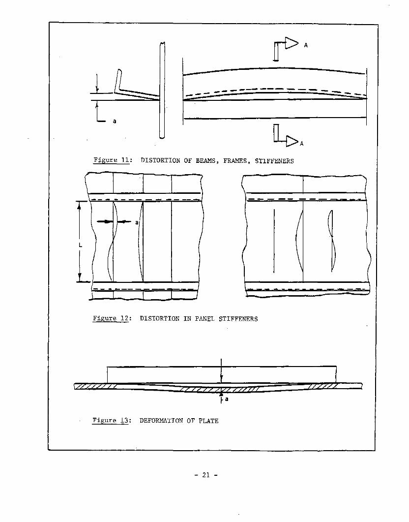
Some commonly encountered structural deficiencies are illustrated inFigures 4 through 13 which should assist inspectors in identifying them duringsurveys:
o00000000
Misalignment, Figs. 4 and 5excessive gap between members, Fig. 6stiffener tilt, Fig. 7improper distance between adjacent welds, Figs. 8, 9, 10weld flaws,weld undercutdistortion, Fig. 11, 12deformation of plate, Fig. 13cracks, dents, and other damage
4.3.5 Recording/Reporting/Evaluation Procedures
a. Documentation of Inspection Activities
Appropriate forms should be developed or adopted from similar forms used byothers for requesting, recording, reporting for corrective action, analyzing,and processing structural inspections and NDE examinations. Forms developed andused by one shipyard may be different from others to reflect differences in thequality control organization.
-17-

BHD
- t-
a Deck
~ 1
TBHD
I~
Figure 4: BULKHEAD MISALIGNMENT
Figure 5: MISALIGNMENT OF BUTT CONNECTIONS
-18-

cl-
r a
t--c+
l-i
Figure 6: EXCESSIVE GAPS BETWEEN MEMBERS
-19-

,. —..
Figure 7: STIFFENER TILT
Figure 9: DISTANCE BETWEEN
ADJACENT BUTT WELDS
.—.~x~
\ \
/ ~ &\
I[ (}
Figure 8: DISTANCE BETWEEN
BUTT WELD AND
SCALLOP
Figure 10: DISTANCE BETWEEN
BUTT WELD AND
l?ILLETWELD
_20-
b
IF’A
—.. — —___----_e - --_e
1
I-1I
b A
Figure 11”: DISTORTION OF BEAMS,
---- .--— -.
r’\-;-‘a
L
Li ( 1
1---—FWS, STIFFENERS
+-+---+
—.—— -———
Figure 12: DISTORTION IN PANEL STIFFENERS
I1 I
-21-

b. Dissemination of Inspection Results
Findings from inspection activities, as they relate to specific parts ofthe ship’s structure, should be recorded on appropriate forms and maintained inthe ship’s inspection file. Applicable forms should be distributed to theproper departments in the yard, to owner’s resident inspectors, and to ABSsurveyors for review and execution or approval of the recommended correctiveaction.
Specifically important, from the standpoint of product liability, is thefeedback of. inspection results to the structural designer. By being aware ofthe deficiencies found and the corrective actions accomplished on the structurehe has designed, the designer can analyze the causes and consequences of thedeficiency, decide whether the corrective action was sufficient, and determineif the original design should be modified to prevent recurrence of similiardeficiencies in follow-on constructions.
reps”ship
pref[
Maintaining brief but clear records of all structural deficiencies andrs will enable the shipyard to determine the “as-built” condition of thehull girder and the elements thereof.
It is also desirable to have all inspection results statistically analyzed,rably by computerized techniques, for the purpose of measuring the level of
efficiency obtained in structural workmanship.
4.3.6 Development of “Structure Condition Record”
A thorough review and analysis of all structural inspection reports anddeficiency/corrective action records will enable the shipyard to prepare astructural “history” of the ship’s construction and the condition of itsstructure as built. It will be possible to record:
o all structure that was inspected and found to be within acceptabletolerances;
o the actual “accepted” tolerances (or deviations from standard) for suchstructures;
o structures found to have deviations larger than allowable levels butjointly accepted by yard/owner/classification society inspectors as notrequiring corrective action;
o the extent of actual deviations for such structures or structuralelements; structures found to have unacceptable deviations and repairedusing standard corrective action procedures;
o the “as corrected” remaining deviations, if any, on such structures;
o structures found to have unacceptably large deviations for which theoriginal design had to be modified to avoid recurrences of deficiencies;
o the modified structural design for such members, parts;
-22-

o the “as modified” remaining deviations, if any, on such structures.
The information listed above should be compiled into a complete reportwhich may be labelled “Structure Condition Record” for use as a reference basisthroughout the ship’s service life.
4.3.7 Preparation of “In-Service Inspection Program”
Towards the end of a ship’s construction period, the “Design InspectionPlan”, the “Construction Inspection Program”, and the “Structure ConditionRecord” should all be reviewed again and a new updated document which may belabelled “In-Service Inspection Program” should be prepared for structuralinspections to be performed during the vessel’s operating life. This documentshould reconcile the three aforementioned documents and include the following:
o identification of critically stressed areas as determined in the “designinspection plan”;
o any changes to critical stress areas due to built-in materialdeficiencies or accepted fabrication errors during the construction pro-cess;
o other significant areas for inspection not due to design allowance butdue solely to material and/or fabrication errors during construction;
o an “inspection checklist” prepared on the basis of the above whichidentifies all structures to be subjected to in-service inspections;
The “inspection checklist” should include:
o inspection frequencies,
o methods and procedures for inspections,
o tools and equipment to be used,
o responsibilities for performance of inspections (i.e. whether to beconducted by the ship’s crew while vessel is in service or by a shipyardcrew while afloat or by the yard crew during drydocking, etc.).
4.4 In-Service Inspections
4.4.1 General
The condition of the ship’s structure should be kept under constantsurveillance by continuous and periodical inspections throughout its operatinglife in accordance with the “In-Service Inspection Program” prepared duringfinal stages of the construction period.
The continuous inspections, obviously, can only be provided by the ship’screw while the vessel is in operation. Some of the periodical inspections maybe performed by the ship’s crew as well, but some others would requirepreparations beyond crew capabilities.
-23-

4.4.2 Crew Inspections
In general, the ship’s crew will have ample opportunity to inspect thestructure while at sea. These inspections may reveal deterioration or damage toparts of structure which may be repaired by the crew or more detailed inspectionand repair, possible in a shipyard, may be requested. In some cases, parts ofthe ship’s structure may be uninspectable by crew while at sea since thestructure may be inaccessible due to existence of fuel, water, cargo,insulation, etc. in the spaces to be inspected. In such cases too, the crewwould request yard inspections.
Crew inspections, when possible, can accomplish the following:
o detect and repair minor damage and deterioration,
o obtain an early warning of major structural problems,
o keep corrosion control systems (if such are installed) undersurveillance,
o identify areas for detailed surveys and prepare planning and budgets forshipyard availability,
o by doing all of the above, reduce overall survey and repair costs.
The “In-Service Inspection Program” prepared during the construction periodwill have identified those structural elements and details that the crew shouldperform continuous inspections for. It will have also flagged those structureswhich are considered significant due to design features or fabrication history(i.e. built-in material /fabrication/workmanship variations).
Some of the typical structural deficiencies that crew can detect are:
o Scale formation on plates and shapes
o Pitting
o Localized wastage
o Resultant loss of thickness
o Wastage of zinc anodes in tanks (if used)
o Condition of coatings
o Buckling in structural members
o Fractures, cracks
o Other obvious damage such as dents, etc.
-24-

In addition to main structural elements, inspections should also covermiscellaneous structures such as handrails, ladders, platforms, valve reachrods, etc.
Main structural members inspected by the crew, to the extent possible,should include deck plating, underdeck girders and longitudinal, side shellplating and framing, transverse and longitudinal bulkheads with theirstiffeners, and stringer platforms, if any.
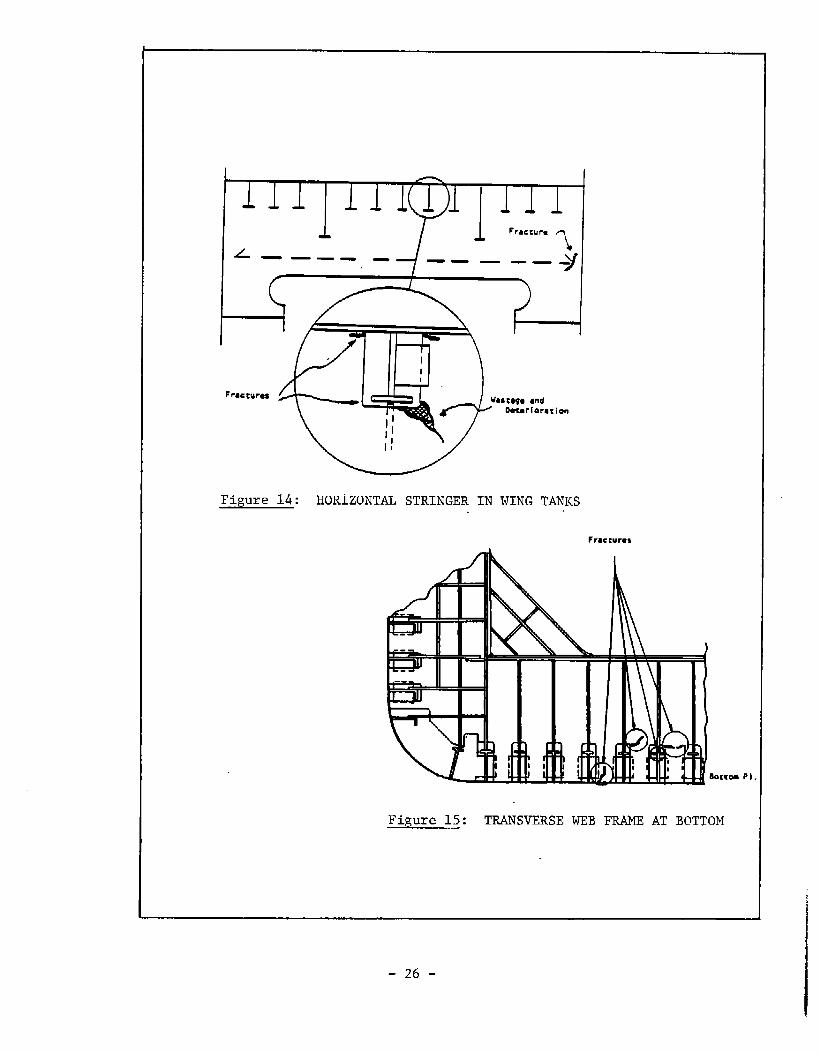
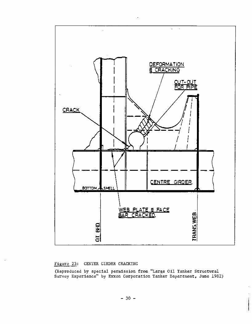
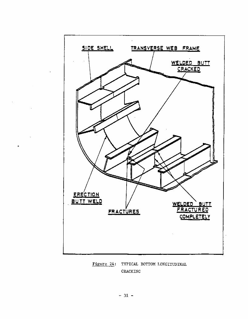
Figures 14 through 24 show some typical structural deficiencies (fractures,buckling, deterioration) that can be detected by crew inspections. Thesesketches are applicable to the design of a tanker; similar sketches should bedeveloped for the specific ship to be inspected and included in the “In-ServiceInspection Program”.
4.4.3 Periodic Inspection by Classification Societies
The classification societies, e.g. the American Bureau of Shipping forvessels being built for U.S. owners in U.S. shipyards, conduct their owninspections by resident surveyors during the vessel’s construction period.,These inspections are made for the purpose of assuring the vessel’s structuralintegrity and its compliance with ABS Rules from the standpoint of meetingminimum classification requirements. At the end of the construction period,resident ABS surveyors prepare and submit to the ABS Head Office a “NewConstruction Hull Report”.
In order to keep the vessel in class during its service life and to ensurethat it is in compliance with USCG regulations, ABS and the U.S. Coast Guardperform periodic inspections of structure, as well as of machinery and allequipment, in accordance with well established procedures and frequencies.These procedures and frequencies are described in detail in the ABS Rules (10)as applicable to vessels of varying types, and are regulated by a U.S. CoastGuard Navigation and Vessel Inspection Circular (13).
ABS makes available to its resident surveyors a “Survey Status” report ofthe vessel to be inspected prior to initiation of in-service inspections. Thisreport will contain, if applicable, instructions for specific structures to beinspected on the basis of “circular letters” promulgated earlier by analyzingresults from actual inspections.
4.4.4 Repair and Conversion Inspections
The procedures to be followed in performing structural inspections for andduring major repairs and overhaul availabilities are, essentially, combinationsof “construction” and “in-service” inspection procedures. The repairs to anystructure due to damage or deterioration should follow the recommended repairprocedures contained in the “In-Service Inspection Program”. If however thedamage is so extensive that it requires removal of the existing structure andrenewal with new materials, then in the fabrication of new structures the“Construction Inspection Program” requirements should be observed.
When alterations are to be made to the existing structure as necessitatedby a conversion desiqn, the areas to be modified should be structurallyi~spected in accordanc~ with “in-service” inspection requirementsconstructed parts or additional structures should be inspectedwith “new construction” requirements.
-25-
and the newlyin accordance
L ——. —— ———
/’ I
I
II
I
Figure 14: HORIZONTAL STRINGER IN WING TANKS
Fracturms
Figure 15: TRANSVERSE WEB FRAME AT BOTTOM
-26-

51de Shell
Figure 16: TRANSVERSE WEB
FRAME AT SICE
SHELL
IEqLong’ I
hccur,
~ P.-----------
Fimre 18:
COMBINED PROGRESSIVE
SHELL PLATE AND TMNSVERSE
WEB FIUME FRACTURE
Figure 17: SIDE SHELL
LONGITUDINAL
FRACTURE
I Lonq’1
-27-

‘=rt-’’’’’ffemII I -“’’’””
\
Shall Plstlng
1 IIFigure 19: FRACTURE IN BOTTOM
TRANSVERSE WEB
Figure 20: FRACTURE IN LONGITUDINAL
INTERCOSTAL GIRDER
/-m=AYP III’’’’”*’-’-”-’
Figure 21: BUCKLING OF CENTERLINE
GIRDER
I
28 -

Figure 22: TYPICAL BOTTOM SHELL LOSS PATTEWS
“Large Oil Tanker(Reproduced by special permission fromStructural Survey Experience”Tanker Department, June 1982)
-29-
by Exxon Corporation
. .
DEFORMATIONS CRACKING
I
I
CRACK I
——— —
WF.B PLATE & FA C~BAR CRACKED. m
i!
*
s~~
0’ *
Figure 23: CENTER GIRDER CRACKING
(Reproduced by special permission from “Large Oil Tanker StructuralSurvey Experience” by Exxon Corporation Tanker Department, June 1982)
-30-
SIDE SHELLI
TRANSVERSE WEB FRAhIE
ERECTIONH=D
vFRACTURES
\ELDfED BUTTFRACTURED
COMPLETELY
Figure 24: TYPICAL BOTTOM LONGITUDINAL
CRACKING
-31-

In either case, i.e. both for major structural renewals due to damage ordeterioration and for structural modifications and/or additions as required bythe conversion design, special attention should be paid to the continuity andcompatibility of structures and materials.
4.4.5 Haintaininq and Updatinq the Structure Condition Record
The “Structure Condition Record” (SCR) prepared at the end of theconstruction period should be referred to prior to initiating periodic in-service inspection activities even if the specific requirements from it havealready been incorporated into an “In-Service Inspection Program”. SCR willhave descriptive background information to enable structural inspectors tounderstand better the reasons for any special inspection requirements for anyspecific parts of the structure.
In order that the SCR preserve its usefulness and value to the inspectors,it must be maintained “current” by modifying the existing data or by adding newdata, as applicable, from the results of any in-service inspections and/or anycorrective measures taken on the basis thereof.
-32-

(1)
(2)
(3)
(4)
(5)
(6)
(7)
(8)
(9)
(lo)
(11)
(12)
(13)
Ship Structure Committee Project SR-1289, “Develop a Guide to a CoherentPhilosophy Toward Ship Structural Inspection’’,,3O November 1983.
Jordan, C.R. and Cochran, C.S., “In-Service Performance of StructuralDetails”, SSC-272, 1978.
Liu, Bakker, “Practical Procedures for Technical and EconomicInvestigations of Ship Structural Details”, Marine Technology, January1981.
Basar, N.S. and Stanley, R.F., “Survey of Structural Tolerances in the U.S.Commercial Shipbuilding Industry”, SSC-273, 1978.
“Japanese Shipbuilding Quality Standard (JSQS) - HU1l Part”, SNAJPublication, Tokyo, 1975.
“Fabrication, Welding and Inspection of Ships Hulls”, NAVSHIPS 0900-LP-OOO-1000, Naval Ship Systems Command, 1968.
“lH1 SPAIS - The Shipbuilding Process and Inspection Standard”,Ishikawajima-Harima Heavy Industries Co., Ltd., Japan, 1980.
“Production Standards of the German Shipbuilding Industry”, Association ofGerman Shipbuilding Industry, Hamburg, 1974.
“Accuracy in Hull Construction - VIS 530”, Varvindustrins Standardcentral,Stockholm, 1976.
“Rules for Building and Classing Steel Vessels”, American Bureau ofShipping, New York, 1982.
Youshaw, “A Guide for Ultrasonic Testing and Evaluation of Weld Flaws”,SSC-213, 1970.
“Rules for Non-Destructive Testing of Hull Welds”, American Bureau ofShipping, 1975.
“Navigation and Vessel Inspection Circular No. 10-82”, United States CoastGuard, Washington, D.C., 18 May 1982.
-33-

ACKNOWLEDGEMENT
The authors wish to express gratitude to the members of the ad-hoc projectadvisory committee of the National Research Council for the support and guidanceprovided during the development of this guide.
-34-

SHIP STRUCTURAL INSPECTION
TERMINOLOGY AND ABBREVIATIONS
Standard tolerances and allowable deviationsfrom standards forstructuraldeficienciesobserved.
ABS
American Bureau
“As-Built”Condition
of Shipping
The actualconfigurationof the structurewhen completed.
Accuracy Control
All inspection operations performed in a shipyard with the objective ofmaintaining greatest possible accuracy at each stage of fabrication.
Alignment Checks
Scheduled and random checks on structure to ensure that any two pieces andthe whole assembly or erection is correctly aligned prior to joining.
Annual Survey
Yearly inspections by the classification society for the purpose of renewingthe classificationcertificate.
BendingLoads
Static andlor dynamic forcesbending moments and stresses toelements.
Bucklirw
which act on structural elements and causedevelop through the cross-section of these
Thedeformationofstructuredue to axial compressive loads or stresses.
Brittleness
The behavior of a material whereby it fractures with relatively little or noelongation.
Construction Inspections
Structural inspections conducted on a new ship while under construction.
-35-

Continuous Survey
Spreading of all classification society surveys over a period of four yearsinstead of once in four years.
CriticalNodes/Areas for Ins~ction
Analyses and calculations to determine thestress concentration in the structural configuration.
Corrective Measures
Methods of repair orbeyond allowable limits.
Checkpoints for Inspction
reneva,
weak points or areas of high
to be used in correcting structural deficiencies
A listing of all parts of structure that must be carefully inspected becausethey contribute to the overall longitudinal strength or they are critical stressareas.
Deficiency Report
A form filled out by structural inpectors to record, report, and recommendcorrective action for deficiencies in excess of allowable deviations.
DnV
“Det Norske Veritas”: Norwegian Classification Society.
Design Inspection Plan
A plan prepared during the detail design development stage to establish basicinspection requirements to be met during construction and service.
Final Acceptance Inspection
Joint inspections performed by shipyard, owners, classification society, andregulatory agency inspectors upon completion of block, assembly, unit, or erectionfor the purpose of acceptance.
Finite Element Analysis
The analysis of structures by mathematical idealization of the actualstructure into discrete elements and solving the stiffness matrices for theseelements for various applied loads, usually utilizing computer to perform thecalculation.
F&P
Early fabrication processes in assembling panels, units, or blocks.
-36-

Fabrication Errors
Errors due toetc.
Fabricability
Considerationconstructed.
Guarantee Period
faulty fabrication practices such as poor welds, misalignment,
during design stages of the ease with which a structure can be
A period during which all structure and materials of a delivered ship isguaranteed by the shipyard against errors - usually one year. ●
In-Plane Compression
Elastic deformation of a structural element such that compressive stressesare developed due to in-plane loads.
In-Plane Loads
Tensile, compressive and shear forces which act in a plane perpendicular to astructural elements’ cross-section.
In-Process Inspections
Inspections performed on the structure by the yard’s production and qualityassurance personnel during various phases of the construction process.
Intermediate Survey
Classification society surveys conducted two years after vessel enters serviceand repeated two years after each subsequent special survey.
IH1Japaneseshipyard:l!lShjkaWajimaHarimaHeavyInd@rjeS”
“In-Service”Ins~ction
Inspections performed on the ship’s structure by the crew, classificationsociety and regulatory agency surveyors, and shipyards during its service life.
Z5Qs
“Japanese
31S“Japanese
Shipbuilding Quality Standards.”
Industrial Standards”
-37-

Monitoring, Structural
Surveillance of anmonitoring system.
MT and MPI
offshore platform’s structure by means of an instrumented
Non-destructive testing of metals by means of Magnetic Particle Inspectionequipment.
New Construction Hull Re~rt
A report filed by resident classification society surveyors upon completion ofa newly constructed vessel to reflect the as-built condition and history of its hullstructure.
NDE
Non-restructure examination of metals: equipment and/or techniquesfor.
Normal Loads
Those loads which act on a structure parallel to its cross-section.
Numerically Controlled Bumin&
The process of cutting steel using offset data as input to an automated flamecutting device.
Pre-hwmection
A term used in shipyards to denote all preparations and inspections performedon the structure prior to inviting classification society, regulatory agency, andowners surveyors to inspect the piece.
Or~anization and activities for controlling and assuring the quality and com-pliance ;ith design drawings of all work
Racking Loads
The loads which induce lateralsystem.
Random Ins~ctions
being &rformed by ;he shipyard;
deformation or sidesway in a structural
Inspections performed by structural inspectors and surveyors at random andin addition to the scheduled inspections.
-38-

Rework
Disassembling or dismantling of a unit, block, or assembly to correct adeficiency.
Redundancy
Provision of additional safety in structures by installing more than onemember to share the same loads, by designing joints with longer fatigue lives, or byusing increased factors of safety.
Receipt Inskction
Inspection of steel materialsimperfections and they conform to
at the receivingspecifications.
point to ensure they are free of
Shear
A load or stress which acts parallel to a plane as distinguished from tensile orcompressive loads or stresses that act normal to a plane.
SUPSHIP
U.S. Navy “Supervisor of Shipbuilding”.
SNAME
Society of Naval Architects and Marine Engineers.
SCR
IIStructure Condition Record”
Special Wriodical Survey
Classification Society surveys conducted once every four years for salt waterservice and five years for Great Lakes service.
Survey Status
A report published and distributed to classification society surveyors prior toinitiation of periodical in-service inspections to reflect the background and currentstatus of a specific ship.
SNAJ
Society of Naval Architects of Japan.
Splash Zone
The parts of side shell plating of a floating vessel that are constantly subjectto the effects of wind and waves.
-39-

Safe-Life Design
A design based on the premise that the structure shall not fail, at least interms of failure due to crack initiation or growth, during its lifetime.
%lf-Inspection
Total inspection effort by the production department supervisors in ashipyard to assume that the ship being constructed is of good quality and incompliance with the detailed design drawings.
Stress Concentration
A high localized stress usuallycaused by an abrupt change in the geometry ofthe load path.
Technical Notes
Memoranda published by classification societies for in-house use pointing outto specific structural problems, determined on the basis of field experience, on aspec-ificshipor a class-ofships.”
U!5CG
United StatesCoast Guard
UK
Great Britain
UTS
Non-destructive examination of metals by ultrasonic
Welding Sequence
The correct sequence in which welding operationsavoid distortions and stress concentrations.
test equipment.
should be performed to
WastaRe
The reduction in thickness and deterioration of metals due to corrosioneffects.
Year of Grace Survey
Extension of the four (or five)year special survey period by one year upondetermination of eligibility of the vessel by the classification society.
Yieldin~
The ability of structure to undergo permanent deformation withoutfracturing.
-40-

COMMITTEE ON MARINE STRUCTURESCommission on Engineering and Technical Systems
National Academy of Sciences - National Research Council
The COMMITTEE ON MARINE STRUCTURESinteragency Ship Structure
has technical cognizance of theCommittee’s research program.
Mr. Stanley G. Stiansen, Chairman, Riverhead, NYProf. C. Allin Cornell, Stanford Univesity, Stanford, CAMr. Peter A. Gale, Webb Institute of Naval Architecture, Glen Cove, NYMr. Griff C. Lee, Griff C. Lee, Inc., New Orleans, L4Prof. David L. Olson, Colorado School of Mines, Goldon, COMr. Paul H. Wirsching, University of Arizona, Tucson, AZMr. Alexander B. Stavovy, Staff Officer, National Research Council, Washington, DCCDR Michael K. Parmelee, Secretary, Ship Structure Committee, Washington, DC
LOADS WORK GROUP
Mr. Paul H. Wirsching, Chairman, University of Arizona, Tucson, AZ
Prof. Keith D. Hjelmstad, University of Illinois, Urbana, ILDr. Hsien Yun Jan, President of Martech Inc., Neshanic Station, NJProf. Jack Y. K. Lou ,Texas A & M University, College Station, TXMr. Edward K. Moll, Bath Iron Works Corp., Bath, MAMr. Naresh Maniar, M. Rosenblatt & Son, Inc., New York NYProf. Anastassios N. Perakis, The University of Michiga~, Ann Arbor, MI
MATERIALS WORK GROUP
Prof. David L. Olson, Chairman, Colorado School of Mines, Golden,COProf. William H. Hartt, Vice Chairman, Florida Atlantic University, Boca Raton, FLDr. Santiago Ibarra Jr., Amoco Corporation, Naperville, ILMr. Paul A. Lagace, Massachusetts Institure of Tech., Cambridge, MAMr. Mamdouh M. Salama, Conoco Inc., Ponca City, OKMr. James M. Sawhill, Jr., Newport News Shipbuilding, Newport News, VAMr. Thomas A. Siewert, National Bureau of Standards, Boulder, CO

,
SHIP STRUCTURE COMMITTEE PUBLICATIONS
SSC-320 A Study of Extreme Waves and Their Effects on Shi~Structure by William H. Buckley, 1983
SSC-321 Survey of Ex~erience Usina Reinforced Concrete inFloating Marine Structures by O. H. Burnside and D. J.Pomerening, 1984
SSC-322 Analysis and Assessment of Maior Uncertainties AssociatedWith Ship Hull Ultimate Failure by P. Kaplan, M. Benatar,J. Bentson and T. A. Achtarides, 1984
SSC-323 UPdatinq of Fillet Weld Strenqth Parameters forcommercial ShiDbuildinq by R. P. Krumpen, Jr., and C. R.
Jordan, 1984 ~
SSC-324 Analytical Techniques for Predicting Grounded ShipRes~onse by J. D. Porricelli and J. H. Boyd, 1984
SSC-325 Correlation of Theoretical and Measured HydrodynamicPressures for the SL-7 Containershi~ and the Great LakesBulk Carrier S. J. Cort by H. H. Chen, Y. S. Shin & I. S.Aulakh, 1984
SSC-326 Lonq-Term Corrosion Fatiaue of Welded Marine Steels byO. H. Burnside, S. J. Hudakr E. Oelkers, K. B. Chan, andR. J. Dexter, 1984
SSC-327 Investigation of Steels for Im~roved Weldability in Shi~cOllStruCtiori by L. J. cuddyr J. S. Lally and L. F. porter
1985
SSC-328 Fracture Control for Fixed Offshore Structures by P. M.Besuner, K. Ortiz, J. M. Thomas and S. D. Adams 1985
SSC-329 Ice Loads and ShiD ResDonse to Ice by J. W. St. John,C. Daley, and H. BIOunt, 1985
SSC-330 Practical Guide for Shi~board Vibration Control by E. F.Noonan, G. P. Antonides and W. A. Woods, 1985
SSC-331 Desian Guide for Ship Structural Details by C. R. Jordanand R. P. Krumpen, Jr., 1985
SSC-332 Guide for Ship Structural Inspections by Nedret S. Basar& Victor W. Jovino, 1985
None Shi~ Structure Committee Publications – A Special
Biblio~raphy, AD-A140339