Embed Size (px)
Citation preview

SS521-AK-HBK-010
REVISION (-)
CLEANING AND GAS ANALYSIS FOR DIVING APPLICATIONS HANDBOOK
DISTRIBUTION STATEMENT A. APPROVED FOR PUBLIC RELEASE:
DISTRIBUTION IS UNLIMITED PUBLISHED BY DIRECTION OF COMMANDER, NAVAL SEA SYSTEMS COMMAND 0910-LP-103-1065 9 November 2005
Downloaded from http://www.everyspec.com

Downloaded from http://www.everyspec.com

NAVSEA SS521-AK-HBK-010
LIST OF EFFECTIVE PAGES
Dates of issue for original and changed pages are: Original......................................................................................................................... 9 Nov 2005 Page Number Change Number Title Page.....................................................................................................0 i through xiii..................................................................................................0 1–1 through 1-21..........................................................................................0 2–1 through 2-3............................................................................................0 3-1 through 3-5 ............................................................................................0 4-1 through 4-13 ..........................................................................................0 5-1 through 5-10 ..........................................................................................0 6-1 through 6-2 ............................................................................................0 7-1 through 7-4 ............................................................................................0 8-1 through 8-26 ..........................................................................................0 9-1 through 9-7 ............................................................................................0 10-1 through 10-8 ........................................................................................0 11-1 through 11-22 ......................................................................................0 A-1 through A-7............................................................................................0
i
Downloaded from http://www.everyspec.com

NAVSEA SS521-AK-HBK-010
RECORD OF CHANGES
CHANGE NO. DATE TITLE OR BRIEF DESCRIPTION ENTERED BY
ii
Downloaded from http://www.everyspec.com

NAVSEA SS521-AK-HBK-010
iii
Downloaded from http://www.everyspec.com

NAVSEA SS521-AK-HBK-010
TABLE OF CONTENTS Page
PREFACE .................................................................................................................................... xiLIST OF DOCUMENTS ..............................................................................................................xiii KEY TO ABBREVIATIONS........................................................................................................ xivMANUAL CHANGE REQUEST FORM....................................................................................... xv 1 CLEANING REQUIREMENTS.............................................................................................1-1 1.1 Cleaning processes.......................................................................................................1-1 1.1.1 Toxicity and flammability hazards ..............................................................................1-1 1.1.2 Applicability of cleaning instructions...........................................................................1-3 1.2 Comparison of cleaning processes ...............................................................................1-4 1.2.1 Facility or environment ...............................................................................................1-4 1.2.2 Process verification ....................................................................................................1-4 1.2.3 Documentation or Objective Quality Evidence (OQE) ...............................................1-4 1.2.4 Process validation......................................................................................................1-5 1.2.5 Personnel qualification ...............................................................................................1-5 1.3 Maintaining cleanliness ...............................................................................................1-11 1.3.1 System entry requirements for maintaining cleanliness...........................................1-11 1.3.2 Loss of cleanliness...................................................................................................1-12 1.4 Acceptance of parts cleaned by another facility..........................................................1-12 1.4.1 Requirements to accept cleaned item......................................................................1-12 1.4.2 Additional actions .....................................................................................................1-13 1.5 Special cleaning processes.........................................................................................1-13 1.6 Particle counts.............................................................................................................1-16 1.6.1 Procedures for taking particle counts.......................................................................1-16 1.6.2 Analysis for particle count ........................................................................................1-17 1.6.3 Acceptance criteria for particle count .......................................................................1-18 1.7 Disinfecting..................................................................................................................1-18 1.8 Verification of solvent removal for instruments ...........................................................1-19 1.9 Assessing contamination ............................................................................................1-20 1.9.1 Gas samples ............................................................................................................1-20 1.9.2 Previously painted diving air flasks ..........................................................................1-20 1.9.3 Evaluation of flasks in contaminated systems..........................................................1-20 1.9.4 Corroded flasks ........................................................................................................1-21 2 CLEANLINESS OF MANNED SPACES ..............................................................................2-1 2.1 Cleaning manned space ...............................................................................................2-1 2.1.1 Cleaning.....................................................................................................................2-1 2.1.2 Inspection...................................................................................................................2-1 2.2 Initial certification of manned space ..............................................................................2-1 2.3 Maintaining cleanliness of manned space ....................................................................2-1 2.3.1 Personnel entry requirements ....................................................................................2-2 2.3.2 Material, tools, and equipment ...................................................................................2-2 2.3.3 Maintaining cleanliness while accomplishing work ....................................................2-2 2.3.4 Maintaining cleanliness while diving ..........................................................................2-3 2.4 Maintaining certification of manned space....................................................................2-3
iv
Downloaded from http://www.everyspec.com

NAVSEA SS521-AK-HBK-010
3 MOISTURE MEASUREMENTS...........................................................................................3-1 3.1 Moisture levels and their significance ...........................................................................3-1 3.1.1 Dew point temperature and parts per million (ppm) ...................................................3-1 3.1.2 Converting dew point temperature measurements to parts per million (ppm) ...........3-1 3.1.3 Pressure.....................................................................................................................3-1 3.1.4 Type of gas ................................................................................................................3-1 3.1.5 Significance of moisture levels...................................................................................3-2 3.1.6 Moisture intrusion from ambient air when opening systems ......................................3-2 3.2 Moisture level requirements ..........................................................................................3-3 3.2.1 System .......................................................................................................................3-4 3.2.2 Flask...........................................................................................................................3-4 3.2.3 Component with inaccessible area ............................................................................3-4 3.2.4 Hose...........................................................................................................................3-4 3.3 Techniques for drying and measuring moisture levels..................................................3-4 3.3.1 Blow down..................................................................................................................3-4 3.3.2 Evaporation ................................................................................................................3-5 3.3.3 Piping and hoses supplying drying gas......................................................................3-5 3.3.4 Dew point temperature measuring equipment ...........................................................3-5 3.3.5 Pressure and volume .................................................................................................3-5 3.3.6 Hold duration..............................................................................................................3-5 4 THEORY FOR GAS ANALYSIS ..........................................................................................4-1 4.1 Definitions .....................................................................................................................4-1 4.1.1 Laboratory analysis limits...........................................................................................4-1 4.1.2 Parts per million (ppm) ...............................................................................................4-1 4.1.3 Depth and pressure conversions ...............................................................................4-2 4.1.4 Pressure ratio.............................................................................................................4-2 4.1.5 Surface equivalent value............................................................................................4-3 4.1.6 Surface equivalent limit ..............................................................................................4-3 4.1.7 Concentration and partial pressure ............................................................................4-3 4.2 Application and values for pressure ratio ......................................................................4-4 4.2.1 Increase pressure of space by reducing floodable volume ........................................4-7 4.2.2 Increase pressure of space by adding gas with same constituent.............................4-8 4.2.3 Increase pressure of space by adding clean gas.......................................................4-9 4.2.4 Detectors (other methods) .......................................................................................4-10 4.2.5 Bulk gas ...................................................................................................................4-10 4.2.6 Storage system ........................................................................................................4-10 4.2.7 Non-storage system.................................................................................................4-10 4.3 Calculations.................................................................................................................4-11 4.3.1 Combining gases at different ppm levels .................................................................4-11 4.3.2 Combining chamber and bulk gas............................................................................4-12 5 DETERMINING GAS ANALYSIS REQUIREMENTS...........................................................5-1 5.1 Sources of contamination..............................................................................................5-1 5.1.1 Personnel ...................................................................................................................5-1 5.1.2 Breathing gas.............................................................................................................5-1 5.1.3 Materials.....................................................................................................................5-1
v
Downloaded from http://www.everyspec.com

NAVSEA SS521-AK-HBK-010
5.2 Gas analysis requirements for bulk gas ........................................................................5-1 5.2.1 Purchased gas ...........................................................................................................5-1 5.2.2 Blended gases ...........................................................................................................5-1 5.2.3 Non-purchased air......................................................................................................5-2 5.3 Gas analysis requirements for the system....................................................................5-2 5.3.1 List of constituents for system sample .......................................................................5-5 5.3.2 Preparation of system for gas sample........................................................................5-5 5.3.3 Sampling small volumes ............................................................................................5-5 5.4 Gas analysis requirements for the space......................................................................5-7 5.4.1 List of constituents for space sample .........................................................................5-7 5.4.2 Ventilation and pressurization of space for sample....................................................5-7 5.4.3 Other requirements to prepare space ......................................................................5-10 5.4.4 Ordnance (explosives) installed in space.................................................................5-10 5.5 Developing customized list of constituents .................................................................5-10 5.6 Analysis for all constituents.........................................................................................5-10 6 GAS ANALYSIS LABORATORY .........................................................................................6-1 6.1 Choosing a gas analysis laboratory ..............................................................................6-1 6.1.1 Previously accepted laboratory ..................................................................................6-1 6.1.2 Qualifying new laboratory...........................................................................................6-1 6.2 Laboratory capabilities ..................................................................................................6-1 6.3 Establishing a contract with the laboratory....................................................................6-1 6.4 Laboratory solicitation ...................................................................................................6-2 7 EQUIPMENT FOR COLLECTING GAS SAMPLES.............................................................7-1 7.1 Equipment for collecting gas samples...........................................................................7-1 7.1.1 Gas sample container ................................................................................................7-1 7.1.2 Gas sample piping assembly .....................................................................................7-1 7.1.3 Gas transfer pump .....................................................................................................7-1 7.2 Portable analyzers and other methods .........................................................................7-3 7.2.1 Other methods ...........................................................................................................7-3 7.2.2 Portable analyzers .....................................................................................................7-3 8 PROCEDURES FOR COLLECTING GAS SAMPLES.........................................................8-1 8.1 Number of gas samples and analysis of backup samples ............................................8-1 8.1.1 Number of samples ....................................................................................................8-1 8.1.2 Backup of samples.....................................................................................................8-1 8.2 Number of pressurization cycles for gas sample container...........................................8-1 8.2.1 Sources of contamination of a gas sample ................................................................8-1 8.2.2 Required number of purge cycles ..............................................................................8-2 8.2.3 Example calculations for number of purge cycles......................................................8-2 8.3 Applicability ...................................................................................................................8-4 8.4 Gas sample ...................................................................................................................8-4 8.4.1 Sample at system connection for system pressure greater than final sample pressure .....................................................................................................................8-4 8.4.2 Sample at system connection for system pressure less than final sample pressure .8-8 8.4.3 Sample of space at pressure of one atmosphere ....................................................8-13 8.4.4 Sample of space at pressure greater than final sample pressure............................8-17
vi
Downloaded from http://www.everyspec.com

NAVSEA SS521-AK-HBK-010
8.4.5 Sample of space at pressure less than final sample pressure.................................8-22 8.5 Other methods or portable analyzer............................................................................8-22 8.5.1 Elevated pressure sampled remotely through system connection...........................8-22 8.5.2 Space or Tedlar sample bag at one atmosphere .....................................................8-25 8.5.3 Space at elevated pressure .....................................................................................8-25 8.6 Portable analyzer ........................................................................................................8-25 8.6.1 Space at one atmosphere ........................................................................................8-25 8.6.2 Space or system at elevated pressure.....................................................................8-26 8.7 Processing gas samples .............................................................................................8-26 8.7.1 Send to laboratory....................................................................................................8-26 8.7.2 Paperwork ................................................................................................................8-26 8.7.3 Evaluation ................................................................................................................8-26 8.7.4 Cleaning gas sample containers ..............................................................................8-26 9 MAINTENANCE OF GAS SAMPLING EQUIPMENT ..........................................................9-1 9.1 Maintenance requirements............................................................................................9-1 9.2 Gas sample piping assembly - sample .........................................................................9-2 9.3 Gas sample container – gas clean and sample ............................................................9-3 9.3.1 Gas clean...................................................................................................................9-3 9.3.2 Gas sample ................................................................................................................9-4 9.4 Gas transfer pump - sample..........................................................................................9-5 10 GAS SAMPLE RESULTS ..................................................................................................10-1 10.1 Evaluation and troubleshooting.................................................................................10-1 10.2 Screening limits and evaluation of non-target compounds .......................................10-1 10.2.1 Screening limits......................................................................................................10-1 10.2.2 Target versus non-target compounds ....................................................................10-1 10.2.3 Reporting non-target compounds...........................................................................10-1 10.2.4 Laboratory accuracy...............................................................................................10-2 10.2.5 Evaluation of non-target compounds .....................................................................10-3 10.2.6 Accurate quantification of non-target compounds..................................................10-3 10.3 Other considerations .................................................................................................10-3 10.3.1 Analysis of backup samples...................................................................................10-3 10.3.2 Qualifying non-metallics .........................................................................................10-3 10.3.3 Replacement or new material ................................................................................10-4 10.3.4 Dual samples .........................................................................................................10-4 10.3.5 Simulated versus actual conditions........................................................................10-4 10.3.5.1 Temperature........................................................................................................10-4 10.3.5.2 Pressure for space..............................................................................................10-5 10.3.5.3 Pressure for system ............................................................................................10-5 10.3.5.4 Hold duration.......................................................................................................10-5 10.3.5.5 Laboratory accuracy............................................................................................10-5 10.3.5.6 Representative sample .......................................................................................10-5 10.3.5.7 Installed and operational items ...........................................................................10-5 10.3.5.8 Carrier gas ..........................................................................................................10-5 10.3.5.9 Preparation for sample........................................................................................10-5 10.3.5.10 Sampling artifact ...............................................................................................10-5 10.4 Report of gas analysis results ...................................................................................10-6
vii
Downloaded from http://www.everyspec.com

NAVSEA SS521-AK-HBK-010
11 OFF-GAS TESTING...........................................................................................................11-1 11.1 When off-gas testing is required ...............................................................................11-1 11.1.1 Testing requirements .............................................................................................11-1 11.1.2 Approved Material ..................................................................................................11-1 11.2 Sample preparation...................................................................................................11-1 11.2.1 Configuration..........................................................................................................11-1 11.2.2 Cleaning.................................................................................................................11-1 11.2.3 Curing.....................................................................................................................11-4 11.2.4 Films and coatings .................................................................................................11-4 11.2.5 Carrier or substrates ..............................................................................................11-4 11.2.6 Three dimensional materials ..................................................................................11-4 11.2.7 Liquids....................................................................................................................11-4 11.2.8 Test chamber .........................................................................................................11-5 11.2.9 Determining amount of sample needed .................................................................11-5 11.2.10 Shipment ..............................................................................................................11-5 11.2.11 List of compounds analyzed for off-gas test.........................................................11-6 11.2.12 Information required for sample ...........................................................................11-6 11.2.13 Where to send sample .........................................................................................11-6 11.3 Off-gas test..............................................................................................................11-10 11.3.1 Procedure.............................................................................................................11-10 11.3.2 Analysis of gas sample ........................................................................................11-11 11.3.3 Test report of results ............................................................................................11-11 11.4 Evaluation of results................................................................................................11-15 11.4.1 Equations to correlate off-gas test results to actual installation ...........................11-15 11.4.2 Basis for equations...............................................................................................11-15 11.4.3 Example of correlating off-gas test results to actual amount ...............................11-19 11.4.4 Combining space and off-gas test results ............................................................11-20 11.4.5 Troubleshooting results........................................................................................11-21 11.4.6 Reporting results ..................................................................................................11-21 11.5 Toxicological/flammability list of materials ..............................................................11-21 11.6 Off-gas testing of ordnance (explosives).................................................................11-22 11.6.1 Submittal of material ............................................................................................11-22 11.6.2 List of compounds analyzed for off-gas test.........................................................11-22 11.7 Flammability testing ................................................................................................11-22 APPENDICES A Moisture Calculations
viii
Downloaded from http://www.everyspec.com

NAVSEA SS521-AK-HBK-010
TABLES Number Title Page 1-1 Applicable cleaning instruction based on toxicity and flammability .................................1-2 1-2 Component Cleaning Requirements for facility, process verification, documentation (OQE), process validation, and personnel qualification .................................................1-6 1-3 Flask Cleaning Requirements for environment, process verification, documentation (OQE) and personnel qualification..........................................................................................1-7 1-4 System Flushing Requirements for environment, process verification, documentation (OQE) and personnel qualification .................................................................................1-8 1-5 Components, systems, and flasks Process verification methods and type of documentation (OQE) ....................................................................................................1-9 1-6 Instrument Cleaning Requirements for facility, process verification, documentation (OQE) and personnel qualification ...............................................................................1-10 1-7 Instruments Process verification methods and type of documentation (OQE) .............1-10 1-8 Requirements for maintaining system cleanliness ........................................................1-12 1-9 Actions to recover from loss of cleanliness ...................................................................1-12 1-10 Actions required to satisfy diving system special cleaning requirements ....................1-13 1-11 Synopsis for other cleaning methods ..........................................................................1-14 1-12 Particle count acceptance criteria successfully used ..................................................1-18 3-1 Conversion from dew point temperature at 1 ata to ppm ................................................3-2 3-2 Moisture level requirements ............................................................................................3-3 4-1 Example and definition of laboratory analysis limits ........................................................4-1 4-2 Pressure ratios for sample of space that can be used at depth of X ata .........................4-5 4-3 Pressure ratios for bulk gas and systems........................................................................4-6 5-1 Commonly used specifications for purchased gas ..........................................................5-2 5-2 Allowable contaminant levels for non-purchased air .......................................................5-3 5-3 When system gas samples are required .........................................................................5-4 5-4 Constituents for system sample ......................................................................................5-6 5-5 Constituents for space sample ........................................................................................5-8 5-6 Establishing baseline atmospheric purity and pressure/hold times for space sample.....5-9 7-1 Compounds analyzed by other methods (gas samples cannot be used)........................7-4 8-1 Sampling procedures.......................................................................................................8-4 9-1 Maintenance requirements ..............................................................................................9-1 10-1 Examples of gas analysis methods .............................................................................10-8 11-1 Non-metallic material qualification and in-kind replacement requirements ..................11-2 11-2 Criteria for calculating amount of sample needed .......................................................11-5 11-3 Examples of target compounds analyzed for off-gas testing of non-metallics.............11-7 11-4 Off-gas testing duration, pressure, and temperature requirements...........................11-10 11-5 Equations to correlate off-gas test results to actual installation.................................11-16 11-6 Test chamber conditions ...........................................................................................11-17
ix
Downloaded from http://www.everyspec.com
NAVSEA SS521-AK-HBK-010
FIGURES Number Title Page 4-1 Pictorial representation of 1000 ppm of a contaminant pressed from 1 ata to 2 ata with gas containing 1000 ppm of same contaminant .....................................................4-3 7-1 Examples of Gas Sampling Setups .................................................................................7-2 8-1 Chart for Example #8.1 showing cylinder vented then filled............................................8-2 8-2 Chart for Example #8.2 showing cylinder in vacuum then filled ......................................8-3 8-3 System sample for system pressure greater than final sample pressure (paragraph 8.4.1) ...........................................................................................................8-7 8-4 System sample for system pressure less than final sample pressure (paragraph 8.4.2) .........................................................................................................8-11 8-5 Space sample at one atmosphere with sample collected in space (paragraph 8.4.3) ..8-16 8-6 Space pressure greater than final sample pressure with sample collected at system connection (paragraph 8.4.4.a, b, and c through p) .....................................................8-20 8-7 Space pressure greater than final sample pressure with sample collected in space (paragraphs 8.4.4.a, b, and q through u) .....................................................................8-21 8-8 Space pressure less than final sample pressure with sample collected at system connection (paragraph 8.4.5) .......................................................................................8-23 10-1 Evaluation of Gas Analysis Results.............................................................................10-7 11-1 Example of Off-Gas Test Request Form .....................................................................11-8 11-2 Example of Off-Gas Test Report ...............................................................................11-13
x
Downloaded from http://www.everyspec.com

NAVSEA SS521-AK-HBK-010
PREFACE To establish and maintain an acceptable atmosphere for diving applications, cleaning, gas analysis, and monitoring are required. The monitoring requirements (e.g., oxygen and carbon dioxide levels, material controls, reentry controls) are addressed in NAVSEA SS800-AG-MAN-010/P-9290 or SS521-AA-MAN-010, as applicable. Cleaning and gas analysis are also addressed in subject manuals, with this manual providing additional guidance and explanations. The Program Manager and System Certification Authority shall use this manual partially or in its entirety for each project. A synopsis of how each section of this manual fits into the goal of establishing and maintaining a safe diving environment is as follows: Chapter 1: Cleaning Requirements. The presence of organic contamination can lead to a fire from adiabatic compression or particle impact and cause toxicity hazards. Thermal decomposition can lead to the formation of highly toxic by-products. Chemical reactions (decomposition) of solvents passing through moderately heated alkali in carbon dioxide removal equipment can form highly toxic compounds. The presence of particulate can lead to a fire or equipment failure from fouling or wear. Use of the wrong cleaning agent can cause flammability and toxicity hazards. The presence of microorganisms can lead to a biological hazard causing illness. Chapter 1 summarizes the cleaning processes for the diving systems that carry the gas. These cleaning processes have been developed to ensure that the above risk factors are adequately mitigated. Chapter 2: Cleanliness of Manned Spaces. Naturally occurring soils, such as soils from food, occupants, and equipment during operation and maintenance can increase to a level that could contaminate the atmosphere. This is mitigated by operating procedures and in-place controls. During an industrial availability, these procedures and controls may not exist, resulting in an increased risk of contamination. To mitigate this risk, Chapter 2 addresses requirements for cleaning a manned space (i.e., a chamber), and provides controls needed for personnel entry, bringing material, tools, and equipment into the space, and work practices for maintaining cleanliness. Chapter 3: Moisture Measurements. Moisture in piping systems can lead to freezing, and potentially partial or complete blockage with ice, at regulators where temperatures can fall well below 0oF as gas expands. Moisture can also cause corrosion, particularly in flasks. Particulate from corrosion by-products can cause fouling. Freezing or corrosion can lead to component failure. Monitoring or evaluation of moisture in diving systems is sometimes accomplished by taking moisture measurements. Chapter 3 addresses the allowable moisture levels for diving systems, along with techniques for properly measuring moisture levels. Chapter 4: Theory for Gas Analysis. Gas is analyzed at one atmosphere by the gas analysis laboratory. When breathing at depths above one atmosphere, corrections need to be made to the analysis results. Chapter 4 presents gas analysis terminology and explains how and when this correction applies. It also provides theory and calculations for combining gas analysis results.
xi
Downloaded from http://www.everyspec.com

NAVSEA SS521-AK-HBK-010
Chapter 5. Determining Gas Analysis Requirements. The gas analysis requirements depend on the application, potential sources of contaminants, and the item being sampled. Chapter 5 provides the gas analysis requirements for various applications, including approved lists for some applications, along with the rationale for developing requirements for other applications. Chapter 6. Gas Analysis Laboratory. The NAVSEA Program Manager and System Certification Authority must accept laboratories that perform gas analysis. Chapter 6 identifies accepted laboratories and provides guidance on determining laboratory capabilities for establishing a contract or solicitation. Chapter 7. Equipment for Collecting Gas Samples. Typically, gas samples are collected in containers and analyzed by a gas analysis laboratory or samples are analyzed on-site using a portable analyzer or other method. Chapter 7 provides guidance for selection of this equipment. Chapter 8. Procedures for Collecting Gas Samples. Gas samples are collected from spaces or systems at one atmosphere or elevated pressures. The amount of gas needed for the sample and the pressurization cycles for the gas sample container need to be determined and incorporated into the sampling procedure. The method for determining this is provided in Chapter 8, along with procedures for collecting samples in a container for analysis by a laboratory or for on-site analysis using a portable analyzer or other methods. Chapter 9. Maintenance of Gas Analysis Equipment. The equipment used to collect gas samples requires cleaning and gas analysis to ensure that it does not contaminate the gas sample causing erroneous results. Chapter 9 provides the cleaning and gas analysis requirements for this equipment. Chapter 10. Gas Sample Results. Before a system can be used, the gas sample must be evaluated to determine if it is acceptable. Chapter 10 explains how to evaluate results and provides suggested corrective actions if results are not acceptable. Chapter 11. Off-Gas Testing. Non-metallic materials can off-gas and introduce a variety of contaminants. This is the most difficult toxicological hazard to control. All non-metallic material should be off-gas tested and a list maintained to control this hazard. Chapter 11 explains when off-gas testing is required, what constituents need to be analyzed, how to prepare sample for analysis, where to send the samples for analysis, how to interpret the analysis results, and reporting requirements. Appendix A. Moisture Calculations. Appendix A provides calculations supporting information in Chapter 3. These calculations provide theory and examples for performing moisture calculations for different gases at elevated pressures.
xii
Downloaded from http://www.everyspec.com

NAVSEA SS521-AK-HBK-010
LIST OF DOCUMENTS The title is given below for each document specified in this manual. Military Specifications: A-A-59155: Nitrogen, High Purity, Special Purpose BB-A-1034: Compressed Air, Breathing BB-N-411: Nitrogen, Technical MIL-PRF-27210: Oxygen, Aviator’s Breathing, Liquid and Gas MIL-PRF-27407: Propellant Pressurizing Agent, Helium MIL-STD-1246: Product Cleanliness Levels and Contamination Control Program MIL-STD-1330: Standard Practice for Precision Cleaning and Testing of Shipboard Oxygen,
Helium, Helium-Oxygen, Nitrogen, and Hydrogen Systems MIL-STD-1622: Cleaning of Shipboard Compressed Air Systems NAVSEA Publications: NAVSEAINST 9300.11: Gas Analysis Laboratory Assessment Program NAVSEA S9086-H7-STM-010/CH-262: Lubricating Oils, Greases, Specialty Lubricants, and
Lubrication Systems NAVSEA S9086-SY-STM-010/CH-551: Compressed Air Plants and Systems NAVSEA S9510-AB-ATM-010: Technical Manual for Nuclear Powered Submarine
Atmosphere Control Manual NAVSEA SS521-AA-MAN-010: U.S. Navy Diving and Manned Hyperbaric Systems Safety
Certification Manual NAVSEA SS521-AG-PRO-010: U.S. Navy Diving Manual – Vol I NAVSEA SS800-AG-MAN-010/P-9290: System Certification Procedures and Criteria Manual
for Deep Submergence Systems NAVSEA ST700-F1-PRO-010: Instrument and Gage Cleaning for MIL-STD-1330
Applications; Procedures Manual Topside Tech Notes, Vol 6: Diver Life Support System Cleaning American Society for Testing and Materials (ASTM) ASTM D1292: Standard Test Method for Odor in Water ASTM G63: Standard Guide for Evaluating Nonmetallic Materials for Oxygen Service ASTM G88: Standard Guide for Designing Systems for Oxygen Service ASTM G94: Standard Guide for Evaluating Metals for Oxygen Service Compressed Gas Association (CGA) CGA G-10.1: Commodity Specification for Nitrogen Institute Of Environmental Sciences And Technology IEST-STD-CC1246D: Product Cleanliness Levels and Contamination Control Program Uniform Industrial Process Instructions UIPI 5510-905: Divers Breathing Air System; Clean, Inspect & Test UIPI 5530-901: Oxygen Systems and Associated Piping; Protecting Cleaning and Testing
xiii
Downloaded from http://www.everyspec.com

NAVSEA SS521-AK-HBK-010
KEY TO ABBREVIATIONS Abbreviations used throughout this handbook are given below. Nomenclature listed in Appendix
and Table 11-5 is not repeated here. A ACGIH - American Conference of Governmental Industrial Hygienists ADS – Atmospheric Diving System ASDS - Advanced Seal Delivery System ASTM – American Society for Testing and Materials ata - atmospheres absolute CAMS - Central Atmosphere Monitoring System CSS – Coastal System Station CTFE -chlorotrifluoroethylene DDS - Dry Deck Shelter DSS - Deep Submergence System FID - Flame Ionization Detector ffw - feet of fresh water fsw - feet of sea water GC - Gas Chromatograph GC/MS – Gas Chromatograph/Mass Spectrometer heliox - helium-oxygen IR - Infrared Spectrophotometer ISO – International Standard LCM – Life Cycle Manager LDL - Laboratory Detection Limit LOC – Lock-Out Chamber LPT – Logistic Plug Trunk LSS - Life Support System LRL - Laboratory Reporting Limit MS - Mass Spectrometer NAVSEA - Naval Sea Systems Command NID - Non-Ionic Detergent NIOSH - National Institute for Occupational Safety and Health nitrox - Nitrogen-oxygen NOC - Navy Oxygen Cleaner NVR - Non-volatile Residue OQE - Objective Quality Evidence OSHA - Occupational Safety and Health Administration PID - Photo-Ionization Detector PMS – Planned Maintenance System ppm - Parts per Million PQL - Practical Quantification Limit PTFE - Polytetrafluoroethylene RDL - Required Detection Limit SEL - Surface Equivalent Limit SEV - Surface Equivalent Value TA – Technical Authority TSP - Trisodium Phosphate TWA – Time-Weighted Average UV - Ultraviolet
xiv
Downloaded from http://www.everyspec.com

NAVSEA SS521-AK-HBK-010
NAVSEA SS521-AK-HBK-010 MANUAL CHANGE REQUEST (MCR) FORM MANUAL REVISION/CHANGE AGAINST WHICH RECOMMENDED CHANGE IS WRITTEN: PRIMARY MANUAL CHAPTER/SECTION/PARAGRAPH IMPACTED BY RECOMMENDED CHANGE:
ORIGINATING ACTIVITY: (ADDRESS)
OTHER MANUAL SECTIONS AFFECTED: POINT OF CONTACT: COMMERCIAL: DSN:
RECOMMENDED CHANGE:
RATIONALE/JUSTIFICATION RELATED DOCUMENTS: (This includes any references or documents which may be affected by recommended change). ORIGINATOR’S SIGNATURE:
DATE:
xv
Downloaded from http://www.everyspec.com

NAVSEA SS521-AK-HBK-010
Note: Fill in your return address in space provided on mailing label printed below, fold on dotted line, staple, and mail.
1st Fold DEPARTMENT OF THE NAVY -----------
POSTAGE AND FEES PAID DEPARTMENT OF THE NAVY DOD-316
----------- OFFICIAL BUSINESS
Department of the Navy Naval Sea Systems Command Attn.: PMS 394E4 1339 Patterson Ave. Stop 8840 Washington Navy Yard DC 20376-8840
2nd Fold
xvi
Downloaded from http://www.everyspec.com

NAVSEA SS521-AK-HBK-010
CHAPTER 1 CLEANING REQUIREMENTS
1.1 CLEANING PROCESSES. Compared to a manned space, systems are at higher pressures, can have higher oxygen levels, and store gas for longer durations. Systems also move gas, increasing the flammability hazard of surface contamination, while manned spaces are essentially static. Different systems can contain different gases (e.g., air, oxygen, nitrogen-oxygen, helium, or helium-oxygen), and can contain different components, each with different hazards. This chapter addresses cleaning processes for diving systems and components where hazards, and thus cleanliness levels, vary for different applications. For these processes, this chapter also summarizes the requirements, provides the basis for differences in the requirements, and places in perspective the relationship between surface cleanliness and gas analysis. For established requirements approved by NAVSEA given in MIL-STD-1330, MIL-STD-1622, and NAVSEA ST700-F1-PRO-010, information in this chapter does not take precedence over any of these documents. Since manned spaces operate at lower oxygen percentages and at static lower pressures than systems, surface contamination poses more of a toxicological hazard than a flammability hazard. Cleanliness and controls necessary to mitigate the toxicological hazard from surface contamination for manned spaces are the same for various applications and are addressed in Chapter 2. 1.1.1 Toxicity and Flammability Hazards. Diving applications require cleaning to mitigate toxicity and flammability hazards. The degree to which these hazards exist dictates the necessary process controls and documentation governed by the cleaning instruction. The toxicity hazard increases with deeper depths (see Chapter 4 for explanation of physiological effects at different depths). The flammability hazard increases with higher oxygen levels and higher pressures. Table 1-1 lists toxicity and flammability hazards for common applications and requisite cleaning processes. The ratings for these hazards are not intended as accurate hazard risk assessments of the systems. Their purpose is to establish comparative risks for the various applications in order to select the appropriate cleaning process. The basis for the ratings is as follows: a. Air and Nitrox: Diving with air or nitrox is depth (partial pressure) and duration limited, and
therefore has a low toxicity hazard compared to helium and helium-oxygen. Air systems generally have a low flammability hazard because of the low oxygen percentage. However, there is still a flammability hazard, particularly for high-pressure oil-lubricated compressors. Generally these fires will not breech the pressure boundary because of the thick walled welded piping combined with the slow burn rate. With the incomplete combustion, the very toxic by-products could reach the diver. For nitrox, with oxygen percentages from 25 to 40%, there is an increased flammability hazard compared to air, but not near the risk associated with oxygen.
b. Oxygen: For oxygen levels greater than 50%, the primary concern is flammability. The
toxicity hazard is low because oxygen applications are depth (partial pressure) and duration limited. During an oxygen fire, the pressure boundary is usually penetrated because the burn rate is high. Unlike a fire in an air system, the burn rate and temperature are so high in an oxygen system that complete combustion occurs. That, combined with the loss of the
1-1
Downloaded from http://www.everyspec.com

NAVSEA SS521-AK-HBK-010
Table 1-1: Applicable cleaning instruction based on toxicity and flammability.
Hazard Applicability (Type of System/Items in System) Toxicity Flammability
Cleaning Instruction 1/
Special Requirements
Air: Piping, flasks, and components other than instruments Low Low MIL-STD-1622,
Critical
Nitrox: Piping, flasks, and components other than instruments Low Medium MIL-STD-1330,
nitrox
Oxygen: Piping flasks and components other than instruments Low High MIL-STD-1330,
general
Helium and heliox (<25% oxygen): Piping, flasks, and components other than instruments
High Low MIL-STD-1330, general
Heliox (>25% oxygen): Piping, flasks, and components other than instruments
High Medium MIL-STD-1330, general
Exhaust for <25% oxygen (e.g., decompression/ recompression chamber exhaust): All items
Low Low
MIL-STD-1622, Critical
Exhaust for >25% (e.g., Built-in-breathing system (BIBS) exhaust for oxygen or 60/40 heliox mix): All items
Low High
MIL-STD-1330, general
Life Support for air: All items Low Low MIL-STD-1622, Critical
Life Support for nitrox diving: All items Low Medium MIL-STD-1330,
nitrox Life Support for heliox diving: All items High Low-Medium MIL-STD-1330,
general
Dew point temperature – see paragraph 3.2 of this manual.
All systems: Diving helmets and masks Low Low
See Table 1-11 of this manual
Disinfect per paragraph 1.7 of this manual
Air: Instruments (e.g., gages and transducers) High Medium MIL-STD-1622,
Appendix C
Helium, heliox, nitrox, and oxygen: Instruments (e.g., gages and transducers) High Medium-high
NAVSEA ST700-F1-PRO-010
See paragraph 1.8 of this manual for verifying solvent removal.
All systems: Very delicate components Various Various
MIL-STD-1330, critical
See paragraph 1.6 of this manual for performing particle counts.
1/ Additional requirements from other governing documents may apply. For cleaning addressed by NAVSEA approved PMS, the PMS takes precedence. For examples of detailed cleaning procedures, see UIPI 5530-901 for MIL-STD-1330 applications and UIPI 5510-905 for diving air applications (MIL-STD-1622 critical).
1-2
Downloaded from http://www.everyspec.com

NAVSEA SS521-AK-HBK-010
pressure boundary, the combustion by-products rarely affect the diver. However, elevated temperatures can cause decomposition into toxicologically hazardous compounds that won’t exist at normal operating temperatures.
c. Helium and Heliox (<25% oxygen): These applications have a low oxygen percentage and
are at deep depths for extended durations, so the primary concern is toxicity. d. Heliox (>25% oxygen): With oxygen percentages as high as 60%, the flammability hazard is
comparable to nitrox. The deep depths for extended durations pose a high toxicological hazard.
e. Exhaust: Exhaust systems transfer expended gas or gas from depressurizing a chamber.
The toxicity hazard is low because it is exhausting gas, not supplying gas. The flammability hazard varies depending on the oxygen levels for the exhausted gas as shown in Table 1-1.
f. Life Support: Life support systems are systems other than breathing gas systems (e.g., air,
oxygen, helium, heliox, and nitrox) that process gas from a chamber that can be breathed (e.g., circulation piping for scrubbers and piping supplying gas from a chamber to a diver). Decomposition of solvents passing through moderately heated alkali in carbon dioxide removal equipment and forming highly toxic compounds does not affect the risk from the cleaning standpoint. This is because residue from these solvents is cleaned adequately with any of the cleaning processes. Therefore, the flammability and toxicity hazard is the same as the corresponding breathing gas system as shown in Table 1-1.
g. Diving helmets and masks: These items are wiped down and disinfected after each use as
specified in Table 1-11. h. Instruments (e.g., gages and transducers): The flammability hazard is high for instruments
because most are dead-ended resulting in heating due to adiabatic compression when it gets pressurized. For instance, a rapid increase in pressure from 0 to 3000 psig can generate gas temperatures of well over 1500oF. Whereas components such as umbilicals that get pressurized from 0 to 100 psig will generate gas temperatures under 500oF. The hazard is medium for air systems because of the lower oxygen levels. All other applications are lumped together to simplify the process. The solvents used for cleaning instruments pose a high toxicity hazard.
i. Delicate components: Some diving applications have delicate components that can be
adversely affected by small amounts of particulate. The flammability or toxicity hazard does not dictate the cleaning process for these applications. The most stringent cleaning process, MIL-STD-1330 critical, must be used for these applications to control particulate. These applications are rare and must be identified by NAVSEA. Examples that have required particle counts in the past are: some laminar flow meters, gas mixing consoles for deep diving, and micro metering valves.
1.1.2 Applicability of Cleaning Instructions. The flammability and toxicity hazards dictate the applicable cleaning instructions that are specified in Table 1-1. MIL-STD-1622, general, is for applications with a low flammability and no toxicity hazard. Since all diving applications have a toxicity hazard, it does not apply. All of the instructions control the low toxicity hazard through use of NAVSEA approved final cleaners in an approved process that verifies removal of the cleaners. Flammability is addressed by the cleanliness verification and documentation requirements discussed in paragraph 1.2. Items with a low flammability hazard are cleaned per
1-3
Downloaded from http://www.everyspec.com

NAVSEA SS521-AK-HBK-010
MIL-STD-1622, critical applications. Items with a medium to high flammability hazard are cleaned respectively per MIL-STD-1330, nitrox and general applications. There are two exceptions to these rules. The first is for the high toxicity hazard presented by helium and heliox systems operated at deep depths for long durations, cleanliness becomes an issue, hence the need to clean per MIL-STD-1330, general applications. The other exception is delicate components cleaned per MIL-STD-1330, critical, which has more rigid requirements to control particulate. For instruments, air system instruments are addressed by MIL-STD-1622, Appendix C, and all other diving applications are addressed by NAVSEA ST700-F1-PRO-010. 1.2 COMPARISON OF CLEANING PROCESSES. For MIL-STD-1622 and MIL-STD-1330, the cleaning processes are the same. The facility or environment, process verification, documentation (Objective Quality Evidence – OQE), process validation, and personnel qualification vary depending on the flammability hazard of the item being cleaned. For each of these five areas, as applicable, the requirements for MIL-STD-1622 and MIL-STD-1330 are given for component cleaning, flask cleaning, and system flushing in Tables 1-2, 1-3, and 1-4, respectively. Details for the process verification and documentation requirements are given in Table 1-5. For instruments, the requirements and details are given in Tables 1-6 and 1-7. How each of these areas varies for each cleaning instruction is explained below. 1.2.1 Facility or Environment. During final cleaning and assembly, the facility or environment must be adequately clean to not contaminate the cleaned item. The degree of cleanliness required for the facility or environment corresponds to the cleanliness requirements for the item being cleaned. 1.2.2 Process Verification. After a process step is performed, testing to verify it was successfully accomplished is process verification. Qualitative process verification is subjective, it does not quantify the result, or the quantified result is not accurate. Quantitative verification is a measured value with a reasonable degree of accuracy. For MIL-STD-1622, all process verification is qualitative. The exception is where a qualitative method does not exist. In this case, the process verification is quantitative. For the various MIL-STD-1330 applications (nitrox, general, and critical), the number of items requiring quantitative process verification increases with the cleanliness requirements, with “critical” having the most. 1.2.3 Documentation or Objective Quality Evidence (OQE). The records of successful accomplishment of a cleaning or process verification step are the documentation or Objective Quality Evidence. For MIL-STD-1622, the only documentation is on the cleaning tag for the part that states the date the item was cleaned, the facility performing the cleaning, and the final cleaner used. Cleaning records are not required. Note that logging of the final cleaner used allows the person installing the item to confirm that a NAVSEA approved cleaner was used, which controls the toxicological hazard. For MIL-STD-1330, in addition to the MIL-STD-1622 cleaning tag requirements, traceability from the cleaning tag to the process verification is also required, except that after a part is installed, traceability is no longer required. These documentation and OQE requirements satisfy the cleaning instructions identified in Table 1-1, NAVSEA SS800-AG-MAN-010/P-9290, and NAVSEA SS521-AA-MAN-010.
1-4
Downloaded from http://www.everyspec.com

NAVSEA SS521-AK-HBK-010
1.2.4 Process Validation. For component cleaning per MIL-STD-1330, process validation is performed annually. This validates the pre-clean, final clean, rinse, and dry steps of the process that, unlike other processes (i.e., flask cleaning, system flushing, and instrument cleaning), can vary with the equipment and personnel. Process validation is not required for MIL-STD-1622 component cleaning. 1.2.5 Personnel Qualification. Personnel training is not required for cleaning per MIL-STD-1622 because it has minimal facility or environment cleanliness requirements, and all process verification is qualitative and not logged. Training is required for MIL-STD-1330 and NAVSEA ST700-F1-PRO-010 applications because of the extensive facility or environment requirements, quantitative process verification, and requirements to document results.
1-5
Downloaded from http://www.everyspec.com

NAVSEA SS521-AK-HBK-010
Table 1-2. Component Cleaning: Requirements for facility, process verification,
documentation (OQE), process validation, and personnel qualification.
Requirement MIL-STD-1622, Critical
MIL-STD-1330, Nitrox
MIL-STD-1330, General
MIL-STD-1330, Critical
Precleaning Documentation (OQE) None None None None
Final Cleaning Facility Clean Area Controlled
Area General Clean Room
Class 100,000 Clean Room
Cleanliness Verification Qualitative Qualitative Qualitative and Quantitative
Qualitative and Quantitative
Documentation (OQE) None Required Required Required Rinse
Verification of Rinse Completion
Qualitative Qualitative Qualitative Qualitative
Documentation (OQE) None Required Required Required Verification of Particulate Cleanliness
Qualitative Qualitative Qualitative Quantitative
Documentation (OQE) None Required Required Required Dry Accessible Areas
Verification Qualitative Qualitative Qualitative Qualitative Documentation (OQE) None None None None
Drying Inaccessible Areas Verification Quantitative Quantitative Quantitative Quantitative Documentation (OQE) None Required Required Required
Documentation Tag with Packaging No traceability
to OQE Traceability to OQE
Process Validation Accomplished annually Not
Accomplished Accomplished Accomplished Accomplished
Personnel Qualification Training None Required
1-6
Downloaded from http://www.everyspec.com
NAVSEA SS521-AK-HBK-010
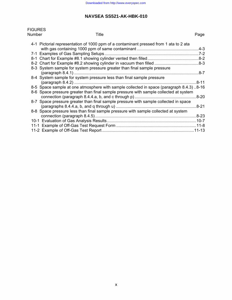
Table 1-3. Flask Cleaning: Requirements for environment, process verification,
documentation (OQE) and personnel qualification.
Requirement MIL-STD-1622, Critical
MIL-STD-1330, Nitrox
MIL-STD-1330, General
MIL-STD-1330, Critical
Precleaning Documentation (OQE) None None None None
Final Cleaning Environment Clean Area Controlled Area Controlled Area Controlled Area Cleanliness Verification Qualitative Qualitative Qualitative and
Quantitative Qualitative and Quantitative
Documentation (OQE) None Required Required Required Rinse
Verification of Rinse Completion
Qualitative Qualitative Qualitative Qualitative
Documentation (OQE) None Required Required Required Verification of Particulate Cleanliness
Qualitative Qualitative Qualitative Quantitative
Documentation (OQE) None Required Required Required Drying
Verification Quantitative Quantitative Quantitative Quantitative Documentation (OQE) None Required Required Required
Documentation Cleaning Logs No traceability
to OQE Traceability to OQE
Personnel Qualification Training None Required
1-7
Downloaded from http://www.everyspec.com

NAVSEA SS521-AK-HBK-010
Table 1-4. System Flushing: Requirements for environment, process verification, documentation (OQE) and personnel qualification.
Requirement MIL-STD-
1622, Critical MIL-STD-1330,
Nitrox MIL-STD-1330,
General MIL-STD-1330,
Critical Precleaning
Documentation (OQE) None None None None Flush Parameters
Flow rate and duration Quantitative Quantitative Quantitative Quantitative Documentation (OQE) None 1/ Required Required Required
Final Cleaning Cleanliness Verification Qualitative Qualitative Qualitative and
Quantitative Qualitative and Quantitative
Documentation (OQE) None Required Required Required Rinse
Verification of Rinse Completion
Qualitative Qualitative Qualitative Qualitative
Documentation (OQE) None Required Required Required Verification of Particulate Cleanliness
Qualitative Qualitative Qualitative Quantitative
Documentation (OQE) None Required Required Required Drying
Verification Quantitative Quantitative Quantitative Quantitative Documentation (OQE) None Required Required Required
System Restoration Environment Clean Area Controlled Area Controlled Area
and/or purge Controlled Area and/or purge
Documentation Flush logs No traceability
to OQE 1/ Traceability to OQE
Personnel Qualification Training None Required 1/ If flushing a system with various pipe sizes or a large system with several outlets, OQE is required.
1-8
Downloaded from http://www.everyspec.com

NAVSEA SS521-AK-HBK-010
Table 1-5. Components, systems, and flasks: Process verification methods and type of documentation (OQE).
Process Qualitative Quantitative
Flushing Parameters (Applicable to System Flush Only) Analysis method Not Applicable Measure flow rate and flush duration Acceptance Criteria Not Applicable Flow rate is 3 ft/sec minimum. See
MIL-STD-1622 and MIL-STD-1330 for duration.
OQE (if required) 1/ Not Applicable Log with quantified results. Cleanliness Verification: Analysis of Navy Oxygen Cleaner (NOC)
Analysis Method Shake and Visual Clarity
Non-Volatile Residue (NVR) or hydrocarbons
Acceptance Criteria SAT/UNSAT < 5 ppm above baseline OQE (if required) 1/ Log with initials indicating SAT Log with analysis results
Cleanliness Verification: Analysis of Trisodium Phosphate (TSP) Analysis Method No qualitative method exists, so
must perform quantitative. NVR or hydrocarbons
Acceptance Criteria See quantitative. MIL-STD-1622: <15 ppm MIL-STD-1330: < 5 ppm above baseline
OQE (if required) 1/ See quantitative. Log with analysis results Verification of Rinse Completion: Analysis of Rinse Water
Analysis Method pH Not Applicable 2/ Acceptance Criteria SAT/UNSAT Not Applicable 2/ OQE (if required) 1/ Log with initials indicating SAT Not Applicable 2/
Verification of Particulate Cleanliness: Analysis of Rinse Water Analysis Method Visual Particulate Particle Count Acceptance Criteria SAT/UNSAT See Paragraph 1.6 OQE (if required) 1/ Log with initials indicating SAT Log with particle counts for specified
size ranges Drying
Analysis Method Visual of part dried Measure dew point temperature Acceptance Criteria SAT/UNSAT See Table 3-1. OQE (if required) 1/ Log with initials indicating SAT Log stating dew point temperature is
less than acceptance criteria (e.g., dew point temperature <-40oF). Actual value is not required.
1/ See Tables 1-2, 1-3, or 1-4, as applicable, to determine if documentation (OQE) is required for each process. 2/ Since analysis of pH is qualitative for all processes, quantitative analysis does not apply.
1-9
Downloaded from http://www.everyspec.com

NAVSEA SS521-AK-HBK-010
Table 1-6. Instrument Cleaning: Requirements for facility, process verification,
documentation (OQE) and personnel qualification.
Requirement MIL-STD-1622 NAVSEA ST700-F1-PRO-010 Precleaning
Documentation (OQE) None None Final Cleaning
Facility Clean Room Clean Room Cleanliness Verification Qualitative Qualitative and Quantitative Documentation (OQE) None Required
Dry Verification of Solvent Removal
Qualitative Qualitative for 190 ft or shallower Quantitative for deeper than 190 ft as required by NAVSEA
Documentation (OQE) None Required Documentation
Tag with Packaging No traceability to OQE Traceability to OQE Personnel Qualification
Training None Required Table 1-7. Instruments: Process verification methods and type of documentation (OQE).
Process Qualitative Quantitative Cleanliness Verification: Analysis of Cleaning Solvent
Analysis Method Visual Clarity and Particulate
Non-Volatile Residue (NVR) or hydrocarbons
Acceptance Criteria SAT/UNSAT
< 5 ppm
OQE (if required) 1/ Log with initials indicating SAT Log with analysis results Verification of Solvent Removal (CFC-113, HFE-7100, or HCFC-225)
Analysis Method Measure qualitatively using room solvent monitor
Measure quantitatively using NAVSEA approved method
Acceptance Criteria CFC-113 or HFE-7100: <100 ppmHCFC-225: <50 ppm
As approved by NAVSEA
OQE (if required) 1/ Log with initials indicating SAT Log solvent level (ppm) 1/ See Table 1-6 to determine if documentation is required for each process.
1-10
Downloaded from http://www.everyspec.com
NAVSEA SS521-AK-HBK-010
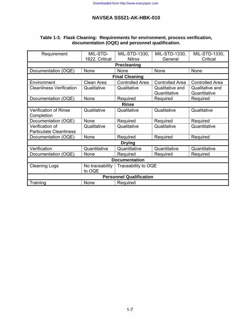
1.3 MAINTAINING CLEANLINESS. After a component or system is cleaned, it needs to be maintained clean. Components are maintained clean by packaging. Systems have requirements for entering the system (i.e., removing components or cleanliness closures) to maintain cleanliness. If contamination is present or suspected, it is considered a loss of cleanliness requiring investigation and potential corrective action. Examples include loss of a purge or exposure of a cleaned surface to an uncontrolled atmosphere for MIL-STD-1330 applications, oil contamination from a compressor for MIL-STD-1622 applications, or system degradation causing pieces of material to deposit in the system for MIL-STD-1330 or MIL-STD-1622 applications. 1.3.1 System Entry Requirements for Maintaining Cleanliness. Similar to cleaning requirements, requirements for maintaining cleanliness differ in the same way, with MIL-STD-1622 being less stringent than MIL-STD-1330 as shown in Table 1-8. The basis for the differences is as follows: a. To control entry of particulate or foreign material, MIL-STD-1330 usually requires a purge
while MIL-STD-1622 does not. Also, MIL-STD-1330 has specific requirements for cleaning the exterior of the piping.
b. For visual inspection of the cavity, there are no specific requirements for MIL-STD-1622,
though it is normally accomplished to verify that the system is not contaminated. For MIL-STD-1330, a visual inspection is used not only to verify that the system is not contaminated, but also to ascertain if cleanliness was properly maintained. The cavity is inspected when a component is removed and any acceptable contamination (i.e., contamination that is normally expected and deemed as acceptable) is locally cleaned. If a direct replacement is not being installed, cleanliness closures or test fittings are installed to perform work on the removed component or testing on the system. When the work is complete and the component is installed, the visual inspection of the cavity is repeated. For this second inspection, any contamination is an indication of loss of maintenance of system cleanliness.
c. For MIL-STD-1330, an inspector or witness is required to ensure that all requirements are
being satisfied and are properly documented. Similar to the cleaning processes, documentation is not required for MIL-STD-1622.
d. Training is required for MIL-STD-1330 because of the specific requirements for
documentation of maintaining cleanliness. Again, similar to the cleaning processes, training is not required for MIL-STD-1622.
1-11
Downloaded from http://www.everyspec.com

NAVSEA SS521-AK-HBK-010
Table 1-8. Requirements for Maintaining System Cleanliness.
Attribute MIL-STD-1622, critical MIL-STD-1330, all applications Environment No airborne contamination No airborne contamination Purge Not required Required unless exempted Clean piping exterior prior to system entry
As needed to prevent entry of foreign material
Specific steps that are always performed
Visual inspection of cavity Not required Required for component removal and installation
Plug or cap openings Required Required Inspector or witness and documentation (OQE)
Not required Required during component removal and installation
Training for worker and inspector/witness
Not required Required
1.3.2 Loss of cleanliness. During system entry, if contamination is noted that is not as expected, it is considered a loss of cleanliness. For MIL-STD-1622 and MIL-STD-1330, visual inspections of selected components are accomplished to establish boundaries for the contamination. The Teflon swipe method is used to distinguish between approved lubricant and unacceptable hydrocarbon contamination. Based on the inspection results, the actions to recover from the loss of cleanliness are as specified in Table 1-9. The only difference is that for MIL-STD-1622, the Teflon swipe method can be used to verify cleanliness because the allowable surface contamination for MIL-STD-1622 is much greater than for MIL-STD-1330. Note that the visual inspection only applies to assessing for loss of cleanliness of a previously cleaned item and not for establishing initial cleanliness.
Table 1-9. Actions to recover from loss of cleanliness. Type of Contamination MIL-STD-1622, critical MIL-STD-1330, all applications Excessive particulate throughout system
Flush with water Flush with water
Localized particulate or approved lubricant 1/
Locally clean Locally clean
Organic contamination of a system
Flush with NAVSEA approved final cleaner
Flush with NAVSEA approved final cleaner
Organic contamination of a component
Clean with NAVSEA approved final cleaner
-or- Locally clean and verify using Teflon swipe method
Clean with NAVSEA approved final cleaner
1/Teflon swipe method may need to be used to differentiate between approved lubricant and unacceptable hydrocarbon contamination. See MIL-STD-1622 or MIL-STD-1330 for details. 1.4 ACCEPTANCE OF PARTS CLEANED BY ANOTHER FACILITY. 1.4.1 Requirements to Accept Cleaned Item. Items cleaned per the specifications given in Table 1-1 are acceptable for use if the cleanliness tag lists the required information in the specification and the item is properly packaged. As stated in the specifications, the tag must list the cleaning specification (e.g., MIL-STD-1330 or MIL-STD-1622). Testing has been performed to qualify cleaners in the Table 1-1 specifications for diving applications. Stating that a part is
1-12
Downloaded from http://www.everyspec.com

NAVSEA SS521-AK-HBK-010
oxygen clean per a commercial specification is not adequate because commercial specifications allow cleaners that do not satisfy the additional toxicological hazards associated with diving systems. Parts cleaned by a vendor per the specifications given in Table 1-1 are acceptable provided that the procedure has been approved by the applicable certifying activity. The certifying activity is one of the following: a. The NAVSEA Program Manager with delegated technical activity concurrence (noting limit in
b below) or concurrence from the Technical Authority. b. A delegated technical activity such as SEA OOC or SupShip Newport News when the
content of the procedure does not violate any requirements of the specifications given in Table 1-1.
c. The Technical Authority (NAVSEA 05Z9) when procedures violate or are different from
those specified in Table 1-1. d. The Life Cycle Manager (LCM), Puget Sound Naval and Intermediate Maintenance Facility
Code 126.1, who may review any cleaning procedure and who reports directly to the Technical Authority (TA).
1.4.2 Additional Actions. Sometimes another facility will clean per the specification, but they do not perform the additional steps necessary for diving applications. If this is the case, the parts do not need to be recleaned, but the special requirements specified in Table 1-10 are required to qualify the part for diving applications. Table 1-10: Actions required to satisfy diving system special cleaning requirements. Special Requirement Actions Required to Satisfy Requirement Particle count If particle counts are required as directed by NAVSEA and they weren’t
performed, rinse the parts and perform particle counts per paragraph 1.6 of this manual. Recleaning the item is not required.
Disinfect If disinfecting applies, repeat the disinfecting per paragraph 1.7 of this manual.
Verification of solvent removal
For instruments cleaned with solvent where solvent removal was not verified, dry the instrument and verify solvent removal as specified in NAVSEA ST700-F1-PRO-010 and paragraph 1.8 of this manual. Recleaning the instrument is not required.
1.5 SPECIAL CLEANING PROCESSES. For piping systems, the common cleaning processes specified in Table 1-1 shall be used. When it is not possible or for other diving equipment, a unique cleaning process shall be developed and approved by the LCM and/or TA. A synopsis of acceptable cleaning processes for various applications are given in Table 1-11. Forms for documenting OQE may need to be
1-13
Downloaded from http://www.everyspec.com

NAVSEA SS521-AK-HBK-010
Table 1-11. Synopsis for other cleaning methods.
Application Number and Description
Synopsis of Cleaning Method 1/ Inspection Requirements that require
documentation (OQE) 2/ #1: Non-piping breathing equipment (e.g., diving helmets, masks, headphones)
Wipe with NID or NOC until visually clean. For NID, rinse with water and verify removal of NID by the shake test. For NOC, rinse with 120oF Grade B or better water until pH<8. Disinfect per paragraph 1.7 of this manual. Dry with oil-free nitrogen until visually dry.
Visual inspection of surface with white and U/V light, and, if >16 in2, swipe. Visual inspection of
rinse water for particles.
#2: Non-piping non-breathing equipment (e.g., electrical whip, cable assemblies, tools)
Scrub with NID using a nylon bristle brush until visually clean. Rinse with Grade B or better water and verify removal of NID by the shake test. In some cases, NID is not required and use of water only is sufficient. Dry with oil-free nitrogen until visually dry.
Visual inspection of surface with white and U/V light, and, if >16 in2 applicable, swipe.
#3: Non-piping non-breathing non-rinsable circuit components
Wet a cloth with NID or water and squeeze excess liquid to prevent entering circuit components where it cannot be dried with nitrogen. Wipe with NID until visually clean. Wipe with cloth wetted with Grade B or better water. In some cases, NID is not required and use of water only is sufficient. Dry with oil-free nitrogen until visually dry.
Visual inspection of surface with white and U/V light, and, if >16 in2, swipe.
#4: Filter elements (not cellulose) and housings too large to be cleaned in ultrasonic tank.
Scrub with NID at 120oF using a nylon bristle brush and clean cloths until visually clean. For filter elements, use the brush only. Rinse with Grade B or better water at 120oF and verify removal of NID by the shake test. Dry with oil-free nitrogen until visually dry.
Visual inspection of surface with white and U/V light, and, if >16 in2, swipe. Visual inspection of
rinse water for particles.
#5: Other large components (i.e., other methods can not be used due to space and handling considerations)
Steam clean until visually clean. Perform visual inspection of rinse water. Dry with oil-free nitrogen until visually dry. Measure dew point temperature for inaccessible surfaces
Visual inspection of surface with white and U/V light, and, if >16 in2, swipe. Visual inspection of
rinse water for particles. See next page for continuation of table and for footnotes.
1-14
Downloaded from http://www.everyspec.com

NAVSEA SS521-AK-HBK-010
Table 1-11. Synopsis for other cleaning methods. - Continued Application Number and
Description Synopsis of Cleaning Method Inspection Requirements
that require documentation (OQE) 2/
#6: Hoses or Umbilicals (e.g., Synflex 3R80 hoses)
Follow MIL-STD-1330 or MIL-STD-1622 as applicable for flushing piping. If using TSP, and there is a concern for material compatibility, prepare the TSP at half-strength and apply at a temperature of 115 to 125oF
See MIL-STD-1330 or MIL-STD-1622 as applicable.
#7: Breathing Bag Pre-cleaning is not required because bags are installed in protective covering that precludes pre-cleaning. Fill bag half full with NOC at 120 to 140oF and shake for 5 to 10 minutes. Drain NOC and immediately fill bag half full with grade B or better water at >110oF and shake bag for 5 minutes minimum. Perform shake test and visual clarity on NOC and pH and particle analysis on water. Dry bag to +20oF. Perform visual inspection of bag.
NOC shake test and visual clarity pH SAT for water Particulate analysis of
water Visual inspection of bag
interior Drying SAT
#8: Special components Scrub with solvent (HCFC-225G or CFC-113) using a nylon bristle brush. For accessible surfaces, bake in an oven at 140oF or higher. For inaccessible surfaces, place in a vacuum oven, with or without heat, and evacuate to no less than 26 inHg. Item shall be placed in oven for no less than 1 hour.
Visual inspection of surface with white and U/V light, and, if >16 in2, swipe. Visual inspection of
solvent for particles.
1/ This table provides guidance only and is not intended for strict compliance. In many cases, other cleaners and methods may be preferred depending on the application. Contact the LCM or TA if guidance is needed for selecting an appropriate cleaner and method. 2/ Documentation (OQE) is only required for items within the cleanliness boundaries defined in MIL-STD-1330. Items within the cleanliness boundary defined in MIL-STD-1622 require the inspections, but they do not require the OQE.
1-15
Downloaded from http://www.everyspec.com

NAVSEA SS521-AK-HBK-010
modified to accommodate these cleaning methods. Note that NID is a hydrocarbon that can pose a limited flammability hazard and a toxicity hazard, particularly in a closed breathing system. If mixed too concentrated, it is difficult to rinse. There is no reliable cleanliness verification method for NID. The Topside Tech Notes, Diver Life Support System Cleaning, allows use of NID for cleaning replacement software on site. This is acceptable because most gaskets and o-rings are captured in metal and the risk of contaminating the breathing gas is remote. Use of NID as a final cleaner shall not be extended to other parts and shall be allowed only for applications falling under the Topside Tech Notes. 1.6 PARTICLE COUNTS. Particle counts are required only if directed by the NAVSEA Program Manager (e.g., via a contract or NAVSEA approved process instruction). If particle counts are required, procedures shall be developed for taking the samples and acceptance criteria shall be established and approved by the NAVSEA Program Manager. 1.6.1 Procedures for Taking Particle Counts. Guidelines for procedures to ensure that the sample is valid and does not get contaminated are as follows: General: Rinse all of the sampling and analysis equipment with filtered Grade B or better water prior to analyzing the sample. System flushing: For a system flush, dust contamination may be a problem. Possible corrective actions are as follows: a. Connect the sample container directly to the flushing rig outlet. A vent or relief may be
required. b. Use a glove box purged with clean nitrogen or air. c. Run the flushing rig outlet to a flow bench or other enclosed area. d. Collect a 2.5-liter sample of rinse water from each outlet of the system prior to the filter. For
analysis per paragraph 1.6.2, agitate each sample and perform analysis on 100 ml of the sample.
Other considerations for taking samples are as follows: a. If installation of additional sample piping is required, minimize the use of valves or other
particle traps. Where valves are required, use valves that will minimize trapping of particles (e.g., ball valves).
b. During sampling, maintain the required flushing velocity to keep particles suspended in
solution. c. Allow the rinse effluent to flow until the effluent is representative of the piping being
sampled. d. Unacceptable samples can be caused by the flushing rig supply filters requiring
replacement. This can be determined by taking a sample near the exit of the filter.
1-16
Downloaded from http://www.everyspec.com

NAVSEA SS521-AK-HBK-010
e. The acceptance criteria for particle counts is given in terms of particle population per square foot. The 100 ml of sample analyzed is modeled as being equivalent to one square foot of surface area so no calculations are required.
Component cleaning in clean room: In order to equate particle counts to a particle population per square foot, a control standard is used. This control standard should have a surface area of one square foot. Calculations are required if the surface area is other than one square foot. The geometry of the control standard needs to be such that rinse effluent can all be collected from the standard and it fits into the basket with the batch of parts. A flat piece of metal shaped into a helix or spiral has been used successfully. The control standard is cleaned with the batch of parts. The rinse effluent of the control standard is representative of the particle population on the parts. If the particle count fails, the rinse is repeated for both the control standard and parts. This eliminates the need to calculate surface areas of parts. After acceptable results are obtained, the control standard is placed in the dryer with the parts. After drying, the control standard is rinsed and a particle count is performed to ensure that the drying process did not contaminate the parts with particulate. For analysis per paragraph 1.6.2, the control standard is rinsed with 500 ml and the entire sample is analyzed. 1.6.2 Analysis for Particle Count. Filtering the sample and analyzing using a microscope should be accomplished in a laminar flow bench. A filtration device is used that is comprised of a funnel capable of holding a 1.0-micron filter and an attached vacuum pump beneath it to pull water through the filter. Guidelines for performing the particle count analysis are as follows: a. Rinse the funnel with filtered Grade B or better water. Using forceps, remove filter from
shipping container and rinse grid-marked surface with filtered Grade B or better water. Place grid side up on filter holder.
b. Pour half of the sample into the funnel. c. Apply vacuum and pull sample through the filter while adding the remainder of the sample.
Do not subsequently rinse walls or filter surface to avoid disturbing the even distribution of particles. Remove funnel and continue applying vacuum for 30 seconds. Using forceps, place the filter in a clean container suitable for viewing under a microscope. If samples need to be transported, condensation in the container can occur. Take precautions to prevent contamination of sample if the holder needs to be opened to get rid of the condensation.
d. Particles are counted using a microscope. The microscope must have adequate
magnification to measure particulate 50 microns and larger. Prior to use, calibrate the microscope for the goal size ranges.
e. Place the container with the filter under the microscope. Using the microscope’s horizontal
and vertical traversing stage adjustments, systematically scan and count all particles and fibers in the effective filtering area of the sample filter. A fiber is a particle whose length to width ratio is 10 to 1 or greater. Log all results.
1-17
Downloaded from http://www.everyspec.com
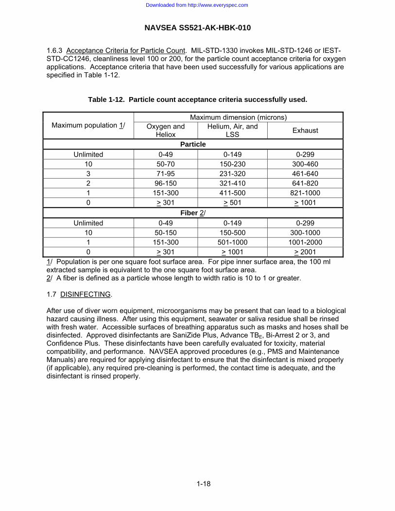
NAVSEA SS521-AK-HBK-010
1.6.3 Acceptance Criteria for Particle Count. MIL-STD-1330 invokes MIL-STD-1246 or IEST-STD-CC1246, cleanliness level 100 or 200, for the particle count acceptance criteria for oxygen applications. Acceptance criteria that have been used successfully for various applications are specified in Table 1-12.
Table 1-12. Particle count acceptance criteria successfully used.
Maximum dimension (microns) Maximum population 1/ Oxygen and
Heliox Helium, Air, and
LSS Exhaust
Particle Unlimited 0-49 0-149 0-299
10 50-70 150-230 300-460 3 71-95 231-320 461-640 2 96-150 321-410 641-820 1 151-300 411-500 821-1000 0 > 301 > 501 > 1001
Fiber 2/ Unlimited 0-49 0-149 0-299
10 50-150 150-500 300-1000 1 151-300 501-1000 1001-2000 0 > 301 > 1001 > 2001
1/ Population is per one square foot surface area. For pipe inner surface area, the 100 ml extracted sample is equivalent to the one square foot surface area. 2/ A fiber is defined as a particle whose length to width ratio is 10 to 1 or greater. 1.7 DISINFECTING. After use of diver worn equipment, microorganisms may be present that can lead to a biological hazard causing illness. After using this equipment, seawater or saliva residue shall be rinsed with fresh water. Accessible surfaces of breathing apparatus such as masks and hoses shall be disinfected. Approved disinfectants are SaniZide Plus, Advance TBE, Bi-Arrest 2 or 3, and Confidence Plus. These disinfectants have been carefully evaluated for toxicity, material compatibility, and performance. NAVSEA approved procedures (e.g., PMS and Maintenance Manuals) are required for applying disinfectant to ensure that the disinfectant is mixed properly (if applicable), any required pre-cleaning is performed, the contact time is adequate, and the disinfectant is rinsed properly.
1-18
Downloaded from http://www.everyspec.com

NAVSEA SS521-AK-HBK-010
1.8 VERIFICATION OF SOLVENT REMOVAL FOR INSTRUMENTS. NAVSEA ST700-F1-PRO-010 requires verification of solvent removal for diving applications. For applications 190 feet or shallower, a gas sample taken from the instrument can be analyzed using the piece of equipment that monitors the solvent level in the clean room. This measurement is qualitative. For applications deeper than 190 feet, the document states that quantitative verification is required with direction provided by NAVSEA. The program manager and certification authority at NAVSEA are responsible for determining if qualitative or quantitative analysis is required for applications deeper than 190 feet. Considerations are the depth and duration for the application, piping configuration, instrument volume, and operating procedures for the system. If it is determined that quantitative analysis is required, the procedure, analysis method, and acceptance criteria require NAVSEA approval. Guidelines are as follows: a. The acceptance criteria for the solvent being used needs to be determined. This will dictate
the analysis and sampling method. NOTE
Testing showed that the analysis sensitivity for a gas chromatograph with a flame ionization detector is 5 ppm for NAVSEA approved halogenated solvents. Testing also showed that the gage cleaning process, which removes solvent from dead-end instruments by establishing a vacuum for 5 minutes, could reduce NAVSEA approved halogenated solvents to 20 ppm, and in some cases as low as 5 ppm. Based on the small volume of instruments, the acceptance criteria would probably be higher than the above stated analysis sensitivity.
b. The analysis method and required detection limit will dictate the sample size. There are
many methods for taking samples, including a gas tight syringe or a bag. c. For analysis with a gas tight syringe, place a piece of Teflon film (specified in NAVSEA
ST700-F1-PRO-010) over the port and affix with tape or a tie-wrap. Insert the syringe through the Teflon film into the instrument port and draw a sample.
d. For a bag, use the procedure given in NAVSEA ST700-F1-PRO-010 for qualitative analysis
using the room solvent monitor.
CAUTION
Do not evacuate beyond instrument limits. If instrument cannot withstand a temperature of 145oF, use a lower oven temperature so as to not damage the instrument.
e. If the instrument does not pass, repeat the drying process. As an alternative, the gage can
be placed in a vacuum oven held at 28 inches Hg for 4 hours minimum (a shorter duration may be used if all solvent is effectively vaporized and confirmed by quantitative analysis). The 28-inch Hg vacuum exceeds the vacuum necessary to reduce the effective boiling temperature of the solvent to below ambient temperature, forcing it to change from liquid to vapor state (NAVSEA ST700-F1-PRO-010 only requires 26 inches Hg minimum). The 28-inch Hg vacuum has been successfully used for applications requiring quantitative measurements and it should be easy to achieve for a vacuum oven. If an elevated temperature is desired, do not exceed 145oF. After 45 minutes, break the vacuum and reestablish the vacuum immediately. The vacuum/purge cycle for the oven should be repeated a minimum of 4 times during the drying period. Drying for longer periods, such as
1-19
Downloaded from http://www.everyspec.com

NAVSEA SS521-AK-HBK-010
overnight, is acceptable. If elevated temperatures are used, allow the instrument to cool prior to measuring the solvent level.
f. Depending on the goal solvent levels and instrument geometry, the instrument may need to
be placed in the vacuum oven for more than 4 hours. If the solvent levels near the oven are near the goal solvent levels, keeping the instrument in the vacuum oven overnight is recommended to allow the solvent levels near the vacuum oven to decrease. If in doubt, keep the instrument in the vacuum oven overnight and take measurements the next day before commencing any operations using solvent.
g. Ensure all of the detailed procedures include steps for maintaining cleanliness of the
instrument during drying, cooling, sampling, and analysis of the instrument. 1.9 ASSESSING CONTAMINATION. MIL-STD-1330, MIL-STD-1622, and NAVSEA ST700-F1-PRO-010, as applicable, provide direction for establishing initial cleanliness, maintaining cleanliness, and recovering from loss of cleanliness. There are some situations in diving systems that need to be addressed for clarification or for providing supplementary direction. 1.9.1 Gas Samples. A gas sample cannot be analyzed to establish cleanliness of a system. Oils and lubricants can be present in quantities well in excess of what is allowed by MIL-STD-1330 and MIL-STD-1622, but because of the low vapor pressure, they will not off-gas enough to be detected or they will be within acceptable limits in a gas sample. A gas sample containing 5 ppm of hydrocarbons is not the same as a system containing 5 ppm of hydrocarbons determined by measuring cleaning effluent per MIL-STD-1330. There is no correlation between these numbers. 1.9.2 Previously Painted Diving Air Flasks. Painting the interior of diving air flasks is not allowed per NAVSEA S9086-SY-STM-010/CH-551. There have been instances where it is desired to change the service of a flask from a system with painted flask interior to a diving air system which is not painted (e.g., converting a nitrogen system to a diving air system). For a painted flask that has been in service for several years, if it passes a gas sample, the paint poses no toxicological hazard. When using Chapter 5 of this manual for determining the gas analysis requirements, the target compound list shall be modified to account for the type of paint and its composition. The gas analysis requirements shall be approved by the NAVSEA Program Manager and the System Certification Authority. The integrity of the paint and deterioration of the flask walls needs to be assessed and is beyond the scope of this manual. 1.9.3 Evaluation of Flasks in Contaminated Systems. If a system gets contaminated such that it needs to be flushed based on MIL-STD-1330 or MIL-STD-1622, the flasks need to be evaluated separately from the system. Unlike system flushing, in-place flask cleaning is extremely difficult and costly. To further complicate matters, NOC or TSP approved for system flushing may damage flask coatings. Some considerations are that for coated flasks, depending on the application and contamination, a simple warm/hot water spray/flush or solvent rinse may be appropriate. For uncoated flasks, improper procedures can do more harm than good. Contact the LCM or TA for guidance if flask cleaning is required. The best option is to not clean the flask if justified. Some rationale is that for low oxygen (<25%) and low flow rate applications, the primary hazard is toxicological. A blow down would remove any contaminants that would come out of the flask during normal system use because the flow rate is well in excess of that experienced during normal system use. After the blow down, a gas sample can
1-20
Downloaded from http://www.everyspec.com

NAVSEA SS521-AK-HBK-010
be used to certify the flasks. With the low flammability hazard, if the contamination does not pose a toxicological hazard, it is acceptable. For oxygen or oxygen enriched (>25%) applications, consult MIL-STD-1330 for direction on recovering from loss of system cleanliness to determine the cleaning requirements. For all applications, if flushing is not accomplished to remove contamination, the NAVSEA Program Manager and System Certification Authority shall be appraised of the course of action. 1.9.4 Corroded Flasks. Unpainted flasks exposed to moisture can corrode producing particulate contamination. The flammability hazard for migrating particulate is reduced because much of the corrosion products are fully oxidized. Migration of particulate contamination depends on the flask design and orientation. Large vertical flasks in low flow applications with the pipe exiting the top of the flask pose the least risk because particulate should not make it out of the flask. There is a greater risk of particulate migration for horizontally mounted flasks (DDS/ASDS) and small flasks (ADS). However, the smaller the flask, the easier it is to remove and clean. Aside from evaluating the flammability risk due to migration of particulate, the structural integrity of the flask needs to be assessed and monitored. For acceptance of corrosion products in a flask, the NAVSEA Program Manager and System Certification Authority shall be appraised.
1-21
Downloaded from http://www.everyspec.com

NAVSEA SS521-AK-HBK-010
This page intentionally left blank.
1-22
Downloaded from http://www.everyspec.com
NAVSEA SS521-AK-HBK-010
CHAPTER 2 CLEANLINESS OF MANNED SPACES
2.1 CLEANING MANNED SPACE. 2.1.1 Cleaning. Whenever cleaning is specified, vacuum all loose debris (chips, particles, and dust) with the vacuum exhaust directed outside the space. If thorough cleaning is required, removal and cleaning of deck plates may be required. Surfaces shall be wiped with a solution of 0.1 to 0.5 ounces NID (MIL-D-16791, type I) per gallon of water until visually clean. Use of higher concentrations will not enhance cleaning performance and can cause difficulty in removing the NID solution from the surface. NID can be used at elevated temperatures, but do not exceed 140oF to prevent possible precipitation. If use of more aggressive cleaners is required, such as isopropyl alcohol or other solvent, consult the point of contact established in 2.3 and consider that the gas sample for certifying atmospheric purity of the space must include the compound(s) representative of the cleaner used. Wipe with a clean cloth wetted with the cleaning solution. If needed, nylon bristle brushes can be used. Remove cleaner with a clean cloth wetted with grade C or better water. Grades of water are defined in MIL-STD-1622 or MIL-STD-1330. Dry the surface with a clean cloth. Inspect the cloths used for drying and the surfaces as specified in 2.1.2. Reclean any surfaces that do not pass the inspection. 2.1.2 Inspection. Inspect the cloths used for drying for evidence of oil, grease, ink, dye, particulate or fibers. Inspect all cleaned surfaces with a bright white light and ultraviolet light as follows: Bright White Light: Inspect the surface with a bright white light of at least 100 foot-candles. The inspection shall be performed by a person with normal visual acuity, natural or corrected. A general purpose two D-cell flashlight, in good condition, at a distance of no greater than 18 inches from the surface being inspected will illuminate the surface with an intensity of not less than 100 foot-candles. The acceptance criterion is that the surface is free of foreign material. Visual trace particles including tap water residue are acceptable. Adherent light superficial rust on non-corrosion resistant surfaces caused by exposure to the atmosphere is acceptable. Ultraviolet Light: Inspect the surface with an ultraviolet light having a wave length of 3600 to 3900 angstroms. The inspection shall be performed by a person with normal visual acuity, natural or corrected. The acceptance criterion is no evidence of fluorescence from oil, grease, ink, or dye. Note that most oils and greases do not fluoresce, while some non-metallic substrates may fluoresce leading to possible false negative or false positive results. 2.2 INITIAL CERTIFICATION OF MANNED SPACE. Requirements for atmospheric testing to certify the space are as specified in NAVSEA SS800-AG-MAN-010/P-9290 or NAVSEA SS521-AA-MAN-010, as applicable, with supplementary and amplifying information provided in this manual. 2.3 MAINTAINING CLEANLINESS OF MANNED SPACE. After a space is cleaned and certified, it must always be maintained clean unless a complete cleaning of the impacted area is planned. The impacted area can easily become the entire space because personnel will spread contamination as they pass through the space. A point of
2-1
Downloaded from http://www.everyspec.com

NAVSEA SS521-AK-HBK-010
contact should be established for answering questions regarding entry requirements and restrictions within the space. The point of contact should be familiar with the work being performed and controls being implemented. 2.3.1 Personnel Entry Requirements. For spaces with a controlled environment, such as saturation diving or air diving recompression chambers, don clean shoes or protective booties, or remove shoes prior to entering a space. For all applications, the worker and worker’s clothing shall be free of excess contaminants, such as oils, grease, dirt, grit or metal particles. “Free of excess contaminants” here means clean enough that contaminants are not left behind. No eating, smoking, or personnel grooming is allowed in the space. 2.3.2 Material, Tools, and Equipment. Controls and restrictions are as follows: a. Material: Use only approved solvents, lubricants, sealants, and other chemicals. Limit use
to that which is required to perform authorized work. Hydrocarbon based oil and grease shall not be stored or used in the space unless specifically approved. All non-metallic material of new or newly refurbished items shall be fully cured in accordance with manufacturer’s instructions or as specified in the installation drawing prior to space entry. For installed material, see Chapter 11 for curing and off-gas testing requirements.
b. Tools: Prior to entering space, verify that tools and tool bags are free of excess
contaminants, such as oils, grease, dirt, grit or metal particles. “Free of excess contaminants” here means clean enough that contaminants are not left behind. If cleaning is required, clean using NOC or NID followed with a thorough grade C or better water rinse and dry with a clean cloth until visually free of excess oil, grease, dirt, grit or metal particles.
c. Equipment: Pneumatic tools discharge air containing suspended oil that can contaminate
the space. Direct the tool exhaust outside the space using any method such as tubing. Temporary services, such as air hoses, ventilation ducting, and extension cords, should be sheathed with clean film such as polyethylene prior to bringing into the space.
2.3.3 Maintaining Cleanliness While Accomplishing Work. Use the following guidelines for maintaining cleanliness while accomplishing work. Additional specific direction may be required. a. Chips, particles, and dust generated during any operation shall be removed during the
operation by vacuum. Direct the vacuum exhaust outside the space. b. Contaminants such as oil, grease, residue, chemicals, and liquid dye penetrant (used for
inspection of welds) shall be cleaned immediately with NOC or NID followed with a thorough grade C or better water rinse and dried with a clean cloth. Inspect the surfaces as specified in 2.1.2. If a cleaning solution other than NID is needed, consult the point of contact established in 2.3. If a cleaner that poses a significant toxicological hazard is used, such as isopropyl alcohol or other solvent, a gas sample for certifying atmospheric purity must be performed and it must include the compound(s) representative of the cleaner used.
c. Avoid loss of foreign objects such as ball point pens, scraps of paper, rags, or any
combustible items that may accidentally be left behind. If a foreign object can not be retrieved, notify the technical point of contact established in 2.3 for assistance. Take special precautions in the case of opened piping and components to prevent the introduction of
2-2
Downloaded from http://www.everyspec.com

NAVSEA SS521-AK-HBK-010
loose articles such as buttons, jewelry, pens, coins, glasses, contact lenses, and hearing aids. Securely fasten badges to the clothing.
WARNING
Butane lighters shall be excluded or logged into/out of any space subject to pressurization. Butane lighter subject to external pressure could implode with catastrophic consequences.
2.3.4 Maintaining Cleanliness While Diving. The requirements for maintaining cleanliness while diving are addressed in NAVSEA approved procedures such as operating procedures. Procedures can vary significantly for the application. In general, saturation diving and air diving recompression chambers are controlled environments that are always maintained clean. Dry deck shelters and lock-out trunks are wet working environments where maintaining cleanliness is difficult. ASDS is an uncontrolled environment for which maintenance of cleanliness is almost impossible and cleanliness may need to be re-established after each mission. One-atmosphere dive suits are controlled environments, but limited space and humid environment may require routine disinfection. 2.4 MAINTAINING CERTIFICATION OF MANNED SPACE. After accomplishment of work, the need and requirements for atmospheric testing to maintain certification of the space are as specified in NAVSEA SS800-AG-MAN-010/P-9290 or NAVSEA SS521-AA-MAN-010, as applicable, with supplementary and amplifying information provided in this manual.
2-3
Downloaded from http://www.everyspec.com

NAVSEA SS521-AK-HBK-010
This page intentionally left blank.
2-4
Downloaded from http://www.everyspec.com

NAVSEA SS521-AK-HBK-010
CHAPTER 3 MOISTURE MEASUREMENTS
3.1 MOISTURE LEVELS AND THEIR SIGNIFICANCE. Moisture measurements are taken of piping systems to verify dryness of the system. These measurements are taken for items such as monitoring flask dryness, verifying adequacy of drying after flushing a piping system, or investigating moisture intrusion. Measuring moisture and conforming to the moisture level requirements is simple. Understanding the meaning of the measurements for troubleshooting moisture problems in a system requires some additional guidance provided in this section. For performing calculations, see Appendix A. 3.1.1 Dew Point Temperature and Parts per Million (PPM). Moisture level requirements are specified as the dew point temperature at one atmosphere. The dew point temperature is the temperature at which water will condense. The temperature at which this will occur depends on the ambient temperature and moisture content of the gas. The moisture content is measured as humidity or parts per million on a volume basis (see next paragraph for explanation of parts per million). See Appendix A, example #A.1 for calculating dew point temperature for a given ambient temperature and humidity. 3.1.2 Converting Dew Point Temperature Measurements to Parts per Million (PPM). Dew point temperature measurements taken at one atmosphere are often converted to parts per million (ppm), which is parts of water per million parts on a volume basis. This is the same as for ppm levels of contaminants in gas as explained in paragraph 4.1.2, except in this case, the contaminant is taken as water. All of the example calculations in Appendix A convert results to ppm. For dew point temperatures, Table 3.1 gives conversions to ppm. These may not correlate exactly to calculated values due to rounding differently or applying different equations. 3.1.3 Pressure. Moisture measurements are taken at one atmosphere because it is easier and more accurate than at elevated pressure. These measurements at one atmosphere need to be converted to the pressurized gas. Suppose that air with a dew point of 50oF at 1 ata is pressurized to 3000 psig. The process of compression removes water, resulting in a drier gas. Appendix A, Example #A.2, shows that for this compressed gas, the dew point temperature measured at 1 ata is –40oF using the NSTM S9086-SY-STM-010/CH-551 graph for real gas. So for a measured dew point temperature at 1 ata of –40oF, if the ambient temperature of the 3000 psig gas fell below 50oF, condensation would occur. Appendix A provides many other calculations at elevated pressure assuming the ideal gas law. For air, data for measurements are given in NSTM S9086-SY-STM-010/CH-551. This data was used for the above example. These measurements are based on real gas and are more accurate than ideal gas. However, for performing calculations simply, ideal gas must be assumed and is a conservative approach. 3.1.4 Type of Gas. Data for moisture content presented in psychrometric charts is generally given for air at one atmosphere. These charts cannot be used for elevated pressures or for gas other than air because they are based on weight of water and weight of air. By performing
3-1
Downloaded from http://www.everyspec.com

NAVSEA SS521-AK-HBK-010
Table 3-1. Conversion from dew point temperature at 1 ata to ppm.
Dew point Temperature at 1 ata (oF)
PPM on volume basis (ppm)
-65 24 -60 34 -55 48 -50 67 -45 92 -40 127 -35 173 -30 234 -25 315 -20 421 -15 558 -10 737 -5 970 0 1,260 5 1,630
10 2,100 15 2,700 20 3,440 25 4,370 30 5,530 35 6,840 40 8,340 45 10,130 50 12,260
calculations on a mass per volume basis, calculations can be performed for any gas at elevated pressure. Appendix A provides some example calculations using this approach at elevated pressures that are independent of the gas used. 3.1.5 Significance of Moisture Levels. The allowable moisture levels discussed in paragraph 3.2 range from a dew point temperature of –40oF to +20oF. These moisture levels provide an indication of how much water is in the system. After a 2 hour hold (see paragraph 3.3.6), a –40oF dew point temperature means that there are no droplets throughout the system, and crevices, such as brazed, welded, and mechanical joints, are not filled with water. Whereas a +20oF dew point temperature means that there can be some droplets and crevices can be filled with water. 3.1.6 Moisture Intrusion From Ambient Air When Opening Systems. When systems are opened for maintenance without a purge, ambient air at well above a dew point temperature of –40oF can enter the system. A misnomer regarding this is the drying that was accomplished is undone and moisture requirements can be relaxed for an in-service system. This is not true. After maintenance is complete, the system is tested, vented, and then it becomes operational with system gas. The moisture levels of the gas used to test and fill the system are well below –40oF and will “dry out” the moisture from the air intrusion, resulting in a moisture level that is still below –40oF. As stated in the previous paragraph, the intent of the moisture measurements
3-2
Downloaded from http://www.everyspec.com

NAVSEA SS521-AK-HBK-010
is to provide an indication of how much water is in the system in the condensed form (droplets or puddles). Ambient air entering the system will not contribute any significant additional condensed water because the system gets pressurized with dry gas. An exception to this is systems that are sensitive to moisture and don’t get pressurized with dry gas, such as a liquid oxygen system. For this rare case, a purge is required when opening the system. 3.2 MOISTURE LEVEL REQUIREMENTS. MIL-STD-1622 and MIL-STD-1330 specify allowable moisture levels measured as dew point temperatures at 1 ata. Dew point temperatures for hoses, exhaust, and life support systems, which are not addressed in these standards, are specified on Table 3-2. The basis for these dryness requirements is provided in paragraphs 3.2.1 through 3.2.4.
Table 3-2. Moisture level requirements.
Application Allowable Dew Point at 1 ata
Source for Requirement Discussion
Helium, Helium-Oxygen, Oxygen, or Nitrogen-Oxygen System -40oF 3.2.1 Flask -20oF 3.2.2 Component with inaccessible area +20oF
MIL-STD-1330 3.2.3
Hose -20oF - 3.2.4 Low Pressure Diver’s Air (< 150 psig)
System +20oF 3.2.1 Flask -20oF
MIL-STD-1622, Diver’s Air 3.2.2
Component with inaccessible area +20oF - 3.2.3
Hose +20oF - 3.2.4 High and Medium Pressure Diver’s Air (>150 psig)
System -40oF 3.2.1 Flask -20oF 3.2.2 Component with inaccessible area -20oF
MIL-STD-1622, medium- and
high-pressure air 3.2.3
Hose -20oF - 3.2.4 Exhaust or Life Support System 1/
System +20oF - 3.2.1 Flask -20oF - 3.2.2 Component with inaccessible area +20oF - 3.2.3
Hose +20oF - 3.2.4 1/ Life support piping systems are systems other than the breathing gas systems (e.g., air, oxygen, helium, heliox, and nitrox) that process gas from a chamber that can be breathed (e.g., circulation piping for scrubbers and piping supplying gas from a chamber to a diver).
3-3
Downloaded from http://www.everyspec.com

NAVSEA SS521-AK-HBK-010
3.2.1 System. Ramifications to consider for excessive moisture are corrosion or freezing. Corrosion is not an issue because most diving piping and components are constructed of corrosion resistant material. Portions of systems most susceptible to freezing are where pressure reductions occur, such as pressure regulators or any orifice-type devices. Excessive moisture can result in partial or complete blockage. Experience has shown that a –40oF dew point is an achievable goal given the drying challenges associated with system configuration (e.g., blind passages, low points) and manufacturing (e.g., socket weld gaps). The –40oF dew point is adequate to prevent freezing of medium- and high-pressure (>150 psig) air systems, and +20oF is adequate for low-pressure (<150 psig) air systems. With the exhaust or life support system connected to the chamber ambient, it is not necessary to dry to below +20oF. 3.2.2 Flask. For flasks, freezing is not an issue because there are no pressure reduction devices within the flask. The primary concern is excessive moisture leading to corrosion for uncoated carbon steel flasks. Unlike systems, in comparison to the total volume, flasks have very few crevices and no blind passages, so drying to –20oF is easy to achieve and is adequate to show that water is not present in the flask. That being the case, after filling a flask with dry gas, the dew point temperature will be commensurate with the dry gas. Example #A.4 shows this by starting with a flask at 421 ppm (-20oF) and then pressurizing it to 3000 psig with gas at 127 ppm (-40oF), which yields a final moisture level of 128.2 ppm. Though the –20oF is established for steel flasks, other materials can be used particularly for cylinders, such as stainless steel and aluminum, that may be able to tolerate a higher dew point temperature. To simplify the requirements and start with an adequately dry flask, -20oF is specified for all applications. 3.2.3 Component with Inaccessible Area. Since components have a small volume and the moisture level will be reduced significantly when dry gas is passed through it during system use, the –20oF dew point is adequate to prevent freezing for medium- and high-pressure air systems, and +20oF is acceptable for low-pressure air systems. Helium, helium-oxygen, oxygen, or nitrogen-oxygen systems generally have a lower flow rate than air systems; therefore, +20oF is acceptable. Exhaust and life support systems are connected to chamber ambient; therefore, +20oF is acceptable. 3.2.4 Hose. Higher dew points can be tolerated for hoses because of the smaller volume (i.e., it is not as small as a component, but it is much smaller than a piping system) and because it can be difficult to dry hoses to a –40oF dew point (i.e., -40oF is the practical limit). Accordingly, where a –40oF dew point is required for the system, only –20oF is required for the hose. 3.3 TECHNIQUES FOR DRYING AND MEASURING MOISTURE LEVELS. After system flushing, bulk water is removed by force with a blow down, and then the remaining film of moisture is dried by evaporation. Methods to accomplish this are identified in MIL-STD-1622 and MIL-STD-1330. Supplementary information for system drying and measuring moisture levels is as follows: 3.3.1 Blow down. After flushing, perform a high-pressure blow to remove pockets of water at low points. Then, continue blowing at a lower pressure such that pressure does not build up in the system, but the flow rate is high. Continue until there is no visible moisture at the system outlet. Placing a dry cloth on the outlet can monitor this. If it is damp, keep on blowing. If it is dry, perform paragraph 3.3.2 to dry the remaining film. Wiping excess moisture from valve cavities and other moisture traps can also be beneficial.
3-4
Downloaded from http://www.everyspec.com

NAVSEA SS521-AK-HBK-010
3.3.2 Evaporation. The remaining film of moisture is difficult to dry because water has a high boiling temperature (212oF) that is well above ambient temperature, a low vapor pressure, and a strong molecular bond. Drying can be accelerated by applying heat, establishing a vacuum (high vacuum will lower the boiling temperature to below ambient forcing the film of moisture to change to vapor), or flowing gas. Heat can be applied to the system using strip heaters or heat guns, particularly at socket joints, valves, and low points, or the nitrogen can be heated. Increasing the temperature from 60 to 120oF will increase the evaporation rate by about 20 to 25%. This helps some, but it can still take several days to dry a piping system. The gas used to dry a system needs to have little moisture, or a dryer is necessary to remove moisture from the gas used to dry the system. If applying heat, take the necessary precautions to prevent damage to piping and equipment – do not overheat. For drying by flowing gas, two keys are maintaining a low flow rate and cycling the outlet valve. Because water evaporates so slowly, low flow rates are adequate to carry evaporated moisture away; high flow rates are a waste of gas. Cycling a valve on the outlet of the piping system being dried provides back pressure that forces gas into the crevices. When shutting the valve, shut it enough to provide back pressure, but always keep some gas flowing to prevent water from accumulating in the valve. This practice is important for crevices with small surface areas such as brazed, welded, and mechanical joints. 3.3.3 Piping and Hoses Supplying Drying Gas. Typically, systems are dried by flowing gas through the system. The equipment supplying the gas is selected to maintain the gas as dry as possible. Flexible hoses, particularly Teflon, should not be used because they are gas permeable and moisture from the ambient can penetrate the hose. Copper tubing is commonly used. 3.3.4 Dew Point Temperature Measuring Equipment. To measure the low dew point temperatures, it can take several days to adequately dry dew point measuring equipment prior to connecting it to the system being dried. While drying a piping system, use a humidity indicator at the outlet. When it reaches 0%, connect the dew point measuring equipment to the piping system. This prevents exposing dew point measuring equipment to elevated moisture levels that could cause the need to repeat the initial drying of the equipment. 3.3.5 Pressure and Volume. If the system cannot be pressurized high enough to attain adequate flow for measuring the dew point temperature, flow dry gas while observing the initial maximum reading on the dew point indicator. If there are several outlets and the volume in the cluster of piping is expended by taking the measurement from one outlet, then the measurement is considered as representative of all the outlets. 3.3.6 Hold Duration. After drying the system, pressurize, isolate, and hold for 2 hours to allow the moisture time to diffuse into the gas stream. Water evaporates very slowly. It can take 2 hours for water to evaporate adequately from a pipe joint to be detected in the sample for measuring the dew point temperature. Moisture measurements of systems have passed yet puddles were remaining because there was not a 2-hour hold. This was a result of measuring the dew point temperature of the gas added to the system instead of the system.
3-5
Downloaded from http://www.everyspec.com

NAVSEA SS521-AK-HBK-010
This page intentionally left blank.
3-6
Downloaded from http://www.everyspec.com

NAVSEA SS521-AK-HBK-010
CHAPTER 4 THEORY FOR GAS ANALYSIS
4.1 DEFINITIONS. A few terms need to be defined that are used in evaluating gas analysis results. 4.1.1 Laboratory Analysis Limits. Several different limits are used to define the ability of the laboratory to perform gas analysis. Terminology may differ slightly between laboratories. Table 4-1 provides an example of the various limits with a definition of each for a compound with an established surface equivalent limit of 1000 ppm and a pressure ratio of 10 (see paragraphs 4.1.4 and 4.1.6 for definitions of pressure ratio and surface equivalent limit). The example ppm levels show the hierarchy of the limits and are not intended to show relationships between the different limits (e.g., the PQL does not need to be 1/100th of the SEL).
Table 4-1. Example and definition of laboratory analysis limits. Example ppm level Term Definition
1000 SEL: Surface Equivalent Limit
Established acceptance criteria for compound at 1 ata.
100 RDL: Required Detection Limit
The SEL divided by the maximum pressure ratio for that application. This represents arithmetically the lowest level that needs to be reported for the constituent.
50 LRL: Laboratory Reporting Limit
An agreed upon quantification level which is between the PQL and RDL. A good rule of thumb is the LRL > RDL/5 to prevent reporting values unnecessarily. For this example, RDL/5 = 100/5 = 20. The LRL at 50 is greater than 20, which satisfies the criteria. Sometimes referred to at Reportable Detection Limit.
10 PQL: Practical Quantification Limit
The lowest level that can be reliably quantified within specified limits of repeatability and accuracy during routine laboratory operating conditions.
1 LDL: Laboratory Detection Limit
The lowest level that can be detected by the laboratory instrument. It can be stated that the compound is present, but it cannot be reliably quantified at this level. Sometimes referred to as Method Detection Level.
4.1.2 Parts Per Million (ppm). For gas analysis, compounds are measured in ppm, which is parts of contaminant per million parts total on a volume basis. Sometimes a subscript “v” is used to indicate a volume basis, but many times it is understood and is not included. Be aware that ppm can also be expressed on a weight basis for other applications, such as hydrocarbon contamination measured in cleaning effluent. For this case, a subscript of “w” is used, but it is usually understood and is omitted. Other ways of expressing ppm for gas samples are as follows:
66v 10 x
moles totaltcontaminan of moles or 10 x
volume totalvolume tcontaminan
total parts milliontcontaminan of partsppm ==
4-1
Downloaded from http://www.everyspec.com
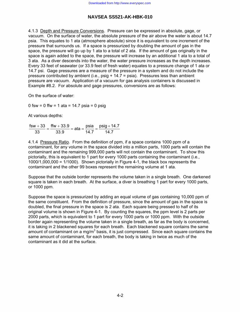
NAVSEA SS521-AK-HBK-010
4.1.3 Depth and Pressure Conversions. Pressure can be expressed in absolute, gage, or vacuum. On the surface of water, the absolute pressure of the air above the water is about 14.7 psia. This equates to 1 ata (atmosphere absolute) since it is equivalent to one increment of the pressure that surrounds us. If a space is pressurized by doubling the amount of gas in the space, the pressure will go up by 1 ata to a total of 2 ata. If the amount of gas originally in the space is again added to the space, the pressure will increase by an additional 1 ata to a total of 3 ata. As a diver descends into the water, the water pressure increases as the depth increases. Every 33 feet of seawater (or 33.9 feet of fresh water) equates to a pressure change of 1 ata or 14.7 psi. Gage pressures are a measure of the pressure in a system and do not include the pressure contributed by ambient (i.e., psig + 14.7 = psia). Pressures less than ambient pressure are vacuum. Application of a vacuum for gas analysis containers is discussed in Example #8.2. For absolute and gage pressures, conversions are as follows: On the surface of water: 0 fsw = 0 ffw = 1 ata = 14.7 psia = 0 psig At various depths:
7.147.14psig
7.14psiaata
9.339.33ffw
3333fsw +
===+
=+
4.1.4 Pressure Ratio. From the definition of ppm, if a space contains 1000 ppm of a contaminant, for any volume in the space divided into a million parts, 1000 parts will contain the contaminant and the remaining 999,000 parts will not contain the contaminant. To show this pictorially, this is equivalent to 1 part for every 1000 parts containing the contaminant (i.e., 1000/1,000,000 = 1/1000). Shown pictorially in Figure 4-1, the black box represents the contaminant and the other 99 boxes represent the remaining volume at 1 ata. Suppose that the outside border represents the volume taken in a single breath. One darkened square is taken in each breath. At the surface, a diver is breathing 1 part for every 1000 parts, or 1000 ppm. Suppose the space is pressurized by adding an equal volume of gas containing 10,000 ppm of the same constituent. From the definition of pressure, since the amount of gas in the space is doubled, the final pressure in the space is 2 ata. Each square being pressed to half of its original volume is shown in Figure 4-1. By counting the squares, the ppm level is 2 parts per 2000 parts, which is equivalent to 1 part for every 1000 parts or 1000 ppm. With the outside border again representing the volume taken in a single breath, as far as the body is concerned, it is taking in 2 blackened squares for each breath. Each blackened square contains the same amount of contaminant on a mg/m3 basis, it is just compressed. Since each square contains the same amount of contaminant, for each breath, the body is taking in twice as much of the contaminant as it did at the surface.
4-2
Downloaded from http://www.everyspec.com

NAVSEA SS521-AK-HBK-010
Physiologically, the body is taking in 2000 ppm. A gas sample of the space analyzed at 1 ata will measure 1000 ppm. In order to compensate for this disparity, the laboratory results need to be multiplied by a factor of 2, which is equivalent to the final pressure in ata. This factor is called the pressure ratio.
1 ata 2 ata
Figure 4-1. Pictorial representation of 1000 ppm of a contaminant pressed from 1 ata to 2 ata with gas containing 1000 ppm of same contaminant
4.1.5 Surface Equivalent Value. To account for the physiological affects of breathing at depth, the amount of each constituent is multiplied by the pressure ratio to yield the surface equivalent value (SEV). This is equivalent to breathing that amount of constituent at the surface (1 ata). For the above example, the amount of constituent is 1000 ppm, the pressure ratio is 2, and the SEV is 2000 ppm. 4.1.6 Surface Equivalent Limit. The cognizant medical officer determines the established limits for all compounds. These limits are based on breathing at the surface (i.e., not under water) at 1 ata. As such, they are referred to as the surface equivalent limit (SEL). The SEV must be less than the SEL to be acceptable. 4.1.7 Concentration and Partial Pressure. Suppose air contains 80% nitrogen and 20% oxygen on a volume basis. These percentages are sometimes referred to as the concentration or percentage. Dalton’s law of partial pressure states that the pressure exerted by each gas is called its partial pressure and the total pressure exerted is equal to the sum of the partial pressures of each gas in the mixture. In equation form: Ptotal = P1 + P2 + P3 + ... These concentrations or percentages can be converted to partial pressure (pp) as follows: ppN2 = concentration x pressure = 0.8 x 1 ata = 0.8 ata ppO2 = concentration x pressure = 0.2 x 1 ata = 0.2 ata Total pressure = ppN2 + ppO2 = 0.8 + 0.2 = 1 ata
4-3
Downloaded from http://www.everyspec.com

NAVSEA SS521-AK-HBK-010
At a depth of 2 ata: ppN2 = concentration x pressure = 0.8 x 2 ata = 1.6 ata ppO2 = concentration x pressure = 0.2 x 2 ata = 0.4 ata Total pressure = ppN2 + ppO2 = 1.6 + 0.4 = 2 ata The concentration or percentage remains at 80% nitrogen and 20% oxygen as the depth changes. Since it does not change with depth, it will not indicate the physiological hazard to the diver as the depth changes. However, since the partial pressure increased in proportion to change in depth (i.e., the partial pressure doubled when the depth doubled), it indicates the hazard to the diver as the depth changes. Suppose a laboratory analysis indicates 1000 ppm of carbon dioxide (CO2) measured at 1 ata. As explained in paragraph 4.1.4, if this gas will be breathed at 2 ata, the surface equivalent limit is 2000 ppm. This is the physiological affect on the body if the gas were breathed at 1 ata. The results can be converted to partial pressure to evaluate the physiological affect as follows: Measurement at 1 ata: 1000 ppm = 1000 x 10-6 = 0.001 ata = ppCO2 = 0.1% (This is equivalent to saying that for every million parts, 1000 contain carbon dioxide; or for every 1 ata, 0.001 ata is carbon dioxide; or for every 100% of gas, 0.1% contains carbon dioxide.) Partial pressure (physiological affect) at 2 ata: ppCO2 = concentration x pressure = (0.1%)(2 ata) = (0.001)(2 ata) = 0.002 ata 0.002 ata = 2000 x 10-6 = 2000 ppm Again, the concentration or percentage remains the same at the different depths, but the partial pressure changes so it can be used to assess the physiological affect at depth. 4.2 APPLICATION AND VALUES FOR PRESSURE RATIO. The amount of constituent is multiplied by the pressure ratio to calculate the surface equivalent value (see paragraph 4.1.5). The surface equivalent value is compared to the surface equivalent limit (see paragraph 4.1.6) to determine if the constituent is at an acceptable level. The pressure ratios for various applications are specified in Tables 4-2 and 4-3 with a discussion of the basis for the ratio provided in 4.2.1 through 4.2.7. All laboratory analysis is performed at 1 ata (i.e., the gas is at 1 ata when it passes through the laboratory detector), so there is no correction for the pressure in the gas sample container.
4-4
Downloaded from http://www.everyspec.com

NAVSEA SS521-AK-HBK-010
Table 4-2. Pressure ratios for sample of space that can be used at a depth of X ata. 1/
Pressure Ratio
Application Sample at Surface
(state 1 of discussion)
Sample at depth of X ata 1/ (Gas at final composition;
state 3 of discussion)
Discussion
Increase pressure by reducing floodable volume (Flood up of space) Space (e.g., diving bell) X X 4.2.1
Increase pressure by adding gas at same contamination level as space Space (e.g., chamber) X X 4.2.2 Detector analyzed at 1 ata X X 4.2.4 Detector analyzed at X ata NA 1 4.2.4
Increase pressure by adding clean (0 ppm) gas Space (e.g., chamber) 1 X 4.2.3 Detector analyzed at 1 ata 1 X 4.2.4 Detector analyzed at X ata NA 1 4.2.4
1/ “X” is the depth at which gas will be breathed in ata (e.g., X= 2.8 for 60 fsw, X =6 for 165 fsw, X = 10 for 300 fsw). For converting from fsw to ata, see paragraph 4.1.3. In many cases, “X” is the pressure ratio. “X” is not the system bank pressure. For samples collected after pressurizing to a depth of “X” and venting to “Y,” the factor is “X”. Examples: A one atmosphere diving suit is sampled and the hydrocarbon level is 10 ppm. Since the diving suit is always at one atmosphere, the pressure ratio is always 1, so the hydrocarbon level is reported as 10 ppm. A diving bell is sampled at its maximum depth of 60 fsw and the hydrocarbon level is 2 ppm. Applying the pressure ratio of 2.8, the physiological affect to the diver is 5.6 ppm. A space is pressed with air to a depth of 165 fsw and a gas sample is taken. Laboratory analysis of the gas sample indicates 100 ppm of carbon dioxide. Prior to pressing, laboratory analysis of the air was 100 ppm of carbon dioxide. Applying the pressure ratio of 6, the physiological affect to the diver is 600 ppm. Note that a carbon dioxide detector used in the space at 165 fsw would measure 600 ppm because the pressure ratio is 1. A space is going to be used at a depth of 300 fsw. Laboratory analysis of a gas sample taken at the surface indicates 15 ppm of hydrocarbons. Laboratory analysis of the gas that will be used to press indicated no hydrocarbons. Since clean gas will be used and the space sample was taken at the surface, the pressure ratio is 1. The physiological affect to the diver is 15 ppm.
4-5
Downloaded from http://www.everyspec.com

NAVSEA SS521-AK-HBK-010
Table 4-3. Pressure ratios for bulk gas and systems. 2/
Pressure Ratio
Application System Sample (500 psig
maximum) 1/
Sample at
Surface
Sample at depth of X
ata 2/
Discussion
Bulk Gas Any gas breathed at a maximum depth of X ata
X NA NA 4.2.5
Storage System: Long-term exposure to gas (e.g., flasks & associated piping) Oxygen system used to store gas for treatment
2.8 (=60 fsw) NA NA 4.2.6
Air system used to store air for use in saturation chamber with initial air pressurization to Y ata
Y NA NA 4.2.6
Air system used to store air for recompression treatment chamber
6 (=165 fsw) NA NA 4.2.6
Air system used to store air for maximum emergency dive
10 (=300 fsw) NA NA 4.2.6
Any gas system used to store gas to be used at a maximum depth of X ata
X NA NA 4.2.6
Non-Storage System: Short term exposure to gas (e.g., life support system) Any gas system used at maximum depth of X ata
1 1 X 4.2.7
1/ See paragraph 4.1.3 for conversion from atmospheres absolute (ata) to feet of sea water (fsw). 2/ “X” is the depth at which gas will be breathed in ata (e.g., X= 2.8 for 60 fsw, X =6 for 165 fsw, X = 10 for 300 fsw). For converting from fsw to ata, see paragraph 4.1.3. In many cases, “X” is the pressure ratio. In many cases, “X” is the pressure ratio. “X” is not the system bank pressure. For samples collected after pressurizing to depth of “X” or “Y” and venting to “Z,” the factor is “X” or “Y,” respectively. Examples: Bulk air contains 50 ppm of carbon dioxide and will be used at a maximum depth of 300 fsw. Multiplying by the pressure ratio of 10, the physiological affect to the diver is 500 ppm. An air system has flasks filled to 3000 psig that are used to supply divers at a depth of 165 fsw. The system sample taken at 500 psig indicates 2 ppm of hydrocarbons. Multiplying by the pressure ratio of 6, the physiological affect to the diver is 12 ppm of hydrocarbons. The pressure ratio is based on the depth at which the gas is breathed, not the system pressure. A life support system that does not store gas is being used at 165 fsw. A system sample is taken at the surface indicates 6 ppm of hydrocarbons. Since the pressure ratio is 1, the physiological affect to the diver is 6 ppm of hydrocarbons. A hydrocarbon detector measuring the system at 165 fsw will indicate 1 ppm of hydrocarbons. Applying the pressure ratio of 6, the physiological affect to the diver is 6 ppm.
4-6
Downloaded from http://www.everyspec.com

NAVSEA SS521-AK-HBK-010
4.2.1 Increase Pressure of Space by Reducing Floodable Volume. Suppose a volume of gas contains 1000 ppm on the surface (at 1 ata). When the volume is flooded to 2 ata in order to increase the pressure and the space is not vented, the ppm (parts of contamination per parts of gas) does not change. Pictorially: Total Pressure: 1 ata 2 ata 1000 ppm 1000 ppm 0.001 ata 0.002 ata 0.1% 0.1% 1 mg/m3 2 mg/m3
Physiological effect: Gas breathed is 2000 ppm at 1 ata
State 1 State 2 At Surface Flooded to 2 ata State 1: The volume contains 1000 ppm, or 0.001 ata, or 0.1% (assume as equivalent to 1 mg/m3) on the surface (at 1 ata). State 2: The volume is flooded to 2 ata. Since the volume of gas is compressed by half, the weight per volume is doubled because the weight can not change. PPM is on a volume per volume basis. Since the volume of the contaminant and total volume changed by the same amount, and since nothing was added to the space, the PPM level and concentration (%) remain constant. The partial pressure is (0.1%)(2 ata ) = (0.001)(2) = 0.002 ata. Physiological effect of gas breathed: 1000 ppm at 2 ata is equivalent to breathing 2000 ppm at 1 ata (i.e., the surface equivalent limit (SEL) or value (SEV)). In equation form:
ppm 2000xata) ppm)(1(x ata) ppm)(2 (1000 =⇒= Pressure ratio for sample at state 1: Since the volume initially contained 1000 ppm, a pressure ratio of 2 is applied to a sample from the volume at state 1. This is confirmed by 0.001 ata or 1 mg/m3 at state 1 and 0.002 ata or 2 mg/m3 at state 2, which means that the sample at state 1 needs a pressure ratio of 2, equivalent to the final pressure of 2 ata, applied to be equivalent to the condition at state 2. Pressure ratio for sample at state 2: A sample of the space at state 2 will yield a result of 1000 ppm measured at 1 ata. At state 2, the physiological effect to the diver is equivalent to breathing 2000 ppm at 1 ata. The pressure ratio is 2, equivalent to the final pressure of 2 ata.
4-7
Downloaded from http://www.everyspec.com

NAVSEA SS521-AK-HBK-010
Physiological effect: Gas breathed is 2000 ppm at 1 ata
4.2.2 Increase Pressure of Space by Adding Gas with Same Constituent. Suppose a volume of gas contains 1000 ppm of carbon dioxide on the surface (at 1 ata) and gas with carbon dioxide at a level of 1000 ppm is added. Pictorially: Total Pressure: 1 ata 1 ata 1 ata 1000 ppm 1000 ppm 1000 ppm 0.001 ata 0.001 ata 0.001 ata 0.1 % 0.1% 0.1% 1 mg/m3 2 mg/m3 2 mg/m3
State 1 State 2 At Surface 1 ata of gas added State 1: The volume contains 1000 ppm, 0.001 ata, of carbon dioxide on the surface (at 1 ata). State 2: 1 ata of gas containing 1000 ppm or 0.001 Since the volume of gas is compressed by half, the wweight can not change. PPM is on a volume per voldioxide and total volume changed by the same amouthe PPM, partial pressure, and concentration (%) rem State 3: The total pressure is the initial 1 ata plus ththe surface equivalent limit (SEL) or value (SEV)). T
10ata 2
ata) ppm)(1 (1000ata) ppm)(1 (1000ppmtotal =+
=
For mg/m3, state 2 has 2 mg/m3 in each volume of eqit is the average, or 2 mg/m3. The partial pressure is+ 0.001 ata = 0.002 ata). Physiological effect of gas breathed: 1000 ppm at 21 ata (i.e., the surface equivalent limit (SEL) or value
ppm 2000xata) ppm)(1(x ata) ppm)(2 (1000 =⇒= o Pressure ratio for sample at state 1: A sample of theppm. At state 3, the physiological effect to the diver ata. A pressure ratio of 2, equivalent to the final pressample at state 1 to account for the physiological effmg/m3 at state 1 and 0.002 ata or 2 mg/m3 at state 3needs a pressure ratio of 2 applied to be equivalent Pressure ratio for sample at state 3: A sample of theppm measured at 1 ata. At state 3, the physiologicabreathing 2000 ppm at 1 ata. The pressure ratio is 2
4-8
Downloaded from http://www.everyspec.com
Add 1 ata of gas at1000 ppm
2 ata
1000 ppm 0.002 ata 0.1% 2 mg/m3
State 3 Final Composition
or 0.1% (assume as equivalent to 1 mg/m3)
ata or 0.1% of carbon dioxide is added. eight per volume is doubled because the
ume basis. Since the volume of the carbon nt and the pressure in each part is 1 ata, ain constant.
e 1 ata of gas added for a total of 2 ata (i.e., he final ppm level is calculated as follows:
dioxide carbon of ppm 00
ual size. Since state 3 is the total volume, the sum of the partial pressures (0.001 ata
ata is equivalent to breathing 2000 ppm at (SEV)). In equation form:
f carbon dioxide
space at state 1 will yield a result of 1000 is equivalent to breathing 2000 ppm at 1 sure of 2 ata, needs to be applied to the
ect. This is confirmed by 0.001 ata or 1 , which means that the sample at state 1 to the condition at state 3.
space at state 3 will yield a result of 1000 l effect to the diver is equivalent to , equivalent to the final pressure of 2 ata.

NAVSEA SS521-AK-HBK-010
Add 1 ata of gas at 0 ppm
Physiological effect: Gas breathed is 10 ppm at 1 ata
4.2.3 Increase Pressure of Space by Adding Clean Gas. Suppose a volume of gas contains 20 ppm of hydrocarbons on the surface (at 1 ata) and clean gas with 0 ppm of hydrocarbons is added. Pictorially: Total Pressure: 1 ata 1 ata 1 ata 2 ata 20 ppm 20 ppm 0 ppm 10 ppm 0.00002 ata 0.00002 ata 0 ata 0.00002ata 0.002% 0.002% 0% 0.001% 0.25 mg/m3 0.5 mg/m3 0 mg/m3 0.25 mg/m3 State 1 State 2 State 3 At Surface 1 ata of gas added Final Composition State 1: The volume contains 20 ppm, 0.00002 ata, or 0.002% (assume as equivalent to 0.25 mg/m3) of hydrocarbons on the surface (at 1 ata). State 2: 1 ata of gas containing 0 ppm (0 ata or 0% or 0 mg/m3) of hydrocarbons is added. Since the volume of gas is compressed by half, the weight per volume is doubled because the weight can not change. PPM is on a volume per volume basis. Since the volume of the contaminant and total volume changed by the same amount and the pressure in each part is 1 ata, the PPM, partial pressure, and concentration (%) remain constant. State 3: The total pressure is the initial 1 ata plus the 1 ata of gas added for a total of 2 ata. The final ppm level is calculated as follows:
ppm 10ata 2
ata) ppm)(1 (0ata) ppm)(1 (20ppmtotal =+
=
For mg/m3, state 2 has 0 or 0.5 mg/m3 in each volume of equal size. Since state 3 is the total volume, it is the average, or 0.25 mg/m3. The partial pressure is the sum of the partial pressures (0.00002 ata + 0 ata = 0.00002 ata). Physiological effect of gas breathed: 10 ppm at 2 ata is equivalent to breathing 20 ppm at 1 ata (i.e., the surface equivalent limit (SEL) or value (SEV)). In equation form:
ppm 020xata) ppm)(1(x ata) ppm)(2 (10 =⇒= Pressure ratio for sample at state 1: A sample of the space at state 1 will yield a result of 20 ppm. At state 3, the physiological effect to the diver is equivalent to breathing 20 ppm at 1 ata. A pressure ratio of 1 needs to be applied to the sample at state 1. This is confirmed by partial pressure and mg/m3 being the same at states 1 and 3, which means that the sample at state 1 is equivalent to the condition at state 3. Pressure ratio for sample at state 3: A sample of the space at state 3 will yield a result of 10 ppm measured at 1 ata. At state 3, the physiological effect to the diver is equivalent to breathing 20 ppm at 1 ata. The pressure ratio is 2, equivalent to the final pressure of 2 ata.
4-9
Downloaded from http://www.everyspec.com

NAVSEA SS521-AK-HBK-010
4.2.4 Detectors (other methods). Detectors measure the amount of contaminant in the volume of gas passed through the device (e.g., colorimetric devices, such as Draeger tubes). This is addressed in Chapters 5, 7, and 8 using “other methods.” If the analysis is performed at 1 ata, then the pressure ratio will be the same as for a laboratory analysis of a gas sample, which is also performed at 1 ata. If the analysis is performed at depth, then the pressure ratio is one because it is measuring the contaminants in the gas in a compressed state. From Figure 4-1, when the gas is compressed, there is twice as much contaminant (mg) in the gas pressurized to 2 ata. This means that twice as much contaminant will pass through the detector if measured in a pressurized state. 4.2.5 Bulk Gas. From the definition of the pressure ratio (4.1.4), gas at 10,000 ppm that gets pressurized to 2 ata still contains 10,000 ppm by counting the squares in Figure 4-1. However, the body is consuming twice as much mg of contaminant in each breath. To account for this physiological effect, the pressure ratio equivalent to the maximum depth at which the gas will be used is always applied to the bulk gas. Note that the system pressure is irrelevant. 4.2.6 Storage System. A storage system holds gas for extended periods, such as gas flasks that store gas for a diving system. Again, from the definition of pressure ratio (4.1.4), for Figure 4-1 at 2 ata, the storage system represents one of the blackened squares and the bulk gas containing the same constituent at the same level the other blackened square. Based on the above explanation for bulk gas, the pressure ratio equivalent to the maximum depth at which the gas will be used is always applied to the system. Another approach is that the storage system can have the same constituent at the same level as the bulk gas. This is the same as the space explained in 4.2.2 where the pressure ratio is equivalent to the maximum depth. 4.2.7 Non-Storage System. The pressure ratio for a non-storage system is dependent on the rate at which gas passes through the system over a period of time and whether it is an open- or closed-circuit system. Suppose gas is supplied by a direct breathing system at a rate of 1 acfm. For a 1 ft3 system (e.g., equivalent to 183 feet of 1-inch ID pipe), the gas will pass through the entire system in 1 minute. Suppose the system off-gasses 144 ppm in 24 hours. In 1 minute, it will off-gas 0.1 ppm. If gas in the system at 1 ata also contains 144 ppm of the same compound, the total ppm level is simply the sum, which is 144.1 ppm. As the pressure being supplied increases, the amount of gas increases causing more dilution, and the amount contributed by the system goes down. This example shows that the amount of contamination contributed by the system is tiny compared to the gas. Rather than performing calculations for each specific application, a pressure ratio of unity is applied, which is conservative. If a sample fails, additional system evaluation could be performed. However, a closed-circuit system can have accumulative affects for the duration of the mission, such as a system that recirculates chamber gas. For this case, one approach is to combine the system and chamber sample results (see paragraph 4.3). This can be accomplished by applying a pressure ratio to the space sample (from Table 4-2, assume that the gas added to the space has the same contamination level as the space). However, for applications with mission durations in excess of 24 hours, since these are the riskiest applications and each is unique, just like chambers (see Table 5-6, footnote 2), NAVSEA Program Manager and System Certification Authority approval of the sampling scheme is required.
4-10
Downloaded from http://www.everyspec.com

NAVSEA SS521-AK-HBK-010
4.3 CALCULATIONS. Analysis results for different items can have the same compound at different ppm levels. For combining these items, such as topping off a bank, calculations are required to determine the level of compounds for the combinations. 4.3.1 Combining Gases at Different PPM Levels. For a mixture of gases, Dalton’s law of partial pressure states that the pressure exerted by each gas is called its partial pressure and the total pressure exerted is equal to the sum of the partial pressures of each gas in the mixture. In equation form: Ptotal = P1 + P2 + P3 + ... The Amagat Model states that the properties of each component are considered as though each component existed separately at the pressure and temperature of the mixture. This, combined with the ideal gas law, yields:
V = V1 + V2 + ... and PP
VV 11 =
Combining these concepts, for gas at P1 containing a constituent at ppm1, the amount of constituent contributing to the total is (p1)(ppm1). Therefore: (ppmtotal)(Ptotal) = (P1)(ppm1) + (P2)(ppm2) + (P3)(ppm3) + ...
total
332211total P
. . . ))(ppm(P))(ppm(P))(ppm(Pppm
+++=
Example #4.1: A chamber starts with 10 ppm of total hydrocarbons prior to pressurization. The chamber is pressed an additional 38 fsw with air containing 2 ppm of total hydrocarbons, then pressed to 600 fsw with helium containing 0.5 ppm of total hydrocarbons. All ppm levels are measured at 1 ata. The air in the chamber and air used for pressing contains 20% oxygen. Calculate the final ppm for the total hydrocarbons and the final oxygen percentage. P1 = 1 ata = 33 fsw, ppm1 = 10 ppm P2,total = 38 + 33 = 71 fsw; P2,added = 71 – 33 = 38 fsw, ppm2,added = 2 ppm P3,total = 600 + 33 = 633 fsw; P3,added = 633 – 38 –33 = 562 fsw, ppm3,added = 0.5 ppm
ppm 1.1fsw 633
ppm) fsw)(0.5 (562ppm) fsw)(2 (38ppm) fsw)(10 (33ppmtotal =++
=
The method for calculating the oxygen percentage is the same as it is for combining gases with different contaminant levels. For states 1 and 2, the air contains 20% oxygen. The helium added to reach state 3 contains no oxygen. Applying the same equation as above:
Oxygen%2.2fsw 633
fsw)(0%) (562fsw)(20%) (38fsw)(20%) (33% Oxygen =++
=
Example #4.2: A 3000 psig system contains 90 ppm of carbon dioxide. The system is vented to 0 psig and filled to 3000 psig with gas that contains 50 ppm of carbon dioxide. The system is used and depleted to 1000 psig. The system is topped off with gas that contains 125 ppm of carbon dioxide. All ppm levels are measured at 1 ata. Calculate the final ppm level for carbon dioxide.
4-11
Downloaded from http://www.everyspec.com

NAVSEA SS521-AK-HBK-010
For first fill: P1 = 14.7 psia, ppm1 = 90 ppm Ptotal = 3000 psig = 3014.7 psia P2,added = 3014.7 – 14.7 = 3000 psia, ppm2,added = 50 ppm
ppm 50.2psia 3014.7
ppm) psia)(50 (3000ppm) psia)(90 (14.7ppmtotal =+
=
For top-off: P3 = 1014.7 psia, ppm3 = 50.2 ppm
Ptotal = 3014.7 psia P4,added = 3014.7 – 1014.7 = 2000 psia, ppm4,added = 125 ppm
ppm 99.8psia 3014.7
ppm) psia)(125 (2000ppm) psia)(50.2 (1014.7ppmtotal =+
=
Note that this is the ppm level of bulk gas measured at 1 ata. If the gas will be consumed at depth, a pressure ratio would be applied equivalent to the maximum depth at which the gas will be consumed. For instance, if the gas will be consumed at a depth of 2 ata (33 fsw), the final ppm level (SEV) is 199.6 ppm to account for physiological effects. 4.3.2 Combining Chamber and Bulk Gas. From Table 4-2, at the surface, the pressure ratio for a chamber is 1 if it is assumed that clean gas is added or X for a chamber used at X atm if it is assumed that the gas added contains the same constituent at the same level as is in the chamber. This is shown mathematically by the following examples: Example #4.3: A chamber has 10 ppm of total hydrocarbons at 1 ata. Gas is added at 0 ppm of total hydrocarbons to 20 ata. All ppm levels are measured at 1 ata. Calculate the final ppm level for total hydrocarbons. P1 = 1 ata, ppm1 = 10 ppm P2,total = 20 ata, P2,added = 19 ata, ppm2,added = 0 ppm
ppm 0.5ata 20
ppm) ata)(0 (19ppm) ata)(10 (1ppmtotal =+
=
ppmtotal = 0.5 ppm This is the ppm level that would be measured at 1 ata. Since the gas is being consumed at 20 ata in the chamber, the pressure ratio of 20 needs to be applied as follows: ppmtotal = 0.5 ppm x 20 = 10 ppm This agrees with Table 4-2 that states that a pressure ratio of X = 1 is applied (10 ppm x 1 = 10 ppm). Example #4.4: A chamber has 10 ppm of total hydrocarbons at 1 ata. Gas is added at 10 ppm of total hydrocarbons to 20 ata. All ppm levels are measured at 1 ata. Calculate the final ppm level for total hydrocarbons. P1 = 1 ata, ppm1 = 10 ppm P2,total = 20 ata, P2,added = 19 ata, ppm2 = 10 ppm
ppm 10ata 20
ppm) ata)(10 (19ppm) ata)(10 (1ppmtotal =+
=
ppmtotal = 10 ppm
4-12
Downloaded from http://www.everyspec.com

NAVSEA SS521-AK-HBK-010
This is the ppm level that would be measured at 1 ata. Since the gas is being consumed at 20 ata in the chamber, the pressure ratio of 20 needs to be applied as follows: ppmtotal = 10 ppm x 20 = 200 ppm This agrees with Table 4-2 that states that a pressure ratio of X = 20 ata is applied (10 ppm x 20 = 200 ppm). Based on the above examples and Table 4-2, if it is known that clean gas will be used to pressurize a chamber, the pressure ratio for the chamber sample is 1. If it is not known if clean gas will be used, then the pressure ratio for the chamber is the depth at which the chamber will be used. The ability to use clean gas and apply a pressure ratio of 1 to a chamber gives the advantage of allowing more contamination in the chamber (i.e., if the pressure ratio was 2, only half the amount of contamination would be allowed in the chamber compared to a pressure ratio of 1). If necessary, the analysis results for the gas and the chamber can be combined.
4-13
Downloaded from http://www.everyspec.com

NAVSEA SS521-AK-HBK-010
This page intentionally left blank.
4-14
Downloaded from http://www.everyspec.com

NAVSEA SS521-AK-HBK-010
CHAPTER 5 DETERMINING GAS ANALYSIS REQUIREMENTS
5.1 SOURCES OF CONTAMINATION. Sources of contamination for the atmosphere occupied by divers are personnel, breathing gas, and material. Controls and testing to ensure the atmosphere is safe for the occupants are as follows: 5.1.1 Personnel. The most common contaminant that produces the greatest risk to personnel in the confined space is carbon dioxide naturally produced during metabolism of oxygen. Other contaminants released by personnel may include carbon monoxide, methane, ethanol, hydrogen, ammonia and other amino based hydrocarbon compounds. All of these contaminants are controlled as specified in NAVSEA SS800-AG-MAN-010/P-9290 or SS521-AA-MAN-010, as applicable. 5.1.2 Breathing Gas. Breathing gas supplied to the space can introduce contaminants. Contaminants for the gas breathed not only include the gas itself, but also the system and space that can contaminate the breathing gas. The gas, system, and space are analyzed to ensure that contaminants are within acceptable limits. Gas analysis requirements are addressed in 5.2 for gas, 5.3 for systems, and 5.4 for the space. 5.1.3 Materials. Non-metallic materials can release contaminants into the atmosphere. Testing and controls for non-metallic materials are addressed in Chapter 11. 5.2 GAS ANALYSIS REQUIREMENTS FOR BULK GAS. Bulk gas not only includes the gas that is breathed, but also gas used for purging and testing the piping system. 5.2.1 Purchased Gas. The NAVSEA Program Manager and the System Certification Authority must approve the applicable commercial, federal, or military specification for purchased gas used. Specifications typically used are given in Table 5-1. Verification of compliance to these specifications can be accomplished by a vendor (by providing a certificate of analysis or certificate of conformance) or the user. Testing by the vendor must be on a sample collected from the delivered storage container. This ensures that the storage container or transfer process did not contaminate the gas. For stringent applications, such as a saturated diving application for extended durations, additional analysis requirements may apply. These requirements require NAVSEA Program Manager and System Certification Authority approval. 5.2.2 Blended Gases. In addition to the requirements specified in 5.2.1, blended gases (e.g., nitrogen-oxygen or helium-oxygen) require analysis to confirm the correct mix is attained. The NAVSEA Program Manager and the System Certification Authority must approve the sampling plan and analysis requirements. Be aware that if a laboratory is already analyzing for a given list of constituents, the laboratory can also measure the amount of oxygen. However, the laboratory often has standards only to quantify 20 to 22% oxygen in air. If other oxygen levels are required by laboratory analysis, it needs to be specifically requested. Usually, it is more cost effective to analyze directly from a container with a portable analyzer.
5-1
Downloaded from http://www.everyspec.com

NAVSEA SS521-AK-HBK-010
Table 5-1. Commonly used specifications for purchased gas.
Type of Gas Specification Oxygen MIL-PRF-27210 Helium MIL-PRF-27407
A-A-59155, grade A or B BB-N-411, type I, class 1, grade A or B 1/ MIL-PRF-27401, type I, grade B or C
Nitrogen
CGA G-10.1, grade L or M 2/ Air – Purchased 3/ BB-A-1034, grade A, source I or II 1/ Nitrogen per A-A-59503 shall not be used because it does not require hydrocarbon analysis. This includes not only breathing (nitrox mixtures), but also purging and testing. 2/ CGA G-10.1 does not have a requirement for particulate. When procuring nitrogen per this specification, a 10-micron or better nominal filter shall be used when filling the containers being delivered. 3/ Air provided from an on-site charging complex (compressor and filters) shall be tested every 6 months per NAVSEA SS521-AG-PRO-010 or as otherwise approved by NAVSEA. 5.2.3 Non-Purchased Air. Air flasks are charged using high pressure air compressors that draw air from an open environment or from a submarine. Air drawn from an open environment can be contaminated from engine exhaust or chemical smog so it requires periodic analysis per Table 5-2 based on NAVSEA SS521-AG-PRO-010. Air drawn from a submarine can contain many additional contaminants. Using NAVSEA SS521-AG-PRO-010 as a baseline for air drawn from an open environment, the customized list in Table 5-2 was developed using the philosophy in paragraph 5.5. It is based on the space being ventilated that provides intake to the compressor. 5.3 GAS ANALYSIS REQUIREMENTS FOR THE SYSTEM. Gas samples are not required for non-diving systems, excluding emergency breathing air, that follow the MIL-STD-1622, MIL-STD-1330, and NAVSEA ST700-F1-PRO-010 processes and are properly cleaned, properly dried, and use approved lubricants. Diving applications pose a greater toxicological risk due to breathing at elevated pressures as explained in Chapter 4. Accordingly, gas samples are required to provide the added assurance that the system produces no toxicological hazard to the diver. Table 5-3 provides guidance to determine if a gas sample is required. Circumstances may dictate other than what is specified in the table, which may require consultation with the NAVSEA Program Manager and System Certification Authority. For evaluating special circumstances, some considerations for determining if a gas sample is required are as follows: a. Accessible surfaces can be cleaned better than non-accessible surfaces. For instance,
components, and many pumps and compressors, are completely disassembled and all parts are individually cleaned and assembled in a clean room, then bagged. A system is a closed volume containing contaminants from the manufacturing process that is cleaned by flushing. Systems also contain many nooks and crannies that can trap contamination. Disassembled components are easier to clean than systems.
b. Volumes that store gas for significant periods of time can off-gas for several days prior to
use. Purging requirements prior to use for the volume may adequately mitigate the risk.
5-2
Downloaded from http://www.everyspec.com

NAVSEA SS521-AK-HBK-010
Table 5-2. Allowable contaminant levels for non-purchased air.
Type of Gas Allowable level 1/ Air drawn from open environment (requirements from NAVSEA SS521-AG-PRO-010) 2/
Oxygen 20-22% Carbon Monoxide 20 ppm Carbon Dioxide 1000 ppm Total Hydrocarbons 25 ppm Oil, mist, and particulate 5 mg/m3 (maximum) Odor and taste Not objectionable 7/
Air drawn from SSN 688 Class submarine for pressure ratio of 7 (190 fsw) 3/, 4/ Oxygen 5/ 20% Carbon Monoxide 5/ 20 ppm Carbon Dioxide 5/ 1000 ppm R-12 (SSN 688 Class Only) 5/ 140 ppm R-114 (SSN 688 Class Only) 5/ 140 ppm R-134A 5/ 140 ppm Toxic Vapor Analyzer (FID and PID) 6/ 4.99 ppm Odor and taste Not objectionable 7/ 1/ Allowable levels are already adjusted for the pressure ratio; therefore, the gas analysis result does not need to be multiplied by the pressure ratio. 2/ Air provided from an on-site charging complex (compressor and filters) shall be tested every 6 months per NAVSEA SS521-AG-PRO-010 or as otherwise approved by NAVSEA. 3/ Readings for each compound are taken every 15 minutes when a HPAC is being used to directly charge a diver’s air bank. If a HPAC is used to charge a bank and sampling of that bank will be performed prior to use of the gas, sampling will occur initially and then again after 30 minutes of supply to ensure piping and bank have been adequately sampled. Note that prior to charging, extensive ventilation is done of the atmosphere until levels for oxygen and carbon dioxide are within required limits at the HPAC inlet. This reduces concentration of other constituents to below the level of interest. See operating procedures for detailed sampling and analysis procedures. 4/ This list is based on analysis of SSN688 Class submarine atmosphere and is approved for use with SSN688 Class, SSN23, Virginia Class, and SSGN Class DSS platforms. Introduction or use of new non-metallic material on these submarines could result in a change to this list (e.g., new type of refrigerant in the air conditioning system). The list for new DSS platforms, such as surface ships, or other applications may be different and requires the NAVSEA Program Manager and System Certification Authority approval. 5/ Carbon dioxide is sampled using portable ANAGAS monitor or equal. Oxygen, carbon monoxide, and refrigerants are sampled using CAMS-I system aboard submarines. 6/ Toxic Vapor Analyzer is a screening limit. If it is exceeded, ventilation needs to be performed until the results are acceptable. If results are still unacceptable, then more detailed laboratory analysis is required. 7/ Certified clean diver quality air has an odor that is accepted and known by the diving community. An objectionable odor is an odor that is other than this baseline (i.e., it doesn’t smell like the air normally does). This differs from the odor test for a space (Table 5-5) or for off-gas testing of non-metallic material (Chapter 11) where the criterion is no detectable odor.
5-3
Downloaded from http://www.everyspec.com

NAVSEA SS521-AK-HBK-010
Table 5-3. When system gas samples are required.
Condition or Situation Gas Analysis Required Initial Certification
After cleaning large system per MIL-STD-1330 or MIL-STD-1622, as applicable. A large system is a system assembled by numerous people over several days.
Yes
After cleaning a small system per MIL-STD-1330 or MIL-STD-1622, as applicable. A small system is a system comprised of small sections of pipe (essentially components), assembled by a single person in a controlled environment (e.g., ADS and DSVs). 3/
Yes 4/
After cleaning component per MIL-STD-1330 or MIL-STD-1622 (e.g., valves, regulators, cylinders, flasks, and breathing bags)
No
After Initial Certification Replacement of component or small sections of piping cleaned per MIL-STD-1330 or MIL-STD-1622 aqueous processes, as applicable (e.g., valves, regulators, and sections of piping (essentially components), assembled by a single person in a controlled environment).
No
Replacement of large sections of piping cleaned per MIL-STD-1330 or MIL-STD-1622, as applicable. Large sections are multiple sections assembled by numerous people over several days.
Yes
Component cleaned with NAVSEA approved halogenated solvent per MIL-STD-1330, MIL-STD-1622, or NAVSEA ST700-F1-PRO-010
Yes 1/
Replacement of non-metallic material that has been qualified per Chapter 11
No
Replacement of non-metallic material that has not been qualified per Chapter 11. The list of compounds would target the material being tested and would exceed the system gas analysis requirements of Table 5-4. NAVSEA approval would be required.
Yes
After performing system maintenance while maintaining cleanliness per MIL-STD-1330 or MIL-STD-1622
No
After performing system maintenance while not maintaining cleanliness per MIL-STD-1330 or MIL-STD-1622. Any recovery plan for loss of cleanliness shall include an assessment for the potential of introducing a toxicological hazard requiring gas analysis. NAVSEA direction is required.
Yes, unless otherwise approved by NAVSEA
Oil-driven air compressors Yes 2/ 1/ Gas analysis is for cleaning solvent only. 2/ Gas analysis is required for initial certification, every 6 months, and after overhaul per NAVSEA SS521-AG-PRO-010. 3/ It shall be noted that for ADS, other OQE was required to certify the system (e.g., cleaning OQE, odor test of system, oxygen bottle atmospheric sample, and OQE for verification of solvent removal of installed gages). 4/ Unless otherwise approved by the NAVSEA Program Manager and System Certification Authority.
5-4
Downloaded from http://www.everyspec.com

NAVSEA SS521-AK-HBK-010
c. Aqueous cleaners per MIL-STD-1330 and MIL-STD-1622 pose no off-gassing hazard. TSP dust is a toxic hazard, while NOC dries hard like glass, leaving no dust and no hazard. NAVSEA approved halogenated solvents do pose a hazard if present in sufficient quantities and shall be dried (solvent removed and verified by measuring the level of the solvent used). This shall be evaluated if other cleaners are used.
d. If possible, non-metallic material shall be approved prior to installation. The material can be
qualified after installation, but there is risk that it will not pass the gas analysis. Some materials that appear to be only metallic may have non-metallic components (e.g., sintered oil-impregnated bronze or metal treated with a corrosion protective coating such as anodized aluminum or passivation).
e. Cleanliness must be maintained per MIL-STD-1330 or MIL-STD-1622, as applicable, or
equivalent. If this cannot be accomplished and a toxicological hazard could be introduced, a gas sample is sometimes required to verify that atmospheric purity was not affected.
f. Oil-driven compressors require periodic sampling to verify that oil has not entered the air
stream and that it is not taking in its own exhaust or exhaust from nearby operating equipment.
5.3.1 List of Constituents for System Sample. The list of constituents that requires analysis for a system sample is from NAVSEA SS800-AG-MAN-010/P-9290. It is repeated for convenience in Table 5-4. This list provides a baseline and is customized for each application as specified in paragraph 5.5. For instance, additional analysis requirements may apply for stringent applications, such as saturated diving for extended applications. Non-metallic material is generally off-gas tested prior to installation as specified in Chapter 11. Material can be certified by off-gas testing it in the system. If this is the case, see paragraph 11.2.11 for developing a list of compounds to qualify the material. Another approach per SS521-AA-MAN-010 is to analyze for everything rather than specific constituents on a list. See paragraph 5.6 for an explanation. 5.3.2 Preparation of System for Gas Sample. Generally, systems are purged and tested immediately prior to collecting the gas sample. This removes off-gassing contamination that has occurred in the system and provides a clean baseline. For special circumstances, purging or cycling (pressurizing and venting) may be necessary. For collecting the sample, pressurize the system to not greater than 500 psig (do not exceed normal system operating pressure) for not less than 24 hours. The basis for 500 psig is to provide adequate pressure for collecting the sample while not diluting the sample too much. Lower pressures are acceptable. The duration of 24 hours is enough time for mixing and off-gassing to occur and be detected in the sample. Using this rationale, samples need to be collected for each bank and each high and low pressure section separated by a pressure reducing device. An exception is systems that are pressurized for less than 24 hours (e.g., a breathing bag). These systems only need to be pressurized for the amount of time they will be pressurized. Some breathing equipment or systems can be opened or activated during the hold for the sample of the space and can be considered as part of the space. See Chapter 7 for gas analysis equipment and Chapter 8 for sampling procedure. 5.3.3 Sampling Small Volumes. Some systems have a volume that is so small there is not enough gas to collect an adequate sample. A sampling scheme needs to be developed for these systems that requires NAVSEA Program Manager and System Certification Authority
5-5
Downloaded from http://www.everyspec.com

NAVSEA SS521-AK-HBK-010
Table 5-4. Constituents for system sample. Constituent CAS No. Surface Equivalent Limit 1/ Benzene 71-43-2 0.1 ppm Carbon Dioxide 124-38-9 Commensurate with carrier gas. Carbon Monoxide 630-08-0 10 ppm Oxygen 7782-44-7 Commensurate with carrier gas. Methanol 67-56-1 7 ppm 1,2-Dichloroethylene 2/ 540-59-0 0.1 ppm 1,1,1 Trichloroethane (methyl chloroform) 2/
71-55-6 2.5 ppm
Trichloroethylene 2/ 79-01-6 0.1 ppm Vinylidene Chloride 2/ 75-35-4 0.15 ppm Total Hydrocarbons (expressed as, and including, methane) 3/
NA 25 ppm
Total Halogens (chlorinated, brominated, and fluorinated compounds) 3/
NA 10 ppm
Odor and Aerosols NA None detected. Accomplished for air during filling of system.
1/ See Chapter 4 for definition of SEL and application of pressure ratio to results. 2/ The limit is based on the potential for decomposition to dichloro- or monochloroacetylene in carbon dioxide removal equipment. 3/ Results that do not pass after applying the pressure ratio (see Table 4-3) require additional analysis (see paragraph 10.2) approval. A couple of examples are provided for guidance. For a piping system used to fill cylinders, a sample can be collected from the filled cylinder. This would be representative of the gas that is breathed during normal system operation. For system piping that is part of a diving suit, a cylinder can be connected to the system to provide enough volume. The analysis results can be adjusted to account for the amount of dilution provided by the cylinder. Another consideration may be to modify the list of compounds to use less gas for the analysis. It is possible that for the item being analyzed, a compound is on the list that is not likely to be present in the system. For instance, limits for precursor compounds (see NAVSEA SS800-AG-MAN-010/P-9290, Table F-2) are based on highly toxic compounds formed by decomposition when the precursor compounds pass through alkaline salts (e.g., Calcium Hydroxide or Lithium Hydroxide) used in carbon dioxide removal equipment. If this equipment is not used, the precursor compounds may not require analysis because they have much higher established limits than the decomposition products. Or, the screening limits may have an adequately low laboratory reporting limit to justify not analyzing some of the target compounds. Another option is to pressurize to above normal system operating pressure to provide more gas; the piping would need to be hydrostatically tested to support the elevated pressure and the laboratory reporting limits and results can be adjusted by the amount that the gas dilutes the sample. For instance, if the normal operating pressure is 80 psig (94.7 psia) and the system is pressurized to 1000 psig (1014.7 psia) for the sample, a correction factor of 1014.7/94.7 = 10.7 applies. This factor is applied to the existing laboratory reporting limit to establish a new lower laboratory reporting limit. All laboratory results are also multiplied by this factor, along with other applicable corrections such the pressure ratio.
5-6
Downloaded from http://www.everyspec.com

NAVSEA SS521-AK-HBK-010
5.4 GAS ANALYSIS REQUIREMENTS FOR THE SPACE. Initial certification of the atmosphere in a space is conducted prior to manned use. After initial certification, the need to collect a sample is based on the type of work that was accomplished. Most constituents are analyzed by collecting a sample in a gas sample container. This sample is sent to a laboratory for analysis. Some compounds are too reactive and can stick to the walls of the gas sample container. These compounds are analyzed by taking samples, usually in colorimetric tubes or passing through some medium, and either evaluating tubes on-site or sending the medium to a laboratory for analysis using other methods (see paragraph 7.2.1 and Table 7-1). The purpose of the initial certification is to determine if the space can be used for unrestricted manned operations. To accomplish this, actions are taken to establish a clean baseline and help reduce off-gassing from within the space prior to the initial certification sample (actions are given in paragraph 5.4.2). After initial certification (maintaining certification), newly procured items that would normally require off-gas testing (see paragraph 10.3.3 and Table 11-1) can be installed and the sample of the space can be used to prove the replacement material is acceptable. It should be noted that material defined upfront by the NAVSEA Program Manager as material that will be future replaceable material during life cycle maintenance is qualified to prove its acceptance instead of requiring an atmospheric sample each time an item is replaced with an in-kind new item (see paragraph 11.1.1). 5.4.1 List of Constituents for Space Sample. The constituents for space samples when this manual was published for various applications are given in Table 5-5. Contact NAVSEA for current requirements. The basis for these lists uses NAVSEA SS800-AG-MAN-010/P-9290 as a baseline. The list is customized for each application as specified in paragraph 5.5. Chapters 7 and 8 discuss the equipment and procedures for collecting gas samples or using other methods as specified in Table 5-5. Another approach per SS521-AA-MAN-010 is to analyze for everything rather than specific constituents on a list. See paragraph 5.6 for an explanation. 5.4.2 Ventilation and Pressurization of Space for Sample. Spaces sit potentially for several days or weeks with material off-gassing prior to collecting a sample (either a gas sample or a sample using other methods). For collecting a sample, the space is isolated and, if applicable, pressurized, for a specified hold time. Actions shall be taken in order to eliminate these off-gassed compounds and start with a clean baseline prior to initiating the hold. The best method for establishing a clean baseline is to ventilate the space. This is accomplished by blowing clean gas thoroughly throughout the space, with all gas exiting to outside of the space. The volume of gas used should be several times the volume of the space. An alternate method is to pressurize, hold, depressurize, and then ventilate the space. Calculations should be performed to determine how many pressure cycles at what pressure are needed to reduce contaminants that have been accumulating. The requirements for establishing baseline atmospheric purity and pressurization and hold times for different types of space samples are given in Table 5-6. See NAVSEA SS800-AG-MAN-010/P-9290 or NAVSEA SS521-AA-MAN-010, as applicable, for other requirements such as load out of equipment and testing the performance of the life support equipment. This overall test scheme works to evaluate off-gassing risks in a space. If circumstances arise where it is desired to determine if off-gassing is reduced to acceptable levels, this can only be accomplished by comparing results of two samples collected several hours apart from one another to determine if any of the constituents analyzed are increasing (see paragraph 10.3.3 for example). See Chapter 7 for gas analysis equipment and Chapter 8 for sampling procedure.
5-7
Downloaded from http://www.everyspec.com

NAVSEA SS521-AK-HBK-010
Table 5-5. Constituents for space sample.
Surface Equivalent Limit 1/ Constituent CAS Analysis
Method MAN-010/P-9290 and ASDS/DDS
Virginia Class 4/
SSGN 4/
Acrolein 107-02-8 6/ 0.01 ppm Ammonia 7/ 7664-41-7 Other 4 ppm Benzene 71-43-2 Gas Sample 0.1 ppm Butyl Cellusolve 111-76-2 Gas Sample 2 ppm Carbon Dioxide 124-38-9 Gas Sample Same as carrier gas Carbon Monoxide 630-08-0 Gas Sample 10 ppm Chlorine 7782-50-5 Other 0.1 ppm 1,2-dichloroethylene 2/ 540-59-0 Gas Sample 0.1 ppm Formaldehyde 5/ 50-00-0 Gas Sample 0.1 ppm Hydrogen 1333-74-0 Gas Sample 10,000 ppm Hydrogen sulfide 7783-06-4 6/ 1 ppm Mercury 7439-97-6 Other 0.01 mg/m3 Oxygen 7782-44-7 Gas Sample Same as carrier gas Sulfur Dioxide 7446-09-5 6/ 1 ppm 1,1,1 Trichloroethane (Methyl Chloroform) 2/
71-55-6 Gas Sample 2.5 ppm
Trichloroethylene 2/ 79-01-6 Gas Sample 0.1 ppm Vinylidene Chloride 2/ 75-35-4 Gas Sample 0.15 ppm Xylene(s) 1330-20-7 Gas Sample 10 ppm Total Hydrocarbons (expressed as, and including, methane) 3/
NA Gas Sample 25 ppm
Total Halogens (chlorinated, brominated, & fluorinated compounds) 3/
NA Gas Sample 10 ppm
Odor and Aerosols NA On-Site None Detected 1/ See Chapter 4 for definition of SEL and application of pressure ratio to results. 2/ The limit is based on the potential for decomposition to dichloro- or monochloroacetylene in carbon dioxide removal equipment. 3/ Results that do not pass after applying the pressure ratio (see Table 4-2) require additional analysis (see paragraph 10.2) 4/ Lists for Virginia Class and SSGN are not yet developed. 5/ Limit for formaldehyde has changed from 0.04 to 0.1 ppm and will be incorporated in next change to NAVSEA SS800-AG-MAN-010/P-9290. 6/ Depending on the sampling and laboratory analysis equipment used, acrolein, hydrogen sulfide and sulfur dioxide can be analyzed by gas samples or other methods 7/ Limit for ammonia has changed from 10 to 4 ppm and will be incorporated in next change to NAVSEA SS800-AG-MAN-010/P-9290.
5-8
Downloaded from http://www.everyspec.com

NAVSEA SS521-AK-HBK-010
Table 5-6. Establishing baseline atmospheric purity and pressure/hold times for space sample.
Type of Test Establishing Baseline (cleansing space) Pressure and hold time
Initial Certification Unmanned one atmosphere test
Ventilate (recommended) or pressure/vent cycles.
Hold at one atmosphere for 24 hours or maximum anticipated mission duration not to exceed 24 hours. 2/
Unmanned at pressure
Pressurize, hold for 30 to 60 minutes, depressurize, ventilate, then pressurize for the test. 1/
Hold at desired pressure for 4 hours. 3/
Manned one atmosphere test
Ventilate (recommended) or pressure/vent cycles.
Hold at one atmosphere for mission duration.
Manned at pressure Ventilate (recommended) or pressure/vent cycles. Initial pressurization is not required because it was performed for the unmanned test.
Hold at maximum manned depth for a time equal to mission duration.
Maintaining Certification Unmanned Ventilate (recommended) or
pressure/vent cycles. Hold at one atmosphere for 24 hours or maximum anticipated mission duration not to exceed 24 hours. 4/
1/ Initial pressurization is optional. The purpose of pressurizing is to force the release of contaminants from paints, resins, and foam blowing agents used for closed cell foams/insulation that occur during the first pressurization. This increases the probability of success for the final pressurization and sample. 2/ Rationale for duration of 24 hours is to provide enough time for adequate mixing for all configurations and for enough off-gassing to occur so that the compounds are detectable by laboratory analysis. This unmanned test is a check to determine if it is acceptable to proceed to the manned test at one atmosphere that will be accomplished for the mission duration. Normally, if the hold time is different than the mission duration, the results can be adjusted. For instance, if a space could only be isolated for 6 hours, mission duration is 12 hours, and adequate mixing has occurred, all of the analysis results need to be multiplied by 2. The laboratory reporting limit (Table 4-1) would need to be adjusted to account for this multiplication factor. Mission durations in excess of 24 hours are special applications requiring NAVSEA Program Manager and System Certification Authority approval for the sampling scheme. 3/ Rationale for duration of 4 hours is that any significant release of contaminants from pressurized paints, resins, and foam blowing agents used for closed cell foams/insulation will occur in 4 hours. The gas analysis results are compared to the one-atmosphere results and the system and gas results to determine if off-gassing is occurring at pressure. This unmanned test is a check to determine if it is acceptable to proceed to the manned test at one atmosphere that will be accomplished for the mission duration. 4/ This test requires NAVSEA Program Manager and System Certification Authority approval. The parameters in this table are recommendations. The rationale for the duration of 24 hours or maximum anticipated mission duration not to exceed 24 hours at one atmosphere is that these test results can be compared to the results for the initial certification to determine if any new off-gassing is occurring. There is no need to pressurize or hold for longer durations. The test
5-9
Downloaded from http://www.everyspec.com

NAVSEA SS521-AK-HBK-010
pressure and duration and compounds analyzed may need to be adjusted to target the items being tested. 5.4.3 Other Requirements to Prepare Space. NAVSEA SS800-AG-MAN-010/P-9290 or SS521-AA-MAN-010, as applicable, specify other requirements for preparing the space, such as temperature, load out of material, and operating life support equipment. These documents also specify when unmanned and manned tests are required. 5.4.4 Ordnance (Explosives) Installed in Space. For ordnance installed in a space where a sample is being collected, see paragraph 11.6 for supplemental requirements. 5.5 DEVELOPING CUSTOMIZED LIST OF CONSTITUENTS. Baseline lists are provided in paragraph 5.2 for gas, paragraph 5.3 for systems, and paragraph 5.4 for a space. Compounds are added to or deleted from these lists considering items such as construction, off-gas testing, load out, cleaning, maintenance, fabrication, solvents used (some vendors use toxic solvents), shop practices employed, operation of equipment, new materials not previously used in other diving applications, and analysis of submarine atmospheres. Consulting the toxicological/flammability list (see paragraph 11.5) may provide useful information particularly for new items. Because it can be difficult to identify all possible target compounds, analyzing for non-target compounds is usually accomplished (see paragraph 10.2). The reporting limit for non-target compounds is determined as specified in paragraph 10.2.3, Method #2. Sample results from initial certification may result in more modifications to the lists for future samples. This philosophy accounts for the variance in the lists for different applications. A surface equivalent limit needs to be established for each target compound. A starting point for establishing a limit is to use one-tenth of the lowest allowable exposure limit (time weighted average for exposure during 40-hour work week) established by OSHA, ACGIH, or NIOSH. The factor of one-tenth accounts for exposure to contaminants for extended durations and exposure to multiple contaminants that may be toxicologically similar. Each list of compounds and surface equivalent limits requires NAVSEA Program Manager, System Certification Authority, and NAVSEA medical authority approval. 5.6 ANALYSIS FOR ALL CONSTITUENTS. The approach per SS521-AA-MAN-010 analyzes for all constituents falling in selected categories rather than analyzing for specific constituents as addressed in paragraphs 5.4 and 5.5 per NAVSEA SS800-AG-MAN-010/P-9290. Each project shall use the approach addressed by the invoked document, SS521-AA-MAN-010 or NAVSEA SS800-AG-MAN-010/P-9290 as applicable.
5-10
Downloaded from http://www.everyspec.com

NAVSEA SS521-AK-HBK-010
CHAPTER 6 GAS ANALYSIS LABORATORY
6.1 CHOOSING A GAS ANALYSIS LABORATORY. Laboratories that perform gas analysis must be accepted by NAVSEA for each project. Either a previously accepted laboratory can be selected as specified in 6.1.1 or a new laboratory can be qualified as specified in 6.1.2. An exception is semi-annual air samples required by NAVSEA SS521-AG-PRO-010 (U.S. Navy Diving Manual). That laboratory is contracted by NAVSEA 00C. Use of another laboratory for these samples requires acceptance by NAVSEA 00C. 6.1.1 Previously Accepted Laboratory. A list of laboratories that have been accepted by NAVSEA for various projects is available at https://subsafe.aditech.com. Use of these laboratories on a specific project requires acceptance by the NAVSEA Program Manager and System Certification Authority for that project. NAVSEA accepted laboratories are required to participate in a surveillance program as specified in NAVSEAINST 3900.11. 6.1.2 Qualifying New Laboratory. Requirements for qualifying a new laboratory and getting that laboratory accepted by NAVSEA are specified in NAVSEAINST 3900.11. 6.2 LABORATORY CAPABILITIES. Whether using a previously accepted laboratory or a new laboratory, the capabilities for the candidate laboratories need to be determined. Items to consider for establishing the laboratory capabilities are as follows: a. Provide the laboratory a list of compounds and major gases requiring analysis (see Chapter
5), corresponding surface equivalent limit, and the required laboratory reporting limit (see Table 4-1). The laboratory shall identify their reporting limit to ensure it meets the required laboratory reporting limit.
b. Establish who will supply the containers for collecting the gas samples (laboratory or facility
collecting the sample). Either way, the piping configuration on the container needs to be identified for adapting to the container and establishing sampling procedures.
c. Determine if the gas sample container will start pressurized or in a vacuum (see 7.1.1). This
will dictate the sampling procedure (see Chapter 8). d. Determine if the laboratory can meet the required turn-around times. 6.3 ESTABLISHING A CONTRACT WITH THE LABORATORY. After a laboratory that is capable of performing the work is selected, a contract needs to be established. Since the laboratory is not responsible for familiarity with documents such as NAVSEA SS800-AG-MAN-010/P-9290 or SS521-AA-MAN-010, requirements from these documents need to be addressed in the contract. Items to consider for establishing a contract are as follows: a. List the compounds and major gases requiring analysis, corresponding surface equivalent
limit, and the required laboratory reporting limit. Identify the protocol used for evaluating non-target compounds (see 10.2).
b. Identify the cleaning requirements for the gas sample container (see Chapter 9 for
guidance).
6-1
Downloaded from http://www.everyspec.com

NAVSEA SS521-AK-HBK-010
c. Provide the format requirements for reporting the data. d. Identify the required turn-around time and where to send the analysis results. For gas
sample containers not being supplied by the laboratory, establish the required turn-around time and where to ship the containers after the analysis is complete.
6.4 LABORATORY SOLICITATION. Sometimes rather than choosing a laboratory, an open-bid solicitation is performed. Generally, the requirements of paragraphs 6.2 and 6.3 are addressed in the solicitation. For a new laboratory, a technical proposal providing information necessary to evaluate the laboratory is requested, and an on-site evaluation as specified in NAVSEAINST 3900.11 is performed. NAVSEA must accept the new laboratory prior to performing gas analysis. Details for the solicitation are beyond the scope of this manual.
6-2
Downloaded from http://www.everyspec.com

NAVSEA SS521-AK-HBK-010
CHAPTER 7 EQUIPMENT FOR COLLECTING GAS SAMPLES
7.1 EQUIPMENT FOR COLLECTING GAS SAMPLES. For analysis of gas, generally a gas sample piping assembly is used to transfer pressurized gas to a container and the container is transported to a laboratory for analysis. If the pressure of the source is at one atmosphere or is less than the final container pressure, a gas transfer pump is used. Guidance for this equipment is specified below. The maintenance requirements are specified in Chapter 9. In rare instances, gas is passed through some medium and the laboratory analyzes the medium to quantify the compound of interest. Instructions for collecting these samples are not covered here and must be provided by the analysis laboratory or equipment manufacturer. 7.1.1 Gas Sample Container. Gas sample containers are generally cylinders, canisters or Tedlar sample bags. These containers are used to collect the gas sample so that it can be analyzed later. For cylinders or canisters, some constituents will react or “stick” to the surface of the container. These constituents must be analyzed directly or a sample is collected in a Tedlar sample bag for immediate analysis using other methods (see 7.2.1). For gas cylinders or canisters, in preparation for collecting a gas sample, the gas analysis laboratory will either evacuate or pressurize the container prior to shipping it. Pressurized containers are vented and, if required, purged prior to collecting a sample. Evacuated containers are necessary for collecting a sample within a pressurized space because the container cannot be vented. 7.1.2 Gas Sample Piping Assembly. For filling a container with a pressurized sample, a gas sample piping assembly comprised of a hose and piping is necessary to connect the container to the item being sampled. The hose should be Teflon lined so as to not absorb constituents being analyzed. There are many acceptable configurations and setups for the gas sampling piping assembly. Examples are given in Figure 7-1. The actual configuration used can vary from these examples. The options listed below Figure 7-1 provide information to select the setup needed for specific circumstances. A gas sample piping assembly is not required if using a Tedlar sample bag. 7.1.3 Gas Transfer Pump. The gas transfer pump must be capable of compressing gas from one atmosphere or elevated pressures and pressurizing the sample container without contaminating the gas being sampled. It shall contain a relief valve capable of being set at the appropriate pressure to protect the gas sample container from over pressurization. Positive displacement pumps and pumps with a stainless steel bellows have been used successfully.
7-1
Downloaded from http://www.everyspec.com

NAVSEA SS521-AK-HBK-010
Figure 7-1. Examples of Gas Sampling Setups Options: 1. Top example shows sampling from a space and bottom example shows sampling from a system. For sampling from a space, the sample can either be collected directly from within the space via tubing, or the tubing can be connected to a system and sampled remotely. 2. The relief valve and regulator (V-6 and V-7) in bottom example are used if overpressure protection is desired for the gas sample container. 3. The gas sample container vent valve (V-5) is used if pressurization cycles are required for the gas sample container (see paragraph 8.2). 4. V-4 is required only if collecting multiple samples (e.g., primary and backup samples).
7-2
Downloaded from http://www.everyspec.com
NAVSEA SS521-AK-HBK-010
7.2 PORTABLE ANALYZERS AND OTHER METHODS. Portable analyzers and methods other than collecting a gas sample in a container are used for on-site analysis for the following: a. Analysis of compounds that cannot be analyzed by collecting a gas sample in a cylinder or
container. For instance, compounds that react or “stick” to the walls of the gas sample container can cause erroneous results. Examples are listed in Table 5-5 for analysis method of “other.” These reactive compounds are not analyzed for piping systems. The samples can be collected in a Tedlar sample bag for analysis shortly after collecting the sample.
b. An on-site check of a specific compound. c. Analysis of oxygen and carbon dioxide for calibration gas. 7.2.1 Other methods. Generally “other methods” are used for 7.2.a or 7.2.b. Table 7-1 provides examples of other methods (NIOSH or OSHA methods or colorimetric devices) that can be used depending on the required analysis limit. Methods or colorimetric devices other than those listed in Table 7-1 can be used. The sensitivity of the methods can sometimes be adjusted by changing the sample size. Colorimetric devices are simple to use and are often employed when they satisfy the required detection limit. The NIOSH or OSHA methods generally use a device, such as an absorbent tube or filter, for collecting the sample that is later analyzed in a laboratory. These methods are used when lower detection limits are required. When selecting a device, note that presence of some items (e.g., some gases, compounds, or moisture) can cause interference with the compound of interest. It may be necessary to test for items that can interfere, or another device may be needed. The odor thresholds are provided for information only. They indicate that for some of the constituents commonly known as having a strong odor, the odor threshold is above the level being analyzed that produces a toxicological hazard. 7.2.2 Portable Analyzers. For 7.2.c, colorimetric devices can be used, but they are not as accurate as portable analyzers. Portable analyzers must be calibrated and checked as specified in the manufacturers instructions. This usually requires using calibration gas stored in containers for on-site checks. The portable analyzer and calibration gas are selected based on the required accuracy for an application. ANAGAS and ANALOX portable oxygen and carbon dioxide monitors have successfully been used.
7-3
Downloaded from http://www.everyspec.com

NAVSEA SS521-AK-HBK-010
Table 7-1. Compounds analyzed by other methods (gas samples cannot be used).
NIOSH or OSHA Colorimetric
Constituent CAS SEL 1/ Odor Threshold
Method Practical Quantification
Limit 2/
Method Practical Quantification
Limit 2/
Acrolein 4/ 107-02-8 0.01 ppm 0.21 ppm OSHA 52 0.0027 ppm Doesn’t meet SEL.
Ammonia 7664-41-7 4 ppm 3/ 46.8 ppm NIOSH6015 0.02 ppm Draeger
or Gastec 0.25 ppm
Chlorine 7782-50-5 0.1 ppm 0.3 ppm NIOSH6011 0.007 ppm Gastec 0.1 ppm
Gastec 0.1 ppm Hydrogen sulfide 4/ 7783-06-4 1 ppm 0.008 ppm NIOSH
6013 0.6 ppm Draeger 0.2 ppm
Mercury 7439-97-6 0.01 mg/m3 Odorless NIOSH6009 0.001 mg/m3 Draeger
or Gastec 0.05 mg/m3
Gastec 0.05 ppm Sulfur Dioxide 4/ 7446-09-5 1 ppm 3 ppm NIOSH
6004 0.2 ppm Draeger 0.1 ppm 1/ Lowest Surface Equivalent Limit (SEL) from Table 5-5. If applicable, a pressure ratio needs to be applied to determine required analysis limit (see Chapter 4). For off-gas testing of non-metallic material (Chapter 11), the analysis limit can be based on the sample size and test chamber volume compared to actual amount of material installed and volume of space (see Table 11-5 for equation). Accounting for this factor may reduce the required analysis limit adequately to allow use of a colorimetric device rather than a NIOSH or OSHA method. In other words, referring to Table 11-5, substitute the established limit of the compound for Xa and solve for Xt (ppm) to determine the level (Xt) that would need to be present for the level of the compound to be at the established limit. Compare Xt with analysis limit of device to determine if the device can be used or not. 2/ See Table 4-1 for definition of Practical Quantification Limit 3/ Limit for ammonia has changed from 10 to 4 ppm and will be incorporated in next change to NAVSEA SS800-AG-MAN-010/P-9290. 4/ Depending on the sampling and laboratory analysis equipment used, acrolein, hydrogen sulfide and sulfur dioxide may be analyzed by a gas sample. If there is doubt, use the methods specified in this table.
7-4
Downloaded from http://www.everyspec.com

NAVSEA SS521-AK-HBK-010
CHAPTER 8 PROCEDURES FOR COLLECTING GAS SAMPLES
8.1. NUMBER OF GAS SAMPLES AND ANALYSIS OF BACKUP SAMPLES. 8.1.1 Number of Samples. Before collecting a sample, the amount of gas needed by the laboratory to analyze the sample needs to be determined. The amount of gas needed will dictate the pressure that the gas sample container will be pressurized to and the number of samples required. 8.1.2 Backup Samples. Collecting more than one sample of an item to yield the amount of gas required by the laboratory is acceptable. Sometimes, the valve on the container leaks and there may not be enough gas remaining for the laboratory to perform the analysis. Sometimes the laboratory may want more gas than usual to repeat analysis of a quantified compound. For these or other similar circumstances, or for items where it would be difficult to collect a sample later, usually a backup sample is collected. This sample is analyzed only if needed. Analysis of the backup sample for comparison to the primary sample is not appropriate for surveillance of the laboratory. There can be sampling artifacts, lubricant on a container component thread can cause low levels of contaminants, or one sample may be more representative than another. Certainly, backup and primary samples can be compared, but sampling inconsistencies can be the cause of differing results. Proper testing of gas samples for laboratory surveillance is accomplished by the gas analysis proficiency testing program established by NAVSEA addressed in Chapter 6. Analyzing a primary and backup sample for the sole purpose of surveillance is not appropriate. 8.2 NUMBER OF PRESSURIZATION CYCLES FOR GAS SAMPLE CONTAINER. 8.2.1 Sources of Contamination of a Gas Sample. When collecting a gas sample, the container can be pressurized and vented several times in order to reduce any contaminants that are present. The goal contaminant levels for the sample will dictate what actions are necessary to minimize the sources of contamination. Some of the sources are: a. After the laboratory performs gas analysis, they generally fill the container with a known gas
at a given pressure, or they will establish a minimum vacuum on the container. Any gas in the container can be a contaminant for the final sample.
b. Generally, before collecting a sample from a container once gas analysis has been
performed, the gas sample container is cleaned as specified in 9.3.1. For gas samples with low acceptance criteria, gas analysis of the container may be performed in order to verify that the cleaning procedure was adequate. If any part of this process is changed, there could be residual contaminants in the container from the previous sample that will contaminate the next sample.
c. After collecting a gas sample, generally the gas sample piping assembly is not cleaned, but
it is thoroughly purged. The gas sample container stores the sample so the actions specified in the above paragraph are necessary. The gas sample piping assembly does not store the sample, so purging is adequate.
8-1
Downloaded from http://www.everyspec.com

NAVSEA SS521-AK-HBK-010
8.2.2 Required Number of Purge Cycles. To reduce these contaminants to an acceptable level, the container is pressurized and vented several times using the gas being sampled, which dilutes the gas originally in the container. For the procedures in paragraph 8.3, two pressurization and vent cycles will be used. For some circumstances, purging may not be required or two cycles may not be adequate and calculations will be needed to determine the required number of purge cycles. If this is the case, the procedures in paragraph 8.4 shall be adjusted accordingly. 8.2.3 Example Calculations for Number of Purge Cycles. If there is a need to calculate the number of purge cycles, the equation derived in paragraph 4.3.1 can be applied. A couple of examples are as follows: Example #8.1: A container starts with gas as 2 ata and 50 ppm (part of this could be attributed to the container and part from the gas in the container). The container gets vented to atmospheric pressure, and then it will be pressurized to 100 psig. The gas sample contains gas at 5 ppm. How many cycles are necessary to reduce the level to less than 10 ppm? Prior to filling the cylinder, it is vented to atmospheric pressure. The final pressure is 100 psig, which equates to 114.7 psia. Of that 114.7 psia, the cylinder already contains 14.7 psia after it is vented. The remaining 100 psia gets filled into the cylinder. The amount of gas in the container is depicted in Figure 8-1.
100 psia at 5 ppm
1 ata at 50 ppm 14.7 psia at
50 ppm 1 ata at 50 ppm 1 ata or 14.7
psia at 50 ppm Prior to Venting After venting After filling 2 ata total 1 ata total 100 psig total
Figure 8-1: Chart for Example #8.1 showing cylinder vented then filled. From paragraph 4.3.1:
total
332211total P
. . . ))(ppm(P))(ppm(P))(ppm(Pppm
+++=
After venting and filling for the first cycle, 14.7 psia contains 50 ppm and 100 psia contains 5 ppm. Applying the above equation:
8-2
Downloaded from http://www.everyspec.com

NAVSEA SS521-AK-HBK-010
ppm 10.8114.7
)ppm psia)(5 (100)ppm (14.7)(50ppm : #1Cycle 21
total =+
=
ppm 5.8114.7
)ppm psia)(5 (100)ppm 8(14.7)(10.ppm : #2Cycle 21
total =+
=
The container will need to be cycled once then pressurized to 100 psig to reduce the contaminant level to below 10 ppm. Note that the analysis results would indicate 5.8 ppm for the gas that contains only 5 ppm because of the residual contamination in the container. Example #8.2: A container starts with a vacuum of 29 in Hg. The small amount of gas in the container contains 50 ppm. The container will be pressurized to 4 ata with gas containing 5 ppm. What is the final ppm level? For a vacuum, 29 in Hg is the amount of pressure below atmospheric pressure (14.7 psia or 0 psig). A perfect vacuum is 29.92 in Hg. The amount of gas in the container is depicted in Figure 8-2.
29.92 x 4 = 119.68 in Hg
Downloaded from http://www.everyspec.com
73.5 psia = 58.5 psig = 4 ata
29.92 x 3 = 89.76 in Hg
5 ppm
58.8 psia = 44.1 psig = 3 ata29.92 x 2 = 59.84 in Hg
5 ppm
44.1 psia = 29.4 psig = 2 ata29.92 in Hg
0 in Hg
5 ppm
5 ppm
29.4 psia = 14.7 psig = 1 ata 14.7 psia = 0 psig = 0 ata
29 in Hg Vacuum
29.92 in Hg Vacuum 50 ppm
0 psia
5 ppm
Figure 8-2: Chart for Example #8.2 showing cylinder in vacuum then filled. From the figure, it is easy to see that 0.92 in Hg contains 50 ppm and the remainder of the gas is at 5 ppm. Applying the above equation:
ppm 5.3(29.92)(5)
ppm) (5(29.92)(4) ppm) (29)(5)ppm (0.92)(50ppm 1total =
++=
This shows the effectiveness of establishing a vacuum when a container is gas cleaned (see paragraph 9.3.1).
8-3

NAVSEA SS521-AK-HBK-010
8.3 APPLICABILITY. NAVSEA approval is required for all gas sampling procedures. Guidance for preparing these procedures for an item being sampled is provided by the procedure and flow chart specified in Table 8-1. The flow charts provide an overview and lack some details given in the procedure.
Table 8-1. Sampling procedures.
Item being sampled Procedure Flow Chart Gas Sample Collected and Analyzed Later1/ 8.4 -- System connection for system pressure > final sample pressure 8.4.1 Figure 8-3 System connection for system pressure < final sample pressure 8.4.2 Figure 8-4 Space at one atmosphere with sample collected in space 8.4.3 Figure 8-5 Space pressure > final sample pressure with sample collected
in space or at system connection 2/ 8.4.4 Figures 8-6
and 8-7 Space pressure < final sample pressure with sample collected
at system connection 8.4.5 Figure 8-8
Non-metallic material off-gas test sample Chapter 11 -- Gas analyzed directly using other methods 8.5 -- Elevated pressure sampled remotely through system connection
8.5.1 --
Space or Tedlar sample bag at one atmosphere 8.5.2 -- Space or system at elevated pressure 8.5.3 -- Gas analyzed directly using portable analyzer 8.6 -- Space at one atmosphere 8.6.1 -- Space or system at elevated pressure 8.6.2 -- 1/ For a gas sample, determine the pressure that the gas sample container will be pressurized to. It will depend on the amount of gas required by the laboratory or analysis method. For containers, transportation requirements may need to be considered. For samples collected from a pressurized source, the final pressure of the container and the pressure of the item being sampled will dictate which procedure applies. 2/ If the laboratory requires more pressure in the gas sample container than is available in the space, either (a) send sample to a laboratory that can perform the analysis with less gas, (b) collect more than one sample, (c) depressurize the space and sample as specified in 8.4.3, or (d) sample remotely at system connection as specified in 8.4.5. 8.4 GAS SAMPLE. 8.4.1 Sample at System Connection for System Pressure Greater than Final Sample Pressure. This procedure applies to collecting a gas sample at a system connection where the system pressure exceeds the final sample pressure. If a Tedlar sample bag, or equal, is used, simply fill the bag by throttling a system or test valve until the bag is filled. For cylinders or canisters or equal, materials required are a gas sample container (7.1.1), a gas sample piping assembly (7.1.2), and a cap, plug, and/or bagging material (per MIL-STD-1622, critical applications, or MIL-STD-1330 for providing cleanliness closures for maintaining cleanliness). See Figure 7-1 for example setups for sampling. For the following procedures, the valve numbers in parentheses correlate to these setups. If a different configuration is used, the desired lineup is also described in words. For guidance, see flow chart, Figure 8-3.
8-4
Downloaded from http://www.everyspec.com

NAVSEA SS521-AK-HBK-010
NOTE This procedure is written for a final fill pressure of 100 psig for the gas sample container. If
other than 100 psig is desired, the pressures will need to be adjusted accordingly. For a container in vacuum, the final fill pressure could be 1 ata.
For items such as a helium trailer, sometimes the trailer piping is vented allowing air to enter
the pipe. Ensure that the trailer piping is adequately purged to eliminate this. If major gases are being measured, the air could result in elevated argon, nitrogen, and oxygen levels.
WARNING
If item being sampled has high oxygen content (>25%), special requirements for collecting the sample and transporting the gas sample flask may apply. Contact the cognizant technical group for direction.
a. Shut valve at system connection. Line up valves so that when gas is supplied to the gas
sample piping assembly, gas will not be vented from or supplied to the gas sample container. (Shut V-1 and V-3. Keep valves V-2 and V-5 shut, and open V-4.) If gas sample container does not have a vent valve and contains pressure, vent the container as specified in paragraph e just prior to connecting to system, except open the gas sample container isolation valve (V-2) vice the vent valve (V-5).
b. Open valve at system connection (V-1) and purge for approximately 30 seconds (purge time
depends on the sample source volume).
WARNING If the pressure of the item being sampled exceeds the working pressure for the sample
container, the gas sample piping assembly or system piping should have a regulator in order to protect the sample container from accidental over pressurization. If a relief valve is used, confirm it is set at the desired pressure.
c. Reduce purge to only a slight flow then attach the gas sample piping assembly with the
clean gas sample container at the system connection. Shut valve at system connection (V-1). d. Open the valve at the system connection (V-1) to pressurize the gas sample piping
assembly. If a regulator is used, adjust the regulator (V-7) on the gas sample piping assembly until 80 to 100 psig is indicated on the gas sample piping assembly gage.
e. For container with a vacuum, no action is required for this step. For container with pressure
that needs to be vented, open vent valve (V-5) on the gas sample container to depressurize the container. Listen for audible flow and when container is almost vented but still has some pressure, shut vent valve (V-5).
NOTE
If the container is supposed to have pressure and it has none, it could be contaminated. Do not use the container. Get it gas cleaned and sampled as specified in 9.3.
8-5
Downloaded from http://www.everyspec.com

NAVSEA SS521-AK-HBK-010
f. Open gas sample container isolation valve (V-2) and pressurize it to 80 to 100 psig. Shut valve (V-2) to isolate the container.
For gas sample containers being pressurized and vented multiple times (see paragraph 8.2) – if it does not apply, skip steps g through j: g. Open vent valve on the gas sample container (V-5) to depressurize container. Listen for
audible flow and when container is almost vented but still has some pressure, shut vent valve (V-5).
h. Open gas supply container isolation valve (V-2) and pressurize it to 80 to 100 psig. Shut
valve (V-2) to isolate the container. i. Repeat pressurizing to 80 to 100 psig and venting one more time. Pressurize the third time
to 90 to 100 psig. Slowly increase the regulator setting if necessary. j. Shut gas sample container isolation valve (V-2). For collecting multiple samples (e.g., primary and backup samples) –if it does not apply, skip steps k and l: k. Shut gas piping assembly isolation valve (V-4). Open the gas sample piping assembly vent
valve (V-3) to vent the piping assembly so the container can be disconnected. While maintaining cleanliness, remove gas sample container. Install clean caps/plugs or install bagging material as specified in MIL-STD-1622, critical applications, or MIL-STD-1330 to maintain cleanliness. Shut the gas sample piping assembly vent valve (V-3).
l. Get another gas sample container for the additional sample. If it does not have a vent valve
and contains pressure, vent the container as specified in paragraph e just prior to connecting to system, except open the gas sample container isolation valve (V-2) vice the vent valve (V-5). Install the gas sample container, open the gas piping assembly isolation valve (V-4), and repeat paragraphs e through k until the desired number of samples are collected.
Completion of collecting sample: m. Shut valve at system connection (V-1) and open gas piping assembly isolation valve (V-4).
Open the gas sample piping assembly vent valve (V-3) to vent the piping assembly. If gas sample container is still connected, while maintaining cleanliness, remove gas sample container. Remove gas sample piping assembly. Install clean caps/plugs or install bagging material as specified in MIL-STD-1622, critical applications, or MIL-STD-1330 to maintain cleanliness.
n. Process the gas sample as specified in 8.7.
8-6
Downloaded from http://www.everyspec.com

NAVSEA SS521-AK-HBK-010
Initial Line-upShut V-1 and V-3. Keep V-2 andV-5 shut. Open V-4.
Start
The container does nothave an installed vent valve and
requires venting?
Depressurize ContainerOpen V-2 to depressurize. Listen foraudible flow. When almost vented butstill has some pressure, shut V-2.
Did container havepressure in it?
Contaminated ContainerContainer did not have pressure andcould be contaminated. Do not useand get it gas cleaned and sample per9.3. Select another container.
Connect ContainerOpen V-1 and purge for about 30 seconds.Reduce to slight flow and attach gas sample pipingassembly and container. Open V-1 to pressurizeassembly. If a regulator is used, adjust regulator(V-7) until gage indicates 80 to 100 psig.
Note: Procedure is for a final fill pressure of 100 psig. If other than100 psig is desired, adjust the pressure accordingly. For acontainer in vacuum, the final fill pressure could be 1 ata.
Yes No
The container has aninstalled vent valve and requires
venting?
Depressurize ContainerOpen V-5 to depressurize. Listen foraudible flow. When almost vented butstill has some pressure, shut V-5.
Did container havepressure in it?
Contaminated ContainerContainer did not have pressure andcould be contaminated. Do not useand get it gas cleaned and sample per9.3. Select another container.
No
Pressurize ContainerOpen V-2 and pressurize containerto 80-100 psig. Shut V-2.
Figure 8-3. System Sample for System Pressure Greater than Final Sample Pressure(paragraph 8.4.1)
Yes
No
No
Yes
Doescontainer require pressing and
venting multiple times?
Note: This procedure is writtenfor 2 purge cycles. If more orless are required, adjustaccordingly
Depressurize ContainerOpen V-5 to depressurize. Listen foraudible flow. When almost vented butstill has some pressure, shut V-5.
Pressurize ContainerOpen V-2 and pressurize to 80-100psig. Shut V-2.
Repeat pressing and ventingtwice. On third pressurization,pressurize to 90-100 psig andadjust regulator if necessary.
Yes
No
Are additional samples being taken (e.g., primary
and backup)?
Remove ContainerShut V-4. Open V-3 and vent piping.Remove gas sample container and installcaps/plugs/bagging material to maintaincleanliness. Shut V-3
Process SampleProcess sample per paragraph 8.7.
Does new container tobe installed not have vent valve and
requires venting prior toconnecting?
Depressurize ContainerOpen V-2 to depressurize. Listen foraudible flow. When almost vented butstill has some pressure, shut V-2.
Did container havepressure in it?
Contaminated ContainerContainer did not have pressureand could be contaminated. Do notuse and get it gas cleaned andsample per 9.3. Select anothercontainer.
Remove ContainerShut V-1 and open V-4. Open V-3 andvent piping. Remove gas samplecontainer and install caps/plugs/baggingmaterial to maintain cleanliness.
Install ContainerInstall new gas sample container andopen V-4.
Yes
No
No
No
Yes
Yes
Yes
8-7
Downloaded from http://www.everyspec.com

NAVSEA SS521-AK-HBK-010
8.4.2 Sample at System Connection for System Pressure Less than Final Sample Pressure. This procedure applies to collecting a gas sample at a system connection where the system pressure is less than the final sample pressure. A Tedlar sample bag does not apply to this procedure because it is only filled to one atmosphere; with the system pressure greater than or equal to the Tedlar sample bag pressure, paragraph 8.4.1 applies. Materials required are a gas sample container (7.1.1), a gas transfer pump (7.1.3), and a cap, plug, and/or packaging material (per MIL-STD-1622, critical applications, or MIL-STD-1330 for providing cleanliness closures for maintaining cleanliness). The gas transfer pump may include a gage, an outlet isolation valve, and an outlet valve. If the pump used does not contain these components, a gas sample piping assembly (7.1.2) may be required. Some pumps can not be started with a pressure source connected to it because the piston may get pushed to the bottom of the stroke and the motor can not push it back when started. If the pump used has this or a similar problem, an inflatable bag fabricated from film used as packaging material as specified in MIL-STD-1330 or MIL-STD-1622, tubing (e.g., Tygon, Teflon, or copper) cleaned per MIL-STD-1622, critical applications, or MIL-STD-1330, and tape may be required. Depending on the design, using a bypass valve around the pump may serve the same purpose. See Figure 7-1 for example setups for sampling. For the following procedures, the valve numbers in parentheses correlate to these setups. If a different configuration is used, the desired lineup is also described in words. For guidance, see flow chart, Figure 8-4.
NOTE This procedure is written for a final fill pressure of 100 psig for the gas sample container. If
other than 100 psig is desired, the pressures will need to be adjusted accordingly. For a container in vacuum, the final fill pressure could be 1 ata.
If an inflatable bag is required, follow the procedure designated with a “(1)”. If it is not
required, use “(2)”. If the system does not have enough volume to collect the required amount of gas for the
analysis, multiple samples may be required (i.e., pressurize system, hold, collect sample #1, pressurize system, hold, collect sample #2, etc.).
WARNING
If item being sampled has high oxygen content (>25%), special requirements for collecting the sample and transporting the gas sample flask may apply. Contact the cognizant technical group for direction.
a. (1): Fabricate an inflatable bag by sealing both ends of a section of MIL-STD-1330 or MIL-
STD-1622 film (either intimate or environmental may be used). Insert tubing in two places at opposite ends of the bag and tape it to form a tight seal. Connect the pump to take suction from the bag.
(2): No action required. b. (1) or (2): If gas sample container does not have a vent valve and contains pressure, vent
the container as specified in paragraph e just prior to connecting to system, except open the gas sample container isolation valve (V-2) vice the vent valve (V-5). Connect a gas sample container to the pump outlet. If a gas sample piping assembly is used, connect it between the gas sample container and pump outlet. Line up valves so that when gas is supplied to the gas sample piping assembly, gas will not be vented from or supplied to the gas sample container. (Shut V-1 and V-3. Keep valves V-2 and V-5 shut, and open V-4).
8-8
Downloaded from http://www.everyspec.com

NAVSEA SS521-AK-HBK-010
c. (1) or (2): Open valve at system connection (V-1) and purge for approximately 30 seconds
(purge time depends on the sample source volume). Reduce purge to only a slight flow. d. (1): Connect the other bag connection to the source. Shut valve at system connection (V-1). (2): Connect the pump directly to the source. Shut valve at system connection (V-1). e. (1) or (2): For container with a vacuum, no action is required for this step. For container
with pressure that needs to be vented, open vent valve (V-5) on the gas sample container to depressurize container. Listen for audible flow and when container is almost vented but still has some pressure, shut vent valve (V-5).
NOTE
If the container is supposed to have pressure and it has none, it could be contaminated. Do not use the container. Get it gas cleaned and sample as specified in 9.3.
For paragraphs f, g, h, i, and j, if it is desired to fill a container in vacuum and pressurize and
vent the gas sample piping assembly multiple times, pressurize and vent the piping up to the gas sample container isolation valve (V-2) as specified in paragraphs f, g, and h. Then, open the gas sample container isolation valve (V-2) and pressurize to desired pressure as specified in paragraph i. Proceed to paragraph j.
f. (1): Open the pump vent valve, open the gas sample container isolation valve (V-2), and
open the pump discharge valve. Open the valve at the system connection (V-1) until the bag is inflated. Start the pump. Shut the pump vent and throttle the system connection valve (V-1) to keep the bag inflated. Do not allow bag to deflate or pump will take in air from the atmosphere. Pressurize the gas sample container until pressure reaches 80 to 100 psig, then stop the pump. Shut gas sample container isolation valve (V-2).
(2): Shut pump vent valve then open all other valves (V-1 and V-2) to equalize pressure in the source and gas sample container. If pump bypass valve is used, shut pump inlet, shut vent valves, and open all other valves. Start the pump. Shut pump bypass valve if used. Pressurize the gas sample container until pressure reaches 80 to 100 psig, then stop the pump. Shut gas sample container isolation valve (V-2).
NOTE
Depending on the pump, the pump will not always start if its discharge is pressurized. If this problem arises, vent the pump discharge when the gas sample container is vented.
For gas sample containers being pressurized and vented multiple times (see paragraph 8.2) –if it does not apply, skip steps g through j: g. (1) or (2): Open vent valve to depressurize gas sample container (V-5) to the pressure of
the system. Shut the vent valve (V-5). h. (1) or (2): Open gas supply container isolation valve (V-2) and pressurize it to 80 to 100
psig. Shut valve (V-2) to isolate the container. i. (1) or (2): Repeat pressurizing to 80 to 100 psig and venting one more time. Pressurize the
third time to 90 to 100 psig. Slowly increase the regulator setting if necessary.
8-9
Downloaded from http://www.everyspec.com

NAVSEA SS521-AK-HBK-010
j. (1) or (2): Shut gas sample container isolation valve (V-2). For collecting multiple samples (e.g., primary and backup samples) –if it does not apply, skip steps k and l: k. (1) or (2): Shut gas piping assembly isolation valve (V-4). Open the gas sample piping vent
valve (V-3) to vent the piping assembly so the container can be disconnected. While maintaining cleanliness, remove gas sample container. Install clean caps/plugs or install bagging material as specified in MIL-STD-1622, critical applications, or MIL-STD-1330 to maintain cleanliness. Shut the gas sample piping assembly vent valve (V-3).
l. (1) or (2): Get another gas sample container for the additional sample. Repeat paragraphs
b through k until the desired number of samples are collected. Completion of collecting sample: m. (1) or (2): Shut valve at system connection (V-1) and open gas piping assembly isolation
valve (V-4). Open the vent valve(s) (V-3) to vent the piping assembly, pump, and associated piping. If gas sample container is still connected, while maintaining cleanliness, remove gas sample container, pump, and if used, gas sample piping assembly. Install clean caps/plugs or install bagging material as specified in MIL-STD-1622, critical applications, or MIL-STD-1330 to maintain cleanliness.
n. (1) or (2): Process the gas sample as specified in 8.7.
8-10
Downloaded from http://www.everyspec.com

NAVSEA SS521-AK-HBK-010
Fabricate Inflatable BagFabricate inflatable bag by sealing both ends of film. InsertTygon tubing at opposite ends and tape to form tight seal.Connect pump to take suction from the bag.
The container does not have an installed vent valve
and requires venting?
Depressurize ContainerOpen V-2 to depressurize. Listen foraudible flow. When almost vented butstill has some pressure, shut V-2.
Did container havepressure in it?
Contaminated ContainerContainer did not have pressure andcould be contaminated. Do not useand get it gas cleaned and sample per9.3. Select another container.
Connect ContainerConnect gas sample container to pump outlet. Ifgas sample piping assembly is used, connect itbetween the gas sample container and pumpoutlet. Shut V-1 and V-3. Keep V-2 and V-5shut. Open V-4. Open V-1 and purge for about30 seconds. Reduce purge to a slight flow.
Note: Procedure is for a final fill pressure of 100 psig. If other than 100 psig is desired,adjust the pressure accordingly. For a container in vacuum, the final fill pressure couldbe 1 ata.
Yes No
The container has an installed vent valve and requires
venting?
Depressurize ContainerOpen V-5 to depressurize. Listen foraudible flow. When almost vented butstill has some pressure, shut V-5.
Did container havepressure in it?
Contaminated ContainerContainer did not have pressure andcould be contaminated. Do not useand get it gas cleaned and sample per9.3. Select another container.
Yes No
A
Figure 8-4. System Sample for System Pressure Less than Final Sample Pressure(paragraph 8.4.2)
Yes
No
No
Yes
Fabricate Inflatable BagNo action required.
A: Inflatable bag neededB: Inflatable bag not needed
Connect to SourceConnect other bag connection to thesource. Shut V-1.
Connect to SourceConnect the pump directly to thesource. Shut V-1.
A: Inflatable bag needed B: Inflatable bag not needed
Start
Doescontainer require pressing and
venting multiple times?
Note: This procedure iswritten for 2 purge cycles. Ifmore or less are required,adjust accordingly
Depressurize ContainerOpen V-5 to depressurize. to thepressure of the system. Shut V-5.
Pressurize ContainerOpen V-2 and pressurize to 80-100psig. Shut V-2.
Yes
No
Is container invacuum and is it desired to pressurize
and vent the gas piping assemblymultiple times?
Pressurize ContainerOpen pump vent valve, open V-2, and open the pumpdischarge valve. Open V-1 until bag is inflated. Start thepump. Shut pump vent valve and throttle V-1 to keep baginflated. Do not allow bag to deflate or pump will take in airfrom the atmosphere. Pressurize gas sample container to80-100 psig, then stop the pump. Shut V-2.
Pressurize ContainerShut pump vent valve, open V-1 and V-2 to equalizepressure in the source and gas sample container. If pumpbypass valve is used, shut pump inlet, shut vent valves,and open all other valves. Start the pump. Shut pumpbypass valve if used. Pressurize gas sample container to80-100 psig, then stop the pump. Shut V-2.
A: Inflatable bag needed B: Inflatable bag not needed
Vent/Pressurize AssemblyPerform the steps in the bracket, exceptpressurize and vent piping up to V-2. Then,open V-2 and pressurize gas samplecontainer to 90-100 psig.
Yes
No
Repeat pressing and ventingtwice. On third pressurization,pressurize to 90-100 psig andadjust regulator if necessary.
B
8-11
Downloaded from http://www.everyspec.com

NAVSEA SS521-AK-HBK-010
Are additional samplesbeing taken (e.g., primary and
backup)?
Process SampleProcess sample per paragraph 8.7.
Remove ContainerShut V-1 and open V-4. Open V-3 and ventpiping. Remove gas sample container and installcaps/plugs/bagging material to maintaincleanliness.
New ContainerGet another gas sample container.
Yes
No
BA
Figure 8-4. System Sample for System Pressure Less than Final Sample Pressure(paragraph 8.4.2)
Remove ContainerShut V-4. Open V-3 and ventpiping. Remove gas samplecontainer and install caps/plugs/bagging material to maintaincleanliness. Shut V-3.
8-12
Downloaded from http://www.everyspec.com
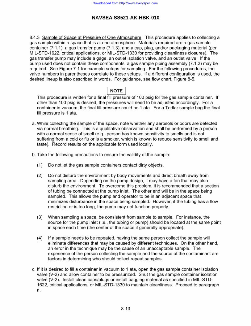
NAVSEA SS521-AK-HBK-010
8.4.3 Sample of Space at Pressure of One Atmosphere. This procedure applies to collecting a gas sample within a space that is at one atmosphere. Materials required are a gas sample container (7.1.1), a gas transfer pump (7.1.3), and a cap, plug, and/or packaging material (per MIL-STD-1622, critical applications, or MIL-STD-1330 for providing cleanliness closures). The gas transfer pump may include a gage, an outlet isolation valve, and an outlet valve. If the pump used does not contain these components, a gas sample piping assembly (7.1.2) may be required. See Figure 7-1 for example setups for sampling. For the following procedures, the valve numbers in parentheses correlate to these setups. If a different configuration is used, the desired lineup is also described in words. For guidance, see flow chart, Figure 8-5.
NOTE This procedure is written for a final fill pressure of 100 psig for the gas sample container. If
other than 100 psig is desired, the pressures will need to be adjusted accordingly. For a container in vacuum, the final fill pressure could be 1 ata. For a Tedlar sample bag the final fill pressure is 1 ata.
a. While collecting the sample of the space, note whether any aerosols or odors are detected
via normal breathing. This is a qualitative observation and shall be performed by a person with a normal sense of smell (e.g., person has known sensitivity to smells and is not suffering from a cold or flu or is a smoker, which is known to reduce sensitivity to smell and taste). Record results on the applicable form used locally.
b. Take the following precautions to ensure the validity of the sample: (1) Do not let the gas sample containers contact dirty objects. (2) Do not disturb the environment by body movements and direct breath away from
sampling area. Depending on the pump design, it may have a fan that may also disturb the environment. To overcome this problem, it is recommended that a section of tubing be connected at the pump inlet. The other end will be in the space being sampled. This allows the pump and operator to be in an adjacent space that minimizes disturbance in the space being sampled. However, if the tubing has a flow restriction or is too long, the pump may not function properly.
(3) When sampling a space, be consistent from sample to sample. For instance, the
source for the pump inlet (i.e., the tubing or pump) should be located at the same point in space each time (the center of the space if generally appropriate).
(4) If a sample needs to be repeated, having the same person collect the sample will
eliminate differences that may be caused by different techniques. On the other hand, an error in the technique may be the cause of an unacceptable sample. The experience of the person collecting the sample and the source of the contaminant are factors in determining who should collect repeat samples.
c. If it is desired to fill a container in vacuum to 1 ata, open the gas sample container isolation
valve (V-2) and allow container to be pressurized. Shut the gas sample container isolation valve (V-2). Install clean caps/plugs or install bagging material as specified in MIL-STD-1622, critical applications, or MIL-STD-1330 to maintain cleanliness. Proceed to paragraph n.
8-13
Downloaded from http://www.everyspec.com

NAVSEA SS521-AK-HBK-010
d. If a gas sample container does not have a vent valve and contains pressure, vent the
container as specified in paragraph e just prior to connecting it, except open the gas sample container isolation valve (V-2) vice the vent valve (V-5). Connect a gas sample container to the pump outlet. If a gas sample piping assembly is used, connect it between the gas sample container and pump outlet. Line up valves so that when gas is supplied, gas will not be vented from or supplied to the gas sample container. (Shut V-1 and V-3. Keep valves V-2 and V-5 shut, and open V-4).
e. For a Tedlar sample bag, no action is required for this step. For container with pressure that
needs to be vented, open vent valve (V-5) on the gas sample container to depressurize container. Listen for audible flow and when container is almost vented but still has some pressure, shut vent valve (V-5).
NOTE
If the container is supposed to have pressure and it has none, it could be contaminated. Do not use the container. Get it gas cleaned and sample as specified in 9.3.
For paragraphs f, g, h, and i, if it is desired to fill a Tedlar bag and vent the gas sample
piping assembly, pressurize and vent the piping up to the isolation valve (V-2) as specified in paragraphs f, g, h and i. Then, open the gas sample container isolation valve (V-2) and fill the Tedlar bag. Used Tedlar bags shall be filled and emptied 2 to 3 times prior to collecting a sample (this is optional for new bags). Proceed to paragraph m.
f. Start the pump, open the gas sample container isolation valve (V-2), and pressurize the gas
sample container to 80 to 100 psig (for a Tedlar sample bag, run pump until bag is full), then stop the pump.
For gas sample containers being pressurized and vented multiple times (see paragraph 8.2) –if it does not apply, skip steps g through j: g. Open vent valve on the gas sample container (V-5) to depressurize container. Listen for
audible flow and when container is almost vented but still has some pressure, shut vent valve (V-5).
h. Open gas supply container isolation valve (V-2) and pressurize it to 80 to 100 psig. Shut
valve (V-2) to isolate the container. i. Repeat pressurizing to 80 to 100 psig and venting one more time. Pressurize the third time
to 90 to 100 psig. Slowly increase the regulator setting if necessary. j. Shut the gas sample container isolation valve (V-2). For collecting multiple samples (e.g., primary and backup samples) –if it does not apply, skip steps k and l; k. Shut gas piping assembly isolation valve (V-4). Open the gas sample piping vent valve (V-3) to vent the piping assembly so the container can be disconnected. While maintaining
cleanliness, remove gas sample container. Install clean caps/plugs or install bagging
8-14
Downloaded from http://www.everyspec.com

NAVSEA SS521-AK-HBK-010
material as specified in MIL-STD-1622, critical applications, or MIL-STD-1330 to maintain cleanliness. Shut the gas sample piping assembly vent valve (V-3).
l. (1) or (2): Get another gas sample container for the additional sample. Repeat paragraphs
b through k until the desired number of samples are collected. Completion of collecting sample: m. Shut valve at system connection (V-1) and open gas piping assembly isolation valve (V-4).
Open the vent valve(s) (V-3) to vent the piping assembly, pump, and associated piping. If gas sample container is still connected, while maintaining cleanliness, remove gas sample container, pump, and if used, gas sample piping assembly. Install clean caps/plugs or install bagging material as specified in MIL-STD-1622, critical applications, or MIL-STD-1330 to maintain cleanliness.
n. Process the gas sample as specified in 8.7.
8-15
Downloaded from http://www.everyspec.com

NAVSEA SS521-AK-HBK-010
Aerosols & OdorsNote if aerosols or odors are detected and record results.Precautionsa. Don't let gas sample containers contact dirty objects.b. Do not disturb environment.c. Be consistent from sample to sample.d. Consider if same person should take repeat sample if required.
The container does nothave an installed vent valve and
requires venting?
Depressurize ContainerOpen V-2 to depressurize. Listen foraudible flow. When almost vented butstill has some pressure, shut V-2.
Did container havepressure in it?
Contaminated ContainerContainer did not have pressure andcould be contaminated. Do not useand get it gas cleaned and sample per9.3. Select another container.
Connect ContainerConnect gas sample container to pump outlet. If gas sampleassembly is used, connect it between the gas samplecontainer and pump. Shut V-1 and V-3. Keep V-2 and V-5shut. Open V-4.
Note: Procedure is for a final fill pressure of 100 psig.If other than 100 psig is desired, adjust the pressureaccordingly. For a container in vacuum, the final fillpressure could be 1 ata.
Yes
No
The container has aninstalled vent valve and requires
venting?
Pressurize ContainerOpen V-2 and pressurize containerto 80-100 psig. For Tedlar bag, runpump until bag is full.
Figure 8-5. Space Sample at One Atmosphere With Sample Collected inSpace (paragraph 8.4.3)
Yes
No
No
YesFillingcontainer in vacuum to 1
ata?
Fill ContainerOpen V-2 and allow container to be pressurized.Shut V-2. Remove gas sample container and installcaps/plugs/bagging material.
Process SampleProcess sampleper paragraph 8.7.
Filling Tedlar bagand is it desired to pressurize and
vent the gas piping assembly multipletimes?
Vent/Pressurize AssemblyPerform the steps in the bracket, exceptpressurize and vent piping up to V-2.
Start
NoYes
Depressurize ContainerOpen V-5 to depressurize. Listen foraudible flow. When almost vented butstill has some pressure, shut V-5.
Did container havepressure in it?
Contaminated ContainerContainer did not have pressure andcould be contaminated. Do not useand get it gas cleaned and sample per9.3. Select another container.
NoYes
Doescontainer require pressing and
venting multiple times?
Note: This procedure is writtenfor 2 purge cycles. If more orless are required, adjustaccordingly
Depressurize ContainerOpen V-5 to depressurize. Listen foraudible flow. When almost vented butstill has some pressure, shut V-5.
Pressurize ContainerOpen V-2 and pressurize to 80-100psig. Shut V-2.
Repeat pressing and ventingtwice. On third pressurization,pressurize to 90-100 psig andadjust regulator if necessary.
Yes
No
YesAre additional samples being taken (e.g., primary
and backup)?
Remove ContainerShut V-4. Open V-3 and vent piping. Removegas sample container and install caps/plugs/bagging material to maintain cleanliness. ShutV-3
Process SampleProcess sample per paragraph 8.7.
Remove ContainerShut V-4 and V-1. Open V-3 and ventpiping. Remove gas sample containerand install caps/plugs/bagging material tomaintain cleanliness.
New ContainerGet another gas sample container.
No
Yes
No
8-16
Downloaded from http://www.everyspec.com

NAVSEA SS521-AK-HBK-010
8.4.4 Sample of Space at Pressure Greater than Final Sample Pressure. This procedure applies to collecting a gas sample for a space where the space pressure exceeds the final sample pressure. Materials required are a gas sample container (7.1.1) and a cap, plug, and/or packaging material (per MIL-STD-1622, critical applications, or MIL-STD-1330 for providing cleanliness closures for maintaining cleanliness). For collecting a sample at connection with a cylinder or canister or equal, a gas sample piping assembly (7.1.2) is needed. For collecting a sample from within the space, the gas sample cylinder or canister or equal and associated valves and fittings must be hydrostatically tested and implosion tested based on the pressure in the space. A Tedlar sample bag can only be used at a system connection. See Figure 7-1 for example setups for sampling. For the following procedures, the valve numbers in parentheses correlate to these setups. If a different configuration is used, the desired lineup is also described in words. For guidance, see flow chart, Figures 8-6 and 8-7. a. While collecting the sample of the space, note whether any aerosols or odors are detected
via normal breathing. This is a qualitative observation and shall be performed by a person with a normal sense of smell (e.g., person has known sensitivity to smells and is not suffering from a cold or flu or is a smoker, which is known to reduce sensitivity to smell and taste). Record results on the applicable form used locally.
b. Take the following precautions to ensure the validity of the sample: (1) Do not let the gas sample containers contact dirty objects. (2) Do not disturb the environment by body movements and direct breath away from
sampling area. If sampling at a system connection, install a section of tubing with one end near the center of the space, or at an alternate location of appropriate. The other end will be connected to a piping system leading outside the space.
(3) When sampling a space, be consistent from sample to sample. For instance, the
tubing should be located at same point in space each time. (4) If a sample needs to be repeated, having the same person collect the sample will
eliminate differences that may be caused by different techniques. On the other hand, an error in the technique may be the cause of an unacceptable sample. The experience of the person collecting the sample and the source of the contaminant are factors in determining who should collect repeat samples.
For collecting sample at system connection (paragraphs c through p) – proceed to paragraph q through u if collecting sample from in space: c. If a Tedlar sample bag, or equal, is employed, simply fill bag by throttling a system or test
valve until the bag is filled. Used Tedlar bags shall be filled and emptied 2 to 3 times prior to collecting a sample (this is optional for new bags). When finished, proceed to paragraph u. For containers or cylinders, collect the sample as specified in paragraphs d through p.
d. Shut valve at system connection. Line up valves so that when gas is supplied to the gas
sample piping assembly, gas will not be vented from or supplied to the gas sample container. (Shut V-1 and V-3. Keep valves V-2 and V-5 shut, and open V-4). If gas sample container does not have a vent valve and contains pressure, vent the container as specified
8-17
Downloaded from http://www.everyspec.com

NAVSEA SS521-AK-HBK-010
in paragraph h just prior to connecting to system, except open the gas sample container isolation valve (V-2) vice the vent valve (V-5).
e. Open valve at system connection (V-1) and purge for approximately 30 seconds (purge time
depends on the sample source volume).
WARNING If the pressure of the item being sampled exceeds the working pressure for the sample
container, the gas sample piping assembly or system piping should have a regulator in order to protect the sample container from accidental over pressurization. If a relief valve is used, confirm it is set at the desired pressure.
f. Reduce purge to only a slight flow then attach the gas sample piping assembly with the
clean gas sample container at the system connection. Shut valve at system connection (V-1). g. Open the valve at the system connection (V-1) to pressurize the gas sample piping
assembly. If a regulator is used, adjust the regulator (V-7) on the gas sample piping assembly until 80 to 100 psig is indicated on the gas sample piping assembly gage.
h. For container with a vacuum, no action is required for this step. For container with pressure
that needs to be vented, open vent valve (V-5) on the gas sample container to depressurize the container. Listen for audible flow and when container is almost vented but still has some pressure, shut vent valve (V-5).
NOTE
If the container is supposed to have pressure and it has none, it could be contaminated. Do not use the container. Get it gas cleaned and sample as specified in 9.3
i. Open gas sample container isolation valve (V-2) and pressurize it to 80 to 100 psig. Shut
valve (V-2) to isolate the container. For gas sample containers being pressurized and vented multiple times (see paragraph 8.2) –if it does not apply, skip steps j through m: j. Open vent valve on the gas sample container (V-5) to depressurize container. Listen for
audible flow and when container is almost vented but still has some pressure, shut vent valve (V-5).
k. Open gas supply container isolation valve (V-2) and pressurize it to 80 to 100 psig. Shut
valve (V-2) to isolate the container. l. Repeat pressurizing to 80 to 100 psig and venting one more time. Pressurize the third time
to 90 to 100 psig. Slowly increase the regulator setting if necessary. m. Shut gas sample container isolation valve (V-2).
8-18
Downloaded from http://www.everyspec.com

NAVSEA SS521-AK-HBK-010
For collecting multiple samples (e.g., primary and backup samples) –if it does not apply, skip steps n and o: n. Shut gas piping assembly isolation valve (V-4). Open the gas sample piping assembly vent
valve (V-3) to vent the piping assembly so the container can be disconnected. While maintaining cleanliness, remove gas sample container. Install clean caps/plugs or install bagging material as specified in MIL-STD-1622, critical applications, or MIL-STD-1330 to maintain cleanliness. Shut the gas sample piping assembly vent valve (V-3).
o. Get another gas sample container for the additional sample. If it does not have a vent valve
and contains pressure, vent the container as specified in paragraph e just prior to connecting to system, except open the gas sample container isolation valve (V-2) vice the vent valve (V-5). Install the gas sample container and repeat paragraphs d through n until the desired number of samples are collected.
Completion of collecting sample: p. Shut valve at system connection (V-1) and open gas piping assembly isolation valve (V-4).
Open the gas sample piping assembly vent valve (V-3) to vent the piping assembly. If gas sample container is still connected, while maintaining cleanliness, remove gas sample container. Remove gas sample piping assembly. Install clean caps/plugs or install bagging material as specified in MIL-STD-1622, critical applications, or MIL-STD-1330 to maintain cleanliness. Process the gas sample as specified in 8.7.
For collecting sample in space: q. Open gas sample container isolation valve (V-2) and allow container to be pressurized.
Shut the gas sample container isolation valve (V-2). r. If the gas sample container will remain in the space, cover the connections to maintain
cleanliness yet allow venting of pressure when the space gets depressurized. Otherwise, transfer (e.g., lock out) the gas sample container out of the space being sampled to a space at one atmosphere.
s. With the gas sample container in the one atmosphere space, install clean caps/plugs or
install bagging material as specified in MIL-STDS-1622, critical applications, or MIL-STD-1330 to maintain cleanliness.
t. Tag the gas sample container to indicate the pressure in the container. Venting some
pressure from the container prior to shipping to the laboratory is acceptable. u. Process the gas sample as specified in 8.7.
8-19
Downloaded from http://www.everyspec.com

NAVSEA SS521-AK-HBK-010
Initial Line-upShut V-1 and V-3. Keep V-2 andV-5 shut. Open V-4.
Start
The container does nothave an installed vent valve and
requires venting?
Depressurize ContainerOpen V-2 to depressurize. Listen foraudible flow. When almost vented butstill has some pressure, shut V-2.
Did container havepressure in it?
Contaminated ContainerContainer did not have pressure andcould be contaminated. Do not useand get it gas cleaned and sample per9.3. Select another container.
Connect ContainerOpen V-1 and purge for about 30 seconds.Reduce to slight flow and attach gas sample pipingassembly and container. Open V-1 to pressurizeassembly. If a regulator is used, adjust regulator(V-7) until gage indicates 80 to 100 psig.
Note: Procedure is for a final fill pressure of 100 psig. If other than100 psig is desired, adjust the pressure accordingly. For acontainer in vacuum, the final fill pressure could be 1 ata.
Yes No
The container has aninstalled vent valve and requires
venting?
Depressurize ContainerOpen V-5 to depressurize. Listen foraudible flow. When almost vented butstill has some pressure, shut V-5.
Did container havepressure in it?
Contaminated ContainerContainer did not have pressure andcould be contaminated. Do not useand get it gas cleaned per 9.3.2.Select another container.
No
Pressurize ContainerOpen V-2 and pressurize containerto 80-100 psig. Shut V-2.
Figure 8-6. Space pressure greater than final sample pressure with sample collected atsystem connection (paragraph 8.4.4.a, b, and c through p)
Yes
No
No
Yes
Doescontainer require pressing and
venting multiple times?
Note: This procedure is writtenfor 2 purge cycles. If more orless are required, adjustaccordingly
Depressurize ContainerOpen V-5 to depressurize. Listen foraudible flow. When almost vented butstill has some pressure, shut V-5.
Pressurize ContainerOpen V-2 and pressurize to 80-100psig. Shut V-2.
Repeat pressing and ventingtwice. On third pressurization,pressurize to 90-100 psig andadjust regulator if necessary.
Yes
No
Are additional samples being taken (e.g., primary
and backup)?
Remove ContainerShut V-4. Open V-3 and vent piping. Removegas sample container and install caps/plugs/bagging material to maintain cleanliness. ShutV-3.
Process SampleProcess sample per paragraph 8.7.
Remove ContainerShut V-4 and V-1. Open V-3 and ventpiping. Remove gas sample containerand install caps/plugs/bagging material tomaintain cleanliness. New Container
Get another gas sample container.
Yes
No
Yes
Aerosols & OdorsNote if aerosols or odors are detected and record results.Precautionsa. Don't let gas sample containers contact dirty objects.b. Do not disturb environment.c. Be consistent from sample to sample.d. Consider if same person should take repeat sample if required.
Filling Tedlar bag?Fill bagFill bag by throttling a system or testvalve until bag is filled.
Yes
No
Process SampleProcess sample per paragraph 8.7.
8-20
Downloaded from http://www.everyspec.com

NAVSEA SS521-AK-HBK-010
Start
Figure 8-7. Space pressure greater than final sample pressure with sample collected inspace (paragraph 8.4.4.a, b, and q through u)
Process SampleProcess sample per paragraph 8.7.
Container CleanlinessIn a one atmosphere space, install caps/plugs/bagging material to maintaincleanliness.
Aerosols & OdorsNote if aerosols or odors are detected and record results.Precautionsa. Don't let gas sample containers contact dirty objects.b. Do not disturb environment.c. Be consistent from sample to sample.d. Consider if same person should take repeat sample if required.
Pressurize ContainerOpen V-2 and pressurize container. Shut V-2.
Preparation of ContainerCover connections to maintain cleanliness yetallow venting of pressure when space getsdepressurized.
Transfer ContainerTransfer (e.g., lock out) the gas sample containerout of the space being sampled to a space at oneatmosphere.
Tag ContainerTag the gas sample container to indicatethe pressure in the container. Ventingsome pressure from the container prior toshipping to the laboratory is acceptable.
Will container remain inspace?
Yes
No
8-21
Downloaded from http://www.everyspec.com

NAVSEA SS521-AK-HBK-010
8.4.5 Sample of Space at Pressure Less Than Final Sample Pressure. This procedure applies to collecting a gas sample for a space where the space pressure is less than the final sample pressure. The sample is collected from a system as shown in top example of Figure 7-1. Perform paragraphs 8.4.4.a and b with the tubing connected to a system, then perform paragraph 8.4.2. For guidance, see flow chart, Figure 8-8. 8.5 OTHER METHODS OR PORTABLE ANALYZER. 8.5.1 Elevated Pressure Sampled Remotely Through System Connection. This procedure applies to collecting a sample using other methods from a system at an elevated pressure. It is written for using a colorimetric device because it is the most common “other method” used. For methods other than a colorimetric device, such as a NIOSH method, the procedures will need to be modified as required by the method used. Follow all manufacturers’ instructions for use of detector tube with sampling pump and calibration of flow rate. Materials required are a detector tube with sampling pump for the desired reactive constituent, and for an inflatable bag, either use a Tedlar bag or fabricate an inflatable bag using packaging material as specified in MIL-STD-1622 or MIL-STD-1330, tubing (e.g., Tygon, Teflon, or copper) cleaned per MIL-STD-1622, critical applications, or MIL-STD-1330, and tape. a. Open valve at system connection (V-1) and purge for approximately 30 seconds (purge time
depends on the sample source volume). Shut valve at system connection (V-1). b. Install a length of tubing on the sampling pump. c. Prepare sampling pump per manufacturer’s instructions. d. Seal the bagging material with tape to form a tightly sealed bag. Puncture a hole in the
sample bag then place over open ended system connection. Open valve at system connection. Adjust the flow for a slight purge. Collect a small, one atmosphere sample in the bag. Shut the isolation valve.
NOTE In order to use colorimetric devices properly, the sample must be at one atmosphere. A
purge (flowing) sample cannot be accurately measured by this method. Therefore, a small sample of gas is collected.
e. Place the tube mounted on the sampling pump in the hole in the bag. f. Each manufacturer of detector tubes and sampling pumps produces tubes that are
compatible with that manufacturer’s pump only. Tubes and pumps are not interchangeable. When sampling, refer to the manufacturer’s instructions for proper operation of the sampling pump, direction for reading the concentration from the tube, and the required number of pump strokes.
g. In some cases, a reading on the low end of the detector tube scale may be obtained by
doubling or tripling the number of pump strokes. This effectively doubles or triples the sample volume. A correct reading is determined by dividing the indicated concentration by 2 or 3, as appropriate. Consult vendor literature to determine if this procedure applies for a detector tube.
h. Record results on the applicable form used locally.
8-22
Downloaded from http://www.everyspec.com
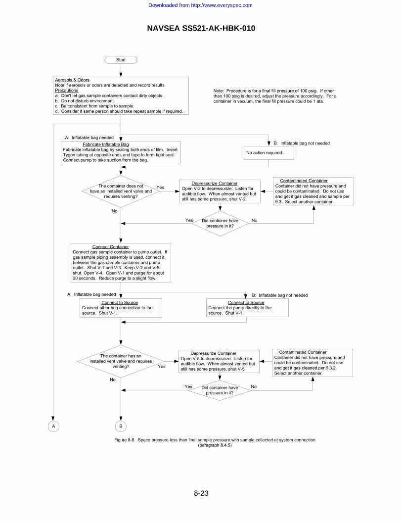
NAVSEA SS521-AK-HBK-010
Fabricate Inflatable BagFabricate inflatable bag by sealing both ends of film. InsertTygon tubing at opposite ends and tape to form tight seal.Connect pump to take suction from the bag.
The container does nothave an installed vent valve and
requires venting?
Depressurize ContainerOpen V-2 to depressurize. Listen foraudible flow. When almost vented butstill has some pressure, shut V-2.
Did container havepressure in it?
Contaminated ContainerContainer did not have pressure andcould be contaminated. Do not useand get it gas cleaned and sample per9.3. Select another container.
Connect ContainerConnect gas sample container to pump outlet. Ifgas sample piping assembly is used, connect itbetween the gas sample container and pumpoutlet. Shut V-1 and V-3. Keep V-2 and V-5shut. Open V-4. Open V-1 and purge for about30 seconds. Reduce purge to a slight flow.
Note: Procedure is for a final fill pressure of 100 psig. If otherthan 100 psig is desired, adjust the pressure accordingly. For acontainer in vacuum, the final fill pressure could be 1 ata.
Yes No
The container has aninstalled vent valve and requires
venting?
Depressurize ContainerOpen V-5 to depressurize. Listen foraudible flow. When almost vented butstill has some pressure, shut V-5.
Did container havepressure in it?
Contaminated ContainerContainer did not have pressure andcould be contaminated. Do not useand get it gas cleaned per 9.3.2.Select another container.
Yes No
Yes
No
No
Yes
No action required.
A: Inflatable bag neededB: Inflatable bag not needed
Connect to SourceConnect other bag connection to thesource. Shut V-1.
Connect to SourceConnect the pump directly to thesource. Shut V-1.
A: Inflatable bag needed B: Inflatable bag not needed
Start
Aerosols & OdorsNote if aerosols or odors are detected and record results.Precautionsa. Don't let gas sample containers contact dirty objects.b. Do not disturb environment.c. Be consistent from sample to sample.d. Consider if same person should take repeat sample if required.
Figure 8-8. Space pressure less than final sample pressure with sample collected at system connection(paragraph 8.4.5)
A B
8-23
Downloaded from http://www.everyspec.com
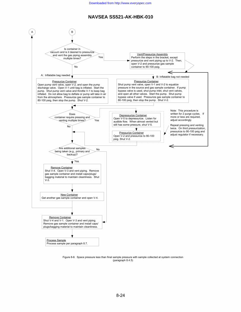
NAVSEA SS521-AK-HBK-010
Are additional samplesbeing taken (e.g., primary and
backup)?
Remove ContainerShut V-4. Open V-3 and vent piping. Removegas sample container and install caps/plugs/bagging material to maintain cleanliness. ShutV-3.
Process SampleProcess sample per paragraph 8.7.
Remove ContainerShut V-4 and V-1. Open V-3 and vent piping.Remove gas sample container and install caps/plugs/bagging material to maintain cleanliness.
New ContainerGet another gas sample container and open V-4.
Yes
No
A
Figure 8-8. Space pressure less than final sample pressure with sample collected at system connection(paragraph 8.4.5)
Doescontainer require pressing and
venting multiple times?
Note: This procedure iswritten for 2 purge cycles. Ifmore or less are required,adjust accordingly
Depressurize ContainerOpen V-5 to depressurize. Listen foraudible flow. When almost vented butstill has some pressure, shut V-5.
Pressurize ContainerOpen V-2 and pressurize to 80-100psig. Shut V-2.
Yes
No
Is container invacuum and is it desired to pressurize
and vent the gas piping assemblymultiple times?
Pressurize ContainerOpen pump vent valve, open V-2, and open the pumpdischarge valve. Open V-1 until bag is inflated. Start thepump. Shut pump vent valve and throttle V-1 to keep baginflated. Do not allow bag to deflate or pump will take in airfrom the atmosphere. Pressurize gas sample container to80-100 psig, then stop the pump. Shut V-2.
Pressurize ContainerShut pump vent valve, open V-1 and V-2 to equalizepressure in the source and gas sample container. If pumpbypass valve is used, shut pump inlet, shut vent valves,and open all other valves. Start the pump. Shut pumpbypass valve if used. Pressurize gas sample container to80-100 psig, then stop the pump. Shut V-2.
A: Inflatable bag needed B: Inflatable bag not needed
Vent/Pressurize AssemblyPerform the steps in the bracket, exceptpressurize and vent piping up to V-2. Then,open V-2 and pressurize gas samplecontainer to 90-100 psig.
Yes
No
Repeat pressing and ventingtwice. On third pressurization,pressuirze to 90-100 psig andadjust regulator if necessary.
B
8-24
Downloaded from http://www.everyspec.com

NAVSEA SS521-AK-HBK-010
8.5.2 Space or Tedlar sample bag at One Atmosphere. This procedure applies to collecting a sample using other methods from a space at one atmosphere. It is written for using a colorimetric device because it is the most common “other method” used. For methods other than a colorimetric device, such as a NIOSH method, the procedures will need to be modified as required by the method used. Materials required are a detector tube with sampling pump for the desired reactive constituent and for sampling from a Tedlar bag, tubing (e.g., Tygon, Teflon, or copper) cleaned per MIL-STD-1622, critical applications, or MIL-STD-1330. a. For sampling in a space, to ensure the validity of the sample, do not disturb the environment
by body movement and direct breath away from the sampling area. b. For sampling from a Tedlar bag, install tubing from the bag to the sampling pump. c. Prepare sampling pump per manufacturer’s instructions. d. Follow guidance specified in 8.5.1.f and 8.5.1.g. e. Record results on the applicable form used locally. 8.5.3 Space at Elevated Pressure. This procedure applies to collecting a sample using other methods from a space at an elevated pressure. It is written for using a colorimetric device because it is the most common “other method” used. For methods other than a colorimetric device, such as a NIOSH method, the procedures will need to be modified as required by the method used. Material required is a detector tube with sampling pump for the desired reactive constituent.
NOTE Ensure that the sampling pump used is appropriate for collecting readings within a
pressurized environment. a. Choose the desired colorimetric device. First, break the tip at the opposite end from the one
to be inserted in the pump. Then break the other tip. The in-rushing gas should then not disturb the chemicals except to make the reading conservative. Insert into pump outlet so that red dot or arrow points toward the pump.
b. Operate the pump per the manufacturer’s instructions. To ensure validity of the sample, do
not disturb the environment by body movement and direct breath away from the sampling area. Follow guidance specified in 8.5.1.f and 8.5.1.g.
c. Record results on the applicable form used locally. 8.6 PORTABLE ANALYZER. 8.6.1 Space at One Atmosphere. This procedure applies to collecting a sample with a portable analyzer from a space at one atmosphere. Material required is a portable analyzer for the desired constituent. a. Follow manufacturer’s instructions for sampling directly from a space. b. Record results on the applicable form used locally.
8-25
Downloaded from http://www.everyspec.com

NAVSEA SS521-AK-HBK-010
8.6.2 Space or System at Elevated Pressure. This procedure applies to collecting a sample with a portable analyzer from a space at elevated pressure. Materials required are a portable analyzer for the desired constituent and tubing with adapters cleaned per MIL-STD-1330 to connect the portable analyzer to a system connection. In some cases, such as the Toxic Vapor Analyzer, a regulator and Y-connection cleaned per MIL-STD-1330 may be required. The regulator is used to reduce the pressure and the Y-connection is used with one branch to the analyzer and the other as overflow. a. For sampling a pressurized space, sample remotely through a system connection. b. Open valve at system connection (V-1) and purge for approximately 30 seconds (purge time
depends on the sample source volume). Shut valve at system connection (V-1). c. Connect tubing at the system connection. If analyzer uses a probe, individually adapt each
analyzer probe to tubing to ensure gas can freely flow around probe without pressurizing the probe. If analyzer does not use a probe, follow manufacturer’s instructions for connecting to source.
d. Open valve at system connection (V-1). Adjust flow to slightly purge analyzer. If probe is
used, purge the probe adapted to the tubing. Adjust flow to slightly purge probe adapted to the tubing.
e. Analyze for contaminants per manufacturer’s instructions. f. Record results on the applicable form used locally. 8.7 PROCESSING GAS SAMPLES. 8.7.1 Send to laboratory. For samples collected in a gas sample container, send the container to the laboratory determined in Chapter 6 for analysis. If the containers need to be shipped, special requirements for transporting the gas sample container may apply. Include instructions for laboratory analysis (e.g., which list of constituents to analyze to). 8.7.2 Paperwork. Ensure all paperwork is properly filled out identifying the source of the sample, when the sample was collected, who took the sample, a unique number identifying the gas sample container, and any on-site analysis such as aerosols and odor. This paperwork is generally sent to the laboratory with the gas sample containers. If the laboratory results are not logged on this paperwork, there must be a unique number to tie the laboratory results to this paperwork. 8.7.3 Evaluation. The laboratory shall submit the completed paperwork to the activity designated to review the data. The results shall be evaluated as specified in Chapter 10. The containers should be held until the results are deemed as acceptable in case repeat analysis or analysis of a backup sample is needed. 8.7.4 Cleaning Gas Sample Containers. After review of the results is complete, the gas sample containers should be cleaned and sampled as specified in paragraph 9.3.
8-26
Downloaded from http://www.everyspec.com

NAVSEA SS521-AK-HBK-010
CHAPTER 9 MAINTENANCE OF GAS SAMPLING EQUIPMENT
9.1 MAINTENANCE REQUIREMENTS. The maintenance requirements for the gas sampling equipment are specified in Table 9-1. The cleaning philosophy is different than for systems. Systems are cleaned to eliminate flammability and toxicological hazards. The gas sampling equipment is cleaned only to eliminate toxicological hazards from contamination or previous sampling. An exception is samples with high oxygen content (>25%) that require cleaning per MIL-STD-1330.
Table 9-1. Maintenance requirements.
Periodicity Action Required 1/ Gas sample piping assembly
After manufacture Clean per MIL-STD-1330 and sample per 9.2 3/.
If contamination is suspected or evident that probably will not affect gas sample (e.g., abnormally large amount of particulate, last item sampled did not pass analysis)
Sample per 9.2.
If contamination is suspected or evident that probably will affect gas sample (e.g., lubricant)
Clean per MIL-STD-1330 and sample per 9.2 3/.
Gas sample container New Clean per MIL-STD-1330 and gas
clean and sample per 9.3 2/, 3/. If contamination is suspected or evident that probably will not affect gas sample (e.g., abnormally large amount of particulate)
Gas clean and sample per 9.3.
If contamination is suspected or evident that probably will affect gas sample (e.g., lubricant, hydrostatic test without maintaining clean)
Clean per MIL-STD-1330 and gas clean and sample per 9.3 2/.
After each use Gas clean and sample per 9.3. Gas transfer pump
New Clean per MIL-STD-1330 and sample per 9.4 3/.
If contamination is suspected or evident that probably will not affect gas sample (e.g., abnormally large amount of particulate)
Sample per 9.4.
If contamination is suspected or evident that probably will affect gas sample (e.g., lubricant)
Clean per MIL-STD- and sample per 9.4 3/.
1/ Rather than collecting a gas sample of the item, it can be certified by using it to collect a gas sample of something else (e.g., a system or chamber sample). Considerations are the risk of not passing due to the item contaminating the sample and the cost of resampling. 2/ Do not use lubricant on gas-wetted surfaces because it could affect the gas analysis results. For any required tightness testing, do not use leak detection solution because it could contaminate items such as valves that are bagged whole with no end caps. A viable alternative is an electronic leak detector. 3/ Cleaning per instructions other than MIL-STD-1330 is acceptable with NAVSEA approval. Cleaning per MIL-STD-1622, critical applications, vice MIL-STD-1330 is acceptable for low oxygen content samples (<25%).
9-1
Downloaded from http://www.everyspec.com

NAVSEA SS521-AK-HBK-010
9.2 GAS SAMPLE PIPING ASSEMBLY - SAMPLE This procedure applies to collecting a gas sample of a gas sample piping assembly. Materials required are a gas sample container (7.1.1) and a cap, plug and/or bagging material (per MIL-STD-1622, critical applications, or MIL-STD-1330 for providing cleanliness closures for maintaining cleanliness). See Figure 7-1 for example setups for sampling. For the following procedures, the valve numbers in parentheses correlate to these setups. If a different configuration is used, the desired lineup is also described in words. A gas supply is needed to provide the carrier gas for the gas sample. For selecting the carrier gas, the purity needs to be considered. Gas with impurities can cause results to be unacceptable due to the carrier gas, despite the gas sample piping assembly being clean. The simplest option is to use the highest purity gas that will be used in the future with the gas piping assembly. Zero air can also be used if analysis of the air is below the laboratory detection limit for all constituents that will be analyzed for gas collected in the future with the gas piping assembly. If necessary, known constituents can be subtracted in the carrier gas from the gas sample piping assembly sample; however, this should be employed with caution considering the constituent, measurement accuracy, and the application.
NOTE This procedure is written for a final fill pressure of 100 psig for the gas sample container. If
other than 100 psig is desired, the pressures will need to be adjusted accordingly. For a container in vacuum, the pressure could be 1 ata.
a. Open gas supply isolation valve (V-1) and purge for approximately 30 seconds (purge time
depends on gas supply volume).
WARNING If the gas source pressure exceeds the working pressure for the sample container, the gas
sample piping assembly or gas source should have a regulator in order to protect the sample container from accidental over pressurization. If a relief valve is used, confirm it is set at the desired pressure.
b. Reduce purge to only a slight flow then attach the gas sample piping assembly with the
clean gas sample container to the gas supply. Shut gas supply isolation valve (V-1). c. Line up valves so that the regulator downstream pressure can be monitored on the gas
sample piping assembly gage and gas will not be vented from or supplied to the gas sample container. (Shut V-1 and V-3. Keep V-2 and V-5 shut, and open V-4).
d. Open the gas supply isolation valve (V-1) to pressurize the gas sample piping assembly.
Adjust the regulator on the gas sample piping assembly until 80 to 100 psig is indicated on the gas sample piping assembly gage.
e. For a container with a vacuum, no action is required for this step. For container with
pressure that needs to be vented, open vent valve (V-5) on the gas sample container to depressurize container. Listen for audible flow and when container is almost vented but still has some pressure, shut vent valve (V-5).
9-2
Downloaded from http://www.everyspec.com

NAVSEA SS521-AK-HBK-010
NOTE
If the container has no pressure in it, it could be contaminated. Do not use the container. Get it gas cleaned and sample as specified in 9.3.
f. Open gas sample container isolation valve (V-2) and pressurize the container to 80 to 100
psig. Shut valve (V-2) to isolate the container. For gas sample containers being pressurized and vented multiple times (see paragraph 8.2) –if it does not apply, skip steps g through i: g. Open vent valve on the gas sample container (V-5) to depressurize container. Listen for
audible flow and when container is almost vented but still has some pressure, shut vent valve (V-5).
h. Repeat pressurizing to 80 to 100 psig and venting one more time. i. Pressurize the third time to 90 to 100 psig. Slowly increase the regulator setting if
necessary. Hold and completion of collecting sample: j. Isolate the gas supply. Maintain the gas sample container and the gas piping sample
assembly at 90 to 100 psig for 24 hours minimum. k. Shut gas sample container isolation valve (V-2) and valve at system connection (V-1).
Open the gas sample piping assembly vent valve (V-3) to vent the piping assembly so the container can be disconnected.
l. While maintaining cleanliness, remove gas sample container and gas sample piping
assembly. Install clean caps/plugs or install bagging material as specified in MIL-STD-1622, critical applications, or MIL-STD-1330 to maintain cleanliness.
m. Process the gas sample as specified in 8.7. For the gas analysis requirements, review all
applicable target compound lists and have all of the constituents analyzed on all of the lists. Use the maximum pressure ratio that could apply for any future analyses.
n. If the results fail, clean the gas sample piping assembly per MIL-STD-1622, critical
applications, or MIL-STD-1330 and repeat the gas sample per this procedure. 9.3 GAS SAMPLE CONTAINER – GAS CLEAN AND SAMPLE. 9.3.1 Gas Clean. This procedure applies to gas cleaning a gas sample container. The gas analysis laboratory usually performs gas sample container cleaning, so steps pertaining to hardware to connect the container to the gas supply are omitted. Materials required are a heat source capable of uniformly heating the container to 160 to 170oF, a vacuum pump capable of establishing a 29-inch minimum vacuum of the gas sample container, and a cap, plug, and/or bagging material (per MIL-STD-1622, critical applications, or MIL-STD-1330 for providing cleanliness closures for maintaining cleanliness). A gas supply is needed to provide the carrier gas for the gas sample. For selecting the carrier gas, the purity needs to be considered. Gas
9-3
Downloaded from http://www.everyspec.com

NAVSEA SS521-AK-HBK-010
with impurities can cause results to be unacceptable due to the carrier gas, despite the gas sample container being clean. The simplest option is to use the highest purity gas that will be used in the future with the gas piping assembly. Zero air can also be used if analysis of the air is below the laboratory detection limit for all constituents that will be analyzed for gas collected in the future with the gas piping assembly. If necessary, known constituents can be subtracted in the carrier gas from the gas sample piping assembly sample; however, this should be employed with caution considering the constituent, measurement accuracy, and the application. a. Heat gas sample container to 160 to 170oF and maintain temperature until the container is
completely heated. Use care not to overheat any portions of the container that contain soft goods.
b. Evacuate the gas sample container to no less than 29 inches Hg vacuum. c. Pressurize the gas sample container with gas to 90 to 100 psig. d. Repeat the vacuum and pressurization (steps b and c) four additional times for a total of five
times while the container remains at 160 to 170oF. e. If the gas sample container is new or, for the last analysis done using this container, a
constituent (other than major gases) result exceeded the laboratory detection limit (see Table 4-1), proceed to paragraph 9.3.2 to collect a gas sample.
f. After the last pressurization of the gas sample flask, evacuate to no less than 29 inches Hg
vacuum, and then for pressurized containers, pressurize to 2 to 5 psig. g. Install clean caps/plugs or install bagging material as specified in MIL-STD-1330 to maintain
cleanliness. Tag each container noting gas analysis results and date. 9.3.2 Gas Sample. This procedure applies to collecting a gas sample of a gas sample container. The gas analysis laboratory usually performs it, so steps pertaining to hardware to connect the container to the gas supply are omitted. Material required is a cap, plug, or bagging material (per MIL-STD-1622, critical applications, or MIL-STD-1330 for providing cleanliness closures for maintaining cleanliness). A gas supply is needed to provide the carrier gas for the gas sample. For selecting the carrier gas, the purity needs to be considered. Gas with impurities can cause results to be unacceptable due to the carrier gas, despite the gas sample piping assembly being clean. The simplest option is to use the highest purity gas that will be used in the future with the gas piping assembly. Zero air can also be used if analysis of the air is below the laboratory detection limit for all constituents that will be analyzed for gas collected in the future with the gas piping assembly. If necessary, known constituents can be subtracted in the carrier gas from the gas sample piping assembly sample; however, this should be employed with caution considering the constituent, measurement accuracy, and the application. a. Perform gas cleaning as specified in 9.3.1, steps a through d. If other than 90 to 100 psig is
required for the laboratory analysis, pressurize to the desired pressure. Maintain pressure in the gas sample container for no less than 24 hours.
b. Process the gas sample as specified in 8.7. For the gas analysis requirements, review all
applicable compound lists and have all of the constituents analyzed on all of the lists. If any of the results are above the laboratory detection limit (see Table 4-1), repeat the gas cleaning and sampling until it passes.
9-4
Downloaded from http://www.everyspec.com

NAVSEA SS521-AK-HBK-010
c. After acceptable analysis results are obtained, evacuate to no less than 29 inches Hg
vacuum, and then for pressurized containers, pressurize to 2 to 5 psig. d. Install clean caps/plugs or install bagging material as specified in MIL-STD-1330 to maintain
cleanliness. Tag each container noting gas analysis results and date. 9.4 GAS TRANSFER PUMP - SAMPLE. This procedure applies to collecting a gas sample of a gas transfer pump. Materials required are a gas sample container (7.1.1) and a cap, plug, and/or packaging material (per 5.16 of MIL-STD-1622, critical applications, or MIL-STD-1330 for providing cleanliness closures). A gas supply is needed to provide the carrier gas for the gas sample. For selecting the carrier gas, the purity needs to be considered. Gas with impurities can cause results to be unacceptable due to the carrier gas, despite the gas sample piping assembly being clean. The simplest option is to use the highest purity gas that will be used in the future with the gas piping assembly. Another option is to subtract known contaminants in the carrier gas from the gas sample piping assembly sample. The gas transfer pump may include a gage, an outlet isolation valve, and an outlet valve. If the pump used does not contain these components, a gas sample piping assembly (7.1.2) may be required. Some pumps can not be started with a pressure source connected to it because the piston may get pushed to the bottom of the stroke and the motor can not push it back when started. If the pump used has this or a similar problem, an inflatable bag fabricated from film used as packaging material as specified in MIL-STD-1622 or MIL-STD-1330, tubing (e.g., Tygon, Teflon, or copper) cleaned per MIL-STD-1622, critical applications, or MIL-STD-1330, and tape may be required. Depending on the design, using a bypass valve around the pump may serve the same purpose. See Figure 7-1 for example setups for sampling. For the following procedures, the valve numbers in parentheses correlate to these setups. If a different configuration is used, the desired lineup is also described in words.
NOTE This procedure is written for a final fill pressure of 100 psig for the gas sample container. If
other than 100 psig is desired, the pressures will need to be adjusted accordingly. For a container in vacuum, the pressure could be 1 ata. For a Tedlar bag, the pressure is 1 ata.
If an inflatable bag is required, follow the procedure designated with a “(1)”. If it is not
required, use “(2)”. a. (1): Fabricate an inflatable bag by sealing both ends of a section of MIL-STD-1622 or MIL-
STD-1330 film (either intimate or environmental may be used). Insert tubing in two places at opposite ends of the bag and tape it to form a tight seal. Connect the pump to take suction from the bag.
(2): No action required. b. (1) or (2): If gas sample container does not have a vent valve and contains pressure, vent
the container as specified in paragraph e just prior to connecting to system, except open the gas sample container isolation valve (V-2) vice the vent valve (V-5). Connect a gas sample container to the pump outlet. If a gas sample piping assembly is used, connect it between the gas sample flask and pump outlet. Line up valves so that when gas is supplied to the gas sample piping assembly, gas will not be vented from or supplied to the gas sample container. (Shut V-1 and V-3. Keep valves V-2 and V-5 shut, and open V-4).
9-5
Downloaded from http://www.everyspec.com

NAVSEA SS521-AK-HBK-010
c. (1) or (2): Open gas supply isolation valve (V-1) and purge for approximately 30 seconds
(purge time depends on the sample source volume). Reduce purge to only a slight flow. d. (1): Connect the other bag connection to the source. Shut gas supply isolation valve (V-1). (2): Connect the pump directly to the source. Shut gas supply isolation valve (V-1). e. (1) or (2):For a container with a vacuum, no action is required for this step. For container
with pressure that needs to be vented, open vent valve (V-5) on the gas sample container to depressurize container. Listen for audible flow and when container is almost vented but still has some pressure, shut vent valve (V-5).
NOTE
If the container has no pressure in it, it could be contaminated. Do not use the container. Get it gas cleaned and sample as specified in 9.3.
For paragraphs f, g, h, i, and j, if it is desired to fill a container in vacuum and vent the gas
sample piping assembly, pressurize and vent the piping up to the gas sample container isolation valve (V-2) as specified in paragraphs f, g, and h. Then, open the gas sample container isolation valve (V-2) and pressurize to desired pressure as specified in paragraph i. Proceed to paragraph j.
f. (1): Open the pump vent valve, open the gas sample container inlet valve, and open the
pump discharge valve. Open the gas supply isolation valve until the bag is inflated. Start the pump. Shut the pump vent and throttle the gas supply isolation valve (V-1) to keep the bag inflated. Do not allow bag to deflate or pump will take in air from the atmosphere. If a Tedlar bag is employed, run pump until bag is full. Used Tedlar bags shall be filled and emptied 2 to 3 times prior to collecting a sample (this is optional for new bags). If a cylinder or canister is used, pressurize the gas sample container until pressure reaches 80 to 100 psig, then stop the pump. Shut gas sample container isolation valve (V-2).
(2): Shut pump vent valve then open all other valves (V-1 and V-2) to equalize pressure in the source and gas sample container. The pressure should be at a low pressure in order to run the pump for the maximum period for collecting the sample. If pump bypass valve is used, shut pump inlet, shut vent valves, and open all other valves. Start the pump. Shut pump bypass valve if used. If a Tedlar bag is employed, run pump until bag is full. Used Tedlar bags shall be filled and emptied 2 to 3 times prior to collecting a sample (this is optional for new bags). If a cylinder or canister is used, pressurize the gas sample container until pressure reaches 80 to 100 psig, then stop the pump. Shut gas sample container isolation valve (V-2).
NOTE
Depending on the pump, the pump will not always start if its discharge is pressurized. If this problem arises, vent the pump discharge when the gas sample container is vented.
For gas sample containers being pressurized and vented multiple times (see paragraph 8.2) –if it does not apply, skip steps g through j: g. (1) or (2): Open vent valve to depressurize gas sample container (V-5). Shut the vent valve
(V-5).
9-6
Downloaded from http://www.everyspec.com

NAVSEA SS521-AK-HBK-010
h. (1) or (2): Repeat pressurizing to 80 to 100 psig and venting one more time. i. (1) or (2): Pressurize the third time to 90 to 100 psig. Slowly increase the regulator setting if
necessary. j. (1) or (2): Shut gas sample container isolation valve (V-2). For collecting multiple samples (e.g., primary and backup samples) –if it does not apply, skip steps k and l: k. (1) or (2): Shut gas piping assembly isolation valve (V-4). Open the gas sample piping vent
valve (V-3) to vent the piping assembly so the container can be disconnected. While maintaining cleanliness, remove gas sample container. Install clean caps/plugs or install bagging material as specified in MIL-STD-1622, critical applications, or MIL-STD-1330 to maintain cleanliness.
l. (1) or (2): Install another gas sample container, open the gas piping assembly isolation
valve (V-4), and repeat paragraphs b through k until the desired number of samples are collected.
Completion of collecting sample: m. (1) or (2): Shut valve at system connection (V-1). Open the vent valve(s) (V-3) to vent the
piping assembly, pump, and associated piping. If gas sample container is still connected, while maintaining cleanliness, remove gas sample container, pump, and if used, gas sample piping assembly. Install clean caps/plugs or install bagging material as specified in MIL-STD-1622, critical applications, or MIL-STD-1330 to maintain cleanliness.
n. (1) or (2): Process the gas sample as specified in 8.7.
9-7
Downloaded from http://www.everyspec.com

NAVSEA SS521-AK-HBK-010
This page intentionally left blank.
9-8
Downloaded from http://www.everyspec.com

NAVSEA SS521-AK-HBK-010
CHAPTER 10 GAS SAMPLE RESULTS
10.1 EVALUATION AND TROUBLESHOOTING. Guidance for evaluating and troubleshooting gas analysis results is given generically in Figure 10-1. This applies only to gas samples collected as specified in Chapter 8 and does not apply to evaluating off-gas testing of non-metallic material (Chapter 11). 10.2 SCREENING LIMITS AND EVALUATION OF NON-TARGET COMPOUNDS. 10.2.1 Screening Limits. Total hydrocarbons and total halogens are screening limits. Exceeding these limits requires analysis to identify and quantify the contaminants, referred to as non-target compounds as explained in paragraph 10.2.2. To determine if the screening limit is exceeded, multiply the laboratory result by the pressure ratio and compare to the screening limit (see Chapter 4 to determine the value of the pressure ratio). If the screening limit is exceeded, then the additional analysis of non-target compounds shall occur. Note that analysis of non-target compounds that are individual hydrocarbons or halogens may not add up to the total hydrocarbons. This could be because the response of the detector or the method may be different or there are many hydrocarbons or halogens below the reporting limit that were not reported, the sum of which is significant. For example, for a reporting limit of 0.1 ppm, suppose there are 30 non-target hydrocarbon compounds at a level of 0.05 ppm. This equates to 1.5 ppm when analyzed as total hydrocarbons. Yet, the sum of the individual non-target hydrocarbons would be 0 because none would be reported. It is acceptable if there is a disparity between the total hydrocarbons and total halogens versus the sum of the individual non-target compounds and no additional analysis is required. 10.2.2 Target Versus Non-Target Compounds. A target compound is a specific compound given on a list. The gas analysis laboratory has the ability to identify and accurately quantify target compounds because they use a standard for each compound at a known level to calibrate their analysis equipment. When a screening limit (hydrocarbons or halogens) is exceeded, or when required for the analysis, non-target compounds are analyzed. These are other detectable gaseous compounds not on the list. Analysis of non-target compounds is usually accomplished using a gas chromatograph/mass spectrometer (GC/MS) and comparing spectral peaks to the reference values in the GC/MS library to identify and quantify probable compounds present. The results will indicate a quality match (the probability that the compound is identified correctly) and the quantity present. To quantify, the peak height is compared to a single standard (benzene is commonly used) or several standards. Since the standard is not the compound being analyzed, the results are not as accurate as target compounds that have a 100% quality match. 10.2.3 Reporting Non-Target Compounds. Sometimes quality matches are poor because there is not enough of the compound present to correctly identify the compound. The protocol for reporting these results is approved by NAVSEA. This protocol is established with the goal of performing enough analysis to satisfy toxicological concerns yet not perform too much analysis. Too much analysis can result in increased costs and time spent performing and evaluating results. Methods #1 and #2 reflect protocol that has been used successfully. Method #3 reflects a combination of methods #1 and #2. Method #4 is used for ordnance testing.
10-1
Downloaded from http://www.everyspec.com

NAVSEA SS521-AK-HBK-010
Method #1: Quality Match Compounds that have a match quality of 90% or greater and could account for a significant fraction of the total hydrocarbons and total halogens measured in the sample will be identified positively and the ppm level determined. The definition of significant in the above sentence shall be determined by the laboratory with approval by the NAVSEA medical authority. At the discretion of the chemist results for spectral peaks that are between 70-90% shall also be included. Method #2: Quantity of Compounds For non-target compounds, use a surface equivalent limit of 2 ppm because it is not expected that a non-target compound will be present that has a TWA below 2 ppm. Compounds that could be present at lower levels are analyzed as target compounds. NAVSEA SS800-AG-MAN-010/P-9290 states that the concentration of a non-target compound shall be less than one-tenth of the TWA to account for exposure to contaminants for extended duration, as well as exposure to multiple contaminants which may be toxicologically similar. Dividing 2 ppm by 10 yields 0.2 ppm. The maximum pressure ratio for the application also needs to be applied. For instance, for a maximum depth of 10 ata, the level would be 0.02 ppm. This would become the reporting limit for non-target compounds. The reporting limit can be adjusted for different pressure ratios. In order to limit the number of compounds reported, only report the top 10 compounds (compounds with the highest ppm levels). This should be adequate to determine if the results are acceptable. If necessary, more compounds can be reported on a case basis. Method #3: Quality Match and Quantity of Compound Method #1 does not define significant and method #2 does not omit compounds with low quality matches. Combining the methods rectifies this. First, apply method #2 to omit compounds that do not make a significant contribution to the total (<2 ppm surface equivalent limit). Then, apply method #1 to omit compounds with low quality matches (<90%, compounds at 70-90% can be included at laboratory discretion with NAVSEA medical authority approval). For this combined method, report all compounds that meet the criteria, not just the top 10. Method #4: Ordnance Testing For off-gas testing of ordnance type material (paragraph 11.6.2), the laboratory shall identify and quantify the top 10 compounds that have a quality match of 90% or greater. At the discretion of the laboratory, compounds with a 70 to 90% quality match can be included. 10.2.4 Laboratory Accuracy. An additional consideration for non-target compounds is laboratory accuracy. This will depend on the standards used for analysis of non-target compounds. An error of +50%, to as high as +100%, is not uncommon. For method #2, the reporting limit would be adjusted to 0.01 ppm to account for a 100% laboratory error.
10-2
Downloaded from http://www.everyspec.com

NAVSEA SS521-AK-HBK-010
10.2.5 Evaluation of Non-Target Compounds. Each non-target compound is evaluated as follows: a. For the non-target compound, determine the lowest allowable exposure limit (time weighted
average for exposure during 40-hour work week) established by OSHA, ACGIH, or NIOSH. If there are no established limits, contact the cognizant medical officer, the NAVSEA Program Manager, or the System Certification Authority for direction. Divide this limit by 10. The factor of 10 accounts for exposure to contaminants for extended durations and exposure to multiple contaminants that may be toxicologically similar.
b. Divide this ppm level by a factor to account for laboratory error. For an error of +100%, the
ppm level would be divided by 2. This ppm level is the surface equivalent limit for the compound and applies each time the compound is identified in an analysis.
c. Multiply the laboratory result for the non-target compound by the pressure ratio. Compare
this to the surface equivalent limit established in paragraph b for the compound. If it is less than that surface equivalent limit, the result is acceptable. If it is greater, the result is unacceptable, however, if the results are close, an option is to quantify more accurately as specified in 10.2.6.
10.2.6 Accurate Quantification of Non-Target Compounds. For quantifying non-target compounds, if more accurate analysis is desired, a calibration standard for the compound can be analyzed and compared to the analysis of the non-target compound. This can be performed after analysis of the non-target compound. It will also confirm that the compound is identified correctly. 10.3 OTHER CONSIDERATIONS. Gas analysis and evaluation of the results has been called an art rather than a science, often with many gray areas. This section explains items that need to be considered when evaluating samples, many of which contribute to the grayness. 10.3.1 Analysis of Backup Samples. If the primary sample fails or has questionable results, the backup sample only needs to be analyzed for the item(s) of interest. Repeat of the entire analysis is not required. Sampling artifacts can cause erroneous results in one sample that will not appear in another sample. Examples include lubricant on gas sample container threads or performing additional purging prior to collecting the back up sample. If both are analyzed, particularly if analysis of non-target compounds is required, the results can vary. This sheds doubt on the results, despite there being reasons why results can differ. 10.3.2 Qualifying Non-Metallics. Initially, non-metallic material is individually off-gas tested as specified in Chapter 11 if the material poses a high risk of causing the sample of the space to fail. Examples of high risk items are material used in greater quantity than another diving application of the same floodable volume or new material not previously tested. Material used in lesser quantities than another diving application of the same floodable volume is considered acceptable and does not need to be retested individually (tested in installed configuration is satisfactory), however, differences in the diving applications and analysis requirements need to be considered.
10-3
Downloaded from http://www.everyspec.com

NAVSEA SS521-AK-HBK-010
10.3.3 Replacement or New Material. After initial certification of a space, non-metallic items that will be replaced during maintenance or are newly added for design improvements are normally tested individually as specified in Chapter 11. This testing will determine if there are any curing requirements for future replacements. Material can be well aged prior to performing the initial certification of the space. Replacement material that is not aged or properly cured can cause unacceptable space sample results; therefore, the initial sample of the space is not adequate to qualify replacement material. However, schedule constraints can arise requiring that newly installed non-metallic material can be installed and certified via the sample of the space. This can be performed on a case basis and does not negate the need to perform normal off-gas testing on material to support future replacement material. At the time of publication of this manual, some deep submergence programs (e.g., ASDS) have requested that if the items were installed and passed the space sample, future replacement material does not need to be individually tested after passing an odor test. So be aware that there are changes in policy currently being considered that will be addressed in future changes to this manual. 10.3.4 Dual Samples. After holding pressure for a specified duration, a single gas sample is taken. Dual samples are taken by pressurizing the item, holding for 24 hours minimum, taking a sample, holding for another 24 hours, and taking a second sample. If there is no change in results, there is no off-gassing occurring and any contaminants present are in the background and are not increasing. The need for dual samples occurs rarely. Historically, dual samples have been used for changing service of flasks from an application where the flask interior is painted to a diving system where interior painting is not allowed. The key to the need for dual samples is a known source of contamination in an installed item. Generally items can be certified using single samples for the following reasons: a. Gas samples of systems or chambers provide a check that there is no source of
contamination. A single sample is acceptable because there is no known source of contamination. For painted flasks given in the above example, dual samples are needed because paint is a source of contamination.
b. For off-gas testing of non-metallic material, the material being tested provides a source of
contamination. A single sample is acceptable because testing is performed under controlled laboratory conditions with clean gas. The gas used to take the sample is laboratory certified clean gas deemed as suitable for off-gas testing. Since the gas is clean, there is no need to subtract contaminants in the gas from the sample. Taking dual samples for shipboard testing allows subtracting contaminants in the gas from the sample, which is necessary because the gas isn’t clean like laboratory gas used for off-gas testing.
10.3.5 Simulated Versus Actual Conditions. Manned testing accomplished for initial certification is performed under actual conditions. Thereafter, for maintaining certification after performing maintenance, gas samples are seldom collected under actual conditions. Some differences between simulated and actual conditions that can affect the final analysis results are given below. These need to be considered when evaluating results. 10.3.5.1 Temperature. The rate of off-gassing increases with temperature. After initial certification, reasonable attempts are made to elevate the temperature to at or near the actual upper operational temperature.
10-4
Downloaded from http://www.everyspec.com

NAVSEA SS521-AK-HBK-010
10.3.5.2 Pressure for Space. Elevated pressures can cause items, such as foam, to release trapped contaminants. The pressure pushes out gases trapped in the voids. Foam can be gas blown (such as nitrogen) or chemical blown (such as HCFC-141b – can be dangerous in confined pressurized spaces). Releasing trapped gases is the only significant affect of pressure on off-gassing of materials. For initial certification of a space, testing under pressure is imperative to test for the trapped gases. However, for systems, it is not necessary to test at full system pressure because systems do not contain items with voids or release blowing agent of foams. 10.3.5.3 Pressure for System. Paragraph 5.3.2 provides rationale for why a system is pressurized to 500 psig maximum for collecting a sample. The more gas that is added to the system, the more the sample gets diluted. This needs to be considered if there is a need to sample above 500 psig. 10.3.5.4 Hold Duration. The item being sampled is either pressurized and/or isolated for a specified duration. The longer the hold time, the more off-gassing can occur. Justification for the required hold times is given in Chapter 5. A variance in the hold time will affect the analysis results. 10.3.5.5 Laboratory Accuracy. The analysis accuracy is different for different compounds. A good rule-of-thumb is + 20% for target compounds (see paragraph 10.2.2), but the accuracy can vary from this value. For any borderline results, consult the laboratory to ascertain the accuracy and confidence level. 10.3.5.6 Representative Sample. The sampling point needs to be considered for collecting a representative sample. For a system, samples need to be collected where the operational pressure changes. Additionally, more than one sample may be needed for a very large system. For a space, collecting the sample at different points can yield different results. 10.3.5.7 Installed and Operational Items. For a space, the non-metallic material that is or is not installed and which systems are operating during the hold needs to be evaluated, particularly if results are being compared. 10.3.5.8 Carrier Gas. The carrier gas is the gas contained in the item being sampled. For a space at one atmosphere, it is ambient air. For a system, it is the test gas used to pressurize the system. The carrier gas can contain contaminants, particularly ambient air used for a chamber. If this occurs, a sample of the carrier gas may be needed so that the levels of compounds can be subtracted for the item being sampled. 10.3.5.9 Preparation for Sample. Chapter 5 discusses how to prepare the item being sampled (e.g., purge a space, pressurize a system, hold times). The method for preparation can affect the analysis results. 10.3.5.10. Sampling Artifact. There can be contaminants from collecting the sample, such as lubricant on the gas sample container threads or sampling equipment not adequately purged. Unless it can be proved that something is attributed to being a sampling artifact, it must be taken as coming from the item being sampled.
10-5
Downloaded from http://www.everyspec.com

NAVSEA SS521-AK-HBK-010
10.4 REPORT OF GAS ANALYSIS RESULTS. The report of the gas analysis results shall, as a minimum include the following: a. Sample origin – organization and/or platform and/or system. b. Pressure of system/space and gas used for testing. c. Temperature if tested at a specified temperature. d. Date sample drawn. e. Unique number identifying the sample. f. Sample container type, size, and pressure. g. Analysis facility name, address, and phone number. h. Date sample tested. i. Signature and date of test director. j. Analysis results:
(1) List of target compounds analyzed or compounds identified. (2) Method of analysis used to analyze compounds (see Table 10-1 for examples) (3) Surface equivalent limit of each compound (See Table 4-1). (4) Laboratory reporting limit for each compound (See Table 4-1). (5) Absolute measured level of each compound. (6) Application of pressure ratio to calculate surface equivalent value (See Tables 4-2 and
4-3). (7) Any evidence of odor, if applicable. (8) If non-target compounds are analyzed, include the name of the compound, CAS
number, reporting limit, method and standard used, quality match, and quantity.
10-6
Downloaded from http://www.everyspec.com

NAVSEA SS521-AK-HBK-010
Are there anyblank test form
entries?
Is blank alaboratory
result?
Determine cause and take thenecessary action to get itemanalyzed or provide rationale fornot analyzing item. A waiversubmitted to NAVSEA may berequired.
Determine if informationis required and get blankfilled in.
Is item amajor gas?
Satisfiesestablishedacceptance
criteria?
Determine cause of out of spec result and takeaction to correct it. Resample until acceptableresults are obtained. Possible causes ofunacceptable results are a pocket of unwantedgas in the item sampled, inadequate purge on thesampling equipment, or ambient gas introduced inthe analysis equipment at the laboratory.
Multiply the ppm level of thescreening limit by the pressureratio and compare to thesurface equivalent limit (SEL)for the screening limit.
Perform detailed analysis of non-target compounds to evaluateeach individual compoundcomprising the screening limit(see paragraph 10.2).
Result <SEL?
Determine cause of out of spec resultand take action to correct it. Resampleuntil acceptable results are obtained. Ifresults continue to be unacceptable,consider sampling the carrier gas orsampling equipment to determine if theyare the cause. Another cause could becontaminated gas analysis equipment atthe laboratory.
Was any odordetected (ifapplicable)?
Purge with clean gas until there is no odor, thenhold and reassess odor. If it is still notacceptable, investigate and eliminate the sourceof the odor. If odor is still present, it can bedeemed as acceptable with NAVSEA approval ifanalysis of non-target compounds justifies theodor and all compounds are at acceptable levels.
Start
Results are acceptable.
Yes
NoNo
Yes
No
Yes
Yes
No Yes
No
No Yes
No
Determine if item is a screening limit, target compound, or non-targetcompound. Evaluate each item using the remainder of this flow chart.
SCREENING LIMIT TARGET COMPOUND NON-TARGET COMPOUND
Multiply the ppm level of thecompound by the pressure ratioand compare to the surfaceequivalent limit (SEL) for thecompound.
Evaluate using protocol inparagraph 10.2.
YesNo
Result <SEL?
Result <acceptance
criteria?Yes
Figure 10-1. Evaluation of Gas Analysis Results
10-7
Downloaded from http://www.everyspec.com

NAVSEA SS521-AK-HBK-010
Table 10-1. Examples of gas analysis methods. Analysis Method
Synopsis and remarks
Electro-chemical
Interaction of an electrochemical cell with the target compound causes a proportional change in electrical output. Commonly used to monitor oxygen and carbon monoxide.
Ultraviolet Light (UV)
Ultraviolet light absorption of a target compound is measured by a UV spectrophotometer. This method has been used to detect mercury.
Colorimetric Interaction of a target compound with a reagent solution causes a change in the reagent color that is proportional to the target compound concentration. The color change is measured with an optical spectrophotometer. This method has been used to detect formaldehyde.
Gold film Interaction of a target compound with a thin gold film that is part of a piezoelectric sensor causes a change in electrical resistance that is proportional to the target compound concentration. This method has been used to detect mercury.
Thermal conductivity
Interaction of a target compound with a thermal filament cools the filament causing a change in electrical resistance proportional to the target compound concentration. This analysis method generally has not been sensitive to very low levels (<500 ppm), but has been used to detect hydrogen gas at relatively high levels.
Flame Ionization Detector (FID)
Combustion of target volatile organic compounds with hydrogen releases ionized carbon that is collected by a platinum electrode. The change in electrode current is proportional to the number of ions being generated and subsequently collected. Commonly used with PID analysis to determine groups of organic compounds such as total hydrocarbons.
Photo-Ionization Detector (PID)
Target volatile organic compounds are ionized with UV light. The change in ion current is proportional to the target compound concentration. Commonly used with FID analysis to determine groups of organic compounds such as total hydrocarbons.
Infrared Spectro-photometer (IR)
The absorption of infrared light by target compounds is measured with an infrared spectrophotometer. Specific compounds can be identified by the selective absorption of infrared radiation at specific wavelengths – often referred to as an IR signature. Depending on the sophistication of the IR device, method can be useful in qualitatively and quantitatively identifying many compounds. Can be tuned to monitor for specific compounds such as carbon dioxide. Use of a Fourier Transform IR device greatly increases sensitivity.
Gas Chromato-graph (GC)
Sample gas is injected into a column that separates the individual compounds by retaining selective compounds at different time periods. At the outlet of the column will be various detectors such as FID, PID, Electron Capture, and MS. Based on the retention time for the type of column used, and the type of detector, individual compounds can be identified and quantified. Gas chromatography is very sensitive with detection limits in the ppb.
Mass Spectrometer (MS)
The mass spectrometer produces charged ions consisting of the parent ion and ionic fragments of the original compound. The ions are differentiated by their mass to charge ratio. In combination with GC, the MS is used to identify individual compounds in a gas sample containing numerous compounds.
10-8
Downloaded from http://www.everyspec.com

NAVSEA SS521-AK-HBK-010
CHAPTER 11 OFF-GAS TESTING
11.1 WHEN OFF-GAS TESTING IS REQUIRED. 11.1.1 Testing Requirements. Any non-metallic material installed in a space must be evaluated for the potential to off-gas because off-gassing can introduce contaminants into the space. This includes not only soft goods, but also items such as paint and adhesives. Table 11-1 provides the qualification testing requirements for new material and the conditions that must be satisfied for in-kind replacement material. These requirements are established to ensure that toxicologically safe materials are installed, to minimize repeated off-gas testing, and to allow in-kind replacement without requiring off-gas retest of the space where the material is installed. Material can be off-gas tested in the space it is installed in (see paragraph 10.3.3), but there is risk in the space not meeting the requirements and not being able to identify if the cause was that particular item. Any new material should be defined by the NAVSEA Program Manager as future replaceable material during life cycle maintenance (see paragraph 10.3.3). Material stored or used within a submarine must also satisfy the requirements of NAVSEA S9510-AB-ATM-010. 11.1.2 Approved Material. Previously approved lubricants identified in NAVSEA S9086-H7-STM-010/CH-262 do not require qualification testing. Information on other approved materials is available in the individual program toxicity and flammability material lists as specified in each program's Deep Submergence System Scope of Certification Notebook. This information provides approval status of material being used on specific projects with accepted material specifications identified. For selecting material for a new design, this is a good source for identifying material successfully used in the past to assess the level of risk (see paragraph 10.3.2) and determine if individual off-gas testing is required. 11.2 SAMPLE PREPARATION. 11.2.1 Configuration. Assemblies comprised of various piece parts (i.e., gages, instruments, etc.) with both metallic and non-metallic parts can be tested as an assembly. Materials that are three dimensional such as foams, plastics, and rubber shall be tested in the same configuration as they would be in when they are installed. In general, samples of non-metallic material shall be tested as installed (e.g., adhesives are cured upon application in accordance with any manufacturers instructions, applied per approved paint schedule, military standard, installation drawing, etc.). Materials that will be installed “out of the box” shall be tested right “out of the box.” 11.2.2 Cleaning. Samples submitted for off-gas testing shall be tested in the “ready for installation” condition which shall be documented. Cleaning, if required, shall equal the cleaning method which will be used on the item if it were to be installed. If this is not possible, it is acceptable to not use the same cleaning process provided that the surface cleanliness is the same (the off-gas test of the material is not qualifying the cleaning process or contaminants, but rather the base material) and the cleaning process does not introduce anything that will affect the off-gas test (e.g., cleaning solvents can off-gas and affect the test). The cleaning process used shall be documented as part of testing and shall become part of a condition for use on the DSS. In the absence of a specific cleaning standard, the surface should be visually free of oil,
11-1
Downloaded from http://www.everyspec.com

Table 11-1. Non-Metallic Material Qualification and In-Kind Replacement Requirements.
Material Condition New Material: Required Qualification Testing
In-Kind Replacement: Conditions That Must Be Satisfied
Material has been approved (see paragraph 11.1.2).
• No testing required. Examples of approved fluorocarbon materials are Teflon, 3M Kel-F, DuPont Vespel, Diakin Neoflon, Viton, PTFE greases such as DuPont Krytox 240AC per MIL-PRF-27617, and CTFE greases such as Halocarbon Products 25-5S.
• None. Fluorocarbon plastics, elastomers, greases, and high viscosity oils.
Material has not been approved.
• Determine the material vendor, and cure date or manufacturing date.
• Test for odor by 2 people per ASTM D1292. If an odor is detected, continue to cure the material and document the cure time and procedure to yield no detectable odor.
• Perform off-gas testing per paragraph 11.2 through 11.4.
• Treat as new material and perform required qualification testing.
Thermosetting structural plastic (e.g., Delrin (copolymer only), Nylon, and Lexan), paints, adhesives, and lubricants
Material (any lot) from same vendor has been previously off-gas tested satisfactorily (see paragraph 11.1.2). If gaskets or seals are purchased per an accepted specification, no testing is required.
• None because material has already been qualified.
• Material is cleaned (see Chapter 1). • Cure time and procedure (if
applicable) have been satisfied. • No detectable odor tested by 2 people
per ASTM D1292. If odor is detected, repeat cure or off-gas testing per paragraph 11.2 through 11.4.
NA
VS
EA
SS
521-AK
-HB
K-010
11-2
Downloaded from http://www.everyspec.com
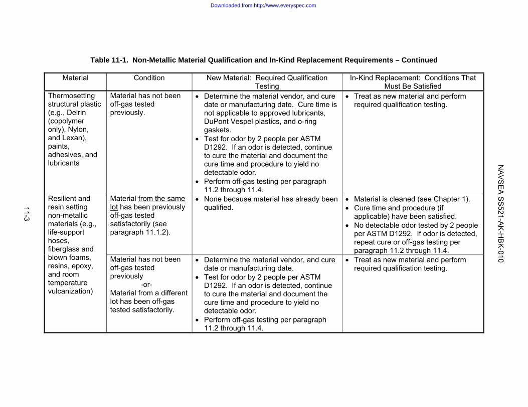
Table 11-1. Non-Metallic Material Qualification and In-Kind Replacement Requirements – Continued
Material Condition New Material: Required Qualification
Testing In-Kind Replacement: Conditions That
Must Be Satisfied Thermosetting structural plastic (e.g., Delrin (copolymer only), Nylon, and Lexan), paints, adhesives, and lubricants
Material has not been off-gas tested previously.
• Determine the material vendor, and cure date or manufacturing date. Cure time is not applicable to approved lubricants, DuPont Vespel plastics, and o-ring gaskets.
• Test for odor by 2 people per ASTM D1292. If an odor is detected, continue to cure the material and document the cure time and procedure to yield no detectable odor.
• Perform off-gas testing per paragraph 11.2 through 11.4.
• Treat as new material and perform required qualification testing.
Material from the same lot has been previously off-gas tested satisfactorily (see paragraph 11.1.2).
• None because material has already been qualified.
• Material is cleaned (see Chapter 1). • Cure time and procedure (if
applicable) have been satisfied. • No detectable odor tested by 2 people
per ASTM D1292. If odor is detected, repeat cure or off-gas testing per paragraph 11.2 through 11.4.
Resilient and resin setting non-metallic materials (e.g., life-support hoses, fiberglass and blown foams, resins, epoxy, and room temperature vulcanization)
Material has not been off-gas tested previously -or- Material from a different lot has been off-gas tested satisfactorily.
• Determine the material vendor, and cure date or manufacturing date.
• Test for odor by 2 people per ASTM D1292. If an odor is detected, continue to cure the material and document the cure time and procedure to yield no detectable odor.
• Perform off-gas testing per paragraph 11.2 through 11.4.
• Treat as new material and perform required qualification testing.
NA
VS
EA
SS
521-AK
-HB
K-010
11-3
Downloaded from http://www.everyspec.com

grease, mold release compound, cleaner residue and any other organic contaminant that could affect the off-gas test. Some items may contain a contaminant that could off-gas, such as grease or lubricant. If this contaminant is supposed to be on the item, such as a greased bearing, do not remove it by cleaning. Do not do anything to the material that could affect off-gassing, such as applying paint or ink to identify the sample. 11.2.3 Curing. For some materials, curing is necessary during manufacture to attain the required physical and chemical properties. Curing during manufacture does not mean that off-gassing is complete. When performing off-gas testing, additional curing may be necessary to eliminate detectable odor. Curing includes processes such as baking at elevated temperature for a specified duration, allowing the material to sit at normal ambient conditions to “air it out”, and performing pressure cycles for compressible items. Aged material may off-gas less and require less curing. Any curing performed to support off-gas testing shall be documented. 11.2.4 Films and coatings. Films and coatings, including but not limited to primers, paints, tapes, labels, and thin film lubricants, shall be applied to a carrier or substrate. The non-metallic sample shall be applied as it would be applied in the installed configuration (e.g., applied per approved paint schedule, military standard, installation drawing, cured per manufacturer's instructions, etc.). Test plates should accommodate the dimensions of the test chamber to be used (so they will fit inside) and consideration should be given to applying the film or coating on both sides of the substrate, if possible, to reduce the total number of carrier plates required. Any special surface preparation or curing requirements performed during application of the film or coating shall be documented, whether applied at the off-gas testing laboratory or other facility. If films or coatings are applied at other than the off-gas testing laboratory, shipping duration and method could affect the results. Procedures for application of the coating shall be documented so that the same procedure will be used to apply the coating to installed items. This documentation shall include anything that can affect off-gassing such as the number of coats and for each coat, the thickness, drying duration and temperature, and any special ventilation requirements (i.e., blowing air on surface). 11.2.5 Carrier or Substrates. Substrates should be metal or glass that is not expected to off-gas and affect the results. The substrate shall be cleaned until it is visually free of oil, grease, cleaner residue, and any organic contaminant that could affect the off-gas test. If possible and appropriate, clean using the component cleaning process as specified in MIL-STD-1622 for critical applications or MIL-STD-1330. When using a carrier or substrate, the facility shipping the sample shall coordinate with the laboratory performing the off-gas testing to determine the sample requirements (e.g., number and size of coated plates required). This is necessary to determine, prior to shipment, the size and quantity of the sample required such that the desired sample to volume ratio is achieved (see paragraph 11.2.9) and to verify that the laboratory test chamber can accommodate such samples. 11.2.6 Three Dimensional Materials. Three-dimensional materials such as foams, plastics, and rubber shall be tested as close to the end use configuration as possible. 11.2.7 Liquids. Liquids shall be placed in an open container, such as a Petri dish, during the off-gas test. The container shall be cleaned until it is visually free of oil, grease, cleaner residue, and any organic contaminant that could affect the off-gas test
11-4
Downloaded from http://www.everyspec.com

11.2.8 Test Chamber. Considerations for designing or selecting a test chamber are as follows: a. Pressurization requirements to force the release of contaminants from paints, resins, and
foam flowing agents used for closed cell foams/insulation. b. Pressurization requirement to collect enough gas for analysis considering the size of the
chamber. c. The size must yield the desired sample to volume ratio (see paragraph 11.2.9). d. It must be capable of maintaining the required test temperature. 11.2.9 Determining Amount of Sample Needed. Assemblies and liquids will be measured by volume, material will be measured by weight, and films and coatings will be measured by surface area. The amount of sample shall depend on the test chamber volume and pressure used for the off-gas test. Using the criteria given in Table 11-2, coordinate with the laboratory performing the off-gas test to determine how much sample is needed.
Table 11-2. Criteria for calculating amount of sample needed.
Basis Criteria 1/
Volume The ratio of the test specimen volume to the standard volume of the test chamber shall equal or exceed the ratio of the volume of installed material to the floodable volume of the space where it will be installed.
Weight The ratio of the test specimen weight (grams) to the standard volume of the test chamber (liters) should fall in the range of 1 to 4 grams/liter.
Surface Area
The ratio of the test specimen exposed surface area to the standard volume of the test chamber shall equal or exceed the ratio of the exposed surface area of installed material to the floodable volume of the space where it will be installed.
1/ The standard volume of the test chamber is the floodable volume of the test chamber multiplied by the test pressure measured in ata. For example, if the test chamber has a floodable volume of 113 liters and is pressurized to 50 psig for the test, the standard volume is:
ata 4.4psia 14.7
psia 14.7) psig (50 Pressure Test =+
=
( ) liters 497(4.4)liters 113PressureTestXVolumeFloodableVolumeStandard === To achieve a ratio of 4 g of material/standard liter, (497 liters) x (4 g/liter) = 1988 grams of material is required. 11.2.10 Shipment. Shipment methods for material being tested shall be discussed and agreed upon with the receiving laboratory. There must be reasonable assurance that shipping itself will not contaminate the sample.
11-5
Downloaded from http://www.everyspec.com

11.2.11 List of Compounds Analyzed for Off-Gas Test. The basis for the list of compounds requiring analysis is a combination of Tables F-3 and F-4 of NAVSEA SS800-AG-MAN-010/P-9290. This list shall be modified, with NAVSEA approval, to account for compounds that may be present based on the composition of the material or method of manufacture, but are below the screening limits. Also, compounds not likely to be present can be deleted. Table 11-3 lists the analysis requirements of combined Tables F-3 and F-4 of NAVSEA SS800-AG-MAN-010/P9290, along with a list developed for other projects. This provides an example of how a list can be adjusted for materials being used for a particular application. See Chapter 5 for additional guidance. 11.2.12 Information Required for Sample. When submitting a sample for off-gas testing, the information given below shall be provided, preferably on a standard form (see Figure 11-1 for an example). a. Lot or batch number of material. For assemblies, provide description and part number. b. Material chemical name (if applicable). c. Manufacturer of material. d. Identify the condition of the sample (e.g., in “as received” condition from supplier prior to
shipment to laboratory), and any special preparation requirements (e.g., cleaning or curing that was accomplished prior to shipment to laboratory). For curing, indicate the cure date and curing procedure (if applicable).
e. Volume and maximum depth of space where material is installed. f. Desired duration, pressure, and temperature for off-gas test (see Table 11-4). g. List of compounds, including the ppm levels, requiring analysis. Note that the surface
equivalent limit divided by the pressure ratio yields the required laboratory reporting limit. h. Identify method used to report non-target compounds (see paragraph 10.2.3). 11.2.13 Where to Send Sample. A list of laboratories that have been accepted by NAVSEA for various projects is available at https://subsafe.aditech.com. Use of these laboratories for off-gas testing on a specific project requires acceptance by the NAVSEA Program Manager and System Certification Authority for that project.
11-6
Downloaded from http://www.everyspec.com

Table 11-3. Examples of target compounds analyzed for off-gas testing of non-metallics.
Limit (ppm or as specified) 1/
Compound CAS No. MAN-010/P-9290, Tables F-3/F-4 combo (SSGN or
Virginia Class) 2/
ASDS or DDS
Acrolein 107-02-8 0.01 -- Ammonia 7664-41-7 4 4 Benzene 71-43-2 0.1 0.1 Butyl-Cellusolve 111-76-2 2 -- Carbon Dioxide 124-38-9 Same as carrier gas for
off-gas test 1000
Carbon Monoxide 630-08-0 10 10 Chlorine 7782-50-5 0.1 -- 1,2-Dichloroethylene 540-59-0 0.1 -- Formaldehyde 50-00-0 0.1 0.1 Hydrogen 3/ 1333-74-0 10,000 -- Hydrogen Sulfide 7783-06-4 1 -- Mercury 7439-97-6 0.01 mg/m3 -- Methanol 67-56-1 7 -- Sulfur Dioxide 7446-09-5 1 -- 1,1,1 Trichloroethane (methyl chloroform) 71-55-6 2.5 2.5 Trichloroethylene 79-01-6 0.1 0.1 Vinyl Chloride 75-01-4 -- 1 Vinylidene Chloride 75-35-4 0.15 -- Xylene(s) 1330-20-7 10 -- Total Hydrocarbons 4/ NA 25 25 Total Halogens (chlorinated, brominated, & fluorinated compounds) 4/
NA 10 10
1/ Limit is the surface equivalent limit and must be adjusted by the pressure ratio for the application (see Chapter 4). 2/ This list is provided for information and not compliance. See the current change or revision of the source document for the current requirement. 3/ Hydrogen limit is an explosion limit, not a toxicological limit. 4/ Results that do not pass require additional analysis (see paragraph 10.2).
11-7
Downloaded from http://www.everyspec.com

Figure 11-1: Example of Off-Gas Test Request Form 1. Requesting Facility Name of Facility Requesting Off-Gas Test: _____________________________________ _____________________________________
Point of Contact: Name:________________________________ Phone number:_________________________ E-mail:________________________________
2. Funding/Tracking Job Order/Funding Document:_________________________________ Tracking Number:___________________________________________ 3. Material Information □ Assembly OR □ Raw Material Part Number:__________________________ _____________________________________ Description:____________________________Manufacturer:__________________________
Lot or Batch Number:_______________________Chemical name:___________________________Trade name: _____________________________ Manufacturer:_____________________________
4. Condition of Sample Prior to Shipment As received from supplier? □Yes □No If no, explain:____________________________________ Cleaning Performed? □Yes □No If yes, provide details:__________________________________ Curing Performed? □Yes □No If yes, provide details:____________________________________5. Application Description of where installed:_______________________________________________________ Volume of space where installed:_________ Maximum depth of space where installed:_________
6. Test Requirements Duration:_____________________Pressure:__________________Temperature:_____________ Special Requirements:_____________________________________________________________ _______________________________________________________________________________
7. List of Compounds □ ASDS or DDS per Dwg 092-7328847 □ SSGN or Virginia Class □ Other – See attached list For non-target compounds, use Method #_____ of paragraph 10.2.3. 8. Report Date Report Required by:________________ □ Mail to:____________________________ ____________________________________ ____________________________________ ____________________________________
□ FAX: Name:___________________________ Number:__________________________ □ E-mail:________________________________
9. Disposition of Material □ Dispose □ Return Return to: __________________________________________ __________________________________________ __________________________________________ __________________________________________
10. Special Instructions:_________________________________________________________________________________________________________________________________________ Attach a copy of this sheet to the off-gas test report.
11-8
Downloaded from http://www.everyspec.com
Instructions for completing off-gas test request form (Figure 11-1): 1. Fill in the name of the facility requesting the off-gas test and provide a point of contact (name, phone number, and E-mail address). 2. Fill in the job order or document that provides funding for the off-gas test. Also fill in a tracking number (e.g., requisition number, contract number, or shop work order) that will be referenced on the off-gas test report. 3. Check if the material is an assembly or raw material. For an assembly, fill in the part number (or drawing number or other identifying marks), description, and manufacturer. For raw material (e.g., nylon rod), fill in the lot or batch number, the chemical name, trade name, and the manufacturer. This information will be referenced on the off-gas test report. 4. Identify if the material was “as received” from the supplier (e.g., if it was received “out of the box” and shipped in same condition, check “yes”, if the item was disassembled for inspection or performing work on it, check “no” and explain). Identify if the material was cleaned or cured and provide any details, no matter how insignificant (e.g., packaging removed and allowed to air out prior to shipping). 5. Describe where the material will be installed (e.g., Virginia Class LOC, SSGN LOC or LPT Upper Hatch). Fill in the volume of the space where the material will be installed and the maximum depth of the space. The volume and depth for the space are necessary for the testing facility to determine the amount of sample needed for material tested as an assembly or liquid (volume) or films and coatings (area) as explained in Table 11-2. The depth of the space may be necessary to determine the required laboratory detection limit for the list of compounds requiring analysis. 6. For the off-gas test, fill in the required duration, pressure, and temperature. Include any special requirements (e.g., how to apply films or coatings). Table 11-4 provides some established protocol. 7. For the list of compounds requiring analysis, check the applicable box. If “other” is checked, attach a list of compounds that require analysis, including the surface equivalent limit for each compound. 8. Fill in the date that you need the report. Check the box(es) indicating how the report is to be sent and fill in the blanks. 9. Check the box to indicate if the material is to be disposed of or returned. For returned material, fill in the shipping address. 10. Provide any special instructions (e.g., special cleaning or curing requirements or additional testing needed if material fails).
11-9
Downloaded from http://www.everyspec.com

11.3 OFF-GAS TEST. 11.3.1 Procedure. Prior to and after performing the off-gas test, the material shall be tested for odor. Test for odor per ASTM D1292 by a minimum of two, preferably 3 people, who have known sensitivity to smells and are not suffering from a cold or flu or are smokers, which is known to reduce sensitivity to smell and taste. If an odor is detected, continue to cure the material and document the cure time and procedure to yield no detectable odor. If an odor is detected and the material cannot be cured (e.g., hydraulic fluid), it is acceptable if it passes the off-gas test with a correction for the mission duration, and additionally analysis of non-target compounds is performed (see paragraph 10.2 for evaluation of non-target compounds). The test chamber shall be cleaned adequately so as to not off-gas compounds that will interfere with the test results. The gas used to pressurize the test chamber shall not contain compounds that interfere with the test results. “Zero” gas can be used to satisfy this. The test duration, pressure, and temperature are specified in Table 11-4.
Table 11-4. Off-gas test duration, pressure, and temperature requirements.
Parameter Test Criteria Duration Closed cell compressible materials such as foams and insulation:
4 hours minimum at pressure. Non-compressible materials: 4 hours minimum for 1 atmosphere or elevated pressure test.
Pressure For non-compressible material a 1-atmosphere test can be done or, if necessary, the test chamber can be pressurized up to 50 psig. Pressure is sometimes necessary to provide the laboratory with enough gas volume to perform the gas analysis; pressure does not affect off-gassing of these materials. For compressible materials such as foams, insulation, and other material made using a blowing agent or closed cell compressible type material, pressurize test chamber to the maximum pressure of space.
Temperature The maximum temperature that the material will see when installed or during transport. Virginia Class uses a temperature of 125oF. ASDS/DDS uses a temperature of 140oF for all material, but if temporary (removable) mission equipment test fails, it is tested at 95oF (the maximum operational temperature of the platform). If it passes at 95oF and fails at 140oF, the item must be removed from the platform when the environmental control system (AC) is on or when the platform is not operational (e.g., back on host submarine).
11-10
Downloaded from http://www.everyspec.com

11.3.2 Analysis of Gas Sample. Collect a gas sample using any method that will not introduce contaminants. Introduction of contaminants could interfere with the results. To determine if the screening limits for total or halogenated hydrocarbons are exceeded, multiply the test result by the pressure in the test chamber (in ata) to account for dilution by the test gas. If either of the screening limits is exceeded, perform additional analysis to determine the probable compounds present (referred to as non-target compounds). Usually, this is accomplished using a gas chromatograph/mass spectrometer (GC/MS) and comparing spectral peaks to the GC/MS library. See paragraph 10.2 for evaluation of non-target compounds. 11.3.3 Test Report of Results. The report of the results from the off-gas test laboratory shall, as a minimum include the information given below, preferably on a standard form (see Figure 11-2 for example). a. Testing facility, name, address, and phone number. b. Date material tested. c. Lot or batch number of material. For assemblies, provide description and part number. d. Material chemical name (if applicable). e. Manufacturer of material. f. Sample weight or volume, as applicable. g. Sample surface area. h. Pressure and volume of test chamber. i. Temperature of test chamber for off-gas test and after pressurizing but before heating. j. Total time specimen was in chamber before gas sample collected. k. Signature of test director and date. l. Test results:
(1) List of constituents analyzed or identified. (2) Method of analysis used to analyze constituent (see Table 10-1). (3) Required detect limit (or allowable limit) of each constituent (see Table 4-1). (4) Laboratory reporting limit for each constituent (see Table 4-1). (5) Absolute measured level of each constituent. (6) Normalized measured level of each constituent (ppm/L or ppm/g/L - see paragraph
11.4). (7) Evidence of odor before and after the test
11-11
Downloaded from http://www.everyspec.com

(8) Curing procedure (if qualifying a curing procedure) (9) For screening limits, show multiplication of test result by the pressure ratio to
demonstrate if the screening limit is exceeded or not. If it is exceeded, include analysis of non-target compounds (see paragraph 11.3.2).
(10) If non-target compounds are analyzed, include the name of the compound, CAS
number, reporting limit, method and standard used, quality match, and quantity.
11-12
Downloaded from http://www.everyspec.com

Figure 11-2: Example of Off-Gas Test Report 1. Test Facility Address: _____________________________________ _____________________________________ _____________________________________
Point of Contact: Name:________________________________ Phone number:_________________________ E-mail:________________________________
2. Funding/Tracking Job Order/Funding Document:_________________________________ Tracking Number:___________________________________________ Date Material Received:________________ 3. Material Information □ Assembly OR □ Raw Material Part Number:__________________________ _____________________________________ Description:____________________________Manufacturer:__________________________
Lot or Batch Number:_______________________Chemical name:___________________________Trade name: _____________________________ Manufacturer:_____________________________
4. Condition of Sample Prior to Testing
As received from supplier? □Yes □No If no, explain:____________________________________ Cleaning Performed? □Yes □No If yes, provide details:__________________________________ Curing Performed? □Yes □No If yes, provide details:____________________________________ 5. Odor (criterion is no detectable odor) Odor assessment prior to test (SAT/UNSAT): Signature:________________Date:____________ Odor assessment after test (SAT/UNSAT): Signature:________________Date:____________ If UNSAT, provide explanation:______________________________________________________ _______________________________________________________________________________ 6. Test Data and Parameters Sample weight, volume, or surface area (as applicable):______________________________ Room Temperature:___________________Test chamber prior to heating:_______________ Test Data for Chamber: Pressure:_______________Temperature:___________________ Volume:________________Duration:______________________ 7. Off-Gas Test Results: See attached list. Date Material Tested:_____________ Analyst: Signature:____________ Date:_____ Test director: Signature:___________Date:_____ 8. Report To: □ Mail to:____________________________ ____________________________________ ____________________________________ ____________________________________
□ FAX: Name:___________________________ Number:__________________________ □ E-mail:________________________________
9. Disposition of Material □ Dispose □ Return Returned to: __________________________________________ __________________________________________ __________________________________________ 10. Remarks:___________________________________________________________________ _______________________________________________________________________________
11-13
Downloaded from http://www.everyspec.com

Instructions for completing off-gas test report (Figure 11-2): 1. Fill in the address of the facility performing the off-gas test and provide a point of contact (name, phone number, and E-mail address). 2. Fill in the job order or document that provides funding for the off-gas test. Also fill in a tracking number (e.g., requisition number, contract number, or shop work order) that will be referenced on the off-gas test report. Fill in the date the material was received. 3. Check if the material is an assembly or raw material. For an assembly, fill in the part number (or drawing number or other identifying marks), description, and manufacturer. For raw material (e.g., nylon rod), fill in the lot or batch number, the chemical name, trade name, and the manufacturer. 4. Identify if the material was “as received” from the supplier (e.g., if it was received “out of the box” and shipped in same condition, check “yes”, if the item was disassembled for inspection or performing work on it, check “no” and explain). Identify if the material was cleaned or cured and provide any details, no matter how insignificant (e.g., packaging removed and allowed to air out prior to shipping). 5. Document results for the odor assessment by circling “SAT” or “UNSAT” and providing a signature and date. For any “UNSAT” results, provide an explanation and any corrective actions taken to correct any unacceptable results (e.g., cure procedure used, analyze for non-targets, etc.). 6. For the off-gas test, fill in the test parameters. 7. Attach the list of compounds tested. For each compound, include the method of analysis (see Table 10-1), the surface equivalent limit (or laboratory detection limit considering pressure ratio) and laboratory reporting limit (see Table 4-1), the absolute measured level, and the normalized measured level (ppm/L or ppm/g/L – see paragraph 11.4). For screening limits, show multiplication of test result by the pressure ratio to demonstrate if the screening limit is exceeded or not. If it is exceeded, include analysis of non-target compounds (see paragraph 11.3.2). 8. Fill in the date the material was tested and provide signatures and dates. 9. Check the box(es) indicating how and who the report was sent to. 10. Check the box to indicate if the material is to be disposed of or returned. For returned material, fill in the shipping address. 11. Provide any remarks (e.g., any special testing, observations during test, any anomalies).
11-14
Downloaded from http://www.everyspec.com

11.4 EVALUATION OF RESULTS. 11.4.1 Equations to Correlate Off-Gas Test Results to Actual Installation. Off-gas testing is performed in a test chamber containing a different amount of material, and different volume, pressure, and temperature than the actual installation. To correlate to the actual installation, the gas analysis results need to be adjusted for these parameters. The results can be reported in ppm, or they can be normalized by correcting for the test temperature, pressure, and amount of material tested. For a weight of material tested, results would be reported as ppm/g/liter, and for a surface area or volume of material tested, results would be reported as ppm/liter. The equations to correlate the gas analysis results and the amount of constituent to be expected when the item is installed are given in Table 11-5. 11.4.2 Basis for Equations. In order to understand the equations in Table 11-5, each one needs to be derived. Equation 11-1 is the simplest equation. It will be derived by providing an example and changing each parameter (sample size and test chamber volume, pressure, and temperature) one at a time. Once equation 11-1 is derived, the other equations will be derived from it. Equation 11-1:
( )tt
s
a
t
t
appmt,a P
TT
VV
WW
xx ⎟⎟⎠
⎞⎜⎜⎝
⎛⎟⎟⎠
⎞⎜⎜⎝
⎛⎟⎟⎠
⎞⎜⎜⎝
⎛=
Parameters for installed material and test chamber are the same: Suppose 20 grams of material is installed in a space that has a volume of 1000 liters. The temperature of the space is 68oF (528oR) and the pressure is 1 ata (i.e., Pt = 1 ata). After 24 hours, a gas sample of the space is collected and the level of a compound is 1 ppm. The weight of the material, volume of the space, and temperature are the same for actual and test conditions because the material is tested under actual conditions. Therefore, Wa = Wt, Vt = Va, and Ts = Tt, which means that Wa/Wt = 1, Vt/Va = 1, and Ts/Tt = 1. With all of these corrections being one, the actual amount of contaminant in the space equals the amount of contaminant measured in the gas analysis (i.e., xa = xt,ppm = 1 ppm). Changing test chamber volume: Suppose that the 20 grams of material is installed in a test chamber that has a volume of 1 liter. The temperature of the test chamber is 68oF and the pressure is 1 ata. After 24 hours, a gas sample of the test chamber is collected. Because the test chamber is smaller than the space by a factor of 1000, there will be 1000 times more contaminant present. The laboratory result would be 1000 ppm for the compound. The temperature does not require corrections because the actual and test conditions are the same. Applying equation 11-1:
( ) ppm1ata)(1R528R528
liters1000liter 1
g 20g 20
ppm) (1000PTT
VV
WW
xxo
o
tt
s
a
t
t
appmt,a =⎟
⎟⎠
⎞⎜⎜⎝
⎛⎟⎟⎠
⎞⎜⎜⎝
⎛⎟⎟⎠
⎞⎜⎜⎝
⎛=⎟⎟
⎠
⎞⎜⎜⎝
⎛⎟⎟⎠
⎞⎜⎜⎝
⎛⎟⎟⎠
⎞⎜⎜⎝
⎛=
11-15
Downloaded from http://www.everyspec.com

Table 11-5. Equations to correlate off-gas test results to actual installation.
Item Tested Reported as Equation to correlate results 1/,2/ Equation # Item Installed in Space
ppm ( )tt
s
a
t
t
appmt,a P
TT
VV
WW
xx ⎟⎟⎠
⎞⎜⎜⎝
⎛⎟⎟⎠
⎞⎜⎜⎝
⎛⎟⎟⎠
⎞⎜⎜⎝
⎛= 11-1
Weight (e.g., a sample of material)
ppm/g/liter ( ) ⎟⎟⎠
⎞⎜⎜⎝
⎛⎟⎟⎠
⎞⎜⎜⎝
⎛=
t
s
aappm/g/lt,a T
TV1Wxx 11-2
ppm ( )tt
s
a
t
t
appmt,a P
TT
VV
NN
xx ⎟⎟⎠
⎞⎜⎜⎝
⎛⎟⎟⎠
⎞⎜⎜⎝
⎛⎟⎟⎠
⎞⎜⎜⎝
⎛= 11-3
Volume (e.g., an assembly that contains metallic and non-metallic material) or surface area (e.g., paint or coating)
ppm/liter ⎟⎟⎠
⎞⎜⎜⎝
⎛⎟⎟⎠
⎞⎜⎜⎝
⎛⎟⎟⎠
⎞⎜⎜⎝
⎛=
t
s
at
appm/lt,a T
TV1
NN
xx 11-4
Item Installed in System
ppm ( )tsys
a
t
s
a
t
t
appmt,a P
PP
TT
VV
WW
xx ⎟⎟⎠
⎞⎜⎜⎝
⎛⎟⎟⎠
⎞⎜⎜⎝
⎛⎟⎟⎠
⎞⎜⎜⎝
⎛⎟⎟⎠
⎞⎜⎜⎝
⎛= 11-5
Weight (e.g., a sample of material)
ppm/g/liter ( ) ⎟⎟⎠
⎞⎜⎜⎝
⎛⎟⎟⎠
⎞⎜⎜⎝
⎛⎟⎟⎠
⎞⎜⎜⎝
⎛=
sys
a
t
s
aappm/g/lt,a P
PTT
V1Wxx 11-6
ppm ( )tsys
a
t
s
a
t
t
appmt,a P
PP
TT
VV
NN
xx ⎟⎟⎠
⎞⎜⎜⎝
⎛⎟⎟⎠
⎞⎜⎜⎝
⎛⎟⎟⎠
⎞⎜⎜⎝
⎛⎟⎟⎠
⎞⎜⎜⎝
⎛= 11-7
Volume (e.g., an assembly that contains metallic and non-metallic material) or surface area (e.g., paint or coating)
ppm/liter ⎟⎟⎠
⎞⎜⎜⎝
⎛⎟⎟⎠
⎞⎜⎜⎝
⎛⎟⎟⎠
⎞⎜⎜⎝
⎛⎟⎟⎠
⎞⎜⎜⎝
⎛=
sys
a
t
s
at
appm/lt,a P
PTT
V1
NN
xx 11-8
1/ Variables are defined as follows: Na = Actual number or quantity installed (# of assemblies or surface area tested) Nt = Number or quantity off-gas tested (# of assemblies or surface area tested) Pa = Actual maximum depth of space (ata) Psys = Maximum system pressure (ata); (e.g., 307 ata (4500 psig) for diving air system) Pt = Pressure in the off-gas test chamber (ata)
Ts = Standard temperature (usually 293oK or 528oR) Tt = Temperature in test chamber after pressurizing and before heating (oK or oR) Va = Actual volume of space where material will be installed (liters or ft3) Vt = Floodable volume of off-gas test chamber (liters or ft3) Wa = Actual amount of material installed (grams) Wt = Amount of material off-gas tested (grams) xa = Actual amount of contaminant that will be present in space (ppm, SEV) xt,ppm = Amount of contaminant measured in gas analysis (ppm) xt,ppm/g/l = Amount of contaminant measured in gas analysis (ppm/g/liter) xt,ppm/l = Amount of contaminant measured in gas analysis (ppm/liter) 2/ The temperature correction term (Ts/Tt) does not need to be applied if Tt is close to Ts. For instance, if the difference between these temperatures is 10oF, the error is less than 2%.
11-16
Downloaded from http://www.everyspec.com

Changing size of test specimen: From Table 11-2, the ratio of the test specimen weight (grams) to the standard volume of the test chamber (liters) should fall in the range of 1 to 4 grams per liter. To achieve this, the material tested will be reduced to 1 gram, yet the amount of material installed remains at 20 grams. The temperature and pressure of the test chamber will remain unchanged at 68oF and 1 ata. With 20 times less material, there will be 20 times less contaminant present. The laboratory result would be 50 ppm. The temperature does not require corrections because the actual and test conditions are the same. Applying equation 11-1:
( ) ppm1ata)(1R528R528
liters1000liter 1
g 1g 20
ppm) (50PTT
VV
WW
xxo
o
tt
s
a
t
t
appmt,a =⎟
⎟⎠
⎞⎜⎜⎝
⎛⎟⎟⎠
⎞⎜⎜⎝
⎛⎟⎟⎠
⎞⎜⎜⎝
⎛=⎟⎟
⎠
⎞⎜⎜⎝
⎛⎟⎟⎠
⎞⎜⎜⎝
⎛⎟⎟⎠
⎞⎜⎜⎝
⎛=
Changing test chamber pressure: Suppose the original 20 grams of material is installed in a space that has a volume of 1000 liters. The temperature is still 68oF, however, the pressure will be increased to 2 ata. After 24 hours, a gas sample of the space is collected. Recall that at 1 ata, the level of the compound was 1 ppm. Adding 1 ata of clean gas to the space will dilute the amount of contaminant present by a factor of 2, which yields 0.5 ppm of the contaminant present at a pressure 2 ata. To account for the toxicological affect in the space, the laboratory result of 0.5 ppm needs to be multiplied by the space pressure of 2 to yield 1 ppm (note that this agrees with Table 4-2 that requires application of a pressure ratio for adding clean gas to a space). For the test chamber, from above, only 1 gram of material will be tested in the 1 liter test chamber at 68oF. With the test chamber pressurized to 2 ata, the 1 ata of clean gas will dilute the amount of contaminant present by a factor of 2, which yields a laboratory result of 25 ppm. The temperature does not require correction because the actual and test conditions are the same. Applying equation 11-1:
( ) ppm1ata)(2R528R528
liters1000liter 1
g 1g 20
ppm) (25PTT
VV
WW
xxo
o
tt
s
a
t
t
appmt,a =⎟
⎟⎠
⎞⎜⎜⎝
⎛⎟⎟⎠
⎞⎜⎜⎝
⎛⎟⎟⎠
⎞⎜⎜⎝
⎛=⎟⎟
⎠
⎞⎜⎜⎝
⎛⎟⎟⎠
⎞⎜⎜⎝
⎛⎟⎟⎠
⎞⎜⎜⎝
⎛=
Changing test chamber temperature: In order to understand the affect of test chamber temperature, consider a test chamber with the following conditions:
Table 11-6. Test chamber conditions.
Condition Measured temperature and pressure
1: Initial condition 1 ata and 70oF 2: After pressurization and some stabilization, but prior to heating 2 ata and 80oF
3: Heating after pressurization 90oF Condition 1: This is the pressure and temperature of the test chamber before starting the test. Condition 2: As the test chamber is pressurized, the temperature increases. Over time, heat will transfer out of the test chamber and the pressure will decrease as the temperature decreases. If necessary, several iterations of pressurization and stabilization can be performed until the desired pressure and temperature are attained. It can take a long time for stabilization
11-17
Downloaded from http://www.everyspec.com
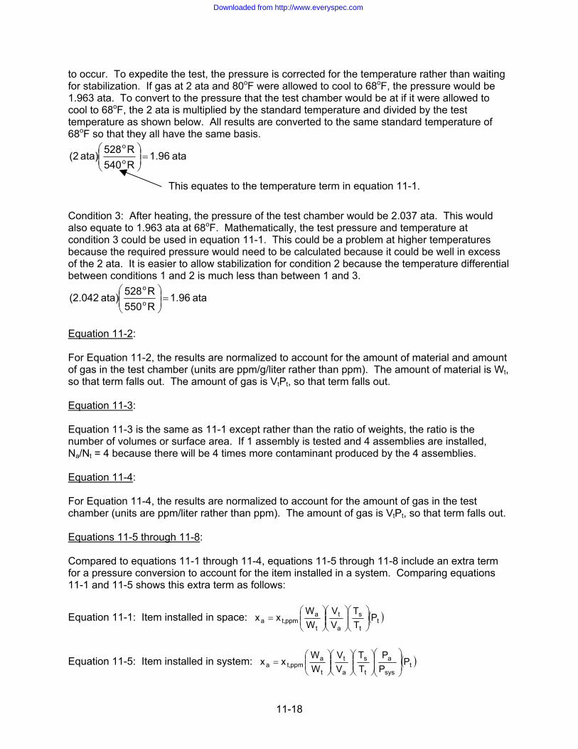
to occur. To expedite the test, the pressure is corrected for the temperature rather than waiting for stabilization. If gas at 2 ata and 80oF were allowed to cool to 68oF, the pressure would be 1.963 ata. To convert to the pressure that the test chamber would be at if it were allowed to cool to 68oF, the 2 ata is multiplied by the standard temperature and divided by the test temperature as shown below. All results are converted to the same standard temperature of 68oF so that they all have the same basis.
ata 1.96R540R528ata) (2 o
o
=⎟⎟⎠
⎞⎜⎜⎝
⎛
This equates to the temperature term in equation 11-1. Condition 3: After heating, the pressure of the test chamber would be 2.037 ata. This would also equate to 1.963 ata at 68oF. Mathematically, the test pressure and temperature at condition 3 could be used in equation 11-1. This could be a problem at higher temperatures because the required pressure would need to be calculated because it could be well in excess of the 2 ata. It is easier to allow stabilization for condition 2 because the temperature differential between conditions 1 and 2 is much less than between 1 and 3.
ata 1.96R550R528ata) (2.042 o
o
=⎟⎟⎠
⎞⎜⎜⎝
⎛
Equation 11-2: For Equation 11-2, the results are normalized to account for the amount of material and amount of gas in the test chamber (units are ppm/g/liter rather than ppm). The amount of material is Wt, so that term falls out. The amount of gas is VtPt, so that term falls out. Equation 11-3: Equation 11-3 is the same as 11-1 except rather than the ratio of weights, the ratio is the number of volumes or surface area. If 1 assembly is tested and 4 assemblies are installed, Na/Nt = 4 because there will be 4 times more contaminant produced by the 4 assemblies. Equation 11-4: For Equation 11-4, the results are normalized to account for the amount of gas in the test chamber (units are ppm/liter rather than ppm). The amount of gas is VtPt, so that term falls out. Equations 11-5 through 11-8: Compared to equations 11-1 through 11-4, equations 11-5 through 11-8 include an extra term for a pressure conversion to account for the item installed in a system. Comparing equations 11-1 and 11-5 shows this extra term as follows:
Equation 11-1: Item installed in space: ( )tt
s
a
t
t
appmt,a P
TT
VV
WW
xx ⎟⎟⎠
⎞⎜⎜⎝
⎛⎟⎟⎠
⎞⎜⎜⎝
⎛⎟⎟⎠
⎞⎜⎜⎝
⎛=
Equation 11-5: Item installed in system: ( )tsys
a
t
s
a
t
t
appmt,a P
PP
TT
VV
WW
xx ⎟⎟⎠
⎞⎜⎜⎝
⎛⎟⎟⎠
⎞⎜⎜⎝
⎛⎟⎟⎠
⎞⎜⎜⎝
⎛⎟⎟⎠
⎞⎜⎜⎝
⎛=
11-18
Downloaded from http://www.everyspec.com

A new example will be used to show how the pressure terms apply as follows: Material Tested in Chamber: At 1 ata, material off-gasses 1 ppm. If test chamber is pressurized to 2 ata, the level of constituent will be diluted, resulting in a level of 0.5 ppm at 2 ata. The laboratory analysis of 0.5 ppm needs to be multiplied by the test chamber pressure (2 ata) to convert to the ppm level at 1 ata. The factor of Pt in the equations account for this. Material installed in space: Suppose all of the parameters for the space are the same as the test chamber, except the pressure of the space is 6 ata. When the space is pressurized to 6 ata, the level of constituent will be diluted, resulting in a level of 0.167 ppm when analyzed at 1 ata. This analysis result needs to be multiplied by the pressure of the space to account for the toxicological affects, which yields 1 ppm (note that this agrees with Table 4-2 that requires application of a pressure ratio for adding clean gas to a space). So, for installing material in a space, there is no conversion for the pressure of the space. The space gets pressurized to the same pressure that the gas is breathed at, making the multiplication factor unity. Material installed in system: Suppose all of the parameters for the system are the same as the test chamber, except the pressure of the system is 10 ata and the maximum pressure the gas will be breathed at is 6 ata. When the system is pressurized to 10 ata, the level of constituent will be diluted, resulting in a level of 0.1 ppm. However, this needs to be multiplied by the pressure the gas will be breathed at to account for the toxicological affects, which yields 0.6 ppm. So, to convert the test chamber results to what will actually be present in the system, the result needs to be multiplied by 6 and divided by 10.
( ) ppm602106111ppm50P
PP
TT
VV
WW
xx tsys
a
t
s
a
t
t
appmt,a .)())()()(.( =⎟
⎠⎞
⎜⎝⎛=⎟
⎟⎠
⎞⎜⎜⎝
⎛⎟⎟⎠
⎞⎜⎜⎝
⎛⎟⎟⎠
⎞⎜⎜⎝
⎛⎟⎟⎠
⎞⎜⎜⎝
⎛=
This shows that for the space sample where Pa = Psys, that term falls out of the equation. 11.4.3 Example of Correlating Off-Gas Test Results to Actual Amount. An example is given to show how the actual amount of constituent that will be present when the material is installed can be calculated using the off-gas test results. Example #11.1: Weight of sample tested for installation into space. Given: 1 gram of non-compressible material was tested and 4 grams of the material will be installed. The volume of the test chamber is 2 liters, and the volume of the space where the material will be installed is 1000 ft3. The temperature in the off-gas chamber before applying heat was 60oF. The test chamber was heated to 120oF and pressurized to 50 psig for 24 hours. The gas analysis results indicated a constituent at 1.2 ppm and an odor was observed after the test (there was no odor prior to the test). The material will be installed in an application with a mission duration of 50 hours. How much of this constituent will be present when the material is installed? Solution: Equation 11-1 applies as follows:
( )tt
s
a
t
t
appmt,a P
TT
VV
WW
xx ⎟⎟⎠
⎞⎜⎜⎝
⎛⎟⎟⎠
⎞⎜⎜⎝
⎛⎟⎟⎠
⎞⎜⎜⎝
⎛=
11-19
Downloaded from http://www.everyspec.com

xt,ppm = 1.2 ppm Wa = 4 grams Wt = 1 gram Vt = 2 liters Va = 1000 ft3 = 28,317 liters Ts = 528oR Tt = 60oF = 460 + 60 = 520oR Pt = 50 psig = 50 + 14.7 = 64.7 psia; 64.7/14.7 = 4.4 ata
( ) ( ) ( ) ppm 0.00154.4R520R528
liters 28,317liters 2
g 1g 4ppm 1.2P
TT
VV
WW
xxo
o
tt
s
a
t
t
appmt,a =⎟
⎟⎠
⎞⎜⎜⎝
⎛⎟⎠
⎞⎜⎝
⎛⎟⎟⎠
⎞⎜⎜⎝
⎛=⎟⎟
⎠
⎞⎜⎜⎝
⎛⎟⎟⎠
⎞⎜⎜⎝
⎛⎟⎟⎠
⎞⎜⎜⎝
⎛=
Note that the final test chamber temperature is not used. The chamber is heated to cause the same constituents to off-gas at the same levels that will occur at temperatures experienced when the material is transported or installed. The gas sample is cooled to room temperature and analyzed at 1 ata. Suppose the laboratory wanted to report the results in ppm/g/liter. They would convert the 1.2 ppm laboratory result as follows:
rppm/g/lite 10.564)liters)(4. gram/(2 ppm/1 1.2rppm/g/lite == Applying equation 11-2 to this result yields:
( ) ( )( ) ppm 0.0015R520R528
liters 28,3171grams 4rppm/g/lite 10.56
TT
V1Wxx
o
o
t
s
aappm/g/lt,a =⎟
⎟⎠
⎞⎜⎜⎝
⎛⎟⎠
⎞⎜⎝
⎛=⎟⎟⎠
⎞⎜⎜⎝
⎛⎟⎟⎠
⎞⎜⎜⎝
⎛=
Because an odor was detected, a correction for mission duration is also required. For the mission duration of 50 hours:
ppm0031.0hours24hours50)ppm0015.0(xa =⎟⎟
⎠
⎞⎜⎜⎝
⎛=
Detection of odor also requires analysis of non-target compounds if not already accomplished. Analysis of non-target compounds requires applying a factor of 10 to account for exposure to contaminants for extended durations and exposure to multiple contaminants that may be toxicologically similar (see paragraph 10.2.5.a) and a factor to account for laboratory accuracy (for a 100% laboratory error, result would be multiplied by 2 as addressed in paragraph 10.2.4). For this example, if the constituent was a non-target compound, 0.0031 ppm is multiplied by 20, which yields a final value of 0.062 ppm. 11.4.4 Combining Space and Off-Gas Test Results. When adding a new item to a space, the off-gas test results need to be combined with the gas analysis results for the space for each reported constituent. The actual amount of the constituent calculated in paragraph 11.4.3 is simply added to the gas analysis result for the space for that constituent to calculate the amount of constituent that will be present in the space when the item is installed. If the acceptance criterion for the constituent is exceeded, then the new item needs to be cured and retested until the constituent is reduced to an acceptable level. This is a conservative approach because as items in the space cure from aging, the amount of constituents off-gassing in the space will be
11-20
Downloaded from http://www.everyspec.com

reduced. This approach allows installation of new items without repeating the gas analysis for a space. Addition of items to an already certified space can also be accepted based on an off-gas test of the space with the new items added (see paragraph 10.3.3). Note however that the cumulative level of total hydrocarbons or total halogens by calculation may exceed the screening limits. Once this occurs, an atmospheric sample of the space can be repeated to determine if the decrease discussed above would allow enough leeway for future additional material. Another approach is to repeat the atmospheric sample of the space and track individual constituents (target or non-target compounds) comprising the total. These individual constituents can be subtracted from the calculated total hydrocarbons or total halogens. For instance, suppose analysis results indicate 5 ppm of methane and calculations indicate 27 ppm of total hydrocarbons. Since the 5 ppm is well below the established methane limit, it can be subtracted from 27 ppm to yield 22 ppm. The result is that by calculation, the total hydrocarbons are acceptable after subtracting for individual hydrocarbons at known levels. An additional factor to account for is the different response for different analysis methods. Compounds analyzed as target compounds use detectors selected to yield accurate results for that compound. For total hydrocarbons, the FID detector used can yield results that are much higher or much lower than the actual amount of compound that is present. This can be accounted for because it is known how FID responds to different compounds. Measuring total hydrocarbons by FID is a simple acceptable approach for a screening limit used to determine if more detailed analysis is required. This response of compounds can be ignored when analyzing total hydrocarbons as a screening limit. However, for adjusting calculations as described above, response to different compounds needs to be considered. 11.4.5 Troubleshooting Results. The above calculations need to be performed for each constituent and compared to the surface equivalent limit. If a result does not pass, curing may reduce the constituent to acceptable levels. After curing, the off-gas test needs to be repeated. Some methods for curing are baking at an elevated temperature, special cleaning, pressure cycling (for materials with voids). If the curing process lowers the constituent level but it still does not pass, continue curing. If after attempting to cure and the results still do not pass, options such as replacement material or installing smaller quantities may need to be considered. For example, formaldehyde, if found, cannot be cured in order to reduce or eliminate it; the material needs to be replaced. Another option is to resample the space with the item installed if there is the possibility that the baseline contaminant level of the space has reduced adequately to allow the results to pass. 11.4.6 Reporting Results. All test results shall be reported to the organization specified in paragraph 11.1.2 so that the “approved material” database is kept up-to-date for use on all projects. Any curing procedures shall be documented, at a minimum, on the installation drawing. 11.5 TOXICOLOGICAL/FLAMMABILITY LIST OF MATERIALS. To identify and control the risk of material in the space, a toxicological/flammability list is created that includes all non-metallics for a specific platform that have been approved (passed toxicity testing and flammability testing). The list reflects the as-built condition of the space at all times and is revised as conditions change. Users of the list include engineering and medical personnel assessing items such as determining why an atmospheric sample failed, selecting new material to be installed in a space, or evaluating an objectionable odor. The list is not a list of qualified material that can be used indiscriminately in new design; it is only a list of material installed and qualified for that asset. The list is meant to be a quick reference to these users to evaluate non-metallics used in the as-built configuration so potential sources of toxicological
11-21
Downloaded from http://www.everyspec.com

and flammability issues can be more readily identified. As an option, the list should include items that have been approved but not installed, along with items that have been tested and were not approved because they failed. Identifying the quantity, intended location, and reference to the off-gas data for these items will save the time and money for retesting these items for other applications where they may be acceptable. In order for the list to function as intended, the list should include the following: a. Identification of all non-metallic material installed during production, maintenance and repair,
including applicable lot number. b. Categories for each non-metallic material (e.g., plastic, fabric, rubber (hose or gasket), foam,
paint, lubricant (oil or grease), solvent, cleaning agent (other than solvent), resin, adhesive, or other).
c. Chemical composition and trade name of material. d. Curing requirements. e. Quantity or volume and location installed. f. For electrical components containing various non-metallic materials, identify the electrical
component and list the non-metallic materials associated with the insulation, housing, display screen, circuit boards, transformers and major capacitors.
g. For assemblies, specify the part number. h. For each item, reference the off-gas test data or correspondence that allows use of the
material. 11.6 OFF-GAS TESTING OF ORDNANCE (EXPLOSIVES). Additional requirements apply for off-gas testing of ordnance type material because of the explosives used and other characteristics of this material. 11.6.1 Submittal of Material. When submitting ordnance material to a laboratory for off-gas testing, identify to the laboratory that it is an ordnance type item and provide a complete list of the composition of the non-metallic items used in the construction of the item being tested and provide a copy to the NAVSEA Program Manager. 11.6.2 List of Compounds Analyzed for Off-Gas Test. Follow the guidance provided in paragraph 11.2.11. Additionally, perform analysis of non-target compounds addressed in paragraph 10.2.2 whether or not the screening limits (total hydrocarbons and total halogens) are exceeded. The laboratory shall identify and quantify the top 10 compounds that have a quality match of 90% or greater. At the discretion of the laboratory, compounds with a 70 to 90% quality match can be included (Method #4 of paragraph 10.2.3). 11.7 FLAMMABILITY TESTING. This manual does not cover flammability testing. For guidance see NAVSEA SS800-AG-MAN-010/P-9290, paragraph F.8 and ASTM G63, G88, and G94.
11-22
Downloaded from http://www.everyspec.com

APPENDIX A MOISTURE CALCULATIONS
A.1 CALCULATIONS FOR MOISTURE LEVELS AT ELEVATED PRESSURES. The moisture content in air at atmospheric pressure is given in psychometric charts. Sometimes it is necessary to calculate the moisture content at elevated pressures or using gases other than air. The key to these calculations is to express the moisture content in “lbm/ft3” rather than “lbv/lbair” as is done on psychometric charts. The theory and governing equations for performing these calculations and some examples are presented below. A.2 NOMENCLATURE. mg Mass of dry gas (lbg) mv Mass of water vapor (lbv) Mg Molecular weight of dry gas (lbg/mol) Mv Molecular weight of water vapor (lbv/mol) P Pressure absolute (lbf/in2) Pg Partial pressure of dry gas (lbf/in2) PSAT Saturation pressure of water vapor at given temperature (lbf/in2) Pv Partial pressure of water vapor (lbf/in2) PPMV Parts per million by volume Rg Gas constant for dry gas (ft-lbf/lbm-oR) = 1545/Mg Rv Gas constant for water vapor (ft-lbf/lbm-oR) = 1545/Mv TDB Dry bulb (ambient) temperature (oF or oR) TDP Dew point temperature (oF or oR) V Volume (in3 or ft3) ω Humidity ratio or specific humidity (lbv/lbg) ϕ Relative humidity (dimensionless, may be expressed as %) ρg Mass density of saturated vapor at dry bulb temperature (lbm/ft3) ρv Mass density of water vapor at dew point temperature (lbm/ft3)
A-1
Downloaded from http://www.everyspec.com

A.3 DEFINITIONS AND THEORY. The theory is derived from defining some terms and assumptions, applying Dalton’s law of partial pressures, the ideal gas equation of state and conservation of mass. Humidity: Humidity is the amount of water, in the vapor phase, present in a gaseous atmosphere. Moisture in the adsorbed/absorbed phase, present in liquids and solids, is not considered. The water in the vapor phase is actually a gas and is treated in accordance with the gas laws. Dew Point Temperature (TDP): The dew point temperature of a mixture of gas and water vapor is defined as that temperature at which condensation will occur when the mixture is cooled at constant pressure. Until condensation occurs in a mixture, the partial pressure of the water vapor is unchanged. Dry Bulb Temperature (TDB): The dry bulb temperature is the true temperature of a mixture of gas and water at rest (ambient temperature). Relative Humidity (ϕ): The relative humidity of a mixture of gas and water vapor is defined as the ratio of the mole fraction of the vapor in the mixture to the mole fraction of vapor in a saturated mixture at the same temperature and total pressure. Considering the vapor as an ideal gas, the definition reduces to the ratio of the partial pressure of the water vapor as it exists in the mixture, Pv, to the saturation pressure of the vapor at the same temperature, PSAT. Since the partial pressure remains constant until condensation occurs, Pv is the water vapor partial pressure at the dry bulb temperature. PSAT is taken at the dry bulb temperature. In equation form:
)(@
)(@
DB
DP
TSAT
Tv
PP
=ϕ (1)
PPM by Volume (PPMV): Parts per million by volume of a mixture of gas and water vapor is defined as the ratio of the amount of water vapor to the amount of dry carrier gas on a volumetric basis. Applying the ideal gas law again, it is equivalent to the ratio of the partial pressure of the water vapor to the partial pressure of the dry carrier gas. In equation form:
6
g
vv 10x
PP
GasDryPartsMillionVaporWaterParts
PPM == (2)
Dalton’s Law of Partial Pressures: From the definition of humidity, the water in the vapor phase is actually a gas and is treated in accordance with the gas laws. Dalton’s law of partial pressures can thus be applied. It states that the total pressure exerted by a mixture of ideal gases or vapors is the sum of the pressures of each gas as if it were to occupy the same volume by itself. In the case of a gas and water vapor mixture, it can be stated that: P = Pv + Pg (3) Combining equations (2) and (3) to eliminate Pg yields:
6
v
vv 10x
PPP
PPM−
= (4)
A-2
Downloaded from http://www.everyspec.com

Humidity Ratio (ω): The humidity ratio of a mixture of gas and water vapor is defined as the ratio of the mass of water vapor to the mass of dry gas. The term “specific humidity” is used synonymously with humidity ratio. In equation form:
g
v
mm
ω = (5)
Ideal Gas Equation of State: The ideal (perfect) gas equation of state is given below. For the typical temperatures and pressures used to perform these calculations, the compressibility factor is near unity and is ignored. For partial pressure of water vapor: DPvvv TRρP = (6) For saturation pressure at given temperature: (7) TRρP DBvgSAT =
Conservation of Mass (or Continuity Equation): For a gas and water vapor mixture at state 1 combined with a mixture at state 2:
2121 vvvggg mmmandmmm +=+= (8) A.4 EXAMPLE CALCULATIONS. Several examples are given showing application of the above equations. Results of these calculations may differ from published data due to rounding errors and applying different equations. Example #A.1: Moist gas exists at 80oF dry bulb temperature, and 50% relative humidity. Determine the dew point temperature and PPMV. Solution: From Steam Table: At TDB = 80oF = 540oR, ρg = 0.0015797 lbm/ft3 For water, Mv = 18 lbv/mol, so Rv = 1545/18 = 85.833 ft-fbf/lbm-oR
( ) psi 0.5085 or /inlb 0.5085in 144
ft 1R540Rlb
lbft 85.833ft
lb 0.0015797TRρP 2
f2
2o
om
f3
mDBvgSAT =⎟
⎟⎠
⎞⎜⎜⎝
⎛⎟⎟⎠
⎞⎜⎜⎝
⎛
−
−⎟⎟⎠
⎞⎜⎜⎝
⎛==
psi 0.25425psi) 085(0.50)(0.5φPPPP
φ SATvSAT
v ===⇒=
Guess that TDP=60oF = 520oR
3m2
2
oomf
2f
DPv
vvDPvvv /ftlb 0.0008203
ft 1in 144
R)R)(520/lblbft (85.833/inlb 0.25425
TRPρTRρP =⎟⎟
⎠
⎞⎜⎜⎝
⎛⎟⎟⎠
⎞⎜⎜⎝
⎛
−−==⇒=
From Steam Table, @60oF, ρv = 0.00082843 lbm/ft3 Guess is correct. Dew point temperature is 60oF.
ppm60017or10x0176010xpsi254250psi714
psi025425010x
PPP
PPM 666
v
vv ,.
...
=−
=−
=
Note that the answer is independent of the type of gas.
A-3
Downloaded from http://www.everyspec.com

Example #A.2: A gas is dried to a dew point temperature of –40oF measured at atmospheric pressure. What is the PPMV? What will the dew point temperature be if the gas is pressurized isothermally to 3000 psia? Solution: At TDP = -40oF = 420oR, ρv = 7.4460 x 10⁻⁶ lbm/ft3For water, Mv = 18 lbv/mol, so Rv = 1545/18 = 85.833 ft-fbf/lbm-oR
( ) psi 10 x 186.4in 144
ft 1R420Rlb
lbft 85.833ft
lb10 x 7.4460TRρP 5
2
2o
om
f3
m6
DPvvv−
−
=⎟⎟⎠
⎞⎜⎜⎝
⎛⎟⎟⎠
⎞⎜⎜⎝
⎛
−
−⎟⎟⎠
⎞⎜⎜⎝
⎛==
ppm 127or10x0.00012710xpsi )10 x (186.4 psi 14.7
psi 10 x 186.410xPP
PPPM 66
5
56
v
vV =
−=
−=
−
−
As the total pressure of a gas sample changes, all of the partial pressures comprising the total pressure change in the same ratio. Therefore:
psia 14.7psia10 x 186.4
psia 3000@TP
psia 14.7F40@P 5
DPvo
v−
==−
Pv = 0.3804 psia = PSAT (for saturated mixture) Guess that TDP = 71oF = 531oR:
3m2
2
oomfDPv
vv /ftlb 0.001202
ft 1in 144
R)R)/18)(531/lblbft ((1545psi 0.3804
TRP
ρ =⎟⎟⎠
⎞⎜⎜⎝
⎛⎟⎟⎠
⎞⎜⎜⎝
⎛
−−==
From Steam Table @70oF, ρv = 0.001189 lbm/ft3 Guess that TDP = 71.7oF = 531.7oR (based on interpolating at 0.001202 lbm/ft3):
3m2
2
oomfDPv
vv /ftlb 0.001200
ft 1in 144
R).7R)/18)(531/lblbft ((1545psi 0.3804
TRP
ρ =⎟⎟⎠
⎞⎜⎜⎝
⎛⎟⎟⎠
⎞⎜⎜⎝
⎛
−−==
From Steam Table @71.7oF, ρv = 0.001201 lbm/ft3 Guess is correct. Dew point temperature is 71.7oF. Note that the answer is independent of the type of gas. NSTM S9086-SY-STM-010/CH-551 contains a graph of water content of saturated air. This chart is based on measurements (real gas). Applying this chart for this problem yields a dew point temperature of 50oF. At elevated pressure, significant error was introduced by assuming that the gas was ideal, but the results are conservative.
A-4
Downloaded from http://www.everyspec.com

Example #A.3: A gas system will be pressurized to 3000 psia. The dew point temperature is measured at atmospheric pressure. What is the required dew point and PPMV for the system to prevent condensation at an ambient temperature of 28oF. Solution: At TDB = 28oF = 488oR, ρg = 0.00025361 lbm/ft3For water, Mv = 18 lbv/mol, so Rv = 1545/18 = 85.833 ft-fbf/lbm-oR
( ) psi 0.07377in 144
ft 1R488Rlb
lbft 85.833ft
lb 0.00025361TRρP
2
2o
om
f3
mDBvgSAT =⎟
⎟⎠
⎞⎜⎜⎝
⎛⎟⎟⎠
⎞⎜⎜⎝
⎛
−
−⎟⎟⎠
⎞⎜⎜⎝
⎛==
mixture) saturated (for Ppsi 0.000361P14.7P
3000psi 0.07377
vSAT
SAT
==
=
Guess that TDP = -65oF = 395oR:
3m
6-2
2
oomfDPv
vv /ftlb 10 x 1.533
ft 1in 144
R)R)(395/lblbft (85.833psi 0.000361
TRP
ρ =⎟⎟⎠
⎞⎜⎜⎝
⎛⎟⎟⎠
⎞⎜⎜⎝
⎛
−−==
From Steam Table @-65oF, ρv = 1.4892 x 10⁻⁶ lbm/ft3 Guess that TDP = -60.5oF = 399.5oR (based on interpolating at 1.533 x 10⁻⁶ lbm/ft3):
3m
62
2
oomfDPv
vv /ftlb 10 x 1.516
ft 1in 144
R)R)(399.5/lblbft (85.833psi 0.000361
TRP
ρ −=⎟⎟⎠
⎞⎜⎜⎝
⎛⎟⎟⎠
⎞⎜⎜⎝
⎛
−−==
From Steam Table @-60.5oF, ρv = 1.533 x 10⁻⁶ lbm/ft3 Guess is correct. Dew point temperature is –60.5oF.
ppm 24.6or10x0000246010xpsi 0.000361psi 14.7
psi 0.00036110xPP
PPPM 666
v
vV .=
−=
−=
Note that the answer is independent of the type of gas. NSTM S9086-SY-STM-010/CH-551 contains a graph of water content of saturated air. This chart is based on measurements (real gas). Applying this chart for this problem yields a dew point temperature of -53oF. Again, the ideal gas assumption introduced error, but the results are conservative.
A-5
Downloaded from http://www.everyspec.com

Example #A.4: A flask is dried to an atmospheric dew point temperature of –20oF and filled with gas at an atmospheric dew point temperature of –40oF to 3014.7 psia. What is the PPM level of the flask initially, the gas added, and the final level after adding gas to the flask? Initial Conditions:
3m
5v
ooDP /ftlb10 x 2.3602ρ R,440F20T At
1
−==−= For water, Mv = 18 lbv/mol, so Rv = 1545/18 = 85.833 ft-fbf/lbm-oR
( ) psi 0.0061900in 144
ft 1R440Rlb
lbft 85.833ft
lb10 x 2.3602TRρP
2
2o
om
f3
m-5
DPvvv 1111=⎟
⎟⎠
⎞⎜⎜⎝
⎛⎟⎟⎠
⎞⎜⎜⎝
⎛
−
−⎟⎟⎠
⎞⎜⎜⎝
⎛==
psi 14.6938 0.0061900 14.7PPP11 v1g =−=−=
ppm 421or10x0.00042110xpsi 0.0061900 psi 14.7
psi 0.006190010xPP
PPPM 666
v1
vV
1
1
1=
−=
−=
gDBg
2
2
DBg
2f
DBg
1g lb
TRV 2116.8
ft 1in 144
TR)(V)/inlb (14.7
TRVP
m1 ⎟
⎟⎠
⎞⎜⎜⎝
⎛=⎟
⎟⎠
⎞⎜⎜⎝
⎛⎟⎟⎠
⎞⎜⎜⎝
⎛==
v
5vv (V)lb10 x 2.3602Vρm
11
−== Conditions for gas added:
3m
6F40-v@
ooDP /ftlb10 x 7.4460ρ R,420 F40T At o
−==−= psia 3000 14.7 3014.7PpP 1fadd =−=−=
For the mixture at one atmosphere:
( ) psi 0.001864in 144
ft 1R420Rlb
lbft 85.833ft
lb10 x 7.4460TRρP 2
2o
om
f3
m-6
DPvvF40@v o =⎟⎟⎠
⎞⎜⎜⎝
⎛⎟⎟⎠
⎞⎜⎜⎝
⎛
−−
⎟⎟⎠
⎞⎜⎜⎝
⎛==−
For the 3000 psi of gas added: As the total pressure of a gas sample changes, all of the partial pressures comprising the total pressure change in the same ratio. Therefore:
psia 14.7psia 0.001864
psia 3000P
psia 14.7
Padd
o vF40@v==−
psi 0.3804P
addv =
psi 2999.62 0.3804 3000PPP
addadd vaddg =−=−=
ppm 127or10x0.00012710xpsi 0.001864 psi 14.7
psi 0.00186410xPP
PPPM 666
F40-v@1
F40-v@V
o
o
add=
−=
−= (@14.7 psi)
A-6
Downloaded from http://www.everyspec.com

gDBg
2
2
DBg
2f
DBg
gg lb
TRV 431,945
ft 1in 144
TR)(V)/inlb (2999.62
TRVP
m add
add ⎟⎟⎠
⎞⎜⎜⎝
⎛=⎟
⎟⎠
⎞⎜⎜⎝
⎛⎟⎟⎠
⎞⎜⎜⎝
⎛==
g2
2
oomf
2f
DPv
vv V)lb0.0015195(
ft 1in 144
R)R)(420-/lblb-ft(85.833)(V)/inlb (0.3804
TRVP
m add
add=⎟⎟
⎠
⎞⎜⎜⎝
⎛⎟⎟⎠
⎞⎜⎜⎝
⎛==
Applying the conservation of mass:
⎟⎟⎠
⎞⎜⎜⎝
⎛=⎟
⎟⎠
⎞⎜⎜⎝
⎛+⎟
⎟⎠
⎞⎜⎜⎝
⎛=+=
DBgDBgDBgggg TR
V 434,062TRV 431,945
TRV 2116.8mmm
add1f
V)0.0015431(V)0.0015195((V)2.3602x10mmm 5vvv add1f
=+=+= − The equation to calculate PPMV using these masses is as follows:
DPgg
DBvv
g
v
ggvv
DBgg
DPvv
g
v
TMPTMP
mm
:1545/MR and 1545/MR ngSubstituti
TV/RPTV/RP
mm
ω
=
==
==
⎥⎥⎦
⎤
⎢⎢⎣
⎡=
==
=⇒=
−
−
))(/)((
))(/)((:
Rmollblb
RmollblbUnitCheck10x
TMmTMm
PPM
TM10xTMPPM
TMPTMPPMP
mm
:above into ngSubstituti
10xPPMPP10xPP
PPM :PPM of definition From
ovg
ogv6
DBvg
DPgvV
DPg
6DBvV
DPgg
DBvVg
g
v
6Vgv
6
g
v
Guess that the dew point temperature is –40oF (=420oR):
ppm 128.2or10 x 1282000010x434,062
833))(420)(85.(0.0015431PPM
1545/MR ngSubstituti
10x)))(18)(TT/R(434,062(V
)(420)(V))(M(0.0015431PPM
66V
gg
6
DBDBg
gV
.==
=
=
The dew point temperature corresponding to 128.2 ppm is close to –40oF, so the guess was adequate. The flask started at 421 ppm (-20oF), it was pressurized to 3000 psig with gas at 127 ppm (-40oF), yielding a final level of 128.2 ppm. This is why flasks dried to –20oF can be used in systems with a dryness level requirement of –40oF. Note that the answer is independent of the dry bulb (ambient) temperature, type of gas, and volume of the flask.
A-7
Downloaded from http://www.everyspec.com

This page intentionally left blank.
A-8
Downloaded from http://www.everyspec.com