Embed Size (px)
Citation preview

SRI SUKHMANI INSTITUTE OF ENGINEERING AND
TECHNOLOGY, DERA BASSI (MOHALI)
MICROWAVE
COMMUNICATION LAB
Laboratory Manual
1. STUDY OF MICROWAVE COMPONENTS
AIM
To study the microwave components in detail.
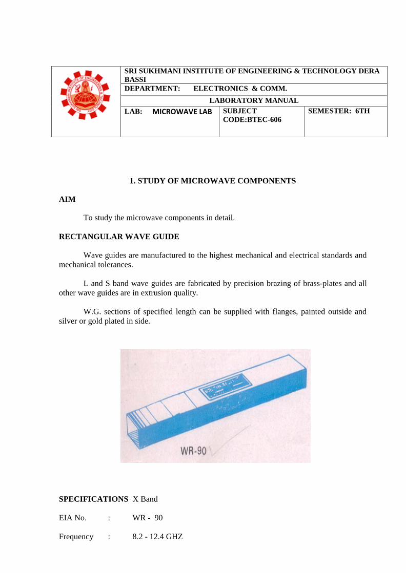
RECTANGULAR WAVE GUIDE
Wave guides are manufactured to the highest mechanical and electrical standards and
mechanical tolerances.
L and S band wave guides are fabricated by precision brazing of brass-plates and all
other wave guides are in extrusion quality.
W.G. sections of specified length can be supplied with flanges, painted outside and
silver or gold plated in side.
SPECIFICATIONS X Band
EIA No. : WR - 90
Frequency : 8.2 - 12.4 GHZ
SRI SUKHMANI INSTITUTE OF ENGINEERING & TECHNOLOGY DERA
BASSI
DEPARTMENT: ELECTRONICS & COMM.
LABORATORY MANUAL
LAB: MICROWAVE LAB SUBJECT
CODE:BTEC-606
SEMESTER: 6TH
Width : 2.286cm Height : 1.1016cm Width : 2.54 cm
Height : 1.27cm ± Tol. (µm) : 7.6 Material : Brass/Copper.
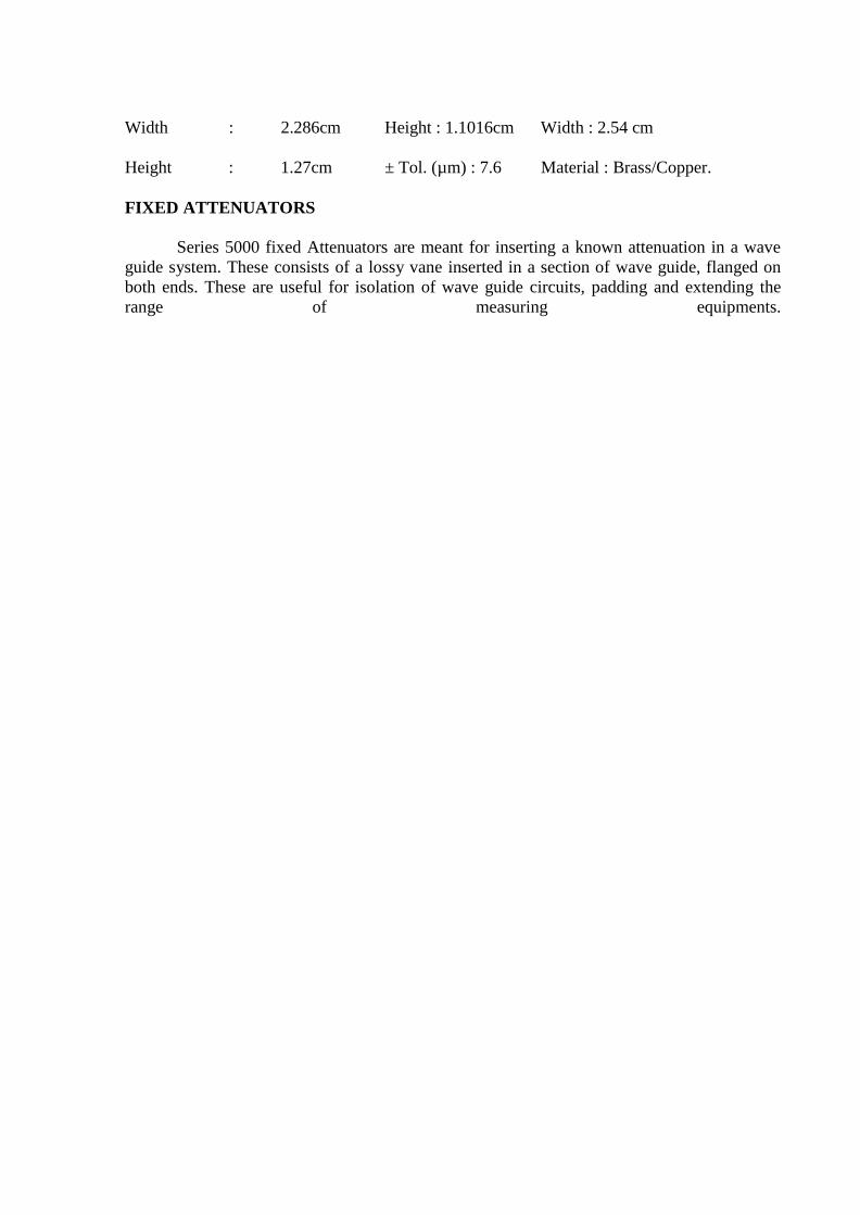
FIXED ATTENUATORS
Series 5000 fixed Attenuators are meant for inserting a known attenuation in a wave
guide system. These consists of a lossy vane inserted in a section of wave guide, flanged on
both ends. These are useful for isolation of wave guide circuits, padding and extending the
range of measuring equipments.
Fixed Attenuators are available for 3,6 or 10 dB attenuation values, but any attenuation valve
between 0 and 30dB can be provided.
SPECIFICATIONS
Model No: X-5000 /Frequency : 8.12 - 12.4 GHZ /Attenuation (dB) :
3,6,10/Callibration Accuracy : ± 0.2dB/Avg Power : 2W/Max VSWR : 1.10/Max Insertion
Loss (dB) : 0.2/W.G. Type: WG – 90/Flange Type (UG/U) : 39.
A precision built probe carriage has a centimeter scale with a vernier reading of
0.1mm least count and a dial gauge can be mounted easily if precise readings are required.
Model No. :
Freq (Ghz) :
X - 6051
8.2 - 12.4
Max Residual VSWR : 1.01
WG type (WR-) : 90
Flange Type (UG-/U) : 39
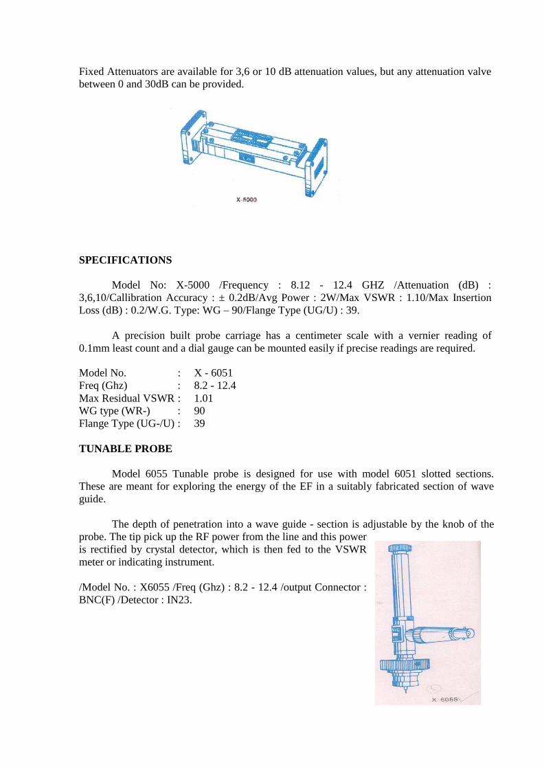
TUNABLE PROBE
Model 6055 Tunable probe is designed for use with model 6051 slotted sections.
These are meant for exploring the energy of the EF in a suitably fabricated section of wave
guide.
The depth of penetration into a wave guide - section is adjustable by the knob of the
probe. The tip pick up the RF power from the line and this power
is rectified by crystal detector, which is then fed to the VSWR
meter or indicating instrument.
/Model No. : X6055 /Freq (Ghz) : 8.2 - 12.4 /output Connector :
BNC(F) /Detector : IN23.
5
WAVE GUIDE DETECTOR MOUNT (TUNABLE)
Model 4051 Tunable Detector Mount is simple and easy to use instrument for
detecting microwave power thro’a suitable detector. It consists of a detector crystal mounted
in a section of a Wave guide and shorting plunger for matching purpose. The output from the
crystal may be fed to an indicating instrument. In K and R bands detector mounts the plunger
is driven by a micrometer.
Model No. : X - 4051
Freq. Range (Ghz) : 8.2 - 12.4
O/P Connector : BNC (F)
Wave guide type (WR-) : 90
Flange Type (UG/U) : 39
Detector : IN23
KLYSTRON MOUNT
Model 2051 Klystron mounts are meant for mounting corresponding Klystrons such
as 2K25, 723A/B, 726A or RK - 5976 etc.
These consists of a section of wave guide
flanged on one end and terminated with a movable
short on the other end. An octal base with cable is
provided for Klystron.
Model No. : X – 2051/ Freq. Range (GHz) 8.2 -
12.4/ WG Type (WR-) : 90
Flange Type (UG-/U): 39
CIRCULATORS
Model 6021 and 6022 are T and Y types of three port circulators respectively. These
are precisely machined and assembled to get the desired specifications. Circulators are
matched three port devices and these are meant for allowing Microwave energy to flow in
clockwise direction with negligible loss but almost no transmission in the anti-clockwise
direction.
Model No. : X - 6021
Frequency Range (Ghz) : 8.6 - 10.6 or 10.2 - 12.2
Min. Isolation (dB) : 20
Max. Insertion Loss (dB) : 0.4
Max. VSWR : 1.20
6
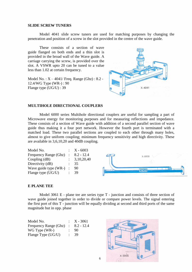
SLIDE SCREW TUNERS
Model 4041 slide screw tuners are used for matching purposes by changing the
penetration and position of a screw in the slot provided in the centre of the wave guide.
These consists of a section of wave
guide flanged on both ends and a thin slot is
provided in the broad wall of the Wave guide. A
carriage carrying the screw, is provided over the
slot. A VSWR upto 20 can be tuned to a value
less than 1.02 at certain frequency.
Model No. : X – 4041/ Freq. Range (Ghz) : 8.2 -
12.4/WG Type (WR-) : 90
Flange type (UG/U) : 39
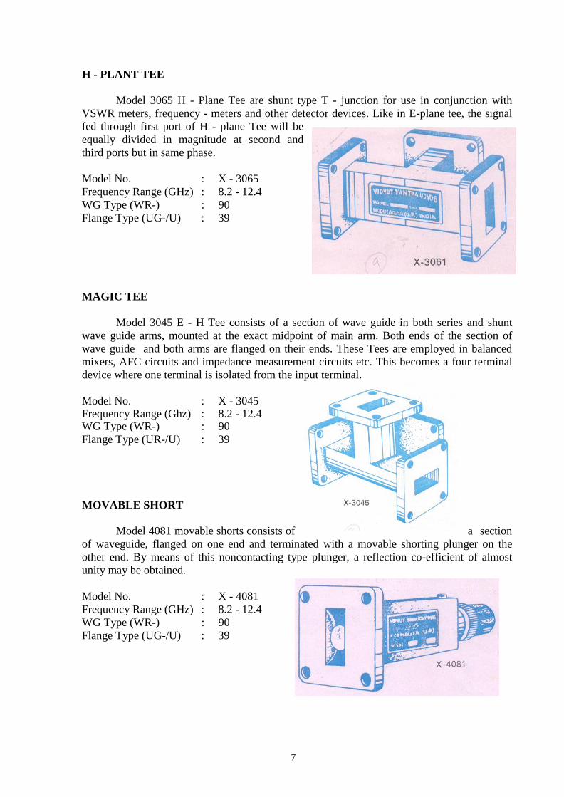
MULTIHOLE DIRECTIONAL COUPLERS
Model 6000 series Multihole directional couplers are useful for sampling a part of
Microwave energy for monitoring purposes and for measuring reflections and impedance.
These consists of a section of Wave guide with addition of a second parallel section of wave
guide thus making it a four port network. However the fourth port is terminated with a
matched load. These two parallel sections are coupled to each other through many holes,
almost to give uniform coupling; minimum frequency sensitivity and high directivity. These
are available in 3,6,10,20 and 40dB coupling.
Model No. : X - 6003
Frequency Range (Ghz) : 8.2 - 12.4
Coupling (dB) : 3,10,20,40
Directivity (dB) : 35
Wave guide type (WR-) : 90
Flange type (UG/U) : 39
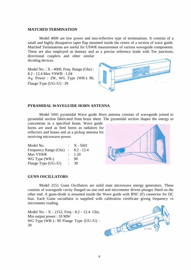
E PLANE TEE
Model 3061 E - plane tee are series type T - junction and consists of three section of
wave guide joined together in order to divide or compare power levels. The signal entering
the first port of this T - junction will be equally dividing at second and third ports of the same
magnitude but in opp. phase
Model No. : X - 3061
Frequency Range (Ghz) : 8.2 - 12.4
WG Type (WR-) : 90
Flange Type (UG/U) : 39
7
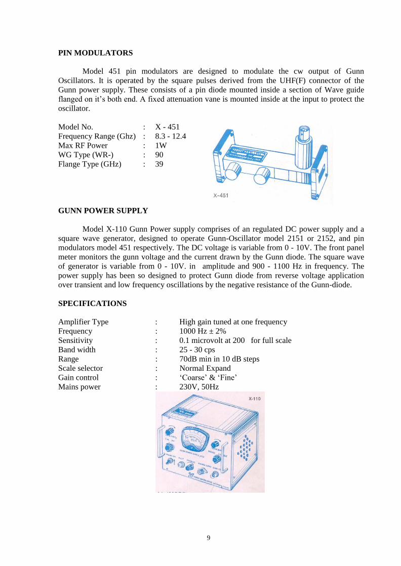
H - PLANT TEE
Model 3065 H - Plane Tee are shunt type T - junction for use in conjunction with
VSWR meters, frequency - meters and other detector devices. Like in E-plane tee, the signal
fed through first port of H - plane Tee will be
equally divided in magnitude at second and
third ports but in same phase.
Model No. : X - 3065
Frequency Range (GHz) : 8.2 - 12.4
WG Type (WR-) : 90
Flange Type (UG-/U) : 39
MAGIC TEE
Model 3045 E - H Tee consists of a section of wave guide in both series and shunt
wave guide arms, mounted at the exact midpoint of main arm. Both ends of the section of
wave guide and both arms are flanged on their ends. These Tees are employed in balanced
mixers, AFC circuits and impedance measurement circuits etc. This becomes a four terminal
device where one terminal is isolated from the input terminal.
Model No. : X - 3045 Frequency Range (Ghz) : 8.2 - 12.4 WG Type (WR-) : 90
Flange Type (UR-/U) : 39
MOVABLE SHORT
Model 4081 movable shorts consists of a section
of waveguide, flanged on one end and terminated with a movable shorting plunger on the
other end. By means of this noncontacting type plunger, a reflection co-efficient of almost
unity may be obtained.
Model No. : X - 4081
Frequency Range (GHz) : 8.2 - 12.4
WG Type (WR-) : 90
Flange Type (UG-/U) : 39
8
MATCHED TERMINATION
Model 4000 are low power and non-reflective type of terminations. It consists of a
small and highly dissapative taper flap mounted inside the centre of a section of wave guide.
Matched Terminations are useful for USWR measurement of various waveguide components.
These are also employed as dummy and as a precise reference loads with Tee junctions,
directional couplers and other similar
dividing devices.
Model No. : X - 4000, Freq. Range (Ghz) :
8.2 - 12.4 Max VSWR : 1.04
AV Power : 2W, WG Type (WR-) 90,
Flange Type (UG-/U) : 39
PYRAMIDAL WAVEGUIDE HORN ANTENNA
Model 5041 pyramidal Wave guide Horn antenna consists of waveguide joined to
pyramidal section fabricated from brass sheet. The pyramidal section shapes the energy to
concentrate in a specified beam. Wave guide
horns are used as feed horns as radiators for
reflectors and lenses and as a pickup antenna for
receiving microwave power.
Model No. : X - 5041
Frequency Range (Ghz) : 8.2 - 12.4
Max VSWR : 1.20
WG Type (WR-) : 90
Flange Type (UG-/U) : 39
GUNN OSCILLATORS
Model 2151 Gunn Oscillators are solid state microwave energy generators. These
consists of waveguide cavity flanged on one end and micrometer driven plunger fitted on the
other end. A gunn-diode is mounted inside the Wave guide with BNC (F) connector for DC
bias. Each Gunn osciallator is supplied with calibration certificate giving frequency vs
micrometer reading.
Model No. : X - 2152, Freq : 8.2 - 12.4 Ghz,
Min output power : 10 MW
WG Type (WR-) : 90 Flange Type (UG-/U) :
39
9
PIN MODULATORS
Model 451 pin modulators are designed to modulate the cw output of Gunn
Oscillators. It is operated by the square pulses derived from the UHF(F) connector of the
Gunn power supply. These consists of a pin diode mounted inside a section of Wave guide
flanged on it’s both end. A fixed attenuation vane is mounted inside at the input to protect the
oscillator.
Model No. : X - 451
Frequency Range (Ghz) : 8.3 - 12.4
Max RF Power : 1W
WG Type (WR-) : 90
Flange Type (GHz) : 39
GUNN POWER SUPPLY
Model X-110 Gunn Power supply comprises of an regulated DC power supply and a
square wave generator, designed to operate Gunn-Oscillator model 2151 or 2152, and pin
modulators model 451 respectively. The DC voltage is variable from 0 - 10V. The front panel
meter monitors the gunn voltage and the current drawn by the Gunn diode. The square wave
of generator is variable from 0 - 10V. in amplitude and 900 - 1100 Hz in frequency. The
power supply has been so designed to protect Gunn diode from reverse voltage application
over transient and low frequency oscillations by the negative resistance of the Gunn-diode.
SPECIFICATIONS
Amplifier Type : High gain tuned at one frequency
Frequency : 1000 Hz ± 2%
Sensitivity : 0.1 microvolt at 200 for full scale
Band width : 25 - 30 cps
Range : 70dB min in 10 dB steps
Scale selector : Normal Expand
Gain control : ‘Coarse’ & ‘Fine’
Mains power : 230V, 50Hz

10
ISOLATORS
The three port circulators Model 6021 may be converted into isolators by terminating
one of its port into matched load. these will work over the frequency range of circulators.
These are well matched devices offering low forward insertion loss and high reverse
isolation.
Model No. : X - 6022
Frequency Range (GHz) : 8.6 - 10.6 or 10.2 - 12.2
Min Isolation (dB) : 20
Max Insertion Loss (dB) : 0.4
Max VSWR : 1.20
RESULT
Thus all the microwave components were studied in detail.

11
REVIEW QUESTIONS
1. What is microwave?
2. Mention the frequency band for a millimeter wave.
3. List some of IEEE microwave frequency bands.
4. List some of characteristic feature of microwave.
5. List some of the application of microwave technology.
6. Draw a simple microwave system.
7. What are waveguide `Tees’?
8. List the basic type of waveguide tees.
9. What is an isolator?
10. What is a circulator?
11. What is a directional coupler?
12. What is velocity modulation?
13. Mention the Principle used in Klystron?
14. When the o/p power of reflex klystron maximum?
15. What is meant by attenuator?
12
2. MODE CHARACTERISTICS OF REFLEX KLYSTRON
AIM
To study the Mode Characteristics of Reflex Klystron.
APPARATUS REQUIRED:
Klystron Power Supply, Klystron with mount, Isolator, Frequency meter, Variable
Attenuator, Slotted section with Probe carriage, CRO, Movable Short.
THEORY
Klystron is a microwave vacuum tube employing velocity modulation. These
electrons move towards the repeller (ie) the electrons leaving the cavity during the positive
half cycle are accelerated while those during negative half cycle are decelerated. The faster
ones penetrate further while slower ones penetrate lesser in the field of repeller voltage. But,
faster electrons leaving the cavity take longer time to return and hence catch up with slower
ones. In the cavity the electrons bunch and intract with the voltage between the cavity grids.
It consists of an electron gun producing a collimated electron beam.
It bunches pass through grids at time the grid potentials is such that electrons are
decelerated they give by energy. The electrons are then collected by positive cavity wall near
cathode. To protect repeller from damage, repeller voltage is applied before accelerating
voltage.
PROCEDURE
i) Assemble the components as shown in fig.
ii) After following the necessary precautions, the Klystron Power Supply is
switched ON.
iii) To obtain peak voltage, the attenuator is positioned at it’s minimum
attenuation.
iv) Vary the repeller voltage from it’s maximum negative value and increase it in
steps on N and record output power and frequency.
v) The frequency is measured by tuning the basic frequency meter to have a dip
in the output voltage each time.
vi) The frequency meter is detuned before measuring the output power each time.
vii) The mode characteristics of Reflex Klystron is plotted. (i.e. Output Voltage Vs
Repeller voltage and Frequency Vs Repeller voltage)
BASIC PRECAUTIONS
SRI SUKHMANI INSTITUTE OF ENGINEERING & TECHNOLOGY DERA
BASSI
DEPARTMENT: ELECTRONICS & COMM.
LABORATORY MANUAL
LAB: MICROWAVE LAB SUBJECT
CODE:BTEC-606
SEMESTER: 6TH

13
1. During operation of Klystron, repeller does not carry any current and as such it
may severely be damaged by electron bombardment. To protect repeller from such
damage, the repeller negative voltage is always applied before anode voltage.
2. The repeller voltage should be varied in one direction to avoid hysteres is in
klystrons
14
1
3. The heater voltage should be applied first and cooling should be provided
simultaneously after some time other voltages should be applied taking
precaution(i).
4. While measuring power, the frequency meter should be detained each time
because there is a dip in the output power when the frequency is tunied.
5. To avoid loading of the klystron an isolator/attenuation should invariably be used
between klystron and the rest of the set-up.
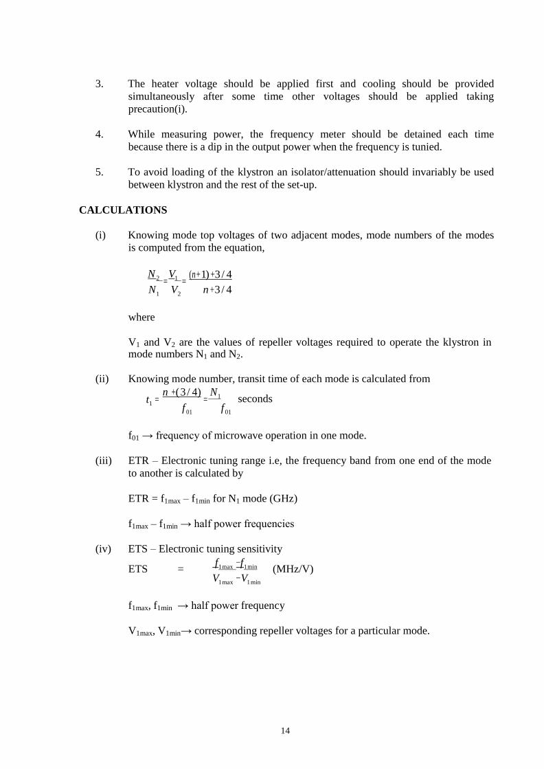
CALCULATIONS
(i) Knowing mode top voltages of two adjacent modes, mode numbers of the modes
is computed from the equation,
N 2 = V1 =
(n +1) + 3 / 4
N1 V2 n + 3 / 4
where
V1 and V2 are the values of repeller voltages required to operate the klystron in mode numbers N1 and N2.
(ii) Knowing mode number, transit time of each mode is calculated from
t = n + ( 3 / 4)
= N1
secondsf 01 f 01
f01 → frequency of microwave operation in one mode.
(iii) ETR – Electronic tuning range i.e, the frequency band from one end of the mode
to another is calculated by
ETR = f1max – f1min for N1 mode (GHz)
f1max – f1min → half power frequencies
(iv) ETS – Electronic tuning sensitivity
ETS = f1 max − f1 min
V1 max −V1 min
(MHz/V)
f1max, f1min → half power frequency
V1max, V1min→ corresponding repeller voltages for a particular mode.
15
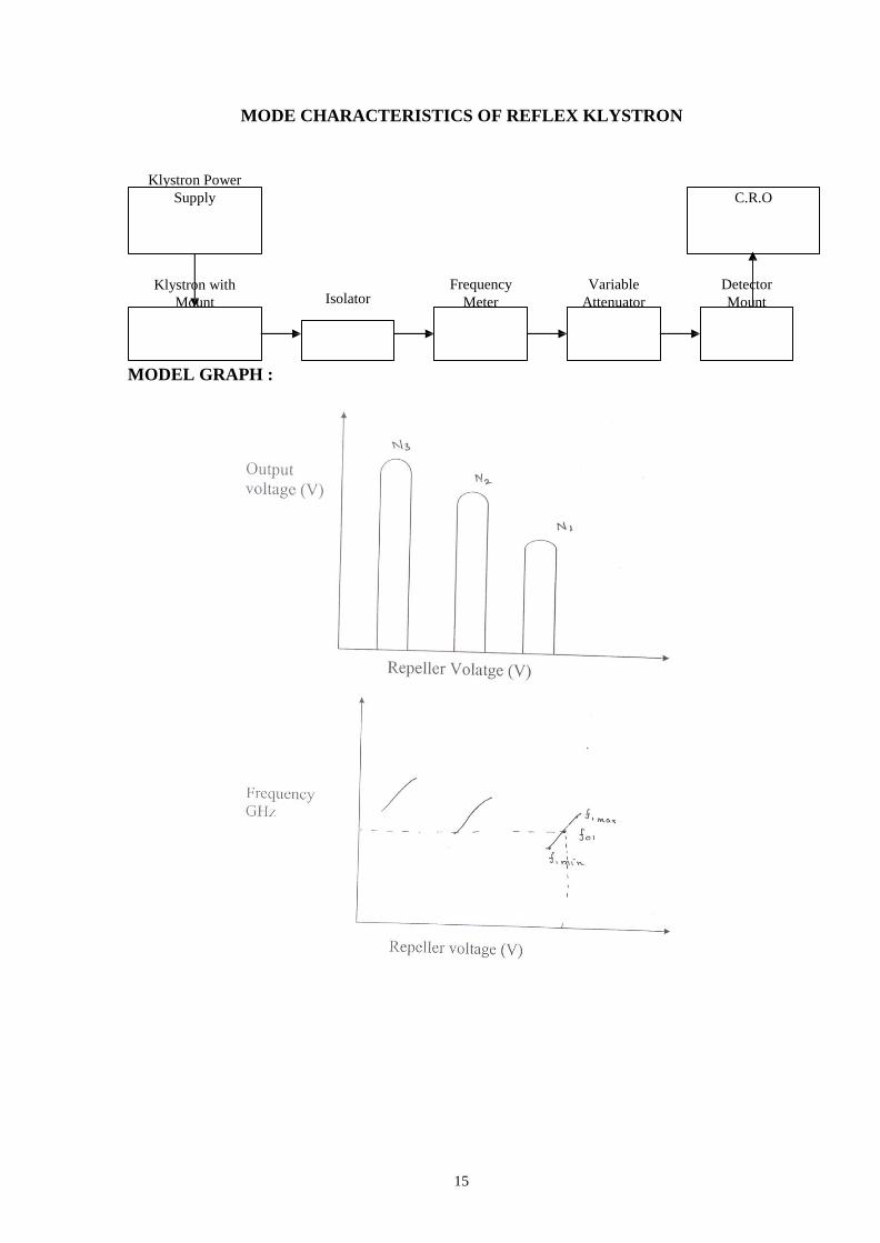
MODE CHARACTERISTICS OF REFLEX KLYSTRON
Klystron Power
Supply C.R.O
Klystron with
Mount Isolator
Frequency
Meter
Variable
Attenuator
Detector
Mount
MODEL GRAPH :
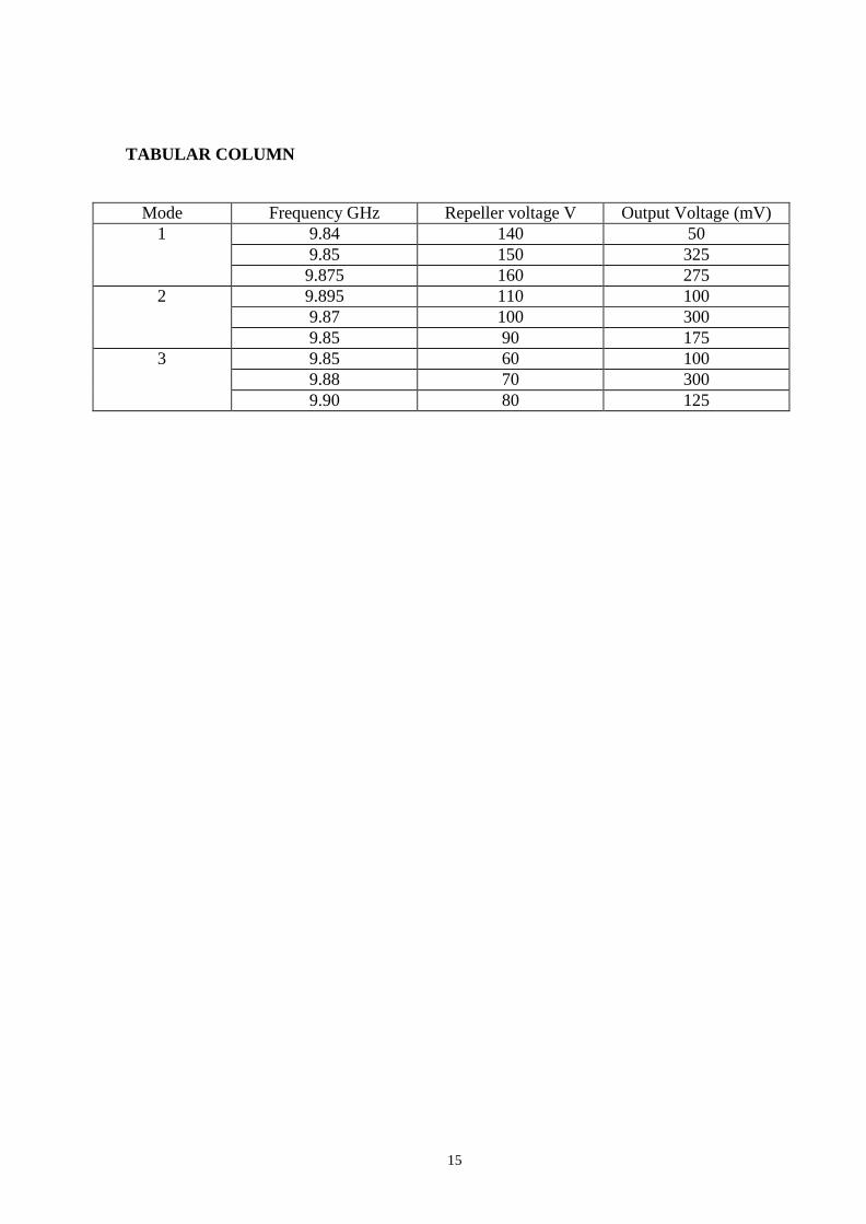
TABULAR COLUMN
Mode Frequency GHz Repeller voltage V Output Voltage (mV)
1 9.84 140 50
9.85 150 325
9.875 160 275
2 9.895 110 100
9.87 100 300
9.85 90 175
3 9.85 60 100
9.88 70 300
9.90 80 125
15

16
REVIEW QUESTIONS
1. List two basic configuration of Klystron tubes.
2. What is velocity modulation?
3. List down the characteristic of two cavity klystron amplifier.
4. Write a note on mode of oscillations.
5. Draw the reflex klystron modes.
6. Higher order mode occur at repeller voltage.
7. When the o/p power of reflex klystron maximum?
8. List the application of reflex klystron.
9. What is transit time?
10. Which mode number is most frequently used? Why?
17
3. IMPEDENCE MEASUREMENT
AIM
To measure the impedence of an unknown load using smith chart.
APPARATUS REQUIRED
Klystron Power supply, Klystron with mount, Isolator, Frequency meter, Variable
attenuator, Slotted section, Movable Short, CRO.
THEORY
The simplest method for measurement of impedence at microwave frequencies is as
follows. The unknown impedence is connected at the end of a slotted co axial line.
Microwave power is fed from the other end of coaxial line. Unknown impedence reflects a
part of this power. This reflection coefficient is measured by probing the standing wave fields
in the slotted line by a suitable arrangements. The reflection coefficient is given by
P = Z L − Z o
Z L + Z o
ZL - Load impedance at any point
ZO - Characteristics impedance of waveguide at operating frequency
Thus if P is measured & ZO is known, ZL can be found. In general ZL is complex, both magnitude and phase of P is needed. The magnitude of P may be found from VSWR measurement.
P = VSWR − − 1
VSWR + 1
The phase of P may be found by measuring the distance of first voltage minima from
the load. Thus the measurement of impedance involves the measurements of VSWR and the
distance of the voltage minima from the load. These measurements may be carried out by
using a slotted line and probe arrangement.
SRI SUKHMANI INSTITUTE OF ENGINEERING & TECHNOLOGY DERA
BASSI
DEPARTMENT: ELECTRONICS & COMM.
LABORATORY MANUAL
LAB: MICROWAVE LAB SUBJECT
CODE:BTEC-606
SEMESTER: 6TH
18
PROCEDURE
1. Assemble the components as per the circuit diagram
2. After making initial adjustments, mode3 is set up for operations
3. The frequency of the excited wave is found by adjusting the frequency meter for a dip
in the output meter. Thereafter detune the frequency meter slightly
4. The VSWR is found for the given load (horn), by measuring Vmax and Vmin.
5. With load - end short circuited, two successive minimas (d1 and d2)are found out by
moving the probe carriage along the slotted waveguide line. 6. With load-end terminated with the given load, the first minima(x) is noted.
7. The given load is replaced with short-circuit, the second minima(y) is noted down.
8. Next the shift is found depending on whether it is towards the load or source.
9. The impedance of the unknown load is found using smith chart and verified using
formula.
RESULT
The impedence of an unknown load was measured and using a smith chart and the
value was found out.
19
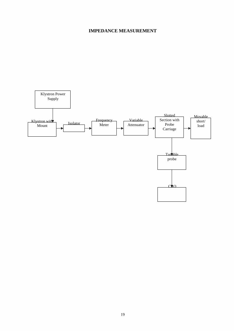
IMPEDANCE MEASUREMENT
Klystron Power
Supply
Klystron with
Mount Isolator
Frequency
Meter
Variable
Attenuator
Slotted
Section with
Probe
Carriage
Movable
short/
load
Tunable
probe
CRO
20
= z
⎦
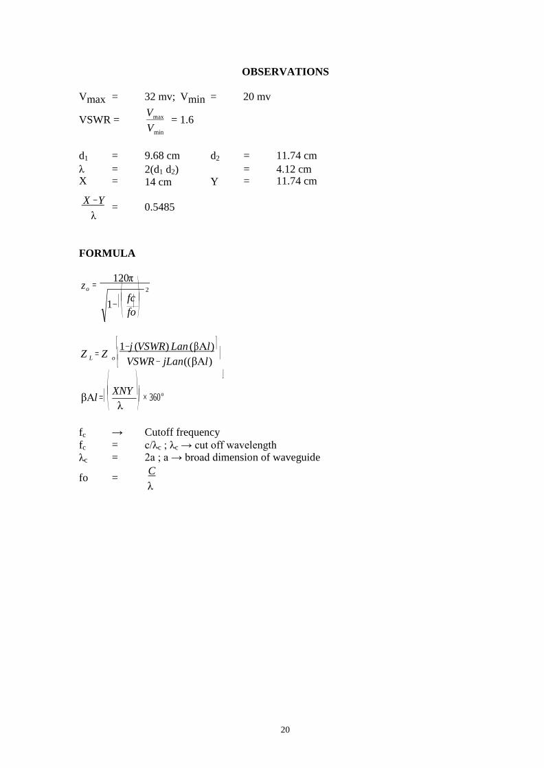
OBSERVATIONS
Vmax = 32 mv; Vmin = 20 mv
VSWR = Vmax
Vmin
= 1.6
d1 = 9.68 cm d2 = 11.74 cm
λ X
= =
2(d1 d2) 14 cm
Y
= =
4.12 cm 11.74 cm
X −Y
λ
= 0.5485
FORMULA
120π o 2
⎛ fc ⎞ 1− ⎜ ⎟
⎝ fo ⎠
Z = Z ⎡ 1− j (VSWR) Lan ( βΑl ) ⎤
L o ⎢ ⎣ VSWR − jLan((βΑl)
⎥
⎛ XNY ⎞βΑl = ⎜
⎝ λ ⎟ × 360o
⎠
fc → Cutoff frequency
fc = c/λc ; λc → cut off wavelength λc = 2a ; a → broad dimension of waveguide
fo = C λ

21
REVIEW QUESTIONS
1. What are the types of methods used in microwave frequencies to measure impedance?
2. Relation-ship between S & P.
3. Under which case the impedance will be
4. How will you measure the impedance of the unknown load in the microwave setup
bench
5. What are the application of smith chart.
22
4. DIRECTIONAL PATTERN OF HORN ANTENNA
AIM
To obtain directional pattern of a Horn Antenna.
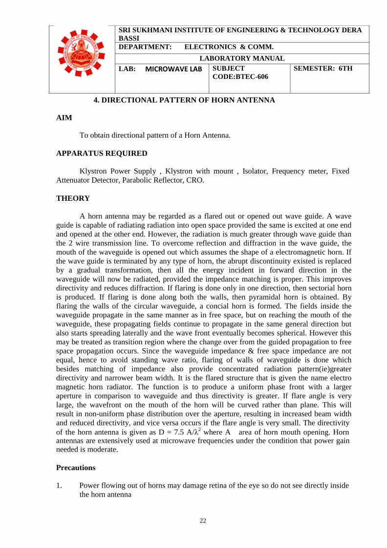
APPARATUS REQUIRED
Klystron Power Supply , Klystron with mount , Isolator, Frequency meter, Fixed
Attenuator Detector, Parabolic Reflector, CRO.
THEORY
A horn antenna may be regarded as a flared out or opened out wave guide. A wave
guide is capable of radiating radiation into open space provided the same is excited at one end
and opened at the other end. However, the radiation is much greater through wave guide than
the 2 wire transmission line. To overcome reflection and diffraction in the wave guide, the
mouth of the waveguide is opened out which assumes the shape of a electromagnetic horn. If
the wave guide is terminated by any type of horn, the abrupt discontinuity existed is replaced
by a gradual transformation, then all the energy incident in forward direction in the
waveguide will now be radiated, provided the impedance matching is proper. This improves
directivity and reduces diffraction. If flaring is done only in one direction, then sectorial horn
is produced. If flaring is done along both the walls, then pyramidal horn is obtained. By
flaring the walls of the circular waveguide, a concial horn is formed. The fields inside the
waveguide propagate in the same manner as in free space, but on reaching the mouth of the
waveguide, these propagating fields continue to propagate in the same general direction but
also starts spreading laterally and the wave front eventually becomes spherical. However this
may be treated as transition region where the change over from the guided propagation to free
space propagation occurs. Since the waveguide impedance & free space impedance are not
equal, hence to avoid standing wave ratio, flaring of walls of waveguide is done which
besides matching of impedance also provide concentrated radiation pattern(ie)greater
directivity and narrower beam width. It is the flared structure that is given the name electro
magnetic horn radiator. The function is to produce a uniform phase front with a larger
aperture in comparison to waveguide and thus directivity is greater. If flare angle is very
large, the wavefront on the mouth of the horn will be curved rather than plane. This will
result in non-uniform phase distribution over the aperture, resulting in increased beam width
and reduced directivity, and vice versa occurs if the flare angle is very small. The directivity
of the horn antenna is given as D = 7.5 A/λ2 where A area of horn mouth opening. Horn antennas are extensively used at microwave frequencies under the condition that power gain needed is moderate.
Precautions
1. Power flowing out of horns may damage retina of the eye so do not see directly inside
the horn antenna
SRI SUKHMANI INSTITUTE OF ENGINEERING & TECHNOLOGY DERA
BASSI
DEPARTMENT: ELECTRONICS & COMM.
LABORATORY MANUAL
LAB: MICROWAVE LAB SUBJECT
CODE:BTEC-606
SEMESTER: 6TH
23
24
25
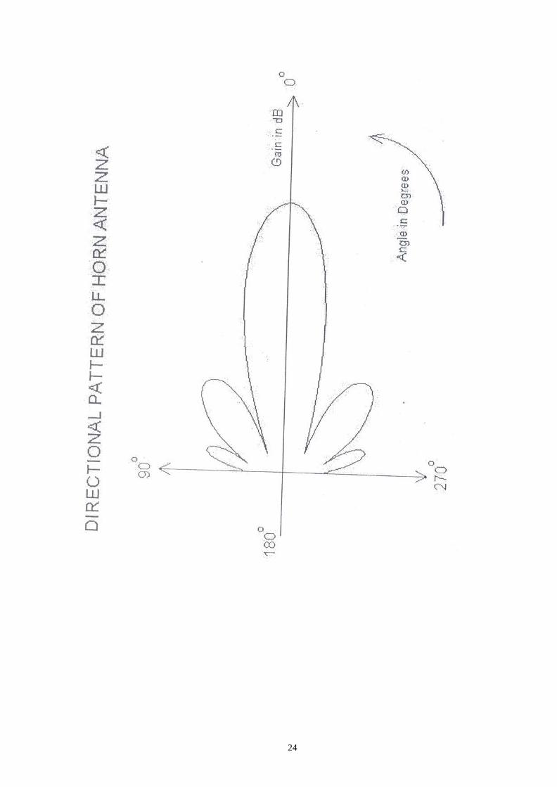
INPUT VOLTAGE VT = 330mv
Angle (degree s) VR (mv) Gain (dB) = 20 log (VR/VT)
Clock wise Anticlock wise Clock wise Anticlock wise
0 61 60 -14.66 -14.807
5
10 56 55 -15.4 -15.56
15
20 41 40 -18.11 -18.32
25
30 21 20 -23.9 -24.34
35
40 16 15 -26.2 -26.84
45
50 26 25 -22.07 -22.41
55
60 41 40 -18.11 -18.32
65
70 61 60 -14.66 -14.80
75
80 21 20 -23.9 -24.3
85
90 11 10 -29.5 -30.3
PROCEDURE
1. Setup the equipments as shown in fig. Keeping the axis of both antennas in same
axis line
2. Energize the microwave source, and set mode 3 determine input power at
transmitting antenna end by connecting detector mount.
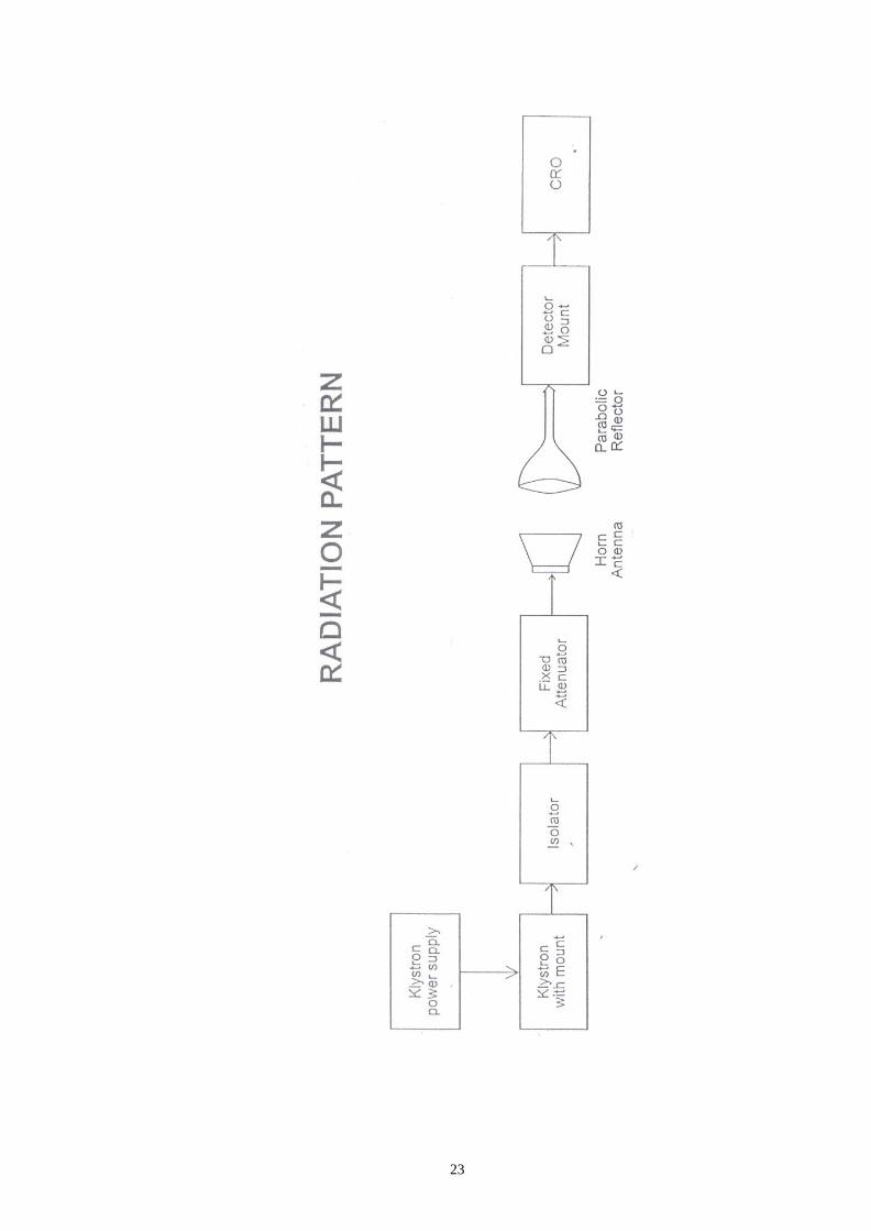
3. Connect the transmitting antenna back. Turn the receiving horn to the left in 5°
steps upto atleast 60° and note the corresponding voltage.
4. Repeat the above step but this time turning the receiver to the right and notedown
the readings.
5. Draw a relative power pattern ie, o/p vs angle.
6. From diagram 3 dB beam width is determined.
RESULT
Thus the directional pattern of the Horn antenna was obtained and the corresponding
graph was drawn.

26
REVIEW QUESTIONS
1. List some of the types of antennas used in microwaves.
2. Why is a paraboloid preferred to horn at microwave frequencies?
3. Write the formula for directivity & power gain of horn antenna.
4. What are the different types of horn antenna is used in microwave frequencies?
5. List some common features of horn antenna.

27
5. CHARACTERISTICS OF DIRECTIONAL COUPLER
AIM
To measure the performance of a Directional coupler and to determine the following :
i) Main line VSWR
ii) Auxiliaries line VSWR
iii) Insertion loss
iv) Coupling factor
v) Directivity
APPARATUS
Klystron power supply, Klystron with mount, Isolator, variable attenuator, slotted
section, CRO, Directional Coupler, Matched termination.
THEORY
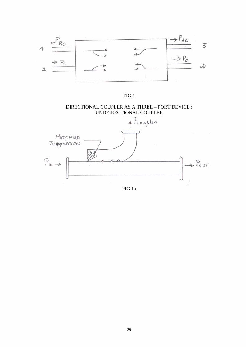
A directional coupler is a useful hybrid waveguide joint, which coules power in an
auxiliary waveguide arm in one direction. It is a four-port device but one of the ports is
terminated into a matched load. Ref figure 1.
Characteristics of a Directional Coupler An ideal directional coupler has the following characteristics
i) If power is fed into port (1) the power is coupled in ports (2) and (3) i.e.,
power flows in the forward direction of the auxiliary arm port (3) but no
power couples in port (4) i.e., in backward direction similarly power fed in (2)
couples into ports (1) and (4) and not in (3).
ii) All the four ports are matched, i.e. if three of them are terminated in matched
loads, the fourth is automatically terminated in a matched load.
iii) If power couples in reverse direction, power fed in (1) appears in ports (2) and
(4) and nothing in (3), then such type of coupler is known as backward
directional coupler. The conclusion is that in the auxiliary section the power is
coupled in only one direction.
We will measure (i) main line and auxiliary line VSWR as a function of frequency, (ii)
coupling coefficient as a function of frequency, (iii) directivity as a function of frequency,
and (iv) the main line insertion loss as a function of frequency. These parameters are defined
as follows:
(i) Main Line VSWR: The main line VSWR is the standing wave ratio measured
looking into the main line input terminals when matched loads are placed at all
the three other terminals. The main line VSWR will be the same for any
orientation of the coupler in the transmission line.
(ii) Auxiliary Line VSWR: The auxiliary line VSWR is the standing wave ratio
measured in the auxiliary line looking into the output terminal to which the
SRI SUKHMANI INSTITUTE OF ENGINEERING & TECHNOLOGY DERA
BASSI
DEPARTMENT: ELECTRONICS & COMM.
LABORATORY MANUAL
LAB: MICROWAVE LAB SUBJECT
CODE:BTEC-606
SEMESTER: 6TH

28
detector is normally connected when matched loads are placed at all the three
other ports or terminals.
DIRECTIONAL COUPLER AS A FOUR – PORT DEVICE
29
FIG 1
DIRECTIONAL COUPLER AS A THREE – PORT DEVICE :
UNDEIRECTIONAL COUPLER
FIG 1a
30
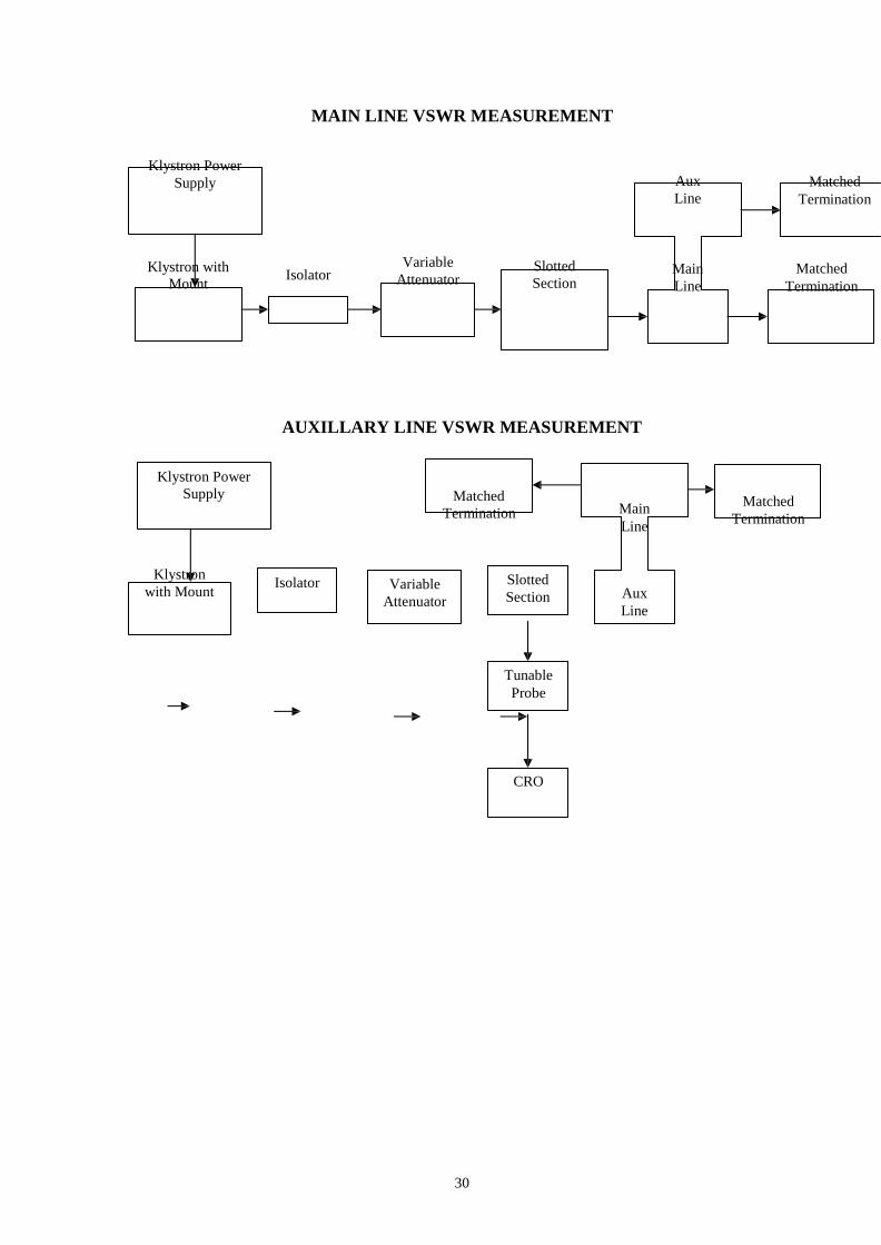
MAIN LINE VSWR MEASUREMENT
Klystron Power
Supply
Aux
Line
Matched
Termination
Klystron with
Mount Isolator
Variable
Attenuator Slotted
Section
Main
Line
Matched
Termination
AUXILLARY LINE VSWR MEASUREMENT
Klystron Power
Supply Matched
Termination
Main
Line
Matched
Termination
Klystron
with Mount
Isolator Variable
Attenuator
Slotted
Section
Aux
Line
Tunable
Probe
CRO
30
31
32
33
34
V ⎜ ⎟
Directional Coupler
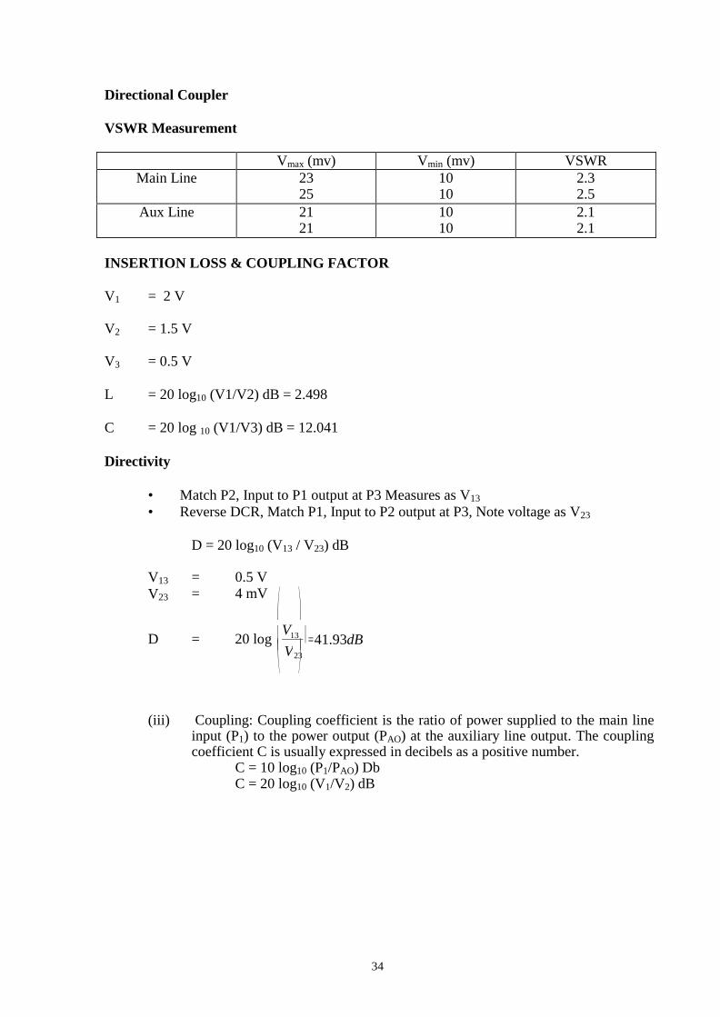
VSWR Measurement
Vmax (mv) Vmin (mv) VSWR
Main Line 23 25
10 10
2.3 2.5
Aux Line 21 21
10 10
2.1 2.1
INSERTION LOSS & COUPLING FACTOR
V1 = 2 V
V2 = 1.5 V
V3 = 0.5 V
L = 20 log10 (V1/V2) dB = 2.498
C = 20 log 10 (V1/V3) dB = 12.041
Directivity
• Match P2, Input to P1 output at P3 Measures as V13
• Reverse DCR, Match P1, Input to P2 output at P3, Note voltage as V23
D = 20 log10 (V13 / V23) dB
V13 = 0.5 V
V23 = 4 mV
⎛ ⎞
D = 20 log ⎜ V13 ⎟ = 41.93dB
23
⎝ ⎠
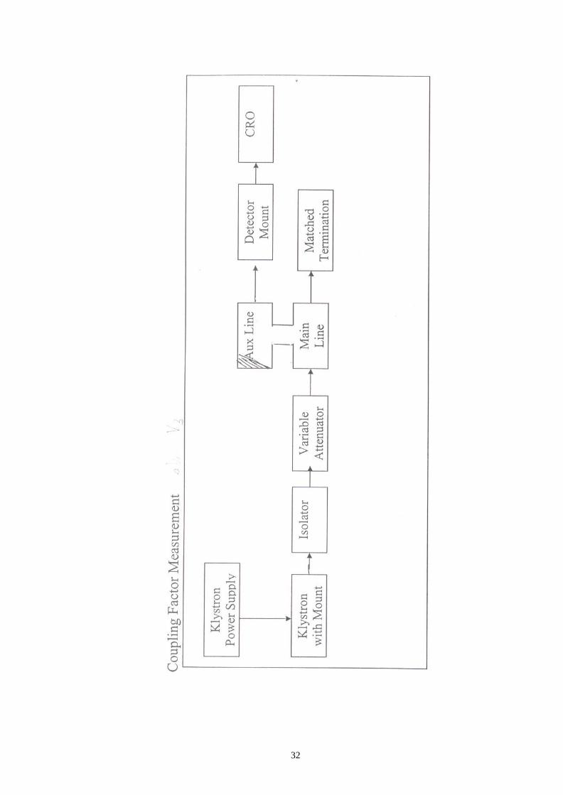
(iii) Coupling: Coupling coefficient is the ratio of power supplied to the main line input (P1) to the power output (PAO) at the auxiliary line output. The coupling coefficient C is usually expressed in decibels as a positive number.
C = 10 log10 (P1/PAO) Db C = 20 log10 (V1/V2) dB
35
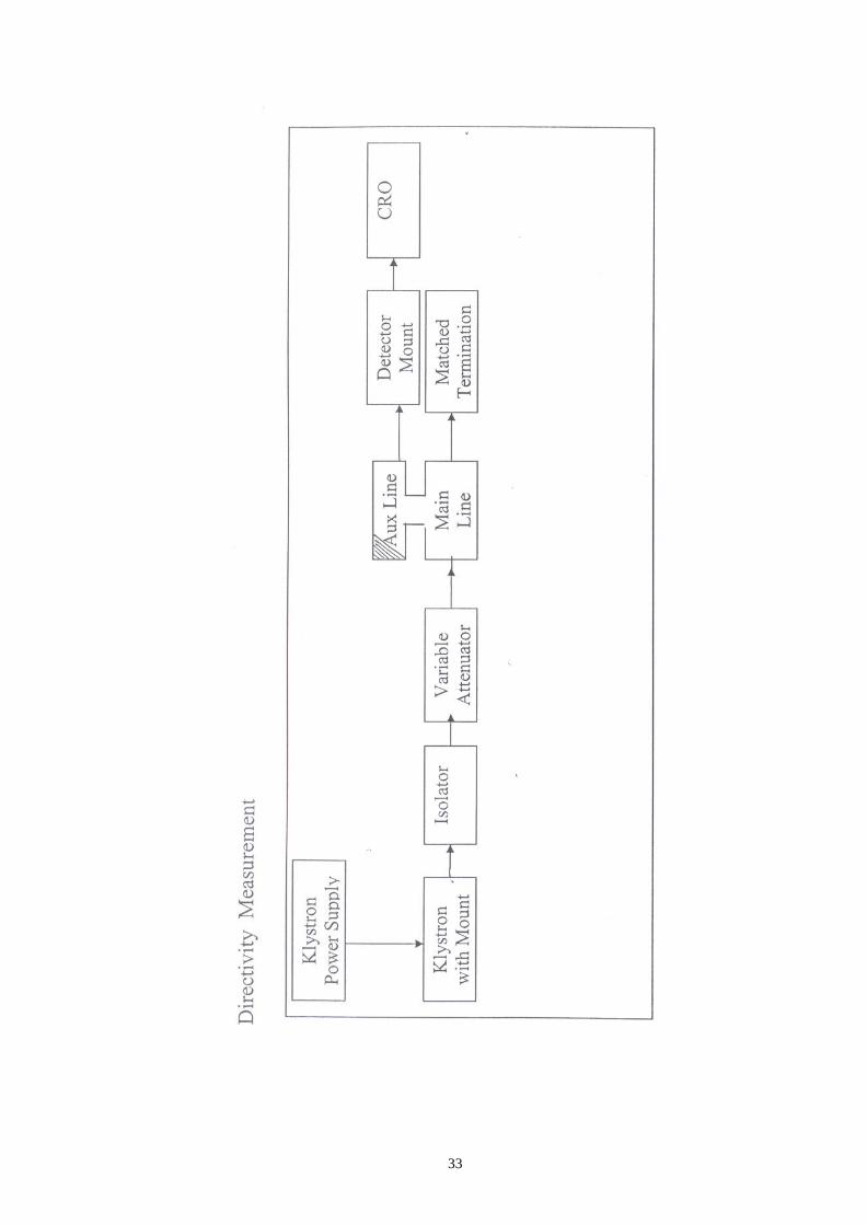
(iv) Main Line Insertion Loss : The main line insertion loss is the attenuation
introduced in a transmission line by the insertion of the directional coupler.
The auxiliary line of the coupler is assumed to be properly terminated. The
main line insertion loss, L is given by
L = 10 log10 (P1/P0) db L = 20 log (V1/V2) db
(v) Directivity: The directivity D is a measure of the discrimination property of a directional coupler between the waves traveling in the two directions in the
main line. It is measured as the ratio of the two power outputs from the
auxiliary line when a given amount of power is successively applied to each
terminal of the main line. The other terminals or ports of the coupler not in use
in the particular measurement are assumed to be terminated in matched loads.
D = 10 log10 (PA0/Pd) db D = 20 log (V3/V4) db
PROCEDURE :
Main Line VSWR 1. Setup the equipment as shown in fig, Terminating Port 2 and Port 3 with matched
termination set modes
2. Move the slotted section and measure Vmax and Vmin
3. Calculate VSWR Vmax and Vmin
Auxillary –line VSWR 1. Set up the equipment as shown in fig. terminating port 1 and port 2i set mode 3 with
matched termination. 2. Move the slotted section and measure Vmax and Vmin
3. Calculate VSWR = Vmax and Vmin
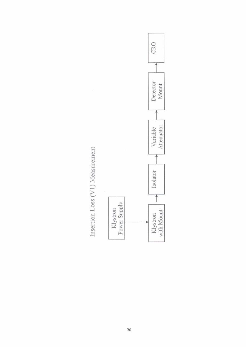
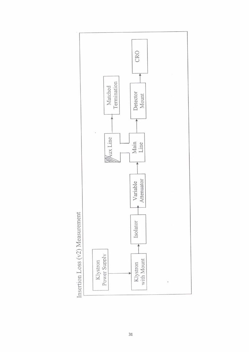
Insertion Loss and Coupling factor
1. Set the equipment by connecting detector mount to the input end(without directional
coupler). 2. Set mode 3 and obverse the input voltage V1 . Do not alter till the end of the
experiment. 3. Insert the directional coupler, terminate port 3 with matched termination. 4. Connect detector mount to port 2 and measure V2.
5. Calculate insertion loss
⎛ V ⎞ 20 log10 ⎜ 1 ⎟ dB
⎝ V2 ⎠
6. To measure coupling factor, terminate port 2 with matched termination, connect detector mount to port 3 and measure V3.
7. Calculate coupling factor
36
⎛ V ⎞
Directivity
C = 20 log10 ⎜ 1 ⎟ dB ⎝ V3 ⎠
1. Set up the equipment as shown in fig Terminate port 2 with matched termination
and connect detector mount to port 3.
2. Measure the voltage at port 3 and note it as V13.
3. Connect the directional coupler in reverse direction. ie, port 2 – input, port 1 – matched termination, port 3 – detector mount
4. Measure the voltage as V23
⎛ V ⎞ 5. Calculate directivity D = 20 log ⎜ 13 ⎟
⎝ V23 ⎠
Calculations:
Main Line VSWR = Vmax / Vmin
Auxiliary line VSWR = Vmax / Vmin
Insertion Loss L = 20 log (V1 / V2) dB
Coupling factor C = 20 log (V1 / V3) dB
Directivity D = 20 log (V3 / V4) dB
RESULT :
The performance characteristics of directional coupler were determined.

37
REVIEW QUESTIONS
1. What is a directional coupler?
2. List the types of directional coupler.
3. Draw a basic directional coupler?
4. List the performance of a directional coupler.
5. Define the directivity `D’ of a directional coupler.
6. Define coupled factor C.
7. What is multihole directional coupler?
38
6. STUDY OF E PLANE, H PLANE AND MAGIC TEE
AIM
To determine isolations, coupling coefficients and input VSWR’s for E and H plane
waveguide Tee and Magic Tee junctions.
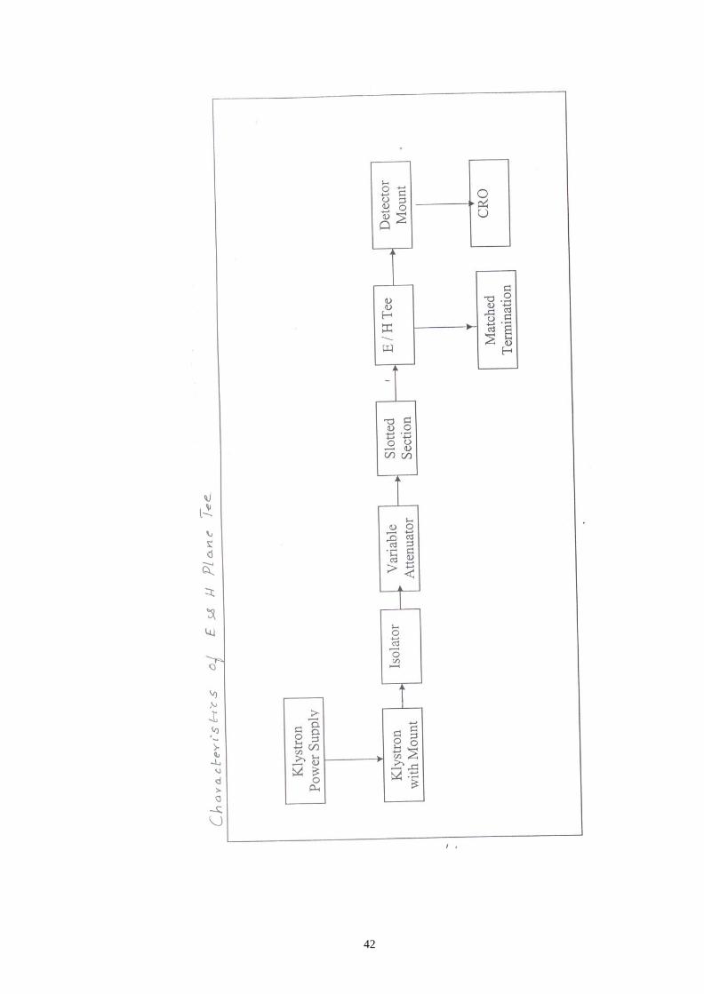
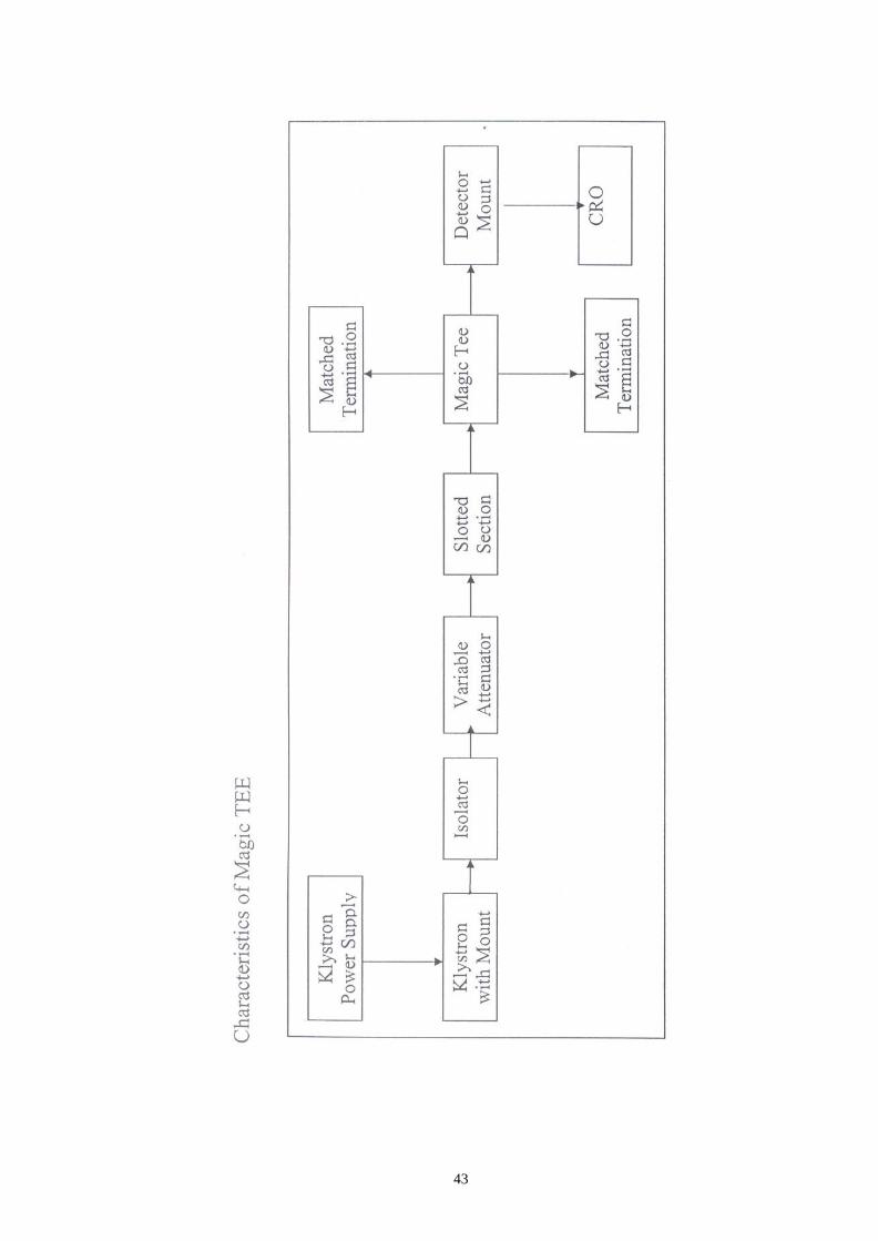
APPARATUS REQUIRED
Klystron power supply, Klystron with mount, isolator, variable attenuator, slotted
section, Magic Tee, Matched termination, detector mount, CRO.
THEORY
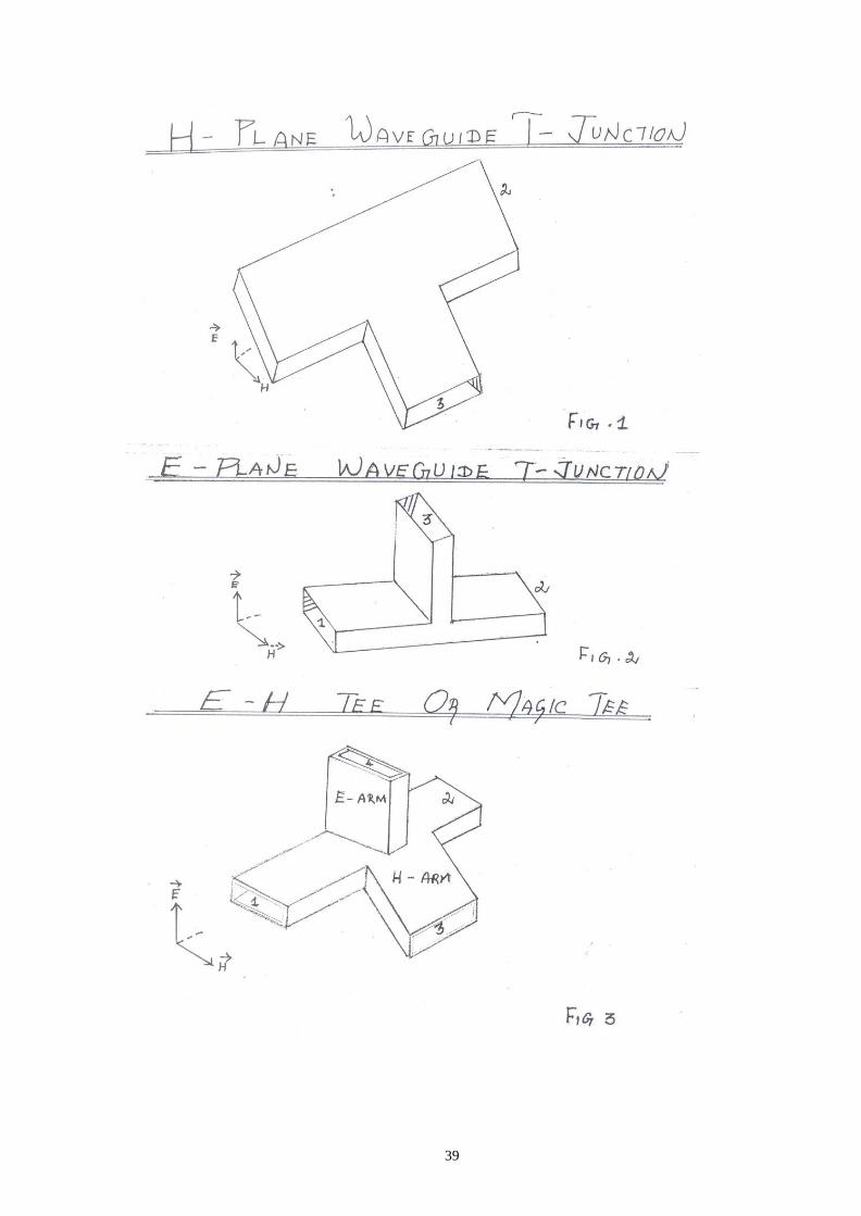
H Plane Tee Fig 1(a) shows the sketch of an H plane tee. It is clear from the sketch that an
auxiliary waveguide arm is fastened perpendicular to the narrow wall of a main guide, thus it is a three port device in which axis of the auxiliary or side arm is parallel to the planes of the magnic field of the main of the main guide and the coupling from the main guide to the branch guide is by means of magnetic fields. Therefore, it is also known as H plane tee.
The perpendicular arm is generally taken as input and other two arms are in shunt to
the input and hence it is also called as shunt tee. Because of symmetry of the tee; equivalent
circuit of H plane, when power enters the auxiliary arm, and the two main arms 1 and 2 are
terminated in identical loads, the power supplied to each load is equal and in phase with one
another.
If two signals of equal amplitude and in same phase are fed into two main arms1 and
2, they will be added together in the side arm. Thus H plane tee is an `adder’.
E Plane Tee
Figure 2 and respectively show the sketch of the E plane tee. It is clear from the sketch of the E plane tee that an auxiliary waveguide arm is fastened to the broader wall of the main guide. Thus it is also a three port device in which the auxiliary arm axis in parallel to the plane of the electric fields of the main guide, and the coupling from the main guide to the auxiliary guide is by means of electric fields. Therefore, it is also known as E plane tee. It is clear that it causes load connected to its branches to appear in series. So it is often referred to as a series tee.
As indicated in fig, the two main guide arms are symmetrical with respect to the
auxiliary guide arm. As such if power is fed from the auxiliary arm, it is equally distributed in
the two arms 1 and 2 when they are terminated in equal loads. However as depicted in the
field configuration, the power floeing out in arm 1 is 180 out of phase to the one in arm 2. As
such tis tee is known as `subtracter’ or `differencer’.
SRI SUKHMANI INSTITUTE OF ENGINEERING & TECHNOLOGY DERA
BASSI
DEPARTMENT: ELECTRONICS & COMM.
LABORATORY MANUAL
LAB: MICROWAVE LAB SUBJECT
CODE:BTEC-606
SEMESTER: 6TH
39
40
Magic Tee An interesting type of T junction is the hybrid tee, commonly known as `magic tee’
which is shown in fig. The device as can be seen from fig is a combination of the E arm and H plane tees. Arm3, the H arm forms an H plane tee and arm 4, the E arm, forms an E plane tee in combination with arms 1 and 2. The central lines of the two tees coincide and define the plane of symmetry, that is, if arms 1 and 2 are of equal length, the part of structure on one side of the symmetry plane shown by shaded area is the mirror image of that on the other. Arms1 and 2 are sometimes called as the side or collinear arms.
Magic of the MAGIC Tee
The name `magic Tee’ is derived from the manner in which power divides among various arms. If power is fed into arm3, the electric field divides equally between arms 1 and 2 and the fields are in phase. Because of symmetry of the T junction, no net electric field parallel to the narrow dimension of the waveguide is excited in arm 4. Thus no power is coupled in port 4. Reciprocity demands no coupling in port 3 if power is fed in 4.
Another property that results from the symmetry of the junction is, if power is fed in
E or H arm, it is equally divided between arms 1 and 2.
Further, magic tee being combination of E and H plane tees, if power is fed from arms
1 and 2, it is added in H arm (3) while is subtracted in E arm (4).
A simple E-H tee has disadvantage of not being matched when seen from E and H
arms when side arms are terminated in matched loads. The VSWR being > 2 the most
commonly used method to reduce VSWR is to introduce discontinuity such as port iris in or
near T junction to cancel out reflections occurring there in.
E Plane, H Plane Tee Parameter
a) Isolation The isolation of a T junction is the ratio of power supplied from a matched generator
to one of the arms, to the power coupled to a matched detector in any other arm when the remaining arm is terminated in a matched load.
Isolation between port 1 and 2 is
I12 = 10 log10 P1 / P2 dB, I12 = 20 log10 (V1 / V2) dB, And when matched load and detector are interchanged
I13 = 10 log10 P1 / P3 dB, I13 = 20 log10 (V1 / V3) dB,Similarly
I31 = 10 log10 P3 / P1 dB, I32 = 20 log10 (V3 / V2) dB,And when matched load and detector are interchanged,
I33 = 10 log10 P3 / P2 dB, I32 = 20 log10 (V3 / V2) dB,
When arm 2 becomes the input, we will have other two values of isolation, I21 and I23. Due to reciprocity Property, I21 will be the same as I12. Therefore, we shall measure only the first four isolation coefficients. b) Coupling coefficient
Corresponding to the values of isolation, we can compute
The coupling coefficient by the formula
41
C = 10-α / 20
Where α is the attenuation in db between the input and detector arm when the third arm is terminated in a matched load. For example, the attenuation measured between arms 1 and 2 is 3 db when arm 3 terminated in matched load, that is, the coupling coefficient between arms 1
and 2,
C12 = 10-α / 20
= 10-3 / 20
= 0.708 db
c) Input VSWR
The are three values of input VSWR associated with a tee, one for each arm. The VSWR of any arm of a tee is the voltage standing wave ratio existing on a transmission line terminated by that arm of the tee when the other two arm of the tee are terminated in matched loads.
Magic Tee Parameter:
The basic properties and associated quantities to be measured for a magic tee are defined as follows:
a) Input VSWR
Corresponding to each port of a magic tee as load to the line, there is a value
of VSWR. Thus there are four values of VSWR. VSWR is defined as the ratio
of maximum voltage to minimum voltage of the standing waves existing on
the line when one port of the tee terminates the line while other three ports are
terminated in matched loads.
b) Isolations
The isolation between E-and H-arms is defined as the ratio of the power
supplied by the matched generator connected to E-arms (port-4), to the power
detected in H-arm (port-3) by a matched detector when collinear arms (1&2)
are terminated in matched loads. It is expressed in db.
I34 = 10 log10 P4/P3, I34 = 20 log 10 (V4 / V3)
P4 : power incident in port4(E-arm) P3 : power detected in port3 (H-arm)
Similarly isolation between other ports may also be defined and measured.
c) Coupling Coefficient:
The voltage coupling coefficient from arm I to arm j is defined as Cij = 10-α/20
42
43
44
Nature of Tee Voltage (mv) I/P O/P
Isolation (Iij) dB
Coupling Coefficient
Cij = 10Iij/20
E-Plane
Ist
arm
2nd
arm 640
5.64
C12 = 0.4167
rd 3 arm
500
7.604
C13 = 0.533
3rd
arm 2nd
= 52 480 C32 = 0.4
1st
arm = 48 440 C31 = 0.366
H = Plane
Ist
arm
= 120
2nd
arm = 66
C12
3rd
arm = 36
C13
3rd
arm 130
2nd
= 54 C32
1st
arm = 48 C31
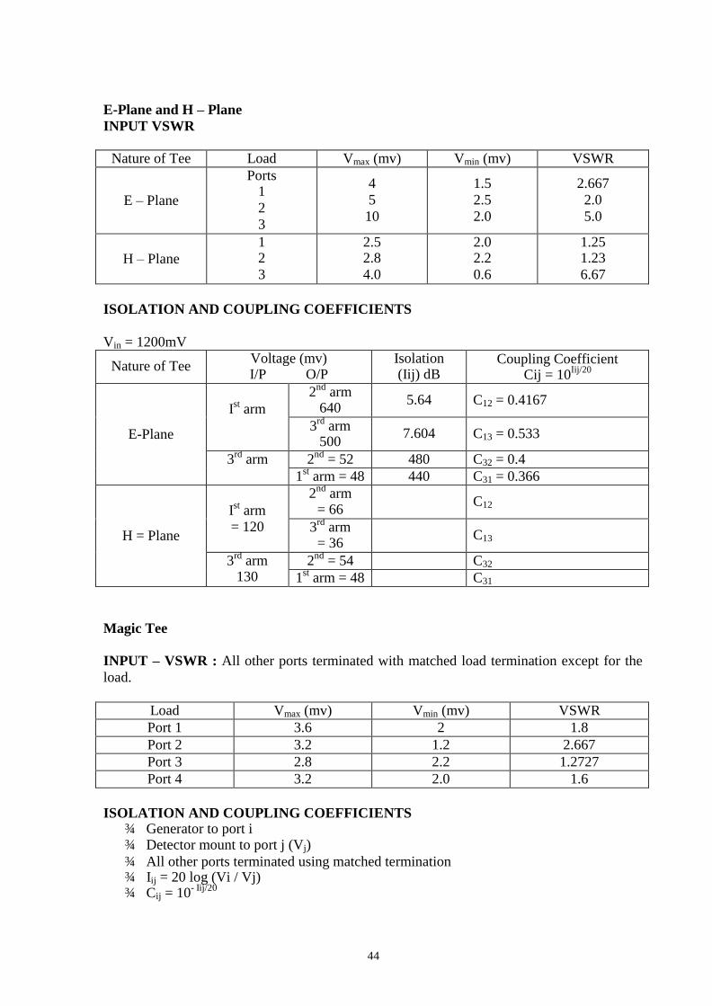
E-Plane and H – Plane
INPUT VSWR
Nature of Tee Load Vmax (mv) Vmin (mv) VSWR
E – Plane
Ports 1
2
3
4
5
10
1.5
2.5
2.0
2.667
2.0
5.0
H – Plane
1 2
3
2.5 2.8
4.0
2.0 2.2
0.6
1.25 1.23
6.67
ISOLATION AND COUPLING COEFFICIENTS
Vin = 1200mV
Magic Tee
INPUT – VSWR : All other ports terminated with matched load termination except for the
load.
Load Vmax (mv) Vmin (mv) VSWR
Port 1 3.6 2 1.8
Port 2 3.2 1.2 2.667
Port 3 2.8 2.2 1.2727
Port 4 3.2 2.0 1.6
ISOLATION AND COUPLING COEFFICIENTS ¾ Generator to port i ¾ Detector mount to port j (Vj)
¾ All other ports terminated using matched termination ¾ Iij = 20 log (Vi / Vj) ¾ Cij = 10
- Iij/20
45
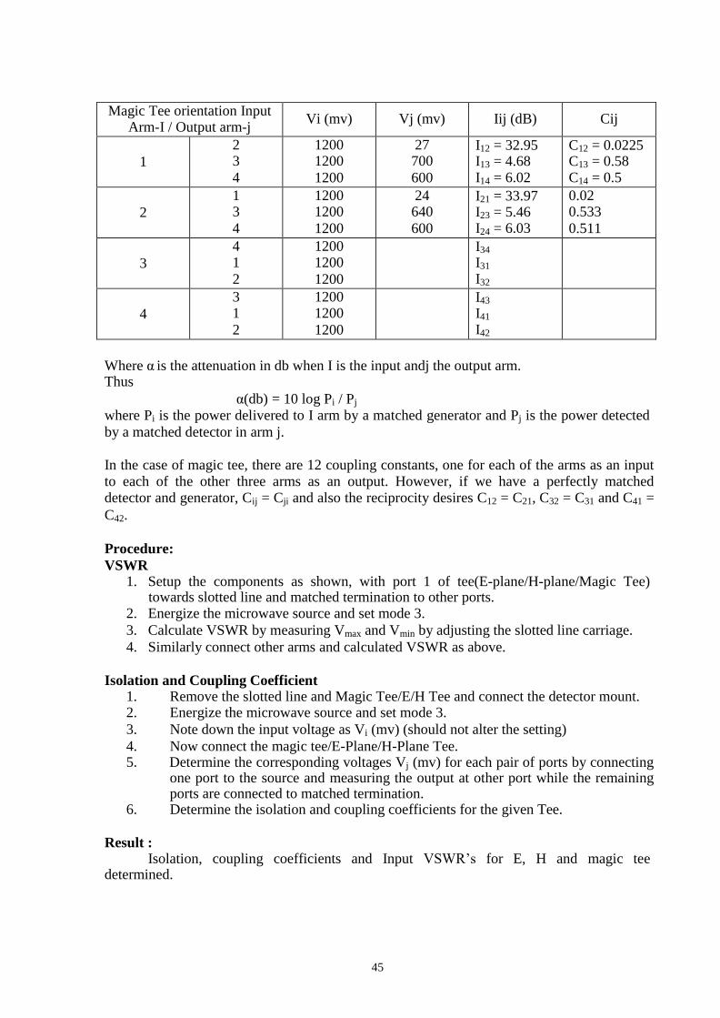
Magic Tee orientation Input Arm-I / Output arm-j
Vi (mv)
Vj (mv)
Iij (dB)
Cij
1
2 3
4
1200 1200
1200
27 700
600
I12 = 32.95 I13 = 4.68 I14 = 6.02
C12 = 0.0225 C13 = 0.58 C14 = 0.5
2
1 3
4
1200 1200
1200
24 640
600
I21 = 33.97 I23 = 5.46 I24 = 6.03
0.02 0.533
0.511
3
4 1
2
1200 1200
1200
I34
I31
I32
4
3 1
2
1200 1200
1200
I43
I41
I42
Where α is the attenuation in db when I is the input andj the output arm. Thus
α(db) = 10 log Pi / Pj
where Pi is the power delivered to I arm by a matched generator and Pj is the power detected by a matched detector in arm j.
In the case of magic tee, there are 12 coupling constants, one for each of the arms as an input to each of the other three arms as an output. However, if we have a perfectly matched detector and generator, Cij = Cji and also the reciprocity desires C12 = C21, C32 = C31 and C41 =
C42.
Procedure:
VSWR 1. Setup the components as shown, with port 1 of tee(E-plane/H-plane/Magic Tee)
towards slotted line and matched termination to other ports. 2. Energize the microwave source and set mode 3.
3. Calculate VSWR by measuring Vmax and Vmin by adjusting the slotted line carriage.
4. Similarly connect other arms and calculated VSWR as above.
Isolation and Coupling Coefficient
1. Remove the slotted line and Magic Tee/E/H Tee and connect the detector mount. 2. Energize the microwave source and set mode 3.
3. Note down the input voltage as Vi (mv) (should not alter the setting)
4. Now connect the magic tee/E-Plane/H-Plane Tee. 5. Determine the corresponding voltages Vj (mv) for each pair of ports by connecting
one port to the source and measuring the output at other port while the remaining ports are connected to matched termination.
6. Determine the isolation and coupling coefficients for the given Tee.
Result :
Isolation, coupling coefficients and Input VSWR’s for E, H and magic tee determined.

46
REVIEW QUESTIONS
1. What are the several types of tees used in microwave communication?
2. What is the S.Matrix of H-plane Tee function.
3. What is a hybrid `T’ or magic `T’?
4. Application of magic Tee.
5. List some of the basic magic Tee parameters.


![Sahib.doc · Web viewsuKmnI. gauVI suKmnI mÚ 5 ] ga-orhee sukhmanee mehlaa 5. Gauree Sukhmani, Fifth Mehl, sloku ] salok. Shalok: siqgur pRswid ] ik-oNkaar satgur parsaad](https://img.dokumen.tips/doc/110x75/5e32086475caf64a6c3ded42/sahibdoc-web-view-sukmni-gauvi-sukmni-m-5-ga-orhee-sukhmanee-mehlaa-5-gauree.jpg)