Embed Size (px)
Citation preview

1
GB Angle Grinder INSTRUCTION MANUAL
UA Кутова шліфувальна машина ІНСТРУКЦІЯ З ЕКСПЛУАТАЦІЇ PL Szlifierka kątowa INSTRUKCJA OBSŁUGI RO Polizor unghiular MANUAL DE INSTRUCŢIUNI DE Winkelschleifer BEDIENUNGSANLEITUNG
HU Sarokcsiszoló HASZNÁLATI KÉZIKÖNYV
SK Uhlová brúska NÁVOD NA OBSLUHU
CZ Úhlová bruska NÁVOD K OBSLUZE
GA4040C GA4540C GA5040C GA6040C GA4041C GA4541C GA5041C GA6041C
SRB Ugaona brusilica UPUTSTVO ZA RUKOVANJE

2
1
1 012725
1
2 012728 1
3 012729
1
4 012747 5 012724
1
2 3
6 012733
1
234
7 009430
1 2
8 009431
123
9 012802
1
2
10 012727
12
4
3
11 012772
1
12 012773

3
1 2
13 010846 14 010863
12
34
15 012740
12
3
16 012742
1 2
34
17 012731
A B
18 012730
1
2
34
19 010855
1
20 012743
1
21 012744
1
2
22 012732
4
ENGLISH (Original instructions) Explanation of general view
1-1. Shaft lock 2-1. Slide switch 3-1. Indication lamp (speed adjusting
dial) 4-1. Speed adjusting dial 6-1. Wheel guard 6-2. Bearing box 6-3. Screw 7-1. Wheel guard 7-2. Bearing box 7-3. Screw 7-4. Lever 8-1. Screw 8-2. Lever 9-1. Lock nut 9-2. Depressed center wheel
9-3. Inner flange 10-1. Lock nut wrench 10-2. Shaft lock 11-1. Ezynut 11-2. Abrasive wheel 11-3. Inner flange 11-4. Spindle 12-1. Shaft lock 13-1. Arrow 13-2. Notch 15-1. Lock nut 15-2. Flex wheel 15-3. Plastic pad 15-4. Inner flange 16-1. Sanding lock nut 16-2. Abrasive disc
16-3. Rubber pad 17-1. Marking A 17-2. Marking B 17-3. Marking C 17-4. Marking D 19-1. Lock nut 19-2. Abrasive cut-off wheel/diamond
wheel 19-3. Inner flange 19-4. Wheel guard for abrasive cut-off
wheel/diamond wheel 20-1. Wire cup brush 21-1. Wire wheel brush 22-1. Exhaust vent 22-2. Inhalation vent
SPECIFICATIONS Model GA4040C GA4041C GA4540C GA4541C GA5040C GA5041C GA6040C GA6041C
Wheel diameter 100 mm (4") 115 mm (4-1/2") 125 mm (5") 150 mm (6") Spindle thread M10 M14 M14 M14
Rated speed (n) / No load speed (n0) 2,800 - 11,000 min-1 2,800 - 11,000 min-1 2,800 - 11,000 min-1 4,000 - 9,000 min-1 Overall length 303 mm 325 mm 303 mm 325 mm 303 mm 325 mm 303 mm 325 mm
Net weight 2.3 kg 2.6 kg 2.5 kg 2.7 kg 2.5 kg 2.7 kg 2.6 kg 2.8 kg Safety class /II
• Due to our continuing program of research and development, the specifications herein are subject to change without notice. • Specifications may differ from country to country. • Weight according to EPTA-Procedure 01/2003
ENE048-1
Intended use The tool is intended for grinding, sanding and cutting of metal and stone materials without the use of water.
ENF002-2
Power supply The tool should be connected only to a power supply of the same voltage as indicated on the nameplate, and can only be operated on single-phase AC supply. They are double-insulated and can, therefore, also be used from sockets without earth wire.
ENG905-1
Noise The typical A-weighted noise level determined according to EN60745:
Model GA4040C, GA4540C, GA5040C
Sound pressure level (LpA) : 86 dB(A) Sound power level (LWA) : 97 dB(A) Uncertainty (K) : 3 dB(A)
Model GA6040C
Sound pressure level (LpA) : 87 dB(A) Sound power level (LWA) : 98 dB(A) Uncertainty (K) : 3 dB(A)
Model GA4541C
Sound pressure level (LpA) : 83 dB(A) Sound power level (LWA) : 94 dB(A) Uncertainty (K) : 3 dB(A)
Model GA5041C, GA6041C
Sound pressure level (LpA) : 84 dB(A) Sound power level (LWA) : 95 dB(A) Uncertainty (K) : 3 dB(A)
Wear ear protection
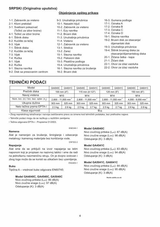
TEHNIČKI PODACIModel
• Zbog neprekidnog istraživanja i razvoja zadržavamo pravo za izmene kod tehničkih podataka, bez prethodne najave.
• Tehnički podaci mogu da se razlikuju u različitim zemljama.
• Težina odgovara EPTA-i - Propisima 01/2003.
ENE048-1
NamenaAlat je namenjen za brušenje, šmirglanje i odsecanje metalnog i kamenog materijala bez korišćenja vode.
ENF002-2
NapajanjeAlat sme da se priključi na izvor napajanja sa istim naponom koji je propisan na nazivnoj tablici i sme da radi na jednofaznu naizmeničnu struju. On je dvojno izolovan i zbog toga može da se koristi sa utikačem bez uzemljenja.
ENG905-1
BukaTipična A – vrednost buke odgovara EN60745:
Model GA4040C, GA4540C, GA5040C Nivo zvučnog pritiska (LpA): 86 dB(A) Nivo zvučne snage (LWA): 97 dB(A) Odstupanje (K): 3 dB(A)
Model GA6040C Nivo zvučnog pritiska (LpA): 87 dB(A) Nivo zvučne snage (LWA): 98 dB(A) Odstupanje (K): 3 dB(A)
Model GA4541C Nivo zvučnog pritiska (LpA): 83 dB(A) Nivo zvučne snage (LWA): 94 dB(A) Odstupanje (K): 3 dB(A)
Model GA5041C, GA6041C Nivo zvučnog pritiska (LpA): 84 dB(A) Nivo zvučne snage (LWA): 95 dB(A) Odstupanje (K): 3 dB(A)
Nosite zaštitu za uši
SRPSKI (Originalna uputstva)Objašnjenje opšteg prikaza
1-1. Zabravnik za vreteno2-1. Klizni prekidač 3-1. Svetlosni pokazivač (Točkić za izbor brzine) 4-1. Točkić za izbor brzine 6-1. Štitnik diska6-2. Kućište za ležaj6-3. Vijak7-1. Štitnik diska 7-2. Kućište za ležaj 7-3. Vijak 7-4. Ručka8-1. Vijak 8-2. Ručka 9-1. Stezna navrtka9-2. Disk sa presovanim centrom
9-3. Unutrašnja prirubnica10-1. Nasadni ključ10-2. Zabravnik za vreteno 11-1. Ezy navrtka11-2. Brusni disk11-3. Unutrašnja prirubnica 11-4. Vreteno12-1. Zabravnik za vreteno 13-1. Strelica13-2. Zarez15-1. Stezna navrtka 15-2. Fleksioni disk15-3. Plsatična podloga15-4. Unutrašnja prirubnica16-1. Stezna navrtka za brušenje16-2. Brusni disk
16-3. Gumena podloga17-1. Oznaka A 17-2. Oznaka B 17-3. Oznaka C 17-4. Oznaka D 19-1. Stezna navrtka 19-2. Brusni disk za otsecanje/ dijamantski disk 19-3. Unutrašnja prirubnica 19-4. Štitnik brusnog diska za otsecanje/dijamantskog diska20-1. Žičana četka - kapa21-1. Žičani disk22-1. Otvor za izlaz vazduha22-2. Otvor za izlaz vazduha
Nom. brz. (n) / brz. bez. opter. (n0)
Prečnik diska
Ukupna dužinaNeto težina prema EPTA-i
Klasa sigurnosti
Navoj vretena

5
Uncertainty (K) : 1.5 m/s2
Work mode : disc sanding with anti vibration side grip Vibration emission (ah,DS) : 2.5 m/s2 or less Uncertainty (K) : 1.5 m/s2
Model GA4540
Work mode : surface grinding with normal side grip Vibration emission (ah,AG) : 6.5 m/s2
Uncertainty (K) : 1.5 m/s2
Work mode : surface grinding with anti vibration side grip Vibration emission (ah,AG) : 6.0 m/s2
Uncertainty (K) : 1.5 m/s2
Work mode : disc sanding with normal side grip Vibration emission (ah,DS) : 2.5 m/s2 or less Uncertainty (K) : 1.5 m/s2
Work mode : disc sanding with anti vibration side grip Vibration emission (ah,DS) : 2.5 m/s2 or less Uncertainty (K) : 1.5 m/s2
Model GA4541, GA5040, GA6040
Work mode : surface grinding with normal side grip Vibration emission (ah,AG) : 7.0 m/s2
Uncertainty (K) : 1.5 m/s2
Work mode : surface grinding with anti vibration side grip Vibration emission (ah,AG) : 6.0 m/s2
Uncertainty (K) : 1.5 m/s2
Work mode : disc sanding with normal side grip Vibration emission (ah,DS) : 2.5 m/s2 or less Uncertainty (K) : 1.5 m/s2
Work mode : disc sanding with anti vibration side grip Vibration emission (ah,DS) : 2.5 m/s2 or less Uncertainty (K) : 1.5 m/s2
Model GA5041
Work mode : surface grinding with normal side grip Vibration emission (ah,AG) : 7.5 m/s2
Uncertainty (K) : 1.5 m/s2
Work mode : surface grinding with anti vibration side grip Vibration emission (ah,AG) : 6.0 m/s2
Uncertainty (K) : 1.5 m/s2
Work mode : disc sanding with normal side grip Vibration emission (ah,DS) : 2.5 m/s2 or less Uncertainty (K) : 1.5 m/s2
Work mode : disc sanding with anti vibration side grip Vibration emission (ah,DS) : 2.5 m/s2 or less Uncertainty (K) : 1.5 m/s2
ENG902-1
• The declared vibration emission value has been measured in accordance with the standard test method and may be used for comparing one tool with another.
• The declared vibration emission value may also be used in a preliminary assessment of exposure.
• The declared vibration emission value is used for main applications of the power tool. However if the power tool is used for other applications, the vibration emission value may be different.
WARNING: • The vibration emission during actual use of the
power tool can differ from the declared emission value depending on the ways in which the tool is used.
• Be sure to identify safety measures to protect the operator that are based on an estimation of exposure in the actual conditions of use (taking account of all parts of the operating cycle such as the times when the tool is switched off and when it is running idle in addition to the trigger time).
ENH101-15
For European countries only
EC Declaration of Conformity We Makita Corporation as the responsible manufacturer declare that the following Makita machine(s): Designation of Machine: Angle Grinder Model No./ Type: GA4040, GA4540, GA5040, GA6040, GA4541, GA5041 are of series production and Conforms to the following European Directives:
2006/42/EC And are manufactured in accordance with the following standards or standardised documents:
EN60745 The technical documentation is kept by our authorised representative in Europe who is:
Makita International Europe Ltd. Michigan Drive, Tongwell, Milton Keynes, Bucks MK15 8JD, England
ENG900-1
VibracijeUkupna vrednost vibracija (vektorski zbir triju osa) prema EN60745:
Model GA4040C Radni režim: šmirglanje sa normalnom drškomEmisija vibracija (ah,AG): 5.0 m/s
2
Odstupanje (K): 1.5 m/s2
Radni režim: šmirglanje sa anti vibracijskom drškom Emisija vibracija (ah,AG): 5.0 m/s
2
Odstupanje (K) : 1.5 m/s2
Radni režim: brušenje sa diskom sa normalnom drškomEmisija vibracija (ah,DS): 3.0 m/s
2
Odstupanje (K): 1.5 m/s2
Radni režim: brušenje sa diskom sa anti vibracijskom drškom Emisija vibracija (ah,DS): 2.5 m/s
2
ili manje Odstupanje (K): 1.5 m/s
2
Model GA4540C Radni režim: šmirglanje sa normalnom drškomEmisija vibracija (ah,AG): 6.0 m/s
2
Odstupanje (K): 1.5 m/s2
Radni režim: šmirglanje sa anti vibracijskom drškom Emisija vibracija (ah,AG): 5.5 m/s
2
Odstupanje (K): 1.5 m/s2
Radni režim: brušenje sa diskom sa normalnom drškomEmisija vibracija (ah,DS): 2.5 m/s
2
Odstupanje (K): 1.5 m/s2
Radni režim: brušenje sa diskom sa anti vibracijskom drškomEmisija vibracija (ah,DS): 2.5 m/s
2
Odstupanje (K) : 1.5 m/s2
Model GA5040C Radni režim: šmirglanje sa normalnom drškomEmisija vibracija (ah,AG): 6.5 m/s
2
Odstupanje (K): 1.5 m/s2
Radni režim: šmirglanje sa anti vibracijskom drškom Emisija vibracija (ah,AG): 5.5 m/s
2
Odstupanje (K): 1.5 m/s2
Radni režim: brušenje sa diskom sa normalnom drškomEmisija vibracija (ah,DS): 2.5 m/s
2
Odstupanje (K): 1.5 m/s2
Radni režim: brušenje sa diskom sa anti vibracijskom drškomEmisija vibracija (ah,DS): 2.5 m/s
2
Odstupanje (K): 1.5 m/s2
Model GA6040C Radni režim: šmirglanje sa normalnom drškomEmisija vibracija (ah,AG): 6.5 m/s
2
Odstupanje (K): 1.5 m/s2
Radni režim: šmirglanje sa anti vibracijskom drškom Emisija vibracija (ah,AG): 6.0 m/s
2
Odstupanje (K): 1.5 m/s2
Radni režim: brušenje sa diskom sa normalnom drškomEmisija vibracija (ah,DS): 2.5 m/s
2
Odstupanje (K): 1.5 m/s2
Radni režim: brušenje sa diskom sa anti vibracijskom drškom Emisija vibracija (ah,DS): 2.5 m/s
2
ili manje Odstupanje (K): 1.5 m/s
2
Model GA4541C, GA6041C Radni režim: šmirglanje sa normalnom drškomEmisija vibracija (ah,AG): 6.5 m/s
2
Odstupanje (K): 1.5 m/s2
Radni režim: šmirglanje sa anti vibracijskom drškom Emisija vibracija (ah,AG): 5.5 m/s
2
Odstupanje (K): 1.5 m/s2
Radni režim: brušenje sa diskom sa normalnom drškom Emisija vibracija (ah,DS): 2.5 m/s
2
ili manjeOdstupanje (K): 1.5 m/s
2
Radni režim: brušenje sa diskom sa anti vibracijskom drškom Emisija vibracija (ah,DS): 2.5 m/s
2
ili manje Odstupanje (K): 1.5 m/s
2
Model GA5041C Radni režim: šmirglanje sa normalnom drškom Emisija vibracija (ah,AG): 7.0 m/s
2
Odstupanje (K) : 1.5 m/s2
Radni režim: šmirglanje sa anti vibracijskom drškom Emisija vibracija (ah,AG): 6.0 m/s
2
Odstupanje (K): 1.5 m/s2
Radni režim: brušenje sa diskom sa normalnom drškom Emisija vibracija (ah,DS): 2.5 m/s
2
ili manje Odstupanje (K): 1.5 m/s
2

6
Work mode : disc sanding with anti vibration side grip Vibration emission (ah,DS) : 2.5 m/s2 or less Uncertainty (K) : 1.5 m/s2
ENG902-1
• The declared vibration emission value has been measured in accordance with the standard test method and may be used for comparing one tool with another.
• The declared vibration emission value may also be used in a preliminary assessment of exposure.
• The declared vibration emission value is used for main applications of the power tool. However if the power tool is used for other applications, the vibration emission value may be different.
WARNING: • The vibration emission during actual use of the
power tool can differ from the declared emission value depending on the ways in which the tool is used.
• Be sure to identify safety measures to protect the operator that are based on an estimation of exposure in the actual conditions of use (taking account of all parts of the operating cycle such as the times when the tool is switched off and when it is running idle in addition to the trigger time).
ENH101-15
For European countries only
EC Declaration of Conformity We Makita Corporation as the responsible manufacturer declare that the following Makita machine(s): Designation of Machine: Angle Grinder Model No./ Type: GA4040C, GA4540C, GA5040C, GA6040C, GA4541C, GA5041C, GA6041C are of series production and Conforms to the following European Directives:
2006/42/EC And are manufactured in accordance with the following standards or standardised documents:
EN60745 The technical documentation is kept by our authorised representative in Europe who is:
Makita International Europe Ltd. Michigan Drive, Tongwell, Milton Keynes, Bucks MK15 8JD, England
30.8.2011
000230
Tomoyasu Kato Director
Makita Corporation 3-11-8, Sumiyoshi-cho,
Anjo, Aichi, 446-8502, JAPAN
GEA010-1
General Power Tool Safety Warnings
WARNING Read all safety warnings and all instructions. Failure to follow the warnings and instructions may result in electric shock, fire and/or serious injury.
Save all warnings and instructions for future reference.
GEB033-6
GRINDER SAFETY WARNINGS Safety Warnings Common for Grinding, Sanding, Wire Brushing, or Abrasive Cutting-Off Operations: 1. This power tool is intended to function as a
grinder, sander, wire brush or cut-off tool. Read all safety warnings, instructions, illustrations and specifications provided with this power tool. Failure to follow all instructions listed below may result in electric shock, fire and/or serious injury.
2. Operations such as polishing are not recommended to be performed with this power tool. Operations for which the power tool was not designed may create a hazard and cause personal injury.
3. Do not use accessories which are not specifically designed and recommended by the tool manufacturer. Just because the accessory can be attached to your power tool, it does not assure safe operation.
4. The rated speed of the accessory must be at least equal to the maximum speed marked on the power tool. Accessories running faster than their rated speed can break and fly apart.
5. The outside diameter and the thickness of your accessory must be within the capacity rating of your power tool. Incorrectly sized accessories cannot be adequately guarded or controlled.
6. The arbour size of wheels, flanges, backing pads or any other accessory must properly fit the spindle of the power tool. Accessories with arbour holes that do not match the mounting hardware of the power tool will run out of balance, vibrate excessively and may cause loss of control.
Radni režim: brušenje sa diskom sa anti vibracijskom drškomEmisija vibracija (ah,DS): 2.5 m/s
2
ili manje Odstupanje (K): 1.5 m/s
2
ENG902-1
• Date vibracije su izmerene po standardnim metodama ispitivanja i mogu da se koriste za poređenje alata jednog sa drugim.
• Date vibracije mogu da se koriste kao preliminarna procena izloženosti.
• Deklarisana vrednost emisija vibracija važi za glavnu primenu električnog alata. Međutima, ako se električni alat koristi za druge namene, vrednost emisija vibracija može da se razlikuje.
UPOZORENJE: • Za vreme korišćenja električnih alata, u zavisnosti
od vrste i načina korišćenja, deklarisana vrednost vibracija može da se razlikuje.
• Uverite se da rukovaoc ima na raspolaganju zaštitna sredstva koja će da upotrebi pri određenim radnim uslovima (vodite računa o svim delovima radnog ciklusa kao o vremenu kada je alat isklučen ili kada radi bez opterećenja).
ENH101-15
Samo za Evropske države
Izjava o usaglašenosti sa normama EU Mi, Makita Korporacija, kao odgovorni proizvođač, izjavljujemo da je sledeća Makita mašina: Naziv mašine: Ugaona brusilicaBroj modela/ Tip: GA4040C, GA4540C, GA5040C, GA6040C, GA4541C, GA5041C, GA6041C proizvedena serijski i da je usklađena sa sledećim Evropskim Smernicama:
2006/42/EC Isto tako proizvedena je u skladu sa sledećim standardima ili standardizovanim dokumentima:
EN60745 Tehnička dokumentacija se čuva kod našeg ovlašćenog pretstavnika u Evropi, a to je:
Makita International Europe Ltd. Michigan Drive, Tongwell, Milton Keynes, Bucks MK15 8JD, England
17.8.2011
000230Tomoyasu Kato
DirektorMakita Corporation
3-11-8, Sumiyoshi-cho,Anjo, Aichi, 446-8502, JAPAN
GEA010-1
Opšta upozorenja za bezbednost za električne alate
UPOZORENJE Pročitajte sva bezbednosna upozorenja i uputstva. Ako ignorišete upozorenja i uputstva možete da izazovete strujni udar, požar i/ili teške povrede.
Sačuvajte sva upozorenja i uputstva da bi mogli ponovo da ih pročitate.
GEB033-6
UPUTSTVA ZA BEZBEDNOST ZA BRUSILICUUputstva za bezbednost za brušenje, šmirglanje, četkanje sa žičanom četkom ili abrazivno odsecanje: 1. Ovaj električni alat se koristi kao alat za brušenje,
šmirglanje, četkanje sa žičanom četkom ili za odsecanje. Pročitajte pažljivo sva upozorenja, uputstva za rad, ilustracije i tehničke podatke. Ako se ne pridržavate prema datim uputstvima postoji opasnost od strujnog udara, požara i/ili rizik od teških povreda.
2. Radovi, kao npr. poliranje, ne smeju da se izvode sa ovim alatom. Radovi koji nisu predviđeni za ovaj alat su opasni i mogu da izazovu povrede.
3. Ne koristite pribor koji nije proizveden i preporučen od strane proizvođača alata. Čak i kada je pribor pričvršćen na alatu ne postoji garancija za bezbedan rad.
4. ribora mora da odgovara maksimalnom broju obrtaja označenom na alatu. Ako se pribor koristi sa većim brojem obrtaja od predviđenog, može da se slomi i da se rasprska u okolini.
5. Spoljni prečnik i debljina pribora mora da bude u okviru kapaciteta električnog alata. Pribor sa neodgovarajućom veličinom ne može da se kontroliše.
6. Veličina nasadnog otvora diska, prirubnice, podložnog jastučića ili drugog pribora mora tačno da odgovara veličini vretena električnog alata. Pribor sa otvorom koji ne odgovara montažnim delovima električnog alata radiće ekscentrično, imaće jake vibracije i izazvaće gubitak kontrole.
7. Ne koristite oštećeni pribor. Pre svakog korišćenja da se kontroliše pribor kao na primer, brusna ploča da nema pukotina, podložni jastučić da nema pukotina ili da nije istrošen, žičana četka da nije isčupana ili da nema slomljena vlakna. U slučaju da je električni alat ili pribor pao, da se provere eventualna oštećenja i da se postavi ispravan pribor. Posle provere i postavljanja pribora rukovaoc i drugi prisutni da ne stoje u ravni rotirajućeg pribora i električni alat da se pusti da radi bez opterećenja oko 1 minut. Oštečeni pribor će se raspasti za ovo vreme.
3
ENGLISH (Original instructions) Explanation of general view
1-1. Red indicator 1-2. Button 1-3. Battery cartridge 2-1. Star mark 3-1. Switch trigger 4-1. Lamp
5-1. Reversing switch lever 6-1. Locator 7-1. Locator 8-1. Locator 9-1. Locator 9-2. Bit
9-3. Magnetic bit holder 10-1. Groove 10-2. Hook 10-3. Screw
SPECIFICATIONS Model BFS441 BFS451
Capacities Drywall screw 4 mm 4 mm No load speed (min-1) 0 - 4000 0 - 4000
With short locator 281 mm 281 mm Overall length
With long locator 296 mm 296 mm Net weight 1.4 kg 1.5 kg
Rated voltage D.C. 14.4 V D.C. 18 V • Due to our continuing programme of research and development, the specifications herein are subject to change without notice. • Specifications and battery cartridge may differ from country to country. • Weight, with battery cartridge, according to EPTA-Procedure 01/2003
ENE033-1
Intended use The tool is intended for screw driving in wood, metal and plastic.
ENG905-1
Noise The typical A-weighted noise level determined according to EN60745:
Model BFS441
Sound pressure level (LpA) : 70 dB(A) or less Uncertainty (K) : 3 dB(A)
The noise level under working may exceed 80 dB (A).
Model BFS451
Sound pressure level (LpA) : 71 dB(A) Uncertainty (K) : 3 dB(A)
The noise level under working may exceed 80 dB (A).
Wear ear protection
ENG900-1
Vibration The vibration total value (tri-axial vector sum) determined according to EN60745:
Work mode: screwdriving without impact Vibration emission (ah) : 2.5 m/s2 or less Uncertainty (K) : 1.5 m/s2
ENG901-1
• The declared vibration emission value has been measured in accordance with the standard test method and may be used for comparing one tool with another.
• The declared vibration emission value may also be used in a preliminary assessment of exposure.
WARNING: • The vibration emission during actual use of the
power tool can differ from the declared emission value depending on the ways in which the tool is used.
• Be sure to identify safety measures to protect the operator that are based on an estimation of exposure in the actual conditions of use (taking account of all parts of the operating cycle such as the times when the tool is switched off and when it is running idle in addition to the trigger time).
ENH101-15
For European countries only
EC Declaration of Conformity We Makita Corporation as the responsible manufacturer declare that the following Makita machine(s): Designation of Machine: Cordless Screwdriver Model No./ Type: BFS441,BFS451 are of series production and Conforms to the following European Directives:
2006/42/EC And are manufactured in accordance with the following standards or standardised documents:
EN60745
4
The technical documentation is kept by our authorised representative in Europe who is:
Makita International Europe Ltd. Michigan Drive, Tongwell, Milton Keynes, Bucks MK15 8JD, England
14.9.2010
000230
Tomoyasu Kato Director
Makita Corporation 3-11-8, Sumiyoshi-cho,
Anjo, Aichi, 446-8502, JAPAN
GEA010-1
General Power Tool Safety Warnings
WARNING Read all safety warnings and all instructions. Failure to follow the warnings and instructions may result in electric shock, fire and/or serious injury.
Save all warnings and instructions for future reference.
GEB050-2
CORDLESS SCREWDRIVER SAFETY WARNINGS 1. Hold power tool by insulated gripping
surfaces, when performing an operation where the fastener may contact hidden wiring. Fasteners contacting a "live" wire may make exposed metal parts of the power tool "live" and could give the operator an electric shock.
2. Always be sure you have a firm footing. Be sure no one is below when using the tool in high locations.
3. Hold the tool firmly. 4. Keep hands away from rotating parts. 5. Do not touch the bit or the workpiece
immediately after operation; they may be extremely hot and could burn your skin.
SAVE THESE INSTRUCTIONS.
WARNING: DO NOT let comfort or familiarity with product (gained from repeated use) replace strict adherence to safety rules for the subject product. MISUSE or failure to follow the safety rules stated in this instruction manual may cause serious personal injury.
ENC007-7
IMPORTANT SAFETY INSTRUCTIONS FOR BATTERY CARTRIDGE 1. Before using battery cartridge, read all
instructions and cautionary markings on (1) battery charger, (2) battery, and (3) product using battery.
2. Do not disassemble battery cartridge. 3. If operating time has become excessively
shorter, stop operating immediately. It may result in a risk of overheating, possible burns and even an explosion.
4. If electrolyte gets into your eyes, rinse them out with clear water and seek medical attention right away. It may result in loss of your eyesight.
5. Do not short the battery cartridge: (1) Do not touch the terminals with any
conductive material. (2) Avoid storing battery cartridge in a
container with other metal objects such as nails, coins, etc.
(3) Do not expose battery cartridge to water or rain.
A battery short can cause a large current flow, overheating, possible burns and even a breakdown.
6. Do not store the tool and battery cartridge in locations where the temperature may reach or exceed 50 ゚ C (122 ゚ F).
7. Do not incinerate the battery cartridge even if it is severely damaged or is completely worn out. The battery cartridge can explode in a fire.
8. Be careful not to drop or strike battery. 9. Do not use a damaged battery.
SAVE THESE INSTRUCTIONS. Tips for maintaining maximum battery life 1. Charge the battery cartridge before
completely discharged. Always stop tool operation and charge the battery cartridge when you notice less tool power.
2. Never recharge a fully charged battery cartridge. Overcharging shortens the battery service life.
3. Charge the battery cartridge with room temperature at 10 ゚ C - 40 ゚ C (50 ゚ F - 104 ゚ F). Let a hot battery cartridge cool down before charging it.
4. Charge the battery cartridge once in every six months if you do not use it for a long period of time.

7
7. Do not use a damaged accessory. Before each use inspect the accessory such as abrasive wheels for chips and cracks, backing pad for cracks, tear or excess wear, wire brush for loose or cracked wires. If power tool or accessory is dropped, inspect for damage or install an undamaged accessory. After inspecting and installing an accessory, position yourself and bystanders away from the plane of the rotating accessory and run the power tool at maximum no-load speed for one minute. Damaged accessories will normally break apart during this test time.
8. Wear personal protective equipment. Depending on application, use face shield, safety goggles or safety glasses. As appropriate, wear dust mask, hearing protectors, gloves and workshop apron capable of stopping small abrasive or workpiece fragments. The eye protection must be capable of stopping flying debris generated by various operations . The dust mask or respirator must be capable of filtrating particles generated by your operation. Prolonged exposure to high intensity noise may cause hearing loss.
9. Keep bystanders a safe distance away from work area. Anyone entering the work area must wear personal protective equipment. Fragments of workpiece or of a broken accessory may fly away and cause injury beyond immediate area of operation.
10. Hold the power tool by insulated gripping surfaces only, when performing an operation where the cutting accessory may contact hidden wiring or its own cord. Cutting accessory contacting a "live" wire may make exposed metal parts of the power tool "live" and could give the operator an electric shock.
11. Position the cord clear of the spinning accessory. If you lose control, the cord may be cut or snagged and your hand or arm may be pulled into the spinning accessory.
12. Never lay the power tool down until the accessory has come to a complete stop. The spinning accessory may grab the surface and pull the power tool out of your control.
13. Do not run the power tool while carrying it at your side. Accidental contact with the spinning accessory could snag your clothing, pulling the accessory into your body.
14. Regularly clean the power tool’s air vents. The motor’s fan will draw the dust inside the housing and excessive accumulation of powdered metal may cause electrical hazards.
15. Do not operate the power tool near flammable materials. Sparks could ignite these materials.
16. Do not use accessories that require liquid coolants. Using water or other liquid coolants may
result in electrocution or shock. Kickback and Related Warnings Kickback is a sudden reaction to a pinched or snagged rotating wheel, backing pad, brush or any other accessory. Pinching or snagging causes rapid stalling of the rotating accessory which in turn causes the uncontrolled power tool to be forced in the direction opposite of the accessory’s rotation at the point of the binding. For example, if an abrasive wheel is snagged or pinched by the workpiece, the edge of the wheel that is entering into the pinch point can dig into the surface of the material causing the wheel to climb out or kick out. The wheel may either jump toward or away from the operator, depending on direction of the wheel’s movement at the point of pinching. Abrasive wheels may also break under these conditions. Kickback is the result of power tool misuse and/or incorrect operating procedures or conditions and can be avoided by taking proper precautions as given below.
a) Maintain a firm grip on the power tool and position your body and arm to allow you to resist kickback forces. Always use auxiliary handle, if provided, for maximum control over kickback or torque reaction during start-up. The operator can control torque reactions or kickback forces, if proper precautions are taken. b) Never place your hand near the rotating accessory. Accessory may kickback over your hand. c) Do not position your body in the area where power tool will move if kickback occurs. Kickback will propel the tool in direction opposite to the wheel’s movement at the point of snagging. d) Use special care when working corners, sharp edges etc. Avoid bouncing and snagging the accessory. Corners, sharp edges or bouncing have a tendency to snag the rotating accessory and cause loss of control or kickback. e) Do not attach a saw chain woodcarving blade or toothed saw blade. Such blades create frequent kickback and loss of control
Safety Warnings Specific for Grinding and Abrasive Cutting-Off Operations:
a) Use only wheel types that are recommended for your power tool and the specific guard designed for the selected wheel. Wheels for which the power tool was not designed cannot be adequately guarded and are unsafe. b) The guard must be securely attached to the power tool and positioned for maximum safety, so the least amount of wheel is exposed towards the operator. The guard helps to protect the operator from broken wheel fragments, accidental contact with wheel and sparks that could ignite clothing. c) Wheels must be used only for recommended applications. For example: do not grind with the side of cut-off wheel. Abrasive cut-off wheels are
8. Nosite ličnu zaštitu. U zavisnosti od vrste posla koristite zaštitu za lice, zaštitne rukavice ili zaštitne naočare. Nosite masku za prašinu, zaštitu za sluh, rukavice i radnu odeću koja štiti od malih otpadaka od brušenja ili od strugotine. Zaštita za oči mora da bude u stanju da zaustavi leteće delove koji nastaju kod različitih vrsta poslova. Maska za prašina mora da bude u stanju da štiti od prašine koja nastaje za vreme posla. Kada ste izloženi dugotrajnoj buci morate da nosite zaštitu za sluh.
9. Prisutna lica da budu na rastojanju od radnog prostora. Svako ko ulazi u radni prostor mora da nosi zaštitnu opremu. Otpaci od radnog komada ili od slomljenog pribora mogu da se razlete i da izazovu povrede u krugu radnog prostora.
10. Električni alat držite za izolirane drške, ako se izvode poslovi kod kojih rezni list može da dođe u kontakt sa skrivenim žicama ili sa kablom. Kontakt sa „živom” žicom pretvara metalne delova električnog alata u „žive” i izazvaće strujni udar kod rukovaoca.
11. Napojni kabl da se čuva dalje od vrtljivog pribora. Ako izgubite kontrolu nad alatom, možete da presečete ili da upletete kabl i vaše ruke da budu zahvaćene od vrtljivog pribora.
12. Alat ne smete da odlažete dok pribor potpuno ne prestane da se vrti. Vrtljivi pribor može da dođe u kontakt sa površinom na koju se odlaže i na taj način izgubiće se kontrola nad alatom.
13. Alat ne sme da radi dok se prenosi. Slučajni dodir sa vrtljivim priborom može da zahvati vašu odeću i da vas alat povredi.
14. Redovno čistite otvore za ventilaciju i alat. Ventilator uvlači prašinu u unutrašnjost kućišta i kod velikih naslaga metalne prašine može da dođe do kratkog spoja.
15. Alat ne sme da se koristi u blizini zapaljivih materijala. Varnice mogu da zapale ove materijale.
16. Ne koristite pribor za koji treba da se koristi rashladno sredstvo. Korišćenje vode ili rashladnog sredstva izazvaće strujni udar.
Uzroci za povratni udarac i upozorenjaPovratni udarac je momentna reakcija zaklinjenog brusnog diska, brusne ploče za brusnu hartiju, četke ili drugog pribora. Pri zaklinjavanju dolazi do brzog zaustavljanja rotirajućeg pribora i na taj način električni alat se pokreće u suprotnom pravcu od rotiranja, u tački dodira. Na primer, ako se brusni disk zaklini u radni komad, rub diska koji je prodro u tački zaklinjavanj može da kopa površinu materijala što izaziva penjanje ili odskakanje diska. Disk odskače u pravcu rukovaoca ili u suprotnom pravcu, što zavisi od pravca kretanja diska ka tački zaklinjavanja. U ovakvim okolnostima brusni disk može i da se polomi.Povratni udarac je rezultat nepravilnog rukovanja i/ili nepravilnog radnog postupka ili stanja i može da se izbegne ako se slede sledeća uputstva.
a) Čvrsto držite dršku električnog alata i telo i ruke da vam budu u položaj u koji mogu da odbiju povratni udarac. Uvek da koristite dopunsku dršku, ako je ima, za maksimalnu kontrolu kod povratnog udarca ili torzione reakcije, za vreme startovanja. Rukovaoc može da kontroliše torzionu reakciju ili povratni udarac ako se preuzmu odgovarajuće mere. b) Nikada ne postavljajte ruke u blizini rotirajućeg pribora. Pribor može da odskoči u vaše ruke.c) Nemojte da stojite u oblasti u kojoj bi alat odskočio pri povratnom udarcu. Povratni udarac će da usmeri alat u pravcu suprotnom od kretanja diska u tački zaglavljivanja. d) Budite posebno oprezni kada radite po ćoškovima, oštrim rubovima itd. Izbegavajte odskakanje i zaklinjavanje opreme. Ćoškovi, oštri rubovi ili odskakanje imaju tendenciju da zakline vrtljivi pribor i da izazovu gubitak kontrole ili povratni udarac. e) Ne postavljajte lančane noževe za drvo ili nazubljene listove. Ovi noževi proizvode česte povratne udarce i gubitak kontrole.
Bezbednosna upozorenja karakteristična za brušenje i abrazivna otsecanja:
a) Koristite samo one tipove diskova koji se preporučuju za vaš električni alat i posebno konstruisane štitnike za izabrane diskove. Diskovi koji nisu konstruisani za ovaj električni alat neće moći adekvatno da se zaštitе sa štitnikom i nisu bezbedni. b) Štitnik mora da bude sigurno povezan i maksimalno bezbedno postavljen na električni alat, tako najmanji deo diska da bude izložen ka rukovaocu. Štitnik pomaže rukovaocu da se zaštiti od delova od slomljenog diska i od slučajnog kontakta sa diskom. c) Diskovi smeju da se koriste samo za one radove za koje su namenjeni. Na primer: nemojte da brusite sa bokom diska. Diskovi za odsecanje su namenjeni za periferno brušenje, bočne sile mogu da polome ove diskove.d) Uvek da koristite neoštećene prirubnice na disku, sa korektnom veličinom i oblikom za izabrani disk. Odgovarajuće prirubnice na disku podupiru disk čime se smanjuje mogućnost da se disk polomi. Prirubnice za diskove za odsecanje mogu da se razlikuju od prirubnica za diskove za brušenje.e) Ne koristite istrošene diskove od većih električnih alata. Diskovi koji su namenjeni za veće električne alate nisu pogodni za veće brzine kod malih električnih alata.
Dodatna bezbednosna upozorenja karakteristična za abrazivna otsecanja:
a) Nemojte da „zaglavljujete“ disk za odsecanje ili da primenjujete veliki pritisak. Ne pokušavajte da pravite duboke rezove. Preopterećenje diska povećava naprezanje i osetljivost na osciliranje ili izvijanje diska, a time i mogućnost za povratni udarac ili lomljenje diska.

8
intended for peripheral grinding, side forces applied to these wheels may cause them to shatter. d) Always use undamaged wheel flanges that are of correct size and shape for your selected wheel. Proper wheel flanges support the wheel thus reducing the possibility of wheel breakage. Flanges for cut-off wheels may be different from grinding wheel flanges. e) Do not use worn down wheels from larger power tools. Wheel intended for larger power tool is not suitable for the higher speed of a smaller tool and may burst.
Additional Safety Warnings Specific for Abrasive Cutting-Off Operations:
a) Do not “jam” the cut-off wheel or apply excessive pressure. Do not attempt to make an excessive depth of cut. Overstressing the wheel increases the loading and susceptibility to twisting or binding of the wheel in the cut and the possibility of kickback or wheel breakage. b) Do not position your body in line with and behind the rotating wheel. When the wheel, at the point of operation, is moving away from your body, the possible kickback may propel the spinning wheel and the power tool directly at you. c) When wheel is binding or when interrupting a cut for any reason, switch off the power tool and hold the power tool motionless until the wheel comes to a complete stop. Never attempt to remove the cut-off wheel from the cut while the wheel is in motion otherwise kickback may occur. Investigate and take corrective action to eliminate the cause of wheel binding d) Do not restart the cutting operation in the workpiece. Let the wheel reach full speed and carefully re-enter the cut. The wheel may bind, walk up or kickback if the power tool is restarted in the workpiece. e) Support panels or any oversized workpiece to minimize the risk of wheel pinching and kickback. Large workpieces tend to sag under their own weight. Supports must be placed under the workpiece near the line of cut and near the edge of the workpiece on both sides of the wheel. f) Use extra caution when making a “pocket cut” into existing walls or other blind areas. The protruding wheel may cut gas or water pipes, electrical wiring or objects that can cause kickback.
Safety Warnings Specific for Sanding Operations: a) Do not use excessively oversized sanding disc paper. Follow manufacturers recommendations, when selecting sanding paper. Larger sanding paper extending beyond the sanding pad presents a laceration hazard and may cause snagging, tearing of the disc or kickback.
Safety Warnings Specific for Wire Brushing Operations:
a) Be aware that wire bristles are thrown by the brush even during ordinary operation. Do not overstress the wires by applying excessive load to the brush. The wire bristles can easily penetrate light clothing and/or skin. b) If the use of a guard is recommended for wire brushing, do not allow interference of the wire wheel or brush with the guard. Wire wheel or brush may expand in diameter due to work load and centrifugal forces.
Additional safety warnings: 17. When using depressed centre grinding wheels,
be sure to use only fiberglass-reinforced wheels.
18. NEVER USE Stone Cup type wheels with this grinder. This grinder is not designed for these types of wheels and the use of such a product may result in serious personal injury.
19. Be careful not to damage the spindle, the flange (especially the installing surface) or the lock nut. Damage to these parts could result in wheel breakage.
20. Make sure the wheel is not contacting the workpiece before the switch is turned on.
21. Before using the tool on an actual workpiece, let it run for a while. Watch for vibration or wobbling that could indicate poor installation or a poorly balanced wheel.
22. Use the specified surface of the wheel to perform the grinding.
23. Watch out for flying sparks. Hold the tool so that sparks fly away from you and other persons or flammable materials.
24. Do not leave the tool running. Operate the tool only when hand-held.
25. Do not touch the workpiece immediately after operation; it may be extremely hot and could burn your skin.
26. Always be sure that the tool is switched off and unplugged or that the battery cartridge is removed before carrying out any work on the tool.
27. Observe the instructions of the manufacturer for correct mounting and use of wheels. Handle and store wheels with care.
28. Do not use separate reducing bushings or adaptors to adapt large hole abrasive wheels.
29. Use only flanges specified for this tool. 30. For tools intended to be fitted with threaded
hole wheel, ensure that the thread in the wheel is long enough to accept the spindle length.
31. Check that the workpiece is properly supported.
32. Pay attention that the wheel continues to rotate after the tool is switched off.
b) Nemojte da stojite u liniji diska koji rotira. Kada se disk, u tački sečenja, kreće od vašeg tela, mogući povratni udarac će da usmeri disk direktno ka vama.c) Kada se disk lepi ili kada pravi isprekidano sečenje, iz bilo kog razloga, isključite električni alat i držite ga bez pomeranja, dok se disk potpuno ne zaustavi. Nikada ne pokušavajte da izvadite disk iz zahvata dok je u kretanju, jer može da dođe do povratnog udara. Ispitajte i preuzmite odgovarajuće mere za otklanjanje uzroka lepljenja diska. d) Nemojte da ponavljate operaciju sa diskom postavljenim u radni komad. Sačekajte da disk postigne maksimalnu brzinu i pažljivo ponovite rez. Disk može da se lepi, da se penje na gore ili da izazove povratni udar, ako se alat startuje u radni komad.e) Naslonite ploče ili prevelike radne komade da bi smanjili rizik da se disk zaklini ili da izazove povratni udar. Veliki komadi imaju tendenciju da se savijaju od sopstvene težine. Nasloni mora da se postave ispod radnog komada, u blizini linije sečenja i ruba radnog komada, sa obe strane diska.f) Budite posebno pažljivi pri „uronjavanju” u zidove ili druge zaštitne površine. Disk koji seče može da iseče cevi za vodu, gas, žice ili objekte, što može da izazove povratni udar.
Bezbednosna upozorenja za šmirglanje: a) Nemojte da koristite preveliku brusnu hartiju. Sledite preporuke proizvođača, pri izboru brusne hartije. Brusna hartija koja je veća od podloge pretstavlja opasnost od posekotina i može da izazove zaglavljivanje, kidanje diska ili povratni udarac.
Bezbednosna upozorenja za rad sa žičanom četkom:a) Imajte na umu da pri normalnom radu mogu da otpadaju žice od četke. Ne preopterećujte četku sa primenom velike sile za vreme posla. Žice od četke lako mogu da se zakače u odeću ili u kožu. b) U slučaju da koristite štitnik, koji se preporučuje kada koristite žičanu četku, osigurajte se da četka ne dodiruje štitnik. Pri opterećenju i zbog centrifugalne sile prečnik četke se povećava.
Dodatna bezbednosna upozorenja: 17. Kada koristite brusne diskove sa presovanim
centrom koristite samo diskove pojačane sa fiberglasom.
18. NIKADA NE KORISTITE čašaste kamene bruseve. Brusilica nije namenjena za ove vrste diskova i njihovo korišćenje može da rezultuje sa ozbiljnim telesnim povredama.
19. Pazite da ne oštetite vreteno, prirubnicu (posebno površinu za montiranje) ili navrtku za zabravljivanje. Oštećenje ovih delova izazvaće lomljenje diska.
20. Uverite se da disk ne dodiruje radni komad, pre nego što uključite prekidač.
21. Pre upotrebe alata, ostavite ga da kratko vreme radi u prazno. Posmatrajte vibracije koje ukazuju na loše postavljanje ili loše balansiranje diska.
22. Brusite sa predviđenom površinom diska. 23. Pazite na razletale varnice. Držite alat tako da
varnice ne lete ka vama i ka drugima ili u zapaljive materijale.
24. Ne ostavljajte alat da radi bez nadzora. Radite s njim samo kada vam je u rukama.
25. Ne dodirujte radni komad odmah posle završenog posla; komad može da bude vruć i izgorećete se.
26. Pre održavanja ili radova oko alata, alat da se isključi i iz napajanja da se izbuče kabl ili da se izvadi akumulator.
27. Proučite uputstva od proizvođača za ispravno postavljanje i korišćenje diskova. Rukujte i skladirajte diskove pažljivo.
28. Ne koristite posebne redukcione čaure ili adaptere za prilagođavanje abrazivnih diskova sa velikim otvorima.
29. Koristite samo one prirubnice koje su namenjene za ovaj alat.
30. Za alate koji su konstruisani za postavljanje diskova sa navojnim otvorima, uverite se da je navoj diska dovoljno dugačak da prihvati dužinu navoja na vretenu.
31. Proverite da li je radni komad pravilno naslonjen. 32. Imajte na umu da se disk okreće i posle
isključivanja alata. 33. Ako je radno mesto mnogo toplo i vlažno ili
loše zagađeno od provodne prašine, koristite prekidač sa kratkom vezom (30 mA) da bi sačuvali bezbednost rukovaoca.
34. Ne obrađujte materijale koji sadrže azbest. 35. Ne koristite vodu ili sredstvo za podmazivanje
tokom brušenja. 36. Održavajte čistim otvore za ventilaciju, kada
radite u prašnjavim uslovima. Ako je neophodno da se očisti prašina, prvo isključite alat iz glavnog napajanja (koristite nemetalne predmete) i pazite da ne polomite unutrašnje delove.
37. Kada koristite diskove za sečenje, uvek da radite sa štitnikom sa sakupljačem za prašinu prema regulativi u vašoj zemlji.
38. Diskovi za sečenje ne smeju da budu izloženi na spoljni pritisak.

9
33. If working place is extremely hot and humid, or badly polluted by conductive dust, use a short-circuit breaker (30 mA) to assure operator safety.
34. Do not use the tool on any materials containing asbestos.
35. Do not use water or grinding lubricant. 36. Ensure that ventilation openings are kept clear
when working in dusty conditions. If it should become necessary to clear dust, first disconnect the tool from the mains supply ( use non metallic objects ) and avoid damaging internal parts.
37. When use cut-off wheel, always work with the dust collecting wheel guard required by domestic regulation.
38. Cutting discs must not be subjected to any lateral pressure.
SAVE THESE INSTRUCTIONS.
WARNING: DO NOT let comfort or familiarity with product (gained from repeated use) replace strict adherence to safety rules for the subject product. MISUSE or failure to follow the safety rules stated in this instruction manual may cause serious personal injury.
FUNCTIONAL DESCRIPTION
CAUTION: • Always be sure that the tool is switched off and
unplugged before adjusting or checking function on the tool.
Shaft lock Fig.1
CAUTION: • Never actuate the shaft lock when the spindle is
moving. The tool may be damaged. Press the shaft lock to prevent spindle rotation when installing or removing accessories.
Switch action Fig.2
CAUTION: • Before plugging in the tool, always check to see
that the slide switch actuates properly and returns to the "OFF" position when the rear of the slide switch is depressed.
• Switch can be locked in "ON" position for ease of operator comfort during extended use. Apply caution when locking tool in "ON" position and maintain firm grasp on tool.
To start the tool, slide the slide switch toward the "I (ON)" position by pushing the rear of the slide switch. For continuous operation, press the front of the slide switch
to lock it. To stop the tool, press the rear of the slide switch, then slide it toward the "O (OFF)" position. Indication lamp Fig.3 The indication lamp lights up green when the tool is plugged. If the indication lamp does not light up, the mains cord or the controller may be defective. The indication lamp is lit but the tool does not start even if the tool is switched on, the carbon brushes may be worn out, or the controller, the motor or the ON/OFF switch may be defective. Unintentional restart proof The tool does not start with the switch being lock-on even when the tool is plugged. At this time, the indication lamp flickers red and shows the unintentional restart proof device is on function. To cancel the unintentional restart proof, return the slide switch to "O(OFF)" position.
Speed adjusting dial Fig.4 The rotating speed can be changed by turning the speed adjusting dial to a given number setting from 1 to 5. Higher speed is obtained when the dial is turned in the direction of number 5. And lower speed is obtained when it is turned in the direction of number 1. Refer to the below table for the relationship between the number settings on the dial and the approximate rotating speed. For model GA4040C, GA4540C, GA5040C
Number min-1 (R.P.M.)
1 2,800
2 4,000
3 6,000
4 8,000
5 11,000 012752
For model GA6040C
Number min-1 (R.P.M.)
1 4,000
2 5,000
3 6,000
4 7,000
5 9,000 012756
CAUTION: • If the tool is operated continuously at low speeds
for a long time, the motor will get overloaded and heated up.
• The speed adjusting dial can be turned only as far as 5 and back to 1. Do not force it past 5 or 1, or the speed adjusting function may no longer work.
Electronic function The tools equipped with electronic function are easy to operate because of the following features.
SAČUVAJTE OVA UPUTSTVA. UPOZORENJE: NE DOZVOLITE zbog udobnosti i bliskosti sa proizvodom (zbog navikavanja pri čestom korišćenju), da zanemarite pravila za bezbednost. ZLOUPOTREBA ili pogrešno sleđenje preporuka za bezbednost u ovom uputstvu može da izazove teške povrede.
OPIS FUNKCIJA PAŽNJA: • Pre podešavanja ili provere funkcije alata uverite se
da je alat isključen i da je izvučena utičnica.
Zabravnik za vretenoSl.1 PAŽNJA: • Nikada da ne aktivirate zabravnik za vreteno dok se
vreteno okreće. Oštetiće se alat. Pritisnite zabravnik za vreteno da se vreteno ne bi okretalo kada postavljate ili kada vadite pribor.
UključivanjeSl.2 PAŽNJA: • Pre nego što priključite kabl u napojnu mrežu,
proverite ispravnu funkciju prekidača i da li se vraća u “OFF” isključeni položaj, kada pritisnete njegov zadnji deo.
• Prekidač može da se zabravi u položaj „ON” da bi se rukovaocu omogućio komforan rad za vreme dugotrajnog korišćenja. Pridržavajte se mera bezbednosti, kada alat zabravljujete u položaj „ON” i čvrsto držite alat za dršku.
Za startovanje alata, gurnite prekidač u položaj „I (ON)” guranjem zadnjeg dela prekidača. Za neprekidan rad, pritisnite prednji deo prekidača, da bi ga zabravili. Za zaustavljanje alata, pritisnite zadnju stranu prekidača, a zatim ga gurnite u položaj „O (OFF)”.
Svetlosni pokazivač
Sl.3 Indikator svetli zeleno kada je alat uključen. Ako indikator ne svetli pokvaren je kabl ili kontroler. Ako indikator svetli ali alat se ne pokreće, iako je uključen, moguće je da su potrošene ugljene čektice ili da je pokvaren kontroler, motor ili prekidač.
Uključivanje od nepažnjeAlat se ne pokreće kada je zaključan prekidač, čak i kada je uključen. U tom slučaju, indikator trepće crveno i pokazuje da je aktiviran uređaj za nenamerno uključivanje. Da bi otkazali funkciju, vratite prekidač u “O (OFF)” položaj.
Točkić za izbor brzine Sl.4 Brzina okretanja se menja okretanjem točkića za izbor brzine, između 1 i 5. Veća brzina se dobija okretanjem točkića u pravcu broja 5. Manja brzina se dobija okretanjem točkića u pravcu broja 1. Izbor odgovarajuće brzine, u zavisnosti od broeja, može približno da se napravi prema datoj tabeli.
Зa model GA4040C, GA4540C, GA5040C
PAŽNJA: • Ako alat dugo vreme neprestano radi sa malom
brzinom, preopteretiće se motor i pregrejaće se. • Točkić za izbor može da se okreće do broja 5 i nazad,
do 1. Ne pokušavajte da ga gurate preko broja 5 ili 1, jer će da se pokvari funkcija za izbor brzine.
Elektronska funkcijaAlati opremljeni sa elektronskom funkcijom su laki za rukovanje zbog sledećih funkcija.
Za model GA6040C
Broj
Broj
3
ENGLISH (Original instructions) Explanation of general view
1-1. Red indicator 1-2. Button 1-3. Battery cartridge 2-1. Star mark 3-1. Switch trigger 4-1. Lamp
5-1. Reversing switch lever 6-1. Locator 7-1. Locator 8-1. Locator 9-1. Locator 9-2. Bit
9-3. Magnetic bit holder 10-1. Groove 10-2. Hook 10-3. Screw
SPECIFICATIONS Model BFS441 BFS451
Capacities Drywall screw 4 mm 4 mm No load speed (min-1) 0 - 4000 0 - 4000
With short locator 281 mm 281 mm Overall length
With long locator 296 mm 296 mm Net weight 1.4 kg 1.5 kg
Rated voltage D.C. 14.4 V D.C. 18 V • Due to our continuing programme of research and development, the specifications herein are subject to change without notice. • Specifications and battery cartridge may differ from country to country. • Weight, with battery cartridge, according to EPTA-Procedure 01/2003
ENE033-1
Intended use The tool is intended for screw driving in wood, metal and plastic.
ENG905-1
Noise The typical A-weighted noise level determined according to EN60745:
Model BFS441
Sound pressure level (LpA) : 70 dB(A) or less Uncertainty (K) : 3 dB(A)
The noise level under working may exceed 80 dB (A).
Model BFS451
Sound pressure level (LpA) : 71 dB(A) Uncertainty (K) : 3 dB(A)
The noise level under working may exceed 80 dB (A).
Wear ear protection
ENG900-1
Vibration The vibration total value (tri-axial vector sum) determined according to EN60745:
Work mode: screwdriving without impact Vibration emission (ah) : 2.5 m/s2 or less Uncertainty (K) : 1.5 m/s2
ENG901-1
• The declared vibration emission value has been measured in accordance with the standard test method and may be used for comparing one tool with another.
• The declared vibration emission value may also be used in a preliminary assessment of exposure.
WARNING: • The vibration emission during actual use of the
power tool can differ from the declared emission value depending on the ways in which the tool is used.
• Be sure to identify safety measures to protect the operator that are based on an estimation of exposure in the actual conditions of use (taking account of all parts of the operating cycle such as the times when the tool is switched off and when it is running idle in addition to the trigger time).
ENH101-15
For European countries only
EC Declaration of Conformity We Makita Corporation as the responsible manufacturer declare that the following Makita machine(s): Designation of Machine: Cordless Screwdriver Model No./ Type: BFS441,BFS451 are of series production and Conforms to the following European Directives:
2006/42/EC And are manufactured in accordance with the following standards or standardised documents:
EN60745
10
Constant speed control Constant speed control provides fine finish by keeping the rotating speed constant under the loaded condition. Soft start feature Soft start feature suppresses starting shock. Overload protector When the load on the tool exceeds admissible levels, power to the motor is reduced to protect the motor from overheating. When the load returns to admissible levels, the tool will operate as normal.
Mechanical brake For model GA4041C, GA4541C, GA5041C, GA6041C Mechanical brake is activated after the tool is switched off. The brake does not work when the power supply is shut down with the switch still on.
ASSEMBLY
CAUTION: • Always be sure that the tool is switched off and
unplugged before carrying out any work on the tool.
Installing side grip (handle) Fig.5
CAUTION: • Always be sure that the side grip is installed
securely before operation. Screw the side grip securely on the position of the tool as shown in the figure.
Installing or removing wheel guard (For depressed center wheel, flap disc, flex wheel, wire wheel brush / abrasive cut-off wheel, diamond wheel)
WARNING: • When using a depressed center wheel, flap disc,
flex wheel or wire wheel brush, the wheel guard must be fitted on the tool so that the closed side of the guard always points toward the operator.
• When using an abrasive cut-off / diamond wheel, be sure to use only the special wheel guard designed for use with cut-off wheels. (In some European countries, when using a diamond wheel, the ordinary guard can be used. Follow the regulations in your country.)
For tool with locking screw type wheel guard Fig.6 Mount the wheel guard with the protrusions on the wheel guard band aligned with the notches on the bearing box. Then rotate the wheel guard around 180 ゚ counterclockwise. Be sure to tighten the screw securely. To remove wheel guard, follow the installation procedure in reverse.
For tool with clamp lever type wheel guard Fig.7 Pull the lever in the direction of the arrow after loosening the screw. Mount the wheel guard with the protrusions on the wheel guard band aligned with the notches on the bearing box. Then rotate the wheel guard around 180 ゚.
Fig.8 Tighten the wheel guard with fastening the screw after pulling lever in the direction of the arrow. The setting angle of the wheel guard can be adjusted with the lever. To remove wheel guard, follow the installation procedure in reverse.
Installing or removing depressed center wheel or flap disc (optional accessory)
WARNING: • When using a depressed center wheel or flap disc,
the wheel guard must be fitted on the tool so that the closed side of the guard always points toward the operator.
Fig.9 Mount the inner flange onto the spindle. Fit the wheel/disc on the inner flange and screw the lock nut onto the spindle.
Fig.10 To tighten the lock nut, press the shaft lock firmly so that the spindle cannot revolve, then use the lock nut wrench and securely tighten clockwise. To remove the wheel, follow the installation procedure in reverse.
Super flange (Optional accessory) Models with the letter F are standard-equipped with Super flange. Only 1/3 of efforts needed to undo lock nut, compared with conventional type.
CAUTION: • Do not use super flange for models equipped with
the mechanical brake. Otherwise it may loosen when the brake is activated.
Installing or removing Ezynut (optional accessory)
CAUTION: • Do not use Ezynut with Super Flange or angle
grinder with “F” on the end of the model No. Those flanges are so thick that the entire thread cannot be retained by the spindle.
Fig.11 Mount inner flange, abrasive wheel and Ezynut onto the spindle so that Makita Logo on Ezynut faces outside.
Fig.12 Press shaft lock firmly and tighten Ezynut by turning the abrasive wheel clockwise as far as it turns.
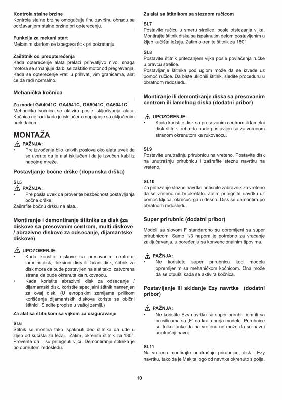
Kontrola stalne brzine Kontrola stalne brzine omogućuje finu završnu obradu sa održavanjem stalne brzine pri opterećenju.
Funkcija za mekani startMekanim startom se izbegava šok pri pokretanju.
Zaštitnik od preopterećenjaKada opterećenje alata prelazi prihvatljivo nivo, snaga motora se smanjuje da bi se zaštitio motor od pregrevanja. Kada se opterećenje vrati u prihvatljivim granicama, alat će da radi normalno.
Mehanička kočnica
Za model GA4041C, GA4541C, GA5041C, GA6041C Mehanička kočnica se aktivira posle isključivanja alata. Kočnica ne radi kada je isključeno napajanje sa uključenim prekidačem.
MONTAŽA PAŽNJA: • Pre izvođenja bilo kakvih poslova oko alata uvek da
se uverite da je alat isključen i da je izvučen kabl iz napojne mreže.
Postavljanje bočne drške (dopunska drška)
Sl.5 PAŽNJA: • Pre posla uvek da proverite bezbednost postavljanja
bočne drške. Zašrafite bočnu dršku na alatu.
Montiranje i demontiranje štitnika za disk (za diskove sa presovanim centrom, multi diskove / abrazivne diskove za odsecanje, dijamantske diskove)
UPOZORENJE: • Kada koristite diskove sa presovanim centrom,
lamelni disk, fleksioni disk ili žičani disk, štitnik za disk mora da bude postavljen na alat tako, zatvorena strana da bude okrenuta ka rukovaocu.
• Kada koristite abrazivni disk za odsecanje / dijamantski disk, koristite specijalni štitnik namenjen za ovaj disk. (U evropskim zemljama prilikom korišćenja dijamantskih diskova koriste se obični štitnici. Sledite propise u vašoj zemlji.)
Za alat sa štitnikom sa vijkom za osiguravanje
Sl.6Štitnik se montira tako ispaknuti deo štitnika da uđe u žljeb od kućišta za ležaj. Zatim, okrenite štitnik za 180°. Proverite da li su pritegnuti vijci. Demontiranje štitnika je po obrnutom redosledu.
Za alat sa štitnikom sa steznom ručicom
Sl.7Postavite ručicu u smeru strelice, posle otstezanja vijka. Montirajte štitnik diska sa ispaknutim delom postavljenim u žljeb kućišta ležaja. Zatim okrenite štitnik za 180°.
Sl.8Postavite štitnik pritezanjem vijka posle povlačenja ručke u pravcu strelice.Postavljanje štitnika pod uglom može da se izvede uz pomoć ručice. Da biste uklonili štitnik, sledite proceduru u obratnom redosledu.
Montiranje ili demontiranje diska sa presovanim centrom ili lamelnog diska (dodatni pribor)
UPOZORENJE: • Kada koristite disk sa presovanim centrom ili lamelni
disk štitnik treba da bude postavljen sa zatvorenom stranom okrenutom ka rukovaocu.
Sl.9Postavite unutrašnju prirubnicu na vreteno. Postavite disk na unutrašnju prirubnicu i zašrafite steznu navrtku na vreteno.
Sl.10Za pritezanje stezne navrtke pritisnite zabravnik za vreteno da se vreteno ne bi okretalo. Zatim pritegnite navrtku uz pomoć ključa, okrećuči ga u desno. Disk se demontira po obratnom redosledu.
Super prirubnic (dodatni pribor)
Modeli sa slovom F standardno su opremljeni sa super prirubnicom. Samo 1/3 napora je potrebno za vraćanje zaključavanja, u poređenju sa konvencionalnim tipovima.
PAŽNJA: • Ne koristete super prirubnicu kod modela
opremljenim sa mehaničkom kočnicom. Ona može da se otpušti kada se aktivira kočnica.
Postavljanje ili skidanje Ezy navrtke (dodatni pribor)
PAŽNJA: • Ne koristite Ezy navrtku sa super prirubnicom ili sa
brusilicama sa „F” na kraju broja modela. Prirubnice su tolko tanke da na vretenu ne može da se navrti unutrašnji navoj.
Sl.11Na vreteno montirajte unutrašnju prirubnicu, disk i Ezy navrtku, tako da je Makita logo od navrtke okrenuto s polja.
3
ENGLISH (Original instructions) Explanation of general view
1-1. Red indicator 1-2. Button 1-3. Battery cartridge 2-1. Star mark 3-1. Switch trigger 4-1. Lamp
5-1. Reversing switch lever 6-1. Locator 7-1. Locator 8-1. Locator 9-1. Locator 9-2. Bit
9-3. Magnetic bit holder 10-1. Groove 10-2. Hook 10-3. Screw
SPECIFICATIONS Model BFS441 BFS451
Capacities Drywall screw 4 mm 4 mm No load speed (min-1) 0 - 4000 0 - 4000
With short locator 281 mm 281 mm Overall length
With long locator 296 mm 296 mm Net weight 1.4 kg 1.5 kg
Rated voltage D.C. 14.4 V D.C. 18 V • Due to our continuing programme of research and development, the specifications herein are subject to change without notice. • Specifications and battery cartridge may differ from country to country. • Weight, with battery cartridge, according to EPTA-Procedure 01/2003
ENE033-1
Intended use The tool is intended for screw driving in wood, metal and plastic.
ENG905-1
Noise The typical A-weighted noise level determined according to EN60745:
Model BFS441
Sound pressure level (LpA) : 70 dB(A) or less Uncertainty (K) : 3 dB(A)
The noise level under working may exceed 80 dB (A).
Model BFS451
Sound pressure level (LpA) : 71 dB(A) Uncertainty (K) : 3 dB(A)
The noise level under working may exceed 80 dB (A).
Wear ear protection
ENG900-1
Vibration The vibration total value (tri-axial vector sum) determined according to EN60745:
Work mode: screwdriving without impact Vibration emission (ah) : 2.5 m/s2 or less Uncertainty (K) : 1.5 m/s2
ENG901-1
• The declared vibration emission value has been measured in accordance with the standard test method and may be used for comparing one tool with another.
• The declared vibration emission value may also be used in a preliminary assessment of exposure.
WARNING: • The vibration emission during actual use of the
power tool can differ from the declared emission value depending on the ways in which the tool is used.
• Be sure to identify safety measures to protect the operator that are based on an estimation of exposure in the actual conditions of use (taking account of all parts of the operating cycle such as the times when the tool is switched off and when it is running idle in addition to the trigger time).
ENH101-15
For European countries only
EC Declaration of Conformity We Makita Corporation as the responsible manufacturer declare that the following Makita machine(s): Designation of Machine: Cordless Screwdriver Model No./ Type: BFS441,BFS451 are of series production and Conforms to the following European Directives:
2006/42/EC And are manufactured in accordance with the following standards or standardised documents:
EN60745

11
Turn the outside ring of Ezynut counterclockwise to loosen.
Fig.13 Fig.14
NOTE: • Ezynut can be loosened by hand as long as the
arrow points the notch. Otherwise a lock nut wrench is required to loosen it. Insert one pin of the wrench into a hole and turn Ezynut counterclockwise.
Installing or removing flex wheel (optional accessory)
WARNING: • Always use supplied guard when flex wheel is on
tool. Wheel can shatter during use and guard helps to reduce chances of personal injury.
Fig.15 Follow instructions for depressed center wheel but also use plastic pad over wheel. See order of assembly on accessories page in this manual.
Installing or removing abrasive disc (optional accessory)
NOTE: • Use sander accessories specified in this manual.
These must be purchased separately.
Fig.16 Mount the rubber pad onto the spindle. Fit the disc on the rubber pad and screw the sanding lock nut onto the spindle. To tighten the sanding lock nut, press the shaft lock firmly so that the spindle cannot revolve, then use the lock nut wrench and securely tighten clockwise. To remove the disc, follow the installation procedure in reverse.
Installing or removing dust cover attachment (Optional accessory)
WARNING: • Always be sure that the tool is switched off and
unplugged before installing or removing the dust cover attachment. Failure to do so causes damage to the tool or a personal injury.
There are four pieces of dust cover attachment and each is used in one of different positions.
Fig.17 Set the dust cover attachment so that the marking (A, B, C or D) places as shown. Snap its pins in the vents. Dust cover attachment can be removed by hand.
NOTE: • Clean out the dust cover attachment when it is
clogged with dust or foreign matters. Continuing operation with a clogged dust cover attachment will damage the tool.
OPERATION
WARNING: • It should never be necessary to force the tool. The
weight of the tool applies adequate pressure. Forcing and excessive pressure could cause dangerous wheel breakage.
• ALWAYS replace wheel if tool is dropped while grinding.
• NEVER bang or hit grinding disc or wheel onto work.
• Avoid bouncing and snagging the wheel, especially when working corners, sharp edges etc. This can cause loss of control and kickback.
• NEVER use tool with wood cutting blades and other saw blades. Such blades when used on a grinder frequently kick and cause loss of control leading to personal injury.
CAUTION: • Never switch on the tool when it is in contact with
the workpiece, it may cause an injury to operator. • Always wear safety goggles or a face shield during
operation. • After operation, always switch off the tool and wait
until the wheel has come to a complete stop before putting the tool down.
Grinding and sanding operation Fig.18 ALWAYS hold the tool firmly with one hand on housing and the other on the side handle. Turn the tool on and then apply the wheel or disc to the workpiece. In general, keep the edge of the wheel or disc at an angle of about 15 ゚ to the workpiece surface. During the break-in period with a new wheel, do not work the grinder in the B direction or it will cut into the workpiece. Once the edge of the wheel has been rounded off by use, the wheel may be worked in both A and B direction.
Operation with abrasive cut-off / diamond wheel (optional accessory) Fig.19 The direction for mounting the lock nut and the inner flange varies by wheel thickness. Refer to the table below.
Sl.12 Pritisnite zabravnik za vreteno i pritegnite Ezy navrtku na desno, dok se vrti. Okrenite na levo spoljni prsten od navrtke da bi se olabavio.
Sl.13
Sl.14
ZABELEŠKA: • Ezy navrtka može da se oslobodi sa rukom dok
strelica ne pokaže na zarez. Inače, potreban je nasadni ključ za otpuštanje. Umetnite jednu čiviju od ključa u rupu od navrtke i okrenite u desno.
Postavljanje ili skidanje fleksionog diska (dodatni pribor)
UPOZORENJE: • Uvek koristite štitnik kada je disk na alatu. Disk može
da prsne u toku posla i štitnik smanjuje šanse za povrede.
Sl.15Sledite uputstva za disk sa presovanim centrom i koristite plastičnu podlogu na disku. Vidi redosledot motiranja dodataka u ovom uputstvu.
Postavljanje i skidanje abrazivnog diska (dodatni pribor)
ZABELEŠKA: • Koristite dodatke koji su navedeni u ovom uputstvu.
Oni moraju da se kupe posebno.
Sl.16Postavite gumenu podlogu na vreteno. Postavite disk na gumenu podlogu i na vreteno zašrafite Ezy navrtku. Za pritezanje Ezy navrtke pritisnite zabravnik za vreteno da bi blokirali vreteno, a zatim pritegnite uz pomoć nasadog ključa. Za skidanje diska, postupak je po obratnom redosledu.
Postavljanje ili skidanje poklopca za zaštitu od prašine (dodatni pribor)
UPOZORENJE: • Pre postavljanja i skidanja poklopca za zaštitu od
prašine alat da bude isključen i kabl da je izvađen iz napajanja. Inače ćete da oštetite alat ili ćete da se povredite.
Postoje četiri priključaka za poklopac za prašinu i mogu da se koriste za različite položaje.
Sl.17Postavite poklopac tako da je oznaka (A, B, C ili D) prema slici. Postavite čivije u otvore. Poklopac se vadi rukom.
ZABELEŠKA: • Očistite poklopac kada je zapušen sa prašinom ili
sa stranim materijalom. Ako radite sa zapušenim poklopcem oštetićete alat.
RUKOVANJE UPOZORENJE: • Ne forsirajte alat. Težina alata ostvaruje potreban
pritisak. Forsiranje i dodatni pritisak izaziva opasno lomljenje diska.
• UVEK zamenite disk ako je alat pao za vreme brušenja.
• Disk NIKADA ne sme da udari u radni komad. • Budite pažljivi pri radu po ćoškovima, oštrim
rubovima itd., kada disk može da otskoči. Može da se izgubi kontrola nad alatom i da dođe do povratnog udarca.
• Alat NIKADA da ne koristite sa listovima za sečenje drveta ili sa drugima listovima za testere. Listovi za testere, montirani na mašini za brušenje, izazvaće povratni udarac i gubitak kontrole, što vodi ka povredama.
PAŽNJA: • Alat nikada da ne uključujete dok je u dodiru sa
radnim komadom. To rezultuje sa povredama. • Za vreme rada nosite zaštitne naočare ili branik za
lice. • Posle posla uvek da isključite alat i da sačekate da
se zaustavi disk, pre nego što odložite alat.
Brušenje i šmirglanje
Sl.18Alat UVEK da držite za kućište sa jednom rukom, a sa drugom, za bočnu dršku. Uključite alat i približite disk radnom komadu. Opšte pravilo je da se rub brusnog diska nalazi pod 15° u odnosu na površinu radnog komada. Kada brusite sa novim diskom, alat da krećete u pravcu B, jer će brusni disk da zaseče radni komad. Kada se zaobli rub brusnog diska, posle duže upotrebe, tada možete alat da krećete u pravcu A i B.
Rad sa brusnim diskom za odsecanje / dijamantski disk (dodatni pribor)
Sl.19Montiranje stezne navrtke i unutrašnje prirubnice zavisi od debljine diska. Vidite tabelu. 3
ENGLISH (Original instructions) Explanation of general view
1-1. Red indicator 1-2. Button 1-3. Battery cartridge 2-1. Star mark 3-1. Switch trigger 4-1. Lamp
5-1. Reversing switch lever 6-1. Locator 7-1. Locator 8-1. Locator 9-1. Locator 9-2. Bit
9-3. Magnetic bit holder 10-1. Groove 10-2. Hook 10-3. Screw
SPECIFICATIONS Model BFS441 BFS451
Capacities Drywall screw 4 mm 4 mm No load speed (min-1) 0 - 4000 0 - 4000
With short locator 281 mm 281 mm Overall length
With long locator 296 mm 296 mm Net weight 1.4 kg 1.5 kg
Rated voltage D.C. 14.4 V D.C. 18 V • Due to our continuing programme of research and development, the specifications herein are subject to change without notice. • Specifications and battery cartridge may differ from country to country. • Weight, with battery cartridge, according to EPTA-Procedure 01/2003
ENE033-1
Intended use The tool is intended for screw driving in wood, metal and plastic.
ENG905-1
Noise The typical A-weighted noise level determined according to EN60745:
Model BFS441
Sound pressure level (LpA) : 70 dB(A) or less Uncertainty (K) : 3 dB(A)
The noise level under working may exceed 80 dB (A).
Model BFS451
Sound pressure level (LpA) : 71 dB(A) Uncertainty (K) : 3 dB(A)
The noise level under working may exceed 80 dB (A).
Wear ear protection
ENG900-1
Vibration The vibration total value (tri-axial vector sum) determined according to EN60745:
Work mode: screwdriving without impact Vibration emission (ah) : 2.5 m/s2 or less Uncertainty (K) : 1.5 m/s2
ENG901-1
• The declared vibration emission value has been measured in accordance with the standard test method and may be used for comparing one tool with another.
• The declared vibration emission value may also be used in a preliminary assessment of exposure.
WARNING: • The vibration emission during actual use of the
power tool can differ from the declared emission value depending on the ways in which the tool is used.
• Be sure to identify safety measures to protect the operator that are based on an estimation of exposure in the actual conditions of use (taking account of all parts of the operating cycle such as the times when the tool is switched off and when it is running idle in addition to the trigger time).
ENH101-15
For European countries only
EC Declaration of Conformity We Makita Corporation as the responsible manufacturer declare that the following Makita machine(s): Designation of Machine: Cordless Screwdriver Model No./ Type: BFS441,BFS451 are of series production and Conforms to the following European Directives:
2006/42/EC And are manufactured in accordance with the following standards or standardised documents:
EN60745
3
ENGLISH (Original instructions) Explanation of general view
1-1. Red indicator 1-2. Button 1-3. Battery cartridge 2-1. Star mark 3-1. Switch trigger 4-1. Lamp
5-1. Reversing switch lever 6-1. Locator 7-1. Locator 8-1. Locator 9-1. Locator 9-2. Bit
9-3. Magnetic bit holder 10-1. Groove 10-2. Hook 10-3. Screw
SPECIFICATIONS Model BFS441 BFS451
Capacities Drywall screw 4 mm 4 mm No load speed (min-1) 0 - 4000 0 - 4000
With short locator 281 mm 281 mm Overall length
With long locator 296 mm 296 mm Net weight 1.4 kg 1.5 kg
Rated voltage D.C. 14.4 V D.C. 18 V • Due to our continuing programme of research and development, the specifications herein are subject to change without notice. • Specifications and battery cartridge may differ from country to country. • Weight, with battery cartridge, according to EPTA-Procedure 01/2003
ENE033-1
Intended use The tool is intended for screw driving in wood, metal and plastic.
ENG905-1
Noise The typical A-weighted noise level determined according to EN60745:
Model BFS441
Sound pressure level (LpA) : 70 dB(A) or less Uncertainty (K) : 3 dB(A)
The noise level under working may exceed 80 dB (A).
Model BFS451
Sound pressure level (LpA) : 71 dB(A) Uncertainty (K) : 3 dB(A)
The noise level under working may exceed 80 dB (A).
Wear ear protection
ENG900-1
Vibration The vibration total value (tri-axial vector sum) determined according to EN60745:
Work mode: screwdriving without impact Vibration emission (ah) : 2.5 m/s2 or less Uncertainty (K) : 1.5 m/s2
ENG901-1
• The declared vibration emission value has been measured in accordance with the standard test method and may be used for comparing one tool with another.
• The declared vibration emission value may also be used in a preliminary assessment of exposure.
WARNING: • The vibration emission during actual use of the
power tool can differ from the declared emission value depending on the ways in which the tool is used.
• Be sure to identify safety measures to protect the operator that are based on an estimation of exposure in the actual conditions of use (taking account of all parts of the operating cycle such as the times when the tool is switched off and when it is running idle in addition to the trigger time).
ENH101-15
For European countries only
EC Declaration of Conformity We Makita Corporation as the responsible manufacturer declare that the following Makita machine(s): Designation of Machine: Cordless Screwdriver Model No./ Type: BFS441,BFS451 are of series production and Conforms to the following European Directives:
2006/42/EC And are manufactured in accordance with the following standards or standardised documents:
EN60745

12
Abrasive cut-off wheel Diamond wheel
Thickness: Less than 4 mm (5/32") Thickness: 4 mm (5/32") or more
16 mm (5/8")20 mm (13/16")
22.23 mm (7/8")
Abrasive cut-off wheel Diamond wheel
Thickness: Less than 4 mm (5/32") Thickness: 4 mm (5/32") or more
Thickness: Less than 4 mm (5/32") Thickness: 4 mm (5/32") or more Thickness: Less than 4 mm (5/32") Thickness: 4 mm (5/32") or more
22.23 mm (7/8") 22.23 mm (7/8") 22.23 mm (7/8")
16 mm (5/8")20 mm (13/16")
1
2
3
1
4
3
100 mm (4") model
115 mm (4 - 1/2") / 125 mm (5") / 150 mm (6") model
1
2
3
1
4
3
Lock nut Abrasive cut-off wheel Inner flange Diamond wheel1. 2. 3. 4.
Lock nut Abrasive cut-off wheel Inner flange Diamond wheel1. 2. 3. 4.
012746
WARNING: • When using an abrasive cut-off / diamond wheel,
be sure to use only the special wheel guard designed for use with cut-off wheels. (In some European countries, when using a diamond wheel, the ordinary guard can be used. Follow the regulations in your country.)
• NEVER use cut-off wheel for side grinding. • Do not "jam" the wheel or apply excessive pressure.
Do not attempt to make an excessive depth of cut. Overstressing the wheel increases the loading and susceptibility to twisting or binding of the wheel in the cut and the possibility of kickback, wheel breakage and overheating of the motor may occur.
• Do not start the cutting operation in the workpiece. Let the wheel reach full speed and carefully enter into the cut moving the tool forward over the workpiece surface. The wheel may bind, walk up or kickback if the power tool is started in the workpiece.
• During cutting operations, never change the angle of the wheel. Placing side pressure on the cut-off wheel (as in grinding) will cause the wheel to crack
and break, causing serious personal injury. • A diamond wheel shall be operated perpendicular
to the material being cut.
Operation with wire cup brush (optional accessory)
CAUTION: • Check operation of brush by running tool with no
load, insuring that no one is in front of or in line with brush.
• Do not use brush that is damaged, or which is out of balance. Use of damaged brush could increase potential for injury from contact with broken brush wires.
Fig.20 Unplug tool and place it upside down allowing easy access to spindle. Remove any accessories on spindle. Thread wire cup brush onto spindle and tighten with supplied wrench. When using brush, avoid applying too much pressure which causes over bending of wires, leading to premature breakage.
UPOZORENJE: • Kada koristite abrazivni disk za odsecanje /
dijamantski disk, koristite specijalni štitnik namenjen za ovaj disk. (U evropskim zemljama prilikom korišćenja dijamantskih diskova koriste se obični štitnici. Sledite propise u vašoj zemlji.)
• NIKADA ne koristite disk za odsecanje za bočno brušenje.
• Nemojte da „zaglavljujete“ disk ili da primenjujete veliki pritisak. Ne pokušavajte da pravite duboke rezove. Preopterećivanje diska povećava naprezanje i osetljivost na osciliranje ili izvijanje diska i mogućnost za povratni udarac, lomljenje diska i pregrevanje motora.
• Ne započinjite sečenje u radni komad. Sačekajte da disk dostigne maksimalnu brzinu i zatim pažljivo počnite da krećete alat napred, preko površine radnog komada. Ako se električni alat uključi u radni komad tada disk može da se zaklini, da otskoči ili će da se pojavi povratni udarac.
• Za vreme sečenja ne smete da menjate ugao diska. Primena bočnog pritiska na disk za odsecanje (kao kod brušenja) izazvaće pucanje i lomljenje diska što izaziva povrede.
• Dijamantski disk mora da se vodi vertikalno u odnosu na materijal koji se seče.
Rad sa žičanom četkom – kapom(dodatni pribor) PAŽNJA: • Proverite rad četke sa startovanjem alata bez
opterećenja, pri čemu da nema ničeg pre ili u liniji četke.
• Ne koristite četku koja je oštećena ili koja je neuravnotežena. Korišćenjem oštećene četke povećavate rizik od povreda.
Sl.20 Isključite alat i okrenite ga naopačke da bi imali pristup vretenu. Izvadite pribor iz vretena. Na vretenu navrtite četku i pritegnite je uz pomoć isporučenog ključa. Izbegavajte primenu prevelikog pritiska koji izaziva savijanje žica na četki, što vodi do njenog prevremenog oštećenja.
3
ENGLISH (Original instructions) Explanation of general view
1-1. Red indicator 1-2. Button 1-3. Battery cartridge 2-1. Star mark 3-1. Switch trigger 4-1. Lamp
5-1. Reversing switch lever 6-1. Locator 7-1. Locator 8-1. Locator 9-1. Locator 9-2. Bit
9-3. Magnetic bit holder 10-1. Groove 10-2. Hook 10-3. Screw
SPECIFICATIONS Model BFS441 BFS451
Capacities Drywall screw 4 mm 4 mm No load speed (min-1) 0 - 4000 0 - 4000
With short locator 281 mm 281 mm Overall length
With long locator 296 mm 296 mm Net weight 1.4 kg 1.5 kg
Rated voltage D.C. 14.4 V D.C. 18 V • Due to our continuing programme of research and development, the specifications herein are subject to change without notice. • Specifications and battery cartridge may differ from country to country. • Weight, with battery cartridge, according to EPTA-Procedure 01/2003
ENE033-1
Intended use The tool is intended for screw driving in wood, metal and plastic.
ENG905-1
Noise The typical A-weighted noise level determined according to EN60745:
Model BFS441
Sound pressure level (LpA) : 70 dB(A) or less Uncertainty (K) : 3 dB(A)
The noise level under working may exceed 80 dB (A).
Model BFS451
Sound pressure level (LpA) : 71 dB(A) Uncertainty (K) : 3 dB(A)
The noise level under working may exceed 80 dB (A).
Wear ear protection
ENG900-1
Vibration The vibration total value (tri-axial vector sum) determined according to EN60745:
Work mode: screwdriving without impact Vibration emission (ah) : 2.5 m/s2 or less Uncertainty (K) : 1.5 m/s2
ENG901-1
• The declared vibration emission value has been measured in accordance with the standard test method and may be used for comparing one tool with another.
• The declared vibration emission value may also be used in a preliminary assessment of exposure.
WARNING: • The vibration emission during actual use of the
power tool can differ from the declared emission value depending on the ways in which the tool is used.
• Be sure to identify safety measures to protect the operator that are based on an estimation of exposure in the actual conditions of use (taking account of all parts of the operating cycle such as the times when the tool is switched off and when it is running idle in addition to the trigger time).
ENH101-15
For European countries only
EC Declaration of Conformity We Makita Corporation as the responsible manufacturer declare that the following Makita machine(s): Designation of Machine: Cordless Screwdriver Model No./ Type: BFS441,BFS451 are of series production and Conforms to the following European Directives:
2006/42/EC And are manufactured in accordance with the following standards or standardised documents:
EN60745
100 mm (4“) model
115 mm (4 - 1/2”) / 125 mm (5”) / 150 mm (6”) model
Brusni disk za odsecanje Dijamantski disk
1. Stezna navrtka 2. Brusni disk za odsecanje 4. Dijamantski disk
3. Unutrašnja prirubnica
Brusni disk za odsecanje Dijamantski disk
1. Stezna navrtka 2. Brusni disk za odsecanje 4. Dijamantski disk
3. Unutrašnja prirubnica
Debljina: Manja od 4 mm Debljina: 4 mm ili veća Debljina: 4 mm ili većaDebljina: Manja od 4 mm
Debljina: Manja od 4 mm Debljina: 4 mm ili veća Debljina: 4 mm ili većaDebljina: Manja od 4 mm
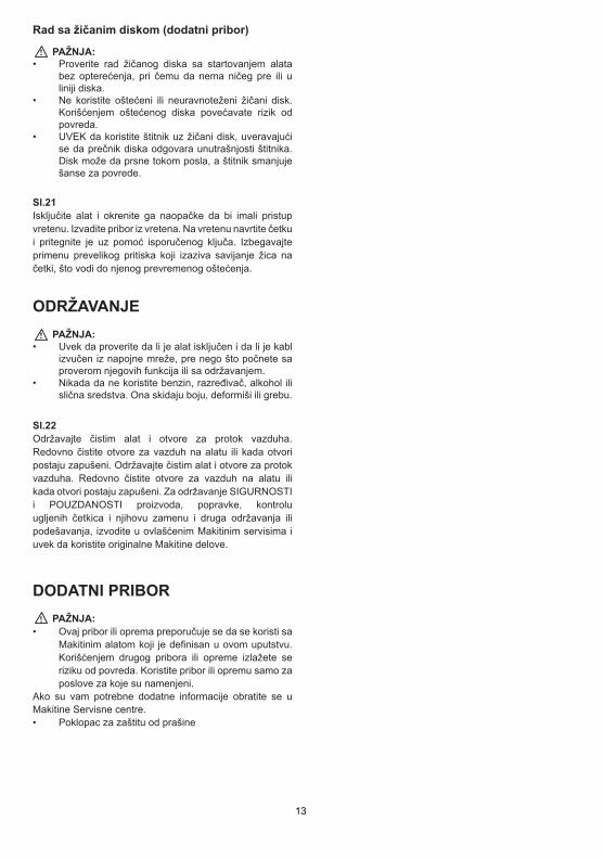
13
Operation with wire wheel brush (optional accessory)
CAUTION: • Check operation of wire wheel brush by running
tool with no load, insuring that no one is in front of or in line with the wire wheel brush.
• Do not use wire wheel brush that is damaged, or which is out of balance. Use of damaged wire wheel brush could increase potential for injury from contact with broken wires.
• ALWAYS use guard with wire wheel brushes, assuring diameter of wheel fits inside guard. Wheel can shatter during use and guard helps to reduce chances of personal injury.
Fig.21 Unplug tool and place it upside down allowing easy access to spindle. Remove any accessories on spindle. Thread wire wheel brush onto spindle and tighten with the wrenches. When using wire wheel brush, avoid applying too much pressure which causes over bending of wires, leading to premature breakage.
MAINTENANCE
CAUTION: • Always be sure that the tool is switched off and
unplugged before attempting to perform inspection or maintenance.
• Never use gasoline, benzine, thinner, alcohol or the like. Discoloration, deformation or cracks may result.
Fig.22 The tool and its air vents have to be kept clean. Regularly clean the tool's air vents or whenever the vents start to become obstructed. To maintain product SAFETY and RELIABILITY, repairs, carbon brush inspection and replacement, any other maintenance or adjustment should be performed by Makita Authorized Service Centers, always using Makita replacement parts.
OPTIONAL ACCESSORIES
CAUTION: • These accessories or attachments are
recommended for use with your Makita tool specified in this manual. The use of any other accessories or attachments might present a risk of injury to persons. Only use accessory or attachment for its stated purpose.
If you need any assistance for more details regarding these accessories, ask your local Makita Service Center.
• Dust cover attachment
Rad sa žičanim diskom (dodatni pribor)
PAŽNJA: • Proverite rad žičanog diska sa startovanjem alata
bez opterećenja, pri čemu da nema ničeg pre ili u liniji diska.
• Ne koristite oštećeni ili neuravnoteženi žičani disk. Korišćenjem oštećenog diska povećavate rizik od povreda.
• UVEK da koristite štitnik uz žičani disk, uveravajući se da prečnik diska odgovara unutrašnjosti štitnika. Disk može da prsne tokom posla, a štitnik smanjuje šanse za povrede.
Sl.21Isključite alat i okrenite ga naopačke da bi imali pristup vretenu. Izvadite pribor iz vretena. Na vretenu navrtite četku i pritegnite je uz pomoć isporučenog ključa. Izbegavajte primenu prevelikog pritiska koji izaziva savijanje žica na četki, što vodi do njenog prevremenog oštećenja.
ODRŽAVANJE PAŽNJA: • Uvek da proverite da li je alat isključen i da li je kabl
izvučen iz napojne mreže, pre nego što počnete sa proverom njegovih funkcija ili sa održavanjem.
• Nikada da ne koristite benzin, razređivač, alkohol ili slična sredstva. Ona skidaju boju, deformiši ili grebu.
Sl.22Održavajte čistim alat i otvore za protok vazduha. Redovno čistite otvore za vazduh na alatu ili kada otvori postaju zapušeni. Održavajte čistim alat i otvore za protok vazduha. Redovno čistite otvore za vazduh na alatu ili kada otvori postaju zapušeni. Za održavanje SIGURNOSTI i POUZDANOSTI proizvoda, popravke, kontrolu ugljenih četkica i njihovu zamenu i druga održavanja ili podešavanja, izvodite u ovlašćenim Makitinim servisima i uvek da koristite originalne Makitine delove.
DODATNI PRIBOR PAŽNJA: • Ovaj pribor ili oprema preporučuje se da se koristi sa
Makitinim alatom koji je definisan u ovom uputstvu. Korišćenjem drugog pribora ili opreme izlažete se riziku od povreda. Koristite pribor ili opremu samo za poslove za koje su namenjeni.
Ako su vam potrebne dodatne informacije obratite se u Makitine Servisne centre. • Poklopac za zaštitu od prašine
3
ENGLISH (Original instructions) Explanation of general view
1-1. Red indicator 1-2. Button 1-3. Battery cartridge 2-1. Star mark 3-1. Switch trigger 4-1. Lamp
5-1. Reversing switch lever 6-1. Locator 7-1. Locator 8-1. Locator 9-1. Locator 9-2. Bit
9-3. Magnetic bit holder 10-1. Groove 10-2. Hook 10-3. Screw
SPECIFICATIONS Model BFS441 BFS451
Capacities Drywall screw 4 mm 4 mm No load speed (min-1) 0 - 4000 0 - 4000
With short locator 281 mm 281 mm Overall length
With long locator 296 mm 296 mm Net weight 1.4 kg 1.5 kg
Rated voltage D.C. 14.4 V D.C. 18 V • Due to our continuing programme of research and development, the specifications herein are subject to change without notice. • Specifications and battery cartridge may differ from country to country. • Weight, with battery cartridge, according to EPTA-Procedure 01/2003
ENE033-1
Intended use The tool is intended for screw driving in wood, metal and plastic.
ENG905-1
Noise The typical A-weighted noise level determined according to EN60745:
Model BFS441
Sound pressure level (LpA) : 70 dB(A) or less Uncertainty (K) : 3 dB(A)
The noise level under working may exceed 80 dB (A).
Model BFS451
Sound pressure level (LpA) : 71 dB(A) Uncertainty (K) : 3 dB(A)
The noise level under working may exceed 80 dB (A).
Wear ear protection
ENG900-1
Vibration The vibration total value (tri-axial vector sum) determined according to EN60745:
Work mode: screwdriving without impact Vibration emission (ah) : 2.5 m/s2 or less Uncertainty (K) : 1.5 m/s2
ENG901-1
• The declared vibration emission value has been measured in accordance with the standard test method and may be used for comparing one tool with another.
• The declared vibration emission value may also be used in a preliminary assessment of exposure.
WARNING: • The vibration emission during actual use of the
power tool can differ from the declared emission value depending on the ways in which the tool is used.
• Be sure to identify safety measures to protect the operator that are based on an estimation of exposure in the actual conditions of use (taking account of all parts of the operating cycle such as the times when the tool is switched off and when it is running idle in addition to the trigger time).
ENH101-15
For European countries only
EC Declaration of Conformity We Makita Corporation as the responsible manufacturer declare that the following Makita machine(s): Designation of Machine: Cordless Screwdriver Model No./ Type: BFS441,BFS451 are of series production and Conforms to the following European Directives:
2006/42/EC And are manufactured in accordance with the following standards or standardised documents:
EN60745
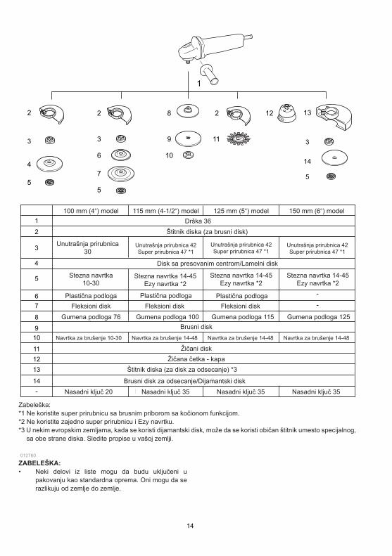
14
2
5
2 2
11
12
4
3
5
6
7
8
9
10
1
13
3
14
5
3
1
2
3
4
5
6
7
8
9
10
11
12
13
14
-
100 mm (4") model 115 mm (4-1/2") model 125 mm (5") model 150 mm (6") model
Grip 36
Wheel Guard (for grinding wheel)
Plastic pad
Flex wheel
Rubber pad 76
Abrasive disc
Sanding lock nut 10-30
Wire wheel brush
Plastic pad Plastic pad
Flex wheel Flex wheel
Rubber pad 100 Rubber pad 115 Rubber pad 125
Wire cup brush
Abrasive cut-off wheel/Diamond wheel
Note:
Inner flange 30Inner flange 42
Super flange 47 *1
Inner flange 42
Super flange 47 *1
Inner flange 42
Super flange 47 *1
Depressed center wheel/Flap disc
Lock nut 10-30Lock nut 14-45
Ezy nut *2
Lock nut 14-45
Ezy nut *2
Lock nut 14-45
Ezy nut *2
Sanding lock nut 14-48 Sanding lock nut 14-48 Sanding lock nut 14-48
Wheel Guard (for cut-off wheel) *3
*1 Do not use Super flange with a grinder equipped with a brake function.
*2 Do not use Super flange and Ezynut together.
Lock nut wrench 20 Lock nut wrench 35 Lock nut wrench 35 Lock nut wrench 35
-
-
*3 In some European countries, when using a diamond wheel, the ordinary guard can be used instead
of the special guard covering the both side of the wheel. Follow the regulations in your country.
012760
NOTE: • Some items in the list may be included in the tool
package as standard accessories. They may differ from country to country.
ZABELEŠKA: • Neki delovi iz liste mogu da budu uključeni u
pakovanju kao standardna oprema. Oni mogu da se razlikuju od zemlje do zemlje.
Zabeleška: *1 Ne koristite super prirubnicu sa brusnim priborom sa kočionom funkcijom. *2 Ne koristite zajedno super prirubnicu i Ezy navrtku. *3 U nekim evropskim zemljama, kada se koristi dijamantski disk, može da se koristi običan štitnik umesto specijalnog,
sa obe strane diska. Sledite propise u vašoj zemlji.
Drška 36Štitnik diska (za brusni disk)
Unutrašnja prirubnica 30
Stezna navrtka 10-30
Plastična podloga Plastična podloga Plastična podlogaFleksioni disk
Gumena podloga 76
Navrtka za brušenje 10-30 Navrtka za brušenje 14-48 Navrtka za brušenje 14-48 Navrtka za brušenje 14-48
Gumena podloga 100 Gumena podloga 115 Gumena podloga 125Fleksioni disk Fleksioni disk
Unutrašnja prirubnica 42Super prirubnica 47 *1
Unutrašnja prirubnica 42Super prirubnica 47 *1
Unutrašnja prirubnica 42Super prirubnica 47 *1
Stezna navrtka 14-45Ezy navrtka *2
Stezna navrtka 14-45Ezy navrtka *2
Stezna navrtka 14-45Ezy navrtka *2
Disk sa presovanim centrom/Lamelni disk
Brusni disk
Žičani diskŽičana četka - kapa
Štitnik diska (za disk za odsecanje) *3
Brusni disk za odsecanje/Dijamantski diskNasadni ključ 20 Nasadni ključ 35 Nasadni ključ 35 Nasadni ključ 35
100 mm (4“) model 115 mm (4-1/2“) model 125 mm (5“) model 150 mm (6“) model