Embed Size (px)
Citation preview

GRUNDFOS PRODUCT GUIDE
SQ, SQE, SQE-NE,CU 321

Contents
2
Product introductionIntroduction 4Features and benefits 4Identification 6
ApplicationsSQ with pressure switch and pressure tank 7 Constant-pressure control with CU 301 - residential water supply 8Constant-pressure control with CU 301 - irrigation 9Maintaining a constant water table 10Emptying or filling a tank 11Pumping from one tank to another 12Setting of operating parameters 13SQE with manual speed control 14
Product overviewPerformance range 15
InstallationInstallation 16
Sizing and selectionSystem sizing guide 17
Cable sizingSQ, SQE, SQE-NE cable sizing chart 18
Curve charts5 SQ, SQE 1910 SQ, SQE 2015 SQ, SQE 2122 SQ, SQE 2230 SQ, SQE 2310 SQE-NE 2422 SQE, SQE-NE 25
Technical dataElectrical data 26Operating conditions 26Storage conditions 26SQ, SQE motor data 27SQ, SQE and SQE-NE dimensions and weights 28Materials of construction 29Material specification 30
Control unitsCU 301 31R100 menu structure for CU 301 control unit 32R100 menus for CU 301 33CU 300 34R100 menu structure for the CU 300 35R100 menus for CU 300 36Examples of R100 displays 37
CU 321 variable frequency driveFeatures 38Applications 38Components 38Sizing 38Performance curves - CU 321 variable speed 39
AccessoriesCU 321 variable frequency drive 41CU 301 Constant Pressure System 41CU 300 Status Box & R100 41SQ, SQE flow sleeves 41
Further product documentationWebCAPS 42WinCAPS 43

SQ, SQE, SQE-NE, CU 321
3
Mission
- It is our mission - the basis of our existence - to successfully develop, produce and sell high-quality pumps and pumping systems world-wide, contributing to a better quality of life and a healthy environment
• One of the 3 largest pump companies in the world• The second largest manufacturer of submersible motors in the world• World headquarters in Denmark• North American headquarters in Kansas City - Manufacturing in Fresno, California• 80 companies in 45 countries• More than 16 million motors and pumps produced annually worldwide• North American companies operating in USA, Canada and Mexico• Continuous reinvestment in growth and development enables the company to
BE responsible, THINK ahead, and INNOVATE
Bjerringbro, Denmark
Fresno, California Olathe, Kansas
Monterrey, Mexico Allentown, Pennsylvania Oakville, Ontario

4
SQ, SQE, SQE-NE, CU 321Product introduction
Introduction3-inch SQ, SQE submersible well pumpsfor 3-inch and larger wellsSQ, SQE pumps are suitable for both continuous and intermittent operation for a variety of applications:
• Domestic water suppy• light commercial• irrigation• tank applications.
Features and benefitsSQ, SQE pumps offer these features:
• Dry-run protection• high efficiency pump and motor• protection against up-thrust• soft-start• over-voltage and under-voltage protection• over-temperature protection• high starting torque.
Additionally, SQE pumps offer these advantages:
• Constant pressure control• variable speed• electronic control and communication.
SQ, SQE innovative motor technologySQ, SQE pumps feature an innovative motor design incorporating permanent-magnet technology. By combining permanent-magnet motors and a Grundfos micro-frequency converter, we are able to deliver unmatched performance and the ability to control and communicate with the pump in ways never before possible. A few of the features that result from this combined technology are Constant Pressure Control, Soft-Start, and Integrated Dry-Run Protection, but these are just a few of the features these pumps offer.
SQ pump models operate at a constant speed much like today’s conventional pumps. The difference is that SQ delivers the benefits of an electronically controlled permanent-magnet motor that cannot be achieved with a conventional induction motor.
SQ pumps are available for single-phase power; a simple 2-wire design makes installation easy.
SQE pumps are equipped with a Grundfos "Smart Motor." Like the SQ models, SQ pumps have a high efficiency permanent-magnet motor — but we add the ability to communicate.
The "Smart Motor" communicates via the CU301 status box through the power leads.
It is not necessary to run any additional wires down the well. Communication with the pump provides Constant Pressure Control and the highly useful ability to change the pump performance while the pump is installed in the well. Like the SQ motor, this is also a 2-wire motor designed for single-phase operation.
Dry-running protectionThe pumps are protected against dry running. A value of Pcut-out ensures cut-out of the pump in case of lack of water in the borehole thus preventing a burnout of the motor.
Pcut-out is factory-set both for the SQ and SQE, SQE-NE pumps.
Fig. 1 Pcut-out curve
High pump efficiencyThe hydraulic pump components are polyamidereinforced with 30 % glass fiber. The hydraulic design provides for high pump efficiency resulting in low energy consumption and therefore low energy costs.
TM01
275
1 22
98
H
Q
P
Q
P1Pcut-out

Product introduction SQ, SQE, SQE-NE, CU 321
High motor efficiencyThe motors are based on a permanent magnet rotor (PM motor) featuring high efficiency within a wide load range.
Fig. 2 Efficiency curves of Grundfos SQ motorversus conventional motors
Wear resistanceThe pump design features "floating" impellers (notfastened to the shaft). Each impeller has its owntungsten carbide/ceramic bearing. The construction and materials ensure high wear resistance to sand for long product life.
Fig. 3 Example of Grundfos floating impeller
Protection against upthrustStarting up a pump with a very low counter pressure involves the risk of the entire impeller stack being lifted, also called upthrust. Upthrust may cause breakdown of both pump and motor.
SQ, SQE, SQE-NE motors are fitted with a top bearing protecting both pump and motor against upthrust, thuspreventing breakdown during the critical start-up phase.
Excellent starting capabilitiesThe integrated electronic unit of the motor features soft starting. Soft start reduces the starting current and thus gives the pump a smooth and steady acceleration.
The soft starter minimizes the risk of wear on the pump and prevents overloading of the mains during start-up.
The excellent starting capabilities are a result of the high locked-rotor torque of the permanent magnet motor together with the few pump stages. The high starting reliability also applies in case of low voltage supply.
Fig. 4 Soft-start feature
Overvoltage and undervoltage protection Overvoltage and undervoltage may occur in case of unstable voltage supply.
The integrated protection of all motors preventsdamage to the motor in case the voltage moves outside the permissible voltage range.
The pump will cut out if the voltage falls below 150 V or rises above 315 V. The motor is automatically cut in again when the voltage again falls within thepermissible voltage range. Therefore no extraprotection relay is needed.
Overload protectionExposure of the pump to heavy load causes the current consumption to rise. The motor will automaticallycompensate for this by reducing the speed to 3000 rpm. Further overload will lead to stop.
If the rotor is being prevented from rotating, this will automatically be detected and the power supply will be cut out. Consequently, no extra motor protection is needed.
Overtemperature protectionA permanent magnet motor gives off very little heat to its surroundings. In combination with an efficientinternal circulation system leading the heat away from the rotor, stator and bearings, this ensures optimum operating conditions for the motor.
As an extra protection, the electronic unit has a built-in temperature sensor. When the temperature rises too high, the motor is cut out; when the temperature has dropped, the motor is automatically cut in again.
TM01
269
8 22
98TM
01 3
141
3498
200 250 300 350 400 450 500 550 P2 [W]
45
50
55
60
65
70
[%]Eta
Conventional 3-ph.
Conventional 1-ph.
SQ.
TM01
347
9 41
98
Current [A]
DOL (direct-on-line starting)
Soft start
3 Time [s]
5

Product introduction SQ, SQE, SQE-NE, CU 321
6
ReliabilityThe motors are built for high reliability and feature:
• Tungsten carbide / ceramic bearings• thrust bearings protecting against downthrust• product life time equal to conventional AC motors.
Variable speedThe SQE motor enables continuously variable speed control from 3,000 to 10,700 rpm. The pump can be set to operate in any duty point in the range between the 3,000 and 10,700 rpm performance curves of the pump. Consequently, the pump performance can be adapted to any specific requirement.
The variable speed control facility requires the use of the CU 300 or CU 301 control unit.
For the calculation of pump speed, the program "SQE Speed Calculation" is available on CD-ROM as an accessory.
IdentificationType key example SQ, SQE, SQE-NE
10 SQ E 05 - 160 N E
Rated gallons per minute
Basic version (without communication)
Electcronic communication
Horsepower
Total Dynamic Head in (ft) at rated flow
Stainless steel 316
Environmental, PVDF impellers

SQ, SQE, SQE-NE, CU 321Applications
SQ with pressure switch and pressure tankSQ is ideally suited for domestic water supply in single- family dwellings or summer homes which are notconnected to municipal waterworks. SQ is easy to install and operate.
Fig. 5 Application example: SQ with pressure switch and pressure tank
SQ with pressure switch and pressure tank
TM01
244
7 17
98
17
14
22
2
3
4
12
1820
2117
31
30
31
1
1 Pump, SQ2 Cable3 Cable clips4 Pressure tank
12 Pressure switch14 Pressure gauge17 Isolating valve18 Tap20 Mains switch21 Mains connection22 Riser pipe30 Straining wire31 Wire clamp
Recommended min.20 inches (0.5 m)
Min. 20 inches (0.5 m)
Pos. Part Type No. of units Product number Unit price Total price1 Pump SQ2 Cable3 Cable clips4 Pressure tank
12 Pressure switch14 Pressure gauge20 Mains switch30 Straining wire31 Wire clamp
7

Applications SQ, SQE, SQE-NE, CU 321
8
Constant-pressure control with CU 301 - residential water supplyFeatures and benefitsThe system maintains a constant pressure within the maximum pump performance in spite of a varying water consumption.
The pressure is registered by the pressure sensor and transmitted to the CU 301. The CU 301 adjusts the pump performance accordingly.
FunctionWhen a tap is opened the pressure in the tank will start to drop. At a flow lower than approximately 1 gpm(0.18 m3/h), the pressure will drop slowly.
When the pressure in the tank is 7 psi (0.5 bar) below setpoint, the pump will start. The pump will run until the pressure is 7 psi (0.5 bar) above setpoint. This way of operation is called on/off operation.
At a flow higher than approximately 1 gpm (0.18 m3/h), the pressure will drop quickly and the pump will startimmediately and maintain a constant pressure.
During operation, the CU 301 will regulate the pump speed to maintain a constant pressure. If there is no consumption, the pump will boost the pressure to 7 psi (0.5 bar) above setpoint and stop after a few seconds.
Fig. 6 Application example: Constant-pressure control with CU 301 - residential water supply
Constant-pressure control with CU 301 - residential water supply
TM03
342
9 04
06
Pos. Part Type No. of units Product number Unit price Total price1 Pump SQE2 Cable3 Cable clips4 Pressure tank 2 gal (8 liters)5 Control unit CU 301
10 Pressure sensor 0 - 120 psi (0 - 6 bar)14 Pressure gauge30 Straining wire31 Wire clamp
Recommended min.20 inches (0.5 m)
Min. 20 inches(0.5 m)
1 Pump, SQE2 Cable3 Cable clips4 Pressure tank, 2 gal (8 liters)5 Control unit, CU 301
10 Pressure sensor, 0 - 120 psi (0 - 6 bar)14 Pressure gauge18 Tap21 Mains connection22 Riser pipe30 Straining wire31 Wire clamp

Applications SQ, SQE, SQE-NE, CU 321
Constant-pressure control with CU 301 - irrigation
Features and benefitsThe system maintains a constant pressure within the maximum pump performance in spite of a varying water consumption.
The pressure is registered by means of the pressure sensor and transmitted to the CU 301. The CU 301 adjusts the pump performance accordingly.
FunctionWhen the sprinkler system is started, the pressure in the tank will start to drop.
At a flow lower than approximately 1 gpm (0.18 m3/h),
the pressure will drop slowly. When the pressure in the tank is 7 psi (0.5 bar) below setpoint, the pump will start. The pump will run until the pressure is 7 psi (0.5 bar) above setpoint. This way of operation is calledon/off operation.
At a flow higher than approximately 1 gpm (0.18 m3/h), the pressure will drop quickly and the pump will startimmediately and maintain a constant pressure.
During operation, the CU 301 will regulate the pump speed to maintain a constant pressure. If there is no consumption, the pump will boost the pressure to 7 psi (0.5 bar) above setpoint and stop after a few seconds.
Fig. 7 Application example: Constant-pressure control with CU 301 - irrigation
Constant-pressure control with CU 301 - irrigation
TM03
342
8 28
10
Pos. Part Type No. of units Product number Unit price Total price1 Pump SQE2 Cable3 Cable clips4 Pressure tank 2 gal (8 liter)5 Control unit CU 301
10 Pressure sensor 0 - 120 psi (0 - 6 bar)14 Pressure gauge30 Straining wire31 Wire clamp
Min. 20 inches(0.5 m)
Recommended min.20 inches (0.5 m)
1 Pump, SQE2 Cable3 Cable clips4 Pressure tank 2 gal (8 liter)5 Control unit, CU 301
10 Pressure sensor, 0 - 120 psi (0-6 bar)14 Pressure gauge18 Sprinkler system21 Mains connection22 Riser pipe30 Straining wire31 Wire clamp
9

Applications SQ, SQE, SQE-NE, CU 321
10
Maintaining a constant water tableFunctioning and benefitsA constant water table can be maintained by adjusting pump performance. It may be important to maintain a constant water table, e.g. in connection with keeping out the groundwater on a building site or waterremediation projects.
The example shows how to maintain a constant water table by adjusting pump performance.
Sensors
Fig. 8 Application example: Maintaining a constant water table
Maintaining a constant water table
Level Description ReactionLevel sensor (pos. 11)
Warning (max.)Too high water level. Possible cause: Insufficient pump capacity.
Alarm relay operates.
Desired level The water level which should be maintained.
Warning (min.)Too low water level. Possible cause: Too high pump capacity.
Alarm relay operates.
TM01
245
9 48
01
22
31
2
3
30
31
11
5
21 29
1
1 Pump, SQE2 Cable3 Cable clips5 Control unit, CU 300
11 Level sensor21 Mains connection22 Riser pipe29 Remote control, R10030 Straining wire31 Wire clamp
R100
Warning (max.)
Desired level
Warning (min.)Recommended min. 20 inches (0.5 m)
Min. 0.5 m
Pos. Part Type No. of units Product number Unit price Total price1 Pump SQE2 Cable3 Cable clips5 Control unit CU 30011 Level sensor 29 Remote control R10030 Straining wire31 Wire clamp

Applications SQ, SQE, SQE-NE, CU 321
Emptying or filling a tankThe SQE pump with CU 300 is ideal for emptying orfilling a tank.
Fig. 9 Application example: Emptying or filling a tank
Emptying or filling a tank
TM01
864
9 48
01
Pos. Part Type No. of units Product number Unit price Total price1 Pump SQE2 Cable3 Cable clips5 Control unit CU 30011 Level sensor22 Riser pipe
27 Flow sleeve with strainer and supporting brackets
29 Remote control R10030 Straining wire31 Wire clamp
22
29
2
3
30
1
31
29
2232
5
21
27
11
1
5
21
11
Min. 20 inches (0.5 m)
Recommended min. 20 inches (0.5 m)
1 Pump, SQE2 Cable3 Cable clips5 Control unit, CU 300
11 Level sensor21 Mains connection22 Riser pipe27 Flow sleeve with strainer and supporting brackets29 Remote control, R10030 Straining wire31 Wire clamp
R100 R100
Max. (start)
Min. (stop)Recommended min. 20 inches(0.5 m)
11
Applications SQ, SQE, SQE-NE, CU 321
12
Pumping from one tank to another
Functioning and benefitsThe SQE pump is ideal for pumping water from one tank to another.
Sensors
Fig. 10 Application example: Pumping from one tank to another
Pumping from one tank to another
Level Description Light indication on CU 300
Level sensor (pos. 11, tank at top)
Max. (stop) When the water has reached this level, the pump stops.
Green indicator light in on/off button is flashing.
Min. (start) When the water has dropped to this level, the pump starts.
Green indicator light in on/off button is permanently on.
Level sensor (pos. 11, tank at bottom)
Max. (start) When the water has reached this level, the pump starts.
Green indicator light in on/off button is on.
Min. (stop) When the water has dropped to this level, the pump stops.
Green indicator light in on/off button is flashing.
TM01
245
4 48
01
Pos. Part Type No. of units Product number Unit price Total price1 Pump SQE2 Cable3 Cable clips5 Control unit CU 30011 Level sensor
27 Flow sleeve with strainer and supporting brackets
29 Remote control R100
22
3
2
1
27
11
21
5
11
29 1 Pump, SQE2 Cable3 Cable clips5 Control unit, CU 300
11 Level sensor21 Mains connection22 Riser pipe27 Flow sleeve with strainer and supporting brackets29 Remote control, R100
R100
Max. (start)
Min. (stop)
Recommended min. 20 inches(0.5 m)
Max. (stop)
Min. (start)

Applications SQ, SQE, SQE-NE, CU 321
Setting of operating parametersUsing the R100 and the CU 300 enables change of the motor speed and thereby setting of the pump to aspecific performance.
The software program "SQE Speed Calculation" has been developed for the calculation of the speed in order to obtain the required flow rate and head.
Dry-running protectionThe value Pcut-out, ensuring dry-running protection, is factory-set for the SQE pump.
If the speed of the SQE pump is reduced by more than 1000 rpm, the Pcut-out value must be readjusted by means of the CU 300 and R100.
Fig. 11 Application example: Workshop setting of operating parameters
Setting of operating parametersTM
01 8
650
4801
Part Type No. of units Product number Unit price Total pricePump SQERemote control R100Control unit CU 300SQE Speed Calculation program
Note: The SQE pump must not be started until the pump has been completely submerged below the water table. However, the change of the motor speed can be made even if the pump is not submerged.
R100
CU 300
SQE
13

Applications SQ, SQE, SQE-NE, CU 321
14
SQE with manual speed control
Functioning and benefitsManual speed control of the SQE pumps is possible by means of R100 and an SPP 1 potentiometer.
This application is especially suitable for sampling from groundwater monitoring wells. The monitoring well is purged at high speed and the sample is taken at a low speed (quiet flow). For contaminated groundwater the SQE-NE type range is recommended.
In case frequent sampling is required, dedicated instal-lation of the pump is recommended, thus eliminating wear caused by frequent assembly and dismantling the installation.
Furthermore, dedicated installations saves the costs of assembling and dismantling the installation.
Important: Through dedicated installation the transfer of contamination from one monitoring well to another is avoided.
Dry-running protectionThe value Pcut out, ensuring dry-running protection, is factory-set for the SQE pump. If the speed of the pump is reduced more than 1,000 rpm, the value of Pcut out must be readjusted by means of CU 300 and R100.
Fig. 12 Application example: Sampling/manual speed control of SQE
Sampling/manual speed control of SQE
TM01
902
8 48
01
21
325
22
2
3
31
1
30
1 SQE pump2 Cable3 Cable clips5 Control unit, CU 300
21 Mains connection22 Riser pipe30 Stainless-steel straining wire31 Stainless-steel wire clamps, 2 per lifting eye32 Potentiometer, SPP 1
Recommended min. 20 inches (0.5 m)
Min. 20 inches (0.5 m)
Pos. Part Type No. of units Product number Unit price Total price1 Pump SQE2 Cable3 Cable clips5 Control unit CU 300
22 Riser pipe30 Stainless-steel straining wire31 Wire clamps 2 per lifting eye32 Potentiometer SPP 1

SQ, SQE, SQE-NE, CU 321
15
Product overview
Performance range
TM02
997
5 20
100 4 8 12 16 20 24 28 32 36 Q [US GPM]
30
40
60
80
100
150
200
300
400
600
800
[ft]H
0 2 4 6 8 Q [m³/h]
1010
20
30
40
50
60
70
80
90
100100
200
[m]H
SQ
ISO 9906 Annex A
SQESQE-NE
5 SQ
, SQ
E
10 S
Q, S
QE,
SQ
E-N
E
15 S
Q, S
QE
22 S
Q, S
QE,
SQ
E-N
E
30 S
Q, S
QE
SQ, SQE, SQE-NE, CU 321
16
Installation
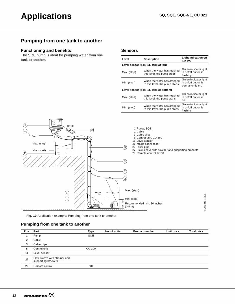
InstallationThe SQ and SQE, SQE-NE may be installed vertically,horizontally or in any position in between.
Note: The pump must not fall below the horizontal level in relation to the motor.
The following features ensure simple installation of the pump:
• Built-in check valve with spring• low weight ensuring user-friendly handling• installation in 3" or larger boreholes• only on/off switch is needed, which means that no
extra motor starter / starter box is necessary.For horizontal installation a flow sleeve isrecommended in order to:
• ensure sufficient flow velocity past the motor and thus provide sufficient cooling
• prevent motor and electronic unit from being buried in sand or mud.
Fig. 13 SQE installation
TM01
137
5 14
98
Allowed
Not allowed

SQ, SQE, SQE-NE, CU 321
17
Sizing and selection
System sizing guideStep 1Calculate minimum head requirements at no flow conditions:
Hmax (required) = dynamic head + system pressure (in feet) + above grade elevation + friction loss
Step 2Select pump from chart as follows:
• Choose model family based on the desired flow rate (i.e. 15SQE for a flow rate of 15 gpm)• Select the first model with a value in Column 2 greater than the Hmax calculated in Step 1
(For example: the choice for a 22 gpm model with an Hmax of 140 ft would be the 22SQE-160).• Double check your selection in the performance curves; see Curve charts on p. 19.
Fig. 14 Recommended sizing
Note: All calculated head requirements must lie between the selected pump models minimum and maximum speed curves.
System sizing matrixColumn 1 Column 2
Pump typeModel B
Shutoff head (0 gpm)@ 3000 rpmmin. speed
Head @ rated gpm@ 10700 rpmmax. speed
TDH [feet] TDH [feet]5SQE-90 11 865SQE-140 17 1315SQE-180 22 1775SQE-230 28 2225SQE-270 34 2705SQE-320 39 3155SQE-360 45 3605SQE-410 51 4055SQE-450 56 450
10SQE-110 12 10510SQE-160 17 16410SQE-200 23 21510SQE-240 29 26710SQE-290 34 32810SQE-330 40 390
15SQE-70 10 7515SQE-110 14 12315SQE-150 19 16415SQE-180 24 20515SQE-220 29 24615SQE-250 33 28715SQE-290 38 328
22SQE-40 5 3622SQE-80 9 7722SQE-120 14 11722SQE-160 18 15922SQE-190 23 20022SQE-220 27 240
30SQE-40 5 3330SQE-90 11 8230SQE-130 16 126
TM01
854
7 04
00
Pump curveat 10,700 ft
Pump curveat 3,000 rpm
Max
. hea
d at
rate
d flo
w
Max
. hea
d at
no
flow

SQ, SQE, SQE-NE, CU 321
18
Cable sizing
SQ, SQE, SQE-NE cable sizing chart
Cable length in feet.
Note: shaded values do not apply when using a CU 301 as its max. recommended cable length is 650 ft.
Motor rating Copper wire size (AWG)Volts Hp Amps 14 12 10 8 6 4 2115 0.5 12 140 220 360 550 880 1390 2260
230 0.5 5.2 640 1000 1660 2250 4060 — —230 0.75 8.4 400 620 1030 1580 2510 3970 —230 1 11.2 300 460 770 1190 1890 2980 4850230 1.5 12 280 430 720 1110 1760 2780 4530

SQ, SQE, SQE-NE, CU 321Curve charts
5 SQ, SQE
TM04
746
3 20
10
0 1 2 3 4 5 6 Q [US GPM]
0
100
200
300
400
500
600
700
800
[ft]H
0
50
100
150
200
250
[m]H
5 SQ
ISO 9906 Annex A 5 SQE
-450
-410
-360
-320
-270
-230
-180
-140
-90
0 1 2 3 4 5 6 Q [US GPM]
0
8
16
24
[ft]H
0
2
4
6
[m]H
0.0 0.4 0.8 1.2 1.6 Q [m³/h]
NPSH
19

Curve charts SQ, SQE, SQE-NE, CU 321
20
10 SQ, SQE
TM04
746
4 20
10
0 1 2 3 4 5 6 7 8 9 10 11 12 13 Q [US GPM]
0
50
100
150
200
250
300
350
400
450
500
550
[ft]H
0
20
40
60
80
100
120
140
160
[m]H
10 SQ
ISO 9906 Annex A10 SQE
-330
-290
-240
-200
-160
-110
0 1 2 3 4 5 6 7 8 9 10 11 12 13 Q [US GPM]
0
10
20
30
[ft]H
0
4
8
[m]H
0.0 0.4 0.8 1.2 1.6 2.0 2.4 2.8 3.2 Q [m³/h]
NPSH

Curve charts SQ, SQE, SQE-NE, CU 321
15 SQ, SQE
TM04
746
5 20
10
0 2 4 6 8 10 12 14 16 18 Q [US GPM]
0
50
100
150
200
250
300
350
400
450
500
[ft]H
0
40
80
120
[m]H
15 SQ
ISO 9906 Annex A15 SQE-290
-250
-220
-180
-150
-110
-70
0 2 4 6 8 10 12 14 16 18 Q [US GPM]
0
10
20
30
[ft]H
0
4
8
[m]H
0 1 2 3 4 Q [m³/h]
NPSH
21

Curve charts SQ, SQE, SQE-NE, CU 321
22
22 SQ, SQE
TM04
746
6 20
10
0 4 8 12 16 20 24 28 Q [US GPM]
0
40
80
120
160
200
240
280
320
360
[ft]H
0
20
40
60
80
100
[m]H
22 SQ
ISO 9906 Annex A22 SQE
-220
-190
-160
-120
-80
-40
0 4 8 12 16 20 24 28 Q [US GPM]
0
10
20
30
[ft]H
0 2 4 6 Q [m³/h]
0
4
8
[m]H
NPSH

Curve charts SQ, SQE, SQE-NE, CU 321
30 SQ, SQE
TM04
746
7 20
10
0 4 8 12 16 20 24 28 32 36 Q [US GPM]
0
20
40
60
80
100
120
140
160
180
200
220
[ft]H
0
10
20
30
40
50
60
[m]H
30 SQ
ISO 9906 Annex A30 SQE
-130
-90
-40
0 4 8 12 16 20 24 28 32 36 Q [US GPM]
0
10
20
30
[ft]H
0
4
8
[m]H
0 2 4 6 8 Q [m³/h]
NPSH
23
Curve charts SQ, SQE, SQE-NE, CU 321
24
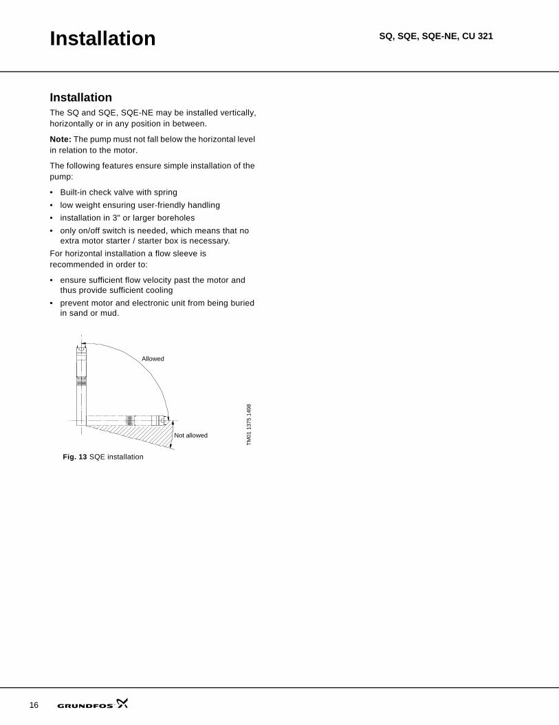
10 SQE-NE
TM04
746
8 20
10
0 2 4 6 8 10 12 Q [US GPM]
0
50
100
150
200
250
300
350
400
450
500
550
[ft]H
0
20
40
60
80
100
120
140
160
[m]H
ISO 9906 Annex A
10 SQE - NE
-340
-300
-260
-220
-180
-140
-100
0 2 4 6 8 10 12 Q [US GPM]
0
10
20
30[ft]H
0
4
8
[m]H
0 1 2 3 Q [m³/h]
NPSH
Curve charts SQ, SQE, SQE-NE, CU 321
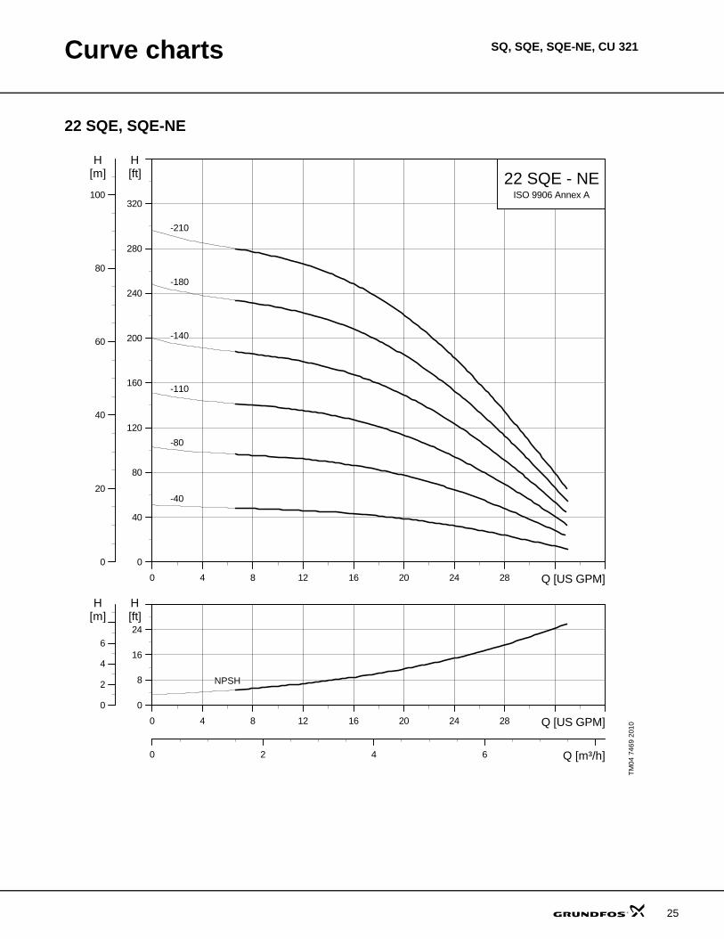
22 SQE, SQE-NE
TM04
746
9 20
10
0 4 8 12 16 20 24 28 Q [US GPM]
0
40
80
120
160
200
240
280
320
[ft]H
0
20
40
60
80
100
[m]H
ISO 9906 Annex A
22 SQE - NE
-210
-180
-140
-110
-80
-40
0 4 8 12 16 20 24 28 Q [US GPM]
0
8
16
24[ft]H
0
2
4
6
[m]H
0 2 4 6 Q [m³/h]
NPSH
25

26
SQ, SQE, SQE-NE, CU 321Technical data
Electrical data
Control units CU 300 and CU 301
Operating conditions
Storage conditions
Supply voltage: 1x200-240V +6%/-10%, 50/60 Hz, PE1x100-115V +6%/-10%, 50/60 Hz, PE
Operation via generator: As a minimum, the generator output must be equal to the motor P1[kw] + 10%Starting current: The motor starting current is equal to the highest value stated on the motor nameplateStarting: Soft StartRun-up time: Maximum: 2 seconds
Motor protection:
Motor is protected against:– Dry running– overvoltage– undervoltage– overload– overtemperature.
Power factor: PF=1Motor cable: 3 wire, 14AWG XLPE, 5 ftMotor liquid: Type SML 2
pH Values: SQ and SQE: 5 to 9SQE-NE: 2 to 13
Liquid temperature: The temperature of the pumped liquid must not exceed 86 °F (30 °C)Note: If liquids with a viscosity higher than that of water are to be pumped, please contact Grundfos.
Voltage: 1 x 100-240 V – 10 %/+ 6 %, 50/60 Hz, PEPower consumption: 5 WCurrent consumption: Maximum 130 mAEnclosure class: IP 55
Ambient temperature: During operation: –22 °F to +122 °C (–30 °C to +50 °C)During storage: –22 °F to 140 °F ( –30 °C to +60 °C)
Relative air humidity: 95 %.Pump cable: Maximum length between CU 300 or CU 301 and pump: 650 ft (198 m)Back-up fuse: Maximum: 16 A
Radio noise: CU 300 and CU 301 comply with EMC Directive 89/336/EEC.Approved according to the standards EN 55014 and EN 55014-2
Marking: CE, cUL (CU 301)Load: Max. 100 mA
Minimum ambient fluid temperature: +34 °F (+1 °C)Maximumambient fluid temperature: +86 °F (+30 °C)Well diameter: 3-inch or largerInstallation depth (maximum): 500 feet below static water level
Minimum ambient temperature: –4 °F (–20 °C)Maximum ambient temperature: +140 °F (+60 °F)
Frost protection: If the pump has to be stored after use, it must be stored at a frost-free location, or it must be ensured that the motor liquid is frost-proof.
Technical data SQ, SQE, SQE-NE, CU 321
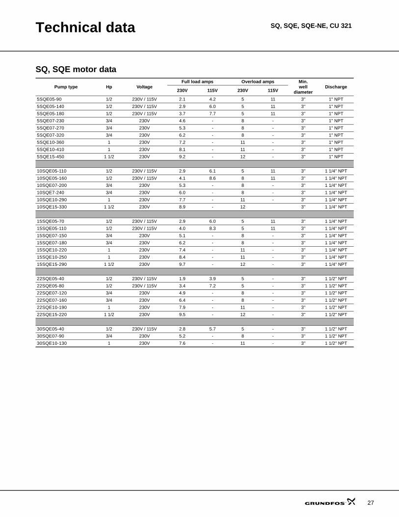
SQ, SQE motor data
Pump type Hp VoltageFull load amps Overload amps Min.
welldiameter
Discharge230V 115V 230V 115V
5SQE05-90 1/2 230V / 115V 2.1 4.2 5 11 3" 1" NPT5SQE05-140 1/2 230V / 115V 2.9 6.0 5 11 3" 1" NPT5SQE05-180 1/2 230V / 115V 3.7 7.7 5 11 3" 1" NPT5SQE07-230 3/4 230V 4.6 - 8 - 3" 1" NPT5SQE07-270 3/4 230V 5.3 - 8 - 3" 1" NPT5SQE07-320 3/4 230V 6.2 - 8 - 3" 1" NPT5SQE10-360 1 230V 7.2 - 11 - 3" 1" NPT5SQE10-410 1 230V 8.1 - 11 - 3" 1" NPT5SQE15-450 1 1/2 230V 9.2 - 12 - 3" 1" NPT
10SQE05-110 1/2 230V / 115V 2.9 6.1 5 11 3" 1 1/4" NPT10SQE05-160 1/2 230V / 115V 4.1 8.6 8 11 3" 1 1/4" NPT10SQE07-200 3/4 230V 5.3 - 8 - 3" 1 1/4" NPT10SQE7-240 3/4 230V 6.0 - 8 - 3" 1 1/4" NPT10SQE10-290 1 230V 7.7 - 11 - 3" 1 1/4" NPT10SQE15-330 1 1/2 230V 8.9 - 12 3" 1 1/4" NPT
15SQE05-70 1/2 230V / 115V 2.9 6.0 5 11 3" 1 1/4" NPT15SQE05-110 1/2 230V / 115V 4.0 8.3 5 11 3" 1 1/4" NPT15SQE07-150 3/4 230V 5.1 - 8 - 3" 1 1/4" NPT15SQE07-180 3/4 230V 6.2 - 8 - 3" 1 1/4" NPT15SQE10-220 1 230V 7.4 - 11 - 3" 1 1/4" NPT15SQE10-250 1 230V 8.4 - 11 - 3" 1 1/4" NPT15SQE15-290 1 1/2 230V 9.7 - 12 - 3" 1 1/4" NPT
22SQE05-40 1/2 230V / 115V 1.9 3.9 5 - 3" 1 1/2" NPT22SQE05-80 1/2 230V / 115V 3.4 7.2 5 - 3" 1 1/2" NPT22SQE07-120 3/4 230V 4.9 - 8 - 3" 1 1/2" NPT22SQE07-160 3/4 230V 6.4 - 8 - 3" 1 1/2" NPT22SQE10-190 1 230V 7.9 - 11 - 3" 1 1/2" NPT22SQE15-220 1 1/2 230V 9.5 - 12 - 3" 1 1/2" NPT
30SQE05-40 1/2 230V / 115V 2.8 5.7 5 - 3" 1 1/2" NPT30SQE07-90 3/4 230V 5.2 - 8 - 3" 1 1/2" NPT30SQE10-130 1 230V 7.6 - 11 - 3" 1 1/2" NPT
27

Technical data SQ, SQE, SQE-NE, CU 321
28
SQ, SQE and SQE-NE dimensions and weightsSQ, SQE
SQE-NE
Model Hp Motorsize Discharge size
Dimensions in inches Approx. ship. wt.A B C D E
5SQ/SQE05-90 1/2 3" 1" NPT 30.4 19.8 10.6 2.6 2.9 125SQ/SQE05-140 1/2 3" 1" NPT 30.4 19.8 10.6 2.6 2.9 125SQ/SQE05-180 1/2 3" 1" NPT 31.5 19.8 11.6 2.6 2.9 125SQ/SQE07-230 3/4 3" 1" NPT 33.6 19.8 13.7 2.6 2.9 135SQ/SQE07-270 3/4 3" 1" NPT 33.6 19.8 13.7 2.6 2.9 135SQ/SQE07-320 3/4 3" 1" NPT 34.6 19.8 14.8 2.6 2.9 135SQ/SQE10-360 1 3" 1" NPT 38.2 21.3 16.9 2.6 2.9 165SQ/SQE10-410 1 3" 1" NPT 38.2 21.3 16.9 2.6 2.9 165SQ/SQE15-450 1 1/2 3" 1" NPT 39.3 21.3 18.0 2.6 2.9 16
10SQ/SQE05/110 1/2 3" 1 1/4" NPT 30.4 19.8 10.6 2.6 2.9 1210SQ/SQE05/160 1/2 3" 1 1/4" NPT 30.4 19.8 10.6 2.6 2.9 1210SQ/SQE07/200 3/4 3" 1 1/4" NPT 31.5 19.8 11.6 2.6 2.9 1310SQ/SQE07/260 3/4 3" 1 1/4" NPT 33.6 19.8 13.7 2.6 2.9 1310SQ/SQE10/290 1 3" 1 1/4" NPT 35.0 21.3 13.7 2.6 2.9 1610SQ/SQE15/330 1 1/2 3" 1 1/4" NPT 36.14 21.3 14.8 2.6 2.9 16
15SQ/SQE05/70 1/2 3" 1 1/4" NPT 30.4 19.8 10.6 2.6 2.9 1215SQ/SQE05/110 1/2 3" 1 1/4" NPT 30.4 19.8 10.6 2.6 2.9 1215SQ/SQE07/150 3/4 3" 1 1/4" NPT 31.5 19.8 11.6 2.6 2.9 1315SQ/SQE07/180 3/4 3" 1 1/4" NPT 33.6 19.8 13.7 2.6 2.9 1315SQ/SQE10/220 1 3" 1 1/4" NPT 35.0 21.3 13.7 2.6 2.9 1615SQ/SQE10/250 1 3" 1 1/4" NPT 36.1 21.3 14.8 2.6 2.9 1615SQ/SQE10/290 1 1/2 3" 1 1/4" NPT 38.2 21.3 16.9 2.6 2.9 16
22SQ/SQE05/40 1/2 3" 1 1/2" NPT 30.4 19.8 10.6 2.6 2.9 1222SQ/SQE05/80 1/2 3" 1 1/2" NPT 30.4 19.8 10.6 2.6 2.9 1222SQ/SQE07/120 3/4 3" 1 1/2" NPT 31.5 19.8 11.6 2.6 2.9 1322SQ/SQE07/160 3/4 3" 1 1/2" NPT 33.6 19.8 13.7 2.6 2.9 1322SQ/SQE10/190 1 3" 1 1/2" NPT 38.2 21.3 16.9 2.6 2.9 1622SQ/SQE15/220 1 1/2 3" 1 1/2" NPT 38.2 21.3 16.9 2.6 2.9 16
30SQ/SQE05/40 1/2 3" 1 1/2" NPT 30.4 19.8 10.6 2.6 2.9 1230SQ/SQE07/90 3/4 3" 1 1/2" NPT 30.4 19.8 10.6 2.6 2.9 1330SQ/SQE10/130 1 3" 1 1/2" NPT 35.0 21.3 13.7 2.6 2.9 13
10SQE-05-100NE 1/2 3" 1 1/4" NPT 30.4 19.8 10.6 2.6 2.9 1210SQE-05-140NE 1/2 3" 1 1/4" NPT 30.4 19.8 10.6 2.6 2.9 1210SQE-05-180NE 3/4 3" 1 1/4" NPT 31.5 19.8 11.6 2.6 2.9 1310SQE-07-220NE 3/4 3" 1 1/4" NPT 33.6 19.8 13.7 2.6 2.9 1310SQE-10-260NE 1 3" 1 1/4" NPT 35.0 21.3 13.7 2.6 2.9 1610SQE-10-300NE 1 3" 1 1/4" NPT 36.1 21.3 14.8 2.6 2.9 1610SQE-10-340NE 1 3" 1 1/4" NPT 38.2 21.3 16.9 2.6 2.9 16
22SQE05-40NE 1/2 3" 1 1/2" NPT 30.4 19.8 10.6 2.6 2.9 1222SQE05-80NE 1/2 3" 1 1/2" NPT 30.4 19.8 10.6 2.6 2.9 1222SQE07-110NE 3/4 3" 1 1/2" NPT 31.5 19.8 11.6 2.6 2.9 1322SQE07-140NE 3/4 3" 1 1/2" NPT 33.6 19.8 13.7 2.6 2.9 1322SQE10-180NE 1 3" 1 1/2" NPT 38.2 21.3 16.9 2.6 2.9 1622SQE10-210NE 1 3" 1 1/2" NPT 38.2 21.3 16.9 2.6 2.9 16

Technical data SQ, SQE, SQE-NE, CU 321
Materials of constructionSQ, SQE SQE-NE
TM04
752
2 21
10
Component Splined shaft Component Splined shaftValve casing Polyamide Valve casing PVDFDischarge chamber 304 stainless steel Discharge chamber 316 stainless steelValve guide Polyamide O-ring FPM rubberValve spring 316LN stainless steel Valve cone PVDFValve cone Polyamide Valve seat FPM rubberValve seat NBR rubber Top chamber PVDFO-ring NBR rubber Empty chamber PVDFLock ring 310 stainless steel Top bearing FPM rubberTop bearing NBR rubber Neck ring PVDFTop chamber Polyamide Lock ring 316 stainless steelGuide vanes Polyamide Guide vanes PVDF
Impeller Polyamide w/ tungstencarbide bearings Bottom chamber PVDF
Bottom chamber Polyamide Impeller w/ tungstencarbide bearing PVDF
Neck ring TPU / PBT Suction interconnector PVDFBearing Aluminum oxide Ring 316 stainless steelSuction interconnector Polyamide
Shaft w/couplingSintered steel
Ring 304 stainless steel 316 stainless steelPump sleeve 304 stainless steel Cable guard 316 stainless steelPressure equalization cone Polyamide Cable guard screws 316 stainless steelSpacer Polyamide Pressure equalization cone PVDFSand trap 316 stainless steel Valve spring 316 stainless steelShaft w/coupling 304 stainless steel Pump sleeve 316 stainless steel
Cable guard 304 stainless steelValve guide PVDFSpacer 316 stainless steel
Discharge sizes:1" NPT1 1/4" NPT1 1/2" NPT
5SQ/SQE10 - 15 SQ/SQE22-30 SQ/SQE
29

Technical data SQ, SQE, SQE-NE, CU 321
30
Material specificationPump
Pos. Component MaterialDIN
W-Nr.SQ/SQE
AISIDIN
W-Nr.SQ/-NE
AISI
1 Valve casing Polyamide 1.4301 304 1.4401 316
1a Discharge chamber Stainless steel1d O-ring NBR rubber2 Valve cup Polyamide
3 Valve seat NBR rubber4a Empty chamber Polyamide6 Top bearing NBR rubber
7 Neck ring TPU / PBT
7a Lock ring Stainlessspring steel 1.4301 310 1.4401 316
7b Neck ring retainer Polyamide9b Chamber top Polyamide9c Chamber bottom Polyamide
13Impeller withtungsten carbidebearing
Polyamide
14 Suctioninter-connector Polyamide
14a Ring Stainless steel 1.4301 304 1.4401 316
16 Shaft with couplingStainless steel 1.4301 304 1.4401 316Sintered steel
18 Cable guard Stainless steel 1.4301 304 1.4401 316
18a18b Screws for cable guard Stainless steel 1.4301 316 1.4401 316
30 Cone for pressureequalization Polyamide
32 Guide vanes Polyamide
39 Spring Stainlessspring steel 1.4406 316LN 1.4406 316LN
55 Pump sleeve Stainless steel 1.4301 304 1.4401 316
64 Priming screw Polyamide70 Valve guide Polyamide86 Lip seal ring NBR rubber
87 Cone for pressureequalization complete
Polyamide /NBR rubber
TM01
274
5 20
10Motor
Pos. Component MaterialDIN
W-Nr.SQ-SQE
AISIDIN
W-Nr.SQE-NE
AISI
201 Stator Stainless steel 1.4301 304 1.4401 316202 Rotor Stainless steel 1.4301 304 1.4401 316
202a Stop ring PP202b Filter Polyester203 Thrust bearing Carbon
205 Radial bearing Ceramictungsten carbine
220 Motor cable with plug EPR
222a Filling plug MS 3: NBRMSE 3: FKM
224 O-ring FKM
225 Top cover PPS
232 Shaft seal MS 3: NBRMSE 3: FKM
Motor liquid SML-2
1d
7a
1
70
2
39
3
1a
55
16
30
8687
6418
18b
18a
6
4a
9b
32
13
9c
7
14
14a
7b
202a
202
202b
222a
232
203
224
205
225
201
220

SQ, SQE, SQE-NE, CU 321Control units
CU 301The CU 301 is a control and communication unitdeveloped especially for the SQE submersible pumps in constant-pressure applications.
The CU 301 control unit provides:
• Full control of the SQE pumps• two-way communication with the SQE pumps• possibility of adjusting the pressure• alarm indication (LED) when service is needed• possibility of starting, stopping and resetting the
pump simply by means of a push-button• configuration with R100 remote control.The CU 301 communicates with the pump via mains borne signalling (Power Line Communication),meaning that no extra cables are required between the CU 301 and the pump.
The CU 301 features the following indications (see drawing in right column):
1. Pump running indicator2. System pressure setting3. System ON/OFF4. Button lock indicator5. Dry-running indicator6. Service needed in case of:
– no contact to pump– overvoltage– undervoltage– speed reduction– overtemperature– overload– sensor defective.
The CU 301 incorporates:
• External signal input for pressure sensor• connection to an operating relay for indication of
pump operation.
Optional R100 remote controlWireless infrared remote control of the CU 301 ispossible by means of the R100.
Using the R100, it is possible to monitor and change the operating parameters, see the R100 menu structure on page 32.
The R100 is a valuable tool in case fault finding is required.
Fig. 15 CU 301 control unit
Fig. 16 CU 301 entry ports
Fig. 17 CU 301 dimensions
TM03
342
6 04
06TM
02 3
427
0406
TM03
300
3 20
10
bar5.0
5
0
3 5
3 0
2 5
2 0
2 3
4
1
5
6
R100
Pressuresensor entry
Power supplyentry
Submersible drop cable entry
Operating relay entry
9.13 in.(232 mm)
4.49 in.(114 mm)
7.68
in.
(195
mm
)
ba5 0
4 54 0
3 53 0
2 5
2 0
31

Control units SQ, SQE, SQE-NE, CU 321
32
R100 menu structure for CU 301 control unit
1.1
1.2
1.3
2.1
2.2
2.3
2.4
2.5
2.6
3.1
3.2
3.3
3.4
3.5
3.6
3.7
3.8
3.9
1.4
1.5
1.6
1.7
1.8
Note: This menu is an example, not the factory setting.
Start
ContrastSetting
Light
0. General 1. Operation 2. Status 3. Installation
3.10
USBversiononly

Control units SQ, SQE, SQE-NE, CU 321
R100 menus for CU 3010. General
1. Operation1.1 Setpoint setting
1.2 Selection of operating mode
1.3 Alarm indication.
2. StatusThe indication of:
2.1 Actual operating mode
2.2 Actual pressure
2.3 Actual motor speed
2.4 Actual motor temperature
2.5 Actual power input and accumulated motor power consumption
2.6 Accumulated number of operating hours and accumulated number of starts.
3. Installation3.1 Sensor parameters
3.2 Choice of sensor
3.3 Setting of maximum pressure setpoint
3.4 Setting of automatic restart time
3.5 Setting of the dry-running stop limit
3.6 Setting of the maximum motor speed
3.7 Setting of the cut-in motor speed
3.8 Activating or deactivating the on/off-button and the buttons for system pressure setting on the CU 301
3.9 Indication of pump operation
3.10 Allocation of identification number.
33

Control units SQ, SQE, SQE-NE, CU 321
34
CU 300The CU 300 is a control and communication unitdeveloped especially for the SQE submersible pumps for control applications other than constant pressure.
The CU 300 control unit provides:
• Flexible pump control based on various sensorinputs
• two-way communication with the SQE pumps• alarm indication of pump operation by LED’s on the
front• possibility of starting, stopping and resetting the
pump simply by means of a push-button• communication with R100 remote control. The CU 300 communicates with the pump via mains borne signalling (Power Line Communication),meaning that no extra cables are required between the CU 300 and the pump.
The following alarms can be indicated by the CU 300:
• No contact• overvoltage• undervoltage• dry running• speed reduction• overtemperature• overload• sensor alarm.
The CU 300 incorporates:
• External signal input for two analog sensors and one digital sensor
• relay output for external alarm indication• control according to the signals received, e.g. of
flow, pressure, water level and conductivity.
R100 remote controlWireless infrared remote control of the CU 300 ispossible by means of the R100.
Using the R100, it is possible to monitor and change the operating parameters, see the R100 menu structure on page 35.
The R100 is a valuable tool in case fault finding is required.
Fig. 18 CU 300 control unit with R100
Fig. 19 CU 300 control unit, external entry ports
Fig. 20 CU 300 dimensionsTM
01 2
760
4801
TM01
276
1 48
01TM
01 2
781
2010
LED alarm indication On/Off button with
red and green indicator lights
IR communication
R100
Power supply entrySubmersible drop cable entry
Extra cable entries
Fieldbus entry
Sensor entries
9.14 in.(232 mm)
4.49 in.(114 mm)
7.68
in.
(195
mm
)

Control units SQ, SQE, SQE-NE, CU 321
R100 menu structure for the CU 300
1.1
1.2
1.3
2.1
2.2
2.3
2.4
2.5
2.6
2.7
2 8
3.1
3.2
3.3
3.4
3.5
3.6
3.7
3.8
3.9
3.10
3.11
4.1
4 2
4 3
4.4
4.5
4.6
4.7
4.8
3.12
4.92 9
4.10
1.4
1.5
1.6
1.7
1.8
Start
Contrast
Setting
Light
0. General 1. Operation 2. Status 4. Installation3. Limits
Note: This menu is an example, not the factory setting.
USBversiononly
35

Control units SQ, SQE, SQE-NE, CU 321
36
R100 menus for CU 3000. General
1. Operation1.1 Setpoint setting
1.2 Selection of operating mode
1.3 Alarm indication.
2. StatusThe indication of:
2.1 Actual operating mode
2.2 Actual and external setpoint
2.3 Actual motor temperature
2.4 Actual motor speed
2.5 Actual power input and accumulated motor power consumption
2.6 Accumulated number of operating hours and accumulated number of starts
2.7 Actual values of sensors 1 and 2, respectively
2.8 Actual values of the digital input
2.9 Accumulated flow, and the power used to pump.
R100 offers the possibility of making a number ofsettings.
3. LimitsThe setting of:
3.1 Sensor 1 parameters
3.2 Min. and max. stop limits of sensor 1
3.3 Min. and max. warning limits of sensor 1
3.4 Min. and max. alarm limits of sensor 1
3.5 Sensor 2 parameters
3.6 Min. and max. stop limits of sensor 2
3.7 Min. and max. warning limits of sensor 2
3.8 Min. and max. alarm limits of sensor 2
3.9 Filling or emptying
3.10 Setting of the function of the digital sensorconnected to the digital input
3.11 The setting of the water quantity stop limit and the setting of the sensor to detect water quantity
3.12 The setting of the temperature warning limits of the motor electronics.
4. Installation4.1 Selection of controller — open loop, closed loop
4.2 Setting of external setpoint
4.3 Setting of automatic restart time
4.4 Allocation of individual start delays
4.5 Setting of the stop and run times for thedewatering function
4.6 Setting of the dry-running stop limit
4.7 Activating or deactivating the dry-runningprotection
4.8 Setting of the maximum motor speed
4.9 Activating or deactivating the on/off-button on the CU 300
4.10 Allocation of ID number where more than one CU 300 is installed.

Control units SQ, SQE, SQE-NE, CU 321
Examples of R100 displays
Menu OPERATIONSetpoint setting
1.1From factory, the pump is set to maximum speed, 10,700 rpm. R100 makes it possible to reduce the pump speed by changing the setpoint. The speed can be set to 3,000 - 10,700 rpm, at 100 rpm intervals.
The unit of the setpoint is automatically changed according to the unit of the sensor connected to sensor input 1.
Example: Sensor input 1 is connected to a pressure sensor using the unit feet (ft) and the range 0-60.Consequently, the setpoint of display 1.1 can be set to between 0-60 ft.
Menu STATUSThe displays appearing in this menu are status displays only. It is not possible to change settings in this menu.
Accumulated flow
2.9In display 2.9, the water quantity (m3)* pumped is shown. The value shown is the accumulated flowregistered by the sensor selected in display 3.11.
The power used to pump 1 m3 is shown in the display as energy per m3 (kWh/m3).
It is possible to read the status of the accumulated flow and energy per m3 at any time.
*Water quantity in units of gpm can be chosen.
Accumulated number of operating hours and number of starts
2.6The number of operating hours and the number of starts are values accumulated from the time of installa-tion and they cannot be reset.
Both values are stored in the motor electronics, and they are kept even if the CU 300 is replaced.
The number of operating hours is registered every two hours of continuous operation.
Menu LIMITS
Sensor 1
3.1The setting of sensor 1.
Depending on the type of sensor, the following settings can be made:
• Sensor outputs:– (not active), 0-10 V, 2-10 V, 0-20 mA, 4-20 mA
• setting range unit: m3/h, m, %, gpm, ft• sensor minimum value: 0-249 (0, 1, 2, 3.....249)• sensor maximum value: 1-250 (1, 2, 3, 4.....250).
37

38
SQ, SQE, SQE-NE, CU 321CU 321 variable frequency drive
CU 321 variable frequency drive
Features• Complete solution from one manufacturer• Easy setup: simply select pump model and choose
pressure setpoint• Four pump choices: offered in most popular sizes,
both 3 and 5 hp: 15, 25, 40, and 75 gpm• Matched pump and motor: 3 hp pump on 3 hp motor
and 5 hp pump on 5 hp motor• Respects original operating designs; operates pump
and motor within its designed rpm and hp ratings• Built-in protection features: soft-start, dry run,
overload, over / under voltage, sensor alarm• Wide voltage range:
3 hp unit:Single or 3-phase 208-240 VAC (+/-10 %)5 hp input:Single or 3-phase 208-240 VAC (+/ -10 %).
ApplicationsFor 4" or larger wells. Main applications:
• Domestic and light commercial water supply• irrigation• livestock watering• water transfer.
Components• Compact, efficient, and reliable CU 321 variable
frequency drive• rugged stainless steel pump end and proven,
reliable, 3-phase 230V motor• pressure sensor• minimum 4 gal diaphragm tank (sold separately).
Fig. 21 CU 321 variable frequency drive and sensor
SizingStep 1Calculate maxiumum head requirements at rated flow conditions:
Hmax=dynamic head + system psi (in feet) +friction loss + above grade elevation.
Step 2Select pump from System Sizing Matrix as follows:
Select a model in which the calculated value of Hmax is below the value in Column 2.
ExampleThe choice for a 40 gpm model with an Hmax of 150 would be the 40S30-9.
TM04
751
0 21
10
System sizing matrix
Pump type
Column 1 Column 2Shutoff head (0 gpm)
@ 1500 rpmmin. speed
Head @ rated gpm@ 3600 rpmmax. speed
3 hp TDH [ft] TDH [ft]16S30-24 128 49025S30-15 80 30540S30-9 45 18575S30-5 30 1055 hp16S50-38 200 82525S50-26 105 53040S50-15 75 31075S50-8 45 175

CU 321 variable frequency drive
SQ, SQE, SQE-NE, CU 321
Performance curves - CU 321 variable speed16 gpm - Model 16S30-24
16 gpm - Model 16S50-38
25 gpm - Model 25S30-15
25 gpm - Model 25S50-26
TM04
752
3 21
10TM
04 7
524
2110
0 2 4 6 8 10 12 14 16 18 20 22Q [US GPM]
0
50
100
150
200
250
300
350
400
450
500
550
600
650
700
750
[ft]H
0 1 2 3 4Q [m³/h]
0
20
40
60
80
100
120
140
160
180
200
220
[m]H
16S30-2460 Hz
55 Hz
50 Hz
45 Hz
40 Hz
35 Hz
30 Hz
0 2 4 6 8 10 12 14 16 18 20 22Q [US GPM]
0
100
200
300
400
500
600
700
800
900
1000
1100
1200
[ft]H
0 1 2 3 4Q [m³/h]
0
50
100
150
200
250
300
350
[m]H
16S50-3860 Hz
55 Hz
50 Hz
45 Hz
40 Hz
35 Hz
30 Hz
TM04
752
5 21
10TM
04 7
526
2110
0 5 10 15 20 25 30 35 40Q [US GPM]
0
50
100
150
200
250
300
350
400
450
500
[ft]H
0 2 4 6 Q [m³/h]
0
20
40
60
80
100
120
140
[m]H
25S30-15
60 Hz
55 Hz
50 Hz
45 Hz
40 Hz
35 Hz
30 Hz
0 5 10 15 20 25 30 35 40Q [US GPM]
0
50
100
150
200
250
300
350
400
450
500
550
600
650
700
750
800
[ft]H
0 2 4 6 Q [m³/h]
0
20
40
60
80
100
120
140
160
180
200
220
240
[m]H
25S50-2660 Hz
55 Hz
50 Hz
45 Hz
40 Hz
35 Hz
30 Hz
39

CU 321 variable frequency drive
SQ, SQE, SQE-NE, CU 321
40
40 gpm - Model 40S30-9
40 gpm - Model 40S50-15
75 gpm - Model 75S30-5
75 gpm - Model 75S50-8
TM04
752
7 21
10TM
04 7
529
2110
0 5 10 15 20 25 30 35 40 45 50 55 60Q [US GPM]
0
20
40
60
80
100
120
140
160
180
200
220
240
260
[ft]H
0 2 4 6 8 10 Q [m³/h]
0
10
20
30
40
50
60
70
80
[m]H
40S30-960 Hz
55 Hz
50 Hz
45 Hz
40 Hz
35 Hz
30 Hz
0 5 10 15 20 25 30 35 40 45 50 55 60Q [US GPM]
0
50
100
150
200
250
300
350
400
450
[ft]H
0 2 4 6 8 10 Q [m³/h]
0
20
40
60
80
100
120
140
[m]H
40S50-15
60 Hz
55 Hz
50 Hz
45 Hz
40 Hz
35 Hz
30 Hz
TM04
753
0 21
10TM
04 7
531
2110
0 10 20 30 40 50 60 70 80 90 100Q [US GPM]
0
20
40
60
80
100
120
140
160
180
[ft]H
0 5 10 15 Q [m³/h]
0
10
20
30
40
50
[m]H
75S30-5
60 Hz
55 Hz
50 Hz
45 Hz
40 Hz
35 Hz
30 Hz
0 10 20 30 40 50 60 70 80 90 100Q [US GPM]
0
20
40
60
80
100
120
140
160
180
200
220
240
260
[ft]H
0 5 10 15 Q [m³/h]
0
10
20
30
40
50
60
70
80
[m]H
75S50-860 Hz
55 Hz
50 Hz
45 Hz
40 Hz
35 Hz
30 Hz

SQ, SQE, SQE-NE, CU 321
41
Accessories
CU 321 variable frequency drive
CU 301 Constant Pressure System
CU 300 Status Box & R100
SQ, SQE flow sleeves
TM04
751
0 21
10
Description Hp Input Ph Input volts Product numberCU321 Constant Pressure Kit 3 1 200 - 240 96581690CU321 Constant Pressure Kit 5 1 200 - 240 96632970CU321 Constant Pressure Kit 5 3 200 - 240 96581691Sensor - - - 96437852Note: Kit includes CU321 and pressure sensor
TM04
750
9 21
10
Description Product numberConstant Pressure Kit(CU 301 and Transducer) 96438895
TM04
750
8 21
10
Description Product numberCU300 Status Box 96422776
Description Product numberR100(for wireless infrared communication with the CU 301 / CU 300)
96615297
TM01
329
2 37
98
Description Product numberSQ, SQE flow sleeve, complete 96037505
55050
88
650 100
50210
250max
. ø10
0
ø90

42
SQ, SQE, SQE-NE, CU 321Further product documentation
WebCAPSWebCAPS is a Web-based Computer Aided Product Selection program available on www.grundfos.com.
WebCAPS contains detailed information on more than 185,000 Grundfos products in more than 20 languages.
In WebCAPS, all information is divided into 6 sections:
• Catalog• Literature• Service• Sizing• Replacement• CAD drawings.
Catalog
This section is based on fields of applica ion and pump types, and contains • technical data• curves (QH, Eta, P1, P2, etc) which can be adapted to the den-
sity and viscosity of the pumped liquid and show the number of pumps in operation
• product photos• dimensional drawings• wiring diagrams• quotation texts, etc.
Literature
In this section you can access all the latest documents of a given pump, such as• product guides• installation and operating instructions• service documentation, such as Service kit catalog
and Service kit instructions• quick guides• product brochures, etc.
Service
This section contains an easy-to-use interactive service catalog. Here you can find and identify service parts of both existing anddiscontinued Grundfos pumps.Furthermore, this section contains service videos showing you how to replace service parts.

Further product documentation
SQ, SQE, SQE-NE, CU 321
WinCAPS
Fig. 1 WinCAPS CD-ROM
WinCAPS is a Windows-based Computer Aided Product Selection program containing detailed informa-tion on more than 185,000 Grundfos products in more than 20 languages.
The program contains the same features and functions as WebCAPS, but is an ideal solution if no Internet connection is available.
WinCAPS is available on CD-ROM and updated once a year.
Sizing
This section is based on different fields of application and installa-tion examples, and gives easy step-by-step instructions in how to• select the most suitable and efficient pump for your installation• carry out advanced calculations based on energy consumption,
payback periods, load profiles, life cycle costs, etc.• analyse your selected pump via the built-in life cycle cost tool• determine the flow velocity in wastewater applications, etc.
Replacement
In this section you find a guide to selecting and comparing replace-ment data of an installed pump in order to replace the pump with a more efficient Grundfos pump. The section contains replacement data of a wide range of pumps produced by other manufacturers than Grundfos.
Based on an easy step-by-step guide, you can compare Grundfos pumps with the one you have installed on your site. When you have specified the installed pump, the guide will suggest a number of Grundfos pumps which can improve both comfort and efficiency.
CAD drawings
In this section it is possible to download 2-dimensional (2D) and3-dimensional (3D) CAD drawings of most Grundfos pumps.
These formats are available in WebCAPS:
2-dimensional drawings:• .dxf, wireframe drawings• .dwg, wireframe drawings.
3-dimensional drawings:• .dwg, wireframe drawings (without surfaces)• .stp, solid drawings (with surfaces)• .eprt, E-drawings.
0 1
43

SQ, SQE, SQE-NE, CU 321
44

SQ, SQE, SQE-NE, CU 321
45

SQ, SQE, SQE-NE, CU 321
46

SQ, SQE, SQE-NE, CU 321
47

GRUNDFOS Pumps Corporation 17100 West 118th TerraceOlathe, Kansas 66061Phone: +1-913-227-3400 Telefax: +1-913-227-3500
GRUNDFOS Canada Inc. 2941 Brighton Road Oakville, Ontario L6H 6C9 CanadaPhone: +1-905 829 9533 Telefax: +1-905 829 9512
Bombas GRUNDFOS de Mexico S.A. de C.V. Boulevard TLC No. 15Parque Industrial Stiva AeropuertoApodaca, N.L. Mexico 66600Phone: +52-81-8144 4000 Telefax: +52-81-8144 4010
www.grundfos.com
Being responsible is our foundationThinking ahead makes it possible
Innovation is the essence
L-SQ-PG-001 0610
USRepl. 02/06
© 2006, 2010 Grundfos Pumps Corp.
The name Grundfos, the Grundfos logo, and the payoff Be–Think–Innovate are registered trademarks owned by Grundfos Management A/S or Grundfos A/S, Denmark. All rights reserved worldwide.