Embed Size (px)
Citation preview
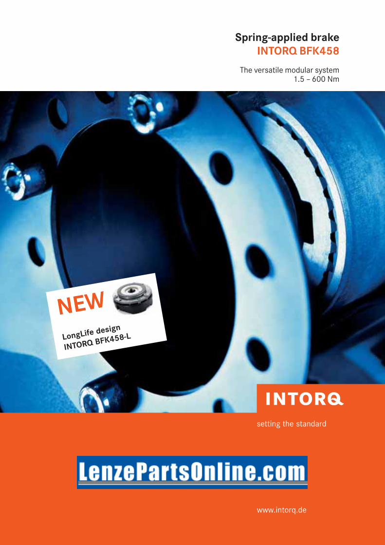
Spring-applied brakeINTORQ BFK458
The versatile modular system1.5 – 600 Nm
setting the standard
www.intorq.de
NEWLongLife design
INTORQ BFK458-L

2
INTORQ BFK458 - The modular system
Our modular system forms the basis for a product range thatoffers versions tailored for almost any task. The BFK458spring-applied brake, as a standard product, can be usedanywhere, but its modular structure also meets the require-ments of specific industries. Its strength lies in its versatility.
Electromagnetically released spring-applied brakes are used wherever masses in motion have to be decelerated as quickly as possible or where masses must be held in adefined position. The braking force is applied by com-pression springs. Thus the braking torque generated by friction locking remains available in the deenergised status –even in the event of mains failure. The brake is released electromagnetically.
The INTORQ BFK458 range replaces the 14.448/14.449and 14.450 models of spring-applied brake. The main com-ponents of the modular system are the two basic modules E (adjustable braking torque) and N (braking torque not adjustable). The greatest degree of flexibility is achieved
for a broad range of applications by the combination of the basic module with specific modules. This catalogue isintended to help you to select and to order the spring-applied brake you require quickly and easily.
The modular system for all applications| Brake motors| Materials handling technology| Cranes| Storage technology| Industrial trucks| Wood working machines| Stage machinery| Vehicles for the disabled| Automation technology| Regulated drives| Gate drives| Escalators
NEW: LongLife design INTORQ BFK458-L
In high-cycle applications, spring-applied brakes are subjectto two kinds of stress. Due to the large number of load alternations, the service life of the brake is determined bothby the mechanical components of the brake itself and theuseful life of the rotor, which is based on friction energy. Inparticular, the rotor/hub connection, the springs and thesleeve bolts are subject to wear due to the number of load
cycles. Based on the components mentioned, without additional measures the service life of spring-applied brakesis limited to 1x10⁶ to 4x10⁶ load cycles depending on theload. The new LongLife design guarantees a service life ofthe brake mechanism at least 10x106 switching cycles.
INTORQ I BFK458 spring-applied brake I en 5/2008

3
INTORQ I BFK458 spring-applied brake I en 5/2008
Contents
Product key 4
List of abbreviations 5
Product information 6
Principle of operation 7
Example applications 8
Technical dataBraking torques 9E/N/L + basic module 10Flange + manual releaseBrake module N + 11centring flangeBasic module N + 12Connection flange + basic module NRated data 13Operating times 14Service life and wear 15
AccessoriesManual release/flange/ 16friction plateCentring flange/ 17connection flange/SealBrake cover 18Microswitch 19Terminal box 20
Type code 21Bridge rectifier andhalf-wave rectifier BEGSpark suppressor 21INTORQ 14.198.00.Oò
Bridge rectifiers and 22half-wave rectifiers BEG Fastening options 25Connection diagrams 26Mains voltage selection table 27
DimensioningBasic information 28Calculation example 29
Order form 30
Sales and service 32around the world
Spring-applied brakes INTORQ BFK458, corrosion-resistant in cranes
Double spring-applied brakes INTORQ BFK458, noise-reduced in the theatre
LongLife spring-applied brakes INTORQ BFK458-òòLin materials handling technology

4
INTORQ I BFK458 spring-applied brake I en 5/2008
Friction plate
Flange
Connectionflange(doublebrake)
Centring flange(tacho flange)
SealHub
Rotor
Complete statorbrake module N
Plug
Shaftsealing ring
Complete statorbrake module E
Manual release
Sizes06, 08, 10, 12, 14, 16, 18, 20, 25
Stator designE – Adjustable (braking torque can be reduced using
torque adjustment ring) N – Non-adjustableL – Non-adjustable, LongLife design
Not coded:Supply voltage, hub bore,Options
INTORQ BFK458-òòò product key
B F K 4 5 8 - òò ò
Product group: Brakes
Product family: Spring-applied brakes
Type
Sizes
Design

5
INTORQ I BFK458 spring-applied brake I en 5/2008
List of abbreviations
P [kW] Drive powerMK [Nm] Rated torque of brakeML [Nm] Load torqueMerf [Nm] Required braking torqueMa [Nm] Deceleration torque∆n0 [rpm] Initial relative speed of the brakeJL [kgm2] Moment of inertia of all
driven parts, referred to the shaftto be braked
t1 [s] Engagement time, t1 = t11 + t12
t2 [s] Disengagement time (time from thebeginning of the torque drop until 0.1 MK is reached)
t3 [s] Slipping time(time during which a relative motionoccurs between the input and output,with brake applied)
t11 [s] Delay time(time from disconnecting the voltage untilthe torque begins to rise)
t12 [s] Rise time of braking torque
K Safety factorQ [J] Calculated friction energy per switching
cycleQzul [J] Maximum permissible friction energy per
switching cycleSh [h-1] Operating frequency, i.e. the number of
periodical brake operationsSlü Rated air gap

6
INTORQ I BFK458 spring-applied brake I en 5/2008
Product information
INTORQ BFK458 spring-applied brake
A powerful and complete range| 9 sizes| Standard voltages 24 V, 96 V, 103 V, 170 V, 180 V, 190 V,
205 V| Graduated torque range from 1.5 – 600 Nm| Short delivery times for the complete range, thanks to
optimised logistics| IP54 enclosure, depending on the particular operating
conditions| CSA and UL over all sizes | ATEX:
The product is suitable for use in potentially explosiveatmospheres in zone II for stationary operation (holding orparking brake), explosion group II and temperature classT4.
Versatile| Modular structure for virtually all applications| Interchangeable with brake models 14.448 and 14.450
Torque transmission| Designed for dry running
Ready for operation immediately| Preset air gap, quick and easy mounting| Special machining of the friction surfaces ensures that
the rated torques are achieved after very few switchingoperations
| No fixed bearing is required on the brake
Durable| The insulation system to temperature class F (155°C)
ensures that the winding has a long service life| These brakes are designed for 100% duty time (current
applied to the brake)
Low maintenance| Long rotor/hub connection with low rate of wear and a
tried-and-tested involute gear| Asbestos-free fiction linings with low rate of wear| Air gap must be checked as a function of the friction
energy used
Reliable| The quality assurance system is certified to ISO 9001
and ISO 14001 and provides the basis for consistentlyhigh-quality products
| Production and testing to VDE 0580
Options| Manual release for all sizes, both directions can be used
for release and mounting (one exception is the tacho brake)
| Noise-reduced design| Various types of corrosion protection and enclosures| Microswitches used to monitor air gap and
wear (size 12 and above)| Monitoring of manual release function (page 19)| Non-standard voltages and bores on request
NEW: LongLife design INTORQ BFK458-L
Characteristics| Armature plate with low backlash and reinforced
torque support| Compression springs with guide pins for protection
against shearing forces| Aluminium rotor with toothed intermediate ring:
Both the friction lining and the tooth system have alow rate of wear
Designs| Sizes 06, 08, 10, 12| Stator in line with the “N design”| Braking torques up to standard torque available
according to the catalogue| Low braking torques also configurable without pole
shim| Microswitches not configurable| Rear face bores and built-on rear face accessories
not possible

7
INTORQ I BFK458 spring-applied brake I en 5/2008
INTORQ BFK458 spring-applied brake
6
1
5
4
3
9
Principle of operation
INTORQ BFK458 spring-applied brakes are single-disc bra-kes with two friction surfaces. When a de-energised, severalcompression springs are used to generate the braking torque through friction locking. The brake is released electromagnetically. During the braking procedure, the rotor(3), which can be shifted axially on the hub (4), is pressedagainst the counter friction face (6) via the armature plate(1), by means of the compression springs (2). When the brakes are applied, an air gap slü is present between thearmature plate and the stator (7). The stator's coil is energised with DC voltage in order to release the brake.
The resulting magnetic flux works against the spring force todraw the armature plate to the stator. This releases the rotorfrom the spring force and allows it to rotate freely. Brakemodule E supports the use of the torque adjustment ring (8)to reduce the braking torque.
Brake module E + rotor + hub + flange
7
2
8
Brake module N + rotor + hub
1
3
4
2
9
7
1 = Armature plate
2 = Compression springs
3 = Rotor
4 = Hub
5 = Shaft
6 = Flange
7 = Stator
8 = Torque adjustment ring
9 = Sleeve bolts
slü = Air gap
slü
slü
Industrial trucks are fitted with spring-applied brakes on the travel motor and with electromagnetic load wheel brakes.

8
INTORQ I BFK458 spring-applied brake I en 5/2008
Example applications
INTORQ BFK458 spring-applied brake
Rotate, lift, move – whenever cranes are in motion,INTORQ spring-applied brakes are never far awayCorrosion resistant designs and various sealing variants forspring-applied brakes in cranes.
INTORQ opens and closes gates and doorsSpring-applied brakes with manual release monitoring viamicroswitches and electromagnetic clutches ensure safeoperation of door drives and automatic doors.
Curtain up for INTORQ brakesA silenced version of the double spring-applied brake is usedin the theatre as a redundant braking system.
9
INTORQ I BFK458 spring-applied brake I en 5/2008
Size 06 08 10 12 14 16 18 20 25
80 E
1,5 E 3,5 N/E 25 N/E 35 N/E 65 N/E 115 N/E 175 N/E
2 N/E 4 E 7 N/E 14 N/E 35 N 45 N/E 80 N/E 145 N/E 220 N
2,5 N/E 5 N/E 9 N/E 18 N/E 40 N/E 55 N/E 100 N/E 170 N/E 265 N/E
3 N/E 6 N/E 11 N/E 23 N/E 45 N/E 60 N/E 115 N/E 200 N/E 300 N/E
3,5 N/E 7 N/E 14 N/E 27 N/E 55 N/E 70 N/E 130 N/E 230 N/E 350 N/E
4 N/E 8 N/E 16 N/E 32 N/E 60 N/E 80 N/E 150 N/E 260 N/E 400 N/E
4,5 N/E 9 N/E 18 N/E 36 N/E 65 N/E 90 N/E 165 N/E 290 N/E 445 N/E
5 E 10 E 20 E 40 E 75 N/E 100 N/E 185 N/E 315 N/E 490 N/E
5,5 E 11 E 23 N/E 46 N/E 80 N/E 105 N/E 200 N/E 345 N/E 530 N/E
6 N/E 12 N/E 125 N/E 235 N/E 400 N/E 600 N/E
Size 06 08 10 12 14 16 18 20 25
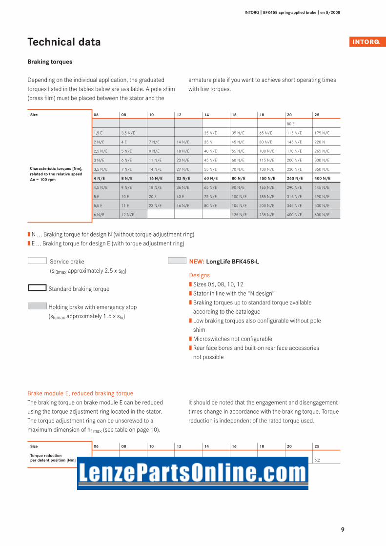
Torque reductionper detent position [Nm] 0.2 0.35 0.8 1.3 1.7 1.6 3.6 5.6 6.2
Technical data
Braking torques
Service brake(slümax approximately 2.5 x slü)
Standard braking torque
Holding brake with emergency stop(slümax approximately 1.5 x slü)
Depending on the individual application, the graduated torques listed in the tables below are available. A pole shim(brass film) must be placed between the stator and the
Brake module E, reduced braking torqueThe braking torque on brake module E can be reducedusing the torque adjustment ring located in the stator.The torque adjustment ring can be unscrewed to a maximum dimension of h1max (see table on page 10).
It should be noted that the engagement and disengagementtimes change in accordance with the braking torque. Torquereduction is independent of the rated torque used.
| N ... Braking torque for design N (without torque adjustment ring)| E ... Braking torque for design E (with torque adjustment ring)
Characteristic torques [Nm], related to the relative speed∆n = 100 rpm
armature plate if you want to achieve short operating timeswith low torques.
NEW: LongLife BFK458-L
Designs| Sizes 06, 08, 10, 12| Stator in line with the “N design”| Braking torques up to standard torque available
according to the catalogue| Low braking torques also configurable without pole
shim| Microswitches not configurable| Rear face bores and built-on rear face accessories
not possible

10
INTORQ I BFK458 spring-applied brake I en 5/2008
slü
Thickness of friction plate: 1.5 mm(sizes 06-16)
Technical data
Brake module E/N + flange + manual release
Size h h1 h1 h2 h3 h4 h5 h5 7) h6 h7 h8 h9 l l15) slü a b6)
min. max. standard max.
06 36.3 39.3 43.25 1 6 15.8 107 – 54.5 23 32.8 56.3 18 400 0.2 25° 12°
08 42.8 46.8 50.8 1.5 7 16.3 116 – 63 23 41.3 65 20 400 0.2 25° 10°
10 48.4 52.4 55.9 2 9 27.4 132 – 73.8 23 42.4 77.8 20 400 0.2 25° 9°
12 54.9 58.9 67.53 2 9 29.4 161 – 85 23 47.4 88.5 25 400 0.3 25° 10°
14 66.3 71.3 77.3 2 11 33 195 – 98 32 50 101.5 30 400 0.3 25° 9°
16 72.5 77.5 85.5 2.25 11 37.5 240 – 113 32 53.5 116 30 600 0.3 25° 10°
18 83.1 89.1 97.09 2.75 11 41.1 279 394 124 32 59.1 128.5 35 600 0.4 25° 9°
20 97.6 104.6 114.6 3.5 11 47.6 319 416 146 32 68.6 149.5 40 600 0.4 25° 10°
25 106.7 115.7 127.7 4.5 12.5 57.7 445 501 170 32 88.7 175.5 50 600 0.5 25° 10°
Size b dJ7 1) dH7 2) d1 d2 d3H7 d5 d6j7 d7 d8 d9H8 d10 d11 d12 d13 d143) d153) d16 di daspec. standard
06 88 10 10/11/12/14/15 3xM4 72 25 91 87 87 52 24 31 8 13 9.6 4xM4 37.7 3x4.5 40 60
08 106.5 10 11/12/14/15/20 3xM5 90 32 109 105 105 60 26 41 8 13 9.6 4xM5 49 3x5.5 47 77
10 132 10 11/12/14/15/20 3xM6 112 42 134 130 130 68 35 45 10 13 12 4xM5 54 3x6.6 66 95
12 152 14 20/25 3xM6 132 50 155 150 150 82 40 52 10 13 12 4xM5 64 3x6.6 70 115
14 169 14 20/25/30 3xM8 145 60 169 165 165 92 52 55 12 24 14 4xM6 75 3x9 80 124
16 194.5 15 25/30/35/38* 3xM8 170 68 195 190 190 102 52 70 12 24 14 4xM6 85 3x9 104 149
18 222 20 30/35/40/45 6xM8 196 75 222 217 217 116 62 77 14 24 15.5 4xM8 95 4x94) 129 174
20 258 25 35/40/45/50 6xM10 230 85 259 254 254 135 72 90 14 24 16.5 4xM10 110 4x114) 148 206
25 302 30 40/45/50/55/60/65/70* 6xM10 278 115 307 302 302 165 85 120 16 24 18.4 4xM10 140 6x11 199 254
| 1) pre-drilled without keyway
| 2) Standard keyway in accordance with DIN 6885/1 P9, selection of the shaft diameter depending on the type of loading (see Operating Instructions)
| * Ø 38 and Ø 70 mm, keyway in accordance with DIN 6885/3 P9
| 3) Bores are made on customer request for sizes 06–12
| 4) The thread in the mounting surface is offset by 30° in relation to the centre axle of themanual release lever
| Dimensions in mm
| 5) Length of the connecting cable
| 6) Manual release angle tolerance +3°
| 7) Recommended lever length for 1.5 MK
| Recommended ISO shaft tolerances: up to Ø 50 mm = k6over Ø 50 mm = m6

11
INTORQ I BFK458 spring-applied brake I en 5/2008
Technical data
Brake module N + centring flange
Brake suitable for mounting a speed or angle sensor
Size h h1 h2 dH7 d11) d2 d3 d45) d5H7 d6h7 d7H7 d8 di da l l12) l2 slümax.
06 42.3 36.3 7 15 3xM4 72 37.7 4xM4 25 95 40 98 40 60 18 400 2 0.2
08 49.8 42.8 8.5 20 3xM5 90 49 4xM5 32 115 50 116 47 77 20 400 2 0.2
10 57.4 48.4 11 20 3xM6 112 54 4xM5 42 140 60 141 66 95 20 400 2 0.2
12 63.9 54.9 11 25 3xM6 132 64 4xM5 50 162 60 165 70 115 25 400 2 0.3
14 76.5 65.5 13 30 3xM8 145 75 4xM6 60 177 80 181 80 124 30 400 2 0.3
16 83.5 72.5 13.25 384) 3xM8 170 85 4xM6 68 204 85 206 104 149 30 600 2 0.3
18 94.1 83.1 13.75 45 6xM8 196 95 4xM8 75 233 90 237 129 174 35 600 2 0.4
20 108.6 97.6 14.5 50 6xM10 230 110 4xM10 85 271 90 274 148 206 40 600 2 0.4
25 118.2 106.7 17 704) 6xM10 278 140 4xM10 115 322 120 324 199 254 50 600 2 0.5
| 1) Use DIN 6912 fixing screws
| 2) Cable length
| 3) Manual release can be mounted as an option, as shown on right of page 10
| 4) Keyway in accordance with DIN 6885/3-P9
| 5) Bores are made on customer request for sizes 06–12
| Dimensions in mm

12
INTORQ I BFK458 spring-applied brake I en 5/2008
Size dH7 d1 d2 d5H7 d6j7 di da H h h1 h2 h3 l l11) l2 slümax.
06 15 3xM4 72 25 87 40 60 84.6 36.3 12 1 48.3 18 400 8.7 0.2
08 20 3xM5 90 32 105 47 77 97.6 42.8 12 1.5 54.8 20 400 9.8 0.2
10 20 3xM6 112 42 130 66 95 109.8 48.4 13 2 61.4 20 400 12.7 0.2
12 25 3xM6 132 50 150 70 115 125.8 54.9 16 2 70.9 25 400 13.1 0.3
14 30 3xM8 145 60 165 80 124 148 65.5 17 2 82.5 30 400 13.1 0.3
16 382) 3xM8 170 68 190 104 149 165 72.5 20 2.25 92.5 30 600 16.4 0.3
18 45 6xM8 196 75 217 129 174 186.2 83.1 20 2.75 103.1 35 600 17.5 0.4
20 50 6xM10 230 85 254 148 206 215.2 97.6 20 3.5 117.6 40 600 17.8 0.4
25 70 6xM10 278 115 302 199 254 238.4 106.7 25 4.5 130.7 50 600 21.5 0.5
| 1) Cable length
| 2) Keyway in accordance with DIN 6885/3-P9
| Manual release as an option
| Dimensions in mm
Technical data
Brake module N + connection flange + brake module N
Noise-reduced designs
The noise reduction required in many applications can beachieved in two ways:
1. Impact-noise-reduced armature plateThe brake's operating noise can be minimised using specialdamping elements, which are installed between the poleface and the armature plate as shock absorbers.
2. Noise-reduced aluminium rotorRattling noises, which can occur in the rotor/hub connec-tion, for example, during frequency inverter operation, or asa result of load alternation, or non-constant speeds, arereduced by using a rotor with a plastic sleeve. The noise-reduced aluminium rotor is for the LongLife designobligatory.
Double brake (double braking torque) as redundant braking system, suitable for use in stage machinery andmany other areas of application

13
INTORQ I BFK458 spring-applied brake I en 5/2008
Size Average braking torque at ∆n0 [rpm] max. speed braking torque on braking [%] ∆n0maxoff ∆n0 to a standstill
[%] 1500 3000 max. [rpm]
06 100 87 80 65 12400
08 100 85 78 66 10100
10 100 83 76 66 8300
12 100 81 74 66 6700
14 100 80 73 67 6000
16 100 79 72 66 5300
18 100 77 70 66 4400
20 100 75 68 66 3700
25 100 73 66 66 3000
Size P1) slü max slü max max. min.2) Jplastic rotor Jaluminium rotor Mass of[20 °C] service brake holding brake adjustment rotor thickness stator
[W] [mm] [mm] [mm] [mm] [kgcm2] [kgcm2] assy [kg]
06 20 0.5 0.3 1.5 4.5 0.11 0.15 0.75
08 25 0.5 0.3 1.5 5.5 0.34 0.61 1.2
10 30 0.5 0.3 1.5 7.5 – 2.0 2.1
12 40 0.75 0.45 2.0 8.0 – 4.5 3.5
14 50 0.75 0.45 2.5 7.5 – 6.3 5.2
16 55 0.75 0.45 3.5 8.0 – 15 7.9
18 85 1.0 0.6 3.0 10.0 – 29 12
20 100 1.0 0.6 4.0 12.0 – 73 19.3
25 110 1.25 0.75 4.5 15.5 – 200 29.1
Braking torques, depending on speed and permissiblelimit speeds
Technical data
Rated data
| 1) Coil power at 20°C in W, possible deviation up to +10%, depending on supply voltage sel-ected
| 2) The friction lining is dimensioned so that the brake can be readjusted at least five times.
As speed increases, so does wear.

14
INTORQ I BFK458 spring-applied brake I en 5/2008
Size Braking torque Maximum permissible Transitional- Switching times [ms] 2)
rating at switching energy at switching at slüRated∆n = 100 rpm single switching operation frequencyMK 1) QE Shü Connection on the DC side Disconnect
[Nm] [J] [h-1] t11 t12 t1 t2
06 4 3000 79 15 13 28 45
08 8 7500 50 15 16 31 57
10 16 12000 40 28 19 47 76
12 32 24000 30 28 25 53 115
14 60 30000 28 17 25 42 210
16 80 36000 27 27 30 57 220
18 150 60000 20 33 45 78 270
20 260 80000 19 65 100 165 340
25 400 120000 15 110 120 230 390
The listed operating times apply to DC switching with ratedair gap slü and a warm coil. The times are mean values whichmay vary depending on the method of rectification
and the air gap slü. The engagement time t1 is approximately10 times higher for AC switching than for DC switching.
| 1) Minimum braking torque for run-in friction pairs
| 2) Operating times valid for 205 V DC coils
AC switching
DC switching
t11 = Delay time
t12 = Rise time ofbraking torque
t1 = Engagement timet2 = Disengagement timet3 = Slipping time
Torque time characteristic, dependent onexcitation voltage
Cha
ract
eris
tic to
rque
Exci
tatio
n
Time
Time
Technical data
Operating times

15
INTORQ I BFK458 spring-applied brake I en 5/2008
Technical data
Permissible friction energy Qzul depending on operating frequency Sh
Service life and wear
The brake has to be adjusted when slümax is reached. Thefriction energy to be withstood up to this point is dependenton a number of factors: in particular, the inertias to be bra-ked, the braking speed, the operating frequency and theresulting temperature on the friction surfaces. For this rea-son, no universal value for all operating conditions can begiven in respect of the amount of friction energy that canbe handled before adjustment is required.
In addition, increased wear should be expected with vertical mounting.
The BFK458 can be adjusted when the maximum permissi-ble working air gap is reached (slümax). The dimensioning ofthe friction lining allows adjustment to be carried out atleast five times.
Where the amount of friction energy per switching operati-on is low, the brake's mechanical components can imposelimitations in terms of service life. In particular, therotor/hub connection, springs, armature plate and sleevesare subject to operational wear. The expected service life ofthe standard design is around 1 million load alternations.Solutions that are optimised in terms of service life areavailable in cases where a longer service life is required(consult the manufacturer).
MaintenanceBrakes are components which are subject to a great deal ofwear. When installing the brake, it must be ensured that itcan be easily accessed for inspection and maintenancepurposes. Intervals between inspections should be set inaccordance with the expected service life and load. Formore information, please see the Operating Instructions.
LongLife Spring-applied brake INTORQ BFK458-L
Guaranteed performance data| Guaranteed service life of brake mechanism:
10x106 repetitive cycles of operation15x106 reversing cycles of operation
| The brake warranty covers either two years or the guaranteed number of cycles – whichever is reached first.
| The scope of the warranty in the event of premature failure covers replacement of the brake, including a flat-rate replacement fee.
2520
18
16 1412
10
08
06
Sh [h-1]
105
104
103
102
Qzu
lin [J
]
Sizes
1 10 102 103 104
10
16
INTORQ I BFK458 spring-applied brake I en 5/2008
slü
Accessories
Flange Friction plate (sizes 06 – 16)
Manual release
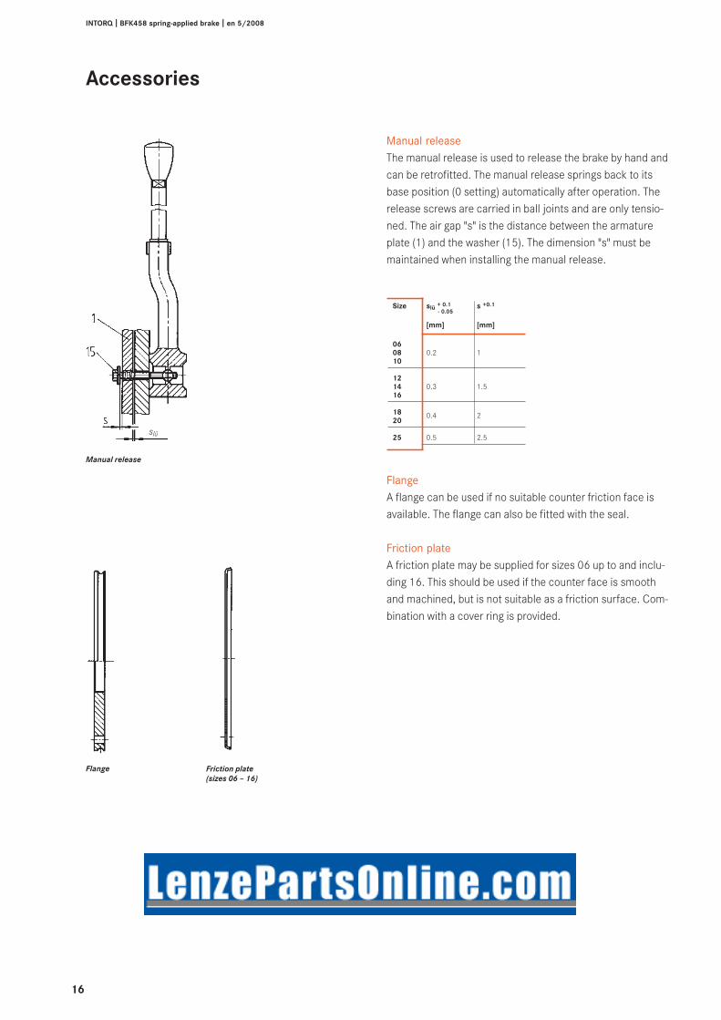
Size slü + 0.1 s +0.1- 0.05
[mm] [mm]
0608 0.2 110
1214 0.3 1.516
18 0.4 220
25 0.5 2.5
Manual releaseThe manual release is used to release the brake by hand andcan be retrofitted. The manual release springs back to itsbase position (0 setting) automatically after operation. Therelease screws are carried in ball joints and are only tensio-ned. The air gap "s" is the distance between the armatureplate (1) and the washer (15). The dimension "s" must bemaintained when installing the manual release.
FlangeA flange can be used if no suitable counter friction face isavailable. The flange can also be fitted with the seal.
Friction plateA friction plate may be supplied for sizes 06 up to and inclu-ding 16. This should be used if the counter face is smoothand machined, but is not suitable as a friction surface. Com-bination with a cover ring is provided.

17
INTORQ I BFK458 spring-applied brake I en 5/2008
Centring flange (tacho brake)Brake module N combined with a centring flange is suitablefor mounting a tachogenerator.
Connection flange (double brake)The connection flange can be used to adapt a second brakemodule to brake module N; the resulting double brake is sui-table for use in stage machinery or other applications withincreased safety requirements.
SealTo a large extent, the seal prevents the exit or ingress ofdust, humidity, dirt, etc., out of or into the braking area. Theseal is inserted into the groove on the stator. If no suitablegroove is available on the counter friction face, we recom-mend the use of a flange.
SealConnection flangeCentring flange
Accessories

18
INTORQ I BFK458 spring-applied brake I en 5/2008
Brake module E, N + cover = encapsulated designA cover can be mounted onto brake module E and brakemodule N as an option, to protect the brake from water anddust (enclosure to IP 65). This design is not available in con-junction with manual release.
Accessories
Brake cover
Size d1 d2 d3H8 d4 d5 h h1 h2 h31)
06 135 120 98 4x5.5 M16x1.5 55 28 16.5 3
08 155 142 118 4x5.5 M20x1.5 61 34 20 3
10 185 166 143 4x5.5 M20x1.5 72 39 21 3
12 205 192 163 4x6.6 M20x1.5 82 42 23 3
14 225 212 183 4x6.6 M20x1.5 92 51 24 3
16 250 236 208 4x6.6 M20x1.5 98 52 25 3
18 285 268 238 4x6.6 M20x1.5 115 60 29 3
20 330 314 283 4x9 M20x1.5 131 69 35 3
25 390 368 328 4x9 M20x1.5 142 78 40 3
| 1) Recommended recess length on motor endshield
19
INTORQ I BFK458 spring-applied brake I en 5/2008
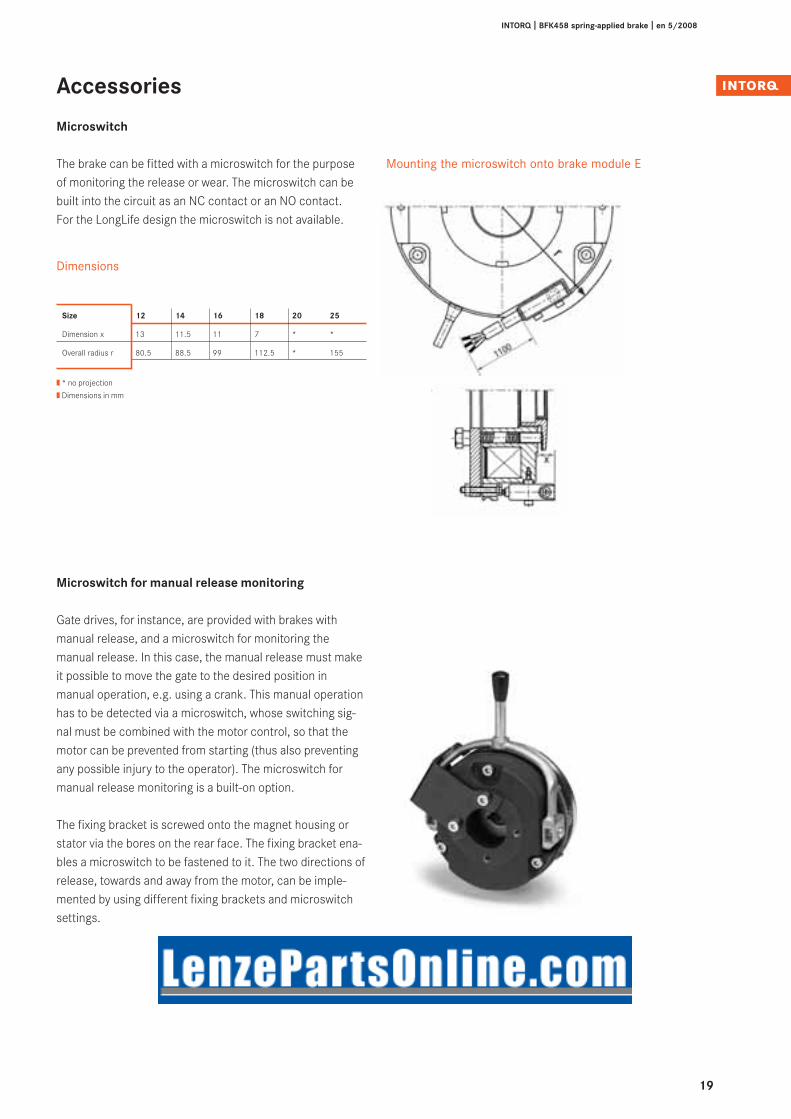
The brake can be fitted with a microswitch for the purposeof monitoring the release or wear. The microswitch can bebuilt into the circuit as an NC contact or an NO contact. For the LongLife design the microswitch is not available.
Dimensions
Mounting the microswitch onto brake module E
Accessories
Microswitch
Size 12 14 16 18 20 25
Dimension x 13 11.5 11 7 * *
Overall radius r 80.5 88.5 99 112.5 * 155
| * no projection
| Dimensions in mm
Microswitch for manual release monitoring
Gate drives, for instance, are provided with brakes withmanual release, and a microswitch for monitoring themanual release. In this case, the manual release must makeit possible to move the gate to the desired position inmanual operation, e.g. using a crank. This manual operationhas to be detected via a microswitch, whose switching sig-nal must be combined with the motor control, so that themotor can be prevented from starting (thus also preventingany possible injury to the operator). The microswitch formanual release monitoring is a built-on option.
The fixing bracket is screwed onto the magnet housing orstator via the bores on the rear face. The fixing bracket ena-bles a microswitch to be fastened to it. The two directions ofrelease, towards and away from the motor, can be imple-mented by using different fixing brackets and microswitchsettings.

20
INTORQ I BFK458 spring-applied brake I en 5/2008
The connecting cables can easily be integrated into higher-level controls via the terminal box (brake sizes 12-25) inorder to support different wiring options (threeinputs/outputs). 2/4-pole terminal strips, half-wave andbridge rectifiers and a microswitch connection can be inte-grated into the terminal box.
The terminal box is shownoffset by 30°.
The terminal box is mounted onto the spring-applied brakeusing a fixing bracket and screws, as shown in the illustrati-on. You can select the mounting angle accordingto your requirements by using the assembly kit.
Accessories
Terminal box
Size 12 14 16 18 20 25
b -5 5.5 12.5 23 37.5 45.5
h 122 130 142 155 174 198
r 126 134 146 158.5 177 201
| Dimensions in mm

21
INTORQ I BFK458 spring-applied brake I en 5/2008
Parallel to contact
Parallel to coil
Type code B E G – 5 6 1 – 440
BrakeElectronicRectifier
1 Bridge rectifier2 Half-wave rectifier5 Bridge rectifier/half-wave rectifier
4-pole6-pole
1-Mounting position horizontal2-Mounting position vertical3-Mounting position horizontal with snap-in stud
440 440 V voltage
Accessories
Bridge rectifiers and half-wave rectifiers
INTORQ 14.198.00.0ò universal spark suppressor
The universal spark suppressor limits the induced voltagearising when inductive direct current consumers are swit-ched off on the DC side. These induced voltages can dama-ge coils and switches. VDE 0580 therefore requires that, inorder to avoid impermissibly
high switch off voltages and overvoltages, suitable protec-tive measures must be provided by the user. The universalspark suppressor is available in 4 versions for the followingvoltage ranges:
INTORQ Coil Max. mains Max. coil Capacitor b1 b2 d e h l1 l2 mvoltage voltage power voltage approx. approx. approx. [g]
14.198.00.01 24 V – 50 V 60 V~ 110 W 250 V- 8.5 12.5 0.7 22.5 18.5 26.5 25 7
14.198.00.02 50 V – 120 V 250 V~ 110 W 630 V- 15 21 0.7 37.5 26 41.5 20 22
14.198.00.03 120 V – 200 V 400 V~ 110 W 1000 V- 13 20 0.7 37.5 24 41.5 15 17
14.198.00.04 200 V – 250 V 555 V~ 110 W 1000 V- 13 20 0.7 37.5 24 41.5 15 10
Dimensions Wiring example

22
INTORQ I BFK458 spring-applied brake I en 5/2008
4-pole bridge rectifierBEG-142-270BEG-143-270
Application areaCurrent supply for spring-applied brakes from AC mains (nor-mal excitation).Example: 205 V coil on 230 V mains
Technical dataMax. mains voltage 270 V~Max. DC current at 60°C 1.0 AMax. ambient temperature 80°C
The rectifiers are protected against overvoltage by input andoutput varistors.
BEG-142/143-270
Ug =U~ =
230 V~ = 205 V1.11 1.11
Ug =U~ =
400 V~ = 180 V2.22 2.22
4-pole half-wave rectifierBEG-242-555BEG-243-555
Application areaCurrent supply for spring-applied brakes from AC mains (nor-mal excitation).Example: 180 V coil on 400 V mains
Technical dataMax. mains voltage 555 V~Max. DC current at 60°C 1.0 AMax. ambient temperature 80°C
The rectifiers are protected against overvoltage by input andoutput varistors.
BEG-142/143-270BEG-242/243-555
Accessories
4-pole bridge rectifier and 4-pole half-wave rectifier
Dimensions

23
INTORQ I BFK458 spring-applied brake I en 5/2008
Accessories
6-pole bridge rectifier
Dimensions
BEG-162-270 BEG-161-270
6-pole bridge rectifierBEG-162-270BEG-161-270
Application areaCurrent supply for spring-applied brakes from AC mains(normal excitation).Example: 205 V coil on 230 V mains
Technical dataMax. mains voltage 270 V~Max. DC current at 60°C 0.75 AMax. ambient temperature 80°CThe rectifiers are protected against overvoltage by input andoutput varistors.
BEG-162-270/161-270/262-460/261-460 rectifiers alsocontain the spark suppressors required by VDE 0580 Section 26.
Ug =U~ =
230 V~ = 205 V1.11 1.11
BEG-161-270BEG-162-270

24
INTORQ I BFK458 spring-applied brake I en 5/2008
Accessories
6-pole half-wave rectifier
Dimensions
6-pole half-wave rectifierBEG-262-460BEG-261-460BEG-262-555 BEG-261-555
Application areaCurrent supply for spring-applied brakes from AC mains(normal excitation).Example: 180 V coil on 400 V mains
Technical dataMax. mains voltage 555 V~ / 460 V~Max. DC current at 60°C 0.75 AMax. ambient temperature 80°C
The rectifiers are protected against overvoltage by input andoutput varistors. BEG-162-270/161-270/262-460/261-460 rectifiers also contain the spark suppressor requi-red by VDE 0580 Section 26.
Ug =U~ =
400 V~ = 180 V2.22 2.22
BEG-262-460 BEG-261-460BEG-262-555 BEG-261-555
BEG-261-460BEG-262-460

25
INTORQ I BFK458 spring-applied brake I en 5/2008
Accessories
Fixing options4-pole rectifier
Brake
or
Guide
Snap-in stud
Bore Ø 4.3
1 to 3 mm thick
Guide
or
Fixing options6-pole rectifier

26
INTORQ I BFK458 spring-applied brake I en 5/2008
Accessories
Connection diagrams
DC switching
AC switching
Bridge rectifierBEG-162-270BEG-161-270
Bridge rectifierBEG-142-270BEG-143-270
Bridge rectifierBEG-142-270BEG-143-270
half-wave rectifierBEG-262-460BEG-261-460
half-wave rectifierBEG-242-555BEG-243-555
half-wave rectifierBEG-242-555BEG-243-555
with half-wave rectifier BEG-262-460BEG-261-460Coil 103 V
180 V
180 V
with half-wave rectifier BEG-242-555BEG-243-555Coil 103 V
with half-wave rectifier BEG-242-555BEG-243-555Coil 103 V
Also for star connection
Also for star connection
Also for star connection
Also for star connection
180 V
AC switching parallel to the motor

27
INTORQ I BFK458 spring-applied brake I en 5/2008
Accessories
Mains voltage selection table
AC Rectifier Rectifier type Spark suppressor Rectifier type Coilvoltage 4-pole 6-pole rated
voltage
[V] 1 A at 60°C INTORQ 0.75 A at 60°C [V]
42 V Half-wave BEG-243/242-555 14.198.00.01 BEG-262/261-460 20 V
48 V Bridge BEG-142/143-270 14.198.00.01 BEG-162/161-270 42 VHalf-wave BEG-243/242-555 14.198.00.01 BEG-262/261-460 20 V
110 V Bridge BEG-142/143-270 14.198.00.02 BEG-162/161-270 103 V
220 V Bridge BEG-142/143-270 14.198.00.04 BEG-162/161-270 205 VHalf-wave BEG-243/242-555 14.198.00.02 BEG-262/261-460 103 V
230 V Bridge BEG-142/143-270 14.198.00.04 BEG-162/161-270 205 VHalf-wave BEG-243/242-555 14.198.00.02 BEG-262/261-460 103 V
240 V Bridge BEG-142/143-270 14.198.00.04 BEG-162/161-270 215 VHalf-wave BEG-243/242-555 14.198.00.02 BEG-262/261-460 103 V
255 V Bridge BEG-142/143-270 14.198.00.04 BEG-162/161-270 225 V
277 V Half-wave BEG-243/242-555 14.198.00.03 BEG-262/261-460 127 V
290 V Half-wave BEG-243/242-555 14.198.00.03 BEG-262/261-460 127 V
380 V Half-wave BEG-243/242-555 14.198.00.03 BEG-262/261-460 180 V
400 V Half-wave BEG-243/242-555 14.198.00.03 BEG-262/261-460 180 V
415 V Half-wave BEG-243/242-555 14.198.00.03 BEG-262/261-460 180 V
420 V Half-wave BEG-243/242-555 14.198.00.03 BEG-262/261-460 180 V
440 V Half-wave BEG-243/242-555 14.198.00.04 BEG-262/261-460 205 V
460 V Half-wave BEG-243/242-555 14.198.00.04 BEG-262/261-460 205 V
480 V Half-wave BEG-243/242-555 14.198.00.04 BEG-262/261-555* 215 V
500 V Half-wave BEG-243/242-555 14.198.00.04 BEG-262/261-555* 225 V
555 V Half-wave BEG-243/242-555 14.198.00.04 BEG-262/261-555* 250 V
Rectifier type and rated coil voltage formains voltage
| * Spark suppressor without capacitor. For optimum interference suppression, we recommendthe use of spark suppressor 14.198.00.04.
Max. rated coil voltage: 250 VStandard coil rated voltages: 24, 96, 103, 170, 180, 190, 205 V

28
INTORQ I BFK458 spring-applied brake I en 5/2008
+ ML = to be used when lowering a load, for example– ML = for normal braking
Dimensioning
Basic information
The size of a brake is largely determined by the requiredbraking torque Merf. The inertias to be braked (moments ofinertia), the relative speeds, the braking times and the ope-rating frequencies also have to be considered in the calcula-tions. Marginal conditions, such as ambient temperature,air humidity, dust and mounting position should be known.In the event of extreme/critical operating conditions, plea-se consult the manufacturer. Selection takes place in accor-dance with VDI rule 2241.
Friction surfaces must always be kept free of oil andgrease. For explanations of the terms used in the calculation, plea-se refer to the list of abbreviations on page 5.
Safety factorTo ensure the necessary transmission security even underextreme operating conditions, the calculated braking torqueis multiplied by safety factor K, which depends on the ope-rating conditions.
Load typesIn practice, the following load types mainly occur:
Merf = Ma · K � MK
Merf = (Ma ± ML ) · K � MK
Merf = JL · ∆n0
± ML · K � MK9.55 · t3
t12(2
)
Dynamic plus static loadMost applications belong to this category, as in most casesthere is not only a static torque but also a dynamic load.
Merf = 9550P
· K � MK∆n0
Approximate determination of the required braking tor-que and the sizeIf only the drive power to be transmitted is known, the requi-red torque or braking torque can be determined as follows:
Thermal loadFor high operating frequencies and friction ener-gy/switching cycle, the brake should be subject to thermalchecking. The friction energy per switching cycle is calcula-ted as follows:
– ML = to be used when lowering a load, for example+ ML = for normal braking
The permissible friction energy per switching cycle at agiven operating frequency can be taken from the diagramson page 14. If the friction energy per switching cycle is kno-wn, the permissible operating frequency can be taken fromthe diagrams mentioned above.
K � 2
Q =JL · ∆n02
·MK
Merf = · Kt3 –
t12
2
· ∆n0JL
( )9.55 ·
Ma =t3 –
t12
2
· ∆n0JL
( )9.55 ·
182.5 MK ± ML
( )

29
INTORQ I BFK458 spring-applied brake I en 5/2008
Merf = –15 · 2 = 50 Nm
Dimensioning
Calculation example
The following technical data is known:P = 3 kW∆n0 = 1450 rpmJL = 0.52 kgm2 totalt3 = 2 sML = 15 NmSh = 6 operations/h
Approximate determination of the required braking torqueand the size:
Merf = 9550 P
· K∆n0
Merf = 95503
· 2 = 40 N1450
Assume INTORQ BFK458-14
Calculating the required braking torque
t12 = 0.025 s (see page 14)
Therefore, INTORQ BFK458-14 is chosen.
MK = 60 Nm > Merf = 50 Nm
( )
( )
Thermal checking
Calculated switching energy Q = 4792 J/switching cycleThe diagram on page 14 shows a permissible switchingenergy of 30,000 J for size 14 at Sh = 6 h-1.
Q = 4792 J < Qzul = 30000 J
Therefore, the brake has been selected correctly.
Ordering exampleBrake type INTORQ BFK458-14E or design N (with or with-out torque adjustment ring) is required, with additionalmanual release and seal.
Supply voltage 205 V = shaft diameter 25 mm.
INTORQ BFK458-14E, 205 V =, d = 25 mm
Q =0.52 · 14502
· 60
182.5 (60 + 15)
0.52 · 1450
9.55 · 2–0.025
2
Q = JL · ∆n02
·MK
182.5 MK ± ML
= 4792 J
Merf = – MLt3 –
t12
2
· ∆n0JL
( )9.55 · · K

30
INTORQ I BFK458 spring-applied brake I en 5/2008
INTORQ BFK458-òòò
Complete stator
Order quantity Number
Size ò 06 ò 08 ò 10 ò 12 ò 14 ò 16 ò 18 ò 20 ò 25
Type ò E (with torque adjustment ring)ò N (without torque adjustment ring)ò L (LongLife design)
Voltage ò 24 V ò 96 V ò 103 V ò 170 V ò 180 V ò 190 V ò 205 V
Braking torque Nm (see graduated torques)
Cable length ò Standardmm (from 100 mm – 1000 mm in 100 mm steps,
from 1000 mm – 2500 mm in 250 mm steps)
Manual release ò Assembled
Armature plate ò Standard ò Hard-chromium plated (from size 06) ò Noise-reduced* (O-ring design)
ò With pole shim/brass film
Microswitch* ò Operation monitoring (size 12 and above)ò Wear monitoring (size 12 and above)ò Manual release monitoring, direction of release away from motor (sizes 06-25)ò Manual release monitoring, direction of release towards motor (sizes 06-10)
Terminal box* ò Mounted (from size 12)
* not available for LongLife design
Recipient: INTORQ GmbH & Co. KGWülmser Weg 5 · D-31855 AerzenFax +49 (0 )51 54 95 39 10
Sender
Company Customer no.
Street/PO Box Order no.
Post code/City Issuer
Delivery address* Telephone
Fax
Invoice recipient* Date of delivery
* Please specify, if different from sender. Date Signature
Order form
INTORQ BFK458 spring-applied brake with accessories

31
INTORQ I BFK458 spring-applied brake I en 5/2008
Order form
Accessories
Rotor ò Plastic ò Aluminium ò Silenced(only for size 06/08) (rotor with sleeve)
Low wear rotor ò Aluminium ò Silenced(rotor with sleeve)for LongLife designobligatory
Hub mm (for bore diameter, see Dimensions)
Fixing ò For mounting onto the flangescrew set ò For mounting onto the motor/friction plate
ò For flange with through hole (up to and including size 16)ò For connection flange/double brake
Manual release ò as mounting kit
Terminal box* ò as mounting kit
Flange ò Friction plate (up to and including size 16)ò Flangeò Tachometer flangeò Connection flange double brake
Sealing ò Sealò Shaft sealing ring (shaft diameter on request)ò Capò Brake cover
Electrical accessories
Bridge rectifier ò 4-pole without snap-in studò 4-pole with snap-in studò 6-pole vertical, integrated spark suppressorò 6-pole horizontal, integrated spark suppressor
Half-wave rectifier ò 4-pole without snap-in studò 4-pole with snap-in studò 6-pole vertical, integrated spark suppressorò 6-pole horizontal, integrated spark suppressor
Spark suppressor ò
* not available for LongLife design

setting the standard
www.intorq.de
1325
0492
Tech
nica
l alte
ratio
ns r
eser
ved
IPrin
ted
in G
erm
any
5.20
08 e
n I5
4 3
2 1
INTORQ GmbH & Co. KG
PO Box 1103D-31849 Aerzen, Germany
Wülmser Weg 5D-31855 Aerzen, Germany
Tel.: +49 (0) 5154 95 39 01Fax: +49 (0) 5154 95 39 10E-mail: [email protected]
INTORQ customers can reach us atany time and from anywhere in theworld. Our Key Account Sales Teamlooks after key account customersand project business.
In addition, we co-operate withLenze's global sales organisation. You can contact us via Lenze Serviceby calling the 24-hour helpline(008000 24 46177).
INTORQ – Sales and Servicearound the world


![INTORQ BFK458 Spring-applied brake · 2015. 7. 22. · 1 [s] Engagement time, t 1 = t 11 + t 12 t 2 [s] Disengagement time (time from the beginning of the torque reduction until 0.1](https://img.dokumen.tips/doc/110x75/60ec2a6a0c631d665a65ea6b/intorq-bfk458-spring-applied-brake-2015-7-22-1-s-engagement-time-t-1-t.jpg)