Embed Size (px)
Citation preview

OWNER’S MANUAL
FOR THE
SPRAYRIDER™ G e n e r a t i o n 2
ATV MOUNTED SPRAYERS
C-Dax Ltd
PO Box 1010, 145 Harts Road
Tiritea, Palmerston North
Ph:06 354 6060
Fax:06 355 3199
E-Mail: [email protected]
www.c-dax.com

2
SAFETY PRECAUTIONS
SPRAYRIDER™
AN IMPORTANT MESSAGE FOR OWNERS & OPERATORS OF
C-Dax ATTACHMENTS/ACCESSORIES
Be warned of the dangers of loading your ATV or other vehicle in excess of its carrying capacity. It is
important to understand that any loads or attachments whether fastened to or placed on a vehicle or ATV will
alter the stability or handling characteristics of that vehicle or ATV.
Spray tanks or other equipment must be filled only to a level where the gross weight is within the load limit of
the ATV or other vehicle.
Safety is a primary concern in the design, manufacture, sale, and use of spray tanks and other equipment. As
manufacturers of spray tanks and other equipment we want to confirm to you, our customers, our concern for
safety. We take this opportunity to remind you about the simple, basic and common sense rules of safety
when using spray tanks and other equipment. Failure to follow these rules can result in severe injury or death
to operators and bystanders.
It is essential that everyone involved in the assembly, operation, transport, maintenance and storage of this
equipment be aware, concerned, prudent and properly trained in safety.
This also applies to equipment that is loaned or rented to someone who has not read the owner’s manual and
is not familiar with the operation of application equipment.
• NEVER EXCEED THE LOAD LIMIT CAPACITY OF THE ATV OR OTHER VEHICLE.
• ALL ATV AND TRAILED EQUIPMENT TYRES SHOULD BE INFLATED TO MANUFACTURERS
RECOMMENDED OPERATING PRESSURES.
• PLEASE NOTE THAT FILLING THE SPRAY TANK OR OTHER EQUIPMENT COMPLETELY AND OR
THE ATTACHMENT OF ADDITIONAL EQUIPMENT TO THE ATV MAY EXCEED THE ATV’S MAXIMUM
LOAD CAPACITY, AND ADVERSELY AFFECT THE STABILITY OF THE ATV OR OTHER VEHICLE.
• CARGO SHOULD BE PROPERLY DISTRIBUTED AND SECURELY ATTACHED.
• REDUCE SPEED WHEN CARRYING CARGO OR PULLING A TRAILER OR TRAILED APPLICATION
EQUIPMENT AND ALLOW GREATER DISTANCE FOR BRAKING.
• NEVER ALLOW ANYONE TO RIDE ON YOUR SPRAYER OR OTHER EQUIPMENT.
• ALWAYS FOLLOW THE INSTRUCTIONS IN THE OWNER’S VEHICLE MANUAL FOR CARRYING
CARGO OR PULLING A TRAILER.
• PROPER MAINTENANCE IN LINE WITH MANUFACTURER’S RECOMMENDED MAINTENANCE
PROCEDURES IS ESSENTIAL.
• BEFORE APPLYING CHEMICALS, READ THE LABEL OF THE CHEMICAL MANUFACTURER OR
SUPPLIER FOR PERSONAL PROTECTIVE EQUIPMENT AND OPERATE AS RECOMMENDED.
• THE SAFETY OF ALL CHEMICALS USED IN AGRICULTURE IS UNDER THE JURISDICTION OF A
GOVERNMENT AGENCY, IE N.Z. MINISTRY FOR THE ENVIRONMENT; USA ENVIRONMENTAL
PROTECTION AGENCY. FURTHER LOCAL GOVERNMENT OR STATE LAWS MAY APPLY.
Throughout this manual there are highlighted text boxes containing warnings, cautions and notes.
Warnings are mandatory instructions to prevent serious injury or permanent damage.
Cautions are advisory instructions to ensure reliable operation of the equipment.
Notes are for convenient operation.
WARNING
To reduce the chance of ATV instability, it is recommended that the ATV be stationary while spot spraying on a
slope or hillside.
WARNING
C-Dax asks that you think of your dogs welfare when spraying by keeping them clear of spray zones,
specifically when using the SR35.
3
C-Dax SPRAYRIDER™
ATV MOUNTED SPRAYERS
OWNER’S MANUAL (Pt.No.2400-6900 Issue 26, Dated 16 Dec 2010)
TABLE OF CONTENTS
2 Safety Precautions
3 Contents
4 Introduction
Description
Specifications
5 Order Information
Optional Equipment
7 Warranty
Liability
8 ATV Compatibility
Installation
All Models
Battery Cable
9 Switch Mounting
Fitting the Tank
10 Ratchet Strap
Vacuum Release Valve
11 Spray Gun
12 Theory of Operation
Operating Instructions
13 Hand Washing
Chemical Application
Chemical Advice
14 Operating Hints
15 Routine Maintenance
Cleaning
Filters
16 Removal of the Sprayrider™
Lubrication of the Spray Lance
Care of Protective Clothing
17 Removing the Pump
Installing the Pump
18 Troubleshooting
19 SR50/80 Parts Diagram
20 SR50/80 Parts List
22 SR35 Parts Diagram / List
23 HGSR Spray Gun Parts Diagram
24 FLOJET Spray Pump Repair Kits

4
INTRODUCTION
Congratulations on the purchase of your new Sprayrider™ spot sprayer. The C-Dax Sprayrider™ has become
the industry-standard for ATV mounted sprayers. You join the many thousands of farmer’s worldwide who have
recognised the remarkable usefulness of this unique equipment.
DESCRIPTION
The C-Dax Sprayriders™ Generation 2 are a high strength series of spray tanks manufactured of non-
corrosive polyethylene designed for mounting on front or rear ATV carriers. All units come complete with 12V
pumps, rugged spray guns, and a unique fresh-water wash tank (not applicable to the SR35). Sprayriders™
are compatible with a full range of
C-Dax sprayer accessories including both pressure nozzle and CDA spray booms.
SPECIFICATIONS
(Specifications subject to change without notice)
Dry Weight SR 35 – 8.5 Kg
SR 50 - 12.5 Kg
SR 80 - 13.5 Kg
Dimensions
Power Consumption 12 VDC 6A (Nominal)
Pump 12 VDC Flojet 7.6LPM 60PSI.
Tanks Non-Corrosive, medium density, UV stabilised polyethylene. Ergonomically
designed for maximum comfort, low center of gravity, and ease of filling and
evacuation.
Filtration Triple filter system comprising; fine mesh tank strainer, large capacity 50
mesh
suction filters, and spray gun filter.
Controls Remote toggle switch for handlebar mounting.
Spray gun 600mm lance-style spray gun with adjustable brass tip.
Hose & Spray gun stowage Each tank provides for 10m of hose stowage and a unique stowage for the
spray gun
SR35 has 3m of self store hose
Non slip dog mat Fitted to the SR35 only
Design Registrations
NZ SR50/80 Tank NZ Reg. Des. 401788
Auxiliary Tank NZ Reg. Des. 401787
AUSTRALIA SR50/80 Tank AU Reg. Des. 148626
Auxiliary Tank AU Reg. Des. 150562
UK SR50/80 Tank GB Reg. Des. 3000349
Auxiliary Tank GB Reg. Des. 3000348
Patent Registrations
NZ A Valve NZ Patent No. 528794
Width Height above carrier Length Capacity
SR35 1000mm 200mm 600mm 35 litres
SR 50 950mm 220mm 930mm 51 litres
SR 80 950mm 275mm 1025mm 81 litres

5
ORDER INFORMATION
Sprayrider NZ, AUS, UK
SR35 Pt. No. 1000
SR50 Pt. No. 1001
SR80 Pt. No. 1002
OPTIONAL EQUIPMENT
Dual Tank Kit
A second tank to increase the carrying capacity and spraying time of your Sprayrider™. Available in 2 tank
sizes. Not applicable to SR35 NZ, AUS, UK
DTK50 Pt.No. 1003
DTK80 Pt.No. 1004
Flat Fan Tip
An alternative to the adjustable tip on the spray gun.
Order: Pt.No. 5300-7700
HG2 Pistol Spray Gun
An alternative to the standard spray lance.
Order: HG2(1.5)HSK Pt.No.4000-3900
Quick Release Valve Kit; (SR50/80 only)
Allows convenient exchange of accessories.
Order: Pt.No.4500-2200
Pressure regulator Kit
Allows control over spraying pressure and recirculation of the tank contents.
Order: CU2SRG2 Pt.No.5210-1600

6
NOTE
SR35 is a spot sprayer only and would not be suitable for boom spraying
Pressure Nozzle Spray Booms
Convert your Sprayrider™ to a convenient pressure nozzle sprayer complete with self returning breakaway
protection, diagonal fold.
NZ, AUS, UK Boom 3m (Covers 3m) Pt.No.1019
Boom 4m (Covers 4m) Pt.No.1020
Convert your Sprayrider™ to a compact, robust firebreak sprayer with adjustable spray width from 1.5-4.5
metres.
NZ, AUS, UK Multiboom Pt.No.1018
Controlled Droplet Applicators
Convert your Sprayrider™ to an efficient Controlled Droplet Applicator (CDA) boom sprayer. A low-volume
sprayer with reduced drift, reduced run off, and increased range (spray 3 ha on a 50L tank).
NZ, AUS, UK
Boom CDA 3.6m Pt.No.1021
Boom CDA 5.4m Pt.No.1022
Convert your Sprayrider™ to an efficient low-volume CDA band sprayer. Adjustable band width and band
spacing. Spray 17.5Km of 1.2M band at 8kph on a 50L tank. Complete with breakaway protection, electric
remote controls.
NZ, AUS, UK
HYD2 Pt.No.1023
(Double band)
HYD3 Pt.No.1024
(Triple band)
QuickSmart Attachment Frame
C-Dax’s QuickSmart Attachment Frame is a universal mounting system that allows implements to be inter-
changed without the need for nuts, bolts and spanners.
QuickSmart Attachment Frame Pt.No.1073
QuickSmart Attachment Upright Mounts for booms only Pt.No.1074

7
WARRANTY
C-Dax Ltd warrants to the original purchaser that the equipment is sold free from defects in materials and
workmanship for a period of 12 months from date of retail sale (6 Months from date of retail sale for all
equipment sold in the U.K.).
Accordingly, C-Dax Ltd undertakes to repair the equipment, or at our option replace, without cost to the original
purchaser either for materials, parts or labour, any part which within the specified warranty period from time of
delivery is found to be defective. PROVIDED that the equipment has been used for normal purposes in
accordance with the instructions, and has not been subject to neglect, misuse or accident, and has not been
repaired, serviced or dismantled by any person other than a service agent or person authorised by C-Dax Ltd.
The warranty does not extend to cover: consequential damage; repair or replacement of parts due to fair wear
and tear; or damage resulting from neglect, misuse, accident or hireage. SPECIFICALLY the warranty
excludes battery damage, damage arising from chemical attack, and units built to customers specifications.
All goods returned to C-Dax Ltd are freight paid by the sender and if subject to a warranty claim, must be
accompanied by a completed warranty claim form. Warranty claim forms are available from C-Dax dealers.
LIABILITY
The maximum liability, which is accepted by C-Dax Ltd, is limited to replacement of faulty goods only. Every
care has been taken in the manufacture of our goods but because use of the goods is outside the control of
the manufacturer, the end user assumes all responsibility for the use. Neither the manufacturer nor retailer
shall be liable for loss or damage resulting from use.
Any advice or recommendations given by C-Dax Ltd, its agents, or employees is given in good faith and based
on the best information available to us. No liability or responsibility is accepted or implied as a result of any
information or advice tendered by C-Dax Ltd, its agents or employees. The end user accepts all responsibility
arising from that advice.

8
ATV COMPATIBILITY
The Sprayrider™ Generation 2 models have been designed to fit the widest range of ATVs. At time of release
the Generation 2 models were designed to fit all available Honda, Yamaha, Suzuki, Kawasaki, Polaris and
Bombadier models available in New Zealand.
For reasons of stability it is not recommended that 80L models be fitted on the front of your ATV.
50 litre models fitted on the front of ATVs where there is a gear lever mounted on the guard , must be offset to
the left to allow the transmission lever to be placed in the park position.
SR35 is best suited for rear carrier mounting, mounting to front carriers may cause tank failure.
INSTALLATION
All Models
Unpack the sprayer and check the contents. The following parts are included (Some parts are packed inside
the tank);
Tank unit with pump and cover(no cover on SR35 units), suction valves and hoses, filter basket and
lid
Auxiliary tank unit (not fitted to SR35) and delivery hose Battery cable assembly (includes remote switch)
Vacuum release valve
Spray gun (lance and handle may be disassembled)
Ratchet tie down strap
Operators manual
CAUTION
To avoid damage do not attempt to remove the suction hoses from inside the tank.
Battery Cable
Locate the battery cable and attach it directly to the ATV battery terminals.
CAUTION
To avoid damage to Sprayrider™ accessories take care to ensure that the red wire is connected to the
positive terminal.

9
Switch Mounting
Route the cable from the battery compartment to the Sprayrider™ location taking care to avoid hot
components and places where the cable can get pinched. The wire coming out of the fuse holder should be
straight. Mount the C-Dax remote on/off switch in a convenient position onto the handlebars of the ATV.
Mounting the switch on the left hand side leaves your right hand free to operate the throttle control.
WARNING
To avoid the risk of fire, do not remove the fuse holder from the circuit or replace the fuse with one rated
higher than 15A.
Fitting the Tank
Place the tank on the carrier and ensure the base of the tank sits flat on the carrier.
CAUTION
To avoid adversely affecting the handling of the ATV do not install an 80 litre model on the front carrier.
10
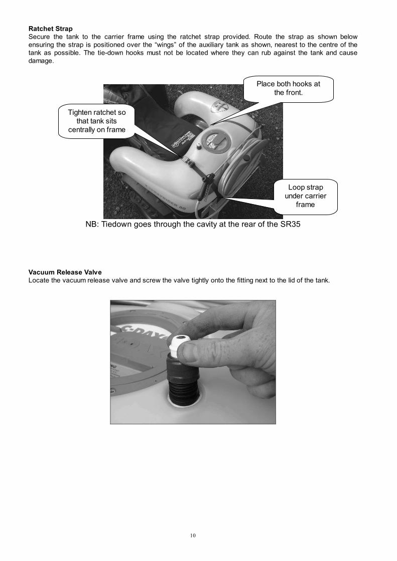
Ratchet Strap
Secure the tank to the carrier frame using the ratchet strap provided. Route the strap as shown below
ensuring the strap is positioned over the “wings” of the auxiliary tank as shown, nearest to the centre of the
tank as possible. The tie-down hooks must not be located where they can rub against the tank and cause
damage.
NB: Tiedown goes through the cavity at the rear of the SR35
Vacuum Release Valve
Locate the vacuum release valve and screw the valve tightly onto the fitting next to the lid of the tank.
Place both hooks at
the front.
Loop strap
under carrier
frame
Tighten ratchet so
that tank sits
centrally on frame

11
Spray Gun
Locate the spray gun (HGSR) and lance inside the spray tank (Gun for SR35 will be located in the shipping
box).
For SR35 the self store hose simply needs to be pushed into the push lock fitting as per the picture below left
For the SR50 screw the lance onto the spray gun trigger handle as per above right. SR80 models have the
lance fitted to the trigger handle.
Screw the spray gun onto the hosetail connected to the spray hose, ensure it is secured tightly so that the
handle does not leak when operated (do not use thread tape as this may cause the trigger handle to split).
Secure the spray gun in the stowed position under the two lugs of the auxiliary (hose reel) tank as shown. This
method of securing the spray gun is unique to the SR50 and SR80 tanks and is designed for the HGSR spray
gun only. On SR35 units the handgun mounts are on either side of the tank
Connect the Sprayrider™ electrical connector (at front of the tank) to the battery cable.
SR50/80 Style SR35 Style,
Push fit

12
THEORY OF OPERATION
Spray fluid is prepared and placed in the tank via the lid opening and strainer basket. Foreign matter is trapped
in the strainer mesh for disposal after the tank has been filled.
When the pump is switched on power is applied to the pump motor from the vehicle electrical system. When
the pump operates, fluid is drawn through the filtered valves at the base of each leg of the tank and into the
pump head via hoses inside the tank.
When one leg of the tank is empty the valve at the base of that leg will close. This will prevent air from being
drawn into the system and allow evacuation of fluid from the opposite leg. When both legs are empty, both
valves will close. With both valves closed, a vacuum is created within the system that retains the valves in the
closed position. When the tank is refilled the vacuum is released by momentarily manually opening and closing
a valve located at the top of the tank. The tank valves will reset to the open position and allow fluid to be
drawn from the tank.
OPERATING INSTRUCTIONS
Before switching on the pump, momentarily open and close the knob on the vacuum release valve located on
top of the tank next to the lid. This will allow the suction valves to reset to open. This operation will need to be
repeated each time the tank is re-filled from empty.
Switch on the pump switch mounted on the handle bar of the ATV. The pump will run for a short time then shut
off.
Operate the spray gun trigger. Fluid will be sprayed from the adjustable spray tip and the pump will operate. If
necessary adjust the spray tip to alter the spray pattern.
NOTE
If fluid does not flow when the pump is running and the spray gun trigger is operated, switch the pump off and
open the knob on the vacuum release valve for five seconds, then close.

13
Hand Washing
50L and 80L Sprayriders™ are fitted with a 2-litre fresh-water wash tank for hand washing in the field. To
wash hands pull the outlet valve to the open position, wash hands then push the valve closed.
NOTE
Hand wash tanks are not fitted to SR35 tanks and are only applicable to 50/80 litre models.
CHEMICAL APPLICATION
CAUTION
This handgun sprayer is not a high volume sprayer nor is it ultra low volume. As a general rule for most
spotting applications, label rates under the heading “knapsack rates” would apply.
As no control can be exercised over the use of the equipment or over weather, plant or soil conditions, or over
the storage, handling, mixing, use or application of sprays or chemicals, C-Dax Ltd will not accept any liability
for loss or damage (consequential or otherwise) arising directly or indirectly from the use of this equipment.
Chemical Advice
C-Dax Ltd or their agents cannot make recommendations or give advice as to the use of chemicals and
cannot accept responsibility for any damage, injury or other consequence for disregarding this warning notice.
Contact your chemical supplier for advice.
WARNING
Mixing chemicals is a most dangerous activity as it involves handling the concentrated material. For toxic
compounds, use protective clothing such as overalls, hat, gloves, boots and respirator.
When using diluted sprays, wear at least a hat, long-sleeved cotton overalls, and boots. If you use pesticides
regularly, it is a good idea to always wear a respirator to avoid accumulation of toxins in the body. Other
protection may be required. Check the label for specific directions for the particular chemical.
Purchasers must ensure that operators of these machines are fully aware of the dangers of spraying
chemicals.

14
OPERATING HINTS
Spray Hose
Be careful not to wrap the hose so tight as to inhibit the flow of fluid by kinking the hose.
Length of Spray Hose
If most spraying is “from the seat”, the hose length should be shortened. Quick release hose connectors
(brass) are available from your C-Dax dealer. These will enable the operator to simply connect the longer hose
when required.
Nozzle Choice
Nozzles provided have been selected to match the performance of the pump. The adjustable nozzle gives a
cone pattern, ideal for spot spraying.
Tank Inserts
Do not over-tighten the quick release hose connector (brass) when fitting it to the tank return brass insert
(SR50/80 only). If the insert is over-strained a leak could occur. Liquid thread seal is recommended to ensure
a leak-free joint. Plastic thread tape is not recommended.
Pump
The Flojet pump features an internal bypass function and as such it needs no pressure adjustment. When the
flow is restricted and pressure builds up the pump will automatically bypass fluid.
Using the Sprayrider™ with a Spray Boom
NOTE
SR35 is a spot sprayer only and would not be suitable for boom spraying
All spray booms supplied by C-Dax as 12Volt Sprayer accessories are supplied with a quick release valve to
allow convenient connection of either the spray gun or spray boom. Spray booms that require a bypass to
divert fluid back to the tank, such as the CDA booms, are supplied with a bypass fitting to screw into the rear
of the Sprayer tank.
All spray booms intended for use with the Sprayrider™ are supplied with spray tips that match the output of the
SR35/50/80 pump and will spray at approximately 2 bar (30 psi). Changing the tip size will alter the spraying
pressure.
Decreasing tip size will increase the spraying pressure. The spray tips are calibrated to 4 bar spraying
pressure, which determines the minimum tip size that can be fitted.
Increasing the tip size will decrease the spraying pressure. All spray booms sold by C-Dax for use with the
Sprayrider™ are fitted with non-drip check valves. These valves close at a pressure of 0.8 bar (10 psi). For
reliable boom operation we do not recommend spraying pressure below 1 bar (15 psi).

15
ROUTINE MAINTENANCE
Cleaning
Clean the sprayer regularly! After each use flush the unit out three times with fresh water. Use a neutralizing
agent for the second rinse.
CAUTION
To prevent damage to the sprayer and spray gun, drain the water from the sprayer and spray gun when there
is a risk of frost.
Filters
There are four filters in each Sprayrider™ fluid system. Each one must be checked and cleaned after each
use.
The tank strainer basket is retained by the lid to assist cleaning. Always clean the strainer before filling the
tank with spray solution.
The C-Dax valve assembly at the base of each leg has a stainless steel mesh filter for straining the fluid
before it reaches the pump. Unscrew the cap at the base of each leg and allow the valve assembly to hang
free from the tank. This exposes the valve filter mesh for cleaning. Take care not to lose the O-ring.
Carefully rinse each stainless steel mesh with a hose.
CAUTION
To avoid damage to the filter mesh, do not attempt to remove the mesh from the valve assembly.
Do not use excessive pressure when cleaning the valve and filter mesh.
CAUTION
When refitting the valve, do not overtighten the valve nut. Tighten to hand tight only.

16
Each HGSR spray gun has a built-in filter in the spray tip. Unscrew the red spray tip holder from the lance nut
to expose the tip filter. Pull the lance nut back to reveal the filter. Rinse under a hose and replace the filter
element in the spray tip (the dished side faces toward the trigger).
Removal of the Sprayrider™
1. Unplug the switch/battery cable at the
tank connector.
2. Release the ratchet strap.
3. Lift the Sprayrider™ off the vehicle.
4. Place the tank on a suitable support so
that the legs do not have to support the
weight of the tank. The tank can be
conveniently hung on a wall using a loop
of string around the center of the tank.
Lubrication of the Spray Lance
For trouble-free operation of the spray lance it is recommended that the trigger valve be lubricated with rubber
grease (lanolin) at regular intervals. Unscrewing the black knob on the topside of the spray gun handle
accesses the trigger valve. The interval should reflect the usage of the lance.
Care of Protective Clothing
Protective clothing should be properly cared for. Rinse heavily contaminated clothes in the open before
washing in the laundry. Wash and dry these clothes every day and keep them separate from other washing.
Respirators need special care. Clean the respirator after spraying. Use soapy water then rinse and allow to
dry completely before storing in a clean plastic bag. Replace canisters in respirator after eight hours use.
Never store used canisters with the respirator.
The minimum requirements for personal safety are that the operator avoids spray inhalation and does
not allow chemicals or spray mixture to contaminate the eyes or skin.

17
Removing the Pump
CAUTION
To prevent damage to the pump and tank connector ensure the tank is upside down when removing the pump
cover. Remove the vacuum release valve first to prevent damage.
1. Remove the vacuum release valve.
2. Place the sprayer upside down.
3. Remove the six screws securing the pump cover and remove the cover (SR50/80 only)
4. Unclip the suction and delivery hose connections by pulling the blue tabs into the unlocked
position.
5. Unscrew the four mounting screws hold the pump in place (SR35 only)
6. Lift out the pump.
Installing the Pump
CAUTION
To prevent leaks, never use thread tape on the suction or delivery hose connections as this may prevent
proper sealing of the cones. Do the nuts up finger tight then advance the nuts one quarter turn.
1. Place the pump in the pump cavity as shown above.
2. Connect the suction and delivery hoses.
3. Screw four mounting screws into inserts (SR35 only)
4. Replace the pump cover. (SR50/80 only)
CAUTION
Always operate the SR50/80 with the pump cover in place. The pump cover holds the pump in position
SR50/80 Style
SR35 Style

18
TROUBLESHOOTING
C-Dax Ltd and their distributors have a comprehensive parts inventory and capable service staff.
Repairs should only be undertaken by C-Dax, or an authorised C-Dax service center.
Symptom Possible causes (procedure) Probable solution
Pump does nothing
(makes no noise)
Blown fuse (check wiring for shorting
and inspect fuse)
Repair/replace faulty wiring or 15A fuse as
necessary
Loose/intermittent connection (check
all wiring and connections)
Check all wiring and connectors to ensure solid
connection
On/Off switch failed (remove switch
from handle bar, bridge the 2 spade
terminals using a screw driver)
Replace switch if using the screw driver causes
pump to work
If all above fails, likely cause is pump
failure
Take in to local dealer or send to C-Dax for repair.
Be sure to include sufficient paperwork detailing the
problem.
Pump runs for few
seconds then stops
Pump has primed and pressure
switch has activated (this is normal) No fault, squeeze spray trigger and use as per usual
Fluid leaks from drain
holes in pump Internal leak within pump head
Take in to local dealer or send to C-Dax for repair.
Be sure to include sufficient paperwork detailing the
problem.
Tank empties from
one leg only
One of the filter valves are not
sealing off properly (Inspect the filter
valve at the base of each leg)
1. Unscrew the nut that holds the filter valve on to
the bottom of the leg. Clean filter thoroughly but
carefully using hose.
2. Check the hose that connects to the filter valve
for splits at bottom. If split found: replace hose.
3. If all above fails, replace filter valve(s)
Tank only partially
empties
One of the internal suction hoses has
developed a leak.
Remove lid and inspect internal suction hoses. The
split/hole will be at the same level as the fluid. You
may need to detach the hoses from the black cross-
fitting at the top of the tank and extract by removing
the filter valve at the bottom of the leg (be sure to
empty tank first).
Pump runs but does
not spray (or sprays
but with little
pressure)
Air lock in pump Operate spray gun trigger until all air is expelled from
the pump and hose (may take a few moments)
Air leak in suction line
Inspect the suction line (between the tank and pump)
for signs of split hoses and loose clamps. Replace
split hose if required and ensure all clamps are done
up tight.
Blocked suction filter valves Inspect filter valves and clean if necessary
Air lock in suction line
Pop up the blue/white vacuum release valve on top
of the tank and press it down again (ensure this
valve is screwed on to the black fitting tightly).
Dirt or spray residue in pump valves Replace valves inside pump
Pump fails to prime (usually on very
first use)
Remove the blue/white vacuum release valve on top
of the tank by carefully unwinding it from the black
fitting (ensure the black fitting stays attached to the
tank). Now force water (from a garden hose) down
the black fitting while the pump is running, this should
force the pump to prime. Screw the blue/white
vacuum release valve back on to the black fitting
tightly and pop the valve down. This should prime
the pump and make the sprayer operate as per
normal.
Pump sprays but
does not stop
spraying
Spray gun trigger open No fault, close trigger

19
SR50/80 PARTS DIAGRAM

20
SR50/80 PARTS LIST
- Sprayrider -
ITEM
NO.
Part No DESCRIPTION QTY. NOTES
1 7500-3650 Tank-50L-Sprayrider-Yellow-MDPE-Incl MIG 1
7500-3900 Tank-80L-Sprayrider-Yellow-MDPE-Incl MIG 1
2 6800-5000 Pump-Flojet-Triplex-12 Volt-7.6LPM-Quad Ports 1
8427-6715 Pump Assembly-Sprayrider 50/80-Flojet Quadport 1
3 7500-1500 Cover-Pump-SR50/80-Yellow-MDPE 1
4 8427-9690 Valve Assembly-Suction-Sprayrider 50/80 2
5 6200-1020 Pipe-Fitting-Adaptor-1/4BSPMxM28-SR G2-Nylon 1
6 8900-8580 Valve-Water Bottle-Sipper Cap-Bottle thread-Plastic 2
7 6200-9300 Pipe-Fitting-TeeJet-Cross-Shank13x13x13x1/4"NPTF-
Black-Nylon
1
8 8427-4150 Hose Assembly-Suction-Sprayrider 50/80 Quadport 1 For Flojet
Quad Port
Pump
9 3700-9150 Gasket-Washer-25x17.4x1.4-Nylon 1
10 3700-9130 Gasket-Washer-17x23x2-Rubber 1
11 2000-2019 Clamp-Hose-Oetiker-Single Ear Stepless-
19.4<>22.6mm-S/S
2
12 8840-8413 Tube-Transluscent-13MM-100PSI (1.15m) 1
13 8840-8413 Tube-Transluscent-13MM-100PSI (1.15m) 1
14 2000-2017 Clamp-Hose-Oetiker-Single Ear Stepless-
16.6<>19.8mm-S/S
4
15 6200-2980 Pipe-Fitting-Flojet-Elbow-10-13mm ShankxQuad Port
Pump-Nylon
1
16 4100-0008 Hose-Spray-Delivery-40 Bar-8.5mm ID-Yellow (10m) 1
17 2000-2014 Clamp-Hose-Oetiker-Single Ear Stepless-
14.5<>7.0mm-S/S
2
18 3400-1110 Filter-Basket-D150-Mesh 1
19 8427-6005 Lid & Ring Assembly-D150-C-Dax Vented-Blue-Nylon 1
20 3270-8012 Fastener-Self Tap-Screw-CSK-8Gx1/2"-Pozi-Stainless 6
21 5500-9110 O'Ring-Metric-5.0x80mm-N70 2 *5
22 3400-5500 Filter-Nut-Bowl-Arag-Series 312 & 314-Nylon 2
23 7500-5100 Tank-Rinse-Sprayrider-Blue-MDPE 1
24 1600-7001 Cap-Tank-Freshwater-Drilled-Black 1
25 3070-0516 Fastener-Machine-Screw-CSK-M5x16-Phillips-
Stainless
6 *4
26 6200-9410 Pipe-Fitting-Thru Tank-Elbow-13 Shankx11/16UNFM-
Nylon
1 *3
27 4100-0013 Hose-Spray-Delivery-40 Bar-13mm ID-Yellow (0.3m) 1 *1
28 4000-5000 Hand Gun-SR-Lance-Complete-600mm-Cone Nozzle-
Adjustable
1 *2
29 7500-2300 Housing-Switch-Handlebar-Yellow-MDPE 1
30 3180-0005 Fastener-Nut-Plain-M5-ZP 1
31 3310-6005 Fastener-Washer-Flat-M5-ZP 2

21
32 3110-0530 Fastener-Machine-Screw-Pan-M5x30-Pozi-ZP 1
33 8410-8450 Strap-Tie Down-Ratchet-Blue 1
34 2250-8200 Cover-Switch-Water Proof Boot-Toggle Lever-Rubber-
Black
1
35 3600-1010 Fuse Link-Electrical-Standard Blow-15 Amp-1"x1/4"-
Glass
1
36 8450-2410 Switch-Electrical-Toggle-SPST-250V-16Amp 1
37 8427-8270 Switch Assembly-Handlebar Mount-Sprayrider 50/80 1
38 6200-7340 Pipe-Fitting-Reducer-1/2NPTMx3/8NPTM-Straight-
Plastic
2
*1 Length of hose was 0.5M pre October, 2006
*2 Post serial number; SR50-1573
SR80-1925
*3 Connector was a straight (14014) pre October, 2006
*4 Post December, 2005
*5 O Ring was 83 x 3.5 NI (10357) pre serial number 366
O Ring was 80 x 4 NI (10314) post serial number 365 and pre serial
number; SR50-918
SR80-937
Notes
*1 Length of hose was 0.5M pre October, 2006
*2 Post serial number; SR50-1573
SR80-1925
*3 Connector was a straight (14014) pre October, 2006
*4 Post December, 2005
*5 O Ring was 83 x 3.5 NI (10357) pre serial number 366
O Ring was 80 x 4 NI (10314) post serial number 365 and pre serial number; SR50-
918
SR80-
937

22

23
HGSR SPRAYGUN PARTS DIAGRAM
ITEM No PART No DESCRIPTION QTY
1 NA Kit-Repair-HGSR-Gun Body 1
2 NA Lever-Trigger-PP-Blue 1
3 4000-5042 Gasket-19x12x3-NY-White 1
4 5500-1000 Oring-15x12x1.5-Viton 2
5 4000-5020 Hose Tail 10mm 1
6 4000-5028 Filter-Cup-50 Mesh-SS 1
7 4000-5026 Adjustable, Brass Hollow Cone Spray Tip 1
8 4000-5030 Nozzle Holder-Red 1
9 5300-7700 Spray Tip Flat Fan-110°SF 08 (OPTION) 1
10 4000-5024 Gun Body w/ Handle-HGSR 1
11 NA Piston pin -SS 1
12 NA Pin spacer 1
13 NA Pin-Hinge-Trigger-SS 1

24
FLOJET SPRAY PUMP RELACEMENT PARTS
The following replacement parts for the 12V Flojet 7.6 L/Min pump are available from any C-Dax dealer:
NOTE
Please select the correct hose connection type for your pump
Quadport Type:
Screw Type:
ITEM PART NO. DESCRIPTION
1 6800-5170 Pumphead Kit (includes pressure switch)
To suit Screw Type
1 6800-5160 Pumphead Kit (includes pressure switch)
To Suit Quadport Type
6800-5000 Replacement Pump
Quadport Type


