Embed Size (px)
Citation preview
2017 DOE Vehicle Technologies OfficeAnnual Merit Review and Peer Evaluation Meeting
June 8, 2017 – Washington, DCThis presentation does not contain any proprietary,
confidential, or otherwise restricted information
Project ID # ACS108
Spray-Wall Interaction at High-Pressure and High-Temperature Conditions
S.-Y. Lee1(PI), J. Naber1, R. Scarcelli2, S. Som2, M. Raessi3, R. Torelli2, L. Zhao1, X. Zhu1, D. Markt3, A. Pathak3
1Michigan Tech, 2Argonne National Lab, 3UMassD
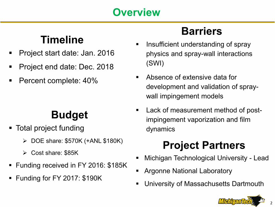
Overview
Timeline Project start date: Jan. 2016
Project end date: Dec. 2018
Percent complete: 40%
Barriers Insufficient understanding of spray
physics and spray-wall interactions (SWI)
Absence of extensive data for development and validation of spray-wall impingement models
Lack of measurement method of post-impingement vaporization and film dynamics
Budget Total project funding
DOE share: $570K (+ANL $180K)
Cost share: $85K
Funding received in FY 2016: $185K
Funding for FY 2017: $190K
Project Partners Michigan Technological University - Lead
Argonne National Laboratory
University of Massachusetts Dartmouth
2

Relevanceo Improvement of existing spray-wall interaction models that are 20 years old
and are validated for water only
Overall Objectiveso High pressure vaporizing drop-wall impingement and film formation supported
by laboratory experimento Physics-based predictive CFD sub-models of spray-wall interaction
Objectives this periodo Impingement experimentation for rebound spray dynamics characterizationo Experimentally validated a high fidelity Lagrangian-Eulerian (LE) Reynolds-
Averaged Navier-Stokes (RANS) model for spray-wall interactiono DNS frame of droplets impinging on dry/wet walls supported by LE model
Impacto Improve the high-density ratio vaporizing processes on spray-wall wetting
Relevance/Objectives
3

Milestones – FY 16 & 17
Date Milestones Status
April 2016 MilestoneTransparent and metal plates design and fabrication Complete
September 2016 MilestoneValidate spray models in CONVERGE framework Complete
March 2017 MilestoneImpinging characterizations in high-pressure chamber Complete
April 2017 Develop capabilities to extract required pre-impingement droplet characteristics from LE CFD simulations Complete
June 2017MilestoneImplementation of basic DNS model of droplet-wallimpingement with multiple droplets
On track
December 2017MilestoneModel of film formation dynamics and interactions between multiple droplets on splashing supported by heated wall test
On track
December 2017GO/NO-GONew improved non-evaporating SWI model based on DNS, 90% accuracy
4

Approach/Strategy – Plan2016QR1 QR2 QR3 QR4
2017QR1 QR2 QR3 QR4
2018QR1 QR2 QR3 QR4
Single injection spray simulation
Non-evaporating DNS initiation and exploration
Impinging plates fabrication and preliminary spray-wall test
High-fildelity spray model setup/code usability
First set test results cover 90% of operating space for model development
Milestone
Milestone
Go/No-Go
Isothermal wall spray test
Sub-model development DNS
Heated wall spray test
Spray-wall interaction for non-evaporating development sprays
New improved non-evaporating SWI model based on DNS, 90% accuracyMilestone
Milestone
Milestone
Go/No-Go
SWI for Non-Evaporating Sprays Validation
SWI for Evaporating Sprays Development
SWI for Evaporating Sprays Validation
Code Usability Tests
Milestone
Milestone
Milestone
Milestone
In progressComplete
Milestone
Milestone
Milestone
Future5

Technical Accomplishments
6
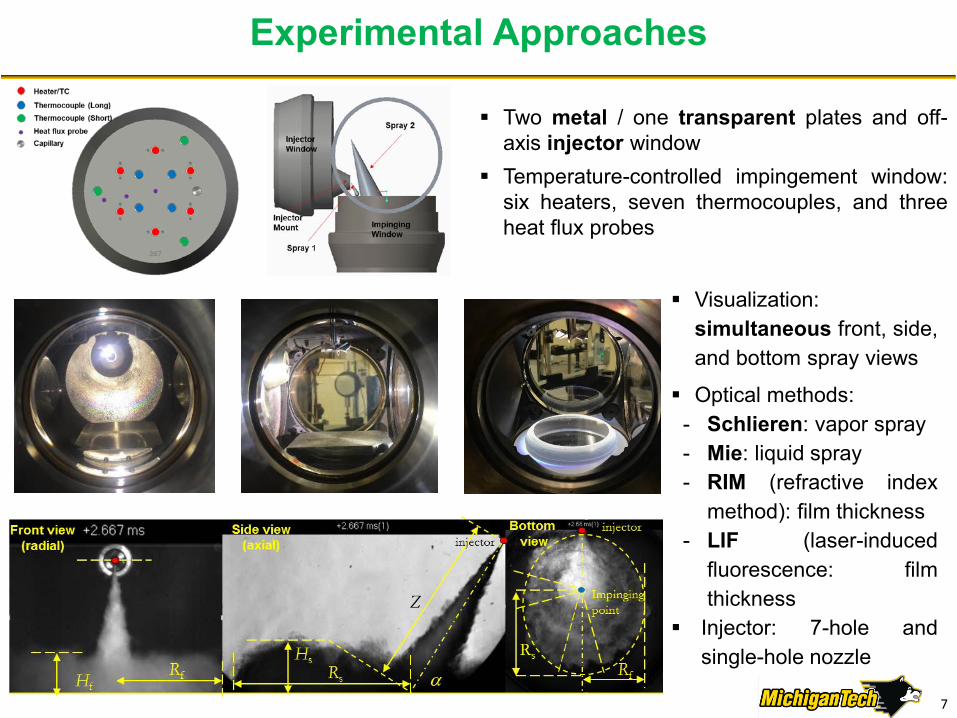
Experimental Approaches
Two metal / one transparent plates and off-axis injector window
Temperature-controlled impingement window:six heaters, seven thermocouples, and threeheat flux probes
Visualization:simultaneous front, side,and bottom spray views
Optical methods:- Schlieren: vapor spray- Mie: liquid spray- RIM (refractive index
method): film thickness- LIF (laser-induced
fluorescence: filmthickness
Injector: 7-hole andsingle-hole nozzle
7
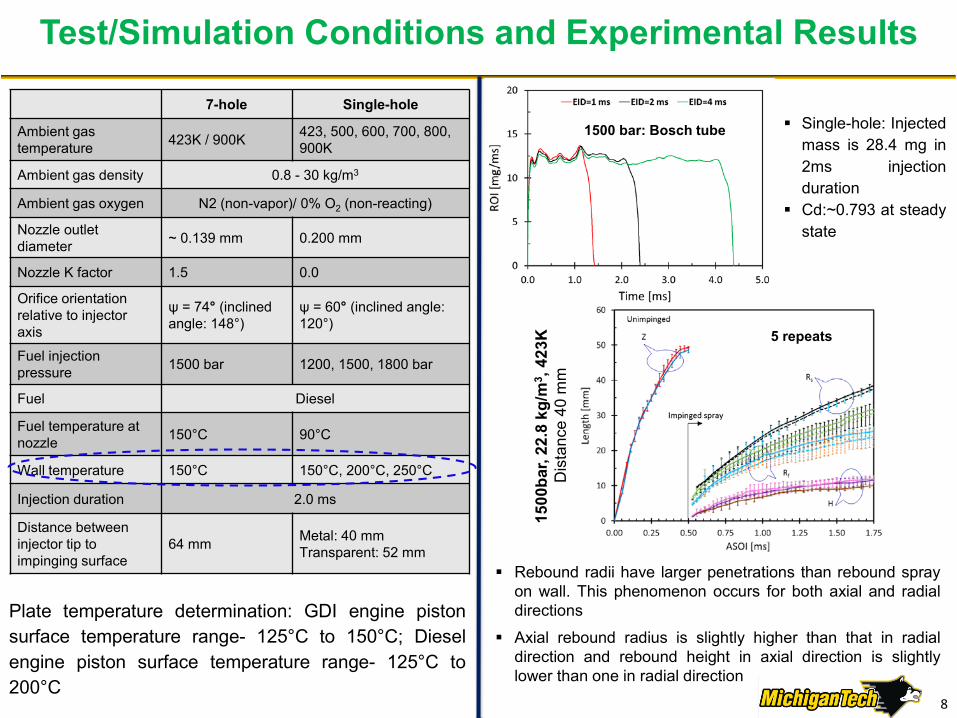
Test/Simulation Conditions and Experimental Results
7-hole Single-hole
Ambient gas temperature 423K / 900K 423, 500, 600, 700, 800,
900K
Ambient gas density 0.8 - 30 kg/m3
Ambient gas oxygen N2 (non-vapor)/ 0% O2 (non-reacting)
Nozzle outlet diameter ~ 0.139 mm 0.200 mm
Nozzle K factor 1.5 0.0
Orifice orientation relative to injector axis
ψ = 74° (inclined angle: 148°)
ψ = 60° (inclined angle: 120°)
Fuel injection pressure 1500 bar 1200, 1500, 1800 bar
Fuel Diesel
Fuel temperature at nozzle 150°C 90°C
Wall temperature 150°C 150°C, 200°C, 250°C
Injection duration 2.0 ms
Distance between injector tip to impinging surface
64 mm Metal: 40 mmTransparent: 52 mm
Plate temperature determination: GDI engine pistonsurface temperature range- 125°C to 150°C; Dieselengine piston surface temperature range- 125°C to200°C
Single-hole: Injectedmass is 28.4 mg in2ms injectionduration
Cd:~0.793 at steadystate
1500 bar: Bosch tube
Rebound radii have larger penetrations than rebound sprayon wall. This phenomenon occurs for both axial and radialdirections
Axial rebound radius is slightly higher than that in radialdirection and rebound height in axial direction is slightlylower than one in radial direction
1500
bar,
22.8
kg/
m3 ,
423K
Dis
tanc
e 40
mm
5 repeats
8

Wall-impinged expanding spray (WIES) Sector-averaged radius over the arc
sector is estimated because the WIESfront is highly wrinkled as it propagateson the wall surface
Final arc angle (30o) is determined byvarying angle for the least sensitivity forthe radius variation
A number of spikes (time interval of 40µs) are formed randomly due tocombined effect of injected flow ratefluctuation and turbulence betweenWIES front and surrounding gas
WIES expansion process is divided intofour stages: rapidly decelerated stage,slowly decreasing stage, relativelyconstant stage, and expandingtermination stage
Rebound Spray Characterizations
22.8kg/m3 , 1500 bar, 423 K
WIES properties
1500 bar, 423 K
1500 bar, 22.8kg/m3, 423 K 9

Mesh Strategies for Grid-Dependency Reduction
A best practice was developed for reduced grid-dependency with multi-hole injectors
• Plumes aligned with the grid (e.g., Orifice 1) are affected by a different momentum exchange
• Maximizing the misalignment between the grid and the plumes guarantees that the influenceof the grid is minimized with respect to the free-spray penetration
• The results were validated against MTU’s experiments on the 7-hole injector
Aligned Grid Rotated Grid
10
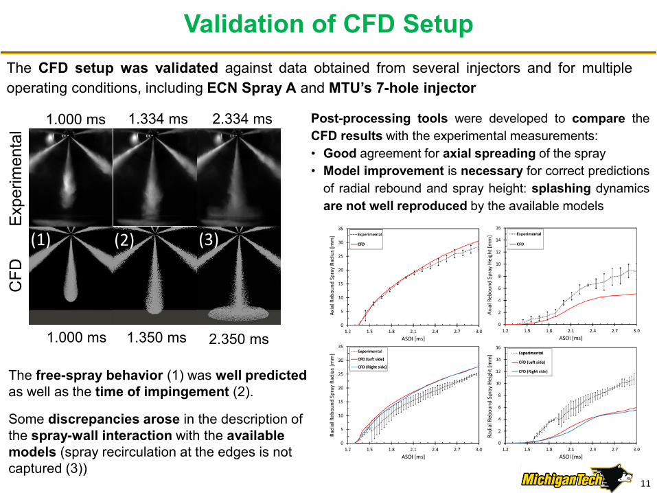
Validation of CFD SetupThe CFD setup was validated against data obtained from several injectors and for multipleoperating conditions, including ECN Spray A and MTU’s 7-hole injector
The free-spray behavior (1) was well predictedas well as the time of impingement (2).
Some discrepancies arose in the description of the spray-wall interaction with the available models (spray recirculation at the edges is not captured (3))
1.000 ms
1.000 ms 2.350 ms
Exp
erim
enta
lC
FD
2.334 ms1.334 ms
1.350 ms
(1) (2) (3)
Post-processing tools were developed to compare theCFD results with the experimental measurements:• Good agreement for axial spreading of the spray• Model improvement is necessary for correct predictions
of radial rebound and spray height: splashing dynamicsare not well reproduced by the available models
11

Generated Inputs for DNS
2.5 ms 2.5 ms
Data can be extracted at any point and time to initialize DNS of dropletimpingement
Data include, but are not limited to, global(SMD, We and Re distributions) and localquantities (droplet size, temperature, gas pressure, velocities)
DNS calculations can capture importantdetails of droplet impact dynamics onto wet or dry surfaces, under non-evaporating and evaporating conditions
The feedback from DNS runs will be used to improve the spray-wall interaction models with more detailed and accurate correlations
From ANL to UMassD
Back to ANL
Newly developed post-processing tools include also extraction of spray morphology related data
12

Spray Film Interaction (O’Rourke & Amsden)- ValidationThe splashing model:
Mundo, Sommerfeld and Tropea[3]
- Experiment: Single impinging drop on dry solid surface
- A splash parameter for occurrence of splash- Secondary drop size / velocity measured
Yarin and Weiss[4]- Experiment: train of drop impinging on wet wall- Secondary drop size / total mass measured- Splash criterion independent of drop diameter
O’Rourke and Amsden[1]
- Single drop impinging on a film- Above experiments used to formulate: splash criterion and secondary droplet distribution
Multiple drop interaction
The secondary drop information input to:film momentum[1] & film energy[2] equation
(Exp.[4])
(Theory[4])
Splashing threshold of 17 independent of drop diameter
All experiments considered drop sizes 60 µm – 200 µm
Validation lacking
Length scale: distance b/w droplets (not diameter)
Spreading only
Extension & Splashing
Does the same threshold apply to single micron drops?
1. O’Rourke and Amsden, SAE, 2000 3. Mundo et al., Intl J Multiphase flows, 19992. O’Rourke and Amsden, SAE, 1996 4. Yarin and Weiss, J. Fluid Mech., 1995
Splashing criterion (Yarin & Weiss):
13
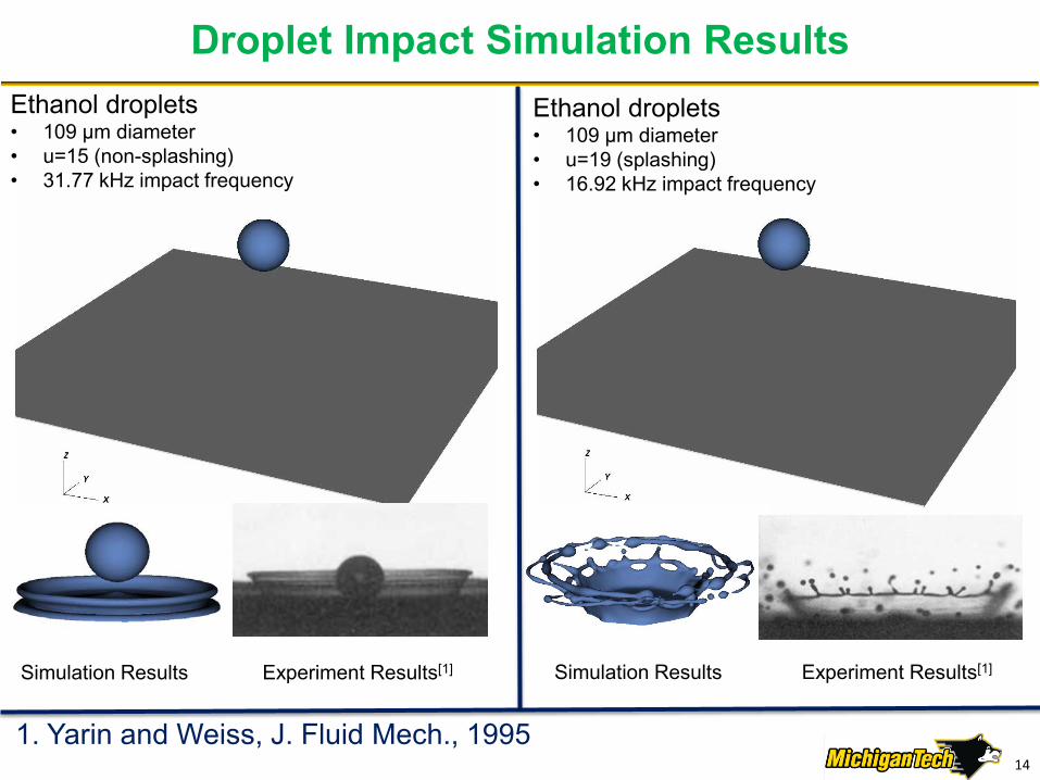
Droplet Impact Simulation Results
1. Yarin and Weiss, J. Fluid Mech., 1995
Simulation Results Experiment Results[1]Simulation Results Experiment Results[1]
Ethanol droplets • 109 μm diameter • u=15 (non-splashing)• 31.77 kHz impact frequency
Ethanol droplets • 109 μm diameter • u=19 (splashing)• 16.92 kHz impact frequency
14
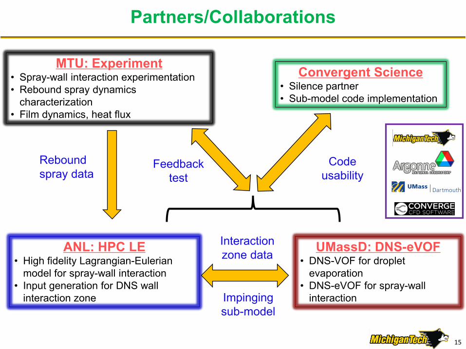
Partners/Collaborations
MTU: Experiment• Spray-wall interaction experimentation• Rebound spray dynamics
characterization• Film dynamics, heat flux
ANL: HPC LE• High fidelity Lagrangian-Eulerian
model for spray-wall interaction• Input generation for DNS wall
interaction zone
UMassD: DNS-eVOF• DNS-VOF for droplet
evaporation • DNS-eVOF for spray-wall
interaction
Rebound spray data
Convergent Science• Silence partner• Sub-model code implementation
Interaction zone data
Impinging sub-model
Feedback test
Code usability
15

Remaining Challenges and Barriers
To extract the details and physics-base information using the DNS model to quantify the model associated with vaporization on the hot surface and explore the post-impingement droplet dynamics and secondary fuel vapor mixing process with ambient gas
To formulate a VOF-based mathematical evaporation sub-model of spray-wall impingement and film formation processes
To accurately measure, firstly, the vaporization before the impingement and, secondly, the vapor portion and film after impingement
To systematically analyze uncertainties in experimental and modeling results and parameters
To address challenges associated with the full implementation of the proposed sub-models (eVOF and drop-wall interaction) in various relevant CFD frameworks
16

Future Work- We will continue to develop and validate of evaporation VOF and spray-wall interaction models
Ong
oing
Su
ppor
t va
lidat
ed L
E m
odel
fram
e fo
r DN
S FY16 – [Q1 Milestone] ECN single injection spray simulationFY16 – [Q3 Milestone] Isothermal spray-wall test for post impinging sprayFY16 – [Q4 Milestone] High-fidelity spray model setup
Prop
osed
Exte
nd D
NS
mod
el to
ha
ndle
eva
pora
tion
spra
y-w
all s
uppo
rted
by
heat
ed
wal
l tes
t
FY17 – Spray-wall test • Continue isothermal non-isothermal/heated wall test• Film formation and surface heat flux
FY17 – Sub-model development DNS• Non-evaporating spray-wall interaction• Impinging evaporating spray droplets
FY17 – Spray-wall interaction for non-evaporating development sprays• Lagrangian-Eulerian (LE) model and VOF based on DNS
Plan
ned
Futu
re so
lver
s for
CFD
pa
ckag
e
FY18 – Feedback test for heat flux and film characteristicsFY18 – DNS for spray-wall interaction and evaporation
• Impinging evaporating spray droplets• Validation of film dynamics and heat flux
FY18 – Spray-Wall Interaction Validation at Vaporizing Conditions• Implement eVOF model into spray modeling approach• Make data to Public
FY18 – Code Usability Test
Any proposed future work is subject to change based on funding levels.17
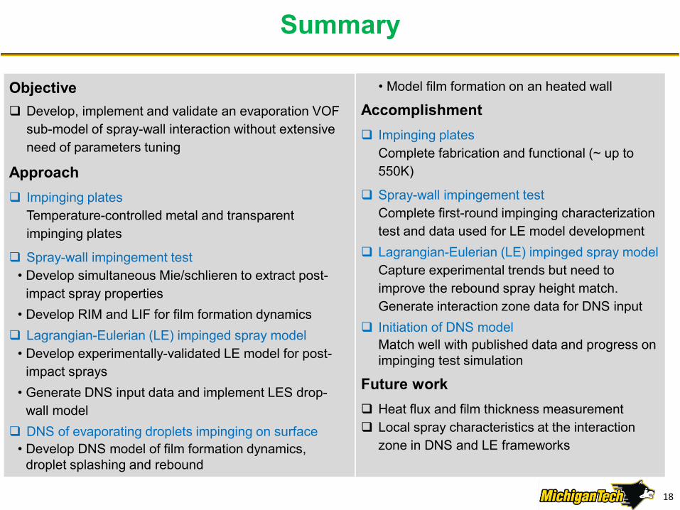
Objective Develop, implement and validate an evaporation VOF
sub-model of spray-wall interaction without extensive need of parameters tuning
Approach Impinging plates
Temperature-controlled metal and transparent impinging plates
Spray-wall impingement test• Develop simultaneous Mie/schlieren to extract post-
impact spray properties• Develop RIM and LIF for film formation dynamics Lagrangian-Eulerian (LE) impinged spray model
• Develop experimentally-validated LE model for post-impact sprays
• Generate DNS input data and implement LES drop-wall model
DNS of evaporating droplets impinging on surface• Develop DNS model of film formation dynamics,
droplet splashing and rebound
Summary
• Model film formation on an heated wall
Accomplishment Impinging plates
Complete fabrication and functional (~ up to 550K)
Spray-wall impingement testComplete first-round impinging characterization test and data used for LE model development
Lagrangian-Eulerian (LE) impinged spray modelCapture experimental trends but need to improve the rebound spray height match. Generate interaction zone data for DNS input
Initiation of DNS modelMatch well with published data and progress on impinging test simulation
Future work Heat flux and film thickness measurement Local spray characteristics at the interaction
zone in DNS and LE frameworks
18
Technical Backup Slides
19

Further DNS Work: we are trying to improve splashing threshold, film formation and wall-film interaction
ANL Droplet Data
Representative Droplet Condition(s):
Fuel Spray Reconstruction:
Use multiple median size droplets to represent the spray conditions Representative droplet will be used to verify and revise the splashing threshold
Use a distribution of droplets contained in the spray to study film formation dynamics and the interactions between multiple droplets on splashing
Develop a VOF-based evaporation model to study how wall-film interaction changesdue to evaporation
• Verify splashing threshold for single micron diameter droplets
20