Embed Size (px)
Citation preview

Parts Manual - 91285 Revision P
SPRAY INJECTION PATCHER

Fill in the appropriate fields that apply to this machine. Machine S/N: ___________________________________ 1st Hose S/N: ___________________________________ 2nd Hose S/N: ___________________________________ 1st Pump S/N: __________________________________ 2nd Pump S/N: __________________________________ Engine S/N: ____________________________________ Compressor S/N: ________________________________ Gear Box S/N (Patcher): __________________________ Blower S/N (Magnum): ___________________________
Magnum Part Manual
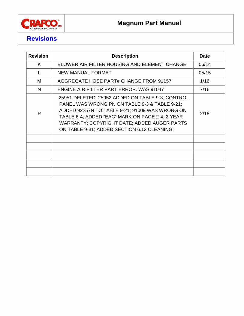
Revisions
Revision Description Date
K BLOWER AIR FILTER HOUSING AND ELEMENT CHANGE 06/14
L NEW MANUAL FORMAT 05/15
M AGGREGATE HOSE PART# CHANGE FROM 91157 1/16
N ENGINE AIR FILTER PART ERROR. WAS 91047 7/16
P
25951 DELETED, 25952 ADDED ON TABLE 9-3; CONTROL PANEL WAS WRONG PN ON TABLE 9-3 & TABLE 9-21; ADDED 92257N TO TABLE 9-21; 91009 WAS WRONG ON TABLE 6-4; ADDED “EAC” MARK ON PAGE 2-4; 2 YEAR WARRANTY; COPYRIGHT DATE; ADDED AUGER PARTS ON TABLE 9-31; ADDED SECTION 6.13 CLEANING;
2/18

Magnum Part Manual
Machine Views

Magnum Part Manual
Machine Views
Magnum Part Manual
Table of Contents
Contents 1.0 About This Manual ................................................................................................................ 1-1
How to use this Manual ................................................................................................... 1-1 1.1 General Machine Overview .............................................................................................. 1-1 1.2 Heating System Overview................................................................................................ 1-2 1.3 Emulsion System Overview ............................................................................................. 1-2 1.4 Aggregate System Overview ........................................................................................... 1-2 1.5 Flush System Overview ................................................................................................... 1-2 1.6
2.0 Safety Precautions ............................................................................................................... 2-1
General Safety ................................................................................................................. 2-1 2.1 Personal Safety ............................................................................................................... 2-1 2.2 Equipment or Operational Safety ..................................................................................... 2-1 2.3 Safety Symbols and Notices ............................................................................................ 2-3 2.4
3.0 Limited Warranty .................................................................................................................. 3-1
Warranty Claim Instructions ............................................................................................. 3-2 3.14.0 Machine Specifications ......................................................................................................... 4-1
5.0 Operating Instructions........................................................................................................... 5-1
Introduction ...................................................................................................................... 5-1 5.1 Preparing the Machine for Start Up .................................................................................. 5-1 5.2 Start Up ........................................................................................................................... 5-5 5.3 Pressurize the Emulsion Tank ......................................................................................... 5-5 5.4 Charge the Auger with Stone ........................................................................................... 5-6 5.5 Set the Auger Feed for Operation .................................................................................... 5-7 5.6 Purge the Solvent from the Emulsion Lines. .................................................................... 5-8 5.7 Patching Operation .......................................................................................................... 5-8 5.8 Shut Down Procedure .................................................................................................... 5-11 5.9
Asphalt Emulsion Line Flush Procedure ...................................................................... 5-11 5.10 Auger Flush Procedure ................................................................................................ 5-12 5.11 Reversing Augers Procedure ....................................................................................... 5-13 5.12 Boom Height Adjustment Procedure ............................................................................ 5-14 5.13 Storing the Machine ..................................................................................................... 5-15 5.14 Overnight Heater ......................................................................................................... 5-15 5.15
6.0 Maintenance Instructions ...................................................................................................... 6-1
Engine ............................................................................................................................. 6-1 6.1

Magnum Part Manual
Table of Contents
Hydraulic System ............................................................................................................. 6-1 6.2 Blower .............................................................................................................................. 6-1 6.3 Air Compressor ................................................................................................................ 6-1 6.4 Air Cleaners for Blower and Engine ................................................................................. 6-1 6.5 Auger Bearings ................................................................................................................ 6-1 6.6 Boom Bearings ................................................................................................................ 6-1 6.7 Bearing Stub Support Shaft on Engine ............................................................................. 6-1 6.8 Wheel Bearing ................................................................................................................. 6-2 6.9 Brakes ........................................................................................................................... 6-2 6.10 Lug Nuts ........................................................................................................................ 6-2 6.11 Tongue Jack .................................................................................................................. 6-2 6.12 Cleaning the Machine .................................................................................................... 6-2 6.13 Maintenance Chart ......................................................................................................... 6-3 6.14 Service Instructions ........................................................................................................ 6-4 6.15 Recommended Fluids and Lubricants ............................................................................ 6-4 6.16 General Maintenance Parts ........................................................................................... 6-5 6.17 Recommended Spare Parts ........................................................................................... 6-5 6.18 Material Specifications ................................................................................................... 6-6 6.19 Stone/Aggregate Specifications ..................................................................................... 6-6 6.20 Emulsion Specifications ................................................................................................. 6-6 6.21 Wiring Code for Tail Lights and Brakes .......................................................................... 6-6 6.22 Tensioning V-Belt Drive Procedure ................................................................................ 6-7 6.24 Maintenance Guide of the V-Belt Drive .......................................................................... 6-8 6.25 Drain Emulsion Tank ...................................................................................................... 6-9 6.26 Adjusting the Air Pressure Regulator ............................................................................. 6-9 6.27 Cleaning Nozzle Spray Ring ........................................................................................ 6-10 6.28
7.0 How to Use a Multimeter ....................................................................................................... 7-1
Checking DC Voltage with a Multimeter ........................................................................... 7-1 7.1 Checking AC Voltage with Multimeter .............................................................................. 7-1 7.2 Checking Resistance (Ohms) .......................................................................................... 7-1 7.3
How to Check Wire Continuity ................................................................................. 7-1 7.3.1 How to Check RTD Sensor ...................................................................................... 7-1 7.3.2
Checking Amperage ........................................................................................................ 7-2 7.48.0 Troubleshooting .................................................................................................................... 8-1
Magnum Part Manual
Table of Contents
Emulsion is Not Flowing from the Nozzle ......................................................................... 8-1 8.1 Stone Not Flowing Through Hose .................................................................................... 8-2 8.2 Engine Will Not Start ........................................................................................................ 8-4 8.3 Emulsion Not Heating from Engine .................................................................................. 8-5 8.4 Emulsion Not Heating From Overnight Heater ................................................................. 8-6 8.5 Hydraulic System Troubleshooting .................................................................................. 8-7 8.6 Electrical Schematic for Hydraulic System ....................................................................... 8-9 8.7 Hydraulic Valve Plug Layout .......................................................................................... 8-10 8.8 Hydraulic Schematic ...................................................................................................... 8-11 8.9
9.0 About the Illustrated Parts List .............................................................................................. 9-1
Ordering Crafco Parts ...................................................................................................... 9-1 9.1 Magnum Parts List ........................................................................................................... 9-2 9.2 Nozzle Emulsion Line Connection Parts List .................................................................... 9-8 9.3 Operator Boom Parts List .............................................................................................. 9-10 9.4 Hydraulic and Fuel Tank Parts List ................................................................................ 9-12 9.5 Dual Hydraulic Control Valve Parts List ......................................................................... 9-13 9.6 Air Blower Parts List ...................................................................................................... 9-14 9.7 Blower Air Cleaner Parts List ......................................................................................... 9-15 9.8 Hydraulic Auger Motor Parts List ................................................................................... 9-16 9.9 Aggregate Feed System Air Lock Parts List ................................................................. 9-17 9.10 Emulsion Tank Drain Valve Parts List .......................................................................... 9-18 9.11 Hitch Area Parts List .................................................................................................... 9-19 9.12 Solvent Flush Tank Parts List ...................................................................................... 9-20 9.13 Battery Parts List ......................................................................................................... 9-21 9.14 Emulsion Tank Top Valve Assembly Parts List ............................................................ 9-22 9.15 Boom Control Console Parts List ................................................................................. 9-23 9.16 Engine and Engine Components Parts List .................................................................. 9-24 9.17 Engine Intake and Exhaust Parts List .......................................................................... 9-25 9.18 Engine Air Compressor Parts List ................................................................................ 9-26 9.19 Engine Control Panel Parts List ................................................................................... 9-27 9.20 Belt Drive Parts List ..................................................................................................... 9-28 9.21 Emulsion Tank Gauge Parts List .................................................................................. 9-30 9.22 Crack Sealing Attachment Option Parts List ................................................................ 9-31 9.23 Electric Throttle Option Parts List ................................................................................. 9-32 9.24

Magnum Part Manual
Table of Contents
8 Foot Quick Flush Hose Option Parts List................................................................... 9-33 9.25 External Water/Fuel Separator Option Parts List .......................................................... 9-34 9.26 Hitch Extension Option Parts List ................................................................................. 9-35 9.27 Air Discharge System Parts List ................................................................................... 9-36 9.28 Aggregate Screw Feed Assembly Parts List ................................................................ 9-38 9.29 Hydraulic Tailgate Assembly Parts List ........................................................................ 9-40 9.30 Hydraulic Schematic and Parts List .............................................................................. 9-42 9.31 Emulsion Supply Line Parts List ................................................................................... 9-44 9.32 Solvent Flush Line Parts List ........................................................................................ 9-45 9.33 Air Supply Line Schematic ........................................................................................... 9-46 9.34 Wiring Schematic ......................................................................................................... 9-47 9.35 Control Panel Wiring Schematic ................................................................................... 9-48 9.36
10.0 Hydraulic Tailgate Mounting Instructions ........................................................................... 10-1
Mounting Information ................................................................................................... 10-1 10.1 Exploded View of Tailgate and Custom Mounts ........................................................... 10-1 10.2 Assembled View of Tailgate and Custom Mounts ........................................................ 10-2 10.3 Mounted Hydraulic Tailgate ......................................................................................... 10-3 10.4

Magnum Part Manual
List of Figures
Figure 5.1 Diesel Fuel Fill Cap and Level Gauge ........................................................................ 5-3 Figure 5.2 Hydraulic Fluid Fill Cap and Level Gauge .................................................................. 5-3 Figure 5.3 Emulsion Thermostat ................................................................................................. 5-4 Figure 5.4 Emulsion Level .......................................................................................................... 5-4 Figure 5.5 Tailgate Hydraulic Connections ................................................................................. 5-4 Figure 5.6 Nozzle Removed from Flush Box............................................................................... 5-5 Figure 5.7 Control Panel ............................................................................................................. 5-6 Figure 5.8 Flow Control Valve .................................................................................................... 5-7 Figure 5.9 Emulsion Tank Valve ................................................................................................. 5-8 Figure 5.10 Tack Coat ................................................................................................................ 5-9 Figure 5.11 Building up the Repair ........................................................................................... 5-10 Figure 5.12 Finishing the Repair ............................................................................................... 5-10 Figure 5.13 Nozzle Flush Box ................................................................................................... 5-11 Figure 5.14 Hopper Gate Handle .............................................................................................. 5-12 Figure 5.15 Reversing Augers .................................................................................................. 5-13 Figure 5.16 Boom Height Adjustment ....................................................................................... 5-14 Figure 6.1 Lug Bolt Tightening Sequence ................................................................................... 6-2 Figure 6.2 Air Pressure Regulator .............................................................................................. 6-9 Figure 6.3 Nozzle Spray Ring ................................................................................................... 6-10 Figure 7.1 Standard Multimeter .................................................................................................. 7-2 Figure 7.2 Clamp-On Amp Meter/Multimeter .............................................................................. 7-3 Figure 8.1 Electrical Schematic for Hydraulic System (PN 92353) .............................................. 8-9 Figure 8.2 Hydraulic Valve Plug Layout .................................................................................... 8-10 Figure 8.3 Hydraulic Schematic (P/N 92352) ............................................................................ 8-11 Figure 9.1 Right Iso View............................................................................................................ 9-2 Figure 9.2 Left Iso View .............................................................................................................. 9-4 Figure 9.3 Nozzle Exploded View ............................................................................................... 9-6 Figure 9.4 Rear View .................................................................................................................. 9-6 Figure 9.5 Nozzle Emulsion Line Connection ............................................................................. 9-8 Figure 9.6 Operator Boom Parts ............................................................................................... 9-10 Figure 9.7 Hydraulic and Fuel Tanks ........................................................................................ 9-12 Figure 9.8 Dual Hydraulic Control Valve ................................................................................... 9-13 Figure 9.9 Air Blower ................................................................................................................ 9-14 Figure 9.10 Blower Air Cleaner ................................................................................................. 9-15 Figure 9.11 Hydraulic Auger Motor ........................................................................................... 9-16 Figure 9.12 Aggregate Feed System Air Lock .......................................................................... 9-17 Figure 9.13 Emulsion Tank Drain Valve .................................................................................... 9-18 Figure 9.14 Hitch Area .............................................................................................................. 9-19 Figure 9.15 Solvent Flush Tank ................................................................................................ 9-20

Magnum Part Manual
List of Figures
Figure 9.16 Battery ................................................................................................................... 9-21 Figure 9.17 Emulsion Tank Top Valve Assembly ...................................................................... 9-22 Figure 9.18 Boom Control Console ........................................................................................... 9-23 Figure 9.19 Engine and Engine Components............................................................................ 9-24 Figure 9.20 Engine Intake and Exhaust .................................................................................... 9-25 Figure 9.21 Engine Air Compressor .......................................................................................... 9-26 Figure 9.22 Engine Control Panel ............................................................................................. 9-27 Figure 9.23 Belt Drive ............................................................................................................... 9-28 Figure 9.24 Emulsion Tank Gauge ........................................................................................... 9-30 Figure 9.25 Crack Sealing Attachment ...................................................................................... 9-31 Figure 9.26 Electric Throttle Option .......................................................................................... 9-32 Figure 9.27 8 Foot Quick Flush Hose Option ............................................................................ 9-33 Figure 9.28 External Water/Fuel Separator Option ................................................................... 9-34 Figure 9.29 Hitch Extension Option .......................................................................................... 9-35 Figure 9.30 Air Discharge System ............................................................................................ 9-36 Figure 9.31 Aggregate Screw Feed Assembly .......................................................................... 9-38 Figure 9.32 Hydraulic Tailgate Assembly .................................................................................. 9-40 Figure 9.33 Hydraulic Schematic (P/N 92352) .......................................................................... 9-42 Figure 9.34 Emulsion Supply Line Parts List (P/N 91264) ......................................................... 9-44 Figure 9.35 Solvent Flush Line Parts List .................................................................................. 9-45 Figure 9.36 Air Supply Line Schematic (P/N 91266) ................................................................. 9-46 Figure 9.37 Wiring Schematic (P/N 92353) ............................................................................... 9-47 Figure 9.38 Control Panel Wiring Schematic (P/N 92251) ......................................................... 9-48 Figure 10.1 Exploded View of Tailgate and Custom Mounts ..................................................... 10-1 Figure 10.2 Assembled View of Tailgate and Custom Mounts .................................................. 10-2 Figure 10.3 Mounted Tailgate ................................................................................................... 10-3

Magnum Part Manual
List of Tables
Table 2-1 Safety Symbols and Notices ....................................................................................... 2-3 Table 2-2 Safety Symbols and Notices (continued) .................................................................... 2-4 Table 4-1 Machine Specifications ............................................................................................... 4-1 Table 5-1 Preparing the Machine for Start Up............................................................................. 5-1 Table 5-2 Preparing the Machine for Start Up (continued) .......................................................... 5-2 Table 5-3 Pressurize the Emulsion Tank .................................................................................... 5-5 Table 5-4 Charge the Auger with Stone ...................................................................................... 5-6 Table 5-5 Set the Auger Feed for Operation ............................................................................... 5-7 Table 5-6 Purge the Solvent from the Emulsion Lines ................................................................ 5-8 Table 5-7 Patching Operation ..................................................................................................... 5-8 Table 5-8 Patching Operation (continued) .................................................................................. 5-9 Table 5-9 Patching Operation (continued) .................................................................................. 5-9 Table 5-10 Patching Operation (continued) .............................................................................. 5-10 Table 5-11 Asphalt Emulsion Line Flush Procedure ................................................................. 5-11 Table 5-12 Auger Flush Procedure ........................................................................................... 5-12 Table 5-13 Reversing Augers Procedure .................................................................................. 5-13 Table 5-14 Boom Height Adjustment Procedure ....................................................................... 5-14 Table 5-15 Overnight Heaters .................................................................................................. 5-15 Table 6-1 Maintenance Chart ..................................................................................................... 6-3 Table 6-2 Service Instructions .................................................................................................... 6-4 Table 6-3 Recommended Fluids and Lubricants ......................................................................... 6-4 Table 6-4 General Maintenance Parts ........................................................................................ 6-5 Table 6-5 Recommended Spare Parts........................................................................................ 6-5 Table 6-6 Emulsion Specifications .............................................................................................. 6-6 Table 6-7 V-Belt Tension Specifications ..................................................................................... 6-7 Table 6-8 Maintenance Guide of the V-Belt Drive ....................................................................... 6-8 Table 6-9 Drain Emulsion Tank .................................................................................................. 6-9 Table 6-10 Adjusting Air Pressure Regulator .............................................................................. 6-9 Table 6-11 Cleaning Nozzle Spray Ring ................................................................................... 6-10 Table 8-1 Emulsion Flow Troubleshooting .................................................................................. 8-1 Table 8-2 Stone Flow Troubleshooting ....................................................................................... 8-2 Table 8-3 Stone Flow Troubleshooting (continued)..................................................................... 8-3 Table 8-4 Engine Will Not Start Troubleshooting ........................................................................ 8-4 Table 8-5 Emulsion Not Heating from Engine Troubleshooting ................................................... 8-5 Table 8-6 Emulsion Not Heating From Overnight Heater Troubleshooting .................................. 8-6 Table 8-7 Hydraulic System Troubleshooting ............................................................................. 8-7 Table 8-8 Hydraulic System Troubleshooting (continued) ........................................................... 8-8 Table 9-1 Right Iso View Parts List ............................................................................................. 9-3

Magnum Part Manual
List of Tables
Table 9-2 Left Iso View Parts List ............................................................................................... 9-5 Table 9-3 Rear View Parts List ................................................................................................... 9-7 Table 9-4 Nozzle Emulsion Line Connection Parts List ............................................................... 9-9 Table 9-5 Operator Boom Parts List ......................................................................................... 9-11 Table 9-6 Hydraulic and Fuel Tank Parts List ........................................................................... 9-12 Table 9-7 Dual Hydraulic Control Valve Parts List..................................................................... 9-13 Table 9-8 Air Blower Parts List.................................................................................................. 9-14 Table 9-9 Blower Air Cleaner Parts List .................................................................................... 9-15 Table 9-10 Hydraulic Auger Motor Parts List ............................................................................. 9-16 Table 9-11 Aggregate Feed System Air Lock Parts List ............................................................ 9-17 Table 9-12 Emulsion Tank Drain Valve Parts List ..................................................................... 9-18 Table 9-13 Hitch Area Parts List ............................................................................................... 9-19 Table 9-14 Solvent Flush Tank Parts List ................................................................................. 9-20 Table 9-15 Battery Parts List .................................................................................................... 9-21 Table 9-16 Emulsion Tank Top Valve Assembly Parts List ....................................................... 9-22 Table 9-17 Boom Control Console Parts List ............................................................................ 9-23 Table 9-18 Engine and Engine Components Parts List ............................................................. 9-24 Table 9-19 Engine Intake and Exhaust Parts List ..................................................................... 9-25 Table 9-20 Engine Air Compressor Parts List ........................................................................... 9-26 Table 9-21 Engine Control Panel Parts List .............................................................................. 9-27 Table 9-22 Belt Drive Parts List ................................................................................................ 9-29 Table 9-23 Emulsion Tank Gauge Parts List ............................................................................. 9-30 Table 9-24 Crack Sealing Attachment Option Parts List............................................................ 9-31 Table 9-25 Electric Throttle Option Parts List ............................................................................ 9-32 Table 9-26 8 Foot Quick Flush Hose Option Parts List ............................................................. 9-33 Table 9-27 External Water/Fuel Separator Option Parts List ..................................................... 9-34 Table 9-28 Hitch Extension Option Parts List ............................................................................ 9-35 Table 9-29 Air Discharge System Parts List .............................................................................. 9-37 Table 9-30 Aggregate Screw Feed Assembly Parts List ........................................................... 9-39 Table 9-31 Hydraulic Tailgate Assembly Parts List ................................................................... 9-41 Table 9-32 Hydraulic Parts List ................................................................................................. 9-43 Table 9-33 Emulsion Supply Line Parts List .............................................................................. 9-44 Table 9-34 Solvent Flush Line Parts List ................................................................................... 9-45 Table 10-1 Mounted Tailgate Parts List .................................................................................... 10-3

Magnum Part Manual
Chapter 1 Introduction
©2018 by Crafco, Inc. All Rights Reserved…………………………………………………………………Introduction 1-1
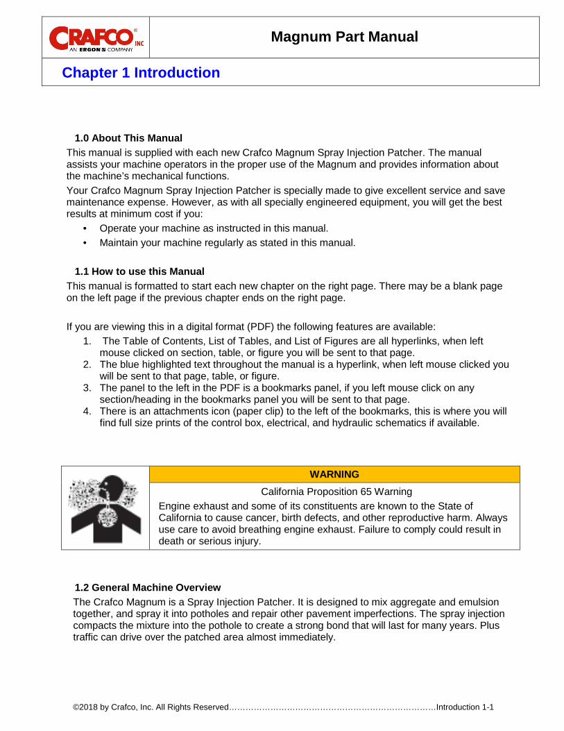
1.0 About This Manual This manual is supplied with each new Crafco Magnum Spray Injection Patcher. The manual assists your machine operators in the proper use of the Magnum and provides information about the machine’s mechanical functions. Your Crafco Magnum Spray Injection Patcher is specially made to give excellent service and save maintenance expense. However, as with all specially engineered equipment, you will get the best results at minimum cost if you:
• Operate your machine as instructed in this manual. • Maintain your machine regularly as stated in this manual.
How to use this Manual 1.1
This manual is formatted to start each new chapter on the right page. There may be a blank page on the left page if the previous chapter ends on the right page. If you are viewing this in a digital format (PDF) the following features are available:
1. The Table of Contents, List of Tables, and List of Figures are all hyperlinks, when left mouse clicked on section, table, or figure you will be sent to that page.
2. The blue highlighted text throughout the manual is a hyperlink, when left mouse clicked you will be sent to that page, table, or figure.
3. The panel to the left in the PDF is a bookmarks panel, if you left mouse click on any section/heading in the bookmarks panel you will be sent to that page.
4. There is an attachments icon (paper clip) to the left of the bookmarks, this is where you will find full size prints of the control box, electrical, and hydraulic schematics if available.
General Machine Overview 1.2The Crafco Magnum is a Spray Injection Patcher. It is designed to mix aggregate and emulsion together, and spray it into potholes and repair other pavement imperfections. The spray injection compacts the mixture into the pothole to create a strong bond that will last for many years. Plus traffic can drive over the patched area almost immediately.
WARNING California Proposition 65 Warning
Engine exhaust and some of its constituents are known to the State of California to cause cancer, birth defects, and other reproductive harm. Always use care to avoid breathing engine exhaust. Failure to comply could result in death or serious injury.
Magnum Part Manual
Chapter 1 Introduction
©2018 by Crafco, Inc. All Rights Reserved…………………………………………………………………Introduction 1-2
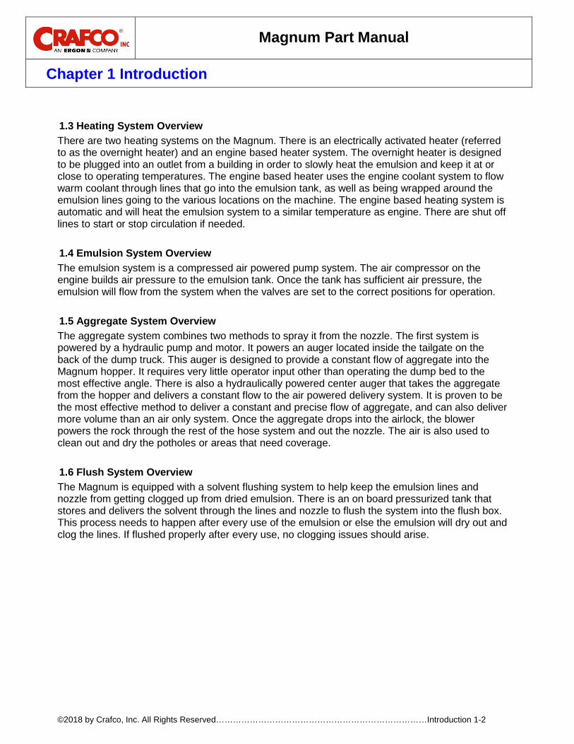
Heating System Overview 1.3
There are two heating systems on the Magnum. There is an electrically activated heater (referred to as the overnight heater) and an engine based heater system. The overnight heater is designed to be plugged into an outlet from a building in order to slowly heat the emulsion and keep it at or close to operating temperatures. The engine based heater uses the engine coolant system to flow warm coolant through lines that go into the emulsion tank, as well as being wrapped around the emulsion lines going to the various locations on the machine. The engine based heating system is automatic and will heat the emulsion system to a similar temperature as engine. There are shut off lines to start or stop circulation if needed.
Emulsion System Overview 1.4The emulsion system is a compressed air powered pump system. The air compressor on the engine builds air pressure to the emulsion tank. Once the tank has sufficient air pressure, the emulsion will flow from the system when the valves are set to the correct positions for operation.
Aggregate System Overview 1.5
The aggregate system combines two methods to spray it from the nozzle. The first system is powered by a hydraulic pump and motor. It powers an auger located inside the tailgate on the back of the dump truck. This auger is designed to provide a constant flow of aggregate into the Magnum hopper. It requires very little operator input other than operating the dump bed to the most effective angle. There is also a hydraulically powered center auger that takes the aggregate from the hopper and delivers a constant flow to the air powered delivery system. It is proven to be the most effective method to deliver a constant and precise flow of aggregate, and can also deliver more volume than an air only system. Once the aggregate drops into the airlock, the blower powers the rock through the rest of the hose system and out the nozzle. The air is also used to clean out and dry the potholes or areas that need coverage.
Flush System Overview 1.6The Magnum is equipped with a solvent flushing system to help keep the emulsion lines and nozzle from getting clogged up from dried emulsion. There is an on board pressurized tank that stores and delivers the solvent through the lines and nozzle to flush the system into the flush box. This process needs to happen after every use of the emulsion or else the emulsion will dry out and clog the lines. If flushed properly after every use, no clogging issues should arise.

Magnum Part Manual
Chapter 2 Safety Precautions
©2018 by Crafco, Inc. All Rights Reserved………...……………………………………………….…Safety Precautions 2-1
2.0 Safety Precautions For more in-depth safety information, please see Safety Manual (PN 26221) which comes with the machine. Or contact your nearest authorized Crafco Distributor at crafco.com/Distributors.
General Safety 2.1• Crafco, Inc. assumes no liability for an accident or injury incurred through improper use of
the machine. • Read this manual thoroughly before operating the machine. • Obey all CAUTION and WARNING signs posted on the machine. • Make sure an operator fully knows how to operate the machine before using the machine.
Personal Safety 2.2
• The high operating temperatures of this machine and the material it contains requires that protective clothing, gloves, hard-soled shoes, and safety glasses or a face shield be worn at all times by operators of the machine.
• Bodily contact with hot material or engine coolant can cause severe burns. • Keep hands, feet, and clothing away from all moving parts.
Equipment or Operational Safety 2.3
• Do not operate the machine in buildings or work areas that do not have sufficient airflow. • Shut down the engine before refilling the fuel tank. • Always keep a correctly maintained fire extinguisher near the machine and know how to use
it. • Temperature control is for the overnight heater only. Operation temperature cannot be
adjusted. • Replace any hoses which show signs of wear, fraying or splitting. • Precaution is the best insurance against accidents. • Make sure all fittings and joints are tight and do not leak each time the machine is used. • Do not leave the machine unattended while it is running. • Tighten all bolts and screws every 100 hours of machine operation. • Check the machine thoroughly for any signs of improper wear. • Crafco, Inc. recommends that the purchasers or users of the machine frequently and
consistently undertake inspections and protective measures with respect to the use and application of the machine.
• Crafco, Inc. assumes no liability for an accident or injury incurred through the improper use of the machine.
• Do not disassemble any valve while under pressure. • Do not fill the emulsion tank more than 2/3’s full. The emulsion will expand after the
emulsion is heated up. Starting at the bottom of the lid opening, fill the emulsion about 12” down from the bottom of the opening. If you overfill the tank, you can damage the machine, and will void the warranty.
• Never operate the machine without all guards in place.

Magnum Part Manual
Chapter 2 Safety Precautions
©2018 by Crafco, Inc. All Rights Reserved………...……………………………………………….…Safety Precautions 2-2
• Do not open the hatch lid on the material tank, solvent flush tank fill port, or emulsion tank rear valve assembly, AS ALL OF THESE TANKS ARE UNDER PRESSURE! To relieve pressure, use the emulsion tank top valve assembly. Open the ½” bronze ball valve. To relieve pressure on the diesel flush tank, open the 2” brass ball valve. The pressure gauge should read “0” before opening any tank.
• Do not plug in emulsion tank overnight heater unless emulsion is above the heating element enclosure inside the tank. This requires a minimum of 60 gallons in the tank.
• Keep emulsion tank airtight when not in use. • Do not allow emulsion to freeze. • Do not put hands, feet, etc. near truck auger tailgate. • Do not fill flush tank more than 2/3 full. • Do not operate near open flame. • Do not use any type of flame to unclog the emulsion hose or spray ring if they should
become clogged. • Do not operate diesel engine above 2200 RPM MAX. • Do not touch the silencer as it can become very hot while the machine is operating. • Hose should not be kinked or run over by any equipment. Hose should not be stored
outdoors due to potential damage from the elements, which may shorten hose life.

Magnum Part Manual
Chapter 2 Safety Precautions
©2018 by Crafco, Inc. All Rights Reserved………...……………………………………………….…Safety Precautions 2-3
Safety Symbols and Notices 2.4Important safety symbols and notices are marked on the machine and in this manual. Failure to comply could result in equipment damage, operational malfunction, serious injury, or death. Please read and comply with all symbols and notices. The table below includes the most commonly used symbols and notices.
Table 2-1 Safety Symbols and Notices
Symbol Item Remarks
WARNING Warning Refers to possible bodily injury or death.
CAUTION Caution Refers to possible equipment damage or operational malfunction.
Severe Burn Hazard Hot material can cause severe burns.
Protective Shoes Wear hard-soled work shoes.
Protective Gloves Wear heat resistant gloves.
Protective Face or Eye Wear Wear face shield or safety glasses.
Body Crush Hazard Do not stand between trailer and hitch when
hooking melter to truck.

Magnum Part Manual
Chapter 2 Safety Precautions
©2018 by Crafco, Inc. All Rights Reserved………...……………………………………………….…Safety Precautions 2-4
Table 2-2 Safety Symbols and Notices (continued)
Symbol Item Remark Crush Hazard Keep feet and legs clear.
Pinch Hazard Keep hands and feet clear.
Moving Machinery Never reach into moving machinery.
Exhaust Hazard Avoid breathing engine exhaust.
Noise Hazard Ear protection is advisable.
Read Manual Read and understand operator and safety
manuals before operating machine.
Magnum Part Manual
Chapter 3 Warranty Information
©2018 by Crafco, Inc. All Rights Reserved………...……………………………………………….…Warranty Information 3-1
3.0 Limited Warranty
Crafco, Inc. (Manufacturer), or one of its affiliated distributors, will replace for the original purchaser free of charge any parts found upon examination by the Manufacturer, to be defective in material or workmanship. This warranty is for a period two years from in-service date, but excludes engine or components, tires, and battery as these items are subject to warranties issued by their manufacturers.
Crafco, Inc. shall not be liable for parts that have been damaged by accident, alteration, abuse, improper lubrication/maintenance, normal wear, or other cause beyond our control.
The warranty provided herein extends only to the repair and/or replacement of those components on the equipment covered above and does not cover labor costs. The warranty does not extend to incidental or consequential damages incurred as a result of any defect covered by this warranty.
All transportation and labor costs incurred by the purchaser in submitting or repairing covered components must be borne by the purchaser. Crafco, Inc. specifically disavows any other representation, warranty, or liability related to the condition or use of the product.
CAUTION Use of replacement parts other than genuine Crafco parts may impair the safety or reliability of your equipment and nullifies any warranty.

Magnum Part Manual
Chapter 3 Warranty Information
©2018 by Crafco, Inc. All Rights Reserved………...……………………………………………….…Warranty Information 3-2
Warranty Claim Instructions 3.1Crafco, Inc. warrants parts and machinery purchased through Crafco or one of its affiliated distributors for two years from purchased or in-service date. Wear items are not covered under the Crafco, Inc. limited warranty. A wear item is defined as but not limited to: material pumps, sealing tips, tires, etc.
If parts fail to function within the two years of purchase, a return authorization number (RA) must be obtained. If the part was purchased through Crafco, Inc., please contact Crafco returns department at [email protected] for an RA number or if purchased through a Crafco distributor please contact your distributor.
Note: if the part has a serial number associated with it, for example; a machine or electric hose or wand, this must be furnished when requesting the RA number. The customer will be emailed or faxed an RA form with all instructions to return the item to Crafco, Inc. See example. If the part is found to be within the two year warranty period and has not been abused or modified, a credit will be issued to the customer’s account or credit card. The customer may request the part be replaced instead of a credit, if desired.
Note: All engine warranties are covered through the engine manufacturer. If you need information for a distributor in your area please contact us and we will direct you to the closest engine distributor.
All parts returned are tested and evaluated. If the part has been modified in any way without prior consent from a Crafco, Inc. representative, warranty is void.
Please follow the instructions stated below when calling in a Warranty Claim. Failure to follow these procedures may be cause to void the warranty.
Call your local Crafco Distributor. If you do not know who your local distributor is, call a Crafco Customer Service Representative, (Toll Free 1-800-528-8242) for name, location and telephone number.
On contacting the distributor, be prepared to identify the serial number, model number, engine number, engine manufacturer, and the date of purchase if available.
Should the cause of the malfunction be a defective part, the Distributor will advise you of the procedure to follow for a replacement.
The warranty is valid only for parts, which have been supplied or recommended by Crafco, Inc.
If you have any additional questions regarding warrant repairs and parts, please do not hesitate to call toll free 1-800-528-8242.
For Warranty: Crafco, Inc. 25527 South Arizona Avenue, Chandler, AZ 85248 Phone: (480) 655-8333 or (800) 528-8242 Fax: (480) 655-1712
For all other inquires: Crafco, Inc. 6165 West Detroit Street Chandler, AZ 85226 Phone: (602) 276-0406 or (800) 528-8242 Fax: (480) 961-0513 [email protected]

Magnum Part Manual
Chapter 4 Machine Specifications
©2018 by Crafco, Inc. All Rights Reserved……………………………..…………………….Machine Specifications 4-1
4.0 Machine Specifications Table 4-1 Machine Specifications
Specification PN 91000
Emulsion Tank Capacity 250 Gallons
Emulsion Temperature Range 160°F to 175°F
Tank Opening Size 8” Diameter
Air Blower Positive Displacement 2475-2887 RPM
Hydraulic Pump Flow 11 Gallons per min @ 1200 RPM
Hydraulic Tank Capacity 22 Gallons
Hydraulic Pressure (running w/ load) 600-1000 PSI
Hydraulic Pressure Max Relief 1850 PSI
Center Auger Speed 39 +/- 10 RPM
Truck Auger Speed 31 +/- 6 RPM
Engine John Deere Diesel Four cylinder Model 4045T 80 HP @ 2400 RPM
Diesel Fuel Tank Capacity 22 Gallons
Solvent Flush Tank Capacity 30 Gallons
Operating Temperature Range Above 0°F
Dry Weight Approximately 6400 lbs.
Axle Capacity Dual 6000 lbs.
Tires ST225/75R15, Load Range D

Magnum Part Manual
Chapter 5 Operating Instructions
©2018 by Crafco, Inc. All Rights Reserved……………………………..…………………….Operating Instructions 5-1
5.0 Operating Instructions
Introduction 5.1The Crafco Magnum Spray Injection Patcher was developed to apply an asphalt emulsion and aggregate mixture to effectively fill and repair pot holes or other road imperfections. Note: DO NOT attempt to operate the machine without using these and all other instructions.
Preparing the Machine for Start Up 5.2Table 5-1 Preparing the Machine for Start Up
Step Action
1
Fill the engine fuel tank with diesel fuel. See Figure 5.1 Diesel Fuel Fill Cap and Level Gauge Note: Refer to the manufacturer’s instruction manual for more specifications on fuel requirements.
2 Check the oil level in the engine crankcase. Refer to the manufacturer’s instruction manual for the engine.
3 Check the hydraulic fluid level while at a temperature of 70°F. Add fluid if necessary. See Figure 5.2 Hydraulic Fluid .
4
Emulsion – The emulsion tank should be filled with an asphalt emulsion suitable for the climate and condition in which the unit will be operating. Commonly this is an RS-2 or a CRS-2. Note: Not all emulsions are compatible. When changing emulsion brand or type, you should completely empty and flush out the tank before the new emulsion is added.
WARNING
Make sure to release pressure from the emulsion tank before opening the emulsion tank lid! Failure to do so could cause personal injury or damage to the machine.
5
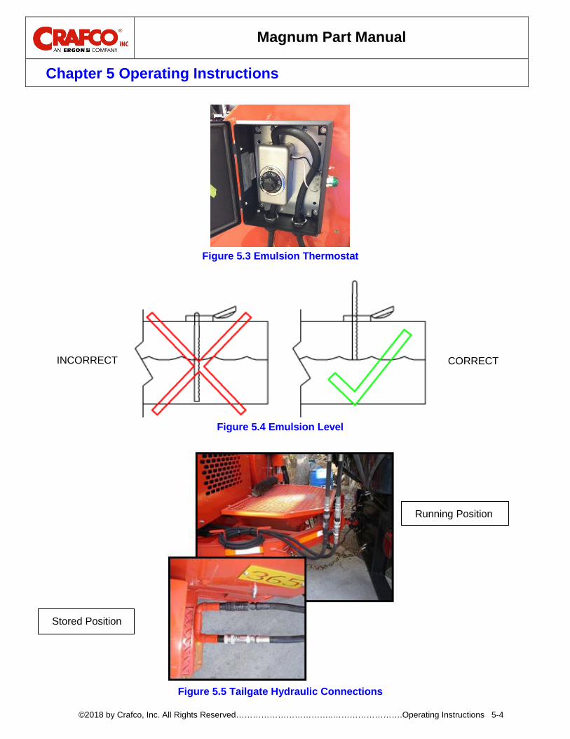
Proper operation temperature for the emulsion is 160°F (+/- 10°F). If the emulsion is below this temperature the unit must be plugged into a 110 volt outlet. (Optional 220 volt wiring is available) The thermostat should be set to 160°F. The electric heating elements are designed to gently heat the emulsion at a rate of 10°F per hour (at 110V). If the emulsion temperature is low it will take several hours to get the emulsion to operation temperature. Plugging in the unit overnight is recommended. See Figure 5.3 Emulsion Thermostat Note: Never allow emulsion to freeze or heat emulsion above 190°F.
6
Emulsion Level- The Magnum comes with a dipstick that can be used to check the level. The dipstick is only meant to measure from the top of the emulsion to the lip of the lid. Do not submerge the dipstick into the emulsion. Just barely touch it to the top of the emulsion, take note of the notch, then wipe the dip stick clean so it won’t stick in the holder. Compare notch to gauge on side of tank for approx. gallons. See Figure 5.4 Emulsion Level

Magnum Part Manual
Chapter 5 Operating Instructions
©2018 by Crafco, Inc. All Rights Reserved……………………………..…………………….Operating Instructions 5-2
Table 5-2 Preparing the Machine for Start Up (continued)
7
Stone – Fill the dump truck bed with the required amount of stone. A 3/8” crushed washed aggregate is the most common and versatile stone to use in patching operations. Smaller stone (1/4”) can be used and may improve results when skin patching. Larger stone (1/2”) can be used to improve results when patching larger holes or repairing shoulders. Note: Each day, before operating the unit, raise the dump body on the truck and rinse the stone with water. Allow the water to drain for several minutes. This will greatly reduce the dust developed during the patching operation and will improve the adhesion of the emulsion to the stone.
8 Solvent- Fill the solvent tank with diesel fuel or another solvent that has been recommended by the emulsion supplier.
9 Connect Tailgate Hydraulics - With the engine off, disconnect the hydraulic lines from the machine and connect them to the tailgate. Make sure the fittings are clean. Be sure to connect the black quick connect fitting to the corresponding black male fitting, otherwise the tailgate auger will run backwards.
CAUTION
Always have the tailgate hydraulic lines connected either in the stored position or to the tailgate, this will prevent undue strain on the hydraulic system. See Figure 5.5 Tailgate Hydraulic Connections
WARNING
The safe operation of this machine is the operator’s responsibility. Use extreme care when operating this machine; safety is the result of being careful and paying attention to details. Remember the emulsion material is at least 160°F, and the hydraulic fluid can get up to 200°F. Always put on protective clothing, gloves, hard-soled shoes, and safety glasses or a face shield, and ear protection. Be sure that all joints and fittings are tight and leak proof. Immediately replace any hose, which shows any signs of wear, fraying, or splitting. Tighten all bolts, nuts, and screws every 100 hours.

Magnum Part Manual
Chapter 5 Operating Instructions
©2018 by Crafco, Inc. All Rights Reserved……………………………..…………………….Operating Instructions 5-3
Figure 5.1 Diesel Fuel Fill Cap and Level Gauge
Figure 5.2 Hydraulic Fluid Fill Cap and Level Gauge
Magnum Part Manual
Chapter 5 Operating Instructions
©2018 by Crafco, Inc. All Rights Reserved……………………………..…………………….Operating Instructions 5-4
Figure 5.3 Emulsion Thermostat
Figure 5.4 Emulsion Level
Figure 5.5 Tailgate Hydraulic Connections
Stored Position
Running Position
INCORRECT CORRECT

Magnum Part Manual
Chapter 5 Operating Instructions
©2018 by Crafco, Inc. All Rights Reserved……………………………..…………………….Operating Instructions 5-5
Start Up 5.3 Pressurize the Emulsion Tank 5.4
Table 5-3 Pressurize the Emulsion Tank
Figure 5.6 Nozzle Removed from Flush Box
Step Action
1 Remove the boom from the holder and remove the nozzle from the flush box.
WARNING
Failure to remove the nozzle from the flush box will blow any solvent and emulsion from the flush box out onto the machine, ground and operator. See Figure 5.6 Nozzle Removed from Flush Box.
2 Make sure all pressure relief valves on the tanks are closed.
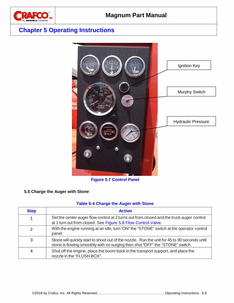
3 With the nozzle pointed at the ground, start the engine by holding in the red Murphy Switch and turning the key. Once engine is running, release Murphy Switch and allow to run for several minutes. See Figure 5.7 Control Panel. The air compressor runs when the engine is running and will automatically start building pressure in the emulsion tank. Allow the pressure to build until the pressure reaches a minimum of 90 PSI.
Magnum Part Manual
Chapter 5 Operating Instructions
©2018 by Crafco, Inc. All Rights Reserved……………………………..…………………….Operating Instructions 5-6
Figure 5.7 Control Panel
Charge the Auger with Stone 5.5
Table 5-4 Charge the Auger with Stone
Step Action
1 Set the center auger flow control at 2 turns out from closed and the truck auger control at 1 turn out from closed. See Figure 5.8 Flow Control Valve.
2 With the engine running at an idle, turn “ON” the “STONE” switch at the operator control panel.
3 Stone will quickly start to shoot out of the nozzle. Run the unit for 45 to 90 seconds until stone is flowing smoothly with no surging then shut “OFF” the “STONE” switch.
4 Shut off the engine, place the boom back in the transport support, and place the nozzle in the “FLUSH BOX”.
Ignition Key
Murphy Switch
Hydraulic Pressure
Magnum Part Manual
Chapter 5 Operating Instructions
©2018 by Crafco, Inc. All Rights Reserved……………………………..…………………….Operating Instructions 5-7
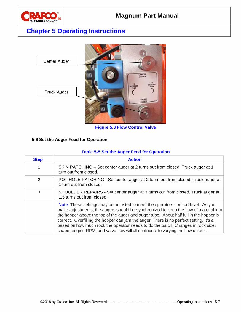
Figure 5.8 Flow Control Valve
Set the Auger Feed for Operation 5.6
Table 5-5 Set the Auger Feed for Operation
Step Action
1 SKIN PATCHING – Set center auger at 2 turns out from closed. Truck auger at 1 turn out from closed.
2 POT HOLE PATCHING - Set center auger at 2 turns out from closed. Truck auger at 1 turn out from closed.
3 SHOULDER REPAIRS - Set center auger at 3 turns out from closed. Truck auger at 1.5 turns out from closed.
Note: These settings may be adjusted to meet the operators comfort level. As you make adjustments, the augers should be synchronized to keep the flow of material into the hopper above the top of the auger and auger tube. About half full in the hopper is correct. Overfilling the hopper can jam the auger. There is no perfect setting. It’s all based on how much rock the operator needs to do the patch. Changes in rock size, shape, engine RPM, and valve flow will all contribute to varying the flow of rock.
Center Auger
Truck Auger

Magnum Part Manual
Chapter 5 Operating Instructions
©2018 by Crafco, Inc. All Rights Reserved……………………………..…………………….Operating Instructions 5-8
Purge the Solvent from the Emulsion Lines. 5.7
Table 5-6 Purge the Solvent from the Emulsion Lines Step Action
1 Locate the EMULSION TANK VALVE at the rear of the emulsion tank.See Figure 5.9 Emulsion Tank Valve.
2 With the nozzle positioned in the flush box and the engine off, turn the EMULSION TANK VALVE to the position marked EMULSION ON.
3
Slowly open the ASPHALT VALVE at the OPERATOR CONTROL PANEL approximately 1/4 open. Solvent will begin to flow from the nozzle for about 10 to 15 seconds, then emulsion will start to flow. When you see the black emulsion start to flow, quickly close the ASPHALT VALVE, as now the solvent will be purged out.
Figure 5.9 Emulsion Tank Valve
Patching Operation 5.8
Table 5-7 Patching Operation Step Action
1
Remove the boom from the transport supports and position the nozzle over the area to be repaired. Note: Always open the boom fully from both holders. The hose needs to be as straight as possible for the best performance. It also needs to have a gradual slope as well, so the position of the hanger chains on the boom arms may need to be adjusted as well.
2 Start the engine.
3 Adjust the throttle up to 2000 RPM.
4 Lower the nozzle to about 12” from the ground and blow all dust, dirt and standing water away from the repair area.
Magnum Part Manual
Chapter 5 Operating Instructions
©2018 by Crafco, Inc. All Rights Reserved……………………………..…………………….Operating Instructions 5-9
Table 5-8 Patching Operation (continued) Step Action
5
Reduce the engine RPMs to: • Skin Patching - 900 to 1000 RPM • Holes - 1100 to 1200 RPM • Shoulder Repairs 1300 to 1500 RPM
Note: With variables in stone, equipment and operator you may find that your unit works better at slightly higher RPM. These settings are our recommended settings for 3/8” stone. Each operator can adjust to their comfort level. We suggest with 1/2” stone increase by100 RPM and with 1/4” stone decrease slightly.
6 Raise the nozzle to 24” to 30” from the pavement (Knee High) and slowly open the ASPHALT VALVE approximately 1/4 open.
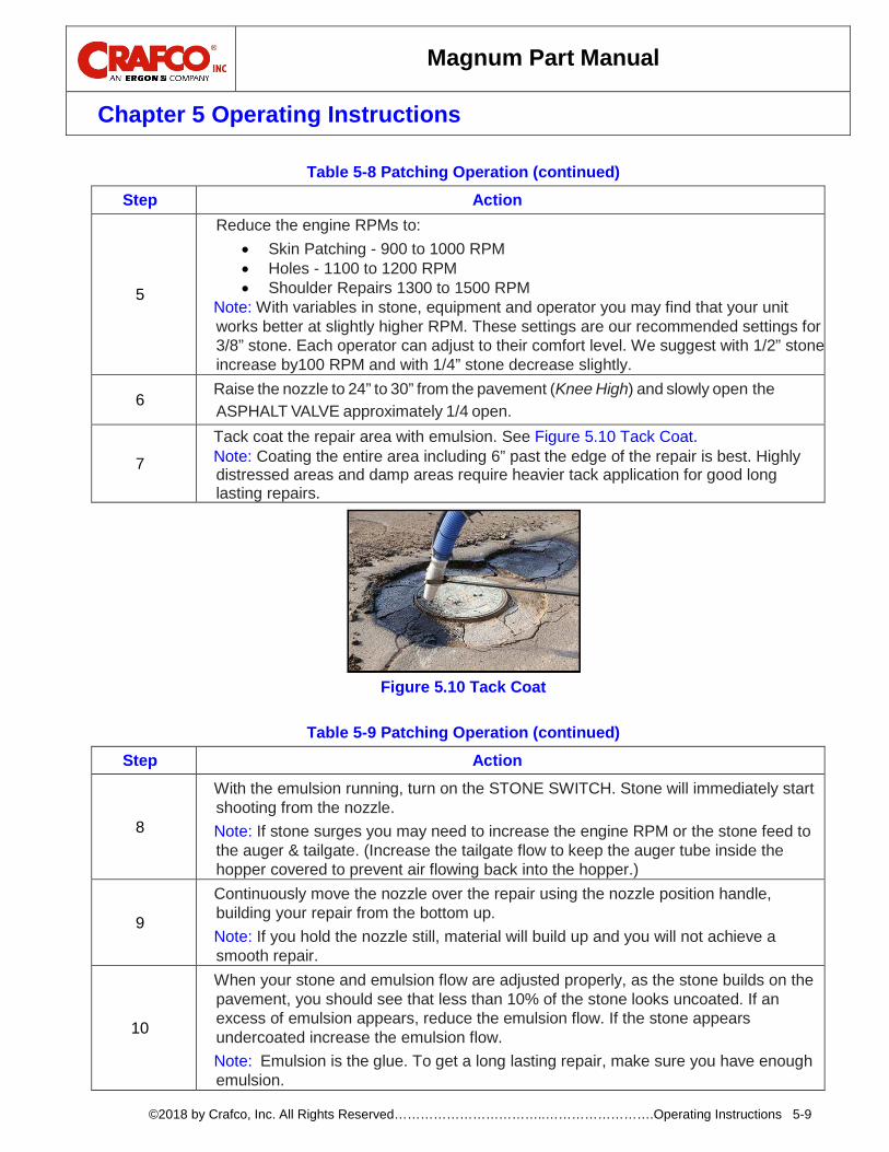
7
Tack coat the repair area with emulsion. See Figure 5.10 Tack Coat. Note: Coating the entire area including 6” past the edge of the repair is best. Highly distressed areas and damp areas require heavier tack application for good long lasting repairs.
Figure 5.10 Tack Coat
Table 5-9 Patching Operation (continued)
Step Action
8
With the emulsion running, turn on the STONE SWITCH. Stone will immediately start shooting from the nozzle. Note: If stone surges you may need to increase the engine RPM or the stone feed to the auger & tailgate. (Increase the tailgate flow to keep the auger tube inside the hopper covered to prevent air flowing back into the hopper.)
9
Continuously move the nozzle over the repair using the nozzle position handle, building your repair from the bottom up. Note: If you hold the nozzle still, material will build up and you will not achieve a smooth repair.
10
When your stone and emulsion flow are adjusted properly, as the stone builds on the pavement, you should see that less than 10% of the stone looks uncoated. If an excess of emulsion appears, reduce the emulsion flow. If the stone appears undercoated increase the emulsion flow. Note: Emulsion is the glue. To get a long lasting repair, make sure you have enough emulsion.

Magnum Part Manual
Chapter 5 Operating Instructions
©2018 by Crafco, Inc. All Rights Reserved……………………………..…………………….Operating Instructions 5-10
Table 5-10 Patching Operation (continued) Step Action
11 When the repair is at the desired level, close the ASPHALT VALVE. Dry stone will continue to flow from the nozzle. Lightly cover the entire repair with dry stone to complete the repair.
12 Shut off STONE SWITCH. Note: Stone continues to flow for about 10 seconds after the switch is off.
13 Move the nozzle away from the repair area.
14 Lower the engine RPM. Tip: With a push broom, clean up any overspray of material by sweeping it back onto the repair area.
15 Move to the next repair area.
CAUTION
Never travel without properly stowing boom in the transport supports and locking into position. NEVER place the nozzle in the flush box with the engine running.
Figure 5.11 Building up the Repair
Figure 5.12 Finishing the Repair
Magnum Part Manual
Chapter 5 Operating Instructions
©2018 by Crafco, Inc. All Rights Reserved……………………………..…………………….Operating Instructions 5-11
Shut Down Procedure 5.9 Asphalt Emulsion Line Flush Procedure 5.10
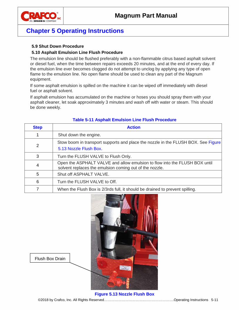
The emulsion line should be flushed preferably with a non-flammable citrus based asphalt solvent or diesel fuel, when the time between repairs exceeds 20 minutes, and at the end of every day. If the emulsion line ever becomes clogged do not attempt to unclog by applying any type of open flame to the emulsion line. No open flame should be used to clean any part of the Magnum equipment. If some asphalt emulsion is spilled on the machine it can be wiped off immediately with diesel fuel or asphalt solvent. If asphalt emulsion has accumulated on the machine or hoses you should spray them with your asphalt cleaner, let soak approximately 3 minutes and wash off with water or steam. This should be done weekly.
Table 5-11 Asphalt Emulsion Line Flush Procedure Step Action
1 Shut down the engine.
2 Stow boom in transport supports and place the nozzle in the FLUSH BOX. See Figure 5.13 Nozzle Flush Box.
3 Turn the FLUSH VALVE to Flush Only.
4 Open the ASPHALT VALVE and allow emulsion to flow into the FLUSH BOX until solvent replaces the emulsion coming out of the nozzle.
5 Shut off ASPHALT VALVE.
6 Turn the FLUSH VALVE to Off.
7 When the Flush Box is 2/3rds full, it should be drained to prevent spilling.
Figure 5.13 Nozzle Flush Box
Flush Box Drain
Magnum Part Manual
Chapter 5 Operating Instructions
©2018 by Crafco, Inc. All Rights Reserved……………………………..…………………….Operating Instructions 5-12
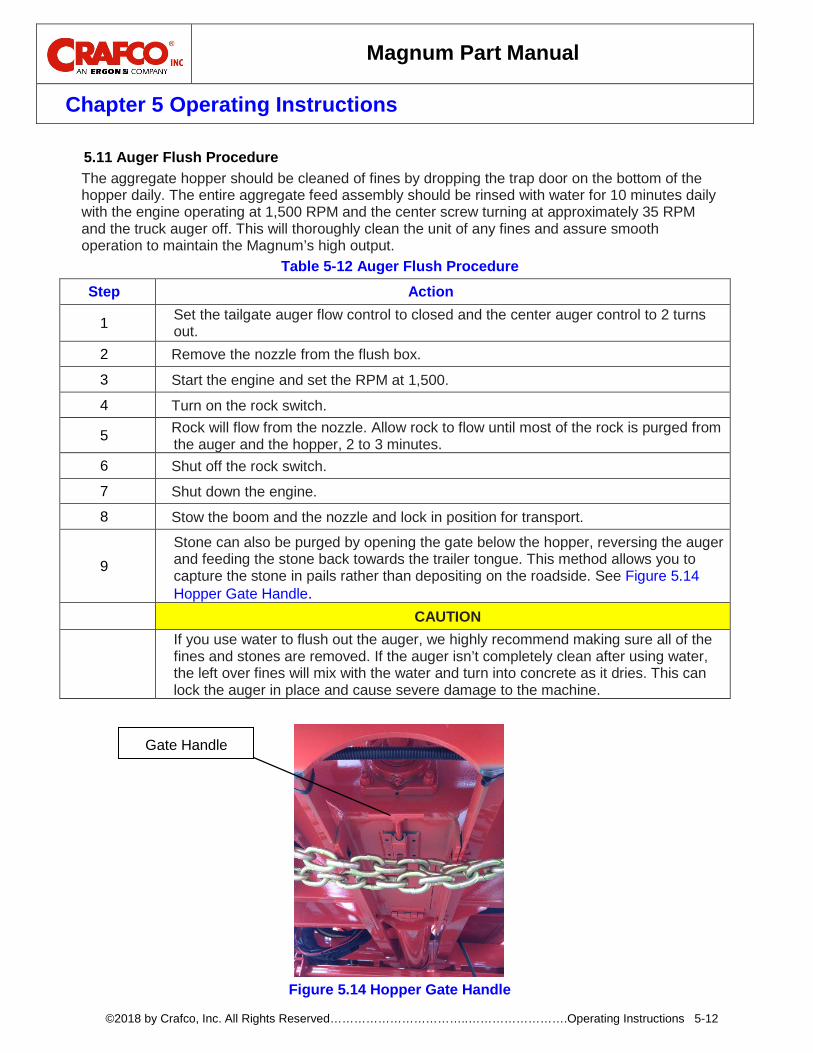
Auger Flush Procedure 5.11The aggregate hopper should be cleaned of fines by dropping the trap door on the bottom of the hopper daily. The entire aggregate feed assembly should be rinsed with water for 10 minutes daily with the engine operating at 1,500 RPM and the center screw turning at approximately 35 RPM and the truck auger off. This will thoroughly clean the unit of any fines and assure smooth operation to maintain the Magnum’s high output.
Table 5-12 Auger Flush Procedure Step Action
1 Set the tailgate auger flow control to closed and the center auger control to 2 turns out.
2 Remove the nozzle from the flush box.
3 Start the engine and set the RPM at 1,500.
4 Turn on the rock switch.
5 Rock will flow from the nozzle. Allow rock to flow until most of the rock is purged from the auger and the hopper, 2 to 3 minutes.
6 Shut off the rock switch.
7 Shut down the engine.
8 Stow the boom and the nozzle and lock in position for transport.
9 Stone can also be purged by opening the gate below the hopper, reversing the auger and feeding the stone back towards the trailer tongue. This method allows you to capture the stone in pails rather than depositing on the roadside. See Figure 5.14 Hopper Gate Handle.
CAUTION
If you use water to flush out the auger, we highly recommend making sure all of the fines and stones are removed. If the auger isn’t completely clean after using water, the left over fines will mix with the water and turn into concrete as it dries. This can lock the auger in place and cause severe damage to the machine.
Figure 5.14 Hopper Gate Handle
Gate Handle
Magnum Part Manual
Chapter 5 Operating Instructions
©2018 by Crafco, Inc. All Rights Reserved……………………………..…………………….Operating Instructions 5-13
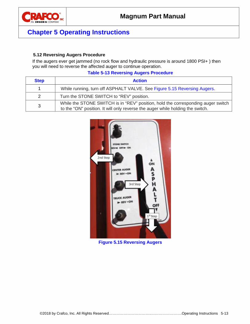
Reversing Augers Procedure 5.12
If the augers ever get jammed (no rock flow and hydraulic pressure is around 1800 PSI+ ) then you will need to reverse the affected auger to continue operation.
Table 5-13 Reversing Augers Procedure Step Action
1 While running, turn off ASPHALT VALVE. See Figure 5.15 Reversing Augers. 2 Turn the STONE SWITCH to “REV” position.
3 While the STONE SWITCH is in “REV” position, hold the corresponding auger switch to the “ON” position. It will only reverse the auger while holding the switch.
Figure 5.15 Reversing Augers

Magnum Part Manual
Chapter 5 Operating Instructions
©2018 by Crafco, Inc. All Rights Reserved……………………………..…………………….Operating Instructions 5-14
Boom Height Adjustment Procedure 5.13For proper operation of the operator boom, the nozzle needs to be able to float in a constant position above the ground for best results. There are adjustable spring cylinders that control the tension on the boom. There is adjustment available because over time the springs may start to stretch, as well as different operating conditions might require a different tension. Correct adjustment allows the operator to be able to raise and lower the boom, and it will also hold its height without input from the operator.
Table 5-14 Boom Height Adjustment Procedure Step Action
1 Turn the adjustment nuts to the right to increase tension, and to the left to decrease tension. See Figure 5.16 Boom Height Adjustment.
2 Usually, all that is needed is an adjustment to the top cylinder. If not enough tension is available, you can decrease the tension on the upper cylinder, and increase tension on the 2 lower cylinders.
3 In the event that a more extreme adjustment is needed, the upper cylinder can also be adjusted by changing the mounting bolt position on the cylinder. There are 5 positions available.
Figure 5.16 Boom Height Adjustment
Top Cylinder
Adjustment Nut
Adjustment Nut
Lower Cylinder
Adjustable Cylinder Mount
Magnum Part Manual
Chapter 5 Operating Instructions
©2018 by Crafco, Inc. All Rights Reserved……………………………..…………………….Operating Instructions 5-15
Storing the Machine 5.14
Store the machine for longer periods with the emulsion tank empty and the lid sealed. Make sure the emulsion lines have been flushed properly to prevent clogging of the lines and nozzle.
Overnight Heater 5.15
The overnight heater may be used to maintain and heat up the emulsion without the engine running.
Table 5-15 Overnight Heaters Step Action
1 Attach the heater power cord to a suitable extension cord and outlet rated for 15 amps.
2 Turn the thermostat dial to the required temperature.
3 Disconnect the heater before moving the machine.
CAUTION
Do not use the heater without at least 60 gallons of emulsion in the tank. Doing so will harm the heater and could cause the emulsion to overheat.


Magnum Part Manual
Chapter 6 Maintenance Instructions
©2018 by Crafco, Inc. All Rights Reserved……………………………..…………………….Maintenance Instructions 6-1
6.0 Maintenance Instructions This chapter contains all normal maintenance instructions to properly maintain your machine.
Engine 6.1
Check oil daily. Service engine per the John Deere owner’s manual. See engine owner’s manual for additional operating and maintenance instructions. This manual is located in the manual storage box.
Hydraulic System 6.2Check hydraulic fluid daily. Remove and clean hydraulic oil filter in first 30 hours and then every 100 hours. Replace return line filter the first 30 hours then every 100 hours. Change the hydraulic fluid every 500 hours.
Blower 6.3Refer to the separate manual (Tuthill Blower Manual). The manual is located in the manual storage box.
Air Compressor 6.4Refer to the separate manual (John Deere Manual). The manual is located in the manual storage box.
Air Cleaners for Blower and Engine 6.5Replace the filter only when the restriction level has reached the maximum recommended by the engine or equipment manufacturer. Empty the dust cap. Dust cap should be dumped when 1/3 full. When reinstalling dust cap, be sure it seals 360° around the air cleaner body. Check the vacuator valve to see that it is not inverted, damaged or plugged. If it is damaged, replace it immediately.
Auger Bearings 6.6Lubricate the bearings at each end of the truck auger tailgate and the bearings on the center auger under the aggregate hopper approximately every 75 hours.
Boom Bearings 6.7Lubricate bearings every 100 hours for boom. Boom has two bearings, an upper and a lower. Grease lightly.
Bearing Stub Support Shaft on Engine 6.8
Grease the bearing stub support shaft assembly on the back of the bell housing. It is under the belt guard cover.
Magnum Part Manual
Chapter 6 Maintenance Instructions
©2018 by Crafco, Inc. All Rights Reserved……………………………..…………………….Maintenance Instructions 6-2
Wheel Bearing 6.9Pack the wheel bearing every 24,000 miles or every two years, whichever comes first. Use a good grade of bearing grease.
Brakes 6.10
Check the brakes daily.
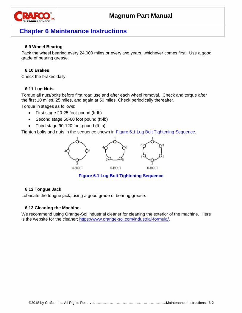
Lug Nuts 6.11Torque all nuts/bolts before first road use and after each wheel removal. Check and torque after the first 10 miles, 25 miles, and again at 50 miles. Check periodically thereafter. Torque in stages as follows:
• First stage 20-25 foot-pound (ft-lb) • Second stage 50-60 foot pound (ft-lb) • Third stage 90-120 foot pound (ft-lb)
Tighten bolts and nuts in the sequence shown in Figure 6.1 Lug Bolt Tightening Sequence.
Tongue Jack 6.12Lubricate the tongue jack, using a good grade of bearing grease.
Cleaning the Machine 6.13We recommend using Orange-Sol industrial cleaner for cleaning the exterior of the machine. Here is the website for the cleaner; https://www.orange-sol.com/industrial-formula/.
Figure 6.1 Lug Bolt Tightening Sequence

Magnum Part Manual
Chapter 6 Maintenance Instructions
©2018 by Crafco, Inc. All Rights Reserved……………………………..…………………….Maintenance Instructions 6-3
Maintenance Chart 6.14Table 6-1 Maintenance Chart
Hours Location Procedure 8 50 100 500
Engine check oil level Refer to the manufacturer’s instructions for the engine X
Other engine maintenance Refer to the manufacture’s operating and maintenance instructions for the engine.
Blower
Oil Check X
Oil Change X
Grease Fittings X
Hydraulic Oil Check X
Change X
Hydraulic Oil Filter – Return Change X
Hydraulic Oil Filter – Suction Check and Clean X
Center Auger Bearings Grease using a good grade bearing grease. X
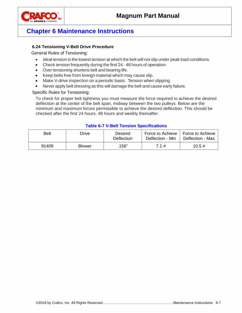
V-Belt Drive Check tension. See Table 6-7 V-Belt Tension Specifications. X
Stub Support Bearing on Engine Grease using a good grade bearing grease. X
Truck Auger Bearings Grease using a good grade bearing grease. X
Boom Bearings Grease using a good grade bearing grease. X
Wheel Bearings Clean and re-pack using a good grade of bearing grease.
Every 24,000 miles or two years
Tongue Jack Grease using a good grade of bearing grease. Once a year
Flush Tank Drain tank. Use solvent to break up hardened emulsion if needed.
When 2/3rds full or as needed.
See Table 6-4 General Maintenance Parts for more info on part numbers.
Magnum Part Manual
Chapter 6 Maintenance Instructions
©2018 by Crafco, Inc. All Rights Reserved……………………………..…………………….Maintenance Instructions 6-4
Service Instructions 6.15Table 6-2 Service Instructions
Step Action
1 Do a general inspection of the machine at least once a week.
2 Replace all worn or damaged parts. Note: Keep regular replacement items in stock for emergency repairs to prevent costly downtime. See Table 6-5 Recommended Spare Parts.
3 Make necessary adjustments and tighten all loose nuts or screws.
4 Watch for leaks. Tighten fittings or repair as necessary.
5 Clean the external surfaces of the machine at regular intervals. Note: Refer to the material manufacturer’s instructions for recommendations.
6 Follow the recommended maintenance per Table 6-1 Maintenance Chart. For service, find a list of authorized Distributors and service centers at Crafco.com/Distributors.
Recommended Fluids and Lubricants 6.16Table 6-3 Recommended Fluids and Lubricants
Application Recommended Full Point Engine Oil Refer to engine manual Refer to Manual
Hydraulic Oil Shell AW Hydraulic 46 Sight Glass
Blower Oil Refer to blower manual. 8.5 Oz.
Blower Grease Refer to blower manual Refer to manual
Bearing Grease Good grade of heavy duty grease N/A
Magnum Part Manual
Chapter 6 Maintenance Instructions
©2018 by Crafco, Inc. All Rights Reserved……………………………..…………………….Maintenance Instructions 6-5
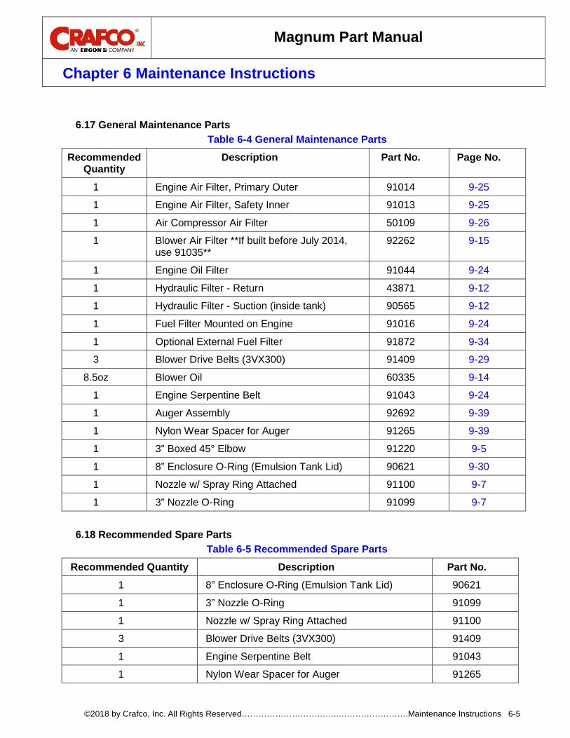
General Maintenance Parts 6.17
Table 6-4 General Maintenance Parts Recommended
Quantity Description Part No. Page No.
1 Engine Air Filter, Primary Outer 91014 9-25
1 Engine Air Filter, Safety Inner 91013 9-25
1 Air Compressor Air Filter 50109 9-26
1 Blower Air Filter **If built before July 2014, use 91035**
92262 9-15
1 Engine Oil Filter 91044 9-24
1 Hydraulic Filter - Return 43871 9-12
1 Hydraulic Filter - Suction (inside tank) 90565 9-12
1 Fuel Filter Mounted on Engine 91016 9-24
1 Optional External Fuel Filter 91872 9-34
3 Blower Drive Belts (3VX300) 91409 9-29
8.5oz Blower Oil 60335 9-14
1 Engine Serpentine Belt 91043 9-24
1 Auger Assembly 92692 9-39
1 Nylon Wear Spacer for Auger 91265 9-39
1 3” Boxed 45° Elbow 91220 9-5
1 8” Enclosure O-Ring (Emulsion Tank Lid) 90621 9-30
1 Nozzle w/ Spray Ring Attached 91100 9-7
1 3” Nozzle O-Ring 91099 9-7
Recommended Spare Parts 6.18
Table 6-5 Recommended Spare Parts Recommended Quantity Description Part No.
1 8” Enclosure O-Ring (Emulsion Tank Lid) 90621
1 3” Nozzle O-Ring 91099
1 Nozzle w/ Spray Ring Attached 91100
3 Blower Drive Belts (3VX300) 91409
1 Engine Serpentine Belt 91043
1 Nylon Wear Spacer for Auger 91265
Magnum Part Manual
Chapter 6 Maintenance Instructions
©2018 by Crafco, Inc. All Rights Reserved……………………………..…………………….Maintenance Instructions 6-6
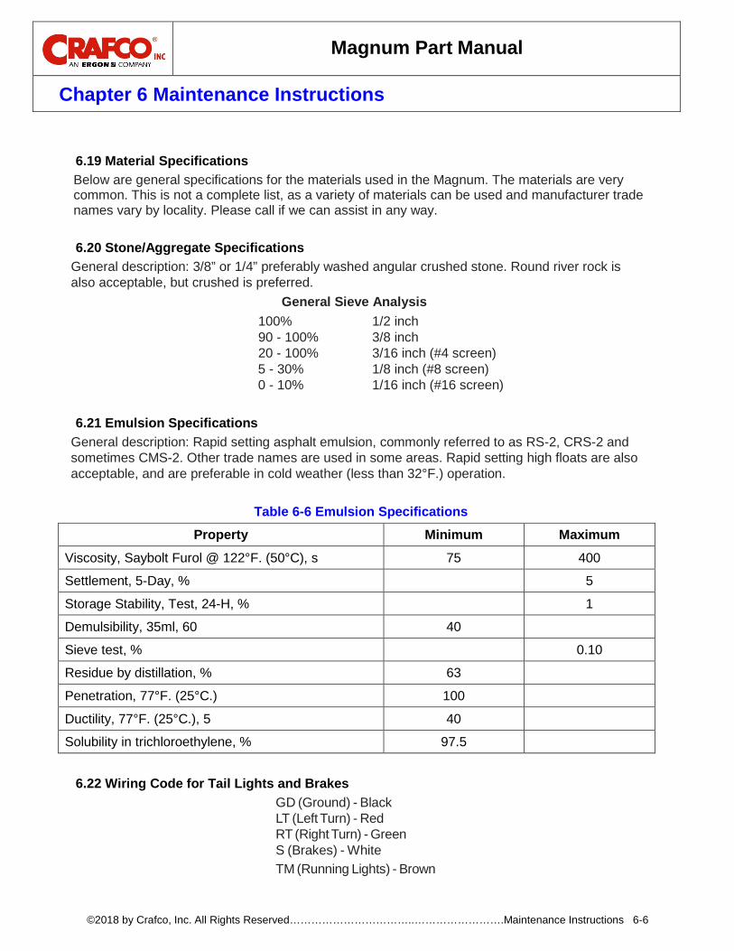
Material Specifications 6.19
Below are general specifications for the materials used in the Magnum. The materials are very common. This is not a complete list, as a variety of materials can be used and manufacturer trade names vary by locality. Please call if we can assist in any way.
Stone/Aggregate Specifications 6.20General description: 3/8” or 1/4” preferably washed angular crushed stone. Round river rock is also acceptable, but crushed is preferred.
General Sieve Analysis 100% 1/2 inch 90 - 100% 3/8 inch 20 - 100% 3/16 inch (#4 screen) 5 - 30% 1/8 inch (#8 screen) 0 - 10% 1/16 inch (#16 screen)
Emulsion Specifications 6.21
General description: Rapid setting asphalt emulsion, commonly referred to as RS-2, CRS-2 and sometimes CMS-2. Other trade names are used in some areas. Rapid setting high floats are also acceptable, and are preferable in cold weather (less than 32°F.) operation.
Table 6-6 Emulsion Specifications Property Minimum Maximum
Viscosity, Saybolt Furol @ 122°F. (50°C), s 75 400
Settlement, 5-Day, % 5
Storage Stability, Test, 24-H, % 1
Demulsibility, 35ml, 60 40
Sieve test, % 0.10
Residue by distillation, % 63
Penetration, 77°F. (25°C.) 100
Ductility, 77°F. (25°C.), 5 40
Solubility in trichloroethylene, % 97.5
Wiring Code for Tail Lights and Brakes 6.22
GD (Ground) - Black LT (Left Turn) - Red RT (Right Turn) - Green S (Brakes) - White TM (Running Lights) - Brown
Magnum Part Manual
Chapter 6 Maintenance Instructions
©2018 by Crafco, Inc. All Rights Reserved……………………………..…………………….Maintenance Instructions 6-7
Tensioning V-Belt Drive Procedure 6.24General Rules of Tensioning: • Ideal tension is the lowest tension at which the belt will not slip under peak load conditions. • Check tension frequently during the first 24 - 48 hours of operation. • Over tensioning shortens belt and bearing life. • Keep belts free from foreign material which may cause slip. • Make V-drive inspection on a periodic basis. Tension when slipping. • Never apply belt dressing as this will damage the belt and cause early failure.
Specific Rules for Tensioning: To check for proper belt tightness you must measure the force required to achieve the desired deflection at the center of the belt span, midway between the two pulleys. Below are the minimum and maximum forces permissible to achieve the desired deflection. This should be checked after the first 24 hours, 48 hours and weekly thereafter.
Table 6-7 V-Belt Tension Specifications
Belt Drive Desired Deflection
Force to Achieve Deflection - Min
Force to Achieve Deflection - Max
91409 Blower .156” 7.1 # 10.5 #
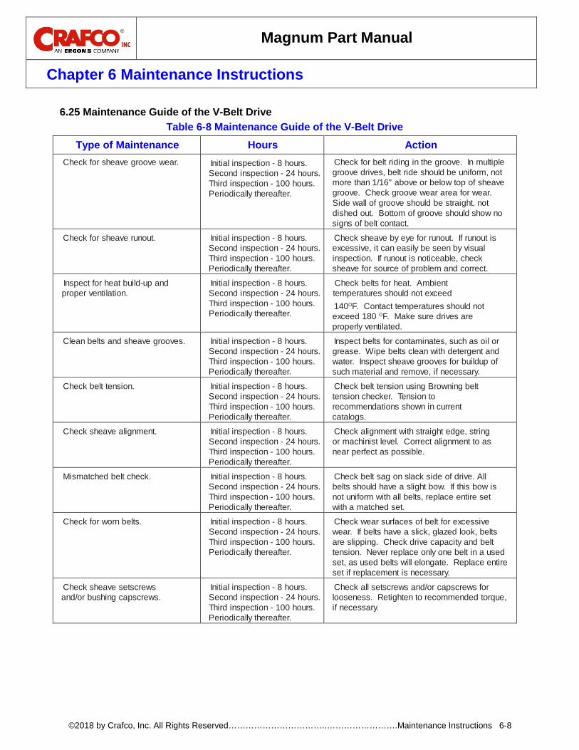
Magnum Part Manual
Chapter 6 Maintenance Instructions
©2018 by Crafco, Inc. All Rights Reserved……………………………..…………………….Maintenance Instructions 6-8
Maintenance Guide of the V-Belt Drive 6.25Table 6-8 Maintenance Guide of the V-Belt Drive
Type of Maintenance Hours Action Check for sheave groove wear. Initial inspection - 8 hours.
Second inspection - 24 hours. Third inspection - 100 hours. Periodically thereafter.
Check for belt riding in the groove. In multiple groove drives, belt ride should be uniform, not more than 1/16" above or below top of sheave groove. Check groove wear area for wear. Side wall of groove should be straight, not dished out. Bottom of groove should show no signs of belt contact.
Check for sheave runout. Initial inspection - 8 hours. Second inspection - 24 hours. Third inspection - 100 hours. Periodically thereafter.
Check sheave by eye for runout. If runout is excessive, it can easily be seen by visual inspection. If runout is noticeable, check sheave for source of problem and correct.
Inspect for heat build-up and proper ventilation.
Initial inspection - 8 hours. Second inspection - 24 hours. Third inspection - 100 hours. Periodically thereafter.
Check belts for heat. Ambient temperatures should not exceed 140OF. Contact temperatures should not exceed 180 OF. Make sure drives are properly ventilated.
Clean belts and sheave grooves. Initial inspection - 8 hours. Second inspection - 24 hours. Third inspection - 100 hours. Periodically thereafter.
Inspect belts for contaminates, such as oil or grease. Wipe belts clean with detergent and water. Inspect sheave grooves for buildup of such material and remove, if necessary.
Check belt tension. Initial inspection - 8 hours. Second inspection - 24 hours. Third inspection - 100 hours. Periodically thereafter.
Check belt tension using Browning belt tension checker. Tension to recommendations shown in current catalogs.
Check sheave alignment. Initial inspection - 8 hours. Second inspection - 24 hours. Third inspection - 100 hours. Periodically thereafter.
Check alignment with straight edge, string or machinist level. Correct alignment to as near perfect as possible.
Mismatched belt check. Initial inspection - 8 hours. Second inspection - 24 hours. Third inspection - 100 hours. Periodically thereafter.
Check belt sag on slack side of drive. All belts should have a slight bow. If this bow is not uniform with all belts, replace entire set with a matched set.
Check for worn belts. Initial inspection - 8 hours. Second inspection - 24 hours. Third inspection - 100 hours. Periodically thereafter.
Check wear surfaces of belt for excessive wear. If belts have a slick, glazed look, belts are slipping. Check drive capacity and belt tension. Never replace only one belt in a used set, as used belts will elongate. Replace entire set if replacement is necessary.
Check sheave setscrews and/or bushing capscrews.
Initial inspection - 8 hours. Second inspection - 24 hours. Third inspection - 100 hours. Periodically thereafter.
Check all setscrews and/or capscrews for looseness. Retighten to recommended torque, if necessary.
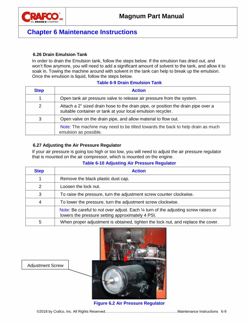
Magnum Part Manual
Chapter 6 Maintenance Instructions
©2018 by Crafco, Inc. All Rights Reserved……………………………..…………………….Maintenance Instructions 6-9
Drain Emulsion Tank 6.26
In order to drain the Emulsion tank, follow the steps below. If the emulsion has dried out, and won’t flow anymore, you will need to add a significant amount of solvent to the tank, and allow it to soak in. Towing the machine around with solvent in the tank can help to break up the emulsion. Once the emulsion is liquid, follow the steps below.
Table 6-9 Drain Emulsion Tank Step Action
1 Open tank air pressure valve to release air pressure from the system.
2 Attach a 2” sized drain hose to the drain pipe, or position the drain pipe over a suitable container or tank at your local emulsion recycler.
3 Open valve on the drain pipe, and allow material to flow out.
Note: The machine may need to be tilted towards the back to help drain as much emulsion as possible.
Adjusting the Air Pressure Regulator 6.27
If your air pressure is going too high or too low, you will need to adjust the air pressure regulator that is mounted on the air compressor, which is mounted on the engine.
Table 6-10 Adjusting Air Pressure Regulator Step Action
1 Remove the black plastic dust cap.
2 Loosen the lock nut.
3 To raise the pressure, turn the adjustment screw counter clockwise.
4 To lower the pressure, turn the adjustment screw clockwise.
Note: Be careful to not over adjust. Each ¼ turn of the adjusting screw raises or lowers the pressure setting approximately 4 PSI.
5 When proper adjustment is obtained, tighten the lock nut, and replace the cover.
Figure 6.2 Air Pressure Regulator
Adjustment Screw
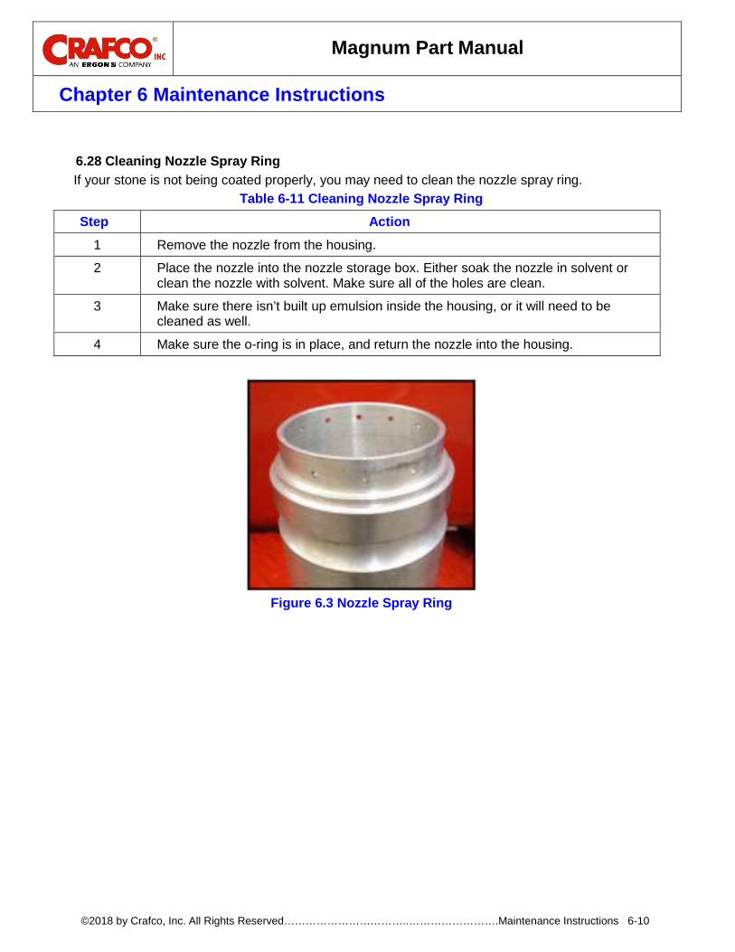
Magnum Part Manual
Chapter 6 Maintenance Instructions
©2018 by Crafco, Inc. All Rights Reserved……………………………..…………………….Maintenance Instructions 6-10
Cleaning Nozzle Spray Ring 6.28
If your stone is not being coated properly, you may need to clean the nozzle spray ring. Table 6-11 Cleaning Nozzle Spray Ring
Step Action
1 Remove the nozzle from the housing.
2 Place the nozzle into the nozzle storage box. Either soak the nozzle in solvent or clean the nozzle with solvent. Make sure all of the holes are clean.
3 Make sure there isn’t built up emulsion inside the housing, or it will need to be cleaned as well.
4 Make sure the o-ring is in place, and return the nozzle into the housing.
Figure 6.3 Nozzle Spray Ring

Magnum Part Manual
Chapter 7 How to Use a Multimeter
©2018 by Crafco, Inc. All Rights Reserved……………………………..…………………….How to Use a Multimeter 7-1
7.0 How to Use a Multimeter
Crafco machines use 12-volt direct current (DC) to power the burner, hydraulic valves, and trigger on electric wand. The DC power is from a 12-volt battery. If equipped, the electric hose and wand uses 24-volt 3-phase alternating current (AC). The AC power is from the generator which hangs under the radiator. This system has no reference to ground so there is no possibility of electrical shock unless you are between 2 of the phases. NOTE: ONLY CHECK AMPERAGE ON A HOSE WITH A CLAMP-ON AMP METER. 12-volt DC power has little danger of electrical shock. Care must still be taken when dealing with DC power systems because it is capable of producing large amounts of current.
Checking DC Voltage with a Multimeter 7.1
Connect the probes to the meter. Set the range to a position that includes 12-volts or higher. Touch the red probe to the positive side of accessory and black probe to ground. If the item you are checking has a ground wire attached then use that ground or you can use a non-painted surface on the frame.
Checking AC Voltage with Multimeter 7.2
Connect the probes to the meter. Set the range to a position that includes 24-volts or higher. There are three steps to test the generator voltage. All 3 values should be in the range of 24-30 volts AC.
• Touch red probe to the white wire of the generator and the black probe to the green wire of the generator.
• Next move black probe to black wire. • Then move red probe to green wire.
Checking Resistance (Ohms) 7.3Connect the probes to the meter. See Figure 7.1 Standard Multimeter. Note: When checking Ohms, the circuit cannot be completed. This means one end of the wire will need to be disconnected.
How to Check Wire Continuity 7.3.1Set the meter to “Audible Continuity”. Now touch the probe to each end of the wire in question. The meter will read “0” on the screen and make an audible beep if the wire has continuity from end to end.
How to Check RTD Sensor 7.3.2
Set dial to Ohms Ω. If your meter has different ranges, set to 2k or 2000 ohm range. Touch one probe to each screw or wire of the sensor. The meter will read X.XX if in the 2k range or XXX.X if in the 2000 range.
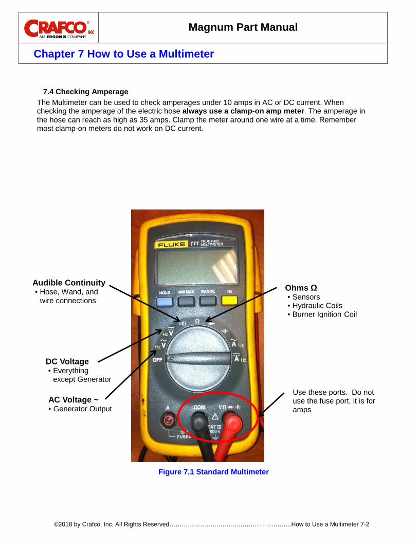
Magnum Part Manual
Chapter 7 How to Use a Multimeter
©2018 by Crafco, Inc. All Rights Reserved……………………………..…………………….How to Use a Multimeter 7-2
Checking Amperage 7.4
The Multimeter can be used to check amperages under 10 amps in AC or DC current. When checking the amperage of the electric hose always use a clamp-on amp meter. The amperage in the hose can reach as high as 35 amps. Clamp the meter around one wire at a time. Remember most clamp-on meters do not work on DC current.
Figure 7.1 Standard Multimeter
AC Voltage ~ • Generator Output
DC Voltage • Everything
except Generator
Audible Continuity • Hose, Wand, and
wire connections Ohms Ω • Sensors • Hydraulic Coils • Burner Ignition Coil
Use these ports. Do not use the fuse port, it is for amps
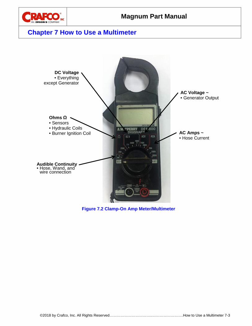
Magnum Part Manual
Chapter 7 How to Use a Multimeter
©2018 by Crafco, Inc. All Rights Reserved……………………………..…………………….How to Use a Multimeter 7-3
Ohms Ω • Sensors • Hydraulic Coils • Burner Ignition Coil
Audible Continuity • Hose, Wand, and
wire connection
DC Voltage • Everything
except Generator
AC Voltage ~ • Generator Output
AC Amps ~ • Hose Current
Figure 7.2 Clamp-On Amp Meter/Multimeter

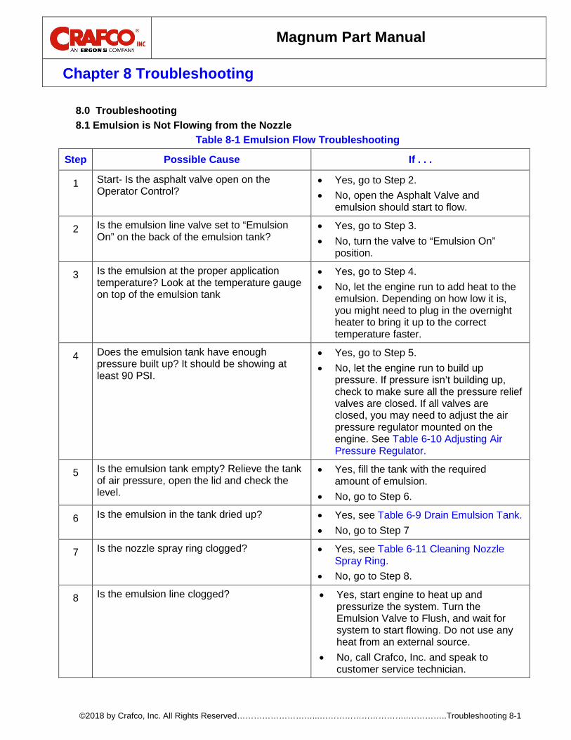
Magnum Part Manual
Chapter 8 Troubleshooting
©2018 by Crafco, Inc. All Rights Reserved………………………...…………………………..…………..Troubleshooting 8-1
8.0 Troubleshooting Emulsion is Not Flowing from the Nozzle 8.1
Table 8-1 Emulsion Flow Troubleshooting
Step Possible Cause If . . .
1 Start- Is the asphalt valve open on the Operator Control?
• Yes, go to Step 2. • No, open the Asphalt Valve and
emulsion should start to flow.
2 Is the emulsion line valve set to “Emulsion On” on the back of the emulsion tank?
• Yes, go to Step 3. • No, turn the valve to “Emulsion On”
position.
3 Is the emulsion at the proper application temperature? Look at the temperature gauge on top of the emulsion tank
• Yes, go to Step 4. • No, let the engine run to add heat to the
emulsion. Depending on how low it is, you might need to plug in the overnight heater to bring it up to the correct temperature faster.
4 Does the emulsion tank have enough pressure built up? It should be showing at least 90 PSI.
• Yes, go to Step 5. • No, let the engine run to build up
pressure. If pressure isn’t building up, check to make sure all the pressure relief valves are closed. If all valves are closed, you may need to adjust the air pressure regulator mounted on the engine. See Table 6-10 Adjusting Air Pressure Regulator.
5 Is the emulsion tank empty? Relieve the tank of air pressure, open the lid and check the level.
• Yes, fill the tank with the required amount of emulsion.
• No, go to Step 6.
6 Is the emulsion in the tank dried up? • Yes, see Table 6-9 Drain Emulsion Tank. • No, go to Step 7
7 Is the nozzle spray ring clogged? • Yes, see Table 6-11 Cleaning Nozzle Spray Ring.
• No, go to Step 8.
8 Is the emulsion line clogged? • Yes, start engine to heat up and pressurize the system. Turn the Emulsion Valve to Flush, and wait for system to start flowing. Do not use any heat from an external source.
• No, call Crafco, Inc. and speak to customer service technician.
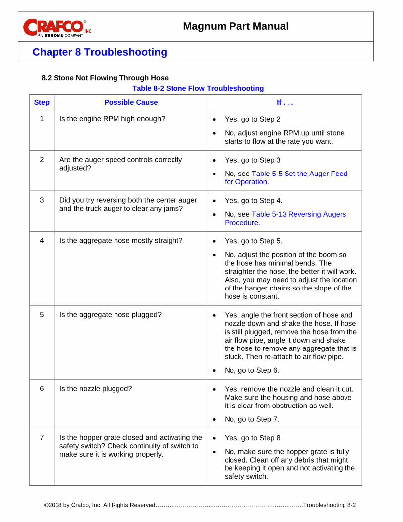
Magnum Part Manual
Chapter 8 Troubleshooting
©2018 by Crafco, Inc. All Rights Reserved………………………...…………………………..…………..Troubleshooting 8-2
Stone Not Flowing Through Hose 8.2Table 8-2 Stone Flow Troubleshooting
Step Possible Cause If . . .
1 Is the engine RPM high enough? • Yes, go to Step 2
• No, adjust engine RPM up until stone starts to flow at the rate you want.
2 Are the auger speed controls correctly adjusted?
• Yes, go to Step 3
• No, see Table 5-5 Set the Auger Feed for Operation.
3 Did you try reversing both the center auger and the truck auger to clear any jams?
• Yes, go to Step 4.
• No, see Table 5-13 Reversing Augers Procedure.
4 Is the aggregate hose mostly straight? • Yes, go to Step 5.
• No, adjust the position of the boom so the hose has minimal bends. The straighter the hose, the better it will work. Also, you may need to adjust the location of the hanger chains so the slope of the hose is constant.
5 Is the aggregate hose plugged? • Yes, angle the front section of hose and nozzle down and shake the hose. If hose is still plugged, remove the hose from the air flow pipe, angle it down and shake the hose to remove any aggregate that is stuck. Then re-attach to air flow pipe.
• No, go to Step 6.
6 Is the nozzle plugged? • Yes, remove the nozzle and clean it out. Make sure the housing and hose above it is clear from obstruction as well.
• No, go to Step 7.
7 Is the hopper grate closed and activating the safety switch? Check continuity of switch to make sure it is working properly.
• Yes, go to Step 8
• No, make sure the hopper grate is fully closed. Clean off any debris that might be keeping it open and not activating the safety switch.
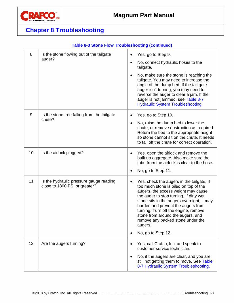
Magnum Part Manual
Chapter 8 Troubleshooting
©2018 by Crafco, Inc. All Rights Reserved………………………...…………………………..…………..Troubleshooting 8-3
Table 8-3 Stone Flow Troubleshooting (continued)
8 Is the stone flowing out of the tailgate auger?
• Yes, go to Step 9.
• No, connect hydraulic hoses to the tailgate.
• No, make sure the stone is reaching the tailgate. You may need to increase the angle of the dump bed. If the tail gate auger isn’t turning, you may need to reverse the auger to clear a jam. If the auger is not jammed, see Table 8-7 Hydraulic System Troubleshooting.
9 Is the stone free falling from the tailgate chute?
• Yes, go to Step 10.
• No, raise the dump bed to lower the chute, or remove obstruction as required. Return the bed to the appropriate height so stone cannot sit on the chute. It needs to fall off the chute for correct operation.
10 Is the airlock plugged? • Yes, open the airlock and remove the built up aggregate. Also make sure the tube from the airlock is clear to the hose.
• No, go to Step 11.
11 Is the hydraulic pressure gauge reading close to 1800 PSI or greater?
• Yes, check the augers in the tailgate. If too much stone is piled on top of the augers, the excess weight may cause the auger to stop turning. If dirty wet stone sits in the augers overnight, it may harden and prevent the augers from turning. Turn off the engine, remove stone from around the augers, and remove any packed stone under the augers.
• No, go to Step 12.
12 Are the augers turning? • Yes, call Crafco, Inc. and speak to customer service technician.
• No, if the augers are clear, and you are still not getting them to move, See Table 8-7 Hydraulic System Troubleshooting.
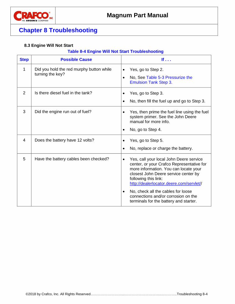
Magnum Part Manual
Chapter 8 Troubleshooting
©2018 by Crafco, Inc. All Rights Reserved………………………...…………………………..…………..Troubleshooting 8-4
Engine Will Not Start 8.3Table 8-4 Engine Will Not Start Troubleshooting
Step Possible Cause If . . .
1 Did you hold the red murphy button while turning the key?
• Yes, go to Step 2.
• No, See Table 5-3 Pressurize the Emulsion Tank Step 3.
2 Is there diesel fuel in the tank? • Yes, go to Step 3.
• No, then fill the fuel up and go to Step 3.
3 Did the engine run out of fuel? • Yes, then prime the fuel line using the fuel system primer. See the John Deere manual for more info.
• No, go to Step 4.
4 Does the battery have 12 volts? • Yes, go to Step 5.
• No, replace or charge the battery.
5 Have the battery cables been checked? • Yes, call your local John Deere service center, or your Crafco Representative for more information. You can locate your closest John Deere service center by following this link: http://dealerlocator.deere.com/servlet//
• No, check all the cables for loose connections and/or corrosion on the terminals for the battery and starter.

Magnum Part Manual
Chapter 8 Troubleshooting
©2018 by Crafco, Inc. All Rights Reserved………………………...…………………………..…………..Troubleshooting 8-5
Emulsion Not Heating from Engine 8.4Table 8-5 Emulsion Not Heating from Engine Troubleshooting
Step Possible Cause If . . .
1 Is the engine up to normal operating temperature?
• Yes, go to Step 2. • No, let the engine run to get to normal
operating temperature.
2 Are the heating line valves on the engine both open?
• Yes, go to Step 3. • No, open both the valves and allow the
engine coolant to flow and heat up the emulsion system.
3 Is there enough emulsion in the tank to reach the heating core?
• Yes, go to Step 4. • No, fill the emulsion tank with the correct
amount of emulsion.
4 Are there any kinked or damaged heating lines?
• Yes, repair or replace any damaged heating lines.
• No, call Crafco, Inc. and speak to customer service.
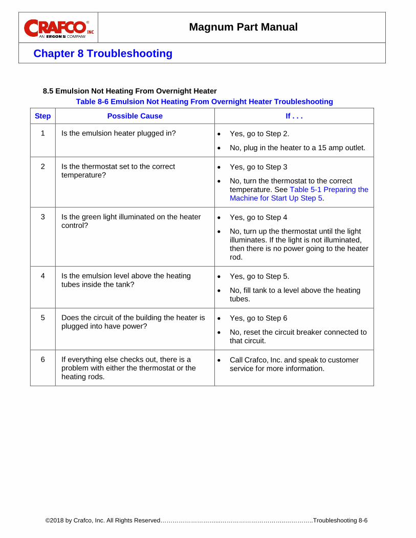
Magnum Part Manual
Chapter 8 Troubleshooting
©2018 by Crafco, Inc. All Rights Reserved………………………...…………………………..…………..Troubleshooting 8-6
Emulsion Not Heating From Overnight Heater 8.5
Table 8-6 Emulsion Not Heating From Overnight Heater Troubleshooting
Step Possible Cause If . . .
1 Is the emulsion heater plugged in? • Yes, go to Step 2.
• No, plug in the heater to a 15 amp outlet.
2 Is the thermostat set to the correct temperature?
• Yes, go to Step 3
• No, turn the thermostat to the correct temperature. See Table 5-1 Preparing the Machine for Start Up Step 5.
3 Is the green light illuminated on the heater control?
• Yes, go to Step 4
• No, turn up the thermostat until the light illuminates. If the light is not illuminated, then there is no power going to the heater rod.
4 Is the emulsion level above the heating tubes inside the tank?
• Yes, go to Step 5.
• No, fill tank to a level above the heating tubes.
5 Does the circuit of the building the heater is plugged into have power?
• Yes, go to Step 6
• No, reset the circuit breaker connected to that circuit.
6 If everything else checks out, there is a problem with either the thermostat or the heating rods.
• Call Crafco, Inc. and speak to customer service for more information.
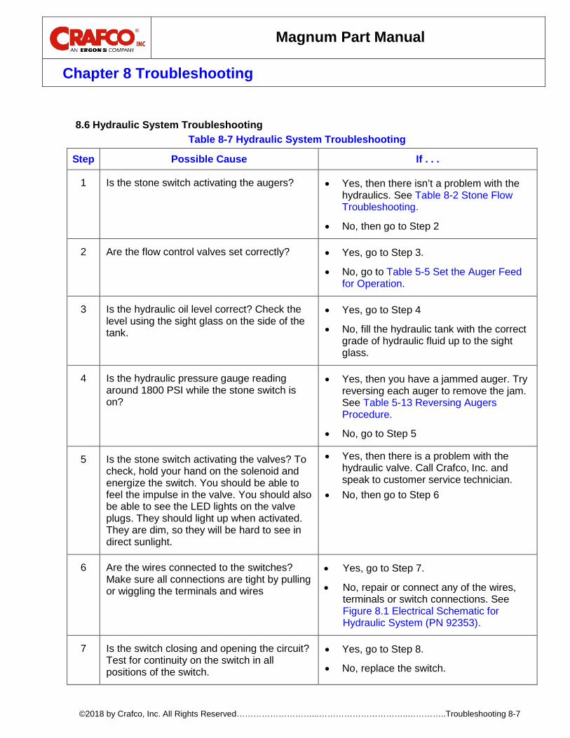
Magnum Part Manual
Chapter 8 Troubleshooting
©2018 by Crafco, Inc. All Rights Reserved………………………...…………………………..…………..Troubleshooting 8-7
Hydraulic System Troubleshooting 8.6
Table 8-7 Hydraulic System Troubleshooting
Step Possible Cause If . . .
1 Is the stone switch activating the augers? • Yes, then there isn’t a problem with the hydraulics. See Table 8-2 Stone Flow Troubleshooting.
• No, then go to Step 2
2 Are the flow control valves set correctly? • Yes, go to Step 3.
• No, go to Table 5-5 Set the Auger Feed for Operation.
3 Is the hydraulic oil level correct? Check the level using the sight glass on the side of the tank.
• Yes, go to Step 4
• No, fill the hydraulic tank with the correct grade of hydraulic fluid up to the sight glass.
4 Is the hydraulic pressure gauge reading around 1800 PSI while the stone switch is on?
• Yes, then you have a jammed auger. Try reversing each auger to remove the jam. See Table 5-13 Reversing Augers Procedure.
• No, go to Step 5
5 Is the stone switch activating the valves? To check, hold your hand on the solenoid and energize the switch. You should be able to feel the impulse in the valve. You should also be able to see the LED lights on the valve plugs. They should light up when activated. They are dim, so they will be hard to see in direct sunlight.
• Yes, then there is a problem with the hydraulic valve. Call Crafco, Inc. and speak to customer service technician.
• No, then go to Step 6
6 Are the wires connected to the switches? Make sure all connections are tight by pulling or wiggling the terminals and wires
• Yes, go to Step 7.
• No, repair or connect any of the wires, terminals or switch connections. See Figure 8.1 Electrical Schematic for Hydraulic System (PN 92353).
7 Is the switch closing and opening the circuit? Test for continuity on the switch in all positions of the switch.
• Yes, go to Step 8.
• No, replace the switch.

Magnum Part Manual
Chapter 8 Troubleshooting
©2018 by Crafco, Inc. All Rights Reserved………………………...…………………………..…………..Troubleshooting 8-8
Table 8-8 Hydraulic System Troubleshooting (continued)
Step Possible Cause If . . .
8 If all electrical connections are correct, the hydraulic valves are working, you have enough hydraulic pressure, and the augers still aren’t working?
• Yes, call Crafco, Inc. and speak to customer service technician.

Magnum Part Manual
Chapter 8 Troubleshooting
©2018 by Crafco, Inc. All Rights Reserved………………………...…………………………..…………..Troubleshooting 8-9
Electrical Schematic for Hydraulic System 8.7
Figure 8.1 Electrical Schematic for Hydraulic System (PN 92353)
(FRONT HORN)BACK-UP ALARM
REAR OF MACHINECONTROL PANEL BOX
COM
WH
ITE-3 -(12")
REVERSE
REVERSE
MOMENTARY SIDE
MOMENTARY SIDE
LOCK
STATIONARY
CENTER AUGER
TRUCK AUGER32521
32521
HOLDLOCK
REVERSE
HOLD
YELLOW-312"
ORANGE-312"
45376 REVERSEFORWARD
(LARGER VALVE)
OF MACHINEPASS SIDE
#1
BLU
E-31
2"
G
G
#1
45376FORWARD
45376
F
F
REVERSE45376
R
45376R
#1
G
#1
G
GRAY-312"
DIN PLUGS ON TOP OF HYD. VALVE
WH
ITE
G
NC
G
BOOM AREA
HORN SWITCH32521
STATIONARYFORWARD
STONE SWITCH32522
RED/BLACK-1-275"
PURPLE-430"
GRAY-312"
BLUE-312"
WHITE/BLACK-440"
RED
-1RE
D-2
8"
BUSSSTRIP
50238
RED
-2RE
D-3
WH
ITE/
GRE
ENRE
D/B
LACK
PURP
LE-4
RED
-24"
RED
-26"
NO
(UP FRONT)HOPPER LID SWITCH
91133
91645
RED
/WH
ITE-
1PU
RPLE
-3
STRIP
50250TERMINAL
FRO
NT O
F M
ACH
INE
DIN PLUGON TOP OFHYD VALVE45376
DIN PLUGS FORCENTER AUGER
USE #1 TERMINAL ON DIN PLUGUSE #2 TERMINAL FOR GROUND
DIN PLUGS FORTRUCK AUGER
1. USE ENGINE CONTROL PANEL SUB ASSY-80 HP PART NUMBER 92251.2. USE #1 TERMINAL ON DIN PLUG FOR POWER "IN". USE #2 TERMINAL ON DIN PLUG FOR GOUND.3. SINGLE POLE, SINGLE THROW (MOMENTARY SIDE) DOUBLE POLE, DOUBLE THROW
(REF. BLACK BOOT COVER 32527)
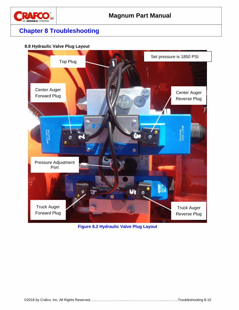
Magnum Part Manual
Chapter 8 Troubleshooting
©2018 by Crafco, Inc. All Rights Reserved………………………...…………………………..…………..Troubleshooting 8-10
Hydraulic Valve Plug Layout 8.8
Figure 8.2 Hydraulic Valve Plug Layout
Set pressure is 1850 PSI
Pressure Adjustment Port
Truck Auger Reverse Plug
Center Auger Reverse Plug
Center Auger Forward Plug
Truck Auger Forward Plug
Top Plug
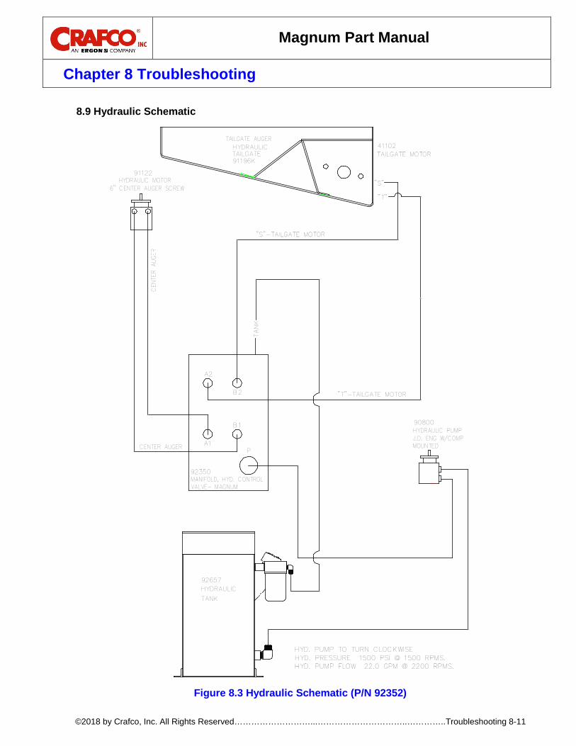
Magnum Part Manual
Chapter 8 Troubleshooting
©2018 by Crafco, Inc. All Rights Reserved………………………...…………………………..…………..Troubleshooting 8-11
Hydraulic Schematic 8.9
Figure 8.3 Hydraulic Schematic (P/N 92352)
A2
"S"
TAILGATE MOTOR
"T"
"T"-TAILGATE MOTOR
TAILGATEHYDRAULIC
91196K
92350
90800
MANIFOLD, HYD. CONTROLVALVE- MAGNUM
HYDRAULIC PUMPJ.D. ENG W/COMPMOUNTED
"S"-TAILGATE MOTOR
HYDRAULIC MOTOR6" CENTER AUGER SCREW
91122
41102
B2
B1
A1P
TANK
CEN
TER
AUGE
R
TAILGATE AUGER
CENTER AUGER
HYDRAULIC
TANK
92657
HYD. PUMP TO TURN CLOCKWISEHYD. PRESSURE 1500 PSI @ 1500 RPMS.HYD. PUMP FLOW 22.0 GPM @ 2200 RPMS.

Magnum Part Manual
Chapter 9 Illustrated Parts List
©2018 by Crafco, Inc. All Rights Reserved………………………...………………………..………..Illustrated Parts List 9-1
9.0 About the Illustrated Parts List The Illustrated Parts List (IPL) is designed to help technical service or maintenance personnel correctly identify orderable replacement parts. The figure and table titles reference the part number (PN) to which they apply. The PN’s for each of the Magnum models are as follows: Magnum PN 91000 Illustrations and pictures are designed to show general shape and size of a part and the relationship that part has to other parts. Actual size and shape of parts or components may differ or vary from the actual part or component.
Ordering Crafco Parts 9.1Crafco distributors and Crafco Pavement Preservation Supply Centers are strategically located throughout the United States. Parts can be ordered from your local Crafco distributor or directly from Crafco, Inc. if a distributor is not available in your area. When ordering parts, give the following information:
• Part Number • Machine Model • Serial Number
Write, call, or Fax Crafco, Inc. at the following: Crafco, Inc. Headquarters 6165 West Detroit Street. Chandler, AZ 85226 Phone: (602) 276-0406 Toll Free: (800) 528-8242 Fax: (480) 961-0513
Visit our website at www.crafco.com
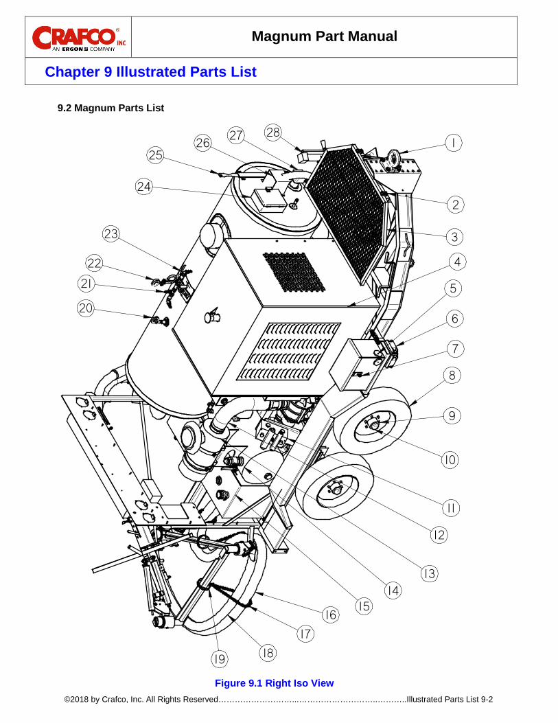
Magnum Part Manual
Chapter 9 Illustrated Parts List
©2018 by Crafco, Inc. All Rights Reserved………………………...………………………..………..Illustrated Parts List 9-2
Magnum Parts List 9.2
Figure 9.1 Right Iso View
1
8
9
10
7
6
5
11
13
12
1415
16
17
1819
20
22
25
24
2628
3
2
4
23
21
27

Magnum Part Manual
Chapter 9 Illustrated Parts List
©2018 by Crafco, Inc. All Rights Reserved………………………...………………………..………..Illustrated Parts List 9-3
Table 9-1 Right Iso View Parts List
FIG. ITEM PART NUMBER QTY DESCRIPTION
Fig. 9.1 1 20019 1 3” PINTLE HITCH (MAGNUM)
2 91132 2 HOPPER LID HOLD DOWN STRAP
3 91186 1 AGGREGATE HOPPER INLET LID ASSY
4 91030 1 ENGINE COVER (JD 4045T)
5 90547 4 3” ROUND AMBER REFLECTOR
6 32314 4 YELLOW CLEARANCE MARKER, LARGE
7 90200 1 BATTERY LOCK BOX ASSY
8 44342 4 TIRE W/ BLACK RIM ST225/75 R15
9 23130 24 LUG NUT
10 92607 2 6000LB TORSION AXLE W/ ELEC BRAKES
11 92350 1 HYDRAULIC CONTROL VALVE ASSY
12 91235 1 RUBBER CONNECTION HOSE BLOWER
13 92261 1 AIR CLEANER HOUSING (2014 AND UP MODELS)
14 90860 1 30 GAL FLUSH TANK ASSY
15 92671 1 FUEL TANK ASSY
16 91158-13 1 3” AGGREGATE HOSE, BLUE, 13FT
17 90181 3 HANGER HOSE CHAIN BOOM
18 90325 1 COVERED BOOM/HEAT HOSE ASSY
19 90149 3 4” AGGREGATE HOSE HANGER
20 41243 1 24” TEMP GAUGE. BOTTOM MOUNT
21 42629 1 SAFETY VALVE
22 29961 1 200PSI PRESSURE GAUGE (FILLED)
23 29214 1 BRONZE BALL VALVE, 1/2”
24 91095 1 READY TO MOUNT THERMOSTAT ASSY
25 91830 1 EMULSION HEIGHT GAUGE DIPSTICK
26 90790 1 EMULSION TANK HEAT SHIELD ASSY
27 91799 1 EMULSION TANK HEATER
28 23082 1 5000LB TONGUE JACK, 15”
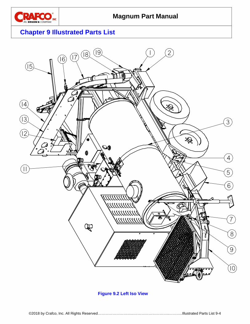
Magnum Part Manual
Chapter 9 Illustrated Parts List
©2018 by Crafco, Inc. All Rights Reserved………………………...………………………..………..Illustrated Parts List 9-4
Figure 9.2 Left Iso View
211917 18
1516
4
5
6
7
8
9
11
313
14
12
10
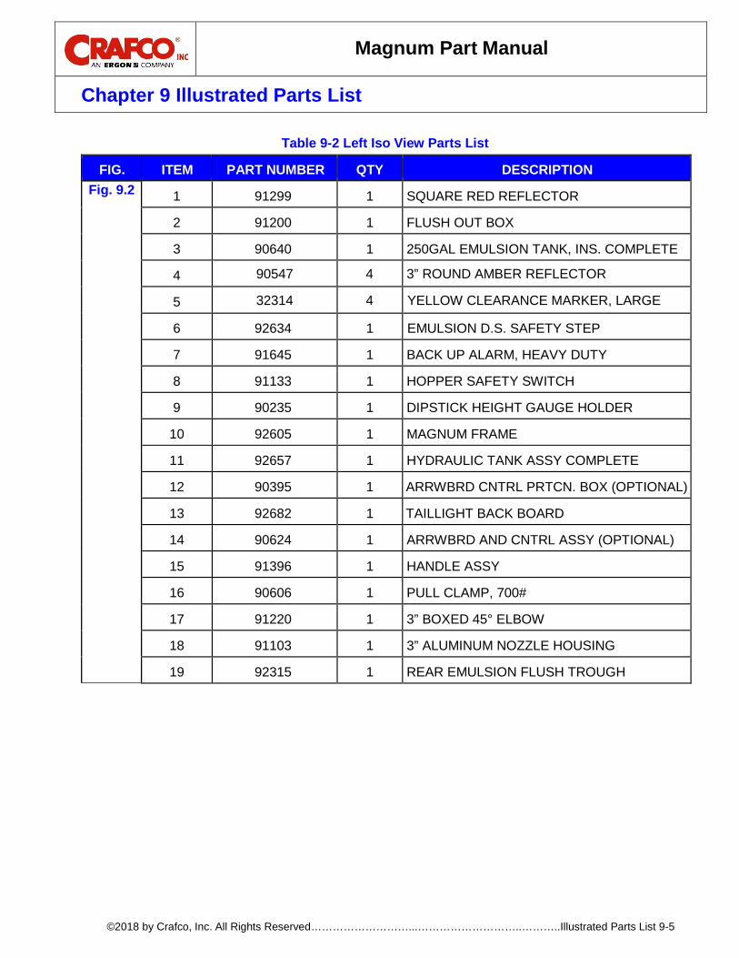
Magnum Part Manual
Chapter 9 Illustrated Parts List
©2018 by Crafco, Inc. All Rights Reserved………………………...………………………..………..Illustrated Parts List 9-5
Table 9-2 Left Iso View Parts List
FIG. ITEM PART NUMBER QTY DESCRIPTION Fig. 9.2 1 91299 1 SQUARE RED REFLECTOR
2 91200 1 FLUSH OUT BOX
3 90640 1 250GAL EMULSION TANK, INS. COMPLETE
4 90547 4 3” ROUND AMBER REFLECTOR
5 32314 4 YELLOW CLEARANCE MARKER, LARGE
6 92634 1 EMULSION D.S. SAFETY STEP
7 91645 1 BACK UP ALARM, HEAVY DUTY
8 91133 1 HOPPER SAFETY SWITCH
9 90235 1 DIPSTICK HEIGHT GAUGE HOLDER
10 92605 1 MAGNUM FRAME
11 92657 1 HYDRAULIC TANK ASSY COMPLETE
12 90395 1 ARRWBRD CNTRL PRTCN. BOX (OPTIONAL)
13 92682 1 TAILLIGHT BACK BOARD
14 90624 1 ARRWBRD AND CNTRL ASSY (OPTIONAL)
15 91396 1 HANDLE ASSY
16 90606 1 PULL CLAMP, 700#
17 91220 1 3” BOXED 45° ELBOW
18 91103 1 3” ALUMINUM NOZZLE HOUSING
19 92315 1 REAR EMULSION FLUSH TROUGH

Magnum Part Manual
Chapter 9 Illustrated Parts List
©2018 by Crafco, Inc. All Rights Reserved………………………...………………………..………..Illustrated Parts List 9-6
Figure 9.3 Nozzle Exploded View
Figure 9.4 Rear View
1
2
3 4
5
768
12
16
17
18
2120
22
11
109
13
14
19
1717
25 24 23

Magnum Part Manual
Chapter 9 Illustrated Parts List
©2018 by Crafco, Inc. All Rights Reserved………………………...………………………..………..Illustrated Parts List 9-7
Table 9-3 Rear View Parts List
FIG. ITEM PART NUMBER QTY DESCRIPTION
Fig.9.4 1 32318 4 SECURITY RING
2 32317 4 FLANGE MOUNT STT RED 4” RD LED LIGHT
3 32315 2 RED SIDE MARKER LIGHT
4 32316 2 ARMORED BRACKET
5 92251 1 CONTROL BOX ENCLOSURE ASSY
6 32319 1 CENTER RED LIGHT
7 92318 1 BRACKET, SINGLE CENTER TAILLIGHT
8 91530 1 DEEP NOZZLE STORAGE BOX
9 91073 1 3” PIPE WELDED ASSY
10 91162 1 NOZZLE POSITION HANDLE
11 90549 2 3” REFLEX REFLECTOR, RED
12 91100 1 3” NOZZLE W/ SPRAY RING
13 91099 1 3” O-RING
14 91103 1 3” ALUMINUM NOZZLE HOUSING
15 91356 1 INSERT, NOZZLE
16 91344 1 NIPPLE HOSE COMBO, KING
17 25952 7 3.5” U BOLT CLAMP
18 91346 1 3” HOSE X 20” LONG GUM RUBBER LINED
19 92693 1 EMULSION TANK INSULATION BOX
20 26099 1 LICENSE PLATE HOLDER
21 44797 1 LED LICENSE PLATE LAMP
22 32371 1 RED 6” CENTER LIGHT KIT
23 43897 1 3/16” CHAIN, 1 LINK
24 91648 1 BOOM STAY SAFETY CHAIN
25 91312 1 AGGREGATE BOOM CLAMP ASSEMBLY

Magnum Part Manual
Chapter 9 Illustrated Parts List
©2018 by Crafco, Inc. All Rights Reserved………………………...………………………..………..Illustrated Parts List 9-8
Nozzle Emulsion Line Connection Parts List 9.3
Figure 9.5 Nozzle Emulsion Line Connection
2
3
4
5
6
8
7
1
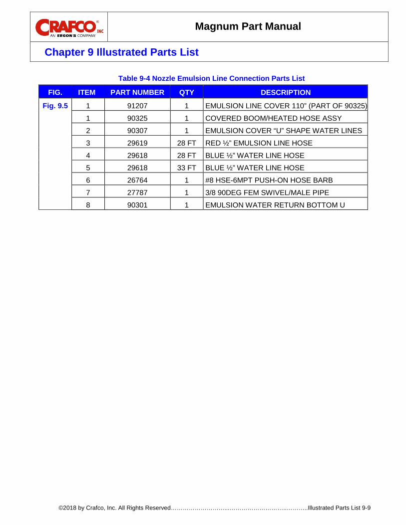
Magnum Part Manual
Chapter 9 Illustrated Parts List
©2018 by Crafco, Inc. All Rights Reserved………………………...………………………..………..Illustrated Parts List 9-9
Table 9-4 Nozzle Emulsion Line Connection Parts List
FIG. ITEM PART NUMBER QTY DESCRIPTION
Fig. 9.5 1 91207 1 EMULSION LINE COVER 110” (PART OF 90325)
1 90325 1 COVERED BOOM/HEATED HOSE ASSY
2 90307 1 EMULSION COVER “U” SHAPE WATER LINES
3 29619 28 FT RED ½” EMULSION LINE HOSE
4 29618 28 FT BLUE ½” WATER LINE HOSE
5 29618 33 FT BLUE ½” WATER LINE HOSE
6 26764 1 #8 HSE-6MPT PUSH-ON HOSE BARB
7 27787 1 3/8 90DEG FEM SWIVEL/MALE PIPE
8 90301 1 EMULSION WATER RETURN BOTTOM U

Magnum Part Manual
Chapter 9 Illustrated Parts List
©2018 by Crafco, Inc. All Rights Reserved………………………...………………………..………..Illustrated Parts List 9-10
Operator Boom Parts List 9.4
Figure 9.6 Operator Boom Parts
1
1819
15
3
11
23
20
22
8
7
10 9121317 16
6
2
14
5
4
26
25
24
27
28
21
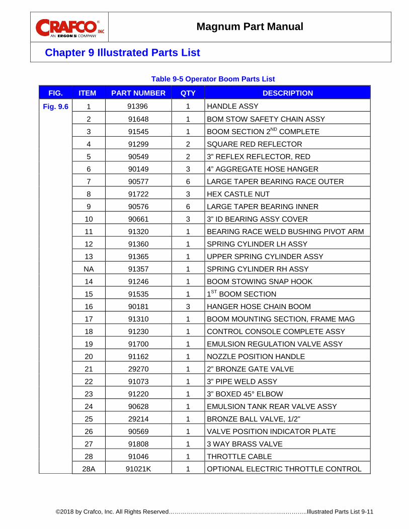
Magnum Part Manual
Chapter 9 Illustrated Parts List
©2018 by Crafco, Inc. All Rights Reserved………………………...………………………..………..Illustrated Parts List 9-11
Table 9-5 Operator Boom Parts List
FIG. ITEM PART NUMBER QTY DESCRIPTION
Fig. 9.6 1 91396 1 HANDLE ASSY
2 91648 1 BOM STOW SAFETY CHAIN ASSY
3 91545 1 BOOM SECTION 2ND COMPLETE
4 91299 2 SQUARE RED REFLECTOR
5 90549 2 3” REFLEX REFLECTOR, RED
6 90149 3 4” AGGREGATE HOSE HANGER
7 90577 6 LARGE TAPER BEARING RACE OUTER
8 91722 3 HEX CASTLE NUT
9 90576 6 LARGE TAPER BEARING INNER
10 90661 3 3” ID BEARING ASSY COVER
11 91320 1 BEARING RACE WELD BUSHING PIVOT ARM
12 91360 1 SPRING CYLINDER LH ASSY
13 91365 1 UPPER SPRING CYLINDER ASSY
NA 91357 1 SPRING CYLINDER RH ASSY
14 91246 1 BOOM STOWING SNAP HOOK
15 91535 1 1ST BOOM SECTION
16 90181 3 HANGER HOSE CHAIN BOOM
17 91310 1 BOOM MOUNTING SECTION, FRAME MAG
18 91230 1 CONTROL CONSOLE COMPLETE ASSY
19 91700 1 EMULSION REGULATION VALVE ASSY
20 91162 1 NOZZLE POSITION HANDLE
21 29270 1 2” BRONZE GATE VALVE
22 91073 1 3” PIPE WELD ASSY
23 91220 1 3” BOXED 45° ELBOW
24 90628 1 EMULSION TANK REAR VALVE ASSY
25 29214 1 BRONZE BALL VALVE, 1/2”
26 90569 1 VALVE POSITION INDICATOR PLATE
27 91808 1 3 WAY BRASS VALVE
28 91046 1 THROTTLE CABLE
28A 91021K 1 OPTIONAL ELECTRIC THROTTLE CONTROL

Magnum Part Manual
Chapter 9 Illustrated Parts List
©2018 by Crafco, Inc. All Rights Reserved………………………...………………………..………..Illustrated Parts List 9-12
Hydraulic and Fuel Tank Parts List 9.5
Figure 9.7 Hydraulic and Fuel Tanks
Table 9-6 Hydraulic and Fuel Tank Parts List
FIG. ITEM PART NUMBER QTY DESCRIPTION
Fig.9.7 1 90813 1 HYD. TANK TOP ACCESS PANEL
2 90812 1 TOP ACCESS PANEL GASKET
3 92657 1 HYDRAULIC TANK ASSY COMPLETE
4 90564 1 2” ROUND HYD LEVEL SIGHT GAUGE
5 51300 1 3/4" TUBE X 1"NPT ELBOW ADPTR
6 43872 1 HYD OIL FILTER ASSY
6A 43871 1 HYDRAULIC FILTER ELEMENT
7 29921 1 45 DEGREE ADAPTER
8 28039 1 1” X 4” PIPE NIPPLE
9 29213 1 1/2” BRASS GATE VALVE
10 90565 1 HYDRAULIC SUCTION FILTER
11 29971 2 1/4 NPT M 90X1/4 M HOSE BARB
12 43579 2 PRESSURE FILLER BREATHER CAP
13 92671 1 FUEL TANK ASSY COMPLETE
14 92664 1 FUEL LEVEL GAUGE 15"
3
1
12
4
6
5
13
12
11
14
7
9
10
11
2
8

Magnum Part Manual
Chapter 9 Illustrated Parts List
©2018 by Crafco, Inc. All Rights Reserved………………………...………………………..………..Illustrated Parts List 9-13
Dual Hydraulic Control Valve Parts List 9.6
Figure 9.8 Dual Hydraulic Control Valve
Table 9-7 Dual Hydraulic Control Valve Parts List
FIG. ITEM PART NUMBER QTY DESCRIPTION
Fig.9.8 1 92350 1 HYDRAULIC CONTROL VALVE ASSY
2 45376 5 DIN PLUG
3 92631 1 HYD. CONTROL VALVE MOUNTING PLATE
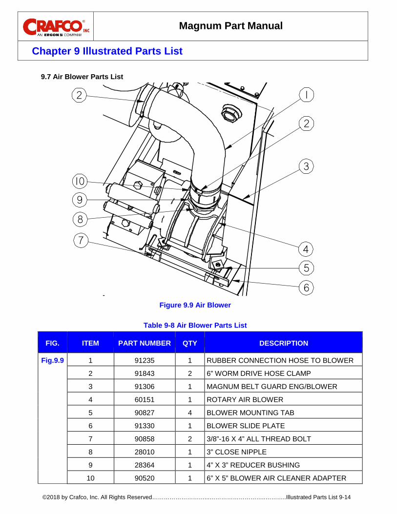
Magnum Part Manual
Chapter 9 Illustrated Parts List
©2018 by Crafco, Inc. All Rights Reserved………………………...………………………..………..Illustrated Parts List 9-14
Air Blower Parts List 9.7
Figure 9.9 Air Blower
Table 9-8 Air Blower Parts List
FIG. ITEM PART NUMBER QTY DESCRIPTION
Fig.9.9 1 91235 1 RUBBER CONNECTION HOSE TO BLOWER
2 91843 2 6” WORM DRIVE HOSE CLAMP
3 91306 1 MAGNUM BELT GUARD ENG/BLOWER
4 60151 1 ROTARY AIR BLOWER
5 90827 4 BLOWER MOUNTING TAB
6 91330 1 BLOWER SLIDE PLATE
7 90858 2 3/8”-16 X 4” ALL THREAD BOLT
8 28010 1 3” CLOSE NIPPLE
9 28364 1 4” X 3” REDUCER BUSHING
10 90520 1 6” X 5” BLOWER AIR CLEANER ADAPTER
12
2
4
6
10
8
9
5
7
3
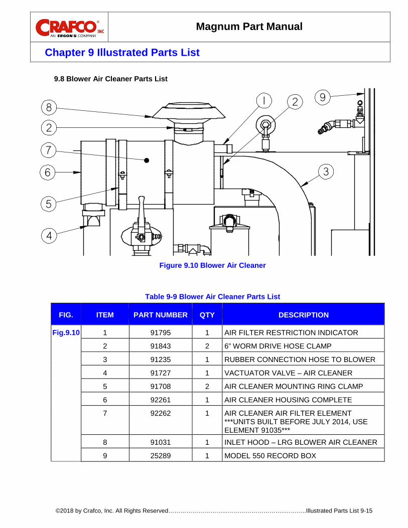
Magnum Part Manual
Chapter 9 Illustrated Parts List
©2018 by Crafco, Inc. All Rights Reserved………………………...………………………..………..Illustrated Parts List 9-15
Blower Air Cleaner Parts List 9.8
Figure 9.10 Blower Air Cleaner
Table 9-9 Blower Air Cleaner Parts List
FIG. ITEM PART NUMBER QTY DESCRIPTION
Fig.9.10 1 91795 1 AIR FILTER RESTRICTION INDICATOR
2 91843 2 6” WORM DRIVE HOSE CLAMP
3 91235 1 RUBBER CONNECTION HOSE TO BLOWER
4 91727 1 VACTUATOR VALVE – AIR CLEANER
5 91708 2 AIR CLEANER MOUNTING RING CLAMP
6 92261 1 AIR CLEANER HOUSING COMPLETE
7 92262 1 AIR CLEANER AIR FILTER ELEMENT ***UNITS BUILT BEFORE JULY 2014, USE ELEMENT 91035***
8 91031 1 INLET HOOD – LRG BLOWER AIR CLEANER
9 25289 1 MODEL 550 RECORD BOX
3
8
2
6
4
5
2
7
1 9

Magnum Part Manual
Chapter 9 Illustrated Parts List
©2018 by Crafco, Inc. All Rights Reserved………………………...………………………..………..Illustrated Parts List 9-16
Hydraulic Auger Motor Parts List 9.9
Figure 9.11 Hydraulic Auger Motor
Table 9-10 Hydraulic Auger Motor Parts List
FIG. ITEM PART NUMBER QTY DESCRIPTION
Fig.9.11 1 91127 1 FACE PLATE, MOTOR MOUNT
2 91122 1 HYDRAULIC MOTOR
3 28763 1 ½”-13 X 1 ¾” BOLT
4 91106 1 HYD MOTOR KEEPING BRACKET
21
4 3
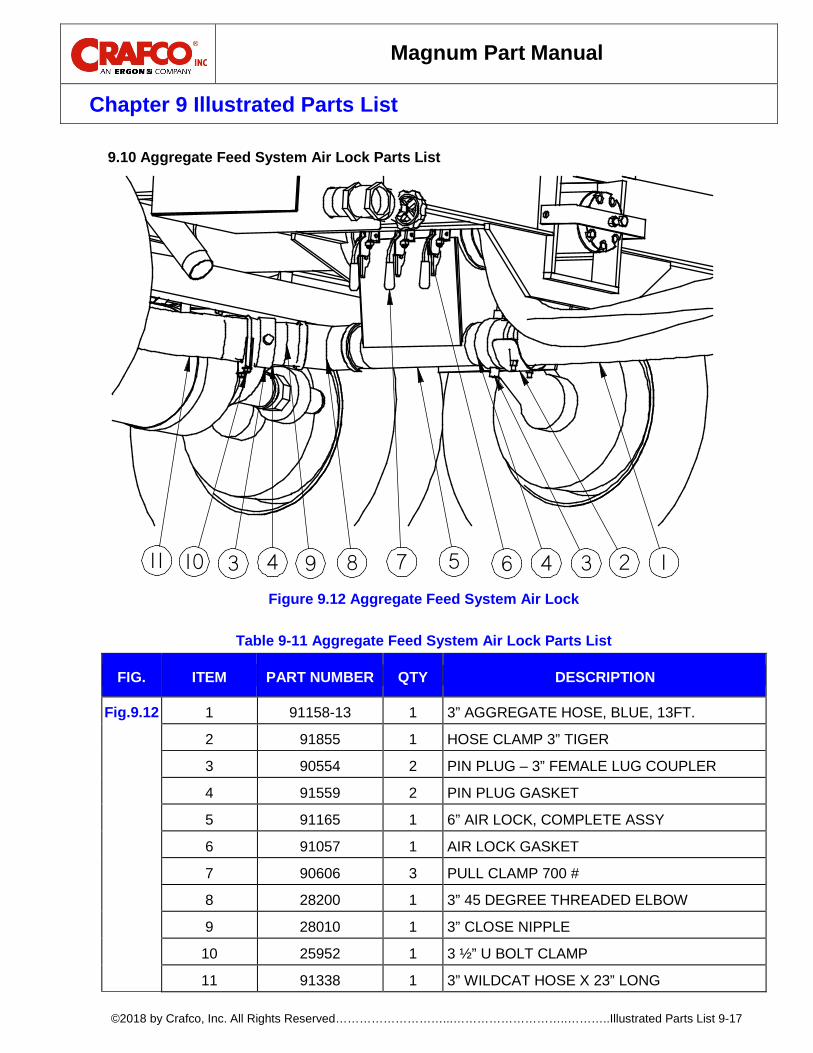
Magnum Part Manual
Chapter 9 Illustrated Parts List
©2018 by Crafco, Inc. All Rights Reserved………………………...………………………..………..Illustrated Parts List 9-17
Aggregate Feed System Air Lock Parts List 9.10
Figure 9.12 Aggregate Feed System Air Lock
Table 9-11 Aggregate Feed System Air Lock Parts List
FIG. ITEM PART NUMBER QTY DESCRIPTION
Fig.9.12 1 91158-13 1 3” AGGREGATE HOSE, BLUE, 13FT.
2 91855 1 HOSE CLAMP 3” TIGER
3 90554 2 PIN PLUG – 3” FEMALE LUG COUPLER
4 91559 2 PIN PLUG GASKET
5 91165 1 6” AIR LOCK, COMPLETE ASSY
6 91057 1 AIR LOCK GASKET
7 90606 3 PULL CLAMP 700 #
8 28200 1 3” 45 DEGREE THREADED ELBOW
9 28010 1 3” CLOSE NIPPLE
10 25952 1 3 ½” U BOLT CLAMP
11 91338 1 3” WILDCAT HOSE X 23” LONG
24 189311 10 34 7 65
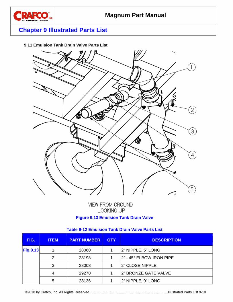
Magnum Part Manual
Chapter 9 Illustrated Parts List
©2018 by Crafco, Inc. All Rights Reserved………………………...………………………..………..Illustrated Parts List 9-18
Emulsion Tank Drain Valve Parts List 9.11
Figure 9.13 Emulsion Tank Drain Valve
Table 9-12 Emulsion Tank Drain Valve Parts List
FIG. ITEM PART NUMBER QTY DESCRIPTION
Fig.9.13 1 28060 1 2” NIPPLE, 5” LONG
2 28198 1 2” - 45° ELBOW IRON PIPE
3 28008 1 2” CLOSE NIPPLE
4 29270 1 2” BRONZE GATE VALVE
5 28136 1 2” NIPPLE, 9” LONG
VIEW FROM GROUND LOOKING UP
1
5
4
3
2
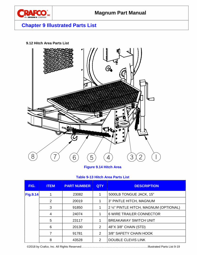
Magnum Part Manual
Chapter 9 Illustrated Parts List
©2018 by Crafco, Inc. All Rights Reserved………………………...………………………..………..Illustrated Parts List 9-19
Hitch Area Parts List 9.12
Figure 9.14 Hitch Area
Table 9-13 Hitch Area Parts List
FIG. ITEM PART NUMBER QTY DESCRIPTION
Fig.9.14 1 23082 1 5000LB TONGUE JACK, 15”
2 20019 1 3” PINTLE HITCH, MAGNUM
3 91850 1 2 ½” PINTLE HITCH, MAGNUM (OPTIONAL)
4 24074 1 6 WIRE TRAILER CONNECTOR
5 23117 1 BREAKAWAY SWITCH UNIT
6 20130 2 48"X 3/8" CHAIN (STD)
7 91781 2 3/8" SAFETY CHAIN HOOK
8 43528 2 DOUBLE CLEVIS LINK
8 7 6 5 4 3 12

Magnum Part Manual
Chapter 9 Illustrated Parts List
©2018 by Crafco, Inc. All Rights Reserved………………………...………………………..………..Illustrated Parts List 9-20
Solvent Flush Tank Parts List 9.13
Figure 9.15 Solvent Flush Tank
Table 9-14 Solvent Flush Tank Parts List
FIG. ITEM PART NUMBER QTY DESCRIPTION
Fig.9.15 1 28238 2 1/2" STREET ELBOW
2 26765 2 #8 HOSE - 8 MPT PUSHON
3 90702 1 SUCTION TUBE ASSY, FLUSH TANK
4 90703 1 2” PIPE PLUG W/ PRESSURE RELIEF HOLE
5 29281 1 2” BALL VALVE
6 28008 1 CLOSE NIPPLE, 2”
7 90860 1 30 GAL FLUSH TANK COMPLETE ASSY
8 91815 1 1/4” DRAIN PETCOCK
9 28253 2 1/2” PIPE TEE
10 28003 3 1/2” CLOSE NIPPLE
11 90861 1 1/2” #60 CHECK VALVE
5
4
2
1
9
11
9
1
8
3
6
10
10
10
7
2

Magnum Part Manual
Chapter 9 Illustrated Parts List
©2018 by Crafco, Inc. All Rights Reserved………………………...………………………..………..Illustrated Parts List 9-21
Battery Parts List 9.14
Figure 9.16 Battery
Table 9-15 Battery Parts List
FIG. ITEM PART NUMBER QTY DESCRIPTION
Fig.9.16 1 24001 1 1000 C.C.A. BATTERY
2 90200 1 BATTERY LOCK BOX ASSEMBLY
3 90215 1 BATTERY HOLD DOWN FRAME
4 90904 1 POS BATTERY CABLE 69” LONG ASSY
5 32602 1 NEG 20” CRESCENT BATTERY CABLE

Magnum Part Manual
Chapter 9 Illustrated Parts List
©2018 by Crafco, Inc. All Rights Reserved………………………...………………………..………..Illustrated Parts List 9-22
Emulsion Tank Top Valve Assembly Parts List 9.15
Figure 9.17 Emulsion Tank Top Valve Assembly
Table 9-16 Emulsion Tank Top Valve Assembly Parts List
FIG. ITEM PART NUMBER QTY DESCRIPTION
Fig.9.17 1 28262 1 1/4” BLK PIPE CROSS
2 28281 1 1/4” PIPE PLUG
3 42629 1 SAFETY VALVE
4 28344 2 1/2" X 1/4" BUSHING
5 41243 1 24" TEMP GAUGE BOTTOM. MOUNT
6 28175 1 1/2” PIPE COUPLING
7 26765 2 #8 HOSE - 8 NPT PUSH ON FITTING
8 28223 2 1/2” 45° STREET ELBOW
9 90861 1 1/2” CHECK VALVE
10 28003 4 1/2” CLOSE NIPPLE
11 28253 3 1/2” PIPE TEE
12 28070 1 1/2” X 6” NIPPLE
13 29214 1 1/2” BRONZE BALL VALVE
14 91135 1 1/4” PIPE PIG TAIL
15 90896 1 AIR BRAKE FITTING, 90°
16 28340 1 1/4” X 1/8” HEX HEAD PIPE BUSHING
17 29961 1 200 PSI PRESSURE GAGE, FILLED
78910111011 12101110138
7
4
3
4
14
17
2
15
1
5
6
16

Magnum Part Manual
Chapter 9 Illustrated Parts List
©2018 by Crafco, Inc. All Rights Reserved………………………...………………………..………..Illustrated Parts List 9-23
Boom Control Console Parts List 9.16
Figure 9.18 Boom Control Console
Table 9-17 Boom Control Console Parts List
FIG. ITEM PART NUMBER QTY DESCRIPTION
Fig.9.18 1 32521 3 TOGGLE SWITCH – SPDT MOMENTARY
2 32522 1 TOGGLE SWITCH – DPDT/ON-OFF-ON
3 91046 1 MANUAL THROTTLE CONTROL (STANDARD)
4 32524 1 ELECTRIC THROTTLE SWITCH (OPTIONAL)
5 91700 1 EMULSION REGULATION VALVE ASSY
6 91230 1 CONTROL PANEL PLATE
7 90299 1 DECAL, OPERATORS CONTROL PANEL
8 32527 4 TOGGLE SWITCH BOOT
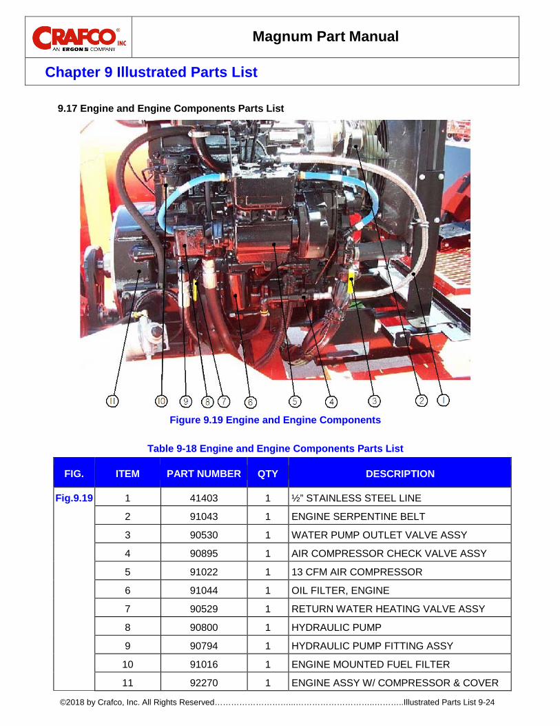
Magnum Part Manual
Chapter 9 Illustrated Parts List
©2018 by Crafco, Inc. All Rights Reserved………………………...………………………..………..Illustrated Parts List 9-24
Engine and Engine Components Parts List 9.17
Figure 9.19 Engine and Engine Components
Table 9-18 Engine and Engine Components Parts List
FIG. ITEM PART NUMBER QTY DESCRIPTION
Fig.9.19 1 41403 1 ½” STAINLESS STEEL LINE
2 91043 1 ENGINE SERPENTINE BELT
3 90530 1 WATER PUMP OUTLET VALVE ASSY
4 90895 1 AIR COMPRESSOR CHECK VALVE ASSY
5 91022 1 13 CFM AIR COMPRESSOR
6 91044 1 OIL FILTER, ENGINE
7 90529 1 RETURN WATER HEATING VALVE ASSY
8 90800 1 HYDRAULIC PUMP
9 90794 1 HYDRAULIC PUMP FITTING ASSY
10 91016 1 ENGINE MOUNTED FUEL FILTER
11 92270 1 ENGINE ASSY W/ COMPRESSOR & COVER

Magnum Part Manual
Chapter 9 Illustrated Parts List
©2018 by Crafco, Inc. All Rights Reserved………………………...………………………..………..Illustrated Parts List 9-25
Engine Intake and Exhaust Parts List 9.18
Figure 9.20 Engine Intake and Exhaust
Table 9-19 Engine Intake and Exhaust Parts List
FIG. ITEM PART NUMBER QTY DESCRIPTION
Fig.9.20 1 91795 1 AIR FILTER RESTRICTION INDICATOR
2 91014 1 ENGINE AIR FILTER ELEMENT, PRIMARY
2 91013 1 ENGINE AIR FILTER ELEMENT, SAFETY
3 91048 1 EXHAUST SYSTEM
4 91727 1 VACTUATOR VALVE – AIR FILTER HOUSING
5 91043 1 ENGINE SERPENTINE BELT
- 26491 1 JOHN DEERE SERVICE MANUAL W/ CD
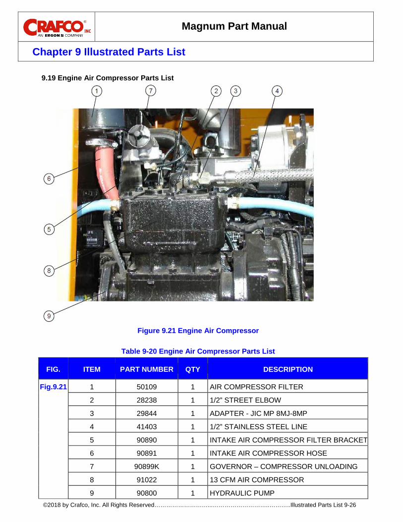
Magnum Part Manual
Chapter 9 Illustrated Parts List
©2018 by Crafco, Inc. All Rights Reserved………………………...………………………..………..Illustrated Parts List 9-26
Engine Air Compressor Parts List 9.19
Figure 9.21 Engine Air Compressor
Table 9-20 Engine Air Compressor Parts List
FIG. ITEM PART NUMBER QTY DESCRIPTION
Fig.9.21 1 50109 1 AIR COMPRESSOR FILTER
2 28238 1 1/2” STREET ELBOW
3 29844 1 ADAPTER - JIC MP 8MJ-8MP
4 41403 1 1/2” STAINLESS STEEL LINE
5 90890 1 INTAKE AIR COMPRESSOR FILTER BRACKET
6 90891 1 INTAKE AIR COMPRESSOR HOSE
7 90899K 1 GOVERNOR – COMPRESSOR UNLOADING
8 91022 1 13 CFM AIR COMPRESSOR
9 90800 1 HYDRAULIC PUMP

Magnum Part Manual
Chapter 9 Illustrated Parts List
©2018 by Crafco, Inc. All Rights Reserved………………………...………………………..………..Illustrated Parts List 9-27
Engine Control Panel Parts List 9.20
Figure 9.22 Engine Control Panel
Table 9-21 Engine Control Panel Parts List
FIG. ITEM PART NUMBER QTY DESCRIPTION
Fig.9.22 1 91869 1 OIL PRESSURE SWITCH GAUGE
2 91822 1 AMP METER GAUGE
3 91764 1 TEMPERATURE SWITCH GAUGE
4 90537 1 IGNITION KEY SWITCH
4A 92257N 1 NUT, DUST COVER, FOR IGNITION SWITCH
5 91854 1 TACHOMETER W/ HOUR METER
6 91758 1 RED MURPHY SWITCH
7 91177 1 FUSE HOLDER
8 91837 1 COOLANT PRESSURE SWITCH GUAGE
9 91780 1 HOUR METER
10 90453 1 2” 0-3000 HYDRAULIC PRESSURE GAUGE
11 92251 1 ENCLOSURE ASSEMBLY
12 51694 1 CIRCUIT BREAKER 5 AMPS
13 51695 1 CIRCUIT BREAKER 30 AMPS

Magnum Part Manual
Chapter 9 Illustrated Parts List
©2018 by Crafco, Inc. All Rights Reserved………………………...………………………..………..Illustrated Parts List 9-28
Belt Drive Parts List 9.21
Figure 9.23 Belt Drive
24

Magnum Part Manual
Chapter 9 Illustrated Parts List
©2018 by Crafco, Inc. All Rights Reserved………………………...………………………..………..Illustrated Parts List 9-29
Table 9-22 Belt Drive Parts List
FIG. ITEM PART NUMBER QTY DESCRIPTION
Fig. 9.23 1 91335 1 BEARING SUPPORT STUB SHAFT ASSY
2 60151 1 ROTARY AIR BLOWER (NOT SHOWN)
3 91330 1 BLOWER SLIDE PLATE, MAGNUM
4 91326 1 ENGINE SHAFT KEY 3/8” X 3/8” X 2-1/2”
5 91308 1 SDS 1-1/2” BUSHING W/ 3/8” KEYWAY
6 91409 3 ENGINE TO BLOWER BELT (3VX300)
7 92304 1 3/3 V 6.0” QD-SDS SHEAVE
8 60335 8.5oz OIL, ROTARY AIR BLOWER (NOT SHOWN)
9 27953 8 3/8”-16 X 1” GR8 HEX HEAD BOLT
10 28641 20 3/8” FLAT HARDENED WASHER
11 28658 20 3/8” LOCK WASHER GRADE 8
12 27955 12 3/8”-16 X 1-1/4” GR8 HEX HEAD BOLT
13 28528 8 1/2”-13 ESNA LOCK NUT
14 28659 8 1/2” LOCK WASHER GRADE 8
15 29026 8 1/2”-13 X 1-1/2” GRADE 8 BOLT
16 90858 2 3/8”-16 X 4” FULL THRD BOLT (NOT SHOWN)
17 28526 2 3/8”-16 ESNA LOCK NUT (NOT SHOWN)
18 27986 2 3/8” FLAT WASHER GRADE 8 (NOT SHOWN)
19 27964 2 3/8”-16 GRADE 8 NUT (NOT SHOWN)
20 90827 8 BLOWER MOUNTING TAB
21 91065 1 BLOWER KEY, 1/4”
22 92306 1 7/8” SH BUSHING
23 92302 1 3/3V 3.65” QD-SH SHEAVE
24 1 GREASE HERE
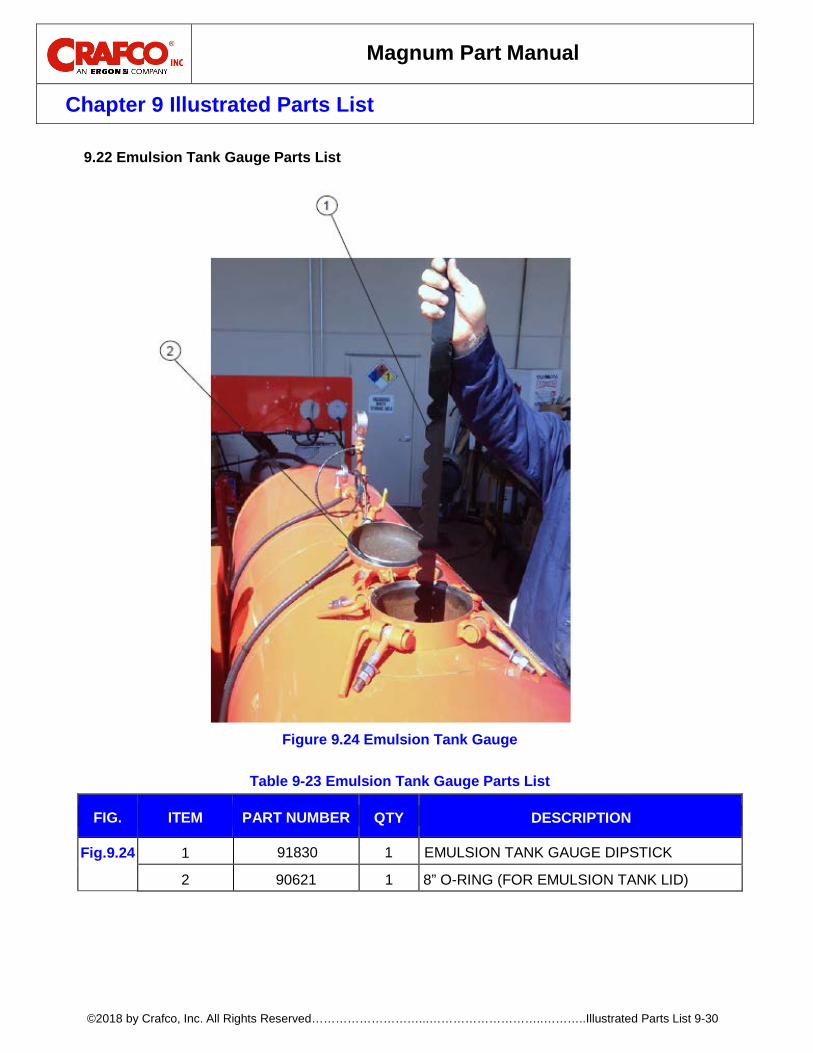
Magnum Part Manual
Chapter 9 Illustrated Parts List
©2018 by Crafco, Inc. All Rights Reserved………………………...………………………..………..Illustrated Parts List 9-30
Emulsion Tank Gauge Parts List 9.22
Figure 9.24 Emulsion Tank Gauge
Table 9-23 Emulsion Tank Gauge Parts List
FIG. ITEM PART NUMBER QTY DESCRIPTION
Fig.9.24 1 91830 1 EMULSION TANK GAUGE DIPSTICK
2 90621 1 8” O-RING (FOR EMULSION TANK LID)
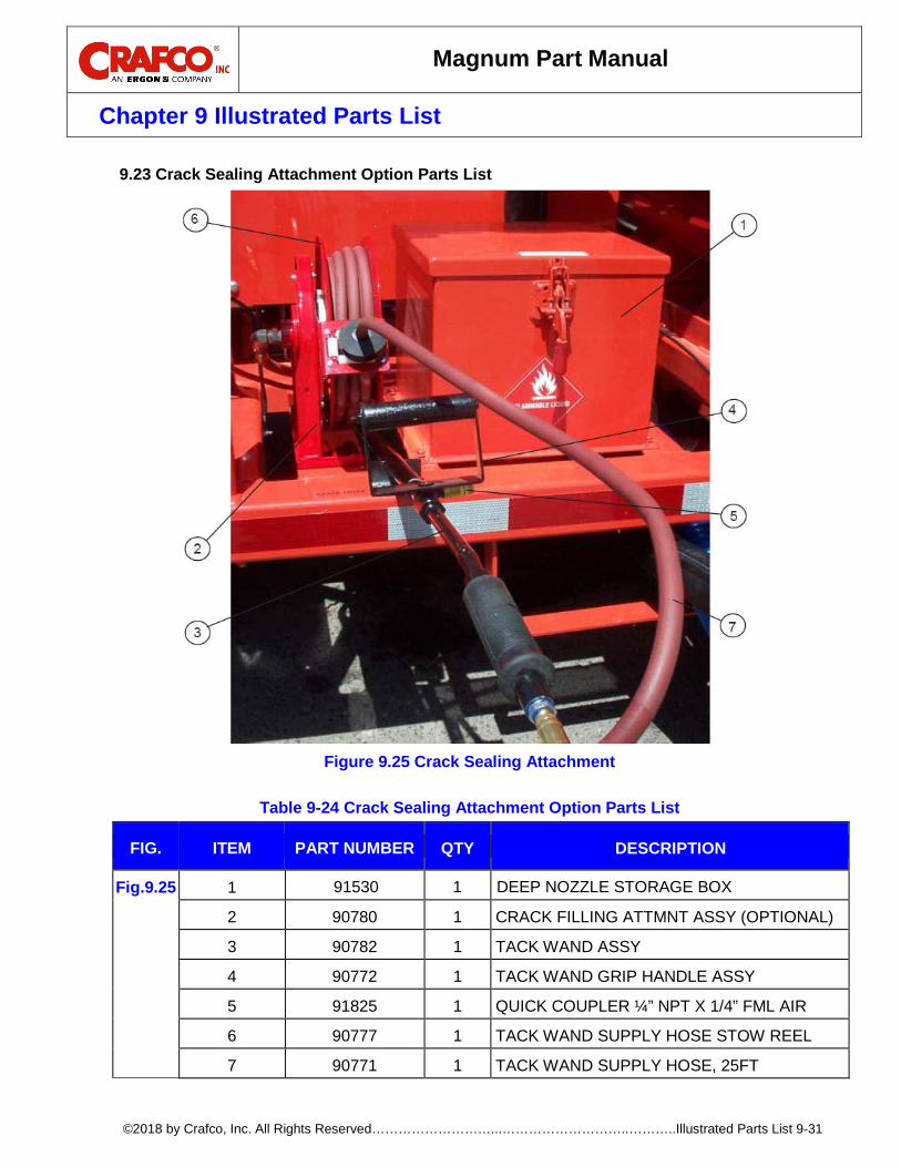
Magnum Part Manual
Chapter 9 Illustrated Parts List
©2018 by Crafco, Inc. All Rights Reserved………………………...………………………..………..Illustrated Parts List 9-31
Crack Sealing Attachment Option Parts List 9.23
Figure 9.25 Crack Sealing Attachment
Table 9-24 Crack Sealing Attachment Option Parts List
FIG. ITEM PART NUMBER QTY DESCRIPTION
Fig.9.25 1 91530 1 DEEP NOZZLE STORAGE BOX
2 90780 1 CRACK FILLING ATTMNT ASSY (OPTIONAL)
3 90782 1 TACK WAND ASSY
4 90772 1 TACK WAND GRIP HANDLE ASSY
5 91825 1 QUICK COUPLER ¼” NPT X 1/4” FML AIR
6 90777 1 TACK WAND SUPPLY HOSE STOW REEL
7 90771 1 TACK WAND SUPPLY HOSE, 25FT

Magnum Part Manual
Chapter 9 Illustrated Parts List
©2018 by Crafco, Inc. All Rights Reserved………………………...………………………..………..Illustrated Parts List 9-32
Electric Throttle Option Parts List 9.24
Figure 9.26 Electric Throttle Option
Table 9-25 Electric Throttle Option Parts List
FIG. ITEM PART NUMBER QTY DESCRIPTION
Fig.9.26 1 91021K 1 ELECTRIC REMOTE CONTROL ACTUATOR
2 90212 1 REMOTE CONTROL ACTR SWCH CVR BOX
3 32527 1 TOGGLE SWITCH BOOT
4 32524 1 ELECTRIC THROTTLE SWITCH
34 2
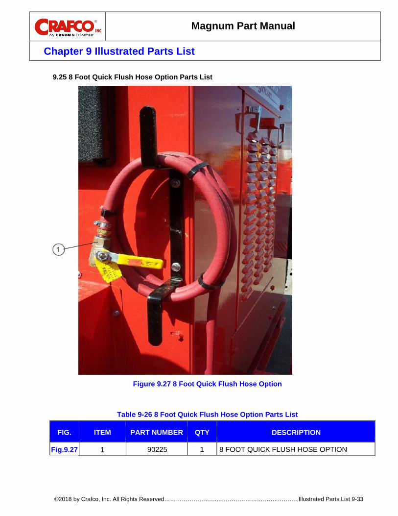
Magnum Part Manual
Chapter 9 Illustrated Parts List
©2018 by Crafco, Inc. All Rights Reserved………………………...………………………..………..Illustrated Parts List 9-33
8 Foot Quick Flush Hose Option Parts List 9.25
Figure 9.27 8 Foot Quick Flush Hose Option
Table 9-26 8 Foot Quick Flush Hose Option Parts List
FIG. ITEM PART NUMBER QTY DESCRIPTION
Fig.9.27 1 90225 1 8 FOOT QUICK FLUSH HOSE OPTION
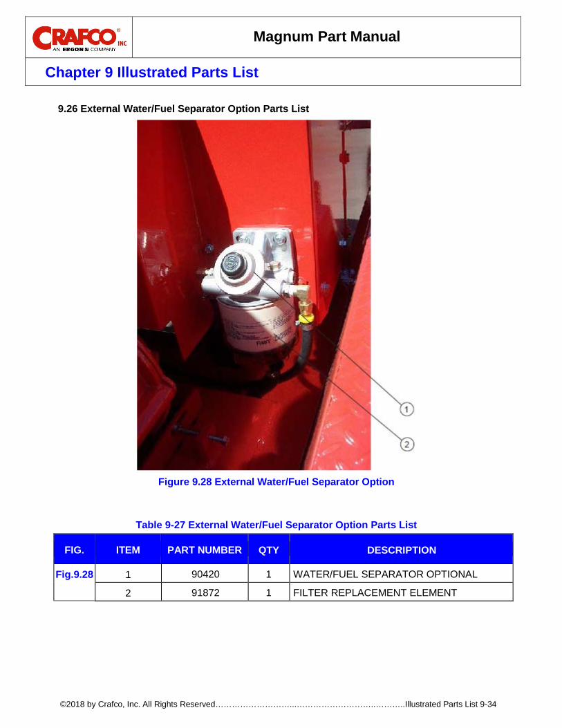
Magnum Part Manual
Chapter 9 Illustrated Parts List
©2018 by Crafco, Inc. All Rights Reserved………………………...………………………..………..Illustrated Parts List 9-34
External Water/Fuel Separator Option Parts List 9.26
Figure 9.28 External Water/Fuel Separator Option
Table 9-27 External Water/Fuel Separator Option Parts List
FIG. ITEM PART NUMBER QTY DESCRIPTION
Fig.9.28 1 90420 1 WATER/FUEL SEPARATOR OPTIONAL
2 91872 1 FILTER REPLACEMENT ELEMENT

Magnum Part Manual
Chapter 9 Illustrated Parts List
©2018 by Crafco, Inc. All Rights Reserved………………………...………………………..………..Illustrated Parts List 9-35
Hitch Extension Option Parts List 9.27
Figure 9.29 Hitch Extension Option
Table 9-28 Hitch Extension Option Parts List
FIG. ITEM PART NUMBER QTY DESCRIPTION
Fig.9.29 1 90887 1 24” HITCH EXTENSION ASSY, 15” OFFSET
1
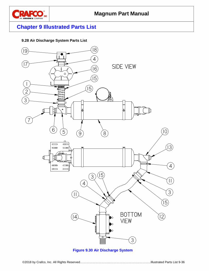
Magnum Part Manual
Chapter 9 Illustrated Parts List
©2018 by Crafco, Inc. All Rights Reserved………………………...………………………..………..Illustrated Parts List 9-36
Air Discharge System Parts List 9.28
Figure 9.30 Air Discharge System
3
4
6
7
89 10
13
11
1214
16
417
1819
11
153
3
4
15
3
2
1
5
15
15
SIDE VIEW
BOTTOM VIEW
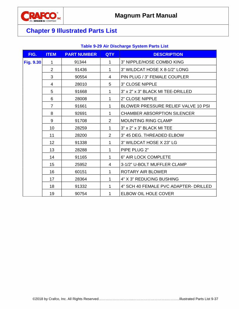
Magnum Part Manual
Chapter 9 Illustrated Parts List
©2018 by Crafco, Inc. All Rights Reserved………………………...………………………..………..Illustrated Parts List 9-37
Table 9-29 Air Discharge System Parts List
FIG. ITEM PART NUMBER QTY DESCRIPTION
Fig. 9.30 1 91344 1 3” NIPPLE/HOSE COMBO KING
2 91436 1 3” WILDCAT HOSE X 8-1/2” LONG
3 90554 4 PIN PLUG / 3” FEMALE COUPLER
4 28010 5 3” CLOSE NIPPLE
5 91668 1 3” x 2” x 3” BLACK MI TEE-DRILLED
6 28008 1 2” CLOSE NIPPLE
7 91661 1 BLOWER PRESSURE RELIEF VALVE 10 PSI
8 92691 1 CHAMBER ABSORPTION SILENCER
9 91708 2 MOUNTING RING CLAMP
10 28259 1 3” x 2” x 3” BLACK MI TEE
11 28200 2 3” 45 DEG. THREADED ELBOW
12 91338 1 3” WILDCAT HOSE X 23” LG
13 28288 1 PIPE PLUG 2”
14 91165 1 6” AIR LOCK COMPLETE
15 25952 4 3-1/2” U-BOLT MUFFLER CLAMP
16 60151 1 ROTARY AIR BLOWER
17 28364 1 4” X 3” REDUCING BUSHING
18 91332 1 4” SCH 40 FEMALE PVC ADAPTER- DRILLED
19 90754 1 ELBOW OIL HOLE COVER

Magnum Part Manual
Chapter 9 Illustrated Parts List
©2018 by Crafco, Inc. All Rights Reserved………………………...………………………..………..Illustrated Parts List 9-38
Aggregate Screw Feed Assembly Parts List 9.29
Figure 9.31 Aggregate Screw Feed Assembly
DETAIL B
DETAIL C
2
4
6
7
9
10
121314
131415 14 16
1819
1720
17
B
C
8
21
1
1 1
5
3
22
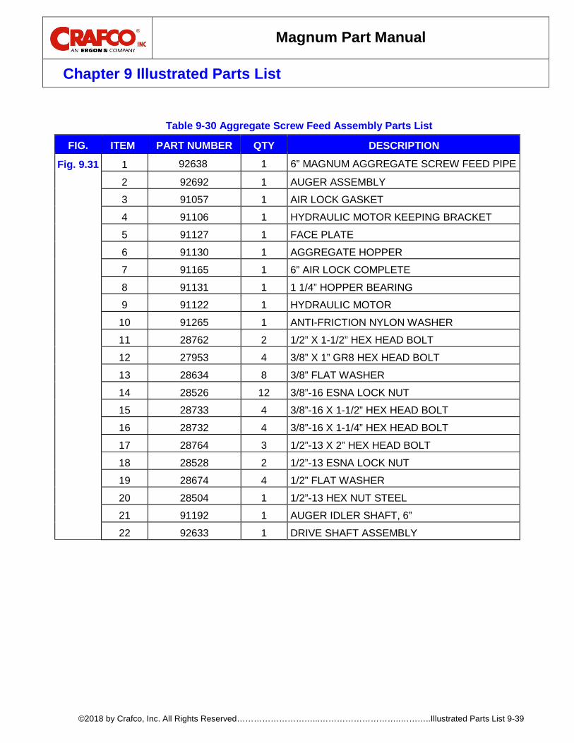
Magnum Part Manual
Chapter 9 Illustrated Parts List
©2018 by Crafco, Inc. All Rights Reserved………………………...………………………..………..Illustrated Parts List 9-39
Table 9-30 Aggregate Screw Feed Assembly Parts List
FIG. ITEM PART NUMBER QTY DESCRIPTION
Fig. 9.31 1 92638 1 6” MAGNUM AGGREGATE SCREW FEED PIPE
2 92692 1 AUGER ASSEMBLY
3 91057 1 AIR LOCK GASKET
4 91106 1 HYDRAULIC MOTOR KEEPING BRACKET
5 91127 1 FACE PLATE
6 91130 1 AGGREGATE HOPPER
7 91165 1 6” AIR LOCK COMPLETE
8 91131 1 1 1/4” HOPPER BEARING
9 91122 1 HYDRAULIC MOTOR
10 91265 1 ANTI-FRICTION NYLON WASHER
11 28762 2 1/2” X 1-1/2” HEX HEAD BOLT
12 27953 4 3/8” X 1” GR8 HEX HEAD BOLT
13 28634 8 3/8” FLAT WASHER
14 28526 12 3/8”-16 ESNA LOCK NUT
15 28733 4 3/8”-16 X 1-1/2” HEX HEAD BOLT
16 28732 4 3/8”-16 X 1-1/4” HEX HEAD BOLT
17 28764 3 1/2”-13 X 2” HEX HEAD BOLT
18 28528 2 1/2”-13 ESNA LOCK NUT
19 28674 4 1/2” FLAT WASHER
20 28504 1 1/2”-13 HEX NUT STEEL
21 91192 1 AUGER IDLER SHAFT, 6”
22 92633 1 DRIVE SHAFT ASSEMBLY
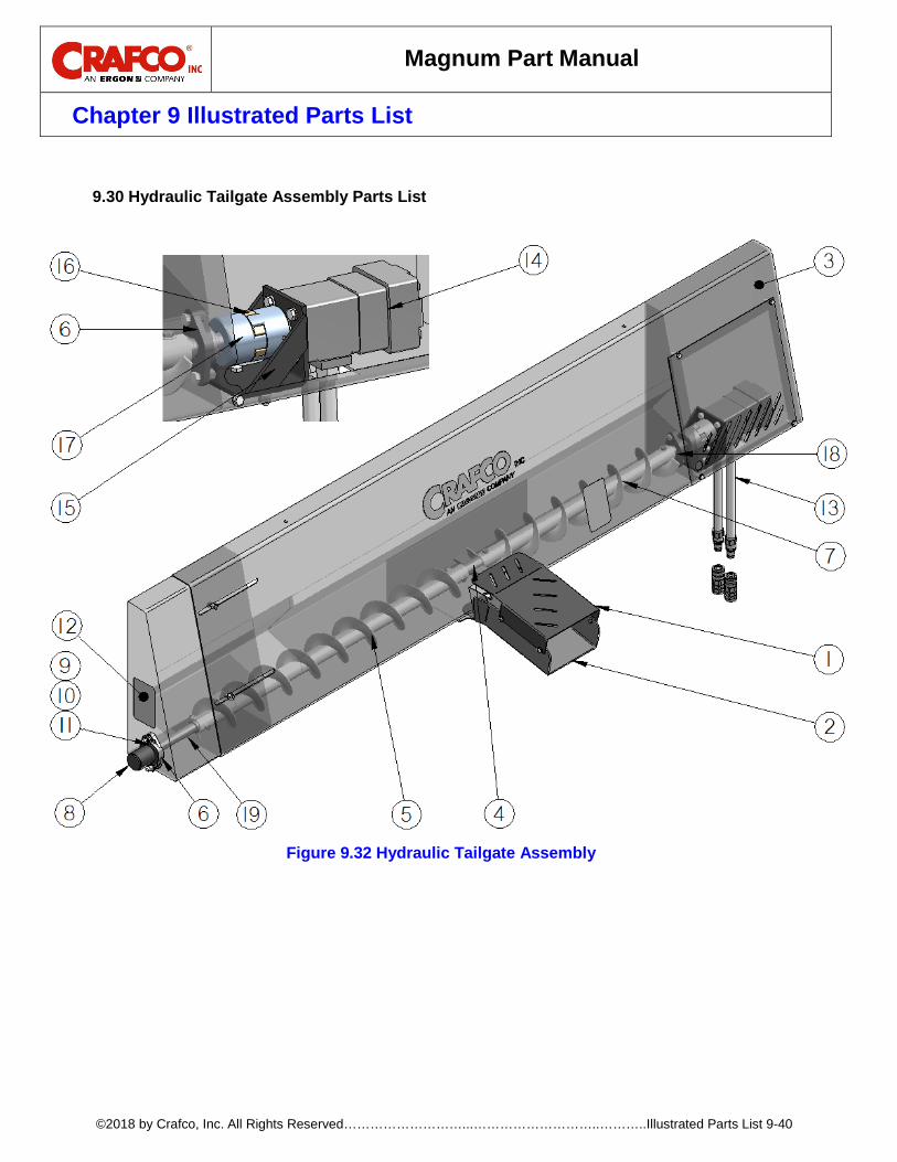
Magnum Part Manual
Chapter 9 Illustrated Parts List
©2018 by Crafco, Inc. All Rights Reserved………………………...………………………..………..Illustrated Parts List 9-40
Hydraulic Tailgate Assembly Parts List 9.30
Figure 9.32 Hydraulic Tailgate Assembly
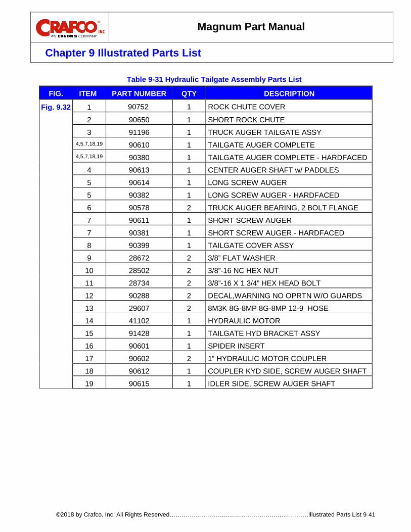
Magnum Part Manual
Chapter 9 Illustrated Parts List
©2018 by Crafco, Inc. All Rights Reserved………………………...………………………..………..Illustrated Parts List 9-41
Table 9-31 Hydraulic Tailgate Assembly Parts List
FIG. ITEM PART NUMBER QTY DESCRIPTION
Fig. 9.32 1 90752 1 ROCK CHUTE COVER
2 90650 1 SHORT ROCK CHUTE
3 91196 1 TRUCK AUGER TAILGATE ASSY 4,5,7,18,19 90610 1 TAILGATE AUGER COMPLETE 4,5,7,18,19 90380 1 TAILGATE AUGER COMPLETE - HARDFACED
4 90613 1 CENTER AUGER SHAFT w/ PADDLES
5 90614 1 LONG SCREW AUGER
5 90382 1 LONG SCREW AUGER - HARDFACED
6 90578 2 TRUCK AUGER BEARING, 2 BOLT FLANGE
7 90611 1 SHORT SCREW AUGER
7 90381 1 SHORT SCREW AUGER - HARDFACED
8 90399 1 TAILGATE COVER ASSY
9 28672 2 3/8” FLAT WASHER
10 28502 2 3/8”-16 NC HEX NUT
11 28734 2 3/8”-16 X 1 3/4” HEX HEAD BOLT
12 90288 2 DECAL,WARNING NO OPRTN W/O GUARDS
13 29607 2 8M3K 8G-8MP 8G-8MP 12-9 HOSE
14 41102 1 HYDRAULIC MOTOR
15 91428 1 TAILGATE HYD BRACKET ASSY
16 90601 1 SPIDER INSERT
17 90602 2 1” HYDRAULIC MOTOR COUPLER
18 90612 1 COUPLER KYD SIDE, SCREW AUGER SHAFT
19 90615 1 IDLER SIDE, SCREW AUGER SHAFT

Magnum Part Manual
Chapter 9 Illustrated Parts List
©2018 by Crafco, Inc. All Rights Reserved………………………...………………………..………..Illustrated Parts List 9-42
Hydraulic Schematic and Parts List 9.31
Figure 9.33 Hydraulic Schematic (P/N 92352)
A2
"S"
TAILGATE MOTOR
"T"
"T"-TAILGATE MOTOR
TAILGATEHYDRAULIC
91196K
92350
90800
MANIFOLD, HYD. CONTROLVALVE- MAGNUM
HYDRAULIC PUMPJ.D. ENG W/COMPMOUNTED
"S"-TAILGATE MOTOR
HYDRAULIC MOTOR6" CENTER AUGER SCREW
91122
41102
B2
B1
A1P
TANK
CEN
TER
AUGE
R
TAILGATE AUGER
CENTER AUGER
HYDRAULIC
TANK
92657
HYD. PUMP TO TURN CLOCKWISEHYD. PRESSURE 1500 PSI @ 1500 RPMS.HYD. PUMP FLOW 22.0 GPM @ 2200 RPMS.
6
5
2
3
4
17
9
9
9
9
8
8
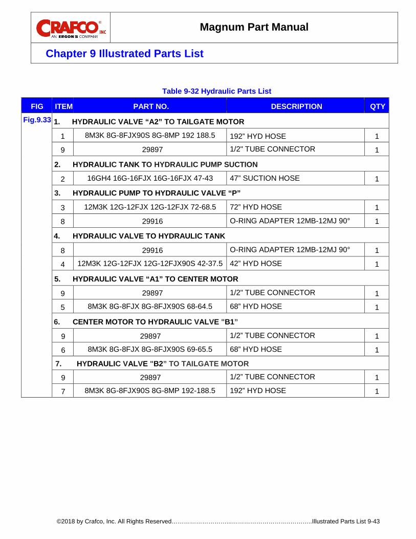
Magnum Part Manual
Chapter 9 Illustrated Parts List
©2018 by Crafco, Inc. All Rights Reserved………………………...………………………..………..Illustrated Parts List 9-43
Table 9-32 Hydraulic Parts List
FIG ITEM PART NO. DESCRIPTION QTY
Fig.9.33 1. HYDRAULIC VALVE “A2” TO TAILGATE MOTOR
1 8M3K 8G-8FJX90S 8G-8MP 192 188.5 192” HYD HOSE 1
9 29897 1/2" TUBE CONNECTOR 1
2. HYDRAULIC TANK TO HYDRAULIC PUMP SUCTION
2 16GH4 16G-16FJX 16G-16FJX 47-43 47” SUCTION HOSE 1
3. HYDRAULIC PUMP TO HYDRAULIC VALVE “P”
3 12M3K 12G-12FJX 12G-12FJX 72-68.5 72” HYD HOSE 1
8 29916 O-RING ADAPTER 12MB-12MJ 90° 1
4. HYDRAULIC VALVE TO HYDRAULIC TANK
8 29916 O-RING ADAPTER 12MB-12MJ 90° 1
4 12M3K 12G-12FJX 12G-12FJX90S 42-37.5 42” HYD HOSE 1
5. HYDRAULIC VALVE “A1” TO CENTER MOTOR
9 29897 1/2" TUBE CONNECTOR 1
5 8M3K 8G-8FJX 8G-8FJX90S 68-64.5 68” HYD HOSE 1
6. CENTER MOTOR TO HYDRAULIC VALVE "B1”
9 29897 1/2” TUBE CONNECTOR 1
6 8M3K 8G-8FJX 8G-8FJX90S 69-65.5 68” HYD HOSE 1
7. HYDRAULIC VALVE "B2” TO TAILGATE MOTOR
9 29897 1/2” TUBE CONNECTOR 1
7 8M3K 8G-8FJX90S 8G-8MP 192-188.5 192” HYD HOSE 1
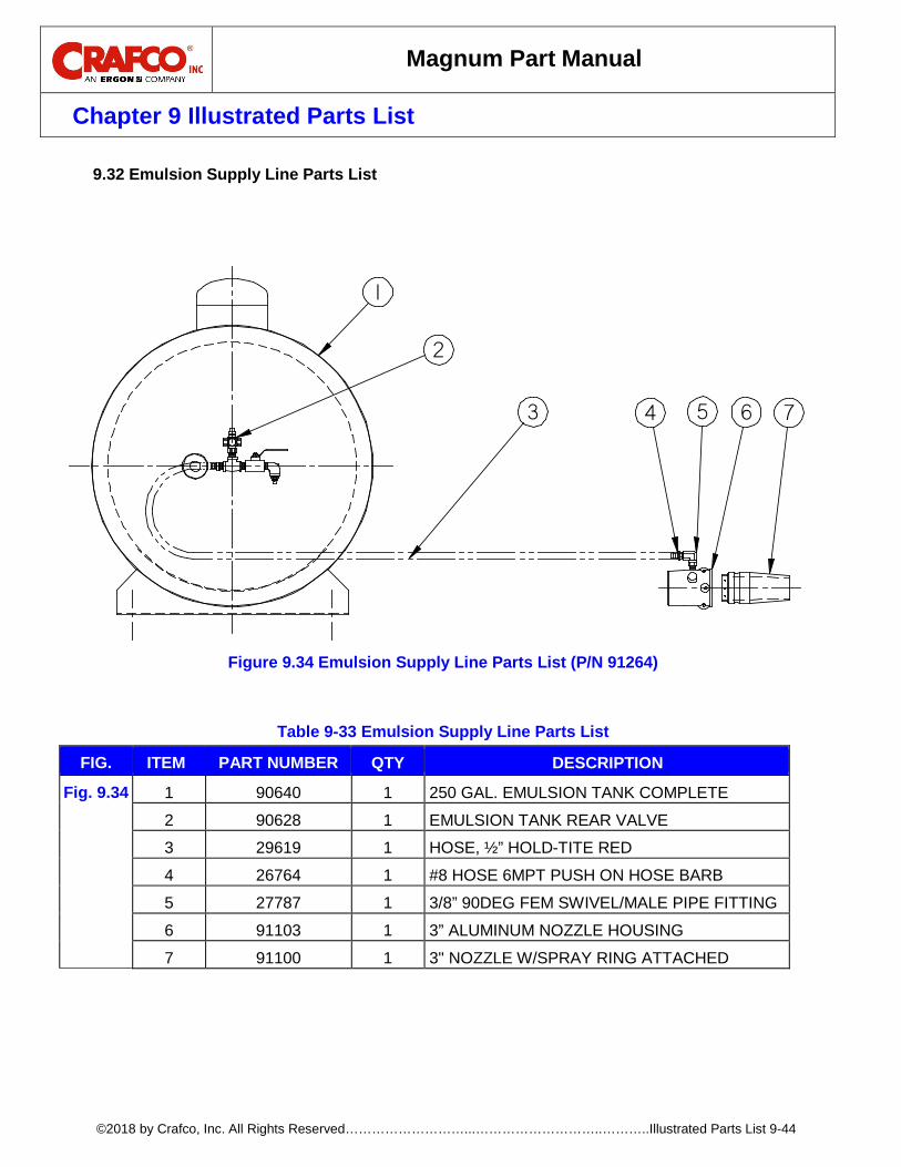
Magnum Part Manual
Chapter 9 Illustrated Parts List
©2018 by Crafco, Inc. All Rights Reserved………………………...………………………..………..Illustrated Parts List 9-44
Emulsion Supply Line Parts List 9.32
Figure 9.34 Emulsion Supply Line Parts List (P/N 91264)
Table 9-33 Emulsion Supply Line Parts List
FIG. ITEM PART NUMBER QTY DESCRIPTION
Fig. 9.34 1 90640 1 250 GAL. EMULSION TANK COMPLETE
2 90628 1 EMULSION TANK REAR VALVE
3 29619 1 HOSE, ½” HOLD-TITE RED
4 26764 1 #8 HOSE 6MPT PUSH ON HOSE BARB
5 27787 1 3/8” 90DEG FEM SWIVEL/MALE PIPE FITTING
6 91103 1 3” ALUMINUM NOZZLE HOUSING
7 91100 1 3" NOZZLE W/SPRAY RING ATTACHED
1
2
3 4 5 6 7
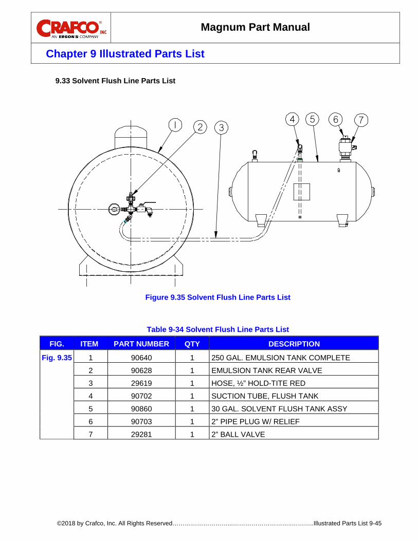
Magnum Part Manual
Chapter 9 Illustrated Parts List
©2018 by Crafco, Inc. All Rights Reserved………………………...………………………..………..Illustrated Parts List 9-45
Solvent Flush Line Parts List 9.33
Figure 9.35 Solvent Flush Line Parts List
Table 9-34 Solvent Flush Line Parts List
FIG. ITEM PART NUMBER QTY DESCRIPTION
Fig. 9.35 1 90640 1 250 GAL. EMULSION TANK COMPLETE
2 90628 1 EMULSION TANK REAR VALVE
3 29619 1 HOSE, ½” HOLD-TITE RED
4 90702 1 SUCTION TUBE, FLUSH TANK
5 90860 1 30 GAL. SOLVENT FLUSH TANK ASSY
6 90703 1 2” PIPE PLUG W/ RELIEF
7 29281 1 2” BALL VALVE
31 24 5 6 7
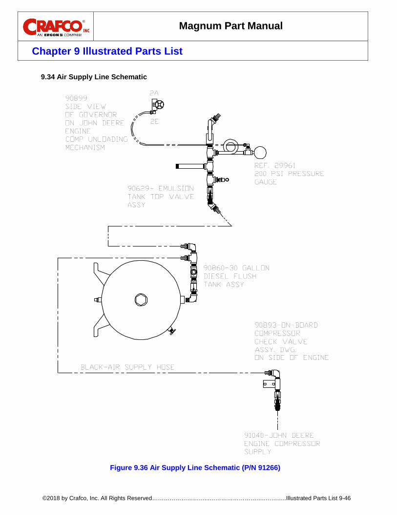
Magnum Part Manual
Chapter 9 Illustrated Parts List
©2018 by Crafco, Inc. All Rights Reserved………………………...………………………..………..Illustrated Parts List 9-46
Air Supply Line Schematic 9.34
Figure 9.36 Air Supply Line Schematic (P/N 91266)
91040-JOHN DEEREENGINE COMPRESSORSUPPLY
90893-ON-BOARDCOMPRESSORCHECK VALVE
90629- EMULSIONTANK TOP VALVEASSY
90860-30 GALLONDIESEL FLUSHTANK ASSY
ASSY. DWG.ON SIDE OF ENGINE
2E
2A
SIDE VIEWOF GOVERNORON JOHN DEEREENGINE
90899
COMP UNLOADINGMECHANISM
BLACK-AIR SUPPLY HOSE
GAUGE200 PSI PRESSUREREF. 29961
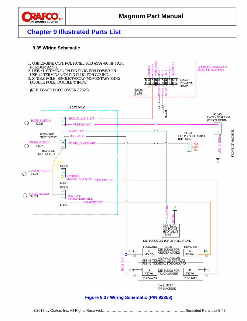
Magnum Part Manual
Chapter 9 Illustrated Parts List
©2018 by Crafco, Inc. All Rights Reserved………………………...………………………..………..Illustrated Parts List 9-47
Wiring Schematic 9.35
Figure 9.37 Wiring Schematic (P/N 92353)
(FRONT HORN)BACK-UP ALARM
REAR OF MACHINECONTROL PANEL BOX
COM
WH
ITE-3 -(12")
REVERSE
REVERSE
MOMENTARY SIDE
MOMENTARY SIDE
LOCK
STATIONARY
CENTER AUGER
TRUCK AUGER32521
32521
HOLDLOCK
REVERSE
HOLD
ORANGE-312"
YELLOW-312"
45376 REVERSEFORWARD
(LARGER VALVE)
OF MACHINEPASS SIDE
#1
BLU
E-31
2"
G
G
#1
45376FORWARD
45376
F
F
REVERSE45376
R
45376R
#1
G
#1
G
GRAY-312"
DIN PLUGS ON TOP OF HYD. VALVE
WH
ITE
G
NC
G
BOOM AREA
HORN SWITCH32521
STATIONARYFORWARD
STONE SWITCH32522
RED/BLACK-1-275"
PURPLE-430"
GRAY-312"
BLUE-312"
WHITE/BLACK-440"
RED
-1RE
D-2
8"
BUSSSTRIP
50238
RED
-2RE
D-3
WH
ITE/
GRE
ENRE
D/B
LACK
PURP
LE-4
RED
-24"
RED
-26"
NO
(UP FRONT)HOPPER LID SWITCH
91133
91645
RED
/WH
ITE-
1PU
RPLE
-3
STRIP
50250TERMINAL
FRO
NT O
F M
ACH
INE
DIN PLUGON TOP OFHYD VALVE45376
DIN PLUGS FORCENTER AUGER
USE #1 TERMINAL ON DIN PLUGUSE #2 TERMINAL FOR GROUND
DIN PLUGS FORTRUCK AUGER
1. USE ENGINE CONTROL PANEL SUB ASSY-80 HP PART NUMBER 92251.2. USE #1 TERMINAL ON DIN PLUG FOR POWER "IN". USE #2 TERMINAL ON DIN PLUG FOR GOUND.3. SINGLE POLE, SINGLE THROW (MOMENTARY SIDE) DOUBLE POLE, DOUBLE THROW
(REF. BLACK BOOT COVER 32527)

Magnum Part Manual
Chapter 9 Illustrated Parts List
©2018 by Crafco, Inc. All Rights Reserved………………………...………………………..………..Illustrated Parts List 9-48
Control Panel Wiring Schematic 9.36
Figure 9.38 Control Panel Wiring Schematic (P/N 92251)
RED/
WHITE-
1
PRP-
3
RED-
2
RED-
1
RED-
3
RED/
BLACK-1
WHITE/
GREEN
ACC
BATT
IGNITION
PRP-2
PRP-1PR
P-4
VIEW AROTATED 90 DEG
BACK VIEW WITH THE COVEROFF.
-+S
RED
BLACK
TACHOMETER

Magnum Part Manual
Chapter 10 Hydraulic Tailgate Mounting
©2018 by Crafco, Inc. All Rights Reserved………………………...……………………...Hydraulic Tailgate Mounting 10-1
10.0 Hydraulic Tailgate Mounting Instructions Mounting Information 10.1
To mount your hydraulically powered tailgate to a dump truck, some custom brackets will have to be made and added in order for it to fit. The brackets will have to mimic the mounts on the original tailgate, so the hydraulic tailgate can be mounted in its place. The new tailgate is adjustable in width to match the truck. Expand it out as needed, and then build the mounts accordingly. You will also need to add a plate to the top depending on the height of the dump bed. See the following figures for more information.
Exploded View of Tailgate and Custom Mounts 10.2
Figure 10.1 Exploded View of Tailgate and Custom Mounts
EXPLODED VIEW
CUSTOM GUSSETS SUPPLIEDBY CUSTOMER TO FIT TO TRUCK
CUSTOM GUSSETS SUPPLIEDBY CUSTOMER TO FIT TO TRUCK
CUSTOM GUSSETS SUPPLIEDBY CUSTOMER TO FIT TO TRUCK
CUSTOM GUSSETS SUPPLIEDBY CUSTOMER TO FIT TO TRUCK
CUSTOM PLATE SUPPLIEDBY CUSTOMER TO FIT TO TRUCK

Magnum Part Manual
Chapter 10 Hydraulic Tailgate Mounting
©2018 by Crafco, Inc. All Rights Reserved………………………...……………………...Hydraulic Tailgate Mounting 10-2
Assembled View of Tailgate and Custom Mounts 10.3
Figure 10.2 Assembled View of Tailgate and Custom Mounts
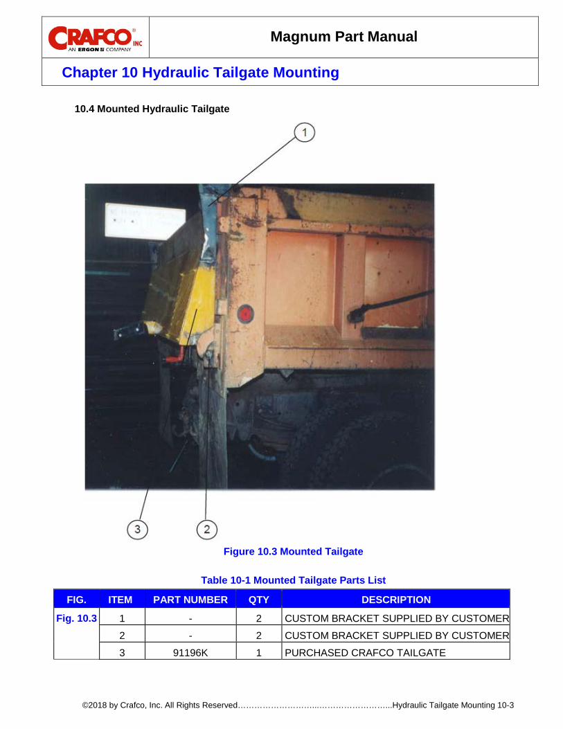
Magnum Part Manual
Chapter 10 Hydraulic Tailgate Mounting
©2018 by Crafco, Inc. All Rights Reserved………………………...……………………...Hydraulic Tailgate Mounting 10-3
Mounted Hydraulic Tailgate 10.4
Figure 10.3 Mounted Tailgate
Table 10-1 Mounted Tailgate Parts List
FIG. ITEM PART NUMBER QTY DESCRIPTION
Fig. 10.3 1 - 2 CUSTOM BRACKET SUPPLIED BY CUSTOMER
2 - 2 CUSTOM BRACKET SUPPLIED BY CUSTOMER
3 91196K 1 PURCHASED CRAFCO TAILGATE


©2018 Crafco, Inc.