Embed Size (px)
Citation preview

Bou
ght b
y M
rs T
rina
McA
nulty
,Cer
tex
Lifti
ng L
td-,
on 0
2/04
/201
2 16
:05
Late
st v
ersi
on. N
ot to
be
dist
ribut
ed/n
etw
orke
d. F
or m
ulti-
user
acc
ess
ww
w.b
sigr
oup.
com
/lice
nse
© B
SI
BRITISH STANDARD BS EN15567-1:2007
Sports and recreational facilities — Ropes courses —Part 1: Construction and safety requirements
ICS 97.220.10
�������������� ���������������������������������������������������

BS EN 15567-1:2007
Bou
ght b
y M
rs T
rina
McA
nulty
,Cer
tex
Lifti
ng L
td-,
on 0
2/04
/201
2 16
:05
Late
st v
ersi
on. N
ot to
be
dist
ribut
ed/n
etw
orke
d. F
or m
ulti-
user
acc
ess
ww
w.b
sigr
oup.
com
/lice
nse
© B
SI
This British Standard was published under the authority of the Standards Policy and Strategy Committee on 31 March 2008
© BSI 2008
ISBN 978 0 580 57732 1
National foreword
This British Standard is the UK implementation of EN 15567-1:2007.The UK participation in its preparation was entrusted by Technical Committee SW/136, Sports, playground and other recreational equipment, to Subcommittee SW/136/15, Sports, playground and other recreational equipment — Adventure courses.A list of organizations represented on this committee can be obtained on request to its secretary.This publication does not purport to include all the necessary provisions of a contract. Users are responsible for its correct application.Compliance with a British Standard cannot confer immunity from legal obligations.
Amendments/corrigenda issued since publication
Date Comments

EUROPEAN STANDARD
NORME EUROPÉENNE
EUROPÄISCHE NORM
EN 15567-1
December 2007
ICS 97.220.10
English Version
Sports and recreational facilities - Ropes courses - Part 1:Construction and safety requirements
Structures de sport et d'activités de plein air - Parcoursacrobatiques - Partie 1: Construction et exigences de
sécurité
Sport- und Freizeitanlagen - Seilgärten - Teil 1: Konstruktion und sicherheitstechnische Anforderungen
This European Standard was approved by CEN on 10 November 2007.
CEN members are bound to comply with the CEN/CENELEC Internal Regulations which stipulate the conditions for giving this EuropeanStandard the status of a national standard without any alteration. Up-to-date lists and bibliographical references concerning such nationalstandards may be obtained on application to the CEN Management Centre or to any CEN member.
This European Standard exists in three official versions (English, French, German). A version in any other language made by translationunder the responsibility of a CEN member into its own language and notified to the CEN Management Centre has the same status as theofficial versions.
CEN members are the national standards bodies of Austria, Belgium, Bulgaria, Cyprus, Czech Republic, Denmark, Estonia, Finland,France, Germany, Greece, Hungary, Iceland, Ireland, Italy, Latvia, Lithuania, Luxembourg, Malta, Netherlands, Norway, Poland, Portugal,Romania, Slovakia, Slovenia, Spain, Sweden, Switzerland and United Kingdom.
EUROPEAN COMMITTEE FOR STANDARDIZATIONC OM ITÉ EUR OP ÉEN DE NOR M ALIS AT IONEUROPÄISCHES KOMITEE FÜR NORMUNG
Management Centre: rue de Stassart, 36 B-1050 Brussels
© 2007 CEN All rights of exploitation in any form and by any means reservedworldwide for CEN national Members.
Ref. No. EN 15567-1:2007: E
Bou
ght b
y M
rs T
rina
McA
nulty
,Cer
tex
Lifti
ng L
td-,
on 0
2/04
/201
2 16
:05
Late
st v
ersi
on. N
ot to
be
dist
ribut
ed/n
etw
orke
d. F
or m
ulti-
user
acc
ess
ww
w.b
sigr
oup.
com
/lice
nse
© B
SI

EN 15567-1:2007 (E)
2
Contents Page
Foreword..............................................................................................................................................................3 Introduction .........................................................................................................................................................4 1 Scope ......................................................................................................................................................5 2 Normative references ............................................................................................................................5 3 Terms and definitions ...........................................................................................................................6 4 Safety requirements ............................................................................................................................10 4.1 Choice of site .......................................................................................................................................10 4.2 Material .................................................................................................................................................10 4.2.1 General..................................................................................................................................................10 4.2.2 Timber and associated products .......................................................................................................11 4.2.3 Metals....................................................................................................................................................11 4.2.4 Wire ropes ............................................................................................................................................12 4.2.5 Synthetics and composites ................................................................................................................13 4.2.6 Dangerous substances .......................................................................................................................13 4.3 Design and manufacture.....................................................................................................................14 4.3.1 General safety requirements ..............................................................................................................14 4.3.2 Loads on safety and activity system .................................................................................................14 4.3.3 Support system....................................................................................................................................15 4.3.4 Activity system.....................................................................................................................................17 4.3.5 Safety system.......................................................................................................................................18 4.4 Personal protective equipment ..........................................................................................................20 5 Test methods........................................................................................................................................20 6 Marking .................................................................................................................................................20 6.1 General..................................................................................................................................................20 6.2 Element identification .........................................................................................................................20 6.3 Element marking..................................................................................................................................20 6.3.1 Notices ..................................................................................................................................................20 6.3.2 Ropes course difficulty .......................................................................................................................21 7 Inspection and maintenance ..............................................................................................................21 8 Documents to be provided .................................................................................................................23 8.1 User manual for operators..................................................................................................................23 8.2 Tree assessment report ......................................................................................................................24 8.3 Inauguration inspection report...........................................................................................................24 Annex A (normative) Minimum information to be included in an arboreal assessment report................25 A.1 General site description......................................................................................................................25 A.2 Arboreal assessment of each tree .....................................................................................................25 A.2.1 General characteristics .......................................................................................................................25 A.2.2 General tree observations ..................................................................................................................25 A.2.3 Comments, final classification of the tree according to its condition ...........................................25 Annex B (informative) Obtaining tree strength data......................................................................................26 Annex C (normative) Rules for the use of the ropes course ........................................................................27 Bibliography ......................................................................................................................................................28
Bou
ght b
y M
rs T
rina
McA
nulty
,Cer
tex
Lifti
ng L
td-,
on 0
2/04
/201
2 16
:05
Late
st v
ersi
on. N
ot to
be
dist
ribut
ed/n
etw
orke
d. F
or m
ulti-
user
acc
ess
ww
w.b
sigr
oup.
com
/lice
nse
© B
SI

EN 15567-1:2007 (E)
3
Foreword
This document (EN 15567-1:2007) has been prepared by Technical Committee CEN/TC 136 “Sports, playground and other recreational equipment”, the secretariat of which is held by DIN.
This European Standard shall be given the status of a national standard, either by publication of an identical text or by endorsement, at the latest by June 2008, and conflicting national standards shall be withdrawn at the latest by June 2008.
This standard is divided into the following two parts:
Part 1: Construction and safety requirements.
Part 2: Operation requirements.
According to the CEN/CENELEC Internal Regulations, the national standards organizations of the following countries are bound to implement this European Standard: Austria, Belgium, Bulgaria, Cyprus, Czech Repub-lic, Denmark, Estonia, Finland, France, Germany, Greece, Hungary, Iceland, Ireland, Italy, Latvia, Lithuania, Luxembourg, Malta, Netherlands, Norway, Poland, Portugal, Romania, Slovakia, Slovenia, Spain, Sweden, Switzerland and the United Kingdom.
Bou
ght b
y M
rs T
rina
McA
nulty
,Cer
tex
Lifti
ng L
td-,
on 0
2/04
/201
2 16
:05
Late
st v
ersi
on. N
ot to
be
dist
ribut
ed/n
etw
orke
d. F
or m
ulti-
user
acc
ess
ww
w.b
sigr
oup.
com
/lice
nse
© B
SI
EN 15567-1:2007 (E)
4
Introduction
Ropes courses vary considerably and may be used for education, recreational, training or therapeutic pur-poses.
Ropes course activities involve risks that should be managed by the operators. This is achieved through care-ful supervision, training, instruction, information etc.
Ropes course activities should only be taken by those who are physically and mentally able to comply with the safety requirements specified by the operator.
The various safety devices (for protection against falling from a height and collisions) consist of equipment designed to limit the consequences of falls or collisions. There are inherent risks associated with ropes courses. These risks should, however, be appropriately managed and minimised by the ropes course operator and his staff; it should be understood that they can not be eliminated altogether.
On the basis of a risk assessment, operators should take reasonably practicable measures to ensure the safety of participants. This means that the degree of risks in a particular job/work place/facility need to be bal-anced against the time, trouble, cost, benefits and physical difficulty of taking measures to avoid or reduce the risk.
Ropes course operators should also consider EN 15567-2, when carrying out risk assessments.
Bou
ght b
y M
rs T
rina
McA
nulty
,Cer
tex
Lifti
ng L
td-,
on 0
2/04
/201
2 16
:05
Late
st v
ersi
on. N
ot to
be
dist
ribut
ed/n
etw
orke
d. F
or m
ulti-
user
acc
ess
ww
w.b
sigr
oup.
com
/lice
nse
© B
SI

EN 15567-1:2007 (E)
5
1 Scope
This European Standard applies to permanent and mobile ropes courses and their components.
This Part 1 of this standard specifies safety requirements for the design, construction, inspection and mainte-nance of ropes courses and their components.
This Part 1 of this standard does not apply to temporary ropes courses (see 3.3) and children's play grounds (see EN 1176 all parts).
For the use of ropes courses part 2 applies.
2 Normative references
The following referenced documents are indispensable for the application of this document. For dated refer-ences, only the edition cited applies. For undated references, the latest edition of the referenced document (including any amendments) applies.
EN 335-2, Durability of wood and wood-based products — Definition of use classes — Part 2: Application to solid wood
EN 350-2:1994, Durability of wood and wood-based products — Natural durability of solid wood — Part 2: Guide to the natural durability and treatability of selected wood species of importance in Europe
EN 351-1:2007, Durability of wood and wood-based products — Preservative-treated solid wood — Part 1: Classification of preservative penetration and retention
EN 636, Plywood – Specifications
EN 13411-1, Terminations for steel wire ropes — Safety — Part 1: Thimbles for steel wire rope slings
EN 13411-2, Terminations for steel wire ropes — Safety — Part 2: Splicing of eyes for wire rope slings
EN 13411-3, Terminations for steel wire ropes — Safety — Part 3: Ferrules and ferrule-securing
EN 13411-4, Terminations for steel wire ropes — Safety — Part 4: Metal and resin socketing
EN 13411-5, Terminations for steel wire ropes — Safety — Part 5: U-bolt wire rope grips
EN 13411-6, Terminations for steel wire ropes — Safety — Part 6: Asymmetric wedge socket
EN 13411-7, Terminations for steel wire ropes - Safety - Part 7: Symmetric wedge socket
EN 15567-2, Sports and recreational facilities - Ropes courses - Part 2: Operation requirements
EN ISO/IEC 17020:2004, General criteria for the operation of various types of bodies performing inspection (ISO/IEC 17020:1998)
ISO 4309:2004, Cranes - Wire ropes - Care, maintenance, installation, examination and discard
Bou
ght b
y M
rs T
rina
McA
nulty
,Cer
tex
Lifti
ng L
td-,
on 0
2/04
/201
2 16
:05
Late
st v
ersi
on. N
ot to
be
dist
ribut
ed/n
etw
orke
d. F
or m
ulti-
user
acc
ess
ww
w.b
sigr
oup.
com
/lice
nse
© B
SI

EN 15567-1:2007 (E)
6
3 Terms and definitions
For the purposes of this European Standard the following terms and definitions shall apply.
3.1 ropes course constructed facility consisting of one or more activity systems, support systems and, if needed, belay and/or safety systems, see Figure 1. A ropes course is distinct from playground equipment in that it has restricted access and requires supervision
Key
Activity systems A
Support systems S
Belaying systems B
A1 A2 A3
Elements Platforms Access
S1
S2 S3
Poles living trees buildings, rock, other supporting structures Foundations, anchors Guy lines
B1 B3
Assisted belaying system Self-belaying system
Figure 1 — Example of a ropes course
3.2 permanent ropes course facility installed for more than one week on the same site
3.3 temporary ropes course facility that has been installed for up to one week
3.4 mobile ropes course facility that is transportable
Bou
ght b
y M
rs T
rina
McA
nulty
,Cer
tex
Lifti
ng L
td-,
on 0
2/04
/201
2 16
:05
Late
st v
ersi
on. N
ot to
be
dist
ribut
ed/n
etw
orke
d. F
or m
ulti-
user
acc
ess
ww
w.b
sigr
oup.
com
/lice
nse
© B
SI

EN 15567-1:2007 (E)
7
3.5 zip wire activity system in which the participant glides under gravity in a sloping direction
3.6 giant swing activity system where the participant performs guided pendulum (to- and-fro) movements
3.7 activity system facility that permits the progression of the participant
EXAMPLE Examples are elements, platforms and access.
NOTE see Figure 1 and Figure 2 for examples.
3.8 support system artificial and/or natural structure intended for installation of activity and safety systems
NOTE See Figure 1 and Figure 2 for examples.
3.9 self-belaying system belaying system that is operated by the participant him-/herself
NOTE See Figure 1.
3.10 assisted belaying system belaying system where the participant is secured by at least one person
NOTE See Figure 1.
3.11 continuous belaying system belaying system that enables participants to progress from one activity system to the next and that does not require participants to undo or change the connection to the belaying system
NOTE See Figure 2.
Bou
ght b
y M
rs T
rina
McA
nulty
,Cer
tex
Lifti
ng L
td-,
on 0
2/04
/201
2 16
:05
Late
st v
ersi
on. N
ot to
be
dist
ribut
ed/n
etw
orke
d. F
or m
ulti-
user
acc
ess
ww
w.b
sigr
oup.
com
/lice
nse
© B
SI

EN 15567-1:2007 (E)
8
Key
Activity systems A
Support systems S
Belaying systems B
A1 A2
Elements Platforms
S1
S2
Poles living trees buildings, rock, other supporting structures Foundations, anchors
B2 B3
Continuous belaying system Self-belaying system
Figure 2 - Example of a continuous belaying system
3.12 change-over manual transfer from one part of a safety system to another
3.13 landing area area in which a participant exiting an element can land
3.14 inspection body body that performs inspection
NOTE 1 A body can be an organization or part of an organization.
[EN ISO/IEC 17020:2004]
NOTE 2 EN ISO/IEC 17020 defines inspection bodies of type A, type B and type C, covered by appropriate profes-sional civil liability insurance.
3.15 falling space any space into which a participant may enter during a fall stopped by the belaying system
Bou
ght b
y M
rs T
rina
McA
nulty
,Cer
tex
Lifti
ng L
td-,
on 0
2/04
/201
2 16
:05
Late
st v
ersi
on. N
ot to
be
dist
ribut
ed/n
etw
orke
d. F
or m
ulti-
user
acc
ess
ww
w.b
sigr
oup.
com
/lice
nse
© B
SI

EN 15567-1:2007 (E)
9
3.16 free space space in, on or around an element that can accommodate a participant carried along passively by the equip-ment
EXAMPLE Examples are oscillating space for a Tyrolean traverse, for a zip wire or for a giant swing.
3.17 arboricultural expert competent person able to undertake arboreal assessments. They shall be covered by appropriate professional civil liability insurance
3.18 maximum fall height maximum height that a participant can fall
3.19 safety line flexible or rigid, horizontal, vertical or sloping, continuous or discontinuous device used as a protection against falling from a height
3.20 platform flat, practically horizontal raised area in which participants can temporarily stay, before or after the element
3.21 safety system system used either to arrest or cushion a participant's fall.
NOTE Fall prevention systems may consist of a guard rail, safety line, landing mat, net, retractable lifeline, etc.
3.22 active braking system system operated by the participant or another person
3.23 passive braking system system operating automatically
EXAMPLE Examples are bungee, gravity, net, water.
3.24 tyrolean traverse ropes (essentially horizontal) on which participants progress under their own power
3.25 routine visual check inspection intended to identify obvious hazards that can result from vandalism, use or weather conditions
3.26 operational inspection inspection, more detailed than routine visual inspection, to check the operation and stability of the equipment
3.27 periodical inspection verification, at intervals not exceeding 12 months intended to establish the overall level of safety of equipment, foundations and surfaces
Bou
ght b
y M
rs T
rina
McA
nulty
,Cer
tex
Lifti
ng L
td-,
on 0
2/04
/201
2 16
:05
Late
st v
ersi
on. N
ot to
be
dist
ribut
ed/n
etw
orke
d. F
or m
ulti-
user
acc
ess
ww
w.b
sigr
oup.
com
/lice
nse
© B
SI

EN 15567-1:2007 (E)
10
3.28 critical application application where the consequences of a failure are likely to lead a serious incident or accident
3.29 spotting one or more persons working to catch, hold or give physical support to other participants
3.30 dead load weight of the element when unloaded
3.31 imposed load load corresponding to average weight of a participant multiplied by the number of participants simultaneously authorised on the element (to be updated)
3.32 dynamic load load generated by a falling participant
3.33 element activity unit in a ropes course, usually between two platforms
3.34 level 1 supervision situation whereby an instructor can physically intervene
3.35 level 2 supervision situation whereby an instructor can clearly see the participant and intervene verbally
4 Safety requirements
4.1 Choice of site
NOTE In general, the installation and use of ropes courses will cause changes to the environment which are covered by national legislation currently in force.
The site of the ropes course shall be chosen to ensure that it is located in an area of reasonable operating safety. It shall be possible to evacuate participants from any part of the ropes course.
The immediate surrounding area shall not impair the safety of the structure and the activities taking place on the site.
Local factors (e.g. lightening, humidity, corrosion, flooding, avalanches etc.) shall be taken into consideration in both the design and the operation of the facility, see EN 15567-2.
Unauthorized access to the ropes course shall be taken into account referring to national regulations.
4.2 Material
4.2.1 General
Materials shall conform to 4.2.2 through 4.2.5.
Bou
ght b
y M
rs T
rina
McA
nulty
,Cer
tex
Lifti
ng L
td-,
on 0
2/04
/201
2 16
:05
Late
st v
ersi
on. N
ot to
be
dist
ribut
ed/n
etw
orke
d. F
or m
ulti-
user
acc
ess
ww
w.b
sigr
oup.
com
/lice
nse
© B
SI

EN 15567-1:2007 (E)
11
Materials shall be fit for purpose.
NOTE 1 The provisions relating to certain materials in this standard do not imply that other equivalent materials are unsuitable in the manufacture of ropes courses.
The selection of materials and their use should be in accordance with appropriate European Standards.
Materials shall be selected and protected so that the structural integrity of the equipment manufactured from them, is not affected before the next relevant maintenance inspection.
NOTE 2 EN 15567-2 gives recommendations on maintenance inspections.
Particular care should be taken in the choice of materials where equipment is to be used in extreme climatic or atmospheric conditions.
In the choice of a material or substance for ropes courses, consideration should be given to the eventual dis-posal of the material or substance having regard to any possible environmental toxic hazard.
When natural or synthetic fibre materials are used in a critical application, the operator shall determine an inspection pro-cedure or adhere to the constraints of the manufacturer's information.
Consideration should also be given to degradation of structural components through ultraviolet influences.
NOTE 3 Attention is drawn to national and local building regulations regarding flammability for equipment installed both indoors and outdoors.
4.2.2 Timber and associated products
Timber parts shall be designed in such a way that precipitation can drain off freely and water accumulation shall be avoided.
In cases of ground contact, one or more of the following methods shall be used:
a) use of timber species with sufficient natural resistance in accordance with Classes 1 and 2 of the natural resistance classification given in EN 350-2:1994, 4.2.2.
b) construction methods, e.g. post shoe;
c) use of timber treated with wood preservatives in accordance with Figure A.1 of EN 351-1:2007 and in ac-cordance with hazard Class 4 of EN 335-2 .
Consideration should also be given to other factors which can be unsuitable, such as splintering, poisoning etc.
All components made of timber and associated products, other than those species conforming to a), that af-fect the stability of the structure and are in constant contact with the ground shall be treated in accordance with c).
When selecting metal fastenings, consideration should be given to the species of timber and chemical treat-ments used as some will accelerate corrosion of metals if there is contact.
Plywood used for outdoor installations shall be according to EN 636.
4.2.3 Metals
Metal parts shall be weatherproof against atmospheric conditions.
Metals that produce toxic oxides that scale or flake shall be protected by a non-toxic coating.
Bou
ght b
y M
rs T
rina
McA
nulty
,Cer
tex
Lifti
ng L
td-,
on 0
2/04
/201
2 16
:05
Late
st v
ersi
on. N
ot to
be
dist
ribut
ed/n
etw
orke
d. F
or m
ulti-
user
acc
ess
ww
w.b
sigr
oup.
com
/lice
nse
© B
SI

EN 15567-1:2007 (E)
12
4.2.4 Wire ropes
The choice of the wire rope shall be appropriate for the application. For wire safety lines only galvanised or stainless steel wire ropes shall be used.
Inspection should be made with reference to ISO 4309:2004, Annex D.
Only approved systems shall be used for wire rope terminations. All wire rope terminations shall conform to EN 13411-1 to EN 13411-7 and shall be used according to the fitting instructions of these standards.
If other types of wire rope terminations are used they shall be used in accordance with the manufacturer's guidelines.
Terminations around trees and poles shall consider the effects of the closure angle. An angle α ≤ 60 ° is rec-ommended (see Figure 3).
Key
αααα = angle of termination
Figure 3 — Angle of termination around a tree
If angles α > 60 °are applied, sufficient measures shall be taken to protect the termination from side loading.
If the angle α is > 120 °, the forces in each leg shall be used to determine the required strength of the wire rope.
If it is necessary to use rope clamps to make an in line connection of two separate wire rope terminations, Figure 4 provides an example of an appropriate inline connection.
Bou
ght b
y M
rs T
rina
McA
nulty
,Cer
tex
Lifti
ng L
td-,
on 0
2/04
/201
2 16
:05
Late
st v
ersi
on. N
ot to
be
dist
ribut
ed/n
etw
orke
d. F
or m
ulti-
user
acc
ess
ww
w.b
sigr
oup.
com
/lice
nse
© B
SI
EN 15567-1:2007 (E)
13
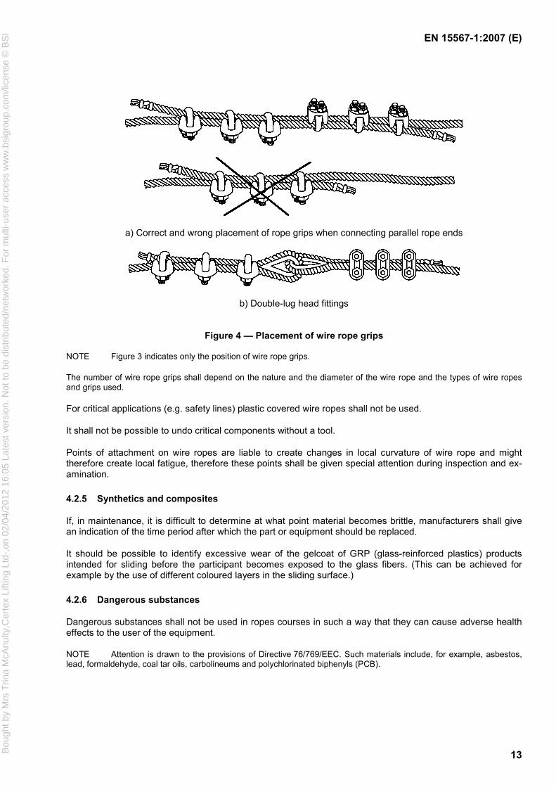
a) Correct and wrong placement of rope grips when connecting parallel rope ends
b) Double-lug head fittings
Figure 4 — Placement of wire rope grips
NOTE Figure 3 indicates only the position of wire rope grips.
The number of wire rope grips shall depend on the nature and the diameter of the wire rope and the types of wire ropes and grips used.
For critical applications (e.g. safety lines) plastic covered wire ropes shall not be used.
It shall not be possible to undo critical components without a tool.
Points of attachment on wire ropes are liable to create changes in local curvature of wire rope and might therefore create local fatigue, therefore these points shall be given special attention during inspection and ex-amination.
4.2.5 Synthetics and composites
If, in maintenance, it is difficult to determine at what point material becomes brittle, manufacturers shall give an indication of the time period after which the part or equipment should be replaced.
It should be possible to identify excessive wear of the gelcoat of GRP (glass-reinforced plastics) products intended for sliding before the participant becomes exposed to the glass fibers. (This can be achieved for example by the use of different coloured layers in the sliding surface.)
4.2.6 Dangerous substances
Dangerous substances shall not be used in ropes courses in such a way that they can cause adverse health effects to the user of the equipment.
NOTE Attention is drawn to the provisions of Directive 76/769/EEC. Such materials include, for example, asbestos, lead, formaldehyde, coal tar oils, carbolineums and polychlorinated biphenyls (PCB).
Bou
ght b
y M
rs T
rina
McA
nulty
,Cer
tex
Lifti
ng L
td-,
on 0
2/04
/201
2 16
:05
Late
st v
ersi
on. N
ot to
be
dist
ribut
ed/n
etw
orke
d. F
or m
ulti-
user
acc
ess
ww
w.b
sigr
oup.
com
/lice
nse
© B
SI

EN 15567-1:2007 (E)
14
4.3 Design and manufacture
4.3.1 General safety requirements
Ropes Courses shall be designed with consideration for the size and the body weight of the participants. The design of the ropes course shall ensure that the impact force for a person with a weight of ≤ 40 kg is not greater than 3 kN.
Moving parts shall be designed to limit the risk of injury (e.g. beams of mobiles).
There shall be no sharp edges and burrs on the facility within reach of the user.
The installation shall be constructed and the equipment shall be chosen so that any openings that can be reached in normal use do not create entrapment hazards.
The free and falling space shall not contain any unprotected obstacles that a person manoeuvring or falling might crash into, other than the constituent parts of the activity system.
If there is a possibility of a participant colliding with an obstacle located in the vicinity of the element (for ex-ample a tree), an appropriate safety device should be installed (for example a pad should be fitted over part of the tree trunk).
On a self-belaying system a clear distinction between the safety system and the activity system (hauling sys-tem, handlines) shall be made. It shall be impossible to connect to the free end of the wire rope. A retractable lifeline shall be used in accordance with the manufacturer's guidelines. Elements located one above the other shall be designed so that lowering of a person who has to be rescued is not impeded.
4.3.2 Loads on safety and activity system
4.3.2.1 Imposed loads
The imposed load shall be 0,8 kN per person.
4.3.2.2 Dynamic loads
The dynamic load for
Self-belaying system;
assisted belaying system;
static installations (e.g. rail systems);
continuous safety system;
shall not exceed 6 kN.
4.3.2.3 Dead loads
The dead loads shall be taken into consideration.
4.3.2.4 Wind, snow and ice loads
These loads shall be taken into consideration.
Bou
ght b
y M
rs T
rina
McA
nulty
,Cer
tex
Lifti
ng L
td-,
on 0
2/04
/201
2 16
:05
Late
st v
ersi
on. N
ot to
be
dist
ribut
ed/n
etw
orke
d. F
or m
ulti-
user
acc
ess
ww
w.b
sigr
oup.
com
/lice
nse
© B
SI

EN 15567-1:2007 (E)
15
4.3.2.5 Calculation
Installations using self-belaying systems, continuous and assisted belaying systems made out of steel wire rope shall be calculated using safety factor 3,0 in relation to the ultimate load.
A belaying system for ropes courses shall be designed to withstand a load of 6 kN without permanent defor-mation to any part of the system.
Rigid installations (e.g. beam systems using a rail belaying system) shall be calculated using the existing Eurocodes and the national annexes, when existing.
The calculations shall take in account the weakness coefficient due to the type of wire rope termination used (EN 13411(all parts)).
Imposed load, dynamic load, dead loads, snow, ice and wind loads applied shall be considered.
The calculation for artificial structures shall relate to the relevant Eurocodes.
For the calculation for natural elements see 4.3.3.3.
4.3.3 Support system
4.3.3.1 General
The support system shall have the stability and resistance appropriate for the load calculated in 4.3.2.5.
The support system may include:
a) Artificial elements like:
framework with foundation;
guys;
foundations;
tension bars and compression bars;
mounting parts on or in buildings.
b) Natural elements like:
trees;
rock.
4.3.3.2 Safety requirements for artificial elements
4.3.3.2.1 General
Hauling systems, retrieval systems and guys should be either inaccessible for participants or clearly identified as not being a safe connection point.
4.3.3.2.2 Guys
Careful attention shall be given to the position of guys, possibly made inaccessible.
Bou
ght b
y M
rs T
rina
McA
nulty
,Cer
tex
Lifti
ng L
td-,
on 0
2/04
/201
2 16
:05
Late
st v
ersi
on. N
ot to
be
dist
ribut
ed/n
etw
orke
d. F
or m
ulti-
user
acc
ess
ww
w.b
sigr
oup.
com
/lice
nse
© B
SI
EN 15567-1:2007 (E)
16
When they are accessible from the ground they shall be clearly visible or protected in order to avoid injury.
When guys are accessible on a self-belaying system, they shall have a device that prevents misuse or an un-controlled descent (e.g. a stop device which itself is inaccessible).
4.3.3.2.3 Foundation
Ground decay of wooden poles should be considered in the design and maintenance of the installation.
4.3.3.2.4 Buildings and existing structures
Before attaching elements to a building, it shall be evaluated for structural strength, electrical hazards and ac-cessibility.
In instances where the ropes course transmits loads to the existing structure (e.g. building) care shall be exer-cised to ensure that the existing structure can bear the loads created by the ropes course.
Calculations shall confirm that the building is fit for purpose.
The manufacturer of the ropes course shall provide the owner of the support structure (or their agent) with all the relevant information relating to the loads and forces that the ropes course and associated equipment may apply to the supporting structure.
4.3.3.3 Safety requirements for natural elements
4.3.3.3.1 Trees
4.3.3.3.1.1 Arboricultural assessment
An arboricultural assessment shall be performed by an arboriculturist to determine the physiological and me-chanical condition of trees used as element supports (see Annex A).
The minimum frequency at which assessments should be made is as follows:
a) first assessment shall be carried out before the ropes course is inaugurated. It is recommended to do this before the designated trees are trimmed and equipped, but no earlier than one year before the ropes course is open;
b) after that date an assessment, by an arboriculturist, shall be carried out annually to assess any changes in the forest and supporting trees.
The minimum information to be included in the arboricultural assessment is specified in Annex A.
4.3.3.3.1.2 Tree strength assessment
The strength of the tree shall be evaluated. Evaluation may include calculation, see Annex B. Loads applied to the tree by safety and activity systems shall be considered.
The wire rope system shall be calculated separately.
When a tree is used as a supporting structure, the element load (dead load) shall not be taken into account if it is less than 30 % of the load created by the maximum fall stress.
The tree strength assessment takes the diameter of the tree and any changes in diameter into account (for example forks).
Bou
ght b
y M
rs T
rina
McA
nulty
,Cer
tex
Lifti
ng L
td-,
on 0
2/04
/201
2 16
:05
Late
st v
ersi
on. N
ot to
be
dist
ribut
ed/n
etw
orke
d. F
or m
ulti-
user
acc
ess
ww
w.b
sigr
oup.
com
/lice
nse
© B
SI

EN 15567-1:2007 (E)
17
When a tree exhibits a structural irregularity between the element anchor point and its base, this discontinuity shall be taken into account in assessing the strength of the tree.
Reinforcement system shall be installed (for example guys, stakes, etc.) when appropriate. It should be taken into account that the movement of the tree is necessary.
4.3.3.3.1.3 Tree and root system protection
The systems used to fix the platforms, safety lines and elements shall be designed to minimise any damage to the trees.
Measures should be taken to protect the root system, particularly against compaction.
4.3.3.3.2 Rocks
When rocks are used as supporting structures, the anchor pull out strength must be at least 4 times the ap-plied load. The choice of anchor should take in account the environmental conditions of the site.
4.3.4 Activity system
4.3.4.1 General
The activity systems shall be designed to accommodate the imposed loads.
The activity system may include for example:
a) ropes, chains and straps;
b) beams, ladders, bridges;
c) landings and platforms;
d) nets;
e) descending devices.
4.3.4.2 Zip wire
4.3.4.2.1 General
The safety connection between the participant and the zip wire rope shall be made with the appropriate per-sonal protective equipment (PPE).
Zip wires shall have no exposed broken wire ends within the reach of the participants.
If any part of the zip wire and the landing area is not visible from the starting point, a departure regulation sys-tem shall be used.
4.3.4.2.2 Special case: zip wire with safety line
If a zip wire is designed with a supporting cable for the trolley and another cable for the belay then each cable shall be calculated according to 4.3.2.
Bou
ght b
y M
rs T
rina
McA
nulty
,Cer
tex
Lifti
ng L
td-,
on 0
2/04
/201
2 16
:05
Late
st v
ersi
on. N
ot to
be
dist
ribut
ed/n
etw
orke
d. F
or m
ulti-
user
acc
ess
ww
w.b
sigr
oup.
com
/lice
nse
© B
SI
EN 15567-1:2007 (E)
18
4.3.4.2.3 Single-ropes zip wire
If a zip wire consists of a single rope that is used both as a progression rope and a safety line, the safety line calculation rules shall be applied, see 4.3.2.
4.3.4.2.4 Protection at the zip wire arrival point
The speed at which a zip wire finishes shall be appropriate to the level of the ropes course in question.
Depending on the arrival speed of the zip wire traverse, the following measures should be taken:
a) if required, the landing area shall be fitted with an appropriate safety device (impact absorbers, impact absorbent floors, nets, landing mats, etc.) to reduce the risks of injury to participants; and
b) appropriate training and equipment shall be provided if participants are required to brake actively during the descent; and
c) passive braking system shall always be in place.
4.3.4.3 Fireman's pole
In the case of a pole with a maximum fall height of less than three metres, the radius of the landing area shall be at least equal to 2/3 the height plus 50 cm.
In the case of a pole with a maximum fall height of more than three metres, a braking device shall be installed to reduce or limit the rate of descent.
4.3.4.4 Platform
The characteristics of the platforms used for this activity shall be as follows:
a) they shall be fixed and stable;
b) they shall withstand the participant's load for which they are designed.
4.3.5 Safety system
4.3.5.1 General
Safety systems can be:
a) collective:
1) guard rails and railings;
2) nets, landing mats and impact absorbent floors appropriate to the potential fall height;
3) spotting;
b) individual.
4) Self-belaying and continuous belaying system: in this case, participants shall wear a safety harness attached to a safety line, retractable lifeline or wire rope loops, etc.
5) Assisted belaying system: in this case participants shall wear a safety harness attached to rope, be-layed by one or more persons using adequate techniques.
Bou
ght b
y M
rs T
rina
McA
nulty
,Cer
tex
Lifti
ng L
td-,
on 0
2/04
/201
2 16
:05
Late
st v
ersi
on. N
ot to
be
dist
ribut
ed/n
etw
orke
d. F
or m
ulti-
user
acc
ess
ww
w.b
sigr
oup.
com
/lice
nse
© B
SI

EN 15567-1:2007 (E)
19
4.3.5.2 Requirements
When participants’ feet are more than 1,0 m from the ground, a safety system shall be in place.
Spotting: the feet of the participant should not be higher than 1,8 m above the ground.
When welded steel parts are being used, a proof of appropriate welding shall be provided.
For non-verified components certificates, type examinations, CE marking, etc. shall be supplied for proof of sufficient load bearing capacity.
4.3.5.3 Specifications for devices used as a protection against falling from a height
4.3.5.3.1 Permissible maximum impact force
The devices used to protect participants against falling from a height shall be designed to ensure that the maximum impact force to which a person is subjected is 6 kN.
4.3.5.3.2 Horizontal or sloping progression
4.3.5.3.2.1 General
Systems, in particular with movable trolleys, shall be designed in such a way as to reduce entrapment of body parts or clothing.
4.3.5.3.2.2 Safety line identification and continuity
On a self-belaying system the safety line shall be clearly distinguishable from the other ropes (for example by means of a colour code). Changing over from one safety line to another shall be an easy operation and en-sure the continuity of the belay.
4.3.5.3.2.3 Safety line slope
The angle of the tangent to the safety line with respect to the horizontal is not specified. A person who falls shall therefore be able to slide forward or backward along the safety line, within the fall area, without colliding with another person. However, in the case of a sloping safety line, the falling person is carried along the safety line with a horizontal movement and may collide with the element or platform components. A device shall then stop the horizontal movement before the speed is such that there is a risk of the person concerned being in-jured by crashing into part of the element or platform.
4.3.5.3.3 Vertical progression
4.3.5.3.3.1 General
For this type of progression, various methods of preventing falls from a height can be used:
a) self-belayed progression with e.g.:
alternate belaying at fixed points;
alternate belaying on wire rope loops, whether or not these are attached to an impact absorbent system;
dynamic ropes loops;
retractable lifeline;
Bou
ght b
y M
rs T
rina
McA
nulty
,Cer
tex
Lifti
ng L
td-,
on 0
2/04
/201
2 16
:05
Late
st v
ersi
on. N
ot to
be
dist
ribut
ed/n
etw
orke
d. F
or m
ulti-
user
acc
ess
ww
w.b
sigr
oup.
com
/lice
nse
© B
SI

EN 15567-1:2007 (E)
20
blocking device with or without energy absorbers;
b) assisted belayed progression, e.g.
top rope;
c) continuous belay.
4.3.5.3.3.2 Requirements
Whatever type of safety device is used, the requirements specified in 4.3.5.3.1 shall be satisfied.
As these requirements are not easily met in the case of belaying at alternate fixed points, the belay points or participants themselves should be fitted with an impact absorbing system or any other system that is equally efficient.
4.4 Personal protective equipment
The personal protection equipment used shall conform to PPE Directive 89/686/EEC and subsequent modi-fied versions of this Directive.
The choice of the PPE shall be in accordance with the ropes course design.
For operational use sport climbing equipment can be used.
When people carrying out all construction, maintenance and inspection work on the ropes course they shall use personal protective equipment in accordance with the PPE Directive 89/686/EEC.
5 Test methods
There are no specific test methods required.
6 Marking
6.1 General
All ropes courses shall be marked in a clearly visible place with the following information:
a) Name and address of the manufacturer/supplier;
b) Number and date of issue of this European Standard (EN 15567-1:2007);
c) Warning sign: unauthorized use.
6.2 Element identification
The elements shall be identified for assistance and rescue purposes.
6.3 Element marking
6.3.1 Notices
For ropes courses where the participants are not under level 1 or level 2 supervision, the minimum information given in the notices posted at the beginning of each element shall include:
Bou
ght b
y M
rs T
rina
McA
nulty
,Cer
tex
Lifti
ng L
td-,
on 0
2/04
/201
2 16
:05
Late
st v
ersi
on. N
ot to
be
dist
ribut
ed/n
etw
orke
d. F
or m
ulti-
user
acc
ess
ww
w.b
sigr
oup.
com
/lice
nse
© B
SI
EN 15567-1:2007 (E)
21
element identification;
maximum number of persons allowed on this element if different from the general instructions;
any special instructions (standing, sitting, kneeling, etc.);
any special safety instructions (where and how to attach oneself, and so on);
difficulty of the ropes course or element, as specified in 6.3.2.
Participants shall be able to see the notices before negotiating an element and the notices should be posi-tioned as far as possible at the same place at the starting point of each element.
Where possible, pictograms shall be used in place of written instructions to ensure that the instructions are more easily understood.
6.3.2 Ropes course difficulty
For ropes courses where the participants are not under level 1 or level 2 supervision, the difficulty of the ropes courses or elements shall be clearly identified (colour code, numerical code, etc.). The ropes course difficulty shall be at least that of the most difficult element that participants will have to negotiate.
When a ropes course bypasses one or more of the more difficult elements, the minimum difficulty shall be in-dicated at the beginning of the ropes course. The more difficult element(s) shall then be identified at the by-pass, according to the difficulty code defined above.
If the ropes course difficulties are colour coded, the following colours shall be used in ascending order of diffi-culty:
green (easy);
blue;
red;
black (very difficult).
Other colours can be used to denote additional levels of difficulty.
7 Inspection and maintenance
Before the site is inaugurated, an inspection body (see 3.14) shall certify that the site is in compliance with this standard.
The following shall be carried out:
Visual inspection,
Functional inspection,
Design validation (e.g. sag to span ratio),
Documentation including structural analysis,
Tree assessment certificate must be drawn up for ropes courses that are situated in trees. The inaugura-tion inspection shall be carried out by an arboricultural expert. Any safety defects which are detected
Bou
ght b
y M
rs T
rina
McA
nulty
,Cer
tex
Lifti
ng L
td-,
on 0
2/04
/201
2 16
:05
Late
st v
ersi
on. N
ot to
be
dist
ribut
ed/n
etw
orke
d. F
or m
ulti-
user
acc
ess
ww
w.b
sigr
oup.
com
/lice
nse
© B
SI

EN 15567-1:2007 (E)
22
must be eliminated before inauguration. An inspection report containing the following information shall be prepared for the inauguration inspection.
— Date and location of inspection;
— Result of inspection and details of defects detected;
— Assessment whether there are any concerns about the inauguration of the ropes course, and if so, details of necessary subsequent inspections;
— Name, address and signature of the examiner.
The inspection report shall be included in the operational manual of the ropes course.
Inauguration inspection shall be carried out by an inspection body (type A in accordance with EN ISO/IEC 17020).
The manufacturer/supplier shall provide instructions for maintenance (marked with the number of this stan-dard), which shall include a statement that the frequency of inspection will vary with the type of equipment, e.g. equipment where the stability relies on one post, or materials used and other factors, e.g. heavy use, levels of vandalism, coastal location, air pollution, age of equipment.
Drawings and diagrams necessary for maintenance, inspection and checking of correct operation and, when appropriate, repair of the equipment.
The instructions shall specify the frequency with which the equipment or its components should be inspected or maintained and shall include guidance on the following, where relevant:
a) routine visual check;
A routine visual check shall be carried out before each opening.
NOTE 1 Examples of visual and operational inspection points are cleanliness, equipment ground clearances, ground surface finishes, exposed foundations, sharp edges, missing parts, excessive wear (of moving parts) and the structural integrity of the safety system.
b) operational inspection;
This should be carried out every 1 month to 3 months, or as indicated by the manufacturer's instruction.
c) periodical inspection.
The following shall be carried out:
Visual inspection,
Functional inspection,
Determination of replacement state of worn parts,
inspection including all manufacturer’s/supplier’s instructions for maintenance.
Periodical inspections shall be carried out at least once every year by an inspection body (type A, type B or type C in accordance with EN ISO/IEC 17020). Any safety relevant defects observed shall be eliminated. Spe-cific considerations on safety critical wire ropes shall be given to the potential effects of fatigue.
Periodical inspection of permanent ropes courses installed on trees shall be carried out at least once every year by an inspection body with experience and knowledge on ropes courses and trees and woods.
Bou
ght b
y M
rs T
rina
McA
nulty
,Cer
tex
Lifti
ng L
td-,
on 0
2/04
/201
2 16
:05
Late
st v
ersi
on. N
ot to
be
dist
ribut
ed/n
etw
orke
d. F
or m
ulti-
user
acc
ess
ww
w.b
sigr
oup.
com
/lice
nse
© B
SI

EN 15567-1:2007 (E)
23
For periodical inspections an inspection report shall be drawn up including the following:
date and place of the inspection;
results of the inspection indicating the defects observed;
assessment, whether there are any misgivings about further use of the facility;
information on necessary re-inspection;
name, address and signature of the examiner.
The inspection report shall be included in the technical documentation of the ropes course.
NOTE 2 Typical checks include the effects of weather, evidence of rotting or corrosion and any change in the level of safety of the equipment as a result of repairs made, or of added or replaced components.
NOTE 3 The periodical inspection may require excavation or dismantling of certain parts.
The manual shall specify the frequency and method by which equipment shall be inspected and maintained for example:
a) where necessary, the servicing points and methods of servicing, e.g. lubrication, tightening of bolts, re-tensioning of ropes;
b) replacement parts shall comply with manufacturer's specifications;
c) if special disposal treatment is required for some equipment or parts;
d) identification of spare parts;
e) any additional measures to be taken during the run-in period, e.g. tightening of fastenings;
f) tensioning of ropes;
g) need to keep drainage holes clear:
h) surfacing shall be maintained: in particular, the levels of loose fill materials.
i) GRP (glass-reinforced plastics) should be replaced or repaired before the glass fibres become exposed through wear or damage. This particularly applies to slides.
8 Documents to be provided
8.1 User manual for operators
The manufacturer or the installer of a ropes course shall provide a manual containing at least the following information together with the main product:
1. Technical description of the facility and its individual components (material certificates etc.);
2. Use of the course according to Annex C;
3. Marking (see Clause 6);
4. Manufacturer's declaration.
Bou
ght b
y M
rs T
rina
McA
nulty
,Cer
tex
Lifti
ng L
td-,
on 0
2/04
/201
2 16
:05
Late
st v
ersi
on. N
ot to
be
dist
ribut
ed/n
etw
orke
d. F
or m
ulti-
user
acc
ess
ww
w.b
sigr
oup.
com
/lice
nse
© B
SI

EN 15567-1:2007 (E)
24
The manufacturer's declaration should contain the following:
a) Basis of static load calculation (e.g. load cases, foundation, fixing, support, special conditions, wind situa-tions);
b) normative references;
c) Exclusions of liability, if any.
8.2 Tree assessment report
8.3 Inauguration inspection report
Bou
ght b
y M
rs T
rina
McA
nulty
,Cer
tex
Lifti
ng L
td-,
on 0
2/04
/201
2 16
:05
Late
st v
ersi
on. N
ot to
be
dist
ribut
ed/n
etw
orke
d. F
or m
ulti-
user
acc
ess
ww
w.b
sigr
oup.
com
/lice
nse
© B
SI

EN 15567-1:2007 (E)
25
Annex A (normative)
Minimum information to be included in an arboreal assessment report
A.1 General site description
Forest;
description of the timber stand, vegetation, soil, general topography and altitude of the site;
recommendations regarding management of the site.
A.2 Arboreal assessment of each tree
A.2.1 General characteristics
unique, long-term identification of the trees over time and marking of this identification on a general site plan;
various species of the trees;
tdiameter of each tree at a height of 1,3 m;
estimated total height of each tree;
incline of each tree (orientation, reaction, etc.).
A.2.2 General tree observations
assessment of the various parts of the tree (crown, trunk, roots): assessment of the physiological, me-chanical and risk condition;
description of the defects and abnormalities detected;
any particular aspect or abnormality to be drawn to the attention of the site operator;
recommended actions to be taken to correct such defects.
A.2.3 Comments, final classification of the tree according to its condition
A coding system for assessing the physiological and mechanical condition of a tree and the risk level can be established. A colour code can be used to assess the various conditions.
Bou
ght b
y M
rs T
rina
McA
nulty
,Cer
tex
Lifti
ng L
td-,
on 0
2/04
/201
2 16
:05
Late
st v
ersi
on. N
ot to
be
dist
ribut
ed/n
etw
orke
d. F
or m
ulti-
user
acc
ess
ww
w.b
sigr
oup.
com
/lice
nse
© B
SI

EN 15567-1:2007 (E)
26
Annex B (informative)
Obtaining tree strength data
B.1 General
The following are examples of methods that can be used to obtain data to address a variety of different symp-toms commonly found in trees. Other methods can also be used. The methods of assessment are listed in order of complexity — starting with the most straightforward. This data can be used to inform tree strength calculations.
B.2 Visual Tree assessment (VTA)
An assessment of the overall appearance of the tree, their root system and their environment allowing a clas-sification of healthy trees (which can be statically calculated) and those trees with defects (e.g. decay, cracks, folds, fungus, hazard beam cracks, fibre buckling, bark defects). To determine the extent of damage soft tools like a metal needle or a wooden hammer are used. For a calculation of trees with defects the following meth-ods are required:
B.3 Drilling Increment Core
Wood strength assessment involves taking a sample through the core which is then tested by a Fractometer. This data provides a reliable calculation of the tree.
B.4 Drilling Resistance Measurement
Involves drilling with a narrow needle connected to a Resistograph which records the resistance of the wood. A paper print shows exactly where soft (= less healthy) regions inside may be found. Only hard (= healthy) wood should be taken into account for the calculation.
B.5 Sonic Speed Measurement
Acoustic signals sent by an impulse hammer are recorded by acoustic sensors fixed at the tree. A computer Tomograph creates a three-dimensional image of the tree — showing the different regions of soft and hard wood.
B.6 Elasto-Inclino-Method
Loads are applied to a tree (thereby simulating the force generated by wind or a ropes course) and are meas-ured by inclination sensors. This method can over-stress the tree by reaching failure loads.
B.7 AFB-Method
A digital photograph of the tree provides the basis for a computer simulation of the likely wind loading. This method could be developed further to simulate loads created by ropes courses.
B.8 Statically Integrated Assessment (SIA) This method adopts the same principals as those used for calculating the stability of buildings. Problem: a tree is a living organism and as such requires an individual assessment.
Bou
ght b
y M
rs T
rina
McA
nulty
,Cer
tex
Lifti
ng L
td-,
on 0
2/04
/201
2 16
:05
Late
st v
ersi
on. N
ot to
be
dist
ribut
ed/n
etw
orke
d. F
or m
ulti-
user
acc
ess
ww
w.b
sigr
oup.
com
/lice
nse
© B
SI

EN 15567-1:2007 (E)
27
Annex C (normative)
Rules for the use of the ropes course
This document is produced by the ropes course designer. It specifies the restrictions regarding the use of the ropes courses and shall contain, at least the following information:
a) use of the elements:
accurate description of the way in which participants are to negotiate each element and the way in which their safety is ensured;
b) meteorological conditions under which the elements are not to be used:
storm; wind; snow and/or frost;
c) number of persons allowed:
on each element; on each platform;
d) morphology of the participants:
minimum size; maximum weight;
e) access restriction with respect to:
age and/or size; f) appropriate clothing, long hair tied back, etc.;
g) description and characteristics of the personal protective equipment (PPE) to be used on all ropes courses:
harness; lanyard (length); impact absorber; connector; pulley; gloves, helmets, coveralls;
h) security and emergency plan with a description of the procedures for evacuating:
injured person from an elevated position (different procedures according to the place where the per-son is located);
all the participants from the park (in the event of a storm, high wind, flood, etc.).
Bou
ght b
y M
rs T
rina
McA
nulty
,Cer
tex
Lifti
ng L
td-,
on 0
2/04
/201
2 16
:05
Late
st v
ersi
on. N
ot to
be
dist
ribut
ed/n
etw
orke
d. F
or m
ulti-
user
acc
ess
ww
w.b
sigr
oup.
com
/lice
nse
© B
SI

EN 15567-1:2007 (E)
28
Bibliography
[1] 76/769/EEC, Council Directive of 27 July 1976 on the approximation of the laws, regulations and ad-ministrative provisions of the Member States relating to restrictions on the marketing and use of cer-tain dangerous substances and preparations
[2] 89/686/EEC, Council Directive of 21 December 1989 on the approximation of the laws of the Member States relating to personal protective equipment
[3] 89/391/EEC, Council Directive of 12 June 1989 on the introduction of measures to encourage im-provements in the safety and health of workers at work
[4] EN 1991-1-3, Eurocode 1 — Actions on structures — Part 1-3: General actions — Snow loads
[5] EN 1991-1-4, Eurocode 1 : Actions on structures — Part 1-4: General actions — Wind actions
[6] EN 1991-1-5, Eurocode 1 : Actions on structures — Part 1-5: General actions — Thermal actions
[7] EN 1176 (all parts), Playground equipment
Bou
ght b
y M
rs T
rina
McA
nulty
,Cer
tex
Lifti
ng L
td-,
on 0
2/04
/201
2 16
:05
Late
st v
ersi
on. N
ot to
be
dist
ribut
ed/n
etw
orke
d. F
or m
ulti-
user
acc
ess
ww
w.b
sigr
oup.
com
/lice
nse
© B
SI

blankBou
ght b
y M
rs T
rina
McA
nulty
,Cer
tex
Lifti
ng L
td-,
on 0
2/04
/201
2 16
:05
Late
st v
ersi
on. N
ot to
be
dist
ribut
ed/n
etw
orke
d. F
or m
ulti-
user
acc
ess
ww
w.b
sigr
oup.
com
/lice
nse
© B
SI

Bou
ght b
y M
rs T
rina
McA
nulty
,Cer
tex
Lifti
ng L
td-,
on 0
2/04
/201
2 16
:05
Late
st v
ersi
on. N
ot to
be
dist
ribut
ed/n
etw
orke
d. F
or m
ulti-
user
acc
ess
ww
w.b
sigr
oup.
com
/lice
nse
© B
SI
BS EN15567-1:2007
BSI389 Chiswick High RoadLondonW4 4AL
BSI — British Standards InstitutionBSI is the independent national body responsible for preparing British Standards. It presents the UK view on standards in Europe and at the international level. It is incorporated by Royal Charter.
Revisions
British Standards are updated by amendment or revision. Users of British Standards should make sure that they possess the latest amendments or editions.
It is the constant aim of BSI to improve the quality of our products and services. We would be grateful if anyone finding an inaccuracy or ambiguity while using this British Standard would inform the Secretary of the technical committee responsible, the identity of which can be found on the inside front cover. Tel: +44 (0)20 8996 9000. Fax: +44 (0)20 8996 7400.
BSI offers members an individual updating service called PLUS which ensures that subscribers automatically receive the latest editions of standards.
Buying standards
Orders for all BSI, international and foreign standards publications should be addressed to Customer Services. Tel: +44 (0)20 8996 9001. Fax: +44 (0)20 8996 7001. Email: [email protected]. Standards are also available from the BSI website at http://www.bsi-global.com.
In response to orders for international standards, it is BSI policy to supply the BSI implementation of those that have been published as British Standards, unless otherwise requested.
Information on standards
BSI provides a wide range of information on national, European and international standards through its Library and its Technical Help to Exporters Service. Various BSI electronic information services are also available which give details on all its products and services. Contact the Information Centre. Tel: +44 (0)20 8996 7111. Fax: +44 (0)20 8996 7048. Email: [email protected].
Subscribing members of BSI are kept up to date with standards developments and receive substantial discounts on the purchase price of standards. For details of these and other benefits contact Membership Administration. Tel: +44 (0)20 8996 7002. Fax: +44 (0)20 8996 7001. Email: [email protected].
Information regarding online access to British Standards via British Standards Online can be found at http://www.bsi-global.com/bsonline.
Further information about BSI is available on the BSI website at http://www.bsi-global.com.
Copyright
Copyright subsists in all BSI publications. BSI also holds the copyright, in the UK, of the publications of the international standardization bodies. Except as permitted under the Copyright, Designs and Patents Act 1988 no extract may be reproduced, stored in a retrieval system or transmitted in any form or by any means – electronic, photocopying, recording or otherwise – without prior written permission from BSI.
This does not preclude the free use, in the course of implementing the standard, of necessary details such as symbols, and size, type or grade designations. If these details are to be used for any other purpose than implementation then the prior written permission of BSI must be obtained.
Details and advice can be obtained from the Copyright & Licensing Manager. Tel: +44 (0)20 8996 7070. Fax: +44 (0)20 8996 7553. Email: [email protected].