Embed Size (px)
Citation preview

Change for Life
Split Air Conditioner
Installation ManualResidential Air Conditioners
Thank you for choosing Residential Air Conditioners,please read this owner’s manual carefully before operation and retain it for future reference.
MODEL: GWC09AB-D3DNA2D GWH09AB-D3DNA2DGWC12AB-D3DNA2D GWH12AB-D3DNA2DGWC18AC-D3DNA2D GWH18AC-D3DNA2DGWC24AC-D3DNA2D GWH24AC-D3DNA2D


■ .............................................3■ ...............................................................4
■ ........................................................1
■ ..............................9
Do not dispose this product as unsorted municipal waste. Collection of such waste separately for special treatment is necessary.
CONTENTS
Notices for installation
Installation dimension diagram
Install indoor unit
Test operation and check after installation■ .......................10Installation and Maintenance of Healthy Filter
Never attempt. Be sure to follow this instruction
The physical product may differ from the drawing in this manual for different display. If there are some differences between them, please refer to the physical product as the standard.
This appliance is not intended for use by persons (including children) with reducedphysical, sensory or mental capabilities or lack of experience and knowledge, unless they have been given supervision or instruction concerning use of the appliance by a person responsible for their safety.Children should be supervised to ensure they are away from the appliance.
■ .............................................................7Install outdoor unit

1
Notices for installation
4.Warning: Before obtaining access to terminals, all supply circuits must be disconnected.5.For appliances with type Y attachment, the instructions shall contain the substance of the following. If the supply cord is damaged, it must be replaced by the manufacturer, its service agent or similarly qualified persons in order to avoid a hazard.6.The appliance must be positioned so that the plug is accessible.7.The temperature of refrigerant line will be high; please keep the interconnection cable away from the copper tube. 8. The instructions shall state the substance of the following: This appliance is not intended for use by persons(including children)with reduced physical, sensory or mental capabilities, or lack of experience and knowledge, unless they have been given supervision or instruction concerning use of the appliance by a person responsible for their safety. Children should be supervised to ensure that they do not play with the appliance.
Caution
Installation Site Instructions
The unit should be installed only by authorized service center according to local or government regulations and in compliance with this manual.
Before installing, please contact with local authorized maintenance center. If the unit isnot installed by the authorized service center, the malfunction may not be solveddue to incovenient contact between the user and the service personnel.When removing the unit to the other place, please firstly contact with the local authorizedservice center.
●
●
●
●
●
●
Proper installation site is vital for correct and efficient operation of the unit. Avoid the following sites where:
strong heat sources, vapours, flammable gas or volatile liquids are emitted. high-frequency electro-magnetic waves are generated by radio equipment, welders and medical equipment. salt-laden air prevails (such as close to coastal areas). the air is contaminated with industrial vapours and oils. the air contains sulphures gas such as in hot spring zones. corrosion or poor air quality exists.
1.
2.
3.
Installation Site of Indoor Unit
Select a site where the condensate can be easily drained out, and where it is easily connected to outdoor unit.
Select a place where the wall is strong enough to withstand the full weight and vibration of the unit.
Select a place where it is out of reach of children.
The air inlet and outlet should be away from the obstructions. Ensure the air can be blown through the whole room.
Be sure to leave enough space to allow access for routine maintenance. The installation site should be 98 3/7 inch or more above the floor.
5.
4.
1.
2.
3.

2
Notices for installation
Note:
Safety Precautions for Electric Appliances
Installation Site of Outdoor Unit
1.Select a site where noise and outflow air emitted by the unit will not annoy neighbors. Select a site where there is sufficient ventilation.
Select a site where there is no obstruction blocking the inlet and outlet.The site should be able to withstand the full weight and vibration.
Select a dry place, but do not expose the unit to direct sunlight or strong wind.Make sure that the outdoor unit is installed in accordance with the installation instructions, and is convenient for maintenance and repair.The height difference between indoor and outdoor units is within16.4ft, and the length of the connecting tubing does not exceed 32.8ft.Select a place where it is out of reach of children.Select a place where the unit does not have negative impact on pedestrians or on the city.
5. The minimum distance between the unit and combustive surface is 4.9ft.
1. A dedicated power supply circuit should be used in accordance with local electrical safety regulations.
2. Don't drag the power cord with excessive force.3.
The appliance shall be installed in accordance with national wiring regulations. An all-pole disconnection switch with a contact separation of at least 9.8ft in all poles should be connected in fixed wiring.
The unit should be reliably earthed and connected to an exclusive earth device by the professionals.
4. The air switch must have the functions of magnetic tripping and heat tripping to preventshort circuit and overload.
Make sure the live wire, neutral wire and earth wire in the family power socket are properly connected. There should be reliable circuit in the diagram.Inadequate or incorrect electrical connections may cause electric shock or fire.
●
●
6.
7.
2. 3. 4.5.6.
7.
8.9.
Make sure that the indoor unit is installed in accordance with installation dimension
Select a place about 3.3ft or more away from TV set or any other electric appliance. Select a place where the filter can be easily taken out.
instructions.
6.7.8.
9. Do not use the unit in the laundry or by swimming pool etc.
Earthing Requirements
① ② ③ ④
1. Air conditioner is type I electric appliance. Please ensure that the unit is reliably earthed.2. The yellow-green wire in air conditioner is the earthing wire which can not be used
for other purposes. Improper earthing may cause electric shock.3. The earth resistance should accord to the national criterion.4. The power must have reliable earthing terminal. Please do not connect the earthing
wire with the following:W epip saGepip reta Contamination pipeOther place that professional personnel consider is unreliable
5. The model and rated values of fuses should accord with the silk print on fuse cover or related PCB.

3
Installation dimension diagram
Space to the ceiling
Space to the wall
Space to the wall
Air outlet sideSpace to the floor
AboveAbove
6inch Above 6inch Above
Above
118inch 98
6inch
Air inlet side
Air outlet side
Space to the wall
Space to the obstruction
Space to the wall
20in
ch a
bove
20inch above
12inch above
12inch above
79inch above
Installation dimension diagram
● Indoor unit
● Outdoor unit
inch

Drill Piping Hole
1.Slant the piping hole (Ф2 1/6 or Ф2 3/4) on the wall sl ightly downward
to the outdoor side. 2.Insert the piping-hole sleeve into the hole to prevent the connection piping
and wiring from being damaged when passing through the hole.
Indoor Outdoor Wall pipe Seal pad
4
Installation of Indoor Unit
Installation of Mounting Plate 1. Mounting plate should be installed horizontally. As the water tray's outlet for the indoor unit is two-way type, during installation, the indoor unit should slightly slant to water tray's outlet for smooth drainage of condensate. 2.Fix the mounting plate on the wall with screws.3.Be sure that the mounting plate has been fixed firmly enough to withstand about 132.3 lb. Meanwhile, the weight should be evenly shared by each screw.
Fig.5
09K、12K UNIT:
(Rear piping hole) (Rear piping hole)Left Right
the wall 6inchabove
Space tothe wall 6inchabove
Wall Wall
18K UNIT:
24K UNIT:
Ф2 1/6 or Ф2 3/4
3 4/7
6 1/61
11 1/
7
23 5/6 3 3/41/3
33 3/4
1 1/9
4 2/7
Unit:inch
4 1/3 27 1/3 5 3/5
2 3/4
1
Ø2 1/6 3 1/71 1
/6Ø2 1/6
11 4/
5
1/3
37 1/4
46
6 8/9 27 8 1/5
13
1 4/7
3
1 1/4
7Ø2 3/4
Ø2 3/4
6 2/5
Ø2 1/6 Ø2 1/6
Connecting Indoor and Outdoor Electric Wires
5
Installation of Indoor Unit
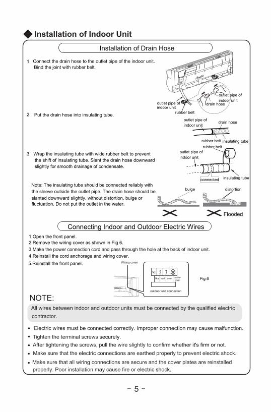
Note: The insulating tube should be connected reliably withthe sleeve outside the outlet pipe. The drain hose should be slanted downward slightly, without distortion, bulge or fluctuation. Do not put the outlet in the water.
bulge distortion
Flooded
●
●
● After tightening the screws, pull the wire slightly to confirm whether it's firm or not.● ● Make sure that all wiring connections are secure and the cover plates are reinstalled
NOTE:All wires between indoor and outdoor units must be connected by the qualified electric contractor.
Electric wires must be connected correctly. Improper connection may cause malfunction.Tighten the terminal screws securely.
Make sure that the electric connections are earthed properly to prevent electric shock.
properly. Poor installation may cause fire or electric shock.
yellow-green
brown Fig.6
1.Open the front panel.2.Remove the wiring cover as shown in Fig 6.3.Make the power connection cord and pass through the hole at the back of indoor unit. 4.Reinstall the cord anchorage and wiring cover.5.Reinstall the front panel.
Wiring cover
outdoor unit connection
1.
2.
3.
Installation of Drain Hose
Connect the drain hose to the outlet pipe of the indoor unit.Bind the joint with rubber belt.
Put the drain hose into insulating tube.
Wrap the insulating tube with wide rubber belt to prevent the shift of insulating tube. Slant the drain hose downward slightly for smooth drainage of condensate.
outlet pipe of indoor unit
insulating tubeconnected
insulating tube
drain hoseoutlet pipe of indoor unit
drain hose
outlet pipe of indoor unit
outlet pipe of indoor unit
rubber belt
rubber beltrubber belt

6
右后
4.
2.
3.
●
1.
⑴ ⑵
1.2.
Installation of Indoor Unit
The piping can be output from right, right rear, leftor left rear.When routing the piping and wiring from the leftor right side of indoor unit, cut off the tailingsfrom the chassis when necessary(As shown in Fig.7)
Cut off tailing 1 when routing the wiring only;Cut off tailing 1 and tailing 2 when routingboth the wiring and piping.
Take out the piping from body case; wrap the piping, power cords, drain hose with the tape and then make them pass through the piping hole. (As shown in Fig.8)Hang the mounting slots of the indoor unit on theupper hooks of the mounting plate and check if it is firm enough. (As shown in Fig.9)The installation site should be 98 3/7 inch or more
above the floor.
Installation of Connection PipeAlign the center of the pipe flare with the related valve.Screw in the flare nut by hand and then tighten thenut with spanner and torque wrench by referring to the following:
NOTE: Connect the connection pipe to indoor unit at first and then to outdoor unit. Handle pi-ping bending with care. Do not damage the connection pipe. Ensure that the joint nut is tightened firmly, otherwise, it may cause leakage.
Spanner Torque wrench
PipingTaper nutIndoor unit piping
Fig.9
Mountingplate
Fixing hook Mounting plate
Right
Right rear Fig.8Left rear
Left
Fig.7Tailing 1Tailing 2
Finally wrap itwith tape
Gas side pipinginsulation
Water drainage pipe
Liquid sidePiping insulation
Gas side pipingExternal connection
electric wireLiquid side piping
(N·m)Ф6.35(1/4”)Ф9.52(3/8”)Ф12.7(1/2”)Ф15.88(5/8”)
34~42N·m(340-420kgf.cm)14~18N·m(140-180kgf.cm)
49~61N·m(490-610kgf.cm)68~82N·m(680-820kgf.cm)
Tube diameter Tightening torque,approximate
Installation of Indoor Unit

7
3.
4.5.
1.2.
Remove the handle on the right side plate of outdoor unit.Take off wire cord anchorage. Connect and fix power cord to the terminal board. Wiring should fit that of indoor unit. Fix the power cord with wire clamps and then connect the
the corresponding connector.
Confirm if the wire has been fixed properly.
Reinstall the handle.
●
●
Installation of Outdoor UnitElectric Wiring
NOTE:Incorrect wiring may cause malfunction of spare part.After the wire has been fixed, ensure there is freespace between the connection and fixing placeson the lead wire.
real product for authentic information.
Wire hole
Sketch map of power connection wire:
Power connection wire Power cord
Cable-cross board
for 9k、12k unit
for 18K、24K unit
Indoor unitconnection
N(1) 2 3 L1
L1
L2
L2
Gblue black brown
POWER
yellow-green bluebrown yellow-
greenSchematic diagram being reference only, please refer to
● Use vacuum pump
1. Connect the charging hose of manifold valve to charging port of low-pressure valve. Both high-pressure valve and low-pressure valve must be tighten up).2. Connect joint of charging hose to vacuum pump.3. Fully open Lo (low pressure) handle of manifold valve and start the vacuum pump for vacuum pumping.4. Usually the vacuum pumping time of 2600W AC is about 15min. The vacuum pumping time of 5000W AC is about 20min. The vacuum pumping time of 7200W AC is about 30min. Make sure the pressure is -1.0X10⁵pa (-76cmHg). When vacuum pumping is finished, close Lo(low pressure) handle of manifold valve completely to stop the vacuum pump.
(Note: R410A refrigerant special vacuum pump should be applied for R410A unit.)
Liquid valve
Gas valve
Manifold valve
MultimeterPiezometer
Hi handleLo handle
Charging hose Charging hose
Vacuum pump
Length of connection pipeAir purging method
Use vacuum pumpNameplate value
Refrigerant charging amount
Not longer than 24.6ft
24.6~65.6ft
● Air purging method:
-76cm Hg
Nameplate value +20g/m (for 9k、12k、18k heat pump unit)Nameplate value +15g/m (for 18k、24k cool only unit)Nameplate value +50g/m (for 24k heat pump unit)add 15g/20g/50g of refrigerant for additional 1m of pippe length
Air purging

8
Installation of Outdoor Unit
Apply soap water to check whether the joints are leaky. Leak detector can also be applied for leakage test.
Leakage test
5. Maintain the pressure for a while after finishing vacuum pumping to see if there is leakage of the system. Usually the pressure maintenance time of the air conditioner above 5000W is 5min and the pressure maintenance time of the air conditioner below 5000W is 3min. During pressure maintenance period, the rebound of pressure should not exceed 0.005Mpa (0.11lb).
7. Tighten bonnets of high-pressure valve, low-pressure valve and charging port.
6. After finishing vacuum pumping, open the liquid valve slightly to release air in order to balance the system pressure and present air inlet when removing the hose. Fully open high-pressure valve and low-pressure valve after removing the hose.
Leak detection point of indoor unit
Leak detection point of outdoor unit
During heating operation, the condensate and defrosting water should be drained out reliably through the drain hose.Install the outdoor drain connector in a Φ1 inch hole onthe base plate and attach the drain hose to the connectorso that the waste water formed in the outdoor unit can bedrained out .The hole diameter 25 must be plugged.Whether to plug other holes will be determined by the dealers according to actual conditions.
Drain-water holeBottom frame
Drain plug
Hose (available commercially,inner dia. 16mm)
Drain connecter
Outdoor Condensate Drainage (only for Heat pump unit)

9
Check after Installation and Operation Test
Check after Installation
noitcnuflam elbissoPdekcehc eb ot smetI
Has the unit been fixed firmly? The unit may drop, shake or emit noise.
Have you done the refrigerant leakage test? It may cause insufficient cooling(heating).
Is thermal insulation sufficient? It may cause condensation.
Is water drainage satisfactory? It may cause water leakage.Is the voltage in accordance with the ratedvoltage marked on the nameplate?
It may cause electric malfunctionor damage the unit.
Is the electric wiring or pipingconnection installed correctly and securely?
It may cause electric malfunctionor damage the parts.
Has the unit been securely earthed? It may cause electrical leakage.
Is the power cord specified? It may cause electric malfunctionor damage the parts.
Is the inlet or outlet blocked? It may cause insufficient cooling(heating).
Is the length of connection pipesand refrigerant capacity recorded?
The refrigerant capacity is not accurate.
Operation Test
1.Before Operation Test(1)Do not switch on power before installation is finished completely. (2)Electric wiring must be connected correctly and securely.(3)Cut-off valves of the connection pipes should be opened.(4)All the impurities such as scraps and thrums must be cleared from the unit.2.Operation Test Method(1)Switch on power and press "ON/OFF" button on the wireless remote controller to start the operation.(2)Press MODE button to select the COOL, HEAT (Not available for cooling only unit), FAN to check whether the operation is normal or not.

Installation and Maintenance of Healthy Filter(Optional)
10
Fig. a
1.
2. (as shown in Fig.b).
3. Install the air filter properly along the arrowdirection in Fig.c, and then close the panel .
●
filter
Air filter
(as shown in Fig.a)
Fig. b
Fig. c
Lift up the front panel from its two ends, as shown by the arrow direction, and then remove the air filter.
Attach the healthy filter onto the air filter, .
Healthy
Remove the healthy filter and reinstall it after cleaning according to the installation instruction. Do not use brush or hard objects to cleanthe filter. After cleaning, be sure to dry it in the shade.
The general service life for the healthy filter is about one year under normal condition. As for silver ion filter, it is ineffective when its surface becomes black (green).
This supplementary instruction is provided for reference to the unit withhealthy filter. If the graphics provided herein are different from the actualproduct, please refer to the actual product. The quantity of healthy filters is based on the actual delivery.
Installation of Healthy Filter
Cleaning and Maintenance
Service Life


Add: West Jinji Rd, Qianshan, Zhuhai, Guangdong, China, 519070Tel: (+86-756) 8522218 Fax: (+86-756) 8669426E-mail: [email protected] www.gree.com
GREE ELECTRIC APPLIANCES, INC. OF ZHUHAI
66129911448