Embed Size (px)
Citation preview
SUNY Geneseo 1 College Circle
Geneseo, NY
December 2011
Spill Prevention, Control and Countermeasure Plan
FINAL PLAN
IN THE EVENT OF AN OIL SPILL, SEE SSEECCTTIIOONN 55 OF THIS PLAN FOR SPECIFIC SPILL RESPONSE AND NOTIFICATION PROCEDURES.
REFER TO AAPPPPEENNDDIIXX DD FOR THE TANKER TRUCK UNLOADING/LOADING PROCEDURES.
FINAL PLAN
360° Engineering and Project Delivery Solutions
Spill Prevention, Control and Countermeasure Plan
JAMES R. HECKATHORNE, VICE PRESIDENT O’Brien & Gere Engineers, Inc.
Prepared for:
SUNY Geneseo Geneseo, New York
December 2011
12336/47946
Page 2 of 96
SPCC PLAN – QUICK REFERENCE GUIDE
360° Engineering and Project Delivery Solutions
I:\Suny-Geneseo.12336\47946.Spcc-Plan-Suny\Docs\Reports\SPCC\SPCC Plan Quick Reference Guide.Doc
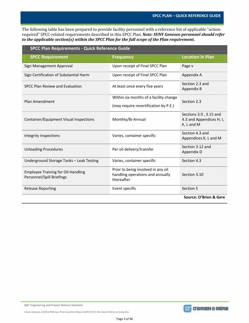
The following table has been prepared to provide facility personnel with a reference list of applicable “action-required” SPCC-related requirements described in this SPCC Plan. Note: SUNY Geneseo personnel should refer to the applicable section(s) within the SPCC Plan for the full scope of the Plan requirement.
SPCC Plan Requirements - Quick Reference Guide
SPCC Requirement Frequency Location in Plan
Sign Management Approval Upon receipt of Final SPCC Plan Page v
Sign Certification of Substantial Harm Upon receipt of Final SPCC Plan Appendix A
SPCC Plan Review and Evaluation At least once every five years Section 2.3 and Appendix B
Plan Amendment Within six months of a facility change
(may require recertification by P.E.) Section 2.3
Container/Equipment Visual Inspections Monthly/Bi-Annual Sections 3.9 , 3.15 and 4.3 and Appendices H, I, K, L and M
Integrity Inspections Varies, container specific Section 4.3 and Appendices K, L and M
Unloading Procedures Per oil delivery/transfer Section 3.12 and Appendix D
Underground Storage Tanks – Leak Testing Varies, container specific Section 4.3
Employee Training for Oil-Handling Personnel/Spill Briefings
Prior to being involved in any oil handling operations and annually thereafter
Section 3.10
Release Reporting Event specific Section 5
Source: O’Brien & Gere
Page 3 of 96
SUNY GENESEO – SPCC PLAN
i | FINAL: December 21, 2011
I:\Suny-Geneseo.12336\47946.Spcc-Plan-Suny\Docs\Reports\SPCC\SPCC Plan_122111 final.doc
TABLE OF CONTENTS
List of Tables ............................................................................................................................................................................ ii List of Figures ........................................................................................................................................................................... ii List of Appendices .................................................................................................................................................................. ii List of Exhibits ....................................................................................................................................................................... iii
Maintenance of the SPCC Plan ........................................................................................................................................................... iv Management Approval .......................................................................................................................................................................... v Professional Engineer Certification (SPCC) ................................................................................................................................. vi 1. Overview of Facility ........................................................................................................................................................................... 1
1.1 General Facility Identification Information ...................................................................................................................... 1 1.2 Facility Description ..................................................................................................................................................................... 1 1.3 Discharges from Facility............................................................................................................................................................ 1
1.3.1 Storm Water Discharges ................................................................................................................................................... 1 1.3.2 Sanitary Discharges ............................................................................................................................................................. 1
2. Introduction .......................................................................................................................................................................................... 2 2.1 Plan Availability ............................................................................................................................................................................ 2 2.2 Purpose and Scope ...................................................................................................................................................................... 2 2.3 Plan Amending and Updating Requirements ................................................................................................................... 2
3. General SPCC Plan Requirements ................................................................................................................................................ 4 3.1 Purpose............................................................................................................................................................................................. 4 3.2 Regulatory Conformance – 40 CFR 112.7(a)(1) ............................................................................................................. 4 3.3 Deviations From Requirement – 40 CFR 112.7(a)(2) .................................................................................................. 4 3.4 Description of Physical Layout of Facility – 40 CFR 112.7(a)(3) ............................................................................. 4 3.5 Spill Reporting Procedures – 40 CFR 112.7(a)(4) and (a)(5) ................................................................................... 5 3.6 Fault Analysis – 40 CFR 112.7(b) .......................................................................................................................................... 5
3.6.1 Potential Spill Sources, Volumes, Rates and Control ............................................................................................ 5 3.6.2 Predicted Fates of Potential Spills ................................................................................................................................ 6
3.7 Containment and/or Diversionary Structures or Equipment – 40 CFR 112.7(c)............................................. 6 3.8 Demonstration of Practicability – 40 CFR 112.7(d) ...................................................................................................... 6 3.9 Inspection and Record Keeping – 40 CFR 112.7(e) ....................................................................................................... 7 3.10 Personnel Training and Discharge Prevention Procedures – 40 CFR 112.7(f) .............................................. 7 3.11 Facility Security Measures – 40 CFR 112.7(g) .............................................................................................................. 8 3.12 Facility Tank Truck Loading/Unloading – 40 CFR 112.7(h) ................................................................................... 8 3.13 Field-Constructed Aboveground Containers – 40 CFR 112.7(i)............................................................................ 9 3.14 Facility Compliance with other Applicability Prevention Standards – 40 CFR 112.7(j) ............................. 9 3.15 Qualified Oil-filled Operational Equipment – 40 CFR 112.7(k) .......................................................................... 10
4. Specific SPCC Plan Requirements ............................................................................................................................................. 11 4.1 Purpose.......................................................................................................................................................................................... 11
Page 4 of 96
SUNY GENESEO – SPCC PLAN
ii | FINAL: December 21, 2011
I:\Suny-Geneseo.12336\47946.Spcc-Plan-Suny\Docs\Reports\SPCC\SPCC Plan_122111 final.doc
4.2 Facility Drainage – 40 CFR 112.8(b) and 112.12(b) .................................................................................................. 11 4.3 Bulk Storage Containers – 40 CFR 112.8(c) and 112.12(c) .................................................................................... 12 4.4 Facility Transfer Operation, Pumping and Facility Process – 40 CFR 112.8(d) and 112.12(d) .............. 14
5. Emergency and Spill Response Procedures ......................................................................................................................... 16 5.1 Spill Discovery and Initial Response ................................................................................................................................. 16 5.2 Internal Reporting Requirements ...................................................................................................................................... 16 5.3 External Reporting Requirements ..................................................................................................................................... 16
5.3.1 Reportable Quantities ..................................................................................................................................................... 16 5.3.2 Federal Written Notification Requirements .......................................................................................................... 18 5.3.4 Emergency Contacts ......................................................................................................................................................... 18
LIST OF TABLES
1 Prediction of Potential Spills
2 Emergency Contacts
LIST OF FIGURES
1 Site Location Map
2 Site Layout
LIST OF APPENDICES
A “Certification of the Applicability of the Substantial Harm Criteria” – 40 CFR Part 112, Appendix C, Attachment C-II
B SPCC Plan Review and Evaluation Form
C SPCC Plan Regulatory Cross – Comparison Matrix
D Unloading Procedure
E Oil/Petroleum Spill Response, Cleanup and Disposal
F Compliance Action Items
G Employee Training Attendance Record
H Bi-Annual Elevator Inspection Record
I Monthly Transformer Inspection Record
J Emergency Containment and Cleanup Supplies
K Monthly Aboveground Tank Inspection Log
L 55-gallon Drum Monthly Inspection Form
M Monthly Heating Plant Piping Inspection Log
N Oil Spill Report Form
O Regulatory Agency Reporting Log
Page 5 of 96
SUNY GENESEO – SPCC PLAN
iii | FINAL: December 21, 2011
I:\Suny-Geneseo.12336\47946.Spcc-Plan-Suny\Docs\Reports\SPCC\SPCC Plan_122111 final.doc
LIST OF EXHIBITS
A Drawings
A-1 Tanks 016, 017 and 018 As-builts
A-2 Tanks 016, 017 and 018 Piping Detail
A-3 Clark Garage Oil-Water Separator Drawings
B Photographic Log
C SPCC – Background, Definitions, and Applicability
Page 6 of 96
SUNY GENESEO – SPCC PLAN
iv | FINAL: December 21, 2011
I:\Suny-Geneseo.12336\47946.Spcc-Plan-Suny\Docs\Reports\SPCC\SPCC Plan_122111 final.doc
MAINTENANCE OF THE SPCC PLAN
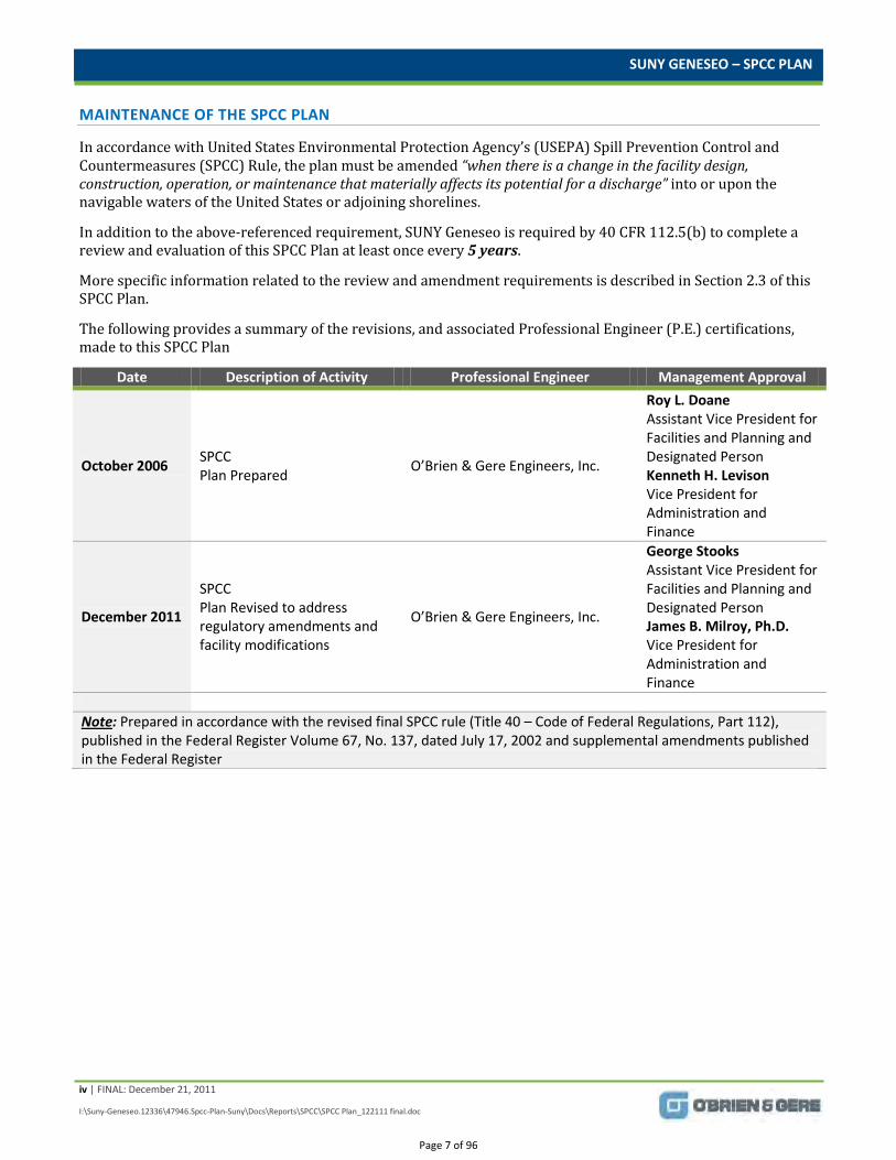
In accordance with United States Environmental Protection Agency’s (USEPA) Spill Prevention Control and Countermeasures (SPCC) Rule, the plan must be amended “when there is a change in the facility design, construction, operation, or maintenance that materially affects its potential for a discharge” into or upon the navigable waters of the United States or adjoining shorelines.
In addition to the above-referenced requirement, SUNY Geneseo is required by 40 CFR 112.5(b) to complete a review and evaluation of this SPCC Plan at least once every 5 years.
More specific information related to the review and amendment requirements is described in Section 2.3 of this SPCC Plan.
The following provides a summary of the revisions, and associated Professional Engineer (P.E.) certifications, made to this SPCC Plan
Date Description of Activity Professional Engineer Management Approval
October 2006 SPCC Plan Prepared O’Brien & Gere Engineers, Inc.
Roy L. Doane Assistant Vice President for Facilities and Planning and Designated Person Kenneth H. Levison Vice President for Administration and Finance
December 2011
SPCC Plan Revised to address regulatory amendments and facility modifications
O’Brien & Gere Engineers, Inc.
George Stooks Assistant Vice President for Facilities and Planning and Designated Person James B. Milroy, Ph.D. Vice President for Administration and Finance
Note: Prepared in accordance with the revised final SPCC rule (Title 40 – Code of Federal Regulations, Part 112), published in the Federal Register Volume 67, No. 137, dated July 17, 2002 and supplemental amendments published in the Federal Register
Page 7 of 96
SUNY GENESEO – SPCC PLAN
v | FINAL: December 21, 2011
I:\Suny-Geneseo.12336\47946.Spcc-Plan-Suny\Docs\Reports\SPCC\SPCC Plan_122111 final.doc
MANAGEMENT APPROVAL
SUNY Geneseo
1 College Circle
Geneseo, New York 14454
Spill Prevention, Control and Countermeasure Plan
SUNY Geneseo is committed to the prevention of discharges of oil to navigable waters and the environment, and maintains the appropriate standards for spill prevention control and countermeasures through regular review, updating, and implementation of this SPCC Plan, as described herein. In accordance with 40 CFR Part 112.7, this SPCC Plan “has the full approval of management at a level with authority to commit the necessary resources to fully implement the Plan.”
SUNY Geneseo
(Date) (Signature)
(Print)
George Stooks
Assistant Vice President for Facilities and Planning
(Date) (Signature) (Print)
James B. Milroy, Ph.D.
Vice President for Administration and Finance
(Title)
Page 8 of 96
SUNY GENESEO – SPCC PLAN
vi | FINAL: December 21, 2011
I:\Suny-Geneseo.12336\47946.Spcc-Plan-Suny\Docs\Reports\SPCC\SPCC Plan_122111 final.doc
PROFESSIONAL ENGINEER CERTIFICATION (SPCC)
This SPCC Plan has been developed based on a site visit to and inspections of the SUNY Geneseo campus (herein referred to as SUNY Geneseo and/ or facility) conducted on July 28, 2011, located in Geneseo, NY, and information provided by the facility. I hereby certify that member(s) of my staff who are familiar with the current requirements of 40 CFR Part 112 examined the facility under my direction and supervision. Based upon my inquiry of these staff member(s) and my familiarity with 40 CFR Part 112, I hereby attest that this SPCC Plan meets the following criteria set forth in the current version of those regulations:
“the SPCC Plan has been prepared in accordance with good engineering practices, including consideration of applicable industry standards and the requirements of Part 112,
procedures for required inspections and testing have been established, and
the SPCC Plan is adequate for the facility.”
O’BRIEN & GERE ENGINEERS, INC. IT IS A VIOLATION OF LAW FOR ANY PERSON, UNLESS
HE OR SHE IS ACTING UNDER THE DIRECTION OF A
LICENSED PROFESSIONAL ENGINEER, TO ALTER THIS
DOCUMENT. [See Section 2.3 for additional information] _________________________________ James R. Heckathorne, P.E. Vice President Date: Registration No.:
December 21, 2011
State: 56609
New York
Page 9 of 96
SUNY GENESEO – SPCC PLAN
1 | FINAL: December 21, 2011
I:\Suny-Geneseo.12336\47946.Spcc-Plan-Suny\Docs\Reports\SPCC\SPCC Plan_122111 final.doc
1. OVERVIEW OF FACILITY
1.1 GENERAL FACILITY IDENTIFICATION INFORMATION
Facility name: SUNY Geneseo
Address: 1 College Circle
Geneseo, NY 14454
Physical location: Livingston County, New York State
Telephone No.: (585) 245-5000 – General Number
Facility Contacts Mr. Chuck Reyes, CHMM, CHO – SPCC Coordinator
Director of Environmental Health & Safety (EHS Director)
(585) 245-5663
24 Hour Campus Emergency Phone Number (University Police)
(585) 245-5222
1.2 FACILITY DESCRIPTION
SUNY Geneseo, founded in 1871, serves as an undergraduate institution located in the Genesee Valley. A site location map is presented as Figure 1 in this SPCC Plan.
As required per 40 CFR Part 112.7(a)(3), Figure 2 presents the locations of the facility structures, oil storage container locations, contents of each container, associated oil transfer areas, and associated connecting pipelines. As-built tank drawings and piping detail associated with Tanks 016, 017 and 018 are provided in Exhibit A.
As described in Table 1 (see Tables tab) of this SPCC Plan, SUNY Geneseo currently has a total oil storage capacity, which exceeds the 1,320-gallon threshold prescribed in the SPCC rule.
For additional details on individual container locations, and oil transfer activities at the facility, refer to the Sections 3 and 4.
1.3 DISCHARGES FROM FACILITY
The SUNY Geneseo facility currently discharges both storm water runoff and sanitary waste waters. The following provides a more descriptive explanation of each type of discharge.
1.3.1 Storm Water Discharges The majority of the storm water runoff from the SUNY Geneseo is collected by a series of catch basins. Storm water is ultimately discharged to the Genesee River via tributaries.
1.3.2 Sanitary Discharges Sanitary wastewater that is generated at the facility is discharged to the Village of Geneseo Sewage Treatment Plant for treatment prior to discharging to the Genesee River.
Page 10 of 96
SUNY GENESEO – SPCC PLAN
2 | FINAL: December 21, 2011
I:\Suny-Geneseo.12336\47946.Spcc-Plan-Suny\Docs\Reports\SPCC\SPCC Plan_122111 final.doc
2. INTRODUCTION
A current version of the Final SPCC Rule (40 CFR 112) can be found at http://www.epa.gov/emergencies/lawsregs.htm#oppr. A summary of the regulatory background, key definitions and applicability of SPCC Plan is provided in Exhibit C.
2.1 PLAN AVAILABILITY
The facility’s EHS Director maintains this SPCC Plan for the facility (see Section 1.1).
The SPCC Plan will be made available to facility personnel for their information and use. A complete copy of this SPCC Plan will be maintained in the EHS Office. This Plan will also be accessible to federal, state and/or local authorities during normal business hours. Requests from other than members of the facility to review the SPCC Plan will be directed to the EHS Director.
2.2 PURPOSE AND SCOPE
The SPCC Plan describes the procedures, methods, and equipment to prevent and, if appropriate, initiate the cleanup of oil at the facility, which may be discharged into or upon navigable waters.
In accordance with Subpart A – 40 CFR Part 112.1 – 112.7, this SPCC Plan addresses the general requirements for all facilities in Section 3. Section 4 of this Plan specifically complies with the requirements of Subpart B – 40 CFR Part 112.8 (excluding production facilities), which addresses the requirements for facilities storing and using petroleum oils or other non-petroleum oils, except those oils covered by Subpart C. Subpart C – 40 CFR Part 112.12 – 112.15 is for facilities storing or using animal fats and oils and greases, or fish and marine mammal oils; and, oils of vegetable origin, including oils from seeds, nuts, fruits, and kernels and is also included in Section 4 of this Plan.
Subpart D – 40 CFR Part 112.20 is for facilities are required to prepare a Facility Response Plan (FRP). Subpart D does not currently apply to the facility.
O’Brien & Gere has prepared this SPCC Plan in accordance with the revised final SPCC rule contained in Subparts A and B of 40 CFR Part 112, dated July 17, 2002 and supplemental amendments published in the Federal Register. A current version of SPCC regulations can be found at http://www.gpoaccess.gov/cfr/index.html.
In addition to the requirements for the preparation of an SPCC Plan, subject facilities are required to complete Appendix C, Attachment C-II of 40 CFR Part 112, “Certification of the Applicability of the Substantial Harm Criteria” (see Appendix A of this SPCC Plan).
2.3 PLAN AMENDING AND UPDATING REQUIREMENTS
Based on the requirements of 40 CFR 112.5(a), this SPCC Plan will be amended “when there is a change in the facility design, construction, operation, or maintenance that materially affects its potential for a discharge” into or upon the navigable waters of the United States or adjoining shorelines [as defined by 40 CFR Part 112.1(b)]. Examples of changes that may require the technical amendment to this SPCC Plan include, but are not limited to, the following:
commissioning or decommissioning containers
replacement, reconstruction, or movement of containers
installation of piping systems
construction or demolition of secondary containment structures
changes of product or service
revision of standard operating procedures.
Page 11 of 96
SUNY GENESEO – SPCC PLAN
3 | FINAL: December 21, 2011
I:\Suny-Geneseo.12336\47946.Spcc-Plan-Suny\Docs\Reports\SPCC\SPCC Plan_122111 final.doc
A technical amendment made to this SPCC Plan related to the SPCC provisions herein is required to be prepared within 6 months of the facility change, and then implemented no later than 6 months following the preparation of the amendment.
In addition to the above-referenced requirement, the facility is also required as per 40 CFR Part 112.5(d) to complete a review and evaluation of this SPCC Plan at least once every 5 years. As a result of this review and evaluation, the facility must amend this SPCC Plan within 6 months of the review to include more effective prevention and control technology if: (1) such technology will significantly reduce the likelihood of a spill event from the facility, and (2) such technology has been field-proven at the time of review. The facility must implement the identified technical amendment as soon as possible, but no later than 6 months after the preparation of an amendment.
As also required per 40 CFR Part 112.5(d), the facility must document the completion of the review and evaluation, and must sign a statement as to whether this SPCC Plan needs to be amended or not. Appendix B presents a SPCC Plan Review and Evaluation Form to document such reviews and evaluations of this SPCC Plan.
Non-technical amendments, including but not limited to the following, do not require Professional Engineer (P.E.) certification of this SPCC Plan:
changes to contact names, titles, telephone numbers
requirements associated with storm water discharges to comply with NPDES rules
product changes (if the new product is compatible with the conditions in the existing container and secondary containment)
other changes that do not materially affect the facility’s potential to discharge oil and do not require the exercise of good engineering practice.
In accordance with 40 CFR 112.5(e) technical amendments to this SPCC Plan, which require the use of good engineering practice, must be certified by a registered P.E. in accordance with 40 CFR Part 112.3(d). If the facility is uncertain if a change is considered to be “technical” or “non-technical,” the amended Plan should be certified by a P.E.
Please see Page iv of this SPCC Plan for the record of P.E. certifications and other amendments associated with the Plan for the Facility.
Page 12 of 96
SUNY GENESEO – SPCC PLAN
4 | FINAL: December 21, 2011
I:\Suny-Geneseo.12336\47946.Spcc-Plan-Suny\Docs\Reports\SPCC\SPCC Plan_122111 final.doc
3. GENERAL SPCC PLAN REQUIREMENTS
The following “boxed and shaded” text areas provide excerpts from the USEPA’s SPCC Plan regulation for reference purposes. A copy of the complete regulation can be found at http://www.gpoaccess.gov/cfr/index.html.
3.1 PURPOSE
This section of the Plan addresses the requirements of Subpart A – 40 CFR Part 112.7, which consists of general requirements for all subject facilities.
3.2 REGULATORY CONFORMANCE – 40 CFR 112.7(a)(1)
As discussed under 40 CFR Part 112.7, a regulatory cross-comparison can be utilized to demonstrate compliance with the USEPA’s revised final SPCC rule. Appendix C presents a SPCC Plan Regulatory Cross – Comparison Matrix, which provides the specific locations (in this document) for each of the current applicable regulatory requirements. Appendix C also provides plan reviewers, such as the USEPA or the facility, with information necessary to review compliance and to verify that the SPCC Plan is complete and meets applicable regulatory requirements.
3.3 DEVIATIONS FROM REQUIREMENT – 40 CFR 112.7(a)(2)
The SPCC regulation allows for the deviation of certain requirements (not secondary containment).
The facility currently deviates from the level alarm and gauge requirements described in 40 CFR 112.8(c)(8) and 112.12(c)(8). In place of a high level alarm or level gauge, the remaining available capacity of the 55-gallon drums and tanks used for the storage of used oil and waste kitchen grease will be visually observed prior to adding additional material.
3.4 DESCRIPTION OF PHYSICAL LAYOUT OF FACILITY – 40 CFR 112.7(a)(3)
Figure 2 shows the locations of the applicable oil storage containers, transfer stations, and connecting piping. In addition, the following presents the specific facility information, as required pursuant to 40 CFR 112.7(a)(3)(i – vi). Exhibit B provides a photographic log of the applicable oil storage containers and transfer stations.
The following presents the specific facility information, as required pursuant to 40 CFR 112.7(a)(3)(i – vi).
Description of storage containers – 40 CFR 112.7(a)(3)(i). Provide a description of the type of oil in each container and its storage capacity.
Table 1, presented in the Tables tab of this SPCC Plan, describes the type of oil and storage capacity of each oil storage container at the facility.
Discharge prevention measures – 40 CFR 112.7(a)(3)(ii). Provide a description of the procedures for routine handling of products (loading/unloading, and facility transfers, etc.)
A specific unloading procedure related to discharge prevention at the facility is presented in Appendix D – Unloading Procedure.
In addition to the unloading provisions outlined in Appendix D, a warning sign is also posted at the bulk storage container truck unloading areas to assist in the prevention of tanker truck departure before disconnecting the transfer line.
Discharge or drainage controls – 40 CFR 112.7(a)(3)(iii). Provide a description of the secondary containment around containers and other structures, equipment, and procedures for the control of a discharge.
Page 13 of 96
SUNY GENESEO – SPCC PLAN
5 | FINAL: December 21, 2011
I:\Suny-Geneseo.12336\47946.Spcc-Plan-Suny\Docs\Reports\SPCC\SPCC Plan_122111 final.doc
The discharge control and drainage measures for the oil storage containers at the facility are presented in Table 1 (see Tables tab).
Countermeasures for discharge discovery, response, and cleanup – 40 CFR 112.7(a)(3)(iv). Provide a description of the countermeasures for discharge discovery, response, and cleanup (both by the facility’s capability and those that might be required of a contractor).
Section 5 of this SPCC Plan addresses the facility’s emergency and spill response procedures. The EHS Director will direct and coordinate spill response and cleanup activities.
Oil spill cleanup disposal measures – 40 CFR 112.7(a)(3)(v). Provide a description of the methods of disposal of recovered materials in accordance with applicable legal requirements.
Appendix E (Oil/Petroleum Spill Response, Cleanup and Disposal) of this SPCC Plan addresses the facility’s approach to the proper management and disposal of oil spill cleanup materials.
The EHS Director will direct and coordinate spill response and cleanup activities.
Emergency response contacts – 40 CFR 112.7(a)(3)(vi). Provide a listing of contacts and phone numbers for the facility response coordinator, National Response Center, cleanup contractors with whom you have an agreement for response, and all appropriate Federal, State, and Local agencies who must be contacted in case of a discharge.
Section 5 and Table 2 of this SPCC Plan addresses the facility’s emergency response contacts.
3.5 SPILL REPORTING PROCEDURES – 40 CFR 112.7(a)(4) AND (a)(5)
40 CFR 112.7(a)(4) - Unless you have submitted a response plan under § 112.20, provide information and procedures in your Plan to enable a person reporting a discharge as described in § 112.1(b) to relate information on the exact address or location and phone number of the facility; the date and time of the discharge, the type of material discharged; estimates of the total quantity discharged; estimates of the quantity discharged as described in § 112.1(b); the source of the discharge; a description of all affected media; the cause of the discharge; any damages or injuries caused by the discharge; actions being used to stop, remove, and mitigate the effects of the discharge; whether an evacuation may be needed; and, the names of individuals and/or organizations. 40 CFR Part 112.7(a)(5) - Unless you have submitted a response plan under §112.20, organize portions of the Plan describing procedures you will use when a discharge occurs in a way that will make them readily usable in an emergency, and include appropriate supporting material as appendices.
In the event of an oil spill that requires notification to appropriate state and federal regulatory agencies, facility personnel should reference Section 5 of this SPCC Plan for specific information and procedures regarding spill notification and reporting requirements.
Appendix E (Oil/Petroleum Spill Response, Cleanup and Disposal) of this SPCC Plan addresses the facility’s approach to spill response procedures.
3.6 FAULT ANALYSIS – 40 CFR 112.7(b)
40 CFR 112.7(b) - Where experience indicates a reasonable potential for equipment failure (such as loading or unloading equipment, tank overflow, rupture, or leakage, or any other equipment known to be a source of a discharge), include in your Plan a prediction of the direction, rate of flow, and total quantity of oil which could be discharged from the facility as a result of each type of major equipment failure.
3.6.1 Potential Spill Sources, Volumes, Rates and Control Table 1 (see Tables tab) describes potential spill sources, a prediction of the direction of flow, rate of flow, and total quantity of oil that could be discharged from each potential source.
Page 14 of 96
SUNY GENESEO – SPCC PLAN
6 | FINAL: December 21, 2011
I:\Suny-Geneseo.12336\47946.Spcc-Plan-Suny\Docs\Reports\SPCC\SPCC Plan_122111 final.doc
Note: The potential release volumes described in Table 1 do not take into account the use of any containment or diversionary structures or equipment.
3.6.2 Predicted Fates of Potential Spills Table 1 (see Tables tab) also identifies the locations of the oil storage areas, potential spill flow direction and the water body that would be affected in the event of a release from the oil storage container or during refueling activities.
3.7 CONTAINMENT AND/OR DIVERSIONARY STRUCTURES OR EQUIPMENT – 40 CFR 112.7(c)
General Containment Requirements- 40 CFR 112.7(c) - Provide appropriate containment and/or diversionary structures or equipment to prevent a discharge as described in §112.1(b), except as provided in paragraph (k) of this section for qualified oil-filled operational equipment, and except as provided in §112.9(d)(3) for flowlines and intra-facility gathering lines at an oil production facility. The entire containment system, including walls and floor, must be capable of containing oil and must be constructed so that any discharge from a primary containment system, such as a tank, will not escape the containment system before cleanup occurs. In determining the method, design, and capacity for secondary containment, you need only to address the typical failure mode, and the most likely quantity of oil that would be discharged. Secondary containment may be either active or passive in design. At a minimum, you must use one of the following prevention systems or its equivalent:
(i) Dikes, berms, or retaining walls sufficiently impervious to contain oil; (ii) Curbing or drip pans; (iii) Sumps and collection systems; (iv) Culverting, gutters, or other drainage systems; (v) Weirs, booms, or other barriers; (vi) Spill diversion ponds; (vii) Retention ponds; or (viii) Sorbent materials.
As previously described, Table 1 (see Tables tab) of this SPCC Plan presents an inventory of oil products and associated containment and/or diversionary structures or spill control equipment associated with the oil storage containers at the facility.
Currently there is inadequate secondary containment associated with each of the nine transformers located at the facility and for periods when the single-walled portable generator is deployed at the facility. As detailed in Appendix F- Compliance Action Items, SUNY Geneseo will provide secondary containment for these containers. It is expected that the secondary containment system will be in place by 1/31/2012.
3.8 DEMONSTRATION OF PRACTICABILITY – 40 CFR 112.7(d)
As presented in Table 1, and in accordance with 40 CFR 112.7(c), appropriate containment and/or diversionary structures or equipment (including the use of sorbent materials) will be provided for the potential spill source areas at the facility to prevent oil from reaching navigable waters.
In accordance with 40 CFR 112.7(d), if any of the spill prevention measures listed in 40 CFR 112.7(c) are deemed impracticable by a facility, that facility must explain why the measures are not practicable, and conduct a series of integrity and leak testing for associated oil storage container and piping systems. In addition, the facility would be required to prepare an Oil Spill Contingency Plan following the provisions of 40 CFR 109, and provide a written commitment of manpower, equipment, and materials required to expeditiously control and remove discharged oil that may be harmful.
Based on the nature and scope of oil use at the facility, and the facility’s use of containment and/or diversionary structures and readily available response equipment described herein, the facility has deemed these measures practical and effective to prevent spilled/leaked oil from reaching navigable waters. As such, there is currently
Page 15 of 96
SUNY GENESEO – SPCC PLAN
7 | FINAL: December 21, 2011
I:\Suny-Geneseo.12336\47946.Spcc-Plan-Suny\Docs\Reports\SPCC\SPCC Plan_122111 final.doc
no need to describe in this SPCC Plan the impracticability of the provisions of 40 CFR 112, as they apply to the facility.
In the event of an oil spill, emergency and spill response/notification procedures provided in Section 5 and Appendix E of this SPCC Plan shall be followed.
3.9 INSPECTION AND RECORD KEEPING – 40 CFR 112.7(e)
Inspections, tests, and records - 40 CFR Part 112.7(e) -. Conduct inspections and tests required by this part in accordance with written procedures that you or the certifying engineer develop for the facility. You must keep these written procedures and a record of the inspections and tests, signed by the appropriate supervisor or inspector, with the SPCC Plan for a period of three years. Records of inspections and tests kept under usual and customary business practices will suffice for purposes of this paragraph. The facility performs various inspections as a component of this SPCC Plan. Formal oil storage container inspections are conducted on a monthly basis and records of these inspections are documented and signed by the inspector (see Sections 3.15 and 4.3 for more information). During these inspections, the oil storage containers/equipment, containment structures, valves, pipelines, lighting, and other appropriate equipment are inspected. The EHS Director maintains signed copies of the inspection and tank integrity testing records for a three-year period, as required per 40 CFR 112.7(e).
3.10 PERSONNEL TRAINING AND DISCHARGE PREVENTION PROCEDURES – 40 CFR 112.7(f)
Personnel training – 40 CFR 112.7(f)(1). At a minimum, train your oil-handling personnel in the operation and maintenance of equipment to prevent discharges; discharge procedure protocols; applicable pollution control laws, rules, and regulations; general facility operations; and, the contents of the facility SPCC Plan. Oil-handling personnel at the facility are required to attend a spill prevention training session, which includes a complete review of this SPCC Plan. Employees are also instructed and tested on the job. On an annual basis, employee refresher training for spill response is conducted.
The facility’s SPCC training program includes the following:
Review of the contents of this SPCC Plan.
Instruction of personnel in the operation and maintenance of equipment to prevent the discharge of oil products, and in applicable pollution control laws, rules and regulations.
Standard operating procedures used to prevent discharges of oil.
Spill identification, notification, containment, control, and clean-up procedures and techniques.
Discussion of past spill events, currently malfunctioning components or systems, if any, and recently developed precautionary measures.
Records of the spill prevention and response training provided to employees are maintained by the EHS Director using the Plan’s Employee Training Attendance Record (see Appendix G) or comparable document. The EHS Director is responsible for the confirmation that these records are being maintained.
Designated person accountable for spill prevention – 40 CFR 112.7 (f)(2). Designate a person at each facility who is accountable for discharge prevention and who reports to facility management. The EHS Director (SPCC Coordinator) is the designated person accountable for spill prevention at the facility and reports to management (see Section 1.1).
Spill prevention briefings – 40 CFR 112.7(f)(3). Schedule and conduct discharge prevention briefings for your oil handling personnel at least once a year to assure adequate understanding of the SPCC Plan for that facility.
Page 16 of 96
SUNY GENESEO – SPCC PLAN
8 | FINAL: December 21, 2011
I:\Suny-Geneseo.12336\47946.Spcc-Plan-Suny\Docs\Reports\SPCC\SPCC Plan_122111 final.doc
In accordance with 40 CFR 112.7(f)(3), spill prevention briefings are scheduled and conducted on an annual basis for oil-handling personnel to assure that each employee has an adequate understanding of this SPCC Plan. Past spill incidents (if any), and/or “close-calls,” are discussed in these meetings to help prevent spills from recurring. Employee feedback and recommendations are encouraged in spill prevention and operations. Documentation, which includes the topics of discussion at each meeting, is maintained to demonstrate compliance with this requirement.
3.11 FACILITY SECURITY MEASURES – 40 CFR 112.7(g)
Security – 40 CFR 112.7(g). Describe in your Plan how you secure and control access to the oil handling, processing and storage areas; secure master flow and drain valves; prevent unauthorized access to starter controls on oil pumps; secure out-of-service and loading/unloading connections of oil pipelines; and address the appropriateness of security lighting to both prevent acts of vandalism and assist in the discovery of oil discharges. The tank fill ports associated with the underground storage tanks (USTs) are locked at all times other than when filling or when access is required for level monitoring or maintenance. Elevator reservoirs are located indoors in areas that are maintained locked and can only be accessed by authorized personnel. The drum storage areas are located in buildings which are locked when unoccupied. Lighting is available as a security measure and assist in the discovery of a spill associated with the waste kitchen grease tanks and the portable generator staging location.
Drain valves, which permit the outward flow of tank contents to the surface, will be securely locked in the closed position when in non-operation or non-standby status. The starter controls and valves for each of the applicable tanks at the facility will be maintained in a locked “off’ position or are located at areas only accessible to authorized personnel.
The unloading/loading connections for container systems will be securely capped when not in service or when in standby service for an extended period of time.
The facility has lighting, to aid in the discovery of oil spills during hours of darkness (both by operating personnel and non-operating personnel), and the minimization of oil spills occurring through acts of vandalism.
3.12 FACILITY TANK TRUCK LOADING/UNLOADING – 40 CFR 112.7(h)
Based on clarifications published by the USEPA in the Federal Register on May 25, 2004 and with the December 2008 amendments, the facility does not maintain unloading/loading “rack” areas. Therefore, the requirements for this section currently do not apply to the facility.
Fuel transfer containment system – 40 CFR 112.7(h)(1). Where loading/unloading rack drainage does not flow into a catchment basin or treatment facility designed to handle discharges, use a quick drainage system for tank car or tank truck loading/unloading racks. You must design any containment system to hold at least the maximum capacity of any single compartment of a tank car or tank truck loaded or unloaded at the facility. Since the facility does not operate a loading/unloading rack, this section is not applicable. However, spill measures such as unloading procedures, are currently in place at the facility to prevent or minimize the risk of an oil release to navigable waters (See Appendix D – Unloading Procedure).
40 CFR 112.7(h)(2). Provide an interlocked warning light or physical barrier system, warning signs, wheel chocks or vehicle brake interlock system in the area adjacent to a loading/unloading rack, to prevent vehicles from departing before complete disconnection of flexible or fixed oil transfer lines. The truck driver will remain present to observe for the duration of the loading/unloading operations.
A warning sign is present at the bulk storage container loading/unloading location to remind the truck driver to disconnect transfer lines prior to departure.
Page 17 of 96
SUNY GENESEO – SPCC PLAN
9 | FINAL: December 21, 2011
I:\Suny-Geneseo.12336\47946.Spcc-Plan-Suny\Docs\Reports\SPCC\SPCC Plan_122111 final.doc
Drain inspection – 40 CFR 112.7(h)(3). Prior to filling and departure of any tank car or tank truck, closely inspect for discharges the lowermost drain and all outlets of such vehicles, and if necessary, ensure that they are tightened, adjusted, or replaced to prevent liquid discharge while in transit.
As stated in Appendix D – Unloading Procedure, prior to filling and departure of a tanker truck, the truck driver and/or a SUNY Geneseo personnel must examine the lower-most drain and all outlets of the tanker truck for leakage. If leakage is observed, the drains or outlets will be tightened, adjusted, or replaced by the driver to prevent oil leakage while in transit.
3.13 FIELD-CONSTRUCTED ABOVEGROUND CONTAINERS – 40 CFR 112.7(I)
Brittle fracture - 40 CFR Part 112.7(i). If a field-constructed aboveground container undergoes a repair, alteration, reconstruction, or a change in service that might affect the risk of a discharge or failure due to brittle fracture or other catastrophe, or has discharged oil or failed due to brittle fracture failure or other catastrophe, evaluate the container for risk of discharge or failure due to brittle fracture or other catastrophe, and as necessary, take appropriate action.
In accordance with 40 CFR Part 112, a field-constructed aboveground container is one that is assembled or reassembled (outside of the container manufacturer) at the location of its intended use.
SUNY Geneseo does not currently use field-constructed aboveground containers; therefore, the requirements for this section do not currently apply to the facility.
3.14 FACILITY COMPLIANCE WITH OTHER APPLICABILITY PREVENTION STANDARDS – 40 CFR 112.7(J)
State conformance – 40 CFR Part 112.7(j). In addition to the minimal prevention standards listed under this section, include in your Plan a complete discussion of conformance with the applicable requirements and other effective discharge prevention and containment procedures listed in this part or any applicable more stringent State rules, regulations, and guidelines.
In accordance with NYS Environmental Conservation Law (ECL) §17-1007, a petroleum bulk storage facility is defined as:
“a single property or contiguous or adjacent properties used for a common purpose which are owned or operated by the same person on or in which are located:
a. one or more stationary tanks which are used singularly or in combination for the storage or containment of more than one thousand one hundred gallons of petroleum; or
b. any tank whose capacity is greater than one hundred ten gallons that is used for the storage or containment of petroleum, the volume of which is ten percent or more beneath the surface of the ground.”
As SUNY Geneseo currently has both a combined storage capacity over 1,100 gallons of “petroleum,” and maintains underground storage tanks greater than 110 gallons in capacity, the facility is subject to the NYSDEC’s Petroleum Bulk Storage (PBS) Regulations (6 NYCRR 612 – 614). There is currently no requirement by the NYSDEC to prepare a specific spill prevention and response plan for PBS tanks.
For the purposes of compliance with 40 CFR 112.7(j), and in order for SUNY Geneseo personnel to evaluate compliance with the applicable NYSDEC PBS regulatory requirements, the following materials should be consulted:
NYSDEC, Compliance Audit – Petroleum Bulk Storage Regulations, 6 NYCRR 612 – 614 (http://www.dec.ny.gov/regs/2490.html)
NYSDEC, Spill Prevention Operations Technology Series (“SPOTS”), Memo #6, Overfill/Spill Prevention Equipment For Petroleum Storage Tanks (http://www.dec.ny.gov/regulations/2387.html)
NYSDEC, Spill Prevention Operations Technology Series (“SPOTS”), Memo #10, Secondary Containment Systems For Aboveground Storage Tanks (http://www.dec.ny.gov/regulations/2387.html)
Page 18 of 96
SUNY GENESEO – SPCC PLAN
10 | FINAL: December 21, 2011
I:\Suny-Geneseo.12336\47946.Spcc-Plan-Suny\Docs\Reports\SPCC\SPCC Plan_122111 final.doc
NYSDEC, Spill Prevention Operations Technology Series (“SPOTS”), Memo #17 (http://www.dec.ny.gov/regulations/2387.html).
3.15 QUALIFIED OIL-FILLED OPERATIONAL EQUIPMENT – 40 CFR 112.7(K)
Qualified Oil-filled Operational Equipment - 40 CFR Part 112.7(k). The owner or operator of a facility with oil-filled operational equipment that meets the qualification criteria in paragraph (k)(1) of this sub-section may choose to implement for this qualified oil-filled operational equipment the alternate requirements as described in paragraph (k)(2) of this sub-section in lieu of general secondary containment required in paragraph (c) of this section. The facility currently maintains oil-filled operational equipment (i.e., elevator reservoirs and transformers) with capacities >55 gallons. The specific equipment and quantities of oil are noted on Table 1 and Figure 2. SUNY Geneseo personnel will conduct inspections of this equipment, using Appendix H - Bi-Annual Elevator Reservoir Inspection Record and Appendix I – Monthly Transformer Inspection Record, as applicable. Monthly inspections of the elevator reservoirs are conducted by the elevator maintenance contractor.
It should be noted that the elevator reservoir located in Bailey Hall is scheduled to be removed in 2012.
The portable emergency generator crankcase is <55 gallons in capacity; therefore, it is not required to be included in this SPCC Plan. It should be noted that the fuel tank associated with the portable generator is subject to the SPCC Rule; therefore, it is included in this SPCC Plan.
As previously described, currently there is inadequate secondary containment associated with each of the nine transformers located at the facility. As detailed in Appendix F - Compliance Action Items, SUNY Geneseo will provide secondary containment for this equipment. It is expected that the secondary containment system will be in place by 1/31/2012.
Page 19 of 96
SUNY GENESEO – SPCC PLAN
11 | FINAL: December 21, 2011
I:\Suny-Geneseo.12336\47946.Spcc-Plan-Suny\Docs\Reports\SPCC\SPCC Plan_122111 final.doc
4. SPECIFIC SPCC PLAN REQUIREMENTS
4.1 PURPOSE
In accordance with Subpart B – 40 CFR Part 112.8 and Subpart C – 40 CFR 112.12, this section of the SPCC Plan addresses specific requirements for the use and storage of petroleum or non-petroleum oils, including animal fats and vegetable oils.
4.2 FACILITY DRAINAGE – 40 CFR 112.8(b) and 112.12(b)
The following presents a response to each component under the requirements of 40 CFR 112.8(b)(1 – 5) and 40 CFR 112.12(b)(1 – 5), as applicable.
Drainage from storage areas – 40 CFR 112.8(b)(1) and 112.12(b)(1). Restrain drainage from diked storage areas by valves to prevent a discharge into the drainage system or facility effluent treatment system, except where facility systems are designed to control such discharge. Currently, there are no outdoor storage areas associated with bulk storage containers that can accumulate rainwater in secondary containment dikes or structures; therefore, the requirements for this section do not currently apply to the SUNY Geneseo facility. Stormwater accumulated in the bermed unloading area associated with Tanks 016, 017 and 018 is directed to an oil-water separator prior to discharging.
Flapper-type drain valves – 40 CFR 112.8(b)(2) and 112.12(b)(2). Use valves of manual, open-and-closed design, for the drainage of diked areas. You may not use flapper-type drain valves to drain diked areas. Currently, there are no flapper-type drain valves associated with tank containment systems at the facility.
Undiked area drainage – 40 CFR 112.8(b)(3) and 112.12(b)(3). Design facility drainage systems from undiked areas with a potential for a discharge to flow into ponds, lagoons, or catchment basins designed to retain oil or return it to the facility. Drainage from undiked areas at the facility (i.e., Tank 012 and 013 truck unloading area) is currently conveyed to the storm water drainage system at the facility. SUNY Geneseo has in place procedures to prevent a discharge of oil from these areas. Such procedures include secondary containment diversionary structures, having spill response equipment readily available, and minimizing the occurrence of product transfers during precipitation events.
As previously described, Table 1 (see Tables tab) of this Plan presents an inventory of associated containment and/or diversionary structures associated with the storage containers at the facility. An inventory and locations of emergency containment and spill cleanup supplies are provided in Appendix J. Unloading procedures are provided in Appendix D.
Other drainage – 40 CFR 112.8(b)(4) and 112.12(b)(4). If facility drainage is not engineered as described in undiked area drainage – 40 CFR 112.8 (b)(3), then the facility must equip the final discharge of all ditches inside the facility with a diversion system that would retain an uncontrolled discharge. Drainage from the tanker truck unloading area associated with Tanks 016, 017 and 018 is diverted to an oil-water separator, which in turn drains to a 4,000-gallon concrete oil interceptor. The surface of the water in the containment area catch basin will be inspected weekly for oily sheens or other indicators of the presence of oil. The interceptor is inspected monthly. If oil is observed, it will be cleaned-up and addressed in accordance with this part.
Treatment of drainage water – 40 CFR 112.8(b)(5) and 112.12(b)(5). If the drainage waters are treated in more than one continuous treatment units and pump transfer is needed, then the facility must provide two lift pumps, at least one of which must be permanently installed. SUNY Geneseo does not treat drainage waters in more than one continuous “treatment unit;” therefore, the requirements for this section do not apply to the facility.
Page 20 of 96
SUNY GENESEO – SPCC PLAN
12 | FINAL: December 21, 2011
I:\Suny-Geneseo.12336\47946.Spcc-Plan-Suny\Docs\Reports\SPCC\SPCC Plan_122111 final.doc
4.3 BULK STORAGE CONTAINERS – 40 CFR 112.8(c) and 112.12(c)
The following presents a response to each component under the requirements of 40 CFR 112.8(c)(1 – 11) and 112.12(c)(1-11), as applicable.
Container compatibility with contents – 40 CFR 112.8(c)(1) and 112.12(c)(1). Both the material and the construction of the storage container must be compatible with the contents stored and the conditions such as pressure in which they are stored. The oil containers at the facility are constructed of either welded steel or fiberglass reinforced plastic (FRP) and are compatible with the contents that they hold.
Diked area construction and containment volume – 40 CFR 112.8(c)(2) and 112.12(c)(2). Construct all bulk storage tank installations (except mobile refuelers and other non-transportation-related tank trucks) so that you provide a secondary means of containment for the entire capacity of the largest single container and sufficient freeboard to contain precipitation. You must ensure that diked areas are sufficiently impervious to contain discharged oil.
SUNY Geneseo currently utilizes secondary containment systems for the oil storage containers, as required, which are designed and constructed so that the contents of the largest single tank is secondarily contained within an area considered sufficiently impervious to contain discharged oil (see Table 1).
Diked area, inspection and drainage of rainwater – 40 CFR 112.8(c)(3) and 112.12(c)(3). Do not allow uncontaminated rainwater from diked areas to bypass the facility treatment system and flow into a storm drain or into an open watercourse, lake, or pond unless: 1) the bypass valve is normally kept sealed closed; 2) the rainwater is inspected for signs of petroleum in order to prevent a discharge; 3) after the bypass valve is opened it is sealed closed properly again; and 4) adequate records of such actions are kept.
As previously described, there are no outdoor diked areas which can accumulate rainwater at the SUNY Geneseo facility; therefore, the requirements for this section do not currently apply. Stormwater accumulated in the bermed unloading area associated with Tanks 016, 017 and 018 is directed to an oil-water separator prior to discharging.
Corrosion protection of buried metallic storage containers – 40 CFR 112.8(c)(4) and 112.12(c)(4). Protect any completely buried or bunkered metallic tank installed on or after January 10, 1974 from corrosion by coatings or cathodic protection compatible with local soil conditions. These tanks must also be tested regularly for leaks.
Currently there are no completely buried metallic storage tanks at the SUNY Geneseo facility without corrosion protection (i.e., fiberglass tank reinforce plastic). As required pursuant to applicable state and federal requirements, SUNY Geneseo inspects these tanks and performs leak testing. Records pertaining to these inspections and leak tests are maintained at the facility.
Corrosion protection of partially buried metallic storage containers – 40 CFR 112.8(c)(5) and 112.12(c)(5). Do not use partially buried or bunkered metallic tanks for the storage of oil, unless you protect the buried section of the tank from corrosion by coatings, cathodic protection compatible with local soil conditions.
SUNY Geneseo does not currently have partially buried storage tanks; therefore, the requirements for this section do not currently apply.
Page 21 of 96
SUNY GENESEO – SPCC PLAN
13 | FINAL: December 21, 2011
I:\Suny-Geneseo.12336\47946.Spcc-Plan-Suny\Docs\Reports\SPCC\SPCC Plan_122111 final.doc
Aboveground container periodic integrity testing – 40 CFR 112.8(c)(6) and 112.12(c)(6). Each container must be tested or inspected for integrity on a regular schedule and whenever material repairs are made. Determine, in accordance with industry standards, the appropriate qualifications of personnel performing tests and inspections and the frequency and type of testing and inspections, which take into account container size, configuration, and design. Examples of these integrity tests include, but are not limited to: visual inspection, hydrostatic testing, radiographic testing, ultrasonic testing, acoustic emissions testing, or other systems of non-destructive testing. You must keep comparison records and you must also inspect the container's supports and foundations. In addition, you must frequently inspect the outside of the container for signs of deterioration, discharges, or accumulation of oil inside diked areas. Records of such inspections must be kept under usual and customary business practices.
In accordance with current industry standard, periodic integrity testing each of the aboveground oil storage containers will consist of monthly visual integrity inspections performed by trained facility oil-handling personnel.
The visual integrity inspection will include the inspection of the exterior surfaces of containers, containment area, and other storage/handling equipment for maintenance deficiencies. Inspections will also include, identification of cracks, areas of wear, corrosion and thinning, poor maintenance and operating practices. Inspections of the waste kitchen grease tanks and portable generator base tank will be documented using the Monthly Aboveground Tank Inspection Log provided in Appendix K. Inspections of the 55-gallon drums will be documented using the 55-gallon Drum Monthly Inspection Form provided in Appendix L.
The frequency of inspection is based upon appropriate industry standards that are currently available for the type and size of steel aboveground bulk storage container at the facility. The following industry standard was consulted for conducting integrity inspections of aboveground storage containers at the facility:
The Steel Tank Institute’s (STI) Standard SP001, Standard For The Inspection of Above Ground Storage Tanks
Identified deficiencies that are observed during the above-referenced monthly inspection will be addressed promptly. Records of inspections, tests and comparison records will be maintained by facility personnel under usual and customary business practices and in accordance with 40 CFR 112.7(e) (See Section 3.9).
Control of leakage through internal heating coils – 40 CFR 112.8(c)(7) and 112.12(c)(7). Prevent leakage from internal heating coils by monitoring the steam return and exhaust lines for contamination from internal heating coils that discharge into an open watercourse, or pass the steam return or exhaust lines through a settling tank, skimmer, or other separation or retention system.
The facility does not currently have internal heating coils within oil storage containers; therefore, the requirements for this section do not apply to the facility.
Level alarm and gauge - 40 CFR 112.8(c)(8) and 112.12(c)(8). Engineer or update each container installation in accordance with good engineering practice to avoid discharges. At least one of the following devices must be provided: 1) high liquid level alarm; 2) high liquid level pump cutoff device set to stop flow at a certain level; 3) direct audible or code signal communication between the container gauges and the pumping station; or 4) a fast response system for determining the liquid level of each container such as digital computers, telepulse, or direct vision gauges. These liquid level-sensing devices must be regularly tested.
With the exception of the 55-gallon and tanks used for the storage of used oil and waste kitchen grease, the bulk oil storage containers at the SUNY Geneseo facility are equipped, at a minimum, with direct vision level gauges. The unloading procedures at SUNY Geneseo allow containers to be filled to a safe volume, which is designated to be 95% of the container capacity and the USTs are equipped with a high level alarm which will activate if they are filled above the 95% level.
The containers, including the various liquid level sensing devices, are inspected on a regular basis (see Appendix K – Monthly Aboveground Tank Inspection Log). In addition, the liquid level sensing devices and alarms will be tested on a regular basis.
Page 22 of 96
SUNY GENESEO – SPCC PLAN
14 | FINAL: December 21, 2011
I:\Suny-Geneseo.12336\47946.Spcc-Plan-Suny\Docs\Reports\SPCC\SPCC Plan_122111 final.doc
Remaining available capacity of the 55-gallon drums and tanks used for the storage of used oil and waste kitchen grease will be visually observed prior to adding additional material.
Observation of disposal facilities for effluent discharge – 40 CFR 112.8(c)(9) and 112.12(c)(9). Effluent treatment facilities must be observed frequently enough to detect a possible system upset that could cause a discharge. The facility does not currently have effluent treatment discharges; therefore, the requirements for this section do not apply to the facility.
Visible oil leak corrections from container seams and gaskets – 40 CFR 112.8(c)(10) and 112.12(c)(10). Visible discharges that result in a loss of oil must be promptly corrected. Any accumulations of oil must be promptly removed from diked areas.
Visible oil leaks are reported so that corrective actions can be immediately implemented. Measures are taken to minimize and mitigate the leak, while awaiting repair. If a leak or spill is observed, the leaked oil product is cleaned up immediately by SUNY Geneseo. Oil spill cleanup supplies are stored at appropriate locations throughout the facility (see Appendix J – Emergency Containment and Cleanup Supplies). Appropriate position of mobile or portable oil storage containers – 40 CFR 112.8(c)(11) and 112.12(c)(11). Mobile or portable oil storage containers must be positioned or located in a manner in which a discharge is prevented. Except for mobile refuelers, you must furnish a secondary means of containment, such as a dike or catchment basin, sufficient to contain the capacity of the largest single compartment or container with sufficient freeboard to contain precipitation.
Mobile or portable storage containers (i.e., 55-gallon drums and portable generator) will be stored or positioned in an area with secondary containment. As previously described, Table 1 (see Tables tab) of this SPCC Plan presents an inventory of associated containment and/or diversionary structures or spill control equipment associated with the primary drum/tote storage areas at the facility.
Secondary containment for the used oil drums stored in the Clark Garage is provided by a 350-gallon oil-water separator. The oil-water separator will be inspected monthly to ensure adequate available capacity (i.e., greater than 55 gallons) and pumped out approximately 1-2 times per year. Required maintenance identified during these inspections will be performed at that time. Drawings of the oil-water separator are provided in Exhibit A.
As described in Appendix F – Compliance Action Items, secondary containment for the single-walled portable generator must be provided for when the unit is deployed at the facility. It is expected that the secondary containment system will be in place by 1/31/2012.
4.4 FACILITY TRANSFER OPERATION, PUMPING AND FACILITY PROCESS – 40 CFR 112.8(d) AND 112.12(d)
The following presents a response to each component under the requirements of 40 CFR 112.8(d)(1 – 5) and 40 CFR 112.12(d)(1 – 5), as applicable.
Corrosion protection for buried piping – 40 CFR 112.8(d)(1) and 112.12(d)(1). Buried piping installed or replaced on or after August 16, 2002 must be provided with a protective wrapping and coating. Corrosion protection standards must also be met. Any exposed line must be inspected for corrosion, if found corrective action must be taken.
The facility has buried piping associated with the transfer of fuel from USTs 016, 017 and 018 to the heating plant. Buried piping is double-walled fiberglass-reinforced plastic (FRP) and is resistant to corrosion by design.
Piping not-in-service – 40 CFR 112.8(d)(2) and 112.12(d)(2). The terminal connection at the transfer point must be capped or blank-flanged and marked as to its origin when piping is not in service or is in standby service for an extended period of time.
Piping terminal connections at SUNY Geneseo will be capped and marked when not in service.
Page 23 of 96
SUNY GENESEO – SPCC PLAN
15 | FINAL: December 21, 2011
I:\Suny-Geneseo.12336\47946.Spcc-Plan-Suny\Docs\Reports\SPCC\SPCC Plan_122111 final.doc
Aboveground piping supports design – 40 CFR 112.8(d)(3) and 112.12(d)(3). Pipe supports must be designed as to minimize abrasion and corrosion and allow for expansion and contraction.
The piping supports for the areas with aboveground piping will be properly designed and maintained to minimize abrasion and allow for expansion and contraction.
Aboveground valves and piping examination – 40 CFR 112.8 (d)(4) and 112.12(d)(4). All aboveground valves, piping, and appurtenances must be regularly inspected during which the general condition of the items must be assessed. Integrity and leak testing of buried piping must be conducted at the time of installation as well as during any modification, construction, relocation, or replacement.
Aboveground valves and piping are examined (to the extent physically possible) by SUNY Geneseo personnel on a monthly basis to assess the conditions of the flange joints, expansion joints, valve glands and bodies, catch pans, pipeline supports, and metal surfaces. Inspections of these above-referenced items are conducted during the inspection of the tank system and results are included on the Monthly Inspection Logs included in Appendix K and M. Deficiencies observed during the inspection will be addressed promptly.
Aboveground piping protection from vehicular traffic – 40 CFR 112.8(d)(5) and 112.12(d)(5). All vehicles entering facility must be warned not to endanger aboveground piping or other oil transfer operations
SUNY Geneseo has positioned aboveground oil distribution piping so that there is no potential for damage from vehicular traffic.
Page 24 of 96
SUNY GENESEO – SPCC PLAN
16 | FINAL: December 21, 2011
I:\Suny-Geneseo.12336\47946.Spcc-Plan-Suny\Docs\Reports\SPCC\SPCC Plan_122111 final.doc
5. EMERGENCY AND SPILL RESPONSE PROCEDURES
5.1 SPILL DISCOVERY AND INITIAL RESPONSE
This Plan has been prepared for the prevention and control of oil spills at the facility.
In the event of an oil spill or leak, the person discovering the oil from a storage container, tank or equipment must immediately initiate the following actions:
1. If there is an immediate threat to human health, evacuate the immediate area.
2. Extinguish all sources of ignition and isolate incompatible or reactive chemical substances.
3. Attempt to stop or contain the spill/release at source [provided there are no health or safety hazards and there is a reasonable certainty of the origin of the leak].
4. Isolate all potential environmental receptors such as floor drains, catch basins, sumps, exposed soil, and runoff areas.
5. Contact the following to provide information regarding the spill event:
Mr. Chuck Reyes, CHMM, CHO – SPCC Coordinator 24 Hour Campus Emergency Phone Number Director of Environmental Health & Safety (EHS Director) (University Police) Work: (585) 245-5663 Ph: (585) 245-5222 Cell: (585) 519-2073
The EHS Director will direct and coordinate the spill clean-up activities and evaluate if an environmental contractor will be required to perform the clean-up activities. The EHS Director will then initiate the notification procedures, as outlined in the following sections.
5.2 INTERNAL REPORTING REQUIREMENTS
Report oil spills occurring on the property or as a result of a college operation either onto land, or into or threatening to enter a waterway. SUNY Geneseo employees detecting such a situation will notify the EHS Director during normal business hours. During after hours, SUNY Geneseo personnel will contact University Police who maintain an up-to-date emergency call list and who will contact the proper persons at their alternate emergency contact phone number.
In the event of an oil spill, Appendix N – Oil Spill Report Form will be used by SUNY Geneseo personnel to document the facts regarding the spill incident. SUNY Geneseo personnel will then contact the EHS Director and report the collected information documented on the Spill History Form.
The SUNY Geneseo EHS Director will coordinate responses to oil spill incidents and will contact other SUNY Geneseo personnel, as necessary. The SUNY Geneseo EHS Director will also direct University Police to make contact with others listed on the internal emergency call list, as necessary.
5.3 EXTERNAL REPORTING REQUIREMENTS
Under the circumstances as outlined below, the EHS Director or designee will notify the appropriate regulatory authorities of spills and discharges of oil, as required. Facility personnel are not
5.3.1 Reportable Quantities
to contact regulatory agencies in the event of a spill. Such personnel should only contact the EHS Director or designee, University Police, and if necessary, the Village of Geneseo Fire Department.
A spill event, as defined by 40 CFR 112.1, is a discharge (e.g., spill, leak, release, or discharge) of oil into or upon navigable waters of the United States or adjoining shorelines in harmful quantities, as described in 40 CFR 110.
Page 25 of 96
SUNY GENESEO – SPCC PLAN
17 | FINAL: December 21, 2011
I:\Suny-Geneseo.12336\47946.Spcc-Plan-Suny\Docs\Reports\SPCC\SPCC Plan_122111 final.doc
Pursuant to 40 CFR 110, an IMMEDIATE call is to be made to the National Response Center (NRC) at 1-800-424-8802,
Federal reportable quantities
if
the amount of oil violates applicable state water quality standards
one of the following occurs:
the amount of oil causes a film or “sheen” upon or discoloration of the surface of the water or adjoining shorelines
the amount of oil causes a sludge or emulsion to be deposited beneath the surface of the water or upon adjoining shorelines.
A variety of reporting obligations, some of them specifying different time periods for reporting, exist in New York State with respect to oil as summarized below. Please see the NYSDEC’s Spill Guidance Manual Spill Reporting and Initial Notification Requirements (
New York State reportable quantities
http://www.dec.ny.gov/docs/remediation_hudson_pdf/1x1.pdf) for additional information.
In addition to any required federal reporting, the facility will report oil spills to the NYSDEC as soon as possible, but not later than two hours after discovery, unless the spill meets ALL of the following criteria:
1. The spill is known to be less than 5 gallons; 2. The spill is contained and under control by facility personnel; 3. The spill has not and will not reach the State’s water or any land; and 4. The spill is cleaned up within two hours of discovery.
Note: For reportable and non-reportable spills, the facts concerning the incident and reporting must be documented using Appendix N – Oil Spill Report Form. For a reportable spill, Appendix O – Regulatory Agency Reporting Log will also be completed to log correspondence with a regulatory agency. These records will be maintained for a period of at least one year.
In the event an oil spill does not meet all of the above criteria the EHS Director, will notify the NYSDEC at the “Spill Hotline” (1-800-457-7362) within two hours of discovery. As appropriate, SUNY Geneseo may also choose to notify the NYSDEC Region 8 office in Avon, New York (585-226-5433).
Prior to calling a state or federal agency regarding a reportable oil spill, the following information should be collected:
1. Address and telephone number of the facility 2. Spill date and time 3. Type of oil product spilled 4. Location of spill 5. Weather conditions at the spill location 6. Estimate of the total quantity spilled 7. Estimate of the quantity spilled into navigable water 8. Source of the spill 9. Description of the affected media (water, air, land) 10. Cause of the spill 11. Damages or injuries caused by the spill 12. Actions used to stop, remove and mitigate the effects of the spill 13. Whether an evacuation is needed 14. Names of individuals or agencies that have also been contacted.
Page 26 of 96
SUNY GENESEO – SPCC PLAN
18 | FINAL: December 21, 2011
I:\Suny-Geneseo.12336\47946.Spcc-Plan-Suny\Docs\Reports\SPCC\SPCC Plan_122111 final.doc
5.3.2 Federal Written Notification Requirements In accordance with 40 CFR Part 112.4, the facility will submit a written report to the USEPA Region 2 Administrator (290 Broadway, New York, NY 10007-1866) and the NYSDEC Region 8 office (6274 E. Avon-Lima Rd., Avon, NY 14414-9519) within sixty (60) days in the event of a reportable spill or release of oil in the following quantities and frequencies:
a single discharge of 1,000 or more gallons into or upon navigable waters of the U.S. or adjoining shorelines, or
discharged more than 42 U.S. gallons of oil in each of two discharges, occurring within any twelve month period.
This written report will include the following information:
1. Name of facility 2. Name of owner or operator of facility 3. Location of the facility 4. Date and year of initial facility operation 5. Maximum storage or handling capacity of the facility and normal daily throughput 6. Description of the facility, including maps, flow diagrams and topographical maps 7. Complete copy of this SPCC Plan with amendments 8. Cause(s) of the spill, including a failure analysis of the system or subsystem in which the failure occurred 9. Corrective actions and/or countermeasures taken, including an adequate description of equipment repairs
and replacements 10. Additional preventive measures taken or contemplated to minimize the possibility of recurrence 11. Such other information as the USEPA Regional Administrator may reasonably require pertinent to the Plan
or spill event.
In accordance with 40 CFR Part 112.4(e), SUNY Geneseo must amend this SPCC Plan within 30 days, as necessary, after receiving notification by the USEPA Regional Administrator. SUNY Geneseo must implement the amended SPCC Plan as soon as possible, but not later than six months after the plan was amended.
5.3.4 Emergency Contacts Table 2 (see Table tab) presents the internal and external emergency contacts for the facility.
Page 27 of 96
TABLE 1
360° Engineering and Project Delivery Solutions
Prediction of Potential Spills
Page 28 of 96
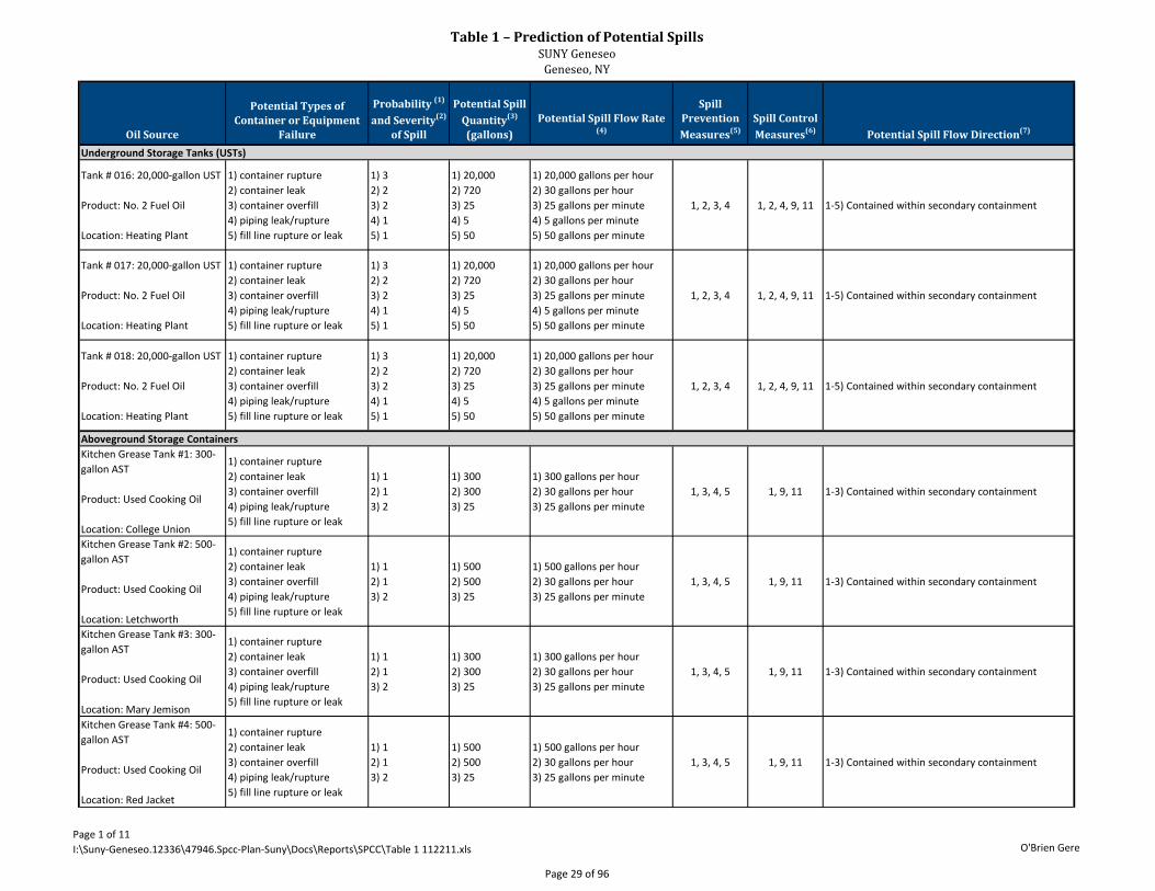
Table 1 – Prediction of Potential SpillsSUNY Geneseo
Geneseo, NY
Page 1 of 11I:\Suny-Geneseo.12336\47946.Spcc-Plan-Suny\Docs\Reports\SPCC\Table 1 112211.xls O'Brien Gere
Oil Source
Potential Types of Container or Equipment
Failure
Probability (1)
and Severity(2)
of Spill
Potential Spill Quantity(3)
(gallons)Potential Spill Flow Rate
(4)
Spill Prevention Measures(5)
Spill Control Measures(6) Potential Spill Flow Direction(7)
Tank # 016: 20,000-gallon UST
Product: No. 2 Fuel Oil
Location: Heating Plant
1) container rupture2) container leak3) container overfill4) piping leak/rupture 5) fill line rupture or leak
1) 32) 23) 24) 15) 1
1) 20,0002) 7203) 254) 55) 50
1) 20,000 gallons per hour2) 30 gallons per hour 3) 25 gallons per minute4) 5 gallons per minute 5) 50 gallons per minute
1, 2, 3, 4 1, 2, 4, 9, 11 1-5) Contained within secondary containment
Tank # 017: 20,000-gallon UST
Product: No. 2 Fuel Oil
Location: Heating Plant
1) container rupture2) container leak3) container overfill4) piping leak/rupture 5) fill line rupture or leak
1) 32) 23) 24) 15) 1
1) 20,0002) 7203) 254) 55) 50
1) 20,000 gallons per hour2) 30 gallons per hour 3) 25 gallons per minute4) 5 gallons per minute 5) 50 gallons per minute
1, 2, 3, 4 1, 2, 4, 9, 11 1-5) Contained within secondary containment
Tank # 018: 20,000-gallon UST
Product: No. 2 Fuel Oil
Location: Heating Plant
1) container rupture2) container leak3) container overfill4) piping leak/rupture 5) fill line rupture or leak
1) 32) 23) 24) 15) 1
1) 20,0002) 7203) 254) 55) 50
1) 20,000 gallons per hour2) 30 gallons per hour 3) 25 gallons per minute4) 5 gallons per minute 5) 50 gallons per minute
1, 2, 3, 4 1, 2, 4, 9, 11 1-5) Contained within secondary containment
Kitchen Grease Tank #1: 300-gallon AST
Product: Used Cooking Oil
Location: College Union
1) container rupture2) container leak3) container overfill4) piping leak/rupture 5) fill line rupture or leak
1) 12) 13) 2
1) 3002) 3003) 25
1) 300 gallons per hour2) 30 gallons per hour 3) 25 gallons per minute
1, 3, 4, 5 1, 9, 11 1-3) Contained within secondary containment
Kitchen Grease Tank #2: 500-gallon AST
Product: Used Cooking Oil
Location: Letchworth
1) container rupture2) container leak3) container overfill4) piping leak/rupture 5) fill line rupture or leak
1) 12) 13) 2
1) 5002) 5003) 25
1) 500 gallons per hour2) 30 gallons per hour 3) 25 gallons per minute
1, 3, 4, 5 1, 9, 11 1-3) Contained within secondary containment
Kitchen Grease Tank #3: 300-gallon AST
Product: Used Cooking Oil
Location: Mary Jemison
1) container rupture2) container leak3) container overfill4) piping leak/rupture 5) fill line rupture or leak
1) 12) 13) 2
1) 3002) 3003) 25
1) 300 gallons per hour2) 30 gallons per hour 3) 25 gallons per minute
1, 3, 4, 5 1, 9, 11 1-3) Contained within secondary containment
Kitchen Grease Tank #4: 500-gallon AST
Product: Used Cooking Oil
Location: Red Jacket
1) container rupture2) container leak3) container overfill4) piping leak/rupture 5) fill line rupture or leak
1) 12) 13) 2
1) 5002) 5003) 25
1) 500 gallons per hour2) 30 gallons per hour 3) 25 gallons per minute
1, 3, 4, 5 1, 9, 11 1-3) Contained within secondary containment
Underground Storage Tanks (USTs)
Aboveground Storage Containers
Page 29 of 96
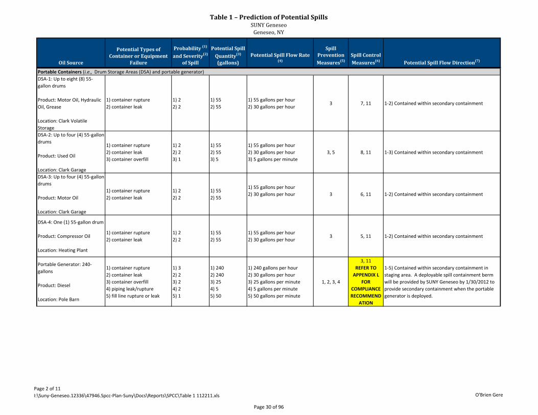
Table 1 – Prediction of Potential SpillsSUNY Geneseo
Geneseo, NY
Page 2 of 11I:\Suny-Geneseo.12336\47946.Spcc-Plan-Suny\Docs\Reports\SPCC\Table 1 112211.xls O'Brien Gere
Oil Source
Potential Types of Container or Equipment
Failure
Probability (1)
and Severity(2)
of Spill
Potential Spill Quantity(3)
(gallons)Potential Spill Flow Rate
(4)
Spill Prevention Measures(5)
Spill Control Measures(6) Potential Spill Flow Direction(7)
DSA-1: Up to eight (8) 55-gallon drums
Product: Motor Oil, Hydraulic Oil, Grease
Location: Clark Volatile Storage
1) container rupture2) container leak
1) 22) 2
1) 552) 55
1) 55 gallons per hour2) 30 gallons per hour
3 7, 11 1-2) Contained within secondary containment
DSA-2: Up to four (4) 55-gallon drums
Product: Used Oil
Location: Clark Garage
1) container rupture2) container leak3) container overfill
1) 22) 23) 1
1) 552) 553) 5
1) 55 gallons per hour2) 30 gallons per hour3) 5 gallons per minute
3, 5 8, 11 1-3) Contained within secondary containment
DSA-3: Up to four (4) 55-gallon drums
Product: Motor Oil
Location: Clark Garage
1) container rupture2) container leak
1) 22) 2
1) 552) 55
1) 55 gallons per hour2) 30 gallons per hour 3 6, 11 1-2) Contained within secondary containment
DSA-4: One (1) 55-gallon drum
Product: Compressor Oil
Location: Heating Plant
1) container rupture2) container leak
1) 22) 2
1) 552) 55
1) 55 gallons per hour2) 30 gallons per hour
3 5, 11 1-2) Contained within secondary containment
Portable Generator: 240-gallons
Product: Diesel
Location: Pole Barn
1) container rupture2) container leak3) container overfill4) piping leak/rupture 5) fill line rupture or leak
1) 32) 23) 24) 25) 1
1) 2402) 2403) 254) 55) 50
1) 240 gallons per hour2) 30 gallons per hour 3) 25 gallons per minute4) 5 gallons per minute 5) 50 gallons per minute
1, 2, 3, 4
3, 11REFER TO
APPENDIX L FOR
COMPLIANCE RECOMMEND
ATION
1-5) Contained within secondary containment in staging area. A deployable spill containment berm will be provided by SUNY Geneseo by 1/30/2012 to provide secondary containment when the portable generator is deployed.
Portable Containers (i.e., Drum Storage Areas (DSA) and portable generator)
Page 30 of 96
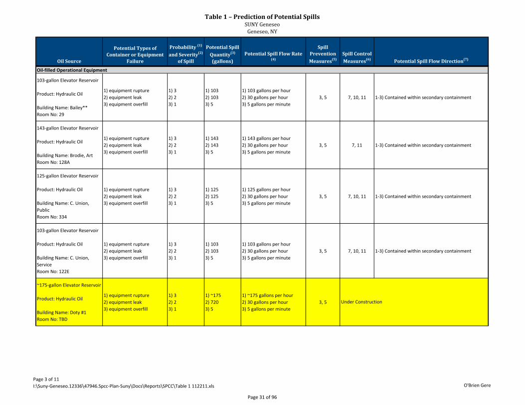
Table 1 – Prediction of Potential SpillsSUNY Geneseo
Geneseo, NY
Page 3 of 11I:\Suny-Geneseo.12336\47946.Spcc-Plan-Suny\Docs\Reports\SPCC\Table 1 112211.xls O'Brien Gere
Oil Source
Potential Types of Container or Equipment
Failure
Probability (1)
and Severity(2)
of Spill
Potential Spill Quantity(3)
(gallons)Potential Spill Flow Rate
(4)
Spill Prevention Measures(5)
Spill Control Measures(6) Potential Spill Flow Direction(7)
103-gallon Elevator Reservoir
Product: Hydraulic Oil
Building Name: Bailey**Room No: 29
1) equipment rupture2) equipment leak3) equipment overfill
1) 32) 23) 1
1) 1032) 1033) 5
1) 103 gallons per hour2) 30 gallons per hour3) 5 gallons per minute
3, 5 7, 10, 11 1-3) Contained within secondary containment
143-gallon Elevator Reservoir
Product: Hydraulic Oil
Building Name: Brodie, ArtRoom No: 128A
1) equipment rupture2) equipment leak3) equipment overfill
1) 32) 23) 1
1) 1432) 1433) 5
1) 143 gallons per hour2) 30 gallons per hour3) 5 gallons per minute
3, 5 7, 11 1-3) Contained within secondary containment
125-gallon Elevator Reservoir
Product: Hydraulic Oil
Building Name: C. Union, PublicRoom No: 334
1) equipment rupture2) equipment leak3) equipment overfill
1) 32) 23) 1
1) 1252) 1253) 5
1) 125 gallons per hour2) 30 gallons per hour3) 5 gallons per minute
3, 5 7, 10, 11 1-3) Contained within secondary containment
103-gallon Elevator Reservoir
Product: Hydraulic Oil
Building Name: C. Union, ServiceRoom No: 122E
1) equipment rupture2) equipment leak3) equipment overfill
1) 32) 23) 1
1) 1032) 1033) 5
1) 103 gallons per hour2) 30 gallons per hour3) 5 gallons per minute
3, 5 7, 10, 11 1-3) Contained within secondary containment
~175-gallon Elevator Reservoir
Product: Hydraulic Oil
Building Name: Doty #1Room No: TBD
1) equipment rupture2) equipment leak3) equipment overfill
1) 32) 23) 1
1) ~1752) 7203) 5
1) ~175 gallons per hour2) 30 gallons per hour3) 5 gallons per minute
3, 5
Oil-filled Operational Equipment
Under Construction
Page 31 of 96
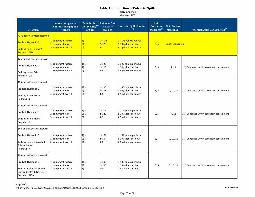
Table 1 – Prediction of Potential SpillsSUNY Geneseo
Geneseo, NY
Page 4 of 11I:\Suny-Geneseo.12336\47946.Spcc-Plan-Suny\Docs\Reports\SPCC\Table 1 112211.xls O'Brien Gere
Oil Source
Potential Types of Container or Equipment
Failure
Probability (1)
and Severity(2)
of Spill
Potential Spill Quantity(3)
(gallons)Potential Spill Flow Rate
(4)
Spill Prevention Measures(5)
Spill Control Measures(6) Potential Spill Flow Direction(7)
~175-gallon Elevator Reservoir
Product: Hydraulic Oil
Building Name: Doty #2Room No: TBD
1) equipment rupture2) equipment leak3) equipment overfill
1) 32) 23) 1
1) ~1752) 7203) 5
1) ~175 gallons per hour2) 30 gallons per hour3) 5 gallons per minute
3, 5
125-gallon Elevator Reservoir
Product: Hydraulic Oil
Building Name: ErieRoom No: C03
1) equipment rupture2) equipment leak3) equipment overfill
1) 32) 23) 1
1) 1252) 1253) 5
1) 125 gallons per hour2) 30 gallons per hour3) 5 gallons per minute
3, 5 7, 11 1-3) Contained within secondary containment
103-gallon Elevator Reservoir
Product: Hydraulic Oil
Building Name: ErwinRoom No: 3
1) equipment rupture2) equipment leak3) equipment overfill
1) 32) 23) 1
1) 1032) 1033) 5
1) 103 gallons per hour2) 30 gallons per hour3) 5 gallons per minute
3, 5 7, 10, 11 1-3) Contained within secondary containment
129-gallon Elevator Reservoir
Product: Hydraulic Oil
Building Name: FraserRoom No: 5
1) equipment rupture2) equipment leak3) equipment overfill
1) 32) 23) 1
1) 1292) 1293) 5
1) 129 gallons per hour2) 30 gallons per hour3) 5 gallons per minute
3, 5 7, 11 1-3) Contained within secondary containment
164-gallon Elevator Reservoir
Product: Hydraulic Oil
Building Name: Integrated Science CenterRoom No: 7
1) equipment rupture2) equipment leak3) equipment overfill
1) 32) 23) 1
1) 1642) 1643) 5
1) 164 gallons per hour2) 30 gallons per hour3) 5 gallons per minute
3, 5 7, 10, 11 1-3) Contained within secondary containment
103-gallon Elevator Reservoir
Product: Hydraulic Oil
Building Name: Integrated Science Center II (Greene)Room No: 129A
1) equipment rupture2) equipment leak3) equipment overfill
1) 32) 23) 1
1) 1032) 1033) 5
1) 103 gallons per hour2) 30 gallons per hour3) 5 gallons per minute
3, 5 7, 10, 11 1-3) Contained within secondary containment
Under Construction
Page 32 of 96
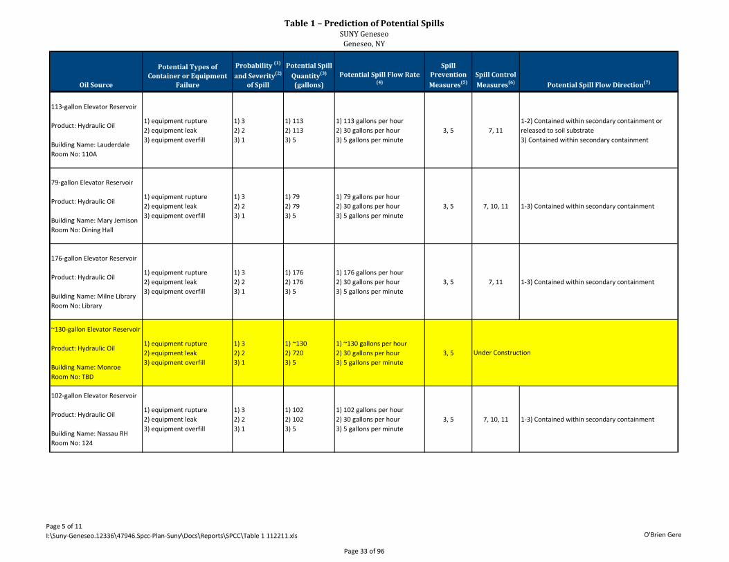
Table 1 – Prediction of Potential SpillsSUNY Geneseo
Geneseo, NY
Page 5 of 11I:\Suny-Geneseo.12336\47946.Spcc-Plan-Suny\Docs\Reports\SPCC\Table 1 112211.xls O'Brien Gere
Oil Source
Potential Types of Container or Equipment
Failure
Probability (1)
and Severity(2)
of Spill
Potential Spill Quantity(3)
(gallons)Potential Spill Flow Rate
(4)
Spill Prevention Measures(5)
Spill Control Measures(6) Potential Spill Flow Direction(7)
113-gallon Elevator Reservoir
Product: Hydraulic Oil
Building Name: LauderdaleRoom No: 110A
1) equipment rupture2) equipment leak3) equipment overfill
1) 32) 23) 1
1) 1132) 1133) 5
1) 113 gallons per hour2) 30 gallons per hour3) 5 gallons per minute
3, 5 7, 111-2) Contained within secondary containment or released to soil substrate3) Contained within secondary containment
79-gallon Elevator Reservoir
Product: Hydraulic Oil
Building Name: Mary JemisonRoom No: Dining Hall
1) equipment rupture2) equipment leak3) equipment overfill
1) 32) 23) 1
1) 792) 793) 5
1) 79 gallons per hour2) 30 gallons per hour3) 5 gallons per minute
3, 5 7, 10, 11 1-3) Contained within secondary containment
176-gallon Elevator Reservoir
Product: Hydraulic Oil
Building Name: Milne LibraryRoom No: Library
1) equipment rupture2) equipment leak3) equipment overfill
1) 32) 23) 1
1) 1762) 1763) 5
1) 176 gallons per hour2) 30 gallons per hour3) 5 gallons per minute
3, 5 7, 11 1-3) Contained within secondary containment
~130-gallon Elevator Reservoir
Product: Hydraulic Oil
Building Name: MonroeRoom No: TBD
1) equipment rupture2) equipment leak3) equipment overfill
1) 32) 23) 1
1) ~1302) 7203) 5
1) ~130 gallons per hour2) 30 gallons per hour3) 5 gallons per minute
3, 5
102-gallon Elevator Reservoir
Product: Hydraulic Oil
Building Name: Nassau RHRoom No: 124
1) equipment rupture2) equipment leak3) equipment overfill
1) 32) 23) 1
1) 1022) 1023) 5
1) 102 gallons per hour2) 30 gallons per hour3) 5 gallons per minute
3, 5 7, 10, 11 1-3) Contained within secondary containment
Under Construction
Page 33 of 96
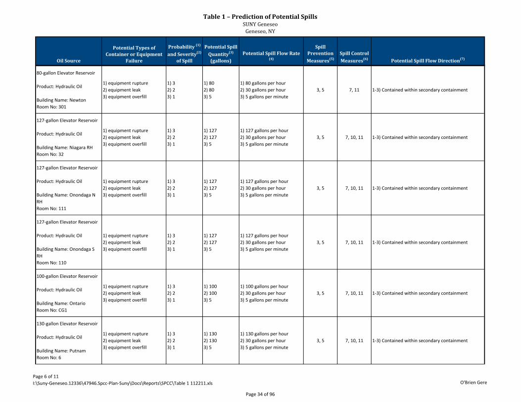
Table 1 – Prediction of Potential SpillsSUNY Geneseo
Geneseo, NY
Page 6 of 11I:\Suny-Geneseo.12336\47946.Spcc-Plan-Suny\Docs\Reports\SPCC\Table 1 112211.xls O'Brien Gere
Oil Source
Potential Types of Container or Equipment
Failure
Probability (1)
and Severity(2)
of Spill
Potential Spill Quantity(3)
(gallons)Potential Spill Flow Rate
(4)
Spill Prevention Measures(5)
Spill Control Measures(6) Potential Spill Flow Direction(7)
80-gallon Elevator Reservoir
Product: Hydraulic Oil
Building Name: NewtonRoom No: 301
1) equipment rupture2) equipment leak3) equipment overfill
1) 32) 23) 1
1) 802) 803) 5
1) 80 gallons per hour2) 30 gallons per hour3) 5 gallons per minute
3, 5 7, 11 1-3) Contained within secondary containment
127-gallon Elevator Reservoir
Product: Hydraulic Oil
Building Name: Niagara RHRoom No: 32
1) equipment rupture2) equipment leak3) equipment overfill
1) 32) 23) 1
1) 1272) 1273) 5
1) 127 gallons per hour2) 30 gallons per hour3) 5 gallons per minute
3, 5 7, 10, 11 1-3) Contained within secondary containment
127-gallon Elevator Reservoir
Product: Hydraulic Oil
Building Name: Onondaga N RHRoom No: 111
1) equipment rupture2) equipment leak3) equipment overfill
1) 32) 23) 1
1) 1272) 1273) 5
1) 127 gallons per hour2) 30 gallons per hour3) 5 gallons per minute
3, 5 7, 10, 11 1-3) Contained within secondary containment
127-gallon Elevator Reservoir
Product: Hydraulic Oil
Building Name: Onondaga S RHRoom No: 110
1) equipment rupture2) equipment leak3) equipment overfill
1) 32) 23) 1
1) 1272) 1273) 5
1) 127 gallons per hour2) 30 gallons per hour3) 5 gallons per minute
3, 5 7, 10, 11 1-3) Contained within secondary containment
100-gallon Elevator Reservoir
Product: Hydraulic Oil
Building Name: OntarioRoom No: CG1
1) equipment rupture2) equipment leak3) equipment overfill
1) 32) 23) 1
1) 1002) 1003) 5
1) 100 gallons per hour2) 30 gallons per hour3) 5 gallons per minute
3, 5 7, 10, 11 1-3) Contained within secondary containment
130-gallon Elevator Reservoir
Product: Hydraulic Oil
Building Name: PutnamRoom No: 6
1) equipment rupture2) equipment leak3) equipment overfill
1) 32) 23) 1
1) 1302) 1303) 5
1) 130 gallons per hour2) 30 gallons per hour3) 5 gallons per minute
3, 5 7, 10, 11 1-3) Contained within secondary containment
Page 34 of 96
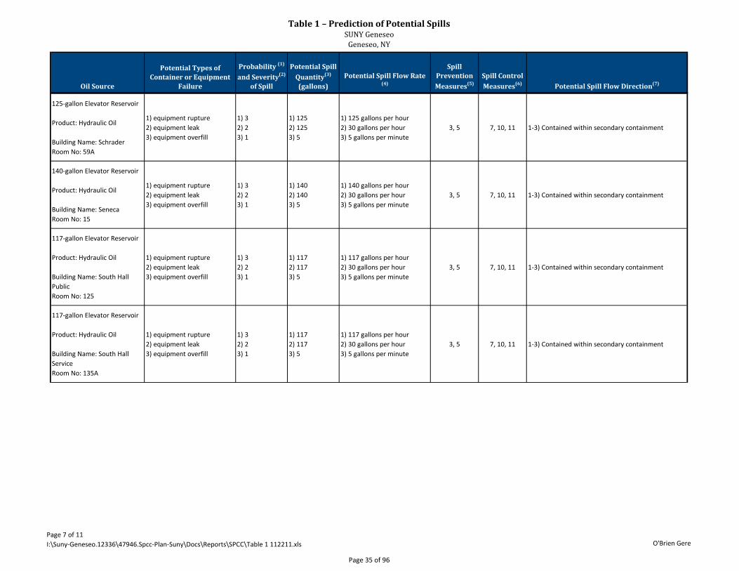
Table 1 – Prediction of Potential SpillsSUNY Geneseo
Geneseo, NY
Page 7 of 11I:\Suny-Geneseo.12336\47946.Spcc-Plan-Suny\Docs\Reports\SPCC\Table 1 112211.xls O'Brien Gere
Oil Source
Potential Types of Container or Equipment
Failure
Probability (1)
and Severity(2)
of Spill
Potential Spill Quantity(3)
(gallons)Potential Spill Flow Rate
(4)
Spill Prevention Measures(5)
Spill Control Measures(6) Potential Spill Flow Direction(7)
125-gallon Elevator Reservoir
Product: Hydraulic Oil
Building Name: SchraderRoom No: 59A
1) equipment rupture2) equipment leak3) equipment overfill
1) 32) 23) 1
1) 1252) 1253) 5
1) 125 gallons per hour2) 30 gallons per hour3) 5 gallons per minute
3, 5 7, 10, 11 1-3) Contained within secondary containment
140-gallon Elevator Reservoir
Product: Hydraulic Oil
Building Name: SenecaRoom No: 15
1) equipment rupture2) equipment leak3) equipment overfill
1) 32) 23) 1
1) 1402) 1403) 5
1) 140 gallons per hour2) 30 gallons per hour3) 5 gallons per minute
3, 5 7, 10, 11 1-3) Contained within secondary containment
117-gallon Elevator Reservoir
Product: Hydraulic Oil
Building Name: South Hall PublicRoom No: 125
1) equipment rupture2) equipment leak3) equipment overfill
1) 32) 23) 1
1) 1172) 1173) 5
1) 117 gallons per hour2) 30 gallons per hour3) 5 gallons per minute
3, 5 7, 10, 11 1-3) Contained within secondary containment
117-gallon Elevator Reservoir
Product: Hydraulic Oil
Building Name: South Hall ServiceRoom No: 135A
1) equipment rupture2) equipment leak3) equipment overfill
1) 32) 23) 1
1) 1172) 1173) 5
1) 117 gallons per hour2) 30 gallons per hour3) 5 gallons per minute
3, 5 7, 10, 11 1-3) Contained within secondary containment
Page 35 of 96
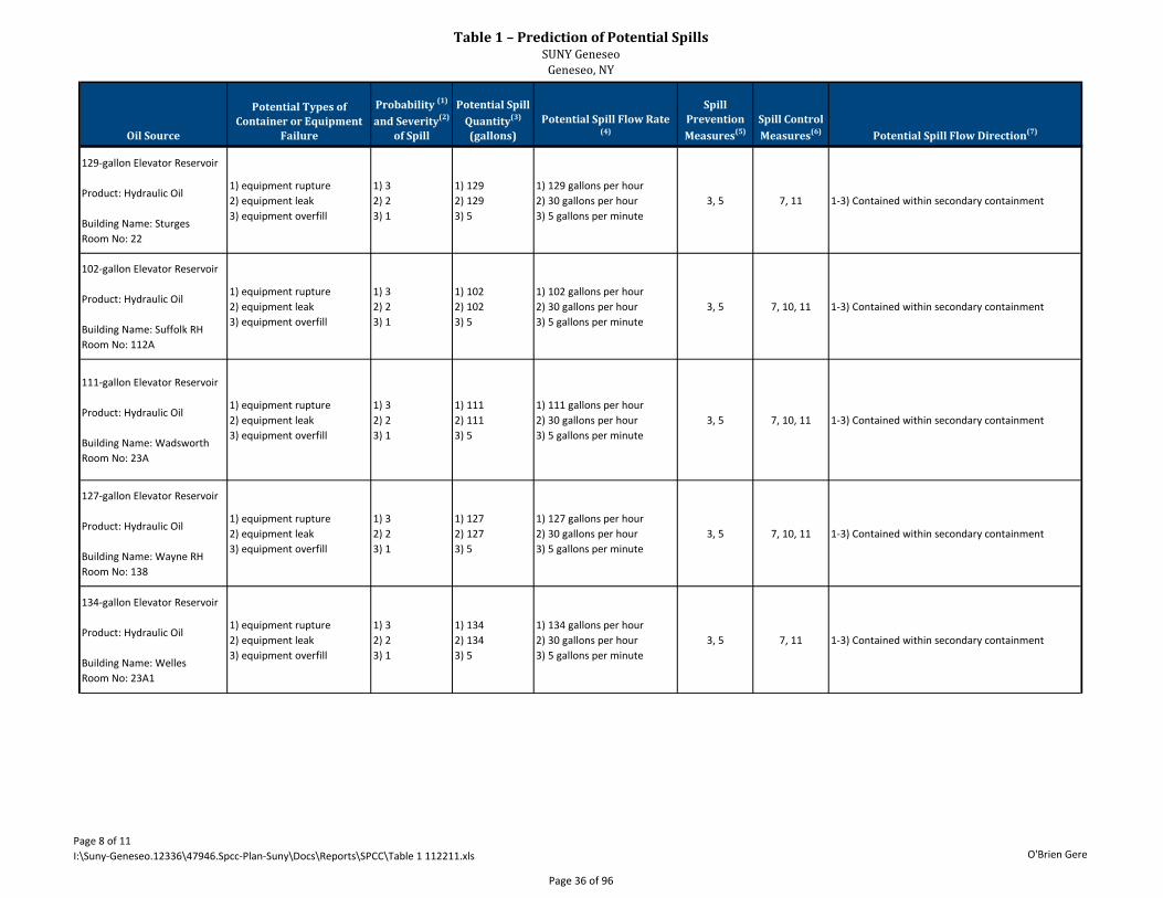
Table 1 – Prediction of Potential SpillsSUNY Geneseo
Geneseo, NY
Page 8 of 11I:\Suny-Geneseo.12336\47946.Spcc-Plan-Suny\Docs\Reports\SPCC\Table 1 112211.xls O'Brien Gere
Oil Source
Potential Types of Container or Equipment
Failure
Probability (1)
and Severity(2)
of Spill
Potential Spill Quantity(3)
(gallons)Potential Spill Flow Rate
(4)
Spill Prevention Measures(5)
Spill Control Measures(6) Potential Spill Flow Direction(7)
129-gallon Elevator Reservoir
Product: Hydraulic Oil
Building Name: SturgesRoom No: 22
1) equipment rupture2) equipment leak3) equipment overfill
1) 32) 23) 1
1) 1292) 1293) 5
1) 129 gallons per hour2) 30 gallons per hour3) 5 gallons per minute
3, 5 7, 11 1-3) Contained within secondary containment
102-gallon Elevator Reservoir
Product: Hydraulic Oil
Building Name: Suffolk RHRoom No: 112A
1) equipment rupture2) equipment leak3) equipment overfill
1) 32) 23) 1
1) 1022) 1023) 5
1) 102 gallons per hour2) 30 gallons per hour3) 5 gallons per minute
3, 5 7, 10, 11 1-3) Contained within secondary containment
111-gallon Elevator Reservoir
Product: Hydraulic Oil
Building Name: WadsworthRoom No: 23A
1) equipment rupture2) equipment leak3) equipment overfill
1) 32) 23) 1
1) 1112) 1113) 5
1) 111 gallons per hour2) 30 gallons per hour3) 5 gallons per minute
3, 5 7, 10, 11 1-3) Contained within secondary containment
127-gallon Elevator Reservoir
Product: Hydraulic Oil
Building Name: Wayne RHRoom No: 138
1) equipment rupture2) equipment leak3) equipment overfill
1) 32) 23) 1
1) 1272) 1273) 5
1) 127 gallons per hour2) 30 gallons per hour3) 5 gallons per minute
3, 5 7, 10, 11 1-3) Contained within secondary containment
134-gallon Elevator Reservoir
Product: Hydraulic Oil
Building Name: WellesRoom No: 23A1
1) equipment rupture2) equipment leak3) equipment overfill
1) 32) 23) 1
1) 1342) 1343) 5
1) 134 gallons per hour2) 30 gallons per hour3) 5 gallons per minute
3, 5 7, 11 1-3) Contained within secondary containment
Page 36 of 96
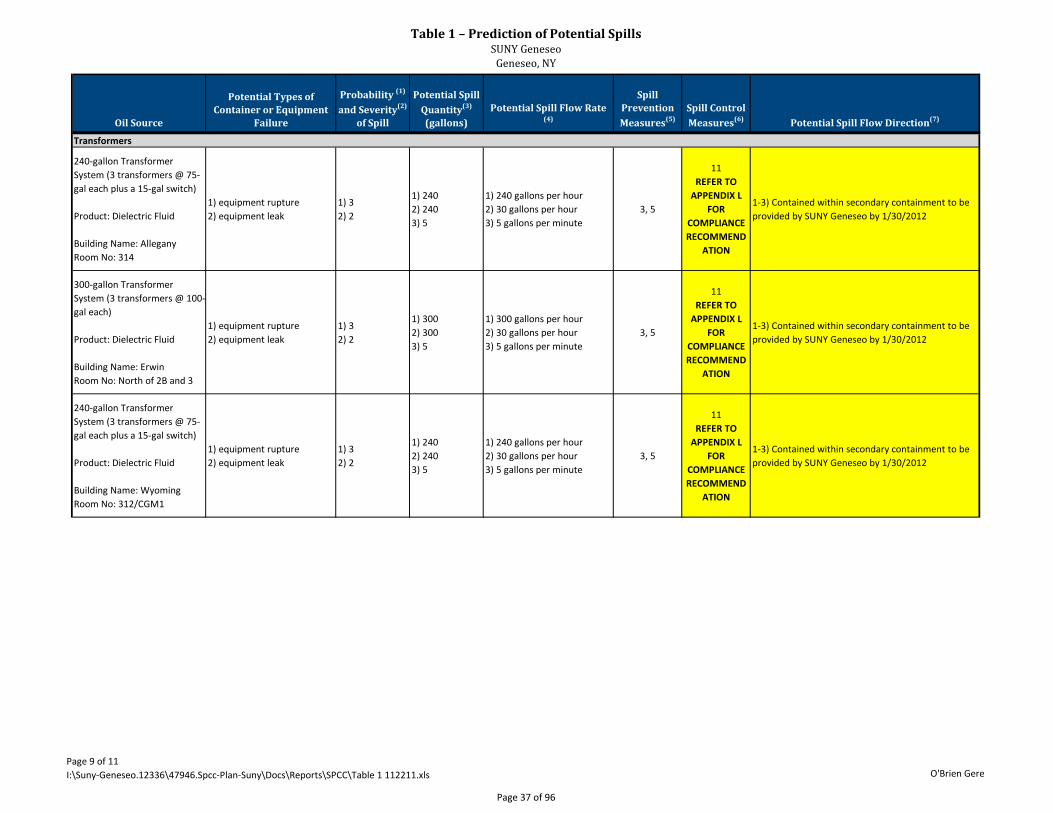
Table 1 – Prediction of Potential SpillsSUNY Geneseo
Geneseo, NY
Page 9 of 11I:\Suny-Geneseo.12336\47946.Spcc-Plan-Suny\Docs\Reports\SPCC\Table 1 112211.xls O'Brien Gere
Oil Source
Potential Types of Container or Equipment
Failure
Probability (1)
and Severity(2)
of Spill
Potential Spill Quantity(3)
(gallons)Potential Spill Flow Rate
(4)
Spill Prevention Measures(5)
Spill Control Measures(6) Potential Spill Flow Direction(7)
240-gallon Transformer System (3 transformers @ 75-gal each plus a 15-gal switch)
Product: Dielectric Fluid
Building Name: AlleganyRoom No: 314
1) equipment rupture2) equipment leak
1) 32) 2
1) 2402) 2403) 5
1) 240 gallons per hour2) 30 gallons per hour3) 5 gallons per minute
3, 5
11REFER TO
APPENDIX L FOR
COMPLIANCE RECOMMEND
ATION
1-3) Contained within secondary containment to be provided by SUNY Geneseo by 1/30/2012
300-gallon Transformer System (3 transformers @ 100-gal each)
Product: Dielectric Fluid
Building Name: ErwinRoom No: North of 2B and 3
1) equipment rupture2) equipment leak
1) 32) 2
1) 3002) 3003) 5
1) 300 gallons per hour2) 30 gallons per hour3) 5 gallons per minute
3, 5
11REFER TO
APPENDIX L FOR
COMPLIANCE RECOMMEND
ATION
1-3) Contained within secondary containment to be provided by SUNY Geneseo by 1/30/2012
240-gallon Transformer System (3 transformers @ 75-gal each plus a 15-gal switch)
Product: Dielectric Fluid
Building Name: WyomingRoom No: 312/CGM1
1) equipment rupture2) equipment leak
1) 32) 2
1) 2402) 2403) 5
1) 240 gallons per hour2) 30 gallons per hour3) 5 gallons per minute
3, 5
11REFER TO
APPENDIX L FOR
COMPLIANCE RECOMMEND
ATION
1-3) Contained within secondary containment to be provided by SUNY Geneseo by 1/30/2012
Transformers
Page 37 of 96
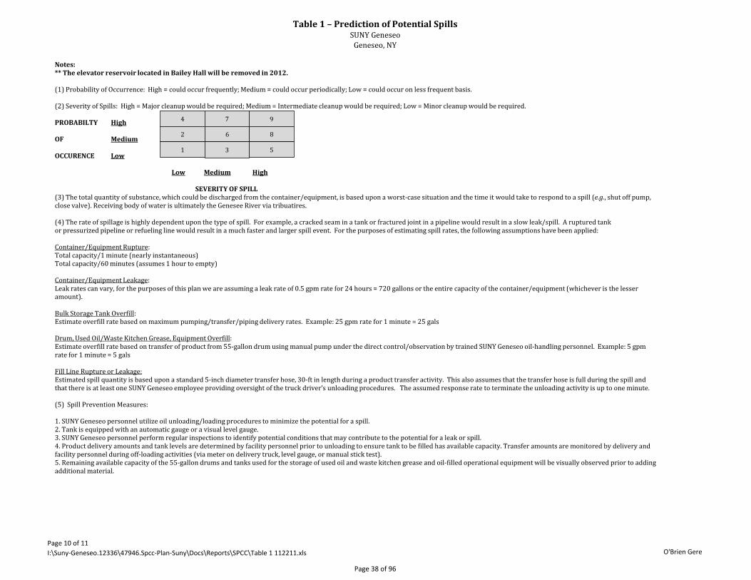
Table 1 – Prediction of Potential SpillsSUNY Geneseo
Geneseo, NY
Page 10 of 11I:\Suny-Geneseo.12336\47946.Spcc-Plan-Suny\Docs\Reports\SPCC\Table 1 112211.xls O'Brien Gere
Notes: ** The elevator reservoir located in Bailey Hall will be removed in 2012. (1) Probability of Occurrence: High = could occur frequently; Medium = could occur periodically; Low = could occur on less frequent basis. (2) Severity of Spills: High = Major cleanup would be required; Medium = Intermediate cleanup would be required; Low = Minor cleanup would be required. PROBABILTY High OF Medium OCCURENCE Low Low Medium High SEVERITY OF SPILL (3) The total quantity of substance, which could be discharged from the container/equipment, is based upon a worst-case situation and the time it would take to respond to a spill (e.g., shut off pump, close valve). Receiving body of water is ultimately the Genesee River via tribuatires. (4) The rate of spillage is highly dependent upon the type of spill. For example, a cracked seam in a tank or fractured joint in a pipeline would result in a slow leak/spill. A ruptured tank or pressurized pipeline or refueling line would result in a much faster and larger spill event. For the purposes of estimating spill rates, the following assumptions have been applied: Container/Equipment Rupture: Total capacity/1 minute (nearly instantaneous) Total capacity/60 minutes (assumes 1 hour to empty) Container/Equipment Leakage: Leak rates can vary, for the purposes of this plan we are assuming a leak rate of 0.5 gpm rate for 24 hours = 720 gallons or the entire capacity of the container/equipment (whichever is the lesser amount). Bulk Storage Tank Overfill: Estimate overfill rate based on maximum pumping/transfer/piping delivery rates. Example: 25 gpm rate for 1 minute = 25 gals Drum, Used Oil/Waste Kitchen Grease, Equipment Overfill: Estimate overfill rate based on transfer of product from 55-gallon drum using manual pump under the direct control/observation by trained SUNY Geneseo oil-handling personnel. Example: 5 gpm rate for 1 minute = 5 gals Fill Line Rupture or Leakage: Estimated spill quantity is based upon a standard 5-inch diameter transfer hose, 30-ft in length during a product transfer activity. This also assumes that the transfer hose is full during the spill and that there is at least one SUNY Geneseo employee providing oversight of the truck driver’s unloading procedures. The assumed response rate to terminate the unloading activity is up to one minute. (5) Spill Prevention Measures: 1. SUNY Geneseo personnel utilize oil unloading/loading procedures to minimize the potential for a spill. 2. Tank is equipped with an automatic gauge or a visual level gauge. 3. SUNY Geneseo personnel perform regular inspections to identify potential conditions that may contribute to the potential for a leak or spill. 4. Product delivery amounts and tank levels are determined by facility personnel prior to unloading to ensure tank to be filled has available capacity. Transfer amounts are monitored by delivery and facility personnel during off-loading activities (via meter on delivery truck, level gauge, or manual stick test). 5. Remaining available capacity of the 55-gallon drums and tanks used for the storage of used oil and waste kitchen grease and oil-filled operational equipment will be visually observed prior to adding additional material.
4 7 9
2 6 8
1 3 5
Page 38 of 96

Table 1 – Prediction of Potential SpillsSUNY Geneseo
Geneseo, NY
Page 11 of 11I:\Suny-Geneseo.12336\47946.Spcc-Plan-Suny\Docs\Reports\SPCC\Table 1 112211.xls O'Brien Gere
6) Spill Control Measures: 1. Container/tank has integral secondary containment (double-walled). 2. Unloading area is equipped with secondary containment via concrete curbing and/or an asphalt bermed are a which drains to an oil-water separator equipped with a 4,000-gallon concrete oil interceptor. 3. Container is stored within a sloped concrete berm staging area. When deployed, the facility will situate the container within a deployable spill containment berm. 4. Underground piping is double walled. Aboveground piping is situated within a building. Floor drains within the building are directed to an oil-water separator. 5. Container is situated within a plastic diked area. 6. Container is situated on secondary containment spill pallets. 7. Container/equipment is situated within a building with no floor drains or sealed floor/trench drains. 8. Floor drains within the building are directed to a 350-gallon oil-water separator. 9. Tank is equipped with a catch basin for overfill protection. 10. Below grade elevator cylinder is double-walled. 11. Appropriate spill containment equipment stored in area or brought to unloading area during delivery. (7) Flow direction is based on physical containment barriers. (8) It should also be noted that during the facility also maintains two underground storage tanks (Tanks 012 and 013). These tanks are subject to all parts of 40 CFR 280; therefore, they are exempt from SPCC regulations. However, the faciliy will follow the unloading procedures detailed in Appendix D during the transfer of fuel to these tanks.
Page 39 of 96

TABLE 2
360° Engineering and Project Delivery Solutions
Emergency Contacts
Page 40 of 96
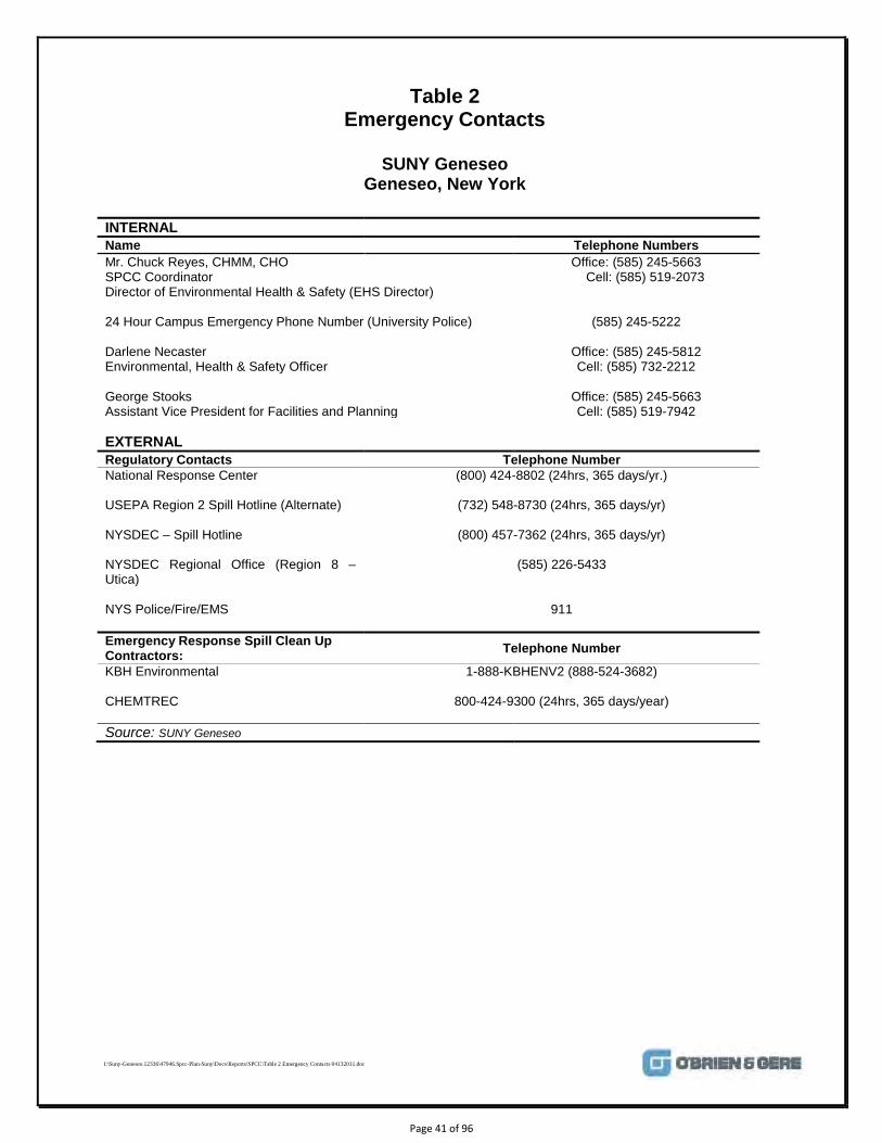
I:\Suny-Geneseo.12336\47946.Spcc-Plan-Suny\Docs\Reports\SPCC\Table 2 Emergency Contacts 04132011.doc
Table 2 Emergency Contacts
SUNY Geneseo
Geneseo, New York
INTERNAL Name Telephone Numbers Mr. Chuck Reyes, CHMM, CHO SPCC Coordinator Director of Environmental Health & Safety (EHS Director)
Office: (585) 245-5663 Cell: (585) 519-2073
24 Hour Campus Emergency Phone Number (University Police) (585) 245-5222 Darlene Necaster Environmental, Health & Safety Officer George Stooks Assistant Vice President for Facilities and Planning
Office: (585) 245-5812 Cell: (585) 732-2212
Office: (585) 245-5663 Cell: (585) 519-7942
EXTERNAL Regulatory Contacts Telephone Number National Response Center (800) 424-8802 (24hrs, 365 days/yr.)
USEPA Region 2 Spill Hotline (Alternate) (732) 548-8730 (24hrs, 365 days/yr)
NYSDEC – Spill Hotline (800) 457-7362 (24hrs, 365 days/yr)
NYSDEC Regional Office (Region 8 – Utica)
(585) 226-5433
NYS Police/Fire/EMS 911
Emergency Response Spill Clean Up Contractors: Telephone Number
KBH Environmental
1-888-KBHENV2 (888-524-3682)
CHEMTREC 800-424-9300 (24hrs, 365 days/year)
Source: SUNY Geneseo
Page 41 of 96

FIGURE 1
360° Engineering and Project Delivery Solutions
Site Location Map
Page 42 of 96
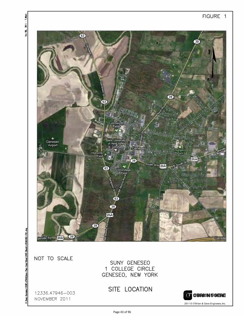
Page 43 of 96
FIGURE 2
360° Engineering and Project Delivery Solutions
Site Layout
Page 44 of 96
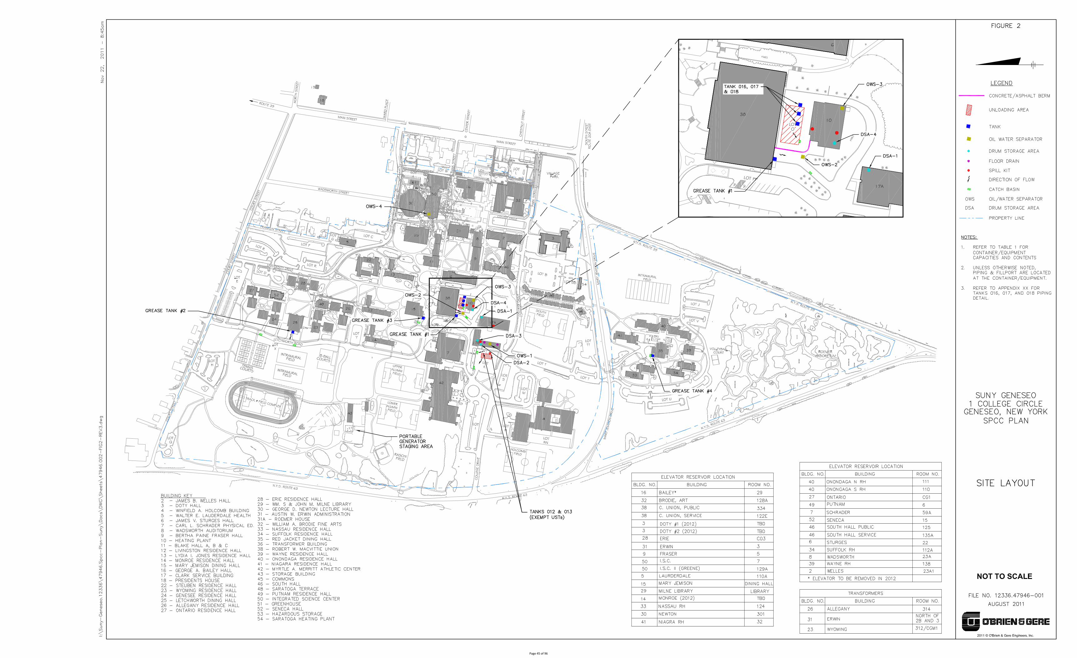
Page 45 of 96
APPENDIX A
360° Engineering and Project Delivery Solutions
Certification of the Applicability of the
Substantial Harm Criteria – 40 CFR Part 112, Appendix C
Page 46 of 96
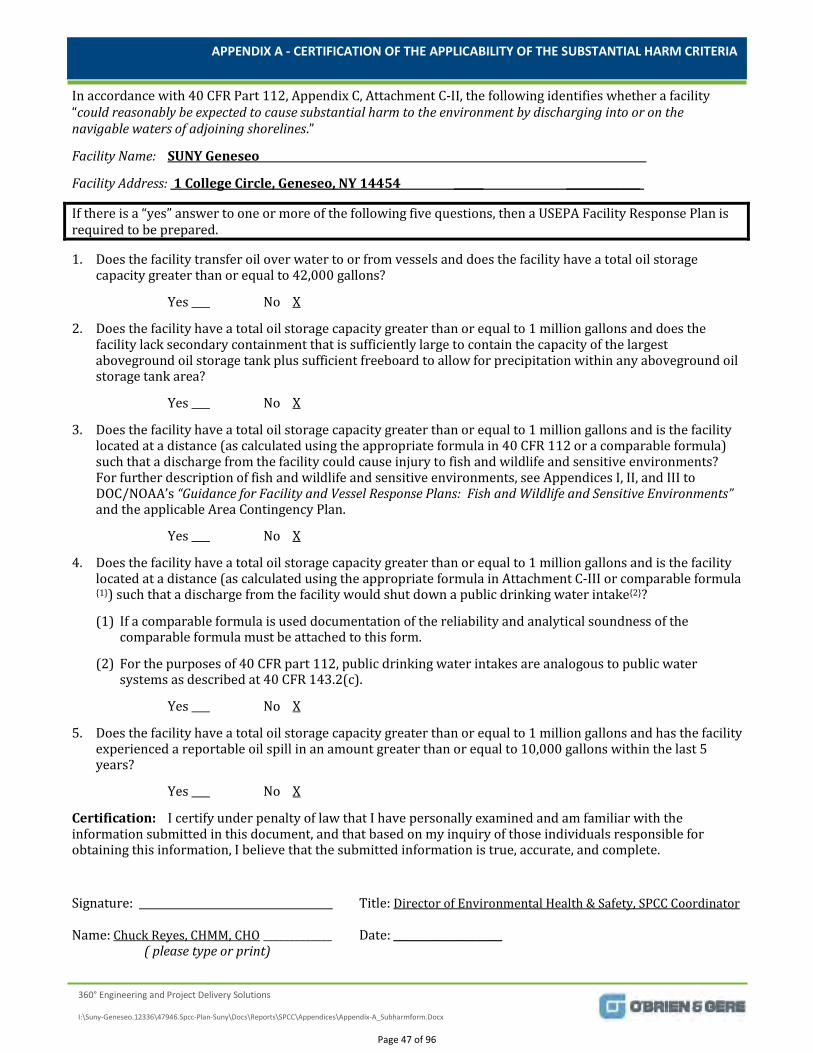
APPENDIX A - CERTIFICATION OF THE APPLICABILITY OF THE SUBSTANTIAL HARM CRITERIA
360° Engineering and Project Delivery Solutions
I:\Suny-Geneseo.12336\47946.Spcc-Plan-Suny\Docs\Reports\SPCC\Appendices\Appendix-A_Subharmform.Docx
In accordance with 40 CFR Part 112, Appendix C, Attachment C-II, the following identifies whether a facility “could reasonably be expected to cause substantial harm to the environment by discharging into or on the navigable waters of adjoining shorelines.”
Facility Name:
Facility Address:
SUNY Geneseo
1 College Circle, Geneseo, NY 14454 ______ _______________
If there is a “yes” answer to one or more of the following five questions, then a USEPA Facility Response Plan is required to be prepared.
1. Does the facility transfer oil over water to or from vessels and does the facility have a total oil storage capacity greater than or equal to 42,000 gallons?
Yes No
2. Does the facility have a total oil storage capacity greater than or equal to 1 million gallons and does the facility lack secondary containment that is sufficiently large to contain the capacity of the largest aboveground oil storage tank plus sufficient freeboard to allow for precipitation within any aboveground oil storage tank area?
X
Yes No
3. Does the facility have a total oil storage capacity greater than or equal to 1 million gallons and is the facility located at a distance (as calculated using the appropriate formula in 40 CFR 112 or a comparable formula) such that a discharge from the facility could cause injury to fish and wildlife and sensitive environments? For further description of fish and wildlife and sensitive environments, see Appendices I, II, and III to DOC/NOAA’s “Guidance for Facility and Vessel Response Plans: Fish and Wildlife and Sensitive Environments” and the applicable Area Contingency Plan.
X
Yes No
4. Does the facility have a total oil storage capacity greater than or equal to 1 million gallons and is the facility located at a distance (as calculated using the appropriate formula in Attachment C-III or comparable formula {1}) such that a discharge from the facility would shut down a public drinking water intake{2}?
X
(1) If a comparable formula is used documentation of the reliability and analytical soundness of the comparable formula must be attached to this form.
(2) For the purposes of 40 CFR part 112, public drinking water intakes are analogous to public water systems as described at 40 CFR 143.2(c).
Yes No
5. Does the facility have a total oil storage capacity greater than or equal to 1 million gallons and has the facility experienced a reportable oil spill in an amount greater than or equal to 10,000 gallons within the last 5 years?
X
Yes No
Certification: I certify under penalty of law that I have personally examined and am familiar with the information submitted in this document, and that based on my inquiry of those individuals responsible for obtaining this information, I believe that the submitted information is true, accurate, and complete.
X
Signature: Title: Director of Environmental Health & Safety, SPCC Coordinator
Name: Chuck Reyes, CHMM, CHO _____________ Date: ( please type or print)
_____________________
Page 47 of 96
APPENDIX B
360° Engineering and Project Delivery Solutions
SPCC Plan Review and Evaluation Form
Page 48 of 96
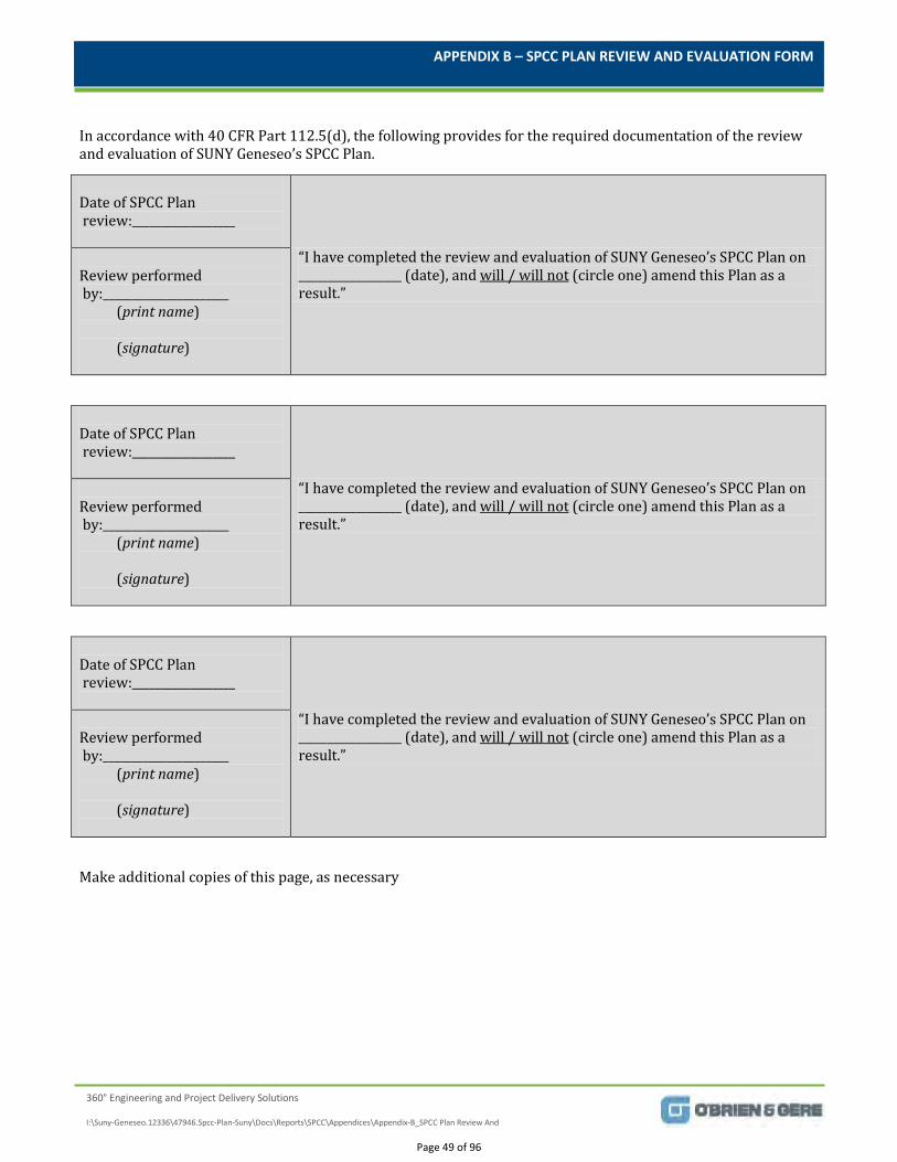
APPENDIX B – SPCC PLAN REVIEW AND EVALUATION FORM
360° Engineering and Project Delivery Solutions
I:\Suny-Geneseo.12336\47946.Spcc-Plan-Suny\Docs\Reports\SPCC\Appendices\Appendix-B_SPCC Plan Review And
In accordance with 40 CFR Part 112.5(d), the following provides for the required documentation of the review and evaluation of SUNY Geneseo’s SPCC Plan.
Date of SPCC Plan review:__________________
“I have completed the review and evaluation of SUNY Geneseo’s SPCC Plan on __________________ (date), and will / will not (circle one) amend this Plan as a result.”
Review performed by:______________________ (print name) (signature)
Date of SPCC Plan review:__________________
“I have completed the review and evaluation of SUNY Geneseo’s SPCC Plan on __________________ (date), and will / will not (circle one) amend this Plan as a result.”
Review performed by:______________________ (print name) (signature)
Date of SPCC Plan review:__________________
“I have completed the review and evaluation of SUNY Geneseo’s SPCC Plan on __________________ (date), and will / will not (circle one) amend this Plan as a result.”
Review performed by:______________________ (print name) (signature)
Make additional copies of this page, as necessary
Page 49 of 96

APPENDIX C
360° Engineering and Project Delivery Solutions
SPCC Plan Regulatory Cross-Comparison Matrix
Page 50 of 96
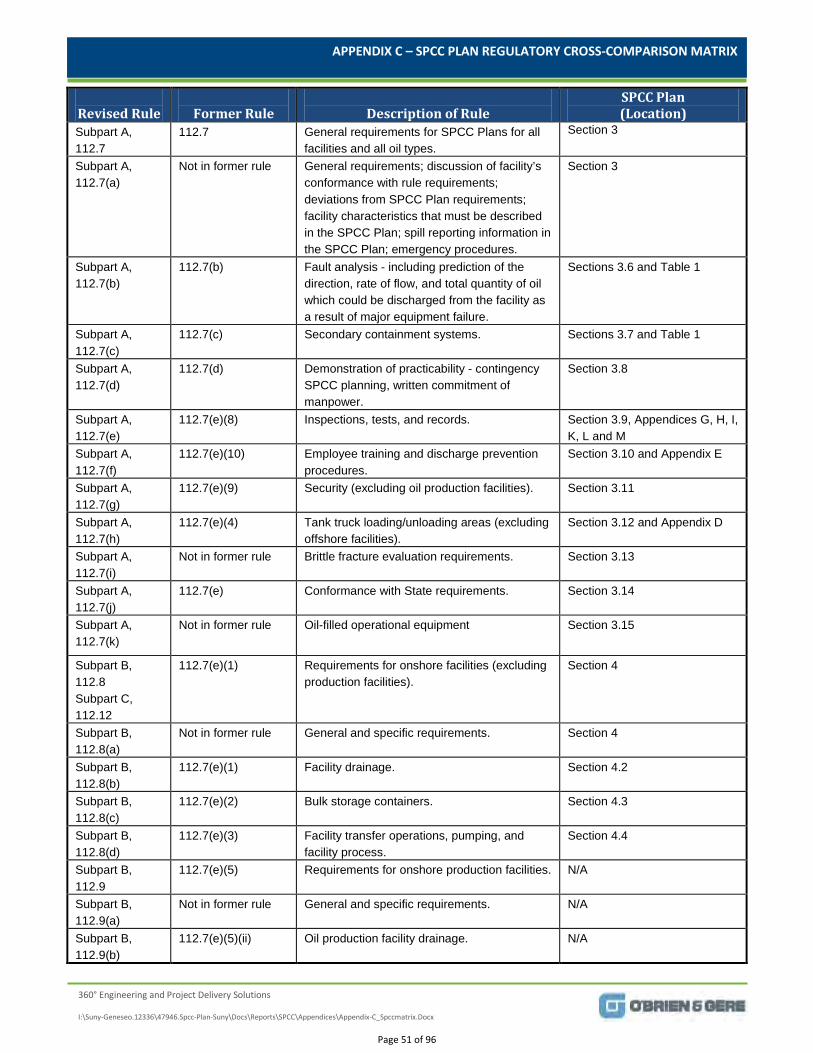
APPENDIX C – SPCC PLAN REGULATORY CROSS-COMPARISON MATRIX
360° Engineering and Project Delivery Solutions
I:\Suny-Geneseo.12336\47946.Spcc-Plan-Suny\Docs\Reports\SPCC\Appendices\Appendix-C_Spccmatrix.Docx
Revised Rule
Former Rule
Description of Rule
SPCC Plan (Location)
Subpart A, 112.7
112.7 General requirements for SPCC Plans for all facilities and all oil types.
Section 3
Subpart A, 112.7(a)
Not in former rule General requirements; discussion of facility’s conformance with rule requirements; deviations from SPCC Plan requirements; facility characteristics that must be described in the SPCC Plan; spill reporting information in the SPCC Plan; emergency procedures.
Section 3
Subpart A, 112.7(b)
112.7(b) Fault analysis - including prediction of the direction, rate of flow, and total quantity of oil which could be discharged from the facility as a result of major equipment failure.
Sections 3.6 and Table 1
Subpart A, 112.7(c)
112.7(c) Secondary containment systems. Sections 3.7 and Table 1
Subpart A, 112.7(d)
112.7(d) Demonstration of practicability - contingency SPCC planning, written commitment of manpower.
Section 3.8
Subpart A, 112.7(e)
112.7(e)(8) Inspections, tests, and records. Section 3.9, Appendices G, H, I, K, L and M
Subpart A, 112.7(f)
112.7(e)(10) Employee training and discharge prevention procedures.
Section 3.10 and Appendix E
Subpart A, 112.7(g)
112.7(e)(9) Security (excluding oil production facilities). Section 3.11
Subpart A, 112.7(h)
112.7(e)(4) Tank truck loading/unloading areas (excluding offshore facilities).
Section 3.12 and Appendix D
Subpart A, 112.7(i)
Not in former rule Brittle fracture evaluation requirements. Section 3.13
Subpart A, 112.7(j)
112.7(e) Conformance with State requirements. Section 3.14
Subpart A, 112.7(k)
Not in former rule Oil-filled operational equipment Section 3.15
Subpart B, 112.8 Subpart C, 112.12
112.7(e)(1) Requirements for onshore facilities (excluding production facilities).
Section 4
Subpart B, 112.8(a)
Not in former rule General and specific requirements. Section 4
Subpart B, 112.8(b)
112.7(e)(1) Facility drainage. Section 4.2
Subpart B, 112.8(c)
112.7(e)(2) Bulk storage containers. Section 4.3
Subpart B, 112.8(d)
112.7(e)(3) Facility transfer operations, pumping, and facility process.
Section 4.4
Subpart B, 112.9
112.7(e)(5) Requirements for onshore production facilities. N/A
Subpart B, 112.9(a)
Not in former rule General and specific requirements. N/A
Subpart B, 112.9(b)
112.7(e)(5)(ii) Oil production facility drainage. N/A
Page 51 of 96
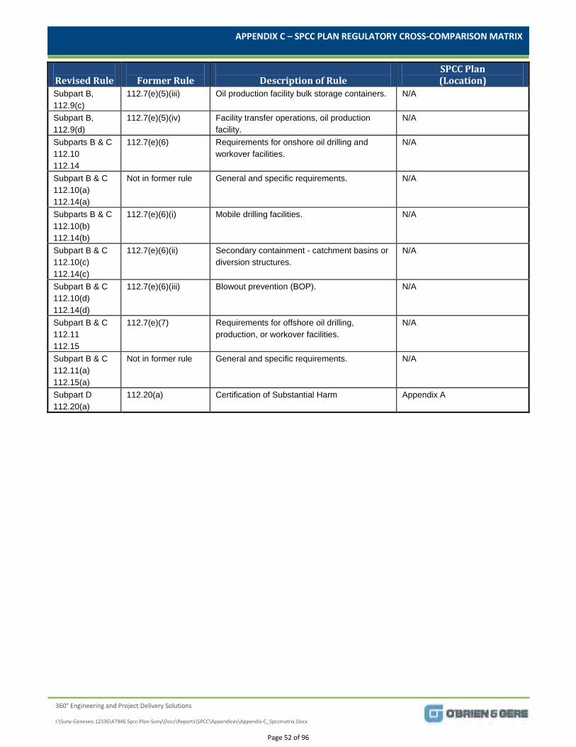
APPENDIX C – SPCC PLAN REGULATORY CROSS-COMPARISON MATRIX
360° Engineering and Project Delivery Solutions
I:\Suny-Geneseo.12336\47946.Spcc-Plan-Suny\Docs\Reports\SPCC\Appendices\Appendix-C_Spccmatrix.Docx
Revised Rule
Former Rule
Description of Rule
SPCC Plan (Location)
Subpart B, 112.9(c)
112.7(e)(5)(iii) Oil production facility bulk storage containers. N/A
Subpart B, 112.9(d)
112.7(e)(5)(iv) Facility transfer operations, oil production facility.
N/A
Subparts B & C 112.10 112.14
112.7(e)(6) Requirements for onshore oil drilling and workover facilities.
N/A
Subpart B & C 112.10(a) 112.14(a)
Not in former rule General and specific requirements. N/A
Subparts B & C 112.10(b) 112.14(b)
112.7(e)(6)(i) Mobile drilling facilities. N/A
Subpart B & C 112.10(c) 112.14(c)
112.7(e)(6)(ii) Secondary containment - catchment basins or diversion structures.
N/A
Subpart B & C 112.10(d) 112.14(d)
112.7(e)(6)(iii) Blowout prevention (BOP). N/A
Subpart B & C 112.11 112.15
112.7(e)(7) Requirements for offshore oil drilling, production, or workover facilities.
N/A
Subpart B & C 112.11(a) 112.15(a)
Not in former rule General and specific requirements. N/A
Subpart D 112.20(a)
112.20(a) Certification of Substantial Harm Appendix A
Page 52 of 96
APPENDIX D
360° Engineering and Project Delivery Solutions
Unloading Procedures
Page 53 of 96
APPENDIX D – UNLOADING PROCEDURE
360° Engineering and Project Delivery Solutions
I:\Suny-Geneseo.12336\47946.Spcc-Plan-Suny\Docs\Reports\SPCC\Appendices\Appendix-D_Unloading
Prior to unloading activities, SUNY Geneseo personnel must position diversionary structures (e.g., impermeable catch basin mat or absorbent spill booms) to prevent any potential spill from entering downgradient catch basins located in the vicinity of any outside transfer areas for PBS Tanks 012 and 013. Refer to Figure 2 for transfer area and catch basin locations. SUNY Geneseo personnel must also place absorbent sheet materials beneath all connections to catch any potential leaks.
SUNY Geneseo personnel must check the liquid level in the storage tank prior to filling the tank to ensure that the available volume in the tank is greater than the volume to be transferred and communicate this amount to the supplier.
Suppliers are required per their contract to comply with the following when unloading. Contractors who pick up, deliver, transfer or otherwise use, any chemical or petroleum product must be
properly trained oil/chemical-handling personnel. In addition to comprehensive safety and environmental training expected to be provided by the contractor to their designated delivery personnel, the training must also include the specific requirements for unloading listed in this section below, along with SUNY Geneseo’s emergency contact information.
Trucks must be equipped with appropriate oil spill response equipment, including containment and absorbent materials, personal protective equipment and means for making immediate emergency contacts, such as cell phones.
Prior to unloading activities, truck drivers must apply chock blocks for the wheels (or equivalent) Prior to connection to the fill port, the vendor delivery personnel must visually assess (prior to
connection to the fill port) the tanker truck transfer line for signs of corrosion, cracks, or other deterioration. In addition, transfer line connections must be evaluated by the vendor delivery personnel to verify that adequate gaskets are located in the fill port fitting and place absorbent sheet materials beneath all connections.
The vendor delivery personnel must remain present DURING THE ENTIRE UNLOADING PROCEDURE and visually observe the complete unloading process.
Under no circumstance will the carrier fill the tank beyond the working capacity. Following the delivery to the tank(s), the drain valve on the truck is to be closed by the driver, and any
spillable portion of the transfer line must be drained before disconnecting. Prior to tanker truck departure, the lower-most drain and all outlets must be closely examined by the
truck driver for leakage and, if necessary, tightened, adjusted or replaced to prevent any material from leaking while in transit.
DRUM SPECIFIC TRANSFER PROCEDURES: While unloading drums, take particular care not to pierce or crush drums during the unloading process.
If at any time a leak is observed, the pump will be immediately turned off and actions will be taken to prevent additional material from leaking. Vendor delivery personnel will immediately notify SUNY Geneseo personnel of an accident or spill. Contact information will be provided in vendor contract.
Page 54 of 96
APPENDIX E
360° Engineering and Project Delivery Solutions
Oil/Petroleum Spill Response, Cleanup and
Disposal
Page 55 of 96
APPENDIX E – OIL/PETROLEUM SPILL RESPONSE, CLEANUP, AND DISPOSAL
360° Engineering and Project Delivery Solutions
I:\Suny-Geneseo.12336\47946.Spcc-Plan-Suny\Docs\Reports\SPCC\Appendices\Appendix-E_Response, Cleanup And Disposal.Docx
FOR ASSISTANCE CONTACT: EHS Director (SPCC Coordinator)
at 585-245-5663 (after normal working hours at 585-519-2073) or designee.
24 Hour Campus Emergency Phone Number (University Police) at 585-245-5222
In the event of an oil spill or leak, the person discovering the oil from a storage container, tank or equipment must immediately initiate the following actions:
1. Extinguish all sources of ignition and isolate incompatible or reactive chemical substances.
2. If there is an immediate threat to human health, evacuate the immediate area.
3. Attempt to stop or contain the spill/release at source [provided there are no health or safety hazards and there is a reasonable certainty of the origin of the leak].
4. Isolate all potential environmental receptors such as floor drains, catch basins, sumps, exposed soil, and runoff areas.
5. Contact the EHS Director (SPCC Coordinator)
at 585-245-5663 (after normal working hours at 585-519-2073) or designee to provide information regarding the spill event.
Pursuant to 40 CFR 110, an IMMEDIATE call is to be made to the National Response Center (NRC) at (800) 424-8802,
Federal reportable quantities
if
one of the following occurs:
the amount of oil violates applicable state water quality standards
the amount of oil causes a film or “sheen” upon or discoloration of the surface of the water or adjoining shorelines
the amount of oil causes a sludge or emulsion to be deposited beneath the surface of the water or upon adjoining shorelines.
For state specific reporting requirements, see Section 5 of this Plan.
Once spills have been contained, absorbed or segregated from a vulnerable area, they must be disposed of properly.
A disposal determination shall be made by the EHS Director.
Any free product in a liquid state shall be containerized in waste containers or 55-gallon drums. Arrangements shall then be made for proper pickup and disposal in accordance with applicable federal and state regulations. Any solid materials associated with an oil or fuel spill (except gasoline) such as absorbent pads, pigs, granular absorbent are generally not considered hazardous and may potentially be disposed of in typical waste receptacles following a hazardous waste determination. However, solid materials used in the cleanup should also be contained and arrangements made with the EHS Director for proper pickup and disposal.
Clean up and Disposal
Response
Page 56 of 96
APPENDIX F
360° Engineering and Project Delivery Solutions
Compliance Action Items
Page 57 of 96
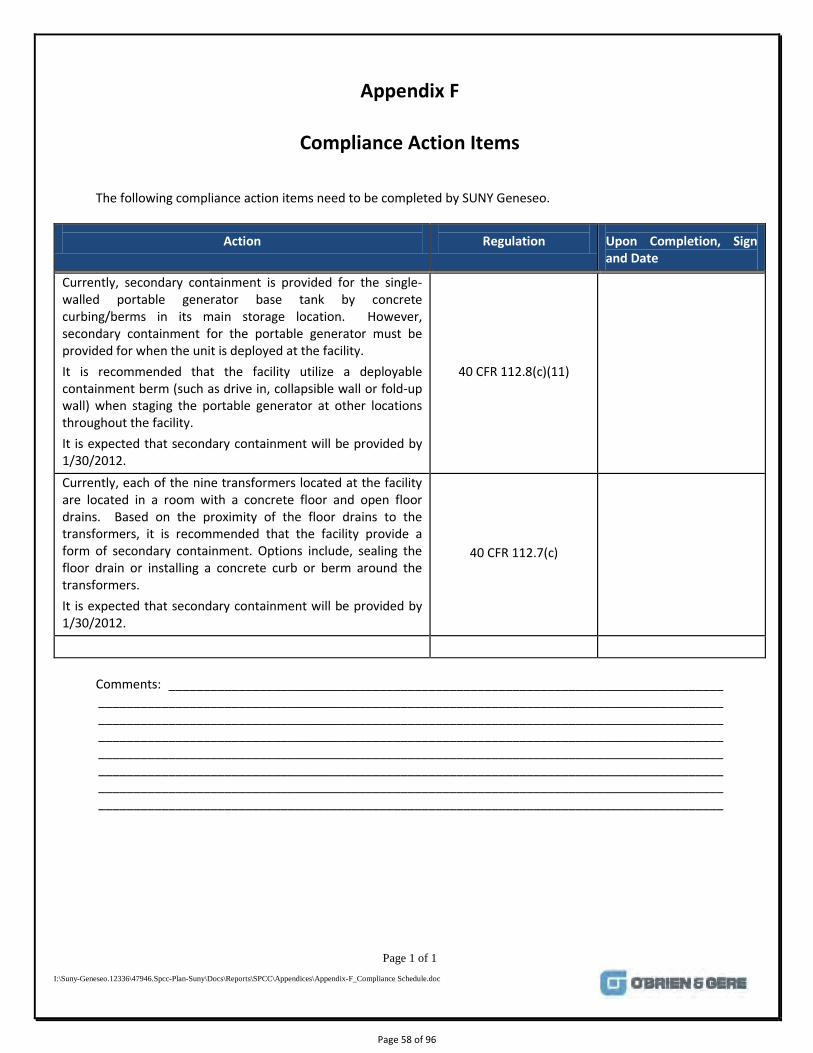
Page 1 of 1
I:\Suny-Geneseo.12336\47946.Spcc-Plan-Suny\Docs\Reports\SPCC\Appendices\Appendix-F_Compliance Schedule.doc
Appendix F
Compliance Action Items
The following compliance action items need to be completed by SUNY Geneseo.
Action
Regulation
Upon Completion, Sign and Date
Currently, secondary containment is provided for the single-walled portable generator base tank by concrete curbing/berms in its main storage location. However, secondary containment for the portable generator must be provided for when the unit is deployed at the facility. It is recommended that the facility utilize a deployable containment berm (such as drive in, collapsible wall or fold-up wall) when staging the portable generator at other locations throughout the facility. It is expected that secondary containment will be provided by 1/30/2012.
40 CFR 112.8(c)(11)
Currently, each of the nine transformers located at the facility are located in a room with a concrete floor and open floor drains. Based on the proximity of the floor drains to the transformers, it is recommended that the facility provide a form of secondary containment. Options include, sealing the floor drain or installing a concrete curb or berm around the transformers. It is expected that secondary containment will be provided by 1/30/2012.
40 CFR 112.7(c)
Comments: _______________________________________________________________________________ _________________________________________________________________________________________ _________________________________________________________________________________________ _________________________________________________________________________________________ _________________________________________________________________________________________ _________________________________________________________________________________________ _________________________________________________________________________________________ _________________________________________________________________________________________
Page 58 of 96

APPENDIX G
360° Engineering and Project Delivery Solutions
Employee Training Attendance Record
Page 59 of 96
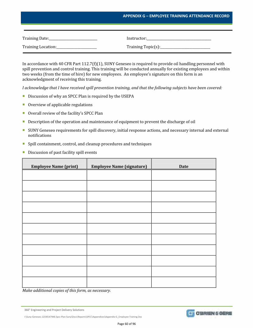
APPENDIX G – EMPLOYEE TRAINING ATTENDANCE RECORD
360° Engineering and Project Delivery Solutions
I:\Suny-Geneseo.12336\47946.Spcc-Plan-Suny\Docs\Reports\SPCC\Appendices\Appendix-G_Employee-Training.Doc
Training Date:______________________________ Instructor:________________________________________
Training Location:_________________________ Training Topic(s):_______________________________
In accordance with 40 CFR Part 112.7(f)(1), SUNY Geneseo is required to provide oil handling personnel with spill prevention and control training. This training will be conducted annually for existing employees and within two weeks (from the time of hire) for new employees. An employee’s signature on this form is an acknowledgment of receiving this training.
I acknowledge that I have received spill prevention training, and that the following subjects have been covered:
Discussion of why an SPCC Plan is required by the USEPA
Overview of applicable regulations
Overall review of the facility’s SPCC Plan
Description of the operation and maintenance of equipment to prevent the discharge of oil
SUNY Geneseo requirements for spill discovery, initial response actions, and necessary internal and external notifications
Spill containment, control, and cleanup procedures and techniques
Discussion of past facility spill events
Employee Name (print)
Employee Name (signature)
Date
Make additional copies of this form, as necessary.
Page 60 of 96

APPENDIX H
360° Engineering and Project Delivery Solutions
Bi-Annual Elevator Inspection Record
Page 61 of 96
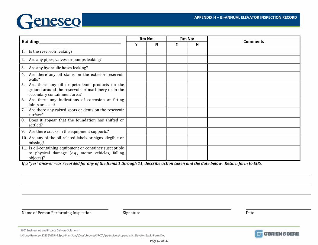
APPENDIX H – BI-ANNUAL ELEVATOR INSPECTION RECORD
360° Engineering and Project Delivery Solutions
I:\Suny-Geneseo.12336\47946.Spcc-Plan-Suny\Docs\Reports\SPCC\Appendices\Appendix-H_Elevator Equip Form.Doc
If a "yes" answer was recorded for any of the Items 1 through 11, describe action taken and the date below. Return form to EHS. Name of Person Performing Inspection Signature Date
Building:____________________________________________________ Rm No: Rm No: Comments Y N Y N 1. Is the reservoir leaking?
2. Are any pipes, valves, or pumps leaking?
3. Are any hydraulic hoses leaking? 4. Are there any oil stains on the exterior reservoir
walls?
5. Are there any oil or petroleum products on the ground around the reservoir or machinery or in the secondary containment area?
6. Are there any indications of corrosion at fitting joints or seals?
7. Are there any raised spots or dents on the reservoir surface?
8. Does it appear that the foundation has shifted or settled?
9. Are there cracks in the equipment supports? 10. Are any of the oil-related labels or signs illegible or
missing?
11. Is oil-containing equipment or container susceptible to physical damage (e.g., motor vehicles, falling objects)?
Page 62 of 96

APPENDIX I
360° Engineering and Project Delivery Solutions
Monthly Transformer Inspection Record
Page 63 of 96
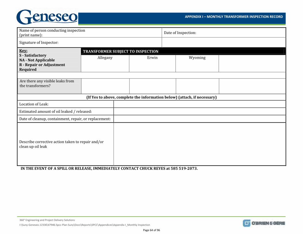
APPENDIX I – MONTHLY TRANSFORMER INSPECTION RECORD
360° Engineering and Project Delivery Solutions
I:\Suny-Geneseo.12336\47946.Spcc-Plan-Suny\Docs\Reports\SPCC\Appendices\Appendix-I_Monthly Inspection
Name of person conducting inspection (print name): Date of Inspection:
Signature of Inspector:
S - Satisfactory Key:
NA - Not Applicable R - Repair or Adjustment Required
TRANSFORMER SUBJECT TO INSPECTION Allegany Erwin Wyoming
Are there any visible leaks from the transformers?
(If Yes to above, complete the information below) (attach, if necessary)
Location of Leak:
Estimated amount of oil leaked / released:
Date of cleanup, containment, repair, or replacement:
Describe corrective action taken to repair and/or clean up oil leak
IN THE EVENT OF A SPILL OR RELEASE, IMMEDIATELY CONTACT CHUCK REYES at 585 519-2073.
Page 64 of 96
APPENDIX J
360° Engineering and Project Delivery Solutions
Emergency Containment and Cleanup Supplies
Page 65 of 96
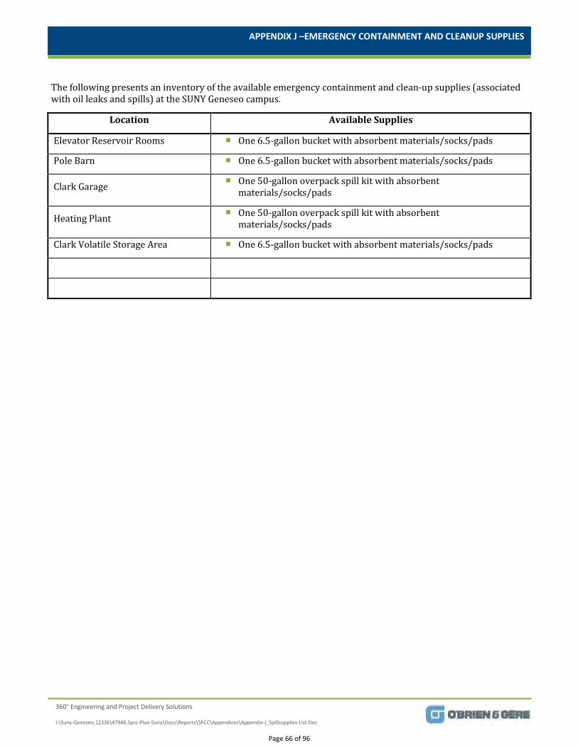
APPENDIX J –EMERGENCY CONTAINMENT AND CLEANUP SUPPLIES
360° Engineering and Project Delivery Solutions
I:\Suny-Geneseo.12336\47946.Spcc-Plan-Suny\Docs\Reports\SPCC\Appendices\Appendix-J_Spillsupplies-List.Doc
The following presents an inventory of the available emergency containment and clean-up supplies (associated with oil leaks and spills) at the SUNY Geneseo campus.
Location Available Supplies
Elevator Reservoir Rooms One 6.5-gallon bucket with absorbent materials/socks/pads
Pole Barn One 6.5-gallon bucket with absorbent materials/socks/pads
Clark Garage One 50-gallon overpack spill kit with absorbent materials/socks/pads
Heating Plant One 50-gallon overpack spill kit with absorbent materials/socks/pads
Clark Volatile Storage Area One 6.5-gallon bucket with absorbent materials/socks/pads
Page 66 of 96

APPENDIX K
360° Engineering and Project Delivery Solutions
Monthly Aboveground Tank Inspection Log
Page 67 of 96
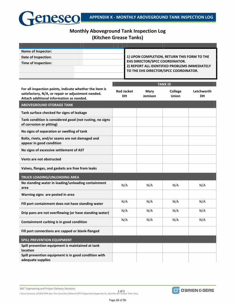
APPENDIX K - MONTHLY ABOVEGROUND TANK INSPECTION LOG
1 of 2
360° Engineering and Project Delivery Solutions
I:\Suny-Geneseo.12336\47946.Spcc-Plan-Suny\Docs\Reports\SPCC\Appendices\Appendix-K1_Monthly AST Grease Tanks.Docx
Monthly Aboveground Tank Inspection Log (Kitchen Grease Tanks)
Name of Inspector:
1) UPON COMPLETION, RETURN THIS FORM TO THE EHS DIRECTOR/SPCC COORDINATOR. 2) REPORT ALL IDENTIFIED PROBLEMS IMMEDIATELY TO THE EHS DIRECTOR/SPCC COORDINATOR.
Date of Inspection: Time of Inspection:
TANK ID For all inspection points, indicate whether the item is satisfactory, N/A, or repair or adjustment needed. Attach additional information as needed.
Red Jacket DH
Mary Jemison
College Union
Letchworth DH
ABOVEGROUND STORAGE TANK
Tank surface checked for signs of leakage
Tank condition is considered good (not rusting, no signs of corrosion or pitting)
No signs of separation or swelling of tank
Bolts, rivets, and/or seams are not damaged and appear in good condition
No signs of excessive settlement of AST
Vents are not obstructed
Valves, flanges, and gaskets are free from leaks
TRUCK LOADING/UNLOADING AREA No standing water in loading/unloading containment area N/A N/A N/A N/A
Warning signs are posted in area
Fill port containment does not have standing water N/A N/A N/A N/A
Drip pans are not overflowing (or have standing water) N/A N/A N/A N/A
Containment curbing is in good condition N/A N/A N/A N/A
Fill port connections are capped or blank-flanged
SPILL PREVENTION EQUIPMENT Spill prevention equipment is maintained at tank location
Spill prevention equipment is in good condition with adequate supplies
Page 68 of 96
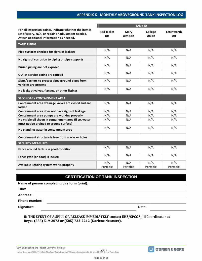
APPENDIX K - MONTHLY ABOVEGROUND TANK INSPECTION LOG
2 of 2
360° Engineering and Project Delivery Solutions
I:\Suny-Geneseo.12336\47946.Spcc-Plan-Suny\Docs\Reports\SPCC\Appendices\Appendix-K1_Monthly AST Grease Tanks.Docx
TANK ID For all inspection points, indicate whether the item is satisfactory, N/A, or repair or adjustment needed. Attach additional information as needed.
Red Jacket DH
Mary Jemison
College Union
Letchworth DH
TANK PIPING
Pipe surfaces checked for signs of leakage N/A N/A N/A N/A
No signs of corrosion to piping or pipe supports N/A N/A N/A N/A
Buried piping are not exposed N/A N/A N/A N/A
Out-of-service piping are capped N/A N/A N/A N/A
Signs/barriers to protect aboveground pipes from vehicles are present
N/A N/A N/A N/A
No leaks at valves, flanges, or other fittings N/A N/A N/A N/A
SECONDARY CONTAINMENT AREA Containment area drainage valves are closed and are locked
N/A N/A N/A N/A
Containment area does not have signs of leakage N/A N/A N/A N/A Containment area pumps are working properly N/A N/A N/A N/A No visible oil sheen in containment area (if so, water must not be drained to ground surface)
N/A N/A N/A N/A
No standing water in containment area N/A N/A N/A N/A
Containment structure is free from cracks or holes
SECURITY MEASURES
Fence around tank is in good condition N/A N/A N/A N/A
Fence gate (or door) is locked N/A N/A N/A N/A
Available lighting system works properly N/A Portable
N/A Portable
N/A Portable
N/A Portable
CERTIFICATION OF TANK INSPECTION
Name of person completing this form (print):
Title:
Address:
Phone number:
Signature: Date:
IN THE EVENT OF A SPILL OR RELEASE IMMEDIATELY contact EHS/SPCC Spill Coordinator at Reyes (585) 519-2073 or (585) 732-2212 (Darlene Necaster).
Page 69 of 96
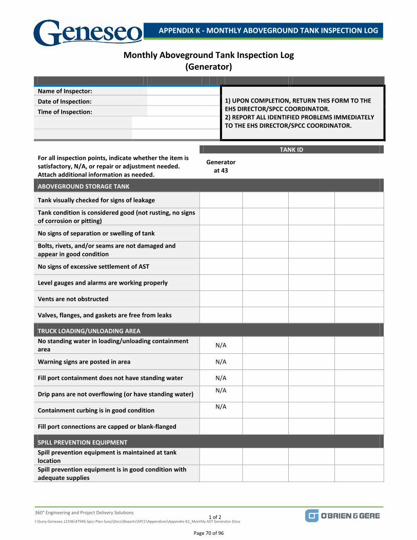
APPENDIX K - MONTHLY ABOVEGROUND TANK INSPECTION LOG
1 of 2
360° Engineering and Project Delivery Solutions
I:\Suny-Geneseo.12336\47946.Spcc-Plan-Suny\Docs\Reports\SPCC\Appendices\Appendix-K2_Monthly AST Generator.Docx
Monthly Aboveground Tank Inspection Log (Generator)
Name of Inspector:
1) UPON COMPLETION, RETURN THIS FORM TO THE EHS DIRECTOR/SPCC COORDINATOR. 2) REPORT ALL IDENTIFIED PROBLEMS IMMEDIATELY TO THE EHS DIRECTOR/SPCC COORDINATOR.
Date of Inspection: Time of Inspection:
TANK ID For all inspection points, indicate whether the item is satisfactory, N/A, or repair or adjustment needed. Attach additional information as needed.
Generator at 43
ABOVEGROUND STORAGE TANK
Tank visually checked for signs of leakage
Tank condition is considered good (not rusting, no signs of corrosion or pitting)
No signs of separation or swelling of tank
Bolts, rivets, and/or seams are not damaged and appear in good condition
No signs of excessive settlement of AST
Level gauges and alarms are working properly
Vents are not obstructed
Valves, flanges, and gaskets are free from leaks
TRUCK LOADING/UNLOADING AREA No standing water in loading/unloading containment area N/A
Warning signs are posted in area N/A
Fill port containment does not have standing water N/A
Drip pans are not overflowing (or have standing water) N/A
Containment curbing is in good condition N/A
Fill port connections are capped or blank-flanged
SPILL PREVENTION EQUIPMENT Spill prevention equipment is maintained at tank location
Spill prevention equipment is in good condition with adequate supplies
Page 70 of 96
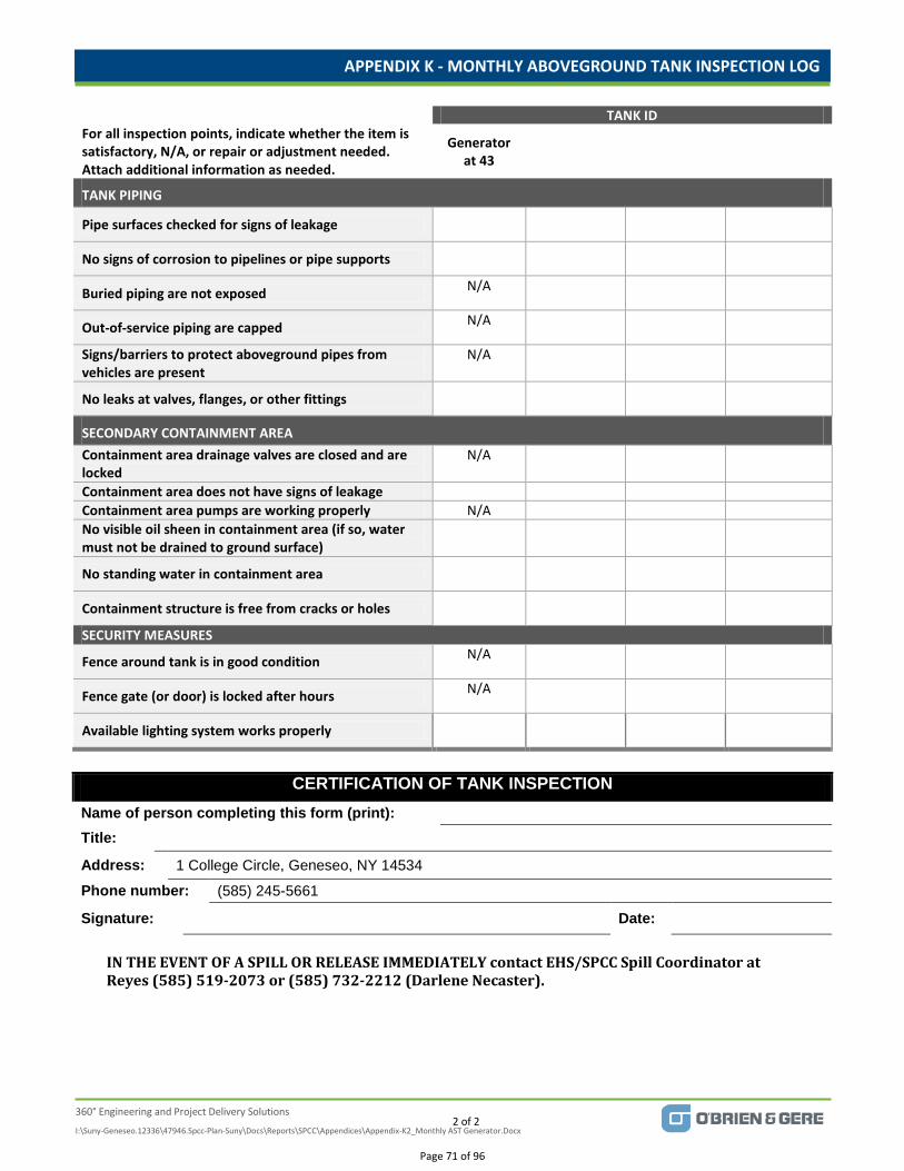
APPENDIX K - MONTHLY ABOVEGROUND TANK INSPECTION LOG
2 of 2
360° Engineering and Project Delivery Solutions
I:\Suny-Geneseo.12336\47946.Spcc-Plan-Suny\Docs\Reports\SPCC\Appendices\Appendix-K2_Monthly AST Generator.Docx
TANK ID For all inspection points, indicate whether the item is satisfactory, N/A, or repair or adjustment needed. Attach additional information as needed.
Generator at 43
TANK PIPING
Pipe surfaces checked for signs of leakage
No signs of corrosion to pipelines or pipe supports
Buried piping are not exposed N/A
Out-of-service piping are capped N/A
Signs/barriers to protect aboveground pipes from vehicles are present
N/A
No leaks at valves, flanges, or other fittings
SECONDARY CONTAINMENT AREA Containment area drainage valves are closed and are locked
N/A
Containment area does not have signs of leakage Containment area pumps are working properly N/A No visible oil sheen in containment area (if so, water must not be drained to ground surface)
No standing water in containment area
Containment structure is free from cracks or holes
SECURITY MEASURES
Fence around tank is in good condition N/A
Fence gate (or door) is locked after hours N/A
Available lighting system works properly
CERTIFICATION OF TANK INSPECTION
Name of person completing this form (print):
Title:
Address: 1 College Circle, Geneseo, NY 14534
Phone number: (585) 245-5661
Signature: Date:
IN THE EVENT OF A SPILL OR RELEASE IMMEDIATELY contact EHS/SPCC Spill Coordinator at Reyes (585) 519-2073 or (585) 732-2212 (Darlene Necaster).
Page 71 of 96

APPENDIX L
360° Engineering and Project Delivery Solutions
55-Gallon Drum Monthly Inspection Form
Page 72 of 96

I:\Suny-Geneseo.12336\47946.Spcc-Plan-Suny\Docs\Reports\SPCC\Appendices\Appendix-L_Monthly Inspection Generic.Doc
Small Petroleum Container (55 gals or more) Monthly Inspection Form
Checklist Item Satisfactory (S) or Problem (P)
Comment - detail any problems and actions taken to correct
Corrective Actions Completed (date/name)
Drums/Containers
Labels visible and readable
No evidence of leaks
No corrosion or thinning of drum shell
No structural damage
Drum sealed other than when filling or emptying
Drums located in secondary containment Secondary Containment
No cracks or other structural damage
No evidence of leaked/spilled material
No water or other materials collected in secondary containment
Room
Clean orderly areas, adequate aisle space
Spill Equipment
Adequately stocked
Inspector Certification: I certify that this inspection was performed in a manner consistent with requirements of 40 CFR Part 112.
This report must be kept on file for three years.
Signature___________________________________ Date:__________________
Page 73 of 96

APPENDIX M
360° Engineering and Project Delivery Solutions
Monthly Heating Plant Piping Inspection Log
Page 74 of 96

APPENDIX M – MONTHLY HEATING PLANT PIPING INSPECTION LOG
1
360° Engineering and Project Delivery Solutions
I:\Suny-Geneseo.12336\47946.Spcc-Plan-Suny\Docs\Reports\SPCC\Appendices\Appendix-M_Monthly UST Piping.Docx
Monthly Piping Inspection Log (UST piping)
Name of Inspector:
1) UPON COMPLETION, RETURN THIS FORM TO THE EHS DIRECTOR/SPCC COORDINATOR. 2) REPORT ALL IDENTIFIED PROBLEMS IMMEDIATELY TO THE EHS DIRECTOR/SPCC COORDINATOR.
Date of Inspection: Time of Inspection:
TANK ID For all inspection points, indicate whether the item is satisfactory, N/A, or repair or adjustment needed. Attach additional information as needed.
UST piping at Heating
Plant
SPILL PREVENTION EQUIPMENT Spill prevention equipment is maintained at tank location
Spill prevention equipment is in good condition with adequate supplies
UST PIPING
Pipe surfaces checked for signs of leakage
No signs of corrosion to piping or pipe supports
Buried piping are not exposed
Out-of-service piping is capped
Signs/barriers to protect aboveground pipes from vehicles are present
No leaks at valves, flanges, or other fittings
CERTIFICATION OF PIPING INSPECTION
Name of person completing this form (print):
Title:
Address: 1 College Circle, Geneseo, NY 14534
Phone number: (585) 245-5661
Signature: Date:
IN THE EVENT OF A SPILL OR RELEASE IMMEDIATELY contact EHS/SPCC Spill Coordinator at Reyes (585) 519-2073 or (585) 732-2212 (Darlene Necaster).
Page 75 of 96
APPENDIX N
360° Engineering and Project Delivery Solutions
Oil Spill Report Form
Page 76 of 96
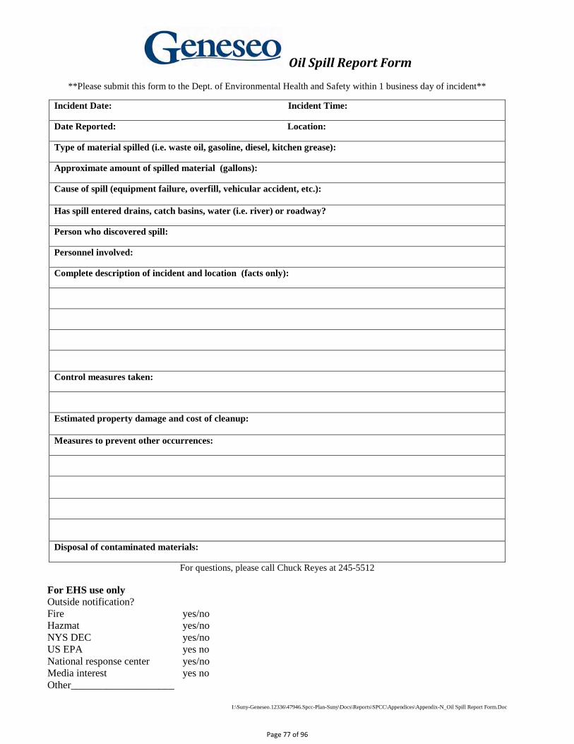
I:\Suny-Geneseo.12336\47946.Spcc-Plan-Suny\Docs\Reports\SPCC\Appendices\Appendix-N_Oil Spill Report Form.Doc
Oil Spill Report Form
**Please submit this form to the Dept. of Environmental Health and Safety within 1 business day of incident**
For questions, please call Chuck Reyes at 245-5512 For EHS use only Outside notification? Fire yes/no Hazmat yes/no NYS DEC yes/no US EPA yes no National response center yes/no Media interest yes no Other____________________
Incident Date: Incident Time:
Date Reported: Location:
Type of material spilled (i.e. waste oil, gasoline, diesel, kitchen grease):
Approximate amount of spilled material (gallons):
Cause of spill (equipment failure, overfill, vehicular accident, etc.): Has spill entered drains, catch basins, water (i.e. river) or roadway?
Person who discovered spill:
Personnel involved:
Complete description of incident and location (facts only):
Control measures taken:
Estimated property damage and cost of cleanup: Measures to prevent other occurrences:
Disposal of contaminated materials:
Page 77 of 96
APPENDIX O
360° Engineering and Project Delivery Solutions
Regulatory Agency Reporting Log
Page 78 of 96
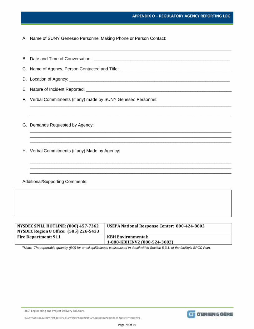
APPENDIX O – REGULATORY AGENCY REPORTING LOG
360° Engineering and Project Delivery Solutions
I:\Suny-Geneseo.12336\47946.Spcc-Plan-Suny\Docs\Reports\SPCC\Appendices\Appendix-O-Regulatory-Reporting-
A. Name of SUNY Geneseo Personnel Making Phone or Person Contact:
___________________________________________________________________________________
B. Date and Time of Conversation: ________________________________________________________
C. Name of Agency, Person Contacted and Title: _____________________________________________
D. Location of Agency: __________________________________________________________________
E. Nature of Incident Reported: ____________________________________________________________
F. Verbal Commitments (if any) made by SUNY Geneseo Personnel: ___________________________________________________________________________________
___________________________________________________________________________________
G. Demands Requested by Agency: _________________________________________________________________________________________________________________________________________________________________________________________________________________________________________________________
H. Verbal Commitments (if any) Made by Agency:
_________________________________________________________________________________________________________________________________________________________________________________________________________________________________________________________
Additional/Supporting Comments:
NYSDEC SPILL HOTLINE: (800) 457-7362 NYSDEC Region 8 Office: (585) 226-5433
USEPA National Response Center: 800-424-8802
Fire Department: 911 KBH Environmental: 1-888-KBHENV2 (888-524-3682)
ΗNote: The reportable quantity (RQ) for an oil spill/release is discussed in detail within Section 5.3.1. of the facility’s SPCC Plan.
Page 79 of 96
EXHIBIT A
360° Engineering and Project Delivery Solutions
A-1. Tanks 016, 017 and 018 As-builts
A-2. Tanks 016, 017 and 018 Piping Detail
A-3. Clark Garage Oil-Water Separator Drawings
Page 80 of 96
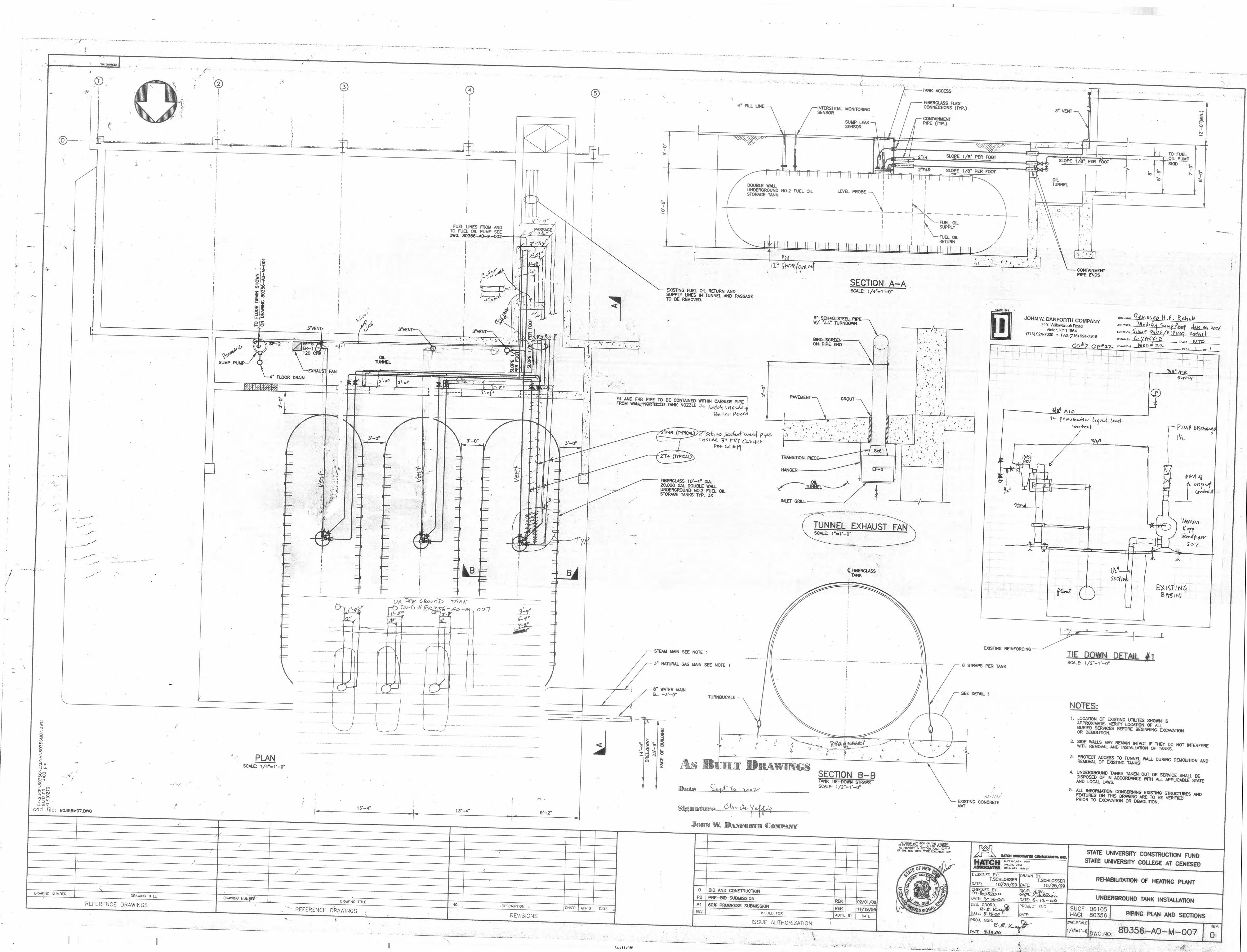
Page 81 of 96
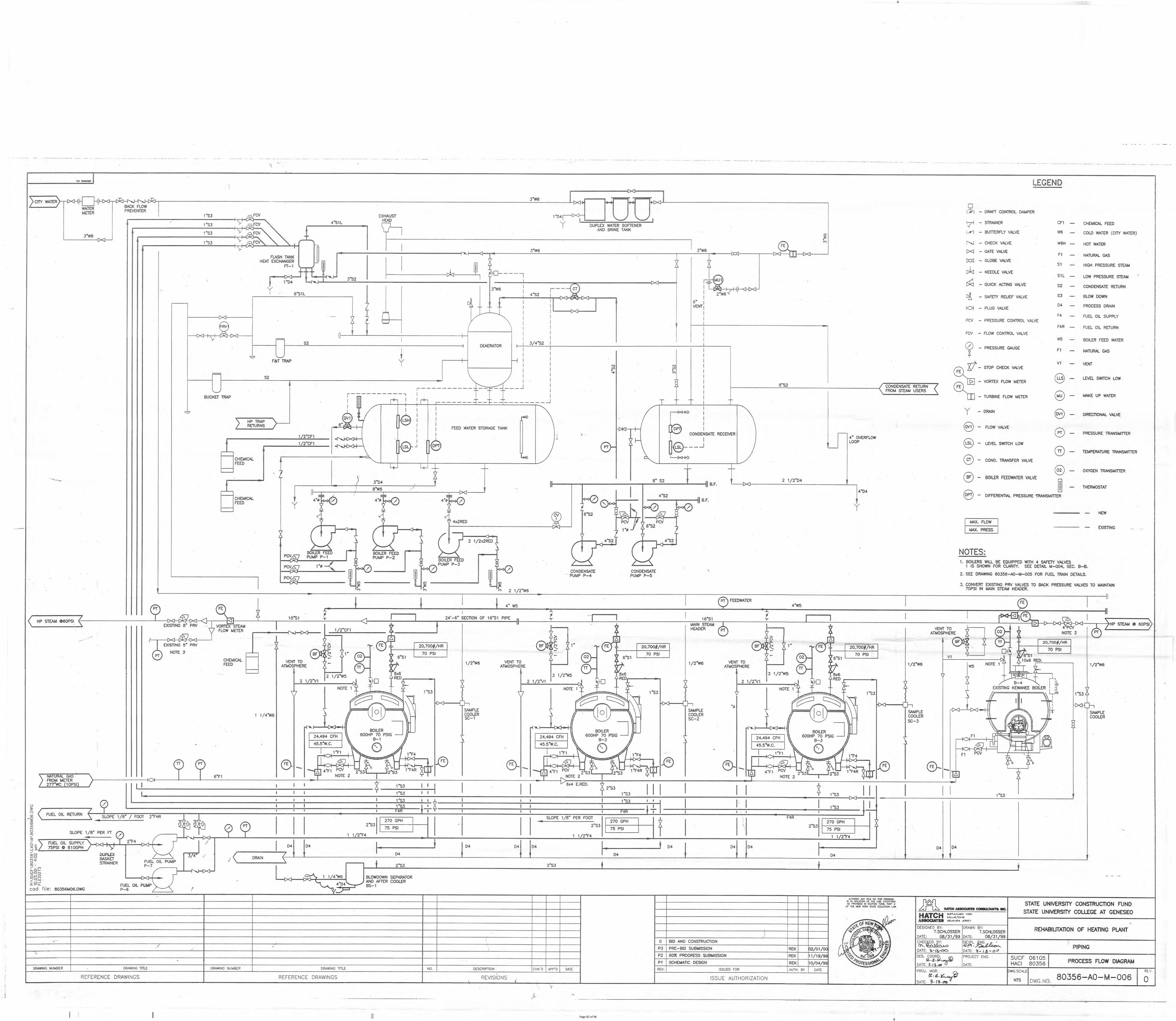
Page 82 of 96
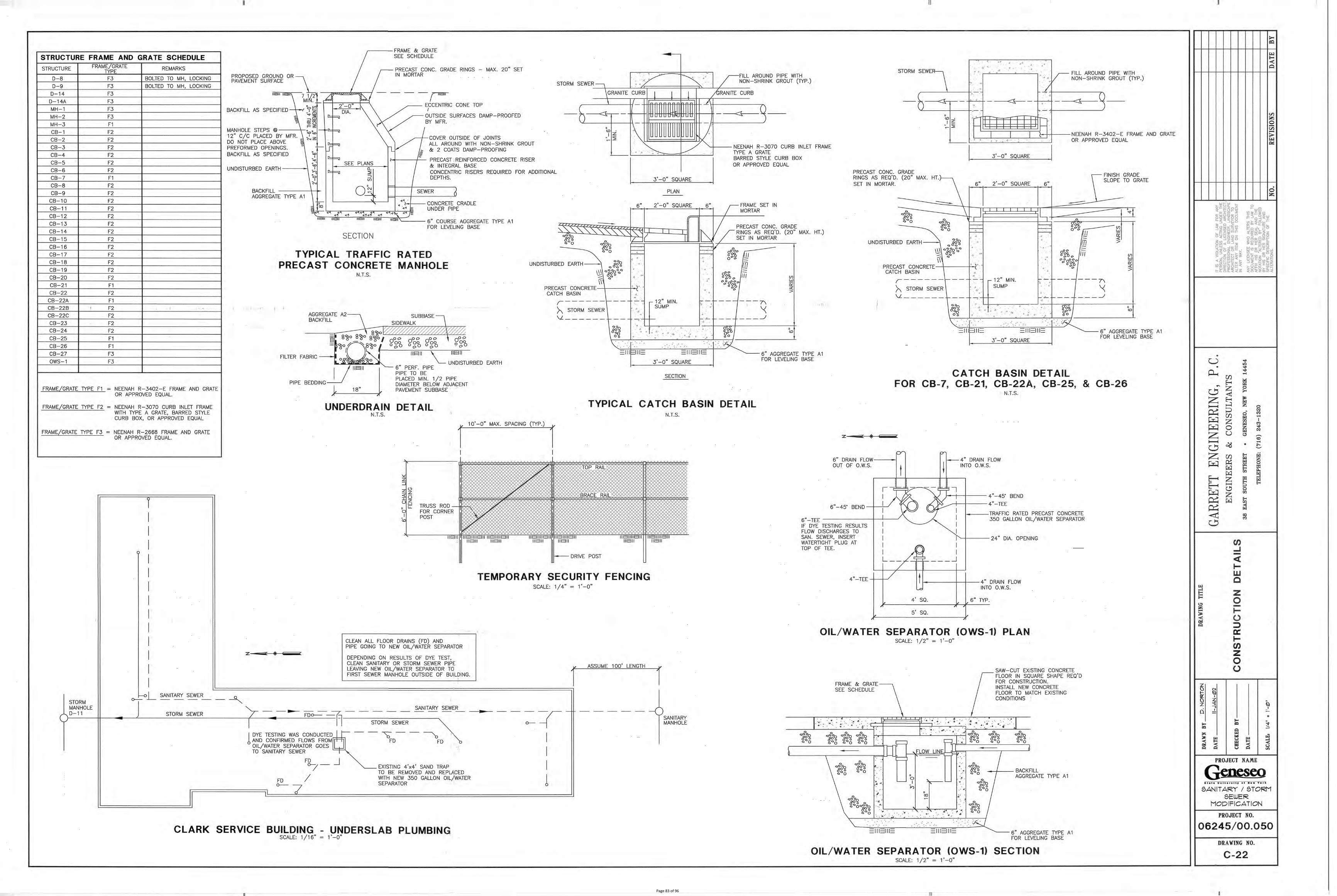
Page 83 of 96
EXHIBIT B
360° Engineering and Project Delivery Solutions
Photographic Log
Page 84 of 96
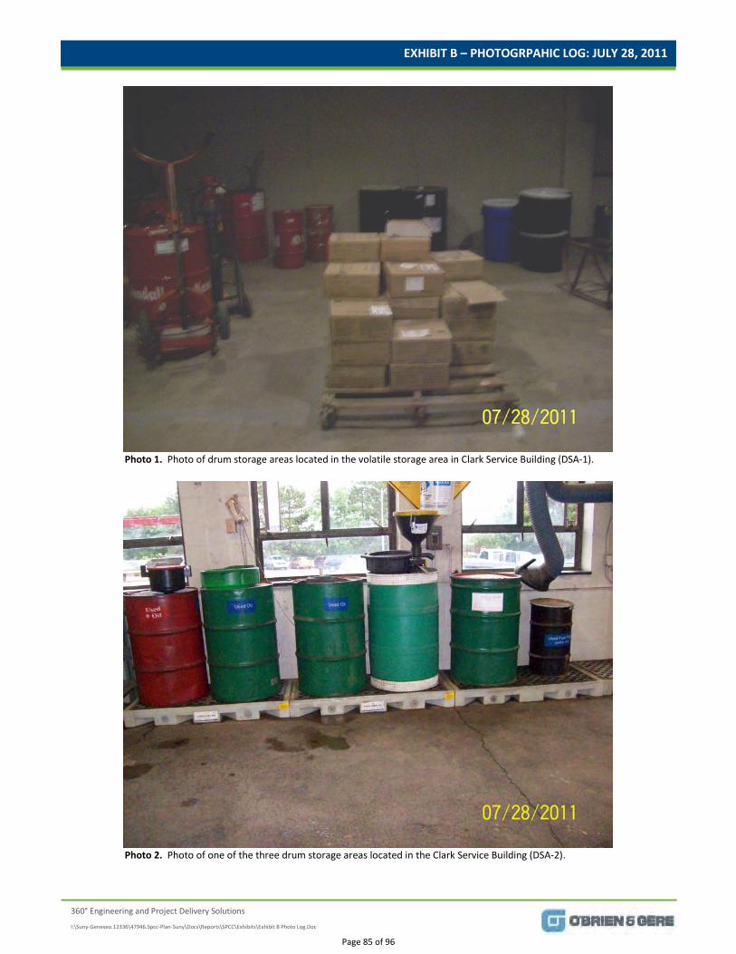
EXHIBIT B – PHOTOGRPAHIC LOG: JULY 28, 2011
360° Engineering and Project Delivery Solutions
I:\Suny-Geneseo.12336\47946.Spcc-Plan-Suny\Docs\Reports\SPCC\Exhibits\Exhibit B Photo Log.Doc
Photo 1. Photo of drum storage areas located in the volatile storage area in Clark Service Building (DSA-1).
Photo 2. Photo of one of the three drum storage areas located in the Clark Service Building (DSA-2).
Page 85 of 96
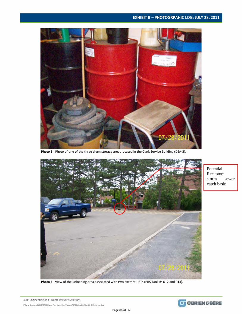
EXHIBIT B – PHOTOGRPAHIC LOG: JULY 28, 2011
360° Engineering and Project Delivery Solutions
I:\Suny-Geneseo.12336\47946.Spcc-Plan-Suny\Docs\Reports\SPCC\Exhibits\Exhibit B Photo Log.Doc
Photo 3. Photo of one of the three drum storage areas located in the Clark Service Building (DSA-3).
Photo 4. View of the unloading area associated with two exempt USTs (PBS Tank #s 012 and 013).
Potential Receptor: storm sewer catch basin
Page 86 of 96
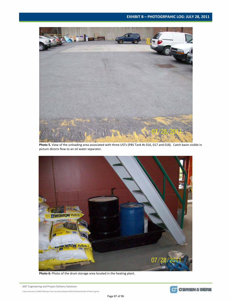
EXHIBIT B – PHOTOGRPAHIC LOG: JULY 28, 2011
360° Engineering and Project Delivery Solutions
I:\Suny-Geneseo.12336\47946.Spcc-Plan-Suny\Docs\Reports\SPCC\Exhibits\Exhibit B Photo Log.Doc
Photo 5. View of the unloading area associated with three USTs (PBS Tank #s 016, 017 and 018). Catch basin visible in picture directs flow to an oil water separator.
Photo 6: Photo of the drum storage area located in the heating plant.
Page 87 of 96
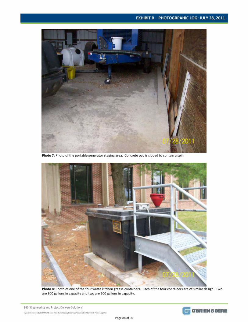
EXHIBIT B – PHOTOGRPAHIC LOG: JULY 28, 2011
360° Engineering and Project Delivery Solutions
I:\Suny-Geneseo.12336\47946.Spcc-Plan-Suny\Docs\Reports\SPCC\Exhibits\Exhibit B Photo Log.Doc
Photo 7: Photo of the portable generator staging area. Concrete pad is sloped to contain a spill.
Photo 8: Photo of one of the four waste kitchen grease containers. Each of the four containers are of similar design. Two are 300 gallons in capacity and two are 500 gallons in capacity.
Page 88 of 96
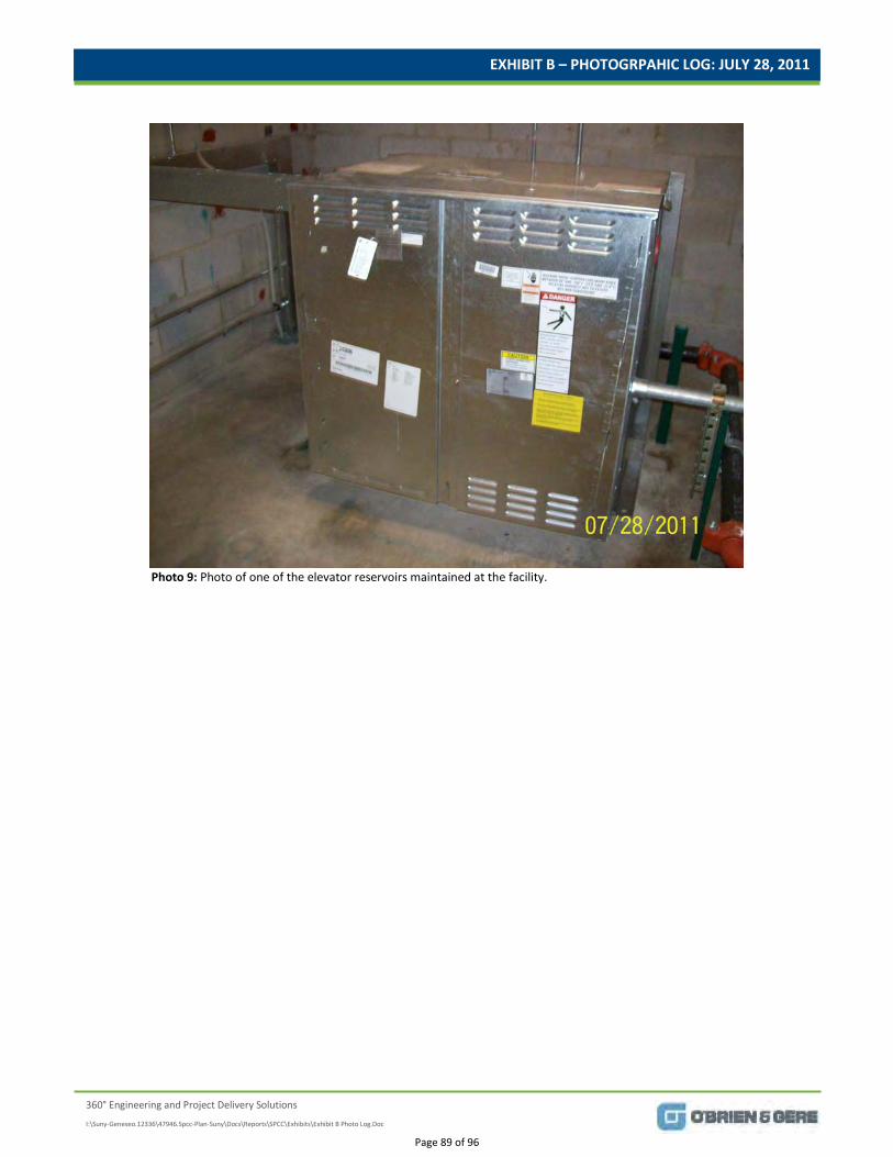
EXHIBIT B – PHOTOGRPAHIC LOG: JULY 28, 2011
360° Engineering and Project Delivery Solutions
I:\Suny-Geneseo.12336\47946.Spcc-Plan-Suny\Docs\Reports\SPCC\Exhibits\Exhibit B Photo Log.Doc
Photo 9: Photo of one of the elevator reservoirs maintained at the facility.
Page 89 of 96
EXHIBIT C
360° Engineering and Project Delivery Solutions
SPCC – Background, Definitions, and
Applicability
Page 90 of 96
EXHIBIT C
I:\Suny-Geneseo.12336\47946.Spcc-Plan-Suny\Docs\Reports\SPCC\Exhibits\Exhibit C.doc
1
EXHIBIT C SPCC – Background, Definitions, and Applicability
1.1. Regulatory Background
The USEPA’s Oil Spill Prevention, Control and Countermeasure (SPCC) rule was initially published in the Federal Register on December 11, 1973, and was promulgated under the authority of Section 311(j)(1)(C) of the 1970 Federal Water Pollution Control Act, as amended, also known as the Clean Water Act (CWA). The SPCC rule is codified in Title 40 of the Code of Federal Regulations (40 CFR) Part 112 under the title “Oil Pollution Prevention,” which first became effective on January 10, 1974. The USEPA has since proposed revisions to the SPCC rules in 1991, 1993, and 1997. On June 28, 2002 the USEPA Administrator signed a notice that amended the SPCC rule, which was published in the Federal Register on July 17, 2002. The SPCC rule amendments became effective on August 16, 2002. Supplemental amendments have been published in the Federal Register. On May 25, 2004, guidance and clarification materials were also published in the Notice Concerning Certain Issues Pertaining to the July 2002 Spill Prevention, Control, and Countermeasure (SPCC) Rule. Additional guidance, SPCC Guidance for Regional Inspectors was published on December 2, 2005. In December 2006, the USEPA finalized additional amendments to the SPCC Rule pertaining to self certification, secondary containment, exempt containers, animal fats and vegetable oils, and compliance deadlines for farms. On November 26, 2008, the Federal Register published USEPA's direct final rule to revise the definition of "navigable waters" in the Spill Prevention, Control and Countermeasure (SPCC) rule to comply with a court decision. On December 5, 2008, the Federal Register published USEPA's Amended Part 112 Requirements to provide increased clarity, to tailor requirements to particular industry sectors, and to streamline certain requirements for those facility owners or operators subject to the rule, which should result in greater protection to human health and the environment. At the present time, the December 2008 Amended Part 112 Requirements will become effective on January 14, 2010. Referenced documents, including the December 2008 Amended Part 112 Requirements, have been considered in the preparation of this SPCC Plan. The goal of the oil pollution prevention regulation in 40 CFR Part 112 is to prevent oil discharges from reaching navigable waters of the United States or adjoining shorelines. The rule was also written to ensure effective responses to oil discharges. The rule further specifies that proactive, and not passive, measures must be used to respond to oil discharges. The oil pollution regulation contains two major types of requirements: prevention requirements (SPCC rule) and facility response plan (FRP) requirements. The prevention requirements in Sections 112.1 through 112.7 were first promulgated in the 1973 SPCC rule. For most facilities, the primary obligation under the SPCC rules is to develop a SPCC Plan, which must contain measures to prevent and control oil spills, including those resulting from human operational error or equipment failures. The requirements for the preparation and implementation of an SPCC Plan are established by 40 CFR Part 112 to “prevent the discharge of oil from non-transportation related on-shore and off-shore facilities into or upon the navigable waters of the United States or adjoining shorelines.” A facility that
Page 91 of 96
EXHIBIT C
I:\Suny-Geneseo.12336\47946.Spcc-Plan-Suny\Docs\Reports\SPCC\Exhibits\Exhibit C.doc
2
has discharged, or could reasonably be expected to discharge, oil in hazardous quantities (as defined in 40 CFR Part 110) into or upon “navigable waters” is required to prepare a SPCC Plan. [See Section 1.2 for definitions of key regulatory terms.] Those facilities that could reasonably be expected to discharge oil into navigable waters or adjoining shorelines and have a total underground (completely buried) oil storage capacity of greater than 42,000 gallons or a total aboveground storage capacity of oil, which is not buried, and is greater than 1,320 gallons, must prepare and implement an SPCC Plan.
Note: For calculating total aboveground storage capacity, only containers of oil with a capacity of 55 gallons or greater are counted towards the 1,320-gallon regulatory threshold. The on-site location (e.g., inside versus outside) of the containers or machinery is irrelevant for calculation purposes.
1.2. Key Terms and Definitions
As there are a number of key terms that are used within the SPCC regulations and within this SPCC Plan, it is important to understand each of the following, which have been defined pursuant to 40 CFR Part 112.2: • Bulk storage container – means any container used to store oil. These containers are used for
purposes including, but not limited to, the storage of oil prior to use, while being used, or prior to further distribution in commerce. Oil-filled electrical, operating, or manufacturing equipment is not a bulk storage container.
• Discharge – includes, but is not limited to, any spilling, leaking, pumping, pouring, emitting, emptying, or dumping of oil, but excludes discharges in compliance with a permit under section 402 of the CWA; discharges resulting from circumstances identified, reviewed, and made a part of the public record with respect to a permit issued or modified under section 402 of the CWA, and subject to a condition in such permit; or continuous or anticipated intermittent discharges from a point source, identified in a permit or permit application under section 402 of the CWA, that are caused by events occurring within the scope of relevant operating or treatment systems. For purposes of 40 CFR Part 112, the term discharge shall not include any discharge of oil that is authorized by a permit issued under section 13 of the River and Harbor Act of 1899 (33 U.S.C. 407).
• Discharge of oil in harmful quantities – means a discharge that violates applicable water quality standards, or causes a film or sheen or discoloration of the surface of the water or adjoining shorelines, or causes a sludge or emulsion to be deposited beneath the surface of the water or upon adjoining shorelines.
• Facility – means any mobile or fixed, onshore or offshore building, property, parcel, lease, structure, installation, equipment, pipe, or pipeline (other than a vessel or a public vessel) used in oil well drilling operations, oil production, oil refining, oil storage, oil gathering, oil processing, oil transfer, oil distribution, and oil waste treatment, or in which oil is used, as described in Appendix A to this part. The boundaries of a facility depend on several site-specific factors, including but not limited to, the ownership or operation of buildings, structures, and equipment on the same site and types of activity at the site. Contiguous or non-contiguous buildings, properties, parcels, leases, structures, installations, pipes, or pipelines under the ownership or
Page 92 of 96

EXHIBIT C
I:\Suny-Geneseo.12336\47946.Spcc-Plan-Suny\Docs\Reports\SPCC\Exhibits\Exhibit C.doc
3
operation of the same person may be considered separate facilities. Only this definition governs whether a facility is subject to this part.
• Loading/unloading rack – means a fixed structure (such as a platform, gangway) necessary for loading or unloading a tank truck or tank car, which is located at a facility subject to the requirements of this part. A loading/unloading rack includes a loading or unloading arm, and may include any combination of the following: piping assemblages, valves, pumps, shut-off devices, overfill sensors, or personnel safety devices.
• Mobile refueler - means a bulk storage container onboard a vehicle or towed, that is designed or used solely to store and transport fuel for transfer into or from an aircraft, motor vehicle, locomotive, vessel, ground service equipment, or other oil storage container.
• Motive power container- means any onboard bulk storage container used primarily to power the movement of a motor vehicle, or ancillary onboard oil-filled operational equipment. An onboard bulk storage container which is used to store or transfer oil for further distribution is not a motive power container. The definition of motive power container does not include oil drilling or workover equipment, including rigs.
• Navigable waters – Navigable waters of the United States means "navigable waters" as defined in section 502(7) of the FWPCA, and includes:
1) All navigable waters of the United States, as defined in judicial decisions prior to passage of
the 1972 Amendments to the FWPCA (Pub. L. 92-500), and tributaries of such waters; 2) Interstate waters; 3) Intrastate lakes, rivers, and streams which are utilized by interstate travelers for recreational
or other purposes; and 4) Intrastate lakes, rivers, and streams from which fish or shellfish are taken and sold in
interstate commerce.
• Non-petroleum oil – means oil of any kind that is not petroleum-based, including but not limited to: fats, oils, and greases of animal, fish, or marine mammal origin; and vegetable oils, including oils from seeds, nuts, fruits, and kernels.
• Oil – means oil of any kind or in any form, including, but not limited to: fats, oils, or greases of animal, fish, or marine mammal origin; vegetable oils, including oils from seeds, nuts, fruits, or kernels; and, other oils and greases, including petroleum, fuel oil, sludge, synthetic oils, mineral oils, oil refuse, or oil mixed with wastes other than dredged spoil.
• Oil-filled operational equipment - means equipment that includes an oil storage container (or multiple containers) in which the oil is present solely to support the function of the apparatus or the device. Oil-filled operational equipment is not considered a bulk storage container, and does not include oil-filled manufacturing equipment (flow-through process). Examples of oil-filled operational equipment include, but are not limited to, hydraulic systems, lubricating systems (e.g., those for pumps, compressors and other rotating equipment, including pumpjack lubrication systems), gear boxes, machining coolant systems, heat transfer systems, transformers, circuit breakers, electrical switches, and other systems containing oil solely to enable the operation of the device.
Page 93 of 96
EXHIBIT C
I:\Suny-Geneseo.12336\47946.Spcc-Plan-Suny\Docs\Reports\SPCC\Exhibits\Exhibit C.doc
4
• Onshore facility – means any facility of any kind located in, on, or under any land within the United States, other than submerged lands.
• Permanently closed – means any container or facility for which: 1) All liquid and sludge has been removed from each container and connecting line; and 2) All connecting lines and piping have been disconnected from the container and blanked off,
all valves (except for ventilation valves) have been closed and locked, and conspicuous signs have been posted on each container stating that it is a permanently closed container and noting the date of closure.
• Petroleum oil – means petroleum in any form, including but not limited to crude oil, fuel oil
(including diesel and gasoline), mineral oil, sludge, oil refuse, and refined products.
• Produced water container – means a storage container at an oil production facility used to store the produced water after initial oil/ water separation, and prior to reinjection, beneficial reuse, discharge, or transfer for disposal.
• Production facility – means all structures (including but not limited to wells, platforms, or storage facilities), piping (including but not limited to flowlines or intra-facility gathering lines), or equipment (including but not limited to workover equipment, separation equipment, or auxiliary non-transportation-related equipment) used in the production, extraction, recovery, lifting, stabilization, separation or treating of oil (including condensate), or associated storage or measurement, and is located in an oil or gas field, at a facility. This definition governs whether such structures, piping, or equipment are subject to a specific section of this part.
• Spill event – means a discharge of oil into or upon the navigable waters of the United States or adjoining shorelines in harmful quantities.
• Storage capacity – means the shell capacity of the container.
Additional terms are defined in the USEPA’s Acronyms and Glossary of Terms Relating to Oil Pollution Prevention, which is located at http://www.epa.gov/Region6/6sf/sfsites/oil/acryglos.htm.
1.3. Applicability
1.3.1. Federal Regulatory Applicability The facility is subject to 40 CFR Part 112 based on the reasonable potential to discharge oil into or upon navigable waters of the United States or adjoining shorelines. The reasonable potential is based upon the geographical and physical aspects of the facility (such as storm water drainage) and excludes consideration of manmade features such as dikes, equipment or other structures which may serve to restrain, contain, or otherwise prevent a discharge of oil into or upon navigable waters of the United States or adjoining shorelines. Additionally, the facility is subject to the requirements of 40 CFR Part 112 on the basis that there is currently an aggregate aboveground storage capacity of more than 1,320 gallons of oil. In accordance with 40 CFR Part 112.1(d)(2)(ii), only containers of oil with a capacity of 55 gallons or greater are
Page 94 of 96
EXHIBIT C
I:\Suny-Geneseo.12336\47946.Spcc-Plan-Suny\Docs\Reports\SPCC\Exhibits\Exhibit C.doc
5
counted towards the aggregate aboveground storage capacity. As required per 40 CFR Part 112.7(a)(3)(i), Table 1, (see Tables tab) describes the capacity and type of oil products stored at the facility. Based on the review of available records for the facility, the following types of containers, which are regulated under 40 CFR Part 112, are not currently present: • field-constructed oil storage containers • partially buried oil storage containers • bunkered oil storage containers • breakout oil storage containers • tanks with internal heating coils
In addition to the requirements for the preparation of an SPCC Plan, subject facilities are required to complete Appendix C, Attachment C-II of 40 CFR Part 112, “Certification of the Applicability of the Substantial Harm Criteria” (see Appendix A of this SPCC Plan). As the current oil storage capacity at the facility is not greater than or equal to 1 million gallons, which would require the preparation of a Facility Response Plan (FRP), SUNY Geneseo is not currently considered a facility that “could reasonably be expected to cause substantial harm to the environment by discharging (oil) into or on the navigable waters of adjoining shorelines” [of the United States]. As such, an FRP is not required to be prepared for the facility.
1.3.2. State Regulatory Applicability In addition to the USEPA’s SPCC Plan requirements, the New York State Department of Environmental Conservation (NYSDEC) manages “Petroleum Bulk Storage” (PBS) regulations, Title 6 of the New York State Official Compilation of Codes, Rules, Regulations Parts 612, 613, and 614 (6 NYCRR 612 – 614). These regulations apply to facilities with an aboveground storage capacity greater than 1,100 gallons of petroleum.
“Petroleum,” as defined by New York Environmental Conservation Law, Article 10, Title 17 means:
a. crude oil and any fraction thereof; b. any mixture containing crude oil or any fraction thereof; and c. synthetic forms of lubricating oil, dielectric oils, insulating oils, hydraulic oils and cutting oils. Such term shall not include:
(1) hazardous waste defined pursuant to section 27-0903 of this chapter; (2) substances meeting the definition of hazardous substance pursuant to section 40-0105 of this chapter; (3) animal or vegetable oil that do not contain crude oil or fractions thereof; or 4) substances that are gases at standard temperature and pressure.
Although petroleum products are included under the SPCC definition of an oil (see Section 1.2), the definition of “petroleum” (as defined above) is more limited, and only represents one of the categories of the definition of an “oil” product.
As the facility is subject to 6 NYCRR 612 – 614, the facility is required to register PBS tanks, perform handling/operating procedures, conduct inspections, and perform other NYSDEC requirements which are in addition to the SPCC Plan requirements, and are not specifically addressed herein.
Page 95 of 96
360° Engineering and Project Delivery Solutions
All materials printed on recycled paper.
Page 96 of 96