Embed Size (px)
Citation preview

SpF® ImplantableSpinal Fusion StimulatorsSurgical Technique

Contents
Introduction ............................................ Page 1
Cathode Configurations ............................ Page 2
Generator Placement ................................ Page 3
Generator Explantation ............................ Page 4
Surgical Techniques .................................. Page 5
Indications .............................................. Page 11
Safety & Efficacy ...................................... Page 11
Further Information .................................. Page 12

1
Introduction
The concept of using electrical stimulation to affect bone
growth began with Julius Wolff over 100 years ago.
Thirty years ago, all of the research that had been done on
the response of bone to electrical stimulation led to Dwyer’s
development of the first implantable bone growth stimulator
for lumbosacral fusion. Since that time, many studies have
conclusively demonstrated the efficacy of direct current
stimulation improving the success rate of spinal fusions.
The SpF® Implantable Spinal Fusion Stimulator maximizes
surgeon convenience and patient comfort, minimizes risk,
is cost effective and is a proven adjunct to the spinal fusion
procedure.

Preformed Wave
Mesh
2
Cathode Configurations
There are two available cathode configurations with the SpF
Spinal Fusion Stimulators.
• Preformed Wave
• Mesh
The use of each configuration is dictated by the specific
fusion application and surgeon preference. The field of
influence is approximately 5 to 8mm around the cathode and
can be enhanced by the cathode configuration. The SpF
PLUS-Mini Stimulator delivers a constant direct current of
60µA. The two cathodes of the SpF PLUS-Mini each deliver
30µA of current. The SpF-XL IIb produces a constant direct
current of 40µA. The two cathodes of the SpF-XL IIb each
deliver 20µA of current.
Applications: Posterolateral lumbar fusion with bone graft
augmentation, with or without internal fixation.
Place the cathode against the decorticated transverse
processes of the levels to be fused, ensuring that the
cathodes are contacting as much live bone as possible. Pack
cancellous or corticocancellous bone graft on and around the
cathodes.
If spinal instrumentation is used, care must be taken to
ensure that the cathodes DO NOT contact the metal fixation
device as this may dissapate the current, causing a reduction
of current density, which could affect the rate of
osteogenesis. Pack bone graft on and around the cathodes,
with additional graft used to insulate the cathode from the
metal fixation device.

3
Generator Placement
Prior to closure, the generator should be placed just beneath
the dorsal fascia in a tunnel which can be created through
the primary incision by using a blunt dissection along the
paramedian region cephalad to the fusion area. The
generator may also be placed in the soft tissue above the
iliac crest. To avoid patient discomfort, facilitate generator
removal and ensure optimum SpF Stimulator function, the
following should be considered:
1. When placing the generator, DO NOT allow the generator
to directly contact bone.
2. Position the generator for maximum patient comfort and:
• Protect it from external irritation or impact
• Palpate it without raising the skin contour
• Facilitate removal as an outpatient procedure under
local anesthetic
3. Place the generator 8 to 10 cm away from the cathodes.
4. DO NOT allow the generator to contact metal fixation
devices as this may dissipate the current.
5. Suture the generator to soft tissue to maintain proper
position and prevent generator migration by placing a
suture through the marker on the soft silastic portion of
the generator.
Suture placed through the suture marker.
Subcutaneous pocket sutured.

Generator Explantation
4
It is recommended that the generator be removed at the end
of its useful life (approximately 26 weeks). Since the effects
of long term implantation have not been investigated, the
surgeon should carefully weigh the risks versus the benefits
of explantation when deciding whether to remove the
device. The explantation may be performed as an outpatient
procedure utilizing local anesthetic.
When the generator is implanted subcutaneously it can be
easily palpated to determine the precise position. Under
sterile technique and with the use of local anesthetic, simple
dissection will permit access to the generator for removal.
Using a pair of forceps, take hold of each lead separately and
wrap it around the forceps. Gently and steadily pull the
generator and lead until they detach from the cathode. The
cathodes will remain embedded in the bony fusion mass. The
wound is then closed using standard closure procedure.
Generator removed through a small incision.
Insulated lead wire wrapped around clamp.

5
Surgical Techniques
To address varying surgeon preference, this surgical guide
highlights the applications and implant procedures of the
SpF PLUS-Mini and SpF-XL IIb Implantable Spinal Fusion
Stimulators as an adjunct to fusion success with and without
spinal instrumentation.
Single Level Fusion - SpF PLUS-Mini
Using a lateral or midline surgical approach, single level
fusion can be achieved by placing a cathode on the
decorticated transverse processes so the cathodes are
contacting the superior and inferior vertebrae to be fused.
Pack corticocancellous bone graft on and around the
cathodes to form a fusion mass, making sure the cathodes
are completely embedded in the fusion mass. The generator
can then be placed as previously described.
Two Level Fusions - SpF PLUS-Mini
The transverse processes are stripped subperiosteally with
care so as to maintain the integrity of the intertransverse
ligament. The lateral wall of the facet joint complex is
cleaned of all adherent tissue, and decortication is carried
out between the tip of the transverse processes medially to
the lateral wall of the facet joint complex. Prior to placing
bone graft on the decorticated transverse processes a
cathode is laid between the transverse processes on each
side of the spinous process to cover the levels to be fused. It
is important that each cathode is in contact with as much
viable bleeding bone as possible. Bone graft is then placed in
the usual fashion completely covering each cathode to form
the fusion mass, making sure the cathodes are completely
embedded in the fusion mass. The generator can then be
placed as previously described. SSppFF PLUS-Mini with wave cathodes.
SSppFF PLUS-Mini with mesh cathodes.
6
Surgical Technique (Continued)
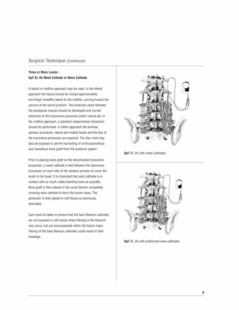
Three or More Levels -
SpF-XL IIb Mesh Cathode or Wave Cathode
A lateral or midline approach may be used. In the lateral
approach the fascia should be incised approximately
two-finger breadths lateral to the midline, curving toward the
sacrum at the sacral junction. The avascular plane between
the paraspinal muscle should be developed and carried
anteriorly to the transverse processes and/or sacral ala. In
the midline approach, a standard subperiosteal dissection
should be performed. In either approach the laminae,
spinous processes, lateral and medial facets and the tips of
the transverse processes are exposed. The iliac crest may
also be exposed to permit harvesting of corticocancellous
and cancellous bone graft from the posterior aspect.
Prior to placing bone graft on the decorticated transverse
processes, a mesh cathode is laid between the transverse
processes on each side of the spinous process to cover the
levels to be fused. It is important that each cathode is in
contact with as much viable bleeding bone as possible.
Bone graft is then placed in the usual fashion completely
covering each cathode to form the fusion mass. The
generator is then placed in soft tissue as previously
described.
Care must be taken to ensure that the bare titanium cathodes
are not exposed in soft tissue where flexing of the titanium
may occur, but are encompassed within the fusion mass.
Flexing of the bare titanium cathodes could result in their
breakage.SpF-XL IIb with preformed wave cathodes.
SpF-XL IIb with mesh cathodes.
7
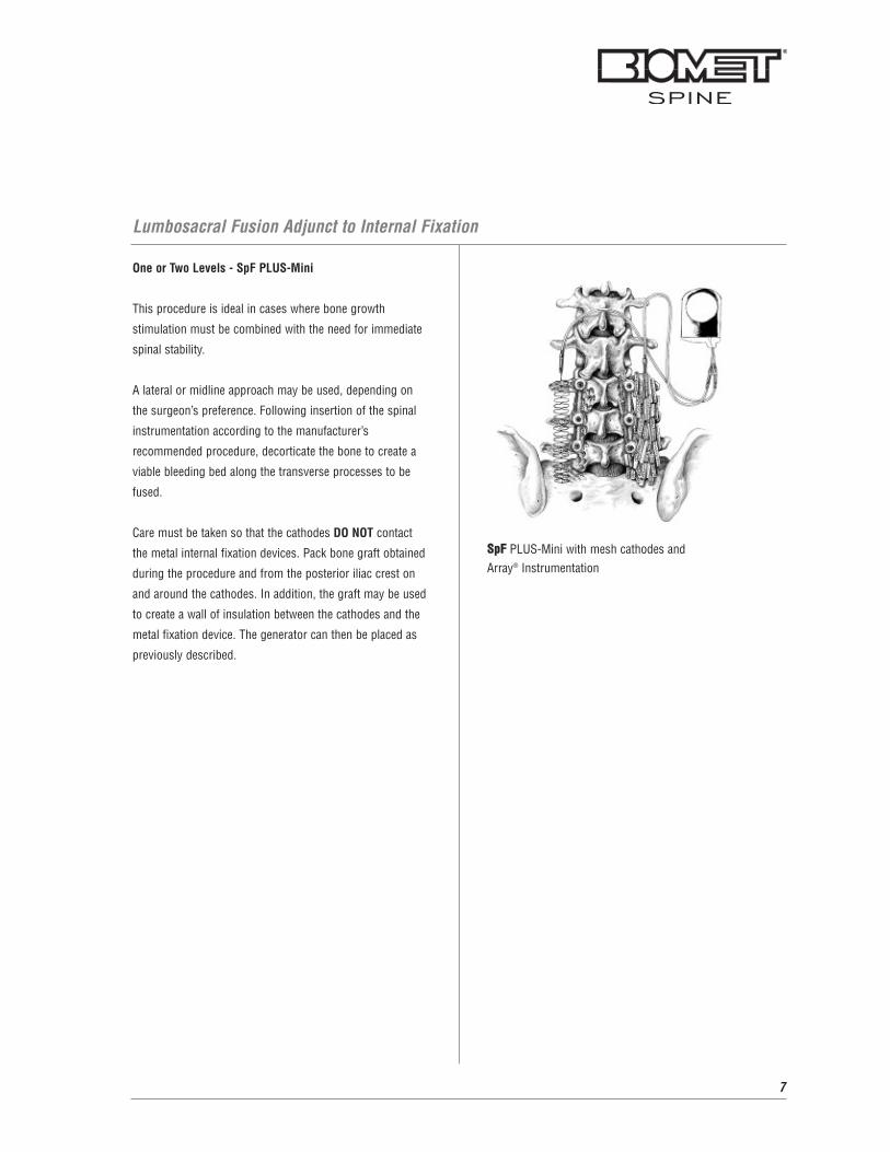
Lumbosacral Fusion Adjunct to Internal Fixation
One or Two Levels - SpF PLUS-Mini
This procedure is ideal in cases where bone growth
stimulation must be combined with the need for immediate
spinal stability.
A lateral or midline approach may be used, depending on
the surgeon’s preference. Following insertion of the spinal
instrumentation according to the manufacturer’s
recommended procedure, decorticate the bone to create a
viable bleeding bed along the transverse processes to be
fused.
Care must be taken so that the cathodes DO NOT contact
the metal internal fixation devices. Pack bone graft obtained
during the procedure and from the posterior iliac crest on
and around the cathodes. In addition, the graft may be used
to create a wall of insulation between the cathodes and the
metal fixation device. The generator can then be placed as
previously described.
SSppFF PLUS-Mini with mesh cathodes and Array® Instrumentation

8
Three or More Levels - SpF-XL IIb
This procedure is ideal in cases where bone growth
stimulation must be combined with the need for immediate
spinal stability.
A lateral or midline approach may be used, depending on the
surgeon’s preference. Following insertion of the spinal
instrumentation according to the manufacturer’s
recommended procedure, decorticate the bone to create a
viable bleeding bed along the transverse processes to be
fused.
Care must be taken so that the cathodes DO NOT contact the
metal internal fixation devices. Pack bone graft obtained
during the procedure and from the posterior iliac crest on
and around the cathodes. In addition, the graft may be
used to create a wall of insulation between the cathodes and
the metal fixation device. The generator can then be placed
as previously described.
Lumbosacral Fusion Adjunct to Internal Fixation (Continued)
SpF-XL IIb with mesh cathodes and Array Instrumentation.

9
Combined Facet and Intertransverse Fusion
The opposing surfaces of the facet joints are denuded. The
proximal end of the uninsulated titanium cathode is wedged
into the facet and packed with bone graft. The graft acts as
an anchor by holding the cathode in place. The remaining
cathode is placed on top of the transverse processes. These
steps are repeated on the other side of the spine. The
generator can then be placed as previously described.
SpF-XL IIb with preformed wave cathodes.

10
Pseudarthrosis Repair
SpF PLUS-Mini and SpF-XL IIb
A lateral or midline approach may be used. Identify and
decorticate the pseudarthrosis to expose bleeding cancellous
bone. Remove fibrous tissue taking care not to damage the
underlying dura. The debridement of the fibrous tissue
should be performed completely to bleeding cancellous bone
for the entire pseudarthrosis defect.
Place the cathodes into the pseudarthrosis defect where
bone growth is desired, achieving as much contact between
the cathode and viable bone as possible. The cathodes must
be completely within the pseudarthrosis site; therefore, they
may contact each other. Bone graft is then placed on and
around the cathodes making sure the cathodes are insulated
from soft tissue contact. The generator can then be placed
as previously described. SpF PLUS-Mini with preformed wave cathodes.

11
Indications
The SpF PLUS-Mini Implantable Spinal Fusion Stimulator is
indicated as a spinal fusion adjunct to increase the probability
of fusion success in one or two levels. The SpF-XL IIb
Implantable Spinal Fusion Stimulators are indicated as a
spinal fusion adjunct to increase the probability of fusion
success in three or more levels.
Contraindications
There are no known contraindications associated with the use
of the SpF Spinal Fusion Stimulators.
WARNINGS AND PRECAUTIONS
Certain warnings and precautions apply. For full prescribing
information, please consult the package insert.
Experiments conducted to assess magnetic field
interactions, artifacts, and operational aspects of the
implantable spinal fusion stimulators, combined with
clinical experience, indicate that MRI procedures may be
performed safely in patients using MRI systems of
1.5 Tesla or less (maximum spatial gradient 450gauss/cm)
following specific recommendations and precautions.
Independent testing showed that the SpF stimulators
passed the ASTM acceptance criteria for deflection angle.
Implantation of the SpF generator as far as possible from
the spinal canal and bone graft is desirable since this will
decrease the likelihood that artifacts will affect the fusion
site on MRI examinations. Implantation of the SpF
generator (i.e., with reference to the center of the device) a
distance of at least 5 to 8 cm from the imaging area of
interest is likely to maintain the diagnostic quality of the MRI
examination. The cathodes of the implantable spinal fusion
stimulator must be positioned at a minimum of 1 cm from
nerve roots to reduce the possibility of nerve excitation
during a MRI procedure. To minimize the possibility of
magnetically induced torque during MRI imaging, the
stimulator should be oriented with its broad face (36 mm x
23 mm plane) parallel to the patient’s coronal plane and to
the staticmagnetic field gradient inside the MRI bore.
MRI Safety & Efficacy
Further Information
Two clinical studies, one randomized and the other
non-randomized, were conducted to support the indications
and usage of the SpF Implantable Spinal Fusion Stimulator
as a spinal fusion adjunct to increase the probability of
fusion success.
The entry criteria included the following: (a) one or more
previous failed spinal fusion(s); (b) grade II or worse
spondylolisthesis; (c) extensive bone grafting necessary for
a multiple level fusion; or (d) other high risk factors for
failure of fusion, including gross instability, obesity,
degenerative osteoarthritis, previous fusion surgery, or
previous disc surgery. The criteria used for determining
success was based on radiographic fusion. A number of
radiographic techniques were used to evaluate fusion. The
radiographic assessment of fusion was confirmed by an
independent radiologist1.
For success rates, please consult the package insert.
1EBI PMA P850035, April 1987 .
Caution: Federal Law (USA) restricts this device to sale by or
on the order of a physician.
12
Biomet Spine would like to acknowledge Neil Kahanovitz,
M.D., Donald Kucharzyk, D.O. and Ronald Wisneski, M.D. for
their contributions to this technique. Biomet Spine, as the
manufacturer of this device, and their surgical consultants
do not recommend this product or any other surgical
technique for use on a specific patient. The surgeon who
performs any implant procedure is responsible for
determining the appropriate product(s) and utilizing the
appropriate technique(s) for said implantation in each
individual patient.
For further information, please contact the Customer Service
Department at:
Biomet Spine
100 Interpace Parkway
Parsippany, NJ 07054
(973) 299-9300, (800) 526-2579
www.biometspine.com


Copyright 2008 Biomet, Inc. All rights reserved. BSP196067L 12/08
100 Interpace ParkwayParsippany, NJ 07054www.biometspine.com800-526-2579
All trademarks are the property of Biomet, Inc., or one of its subsidiaries, unless otherwise indicated. Rx Only.


![19. FINAL Novocure- PIOM 10.4.15[1] - Food and Drug ... of active electronic devices include deep brain stimulators, spinal cord stimulators, vagus nerve stimulators, pacemakers, defibrillators](https://img.dokumen.tips/doc/110x75/5b0be9927f8b9ae61b8eae77/19-final-novocure-piom-104151-food-and-drug-of-active-electronic-devices.jpg)