Embed Size (px)
Citation preview

Spent Fuel Managementand Storage in Korea
Jongwon CHOI
2010 Int’l Seminar on Spent Fuel Storage, nov.15-17, Tokyo, Japan
2010. 11. 15

1
Spent Fuel Management NPP & SF Status Policy Storage
R&D Activities for Dry Storage Storage System Spent Fuel Integrity
Contents

2Nuclear Power Plant in Korea
Units (MWe), As of Oct. 2010
Fossil Fuel59.6%
Hydro1.4%
Nuclear39.0%
Site In Operation
UnderConstruction Total
Kori 4 (3,137) 4 (4,800) 8 (7,937)
Wolsong 4 (2,779) 2 (2,000) 6 (4,779)
Yonggwang 6 (5,900) - 6 (5,900)
Ulchin 6 (5,900) 2 (2,400) 8 (8,300)
Total 20 (17,716) 8 (9,200) 28 (24,516)
Ulchin (#1,2,3,4,5,6)
Kori (#1,2,3,4)Shin-Kori (#1,2,3,4)
Yonggwang(#1,2,3,4,5,6)
Wolsong (#1,2,3,4) Shin-Wolsong (#1,2)
Seoul
Daejeon
~10 NPPs will be added in 2030.

3
Spent Fuel Amount
0
2
4
6
8
10
12
14
16
18
20
1997 2000 2005 2010 2015 2020Year
Amou
nt (
1000
MTU
) PWR CANDUTOTAL
7,960
19,00011,000
Annual arising : 700 tU/Yr
CANDU PWR
~20 tU/yr16 units~320 tU/yr
~100 tU/yr4 units~400 tU/Yr
NPP Site Capacity (ton) Accu. (ton) Expected Saturation (year)Kori 2,190 1,784 2016
Yonggwang 2,670 1,753 2016Ulchin 2,350 1,449 2017
Wolsong 9,440 5,886 2018Sum 16,650 10,872 -
SF Amount

4
National Policy for RadWaste
253rd AEC’s Decision (Dec. 2004)
Final repository for LILW should be constructed by2008. Delayed until 2012 for Safety Reason
Spent Fuel Management - All spent fuel will be stored at plant sites until 2016.- Future national policy for SF management will be decided
through public participation taking into consideration of national and international trends on policy and technology development.

5RadWaste Management Act
This Act has been effective since January 1st, 2009.
Key contents are:
- Establish. of a new Org., responsible body for radwaste management
Korea Radioactive Waste Management Corporation (KRMC)
- Establish. of the Radioactive Waste Management Fund
which will be paid by the Radwaste generator.
KRMC is responsible for managing the RadWaste Fund

6 6
Organization related with RadWaste Management

7
PowerReactors
ResearchReactors
SFP (4) Dry Storage
HANARO
PIEF
KRR1 and 2
PWRs(16)
PHWRs(4)
transported to the United States (1998)
to be determined
Interim Storage(to be determined)
Post Irradiation Examination Facility Hot Cell LILW
Inter im Storage
Inter im Storage Deep GeologicalRepositorySFP (16)
End Point(to be determined)
Overall Plan for Radwaste Management
ANFC?
unde r Cons truc tion
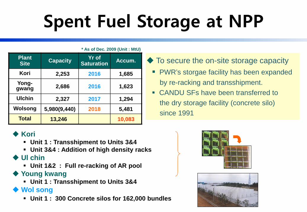
To secure the on-site storage capacity PWR’s storgae facility has been expanded
by re-racking and transshipment. CANDU SFs have been transferred to
the dry storage facility (concrete silo)since 1991
Kori Unit 1 : Transshipment to Units 3&4 Unit 3&4 : Addition of high density racks
Ul chin Unit 1&2 : Full re-racking of AR pool
Young kwang Unit 1 : Transshipment to Units 3&4
Wol song Unit 1 : 300 Concrete silos for 162,000 bundles
PlantSite Capacity Yr of
Saturation Accum.
Kori 2,253 2016 1,685Yong-gwang 2,686 2016 1,623
Ulchin 2,327 2017 1,294Wolsong 5,980(9,440) 2018 5,481
Total 13,246 10,083
* As of Dec. 2009 (Unit : MtU)
Spent Fuel Storage at NPP

9Expansion of Storage Capacity
PWR SFPHWR(CANDU) SF
High Density Reracking
Transshipment between NPPs
① Concrete Silo
② MACSTOR/KN-400

10
Concrete Silo for CANDU SF Storage
Concrete Silo SystemCapacity: 540 Bundle (60 Bundle/Basket x 9 Basket)Out Diameter: 3.07 mHeight: 6.52 m
Total 300 Silos (~3,200 MtU) installed from 1990

11MACSTOR/KN-400 for CANDU SF Storage
Air Outlet
Air Inlet
Weather CoverShield Plug
CANDU Fuel
Fuel Basket
Storage Cylinder
High-dry Storage Facility 7 modules at Wolsong site (2010) Economy : reduce of Area by 2.7
times compared to concrete silo Cooling: Passive Natural Cooling

12Design Parameters of MACSTOR/KN-400
Storage SystemLifetime 50 years
Temp. Limit in operation 66 ℃
KN-400 system
24,000 bundles
System: 40 cylinders
Cylinder : 10 baskets
Basket : 60 bundles
5,000 Bundles generation in a PWHR / year24,000 bundles = 1.2 x All SF generation in 4 PHWR in a year
= 44.4 x Silo dry storage
Dimension 22 (L) x 12.5 (W) x 7.5 (H) m
Structure Material Reinforced Concrete
Thickness Side : 0.98 mTop : 1.08 m
PHWR Spent FuelCooling Time Minimum 6 years
Average Burnup 7,800 MWd/MtU
Average Heat Flux 6.08 Watt
Initial U mass 19.2 kgU / Bundle
Bundle Max. Temp in dry storage
168 ℃

13
SF transshipment between NPPs
Transshipment Year No. of Spent fuels Transfer Cask
Kori 1→Kori 3 1990-2004 424 KSC-4
Kori 1→Kori 4 1994-2004 188 KSC-4, KN-12
Kori 2→Kori 4 2000 12 KN-12
Kori 2→Kori 3 2001-2004 244 KSC-4, KN-12
Kori 4→Kori 3 2004 60 KN-12
Total 928
- Total 928 assembles moved to neighboring units between 1990-2004.

14
Spent Fuel Management NPP & SF Status Policy Storage
R&D Activities for Dry Storage Storage System Spent Fuel Integrity
Contents

15
Backgrounds of SF Dry Storage
ISFSF should be in commission by 2016
Some prerequisites for dry storage (to be considered)
- Integral spent fuel history & properties database
: new fuel design, increased burnup due to improved op. tech.
- Thermal cycling limitation due to to in-site transshipment
for expansion of the on-site storage capacity
- Technical criteria for safe dry storage system such as the
long-term integrity of SF and storage facility material

16
2009 2010 2011 2012 2013 2014 2015 2016
StorageSystem
Develop.
SFIntegrity
ProjectSchedule
Conceptual Design Evaluation
Burnup Credit
Serious Accident Evaluation
System Manufac. and Performance Test
Radiation Monitoring System Devel.
Transfer Cask Design
System Design
Transportation & PSA
Core Material Development
Stage 1Core Design Tech.
Stage 2System Design
Stage 3Performance Test , V&V
Demon. Facility Installation
Degradation Model Unit/Integral Test of SFModel V&V
Integral Integrity Evaluation
System Operation
New Storage System
Product
InstallationStart Licensing
Storage System Develop. Plan

17
Fuel Environ. Change
Fuel IDFuel typeInitial Enrich.Fuel DimensionFuel CladdingFuel PelletLoading Date
Manufacture Burn We t S tora ge Dry S tora ge
NDR BurnupDischarge BUPower HistoryDamage Info.Coolant Chem.Radiation LevelThermal-HydroDischarge Date
Discharege BUDamage Info.Cooling Info.Cooling Date
Discharege BUCladding Info.Cooling DateEnrichmentTransfer History
Temp: RoomClad Pressure:
~20 atm
Coolant : 150 atm~320°C
Cladding: ~450°CPellet: ~800°C
Coolant : ~1.5 atm~40°C
Clad: ~150atm~100°C
Air : ~1 atm ~20°C
Clad: ~150 atm~400°C

18
Fuel Supply History in Korea
KOFA : Korean FA, OFA : W’s Optimized FA, STD : W’s Standard FAV5H : Vantage5H FA, RFA : Robust FA, NGF : Next Generation FAOPR : OPR FA, Guardian : OPR FA with Debris Filtering Grid, PLUS7 : Advanced OPR FA, STD CANDU : Standard CANDU Fuel Bundle
ACE7ACE7
ACE7
ACE7
KOFA OFAKOFA STD
KOFA V5HKOFA V5H
KOFA V5H
OPR
Plant YearKori-1 (WH14)Kori-2 (WH16)
Kori-3/4 (WH17)YGN-1/2 (WH17)UCN-1/2 (WH17)
YGN-3/4 (OPR)
1990 1995 2000 2005 2010
RFARFARFA
Guardian PLUS7OPRYGN-5/6 (OPR) Guardian PLUS7
OPRUCN-3/4 (OPR) Guardian PLUS7UCN-5/6 (OPR) Guardian PLUS7S-KR-1/2 (OPR) Guardian PLUS7S-KR-3/4 (APR) PLUS7
Wolsong(CANDU) STD CANDUS- Wolsong (OPR ) Guardian PLUS7
S-UCN-1/2(APR ) Guardian PLUS7

19
Capacity Factor in Korea
1984 ~ 1994
1998 ~ 2007
Source: Ministry of Knowledge and Economy
2008 Nuclear Power Note

20
Discharge Burnup Increase
1.5 2.0 2.5 3.0 3.5 4.0 4.5 5.00
200
400
600
800
1000
1200
1400
Num
ber o
f Ass
embli
es
Initial 235U Enrichment (w/o)
62.3% < 4.0 235U wt.% 86.4% < 4.3 235U wt.%
Discharge Burnup Increase as longer NPP operating cycle
235U enrichmentperiod
3.2 wt.%1980’s
4.0~4.2 wt.%1990’s
4.2~4.5 wt.%2000’s(early)
4.5 wt.%2000’s(current)
Current average discharge burnup : 45 GWd/MTU4.5 wt.% enriched spent fuels from 2010 with average 55GWd/MTU burnup
15
20
25
30
35
40
45
50
55
60
80 82 84 86 88 90 92 94 96 98 00 02 04 06 080
100
200
300
400
500
Prod
uctio
n Am
ount
[tU]
Time [year]
Bur
nup
of S
pent
Nuc
lear
Fue
l [G
Wd/
tU]
Average Burnup
Maximum Burnup
Production Amount

• Uranium Provenance• Fuel ID• Fuel Type• Cask Type• Fuel Storage Facility• Fuel Storage
Location• Initial Enrichment• Fuel Loading Date
• Fuel Discharge Date• Discharge Burnup• Fuel Inventory• Fuel Activity• Defect Fuel Check• Heat Generation• End Cycle
Enrichment
• Storage Type (Wet / Dry)
• Fuel Discharge Date• Storage Cask
Information• Fuel Inventory• Fuel Activity• Heat Generation
• Fuel Undertaking Date
• Fuel Disposal Date• Storage Cask
Information• Transport
Procedure• Fuel Inventory• Fuel Activity
• Fuel Disposal Date• Storage Cask
Information• Transport
Procedure• Fuel Inventory• Fuel Activity
Mining Milling Conversion Enrichment
Fuel Fabrication Reactor Operation Storage (AR) Interim Storage Final Disposal
SNF DB : planed tracing system on ID basis
Spent Fuel DB (1/2)

Radiation InformationInitial Uranium EnrichmentFuel Material Mass in AssemblyDischarge BurnupTotal Mass of AssemblyVolume of AssemblyHeat Generation Rate Evaluation DateHeat Generation RateTotal Radioactivity Evaluation MethodTotal RadioactivityTotal Radioactivity Evaluation DateRemaining Uranium InventoryDefect Fuel RateNuclide Activity Detection MethodNuclide Activity Detection Date
FA Information
Fuel Rod InformationManagement Facility
Separation Factor for Assembly/Fuel RodUser IDCause InformationAcquisition DateExtracted Ass. No.Fuel Defect Check
Fuel Storage Information
Storage Facilitty
Cask Serial Number
Cask TypeStorage Date
Defect Fuel Information
Defect Fuel Rod Occurrence DateManagement FacilityExtracted Ass. No.Storage FacilityStorage LocationSpecific Matters
Nuclide ActivityNuclide CodeRadiation Intensity
Manage FacilityTotal Assembly NumberOccurrence CauseMinimum Burnup PeriodFinal Burnup PeriodInitial Core Loading DateFinal Core Discharge DateAss. Arrangement TypeFuel TypeReactor Equipment
SNF DB Module Structure
H-3C-14Co-60 Sm-151Cs-135Cs-137U-235
U-238 Np-237 Pu-238Pu-239Pu-240 …
Spent Fuel DB (2/2)

23Tech. Roadmap for SF Integrity study
Phase 1 (2009-2010) Phase 2 (2011-2013) Phase 3 (2014-2016)
CommercialziationPatent
PIE Test
PropertiesAnalysis
Test Facility
PrototypeModel
PrototypeCode
CodeVerification
Material Degradation Model Spent Fuel Degradation Model Hot Test Senario
Test Facility design &
construction
Hot test
Long-term behavior test
Hot test database
Model verification
Integral Code Develop
Comprehensive Evaluation
Technology Application
- Design Requirement
and improvement(s)
- Basic data for license
TestProcedure
(2016~)
Technology development for the dry-stored SF integrity evaluation Objective
TechnologyApplication
24
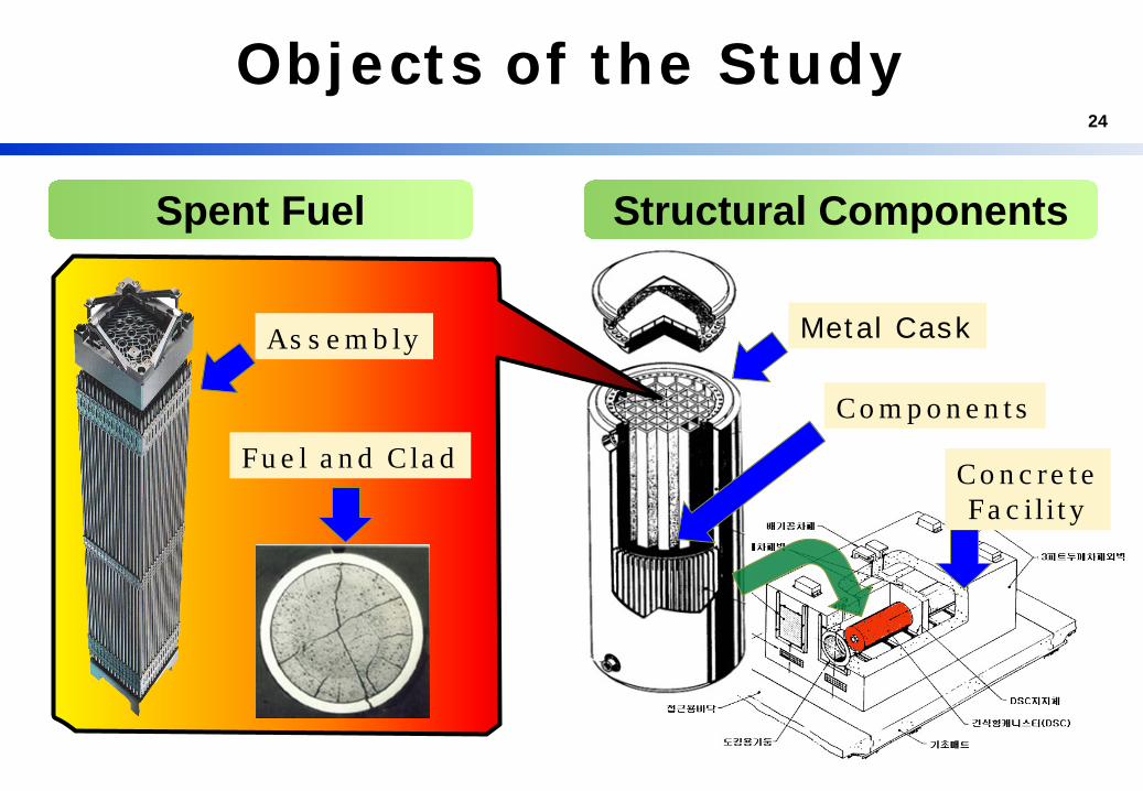
Objects of the Study
Spent Fuel Structural Components
Metal Cask
Fu e l a n d C la d
As s e m b ly
Co m p o n e n t s
Co n c re t eFa c i l i t y

25
Target
① Developing prototype model
② Evaluating SF structural deformation
③ Analyzing previous SF test data
④ Developing integrity evaluation code system
Product
Patent/report/article for degradation models
Integrity evaluation code design and model PIRT
(Phenomena Identification and Ranking Table)
To develop reference degradation mechanism model under SF characteristics and storage condition
Ongoing Project (1/2)

26
Target
① Characterization test scenario of SF
② Unit test scenario of SF
③ Integrated test scenario of SF
Product
Conceptual design of unit test experiments
Patent application for conceptual design
Scenarios for Char./Unit/Integrated test
To develop hot-test scenario of 2nd Phase experiments
Ongoing Project (2/2)

27
Creep Rupture
Hydrogen re-orientation
Delayed Hydride Cracking
Oxidation
Stress Corrosion Cracking
Diffusion Controlled Cavity Growth
Clad Degradation
Oxidation
Fragmentation
Pellet Degradation
Major Degradation Mechanisms

28Characteriz. Test of SF in PIEF
FA Pool Test
Undertaking
VisualInspection
Storing
Pool Test
Dismantling Cutting
NDT
DimensionMeasuring
BurnupMeasuring
Visual Inspection
Oxidation Measuring
Dimension Measuring
ECT
FGR/Internal Pressure
DT
Macro Texture
Micro Texture
Gamma Scaning
Density Measuring
Burnup&H Analysis
SEM / EPMA
Spent Fuel Integrity• Degradation• Damage• Creep• He-reorientation
Transportation
Unloading
Rod Hot Cell Test Specimen Hot Cell Test

29
STD KOFA OFA STD KOFA STD 16ACE7 OFA KOFA V5H RFA 17ACE7 KSNP Guardian PLUS7
Owned Assembly 6 - - - 1 - - - - 1 - - - - - 8
Enrich (U-235 wt %) 2.1~3.2 3.5 4.2
Burnup (GWd/tU) 17~38 35 53
Cladding Zry-4 Zry-4 Imp. Zry-4
Owned Rods - - - - - 9 - - 3 16 6 - 2 6 10 52
Enrich (U-235 wt %) 3.8 3.8 4.2~4.49 2.61~4.51 2.3~3.4 4.49 4.49
Burnup (GWd/tU) 32~42 7~12 40~56 34~54 1.8~2 48~55 55~58
Cladding Zry-4Low TinZry-4
Adv. Zry-4Zirlo
Zirlo Zry-4 Zirlo Zirlo
Visusal Test 19 - - - 8 9 - - 3 22 4 - 2 6 3 76
Dimension Measure 19 - - - 8 9 - - 3 17 4 - 2 2 3 67
ECT 19 - - - 8 9 - - 3 21 4 - 2 6 3 75
γ-spectroscopy 19 - - - 8 9 - - 3 21 4 - 2 6 3 75
Rod Internal Pressure/FGR Measure 13 - - - 2 6 - - 2 16 2 - 0 2 2 45
Ceramography/Metallography 13 - - - 2 7 - - 2 20 2 - 2 2 3 53
Chem. Analy(Burnup,Hydroge) 13 - - - 2 7 - - 2 19 2 - 0 2 2 49
Pellet/Clad Material Properties 13 - - - 2 7 - - 2 9 2 - 2 2 2 41
DT
Characterizati
onTest
Assembly
Rod
Own
Fuel Name
Array type
Design type
Sum
NDT
14X14 16X16 17X17 16X16
Westinghouse type OPR
Characteriz. Test of SF in PIEF
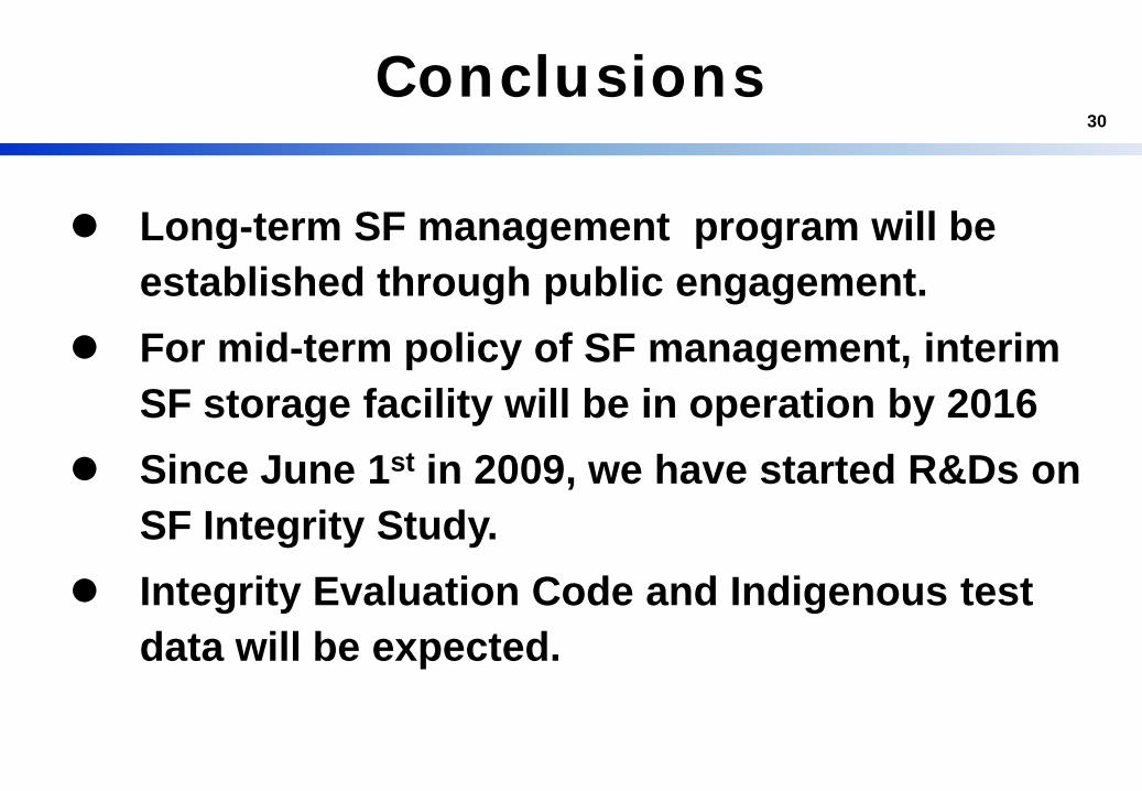
30Conclusions
Long-term SF management program will be established through public engagement.
For mid-term policy of SF management, interim SF storage facility will be in operation by 2016
Since June 1st in 2009, we have started R&Ds on SF Integrity Study.
Integrity Evaluation Code and Indigenous test data will be expected.

31

2009 2010 2011
6 8 10 12 2 4 6 8 10 12 2 4
Implementation Schedule for 1st Phase
previous spent fuel test database analysis spent fuel selection for pre-test
expert advice
test item list for spent fuel integrity properties
degradation unit mechanism test item list dry storage performance verification technology develop
unit mechanism test procedure
unit test/full test conceptual design of experimental equipments
relation procedure check between model and test results
spent fuel properties test senario
pre-exist degradation model analysis
reference model selection
foreign/domestic integrity data compilation & analysis
reference model evaluation prototype model develop
degradation causes and behaviour analysis
integrity evaluation code requirements analysis model/code connection scheme develop
reports model code, reports, ariticles
structural fabric list
pre-exist degradation mechanism analysis
reference model
reference model evaluation prototype model develop
degradation causes and behaviour analysisgrouping structural fabrics technologies for
each storage type
reports reports, articlesdomestic/International meeting
International Workshop
International Workshopexpert advice
reportsreports
International Workshop
domestic/International meeting
domestic/International meeting
Degradation model development ofStorage System
Material
Degradation modelDevelopment of SF
Development of Experimental Plan for the 2nd Phase