Embed Size (px)
Citation preview

16M
OTOR CONTROL CENTERS
Siemens / Speedfax Previous folio: 15-1
SPEEDFAXTM 2011 Motor Control Centers
Residential L Commercial L Industrial
ContentsProduct Overview
OverviewoftiastarTM 16-2
ConstructionDetails 16-3–16-4
Technical
DimensionsandWeights 16-5
WiringClassifications 16-6
IncomingCableSpace,WiringTroughs,WiringTerminations 16-7
Components Overview
HeavyDutyStarters 16-8
OverloadRelays 16-9
SIRIUSSoftStarters 16-10
VariableFrequencyDrives 16-11
PowerMonitoring 16-12
SurgeProtectiveDevices 16-13
Selection Guide
StarterRatingsandDimensions 16-14–16-15
PowerDistributionRatingsandDimensions 16-16
Aftermarket
ProductHistory 16-17–16-18
MCCQuoteRequestForm 16-19–16-20

Siemens Industry, Inc. SPEEDFAX™ 2011 Product Catalog16-2
16M
OTOR
CON
TROL
CE
NTER
S
Siemens / Speedfax Previous folio: 15-2
tiastarTM Motor Control CentersOverview of tiastar Product OverviewMotor Control Center @ SiemensMotor control centers (MCC) have come a long way since they were intro-duced in 1937 as a way to save floor space by placing several starters in a single cabinet. Modern processes and facilities now dictate that motor control centers should display a high level of intelligence as well. They must deliver vital operating information; plus provide automation features, optimal control, and critically fast communications to meet even the most demanding appli-cations. Ideally, the best-of the-best must also save installation time and money. Siemens MCCs are designed as self-contained modular units. They come with rear-mounted, self-aligning copper stabs that firmly grasp onto the bus. Brackets also guide the place-ment of units, further assuring positive engagement with the bus.
tiastar MCCSiemens tiastar MCC is based on the Furnas System/89TM MCC introduced in 1980 and represent the state-of-the-art motor control technology, with a modular, open architecture design. High performance and quality expectations have been researched at the planning stage and throughout the construction stage. The Siemens tiastar MCC has many features and options to meet your specific needs. Requirements such as the standard isolated vertical bus to fully insulated vertical bus and standard 22mm to 30mm pilot devices. Heavy
tiastarMotorControlCenter
gauge steel is used for framing and side panel; sections are separated by 14 gauge steel barriers that are formed to provide rigidity and durability. The modu-lar units implement all the motor protec-tion and control functions, determine operational, diagnostic and statistical data, and organize communications data between the automation system and the motor feeder.
tiastar SMART MCC Siemens tiastar Smart MCC with PROFIBUS-DP Communications com-bines heavy-duty construction and user friendly features. These intelligent units deliver detailed diagnostics by com-municating with starter units, variable frequency drives, reduced voltage soft-start units, circuit breakers, or power meters via PLC/DCS. This means over-load relays, linked to the PLCs, can now deliver detailed motor management data at speeds previously unheard of. PROFIBUS-DP, the backbone of the system, greatly simplifies I/O wiring.
Domestic Design StandardsThe following are the principal domestic standards which apply to motor control center design, testing, construction and application. The tiastar motor control center complies fully with the latest version of all these standards.
NEMA AB-1 Molded Case Circuit Breakers
ICS 1 General Standards for Industrial Control
ICS 2 Standard for Industrial Control Devices, Controllers and Assemblies
ICS 18 Standard for motor control centers
UL 845 Motor Control Centers
508 Industrial Control Equipment
891 Switchboard Design
94 Test for Flammability of Plastic Materials for Parts, Devices, and Appliances
489 Molded Case Circuit Breakers and Circuit Breaker Enclosures
991 Tests for Safety-related Controls Employing Solid-state Devices
NFPA – National Fire Protection Association 70 National Electrical Code
Low Voltage Seismic ComplianceToday, strict seismic requirements are not limited to areas prone to earth-quakes. Engineers in all locations must be aware of, and comply with, earth-quake protection regulations. In addition to construction materials and tech-niques, these regulations cover non-structural building systems, including electrical components. In critical appli-cations, such as healthcare facilities, these components must be designed to go beyond surviving an earthquake, to remain in operation after the event is over.
At Siemens, we are committed to mak-ing it easier for you to comply with all building requirements, including seismic ratings.
Please contact your Siemens represen-tative for complete details on seismic rating compliance for specific products and configurations.
The purpose of this compliance assess-ment is to document the seismic com-pliance of tiastar motor control center to the following building codes:
Building code Edition
UniformBuildingCode(UBC) 1997BOCANationalBuildingCode(BOCA)
1999
StandardBuildingCode(SBC) 1999CaliforniaBuildingCode(CBC) 2010InternationalBuildingCode(IBC) 2009
Earthquake loading compliance tests (shake tests) were performed at Clarke Dynamic Test Laboratories in accordance with ICC-ES-AC 156 and ASCE 7-10.
Notes:1.tiastarmotorcontrolcentersarecertifiedtothestrin-
gentseismicrequirementsofCaliforniaOSHPD(OfficeofStatewideHealthPlanningandDevelopment).Approval#OSP-0074-10.Fordetails,referto:http://www.oshpd.ca.gov/FDD/Pre-Approval/.
2.Thecodesandstandardsreferencedinthisdocumentarepublishedbyindependentorganizations,institutes,oragencies.Allcopyrightsandtrademarksrelatedtosuchcodesandpublicationsandtheusethereofbelongtotheentitiesowningrightstothesame.
3.Thesetestresultsindicatethird-partyanalysisoftheSiemensproductforcompliancetothereferencedcodesandeditions.Nothinginthispublicationshouldbetakenasendorsements,officialapprovals,orofficialtestresultsprovidedbythepublishersofthereferencedcodesoranycodeenforcementauthorities.

Siemens Industry, Inc. SPEEDFAX™ 2011 Product Catalog 16-3
16M
OTOR CONTROL CENTERS
Siemens / Speedfax Previous folio: 15-4
tiastar Motor Control CentersConstruction Details Product OverviewQuality Features Exceed Standards
a
b
c
d
ek
j
i
h
g
f
Siemens tiastar motor control centers are composed of a number of vertical sections bolted together. That allows for future addition of MCC vertical units so the equipment can expand with customer needs. The standards structure is 90 in. (2286 mm) high, plus a 1.125 in.
(29 mm) high channel sill. Front-only structures can be either 15 in. (381 mm) or 20 in. (508 mm) deep. Back-to-back mounted structures are 30 in. (762 mm) or 40 in. (1016 mm) deep, and consist of two horizontal and vertical buses. This
allows for correct bus phasing on the front or rear. Siemens provides a 21 in. back-to-back design, consisting of a common horizontal and vertical bus structure, for applications where available footprint is limited.

Siemens Industry, Inc. SPEEDFAX™ 2011 Product Catalog16-4
16M
OTOR
CON
TROL
CE
NTER
S
Siemens / Speedfax Previous folio: 15-5
tiastar Motor Control CentersConstruction Details Product Overview
Important Additional Features:J All wiring and components meet or exceed the
requirements of UL, CSA, NEMA, EEMAC, and NECJ Pre-wired components are professionally harnessed
to industrial terminal blocksJ Full depth wire tie rods are standard in each vertical
wirewayJ White interior increases visibility for easy wiring,
maintenance and inspectionJ Modular units are fully interchangeableJ Each tiastar MCC is designed to satisfy your most
exacting specificationsJ White on black base operating handle is easy to
identify
Horizontalbusdesignkeepsthebusinthetop12"ofthestructure,neverbehindunits,foreasymaintenanceandaccessibility.
g
Apositivestopmechanismpreventstheunitfromfallingoutofthestructureduringunitremoval.
e
Pilotdevicesaremountedonasturdyformed-metalpanelattachedwithtwocaptivescrewstotheMCCunitdoorforeasyaccesstointernalcomponents.Forunitremovalandtest,thepilotdevicepaneliseasilyremovedfromthedoorandmountdontheunit.
d
Apositivestopinthe“TEST”positionindicatesthataplug-inunitisfullywithdrawnfromtheverticalbus.
c
Arackingleveronallplug-inunitsensuresthattheyarefullyengagedwiththeverticalbus.Aninterlockwiththedisconnectdeviceensuresthataplug-inunitisnotinsertedorremovedfromtheverticalbuswhentheunitisenergized.
b
Foreaseinwiringandinspection,terminalblocksaremountedonaswing-outsidebarrier.
a
Plug-inunitstabassembliesincludeself-aligningstabclipswithspringsteelbackupsprings.Wiresfromthestabclipstotheline-sideofthecircuitbreakerordisconnectswitcharecontainedinthestabhousingandareisolatedphase-to-phaseuntilthewiresentertheMCC.
Alldoorsswingopenaminimumof110°foreasyunitaccessandremoval.
k
Ascrewdriveroperateddefeatermechanismallowsaccesstoanenergizedunitbyauthorizedpersonnel.
j
Theunitdisconnectoperatinghandlefeaturesasimple,ruggeddesign.“ON”and“OFF”areclearlyindicatedbyposition,colorandword.The“TRIP”indicationisclearlydisplayedoncircuitbreakerequippedunits.
i
Thehorizontalbuscompartmentisisolatedfromthehorizontalwirewaysbyacrystalclearpolycarbonatebarrierthatmakesvisibleandinfraredmaintenanceinspectionabreeze.Thebarrieriseasilyremovedwhenaccesstothehorizontalbusisrequired.
f
Acoppercliponplug-inunitsengagesandgroundsunitsatalltimes.
h

Siemens Industry, Inc. SPEEDFAX™ 2011 Product Catalog 16-5
16M
OTOR CONTROL CENTERS
Siemens / Speedfax Previous folio: 15-6
tiastar Motor Control CentersDimensions and Weights Technical DimensionsStructureHeight 91.125in. (2315mm)Front Mounted Only Structure (FO)Width 20in. (508mm)
24in. (610mm)30in. (762mm)
Depth 15in. (381mm)20in. (508mm)
Back to Back Structure (BTB)Width 20in. (508mm)
30in. (762mm)Depth 21in. (533mm)Vertical WirewayHeight 72in. (1829mm)Width 4in. (102mm)Depth 10in. (254mm)CrossSection 38.25sq.in. (972sq.mm.)Top Horizontal WirewayHeight 12in. (305mm)Depth 7in. (178mm)Bottom Horizontal WirewayHeight 6in. (152mm)Depth 15in. (381mm)
20in. (508mm)30in.* (762mm)*
*BTB 40in.* (1016mm)*Enclosure TypesNEMA1 IndoorNEMA1A Gasketed IndoorNEMA2 Dripproof IndoorNEMA12 Dusttight IndoorNEMA3R Rainproof Outdoor(Non
walk-in)Pull Box (Top Hat)Height 12in.
18in.24in.
Width 20in.30in.
Depth 15in.20in.
Structural Gauge ChartStructural PartsDividerSheets 14ga.SideSheets 14ga.CenterBottomCrossTies 12ga.RearChannel(FO) 13ga.ChannelSills 7ga.Center-TopChannel 13ga.VerticalBusMountingAngles 14ga.LiftingAngles 7ga.RearCovers 16ga.TopPlates 13ga.EndCovers 16ga.SeparatorAngles 12ga.ShelfBrackets 10ga.Unit PartsTopandBottomUnitBarriers 14ga.BackPan 13ga.
14ga.SideBarrierPlate 18ga.Angles 14ga.Doors 13ga.
14ga.Finish (Ext.) ANSI61LightGrayElectrostaticallyapplieddrypowderpaintinStandard
BusHorizontal Bus (A) 600A Cu
800A Cu1200A Cu1600A Cu2000A Cu2500A Cu600A Al800A Al1200 Al
Vertical Bus (A) 300A Cu600A Cu
Neutral Bus (Bottom Mounted) (A) 600A Cu800A Cu1200A Cu1600A Cu
Options FullNeutralCuNeutralLandingPad
BusBracing(KASym) 42KA65KA100KA* *CuOnly
BarriersIsolationBarrier GroundedsheetsteelwithstabopeningsInsulated&IsolatedBarrier Glassfilledpolyestersandwichthatisolates
andinsulateseachphasefromtheothersandthebusfromthefrontandrearcompartments
Removablecovers InsertstocoverunusedopeningsinV-busbarrier
Automaticshuttermechanism Optionavailableforthestabinlocationofeachplug-inunitandrequestedfuturespace
Ground Bus Horizontal(BottomMounted)(A) 300A CuRequiredforULlabeling 600A Cu
600A AlVertical(A)* 300A Cu*AvailablewithmotorgroundterminationsPlatingAllpowerbus,tinplatedisStandard
Silverplatingavailablebyrequest(Cuonly)
Incoming Line TerminationsIncominglinearrangementsareavailableinmanyconfigura-tionsfrom600Ato2500A
Weight TableDimensions Inches (mm) Shipping weight per
Section in lbs (Kg)H W D Type
91.125(2315) 20(508) 15(381) FO 550(250)20(508) 20(508) FO 650(295)30(762) 15(381) FO 700(318)30(762) 20(508) FO 850(386)20(508) 21(533) BTB 670(304)30(762) 21(533) BTB 880(400)
Wiring SpecificationsControlonUnits 16ga.
19strandbondedcopper105°C600V
InterconnectioncontrolwiringbetweenUnits
14ga.19strandcopper105°C600V
Powerwiring–SizedtosuitmaximumHPratingofunit
12ga.to2ga. 19strandcopper105°C600V
1ga.to500MCM 19strandto37strandcopper105°C600V

Siemens Industry, Inc. SPEEDFAX™ 2011 Product Catalog16-6
16M
OTOR
CON
TROL
CE
NTER
S
Siemens / Speedfax Previous folio: 15-7
tiastar Motor Control CentersWiring Classifications Technical Siemens MCC’s are available as either Class I or Class II assemblies utilizing either Type A, Type B, or Type C wiring as defined in NEMA ICS18-2001(3.1) and NEMA ICS18-2001(3.3). Below are the NEMA class and type definitions:
Class I — Independent Units (NEMA ICS18-2001(3.2.1))Class I motor control centers shall consist of mechanical groupings of combination motor control units, feeder tap units, other units, and electrical devices arranged in a convenient assembly. The manufacturer shall furnish drawings that include:
a. Overall dimensions of the motor control center, identification of units and their location in the motor control center, locations of incoming line terminals, mounting dimensions, available conduit entrance areas, and the location of the master terminal board if required (Type C wiring only).
b. Manufacturer’s standard diagrams for individual units and master terminal boards (Type C wiring only) consist of one or more drawing(s) that:
1. Identify electrical devices.2. Indicate electrical connections.3. Indicate terminal numbering
designations.
Note: When a combination schematic and / or wiring diagram for a unit is supplied showing optional devices, the manufacturer shall provide information to indicate which devices are actually furnished.
Class II — Interconnected Units (NEMA ICS18-2001(3.2.2))Class II motor control centers shall be the same as Class I motor control centers with the addition of manufacturer furnished electrical interlocking and wiring between units as specified in overall control system diagrams supplied by the purchaser. In addition to the drawings furnished for Class I motor control centers, the manufacturer shall furnish drawings that indicate factory interconnections within the motor control center.
Class I-S and II-S — Motor Control Centers With Custom Drawing Requirements (NEMA ICS18-2001(3.2.3)) Class I-S and II-S motor control centers shall be the same as Class I and II except custom drawings shall be provided in lieu of standard drawings as specified by the user. Examples of custom drawings are:
b Special identifications for electrical devices
b Special terminal numbering designations
b Special sizes of drawings
The drawings supplied by the manufacturer shall convey the same information as drawings provided with Class I and II motor control centers, additionally modified as specified by the user.
Types of Wiring — NEMA ICS18-2001(3.3.1)
Type A (NEMA ICS18-2001 (3.3.1.1)) User field wiring shall connect directly to device terminals internal to the unit and shall be provided only on Class I motor control centers.
Type B (NEMA ICS18-2001(3.3.1.2)) a. Type B user field load wiring for combination motor control units size 3 or smaller shall be designated as B-D or B-T, according to the following:
b B-D connects directly to the device terminals, which are located immediately adjacent and readily accessible to the vertical wireway.
b B-T connects directly to a load terminal block in, or adjacent to, the unit.
b. Type B user field load wiring for combination motor control units larger than size 3, and for feeder tap units, shall connect directly to unit device terminals.
c. Type B user field control wiring shall connect directly to unit terminal block(s) located in, or adjacent to, each combination motor control unit.
Type C (NEMA ICS18-2001(3.3.1.3))User field control wiring shall connect directly to master terminal blocks mounted at the top or bottom of those vertical sections that contain combination motor control units or control assemblies which shall be factory wired to their master terminal blocks. User field load wiring for combination motor control units, size 3 or smaller, shall connect directly to master terminal blocks mounted at the top or bottom of vertical sections. Motor control unit load wiring shall be factory wired to the master terminal blocks. User field load wiring for combination motor control units larger than size 3, and for feeder tap units, shall connect directly to unit device terminals.
IC
IB-T
IB-D
IA
IIB IIC

Siemens Industry, Inc. SPEEDFAX™ 2011 Product Catalog 16-7
16M
OTOR CONTROL CENTERS
Siemens / Speedfax Previous folio: 15-10
tiastar Motor Control CentersIncoming Cable Space, Wiring Troughs, Wiring Terminations Technical The National Electrical Code establishes very specific guidelines for minimum cable bending space within motor control centers. Figures 1 through 5 below describe the most common arrangements for terminating main incoming power cables in the MCC. Consult Siemens for incoming line compartment braced for 100,000 amperes symmetrical, short circuit.
Siemens MCC’s are equipped with a 12 in. (305 mm) high, full-width horizontal wireway in the top and 6 in. (152 mm) in the bottom of each structure. A separate vertical wireway connects the top and bottom wiring areas in each vertical section. This wireway is 4 in. (102 mm) wide by 10 in. (254 mm) deep.Note:AllstandardSiemensterminationschemesshownhereindocomplywithapplicablecablebendingrequirementsofULandtheNEC.
Figure 1
MainLugsatTopwithTopCableEntryCan accommodate up to two 600 kcmil cables per phase when using Siemens standard mechanical lugs. A total height of 24 in. (610 mm). This includes 12 in. (305 mm) for the top wireway plus 12 in. (305mm) of unit space. Compression lugs require extra vertical space or the addition of a top hat.
MainLugsatTopwithToporBottomCableEntryIn this arrangement the lugs mount directly on the horizontal bus, eliminating the need to use unit mounting space. The limitation here is 350 kcmil cable per phase.
Figure 4
MainDisconnectwithBottomCableEntry MainDisconnectwithTopCableEntry
Top or Bottom Consult Siemens
Incoming Cable SpaceTop or BottomIncoming Section
Space Requirementsin Inches (mm) Notes
Description ofIncoming Service
Cable EntryTop or Bottom
≤ 350 kcmilTwo per Phase
Top — Directlyon Main Bus
Top Wireway plus12.0 (305) or18.0 (457)
Bottom Wireway plus24.0 (610)
Bottom Wireway plus18.0 (457)
Top Wireway plus24.0 (607)
Top
Top
Top Top
Top
Top Top SeeBreaker / Disconnect
SeeBreaker / Disconnect
Bottom Bottom
BottomBottom
Top or Bottom
350 kcmil One orTwo per Phase
≤ 600 kcmil One orTwo per Phase≤ 750 kcmil, up to eight per phase
Busway or Cable Feedto Line Reactor
750 kcmil One orTwo per Phase
≤ 600 kcmil One orTwo per Phase
≤ 600 kcmil Three orFour per Phase
≤ 500 kcmil One or Two per Phase≤ 750 kcmil One per Phase toMain Breaker≤ 500 kcmil One toFour per Phase≤ 750 kcmil One per Phase toMain Breaker
Either
Either
Top
Bottom
Either Consult Siemens
Consult Siemens
See Figure 4
See Figure 5
Full Structure
Either
None See Figure 3
See Figure 1
600 A MaximumSee Figure 2600 A MaximumSee Figure 2
Top Wireway plus18.0 (457)
—
See Figure 1
Figure 2
Figure 5
If bottom entry is used, cables must be properly laced and supported based upon the available short circuit current. See dimensional requirements for molded case breakers and fused switches, consult local sales office.
Figure 3
MainLugsatBottomwithBottomCableEntryLugs are bolted directly to the bottom of the vertical bus. Can accommodate up to two 350 kcmil per phase in 24 in. (610 mm) high compartment. This includes 6 in. (152 mm) for the bottom wireway plus 18 in. (457 mm) of unit space. Can accommodate up to two 600 kcmil per phase in 30 in. (762 mm) high compartment. This includes 6 in. (152 mm) for the bottom wireway plus 24 in. (610 mm) of unit space.

Siemens Industry, Inc. SPEEDFAX™ 2011 Product Catalog16-8
16M
OTOR
CON
TROL
CE
NTER
S
tiastar Motor Control CentersHeavy Duty Starters Components Overview
Solid State Starter Class 14
Heavy Duty StartersSize 00–4 magnetic starters include the following standard features:
b Rugged Industrial Design
b Half Sizes for Cost and Space Savings
b Dual Voltage, Dual Frequency Coils
b Solid State or Ambient Compensated Bimetal Overload Protection
b Wide Range of Accessories
b Easy Coil Access
b Overload Test Feature
b Straight Thru Wiring
b Gravity Dropout
b Large Silver Cadmium Contacts
b UL listed file #E14900 (class 14, 22, 30, 40 & 43)
b CSA certified file #LR 6535 (class 14, 22, 30, 40 & 43)
ApplicationHeavy Duty starters are designed for across the line starting of single phase and polyphase motors.
These controls are available in NEMA Sizes 00 through 8. In addition to the usual NEMA Starter Sizes, Siemens offers three exclusive Half Sizes; 13⁄4, 21⁄2 and 31⁄2. These integral sizes offer the same rugged, industrial construction as our NEMA Sizes and ensure efficient operating performance. Half Sizes provide a real cost savings by cutting down on over capacity when NEMA Sizes exceed the motor rat-ings. All Siemens Heavy Duty controls, including our popular Half Sizes comply with applicable NEMA and UL tests.
All starters are supplied with a NO holding interlock that in conjunction with an appropriate pilot device will provide low voltage protection or release.
NEMA starters are ideal for applications requiring dependability and durability. Typical applications include use with machine tools, air conditioning equipment, material handling equipment, compressors, hoists and various production and industrial equipment as well as in demanding automotive applications.

Siemens Industry, Inc. SPEEDFAX™ 2011 Product Catalog 16-9
16M
OTOR CONTROL CENTERS
Siemens / Speedfax Previous folio: 15-3
SIMOCODE ProSIMOCODE Pro is the latest generation of Motor Management System (“Smart Overload”) bringing a new level of flexibility and functionality within the Siemens smart motor control center. By means of a PROFIBUS DP interface, it can easily be linked to higher-level automation systems. SIMOCODE Pro implements all motor protection and control functions, determines operational, diagnostic and statistical data and organizes the communication between the automation system and MCC bucket.
The SIMOCODE Pro consists of two device series with different levels of functionality:
SIMOCODE Pro C (Compact)The compact motor management system can be used for Full Voltage Non-reversing (FVNR) starters, Full Voltage Reversing (FVR) starters, and base overload functionality.
SIMOCODE Pro V (Variable)The variable motor management system has an even greater range of functions, including voltage and power monitoring and expandable modules for additional I/O, as well as temperature and ground fault protection.
Note:FordetailedinformationontheSIMODEPropleasecontactthelocalSiemensSalesOffice.
CT Module
Keypad (Door Mounted)
SIMOCODE Pro C
Expandable Module
CT Module
Keypad (Door Mounted)
SIMOCODE Pro V
ESP200SolidStateOverload
AmbientCompensatedBimetalSinglePhaseandThreePhase
Ambient Compensated Bimetal OverloadsThese thermal type overload relays are used to protect motors from excessive heat resulting from sustained motor overloads, rapid motor cycling and stalled rotor conditions. Although these devices function based on thermal principles they are designed to compensate for the ambient air temperature surround-ing the overload. This helps prevent the occurrence of nuisance tripping when there are high surrounding ambient tem-peratures. The percentage of overload determines the length of time required to open the circuit.
b Ambient Compensated Bimetal Overloads
— Automatic or manual reset adjustment — A manual test button is provided
to test the operation of the 3-pole overload relay control contacts
— w15% nominal trip current adjustment — Accept either standard Class 20 or
Quick Trip (NEMA Class 10) heater elements without any other chang-es or adjustments
— Available with a normally open con-tact for an alarm circuit (SPDT) up to 60A
— Compensated bimetal overload relays provide a constant trip time in ambient temperatures from –20°F to r170°F for a given heater rating
b UL Listed File #E22655 or Component Recognized
b CSA Certified File #LR6535
ESP200 Solid State Overloads
Designed for a wide variety of applica-tions. The field selectable Trip Class 5, 10, 20 or 30 can easily be set by 2 DIP switches. This eliminates the guess factor of an application requirements and provides reduced inventory for multiple applications. The inherent benefits of the ESP200 ultimately results in cost savings for the user.
ESP200 has a 4:1 current adjustment range with a fine adjustment dial labeled in full load amps. The heat-erless overload minimizes the heat trapped in the enclosures, reduces cost for ventilation or cooling. Easily accessible Reset button, provides vis-ible and audible indications to ensure the tripped overload is ready to re-start.
Designed to replace thermal, or ESP100 overload relays for any appli-cation. It has the same dimensions and footprint of the ESP100 overload relays. It can be directly coupled to the contactors or remotely mounted. In addition to the NEMA contactor appli-cations, it also can be used with other types of controllers for applications requiring DP or IEC contactors. As a retrofit for other brands, it is used with a plate available for retrofitting com-petitive products.
tiastar Motor Control CentersOverload Relays Components Overview
Overload ProtectionSiemens understands customer needs vary from motor to motor. That is why we offer 4 lines of overload protection. For basic needs you can specify bi-metal ambient compensated overloads. If single phase is a concern our customers can specify ESP200, and for the most advanced motor protection, customers can consider SIMOCODE overloads that provide detailed information and control.

Siemens Industry, Inc. SPEEDFAX™ 2011 Product Catalog16-10
16M
OTOR
CON
TROL
CE
NTER
S
SIRIUS Soft StartersOverviewThe advantages of the SIRIUS soft starters at a glance:
• Soft starting and soft stop
• Stepless starting
• Reduction of current peaks
• Avoidance of mains voltage fluctua-tions during starting
• Reduced load on the power supply network
• Reduction of the mechanical load in the operating mechanism
• Considerable space savings and reduced wiring compared with mechanical reduced voltage starters
• Maintenance-free switching
• Fits perfectly in the SIRIUS modular system
tiastar Motor Control CentersSIRIUS Soft Starters Components Overview
SIRIUS 3RW40SIRIUS 3RW40 soft starters include soft start and soft stop, and internal bypass. At the same time they come with additional functions, i.e. select-able solid-state motor overload, intrinsic device protection and adjustable cur-rent limiting, as well as a new patented two-phase control method (Polarity Balancing) that is unique in this rating range.
SIRIUS 3RW40 soft starters are part of the SIRIUS modular system. This results in advantages such as identical sizes and a uniform connection system. Thanks to their particularly compactdesign, SIRIUS 3RW40 soft starters are only half as big as comparable wye-del-ta starters. Hence they can be mounted in compact space requirements in the control cabinet. Configuring and instal-lation are carried out quickly and easily thanks to the 3-wire connection.
SIRIUS 3RW40 for three-phase motorsSoft starters rated up to 300 Hp (at 460 V) for standard applications in three-phase power systems. Extremely smallsizes, low power losses and simple commissioning are just three of the many advantages of the SIRIUS 3RW40 soft starters.
Applicable standards• IEC 60947-2
• UL/CSA #E143112
Application areas• Fans
• Pumps
• Building/construction machines
• Presses
• Escalators
• Transport systems
• Air conditioning systems
• Ventilators
• Assembly lines
• Operating mechanisms
SIRIUS 3RW44In addition to soft starting and soft stopping, the solid-state SIRIUS 3RW44 soft starters provide numerous func-tions for higher-level requirements. They cover a rating range up to 900Hp at 460 V in the inline circuit.
The SIRIUS 3RW44 soft starters are characterized by a compact design for space-saving and clearly arranged control cabinet layouts. For optimized motor starting and stopping, the innova-tive SIRIUS 3RW44 soft starters are an attractive alternative with considerable
savings potential compared to applica-tions with a frequency converter. The new torque control and adjustable cur-rent limiting enable these high feature soft starters to be used in nearly every conceivable task. They reliably mitigate the sudden torque applications and cur-rent peaks during motor starting and stopping. This creates savings potential when calculating the size of the control-gear and when servicing the machinery installed. Be it for inline circuits or inside-delta circuits – the SIRIUS 3RW44 soft starter offers savings especially in terms of size and equipment costs.
Combinations of various starting, operat-ing and ramp-down possibilities ensure an optimum adaptation to the applica-tionspecific requirements. Operating and commissioning can beperformed by means of the user-friendly keypad and a menuprompted, multi-line graphic display with background lighting. The optimized motor ramp-up and ramp-down can be effected by means of just a few settings with a previously select-ed language. Four-key operation and plain-text displays for each menu point guarantee full clarity at every moment of the parameterization and operation.
Applicable standards• IEC 60947-4-2
• UL/CSA #E143112
Application areas, e.g.• Pumps
• Mills
• Ventilators
• Saws
• Compressors
• Crushers
• Water transport
• Mixers
• Conveying systems and lifts
• Centrifuges
• Hydraulics
• Industrial cooling and refrigerating systems

Siemens Industry, Inc. SPEEDFAX™ 2011 Product Catalog 16-11
16M
OTOR CONTROL CENTERS
tiastar Motor Control CentersVariable Frequency Drives Components Overview
MICROMASTER 440ApplicationThe MICROMASTER 440 inverteris suitable for a variety of variable-speed drive applications. Its flexibility provides for a wide spectrum of applications. These also include cranes and hoisting gear, high-bay warehouses, produc-tion machines for food, beverages and tobacco, packaging machines etc.; i.e. applications which require thefrequency inverter to have a higher functionality and dynamic response than usual. The inverter is especially charac-terized by its customer-orientedperformance and easeof- use. Its large mains voltage range enables it to be used all over the world.
DesignThe MICROMASTER 440 inverterhas a modular design. The operator panels and modules can be easily exchanged.
International standards The MICROMASTER 440 inverter complies with the requirements of the EU lowvoltage guideline
The MICROMASTER 440 inverter has the marking
acc. to and c certified
c-tick
Main characteristics Easy, guided start-up
Modular construction allows maxi-mum configuration flexibility
Six programmable isolated digital inputs
Two scaleable analog inputs (0 V to 10 V, 0 mA to 20 mA) can also be used as a 7th/8th digital input
Two programmable analog outputs (0 mA to 20 mA)
Three programmable relay outputs (30 V DC/5 A resistive load; 250 V AC/2A inductive load)
Low-noise motor operation thanks to high pulse frequencies, adjustable (observe derating if necessary)
Complete protection for motor and inverter.
Options (overview) EMC filter, Class A/B
LC filter and sinusoidal filter
Line commutating chokes
Output chokes
Gland plates
Basic Operator Panel (BOP) for param-eterizing the inverter
Plain text Advanced Operator Panel (AOP) with multilanguage display
Communication modules
– PROFIBUS
– DeviceNet
– CANopen
Pulse encoder evaluation module
PC connection kits
Mounting kits for installing the opera-tor panels in the control cabinet doors
PC start-up tools executable under Windows 98 and NT/2000/ME/XP Professional
TIA integration with Drive ES
MICROMASTER family of products

Siemens Industry, Inc. SPEEDFAX™ 2011 Product Catalog16-12
16M
OTOR
CON
TROL
CE
NTER
S
Power MonitoringSiemens line of power meters provides market leading technology for power quality measurement. These products continually change to meet growing needs for power quality and energy monitoring. Siemens tiastar MCCs are fully capable of installing any of Siemens power meters for your needs.
PAC3100The SENTRON PAC3100 is a power-ful compact power monitoring device that is suitable for use in industrial, government and commercial applica-tions, where basic metering and energy monitoring is required. The meter may be used as a stand alone device moni-toring over 25 parameters or as part of an industrial control, building automa-tion or global power monitoring system. Metering and monitoring applications range from simple analog volt and amp meter replacements to stand-alone sub-billing or cost allocation installations.
The PAC3100 has many features not usually found in this price class of meters. A large graphical display sup-ports multiple languages and easy to use menus that can be used to set up the meter. The meter also has built in Modbus RTU communications via a RS485 interface. The meter comes standard with two digital inputs and out-puts. One output is suitable for pulse output for export/import real and reac-tive energy. The other output is control-lable from an outside source by way of a Modbus register.
tiastar Motor Control CentersPower Monitoring Components Overview
PAC3200The SENTRON PAC3200 is a power-ful compact power monitoring device that is suitable for use in industrial, government and commercial applica-tions where basic metering and ener-gy monitoring is required. The meter may be used as a stand alone device monitoring over 50 parameters or as part of an industrial control, building automation or global power monitor-ing system. Metering and monitoring applications range from simple analog volt and amp meter replacements to stand-alone sub billing or cost allocation installations with multiple tariffs.
The SENTRON PAC3200 provides open communications using Modbus RTU/TCP, PROFIBUS-DP, and PROFINET protocols for easy integration into any local or remote monitoring system. Simple configuration of the meter can be done from the front display.
PAC4200The SENTRON PAC4200 is a feature packed power monitoring device that is suitable for use in industrial, gov-ernment and commercial applications where basic to advanced metering, log-ging, and I/O is required. The meter may be used as a stand alone device moni-toring over 200 parameters or as part of an industrial control, building automation or global enterprise wide monitoring system.
Advanced power quality monitoring and logging applications range from single low voltage breaker / building metering to sub-station main feeder monitoring, sub-billing or cost allocation installations with multiple tariffs. Whether your goal is to reduce operation cost, reduce your carbon footprint or to maintain your power assets, the PAC 4200 meter should be an important part of your power monitoring system.
The SENTRON PAC4200 provides open communication using the standard built-in Ethernet Modbus TCP and has the capability of communicating through Optional Modbus RTU, PROFIBUS-DP, and PROFINET protocol modules simul-taneously. This allows for easy integra-tion into any local or remote monitoring system. The gateway functionality of this device reduces installation cost by replacing other gateway devices and simplifying wiring.
PAC3200 PAC4200

Siemens Industry, Inc. SPEEDFAX™ 2011 Product Catalog 16-13
16M
OTOR CONTROL CENTERS
tiastar Motor Control CentersTPS3 Family of Hardwired Surge Protective Devices Product Overview
TPS3 01 Features UL 1449 3rd Edition and UL 1283
UL Type 1 (consult factory) or Type 4 tested as Type 1 or 2 SPDs
20 kA In (most models)
100 - 300 kA per phase surge current capacity
EMI/RFI filtering or Sine Wave tracking
Standard 6 in bucket
LED, Audible Alarm, Dry Contacts, and Ground Integrity Monitoring Diagnostics
200 kA SCCR (most models)
UL96A Lightning Protection Master Label Compliant
TPS3 Integral or Internally Mounted SPDs for MCCsSiemens Integral TPS3s are UL 1449 3rd Edition, factory installed SPDs within our MCCs, utilizing optimal electrical system connections to minimize impedance losses. This results in the some of the industry’s best “installed” Voltage Protection Ratings. This SPD has the following features:
TPS3 01 Module
TPS3 01 MCC Installation
Ordering Information
10=100kAperphase15=150kAperphase20=200kAperphase25=250kAperphase30=300kAperphase
-- Example:--TPS3C0120X0M-=-Type-4-SPD-intended-for-use-in-Type-1-applications,-for-a-208/120-V-MCC-with-a-surge-current-capacity-of-200-kA-per-phase-and-a-surge-counter-option
-- When-an-option-is-not-selected,-include-a-zero-(0)-in-the-field- AvailableAccessory:OrderedSeparately
RMSIE=Remotemonitor
A=120/240V,1Ø,3WB=120/240V,3Ø,4WC=120/208V,3Ø,4WD=240V,3Ø,3WE=277/480V,3Ø,4WF=480V,3Ø,3WG=600V,3Ø,3WK=380/220V,3Ø,4WL=600/347V,3Ø,4WS=400/230V,3Ø,4W
VoltageCode SurgeCurrent(kA) M=MCCApplication
Catalog# TPS3 01 M
X=SurgeCounter
0
Please consult the factory for applications requiring SPDs with larger per phase surge current capacities and/or 10-mode style configurations.

Siemens Industry, Inc. SPEEDFAX™ 2011 Product Catalog16-14
16M
OTOR
CON
TROL
CE
NTER
S
Siemens / Speedfax Previous folio: 15-8
tiastar Motor Control CentersStarter Ratings and Dimensions Selection Guide
MCC Starter Ratings and Dimensions
NEMA Size
Maximum Horsepower Rating
Circuit Breaker Type (For Maximum HP at 460V) Fusible Type (For Maximum HP at 460V)
Standard Breaker Type
Dimensions in inches (mm) Unit Heighta
W= Width, D= Depth
kA Interrupting Rating at 480Vbc
Standard Disconnect Sw/Fuse Clip Sizes
Dimensions in inches (mm) Unit Heighta W= Width, D= Depth
kA Interrupting Rating at 480Vbc208V 230V 460V
Full Voltage — UL ListedFVNR FVR IR Std/Opt FVNR FVR IR
1 7.5 7.5 10
MCP
12(305) 18(457)
42/100
30/30 12(305) 18(457)
100
2 10 15 25 12(305) 24(610) 60/60 12(305) 24(610)
3 25 30 50 18(457) 30(762) 100/100 24(610) 36(914)
4 40 50 100 24(610) 36(914) 200/200 42(1067) 48(1219)
5 75 100 200 36(914) 48(1219) JD6MCS/400 60(1524) 60(1524)
6d 150 200 400 48(1219) 72(1829)30W(762W) LD6MCS/600 72(1829) 72(1829)
30W(762W)
7d — 300 600 ND672(1829)30Wx20D(762Wx508D)
N/A ND6MCS/120072(1829)40Wx20D(1016Wx508D)
N/A
Two Speed, Constant or Variable Torque — UL Listed2S2W 2S1W IR Std/Opt 2S2W 2S1W IR
1 7.5 7.5 10
MCP
24(610) 24(610)
42/100
30/30 24(610) 24(610)
100
2 10 15 25 24(610) 24(610) 60/60 24(610) 24(610)
3 25 30 50 30(762) 36(914) 100/100 36(914) 48(1219)
4 40 50 100 36(914) 48(1219) 200/200 48(1219) 60(1524)d
5d 75 100 200 72(1829)30W(762W)
72(1829)30W(762W) JD6MCS/400 72(1829)
30W(762W)72(1829)30W(762W)
6d 150 200 400 72(1829)30W(672W)
ConsultSiemens MD6MCS/600 72(1829)
40W(1016W)ConsultSiemens
Two Speed, Constant Horsepower — UL Listed2S2W-CH 2S1W-CH IR Std/Opt 2S2W-CH 2S1W-CH IR
1 5 5 7.5
MCP
24(610) 24(610)
42/100
30/30 24(610) 24(610)
100
2 7.5 10 20 24(610) 24(610) 60/60 24(610) 24(610)
3 20 25 40 30(762) 36(914) 100/100 36(914) 48(1219)
4d 30 40 75 30(762) 48(1219) 200/200 48(1219) 60(1524)
5d 60 75 150 72(1829)30W(762W)
72(1829)30W(762W) JD6MCS/400 72(1829)
30W(672W)72(1829)30W(672W)
6d 100 150 300 72(1829)30W(762W)
ConsultSiemens MD6MCS/600 72(1829)
40W(1016W)ConsultSiemens
Reduced Voltage Autotransformer Non-Reversing, Closed Transition — UL ListedRVAT IR Std/Opt RVAT IR
2d 10 15 25
MCP
42(1067)
42/100
60/60 42(1067)
100
3d 25 30 50 42(1067) 100/100 48(1219)
4d 40 50 100 48(1219) 200/200 60(1524)
5d 75 100 200 72(1829)30W(762W) JD6MCS/400 72(1829)
30W(762W)
6d 150 200 400 72(1829)30W(762W) MD6MCS/800 72(1829)
30W(762W)
7d 300 300 600 ND6 ConsultSiemens ND6MCS/1200 ConsultSiemens
aTheadditionofoversizedCPTs(above50VA),relays,timers,etc.mayincreaseunitheight.b Forotheravailablevoltageratings,consultSiemens.c Interruptingratingsare25kAICwhennotULlisted.d Fixedmountedunits(notplug-in).
Note:Forhalfsizestarters,contactSiemens.
Siemens Industry, Inc. SPEEDFAX™ 2011 Product Catalog 16-15
16M
OTOR CONTROL CENTERS
Siemens / Speedfax Previous folio: 15-9
tiastar Motor Control CentersStarter Ratings and Dimensions Selection Guide
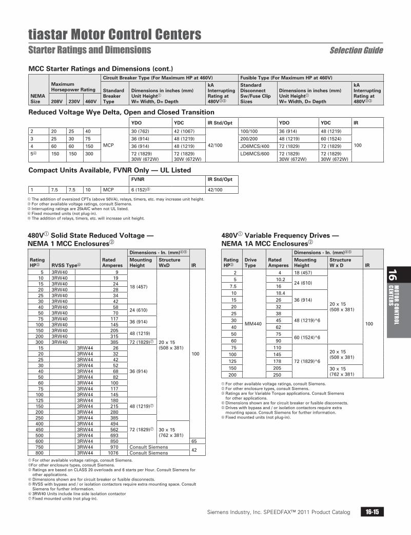
MCC Starter Ratings and Dimensions (cont.)
NEMA Size
Maximum Horsepower Rating
Circuit Breaker Type (For Maximum HP at 460V) Fusible Type (For Maximum HP at 460V)
Standard Breaker Type
Dimensions in inches (mm) Unit Heighta
W= Width, D= Depth
kA Interrupting Rating at 480Vbc
Standard Disconnect Sw/Fuse Clip Sizes
Dimensions in inches (mm) Unit Heighta W= Width, D= Depth
kA Interrupting Rating at 480Vbc208V 230V 460V
Reduced Voltage Wye Delta, Open and Closed TransitionYDO YDC IR Std/Opt YDO YDC IR
2 20 25 40
MCP
30(762) 42(1067)
42/100
100/100 36(914) 48(1219)
1003 25 30 75 36(914) 48(1219) 200/200 48(1219) 60(1524)
4 60 60 150 36(914) 48(1219) JD6MCS/400 72(1829) 72(1829)
5d 150 150 300 72(1829)30W(672W)
72(1829)30W(672W)
LD6MCS/600 72(1829)30W(672W)
72(1829)30W(672W)
Compact Units Available, FVNR Only — UL ListedFVNR IR Std/Opt
1 7.5 7.5 10 MCP 6(152)e 42/100
aTheadditionofoversizedCPTs(above50VA),relays,timers,etc.mayincreaseunitheight.b Forotheravailablevoltageratings,consultSiemens.c Interruptingratingsare25kAICwhennotULlisted.d Fixedmountedunits(notplug-in).eTheadditionofrelays,timers,etc.willincreaseunitheight.
480Va Solid State Reduced Voltage —NEMA 1 MCC Enclosuresb
Rating HPc RVSS Typef
Rated Amperes
Dimensions - In. (mm)de
IRMounting Height
Structure WxD
5 3RW40 9
18(457)
20x15(508x381)
100
10 3RW40 1915 3RW40 2420 3RW40 2825 3RW40 3430 3RW40 4240 3RW40 58
24(610)50 3RW40 7075 3RW40 117
36(914)100 3RW40 145150 3RW40 205
48(1219)200 3RW40 315300 3RW40 385 72(1829)g
15 3RW44 26
36(914)
20 3RW44 3225 3RW44 4230 3RW44 5240 3RW44 6850 3RW44 8260 3RW44 10075 3RW44 117
100 3RW44 145125 3RW44 180
48(1219)g150 3RW44 215200 3RW44 280250 3RW44 385
72(1829)g400 3RW44 494
30x15(762x381)
450 3RW44 562500 3RW44 693600 3RW44 850 65750 3RW44 970 ConsultSiemens
42800 3RW44 1076 ConsultSiemens
aForotheravailablevoltageratings,consultSiemens.bForotherenclosuretypes,consultSiemens.cRatingsarebasedonCLASS20overloadsand6startsperHour.ConsultSiemensfor
otherapplications.dDimensionsshownareforcircuitbreakerorfusibledisconnects.eRVSSwithbypassand/orisolationcontactorsrequireextramountingspace.Consult
Siemensforfurtherinformation.f3RW40UnitsincludelinesideisolationcontactorgFixedmountedunits(notplug-in).
480Va Variable Frequency Drives — NEMA 1A MCC Enclosuresb
Rating HPc
Drive Type
Rated Amperes
Dimensions - In. (mm)de
IRMounting Height
Structure W x D
2
MM440
4 18(457)
20x15(508x381)
100
5 10.224(610)
7.5 1610 18.4
36(914)15 2620 3225 38
48(1219)^630 4540 6250 75
60(1524)^660 9075 110
72(1829)^6
20x15(508x381)100 145
125 178150 205 30x15
(762x381)200 250
aForotheravailablevoltageratings,consultSiemens.bForotherenclosuretypes,consultSiemens.cRatingsareforVariableTorqueapplications.ConsultSiemens
forotherapplications.dDimensionsshownareforcircuitbreakerorfusibledisconnects.eDriveswithbypassand/orisolationcontactorsrequireextra
mountingspace.ConsultSiemensforfurtherinformation.fFixedmountedunits(notplug-in).

Siemens Industry, Inc. SPEEDFAX™ 2011 Product Catalog16-16
16M
OTOR
CON
TROL
CE
NTER
S
tiastar Motor Control CentersPower Distribution Ratings and Dimensions Selection Guide
Lighting PanelboardsApplied in MCCs
Amp Rating
Number of Circuits
Height in Inches (mm)
1%, 3W 240/120
3%, 4W 208Y/120
3%, 4W 277/480
Main Lug Only
125/25018 30(762) 30(762) 30(762)30 36(914) 36(914) 36(914)42 42(1067) 42(1067) 42(1067)
Main Lug Only
125/25018 30(762) 30(762) 30(762)30 36(914) 36(914) 36(914)42 42(1067) 42(1067) 42(1067)
Distribution Transformers
KVA Rating PhaseUnit Height in Inches (mm)
1
1
12(305)a
1.52357.5
18(457)b101525
24(610)bc
3037.5
36(914)bc
459
3c
18(457)15253037.5
24(610)45
aPlatemounted.bTransformermountedonbrackets6in.
(152mm)offsills.cRequires20in.(508mm)deepstructure.

Siemens Industry, Inc. SPEEDFAX™ 2011 Product Catalog 16-17
16M
OTOR CONTROL CENTERS
Siemens / Speedfax Previous folio: 15-11
tiastar Motor Control CentersProduct History Aftermarket
Siemens has an installed base of motor control centers dating back to 1964 due to acquisitions of Allis-Chalmers in 1978, ITE Gould in 1983 and Furnas Electric in 1996. This has resulted in eleven MCC models installed across the United States. Replacement units for these models as well as the cur-rent tiastarTM MCC offerings are built in the Siemens West Chicago plant. Siemens developed this tool to help people gain a better understanding of the wide variety of this installed base of MCCs. This should enable people
MCC Timeline
YearNote: Timeline represents approximate values
1964 1965 1971 1972 1975 1979 1980 1986 1990 1992 1993 1995 1996 1997 2001 2002 >2002
Allis-Chalmers
Siemens-Furnas
Siemens
Siemens
Siemens
ITE
Allis-Chalmers
Furnas
ITE
Furnas
Siemens-Allis Siemens
Siemens
to order aftermarket buckets or new MCCs much easier. In this program bro-chure, all the tools necessary for identi-fying existing MCCs to ordering forms are included. All items listed as follows: timeline, product overview, identifica-tion guide, product descriptions, work sheets and ordering check sheet. The intent of this guide is to provide a tool for Siemens customers so they can make a more educated purchasing deci-sion. If you have any questions, please contact your local Siemens representa-tive.

Siemens Industry, Inc. SPEEDFAX™ 2011 Product Catalog16-18
16M
OTOR
CON
TROL
CE
NTER
S
Siemens / Speedfax Previous folio: 15-12
tiastar Motor Control CentersProduct History Aftermarket
Original manufacturer Model
Productiondatesa
Bucket w/ door & handleb
Factoryretrofitc
Typical MCCnumberd
X=Letter# = Number
Siemens tiastar 2002–Current X — SameasSystem89Siemens/Furnas System89 1980–2001 X — 89BFXX######
89BSXX######89BBXX######WX###(ex.WU760)
Siemens Model95+ 1997–2001 X — 95BFXX######95BSXX######95BBXX######XX###(ex.WU760)
Siemens Model95 1995–1997 X — 09-001-XXXX-XXXXX-XXXSiemens Model90 1990–1997 X — 30-001-XXXX-XXXXXSiemensAllis Marq21 1975–1990 X — 01-14XX-XXXXX-XXAllis-Chalmers Mark2 1972–1975 X — #####(ex.15375)Allis-Chalmers Mark1 1965–1972 X —ITE Gould5600 1971–1992 — X 84-XXXXX-XXITE Gould9600 1964–1971 — X 85-XXXXX-XX
86-XXXXX-XXFurnas Class89 1965–1979 — X 89FVXXXXXXX
89SVXXXXXXX89BVXXXXXXXV####(ex.V2176)
aDatesrepresentapproximatevaluesonly.bBucketsexceeding250ampsarefixmounted.cContactWestChicagoAftermarketDept.forRetrofitProgramat(800)683-6200.d Insomeinstances,ageneric5alphanumericnumberisdesignedastheMCCsalesordernumber.Inmostcasesa5alphanumericnumberwithinthe
MCCnumberisthesalesordernumber.MCCnumberscanbefoundinsidetheMCCbucket.
This overview is a clear and concise snap shot of Siemens entire MCC product offering. For your convenience, typical MCC part numbers are shown for continued identification pos-sibilities.
Furthermore, the overview covers the standard options for the product offering.
Starters240V, 480V, 575V NEMA size
FVNR 1-6
FVR 1-5
2S1W-CT 1-5
2S1W-VT 1-5
2S2W-CT 1-5
2S2W-VT 1-5
RVAT 2-6
RVSS Consultfactory
VFD Consultfactory
Standard options
Ampmeter+CT Surgesuppression
CT UndervoltageCB
Voltagemonitor Shunttrip
Vac.contactor Groundstab
Transducer Highdensitybucket
Fusepuller Specialpaint
Bypass Timer
ASI® 4Prelay
Groundfault Extraunitspace
Elapsetimemeter

Siemens Industry, Inc. SPEEDFAX™ 2011 Product Catalog 16-19
16M
OTOR CONTROL CENTERS
Siemens / Speedfax Previous folio: 15-13
tiastar Motor Control CentersMCC Quote Request Form Aftermarket
www.usa.siemens.com/mcc_aftermarket
Serial #: __________________________________________
Order #:__________________________________________
Style #:__________________________________________
Section #:__________________________________________
System voltage: q480V q575V
System: q3x3WAC q3x4WAC qOther_________________________________
Control voltage:q24DC q120AC q240AC qOther________________________
System grounding:qSolidlyGrounded qUngrounded qHighResistanceGrounded
Short circuit withstand current:q42Kq65Kq100K
MCC model:
qSiemenstiastar™
qSiemensModel95+
qFurnasSystem89
qSiemensModel95
qSiemensModel90
qSiemens-AllisMarq21
qAllis-ChalmersMark2
qAllis-ChalmersMark1*
qITEGould9600*
qITEGould5600*
qFurnasClass89*
* Contactsalesofficefor replacementoptions.
Existing Equipment3
Quote request formMCC Aftermarket Units
Company: _______________________________________
Name (last/first): ___________________/___________________
Title: _______________________________________
q Nodistributoridentified
Company: _______________________________________
Name (last/first): ___________________/___________________
Title: _______________________________________
User Contact Info
Distributor Contact Info
Phone #: (_______)_____________________________
Email: _______________________________________
Street: _______________________________________
City: ________________State:___ZIP:___________
Phone #: (_______)_____________________________
Email: _______________________________________
Street: _______________________________________
City: ________________State:___ZIP:___________
1
2
Ordering Instructions:Completethisformonlineandsubmit.Youwillreceiveareplayin48hourswithastatusofyourrequest.
Bucket / Unit ID #:_______________________________________
Other voltage: _______________________________________
Unit type: qStarter qFeeder
Starter type:qFVNR qFVR qOther________________________________
NEMA size:q1q2q3q4q5q6
HP or Motor FLA: _________________________________________
Wiring diagrams: Yes No Suppliedbythecustomer:q q Requiredwithnewunit:q q Approvaldrawingsrequired:q q
Overload relays:qESPsolidstateqSimocode qBi-metalambientcompensated
Disconnect type:qCircuitbreakerqFusibleswitch
Control Voltage:qCPT qSeparatesource
CPT sizing:qStandard qExtra100V qOther*_____________________ *Mayrequireadditionalunitspace
Pilot Devices: Qty. Qty. SelectorSwitch: 2P/3P 4P PilotLights: Standard PTT Color/function:______________________________ (e.g.ambertriplight)
Bulb:qStandard qLED
Whatisthefunctionofthisdevice?
______________________________________________
______________________________________________
aAftermarket Units4 Toorderadditionalaftermarketunits,completesection4b
Aftermarket and Replacement units forms are available at www.usa.siemens.com/mcc_aftermarket

Siemens Industry, Inc. SPEEDFAX™ 2011 Product Catalog16-20
16M
OTOR
CON
TROL
CE
NTER
S
Siemens / Speedfax Previous folio:15-14
tiastar Motor Control CentersMCC Quote Request Form Aftermarket
b Complete this section to order additional aftermarket units
Glossary of acronyms5
FVNR: Full Voltage Non Reversing
FVR: Full Voltage Reversing
FLA: Full Load Amps
ESP: Extra Starter Protection
CPT: Control Power Transformer
PTT: Push To Test
Bucket / Unit ID #: _______________________________________
Other voltage: _______________________________________
Unit type: q Starter q Feeder
Starter type: q FVNR q FVR q Other________________________________
NEMA size: q1 q2 q3 q4 q5 q6
HP or Motor FLA: _________________________________________
Wiring diagrams: Yes No Supplied by the customer: q q Required with new unit: q q Approval drawings required: q q
Overload relays: q ESP solid state q Simocode q Bi-metal ambient compensated
Disconnect type: q Circuit breaker q Fusible switch
Control Voltage: q CPT q Separate source
CPT sizing: q Standard q Extra 100 V q Other*_____________________ *May require additional unit space
Pilot Devices: Qty. Qty. Selector Switch: 2P/3P 4P Pilot Lights: Standard PTT Color / function: ______________________________ (e.g. amber trip light)
Bulb: q Standard q LED
What is the function of this device?
______________________________________________
______________________________________________
Qty. Qty. Qty.
Handle Assembly:Include location,
Unit type /application
Door Kit:Include
dimensions,blank, location
Nameplate:Include size,
letter / plate color,text to be engraved
Pilot Devices:
Pilot Devices:
Reset Parts:(Overload)
Transformer:
Fuse:
Other:Please
specify
Replacement Parts4 Please include the part # (if available) and a brief description with application / rating details.
Quote request form


![Facilities Development Division...2018/02/13 · Special Seismic Certification [OSHPD 1R, 2, 5] 1705.13.3.1 Special seismic certification. [OSHPD 1R, 2 and OSHPD 5] Required for:](https://img.dokumen.tips/doc/110x75/5f06a0fa7e708231d418f11d/facilities-development-division-20180213-special-seismic-certification.jpg)