Embed Size (px)
Citation preview

SPEED TRACKING OF INDIRECT FIELD ORIENTED CONTROL INDUCTION MOTOR
USING NEURAL NETWORK
AZUWIEN AIDA BINTI BOHARI
UNIVERSITI TUN HUSSEIN ONN MALAYSIA

ii
UNIVERSITI TUN HUSSEIN ONN MALAYSIA
STATUS CONFIRMATION FOR MASTER’S THESIS
SPEED TRACKING OF INDIRECT FIELD ORIENTED CONTROL
INDUCTION MOTOR USING NEURAL NETWORK
ACADEMIC SESSION: 2015/2016
I, AZUWIEN AIDA BINTI BOHARI, agree to allow this Master’s Thesis to be kept at the library under the following terms: 1. This Master’s Thesis is the property of the Universiti Tun Hussein Onn Malaysia.
2. The library has the right to make copies for educational purposes only.
3. The library is allowed to make copies of this report for educational exchange between higher
educational institutions.
4. **Please Mark (√)
CONFIDENTAL (Contains information of high security or of great importance to Malaysia as STIPULATED under the OFFICIAL SECRET ACT 1972)
RESTRICTED (Contains restricted information as determined by the organization institution where research was conducted)
FREE ACCESS
(WRITER’S SIGNATURE) AZUWIEN AIDA BINTI BOHARI
Writer’s Name Permanent address: POS 74, KAMPUNG PARIT BARU, PARIT RAJA, 86400BATU PAHAT, JOHOR. Date : ____________________
Approved by,
(SUPERVISOR’S SIGNATURE) DR. WAHYU MULYO UTOMO
Supervisor’s Name
Date : ____________________
NOTE:
** If this Master’s Thesis is classified as CONFIDENTIAL or RESTRICTED,
please attach the letter from the relevant authority/organization stating
reasons and duration for such classifications.
√

iii
This thesis has been examined on date 29 February 2016 and is sufficient in
fulfilling the scope and quality for the purpose of awarding the Degree of Masters in
Electrical Engineering
Chairperson:
Prof. Madya Siti Hawa Binti Ruslan
Faculty of Electrical and Electronic Engineering
Universiti Tun Hussein Onn Malaysia (UTHM)
Examiners:
Prof. Madya Dr. Abu Zaharin Bin Ahmad
Faculty of Electric and Electronic Engineering
Universiti Malaysia Pahang (UMP)
Prof. Madya Dr. Dirman Hanafi Burhannuddin
Faculty of Electrical and Electronic Engineering
Universiti Tun Hussein Onn Malaysia (UTHM)

i
SPEED TRACKING OF INDIRECT FIELD ORIENTED CONTROL INDUCTION
MOTOR USING NEURAL NETWORK
AZUWIEN AIDA BINTI BOHARI
A thesis submitted in
fulfillment of the requirement for the award of the
Degree of Master
Faculty of Electrical and Electronic Engineering
Universiti Tun Hussein Onn Malaysia
APRIL 2016

ii
I hereby declare that the work in this thesis is my own except for quotations and
summaries which have been duly acknowledged
Student : ………………………………………………..
AZUWIEN AIDA BINTI BOHARI
Date : ………………………………………………..
Supervisor : ………………………………………………..
DR. WAHYU MULYO UTOMO
Co Supervisor : ……….…………………………………….
ASSOC. PROF DR. ZAINAL ALAM BIN
HARON

iii
Special dedicated to my mother Rodiah Ramlan, my father Bohari Selamat, my
husband Mohd Nizam Mohd Talib, my daughter Syafia Nurhanna Mohd Nizam and
my son Muhammad Izz Zafran Bin Mohd Nizam, thank you so much for the support
and attention to me.

iv
ACKNOWLEDGEMENT
First of all, Alhamdullilah, praise to Allah for His Blessings I have finished writing
this dissertation for Master of Electrical Engineering. I express my sincere
appreciation to my supervisor, Dr Wahyu Mulyo Utomo for his encouragement,
guidance, advices and critics. Without his continuous support and interest, this
research could not be finished.
I would like to gratitude Faculty of Electrical and Electronic Engineering
(FKEE) Universiti Tun Hussein Onn Malaysia for any valuable supports during
conducting this project and in preparing this report.
My appreciation also goes to my family especially my husband and my
parents for their biggest support and involvement in every aspect. Last but not least,
my appreciation goes to my fellow friends and everyone involved directly or
indirectly in order to finish this study and compilation of this dissertation.

v
ABSTRACT
This thesis presents the development of speed tracking of indirect field oriented
control (IFOC) induction motor (IM) using neural network (NN). IM are usually low
cost, physically smaller, reliable and rugged machines. Furthermore, in contrast to
direct current (DC) motor, it can also be used in hostile or volatile environment.
Unfortunately, the operation of IM is much more complicated rather than DC motor
and low control precision as the field and torque producing component of its input
current are linked. To achieve better control precision, it is necessary to control these
two parameters of stator current independently. The objectives of this project is to
implement an efficient neural network indirect field oriented control (NNIFOC) that
could be implanted to control the speed of IM and capable of observing steady state,
transient motor behavior and thus improves the performance of the drive. Here, the
online NN with 1-3-1 network structure with feed-forward architecture is used to
maintain the speed trajectory specified by reference model and compared with offline
NN based approach to the area of decoupling control using IFOC principles of speed
tracking for an IM. Both offline and online NN are trained by backpropagation
technique with one hidden layer to update parameters of weight and bias. Simulation
model has been developed using MATLAB Simulink. Validity of proposed NNIFOC
is verified with actual experimental results focusing on speed variation and load
disturbance using digital signal processing (DSP) techniques. The results show that
online NNIFOC reveals better performance than offline NNIFOC in terms of settling
time.

vi
ABSTRAK
Projek ini membentangkan pembangunan pengesanan kelajuan berorientasikan
kawalan bidang tidak langsung (IFOC) motor aruhan (IM) yang menggunakan
rangkaian neural (NN). IM murah, lebih kecil, kebolehpercayaan operasi dan mesin
yang lasak. Tambahan pula, berbeza dengan motor arus terus (DC), IM boleh
digunakan dalam persekitaran yang agresif atau tidak menentu. Malangnya operasi
IM adalah lebih rumit berbanding DC motor dan kurang tepat dalam kawalan kerana
komponen fluk dan tork yang terhasil dari masukan arusnya adalah berkait. Dalam
usaha untuk mencapai kawalan yg tepat bagi motor aruhan, adalah perlu untuk
mengawal dua komponen arus stator secara berasingan.Objektif projek ini adalah
untuk mengamalkan orientasi kawalan bidang tidak langsung (NNIFOC) yang boleh
digunakan untuk mengawal kelajuan IM dan mampu mengawal keadaan sehingga
stabil, tingkah laku motor fana dan prestasi pemacu. Di dalam projek ini, NN atas
talian dengan struktur rangkaian 1-3-1 oleh senibina suapdepan yang digunakan
untuk mengekalkan kawalan kelajuan ditetapkan oleh model rujukan akan
dibandingkan dengan NN luar talian berdasarkan pendekatan kepada kaitan kawalan
nyahgandingan menggunakan prinsip IFOC dari pengesanan kelajuan sebuah IM.
NN atas talian akan dilatih dengan teknik pembiakan kembali dengan satu lapisan
tersembunyi untuk mengemaskini parameter. Model simulasi telah dibangunkan
dengan menggunakan pakej Perisian MATLAB Simulink. Kesahihan cadangan
NNIFOC ditunjukkan dengan keputusan eksperimen yang dijalankan dengan
menumpukan kepada perubahan kelajuan dan beban gangguan berasaskan
pemprosesan isyarat digital DSP. Keputusan menunjukkan prestasi NNIFOC dalam
talian adalah lebih baik dari NNIFOC luar talian dari segi masa stabil.

vii
TABLE OF CONTENTS
TITLE i
DECLARATION ii
DEDICATION iii
ACKNOWLEDGEMENT iv
ABSTRACT v
ABSTRAK vi
TABLE OF CONTENTS vii
LIST OF TABLES xii
LIST OF FIGURES xiii
LIST OF SYMBOLS AND ABBREVIATIONS xviii
LIST OF APPENDICES xx
CHAPTER 1 INTRODUCTION 1
1.1 Introduction 1
1.2 Background Study 1
1.3 Problem Statement 2
1.4 Research Objective 3
1.5 Research Scope 3
1.6 Thesis Outline 4

viii
CHAPTER 2 LITERATURE REVIEW 6
2.1 Introduction 6
2.2 Electric Motor Classification 6
2.2 Advantages AC Motor over DC Motor 7
2.3 Induction Motor Control Methods 8
2.4 Field Oriented Control (FOC) 10
2.4.1 Review of Existing Previous Work 11
2.4.1.1 Field Oriented Control of
IM Drive
12
2.4.1.2 FOC of IM Drive System
with Conventional Speed
Controller
13
2.4.1.3 FOC of IM Drive with
Artificial Intelligent Speed
Controller
17
2.5 Gap of Study 23
2.6 Conclusion 23
CHAPTER 3 METHODOLOGY 24
3.1 Introduction 24
3.2 Project Flow Chart 24
3.3 Control Strategy of the FOC of IM Drive
System
26
3.3.1 Id* and Iq* Calculation Block 27
3.3.2 ω Slip Calculation Block 28
ix
3.3.3 Flux And Torque Controller 28
3.3.4 Park and Clark Transformation
Block
29
3.4 Proposed NN Speed Controller 30
3.4.1 Updating Algorithm of Proposed
NN
35
3.4.2 Training of Proposed NN Speed
Controller
38
3.5 Conclusion 43
CHAPTER 4 RESULT AND ANALYSIS 44
4.1 Introduction 44
4.2 Overview of Systems Developments 44
4.3 Simulation Model using MATLAB 46
4.3.1 Space Vector Pulse Width
Modulation Inverter Block
46
4.4 Simulation Results and Discussion 47
4.4.1 Simulation Test for Better
Performance of the Proposed
NNIFOC of IM
47
4.4.2 Simulation Test for Speed Variation 52
4.4.3 Simulation Test for Constant Speed
with Load Disturbance
54
4.4.4 Experimental Performance
Comparison
57

x
4.5 Hardware Development and
Implementation
58
4.5.1 The Real-Time Interface
Integration with DSP Controller
59
4.5.1.1 Feedback of the Motor
Speed Signal
60
4.5.1.2 Feedback of the Motor
Current Signal
60
4.5.2 The Experimental Set-Up 61
4.6 The Experimental Results and Discussion 62
4.6.1 Experimental Test for Better
Performance of the Proposed
NNIFOC of IM Drive System
63
4.6.2 Experimental Test for Speed
Variation
67
4.6.3 Experimental Test for Constant
Speed with Load Disturbance
68
4.6.4 Experimental Performance
Comparison
71
4.7 Conclusion 73
CHAPTER 5 CONCLUSION 75
5.1 Conclusion 75
5.2 Future Work 76
LIST OF PUBLICATIONS 76
REFERENCES 79

xi
APPENDIX 86
VITAE 108

xii
LIST OF TABLES
2.1 Gap of study for the NN based FOC of IM drive
according to the several recent works
23
4.1 Performance comparison for different constant speed
condition
57
4.2 Performance comparison for speed variation condition 57
4.3 Performance comparison for constant speed with load
disturbance
58
4.4 Performance comparison for different constant speed
condition
71
4.5 Performance comparison for speed variation condition 72
4.6 Performance comparison for constant speed with load
disturbance
72
xiii
LIST OF FIGURES
2.1 Electric motors family 7
2.2 General classification of IM control methods 9
2.3 Indirect vector control method 11
2.4 Direct vector control method 11
2.5 The speed controller of FOC IM drives incorporated by PID
controller
14
2.6 The speed controller of FOC IM drives incorporated by fuzzy
logic controller
17
2.7 The speed controller of FOC IM drives incorporated by NN
controller
20
3.1 Project flow chart 25
3.2 Block diagram of speed control IFOC of IM drives system 27
3.3 Block diagram of PI, flux and torque controller 29
3.4 Backpropagation NN training flow chart 31
3.5 Neuron Structure 32
3.6 Structure of NNIFOC 35
3.7 Block diagram of FOC 38
3.8 Graph of input, target and output of training data for 1 neuron
of hidden layer structure
40
xiv
3.9 Best validation performance obtain by 1 neuron of hidden
layer structure
40
3.10 Graph of input, target and output of training data for 2 neuron
of hidden layer structure
41
3.11 Best validation performance obtain by 2 neuron of hidden
layer structure
41
3.12 Graph of input, target and output of training data for 3 neuron
of hidden layer structure
42
3.13 Best validation performance obtain by 3 neuron of hidden
layer structure
42
4.1 The general testing diagram of the proposed NNIFOC of IM
drive system
45
4.2 The complete Simulink block of the proposed NNIFOC of IM
drive system
46
4.3 The Simulink circuit of the SVPWM control technique for the
three phase’s inverter
47
4.4 The speed, current and torque response for the speed of 600
rpm with 0.2Nm load torque applied: (a) Online learning
NNIFOC; (b) Offline learning NNIFOC
48
4.5 The speed, current and torque response for the speed of
900rpm with 0.2Nm load torque applied: (a) Online learning
NNIFOC; (b) Offline learning NNIFOC
49
4.6 The speed, current and torque response for the speed of
1200rpm with 0.2Nm load torque applied: (a) Online learning
NNIFOC; (b) Offline learning NNIFOC
49
4.7 The speed, current and torque response for the speed of
600rpm with 0.8Nm load torque applied: (a) Online learning
NNIFOC; (b) Offline learning NNIFOC
50

xv
4.8 The speed, current and torque response for the speed of
900rpm with 0.8Nm load torque applied: (a) Online learning
NNIFOC; (b) Offline learning NNIFOC
50
4.9 The speed, current and torque response for the speed of
1200rpm with 0.8Nm load torque applied: (a) Online learning
NNIFOC; (b) Offline learning NNIFOC
51
4.10 The speed, current and torque response for a step speed
variation under the 0.2Nm load torque applied: (a) Online
learning NNIFOC; (b) Offline learning NNIFOC
53
4.11 The speed, current and torque response for a step speed
variation under the 0.8Nm load torque applied: (a) Online
learning NNIFOC; (b) Offline learning NNIFOC
53
4.12 The speed, current and torque response for a constant speed of
600 rpm with load disturbance of 0.2 Nm and 0.8 Nm at the
time of 0.7s, and 1.2s; (a) Online learning NNIFOC, (b)
Offline learning NNIFOC
55
4.13 The speed, current and torque response for a constant speed of
900 rpm with load disturbance of 0.2 Nm and 0.8 Nm at the
time of 0.7s, and 1.2s; (a) Online learning NNIFOC, (b)
Offline learning NNIFOC
55
4.14 The speed, current and torque response for a constant speed of
1200 rpm with load disturbance of 0.2 Nm and 0.8 Nm at the
time of 0.7s, and 1.2s; (a) Online learning NNIFOC, (b)
Offline learning NNIFOC
56
4.15 The connection between MATLAB and DSP Board 58
4.16 Real-time interface model with digital output block 59
4.17 The experimental set-up of NNIFOC of IM 61
4.18 The speed and current response for the speed of 600 rpm with 63

xvi
0.2Nm load torque applied: (a) Online learning NNIFOC; (b)
Offline learning NNIFOC
4.19 The speed and current response for the speed of 900 rpm with
0.2Nm load torque applied: (a) Online learning NNIFOC; (b)
Offline learning NNIFOC
64
4.20 The speed and current response for the speed of 1200 rpm with
0.2Nm load torque applied: (a) Online learning NNIFOC; (b)
Offline learning NNIFOC
64
4.21 The speed and current response for the speed of 600 rpm with
0.8Nm load torque applied: (a) Online learning NNIFOC; (b)
Offline learning NNIFOC
65
4.22 The speed and current response for the speed of 900 rpm with
0.8Nm load torque applied: (a) Online learning NNIFOC; (b)
Offline learning NNIFOC
65
4.23 The speed and current response for the speed of 1200 rpm with
0.8Nm load torque applied: (a) Online learning NNIFOC; (b)
Offline learning NNIFOC
66
4.24 The speed and current response for a step speed variation
under 0.2Nm load torque applied: (a) Online learning
NNIFOC (b) Offline learning NNIFOC
67
4.25 The speed and current response for a step speed variation
under 0.8Nm load torque applied: (a) Online learning
NNIFOC (b) Offline learning NNIFOC
68
4.26 The speed and current response for a constant speed of 600
rpm with load disturbance of 0.2 Nm and 0.8 Nm at the time
of 3s, and 5s; (a) Online learning NNIFOC, (b) Offline
learning NNIFOC
69
4.27 The speed and current response for a constant speed of 900
rpm with load disturbance of 0.2 Nm and 0.8 Nm at the time
70

xvii
of 3s, and 5s; (a) Online learning NNIFOC, (b) Offline
learning NNIFOC
4.28 The speed and current response for a constant speed of 1200
rpm with load disturbance of 0.2 Nm and 0.8 Nm at the time
of 3s, and 5s; (a) Online learning NNIFOC, (b) Offline
learning NNIFOC
70

xviii
LIST OF ABBREVIATIONS AND SYMBOLS
α - Alpha
A - Ampere
β - Beta
Nm - Newton Meter
V - Voltage
kW - Kilo Watt
AC - Alternating Current
ANN - Artificial Neural Network
DTC - Direct Torque Control
DC - Direct Current
DFIM - Doubly Fed Induction Motor
DSP - Digital Signal Processing
EMF - Electromotive Force
FAG - Fuzzy Adapted Gains
FLC - Fuzzy Logic Controller
FOC - Field Oriented Control
FRC - Fuzzy Robust Controller
IFOC - Indirect Field Oriented Control
xix
IM - Induction Motor
IRFOC - Indirect Rotor Field Oriented Control
ISFOC - Indirect Stator-Flux-Oriented Control
IVC - Indirect Vector Control
IVCIM - Indirect Vector Control Induction Motor
MSE - Mean Square Error
NN - Neural Network
NNIFOC - Neural Network Indirect Field Oriented Control
PI - Proportional Integral
PID - Proportional Integral Derivative
PWM - Pulse Width Modulation
RNN - Recurrent Neural Network
rpm - Round Per Minute
SDRFOC - Sensorless Direct Rotor Field Oriented Control
SMC - Sliding Mode Control
VC - Vector Control
VGPI - Variable Gain Proportional Integral
2DOFC - Two-Degree-Of-Freedom Controller
xx
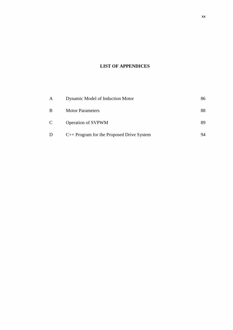
LIST OF APPENDICES
A Dynamic Model of Induction Motor 86
B Motor Parameters 88
C Operation of SVPWM 89
D C++ Program for the Proposed Drive System 94
1
CHAPTER 1
INTRODUCTION
1.1 Introduction
In this chapter, the introduction of the thesis will be explained in detail that consists
of research background, focus of the study, problem statements, research objectives,
scope and outlines.
1.2 Background Study
Russia, Japan, China, the European Union and the United States are five big motor
consumers, about 84% collectively account for motor electricity consumption in the
countries [1]. Approximately, 68% of the electricity used by electric motors with
input power range from 0.75 kW up to 375 kW. Most of them are asynchronous
current (AC) induction motor (IM) with 2, 4, 6 or 8 poles. There are various types of
motor designs available, but the AC IM has been dominating and frequently used.
Electric motors use about half the electricity produced by developed countries,
where 90% is from induction motor [2]. The rugged structure, robustness, low cost,
high reliability and very minimal maintenance are among the advantages of IM as
compared to direct current (DC) motor counterpart.
A lot of researchers have been attracted to the field of electric drives by IM
control over time. The IM control methods are divided into scalar and vector control
(VC). The scalar control is usually used in low cost and low performance drives.
Even though the control is easy to implement and offer a relatively steady-state
2
response, unfortunately the dynamics are sluggish. To obtain high precision and good
dynamics, VC approach is being employed with closed-loop feedback control [3].
Translation of coordinate from fixed reference stator frame to the frame of rotating
synchronous is implied by the VC [4, 5]. IM variable speed AC drives with VC
technique has been popular in recent years for better performance set by DC drives.
The possibility of the flux and torque separated control in the dynamic complex
of IM is achieved using decoupling technique in early 1970s [6,7] Decoupling
between flux and torque is highly recommended for excellent control of flux and
torque. The relevant mathematical description of three-phase IM is contributed by
field oriented control (FOC) which produces high dynamic performance [8, 9].
1.3 Problem Statement
IM is superior to DC machine with respect to physical size, weight, inertia, cost and
speed. In addition, it is able to operate in elusive and hostile environment than DC
motor with mechanical commutation. However, the operation of IM is much more
complicated and lack of precision control as the flux and torque of its input current
are coupled.
With the advancement of power electronics and culminating in DSP and
microcontrollers, controlled electrical drives have achieved fast development. The
powerful control development of AC drive with minimized power dissipation and
definite control structures can be obtained by these technological improvements. To
obtain definite control of IM, it is crucial to manage these two components of stator
currents individually using FOC. Commonly used variable speed controls of motors
are classically handled by conventional controllers such as proportional integral (PI)
and proportional integral derivative (PID) controllers in FOC. Even though PID are
simple and is very easy to implement, several problems such as high overshoot and
torque oscillation causing by load disturbances do occur. Furthermore, the controller
performance diversifies depend on operating conditions. To overcome the drawbacks
in conventional controller, a solution has been proposed using an online neural
network (NN) controller. NN has the capability to coordinate when changes is given
in the control environment applying input and output system. It has the ability to
identify and control nonlinear system. The complex theory of control system or the
real model is not required in NN. Recent development in the NN technique has made
3
it possible to train a NN to represent a variety of complicated nonlinear systems.
Online NN is chosen according to the fact that even offline model can handle large
data as computation time is not critical to their structure, it is only robust to small
variation, but fail to adapt to larger changes in the system, while the online model
adapts to variation quickly in non-linear behavior of the system. This research is not
limited to control the speed in any operation with different load torques and speed
variations but at the same time, to maintain and increase the system performance
when dealing with system uncertainties, such as dynamic load disturbance.
1.4 Research Objective
The objective of this project is to control the IM with the proposed speed controller.
The controller is able to maintain the performance of the motor in any conditions
given, namely
i. To model and develop FOC IM drive system using MATLAB Simulink.
ii. To develop a proposed speed controller using online and offline NN
technique to track the speed of IM based FOC.
iii. To verify the performance of proposed neural network indirect field oriented
control (NNIFOC) for both offline and online method in simulation and
experiments.
1.5 Research Scope
The motor specifications for the hardware are given below:
- frequency, f : 50 Hz
- Pole, p : 2
- Stator Resistance, Rs : 8.2Ω
- Rotor Resistance, Rr : 5.3667Ω
- Stator Self Inductances, Ls : 0.4934H
- Rotor Self Inductances,Lr : 0.4934H
- Mutual Inductance, Lm : 0.4867H

4
This project is conducted as the following stages:
i. Modeling and simulation:
- MATLAB Simulink is used to develop the proposed online NNFOC of IM
drives system.
ii. Software and hardware implementation:
- The speed controller to deal with speed variation and load disturbance is
designed.
- Prototype of the proposed NNIFOC of IM drives system is constructed.
- Code Composer Studio, CC Studio v3.3 is used as an interface to connect
the proposed NNIFOC of IM with digital board controller (DSP) board
controller.
1.6 Thesis Outline
This section explains the design, comparison and performance of proposed NNIFOC
IM drive. It is divided into five chapters and the summary of each chapter is given
below.
(a) Chapter 1 : Introduction
This first chapter gives some background introductions of the research.
Problems of previous work are highlighted and research objectives are also
discussed here.
(b) Chapter 2 : Literature Reviews
This chapter explains the electric motor classifications. In addition,
advantages AC over DC motor and their control method are also discussed.
The review of previous and current research in FOC IM drive system are
presented.
(c) Chapter 3 : Research Methodology
This chapter describes the project implementation. Explanation of the
proposed NN speed controller in indirect field oriented control (IFOC) IM is
also discussed here and the control algorithms of the NN are explained in
details.
5
(d) Chapter 4 : Simulation and Experimental Results
This chapter describes performance of the proposed NNIFOC IM drive in
both simulation and hardware implementation. The proposed design is
simulated using MATLAB Simulink, while the experiment is realized
through C2000 DSP controllers, TMS320C2800 controller board. The test
data obtained in simulation is verified with experimental setup.
(e) Chapter 5 : Conclusions
This final chapter describes and concludes the project summary. Objectives
of the research successfully achieved, and suggestions for future work are
described as well.
6
CHAPTER 2
LITERATURE REVIEW
2.1 Introduction
This chapter describes fundamental knowledge of induction motor. Besides,
background studies of the available control methods for motor drives conjointly with
the proposed FOC method is also described here. Some literatures related to the topic
that have been invented or have been produced nowadays also will be discussed to
reveal and give overview concept and the idea of the entire project.
2.2 Electric Motor Classification
Electrical to mechanical conversion process in modern industrial civilization plays an
important role. Electric motor is a machine that converts electrical to mechanical
energy. It can be classified into two major categories, namely DC and AC motor.
Either AC or DC current can be used to run the electric motor at one time. Family
tree of the electric motor is show in Figure 2.1. A DC electric motor is able to run if
only DC current is being supplied into it and the same thing goes to AC electric
motor.
7
Figure 2.1 : Electric motors family
2.2 Advantages AC Motor over DC Motor
Electric motor contributes significantly in industrial production and many other
applications. The use of AC motor has extensively spread in industry attributable to
their simple and rugged structure and excellent performance. The AC motor,
particularly the squirrel cage type, is widely used up to 70% in industries. As
compared to DC motor, an AC motor is very reliable, simple in construction, low
cost and simpler maintenance requirements [10]. In addition, they are also resistant
to heavy overloads.
On the other hand, an induction motor does not face any problems with spark
and corrosion and can be used in volatile environment. The major limitation is the
presence of DC motor brushes and commutators [11-13]. When the brush wears off,
low pressure environment increases dramatically and the sparks from the brushes can
lead to explosion if the environment contains explosive materials since they need
brushes to connect the rotor winding. The highest impediments of DC motor are the
brush erosion, maintenance, requirements, environmental effect, power limits and
lastly complex structure.
Electric Motor
DC Motor
Brushless DC Motor
Brush DC Motor
AC Motor
Asynchronous Motor
Synchronous Motor
Induction Motor

8
The main limitation of an IM is based on controllability which is caused by
its complex mathematical model and nonlinear behavior at saturation stage. The
complexity of an AC drive increases substantially if high performances is required as
the control and estimation in general, are considerably more complex. The motor
speed should tightly comply with a specific reference trajectory on any load
disturbance, parameter variations and uncertainties for high performance system
[14].
No linear ties between stator current and either the torque or flux since an IM
requires complex algorithms. This means that it is hard to manage the torque and
speed. High performance control and evaluation methods for IM drives are very
demanding and it is an interesting subject at the same time. Nowadays, a lot of
methods have been developed for IM drives and leads to excellent control
performance. It shows that the development of high performance motor drives to
manipulate the motor is very crucial in industrial applications [15]. Normally, a good
dynamic speed tracking and load regulating as well as the performance are incentives
to the drive and load parameter variations are the characteristics of the high
performance drive system [16].
2.3 Induction Motor Control Methods
Many researchers are interested in IM as it provides diverse control techniques. Its
control methods are divided in two groups, namely the vector and scalar control
which are also known as open and close loop control [17].
Figure 2.2 illustrates general classification of IM control techniques. Study on
the control methods has initially been done for scalar control. With assumption that
rated flux is proportional to voltage over constant frequency, this method is based on
the relationship valid for steady states. Problem of independent control of outputs, for
example, torque and flux are regardless of the scheme and unable to perform
decoupling between input and output. To date, to achieve decoupling on high-
performance IM drives, the possible solution is on VC.

9
Figure 2.2 : General classification of IM control methods
The magnitude and angular speed as well as the instantaneous positions of
voltage and controlled current are the vital parameters for dynamic states of vector
control. Therefore, the control provides correct orientation for both steady and
transient states besides acting on the position of space vectors. This belongs to high-
performance control implemented in a closed-loop mode and it enhances
dynamically decoupled fast flux and torque control [3, 18]. The benefits that have
been offered by VC are the speed control over a wide range, precise speed
regulation, fast dynamic response and operational above base speed. Only several
basic schemes that are offered in the market despite the vector control itself can be
implemented in many different ways. Nowadays, FOC and direct torque control
(DTC) are the most popular strategies.
The appearance of VC in early 1970s allowed a considerable increase of
dynamic performance of IM [19]. Based on Fleming’s Law, the VC makes
performance of IM to be as good as DC motor where torque and flux can be
controlled independently after being decoupled. The effect of factors, such as
inaccurate control and variable motor parameter will make actual performance of VC
be worse than predicted in practical engineering applications. Some improved
techniques, such as flux observer, rotor resistance identification are adopted to
reduce the effect of this variation such that the control of VC can be satisfied in most
applications and several methods are investigated to address this problem.
IM Control
Scalar Control Vector Control
Direct Field
Oriented Control
Indirect Field
Oriented Control

10
2.4 Field Oriented Control (FOC)
FOC have made possible the application of IM for high performance applications
where traditionally only DC drives were applied. Separate excitation DC motor has
similar way as field oriented scheme that allows the control of IM. Speed control of
three-phase AC electric motors is achieved by controlling the current where it is one
of the methods used in variable-frequency drives or variable speed drives to control
its torque. FOC torque is obtained by controlling the torque and flux current
independently. By using FOC, at low and high speeds, there is not any torque ripples,
thus smoother and accurate control can be achieved.
Figure 2.3 and Figure 2.4 shows the basic schemes of indirect and direct
methods of VC. The direct VC method relies on the stator or air-gap flux with
generation of unit vector signals. From stator voltage and current, the air-gap signals
can be measured directly and estimated. Stator quantities can be directly computed
through the stator flux. Rotor field angle does not need rotor speed in these systems.
Rotor field angle and unit vectors are indirectly acquired by summation of the rotor
speed and slip frequency which happens in indirect vector control (IVC).
Controlling the stator currents represented by a vector is included in FOC.
Transforming a three-phase time and speed dependent system into two coordinates,
i.e. d and q coordinates time invariant system by this control which based on
projections. A structure that is similar to a DC machine control is brought by the
projections.
The torque component which aligns with q coordinate and flux component
which aligns with d coordinate are the two constants that act as input reference for
FOC machines. The control structure handles instantaneous electrical quantities
while FOC is simply based on projections. Therefore, the control will be independent
on limited bandwidth and accurate in every working operation.
11
Figure 2.3 : Indirect vector control method
Figure 2.4 : Direct vector control method
Knowledge of two currents and rotor flux position are the fundamental
requirements for FOC. The core knowledge of FOC is the rotor flux position. The
rotor flux is not aligned with d-axis and the current components are incorrectly
estimated if there is an error in this variable. The rotor speed is not equivalent to
rotor flux in the machine. A big credit to FOC is that it turns torque and flux of IM
for direct and separate control. Instantaneous control of the separate quantities
facilitates accurate transient and steady state management and obtaining DC motor’s
advantage for FOC IM.
2.4.1 Review of Existing Previous Work
Reviews have been made for FOC IM with conventional and artificial intelligent
based speed control techniques. Different control methods with their own advantages
and disadvantages have also been discussed. On the other hand, speed performance
has its own merits with different speed control methods.
FOC INVERTER IM
Ψ VECTOR MEASUREMENT
/ESTIMATION
θ
Voltage Current Ψ*
Te*
Voltage
INVERTER
IM FOC
SLIP CALCULATION
∫
Ψ*
Te*
θ
+ +
Current
12
2.4.1.1 Field Oriented Control of IM Drive
The control of AC electric machines is known as a considerable development and a
possibility of real-time applications is similar to a consequence of the important
progress in power electronics and micro computing [20]. Robustness, cost,
reliability, effectiveness, maintenance free, simple and rugged structure, and ease of
control [4, 15] that is used in various applications ranging from industrial motion,
control systems to home appliances are some of the AC IM desirable features. DC
motor drive has proven to have good dynamic torque response but the AC motor has
also come up with the same features [21]. But it has only been used in industrial
applications that do not require high performance for a long time. Very complex
mathematical model due to coupling of physical parameters becomes a challenging
problem because there is not any linear relationship between stator current and either
the torque or flux and they exhibit significant non linearity than DC drives in
dynamic industrial applications [22].
The use of the IM has become more popular since Blashke and Hasse who
developed the new technique known as FOC [23]. It has been proven that this control
strategy is well adapted to all types of electrical drives associated with IM and good
at providing the same performance as DC machine [24]. A powerful tool for high
performance control of IM has turned up to be FOC. Traditionally, only DC drives
are used for high performance applications, but this technique has also made the
application of IM successfully replacing the expensive DC motor.
Direct and indirect methods are the two schemes that can be reached in FOC.
Flux position is measured or evaluated on the basis of flux components in the stator
coordinates in direct FOC schemes. On the other hand, flux position is indirectly
determined through rotor speed and slip estimation for indirect control schemes [25].
Among all the methods, simplicity of design and construction, the absence of rotor
flux position sensor and the ability to operate at low speeds has made the indirect
FOC control strategy well known.
Separately flux and torque producing current are the two components of
stator current that need to be controlled for precision [19]. Torque is controlled
independently by adjusting the armature current, iq so that the control of IM becomes
identical with DC motor and flux is controlled by exciting current in FOC. It permits,
13
through a coordinate transformation, to decouple the electromagnetic torque control
from rotor flux, and therefore manage like a DC motor. To obtain DC quantities with
dynamic behaviour, the variables are converted into a reference frame in this
technique [26]. To achieve fast transient response of the IM, decoupling control
between the flux and torque assigns. Thus, it is preferably used in high performance
motor applications.
Normally, a high performance drive system is insensitive to load parameter
variations, and must possess good dynamic speed tracking and load regulating
capabilities [27]. The decoupling of torque and flux characteristics and easy
implementation are the primary advantages of FOC technique. A parameter
disturbance still limits the performance of these drives caused by detuning. Main
criteria in controller design are the controllability of speed and torque in an IM
without any peak overshoot and minimum ripples with good transient and steady-
state response. A conventional controller is used to accomplish variable-speed
operation.
2.4.1.2 FOC of IM Drive System with Conventional Speed Controller
Although under ideal field oriented conditions, conventional controllers could not
provide best performance over a wide range of operations. FOC is traditionally
handled by conventional controllers, namely PI and PID controllers in variable speed
of IM [6]. Zeigler Nichols and poles assignment are the known methods to determine
optimal way for the PID controller’s parameters. Conventional controller complies
with either using open or closed loop modes. It is a stable operation of the motor
which in turn improves the operation of the motor and prolong its lifespan and
eliminates steady-state errors by incorporating the limits in the integral portion of PI
controller.
A speed control of FOC IM drive incorporated with PID controller is shown
in Figure 2.5. The use of PID controller induces many problems such as high
overshoot, oscillation of speed and torque due to sudden changes in load and external
disturbances even though PID are simple and easy to implement [28]. Furthermore,
the performance of these controllers varies under different operating conditions. The
difficulty occurs when its characteristics is nonlinear and may need frequent on-line
retuning since the controllers’ gain is fixed or in dealing with parameter variations
14
and load disturbances that cannot always effectively control systems with changing
parameters [29]. Hence, it is unable to regulate for conditions variations
simultaneously and does not lead to good tracking as well. Deterioration of drive
performance is usually caused by this type of behavior [30].
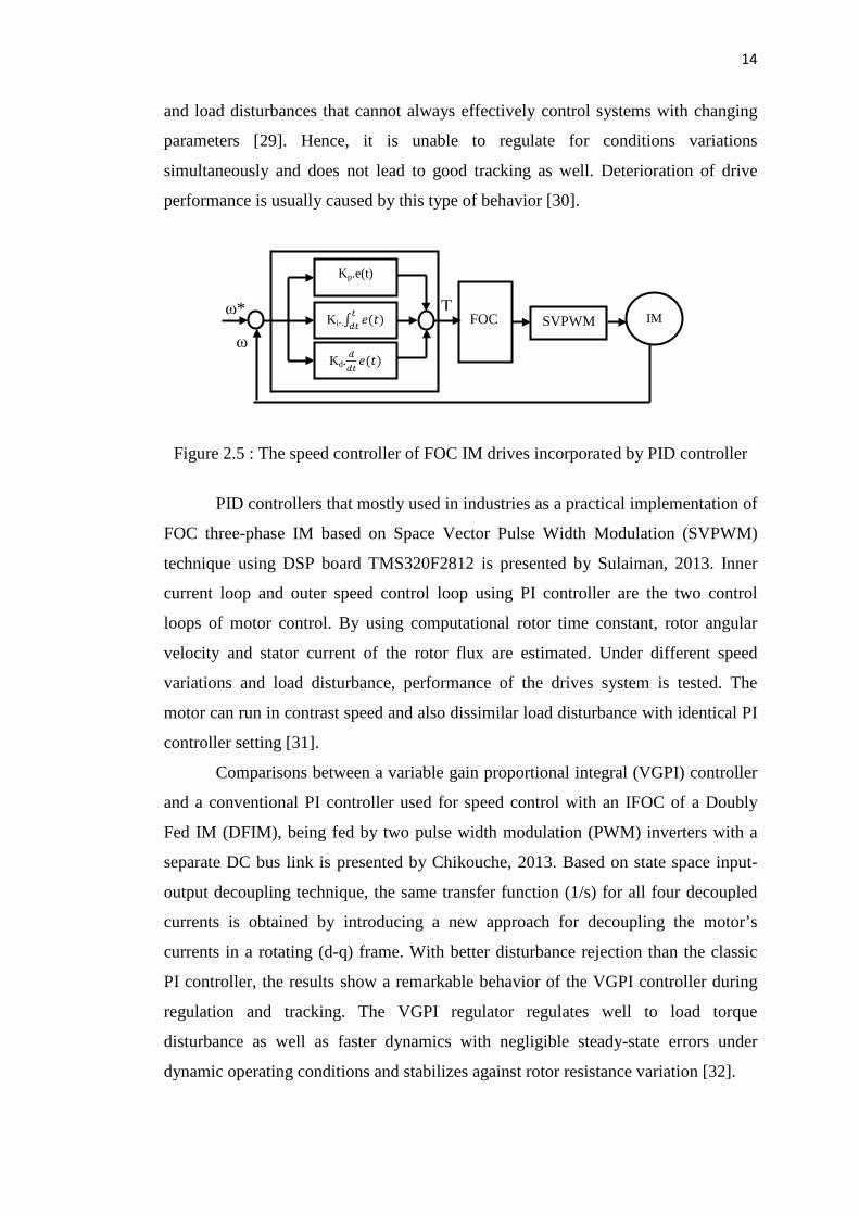
Figure 2.5 : The speed controller of FOC IM drives incorporated by PID controller
PID controllers that mostly used in industries as a practical implementation of
FOC three-phase IM based on Space Vector Pulse Width Modulation (SVPWM)
technique using DSP board TMS320F2812 is presented by Sulaiman, 2013. Inner
current loop and outer speed control loop using PI controller are the two control
loops of motor control. By using computational rotor time constant, rotor angular
velocity and stator current of the rotor flux are estimated. Under different speed
variations and load disturbance, performance of the drives system is tested. The
motor can run in contrast speed and also dissimilar load disturbance with identical PI
controller setting [31].
Comparisons between a variable gain proportional integral (VGPI) controller
and a conventional PI controller used for speed control with an IFOC of a Doubly
Fed IM (DFIM), being fed by two pulse width modulation (PWM) inverters with a
separate DC bus link is presented by Chikouche, 2013. Based on state space input-
output decoupling technique, the same transfer function (1/s) for all four decoupled
currents is obtained by introducing a new approach for decoupling the motor’s
currents in a rotating (d-q) frame. With better disturbance rejection than the classic
PI controller, the results show a remarkable behavior of the VGPI controller during
regulation and tracking. The VGPI regulator regulates well to load torque
disturbance as well as faster dynamics with negligible steady-state errors under
dynamic operating conditions and stabilizes against rotor resistance variation [32].
ω* T
ω
FOC SVPWM IM
Kp.e(t)
Ki..∫ 𝑒(𝑡)𝑡
𝑑𝑡
Kd.𝑑𝑑𝑡𝑒(𝑡)
15
An analysis for achieving control torque and speed with IFOC of IM is
described by Maher, 2012. Low-cost applications are suitable for an indirect field-
oriented output feedback motor PI controller. By using an analog-to-digital
converter, a current model control is used to sense back electromotive force (EMF).
This has proven that the conventional PI controller cannot compensate for such
parameter variations in the plant and PI controller is not an intelligent controller nor
is the slip calculation accurate [33].
Based on a sensorless closed-loop rotor flux observer with PI speed controller
whose main advantages are simplicity and robustness to motor parameter detuning,
Radu Bojoi, 2008 has implemented a sensorless direct rotor field-oriented control
(SDRFOC) scheme of three-phase IMs for low-cost applications. At a low-cost fixed
point, a DSP controller with full algorithms has been developed. In order to replace
the traditional V/Hz open-loop control, the simple observer is implemented with low-
cost fixed point DSP controllers, making it an attractive solution [34].
On the other hand, methods of computing PID parameters controller for VC
of IM is proposed by Ajangnay, 2010. Settling time is required and motor parameters
will be computed by the proposed method with optimal parameters for current loop,
flux loop, and speed loop as functions. The only parameter required to be given by a
user such that the method calculates the PID parameter for each loop control as the
significance of the proposed method is the only factor to prove the proposed method.
Robustness of the proposed method to system parameters variations is shown in
simulation [35].
Boussak, 2006 has proposed a new method for the implementation of a
sensorless indirect stator-flux-oriented control (ISFOC) of IM drives with stator
resistance tuning. It is based only on measurement of stator current for the proposed
method of the estimation of speed and stator resistance. The q-axis measures the
error from its reference value feeds the PI controller, where the estimated slip
frequency acts as output. To have the estimated rotor speed, the synchronous angular
frequency is subtracted to obtain the output integral plus proportional rotor speed
controller. This paper proposes a conventional PI controller with feed-forward
compensation values in the synchronous frame to control current regulation.
Degradation due to stator resistance variation caused by temperature is taken into
account while on the other hand good performance has been obtained at locked rotor
conditions [36].
16
To control the speed of IM based on VC strategy, robust PI controllers are
designed. Using Kharitonov theorem the design defines robust stability and
performance regions in the kp–ki, PI controller coefficient plane. While necessary
equations are derived from required foundations for designing a robust PI controller
are also generally introduced. After the equations are derived, the required
foundations for designing a robust PI controller are also introduced. The proposed
method provides a systematic approach to design PI controllers for an IM and could
be used to easily compute the stability region apart from ensuring robust stability and
performance of the closed-loop system [37].
The PWM with IFOC of an IM in parallel Hybrid Electrical Vehicle to
enhance the performance and the stability of the system is applied by Abad, 2011. PI
controller is employed to control rotor speed of the IM. To be able to control the
output voltage of the PWM inverter which feeds the IM, a hysteresis current
controller is applied. The IM responses to torque changes very quickly and precisely.
Nevertheless, the torque response is not fair enough as shown in simulation for
various rotor speeds. It takes 0.2s for the torque to reach its steady-state condition in
every step of changing the rotor speed. Consequently, speed should be sustained at
different torque [38].
Reljic, 2006 proposed a modified PI controller with feed-forward for desired
performance such as quick response, reference tracking, low steady-state errors, and
wide system bandwidth and good disturbance rejecting capability despite being the
traditional PI controller. In this paper, optimization procedure for classical PI and
modified PI controller is mentioned. The only problem is that the modified PI
controller has 3 parameters to tune [39].
Sensorless field oriented method using PID controller was developed by
Kushwaha, 2013. Without having sensors, this model is capable at motor speed
control. The nature of high performance motor drive system is comparable with the
obtained simulation results. In order to decouple rotor resistance adaption with the
motor speed variation, a new rotor resistance adaptive scheme has been proposed.
Better precision and stability in speed and torque control of 3 phase IM has shown in
the results obtained using developed model with PID controller [40].
17
2.4.1.3 FOC of IM Drive with Artificial Intelligent Speed Controller
The control algorithm should include a complicated computation process to eliminate
the variations in the load disturbance so as to overcome the drawbacks in
conventional controllers [28]. Real-time implementation requires extensive
computations as the control algorithms applicable to these systems have become
increasingly more complicated. The essential of intelligent controllers is to gain
adequate dynamic performance of traditional methods. NN and fuzzy logic controller
(FLC) are considered as potential candidates for such an application in recent years
[41]. The research on the design and implementation have proved their dexterity in
many respects and gained great importance [26].
FLC as a sophisticated method which lends itself very well to regulate and
control to understandable process using appropriate conventional classic methods is a
solution that had been proposed in [42]. A FLC has excelled in dealing with systems
that are complex, ill-defined, non-linear, or time-varying. It is relatively easy to
implement, as it usually needs no mathematical model for the controlled system. The
simplicity in control are the advantages of FLC over PI controller by converting the
linguistic control strategy of human experience into an automatic control strategy
that will be achieved [43].
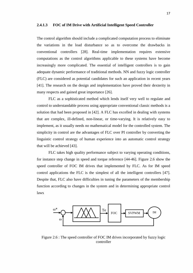
FLC takes high quality performance subject to varying operating conditions,
for instance step change in speed and torque reference [44-46]. Figure 2.6 show the
speed controller of FOC IM drives that implemented by FLC. As for IM speed
control applications the FLC is the simplest of all the intelligent controllers [47].
Despite that, FLC also have difficulties in tuning the parameters of the membership
function according to changes in the system and in determining appropriate control
laws
Figure 2.6 : The speed controller of FOC IM drives incorporated by fuzzy logic controller
Te
ω
ω* FOC SVPWM IM
18
It has been proven that various control strategies in controlling inverter fed
IM Drives gives good steady-state performance but poor dynamic performance.
Variable speed AC Drives came into existence to achieve good dynamic performance
and to meet preferences set by DC drives. By decoupling torque and flux control
FOC of IM has produced fast transient response. Major difficulty for IFOC method is
the field orientation detuning caused by parameter variations. Even when proper field
orientation is achieved, the traditional probability density function PID controllers
also have trouble meeting a wide range of speed tracking. When detuning occurs,
PID controller’s performance is severely degraded. FLC design that meets the speed
tracking requirements even when detuning occurs is proposed by Brian Heber, 1997.
Methods for synthesizing a controller from engineering experience that can be more
robust, having better performance, and reduce the cycle times is achievable in FLC
[48].
Fuzzy logic based controller used for an indirect vector controlled (IVC)
three-phase IM has been proposed by Bhushan, 2011 and Mariun, 2004 in terms of
theory, design and simulation. By decoupling the flux and torque, the FOC of an IM
has achieved fast transient response. By using MATLAB, the simulations have been
realized. Based on drive at different operating conditions such as parameter
variations and sudden change in load, the performance of the proposed FLC has been
investigated and compared with the results obtained from the conventional PI
controller. A FLC in indirect vector control IM (IVCIM) gives superior performance
in terms of fast dynamic response and parameter variations and more robust than PI
controller [49-52].
Kouzi, 2003 has proposed a new design of FLC with fuzzy adapted gains
(FAG) instead of standard FLC. By using classical FLC at different dynamic
operating conditions, such as sudden change in command speed, step change in load
and some key parameters deviation, the improvements and the performance of the
proposed controller based on IM drive are investigated and compared to those
obtained in simulation. Rotor resistance and inertia are severe variations of some key
parameters that are used in comparison of simulation results to show that FLC with
FAG is more robust. In order to improve industrial drive performance and robustness
in a wide range of changing conditions it is found to be a suitable replacement of the
standard FLC [53].
19
IM have many applications in industries because of its low maintainability
and robustness. An IM with smart speed control system using fuzzy logic controller
was introduced by Eltamaly, 2010. To compare the performance of control system
with FLC with two speed control techniques, scalar control and IFOC are used.
Especially with high dynamic disturbance IFOC technique with FLC provides better
speed control. With speed variation and transient conditions in controlling three-
phase IM with IFOC, the simulation results have proven the superiority of the FLC
that gives fast response, smooth performance, and high dynamic response [44].
Chao, 2011 research on the speed control performance improvement of a
detuned indirect field oriented (IFO) IM drive. A transfer function model is
established and the dynamic behavior of a detuned IFO IM drive is observed. An
ideal IFO IM drive for a nominal case with desired dynamic response is designed
from then PID two-degree-of-freedom controller (2DOFC). The detuning of field-
orientation accompanying the load parameter changes may significantly worsen the
speed dynamic response as the variation of motor parameters occurs. A proposed
fuzzy robust control (FRC) to preserve prescribed response is yielded by a
compensation signal in this case. The compromise between control effort and
performance is considered, robust model following speed response is obtained since
the compensation signal is adaptively tuned by a model following the error driven
fuzzy weighting controller [38].
A FLC requires finer tuning and simulation before operational even though it
is easy to verify and explicit. NN has been used in some power electronic
applications in the past decade. Using a system input and output, the NN controller,
on the other hand, has the ability to adapt itself to changes in control environment
[54]. It is able to identify and control nonlinear system [8, 55]. It does not require
exact model of the system or complicated control theories. The outputs are the torque
of the artificial NN valuated on several counts including their adaptability, non-
linearity, and generalization capabilities as well as the operating speed that trains a
NN to represent a variety of complicated nonlinear systems has made it possible in
the recent development of NN technology [56].
NN can be trained to solve lost complex non-linear problems with variable
parameters just like the human brain. It has been successfully applied to identify and
control the currents of an induction machine. Adaptive flux control, current control,
speed control, and FOC are some of the applications of NN in AC drive systems. A
20
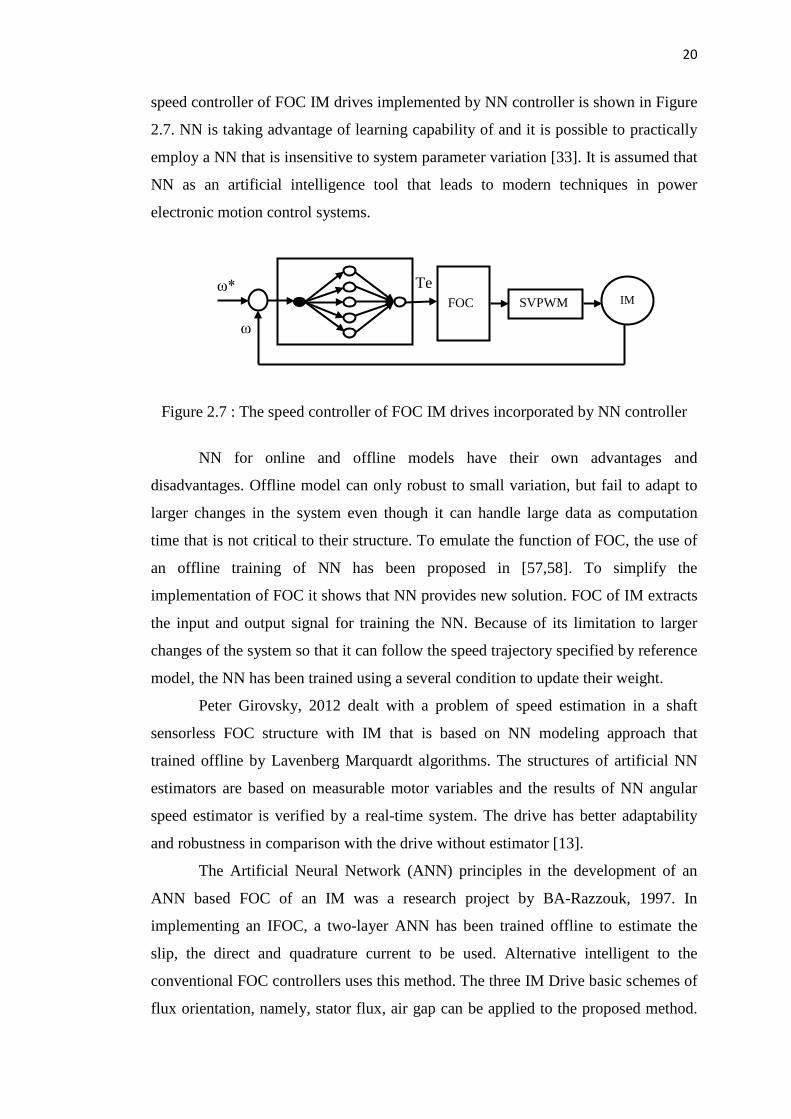
speed controller of FOC IM drives implemented by NN controller is shown in Figure
2.7. NN is taking advantage of learning capability of and it is possible to practically
employ a NN that is insensitive to system parameter variation [33]. It is assumed that
NN as an artificial intelligence tool that leads to modern techniques in power
electronic motion control systems.
Figure 2.7 : The speed controller of FOC IM drives incorporated by NN controller
NN for online and offline models have their own advantages and
disadvantages. Offline model can only robust to small variation, but fail to adapt to
larger changes in the system even though it can handle large data as computation
time that is not critical to their structure. To emulate the function of FOC, the use of
an offline training of NN has been proposed in [57,58]. To simplify the
implementation of FOC it shows that NN provides new solution. FOC of IM extracts
the input and output signal for training the NN. Because of its limitation to larger
changes of the system so that it can follow the speed trajectory specified by reference
model, the NN has been trained using a several condition to update their weight.
Peter Girovsky, 2012 dealt with a problem of speed estimation in a shaft
sensorless FOC structure with IM that is based on NN modeling approach that
trained offline by Lavenberg Marquardt algorithms. The structures of artificial NN
estimators are based on measurable motor variables and the results of NN angular
speed estimator is verified by a real-time system. The drive has better adaptability
and robustness in comparison with the drive without estimator [13].
The Artificial Neural Network (ANN) principles in the development of an
ANN based FOC of an IM was a research project by BA-Razzouk, 1997. In
implementing an IFOC, a two-layer ANN has been trained offline to estimate the
slip, the direct and quadrature current to be used. Alternative intelligent to the
conventional FOC controllers uses this method. The three IM Drive basic schemes of
flux orientation, namely, stator flux, air gap can be applied to the proposed method.
Te ω*
ω
FOC SVPWM IM

21
It is accomplished with manipulating only the weights and biases of the ANN, using
the same training strategy and the same ANN structure can easily handle these three
schemes [59].
A scheme for estimation of rotor resistance using a NN block is presented by
Ebrahimi, 2010. By using stator voltage and current, the flux and torque have been
estimated. At the input and estimates the actual rotor resistance at the output, which
is used in the control of an indirect vector controlled drive system, a back
propagation NN receives the flux and torque errors and a supposed rotor resistance.
In detuning operations, the NN has been trained offline with mathematical model of
the control scheme. The NN estimator used with IRFOC control has been studied in
the detuning condition. Despite when the rotor time constant is increased from
nominal rate to twice the nominal value, as well as torque variations, the
performance of the controller is good. Though this method’s design is simple,
estimation is done quickly and accurately.
A DSP implementation of a NN IM controller performing with FOC is
presented by Mohamadian, 2003. Two stages of training are required to train the NN,
which is at offline training stage and another stage where experimental data is
employed to train the NN has been confirmed by experimental test results. Compared
to the errors caused by the limited number of neurons and any lack of information in
the training data, the NN error due to computation approximations is negligible [58].
On the other hand, Parma, 2003 proposed a scheme that based on the direct
application of an artificial NN, trained with sliding mode control, into the feedback
control system based on the online model adapts to variation quickly in the non-
linear behavior of the system [9]. Robustness and high speed learning is inherits from
Sliding Mode Control (SMC) when NN learning is implemented with an online
adaptation algorithm. As a function of speed and flux references, it is important to
mention that the control quality can be improved if the training algorithm is
employed with adaptive gains. Using only two ANN controllers the training
algorithm based on SMC is robust enough to maintain the system’s controllability.
The findings show that NN with online learning can replace the PI and PID
controllers used in classical motor drives [60].
An adaptive speed observer for an IM using an ANN with a DFOC drive is
presented by Mechernene, 2012. With the only assumption that from stator voltage
and current are measurable, the speed and rotor flux are estimated. To estimate rotor
22
speed, the estimation algorithm uses a state observer combined with an intelligent
adaptive mechanism based on a recurrent NN (RNN). A simple PI controller, which
reduces sensitivity to variations, due essentially to the influence of temperature,
estimates the stator and rotor resistance. Various operating conditions of the IM drive
are tested by the proposed sensorless control scheme. It guarantees that a precise
trajectory tracking with prescribed dynamics as the experimental results demonstrate
good robustness against load torque disturbances, the estimated flux and rotor speed
converge to their true values [61].
The use of RNN was proposed by Mayaleh, 1998 where the method of vector
control allows high-performance control of torque, speed or position to be achieved
from an IM by online estimation of the rotor resistance. A highly coupled nonlinear
IM is controlled as a linear-decoupled separately excited DC motor. In the VC
method, it is necessary to perform coordinate transformation because decoupling of
the flux and torque of the stator currents in VC is ensured by accurate calculation of
the unit vectors. Simulation results show that the new approach is capable of fast
estimation of the rotor resistance with negligible errors [62].
2.5 Gap of Study
The gap of study can be seen obviously from comparison between research work in
this project and the previous work done by other researchers on FOC of IM in the
Table 2.1. It is clear that none of the researchers have done the performance
comparisons between online and offline learning NN.
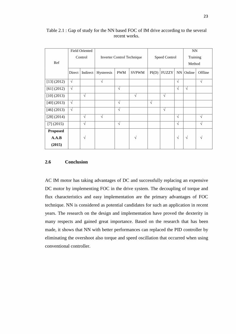
23
Table 2.1 : Gap of study for the NN based FOC of IM drive according to the several recent works.
Ref
Field Oriented
Control
Inverter Control Technique
Speed Control
NN
Training
Method
Direct Indirect Hysteresis PWM SVPWM PI(D) FUZZY NN Online Offline
[13] (2012) √ √ √ √
[61] (2012) √ √ √ √
[10] (2013) √ √ √
[40] (2013) √ √ √
[46] (2013) √ √ √
[28] (2014) √ √ √ √
[7] (2015) √ √ √ √
Proposed
A.A.B
(2015)
√ √ √ √ √
2.6 Conclusion
AC IM motor has taking advantages of DC and successfully replacing an expensive
DC motor by implementing FOC in the drive system. The decoupling of torque and
flux characteristics and easy implementation are the primary advantages of FOC
technique. NN is considered as potential candidates for such an application in recent
years. The research on the design and implementation have proved the dexterity in
many respects and gained great importance. Based on the research that has been
made, it shows that NN with better performances can replaced the PID controller by
eliminating the overshoot also torque and speed oscillation that occurred when using
conventional controller.

24
CHAPTER 3
METHODOLOGY
3.1 Introduction
In this chapter, the overall planning and block diagram of this project are discussed
further. Before proceeding to detail development of the proposed NNIFOC schemes
of IM drives, it is essential to understand the concept of the feed-forward network
and the online learning control schemes. Then, the specific explanation of the
proposed NNIFOC of IM drives is given.
3.2 Project Flow Chart
The objectives of this research are to model and simulate the IM drive system and
develop a controlled program for the proposed technique on a DSP board. Figure 3.1
shows the flow chart, which illustrates the important steps that will be taken during
the project development. Referring to the flowchart, determination of the research
objectives is most important part.


![[3jam] JawabLIMA(5) soalan · g) Kelutsinaran adalah sifatfizikal mineralyangberkaitandengan: h) Ketampakan kilauan padamineral terhasil disebabkan oleh: i) Ciri warna mineral-mineralpada](https://img.dokumen.tips/doc/110x75/5e44be2c8baf373fc80300d2/3jam-jawablima5-soalan-g-kelutsinaran-adalah-sifatfizikal-mineralyangberkaitandengan.jpg)

