Embed Size (px)
Citation preview
7/30/2019 Speed Droop Woodward
http://slidepdf.com/reader/full/speed-droop-woodward 1/10
Application Note 01302(Revision NEW)
Original Instructions
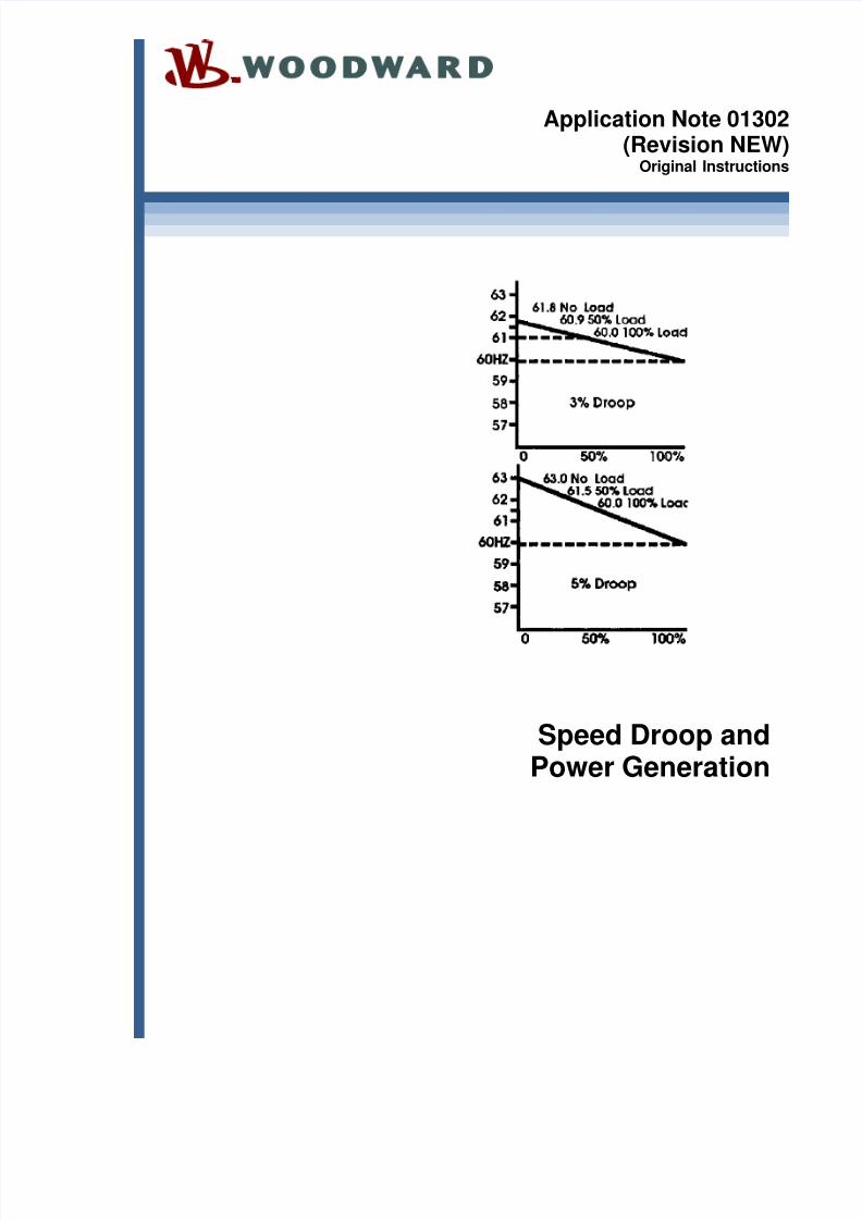
Speed Droop andPower Generation

7/30/2019 Speed Droop Woodward
http://slidepdf.com/reader/full/speed-droop-woodward 2/10
GeneralPrecautions
Read this entire manual and all other publications pertaining to the work to beperformed before installing, operating, or servicing this equipment.
Practice all plant and safety instructions and precautions.
Failure to follow instructions can cause personal injury and/or property damage.
Revisions
This publication may have been revised or updated since this copy was produced.
To verify that you have the latest revision, check manual 26311 , Revision Status &Distribution Restrictions of Woodward Technical Publications , on the publications page of the Woodward website:
www.woodward.com/publications
The latest version of most publications is available on the publications page . Ifyour publication is not there, please contact your customer service representativeto get the latest copy.
Proper Use
Any unauthorized modifications to or use of this equipment outside its specifiedmechanical, electrical, or other operating limits may cause personal injury and/orproperty damage, including damage to the equipment. Any such unauthorizedmodifications: (i) constitute "misuse" and/or "negligence" within the meaning ofthe product warranty thereby excluding warranty coverage for any resultingdamage, and (ii) invalidate product certifications or listings.
Translated
Publications
If the cover of this publication states "Translation of the Original Instructions"please note:
The original source of this publication may have been updated since this
translation was made. Be sure to check manual 26311 , Revision Status &Distribution Restrictions of Woodward Technical Publications , to verify whetherthis translation is up to date. Out-of-date translations are marked with . Alwayscompare with the original for technical specifications and for proper and safeinstallation and operation procedures.
Revisions—Changes in this publication since the last revision are indicated by a black linealongside the text.
Woodward reserves the right to update any portion of this publication at any time. Information provided by Woodward isbelieved to be correct and reliable. However, no responsibility is assumed by Woodward unless otherwise expresslyundertaken.
Copyright © Woodward 1991All Rights Reserved
7/30/2019 Speed Droop Woodward
http://slidepdf.com/reader/full/speed-droop-woodward 3/10
Application Note 01302 Speed Droop and Power Generation
Woodward 1
Warnings and Notices
Important DefinitionsThis is the safety alert symbol. It is used to alert you to potentialpersonal injury hazards. Obey all safety messages that follow thissymbol to avoid possible injury or death.
DANGER —Indicates a hazardous situation which, if not avoided, will result
in death or serious injury. WARNING —Indicates a hazardous situation which, if not avoided, could
result in death or serious injury.
CAUTION —Indicates a hazardous situation which, if not avoided, couldresult in minor or moderate injury.
NOTICE —Indicates a hazard that could result in property damage only(including damage to the control).
IMPORTANT —Designates an operating tip or maintenance suggestion.
Overspeed /Overtemperature /
Overpressure
The engine, turbine, or other type of prime mover should beequipped with an overspeed shutdown device to protect againstrunaway or damage to the prime mover with possible personal injury,
loss of life, or property damage.The overspeed shutdown device must be totally independent of theprime mover control system. An overtemperature or overpressureshutdown device may also be needed for safety, as appropriate.
Personal ProtectiveEquipment
The products described in this publication may present risks thatcould lead to personal injury, loss of life, or property damage. Alwayswear the appropriate personal protective equipment (PPE) for the jobat hand. Equipment that should be considered includes but is notlimited to:
Eye Protection Hearing Protection
Hard Hat Gloves
Safety Boots
Respirator
Always read the proper Material Safety Data Sheet (MSDS) for anyworking fluid(s) and comply with recommended safety equipment.
Start-up
Be prepared to make an emergency shutdown when starting theengine, turbine, or other type of prime mover, to protect againstrunaway or overspeed with possible personal injury, loss of life, orproperty damage.
AutomotiveApplications
On- and off-highway Mobile Applications: Unless Woodward's controlfunctions as the supervisory control, customer should install asystem totally independent of the prime mover control system thatmonitors for supervisory control of engine (and takes appropriateaction if supervisory control is lost) to protect against loss of enginecontrol with possible personal injury, loss of life, or property damage.

7/30/2019 Speed Droop Woodward
http://slidepdf.com/reader/full/speed-droop-woodward 4/10
Speed Droop and Power Generation Application Note 01302
2 Woodward
Battery ChargingDevice
To prevent damage to a control system that uses an alternator orbattery-charging device, make sure the charging device is turned offbefore disconnecting the battery from the system.
Electrostatic Discharge Awareness
ElectrostaticPrecautions
Electronic controls contain static-sensitive parts. Observe thefollowing precautions to prevent damage to these parts: Discharge body static before handling the control (with power to
the control turned off, contact a grounded surface and maintaincontact while handling the control).
Avoid all plastic, vinyl, and Styrofoam (except antistatic versions)
around printed circuit boards. Do not touch the components or conductors on a printed circuit
board with your hands or with conductive devices.
To prevent damage to electronic components caused by improperhandling, read and observe the precautions in Woodward manual
82715 , Guide for Handling and Protection of Electronic Controls,Printed Circuit Boards, and Modules .
Follow these precautions when working with or near the control.1. Avoid the build-up of static electricity on your body by not wearing clothing
made of synthetic materials. Wear cotton or cotton-blend materials as muchas possible because these do not store static electric charges as much as
synthetics.2. Do not remove the printed circuit board (PCB) from the control cabinet
unless absolutely necessary. If you must remove the PCB from the controlcabinet, follow these precautions:
Do not touch any part of the PCB except the edges.
Do not touch the electrical conductors, the connectors, or thecomponents with conductive devices or with your hands.
When replacing a PCB, keep the new PCB in the plastic antistaticprotective bag it comes in until you are ready to install it. Immediatelyafter removing the old PCB from the control cabinet, place it in theantistatic protective bag.
7/30/2019 Speed Droop Woodward
http://slidepdf.com/reader/full/speed-droop-woodward 5/10
Application Note 01302 Speed Droop and Power Generation
Woodward 3
Speed Droopand Power Generation
Droop Engine Control for Stable Operation
Speed droop is a governor function which reduces the governor reference speedas fuel position (load) increases.
All engine controls use the principle of droop to provide stable operation. Thesimpler mechanical governors have the droop function built into the controlsystem, and it cannot be changed. More complex hydraulic governors caninclude temporary droop, returning the speed setting to its original place after theengine has recovered from a change in fuel position. This temporary droop iscalled compensation.
The ability to return to the original speed after a change in load is calledisochronous speed control. All electronic controls have circuits which effectivelyprovide a form of temporary droop by adjusting the amount of actuator position
change according to how much off speed is sensed.
Without some form of droop, engine-speed regulation would always be unstable.A load increase would cause the engine to slow down. The governor wouldrespond by increasing the fuel position until the reference speed was attained.However, the combined properties of inertia and power lag would cause thespeed to recover to a level greater than the reference.
The governor would reduce fuel and the off speed would then occur in theunderspeed direction. In most instances the off-speed conditions would build untilthe unit went out on overspeed.
With droop, the governor speed setting moves toward the offspeed as the fuelcontrol moves to increase, allowing a stable return to steady state control. Thefeedback in the governor is from the output position. Since a minimal movementof the output position can cause major speed changes in an unloaded engine, itis sometimes difficult to gain stability in unloaded conditions. Actuator linkagerequiring more movement of the output to achieve a given amount of rackmovement at the idle settings than at the loaded settings will often help achievestability in the unloaded position. Setting a greater amount of droop in thegovernor is another solution.
In the case of isochronous (temporary droop) control, the governor speed withwhich the engine returns to the predetermined speed reference is adjustable,allowing greater flexibility in achieving stable operation, even when unloaded.
7/30/2019 Speed Droop Woodward
http://slidepdf.com/reader/full/speed-droop-woodward 6/10
Speed Droop and Power Generation Application Note 01302
4 Woodward
The Droop Curve
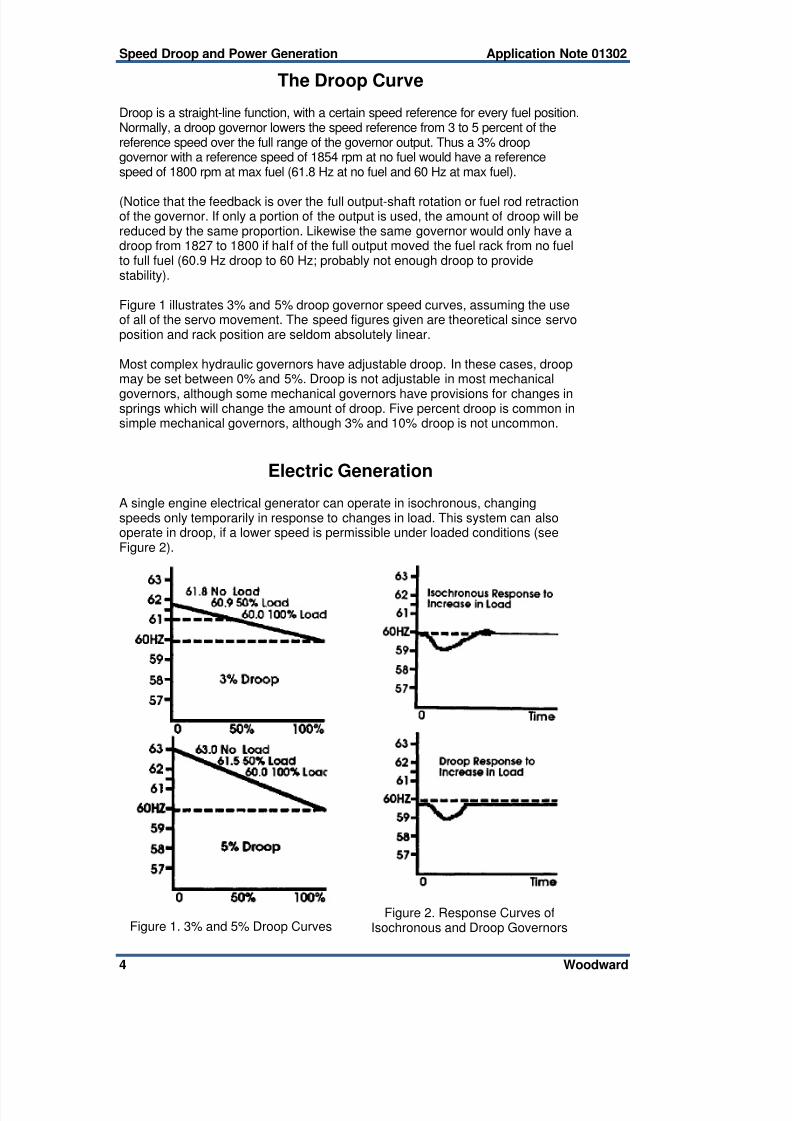
Droop is a straight-line function, with a certain speed reference for every fuel position.Normally, a droop governor lowers the speed reference from 3 to 5 percent of thereference speed over the full range of the governor output. Thus a 3% droopgovernor with a reference speed of 1854 rpm at no fuel would have a referencespeed of 1800 rpm at max fuel (61.8 Hz at no fuel and 60 Hz at max fuel).
(Notice that the feedback is over the full output-shaft rotation or fuel rod retractionof the governor. If only a portion of the output is used, the amount of droop will bereduced by the same proportion. Likewise the same governor would only have adroop from 1827 to 1800 if half of the full output moved the fuel rack from no fuelto full fuel (60.9 Hz droop to 60 Hz; probably not enough droop to providestability).
Figure 1 illustrates 3% and 5% droop governor speed curves, assuming the useof all of the servo movement. The speed figures given are theoretical since servoposition and rack position are seldom absolutely linear.
Most complex hydraulic governors have adjustable droop. In these cases, droopmay be set between 0% and 5%. Droop is not adjustable in most mechanical
governors, although some mechanical governors have provisions for changes insprings which will change the amount of droop. Five percent droop is common insimple mechanical governors, although 3% and 10% droop is not uncommon.
Electric Generation
A single engine electrical generator can operate in isochronous, changingspeeds only temporarily in response to changes in load. This system can alsooperate in droop, if a lower speed is permissible under loaded conditions (seeFigure 2).
Figure 1. 3% and 5% Droop CurvesFigure 2. Response Curves of
Isochronous and Droop Governors
7/30/2019 Speed Droop Woodward
http://slidepdf.com/reader/full/speed-droop-woodward 7/10
Application Note 01302 Speed Droop and Power Generation
Woodward 5
Parallel with a Utility
If, however, the single engine generator is connected to a utility bus, the utilitywill determine the frequency of the alternator. Should the governor speedreference be less than the utility frequency, power in the utility bus will flow to thealternator and motor the unit. If the governor speed is even fractionally higherthan the frequency of the utility, the governor will go to full load in an attempt toincrease the bus speed. Since the definition of a utility is a frequency which is toostrong to influence, the engine will remain at full fuel.
Isochronous governor control is impractical when paralleling with a utilitybecause a speed setting above utility frequency, by however small an amount,would call for full rack, since the actual speed could not reach the referencespeed. Similarly, if the setting were even slightly below actual speed, the rackswould go to fuel-off position.
Governors should not be paralleled isochronously with any system so big that thegoverned unit cannot affect the speed of the system.
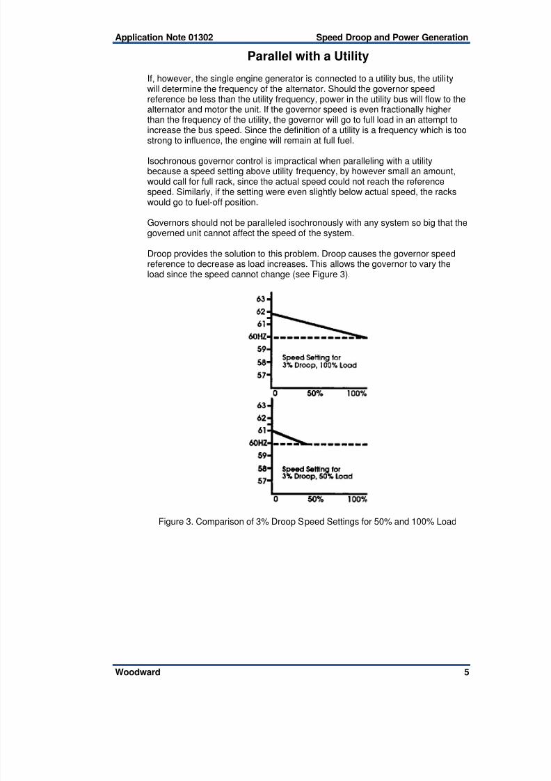
Droop provides the solution to this problem. Droop causes the governor speedreference to decrease as load increases. This allows the governor to vary the
load since the speed cannot change (see Figure 3).
Figure 3. Comparison of 3% Droop Speed Settings for 50% and 100% Load
7/30/2019 Speed Droop Woodward
http://slidepdf.com/reader/full/speed-droop-woodward 8/10
Speed Droop and Power Generation Application Note 01302
6 Woodward
Governor Speed Setting Determines Load
When paralleled with a bus, the load on an engine is determined by the referencespeed setting of the droop governor. Increasing the speed setting cannot cause achange in the speed of the bus, but it will cause a change in the amount of loadthe engine is carrying. The graph shows that the amount of load is determined bywhere the droop line intersects the speed of the bus. If the location of this line ismoved, either by changing the reference speed or the amount of droop in theunit, the amount of load will also be moved.
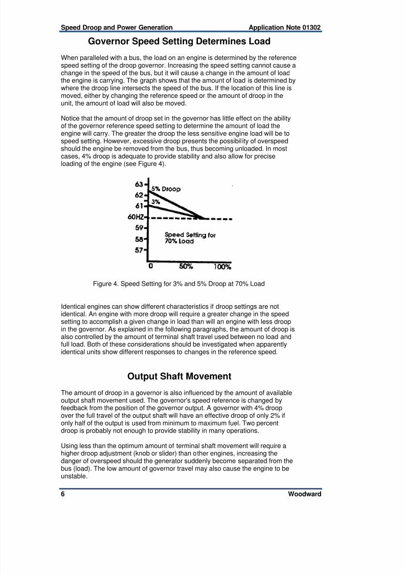
Notice that the amount of droop set in the governor has little effect on the abilityof the governor reference speed setting to determine the amount of load theengine will carry. The greater the droop the less sensitive engine load will be tospeed setting. However, excessive droop presents the possibil ity of overspeedshould the engine be removed from the bus, thus becoming unloaded. In mostcases, 4% droop is adequate to provide stability and also allow for preciseloading of the engine (see Figure 4).
Figure 4. Speed Setting for 3% and 5% Droop at 70% Load
Identical engines can show different characteristics if droop settings are notidentical. An engine with more droop will require a greater change in the speedsetting to accomplish a given change in load than will an engine with less droopin the governor. As explained in the following paragraphs, the amount of droop isalso controlled by the amount of terminal shaft travel used between no load andfull load. Both of these considerations should be investigated when apparentlyidentical units show different responses to changes in the reference speed.
Output Shaft Movement
The amount of droop in a governor is also influenced by the amount of available
output shaft movement used. The governor's speed reference is changed byfeedback from the position of the governor output. A governor with 4% droopover the full travel of the output shaft will have an effective droop of only 2% ifonly half of the output is used from minimum to maximum fuel. Two percentdroop is probably not enough to provide stability in many operations.
Using less than the optimum amount of terminal shaft movement will require ahigher droop adjustment (knob or slider) than other engines, increasing thedanger of overspeed should the generator suddenly become separated from thebus (load). The low amount of governor travel may also cause the engine to beunstable.

7/30/2019 Speed Droop Woodward
http://slidepdf.com/reader/full/speed-droop-woodward 9/10
Application Note 01302 Speed Droop and Power Generation
Woodward 7
Multiple Engine Isolated Bus
Droop may also be used to parallel multiple engines on an isolated bus. In thiscase, the engines are capable of changing the frequency of the bus, and if allengines are operating in droop, the speed of the bus will change with a change inload. This is satisfactory only in cases where variations in the speed areacceptable.
Multiple engines can also be paralleled on an isolated bus with all but one of theengines in droop and that one engine in isochronous. These systems will be ableto maintain a constant speed as long as the isochronous engine is capable ofaccommodating any load changes (see Figure 5).
Figure 5. Use of Isochronous and Droop Units on an Isolated System
In these cases, should load decrease below the combined load setting of thedroop engines, the isochronous engine will completely unload, and the systemfrequency will increase to the point that load equals the combined droop settingof the droop engines. The isochronous engine would be motored in this instanceunless it was automatically removed from the bus.
If the load increases beyond the capacity of the isochronous unit, the entiresystem will slow to the point where the combined droop of the other units meetsthe droop-speed position. In this case, the isochronous unit would remainoverloaded to a point where it was unable to achieve the governor referencespeed.
Negative Droop
As has been stated, all mechanical governors use droop, either constant or in thecase of isochronous governors temporary, to achieve stable engine control. It ispossible to adjust negative droop (speed reference increases as load increases)
into some governors. Satisfactory governor control (engine stability) cannot beachieved with negative droop adjusted into a governor.

7/30/2019 Speed Droop Woodward
http://slidepdf.com/reader/full/speed-droop-woodward 10/10
We appreciate your comments about the content of our publications.
Send comments to: [email protected]
Please reference publication 01302.
PO Box 1519, Fort Collins CO 80522-1519, USA1000 East Drake Road, Fort Collins CO 80525, USA
Phone +1 (970) 482-5811 Fax +1 (970) 498-3058
Email and Website—www.woodward.com
Woodward has company-owned plants, subsidiaries, and branches,as well as authorized distributors and other authorized service and sales facilities throughout the world.
Complete address / phone / fax / email information for all locations is available on our website.
2012/11/Colorado