Embed Size (px)
Citation preview
Speed Control of a DC Motor with Variable Load Using Sliding Mode Control
Emre Hasan Dursun*, Akif Durdu
Selcuk University, Engineering Faculty, Department of Electrical-Electronics Engineering, Konya, Turkey. * Corresponding author. Tel.: +90332 2232258; email: [email protected] Manuscript submitted February 2, 2016; accepted June 14, 2016. doi: 10.17706/ijcee.2016.8.3.219-226
Abstract: Sliding mode control method (SMC), which is built on Variable structure control (VSC) theory, is a
robust nonlinear control method creating insensibility against to modeling errors, external disturbing
effects and parametric change of the system. In this paper, control of a DC Motor used in particularly robots
and countless industrial applications is carried out by using SMC and analysis are also performed under
load changes. It is desirable that motors operating under load in robotic applications must not be affected
by changes depending on loading condition. In this paper, SMC Method is used against to this situation
which is affected stability of system and performance of motor. Modeling of a DC motor, designing of its
controller and overall analyses are performed by using actual data. When comparisons between proposed
method and commonly used PID control are made in terms of performance analyses, it is seen that SMC
method produces more successful results.
Key words: Control of DC motor, nonlinear control method, PID, robust control, sliding mode control.
1. Introduction
Numerous mechanical actions which are seen around us are provided by electric motors. They are
devices converting electrical energy to mechanical energy. At the end of 1800’s, several inventors
discovered the first DC (direct current) supplied motors. Due to its high torque in terms of inertia ratio, high
efficiency, big power density, successful performance, easy controllability, exact, broad, simple and
continuous control characteristic, DC motors are widely used in many industrial applications such as
electric cars, electric winches, steelworks, robotic manipulator, paper machines and home applications
[1]-[3]. As compared with AC motors, driver modules of DC motors are cheaper and its controllers are
easier [1]. According to the type, DC motors are controlled by changing the field current or armature
voltage.
Due to easy design, they are commonly controlled by PID controller. To adjust PID parameters, it is
required to do some experiment or to determine the best way mathematical model of the system. However,
conventional PID does not work attractively in applications of nonlinear, complex and of which system
model cannot be defined precisely [4], [5].
Electrical parameters of motor get changed in time as to temperature, current and voltage fluctuations,
time varying loading conditions, driving and operating conditions [4]. Loading changes generate
fluctuations in speed of rotor [1].
PID controller is affected negatively by external disturbing effects, loading changes and parametric
changes which occur depending on its location, so its usage is restricted in applications such as speed
International Journal of Computer and Electrical Engineering
219 Volume 8, Number 3, June 2016

control. Because PID controller with constant coefficient cannot show a good performance, until now,
various modified PIDs such as Adaptive and self-tuning have been developed to cope with these effects [4].
Additionally, Fuzzy Logic, Fractional Order PID, Genetic Algorithm and different methods are investigated in
applications control of DC motor in order to get a control structure with better performance. Control of a
permanent magnet DC motor (PMDC) is realized by using PI and fuzzy logic control in a simulation study
[6]. Gowthaman et al. in [7] designed a speed controller for a PMDC motor via self-tuning PID control
method and also use fuzzy logic for a self-tuning. Velagic et al. in [8] carry out speed control of a PMDC
motor by fuzzy logic controller. Comparisons are made between PID and fuzzy control under disturbing
effect in both simulation and real time application. Kumar et al. in [9], speed control of separately excited
DC motor performs using various PI, PID and Ziegler Nichols methods. In [10], Ziegler Nichols, modified
Ziegler Nichols methods and PI controller which are designed via Particle Swarm Optimization (PSO) are
used for speed control of DC motor. In this paper, Sliding mode control as a control method will be used to
cope with mentioned effects and analysis will be made under various loading conditions.
2. Sliding Mode Control
Variable structure control (VSC) has been used for the first time by Emelyanov and et al, at the end of
1800’s in Russia. Although SMC which is founded on the VSC was unknown until 1977, when Utkin made a
study, then, it has been started to use for linear and nonlinear applications in the international communities
[11]. SMC, which has low sensitivity against to parametric changes of the system and disturbing effects, is
an effective method to control complex and dynamic systems. Moreover it can operate under uncertain
conditions which commonly occur in the modern technology [12].
Fig. 1. (a)Phase portrait of sliding mode control, (b) Sliding surface, reaching mode and high frequency
switching.
SMC consists of two parts called as reaching mode and sliding mode and its phase portrait is shown like
Fig. 1(a). The first of all, a surface is designed for system to be controlled.
As shown Fig. 1(b), control signal switched high frequency slide state trajectories of the system to this
surface and this surface is called sliding surface. The movement along this surface represents output action
of the system. SMC method tries to pull states of system from sliding surface to origin. Movement in sliding
surface signify sliding mode and is stage from starting point to sliding mode called as reaching mode. States
of system are insensitive to parametric changes and disturbing effects. The aim of the SMC is that output of
system is to tracking to desired reference and to produce signal ‘u’ which makes minimum to tracking error.
System reaches sliding surface by making transitions between stable and unstable trajectories and error
converge to zero in sliding surface.
International Journal of Computer and Electrical Engineering
220 Volume 8, Number 3, June 2016

Basic Theory 2.1.
Aim of the SMC is that output of system )(ty is to tracking to desired output )(tyd and is to produce )(tu
which makes minimum to tracking error which is defined in (1). If this equation is generalized as (2),
sliding surface is indicated as in (3) and C is Hurwitzian polynomial coefficients. Equation (4) is commonly
used for sliding surface.
)()()( tytyte d
(1)
Rtetetete Tn
)](),......,(),([)(1
(2)
)(*)( teCts (3)
)(),(
1
tedt
dtxs
n
(4)
In design of sliding surface, it is produced homogeny differential equation to be 0),( txs and 0)( te .
Lyapunov function in (5) is commonly used for sliding mode and stability condition of system is obtained by
(6), which is shown (7).
2
2
1sV
(5)
0)(,0,0)0( sVsV
(6)
ssdt
dV 2.
2
1
(7)
Condition of convergence is acquired as (8) and condition of sliding mode is defined as (9).
ssss
sss
)sgn(
(8)
)sgn(ss (9)
System reaches to sliding mode if 0 . If dynamic equations are continued, signal )(tu can be
demonstrated as (10) which are consisted of two parts. The first of part symbolizes equivalent control
signal, the other one symbolizes switching control signal which is shown as (10).
)sgn()(),()()( sKtutututu swsweq (10)
0)(,1
0)(,0
0)(,1
))(sgn(
tsif
tsif
tsif
ts
(11)
Switching control signal pulls states of system to sliding surface, while 0)( ts . After reached sliding
surface, switching control signal is disable and equivalent control signal keep stable to system. K in (10) is
positive number and sgn(.) is signum function. They are described as (11).
Disadvantage of SMC method is chattering phenomenon that it happens by high frequency switching and
signum function. Chattering can be decreased by altering signum function or using fuzzy logic.
3. Modeling of DC Motor
International Journal of Computer and Electrical Engineering
221 Volume 8, Number 3, June 2016
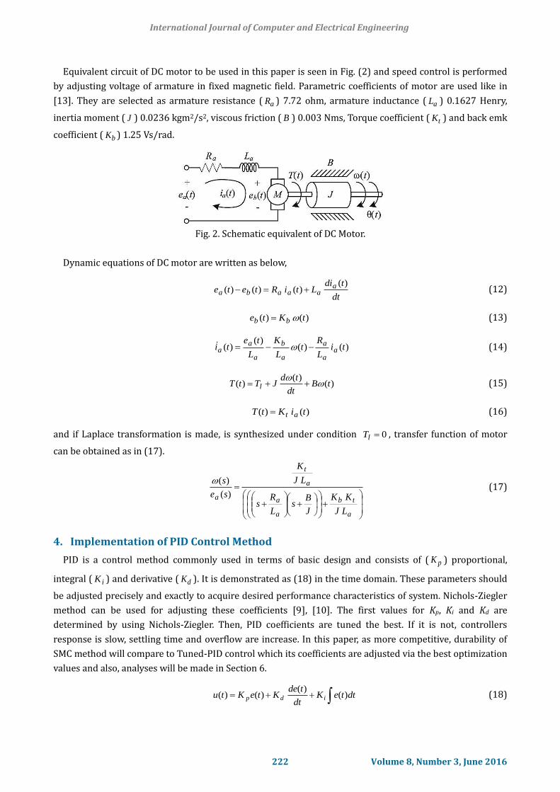
Equivalent circuit of DC motor to be used in this paper is seen in Fig. (2) and speed control is performed
by adjusting voltage of armature in fixed magnetic field. Parametric coefficients of motor are used like in
[13]. They are selected as armature resistance ( aR ) 7.72 ohm, armature inductance ( aL ) 0.1627 Henry,
inertia moment ( J ) 0.0236 kgm2/s2, viscous friction ( B ) 0.003 Nms, Torque coefficient ( tK ) and back emk
coefficient ( bK ) 1.25 Vs/rad.
Fig. 2. Schematic equivalent of DC Motor.
Dynamic equations of DC motor are written as below,
dt
tdiLtiRtete a
aaaba
)()()()(
(12)
)()( tKte bb
(13)
)()()(
)( tiL
Rt
L
K
L
teti a
a
a
a
b
a
aa
(14)
)()(
)( tBdt
tdJTtT l
(15)
)()( tiKtT at
(16)
and if Laplace transformation is made, is synthesized under condition 0lT , transfer function of motor
can be obtained as in (17).
a
tb
a
a
a
t
a
LJ
KK
J
Bs
L
Rs
LJ
K
se
s
)(
)(
(17)
4. Implementation of PID Control Method
PID is a control method commonly used in terms of basic design and consists of ( pK ) proportional,
integral ( iK ) and derivative ( dK ). It is demonstrated as (18) in the time domain. These parameters should
be adjusted precisely and exactly to acquire desired performance characteristics of system. Nichols-Ziegler
method can be used for adjusting these coefficients [9], [10]. The first values for Kp, Ki and Kd are
determined by using Nichols-Ziegler. Then, PID coefficients are tuned the best. If it is not, controllers
response is slow, settling time and overflow are increase. In this paper, as more competitive, durability of
SMC method will compare to Tuned-PID control which its coefficients are adjusted via the best optimization
values and also, analyses will be made in Section 6.
dtteKdt
tdeKteKtu idp )(
)()()(
(18)
International Journal of Computer and Electrical Engineering
222 Volume 8, Number 3, June 2016

5. Implementation of SMC Method
If simplifications are made in (19) by using (17), (20) is obtained. If descriptions of state for SMC is made
as in (21), (22) is obtained. Moreover, equation of sliding surface is acquired as in (23).
a
tb
a
a
a
t
LJ
KKA
J
BA
L
RA
LJ
KA 4321 ,,,
(19)
143232 .. AeAAAAA a (20)
)(),(),(),(),( 12121 teutXYtXtXXtX a (21)
1432322 ..)( AeAAAAAtX a (22)
rrCeeCXXCs 21 (23)
)sgn(0 sKCs rr (24)
If (22) is substituted in (24) and parametric data of used motor, which are seen in Section 3, is also
substituted in (25), )(tu control signal will produced as in (26).
)sgn(.1
)( 432321
sKAAACAAA
tu (25)
A change in signum function as shown in (27) is done to reduce processing load and relieve chattering.
)sgn(88.412567.47484.325
1)( 12 sKXXCtu
(26)
10,88.412567.47484.325
1)( 12
s
sKXXCtu
(27)
6. Simulation Result and Comparisons
According to (23), (24) and (27), block scheme of SMC and simulation scheme of control system are
introduced in Fig. 3. Sliding mode control of DC motor is carried out both without any loading and loading.
Performance analyses are shown Fig. 4 and Fig. 5.
Fig. 3. (a) Block schema of SMC, (b) Overall simulation scheme.
International Journal of Computer and Electrical Engineering
223 Volume 8, Number 3, June 2016

Fig. 4. (a) . Change of angular velocity for PID and SMC, (b) Change of control signal u(t).
Fig. 5. (a) Change of sliding surface, (b) Change of phase portrait according to error and derivative of error.
0.1Nm torque is loaded after 2.sec as disturbing effect on DC motor system. In Fig. 4(a), it is seen
comparison graph of between PID and SMC in terms of transient analysis, steady state and loading change.
According to this graph, SMC has a better performance due to less overshoot and quick come again to
reference under loading. When variations of load are occurred or increased by continuing analysis, it can be
seen that difference of performance is increasing. Produced control signals, switching and equivalent
control signals, are seen in Fig. 4(b). Furthermore, it seen that )(tusw is cut out from 0.18s in this graph. This
means that to system output reaches to desired value. In Fig. 5(a), it is shown that sliding surface is
converging to zero. Change of error and its derivative are demonstrated in Fig. 5(b). This is means that error
in max value is converging to zero and it does little loop again under change of load. Comparison of
performance of controllers is given in Table 1. According to performance criteria, it is shown that SMC has a
better performance.
Table 1. Comparison of Controllers
Criteria Expression PID SMC
rT Rising Time (s) 0.076 0.097
sT Settling Time (s) 0.32 0.18
Overshoot Overshoot (%) 7.7 0
sse Steady state error 0 0
Overshoot Overshoot in loading (%) -16.8 -1.8
t Time difference for settling in loading (s) 0.3 0.05
International Journal of Computer and Electrical Engineering
224 Volume 8, Number 3, June 2016

7. Conclusion
In this paper, SMC and PID control method is used speed control of DC motor, which is an important issue
in control systems, and analysis are made by comparing performance of designed controllers. Also, a change
is made for chattering in SMC method. First of all, analysis are performed without disturbing effect, and
then performed according to variable loading conditions. It seen that SMC give successful results in terms of
settling time, state-state error and rapid response to disturbance. Moreover, SMC tolerates more
successfully for particularly transient analysis. To use the SMC provide an advantage in applications which
doesn’t effect changes by depending on loading condition of motors operated especially under the load in
robotic applications.
References
[1] Yulin, D. (2010). The analysis and implement of PLC-based PI control for the permanent magnet DC
motor. Proceedings of Second International Conference on Communication Systems, Networks and
Applications.
[2] Khan, M. K. (2003). Design and Application of Second Order Sliding Mode Control Algorithms. Doctor of
Philosophy, University of Leicester (pp. 11-26).
[3] Kumar, T. R. D., & Mija, S. J. (2014). Design and performance evaluation of robust SMC schemes for
speed control of DC motor. Proceedings of IEEE International Conference on Advanced Communication
Control and Computing Technologies (ICACCCT).
[4] Nouri, K., Dhaouadi, R., & Braiek, N. B. (2008). Adaptive control of a nonlinear DC motor drive using
recurrent neural networks. Applied Soft Computing.
[5] Huang, G. (2008). PC-based PID speed control in DC motor. Proceedings of International Conference on
Audio, Language and Image Processing (pp. 400-407).
[6] Ananthababu, P., & Reddy, B. A. (2009). Control of PMDC motor using fuzzy PI controller. Proceedings of
International Conference on Control, Automation, Communication and Energy Conservation (pp. 1-4).
[7] Gowthaman, E., & Balaji, C. D. (2013). Self-tuned PID based speed control of PMDC drive. Proceedings of
International Multi-conference on Automation, Computing, Communication, Control and Compressed
Sensing (pp. 686-692).
[8] Velagic, J., & Galijasevic, A. (2009). Design of fuzzy logic control of permanent magnet DC motor under
real constraints and disturbances. Proceedings of International Conference on Control Applications &
Intelligent Control (pp. 461-466).
[9] Kumar, U., & Dohera, D. (2015). Separately excited DC motor speed control of using various tuning
conventional controllers. International Research Journal of Engineering and Technology, 2(8), 2015.
[10] Kanojiya, R. G., & Meshram, P. M. (2012). Optimal tuning of PI controller for speed control of DC motor
drive using particle swarm optimization. Proceedings of International Conference on Advances in Power
Conversion and Energy Technologies (pp. 1-6).
[11] Edwards, C., & Spurgeon, S. K. (1998). Sliding mode control. Taylor and Francis (pp. 1-65).
[12] Utkin, V., Guldner, J., & Shi, J. (1999). Sliding mode control İn electromechanical systems. Taylor and
Francis (pp. 1-8).
[13] Moussavi, S. Z., Alasvandi, M., & Javadi, S. (2012). Speed control of permanent magnet DC motor by
using combination of adaptive controller and fuzzy controller. International Journal of Computer
Applications, 52(20).
International Journal of Computer and Electrical Engineering
225 Volume 8, Number 3, June 2016

Emre Hasan Dursun received his B.Sc. degree in electrical-electronics engineering from
the Sakarya University, (SAU), Turkey, in 2011. He has been a research assistant with the
Electrical-Electronics Engineering Department at the Selcuk University (SU) since 2013.
His research interests include electric motors, control theory, artificial intelligence and
intelligent control systems.
Akif Durdu has been an assistant professor with the Electrical-Electronics Engineering
Department at the Selcuk University (SU) since 2013. He earned a Ph.D. degree in
electrical-electronics engineering from the Middle East Technical University (METU), in
2012. He received his B.Sc. degree in electrical-electronics engineering in 2001 at the
Selcuk University. His research interests include mechatronic design, search & rescue
robotics, robot manipulators, human- robot interaction, multi-robots networks and
sensor networks. Dr. Durdu is teaching courses in control engineering, robotic and
mechatronic systems.
International Journal of Computer and Electrical Engineering
226 Volume 8, Number 3, June 2016