Embed Size (px)
Citation preview

WU Boyang
APMT
Satellite Communication
Satcom ABC series (1)
Page 2
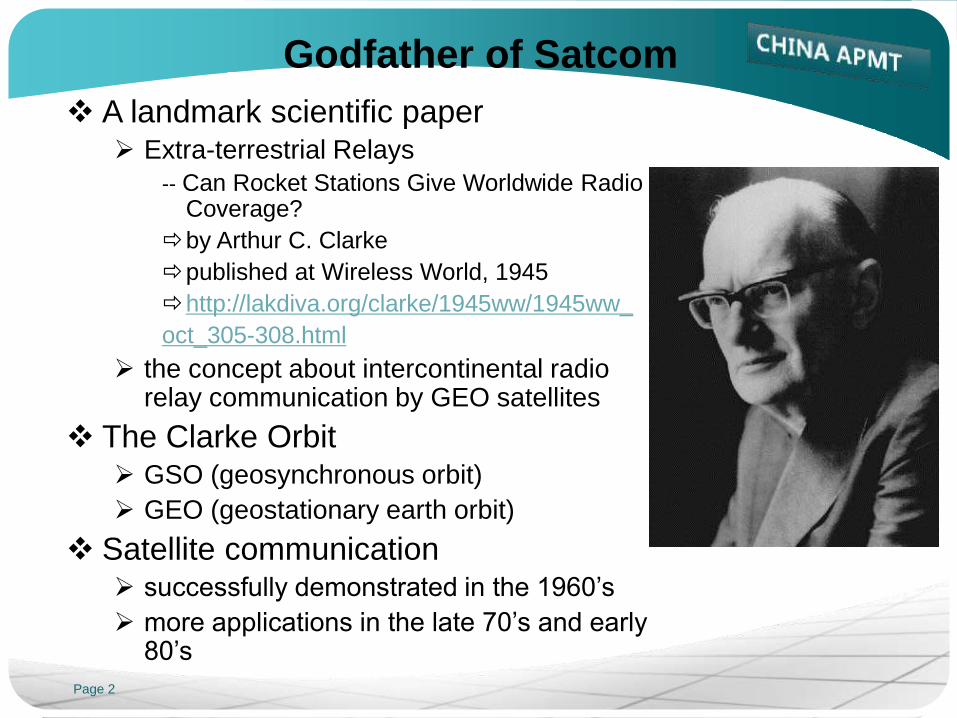
Godfather of Satcom
A landmark scientific paper Extra-terrestrial Relays
-- Can Rocket Stations Give Worldwide Radio Coverage?
by Arthur C. Clarke
published at Wireless World, 1945
http://lakdiva.org/clarke/1945ww/1945ww_
oct_305-308.html
the concept about intercontinental radio relay communication by GEO satellites
The Clarke Orbit GSO (geosynchronous orbit)
GEO (geostationary earth orbit)
Satellite communication successfully demonstrated in the 1960’s
more applications in the late 70’s and early 80’s

Page 3
Godfather of Satcom (cont.)
Sir Arthur C. Clarke
Dec. 1917 (England) - March 2008 (Sri Lanka)
As a radar specialist in RAF of UK during World War II
As a scientist the Assistant Editor for Science Abstracts, UK
the Professorship of the Physical Research Laboratory, India,
the Fellowship of King's College, London,
the Chancellor of the University of Moratuwa, Sri Lanka
As a science fiction writer dozens of published Essays, short stories and novels (1937 to 2006)
an Oscar nomination in 1969 for his screenplay of 2001: A Space Odyssey
http://www.arthurcclarke.net/?scifi=1&type=0
Knight of the British Empire
an asteroid was named in Clarke's honour, (4923 Clarke)
Epitaph: He never grew up, but he never stopped growing
Homepage: http://www.arthurcclarke.net

Page 4
Introduction
Decibel
History of Satellites
GEO Satellite Communication
Antenna
Space Segment
Communication Satellite
Frequency and Polarization Plan
Transponder and Transmission Loss
Earth Segment
Carrier and Network
Earth Station and VSAT Terminal

Page 5
Decibel
Notation
Normalized notation
absolute value: 300000000, 0.00000003
Exponential notation or scientific notation
Index number: 3 x 10⁸, 3 x 10⁻⁸
Logarithmic notation
logarithm, decibel: 84.8dB, -75.2dB
Decibel
dB
a logarithmic unit of measurement
10 times the common logarithm (to base 10)
To represent a very large range (ratio or exact value) as a
convenient number
To simplify addition and subtraction operation to multiplication
and division

Page 6
Decibel (cont.)
Frequently-used data
absolute value logarithm logarithm absolute value
2 3dB 2dB 1.6
3 4.8dB 1dB 1.3
5 7dB 0.5dB 1.1
7 8.5dB 0.2dB 1.05
20 13dB -0.2dB 0.95
300 24.8dB -0.5dB 0.9
5000 37dB -1dB 0.8
70000 48.5dB -2dB 0.6

Page 7
Decibel (cont.)
Simplified operation
Example
300000000 / 0.00000003 = 10000000000000000 = 1 x 10¹⁶
84.8dB - -75.2dB = 160dB => 1 x 1016 = 10000000000000000
0.00000003 / 300000000 = 0.0000000000000001 = 1 x 10-16
-75.2dB - 84.8dB = -160dB => 1 x 10-16 = 0.0000000000000001
Cascaded gain
GTotal = G1 * G2 * G3 = GdB1 + GdB2 + GdB3
Power density
P0 = P / BW (W/Hz) = PdBW – BWdBHz (dBW/Hz)
Count by Frequently-used data
36MHz = 2x2x3x3x1000000 (Hz) = 3+3+5+5+60 (dBHz)
Page 8
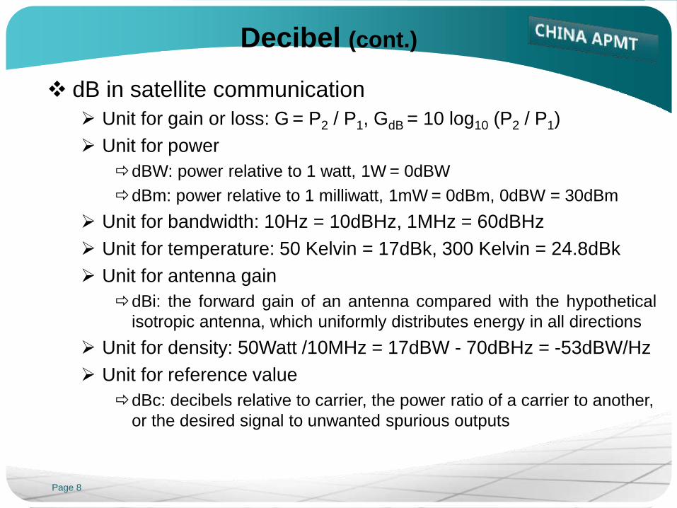
Decibel (cont.)
dB in satellite communication
Unit for gain or loss: G = P2 / P1, GdB = 10 log10 (P2 / P1)
Unit for power
dBW: power relative to 1 watt, 1W = 0dBW
dBm: power relative to 1 milliwatt, 1mW = 0dBm, 0dBW = 30dBm
Unit for bandwidth: 10Hz = 10dBHz, 1MHz = 60dBHz
Unit for temperature: 50 Kelvin = 17dBk, 300 Kelvin = 24.8dBk
Unit for antenna gain
dBi: the forward gain of an antenna compared with the hypothetical
isotropic antenna, which uniformly distributes energy in all directions
Unit for density: 50Watt /10MHz = 17dBW - 70dBHz = -53dBW/Hz
Unit for reference value
dBc: decibels relative to carrier, the power ratio of a carrier to another,
or the desired signal to unwanted spurious outputs

Page 9
Introduction
Decibel
History of Satellites
GEO Satellite Communication
Antenna
Space Segment
Communication Satellite
Frequency and Polarization Plan
Transponder and Transmission Loss
Earth Segment
Carrier and Network
Earth Station and VSAT Terminal
Page 10
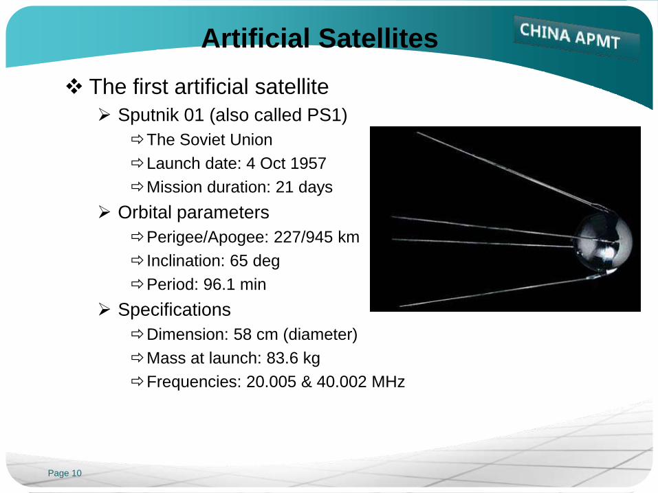
Artificial Satellites
The first artificial satellite
Sputnik 01 (also called PS1)
The Soviet Union
Launch date: 4 Oct 1957
Mission duration: 21 days
Orbital parameters
Perigee/Apogee: 227/945 km
Inclination: 65 deg
Period: 96.1 min
Specifications
Dimension: 58 cm (diameter)
Mass at launch: 83.6 kg
Frequencies: 20.005 & 40.002 MHz

Page 11
Artificial Satellites (cont.)
The first artificial satellite of USA
Explorer-I (also called Satellite 1958 Alpha)
Launch date: 31 Jan 1958
Mission duration: 111 days
Orbital parameters
Perigee/Apogee: 360/2535 km
Inclination: 33 deg
Period: 114.9 min
Specifications
Mass at launch: 13.9 kg
Frequency: 108 MHz
Transmitter power: 60mW(30 days)& 10mW(105 days)
Onboard instruments: cosmic ray detector, temperature
sensors, etc.
Discovery: Van Allen radiation belt (the belts consists of energetic
charged particles around the Earth)

Page 12
The History of Comsat
The first satellite communication test
SCORE, USA
Launch date: 18 Dec 1958
Mission duration: 34 days
(the batteries lasted 12 days)
Orbital parameters
Perigee/Apogee: 183/1481 km
Inclination: 32 deg
Period: 110.5 min
Specifications
Mass of payload: 68 kg (at the
top of the Atlas missile)
Frequency: 108 MHz
Transmitter power: 60mW(30 days)& 10mW(105 days)
Real-time and store-and-forward (by 2 tape recorders)
repeater for orbiting relay communications

Page 13
The History of Comsat (cont.)
Passive balloon satellite
Echo 1, USA
Launch date: 12 Aug 1960
Orbital parameters
Perigee/Apogee:
1524/1864 km
Inclination: 47.2 deg
Period: 118.3 min
Specifications
Diameter: 30.5 m
Mass: 180 kg
Beacon frequency: 107.9 MHz
Aluminum surface acting as a passive reflector, to bounce off
the microwave signals (telephone, radio and TV signals
modulated at 960 and 2390 MHz)
Page 14
The History of Comsat (cont.)
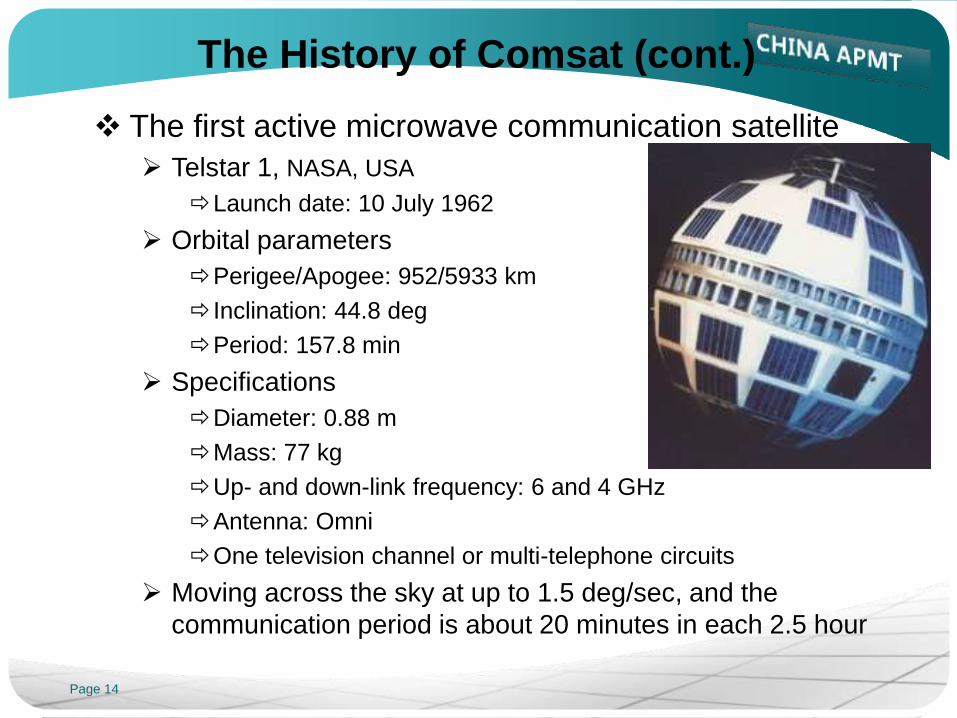
The first active microwave communication satellite
Telstar 1, NASA, USA
Launch date: 10 July 1962
Orbital parameters
Perigee/Apogee: 952/5933 km
Inclination: 44.8 deg
Period: 157.8 min
Specifications
Diameter: 0.88 m
Mass: 77 kg
Up- and down-link frequency: 6 and 4 GHz
Antenna: Omni
One television channel or multi-telephone circuits
Moving across the sky at up to 1.5 deg/sec, and the
communication period is about 20 minutes in each 2.5 hour

Page 15
The History of Comsat (cont.)
The first GSO communication satellite
Syncom 2, NASA, USA
Launch date: 26 July 1963
Orbit slot: 55W/26W/28.5E
Bus
Spin stabilized
Dimension: 0.71m (diameter), 0.39m (height)
Mass: 68 kg
DC power: 29 W
Two transponders
Up- and down-link frequency: 7360 and 1815 MHz
BW: 13MHz (low quality TV) and 5MHz (110ch telephone/fax)
TWTA: 2 W
Slotted dipole antenna: 2dBi (gain), 25deg (beam width)
32.7deg inclined rather than geostationary, the sub-satellite
track looks like “8”, and tracking antenna is needed in ES

Page 16
The History of Comsat (cont.)
The first GEO communication satellite
Syncom 3, NASA, USA
Launch date: 19 Aug 1964
Orbit slot: 64W/180E/25W/165E/6W
Bus and Payload: same as Syncom 2
TV transmission for Tokyo Olympic Games
Page 17
The History of Comsat (cont.)
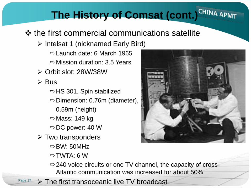
the first commercial communications satellite
Intelsat 1 (nicknamed Early Bird)
Launch date: 6 March 1965
Mission duration: 3.5 Years
Orbit slot: 28W/38W
Bus
HS 301, Spin stabilized
Dimension: 0.76m (diameter),
0.59m (height)
Mass: 149 kg
DC power: 40 W
Two transponders
BW: 50MHz
TWTA: 6 W
240 voice circuits or one TV channel, the capacity of cross-
Atlantic communication was increased for about 50%
The first transoceanic live TV broadcast

Page 18
Introduction
Decibel
History of Satellites
GEO Satellite Communication
Antenna
Space Segment
Communication Satellite
Frequency and Polarization Plan
Transponder and Transmission Loss
Earth Segment
Carrier and Network
Earth Station and VSAT Terminal

Page 19
Geostationary Earth Orbit
Geosynchronous orbit
GSO
Orbital period: one sidereal day,
matching the earth's rotation period
Geostationary earth orbit
GEO
A circular geosynchronous orbit at
zero inclination
Orbital velocity and attitude
Balance: between centripetal force
and centrifugal force
Mean earth radius: 6378km
Velocity: 11040km/h or 3.07km/s
Attitude of GEO orbit: 35786km

Page 20
GEO Satellite
GEO satellite
Appearing fixed above the surface of the earth
Seeing the earth at GEO, the angular diameter
is about 17.4 degrees
Proper orbited 3 GEO satellites can cover
almost whole surface of the earth
GEO communication satellite
Microwave relay communication
As a repeater: receiving the signals from the
earth, and then retransmitting them back to the
earth
Page 21
Coverage
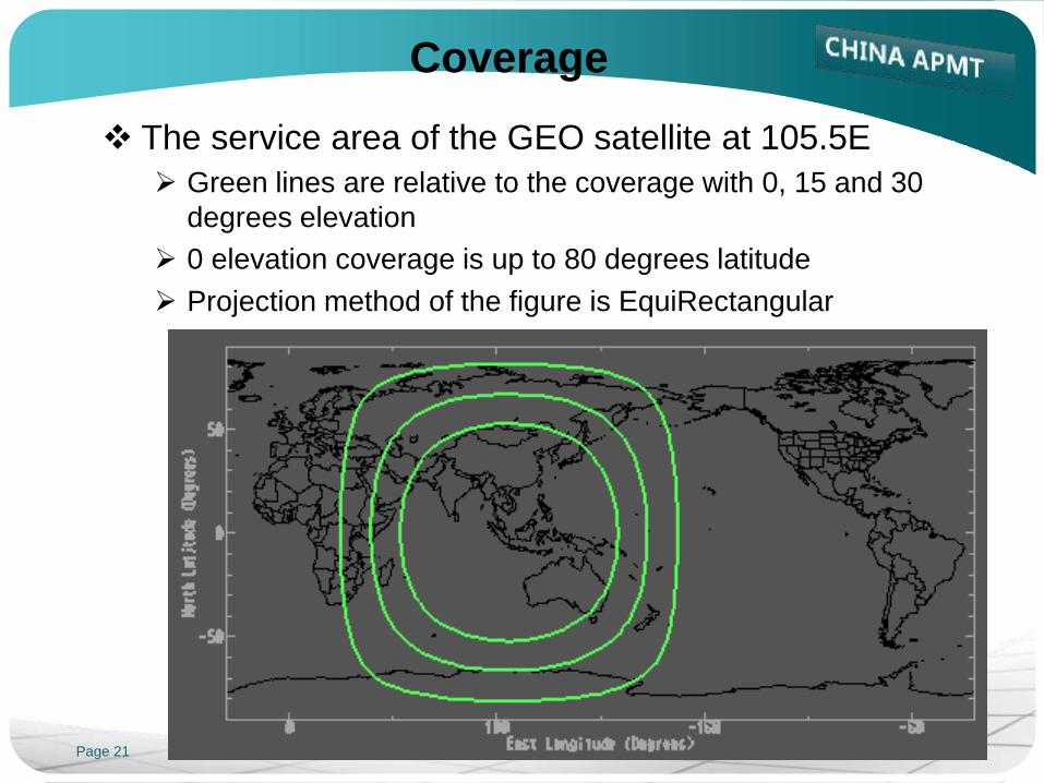
The service area of the GEO satellite at 105.5E
Green lines are relative to the coverage with 0, 15 and 30
degrees elevation
0 elevation coverage is up to 80 degrees latitude
Projection method of the figure is EquiRectangular

Page 22
GEO Satellite Communication
Wide coverage
Suitable for broadcasting
Same cost for long or short communication distance
Easy for network expansion and emergency terminal setting
Difficult to find interference resource
Long distance
One-way transmitting (up- or down-link)
about 37000 to 41000 km
Long time-delay
one-hoop needs about 1/4 sec
Huge transmission loss
200/196 dB loss for C-band up/down-link
207/206 dB loss for Ku-band up/down-link
Page 23
GEO Satellite Communication (cont.)
High frequency
Wider frequency band and more capacity
Rain attenuation existed in Ku- and Ka-band
High costs in configuration and operation
Transponder (bandwidth resource and power resource)
Antennas and earth station equipments
(Network management system)
Installation costs for the network and earth stations

Page 24
Classifications
By service
FSS, Fixed Satellite Service
BSS, Broadcasting Satellite Service
MSS, Mobile Satellite Service
By frequency band
L-band, 1-2 (or 0.39-1.55) GHz, mobile communication and
radio broadcast
S-band, 2-3 (or 1.55-5.2) GHz, mobile communication and TV
broadcast
C-band, 4-6 (or 3.7-6.2) GHz, fixed communication and radio
broadcast
X-band, 7-8 (or 5.2-10.9) GHz, fixed communication
Ku-band, 10-14 (or 10.7-18) GHz, fixed communication and
direct-to-home TV broadcast
Ka-band, 17-31 (or 18-40) GHz , fixed and mobile
communication

Page 25
Classifications (cont.)
By orbit
Height
LEO, low earth orbit, 700 to 1400 km attitude, 40+ satellites for
global coverage
MEO, medium earth orbit, 10000 to 15000 km, 10 to 15
satellites for global coverage
HEO, highly elliptical orbit, 500+ km perigee with 50000+ km
apogee
Page 26
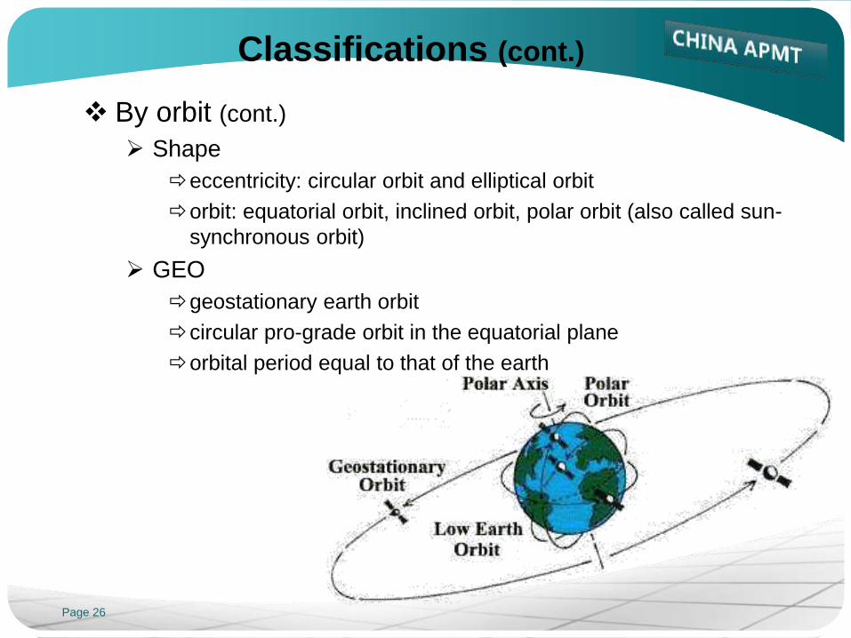
Classifications (cont.)
By orbit (cont.)
Shape
eccentricity: circular orbit and elliptical orbit
orbit: equatorial orbit, inclined orbit, polar orbit (also called sun-
synchronous orbit)
GEO
geostationary earth orbit
circular pro-grade orbit in the equatorial plane
orbital period equal to that of the earth

Page 27
Classifications (cont.)
By Payload
Transparent channel
also called bent pipe payload
receiving and transmission
On-board processing
also called regenerative payload
receiving, regeneration (demodulation, rearrangement and re-
modulation) and then re-transmission
Store-and-forward
receiving, store, and then re-transmission
normally used for LEO and MEO
Page 28
Introduction
Decibel
History of Satellites
GEO Satellite Communication
Antenna
Space Segment
Communication Satellite
Frequency and Polarization Plan
Transponder and Transmission Loss
Earth Segment
Carrier and Network
Earth Station and VSAT Terminal

Page 29
Reflector Antenna
Directional antenna
Focus the signal energy for overcoming
transmission loss
Parabolic reflector antenna: used for
earth stations
Beam forming antenna: used for
communication satellites
Antenna gain
Ratio of radiated power in a given direction relative to that of
an isotropic antenna
The unit of antenna gain is dBi, where i means isotropic
Antenna gain is proportional to the square of signal frequency
Antenna gain of a parabolic reflector antenna is proportional
to the square of the diameter of the reflector

Page 30
Reflector Antenna (cont.)
Antenna radiation pattern
The distribution of antenna gain at an angular coordinate
Parabolic reflector antenna: by the coordinates of azimuth
angle and elevation angle
Beam forming antenna: by contour map
Page 31
Parabolic Reflector Antenna
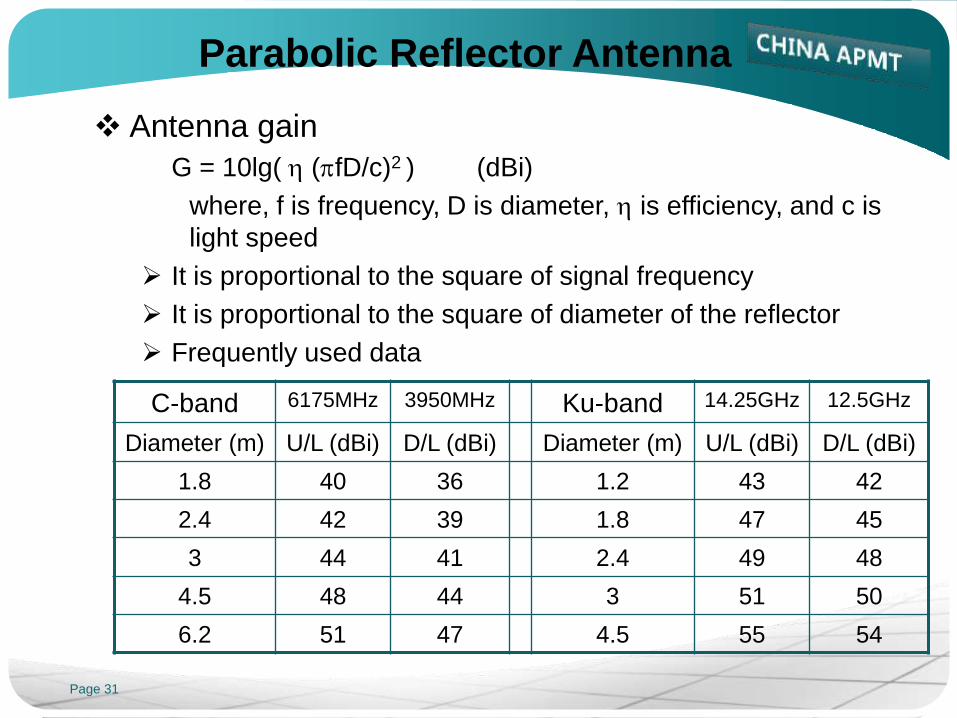
Antenna gain
G = 10lg( h (pfD/c)2 ) (dBi)
where, f is frequency, D is diameter, h is efficiency, and c is
light speed
It is proportional to the square of signal frequency
It is proportional to the square of diameter of the reflector
Frequently used data
C-band 6175MHz 3950MHz Ku-band 14.25GHz 12.5GHz
Diameter (m) U/L (dBi) D/L (dBi) Diameter (m) U/L (dBi) D/L (dBi)
1.8 40 36 1.2 43 42
2.4 42 39 1.8 47 45
3 44 41 2.4 49 48
4.5 48 44 3 51 50
6.2 51 47 4.5 55 54

Page 32
Beam Forming Antenna
Why beam forming
To form the antenna pattern as the required service area
How beam forming
Single reflector with multi-feeds
Single feed with shaped reflector
Relationship between antenna
pattern and transponder
parameters
The receive pattern is relative
to G/T and SFD
The transmit pattern is relative
to EIRP

Page 33
Introduction
Decibel
History of Satellites
GEO Satellite Communication
Antenna
Space Segment
Communication Satellite
Frequency and Polarization Plan
Transponder and Transmission Loss
Earth Segment
Carrier and Network
Earth Station and VSAT Terminal

Page 34
Communication Satellite
Two main parts
Payload: communication subsystem
Bus: platform
Payload
Antennas
Transponders
transponder = trans(mitter) + (res)ponder
repeater: to receive, amplify and retransmit the incoming signals
Bus
Telemetry and command subsystem
Electrical power subsystem
Attitude control subsystem
Thermal control subsystem
Propulsion subsystem
Page 35
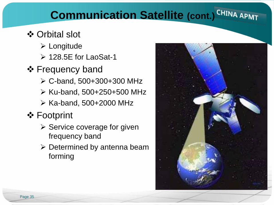
Communication Satellite (cont.)
Orbital slot
Longitude
128.5E for LaoSat-1
Frequency band
C-band, 500+300+300 MHz
Ku-band, 500+250+500 MHz
Ka-band, 500+2000 MHz
Footprint
Service coverage for given
frequency band
Determined by antenna beam
forming
Page 36
Introduction
Decibel
History of Satellites
GEO Satellite Communication
Antenna
Space Segment
Communication Satellite
Frequency and Polarization Plan
Transponder and Transmission Loss
Earth Segment
Carrier and Network
Earth Station and VSAT Terminal

Page 37
Frequency Band
Up-link and down-link
Up-link
U/L, the carrier from earth station to satellite
Down-link
D/L, the carrier from satellite to E/S
U/L and D/L using different frequencies
to avoid interference with each other
U/L frequency is normally higher than that of D/L
higher gain for receiving antennas
smaller size for traveling wave tube and TWTA in E/S
Page 38
Frequency Band (cont.)
Common frequency bands for FSS
C-band: 5850-6425MHz (U/L) and 3725-4200MHz (D/L)
Expand C-band: 6425-6725MHz/3400-3700MHz
Ku-band: 14.0-14.5GHz/12.25-12.75GHz (for ITU region 3)
Ka-band: 27.5-31.0GHz/17.7-21.2GHz
Common frequency bands for BSS
Ku-band: 14.5-14.8GHz/11.7-12.2GHz (for ITU region 3)
Ka-band: 17.3-17.8GHz (U/L, for ITU region 3)
Page 39
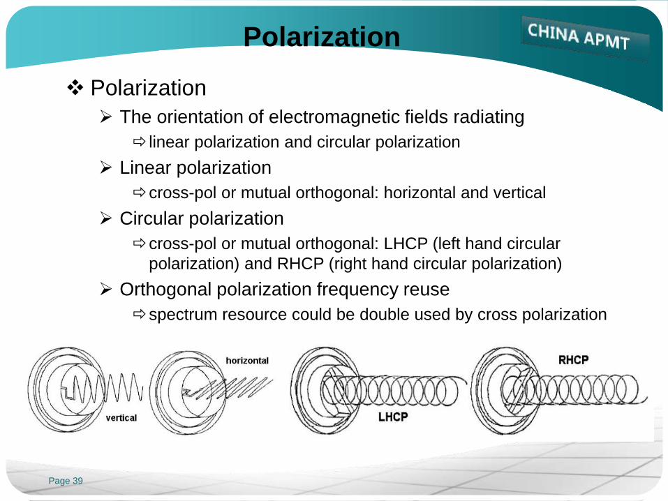
Polarization
Polarization
The orientation of electromagnetic fields radiating
linear polarization and circular polarization
Linear polarization
cross-pol or mutual orthogonal: horizontal and vertical
Circular polarization
cross-pol or mutual orthogonal: LHCP (left hand circular
polarization) and RHCP (right hand circular polarization)
Orthogonal polarization frequency reuse
spectrum resource could be double used by cross polarization

Page 40
Polarization (cont.)
Common polarization for FSS
Linear polarization
often used by regional and domestic communication satellites
Circular polarization
often used by INTELSAT satellites in C-band
Common polarization for BSS
Circular polarization
assigned for BSS bands by ITU
Linear polarization
could also reassigned for BSS bands
Page 41
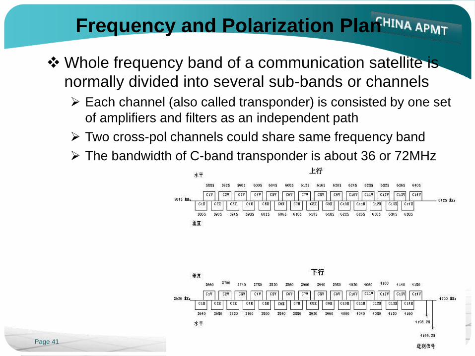
Frequency and Polarization Plan
Whole frequency band of a communication satellite is
normally divided into several sub-bands or channels
Each channel (also called transponder) is consisted by one set
of amplifiers and filters as an independent path
Two cross-pol channels could share same frequency band
The bandwidth of C-band transponder is about 36 or 72MHz

Page 42
Frequency and Polarization Plan (cont.)
FSS Beam 1
FSS Beam 2
BSS Beam
上行垂直
下行水平
上行水平
下行垂直
上行水平
下行垂直
上行垂直
下行右旋
The bandwidth of Ku-band transponder is about 54 or 36MHz

Page 43
Introduction
Decibel
History of Satellites
GEO Satellite Communication
Antenna
Space Segment
Communication Satellite
Frequency and Polarization Plan
Transponder and Transmission Loss
Earth Segment
Carrier and Network
Earth Station and VSAT Terminal

Page 44
Transponder
Bent pipe transponder
Signal is only filtered, frequency converted and amplified in it
(up-link signals in the service area is received by Rx-antenna)
signals are pre-amplified by LNA
U/L frequency is converted to D/L frequency by down-converter
relevant frequency component is selected by input BPF
signal level is properly amplified by channel amplifier with the
adjusted gain
output signal is amplified by power amplifier
out-of-band interference is filtered by output BPF to protect the
adjacent channels
(down-link signals is directionally transmitted by Tx-antenna)

Page 45
Transponder (cont.)
Bent pipe transponder (cont.)
Nearly 200dB gain to counteract the huge free space loss
The Signal Level change through the S/C C-band communication link
-200
-150
-100
-50
0
50
100
Po
we
r L
ev
el
(dB
W)
Video In,
-30dBW
U/C gain,
11dB
HPA gain, 40dB
W/G loss, -5dB
ES Ant.gain,
49.6dB
U/L path loss
-199.6dB
S/C Ant. Gain
24dB
RCVR atten. &
loss, -12.5dB RCVR gain, 62.5dB
IMUX/Cable
loss,
-7dB
CCLU gain
30dB
TWTA gain
55dB
OMUX & W/G
loss
-1.1dB
S/C Ant. Gain
24dB
D/L path
loss
-195.7dB
E/S Rcv. Ant. Gain
34.9dB
LNA
gain
65dB
E/S Cable loss
-5dB
D/C IF Amp. Gain
30dB
Video out
-30dB
Signal at S/C
Ant. Input
-134dBW
Ground U/L EIRP
65.6dBW
D/L EIRP
40.9dBW
RF power @
Ant. Frond end
-154.8dBW
Page 46
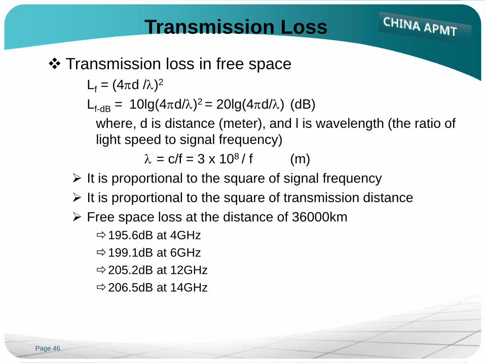
Transmission Loss
Transmission loss in free space
Lf = (4pd /l)2
Lf-dB = 10lg(4pd/l)2 = 20lg(4pd/l) (dB)
where, d is distance (meter), and l is wavelength (the ratio of
light speed to signal frequency)
l = c/f = 3 x 10⁸ / f (m)
It is proportional to the square of signal frequency
It is proportional to the square of transmission distance
Free space loss at the distance of 36000km
195.6dB at 4GHz
199.1dB at 6GHz
205.2dB at 12GHz
206.5dB at 14GHz

Page 47
Introduction
Decibel
History of Satellites
GEO Satellite Communication
Antenna
Space Segment
Communication Satellite
Frequency and Polarization Plan
Transponder and Transmission Loss
Earth Segment
Carrier and Network
Earth Station and VSAT Terminal
Page 48
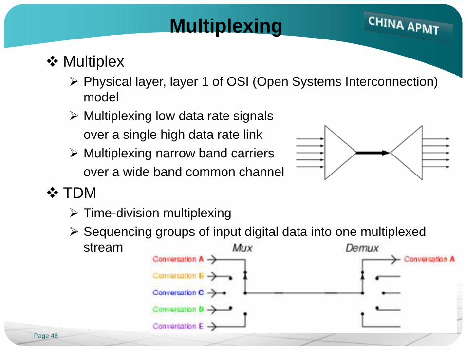
Multiplexing
Multiplex
Physical layer, layer 1 of OSI (Open Systems Interconnection)
model
Multiplexing low data rate signals
over a single high data rate link
Multiplexing narrow band carriers
over a wide band common channel
TDM
Time-division multiplexing
Sequencing groups of input digital data into one multiplexed
stream
Page 49
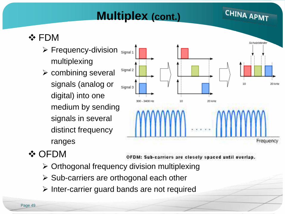
Multiplex (cont.)
FDM
Frequency-division
multiplexing
combining several
signals (analog or
digital) into one
medium by sending
signals in several
distinct frequency
ranges
OFDM
Orthogonal frequency division multiplexing
Sub-carriers are orthogonal each other
Inter-carrier guard bands are not required

Page 50
Multiple Access
Multiple Access
Data link layer, layer 2 of OSI model
One channel shared by several signals and offering multi-
point transmission
FDMA
Frequency division
multiple access
Assigning particular
frequency channels
to different carriers
Page 51
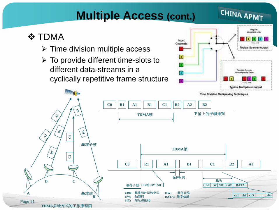
Multiple Access (cont.)
TDMA
Time division multiple access
To provide different time-slots to
different data-streams in a
cyclically repetitive frame structure
C0 R1 A1 B1 C1 R2 A2 B2
TDMA帧 卫星上的子帧排列
C1
C
2
A
B C
R
基准子帧
基准站
TDMA多址方式的工作原理图
C0 R1 A1 B1 C1 R2 A2
TDMA帧
CBR UW SIC CBR UW SIC OW DATA
ch1 ch2 ch3 chn …
保护时间 报头
CBR:载波和时间恢复码
UW: 独特码
SIC: 站址识别码
OW: 勤务联络
DATA:数字信道
基准子帧

Page 52
Multiple Access (cont.)
CDMA
Code division multiple access: a
kind of spread-spectrum multiple
access
Signals encoded by unique
spreading codes (orthogonal to
others)
Spread-spectrum signals sharing
a frequency band simultaneously
Each signal behaving like noise
to others
The paired transmitters and
receivers recognize their
assigned and correlated code
sequences, which look to all
others as pseudorandom noise

Page 53
Multiple Access (cont.)
Brief summary
FDMA: each carrier assigned fixed frequency band
continually, desired channel filtered out by BPF
TDMA: each station utilizing allocated time slot in data frame
cyclically, relative data stream picked up by synchronous
technique
CDMA: all users share same frequency band simultaneously,
required data encoded
by unique code
Page 54
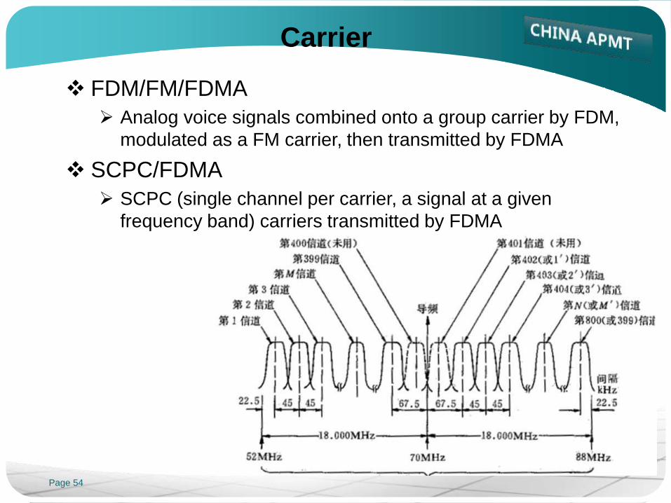
Carrier
FDM/FM/FDMA
Analog voice signals combined onto a group carrier by FDM,
modulated as a FM carrier, then transmitted by FDMA
SCPC/FDMA
SCPC (single channel per carrier, a signal at a given
frequency band) carriers transmitted by FDMA

Page 55
Carrier (cont.)
TDM/PSK/FDMA
Digital voice signals or data combined by TDM, modulated as
a PSK carrier, then transmitted by FDMA
IDR: intermediate data rate
IBS: Intelsat business service
TDM/PSK/TDMA
Digital voice signals or data combined by TDM, modulated as
a PSK carrier, then transmitted by TDMA
DVB: digital video broadcasting
MCPC (multi channel per carrier)
broadcast, multicast, unicast

Page 56
Network
Point to point
Communication carrier from one earth station to another
Carriers between two earth stations
FDM/FM/FDMA, SCPC/FDMA,
TDM/PSK/FDMA
Star network
Broadcasting
TV or data, one way
Intercommunication
single hop between hub and remote
double hop between two remotes
TDM/PSK/TDMA
DVB, DVB-RCS (return channel via
satellite), Hughes-PES
Page 57
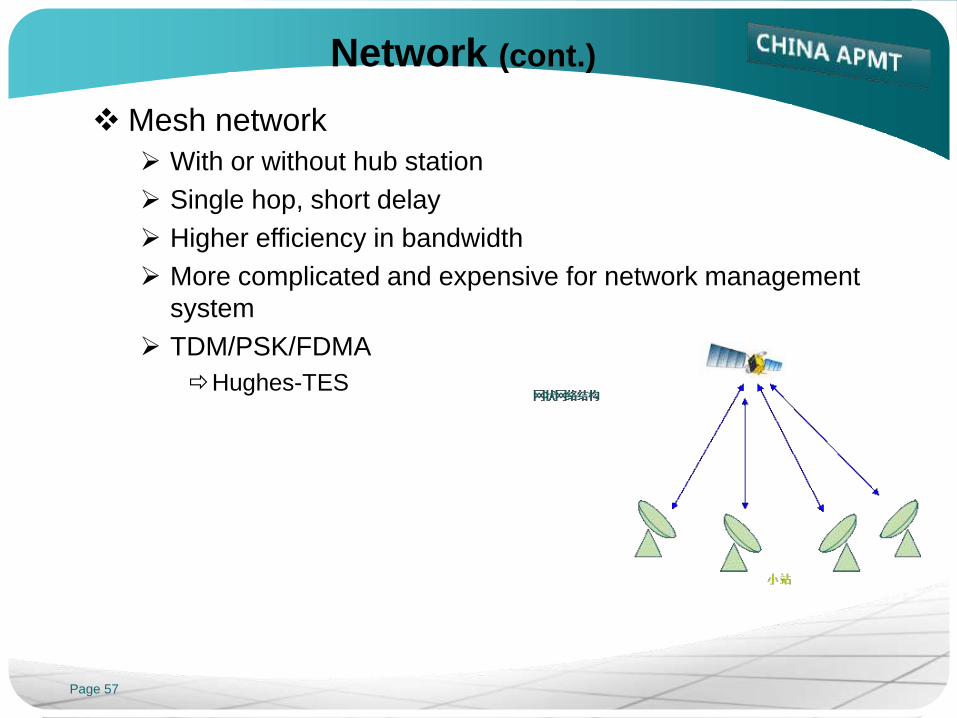
Network (cont.)
Mesh network
With or without hub station
Single hop, short delay
Higher efficiency in bandwidth
More complicated and expensive for network management
system
TDM/PSK/FDMA
Hughes-TES

Page 58
Introduction
Decibel
History of Satellites
GEO Satellite Communication
Antenna
Space Segment
Communication Satellite
Frequency and Polarization Plan
Transponder and Transmission Loss
Earth Segment
Carrier and Network
Earth Station and VSAT Terminal

Page 59
Earth Station
Uplink
(BB) - MOD (IF) - U/C (RF) - HPA - antenna - satellite
Downlink
Satellite - antenna - LNA (RF) - D/C (IF) - DEMOD (BB)

Page 60
Earth Station (cont.)
Satellite control station
Telemetry processing
Manual and automatic commanding
On-board software management
Mission archive and web-based data distribution
Teleport
Broadband hub or gateway station
Connecting satellite circuits with
terrestrial fiber
Providing TV, Internet and
enterprise network connections
Page 61
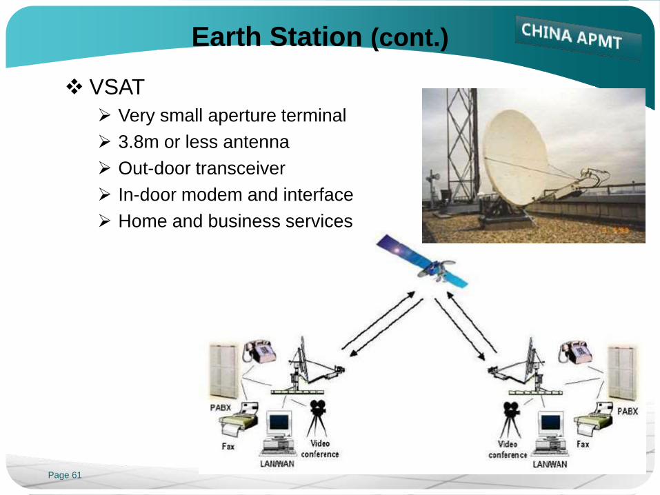
Earth Station (cont.)
VSAT
Very small aperture terminal
3.8m or less antenna
Out-door transceiver
In-door modem and interface
Home and business services

Page 62
Reference:
AsiaSat: Customer Training Materials, April 2004
Wikipedia
GVF: VSAT Installation & Maintenance Training
Thanks!
Welcome to my homepage
www.satcomengr.com