Embed Size (px)
Citation preview

Spectroscopic ellipsometry of slightlyinhomogeneous nonabsorbing thin films witharbitrary refractive-index profiles: theoretical study
Alexander V. Tikhonravov, Michael K. Trubetskov, and Anna V. Krasilnikova
We develop a new approximation for the amplitude reflection coefficients of a slightly inhomogeneous thinfilm. This approximation incorporates exactly the interference effects at the substrate and the ambientinterfaces. Interference effects inside the inhomogeneous film are incorporated in the Born approxima-tion. We also develop a new approach to the reconstruction of the refractive-index profile from ellipso-metric spectra. It is based on a physically sound parameterization of the refractive-index profile. Thenew approach is tested on the model reconstruction problem. © 1998 Optical Society of America
OCIS codes: 120.2130, 120.5710, 300.0300, 310.0310.
acba
afiioctis
ct
1. Introduction
Spectroscopic ellipsometry is a powerful tool for thedetermination of optical parameters of homogeneousthin films. During the last few years, it has alsobeen widely applied for the characterization of inho-mogeneous dielectric thin films. At the same timetheoretical studies of the spectral ellipsometry of in-homogeneous thin films have been in progress.Quite often, dielectric thin films feature small inho-mogeneities, and it is not surprising that theoreticalstudies were mainly concerned with slightly inhomo-geneous thin films.1–5
Essential parameters of a slightly inhomogeneousthin film are the mean refractive index and the de-gree of inhomogeneity of a film.6,7 It was shown thatthese two parameters can be determined based on thetheoretical consideration of spectroscopic ellipsom-etry of slightly inhomogeneous thin films with linearrefractive-index profiles.2,3 An important role in thetheoretical analysis of spectral ellipsometric data isplayed by the so-called quarter-wave ~QW! and half-wave ~HW! wavelength points.2 The considerationof films with linear refractive-index profiles predictsthat the values of the ellipsometric angle C at the QW
The authors are with the Research Computing Center and De-partment of Physics, Moscow State University, Moscow 119899,Russia.
Received 22 December 1997; revised manuscript received 14April 1998.
0003-6935y98y255902-10$15.00y0© 1998 Optical Society of America
5902 APPLIED OPTICS y Vol. 37, No. 25 y 1 September 1998
points are independent of the degree of inhomogene-ity, whereas those values at the HW points are mostsensitive to the film inhomogeneity and can be usedto determine the degree of inhomogeneity.2,3
The approximation resulting in the above conclu-sions can be traced back to the work by Schroder.8 Itis based on the assumption that the contribution ofthe interference effects inside the film can beignored.8–10 At the same time it incorporates ex-ctly the reflections connected with the abrupthanges of the refractive-index profile at the filmoundaries. In the following we shall refer to thispproximation as Schroder’s approximation.Schroder’s approximation, however, is only a first
pproximation to the properties of inhomogeneouslms. It is valid for films with a linear refractive-
ndex profile, but it does not entirely fit the propertiesf ellipsometric spectra in the case of more compli-ated refractive-index profiles. It is shown in Sec-ion 3 that the C values at the QW points arendependent of the film inhomogeneity in only somepecial cases.A more precise approximation was derived for the
ase of an infinite inhomogeneous layer bounded byhe interface with a homogeneous substrate.1 The
effect of the interface was incorporated exactly,whereas for the inhomogeneous layer the first Bornapproximation was used. This approach was laterextended to include the effects of local perturbationsat both sides of the substrate interface.5
In this paper we derive a more precise approxima-tion for the inhomogeneous film with two abruptchanges of the refractive index at the substrate and
edo
mAl
fi
fii
ambient interfaces. It is based on the same ideas asthose leading to the approximation derived in Refs. 1and 5. The effects of the interfaces are incorporatedexactly, whereas the contribution of a small inhomo-geneity inside the film is taken into account approx-imately.
Recently, a new approximation has been developedfor the reflection coefficient of a multilayer consistingof inhomogeneous layers.11 The emphasis was ondeveloping a fast computational algorithm. On thecontrary, the main goal of our derivations is to obtainqualitative conclusions concerning the influence ofthe inhomogeneity on the ellipsometric spectra. Forthis reason our approach differs from that used inRef. 11. Our approach is developed in Section 2. InSection 3 we consider various model refractive-indexprofiles and analyze ellipsometric spectra by usingthe new approximation.
Section 4 is devoted to developing an algorithm forthe reconstruction of inhomogeneous profiles fromspectral ellipsometric data. Various reconstructionalgorithms have been proposed during the last fewyears.12–18 The most widely used is based on theassumption of a three-layer model of an inhomoge-neous film.12–15 This may limit the application ofthe algorithm if the true refractive-index profile doesnot fit the above assumption. The algorithms basedon the Born approximation16,17 do not imply any spe-cific behavior of the refractive-index profile but areinherently approximate. At the same time it is pos-sible to develop an accurate reconstruction algorithmassuming only the smoothness of the refractive-indexprofile.18 The algorithm from Ref. 18 is based on theideas of the theory of inverse problems19 and imple-ments the Newton–Kantorovitch method for the re-construction procedure. In Section 4 we develop theaccurate algorithm, which is also based on the ideasof the theory of inverse problems but implements adifferent reconstruction procedure from that given inRef. 18. Our approach is directly connected with theresults of the approximate analysis performed in Sec-tion 3.
2. Approximation for the Amplitude ReflectionCoefficients of a Slightly InhomogeneousNonabsorbing Film
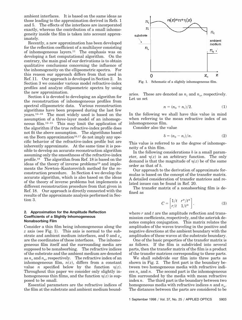
Consider a thin film being inhomogeneous along thez axis ~see Fig. 1!. This axis is normal to the sub-strate and ambient medium interfaces, and 0 and zaare the coordinates of these interfaces. The inhomo-geneous film itself and the surrounding media aresupposed to be nonabsorbing. The refractive indicesof the substrate and the ambient medium are denotedas ns and na, respectively. The refractive index of aninhomogeneous film, n~z!, differs from a constantvalue n specified below by the function h~z!.Throughout this paper we consider only slightly in-homogeneous thin films, and the function h~z! is sup-posed to be small.
Essential parameters are the refractive indices ofthe film at the substrate and ambient medium bound-
1
aries. These are denoted as ni and no, respectively.Let us set
n 5 ~n0 1 ni!y2. (1)
In the following we shall have this value in mindwhen referring to the mean refractive index of aninhomogeneous film.
Consider also the value
d 5 ~n0 2 ni!yn. (2)
This value is referred to as the degree of inhomoge-neity of a thin film.
In the following considerations d is a small param-ter, and h~z! is an arbitrary function. The onlyemand is that the magnitude of h~z! be of the samerder as that of d.Our approach to the derivation of approximate for-ulas is based on the concept of the transfer matrix.detailed consideration of transfer matrices and re-
ated issues can be found in Ref. 20.The transfer matrix of a nonabsorbing film is de-
ned as
C 5 F1yt r*yt*ryt 1yt* G . (3)
where r and t are the amplitude reflection and trans-mission coefficients, respectively, and the asterisk de-notes complex conjugation. This matrix relates theamplitudes of the waves traveling in the positive andnegative directions at the ambient boundary with theamplitudes of these waves at the substrate boundary.
One of the basic properties of the transfer matrix isas follows. If the film is subdivided into severalparts, then the transfer matrix of the film is a productof the transfer matrices corresponding to these parts.
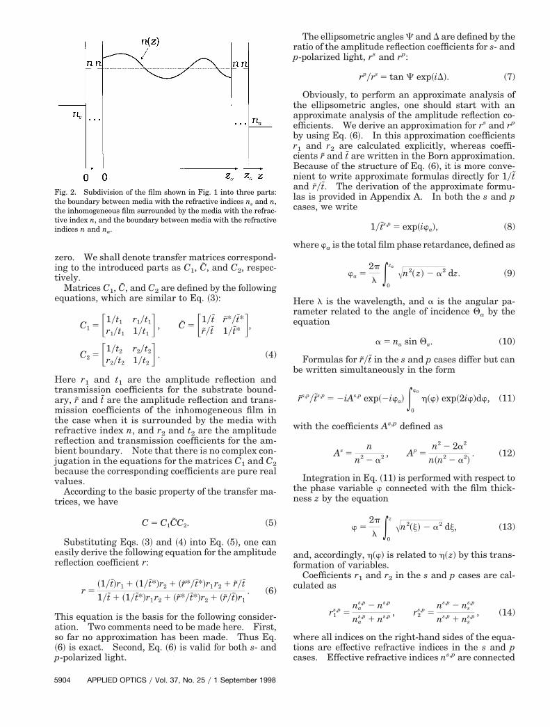
We shall subdivide our film into three parts asshown in Fig. 2. The first part is the boundary be-tween two homogeneous media with refractive indi-ces ns and n. The second part is the inhomogeneous
lm surrounded by the media with mean refractivendex n. The third part is the boundary between two
homogeneous media with refractive indices n and na.The distances between the parts are considered to be
Fig. 1. Schematic of a slightly inhomogeneous film.
September 1998 y Vol. 37, No. 25 y APPLIED OPTICS 5903
H
tae
a
b
tn
5
zero. We shall denote transfer matrices correspond-ing to the introduced parts as C1, C, and C2, respec-tively.
Matrices C1, C, and C2 are defined by the followingequations, which are similar to Eq. ~3!:
C1 5 F1yt1 r1yt1
r1yt1 1yt1G , C 5 F1yt r*yt*
ryt 1yt* G,
C2 5 F1yt2 r2yt2
r2yt2 1yt2G . (4)
ere r1 and t1 are the amplitude reflection andtransmission coefficients for the substrate bound-ary, r and t are the amplitude reflection and trans-mission coefficients of the inhomogeneous film inthe case when it is surrounded by the media withrefractive index n, and r2 and t2 are the amplitudereflection and transmission coefficients for the am-bient boundary. Note that there is no complex con-jugation in the equations for the matrices C1 and C2because the corresponding coefficients are pure realvalues.
According to the basic property of the transfer ma-trices, we have
C 5 C1CC2. (5)
Substituting Eqs. ~3! and ~4! into Eq. ~5!, one caneasily derive the following equation for the amplitudereflection coefficient r:
r 5~1yt!r1 1 ~1yt*!r2 1 ~r*yt*!r1 r2 1 ryt1yt 1 ~1yt*!r1 r2 1 ~r*yt*!r2 1 ~ryt!r1
. (6)
This equation is the basis for the following consider-ation. Two comments need to be made here. First,so far no approximation has been made. Thus Eq.~6! is exact. Second, Eq. ~6! is valid for both s- andp-polarized light.
Fig. 2. Subdivision of the film shown in Fig. 1 into three parts:the boundary between media with the refractive indices ns and n,the inhomogeneous film surrounded by the media with the refrac-tive index n, and the boundary between media with the refractiveindices n and na.
904 APPLIED OPTICS y Vol. 37, No. 25 y 1 September 1998
The ellipsometric angles C and D are defined by theratio of the amplitude reflection coefficients for s- andp-polarized light, rs and rp:
rpyrs 5 tan C exp~iD!. (7)
Obviously, to perform an approximate analysis ofhe ellipsometric angles, one should start with anpproximate analysis of the amplitude reflection co-fficients. We derive an approximation for rs and rp
by using Eq. ~6!. In this approximation coefficientsr1 and r2 are calculated explicitly, whereas coeffi-cients r and t are written in the Born approximation.Because of the structure of Eq. ~6!, it is more conve-nient to write approximate formulas directly for 1ytnd ryt. The derivation of the approximate formu-
las is provided in Appendix A. In both the s and pcases, we write
1yts,p 5 exp~iwa!, (8)
where wa is the total film phase retardance, defined as
wa 52p
l *0
za În2~ z! 2 a2 dz. (9)
Here l is the wavelength, and a is the angular pa-rameter related to the angle of incidence Qa by theequation
a 5 na sin Qa. (10)
Formulas for ryt in the s and p cases differ but cane written simultaneously in the form
rs,pyts,p 5 2iAs,p exp~2iwa! *0
wa
h~w! exp~2iw!dw, (11)
with the coefficients As,p defined as
As 5n
n2 2 a2 , Ap 5n2 2 2a2
n~n2 2 a2!. (12)
Integration in Eq. ~11! is performed with respect tohe phase variable w connected with the film thick-ess z by the equation
w 52p
l *0
z În2~j! 2 a2 dj, (13)
and, accordingly, h~w! is related to h~z! by this trans-formation of variables.
Coefficients r1 and r2 in the s and p cases are cal-culated as
r1s,p 5
nas,p 2 ns,p
nas,p 1 ns,p , r2
s,p 5ns,p 2 ns
s,p
ns,p 1 nss,p , (14)
where all indices on the right-hand sides of the equa-tions are effective refractive indices in the s and pcases. Effective refractive indices ns,p are connected
t
gr
p~p
tH
t
with the film mean refractive index n by the equa-ions
ns 5 În2 2 a2, np 5 n2yÎn2 2 a2. (15)
Effective refractive indices of the ambient mediumand the substrate, na
s,p and nss,p, are defined in a sim-
ilar way.Substitution of Eqs. ~8!, ~11!, and ~14! into Eq. ~6!
ives approximate formulas for the film amplitudeeflection coefficients rs and rp. For brevity we shall
henceforth omit superscripts s and p when this doesnot cause ambiguity. After some simple rearrange-ments the formulas for the amplitude reflection coef-ficients can be written in the form
dmta
pmtvarftr
where
m 5 A *0
wa
h~w!sin~2w 2 wa!dw, (17)
n 5 A *0
wa
h~w!sin~2w 2 wa!dw, (18)
Equations ~16!–~18! are final equations of the newapproximation for the amplitude reflection coeffi-cients of a slightly inhomogeneous film. If there is noinhomogeneity, i.e., h~w! 5 0, then m and n are equalto zero and Eq. ~16! is reduced to the well-knownformula for the amplitude reflection coefficients of ahomogeneous film. Schroder’s approximation canbe derived from Eqs. ~16!–~18! by integrating Eqs.~17! and ~18! by parts and neglecting terms contain-ing the derivative of h~w!.
3. Qualitative Analysis of Ellipsometric Spectra
In this paper we shall restrict our consideration to thespectral behavior of the ellipsometric angle C. To
erform a qualitative analysis, we shall consider Eq.16! at the QW and HW wavelength points.2 Theseoints are the wavelengths for which
wa 5 mpy2, (19)
where m is an integer. Odd m values correspond tohe QW points, and even m values correspond to theW points.At the QW points Eq. ~16! is reduced to the equa-
ion
1
and at the HW points it is reduced to the equation
r 5@~na 2 ns!~21!my2 1 ~na 1 ns!m# 2 i~na nsyn 1 n!n
@~na 1 ns!~21!my2 1 ~na 2 ns!m# 2 i~na nsyn 2 n!n
(21)
According to the initial assumption, the deviationof the refractive-index profile from the mean valuen is a small function. Thus m and n are also smallvalues. When analyzing variations of the ampli-tude reflection coefficients, we shall keep in mindonly terms of the same order of smallness as that of
m and n and neglect all higher-order terms. In thisapproximation
uru2 5~na nsyn 2 n!2 2 2~21!~m21!y2~na
2ns2yn2 2 n2!n
~na nsyn 1 n!2 2 2~21!~m21!y2~na2ns
2yn2 2 n2!n
(22)
at the QW points, and
uru2 5~na 2 ns!
2 1 2~21!my2~na2 2 ns
2!m
~na 1 ns!2 1 2~21!my2~na
2 2 ns2!m
(23)
at the HW points. Thus the variations of uru areefined only by n values at the QW points and only byvalues at the HW points. Obviously, the same is
rue with respect to the variations of the ellipsometricngle C caused by a small inhomogeneity.It is not difficult to derive equations for the varia-
tions of the ellipsometric angle C. We shall not dothis here, however, as we are able to obtain someimportant qualitative conclusions directly from Eqs.~17! and ~18!.
First of all, the values n are generally nonzero, andin contrast with Schroder’s approximation, Eq. ~20!
redicts that variations of the ellipsometric angle Cay take place at the QW points. There is no con-
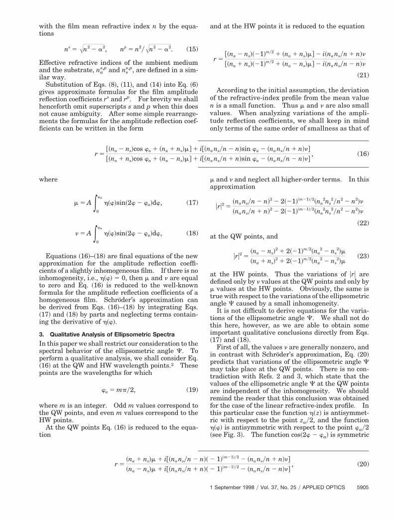
radiction with Refs. 2 and 3, which state that thealues of the ellipsometric angle C at the QW pointsre independent of the inhomogeneity. We shouldemind the reader that this conclusion was obtainedor the case of the linear refractive-index profile. Inhis particular case the function h~z! is antisymmet-ic with respect to the point zay2, and the function
h~w! is antisymmetric with respect to the point way2~see Fig. 3!. The function cos~2w 2 wa! is symmetric
r 5@~na 2 ns!cos wa 1 ~na 1 ns!m# 1 i@~na nsyn 2 n!sin wa 2 ~na nsyn 1 n!n#
@~na 1 ns!cos wa 1 ~na 2 ns!m# 1 i@~na nsyn 1 n!sin wa 2 ~na nsyn 2 n!n#, (16)
r 5~na 1 ns!m 1 i@~na nsyn 2 n!~ 2 1!~m21!y2 2 ~na nsyn 1 n!n#
~na 2 ns!m 1 i@~na nsyn 1 n!~ 2 1!~m21!y2 2 ~na nsyn 2 n!n#, (20)
September 1998 y Vol. 37, No. 25 y APPLIED OPTICS 5905
m
r
aWet
a~
5
with respect to this point ~see Fig. 3!, and the inte-gration in Eq. ~18! gives n 5 0.
Equation ~18! shows that n 5 0 for the refractive-index profiles that are antisymmetric with respect tothe middle of the film. For other refractive-indexprofiles, n Þ 0 and the inhomogeneity causes thevariations of the ellipsometric angle C at the QWpoints.
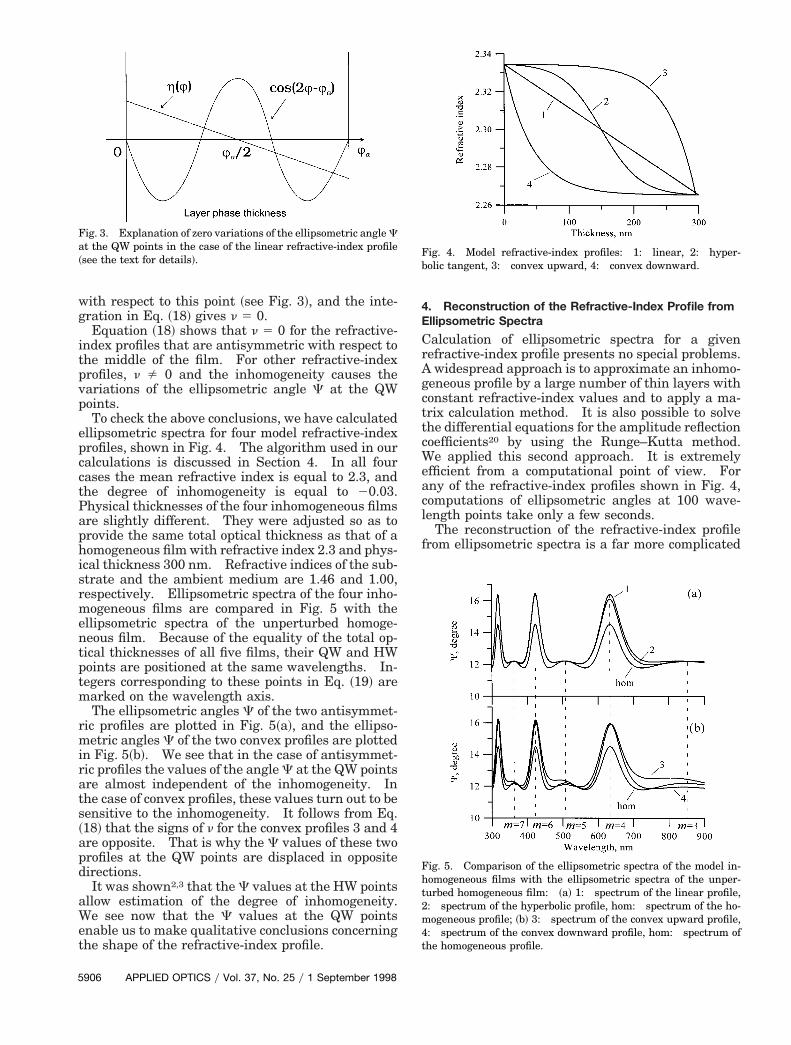
To check the above conclusions, we have calculatedellipsometric spectra for four model refractive-indexprofiles, shown in Fig. 4. The algorithm used in ourcalculations is discussed in Section 4. In all fourcases the mean refractive index is equal to 2.3, andthe degree of inhomogeneity is equal to 20.03.Physical thicknesses of the four inhomogeneous filmsare slightly different. They were adjusted so as toprovide the same total optical thickness as that of ahomogeneous film with refractive index 2.3 and phys-ical thickness 300 nm. Refractive indices of the sub-strate and the ambient medium are 1.46 and 1.00,respectively. Ellipsometric spectra of the four inho-mogeneous films are compared in Fig. 5 with theellipsometric spectra of the unperturbed homoge-neous film. Because of the equality of the total op-tical thicknesses of all five films, their QW and HWpoints are positioned at the same wavelengths. In-tegers corresponding to these points in Eq. ~19! are
arked on the wavelength axis.The ellipsometric angles C of the two antisymmet-
ic profiles are plotted in Fig. 5~a!, and the ellipso-metric angles C of the two convex profiles are plottedin Fig. 5~b!. We see that in the case of antisymmet-ric profiles the values of the angle C at the QW pointsare almost independent of the inhomogeneity. Inthe case of convex profiles, these values turn out to besensitive to the inhomogeneity. It follows from Eq.~18! that the signs of n for the convex profiles 3 and 4are opposite. That is why the C values of these twoprofiles at the QW points are displaced in oppositedirections.
It was shown2,3 that the C values at the HW pointsllow estimation of the degree of inhomogeneity.e see now that the C values at the QW points
nable us to make qualitative conclusions concerninghe shape of the refractive-index profile.
Fig. 3. Explanation of zero variations of the ellipsometric angle Ct the QW points in the case of the linear refractive-index profilesee the text for details!.
906 APPLIED OPTICS y Vol. 37, No. 25 y 1 September 1998
4. Reconstruction of the Refractive-Index Profile fromEllipsometric Spectra
Calculation of ellipsometric spectra for a givenrefractive-index profile presents no special problems.A widespread approach is to approximate an inhomo-geneous profile by a large number of thin layers withconstant refractive-index values and to apply a ma-trix calculation method. It is also possible to solvethe differential equations for the amplitude reflectioncoefficients20 by using the Runge–Kutta method.We applied this second approach. It is extremelyefficient from a computational point of view. Forany of the refractive-index profiles shown in Fig. 4,computations of ellipsometric angles at 100 wave-length points take only a few seconds.
The reconstruction of the refractive-index profilefrom ellipsometric spectra is a far more complicated
Fig. 4. Model refractive-index profiles: 1: linear, 2: hyper-bolic tangent, 3: convex upward, 4: convex downward.
Fig. 5. Comparison of the ellipsometric spectra of the model in-homogeneous films with the ellipsometric spectra of the unper-turbed homogeneous film: ~a! 1: spectrum of the linear profile,2: spectrum of the hyperbolic profile, hom: spectrum of the ho-mogeneous profile; ~b! 3: spectrum of the convex upward profile,4: spectrum of the convex downward profile, hom: spectrum ofthe homogeneous profile.
19
sarbd
r
a
problem. It is a typical inverse problem, and spe-cial precautions must be taken to provide a physicallysensible solution. In Ref. 18 Tikhonov’s regulariza-tion algorithm was used for this purpose. We de-velop a different approach, but it also has its origin inthe ideas of the theory of inverse problems. Ourapproach is based on a physically sensible parame-terization of the film refractive index.
The refractive index of the inhomogeneous film ofdispersive material is a function of the two variablesz and l. The first step of our approach is the repre-sentation of the film refractive index in the form
n~z, l! 5 q~z!n~l!. (24)
The reasons for this representation are as follows.First of all, it separates the effects of dispersion andinhomogeneity and thus simplifies the interpretationof the results. Then, the parameterization of theright-hand side of Eq. ~24! is much simpler than theparameterization of a general function of two vari-ables. Finally, this representation does not restrictus to any specific cause of the inhomogeneity.
Certainly, the representation ~24! narrows a set ofmodel functions. But when both the inhomogeneityand the dispersion are small, this narrowing is notessential from a practical point of view. We are go-ing to discuss this issue in more detail in future pa-pers devoted to the practical characterization ofslightly inhomogeneous dielectric thin films. Themain goal of this section is the description of thereconstruction algorithm proper.
We shall call the function q~z! in Eq. ~24! the in-homogeneity factor. Parametric models for q~z! andn~l! are chosen independently. We shall concen-trate our attention on the parameterization of theinhomogeneity factor. A usual model for n~l! in thenear UV and the visible is a three-parameter Cauchymodel:
n~l! 5 n` 1Al2 1
Bl4 . (25)
For the parameterization of the inhomogeneity fac-tor, one should choose a set of basis functions andrepresent q~z! as a linear combination of these func-tions. We shall represent q~z! in the form
q~z! 5 1 1 a1 T1~z! 1 a2 T2~z! 1 · · ·, (26)
where Tn~z! are Chebyshev polynomials on the seg-ment @0, za# and an are model parameters.
The reasons for our choice are as follows. Cheby-hev polynomials form a set of orthogonal polynomi-ls, and the orthogonality of basis functions alwaysaises the efficiency of computations. To provide aetter stability of the inverse problem solution, it isesirable to use fewer model parameters.19 Obvi-
ously, it is good if the reduction of the number ofmodel parameters results in a physically sound ap-proximation. This is just the case with our repre-sentation.
When all model parameters in Eq. ~26! are set to
1
zero, we have the model of a homogeneous film.With the nonzero model parameter a1, we get a linearmodel of the inhomogeneity factor:
a~z! 5 1 1 a1
2zaSz 2
za
2D . (27)
According to Section 3 this model corresponds toSchroder’s approximation, and the coefficient a1 isproportional to the degree of inhomogeneity. Byadding more model parameters, we incorporate ef-fects that are ignored by Schroder’s approximation.All these considerations are taken into account in ourreconstruction procedure.
Let C~lj! and D~lj! be the experimental ellipsomet-ic spectra measured on the wavelength grid lj ~ j 5
1, . . . , J! and dCj and dDj be the corresponding mea-surement tolerances. Denote as C~lj! and D~lj! thetheoretical spectra for a given model of an inhomoge-neous film ~these spectra are calculated as describedt the beginning of this section!.Consider the discrepancy function
F 51
2J (j51
J HFC~lj! 2 C~lj!
dCjG2
1 FD~lj! 2 D~lj!
dDjG2J . (28)
The discrepancy function is a function of modelparameters. The square root of F represents theweighted mean-square estimation of the closenessbetween theoretical and experimental ellipsometricspectra. Note that Eq. ~28! is written for the case ofa single incidence angle. An extension for the caseof several incidence angles is quite obvious.
Our reconstruction procedure is based on the min-imization of the discrepancy function with respect toa set of model parameters. We use the quasi-Newton optimization method21 and apply an analytictechnique for the calculation of the discrepancy func-tion derivatives.22
The reconstruction procedure starts with the modelof a homogeneous film. When the minimization isover, the fit between theoretical and experimentalspectra is examined. The presence of a systematicdiscrepancy between these spectra indicates that in-homogeneous film models ought to be used. Westart with a one-parameter model of q~z! correspond-ing to Schroder’s approximation and then graduallyraise the model complexity. Model parameters ob-tained with lower-order parametric models are usedas starting parameter values for the next minimiza-tion process.
Model complexity is justified only to a certain level.It is definitely not sound when there is no evidentsystematic discrepancy between theoretical and ex-perimental spectra indicating the model deficiency.
To demonstrate an application of the reconstruc-tion procedure, we simulated experimental ellipso-metric spectra by using the model hyperbolic profileshown in Fig. 4. It is described by the function
n~z! 5 nF1 2d
2tanh a~z 2 zay2!
tanh~azay2! G (29)
September 1998 y Vol. 37, No. 25 y APPLIED OPTICS 5907
Tfd
pfpt
fsesfata
trutitp
tcuahl
iei~miaw
r
5
with the parameters n 5 2.3, d 5 20.03, and a 5 5.he dispersion was not included in the model. Re-
ractive indices of the substrate and the ambient me-ium are 1.46 and 1.00, as in Section 3.We specifically selected a transcendental model
rofile that does not belong to the class of polynomialunctions. This complicates the reconstructionroblem and offers a severer test of the reliability ofhe reconstruction procedure.
Experimental ellipsometric spectra were simulatedor the three angles of incidence 55°, 65°, and 75° in thepectral region 300–900 nm with the wavelength stepqual to 1 nm. Random errors were added to theimulated experimental data. These errors were uni-ormly distributed in the range 0°–0.2° for the angle Cnd in the range 0°–1° for the angle D. Measurementolerances in the discrepancy function were 0.2° for thengle C and 1° for the angle D at all wavelengths.In the framework of a homogeneous model, the film
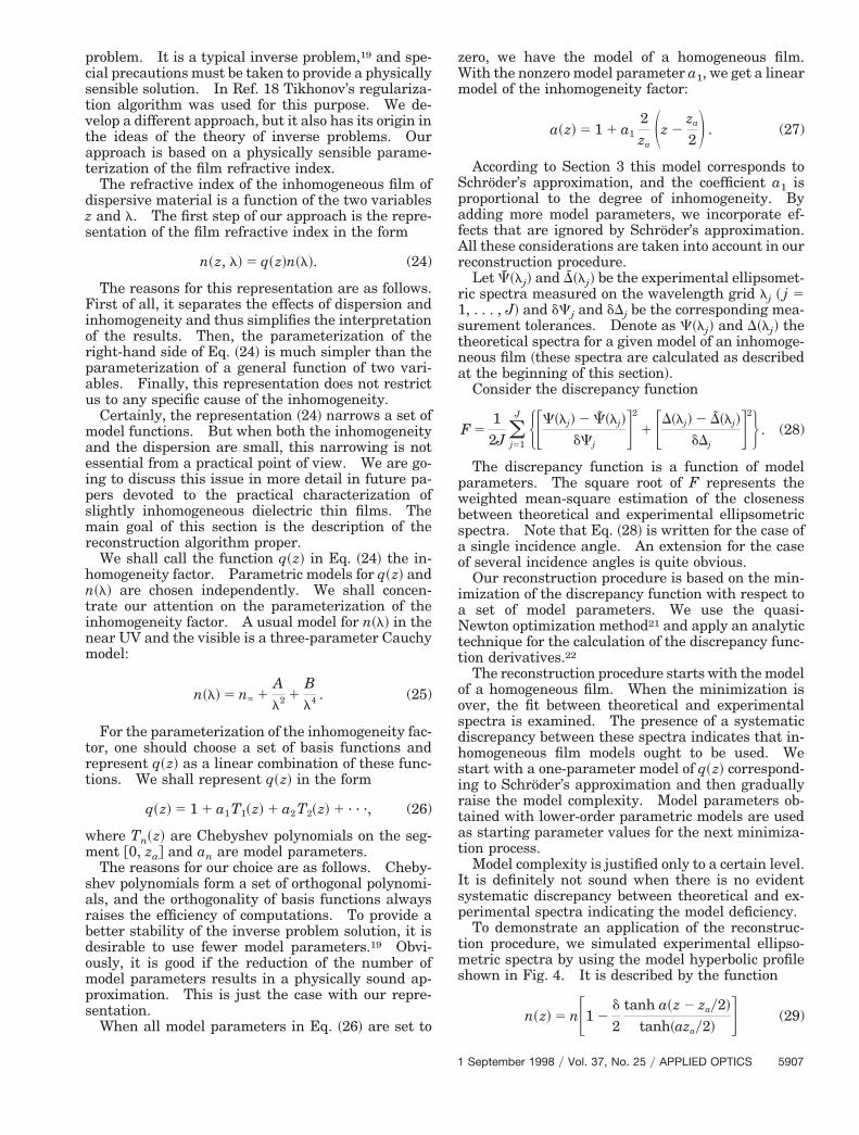
hickness was found to be 299.39 nm, and the filmefractive index was identified as 2.3034. These val-es are in excellent agreement with the actual filmhickness of 300 nm and with the mean refractive-ndex value being equal to 2.3. The comparison ofhe restored refractive-index profiles with the modelrofile is provided by Fig. 6.An examination of the correspondence between
heoretical and experimental spectra clearly indi-ates the deficiency of a homogeneous model. Fig-re 7 illustrates this correspondence for the angle Ct 65°. Plot 1 in this figure corresponds to the foundomogeneous approximation. Crosses mark simu-
ated experimental data.The application of the one-parameter model of the
nhomogeneity factor provides a much better fit of thexperimental data ~see plot 2 in Fig. 7!. The result-ng linear refractive-index profile is shown in Fig. 6plot 2!. The film thickness equals 300.20 nm, theean refractive index is 2.298, and the degree of
nhomogeneity is 20.027. The last value is in goodgreement with the actual degree of inhomogeneity,hich is equal to 20.03.
Fig. 6. Results of the reconstruction of the model refractive-indexprofile ~dashed curve! by using a homogeneous model ~plot 1!, aone-parameter model of the inhomogeneity factor ~plot 2!, a three-parameter model of the inhomogeneity factor ~plot 3!, and a seven-parameter model of the inhomogeneity factor ~plot 4!.
908 APPLIED OPTICS y Vol. 37, No. 25 y 1 September 1998
There is no evident systematic discrepancy be-tween plot 2 and the experimental data in Fig. 7. Ingeneral, the discrepancy is in the range of simulatederrors.
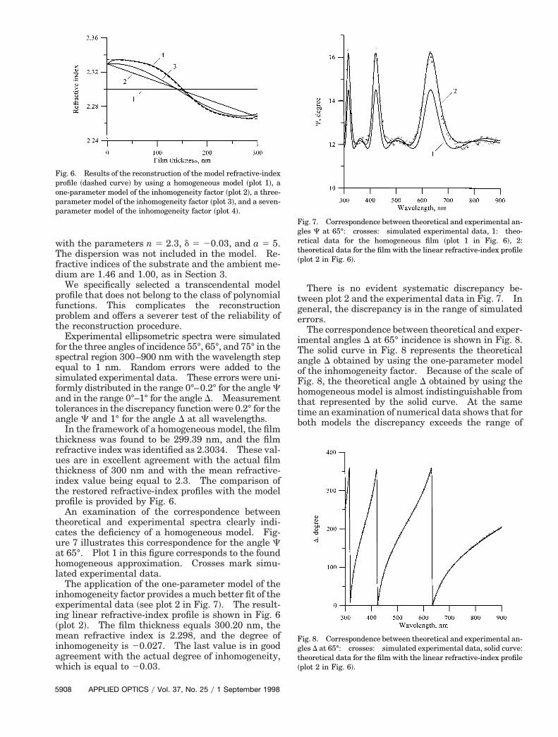
The correspondence between theoretical and exper-imental angles D at 65° incidence is shown in Fig. 8.The solid curve in Fig. 8 represents the theoreticalangle D obtained by using the one-parameter modelof the inhomogeneity factor. Because of the scale ofFig. 8, the theoretical angle D obtained by using thehomogeneous model is almost indistinguishable fromthat represented by the solid curve. At the sametime an examination of numerical data shows that forboth models the discrepancy exceeds the range of
Fig. 7. Correspondence between theoretical and experimental an-gles C at 65°: crosses: simulated experimental data, 1: theo-etical data for the homogeneous film ~plot 1 in Fig. 6!, 2:
theoretical data for the film with the linear refractive-index profile~plot 2 in Fig. 6!.
Fig. 8. Correspondence between theoretical and experimental an-gles D at 65°: crosses: simulated experimental data, solid curve:theoretical data for the film with the linear refractive-index profile~plot 2 in Fig. 6!.
t
Tw
bpdscms
i
cscdmfimoptpa
c
simulated errors. Clearly, this means that the sen-sitivity of D to the film inhomogeneity is greater thanhat of C.
The application of more complicated models of theinhomogeneity factor improves the correspondencebetween the theoretical and experimental angles D.
he discrepancy enters the range of simulated errorshen the number of polynomials reaches 7.Figure 6 shows refractive-index profiles obtained
y using three-parameter ~plot 3! and seven-arameter ~plot 4! models. These results clearlyemonstrate the efficiency of the proposed recon-truction procedure. The fits of experimental dataorresponding to the three- and seven-parameterodels are not shown because they are qualitatively
imilar to those shown in Figs. 7 and 8.
5. Conclusions
We have developed a new approximation for the am-plitude reflection coefficients of a slightly inhomoge-neous thin film. This approximation incorporatesexactly the effects of the substrate and ambient in-terfaces. Interference effects inside the inhomoge-neous film are incorporated in the Bornapproximation. The final equations of the new ap-proximation are Eqs. ~16!–~18!. Working from theseequations, we have performed a qualitative analysisof the ellipsometric angle C at the QW and HWpoints. It has been shown that in a general case thevalues of C at the QW points are dependent on theinhomogeneity. These values are independent ofthe film inhomogeneity in the case of refractive-indexprofiles that are antisymmetric with respect to themiddle of the film. The linear refractive-index pro-file is a particular case of such profiles.
Equations ~16!–~18! may serve as a basis for theanalysis of the effects caused by a surface inhomoge-neity. This question is out of the scope of thepresent paper, but we are going to address it in thenear future. The application of Eqs. ~16!–~18! to thequalitative analysis of the angle D would also be ofnterest.
We have also proposed a new approach to the re-onstruction of the refractive-index profile from ellip-ometric spectra. To develop this approach, theoncept of the inhomogeneity factor has been intro-uced. The reconstruction procedure is based on theinimization of the discrepancy function for a set oflm models with a growing complexity of the inho-ogeneity factor parameterization. The lower-
rder models of this set correspond to the basichysical approximation of a slightly inhomogeneoushin film. The solution of the model reconstructionroblem demonstrates the efficiency of the proposedpproach.
Appendix A: Derivation of the Approximate Formulasfor 1yt and ryt
We derive approximate formulas only for the case ofs-polarized light. The derivations in the case ofp-polarized light are analogous.
Amplitude reflection and transmission coefficients
1
of an inhomogeneous film can be calculated throughthe solutions of the differential equations for the tan-gential components of the electromagnetic field in thefilm.23 In the s case these equations have the form
dudz
5 i2p
lv,
dudz
5 i2p
l@n2~z! 2 a2#u, (A1)
where u and v are the tangential components of theelectric and magnetic vectors, respectively, n~z! is therefractive-index profile along the film, l is the wave-length, and a is the angular parameter related to theangle of incidence Qa by the equation
a 5 na sin Qa. (A2)
For the inhomogeneous film surrounded by the me-dia with the refractive index n ~see Fig. 2!, the initialonditions for Eqs. ~A1! are
u~0! 5 1, v~0! 5 În2 2 a2, (A3)
and the formulas for the amplitude reflection andtransmission coefficients are
r 5În2 2 a2u~za! 2 v~za!
În2 2 a2u~za! 1 v~za!,
t 52În2 2 a2
În2 2 a2u~za! 1 v~za!. (A4)
Let us introduce the two functions
f1~z! 5 0.5@u~z! 1 v~z!yÎn2 2 a2#. (A5)
f2~z! 5 0.5@u~z! 2 v~z!yÎn2 2 a2#. (A6)
It follows from Eqs. ~A4! that
f1~za! 5 1yt, f2~za! 5 ryt. (A7)
Using Eqs. ~A1!, one can derive the differentialequations for the functions f1~z! and f2~z!. Theseequations have the form
df1
dz5 i
p
l FÎn2 2 a2~ f1 2 f2! 1n2~z! 2 a2
În2 2 a2~ f1 1 f2!G ,
(A8)
df2
dz5 i
p
l FÎn2 2 a2~ f1 2 f2! 2n2~z! 2 a2
În2 2 a2~ f1 1 f2!G ,
(A9)
The initial conditions for these equations are derivedfrom Eqs. ~A3!:
f1~0! 5 1, (A10)
f2~0! 5 0. (A11)
The refractive index of a slightly inhomogeneousfilm, n~z!, differs from the value n by a small functionh~z! ~see Fig. 1!. The function f2 is also small. Thisfollows from the initial condition ~A11! and a stan-
September 1998 y Vol. 37, No. 25 y APPLIED OPTICS 5909
Bf~
p
I
5
dard estimation of the solution of Eq. ~A9!. Theorn approximation omits all products of two small
unctions on the right-hand sides of Eqs. ~A8! andA9!. This leads to the equations
df1
dz5 i
2p
l FÎn2 2 a2 1nh~z!
În2 2 a2G f1, (A12)
df2
dz5 2i
2p
l FÎn2 2 a2 1nh~z!
În2 2 a2G f2
2 i2p
l
nh~z!
În2 2 a2f1. (A13)
With an accuracy of h2~z!, the sum in the squarebrackets of these equations can be represented as
În2 2 a2 1nh~z!
În2 2 a25 În2~ z! 2 a2 , (14)
and Eqs. ~A12! and ~A13! can be further rewritten as
df1
dz5 i
2p
lÎn2~ z! 2 a2f1, (A15)
df2
dz5 2i
2p
lÎn2~ z! 2 a2f2 2 i
2p
l
nh~z!
În2 2 a2f1. (A16)
When we take into account Eq. ~A10!, the solution ofEq. ~A15! is
f1~z! 5 expFi2p
l *0
z În2~s! 2 a2 dsG . (A17)
Substituting this expression into Eq. ~A16! and inte-grating Eq. ~A16! with the initial condition ~A11! give
f2~z! 5 2i2p
l
n
În2 2 a2expF2i
2p
l *0
z În2~s! 2 a2 dsG3 *
0
z
h~s! expF2i2p
l *0
s În2~j! 2 a2 djGds.
(A18)
It is convenient to substitute the variable z for thehase variable w connected with z by the equation
w 52p
l *0
z În2~s! 2 a2 ds. (A19)
According to Eq. ~A19! the total physical thickness ofthe film, za, corresponds to the total film phase retar-dance wa, defined as
wa 52p
l *0
za În2~ z! 2 a2 dz. (A20)
t follows from Eqs. ~A7! that
1yt 5 f1~za! 5 f1~wa!, ryt 5 f2~za! 5 f2~wa!. (A21)
910 APPLIED OPTICS y Vol. 37, No. 25 y 1 September 1998
Using Eqs. ~A17!, ~A18!, and ~A21!, we obtain thefollowing approximate formulas:
1yt 5 exp~iwa!, (A22)
ryt 5 2in
n2 2 a2 exp~2iwa! *0
wa
h~w!exp~2iw!dw.
(A23)
The function h~w! is obtained from the function h~z!after the substitution of the variable z for the variablew.
References1. J. C. Charmet and P. G. de Gennes, “Ellipsometric formulas for
an inhomogeneous layer with arbitrary refractive-index pro-file,” J. Opt. Soc. Am. 73, 1777–1784 ~1983!.
2. C. K. Carniglia, “Ellipsometric calculations for nonabsorbingthin films with linear refractive-index gradients,” J. Opt. Soc.Am. A 7, 848–856 ~1990!.
3. G. Parjadis de Lariviere, J. M. Frigerio, J. Rivory, and F.Abeles, “Estimate of the degree of inhomogeneity of the refrac-tive index of dielectric films from spectroscopic ellipsometry,”Appl. Opt. 31, 6056–6061 ~1992!.
4. V. A. Shvets, “Profiles of optical constants of inhomogeneouslayers determined by ellipsometric measurements in situ,” Op-toelectron. Instrum. Data Process. 6, 25–32 ~1993!.
5. S. Y. Kim, “Numerical calculation of ellipsometric spectra oflayer with arbitrary refractive index profiles,” Opt. Eng. 32,88–93 ~1993!.
6. J. P. Borgogno, B. Lazarides, and E. Pelletier, “Automatic de-termination of optical constants of inhomogeneous thin films,”Appl. Opt. 21, 4020–4029 ~1982!.
7. J. P. Borgogno, F. Flory, P. Roche, B. Schmitt, G. Albrand, E.Pelletier, and H. A. Macleod, “Refractive index and inhomoge-neity of thin films,” Appl. Opt. 23, 3567–3570 ~1984!.
8. H. Schroder, “Bemerkung zur Theorie des Lichtdurchgangsdurch inhomogene durchsichtige Schichten,” Ann. Phys.~Leipzig! 39, 55–58 ~1941!.
9. R. Jacobsson, “Light reflection from films of continuously vary-ing refractive index,” in Progress in Optics, E. Wolf, ed. ~North-Holland, Amsterdam, 1966!, Vol. 5, Sec. 2, 247–286.
10. R. Jacobson, “Inhomogeneous and coevaporated homogeneousfilms for optical applications,” in Physics of Thin Films, G.Hass, M. H. Francombe, and R. W. Hoffman, eds. ~Academic,New York, 1975!, Vol. 8.
11. M. Kildemo, O. Hunderi, and B. Drevillon, “Approximationof reflection coefficients for rapid real-time calculation ofinhomogeneous films,” J. Opt. Soc. Am. A 14, 931–939~1997!.
12. K. Vedam, S. Y. Kim, L. D’Aries, and A. H. Guenther, “Non-destructive depth profiling of ZnS and MgO films by spectro-scopic ellipsometry,” Opt. Lett. 12, 456–458 ~1987!.
13. S. Y. Kim and K. Vedam, “Simultaneous determination ofdispersion relation and depth profile of thorium fluoride thinfilms by spectroscopic ellipsometry,” Thin Solid Films 166,325–334 ~1988!.
14. K. Vedam and S. Y. Kim, “Simultaneous determination ofrefractive index, its dispersion and depth-profile of magnesiumoxide thin film by spectroscopic ellipsometry,” Appl. Opt. 28,2691–2694 ~1989!.
15. S. Y. Kim, “Simultaneous determination of refractive index,extinction coefficient, and void distribution of titanium dioxidethin films by optical methods,” Appl. Opt. 35, 6703–6707~1996!.

16. J. H. Kaiser, “Regularization in ellipsometry,” Appl. Phys. B tilayer Systems ~Editions Frontieres, Gif-sur-Yvette, France,
2
2
45, 1–5 ~1988!.17. B. Dugnoille and O. Virlet, “Optical profile of surface layers on
a float glass determined by ellipsometry,” Appl. Opt. 33, 5853–5858 ~1994!.
18. D. Tonova and A. Konova, “Damage depth profiles determina-tion by ellipsometry: a new numerical algorithm,” Surf. Sci.293, 195–201 ~1993!.
19. A. N. Tikhonov and V. Y. Arsenin, Solution of Ill-Posed Prob-lems ~Wiley, New York, 1977!.
20. Sh. Furman and A. V. Tikhonravov, Basics of Optics of Mul-
1
1992!, Chap. 2.21. P. E. Gill, W. Murray, and M. H. Wright, Practical Optimiza-
tion ~Academic, London, 1981!.2. A. N. Tikhonov, Jr., A. V. Tikhonravov, and M. K. Trubetskov,
“Second order optimization methods in the synthesis of mul-tilayer coatings,” Comp. Maths. Math. Phys. 33, 1339–1352~1993!.
3. Sh. Furman and A. V. Tikhonravov, Basics of Optics of Mul-tilayer Systems ~Editions Frontieres, Gif-sur-Yvette, France,1992!, Chap. 1.
September 1998 y Vol. 37, No. 25 y APPLIED OPTICS 5911