Embed Size (px)
Citation preview

SpectraSYSTEM
P4000 Gradient Pump
User Guide
A0099-97004 Revision A August 2008
© 2008 Thermo Fisher Scientific Inc. All rights reserved.
SpectraSYSTEM and Develop File are trademarks of Thermo Fisher Scientific Inc. in the United States. Cheminert is a registered trademark of Valco Instruments, Inc. Kel-F is a registered trademark of the 3M Co. Luer-LOK is a registered trademark of Becton-Dickinson and Company. Teflon and Tefzel are registered trademarks of E.I. du Pont de Nemours & Co. Tygon is a registered trademark of Saint-Gobain Performance Plastics Corporation.
Thermo Fisher Scientific Inc. provides this document to its customers with a product purchase to use in the product operation. This document is copyright protected and any reproduction of the whole or any part of this document is strictly prohibited, except with the written authorization of Thermo Fisher Scientific Inc.
The contents of this document are subject to change without notice. All technical information in this document is for reference purposes only. System configurations and specifications in this document supersede all previous information received by the purchaser.
Thermo Fisher Scientific Inc. makes no representations that this document is complete, accurate or error-free and assumes no responsibility and will not be liable for any errors, omissions, damage or loss that might result from any use of this document, even if the information in the document is followed properly.
This document is not part of any sales contract between Thermo Fisher Scientific Inc. and a purchaser. This document shall in no way govern or modify any Terms and Conditions of Sale, which Terms and Conditions of Sale shall govern all conflicting information between the two documents.
Release history: Revision A released August 2008
For Research Use Only. Not regulated for medical or veterinary diagnostic use by U.S. Federal Drug Administration or other competent authorities.
Regulatory Compliance
Thermo Fisher Scientific performs complete testing and evaluation of its products to ensure full compliance with applicable domestic and international regulations. When the system is delivered to you, it meets all pertinent electromagnetic compatibility (EMC) and safety standards as described below.
EMC Directive 2004/108/EC
EMC compliance has been evaluated by TUV Rheinland of North America.
Low Voltage Safety Compliance
Low voltage safety compliance has been evaluated by TUV Rheinland of North America.
This device complies with Low Voltage Directive 2006/95/EC, harmonized standard EN 61010-1: 2001, IEC 61010-1: 2002, UL 61010A-1: 2004, and CAN/CSA 22.2 61010-1: 2004.
Changes that you make to your system may void compliance with one or more of these EMC and safety standards. Changes to your system include replacing a part or adding components, options, or peripherals not specifically authorized and qualified by Thermo Fisher Scientific. To ensure continued compliance with EMC and safety standards, replacement parts and additional components, options, and peripherals must be ordered from Thermo Fisher Scientific or one of its authorized representatives.
FCC Compliance Statement
CISPR 11: 1998 EN 61000-4-4: 2004
EN 55011: 1998, A1:1999, A2, 2002 EN 61000-4-5: 2001
EN 61000-3-2: 2000 EN 61000-4-6: 2003
EN 61000-3-3: 1995, A1: 2001 EN 61000-4-11: 2001
EN 61000-4-2: 2001 EN 61326-1: 1997, A1: 1998, A2: 2001, A3: 2003
EN 61000-4-3: 2002 CFR 47: 2007
THIS DEVICE COMPLIES WITH PART 15 OF THE FCC RULES. OPERATION IS SUBJECT TO THE FOLLOWING TWO CONDITIONS: (1) THIS DEVICE MAY NOT CAUSE HARMFUL INTERFERENCE, AND (2) THIS DEVICE MUST ACCEPT ANY INTERFERENCE RECEIVED, INCLUDING INTERFERENCE THAT MAY CAUSE UNDESIRED OPERATION.

Notice on Lifting and Handling ofThermo Scientific Instruments
For your safety, and in compliance with international regulations, the physical handling of this Thermo Fisher Scientific instrument requires a team effort to lift and/or move the instrument. This instrument weighs 18 kg (40 lbs) and is too heavy for one person alone to handle safely.
Notice on the Proper Use ofThermo Scientific Instruments
In compliance with international regulations: Use of this instrument in a manner not specified by Thermo Fisher Scientific could impair any protection provided by the instrument.
Notice on the Susceptibility to Electromagnetic Transmissions
Your instrument is designed to work in a controlled electromagnetic environment. Do not use radio frequency transmitters, such as mobile phones, in close proximity to the instrument.
For manufacturing location, see the label on the instrument.
CAUTION Read and understand the various precautionary notes, signs, and symbols contained inside this manual pertaining to the safe use and operation of this product before using the device.

WEEE Compliance
This product is required to comply with the European Union’s Waste Electrical & Electronic Equipment (WEEE) Directive 2002/96/EC. It is marked with the following symbol:
Thermo Fisher Scientific has contracted with one or more recycling or disposal companies in each European Union (EU) Member State, and these companies should dispose of or recycle this product. See www.thermo.com/WEEERoHS for further information on Thermo Fisher Scientific’s compliance with these Directives and the recyclers in your country.
WEEE Konformität
Dieses Produkt muss die EU Waste Electrical & Electronic Equipment (WEEE) Richtlinie 2002/96/EC erfüllen. Das Produkt ist durch folgendes Symbol gekennzeichnet:
Thermo Fisher Scientific hat Vereinbarungen mit Verwertungs-/Entsorgungsfirmen in allen EU-Mitgliedsstaaten getroffen, damit dieses Produkt durch diese Firmen wiederverwertet oder entsorgt werden kann. Mehr Information über die Einhaltung dieser Anweisungen durch Thermo Fisher Scientific, über die Verwerter, und weitere Hinweise, die nützlich sind, um die Produkte zu identifizieren, die unter diese RoHS Anweisung fallen, finden sie unter www.thermo.com/WEEERoHS.

Conformité DEEE
Ce produit doit être conforme à la directive européenne (2002/96/EC) des Déchets d'Equipements Electriques et Electroniques (DEEE). Il est marqué par le symbole suivant:
Thermo Fisher Scientific s'est associé avec une ou plusieurs compagnies de recyclage dans chaque état membre de l’union européenne et ce produit devrait être collecté ou recyclé par celles-ci. Davantage d'informations sur la conformité de Thermo Fisher Scientific à ces directives, les recycleurs dans votre pays et les informations sur les produits Thermo Fisher Scientific qui peuvent aider la détection des substances sujettes à la directive RoHS sont disponibles sur www.thermo.com/WEEERoHS.
AVVERTENZA
trumento s de ntes de
al arse y limentacion nto sin sus o remueva
s tarjetas
Shock da folgorazione. L’apparecchio è alimentato da corrente ad alta tensione che puo provocare lesioni fisiche. Prima di effettuare qualsiasi intervento di manutenzione occorre spegnere ed isolare l’apparecchio dalla linea elettrica. Non attivare lo strumento senza lo schermo superiore. Non togliere i coperchi a protezione dalle schede di circuito stampato (PCB).
e contener . Utilice quimicos nos o cipientes y a
Prodotti chimici. Possibile presenza di sostanze chimiche pericolose nell’apparecchio. Indossare dei guanti per maneggiare prodotti chimici tossici, cancerogeni, mutageni, o corrosivi/irritanti. Utilizzare contenitori aprovo e seguire la procedura indicata per lo smaltimento dei residui di olio.
que lop de efectuar
Calore. Attendere che i componenti riscaldati si raffreddino prima di effetturare l’intervento di manutenzione.
ar el
Incendio. Adottare le dovute precauzioni quando si usa il sistema in presenza di gas infiammabili.
icaduras de s que usar teojos tos .
Pericolo per la vista. Gli schizzi di prodotti chimici o delle particelle presenti nell’aria potrebbero causare danni alla vista. Indossare occhiali protettivi quando si maneggiano prodotti chimici o si effettuano interventi di manutenzione sull’apparecchio.
e existe un gorias én se utiliza l usuario a n este
Pericolo generico. Pericolo non compreso tra le precedenti categorie. Questo simbolo è utilizzato inoltre sull’apparecchio per segnalare all’utente di consultare le istruzioni descritte nel presente manuale.
de un tes de o con la local para r Scientific
Quando e in dubbio la misura di sicurezza per una procedura, prima di continuare, si prega di mettersi in contatto con il Servizio di Assistenza Tecnica locale per i prodotti di Thermo Fisher Scientific San Jose.
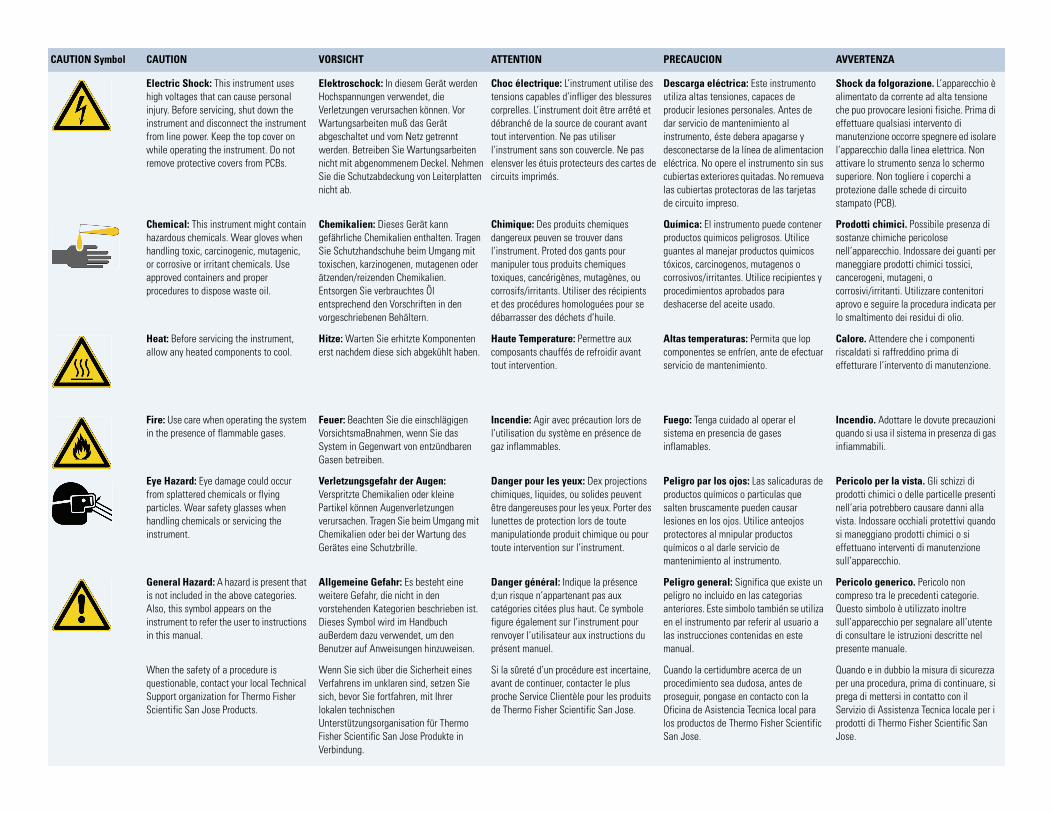
CAUTION Symbol CAUTION VORSICHT ATTENTION PRECAUCION
Electric Shock: This instrument uses high voltages that can cause personal injury. Before servicing, shut down the instrument and disconnect the instrument from line power. Keep the top cover on while operating the instrument. Do not remove protective covers from PCBs.
Elektroschock: In diesem Gerät werden Hochspannungen verwendet, die Verletzungen verursachen können. Vor Wartungsarbeiten muß das Gerät abgeschaltet und vom Netz getrennt werden. Betreiben Sie Wartungsarbeiten nicht mit abgenommenem Deckel. Nehmen Sie die Schutzabdeckung von Leiterplatten nicht ab.
Choc électrique: L’instrument utilise des tensions capables d’infliger des blessures corprelles. L’instrument doit être arrêté et débranché de la source de courant avant tout intervention. Ne pas utiliser l’instrument sans son couvercle. Ne pas elensver les étuis protecteurs des cartes de circuits imprimés.
Descarga eléctrica: Este insutiliza altas tensiones, capaceproducir lesiones personales. Adar servicio de mantenimientoinstrumento, éste debera apagdesconectarse de la línea de aeléctrica. No opere el instrumecubiertas exteriores quitadas. Nlas cubiertas protectoras de lade circuito impreso.
Chemical: This instrument might contain hazardous chemicals. Wear gloves when handling toxic, carcinogenic, mutagenic, or corrosive or irritant chemicals. Use approved containers and proper procedures to dispose waste oil.
Chemikalien: Dieses Gerät kann gefährliche Chemikalien enthalten. Tragen Sie Schutzhandschuhe beim Umgang mit toxischen, karzinogenen, mutagenen oder ätzenden/reizenden Chemikalien. Entsorgen Sie verbrauchtes Öl entsprechend den Vorschriften in den vorgeschriebenen Behältern.
Chimique: Des produits chemiques dangereux peuven se trouver dans l’instrument. Proted dos gants pour manipuler tous produits chemiques toxiques, cancérigènes, mutagènes, ou corrosifs/irritants. Utiliser des récipients et des procédures homologuées pour se débarrasser des déchets d’huile.
Química: El instrumento puedproductos quimicos peligrososguantes al manejar productos tóxicos, carcinogenos, mutagecorrosivos/irritantes. Utilice reprocedimientos aprobados pardeshacerse del aceite usado.
Heat: Before servicing the instrument, allow any heated components to cool.
Hitze: Warten Sie erhitzte Komponenten erst nachdem diese sich abgekühlt haben.
Haute Temperature: Permettre aux composants chauffés de refroidir avant tout intervention.
Altas temperaturas: Permitacomponentes se enfríen, ante servicio de mantenimiento.
Fire: Use care when operating the system in the presence of flammable gases.
Feuer: Beachten Sie die einschlägigen VorsichtsmaBnahmen, wenn Sie das System in Gegenwart von entzündbaren Gasen betreiben.
Incendie: Agir avec précaution lors de l’utilisation du système en présence de gaz inflammables.
Fuego: Tenga cuidado al opersistema en presencia de gasesinflamables.
Eye Hazard: Eye damage could occur from splattered chemicals or flying particles. Wear safety glasses when handling chemicals or servicing the instrument.
Verletzungsgefahr der Augen: Verspritzte Chemikalien oder kleine Partikel können Augenverletzungen verursachen. Tragen Sie beim Umgang mit Chemikalien oder bei der Wartung des Gerätes eine Schutzbrille.
Danger pour les yeux: Dex projections chimiques, liquides, ou solides peuvent être dangereuses pour les yeux. Porter des lunettes de protection lors de toute manipulationde produit chimique ou pour toute intervention sur l’instrument.
Peligro par los ojos: Las salproductos químicos o particulasalten bruscamente pueden calesiones en los ojos. Utilice anprotectores al mnipular producquímicos o al darle servicio demantenimiento al instrumento
General Hazard: A hazard is present that is not included in the above categories. Also, this symbol appears on the instrument to refer the user to instructions in this manual.
Allgemeine Gefahr: Es besteht eine weitere Gefahr, die nicht in den vorstehenden Kategorien beschrieben ist. Dieses Symbol wird im Handbuch auBerdem dazu verwendet, um den Benutzer auf Anweisungen hinzuweisen.
Danger général: Indique la présence d;un risque n’appartenant pas aux catégories citées plus haut. Ce symbole figure également sur l’instrument pour renvoyer l’utilisateur aux instructions du présent manuel.
Peligro general: Significa qupeligro no incluido en las cateanteriores. Este simbolo tambien el instrumento par referir alas instrucciones contenidas emanual.
When the safety of a procedure is questionable, contact your local Technical Support organization for Thermo Fisher Scientific San Jose Products.
Wenn Sie sich über die Sicherheit eines Verfahrens im unklaren sind, setzen Sie sich, bevor Sie fortfahren, mit Ihrer lokalen technischen Unterstützungsorganisation für Thermo Fisher Scientific San Jose Produkte in Verbindung.
Si la sûreté d’un procédure est incertaine, avant de continuer, contacter le plus proche Service Clientèle pour les produits de Thermo Fisher Scientific San Jose.
Cuando la certidumbre acerca procedimiento sea dudosa, anproseguir, pongase en contactOficina de Asistencia Tecnica los productos de Thermo FisheSan Jose.
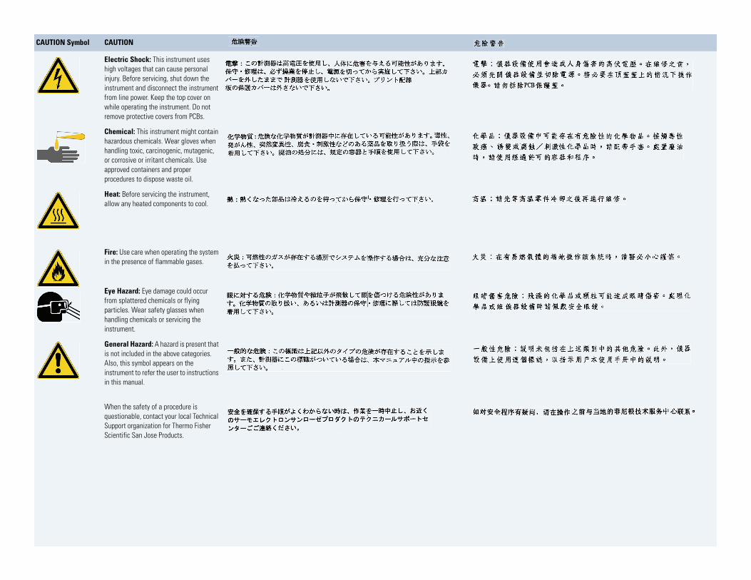
CAUTION Symbol CAUTION
Electric Shock: This instrument uses high voltages that can cause personal injury. Before servicing, shut down the instrument and disconnect the instrument from line power. Keep the top cover on while operating the instrument. Do not remove protective covers from PCBs.
Chemical: This instrument might contain hazardous chemicals. Wear gloves when handling toxic, carcinogenic, mutagenic, or corrosive or irritant chemicals. Use approved containers and proper procedures to dispose waste oil.
Heat: Before servicing the instrument, allow any heated components to cool.
Fire: Use care when operating the system in the presence of flammable gases.
Eye Hazard: Eye damage could occur from splattered chemicals or flying particles. Wear safety glasses when handling chemicals or servicing the instrument.
General Hazard: A hazard is present that is not included in the above categories. Also, this symbol appears on the instrument to refer the user to instructions in this manual.
When the safety of a procedure is questionable, contact your local Technical Support organization for Thermo Fisher Scientific San Jose Products.
C
Contents
Preface . . . . . . . . . . . . . . . . . . . . . . . . . . . . . . . . . . . . . . . . . . . . . . . . . . . . . . . . . . . . . . xiAbout This Guide. . . . . . . . . . . . . . . . . . . . . . . . . . . . . . . . . . . . . . . . . . . . . . . .xiSafety and Special Notices . . . . . . . . . . . . . . . . . . . . . . . . . . . . . . . . . . . . . . . . .xiManual Conventions . . . . . . . . . . . . . . . . . . . . . . . . . . . . . . . . . . . . . . . . . . . . xiiGood Laboratory Practices . . . . . . . . . . . . . . . . . . . . . . . . . . . . . . . . . . . . . . . .xiiiContacting Us . . . . . . . . . . . . . . . . . . . . . . . . . . . . . . . . . . . . . . . . . . . . . . . . . xv
Chapter 1 Installation and Specifications . . . . . . . . . . . . . . . . . . . . . . . . . . . . . . . . . . . . . . . . . . . . .1Start-up Checklist . . . . . . . . . . . . . . . . . . . . . . . . . . . . . . . . . . . . . . . . . . . . . . . . 2Unpacking. . . . . . . . . . . . . . . . . . . . . . . . . . . . . . . . . . . . . . . . . . . . . . . . . . . . . . 3Installation . . . . . . . . . . . . . . . . . . . . . . . . . . . . . . . . . . . . . . . . . . . . . . . . . . . . . 5LC System Connections . . . . . . . . . . . . . . . . . . . . . . . . . . . . . . . . . . . . . . . . . . 17Performance Verification. . . . . . . . . . . . . . . . . . . . . . . . . . . . . . . . . . . . . . . . . . 18Specifications. . . . . . . . . . . . . . . . . . . . . . . . . . . . . . . . . . . . . . . . . . . . . . . . . . . 23
Chapter 2 A Quick Example. . . . . . . . . . . . . . . . . . . . . . . . . . . . . . . . . . . . . . . . . . . . . . . . . . . . . . . . .25Learning Your Way Around . . . . . . . . . . . . . . . . . . . . . . . . . . . . . . . . . . . . . . . 25Instrument Control . . . . . . . . . . . . . . . . . . . . . . . . . . . . . . . . . . . . . . . . . . . . . . 27Practice Examples . . . . . . . . . . . . . . . . . . . . . . . . . . . . . . . . . . . . . . . . . . . . . . . 30
Chapter 3 Basic Operations. . . . . . . . . . . . . . . . . . . . . . . . . . . . . . . . . . . . . . . . . . . . . . . . . . . . . . . . .35Theory of Operation . . . . . . . . . . . . . . . . . . . . . . . . . . . . . . . . . . . . . . . . . . . . . 35SpectraSYSTEM 4000 Pump . . . . . . . . . . . . . . . . . . . . . . . . . . . . . . . . . . . . . . 36Instrument Startup . . . . . . . . . . . . . . . . . . . . . . . . . . . . . . . . . . . . . . . . . . . . . . 38Some Routine Operations . . . . . . . . . . . . . . . . . . . . . . . . . . . . . . . . . . . . . . . . . 39The File(s) Menu. . . . . . . . . . . . . . . . . . . . . . . . . . . . . . . . . . . . . . . . . . . . . . . . 39Purging Solvent Lines . . . . . . . . . . . . . . . . . . . . . . . . . . . . . . . . . . . . . . . . . . . . 54Running the Pump . . . . . . . . . . . . . . . . . . . . . . . . . . . . . . . . . . . . . . . . . . . . . . 57The Commands Menu . . . . . . . . . . . . . . . . . . . . . . . . . . . . . . . . . . . . . . . . . . . 60Status . . . . . . . . . . . . . . . . . . . . . . . . . . . . . . . . . . . . . . . . . . . . . . . . . . . . . . . . 61Monitoring Pump Performance. . . . . . . . . . . . . . . . . . . . . . . . . . . . . . . . . . . . . 63Shutting Down at the End of the Day. . . . . . . . . . . . . . . . . . . . . . . . . . . . . . . . 64
Chapter 4 Advanced Operations. . . . . . . . . . . . . . . . . . . . . . . . . . . . . . . . . . . . . . . . . . . . . . . . . . . . .65The Options Menu . . . . . . . . . . . . . . . . . . . . . . . . . . . . . . . . . . . . . . . . . . . . . . 65The Queue Menu . . . . . . . . . . . . . . . . . . . . . . . . . . . . . . . . . . . . . . . . . . . . . . . 70
Thermo Scientific SpectraSYSTEM P4000 Gradient Pump User Guide ix
Contents
x
The Develop File. . . . . . . . . . . . . . . . . . . . . . . . . . . . . . . . . . . . . . . . . . . . . . . . 76Creating a Develop File Program. . . . . . . . . . . . . . . . . . . . . . . . . . . . . . . . . . . . 78Develop File Examples . . . . . . . . . . . . . . . . . . . . . . . . . . . . . . . . . . . . . . . . . . . 88Running the Develop File . . . . . . . . . . . . . . . . . . . . . . . . . . . . . . . . . . . . . . . . . 98Preview Record . . . . . . . . . . . . . . . . . . . . . . . . . . . . . . . . . . . . . . . . . . . . . . . . 106The Tests Menu . . . . . . . . . . . . . . . . . . . . . . . . . . . . . . . . . . . . . . . . . . . . . . . 108
Chapter 5 Required Maintenance . . . . . . . . . . . . . . . . . . . . . . . . . . . . . . . . . . . . . . . . . . . . . . . . . .127Maintenance Schedule. . . . . . . . . . . . . . . . . . . . . . . . . . . . . . . . . . . . . . . . . . . 128Maintenance Log. . . . . . . . . . . . . . . . . . . . . . . . . . . . . . . . . . . . . . . . . . . . . . . 128Extending the Maintenance Period . . . . . . . . . . . . . . . . . . . . . . . . . . . . . . . . . 132Maintenance Procedures . . . . . . . . . . . . . . . . . . . . . . . . . . . . . . . . . . . . . . . . . 133Maintenance Tips . . . . . . . . . . . . . . . . . . . . . . . . . . . . . . . . . . . . . . . . . . . . . . 153Repair Instructions . . . . . . . . . . . . . . . . . . . . . . . . . . . . . . . . . . . . . . . . . . . . . 155
Appendix A Troubleshooting . . . . . . . . . . . . . . . . . . . . . . . . . . . . . . . . . . . . . . . . . . . . . . . . . . . . . .157Theory of Operation . . . . . . . . . . . . . . . . . . . . . . . . . . . . . . . . . . . . . . . . . . . . 157Troubleshooting Your Pump. . . . . . . . . . . . . . . . . . . . . . . . . . . . . . . . . . . . . . 158
Appendix B Glossary . . . . . . . . . . . . . . . . . . . . . . . . . . . . . . . . . . . . . . . . . . . . . . . . . . . . . . . . . . . . .167
Appendix C Kits and Parts Lists . . . . . . . . . . . . . . . . . . . . . . . . . . . . . . . . . . . . . . . . . . . . . . . . . . . .175Accessory Kit . . . . . . . . . . . . . . . . . . . . . . . . . . . . . . . . . . . . . . . . . . . . . . . . . . 175Standard Maintenance Kit. . . . . . . . . . . . . . . . . . . . . . . . . . . . . . . . . . . . . . . . 176Standard LC Fittings Kit . . . . . . . . . . . . . . . . . . . . . . . . . . . . . . . . . . . . . . . . . 176Piston Flush Seal Kit (10 mL) . . . . . . . . . . . . . . . . . . . . . . . . . . . . . . . . . . . . . 177Piston Seal Kit (30 mL) . . . . . . . . . . . . . . . . . . . . . . . . . . . . . . . . . . . . . . . . . . 177Solvent Inlet Tube Kit. . . . . . . . . . . . . . . . . . . . . . . . . . . . . . . . . . . . . . . . . . . 177Solvent Tube Extension Kit. . . . . . . . . . . . . . . . . . . . . . . . . . . . . . . . . . . . . . . 177Manual Injection Valve Bracket Kit. . . . . . . . . . . . . . . . . . . . . . . . . . . . . . . . . 178Narrow-bore Upgrade Kit . . . . . . . . . . . . . . . . . . . . . . . . . . . . . . . . . . . . . . . . 181
Index
SpectraSYSTEM P4000 Gradient Pump User Guide Thermo Scientific
P
Preface
About This GuideThis guide describes how to install and maintain the SpectraSYSTEM P4000 gradient pump, as well as how to control the gradient pump from the front panel keypad.
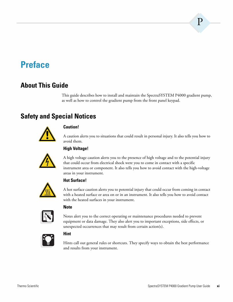
Safety and Special NoticesCaution!
A caution alerts you to situations that could result in personal injury. It also tells you how to avoid them.
High Voltage!
A high voltage caution alerts you to the presence of high voltage and to the potential injury that could occur from electrical shock were you to come in contact with a specific instrument area or component. It also tells you how to avoid contact with the high-voltage areas in your instrument.
Hot Surface!
A hot surface caution alerts you to potential injury that could occur from coming in contact with a heated surface or area on or in an instrument. It also tells you how to avoid contact with the heated surfaces in your instrument.
Note
Notes alert you to the correct operating or maintenance procedures needed to prevent equipment or data damage. They also alert you to important exceptions, side effects, or unexpected occurrences that may result from certain action(s).
Hint
Hints call out general rules or shortcuts. They specify ways to obtain the best performance and results from your instrument.
Thermo Scientific SpectraSYSTEM P4000 Gradient Pump User Guide xi
Preface
xii
Manual ConventionsThis manual uses several conventions. Among them are menu displays, text conventions (brackets, slashes, and so on), and standard words.
Displays
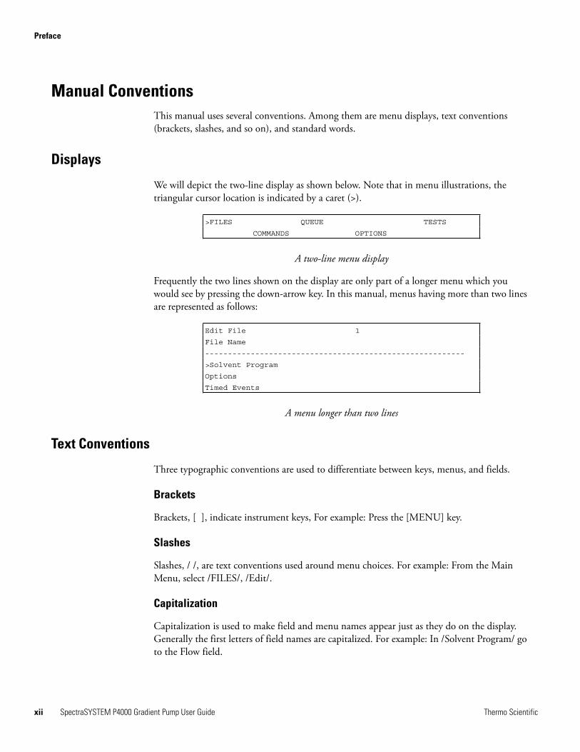
We will depict the two-line display as shown below. Note that in menu illustrations, the triangular cursor location is indicated by a caret (>).
A two-line menu display
Frequently the two lines shown on the display are only part of a longer menu which you would see by pressing the down-arrow key. In this manual, menus having more than two lines are represented as follows:
A menu longer than two lines
Text Conventions
Three typographic conventions are used to differentiate between keys, menus, and fields.
Brackets
Brackets, [ ], indicate instrument keys, For example: Press the [MENU] key.
Slashes
Slashes, / /, are text conventions used around menu choices. For example: From the Main Menu, select /FILES/, /Edit/.
Capitalization
Capitalization is used to make field and menu names appear just as they do on the display. Generally the first letters of field names are capitalized. For example: In /Solvent Program/ go to the Flow field.
>FILES QUEUE TESTS
COMMANDS OPTIONS
Edit File 1
File Name
---------------------------------------------------------
>Solvent Program
Options
Timed Events
SpectraSYSTEM P4000 Gradient Pump User Guide Thermo Scientific
Preface
T
Standard Words
We have also standardized the meanings of two words: “select” and “enter.”
Select
The word “select” is used when you need to choose from among available options. For example, to select a particular menu choice, you would move the cursor to the appropriate choice and press [ENTER]. To “select” a field entry, move the cursor to the appropriate field and use the [+] and [–] keys to scroll to the desired choice.
Enter
The word “enter” is used when you need to specify individual alphanumeric digits. To “enter” a particular value, move the cursor to the field and use the [+] and [–] keys to increment or decrement each digit in the field until the desired value or letter appears.
Good Laboratory PracticesTo obtain optimal performance from your LC system and to prevent personal injury or injury to the environment, do the following:
• Keep good records
• Read the manufacturers’ Material Safety Data Sheets for the chemicals being used in your laboratory
• Remove particulate matter from your samples before you inject them into the liquid chromatograph
• Use HPLC grade solvents
• Connect the drainage tubes from the pump, autosampler, and detector to an appropriate waste receptacle. Dispose of solvents as specified by local regulations
Keep Good Records
To help identify and isolate problems with either your equipment or your methodology, keep good records of all system conditions (for example,% RSDs on retention times and peak areas, peak shape and resolution). At a minimum, keep a chromatogram of a typical sample and standard mixture, well documented with system conditions, for future reference. Careful comparison of retention times, peak shapes, peak sensitivity, and baseline noise can provide valuable clues to identifying and solving future problems.
hermo Scientific SpectraSYSTEM P4000 Gradient Pump User Guide xiii
Preface
xiv
Chemical Toxicity
Although the large volume of toxic and flammable solvents used and stored in laboratories can be quite dangerous, do not ignore the potential hazards posed by your samples. Take special care to read and follow all precautions that ensure proper ventilation, storage, handling, and disposal of both solvents and samples. Become familiar with the toxicity data and potential hazards associated with all chemicals by referring to the manufacturers’ Material Safety Data Sheets (MSDS).
Sample Preparation
Always consider the solubility of your sample in the solvent/mobile phase. Sample precipitation can plug the column, tubing or flowcell causing flow restriction. This obstruction can result in irreparable damage to the system. To avoid damage caused by particulate matter, filter samples through 0.45 or 0.2 micron (or less) filters.
Solvent Requirements
Many chemical manufacturers provide a line of high-purity or HPLC-grade reagents that are free of chemical impurities. Routine filtration of all solvents or eluents through a 0.45 or 0.2 micron (or less) fluorocarbon filter before placing them in the solvent reservoir significantly prolongs the life and effectiveness of the inlet filters, check valves and seals, injector, and column. Typically, HPLC-grade solvents do not require filtration.
Choose a mobile phase that is compatible with the sample and column you have selected for your separation. Remember that some solvents are corrosive to stainless steel.
Solvent Disposal
Make sure you have a solvent waste container or other kind of drain system available at or below the benchtop level. Most solvents have special disposal requirements and should not be disposed of directly down a drain. Follow all governmental regulations when disposing of any chemical.
High-pressure Systems and Leaks
LC systems operate at high pressures. Because liquids are not highly compressible they do not store much energy. Accordingly, there is little immediate danger from the high pressures in an LC system. However, if a leak occurs, correct it as soon as possible. Always wear eye and skin protection when operating or maintaining an LC system. Always shut down the system and return it to atmospheric pressure before attempting any maintenance.
SpectraSYSTEM P4000 Gradient Pump User Guide Thermo Scientific
Preface
T
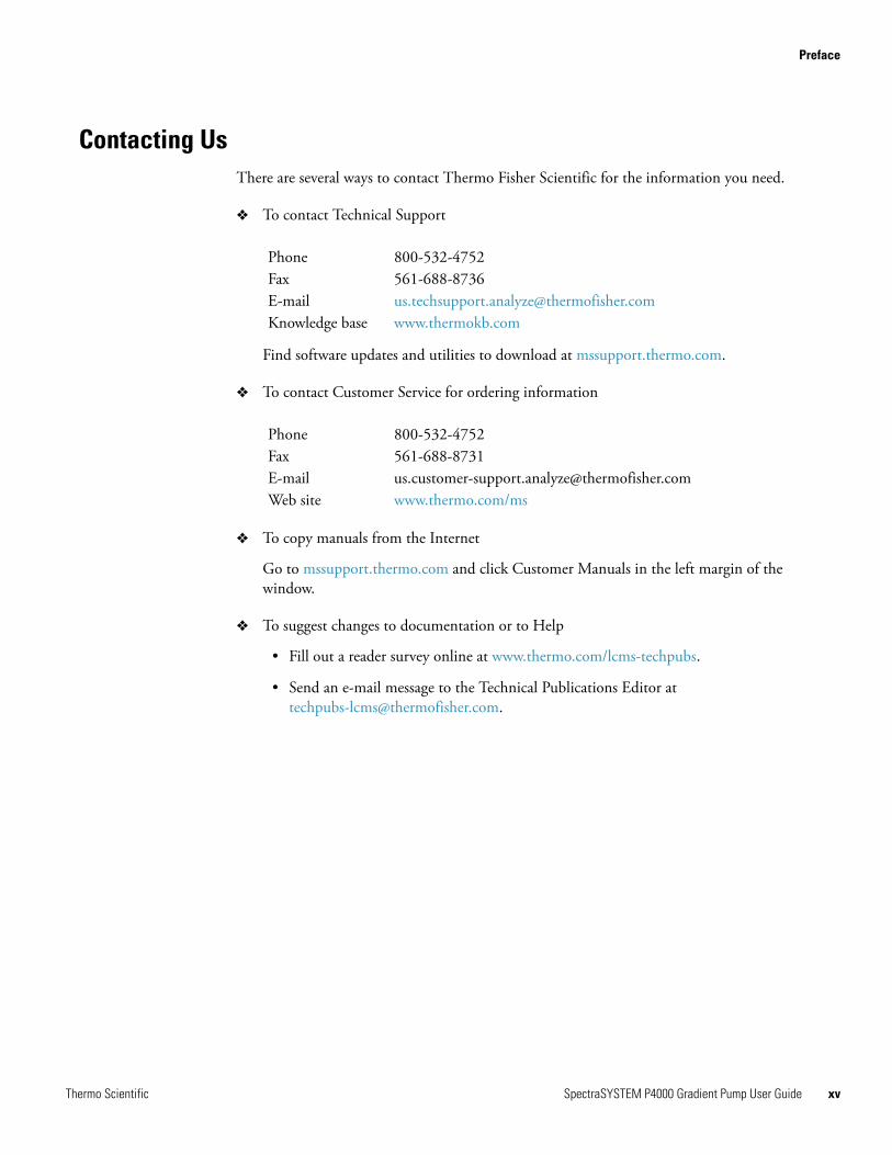
Contacting UsThere are several ways to contact Thermo Fisher Scientific for the information you need.
To contact Technical Support
Find software updates and utilities to download at mssupport.thermo.com.
To contact Customer Service for ordering information
To copy manuals from the Internet
Go to mssupport.thermo.com and click Customer Manuals in the left margin of the window.
To suggest changes to documentation or to Help
• Fill out a reader survey online at www.thermo.com/lcms-techpubs.
• Send an e-mail message to the Technical Publications Editor at [email protected].
Phone 800-532-4752Fax 561-688-8736E-mail [email protected] base www.thermokb.com
Phone 800-532-4752Fax 561-688-8731E-mail [email protected] site www.thermo.com/ms
hermo Scientific SpectraSYSTEM P4000 Gradient Pump User Guide xv

Thermo Scientific 1
1 Installation and Specifications
Introduction This chapter contains information necessary to install your Thermo Scientific, SpectraSYSTEM P4000 pump. The step-by-step instructions describe how to set the voltage, how to connect tubing, and how to prime and purge the pump. Use the checklist on the next page to complete pump installation. Also, be sure you read the Safety Information at the front of this manual before proceeding with any installation. If you have any questions or need further assistance, refer to the Preface for the product support or technical assistance numbers.
2 Thermo Scientific
Start-up Checklist This list is a brief summary of tasks that should be completed to install your pump. Complete installation information is contained in this chapter.
Inspect your instrument
Check for parts shortages
Set the voltage
Place the pump
Connect the power cord
Check initial response to power-on
Hardwire to eight-pin port, using external function connector, making electrical connection to other SpectraSYSTEM instruments
Install kits or accessories
Prepare and connect solvents
Connect inlet lines
Prime with solvent
Purge solvent lines
Connect to system
This pump was installed by:
______________________________________ ______________ (Name) (Date)
Thermo Scientific 3
Unpacking INSPECT YOUR INSTRUMENT
Your pump was shipped in a special container designed to provide excellent protection from routine wear and tear encountered in transit.
After unpacking, inspect your pump and its accessories for missing parts and/or physical damage. If damage is found, notify both the carrier and your sales representative. DO NOT return any goods without prior authorization from Thermo Fisher Scientific.
The contents of your ship kit is as follows:
1 Pump 1 Accessory Kit (A4070-010) 1 Tubing Kit (See Appendix C) 1 Declaration of Conformity 1 SpectraSYSTEM documentation CD
OPTIONS AVAILABLE
A variety of options, kits, and accessories is available for your pump. Refer to Appendix C for a description and parts list for each. If you purchased an inert/biocompatible pump, the correct tubing and liquid ends were installed at the factory before shipment. For a list of all available accessories, upgrades, and kits, contact your Thermo Fisher Scientific sales representative. Note that all upgrades require installation by Thermo Fisher Scientific.
NOTE: The pump features a bypass valve pre-installed as standard equipment.
4 Thermo Scientific
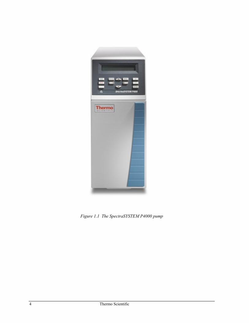
Figure 1.1 The SpectraSYSTEM P4000 pump
Thermo Scientific 5
Installation LIFTING AND CARRYING THE PUMP
The correct way to carry the pump is to use the two hand holds, one located underneath the front of the pump, and the other at the top of the back, near the power switch. Grasp the pump well underneath the front when lifting and carrying.
SETTING THE VOLTAGE
All pumps are configured at shipment for 230 VAC (50/60 Hz) operation. Depending upon the country of use, you might need to change the voltage setting.
NOTE: Check the position of the voltage select barrel located on the rear of the instrument. If the indicated voltage setting is not consistent with your area, DO NOT CONNECT THE POWER CORD!
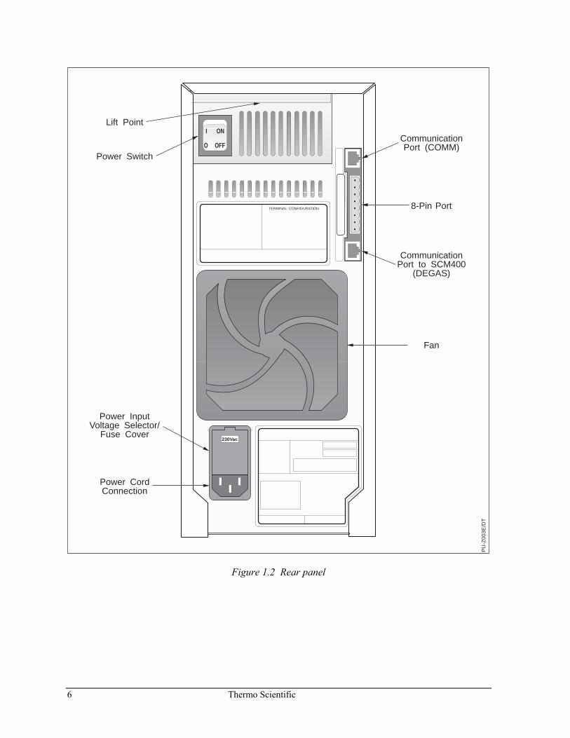
Figure 1.2 shows the pump rear panel.
6 Thermo Scientific
I ON
O OFF
230Vac
PU
-Z00
3E/D
T
TERMINAL CONFIGURATION
Power Switch
Power InputVoltage Selector/
Fuse Cover
Power CordConnection
8-Pin Port
CommunicationPort (COMM)
CommunicationPort to SCM400
(DEGAS)
Fan
Lift Point
Figure 1.2 Rear panel
Thermo Scientific 7
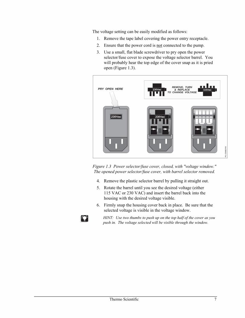
The voltage setting can be easily modified as follows: 1. Remove the tape label covering the power entry receptacle. 2. Ensure that the power cord is not connected to the pump. 3. Use a small, flat blade screwdriver to pry open the power
selector/fuse cover to expose the voltage selector barrel. You will probably hear the top edge of the cover snap as it is pried open (Figure 1.3).
230Vac
PRY OPEN HERE
230Vac
PU
-Z00
6E/F
M
REMOVE, TURN& REPLACE
TO CHANGE VOLTAGE230Vac 115Vac
Figure 1.3 Power selector/fuse cover, closed, with "voltage window." The opened power selector/fuse cover, with barrel selector removed.
4. Remove the plastic selector barrel by pulling it straight out. 5. Rotate the barrel until you see the desired voltage (either
115 VAC or 230 VAC) and insert the barrel back into the housing with the desired voltage visible.
6. Firmly snap the housing cover back in place. Be sure that the selected voltage is visible in the voltage window.
HINT: Use two thumbs to push up on the top half of the cover as you push in. The voltage selected will be visible through the window.
8 Thermo Scientific
PLACING THE PUMP
The pump weighs approximately 38 pounds (18 kg) and requires at least 6 inches (16 cm) of bench width and at least 19 inches (48 cm) of bench depth. If used with a manual injector bracket, the pump requires 9 inches (23 cm) of bench width. The pump needs a space at least 15 inches (38 cm) high.
Place the pump on a level surface. Leave 2 inches (6 - 7 cm) behind the instrument for good air flow and access to electrical connections. Keep the pump away from heating and cooling ducts, and avoid exposing the pump to direct sunlight. The pump should be placed to the far left of your LC system if it is used with a SpectraSYSTEM autosampler or detector.
CONNECTING THE POWER CORD
Attach the AC power cord (Figure 1.3). Plug the power connector into an appropriately grounded power outlet.
NOTE: For safe operation and optimum performance, the pump must be connected to a properly grounded power receptacle.
CHECKING INITIAL RESPONSE TO POWER ON
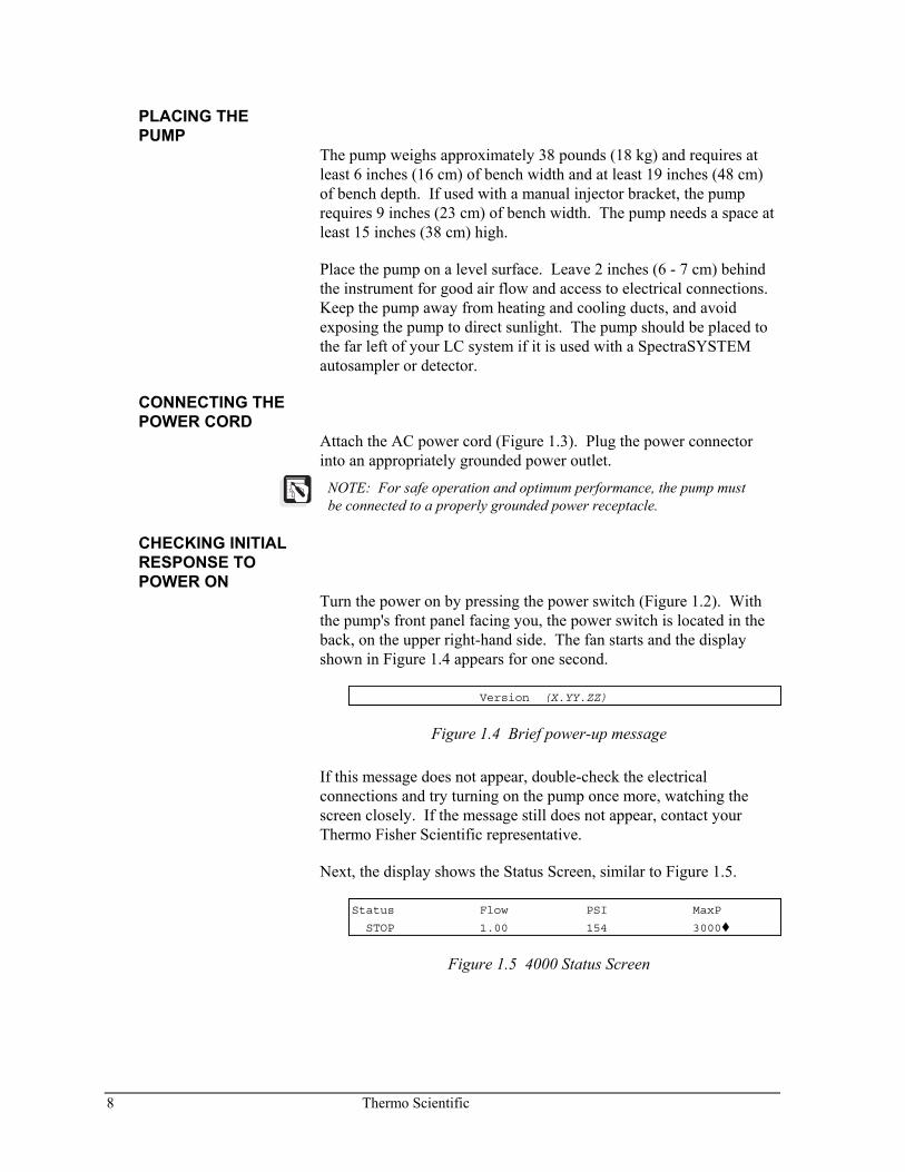
Turn the power on by pressing the power switch (Figure 1.2). With the pump's front panel facing you, the power switch is located in the back, on the upper right-hand side. The fan starts and the display shown in Figure 1.4 appears for one second.
Version (X.YY.ZZ)
Figure 1.4 Brief power-up message
If this message does not appear, double-check the electrical connections and try turning on the pump once more, watching the screen closely. If the message still does not appear, contact your Thermo Fisher Scientific representative.
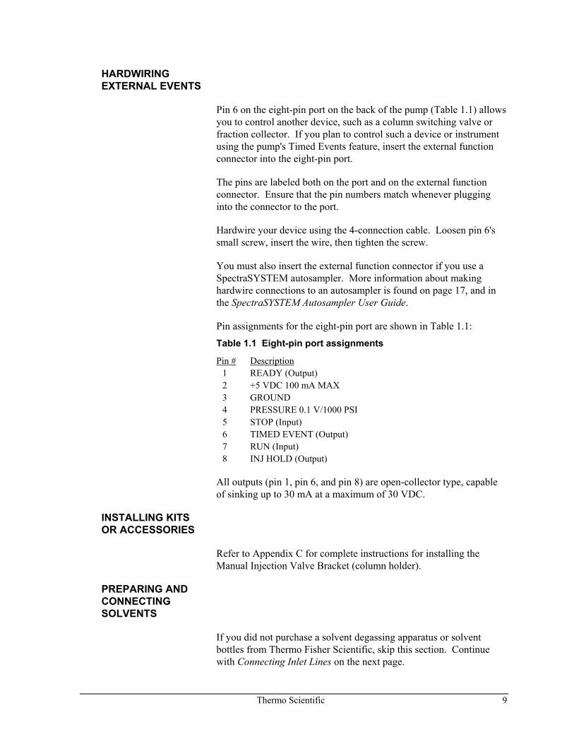
Next, the display shows the Status Screen, similar to Figure 1.5.
Status Flow PSI MaxP
STOP 1.00 154 3000
Figure 1.5 4000 Status Screen
Thermo Scientific 9
HARDWIRING EXTERNAL EVENTS
Pin 6 on the eight-pin port on the back of the pump (Table 1.1) allows you to control another device, such as a column switching valve or fraction collector. If you plan to control such a device or instrument using the pump's Timed Events feature, insert the external function connector into the eight-pin port.
The pins are labeled both on the port and on the external function connector. Ensure that the pin numbers match whenever plugging into the connector to the port.
Hardwire your device using the 4-connection cable. Loosen pin 6's small screw, insert the wire, then tighten the screw.
You must also insert the external function connector if you use a SpectraSYSTEM autosampler. More information about making hardwire connections to an autosampler is found on page 17, and in the SpectraSYSTEM Autosampler User Guide.
Pin assignments for the eight-pin port are shown in Table 1.1:
Table 1.1 Eight-pin port assignments
Pin # Description 1 READY (Output) 2 +5 VDC 100 mA MAX 3 GROUND 4 PRESSURE 0.1 V/1000 PSI 5 STOP (Input) 6 TIMED EVENT (Output) 7 RUN (Input) 8 INJ HOLD (Output)
All outputs (pin 1, pin 6, and pin 8) are open-collector type, capable of sinking up to 30 mA at a maximum of 30 VDC.
INSTALLING KITS OR ACCESSORIES
Refer to Appendix C for complete instructions for installing the Manual Injection Valve Bracket (column holder).
PREPARING AND CONNECTING SOLVENTS
If you did not purchase a solvent degassing apparatus or solvent bottles from Thermo Fisher Scientific, skip this section. Continue with Connecting Inlet Lines on the next page.
10 Thermo Scientific
Solvent Bottles
Prepare your solvent bottles by following the steps below. 1. Rinse the bottles with LC-grade solvent to remove any dust. 2. Fill the bottles with appropriate LC-grade solvents. 3. The bottle caps are pre-assembled to include an inlet line and
filter. Ensure that the filters are tightly assembled to their fittings, and the filter fittings are firmly attached to the inlet lines. Place the solvent filter/inlet line into each bottle, making sure that the inlet filter rests on the bottom of the bottle. Cap the bottle.
4. Attach the appropriate A, B, C, or D label to each solvent bottle cap to identify it.
5. Run vent lines from each bottle to an appropriate exhaust apparatus.
Degassing
There are two recommended methods for degassing solvents for use with your pump: vacuum degassing and helium degassing.
NOTE: Solvent degassing is required when proportioning (blending) solvent using your SpectraSYSTEM gradient pump. Degassing is not required for isocratic, premixed pump operation, but is recommended because of improved detector performance.
If you purchased a Thermo Scientific degasser, set up your degas apparatus as described in the degasser kit and continue the pump installation when you have a supply of degassed solvent available.
CONNECTING INLET LINES
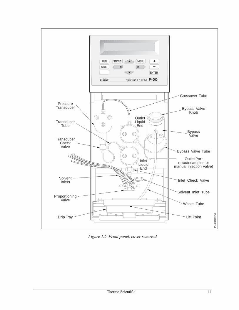
Refer to Figure 1.6 to make the plumbing connections.
Thermo Scientific 11
PU
-Z00
2E/F
M
RUN
STOP
STATUS MENU
ENTER
PURGE P4000SpectraSYSTEM
TransducerTube
PressureTransducer
TransducerCheckValve
SolventInlets
ProportioningValve
Drip Tray Lift Point
OutletLiquidEnd
BypassValve
Waste Tube
Outlet Port(toautosampler or
manual injection valve)
Inlet Check Valve
Solvent Inlet Tube
InletLiquid End
Bypass ValveKnob
Crossover Tube
Bypass Valve Tube
Figure 1.6 Front panel, cover removed
12 Thermo Scientific
BYPASS VALVE
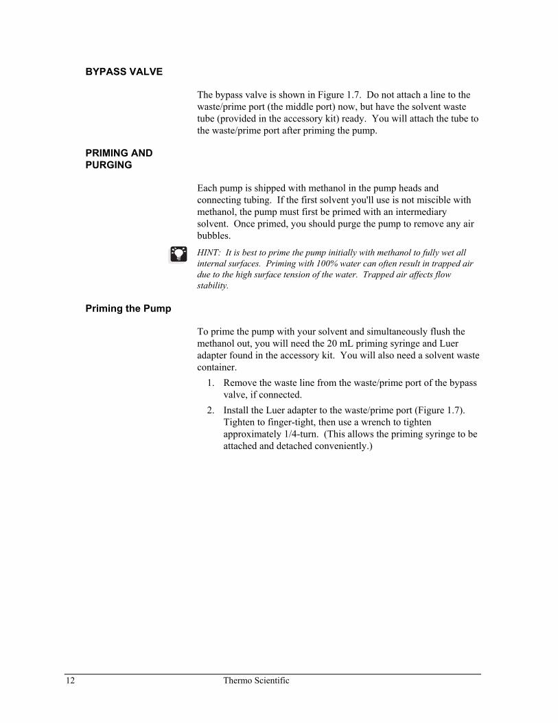
The bypass valve is shown in Figure 1.7. Do not attach a line to the waste/prime port (the middle port) now, but have the solvent waste tube (provided in the accessory kit) ready. You will attach the tube to the waste/prime port after priming the pump.
PRIMING AND PURGING
Each pump is shipped with methanol in the pump heads and connecting tubing. If the first solvent you'll use is not miscible with methanol, the pump must first be primed with an intermediary solvent. Once primed, you should purge the pump to remove any air bubbles.
HINT: It is best to prime the pump initially with methanol to fully wet all internal surfaces. Priming with 100% water can often result in trapped air due to the high surface tension of the water. Trapped air affects flow stability.
Priming the Pump
To prime the pump with your solvent and simultaneously flush the methanol out, you will need the 20 mL priming syringe and Luer adapter found in the accessory kit. You will also need a solvent waste container.
1. Remove the waste line from the waste/prime port of the bypass valve, if connected.
2. Install the Luer adapter to the waste/prime port (Figure 1.7). Tighten to finger-tight, then use a wrench to tighten approximately 1/4-turn. (This allows the priming syringe to be attached and detached conveniently.)
Thermo Scientific 13
Bypass Valve
Open Closed
Bracket mountingscrews
Waste/Prime port
Bypass inlettube
Luer adapter
Bypass outlet tube
Figure 1.7 Bypass valve with Luer adapter connected
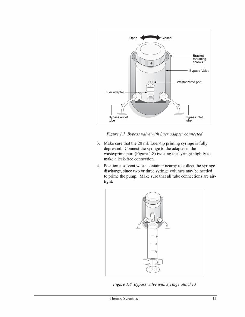
3. Make sure that the 20 mL Luer-tip priming syringe is fully depressed. Connect the syringe to the adapter in the waste/prime port (Figure 1.8) twisting the syringe slightly to make a leak-free connection.
4. Position a solvent waste container nearby to collect the syringe discharge, since two or three syringe volumes may be needed to prime the pump. Make sure that all tube connections are air-tight.
Figure 1.8 Bypass valve with syringe attached
14 Thermo Scientific
5. Open the bypass valve by turning the knob fully counterclockwise.
NOTE: Solvents flow through the pump when the pump is purging or when a file is initialized (loaded as a run file).
6. Turn on power to the pump (if it not already on) and press [PURGE]. The cursor should appear under the word Purge on the display. Press [+] until the word ALL appears on the P4000.
NOTE: Do not purge ALL or BOTH unless all solvent lines are connected, and contain solvent. If this is not the case, select the appropriate solvent (A, B, C, D), instead.
NOTE: Purging starts whenever the cursor is moved out of the Time field using the [ENTER] key.
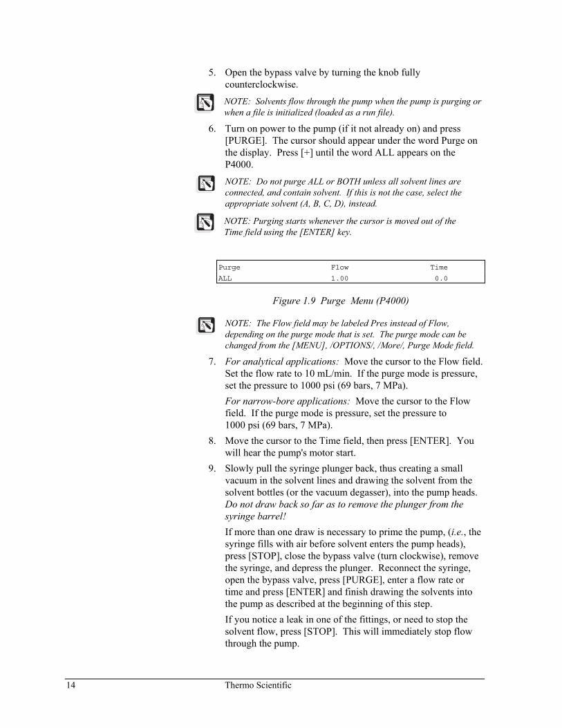
Purge Flow Time
ALL 1.00 0.0
Figure 1.9 Purge Menu (P4000)
NOTE: The Flow field may be labeled Pres instead of Flow, depending on the purge mode that is set. The purge mode can be changed from the [MENU], /OPTIONS/, /More/, Purge Mode field.
7. For analytical applications: Move the cursor to the Flow field. Set the flow rate to 10 mL/min. If the purge mode is pressure, set the pressure to 1000 psi (69 bars, 7 MPa).
For narrow-bore applications: Move the cursor to the Flow field. If the purge mode is pressure, set the pressure to 1000 psi (69 bars, 7 MPa).
8. Move the cursor to the Time field, then press [ENTER]. You will hear the pump's motor start.
9. Slowly pull the syringe plunger back, thus creating a small vacuum in the solvent lines and drawing the solvent from the solvent bottles (or the vacuum degasser), into the pump heads. Do not draw back so far as to remove the plunger from the syringe barrel!
If more than one draw is necessary to prime the pump, (i.e., the syringe fills with air before solvent enters the pump heads), press [STOP], close the bypass valve (turn clockwise), remove the syringe, and depress the plunger. Reconnect the syringe, open the bypass valve, press [PURGE], enter a flow rate or time and press [ENTER] and finish drawing the solvents into the pump as described at the beginning of this step.
If you notice a leak in one of the fittings, or need to stop the solvent flow, press [STOP]. This will immediately stop flow through the pump.
Thermo Scientific 15
10. When solvent steadily appears in the syringe and no air bubbles are present, press [STOP], then close the bypass valve.
11. Gently remove the syringe and empty it into the solvent waste container.
12. Remove the Luer adapter from the valve port and store it, along with the priming syringe, for later use.
13. Connect the solvent waste line to the waste/prime port of the valve and tighten to finger-tight. Route the waste tubing to an appropriate solvent waste container.
16 Thermo Scientific
Purging the Pump
With the pump primed, you now must purge the lines containing your chosen solvents.
1. Ensure that the solvent inlet filters inside each solvent bottle are in a vertical position so that air within the filter will not be trapped.
2. Fully open the bypass valve. 3. We suggest that you initially purge the lines with a volume of
10 mL. Follow the steps below to begin the purge operation:
a) Press [PURGE] to reach the Purge Menu. If desired, change the purge mode by pressing [MENU] and selecting /OPTIONS/, /More/, Purge Mode. (The words in the top line of the display will change, depending on your purge mode preference.)
b) Select "ALL" or the solvent of choice in the Purge field, then press [ENTER]. (See Figure 1.10).
c) If the purge mode is Flow, do the following: For analytical applications: If the purge mode is Flow,
enter a flow of 10.00 mL/min. [If pressure, set to 1000 psi (69 bars, 7 MPa).]
For narrow-bore applications: If the purge mode is Flow, enter a flow of 5.00 mL/min. [If pressure, set to 1000 psi (69 bars, 7 MPa).]
d) Press [ENTER] and enter a time of 1.00 minute. Ten milliliters should be enough volume to remove any trapped air and ensure that the pump and tubing are cleansed of any contaminants.
e) Press [ENTER]. The pump's motor will start. Purging will automatically stop after one minute and will initialize the pump. After the pump has stopped, be sure to close the purge valve.
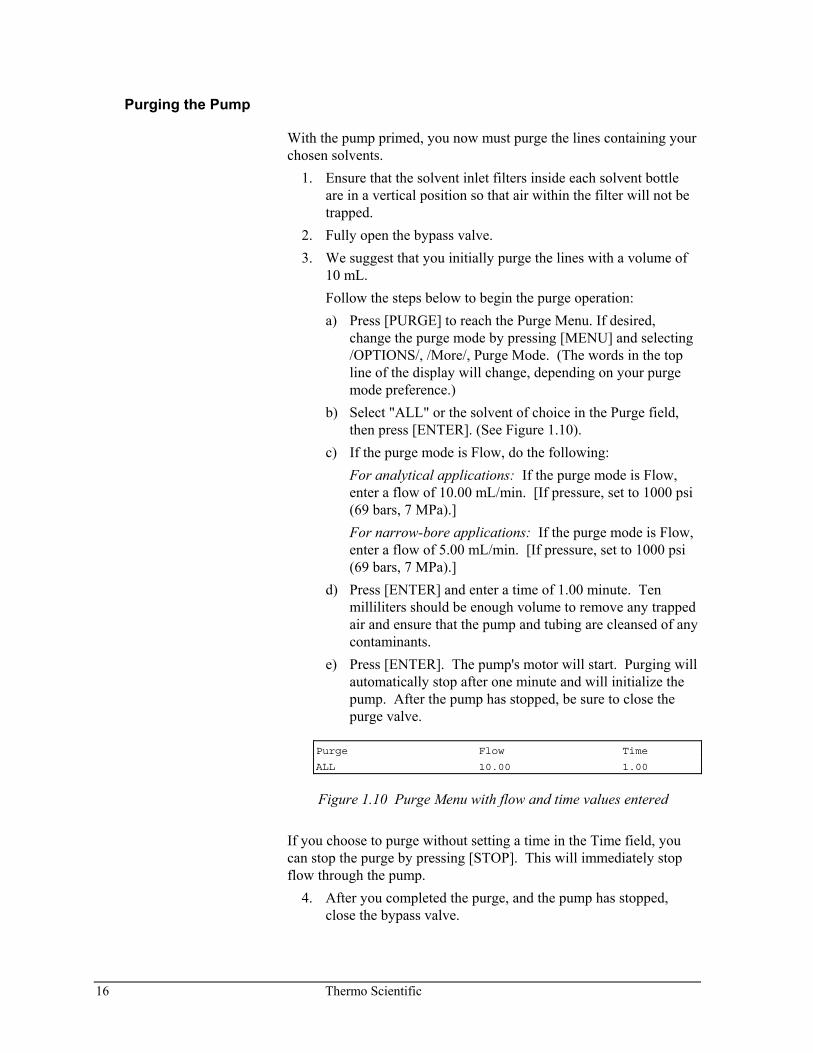
Purge Flow Time
ALL 10.00 1.00
Figure 1.10 Purge Menu with flow and time values entered
If you choose to purge without setting a time in the Time field, you can stop the purge by pressing [STOP]. This will immediately stop flow through the pump.
4. After you completed the purge, and the pump has stopped, close the bypass valve.
Thermo Scientific 17
LC System Connections Once the pump is purged, you can plumb it to the rest of your chromatographic system. Figure 1.7 and Figure 1.8 illustrate the bypass valve, showing the pump's outlet. Using a pre-cut piece of stainless steel tubing, connect the outlet to your autosampler or manual injection apparatus.
If you are using a manual injector valve from Thermo Fisher Scientific, Appendix C for complete information for installing the injector valve bracket.
If you are using a SpectraSYSTEM autosampler, the pump can send a ready signal to the autosampler through pin 1, and can receive a stop signal from the autosampler through pin 5. In addition, the ground contact (pin 3) must also be connected to the autosampler's ground contact. For complete information on how to make these connections, refer to the Chapter 1 of the SpectraSYSTEM Autosamplers User Guide. The table below summarizes the hardwire connections necessary between a SpectraSYSTEM autosampler and pump.
Table 1.2 Pump connections to SpectraSYSTEM autosampler
Pump Autosampler
READY (Output) Pin 1 Pin 5 PUMP READY GROUND Pin 3 Pin 1 GROUND STOP (Input) Pin 5 Pin 3 PUMP STOP RUN (Input) Pin 7 Pin 4 GRAD START INJ HOLD (Output) Pin 8 Pin 7 INJ HOLD
18 Thermo Scientific
Performance Verification After installing your SpectraSYSTEM pump, for best results, run a performance test to verify that the instrument is working properly. Common tests for pumps include flow accuracy and precision, gradient linearity, and compositional accuracy. Procedures for these performance tests are described below.
FLOW ACCURACY
There are many ways to test pump flow accuracy: graduated cylinder vs. time, calibrated flowmeter, or gravimetric vs. time. The procedure below describes how to measure the flow accuracy using a gravimetric procedure. In general you will set the pump to a flow rate, collect eluent for a specified time in a weighed flask, and determine the flow rate and accuracy. The actual flow rate can also be used to calibrate your pump. This test will take approximately 20 minutes.
Test Setup Column or flow restrictor: To deliver 1000 psi backpressure
Flow rate: Any flow rate to be tested for accuracy
Mobile phase: MeOH or other appropriate mobile phase
Experimental
Using the following steps to calculate the flow rate accuracy: 1. Prepare the desired mobile phase for the accuracy test. 2. Filter and degas the mobile phase. 3. Purge the pump and the column or flow restrictor being used. 4. Set the pump at the desired flow rate and start. 5. Weigh a clean flask capable of holding approximately
10 minutes of volume at the set flow rate. Include top and any other items attached to the flask.
HINT: A volumetric flask is ideal because it helps to minimize evaporation. Also, wrap tube and top of flask with aluminum foil to help eliminate evaporation.
6. Record this weight. 7. Place the flask under the flow stream from the pump and start
timing.
HINT: Use a stopwatch for the timing portion of the test. The more accurate the stopwatch the better the results.
Thermo Scientific 19
8. Collect the pump's eluent for 20 minutes. 9. Reweigh the flask and record. 10. Calculate the actual flow rate:
[(Weightfull - Weightempty) / Density] / Time = Flow Rate
11. Set a flow rate of 0.5 mL/min using MeOH as the mobile phase.
Flow Rate = [(22.8577 g - 14.8858 g) / 0.7894 g/mL] / 19.9687 min
Flow Rate = [(7.9719 g) / 0.7894 g/mL] / 19.9687 min
Flow Rate = 10.0987 mL / 19.9687 min
Flow Rate = 0.506 mL / min
12. Calculate the flow accuracy of the pump:
Flow Accuracy = 100 × ⎢(FRset - FRactual) / FRset⎟
Flow Accuracy = 100 × 0.006 mL / min
Example
Using the data from step 10 gives the following results:
Flow Accuracy = 100 × ⎢(0.5 mL/min - 0.506 mL/min)/0.5 mL/min ⎢
Flow Accuracy = 100 × (0.006 mL / 0.5 mL/min)
Flow Accuracy = 1.2%
HINT: For flow rates above 0.5 mL/min, it is best to install an in-line 100 μL mixer replacing the 3 μL mixer.
Specification Typical flow accuracy results are less than 1.5% (absolute) using this gravimetric procedure in the 100 μL/min to 2 mL/min flow rate range.
The factory specification is less than 1% (absolute) using a calibrated flowmeter and methanol as the mobile phase.
FLOW PRECISION
Flow precision checks the reproducibility of the flow rate. This procedure is simply running the accuracy test 7 or more times and calculating a percent relative standard deviation. This procedure will require at least a couple of hours.
20 Thermo Scientific
Test Setup
Set up the flow precision test above to perform 7 or more replicate runs.
Column or flow restrictor: To deliver 1000 psi back pressure
Flow rate: Any flow rate that accuracy is to be tested
Mobile phase: MeOH or other appropriate mobile phase
HINT: For flow rates above 0.5 mL/min, it is best to install a 100 μL mixer in-line replacing the 3 μL mixer.
Experimental 1. Repeat the flow accuracy test above for 7 or more replicate
runs. 2. Determine the flow rate for each replicate. 3. Determine the average flow rate for the replicate runs. 4. Determine the standard deviation for the replicate runs. 5. Determine the relative standard deviation for the replicate runs.
Using the following example values: Average = 0.502 mL/min Standard Deviation = 0.004 Relative Standard Deviation (RSD) = 100 × SD/Average Yields: RSD = 100 × (0.004/0.502 mL/min) RSD = 100 × 0.00797 RSD = 0.797%
Specification
Typical results for flow precision are less than 1% (absolute). However, results can vary based on temperature, mobile phase, and flow rate.
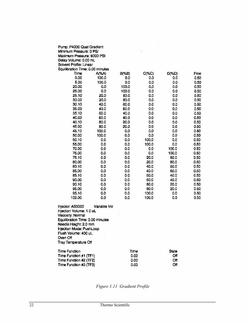
GRADIENT PERFORMANCE
Gradient performance is measured by testing gradient linearity and step/compositional accuracy. This procedure consists of running a pump method, which establishes a baseline, runs a linear gradient, and then runs 20% steps. This procedure can be run on a single pair of pump solenoid/switching valves or both pairs for quaternary gradient pumps. Each pair of valves will take approximately 50 minutes.
Thermo Scientific 21
Depending data system, you will need a way to record the absorbance levels throughout the gradient run. With a computer data system or strip chart recorder this is automatically done for you. However, with an integrator this may require some manual recording of these levels.
HINT: The levels of importance are 0% spiked mobile phase, 100% spiked mobile phase, and each of the 20% steps.
Test Setup Flow Restrictor: Deliver 1,000 to 2,000 psi
Mobile phases: A and/or C: Methanol
B and/or D: Spiked Methanol with 7 ppm Ethyl Paraben
Flow rate: 0.5 mL/min (or other desired flow rate)
Detection: UV at 254 nm
Experimental 1. Prepare mobile phases, filter through a 0.45-micron filter, and
degas. 2. Purge pump lines with the appropriate mobile phase. 3. Purge entire system with methanol. 4. Setup the following gradient method for the pump:
NOTE: This procedure is for a quaternary pump. For a binary pump simply eliminate the gradient profile for C & D.
5. Run the gradient profile of step 4. 6. Record the 0%, 100%, and each 20% absorbance level of the
spiked methanol. 6. Subtract the 0% level from all other recorded levels. 7. Determine 1% absorbance level of spiked methanol from the
recorded 100% level. 8. Record each of the 20% absorbance levels of spiked methanol.
HINT: Record data after the particular step has stabilized.
Specification
The factory specification is that the linear gradient falls within ±1%. Each step must fall within ±1% of it’s respective theoretical value.
22 Thermo Scientific
Figure 1.11 Gradient Profile
Thermo Scientific 23
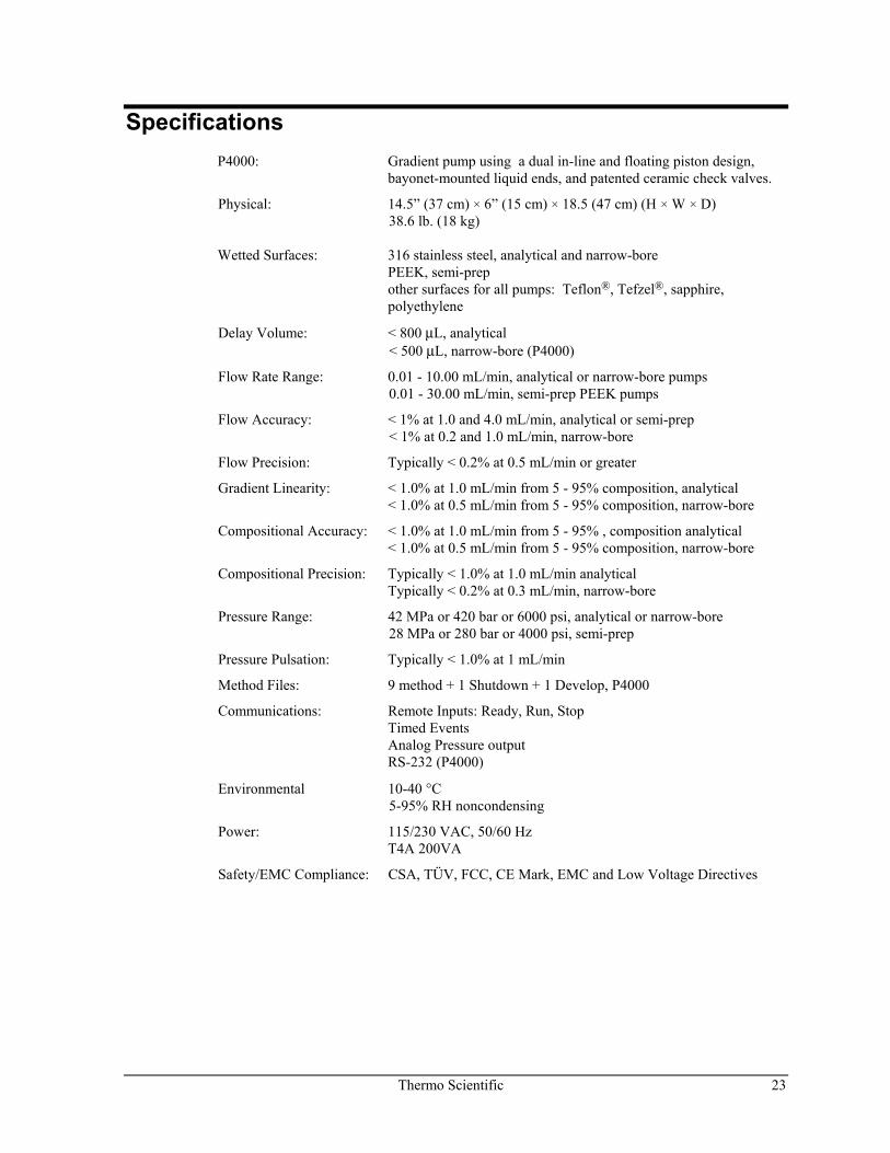
Specifications
P4000: Gradient pump using a dual in-line and floating piston design, bayonet-mounted liquid ends, and patented ceramic check valves.
Physical: 14.5” (37 cm) × 6” (15 cm) × 18.5 (47 cm) (H × W × D) 38.6 lb. (18 kg)
Wetted Surfaces: 316 stainless steel, analytical and narrow-bore
PEEK, semi-prep other surfaces for all pumps: Teflon®, Tefzel®, sapphire, polyethylene
Delay Volume: < 800 μL, analytical < 500 μL, narrow-bore (P4000)
Flow Rate Range: 0.01 - 10.00 mL/min, analytical or narrow-bore pumps 0.01 - 30.00 mL/min, semi-prep PEEK pumps
Flow Accuracy: < 1% at 1.0 and 4.0 mL/min, analytical or semi-prep < 1% at 0.2 and 1.0 mL/min, narrow-bore
Flow Precision: Typically < 0.2% at 0.5 mL/min or greater
Gradient Linearity: < 1.0% at 1.0 mL/min from 5 - 95% composition, analytical < 1.0% at 0.5 mL/min from 5 - 95% composition, narrow-bore
Compositional Accuracy: < 1.0% at 1.0 mL/min from 5 - 95% , composition analytical < 1.0% at 0.5 mL/min from 5 - 95% composition, narrow-bore
Compositional Precision: Typically < 1.0% at 1.0 mL/min analytical Typically < 0.2% at 0.3 mL/min, narrow-bore
Pressure Range: 42 MPa or 420 bar or 6000 psi, analytical or narrow-bore 28 MPa or 280 bar or 4000 psi, semi-prep
Pressure Pulsation: Typically < 1.0% at 1 mL/min
Method Files: 9 method + 1 Shutdown + 1 Develop, P4000
Communications: Remote Inputs: Ready, Run, Stop Timed Events Analog Pressure output RS-232 (P4000)
Environmental 10-40 °C 5-95% RH noncondensing
Power: 115/230 VAC, 50/60 Hz T4A 200VA
Safety/EMC Compliance: CSA, TÜV, FCC, CE Mark, EMC and Low Voltage Directives

Thermo Scientific 25
2 A Quick Example
Introduction This chapter provides you with the concepts you'll need for using your gradient pump. It also introduces you to the instrument's pump's screens and menus. In this chapter you will set up a few typical options, purge your solvent lines, and run a flow stability test.
If you already feel comfortable with how to move through menus and displays, just scan this chapter and proceed to Chapter 3. If you want more practice with the pump, follow the instructions in this chapter closely. Since the object of this chapter is to become familiar with the keypad and menus, we won't provide detailed explanations of the examples shown. More information can be found in one of the succeeding chapters.
If you haven't installed your pump, be sure that you read the Safety Information section and follow the procedure in Chapter 1.
Throughout our explanations, we encourage you to explore the general architecture of the instrument's menus and screens. Use the menu trees in the front pocket of the manual as your guide.
Learning Your Way Around AS EASY AS 1-2-3!
It's easy to learn your way around a SpectraSYSTEM pump. Just remember these three easy rules:
1. The ([∧], [∨], [<], [>]) move the cursor in the direction printed on the key.
HINT: Press [MENU] to jump quickly to the top of the menu structure.
2. The shape of the cursor determines how you make a selection: • If a triangular cursor appears, press [ENTER]. • If a blinking square cursor appears, press the [+] or [-] keys
to scroll up or down through preset choices, or to increase or decrease alphanumeric entries
26 Thermo Scientific
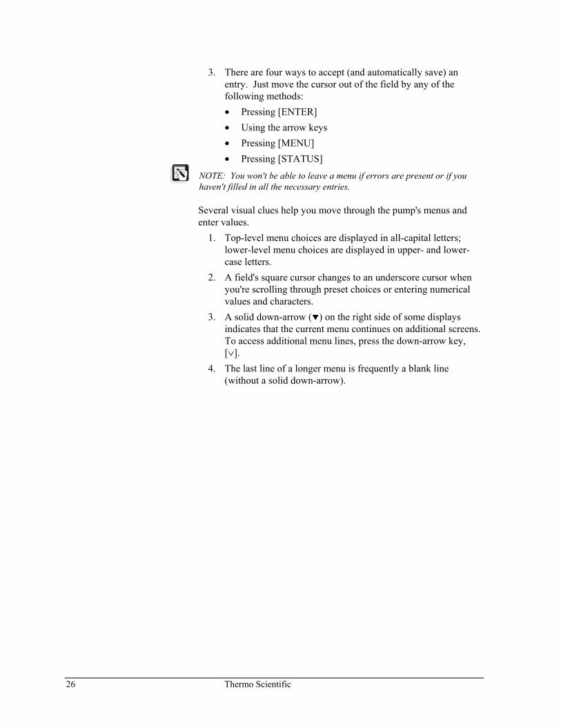
3. There are four ways to accept (and automatically save) an entry. Just move the cursor out of the field by any of the following methods: • Pressing [ENTER] • Using the arrow keys • Pressing [MENU] • Pressing [STATUS]
NOTE: You won't be able to leave a menu if errors are present or if you haven't filled in all the necessary entries.
Several visual clues help you move through the pump's menus and enter values.
1. Top-level menu choices are displayed in all-capital letters; lower-level menu choices are displayed in upper- and lower-case letters.
2. A field's square cursor changes to an underscore cursor when you're scrolling through preset choices or entering numerical values and characters.
3. A solid down-arrow ( ) on the right side of some displays indicates that the current menu continues on additional screens. To access additional menu lines, press the down-arrow key, [∨].
4. The last line of a longer menu is frequently a blank line (without a solid down-arrow).
Thermo Scientific 27
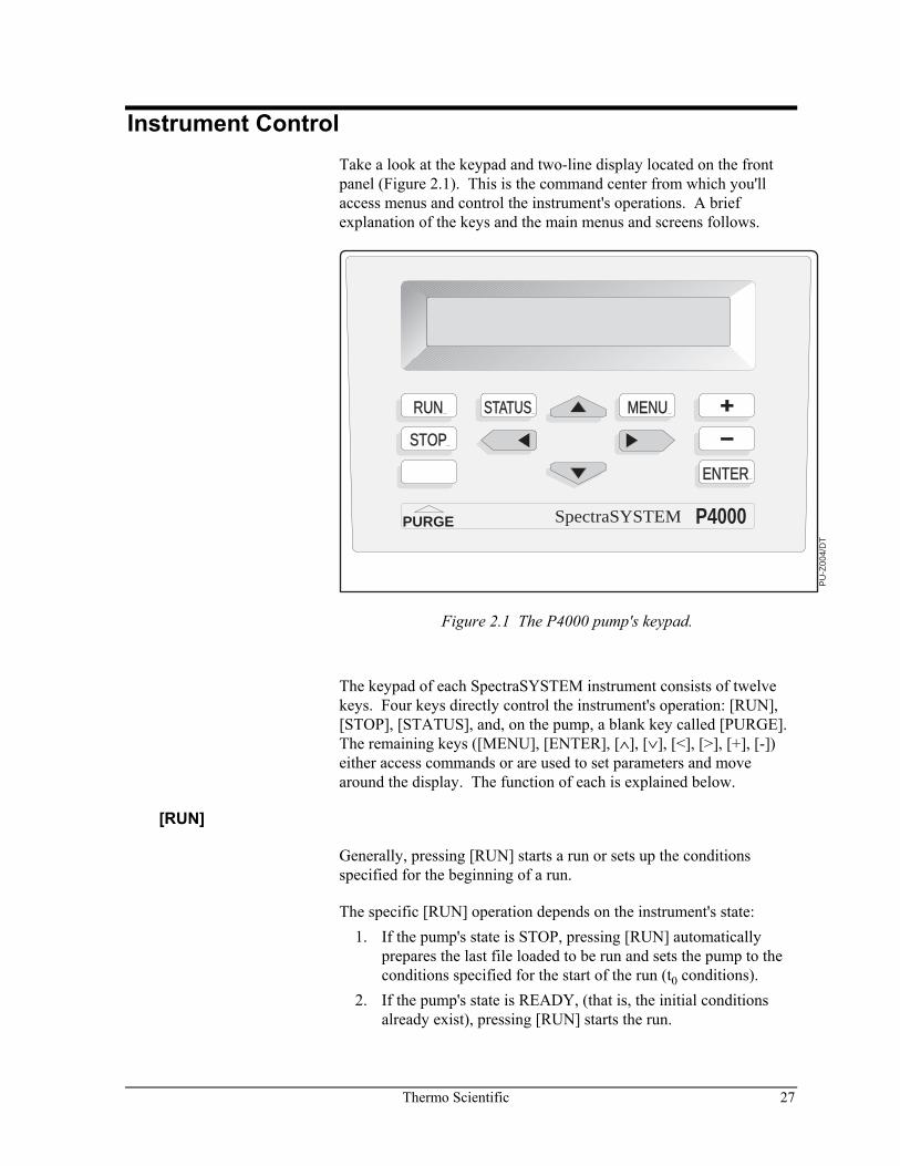
Instrument Control Take a look at the keypad and two-line display located on the front panel (Figure 2.1). This is the command center from which you'll access menus and control the instrument's operations. A brief explanation of the keys and the main menus and screens follows.
RUN
STOP
STATUS MENU
ENTER
PURGE P4000SpectraSYSTEM
PU
-Z00
4/D
T
Figure 2.1 The P4000 pump's keypad.
The keypad of each SpectraSYSTEM instrument consists of twelve keys. Four keys directly control the instrument's operation: [RUN], [STOP], [STATUS], and, on the pump, a blank key called [PURGE]. The remaining keys ([MENU], [ENTER], [∧], [∨], [<], [>], [+], [-]) either access commands or are used to set parameters and move around the display. The function of each is explained below.
[RUN]
Generally, pressing [RUN] starts a run or sets up the conditions specified for the beginning of a run.
The specific [RUN] operation depends on the instrument's state: 1. If the pump's state is STOP, pressing [RUN] automatically
prepares the last file loaded to be run and sets the pump to the conditions specified for the start of the run (t0 conditions).
2. If the pump's state is READY, (that is, the initial conditions already exist), pressing [RUN] starts the run.
28 Thermo Scientific
[STOP]
Pressing stop halts an operation in progress. (Specifically, the [STOP] key aborts a run in progress by stopping solvent flow through the pump.)
[STATUS]
Pressing [STATUS] displays the Status Screen (Figure 2.3). From the status screen you can monitor the run in progress. You can also access the Status Menu. See page 29 for more information.
[PURGE]
The unlabeled key is the only variable key in the whole SpectraSYSTEM family. On the pump, the blank key is the [PURGE] key. The key's name appears on the nameplate below the key.
The [PURGE] key brings the PURGE Screen to the display. Purge parameters can be changed, and the purge operation started from this display. Refer to Purging Solvent Lines in Chapter 1 and to Priming and Purging the Pump in Appendix A for complete information.
[MENU]
Pressing [MENU] displays the Main Menu (Figure 2.2). Each main menu item is explained in detail in the rest of this manual. For FILES and COMMANDS see Chapter 3, for QUEUE and OPTIONS and TESTS, see Chapter 4.
[ENTER]
Pressing [ENTER] accepts a selected choice or menu entry. The [ENTER] key also advances the cursor to a new field, either on the same line of the display or in the line below.
ARROWS
Pressing any arrow key (up, down, left, or right) moves the cursor in the direction indicated on the key. If the cursor is on the first or the last line of a menu, the up- and down-arrow keys move you "up" or "down" in the menu structure.
[+] and [-]
Pressing the [+] and [-] keys scrolls you through a field's available choices or changes the value of alphanumeric entries. Holding down either key will continuously scroll the list of choices forward or backward until you release the key.
Thermo Scientific 29
In fields that require numeric entries, the value of each digit is increased or decreased by one unit each time you press the [+] or [-] key. In fields that accept either numeric or alphabetic entries, such as the File Name field, the [+] and [-] key scroll through the alphabet from A to Z, then through the numbers 0 to 9, and finally to a slash, hyphen and blank space.
In other fields, the [+] key advances you through a preset list of choices while the [-] key takes you back through the list.
MENUS AND SCREENS
Your pump has two kinds of displays: menus and screens. Menus require you to make selections or enter specific values. Screens display information that cannot be edited. The Menu Tree in the front pocket illustrates the structure and content of the pump's menus and screens.
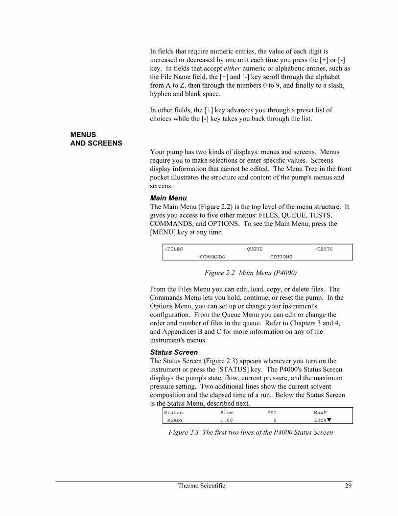
Main Menu The Main Menu (Figure 2.2) is the top level of the menu structure. It gives you access to five other menus: FILES, QUEUE, TESTS, COMMANDS, and OPTIONS. To see the Main Menu, press the [MENU] key at any time.
>FILES ·QUEUE ·TESTS
·COMMANDS ·OPTIONS
Figure 2.2 Main Menu (P4000)
From the Files Menu you can edit, load, copy, or delete files. The Commands Menu lets you hold, continue, or reset the pump. In the Options Menu, you can set up or change your instrument's configuration. From the Queue Menu you can edit or change the order and number of files in the queue. Refer to Chapters 3 and 4, and Appendices B and C for more information on any of the instrument's menus.
Status Screen The Status Screen (Figure 2.3) appears whenever you turn on the instrument or press the [STATUS] key. The P4000's Status Screen displays the pump's state, flow, current pressure, and the maximum pressure setting. Two additional lines show the current solvent composition and the elapsed time of a run. Below the Status Screen is the Status Menu, described next.
Status Flow PSI MaxP
READY 1.00 0 3000
Figure 2.3 The first two lines of the P4000 Status Screen
30 Thermo Scientific
Status Menu Just below the Status Screen is the Status Menu. To access the Status Menu, press the down-arrow key from the Status Screen. The Status Menu lets you review and edit run parameters during a run. Chapter 3 discusses the Status Menu in more detail.
MESSAGES There are three different kinds of messages that can appear on the pump's display: user messages, confirmation messages, and error messages.
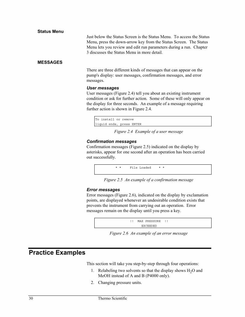
User messages User messages (Figure 2.4) tell you about an existing instrument condition or ask for further action. Some of these will only appear on the display for three seconds. An example of a message requiring further action is shown in Figure 2.4.
To install or remove
liquid ends, press ENTER
Figure 2.4 Example of a user message
Confirmation messages Confirmation messages (Figure 2.5) indicated on the display by asterisks, appear for one second after an operation has been carried out successfully.
* * File Loaded * *
Figure 2.5 An example of a confirmation message
Error messages Error messages (Figure 2.6), indicated on the display by exclamation points, are displayed whenever an undesirable condition exists that prevents the instrument from carrying out an operation. Error messages remain on the display until you press a key.
!! MAX PRESSURE !!
EXCEEDED
Figure 2.6 An example of an error message
Practice Examples This section will take you step-by-step through four operations:
1. Relabeling two solvents so that the display shows H2O and MeOH instead of A and B (P4000 only).
2. Changing pressure units.
Thermo Scientific 31
3. Purging these two solvent lines. 4. Running a flow stability test.
These examples assume that the pump is properly installed and that the bypass valve's outlet is routed to a solvent waste container. [The solvents you actually use need not be water and methanol (MeOH), but the solvents connected to lines A and B must be miscible. If they are not, skip the example in Purging Lines A and B; it calls for mixing the two solvents which may damage the liquid ends.]
LABELING SOLVENTS
The pump display can be changed to suit your own needs. The solvent labels in the P4000 are a good example.
To change solvent labels: 1. Press [MENU]. 2. Use the right-arrow key [>] to move the cursor to /OPTIONS/.
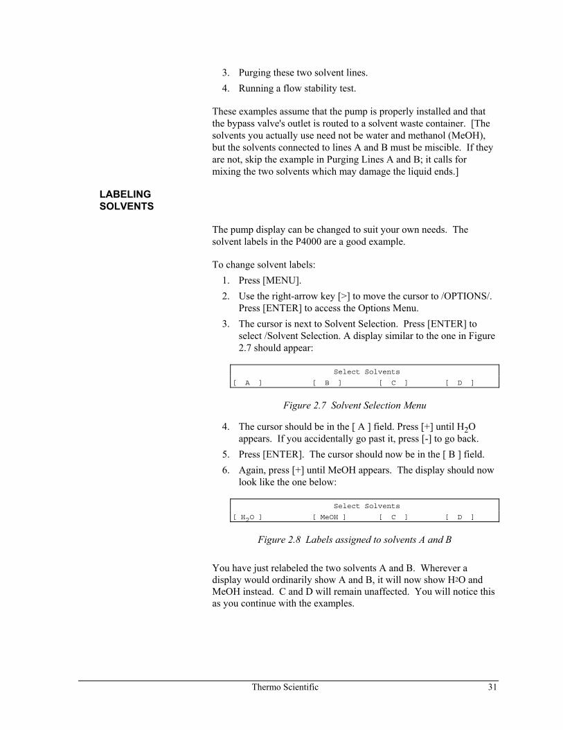
Press [ENTER] to access the Options Menu. 3. The cursor is next to Solvent Selection. Press [ENTER] to
select /Solvent Selection. A display similar to the one in Figure 2.7 should appear:
Select Solvents
[ A ] [ B ] [ C ] [ D ]
Figure 2.7 Solvent Selection Menu
4. The cursor should be in the [ A ] field. Press [+] until H2O appears. If you accidentally go past it, press [-] to go back.
5. Press [ENTER]. The cursor should now be in the [ B ] field. 6. Again, press [+] until MeOH appears. The display should now
look like the one below:
Select Solvents
[ H2O ] [ MeOH ] [ C ] [ D ]
Figure 2.8 Labels assigned to solvents A and B
You have just relabeled the two solvents A and B. Wherever a display would ordinarily show A and B, it will now show H2O and MeOH instead. C and D will remain unaffected. You will notice this as you continue with the examples.
32 Thermo Scientific
CHANGING PRESSURE UNITS
To change pressure units on your display: 1. Press [MENU] and move the cursor to /OPTIONS/. Press
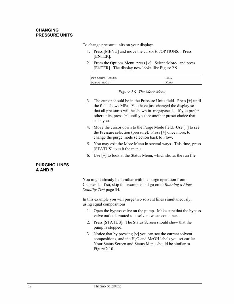
[ENTER]. 2. From the Options Menu, press [∨]. Select /More/, and press
[ENTER]. The display now looks like Figure 2.9.
Pressure Units PSIν
Purge Mode Flow
Figure 2.9 The More Menu
3. The cursor should be in the Pressure Units field. Press [+] until the field shows MPa. You have just changed the display so that all pressures will be shown in megapascals. If you prefer other units, press [+] until you see another preset choice that suits you.
4. Move the cursor down to the Purge Mode field. Use [+] to see the Pressure selection (pressure). Press [+] once more, to change the purge mode selection back to Flow.
5. You may exit the More Menu in several ways. This time, press [STATUS] to exit the menu.
6. Use [∨] to look at the Status Menu, which shows the run file.
PURGING LINES A AND B
You might already be familiar with the purge operation from Chapter 1. If so, skip this example and go on to Running a Flow Stability Test page 34.
In this example you will purge two solvent lines simultaneously, using equal compositions.
1. Open the bypass valve on the pump. Make sure that the bypass valve outlet is routed to a solvent waste container.
2. Press [STATUS]. The Status Screen should show that the pump is stopped.
3. Notice that by pressing [∨] you can see the current solvent compositions, and the H2O and MeOH labels you set earlier. Your Status Screen and Status Menu should be similar to Figure 2.10.
Thermo Scientific 33
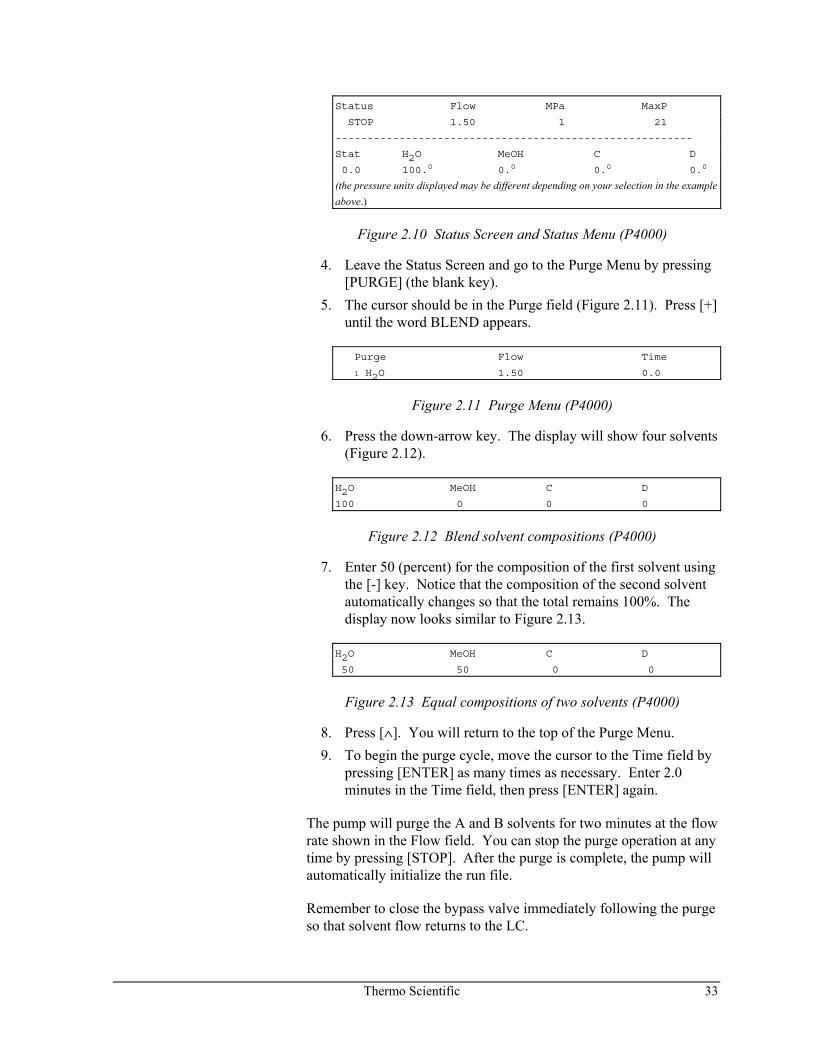
Status Flow MPa MaxP
STOP 1.50 1 21
--------------------------------------------------------
Stat H2O MeOH C D
0.0 100.0 0.0 0.0 0.0
(the pressure units displayed may be different depending on your selection in the example above.)
Figure 2.10 Status Screen and Status Menu (P4000)
4. Leave the Status Screen and go to the Purge Menu by pressing [PURGE] (the blank key).
5. The cursor should be in the Purge field (Figure 2.11). Press [+] until the word BLEND appears.
Purge Flow Time
1 H2O 1.50 0.0
Figure 2.11 Purge Menu (P4000)
6. Press the down-arrow key. The display will show four solvents (Figure 2.12).
H2O MeOH C D
100 0 0 0
Figure 2.12 Blend solvent compositions (P4000)
7. Enter 50 (percent) for the composition of the first solvent using the [-] key. Notice that the composition of the second solvent automatically changes so that the total remains 100%. The display now looks similar to Figure 2.13.
H2O MeOH C D
50 50 0 0
Figure 2.13 Equal compositions of two solvents (P4000)
8. Press [∧]. You will return to the top of the Purge Menu. 9. To begin the purge cycle, move the cursor to the Time field by
pressing [ENTER] as many times as necessary. Enter 2.0 minutes in the Time field, then press [ENTER] again.
The pump will purge the A and B solvents for two minutes at the flow rate shown in the Flow field. You can stop the purge operation at any time by pressing [STOP]. After the purge is complete, the pump will automatically initialize the run file.
Remember to close the bypass valve immediately following the purge so that solvent flow returns to the LC.
34 Thermo Scientific
RUNNING A FLOW STABILITY TEST
The flow stability test is a common test of the pump's performance. The pump must be in a READY, EQUIL, or RUN state for this test to be initiated, and the flow rate must be greater than 0 mL/min. If you need to change the flow rate, edit the flow setting from the Status Menu, then proceed with the steps below.
1. When the Status Screen shows READY, press [MENU] and select /TESTS/.
2. Select /Diagnostics/ from the Tests Menu. 3. The cursor should be on /Flow Stability/. Press [ENTER].
After a short time, the flow stability rating followed by a numerical value will appear. STABLE flow corresponds to a reading between 0 and 25, ACCEPTABLE is between 26 and 90, and UNSTABLE is a value greater than 90.
NOTE: The Flow Stability test may show unstable flow during gradient compositional changes or during column equilibration.
Thermo Scientific 35
3 Basic Operations
Introduction The type of chromatographic analyses you do will determine how you choose to use your pump. The P4000 is a gradient pump used for methods development, and characterized by automatically varying solvent compositions during a run. This chapter contains a pump theory of operation, some recommended LC pump practices, and describes how the pump is used to perform basic operations: editing, loading and running a file, purging the pump, and viewing the pump's status.
Theory of Operation The pump is typically the second of six components in an LC system (solvent degasser is the first). A pump delivers a steady flow of one or more solvents to a sample-injection instrument (generally an autosampler). This solvent flow continues through the column and on to a detector. From the detector, a signal is passed to an integrator, a recorder or another kind of data system capable of collecting the data and allowing the data of the injected sample to be analyzed.
A gradient pump works by first pulling a filtered and degassed solvent into a proportioning valve. The P4000 pump has four proportioning valves. Solvents are measured by percentages, specified by you, and mixed inside the pump. The solvents then travel to the pump head where a piston meters the flow of the mixture to an outlet tube. The pump's outlet tubing then connects the solvent stream to an automatic or manual injector.
36 Thermo Scientific
SpectraSYSTEM P4000 Pump The SpectraSYSTEM P4000 pump has been designed for ease of use and unsurpassed performance. It can be used as a stand-alone pump or as a module in a totally automated LC system.
The P4000 pump provides low-pressure quaternary mixing for accurate proportioning of binary, ternary, or quaternary gradient mobile-phase compositions and solvent switching when used for isocratic applications. The P4000 pump contains as many as 210 lines in as many as 9 method files (40 lines per file maximum). Table 3.1 File Characteristics for P4000 pump
File Characteristics P4000
Time Lines/File 40
Total Number Files 9 + Shutdown + Develop
Total Time Lines 210 lines
The SpectraSYSTEM P4000 pump is engineered for reliability and ease of maintenance. Easy maintenance helps to ensure that your chromatography results are accurate and remain accurate. A built-in, patented Maintenance Log (Chapter 5) allows you to follow the life span and use of seals, pistons, and check valves. If service is ever required, the resident diagnostics and modular design of the pump will keep downtime to a minimum. The simplicity and durability of the pump means that a minimum of spare parts need to be kept on hand.
OPTIONS
Narrow-bore
LC refers to the use of narrow-ID, 2.0-3.0 mm columns for LC separations. To optimize instruments for narrow-bore LC, standard LC hardware must be modified to reduce extra-column volume and gradient delay. Specific hardware modifications include minimizing the pump’s dead volume, the detector flowcell’s volume, and the volume contained in any interconnecting tubing and fittings. The lower system volume of narrow-bore LC increases sample concentration, which results in greatly improved sensitivity. Decreased solvent consumption reduces operating costs as compared to standard (4.0-4.6 mm ID) LC separation techniques.
NOTE: For narrow-bore applications we recommend you use a 20 μL sample loop in Thermo Scientific autosamplers.
Thermo Scientific 37
Narrow-bore Hardware Modifications Pump: For the SpectraSYSTEM gradient pump, the following hardware changes have been made to create a compatible pump for narrow-bore applications.
• The solvent inlet line (from the gradient valve to the inlet check valve) is changed from 0.060-inch to 0.030-inch ID tubing and shortened from 12 cm to 10 cm.
• All interconnecting tubing has been changed from 0.020-inch ID to 0.010-inch ID.
• The outlet liquid end is changed from the standard to the low-volume design.
Autosampler: For the SpectraSYSTEM narrow-bore autosampler the pump-to-autosampler tubing (~ 6 inches long) and pre-heat tubing (~ 24 inches long) has been changed from 0.020-inch ID to 0.007-inch ID.
Operational Considerations Injection Mode: We recommend that you consider the following in setting up your methods and LC instrumentation for most narrow-bore applications. Due to the manner in which the pump firmware stores certain values and references the hardware, the minimum operating pressure for these pumps is 200 psi.
We recommend that you use the PushLoop® mode for narrow-bore applications; however, depending on your sample volume, other injection modes may be more beneficial (see below) in some cases.
The following algorithms define the amount of sample needed for your injection volume:
PushLoop (Injection Volume + 15 μL) Pull Loop (Injection Volume + 1.1 μL) Full Loop (Injection Volume x 1.33) + 70 μL
In PushLoop mode, the smallest setable sample volume is 0.1 μL. Allowed volume increments are also 0.1 μL. You should not inject more than 10 μL without changing the standard 20 μL loop. The autosampler is supplied with a 20 μL loop.
38 Thermo Scientific
Reducing Extra Column Volume: Minimizing extra column volume maximizes analytical efficiency. Band-broadening can occur in several ways. With narrow-bore columns, it is vital that good plumbing connections are made. Otherwise, a dead volume created by a bad fitting can result in much lower than expected efficiency and peak resolution. Use zero dead volume (ZDV) fittings only with the proper nuts and ferrules. Cut tubing with the proper tools. If possible, electropolish metal tubing after cutting. For polymer tubing (for example PEEK), use a "guillotine" cutter to ensure straight, right-angle cuts.
Instrument Startup Be sure you have installed the pump according to Chapter 1 and have completed the Start-up Checklist.
When you turn on the pump, the Status display appears. This allows you to check the instrument settings before entering your parameters. As described in Chapter 2, it is possible to edit a file under the Status Menu. If you have turned on the pump before, and have used this editing capability, the Status Menu will contain the parameters last saved before the pump was turned on.
At powerup, there are no messages to alert you that a file is being loaded, but you can check the file number and name by pressing the [STATUS] key. Then use the down-arrow key to scroll to the file listing. (Both the [STATUS] key and the creation of files are discussed later in this chapter.)
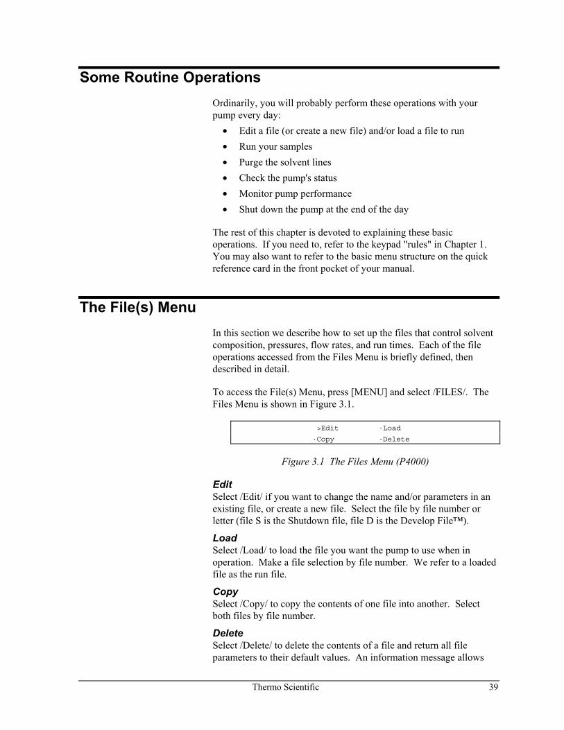
Thermo Scientific 39
Some Routine Operations Ordinarily, you will probably perform these operations with your pump every day:
• Edit a file (or create a new file) and/or load a file to run • Run your samples • Purge the solvent lines • Check the pump's status • Monitor pump performance • Shut down the pump at the end of the day
The rest of this chapter is devoted to explaining these basic operations. If you need to, refer to the keypad "rules" in Chapter 1. You may also want to refer to the basic menu structure on the quick reference card in the front pocket of your manual.
The File(s) Menu In this section we describe how to set up the files that control solvent composition, pressures, flow rates, and run times. Each of the file operations accessed from the Files Menu is briefly defined, then described in detail.
To access the File(s) Menu, press [MENU] and select /FILES/. The Files Menu is shown in Figure 3.1.
>Edit ·Load
·Copy ·Delete
Figure 3.1 The Files Menu (P4000)
Edit Select /Edit/ if you want to change the name and/or parameters in an existing file, or create a new file. Select the file by file number or letter (file S is the Shutdown file, file D is the Develop File™).
Load Select /Load/ to load the file you want the pump to use when in operation. Make a file selection by file number. We refer to a loaded file as the run file.
Copy Select /Copy/ to copy the contents of one file into another. Select both files by file number.
Delete Select /Delete/ to delete the contents of a file and return all file parameters to their default values. An information message allows
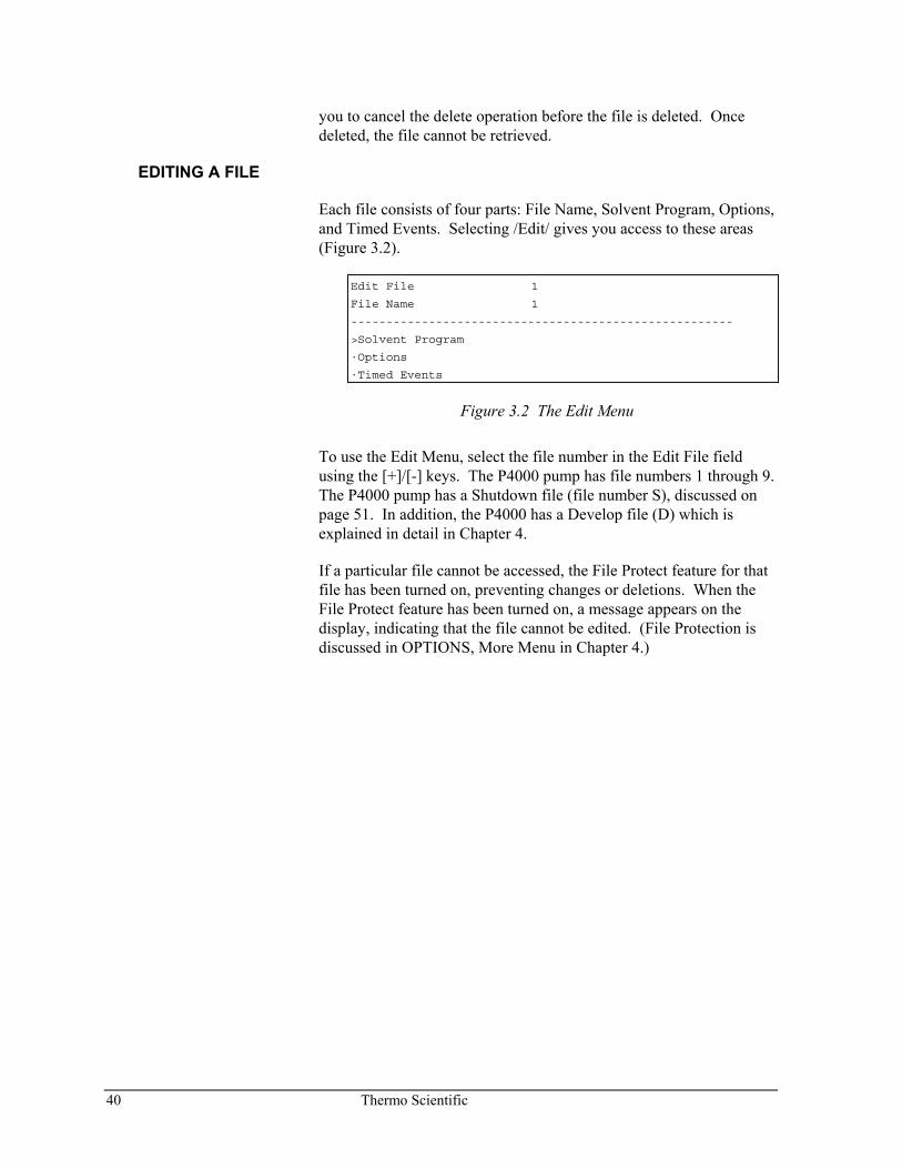
40 Thermo Scientific
you to cancel the delete operation before the file is deleted. Once deleted, the file cannot be retrieved.
EDITING A FILE
Each file consists of four parts: File Name, Solvent Program, Options, and Timed Events. Selecting /Edit/ gives you access to these areas (Figure 3.2).
Edit File 1
File Name 1
------------------------------------------------------
>Solvent Program
·Options
·Timed Events
Figure 3.2 The Edit Menu
To use the Edit Menu, select the file number in the Edit File field using the [+]/[-] keys. The P4000 pump has file numbers 1 through 9. The P4000 pump has a Shutdown file (file number S), discussed on page 51. In addition, the P4000 has a Develop file (D) which is explained in detail in Chapter 4.
If a particular file cannot be accessed, the File Protect feature for that file has been turned on, preventing changes or deletions. When the File Protect feature has been turned on, a message appears on the display, indicating that the file cannot be edited. (File Protection is discussed in OPTIONS, More Menu in Chapter 4.)
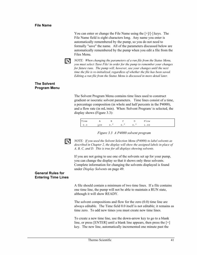
Thermo Scientific 41
File Name
You can enter or change the File Name using the [+]/[-] keys. The File Name field is eight characters long. Any name you enter is automatically remembered by the pump, so you do not need to formally "save" the name. All of the parameters discussed below are automatically remembered by the pump when you edit a file from the Files Menu.
NOTE: When changing the parameters of a run file from the Status Menu, you must select /Save File/ in order for the pump to remember your changes for future runs. The pump will, however, use your changes until the next time the file is re-initialized, regardless of whether the file has been saved. Editing a run file from the Status Menu is discussed in more detail later.
The Solvent Program Menu
The Solvent Program Menu contains time lines used to construct gradient or isocratic solvent parameters. Time lines consist of a time, a percentage composition (in whole and half percents in the P4000), and a flow rate (in mL/min). When /Solvent Program/ is selected, the display shows (Figure 3.3):
Time A B C D Flow
0.0 100 0.0 0.0 0.0 1.00
Figure 3.3 A P4000 solvent program
NOTE: If you used the Solvent Selection Menu (P4000) to label solvents as described in Chapter 2, the display will show the assigned labels in place of A, B, C, and D. This is true for all displays showing solvents.
If you are not going to use one of the solvents set up for your pump, you can change the display so that it shows only three solvents. Complete information for changing the solvents displayed is found under Display Solvents on page 49.
General Rules for Entering Time Lines
A file should contain a minimum of two time lines. If a file contains one time line, the pump will not be able to maintain a RUN state, although it will show READY.
The solvent compositions and flow for the zero (0.0) time line are always editable. The Time field 0.0 itself is not editable; it remains as time zero. To add new times you must create new time lines.
To create a new time line, use the down-arrow key to go to a blank line, or press [ENTER] until a blank line appears, then press the [+] key. The new line, automatically incremented one minute past the
42 Thermo Scientific
previous line, will be displayed. The cursor will appear in the Time field of the new line. The Time field in any new line is editable.
HINT: Don't add all your time lines to the file at once. Enter values for solvent composition and flow in the first time line, then add a new time line. All of the solvent composition and flow rate values will be copied to the new line automatically. In fact, a new line is always identical to the one just before it, with the exception of the Time field as discussed earlier. Solvent composition values can be incremented easily then, from the previous values.
The solvent compositions in each time line must always add to 100. As soon as one percentage is changed, the pump automatically changes the remaining solvents to keep the total equal to 100.
Solvent compositions can be set to whole (X.0) or half (X.5) percents in the P4000.
You can enter times in any order you choose. The pump will automatically rearrange the time lines on the display so that they are in chronological order as soon as you move the cursor off the Time field.
Gradients occur between adjacent pairs of time lines. The pump continually adjusts the solvent composition to achieve the composition shown in the next time line by the time specified.
One of twenty-one preset gradient curves can be selected from the Options Menu (P4000). Creating step gradients is explained on page 48.
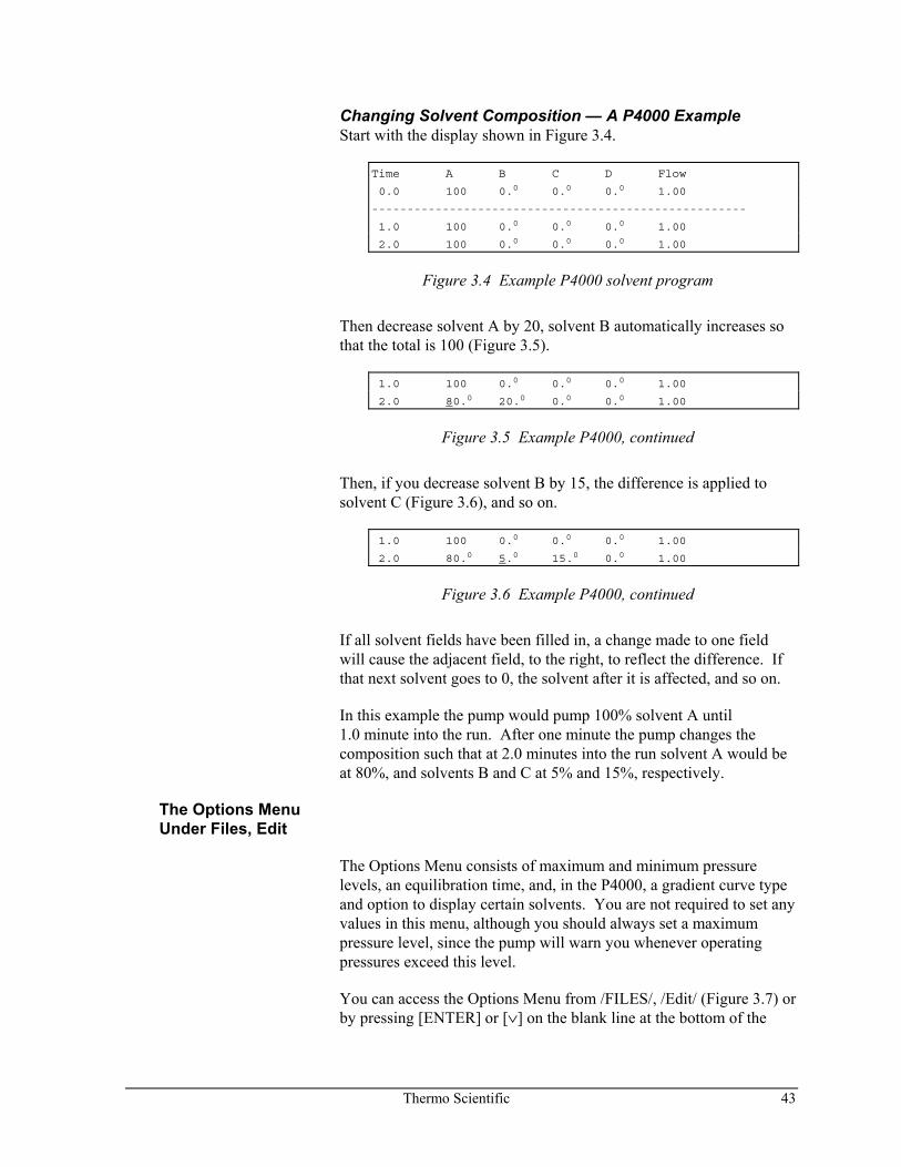
Thermo Scientific 43
Changing Solvent Composition — A P4000 Example Start with the display shown in Figure 3.4.
Time A B C D Flow
0.0 100 0.0 0.0 0.0 1.00
-----------------------------------------------------
1.0 100 0.0 0.0 0.0 1.00
2.0 100 0.0 0.0 0.0 1.00
Figure 3.4 Example P4000 solvent program
Then decrease solvent A by 20, solvent B automatically increases so that the total is 100 (Figure 3.5).
1.0 100 0.0 0.0 0.0 1.00
2.0 80.0 20.0 0.0 0.0 1.00
Figure 3.5 Example P4000, continued
Then, if you decrease solvent B by 15, the difference is applied to solvent C (Figure 3.6), and so on.
1.0 100 0.0 0.0 0.0 1.00
2.0 80.0 5.0 15.0 0.0 1.00
Figure 3.6 Example P4000, continued
If all solvent fields have been filled in, a change made to one field will cause the adjacent field, to the right, to reflect the difference. If that next solvent goes to 0, the solvent after it is affected, and so on.
In this example the pump would pump 100% solvent A until 1.0 minute into the run. After one minute the pump changes the composition such that at 2.0 minutes into the run solvent A would be at 80%, and solvents B and C at 5% and 15%, respectively.
The Options Menu Under Files, Edit
The Options Menu consists of maximum and minimum pressure levels, an equilibration time, and, in the P4000, a gradient curve type and option to display certain solvents. You are not required to set any values in this menu, although you should always set a maximum pressure level, since the pump will warn you whenever operating pressures exceed this level.
You can access the Options Menu from /FILES/, /Edit/ (Figure 3.7) or by pressing [ENTER] or [∨] on the blank line at the bottom of the
44 Thermo Scientific
Solvent Program, then selecting /Options/. The Options Menu is shown in Figure 3.7.
Maximum Pressure 3000
Minimum Pressure 0
-----------------------------------------------------
Equilibration Time 0.0
Gradient Curve Linear
Display Solvents
A B C D
Figure 3.7 The Files, Options Menu (P4000)
Maximum, Minimum Pressures Change the pressure levels as desired. The maximum value is 6000 psi, the minimum is 0 psi. (The allowed values depend on the pressure units, selected in /OPTIONS/, /More/, Pressure Units.) The maximum pressure value must be greater than the minimum pressure. The pump will not allow you to set maximum and minimum pressures that are inconsistent. If you are unable to edit one value, try to edit the other.
NOTE: Pressure units (psi, bar, or MPa) are selected from the Main Menu, /OPTIONS/, /More/, described in Chapter 4.
During operation, the pump continuously monitors the actual operating pressure and displays this on the Status Screen. If the actual pressure ever exceeds the maximum pressure level, or falls below the minimum pressure level set here, an error message will alert you to this circumstance. For more information about using this error feature, refer to Chapter 4, Options, Error Recovery.
Equilibration Time If desired, enter a value for the equilibration time. The equilibration time is the time that the pump will maintain the conditions (solvent composition and flow) specified on the first line of a run file (the zero time line), before showing READY on the Status Screen.
Gradient Curve The P4000 pump has the ability to automatically run a Gradient Curve between time lines. There are twenty-one choices in this field: Linear, Convex 1 to Convex 10, and Concave 1 to Concave 10. These shapes are shown in Figure 3.8. The curve is applied to all solvents participating in the gradient.
Thermo Scientific 45
�
�
| |
Convex 1
Linear
Convex 10
Concave 10
INITIAL %
BEGIN(TIME)
END
(CO
MP
OS
ITIO
N)
Concave 1
FINAL %
Figure 3.8 Gradient Curves in the P4000
The selected curve operates between adjacent pairs of time lines of the Solvent Program. Gradient curves are usually used by specifying only two time lines (a zero time line and one other time line). The pump automatically runs the chosen gradient curve between these two time lines.
Concave gradients begin with a small and end with a high rate of change. Convex gradients begin with a high rate of change and end with a small rate of change. Linear gradients have a constant rate of change between solvent compositions.
For example, if the Solvent Program contained the time lines shown in Figure 3.9, and the gradient curve were Convex 3, then, over 12 minutes, solvent A would follow the shape of Convex 3, starting at a composition of 20%, and ending with a composition of 100%. Solvent C would follow a complimentary shape, starting at a composition of 80%, and ending with a composition of 0% (Figure 3.10).
0.0 20.0 0.0 80.0 0.0 1.00
12.0 100 0.0 0.0 0.0 1.00
Figure 3.9 A two-solvent program
46 Thermo Scientific
PU
-Z01
2E/D
G
Time (in Minutes)
%S
olv
ent
70
50
100
30
0
-
-
-
-
-
-
-
-
-
-
- -
A
C
12
-
Figure 3.10 Solvents A and C, using a Convex 3 gradient curve.
When three solvents are involved, as in the Solvent Program shown in Figure 3.11, Solvent A follows the designated curve from 0% to 100% over 12 minutes. Solvents B and C follow a similar curve (remember, it is the rate of change that defines the curve shape), from 70% to 0%, and 30% to 0%, respectively, over the same 12 minutes (Figure 3.12).
0.0 0.0 70.0 30.0 0.0 1.00
12.0 100 0.0 0.0 0.0 1.00
Figure 3.11 A three-solvent program
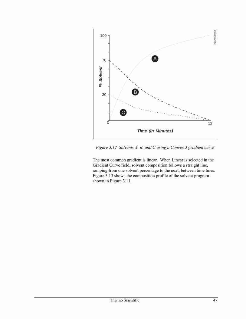
Thermo Scientific 47
B
PU
-Z01
0E/D
G
Time (in Minutes)
%S
olv
ent
70
100
30
-
-
-
-
-
-
-
-
-
-
-
A
C
0 12
Figure 3.12 Solvents A, B, and C using a Convex 3 gradient curve
The most common gradient is linear. When Linear is selected in the Gradient Curve field, solvent composition follows a straight line, ramping from one solvent percentage to the next, between time lines. Figure 3.13 shows the composition profile of the solvent program shown in Figure 3.11.
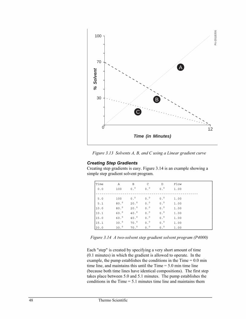
48 Thermo Scientific
PU
-Z01
1E/D
G
Time (in Minutes)
%S
olv
ent
70
100
30
0 12
-
-
-
-
-
-
-
-
-
-
-- -
B
A
C
Figure 3.13 Solvents A, B, and C using a Linear gradient curve
Creating Step Gradients Creating step gradients is easy. Figure 3.14 is an example showing a simple step gradient solvent program.
Time A B C D Flow
0.0 100 0.0 0.0 0.0 1.00
-----------------------------------------------------
5.0 100 0.0 0.0 0.0 1.00
5.1 80.0 20.0 0.0 0.0 1.00
10.0 80.0 20.0 0.0 0.0 1.00
10.1 60.0 40.0 0.0 0.0 1.00
15.0 60.0 40.0 0.0 0.0 1.00
15.1 30.0 70.0 0.0 0.0 1.00
20.0 30.0 70.0 0.0 0.0 1.00
Figure 3.14 A two-solvent step gradient solvent program (P4000)
Each "step" is created by specifying a very short amount of time (0.1 minutes) in which the gradient is allowed to operate. In the example, the pump establishes the conditions in the Time = 0.0 min time line, and maintains this until the Time = 5.0 min time line (because both time lines have identical compositions). The first step takes place between 5.0 and 5.1 minutes. The pump establishes the conditions in the Time = 5.1 minutes time line and maintains them
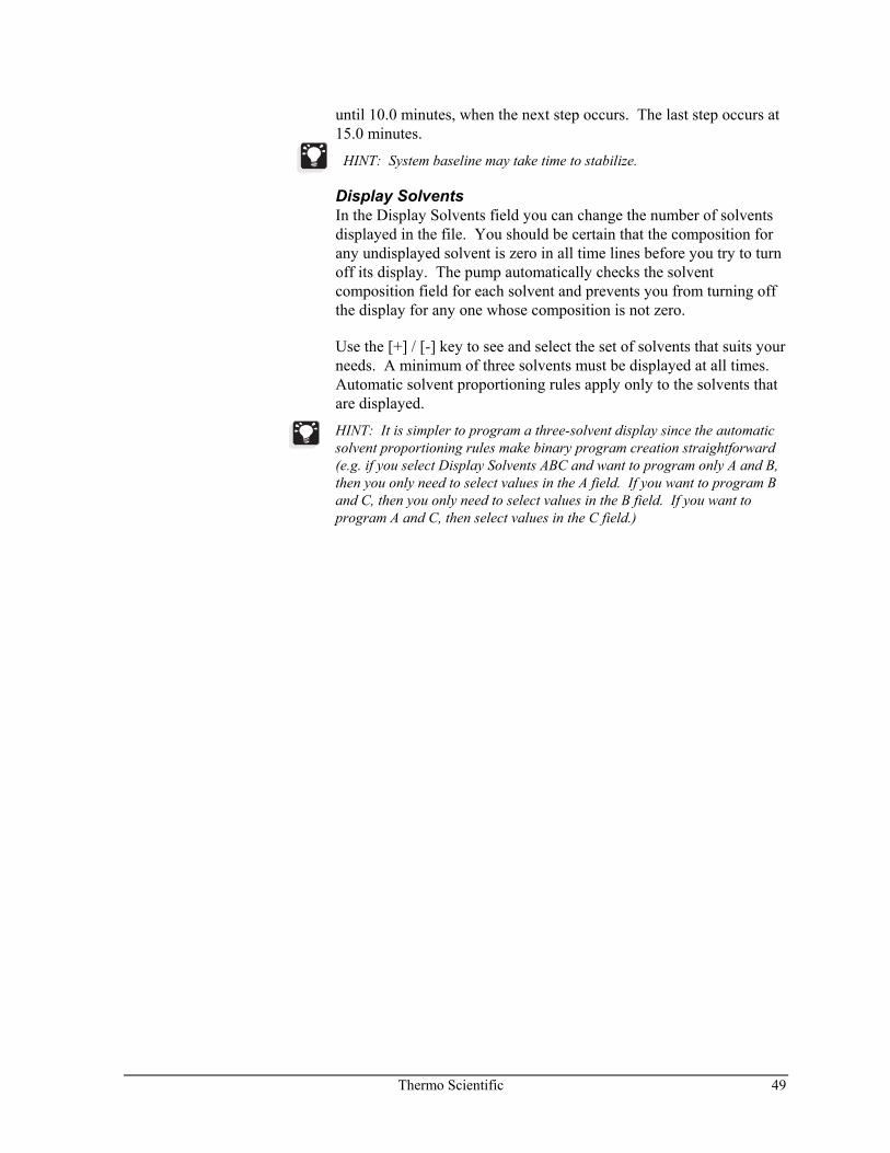
Thermo Scientific 49
until 10.0 minutes, when the next step occurs. The last step occurs at 15.0 minutes.
HINT: System baseline may take time to stabilize.
Display Solvents In the Display Solvents field you can change the number of solvents displayed in the file. You should be certain that the composition for any undisplayed solvent is zero in all time lines before you try to turn off its display. The pump automatically checks the solvent composition field for each solvent and prevents you from turning off the display for any one whose composition is not zero.
Use the [+] / [-] key to see and select the set of solvents that suits your needs. A minimum of three solvents must be displayed at all times. Automatic solvent proportioning rules apply only to the solvents that are displayed.
HINT: It is simpler to program a three-solvent display since the automatic solvent proportioning rules make binary program creation straightforward (e.g. if you select Display Solvents ABC and want to program only A and B, then you only need to select values in the A field. If you want to program B and C, then you only need to select values in the B field. If you want to program A and C, then select values in the C field.)
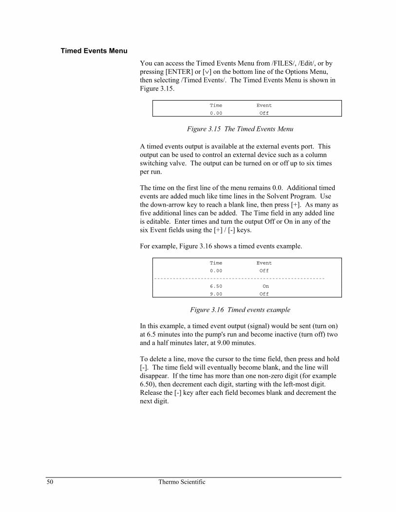
50 Thermo Scientific
Timed Events Menu You can access the Timed Events Menu from /FILES/, /Edit/, or by pressing [ENTER] or [∨] on the bottom line of the Options Menu, then selecting /Timed Events/. The Timed Events Menu is shown in Figure 3.15.
Time Event
0.00 Off
Figure 3.15 The Timed Events Menu
A timed events output is available at the external events port. This output can be used to control an external device such as a column switching valve. The output can be turned on or off up to six times per run.
The time on the first line of the menu remains 0.0. Additional timed events are added much like time lines in the Solvent Program. Use the down-arrow key to reach a blank line, then press [+]. As many as five additional lines can be added. The Time field in any added line is editable. Enter times and turn the output Off or On in any of the six Event fields using the [+] / [-] keys.
For example, Figure 3.16 shows a timed events example.
Time Event
0.00 Off
-------------------------------------------------------
6.50 On
9.00 Off
Figure 3.16 Timed events example
In this example, a timed event output (signal) would be sent (turn on) at 6.5 minutes into the pump's run and become inactive (turn off) two and a half minutes later, at 9.00 minutes.
To delete a line, move the cursor to the time field, then press and hold [-]. The time field will eventually become blank, and the line will disappear. If the time has more than one non-zero digit (for example 6.50), then decrement each digit, starting with the left-most digit. Release the [-] key after each field becomes blank and decrement the next digit.
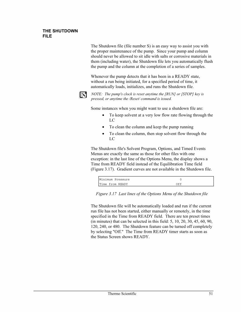
Thermo Scientific 51
THE SHUTDOWN FILE
The Shutdown file (file number S) is an easy way to assist you with the proper maintenance of the pump. Since your pump and column should never be allowed to sit idle with salts or corrosive materials in them (including water), the Shutdown file lets you automatically flush the pump and the column at the completion of a series of samples.
Whenever the pump detects that it has been in a READY state, without a run being initiated, for a specified period of time, it automatically loads, initializes, and runs the Shutdown file.
NOTE: The pump's clock is reset anytime the [RUN] or [STOP] key is pressed, or anytime the /Reset/ command is issued.
Some instances when you might want to use a shutdown file are: • To keep solvent at a very low flow rate flowing through the
LC • To clean the column and keep the pump running • To clean the column, then stop solvent flow through the
LC
The Shutdown file's Solvent Program, Options, and Timed Events Menus are exactly the same as those for other files with one exception: in the last line of the Options Menu, the display shows a Time from READY field instead of the Equilibration Time field (Figure 3.17). Gradient curves are not available in the Shutdown file.
Minimum Pressure 0
Time from READY Off
Figure 3.17 Last lines of the Options Menu of the Shutdown file
The Shutdown file will be automatically loaded and run if the current run file has not been started, either manually or remotely, in the time specified in the Time from READY field. There are ten preset times (in minutes) that can be selected in this field: 5, 10, 20, 30, 45, 60, 90, 120, 240, or 480. The Shutdown feature can be turned off completely by selecting "Off." The Time from READY timer starts as soon as the Status Screen shows READY.
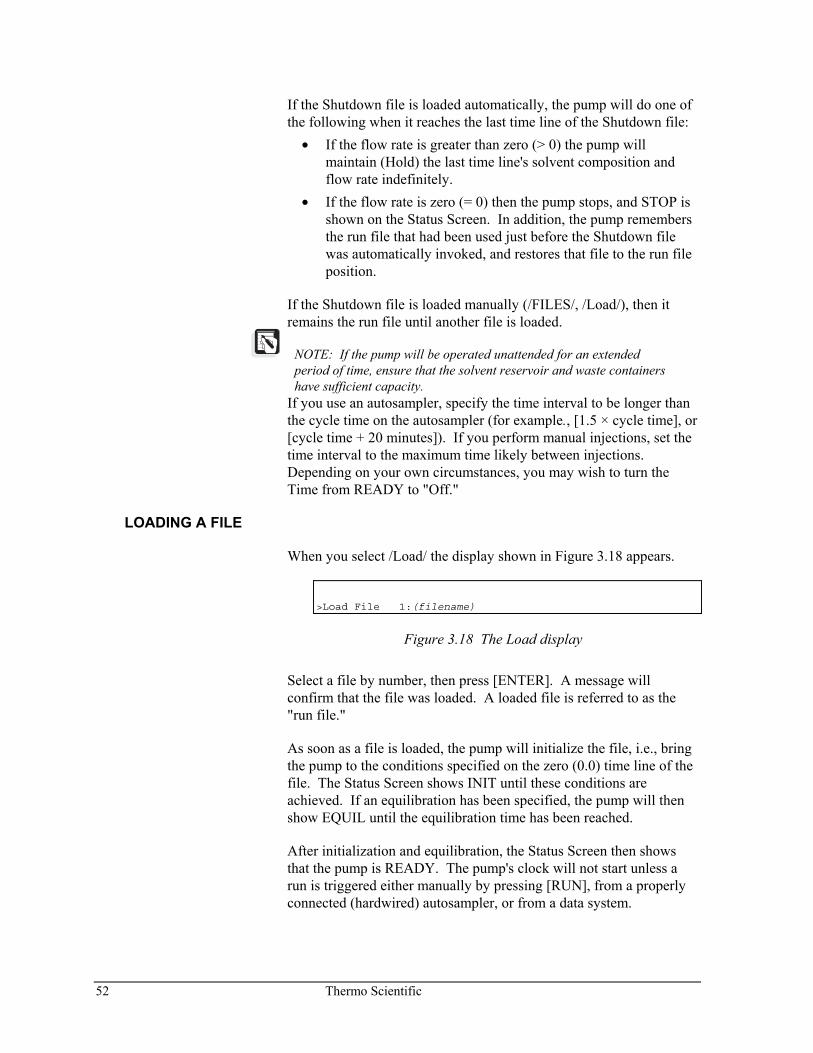
52 Thermo Scientific
If the Shutdown file is loaded automatically, the pump will do one of the following when it reaches the last time line of the Shutdown file:
• If the flow rate is greater than zero (> 0) the pump will maintain (Hold) the last time line's solvent composition and flow rate indefinitely.
• If the flow rate is zero (= 0) then the pump stops, and STOP is shown on the Status Screen. In addition, the pump remembers the run file that had been used just before the Shutdown file was automatically invoked, and restores that file to the run file position.
If the Shutdown file is loaded manually (/FILES/, /Load/), then it remains the run file until another file is loaded.
NOTE: If the pump will be operated unattended for an extended period of time, ensure that the solvent reservoir and waste containers have sufficient capacity.
If you use an autosampler, specify the time interval to be longer than the cycle time on the autosampler (for example., [1.5 × cycle time], or [cycle time + 20 minutes]). If you perform manual injections, set the time interval to the maximum time likely between injections. Depending on your own circumstances, you may wish to turn the Time from READY to "Off."
LOADING A FILE
When you select /Load/ the display shown in Figure 3.18 appears.
>Load File 1:(filename)
Figure 3.18 The Load display
Select a file by number, then press [ENTER]. A message will confirm that the file was loaded. A loaded file is referred to as the "run file."
As soon as a file is loaded, the pump will initialize the file, i.e., bring the pump to the conditions specified on the zero (0.0) time line of the file. The Status Screen shows INIT until these conditions are achieved. If an equilibration has been specified, the pump will then show EQUIL until the equilibration time has been reached.
After initialization and equilibration, the Status Screen then shows that the pump is READY. The pump's clock will not start unless a run is triggered either manually by pressing [RUN], from a properly connected (hardwired) autosampler, or from a data system.
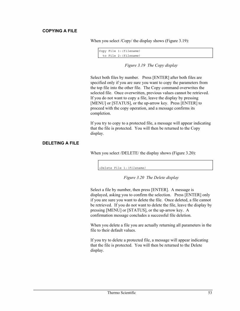
Thermo Scientific 53
COPYING A FILE
When you select /Copy/ the display shows (Figure 3.19):
Copy File 1:(filename)
to File 2:(filename)
Figure 3.19 The Copy display
Select both files by number. Press [ENTER] after both files are specified only if you are sure you want to copy the parameters from the top file into the other file. The Copy command overwrites the selected file. Once overwritten, previous values cannot be retrieved. If you do not want to copy a file, leave the display by pressing [MENU] or [STATUS], or the up-arrow key. Press [ENTER] to proceed with the copy operation, and a message confirms its completion.
If you try to copy to a protected file, a message will appear indicating that the file is protected. You will then be returned to the Copy display.
DELETING A FILE
When you select /DELETE/ the display shows (Figure 3.20):
>Delete File 1:(filename)
Figure 3.20 The Delete display
Select a file by number, then press [ENTER]. A message is displayed, asking you to confirm the selection. Press [ENTER] only if you are sure you want to delete the file. Once deleted, a file cannot be retrieved. If you do not want to delete the file, leave the display by pressing [MENU] or [STATUS], or the up-arrow key. A confirmation message concludes a successful file deletion.
When you delete a file you are actually returning all parameters in the file to their default values.
If you try to delete a protected file, a message will appear indicating that the file is protected. You will then be returned to the Delete display.
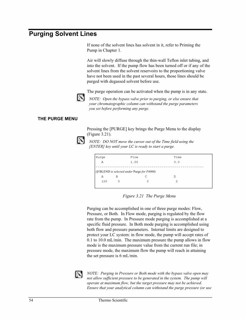
54 Thermo Scientific
Purging Solvent Lines If none of the solvent lines has solvent in it, refer to Priming the Pump in Chapter 1.
Air will slowly diffuse through the thin-wall Teflon inlet tubing, and into the solvent. If the pump flow has been turned off or if any of the solvent lines from the solvent reservoirs to the proportioning valve have not been used in the past several hours, those lines should be purged with degassed solvent before use.
The purge operation can be activated when the pump is in any state.
NOTE: Open the bypass valve prior to purging, or else ensure that your chromatographic column can withstand the purge parameters you set before performing any purge.
THE PURGE MENU
Pressing the [PURGE] key brings the Purge Menu to the display (Figure 3.21).
NOTE: DO NOT move the cursor out of the Time field using the [ENTER] key until your LC is ready to start a purge.
Purge Flow Time
A 1.00 0.0
--------------------------------------------------------
(If BLEND is selected under Purge for P4000) A B C D
100 0 0 0
Figure 3.21 The Purge Menu
Purging can be accomplished in one of three purge modes: Flow, Pressure, or Both. In Flow mode, purging is regulated by the flow rate from the pump. In Pressure mode purging is accomplished at a specific fluid pressure. In Both mode purging is accomplished using both flow and pressure parameters. Internal limits are designed to protect your LC system: in flow mode, the pump will accept rates of 0.1 to 10.0 mL/min. The maximum pressure the pump allows in flow mode is the maximum pressure value from the current run file; in pressure mode, the maximum flow the pump will reach in attaining the set pressure is 6 mL/min.
NOTE: Purging in Pressure or Both mode with the bypass valve open may not allow sufficient pressure to be generated in the system. The pump will operate at maximum flow, but the target pressure may not be achieved. Ensure that your analytical column can withstand the purge pressure (or use
Thermo Scientific 55
a flow restrictor or old column), and do not open the bypass valve.
The purge mode can be changed from /OPTIONS/, /More/, Purge Mode, described in Chapter 4. The top line of the Purge Menu will show either Flow or Pres, depending on the purge mode you select.
Purge (field) There are six choices available in the Purge field for the P4000 (A, B, C, D, All, Blend). When Blend is selected, one additional line can be accessed by pressing the down-arrow key (not the [ENTER] key!). These are used to set solvent compositions. You should enter values for the solvent composition in these fields before you initiate a purge.
Initially, the compositions will be copied automatically from the first line of the Run File. These solvent fields follow the same proportioning rules as the fields in the Solvent Program; they must total 100. Unlike the solvent program however, all solvents are automatically displayed, regardless of the selections made from Display Solvents.
Flow or Pres The flow rate is taken from the last line of the run file. Use this field to select a flow rate. If the purge mode is Pres (pressure) instead of Flow, the pressure is automatically set to one-half (50%) of the maximum pressure level set in the run file.
NOTE: To change the purge mode you must go to /OPTIONS/, /More/, Purge Mode. Refer to Chapter 4 for complete information.
Time The Time field is used to set the length of time you want the pump to purge. If the field remains 0.0, purging, once started, will continue until stopped.
NOTE: When you check the purge operation from the Status Screen, the P4000 displays PURGE. The time remaining to complete the purge is shown on line 4.
56 Thermo Scientific
Starting a Purge
To initiate a purge cycle, move the cursor out of the Time field by using the [ENTER] key.
If the time stays set to 0.0, purging will continue until you press [STOP], or a file is initialized. If a time is entered, the pump will purge until the time set. After completing a purge, the pump automatically initializes the run file.
When running in a timed purge mode, the Status Screen will indicate the time remaining to purge (that is, counts backwards toward 0.0). If the [PURGE] key is pressed once more, the Purge Menu is again displayed and the time countdown continues, uninterrupted, unless the cursor is moved out of the Time field by pressing [ENTER], at which point the timer will be reset and purging will restart.
The pump will retain the selections made in the PURGE display as long as the power to the pump is on.
If power is turned off, the pressure parameter must be re-entered. However, the flow rate setting is retained in NOVRAM.
Stopping a Purge
There are three ways to stop a purge cycle: • Press the [STOP] key • Load (initialize) a file by selecting a file using /FILES/, /Load/ • Allow the pump to complete the purge (if a time has been
specified), at which point the pump will automatically initialize the last run file.
Thermo Scientific 57
Running the Pump To perform a run:
• purge the solvent lines if necessary, • establish a READY state (may require the pump to INIT,
and/or EQUIL) • inject the sample, and • press [RUN].
If you are performing a manual injection, fill the injection loop, check that the Status Screen shows READY, inject the sample, and press [RUN] in succession. If an autosampler is hardwired to the pump, simply initiate the autosampler run sequence.
NOTE: Generally, when operated manually, if the pump is stopped (i.e., the Status Screen shows STOP), the run file can be initialized by pressing [RUN], and then started by pressing [RUN] again when the Status Screen shows READY.
58 Thermo Scientific
ESTABLISHING READY
The READY state means that the pump has reached the conditions specified on the first line of the solvent program and is ready to start a run.
Initializing a file
To achieve the READY state, initialize a run file, by any of the following methods:
• Load a file by selecting /FILES/, /Load/, a file number, then pressing [ENTER]. This simultaneously loads the run file and initializes it.
• If the pump is stopped (Status Screen shows STOP), press [RUN]. This initializes the run file, without starting the run.
• If the pump is stopped or in run, reset the run file by selecting /COMMANDS/, /Reset/. This initializes the run file without starting the run.
Wait for the pump to reach zero time line conditions. If an equilibration time was specified in the file, the Status Screen will show EQUIL for this period of time.
PRESSING [RUN]
As soon as the pump shows READY, begin the run by pressing the [RUN] key. This starts the pump's clock.
NOTE: Even though the pump may be ready, your column and the rest of your LC system may not be! Take into account your own LC application and ensure that your column is at chemical equilibrium and that the other instruments in your system are ready before your proceed with any injection.
As soon as the [RUN] key is pressed, the pump begins to operate based on the time lines in the Solvent Program of the run file, and the Status Screen is displayed. The Status field on the P4000 Status Screen shows RUN, indicating that the pump is operating from the parameters in the run file. Line 4 shows the time into the run. Status is fully described on page 61.
STOPPING THE PUMP
There are a number of ways to stop the pump, depending on what you wish to do next. More information regarding the Commands Menu, referred to below, is found on page 60.
Thermo Scientific 59
Using a Hold Command
If you want to stop the pump's clock momentarily (but not stop solvent flow), and plan to resume the run where it was stopped, press [MENU], and select /COMMANDS/, /Hold/. To resume, select /COMMANDS/, /Continue/.
By Resetting the Pump's Clock
If you want to restart the current run, press [MENU] and select /COMMANDS/, /Reset/. This stops the pump's clock and returns to the zero time line, automatically initializing the file. Restart the run by pressing [RUN] after the pump shows READY.
By Pressing [STOP]
If you want to completely stop the pump, press [STOP]. This aborts the run and stops solvent flow through the pump. If you want to resume with the same file, you must initialize the run file by pressing [RUN], waiting for the pump to show [READY], then pressing [RUN] again.
WHILE THE PUMP IS RUNNING
There are several messages which can appear in the Status field. These are discussed in detail in the Status section below.
While the pump is running you may do several things without disturbing pump operation:
• edit files (/FILES/, /Edit/). • check some pump performance parameters. • edit the run file from the Status Menu. (This has an effect
on the current run - see page 63 for more information.)
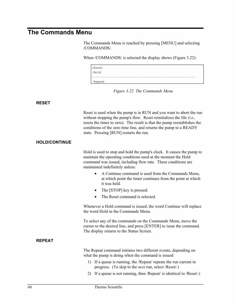
60 Thermo Scientific
The Commands Menu The Commands Menu is reached by pressing [MENU] and selecting /COMMANDS/.
When /COMMANDS/ is selected the display shows (Figure 3.22):
>Reset
·Hold
--------------------------------------------------------
·Repeat
Figure 3.22 The Commands Menu
RESET
Reset is used when the pump is in RUN and you want to abort the run without stopping the pump's flow. Reset reinitializes the file (i.e., resets the timer to zero). The result is that the pump reestablishes the conditions of the zero time line, and returns the pump to a READY state. Pressing [RUN] restarts the run.
HOLD/CONTINUE
Hold is used to stop and hold the pump's clock. It causes the pump to maintain the operating conditions used at the moment the Hold command was issued, including flow rate. These conditions are maintained indefinitely unless:
• A Continue command is used from the Commands Menu, at which point the timer continues from the point at which it was held.
• The [STOP] key is pressed. • The Reset command is selected.
Whenever a Hold command is issued, the word Continue will replace the word Hold in the Commands Menu.
To select any of the commands on the Commands Menu, move the cursor to the desired line, and press [ENTER] to issue the command. The display returns to the Status Screen.
REPEAT
The Repeat command initiates two different events, depending on what the pump is doing when the command is issued:
1) If a queue is running, the /Repeat/ repeats the run current in progress. (To skip to the next run, select /Reset/.)
2) If a queue is not running, then /Repeat/ is identical to /Reset/.)
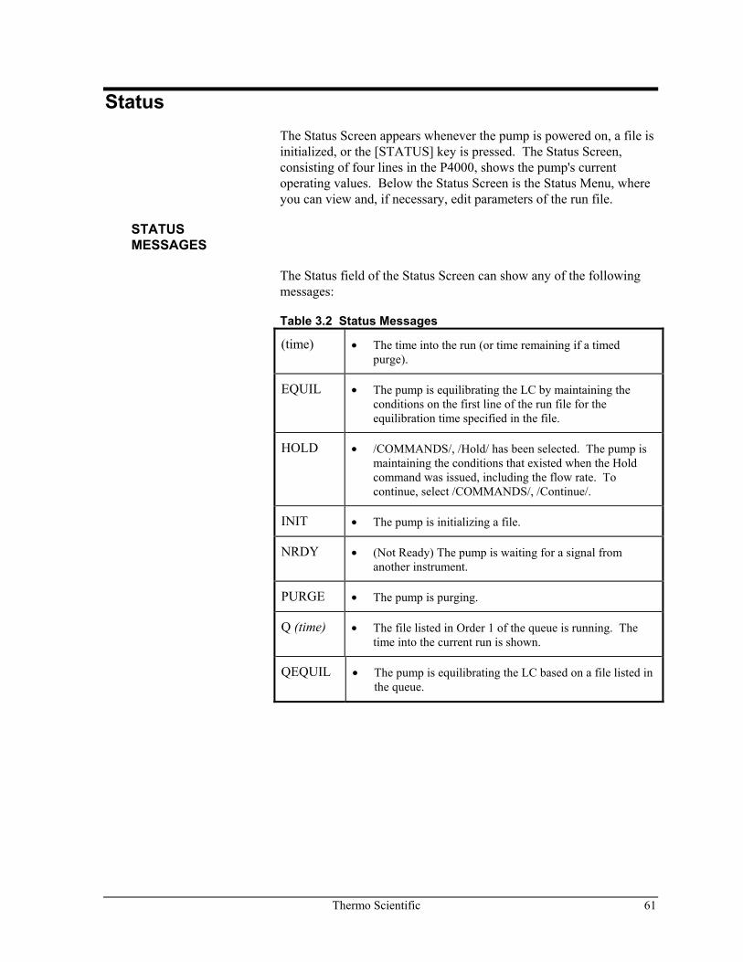
Thermo Scientific 61
Status The Status Screen appears whenever the pump is powered on, a file is initialized, or the [STATUS] key is pressed. The Status Screen, consisting of four lines in the P4000, shows the pump's current operating values. Below the Status Screen is the Status Menu, where you can view and, if necessary, edit parameters of the run file.
STATUS MESSAGES
The Status field of the Status Screen can show any of the following messages:
Table 3.2 Status Messages
(time) • The time into the run (or time remaining if a timed purge).
EQUIL
• The pump is equilibrating the LC by maintaining the conditions on the first line of the run file for the equilibration time specified in the file.
HOLD • /COMMANDS/, /Hold/ has been selected. The pump is maintaining the conditions that existed when the Hold command was issued, including the flow rate. To continue, select /COMMANDS/, /Continue/.
INIT • The pump is initializing a file.
NRDY • (Not Ready) The pump is waiting for a signal from another instrument.
PURGE • The pump is purging.
Q (time) • The file listed in Order 1 of the queue is running. The time into the current run is shown.
QEQUIL
• The pump is equilibrating the LC based on a file listed in the queue.
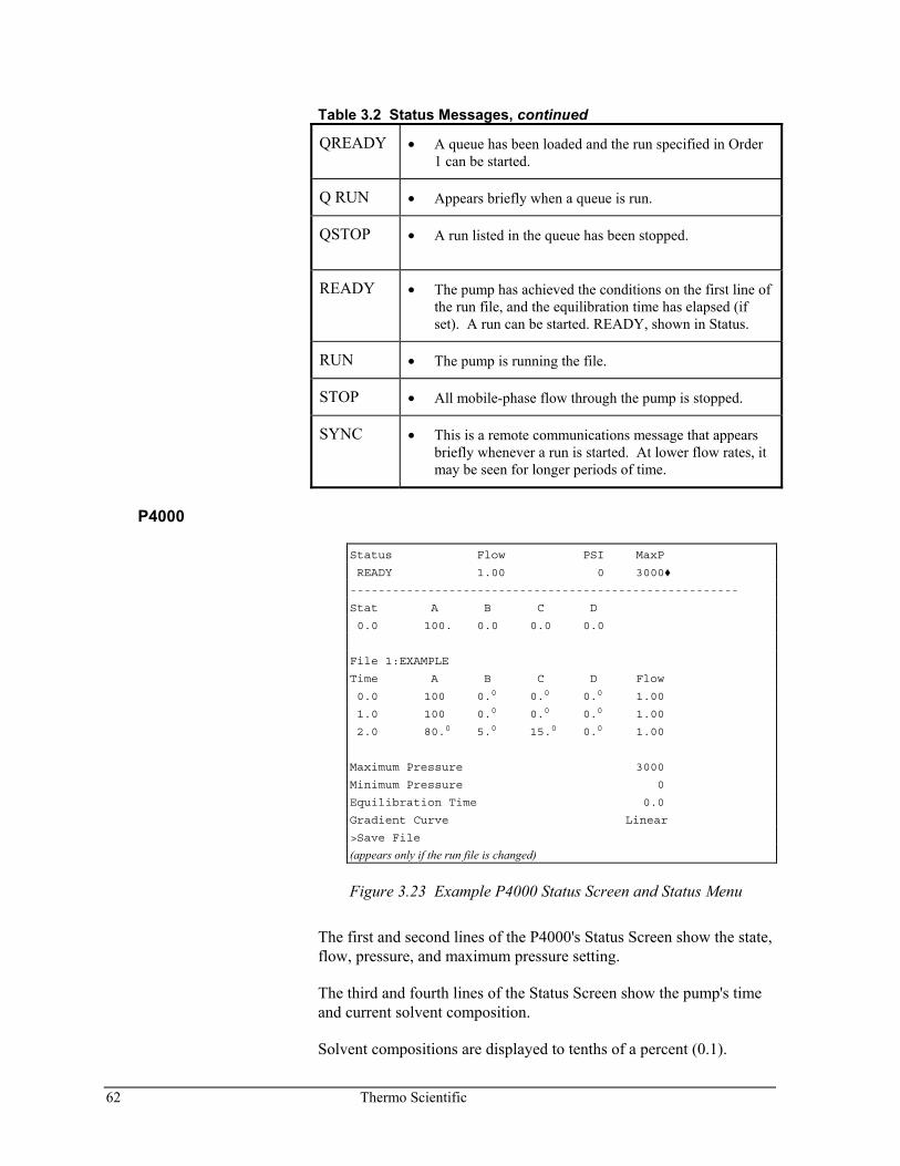
62 Thermo Scientific
Table 3.2 Status Messages, continued
QREADY • A queue has been loaded and the run specified in Order 1 can be started.
Q RUN • Appears briefly when a queue is run.
QSTOP
• A run listed in the queue has been stopped.
READY • The pump has achieved the conditions on the first line of the run file, and the equilibration time has elapsed (if set). A run can be started. READY, shown in Status.
RUN • The pump is running the file.
STOP • All mobile-phase flow through the pump is stopped.
SYNC • This is a remote communications message that appears briefly whenever a run is started. At lower flow rates, it may be seen for longer periods of time.
P4000
Status Flow PSI MaxP
READY 1.00 0 3000
-------------------------------------------------------
Stat A B C D
0.0 100. 0.0 0.0 0.0
File 1:EXAMPLE
Time A B C D Flow
0.0 100 0.0 0.0 0.0 1.00
1.0 100 0.0 0.0 0.0 1.00
2.0 80.0 5.0 15.0 0.0 1.00
Maximum Pressure 3000
Minimum Pressure 0
Equilibration Time 0.0
Gradient Curve Linear
>Save File
(appears only if the run file is changed)
Figure 3.23 Example P4000 Status Screen and Status Menu
The first and second lines of the P4000's Status Screen show the state, flow, pressure, and maximum pressure setting.
The third and fourth lines of the Status Screen show the pump's time and current solvent composition.
Solvent compositions are displayed to tenths of a percent (0.1).
Thermo Scientific 63
EDITING A RUN FILE
The remaining lines, which comprise the Status Menu, show the file name, solvent program, and options of the run file. If the solvent program and options do not appear, the Status Lock feature has been turned on. (Status Lock is described in Chapter 4, under the OPTIONS, More Menu.)
All time lines of the run file's solvent program may be edited while the pump is running, as may the maximum and minimum pressures, and the equilibration time. Any changes take effect as soon as the cursor leaves each field. However, the changes are saved only when the /Save File/ command is selected below Gradient Curve (P4000).
HINT: Any time the parameters of the Run File are changed, the /Save File/ command will appear at the bottom of the Status Menu. Note that you cannot save changes using the /Save File/ command if file protection for that file has been turned "On".
When changing the parameters of a run file from the Status Menu, you must select /Save File/ in order for the pump to remember your changes. The pump will, however, use your changes until the next time the file is initialized by selecting /FILES/, /Load/. Use the same methods described on page 41 and on page 43 to edit the parameters of a run file. New lines may be added to the run file. Timed events may only be edited using /FILES/, /Edit/, /Timed Events/, and will not take effect until that file is loaded (becomes the run file).
Monitoring Pump Performance The pump has the capability to automatically monitor its own performance and warn you if a flow problem exists. The way the pump responds to error conditions is set in the Error Recovery menu of OPTIONS, selected from the Main Menu. These options (not to be confused with File Options), are described in detail in Chapter 4.
Certain flow and pressure conditions are monitored continuously. For example, if a time line with a zero flow rate has been encountered, the pump responds with the appropriate error message shown below. As mentioned earlier, you can select the pump's response to certain conditions.
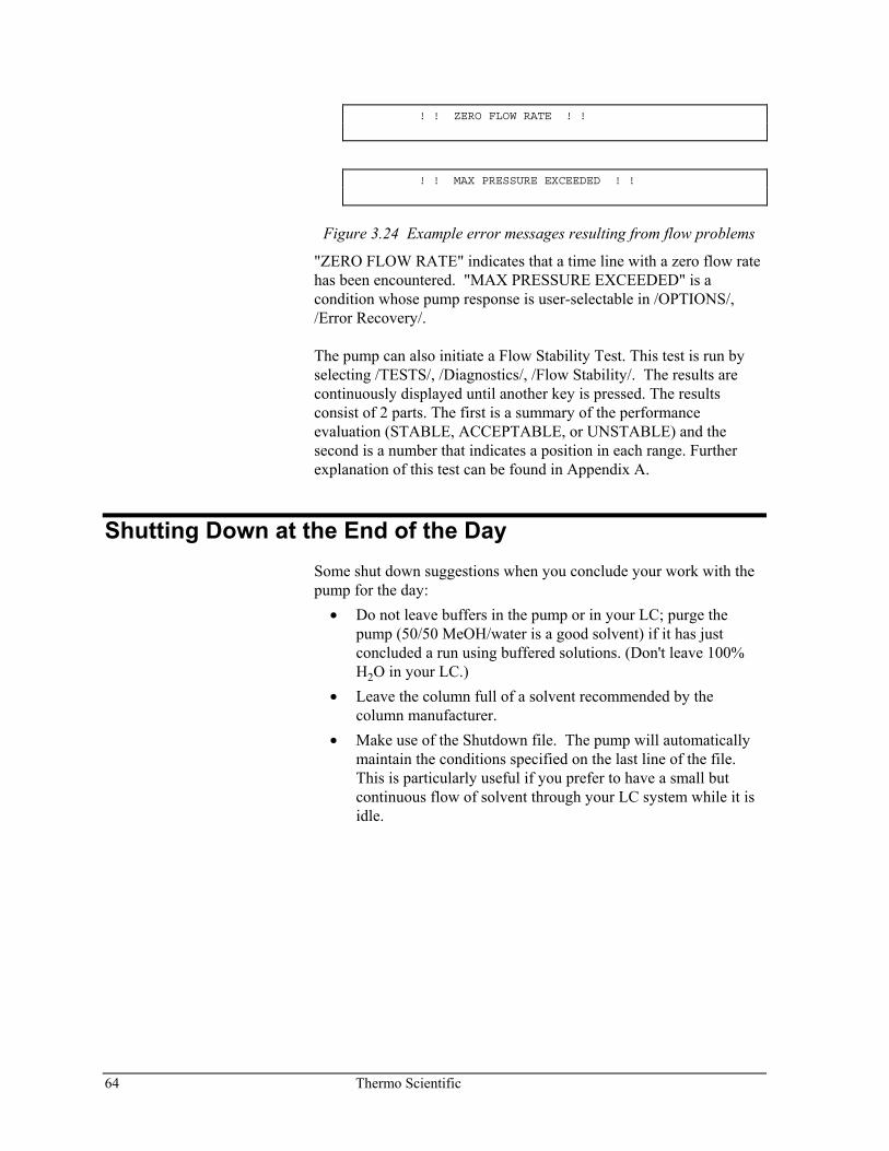
64 Thermo Scientific
! ! ZERO FLOW RATE ! !
! ! MAX PRESSURE EXCEEDED ! !
Figure 3.24 Example error messages resulting from flow problems
"ZERO FLOW RATE" indicates that a time line with a zero flow rate has been encountered. "MAX PRESSURE EXCEEDED" is a condition whose pump response is user-selectable in /OPTIONS/, /Error Recovery/. The pump can also initiate a Flow Stability Test. This test is run by selecting /TESTS/, /Diagnostics/, /Flow Stability/. The results are continuously displayed until another key is pressed. The results consist of 2 parts. The first is a summary of the performance evaluation (STABLE, ACCEPTABLE, or UNSTABLE) and the second is a number that indicates a position in each range. Further explanation of this test can be found in Appendix A.
Shutting Down at the End of the Day Some shut down suggestions when you conclude your work with the pump for the day:
• Do not leave buffers in the pump or in your LC; purge the pump (50/50 MeOH/water is a good solvent) if it has just concluded a run using buffered solutions. (Don't leave 100% H2O in your LC.)
• Leave the column full of a solvent recommended by the column manufacturer.
• Make use of the Shutdown file. The pump will automatically maintain the conditions specified on the last line of the file. This is particularly useful if you prefer to have a small but continuous flow of solvent through your LC system while it is idle.
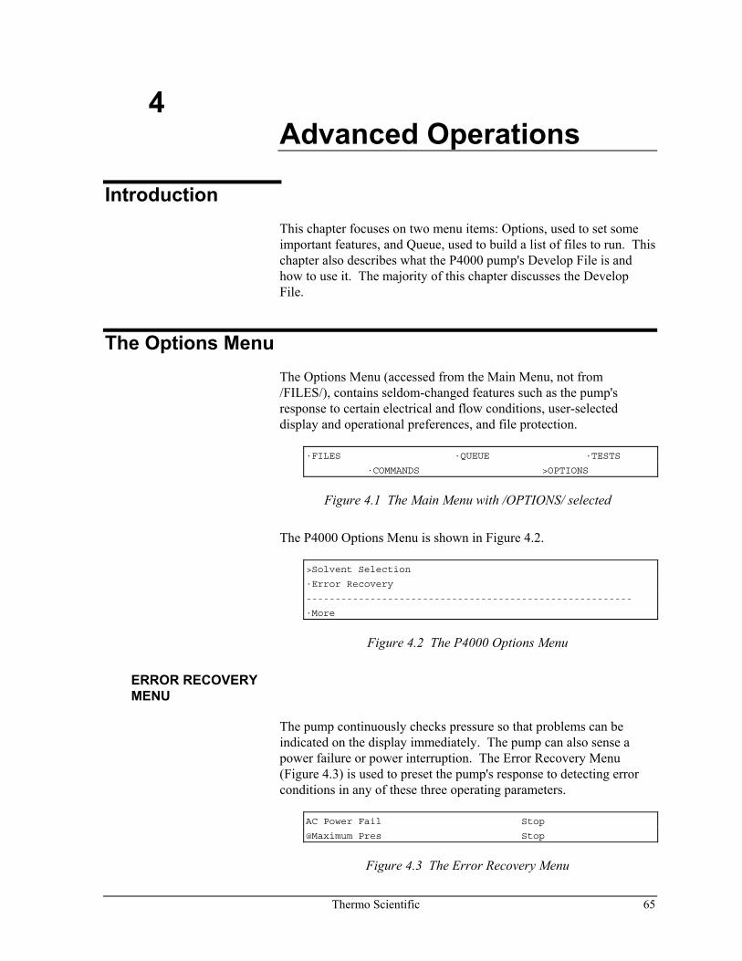
Thermo Scientific 65
4 Advanced Operations
Introduction This chapter focuses on two menu items: Options, used to set some important features, and Queue, used to build a list of files to run. This chapter also describes what the P4000 pump's Develop File is and how to use it. The majority of this chapter discusses the Develop File.
The Options Menu The Options Menu (accessed from the Main Menu, not from /FILES/), contains seldom-changed features such as the pump's response to certain electrical and flow conditions, user-selected display and operational preferences, and file protection.
·FILES ·QUEUE ·TESTS
·COMMANDS >OPTIONS
Figure 4.1 The Main Menu with /OPTIONS/ selected
The P4000 Options Menu is shown in Figure 4.2.
>Solvent Selection
·Error Recovery
--------------------------------------------------------
·More
Figure 4.2 The P4000 Options Menu
ERROR RECOVERY MENU
The pump continuously checks pressure so that problems can be indicated on the display immediately. The pump can also sense a power failure or power interruption. The Error Recovery Menu (Figure 4.3) is used to preset the pump's response to detecting error conditions in any of these three operating parameters.
AC Power Fail Stop
@Maximum Pres Stop
Figure 4.3 The Error Recovery Menu
66 Thermo Scientific
Each field in the Error Recovery Menu can be set to one of three selections:
Selection Pump's Response
Stop The pump stops immediately if the condition is encountered
Continue The pump continues as if the condition had not occurred
Shutdown The pump immediately stops, then loads and runs the Shutdown file.
AC Power Fail The pump may sense a power interruption at any time. Select Stop, Continue, or Shutdown in the AC Power Fail field to stop, continue, or shut down the pump as soon as power is restored.
NOTE: If the power switch is turned off while the motor is running, the pump considers this a power failure and will respond accordingly as soon as power is restored.
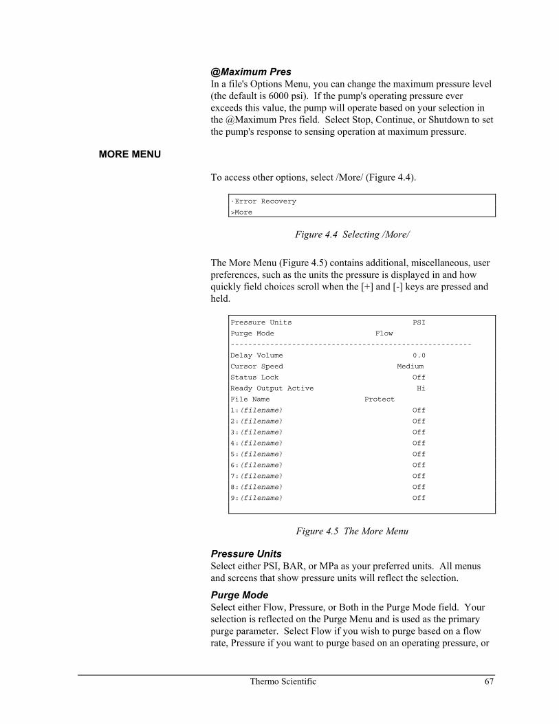
Thermo Scientific 67
@Maximum Pres In a file's Options Menu, you can change the maximum pressure level (the default is 6000 psi). If the pump's operating pressure ever exceeds this value, the pump will operate based on your selection in the @Maximum Pres field. Select Stop, Continue, or Shutdown to set the pump's response to sensing operation at maximum pressure.
MORE MENU
To access other options, select /More/ (Figure 4.4).
·Error Recovery
>More
Figure 4.4 Selecting /More/
The More Menu (Figure 4.5) contains additional, miscellaneous, user preferences, such as the units the pressure is displayed in and how quickly field choices scroll when the [+] and [-] keys are pressed and held.
Pressure Units PSI
Purge Mode Flow
-------------------------------------------------------
Delay Volume 0.0
Cursor Speed Medium
Status Lock Off
Ready Output Active Hi
File Name Protect
1:(filename) Off
2:(filename) Off
3:(filename) Off
4:(filename) Off
5:(filename) Off
6:(filename) Off
7:(filename) Off
8:(filename) Off
9:(filename) Off
Figure 4.5 The More Menu
Pressure Units Select either PSI, BAR, or MPa as your preferred units. All menus and screens that show pressure units will reflect the selection.
Purge Mode Select either Flow, Pressure, or Both in the Purge Mode field. Your selection is reflected on the Purge Menu and is used as the primary purge parameter. Select Flow if you wish to purge based on a flow rate, Pressure if you want to purge based on an operating pressure, or
68 Thermo Scientific
Both if you wish both flow and pressure parameters to govern purging.
Purging in pressure mode requires a certain amount of back pressure in the system. Ensure that your analytical column can withstand the purge pressure (or use a flow restrictor or old column), and do not open the bypass valve.
Delay Volume The gradient delay volume is the volume of mobile phase that the pump will pump before allowing a SpectraSYSTEM autosampler to proceed with an injection. This prevents an injection from occurring before the gradient has reached the column. Determine the delay volume of your system, and enter this value (in mL) in the Delay Volume field. (The pump must be properly hardwired to the autosampler for the delay volume to be recognized by the autosampler. The pump sends a signal to the autosampler's Inject Hold input while the delay volume is being pumped.)
Cursor Speed Cursor Speed is used to change how quickly choices scroll on the display when the [+] and [-] keys are pressed and held, and how quickly a menu scrolls (up and down) when the arrow keys are pressed and held. Select Fast, Medium, or Slow.
Status Lock Status Lock prevents a run file from being edited from the Status Menu. When Status Lock is On, the Status Menu only shows the run file name (and number). The rest of the run file cannot be accessed.
Status Lock is different from File Protection (below). A protected file cannot be saved from the Status Menu (using the /Save File/ command), although it can be viewed (from the Status Menu), nor can it be edited from /FILES/. Status Lock, on the other hand, prevents a run file from being seen (and hence edited) from the Status Menu. The file remains editable from /FILES/.
The Status Screen is unaffected by Status Lock; it can always be viewed.
Thermo Scientific 69
Ready Output Active The Ready output, located on the back of the pump, continuously sends an electrical signal to any device hardwired to it. Use the Ready Output Active field to choose whether the signal is either a 5V signal (Hi) or a 0V signal (Lo) whenever the pump is in a READY state. If the pump is not READY, the other signal is output. Whenever the pump's Ready Output is hardwired to a SpectraSYSTEM autosampler to coordinate injections, it should be set to provide "Hi" voltage in the READY state.
File Protection Each numbered file can be safeguarded against accidental or unauthorized changes by turning on the file protection feature. When File Protection for a specific file is turned On, that file cannot be edited, deleted, or copied to. Initially, all files are editable (file protection is Off.) Use the [+] or [-] key to select Off or On in the Protect field.
SOLVENT SELECTION MENU
The Solvent Selection Menu displays four solvent labels (A, B, C, and D), each of which can be changed to one of thirteen preset solvent names. Matching a label to the actual solvents that are connected to the four inlet lines is a convenient way to avoid confusion. When you label solvents, each of the pump's displays that would normally show lettered solvent labels A, B, C, and D will instead show the name you set. The labels available are: H2O, MeOH, ACN, Phos (Phosphate), Acet (acetate), TFA, Buff (Buffer), Acid, Base, THF, IPA, MeCl, and HEX.
To change a label, select /OPTIONS/, /Solvent Selection/. The display in Figure 4.6 appears.
Select Solvents
[ A ] [ B ] [ C ] [ D ]
Figure 4.6 Solvent Names display
Use the [+]/[-] keys to select a label in any of the four fields. Figure 4.7 shows an example.
Select Solvents
[ H2O ] [ MeOH ] [ IPA ] [ D ]
Figure 4.7 Solvent labels for A, B, and C chosen
NOTE: If your solvent isn't in the list of available choices, retain the default letter as the solvent label.
70 Thermo Scientific
The Queue Menu The Queue Menu is used to edit, load or delete a chronological list of files the pump will run, and the number of times each file is run. By linking several files together by means of a queue you can match specific pump files with injections in your sequence. Any regular file (numbers 1 - 9 in the P4000) can be put into the queue. (The Shutdown and Develop files are not queue-able.)
You can create a queue with as many as ten lines. Access the Queue Menu by pressing [MENU] and selecting /QUEUE/ (Figure 4.8).
·FILES >QUEUE ·TESTS
·COMMANDS ·OPTIONS
Figure 4.8 The Main Menu, showing /QUEUE/ selected
When you select /QUEUE/ the display shown in Figure 4.9 appears.
>Edit ·Load
·Delete
Figure 4.9 The Queue Menu
This section describes how the queue works, and how to edit, load, delete, and run a queue. It also explains how a running queue can be paused, stopped, or edited.
HOW THE QUEUE WORKS
The pump looks at the first line of the queue to determine which file to run. It then runs that file as many times as specified, with each run being initiated by a manual or remote RUN command.
To use the queue: 1. Edit the Queue. 2. Load the Queue. 3. Initiate the [RUN] manually or remotely each time a new
injection/run needs to be started.
NOTE: Set the autosampler cycle time equal to the pump run time.
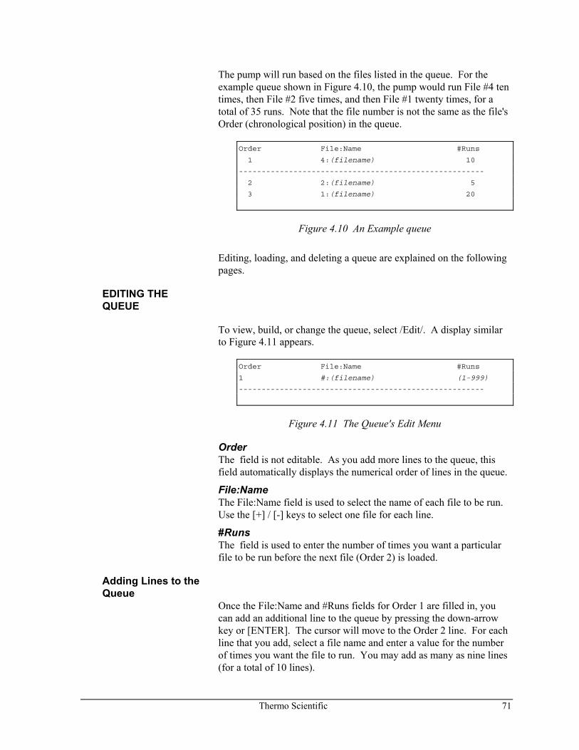
Thermo Scientific 71
The pump will run based on the files listed in the queue. For the example queue shown in Figure 4.10, the pump would run File #4 ten times, then File #2 five times, and then File #1 twenty times, for a total of 35 runs. Note that the file number is not the same as the file's Order (chronological position) in the queue.
Order File:Name #Runs
1 4:(filename) 10
------------------------------------------------------
2 2:(filename) 5
3 1:(filename) 20
Figure 4.10 An Example queue
Editing, loading, and deleting a queue are explained on the following pages.
EDITING THE QUEUE
To view, build, or change the queue, select /Edit/. A display similar to Figure 4.11 appears.
Order File:Name #Runs
1 #:(filename) (1-999)
------------------------------------------------------
Figure 4.11 The Queue's Edit Menu
Order The field is not editable. As you add more lines to the queue, this field automatically displays the numerical order of lines in the queue.
File:Name The File:Name field is used to select the name of each file to be run. Use the [+] / [-] keys to select one file for each line.
#Runs The field is used to enter the number of times you want a particular file to be run before the next file (Order 2) is loaded.
Adding Lines to the Queue
Once the File:Name and #Runs fields for Order 1 are filled in, you can add an additional line to the queue by pressing the down-arrow key or [ENTER]. The cursor will move to the Order 2 line. For each line that you add, select a file name and enter a value for the number of times you want the file to run. You may add as many as nine lines (for a total of 10 lines).
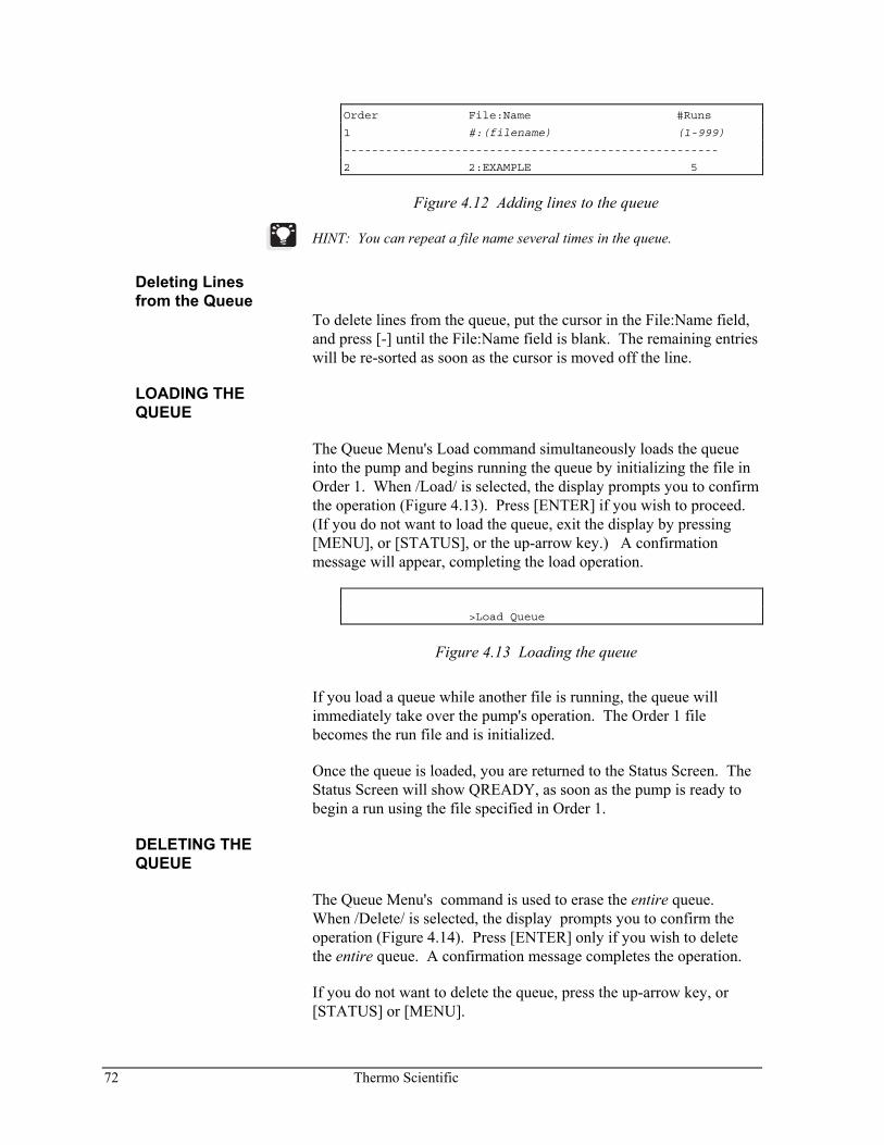
72 Thermo Scientific
Order File:Name #Runs
1 #:(filename) (1-999)
------------------------------------------------------
2 2:EXAMPLE 5
Figure 4.12 Adding lines to the queue
HINT: You can repeat a file name several times in the queue.
Deleting Lines from the Queue
To delete lines from the queue, put the cursor in the File:Name field, and press [-] until the File:Name field is blank. The remaining entries will be re-sorted as soon as the cursor is moved off the line.
LOADING THE QUEUE
The Queue Menu's Load command simultaneously loads the queue into the pump and begins running the queue by initializing the file in Order 1. When /Load/ is selected, the display prompts you to confirm the operation (Figure 4.13). Press [ENTER] if you wish to proceed. (If you do not want to load the queue, exit the display by pressing [MENU], or [STATUS], or the up-arrow key.) A confirmation message will appear, completing the load operation.
>Load Queue
Figure 4.13 Loading the queue
If you load a queue while another file is running, the queue will immediately take over the pump's operation. The Order 1 file becomes the run file and is initialized.
Once the queue is loaded, you are returned to the Status Screen. The Status Screen will show QREADY, as soon as the pump is ready to begin a run using the file specified in Order 1.
DELETING THE QUEUE
The Queue Menu's command is used to erase the entire queue. When /Delete/ is selected, the display prompts you to confirm the operation (Figure 4.14). Press [ENTER] only if you wish to delete the entire queue. A confirmation message completes the operation.
If you do not want to delete the queue, press the up-arrow key, or [STATUS] or [MENU].
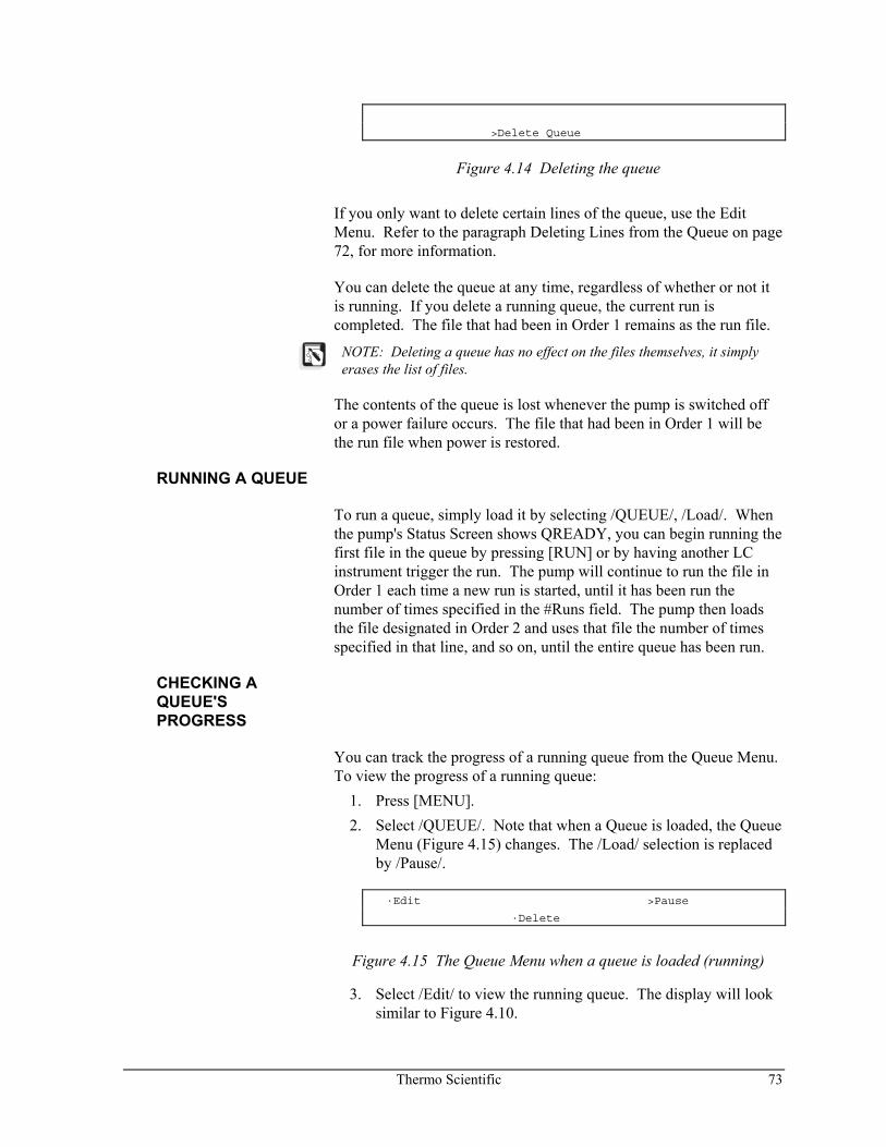
Thermo Scientific 73
>Delete Queue
Figure 4.14 Deleting the queue
If you only want to delete certain lines of the queue, use the Edit Menu. Refer to the paragraph Deleting Lines from the Queue on page 72, for more information.
You can delete the queue at any time, regardless of whether or not it is running. If you delete a running queue, the current run is completed. The file that had been in Order 1 remains as the run file.
NOTE: Deleting a queue has no effect on the files themselves, it simply erases the list of files.
The contents of the queue is lost whenever the pump is switched off or a power failure occurs. The file that had been in Order 1 will be the run file when power is restored.
RUNNING A QUEUE
To run a queue, simply load it by selecting /QUEUE/, /Load/. When the pump's Status Screen shows QREADY, you can begin running the first file in the queue by pressing [RUN] or by having another LC instrument trigger the run. The pump will continue to run the file in Order 1 each time a new run is started, until it has been run the number of times specified in the #Runs field. The pump then loads the file designated in Order 2 and uses that file the number of times specified in that line, and so on, until the entire queue has been run.
CHECKING A QUEUE'S PROGRESS
You can track the progress of a running queue from the Queue Menu. To view the progress of a running queue:
1. Press [MENU]. 2. Select /QUEUE/. Note that when a Queue is loaded, the Queue
Menu (Figure 4.15) changes. The /Load/ selection is replaced by /Pause/.
·Edit >Pause
·Delete
Figure 4.15 The Queue Menu when a queue is loaded (running)
3. Select /Edit/ to view the running queue. The display will look similar to Figure 4.10.
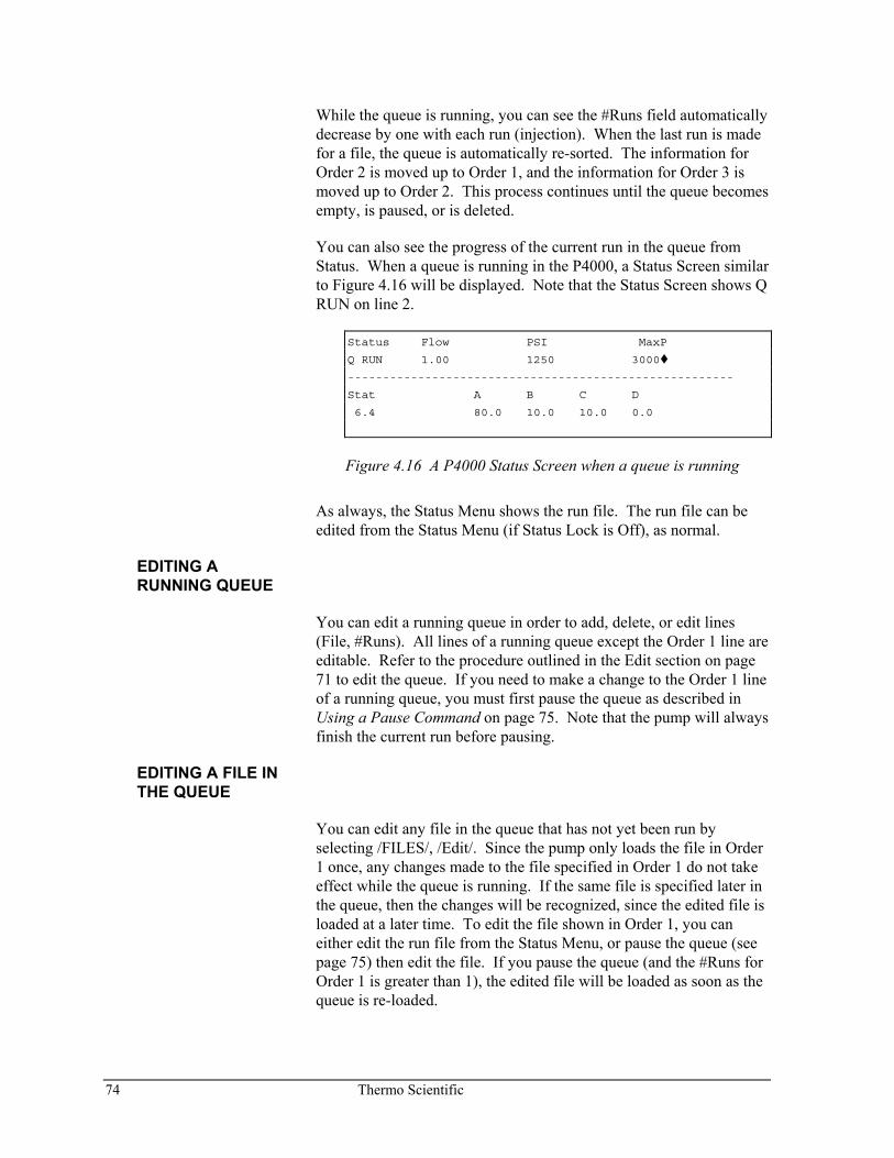
74 Thermo Scientific
While the queue is running, you can see the #Runs field automatically decrease by one with each run (injection). When the last run is made for a file, the queue is automatically re-sorted. The information for Order 2 is moved up to Order 1, and the information for Order 3 is moved up to Order 2. This process continues until the queue becomes empty, is paused, or is deleted.
You can also see the progress of the current run in the queue from Status. When a queue is running in the P4000, a Status Screen similar to Figure 4.16 will be displayed. Note that the Status Screen shows Q RUN on line 2.
Status Flow PSI MaxP
Q RUN 1.00 1250 3000
-------------------------------------------------------
Stat A B C D
6.4 80.0 10.0 10.0 0.0
Figure 4.16 A P4000 Status Screen when a queue is running
As always, the Status Menu shows the run file. The run file can be edited from the Status Menu (if Status Lock is Off), as normal.
EDITING A RUNNING QUEUE
You can edit a running queue in order to add, delete, or edit lines (File, #Runs). All lines of a running queue except the Order 1 line are editable. Refer to the procedure outlined in the Edit section on page 71 to edit the queue. If you need to make a change to the Order 1 line of a running queue, you must first pause the queue as described in Using a Pause Command on page 75. Note that the pump will always finish the current run before pausing.
EDITING A FILE IN THE QUEUE
You can edit any file in the queue that has not yet been run by selecting /FILES/, /Edit/. Since the pump only loads the file in Order 1 once, any changes made to the file specified in Order 1 do not take effect while the queue is running. If the same file is specified later in the queue, then the changes will be recognized, since the edited file is loaded at a later time. To edit the file shown in Order 1, you can either edit the run file from the Status Menu, or pause the queue (see page 75) then edit the file. If you pause the queue (and the #Runs for Order 1 is greater than 1), the edited file will be loaded as soon as the queue is re-loaded.
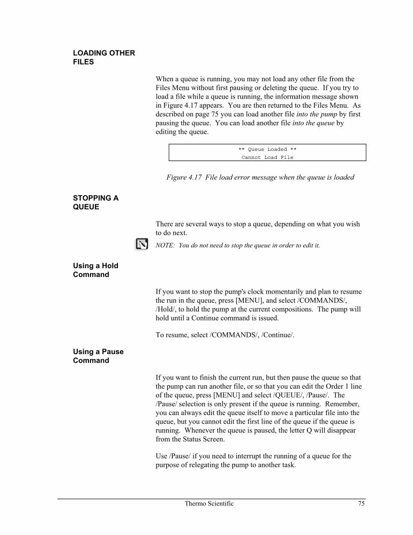
Thermo Scientific 75
LOADING OTHER FILES
When a queue is running, you may not load any other file from the Files Menu without first pausing or deleting the queue. If you try to load a file while a queue is running, the information message shown in Figure 4.17 appears. You are then returned to the Files Menu. As described on page 75 you can load another file into the pump by first pausing the queue. You can load another file into the queue by editing the queue.
** Queue Loaded **
Cannot Load File
Figure 4.17 File load error message when the queue is loaded
STOPPING A QUEUE
There are several ways to stop a queue, depending on what you wish to do next.
NOTE: You do not need to stop the queue in order to edit it.
Using a Hold Command
If you want to stop the pump's clock momentarily and plan to resume the run in the queue, press [MENU], and select /COMMANDS/, /Hold/, to hold the pump at the current compositions. The pump will hold until a Continue command is issued.
To resume, select /COMMANDS/, /Continue/.
Using a Pause Command
If you want to finish the current run, but then pause the queue so that the pump can run another file, or so that you can edit the Order 1 line of the queue, press [MENU] and select /QUEUE/, /Pause/. The /Pause/ selection is only present if the queue is running. Remember, you can always edit the queue itself to move a particular file into the queue, but you cannot edit the first line of the queue if the queue is running. Whenever the queue is paused, the letter Q will disappear from the Status Screen.
Use /Pause/ if you need to interrupt the running of a queue for the purpose of relegating the pump to another task.
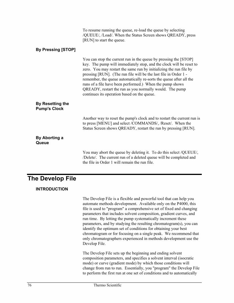
76 Thermo Scientific
To resume running the queue, re-load the queue by selecting /QUEUE/, /Load/. When the Status Screen shows QREADY, press [RUN] to start the queue.
By Pressing [STOP]
You can stop the current run in the queue by pressing the [STOP] key. The pump will immediately stop, and the clock will be reset to zero. You may restart the same run by initializing the run file by pressing [RUN]. (The run file will be the last file in Order 1 - remember, the queue automatically re-sorts the queue after all the runs of a file have been performed.) When the pump shows QREADY, restart the run as you normally would. The pump continues its operation based on the queue.
By Resetting the Pump's Clock
Another way to reset the pump's clock and to restart the current run is to press [MENU] and select /COMMANDS/, /Reset/. When the Status Screen shows QREADY, restart the run by pressing [RUN].
By Aborting a Queue
You may abort the queue by deleting it. To do this select /QUEUE/, /Delete/. The current run of a deleted queue will be completed and the file in Order 1 will remain the run file.
The Develop File INTRODUCTION
The Develop File is a flexible and powerful tool that can help you automate methods development. Available only on the P4000, this file is used to "program" a comprehensive set of fixed and changing parameters that includes solvent composition, gradient curves, and run time. By letting the pump systematically increment these parameters, and by studying the resulting chromatogram(s), you can identify the optimum set of conditions for obtaining your best chromatogram or for focusing on a single peak. We recommend that only chromatographers experienced in methods development use the Develop File.
The Develop File sets up the beginning and ending solvent composition parameters, and specifies a solvent interval (isocratic mode) or curve (gradient mode) by which those conditions will change from run to run. Essentially, you "program" the Develop File to perform the first run at one set of conditions and to automatically
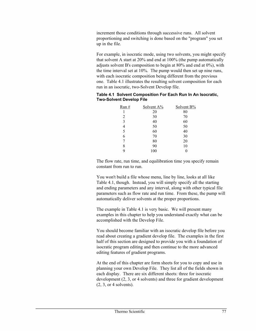
Thermo Scientific 77
increment those conditions through successive runs. All solvent proportioning and switching is done based on the "program" you set up in the file.
For example, in isocratic mode, using two solvents, you might specify that solvent A start at 20% and end at 100% (the pump automatically adjusts solvent B's composition to begin at 80% and end at 0%), with the time interval set at 10%. The pump would then set up nine runs, with each isocratic composition being different from the previous one. Table 4.1 illustrates the resulting solvent composition for each run in an isocratic, two-Solvent Develop file.
Table 4.1 Solvent Composition For Each Run In An Isocratic, Two-Solvent Develop File
Run # Solvent A% Solvent B% 1 20 80 2 30 70 3 40 60 4 50 50 5 60 40 6 70 30 7 80 20 8 90 10 9 100 0
The flow rate, run time, and equilibration time you specify remain constant from run to run.
You won't build a file whose menu, line by line, looks at all like Table 4.1, though. Instead, you will simply specify all the starting and ending parameters and any interval, along with other typical file parameters such as flow rate and run time. From these, the pump will automatically deliver solvents at the proper proportions.
The example in Table 4.1 is very basic. We will present many examples in this chapter to help you understand exactly what can be accomplished with the Develop File.
You should become familiar with an isocratic develop file before you read about creating a gradient develop file. The examples in the first half of this section are designed to provide you with a foundation of isocratic program editing and then continue to the more advanced editing features of gradient programs.
At the end of this chapter are form sheets for you to copy and use in planning your own Develop File. They list all of the fields shown in each display. There are six different sheets: three for isocratic development (2, 3, or 4 solvents) and three for gradient development (2, 3, or 4 solvents).
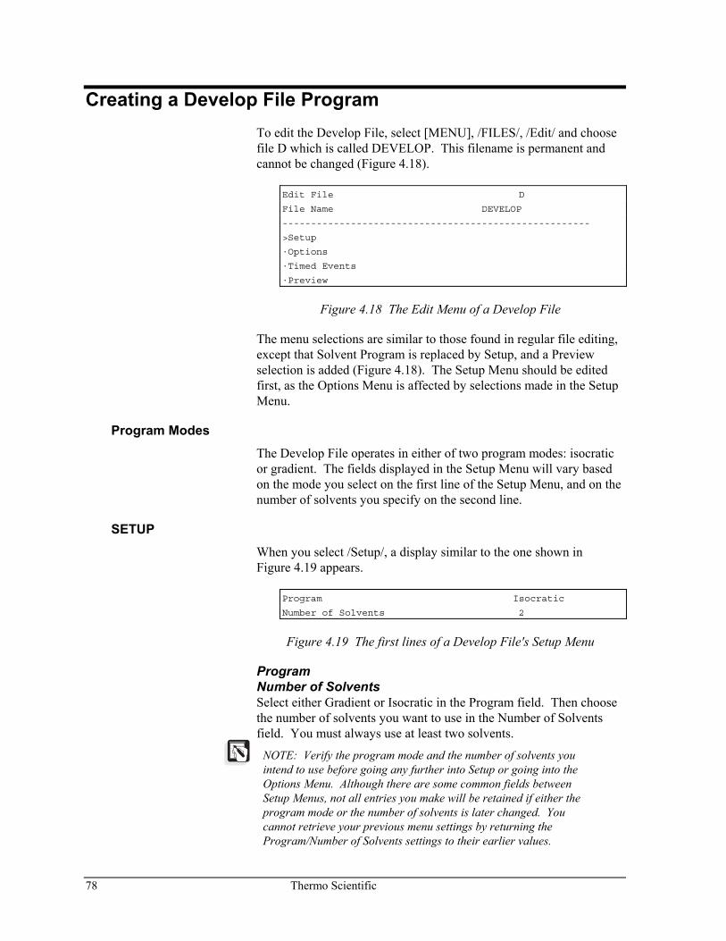
78 Thermo Scientific
Creating a Develop File Program To edit the Develop File, select [MENU], /FILES/, /Edit/ and choose file D which is called DEVELOP. This filename is permanent and cannot be changed (Figure 4.18).
Edit File D
File Name DEVELOP
------------------------------------------------------
>Setup
·Options
·Timed Events
·Preview
Figure 4.18 The Edit Menu of a Develop File
The menu selections are similar to those found in regular file editing, except that Solvent Program is replaced by Setup, and a Preview selection is added (Figure 4.18). The Setup Menu should be edited first, as the Options Menu is affected by selections made in the Setup Menu.
Program Modes The Develop File operates in either of two program modes: isocratic or gradient. The fields displayed in the Setup Menu will vary based on the mode you select on the first line of the Setup Menu, and on the number of solvents you specify on the second line.
SETUP When you select /Setup/, a display similar to the one shown in Figure 4.19 appears.
Program Isocratic
Number of Solvents 2
Figure 4.19 The first lines of a Develop File's Setup Menu
Program Number of Solvents Select either Gradient or Isocratic in the Program field. Then choose the number of solvents you want to use in the Number of Solvents field. You must always use at least two solvents.
NOTE: Verify the program mode and the number of solvents you intend to use before going any further into Setup or going into the Options Menu. Although there are some common fields between Setup Menus, not all entries you make will be retained if either the program mode or the number of solvents is later changed. You cannot retrieve your previous menu settings by returning the Program/Number of Solvents settings to their earlier values.
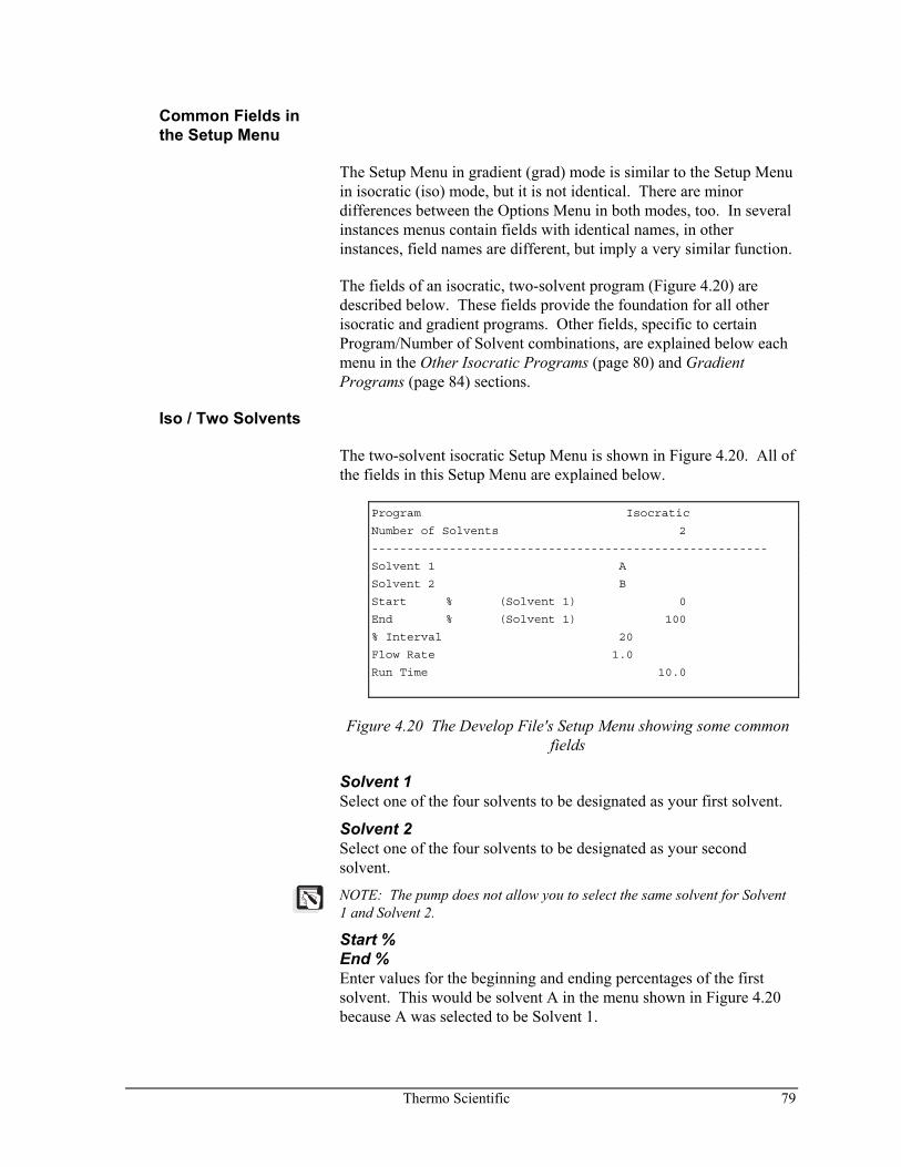
Thermo Scientific 79
Common Fields in the Setup Menu
The Setup Menu in gradient (grad) mode is similar to the Setup Menu in isocratic (iso) mode, but it is not identical. There are minor differences between the Options Menu in both modes, too. In several instances menus contain fields with identical names, in other instances, field names are different, but imply a very similar function.
The fields of an isocratic, two-solvent program (Figure 4.20) are described below. These fields provide the foundation for all other isocratic and gradient programs. Other fields, specific to certain Program/Number of Solvent combinations, are explained below each menu in the Other Isocratic Programs (page 80) and Gradient Programs (page 84) sections.
Iso / Two Solvents
The two-solvent isocratic Setup Menu is shown in Figure 4.20. All of the fields in this Setup Menu are explained below.
Program Isocratic
Number of Solvents 2
--------------------------------------------------------
Solvent 1 A
Solvent 2 B
Start % (Solvent 1) 0
End % (Solvent 1) 100
% Interval 20
Flow Rate 1.0
Run Time 10.0
Figure 4.20 The Develop File's Setup Menu showing some common fields
Solvent 1 Select one of the four solvents to be designated as your first solvent.
Solvent 2 Select one of the four solvents to be designated as your second solvent.
NOTE: The pump does not allow you to select the same solvent for Solvent 1 and Solvent 2.
Start % End % Enter values for the beginning and ending percentages of the first solvent. This would be solvent A in the menu shown in Figure 4.20 because A was selected to be Solvent 1.
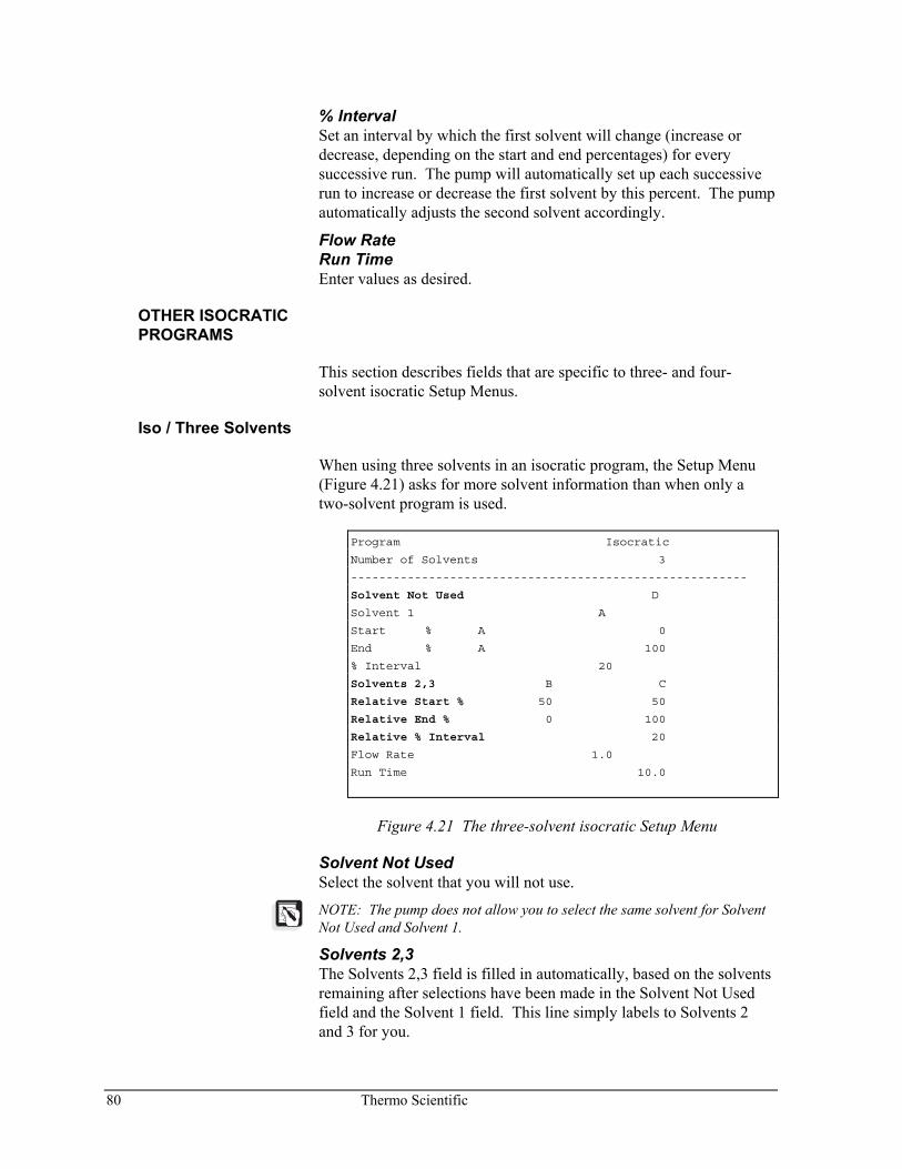
80 Thermo Scientific
% Interval Set an interval by which the first solvent will change (increase or decrease, depending on the start and end percentages) for every successive run. The pump will automatically set up each successive run to increase or decrease the first solvent by this percent. The pump automatically adjusts the second solvent accordingly.
Flow Rate Run Time Enter values as desired.
OTHER ISOCRATIC PROGRAMS
This section describes fields that are specific to three- and four- solvent isocratic Setup Menus.
Iso / Three Solvents
When using three solvents in an isocratic program, the Setup Menu (Figure 4.21) asks for more solvent information than when only a two-solvent program is used.
Program Isocratic
Number of Solvents 3
--------------------------------------------------------
Solvent Not Used D
Solvent 1 A
Start % A 0
End % A 100
% Interval 20
Solvents 2,3 B C
Relative Start % 50 50
Relative End % 0 100
Relative % Interval 20
Flow Rate 1.0
Run Time 10.0
Figure 4.21 The three-solvent isocratic Setup Menu
Solvent Not Used Select the solvent that you will not use.
NOTE: The pump does not allow you to select the same solvent for Solvent Not Used and Solvent 1.
Solvents 2,3 The Solvents 2,3 field is filled in automatically, based on the solvents remaining after selections have been made in the Solvent Not Used field and the Solvent 1 field. This line simply labels to Solvents 2 and 3 for you.
Thermo Scientific 81
RelativeStart % There are two fields on the RelativeStart % line. These correspond to Solvents 2 and 3. The relative start percentages for the two solvents always add to 100. You enter a value for Solvent 2. Solvent 3 is entered automatically. The values in these fields are relative to Solvent 1's composition.
For example, if the Start % of Solvent 1 were 60%, then the remaining 40% would be comprised of a combination of solvents 2 and 3. If you want the relative ratio of Solvents 2 and 3 to be 50 / 50, you would enter a RelativeStart % of 50 for Solvent 2. Then, the actual proportions delivered by the pump would be:
Solvent 1 60% Solvent 2 20% (40% × 0.5 = 20) Solvent 3 20% (40% × 0.5 = 20)
The total of all solvents is 100%.
If solvents 2 and 3 were not entered as 50 / 50, but 20 / 80 instead, then the actual proportions delivered by the pump would be:
Solvent 1 60% Solvent 2 8% (40% × 0.2 = 8) Solvent 3 32% (40% × 0.8 = 32)
You do not need to make these calculations yourself to see what the pump will actually do. After you complete your program in the Setup Menu, you can preview the composition of the resulting runs by selecting /Preview/ as described in conjunction with several examples beginning on page 87.
Relative End % Enter a value for the relative end % of Solvent 2. Solvent 3 is entered automatically.
Relative % Interval Enter a value for the relative percent increment from run to run of Solvents 2 and 3. If you do not wish to increment Solvents 2 and 3, make sure the Relative End % is the same as the RelativeStart %.
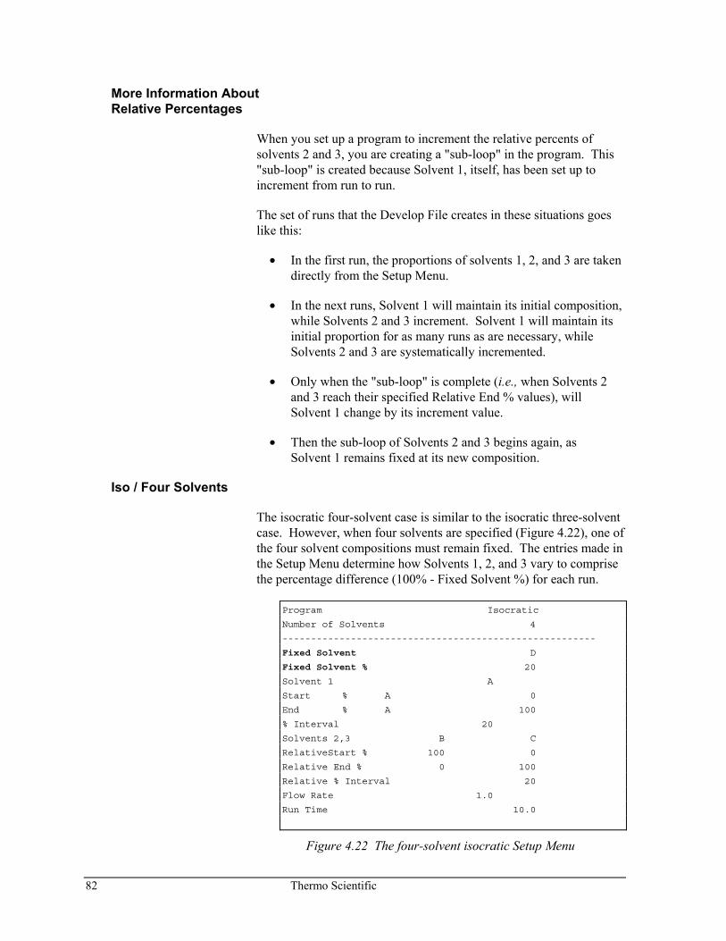
82 Thermo Scientific
More Information About Relative Percentages
When you set up a program to increment the relative percents of solvents 2 and 3, you are creating a "sub-loop" in the program. This "sub-loop" is created because Solvent 1, itself, has been set up to increment from run to run.
The set of runs that the Develop File creates in these situations goes like this:
• In the first run, the proportions of solvents 1, 2, and 3 are taken directly from the Setup Menu.
• In the next runs, Solvent 1 will maintain its initial composition, while Solvents 2 and 3 increment. Solvent 1 will maintain its initial proportion for as many runs as are necessary, while Solvents 2 and 3 are systematically incremented.
• Only when the "sub-loop" is complete (i.e., when Solvents 2 and 3 reach their specified Relative End % values), will Solvent 1 change by its increment value.
• Then the sub-loop of Solvents 2 and 3 begins again, as Solvent 1 remains fixed at its new composition.
Iso / Four Solvents
The isocratic four-solvent case is similar to the isocratic three-solvent case. However, when four solvents are specified (Figure 4.22), one of the four solvent compositions must remain fixed. The entries made in the Setup Menu determine how Solvents 1, 2, and 3 vary to comprise the percentage difference (100% - Fixed Solvent %) for each run.
Program Isocratic
Number of Solvents 4
-------------------------------------------------------
Fixed Solvent D
Fixed Solvent % 20
Solvent 1 A
Start % A 0
End % A 100
% Interval 20
Solvents 2,3 B C
RelativeStart % 100 0
Relative End % 0 100
Relative % Interval 20
Flow Rate 1.0
Run Time 10.0
Figure 4.22 The four-solvent isocratic Setup Menu
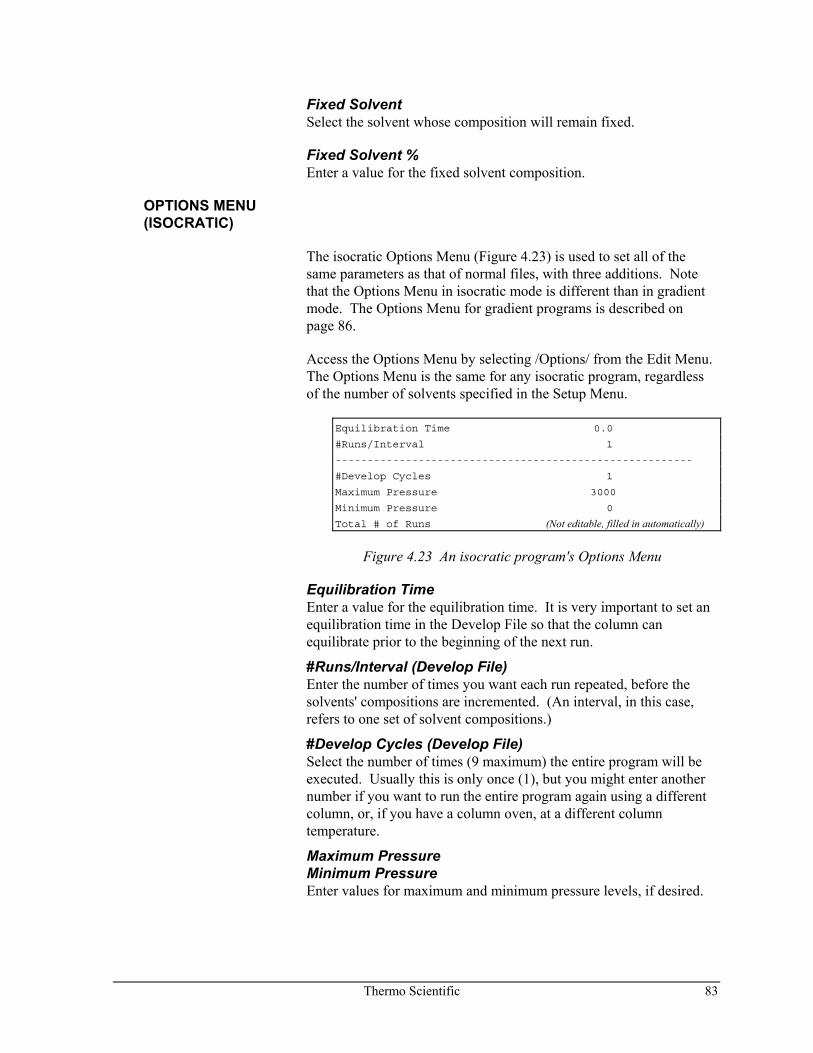
Thermo Scientific 83
Fixed Solvent Select the solvent whose composition will remain fixed.
Fixed Solvent % Enter a value for the fixed solvent composition.
OPTIONS MENU (ISOCRATIC)
The isocratic Options Menu (Figure 4.23) is used to set all of the same parameters as that of normal files, with three additions. Note that the Options Menu in isocratic mode is different than in gradient mode. The Options Menu for gradient programs is described on page 86.
Access the Options Menu by selecting /Options/ from the Edit Menu. The Options Menu is the same for any isocratic program, regardless of the number of solvents specified in the Setup Menu.
Equilibration Time 0.0
#Runs/Interval 1
--------------------------------------------------------
#Develop Cycles 1
Maximum Pressure 3000
Minimum Pressure 0
Total # of Runs (Not editable, filled in automatically)
Figure 4.23 An isocratic program's Options Menu
Equilibration Time Enter a value for the equilibration time. It is very important to set an equilibration time in the Develop File so that the column can equilibrate prior to the beginning of the next run.
#Runs/Interval (Develop File) Enter the number of times you want each run repeated, before the solvents' compositions are incremented. (An interval, in this case, refers to one set of solvent compositions.)
#Develop Cycles (Develop File) Select the number of times (9 maximum) the entire program will be executed. Usually this is only once (1), but you might enter another number if you want to run the entire program again using a different column, or, if you have a column oven, at a different column temperature.
Maximum Pressure Minimum Pressure Enter values for maximum and minimum pressure levels, if desired.
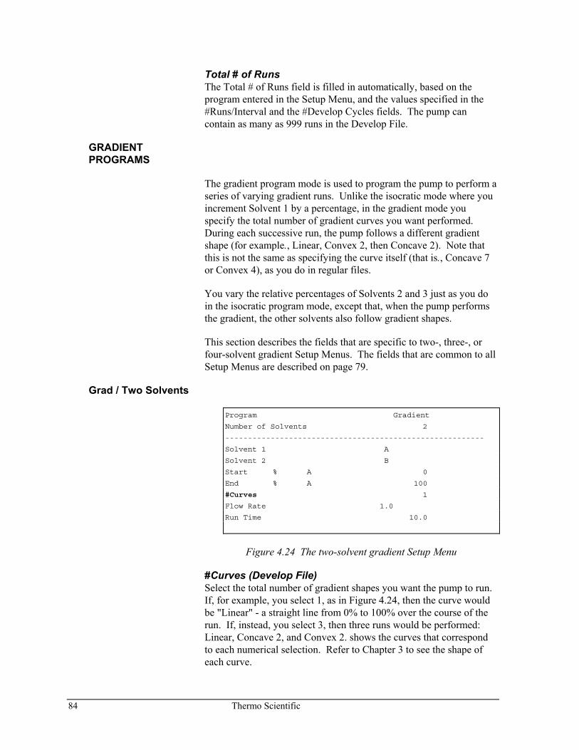
84 Thermo Scientific
Total # of Runs The Total # of Runs field is filled in automatically, based on the program entered in the Setup Menu, and the values specified in the #Runs/Interval and the #Develop Cycles fields. The pump can contain as many as 999 runs in the Develop File.
GRADIENT PROGRAMS
The gradient program mode is used to program the pump to perform a series of varying gradient runs. Unlike the isocratic mode where you increment Solvent 1 by a percentage, in the gradient mode you specify the total number of gradient curves you want performed. During each successive run, the pump follows a different gradient shape (for example., Linear, Convex 2, then Concave 2). Note that this is not the same as specifying the curve itself (that is., Concave 7 or Convex 4), as you do in regular files.
You vary the relative percentages of Solvents 2 and 3 just as you do in the isocratic program mode, except that, when the pump performs the gradient, the other solvents also follow gradient shapes.
This section describes the fields that are specific to two-, three-, or four-solvent gradient Setup Menus. The fields that are common to all Setup Menus are described on page 79.
Grad / Two Solvents
Program Gradient
Number of Solvents 2
---------------------------------------------------------
Solvent 1 A
Solvent 2 B
Start % A 0
End % A 100
#Curves 1
Flow Rate 1.0
Run Time 10.0
Figure 4.24 The two-solvent gradient Setup Menu
#Curves (Develop File) Select the total number of gradient shapes you want the pump to run. If, for example, you select 1, as in Figure 4.24, then the curve would be "Linear" - a straight line from 0% to 100% over the course of the run. If, instead, you select 3, then three runs would be performed: Linear, Concave 2, and Convex 2. shows the curves that correspond to each numerical selection. Refer to Chapter 3 to see the shape of each curve.
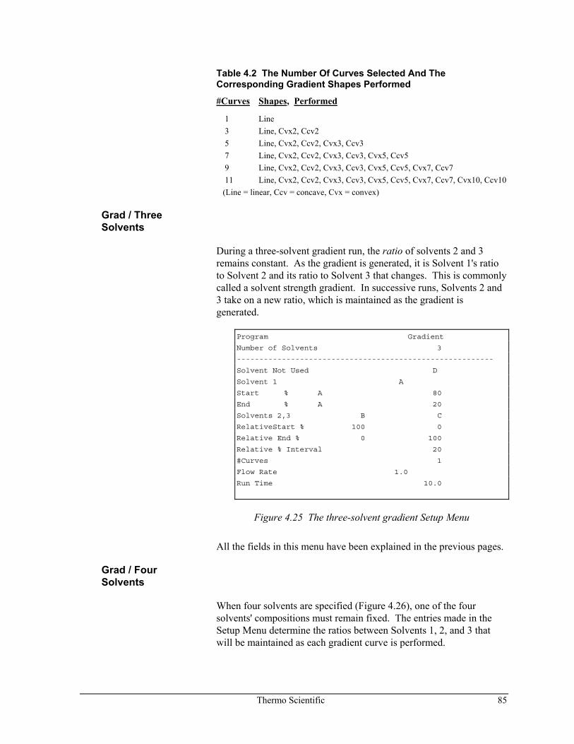
Thermo Scientific 85
Table 4.2 The Number Of Curves Selected And The Corresponding Gradient Shapes Performed
#Curves Shapes, Performed
1 Line 3 Line, Cvx2, Ccv2 5 Line, Cvx2, Ccv2, Cvx3, Ccv3 7 Line, Cvx2, Ccv2, Cvx3, Ccv3, Cvx5, Ccv5 9 Line, Cvx2, Ccv2, Cvx3, Ccv3, Cvx5, Ccv5, Cvx7, Ccv7 11 Line, Cvx2, Ccv2, Cvx3, Ccv3, Cvx5, Ccv5, Cvx7, Ccv7, Cvx10, Ccv10 (Line = linear, Ccv = concave, Cvx = convex)
Grad / Three Solvents
During a three-solvent gradient run, the ratio of solvents 2 and 3 remains constant. As the gradient is generated, it is Solvent 1's ratio to Solvent 2 and its ratio to Solvent 3 that changes. This is commonly called a solvent strength gradient. In successive runs, Solvents 2 and 3 take on a new ratio, which is maintained as the gradient is generated.
Program Gradient
Number of Solvents 3
---------------------------------------------------------
Solvent Not Used D
Solvent 1 A
Start % A 80
End % A 20
Solvents 2,3 B C
RelativeStart % 100 0
Relative End % 0 100
Relative % Interval 20
#Curves 1
Flow Rate 1.0
Run Time 10.0
Figure 4.25 The three-solvent gradient Setup Menu
All the fields in this menu have been explained in the previous pages.
Grad / Four Solvents
When four solvents are specified (Figure 4.26), one of the four solvents' compositions must remain fixed. The entries made in the Setup Menu determine the ratios between Solvents 1, 2, and 3 that will be maintained as each gradient curve is performed.
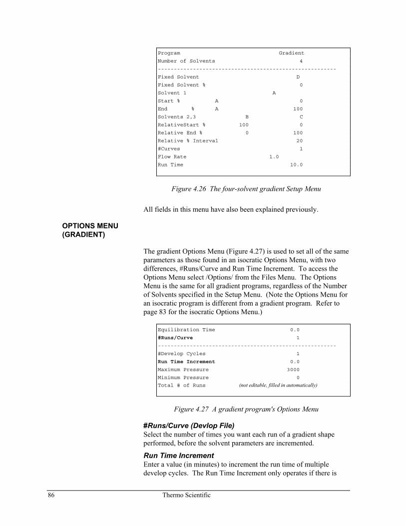
86 Thermo Scientific
Program Gradient
Number of Solvents 4
--------------------------------------------------------
Fixed Solvent D
Fixed Solvent % 0
Solvent 1 A
Start % A 0
End % A 100
Solvents 2,3 B C
RelativeStart % 100 0
Relative End % 0 100
Relative % Interval 20
#Curves 1
Flow Rate 1.0
Run Time 10.0
Figure 4.26 The four-solvent gradient Setup Menu
All fields in this menu have also been explained previously.
OPTIONS MENU (GRADIENT)
The gradient Options Menu (Figure 4.27) is used to set all of the same parameters as those found in an isocratic Options Menu, with two differences, #Runs/Curve and Run Time Increment. To access the Options Menu select /Options/ from the Files Menu. The Options Menu is the same for all gradient programs, regardless of the Number of Solvents specified in the Setup Menu. (Note the Options Menu for an isocratic program is different from a gradient program. Refer to page 83 for the isocratic Options Menu.)
Equilibration Time 0.0
#Runs/Curve 1
--------------------------------------------------------
#Develop Cycles 1
Run Time Increment 0.0
Maximum Pressure 3000
Minimum Pressure 0
Total # of Runs (not editable, filled in automatically)
Figure 4.27 A gradient program's Options Menu
#Runs/Curve (Devlop File) Select the number of times you want each run of a gradient shape performed, before the solvent parameters are incremented.
Run Time Increment Enter a value (in minutes) to increment the run time of multiple develop cycles. The Run Time Increment only operates if there is
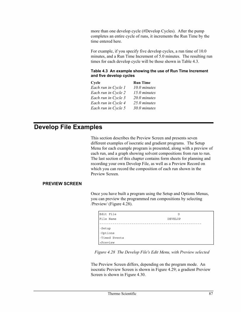
Thermo Scientific 87
more than one develop cycle (#Develop Cycles). After the pump completes an entire cycle of runs, it increments the Run Time by the time entered here.
For example, if you specify five develop cycles, a run time of 10.0 minutes, and a Run Time Increment of 5.0 minutes. The resulting run times for each develop cycle will be those shown in Table 4.3.
Table 4.3 An example showing the use of Run Time Increment and five develop cycles
Cycle Run Time Each run in Cycle 1 10.0 minutes Each run in Cycle 2 15.0 minutes Each run in Cycle 3 20.0 minutes Each run in Cycle 4 25.0 minutes Each run in Cycle 5 30.0 minutes
Develop File Examples This section describes the Preview Screen and presents seven different examples of isocratic and gradient programs. The Setup Menu for each example program is presented, along with a preview of each run, and a graph showing solvent compositions from run to run. The last section of this chapter contains form sheets for planning and recording your own Develop File, as well as a Preview Record on which you can record the composition of each run shown in the Preview Screen.
PREVIEW SCREEN
Once you have built a program using the Setup and Options Menus, you can preview the programmed run compositions by selecting /Preview/ (Figure 4.28).
Edit File D
File Name DEVELOP
------------------------------------------------------
·Setup
·Options
·Timed Events
>Preview
Figure 4.28 The Develop File's Edit Menu, with Preview selected
The Preview Screen differs, depending on the program mode. An isocratic Preview Screen is shown in Figure 4.29; a gradient Preview Screen is shown in Figure 4.30.
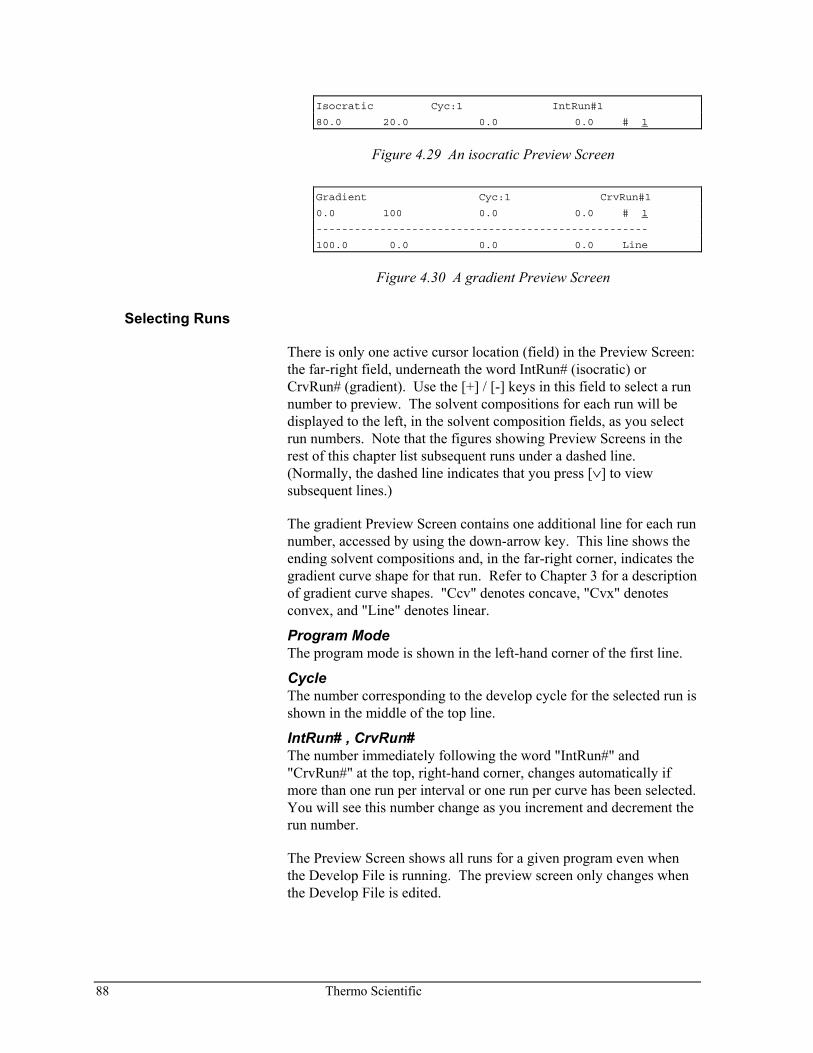
88 Thermo Scientific
Isocratic Cyc:1 IntRun#1
80.0 20.0 0.0 0.0 # 1
Figure 4.29 An isocratic Preview Screen
Gradient Cyc:1 CrvRun#1
0.0 100 0.0 0.0 # 1
----------------------------------------------------
100.0 0.0 0.0 0.0 Line
Figure 4.30 A gradient Preview Screen
Selecting Runs
There is only one active cursor location (field) in the Preview Screen: the far-right field, underneath the word IntRun# (isocratic) or CrvRun# (gradient). Use the [+] / [-] keys in this field to select a run number to preview. The solvent compositions for each run will be displayed to the left, in the solvent composition fields, as you select run numbers. Note that the figures showing Preview Screens in the rest of this chapter list subsequent runs under a dashed line. (Normally, the dashed line indicates that you press [∨] to view subsequent lines.)
The gradient Preview Screen contains one additional line for each run number, accessed by using the down-arrow key. This line shows the ending solvent compositions and, in the far-right corner, indicates the gradient curve shape for that run. Refer to Chapter 3 for a description of gradient curve shapes. "Ccv" denotes concave, "Cvx" denotes convex, and "Line" denotes linear.
Program Mode The program mode is shown in the left-hand corner of the first line.
Cycle The number corresponding to the develop cycle for the selected run is shown in the middle of the top line.
IntRun# , CrvRun# The number immediately following the word "IntRun#" and "CrvRun#" at the top, right-hand corner, changes automatically if more than one run per interval or one run per curve has been selected. You will see this number change as you increment and decrement the run number.
The Preview Screen shows all runs for a given program even when the Develop File is running. The preview screen only changes when the Develop File is edited.
Thermo Scientific 89
EXAMPLE 1 ISO / TWO SOLVENTS
This example shows a two-solvent isocratic program (Figure 4.31). Solvent A starts at 20% and will increment 20% for each run until it reaches the last run at 80%. The total number of runs is four (4).
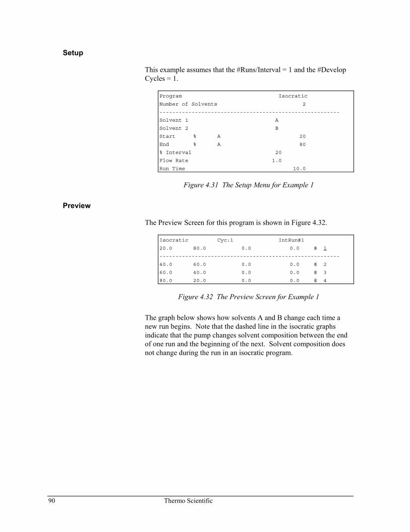
90 Thermo Scientific
Setup
This example assumes that the #Runs/Interval = 1 and the #Develop Cycles = 1.
Program Isocratic
Number of Solvents 2
--------------------------------------------------------
Solvent 1 A
Solvent 2 B
Start % A 20
End % A 80
% Interval 20
Flow Rate 1.0
Run Time 10.0
Figure 4.31 The Setup Menu for Example 1
Preview
The Preview Screen for this program is shown in Figure 4.32.
Isocratic Cyc:1 IntRun#1
20.0 80.0 0.0 0.0 # 1
--------------------------------------------------------
40.0 60.0 0.0 0.0 # 2
60.0 40.0 0.0 0.0 # 3
80.0 20.0 0.0 0.0 # 4
Figure 4.32 The Preview Screen for Example 1
The graph below shows how solvents A and B change each time a new run begins. Note that the dashed line in the isocratic graphs indicate that the pump changes solvent composition between the end of one run and the beginning of the next. Solvent composition does not change during the run in an isocratic program.
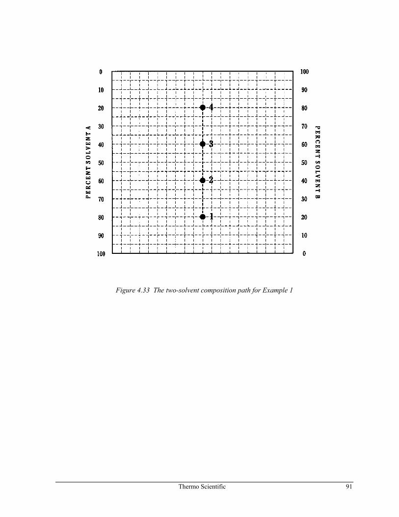
Thermo Scientific 91
Figure 4.33 The two-solvent composition path for Example 1
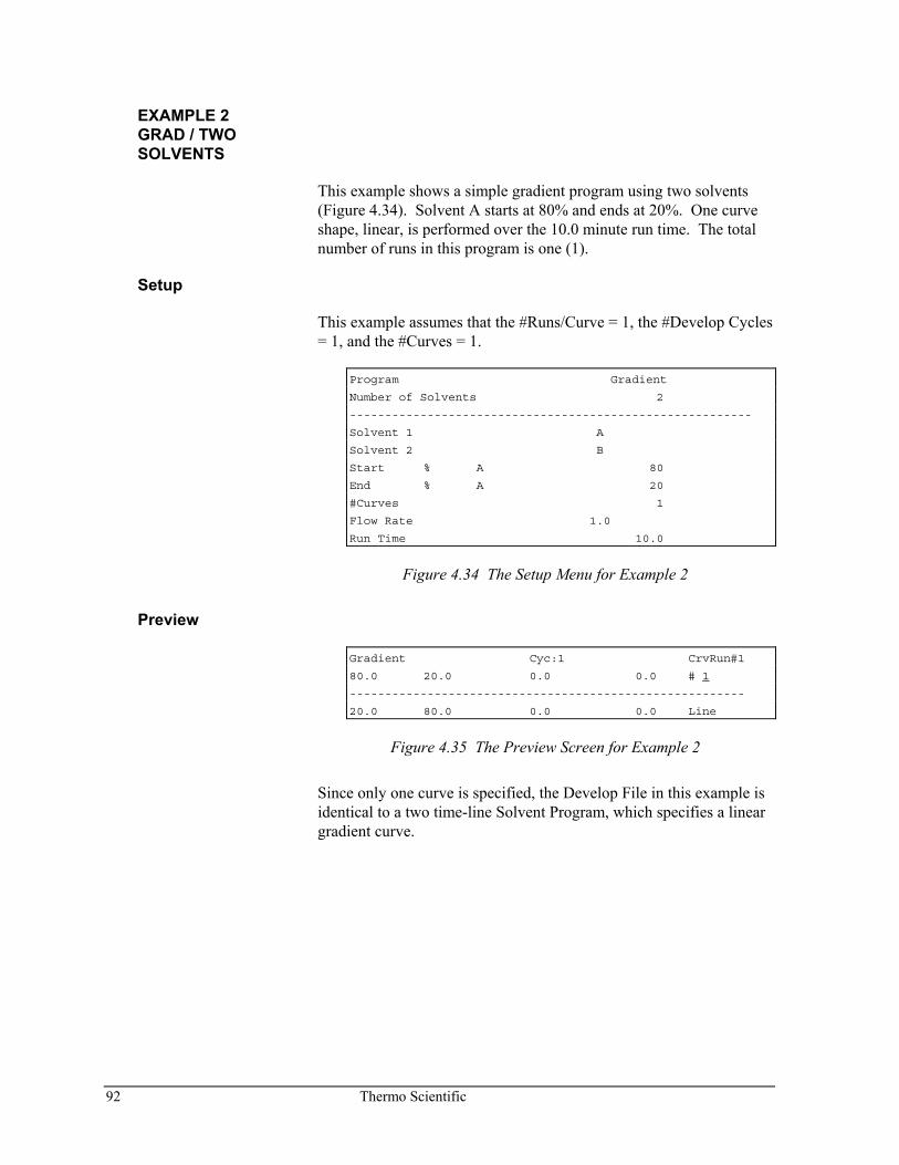
92 Thermo Scientific
EXAMPLE 2 GRAD / TWO SOLVENTS
This example shows a simple gradient program using two solvents (Figure 4.34). Solvent A starts at 80% and ends at 20%. One curve shape, linear, is performed over the 10.0 minute run time. The total number of runs in this program is one (1).
Setup
This example assumes that the #Runs/Curve = 1, the #Develop Cycles = 1, and the #Curves = 1.
Program Gradient
Number of Solvents 2
---------------------------------------------------------
Solvent 1 A
Solvent 2 B
Start % A 80
End % A 20
#Curves 1
Flow Rate 1.0
Run Time 10.0
Figure 4.34 The Setup Menu for Example 2
Preview
Gradient Cyc:1 CrvRun#1
80.0 20.0 0.0 0.0 # 1
--------------------------------------------------------
20.0 80.0 0.0 0.0 Line
Figure 4.35 The Preview Screen for Example 2
Since only one curve is specified, the Develop File in this example is identical to a two time-line Solvent Program, which specifies a linear gradient curve.
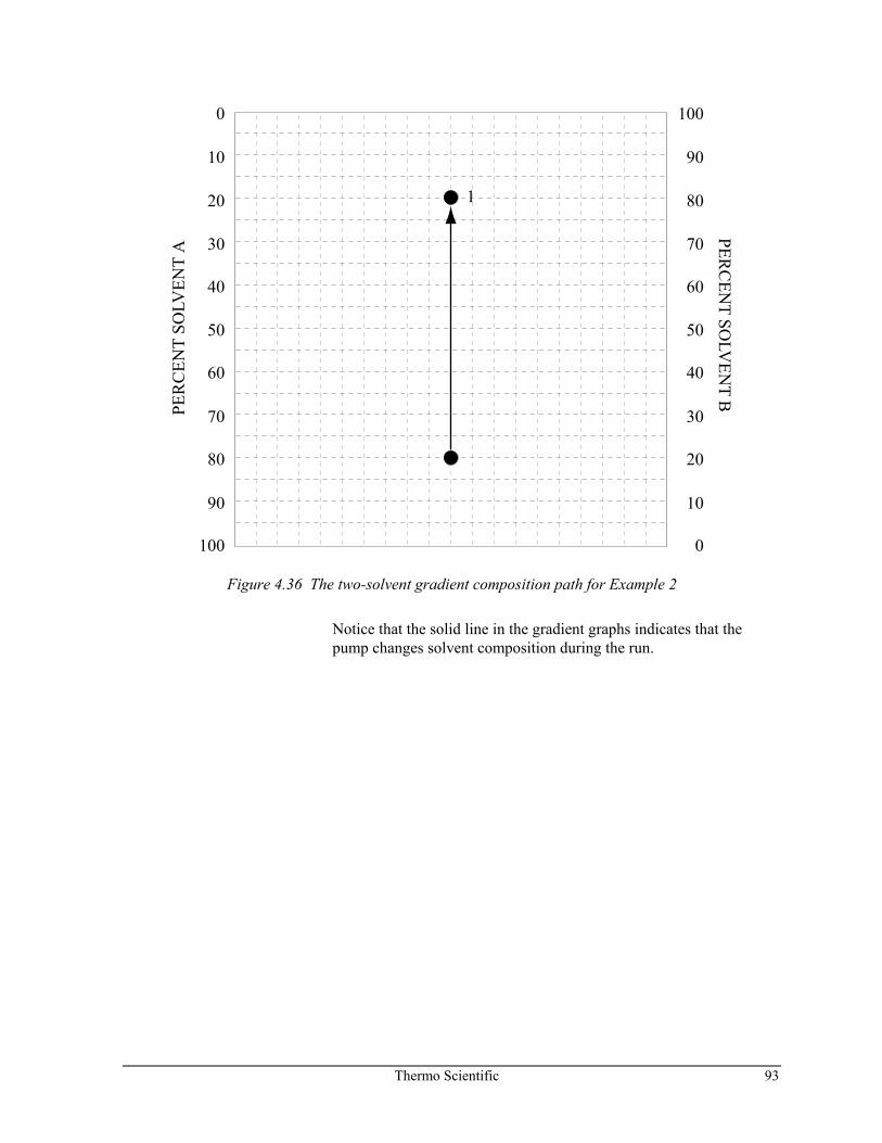
Thermo Scientific 93
0
10
20
30
40
50
60
70
80
90
100 0
10
20
30
40
50
60
70
80
90
100
1PE
RC
ENT
SOLV
ENT
APER
CEN
T SOLV
ENT B
Figure 4.36 The two-solvent gradient composition path for Example 2
Notice that the solid line in the gradient graphs indicates that the pump changes solvent composition during the run.
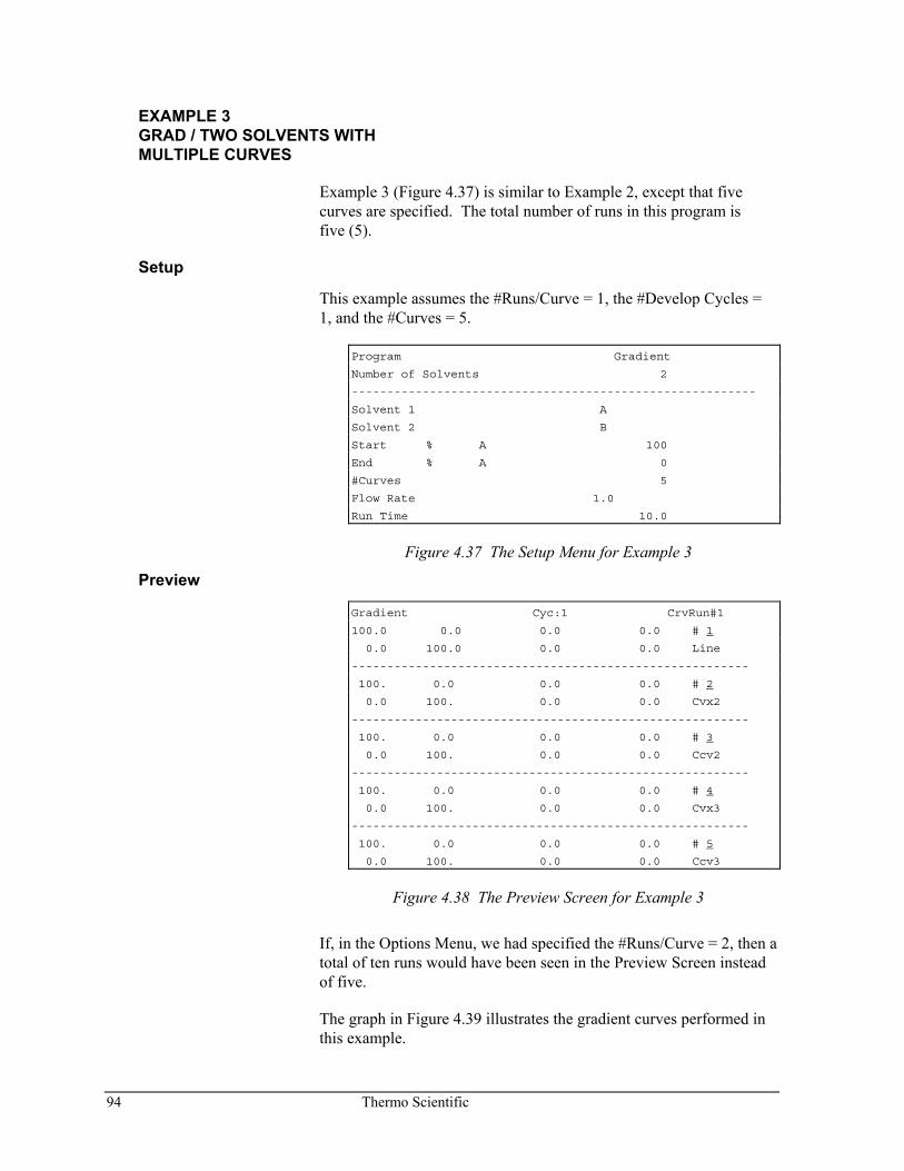
94 Thermo Scientific
EXAMPLE 3 GRAD / TWO SOLVENTS WITH MULTIPLE CURVES
Example 3 (Figure 4.37) is similar to Example 2, except that five curves are specified. The total number of runs in this program is five (5).
Setup
This example assumes the #Runs/Curve = 1, the #Develop Cycles = 1, and the #Curves = 5.
Program Gradient
Number of Solvents 2
---------------------------------------------------------
Solvent 1 A
Solvent 2 B
Start % A 100
End % A 0
#Curves 5
Flow Rate 1.0
Run Time 10.0
Figure 4.37 The Setup Menu for Example 3
Preview
Gradient Cyc:1 CrvRun#1
100.0 0.0 0.0 0.0 # 1
0.0 100.0 0.0 0.0 Line
--------------------------------------------------------
100. 0.0 0.0 0.0 # 2
0.0 100. 0.0 0.0 Cvx2
--------------------------------------------------------
100. 0.0 0.0 0.0 # 3
0.0 100. 0.0 0.0 Ccv2
--------------------------------------------------------
100. 0.0 0.0 0.0 # 4
0.0 100. 0.0 0.0 Cvx3
--------------------------------------------------------
100. 0.0 0.0 0.0 # 5
0.0 100. 0.0 0.0 Ccv3
Figure 4.38 The Preview Screen for Example 3
If, in the Options Menu, we had specified the #Runs/Curve = 2, then a total of ten runs would have been seen in the Preview Screen instead of five.
The graph in Figure 4.39 illustrates the gradient curves performed in this example.
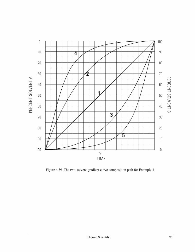
Thermo Scientific 95
Figure 4.39 The two-solvent gradient curve composition path for Example 3
5
3
1
2
4
0
10
20
30
40
50
60
70
80
90
1005
TIME
PERCENT SO
LVENT BPE
RCEN
T SO
LVEN
T A
100
90
80
70
60
50
40
30
20
10
0
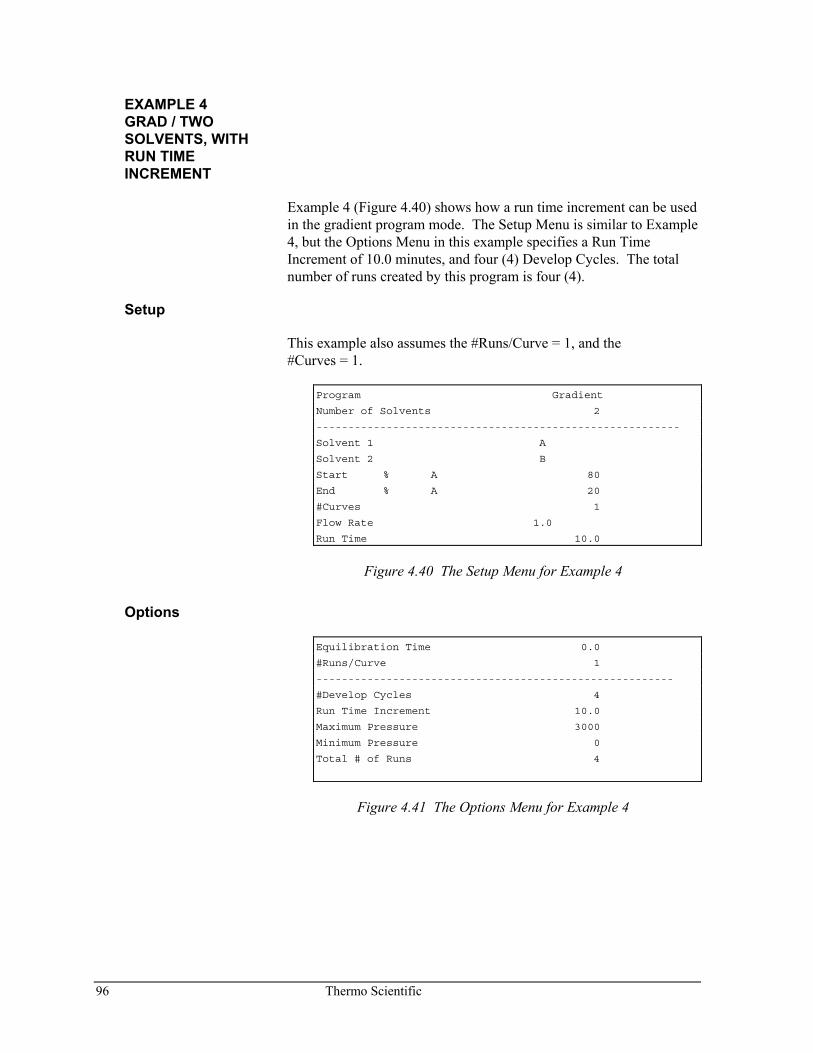
96 Thermo Scientific
EXAMPLE 4 GRAD / TWO SOLVENTS, WITH RUN TIME INCREMENT
Example 4 (Figure 4.40) shows how a run time increment can be used in the gradient program mode. The Setup Menu is similar to Example 4, but the Options Menu in this example specifies a Run Time Increment of 10.0 minutes, and four (4) Develop Cycles. The total number of runs created by this program is four (4).
Setup
This example also assumes the #Runs/Curve = 1, and the #Curves = 1.
Program Gradient
Number of Solvents 2
---------------------------------------------------------
Solvent 1 A
Solvent 2 B
Start % A 80
End % A 20
#Curves 1
Flow Rate 1.0
Run Time 10.0
Figure 4.40 The Setup Menu for Example 4
Options
Equilibration Time 0.0
#Runs/Curve 1
--------------------------------------------------------
#Develop Cycles 4
Run Time Increment 10.0
Maximum Pressure 3000
Minimum Pressure 0
Total # of Runs 4
Figure 4.41 The Options Menu for Example 4
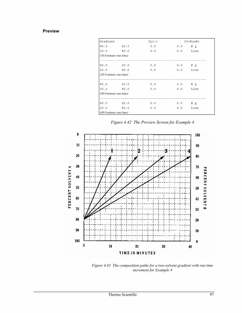
Thermo Scientific 97
Preview
Gradient Cyc:1 CrvRun#1
80.0 20.0 0.0 0.0 # 1
20.0 80.0 0.0 0.0 Line
(10.0 minute run time) --------------------------------------------------------
80.0 20.0 0.0 0.0 # 2
20.0 80.0 0.0 0.0 Line
(20.0 minute run time) --------------------------------------------------------
80.0 20.0 0.0 0.0 # 3
20.0 80.0 0.0 0.0 Line
(30.0 minute run time) --------------------------------------------------------
80.0 20.0 0.0 0.0 # 4
20.0 80.0 0.0 0.0 Line
(40.0 minute run time)
Figure 4.42 The Preview Screen for Example 4
Figure 4.43 The composition paths for a two-solvent gradient with run time increment for Example 4
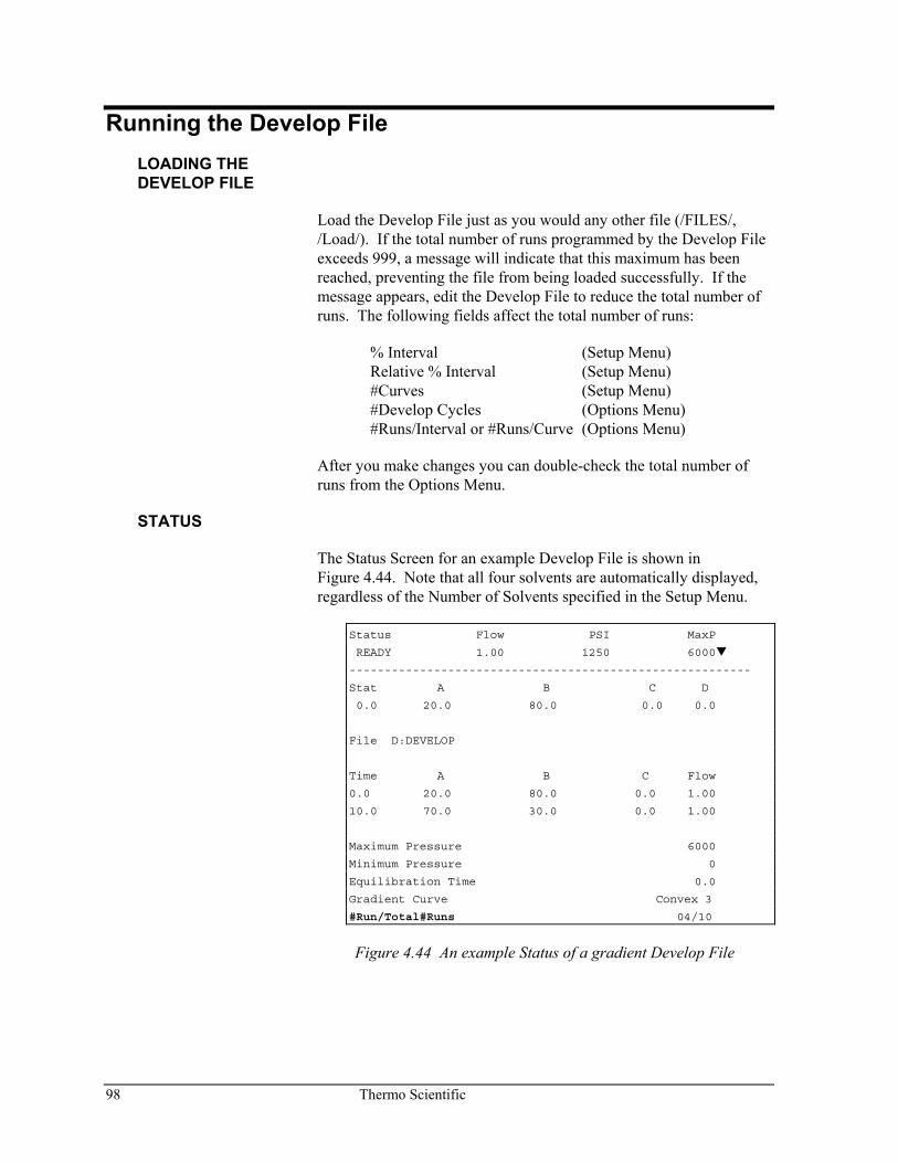
98 Thermo Scientific
Running the Develop File LOADING THE DEVELOP FILE
Load the Develop File just as you would any other file (/FILES/, /Load/). If the total number of runs programmed by the Develop File exceeds 999, a message will indicate that this maximum has been reached, preventing the file from being loaded successfully. If the message appears, edit the Develop File to reduce the total number of runs. The following fields affect the total number of runs:
% Interval (Setup Menu) Relative % Interval (Setup Menu) #Curves (Setup Menu) #Develop Cycles (Options Menu) #Runs/Interval or #Runs/Curve (Options Menu)
After you make changes you can double-check the total number of runs from the Options Menu.
STATUS
The Status Screen for an example Develop File is shown in Figure 4.44. Note that all four solvents are automatically displayed, regardless of the Number of Solvents specified in the Setup Menu.
Status Flow PSI MaxP
READY 1.00 1250 6000
---------------------------------------------------------
Stat A B C D
0.0 20.0 80.0 0.0 0.0
File D:DEVELOP
Time A B C Flow
0.0 20.0 80.0 0.0 1.00
10.0 70.0 30.0 0.0 1.00
Maximum Pressure 6000
Minimum Pressure 0
Equilibration Time 0.0
Gradient Curve Convex 3
#Run/Total#Runs 04/10
Figure 4.44 An example Status of a gradient Develop File
Thermo Scientific 99
Status Menu
The Status Menu shows one new line, #Run/Total#Runs. This line displays the current run number and the total number of runs programmed in the file. The Gradient Curve field shows the curve shape of the current run.
The same Status Menu editing capabilities of a run file also apply when a Develop File is loaded, except that the run file may not contain more than two time-lines.
COMMANDS
All commands function as they would for any other file. However, the pump sees the Develop File as one file, not as a series of runs. This is important if you reset the file, using /COMMANDS/, /Reset/. When the reset command is issued, the pump will return to the initial conditions of Run #1. The entire program then restarts as soon as the pump receives a RUN command.
Develop File Review The examples presented in the preceding pages give you a good idea of the flexibility and power of the Develop File. You can combine many of the concepts presented in these examples into your own Develop File, depending on your needs.
For instance, in a gradient program you might combine the run time increment with three or more curves, instead of one. The pump would perform all the curve shapes, then increment the run time and run all the shapes again.
In an isocratic program you might specify two develop cycles, instead of one, and run the second cycle with a different column. You could do the same thing with a gradient program.
The Develop File can greatly assist you in automating methods development. The form sheets supplied in the following pages can help you plan and document the conditions necessary for optimizing your chromatography.
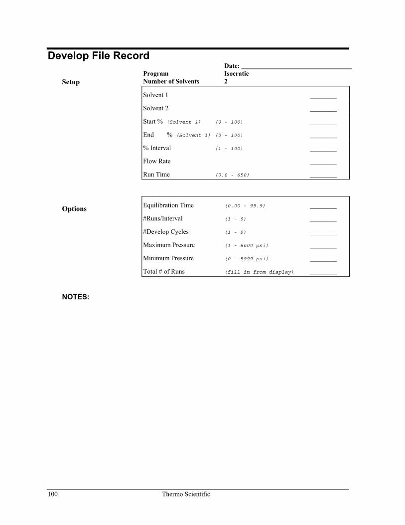
100 Thermo Scientific
Develop File Record Date:
Setup Program Isocratic Number of Solvents 2
Solvent 1 ________
Solvent 2 ________
Start % (Solvent 1) (0 - 100) ________
End % (Solvent 1) (0 - 100) ________
% Interval (1 - 100) ________
Flow Rate ________
Run Time (0.0 - 650) ________
Options Equilibration Time (0.00 - 99.9) ________
#Runs/Interval (1 - 9) ________
#Develop Cycles (1 - 9) ________
Maximum Pressure (1 - 6000 psi) ________
Minimum Pressure (0 - 5999 psi) ________
Total # of Runs (fill in from display) ________
NOTES:
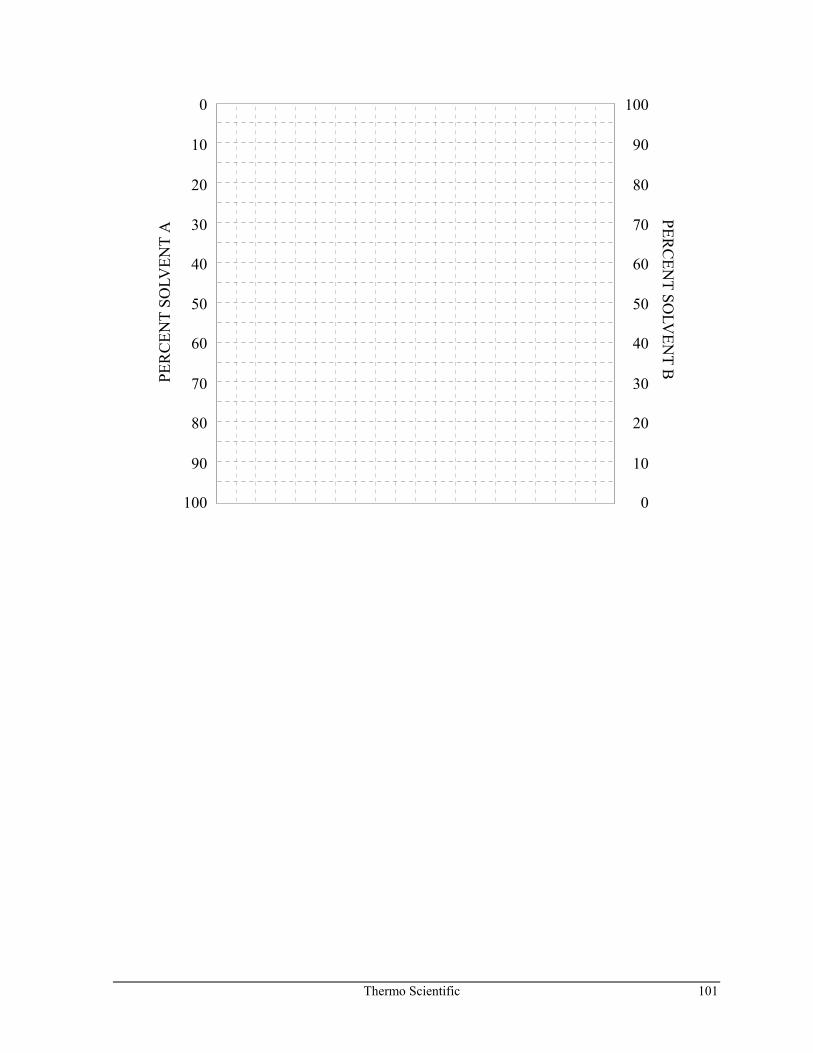
Thermo Scientific 101
0
10
20
30
40
50
60
70
80
90
100 0
10
20
30
40
50
60
70
80
90
100
PER
CEN
T SO
LVEN
T A
PERC
ENT SO
LVEN
T B
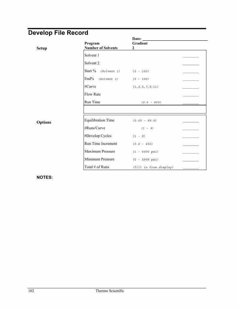
102 Thermo Scientific
Develop File Record Date:
Setup Program Gradient Number of Solvents 2
Solvent 1 ________
Solvent 2 ________
Start % (Solvent 1) (0 - 100) ________
End% (Solvent 1) (0 - 100) ________
#Curve (1,3,5,7,9,11) ________
Flow Rate ________
Run Time (0.0 - 650) ________
Options Equilibration Time (0.00 - 99.9) ________
#Runs/Curve (1 - 9) ________
#Develop Cycles (1 - 9) ________
Run Time Increment (0.0 - 650) ________
Maximum Pressure (1 - 6000 psi) ________
Minimum Pressure (0 - 5999 psi) ________
Total # of Runs (fill in from display) ________
NOTES:

Thermo Scientific 103
0
10
20
30
40
50
60
70
80
90
100 0
10
20
30
40
50
60
70
80
90
100
PER
CEN
T SO
LVEN
T A
PERC
ENT SO
LVEN
T B
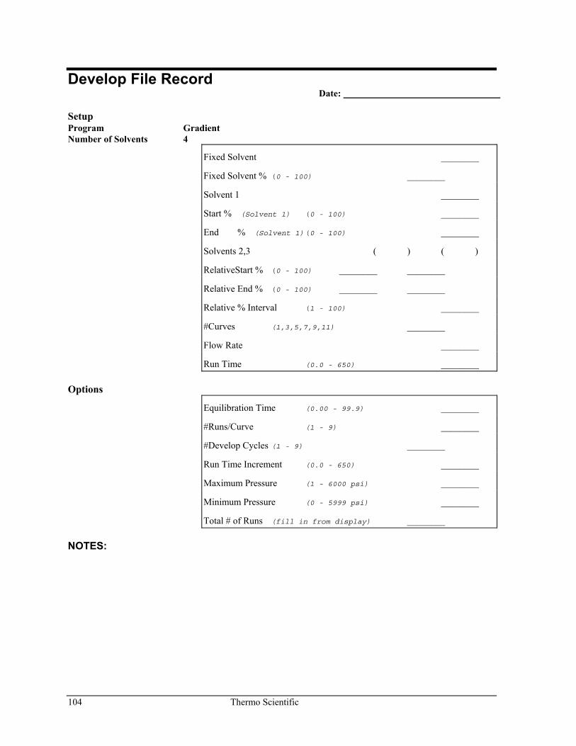
104 Thermo Scientific
Develop File Record Date:
Setup Program Gradient Number of Solvents 4
Fixed Solvent ________
Fixed Solvent % (0 - 100) ________
Solvent 1 ________
Start % (Solvent 1) (0 - 100) ________
End % (Solvent 1) (0 - 100) ________
Solvents 2,3 ( ) ( )
RelativeStart % (0 - 100) ________ ________
Relative End % (0 - 100) ________ ________
Relative % Interval (1 - 100) ________
#Curves (1,3,5,7,9,11) ________
Flow Rate ________
Run Time (0.0 - 650) ________
Options
Equilibration Time (0.00 - 99.9) ________
#Runs/Curve (1 - 9) ________
#Develop Cycles (1 - 9) ________
Run Time Increment (0.0 - 650) ________
Maximum Pressure (1 - 6000 psi) ________
Minimum Pressure (0 - 5999 psi) ________
Total # of Runs (fill in from display) ________
NOTES:
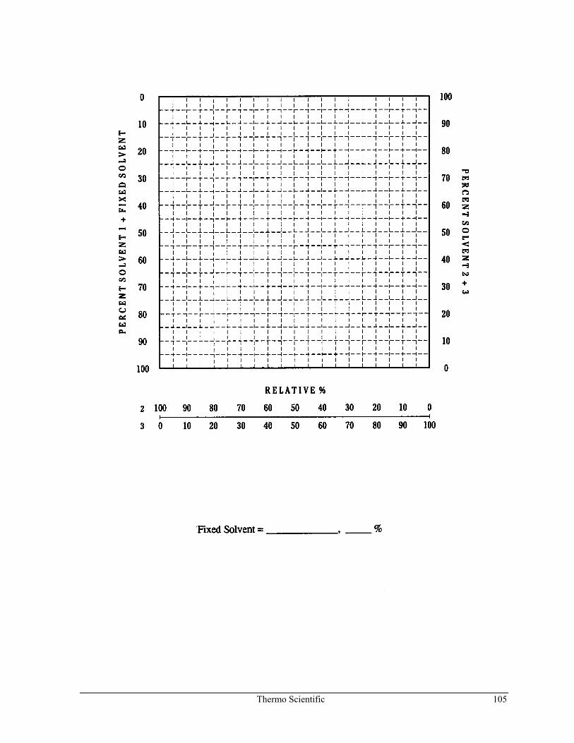
Thermo Scientific 105
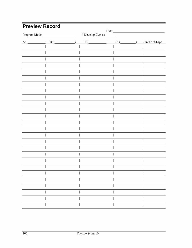
106 Thermo Scientific
Preview Record Date:
Program Mode: # Develop Cycles: A: ( ) B: ( ) C: ( ) D: ( ) Run # or Shape | | | |
| | | |
| | | |
| | | |
| | | |
| | | |
| | | |
| | | |
| | | |
| | | |
| | | |
| | | |
| | | |
| | | |
| | | |
| | | |
| | | |
| | | |
| | | |
| | | |
| | | |
| | | |
| | | |
| | | |
| | | |
| | | |
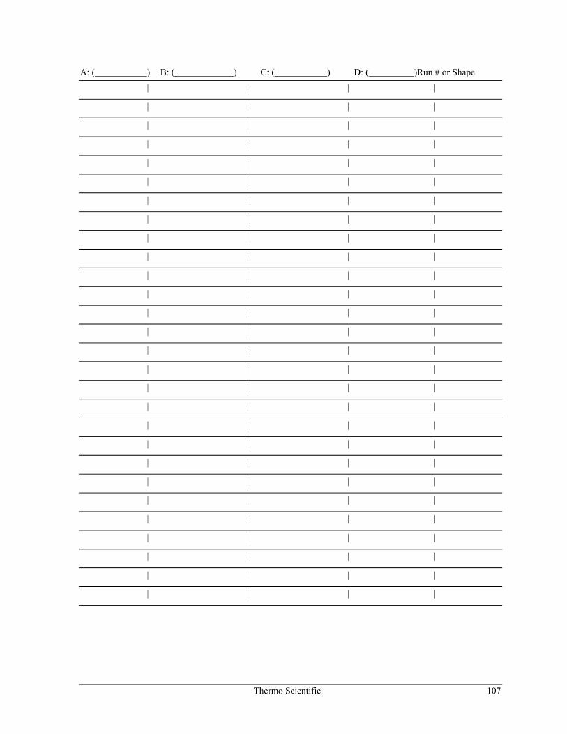
Thermo Scientific 107
A: ( ) B: ( ) C: ( ) D: ( )Run # or Shape | | | |
| | | |
| | | |
| | | |
| | | |
| | | |
| | | |
| | | |
| | | |
| | | |
| | | |
| | | |
| | | |
| | | |
| | | |
| | | |
| | | |
| | | |
| | | |
| | | |
| | | |
| | | |
| | | |
| | | |
| | | |
| | | |
| | | |
| | | |
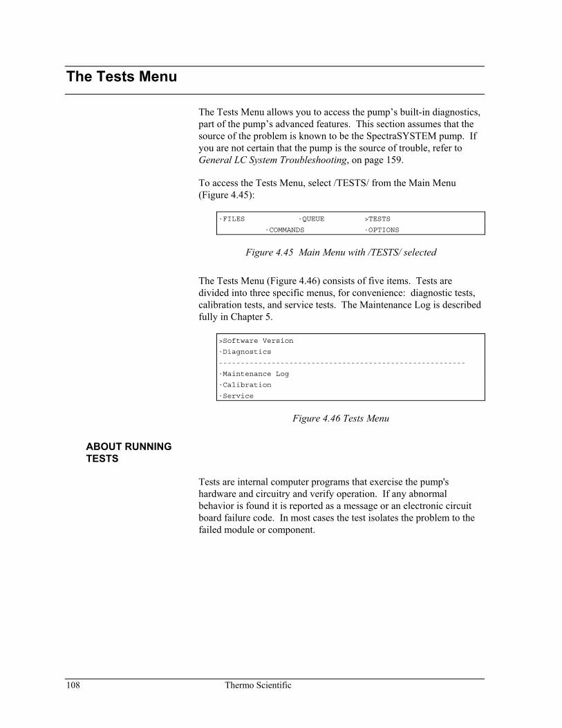
108 Thermo Scientific
The Tests Menu
The Tests Menu allows you to access the pump’s built-in diagnostics, part of the pump’s advanced features. This section assumes that the source of the problem is known to be the SpectraSYSTEM pump. If you are not certain that the pump is the source of trouble, refer to General LC System Troubleshooting, on page 159.
To access the Tests Menu, select /TESTS/ from the Main Menu (Figure 4.45):
·FILES ·QUEUE >TESTS
·COMMANDS ·OPTIONS
Figure 4.45 Main Menu with /TESTS/ selected
The Tests Menu (Figure 4.46) consists of five items. Tests are divided into three specific menus, for convenience: diagnostic tests, calibration tests, and service tests. The Maintenance Log is described fully in Chapter 5.
>Software Version
·Diagnostics
--------------------------------------------------------
·Maintenance Log
·Calibration
·Service
Figure 4.46 Tests Menu
ABOUT RUNNING TESTS
Tests are internal computer programs that exercise the pump's hardware and circuitry and verify operation. If any abnormal behavior is found it is reported as a message or an electronic circuit board failure code. In most cases the test isolates the problem to the failed module or component.
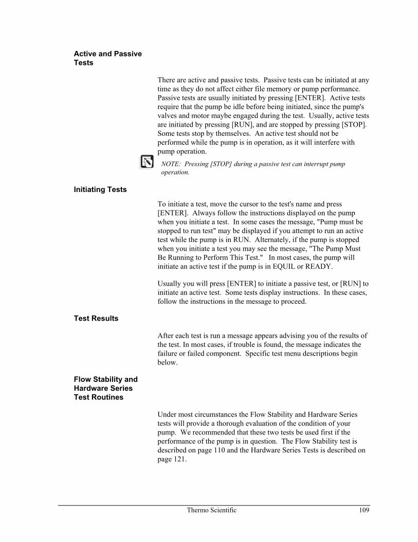
Thermo Scientific 109
Active and Passive Tests
There are active and passive tests. Passive tests can be initiated at any time as they do not affect either file memory or pump performance. Passive tests are usually initiated by pressing [ENTER]. Active tests require that the pump be idle before being initiated, since the pump's valves and motor maybe engaged during the test. Usually, active tests are initiated by pressing [RUN], and are stopped by pressing [STOP]. Some tests stop by themselves. An active test should not be performed while the pump is in operation, as it will interfere with pump operation.
NOTE: Pressing [STOP] during a passive test can interrupt pump operation.
Initiating Tests
To initiate a test, move the cursor to the test's name and press [ENTER]. Always follow the instructions displayed on the pump when you initiate a test. In some cases the message, "Pump must be stopped to run test" may be displayed if you attempt to run an active test while the pump is in RUN. Alternately, if the pump is stopped when you initiate a test you may see the message, "The Pump Must Be Running to Perform This Test." In most cases, the pump will initiate an active test if the pump is in EQUIL or READY.
Usually you will press [ENTER] to initiate a passive test, or [RUN] to initiate an active test. Some tests display instructions. In these cases, follow the instructions in the message to proceed.
Test Results
After each test is run a message appears advising you of the results of the test. In most cases, if trouble is found, the message indicates the failure or failed component. Specific test menu descriptions begin below.
Flow Stability and Hardware Series Test Routines
Under most circumstances the Flow Stability and Hardware Series tests will provide a thorough evaluation of the condition of your pump. We recommended that these two tests be used first if the performance of the pump is in question. The Flow Stability test is described on page 110 and the Hardware Series Tests is described on page 121.
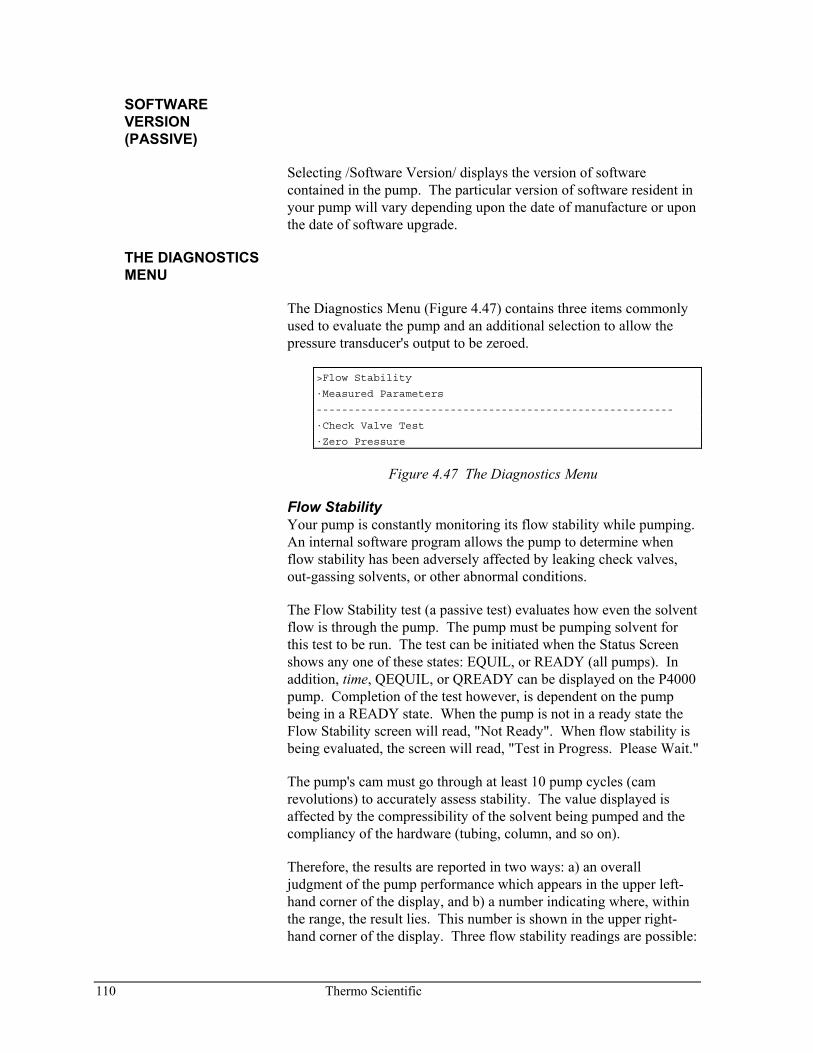
110 Thermo Scientific
SOFTWARE VERSION (PASSIVE)
Selecting /Software Version/ displays the version of software contained in the pump. The particular version of software resident in your pump will vary depending upon the date of manufacture or upon the date of software upgrade.
THE DIAGNOSTICS MENU
The Diagnostics Menu (Figure 4.47) contains three items commonly used to evaluate the pump and an additional selection to allow the pressure transducer's output to be zeroed.
>Flow Stability
·Measured Parameters
--------------------------------------------------------
·Check Valve Test
·Zero Pressure
Figure 4.47 The Diagnostics Menu
Flow Stability Your pump is constantly monitoring its flow stability while pumping. An internal software program allows the pump to determine when flow stability has been adversely affected by leaking check valves, out-gassing solvents, or other abnormal conditions.
The Flow Stability test (a passive test) evaluates how even the solvent flow is through the pump. The pump must be pumping solvent for this test to be run. The test can be initiated when the Status Screen shows any one of these states: EQUIL, or READY (all pumps). In addition, time, QEQUIL, or QREADY can be displayed on the P4000 pump. Completion of the test however, is dependent on the pump being in a READY state. When the pump is not in a ready state the Flow Stability screen will read, "Not Ready". When flow stability is being evaluated, the screen will read, "Test in Progress. Please Wait."
The pump's cam must go through at least 10 pump cycles (cam revolutions) to accurately assess stability. The value displayed is affected by the compressibility of the solvent being pumped and the compliancy of the hardware (tubing, column, and so on).
Therefore, the results are reported in two ways: a) an overall judgment of the pump performance which appears in the upper left-hand corner of the display, and b) a number indicating where, within the range, the result lies. This number is shown in the upper right-hand corner of the display. Three flow stability readings are possible:
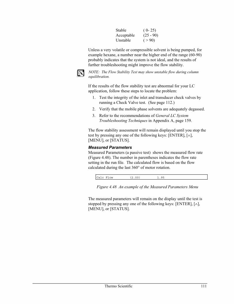
Thermo Scientific 111
Stable ( 0- 25) Acceptable (25 - 90) Unstable ( > 90)
Unless a very volatile or compressible solvent is being pumped, for example hexane, a number near the higher end of the range (60-90) probably indicates that the system is not ideal, and the results of further troubleshooting might improve the flow stability.
NOTE: The Flow Stability Test may show unstable flow during column equilibration.
If the results of the flow stability test are abnormal for your LC application, follow these steps to locate the problem:
1. Test the integrity of the inlet and transducer check valves by running a Check Valve test. (See page 112.)
2. Verify that the mobile phase solvents are adequately degassed. 3. Refer to the recommendations of General LC System
Troubleshooting Techniques in Appendix A, page 159.
The flow stability assessment will remain displayed until you stop the test by pressing any one of the following keys: [ENTER], [∧], [MENU], or [STATUS].
Measured Parameters Measured Parameters (a passive test) shows the measured flow rate (Figure 4.48). The number in parentheses indicates the flow rate setting in the run file. The calculated flow is based on the flow calculated during the last 360° of motor rotation.
Calc Flow (2.00) 1.95
Figure 4.48 An example of the Measured Parameters Menu
The measured parameters will remain on the display until the test is stopped by pressing any one of the following keys: [ENTER], [∧], [MENU], or [STATUS].
112 Thermo Scientific
Check Valve Test The Check Valve test (an active test) can help you further diagnose the source of flow stability problems. If the results indicate a defective check valve, the test should be repeated to ensure the results were not due to an isolated transient condition, such as a single air bubble.
This test affects flow accuracy while the test is running. Do not run the test during an analysis. The pump can be in EQUIL, or READY and the flow rate must be 2.5 mL/min or less (for standard liquid ends). If the test is activated and the current flow rate is greater than 2.5 mL/min, a message will be displayed, prompting you to reset the flow rate. In general, the flow rate must be set to one-quarter or less of the maximum flow rate of the liquid ends.
HINT: Defective check valves tend to perform better at higher column pressures. Lowering the column pressure by decreasing the flow rate increases the test's sensitivity of marginally operating check valves.
NOTE: The inlet check valve is located at the base of the inlet liquid end. The transducer check valve is located at the base of the pressure transducer.
To activate the test select /Check Valve Test/. Follow the displayed instructions. A message will inform you of the 8 - 10 pump cycle delay before test completion. During this time, the condition of the inlet and transducer check valves of the pump are monitored. When the monitoring period is complete, pumping returns to normal constant flow control and a message is displayed, showing the results. Messages are listed in Table 4.1.
NOTE: Changing mobile phase concentration may cause the test to report a good check valve as defective. Stabilize composition before running the test.
Pressing [RUN] after the results are displayed will rerun the test. Stop the test by pressing [ENTER] or [∧].
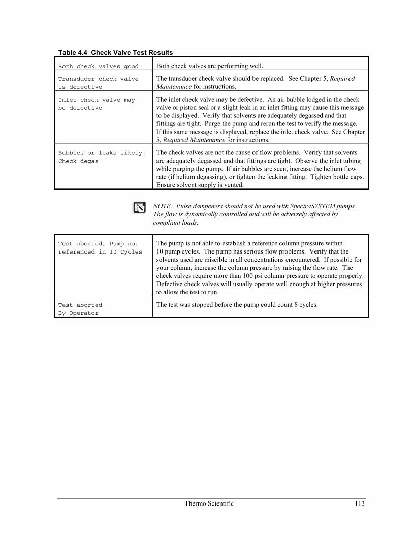
Thermo Scientific 113
Table 4.4 Check Valve Test Results
Both check valves good Both check valves are performing well.
Transducer check valve
is defective
The transducer check valve should be replaced. See Chapter 5, Required Maintenance for instructions.
Inlet check valve may
be defective
The inlet check valve may be defective. An air bubble lodged in the check valve or piston seal or a slight leak in an inlet fitting may cause this message to be displayed. Verify that solvents are adequately degassed and that fittings are tight. Purge the pump and rerun the test to verify the message. If this same message is displayed, replace the inlet check valve. See Chapter 5, Required Maintenance for instructions.
Bubbles or leaks likely.
Check degas
The check valves are not the cause of flow problems. Verify that solvents are adequately degassed and that fittings are tight. Observe the inlet tubing while purging the pump. If air bubbles are seen, increase the helium flow rate (if helium degassing), or tighten the leaking fitting. Tighten bottle caps. Ensure solvent supply is vented.
NOTE: Pulse dampeners should not be used with SpectraSYSTEM pumps. The flow is dynamically controlled and will be adversely affected by compliant loads.
Test aborted, Pump not
referenced in 10 Cycles
The pump is not able to establish a reference column pressure within 10 pump cycles. The pump has serious flow problems. Verify that the solvents used are miscible in all concentrations encountered. If possible for your column, increase the column pressure by raising the flow rate. The check valves require more than 100 psi column pressure to operate properly. Defective check valves will usually operate well enough at higher pressures to allow the test to run.
Test aborted
By Operator
The test was stopped before the pump could count 8 cycles.
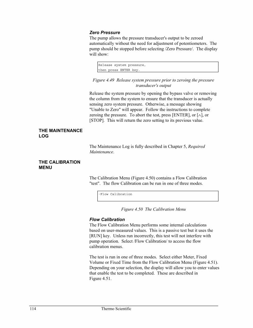
114 Thermo Scientific
Zero Pressure The pump allows the pressure transducer's output to be zeroed automatically without the need for adjustment of potentiometers. The pump should be stopped before selecting /Zero Pressure/. The display will show:
Release system pressure,
then press ENTER key.
Figure 4.49 Release system pressure prior to zeroing the pressure transducer's output
Release the system pressure by opening the bypass valve or removing the column from the system to ensure that the transducer is actually sensing zero system pressure. Otherwise, a message showing "Unable to Zero" will appear. Follow the instructions to complete zeroing the pressure. To abort the test, press [ENTER], or [∧], or [STOP]. This will return the zero setting to its previous value.
THE MAINTENANCE LOG
The Maintenance Log is fully described in Chapter 5, Required Maintenance.
THE CALIBRATION MENU
The Calibration Menu (Figure 4.50) contains a Flow Calibration "test". The flow Calibration can be run in one of three modes.
·Flow Calibration
Figure 4.50 The Calibration Menu
Flow Calibration The Flow Calibration Menu performs some internal calculations based on user-measured values. This is a passive test but it uses the [RUN] key. Unless run incorrectly, this test will not interfere with pump operation. Select /Flow Calibration/ to access the flow calibration menus.
The test is run in one of three modes. Select either Meter, Fixed Volume or Fixed Time from the Flow Calibration Menu (Figure 4.51). Depending on your selection, the display will allow you to enter values that enable the test to be completed. These are described in Figure 4.51.
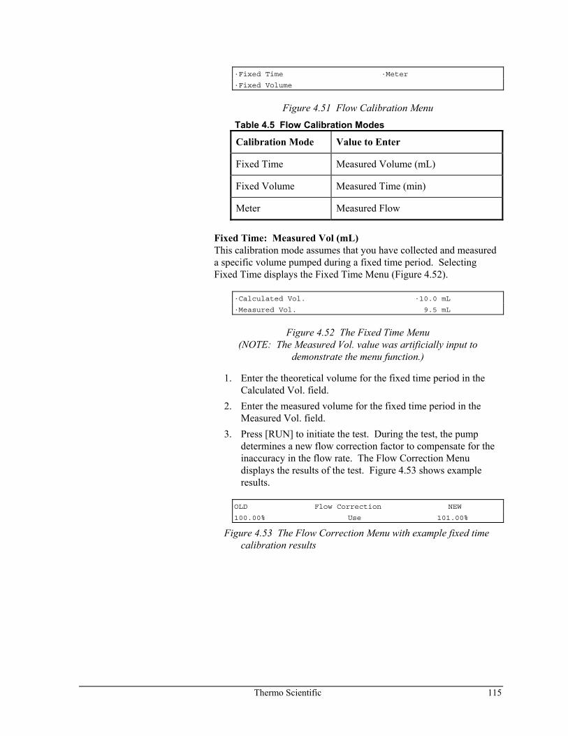
Thermo Scientific 115
·Fixed Time ·Meter
·Fixed Volume
Figure 4.51 Flow Calibration Menu
Table 4.5 Flow Calibration Modes
Calibration Mode Value to Enter
Fixed Time Measured Volume (mL)
Fixed Volume Measured Time (min)
Meter Measured Flow
Fixed Time: Measured Vol (mL) This calibration mode assumes that you have collected and measured a specific volume pumped during a fixed time period. Selecting Fixed Time displays the Fixed Time Menu (Figure 4.52).
·Calculated Vol. ·10.0 mL
·Measured Vol. 9.5 mL
Figure 4.52 The Fixed Time Menu (NOTE: The Measured Vol. value was artificially input to
demonstrate the menu function.)
1. Enter the theoretical volume for the fixed time period in the Calculated Vol. field.
2. Enter the measured volume for the fixed time period in the Measured Vol. field.
3. Press [RUN] to initiate the test. During the test, the pump determines a new flow correction factor to compensate for the inaccuracy in the flow rate. The Flow Correction Menu displays the results of the test. Figure 4.53 shows example results.
OLD Flow Correction NEW
100.00% Use 101.00%
Figure 4.53 The Flow Correction Menu with example fixed time calibration results
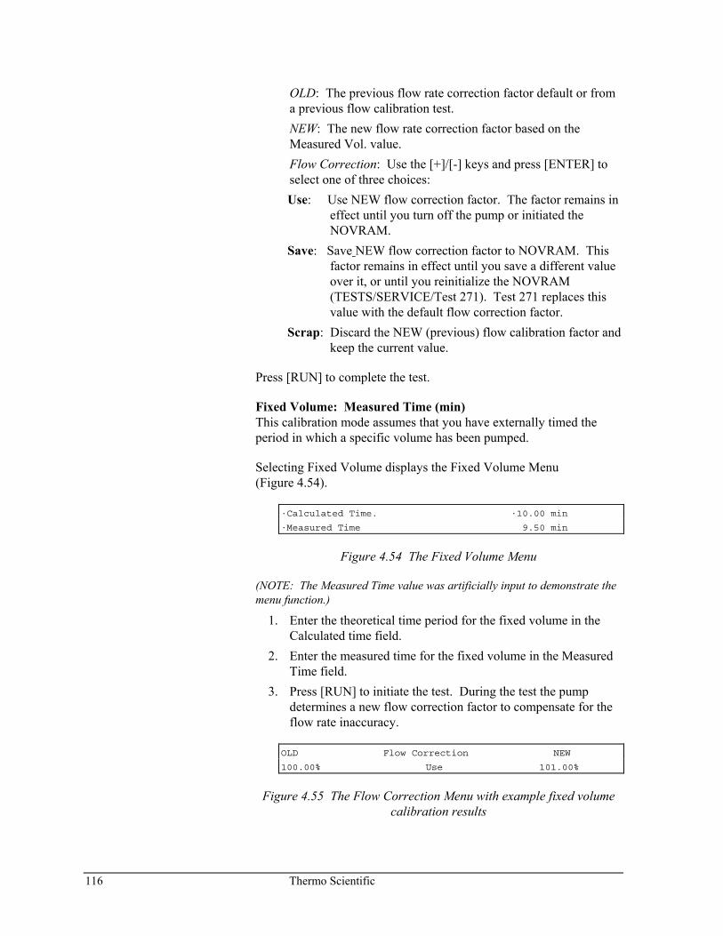
116 Thermo Scientific
OLD: The previous flow rate correction factor default or from a previous flow calibration test.
NEW: The new flow rate correction factor based on the Measured Vol. value.
Flow Correction: Use the [+]/[-] keys and press [ENTER] to select one of three choices: Use: Use NEW flow correction factor. The factor remains in
effect until you turn off the pump or initiated the NOVRAM.
Save: Save NEW flow correction factor to NOVRAM. This factor remains in effect until you save a different value over it, or until you reinitialize the NOVRAM (TESTS/SERVICE/Test 271). Test 271 replaces this value with the default flow correction factor.
Scrap: Discard the NEW (previous) flow calibration factor and keep the current value.
Press [RUN] to complete the test.
Fixed Volume: Measured Time (min) This calibration mode assumes that you have externally timed the period in which a specific volume has been pumped.
Selecting Fixed Volume displays the Fixed Volume Menu (Figure 4.54).
·Calculated Time. ·10.00 min
·Measured Time 9.50 min
Figure 4.54 The Fixed Volume Menu
(NOTE: The Measured Time value was artificially input to demonstrate the menu function.)
1. Enter the theoretical time period for the fixed volume in the Calculated time field.
2. Enter the measured time for the fixed volume in the Measured Time field.
3. Press [RUN] to initiate the test. During the test the pump determines a new flow correction factor to compensate for the flow rate inaccuracy.
OLD Flow Correction NEW
100.00% Use 101.00%
Figure 4.55 The Flow Correction Menu with example fixed volume calibration results
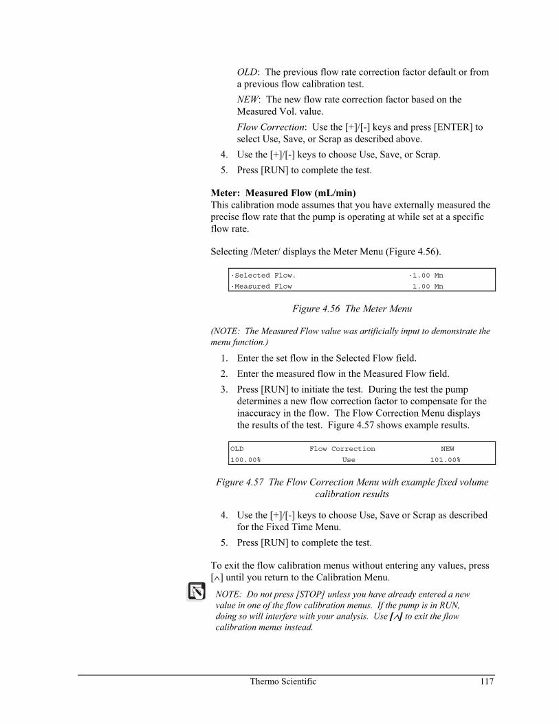
Thermo Scientific 117
OLD: The previous flow rate correction factor default or from a previous flow calibration test.
NEW: The new flow rate correction factor based on the Measured Vol. value.
Flow Correction: Use the [+]/[-] keys and press [ENTER] to select Use, Save, or Scrap as described above.
4. Use the [+]/[-] keys to choose Use, Save, or Scrap. 5. Press [RUN] to complete the test.
Meter: Measured Flow (mL/min) This calibration mode assumes that you have externally measured the precise flow rate that the pump is operating at while set at a specific flow rate.
Selecting /Meter/ displays the Meter Menu (Figure 4.56).
·Selected Flow. ·1.00 Mn
·Measured Flow 1.00 Mn
Figure 4.56 The Meter Menu
(NOTE: The Measured Flow value was artificially input to demonstrate the menu function.)
1. Enter the set flow in the Selected Flow field. 2. Enter the measured flow in the Measured Flow field. 3. Press [RUN] to initiate the test. During the test the pump
determines a new flow correction factor to compensate for the inaccuracy in the flow. The Flow Correction Menu displays the results of the test. Figure 4.57 shows example results.
OLD Flow Correction NEW
100.00% Use 101.00%
Figure 4.57 The Flow Correction Menu with example fixed volume calibration results
4. Use the [+]/[-] keys to choose Use, Save or Scrap as described for the Fixed Time Menu.
5. Press [RUN] to complete the test.
To exit the flow calibration menus without entering any values, press [∧] until you return to the Calibration Menu.
NOTE: Do not press [STOP] unless you have already entered a new value in one of the flow calibration menus. If the pump is in RUN, doing so will interfere with your analysis. Use [∧] to exit the flow calibration menus instead.
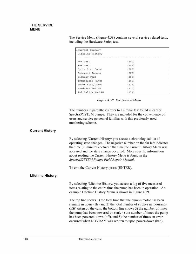
118 Thermo Scientific
THE SERVICE MENU
The Service Menu (Figure 4.58) contains several service-related tests, including the Hardware Series test.
>Current History
·Lifetime History
-------------------------------------------------------
·ROM Test (200)
·RAM Test (201)
·Cycle Step Count (205)
·External Inputs (206)
·Display Test (208)
·Transducer Range (209)
·Motor Step/Valve (211)
·Hardware Series (220)
·Initialize NOVRAM (271)
Figure 4.58 The Service Menu
The numbers in parentheses refer to a similar test found in earlier SpectraSYSTEM pumps. They are included for the convenience of users and service personnel familiar with this previously-used numbering scheme.
Current History
By selecting /Current History/ you access a chronological list of operating state changes. The negative number on the far left indicates the time (in minutes) between the time the Current History Menu was accessed and the state change occurred. More specific information about reading the Current History Menu is found in the SpectraSYSTEM Pumps Field Repair Manual.
To exit the Current History, press [ENTER].
Lifetime History
By selecting /Lifetime History/ you access a log of five measured items relating to the entire time the pump has been in operation. An example Lifetime History Menu is shown in Figure 4.59.
The top line shows 1) the total time that the pump's motor has been running in hours (Hr) and 2) the total number of strokes in thousands (kSt) taken by the cam; the bottom line shows 3) the number of times the pump has been powered-on (on), 4) the number of times the pump has been powered-down (off), and 5) the number of times an error occurred when NOVRAM was written to upon power-down (bad).
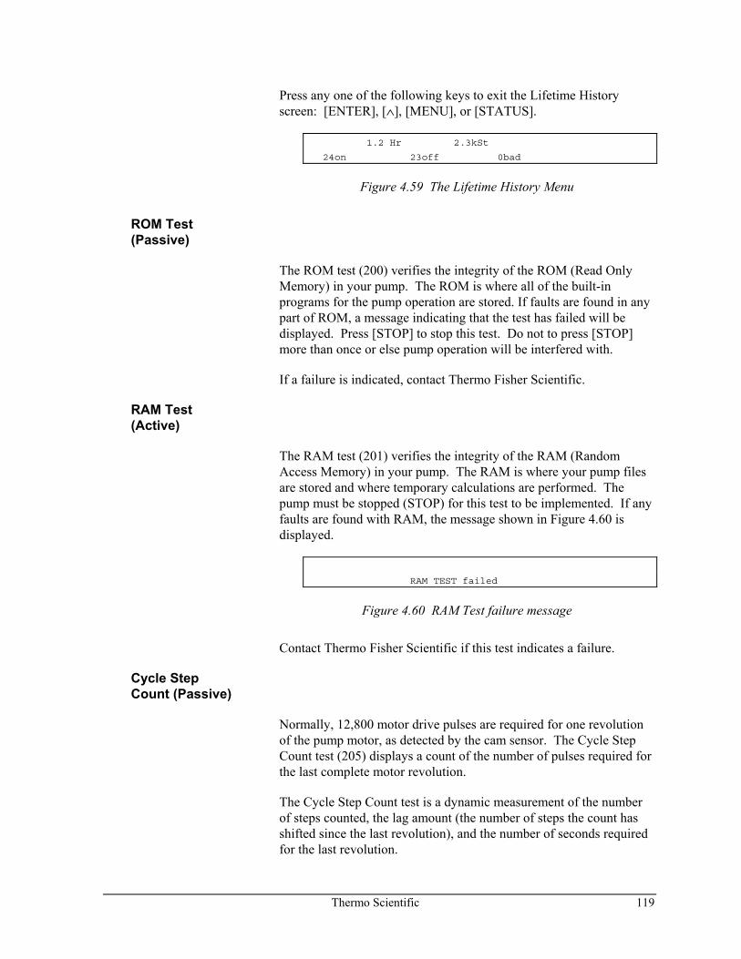
Thermo Scientific 119
Press any one of the following keys to exit the Lifetime History screen: [ENTER], [∧], [MENU], or [STATUS].
1.2 Hr 2.3kSt
24on 23off 0bad
Figure 4.59 The Lifetime History Menu
ROM Test (Passive)
The ROM test (200) verifies the integrity of the ROM (Read Only Memory) in your pump. The ROM is where all of the built-in programs for the pump operation are stored. If faults are found in any part of ROM, a message indicating that the test has failed will be displayed. Press [STOP] to stop this test. Do not to press [STOP] more than once or else pump operation will be interfered with.
If a failure is indicated, contact Thermo Fisher Scientific.
RAM Test (Active)
The RAM test (201) verifies the integrity of the RAM (Random Access Memory) in your pump. The RAM is where your pump files are stored and where temporary calculations are performed. The pump must be stopped (STOP) for this test to be implemented. If any faults are found with RAM, the message shown in Figure 4.60 is displayed.
RAM TEST failed
Figure 4.60 RAM Test failure message
Contact Thermo Fisher Scientific if this test indicates a failure.
Cycle Step Count (Passive)
Normally, 12,800 motor drive pulses are required for one revolution of the pump motor, as detected by the cam sensor. The Cycle Step Count test (205) displays a count of the number of pulses required for the last complete motor revolution.
The Cycle Step Count test is a dynamic measurement of the number of steps counted, the lag amount (the number of steps the count has shifted since the last revolution), and the number of seconds required for the last revolution.
120 Thermo Scientific
Generally, the number of steps should be 12,800 ± 64. The lag value varies due to the load on the pump. This number should be steady, or fluctuate no more than ±120 steps.
Start the test by selecting /Cycle Step Count/. To stop the test, press any one of the following keys: [ENTER], [∧], [MENU], or [STATUS].
NOTE: The Cycle Step Count test requires that a full cam revolution has occurred.
External Inputs (Passive)
The External Inputs test (206) allows you to conveniently monitor the status of two of the external input lines, STOP and RUN. The STOP line causes the pump to stop pumping when momentarily grounded. A momentary ground at the RUN input line causes the run time clock to begin. Use this test if you are having difficulty interfacing your pump to a controlling device, such as a SpectraSYSTEM autosampler.
To run the test, select /External Inputs/. The display continuously shows the current state of the STOP and RUN inputs (updates every 0.5 second). "Lo" means the input is grounded (active) and "Hi" means the input is "high" (inactive).
To stop the test, press either [ENTER], [∧], [MENU], or [STATUS].
Display Test (Passive)
The Display test (208) exercises the pump's display. When initiated, the display shows staggered alphanumeric characters that scroll from left to right. Pressing [STOP] freezes the display; pressing [RUN] resumes movement.
This test is also a keyboard test. Pressing the cursor keys will cause the alphanumeric display to scroll in that direction.
Other keys can be tested by first pressing [ENTER] to access the key test. The display will verify other keys such as [STATUS] or [MENU], as soon as each is pressed.
To return to the scrolling alphanumeric characters, press [RUN], [RUN]. To stop the test, and return to the Service Test Menu, press [STOP], [STOP].
Contact your representative if the display appears unusual.
Thermo Scientific 121
Transducer Range (Active)
Transducer Range is not truly a test. It contains a field where you must enter the calibration value (in mV) for a replaced pressure transducer. The range is located on the replacement transducer wire. Your pump features advanced circuit designs which allow the pressure transducer range adjustment to be set by entering a value from the keyboard. No adjustment of potentiometers is necessary. Your pump comes from the factory preset to the proper range. The value is stored in a NOVRAM. Do not change the transducer calibration setting unless the pressure transducer or System PCB are replaced. The calibration number is recorded on a tag attached to the transducer cable. The System PCB and pressure transducer are not user-serviceable parts. A qualified service representative must perform any repair or replacement.
Motor Step/Valve (Active)
The Motor Step/Valve test (211) exercises the pump motor and the switching valve on the pump. When activated, the pump motor is continuously stepped and each switching valve is sequentially opened and closed at a rate of 1 valve per 0.512 seconds. This test is useful for detecting an intermittently failing switching valve or pump motor.
Select /Motor Step Valve/ to initiate the test. Follow the instructions. Each open valve is shown dynamically on the display. The test will continue until one of the following keys is pressed: [ENTER], [∧], [STOP], [MENU], or [STATUS].
Hardware Series (Active)
The Hardware Series test (220) is an extensive evaluation of the System Printed Circuit Board (PCB), switching valve, pump motor, and pressure transducer. The System PCB contains all of the circuitry for the operation of the pump, except for the display functions. Once activated, the test exercises and diagnoses the condition of various circuits. The pump must be idle (not pumping) before activating the test. This test will not affect pump files.
NOTE: The external events connector (if present) must be removed from the rear of the pump before initiating the Hardware Series test. Otherwise, "Board Failure: Code 8" may occur.
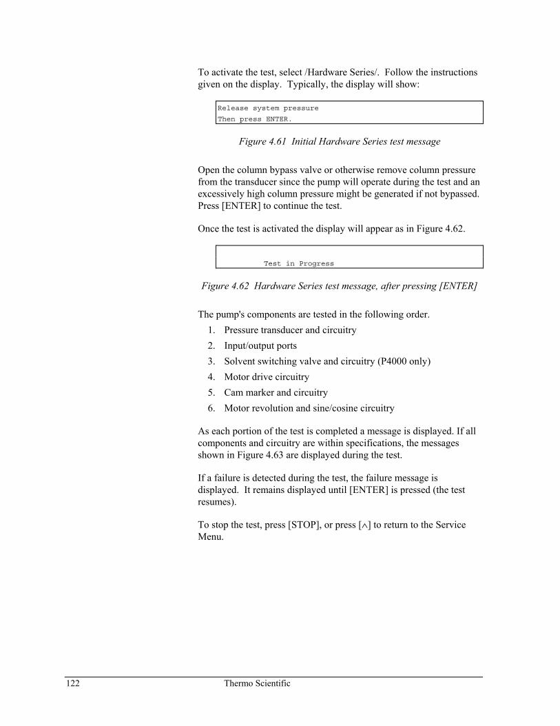
122 Thermo Scientific
To activate the test, select /Hardware Series/. Follow the instructions given on the display. Typically, the display will show:
Release system pressure
Then press ENTER.
Figure 4.61 Initial Hardware Series test message
Open the column bypass valve or otherwise remove column pressure from the transducer since the pump will operate during the test and an excessively high column pressure might be generated if not bypassed. Press [ENTER] to continue the test.
Once the test is activated the display will appear as in Figure 4.62.
Test in Progress
Figure 4.62 Hardware Series test message, after pressing [ENTER]
The pump's components are tested in the following order. 1. Pressure transducer and circuitry 2. Input/output ports 3. Solvent switching valve and circuitry (P4000 only) 4. Motor drive circuitry 5. Cam marker and circuitry 6. Motor revolution and sine/cosine circuitry
As each portion of the test is completed a message is displayed. If all components and circuitry are within specifications, the messages shown in Figure 4.63 are displayed during the test.
If a failure is detected during the test, the failure message is displayed. It remains displayed until [ENTER] is pressed (the test resumes).
To stop the test, press [STOP], or press [∧] to return to the Service Menu.
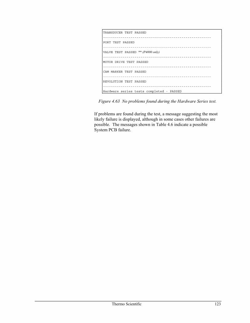
Thermo Scientific 123
TRANSDUCER TEST PASSED
-------------------------------------------------------
PORT TEST PASSED
-------------------------------------------------------
VALVE TEST PASSED ** (P4000 only) -------------------------------------------------------
MOTOR DRIVE TEST PASSED
-------------------------------------------------------
CAM MARKER TEST PASSED
-------------------------------------------------------
REVOLUTION TEST PASSED
-------------------------------------------------------
Hardware series tests completed - PASSED
Figure 4.63 No problems found during the Hardware Series test.
If problems are found during the test, a message suggesting the most likely failure is displayed, although in some cases other failures are possible. The messages shown in Table 4.6 indicate a possible System PCB failure.
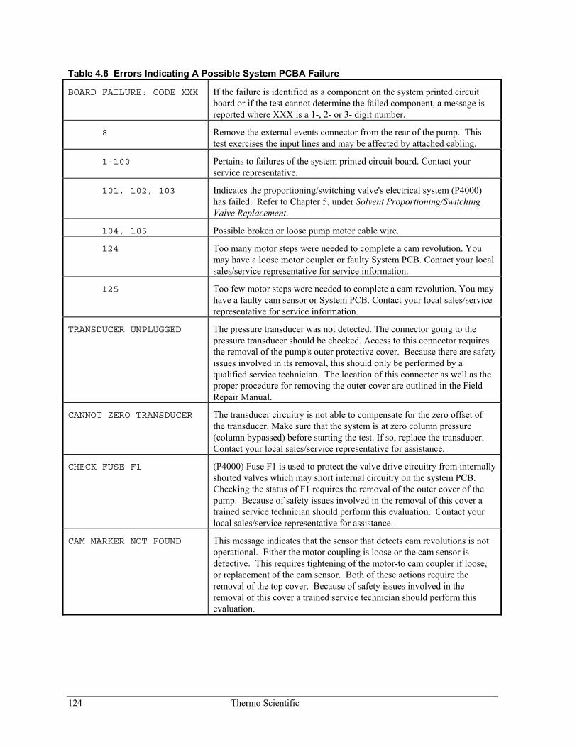
124 Thermo Scientific
Table 4.6 Errors Indicating A Possible System PCBA Failure
BOARD FAILURE: CODE XXX If the failure is identified as a component on the system printed circuit board or if the test cannot determine the failed component, a message is reported where XXX is a 1-, 2- or 3- digit number.
8 Remove the external events connector from the rear of the pump. This test exercises the input lines and may be affected by attached cabling.
1-100 Pertains to failures of the system printed circuit board. Contact your service representative.
101, 102, 103 Indicates the proportioning/switching valve's electrical system (P4000) has failed. Refer to Chapter 5, under Solvent Proportioning/Switching Valve Replacement.
104, 105 Possible broken or loose pump motor cable wire.
124 Too many motor steps were needed to complete a cam revolution. You may have a loose motor coupler or faulty System PCB. Contact your local sales/service representative for service information.
125 Too few motor steps were needed to complete a cam revolution. You may have a faulty cam sensor or System PCB. Contact your local sales/service representative for service information.
TRANSDUCER UNPLUGGED The pressure transducer was not detected. The connector going to the pressure transducer should be checked. Access to this connector requires the removal of the pump's outer protective cover. Because there are safety issues involved in its removal, this should only be performed by a qualified service technician. The location of this connector as well as the proper procedure for removing the outer cover are outlined in the Field Repair Manual.
CANNOT ZERO TRANSDUCER The transducer circuitry is not able to compensate for the zero offset of the transducer. Make sure that the system is at zero column pressure (column bypassed) before starting the test. If so, replace the transducer. Contact your local sales/service representative for assistance.
CHECK FUSE F1 (P4000) Fuse F1 is used to protect the valve drive circuitry from internally shorted valves which may short internal circuitry on the system PCB. Checking the status of F1 requires the removal of the outer cover of the pump. Because of safety issues involved in the removal of this cover a trained service technician should perform this evaluation. Contact your local sales/service representative for assistance.
CAM MARKER NOT FOUND This message indicates that the sensor that detects cam revolutions is not operational. Either the motor coupling is loose or the cam sensor is defective. This requires tightening of the motor-to cam coupler if loose, or replacement of the cam sensor. Both of these actions require the removal of the top cover. Because of safety issues involved in the removal of this cover a trained service technician should perform this evaluation.
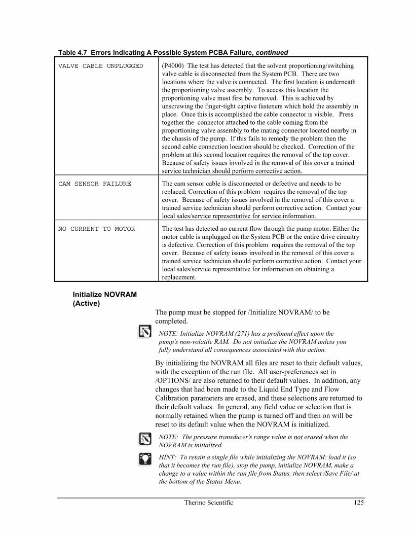
Thermo Scientific 125
Table 4.7 Errors Indicating A Possible System PCBA Failure, continued
VALVE CABLE UNPLUGGED (P4000) The test has detected that the solvent proportioning/switching valve cable is disconnected from the System PCB. There are two locations where the valve is connected. The first location is underneath the proportioning valve assembly. To access this location the proportioning valve must first be removed. This is achieved by unscrewing the finger-tight captive fasteners which hold the assembly in place. Once this is accomplished the cable connector is visible. Press together the connector attached to the cable coming from the proportioning valve assembly to the mating connector located nearby in the chassis of the pump. If this fails to remedy the problem then the second cable connection location should be checked. Correction of the problem at this second location requires the removal of the top cover. Because of safety issues involved in the removal of this cover a trained service technician should perform corrective action.
CAM SENSOR FAILURE The cam sensor cable is disconnected or defective and needs to be replaced. Correction of this problem requires the removal of the top cover. Because of safety issues involved in the removal of this cover a trained service technician should perform corrective action. Contact your local sales/service representative for service information.
NO CURRENT TO MOTOR The test has detected no current flow through the pump motor. Either the motor cable is unplugged on the System PCB or the entire drive circuitry is defective. Correction of this problem requires the removal of the top cover. Because of safety issues involved in the removal of this cover a trained service technician should perform corrective action. Contact your local sales/service representative for information on obtaining a replacement.
Initialize NOVRAM (Active)
The pump must be stopped for /Initialize NOVRAM/ to be completed.
NOTE: Initialize NOVRAM (271) has a profound effect upon the pump's non-volatile RAM. Do not initialize the NOVRAM unless you fully understand all consequences associated with this action.
By initializing the NOVRAM all files are reset to their default values, with the exception of the run file. All user-preferences set in /OPTIONS/ are also returned to their default values. In addition, any changes that had been made to the Liquid End Type and Flow Calibration parameters are erased, and these selections are returned to their default values. In general, any field value or selection that is normally retained when the pump is turned off and then on will be reset to its default value when the NOVRAM is initialized.
NOTE: The pressure transducer's range value is not erased when the NOVRAM is initialized.
HINT: To retain a single file while initializing the NOVRAM: load it (so that it becomes the run file), stop the pump, initialize NOVRAM, make a change to a value within the run file from Status, then select /Save File/ at the bottom of the Status Menu.

Thermo Scientific 127
5 Required Maintenance
Introduction When properly maintained, your Thermo Scientific SpectraSYSTEM pump will provide years of trouble-free operation. It is important that your pump receive routine preventive maintenance to ensure reliability and optimum performance. Properly performed routine, preventive maintenance also helps keep your warranty valid. Your pump is designed to encourage proper maintenance by making maintenance parts easy to access, replace and record.
This chapter describes the Maintenance Log Menu and how to use it. Some hints to help you extend the maintenance period of your pump are also included. Easy-to-follow, step-by-step required maintenance procedures are also contained in this chapter so that you can keep your pump in optimum working condition. A few maintenance tips for parts of the pump not directly involved with solvent flow follow the maintenance procedures. The last section contains replacement procedures for two user-serviceable parts: fuses and the solvent switching valve.
NOTE: Maintenance of the pump is the responsibility of the user. Routine maintenance is not provided under warranty. However, planned maintenance contracts are generally available. Please contact your local representative if you are interested in purchasing a planned maintenance contract.
THE BENEFITS OF PROPER MAINTENANCE
As with most things, there is tremendous benefit in doing things right the first time. For example, an unusually fast seal failure may indicate either incorrect installation or a scratched piston. A scratched piston may be caused by improper installation of the seal or piston, by allowing the pump to sit idle with a buffered eluant in it, or by failing to filter your eluants.
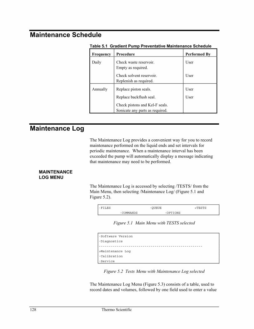
128 Thermo Scientific
Maintenance Schedule Table 5.1 Gradient Pump Preventative Maintenance Schedule
Frequency Procedure Performed By
Daily Check waste reservoir. Empty as required.
Check solvent reservoir. Replenish as required.
User
User
Annually Replace piston seals.
Replace backflush seal.
Check pistons and Kel-F seals. Sonicate any parts as required.
User
User
Maintenance Log The Maintenance Log provides a convenient way for you to record maintenance performed on the liquid ends and set intervals for periodic maintenance. When a maintenance interval has been exceeded the pump will automatically display a message indicating that maintenance may need to be performed.
MAINTENANCE LOG MENU
The Maintenance Log is accessed by selecting /TESTS/ from the Main Menu, then selecting /Maintenance Log/ (Figure 5.1 and Figure 5.2).
·FILES ·QUEUE >TESTS
·COMMANDS ·OPTIONS
Figure 5.1 Main Menu with TESTS selected
·Software Version
·Diagnostics
----------------------------------------------------
>Maintenance Log
·Calibration
·Service
Figure 5.2 Tests Menu with Maintenance Log selected
The Maintenance Log Menu (Figure 5.3) consists of a table, used to record dates and volumes, followed by one field used to enter a value
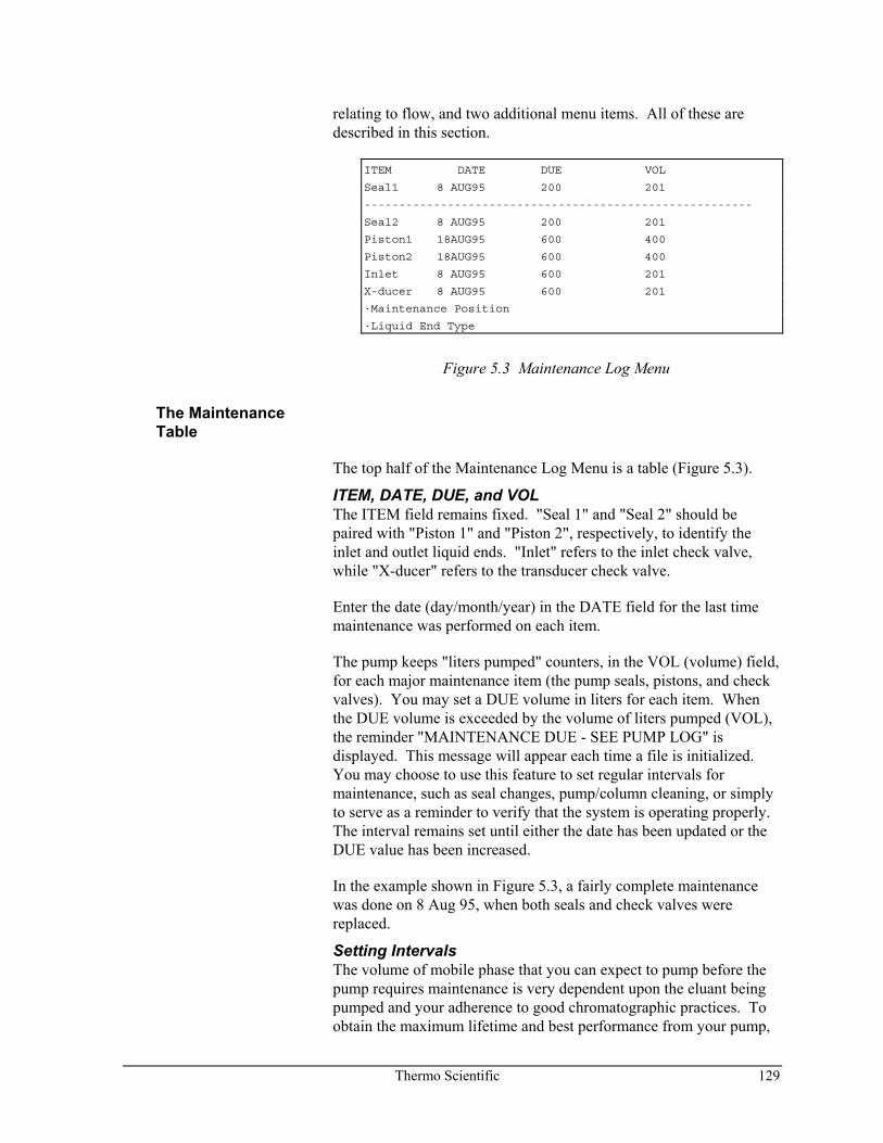
Thermo Scientific 129
relating to flow, and two additional menu items. All of these are described in this section.
ITEM DATE DUE VOL
Seal1 8 AUG95 200 201
--------------------------------------------------------
Seal2 8 AUG95 200 201
Piston1 18AUG95 600 400
Piston2 18AUG95 600 400
Inlet 8 AUG95 600 201
X-ducer 8 AUG95 600 201
·Maintenance Position
·Liquid End Type
Figure 5.3 Maintenance Log Menu
The Maintenance Table
The top half of the Maintenance Log Menu is a table (Figure 5.3).
ITEM, DATE, DUE, and VOL The ITEM field remains fixed. "Seal 1" and "Seal 2" should be paired with "Piston 1" and "Piston 2", respectively, to identify the inlet and outlet liquid ends. "Inlet" refers to the inlet check valve, while "X-ducer" refers to the transducer check valve.
Enter the date (day/month/year) in the DATE field for the last time maintenance was performed on each item.
The pump keeps "liters pumped" counters, in the VOL (volume) field, for each major maintenance item (the pump seals, pistons, and check valves). You may set a DUE volume in liters for each item. When the DUE volume is exceeded by the volume of liters pumped (VOL), the reminder "MAINTENANCE DUE - SEE PUMP LOG" is displayed. This message will appear each time a file is initialized. You may choose to use this feature to set regular intervals for maintenance, such as seal changes, pump/column cleaning, or simply to serve as a reminder to verify that the system is operating properly. The interval remains set until either the date has been updated or the DUE value has been increased.
In the example shown in Figure 5.3, a fairly complete maintenance was done on 8 Aug 95, when both seals and check valves were replaced.
Setting Intervals The volume of mobile phase that you can expect to pump before the pump requires maintenance is very dependent upon the eluant being pumped and your adherence to good chromatographic practices. To obtain the maximum lifetime and best performance from your pump,
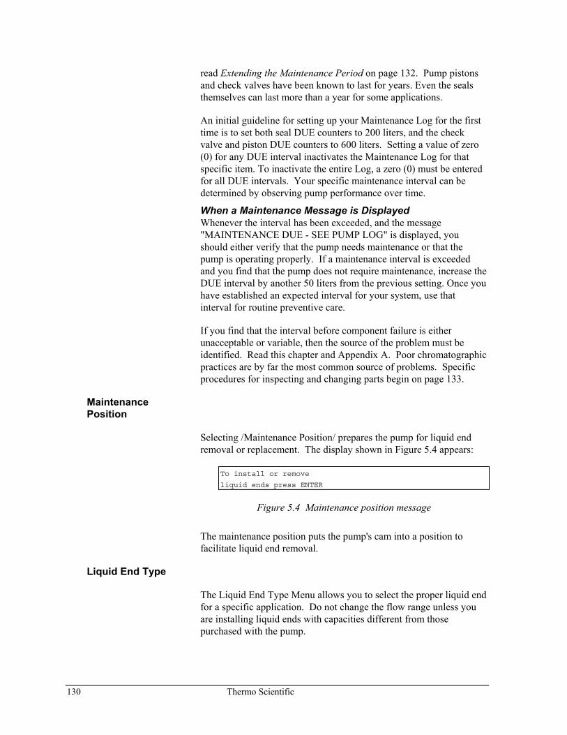
130 Thermo Scientific
read Extending the Maintenance Period on page 132. Pump pistons and check valves have been known to last for years. Even the seals themselves can last more than a year for some applications.
An initial guideline for setting up your Maintenance Log for the first time is to set both seal DUE counters to 200 liters, and the check valve and piston DUE counters to 600 liters. Setting a value of zero (0) for any DUE interval inactivates the Maintenance Log for that specific item. To inactivate the entire Log, a zero (0) must be entered for all DUE intervals. Your specific maintenance interval can be determined by observing pump performance over time.
When a Maintenance Message is Displayed Whenever the interval has been exceeded, and the message "MAINTENANCE DUE - SEE PUMP LOG" is displayed, you should either verify that the pump needs maintenance or that the pump is operating properly. If a maintenance interval is exceeded and you find that the pump does not require maintenance, increase the DUE interval by another 50 liters from the previous setting. Once you have established an expected interval for your system, use that interval for routine preventive care.
If you find that the interval before component failure is either unacceptable or variable, then the source of the problem must be identified. Read this chapter and Appendix A. Poor chromatographic practices are by far the most common source of problems. Specific procedures for inspecting and changing parts begin on page 133.
Maintenance Position
Selecting /Maintenance Position/ prepares the pump for liquid end removal or replacement. The display shown in Figure 5.4 appears:
To install or remove
liquid ends press ENTER
Figure 5.4 Maintenance position message
The maintenance position puts the pump's cam into a position to facilitate liquid end removal.
Liquid End Type
The Liquid End Type Menu allows you to select the proper liquid end for a specific application. Do not change the flow range unless you are installing liquid ends with capacities different from those purchased with the pump.
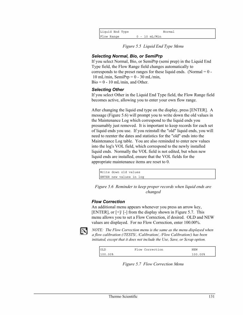
Thermo Scientific 131
Liquid End Type Normal
Flow Range 0 - 10 mL/Min
Figure 5.5 Liquid End Type Menu
Selecting Normal, Bio, or SemiPrp If you select Normal, Bio, or SemiPrp (semi prep) in the Liquid End Type field, the Flow Range field changes automatically to corresponds to the preset ranges for these liquid ends. (Normal = 0 - 10 mL/min, SemiPrp = 0 - 30 mL/min, Bio = 0 - 10 mL/min, and Other.
Selecting Other If you select Other in the Liquid End Type field, the Flow Range field becomes active, allowing you to enter your own flow range.
After changing the liquid end type on the display, press [ENTER]. A message (Figure 5.6) will prompt you to write down the old values in the Maintenance Log which correspond to the liquid ends you presumably just removed. It is important to keep records for each set of liquid ends you use. If you reinstall the "old" liquid ends, you will need to reenter the dates and statistics for the "old" ends into the Maintenance Log table. You are also reminded to enter new values into the log's VOL field, which correspond to the newly installed liquid ends. Normally the VOL field is not edited, but when new liquid ends are installed, ensure that the VOL fields for the appropriate maintenance items are reset to 0.
Write down old values
ENTER new values in log
Figure 5.6 Reminder to keep proper records when liquid ends are changed
Flow Correction An additional menu appears whenever you press an arrow key, [ENTER], or [+]/ [-] from the display shown in Figure 5.7. This menu allows you to set a Flow Correction, if desired. OLD and NEW values are displayed. For no Flow Correction, enter 100.00%.
NOTE: The Flow Correction menu is the same as the menu displayed when a flow calibration (/TESTS/, /Calibration/, /Flow Calibration/) has been initiated, except that it does not include the Use, Save, or Scrap option.
OLD Flow Correction NEW
100.00% 100.00%
Figure 5.7 Flow Correction Menu
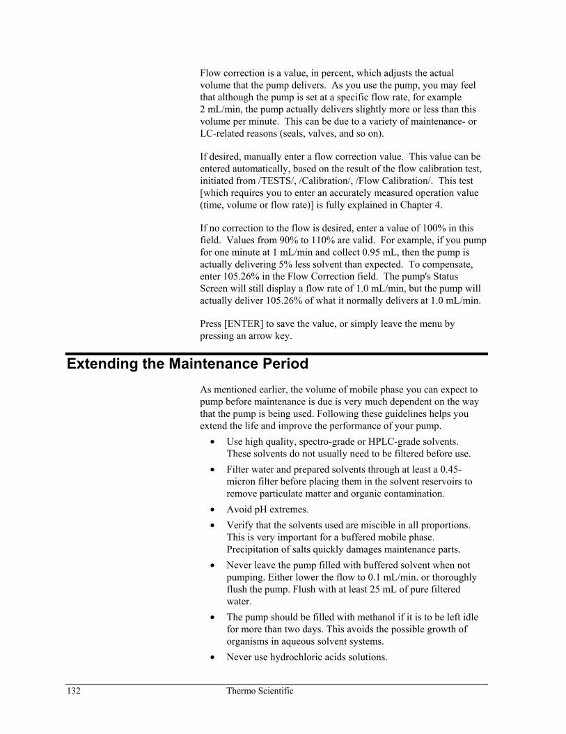
132 Thermo Scientific
Flow correction is a value, in percent, which adjusts the actual volume that the pump delivers. As you use the pump, you may feel that although the pump is set at a specific flow rate, for example 2 mL/min, the pump actually delivers slightly more or less than this volume per minute. This can be due to a variety of maintenance- or LC-related reasons (seals, valves, and so on).
If desired, manually enter a flow correction value. This value can be entered automatically, based on the result of the flow calibration test, initiated from /TESTS/, /Calibration/, /Flow Calibration/. This test [which requires you to enter an accurately measured operation value (time, volume or flow rate)] is fully explained in Chapter 4.
If no correction to the flow is desired, enter a value of 100% in this field. Values from 90% to 110% are valid. For example, if you pump for one minute at 1 mL/min and collect 0.95 mL, then the pump is actually delivering 5% less solvent than expected. To compensate, enter 105.26% in the Flow Correction field. The pump's Status Screen will still display a flow rate of 1.0 mL/min, but the pump will actually deliver 105.26% of what it normally delivers at 1.0 mL/min.
Press [ENTER] to save the value, or simply leave the menu by pressing an arrow key.
Extending the Maintenance Period As mentioned earlier, the volume of mobile phase you can expect to pump before maintenance is due is very much dependent on the way that the pump is being used. Following these guidelines helps you extend the life and improve the performance of your pump.
• Use high quality, spectro-grade or HPLC-grade solvents. These solvents do not usually need to be filtered before use.
• Filter water and prepared solvents through at least a 0.45-micron filter before placing them in the solvent reservoirs to remove particulate matter and organic contamination.
• Avoid pH extremes. • Verify that the solvents used are miscible in all proportions.
This is very important for a buffered mobile phase. Precipitation of salts quickly damages maintenance parts.
• Never leave the pump filled with buffered solvent when not pumping. Either lower the flow to 0.1 mL/min. or thoroughly flush the pump. Flush with at least 25 mL of pure filtered water.
• The pump should be filled with methanol if it is to be left idle for more than two days. This avoids the possible growth of organisms in aqueous solvent systems.
• Never use hydrochloric acids solutions.
Thermo Scientific 133
• Avoid metal ions that can cause corrosion due to electrochemical processes. Typical metal ions to avoid: manganese, chromium, nickel, copper, iron, molybdenum.
Maintenance Procedures SAFETY PRECAUTIONS
Observe the following safety precautions whenever performing periodic maintenance.
Caution! A caution alerts you to situations that could result in personal injury. It also tells you how to avoid them.
High Voltage! This icon alerts you to the presence of high voltage and to the potential injury that could occur from electrical shock were you to come in contact with a specific instrument area or component. It also tells you how to avoid contact with the high-voltage areas in your instrument.
Hot Surface! This icon alerts you to potential injury that could occur from coming in contact with a heated surface or area on or in an instrument. It also tells you how to avoid contact with the heated surfaces in your instrument.
This section includes procedures for: • Complete liquid end maintenance (includes disassembly and
assembly) • Check valve replacement • Passivating stainless steel parts
Also included are maintenance tips for pump parts that are not involved with pump flow.
134 Thermo Scientific
TOOLS
The following tools are useful to have on-hand as you perform maintenance procedures.
• Tweezers • Open-end wrenches (1/4-inch, 5/16-inch, 1/2-inch) • Loupe or magnifying glass • Allen wrench (Hex head) 9/64-inch
PREPARATION
Prepare the pump for maintenance before performing any maintenance procedure.
To prepare the pump for maintenance, flush the pump with 25 mL of methanol. If an incompatible solvent is resident in the pump, flush with appropriate intermediate solvents before flushing with methanol. For example, if chloroform is being used as the mobile phase solvent, an intermediate flush of 25 mL methylene chloride would be appropriate before flushing with methanol.
LIQUID END MAINTENANCE
Complete liquid end maintenance includes procedures for seal and piston maintenance:
• Removal • Disassembly
— inspection for contamination — cleaning — piston inspection — cleaning/replacing parts if necessary
• Assembly • Installation
For thorough cleaning, piston replacement, or total liquid end reconditioning, the liquid ends must be removed.
Having a second set of reconditioned liquid ends on hand for quick replacement will save additional time and allow maintenance to be performed at your convenience. Contact your local Thermo Fisher Scientific representative if you are interested in obtaining spare components. Part numbers are included in Appendix C.
NOTE: Keep the liquid end components as clean as possible. Contamination decreases seal life significantly.
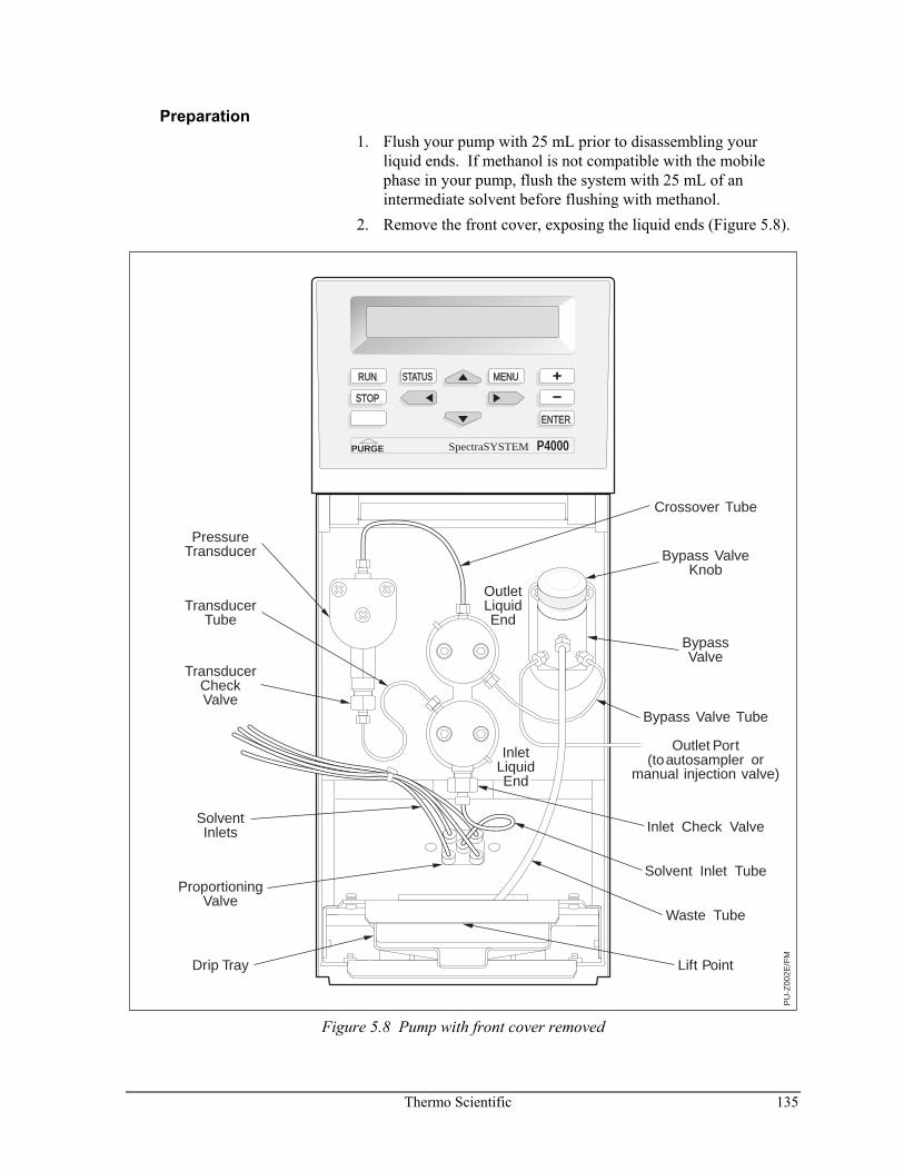
Thermo Scientific 135
Preparation 1. Flush your pump with 25 mL prior to disassembling your
liquid ends. If methanol is not compatible with the mobile phase in your pump, flush the system with 25 mL of an intermediate solvent before flushing with methanol.
2. Remove the front cover, exposing the liquid ends (Figure 5.8).
PU
-Z00
2E/F
M
RUN
STOP
STATUS MENU
ENTER
PURGE P4000SpectraSYSTEM
TransducerTube
PressureTransducer
TransducerCheckValve
SolventInlets
ProportioningValve
Drip Tray Lift Point
OutletLiquidEnd
BypassValve
Waste Tube
Outlet Port(toautosampler or
manual injection valve)
Inlet Check Valve
Solvent Inlet Tube
InletLiquid End
Bypass ValveKnob
Crossover Tube
Bypass Valve Tube
Figure 5.8 Pump with front cover removed
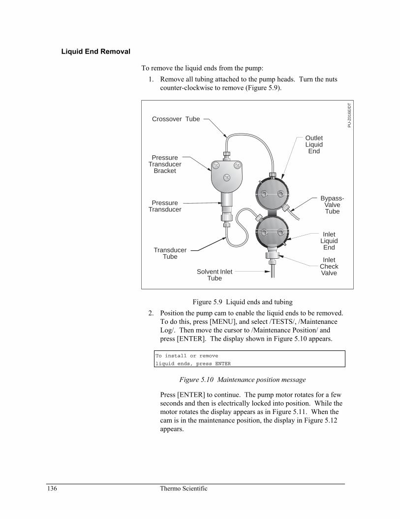
136 Thermo Scientific
Liquid End Removal
To remove the liquid ends from the pump: 1. Remove all tubing attached to the pump heads. Turn the nuts
counter-clockwise to remove (Figure 5.9).
PressureTransducer
Bracket
PressureTransducer
TransducerTube
Bypass-ValveTube
OutletLiquidEnd
InletLiquidEnd
InletCheckValve
Crossover Tube
PU
-Z01
6E/D
T
Solvent InletTube
Figure 5.9 Liquid ends and tubing 2. Position the pump cam to enable the liquid ends to be removed.
To do this, press [MENU], and select /TESTS/, /Maintenance Log/. Then move the cursor to /Maintenance Position/ and press [ENTER]. The display shown in Figure 5.10 appears.
To install or remove
liquid ends, press ENTER
Figure 5.10 Maintenance position message
Press [ENTER] to continue. The pump motor rotates for a few seconds and then is electrically locked into position. While the motor rotates the display appears as in Figure 5.11. When the cam is in the maintenance position, the display in Figure 5.12 appears.
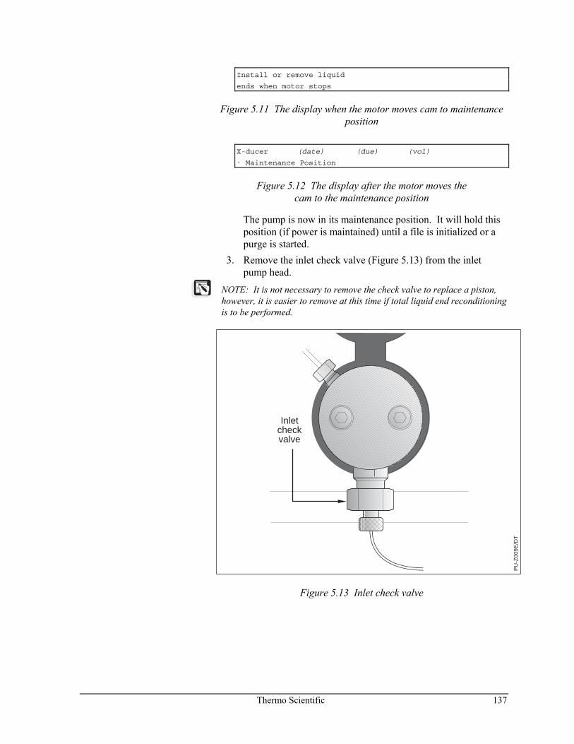
Thermo Scientific 137
Install or remove liquid
ends when motor stops
Figure 5.11 The display when the motor moves cam to maintenance position
X-ducer (date) (due) (vol)
· Maintenance Position
Figure 5.12 The display after the motor moves the cam to the maintenance position
The pump is now in its maintenance position. It will hold this position (if power is maintained) until a file is initialized or a purge is started.
3. Remove the inlet check valve (Figure 5.13) from the inlet pump head.
NOTE: It is not necessary to remove the check valve to replace a piston, however, it is easier to remove at this time if total liquid end reconditioning is to be performed.
PU
-Z00
9E/D
T
Inletcheckvalve
Figure 5.13 Inlet check valve
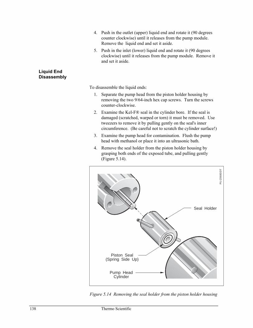
138 Thermo Scientific
4. Push in the outlet (upper) liquid end and rotate it (90 degrees counter clockwise) until it releases from the pump module. Remove the liquid end and set it aside.
5. Push in the inlet (lower) liquid end and rotate it (90 degrees clockwise) until it releases from the pump module. Remove it and set it aside.
Liquid End Disassembly
To disassemble the liquid ends: 1. Separate the pump head from the piston holder housing by
removing the two 9/64-inch hex cap screws. Turn the screws counter-clockwise.
2. Examine the Kel-F® seal in the cylinder bore. If the seal is damaged (scratched, warped or torn) it must be removed. Use tweezers to remove it by pulling gently on the seal's inner circumference. (Be careful not to scratch the cylinder surface!)
3. Examine the pump head for contamination. Flush the pump head with methanol or place it into an ultrasonic bath.
4. Remove the seal holder from the piston holder housing by grasping both ends of the exposed tube, and pulling gently (Figure 5.14).
PU
-Z05
0E/D
T
Seal Holder
Piston Seal (Spring Side Up)
Pump HeadCylinder
Figure 5.14 Removing the seal holder from the piston holder housing
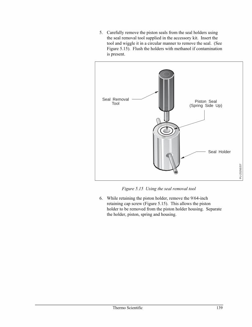
Thermo Scientific 139
5. Carefully remove the piston seals from the seal holders using the seal removal tool supplied in the accessory kit. Insert the tool and wiggle it in a circular manner to remove the seal. (See Figure 5.15). Flush the holders with methanol if contamination is present.
Seal RemovalTool
PU
-Z02
5E/D
T
Seal Holder
Piston Seal(Spring Side Up)
Figure 5.15 Using the seal removal tool
6. While retaining the piston holder, remove the 9/64-inch retaining cap screw (Figure 5.15). This allows the piston holder to be removed from the piston holder housing. Separate the holder, piston, spring and housing.
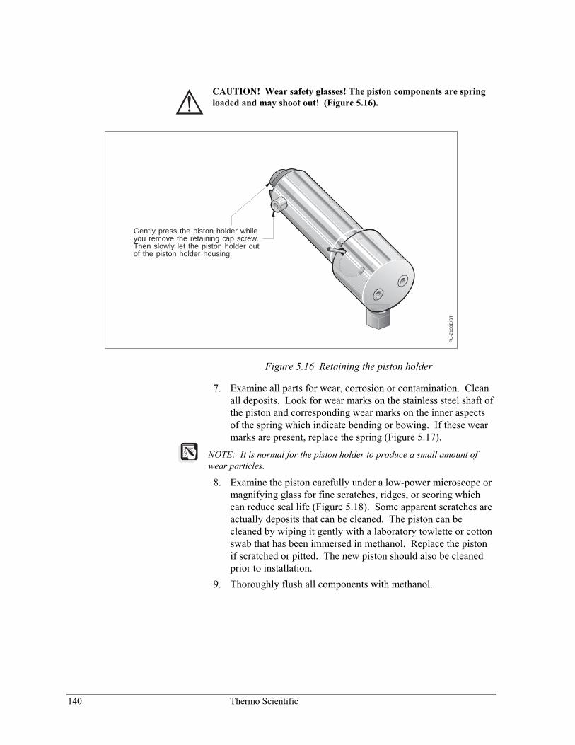
140 Thermo Scientific
CAUTION! Wear safety glasses! The piston components are spring loaded and may shoot out! (Figure 5.16).
PU
-Z13
0E/S
T
Gently press the piston holder whileyou remove the retaining cap screw.Then slowly let the piston holder outof the piston holder housing.
Figure 5.16 Retaining the piston holder
7. Examine all parts for wear, corrosion or contamination. Clean all deposits. Look for wear marks on the stainless steel shaft of the piston and corresponding wear marks on the inner aspects of the spring which indicate bending or bowing. If these wear marks are present, replace the spring (Figure 5.17).
NOTE: It is normal for the piston holder to produce a small amount of wear particles.
8. Examine the piston carefully under a low-power microscope or magnifying glass for fine scratches, ridges, or scoring which can reduce seal life (Figure 5.18). Some apparent scratches are actually deposits that can be cleaned. The piston can be cleaned by wiping it gently with a laboratory towlette or cotton swab that has been immersed in methanol. Replace the piston if scratched or pitted. The new piston should also be cleaned prior to installation.
9. Thoroughly flush all components with methanol.
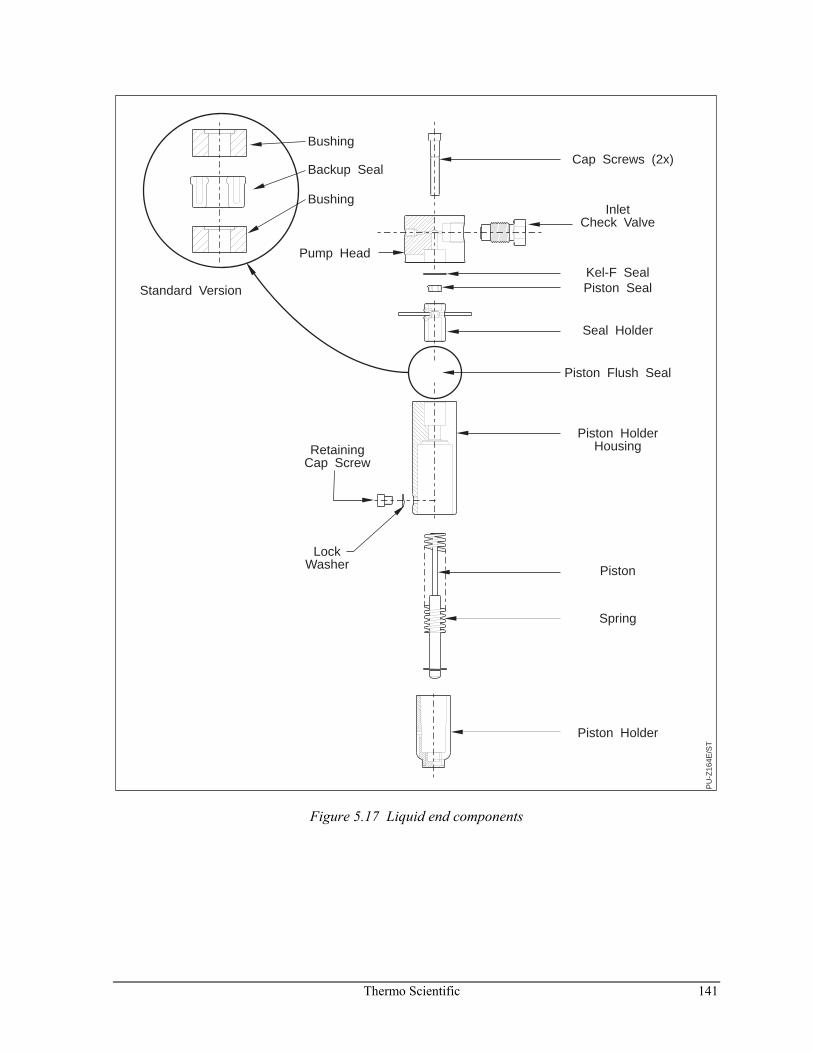
Thermo Scientific 141
PU
-Z16
4E/S
T
InletCheck Valve
Pump Head
Bushing
Bushing
Backup Seal
RetainingCap Screw
LockWasher
Cap Screws (2x)
Kel-F SealPiston Seal
Seal Holder
Piston Flush Seal
Piston HolderHousing
Piston
Spring
Piston Holder
Standard Version
Figure 5.17 Liquid end components
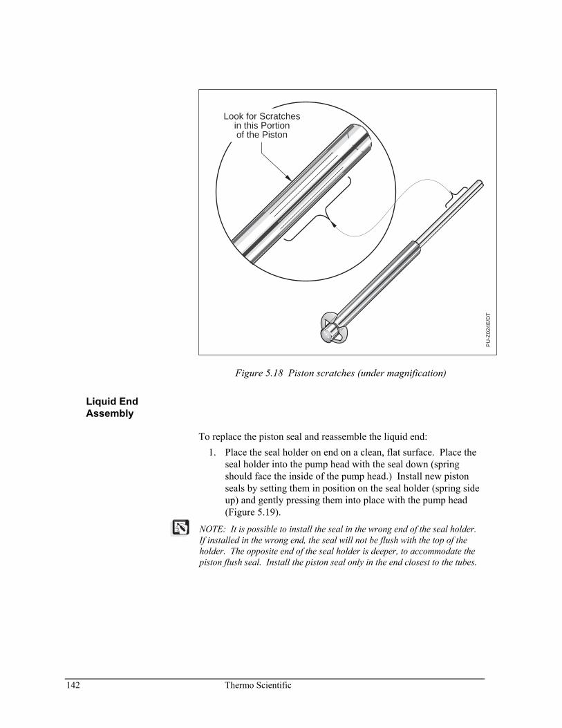
142 Thermo Scientific
PU
-Z02
4E/D
T
Look for Scratchesin this Portion of the Piston
Figure 5.18 Piston scratches (under magnification)
Liquid End Assembly
To replace the piston seal and reassemble the liquid end: 1. Place the seal holder on end on a clean, flat surface. Place the
seal holder into the pump head with the seal down (spring should face the inside of the pump head.) Install new piston seals by setting them in position on the seal holder (spring side up) and gently pressing them into place with the pump head (Figure 5.19).
NOTE: It is possible to install the seal in the wrong end of the seal holder. If installed in the wrong end, the seal will not be flush with the top of the holder. The opposite end of the seal holder is deeper, to accommodate the piston flush seal. Install the piston seal only in the end closest to the tubes.
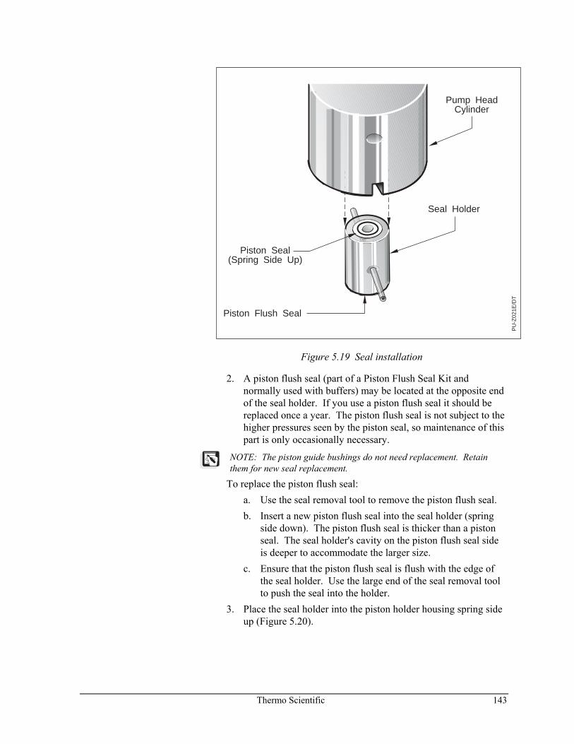
Thermo Scientific 143
PU
-Z02
1E/D
T
Seal Holder
Piston Seal(Spring Side Up)
Piston Flush Seal
Pump HeadCylinder
Figure 5.19 Seal installation
2. A piston flush seal (part of a Piston Flush Seal Kit and normally used with buffers) may be located at the opposite end of the seal holder. If you use a piston flush seal it should be replaced once a year. The piston flush seal is not subject to the higher pressures seen by the piston seal, so maintenance of this part is only occasionally necessary.
NOTE: The piston guide bushings do not need replacement. Retain them for new seal replacement.
To replace the piston flush seal: a. Use the seal removal tool to remove the piston flush seal. b. Insert a new piston flush seal into the seal holder (spring
side down). The piston flush seal is thicker than a piston seal. The seal holder's cavity on the piston flush seal side is deeper to accommodate the larger size.
c. Ensure that the piston flush seal is flush with the edge of the seal holder. Use the large end of the seal removal tool to push the seal into the holder.
3. Place the seal holder into the piston holder housing spring side up (Figure 5.20).
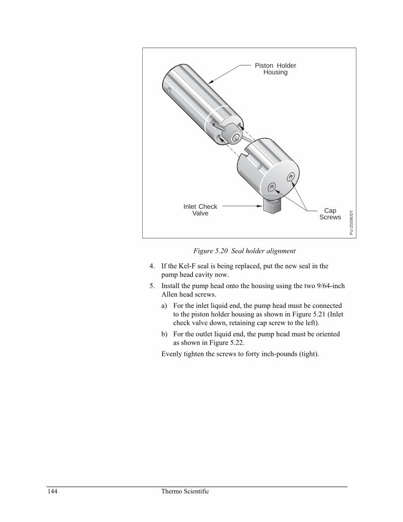
144 Thermo Scientific
PU
-Z02
0E/D
TCapScrews
Piston HolderHousing
Inlet CheckValve
Figure 5.20 Seal holder alignment
4. If the Kel-F seal is being replaced, put the new seal in the pump head cavity now.
5. Install the pump head onto the housing using the two 9/64-inch Allen head screws. a) For the inlet liquid end, the pump head must be connected
to the piston holder housing as shown in Figure 5.21 (Inlet check valve down, retaining cap screw to the left).
b) For the outlet liquid end, the pump head must be oriented as shown in Figure 5.22.
Evenly tighten the screws to forty inch-pounds (tight).
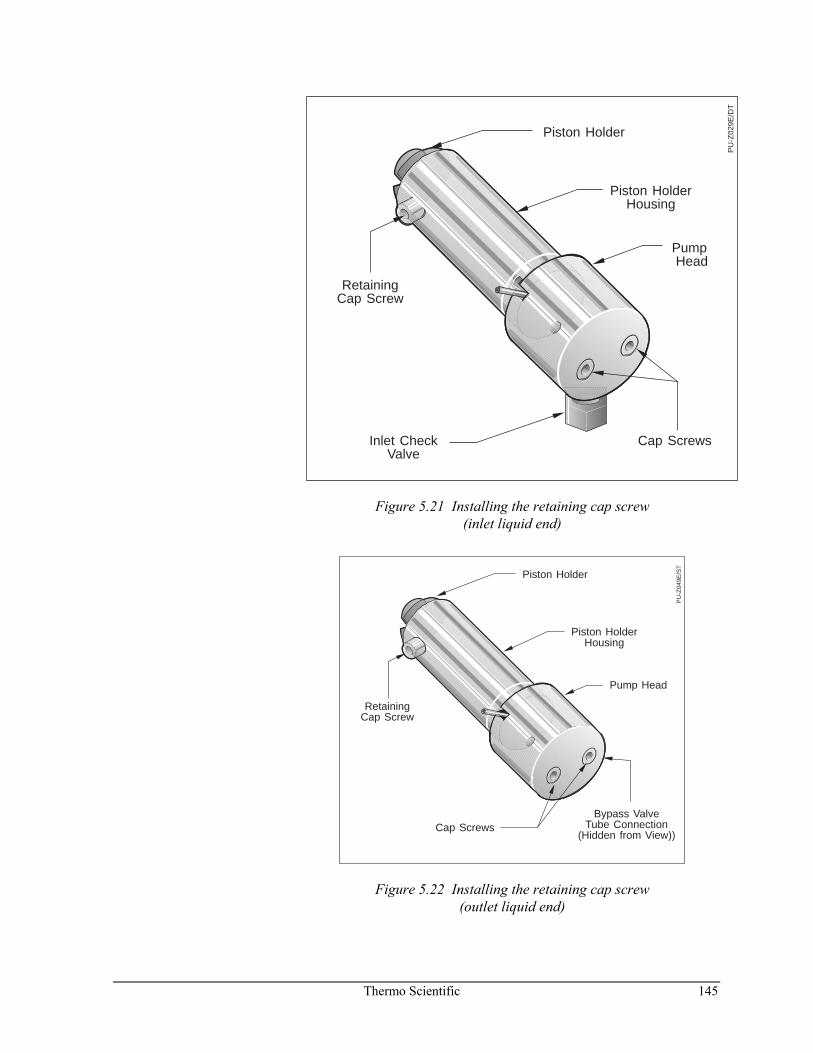
Thermo Scientific 145
PU
-Z02
9E/D
T
Piston Holder
Piston HolderHousing
RetainingCap Screw
PumpHead
Cap ScrewsInlet CheckValve
Figure 5.21 Installing the retaining cap screw (inlet liquid end)
PU
-Z04
9E/S
T
Piston Holder
Piston HolderHousing
RetainingCap Screw
Pump Head
Bypass Valve Tube Connection
(Hidden from View))Cap Screws
Figure 5.22 Installing the retaining cap screw (outlet liquid end)
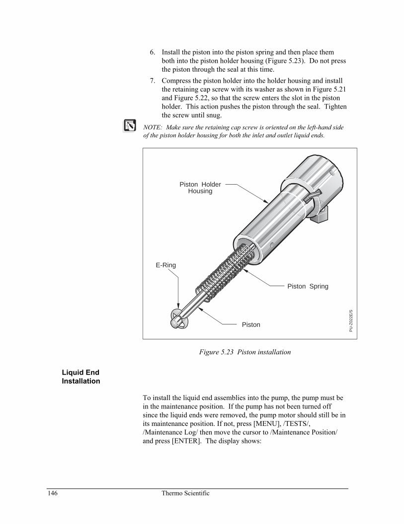
146 Thermo Scientific
6. Install the piston into the piston spring and then place them both into the piston holder housing (Figure 5.23). Do not press the piston through the seal at this time.
7. Compress the piston holder into the holder housing and install the retaining cap screw with its washer as shown in Figure 5.21 and Figure 5.22, so that the screw enters the slot in the piston holder. This action pushes the piston through the seal. Tighten the screw until snug.
NOTE: Make sure the retaining cap screw is oriented on the left-hand side of the piston holder housing for both the inlet and outlet liquid ends.
PU
-Z02
2E/S
E-Ring
Piston Spring
Piston HolderHousing
Piston
Figure 5.23 Piston installation
Liquid End Installation
To install the liquid end assemblies into the pump, the pump must be in the maintenance position. If the pump has not been turned off since the liquid ends were removed, the pump motor should still be in its maintenance position. If not, press [MENU], /TESTS/, /Maintenance Log/ then move the cursor to /Maintenance Position/ and press [ENTER]. The display shows:
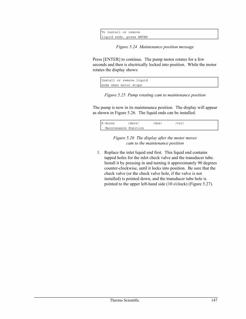
Thermo Scientific 147
To install or remove
liquid ends, press ENTER
Figure 5.24 Maintenance position message
Press [ENTER] to continue. The pump motor rotates for a few seconds and then is electrically locked into position. While the motor rotates the display shows:
Install or remove liquid
ends when motor stops
Figure 5.25 Pump rotating cam to maintenance position
The pump is now in its maintenance position. The display will appear as shown in Figure 5.26. The liquid ends can be installed.
X-ducer (date) (due) (vol)
· Maintenance Position
Figure 5.26 The display after the motor moves cam to the maintenance position
1. Replace the inlet liquid end first. This liquid end contains tapped holes for the inlet check valve and the transducer tube. Install it by pressing in and turning it approximately 90 degrees counter-clockwise, until it locks into position. Be sure that the check valve (or the check valve hole, if the valve is not installed) is pointed down, and the transducer tube hole is pointed to the upper left-hand side (10 o'clock) (Figure 5.27).
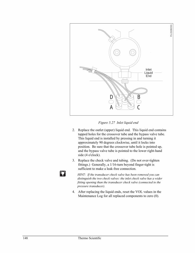
148 Thermo Scientific
PU
-Z02
8E/D
G
InletLiquidEnd
B
C
D
A
Figure 5.27 Inlet liquid end
2. Replace the outlet (upper) liquid end. This liquid end contains tapped holes for the crossover tube and the bypass valve tube. This liquid end is installed by pressing in and turning it approximately 90 degrees clockwise, until it locks into position. Be sure that the crossover tube hole is pointed up, and the bypass valve tube is pointed to the lower right-hand side (4 o'clock).
3. Replace the check valve and tubing. (Do not over-tighten fittings.) Generally, a 1/16-turn beyond finger-tight is sufficient to make a leak-free connection.
HINT: If the transducer check valve has been removed you can distinguish the two check valves: the inlet check valve has a wider fitting opening than the transducer check valve (connected to the pressure transducer).
4. After replacing the liquid ends, reset the VOL values in the Maintenance Log for all replaced components to zero (0).
Thermo Scientific 149
POST-INSTALLATION SEAL CONDITIONING
Follow the procedure below each time you replace liquid end seals. 1. Open the column bypass valve and purge with methanol to
clear air from the solvent lines and liquid ends. 2. Purge the pump through an old column or flow restrictor at
4000 psi for a minimum of 20 minutes. Reduce the flow to 1 mL/min and continue pumping for 15 minutes.
3. Check for solvent leaks. Do not return the pump to every-day service unless you are sure that no leaks are present.
CHECK VALVE MAINTENANCE
If the pump has notified you that it is time to replace check valves or if check valve replacement was recommended in Appendix A, Troubleshooting, then follow these steps. Check valve maintenance consists of:
• Inlet check valve removal and installation • Transducer check valve removal and installation
NOTE: The factory-supplied replacement check valves are manufactured in a clean-room environment and capped to protect them from contamination. It is very important to maintain a clean environment when installing them.
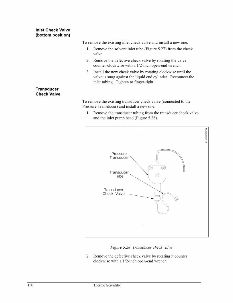
150 Thermo Scientific
Inlet Check Valve (bottom position)
To remove the existing inlet check valve and install a new one: 1. Remove the solvent inlet tube (Figure 5.27) from the check
valve. 2. Remove the defective check valve by rotating the valve
counter-clockwise with a 1/2-inch open-end wrench. 3. Install the new check valve by rotating clockwise until the
valve is snug against the liquid end cylinder. Reconnect the inlet tubing. Tighten to finger-tight.
Transducer Check Valve
To remove the existing transducer check valve (connected to the Pressure Transducer) and install a new one:
1. Remove the transducer tubing from the transducer check valve and the inlet pump head (Figure 5.28).
TransducerTube
PressureTransducer
TransducerCheck Valve
PU
-Z01
5E/D
G
Figure 5.28 Transducer check valve
2. Remove the defective check valve by rotating it counter clockwise with a 1/2-inch open-end wrench.
Thermo Scientific 151
3. Install the new check valve by rotating it clockwise until snug, and tighten with a 1/2-inch open-end wrench. Replace the connecting tubing. Tighten fittings only enough to stop leaks. Generally, this is 1/16-turn beyond finger-tight.
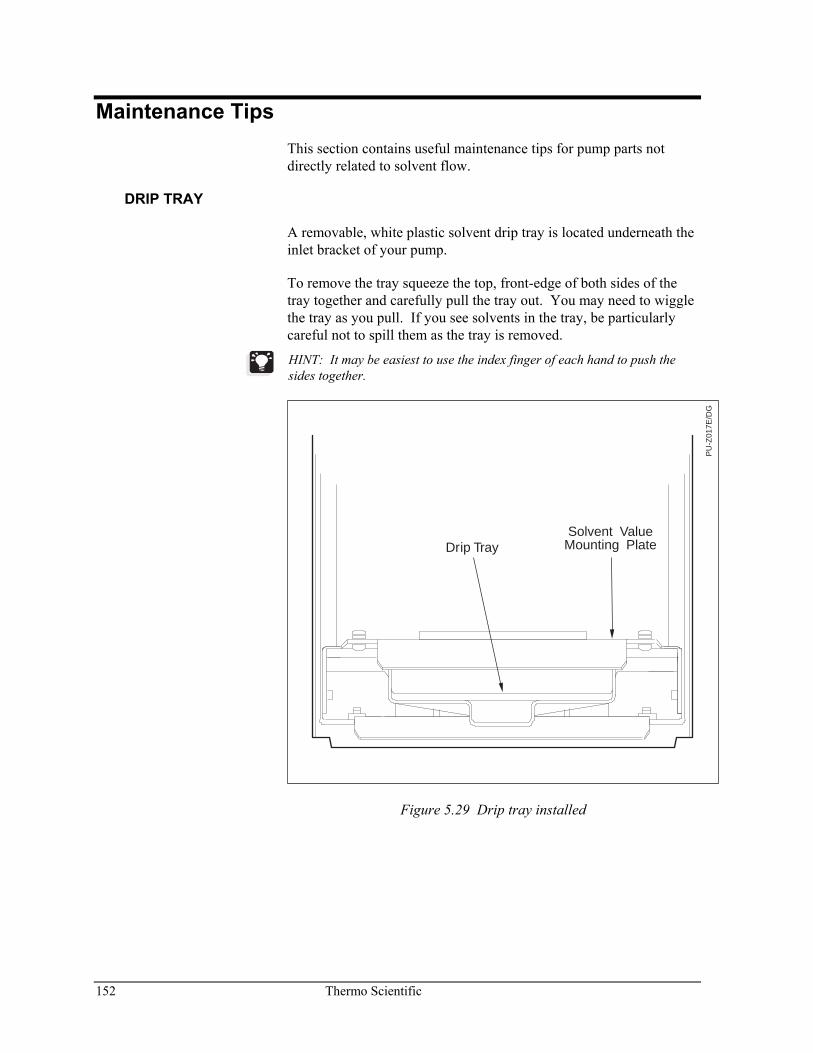
152 Thermo Scientific
Maintenance Tips This section contains useful maintenance tips for pump parts not directly related to solvent flow.
DRIP TRAY
A removable, white plastic solvent drip tray is located underneath the inlet bracket of your pump.
To remove the tray squeeze the top, front-edge of both sides of the tray together and carefully pull the tray out. You may need to wiggle the tray as you pull. If you see solvents in the tray, be particularly careful not to spill them as the tray is removed.
HINT: It may be easiest to use the index finger of each hand to push the sides together.
Drip TraySolvent Value
Mounting Plate
PU
-Z01
7E/D
G
Figure 5.29 Drip tray installed
Thermo Scientific 153
PASSIVATION OF STAINLESS STEEL COMPONENTS
All the major type 316 stainless steel components used in the SpectraSYSTEM pumps are passivated prior to assembly to ensure the removal of porous particles from the surface and to coat the surface with a layer of chromium oxide, which is highly resistant to corrosion. All stainless steel replacement parts purchased from Thermo Fisher Scientific are also passivated.
However, stainless steel components are subject to corrosion from strong acid solutions (in particular, materials containing halides), organic acids, and sometimes even water. Resistance to corrosion of the stainless steel components can be enhanced by using the following procedures.
CAUTION—Chemical Hazard! Take care when passivating with strong acids. Wear protective eye covering and protective clothing.
NOTE: Before installing any new parts not supplied from the Factory such as stainless steel tubing, the parts should first be passivated using the methods below.
NOTE: DO NOT expose a column to the passivation mixture. Remove the column before pumping if it is necessary to pump passivation solvents through the pump. It is preferable, however, to remove the components from the pump and then passivate them apart from the system.
1. When the surface area to be passivated is thoroughly clean, it is passivated by wetting the surface with a 20% nitric acid solution in deionized water for about 10 minutes at room temperature.
2. After passivation, thoroughly clean the parts to remove any residual nitric acid. Wash with deionized water until the system is neutral to pH paper. Follow up with another wash using 50-50 water/methanol followed by methanol. When thoroughly clean, blow dry using nitrogen. (Do not use the laboratory air system or air from a compressor that may contain an oily residue.)
154 Thermo Scientific
Repair Instructions If troubleshooting has pointed to a blown fuse in the power entry module, or to the need to replace the solvent switching valve (P4000), use the procedures below to make repairs.
POWER ENTRY MODULE FUSE REPLACEMENT
Instrument power is supplied by two 4.0-amp fuses housed in the fuse compartment of the power entry module, above the power cord receptacle.
To replace the fuses: 1. Ensure that the power cord is not connected to the pump. 2. Use a small, flat blade screwdriver to pry open the power
selector/fuse cover. You will probably hear the top edge of the cover snap as it is pried open.
3. Pull out the fuse holder and discard the bad fuse. Place the new fuse into the holder with the metal end visible.
4. Snap the fuse holder back into place.
NOTE: If the power selector barrel accidentally comes out, be sure to replace it so that the correct voltage for your area shows through the voltage window.
5. Firmly snap the housing cover back in place. Be sure that the correct voltage is visible in the voltage window.
HINT: Use two thumbs to push up on the top half of the cover as youpush in.
Thermo Scientific 155
SOLVENT SWITCHING VALVE REPLACEMENT (P4000 ONLY)
To remove the solvent switching valve: 1. Turn off power. 2. Remove front cover. 3. Remove the solvent inlet tube fitting from the inlet check
valve. 4. Loosen the two knurled screws on the front-left and front-right
sides of the inlet bracket. 5. Lift and pull the bracket forward 3 - 4 inches. 6. Disconnect the inlet tubes from the solvent switching valves at
locations A and B. 7. Remove the solvent inlet line from the center port of the valve. 8. Disconnect the solvent switching valve cable at the rear of the
solvent valve cavity, and remove the solvent valve/bracket fully from the pump.
To install a new solvent switching valve: 1. Connect the replacement valve's cable to the connector at the
rear of the solvent valve cavity. 2. Connect the solvent inlet line to the center port of the
replacement valve. Tighten snugly but only finger-tight. 3. Re-connect the inlet tubes to the valve ports, making sure the
identification of each inlet tube matches the identification of each valve port location.
4. Install the valve and bracket into the solvent valve cavity. Tighten the knurled screws.
5. Attach the solvent inlet line to the inlet check valve. Tighten snugly but only finger-tight.
6. Prime the pump using the technique described in Chapter 1.

Thermo Scientific 157
A Troubleshooting
Introduction Your SpectraSYSTEM pump is designed to operate trouble-free for many years when properly maintained. Most pump problems can be avoided by simple, periodic maintenance, as described in Chapter 5. However, in the event that an error message is displayed or if a mechanical or electrical failure is suspected, the problem can be easily diagnosed. Further, if the diagnosis indicates that a problem exists with non user-serviceable parts inside the pump, a qualified Thermo Fisher Scientific service representative can quickly and easily replace most malfunctioning parts.
This appendix contains information on: • Theory of operation • General LC system troubleshooting • Pump-specific Troubleshooting • Error Messages • Display Messages
A quick-reference hardware troubleshooting guide is included at the end of this appendix that includes tips for diagnosing and remedying hardware problems. This guide can save you time in diagnosing problems when the symptoms are known.
Theory of Operation A gradient pump works by first pulling a solvent into a proportioning valve. The P4000 pump has four proportioning valves. Solvents are measured by percentages, as specified by the user, and mixed inside the pump. The solvents then travel to the pump head, where a piston regulates the flow of the mixture to an outlet tube. The mixed solvent is routed through the pressure transducer, into a second pump head, then through a bypass valve (closed during normal operation), and finally out to the LC system. The pump's outlet tubing is then generally connected to an automatic injector, such as an autosampler.
158 Thermo Scientific
Troubleshooting Your Pump SAFETY PRECAUTIONS
Observe the following safety precautions whenever troubleshooting hardware difficulties.
Caution! A caution alerts you to situations that could result in personal injury. It also tells you how to avoid them.
High Voltage! This icon alerts you to the presence of high voltage and to the potential injury that could occur from electrical shock were you to come in contact with a specific instrument area or component. It also tells you how to avoid contact with the high-voltage areas in your instrument.
Hot Surface! This icon alerts you to potential injury that could occur from coming in contact with a heated surface or area on or in an instrument. It also tells you how to avoid contact with the heated surfaces in your instrument.
TROUBLESHOOTING TIPS
Eliminate all Other possible sources of trouble Before you spend any time trying to diagnose a suspected pump problem you should verify that the pump is the only source of difficulty. Systematically eliminate all other instruments in your LC system as the source of trouble. If you are not sure which component of your chromatography system is responsible for poor system performance the General LC System Troubleshooting section beginning on page 159 of this appendix provides useful suggestions.
When You're Sure Its the Pump Once you have isolated the pump as the only remaining source of difficulty, a variety of self-tests are built into the pump to help you determine if your pump is operating correctly.
The next section describes the tests found in the /TESTS/ menu item. Instructions for the built-in hardware and electronics diagnostics are contained within the description of the Tests Menu.
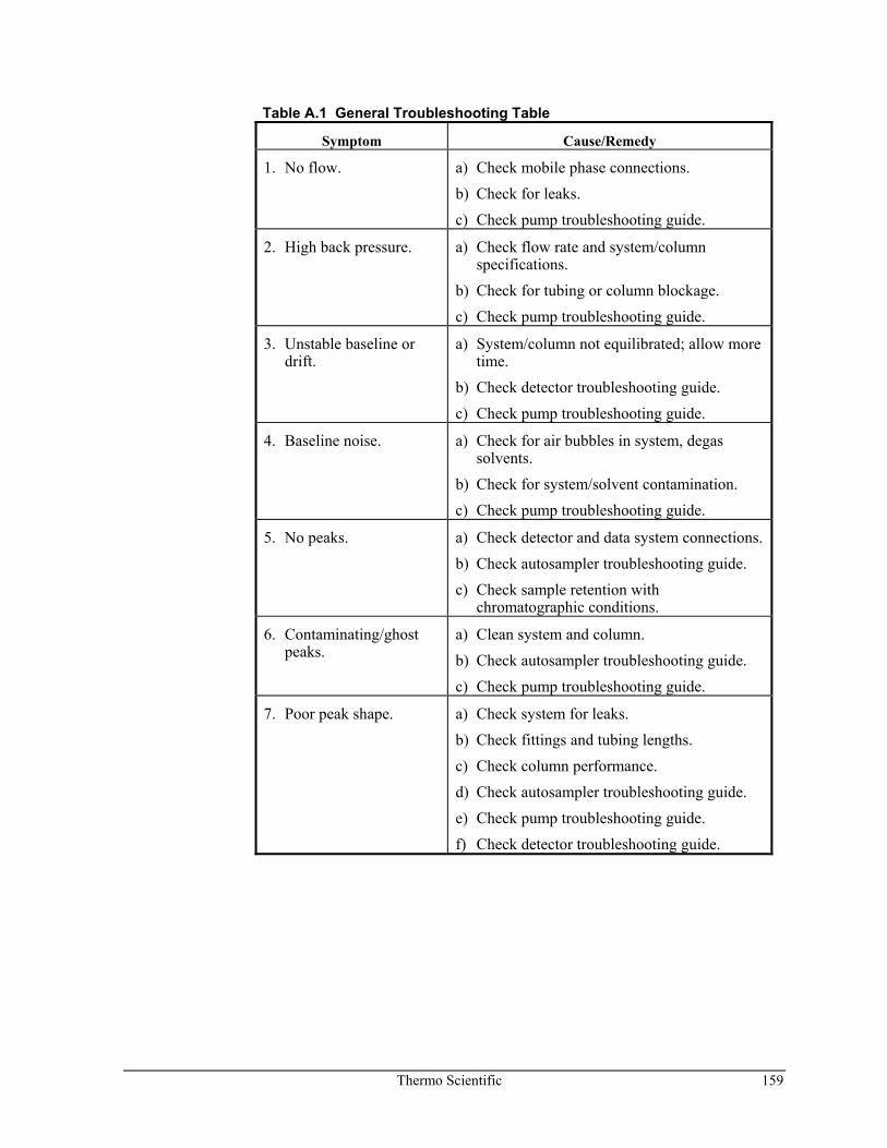
Thermo Scientific 159
Table A.1 General Troubleshooting Table
Symptom Cause/Remedy
1. No flow. a) Check mobile phase connections. b) Check for leaks. c) Check pump troubleshooting guide.
2. High back pressure. a) Check flow rate and system/column specifications.
b) Check for tubing or column blockage. c) Check pump troubleshooting guide.
3. Unstable baseline or drift.
a) System/column not equilibrated; allow more time.
b) Check detector troubleshooting guide. c) Check pump troubleshooting guide.
4. Baseline noise. a) Check for air bubbles in system, degas solvents.
b) Check for system/solvent contamination. c) Check pump troubleshooting guide.
5. No peaks. a) Check detector and data system connections. b) Check autosampler troubleshooting guide. c) Check sample retention with
chromatographic conditions.
6. Contaminating/ghost peaks.
a) Clean system and column. b) Check autosampler troubleshooting guide. c) Check pump troubleshooting guide.
7. Poor peak shape. a) Check system for leaks. b) Check fittings and tubing lengths. c) Check column performance. d) Check autosampler troubleshooting guide. e) Check pump troubleshooting guide. f) Check detector troubleshooting guide.

160 Thermo Scientific
Table A.1 General Troubleshooting Table, continued
Symptom Cause/Remedy
8. Poor retention time reproducibility.
a) Check system for leaks and bubbles. b) System/column not equilibrated, allow more
time. c) Check column performance.
d) Check pump troubleshooting guide.
e) Check autosampler troubleshooting guide.
f) Check data system troubleshooting guide.
9. Poor peak area reproducibility.
a) Check column performance. b) Check autosampler troubleshooting guide. c) Check data system troubleshooting guide.
10. Non-integrated or too many peaks.
a) Check integrator or data system troubleshooting guide.
11. No instrument of device control.
a) Check cable connections. b) Check system configuration. c) Check individual instrument troubleshooting
guide. d) Check integrator or data system
troubleshooting guide.
For more detailed chromatographic troubleshooting, refer to any HPLC troubleshooting reference book or call your local sales or service representative.
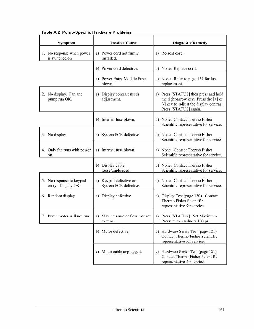
Thermo Scientific 161
Table A.2 Pump-Specific Hardware Problems
Symptom Possible Cause Diagnostic/Remedy
1. No response when power is switched on.
a) Power cord not firmly installed.
a) Re-seat cord.
b) Power cord defective. b) None. Replace cord.
c) Power Entry Module Fuse blown.
c) None. Refer to page 154 for fuse replacement.
2. No display. Fan and pump run OK.
a) Display contrast needs adjustment.
a) Press [STATUS] then press and hold the right-arrow key. Press the [+] or [-] key to adjust the display contrast. Press [STATUS] again.
b) Internal fuse blown. b) None. Contact Thermo Fisher Scientific representative for service.
3. No display. a) System PCB defective. a) None. Contact Thermo Fisher Scientific representative for service.
4. Only fan runs with power on.
a) Internal fuse blown. a) None. Contact Thermo Fisher Scientific representative for service.
b) Display cable loose/unplugged.
b) None. Contact Thermo Fisher Scientific representative for service.
5. No response to keypad entry. Display OK.
a) Keypad defective or System PCB defective.
a) None. Contact Thermo Fisher Scientific representative for service.
6. Random display. a) Display defective. a) Display Test (page 120). Contact Thermo Fisher Scientific representative for service.
7. Pump motor will not run. a) Max pressure or flow rate set to zero.
a) Press [STATUS]. Set Maximum Pressure to a value > 100 psi.
b) Motor defective. b) Hardware Series Test (page 121). Contact Thermo Fisher Scientific representative for service.
c) Motor cable unplugged. c) Hardware Series Test (page 121). Contact Thermo Fisher Scientific representative for service.
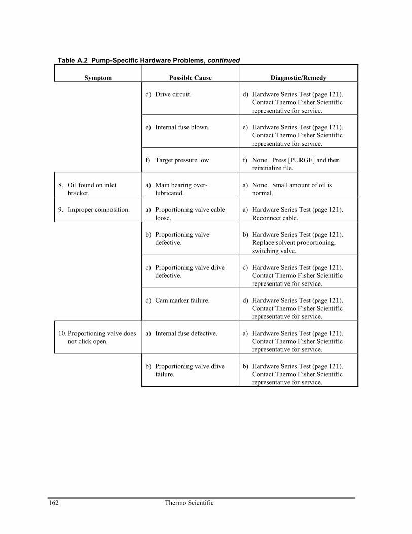
162 Thermo Scientific
Table A.2 Pump-Specific Hardware Problems, continued
Symptom Possible Cause Diagnostic/Remedy
d) Drive circuit. d) Hardware Series Test (page 121). Contact Thermo Fisher Scientific representative for service.
e) Internal fuse blown. e) Hardware Series Test (page 121). Contact Thermo Fisher Scientific representative for service.
f) Target pressure low. f) None. Press [PURGE] and then reinitialize file.
8. Oil found on inlet bracket.
a) Main bearing over- lubricated.
a) None. Small amount of oil is normal.
9. Improper composition. a) Proportioning valve cable loose.
a) Hardware Series Test (page 121). Reconnect cable.
b) Proportioning valve defective.
b) Hardware Series Test (page 121). Replace solvent proportioning; switching valve.
c) Proportioning valve drive defective.
c) Hardware Series Test (page 121). Contact Thermo Fisher Scientific representative for service.
d) Cam marker failure. d) Hardware Series Test (page 121). Contact Thermo Fisher Scientific representative for service.
10. Proportioning valve does not click open.
a) Internal fuse defective. a) Hardware Series Test (page 121). Contact Thermo Fisher Scientific representative for service.
b) Proportioning valve drive failure.
b) Hardware Series Test (page 121). Contact Thermo Fisher Scientific representative for service.
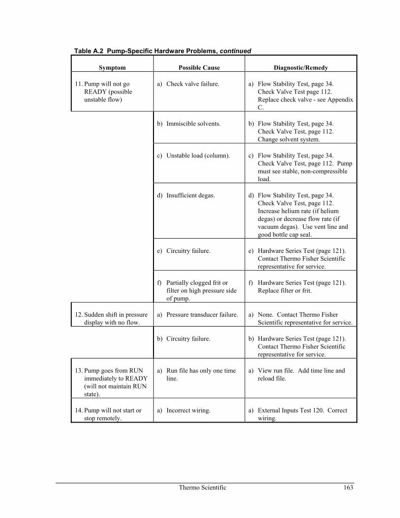
Thermo Scientific 163
Table A.2 Pump-Specific Hardware Problems, continued
Symptom Possible Cause Diagnostic/Remedy
11. Pump will not go READY (possible unstable flow)
a) Check valve failure. a) Flow Stability Test, page 34. Check Valve Test page 112. Replace check valve - see Appendix C.
b) Immiscible solvents. b) Flow Stability Test, page 34. Check Valve Test, page 112. Change solvent system.
c) Unstable load (column). c) Flow Stability Test, page 34. Check Valve Test, page 112. Pump must see stable, non-compressible load.
d) Insufficient degas. d) Flow Stability Test, page 34. Check Valve Test, page 112. Increase helium rate (if helium degas) or decrease flow rate (if vacuum degas). Use vent line and good bottle cap seal.
e) Circuitry failure. e) Hardware Series Test (page 121). Contact Thermo Fisher Scientific representative for service.
f) Partially clogged frit or filter on high pressure side of pump.
f) Hardware Series Test (page 121). Replace filter or frit.
12. Sudden shift in pressure display with no flow.
a) Pressure transducer failure. a) None. Contact Thermo Fisher Scientific representative for service.
b) Circuitry failure. b) Hardware Series Test (page 121). Contact Thermo Fisher Scientific representative for service.
13. Pump goes from RUN immediately to READY (will not maintain RUN state).
a) Run file has only one time line.
a) View run file. Add time line and reload file.
14. Pump will not start or stop remotely.
a) Incorrect wiring. a) External Inputs Test 120. Correct wiring.
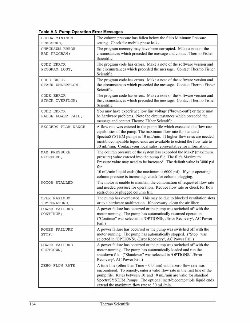
164 Thermo Scientific
Table A.3 Pump Operation Error Messages BELOW MINIMUM PRESSURE;
The column pressure has fallen below the file's Minimum Pressure setting. Check for mobile phase leaks.
CHECKSUM ERROR BAD PROGRAM;
The program memory may have been corrupted. Make a note of the circumstances which preceded the message and contact Thermo Fisher Scientific.
CODE ERROR PROGRAM LOST;
The program code has errors. Make a note of the software version and the circumstances which preceded the message. Contact Thermo Fisher Scientific.
CODE ERROR STACK UNDERFLOW;
The program code has errors. Make a note of the software version and the circumstances which preceded the message. Contact Thermo Fisher Scientific.
CODE ERROR STACK OVERFLOW;
The program code has errors. Make a note of the software version and the circumstances which preceded the message. Contact Thermo Fisher Scientific.
CODE ERROR FALSE POWER FAIL;
You may have experience low line voltage ("brown-out") or there may be hardware problems. Note the circumstances which preceded the message and contact Thermo Fisher Scientific.
EXCEEDS FLOW RANGE A flow rate was entered in the pump file which exceeded the flow rate capabilities of the pump. The maximum flow rate for standard SpectraSYSTEM pumps is 10 mL/min. If higher flow rates are needed, inert/biocompatible liquid ends are available to extend the flow rate to 30 mL/min. Contact your local sales representative for information.
MAX PRESSURE EXCEEDED;
The column pressure of the system has exceeded the MaxP (maximum pressure) value entered into the pump file. The file's Maximum Pressure value may need to be increased. The default value is 3000 psi for 10 mL/min liquid ends (the maximum is 6000 psi). If your operating column pressure is increasing, check for column plugging.
MOTOR STALLED The motor is unable to maintain the combination of requested flow rate and needed pressure for operation. Reduce flow rate or check for flow restriction or plugged column frit.
OVER MAXIMUM TEMPERATURE;
The pump has overheated. This may be due to blocked ventilation slots or to a hardware malfunction. If necessary, clean the air filter.
POWER FAILURE CONTINUE;
A power failure has occurred or the pump was switched off with the motor running. The pump has automatically resumed operation. ("Continue" was selected in /OPTIONS/, /Error Recovery/, AC Power Fail.)
POWER FAILURE STOP;
A power failure has occurred or the pump was switched off with the motor running. The pump has automatically stopped. ("Stop" was selected in /OPTIONS/, /Error Recovery/, AC Power Fail.)
POWER FAILURE SHUTDOWN;
A power failure has occurred or the pump was switched off with the motor running. The pump has automatically loaded and run the shutdown file. ("Shutdown" was selected in /OPTIONS/, /Error Recovery/, AC Power Fail.)
ZERO FLOW RATE A time line (other than Time = 0.0 min) with a zero flow rate was encountered. To remedy, enter a valid flow rate in the first line of the pump file. Rates between .01 and 10 mL/min are valid for standard SpectraSYSTEM Pumps. The optional inert/biocompatible liquid ends extend the maximum flow rate to 30 mL/min.
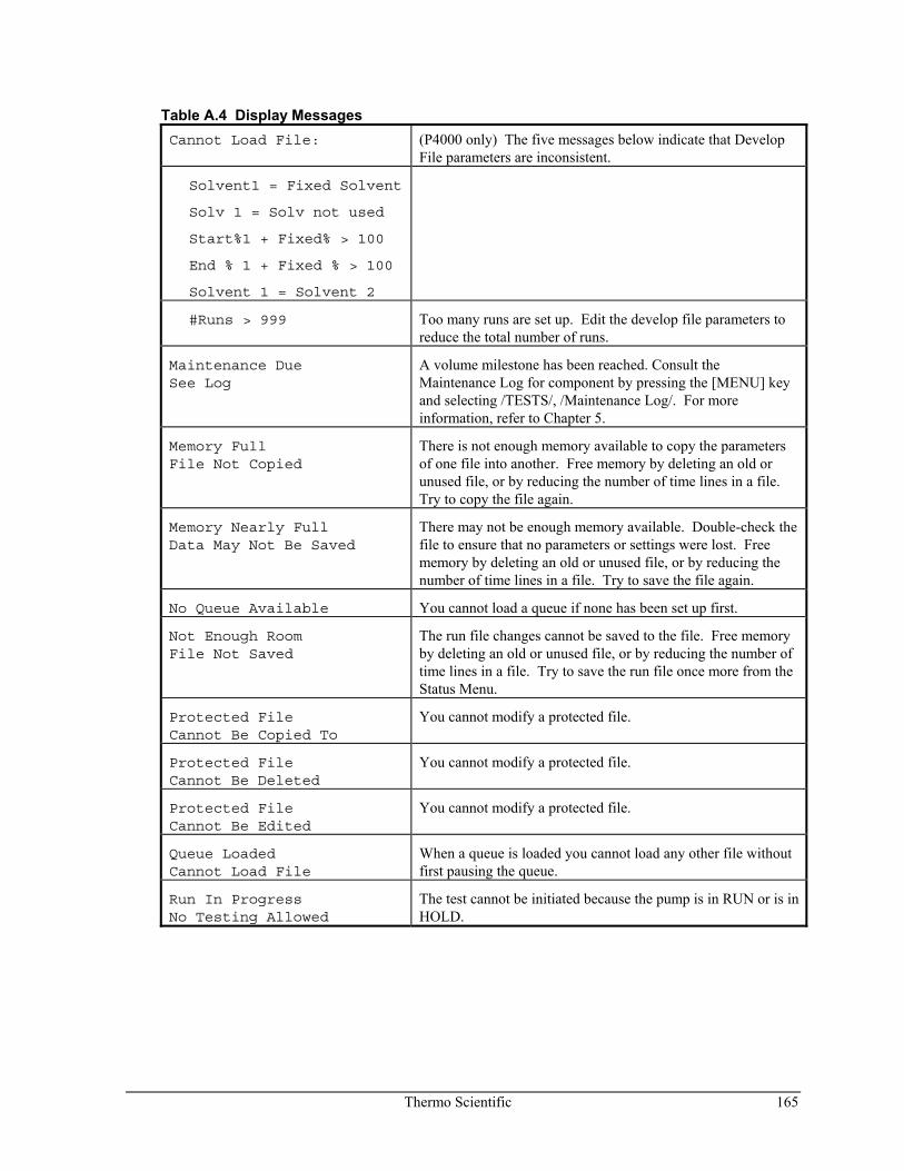
Thermo Scientific 165
Table A.4 Display Messages Cannot Load File: (P4000 only) The five messages below indicate that Develop
File parameters are inconsistent.
Solvent1 = Fixed Solvent
Solv 1 = Solv not used
Start%1 + Fixed% > 100
End % 1 + Fixed % > 100
Solvent 1 = Solvent 2
#Runs > 999 Too many runs are set up. Edit the develop file parameters to reduce the total number of runs.
Maintenance Due See Log
A volume milestone has been reached. Consult the Maintenance Log for component by pressing the [MENU] key and selecting /TESTS/, /Maintenance Log/. For more information, refer to Chapter 5.
Memory Full File Not Copied
There is not enough memory available to copy the parameters of one file into another. Free memory by deleting an old or unused file, or by reducing the number of time lines in a file. Try to copy the file again.
Memory Nearly Full Data May Not Be Saved
There may not be enough memory available. Double-check the file to ensure that no parameters or settings were lost. Free memory by deleting an old or unused file, or by reducing the number of time lines in a file. Try to save the file again.
No Queue Available You cannot load a queue if none has been set up first.
Not Enough Room File Not Saved
The run file changes cannot be saved to the file. Free memory by deleting an old or unused file, or by reducing the number of time lines in a file. Try to save the run file once more from the Status Menu.
Protected File Cannot Be Copied To
You cannot modify a protected file.
Protected File Cannot Be Deleted
You cannot modify a protected file.
Protected File Cannot Be Edited
You cannot modify a protected file.
Queue Loaded Cannot Load File
When a queue is loaded you cannot load any other file without first pausing the queue.
Run In Progress No Testing Allowed
The test cannot be initiated because the pump is in RUN or is in HOLD.
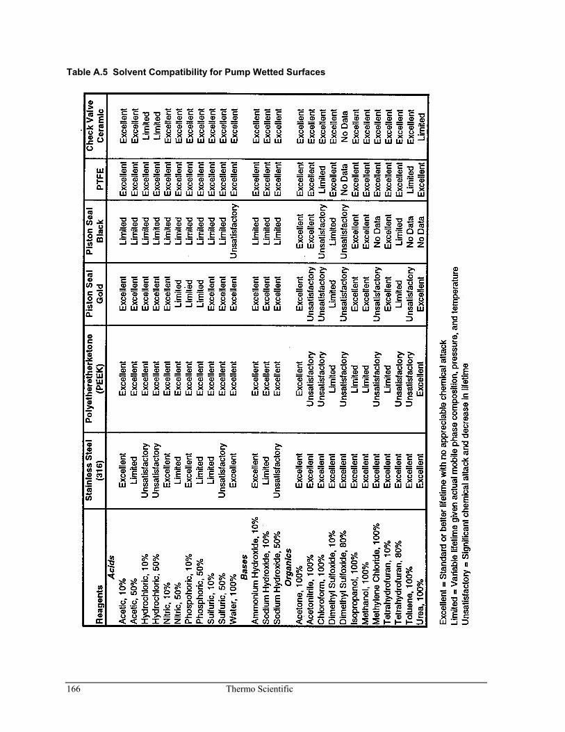
166 Thermo Scientific
Table A.5 Solvent Compatibility for Pump Wetted Surfaces
Thermo Scientific 167
B Glossary
A
autosampler an instrument designed to automatically inject samples into the sample flow path with a high degree of precision and reproducibility; sometimes called an injector
B
baseline the reference line at the bottom of a chromatogram from which measurements are made; a baseline represents the chromatogram that would be drawn if only the mobile phase (with no sample) were run through the column
binary capable of mixing or switching between two solvents
biocompatible describes components that are inert when used with biological samples; biocompatible components are usually made from titanium, PEEK, Teflon, quartz, or sapphire
blend a purge option in the P4000 pump allowing all solvents to be purged simultaneously
buffer a substance that can neutralize both acids and bases
C
channel the path along which something (solvent or information) flows
chromatogram a plot depicting the separated components in a sample (absorbance units versus time); each component is shown as a separate peak whose concentration can be determined by studying the area under the peak
chromatograph the basic set of instruments needed to perform chromatography: a pump, injector (manual or automatic), a column, and a detector; various recording and data handling instruments are common additions
chromatography a means of separating and analyzing mixtures of chemical substances
column the packed tube through which a sample is passed for separation; the sample separates according to the way in which it adheres to the column's packing material
component an "ingredient" in a chemical mixture, also the individual parts of a liquid end assembly
168 Thermo Scientific
conditioning the process of preparing the surface of the column wall and introducing the buffer pH conditions into the column before a run
configuration the way instruments are interconnected to form a system
cursor a moving or blinking symbol on the display which indicates where information is entered
D
default a value or choice built into a system; if no specific choice is made, instruments will run (or data analyzed) using the default settings
degassing removal of dissolved gas (i.e. oxygen) from the solvent to prevent bubbles from forming in the pump; degassing can be done by vacuum or by sparging
detector the instrument used to detect the presence of a chemical compound
develop file in the P4000 pump a file which allows a comprehensive set of parameters to be changed, automatically and sequentially
diagnostics ways of detecting and isolating instrument or software problems
digit an editable space within a field
display the backlit LCD screen on all SpectraSYSTEM™ instruments
E
elution time the length of time needed to pass a particular sample through a packed LC column
equilibration the process used to bring a system (solvent, column, and so on) to a point of equilibrium, where all thermal and chemical reactions occur at equal rates; a stable baseline is a good sign of a well-equilibrated system
error message a printed or displayed message that notifies the user of an error condition
error recovery user selectable responses to error conditions detected by the instrument, such as a power interruption or over-pressure
external event an action performed by an external device that is under the control of the current instrument (see also timed event)
Thermo Scientific 169
F
field an area in a display, screen, or menu where an entry is required or a choice must be made
file protect a setting which allows files to be edited when "off" and protects files from being changed by editing when "on"
flow parameters flow rate, run time and solvent composition
flow rate the rate at which solvent flows through a system
G
gradient changes the percentage composition of two or more solvents over time; changes may be continuous or in steps
gradient curve pre-programmed gradient time line accessed in the Develop file of the P4000 pump. Also refers to the shape of the solvent composition curve between two time lines.
ground terminal a terminal used to connect the ground or earth lead of a signal or contact closure cable; generally green and/or black
H
helium manifold a pneumatic assembly containing valves and switches for regulating helium sparging
helium sparging see sparging
I
inert see biocompatible
injection the manual or automatic introduction of a sample into a chromatography system
integrator the instrument used to analyze data and produce a chromatogram
isocratic constant flow and solvent composition
170 Thermo Scientific
K
Kel-F seal the translucent seal, made of Kel-F material, inside the pump head which faces the piston seal
keypad all of the keys by which you can communicate with an instrument or computer
L
LC Liquid Chromatography
linear a gradient curve that follows a straight line
liquid end the inlet or outlet assemblies of the pump consisting of the head, piston, seals, and sometimes a check valve
M
maintenance log a place to record dates, service, and cumulative solvent volume pumped
menu a list of choices
method the set of parameters that define how one or more analyses will be accomplished
method development the process of specifying the parameters under which an instrument will perform a particular function
N
NOVRAM Non-volatile RAM (random access memory). Computer memory into which the user can enter information and instructions and from which the user can recall information. Data in NOVRAM are saved even when the instrument is switched off
P
parameter a value or set of values used to define the characteristics or behavior of an instrument or system
PEEK polyetheretherketone; a material frequently used in fabricating inert/biocompatible components
piston the short cylinder piece which moves inside the sealed cylindrical opening and used to pressurize fluid
Thermo Scientific 171
piston holder housing the shaft into which the piston and its holder are housed
piston flush seal the low-pressure spring seal inside the liquid ends, facing the piston assembly
piston seal also called pump seal, a high-pressure spring seal located inside the pump head
plot the presentation of analytical data in a graphical manner; typical plots include chromatogram traces and calibration curves
prime to flush the solvents contained in a new pump in order to prepare the pump for solvents chosen by the user
proportioning the process of opening and closing solenoid valves in sequence to create a desired solvent composition; usually makes a clicking sound as the solvent composition is generated
pump the instrument used to push a liquid solvent through a chromatography system
purge to flush the system with fresh, degassed solvent
Q
quaternary capable of mixing or switching between as many as four solvents
queue a set of files in a prearranged order
R
RAM Random Access Memory (computer)
real-time the current, actual time
reproducibility the precision with which a piece of data can be repeated; a good measure of a system's overall performance
retaining screw also retaining cap screw; the screw which holds the piston assembly into the piston holder housing
run a complete analytical operation cycle of the chromatographic system
run file the file that has been loaded and that the pump is currently operating by
run time the duration of a sample run, from injection to separation
172 Thermo Scientific
S
sample a known or unknown substance in a small quantity
seal holder a metal part used for pumps fitted with standard parts which contains two seals, (piston seal and piston flush seal) and allows the pump head and piston holder housing to be joined
shutdown file a special file used by the pump after the pump has been in a READY state for a period of time set by the user
solvent a substance that can completely dissolve another; the mobile phase of an LC system
solvent filter a small cylindrical attachment for inlet tubing used to filter a solvent prior to the solvent entering a pump
solvent program a set of time lines indicating pump flow and solvent composition at specific times during a run
solvent-strength gradient a gradient in which the secondary solvents' composition ratios remain constant during the run
sparging a degassing technique in which solvent gases are replaced with an inert gas such as helium or nitrogen
status the current condition
status lock a feature used to prevent a run file from being changed from the Status Menu
step gradient a gradient created in step-wise fashion using two solvents, pumped through a binary, isocratic, solvent delivery system
stroke one complete revolution of the pump's cam which displaces both pistons
system a set of chromatography instruments that operate together in a concerted manner to produce an analytical result
T
timed event an instrument action triggered to occur at a specific, preset time during a run or analysis
trace a chromatogram
transducer check valve the valve which attached to the inlet of the pressure transducer
Thermo Scientific 173
V
vacuum degassing the technique of removing dissolved gasses from solvents by passing the solvent through tubing made of gas-permeable membrane, and creating a vacuum around the tubing, thus allowing gasses to be evacuated out of the solvent and into the surrounding chamber
viscosity the degree to which a fluid resists flow

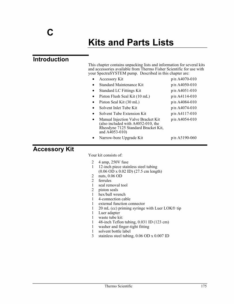
Thermo Scientific 175
C Kits and Parts Lists
Introduction This chapter contains unpacking lists and information for several kits and accessories available from Thermo Fisher Scientific for use with your SpectraSYSTEM pump. Described in this chapter are:
• Accessory Kit p/n A4070-010 • Standard Maintenance Kit p/n A4050-010 • Standard LC Fittings Kit p/n A4051-010 • Piston Flush Seal Kit (10 mL) p/n A4114-010 • Piston Seal Kit (30 mL) p/n A4084-010 • Solvent Inlet Tube Kit p/n A4074-010 • Solvent Tube Extension Kit p/n A4117-010 • Manual Injection Valve Bracket Kit p/n A4054-010
(also included with A4052-010, the Rheodyne 7125 Standard Bracket Kit, and A4053-010)
• Narrow-bore Upgrade Kit p/n A5190-060
Accessory Kit Your kit consists of:
2 4 amp, 250V fuse 1 12-inch piece stainless steel tubing (0.06 OD x 0.02 ID) (27.5 cm length) 2 nuts, 0.06 OD 2 ferrules 1 seal removal tool 2 piston seals 1 hex/ball wrench 1 4-connection cable 1 external function connector 1 20 mL (cc) priming syringe with Luer LOK® tip 1 Luer adapter 1 waste tube kit: 1 48-inch Teflon tubing, 0.031 ID (123 cm) 1 washer and finger-tight fitting 1 solvent bottle label 3 stainless steel tubing, 0.06 OD x 0.007 ID
176 Thermo Scientific
Standard Maintenance Kit The Standard Maintenance Kit contains the following:
4 inlet filter cartridges 1 inlet check valve 1 transducer check valve 2 sapphire pistons (0.125 inch-diameter) 1 barbed fitting (nylon) 1 piece piston flush tube (Tygon®), 0.0655 ID (approx. 76 cm long) 1 syringe (20 cc) 6 piston seals 2 piston flush seals 6 Kel-F seals 1 seal removal tool 1 seal insertion tool
Standard LC Fittings Kit Your kit consists of:
1 storage/carrying case 1 120-inch piece Teflon tubing, 0.063-inch ID 2 adapter fittings (10-32M) 4 Rheodyne nuts/ferrules 4 Parker type nuts/ferrules 3 wrenches (sizes: 1/4" - 5/16", 3/8" - 7/16", 1/2" - 9/16") 1 1/8-inch tube adapter for gas regulator assorted tubing: stainless steel 0.020-inch ID stainless steel 0.010-inch ID
Fittings kits contain tubing and fittings commonly needed for LC systems. These fittings can be used for several different instruments. If you change your LC configuration or damage connections, the fittings provided in this kit should allow you to make changes or replacements quickly and easily. All fittings can be kept in the compartmentalized storage box.
Thermo Scientific 177
Piston Flush Seal Kit (10 mL) Your kit consists of:
1 piece tubing, 30-inch, Tygon (76 cm length) 1 barbed fitting (nylon) 2 piston flush seals 1 seal removal tool 1 seal insertion tool 1 syringe, 20 cc
Piston Seal Kit (30 mL) Your kit consists of:
1 piston (with small O-ring, high pressure) 3 PEEK wash rings 1 large O-ring 1 Piston flush seal (low-pressure)
Solvent Inlet Tube Kit Your kit consists of:
1 bottle cap 1 tubing, Teflon, 0.063 ID
Solvent Tube Extension Kit Your kit consists of:
4 60-inch extension tubing, with washer and union (152 cm length) 1 tubing Teflon, 0.063 ID
178 Thermo Scientific
Manual Injection Valve Bracket Kit Your kit contains:
1 11-3/16 inch steel mounting rod 2 rod brackets 2 short column brackets 2 long column brackets 1 manual injector valve mount 4 short set screws (6-32 x 1/4-inch) 2 flat-head screws (8-32 x 3/8-inch) 2 screws (6-32 x 7/16-inch) 2 long set screws (6-32 x 5/8-inch) 1 Allen wrench (1/16-inch) 1 12 inches stainless steel tubing, 0.06 OD x 0.01 ID, 12 inches
If you purchased a Rheodyne valve, you also received the valve, accompanied by Rheodyne's documentation.
Installing the Holder onto the Valve
Refer to page 187 to install the valve onto the bracket: 1. Move the injector valve handle to the "LOAD" position.
Using the Allen wrench supplied with your Rheodyne valve, loosen the two set screws and remove the injection valve handle.
2. Hold the valve mounting bracket so that the two set screw holes are on the left. Place the injector valve into the bracket from the rear. If your injector valve has a remote start cable attached to it, place the cable into the cut-out on the left side of the bracket. When aligned correctly the "V" made by the two flats of the valve shaft will point to the upper left-hand mounting hole.
3. Fasten the valve securely with the two flat-head (Phillips) screws.
4. Attach the handle to the valve by tightening the two set screws, making sure that each screw is positioned over a flat edge of the valve shaft.
5. Install a long (5/8-inch) set screw into each of the valve bracket's mounting holes.
6. Install the rod through the valve bracket so that the notched portion of the rod faces you, as you look at the front of the injection valve.
Thermo Scientific 179
7. Slide the valve bracket so that it is within the top quarter of the rod. Tighten the two set screws, securing the valve bracket to the rod.
8. Brackets for long (22 cm - 25 cm) and short (3 cm - 10 cm) columns are provided. Choose the bracket size that matches the type of column you use. Both brackets can be mounted, if desired.
9. Install a short (1/4-inch) set screw into each column bracket you wish to use. Slide the brackets onto the rod for positioning. Temporarily tighten the set screws to hold the brackets in place (Figure C.1).
10. Remove the two top cover screws from the right side of your SpectraSYSTEM pump or detector. Install a rod bracket into the lower hole, using a 7/16-inch Phillips-head screw.
11. Rest the rod in the lower rod bracket (with the injector valve facing toward the front) and place the upper rod bracket on top of the rod. Attach the upper rod bracket to the pump or detector, using the other 7/16-inch screw.
12. Re-position the column brackets or manual injector valve as needed, and tighten the set screws.
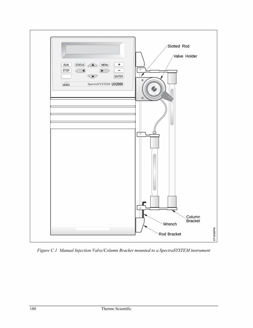
180 Thermo Scientific
DT-
Z01
8/F
M
RUN
STOP
STATUS MENU
ENTER
ZERO UV2000SpectraSYSTEM
Rod Bracket
Wrench
ColumnBracket
Slotted Rod
Valve Holder
DT-
Z01
8/F
M
RUN
STOP
STATUS MENU
ENTER
ZERO UV2000SpectraSYSTEM
Rod Bracket
Wrench
ColumnBracket
Slotted Rod
Valve Holder
Figure C.1 Manual Injection Valve/Column Bracket mounted to a SpectraSYSTEM instrument
Thermo Scientific 181
Narrow-bore Upgrade Kit Your kit consists of:
• 0.01” ID bypass, crossover, and transducer stainless steel tubes • 0.03” ID Teflon solvent inlet tube • Low-volume outlet liquid-end assembly • 3 μL static mixer • 0.007” stainless steel tubing • Nuts and ferrules for all tubes • Instruction sheet

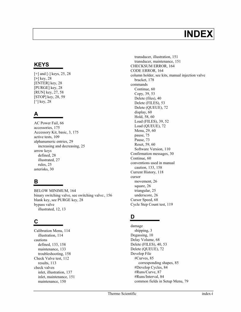
Thermo Scientific index-i
INDEX
KEYS [+] and [-] keys, 25, 28 [>] key, 28 [ENTER] key, 28 [PURGE] key, 28 [RUN] key, 27, 58 [STOP] key, 28, 59 [^] key, 28
A AC Power Fail, 66 accessories, 175 Accessory Kit, basic, 3, 175 active tests, 109 alphanumeric entries, 29
increasing and decreasing, 25 arrow keys
defined, 28 illustrated, 27 rules, 25
asterisks, 30
B BELOW MINIMUM, 164 binary switching valve, see switching valve:, 156 blank key, see PURGE key, 28 bypass valve
illustrated, 12, 13
C Calibration Menu, 114
illustration, 114 cautions
defined, 133, 158 maintenance, 133 troubleshooting, 158
Check Valve test, 112 results, 113
check valves inlet, illustration, 137 inlet, maintenance, 151 maintenance, 150
transducer, illustration, 151 transducer, maintenance, 151
CHECKSUM ERROR, 164 CODE ERROR, 164 column holder, see kits, manual injection valve
bracket, 178 commands
Continue, 60 Copy, 39, 53 Delete (files), 40 Delete (FILES), 53 Delete (QUEUE), 72 display, 60 Hold, 58, 60 Load (FILES), 39, 52 Load (QUEUE), 72 Menu, 29, 60 pause, 75 Pause, 73 Reset, 59, 60 Software Version, 110
Confirmation messages, 30 Continue, 60 conventions used in manual
caution, 133, 158 Current History, 118 cursor
movement, 26 square, 26 triangular, 25 underscore, 26
Cursor Speed, 68 Cycle Step Count test, 119
D damage
shipping, 3 Degassing, 10 Delay Volume, 68 Delete (FILES), 40, 53 Delete (QUEUE), 72 Develop File
#Curves, 85 corresponding shapes, 85
#Develop Cycles, 84 #Runs/Curve, 87 #Runs/Interval, 84 common fields in Setup Menu, 79
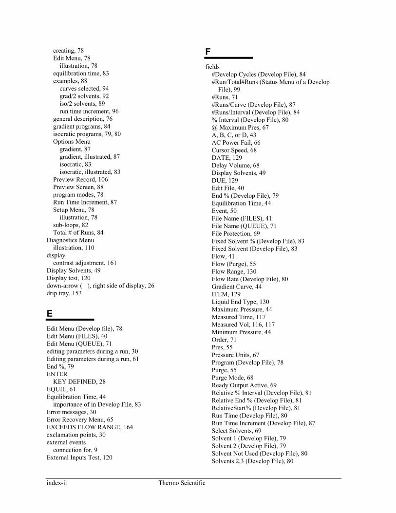
index-ii Thermo Scientific
creating, 78 Edit Menu, 78
illustration, 78 equilibration time, 83 examples, 88
curves selected, 94 grad/2 solvents, 92 iso/2 solvents, 89 run time increment, 96
general description, 76 gradient programs, 84 isocratic programs, 79, 80 Options Menu
gradient, 87 gradient, illustrated, 87 isocratic, 83 isocratic, illustrated, 83
Preview Record, 106 Preview Screen, 88 program modes, 78 Run Time Increment, 87 Setup Menu, 78
illustration, 78 sub-loops, 82 Total # of Runs, 84
Diagnostics Menu illustration, 110
display contrast adjustment, 161
Display Solvents, 49 Display test, 120 down-arrow (�), right side of display, 26 drip tray, 153
E Edit Menu (Develop file), 78 Edit Menu (FILES), 40 Edit Menu (QUEUE), 71 editing parameters during a run, 30 Editing parameters during a run, 61 End %, 79 ENTER
KEY DEFINED, 28 EQUIL, 61 Equilibration Time, 44
importance of in Develop File, 83 Error messages, 30 Error Recovery Menu, 65 EXCEEDS FLOW RANGE, 164 exclamation points, 30 external events
connection for, 9 External Inputs Test, 120
F fields
#Develop Cycles (Develop File), 84 #Run/Total#Runs (Status Menu of a Develop
File), 99 #Runs, 71 #Runs/Curve (Develop File), 87 #Runs/Interval (Develop File), 84 % Interval (Develop File), 80 @ Maximum Pres, 67 A, B, C, or D, 43 AC Power Fail, 66 Cursor Speed, 68 DATE, 129 Delay Volume, 68 Display Solvents, 49 DUE, 129 Edit File, 40 End % (Develop File), 79 Equilibration Time, 44 Event, 50 File Name (FILES), 41 File Name (QUEUE), 71 File Protection, 69 Fixed Solvent % (Develop File), 83 Fixed Solvent (Develop File), 83 Flow, 41 Flow (Purge), 55 Flow Range, 130 Flow Rate (Develop File), 80 Gradient Curve, 44 ITEM, 129 Liquid End Type, 130 Maximum Pressure, 44 Measured Time, 117 Measured Vol, 116, 117 Minimum Pressure, 44 Order, 71 Pres, 55 Pressure Units, 67 Program (Develop File), 78 Purge, 55 Purge Mode, 68 Ready Output Active, 69 Relative % Interval (Develop File), 81 Relative End % (Develop File), 81 RelativeStart% (Develop File), 81 Run Time (Develop File), 80 Run Time Increment (Develop File), 87 Select Solvents, 69 Solvent 1 (Develop File), 79 Solvent 2 (Develop File), 79 Solvent Not Used (Develop File), 80 Solvents 2,3 (Develop File), 80
Thermo Scientific index-iii
Start % (Develop File), 79 Status Lock, 68 Time (Purge), 55 Time (Solvent Program), 41 Time (Timed Events), 50 Time from READY, 51 Total # of Runs (Develop File), 84 Transducer Range, 121 VOL, 129
file linking, see Queue:, 70 File Name (FILES), 41 file numbers, 40 File Protection, 69 files
initializing, 58 Files
Menu, 29 FILES
Copy, 39, 53 Delete, 40, 53 Edit, 40 Load, 39, 52 Menu, 39
Fixed Solvent, 83 Fixed Solvent %, 83 Flow
field of [PURGE] Menu, 55 Flow Calibration Test, 114 Flow Correction, 131 flow stability test
example of running, 34 Flow Stability test, 110 front panel
illustration, 27 fuse
power entry module replacement, 155
G gradient
curves (P4000 only) examples, 45 illustration, 45 operation, 45
delay volume, 68 programs (Develop File), 84 solvent strength, 85 step, 48
H Hardware modifications
autosampler, 37 pump, 37
Hardware Series test, 121 results, 124
high voltage, defined, 133, 158 Hold, 60 HOLD, shown in Status, 61 hot surface
defined, 133, 158
I Increment (+) and decrement (-)
keys defined, 28 illustrated, 27
INIT, 61 initializing a file, 58 injection valve/column bracket, see kits, manual
injection valve bracket:, 178 inlet bracket, 156, 162 installation
bench space needed, 8 external events connection, 9 power-on response, 8 setting voltage, 5 unpacking, 3
instrument control, 27 isocratic
programs (Develop File), 79
K Kel-F seal, 138 keypad
illustrated, 27 instrument control, 27 moving around, 25
keys [+] and [-], 25, 28 [<], 28 [>], 28 [ENTER], 28 [MENU], 28 [PURGE], 28 [RUN], 27 [STATUS], 28 [STOP], 28 [^], 28 BLANK, 28
kits, 175 maintenance, 10 mL/min piston flush seal, 177 maintenance, standard, 176 manual injection valve bracket
illustration, 180 Manual Injection Valve Bracket, 178
index-iv Thermo Scientific
Piston Flush Seal, 177 Solvent Inlet Tube, 177 Solvent Tube Extension, 177 Standard LC Fittings, 176
L Lifetime History, 118 lifting, 5 linking, see Queue:, 70 liquid end
piston seal, 143 Liquid End Type, 130 liquid ends
assembly, 143 components, illustration, 142 disassembly, 138 inlet, illustration, 149 installation, 147 maintenance, 134 removal, 136
Load (FILES), 39, 52 Load (QUEUE), 72
M Main Menu
illustration, 29, 30, 31, 32, 33 maintenance
check valves, see also check valves, 150 drip tray, 153 kits
contents of 10 mL/min piston flush seal, 177 contents of standard, 176
liquid end, see also Liquid Ends, 134 period, extending, 132 piston, 141 piston flush seal, 144 preparing the pump for, 134 tips, 153
Maintenance Log, 128 DATE, 129 DUE, 129 ITEM, 129 menu, 128
illustration, 129 message, 128, 130 setting intervals, 129 table, 129 using, 129 VOL, 129
Maintenance Position, 130 Manual Injection Valve Bracket, 178 MAX PRESSURE, 164
Measured Parameters, 111 MENU
KEY DEFINED, 28 menus
Calibration, 114 COMMANDS, 60 Current History, 118 Diagnostics, 110 Edit (FILES), 40 Edit (QUEUE), 71 Error Recovery, 65 FILES, 39 Flow Correction, 131 Lifetime History, 118 Liquid End Type, 130 More (OPTIONS), 67 OPTIONS, 65 Options (Develop File), 83 Options (FILES), 43 QUEUE, 70 Service, 118 Setup (Develop File), 78 Solvent Program, 41 Status, 61 TESTS, 108 Timed Events, 50
Menus Status, 30
Menus and Screens, general description of Commands Menu, 29 Files Menu, 29 Main Menu, 29 Options Menu, 29 Queue Menu, 29 Status Screen, 29
menusDiagnostics, 110 messages, 30
confirmation, 30 error, 30 user, 30
More Menu (OPTIONS), 67 MOTOR STALLED, 164 Motor Step/Valve test, 121
N numeric entries, 29
O Options Menu, 29, 65
under Files, Edit, 43 Options Menu (Develop File), 83
Thermo Scientific index-v
Order (QUEUE), 71 OVER MAXIMUM, 164
P passivation of stainless steel parts, 154 passive tests, 109 pause (QUEUE), 73, 75 pausing a queue, 75 piston
flush seal, 144, 177 holder housing, 138 scratches, 127
illustration, 143 seal, 143
Piston flush seal kit, 177 power entry module
fuse replacement, 155 POWER FAILURE, 164 power selection
see voltage selection, 5 power-on response, 8 preset choices
scrolling through, 28 selecting from, 28
pressure setting limits, 44
pressure units, 67 example of changing, 32
Pressure Units, 67 Preview Screen, 88 Priming the Pump, 12 program modes (Develop File), 78 Program Version, 110 pump
front panel, illustration of, 27 gradient basics, 35 LC basics, 35 lifting and carrying, 5 list of routine operations, 39 operating statistics, 118 P4000
description, 36 placement, 8 pressure, 44 rear panel, illustration of, 6 repair, 155 rules for operation, 25 state changes, 118 stopping, 58 theory of operation, 157
Pump carrying, 5
purge
field, of Purge Menu, 55 mode
example of changing, 32 starting, 56 stopping, 56
PURGE key, 54 key defined, 28 MENU, 54
Purge Mode, 67 purging
after priming the pump, 16 example, 32 solvents, 54
Q Q RUN, 62 QEQUIL, 61 QREADY, 62 QSTOP, 62 queue
#Runs, 71 adding lines, 71 Delete command, 72 deleting entire, 72 deleting lines, 72 description, 70 editing, 71
illustration, 71 holding a file in the, 75 Load command, 72 Menu, 29
illustrated, 70 order, 71 Pause command, 75 running, 73 stopping, 75
R RAM test, 119 rate of change, gradient curves, 45 READY, 58 Ready Output Active, 69 READY, shown in Status, 62 Rear panel
illustration, 6 records
Develop File, 100 Preview Screen, 106
Relative % description, 82 fields, 81
index-vi Thermo Scientific
Relative % Interval, 81 Relative End %, 81 RelativeStart %, 81 repair
fuse replacement, 155 solvent switching valve replacement, 156
Reset, 60 reviewing parameters during a run, 30 ROM test, 119 RUN, 57, 58
key defined, 27 shown in Status, 62
run file, defined, 39 run time increment 87
example, 96
S safety
icons, 133, 158 safety certification
see Safety Information:, 133 safety precautions
for troubleshooting, 158 saving an entry, 26 screens
Preview (Develop File), 88 Status, 61
Screens Status
P4000 illustrated, 29 Status (P4000), 62
scrolling, 28 seals
Kel-F, 138 piston, 143 piston flush, 144, 177
Service Menu, 118 illustration, 118
Setup Menu (Develop File), 78 shipping
damage, 3 Shutdown File, 51 Software Version, 110 Solvent 1, 79 Solvent 2, 79 Solvent Not Used, 80 Solvent Program Menu, 41 Solvent Selection Menu, 69 solvents
changing the number displayed, 49 composition
example of, 43 connecting, 9
drip tray, 153 entering percentages, 43 labeling
example, 31 labels, 69 naming, illustration, 69 purging, 54 selection, 69 solvent strength gradient, 85
Solvents 2,3, 80 stainless steel
passivation, 154 Start %, 79 state changes, chronological list of, 118 statistics, operating, 118 status
display, 62 Status, 61
Develop File, 98 P4000, 62
STATUS KEY DEFINED, 28
Status lock differences between file protection, 68
Status Lock, 68 Status Menu
described, 30 P4000 illustrated, 62
Status Messages, 61 Status Screen
described, 29 P4000 illustrated, 62
step gradients, 48 STOP
KEY DEFINED, 28 shown in Status, 62
sub-loops, 82 switching valve
replacement, 156 SYNC, 62
T tests
active and passive, 109 Calibration, 114 Check Valve Test, 112 Cycle Step Count, 119 Display, 120 External Inputs, 120 Flow Stability, 110 Hardware Series, 121 initiating, 109 Measured Parameters, 111
Thermo Scientific index-vii
Motor/Step Valve, 121 RAM, 119 results, 109 ROM, 119 Service, 118 Software Version, 110 Transducer Range, 121
Tests Menu, 108 illustration, 108
theory of operation, 157 time
shown in Status, 61 Time
field of [PURGE] display, 55 time lines
adding, 41 chronological order of, 42 creating, 41 general rules, 41
Time lines defined, 41
timed events display, 50
Timed Events Menu, 50 Total # of Runs, 84
fields affecting, 98
modifying, 98 Transducer Range, 121 troubleshooting, 157
isolating the source of the problem, 158 safety precautions for, 158
U unpacking, 4
V Visual clues on display, 26 voltage select barrel, 5 voltage selection, 5
barrel, 7 illustration, 7 instructions for, 7
Z ZERO FLOW RATE, 164 Zero Pressure, 114

![SpectraSYSTEM RI-150 Refractive Index Detector Reference ......Italy: Strada Rivoltana • I-20090 Rodano (Milano) • [39] (02) 95059 226 Japan: C-2F • 3-9, Moriya-cho, Kanagawa-ku](https://img.dokumen.tips/doc/110x75/5f65e61f4a5841504d026875/spectrasystem-ri-150-refractive-index-detector-reference-italy-strada-rivoltana.jpg)


![SpectraSYSTEM UV/Vis Detectors Reference Manual Version Gtools.thermofisher.com/content/sfs/manuals/Man-A...Phone [1] (847) 310-0140 Fax [1] (847) 310-0145 Western Region Phone [1]](https://img.dokumen.tips/doc/110x75/600dbaf8589c760aa01827a5/spectrasystem-uvvis-detectors-reference-manual-version-phone-1-847-310-0140.jpg)