Embed Size (px)
Citation preview
Chinese Journal of Aeronautics, (2015), 28(3): 669–675
brought to you by COREView metadata, citation and similar papers at core.ac.uk
provided by Elsevier - Publisher Connector
Chinese Society of Aeronautics and Astronautics& Beihang University
Chinese Journal of Aeronautics
Spectral analysis and self-adjusting mechanism
for oscillation phenomenon in hydrogen-oxygen
continuously rotating detonation engine
* Corresponding author at: Center for Combustion and Propulsion,
College of Engineering, Peking University, Beijing 100871, China.
Tel.: +86 10 82529038.E-mail addresses: [email protected] (Y. Liu), [email protected]
(J. Wang).
Peer review under responsibility of Editorial Committee of CJA.
Production and hosting by Elsevier
http://dx.doi.org/10.1016/j.cja.2015.03.0061000-9361 ª 2015 The Authors. Production and hosting by Elsevier Ltd. on behalf of CSAA & BUAA.This is an open access article under the CC BY-NC-ND license (http://creativecommons.org/licenses/by-nc-nd/4.0/).
Liu Yusi a,b,c, Wang Yuhui a,b,c, Li Yongsheng a,b,c, Li Yang a,b,c,
Wang Jianping a,b,c,*
a Center for Combustion and Propulsion, College of Engineering, Peking University, Beijing 100871, Chinab Center for Applied Physics and Technology, Peking University, Beijing 100871, Chinac State Key Laboratory for Turbulence & Complex Systems, Peking University, Beijing 100871, China
Received 13 June 2014; revised 28 November 2014; accepted 9 February 2015Available online 8 April 2015
KEYWORDS
Continuously rotating
detonation;
Detonation engines;
Hydrogen-oxygen
detonation;
Self-adjusting mechanism;
Spectral analysis
Abstract The continuously rotating detonation engine (CRDE) is a new concept of engines for air-
craft and spacecraft. Quasi-stable continuously rotating detonation (CRD) can be observed in an
annular combustion chamber, but the sustaining, stabilizing and adjusting mechanisms are not
yet clear. To learn more deeply into the CRDE, experimental studies have been carried out to inves-
tigate hydrogen-oxygen CRDE. Pressure histories are obtained during each shot, which show that
stable CRD waves are generated in the combustor, when feeding pressures are higher than 0.5 MPa
for fuel and oxidizer, respectively. Each shot can keep running as long as fresh gas feeding main-
tains. Close-up of the pressure history shows the repeatability of pressure peaks and indicates the
detonation velocity in hydrogen–oxygen CRD, which proves the success of forming a stable
CRD in the annular chamber. Spectrum of the pressure history matches the close-up analysis
and confirms the CRD. It also shows multi-wave phenomenon and affirms the fact that in this case
a single detonation wave is rotating in the annulus. Moreover, oscillation phenomenon is found in
pressure peaks and a self-adjusting mechanism is proposed to explain the phenomenon.ª 2015 The Authors. Production and hosting by Elsevier Ltd. on behalf of CSAA & BUAA. This is an
open access article under the CC BY-NC-ND license (http://creativecommons.org/licenses/by-nc-nd/4.0/).
1. Introduction
The heat releasing process in detonation is nearly isochoric.The isochoric Humphrey cycle has inherently higher
thermodynamic efficiency than the isobaric Brayton cycle ofdeflagration, which is now widely used in engine combustion.When the compression ratio is 12, the thermal efficiency of
Humphrey cycle is 18% to 37% higher than Brayton cycle inthe combustion of hydrogen–oxygen mixture,1 and 20% to
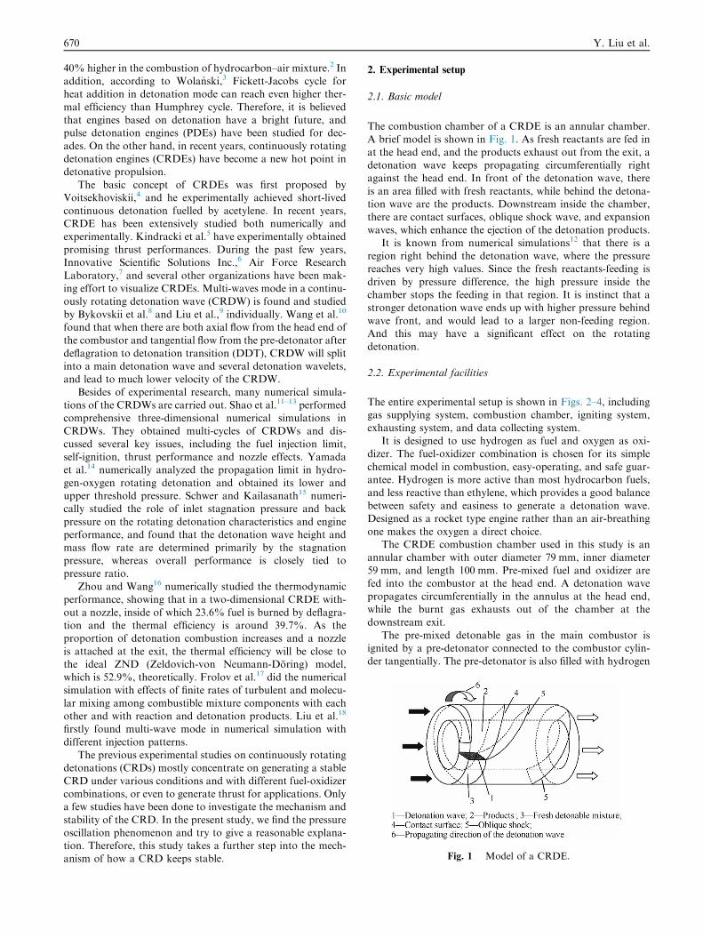
Fig. 1 Model of a CRDE.
670 Y. Liu et al.
40% higher in the combustion of hydrocarbon–air mixture.2 Inaddition, according to Wolanski,3 Fickett-Jacobs cycle forheat addition in detonation mode can reach even higher ther-
mal efficiency than Humphrey cycle. Therefore, it is believedthat engines based on detonation have a bright future, andpulse detonation engines (PDEs) have been studied for dec-
ades. On the other hand, in recent years, continuously rotatingdetonation engines (CRDEs) have become a new hot point indetonative propulsion.
The basic concept of CRDEs was first proposed byVoitsekhoviskii,4 and he experimentally achieved short-livedcontinuous detonation fuelled by acetylene. In recent years,CRDE has been extensively studied both numerically and
experimentally. Kindracki et al.5 have experimentally obtainedpromising thrust performances. During the past few years,Innovative Scientific Solutions Inc.,6 Air Force Research
Laboratory,7 and several other organizations have been mak-ing effort to visualize CRDEs. Multi-waves mode in a continu-ously rotating detonation wave (CRDW) is found and studied
by Bykovskii et al.8 and Liu et al.,9 individually. Wang et al.10
found that when there are both axial flow from the head end ofthe combustor and tangential flow from the pre-detonator after
deflagration to detonation transition (DDT), CRDW will splitinto a main detonation wave and several detonation wavelets,and lead to much lower velocity of the CRDW.
Besides of experimental research, many numerical simula-
tions of the CRDWs are carried out. Shao et al.11–13 performedcomprehensive three-dimensional numerical simulations inCRDWs. They obtained multi-cycles of CRDWs and dis-
cussed several key issues, including the fuel injection limit,self-ignition, thrust performance and nozzle effects. Yamadaet al.14 numerically analyzed the propagation limit in hydro-
gen-oxygen rotating detonation and obtained its lower andupper threshold pressure. Schwer and Kailasanath15 numeri-cally studied the role of inlet stagnation pressure and back
pressure on the rotating detonation characteristics and engineperformance, and found that the detonation wave height andmass flow rate are determined primarily by the stagnationpressure, whereas overall performance is closely tied to
pressure ratio.Zhou and Wang16 numerically studied the thermodynamic
performance, showing that in a two-dimensional CRDE with-
out a nozzle, inside of which 23.6% fuel is burned by deflagra-tion and the thermal efficiency is around 39.7%. As theproportion of detonation combustion increases and a nozzle
is attached at the exit, the thermal efficiency will be close tothe ideal ZND (Zeldovich-von Neumann-Doring) model,which is 52.9%, theoretically. Frolov et al.17 did the numericalsimulation with effects of finite rates of turbulent and molecu-
lar mixing among combustible mixture components with eachother and with reaction and detonation products. Liu et al.18
firstly found multi-wave mode in numerical simulation with
different injection patterns.The previous experimental studies on continuously rotating
detonations (CRDs) mostly concentrate on generating a stable
CRD under various conditions and with different fuel-oxidizercombinations, or even to generate thrust for applications. Onlya few studies have been done to investigate the mechanism and
stability of the CRD. In the present study, we find the pressureoscillation phenomenon and try to give a reasonable explana-tion. Therefore, this study takes a further step into the mech-anism of how a CRD keeps stable.
2. Experimental setup
2.1. Basic model
The combustion chamber of a CRDE is an annular chamber.A brief model is shown in Fig. 1. As fresh reactants are fed in
at the head end, and the products exhaust out from the exit, adetonation wave keeps propagating circumferentially rightagainst the head end. In front of the detonation wave, there
is an area filled with fresh reactants, while behind the detona-tion wave are the products. Downstream inside the chamber,there are contact surfaces, oblique shock wave, and expansionwaves, which enhance the ejection of the detonation products.
It is known from numerical simulations12 that there is aregion right behind the detonation wave, where the pressurereaches very high values. Since the fresh reactants-feeding is
driven by pressure difference, the high pressure inside thechamber stops the feeding in that region. It is instinct that astronger detonation wave ends up with higher pressure behind
wave front, and would lead to a larger non-feeding region.And this may have a significant effect on the rotatingdetonation.
2.2. Experimental facilities
The entire experimental setup is shown in Figs. 2–4, includinggas supplying system, combustion chamber, igniting system,
exhausting system, and data collecting system.It is designed to use hydrogen as fuel and oxygen as oxi-
dizer. The fuel-oxidizer combination is chosen for its simple
chemical model in combustion, easy-operating, and safe guar-antee. Hydrogen is more active than most hydrocarbon fuels,and less reactive than ethylene, which provides a good balance
between safety and easiness to generate a detonation wave.Designed as a rocket type engine rather than an air-breathingone makes the oxygen a direct choice.
The CRDE combustion chamber used in this study is an
annular chamber with outer diameter 79 mm, inner diameter59 mm, and length 100 mm. Pre-mixed fuel and oxidizer arefed into the combustor at the head end. A detonation wave
propagates circumferentially in the annulus at the head end,while the burnt gas exhausts out of the chamber at thedownstream exit.
The pre-mixed detonable gas in the main combustor isignited by a pre-detonator connected to the combustor cylin-der tangentially. The pre-detonator is also filled with hydrogen
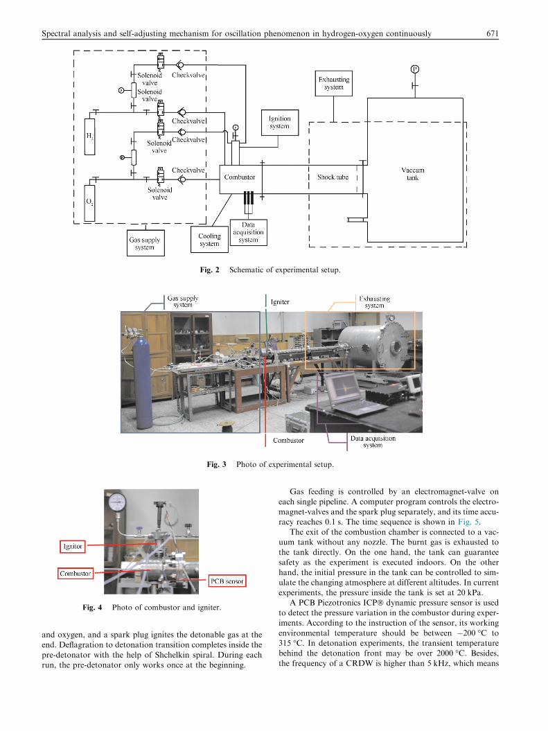
Fig. 2 Schematic of experimental setup.
Fig. 3 Photo of experimental setup.
Fig. 4 Photo of combustor and igniter.
Spectral analysis and self-adjusting mechanism for oscillation phenomenon in hydrogen-oxygen continuously 671
and oxygen, and a spark plug ignites the detonable gas at theend. Deflagration to detonation transition completes inside the
pre-detonator with the help of Shchelkin spiral. During eachrun, the pre-detonator only works once at the beginning.
Gas feeding is controlled by an electromagnet-valve on
each single pipeline. A computer program controls the electro-magnet-valves and the spark plug separately, and its time accu-racy reaches 0.1 s. The time sequence is shown in Fig. 5.
The exit of the combustion chamber is connected to a vac-uum tank without any nozzle. The burnt gas is exhausted tothe tank directly. On the one hand, the tank can guarantee
safety as the experiment is executed indoors. On the otherhand, the initial pressure in the tank can be controlled to sim-ulate the changing atmosphere at different altitudes. In current
experiments, the pressure inside the tank is set at 20 kPa.A PCB Piezotronics ICP� dynamic pressure sensor is used
to detect the pressure variation in the combustor during exper-iments. According to the instruction of the sensor, its working
environmental temperature should be between �200 �C to315 �C. In detonation experiments, the transient temperaturebehind the detonation front may be over 2000 �C. Besides,
the frequency of a CRDW is higher than 5 kHz, which means
Fig. 5 Time sequence of experiments.
Fig. 6 Mounting of PCB sensor.
Fig. 7 A typical result of pressure history of an entire run.
Fig. 8 Close-up of pressure history in stable section.
672 Y. Liu et al.
the sensor is under extremely high temperature environmentthroughout every experiment shot. This would seriously curtailthe sensor life as well as result in unreliable measurement. To
protect the sensor from damage and achieve relative reliableresults, the sensor is mounted to the outer wall of the combus-tor behind a 2 mm-deep hole. And the hole is filled with silicongrease to insulate from thermal flash, as shown in Fig. 6. With
these protections, the measured pressure is significantly lowerthan the real value in the combustor, and the pulse rise timeis increased. But still each single detonation wave can be
detected and captured when it sweeps over. In experiments,when the first time a detonation wave reaches the measuringpoint, the high pressure triggers on the recording system to
write down the pressure change at the sensing point.
3. Results and discussion
3.1. Pressure history of CRD
A typical result of the pressure history obtained in experimentis shown in Fig. 7. It is the history of an entire run. In this run,the total pressure of O2 and H2 feeding is 0.8 MPa and0.7 MPa, respectively, while the average mass flow rate
into the main combustor during the entire 2 s is 5.9 g/s and0.8 g/s, for O2 and H2 respectively.
Ignition takes place at time point 0 ms and it takes around
250 ms to form a stable rotating detonation wave. After that, itcomes to the stable stage when the detonation wave propagatescircumferentially in the annulus. During the stable stage, the
pressure ranges within 300 kPa. Considering that the low back-ground pressure is 20 kPa and the static pressure inside thecombustor without detonation is close to that, the pressure
range with CRDW is reasonable. The gas feeding is shut downat 1.5 s. And then the detonation wave dies out because oflacking fresh reactants. However, the figure shows that thedie-out is not right at 1.5 s, which is mainly because of the
delay of electromagnet-valves and some fresh gas remaining
in the feeding pipes downstream the electromagnet-valves.As the detonation wave leads to an obvious rise in temper-
ature, it causes significant baseline drifting for the piezoelectricpressure sensor. That is why the figure seems somehow dis-
torted. Even though, the full trace clearly shows the ignitingsection and the dying out section.
Close-up of pressure history in stable section is shown in
Fig. 8. Each time the detonation wave sweeps over the sensor,a peak appears in the pressure history. The peak values aredetermined by the strength of the detonation waves, and they
are not exactly the same, which means the strength of the det-onation wave is not perfectly constant. This phenomenon andits reasons will be discussed later.
A series of much smaller perks is found between the adja-cent high peaks, which implies that the CRDW may have splitinto a main detonation wave and smaller wavelets. The samephenomenon had also been found in the work by Wang et al.10
with both axial and tangential flow of fresh gas feeding. Andsuch splitting would lead to much lower velocity of the maindetonation wave.
Concentrating on the reproducibility of pressure peak, it isseen that the duration between two neighboring peaks is175 ls. Ahead of each exact peak, there is always obvious fluc-
tuation, which is mainly caused by the installation of the sen-sor. Assume that there is only one detonation wave rotating inthe combustion chamber, the detonation wave takes 175 ls to
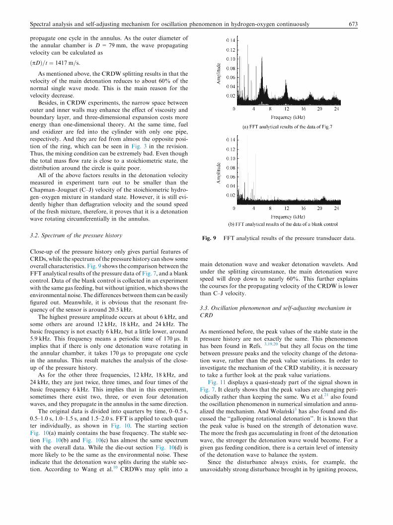
Fig. 9 FFT analytical results of the pressure transducer data.
Spectral analysis and self-adjusting mechanism for oscillation phenomenon in hydrogen-oxygen continuously 673
propagate one cycle in the annulus. As the outer diameter ofthe annular chamber is D = 79 mm, the wave propagatingvelocity can be calculated as
ðpDÞ=t ¼ 1417 m=s:
As mentioned above, the CRDW splitting results in that thevelocity of the main detonation reduces to about 60% of thenormal single wave mode. This is the main reason for the
velocity decrease.Besides, in CRDW experiments, the narrow space between
outer and inner walls may enhance the effect of viscosity and
boundary layer, and three-dimensional expansion costs moreenergy than one-dimensional theory. At the same time, fueland oxidizer are fed into the cylinder with only one pipe,
respectively. And they are fed from almost the opposite posi-tion of the ring, which can be seen in Fig. 3 in the revision.Thus, the mixing condition can be extremely bad. Even thoughthe total mass flow rate is close to a stoichiometric state, the
distribution around the circle is quite poor.All of the above factors results in the detonation velocity
measured in experiment turn out to be smaller than the
Chapman–Jouguet (C–J) velocity of the stoichiometric hydro-gen–oxygen mixture in standard state. However, it is still evi-dently higher than deflagration velocity and the sound speed
of the fresh mixture, therefore, it proves that it is a detonationwave rotating circumferentially in the annulus.
3.2. Spectrum of the pressure history
Close-up of the pressure history only gives partial features ofCRDs,while the spectrumof the pressure history can show someoverall characteristics. Fig. 9 shows the comparison between the
FFT analytical results of the pressure data of Fig. 7, and a blankcontrol. Data of the blank control is collected in an experimentwith the same gas feeding, but without ignition, which shows the
environmental noise. The differences between them can be easilyfigured out. Meanwhile, it is obvious that the resonant fre-quency of the sensor is around 20.5 kHz.
The highest pressure amplitude occurs at about 6 kHz, andsome others are around 12 kHz, 18 kHz, and 24 kHz. Thebasic frequency is not exactly 6 kHz, but a little lower, around5.9 kHz. This frequency means a periodic time of 170 ls. Itimplies that if there is only one detonation wave rotating inthe annular chamber, it takes 170 ls to propagate one cyclein the annulus. This result matches the analysis of the close-
up of the pressure history.As for the other three frequencies, 12 kHz, 18 kHz, and
24 kHz, they are just twice, three times, and four times of the
basic frequency 6 kHz. This implies that in this experiment,sometimes there exist two, three, or even four detonationwaves, and they propagate in the annulus in the same direction.
The original data is divided into quarters by time, 0–0.5 s,0.5–1.0 s, 1.0–1.5 s, and 1.5–2.0 s. FFT is applied to each quar-ter individually, as shown in Fig. 10. The starting sectionFig. 10(a) mainly contains the base frequency. The stable sec-
tion Fig. 10(b) and Fig. 10(c) has almost the same spectrumwith the overall data. While the die-out section Fig. 10(d) ismore likely to be the same as the environmental noise. These
indicate that the detonation wave splits during the stable sec-tion. According to Wang et al.10 CRDWs may split into a
main detonation wave and weaker detonation wavelets. And
under the splitting circumstance, the main detonation wavespeed will drop down to nearly 60%. This further explainsthe courses for the propagating velocity of the CRDW is lower
than C–J velocity.
3.3. Oscillation phenomenon and self-adjusting mechanism inCRD
As mentioned before, the peak values of the stable state in thepressure history are not exactly the same. This phenomenonhas been found in Refs. 3,19,20 but they all focus on the time
between pressure peaks and the velocity change of the detona-tion wave, rather than the peak value variations. In order toinvestigate the mechanism of the CRD stability, it is necessary
to take a further look at the peak value variations.Fig. 11 displays a quasi-steady part of the signal shown in
Fig. 7. It clearly shows that the peak values are changing peri-
odically rather than keeping the same. Wu et al.21 also foundthe oscillation phenomenon in numerical simulation and annu-alized the mechanism. And Wolanski3 has also found and dis-cussed the ‘‘galloping rotational detonation’’. It is known that
the peak value is based on the strength of detonation wave.The more the fresh gas accumulating in front of the detonationwave, the stronger the detonation wave would become. For a
given gas feeding condition, there is a certain level of intensityof the detonation wave to balance the system.
Since the disturbance always exists, for example, the
unavoidably strong disturbance brought in by igniting process,

Fig. 10 Spectrum of quarters of pressure transducer data of Fig. 7.
Fig. 11 Part of the pressure history in Fig. 7.Fig. 12 Self-adjusting mechanism of CRD.
674 Y. Liu et al.
the exact balancing-level cannot maintain. If the detonationwave becomes stronger, the pressure behind the detonationfront becomes higher. Higher pressure slows down the gas
feeding so that less fresh gas can be injected into the combustorduring the next cycle. When the wave front rounds back, thereis less fresh gas ahead. Then the detonation wave becomes
weaker. And as the detonation wave becomes weaker thanthe balancing level, it goes the other way round. The wholeprocedure is shown in Fig. 12, and it is the self-adjusting mech-
anism in the CRD system.This process may maintain for more than one cycle, some-
times tens of cycles, represented by the pressure history thattheir peaks become gradually weaker and then stronger.
4. Conclusions
An experimental study is carried out to investigate the contin-uously rotating detonation (CRD). An annular chamber com-
bustor is designed for testing, and pressure history is obtainedduring each shot. According to the analysis of the experimen-tal data, several conclusions are obtained.
(1) The overall pressure history shows that stable CRDs canbe obtained in the combustor when hydrogen–oxygen isused for combustible gas. The experiments are successful
with feeding pressure higher than 0.5 MPa for fuel and

Spectral analysis and self-adjusting mechanism for oscillation phenomenon in hydrogen-oxygen continuously 675
oxidizer respectively. And each run can keep going as
long as fresh gas feeding maintains.(2) Close-up of the pressure history shows the repeatability
of pressure peaks and splitting of the CRDW. An esti-
mation of the detonation velocity of a hydrogen–oxygenCRD is done, proving the success of forming a stableCRD in the annular chamber.
(3) Spectrum of the pressure history matches the close-up
analysis and confirms the CRD. It also shows multi-wave phenomena and verifies that there is only onequasi-steady CRDW in this case, and the CRDW splits
into a main detonation and two, three or four detona-tion waves.
(4) Oscillation phenomenon is found in the pressure peaks,
and a self-adjusting mechanism is proposed to explainthis phenomenon.
Acknowledgement
This study was supported by the National Natural Science
Foundation of China (No. 91441110).
References
1. Bussing T, Pappas G. An introduction to pulse detonation
engines. Proceedings of 32nd aerospace sciences meeting & exhibit;
1994 Jan 10–13; Reno, NV. Reston: AIAA; 1994.
2. Bratkovich TE, Aarnio MJ, Williams JT, Bussing TR. An
introduction to pulse detonation rocket engines (PDREs).
Proceedings of 33rd joint propulsion conference and exhibit; 1997
Jul 6–9; Seattle, WA. Reston: AIAA; 1997.
3. Wolanski P. Detonative propulsion. Proc Combust Inst
2012;34(1):125–58.
4. Voitsekhovskii BV. Stationary spin detonation. Sov J Appl Mech
Tech Phys 1960;3:157–64.
5. Kindracki J, Wolanski P, Gut Z. Experimental research on the
rotating detonation in gaseous fuels–oxygen mixtures. Shock
Waves 2011;21(2):75–84.
6. Naples A, Hoke J, Karnesky J, Schauer F. Flowfield character-
ization of a rotating detonation engine. Proceedings of 51st AIAA
aerospace sciences meeting including the new horizons forum and
aerospace exposition; 2013 Jan 7–10; Grapevine (Dallas/Ft. Worth
Region), Texas. Reston: AIAA; 2013.
7. Miller SJ, King PI, Schauer FR, Hoke JL. Ignition design for a
rotating detonation engine. Proceedings of 51st AIAA aerospace
sciences meeting including the new horizons forum and aerospace
exposition; 2013 Jan 7–10; Grapevine (Dallas/Ft. Worth Region),
Texas. Reston: AIAA; 2013.
8. Bykovskii FA, Zhdan SA, Vedernikov EF. Continuous spin
detonations of fuel-air mixtures. Combust, Explosion Shock Waves
2006;42(4):463–71.
9. Liu SJ, Lin ZY, Liu WD, Lin W, Zhuang FG. Experimental
realization of H2/air continuous rotating detonation in a cylindri-
cal. Combustor Combust Sci Technol 2012;184(9):1302–17.
10. Wang YH, Wang JP, Li YS, Li Y. Induction for multiple rotating
detonation waves in the hydrogen–oxygen mixture with tangential
flow. Int J Hydrogen Energy 2014;39(22):11792–7.
11. Shao YT, Wang JP. Change in continuous detonation wave
propagation mode from rotating detonation to standing detona-
tion. Chin Phys Lett 2010;27(3):034705.
12. Shao YT, Liu M, Wang JP. Numerical investigation of rotating
detonation engine propulsive performance. Combust Sci Technol
2010;182(11–12):1586–97.
13. Shao YT, Liu M, Wang JP. Continuous detonation engine and
effects of different types of nozzle on its propulsion performance.
Chin J Aeronaut 2010;23(6):647–52.
14. Yamada T, Hayashi AK, Yamada E, Tsuboi N, Tangirala V,
Fujiwara T. Detonation limit thresholds in H2/O2 rotating
detonation engine. Combust Sci Technol 2010;182(11–12):
1901–14.
15. Schwer D, Kailasanath K. Numerical investigation of the physics
of rotating-detonation-engines. Proc Combust Inst 2011;33(2):
2195–202.
16. Zhou R, Wang JP. Numerical investigation of flow particle paths
and thermodynamic performance of continuously rotating
detonation engines. Combust Flame 2012;159(12):3632–45.
17. Frolov SM, Dubrovskii AV, Ivanov VS. Three-dimensional
numerical simulation of the operation of a rotating-detonation
chamber with separate supply of fuel and oxidizer. Russ J Phys
Chem B 2013;7(1):35–43.
18. Liu M, Zhou R, Wang JP. Numerical investigation of different
injection patterns in rotating detonation engines. Combust Sci
Technol 2015;187(3):343–61.
19. Suchocki JA, Yu STJ, Hoke JL, Naples AG. Rotating detonation
engine operation. Proceedings of 50th AIAA aerospace sciences
meeting including the new horizons forum and aerospace exposition;
2012 Jan 9–12; Nashville, Tennessee. Reston: AIAA; 2012.
20. Dyer R, Naples A, Kaemming, Hoke J, Schauer F. Parametric
testing of a unique rotating detonation engine design. Proceedings
of 50th AIAA aerospace sciences meeting including the new horizons
forum and aerospace exposition; 2012 Jan 9–12; Nashville,
Tennessee. Reston: AIAA; 2012.
21. Wu D, Zhou R, Liu M, Wang JP. Numerical investigation of the
stability of rotating detonation engines. Combust Sci Technol
2014;186(10–11):1699–715.
Liu Yusi is a Ph.D. student at College of Engineering, Peking
University, China. He received his B.S. degree from Peking University
in 2010. His main research interest is detonation propulsion.
Wang Jianping is a professor and Ph.D. supervisor at College of
Engineering, Peking University, China. He received his B.S. degree,
M.S. and Ph.D degrees from Nagoya University in 1984, 1986 and
1991, respectively. His current research interests are CFD and
detonation propulsion.


![A Hybrid Mechanism for Adaptively Adjusting Bitcoin's Block Size Limit [BIP10X]](https://img.dokumen.tips/doc/110x75/563dbb20550346aa9aaa7383/a-hybrid-mechanism-for-adaptively-adjusting-bitcoins-block-size-limit-566f02168fb17.jpg)


