Embed Size (px)
Citation preview

City of New York DOT Systems Engineering
SPECIFICATIONS for Furnishing All Labor and Material Necessary and Required
for Removal, Installation, Relocation and Maintenance of
Traffic Signals and Intelligent Transportation Systems
November 2013

November 2013 NYCDOT Specifications for Traffic Signals & ITS Systems
Page 1
NOTICE TO CONTRACTORS ........................................................................................................................................................... 13
DEFINITIONS OF WORDS AND PHRASES ..................................................................................................................................... 15
ABBREVIATIONS .............................................................................................................................................................................. 17
GS. NYCDOT GENERAL SPECIFICATIONS ................................................................................................................................ 21 GS.1. SCOPE OF PROJECT ...................................................................................................................................................... 21 GS.2. WORK INCLUDED ........................................................................................................................................................... 21 GS.3. TIME ............................................................................................................................................................................. 21 GS.4. DRAWINGS .................................................................................................................................................................... 21 GS.5. INTERPRETATION OF APPARENT OMISSIONS .................................................................................................................... 21 GS.6. CONFLICT ..................................................................................................................................................................... 21 GS.7. OMISSION OF DETAILS ................................................................................................................................................... 21 GS.8. CONTRACTOR TO VERIFY DIMENSIONS ........................................................................................................................... 22 GS.9. SUPPLEMENTARY DRAWINGS ......................................................................................................................................... 22 GS.10. RECORD OF WORK DONE .............................................................................................................................................. 22 GS.11. CHANGED CONDITIONS .................................................................................................................................................. 22 GS.12. NOTICE REQUIRED FOR INSPECTION ............................................................................................................................... 22 GS.13. PERMITS ....................................................................................................................................................................... 22 GS.14. STRUCTURES AND PROPORTION ..................................................................................................................................... 23 GS.15. CITY MONUMENTS AND MARKS ...................................................................................................................................... 23 GS.16. COOPERATION AMONG CONTRACTORS ........................................................................................................................... 23 GS.17. WORKMEN’S COMPENSATION INSURANCE ....................................................................................................................... 23 GS.18. PUBLIC LIABILITY AND PROPERTY DAMAGE ..................................................................................................................... 23 GS.19. OWNERS PROTECTIVE LIABILITY AND PROPERTY DAMAGE ............................................................................................... 23 GS.20. EXCISE AND TRANSPORTATION TAXES ............................................................................................................................ 24 GS.21. ENGINEERS’ POWERS .................................................................................................................................................... 24 GS.22. TIME FOR EXECUTION OF ORDERS.................................................................................................................................. 25 GS.23. PAYMENTS .................................................................................................................................................................... 25 GS.24. PRECAUTIONARY MEASURES ......................................................................................................................................... 25 GS.25. MAINTENANCE OF TRAFFIC............................................................................................................................................. 26 GS.26. EQUAL QUALITY OF MATERIAL ........................................................................................................................................ 26 GS.27. MATERIAL STORAGE ...................................................................................................................................................... 27 GS.28. OBSOLETE EQUIPMENT .................................................................................................................................................. 27 GS.29. EXCAVATIONS ............................................................................................................................................................... 28 GS.30. RESTORATION OF PAVEMENT ......................................................................................................................................... 28 GS.31. CLEANING UP ................................................................................................................................................................ 28 GS.32. TESTING OF MATERIALS AND EQUIPMENT ........................................................................................................................ 28 GS.33. MATERIAL REQUIREMENTS ............................................................................................................................................. 29 GS.34. SPECIAL REPORTS ........................................................................................................................................................ 29
C1. NYCDOT DETAIL SPECIFICATIONS FOR FOUNDATIONS ................................................................................................. 33 C1.1. SCOPE OF WORK .......................................................................................................................................................... 33 C1.2. CONCRETE .................................................................................................................................................................... 33 C1.3. SIDEWALK RESTORATION ............................................................................................................................................... 34 C1.4. DETAIL SPECIFICATIONS BY ITEMS .................................................................................................................................. 35
C2. NYCDOT DETAIL SPECIFICATIONS FOR POLE ERECTIONS ........................................................................................... 41 C2.1. SCOPE OF WORK .......................................................................................................................................................... 41 C2.2. WIRING OF POLES ......................................................................................................................................................... 41 C2.3. COMBINATION POLES ..................................................................................................................................................... 42 C2.4. DETAIL SPECIFICATION BY ITEMS .................................................................................................................................... 43

NYCDOT Specifications for Traffic Signals & ITS Systems November 2013
Page 2
C3. NYCDOT DETAIL SPECIFICATIONS FOR TRAFFIC SIGNALS AND OTHER ILLUMINATED DEVICES .......................... 49 C3.1. SCOPE OF WORK .......................................................................................................................................................... 49 C3.2. SIGNALS REMOVED ....................................................................................................................................................... 50 C3.3. DETAIL SPECIFICATIONS BY ITEMS .................................................................................................................................. 51
C4. NYCDOT SPECIFICATION FOR TRAFFIC SIGNAL CONTROLLER INSTALLATIONS ...................................................... 57 C4.1. SCOPE OF WORK .......................................................................................................................................................... 57 C4.2. CONTROLLERS AND CONTROLLER CABINETS REMOVED ................................................................................................... 57 C4.3. SPLICES AND CONNECTIONS ABOVE GROUND ................................................................................................................. 57 C4.4. DETAIL SPECIFICATION BY ITEMS .................................................................................................................................... 58
C5. NYCDOT DETAIL SPECIFICATIONS FOR THE INSTALLATION OF CONDUIT, DUCT AND BENDS ............................... 63 C5.1. SCOPE OF WORK .......................................................................................................................................................... 63 C5.2. MATERIALS ................................................................................................................................................................... 63 C5.3. ROUTING ...................................................................................................................................................................... 63 C5.4. EXCAVATION ................................................................................................................................................................. 64 C5.5. INSTALLATION ................................................................................................................................................................ 64 C5.6. CONNECTING TO EXISTING UNDERGROUND CONDUIT ...................................................................................................... 64 C5.7. REPAIRING OR REPLACING DAMAGED OR OBSTRUCTED UNDERGROUND CONDUIT AND BENDS .......................................... 64 C5.8. INSTALLATION OF CONDUIT BENDS IN EXISTING POLE ...................................................................................................... 65 C5.9. INSPECTION AND RODDING ............................................................................................................................................. 65 C5.10. BACKFILL ...................................................................................................................................................................... 65 C5.11. UNDERGROUND CONDUIT TO MANHOLE .......................................................................................................................... 66 C5.12. DETAIL SPECIFICATIONS BY ITEMS .................................................................................................................................. 67
C6. NYCDOT DETAIL SPECIFICATIONS FOR CABLE INSTALLATION AND CABLE SPLICES ............................................. 75 C6.1. SCOPE OF WORK .......................................................................................................................................................... 75 C6.2. USAGE OF CABLE .......................................................................................................................................................... 75 C6.3. CABLE INSTALLATION ..................................................................................................................................................... 75 C6.4. TERMINATING CABLE ..................................................................................................................................................... 76 C6.5. METHOD OF MAKING A SPLICE IN NEOPRENE, POLYVINYL CHLORIDE AND CROSS LINKED POLYETHYLENE JACKETED CABLE76 C6.6. RACKING AND PROTECTION OF CABLE ............................................................................................................................ 77 C6.7. CABLE IDENTIFICATION .................................................................................................................................................. 77 C6.8. BONDING ...................................................................................................................................................................... 77 C6.9. SEALING DUCTS ............................................................................................................................................................ 77 C6.10. GUARANTEE .................................................................................................................................................................. 78 C6.11. WIRING OF POLES, TRAFFIC SIGNALS AND TRAFFIC CONTROLLERS .................................................................................. 78 C6.12. JUNCTION BOXES .......................................................................................................................................................... 78 C6.13. CABLE IN CONDUIT ........................................................................................................................................................ 78 C6.14. AERIAL CABLE AND SUPPORTS ....................................................................................................................................... 79 C6.15. DETAIL SPECIFICATIONS BY ITEMS .................................................................................................................................. 80
C7. NYCDOT DETAIL SPECIFICATIONS FOR AUXILIARY DEVICES AND EQUIPMENT ........................................................ 85 C7.1. SCOPE OF WORK .......................................................................................................................................................... 85 C7.2. AUXILIARY DEVICE AND EQUIPMENT REMOVED ................................................................................................................ 85 C7.3. DETECTORS AND SENSORS ............................................................................................................................................ 85 C7.4. PEDESTRIAN PUSH BUTTON ........................................................................................................................................... 85 C7.5. INSTALLATION OF INDUCTIVE LOOP DETECTORS AND INDUCTIVE LOOP SENSORS .............................................................. 85 C7.6. REMOVAL OF PULL BOXES ............................................................................................................................................. 86 C7.7. VEHICLE INDUCTIVE LOOP INSTALLATION SPECIFICATION ................................................................................................. 86 C7.8. INSTALLATION SPECIFICATION FOR TYPE 2 VTCS CONTROLLER INTERFACE UNIT, AND ASSOCIATED HARNESS .................. 91 C7.9. DETAIL SPECIFICATIONS BY ITEMS .................................................................................................................................. 94
C8. NYCDOT DETAIL SPECIFICATIONS FOR WOOD BASE AND CONCRETE BASE PYLON AND EQUIPMENT ............. 103 C8.1. SCOPE OF WORK ........................................................................................................................................................ 103 C8.2. INSTALLATION OF TEMPORARY PYLON .......................................................................................................................... 103

November 2013 NYCDOT Specifications for Traffic Signals & ITS Systems
Page 3
C8.3. MAINTENANCE OF TEMPORARY PYLON ......................................................................................................................... 103 C8.4. REMOVAL OF TEMPORARY PYLON ................................................................................................................................ 103 C8.5. DETAIL SPECIFICATIONS BY ITEMS ................................................................................................................................ 104
NYCDOT SPECIFICATION LIST OF MOST COMMON CONSTRUCTION RELATED FURNISH MATERIAL.............................. 106
4. NYCDOT SPECIFICATION FOR TRAFFIC SIGNAL CABLE .............................................................................................. 113 4.1. GENERAL .................................................................................................................................................................... 113 4.2. CONDUCTORS ............................................................................................................................................................. 113 4.3. INSULATION ................................................................................................................................................................. 113 4.4. COLOR CODING ........................................................................................................................................................... 114 4.5. CONDUCTOR ASSEMBLY .............................................................................................................................................. 115 4.6. IDENTIFICATION TAPE .................................................................................................................................................. 116 4.7. INSPECTION AND TESTS ............................................................................................................................................... 116 4.8. REELS ........................................................................................................................................................................ 117 4.9. IDENTIFICATION ........................................................................................................................................................... 117 4.10. DELIVERY.................................................................................................................................................................... 117 4.11. APPENDIX ................................................................................................................................................................... 117
4B. NYCDOT SPECIFICATION FOR CABLE 2C-10B: CABLE FOR 120 VOLT POWER SUPPLY ......................................... 121 4B.1. CABLE NAME ............................................................................................................................................................... 121 4B.2. INTENDED USE ............................................................................................................................................................ 121 4B.3. CONSTRUCTION ........................................................................................................................................................... 121 4B.4. INSULATION ................................................................................................................................................................. 121
5. NYCDOT SPECIFICATION FOR ACCESSIBLE PEDESTRIAN SIGNAL (APS) CABLE ................................................... 125 5.1. GENERAL .................................................................................................................................................................... 125 5.2. CABLE CHARACTERISTICS ............................................................................................................................................ 125 5.3. IDENTIFICATION TAPE .................................................................................................................................................. 125
6. NYCDOT SPECIFICATIONS FOR ANCHOR BOLT ASSEMBLIES FOR STANDARD TRAFFIC SIGNAL POLE ............ 129 6.1. GENERAL .................................................................................................................................................................... 129 6.2. MATERIAL ................................................................................................................................................................... 129 6.3. MANUFACTURE ............................................................................................................................................................ 129 6.4. ASSEMBLING ............................................................................................................................................................... 129 6.5. SAMPLES .................................................................................................................................................................... 129 6.6. DELIVERY TIME ........................................................................................................................................................... 129 6.7. DELIVERY POINT ......................................................................................................................................................... 130
7. NYCDOT SPECIFICATIONS FOR ADJUSTABLE THREE SECTION DIE CAST ALUMINUM TRAFFIC SIGNAL FACE WITH LED LENSES .............................................................................................................................................................. 133
7.1. DEFINITIONS................................................................................................................................................................ 133 7.2. GENERAL .................................................................................................................................................................... 133 7.3. HOUSING .................................................................................................................................................................... 134 7.4. HOUSING DOOR .......................................................................................................................................................... 135 7.5. VISOR ......................................................................................................................................................................... 135 7.6. LENS (LED) ................................................................................................................................................................ 135 7.7. GASKETS .................................................................................................................................................................... 135 7.8. PAINTING .................................................................................................................................................................... 136 7.9. CRATING ..................................................................................................................................................................... 136 7.10. SAMPLES .................................................................................................................................................................... 136 7.11. TESTS......................................................................................................................................................................... 136 7.12. DELIVERY POINT ......................................................................................................................................................... 136 7.13. DELIVERY AND METHOD ............................................................................................................................................... 136 7.14. INSPECTION ................................................................................................................................................................ 137 7.15. GUARANTEE ................................................................................................................................................................ 137

NYCDOT Specifications for Traffic Signals & ITS Systems November 2013
Page 4
7B. NYCDOT SPECIFICATION FOR LED VEHICLE TRAFFIC SIGNAL ................................................................................... 141 7B.1. GENERAL .................................................................................................................................................................... 141 7B.2. INSTALLATION .............................................................................................................................................................. 141 7B.3. LED SIGNAL LENS ....................................................................................................................................................... 141 7B.4. SIGNAL MODULE CONSTRUCTION ................................................................................................................................. 141 7B.5. ENVIRONMENTAL REQUIREMENTS................................................................................................................................. 142 7B.6. LUMINOUS INTENSITY ................................................................................................................................................... 142 7B.7. CHROMATICITY ............................................................................................................................................................ 142 7B.8. ELECTRICAL ................................................................................................................................................................ 142 7B.9. CONTROLLER ASSEMBLY COMPATIBILITY ...................................................................................................................... 143 7B.10. QUALITY ASSURANCE .................................................................................................................................................. 144 7B.11. WARRANTY ................................................................................................................................................................. 145
7P. NYCDOT SPECIFICATION FOR 12” TRAFFIC SIGNAL HEAD ......................................................................................... 151 7P.1. DESCRIPTION .............................................................................................................................................................. 151 7P.2. OPTICAL SYSTEM ........................................................................................................................................................ 151 7P.3. CONSTRUCTION ........................................................................................................................................................... 151 7P.4. MOUNTING AND INSTALLATION ...................................................................................................................................... 151 7P.5. GUARANTEE ................................................................................................................................................................ 152
NYCDOT SPECIFICATIONS FOR 10’ ALUMINUM TRAFFIC SIGNAL POLE TYPE “S-1A” ............................................ 155 18.18.1. GENERAL .................................................................................................................................................................... 155 18.2. BASE .......................................................................................................................................................................... 155 18.3. SHAFT ........................................................................................................................................................................ 155 18.4. WELDING .................................................................................................................................................................... 156 18.5. ANCHOR CLEATS ......................................................................................................................................................... 156 18.6. SAMPLES .................................................................................................................................................................... 156 18.7. DELIVERY TIME ........................................................................................................................................................... 156 18.8. PACKING ..................................................................................................................................................................... 156 18.9. DELIVERY, UNLOADING AND STACKING ......................................................................................................................... 156 18.10. GUARANTEE ................................................................................................................................................................ 157
NYCDOT SPECIFICATIONS FOR PEDESTRIAN OPERATED PUSH BUTTON SWITCH ................................................. 161 27.27.1. GENERAL .................................................................................................................................................................... 161 27.2. BASE .......................................................................................................................................................................... 161 27.3. COVER........................................................................................................................................................................ 161 27.4. PUSH BUTTON MECHANISM .......................................................................................................................................... 162 27.5. ELECTRICAL ................................................................................................................................................................ 162 27.6. HARDWARE AND MISCELLANEOUS ................................................................................................................................ 162 27.7. PATTERNS .................................................................................................................................................................. 163 27.8. PAINTING .................................................................................................................................................................... 163 27.9. SAMPLES .................................................................................................................................................................... 163 27.10. PERFORMANCE TIMING ................................................................................................................................................ 163 27.11. INSPECTOR ................................................................................................................................................................. 163 27.12. CRATING ..................................................................................................................................................................... 163 27.13. DELIVERY, UNLOADING, AND STACKING ........................................................................................................................ 164 27.14. GUARANTEE ................................................................................................................................................................ 164
27A. NYCDOT SPECIFICATION FOR EXTREME DUTY PEDESTRIAN PUSH BUTTON .......................................................... 167 27A.1. GENERAL REQUIREMENTS ........................................................................................................................................... 167
27B. NYCDOT SPECIFICATION FOR PEDESTRIAN SIGNAL (APS) ......................................................................................... 171 27B.1. GENERAL DESCRIPTION ............................................................................................................................................... 171 27B.2. FUNCTIONAL REQUIREMENTS ....................................................................................................................................... 171 27B.3. CONTROL UNIT ............................................................................................................................................................ 171 27B.4. POLE MOUNTING ASSEMBLY ........................................................................................................................................ 172

November 2013 NYCDOT Specifications for Traffic Signals & ITS Systems
Page 5
28. NYCDOT SPECIFICATION FOR ROUND ALUMINUM TRAFFIC SIGNAL POLE TYPE “S-14A” ..................................... 175 28.1. GENERAL .................................................................................................................................................................... 175 28.2. SHAFT ........................................................................................................................................................................ 175 28.3. SHOE BASE ................................................................................................................................................................. 175 28.4. TRANSFORMER BASE ................................................................................................................................................... 175 28.5. IDENTIFICATION ........................................................................................................................................................... 176 28.6. OUTSIDE SURFACE FINISH ........................................................................................................................................... 176 28.7. CONTRACTOR’S WORKING DRAWINGS .......................................................................................................................... 176 28.8. SAMPLES .................................................................................................................................................................... 176 28.9. DELIVERY.................................................................................................................................................................... 176 28.10. INSPECTION ................................................................................................................................................................ 176 28.11. PACKAGING ................................................................................................................................................................. 176 28.12. DELIVERY, UNLOADING AND STACKING ......................................................................................................................... 176 28.13. GUARANTEE ................................................................................................................................................................ 177
NYCDOT SPECIFICATION FOR TRAFFIC SIGNAL MAST ARM ASSEMBLY FOR WOOD POLES “MAW-15” ............. 181 30.30.1. GENERAL .................................................................................................................................................................... 181 30.2. WELDING .................................................................................................................................................................... 181 30.3. MAST ARM .................................................................................................................................................................. 181 30.4. TIE ROD ...................................................................................................................................................................... 182 30.5. BRACE ANGLES ........................................................................................................................................................... 182 30.6. PACKING ..................................................................................................................................................................... 182 30.7. PERFORMANCE TIMING ................................................................................................................................................ 182 30.8. DELIVERY, UNLOADING AND STACKING ......................................................................................................................... 182 30.9. GUARANTEE ................................................................................................................................................................ 183 30.10. INSPECTION ................................................................................................................................................................ 183
NYCDOT SPECIFICATIONS FOR ALUMINUM DIE CASTINGS AND ASSEMBLIES FOR POLE SIGNAL MOUNTING . 187 34.34.1. GENERAL .................................................................................................................................................................... 187 34.2. PIPE AND PIPE THREADING .......................................................................................................................................... 188 34.3. SLIPFITTER CASTINGS AND COVER ............................................................................................................................... 188 34.4. SLIPFITTER ASSEMBLIES “1SA”, “2SPA”, “3SPA”, “4SPA” ............................................................................................ 188 34.5. CHASE NIPPLES AND CLOSURE CAPS ........................................................................................................................... 189 34.6. SERRATED TEE ........................................................................................................................................................... 189 34.7. SERRATED LOCKING RING ........................................................................................................................................... 189 34.8. VEHICLE SIGNAL BRACKET ASSEMBLY “VB” AND PEDESTRIAN SIGNAL BRACKET ASSEMBLIES “VB-P” AND “VB-2P” ......... 189 34.9. POLE HUB (“LOWTON HUB”) ASSEMBLY ........................................................................................................................ 189 34.10. SIGNAL HEAD TIES ...................................................................................................................................................... 190 34.11. WOOD POLE BRACKETS ............................................................................................................................................... 190 34.12. PAINTING .................................................................................................................................................................... 190 34.13. SAMPLES .................................................................................................................................................................... 191 34.14. INSPECTION ................................................................................................................................................................ 191 34.15. PACKING ..................................................................................................................................................................... 191 34.16. DELIVERY, UNLOADING AND STACKING ......................................................................................................................... 191 34.17. GUARANTEE ................................................................................................................................................................ 192
35. NYCDOT SPECIFICATIONS FOR MAST ARM TRAFFIC SIGNAL MOUNTING ASSEMBLIES “1MS”, “2MS”, “3MS”, “4MS” .................................................................................................................................................................................... 195
35.1. GENERAL .................................................................................................................................................................... 195 35.2. PIPE AND PIPE THREADING .......................................................................................................................................... 196 35.3. JUNCTION BOXES AND COVER ...................................................................................................................................... 196 35.4. CLOSURE CAPS AND CHASE NIPPLES ........................................................................................................................... 196 35.5. SERRATED TEE ........................................................................................................................................................... 197 35.6. SERRATED LOCKING RING ........................................................................................................................................... 197 35.7. MAST ARM TRAFFIC SIGNAL MOUNTING ASSEMBLIES (AKA “MS” SPIDER ASSEMBLY) ...................................................... 197 35.8. SIGNAL HEAD TIES ...................................................................................................................................................... 197

NYCDOT Specifications for Traffic Signals & ITS Systems November 2013
Page 6
35.9. PATTERNS .................................................................................................................................................................. 197 35.10. PAINTING .................................................................................................................................................................... 198 35.11. SAMPLES .................................................................................................................................................................... 198 35.12. INSPECTION ................................................................................................................................................................ 198 35.13. PACKING ..................................................................................................................................................................... 198 35.14. DELIVERY, UNLOADING AND STACKING ......................................................................................................................... 198 35.15. GUARANTEE ................................................................................................................................................................ 199
NYCDOT SPECIFICATIONS FOR 20’ TRAFFIC SIGNAL MAST ARM POLE ASSEMBLY TYPE “M-2A” ....................... 203 38.38.1. SCOPE ........................................................................................................................................................................ 203 38.2. GENERAL .................................................................................................................................................................... 203 38.3. WELDING .................................................................................................................................................................... 204 38.4. CURVED MAST ARM..................................................................................................................................................... 204 38.5. CROSS ARM ................................................................................................................................................................ 204 38.6. TIE RODS .................................................................................................................................................................... 204 38.7. CASTINGS AND FORGINGS ............................................................................................................................................ 205 38.8. PATTERNS AND FORGING DIES ..................................................................................................................................... 205 38.9. OCTAGONAL POLE (SHAFT) .......................................................................................................................................... 205 38.10. ANCHOR BASE ............................................................................................................................................................ 206 38.11. TRANSFORMER BASE ................................................................................................................................................... 206 38.12. TESTS......................................................................................................................................................................... 206 38.13. INSPECTION ................................................................................................................................................................ 207 38.14. PACKING ..................................................................................................................................................................... 207 38.15. SAMPLE ...................................................................................................................................................................... 209 38.16. DELIVERY.................................................................................................................................................................... 209 38.17. UNLOADING AND STACKING .......................................................................................................................................... 209 38.18. GUARANTEE ................................................................................................................................................................ 209 38.19. LIST OF SPARE PARTS (SEE ARTICLE 38.1.1.) .............................................................................................................. 209
38A. NYCDOT SPECIFICATION FOR “M-2A” MONO TUBE MAST ARM ASSEMBLY ............................................................. 213 38A.1. SCOPE ........................................................................................................................................................................ 213 38A.2. GENERAL .................................................................................................................................................................... 213 38A.3. WELDING .................................................................................................................................................................... 213 38A.4. STRAIGHT MAST ARM .................................................................................................................................................. 214 38A.5. CASTINGS AND FORGINGS ............................................................................................................................................ 214 38A.6. PATTERNS AND FORGING DIES ..................................................................................................................................... 214 38A.7. OCTAGONAL POLE ....................................................................................................................................................... 214 38A.8. ANCHOR BASE ............................................................................................................................................................ 215 38A.9. TRANSFORMER BASE ................................................................................................................................................... 215 38A.10. TESTS......................................................................................................................................................................... 215 38A.11. INSPECTION ................................................................................................................................................................ 216 38A.12. PACKING ..................................................................................................................................................................... 216 38A.13. SAMPLE ...................................................................................................................................................................... 217 38A.14. DELIVERY.................................................................................................................................................................... 217 38A.15. UNLOADING STACKING ................................................................................................................................................. 218 38A.16. GUARANTEE ................................................................................................................................................................ 218 38A.17. LIST OF SPARE PARTS (SEE ARTICLE 38A.1.1) ............................................................................................................. 218
38B. NYCDOT SPECIFICATION FOR HINGED SIGN MAST ARM BRACKET ........................................................................... 221 38B.1. GENERAL .................................................................................................................................................................... 221 38B.2. CONSTRUCTION ........................................................................................................................................................... 221
NYCDOT SPECIFICATION FOR TUNNEL TYPE VISORS FOR 8” AND 12” VEHICULAR TRAFFIC SIGNALS ............. 225 41.41.1. GENERAL .................................................................................................................................................................... 225 41.2. MATERIAL ................................................................................................................................................................... 225 41.3. PAINTING .................................................................................................................................................................... 225
November 2013 NYCDOT Specifications for Traffic Signals & ITS Systems
Page 7
41.4. SAMPLES .................................................................................................................................................................... 225 41.5. INSPECTION ................................................................................................................................................................ 225 41.6. PACKAGING ................................................................................................................................................................. 226 41.7. DELIVERY, UNLOADING AND STACKING ......................................................................................................................... 226 41.8. GUARANTEE ................................................................................................................................................................ 226
NYCDOT SPECIFICATIONS FOR ALUMINUM MAST ARM TRAFFIC SIGNAL HEAD “R2” AND UNIVERSAL LINK 44.“K2A” ASSEMBLY ............................................................................................................................................................... 229
44.1. GENERAL .................................................................................................................................................................... 229 44.2. CASTINGS ................................................................................................................................................................... 229 44.3. INSULATING BUSHING .................................................................................................................................................. 229 44.4. PATTERNS .................................................................................................................................................................. 230 44.5. INSPECTION ................................................................................................................................................................ 230 44.6. PACKING ..................................................................................................................................................................... 230 44.7. PERFORMANCE TIMING ................................................................................................................................................ 230 44.8. DELIVERY, UNLOADING AND STACKING ......................................................................................................................... 230 44.9. GUARANTEE ................................................................................................................................................................ 231
45. NYCDOT SPECIFICATION FOR ALUMINUM MAST ARM TRAFFIC SIGNAL WEATHERHEAD ASSEMBLY “L2A” ..... 235 45.1. GENERAL .................................................................................................................................................................... 235 45.2. CASTINGS ................................................................................................................................................................... 235 45.3. STAINLESS STEEL NIPPLE ............................................................................................................................................ 236 45.4. INSULATING BUSHING .................................................................................................................................................. 236 45.5. PATTERNS .................................................................................................................................................................. 236 45.6. INSPECTION ................................................................................................................................................................ 236 45.7. PACKING ..................................................................................................................................................................... 236 45.8. PERFORMANCE TIMING ................................................................................................................................................ 236 45.9. DELIVERY, UNLOADING AND STACKING ......................................................................................................................... 237 45.10. GUARANTEE ................................................................................................................................................................ 237
46B. NYCDOT SPECIFICATION FOR ADVANCED SOLID-STATE TRAFFIC CONTROLLER (ASTC) .................................... 241
46C. NYCDOT SPECIFICATION FOR ASTC CABINET ............................................................................................................... 245 46C.1. CABINET HOUSING....................................................................................................................................................... 245 46C.2. MATERIAL ................................................................................................................................................................... 245 46C.3. CONSTRUCTION ........................................................................................................................................................... 245 46C.4. EXTERIOR SURFACES .................................................................................................................................................. 245 46C.5. GASKETING ................................................................................................................................................................. 246 46C.6. CABINET DOOR ........................................................................................................................................................... 246 46C.7. WATER MANAGEMENT ................................................................................................................................................. 246 46C.8. DOOR LOCK ................................................................................................................................................................ 247 46C.9. CABINET VENTILATION ................................................................................................................................................. 247 46C.10. CABINET MOUNTING .................................................................................................................................................... 247 46C.11. LABELING .................................................................................................................................................................... 247
NYCDOT SPECIFICATION FOR STEEL JUNCTION BOX .................................................................................................. 251 47.47.1. GENERAL .................................................................................................................................................................... 251 47.2. CONSTRUCTION ........................................................................................................................................................... 251
NYCDOT SPECIFICATION FOR NYCWIN MODEM AND CABINET TOP ANTENNA INSTALLATION ............................ 255 48.48.1. GENERAL .................................................................................................................................................................... 255 48.2. ANTENNA INSTALLATION ............................................................................................................................................... 255 48.3. MODEM INSTALLATION ................................................................................................................................................. 256 48.4. ASTC AUTO CONFIGURE MODE .................................................................................................................................... 257 48.5. OTHER THAN ASTC INSTALLATIONS ............................................................................................................................. 257
NYCDOT Specifications for Traffic Signals & ITS Systems November 2013
Page 8
58. NYCDOT SPECIFICATION FOR VEHICLE DETECTOR LOOP WIRE SEALANT ............................................................. 261 58.1. SCOPE ........................................................................................................................................................................ 261 58.2. GENERAL .................................................................................................................................................................... 261 58.3. PHYSICAL PROPERTIES ........................................................................................................................................ 261 58.4. CERTIFICATION ............................................................................................................................................................ 262 58.5. PACKAGING ................................................................................................................................................................. 262 58.6. MEASUREMENT ........................................................................................................................................................... 262
61A. NYCDOT SPECIFICATION FOR ASTC INPUT FILE DEVICES .......................................................................................... 265
62. NYCDOT SPECIFICATION FOR RADAR VEHICLE DETECTOR (RVD) ............................................................................ 269 62.1. GENERAL INFORMATION ............................................................................................................................................... 269 62.2. DESCRIPTION .............................................................................................................................................................. 269 62.3. ENVIRONMENTAL CONDITIONS AND PROTECTION ........................................................................................................... 269 62.4. MICROWAVE TRANSMISSION ........................................................................................................................................ 270 62.5. FUNCTIONAL CHARACTERISTICS ................................................................................................................................... 270 62.6. ELECTRICAL ................................................................................................................................................................ 272 62.7. INSTALLATION .............................................................................................................................................................. 273 62.8. TRAINING (TRAINING IS ONLY REQUIRED WHEN SPECIFIED)........................................................................................... 274 62.9. COMMUNICATIONS ....................................................................................................................................................... 274 62.10. EQUIPMENT AND LABELING........................................................................................................................................... 274 62.11. QUALITY ASSURANCE .................................................................................................................................................. 275 62.12. DOCUMENTATION ........................................................................................................................................................ 275 62.13. GUARANTEE ................................................................................................................................................................ 276 62.14. CRATING ..................................................................................................................................................................... 276 62.15. DELIVERY.................................................................................................................................................................... 276
62A. NYCDOT SPECIFICATION FOR RADAR VEHICLE DETECTOR (RVD) WITH WIRELESS RADIO ................................. 279 62A.1. DESCRIPTION .............................................................................................................................................................. 279 62A.2. CONSTRUCTION ........................................................................................................................................................... 279 62A.3. ELECTRICAL ................................................................................................................................................................ 285 62A.4. QUALITY ASSURANCE .................................................................................................................................................. 288 62A.5. GUARANTEE ................................................................................................................................................................ 290 62A.6. CRATING ..................................................................................................................................................................... 290 62A.7. DELIVERY.................................................................................................................................................................... 290 62A.8. TRAINING .................................................................................................................................................................... 291
62BIU. NYCDOT SPECIFICATION FOR RADAR VEHICLE DETECTOR (RVD) BUS INTERFACE UNIT (BIU) .................. 295 62BIU.1. GENERAL .................................................................................................................................................................... 295 62BIU.2. DESIGN ....................................................................................................................................................................... 295 62BIU.3. SIGNAL INPUTS ............................................................................................................................................................ 296 62BIU.4. ISOLATED INPUTS ........................................................................................................................................................ 296 62BIU.5. POWER ....................................................................................................................................................................... 296 62BIU.6. OPERATION ................................................................................................................................................................. 296 62BIU.7. BIU-S EXTERNAL INPUTS VIA SERIAL CONNECTOR ........................................................................................................ 296
63. NYCDOT SPECIFICATION FOR A WIRELESS BATTERY-POWERED MAGNETOMETER VEHICLE DETECTION SYSTEM FOR PRESENCE DETECTION APPLICATIONS ................................................................................................. 299
63.1. OVERVIEW .................................................................................................................................................................. 299 63.2. FUNCTIONAL CAPABILITIES ........................................................................................................................................... 299 63.3. SENSOR HARDWARE.................................................................................................................................................... 301 63.4. ACCESS POINT (AP) HARDWARE .................................................................................................................................. 301 63.5. REPEATER (RP) HARDWARE ........................................................................................................................................ 302 63.6. CONTACT CLOSURE INTERFACE (CCI) CARD HARDWARE .............................................................................................. 302 63.7. LIMITED WARRANTY ..................................................................................................................................................... 303 63.8. MAINTENANCE AND SUPPORT ....................................................................................................................................... 303

November 2013 NYCDOT Specifications for Traffic Signals & ITS Systems
Page 9
63.9. SUPPLIED EQUIPMENT ................................................................................................................................................. 303
64A. NYCDOT SPECIFICATION FOR 16”X16” POLYCARBONATE PEDESTRIAN SIGNAL HOUSING WITH LED LENS .... 307 64A.1. GENERAL .................................................................................................................................................................... 307 64A.2. HOUSING .................................................................................................................................................................... 308 64A.3. PAINTING .................................................................................................................................................................... 309 64A.4. VISOR (THIS SECTION INTENTIONALLY LEFT BLANK) ...................................................................................................... 309 64A.5. LENS .......................................................................................................................................................................... 309 64A.6. OPTICAL SYSTEM (THIS SECTION INTENTIONALLY LEFT BLANK) ...................................................................................... 309 64A.7. GASKETS .................................................................................................................................................................... 309 64A.8. ELECTRICAL REQUIREMENTS........................................................................................................................................ 310 64A.9. TESTING ..................................................................................................................................................................... 310 64A.10. MATERIAL ................................................................................................................................................................... 310 64A.11. MISCELLANEOUS ......................................................................................................................................................... 310 64A.12. GUARANTEES AND WARRANTIES .................................................................................................................................. 311 64A.13. SAMPLES .................................................................................................................................................................... 311 64A.14. DELIVERY, HANDLING AND TRANSPORTATION ................................................................................................................ 312 64A.15. POLYCARBONATE CASE-MATERIAL TESTS AND MATERIALS ............................................................................................ 312
64B. NYCDOT SPECIFICATION FOR 16”X16” LED PEDESTRIAN SIGNAL MODULE ............................................................ 317 64B.1. GENERAL .................................................................................................................................................................... 317 64B.2. INSTALLATION .............................................................................................................................................................. 317 64B.3. LED SIGNAL LENS ....................................................................................................................................................... 317 64B.4. LED SIGNAL MODULE CONSTRUCTION ......................................................................................................................... 317 64B.5. ENVIRONMENTAL REQUIREMENTS................................................................................................................................. 318 64B.6. LUMINOUS INTENSITY ................................................................................................................................................... 318 64B.7. CHROMATICITY ............................................................................................................................................................ 318 64B.8. ELECTRICAL ................................................................................................................................................................ 318 64B.9. QUALITY ASSURANCE .................................................................................................................................................. 319 64B.10. PRODUCTION QUALITY ASSURANCE .............................................................................................................................. 319 64B.11. DESIGN QUALIFICATION TESTING .................................................................................................................................. 319 64B.12. WARRANTY ................................................................................................................................................................. 320
64D. NYCDOT SPECIFICATION FOR 16”X18” POLYCARBONATE PEDESTRIAN SIGNAL HOUSING WITH LED LENS .... 323 64D.1. GENERAL .................................................................................................................................................................... 323 64D.2. INTERPRETATIONS OF APPARENT OMISSIONS ................................................................................................................ 323 64D.3. HOUSING .................................................................................................................................................................... 324 64D.4. PAINTING .................................................................................................................................................................... 325 64D.5. VISOR ......................................................................................................................................................................... 325 64D.6. LENS .......................................................................................................................................................................... 325 64D.7. GASKETS .................................................................................................................................................................... 325 64D.8. ELECTRICAL REQUIREMENTS........................................................................................................................................ 326 64D.9. TESTING ..................................................................................................................................................................... 326 64D.10. MATERIAL ................................................................................................................................................................... 326 64D.11. SOURCE DOCUMENTATION ........................................................................................................................................... 326 64D.12. MISCELLANEOUS ......................................................................................................................................................... 326 64D.13. NAMEPLATE ................................................................................................................................................................ 327 64D.14. GUARANTEES AND WARRANTIES .................................................................................................................................. 327 64D.15. REPLACEMENT COMPONENTS ...................................................................................................................................... 327 64D.16. REPLACEMENT ............................................................................................................................................................ 327 64D.17. SAMPLES ................................................................................................................................................................. 328 64D.18. DELIVERY HANDLING AND TRANSPORTATION ................................................................................................................. 328 64D.19. POLYCARBONATE CASE-MATERIAL TESTS AND MATERIALS ............................................................................................ 328

NYCDOT Specifications for Traffic Signals & ITS Systems November 2013
Page 10
65D. NYCDOT SPECIFICATION FOR 16”X18” LED PEDESTRIAN HAND/PERSON/COUNTDOWN MODULE, (16”X18” NYC PEDESTRIAN COUNTDOWN SIGNAL) ...................................................................................................................... 333
65D.1. OVERVIEW .................................................................................................................................................................. 333 65D.2. PHYSICAL AND MECHANICAL REQUIREMENTS ................................................................................................................ 333 65D.3. PHOTOMETRIC REQUIREMENTS .................................................................................................................................... 335 65D.4. ELECTRICAL ................................................................................................................................................................ 337 65D.5. QUALITY ASSURANCE .................................................................................................................................................. 339 65D.6. WARRANTY REQUIREMENTS ......................................................................................................................................... 344 65D.7. ATTACHMENT 1 ........................................................................................................................................................... 344 65D.8. TABLE 3: LED MODULE SUPPLIER CHECKLIST .............................................................................................................. 345
65E. NYCDOT SPECIFICATION FOR 16”X18” LED PEDESTRIAN SIGNAL MODULE ............................................................ 353 65E.1. GENERAL .................................................................................................................................................................... 353 65E.2. INSTALLATION .............................................................................................................................................................. 353 65E.3. LED SIGNAL LENS ....................................................................................................................................................... 353 65E.4. LED SIGNAL MODULE CONSTRUCTION ......................................................................................................................... 353 65E.5. ENVIRONMENTAL REQUIREMENTS................................................................................................................................. 354 65E.6. LUMINOUS INTENSITY ................................................................................................................................................... 354 65E.7. CHROMATICITY ............................................................................................................................................................ 354 65E.8. ELECTRICAL ................................................................................................................................................................ 354 65E.9. QUALITY ASSURANCE .................................................................................................................................................. 355 65E.10. PRODUCTION QUALITY ASSURANCE .............................................................................................................................. 355 65E.11. DESIGN QUALIFICATION TESTING .................................................................................................................................. 355 65E.12. WARRANTY ................................................................................................................................................................. 356
NYCDOT SPECIFICATION FOR 16”X16” LED PEDESTRIAN HAND/PERSON/COUNTDOWN MODULE (NYCDOT 66.PEDESTRIAN COUNTDOWN SIGNAL) ............................................................................................................................... 359
66.1. OVERVIEW .................................................................................................................................................................. 359 66.2. PHYSICAL AND MECHANICAL REQUIREMENTS ................................................................................................................ 359 66.3. PHOTOMETRIC REQUIREMENTS .................................................................................................................................... 361 66.4. ELECTRICAL ................................................................................................................................................................ 363 66.5. QUALITY ASSURANCE .................................................................................................................................................. 365 66.6. WARRANTY REQUIREMENTS ......................................................................................................................................... 370 66.7. ATTACHMENT 1 ........................................................................................................................................................... 370
NYCDOT SPECIFICATION FOR HIGH TEMPERATURE NON-COPPER NICKEL ANTI-SEIZE COMPOUND ................. 379 110.110.1. GENERAL .................................................................................................................................................................... 379 110.2. COMPOUND FORMULATION .......................................................................................................................................... 379 110.3. INTENDED USE ............................................................................................................................................................ 379 110.4. MSDS ........................................................................................................................................................................ 379
111. NYCDOT SPECIFICATION FOR WATER RESISTANT WIRE CONNECTORS .................................................................. 383 111.1. GENERAL .................................................................................................................................................................... 383 111.2. DESCRIPTION .............................................................................................................................................................. 383
NYCDOT SPECIFICATION FOR LED SPEED DISPLAY SIGN ........................................................................................... 387 121.121.1. SCOPE ........................................................................................................................................................................ 387 121.2. DISPLAY ...................................................................................................................................................................... 387 121.3. POWER SOURCE ......................................................................................................................................................... 387 121.4. CENTRAL PROCESSING UNIT ........................................................................................................................................ 387 121.5. RADAR TRANSDUCER .................................................................................................................................................. 388 121.6. SIGN CASE .................................................................................................................................................................. 388 121.7. GUARANTEE ................................................................................................................................................................ 389 121.8. PACKAGING ................................................................................................................................................................. 389 121.9. SAMPLES .................................................................................................................................................................... 389 121.10. TESTS......................................................................................................................................................................... 390

November 2013 NYCDOT Specifications for Traffic Signals & ITS Systems
Page 11
121.11. PROGRAMMING AND SOFTWARE ................................................................................................................................... 390 121.12. DELIVERY.................................................................................................................................................................... 390
122. NYCDOT SPECIFICATION FOR BATTERY BACKUP SYSTEM ........................................................................................ 393 122.1. BATTERY BACKUP SYSTEM (BBS) ................................................................................................................................ 393 122.2. CABINET HOUSING....................................................................................................................................................... 399 122.3. DELIVERY.................................................................................................................................................................... 402 122.4. SAMPLE TESTING ........................................................................................................................................................ 403 122.5. GUARANTEE ................................................................................................................................................................ 403 122.6. PACKAGING ................................................................................................................................................................. 403 122.7. SAMPLES .................................................................................................................................................................... 404
NYCDOT SPECIFICATION FOR FIBER OPTIC INSTALLATION ....................................................................................... 407 132.132.1. GENERAL REQUIREMENTS ........................................................................................................................................... 407 132.2. APPLICABLE STANDARDS ............................................................................................................................................. 407 132.3. FIBER OPTIC CONDUCTOR QUALIFICATIONS .................................................................................................................. 407 132.4. GENERAL SYSTEM CONSTRUCTION .............................................................................................................................. 408 132.5. CABLE INSTALLATION ................................................................................................................................................... 408 132.6. FIBER OPTIC INNERDUCT, 1 CHANNEL .......................................................................................................................... 410 132.7. GALVANIZED STEEL CONDUIT MULTIDUCT WITH 4 DUCTS .............................................................................................. 411 132.8. PVC MULTIDUCT CONDUIT WITH 4 DUCT ...................................................................................................................... 412
133. NYCDOT SPECIFICATION FOR SINGLE MODE FIBER OPTIC CABLE WITH NON METAL JACKET ........................... 421 133.1. GENERAL .................................................................................................................................................................... 421 133.2. DESCRIPTION .............................................................................................................................................................. 421 133.3. MATERIALS ................................................................................................................................................................. 421 133.4. CONSTRUCTION DETAILS: ............................................................................................................................................ 425
133A. NYCDOT SPECIFICATION FOR SINGLE MODE FLEXIBLE FIBER OPTIC CABLE ......................................................... 431 133A.1. GENERAL .................................................................................................................................................................... 431 133A.2. DESCRIPTION .............................................................................................................................................................. 431 133A.3. MATERIALS ................................................................................................................................................................. 431 133A.4. REQUIREMENTS ........................................................................................................................................................... 431 133A.5. FIBER CHARACTERISTICS ............................................................................................................................................. 433 133A.6. MECHANICAL AND ENVIRONMENTAL PERFORMANCE ...................................................................................................... 433 133A.7. TIA/EIA-598 OPTICAL FIBER CABLE COLOR CODING .................................................................................................... 434 133A.8. PREPARATION FOR DELIVERY ....................................................................................................................................... 434
134. NYCDOT SPECIFICATION FOR SINGLE MODE REDUCED SIZE FLEXIBLE FIBER OPTIC CABLE ............................. 437 134.1. GENERAL .................................................................................................................................................................... 437 134.2. DESCRIPTION .............................................................................................................................................................. 437 134.3. APPLICATIONS ............................................................................................................................................................. 437 134.4. PERFORMANCE ........................................................................................................................................................... 437 134.5. TENSILE RATING .......................................................................................................................................................... 438 134.6. TEMPERATURE RANGE................................................................................................................................................. 438 134.7. BUFFER TUBE ............................................................................................................................................................. 438 134.8. TIA/EIA-598 OPTICAL FIBER CABLE COLOR CODING .................................................................................................... 439 134.9. PREPARATION FOR DELIVERY ....................................................................................................................................... 439
140B. NYCDOT SPECIFICATION FOR SCHOOL ZONE FLASHER WITH 120 VAC ELECTROMECHANICAL TIME SWITCH 443 140B.1. GENERAL .................................................................................................................................................................... 443 140B.2. OPERATION ................................................................................................................................................................. 443 140B.3. TIME SWITCH .............................................................................................................................................................. 443 140B.4. 204 FLASHER .............................................................................................................................................................. 443 140B.5. CABINET HOUSING....................................................................................................................................................... 443 140B.6. MATERIAL ................................................................................................................................................................... 444

NYCDOT Specifications for Traffic Signals & ITS Systems November 2013
Page 12
140B.7. CONSTRUCTION ........................................................................................................................................................... 444 140B.8. EXTERIOR SURFACES .................................................................................................................................................. 444 140B.9. GASKETING ................................................................................................................................................................. 444 140B.10. CABINET DOOR ........................................................................................................................................................... 445 140B.11. WATER MANAGEMENT ................................................................................................................................................. 445 140B.12. DOOR LOCK ................................................................................................................................................................ 446 140B.13. CABINET VENTILATION ................................................................................................................................................. 446 140B.14. CABINET MOUNTING .................................................................................................................................................... 446 140B.15. LABELING .................................................................................................................................................................... 447 140B.16. CABINET INSTALLATION KIT .......................................................................................................................................... 447 140B.17. CABINET EQUIPMENT ................................................................................................................................................... 447 140B.18. PANEL LAYOUT ............................................................................................................................................................ 448 140B.19. WARRANTY ................................................................................................................................................................. 449
151. NYCDOT SPECIFICATION FOR 900 MHZ RF WIRELESS BRIDGE RADIO ..................................................................... 453
NYCDOT SPECIFICATION FOR EQUIPMENT CABINET ................................................................................................... 457 170.170.1. CABINET ..................................................................................................................................................................... 457 170.2. CABINET CONFIGURATION ............................................................................................................................................ 460 170.3. DELIVERY LOCATION .................................................................................................................................................... 462

November 2013 NYCDOT Specifications for Traffic Signals & ITS Systems
Page 13
NOTICE TO CONTRACTORS The information provided in the following specifications are provided primarily for the technical data required for the production and installation of Traffic Signal facilities. All such specifications shall be strictly adhered to. All certifications and test data specified shall be provided as per each specification. However, certain ancillary provisions including, but not limited to, delivery, material “handling and storage” which may not apply, may be waived upon written application to the Commissioner. All contractors working on all Traffic Signal and Intelligent Transpiration System (ITS) contracts shall have all field personnel trained in approved Work Zone Safety Certificate programs equal to or greater than the program outlined by the International Municipal Signal Association (IMSA). All field personnel actively engaged in Installation, Maintenance and Modifications of Traffic Signal or ITS systems other than diggers shall be trained and certified to a level equal to or greater than the program outlined by the IMSA as Traffic Signal Technician level 1. All persons working on traffic controller installation and ITS equipment installation shall be trained and certified by a program equal to or greater than the program outlined by IMSA Traffic Signal Technician level 2. Each person working on bench repairs of Traffic Signal and ITS equipment shall be trained and certified to a level equal to or greater than the program outlined by IMSA Traffic Signal Technician level 3 or greater than the course outlined by the IMSA traffic bench. Every contractor shall have at least one person certified and trained to a level equal to signal level 3 bench and traffic signal level 3 field. All contractors shall have a program in place for continuing education and certificate renewal to keep current with technology and Industry standards. All contractors shall be a licensed NYC Master Electrician. Before any work in the field starts on any contract, a plan of compliance to the training requirements must be submitted in writing to the Engineer for approval. This will allow for new contractors to have time to start the training program without delaying the contract. In all cases proof of qualified personnel must be submitted to the Engineer prior to the start of field work in lieu of meeting training requirements at the start of field work.


November 2013 NYCDOT Specifications for Traffic Signals & ITS Systems
Page 15
Definitions of Words and Phrases
Agency – entity providing a specific service for a government, utility company or similar organization, such as Metropolitan Transpiration Authority (MTA); The Port Authority of New York and New Jersey (PANYNJ); The Triboro Bridge Transportation Authority (TBTA), Department of Environmental Protection (DEP); telephone, cable, gas and electric companies.
Department - A division of a large organization such as a government, dealing with a specific subject. The Department, in the context of this document refers to the NYC Department of Transportation
Engineer – the designated city personnel assigned to a project and responsible for accomplishing the stated project objectives.
May – a permissive condition. No requirement for design or application is intended.
Midblock Location – location of pole extending past 50 feet of point of intersection.
Pull Box – any enclosure with a purpose of splicing cables to one another. It may contain overcurrent device.
Record Drawing - the drawing produced by the Contractor showing all the work and locations as actually installed
Shall – mandatory condition. Where certain requirements in the design or application of the device/procedure are described with the “SHALL” stipulation, it is mandatory that these requirements are met.
Should – an advisory condition. Where the word “SHOULD” is used, it is considered to be advisable usage, recommended but not mandatory.
Specifications – NYCDOT specifications for furnishing all labor and material necessary for installation, removal and maintenance of traffic signal and intelligent transportation systems
Specification Drawing – refers to the traffic signal specification drawing
Streetlights Specification Drawing – refers to streetlights specification drawing
Supplementary Drawing – the drawing containing revisions to the original drawing.
Trolley Pole – a pole used exclusively to support wiring to supply electrical power to transit vehicles


November 2013 NYCDOT Specifications for Traffic Signals & ITS Systems
Page 17
Abbreviations
AC Alternate Current
ADSS All Dielectric Self Supporting (cable)
AISC American Institute of Steel Construction
AIS American Iron and Steel Institute
AP Access Point
APS Accessible Pedestrian Signal
ASTM American Society for Testing and Materials
AWG American Wire Gauge
BCI Battery Consul International
BIU Bus Interface Unit
CCI Contact Closure Interface
CCTV Closed Circuit TV
CDMA Code Division Multiple Access
CPU Central Processing Unit
CSA Canadian Standards Association
DCAS Department of Citywide Administration Services
DWS Department of Water Supply
EMI Electromagnetic Interference
EPDM Ethylene Propylene Diene Monomer (gasket)
FCC Federal Communications Commission
FHSS Frequency Hopping Spread Spectrum (technology)
GPRS General Packet Radio Service
GSM Global System for Mobile Communications
HDPE High Density Polyethylene
IEEE Institute of Electrical and Electronics Engineers
IMSA International Municipal Signal Association
IP Internet Protocol
IPCEA Insulated Power Cable Engineers Association
ITS Intelligent Transpiration System
ITU-T International Telecommunication Union Standardization Sector
LED Light Emitted Diode
LSA Least Square Average
MDPE Medium Density Polyethylene
MIB Management Information Base

NYCDOT Specifications for Traffic Signals & ITS Systems November 2013
Page 18
MIB Management Information Base
NC National Coarse (thread)
NEC National Electric Code
NEMA NATIONAL Electrical Manufacturers Association
NPSM National Pipe Straight Machine
NPT National Pipe Thread
NTCIP National Transportation Communications for ITS Protocol
NYC New York City
NYCDOT New York City Department of Transportation
NYCWiN New York City Wireless Network
OTDR Optical Time Domain Reflectometer
PPP Point to Point Protocol
PR Repeater
PSI Pounds per square inch
QA Quality Assurance
RFI Radio Frequency Interference
RMS(V) Root Mean Squared (Voltage)
RTT Real Time Text
RVD Radar Vehicle Detector
RVDS Radar Vehicle Detection Station
SNMP Simple Network Management Protocol
SOOW Service Oil resistant jacket, Oil resistant insulation, Weather resistant (cable)
STMP Simple Transportation Management Protocol
TCP/IP Transmission Control Protocol/Internet Protocol
THD Total Harmonic Distortion
TMC Traffic Monitoring Center
UL Underwriters Laboratories Inc
VAC Volts AC (power)
VTCSH Vehicle Traffic Control Signal Head

NYCDOT General Specifications
Date of Revision Revised by Description

NYCDOT Specifications for Traffic Signals & ITS Systems November 2013
Page 20
GS. NYCDOT GENERAL SPECIFICATIONS ................................................................................................................................ 21 GS.1. SCOPE OF PROJECT ...................................................................................................................................................... 21 GS.2. WORK INCLUDED ........................................................................................................................................................... 21 GS.3. TIME ............................................................................................................................................................................. 21 GS.4. DRAWINGS .................................................................................................................................................................... 21 GS.5. INTERPRETATION OF APPARENT OMISSIONS .................................................................................................................... 21 GS.6. CONFLICT ..................................................................................................................................................................... 21 GS.7. OMISSION OF DETAILS ................................................................................................................................................... 21 GS.8. CONTRACTOR TO VERIFY DIMENSIONS ........................................................................................................................... 22 GS.9. SUPPLEMENTARY DRAWINGS ......................................................................................................................................... 22 GS.10. RECORD OF WORK DONE .............................................................................................................................................. 22 GS.11. CHANGED CONDITIONS .................................................................................................................................................. 22 GS.12. NOTICE REQUIRED FOR INSPECTION ............................................................................................................................... 22 GS.13. PERMITS ....................................................................................................................................................................... 22 GS.14. STRUCTURES AND PROPORTION ..................................................................................................................................... 23 GS.15. CITY MONUMENTS AND MARKS ...................................................................................................................................... 23 GS.16. COOPERATION AMONG CONTRACTORS ........................................................................................................................... 23 GS.17. WORKMEN’S COMPENSATION INSURANCE ....................................................................................................................... 23 GS.18. PUBLIC LIABILITY AND PROPERTY DAMAGE ..................................................................................................................... 23 GS.19. OWNERS PROTECTIVE LIABILITY AND PROPERTY DAMAGE ............................................................................................... 23 GS.20. EXCISE AND TRANSPORTATION TAXES ............................................................................................................................ 24 GS.21. ENGINEERS’ POWERS .................................................................................................................................................... 24 GS.22. TIME FOR EXECUTION OF ORDERS.................................................................................................................................. 25 GS.23. PAYMENTS .................................................................................................................................................................... 25 GS.24. PRECAUTIONARY MEASURES ......................................................................................................................................... 25 GS.25. MAINTENANCE OF TRAFFIC............................................................................................................................................. 26 GS.26. EQUAL QUALITY OF MATERIAL ........................................................................................................................................ 26 GS.27. MATERIAL STORAGE ...................................................................................................................................................... 27 GS.28. OBSOLETE EQUIPMENT .................................................................................................................................................. 27 GS.29. EXCAVATIONS ............................................................................................................................................................... 28 GS.30. RESTORATION OF PAVEMENT ......................................................................................................................................... 28 GS.31. CLEANING UP ................................................................................................................................................................ 28 GS.32. TESTING OF MATERIALS AND EQUIPMENT ........................................................................................................................ 28 GS.33. MATERIAL REQUIREMENTS ............................................................................................................................................. 29 GS.34. SPECIAL REPORTS ........................................................................................................................................................ 29

NYCDOT General Specifications
Page 21
GS. NYCDOT General Specifications
GS.1. Scope of Project GS.1.1. This project is for furnishing all labor and material necessary for installation, removal and maintenance of
traffic signals and ITS equipment as specified in these Specifications. It details the needs to install or remove traffic signal equipment and perform other related work at the request of the Department of Transportation for control of traffic on the street network and other public places of the City.
GS.2. Work Included GS.2.1. The Contractor shall furnish all the necessary labor and material to complete the work contained herein with
the exception of certain materials and equipment that will be supplied by the City. Materials and equipment supplied by the Department shall be picked up and transported by the Contractor, to the job site or Contractor’s warehouse. Materials and equipment supplied by the Department is clearly stated in the following Specifications and the Detail Specifications will describe their use and installation.
GS.2.2. All work done that affects the structures and properties of various the Department’s units, other Departments or Agencies, such as, streetlights, sidewalks, roadways utilities and subways shall be done to the satisfaction of such Department/Agencies.
GS.2.3. The Contractor shall make all necessary arrangements for street openings directly with the Department of Transportation or other Agency having jurisdiction.
GS.3. Time GS.3.1. It is hereby specified that the work covered by this Contract shall commence ___________ days after the
award of the Contract and shall be completed within _________ consecutive calendar days in accordance with Chapter 3 of the agreement.
GS.4. Drawings GS.4.1. In addition, the Contract Drawings of the Department, which are necessary to illustrate the method of
procedure of the project, are hereby made a part of these Specifications.
GS.5. Interpretation of Apparent Omissions GS.5.1. The apparent silence of the Specifications as to any detail, or the apparent omissions from them of a detailed
description concerning any work to be done and materials to be furnished, shall be regarded as meaning that only the best general practice is to prevail and that only the best material and workmanship is to be used. Interpretation of these Specifications shall be made upon that basis.
GS.6. Conflict GS.6.1. Should conflict occur in or between the drawings and specifications, the Contractor shall be deemed to have
estimated on the more expensive way of doing the work, unless they have asked for and obtained a decision in writing from the Commissioner before the submission for bids as to what shall govern.
GS.7. Omission of Details GS.7.1. All work called for in the Specifications but not shown on the Contract in their present form, or vice versa, and
work not specified in either the Contract Drawings or in the Specifications but involved in carrying out their intent or in the complete and proper execution of the work, required, and shall be performed by the Contractor as though it were specifically delineated or described.
NYCDOT Specifications for Traffic Signals & ITS Systems November 2013
Page 22
GS.8. Contractor to Verify Dimensions GS.8.1. The Contractor shall verify all dimensions and details shown on the drawings or other data received from the
Engineer and shall notify the Department of all errors, omissions, conflicts, and discrepancies found therein. Notice of such errors shall be given before the Contractor proceeds with the work.
GS.9. Supplementary Drawings GS.9.1. The Engineer may make revisions which are to the advantage or in the best interest of the City at any time
before or during construction. When such a revision is indicated, a letter of intent will be given to the Contractor. The letter of intent will be followed by four copies of revised drawings and four copies of the Specifications (if these latter are required). The drawings will be known as Supplementary Drawings and the Specifications as Supplementary Specifications. It is anticipated that all revisions will remain within the scope of all contract items.
GS.9.2. These Supplementary Drawings and Specifications shall be binding upon the Contractor with the same force as the original Contract Drawings and Specifications.
GS.10. Record of Work Done GS.10.1. The Contractors shall maintain an accurate record of the work as actually installed during the progress
thereof. Before final payment, the Contractor shall furnish to the Engineer, within 30 consecutive calendar days after completion of the work at each intersection subject to his approval, one complete set of drawings in CADD and PDF format showing all of the work and locations thereof as actually installed, except that if signs are installed, the Engineer may accept in his discretion a tabulation showing the location and type of mountings of each sign. Record drawings shall be the same size as the Contract Drawings.
GS.10.2. The Contractor may avail himself of the opportunity securing at his own expense a set of photographic reproductions on Mylar made from the tracings of Contract Drawings, upon which he shall indicate all changes and corrections occurring in the work as actually completed, supplemented by such other drawing made with ink on Mylar as may be necessary to indicate all work and locations thereof in detail as actually completed. The Contractor’s attention is particularly directed to the necessity of keeping accurate records of all subsurface and concealed work so that the record drawings may contain this information in exact detail and location.
GS.11. Changed Conditions GS.11.1. If, during the progress of the work, conditions are discovered which make it impossible to produce in
accordance with the best general practice, or should cause any change in the work from that specified, the Contractor shall refer the matter to the Engineer before proceeding with the work. If the Contractor fails to make such reference to the Engineer, the Contractor may proceed at their own risk, and should such work not be satisfactory to the Engineer, the Contractor shall remove and replace it without additional cost to the satisfaction of the Engineer.
GS.12. Notice Required for Inspection GS.12.1. The Contractor shall keep the Engineer informed in advance of the time and place at which they intend to
do work in order that proper arrangement may be made for inspection. Notification is to be by Fax or E-Mail to the Department’s Electrical Inspection Unit prior to 7:00 A.M. of each working day. Fax and E-Mail information shall be given at project kick-off meeting.
GS.13. Permits GS.13.1. The Contractor shall procure all the necessary permits in the name of the Department for opening sidewalks
and pavements with permit fees, if any, charged to the Department. All other permits required for this work shall be obtained by the Contractor at their own expense and in their own name.

NYCDOT General Specifications
Page 23
GS.14. Structures and Proportion GS.14.1. Before doing any work over, under, or near duct lines, vaults, subways, street lights, or other structures or
properties, the Contractor shall, at their own expense, make such arrangements as shall satisfactory to the owners of the structures or properties, for properly removing or protecting them during the progress of the work. Any damages to such structures shall be reported immediately to the owners and to the Engineer and shall be repaired by the Contractor, at their own expense, to the satisfaction of the owner, Engineer, and the Department/Agency having jurisdiction.
GS.15. City Monuments and Marks GS.15.1. The Contractor shall not disturb or excavate within three feet of any city monuments which may be within
the limits of, or be disturbed by the work, but shall cease operations at such places until the said monuments have been referenced and reset or otherwise disposed of, except upon special permit from the City of New York. After permission has been given to remove the monument, the Contractor shall take up and preserve such monuments, and if required, remove same to a point designated by the Engineer. The Cost of such work shall be included in the unit cost bid for all items.
GS.16. Cooperation Among Contractors GS.16.1. The Contractor engaged in the performance of the work in the Contract is hereby required to execute each
and every order given in cooperation with Contractors who may be affected by the execution of such order. Any work begun must be conducted under a schedule pre-arranged with any such other Contractors to the end that the work of all Contractors at one location may proceed continuously and as efficiently as possible.
GS.17. Workmen’s Compensation Insurance GS.17.1. Before performing any contract work, the Contractor shall procure and maintain, during the term of the
Contract, Workmen’s Compensation Insurance in accord with the New York State Laws. Two certificates of such insurance shall be furnished to the Department.
GS.18. Public Liability and Property Damage GS.18.1. Before commencing work at the site, the Contractor shall procure and maintain during the life of the
Contract except during the guarantee period, such Public Liability Damage Insurance, in an amount not less than the coverage specified in Schedule A, as shall protect him and his sub-Contractors performing work at the site from claims of damages for bodily injury, including death, and claims of damages for property damage which may arise from operations under this contract, whether such operations be by himself, by any sub-Contractor, or by anyone directly or indirectly employed by either of them.
GS.18.2. The lower limit on Public liability shall cover injury or death to any one person and the upper limit shall cover injury or death to two or more persons resulting from any one accident. The lower limit on property damage shall cover claims arising out of any one accident and the upper limit or aggregate shall claims arising out of two or more accidents.
GS.18.3. Two certificates of such insurance shall be furnished to the Department.
GS.19. Owners Protective Liability and Property Damage GS.19.1. Before commencing work at the site, the Contractor shall furnish to the Department such Owner’s
Protective Liability and Property Damage Insurance Policies, in not less than the coverage specified in Schedule A, as shall protect the City against claims arising from the operations of the Contractor and his sub-Contractors. The lower and upper limits shall apply similarly to the corresponding limits for Public Liability and Property Damage Insurance.

NYCDOT Specifications for Traffic Signals & ITS Systems November 2013
Page 24
GS.19.2. The policies shall insure the State and City of New York shall contain, by rider annexed to said policies the following provisions:
GS.19.2.1. Notice under the Policy of the Insured shall be addressed to the Engineer based at 34-02 Queens Boulevard, Long Island City, New York 11101.
GS.19.2.2. Notice of Accident shall be given by the Insured within sixty (60) days after notice to the Engineer such accident.
GS.19.2.3. Notice of Claim shall be given to the Company within sixty (60) days after such claim shall be filed with the Comptroller of the City of New York.
GS.19.2.4. Notice of Cancellation of Policy The policy shall not be cancelled, terminated, modified, or changed by the Company unless ten (10) days prior written notice is sent to the Insured by registered mail and addressed to the Engineer, nor shall it be cancelled terminated, modified, or changed by the Contractor securing such policy without the prior consent of the City of New York.
GS.19.2.5. The presence of Engineers or Inspectors of the Insured at the work site under the contract with the Insured shall not invalidate the policy of insurance.
GS.19.2.6. The policy shall not be invalidated by reason of any violation of any of the terms of any policy by the insurance company to the Contractor.
GS.20. Excise and Transportation Taxes GS.20.1. Pursuant to Section 5 of the Proposal for Bids, the Contractor may be exempted from the payment of
Federal Excise and Transportation Taxes in accord with the following:
GS.20.1.1. Excise Tax Exemption Certificates, where required by the Contractor, will be certified by the Department for items which fall within the scope of the Contract and which may be exempt from Federal Excise Tax.
GS.20.1.2. The Contractor in order to obtain exemption from the three percent (3%) Federal Transportation Tax shall notify all suppliers that shipping papers be worded as follows: “To The City of New York, Consignee, C/O A.B., Contractor”, nor certificate of exemption is required.
GS.21. Engineers’ Powers GS.21.1. Each and every feature of the performance of this Contract shall be subject to the inspection and approval
of the Engineer. All work shall be done in a substantial and workmanlike manner and to his satisfaction.
GS.21.2. The Engineer and his inspectors and agents shall at all times have access to all places of manufacture where materials are being made for use under this Contract, and shall be accorded full facilities for determining that all such materials are made strictly in accordance herewith.
GS.21.3. To prevent disputes and litigations, the Engineer shall in all cases determine the amount, quality and quantity of the material and work which are to be paid for under this Contract and all questions in relocation thereto. The Engineer shall explain any doubt as to the meaning of the Specification and give any directions necessary to complete of the previsions thereof.
GS.21.4. The Engineer shall decide every question which may arise relative to the performance of this Contract on the part of the Contractor. The decisions of the Engineer shall be subject to review by the Engineer’s superiors and that decision shall be final and conclusive.
GS.21.5. Orders and directions may be given orally by the Engineers to the Contractor or their authorized representative and shall be received and promptly obeyed, confirmed in writing of such orders promptly as possible. The Contractor or their duly authorized representative shall be present at all times at a place or places to be designated by him to receive orders and directions from the Engineer.
GS.21.6. The Contractor shall promptly comply with every direction which shall be given by the Engineer, including any direction which the Engineer shall give by way of withdrawal, modifications or reversal of any previous direction given by the Engineer.
NYCDOT General Specifications
Page 25
GS.22. Time for Execution of Orders GS.22.1. An order to perform any work under the Contract shall be executed as ordered by the Engineer after service
thereof on the Contractor, provided the necessary permits are issued promptly by the City, unless for good cause shown, the Commissioner shall grant further time.
GS.22.2. All work commenced at any intersection shall be continuously executed in an orderly and expeditious manner until all the work is completed and accepted by the Engineer, including repaving as required.
GS.23. Payments GS.23.1. On or before the 15th day of each calendar month in accordance with Article 39 in the Agreement, the
Contractor shall render to the City a statement of the amount due the Contractor for performing the provisions of the contract during the proceeding calendar month. Such statement shall be furnished in such form and contain such details as the Department may prescribe. Only completed items shall be shown on the statement since no payment will be more for partial items.
GS.23.2. All work performed will be paid at the unit bid price for that item by the Contractor. There will be some instances where the Contractor will be prohibited from working during regular hours by the City. In these situations, the Contractor will be paid one and one-half times the unit bid price for items of work which must be performed during this premium time.
GS.23.3. Monthly payments will made for the required work performed upon completion of each phase of construction at each intersection. Those phases are to be:
GS.23.3.1. Trenching and Foundations • Items 1.1 to and including 1.28 • Items 3.1 to and including 5.31 • Items 9.33 to and including 5.40
GS.23.3.2. Wiring (including Pole & Signal installation) • Items 2.1 to and including 2.32 • Items 3.1 to and including 3.27 • Items 4.1 to and including 4.19 • Items 6.1 to and including 6.14 • Items 7.1 to and including 7.63 • Items 8.1 to and including 8.7
GS.23.3.3. Final Restoration • Item 5.32
GS.24. Precautionary Measures GS.24.1. All equipment requiring insulation in order to prevent danger to life or property shall be thoroughly insulated
by the Contractor at his expense. Lamps, wires, conductors, and other movable equipment shall be placed in such locations and in such manner as will prevent unauthorized persons from handling or tampering with them. Ladders, guards, etc., shall not be left attached to or resting against lamp poles or poles.
GS.24.2. Where excavations occur in sidewalks or other pedestrian ways, the Contractor shall provide a safe and orderly pedestrian passage around the excavation area. The pedestrian passage shall not subject pedestrians to hazards from traffic or construction operations nor cause the pedestrians to walk upon unsuitable or hazardous surfaces.
GS.24.3. At the end of each day’s work and at all other times when construction operations are suspended, all equipment and other obstructions shall be removed from that portion of the roadway or sidewalk normally open for traffic.
GS.24.4. The Contractor shall use all standard precautionary measures as required by the work involved to eliminate danger to life or property such as barricades, warning lights, plates, etc. in conformance with, or exceeding, city codes.
NYCDOT Specifications for Traffic Signals & ITS Systems November 2013
Page 26
GS.25. Maintenance of Traffic GS.25.1. The Contractor is placed on notice that the maintenance and protection of traffic is considered as important
and necessary an item of work as is the actual construction itself. The Contractor at all times shall conduct their operation in such a manner as to insure the safety of the motorist, the pedestrian and his own employees. The Contractor shall adhere to the procedure set forth in the: Regulation Manual on Temporary Traffic Control by Barricades and Channelization and “New York State Manual of Uniform Traffic Control Devices” which can be reviewed at the Department of Transportation, or other as may be designated.
GS.25.2. The Contractor shall perform his work in such manner and sequence as to maintain vehicular and pedestrian traffic at all times and to maintain full access to adjacent private properties as approved by the Engineer. The Contractor shall maintain at all times safe and adequate ingress and egress at intersecting roadways and abutting properties of existing or new access points unless otherwise authorized by the Engineer. The Contractor shall conduct his operations to insure a minimum of delay to traffic. Stopping traffic for more than five minutes is unsatisfactory. Equipment and personnel necessary to attain and maintain a satisfactory riding surface shall be available and used promptly as needed, both when work is under way and when work is temporarily suspended. The Contractor shall give special attention to maintenance of a satisfactory travel way over weekends, holidays and during the winter season.
GS.25.3. Traffic will have to be shifted from lane to lane in stages to conform with the stages of construction required under this Contract. The Contractor shall not occupy any traffic lanes of those required to remain open. In case of the Contractor’s demonstrated need to use such a traffic lane, consideration will be given pending approval of all Agencies having jurisdiction.
GS.25.4. All excavations in the traveled way shall be backfilled or covered with plates, subject to approval of the Engineer, adequate to withstand the traffic using the roadway. The backfilling or plating shall be completed prior to any period during which the street must be open to traffic as indicated on the permit from the Department of Transportation or as directed by the Engineer. Such backfilling or plating shall not be removed until the end of the period as stated on the permit.
GS.25.5. The Contractor shall install and maintain, as directed by the Engineer, all signs for directing, warning, detouring and rerouting traffic flow. The Department shall furnish the signs required.(is this how it is conducted? D’Amico thinks the sentence should be removed The Contractor shall furnish, install and maintain warning lights, barricades and other devices including flag personal necessary to adequately inform the motorist of unusual or unsafe conditions and guide him safely through the contract work area. Any area judged by the Engineer to be especially hazardous, shall be marked by the Contractor by the using signal flashers with large reflectorized lenses, and reflectorized markings where required. The Contractor shall cause all signs flashers, and other markings to be removed, moved or changed immediately as the conditions and hazards they indicate are eliminated or altered.
GS.25.6. All city streets used for hauling of materials shall be kept clear of debris and maintained at all times and left in a condition satisfactory to the Engineer. All hauling on City streets shall be subject to the rules and regulations of the City.
GS.25.7. If the Contractor fails over a period of 24 hours in adequate maintenance and full protection of traffic, the Engineer may order the correction of the adverse condition by another Agency, using hired equipment and personnel for the Contractor’s account. These costs shall be deducted from monies due the Contractor on this Contract.
GS.26. Equal Quality of Material GS.26.1. All material and equipment which are designated in the Specifications by a number in the catalogue of any
manufacturer or by a manufacturer’s grade or trade name are designated for the purpose of describing the article and fixing the standard of the quality and finish. No other materials shall be used under this Contract unless they have been approved prior to their usage by the Department writing as equal to the item specified. The submission of any material or equipment as the equal of the materials or equipment set forth in the Specifications as a standard shall be accompanied by illustrations, drawings, descriptions, catalogues, record of tests, samples and any and all other information essential for judging the equality to
NYCDOT General Specifications
Page 27
the materials, finish and durability of that specified as standard, as well information including satisfactory use under similar operating conditions.
GS.27. Material Storage GS.27.1. The Contractor shall maintain storage space within the City sufficient to accommodate all equipment and
material as may be furnished by the City. A substantial part of this space shall be within a building and shall be dry and heated when necessary. Deliveries of such equipment shall be made F.O.B. New York City, or at the option of the City, at a point within the City designated by the Engineer. All loading, hauling, unloading and stacking of equipment furnished by the City shall be performed by the Contractor at their own cost and expense.
GS.27.2. All equipment while in the possession of the Contractor and until installed and accepted shall be at the Contractor’s risk, except at locations where the Contractor is prevented from completing his work within a reasonable time, due to some act or omission on the part of the City. The Contractor shall keep an accurate inventory record of city-owned equipment and materials, showing daily transactions and current balances, available for inspection at any time. The Contractor shall submit a monthly report within five (5) consecutive calendar days after the end of each month showing opening balance, in-and-out transactions, location of equipment installed, salvage and junk entries, closing balances and shall conduct a physical inventory of all city-owned equipment and material handled under this Contract. Two copies, certified by the Contractor, of the monthly report and inventory shall be submitted to the Department.
GS.27.3. When city-owned equipment is removed, it shall be taken down with due care and in a workmanlike manner, the items shall be marked for identification and the whole shall be stored in the City’s stock in the Contractor’s premises subject to further orders from the City. This equipment shall be delivered by the Contractor to the Department’s designated storage point, unloaded and stacked to a height as directed by the Engineer. This does not include obsolete equipment which is specified in Section 29.
GS.27.4. At the expiration of the Contract, all city-owned in the possession of the Contractor shall be returned at the Contractor’s expense to the Department’s Warehouse (loading bays 5 and 6) at 66-26 Metropolitan Ave in Middle Village (Queens), NY 11379, any other locations within the limits of the City of New York designated by the Department, or as directed by the Engineer. Material/equipment will be accepted between the hours of 8:00 AM and 12:00 PM with unloading to be completed before 3:00 PM, Monday thru Friday, except holidays. The Contractor must notify the Department at least 24 hours in advance of delivery. The Contractor shall furnish all labor, dunnage, blocking, wedges and equipment necessary for the safe delivery stacking and storing of material to a height of fifteen (15) feet.
GS.27.5. The Contractor shall immediately report all damage, or loss of, city-owned equipment or material while in their possession.
GS.28. Obsolete Equipment GS.28.1. All obsolete equipment removed from the field under this Contract shall revert to the Contractor. The
Contractor shall be responsible for the safe removal of this obsolete equipment from the site of the work.
GS.28.2. The obsolete equipment includes the following:
• Four-way, two color rigid type signal heads. • Type “A” traffic signal poles. • Type “B” traffic signal poles. • Type “C” traffic signal poles. • Type “D” traffic signal poles. • Type Modified “B” traffic signal poles. • Steel Cylinder wheel guards. • Lead sheathed cable. • Neoprene and polyvinyl chloride jacketed cable determined by the Engineer to be
damaged or defective. • Empty non-returnable type cable reels.

NYCDOT Specifications for Traffic Signals & ITS Systems November 2013
Page 28
• P2, & P3 Pedestrian Signal when damaged beyond repair. • S-1 Pole (Bell Shaped Base).P4 and P5 Pedestrian Signals (when damaged beyond repair). • S-1, T-1, S-10, S-14 Type Aluminum Signal Poles (when damaged beyond repair). • M1 and M2 type steel Signal Poles (when damaged beyond repair) • Any controller that is not a Type 170, 179, 2070 or ASTC.
GS.29. Excavations GS.29.1. All excavation and backfilling work required for the installation of conduit, foundations, pull boxes, and other
underground structures, including trench excavations, and the removal of curbs, sidewalks, pavement, and other materials necessary to complete the project in accordance with the traffic signal design drawings or work orders shall conform to the following:
GS.29.1.1. All excavations shall be done in a neat and workmanlike manner, so as to cause the least possible injury to streets, sidewalks, and other improvements.
GS.29.1.2. Any property damage caused by the excavations shall be repaired at the Contractor’s expense to the satisfaction of the Engineer.
GS.29.1.3. The excavation material shall be placed in such a position as to minimize any damage and obstruction to vehicular and pedestrian traffic and cause the least interference with the surface drainage.
GS.29.1.4. The Contractor shall close and backfill all open street excavations within 24 hours and all sidewalks and other excavation within one week. A week is five working days.
GS.29.1.5. The Contractor shall remove all surplus materials excavated from the right of way within 48 hours.
GS.29.1.6. Refilled excavations shall be well tamped and maintained in a smooth and well-drained condition until permanent repairs are made to the satisfaction of the Agency having jurisdiction. The permanent restoration of the pavement shall conform to New York City Specifications.
GS.29.1.7. All excavations for pole foundations shall be made to the neat lines of the foundations. No forms will be permitted as the concrete shall be placed directly against the undisturbed sides of the excavation. If an exception to this is necessary due to poor soil conditions, an alternate method shall be used as approved by the Engineer.
GS.29.1.8. Special care shall be exercised in placing and compacting material immediately adjacent to drainage, water or any other pipes to avoid damage either to the pipes or their alignment.
GS.30. Restoration of Pavement GS.30.1. The restoration of pavement shall be in accordance with New York City Specifications.
GS.31. Cleaning Up GS.31.1. Upon completion of the work at each location, the Contractor shall remove all remaining material and shall
leave the area which may have been affected by his operations, in a neat condition.
GS.32. Testing of Materials and Equipment GS.32.1. The Contractor shall make any materials or equipment for testing as requested by the Engineer. Such
materials and equipment shall include concrete, hardware, or any other materials the Contractor is required to supply under the terms of this Contract.
GS.32.2. Should any test show that any material or workmanship is less than that necessary to comply with the minimum requirements of the Department or not in accordance with the drawings and Specifications, the Contractor, on written notice, shall remove same and replace with other material in conformance with

NYCDOT General Specifications
Page 29
Specifications. The removal, replacement and furnishing of the material shall be at the expense of the Contractor.
GS.32.3. All equipment and material furnished or installed under this Contract shall conform to the requirement of the Specifications, and shall not be less than necessary to comply with the minimum requirements of the Department and all other Agencies having jurisdiction.
GS.32.4. Whenever the Specifications or any Agency having jurisdiction requires the acceptance test, the Contractor shall give written notice to all concerned of the time when he will conduct these tests.
GS.32.5. The Contractor will furnish labor and all other material and instruments necessary to conduct acceptance tests at no additional cost to the Department.
GS.33. Material Requirements GS.33.1. All materials furnished under this Contract shall meet the quality and specific requirements described in the
detail specifications, the responsibility for which shall lie solely with the Contractor.
GS.33.2. Upon award of the contract, the Contractor shall furnish in writing to the Department the sources of supply, types of all items and kinds of materials which he proposes to use in the work.
GS.33.3. All materials proposed to be used shall be subject to inspection and testing as required by the detail specifications. The Contractor shall furnish all required samples of material for approval by the Department and no material shall be used until written notification of acceptance has been received. The initial acceptance of the material shall in no way preclude further examination and testing of the material at any time by the Department. Material not meeting specifications must be replaced or corrected at no additional cost.
GS.33.4. The Contractor shall be responsible for all required in the detail specifications.
GS.33.5. The Contractor shall notify the Department in writing of any writing of any change in sources of supply or kinds of materials or in the type of any item. Such material must meet the specific requirements, and shall be subject to all testing, inspection and samples as required. The materials shall not be used until approved by the Department in writing and must meet all guarantees.
GS.33.6. The rejection of any material shall in no way relieve the Contractor from his responsibility of meeting all the terms and conditions of the contract. Final acceptance by the Department shall be contingent upon the Contractor delivering to the Department all necessary certificates evidencing compliance in every respect with the requirements of all Departments/Agencies having jurisdiction. There will be no direct payment, nor will the City entertain any claims for “Extra Work” damages, loss or additional cost to the Contractor due to the stipulations continued in this Section.
GS.34. Special Reports GS.34.1. In addition to all the necessary reports, certificates, “as built” drawings, copies of permits and other data
required, the Contractor will file the special forms and reports as required by the New York State Department of Transportation. Details of the forms and manner of reporting work completed is contained in a publication entitled “Manual for Uniform Record Keeping on Highway Contract” (M.U.R.K.) latest revised edition. Copies of this manual are to be secured by the Contractor and are to be considered part of the requirements of this Contract if required.
END OF GENERAL SPECIFICATIONS


Chapter 1
NYCDOT Detail Specifications for Foundations
Date of Revision Revised by Description

NYCDOT Specifications for Traffic Signals & ITS Systems November 2013
Page 32
C1. NYCDOT DETAIL SPECIFICATIONS FOR FOUNDATIONS ................................................................................................. 33 C1.1. SCOPE OF WORK .......................................................................................................................................................... 33 C1.2. CONCRETE .................................................................................................................................................................... 33 C1.3. SIDEWALK RESTORATION ............................................................................................................................................... 34 C1.4. DETAIL SPECIFICATIONS BY ITEMS .................................................................................................................................. 35

Chapter1: NYCDOT Detail Specifications for Foundations
Page 33
C1. NYCDOT Detail Specifications for Foundations
C1.1. Scope of Work C1.1.1. The Contractor shall install the foundation centerline specified on the traffic signal design drawings or work
orders, two feet eight inches from the face of the curb and in the exact location as shown or described therein, unless unexpected conditions, e.g. abandoned foundations, vaults, etc., are discovered in the field which prevent this installation. The Department shall be notified immediately regarding these conditions.
C1.1.2. In case that the existing street light pole is being replaced with “M-2A” pole or a new traffic signal pole is being installed in a midblock location, the foundation centerline shall be according to the street light foundation specifications.
C1.1.3. Spread foundation shall be reinforced with rebars. Size 4 rebars (1/2” diameter) shall be places no more than 6 inches off-center to form a perpendicular lathing pattern and laid three inches from the bottom and the top of foundation.
C1.1.4. Where obstructions prevent construction of planned foundations, the Contractor shall restore the disturbed area to the pre-existing condition and construct a foundation satisfactory to the Department standards.
C1.1.5. Excavation, supplying backfill material satisfactory to the Department, if necessary, tamping, and sidewalk restoration in addition to the supplying and placement of concrete shall be performed by the Contractor in each instance.
C1.1.6. Forms shall be true to line and grade, securely and rigidly braced in place. The forms and ground which will be in contact with the concrete shall be thoroughly moistened before pouring concrete. The forms shall not be removed until the concrete has thoroughly set. Forms shall be used only in earth and they extend only six inches below finished grade unless otherwise directed by the Engineer.
C1.1.7. Conduit ends and anchor bolts shall be placed in proper position and at the proper height and shall be held in place by means of a welded steel template until the concrete has set. The center of the template and the center of the concrete foundation shall coincide unless otherwise directed by the Engineer.
C1.1.8. The Contractor shall install one extra two-inch bend in all pole foundations that are to have a controller or mast arm attached, or when directed by the Engineer. The extra bend shall be closed with pipe caps. However, any foundation must have a minimum of three (3) elbows.
C1.1.9. All Precast concrete slabs (mats) that are required for foundations shall be furnished and installed by the Contractor as detailed on drawings furnished by the Department in which provision has been made for inserting and grouting of the anchor rods and bends. The Precast slab shall be cleaned and “wet down” before placement on the unset foundation and concreted in place around its perimeter. The top of the slab shall be leveled off not less than two inches above the top of curb or sidewalk.
C1.2. Concrete C1.2.1. The concrete used for the foundations, except as noted, shall be 3,000 pound per square inch (PSI) test
concrete. The materials shall consist of one part Portland cement, two parts sand, and four parts stone or gravel and not more than six and one-half gallons of water per bag of cement. The materials for each batch of concrete shall be mixed at the work site, unless controlled “ready-mix” or “transit-mix” concrete is used. All concrete work shall be monolithically poured and vibrated. No concrete which has been allowed to stand for more than 30 minutes after wetting shall be used. No concrete work will be permitted during freezing weather unless written permission is granted by the Department and all standard precautions are taken to prevent the effects of cold weather on concreting.
C1.2.2. Water used in mixing concrete shall be clean and free from injurious amount of oils, acids, alkalis, organic material, or other deleterious substances.
C1.2.3. The concrete will be rejected if there is any evidence of setting prior to placement.
NYCDOT Specifications for Traffic Signals & ITS Systems November 2013
Page 34
C1.2.4. Where “ready-mix” or “transit-mix” concrete is used, batching plant certification of mix materials used shall be delivered to Engineer at time of pouring.
C1.2.5. The stone or gravel shall conform to Grade B Size 7 Type II (Stones).
C1.2.6. The cement shall conform to the requirements of the standard specification for Portland cement Type II.
C1.2.7. All sand shall conform to the requirements of the standard specification for fine aggregates Type IIIA.
C1.3. Sidewalk Restoration C1.3.1. After the foundation has been installed or removed, the sidewalk or street area shall be restored with the
same sidewalk material surrounding the site in a neat and workmanlike manner to the satisfaction of the Engineer.
C1.3.2. When a foundation is poured monolithically to the top of the sidewalk, the area of the sidewalk within the limits of the foundation shall be considered part of the foundation and no item for Sidewalk Restoration shall apply for this area.
C1.3.3. When a temporary cement finish is added to a foundation for a future signal pole, the bond, with the foundation, shall be minimized with a thin layer of sand between the finish and the foundation. An area of two feet square on top of the finish shall be scored approximately concentric with the center of the pole connection.
C1.3.4. All new sidewalk flags installed and all sidewalk flags repaired by the Contractor shall be properly “pointed up” so as to present a neat appearance conforming to the surrounding surface.
C1.3.5. If the pole and foundation is installed in another area than sidewalk area, the surface disturbed shall be restored in a neat and workmanlike manner to conform to the surrounding surface.
C1.3.6. Backfill material, if necessary shall be supplied by the Contractor and shall be placed in layers not more than eight inches thick and properly tamped into a compact mass.
C1.3.7. If the foundation is to be abandoned after the pole has been removed, all projections such as anchor rods and conduit shall be cut off below the foundation surface. The sidewalk or other surfaces shall then be restored.
C1.3.8. Where the abandoned foundation surface is level with the surface, the Contractor shall “chip out” a minimum of two inches of the foundation, cut off all projections plug the conduits and other openings about the six inches below the surface, and then fill the openings with cement grout. A cement finish shall then be added flush with the sidewalk, and if necessary scored to conform to the sidewalk slabs.

Chapter1: NYCDOT Detail Specifications for Foundations
Page 35
C1.4. Detail Specifications by Items C1.4.1. Item 1.1 - Install One Type “S” or “T” Foundation
The Contractor shall cut a neat opening two feet by two feet and excavate the area to a uniform depth of three feet as shown on the specification drawing F-001. They shall then install the number of two-inch bends pointed in the proper direction and connect them to the conduit as shown on the traffic signal design drawing.
Anchor rod assemblies shall be installed in the excavation in accordance with the latest revision of the specification drawing F-001.
C1.4.2. Item 1.2 - Install One Type “S-14A” (Former “F-1”) Foundation The Contractor shall cut a neat opening three feet by three feet and excavate to a uniform depth of four feet as on the specification drawing F-001. They shall then install the required number of two-inch bends pointed in the proper direction and connect them to the underground conduit as shown on the traffic signal design drawing.
Anchor rod assembles shall be installed in the foundation in accordance with the latest revision of the specification drawing F-001.
C1.4.3. Item 1.3 - Install One Type “M2-5S” Foundation The Contractor shall cut a neat opening three feet by three feet and excavate the area to a uniform depth of five feet as shown on the specification drawing F-002. They shall then install the number of two-inch bends pointed in the proper direction and connect them to the underground conduit as shown on the traffic signal design drawing.
Anchor rod assemblies shall be installed in the foundation in the accordance with the latest revision of the specification drawing F-002.
C1.4.4. Item 1.4 - Install One Type “M2-3S” Foundation The Contractor shall cut a neat opening five feet nine inches by five feet nine inches and excavate the area to a uniform depth of three feet as shown on the specification drawing F-002. They shall then install the number of two-inch bends pointed in the proper direction and connect them to the underground conduit as shown on the traffic signal design drawing.
Anchor rod assemblies shall be installed in the foundation in accordance with the latest revision of the specification drawing F-002.
C1.4.5. Item 1.5 - Install One Type “M2-2S” Foundation The Contractor shall cut a neat opening seven feet by seven feet and excavate the area to a minimum uniform depth of the two feet or as shown on the specification drawing F-002. They shall then install the number of two-inch bends pointed in the proper direction and connect them to the underground conduit as shown on the traffic signal design drawing.
Anchor rod assemblies shall be installed in the foundation in accordance with the latest revision of the specification drawing F-002.
C1.4.6. Item 1.6 - Install One Type “M2-5T” Foundation The Contractor shall cut a neat opening four feet by four feet and excavate the area to a minimum uniform depth of the five feet or as shown on the specification drawing. They shall then install the number of two-inch bends pointed in the proper direction and connect them to the underground conduit as shown on the traffic signal design drawing.
Anchor rod assemblies shall be installed in the foundation in accordance with the latest revision of drawing F-002.
C1.4.7. Item 1.7 - Install One Type “M2-3T Foundation The Contractor shall cut a neat opening seven feet by seven feet and excavate the area to a uniform depth of three feet as shown on the specification drawing F-002. They shall then install the number of two-inch bends pointed in the proper direction and connect them to the underground conduit as shown on the traffic signal design drawing.
Anchor rod assemblies shall be installed in the foundation in accordance with the latest revision of drawing F-002.

NYCDOT Specifications for Traffic Signals & ITS Systems November 2013
Page 36
C1.4.8. Item 1.8 - Install One Type “M2-2T” Foundation The Contractor shall cut a neat opening eight feet nine inches by eight feet nine inches and excavate the area to a uniform depth of two feet as shown on the specification drawing F-002.They shall then install the number of two-inches bends in the proper direction and connect them to the underground conduit as shown on the traffic signal design drawing.
Anchor rod assemblies shall be installed in the foundation in accordance with the latest revision of drawing F-002.
C1.4.9. Item 1.9 - Install Foundation for Ground Mount Controller Cabinet (Former Type “M”’ Cabinet Foundation) The Contractor shall cut a neat opening four feet by two feet six inches and excavate the area to a uniform depth of three feet. He shall then install the number of two-inch bends in the pointed in the proper direction and connect them to the underground conduit as shown on the traffic signal design drawing.
Anchor rod assemblies shall be installed in the foundation in accordance with the latest revision of the specification drawing F-003.
The base casting shall be installed and leveled after the foundation is poured and before the cabinet is bolted in place.
C1.4.10. Item 1.10 - Install One 32 inch Diameter by 9 inch Steel Cylinder This item provides for the installation steel cylinder as shown on the specification drawing F-005. Payment for the foundation under the cylinder shall be paid for under the foundation item in the Bid Schedule.
The anchor rods shall be equally spaced as shown in the specification drawings F-001 and F-002 of the foundation for the pole specified. The Contractor shall install the number of two-inch bends pointed in the proper direction and connect them to the underground conduit as shown on the traffic signal design drawing. The foundation and pedestal shall be monolithically poured to a point level with the top of the form.
A Precast concrete slab, specification drawing F-004, shall be set in the concrete in the cylinder, with the top leveled before the concrete sets.
The Contractor shall furnish the sheet steel cylinder and the precast slab as shown on the specification drawings F-005 and F-004. The steel cylinder shall be painted as per Engineer.
C1.4.11. Item 1.11 - Install One Foundation to Underground Structure A special foundation will be specified when the distance between the top of an existing subsurface structure (substructure) and the sidewalk is such that no other type of standard foundation may be used. This type foundation is to be installed only when shown on traffic signal design drawing, noted in the work order or directed by the Engineer.
The Contractor shall cut a neat opening to afford himself ample working room. Any damage or injury to the substructure or its waterproofing other than specified on detailed traffic signal design drawing shall be repaired by the Contractor at his own expense and to the satisfaction of the owner of the substructure and the Engineer.
The Contractor shall remove any concrete on the steel of the roof of the substructure to afford a good connection by welding. Two wide flange beams shall be connected to the existing roof beams by continuous five-sixteenth inch fillet welds all around the ends of the beams. All welding shall conform to the American Institute of Steel Construction (AISC) standards.
After the wide flange beams are in place, the anchor bolts shall be installed by using two four inch by three inch by three-fourth inch zee bars to bear on the bottom of the wide flange beams. The Contractor shall then install conduits and required bends. After beams, bolts, zee bars, etc. are in place, 3000PSI concrete shall be poured and rodded to insure filling the area between the bottom of the beams and the top of the sidewalk for the entire length of the wide flange beams.
Waterproofing shall be repaired according to the specifications of the entity owning the substructure.
C1.4.12. Item 1.12 - Install One Foundation to Underground Structure over Railroad Tracks This item is the same as Item 1.11 except the additional cost of premium work hours, flagman, equipment, etc., shall be included as part of this item.
C1.4.13. Item 1.13 - Install One Type “M-1-S” Foundation !!!OBSOLETE!!!

Chapter1: NYCDOT Detail Specifications for Foundations
Page 37
C1.4.14. Item 1.14 - Install One Precast Concrete Slab (Mat) on Existing Foundation Install and level a precast concrete slab (mat) on existing foundation not conforming to the Department’s standard foundation in the following manner:
Chop out sufficient amount of existing concrete to accommodate slab (mat), level new concrete slab in grout for the new top surface of the required foundation.
The Contractor shall furnish and install nipple and bolt stud extensions and provide all concrete work where foundation is below grade.
C1.4.15. Item 1.15 - Probe and Restore to Existing Field Condition (Per Cubic Foot) Whenever a Contractor cannot install a proposed foundation due to subsurface conditions, they shall restore the disturbed area to existing conditions. Payment shall be made on a cubic foot removed basis but shall not exceed the actual volume per foot of depth as shown on standard foundation drawings. The permanent restoration of sidewalk or roadway shall be paid for under the respective items.
C1.4.16. Item 1.16 - Rework Any Type Foundation to Take a Type “S-1” or T-1” Series Pole The Contractor shall be paid under this item for making a foundation adequate for a Type “S-1” or “T-1” series poles in accordance with the latest revision of the specification drawing F-001
The reworking shall include the installations of expansion anchor shields to a minimum depth and oriented as shown on the specification drawing F-001. The anchor shields shall be self-drilling expansion type made of case hardened and drawn carbonizing steel with cutting annular broaching grooves.
C1.4.17. Item 1.17 - Install Additional Concrete (Per Cubic Yard) The Contractor shall furnish and install additional concrete as specified in work order or directed by the Engineer. This additional concrete shall be paid for on a cubic yard basis or portion thereof, and shall be of minimum 3000 PSI.
C1.4.18. Item 1.18 - Remove One Type “S” or “T” Series Foundation The Contractor shall be paid for the complete removal of a Type “S” or “T” series foundation as shown on the specification F-001.
C1.4.19. Item 1.19 - Remove One Type “C” or “D” Series Foundation !!!OBSOLETE!!!
C1.4.20. Item 1.20 - Remove One Type “M” Series Foundation The Contractor shall be paid for the complete removal of a Type “M” Series foundation as shown on the specification drawing F-002.
C1.4.21. Item 1.21 - Remove One Type “S-14A” (Former “F-1”) Foundation The Contractor shall be paid for the complete removal of a Type “S-14A” (Former “F-1”) foundation as shown on the specification drawing F-001.
C1.4.22. Item 1.22 - Remove One Foundation for Ground Mount Controller Cabinet (Former Type “M” Cabinet Foundation) The Contractor shall be paid for the complete removal of a foundation for ground mount controller cabinet (former Type “M” cabinet foundation)
C1.4.23. Item 1.23 - Remove One Street Light Foundation The Contractor shall be paid for the complete removal of a street light foundation as shown on streetlights specification drawing E-3788. A streetlight foundation measures two feet by two feet by four feet deep.
C1.4.24. Item 1.24 - Remove One Type “M-1-S” Foundation !!!OBSOLETE!!!
C1.4.25. Item 1.25 - Remove Any other Type Foundation (per Cubic Foot) The Contractor shall be paid per cubic foot of removed concrete for the partial or complete removal as specified in work order or directed by the Engineer, of any other type foundation not included in these Specifications.
C1.4.26. Item 1.26 - Remove One 32 inch Diameter by 9 inch Steel Cylinder The Contractor shall be paid for the complete removal of a thirty two inch diameter by nine inch steel cylinder as shown on the specification drawing F-005.
C1.4.27. Item 1.27 - Remove One 32 inch Diameter by 18 inch Steel Cylinder

NYCDOT Specifications for Traffic Signals & ITS Systems November 2013
Page 38
The Contractor shall be paid for the complete removal of a thirty two inch diameter by eighteen inch steel cylinder.
C1.4.28. Item 1.28 - Remove One 48 inch Diameter by 27 inch Steel Cylinder The Contractor shall be paid for the complete removal of a forty eight inch diameter by twenty seven inch steel cylinder.
C1.4.29. Item 1.29 - Raise or Lower Existing Foundation to Grade The Contractor shall remove pole, remove or add up to 6 inches of concrete to raise or lower a foundation to grade and reinstall pole. Removal and reinstallation of pole shall be paid for under the appropriate item.
C1.4.30. Item 1.30 - Install NYSDOT Traffic Signal Pole Foundation Furnish and install a foundation as specified in NYSDOT Traffic Signal Pole foundation drawing M680-13R. The size of foundation will be specified by the Engineer
C1.4.31. Item 1.31 - Install Type “M-3” Foundation Furnish and install one Type “M-3” Foundation 3 feet by 9 feet by 5 feet deep.
C1.4.32. Item 1.32 - Furnish and Install One Standard Street Light Type Anchor Bolt Foundation The contractor shall be paid for furnishing and installation of one 2 feet by 2 feet by 4 feet deep standard street light type anchor foundation as per drawing E-3788.
C1.4.33. Item 1.33 - Restore Granite, Marble, Cobblestone and Other Non-Concrete Sidewalks
C1.4.34. Item 1.34 - Intentionally left blank
C1.4.35. Item 1.35 - Furnish and Install One Type Accessible Pedestrian Signal (APS) Foundation The contractor shall be paid for installation of one Accessible Pedestrian Signal (APS) foundation as per drawing SE-026.
C1.4.36. Item 1.36 - Install One Coastal Storm Foundation for “S-1a” Pole The contractor shall be paid for installation of one 2 feet by 2 feet by 5 feet deep monolithic concrete pour foundation including 24 inch square by 9 inch high pedestal for “S-1a” pole, as shown on the specification drawing F-010. Concrete must be vibrated to eliminate air pockets. The 24 inch square pedestal cylinder shall be painted same color as pole.
C1.4.37. Item 1.37 - Install One Coastal Storm Foundation for Street Light Pole The contractor shall be paid for installation of one 2 feet by 2 feet by 5 feet deep monolithic concrete pour foundation including 24 inch square by 9 inch high pedestal for street lite pole, as shown on the specification drawing F-010. Concrete must be vibrated to eliminate air pockets. The 24 inch square pedestal cylinder shall be painted same color as pole.
C1.4.38. Tem 1.38 - Install One Coastal Storm Foundation for “S-14A” Pole The contractor shall be paid for installation of one 2 feet by 2 feet by 5 feet deep monolithic concrete pour foundation including 24 inch square by 9 inch high pedestal for “S-14A” pole, as shown on the specification drawing F-010. Concrete must be vibrated to eliminate air pockets. The 24 inch square pedestal cylinder shall be painted same color as pole.
C1.4.39. Item 1.39 - Install One Coastal Storm Foundation for “M-2A” Pole The contractor shall be paid for installation of one 3 feet by 6 feet by 5 feet deep monolithic concrete pour foundation including 24 inch square by 9 inch high pedestal for “M-2A” pole, as shown on the specification drawing F-010. Concrete must be vibrated to eliminate air pockets. The 24 inch square pedestal cylinder shall be painted same color as pole.
C1.4.40. Item 1.40 – Install One Coastal Storm Foundation for “M-3” Pole The contractor shall be paid for installation of one 3 feet by 9 feet by 5 feet deep monolithic concrete pour foundation including 24 inch square by 9 inch high pedestal for “M-3” pole, as shown on the specification drawing F-010. Concrete must be vibrated to eliminate air pockets. The 24 inch square pedestal cylinder shall be painted same color as pole.
END OF FOUNDATION SPECIFICATIONS

Chapter 2
NYCDOT Detail Specifications for Pole Erections
Date of Revision Revised by Description

NYCDOT Specifications for Traffic Signals & ITS Systems November 2013
Page 40
C2. NYCDOT DETAIL SPECIFICATIONS FOR POLE ERECTIONS ........................................................................................... 41 C2.1. SCOPE OF WORK .......................................................................................................................................................... 41 C2.2. WIRING OF POLES ......................................................................................................................................................... 41 C2.3. COMBINATION POLES ..................................................................................................................................................... 42 C2.4. DETAIL SPECIFICATION BY ITEMS .................................................................................................................................... 43
Chapter 2: NYCDOT Detail Specifications for Traffic Signals and Other Illuminated Devices
Page 41
C2. NYCDOT Detail Specifications for Pole Erections
C2.1. Scope of Work C2.1.1. Poles shall be erected on their proper foundations as shown on the specification drawings or as described in
the work order. The Contractor shall install the poles complete, except for the signals and special equipment covered by other items in the Bid Schedule. They shall furnish all labor and material necessary to erect the poles.
C2.1.2. Damage or injury to property belonging to either the City or others during the performance of this work will be the direct responsibility of the Contractor. The Contractor shall repair or replace at their own expense such damaged property to the satisfaction of the Department and the owner of the property. Any material or equipment furnished to the Contractor by the City will be replaced by the Contractor at their own expense if lost or damaged.
C2.1.3. All poles shall be grounded by means of grounding stud “K-2C” provided in the transformer bases of poles. The bonding conductor from the 2c/10-B cable shall be connected to the grounding stud in the base of the pole and the galvanized bonding bushing on the conduit nipple. At the service point only shall the bonding conductor be connected to the grounding stud “K-2C”, the galvanized bonding bushing and the service neutral. For additional information see specification drawing F-008.
C2.1.4. Where an existing pole with signs or other approved attachments is replaced by a new pole, the traffic signs and attachments shall be transferred to the replacement pole and properly oriented. The stainless steel strapping and brackets shall be Type 301 AISI Specifications. Payment for removal and reinstallation of these attachments shall be included in the unit price bid for all contract items.
C2.1.5. Substitution of poles on an existing foundation shall be paid for as one pole removal and one pole erection. Relocation of a pole from one foundation to another foundation that is properly fitted to receive it will be paid for a one pole removal and one pole erection.
C2.1.6. The Contractor shall set the pole on its foundation when the concrete has sufficiently hardened but not before the foundation has been accepted by the Engineer. The door or hand hole in the base shall be located as shown on the drawing or directed by the Engineer. The Contractor shall cap unused nipples and plug others with oakum and duct seal.
C2.1.7. The pole shall be oriented as shown on traffic signal design drawing, noted in the work order or directed by the Engineer. There shall be a coat of non-conductive paint applied to the lower 7 feet of the pole. Payments for the non-conductive paint shall be included in the unit prices of the contract.
C2.1.8. If the Engineer desires the erected pole to be raked, they will inform the Contractor in writing of their intention, starting the magnitude of the rake and its direction with reference to a plumb line and the curb line. In such instances the pole will be set as requested before tightening the anchor bolts to obtain the desired position of the pole.
C2.1.9. Under certain conditions and with the approval of the Engineer, the Contractor may erect the pole with mast arm and fittings in place; however such approval will only be granted if the Contractor can demonstrate to the satisfaction of the Engineer the method in which he intends to perform the erection and at the same time safeguard the life and property of others. After erection, the pole shall be cleaned and painted to match the existing area streetscape or as directed by the Engineer. The cleaning and painting shall be included in the unit price for all contract items.
C2.2. Wiring of Poles C2.2.1. Traffic Signal Poles - In each traffic signal pole the Contractor shall install cable between the signals or other
illuminated devices and the distribution cable in the base of the pole. The Contractor shall be required to provide a single conductor for each signal section from the signal section to the base of the pole.
C2.2.2. Traffic Signal Controller Poles - In each traffic signal controller pole the Contractor shall install cable between the controller cabinet and the signals or other illuminated devices on the pole.

NYCDOT Specifications for Traffic Signals & ITS Systems November 2013
Page 42
C2.2.3. Streetlight or other Poles - The Contractor shall install cable between the illuminated devices or signals and the base of the streetlight pole or other source of electrical service as designated by the Engineer.
C2.3. Combination Poles C2.3.1. When a combination pole is shown on the traffic signal design drawing or specified in the work order, the
Contractor shall install the combination pole and foundation in the manner described below.
C2.3.2. The center line of the new foundation shall be installed as per traffic signal design drawing or directed by the Engineer. The Anchor bolts shall be installed in such a way as to allow the poles with one of the flat sides of the pole parallel to the curb line of the street where the street light is located.
C2.3.3. After the pole has been installed, the Contractor notifies inspection that the street light can be or has been installed on the combination pole.
C2.3.4. Poles or pedestals removed from their present sites shall be dismantled and transported to the Department’s Warehouse (loading bays 5 and 6) at 66-26 Metropolitan Ave in Middle Village (Queens), NY 11379, any other locations within the limits of the City of New York designated by the Department, or as directed by the Engineer. Material/equipment will be accepted between the hours of 8:00 AM and 12:00 PM with unloading to be completed before 3:00 PM, Monday thru Friday, except holidays. The Contractor must notify the Department at least 24 hours in advance of delivery. The Contractor shall furnish all labor, dunnage, blocking, wedges and equipment necessary for the safe delivery stacking and storing of material to a height of fifteen (15) feet Any attachment to the poles shall be removed and care taken off to prevent any damage there to. The cost of delivering the poles to the designated location shall be included in the unit price for removal.

Chapter 2: NYCDOT Detail Specifications for Traffic Signals and Other Illuminated Devices
Page 43
C2.4. Detail Specification by Items C2.4.1. Item 2.1 - Install One Type “S-1” and “T-1” Series Poles
Install one type “S-1” series pole as shown on the specification drawing P-002 in its proper location as shown on the traffic signal design drawings or noted in the work order.
Where a type “T-1” series pole is specified, the Contractor shall install the pole on the foundation and retain the loose plate furnished with the pedestal until they are ready to install the controller cabinet thereon. The controller cabinet will be fastened to the pole by use of three-eighth inch NC stainless steel bolts supplied by the Contractor. The bolts will connect the loose plate placed inside the controller cabinet which will be sandwiched between these two plates. All bolts shall be drawn up tight using lock washers furnished by the Contractor. The Contractor shall drill a three-fourth inch hole in the pole shaft as per traffic signal design drawing or directed by the Engineer.
C2.4.2. Item 2.2 - Install One Type “S-14A” Pole Install one type “S-14A” pole as shown on the specification drawing P-010 in its proper location as shown on the traffic signal design drawing or noted in the work order.
C2.4.3. Item 2.3 - Install One Type “SM-2” Sensor Mast Arm Pole Assembly Pole for Sensor Mounting !!!OBSOLETE!!!
C2.4.4. Item 2.4 - Install One Type “M-2A” Pole with Traffic Signal Mast Arm Assembly Install one type “M-2A” pole including traffic signal mast arm and fittings complete as shown on the specification drawings MA-001 and MA-002 in its proper location as shown on the traffic signal design drawings, noted in the work order or directed by the Engineer.
C2.4.5. Item 2.5 - Install One Type “ME-125” Pole !!!OBSOLETE!!!
C2.4.6. Items 2.6 - Install One 5-foot Traffic Signal Mast Arm Extension Install one 5-foot traffic signal mast arm extension on existing traffic signal mast arm as shown on the specification drawing MA-005. The removal and reinstallation of signal assembly shall be paid for under Items 3.1, 3.18, and 7.5. Paint traffic signal mast arm extension to match existing streetscape.
C2.4.7. Item 2.7 - Install “M-2A” Pole Shaft Extensions Install one Type “M-2A” shaft extensions as shown on the specification drawings P-003 and P-004 without mast arm as directed by the Engineer or specified in the work order.
C2.4.8. Item 2.8 - Install Sensor Mast Arm on Existing “M-2A” Pole for Sensor Mounting !!!OBSOLETE!!!
C2.4.9. Item 2.9 - Install One Traffic Signal Mast Arm on Existing “M-2A” Pole Install one traffic signal mast arm on existing “M-2A” pole as shown on the specification drawing MA-001 and MA-002, noted in the work order or directed by the Engineer. Paint traffic signal mast arm to match existing streetscape.
C2.4.10. Item 2.10 - Install One Traffic Signal Mast Arm on any other Existing Pole Type Install one traffic signal mast arm on any other existing pole type as shown on the traffic signal design drawing, noted on the work order or directed by the Engineer. Paint traffic signal mast arm to match existing streetscape.
C2.4.11. Item 2.11 - Install One Marine Fixture Base Light !!!OBSOLETE!!!
C2.4.12. Item 2.12 - Install Two Marine Fixture Base Lights !!!OBSOLETE!!!
C2.4.13. Item 2.13 - Install Three Marine Fixture Base Lights !!!OBSOLETE!!!
C2.4.14. Item 2.14 - Install Four Marine Fixture Base Lights !!!OBSOLETE!!!
C2.4.15. Item 2.15 - Reorient One Mast Arm Reorient one existing arm as shown on traffic signal design drawing, noted in the work order, or directed by the Engineer.
C2.4.16. Item 2.16 - Furnish, Install, Maintain and Remove One Temporary Wood Base Pylon with Traffic Signals

NYCDOT Specifications for Traffic Signals & ITS Systems November 2013
Page 44
Furnish, install, maintain and remove one temporary wood base pylon, shown on specification drawing MISC-001_2, with signals in its proper location as shown on traffic signal design drawing, noted in the work order or directed by the Engineer.
C2.4.17. Item 2.17 - Furnish, Install, Maintain and Remove One Temporary Wood Base Pylon with Traffic Controller. Furnish, install, maintain and remove one temporary wood base pylon, shown on drawing MISC-001_2, with controller in its proper location as shown on traffic signal design drawing, noted in the work order or directed by the Engineer.
C2.4.18. Item 2.18 - Furnish, Install, Maintain and Remove One Temporary Wood Base or Pylon with Traffic Controller and Traffic Signals Furnish, install, maintain and remove one temporary wood base pylon, shown on drawing MISC-001_2, with traffic controller and traffic signals in its proper location as shown on traffic signal design drawing, noted in the work order or directed by the Engineer.
C2.4.19. Item 2.19 - Remove One Type “A”, “B” or Modified “B” Pole !!!OBSOLETE!!!
C2.4.20. Item 2.20 - Remove One Type “C” Pole !!!OBSOLETE!!!
C2.4.21. Item 2.21 - Remove One Type “O” Pole !!!OBSOLETE!!!
C2.4.22. Item 2.22 - Remove One Type “S-1” or T-1” Series Pole Remove one Type “S-1”, “T-1” or “S-1” pole as shown on the specification drawing P-002.
C2.4.23. Item 2.23 - Remove One Type “S-10”, “T-10” or S-14A Pole Remove one Type “S-10” or “T-10” or “S-14A” pole as shown on the specification drawing P-002.
C2.4.24. Item 2.24 - Remove One Type “M-2A” Pole Remove one “M-2A” pole, as shown on specification drawing MA-001, complete with traffic signal mast arm and shaft.
C2.4.25. Item 2.25 - Remove One Type “ME-12S” Pole !!!OBSOLETE!!!
C2.4.26. Item 2.26 - Remove One Type “ME-15R” Pole !!!OBSOLETE!!!
C2.4.27. Item 2.27 - Remove One of any other Type Pole Remove any other type pole not covered in these specifications.
C2.4.28. Item 2.28 - Remove One Traffic Signal Mast Arm from any Pole Remove one traffic signal mast arm from any pole.
C2.4.29. Item 2.29 - Remove One Marine Fixture !!!OBSOLETE!!!
C2.4.30. Item 2.30 –
C2.4.31. Item 2.31 – Remove One Streetlight Pole and Arm and Restore Area to Match Existing
C2.4.32. Item 2.32 – Install One “M-2A” Pole Shaft Extension and Streetlight Luminaire Support Arm Install one “M-2A” pole shaft extension and streetlight luminaire arm as shown on the specification drawing P-003 and/or P-004
C2.4.33. Item 2.33 – Install One Streetlight or Furnished M-2A Pole Foundation Closing Top with ½” Plywood
C2.4.34. Item 2.34 – Remove One “M” Series Light Pole and Replace It with Streetlight Pole, Luminaire and Photoelectric Control (PEC)
C2.4.35. Item 2.35 – Remove One of Additional Streetlight Luminaire Arm (Twin Type)
C2.4.36. Item 2.36 – Install One Additional Streetlight Luminaire Arm (Twin Type)
C2.4.37. Item 2.37 – Remove One Streetlight Bracket form a Wood Pole
C2.4.38. Item 2.38 – Install One Streetlight Pole
C2.4.39. Item 2.39 – Remove One Sign Support in Grass or Dirt Area
Chapter 2: NYCDOT Detail Specifications for Traffic Signals and Other Illuminated Devices
Page 45
C2.4.40. Item 2.40 – Remove One Sign Support in Paved area and Restore Paved Area
C2.4.41. Item 2.41 – Install NYSDOT Region 10 Traffic Signal Pole with Mast Arm
C2.4.42. Item 2.42 –
C2.4.43. Item 2.43 –
C2.4.44. Item 2.44 –
C2.4.45. Item 2.45 – Install Five Foot Toll Galvanized Steel Accessible Pedestrian Signal (APS) Pole
C2.4.46. Item 2.46 – Install One Alliance Downtown New York (ADNY) Pole Type “S”
C2.4.47. Item 2.47 – Install One Alliance Downtown New York (ADNY) Pole Type “P”
END OF POLE ERECTION SPECIFICATIONS


Chapter 3
NYCDOT Detail Specifications for Traffic Signals and Other Illuminated Devices
Date of Revision Revised by Description
NYCDOT Specifications for Traffic Signals & ITS Systems November 2013
Page 48
C3. NYCDOT DETAIL SPECIFICATIONS FOR TRAFFIC SIGNALS AND OTHER ILLUMINATED DEVICES .......................... 49 C3.1. SCOPE OF WORK .......................................................................................................................................................... 49 C3.2. SIGNALS REMOVED ....................................................................................................................................................... 50 C3.3. DETAIL SPECIFICATIONS BY ITEMS .................................................................................................................................. 51

Chapter 3: NYCDOT Detail Specifications for Traffic Signals and Other Illuminated Devices
Page 49
C3. NYCDOT Detail Specifications for Traffic Signals and Other Illuminated Devices
C3.1. Scope of Work C3.1.1. The Contractor shall furnish all the necessary labor and materials to install the traffic signals shown on the
traffic signal design drawings, as described in the work orders or directed by the Engineer. The installations shall include the placement and fastening of the fittings or supports necessary to install in their proper positions and the connections of all necessary conductors to place the signals in operation. The Contractor shall install special fittings between pole and signal head when directed by the Engineer.
C3.1.2. Listed below are the definitions of some of the terms used in the Section:
C3.1.2.1. Traffic Signal—any highway traffic signal by which traffic is alternately directed to stop and permitted to proceed1.
C3.1.2.2. Signal Head - An assembly of one or more signal faces that is provided for controlling traffic movements on one or more approaches.
C3.1.2.3. Signal Face (former “One-Way Signal”) - An assembly of one or more signal sections that is provided for controlling one or more traffic movements on a single approach1.
C3.1.2.4. Signal Section - The assembly of a signal housing, signal lens, if any, and light source with necessary components (such as visor, louver) to be used for displaying one signal indication1.
C3.1.2.5. Signal Indication - The illumination of a signal lens or equivalent device, consisting of a uniformly colored Red, Yellow or Green Lens, or corresponding colored arrow lens.
C3.1.2.6. Signal Housing – the part of a signal section that protects the light source and other required components1 above.
C3.1.2.7. Signal Lens – The part of the signal section that redirects the light coming directly from the light source and its reflector, if any1.
C3.1.2.8. Signal Visor – the part of signal section that directs the signal indication specifically to approaching traffic and reduces the effect of direct external light entering the signal lens1.
C3.1.2.9. Signal Louver – a device that can be mounted inside a signal visor to restrict visibility of a signal indication from the side or to limit the visibility of the signal indication to a certain lane or lanes, or to a certain distance from the stop line1.
C3.1.2.10. Pedestrian Signal Head – a signal head, which contains the symbols “Walking Person” (symbolizing Walk) and “Upraised Hand” (symbolizing Don’t Walk), that is installed to direct pedestrian traffic at a traffic control signal1.
C3.1.2.11. Illuminated Sign —A sign in which the source of illumination is an integral part of the sign (floodlights illuminating the sign do not convert the sign to an illuminated sign). It includes any sign where light shines through a transparent or semi-transparent sign face to illuminate the sign’s message1.
C3.1.3. Traffic signals, pedestrian signals and illuminated sign units installed under this Specification shall be paid for at the bid price per unit, which in signal face (former “one-way traffic signal”) shall be deemed face, regardless of the number of individual sections or illuminated levels. The Contractor shall assemble the signals in the correct number of sections or levels in the proper sequence in a manner satisfactory to the specification drawings or the Engineer.
1 MUTCD, 2009; Section 1A.13

NYCDOT Specifications for Traffic Signals & ITS Systems November 2013
Page 50
C3.1.4. The Contractor shall furnish and install stainless steel strapping, (Type 301) AISI Specifications, for mounting signal equipment on poles and structures. All straps, and brackets used with the stainless steel strapping shall also be stainless steel and approved by the Department.
C3.1.5. Where the use of stainless steel strapping for mounting equipment is impractical, the Contractor shall furnish mounting fittings one and one-half inch by one and one-fourth inch steel bar, appropriately painted, suited to the conditions and acceptable to Department standards or the Engineer.
C3.1.6. The Contractor shall drill a hole in the pole as indicated on detailed traffic signal design drawing or as directed by the Engineer. The hole size shall be determined from the size of the nipple or other fittings used the particular support. They shall exercise care not to come in contact with any existing service wires on the inside of the pole. The Contractor shall install the wire between the signals and between the signals and the base in the pole. The wires shall be tapped into a cable where exposed and where they pass through the hole in the pole. The Contractor shall make the necessary connections between the signals and the cable and shall make all necessary splices. All splices shall be properly covered with an approved weather resistant plastic electrical tape and when continuously subject to the weather elements shall be properly coated with Electrical Coating.
C3.1.7. The cost of installing cable in all poles and mast arms shall be included in the unit price for the installation of the items to be installed on the poles or mast arms. The removal of the pole shall be included in the unit price for removal of the items on the pole or mast arm.
C3.1.8. All traffic signals, pedestrian signals, and illuminated signs shall be mounted in the proper location and oriented in the proper direction as shown on the traffic signal design drawings, work orders or as directed by the Engineer.
C3.1.9. All traffic signal heads and pedestrian signals installed prior to having the installation placed into service shall be completely enveloped (hooded) in burlap sack by the Contractor and shall be included in the unit price of the installation of the signal unit. The hood must be maintained until the signals are placed into service.
C3.1.10. All traffic signals installations and removals done in conjunction with “Street Light Modernization” shall be accomplished in cooperation and coordination of schedules with other Contractors and shall be installed as directed by the Engineer.
C3.2. Signals Removed C3.2.1. Traffic signals, pedestrian signals or illuminated signs removed from their present sites shall be dismantled
and transported to the Department’s Warehouse (loading bays 5 and 6) at 66-26 Metropolitan Ave in Middle Village (Queens), NY 11379, any other locations within the limits of the City of New York designated by the Department, or as directed by the Engineer. Material/equipment will be accepted between the hours of 8:00 AM and 12:00 PM with unloading to be completed before 3:00 PM, Monday thru Friday, except holidays. The Contractor must notify the Department at least 24 hours in advance of delivery. The Contractor shall furnish all labor, dunnage, blocking, wedges and equipment necessary for the safe delivery stacking and storing of material to a height of fifteen (15) feet. The cost of delivering the signals to the designated location shall be included in the unit price for removals.
Chapter 3: NYCDOT Detail Specifications for Traffic Signals and Other Illuminated Devices
Page 51
C3.3. Detail Specifications by Items C3.3.1. Item 3.1 - Install One Signal Face (Former “One-Way Signal”) on Traffic Signal Mast Arm or Top of
Traffic Pole Install one signal face (former “one-way signal”) on top of traffic signal pole or traffic signal mast arm as shown on specification drawing sets SE-004 and SE-014 in its proper location as indicated on the traffic signal design drawing, work order or as directed by the Engineer. Supplementary drawings may be supplied by the Department.
C3.3.2. Item 3.2 - Install One Signal Face (Former “One-Way Signal”) Unit on the Shaft of any Pole Install one signal face (former “one-way signal”) unit on the shaft of any pole as shown on the specification drawing SE-001 in its proper location as indicated on the traffic signal design drawing, work order or as directed by the Engineer. Supplementary drawings may be supplied by the Department.
C3.3.3. Item 3.3 - Install One Signal Face (Former “One- Way Signal”) Unit on a Wood Pole – Contractor Supplying Brackets Install one signal face (former “one-way signal”) unit on the shaft of a wood pole as shown on the specification drawing SE-019_1 and SE-019_2 in its proper location as indicated on the traffic signal design drawing, work order or as directed by the Engineer. The Contractor to supply and install required wood pole brackets as shown on the specification drawing SE-019_3. Where more than one signal face unit (former “one-way signal”) is installed on the same brackets, additional units to be charged to Item 3.2.
C3.3.4. Item 3.4 - Install One Signal Face (Former “One-Way Signal”) Unit or Pedestrian Signal on Steel Structure (Per Face) Install one signal face (former “one-way signal”) unit or pedestrian signal on steel structure in its proper location as shown on the traffic signal design drawings, work order as directed by the Engineer.
The Contractor shall install signals on supports as shown on specification drawing set MISC-005 unless otherwise specified and properly orient the signal. The Department shall supply drawings where special supports are required. The Contractor shall fabricate, furnish and install the fasteners necessary.
The Contractor must obtain permission from other entities (such as the Transit Authority) if it is found necessary for theirs workmen to enter upon their property (such as railroad tracks). Where more than one signal face is installed on same assembly, additional units to be charged to Item 3.2 or 3.6.
C3.3.5. Item 3.5 - Install Pedestrian Signal Head on Wood Pole - Contractor Supplying Brackets Install pedestrian signal head on a wood pole as shown on the specification drawing set SE-029 in its proper location as indicated on the traffic signal design drawing, work order or as directed by the Engineer. The Contractor to supply and install wood pole brackets as shown on the specification drawing SE-019_3. Where more than one pedestrian signal is installed on same brackets, additional units to be charged to Item 3.6
C3.3.6. Item 3.6 - Install Pedestrian Signal Head on Any Type Pole Install pedestrian signal head on any other type pole as shown on the specification drawing SE-021 in its proper location as indicated on the traffic signal design drawing, work order or as directed by the Engineer.
C3.3.7. Item 3.7 - Install One Signal Face (Former “One-Way Signal”) Unit or Pedestrian Signal on Any Other Structure (Masonry or Concrete) Per Face Install one signal face (former “one-way signal”) unit or pedestrian signal in its proper location on any other structure, such as masonry or concrete as shown on detailed traffic signal design drawing, unless otherwise specified in work order or as directed by the Engineer. The Contractor shall fabricate, furnish and install the necessary supports. Where more than one signal face is installed on same assembly, additional units to be paid under Item 3.2 or Item 3.6.
C3.3.8. Item 3.8 - Install a Single Signal Section Unit on an Existing Signal Head Mount a single signal section unit at the top, bottom or side of an existing traffic signal mast arm spider or vehicular bracket assemblies.
C3.3.9. Item 3.9 - Install a Single Signal Section Unit on an Existing Traffic Signal Mast Arm Mounted Signal Head When Cable Is Not Adequate

NYCDOT Specifications for Traffic Signals & ITS Systems November 2013
Page 52
When the cable is not adequate to install a single signal section unit on an existing traffic signal mast arm mounted signal head, the Contractor shall disconnect the cable in the signal head and pole and pull in new cable using old cable as drag line. The Contractor shall make all necessary splices and connections to replace the signal head into operation.
C3.3.10. Item 3.10 - Install a Single Signal Section Unit on an Existing Pole Mounted Signal Head When Cable in Not Adequate When the cable is not adequate to install a single signal section unit on an existing pole mounted signal head, the Contractor shall disconnect the cable in the signal head and pole base and pull in new cable using old cable as drag line. The Contractor shall make all necessary splices and connections to replace the signal head into operation.
C3.3.11. Item 3.11 - Install a Signal Head on an Overhead Messenger Cable Install a signal head on an overhead messenger cable in its proper location as indicated on the detailed traffic signal design drawing, work order or as directed by the Engineer. Contractor to supply span wire hangers and weather head entrance fitting, which are to be submitted for approval prior to installation.
C3.3.12. Item 3.12 - Install Signal Louvers on Traffic Signal Unit (Per Lens) Install signal louvers on traffic signal unit as shown on the traffic signal design drawing, work order or as directed by the Engineer.
C3.3.13. Item 3.13 - Reorient One Signal Face Reorient one traffic signal face or pedestrian signal as shown on traffic signal design drawing, work order, or as directed by the Engineer. The Contractor shall be paid for under this item when an existing signal face is turned from facing one street to another and shall include the changing of the wiring from one signal phase to another.
C3.3.14. Item 3.14 - Re-Index One Signal Face Re-index one traffic signal face or pedestrian signal as shown on traffic signal design drawing, work order or as directed by the Engineer.
C3.3.15. Item 3.15 - Hood One Signal Head Completely envelope (hood) one traffic signal head or pedestrian signal in a burlap bag as shown on traffic signal design drawing, work order or as directed by the Engineer.
C3.3.16. Item 3.16 - Raise Signal Head on Any Type Pole Raise signal head on any type pole as shown on traffic signal design drawing, work order or as directed by the Engineer. Payment will be made for unit bid price which is per signal head.
C3.3.17. Item 3.17 - Remove Signal Head and Install New Signal Head The Contractor shall remove existing signal head and install new signal head on a pole when a change is necessitated by a “Street Lighting Modernization” Program. Payment will be made for unit bid price which is per signal head. Where the installation of a pylon is required maintain signalization and so designated by the Engineer, the Contractor shall be paid for the installation and removal of pylon under the separate items in the BID SCHEDULE.
C3.3.18. Item 3.18 - Remove Signal Head from any type Pole Remove all devices mounted on the support as shown on traffic signal design drawing, work order or as directed by the Engineer. Payment will be made for unit price, which is per signal head removed, regardless of the number of signal face (“one-way signal”) units.
C3.3.19. Item 3.19 - Remove Signal Head from Other Structures Remove all devices mounted on the support as shown on traffic signal design drawing, work order or as directed by the Engineer. Payment will be made for unit bid price, which is per signal head removed, regardless of the number of one-way signal units.
C3.3.20. Item 3.20 - Deleted
C3.3.21. Item 3.21 - Remove One Pedestrian Signal Head or Sign Unit or Other Illuminated Signs from any Poles Remove pedestrian signal head or sign units or illuminated signs and connections as shown on traffic signal design drawing, work order or as directed by the Engineer.

Chapter 3: NYCDOT Detail Specifications for Traffic Signals and Other Illuminated Devices
Page 53
C3.3.22. Items 3.22 - Remove One Pedestrian Sign Head Unit or Other Illuminated Signs from other Structures Remove pedestrian signal head or sign units or illuminated signs and connections as shown on traffic signal design drawing, work order or as directed by the Engineer.
C3.3.23. Items 3.23 - Remove a Single Section from Signal Head Remove a single section and connection from a signal head as shown on traffic signal design drawing, work order or as directed by the Engineer.
C3.3.24. Item 3.24 - Remove a Signal Head from Overhead Messenger Cable Remove a signal assembly and its connection from an overhead messenger cable as shown on traffic signal design drawing, work order or as directed by the Engineer.
C3.3.25. Item 3.25 - Deleted
C3.3.26. Item 3.26 - Remove Street light Luminaries and Photo- Electric Control from Street Light Arm The Contractor shall remove an existing street light luminaire from street light pole and the associated photo- electric control as shown on traffic signal design drawing, work order or as directed by the Engineer.
Where the installation of a pylon is required to maintain illumination and so designated by the Engineer, the Contractor shall be paid for the furnishing, installation, maintenance and removal of a said under the separate items in the Bid Schedule. The luminaire shall be delivered to a designated area within the city limits or as directed by the Engineer.
C3.3.27. Item 3.27 - Install One Street Light Luminaire and Photo- Electric Control on Street Light Mast Arm Contractor shall install on an existing Street Light Mast Arm one Street Light Luminaire and associated photo-electric control.
C3.3.28. Item 3.28 – Install One Long Visor on Traffic Signal Unit
C3.3.29. Item 3.29 - !!!OBSOLETE!!!
C3.3.30. Item 3.30 - Install Traffic Signal 12” Lenses, Three Sections (Modular Pole)
C3.3.31. Item 3.31 - Install Traffic Signal 8” Lenses, Three Sections (Modular Pole)
C3.3.32. Item 3.32 - Furnish and Install Pedestrian Signal (Modular Pole)
C3.3.33. Item 3.33 - Furnish and Install One Street Light Luminaire & Photo Electric (Modular Pole)
C3.3.34. Item 3.34 – Install One Pedestrian LED Module in an Existing Pedestrian Signal Housing
C3.3.35. Item 3.35 – Install One Vehicular LED Module in an Existing Vehicular Signal Section Housing
C3.3.36. Item 3.36 –
C3.3.37. Item 3.37 – Install One Traffic Signal on Mast arm Using Rigid Mounting Bracket
C3.3.38. Item 3.38 –
C3.3.39. Item 3.39 –
C3.3.40. Item 3.40 – Install One Accessible Pedestrian Signal (APS)
END OF TRAFFIC SIGNALS AND OTHER ILLUMINATED DEVICES SPECIFICATIONS


Chapter 4
NYCDOT Detail Specifications for Traffic Signals Controller Installations
Date of Revision Revised by Description

NYCDOT Specifications for Traffic Signals & ITS Systems November 2013
Page 56
C4. NYCDOT SPECIFICATION FOR TRAFFIC SIGNAL CONTROLLER INSTALLATIONS ...................................................... 57 C4.1. SCOPE OF WORK .......................................................................................................................................................... 57 C4.2. CONTROLLERS AND CONTROLLER CABINETS REMOVED ................................................................................................... 57 C4.3. SPLICES AND CONNECTIONS ABOVE GROUND ................................................................................................................. 57 C4.4. DETAIL SPECIFICATION BY ITEMS .................................................................................................................................... 58
Chapter 4: NYCDOT Detail Specifications for Traffic Signals Controller Installation
Page 57
C4. NYCDOT Specification for Traffic Signal Controller Installations
C4.1. Scope of Work C4.1.1. The Contractor shall furnish the necessary labor and material to install the traffic signal controllers and
controller cabinets as shown on the traffic signal design drawing, work order or directed by the Engineer. The Contractor shall place the controller in operation in accordance with the tiring schedule furnished by the Department. The installations shall include the drilling of poles for placement and fastening of the fittings or supports necessary to install the controller cabinets in their proper positions and the connection or splicing of all the necessary conductors to place the equipment in operation. The Contractor shall furnish and install in the base of each controller pole one weather resistant fuse holder with SC-35 ampere fuse with set screw J connector terminals and connect the fuse holder to the live side of the service feed from the feed controller cabinet. The cost of installing or removing the cable shall be included in the unit price of those items.
C4.1.2. The Contractor shall supply all the bolts, nuts, bushings, straps, unilet fittings and nipples necessary to properly secure the controller cabinet in place.
C4.1.3. Listed below are the definitions of some of the terms used in the Section:
C4.1.3.1. Controller (“Brain”) — the part of a controller assembly that is devoted to the selection and timing of the display of signal indications2.
C4.1.3.2. Controller Assembly – a complete electrical device, including the controller (“brain”), mounted in a cabinet for controlling the operation of a traffic signal2.
C4.1.3.3. Controller Cabinet – housing for a controller assembly2.
C4.1.3.4. Equipment or Auxiliary Cabinet – housing for electrical equipment other than controller assembly.
C4.2. Controllers and Controller Cabinets Removed C4.2.1. Controllers and controller cabinets removed from their present site shall be dismantled and transported to the
Department’s Warehouse (loading bays 5 and 6) at 66-26 Metropolitan Ave in Middle Village (Queens), NY 11379, any other locations within the limits of the City of New York designated by the Department, or as directed by the Engineer. Material/equipment will be accepted between the hours of 8:00 AM and 12:00 PM with unloading to be completed before 3:00 PM, Monday thru Friday, except holidays. The Contractor must notify the Department at least 24 hours in advance of delivery. The Contractor shall furnish all labor, dunnage, blocking, wedges and equipment necessary for the safe delivery stacking and storing of material to a height of fifteen (15) feet. The cost of delivering the controllers and controller cabinets to the designated location shall be included in the unit price for removal.
C4.3. Splices and Connections above Ground C4.3.1. The Contractor shall make all the necessary splices using solder or, in lieu of soldering, approved solderless
connectors. All splices shall be properly covered with weather resistant plastic electrical tape. If the splice will be exposed to the weather, the Contractor shall properly coat the splice with Electrical Coating.
C4.3.2. The Contractor shall make all connections in the signal heads and controller cabinets by means of approved solderless lugs.
2 MUTCD, 2009; Section 1A.13

NYCDOT Specifications for Traffic Signals & ITS Systems November 2013
Page 58
C4.4. Detail Specification by Items C4.4.1. Item 4.1 - Install One Controller Cabinet and Controller Assembly on any Type Pole
Install a controller cabinet and controller assembly on any type existing pole as shown on the specification drawing P-005 or other drawings supplied by the Department in its proper location as indicated on traffic signal design drawing or work order.
Install the controller cabinet on the poles or supports by means of aluminum straps encircling the pole as shown on specification drawings P-006 and P-007, or support and firmly bolt the near surface of the controller cabinet at both ends. The straps shall be drawn tight around the structure to prevent movement of the cabinet after positioning. All bolts and nuts shall be fitted with standard lock washers. Where bolts protrude, cut the bolts short and cover with an acorn nut.
The Contractor shall supply aluminum, straps, nuts, bolts, lock washers, conduit or condulets, chase nipples and bushings necessary to complete the installation.
Methods slightly different than those mentioned are sometimes used to install the equipment. If the traffic signal design drawing, work order, or the Engineer specifies another method, a complete description will be furnished the Contractor. These methods of installation shall be paid for under this item.
C4.4.2. Item 4.2 - Install Controller Cabinet and Controller Assembly on “EL” Structure Install controller cabinet and controller assembly on “EL” structure in its proper location as indicated on traffic signal design drawing, work order or where directed by Engineer.
C4.4.3. Item 4.3 - Install One Type “P” or Type “R” (Former Type “M”) Controller Cabinet and Controller Assembly Install one Type “P” or Type “R” (former type “M”) controller cabinet and controller assembly on a foundation shown on specification drawing F-003 in accordance with the manufacturer’s specifications in its proper location as indicated on the traffic signal design drawing, work order or directed by the Engineer.
C4.4.4. Item 4.4 - Install One Controller Cabinet on any Pole Install a controller cabinet on any pole, detector or sensor chassis, auxiliary equipment, or other traffic control equipment in its proper location as shown on traffic signal design drawing or work order.
C4.4.5. Item 4.5 - !!!OBSOLETE!!!
C4.4.6. Item 4.6 - Install One Controller Assembly in Existing Type “P” or Type “R” (Former Type “M”) Cabinet Install a controller assembly in a Type “P” or Type “R” (former Type “M”) controller cabinet. The installation of the controller cabinet shall be paid for under another item in the Bid Schedule.
C4.4.7. Item 4.7 - Install One Controller (“Brain”) in any Controller Cabinet Install one controller (“brain”) in any controller cabinet.
C4.4.8. Item 4.8 - Remove One Controller, Controller Assembly and Controller Cabinet from any Pole or Support Remove one controller, controller assembly and controller cabinet from any pole or support.
C4.4.9. Item 4.9 - Remove One Equipment or Auxiliary Cabinet and Its Equipment from Any Pole or Support Remove one equipment or auxiliary cabinet from any pole or support.
C4.4.10. Item 4.10 - !!!OBSOLETE!!!
C4.4.11. Item 4.11 - Remove One Controller from any Controller Cabinet Remove one controller from any controller cabinet
C4.4.12. Item 4.12 - Remove One Type “P” or Type “R” (former Type “M”) Controller Cabinet Remove one Type “P” or Type “R” (former Type “M”) controller cabinet
C4.4.13. Item 4.13 - Remove One Type “P” or Type “R” (former Type “M”) Controller Cabinet and Controller Assembly Remove one Type “P” or Type “R” (former Type “M”) controller cabinet and controller assembly from its foundation
C4.4.14. Item 4.14 - !!!OBSOLETE!!!

Chapter 4: NYCDOT Detail Specifications for Traffic Signals Controller Installation
Page 59
C4.4.15. Item 4.15 - !!!OBSOLETE!!!
C4.4.16. Item 4.16 - Install a Synchronous Motor Driven Controller in a Controller Cabinet for an Electrical System Type Controller!!!OBSOLETE!!!
C4.4.17. Item 4.17 - Install Auxiliary Control Equipment and Mount Auxiliary Cabinet or Controller Cabinet The Contractor shall be paid under this item when shown on traffic signal design drawing, work order or as directed by the Engineer to install auxiliary control equipment and its associated cabinet or controller cabinet on any pole or structure as shown on drawings supplied by the Department. The work shall include the mounting of the auxiliary cabinet or controller cabinet, the connection of the connecting cord to the terminal strip, installation of necessary conductors where required, the mounting of the unit, connection to the parent controller and the proper setting of any timing schedules.
C4.4.18. Item 4.18 - Install Auxiliary Control Equipment in an Existing Auxiliary Cabinet or Controller Cabinet The Contractor shall be paid under this item when shown on the traffic signal design drawing, work order or as directed by the Engineer to install auxiliary control equipment in an existing controller cabinet. The work shall include the connection of the connecting cord to the terminal strip, installation of necessary conductors where required, the mounting of the unit, connection to the parent controller and the proper setting of any timing schedules.
C4.4.19. Item 4.19 - Remove Auxiliary Control Equipment from an Existing Auxiliary Cabinet or Controller Cabinet Remove auxiliary control equipment from an existing auxiliary cabinet or controller cabinet.
C4.4.20. Item 4.20 - Modify Existing Controller Modify an existing traffic signal controller to match the breakout and phasing diagram issued by the Department. The Contractor will furnish all controller parts and change wiring as required, to make modification.
C4.4.21. Item 4.21 - Furnish and Install Make Ready Items for Advanced Solid State Traffic Signal Controller Installation All electrical connections shall be made using an approved weather resistant connector (Dryconn or approved equivalent). All the exposed wires and splice connectors shall be fully covered with an electrical tape that is 1 inch in width, at least 0.7 mil thick, black in color and has an operating range of at least -18º C to +105º C (0º F to 200º F).
All power and signal cables at the remaining pole bases shall be re-spliced. An 8 AWG stranded bonding wire furnished under this ASTC installation item shall be connected to the existing conduit insulated bonding bushing or clamp. If the bonding bushing or clamp is not available, a bonding kit shall be furnished and installed by the Contractor under this ASTC installation item as approved by the Department at no additional cost to the City.
At pole bases where the street light power is being provided through the traffic signal cable, the signal cable shall be re-spliced to provide power to the street light.
At the service entrance point, the Contractor shall remove the existing fuse and fuse holder, and furnish and install a 35 Amp fuse and a 60 Amp in-line fuse holder subject to the Department’s approval.
Upon completion of the cable replacement and re-splice at the intersection, the Contractor shall perform voltage tests at the field terminal block of the existing controller cabinet in accordance with the test procedure specified below. The Contractor shall record voltage and ampere measurements in the ASTC installation report (furnished by the Contractor) and submit it to the Department on a weekly basis.
The Contractor shall measure and record the back-feed voltage at every field terminal of the existing controller cabinet terminal block where the signal cables terminate. The voltage reading shall be taken between de-energized signal conductors and the cabinet neural bar, and shall be repeated for every signal conductor for all vehicle and pedestrian signal heads. For example, voltage readings shall be taken at the terminals of the amber and red outputs (the signals are off) during the period that the green signal is on from the same signal head, and vice versa.
If the back-feed voltage exceeds 5 V on any signal conductor, the Contractor shall identify and tag the signal conductor for future reference.

NYCDOT Specifications for Traffic Signals & ITS Systems November 2013
Page 60
The Contractor shall take a voltage reading on the incoming power conductors at the terminals of the existing controller cabinet terminal block where the power conductors terminate. The Contractor shall continue monitoring the voltage for at least one traffic signal cycle. The voltage should be a minimum of 110 V and should not drop by more than 2 V from the average cycle voltage at any point during the cycle. If the reading does not meet this minimum, a reading shall be taken at the service entrance point to identify whether the low voltage is associated with the utility side or with the field wiring. A current (in amperes) reading shall be taken at the cabinet terminal block and at the service point as well.
If low voltage is identified during the above tests, the Contractor shall immediately notify the Department so corrective measures can be initiated by NYCDOT. After the low voltage condition is corrected by NYCDOT, the Contractor shall repeat the voltage tests as noted above.
If no low voltage is identified, the Contractor shall proceed with the ASTC installation.
C4.4.22. Item 4.22 - Install any Type of Advanced Solid State Traffic Signal Controller and Cabinet on Metal Pole Install any type of a controller cabinet and Advanced solid State Traffic signal Controller (ASTC) assembly (ASTC6, ASTC8 or ASTC12) on an existing pole as shown on the specification drawing P-005 or other drawings supplied by the Department in its proper location as indicated on traffic signal design drawing or work order.
Install the controller cabinet on the poles or supports by means of aluminum straps encircling the pole as shown on specification drawings P-006 and P-007, or support and firmly bolt the near surface of the controller cabinet at both ends. The straps shall be drawn tight around the structure to prevent movement of the cabinet after positioning. All bolts and nuts shall be fitted with standard lock washers. Where bolts protrude, cut the bolts short and cover with an acorn nut
C4.4.23. Item 4.23 - Install Battery Backup Power Supply System on any Pole The Contractor shall be paid under this item when shown on traffic signal design drawing, work order or as directed by the Engineer to install battery backup power supply on any pole.
C4.4.24. Item 4.24 - Furnish and Install Type 6 ASTC Cabinet for Highway Advisory Radio with HAR Equipment The Contractor shall be paid under this item when shown on traffic signal design drawing, work order or as directed by the Engineer to install Type 6 ASTC cabinet (19”wide X 35”high X 15”deep) for highway advisory radio with HAR equipment.
END OF TRAFFIC SIGNAL CONTROLLER INSTALLATION SPECIFICATIONS

Chapter 5
NYCDOT Detail Specifications for the Installation of Conduit, Duct and Bends
Date of Revision Revised by Description

NYCDOT Specifications for Traffic Signals & ITS Systems November 2013
Page 62
C5. NYCDOT DETAIL SPECIFICATIONS FOR THE INSTALLATION OF CONDUIT, DUCT AND BENDS ............................... 63 C5.1. SCOPE OF WORK .......................................................................................................................................................... 63 C5.2. MATERIALS ................................................................................................................................................................... 63 C5.3. ROUTING ...................................................................................................................................................................... 63 C5.4. EXCAVATION ................................................................................................................................................................. 64 C5.5. INSTALLATION ................................................................................................................................................................ 64 C5.6. CONNECTING TO EXISTING UNDERGROUND CONDUIT ...................................................................................................... 64 C5.7. REPAIRING OR REPLACING DAMAGED OR OBSTRUCTED UNDERGROUND CONDUIT AND BENDS .......................................... 64 C5.8. INSTALLATION OF CONDUIT BENDS IN EXISTING POLE ...................................................................................................... 65 C5.9. INSPECTION AND RODDING ............................................................................................................................................. 65 C5.10. BACKFILL ...................................................................................................................................................................... 65 C5.11. UNDERGROUND CONDUIT TO MANHOLE .......................................................................................................................... 66 C5.12. DETAIL SPECIFICATIONS BY ITEMS .................................................................................................................................. 67
Chapter 5: NYCDOT Detail Specifications for the Installation of Conduit, Duct and Bends
Page 63
C5. NYCDOT Detail Specifications for the Installation of Conduit, Duct and Bends
C5.1. Scope of Work C5.1.1. The Contractor shall furnish the necessary labor and material to install the conduit as shown on the traffic
signal design drawings, described in the work orders or directed by the Engineer.
C5.1.2. The installation of conduit of all types shall include: the layout of the work in accordance with the traffic signal design drawings; excavation of every nature and description; the cost of cutting, patching and masonry; fill and backfill; the installation of temporary pavement and sidewalk and its maintenance in accordance with the specifications of the City of New York; transportation of all materials to and from sites; the testing of all conduit and the installation of pull wires; maintaining uninterrupted flow of traffic; and performing other kinds of work and furnishings other kinds of material necessary and required to complete the work. The bid price of each item shall include the above mentioned work as required and such work will be performed by the Contractor just as it was specifically mentioned in the Detail Specifications.
C5.1.3. Excavation of every nature and description shall include the removal of stone, concrete, abandoned plant or structures or other extraneous material present that will be evident to a reasonably prudent Contractor after due study of existing records and site examinations.
C5.1.4. Bends shall only be paid for when they installed in existing foundations or placed in conduit runs in other ways and not part of any new foundations. Bends placed in new foundations shall be included in the cost of new foundations. Bends and conduit shall be paid for under the various items at the price per linear foot in the Bid Schedule. Condit runs shall be measured along the centerline of the conduit installed, from the connection to the bend in the foundation from which it originates to the connection to the bend in the foundation at which it terminates; or to a typical connection to a pull box, or other equipment.
C5.1.5. The installation of all conduit and/or asbestos-cement conduit shall conform to the general practice prescribed by the Department. Any conduit installed under roadway or sidewalk shall have an inside diameter of not less than two inches. Conduit risers above ground shall be the size called for by the National Electrical Code (NEC) or as otherwise specified. Conduit to pedestrian push button shall be one-half inch trade size. Ground connections may be installed in one-half inch conduit. All other conduit shall have an inside diameter of not less than one inch.
C5.1.6. Conduit bends, except factory fabricated, shall have a radius of not less than six times the inside diameter of the conduit. When factory bends are not used, conduit shall be bent without crimping or flattening and by using the longest radius practicable.
C5.1.7. The restoration of permanent pavement and the restoration or replacing of sidewalk in kind, together with its base in accordance with the Specifications, shall be paid for as separate items in the Bid Schedule.
C5.2. Materials C5.2.1. The Contractor shall furnish hot-dipped rigid galvanized steel conduit complying with American Standards
Association Specification C-80 1 (Rigid Steel Conduit Zinc Coated).
C5.3. Routing C5.3.1. The routing conduit as shown on the traffic signal design drawings is schematic but no major change of an
alignment will be allowed unless approved by the Engineer. In all cases where obstructions are met, the judgment of the Engineer shall govern the passage of such obstacles. Installation of conduit to pull boxes, poles, etc., shall be as shown on traffic signal design drawing, described in the work order or directed by the Engineer. All routing of conduit shall be of such nature and in good practice to allow the minimum of difficulty in installing cable within the conduit. When routing is other than on the traffic signal design drawing or

NYCDOT Specifications for Traffic Signals & ITS Systems November 2013
Page 64
described in the work order a marked-up drawing indicating the field installation shall be returned to the Department within 15 days after acceptance of the Engineer.
C5.4. Excavation C5.4.1. All excavations for conduit shall be of such a depth to provide at the highest point in the conduit a distance
not less than 20 inches between of the pipe and the surface of the street. The trench shall be of sufficient width to allow the pipe to be installed in a proper manner. The bottom of the trench shall be tamped where necessary and graded to a slope not less than 6 inches in 100 feet toward the manhole. A depth of less than 20 inches shall be acceptable only where existing subterranean conditions such as duct lines, sewer pipes, water mains, steam mains, gas mains, subway roof or other obstruction prevent reaching the specified depth. Where the available distance is less than 12 inches between the top of the pipe and the surface of the street, the Contractor shall furnish and install steel plates not less than 6 inches wide and one-fourth inch thick or three inch by three inch by one-fourth inch thick angle iron to cover the top of the pipe.
C5.5. Installation C5.5.1. Where underground conducts must of necessity, cross near other or metal pipes or metal structures, they
shall be protected by slipping over them one or more lengths of vitrified clay sewer tile, vitrified clay single duct tile, or fiber duct in such a manner as to permanently insulate and separate the conduit from the other pipes in structure. All joints in conduit shall be made in a substantial manner with standard coupling screwed up tight. Where the use of couplings is impracticable, the Contractor shall obtain the Engineer’s permission to use a snug fitting sleeve to make the joint. The sleeve shall be composed of the same material as the conduit and shall not be less than eight inches in length. The Contractor shall furnish and install at each end of such sleeve one three-eighths inch set screws to hold the conduit firmly while the unit is being cemented in place. Such sleeve shall be thoroughly covered with a cement mortar envelope of a minimum uniform thickness of two inches. The cement mortar envelopes shall be formed by first installing building paper under the pipe, placing the cement around the pipe and then wrapping the paper around to form the cement envelope.
C5.5.2. Where it may be necessary to cut the conduit, the inside edge of each conduit shall be carefully reamed and cleaned in such a manner that no burrs or other obstacles shall exist which might injure the cables to be drawn into them. All conduit entering the base of the pole shall be furnished with a nipple, where necessary, to bring the outlet of the conduit not more than six inches and not less than three inches above the finished sidewalk level.
C5.6. Connecting to Existing Underground Conduit C5.6.1. Where proposed underground is to be connected to existing conduit, the Contractor shall open the existing
conduit at the point indicated on the traffic signal design drawing, work order or directed by the Engineer and shall connect the proposed conduit to the existing conduit by means of threaded joints. If it is not feasible to make such connections by threaded joints, the Contractor shall install sleeves as specified in Section C.5.5. of this specification. Where directed by the Engineer or shown on traffic signal design drawing the Contractor shall make all effort to blow, rod, or snake existing conduit.
C5.7. Repairing or Replacing Damaged or Obstructed Underground Conduit and Bends
C5.7.1. Where obstructed or damaged conduit is to be replaced, the Contractor shall open the existing conduit at the point of damage or obstruction, remove the damaged or obstructed section and shall install and connect a new section of conduit by means of threaded joints. If it is not feasible to make such connections by threaded joints, the Contractor shall install sleeves as specified in Section C.5.5. of this Chapter.
C5.7.2. Where bends in existing foundations are obstructed or damaged, the Contractor shall clear all obstructions and shall make necessary repairs or replacements to clear obstructions or damaged bends. The Contractor

Chapter 5: NYCDOT Detail Specifications for the Installation of Conduit, Duct and Bends
Page 65
shall do all the necessary work to open the existing foundation remove the obstructed or damaged bends and install new ones. The Contractor shall restore the foundation as specified in this Section.
C5.7.3. Where the conduit has been repaired or replaced, the Contractor shall rod and clear the conduit from pole to pole subject to the approval of the Engineer before installing cable.
C5.8. Installation of Conduit Bends in Existing Pole C5.8.1. Where a conduit is to be connected to an existing signal pole or streetlight pole, the Contractor shall use a
rotary drill through the foundation and install therein two-inch flexible conduit.
C5.8.2. In exceptional cases, at the discretion of the Engineer, the Contractor may be permitted to chase a neat opening in the concrete foundation of the existing pole instead of using the rotary drill.
C5.8.3. The top of the flexible conduit shall terminate inside the base of the existing pole not less than three inches and not more than eight inches above the sidewalk level. The bottom of the flexible conduit shall project not more than six inches from the foundation. The flexible conduit shall be connected to the rigid conduit by means of a two-inch connector. The entire length of the flexible conduit shall be encased in cement mortar of a uniform thickness of not less than two inches and shall be of the quality specified below.
C5.8.4. The Contractor shall restore the foundation of the existing pole using a cement mortar of one part cement and two parts sand. The sand and cement shall be of the same quality as that specified in Section C.1.2. Concrete of the foundation Specifications.
C5.9. Inspection and Rodding C5.9.1. Before the section or run of conduit installed is accepted by the Department, the run of conduit must be
inspected and rodded to the satisfaction of the Engineer to make certain that the conduit is clear and satisfactory for installation of cable. After the trench has been backfilled, the steel mandrel, of a diameter of one-fourth inch smaller than the internal diameter of the conduit and two inches long, shall be passed through the entire run of conduit from one end to the other, without binding. All conduits which will not allow the mandrel to be pulled through, shall be repaired or replaced to the satisfaction of the Engineer at no additional cost to the City.
C5.9.2. After the conduit has been rodded, the inside of the conduit shall be installed with a series of steel wire brushes to completely remove all foreign matter which might impair or damage the cable. The mandrel, rodding equipment and wire brushes shall be furnished by the Contractor. After the cleaning operation has been completed and when directed by the Engineer, the Contractor shall furnish and install a nylon drag line of minimum 3/16” diameter in the conduits from one end to the other leaving at least one foot of extra line each pull box, pole foundation, or other terminus, Care is to be secure drag line at each end of the conduit. Contractor shall be paid for installation of drag line I existing pipe under Item 6.1 unless twenty or more feet of pipe must be replaced to clear obstruction in a single run.
C5.9.3. Where orders are to continue incomplete run previously installed by others, Contractors shall be paid to drag only that portion of the run which is existing.
C5.10. Backfill C5.10.1. After the section of run of conduit in place has been inspected and approved by the Engineer, the trench
shall be backfilled with selected material free from mud, organic matter, rubbish or other foreign substances. The backfill shall be placed in layers not exceeding eight inches in depth. The first layer shall be sand. Each layer of backfill shall be properly tamped with an air-operated tamper before the next layer is placed. The Contractor shall exercise care not to damage the conduit in any way during the backfilling or tamping operation. In the event of any such damage, the Contractor shall, at his own expense, replace any section as directed by the Engineer. This procedure shall be performed in accordance with specification and to the satisfaction of the Department.

NYCDOT Specifications for Traffic Signals & ITS Systems November 2013
Page 66
C5.11. Underground Conduit to Manhole C5.11.1. Where underground conduit is to be installed from a traffic signal pole or other to manhole of the Empire City
Subway Company, Ltd., Verizon, or other public or private entity requests for the opening of such manholes will be made to the appropriate agency through its Chief Engineer. The Contractor must make such requests for opening 24 hours in advance of the time he intends to start operation in such manholes. No opening shall be made in the walls of such manholes until the exact point of the conduit entrance has been designated by an Inspector of the appropriate agency.
C5.11.2. The Contractor shall cut the required openings in the wall of the manhole for entrance of the conduit. All pipes shall be brought into the wall of the manhole and terminated three inches from inner surface of the wall. The wall opening in the manhole shall be properly “pointed-up” after the pipes have been installed to the satisfaction of the Department and its Engineer. The opening at the outer surface of the wall shall be filled with concrete around the pipes before backfilling the trench. The opening in the walls of the manholes shall be properly bricked-in as required by the Department.
Chapter 5: NYCDOT Detail Specifications for the Installation of Conduit, Duct and Bends
Page 67
C5.12. Detail Specifications by Items C5.12.1. Item 5.1 - Furnish and Install Two Inch Rigid Underground Conduit in Unpaved Area (Per Foot)
Furnish and install two inch rigid underground conduit in grass or dirt areas and restore any grass removed.
C5.12.2. Item 5.2 - Furnish and Install Two Inch Rigid Underground Conduit in Paved Roadway (Per Foot) Furnish and install two inch rigid underground conduit in paved roadway.
C5.12.3. Item 5.3 - Furnish and Install Two Inch Rigid Underground Conduit in Paved Sidewalk (Per Foot) Furnish and install two inch rigid underground conduit in paved sidewalk.
C5.12.4. Item 5.4 - Furnish and Install Three Inch Rigid Underground Conduit in Unpaved Area (Per Foot) Furnish and install three inch rigid underground conduit in grass or dirt areas and restore any grass removed.
C5.12.5. Item 5.5 - Furnish and Install Three Inch Rigid Underground Conduit in Paved Roadway Furnish and install three inch rigid underground conduit in paved roadway.
C5.12.6. Item 5.6 - Furnish and Install Three Inch Rigid Underground Conduit in Paved Sidewalk (Per Foot) Furnish and install three inch rigid underground conduit in paved sidewalk.
C5.12.7. Item 5.7 - Furnish and Install One Additional Two Inch Rigid Underground Conduit (Per Foot) Furnish and install one additional two inch rigid underground conduit in addition to other conduit installed in same trench. This is for laying conduit only and not for excavating or backfilling.
C5.12.8. Item 5.8 - Furnish and Install One Additional Three Inch Rigid Underground Conduit (Per Foot) Furnish and install one additional three inch rigid underground conduit in addition to other conduit installed in same trench. This is for laying conduit only and not for excavating or backfilling.
C5.12.9. Item 5.9 - Furnish and Install Two Inch Rigid Underground Conduit in Existing Trench (Per Foot) Furnish and install two inch rigid underground in existing trench dug by another entity.
C5.12.10. Item 5.10 - Furnish and Install Three Inch Rigid Underground Conduit in Existing Trench (Per Foot) Furnish and install three inch rigid underground conduit in existing trench dug by another entity.
C5.12.11. Item 5.11 - Furnish and Install Three Inch Asbestos-Cement Underground Conduit in Unpaved Area (Per Foot) Furnish and install three inch asbestos-cement underground conduit in grass or dirt areas and restore any grass removed.
C5.12.12. Item 5.12 - Furnish and Install Three Inch Asbestos-Cement Underground Conduit in Paved Roadway (Per Foot) Furnish and Install three inch asbestos-cement underground conduit in paved roadway.
C5.12.13. Item 5.13 - Additional Excavation for Conduit (Per Foot) The Contractor shall be paid under this item in addition to the bid item for installing the conduit, when directed by the Engineer, to install conduit at a depth exceeding 25 inches but not more than 36 inches. . Installing conduit into manhole shall not be included under this item.
C5.12.14. Item 5.14 - Cut Roadway with Saw The Contractor shall be paid per linear foot to cut roadway with saw when directed by Engineer.
C5.12.15. Item 5.15 - Furnish and Install One Inch Rigid Conduit on Poles (Per Foot) Where conduit is to be installed on a wood pole or trolley pole, the Contractor shall furnish and install bends on the side of the pole as directed by the Engineer and always on the side opposite from that normally used for climbing by lineman.
Where one or more conduit is to be installed on a wood pole, the Contractor shall extend the conduit to a point not less than one foot above the top of the signal heads or at the level of the mast area or bracket, whichever is higher. Special variations will be governed by the decision of the Engineer. The Contractor shall furnish and install an approved service weatherhead at the end of all conduits on such poles.
Where two or more conduits are to be installed on a wood pole, the Contractor shall bring the bends up the pole to a point one foot above the sidewalk level. On the ends of the bends, the Contractor shall furnish and install a NEMA type 4 junction box of the size indicated in the table below as shown on traffic signal design

NYCDOT Specifications for Traffic Signals & ITS Systems November 2013
Page 68
drawing or directed by the Engineer and connect the conduit into the junction box by means of approved locknuts and bushings.
Type of Junction Box
Dimensions (inch)
Length Width Depth
1 10 8 4
2 16 14 6
3 20 20 6
The installation of the junction box will be paid for under another item of the Bid Schedule. From the top of the junction box, the Contractor shall furnish and install a one inch conduit up the pole, and shall furnish and install at the top of the one inch conduit a one inch service weatherhead.
Where conduit is to be installed to a controller cabinet on a wood pole, the Contractor shall furnish and install the conduit on the wood pole as specified in previous paragraph and also shall bring the subsidiary conduit into the bottom of the controller cabinet.
The Contractor shall secure the conduit to the wood pole by means of approved straps and screws.
Where conduit is to be installed on a trolley pole, the Contractor shall furnish and install the conduit in the manner similar to that specified in the Traffic Signals and Other Illuminated Devices Chapter of these Specifications.
Connections to overhead cable, when necessary shall be made under this item.
C5.12.16. Item 5.16 - Furnish and Install One and One-Half Inch Rigid Conduit on a Pole (Per Foot) Furnish and install one and one-half inch rigid conduit on a pole by the same procedure outlined in Item 5.15.
C5.12.17. Item 5.17 - Furnish and Install Two Inch Rigid Conduit on a Pole (Per Foot) Furnish and install two inch rigid conduit on a pole by the same procedure as outlined in Item 5.15.
C5.12.18. Item 5.18 - Furnish and Install Two Inch Rigid Conduit on “EL” Structure (Per Foot) Where conduit is to be installed on a column of an elevated structure (“EL” structure), the Contractor shall install the conduit to within six feet of the base of the column, then couple on a two inch fiber duct and two inch fiber elbow to within three inches below the sidewalk or roadway pavement alongside the column as shown on the specification drawing F-009. At the end of the fiber elbow, the Contractor shall couple on a two inch conduit and bring the conduit into the bottom of the controller cabinet or junction box on the column. Where conduit does not go into a controller cabinet or junction box, the Contractor shall furnish and install a two inch service weatherhead at the top of the conduit.
The conduit shall be secured in the controller cabinet or junction box by means of approved lock nuts and bushings. The coupling between the conduit and fiber duct shall be done by means of a coupling, and between the fiber duct and fiber elbow by means of a fiber coupling.
At the base of the column, the Contractor shall build a concrete guard around the conduit in the form of a cone with a base of not less than twelve inches in diameter.
The couplings between the steel pipe and fiber duct, as well as the coupling of fiber duct to fiber elbow, shall be covered with a cement mortar to insure water resistance.
Before laying the fiber duct in the trench, the bottom of the trench shall be graded flat and smooth to prevent strain on the duct. A cement mortar shall then be placed over and around the fiber duct in the trench for the entire length to prevent damage to the duct in backfilling of the trench.
C5.12.19. Item 5.19 - Furnish and Install One and One-Half Inch Rigid Conduit on “EL” Structure (Per Foot) Furnish and install one and one-half inch rigid conduit on elevated structure of the same procedure as outlined in Item 5.18.
C5.12.20. Item 5.20 - Furnish and Install One Inch Rigid Conduit on “EL” Structure (Per Foot) Furnish and install one inch rigid conduit on elevated structure by the same procedure as outlined in Item 5.13.

Chapter 5: NYCDOT Detail Specifications for the Installation of Conduit, Duct and Bends
Page 69
C5.12.21. Item 5.21 - Furnish and Install Two Inch Rigid Conduit on Subsurface Structure (Per Foot) This item provides for payment in cases where two inch conduit must be hung from a subway roof, beams, vaults, viaducts, etc, below grade. The maximum spacing of fasteners under this item shall be five feet. Standard type fasteners with the approval of the Engineer may be used as field conditions warrant.
C5.12.22. Item 5.22 - Furnish and Install Three Inch Rigid Conduit on Subsurface Structure (Per Foot) This item provides for payment in cases where three inch conduit must be hung from a subway roof, beams, vaults, viaducts, etc., below grade. The maximum spacing of fasteners under this item shall be five feet. Standard type fasteners with the approval of the Engineer may be used as field conditions warrant.
C5.12.23. Item 5.23 - Furnish and Install Two Inch Rigid Conduit on Subsurface Structure over Railroad Tracks (Per Foot) This item provides for payment in cases where two-inch conduit must be hung from a subway roof, beams, vaults, viaducts, railroad tracks, etc., below grade. The maximum spacing of fasteners under this item shall be five feet. Standard type fasteners with the approval of the Engineer may be used as field conditions warrant.
The additional cost of flagmen, premium time, and special equipment are to be included in the bid price for this item.
C5.12.24. Item 5.24 - Furnish and Install Three Inch Rigid Conduit on Subsurface Structure over Railroad Tracks (Per Foot) This item provides for payment in cases where three inch conduit must be hung from a subway roof, beams, vaults, viaducts, railroad tracks, etc., below grade. The maximum spacing of fasteners under this item shall be five feet. Standard type fasteners with the approval of the Engineer may be used as field conditions warrant.
The additional cost of flagmen, premium time, and special equipment are to be included in the bid price for this item.
C5.12.25. Item 5.25 - Furnish and Install One and One-Half Inch Rigid Conduit on Any Other Structure (Per Foot) Furnish and install one and one-half inch rigid conduit on any other structure. The maximum spacing of fasteners shall be five feet. Standard type fasteners with the approval of the Engineer may be used as field conditions warrant.
C5.12.26. Item 5.26 - Furnish and Install Two Inch Rigid Conduit on Any Other Structure (Per Foot) Furnish and install two inch rigid conduit on any other structure. The maximum spacing of fasteners shall be five feet. Standard type fasteners with the approval of the Engineer may be used as field conditions warrant.
C5.12.27. Item 5.27 - Furnish and Install Three Inch Rigid Conduit on Any Other Structure (Per Foot) Furnish and install three inch rigid conduit on any other structure. The maximum spacing of fasteners shall be five feet. Standard type fasteners with the approval of the Engineer may be used as field conditions warrant.
C5.12.28. Item 5.28 - Furnish and Install Two Inch Rigid Conduit into Manhole (Per Manhole) Furnish and install two inch rigid conduit into Manhole.
C5.12.29. Item 5.29 - Furnish and Install Three Inch Rigid Conduit into Manhole (Per Manhole) Furnish and install three inch rigid conduit into Manhole.
C5.12.30. Item 5.30 - Furnish and Install Two Inch Flexible Conduit Underground or on Structure (Per Foot) Furnish and install two inch flexible conduit underground or on structure.
C5.12.31. Item 5.31 - Furnish and Install Two Inch Flexible Bend in Existing Foundation (Per Bend) Furnish and install two inch flexible bend in existing foundation.
C5.12.32. Item 5.32 - Restoring Permanent Roadway (Per Lin. Ft. of Trench) Permanent roadway restoration shall be paid for per linear foot of trench and shall be done in accordance with Specifications and to the satisfaction of the City of New York, (NYCDOT Highways Rules). This item includes the base and surface layers of roadway.
C5.12.33. Item 5.33 - Restoring Permanent Base or Sub-Base Only (Per Lin. Lt. of Trench)
NYCDOT Specifications for Traffic Signals & ITS Systems November 2013
Page 70
Permanent roadway restoration shall be paid for per linear foot of trench and shall be done in accordance with the specifications and to the satisfaction of the City of New York, (NYCDOT Highways Rules). This item is for base or sub-base of roadway only.
C5.12.34. Item 5.34 - Restoring Permanent Sidewalk (Per Sq. Ft.) Permanent sidewalk restoration shall be paid for per square foot and shall be done in accordance with the Specifications and to the satisfaction of the City of New York.
C5.12.35. Item 5.35 - Probe and Restore to Existing Conditions (Per Cu. Ft.) Whenever a Contractor cannot install a proposed conduit run according to traffic signal design drawings, they shall restore the disturbed area to existing conditions. Payment shall be made on a cubic foot removed basis.
C5.12.36. Item 5.36 - Remove Conduit from any Existing Pole (Per Foot) When conduit is removed from any existing pole, it shall be paid for under this item.
C5.12.37. Item 5.37 - Remove Conduit from “EL” Structure (Per Foot) When conduit is removed from an elevated structure, it shall be paid for under this item.
C5.12.38. Item 5.38 - Remove Conduit from Subsurface Structure (Per Foot) When conduit is removed from a subsurface, it shall be paid for under this item.
C5.12.39. Item 5.39 - Remove Conduit from Any Other Structure (Per Foot) When conduit is removed from any other structure, it shall be paid for under this item.
C5.12.40. Item 5.40 - Clear, Ball and Brush Existing Conduit (Per Foot) The Contractor, where directed, shall clear the conduit that exists between the telephone manhole and the Department control point. He shall remove all old cable, debris, sand and any obstructions in the conduit. Where conduit has collapsed or cannot be cleared, that section shall be removed as directed by the Engineer. Payment for replaced conduit shall be covered for under Items for Installation of Conduit and Restoration of Pavement or Sidewalk. Approval of cleared conduit will be made by Engineer after the conduit has been balled and brushed and drag line installed in presence of Engineer. Payment for conduit cleared shall be per foot and installation of drag line as per Item 6.14.
C5.12.41. Item 5.41 - Perform Density Test (Trench) Price per trench for soil compaction tests as required by the Department.
C5.12.42. Item 5.42 - Restoring Guaranteed Roadway (per Lin. Ft. of Trench) Guaranteed roadway restoration shall be paid for per linear foot of trench and shall be done with specifications and to the satisfaction of the City of New York.
C5.12.43. Item 5.43 - Restore Concrete Roadway Concrete roadway restoration shall be paid for per linear foot of trench and shall be done with specifications and to the satisfaction of the City of New York.
C5.12.44. Item 5.44 - Restore Permanent Roadway on Newly Constructed Street (Includes Sawcut) Permanent roadway restoration shall be paid for per linear foot of trench and shall be done with specifications and to the satisfaction of the City of New York.
C5.12.45. Item 5.45 - Apply Street Coating System on Existing Asphalt Roadway Pavement coating system shall be StreetBond SP150E or approved equal and color shall be specified by the Engineer.
Pavement must be stable, well compacted and generally in excellent condition for the application of StreetBond SP150E. Existing pavement markings may be removed by sandblasting, water-blasting, grinding, or other approved mechanical methods. The removal methods should, to the fullest extent possible, cause no significant damage to the pavement surface. It shall be dry and free from all foreign matter, including but not limited to dirt, dust, de-icing materials, and chemical residue.
The application of the StreetBond primer prior to the application of the StreetBond SP150E will be determined based on the pavement condition. The first layer of coating shall be spray applied then broomed to work the material into the pavement surface. Subsequent applications shall be sprayed then broomed or

Chapter 5: NYCDOT Detail Specifications for the Installation of Conduit, Duct and Bends
Page 71
rolled. It is required 3 layers of StreetBond SP150E for pedestrian only surfaces and 4 layers for vehicle trafficked surfaces.
StreetBond SP150E shall be applied only when the air temperature is at least 50° F and rising, and will not drop below 50° F within 8 hours of application of the coating material. There should be no precipitation expected within 2 hours after the final layer of StreetBond SP150E is dry to touch.
C5.12.46. Item 5.46 - Restore Curb to Curb for Full Intersection Restoration Restore roadway where protected street status is 18 months or less as per Section 2-11 F (vi) of DOT Highway Regulations. Full intersection curb to curb restoration (per square yard).
C5.12.47. Item 5.47 - Restore Curb to Curb for Quadrant Restoration Restore roadway where protected street status is 18 months or less as per Section 2-11 F (vi) of DOT Highway Regulations. Quadrant of intersection curb to curb restoration (per square yard).
C5.12.48. Item 5.48 - Restore Curb to Curb for Single Trench Restoration Restore roadway where protected street status is 18 months or less as per Section 2-11 F (vi) of DOT Highway Regulations, single trench curb to curb restoration (per square yard).
C5.12.49. Item 5.49 - Furnish and Install Additional Two Inch HDPE Conduit (Per Foot)
C5.12.50. Item 5.50 - Furnish and Install Two Inch HDPE Underground Conduit in Paved Roadway (Per Foot) Furnish and install two inch rigid underground conduit in paved roadway.
C5.12.51. Item 5.51 - Furnish and Install Two Inch HDPE Underground Conduit in Paved Sidewalk (Per Foot) Furnish and install two inch HDPE underground conduit in paved sidewalk.
C5.12.52. Item 5.52 - Furnish and Install Two Inch HDPE Underground Conduit in Unpaved Area (Per Foot) Furnish and install two inch HDPE underground conduit in grass or dirt areas and restore any grass removed.
END OF SPECIFICATIONS FOR THE INSTALLATION OF CONDUIT, DUCT AND BANDS


Chapter 6
NYCDOT Detail Specifications for Cable Installation and Cable Splices
Date of Revision Revised by Description
NYCDOT Specifications for Traffic Signals & ITS Systems November 2013
Page 74
C6. NYCDOT DETAIL SPECIFICATIONS FOR CABLE INSTALLATION AND CABLE SPLICES ............................................. 75 C6.1. SCOPE OF WORK .......................................................................................................................................................... 75 C6.2. USAGE OF CABLE .......................................................................................................................................................... 75 C6.3. CABLE INSTALLATION ..................................................................................................................................................... 75 C6.4. TERMINATING CABLE ..................................................................................................................................................... 76 C6.5. METHOD OF MAKING A SPLICE IN NEOPRENE, POLYVINYL CHLORIDE AND CROSS LINKED POLYETHYLENE JACKETED CABLE76 C6.6. RACKING AND PROTECTION OF CABLE ............................................................................................................................ 77 C6.7. CABLE IDENTIFICATION .................................................................................................................................................. 77 C6.8. BONDING ...................................................................................................................................................................... 77 C6.9. SEALING DUCTS ............................................................................................................................................................ 77 C6.10. GUARANTEE .................................................................................................................................................................. 78 C6.11. WIRING OF POLES, TRAFFIC SIGNALS AND TRAFFIC CONTROLLERS .................................................................................. 78 C6.12. JUNCTION BOXES .......................................................................................................................................................... 78 C6.13. CABLE IN CONDUIT ........................................................................................................................................................ 78 C6.14. AERIAL CABLE AND SUPPORTS ....................................................................................................................................... 79 C6.15. DETAIL SPECIFICATIONS BY ITEMS .................................................................................................................................. 80

Chapter 6: NYCDOT Detail Specifications for Cable Installation and Cable Splices
Page 75
C6. NYCDOT Detail Specifications for Cable Installation and Cable Splices
C6.1. Scope of Work C6.1.1. The work to be done under this Specification consists of installing all types of specified cable in the conduit
runs or elsewhere as shown in the traffic signal design drawings or described in the work orders and the making of all splices and connections necessary to complete the signal system not covered under other items of this Specification.
C6.2. Usage of Cable C6.2.1. The 3-conductor cable shall have individual conductors as per the National Electrical Code (NEC) and NFPA
70 (National Fire Prevention Association) as following: • One size 10 AWG solid copper wire with continues black insulation • One size 10 AWG solid copper wire with continues white insulation • One size 8 AWG bare tinned stranded copper wire
C6.2.2. This cable shall be used as a power feed from the facility point to the traffic controller cabinet for traffic controller equipment only and shall not have any street lighting dedicated power supply circuit (former Department of Water Supply (DWS) feeds) tied to it. This wire shall be installed on every pipe run even if a facility point is not needed. If a DWS feed is required, a second cable of this type shall be provided for this purpose.
C6.2.3. All mast arms shall be wired with a minimum of a 13-conductor cable (13c)
C6.2.4. All underground pipes shall have a minimum of 2-13c/14 AWG cables and 2c/10-B cable in every pipe run. One 13c shall be for traffic signals and labeled as “cable 1” and the remaining 13c cable for pedestrian signals, push buttons, etc. and labeled as “cable 2” at each splice point.
C6.3. Cable Installation C6.3.1. Cable shall be installed as shown on traffic signal design drawings or as described on work orders. All
splices or connections necessary to make all the cable continuous from end to end as shown on the traffic signal design drawing, work order or as described in the Specifications, shall be made by the Contractor. All cable shall be drawn into the conduit in such a manner as not to injure the conductors, insulation or jacketing in any way. Where directed, cable shall be lubricated with an approved lubricant before pulling. Sufficient slack shall be left in each manhole or pull box so that the cable can be properly spliced, racked and tagged. Short bends in manholes or pull boxes shall be avoided and care shall be exercised not to cross over any cables already in the manhole or pull box, or to block any vacant conduit. Where traffic control cable is to occupy a duct with cable from other entities, the Contractor may be required to withdraw existing cable and reinstall together control cable. The Contractor must obtain permission of the entity owning such cable before it is disconnected or removed.
C6.3.2. Splices may be made when necessary in an approved pull box, junction box, or manhole when so indicated by the Specification, traffic signal design drawings, work orders, or directed by the Engineer.
C6.3.3. Should it be found necessary to open any cable splice or end of cable or terminal box connection for rearrangement of wires, examinations, test or any other necessary purpose, it shall be done by the Contractor. The Contractor shall be required to remake the splice. All cable ends prior to splicing or attaching to equipment or terminal strips, if exposed to weather must be protected by water resistant cover or jacket.

NYCDOT Specifications for Traffic Signals & ITS Systems November 2013
Page 76
C6.4. Terminating Cable C6.4.1. Cable shall be terminated by the Contractor in the equipment or the poles at the locations shown on the
traffic signal design drawings or work orders. In all poles the Contractor shall extend a sufficient amount of cable beyond the top of the conduit to enable connections to be made. In poles mounted controller cabinets, all conductors required to extend the controller assembly shall be connected to the proper terminals or equipment in the controller cabinet. The balance of the conductors shall be properly taped and neatly coiled in the controller cabinet. In all other poles all spare conductors shall be properly taped and neatly coiled in the base of the pole.
C6.5. Method of Making a Splice in Neoprene, Polyvinyl Chloride and Cross Linked Polyethylene Jacketed Cable
C6.5.1. All conductor joins shall be made using the pigtail joint or other approved method.
C6.5.1.1. Pigtail Joint - The end of wires to be connected shall be skinned of their jacket, insulation, and bared for space of one inch and brightened. Extreme care shall be exercised in this operation to avoid nicking the copper conductor. The bared wires shall then be laid adjacent to each other. A twist on wire connector shall be used. The wire connector shall be of the twist on direct burial Pressure type and certified as such by Canadian Standards Association (CSA). These connectors shall be filled with a non-drying silicone sealant rated for 45º F to 400º F without Harding or liquefying. The connector shall be rated for use up to 167º F and be rated for copper to copper connections only at 600 V or less. The connectors shall be color coded light blue, yellow, red and blue for size selection and shall accommodate the following wire configuration by color. The spliced wire shall be placed into a group and covered with electrical tape to form a protective covering leaving no unjacketed cable or wiring exposed. This tape shall be highly conformable and super stretchy in weather resistant applications. This tape shall provide flexibility and easy handling for all around performance. It shall have a PVC backing with excellent electrical insulating properties to provide primary electrical insulation for splices up to 600 V and protective jacketing. UL Listed and CSA Certified. Excellent resistance to UV rays, abrasion, moisture, copper corrosion, alkalis and acids, and is flame-retardant. Excellent weather resistant performance in cold to 0° F (-18° C) and is designed to perform in a continuous temperature environment up to 220° F (105° C).
C6.5.1.2. Spilt Bolt Connectors - The end of wires to be connected shall be skinned of their jacket, insulation, and bared for space of one inch and brightened. Extreme care shall be exercised in this operation to avoid nicking the copper conductor. Splice connectors shall be a bronze, compression bolt-type. Connectors of the proper size to fit the largest conductor in the connection shall be used to join wires in pull boxes. Split-bolt connectors shall be used only to connect tap wires to service cable, circuit ground. The connector shall be encapsulated in a push-on gel stub splice kit. The kit shall provide abrasion resistance, added insulation value, UV resistance and rated for use up to 1000 volts. The outer covering shall be clear to allow visual inspection of connector positioning during installation and allow inspection during its service life. There shall be a molded clamp of UV stable, impact resistant polypropylene that secures the cover in place. The clamp shall have a snap lock feature for quick installation and removal. The cover shall be molded of high abrasion and impact resistant elastomer. The cover shall be factory filled with silicone gel that is of high dielectric insulation and that provides constant pressure on cable and connector to provide a water resistant seal. They shall be formulated for high temperature environments. The splice kit must meet the following requirement for product performance.

Chapter 6: NYCDOT Detail Specifications for Cable Installation and Cable Splices
Page 77
C6.6. Racking and Protection of Cable C6.6.1. Every cable installed under Specifications shall be well racked in position in manholes and pull boxes in such
manner that the splice will come between two cable hangers in order to guard against mechanical injury and preserve a workmanlike appearance. An approved form of split sleeve shall be placed in the mouth of every duct unless it has an approved bushing attached to protect the cable sheath from injury or contact with the edge of the duct.
C6.6.2. So far as practicable, all splices in underground cables shall be made so as to occupy the center of the sidewall of the manhole or pull box but shall come between the hangers. No splice will be permitted in a duct or between rack and duct.
C6.6.3. The Contractor shall exercise extreme care to avoid interruption to live circuits when working in close proximity to working cables of the existing plant. Where cable splices or cable ends are left open overnight or at any other time, they shall be carefully protected and wrapped with a rubber bandage and covered with a canvas blanket of minimum size three feet by three feet.
C6.7. Cable Identification C6.7.1. All cable runs, splices and terminations shall be identified by a brass tag not less than one and one-fourth
inches in diameter attached by means of a size 20 AWG brass wire. The identifying numbers and letters shall be in such form as per the Department standards. The vehicle signal cable shall be labeled #1, the pedestrian signals shall be labeled #2 and the runs shall be labeled in letters.
C6.7.2. A Nelco Nylon Write, or approved equivalent, on tie marker will be acceptable to identify cables and runs.
C6.8. Bonding C6.8.1. Each pipe run shall have a 2c/10-B to enable the bonding of each conduit and shall have a threaded bonding
bushing approved for the job (such as bronze, brass, malleable iron, galvanized steel) in place at each end. Each bonding conductor shall be placed under the bonding lug of at least 2 bonding bushings (if at least 2 pipes are installed) and the remaining tail be attached uninterrupted to the pole base bonding lug. If a junction box is installed at that location, one of the tails uninterrupted shall be used to bond the box. This shall include sidewalk box frames if made of metal and push button pipes on wood poles. The incoming Edison facility point shall have the Con Edison neutral bonded to the Con Edison pipe with a brass bonding bushing and at least one other approved equal for the job bonding bushing and at least one other bonding tail from another pipe run (when at least 2 conduits are present). This is the only spot (facility entrance point) where the neutral should ever be bonded. The bonding of the neutrals at other point is strictly prohibited. For additional information see specification drawing F-008.
C6.9. Sealing Ducts C6.9.1. After cables are installed, all conduits to poles shall be sealed in the manholes with duct seal.

NYCDOT Specifications for Traffic Signals & ITS Systems November 2013
Page 78
C6.10. Guarantee C6.10.1. Any defect which may develop in any of the splices, furnished under this Specification within five years after
date of installation which may be due to faulty material or workmanship, shall be made good by the Contractor, free from all expense to the City.
C6.11. Wiring of Poles, Traffic Signals and Traffic Controllers C6.11.1. The cost of installing cable in poles shall be included in the unit price for the installation of the traffic signal
head, pedestrian signal, sensor and detector.
C6.11.1.1. Traffic Signal Poles - In each traffic signal pole the Contractor shall install cable without splices between the traffic signals or other devices and the distribution cable in the base of the pole. The Contractor shall be required to provide a single conductor for each signal section from the signal section to the bass of the pole.
C6.11.1.2. Traffic Signal Controller Poles - In each traffic signal controller pole the Contractor shall install cable without splices between the controller cabinet and the traffic signals or other illuminated devices on the pole.
C6.11.1.3. Street Light or Other Poles - The Contractor shall install cable without splices between the illuminated devices or traffic signals and the base of the street light pole or other source of electrical service as designated by the Engineer.
C6.11.1.4. Splices - The Contractor shall necessary splices between the conductors in the cable and the cable in the base of the pole. All splices shall use approved solderless connectors. All splices shall be covered with weather resistant plastic electrical tape.
C6.11.1.5. Connections - The Contractor shall make all connections in the signal devices, controller assemblies and controller cabinets by using an approved solderless lug to fit the terminals.
C6.12. Junction Boxes C6.12.1. The Contractor shall furnish and install the junction box described below as shown on traffic signal design
drawing, work order or directed by the Engineer. The junction box shall be cast iron with continuous hinged cover.
C6.12.2. The sizes of the junction boxes shall be as follows unless otherwise specified:
• 10”x8”x4” for wood pole and structure installations or as directed by the Engineer. • 16”x14”x6” for wood pole and structure installation or as directed by the Engineer.
C6.12.3. The type of supports to be used for attaching the junction boxes to the structure will be indicated to the Contractor on the job. The furnishing and installing of the junction shall be paid for under separate items in the Bid Schedule.
C6.13. Cable in Conduit C6.13.1. The Contractor shall install the cable into the conduit connecting any two traffic signal poles or two street light
poles with traffic signals, without splices from pole to pole. The Contractor shall leave on the ends of each cable, the following extra lengths:
• Six feet of cable in the base of any pole with controller cabinet. • Three feet in the base of all other poles. • Four feet in the base of each street light pole. • One foot in the junction box on wood pole or trolley pole, or “EL” column. • Three feet at service at head on wool pole or trolley pole. • Five feet in pull box. • Two feet in controller cabinet on wood pole or as otherwise directed by the Engineer.

Chapter 6: NYCDOT Detail Specifications for Cable Installation and Cable Splices
Page 79
C6.13.1.1. After cable is installed, the end of the conduits leading into poles, cabinets and junction boxes shall be sealed with an approved duct sealing compound.
C6.14. Aerial Cable and Supports C6.14.1. Aerial cable may be permitted at temporary traffic signal installations or at points specifically demoted as
aerial cable on the traffic signal design drawing, work order or directed by the Engineer. All aerial cable shall be supported by a five-sixteenth inch 5350 pound break strength, steel messenger cable unless otherwise specified on the traffic signal design drawing, work order or by the Engineer. Cable shall be properly secured to the messenger over 24 inches by means of cable rings, preformed cable material, lashing wire or as directed by the Engineer.

NYCDOT Specifications for Traffic Signals & ITS Systems November 2013
Page 80
C6.15. Detail Specifications by Items C6.15.1. Item 6.1 - Install Single Cable (Per Foot)
Install single cable as shown on traffic signal design drawing, work order or directed by the Engineer. Includes temporary overhead cable and anchors between poles.
C6.15.2. Item 6.2 - Install Multiple Cable (Per Foot) Install multiple cable as shown on traffic signal design drawing, order or directed by the Engineer. Each multiple group shall be considered one run of cable, whether it be 2, 3, or more cables. Includes temporary overhead cable and anchors between poles.
C6.15.3. Item 6.3 - Install Cable and Supports on Structure (Per Foot) The Contractor shall make necessary splices or connections in the junction boxes between the cables and the underground cable, in the manner specified elsewhere in the Specifications. The cable shall be carried along the structure by means of an approved insulated pressure type clamps and insulators, which shall be supplied by the Contractor. These clamps shall be spaced not more than 30 inches apart.
Where two or more cables leave the structure to enter the junction boxes or traffic signals, the cables shall be neatly tied together with an approved UV resistant tiewrap from the point where they leave the structure to the service weatherheads or junction box.
C6.15.4. Item 6.4 - Furnish and Install 5/16 Messenger Cable (Per Foot) Furnish and install five-sixteenths 5350 pound break strength steel messenger cable including attachments for receiving cable. Spring clips spaced not more than 24 inches apart shall be used to suspend distribution cable from messenger cable unless otherwise specified on the traffic signal design drawing, work order, or by the Engineer. Where the messenger cable runs less than six inches from any part of the structure, it shall be held clear of the structure by an insulated support.
The type of supports and anchorages for the messenger cable shall be of the type indicated to the Contractor by the Engineer.
C6.15.5. Item 6.5 - Install Overhead Cable on Existing Messenger Cable (Per Foot) The Contractor shall make use of existing attachments to a messenger cable for the installation of new cable and furnish any additional attachments as directed by the Engineer.
C6.15.6. Item 6.6 - Install Cable in Surface Groove (Per Foot) The Contractor shall cut a straight run groove in the street surface to a minimum depth of two inches by using a diamond saw. The Contractor shall install a standard trench wire or cable supplied by the Department and backfill with an epoxy resin approved by the Department.
C6.15.7. Item 6.7 - Install Multiple Cable and Supports on Structure (Per Foot) Install multiple cable and supports on structure as shown on traffic signal design drawing, work order or directed by the Engineer. Multiple groups shall be considered one run of cable whether it is two, three, or more.
C6.15.8. Item 6.8 - Install Multiple Cable on Messenger Cable (Per Foot) Install multiple cable on existing messenger cable as shown on traffic signal design drawing, work order or directed by the Engineer. Multiple groups shall be considered one run of cable whether it is two, three or more.
C6.15.9. Item 6.9 - Make One Cable Splice Using Water Resistant Splicing Kit Make one cable splice in conformance with Section C6.4 of this chapter using a water resistant splicing kit as directed by the Engineer.
C6.15.10. Item 6.10 - Remove Cable (Per Foot) Remove cable as shown on traffic signal design drawing, work order or directed by the Engineer. Includes temporary cable and anchors between poles.
C6.15.11. Item 6.11 - Remove Overhead Cable and Supports on Structure (Per Foot) Remove messenger as shown on traffic signal design drawing, work order or directed by the Engineer.

Chapter 6: NYCDOT Detail Specifications for Cable Installation and Cable Splices
Page 81
C6.15.12. Item 6.12 - Remove Messenger Cable (Per Foot) Remove messenger as shown on traffic signal design drawing, work order or directed by the Engineer.
C6.15.13. Item 6.13 - Remove Overhead Cable from Messenger Cable (Per Foot) Remove overhead cable from messenger cable as shown on traffic signal design drawing, work order or directed by the Engineer.
C6.15.14. Item 6.14 - Furnish and Install Drag Line in Conduit (Per Foot) The Contractor, where directed, shall install a 3/16” plastic drag line in existing conduit that has been cleared between the utility manhole and the Department’s entry point. This drag line shall be supplied by the Contractor and payment shall be per foot of drag line installed.
END OF SPECIFICATIONS FOR CABLE INSTALLATION AND CABLE SPLICES

Chapter 7
NYCDOT Detail Specifications for Auxiliary Devices and Equipment
Date of Revision Revised by Description

NYCDOT Specifications for Traffic Signals & ITS Systems November 2013
Page 84
C7. NYCDOT DETAIL SPECIFICATIONS FOR AUXILIARY DEVICES AND EQUIPMENT ........................................................ 85 C7.1. SCOPE OF WORK .......................................................................................................................................................... 85 C7.2. AUXILIARY DEVICE AND EQUIPMENT REMOVED ................................................................................................................ 85 C7.3. DETECTORS AND SENSORS ............................................................................................................................................ 85 C7.4. PEDESTRIAN PUSH BUTTON ........................................................................................................................................... 85 C7.5. INSTALLATION OF INDUCTIVE LOOP DETECTORS AND INDUCTIVE LOOP SENSORS .............................................................. 85 C7.6. REMOVAL OF PULL BOXES ............................................................................................................................................. 86 C7.7. VEHICLE INDUCTIVE LOOP INSTALLATION SPECIFICATION ................................................................................................. 86 C7.8. INSTALLATION SPECIFICATION FOR TYPE 2 VTCS CONTROLLER INTERFACE UNIT, AND ASSOCIATED HARNESS .................. 91 C7.9. DETAIL SPECIFICATIONS BY ITEMS .................................................................................................................................. 94

Chapter 7: NYCDOT Detail Specifications for Auxiliary Devices and Equipment
Page 85
C7. NYCDOT Detail Specifications for Auxiliary Devices and Equipment
C7.1. Scope of Work C7.1.1. The Contractor shall furnish all necessary labor and material to install auxiliary devices and equipment as
shown on the traffic signal design drawing, described in the work order or directed by the engineer.
C7.2. Auxiliary Device and Equipment Removed C7.2.1. All auxiliary devices and equipment removed from their present site shall be dismantled and transported to
the Department’s Warehouse at 56-45 57th Street, Maspeth (Queens), NY 11378, any other locations within the limits of the City of New York designated by the Department, or as directed by the Engineer. Material/equipment will be accepted between the hours of 8:00 AM and 12:00 PM with unloading to be completed before 3:00 PM, Monday thru Friday, except holidays. The Contractor must notify the Department at least 24 hours in advance of delivery. The Contractor shall furnish all labor, dunnage, blocking, wedges and equipment necessary for the safe delivery stacking and storing of material to a height of fifteen (15) feet.. The cost of delivering the auxiliary devices and equipment to the designated location shall be included in the unit price for removal.
C7.3. Detectors and Sensors C7.3.1. Detector shall mean a device used for detecting the presence or passage of vehicles or pedestrians3 used
exclusively for local controllers. Sensor shall mean a device used for detecting the presence or passage of vehicles or pedestrians used for system control.
C7.4. Pedestrian Push Button C7.4.1. Push Button shall mean a button to activate a device or signal timing for pedestrians, bicyclist or other road
users3. Push buttons shall be installed for all actuated crosswalks and shall be mounted on the controller cabinet, pole or pedestal at a point 42” from the surface of the sidewalk. The location of the push button with respect to the crosswalk shall be as follows:
C7.4.2. At locations having an actuated concurrent walk (walking with green interval for vehicles) the push button shall be mounted on the side pole, pedestal or as shown on the engineering drawing. Push buttons for intersections having an actuated exclusive pedestrian interval (Barnes’ Dance) shall be located on the back of the pole, pedestal, or as shown on the engineering drawing.
C7.4.3. Appropriate signs shall be installed above the push button to indicated proper use of the crosswalk. Signs for concurrent pedestrian crossings shall include a painted arrow and the sign installed so that the arrow points in the direction of the actuated crosswalk.
C7.4.4. Two Allen head #8-10 machine screws shall be used to secure the sign to the pole, pedestal or controller cabinet.
C7.5. Installation of Inductive Loop Detectors and Inductive Loop Sensors C7.5.1. The Contractor shall install the detectors or sensors, associated equipment and conduit as shown on the
traffic signal design drawings, work orders or as directed by the Engineer. The Contractor shall install the necessary cable, conduit, terminal block and wiring harness and make all splices and all connections in both the controller and the detector or sensor. The item in the bid schedule for the installation of the inductive loop
3 MUTCD, 2009; Section 1A.13

NYCDOT Specifications for Traffic Signals & ITS Systems November 2013
Page 86
detector or inductive loop sensor include the installation of the detector or sensor unit and making all the necessary splices and connections to place unit the operating circuit.
C7.5.2. All other work performed and materials used in the installation of a inductive loop detector or inductive loop sensor shall be in accordance with the specification for the item. This work shall be paid for under the respective in the Bid Schedule.
C7.6. Removal of Pull Boxes C7.6.1. Whenever pull boxes are removed, the Contractor shall join the conduits to be continued in the use and plug
and seal the conduits to be abandoned as shown on traffic signal design drawing, work order or as directed by the Engineer. Abandoned conduits shall be sealed with duct seal.
C7.6.2. The Contractor shall backfill the opening in the ground and restore the surrounding area. The permanent restoration of the paved roadway or sidewalk shall be included in the unit price for the removal of the pull box.
C7.7. Vehicle Inductive Loop Installation Specification C7.7.1. General
C7.7.1.1. The inductive loop detector consists of a few turns of wire embedded in the roadway pavements; the wires are connected to an electronic unit located in cabinet at the side of the road. The detector is designed so that the passage of a vehicle over the inductive loop in the pavement modifies the magnetic flux around the resonantly tuned loops of wire, thereby increasing or decreasing the inductance so that a change in resonant frequency, impedance, amplitude, or phase shift is detected by the transistorized roadside unit, and it is transmitted to an amplifying and/or relay circuit.
C7.7.1.2. The proper installation of the inductive loop is of the utmost importance. The wires, being underground, are subject to deterioration from chemicals in the soil, water, rodents, and damage from shifting of pavement, frost, and improper installation procedures. Interruption of the normal flow of traffic should be held to the minimum time necessary for installation of the inductive loop. To accomplish this, a checklist shall be completed and work shall not begin until all material, equipment, and personnel are at the site. Barricades, warning signs, and flagmen shall be deployed to protect the workers and the traveling public. The Contractor shall exercise all safety measures during the installation according to the Department standards.
C7.7.1.3. This specification presents in detail procedures and material to be employed in carrying out the inductive loop installation. The explicit definition of these items shall in no way relieve the installation Contractor of the responsibility of providing a satisfactory and acceptable installation. If at the time the installation Contractor considers the designated procedures or materials to be in conflict with this requirement, they will so inform the Engineer prior to carrying out the task and totally agreeable resolution will be affected.
C7.7.2. Preliminary Preparations by the Contractor
C7.7.2.1. The preliminary preparations for making inductive loop installations shall include the on-site inspections of each location before the loop installation is begun. This on-site inspection determine as minimum:
• Type of equipment needed for the particular installation. • The nearest source of water for cooling the saw. • The required electrical source. • The location of the roadside equipment cabinet. • The strategy for the installation of all electrical wiring associated with the installation, by sawing,
trenching, rodding, etc. • The position and quantity of barricades according to the specifications of the City of New York. • The methods for routing traffic around the location during installation. • Contractor to secure all City of New York permits and other permits if required, prior to
commencing work.

Chapter 7: NYCDOT Detail Specifications for Auxiliary Devices and Equipment
Page 87
C7.7.2.2. Specific preparations must be made regarding the programming of personnel and equipment required for installing inductive loops. The following equipment requirements and material supplied must be made:
• Determine and obtain the required flagmen, barricades, signs, cones, etc., to conform to the procedure set forth in Department standards.
• Provide an adjustable template, straight edge, or string line marker for the outline of inductive loops on the pavement as required by the Engineer.
• Provide the self-propelled power saw with diamond blade or abrasive saw blades that will be required for saw cutting the pavement to the length, depth, and width specified. The power saw must be equipped with a depth measurement device, water valve, and guide.
• Supply splice boxes for connecting loop lead-in to shielded connecting cable where required. Box to comply with Department’s standard 12” x 16” size, unless otherwise directed by the Engineer.
• Where required, provide a drill for boring one-inch hole through curb for conduit to protect lead-in wire to splice box or pole foundation.
• Provide a water supply (whether it be from hydrant or water truck) to keep diamond blade cool and to clean slots.
• Provide an air compressor or air tank for cleaning out the saw cuts. • Provide a 120-V gasoline generator or other power-source for making solder connections and for
splicing. • Supply weather resistant electrical tape and adhesive coating for splicing shielded connecting
cable and lead-in wire in splice box or base of pole. • Provide a megger meter for checking integrity of inductive loop insulation. • Provide a loop tester for checking continuity and inductance of inductive loop.
C7.7.3. Planning
C7.7.3.1. Before commencement of work, the Contractor shall review and become familiar with the installation drawings, detail, plans, specifications, and any other information furnished by the Department.
C7.7.3.2. If field conditions necessitate repositioning a inductive loop, the change shall be approved by the Engineer. The Contractor shall begin and complete all work at a location before moving to another site.
C7.7.3.3. Where roadway surface being saw cut is bituminous concrete, no saw cut shall be exposed to traffic flow until the wire installation has been completed and the sealant has been properly cured.
C7.7.3.4. If for any unforeseen circumstances a saw cut must remain open, it shall be the Contractor’s responsibility to ensure that the saw cut is cleaned and in proper condition prior to the installation of the wire and sealer. No traffic lane shall be barricade beyond and the end of the working shift.
C7.7.3.5. In the event of any damage to the roadway, the Contractor shall repair the roadway to a condition to that which existed prior to the damage and to the satisfaction of the City of New York.
C7.7.4. Layout
C7.7.4.1. The layout of saw cuts shall be performed by the Contractor. The Engineer will be notified 48 hours in advance at the designed site location and will approve the saw cut. In the event that it is not possible for an engineer to be available as specified above, the Contractor may proceed with the layout work. However, actual saw cutting shall not be undertaken until the inductive loop location is verified by the Engineer. The Contractor will bear the entire expense for restoration of saw cuts that are not properly located.
C7.7.4.2. Inductive detector loop locations as given on the installation drawings must be maintained. However, when roadway obstructions occur where inductive loops or associated saw cuts are indicated, the inductive loop location may be relocated only when and as directed by the Engineer.
C7.7.4.3. Care shall be exercised to place the inductive loop at the designated location, perpendicular to the roadway lane and it shall be the proper size. The layout can be facilitated by using a temple of the proper size and shape and marking the pavement with lumber crayon or spray paint to guide the saw. The use of a straight edge or chalk line is also permitted. The inductive loop shall conform to the drawing dimension with overlap cuts.
NYCDOT Specifications for Traffic Signals & ITS Systems November 2013
Page 88
C7.7.4.4. The inductive loop to splice box lead-in dimensions will vary with each site; however shall be run in accordance with the inductive loop lead-in detail drawing.
C7.7.5. Curb Entry
C7.7.5.1. The work refers to the coupling of the splice box or pole base to the lead-in saw cut, by installation of one and one-half inch conduit, unless otherwise directed by the Engineer, through the curb.
C7.7.5.2. The chase from the saw cut to the splice box or to the pole base shall extend no more than one foot from curb. The chase shall be made by means of punch or drill-type tool.
C7.7.5.3. Conduit shall be installed from the splice box or pole base to its intercept with the saw cut. The above road surface portion of the curbing shall not be cut for conduit installation.
C7.7.5.4. Conduit shall be installed to directly receive the lead-in wire, inline, and not at an angle. The hole to receive the conduit should be sufficiently below the roadway surface so that there is a minimum of two inches of cover on top of the conduit, when installed. The top two inches of the cover over the conduit hole shall be the same sealant, or an approved, as used to close the saw cut.
C7.7.5.5. The conduit installation shall be made at the same time as the splice box when required.
C7.7.6. Saw Cutting
C7.7.6.1. For cutting paved and concrete surfaces, self-propelled concrete cutting equipment shall be utilized. The machine shall have the capability either a local or tank supplied water source with adequate pressure to act as a blade coolant, lubricant, and slot cleaner. The diamond blades utilized for the saw cut shall provide a clean, well-defined 5/16 inch width saw cut without damage to adjacent areas. The saw cut depth shall be at least 13/4 inches and not more than 2 inches. The saw cuts shall be overlapped to provide full depth at all corners. All slots requiring a right angle turn of wire shall be cut a diagonal to prevent sharp wire bends. All cuts must be wired and sealed on the same day in which they were made. Vehicle traffic shall not pass over an open cut unless the cut is covered by protective panel. Note that an additional cut is required where the lead-in wire exists from the actual inductive loop, and that a continuous slot is necessary for the lead-in wire entrance.
C7.7.7. Cleaning the Saw cut
C7.7.7.1. Prior to the installation of wire, the saw cut shall be checked for the presence of jagged edges or protrusions, cleaned and dried. There shall be no cutting dust, grit, oil, moisture, or other contaminations in the saw cut.
C7.7.7.2. The slots shall be flushed cleaned by means of water stream. Then, the slots shall be cleared of water and dried by means of an air stream. The blown air, from the compressors or air tank shall be free of oil or water. The slots shall be cleaned immediately after the cutting operation.
C7.7.7.3. Care should be taken during cleaning of the slots to avoid blowing the debris at passing pedestrians and motorists.
C7.7.8. Wire Installation
C7.7.8.1. Wire Installation between Inductive Loop to Junction Box or Pole Base
C7.7.8.1.1. Before proceeding with the wire installation, the slot must be cleaned and free of moisture. Inductive loop lead-in wire shall go directly from the inductive loop to a splice box or pole base as indicated on the plans. Wire and/or installations to and from the splice box or pole base to controller cabinet shall be one continuous length without the use of in-line splices. All damaged wires shall be replaced. The inductive loops shall be installed as per specification drawing MISC-013. The wire shall be laid in the slot so that there are no kinks or curls and no straining or stretching of the insulation. The wire shall be installed as far down in the slot as possible. A blunt object, similar to a wooden paint stirrer, shall be used to seat the loop wire. In no case shall a screw-driver or other sharp tool be used for this purpose.
C7.7.8.1.2. The inductive loops shall contain complete turns as indicated on the drawings. All inductive loops shall be wired in a counter-clockwise direction. The inductive loop lead-in wires shall be

Chapter 7: NYCDOT Detail Specifications for Auxiliary Devices and Equipment
Page 89
twisted to provide a minimum of five turns per foot from the loop to the splice box or pole base. The wire shall be held in place during installation by means of short strips of a polyethylene from sealant backers supplied by the Contractor. The strips shall be approximately two inches long and placed approximately every two feet, and shall be resilient over the temperature range of -40º F to 160º F. These strips shall left in the slots during pouring of the sealant. The top of the strip shall be at least one-half inch beneath the surface pavement. Where the inductive loop wire crosses cracks or joints in the pavement, approved plastic sleeving shall be tightly laced at both ends to prevent sealer from getting to the enclosed wire. The plastic sleeve shall extend a minimum of four inches on each side of the joint.
C7.7.8.2. Wire Installation between Splice Box to Field Cabinet:
C7.7.8.2.1. The splice box shall be installed at locations shown on the traffic signal design drawings or as directed by the Engineer. At the splice box, the previously tagged ends of lead-in wire shall be securely spliced to shielded dual conductor cable as shown on the specification drawing MISC-013. The splice shall be completely water resistant, and shall be made in accordance with the procedure given in this specification and/or details furnished by the Engineer. The cable shall be run to the designated field cabinet through 2” steel conduit. One conduit between a splice box and a field cabinet shall be installed. In the cabinet, the end of the cable shall be tagged clearly identifying the inductive loop. Cable length for any inductive loop shall not exceed 500 feet. The cable run shall be continuous, no splice permitted between the lead-in splice and the cabinet.
C7.7.8.3. Inductive Loop Detector Feeder Cable Installation
C7.7.8.3.1. In areas where there are sidewalks, the feeder cable and the inductive loop lead-in wire shall be terminated in a splice box or pole base and a waterp resistant splice made at this point when required. The cable shall then be placed in the conduit from the splice box or pole base to the controller cabinet as shown on the traffic signal design drawing.
C7.7.8.3.2. In areas where the roadway ends and the shoulder begin, a slot shall be cut at a down angle of approximately 30º to avoid sheering of the lead-in at this point.
C7.7.8.4. Testing Prior to Sealing the Slot
C7.7.8.4.1. Prior to sealing the slot, the slot and lead-in wire shall be checked at the junction box for continuity, inductance, and insulation leakage. For the latter, a Megger meter shall be used (500 volts DC minimum) to measure the resistance between one end do the lead-in wire and the nearest reliable electrical ground. The resistance to ground shall be greater then10 MΩ. Inductance shall be checked with a battery powered, portable “loop tester” which shall be approved by the Department. It shall have a minimum inductance measuring range of from 50
to 500 mH (micro Henries), with an accuracy of 15 or better. The measurements shall be
made without a vehicle over the loop. The measured inductance value shall be as the following:

NYCDOT Specifications for Traffic Signals & ITS Systems November 2013
Page 90
6 Foot Inductive Loop Width
Inductive Loop Inductance (mH)
Size 1 Turn 2 Turn 3 Turn 4 Turn
6 x 4 8 25 56 100
6 x 5 10 31 70 124
6 x 10 14 43 96 171
6 x 15 19 58 129 225
6 x 20 24 72 161 286
6 x 25 29 87 194
6 x 30 34 101 226
6 x 35 38 116 259
6 x 40 43 130
6 x 45 48 145
6 x 50 53 159
6 x 55 58 173
6 x 60 63 188
6 x 65 67 202
6 x 70 72 217
6 x 75 77 231
6 x 80 82 246
6 x 85 87 260
6 x 90 91 275
6 x 95 96 289
6 x 100 101 303
C7.7.8.4.2. The Contractor shall record the location and values of all measurements. Satisfactory results
shall be obtained. These measurements shall be given to the Engineer.
C7.7.9. Saw cut Seal
C7.7.9.1. The Sealer shall be used strictly in accordance with the manufacturer’s instructions. The sealer shall be poured into the slot to half depth. When both inductive loop and lead-in slots are half filled, check for air bubbles or material pile up and then proceed to fill the slots to roadway level. Excess sealant shall be removed by means of a “squeeze”. In all cases, there shall be neither a trough nor a mound formed. The sealer, when poured into a saw cut, shall completely surround the wires, displace all air therein and completely fill the area of the slot, except for that portion filled with the wire hold down material. The Contractor shall allow sufficient time for the sealer to harden in accordance with manufacturer’s instructions before allowing traffic to move over the area.
C7.7.10. Testing After Sealing the Slots
C7.7.10.1. The same tests and data recording as in “Testing Prior to Sealing the Slot” section shall be performed at the splice box after the slot has been sealed.
C7.7.11. Final Testing
C7.7.11.1. The same tests and data recording as in “Testing Prior to Sealing the Slot” section shall be performed at the field equipment cabinet, after the dual-Contractor shielded cable had been spliced to the inductive loop lead-in wire at the splice box and the installation the cable has been completed. For this
test, the measured value of inductance at the cabinet shall be less than 310 mH for any loop size.
C7.7.12. Test Compliance
C7.7.12.1. Failure to meet any of the above test requirements shall constitute cause for rejection of the inductive loop installation. The Contractor shall be required to make such changes necessary for the installation requirements to be met all at his own expense.
Chapter 7: NYCDOT Detail Specifications for Auxiliary Devices and Equipment
Page 91
C7.7.13. Method of Measurement
C7.7.13.1. Inductive loop detector installation shall be measured by the linear feet of saw cut containing wire, as actually placed, including inductive loop wire and sealer, the linear feet of all required as actually placed, the linear feet of shield conductor cable installed in conduit including all splicing, and each splice box installed in place.
C7.7.14. Basis of Payment
C7.7.14.1. The inductive loop detector installation measured as provided above shall be paid for at the contract unit price for: “Saw cut with Loop Wire” and “Sealer Linear Foot of Saw cut” Item 7.9. All other items such as Conduit, Cable Installation, and Pull Boxes etc. shall be installed in accordance with the Specification for that item and paid for under the respective items in the Bid Schedule.
C7.7.14.2. Such payment shall be full compensation for furnishing all materials and miscellaneous hardware for all necessary trenching, excavation, jacking and restoration and for testing of the installation.
C7.7.15. Clean Up
C7.7.15.1. Upon completion of the work at each location, the Contractor shall remove all remaining debris and material and shall leave the area in a neat condition.
C7.7.16. Record Keeping
C7.7.16.1. Before leaving the site, a record of any modification to the original traffic signal design drawing should be made.
C7.7.17. Maintenance and Protection of Traffic
C7.7.17.1. The maintenance and protection of traffic is considered as important and necessary an item of work as is the actual construction itself. The Contractor shall at all times conduct his operation in such manner as to insure the safety of the motorist, the pedestrian, and his own employees.
C7.7.17.2. The Contractor shall perform in such manner and sequence as to maintain vehicular and pedestrian traffic at all times and to maintain full access to private properties. The Contractor shall maintain at all times safe and adequate ingress and egress at intersecting roadways and abutting properties. Equipment and personnel necessary to provide and maintain a satisfactory riding surface shall be available and used promptly as needed, both when work is underway and when work is temporarily suspended.
C7.7.17.3. Traffic may have to be shifted from lane to lane in stages to complete the required tasks. The Contractor shall not occupy any traffic lanes which are required to remain open. If there is a requirement to use such traffic lanes, the Contractor must obtain prior approval or permits obtained at the Contractors expense from all Agencies having jurisdiction.
C7.7.17.4. The Contractor shall furnish, install, and maintain all signs for directing, warning, detouring and rerouting traffic flow. The Contractor shall furnish, install, and maintain warning lights, barricades, and other devices necessary to adequately inform the motorist of unusual or unsafe conditions and guide him safely through the contract work area. Any area judged by the Engineer to be especially hazardous shall be shall be marked by the Contractor using signal flashers with large reflectorized orange lenses and reflectorized markings. The Contractor shall cause all signs, flashers, and other markings to be moved, removed, or changed immediately as the conditions and hazards they indicate are eliminated or altered.
C7.8. Installation Specification for Type 2 VTCS Controller Interface Unit, and Associated Harness
C7.8.1. General
C7.8.1.1. The field equipment includes a Controller Interface Unit (CIU) and an associated Cable Harness which provides for the direct operation of a traffic signal controller by means of a telephone pair link (interface) from a central control station. The Controller Interface Unit, Type 2 provides non-extendable

NYCDOT Specifications for Traffic Signals & ITS Systems November 2013
Page 92
semi-actuated operation, and can be used for fixed time operation by use of the recall switch. These instructions cover the installation of the Type 2 Controller Interface Unit portion of the traffic signal controller assembly, including instructions for mounting it in a controller cabinet and connecting and checking the electrical harness wires to it.
C7.8.2. Installation
C7.8.2.1. The Controller Interface Unit is housed in a seven inch high, six inch wide, and three inch deep metal cabinet. The unit comes in two or more versions, with each version having similar electrical, mechanical, and functional characteristics, and each being directly interchangeable with one another. In either case the unit shall be mounted vertically in the traffic signal controller cabinet as per instructions listed in Table 1 due to variations in configurations and space limitations within each type of traffic signal controller cabinet.
C7.8.3. Installation of Harness and Terminal Strip
C7.8.3.1. The harness furnished with each unit contains thirteen wires and is marked for easy installation. The harness, including a terminal strip for the telephone line connection, is permanently installed to the controller circuits and connects to the Connector Interface Unit case with an MS connector. The twenty one point terminal strip is to be mounted in the traffic signal controller cabinet as per instructions listed in Table 1.
C7.8.3.2. Connect the following wires of the harness as follows: • Tip to terminal 1 of terminal strip • Ring to terminal 2 of terminal strip • AC + to fused side of controller AC input • AC- to ground terminal • RB to Red Signal of phase preceding beginning of Main Street Green • ADW to A Don’t Walk signal output terminal • AWK to A Walk signal output terminal
BDW to B Don’t Walk signal output terminal • PED to pedestrian pushbutton terminal (call PED) • VEH to vehicle detector terminal (call VEH) • OFFSET to 03 offset terminal (yellow key) • DIAL- See Table 2 • CAM- See Table 2
C7.8.4. Operational Check- Isolated (Off-Line) Operation
C7.8.4.1. Set the Isolated Recall Switch on the Controller Interface Unit to the “UP” or “ON” position. Turn the AC power “On”. The controller should operate and cycle continuously. Perform the following tests.
C7.8.4.1.1. Main Street Green (MSG) Test - With Zero Center Voltmeter or a phase sensitive DC Voltmeter, scale -+ VDC, connect the plus (+) lead of the meter to Terminal 1 of the Terminal Strip (Harness) and the minus (-) lead to Terminal 2. The output steps (IGO VDC and polarity) should match the MSG and WDT MSG at the intersection. For example, if the controller is a 12 step controller with three steps of Green and nine steps of NOT Green, then the meter shall read -100 VDC for each of the three steps of Green and +100 VDC for each of the nine steps of NOT Green.
C7.8.4.1.2. b) Isolated Recall Test - With the Isolated Recall Switch set to the “OFF” or “DOWN” position, the CIU Unit should “dwell” or “rest” at the first step of green if no Vehicle or Pedestrian call is present. Operation can be checked by grounding the VEH or PED wire momentarily, in which case it should go out of “dwell” and go through a cycle. With the Isolated Recall Switch set to the “ON” or “UP” position, the unit should cycle continuously.
C7.8.4.1.3. c) Resynch Test - Connect a 120 VAC voltage to the 03 Offset (yellow key) terminal in the controller. Check that the dial stops on the Yellow Key under this condition as it crosses the stack switch.

Chapter 7: NYCDOT Detail Specifications for Auxiliary Devices and Equipment
Page 93
C7.8.4.1.4. d) ADV Test - To check that the Dial and Cam Wires are correctly connected, remove the AC + fuse from the Controller Interface Unit. Cam shaft should not advance when the advance key crosses the stack switch.
C7.8.4.2. If the controller does not operate or does not conform to the tests outlined above in whole or in part, then check the fuses, polarity of the AC line, and wiring. Replace unit if necessary.
Table 1- Installation of Controller In Unit and Terminal Strip (Harness)
Type of Controller Controller Interface Unit Harness Terminal Strip Comments
Marbelite M-30 Mount in cabinet on right side lower wall. Drill and tap 2 holes see comments.
Mount in cabinet vertically on left side wall. Drill and tap 2 holes.
Remove AC line filter and relocate in rear or left side wall of cabinet. Drill and tap 2 holes.
EAGLE EF 15 Mount on door of cabinet. Drill and tap 2 holes.
Mount in cabinet vertically on right side wall. Drill and tap 2 holes.
CROUSE-HINDS PCN 300 Mount in cabinet on right side lower wall. Drill and tap 2 holes.
Mount in cabinet vertically on right side wall. Drill and tap 2 holes.
Table 2 - Connection of Dial and Can Wires on CIU Harness
Type of Controller Dial Wire Can Wire
Marbelite M-30 Models Up To Cannon Plug Series
Dial transfer socket (Remove jumper)
Can transfer socket (Remove jumper)
Marbelite M-30 Cannon Plug Series
Tip terminal on back Panel terminal
Ring terminal on back panel terminal black
Install jumper plug in socket at last dial position (right) on tray. Jump pins 1 and 8, and 2 and 4 on jumper plug.
Eagle EF 15 At Terminal Block TS-1, remove shunt between 16 and 18. Install jumpers between 3 and 16, and between 5 and 18. At the lower right hand side Terminal Block. Connect Dial wire to HI and Can wire to AD1.
Crouse-Hinds PCN 300 Terminals ADV and D1 on top left hand Terminal block. Remove jumper. Connect Dial wire to ADV and Can wire to D1.

NYCDOT Specifications for Traffic Signals & ITS Systems November 2013
Page 94
C7.9. Detail Specifications by Items C7.9.1. Item 7.1 - Install One Overhead Detector !!!OBSOLETE!!!
C7.9.2. Item 7.2 - Install One Detector for “Side-Fire” or “Angle-Fire” Operation !!!OBSOLETE!!!
C7.9.3. Item 7.3 - Install One Overhead Sensor !!!OBSOLETE!!!
C7.9.4. Item 7.4 - Install One Sensor for “Side-Fire” or “Angle-Fire” Operation v
C7.9.5. Item 7.5 - Install One Overhead Sensing Device for a Sensor or Detector !!!OBSOLETE!!!
C7.9.6. Item 7.6 - Install One Sensing Device for Sensor or Detector for “Side-Fire” or “Angle-Fire” Operation !!!OBSOLETE!!!
C7.9.7. Item 7.7 - Install One Magnetic Type Vehicle !!!OBSOLETE!!!
C7.9.8. Item 7.8 - Install One Magnetic Type Vehicle Detector in Existing Duct !!!OBSOLETE!!!
C7.9.9. Item 7.9 - Install Inductive Loop Type Vehicle Detector (per foot of Saw Cut) !!!OBSOLETE!!!
C7.9.10. Item 7.10 - Install One Pressure Type Vehicle Detector !!!OBSOLETE!!!
C7.9.11. Item 7.11 - Install One Flasher Mechanism Install one flasher mechanism as shown on traffic signal design drawing, work order or as directed by the Engineer.
C7.9.12. Item 7.12 - Install One Electric Time Switch Item one electric time switch as shown on traffic signal design drawing, work order or as directed by the Engineer.
C7.9.13. Item 7.13 - Install One Pedestrian Push Button and Push Button Sign on Wood Pole Mount the pedestrian push button and push button sign by means of wood screws or metal fasteners. The Contractor shall furnish and install one-half inch conduit on the pole or structure from the push button to the point indicated on the traffic signal design drawing or by the Engineer. The conduit shall be screwed into the push button. The installation of this conduit shall be deemed to be included in the bid price of this item.
C7.9.14. Item 7.14 - Install One Pedestrian Push Buton and Push Button Sign on any Pole Install the pedestrian push button and push button sign on the pole or structure by means of a stainless steel strap or other method approved by the Engineer.
C7.9.15. Item 7.15 - Install One Pedestrian Push Button and Push Button Sign on a Traffic Signal Controller Cabinet Install the pedestrian push button and push button sign on the traffic signal controller cabinet by means of screws as approved by the Department.
C7.9.16. Item 7.16 - Install One Warning Unit on Any Traffic Pole Install one warning unit on any other structure as shown on the traffic signal design drawing, work order or as directed by the Engineer.
C7.9.17. Item 7.17 - Install One Warning Unit On Any Other Structure Install one warning unit on any other structure as shown on the traffic signal design drawing, work order or as directed by the Engineer or as otherwise directed by the Engineer.
C7.9.18. Item 7.18 - Furish One 10”x8”x4” Junction Box Furnish one ten inch by eight inch by four inch junction box.
C7.9.19. Item 7.19 - Furnish One 16”x14”x6” Junction Box Furnish one sixteen inch by fourteen inch by six inch junction box.
C7.9.20. Item 7.20 - Install One Junction Box on Any Pole Install one junction box on any pole as shown on traffic signal design drawing, work order or as directed by the Engineer.

Chapter 7: NYCDOT Detail Specifications for Auxiliary Devices and Equipment
Page 95
C7.9.21. Install 7.21 - Install one Junction Box on “EL” Structure Install one junction box on an “EL” structure as shown on traffic signal design drawing, work order or directed by the Engineer. The Contractor shall also furnish and install brackets approved by the Department.
C7.9.22. Item 7.22 - Install One Junction Box on Any Other Type Structure Install one junction box on any other type structure as shown on traffic signal design drawing, work order or directed by the Engineer. The Contractor shall also furnish and install brackets approved by the Department.
C7.9.23. Item 7.23 - Furnish and Install One Type 1812 Sidewalk Box/Underground Electrical Enclosure in Unpaved Area The type 1812 sidewalk box/underground electrical enclosure shall be furnished and installed by the Contractor as shown on the traffic signal design drawing, work order or directed by the Engineer. Where field conditions make it impossible or impractical to install the boxes where indicated, an alternate location will be determined by the Engineer.
The sidewalk box/underground electrical enclosure shall be constructed and installed according to details shown on the latest revision of the specification drawing set MISC-008. The permanent restoration of the unpaved area shall be included in the unit price for the installation of the sidewalk box/underground electrical enclosure.
C7.9.24. Item 7.24 - Furnish and Install One Type 1812 Sidewalk Box/Underground Electrical Enclosure in Paved Roadway The type 1812 sidewalk box/underground electrical enclosure shall be furnished and installed by the Contractor as shown on the traffic signal design drawing, work order or directed by the Engineer. Where field conditions make it impossible or impractical to install the box where indicated, an alternate location will be determined by the Engineer.
The sidewalk box/underground electrical enclosure shall be constructed and installed according to details shown on the latest revision of the specification drawing set MISC-008. The permanent restoration of the paves roadway shall be included in the unit price for the installation of the sidewalk box/underground electrical enclosure.
C7.9.25. Item 7.25 - Furnish and Install One Type 1812 Sidewalk Box/Underground Electrical Enclosure in Paved Sidewalk The type 1812 sidewalk box/underground electrical enclosure shall be furnished and installed by the Contractor as shown on the traffic signal design drawing, work order or directed by the Engineer. Where field conditions make it impossible or impractical to install the boxes where indicated, an alternate location will be determined by the Engineer.
The sidewalk box/underground electrical enclosure shall be constructed and installed according to details shown on the latest revision of the specification drawing set MISC-008. The permanent restoration of the paved sidewalk shall be included in the unit price for the installation of the sidewalk box/underground electrical enclosure.
C7.9.26. Item 7.26 - Furnish and Install One Type 2418 Sidewalk Box/Underground Electrical Enclosure in Paved Roadway The type 2418 sidewalk box/underground electrical enclosure shall be furnished and installed by the Contractor as shown on the traffic signal design drawing, work order or directed by the Engineer. Where field conditions make it impossible or impractical to install the boxes where indicated, an alternate location will be determined by the Engineer.
The sidewalk box/underground electrical enclosure shall be constructed and installed according to details shown on the latest revision of the specification drawing set MISC-008. The permanent restoration of the paved roadway shall be included in the unit price for the installation of the sidewalk box/underground electrical enclosure
C7.9.27. Item 7.27 - Furnish and Install One Type 2418 Sidewalk Box/Underground Electrical Enclosure in Unpaved Area The type 2418 sidewalk box/underground electrical enclosure shall be furnished and installed by the Contractor as shown on the traffic signal design drawings, work order or directed by the Engineer. Where

NYCDOT Specifications for Traffic Signals & ITS Systems November 2013
Page 96
field conditions make it impossible or impractical to install the boxes where indicated, an alternate location will be determined by the Engineer.
The sidewalk box/underground electrical enclosure shall be constructed and installed according to details shown on the latest revision of drawing set MISC-008. The permanent restoration of the unpaved area shall be included in the unit price for the installation of the sidewalk box/underground electrical enclosure.
C7.9.28. Item 7.28 - Furnish and Install One Type 2418 Sidewalk Box/Underground Electrical Enclosure in Paved Sidewalk The type 2418 sidewalk box/underground electrical enclosure shall be furnished and installed by the Contractor as shown on the traffic signal design drawing, work order or directed by the Engineer. Where field conditions make it impossible or impractical to install the boxes where indicated, an alternate location will be determined by the Engineer.
The sidewalk box/underground electrical enclosure shall be constructed and installed according to details shown on the latest revision of the specification drawing set MISC-008. The permanent restoration of the paved sidewalk shall be included in the unit price for the installation of the sidewalk box/underground electrical enclosure.
C7.9.29. Item 7.29 - Furnish and Install One Type C Pull Box in Unpaved Area The type C or pull box shall be furnished and installed by the Contractor as shown on the traffic signal design drawing, work order or directed by the Engineer. Where field conditions make it impossible or impractical to install the boxes where indicated, an alternate location will be determined by the Engineer.
The pull box shall be constructed and installed according to details shown on the latest revision of the specification drawing MISC-009. The permanent restoration of the unpaved area shall be included in the unit price for the installation of the pull box.
C7.9.30. Item 7.30 - Furnish and Install One Type C Pull Box in Paved Roadway The type C pull box shall be furnished and installed by the Contractor as shown on the traffic signal design drawing or work order or directed by the Engineer. Where field conditions make it impossible or impractical to install the boxes where indicated, an alternate location will be determined by the Engineer.
The pull box shall be constructed and installed according to details shown on the latest revision of the specification drawing MISC-009. The permanent restoration of the paved roadway shall be included in the unit price for the installation of the pull box.
C7.9.31. Item 7.31 - Furnish and Install One Type C Pull Box in Paved Sidewalk The type C pull box shall be furnished and installed by the Contractor as shown on the traffic signal design drawing, work order or directed by the Engineer. Where field conditions make it impossible or impractical to install the boxes where indicated, an alternate location will be determined by the Engineer.
The pull box shall be constructed and installed according to details shown on the latest revision of the specification drawing MISC-009. The permanent restoration of the paved sidewalk shall be included in the unit price for the installation of the pull box.
C7.9.32. Item 7.32 - Reset Any Pull Box or Sidewalk Box/Underground Electrical Enclosure to Conform to Grade Reset any pull box or sidewalk box/underground electrical enclosure to conform to grade as directed by the Engineer. This shall include all work necessary to raise or lower the pull box or sidewalk box/underground electrical enclosure to the new grade. The permanent restoration of the paved roadway or sidewalk shall be included in the unit price for this installation.
C7.9.33. Item 7.33 - Furnish and Install One New Cover on Any Existing Pull Box or Sidewalk Box/Underground Electrical Enclosure Furnish and install a new cover on any existing pull box or sidewalk box/underground electrical enclosure as directed by the Engineer.
C7.9.34. Item 7.34 - Furnish and Install One 35-foot Wood Pole Furnish, install and erect a 35 foot wood pole as shown on traffic signal design drawing, work order or directed by the Engineer, and in accordance with specification supplied by the Department.

Chapter 7: NYCDOT Detail Specifications for Auxiliary Devices and Equipment
Page 97
C7.9.35. Item 7.35 - Remove One Overhead Detector Remove an overhead detector
C7.9.36. Item 7.36 - Remove One Pole Mounted Detector Remove a pole mounted detector
C7.9.37. Item 7.37 - Remove One Overhead Sensor Remove an overhead sensor
C7.9.38. Item 7.38 - Remove One Pole Mounted Sensor Remove a pole mounted sensor.
C7.9.39. Item 7.39 - Remove One Overhead Sensing Device for Sensor or Detector Remove an overhead sensing device for detector or sensor.
C7.9.40. Item 7.40 - Remove One Pole Mounted Sensing Device for Sensor or Detector Remove a pole mounted sensing device for sensor or detector.
C7.9.41. Item 7.41 - Remove One Magnetic Type Vehicle Detector Remove a magnetic type vehicle detector including amplifying equipment, and harness and connections.
C7.9.42. Item 7.42 - Remove One Pressure Type Vehicle Detector Remove a pressure type vehicle detector and make permanent restoration of pavement. Permanent restoration shall be included in unit price.
C7.9.43. Item 7.43 - Remove One Flasher Mechanism Remove a flasher mechanism. All exposed holes shall be closed with aluminum plugs or as directed by the Engineer.
C7.9.44. Item 7.44 - Remove One Time Switch When an electric time switch is removed, all exposed holes shall be closed with aluminum plugs or as directed by the Engineer.
C7.9.45. Item 7.45 - Remove One Pedestrian Push Button and Push Button Sign Remove a pedestrian push button and push button sign and close all exposed holes with aluminum plugs or as directed by the Engineer.
C7.9.46. Item 7.46 - Remove One Warning Unit Remove a warning unit
C7.9.47. Item 7.47 - Remove One Junction Box Remove a junction box as shown on traffic signal design drawing , work order, or directed by the Engineer.
C7.9.48. Item 7.48 - Remove One Type 1812 Sidewalk Box/Underground Electrical Enclosure in Unpaved Area Remove a type 1812 sidewalk box/underground electrical enclosure in unpaved roadway.
C7.9.49. Item 7.49 - Remove One Type 1812 Sidewalk Box/Underground Electrical Enclosure in Paved Roadway Remove a type 1812 sidewalk box/underground electrical enclosure on paved roadway.
C7.9.50. Item 7.50 - Remove One Type 1812 Sidewalk Box/Underground Electrical Enclosure in Paved Sidewalk Remove a type 1812 sidewalk box/underground electrical enclosure in paved sidewalk.
C7.9.51. Item 7.51 - Remove a type 2418 Sidewalk Box/Underground Electrical Enclosure in Unpaved Area Remove a type 2418 sidewalk box/underground electrical enclosure in unpaved area.
C7.9.52. Item 7.52 - Remove a type 2418 Sidewalk Box/Underground Electrical Enclosure in Paved Roadway Remove a type 2418 sidewalk box/underground electrical enclosure in paved roadway.
C7.9.53. Item 7.53 - Remove One Type 2418 Sidewalk Box/Underground Electrical Enclosure in Paved Sidewalk Remove a type 2418 sidewalk box/underground electrical enclosure in paved sidewalk.

NYCDOT Specifications for Traffic Signals & ITS Systems November 2013
Page 98
C7.9.54. Item 7.54 - Remove One Type C Pull Box in Unpaved Area Remove a type C pull box in unpaved area.
C7.9.55. Item 7.55 - Remove One Type C Pull Box in Paved Roadway Remove a type C pull box in paved roadway.
C7.9.56. Item 7.56 - Remove One Type C Pull Box in Paved Sidewalk Remove a type C pull box in paved sidewalk
C7.9.57. Item 7.57 - Remove One Wooden Pole Remove a wooden pole
C7.9.58. Item 7.58 - Remove Portion of a Foundation and Install Any Pull Box or Sidewalk Box/Underground Electrical Enclosure Remove only a portion of the existing foundation and install any pull box or sidewalk box/underground electrical enclosure, width the bottom removed, as shown on traffic signal design drawing work order or directed by the Engineer.
C7.9.59. Item 7.59 - Remove One Steel Trolley Pole Remove a steel trolley pole and abandon the foundation. The Contractor shall chip out a minimum of three inches of the foundation, cut off the pole and other projections, properly backfill the excavation and restore the permanent pavement as directed by the Engineer.
C7.9.60. Item 7.60 - Install Push Button on Three Inch Pipe including Foundation The Contractor shall cut a neat opening one foot by one foot and excavate the area to a uniform depth of one foot. They shall then install a two inch bend, properly oriented, and connect it to the underground conduit as shown on the traffic signal design drawing, work order or directed by the Engineer. The three inch pipe shall be connected by the use of a reducing coupling to the bend and extended five feet above the surface. A galvanized threaded pipe cap of malleable iron shall be installed on the top of the pipe.
C7.9.61. Item 7.61 - Install Special Sign Associated with Traffic Signals (per sign) The Contractor shall install “Left Turn” or “Right Turn” signs as noted on work order, traffic signal design drawing or directed by the Engineer.
C7.9.62. Item 7.62 - Deleted
C7.9.63. Item 7.63 - Deleted
C7.9.64. Item 7.64 - Deleted
C7.9.65. Item 7.65 - Furnish, Install and Connect Local Controller Interface Unit Furnish and install a local controller interface unit in controller cabinet as shown on the traffic signal design drawings or noted in the work orders
C7.9.66. Item 7.66 - Remove Pavement Message By Abrasion Burning or Other Approved Method
C7.9.67. Item 7.67 - Furnish and Install One 1836 Sidewalk Box/Underground Electrical Enclosure in Paved Sidewalk
C7.9.68. Item 7.68 - Furnish and Install One 2448 Sidewalk Box/Underground Electrical Enclosure in Paved Sidewalk
C7.9.69. Item 7.69 – Modify M2 Sensor Foundation for Loop Use, Install Frame, Drill Holes and Remove any Transformer Base !!!OBSOLETE!!!
C7.9.70. Item 7.70 - Furnish and Install One Type 3618 Sidewalk Box/Underground Electrical Enclosure in Unpaved Area
C7.9.71. Item 7.71 - Furnish and Install One Type 3618 Sidewalk Box/Underground Electrical Enclosure in Paved Roadway
C7.9.72. Item 7.72 - Furnish and Install One Type 3618 Sidewalk Box/Underground Electrical Enclosure in Paved Sidewalk
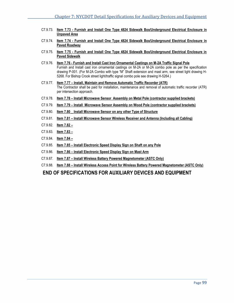
Chapter 7: NYCDOT Detail Specifications for Auxiliary Devices and Equipment
Page 99
C7.9.73. Item 7.73 - Furnish and Install One Type 4824 Sidewalk Box/Underground Electrical Enclosure in Unpaved Area
C7.9.74. Item 7.74 - Furnish and Install One Type 4824 Sidewalk Box/Underground Electrical Enclosure in Paved Roadway
C7.9.75. Item 7.75 - Furnish and Install One Type 4824 Sidewalk Box/Underground Electrical Enclosure in Paved Sidewalk
C7.9.76. Item 7.76 - Furnish and Install Cast Iron Ornamental Castings on M-2A Traffic Signal Pole Furnish and Install cast iron ornamental castings on M-2A or M-2A combo pole as per the specification drawing P-001. (For M-2A Combo with type “M” Shaft extension and mast arm, see street light drawing H-5268. For Bishop Crook street light/traffic signal combo pole see drawing H-5264.)
C7.9.77. Item 7.77 – Install, Maintain and Remove Automatic Traffic Recorder (ATR) The Contractor shall be paid for installation, maintenance and removal of automatic traffic recorder (ATR) per intersection approach.
C7.9.78. Item 7.78 – Install Microwave Sensor Assembly on Metal Pole (contractor supplied brackets)
C7.9.79. Item 7.79 – Install Microwave Sensor Assembly on Wood Pole (contractor supplied brackets)
C7.9.80. Item 7.80 _ Install Microwave Sensor on any other Type of Structure
C7.9.81. Item 7.81 – Install Microwave Sensor Wireless Receiver and Antenna (Including all Cabling)
C7.9.82. Item 7.82 –
C7.9.83. Item 7.83 –
C7.9.84. Item 7.84 –
C7.9.85. Item 7.85 – Install Electronic Speed Display Sign on Shaft on any Pole
C7.9.86. Item 7.86 – Install Electronic Speed Display Sign on Mast Arm
C7.9.87. Item 7.87 – Install Wireless Battery Powered Magnetometer (ASTC Only)
C7.9.88. Item 7.88 – Install Wireless Access Point for Wireless Battery Powered Magnetometer (ASTC Only)
END OF SPECIFICATIONS FOR AUXILIARY DEVICES AND EQUIPMENT

Chapter 8
NYCDOT Detail Specifications for Wood Base and Concrete Base Pylon and Equipment
Date of Revision Revised by Description

NYCDOT Specifications for Traffic Signals & ITS Systems November 2013
Page 102
C8. NYCDOT DETAIL SPECIFICATIONS FOR WOOD BASE AND CONCRETE BASE PYLON AND EQUIPMENT ............. 103 C8.1. SCOPE OF WORK ........................................................................................................................................................ 103 C8.2. INSTALLATION OF TEMPORARY PYLON .......................................................................................................................... 103 C8.3. MAINTENANCE OF TEMPORARY PYLON ......................................................................................................................... 103 C8.4. REMOVAL OF TEMPORARY PYLON ................................................................................................................................ 103 C8.5. DETAIL SPECIFICATIONS BY ITEMS ................................................................................................................................ 104
Chapter 8: NYCDOT Detail Specifications for Temporary Pole or Pylon and Equipment
Page 103
C8. NYCDOT Detail Specifications for Wood Base and Concrete Base Pylon and Equipment
C8.1. Scope of Work C8.1.1. The Contractor shall furnish all necessary labor and material to remove and install equipment on temporary
pole, aka temporary pylon, as shown on the traffic signal design drawing, described in the work order or directed by the Engineer. For more details of temporary pylon see the specification drawing MISC-001.
C8.2. Installation of Temporary Pylon C8.2.1. Where a streetlight or traffic signal is being removed and a temporary pylon is to be installed to provide
support for street light luminaire or traffic signal, the Contractor shall install luminaire or traffic signal on the temporary pylon. The payment for removal and installation of luminaire or traffic signal shall be made under a separate item.
C8.3. Maintenance of Temporary Pylon C8.3.1. When the Contractor installs a temporary pylon it is their responsibility to provide 24 hour, seven days a
week maintenance for the temporary pylon and all equipment attached thereto. In the event the pylon is hit, damaged, vandalized or blown over it will be the responsibility of the Contractor to restore it to its normal working condition within six hours of notification from the Department or other agencies.
C8.4. Removal of Temporary Pylon C8.4.1. When the new streetlight pole or traffic signal pole is installed, the Contractor, when directed to do so by the
Engineer, will install the streetlight luminaire or traffic signal on the new streetlight pole or traffic signal pole and remove the temporary pylon from the field and secure all electrical connections and cable. The installation of streetlight luminaire shall be paid for under Item 3.27 of this specification.

NYCDOT Specifications for Traffic Signals & ITS Systems November 2013
Page 104
C8.5. Detail Specifications by Items C8.5.1. Item 8.1 - Install, Maintain, and Remove One Temporary Pylon with Streetlight Luminaire with or
without Photo Electric Cell Install, maintain and remove a temporary pylon with streetlight luminaire at its proper location. The Contractor shall install an approved type temporary pylon and affix thereto the streetlight luminaire. The wiring, fusing, splicing and all other required work is to be performed by the Contractor.
C8.5.2. Item 8.2 - Remove Fire Alarm Luminaire and Bracket from Existing Streetlight Pole The Contractor shall remove the existing fire alarm luminaire and bracket, if any, from existing streetlight pole. Where the existing streetlight pole is being removed and a temporary pylon is being installed, a fire alarm luminaire shall be installed on the pylon.
The installation of the fire alarm luminaire shall be paid for under item 8.3 and/or 8.4 of this Specification. If it is not to be installed on the temporary pylon, then it shall be returned to the City.
C8.5.3. Item 8.3 - Install. Maintain, and Remove Fire Alarm Luminaire on Temporary Pylon The Contractor shall install a fire alarm luminaire on a temporary pylon as per traffic signal design drawing, described in a work order or directed by the Engineer. The Contractor is to supply all labor, material, wiring and electrical connections to properly put into operation the fire alarm luminaire on a temporary pylon at the noted location. When pylon is to be removed the fire alarm luminaire is to be removed and either installed on permanent pole or returned to the City.
C8.5.4. Item 8.4 - Install Fire Alarm Luminaire on any Permanent Pole !!!OBSOLETE!!! The Contractor shall install a fire alarm luminaire on any pole other than temporary pylon as per traffic signal design drawing, described in a work order or directed by the Engineer.
The Contractor, where necessary, shall drill a hole in the shaft to serve as a wire-way, remove all sharp edges to prevent injury to the insulation of cable to be installed. The bracket shall be attached to the pole with stainless steel strapping A.I.S.I Type No. 201 or No. 301 or approved equal. The Contractor shall install the required number of size 14 AWG conductors, from the luminaire socket through the bracket and shaft to the fuse cutout in the base of the pole. The Contractor shall also furnish and install an in-line fuse cutout with a 15 amp fuse connected to the control side of the PEC. Bracket and luminaire shall be supplied by the Department and the Contractor to furnishing the lamp.
C8.5.5. Item 8.5 - Deleted
C8.5.6. Item 8.6 - Deleted
C8.5.7. Item 8.7 - Deleted
C8.5.8. Item 8.8 - Install Concrete Pylon with Pole When directed by a work order or Engineer, the Contractor shall install a concrete block base pylon with pole. The concrete block base shall be constructed as shown on the specification drawing MISC-001_1. The Contractor shall place a standard FS streetlight shaft on the concrete base without streetlight arm. All necessary equipment to be placed in service at that location shall be included in this item.
C8.5.9. Item 8.9 - Remove Temporary Concrete Pylon with Pole Remove temporary concrete pylon and all equipment
C8.5.10. Item 8.10 - Relocate Temporary Concrete Pylon with Pole Relocate temporary concrete pylon and all equipment
END OF SPECIFICATIONSFOR TEMPORARY POLE OR PYLON AND EQUIPMENT

NYCDOT Specification List of Most Common Construction Related Furnish Material
Date of Revision Revised by Description

NYCDOT Specifications for Traffic Signals & ITS Systems November 2013
Page 106
NYCDOT Specification List of Most Common Construction Related Furnish Material
No. Description Unit
20000 10-foot aluminum signal pole type “S-1a” (Specification 18) EA
20001 5-foot galvanized steel Accessible Pedestrian Signal (APS) pole, (Specification 28) EA
20002 Alliance Downtown New York (ADNY) type “P” pole (Specification drawing P-011) EA
20020 Set of three 3/4" anchor bolt assembly for “S-1a” pole (Specification 6) SET
20021 Set of four 1" anchor bolt assembly for “S-14” and streetlight poles (Specification 6) SET
20111 15 1/2-inch “M-2A” pole shaft extension for streetlight luminaire arm (Specification drawing P-004) EA
20113 15 1/2-inch “M-2A” pole shaft extension for twin streetlight luminaire arm (Specification drawing P-004) EA
20114 7-foot “M-2A” pole shaft extension (“stove pipe” exten.) for 90º twin streetlight luminaire arm (Spec dwg P-003) EA
20115 7-foot “M-2A” pole shaft extension (“stove pipe” exten.) for 180º twin streetlight luminaire arm (Spec dwg P-003) EA
20150 “M-2A” traffic signal pole with a 40-foot mast arm (including anchor rod assembly) EA
20160 20' traffic signal mast arm pole assembly for “M-2A” pole (Specification 38) EA
20169 Alliance Downtown New York (ADNY) type “S” pole (Specification drawing P-011) EA
20184 5' mast arm extension assembly with fittings (Specification drawing MA-005) EA
20186 20' mast arm assembly with fittings (Specification 38) EA
20200 “M-2A” pole transformer base (Specification 38) EA
20220 Set of four 1-1/4” anchor bolt assembly for “M-2A” pole (Specification 6) SET
20270 Set of four lug cleats for “M-2A” pole (Specification 38) SET
20360 "J2A" tie rod elbow for “M-2A” pole mast arm (Specification drawing set MA-004) EA
20430 Aluminum mast arm traffic signal head "R2" (Specification 44) EA
20441 Complete “M-2A” signal pole parts kits, (Specification 38) EA
20450 Complete ornamental castings (as per drawing P-001) EA
20640 Aluminum traffic signal pole type “S-14” (Specification 28) EA
21200 15-foot straight support arm for overhead sign (Specification drawing MISC-004) EA
21500 20-foot straight support arm for overhead sign (Specification drawing MISC-004) EA
21600 25-foot straight support arm for overhead sign (Specification drawing MISC-004) EA
30013-L 8” Red-Amber-Green LED 3-section traffic signal face (former “One-Way” signal) (Specification 7) EA
30013-RB 8” Red Ball LED lens and traffic signal section (Specification 7) EA
30013-AB 8” Amber Ball LED lens and traffic signal section (Specification 7) EA

NYCDOT Specification of Most Common Construction Related Furnish Material
Page 107
No. Description Unit
30013-GB 8” Green Ball LED lens and traffic signal section (Specification 7) EA
30080 Tunnel type visors for 8" and 12" vehicular traffic signal (Specification 41) EA
31014-R 8” Red Ball LED lens (Specification 7) EA
31014-A 8” Amber Ball LED lens (Specification 7) EA
31014-G 8” Green Ball LED lens (Specification 7) EA
31150 Aluminum die castings and assembly for pole mounted traffic signal “1SA” (Specification 34) EA
31175 Aluminum die castings and assembly for pole mounted traffic signals “2SPA” (Specification 34) EA
31185 Aluminum die castings and assembly for pole mounted traffic signals “3SPA” (Specification 34) EA
31195 Aluminum die castings and assembly for pole mounted traffic signals “4SPA” (Specification 34) EA
31200 One pair of "VB" assembly (Specification 34) EA
31205 Aluminum die castings and assembly for mast arm mounted traffic signal “1MS” (Specification 35) EA
31210 Pole hub (“Lowton hub”/”Hub”) assembly (consisting of 2 hubs and 1 pipe nipple) (Specification 34) EA
31215 Aluminum die castings and assembly for mast arm mounted traffic signals “2MS” (Specification 35) EA
31225 Aluminum die castings and assembly for mast arm mounted traffic signals “3MS” (Specification 35) EA
31235 Aluminum die castings and assembly for mast arm mounted traffic signals “4MS” (Specification 35) EA
31245 Rigid mounting bracket for one traffic signal face (former “One-Way” signal) (Specification drawing SE-024) EA
31340 One pair of "VB-P" assembly (Specification 34) EA
31351 One pair of "VB-2P" assembly (Specification 34) EA
31500-L 12” Red-Amber-Green LED 3-section traffic signal face (former “One-Way” signal) (Specification 7) EA
31500-RB 12” Red Ball LED lens and traffic signal section (Specification 7) EA
31500-AB 12” Amber Ball LED lens and traffic signal section (Specification 7) EA
31500-GB 12” Green Ball LED lens and traffic signal section (Specification 7) EA
31500-RL 12” Red Arrow LED lens and traffic signal section (Specification 7) EA
31500-AL 12” Amber Arrow LED lens and traffic signal section (Specification 7) EA
31500-GL 12” Green Arrow LED lens and traffic signal section (Specification 7) EA
31501-R 12” Red Ball LED lens (Specification 7) EA
31501-A 12” Amber Ball LED lens (Specification 7) EA
31501-G 12” Green Ball LED lens (Specification 7) EA
31501-RA 12” Red Arrow LED lens (Specification 7) EA
31501-AA 12” Amber Arrow LED lens (Specification 7) EA
31501-GA 12” Green Arrow LED lens (Specification 7) EA
31600-L 12” Red-Amber-Green LED 3-section bicycle signal face (Specification drawing SE-028) EA
33000-L 16”x16” polycarbonate LED pedestrian signal head (Specification 64A) EA
33001-L 16”x16” polycarbonate LED pedestrian countdown signal head (Specifications 64A and 66) EA

NYCDOT Specifications for Traffic Signals & ITS Systems November 2013
Page 108
No. Description Unit
33002 Accessible Pedestrian Signal (APS) (Specification 27B) EA
35001 16”x16” LED pedestrian countdown lens (Specification 66) EA
44062 Single pre-timed 27 circuit controller with fittings & brackets (includes security strap) EA
49010 Aluminum detector cabinet with fittings & brackets (Specification 60) EA
60000B Traffic signal cable 2c-10B (2 size 10 AWG conductors with a third wire for bonding) (Specification 4B) LF
60001 Traffic signal cable 2c-14 (2 size 14 AWG conductors) (Specification 4) LF
60002 Size 8 AWG green Thermoplastic High Heat-resistant Nylon-coated (THHN) conductor LF
60040 Traffic signal cable 7c-14 (7 size 14 AWG conductors) (Specification 4) LF
60060 Traffic signal cable 10c-14 (10 size 14 AWG conductors) (Specification 4) LF
60190 Traffic signal cable 13c-14 (13 size 14 AWG conductors 13) (Specification 4) LF
60200 Accessible Pedestrian Signal (APS) cable (Specification 5) LF
65000 Battery back-up power supply system (Specification 122) EA
66000 Single dial pre-timed controller with fitting and brackets (Specification 46, October ’94). Controller to be 19 circuits. Cabinet to be of standard size to house 27 circuit controller (includes security strap)
EA
66000-M Single dial electromechanical semi-actuated controller with brackets and fittings EA
70750 Pedestrian operated switch (Specification 27A) EA
70764 “Pedestrian operated switch” sign with no arrow EA
70765 “Pedestrian operated switch” sign with Left arrow R10-4a EA
70766 “Pedestrian operated switch” sign with Two-Way arrow EA
70767 “Pedestrian operated switch” sign with Right arrow EA
70793 Traffic signal mast arm assembly “MAW-15” for wood poles (Specification 30) EA
70830 Weatherhead assembly "L2A" with nipple (Specification 45) EA
70840 Concentric link "K2A" with bolt (Specification 44) EA
72180 100 KHz loop vehicle detector EA
72181 110 KHz loop vehicle detector EA
72187 Dual conductor shielded cable (lead in wire) LF
72188 Loop detector wire LF
72189 Magnetometer kit (one wireless access point and four pucks) (Specification 63) EA
73000 Remote microwave sensor include bracket, back connectors and 120 VAC option EA
73500 Microwave sensor assembly including microwave sensor, cabinet and wireless data transmitter and receiver EA
73501 Type “S” bus interface unit (BIU) (Specification 62BIU) EA
73502 896-940 MHz; 8.5 db; 6 element Broadband welded Yagi Antenna with N-Female antenna with mounting bracket for 1 1/2 "pipe
EA
73503 Microwave sensor assembly including microwave sensor, cabinet and wireless data transmitter and receiver with Bluetooth
EA
75000 Electronic speed display sign (contractor to supply cable & brackets) (Specification 121) EA
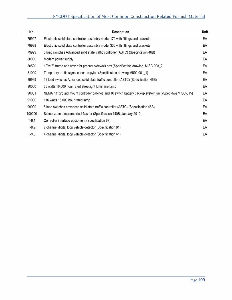
NYCDOT Specification of Most Common Construction Related Furnish Material
Page 109
No. Description Unit
79997 Electronic solid state controller assembly model 170 with fittings and brackets EA
79998 Electronic solid state controller assembly model 330 with fittings and brackets EA
79999 6 load switches Advanced solid state traffic controller (ASTC) (Specification 46B) EA
80000 Modem power supply EA
80500 12”x18” frame and cover for precast sidewalk box (Specification drawing MISC-008_2) EA
81000 Temporary traffic signal concrete pylon (Specification drawing MISC-001_1) EA
89999 12 load switches Advanced solid state traffic controller (ASTC) (Specification 46B) EA
90000 68 watts 16,000 hour rated streetlight luminaire lamp EA
90001 NEMA "R" ground mount controller cabinet and 16 switch battery backup system unit (Spec dwg MISC-015) EA
91000 116 watts 16,000 hour rated lamp EA
99999 8 load switches advanced solid state traffic controller (ASTC) (Specification 46B) EA
100000 School zone electrometrical flasher (Specification 140B, January 2010) EA
T-9.1 Controller interface equipment (Specification 67) EA
T-9.2 2 channel digital loop vehicle detector (Specification 61) EA
T-9.3 4 channel digital loop vehicle detector (Specification 61) EA


Specification 4
NYCDOT Specification for Polyethylene Insulated and Jacketed Traffic Signal Cable
Date of Revision Revised by Description
6/17/06 Soft copy & revise ASTM #
2/30/10 Add color coding
8/20/10 Add name tape and strength member

NYCDOT Specifications for Traffic Signals & ITS Systems November 2013
Page 112
4. NYCDOT SPECIFICATION FOR TRAFFIC SIGNAL CABLE .............................................................................................. 113 4.1. GENERAL .................................................................................................................................................................... 113 4.2. CONDUCTORS ............................................................................................................................................................. 113 4.3. INSULATION ................................................................................................................................................................. 113 4.4. COLOR CODING ........................................................................................................................................................... 114 4.5. CONDUCTOR ASSEMBLY .............................................................................................................................................. 115 4.6. IDENTIFICATION TAPE .................................................................................................................................................. 116 4.7. INSPECTION AND TESTS ............................................................................................................................................... 116 4.8. REELS ........................................................................................................................................................................ 117 4.9. IDENTIFICATION ........................................................................................................................................................... 117 4.10. DELIVERY.................................................................................................................................................................... 117 4.11. APPENDIX ................................................................................................................................................................... 117

Specification 4: NYCDOT Specification for Traffic Signal Cable
Page 113
4. NYCDOT Specification for Traffic Signal Cable
4.1. General This specification covers 600 volts rated polyethylene-insulated, jacketed cable for use in traffic signal systems 4.1.1.
in underground conduits and as aerial cable not supported by a Messenger cable. The cable assembly must have a minimum a two strength members to act as strain reliefs when use in unsupported aerial applications
The traffic signal cable shall consist of uncoated copper individually insulated with heat stabilized polyethylene 4.1.2.laid up in a compact cable form and bound with suitable tape. The cable core shall be enclosed in a non-metallic jacket. Detailed requirements for the components and their assembly are prescribed below.
4.2. Conductors Conductors, before application of insulation, shall be solid round, annealed copper conforming to ASTM 4.2.1.
Designation B-3.
Conductor size (in AWG) and the number of conductors in the traffic signal cable shall be as specified. 4.2.2.
4.3. Insulation The insulation compound before application to the conductors shall be heat-stabilized polyethylene conforming 4.3.1.
to the requirements of ASTM Designation D 1248, for Type 1, Class B, Category 5, Grade E4 materials. The insulation shall be applied concentrically about the conductor. After application to the conductors the insulation shall meet the following requirements when tested in accordance with the procedures of ASTM Designation D 2633 and D 1351.
Physical Properties of Polyethylene Insulation 4.3.1.1.
Initial properties 4.3.1.1.1.Tensile strength, lbs. per sq. in min 1400 Elongation at rupture, percent min 350
After 48 hours in air oven at 100º C ± 1º C 4.3.1.1.2.Tensile strength, percent of original min 75 Elongation at rupture, percent of original, min. 75
Cold bend test, 1 hour at minus 55º C ± 1º C, mandrel diameter 4.3.1.1.3.2.5 times insulated conductor diameter No cracks
For Conductors size of 20 to 14 AWG the average thickness of insulation shall be not less than 0.025 inch; for 4.3.2.conductors size of 13 to 8 AWG it shall be not less than 0.030 inch; and for conductors size of 7 to 2 AWG it shall be not less than 0.045 inch. The minimum thickness shall not be less than 90% of the average thickness.
Moisture absorption - After a 24 hour immersion in the tap water at 50° C ± 1° C, the specific inductive capacity 4.3.3.of the insulation shall be more than 2.5. After a continued 14 day immersion, the specific inductive capacity shall be more than 1.5 percent higher than the value determined at the end of the first day, or more than 1.0 percent higher than at the end of the seventh day. The moisture absorption tests shall be conducted in accordance with methods specified in IPCEA Standard S-61-402, NEMA WO5, latest revision.
Dielectric Strength - When tested in accordance with ASTM Designation D 2633, each processed length of 4.3.4.insulated conductor before cabling shall withstand the test voltages shown below for a period of 5 minutes after immersion in water for not less than 6 hours and while still immersed.

NYCDOT Specifications for Traffic Signals & ITS Systems November 2013
Page 114
Conductor Size (AWG) Test Voltage 20-14 2500 13-8 3000
Insulation Resistance - When tested in accordance with ASTM Designation D 2633, each processed length of 4.3.5.
insulated conductor, after withstanding the Dielectric Strength Test, and while still immersed shall have an insulation resistance as follows:
Conductor Size Insulated Resistance at Size, AWG 60º F, Mega Ω per 1000 Ft
20 thru 17 15,000
16 14,800
15 13,700
14 12,600
13 13,200
12 12,100
11 11,000
10 10,100
9 9,200
8 8,300
Jacketing of individual conductors – Each insulated conductor shall be jacketed with clear electrical grade 4.3.6.polyamide (nylon). Jacket thickness shall be between 0.003 and 0.006 inch.
4.4. Color Coding Color coding for cables shall be as specified. Ease colors shall be obtained by the use of colored insulation. 4.4.1.
Tracers shall be colored stripes which are integral with the insulation and will afford distinctive circuit coding throughout the length of each wire. Tracers shall be continued be continuous and shall be longitudinal or spiral.

Specification 4: NYCDOT Specification for Traffic Signal Cable
Page 115
Traffic Cable Color Coding for 4C, 7C, 10C, 13C, 16C, 19C, 22C 4.4.2.
Conductor number Group Number Color Trace Color
1 Neutral White None
2 1 Red None
3 1 Yellow None
4 1 Green None
5 2 Red Black
6 2 Yellow Black
7 2 Green Black
8 3 Red White
9 3 Yellow White
10 3 Green White
11 4 Red Pink
12 4 Yellow Pink
13 4 Green Pink
14 5 Red Brown
15 5 Yellow Brown
16 5 Green Brown
17 6 Red Orange
18 6 Yellow Orange
19 6 Green Orange
20 7 Red Violet
21 7 Yellow Violet
22 7 Green Violet
4.5. Conductor Assembly Two-conductor cable shall have a maximum length of lay of not more than 30 times the insulated conductor 4.5.1.
diameter. They shall be of the twisted type except on cables size 10 AWG or larger used for power exclusively.
In multi-conductor cables, the single conductors shall be laid up symmetrically in layers with lay not exceeding 4.5.2.the following:
Number of Conductors to Cable Maximum Length of Lay
3 35 times insulated conductor diameter
4 40 times insulated conductor diameter
5 or more 15 times insulated conductor diameter
Each layer of conductors in the cable shall be laid in a direction opposite to that of adjacent layers. The outer layer shall be left-hand lay.
Fillers - Unless their use is prohibited in the bid schedule, fillers shall be used if necessary to secure a firm 4.5.3.compact assembly. Fillers shall be of a non-metallic moisture-resistant material, which shall have not injurious effect on the component parts of the cable.
Cable Tape - The conductor assembly shall be covered with a spiral wrapping of moisture-resistant tape applied 4.5.4.so as to overlap at least 121/2 percent of its width. The tape shall be of Mylar or its equivalent.
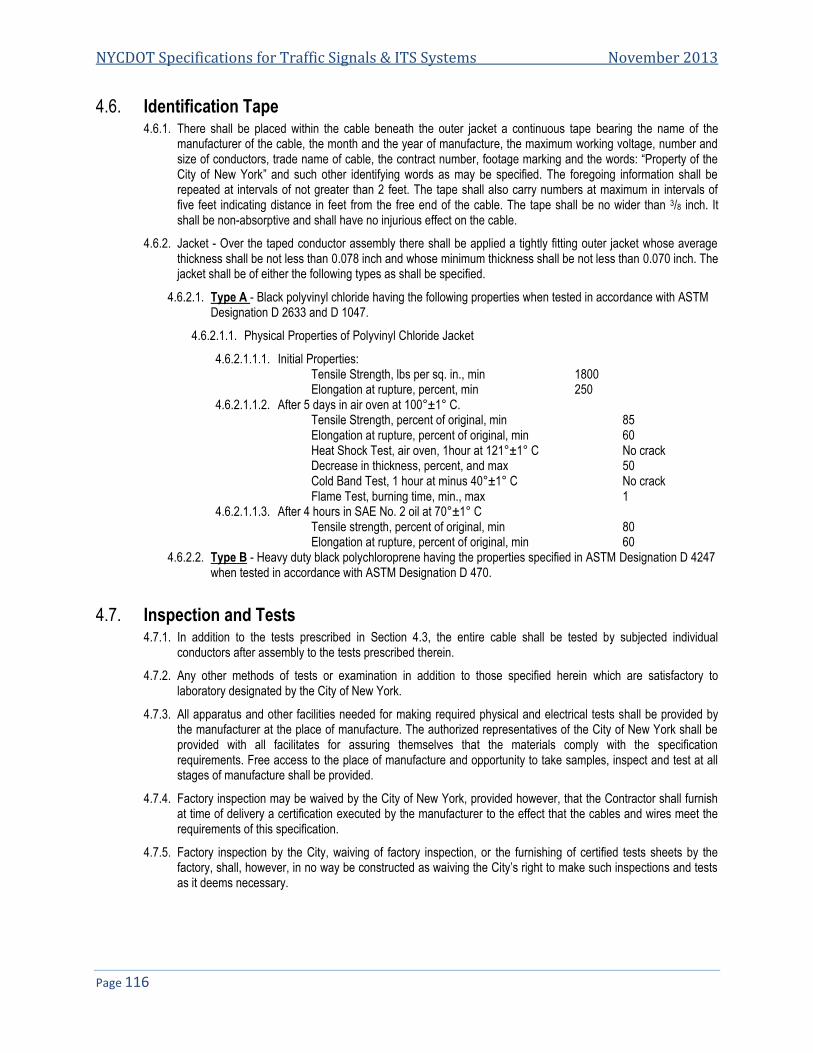
NYCDOT Specifications for Traffic Signals & ITS Systems November 2013
Page 116
4.6. Identification Tape There shall be placed within the cable beneath the outer jacket a continuous tape bearing the name of the 4.6.1.
manufacturer of the cable, the month and the year of manufacture, the maximum working voltage, number and size of conductors, trade name of cable, the contract number, footage marking and the words: “Property of the City of New York” and such other identifying words as may be specified. The foregoing information shall be repeated at intervals of not greater than 2 feet. The tape shall also carry numbers at maximum in intervals of five feet indicating distance in feet from the free end of the cable. The tape shall be no wider than 3/8 inch. It shall be non-absorptive and shall have no injurious effect on the cable.
Jacket - Over the taped conductor assembly there shall be applied a tightly fitting outer jacket whose average 4.6.2.thickness shall be not less than 0.078 inch and whose minimum thickness shall be not less than 0.070 inch. The jacket shall be of either the following types as shall be specified.
Type A - Black polyvinyl chloride having the following properties when tested in accordance with ASTM 4.6.2.1.Designation D 2633 and D 1047.
Physical Properties of Polyvinyl Chloride Jacket 4.6.2.1.1.
4.6.2.1.1.1. Initial Properties: Tensile Strength, lbs per sq. in., min 1800 Elongation at rupture, percent, min 250
4.6.2.1.1.2. After 5 days in air oven at 100°±1° C. Tensile Strength, percent of original, min 85 Elongation at rupture, percent of original, min 60 Heat Shock Test, air oven, 1hour at 121°±1° C No crack Decrease in thickness, percent, and max 50 Cold Band Test, 1 hour at minus 40°±1° C No crack Flame Test, burning time, min., max 1
4.6.2.1.1.3. After 4 hours in SAE No. 2 oil at 70°±1° C Tensile strength, percent of original, min 80 Elongation at rupture, percent of original, min 60
Type B - Heavy duty black polychloroprene having the properties specified in ASTM Designation D 4247 4.6.2.2.when tested in accordance with ASTM Designation D 470.
4.7. Inspection and Tests In addition to the tests prescribed in Section 4.3, the entire cable shall be tested by subjected individual 4.7.1.
conductors after assembly to the tests prescribed therein.
Any other methods of tests or examination in addition to those specified herein which are satisfactory to 4.7.2.laboratory designated by the City of New York.
All apparatus and other facilities needed for making required physical and electrical tests shall be provided by 4.7.3.the manufacturer at the place of manufacture. The authorized representatives of the City of New York shall be provided with all facilitates for assuring themselves that the materials comply with the specification requirements. Free access to the place of manufacture and opportunity to take samples, inspect and test at all stages of manufacture shall be provided.
Factory inspection may be waived by the City of New York, provided however, that the Contractor shall furnish 4.7.4.at time of delivery a certification executed by the manufacturer to the effect that the cables and wires meet the requirements of this specification.
Factory inspection by the City, waiving of factory inspection, or the furnishing of certified tests sheets by the 4.7.5.factory, shall, however, in no way be constructed as waiving the City’s right to make such inspections and tests as it deems necessary.

Specification 4: NYCDOT Specification for Traffic Signal Cable
Page 117
4.8. Reels Reels shall be substantially constructed and in good condition. The maximum outside diameter shall be 42 inch. 4.8.1.
Reel shall have a center hole 27/16 to 3 inches in diameter. The diameter of the reel shall be not less than 12 times the outside of the cable.
There shall be marked on each head of each reel an arrow and the words “Roll this way.” The arrow shall point 4.8.2.in the direction which will tend to tighten the cable on the drum.
Each end of the cable on a reel shall be accessible for testing, and shall be properly sealed and protected for 4.8.3.injury.
Reels shall become the property for the City of New York. Cable on reels shall be covered with a weather 4.8.4.resistant wrapping held in place by at least two corrosion-resistant metal bands or wires.
Materials & Workmanship - Materials and workmanship shall be of first quality. Cable and reels shall be free 4.8.5.from imperfections and defects which may affect appearance or serviceability or both.
4.9. Identification Both heads of each reel shall be stenciled or labeled with the following information: description of cable, length 4.9.1.
on reel, date of manufacture, names and addresses of manufacturer and Contractor, and contract or purchase order number. A shipping tag containing the same information shall be attached to the outer end of the cable.
The manufacturer’s or Contractor’s serial number of each reel shall be either plainly branded on the heads of 4.9.2.the reel or stamped on metal plates having a diameter or length of not less than 1.5, which are countersunk below the surface of the heads of the reel. The metal shall be sufficiently thick so as not to bend easily and the figures shall be as large as practicable.
4.10. Delivery Deliveries will include unloading from carrier and placing in designated location of specified address. 4.10.1.
4.11. Appendix
Note 1 - In order that each request for contract or purchase order quotation will result in fair competition and 4.11.1.delivery of the cable required, the requisition must contain the following information:
• Name of Commodity - Cable; Signal, Polyethylene Insulated Jacketed. • Specification Number - 4 • Quantity - Number of feet per reel and number of reels. • Number of Conductors or Pairs • Size of Conductors - AWG number • Color Coding - See Section 4.4. Color Coding • Jacket - Type A or B. See Section 4.6. Identification Tape • Delivery - Delivery point(s) and manner of delivery.
Note 2 - If in the opinion of the Quality Assurance officer, analyses and tests are necessary to determine 4.11.2.compliance with any requirement of this specification, a sample consisting of 5 feet shall be taken from every manufacturing lot
END OF SPECIFICATIONS FOR TRAFFIC SIGNAL CABLE


Specification 4B
NYCDOT Specification for Cable 2c-10B: Cable for 120 Volt Power Supply
Date of Revision Revised by Description
1/5/2010 Tinned copper on bare copper
.

NYCDOT Specifications for Traffic Signals & ITS Systems November 2013
Page 120
4B. NYCDOT SPECIFICATION FOR CABLE 2C-10B: CABLE FOR 120 VOLT POWER SUPPLY ......................................... 121 4B.1. CABLE NAME ............................................................................................................................................................... 121 4B.2. INTENDED USE ............................................................................................................................................................ 121 4B.3. CONSTRUCTION ........................................................................................................................................................... 121 4B.4. INSULATION ................................................................................................................................................................. 121
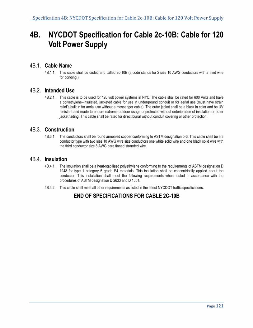
Specification 4B: NYCDOT Specification for Cable 2c-10B: Cable for 120 Volt Power Supply
Page 121
4B. NYCDOT Specification for Cable 2c-10B: Cable for 120 Volt Power Supply
4B.1. Cable Name 4B.1.1. This cable shall be coded and called 2c-10B (a code stands for 2 size 10 AWG conductors with a third wire
for bonding.)
4B.2. Intended Use 4B.2.1. This cable is to be used for 120 volt power systems in NYC. The cable shall be rated for 600 Volts and have
a polyethylene–insulated, jacketed cable for use in underground conduit or for aerial use (must have strain relief’s built in for aerial use without a messenger cable). The outer jacket shall be a black in color and be UV resistant and made to endure extreme outdoor usage unprotected without deterioration of insulation or outer jacket fading. This cable shall be rated for direct burial without conduit covering or other protection.
4B.3. Construction 4B.3.1. The conductors shall be round annealed copper conforming to ASTM designation b-3. This cable shall be a 3
conductor type with two size 10 AWG wire size conductors one white solid wire and one black solid wire with the third conductor size 8 AWG bare tinned stranded wire.
4B.4. Insulation 4B.4.1. The insulation shall be a heat-stabilized polyethylene conforming to the requirements of ASTM designation D
1248 for type 1 category 5 grade E4 materials. This insulation shall be concentrically applied about the conductor. This installation shall meet the following requirements when tested in accordance with the procedures of ASTM designation D 2633 and D 1351.
4B.4.2. This cable shall meet all other requirements as listed in the latest NYCDOT traffic specifications.
END OF SPECIFICATIONS FOR CABLE 2C-10B

Specification 5
NYCDOT Specifications for Accessible Pedestrian Signal (APS) Cable
Date of Revision Revised by Description
10/29/11 New spec

NYCDOT Specifications for Traffic Signals & ITS Systems November 2013
Page 124
5. NYCDOT SPECIFICATION FOR ACCESSIBLE PEDESTRIAN SIGNAL (APS) CABLE ................................................... 125 5.1. GENERAL .................................................................................................................................................................... 125 5.2. CABLE CHARACTERISTICS ............................................................................................................................................ 125 5.3. IDENTIFICATION TAPE .................................................................................................................................................. 125

Specification 5: NYCDOT Specification for Accessible Pedestrian Signal (APS) Cable
Page 125
5. NYCDOT Specification for Accessible Pedestrian Signal (APS) Cable
5.1. General The APS cable shall be used for low voltage interconnection between the Pedestrian signal and the APS 5.1.1.
Devise.
The cable shall have 3 pair (6 conductors) of twisted 18 AWG 19 strand tinned copper and a single bare 8 5.1.2.AWG 7 strand tinned copper.
The cable primary insulation shall 105º C temperature Rating and made from PVC with a Nominal wall 5.1.3.
thickness of 0.015 inch with a secondary insulation made of nylon with a wall thickness 0.004 inch
The cable shall be wrapped in a waterblock tape between the conductors and outside jacket. 5.1.4.
The outer jacket shall be made of PVC-105º C with a nominal thickness of 0.045 inch ,the total outside 5.1.5.diameter of the cable shall be under 0.40 inch
The cable temperature rating shall be -27º C to 105º C with a 600 VAC operating voltage. 5.1.6.
5.2. Cable Characteristics This cable is made with pvc/nylon covered tinned copper conductors and twisted into pairs. 5.2.1.
It is then cabled together with an 8 AWG drain wire and fillers to make round with an overall waterblocking tape 5.2.2.and jacketed with an overall PVC jacket
The cable shall be Sunlight, Oil & Gas Resistant and Flame Retardant VW- 1 RoHS 5.2.3.
Color coding: White/Black - Red/Green - Brown/Yellow 5.2.4.
5.3. Identification Tape There shall be placed within the cable beneath the outer jacket a continuous tape bearing the name of the 5.3.1.
manufacturer of the cable, the month and the year of manufacture, the maximum working voltage, number and size of conductors, trade name of cable, the contract number, footage marking and the words: “Property of the City of New York” and such other identifying words as may be specified. The foregoing information shall be repeated at intervals of not greater than 2ft. The tape shall also carry numbers at maximum in intervals of five feet indicating distance in feet from the free end of the cable. The tape shall be no wider than 3/8 in. It shall be non-absorptive and shall have no injurious effect on the cable.
END OF SPECIFICATIONS FOR ACCESSIBLE PEDESTRIAN SIGNAL (APS) CABLE

Specification 6
NYCDOT Specifications for Anchor Bolt Assemblies for Standard Traffic Signal Poles
Item No. 20020 - ¾” Anchor Bolt Assembly Item No. 20021 - 1” Anchor Bolt Assembly Item No. 20220 - 1 1/4” Anchor Bolt Assembly
Date of Revision Revised by Description
6/17/06 Revised spec date
NYCDOT Specifications for Traffic Signals & ITS Systems November 2013
Page 128
6. NYCDOT SPECIFICATIONS FOR ANCHOR BOLT ASSEMBLIES FOR STANDARD TRAFFIC SIGNAL POLE ............ 129 6.1. GENERAL .................................................................................................................................................................... 129 6.2. MATERIAL ................................................................................................................................................................... 129 6.3. MANUFACTURE ............................................................................................................................................................ 129 6.4. ASSEMBLING ............................................................................................................................................................... 129 6.5. SAMPLES .................................................................................................................................................................... 129 6.6. DELIVERY TIME ........................................................................................................................................................... 129 6.7. DELIVERY POINT ......................................................................................................................................................... 130

Spec 6: NYCDOT Specification for Anchor Bolt Assemblies for Standard Traffic Signal Poles
Page 129
6. NYCDOT Specifications for Anchor Bolt Assemblies for Standard Traffic Signal Pole
6.1. General The scope of work under this Specification shall be the satisfactory manufacturing, assembly, delivery and 6.1.1.
stacking of anchor bolt assemblies, as detailed on the specification drawing F-007 and in accordance with these specifications.
6.2. Material Each assembly shall consist of an “L” bolt a hexagonal bolt coupling, a stud bolt, and a standard hexagonal nut 6.2.1.
with washer and lock washer. A heavy standard plain washer shall be included in Assembly “D”. All bolts and couplings shall be made of open-hearth, hot-rolled, mild carbon steel as per ASTM Specification A-307-65, Grade A with a minimum yield point of 36,000 PSI and a minimum tensile strength of 58,000 PSI unless otherwise noted.
6.3. Manufacture All threading shall be standard National Coarse (NC) threading with a final Class 2 fit so that any unit of a bolt 6.3.1.
assembly shall be interchangeable with the same unit in any other assembly of the same bolt size included in this order. All stud bolts shall be completely threaded. The coupling shall be completely threaded concentric with the axial counter lines. All burrs and sharp edges shall be removed and the threaded ends slightly chamfered before galvanizing.
All parts shall be individually hot-galvanized after fabrication and before assembling according to ASTM 6.3.2.Specifications A123-65 except for the female threading in the coupling which shall be tapped after galvanization, unless otherwise noted. After galvanizing, the threading shall be brushed or spun to remove any lumps and excess fluid retained after dipping in the galvanic solution.
In the manufacture of the bolts, care shall be used to maintain the original strength of the steel throughout the 6.3.3.entire bolt length.
6.4. Assembling Anchor bolt assemblies shall be completely assembled and then securely wired together for shipment in the 6.4.1.
quantities, per pole, noted for particular type on the specification drawing F-004. Coupling joints shall be screwed tight for locking action and the exposed threading shall be protected before shipment with burlap, or the equivalent. These groups of assemblies shall be tagged to identify the type of assembly, the manufacturer’s name, year of manufacture, and the order number. The information on the tags shall remain legible, during outdoor storage, for a period of at least five (5) years from the time of delivery.
6.5. Samples Two complete pre-production samples of each item in the BID SCHEDULE shall be delivered for inspection and 6.5.1.
testing within ten (10) consecutive calendar days after notice from the City of New York.
Upon receipt of this notice, the Contractor shall also submit six (6) complete sets of working drawing to the 6.5.2.Department. Failure to submit the samples and drawings within the time specified will be sufficient reason to declare the Contractor in default.
6.6. Delivery Time Quantities and timing of deliveries shall be as noted in the BID SCHEDULE. 6.6.1.
NYCDOT Specifications for Traffic Signals & ITS Systems November 2013
Page 130
6.7. Delivery Point The Contractor shall make deliveries to the Department’s Warehouse (loading bays 5 and 6) at 66-26 6.7.1.
Metropolitan Ave in Middle Village (Queens), NY 11379, any other locations within the limits of the City of New York designated by the Department, or as directed by the Engineer. Material/equipment will be accepted between the hours of 8:00 AM and 12:00 PM with unloading to be completed before 3:00 PM, Monday thru Friday, except holidays. The Contractor must notify the Department at least 24 hours in advance of delivery.
The Contractor shall deliver material into the designated storage point and shall unload and stack this material 6.7.2.under the direction of the Department.
The Contractor shall furnish all labor, dunnage, blocking, wedges, and pallets necessary for the safe delivery, 6.7.3.unloading and stacking of material to a height of fifteen (15) feet under this Specification to the Department.
The Contractor shall pay all transportation and delivery charges associated with this Specification. 6.7.4.
END OF SPECIFICATIONS FOR ANCHOR BOLT ASSEMBLY FOR TRAFFIC SIGNAL POLE

Spec 7: NYCDOT Spec for Adjustable 3 Section Die Cast Alum Traffic Signal Face with LED Lenses
Page 131
Specification 7
NYCDOT Specifications for Adjustable Three Section Die Cast Aluminum Traffic Signal Face with LED Lenses
Item No. 30013(LED) - 8” LED Lenses Item No. 31500(LED) - 12” LED Lenses
Revision number Revision Date Revised by Reason
7.2 5/10/06 amber led, remove lamp

NYCDOT Specifications for Traffic Signals & ITS Systems November 2013
Page 132
7. NYCDOT SPECIFICATIONS FOR ADJUSTABLE THREE SECTION DIE CAST ALUMINUM TRAFFIC SIGNAL FACE WITH LED LENSES .............................................................................................................................................................. 133
7.1. DEFINITIONS................................................................................................................................................................ 133 7.2. GENERAL .................................................................................................................................................................... 133 7.3. HOUSING .................................................................................................................................................................... 134 7.4. HOUSING DOOR .......................................................................................................................................................... 135 7.5. VISOR ......................................................................................................................................................................... 135 7.6. LENS (LED) ................................................................................................................................................................ 135 7.7. GASKETS .................................................................................................................................................................... 135 7.8. PAINTING .................................................................................................................................................................... 136 7.9. CRATING ..................................................................................................................................................................... 136 7.10. SAMPLES .................................................................................................................................................................... 136 7.11. TESTS......................................................................................................................................................................... 136 7.12. DELIVERY POINT ......................................................................................................................................................... 136 7.13. DELIVERY AND METHOD ............................................................................................................................................... 136 7.14. INSPECTION ................................................................................................................................................................ 137 7.15. GUARANTEE ................................................................................................................................................................ 137

Spec 7: NYCDOT Spec for Adjustable 3 Section Die Cast Alum Traffic Signal Face with LED Lenses
Page 133
7. NYCDOT Specifications for Adjustable Three Section Die Cast Aluminum Traffic Signal Face with LED Lenses
7.1. Definitions Traffic Signal - any highway traffic signal by which traffic is alternately directed to stop and permitted to 7.1.1.
proceed4.
Signal Housing – the part of a signal section that protects the light source and other required components4. 7.1.2.
Signal Head - an assembly of one or more signal faces that is provided for controlling traffic movements on one 7.1.3.or more approaches.
Signal Face (former “One-Way Signal”) - an assembly of one or more signal sections that is provided for 7.1.4.controlling one or more traffic movements on a single approach4.
Signal Section - the assembly of a signal housing, signal lens, if any, and light source with necessary 7.1.5.components (such as visor, louver) to be used for displaying one signal indication4.
Signal Indication - the illumination of a signal lens or equivalent device, consisting of a uniformly colored Red, 7.1.6.Yellow or Green Lens, or corresponding colored arrow lens.
Lens - the part of the signal section that redirects the light coming directly from the light source and its reflector, 7.1.7.if any4.
Optical Unit - an assembly of redirecting cover glass or lens, reflector and lamp socket with the necessary 7.1.8.supporting pars to be used for providing a single "Signal Indication".
Signal Visor - the part of signal section that directs the signal indication specifically to approaching traffic and 7.1.9.reduces the effect of direct external light entering the signal lens4.
Signal Louver – a device that can be mounted inside a signal visor to restrict visibility of a signal indication 7.1.10.from the side or to limit the visibility of the signal indication to a certain lane or lanes, or to a certain distance from the stop line4.
LED – A traffic signal lens that uses Light Emitting Diodes as the light source. 7.1.11.
Pedestrian Signal Head – a signal head, which contains the symbols “Walking Person” (symbolizing Walk) 7.1.12.and “Upraised Hand” (symbolizing Don’t Walk), that is installed to direct pedestrian traffic at a traffic control signal4.
7.2. General These specifications are for a three-section one-signal face traffic signal head, electrically operated on a 120 V, 7.2.1.
60 Hz alternating current, and designed for vertical mounting. The signal head shall be designed so that when mounted its orientation may be adjusted without removal from the brackets. The design of the signal shall be such that, with the aid of simple tools and the addition of New York City approved parts, it shall be possible to make an assembly consisting of one, two, three, four, five or six signal sections, one above the other. It shall further be possible with the addition of New York City bracket assemblies and accessories to assemble one or more such signal faces into a two-signal face, three-signal face, four-signal face or five-signal face traffic signal head. The Contractor shall personally inspect and become familiar with the New York City approved parts bracket assemblies and accessories prior to the submission of a bid. This shall be done so that the design of the signal will be compatible with the New York City approved parts and assemblies without any modifications or use of any additional parts.
4 MUTCD, 2009; Section 1A.13

NYCDOT Specifications for Traffic Signals & ITS Systems November 2013
Page 134
The signal head shall be completely assembled and shall include housing, LED lenses, visors, optical systems, 7.2.2.
terminal block and necessary wiring.
Any part not mentioned in these specifications, but necessary for satisfactory use of the signal, shall be 7.2.3.furnished by the Contractor as though such necessary part was specified.
Any unit in the signal head assembly shall be interchangeable with the same unit in other signals of the same 7.2.4.type.
The lighted signal shall be clearly illuminated, without spots or shadows, over its entire surface when viewed 7.2.5.from the usual angles encountered in service. The optical unit and visor shall be designed as a whole so as to eliminate the return of outside rays entering the unit from above the horizon (known as sun phantom). The optical unit shall be so designed and assembled that no light can escape from one indication to another.
All signal indications for each signal face shall be in a straight line and assembled for vertical operation. 7.2.6.
Position Signal Indication 1 Red 2 Yellow 3 Green
The signals shall have a finger safe terminal block installed in each unit having at least four terminals. Each 7.2.7.terminal shall have 2 connected screw terminal with a pressure pad installed under each screw terminal. This block shall be rated for 55 Amp at 600 V and rated for use with both solid and stranded wire. This block shall be held in place by 2 stainless steel screws #8 minimum and treaded into a tapped hole. The block shall be equivalent to the “Marathon” electric block in use by the City of New York.
7.3. Housing The section housing shall consist of three complete independent sections completely water resistant, one for 7.3.1.
each optical system, which can be fastened together with common hand tools, such as screwdriver or wrench, to form a rigid weather resistant assembly with one signal face.
The top and bottom of the housing for each section shall be die cast integrally with the sides forming a complete 7.3.2.and independent unit. Aluminum alloy number 13 or approved equal, which shall meet the requirements of ASTM Specification 885-57T, shall be used for the housing. All castings shall be free of voids, fins, burs, dents, cracks and sharp ridges.
The top and bottom of the housing shall have an opening two inches in diameter to permit entrance of one and 7.3.3.one-half inch connecting hardware and there shall be no other opening in the top or bottom of the housing. The top of each section shall have 72 evenly spaced protruding serrations integrally cast around the pipe opening. The bottom of each section shall have 72 evenly spaced received serrations integrally cast around the pipe opening. The top and bottom serrations shall match and conform with the New York City specification drawing set SE-006. A neoprene gasket shall be provided for the top of each signal section to provide a weather resistant seal between each section and also between the signal face and the bracket fittings.
Individual signal sections shall be fastened together by means of approved cadmium or zinc plated coupler. The 7.3.4.coupler shall provide sufficient space for the entrance of two cables, each with the diameter of three-fourths of an inch. This coupler shall rigidly hold the sections in place with the matching or meshing of the top and bottom serrations and permit rotation of one section with respect to another when required. The use of tie rods will not be acceptable.
Two hinge lugs, for mounting the door, shall be cast integrally with the side of the housing at the left side of the 7.3.5.door.
Two lugs shall be cast integrally with the side of the housing, at the center of the right side of the door, to 7.3.6.accommodate an eye-bolt latch with a wing nut and plain washer, all stainless steel. The hinge pins for the door and latch shall be of stainless steel.

Spec 7: NYCDOT Spec for Adjustable 3 Section Die Cast Alum Traffic Signal Face with LED Lenses
Page 135
The end of the threaded portion of the eye-bolt shall be slightly upset, after the washer and wing nut are added, 7.3.7.to prevent their loss.
7.4. Housing Door The housing door of each section shall also be die cast of the same alloy as the housing. A gasket groove shall 7.4.1.
accommodate a weather resistant neoprene gasket, which, when the door is closed shall seal against a raised bead on the housing making a positive weather resistant and dustproof seal.
A raised collar shall be cast integrally with the door around the periphery of the lens opening, on the outside of 7.4.2.the door. This collar shall be designated to fit up into the visor in such a way as to prevent any perceptible filtration of light between the door and the attached visor. The minimum height of the raised collar shall be five-sixty fourths of an inch.
The hinge lugs shall be cast integrally with the door. It shall be possible to completely invert the signal head, 7.4.3.re-arrange the lenses and provide reverse door swing whenever conditions require.
A lug with an open-end slot shall be cast integrally with the right side of the door, at the center, which will 7.4.4.provide a bearing surface for the wing nut on the eye-bolt latch.
The door shall also contain four #10-24 tapped holes equally spaced and straddling the vertical centerline 7.4.5.through bosses on the door. These holes will accommodate visor clip connections on the outside and lens clip connections on the inside of the door. The fastening screws shall be the Truss Type of stainless steel
7.5. Visor Each section shall be provided with a removable visor of #16 american gauge aluminum sheeting. The 7.5.1.
aluminum used shall be non-heat treatable alloy 3003-H14, or approved equal. The clip angles shall be the same gauge and alloy as the visor.
The visor shall be manufactured according to the specification drawing SE-022 where applicable. 7.5.2.
The visor shall be securely fastened to the door, over the raised collar, to prevent any perceptible filtration of 7.5.3.signal light around the connection of the visor.
The fastening screws for the visor shall be #10-24 truss type of stainless steel. 7.5.4.
The visor, when mounted, shall have a seven degree downward slope from a horizontal projection 7.5.5.perpendicular to the door.
The removal or mounting of the visors shall be accomplished either by the visors being manufactured with 7.5.6.slotted bars which shall keep the screws in place or in accordance with the specification drawing SE-022 where applicable which call for visors having ”K” holes requiring the complete removal of the screws for the removal of the visors.
7.6. Lens (LED) The lens for the traffic signal indications shall be LEDs and conform to the New York City Specifications for LED 7.6.1.
vehicular signals (Specification 7B).
7.7. Gaskets Door Gasket - A neoprene hollow cored door gasket shall provide positive seal between the door and signal 7.7.1.
housing.
Lens Gasket - A special slotted air cored neoprene lens gasket shall provide positive seals between the lens 7.7.2.and the signal door and between the lens and the reflector holder. It shall be an unbroken circular gasket with a "D" shaped cross section.

NYCDOT Specifications for Traffic Signals & ITS Systems November 2013
Page 136
7.8. Painting All metal surfaces of the signal head, including both sides of all visors, shall be first cleaned of all foreign 7.8.1.1.
deposits, oil and grease, and then neutralized for priming. This shall be followed by immersion from 25 to 35 seconds in a phosphate coating solution as per MIL-C-5541A Government Specification: next a clear water rinse followed by immersion in a sealing, neutralizing solution: then oven-baked enamel and shall meet or exceed the salt spray and be added two coats of best quality alkyd urea type oven-baked enamel and shall meet or exceed the salt spray and weatherometer requirements of Federal Specification TT-P-1416. On all but the inside surfaces of the visors, the two final coats shall be Federal Yellow matching 13538 Federal Specification #595. The inside of all visors shall be painted two coats of flat black enamel. All separate parts shall be painted before assembly: each coat shall be baked on separately. The stainless steel latching devices shall not be painted.
No painting or preparation shall be started before notifying the Inspector and allowing him ample time 7.8.1.2.and opportunity to inspect the product.
7.9. Crating One complete signal head shall be safely packed in a carton with visors. All necessary packing shall be used to 7.9.1.
prevent damage to signal when shipping.
Both ends of all cartons shall be clearly marked to identify the contents, the manufacturer, and the order and 7.9.2.serial numbers.
7.10. Samples Two complete pre-production samples shall be delivered for inspection and testing within thirty (30) 7.10.1.
consecutive calendar days after notice from the City of New York. Upon receipt of this notice, the Contractor shall also submit six (6) complete sets of working drawings to the City of New York, submit the samples and drawings within the time specified will be sufficient reason to declare the Contractor in default. Sample and drawings shall be delivered to the Department’s Warehouse (loading bays 5 and 6) at 66-26 Metropolitan Avenue, Middle Village (Queens), NY 11379.
7.11. Tests The City may employ any organization it may deem qualified to perform any test required to determine 7.11.1.
compliance of the Contractor's product with this specification. The costs of such tests are to be borne by the successful bidder.
7.12. Delivery Point All equipment shall be delivered to the Department’s Warehouse (loading bays 5 and 6) at 66-26 Metropolitan 7.12.1.
Ave in Middle Village (Queens), NY 11379, any other locations within the limits of the City of New York designated by the Department, or as directed by the Engineer. Material/equipment will be accepted between the hours of 8:00 AM and 12:00 PM with unloading to be completed before 3:00 PM, Monday thru Friday, except holidays. The Contractor must notify the Department at least 24 hours in advance of delivery..
7.13. Delivery and Method The Contractor shall deliver material into the designated delivery point, and shall unload and stack this 7.13.1.
material under the direction of the warehouse supervisor
The Contractor shall furnish all labor, dunnage, blocking, wedges and other equipment necessary for the safe 7.13.2.delivery, stacking and storing of material under this Specification, satisfactory to the Department.
Quantities and timing of deliveries shall be as noted in the BID SCHEDULE. 7.13.3.

Spec 7: NYCDOT Spec for Adjustable 3 Section Die Cast Alum Traffic Signal Face with LED Lenses
Page 137
The Contractor shall pay all transportation and delivery charges associated with this Specification. 7.13.4.
7.14. Inspection The Contractor shall maintain an inspection staff whose duty shall be the maintenance of a high quality 7.14.1.
product as to materials and workmanship of all equipment purchased under this Specification. The Contractor, when required, shall make inspector’s names available to the Department’s inspection unit.
Under this Specification, the Contractor shall furnish the City's representatives with adequate facilities for the 7.14.2.proper performance of his duties.
7.15. Guarantee All materials furnished under these specifications shall be guaranteed for a period of one (1) year from the 7.15.1.
date of completion of this Specification. During the term of the guarantee, the Contractor shall repair or replace, free from all expense to the City including delivery and shipping charges, and deficiencies due to faulty material or workmanship.
END OF SPECIFICATIONS FOR ADJUSTABLE 3 SECTION DIE CAST ALUMINUM TRAFFIC SIGNAL FACE WITH LED LENSES

Specification 7B
NYCDOT Specification for LED Vehicle Traffic Signal
Date of Revision Revised by Description
6/17/06 Soft copy & revise ASTM #
2/30/10 Add color coding
8/20/10 Add name tape and strength member

NYCDOT Specifications for Traffic Signals & ITS Systems November 2013
Page 140
7B. NYCDOT SPECIFICATION FOR LED VEHICLE TRAFFIC SIGNAL ................................................................................... 141 7B.1. GENERAL .................................................................................................................................................................... 141 7B.2. INSTALLATION .............................................................................................................................................................. 141 7B.3. LED SIGNAL LENS ....................................................................................................................................................... 141 7B.4. SIGNAL MODULE CONSTRUCTION ................................................................................................................................. 141 7B.5. ENVIRONMENTAL REQUIREMENTS................................................................................................................................. 142 7B.6. LUMINOUS INTENSITY ................................................................................................................................................... 142 7B.7. CHROMATICITY ............................................................................................................................................................ 142 7B.8. ELECTRICAL ................................................................................................................................................................ 142 7B.9. CONTROLLER ASSEMBLY COMPATIBILITY ...................................................................................................................... 143 7B.10. QUALITY ASSURANCE .................................................................................................................................................. 144 7B.11. WARRANTY ................................................................................................................................................................. 145
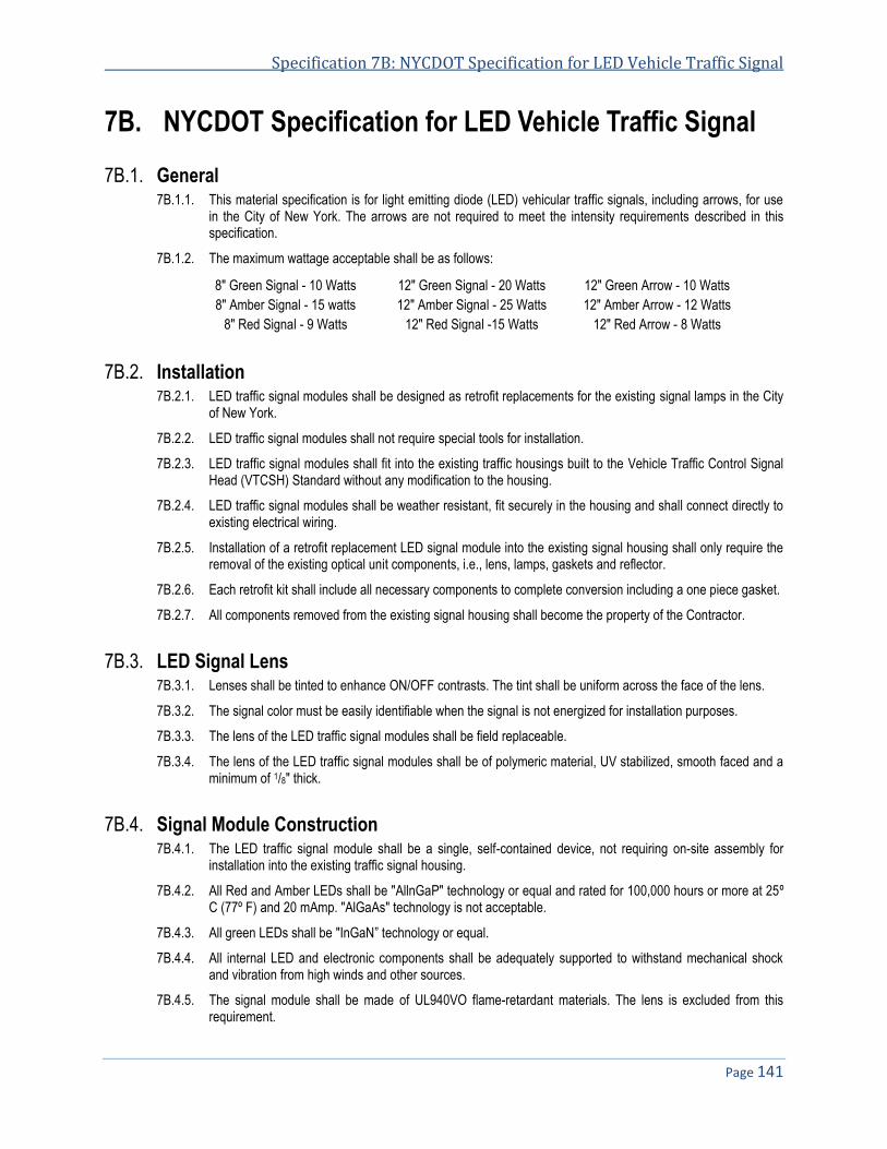
Specification 7B: NYCDOT Specification for LED Vehicle Traffic Signal
Page 141
7B. NYCDOT Specification for LED Vehicle Traffic Signal
7B.1. General 7B.1.1. This material specification is for light emitting diode (LED) vehicular traffic signals, including arrows, for use
in the City of New York. The arrows are not required to meet the intensity requirements described in this specification.
7B.1.2. The maximum wattage acceptable shall be as follows:
8" Green Signal - 10 Watts 12" Green Signal - 20 Watts 12" Green Arrow - 10 Watts
8" Amber Signal - 15 watts 12" Amber Signal - 25 Watts 12" Amber Arrow - 12 Watts
8" Red Signal - 9 Watts 12" Red Signal -15 Watts 12" Red Arrow - 8 Watts
7B.2. Installation 7B.2.1. LED traffic signal modules shall be designed as retrofit replacements for the existing signal lamps in the City
of New York.
7B.2.2. LED traffic signal modules shall not require special tools for installation.
7B.2.3. LED traffic signal modules shall fit into the existing traffic housings built to the Vehicle Traffic Control Signal Head (VTCSH) Standard without any modification to the housing.
7B.2.4. LED traffic signal modules shall be weather resistant, fit securely in the housing and shall connect directly to existing electrical wiring.
7B.2.5. Installation of a retrofit replacement LED signal module into the existing signal housing shall only require the removal of the existing optical unit components, i.e., lens, lamps, gaskets and reflector.
7B.2.6. Each retrofit kit shall include all necessary components to complete conversion including a one piece gasket.
7B.2.7. All components removed from the existing signal housing shall become the property of the Contractor.
7B.3. LED Signal Lens 7B.3.1. Lenses shall be tinted to enhance ON/OFF contrasts. The tint shall be uniform across the face of the lens.
7B.3.2. The signal color must be easily identifiable when the signal is not energized for installation purposes.
7B.3.3. The lens of the LED traffic signal modules shall be field replaceable.
7B.3.4. The lens of the LED traffic signal modules shall be of polymeric material, UV stabilized, smooth faced and a minimum of 1/8" thick.
7B.4. Signal Module Construction 7B.4.1. The LED traffic signal module shall be a single, self-contained device, not requiring on-site assembly for
installation into the existing traffic signal housing.
7B.4.2. All Red and Amber LEDs shall be "AllnGaP" technology or equal and rated for 100,000 hours or more at 25º C (77º F) and 20 mAmp. "AlGaAs" technology is not acceptable.
7B.4.3. All green LEDs shall be "InGaN” technology or equal.
7B.4.4. All internal LED and electronic components shall be adequately supported to withstand mechanical shock and vibration from high winds and other sources.
7B.4.5. The signal module shall be made of UL940VO flame-retardant materials. The lens is excluded from this requirement.
NYCDOT Specifications for Traffic Signals & ITS Systems November 2013
Page 142
7B.4.6. LED traffic signal modules shall have a prominent and permanent vertical indexing indicator for correct indexing and orientation inside the signal housing.
7B.4.7. Each individual LED traffic signal module shall be identified for warranty purposes with the manufacturer's name, serial number and operating characteristics, i.e., rated voltage and power consumption.
7B.4.8. All modules shall be incandescent look modules.
7B.5. Environmental Requirements 7B.5.1. The LED traffic signal modules shall be rated for use in the ambient operating temperature range of -40° C to
60° C (-40° F to 140° F).
7B.5.2. The LED traffic signal modules, when properly installed with gasket, shall be protected against dust and moisture intrusion per requirements of NEMA Standard 250-1991; sections 4.7.2.1 and 4.7.3.2, for type 4 enclosures to protect all internal LED, electronic and electrical components.
7B.6. Luminous Intensity 7B.6.1. The minimum maintained luminous intensity of the LED traffic signal module shall not be less than the values
established in Table 1 at 38° C (100º F) throughout its warranty period.
7B.6.2. The initial luminous intensity of the LED traffic signal module shall be sufficient so as to ensure the values defined in Table 2 at 38° C (100º C) when first provided and shall be substantiated by independent lab reports.
7B.6.3. The maximum luminous intensity of the signal module, within its operating range and during the warranty period, for the 8" and 12" signals shall not exceed 800 candelas for red and 1,600 for green.
7B.6.4. The luminous intensity of the LED traffic signal module shall not vary more than +10 % for the voltage range of 80 VAC to 135 VAC.
7B.7. Chromaticity 7B.7.1. The measured chromaticity coordinates of the LED signal modules shall be between 500nm and 650nm,
conforming to the chromaticity requirements of Section 8.04 and Figure 1 of the VTCSH standard.
7B.8. Electrical 7B.8.1. Two secured, color coded, 914 mm (36 in) long, 600V, 20 AWG minimum, jacketed wires, conforming to the
National Electrical Code (NEC), rated for service at 105° C (221º F), 2% in stripped and tinned are to be provided for electrical connection.
7B.8.2. The LED traffic signal module shall operate from a 60±3 Hz AC line over a voltage range of 80 VAC to 135 VAC. The current draw shall be sufficient to ensure compatibility and proper triggering and operation of load current switches and conflict monitors in the signal controller units in use in the City of New York.
7B.8.3. Nominal operating voltage for all measurements shall be 120±3 VAC RMS.
7B.8.4. The LED circuitry shall prevent flicker at less than 100 Hz over the voltage range specified above.
7B.8.5. The LED circuitry shall include voltage surge protection against high-repetition noise transients and low-repetition noise transients as stated in Section 2.1.6, NEMA Standard TS-2, 1992.
7B.8.6. Catastrophic failure of one LED light source shall result in the loss of no more than 10 percent of the signal's light output.
7B.8.7. The LED signal module shall be operationally compatible with the currently used controller assemblies.

Specification 7B: NYCDOT Specification for LED Vehicle Traffic Signal
Page 143
7B.8.8. The City of New York utilizes electro-mechanical and type 170 load switches. The LED signal module shall be operationally compatible with both types to allow for potential upgrades in the future. The LED signal module shall be operationally compatible with voltage conflict monitors.
7B.8.9. The LED signal module including its circuitry must meet Federal Communications Commission (FCC) Title 47, Subpart B. Section 15 regulation concerning the emission of noise.
7B.8.10. The LED signal module shall provide a power factor of 0.90 or greater over the operating voltage range and temperature range specified above.
7B.8.11. Total harmonic distortion (current and voltage) induced into an AC power line by an LED signal module shall not exceed 20% over the operating voltage range and temperature range specified above.
7B.8.12. Shut down circuit should be triggered by the absence of LED current and not by measuring the output voltage across the LEDs.
7B.8.13. Power supply must be current regulated.
7B.8.14. Transient Voltage Protection
7B.8.14.1. The LED module on-board circuitry shall include voltage surge protection to withstand high-repetition noise transients and low-repetition, high-energy transients as stated in NEMA Standard TS-2-2003 Section 2.1.8.
7B.8.14.2. In addition the module shall withstand the following surge immunity tests: • Sec 2.1.6 NEMA TS-2-2003, 300V, 2500W (Yellow 12-inch only) • Sec 2.1.6 NEMA TS-2-2003, 600V, 10 microfarads (Yellow 12-inch only) • IEC 1000-4-5 & ANSI/IEEE C62.41.2-2002, 3kV, 2 Ω • IEC 1000-4-12 & ANSI/IEEE C62.41.2-2002, 6 kV, 30 Ω
7B.8.15. Electronic Noise
7B.8.15.1. The LED module and the associated on-board circuitry must meet Federal Communications Commission (FCC) Title 47, Subpart B, Section 15.109(b) regulations concerning the emission of electronic noise by Class A digital devices.
7B.8.16. Power Factor (PF) and AC Harmonics
7B.8.16.1. LED modules shall provide a power factor of 90% or greater when operated at nominal operating voltage and 25° C (77° F).
7B.8.16.2. Total harmonic distortion induced into an AC power line by an LED signal module, operated at nominal operating voltage and 25° C (77° F) shall not exceed 20.
7B.8.17. Failed State Impendence
7B.8.17.1. The LED module shall be designed to detect catastrophic loss of the LED load. Upon sensing of the LED load, the module shall present a resistance of at least 250 KΩ across the input power leads within 300 msec. The LED light source will be said to have failed catastrophically if it fails to show any visible illumination when energized according to Section 4.2.1 after 75 msec.
7B.9. Controller Assembly Compatibility 7B.9.1. The current draw shall be sufficient to ensure compatibility and proper triggering and operation of load
current switches and conflict monitors in signal controller units.
7B.9.2. Off-state Voltage Decay: When the module is switched from the on-state to the off-state, the terminal voltage decay to a value less than 10 VAC RMS in less than 100 msec when driven by a maximum allowed load switch leakage current of 10 mAmp peak (7.1 mAmp AC).

NYCDOT Specifications for Traffic Signals & ITS Systems November 2013
Page 144
7B.10. Quality Assurance 7B.10.1. LED traffic signal modules shall be manufactured in accordance with a vendor quality assurance (QA)
program including both design and production quality assurance. All QA process and test results documentation described further shall be kept on file for a minimum of seven years.
7B.10.2. The following Production Quality Assurance tests shall be performed on each new LED signal module prior to shipment. The specific values of the test results with the corresponding serial number are to be documented for each LED signal module. Failure to meet requirements of any of the tests shall be cause for rejection. This documentation must be forwarded with each invoice.
7B.10.2.1. Signal Module Burn-in, all LED signal modules shall be energized for a minimum of 24 hours, at 100 percent duty cycle, in an ambient temperature of 60° C (140° F).
7B.10.2.2. After burn-in, all LED signal modules shall be tested for rated maintained minimum initial luminous intensity. Each module shall be energized at the nominal operating voltage for a five-minute stabilization period before measurement is made. The ambient temperature for this measurement shall be 25° C (77° F). A single point measurement with a correlation to the intensity requirements defined in this specification shall be used.
7B.10.2.3. After burn-in, all LED signal modules shall be tested for power factor and shall meet the requirements defined in this specification.
7B.10.2.4. After burn-in, LED signal modules shall be measured for current flow in amperes. The measured current values shall not exceed 110 percent of the design qualification measurements (described in the next section).
7B.10.2.5. All LED signal modules shall be visually inspected for any exterior physical damage or assembly anomalies. Careful attention shall be paid to the surface of the lens to ensure there are no scratches, cracks, chips, discoloration, or other defects.
7B.10.3. Design Qualification Testing
7B.10.3.1. Design Qualification testing described below shall be performed and the resulting test data shall be submitted to the Department for approval. All Design Qualification testing shall be performed after a burn in (module energized for a minimum of 24 hours, at 100 percent duty cycle, in an ambient temperature of 60° C (140° F). Signals submitted for test shall be representative of typical production units.
7B.10.3.2. Documentation of each of these tests results shall be submitted, in a binder with tabs labeled with the signal color and the corresponding letter of the test described below. Tests from Article 7B.10.3.3.1 to Article 7B.10.3.3.9 shall be performed on the same sample set. Each test shall be performed on red, amber and green signals.
7B.10.3.3. The following is the list of tests required:
7B.10.3.3.1. The LED signal modules shall be tested for minimum initial luminous intensity at each of the 80 points indicated in Table 2. These measurements shall be recorded at an ambient temperature of 25° C (77º F) after the signal has operated for 60 minutes.
7B.10.3.3.2. The LED signal modules shall be tested for luminous intensity output at 38° C (100º F), allowing the signals to achieve thermal equilibrium for 60 minutes, while the signal is energized at nominal operating voltage, at 100% duty cycle. A single luminous intensity measurement shall be recorded and correlated to the requirements of Table 2.
7B.10.3.3.3. The LED signal modules shall be measured for current flow in amperes by an independent testing laboratory.
7B.10.3.3.4. The LED signal modules shall be measured for wattage by an independent testing laboratory.
7B.10.3.3.5. The LED signal modules shall be measured for chromaticity per the requirements defined in this specification using a spectroradiometer at an ambient temperature of 25° C (77° F).

Specification 7B: NYCDOT Specification for LED Vehicle Traffic Signal
Page 145
7B.10.3.3.6. The LED signal modules shall be measured for power factor per the requirements defined in this specification by an independent testing laboratory.
7B.10.3.3.7. The LED signal modules shall be measured for total harmonic distortion per the requirements defined in this specification by an independent testing laboratory.
7B.10.3.3.8. The LED signal modules shall be tested for electronic noise per the requirements defined in this specification with reference to Class A emission limits referenced FCC Title 47 Subpart B, Section 15 by an independent testing laboratory.
7B.10.3.3.9. The LED signal modules shall be tested for compatibility with the controller unit, conflict monitor and both types of load switches used in the City of New York. These tests are to be conducted in accordance with the Interim LED Purchase Specification of the Institute of Transportation Engineers Section 6.4.4.5, 6.4.4.5.1 and 6.4.4.5.2.
7B.10.3.3.10. The LED signal modules shall be tested for transient immunity (e.g., early electronic component mortality failures, component reliability problems) using NEMA Standard TS 2-1992 Section 2.1.8 by an independent testing laboratory.
7B.10.3.3.11. Mechanical vibration testing shall be performed on the LED signal modules, by an independent testing laboratory, in accordance with MIL-STD-883, Test Method 2007, using three 4 minute cycles along each x, y, and z axis, at a force of 2.5 Gs, with a frequency sweep from 2 Hz to 120 Hz. The loosening of the lens, of any internal components, or any other physical damage shall be cause for rejection.
7B.10.3.3.12. Temperature cycling shall be performed on the LED signal modules, by an independent testing laboratory, in accordance with MIL-STD-883, Test Method 1010. Using the temperature range of -40° C to 60° C (-40° F to 140° F), twenty cycles (minimum) with a thirty-minute dwell time at each extreme shall be performed. Modules under test shall not be energized. Modules that fail to function properly or that show evidence of cracking of the lens or housing shall be rejected.
7B.10.3.3.13. Moisture resistance testing shall be performed on the LED signal modules with gasket, by an independent testing laboratory, in accordance with NEMA Standard 250-1991 for Type 4 enclosures. Any evidence of internal moisture after testing shall be cause for rejection.
7B.10.4. NOTE: With respect to design changes, if the construction of the module has not been modified, documentation of testing described in items a through m on older models is acceptable at time of bid. Updated documentation will be required prior to first shipment. All test documentation must be submitted for both red and green signal modules.
7B.11. Warranty 7B.11.1. Manufacturers shall provide a Certificate of Compliance to this specification for each shipment of LED traffic
signals.
7B.11.2. Manufacturers shall provide (within 48 hours) a replacement for any LED signal that fails to function in accordance with this specification or does not exhibit the luminous intensity defined in this specification.
7B.11.3. The term of this warranty shall be seven (7) years from the date of installation.

NYCDOT Specifications for Traffic Signals & ITS Systems November 2013
Page 146
Table 1: Minimum Maintained Luminous Intensities (Candelas) Through the Specified Warranty Period
Vertical Angle
Horizontal Angle
8 Inch Ball 12 Inch Ball
Red Yellow Green Red Yellow Green
2.5
2.5 133 186 177 339 475 451
5.0 115 161 153 295 413 392
7.5 97 136 129 251 351 334
10.0 77 108 102 196 274 261
12.5 57 80 76 141 197 188
15.0 41 57 54 109 153 145
17.5 25 35 33 77 108 102
7.5
2.5 101 141 134 226 316 301
5.0 95 133 126 214 300 285
7.5 89 125 118 202 283 269
10.0 77 108 102 173 242 231
12.5 65 91 86 145 203 193
15.0 53 74 70 117 164 155
17.5 41 57 55 89 125 118
20.0 29 41 39 63 88 84
22.5 18 25 24 38 50 51
25.0 14 20 18 27 38 36
27.5 10 14 13 16 22 21
12.5
2.5 37 52 49 50 70 67
5.0 34 48 46 49 69 65
7.5 32 45 43 48 67 64
10.0 30 42 40 46 64 61
12.5 28 39 37 44 62 59
15.0 24 34 32 39 55 52
17.5 20 28 27 34 48 45
20.0 16 22 21 28 39 37
22.5 12 17 16 22 31 29
25.0 10 14 14 19 27 25
27.0 9 13 12 16 22 21
17.5
2.5 16 22 21 22 31 29
5.0 15 21 20 22 31 29
7.5 14 20 19 22 31 29
10.0 12 17 16 22 31 29
12.5 10 14 13 22 31 29
15.0 9 13 12 22 31 29
17.5 9 13 12 22 31 29
20.0 7 10 10 21 29 28
22.5 6 8 8 20 28 27
25.0 5 7 6 18 25 24
27.0 4 6 5 16 22 21

Specification 7B: NYCDOT Specification for LED Vehicle Traffic Signal
Page 147
Table 2: Minimum Maintained Luminous Intensities (Candelas) Upon Receipt of New or Replacement Product
END OF SPECIFICATIONS FOR LED VEHICLE TRAFFIC SIGNAL
Vertical Angle
Horizontal Angle
8 Inch Ball 12 Inch Ball
Red Yellow Green Red Yellow Green
2.5
2.5 157 220 208 399 559 531
5.0 135 189 180 347 486 462
7.5 114 160 152 295 413 393
10.0 90 126 120 230 322 307
12.5 67 94 89 166 232 221
15.0 48 64 64 128 176 170
17.5 29 41 39 90 126 120
7.5
2.5 119 167 158 266 372 354
5.0 112 157 148 252 353 335
7.5 105 147 139 238 333 316
10.0 90 126 120 204 286 271
12.5 76 106 101 171 239 227
15.0 62 87 82 138 193 183
17.5 48 67 64 10.5 147 139
20.0 34 48 46 75 105 99
22.5 20 28 28 45 63 60
25.0 15 21 21 32 45 42
27.5 11 15 15 19 27 25
12.5
2.5 44 62 58 59 83 79
5.0 39 55 54 58 81 77
7.5 38 53 51 57 80 75
10.0 35 50 47 54 76 72
12.5 33 46 44 52 73 69
15.0 28 39 38 46 64 61
17.5 24 34 32 40 56 53
20.0 19 27 25 33 46 43
22.5 14 20 19 26 36 34
25.0 12 17 16 22 31 29
27.0 10 14 14 19 27 25
17.5
2.5 19 27 25 26 36 34
5.0 17 24 23 26 36 34
7.5 16 22 22 26 36 34
10.0 13 18 18 26 36 34
12.5 11 15 15 26 36 34
15.0 10 14 14 26 36 34
17.5 10 14 14 26 36 34
20.0 8 11 11 25 35 33
22.5 7 10 9 24 34 32
25.0 6 8 7 21. 29 28
27.0 5 7 6 19 27 25


Specification 7P
NYCDOT Specification for 12” Traffic Signal Head
Date of Revision Revised by Description
8/22/12 New Specification
NYCDOT Specifications for Traffic Signals & ITS Systems November 2013
Page 150
7P. NYCDOT SPECIFICATION FOR 12” TRAFFIC SIGNAL HEAD ......................................................................................... 151 7P.1. DESCRIPTION .............................................................................................................................................................. 151 7P.2. OPTICAL SYSTEM ........................................................................................................................................................ 151 7P.3. CONSTRUCTION ........................................................................................................................................................... 151 7P.4. MOUNTING AND INSTALLATION ...................................................................................................................................... 151 7P.5. GUARANTEE ................................................................................................................................................................ 152
Specification 7P: NYCDOT Specification for 12” Traffic Signal Head
Page 151
7P. NYCDOT Specification for 12” Traffic Signal Head
7P.1. Description 7P.1.1. The intent of this specification is to describe a 12-inch adjustable Programmable limiting traffic signal head
which shall permit the visibility zone of the indication to be determined optically.
7P.1.2. The head shall employ no louvers or hoods to obtain this programmable limitation, however, if required, hoods shall be provided to eliminate extraneous light falling on the lens.
7P.1.3. The projected indication may be selectively visible or veiled anywhere within 15 degrees of the optical axis.
7P.2. Optical System 7P.2.1. The optical system shall consist of the following basic components:
• Lamp • Lamp Collar • Optical Limiter-Diffuser • Objective Lens
7P.2.2. All other minor components necessary for the full utilization of the programmable head shall be
7P.2.3. provided.
7P.2.4. Each section shall have a 120 volt LED light source meeting chromaticity requirements ITE VTCHSH-STD Part 2
7P.2.5. The Operating Voltage Range is 80-135VAC, 10-14Watt
7P.3. Construction 7P.3.1. Signal housings shall be die-cast conforming to the latest ITE specification alloy and tensile requirements.
The exterior of the signal housing, lamp housing and mounting flanges shall be finished with two coats of separately baked on high quality enamel paint or podwer coated. The exterior color of the signal head with the exception of the inside of the visors shall be Federal Yellow 13538 Specification #595 unless otherwise specified on the drawings. The inside of the visors shall be painted a dull black.
7P.3.2. Hinges and latch pins shall be stainless steel. All access openings not otherwise utilized for mounting hardware or other purposes, shall be sealed with weather resistant rubber gaskets so that the resulting housing shall be moisture and dust proof.
7P.3.3. The complete signal head shall consist of three or more individual sections, as shown on the drawings. The lens to be furnished likewise shall be as shown on the drawings. Heat resistant tape or other masking material shall be provided in sufficient quantity to adequately tape or mask all sections as specified. Lamps, as specified, shall be provided for each required signal section so that each signal head will be a complete unit. Each signal section shall include a terminal block for screw-type attachment of lead wires. The lead in wires shall No. 18 tinnned stranded copper wire. The wiring shalled color coded to identify the color of the led section red, amber, brown or green. The neutral conductor shall be colored white.
7P.3.4. Shall interconnect all sections to permit field connection within any section.
7P.4. Mounting and Installation 7P.4.1. The signal shall mount to standard 1-1/2 inch fittings as a single section, multiple sections or in combination
with other signals. The fittings shall be provided with the signal head and shall be mounted as indicated on the drawings. The signals shall be mountable with ordinary tools and capable of being serviced with no tools.

NYCDOT Specifications for Traffic Signals & ITS Systems November 2013
Page 152
7P.5. Guarantee 7P.5.1. It is normal trade practice for the manufacturer to furnish a guarantee for the work provided herein. The
Contractor shall turn this guarantee over to the Engineer for potential dealing with the guarantor. The extent of such guarantee will not be a factor in selecting the successful bidder.
END OF SPECIFICATIONS FOR 12” TRAFFIC SIGNAL HEAD

Specification 18
NYCDOT Specification for 10’ Aluminum Traffic Signal Pole Type “S-1a”
Date of Revision Revised by Description
6/17/06 Revised spec date

NYCDOT Specifications for Traffic Signals & ITS Systems November 2013
Page 154
NYCDOT SPECIFICATIONS FOR 10’ ALUMINUM TRAFFIC SIGNAL POLE TYPE “S-1A” ............................................ 155 18.18.1. GENERAL .................................................................................................................................................................... 155 18.2. BASE .......................................................................................................................................................................... 155 18.3. SHAFT ........................................................................................................................................................................ 155 18.4. WELDING .................................................................................................................................................................... 156 18.5. ANCHOR CLEATS ......................................................................................................................................................... 156 18.6. SAMPLES .................................................................................................................................................................... 156 18.7. DELIVERY TIME ........................................................................................................................................................... 156 18.8. PACKING ..................................................................................................................................................................... 156 18.9. DELIVERY, UNLOADING AND STACKING ......................................................................................................................... 156 18.10. GUARANTEE ................................................................................................................................................................ 157

Specification 18: NYCDOT Specification for 10’ Aluminum Traffic Signal Pole Type “S-1a”
Page 155
NYCDOT Specifications for 10’ Aluminum Traffic 18.Signal Pole Type “S-1a”
18.1. General 18.1.1. The scope of work under this Specification shall be the satisfactory manufacture, unloading and stacking of
complete assemblies of Type “S-1a” Poles as detailed on the specification drawing P-002 and in accordance with these Specifications, in quantities noted in the BID SCHEDULE.
18.1.2. All aluminum parts shall be made of the alloy specified. Casting shall be sound free from blow holes, sand, scales, fins, burrs and cracks, and shall be commercially acceptable.
18.1.3. All inside edges that could damage cable insulation, including those around the door in the base, shall be slightly chamfered or rounded.
18.1.4. All structural steel shall be high quality open hearth mild carbon steel, as per ASTM Specifications A36-62 T with a minimum yield point of 33,000 PSI and a minimum tensile strength of 60,000 PSI, unless otherwise noted.
18.1.5. All corrosive steel units shall be hot galvanized after fabrication according to ASTM Specifications A123-63.
18.2. Base 18.2.1. The base, except for the door and adapter plate, shall be cast monolithically of aluminum alloy A356-T6, to
size and configuration as shown on specification drawing P-002.
18.2.2. The adapter Plate shall be cast of alloy A356-T6. When welded to the sides of the base near the bottom, as shown on specification drawing P-002, it will complete the bottom of the base and a provide bearing areas for the Anchor Cleats.
18.2.3. The door shall also be cast of alloy A356-T6 and shall be 1/8 of an inch thick. When in place, the door shall bear uniformly on the rabbitted ledges around the opening; the outside surface shall be flush with and follow the same contour as the outside of the base. The door shall be hinged at the top with a stainless steel piano hinge that is permanently affixed with stainless steel rivets to the base. A clearance of 1/16 of an inch shall be provided at each edge of the door.
18.2.4. A ¼”-20 stainless steel socket head fastening screw shall be sunk in a circular depression on the outside of the door at the bottom with the head of the screw into a latch inside of the door, with a Class 2 fit, to control the latch plate. The end of the screw shall be slightly peened to prevent separation from the latch plate. A stop lug shall be furnished for the latch plate on the inside door.
18.2.5. A 5/16”-18 grounding stud with bronze lock washer shall be installed inside the base at the center of the side to the left of the door opening. The stud to be installed into a 1/8 of an inch aluminum plate welded to base. A legend - NYC, year and manufactured shall be stamped onto aluminum plate holding grounding stud on base.
18.3. Shaft 18.3.1. The shaft shall preferable be formed from seamless aluminum tubing, not less than 0.156 inch thick of alloy
6063-T6. An alternative shaft may be fabricated from equivalent aluminum sheeting, of alloy 5062-H34, with a single longitudinal weld flush with the outside.
18.3.2. The outside surface of the shaft shall be free from any protuberances, dent, cracks, or other imperfections, and shall have a smooth natural mill finish over the entire area with all grease chemically removed satisfactory to the Department.
18.3.3. When assembling the pole, the shaft shall telescope the collar in the base no less than one inch with a tight fit. The shaft shall then be connected to the base with a continuous weld at the top of the base and four stitch
NYCDOT Specifications for Traffic Signals & ITS Systems November 2013
Page 156
welds, equally spaced, each two inches long at the bottom of the shaft. The vertical centerlines of the shift base shall be parallel and as nearly concentric as possible with a maximum of 1/8 of an inch.
18.4. Welding 18.4.1. All areas of surfaces involved in welding shall be first thoroughly cleaned of all dirt, oil, and grease of any
organic materials just prior to welding.
18.4.2. All welding shall be performed by certified operators using the inert gas shielded arc process. A method of welding shall employed which will satisfactorily control the speed, heat, and arc length to insure proper fusion and penetration, resulting in sound welds with any cracks or defects. Care shall be used in selecting the proper electrodes for the alloys of the units to be joined. Care should also be used to completely surround the arc and weld pool with the inert gas during welding.
18.4.3. Any welded joints, rejected after inspection because of defects, may be repaired only by rewelding. The defective weld shall be completely removed by chipping or machining and the areas prepared as in Article 18.4.1.
18.5. Anchor Cleats 18.5.1. The Contractor shall furnish three anchor cleats, of structural steel, with each pole assembly fabricated as
detailed in NYCDOT Specification 6 and shown on the specification drawing F-007. All anchor cleats shall be hot-galvanized after fabrication. (See Article 18.1.5.)
18.6. Samples 18.6.1. Two complete pre-production samples shall be delivered for inspection and testing within thirty (30)
consecutive calendar days after notice from the City of New York. Upon receipt of this notice, the Contractor shall also submit six (6) complete sets of working drawings to the City of New York. Failure to submit the samples within the time specified will be considered sufficient reason to declare the Contractor in default.
18.7. Delivery Time 18.7.1. Quantities and timing of deliveries shall be as noted in BID SCHEDULE.
18.8. Packing 18.8.1. All Pole Assemblies shall be shipped completely assembled and adequately protected against damage, or
defacement, especially to the outside surface.
18.8.2. The Anchor Cleats shall be packed in suitable wooden crates in such manner as to prevent or storage. The gross weight per crate shall not exceed 100 pounds.
18.8.3. Both ends of all crates shall be clearly marked to identify the contents, the manufacturer, the order number and the date of the order.
18.8.4. Details of packing poles for shipping to be supplied by warehouse supervisor.
18.9. Delivery, Unloading and Stacking 18.9.1. The Contractor shall make all deliveries to the Department’s Warehouse (loading bays 5 and 6) at 66-26
Metropolitan Ave in Middle Village (Queens), NY 11379, any other locations within the limits of the City of New York designated by the Department, or as directed by the Engineer. Material/equipment will be accepted between the hours of 8:00 AM and 12:00 PM with unloading to be completed before 3:00 PM, Monday thru Friday, except holidays. The Contractor must notify the Department at least 24 hours in advance of delivery.

Specification 18: NYCDOT Specification for 10’ Aluminum Traffic Signal Pole Type “S-1a”
Page 157
18.9.2. The Contractor shall deliver into the designated storage point, and shall unload and stack this material, under the direction of the Warehouse Supervisor.
18.9.3. The Contractor shall furnish all dunnage, blocking, wedges, and any other equipment necessary for the safe delivery, stacking and storing of items under this Specification, satisfactory to the Warehouse Supervisor.
18.9.4. The Contract shall pay all transportation and delivery charges associated with this Specification.
18.10. Guarantee 18.10.1. All material and workmanship furnished under these specifications shall be guaranteed for a period of one (1)
year from the date of completion of this Specification.
18.10.2. The Contractor shall be responsible for any defective parts, due to faulty material or workmanship, free from expense to the City of New York, during the term of this Guarantee, where such material is exposed to normal operating conditions.
18.10.3. Units or parts found damaged or imperfect, when inspected after delivery, shall be replaced by the Contractor at his own expense, including all subsequent delivery and shipping charges.
END OF SPECIFICATIONS FOR 10’ ALUMINUM TRAFFIC SIGNAL POLE “S-1A”


Specification 27
NYCDOT Specification for Pedestrian Operated Push Button Switch
Date of Revision Revised by Description
6/17/06 Revised spec date

NYCDOT Specifications for Traffic Signals & ITS Systems November 2013
Page 160
NYCDOT SPECIFICATIONS FOR PEDESTRIAN OPERATED PUSH BUTTON SWITCH ................................................. 161 27.27.1. GENERAL .................................................................................................................................................................... 161 27.2. BASE .......................................................................................................................................................................... 161 27.3. COVER........................................................................................................................................................................ 161 27.4. PUSH BUTTON MECHANISM .......................................................................................................................................... 162 27.5. ELECTRICAL ................................................................................................................................................................ 162 27.6. HARDWARE AND MISCELLANEOUS ................................................................................................................................ 162 27.7. PATTERNS .................................................................................................................................................................. 163 27.8. PAINTING .................................................................................................................................................................... 163 27.9. SAMPLES .................................................................................................................................................................... 163 27.10. PERFORMANCE TIMING ................................................................................................................................................ 163 27.11. INSPECTOR ................................................................................................................................................................. 163 27.12. CRATING ..................................................................................................................................................................... 163 27.13. DELIVERY, UNLOADING, AND STACKING ........................................................................................................................ 164 27.14. GUARANTEE ................................................................................................................................................................ 164

Specification 27: NYCDOT Specification for Pedestrian Operated Push Button Switch
Page 161
NYCDOT Specifications for Pedestrian Operated Push 27.Button Switch
27.1. General 27.1.1. The scope of work under this Specification shall be the satisfactory manufacture, delivery and unloading of
complete assemblies of Pedestrian Operated Push Button Switches in accordance with these specifications and in quantities as noted in the BID SCHEDULE. For information see specification drawing MISC-006.
27.1.2. All aluminum, bronze and stainless steel parts shall be made of the alloys specified or approved equal. Castings shall be sound, free from blow holes, sand, scales, fins, burrs, and cracks and shall be commercially acceptable.
27.1.3. The Push Button Switch shall consist of a push button mounting cup, cover, push button mechanism (or integrated cover-push button mechanism), and accessory mounting unit and the necessary parts to perform its function.
27.1.4. Resistance to vandalism is of prime concern in the design of these switches, and shall be the controlling factor in any design decisions.
27.1.5. The base and cover shall be constructed so that adequate space is provided for pipe entrances, field wiring, mounting bolts and the electrical components.
27.1.6. All threading for pipe or fitting connections shall be uniform, well-formed, National Pipe Straight Machine (NPSM) threading for standard aluminum piping. A final Class 2 fit shall be maintained in all pipe and screw connections.
27.2. Base 27.2.1. The base shall be made of cast aluminum alloy #13 as per ASTM B85-575 Specifications.
27.2.2. The base shall be circular in shape with an outside diameter not exceed 3½ inches. The overall outside depth shall not exceed 2¾ inches. The wall thickness shall be least 3/16 of an inch.
27.2.3. The back of the base casting shall be so designed that it can be mounted securely on round or octagonal poles of various diameters. See specification drawing MISC-006 for approximate contour.
27.2.4. The back of the base casting shall provide for the drilling of five holes. The first hole shall be drilled and tapped for a ½ inch pipe and shall be located in the center of the base. The other holes shall have their centers on a 1½ inch circle concentric with center of the base. Two of these holes shall be drilled to clear a ¼”-20 machine screw with the centers of the other two established by an indentation, e.g. by spot casting. The two holes to be drilled shall be those on the same centerline as the ½ inch pipe opening in the side of the base as shown on specification drawing MISC-006. A flat surface for seating the bolt head, if required, shall be provided in the base by the use of bosses. A boss shall be provided on the side of the base, and shall be drilled and tapped for entry of a ½ inch pipe (½”-12 NPSM). A plug of the same material as the base shall be provided for this opening and shall be installed or removed only by using a spanner type of tool similar to the one for the bolts holding the cover in place.
27.2.5. The base shall be equipped with four holes drilled and tapped for #12-24 National Corse (NC) thread machine screws. These holes shall be equally spaced and so arranged that the cover could be mounted in any of four orientations with respect to the base.
27.3. Cover 27.3.1. The cover shall be cast of the same material as the base and shall have the same diameter as the base.

NYCDOT Specifications for Traffic Signals & ITS Systems November 2013
Page 162
27.3.2. The cover shall have four bolt holes #12-24 NC fillister head machine screws. The countersunk holes shall be of sufficient depth that the screw heads do not project beyond the surface of the cover, and of such diameter that only the minimum clearance is provided for the screw head.
27.3.3. The cover shall be drilled for a push button at least ¾ of an inch in diameter. The clearance for the push button shall be the minimum necessary to permit ease of operation and yet prevent “jamming” by vandalism.
27.3.4. The cover shall provide a raised hood 5/8 of an inch deep and 1/8 of an inch thick, to protect the push button from weather and vandalism. This hood shall be open at the bottom to prevent retention of rain or snow.
27.4. Push Button Mechanism 27.4.1. The push button shall be case or machined of an approved alloy metal.
27.4.2. The push button mechanism shall consist of the button, push rod, return spring and magnet. These parts shall be so arranged as to permit disassembly with simple hand tools for maintenance purposes.
27.4.3. The push button shall project beyond the fact of the cover sufficiently to permit 5/16 of an inch of travel without going below the surface, when operated. It shall be so arranged that it cannot be jammed or pried loose.
27.4.4. The push button shall have a mechanism for positive return after actuation.
27.5. Electrical 27.5.1. The switching mechanism shall be magnetically operated vacuum reed switch designed for 20,000,000
operations with an AC resistive load. The reed switch shall be rated.
27.5.2. The actuating mechanism for the reed switch shall be permanent magnet designed to retain its magnetism through 20 years of operation of the switch
27.5.3. The push button, reed switch and magnet shall be so arranged that in the “rest” or non-operated position the red switch is open circuited, with the operation of the push button and the 5/16 of an inch travel of the magnet the switch shall close and remain closed until the push button return mechanism returns it to the “rest” position at which point the reed switch shall be open. The reed switch shall be electrically connected by size 16 AWG insulated copper wire per MIL-W-76A Specifications to a pair of terminals. These terminals shall be designed to permit the connection of the field wiring which shall consist of two size 14 AWG copper conductors.
27.5.4. The arrangement of the electrical components shall be designed to protect and prevent electrical shock to persons operating the push button.
27.5.5. The reed switch and operating assembly shall be mounted for protection from damage and false operation due to vibration and shock.
27.6. Hardware and Miscellaneous 27.6.1. Four # 12-24 NC fillister head machine screws shall be provided to secure the cover to the base. These
machine screws shall be equipped with captive lock washers under the head. The machine screws shall be provided with two holes in the head utilizes a spanner type of tool for installation and removal. The spanner tools shall be supplied in quantities as indicated in the BID SCHEDULE.
27.6.2. A compound shall be used on both units in all threaded joints of two aluminum parts to prevent “seizing”.
27.6.3. Two ¼-20 NC hex head machine screws shall be supplied for mounting the push button assembly. These machine screws shall be equipped with captive lock washers under the head. The machine screws shall be of sufficient length to project ½ inch beyond the base.
27.6.4. All machine screws and lock washers shall be stainless steel No. 305.
27.6.5. A neoprene gasket of one continuous piece construction shall be furnished to provide a weather resistant seal between the base and cover.

Specification 27: NYCDOT Specification for Pedestrian Operated Push Button Switch
Page 163
27.6.6. An accessory unit case of the same alloy as the base shall be provided to permit mounting on a flat surface. This accessory unit shall be drilled as shown in specification drawing MISC-006.
27.7. Patterns 27.7.1. Patterns or dies necessary for this Specification are to be furnished by the Contractor and remain the sole
property of the vendor.
27.8. Painting 27.8.1. All outside metal surfaces shall be first cleaned of all foreign deposits of oil and grease and then neutralized
for priming. This shall be followed by immersion from 25 to 35 seconds in phosphate coating solution per MIL-C-5541A Government Specification. Next, a clear water rinse followed by immersion in a sealing, neutralizing solution, then oven-dried in preparation for painting. Over this prime coat shall be added two coats of best quality alkyd urea-formaldehyde type oven baked enamel. This painted housing shall meet or exceed the requirements of the Federal Test Method Standard No. 141 for salt spray and fog. The color of the finished surfaces shall be dark green to match Federal Specification 595A, Color 14109. The stainless steel hardware and push button shall not be painted.
27.8.2. No painting or preparation shall be started before notifying the Inspector and allowing him ample time and opportunity to inspect the product.
27.9. Samples 27.9.1. The successful bidder shall submit two samples of the complete assembly for examination and approval to the
Department’s Warehouse (loading bays 5 and 6) at 66-26 Metropolitan Avenue, Middle Village (Queens),NY 11379, within thirty (30) consecutive calendar days after the Notice of City of New York indicating company is apparent low bidder. Examination shall be conducted by the Department.
27.10. Performance Timing 27.10.1. Production shall begin no later than ten (10) consecutive calendar days after written approval of samples and
award of contract.
27.10.2. Delivery of equipment shall be as noted in the BID SCHEDULE.
27.11. Inspector 27.11.1. The Contractor shall maintain an inspection staff whose duty shall be the maintenance of a high quality of
materials and workmanship in the manufacture of all equipment furnished under this Specification. The Contractor, when required, shall make inspector’s names available to the Department’s inspection unit.
27.11.2. Under this Specification, the Contractor shall furnish the City’s respective with adequate facilities for the proper performance of his duties.
27.12. Crating 27.12.1. Quantities of complete assemblies of Pedestrian Push Button switches shall be carefully packed in minimum
350-pound test cartons. Inserts shall be placed between the castings to protect the castings and the painting on the outside of them. The gross weight per carton shall not exceed 100 pounds.
27.12.2. Both ends of all cartons shall be clearly marked to identify the contents, the manufacturer, the order number and the date of the order.

NYCDOT Specifications for Traffic Signals & ITS Systems November 2013
Page 164
27.13. Delivery, Unloading, and Stacking 27.13.1. The Contractor shall make all deliveries to the Department’s Warehouse (loading bays 5 and 6) at 66-26
Metropolitan Ave in Middle Village (Queens), NY 11379, any other locations within the limits of the City of New York designated by the Department, or as directed by the Engineer. Material/equipment will be accepted between the hours of 8:00 AM and 12:00 PM with unloading to be completed before 3:00 PM, Monday thru Friday, except holidays. The Contractor must notify the Department at least 24 hours in advance of delivery.
27.13.2. The Contractor shall deliver material into the designated storage point, and shall unload and stack this material under the direction of the Warehouse supervisor.
27.13.3. The Contractor shall furnish all dunnage, blocking, wedges, and any other equipment necessary for the safe delivery, stacking and storing of material under the Contract satisfactory to the Warehouse Supervisor.
27.14. Guarantee 27.14.1. All material furnished under these Specifications shall be guaranteed for a period of one year from the date
of installation of the Pedestrian Push Button Switch or three years after the date of the final delivery of the order, unless otherwise noted.
27.14.2. The Contractor shall be responsible for any defective parts, due to faulty material or workmanship, free from any expense to the City of New York during the term of this guarantee, where such material is exposed to normal operating conditions.
27.14.3. Units or parts found damaged or imperfect, inspected after delivery, shall be replaced by the Contractor at his own expense including all subsequent delivery and shipping charges.
END OF SPECIFICATIONS FOR PEDESTRIAN OPERATED PUSH BUTTON SWITH

Specification 27A
NYCDOT Specification for Extreme Duty Push Button
Date of Revision Revised by Description
2/12/05 Electronic form

NYCDOT Specifications for Traffic Signals & ITS Systems November 2013
Page 166
27A. NYCDOT SPECIFICATION FOR NYCDOT EXTREME DUTY PEDESTRIAN PUSH BUTTON .......................................... 167 27A.1. GENERAL REQUIREMENTS ........................................................................................................................................... 167

Specification 27A: NYCDOT Specification for Extreme Duty Push Button Switch
Page 167
27A. NYCDOT Specification for Extreme Duty Pedestrian Push Button
27A.1. General Requirements 27A.1.1. Button must be highly vandal resistant and pressure activated with essentially no moving parts. Button must
be able to withstand an impact from a baseball bat or hammer.
27A.1.2. Button housing must be cast aluminum powder coated
27A.1.3. Button cap must be made of 316 stainless steel.
27A.1.4. Switch must be solid state electronic Piezo switch rated for 100 million cycles with no moving plunger or moving electrical contacts.
27A.1.5. Button must have LED to give indication of button being pushed.
27A.1.6. Button must give a two toned beep indication of button being pushed (one tone for push, one tone for release).
27A.1.7. Button must have built in surge protection.
27A.1.8. Button must be able to hold the call for a minimum of 5 seconds.
27A.1.9. Button must operate immediately after being completely immersed in water for 5 minutes.
27A.1.10. Button must not be able to allow ice to form such that it would impede function of button or button cap.
27A.1.11. All switch electronics must be sealed within the cast aluminum housing.
27A.1.12. Total depth of button, from face of button cap to back of button terminal, must be less than 1.75 inches.
27A.1.13. Button must have raised ridges to protect the button from side impacts.
27A.1.14. The button shall be able to be retro fitted to the existing push button mounting cup (4 screw face plates).
27A.1.15. The push button shall be provided with a mounting cup for installation this cup shall be the same type and use the same mounting hole as the units in use by the City of New York (see NYCDOT Specification 27, Specifications for Pedestrian Operated Push Button Switch). A gasket shall be supplied to seal mounting cup to push button. The mounting shall have a ½” National Pipe Thread (NPT) tapped conduit entry hole in the rear and side of cup. The cup shall be designed to allow the side conduit entry hole can be faced top, bottom or to either side.
27A.1.16. The push button and mounting cup shall be dark green in color and a near match to the units in use by the City of New York.
27A.1.17. All push buttons shall be supplied with one ½”x1” long NPT nipple, two ¼”-20x1” long NC flat head stainless steel screws and 4 tamper proof screws (spanner screws) to hold push button to mounting cup.
27A.1.18. Each push button mounting cup shall be supplied with an accessory mounting plate to adapt the mounting cup for flat surface mounting.
27A.1.19. Each push button unit shall be wrapped to avoid marring the finish and shall be boxed individually and marked to indicate contains.
END OF SPECIFICATIONS FOR EXTREME DUTY PEDESTRIAN PUSH BUTTON

Specification 27B
NYCDOT Specification for Accessible Pedestrian Signal (APS)
Date of Revision Revised by Description
11/13/06 Revised spec date
NYCDOT Specifications for Traffic Signals & ITS Systems November 2013
Page 170
27B. NYCDOT SPECIFICATION FOR PEDESTRIAN SIGNAL (APS) ......................................................................................... 171 27B.1. GENERAL DESCRIPTION ............................................................................................................................................... 171 27B.2. FUNCTIONAL REQUIREMENTS ....................................................................................................................................... 171 27B.3. CONTROL UNIT ............................................................................................................................................................ 171 27B.4. POLE MOUNTING ASSEMBLY ........................................................................................................................................ 172

Specification 27B: NYCDOT Specification for Accessible Pedestrian Signal (APS)
Page 171
27B. NYCDOT Specification for Pedestrian Signal (APS)
27B.1. General Description 27B.1.1. The Accessible Pedestrian Signal (APS) shall be an audible-tactile pedestrian signal system. The APS shall
consist of all electronic control equipment, mounting hardware, push buttons, and sign face, which is designed to provide both a button (with a raised vibrating tactile arrow on the button) along with a variety of audible sounds for different pedestrian signal functions. The system shall consist of a Control Unit and Pole Mounting Assembly, as described below.
27B.2. Functional Requirements 27B.2.1. The system shall be able to be set to vibrate a tactile arrow button during the WALK interval following
actuation and/or every time the WALK interval is displayed.
27B.2.2. The system shall have a field-selectable function known as “Locating Tone”. This means that during the FLASHING DON’T WALK and the DON’T WALK intervals, the system shall provide a locating tone that emanates from the Pedestrian Push Button Station.
27B.2.3. The system shall have a field selectable function known as “Extended Push Activation”. This means that the audible WALK message will only be activated and sound during the WALK interval if the button is depressed for a field selected minimum period of time. For the following walk phase, the volumes will be increased to play at a set volume level.
27B.2.4. The system shall have a field selectable function known as “Informational Message”. This means that the audible message giving the direction of travel or a custom message giving the location of the street to cross and the intersection (or other information), will be vocalized only when the button is depressed for a minimum field selectable time.
27B.2.5. The system shall have at least five field selectable sound options for the WALK interval including a “cuckoo”, a “chirp” and a standard or custom voice message.
27B.2.6. The system shall be capable of providing an audible countdown of the time remaining during the pedestrian clearance interval.
27B.2.7. All sound levels shall adjust automatically in response to ambient noise over a 60 decibel range.
27B.2.8. All electronic components and wiring shall operate within a temperature range of -34° C to 74° C.
27B.2.9. All field selectable options must be able to be set using an infrared remote with password security.
27B.3. Control Unit 27B.3.1. The control unit shall be mounted in the pedestrian head and be powered from the 120 VAC, WALK/DON’T
WALK pedestrian head lamp indications. The unit shall conform to the following specifications:
27B.3.1.1. Power Requirements: 120 VAC, 60Hz, (100 mAmp, typical). Separate power inputs for “WALK” and “DON’T WALK”, each with a ¼ AMP fuse mounted on the board. Shall require only 4 conductors to be routed from the control unit to its corresponding push button station to control and operate all functions. All voltages supplied to the push button station shall be 24 VAC or less.
27B.3.1.2. Maximum Dimensions: 6” L x 4” W x 1.25” H.
27B.3.1.3. Mounting: Must be mountable inside all types of pedestrian heads with the exception of older, neon/transformer type pedestrian heads.
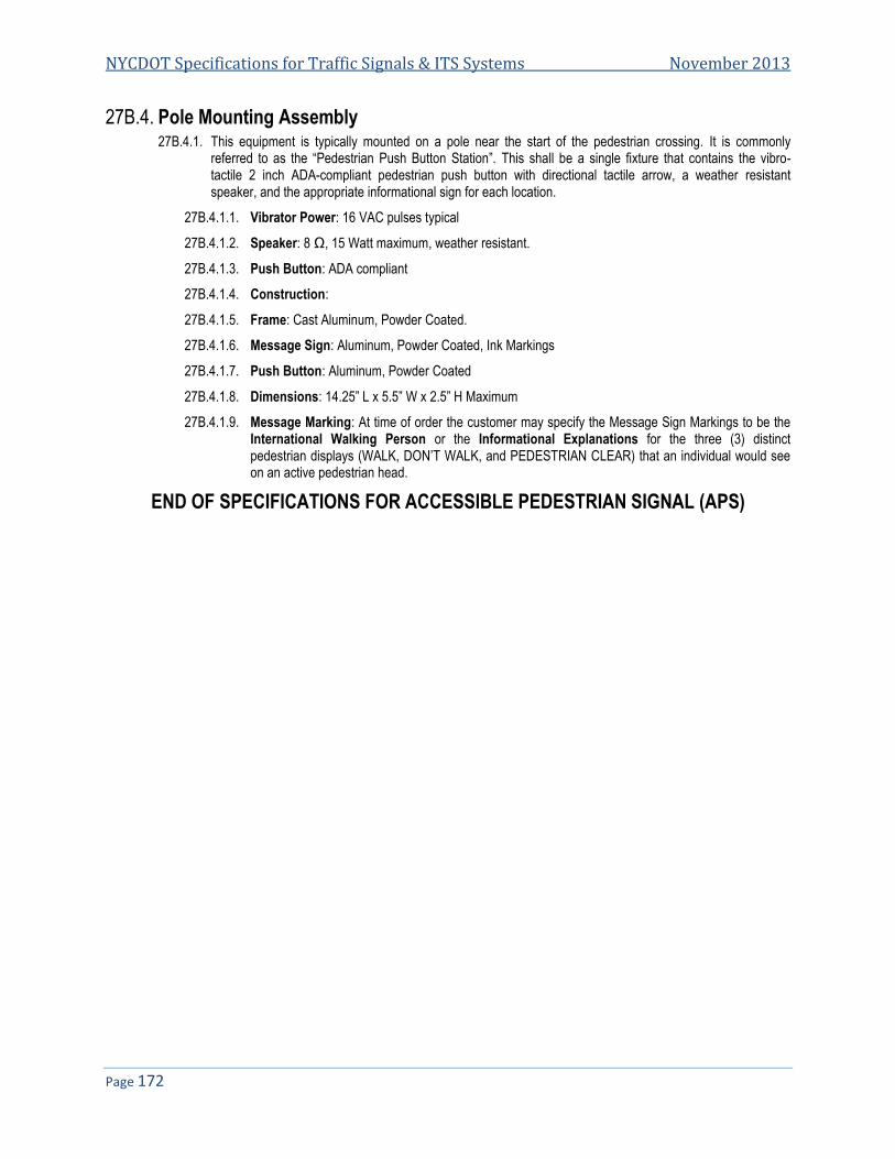
NYCDOT Specifications for Traffic Signals & ITS Systems November 2013
Page 172
27B.4. Pole Mounting Assembly 27B.4.1. This equipment is typically mounted on a pole near the start of the pedestrian crossing. It is commonly
referred to as the “Pedestrian Push Button Station”. This shall be a single fixture that contains the vibro-tactile 2 inch ADA-compliant pedestrian push button with directional tactile arrow, a weather resistant speaker, and the appropriate informational sign for each location.
27B.4.1.1. Vibrator Power: 16 VAC pulses typical
27B.4.1.2. Speaker: 8 Ω, 15 Watt maximum, weather resistant.
27B.4.1.3. Push Button: ADA compliant
27B.4.1.4. Construction:
27B.4.1.5. Frame: Cast Aluminum, Powder Coated.
27B.4.1.6. Message Sign: Aluminum, Powder Coated, Ink Markings
27B.4.1.7. Push Button: Aluminum, Powder Coated
27B.4.1.8. Dimensions: 14.25” L x 5.5” W x 2.5” H Maximum
27B.4.1.9. Message Marking: At time of order the customer may specify the Message Sign Markings to be the International Walking Person or the Informational Explanations for the three (3) distinct pedestrian displays (WALK, DON’T WALK, and PEDESTRIAN CLEAR) that an individual would see on an active pedestrian head.
END OF SPECIFICATIONS FOR ACCESSIBLE PEDESTRIAN SIGNAL (APS)

Specification 28
NYCDOT Specification for Round Aluminum Pole Type “S-14A”
Date of Revision Revised by Description
6/17/06 Soft copy

NYCDOT Specifications for Traffic Signals & ITS Systems November 2013
Page 174
28. NYCDOT SPECIFICATION FOR ROUND ALUMINUM TRAFFIC SIGNAL POLE TYPE “S-14A” ..................................... 175 28.1. GENERAL .................................................................................................................................................................... 175 28.2. SHAFT ........................................................................................................................................................................ 175 28.3. SHOE BASE ................................................................................................................................................................. 175 28.4. TRANSFORMER BASE ................................................................................................................................................... 175 28.5. IDENTIFICATION ........................................................................................................................................................... 176 28.6. OUTSIDE SURFACE FINISH ........................................................................................................................................... 176 28.7. CONTRACTOR’S WORKING DRAWINGS .......................................................................................................................... 176 28.8. SAMPLES .................................................................................................................................................................... 176 28.9. DELIVERY.................................................................................................................................................................... 176 28.10. INSPECTION ................................................................................................................................................................ 176 28.11. PACKAGING ................................................................................................................................................................. 176 28.12. DELIVERY, UNLOADING AND STACKING ......................................................................................................................... 176 28.13. GUARANTEE ................................................................................................................................................................ 177

Specification 28: NYCDOT Specification for Round Aluminum Pole Type “S-14A”
Page 175
28. NYCDOT Specification for Round Aluminum Traffic Signal Pole Type “S-14A”
28.1. General 28.1.1. Round aluminum traffic signal pole type “S-14A” shall consist of shaft with shoe base welded on, together with
all necessary appurtenant parts. When installed on 20” high transformer base, signal mounting height shall be 14’-0”, measured vertically from top of the foundation to the top of the shaft. All nuts, bolts, and washers used in pole shall be furnished under this Specification and shall be stainless steel, 300 series 18/8 except as noted. All hardware shall be boxed. All welding shall be performed by the inert gas shielded arc and all welds shall be free from cracks and porosity. All equipment shall be as specified herein.
28.2. Shaft 28.2.1. Shaft shall be one-piece, seamless, tapered, round, spun aluminum with wall thickness of 0.188” and 12’-4”
long. Lower section for the first 3’-0” shall be straight, that is, of constant diameter. Upper section for approximately 8” shall be straight, that is, of constant diameter. Shaft shall have a continuous and uniform taper between lower and upper straight sections. The material used shall be aluminum alloy 6063 which shall conform to the physical and mechanical property specifications set forth, or equal thereto in all respects, and shall be full length heat treated after welding on shoe base to produce the T6 temper. For more details see specification drawing P-010.
28.2.2. Tolerances on shaft as regards twist, straightness, length contour, and cross-sectional dimensions shall be standard tolerances except as noted. Shaft shall be provided with satin finish accomplished by mechanical rotary grinding. All materials shall be cleaned and free from dents and unsightly scratches. No surface preparation or painting of any type shall be required at time of installation.
28.3. Shoe Base 28.3.1. Shoe base shall be a one-piece permanent mold casting, aluminum alloy A356-T6. It shall be approximately
12” square at bottom with a height of approximately 3½”. It shall be provided with four (4) 1¼”x1¾” slots to receive 1” diameter bolts placed on 11” to 12” diameter bolt circle. Shoe base shall be joined to shaft by means of complete circumferential welds, externally at top of shoe and internally at bottom of shaft. Four (4) 1’ diameter x 3¾” or 4” long hot-dipped galvanized steel hexagon head machine bolts with bearing plates or oversize washers, lockers washers, and hexagon nuts, all hot-dipped galvanized steel, shall be supplied to attach shoe base to transformer base. For more details see specification drawing P-010.
28.4. Transformer Base 28.4.1. The base, except for the door and adapter plate shall be monolithically formed of aluminum alloy A356-T6 to
size and configuration as shown on specification drawing P-010. The adapter plate shall be cast of aluminum alloy A356-T6 and welded to the sides of the base near the bottom as shown on specification drawing P-010. It will complete the bottom of the base and provide areas for the anchor cleats. The door shall be cast of aluminum alloy A356-T6 and shall be 3/16 inch thick. When fastened in place, the door shall bear uniformly on the rabbitted ledge around the opening; the outside surface shall be flush with and follow the same contour as the outside of the base. The door shall be hinged at the top with a stainless steel piano hinge that is permanently affixed with stainless steel rivets to the door and base. A clearance of 1/16 of an inch shall be provided at each of the door.
28.4.2. A ¼”-20 stainless steel socket head fastening screw to be sunk in a circular depression on the outside of the door, near the bottom, with the outside. The screw shall be screwed into latch plate. The end of the screw shall be slightly peened to prevent separation from the latch plate whenever the door is removed. A stop lug shall be furnished for the latch plate on the inside of the door. A 5/16”-18 grounding stud (Burndy or equal) with bronze lock washer shall be installed inside the base at the center of the side to the left of the door opening.

NYCDOT Specifications for Traffic Signals & ITS Systems November 2013
Page 176
After the stud has been tightened, any protrusion of the stud shall be ground flush with the outside surface. A legend, New York City, year and manufacturer shall be cast integrally or stamped at the top of the rear panel opposite the door opening on the outside of the base.
28.5. Identification 28.5.1. On side of shoe base ½” below top edge, the following marking shall appear: NYC, YEAR and
MANUFACTURER’S NAME” in letters approximately 3/8” high arranged on two or three lines. On shoe base the marking shall be cast or indented into surface by stamping. No other method of marking will be accepted.
28.6. Outside Surface Finish 28.6.1. Finish of all castings shall be as cast, except as required to adequately clean them.
28.7. Contractor’s Working Drawings 28.7.1. Before proceeding with the order for manufacture of the poles, the Contractor shall furnish to the Department
for approval a complete set of working drawings giving details of construction.
28.8. Samples 28.8.1. Two complete pre-production samples shall be delivered for inspection and testing with sixty (60) consecutive
calendar days after notice from City of New York. Upon receipt of this notice, the Contractor shall also submit six (6) complete sets of working drawings to the NYC Department of Transportation. Failure to submit the samples and drawings within the time specified will be sufficient reason to declare the Contractor in default.
28.9. Delivery 28.9.1. Quantities and timing of deliveries shall be as noted in the BID SCHEDULE. The Contractor shall pay all
transportation and delivery charges associated with this Specification.
28.10. Inspection 28.10.1. The Contractor shall maintain an Inspection Staff, whose duty shall be the maintenance of a high quality of
materials and workmanship in the manufacture of all Assemblies under this Specification. The Contractor, when requested, shall make inspector’s names available to the Department’s inspection unit. The Contractors shall furnish the City’s representative with adequate facilities for the proper performance of his duties under this Specification.
28.11. Packaging 28.11.1. All pole Assemblies shall be shipped adequately protected against damage, or defacement especially to the
outside surface.
28.12. Delivery, Unloading and Stacking 28.12.1. The Contractor shall make all deliveries to the Department’s Warehouse (loading bays 5 and 6) at 66-26
Metropolitan Ave in Middle Village (Queens), NY 11379, any other locations within the limits of the City of New York designated by the Department, or as directed by the Engineer. Material/equipment will be accepted between the hours of 8:00 AM and 12:00 PM with unloading to be completed before 3:00 PM, Monday thru Friday, except holidays. The Contractor must notify the Department at least 24 hours in advance of delivery. .

Specification 28: NYCDOT Specification for Round Aluminum Pole Type “S-14A”
Page 177
28.12.2. The Contractor shall deliver material into the designated delivery point, and shall unload and stack this material, under the direction of the Warehouse Supervisor. The Contractor shall furnish all dunnage, blocking, wedges, and any other equipment necessary for the safe delivery, stacking, and storage of items under this Specification, to a height of 15 feet, satisfactory to the Department.
28.13. Guarantee 28.13.1. All material and workmanship furnished under these Specifications shall be guaranteed for a period of one
year from the date of completion of this Specification. The Contractor shall be responsible for any defective parts, due to faulty material or workmanship, free from any expense to the City of New York during the term of this guarantee, where such material is exposed to normal operating conditions. Units or parts found damaged or imperfect, when inspected after delivery shall be replaced by Contractor at his own expense, including all subsequent delivery and shipping charges.
END OF SPECIFICATIONS FOR ROUND ALUMINUM POLE TYPE “S-14”


Specification 30
NYCDOT Specification for Traffic Signal Mast Arm Assembly for Wood Poles “MAW-15”
Date of Revision Revised by Description
5/16/06 Revised Spec. date

NYCDOT Specifications for Traffic Signals & ITS Systems November 2013
Page 180
NYCDOT SPECIFICATION FOR TRAFFIC SIGNAL MAST ARM ASSEMBLY FOR WOOD POLES “MAW-15” ............. 181 30.30.1. GENERAL .................................................................................................................................................................... 181 30.2. WELDING .................................................................................................................................................................... 181 30.3. MAST ARM .................................................................................................................................................................. 181 30.4. TIE ROD ...................................................................................................................................................................... 182 30.5. BRACE ANGLES ........................................................................................................................................................... 182 30.6. PACKING ..................................................................................................................................................................... 182 30.7. PERFORMANCE TIMING ................................................................................................................................................ 182 30.8. DELIVERY, UNLOADING AND STACKING ......................................................................................................................... 182 30.9. GUARANTEE ................................................................................................................................................................ 183 30.10. INSPECTION ................................................................................................................................................................ 183
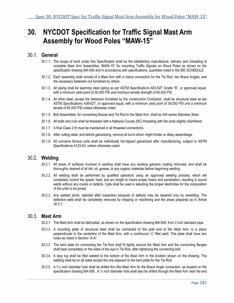
Spec 30: NYCDOT Spec for Traffic Signal Mast Arm Assembly for Wood Poles “MAW-15”
Page 181
NYCDOT Specification for Traffic Signal Mast Arm 30.Assembly for Wood Poles “MAW-15”
30.1. General 30.1.1. The scope of work under this Specification shall be the satisfactory manufacture, delivery and unloading of
complete Mast Arm Assemblies “MAW-15” for mounting Traffic Signals on Wood Poles as shown on the specification drawing MA-006 and in accordance with specifications, quantities noted in the BID SCHEDULE.
30.1.2. Each assembly shall consist of a Mast Arm with a clamp connection for the Tie Rod, two Brace Angles, and the necessary fasteners not furnished by others
30.1.3. All piping shall be seaming steel piping as per ASTM Specifications A53-62T Grade “B”, or approved equal, with a minimum yield point of 35,000 PSI and minimum tensile strength of 60,000 PSI.
30.1.4. All other steel, except the fasteners furnished by the construction Contractor, shall be structural steel as per ASTM Specifications A36-62T, or approved equal, with a minimum yield point of 36,000 PSI and a minimum tensile of 60,000 PSI unless otherwise noted.
30.1.5. Bolt Assemblies, for connecting Braces and Tie Rod to the Mast Arm, shall be 304 series Stainless Steel.
30.1.6. All bolts and nuts shall be threaded with a National Course (NC) threading with the ends slightly chamfered.
30.1.7. A final Class 2 fit must be maintained in all threaded connections.
30.1.8. After cutting steel, and before galvanizing, remove all burrs which might hinder or delay assemblage.
30.1.9. All corrosive ferrous units shall be individually hot-dipped galvanized after manufacturing, subject to ASTM Specifications A123-63, unless otherwise noted.
30.2. Welding 30.2.1. All areas of surfaces involved in welding shall have any existing galvanic coating removed; and shall be
thoroughly cleaned of all dirt, oil, grease, or any organic materials before beginning welding.
30.2.2. All welding shall be performed by qualified operators using an approved welding process, which will completely control the speed, heat, and arc length to insure proper fusion and penetration, resulting in sound welds without any cracks or defects. Care shall be used in selecting the proper electrodes for the composition of the units to be joined.
30.2.3. Any welded joints, rejected after inspection because of defects may be repaired only by rewelding. The defective weld shall be completely removed by chipping or machining and the areas prepared as in Article 30.2.1.
30.3. Mast Arm 30.3.1. The Mast Arm shall be fabricated, as shown on the specification drawing MA-006, from 2 inch standard pipe.
30.3.2. A mounting plate of structural steel shall be connected to the pole end of the Mast Arm, in a plane perpendicular to the centerline of the Mast Arm, with a continuous ¼” fillet weld. This plate shall have two holes as noted in Section “A-A”.
30.3.3. The bent plate for connecting the Tie Rod shall fit tightly around the Mast Arm and the connecting flanges shall bear completely on the sides of the eye in Tie Rod, after tightening the connecting bolt.
30.3.4. A stop lug shall be fillet welded to the bottom of the Mast Arm in the location shown on the drawing. The welding shall be on all sides except the one adjacent to the bent plate for the Tie Rod.
30.3.5. A 9/16 inch diameter hole shall be drilled thru the Mast Arm for the Brace Angle connection, as located on the specification drawing MA-006. A ½ inch diameter hole shall also be drilled through the Mast Arm near the end

NYCDOT Specifications for Traffic Signals & ITS Systems November 2013
Page 182
for the Signal Support Fitting (not in this Specification). The centers of both holes shall be perpendicular to the long side of the mounting plate.
30.3.6. A 1 inch diameter hole, in the bottom of the Mast Arm, shall be modified as shown in Detail “C” to permit easier entrance for the cable. The edges of the hole that would endanger the cable insulation shall be chamfered or rounded smooth.
30.4. Tie Rod 30.4.1. The Tie Rod shall be 5/8 inch diameter rod of structural steel with ¾ inch inside diameter eyes on the ends, in
planes at 90 degrees to each other. The eyes shall be securely welded closed; but both bearing surfaces of each eye shall provide complete uniform bearing. The Tie Rod shall be bent at one end as shown in Detail “A”, but the strength of the rod shall be maintained throughout.
30.5. Brace Angles 30.5.1. The Brace Angles shall be standard angles of structural steel with ½ inch clearance holes in the 2 inch leg, 1
inch from each end.
30.6. Packing 30.6.1. The stainless steel bolt assemblies shall be installed in their respective locations according to the specification
drawing MA-006. The Tie Rod and Brace Angles shall be wired to the Mast Arm with size 10 conductor throughout the hole at the end of the Mast Arm, the hole at one end of the Brace Angles, and an eye in the Tie Rod (not at the bent end). The remaining portion of the Tie Rod and Brace Angles shall then be securely wired to the Mast Arm as compactly as possible. A marker, impervious to weather, with the letters “N.Y.C.” the order number, and the initials or trade mark of the manufacturer, shall be securely attached to each assembly. Protection for all galvanizing shall be provided between the members and under the wire binding.
30.7. Performance Timing 30.7.1. Two complete sample Assemblies of Mast Arm “MAW-15” for Wood Poles shall be ready, at the point of
production, for inspection and testing by the Department within 30 consecutive calendar days after the Notice to Proceed issued by the City of New York.
30.7.2. Production shall begin no later than ten consecutive calendar days after the date of receipt of purchase order from City of New York.
30.7.3. Delivery of complete Assemblies shall be made as stated in the Bid Schedule.
30.8. Delivery, Unloading and Stacking 30.8.1. The Contractor shall make all deliveries to the Department’s Warehouse(loading bays 5 and 6) at 66-26
Metropolitan Ave in Middle Village (Queens), NY 11379, any other locations within the limits of the City of New York designated by the Department, or as directed by the Engineer. Material/equipment will be accepted between the hours of 8:00 AM and 12:00 PM with unloading to be completed before 3:00 PM, Monday thru Friday, except holidays. The Contractor must notify the Department at least 24 hours in advance of delivery. All Assemblies must be complete assemblies; and shall have galvanic coating protected from damage during delivery.
30.8.2. The Contractor shall deliver material into the designated storage point, unload, and stack, under the direction of the Warehouse Supervisor, at a site accessible to truck delivery.
30.8.3. The Contractor shall furnish all labor, dunnage, blocking, wedges, and any equipment necessary for the safe delivery, unloading, stacking and storing of material under this Specification, satisfactory to the Warehouse Supervisor.

Spec 30: NYCDOT Spec for Traffic Signal Mast Arm Assembly for Wood Poles “MAW-15”
Page 183
30.9. Guarantee 30.9.1. All material and workmanship furnished under these specifications shall be guaranteed for a period of one
year from the date of completions of this Specification, unless otherwise noted.
30.9.2. The Contractor shall be responsible for any defective parts, due to faulty material or workmanship, free from any expense to the City of New York, during the term of this guarantee, where such material is exposed to normal conditions.
30.9.3. Units or parts found damaged, or imperfect, when imperfect, when inspected after delivery, shall be replaced by the Contractor at his own expense, including cost of all subsequent delivery and shipping charges.
30.10. Inspection 30.10.1. The Contractor shall maintain an Inspection Staff, whose duty shall be the maintenance of high quality of
materials and workmanship in the manufacture of all Assemblies under this Specification. The Contractor, when requested, shall make inspector’s names available to the Department’s inspection unit.
30.10.2. The Contractor shall furnish the City’s representative with adequate facilities for the proper performance of his duties this Specification.
END OF SPECIFICATIONS FOR TRAFFIC SIGNAL MAST ARM ASSEMBLY FOR WOOD POLE “MAW-15”

Specification 34
NYCDOT Specification for Aluminum Die Casting and Assemblies for Pole Signal Mounting
Item #31150 - “1SA” Item #31175 - “2SPA” Item #31185 - “3SPA” Item #31195 - “4SPA” Item #31200 - “VB” Assembly Item #31340 - “VB-2P” Assembly Item #31351 - “VB-2P” Assembly Item #31210 - “HUB” Assembly Item#31211 - Wood Pole Bracket
Date of Revision Revised by Description
5/16/06 Revised Drawing Numbers
Add wood pole Bracket
NYCDOT Specifications for Traffic Signals & ITS Systems November 2013
Page 186
NYCDOT SPECIFICATIONS FOR ALUMINUM DIE CASTINGS AND ASSEMBLIES FOR POLE SIGNAL MOUNTING . 187 34.34.1. GENERAL .................................................................................................................................................................... 187 34.2. PIPE AND PIPE THREADING .......................................................................................................................................... 188 34.3. SLIPFITTER CASTINGS AND COVER ............................................................................................................................... 188 34.4. SLIPFITTER ASSEMBLIES “1SA”, “2SPA”, “3SPA”, “4SPA” ............................................................................................ 188 34.5. CHASE NIPPLES AND CLOSURE CAPS ........................................................................................................................... 189 34.6. SERRATED TEE ........................................................................................................................................................... 189 34.7. SERRATED LOCKING RING ........................................................................................................................................... 189 34.8. VEHICLE SIGNAL BRACKET ASSEMBLY “VB” AND PEDESTRIAN SIGNAL BRACKET ASSEMBLIES “VB-P” AND “VB-2P” ......... 189 34.9. POLE HUB (“LOWTON HUB”) ASSEMBLY ........................................................................................................................ 189 34.10. SIGNAL HEAD TIES ...................................................................................................................................................... 190 34.11. WOOD POLE BRACKETS ............................................................................................................................................... 190 34.12. PAINTING .................................................................................................................................................................... 190 34.13. SAMPLES .................................................................................................................................................................... 191 34.14. INSPECTION ................................................................................................................................................................ 191 34.15. PACKING ..................................................................................................................................................................... 191 34.16. DELIVERY, UNLOADING AND STACKING ......................................................................................................................... 191 34.17. GUARANTEE ................................................................................................................................................................ 192

Spec 34: NYCDOT Spec for Aluminum Die Casting and Assemblies for Pole Signal Mounting
Page 187
NYCDOT Specifications for Aluminum Die Castings 34.and Assemblies for Pole Signal Mounting
“1SA”, 2SPA”, “3SPA”, 4SPA”, “VB”, “VB-P”, “VB-2P”, “HUB”
34.1. General 34.1.1. The scope of work under this Specification shall be the satisfactory manufacture, delivery, unloading, and
stacking of completed parts and sub-assemblies for “1SA” and “SPA” pole signal mounting assemblies, “VB” signal mounting bracket assemblies, Pole hub assemblies, and pedestrian signal mounting bracket assemblies in quantities and pedestrian signal mounting bracket assemblies in quantities noted in the BID SCHEDULE. The parts and sub-assemblies shall be manufactured as shown on the latest revision of the following specification drawings and as noted in these specifications:
Part or Assembly Type Specification Drawing
1 ½ inch Die Cast Serrated Tee SE-007
1 ½ inch Die Cast Serrated Locking Ring SE-008
1 ½ inch Die Cast Chase Nipple SE-009
1 ½ inch Die Cast Pipe Lock Nut SE-010
1 ½ inch Closure Caps SE-011
Signal Head Ties SE-013
Slipfitter Pole Signal Mounting Assemblies “SPA” SE-014
Die Cast Slipfitter “1SA” SE-015
Die Cast Slipfitters “4S” SE-016
Vehicle Bracket Assemblies “VB” SE-017
Pole Hub (“Lowton Hub”) Assembly SE-018
Wood Pole Assemblies “WP” & “WP2” SE-019
Pedestrian Signal Mounting Assemblies “VB-P” & “VB-2P” SE-021
34.1.2. Each assembly shall be complete in accordance with the “Assembly and Parts List” for that particular type, as shown on one of the following assembly drawings:
Specification drawing set SE-014 for Slipfitter Pole Signal Mounting Assemblies “1SA”, “2SPA”, “3SPA” and “4SPA” Specification drawing set SE-017 for Vehicle Bracket Assemblies “VB” and “2VB” Specification drawing set SE-018 for Pole Hub (“Lowton Hub”) Assembly Specification drawing set SE-021 for Pedestrian Signal Mounting Assemblies “VB-P” & “VB-2P”
34.1.3. All castings, pipe and pipe fittings shall be made of the aluminum alloy specified. Castings shall be sound, free from blow holes, scales, fins, burrs, dents, and cracks. Deburr and break all sharp edges before painting.
34.1.4. All inside edges shall be chamfered or rounded smooth before painting to protect cable insulation.
34.1.5. All castings shall have the manufacturer’s name or trademark, the part number and the year of manufacture cast or stamped on them in sufficiently large letters so as to be read easily. On Slipfitters this identification shall be cast on the inside, but not on the telescoping surfaces.
34.1.6. All serrations for signal head connections shall be symmetrical, radial serrations spaced at 5-degree increments. They shall be well formed with a 90-degree angle along the complete apexes of the male serrations to completely mesh with the serrations on the signal housing. Details of the serrated areas on the Serrated Tee and the “1SA” Slipfitter are shown on specification drawings SE-007 and SE-015 respectively. The horizontal centerlines of all serrations shall be in a single plane perpendicular to the vertical centerline of the Slipfitter or the stem of the Serrated Tee.

NYCDOT Specifications for Traffic Signals & ITS Systems November 2013
Page 188
34.1.7. Samples of a typical signal head, a “1SA” Slipfitter, a 1½” Serrated Tee, a Pole Hub (Lowton Hub), Closure Caps, and Chase Nipples (all die cast), may be seen at the Department’s Warehouse (Loading bays 5 and 6) at 66-26 Metropolitan Avenue, Middle Village (Queens)NY 11379, or as directed by the Engineer. Equipment furnished under this Specification shall match the quality and precision of these samples.
34.1.8. All screws shall be 18/8 stainless steel, unless otherwise noted.
34.1.9. A compound shall be used on both units in all threaded joints of two aluminum parts to prevent “seizing”.
34.1.10. For the die castings that are made, the Contractor shall furnish the dies and retain ownership of them. Aluminum alloy #13 shall be used for die castings.
34.2. Pipe and Pipe Threading 34.2.1. All pipes shall be extruded from aluminum alloy 6061-T6 to recognized standard dimensions for Schedule 40
piping, unless otherwise noted.
34.2.2. All threading for pipe and pipe fitting connections shall match standard well-formed National Pipe Straight Mechanical (NPSM) pipe threading. It shall be either cast or machined to meet the following requirements.
34.2.3. To insure that the threaded joints will not be too loose or sloppy, both threads for each joint shall be tested with these Gauges:
34.2.3.1. Standard “Go” and “No Go” Gauges for straight machine threading.
34.2.3.2. A New York City Perpendicularity Gauge - This Gauge consist of a straight piece of standard pipe with a plain coupling on one end, locked in place with tack welds. The overall length is five feet. Both ends have satisfactory standard NPSM threading, ¾ inch long. The pipe and coupling are Type 304 stainless steel. This Gauge is available for inspection at the Department’s Warehouse. When testing 1 ½” pipe threading with the Gauge, the connection shall be made with the required end of the Gauge. The centerline of the Gauge, at the opposite end, shall then deflect no more than ¼” from the extended centerline of the threaded unit to which it has been connected.
34.3. Slipfitter Castings and Cover 34.3.1. Slipfitter casting “1SA”, for one signal face pole signal mounting assembly, shall be die cast as shown on
specification drawing SE-015 using aluminum alloy #13 (see Article 34.1.10.). The threading of the opening in the top shall be for 1½ inch pipe. The centers of the tapped holes for 3/8”-18 set screws “D” shall be perpendicular to the axial centerline of the Slipfitter.
Slipfitter casting “4S” shall be cast as shown on the specification drawing SE-016 using aluminum alloy #13. The five hubs, one on the top of the Slipfitter and four axial near the top of the side shall be completely threaded inside to receive 1 1/2” threaded pipe brackets. The axial centerlines of these four hubs shall be in a plane perpendicular to the axial centerline of the Slipfitter. A 1/4”-20x1/2” long stainless steel hollow point set screw, shall be installed in the top of each four axial hubs of the Slipfitter and shall be smooth and parallel to the top of the Slipfitter, as well as one on 45-degree angle for the top hub. The bottoms of the four inside ribs, which support the Slipfitter and signals, shall also be in a plane perpendicular to the axial centerline of the Slipfitter with minimum radius fillets at the junction with the sidewall. The holes for 3/8”-16 set screws “D” shall be tapped perpendicular to the centerline of the Slipfitter.
34.3.2. A 1½”x3/8” long aluminum dies cast Closure Cap shall be used to cover the top opening of Slipfitter “4S”.
34.4. Slipfitter Assemblies “1SA”, “2SPA”, “3SPA”, “4SPA” 34.4.1. All “1SA” Slipfitter assemblies shall consist of the parts shown on specification drawing SE-014_2
34.4.2. All “SPA” Slipfitter assemblies shall consist of the necessary parts listed in the “PARTS LIST”, on specification drawings SE-014_3, SE-014_4 and SE-014_5, for that type of assembly.
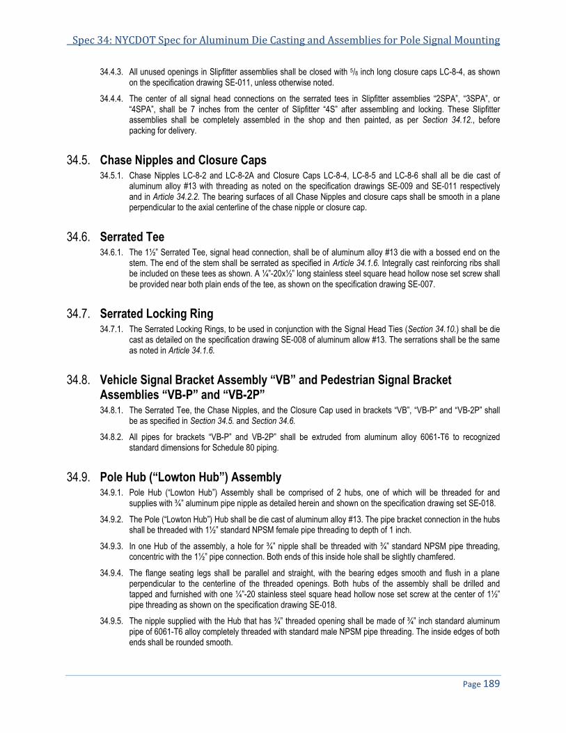
Spec 34: NYCDOT Spec for Aluminum Die Casting and Assemblies for Pole Signal Mounting
Page 189
34.4.3. All unused openings in Slipfitter assemblies shall be closed with 5/8 inch long closure caps LC-8-4, as shown on the specification drawing SE-011, unless otherwise noted.
34.4.4. The center of all signal head connections on the serrated tees in Slipfitter assemblies “2SPA”, “3SPA”, or “4SPA”, shall be 7 inches from the center of Slipfitter “4S” after assembling and locking. These Slipfitter assemblies shall be completely assembled in the shop and then painted, as per Section 34.12., before packing for delivery.
34.5. Chase Nipples and Closure Caps 34.5.1. Chase Nipples LC-8-2 and LC-8-2A and Closure Caps LC-8-4, LC-8-5 and LC-8-6 shall all be die cast of
aluminum alloy #13 with threading as noted on the specification drawings SE-009 and SE-011 respectively and in Article 34.2.2. The bearing surfaces of all Chase Nipples and closure caps shall be smooth in a plane perpendicular to the axial centerline of the chase nipple or closure cap.
34.6. Serrated Tee 34.6.1. The 1½” Serrated Tee, signal head connection, shall be of aluminum alloy #13 die with a bossed end on the
stem. The end of the stem shall be serrated as specified in Article 34.1.6. Integrally cast reinforcing ribs shall be included on these tees as shown. A ¼”-20x½” long stainless steel square head hollow nose set screw shall be provided near both plain ends of the tee, as shown on the specification drawing SE-007.
34.7. Serrated Locking Ring 34.7.1. The Serrated Locking Rings, to be used in conjunction with the Signal Head Ties (Section 34.10.) shall be die
cast as detailed on the specification drawing SE-008 of aluminum allow #13. The serrations shall be the same as noted in Article 34.1.6.
34.8. Vehicle Signal Bracket Assembly “VB” and Pedestrian Signal Bracket Assemblies “VB-P” and “VB-2P” 34.8.1. The Serrated Tee, the Chase Nipples, and the Closure Cap used in brackets “VB”, “VB-P” and “VB-2P” shall
be as specified in Section 34.5. and Section 34.6.
34.8.2. All pipes for brackets “VB-P” and VB-2P” shall be extruded from aluminum alloy 6061-T6 to recognized standard dimensions for Schedule 80 piping.
34.9. Pole Hub (“Lowton Hub”) Assembly 34.9.1. Pole Hub (“Lowton Hub”) Assembly shall be comprised of 2 hubs, one of which will be threaded for and
supplies with ¾” aluminum pipe nipple as detailed herein and shown on the specification drawing set SE-018.
34.9.2. The Pole (“Lowton Hub”) Hub shall be die cast of aluminum alloy #13. The pipe bracket connection in the hubs shall be threaded with 1½” standard NPSM female pipe threading to depth of 1 inch.
34.9.3. In one Hub of the assembly, a hole for ¾” nipple shall be threaded with ¾” standard NPSM pipe threading, concentric with the 1½” pipe connection. Both ends of this inside hole shall be slightly chamfered.
34.9.4. The flange seating legs shall be parallel and straight, with the bearing edges smooth and flush in a plane perpendicular to the centerline of the threaded openings. Both hubs of the assembly shall be drilled and tapped and furnished with one ¼”-20 stainless steel square head hollow nose set screw at the center of 1½” pipe threading as shown on the specification drawing SE-018.
34.9.5. The nipple supplied with the Hub that has ¾” threaded opening shall be made of ¾” inch standard aluminum pipe of 6061-T6 alloy completely threaded with standard male NPSM pipe threading. The inside edges of both ends shall be rounded smooth.

NYCDOT Specifications for Traffic Signals & ITS Systems November 2013
Page 190
34.10. Signal Head Ties 34.10.1. The Signal Head Ties shall be fabricated with all bars flush on one side of the assembly as shown on the
specification drawing set SE-013. Three-way ties for the “3SPA” assemblies shall be the 120-degree type.
34.10.2. If made with steel, all Steel shall be high-quality open hearth, hot rolled low carbon steel according to one of the following AISI Specifications #C-1020 or #M-1020.
34.10.3. All ties shall have a complete electrodeposited coating of either cadmium or zinc after fabrication according to ASTM Specification A-165-55 or A-164-55, respectively.
34.10.4. The surface on the inside of all openings shall be smooth before coating, and the openings shall have a tolerance, in all dimensions, of not more than one sixty-fourth (1/64) of an inch. Each face of all ties shall be flush at the openings before coating.
34.10.5. If welded, all areas of surfaces involved in welding shall have any existing removed; and be thoroughly cleaned of all dirt, oil, grease or any organic materials just prior to welding.
34.10.6. All welding shall be performed by qualified operators using an approved welding process which will satisfactory control the speed, heat, and arc length to insure proper fusion and penetration, resulting in sound welds without any cracks or defects. Care shall be used in selecting the proper electrodes for the composition of the units to be joined.
34.10.7. Any welded joints, rejected after inspection because of defects, shall either be satisfactorily repaired or a new tie of the same type furnished.
34.11. Wood Pole Brackets 34.11.1. The wood pole bracket assembly shall have a top bracket, a bottom bracket and a 1½” standard tee as
shown in the specification drawing set SE-019.
34.11.2. The top bracket shall be made from aluminum plate and a threaded 1½” aluminum Schedule 80 pipe continuously welded to the plate. There shall also be a 1½” Plain Tee supplied with an 1½” UV resistant plastic insulating bushing
34.11.3. The bottom bracket shall be made from aluminum Plate and a 2” aluminum Schedule 80 pipe continuously welded to the plate.
34.12. Painting 34.12.1. After all Signal Head Ties, aluminum casting ,wood pole brackets and/or slip fitter assemblies have been
carefully completed, all metal surfaces to be painted shall be first cleaned of all foreign deposits, oil and grease, and then neutralized for priming. This shall be followed by immersion from 25 to 35 seconds in a phosphate coating solution as per Government Specifications MIL-C-5541A (Chemical Films for Aluminum and Aluminum Alloys). Next a clear water rinse followed by immersion in a sealing, neutralizing solution and then oven-dried in preparation for painting. Over this prime coat shall be added to the outside of all slip fitter assemblies, “VB” bracket assemblies, “VB-P” and “VB-2P” bracket assemblies, signal head ties, and Pole Hubs, two coats of best quality, alkyd urea-formaldehyde type oven-baking enamel which shall meet or exceed the requirements of the Federal Test Method Standard No. 141 for Salt Spray (Fog) Test and Weather Resistance. The color of the two final coats shall be Federal Yellow matching #13538 of Federal Standard #595. However, all threaded areas shall be kept entirely from paint. The insides of all openings in Signal Head Ties shall also be kept free from paint. Each coat shall be baked on separately. The aluminum Chase nipples and aluminum pipe lock nuts shall not painted.
34.12.2. When closure caps LC-8-4, LC-8-5 and LC-8-6 are ordered separately, the head portion, except the soffit, shall also be cleaned, primed, and painted as in Article 34.12.1.
34.12.3. No painting or preparation shall be started before notifying the City of New York Inspector and allowing him ample time and opportunity to inspect the product.

Spec 34: NYCDOT Spec for Aluminum Die Casting and Assemblies for Pole Signal Mounting
Page 191
34.13. Samples 34.13.1. Two complete pre-production samples of each item in the BID SCHEDULE, together with one sample of a
marked packing carton to be used in delivering the equipment in the order, shall be delivered for inspection and testing within (90) consecutive calendar days after notice from the City of New York. Upon receipt of this notice, the Contractor shall also submit six (6) complete sets of working drawings to the City of New York. Failure to submit the samples and drawings within the time specified will be sufficient reason to declare the Contractor in default.
34.14. Inspection 34.14.1. The Contractor shall maintain an Inspection Staff whose duty shall be the maintenance of a high quality of
materials and workmanship in the manufacture of all Signal Head Ties, aluminum castings and/or assemblies under this Specification.
34.14.2. The Contractor, when requested, shall make inspector’s names available to the Department’s inspection unit.
34.14.3. Under this Specification, the Contractor shall furnish the City’s representative with adequate facilities for the proper performance of his duties.
34.15. Packing 34.15.1. Complete Assemblies, listed in Article 34.1.2. and included in this order, shall be packed in corrugated
cardboard cartons sufficiently strong to withstand a gross load of not over one hundred (100) pounds per carton during delivery and stacking to a height of fifteen (15) feet. Each carton shall contain parts and sub-assemblies for only one type of mounting assembly; and all parts for each complete mounting assembly shall be packed together in the carton. Each part or sub-assembly shall be protected by the use of corrugated cardboard inserts or wrappings; and packed so as to prevent damage during delivery and stacking. All small loose units for each mounting assembly shall be grouped in a bag or small carton. Avoid “seizing” when delivering small units.
34.15.2. The four vertical sides of all cartons, when stacked after delivery, shall have the contents, the manufacturer’s name, the order number, the date of the order, and the test value of the carton imprinted in black on these sides. This information shall be large enough to be easily read from a distance of ten (10) feet.
34.16. Delivery, Unloading and Stacking 34.16.1. The Contractor shall make all deliveries to the Department’s Warehouse at 66-26 Metropolitan Avenue,
Middle Village (Queens) or to other location in the City of New York as designated by the Department or as directed by the Engineer.
34.16.2. Quantities and timing of deliveries shall be as noted in the BID SCHEDULE.
34.16.3. Material will be accepted between the hours of 9:00 AM and 2:00 PM, with unloading to be completed before 3:00 PM from Monday through Friday, except holidays. The Contractors shall notify the Department at least 48 hours in advance of delivery.
34.16.4. The Contractor shall deliver material into the designated storage point; and shall unload and stack this material under the direction of the department.
34.16.5. The Contractor shall pay all transportation and delivery charges associated with this Specification.
34.16.6. The Contractor shall furnish all labor, dunnage, blocking, wedges and equipment necessary for the safe delivery stacking, and storing of material under this Specification, to a height of fifteen (15) feet, satisfactory to the Department.
NYCDOT Specifications for Traffic Signals & ITS Systems November 2013
Page 192
34.17. Guarantee 34.17.1. All material and workmanship furnished under these Specifications shall be guaranteed for a period of one
(1) year from the date of completion of this Specification, unless otherwise noted.
34.17.2. The Contractor shall be responsible for any defective parts, due to faulty material or workmanship, free from any expense to the City of New York during the terms of this guarantee, where such material is exposed to normal operating conditions.
34.17.3. Delivered units or parts found damaged or imperfect, and those missing shall be subject to subsequent delivery and shipping charges.
END OF SPECIFICATIONS FOR ALUMINUM DIE CASTINGS AND ASSEMBLIES FOR POLE SIGNAL MOUNTING

Specification 35
NYCDOT Specifications for Mast Arm Traffic Signal Mounting Assemblies “1MS”, “2MS”, “3MS”, “4MS”
Item #31205 - “1MS” Assembly Item #31215 - “2MS” Assembly Item #31225 - “3MS” Assembly Item #31235 - “4MS” Assembly
Date of Revision Revised by Description
5/16/06 Revised Drawing Numbers
NYCDOT Specifications for Traffic Signals & ITS Systems November 2013
Page 194
35. NYCDOT SPECIFICATIONS FOR MAST ARM TRAFFIC SIGNAL MOUNTING ASSEMBLIES “1MS”, “2MS”, “3MS”, “4MS” .................................................................................................................................................................................... 195
35.1. GENERAL .................................................................................................................................................................... 195 35.2. PIPE AND PIPE THREADING .......................................................................................................................................... 196 35.3. JUNCTION BOXES AND COVER ...................................................................................................................................... 196 35.4. CLOSURE CAPS AND CHASE NIPPLES ........................................................................................................................... 196 35.5. SERRATED TEE ........................................................................................................................................................... 197 35.6. SERRATED LOCKING RING ........................................................................................................................................... 197 35.7. MAST ARM TRAFFIC SIGNAL MOUNTING ASSEMBLIES (AKA “MS” SPIDER ASSEMBLY) ...................................................... 197 35.8. SIGNAL HEAD TIES ...................................................................................................................................................... 197 35.9. PATTERNS .................................................................................................................................................................. 197 35.10. PAINTING .................................................................................................................................................................... 198 35.11. SAMPLES .................................................................................................................................................................... 198 35.12. INSPECTION ................................................................................................................................................................ 198 35.13. PACKING ..................................................................................................................................................................... 198 35.14. DELIVERY, UNLOADING AND STACKING ......................................................................................................................... 198 35.15. GUARANTEE ................................................................................................................................................................ 199
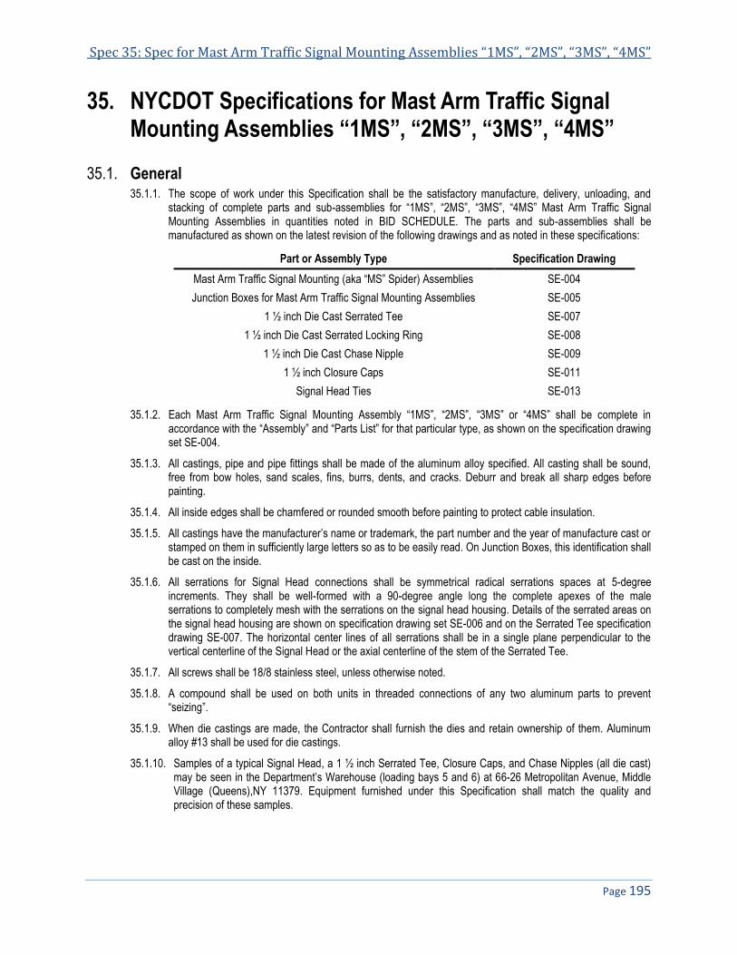
Spec 35: Spec for Mast Arm Traffic Signal Mounting Assemblies “1MS”, “2MS”, “3MS”, “4MS”
Page 195
35. NYCDOT Specifications for Mast Arm Traffic Signal Mounting Assemblies “1MS”, “2MS”, “3MS”, “4MS”
35.1. General 35.1.1. The scope of work under this Specification shall be the satisfactory manufacture, delivery, unloading, and
stacking of complete parts and sub-assemblies for “1MS”, “2MS”, “3MS”, “4MS” Mast Arm Traffic Signal Mounting Assemblies in quantities noted in BID SCHEDULE. The parts and sub-assemblies shall be manufactured as shown on the latest revision of the following drawings and as noted in these specifications:
Part or Assembly Type Specification Drawing
Mast Arm Traffic Signal Mounting (aka “MS” Spider) Assemblies SE-004
Junction Boxes for Mast Arm Traffic Signal Mounting Assemblies SE-005
1 ½ inch Die Cast Serrated Tee SE-007
1 ½ inch Die Cast Serrated Locking Ring SE-008
1 ½ inch Die Cast Chase Nipple SE-009
1 ½ inch Closure Caps SE-011
Signal Head Ties SE-013
35.1.2. Each Mast Arm Traffic Signal Mounting Assembly “1MS”, “2MS”, “3MS” or “4MS” shall be complete in accordance with the “Assembly” and “Parts List” for that particular type, as shown on the specification drawing set SE-004.
35.1.3. All castings, pipe and pipe fittings shall be made of the aluminum alloy specified. All casting shall be sound, free from bow holes, sand scales, fins, burrs, dents, and cracks. Deburr and break all sharp edges before painting.
35.1.4. All inside edges shall be chamfered or rounded smooth before painting to protect cable insulation.
35.1.5. All castings have the manufacturer’s name or trademark, the part number and the year of manufacture cast or stamped on them in sufficiently large letters so as to be easily read. On Junction Boxes, this identification shall be cast on the inside.
35.1.6. All serrations for Signal Head connections shall be symmetrical radical serrations spaces at 5-degree increments. They shall be well-formed with a 90-degree angle long the complete apexes of the male serrations to completely mesh with the serrations on the signal head housing. Details of the serrated areas on the signal head housing are shown on specification drawing set SE-006 and on the Serrated Tee specification drawing SE-007. The horizontal center lines of all serrations shall be in a single plane perpendicular to the vertical centerline of the Signal Head or the axial centerline of the stem of the Serrated Tee.
35.1.7. All screws shall be 18/8 stainless steel, unless otherwise noted.
35.1.8. A compound shall be used on both units in threaded connections of any two aluminum parts to prevent “seizing”.
35.1.9. When die castings are made, the Contractor shall furnish the dies and retain ownership of them. Aluminum alloy #13 shall be used for die castings.
35.1.10. Samples of a typical Signal Head, a 1 ½ inch Serrated Tee, Closure Caps, and Chase Nipples (all die cast) may be seen in the Department’s Warehouse (loading bays 5 and 6) at 66-26 Metropolitan Avenue, Middle Village (Queens),NY 11379. Equipment furnished under this Specification shall match the quality and precision of these samples.

NYCDOT Specifications for Traffic Signals & ITS Systems November 2013
Page 196
35.2. Pipe and Pipe Threading 35.2.1. All pipes shall be extruded from aluminum alloy 6061-T6 to recognized standard dimensions for schedule 40
piping.
35.2.2. All threading for pipe and pipe fitting connections shall match standard well-formed National Pipe Straight Mechanical (NPSM) pipe threading. It shall be either cast or machined to meet the following requirements:
35.2.2.1. The 1½ inch piping shall have 11½ threads per inch with the threading ¾ inch long, unless otherwise noted, for engagement of the pipe. The ends of the piping shall be slightly chamfered.
35.2.2.2. To insure that the threaded joints will not be too loose or sloppy, both threads for each joint shall be tested with these Gauges:
35.2.2.2.1. Standard “Go” and “No Go” Gauges for Straight Mechanical Threading.
35.2.2.2.2. A perpendicularity Gauge consists of a straight piece of standard pipe with a plain coupling on one end, locked in place with tack welds. The overall length is five feet. Both ends have satisfactory standard NPSM threading, ¾ inch long. When testing 1½ inch pipe threading with this Gauge, the connection shall be made with the required end of the Gauge. The centerline of the Gauge, at the opposite end, shall then deflect no more than 4 inches from the extended line of the threaded unit to which it has been connected.
35.3. Junction Boxes and Cover 35.3.1. The Junction Boxes, Parts LC-23-1 and LC-23-2, detailed on the specification drawing SE-005, shall be sand
cast of aluminum alloy 356-T6, with the bottom smooth and flush in a plane perpendicular to the vertical center line of the Junction Box.
35.3.2. A 2½ inch outside diameter cable entrance hub shall be cast monolithic with each Junction Box, perpendicular to and concentric with top of the Box. This hub shall be completely threaded on the inside through the top of the Junction Box. The threading shall be 1½ inch standard NPSM threading, slightly chamfered at the top and bottom, to provide a nipple connection to the weatherhead for supporting the Signal Assembly.
Four holes for ¼”-20x5/8” long stainless steel square head hollow nose set screws, equally spaced in the hub as shown on the drawing, shall be tapped perpendicular to the axial centerline of the hub.
35.3.3. Opening shown in the sides of each Junction Box, for 1½ inch pipe brackets, shall be tapped through perpendicular to the vertical center line of the Junction Box.
35.3.4. Holes for ¼”-20 socket head hollow nose set screws shall be drilled and tapped perpendicular to the bottom of the Junction Box on the center line of all threaded pipe connections. The holes shall be at the center of the side walls
35.3.5. Four holes shall be drilled and tapped 5/8” deep, perpendicular to the bottom of the Box, for #10-24x5/8” long fillister head machine screws for fastening the cover. These holes are located on the specification drawing SE-005.
35.3.6. The Box Cover, Part LC-23-3, shall be punched out of #11 gauge sheeting of aluminum alloy 6061-T6, including the four holes as detailed on the specification drawing SE-005.
35.4. Closure Caps and Chase Nipples 35.4.1. Closure Caps, parts LC-8-4, LC-8-5 and LC-8-6, detailed on the specification drawing SE-011 and Chase
Nipples, parts LC-8-2 and LC-8-2A, detailed on the specification drawing SE-009, shall all be die cast. The bearing surface of each Closure Cap and Chase Nipple shall be smooth and in a plane perpendicular to the axial center of the Closure Cap or Chase Nipple. (Article 35.2.2.).

Spec 35: Spec for Mast Arm Traffic Signal Mounting Assemblies “1MS”, “2MS”, “3MS”, “4MS”
Page 197
35.5. Serrated Tee 35.5.1. The 1½ inch Serrated Tee, for signal head connection, shall be die cast with bossed end on the stem. The end
of the stem shall be serrated as noted in Article 35.1.6. and as shown on the specification drawing SE-007. Integrally cast reinforcing ribs shall be included on these Serrated Tees as shown. A ¼”-20x½” long stainless steel square head hollow nose set screw shall be provided near both plain ends of the Serrated Tee, as shown on the specification drawing SE-007.
35.6. Serrated Locking Ring 35.6.1. The Serrated Locking Ring, to be used in conjunction with the Signal Head Ties (Section 35.8.), shall be die
cast, as detailed on the specification drawing SE-008. The serrations shall be the same as noted in Article 35.1.6.
35.7. Mast Arm Traffic Signal Mounting Assemblies (aka “MS” Spider Assembly) 35.7.1. Each “MS” Spider Assembly, for supporting the traffic signal headsshall be completely assembled in the shop
in accordance with the “SPIDER ASSEMBLY” and “PARTS LIST” for that particular type of assembly as shown on the specification drawing SE-004; and then painted as per Section 35.10., before packing for delivery.
35.7.2. All unused openings in pipe fittings and Junction Boxed shall be closed with the 5/8” long Closure Cap, Part LC-8-4.
35.8. Signal Head Ties 35.8.1. The Signal Head Ties shall be fabricated with all bars flush on one side of the assembly as shown on the
specification drawing set SE-013. Three-way ties for the “3MS” Signal Mounting assemblies shall be the 120-degree type.
35.8.2. If made with steel, all steel shall be high-quality, open-hearth, hot-rolled, low carbon steel, according to one of the following AISI specifications #C-1015, #C-1020 or M-1020.
35.8.3. All ties shall have a complete electrodeposited coating of either cadmium or zinc after fabrication according to ASTM specifications A-165-55 or A-164-55 respectively.
35.8.4. The surface on the inside of all openings shall be smooth before coating, and the opening shall have a tolerance, in all dimensions, of not more than one sixty-fourth (1/64) of an inch. Each face of all ties shall also be flush at the openings before coating.
35.8.5. If welded, all areas of surfaces involved in welding shall any existing coating removed; and shall be thoroughly cleaned of all dirt, oil grease, or any organic material just prior to welding.
35.8.6. All welding shall be performed by qualified operators using an approved welding process which will satisfactorily control the speed, heat, and the arc length to insure proper fusion and penetration, resulting in sound welds with-out cracks or defects. Care shall be used in selecting the proper electrodes for the composition of the units to be joined.
35.8.7. Any welded joints, rejected after inspection of defects, shall either be satisfactorily repaired or a new tie of the same type furnished.
35.9. Patterns 35.9.1. Patterns, dies or any other tooling repaired to fabricate fittings shall be furnished by the Contractor and is the
sole property of vendor.

NYCDOT Specifications for Traffic Signals & ITS Systems November 2013
Page 198
35.10. Painting 35.10.1. After all Signal Head Ties, Aluminum Castings and/or “MS” Spider Assemblies have been carefully
completed, all metal surfaces to be painted shall be first cleaned of all foreign deposits, oil and grease, and then neutralized for priming. This shall be followed by immersion from 25 to 35 seconds in a phosphate coating solution as per Government specification MIL-C5541A (Chemical Files for Aluminum and Aluminum Alloys). Next a clear water rinse followed by immersion in a sealing, neutralizing solution and then oven-dried in preparation for painting. Over this prime coat shall be added to the outside of all Signal Head Ties and “MS” Spider assemblies, two coats of best quality alkyd urea formaldehyde oven-baking enamel which shall meet or exceed the requirements of the Federal Test Method Standard No. 141 for salt Spray (Fog) test and Weather Resistance. The color of the two final costs shall be Federal Yellow matching #13538 of Federal Standard #595. However, all threaded areas shall be kept entirely free from paint. The sides of all openings in Signal Head Ties shall also be kept free from paint. Each coat shall be baked on separately. The Aluminum Chase Nipples, the Serrated Locking Rings, and Aluminum Pipe Lock Nuts shall not be painted.
35.10.2. When Closure Caps LC-8-4, LC-8-5, and LC-8-6 are ordered separately, the head portion, except the soffit , shall also be cleaned, primed and painted as in Article 35.10.1.
35.10.3. No painting or preparation shall be started before notifying the City of New York Inspector and allowing him ample time and opportunity to inspect the product.
35.11. Samples 35.11.1. Two complete pre-production samples of each item in the BID SCHEDULE, together with one sample of a
marked packing carton to be used in delivering the equipment in this order, shall be delivered for inspection and testing within ninety (90) consecutive calendar days after notice from the City of New York. Upon receipt of this notice, the Contractor shall also submit six (6) complete sets of working to the City of New York.
35.12. Inspection 35.12.1. The Contractor shall maintain an inspection Staff whose duty shall be the maintenance of a high quality of
materials and workmanship in the manufacture of all Steel Signal Head Ties, Aluminum Castings and/ or “MS” Spider assemblies purchased under this Specification.
35.12.2. The Contractor, when requested, shall make inspector’s names available the Department’s inspection unit.
35.12.3. Under this Specification, the Contractor shall furnish the City’s representative with adequate facilities for the proper performance of his duties.
35.13. Packing 35.13.1. Complete Assemblies, listed in Article 35.1.2. and included in this order, shall be packed in corrugated
cardboard cartons sufficiently strong to withstand a gross load of not over one hundred (100 pounds per carton during delivery and stacking. Each carton shall contain parts and sub-assemblies for only one type of Mounting Assembly; and all parts for each complete Mounting Assembly shall be packed together in the carton. Each part or sub-assembly shall be protected by the use of corrugated cardboard inserts or wrappings; and packed so as to prevent damage during delivery and stacking. All small loose units for each Mounting Assembly shall be grouped in a bag or small carton. Avoid “seizing” when delivering small units.
35.13.2. The four vertical sides of all cartons, when stacked after delivery, shall have the contents, the manufacturer’s name the order number, the date of the order and the test value of the carton imprinted in black on these sides. This information shall be large enough to be easily read from a distance of ten (10) feet.
35.14. Delivery, Unloading and Stacking 35.14.1. The Contractor shall make all deliveries to the Department’s Warehouse (loading bays 5 and 6) at 66-26
Metropolitan Ave in Middle Village (Queens), NY 11379, any other locations within the limits of the City of New York designated by the Department, or as directed by the Engineer.

Spec 35: Spec for Mast Arm Traffic Signal Mounting Assemblies “1MS”, “2MS”, “3MS”, “4MS”
Page 199
35.14.2. Quantities and timing shall be as noted in the BID SCHEDULE.
35.14.3. Material/equipment will be accepted between the hours of 8:00 AM and 12:00 PM with unloading to be completed before 3:00 PM, Monday thru Friday, except holidays. The Contractor must notify the Department at least 24 hours in advance of delivery.
35.14.4. The Contractor shall deliver the material into the designated storage point and shall unload and stack this material under the warehouse supervisor.
35.14.5. The Contractor shall pay all transportation and delivery charges associated with this Specification.
35.14.6. The Contractor shall furnish all labor, dunnage, blocking, wedges, and any equipment necessary for the safe delivery, stacking, and storing of material under this Specification, satisfactory to the warehouse supervisor.
35.15. Guarantee 35.15.1. All material and workmanship under these Specifications shall be guaranteed for a period of one year from
the date of completion of this Specification, unless otherwise noted.
35.15.2. The Contractor shall be responsible for any defective parts, due to faulty material or workmanship, free from any expense to the City of New York, during the term of this guarantee, where such material is exposed to normal operating conditions.
35.15.3. Delivered units or parts found damaged or imperfect, and those missing, shall be replaced by the Contractor at his own expense, including all subsequent delivery and shipping charges.
END OF SPECIFICATIONS FOR MAST ARM SIGNAL MOUNTING ASSEMBLIES “1MS”, “2MS”, “3MS” AND “4MS”


Specification 38
NYCDOT Specifications for 20’ Traffic Signal Mast Arm Pole Assembly Type “M-2A”
REVISED BY DATE REASON
J. Ornas Electronic form

NYCDOT Specifications for Traffic Signals & ITS Systems November 2013
Page 202
NYCDOT SPECIFICATIONS FOR 20’ TRAFFIC SIGNAL MAST ARM POLE ASSEMBLY TYPE “M-2A” ....................... 203 38.38.1. SCOPE ........................................................................................................................................................................ 203 38.2. GENERAL .................................................................................................................................................................... 203 38.3. WELDING .................................................................................................................................................................... 204 38.4. CURVED MAST ARM..................................................................................................................................................... 204 38.5. CROSS ARM ................................................................................................................................................................ 204 38.6. TIE RODS .................................................................................................................................................................... 204 38.7. CASTINGS AND FORGINGS ............................................................................................................................................ 205 38.8. PATTERNS AND FORGING DIES ..................................................................................................................................... 205 38.9. OCTAGONAL POLE (SHAFT) .......................................................................................................................................... 205 38.10. ANCHOR BASE ............................................................................................................................................................ 206 38.11. TRANSFORMER BASE ................................................................................................................................................... 206 38.12. TESTS......................................................................................................................................................................... 206 38.13. INSPECTION ................................................................................................................................................................ 207 38.14. PACKING ..................................................................................................................................................................... 207 38.15. SAMPLE ...................................................................................................................................................................... 209 38.16. DELIVERY.................................................................................................................................................................... 209 38.17. UNLOADING AND STACKING .......................................................................................................................................... 209 38.18. GUARANTEE ................................................................................................................................................................ 209 38.19. LIST OF SPARE PARTS (SEE ARTICLE 38.1.1.) .............................................................................................................. 209

Specification 38: NYCDOT Spec for 20’ Traffic Signal Mast Arm Pole Assembly Type “M-2A”
Page 203
NYCDOT Specifications for 20’ Traffic Signal Mast Arm 38.Pole Assembly Type “M-2A”
38.1. Scope 38.1.1. The scope of work under this Specification shall be the satisfactory fabrication, delivery, unloading and
stacking of complete 20 foot traffic signal mast arm pole assemblies. Type “M-2A” and/or any spare parts included in this order in quantities noted in the BID SCHEDULE. The spare parts are identified in the list at the end of the specifications. The assemblies and/or spare parts shall be manufactured according to the following drawings and specifications:
Part or Assembly Type Specification Drawing
“M-2A” Pole and 20 Foot Traffic Signal Mast Arm Arrangement Drawing MA-001
“M-2A” Pole and 20 Foot Traffic Signal Mast Arm Assembly Drawing MA-002
“M-2A” Pole Parts “A2”, “B2”, “C2”, “F2A” and “H2” MA-003
Traffic Signal Mast Arm Tie-Rod Elbow “J2A” and Suspension Cast Parts “K2A” and “L2A”
MA-004
“M-2A” Pole Transformer Base MA-008
“M-2A” Pole Anchor Base Bolt Coverage and Spring Nuts MA-009
38.2. General 38.2.1. Each 20-foot traffic mast arm pole assembly Type “M-2A” shall consist of:
• a complete transformer base with steel cleats and shims; an anchor base four bolt covers “N2A”; • a tapered octagonal shaft with cap “H2”; a curved mast arm with connecting fitting “J2A”; • a cross arm with two stay bolts; two tie rods with six nuts and two washers “A” each; • one each of pole clamp fittings “A2”, “B2”, “C2” and D2” (on cross arm), • one each of signal suspension castings “K2A” and “L2A”; • 1½ inch stainless steel, Schedule 40 welded pipe nipple, 1½ inches long (continuously threaded); • two molded UV resistant plastic bushings; • four ½ inch spring nuts together with all necessary screws, bolts, nuts, fasteners, and • other appurtenant parts shown or noted on the Department drawings and specifications listed in
Article 38.1.1.
38.2.2. All screws, bolts, nuts, washers and other fastening hardware, shall be Series 300 stainless steel, unless otherwise noted. The bolts and nuts for connecting the anchor base to the transformer base shall be low carbon steel as per ASTM Specifications A-307-65.
38.2.3. The pole is fabricated from coil or plate conforming to specification ASTM A595 Grade A with a minimum yield strength of 55 PSI
38.2.4. All other structural steel shall be open-hearth, hot-rolled, mild carbon steel as per ASTM specifications A-36-62T with a minimum yield point of 33,000 PSI and a minimum tensile strength of 60,000 PSI unless otherwise noted.
38.2.5. All threading on aluminum and stainless steel pipe shall be standard National Pipe Straight Machine threading (NPSM) with the outside ends slightly chamfered.
38.2.6. After cutting steel and before galvanizing, all burrs which might hinder or delay assemblage shall be removed.
38.2.7. All corrodible ferrous units shall be individually hot-galvanized after fabrication, drilling and threading, unless otherwise noted, subject to ASTM Specifications A-123-63. After galvanizing, all male threads shall be carefully brushed or spun to remove any lumps, retained from the galvanic solution, which might impede proper assembly.

NYCDOT Specifications for Traffic Signals & ITS Systems November 2013
Page 204
38.2.8. A final Class 2 fit must be maintained in all screws, bolt, and pipe threaded connections.
38.2.9. Each part of sub-assembly shall be interchangeable with the same part or sub-assembly on other mast arm assemblies “M-2A” of the same type.
38.3. Welding 38.3.1. All areas of surfaces involved in welding shall have any existing galvanic coating removed; and shall be
thoroughly cleaned of all dirt, oil, grease and organic materials before welding.
38.3.2. All welding shall be performed by qualified operators using an approved welding process which will completely control the speed, heat, and arc length to insure proper fusion and penetration resulting in sound welds without cracks or defects. Care shall be used in selecting the proper electrodes for the composition of the units to be joined.
38.3.3. Any welded joints rejected after inspection because of defects shall be repaired only by re-welding. The defective weld shall be completely removed by chipping or machining and the area prepared as specified in Article 38.3.1.
38.4. Curved Mast Arm 38.4.1. The curved mast arm shall be fabricated from 3 inch Schedule 40 pipe of low alloy, high strength steel with
both ends cut along the two outside radii of the bend in the mast arm. One end shall contain an open-end slotted hole at the bottom, as shown in Elevation “C-C” on the specification drawing set MA-002 to just fit over the key on part “F2A” (specification drawing MA-003) and also provide a cable inlet. Both edges around the cable inlet shall be rounded to protect the cable. The centerline of the slotted hole shall be in the same plane with the vertical centerline of the curved mast arm. Fitting “F2A” shall bear on the end of the curved mast arm pipe that has the slotted hole and then be continuously welded to the pipe, thus making the axis of the connecting pin perpendicular to the plane mentioned above. The other end of the curved mast arm pipe shall bear against the rib inside fitting “J2A”, as shown in Elevation “C-C”, the specification drawing set MA-002. Fitting “J2A” shall be securely fastened in the field to the mast arm with the axial centerline of the hole in the lug on the bottom perpendicular to the plane that contains the vertical centerline of the curved mast arm.
38.5. Cross Arm 38.5.1. The cross arm shall be fabricated, as shown on the specification drawing set MA-002, from 3½ inch extra
strong open-hearth steel pipe, as per ASTM Specifications A-53-64. Bessemer Steel will not be accepted for this unit.
38.5.2. A ½ inch hole shall be drilled in the cross arm at the center of the connection of the cross arm to pole clamp “D2” Special care should be used in making the connection to pole clamp “D2”.
38.5.3. The centerlines of the two slots, at each end of the cross arm, shall be approximately horizontal and the longer slots shall be on the side of the pipe connected to pole clamp “D2”. The outside corners of all these slots shall be slightly chamfered.
38.5.4. Each cross arm shall be drilled and furnished with two stay bolts with nut and cotter pin each as detailed, all stainless steel.
38.6. Tie Rods 38.6.1. All tie rods shall be solid 5/8 inch diameter rods of low alloy high strength steel. The lengths of the threading on
the ends shall not be less than those called for on the specification drawing set MA-002 and the ends of the threading shall be slightly chamfered.
38.6.2. Each end of the rods shall have three 5/8”-11 stainless steel nuts, as shown on the specification drawing set MA-002.

Specification 38: NYCDOT Spec for 20’ Traffic Signal Mast Arm Pole Assembly Type “M-2A”
Page 205
38.6.3. The end of each tie rod with the 13 inch long thread shall also have two cast or forged steel beveled saddle washers “A”, installed on the rod in the field, to provide firm bearing for the nuts.
38.7. Castings and Forgings 38.7.1. All fittings for pole connections, such as the pole clamps “A2”, “B2”, “C2”, and “D2” the arm support hinge
“F2A” the pole cap “H2” are detailed on the specification drawing MA-003 and washers “A” for the tie rods are detailed on the specification drawing set MA-002. The anchor base is detailed on the specification drawing MA-009. All of these fittings shall be cast of Grade 65-35 steel, as per ASTM Specifications A-27-65, except as noted in Article 38.7.2. with a minimum yield point of 35,000 PSI and a minimum tensile strength of 65,000 PSI.
38.7.2. However, all of the above fittings, except the anchor base, may be drop-forged using AISI Steel C-1025, with a minimum yield point of 35,000 PSI and a minimum tensile strength of 65,000 PSI as an alternate. The pole clamps “A2”, “B2”, “C2”, and “D2” and the arm support hinge “F2A” shall all be hot forged. The pole cap “H2” and the washers “A” for the tie rods may be hot or cold with the Contractor furnishing his own forging dies. The configuration of the forged fittings shall be as nearly as possible, the same as those detailed on the specification drawing MA-003.
38.7.3. The bolt covers “N2A” (detailed on the specification drawing MA-009) shall be sand cast of grey cast iron according to ASTM Specifications A-48-64 and then drilled for connection to the anchor base and shaft.
38.7.4. All signal suspension castings “K2A” and “L2A” and the tie rod elbow “K2A” shall be sand cast of aluminum alloy 356-T6 and then drilled and tapped, as detailed on the specification drawing set MA-004. Split stainless steel bushings shall line all unthreaded bolt holes in these castings as detailed.
38.7.5. All castings or forgings shall have the legend “M-2A”, the manufacturer’s name or trade mark, the year of manufacture and part number cast or forged on the outside in sufficiently large letters to be easily read. In addition, parts “A2” and “B2” shall have the words “Bottom” and “Top” respectively cast or forged on the outside so as to aid in field assembling.
38.7.6. All castings shall be sound, free of blow holes, sand, scales, fins, burrs, dents, and cracks, and shall be true to the pattern.
38.7.7. All sharp edges of castings shall be removed and deburred. This shall be done before galvanizing corrodible castings.
38.7.8. Inside edges of all castings, housing cable shall be rounded smooth for the protection of the cable. This shall be done before galvanizing corrodible castings.
38.8. Patterns and Forging Dies 38.8.1. All patterns, dies, drop forging dies and any other tooling shall be furnished by manufacturer. All such items
will be sole property of manufacturer.
38.9. Octagonal Pole (Shaft) 38.9.1. The shaft shall be made of low alloy, high strength steel plate, one-quarter (¼) inch thick, formed into a
tapered shaft with a regular octagonal cross section shall measure eight and one-half (8½) inches across the outside of the flats at the bottom of the shaft and decrease uniformly (with a taper of approximately 0.14 inch per foot) to six (6) inches across the outside of the flats at the top of the shaft. Care should be taken to preserve the equilateral shape throughout the entire length of the shaft while maintaining a straight shaft. (See the specification drawing MA-001).
38.9.2. The shaft shall be fabricated with not more than two longitudinal welds.
38.9.3. Four 9/16 inch diameter holes shall be provided at the top of the shaft, matching the location of the holes in pole cap. (See Elevation “C-C” the specification drawing set MA-003 and the cap detail on the specification drawing MA-004).
NYCDOT Specifications for Traffic Signals & ITS Systems November 2013
Page 206
38.9.4. The top, and an area on the outside at the top of each side of the shaft that contains a 9/16 inch diameter hole, shall be recessed as detailed on the specification drawing set MA-003 to accommodate the hooks on the ½ inch spring nuts, detailed on the specification drawing MA-009.
38.9.5. Four 7/16 inch diameter holes for bolt cover connections shall be drilled in the shaft, concentric with the 7/16 inch diameter holes in the anchor base, after welding the anchor base to the shaft.
38.9.6. An outlet for cable shall be provided below the mast arm connection cutting a hole in the shaft and continuously welding a curved piece of 1¼ inch Schedule 80 low alloy, high strength steel pipe to the shaft, as shown in Elevation “C-C” on the specification drawing set MA-002. Both inside edges of the pipe shall be rounded smooth to protect the cable.
38.10. Anchor Base 38.10.1. The anchor base shall be cast steel as noted Article 38.7.1. The opening in the anchor base, for the shaft
connection shall be cored at the center of the base with the draft on the core matching the taper of the shaft. This will permit the sleeve portion of the base to fit tightly around the bottom of the shaft and be securely welded to it, as shown on the specification drawing set MA-002. Care should be used to keep the bottom surface of the anchor base perpendicular to the axial centerline of the shaft. The letters “N.Y.C., the word “TRAFFIC”, the manufacturer’s name or symbol the year of manufacture and the type of pole assembly (M-2A) shall be cast in raised letters on the top surface of the anchor base, as shown on the specification drawing MA-009.
38.11. Transformer Base 38.11.1. The transformer base with a hinged door shall be fabricated, as shown on the specification drawing MA-008,
of structural steel (Article 38.2.4.) using ¼ inch thick plate for the sides, 1/8 inch thick plate for the door, and ¾ inch thick plate for the top and bottom. The door shall be secured in place with a stainless steel piano hinge at top and a latch or locking device at bottom of door.
38.11.2. In fabrication the top and bottom surfaces of the transformer base shall be perpendicular to the vertical centerline of the base. Steel cleats and skims shall be provided for each assembly, as detailed on the specification drawing MA-008 in the quantities noted on that drawing.
38.11.3. A 5/16 inch grounding stud, with a bronze lock washer and 5/16 inch plain steel washer shall be securely connected to a loose fit 5/16 inch heavy steel nut in a steel retainer welded to the transformer base at the center of the side to left of the door (on the inside) for attaching the grounding conductors. (See specification drawing MA-006).
38.11.4. The letters “N.Y.C.”, the year of manufacture, the manufacture’s name or symbol and the word “Traffic” shall be legibly stamped in the side plate, just over the door opening, concentric with the centerline of the door.
38.12. Tests 38.12.1. A total of not less than one percent of the entire order for complete mast pole assemblies shall be tested at
the Contractor’s plant in the presence of New York City’s representatives, as follows:
38.12.1.1. The complete mast arm pole assembly shall be mounted on a rigid foundation with the axis of the pole perpendicular to a horizontal mounting surface, using bolts equal in size and strength to those specified for use in regular mounting.
38.12.1.2. The tie rods shall be as nearly horizontal as possible.
38.12.1.3. A vertical load of 500 pounds shall then be applied to the signal suspension assembly in the same manner as that expected to be applied by the signal under field conditions.
38.12.1.4. The nuts on the tie rods shall then be adjusted to compensate for the deflection caused by the application of this load thus restoring the tie rods to a horizontal position and maintaining the desired vertical clearance under the signal.

Specification 38: NYCDOT Spec for 20’ Traffic Signal Mast Arm Pole Assembly Type “M-2A”
Page 207
38.12.1.5. The mast arm assembly shall withstand this load for five minutes without failure or permanent deformation.
38.12.2. The shaft assembly including the transformer base shall also be tested as follows:
38.12.2.1. The shaft assembly shall be mounted as in Article 38.12.1.1. above.
38.12.2.2. A horizontal load shall be applied by a hydraulic jack or spring dynamometer eighteen feet above the bottom of the shoe base.
38.12.2.3. The load should not exceed 2,200 pounds nor should it be less than 2,000 pounds.
38.12.2.4. After the load is removed the maximum allowable permanent lateral deflection of the shaft shall be ¾ of an inch, Poles with lateral deflection in excess of ¾ of an inch will be rejected.
38.13. Inspection 38.13.1. The Contractor shall maintain an inspection staff whose duty shall be the maintenance of a high quality of
materials and workmanship in the manufacture of all mast arm pole assemblies under this Specification. The Contractor, when requested, shall make inspector’s names available to the Department’s inspection unit.
38.13.2. The Contractor shall furnish the necessary men and facilities to assist the City’s representatives in the proper performance of their duties when inspecting and testing the assemblies.
38.14. Packing 38.14.1. To facilitate field assembling all loose parts and sub-assemblies for each 20 foot traffic signal mast arm pole
assembly Type “M-2A” except the transformer base, pole cross arm, curved mast arm and tie rods, shall be packed in a wire-bound wooden crate sufficiently strong to safely contain gross load of not more than hundred (100) pounds per crate, during delivery. The units, inside the crate, shall be separated from each other with inserts or wrappings and packed so as to prevent damage during delivery and stacking. All crates shall have the type of contents, the name of the manufacturer, the order number, the date of the order and the test value of the crate clearly marked on both ends of the crate in BLACK. A detailed Packing List shall be enclosed in each crate. Each tie rod shall have three (3) stainless steel nuts screwed all the way on the threading at both ends shall be protected against damage during delivery and outdoor storage with tight fitting polyethylene tubes. The tie rods shall be bound in groups of twenty rod-assemblies for delivery.
38.14.2. The various small parts, bolts, nuts, cotter pins, washers and others shall be placed in numbered bags and tied. The items in each bag are as per following schedule:
Bag No. 1
Item P/A Description Required
1 00103 ½”-13x1” long stainless steel hex head bolt 4
2 02200 ½” spring nut 4
3 00104 1 ¼”-7x3 ½” long galvanized hex head bolt 4
4 00105 1 ¼”-7 galvanized hex nut 4
5 00106 1 ¼” galvanized washer 4
6 00107 ¼”-20x1 ¾” long stainless steel hex head bolt 4
7 00108 ¼”-20 stainless steel hex nut 4
8 00109 ¼” stainless steel lock washer 4
9 00110 ¼” stainless steel flat washer 4
Bag No. 2
Item P/A Description Required

NYCDOT Specifications for Traffic Signals & ITS Systems November 2013
Page 208
1 03800 UV resistant plastic Bushing 2
2 00112 #8-32x¾” long stainless steel round head screw 4
3 00117 1½”x1½” long NPSM stainless steel pipe nipple 1
4 00113 5/8”x2¼” long stainless steel hex head cross drill pin 2
5 00115 5/8” stainless steel spacer washer 8
6 00116 1/8”x1” long cotter pin 2
Bag No. 3
Item P/A Description Required
1 00121 3/8”-16x5” long cross drilled stainless steel hex head bolt 2
2 00122 3/8”-16 stainless steel hex nut 2
3 00123 3/32”x¾” long stainless steel cotter pin 2
4 00124 5/8”-11x2½” long stainless steel hex head bolt 8
5 00125 5/8”-11stainless steel hex nut 8
6 00126 5/8” lock washer 8
7 00127 ¾”-10x3½” long cross drilled stainless steel hex head bolt 1
8 00128 ¾”-10 stainless steel hex nut 1
9 00129 ¾” stainless steel flat washer 2
10 00130 1/8”x11/8” long cotter pin 1
38.14.3. The following parts are those to be packed in wooden crate or special water resistant cartons sufficiently
strong to enable parts to be successfully marked and stored.
Bag No. 1
Item P/A Description Required
1 02200-N2A Bolt cover 4
2 02000-H2 Pole cap 1
3 04100-A2 Clamp segment 1
4 04200-B2 Cross arm clamp segment 1
5 04000-C2 Hinge clamp segment 1
6 03100-J2 Tie rod elbow 1
7 03400-K2 Concentric link 1
8 03600-L2 Weather head 1
9 00500 ¾” hold down lug 1
10 01300 1/16” shim 4
11 03900 Washer “A” 12
12 Bag 1, 2 & 3 as detailed above 4
Specification 38: NYCDOT Spec for 20’ Traffic Signal Mast Arm Pole Assembly Type “M-2A”
Page 209
38.15. Sample 38.15.1. Two complete sample assemblies of the 20 foot traffic signal mast arm pole assembly Type “M-2A” shall be
ready at the point of production, for testing and inspection within sixty-five (65) consecutive calendar days after notice from the City of New York. Upon receipt of this notice the Contractor shall also submit six (6) complete electronic sets of working drawings in DWG format to the Department. Failure to submit the samples and drawings within the time specified will sufficient reason to declare the Contractor in Default.
38.16. Delivery 38.16.1. Quantities and timing of delivery of complete functional assemblies shall be as stated in the BID SCHEDULE.
38.17. Unloading and Stacking 38.17.1. The Contractor shall make all deliveries to the Department’s Warehouse (loading bays 5 and 6) at 66-26
Metropolitan Ave in Middle Village (Queens), NY 11379, any other locations within the limits of the City of New York designated by the Department, or as directed by the Engineer. Material/equipment will be accepted between the hours of 8:00 AM and 12:00 PM with unloading to be completed before 3:00 PM, Monday thru Friday, except holidays. The Contractor must notify the Department at least 24 hours in advance of delivery.. All deliveries must be complete functional assemblies, unless otherwise requested by the Contractor and approved by the City of New York.
38.17.2. The Contractor shall deliver material into the designated storage point, unload, and stack this material under the direction of the warehouse supervisor.
38.17.3. The Contractor shall furnish all dunnage, blocking, wedges and any other equipment and material necessary for the safe delivery, unloading and stacking material under this Specification satisfactory to the Warehouse Supervisor.
38.17.4. The Contractor shall pay all transportation and delivery charges associated with this Specification.
38.17.5. The Contractor to furnish all material handling equipment to facilitate unloading and stacking of poles.
38.18. Guarantee 38.18.1. All galvanizing of materials, under these specifications, shall be guaranteed for a period one (1) year after
completion of this Specification. However, all material and workmanship involved in the casting, forging and fabrication of this equipment shall be guaranteed for a period of one (1) year installation in the field.
38.18.2. The Contractor shall be responsible for any defective parts due to faulty material or workmanship, free from any expense to the City of New York during the term of this Guarantee where such material is exposed to normal operating conditions.
38.18.3. Units or parts found damaged or imperfect, when inspected after delivery, shall be replaced by the Contractor at his own expense, including cost of all necessary delivery and shipping charges involved.
38.19. List of Spare Parts (See Article 38.1.1.) • Transformer Base Door • Bolt Cover “N2A” • Cleats • Shims • Pole Cap “H2” • ½” Spring Nut • Washer “A” • Pole Clamp “A2”, “B2”, “C2” D2 • Molded UV resistant plastic Bushing • Tie Rod Elbow “J2A”

NYCDOT Specifications for Traffic Signals & ITS Systems November 2013
Page 210
• Universal Link “K2A” • Weather Head “L2A” • 1½” Stainless Steel Pipe Nipple • (Schedule 40) 1½” Long Necessary Fasteners • Note: See Article 38.14.2. for special packing instructions
END OF SPECIFICATIONS FOR 20’ TRAFFIC SIGNAL MAST ARM POLE ASSEMBLY TYPE “M-2A”
Specification 38A
NYCDOT Specification for “M-2A” Mono Tube Mast Arm Assembly
Date of Revision Revised by Description
5/10/12 New Specification

NYCDOT Specifications for Traffic Signals & ITS Systems November 2013
Page 212
38A. NYCDOT SPECIFICATION FOR “M-2A” MONO TUBE MAST ARM ASSEMBLY ............................................................. 213 38A.1. SCOPE ........................................................................................................................................................................ 213 38A.2. GENERAL .................................................................................................................................................................... 213 38A.3. WELDING .................................................................................................................................................................... 213 38A.4. STRAIGHT MAST ARM .................................................................................................................................................. 214 38A.5. CASTINGS AND FORGINGS ............................................................................................................................................ 214 38A.6. PATTERNS AND FORGING DIES ..................................................................................................................................... 214 38A.7. OCTAGONAL POLE ....................................................................................................................................................... 214 38A.8. ANCHOR BASE ............................................................................................................................................................ 215 38A.9. TRANSFORMER BASE ................................................................................................................................................... 215 38A.10. TESTS......................................................................................................................................................................... 215 38A.11. INSPECTION ................................................................................................................................................................ 216 38A.12. PACKING ..................................................................................................................................................................... 216 38A.13. SAMPLE ...................................................................................................................................................................... 217 38A.14. DELIVERY.................................................................................................................................................................... 217 38A.15. UNLOADING STACKING ................................................................................................................................................. 218 38A.16. GUARANTEE ................................................................................................................................................................ 218 38A.17. LIST OF SPARE PARTS (SEE ARTICLE 38A.1.1) ............................................................................................................. 218

Specification 38A: NYCDOT Specification for “M-2A” Mono Tube Mast Arm Assembly
Page 213
38A. NYCDOT Specification for “M-2A” Mono Tube Mast Arm Assembly
38A.1. Scope 38A.1.1. The scope of work under this Contract shall be the satisfactory fabrication, delivery, unloading and stacking
of complete traffic mast arm pole assemblies type “M-2A” Mono Tube and/or any spare parts included in this order in quantities noted in the BID SCHEDULE. The spare parts are identified in the list at the end of the specifications. The assemblies and/or spare parts shall be manufactured according to this Specification.
38A.2. General 38A.2.1. Each traffic mast arm pole assembly type “M-2A” Mono Tube shall consist of:
• a complete transformer base with steel cleats and shims • an anchor base four bolt covers “N2A” • a tapered octagonal shaft with cap “H2” • a straight mast arm
38A.2.2. All screws, bolts, nuts, washers and other fastening hardware, shall be Series 300 stainless, unless otherwise noted. The bolts and nuts for connecting the anchor base to the transformer base shall be low carbon steel as per ASTM Specifications A-307-65.
38A.2.3. The pole is fabricated from coil or plate conforming to specification ASTM A595 Grade A with a minimum yield strength of 55 ksi
38A.2.4. All other structural steel shall be open-hearth, hot-rolled, mild carbon steel as per ASTM Specifications A-36-62T with a minimum yield point of 33,000 PSI and a minimum tensile strength of 60,000 PSI unless otherwise noted.
38A.2.5. All threading on aluminum and stainless steel pipe shall be standard National Pipe Straight Machine threading (NPSM) with the outside ends slightly chamfered.
38A.2.6. After cutting steel and before galvanizing, all burrs which might hinder or delay assemblage shall be removed.
38A.2.7. All corrodible ferrous units shall be individually hot-galvanized after fabrication, drilling and threading, unless otherwise noted, subject to ASTM Specifications A-123-63. After galvanizing, all male threads shall be carefully brushed or spun to remove any lumps, retained from the galvanic solution, which might impede proper assembly.
38A.2.8. A final Class 2 fit must be maintained in all screws, bolt, and pipe threaded connections.
38A.2.9. Each part of subassembly shall be interchangeable with the same part or subassembly on other mast arm assemblies “M-2A” of the same type.
38A.3. Welding 38A.3.1. All areas of surfaces involved in welding shall have any existing galvanic coating removed and shall be
thoroughly cleaned of all dirt, oil, grease and organic materials before welding.
38A.3.2. All welding shall be performed by qualified operators using an approved welding process which will completely control the speed, heat, and arc length to insure proper fusion and penetration resulting in sound welds without cracks or defects. Care shall be used in selecting the proper electrodes for the composition of the units to be joined.

NYCDOT Specifications for Traffic Signals & ITS Systems November 2013
Page 214
38A.3.3. Any welded joints rejected after inspection because of defects shall be repaired only by re-welding. The defective weld shall be completely removed by chipping or machining and the area prepared as specified in Article 38A.3.1.
38A.4. Straight Mast Arm 38A.4.1. The curved mast arm shall be fabricated from 3” Schedule 40 pipe of low alloy high strength steel. One end
shall contain an open-end slotted hole at the bottom, and also provide cable inlets every 5’. Both edges around the cable inlet shall be rounded to protect the cable. The centerline of the slotted hole shall be in the same plane with the wire inlets on the mast arm.
38A.5. Castings and Forgings 38A.5.1. All fittings for pole connections, such as the pole clamps “A2”, “B2”, “C2”, and “D2” the arm support hinge
“F2A” the pole cap “H2” and washers “A” for the tie rods are detailed on specification drawing MA-003. The anchor base is detailed on specification drawing MA-009. All of these fittings shall be cast of Grade 65-35 steel, as per ASTM Specifications A-27-65, except as noted in Article 38A.5.2 with a minimum yield point of 35,000 PSI and a minimum tensile strength of 65,000 PSI.
38A.5.2. However, all of the above fittings, except the anchor base, may be drop-forged using AISI Steel C-1025, with a minimum yield point of 35,000 PSI and a minimum tensile strength of 65,000 PSI as an alternate. The pole clamps “A2”, “B2”, “C2”, and “D2” and the arm support hinge “F2A” shall all be hot forged. The pole cap “H2” and the washers “A” for the tie rods may be hot or cold forged with the Contactor furnishing his own forging dies. The configuration of the forged fittings shall be, as nearly as possible, the same as those detailed on the specification drawing MA-003.
38A.5.3. The bolt covers “N2A” (detailed on specification drawing MA-009) shall be sand cast of grey cast iron according to ASTM Specifications A-48-64 and then drilled for connection to the anchor base and shaft.
38A.5.4. All castings or forgings shall have the legend “M-2A”, the manufacturer’s name or trade mark, the year of manufacture and part number cast or forged on the outside in sufficiently large letters to be easily read. In addition, parts “A2” and “B2” shall have the words “Bottom” and “Top” respectively cast or forged on the outside so as to aid in field assembling.
38A.5.5. All castings shall be sound, free of blow holes, sand, scales, fins, burrs, dents, and cracks, and shall be true to the pattern.
38A.5.6. All sharp edges of castings shall be removed and deburred. This shall be done before galvanizing corrodible castings.
38A.5.7. Inside edges of all castings, housing cable shall be rounded smooth for the protection of the cable. This shall be done before galvanizing corrodible castings.
38A.6. Patterns and Forging Dies 38A.6.1. All patterns, dies, drop forging dies and any other tooling shall be furnished by manufacturer. All such items
will be sole property of manufacturer.
38A.7. Octagonal Pole 38A.7.1. The shaft shall be made of low alloy, high strength steel plate, ¼” thick, formed into a tapered shaft with a
regular octagonal cross section shall measure 8½” across the outside of the flats at the bottom of the shaft and decrease uniformly (with a taper of approximately 0.14” per foot) to 6” across the outside of the flats at the top of the shaft. Care should be taken to preserve the equilateral shape throughout the entire length of the shaft while maintaining a straight shaft (see specification drawing MA-001).
38A.7.2. The shaft shall be fabricated with not more than two longitudinal welds.

Specification 38A: NYCDOT Specification for “M-2A” Mono Tube Mast Arm Assembly
Page 215
38A.7.3. Four 9/16“ diameter holes shall be provided at the top of the shaft, matching the location of the holes in pole cap
38A.7.4. The top, and an area on the outside at the top of each side of the shaft that contains a 9/16” diameter hole, shall be recessed as detailed on specification drawing set MA-002 accommodate the hooks on the ½” spring nuts,
38A.7.5. Four 7/16” diameter holes for bolt cover connections shall be drilled in the shaft, concentric with the 7/16” diameter holes in the anchor base, after welding the anchor base to the shaft.
38A.7.6. Wire inlets for cable shall be provided below the mast arm connection cutting a hole in the shaft and continuously welding a curved piece of 1¼” Schedule 80 low alloy, high strength steel pipe to the shaft, both inside edges of the pipe shall be rounded smooth to protect the cable.
38A.8. Anchor Base 38A.8.1. The anchor base shall be cast steel as noted Article 38A.5.1. The opening in the anchor base, for the shift
connection shall be cored at the center of the base with the draft on the core matching the taper of the shaft. This will permit the sleeve portion of the base to fit tightly around the bottom of the shaft and be securely welded to it, as shown on specification drawing set MA-002. Care should be used to keep the bottom surface of the anchor base perpendicular to the axial centerline of the shaft. The letters “N.Y.C.”, the word “TRAFFIC”, the manufacturer’s name or symbol the year of manufacture and the type of pole assembly (“M-2A”) shall be cast in raised letters on the top surface of the anchor base, as shown on specification drawing MA-009.
38A.9. Transformer Base 38A.9.1. The transformer base with a hinged door shall be fabricated, as shown on specification drawing MA- 008, of
structural steel (Article 38A.2.4) using ¼” thick plate for the sides, 1/8” thick plate for the door, and ¾” thick plate for the top and bottom. The door shall be secured in place with a stainless steel piano hinge at top and a latch or locking device at bottom of door.
38A.9.2. In fabrication the top and bottom surfaces of the transformer base shall be perpendicular to the vertical centerline of the base. Steel cleats and skims shall be provided for each assembly, as detailed on specification drawing MA-008 in the quantities noted on that drawing.
38A.9.3. A 5/16” grounding stud, with a bronze lock washer and 5/16” plain steel washer shall be securely connected to a loose 5/16” heavy steel nut in a steel retainer welded to the transformer base at the center of the side to left of the door (on the inside) for attaching the grounding conductors (see specification drawing MA-008).
38A.9.4. The letters “N.Y.C.”, the year of manufacture, the manufacture’s name or symbol and the word “Traffic” shall be legibly stamped in the side plate, just over the door opening, concentric with the centerline of the door.
38A.10. Tests 38A.10.1. A total of not less than one percent of the entire order for complete mast pole assemblies shall be tested at
the Contractor’s plant in the presence of New York City’s representatives, as follows: • The complete mast arm pole assembly shall be mounted on a rigid foundation with the axis of the pole
perpendicular to a horizontal mounting surface, using bolts equal in size and strength to those specified for use in regular mounting.
• The tie rods shall be as nearly horizontal as possible. • A vertical load of 500 pounds shall then be applied to the signal suspension assembly in the same
manner as that expected to be applied by the signal under field conditions. • The nuts on the tie rods shall then be adjusted to compensate for the deflection caused by the
application of this load thus restoring the tie rods to a horizontal position and maintaining the desired vertical clearance under the signal.
• The mast arm assembly shall withstand this load for five minutes without failure or permanent

NYCDOT Specifications for Traffic Signals & ITS Systems November 2013
Page 216
deformation.
38A.10.2. The shaft assembly including the transformer base shall also be tested as follows: • The shaft assembly shall be mounted as in Article 38A.10.1 above. • A horizontal load shall be applied by a hydraulic jack or spring dynamometer eighteen feet above the
bottom of the shoe base. • The load should not exceed 2,200 pounds nor should it be less than 2,000 pounds. • After the load is removed the maximum allowable permanent lateral deflection of the shaft shall be ¾”.
Poles with lateral deflection in excess of ¾” will be rejected.
38A.11. Inspection 38A.11.1. The Contractor shall maintain an inspection staff whose duty shall be the maintenance of a high quality of
materials and workmanship in the manufacture of all mast arm pole assemblies under this contract. The Contractor, when requested, shall make inspector’s names available to the Department’s inspection unit.
38A.11.2. The Contractor shall furnish the necessary men and facilities to assist the City’s representatives in the proper performance of their duties when inspecting and testing the assemblies.
38A.12. Packing 38A.12.1. To facilitate field assembling all loose parts and sub-assemblies for each 20’ traffic signal mast arm pole
assembly Type “M-2A” except the transformer base, pole cross arm, curved mast arm and tie rods, shall be packed in a wire-bound wooden crate sufficiently strong to safely contain gross load of not more than hundred (100) pounds per crate, during delivery. The units, inside the crate, shall be separated from each other with inserts or wrappings and packed so as to prevent damage during delivery and stacking. All crates shall have the type of contents, the name of the manufacturer, the order number, the date of the order and the test value of the crate clearly marked on both ends of the crate in BLACK. A detailed Packing List shall be enclosed in each crate. Each tie rod shall have three (3) stainless steel nuts screwed all the way on the threading at both ends shall be protected against damage during delivery and outdoor storage with tight fitting polyethylene tubes. The tie rods shall be bound in groups of twenty rod-assemblies for delivery.
38A.12.2. The various small parts, bolts, nuts, cotter pins, washers and others shall be placed in numbered cloth bags and tied. The items in each bag are as per following schedule:
Bag No. 1
Item P/A Description Required
1 00103 ½”-13x1” Stainless Steel Hex Head Bolts 4
2 02200 ½”-13 Spring Nuts 4
3 00104 11/4”-7 x 3½” Galvanized Hex Head Bolts 4
4 00105 11/4”-7 Galvanized Hex Nuts 4
5 00106 11/4” Galvanized Washers 4
6 00107 1/4”- 20x13/4“ Stainless Steel Hex Head Bolts 4
7 00108 1/4”- 20 Stainless Steel Hex Nuts 4
8 00109 1/4”- 20 Stainless Steel Lock Washers 4
9 00110 1/4” Stainless Steel Flat Washers 4
Bag No. 2
Item P/A Description Required
1 03800 UV Resistant Plastic Bushings 2
2 00112 #8-32x ¾” Stainless Steel Round Head Screws 4

Specification 38A: NYCDOT Specification for “M-2A” Mono Tube Mast Arm Assembly
Page 217
3 00113 5/8”- 11x21/4” Stainless Steel Hex Head Cross Drilled Pin 2
4 00115 5/8” Stainless Steel Spacer Washers 8
5 00116 1/8”x1” long Cotter Pins 2
6 00117 1½”x1½” long Stainless Steel Pipe Nipple 1
Bag No. 3
Item P/A Description Required
1 00121 3/8”-16x5” Stainless Steel Cross Drilled Hex Head Bolts 2
2 00122 3/8”-16 Stainless Steel Hex Nuts 2
3 00123 3/32”x¾” Stainless Steel Cotter Pins 2
4 00124 5/8”- 11x21/2” Stainless Steel Hex Head Bolts 8
5 00125 5/8”- 11 Stainless Steel Hex Nuts 8
6 00126 5/8” Lock Washers 8
7 00127 3/4”- 10x31/2” Stainless Steel Hex Head Cross drilled Bolts 1
8 00128 3/4” Stainless Steel Hex Nuts 1
9 00129 3/4” Stainless Steel Flat Washers 2
10 00130 1/8”x11/8” Long Cotter Pin 1
38A.12.3. The following parts are those to be packed in wooden crate or special water resistant cartons sufficiently
strong to enable parts to be successfully marked and stored.
Item Description Required
1 Bolt Cover 4
2 Pole Cover 1
3 Clamp Segment 1
4 Arm Clamp Segment 1
5 ¾” Hold Down Lugs 4
6 1/16” Shim 12
7 Bag 1, 2 and 3 as detailed above
38A.13. Sample 38A.13.1. Two complete sample assemblies of the 20’ traffic signal mast arm pole assembly type “M2A” shall be
ready at the point of production, for testing and inspection within sixty-five (65) consecutive calendar days after notice from the City of New York. Upon receipt of this notice the Contractor shall also submit six (6) complete sets of working drawings to the City of New York Division of Quality Assurance. Failure to submit the samples and drawings within the time specified will sufficient reason to declare the Contractor in Default.
38A.14. Delivery 38A.14.1. Quantities and timing of delivery of complete functional assemblies shall be as stated in the BID
SCHEDULE.
NYCDOT Specifications for Traffic Signals & ITS Systems November 2013
Page 218
38A.15. Unloading Stacking 38A.15.1. The Contractor shall make all deliveries to the Department’s Warehouse (loading bays 5 and 6) at 66-26
Metropolitan Ave in Middle Village (Queens), NY 11379, any other locations within the limits of the City of New York designated by the Department, or as directed by the Engineer. Material/equipment will be accepted between the hours of 8:00 AM and 12:00 PM with unloading to be completed before 3:00 PM, Monday thru Friday, except holidays. The Contractor must notify the Department at least 24 hours in advance of delivery.
38A.15.2. The Contractor shall deliver into the designated storage point, and shall unload and stack this material, under the direction of the Warehouse Supervisor.
38A.15.3. The Contractor shall furnish all dunnage, blocking, wedges, and any other equipment necessary for the safe delivery, stacking and storing of items under this Specification, satisfactory to the Warehouse Supervisor.
38A.15.4. The Contract shall pay all transportation and delivery charges associated with this Specification.
38A.15.5. The Contractor to furnish all material handling equipment to facilitate unloading and stacking of poles.
38A.16. Guarantee 38A.16.1. All galvanizing of materials, under these specifications, shall be guaranteed for a period one (1) year after
completion of this contract. However, all material and workmanship involved in the casting, forging and fabrication of this equipment shall be guaranteed for a period of one (1) year installation in the field.
38A.16.2. The Contractor shall be responsible for any defective parts due to faulty material or workmanship, free from any expense to the City of New York during the term of this Guarantee where such material is exposed to normal operating conditions.
38A.16.3. Units or parts found damaged or imperfect, when inspected after delivery, shall be replaced by the Contractor at his own expense, including cost of all necessary delivery and shipping charges involved.
38A.17. List of Spare Parts (See Article 38A.1.1) • Transformer Base Door • Transformer Base • Mono tube mast arm 15’, 20’ and 25‘ • Bolt Cover “N2A” • Cleats • Shims • Pole Cap “H2” • ½” Spring Nut
Note: See Article 38A.12.1 for special packing instructions
END OF SPECIFICATIONS FOR “M-2A” MONO TUBE MAST ARM ASSEMBLY

Specification 38B
NYCDOT Specification for Hinged Sign Mast Arm Bracket
Date of Revision Revised by Description
5/17/12 New Specification

NYCDOT Specifications for Traffic Signals & ITS Systems November 2013
Page 220
38B. NYCDOT SPECIFICATION FOR HINGED SIGN MAST ARM BRACKET ........................................................................... 221 38B.1. GENERAL .................................................................................................................................................................... 221 38B.2. CONSTRUCTION ........................................................................................................................................................... 221

Specification 38B: NYCDOT Specification for Hinged Sign Mast Arm Bracket
Page 221
38B. NYCDOT Specification for Hinged Sign Mast Arm Bracket
38B.1. General 38B.1.1. The sign arm bracket shall be used to support a sign from a mast arm. The assembly shall be made of
corrosion resistant aluminum except for nuts and bolts, which shall be stainless steel and the hinge bearings, which shall be bronze Oilite type.
38B.2. Construction 38B.1.2. The bracket assembly shall be made up of the following Pieces
• 2 Mast Arm mount assembly 2 piece bolted clamp (not straps or cables allowed) • 10’ schedule 80 pipe 1.910” Dia. • Slider bracket one for every hinge • Hinge assembly with Oilite bearing and spring wind damper every 24” starting 12” from end of sign
and finishing 12” from end of sign. Minimum of 5 hinges • Hardware kit
END OF SPECIFICATIONSFOR HINGED SIGN MAST SRM BRACKET


Specification 41
NYCDOT Specification for Tunnel Type Visors for 8” and 12” Vehicular Traffic Signals
Date of Revision Revised by Description
5/16/06 Revised Drawing Numbers

NYCDOT Specifications for Traffic Signals & ITS Systems November 2013
Page 224
NYCDOT SPECIFICATION FOR TUNNEL TYPE VISORS FOR 8” AND 12” VEHICULAR TRAFFIC SIGNALS ............. 225 41.41.1. GENERAL .................................................................................................................................................................... 225 41.2. MATERIAL ................................................................................................................................................................... 225 41.3. PAINTING .................................................................................................................................................................... 225 41.4. SAMPLES .................................................................................................................................................................... 225 41.5. INSPECTION ................................................................................................................................................................ 225 41.6. PACKAGING ................................................................................................................................................................. 226 41.7. DELIVERY, UNLOADING AND STACKING ......................................................................................................................... 226 41.8. GUARANTEE ................................................................................................................................................................ 226

Specification 41: NYCDOT Spec for Tunnel Type Visor for 8” & 12” Vehicle Traffic Signals
Page 225
NYCDOT Specification for Tunnel Type Visors for 8” 41.and 12” Vehicular Traffic Signals
41.1. General 41.1.1. The scope of work under this Specification shall be the satisfactory manufacture, delivery, unloading and
stacking of complete Tunnel Type Visors, for 8 inch and/or 12 inch Vehicular Traffic Signals, as detailed on the specification drawing SE-022 and this Specification, in quantities noted in the BID SCHEDULE.
41.2. Material 41.2.1. All Visors, including the clip angels, shall be made of No. 16 American gauge aluminum sheeting of non-heat
treatable alloy 3003 H14 or approved equal.
41.2.2. Clips shall be fabricated as part of a visor. If not, each clip angle shall be securely attached to the Visor with two one-eighth inch hollow brass rivets before painting.
41.2.3. Remove all sharp edges before painting.
41.3. Painting 41.3.1. After all Visors have been completely fabricated, all metal surfaces to be painted shall be first cleaned of all
foreign deposits, oil and grease, and then neutralized for priming. This shall be followed Government Specifications MIL-C-5541A (Chemical Films for Aluminum and Aluminum Alloys). The Visors shall then be clear water rinsed, followed by immersion in a sealing, neutralizing solution, and then oven-dried in preparation for painting. Over this prime coat shall be added, to the outside of all Visors, two coats of best quality Alkyd Urea-Formaldehyde oven-baking enamel which shall meet or exceed the requirements of Federal Test Method Standard No.141 Salt Spray (Fog) Test and Weather Resistance. The color of two final outside coats shall be Federal Weather Resistance. The color of the two final outside coats shall be Federal Yellow matching #13535 of Federal Standard #595. The inside of al Visors shall be painted with two coats of flat black enamel. Each coat shall be baked on separately.
41.3.2. No painting or preparation shall be started before notifying the Inspector from the City of New York and allowing him ample time and opportunity to inspect the product.
41.4. Samples 41.4.1. The successful bidder shall submit two samples of the complete assembly for examination and approval to the
Department’s Warehouse (loading bays 5 and 6) at 66-26 Metropolitan Avenue, Middle Village (Queens),NY 11379, within thirty (30) consecutive calendar days after the Notice of City of New York indicating company is apparent low bidder. Examination shall be conducted by the Department.
41.4.2. Production shall begin no later than ten (10) consecutive calendar days after receiving written approval of the samples from the City of New York.
41.5. Inspection 41.5.1. The Contractor shall maintain an Inspection Staff whose duty shall be the maintenance of high quality of
material and workmanship in the manufacture of all Visors purchased under this Specification. The Contractor, when requested, shall make inspector’s names available to the Department’s inspection unit.
41.5.2. The Contractor shall furnish New York City’s representative with adequate facilities for the proper performance of his duties.

NYCDOT Specifications for Traffic Signals & ITS Systems November 2013
Page 226
41.6. Packaging 41.6.1. All visors shall be packed in corrugated cardboard cartons sufficiently strong to withstand a gross load of one
hundred (100) pound per carton during delivery and stacking to a height of fifteen (15) feet. Each carton shall contain only one type of Visor.
41.6.2. Separators, wrappings or slip sheets shall be used between the Visor to protect the panting during delivery, handling and stacking.
41.6.3. If the Visors are telescoped when packing, the number in each group shall be limited to six (6) so that the outside Visor will not be sprung enough to crack the enamel or destroy its bond.
41.6.4. Both ends of all cartons shall be clearly marked to identify the contents, the manufacturer, the order number, the dated of the order, and the test value of the carton.
41.7. Delivery, Unloading and Stacking 41.7.1. The complete order of Visors shall be included in one delivery, if possible thirty (30) days after approval of the
samples, unless otherwise noted in the BID SCHEDULE.
41.7.2. The Contractor shall deliver the material into the Department’s Warehouse (loading bays 5 and 6) at 66-26 Metropolitan Ave in Middle Village (Queens), NY 11379, any other locations within the limits of the City of New York designated by the Department, or as directed by the Engineer. Material/equipment will be accepted between the hours of 8:00 AM and 12:00 PM with unloading to be completed before 3:00 PM, Monday thru Friday, except holidays. .
41.7.3. The Contractor shall furnish all labor, dunnage, blocking, wedges, and other equipment necessary for the safe delivery and stacking of it under this Specification to a height of 15 feet satisfactory to the Warehouse Supervisor.
41.7.4. The Contractor must notify the Department at least 24 hours in advance of delivery.
41.8. Guarantee 41.8.1. All material and workmanship under these specifications shall be guaranteed for a period of one year the date
of completion of this Specification, unless otherwise noted.
41.8.2. The Contractor shall be responsible for any defective parts due to faulty material or workmanship, free from any expense to the City of New York, during the term of this guarantee, where such material is exposed to normal operating conditions.
41.8.3. Units or parts found damaged or imperfect, when inspected after delivery, shall be replaced by the Contractor at his own expense including all subsequent delivery and shipping charges.
END OF SPECIFICATIONS FOR TUNNEL TYPE VISOR FOR 8” AND 12” VEHICLE TRAFFIC SIGNALS

Specification 44
NYCDOT Specifications for Aluminum Mast Arm Traffic Signal Head “R2” and Universal Link “K2A” Assembly
Date of Revision Revised by Description
5/16/06 Revised Drawing Numbers
NYCDOT Specifications for Traffic Signals & ITS Systems November 2013
Page 228
NYCDOT SPECIFICATIONS FOR ALUMINUM MAST ARM TRAFFIC SIGNAL HEAD “R2” AND UNIVERSAL LINK 44.“K2A” ASSEMBLY ............................................................................................................................................................... 229
44.1. GENERAL .................................................................................................................................................................... 229 44.2. CASTINGS ................................................................................................................................................................... 229 44.3. INSULATING BUSHING .................................................................................................................................................. 229 44.4. PATTERNS .................................................................................................................................................................. 230 44.5. INSPECTION ................................................................................................................................................................ 230 44.6. PACKING ..................................................................................................................................................................... 230 44.7. PERFORMANCE TIMING ................................................................................................................................................ 230 44.8. DELIVERY, UNLOADING AND STACKING ......................................................................................................................... 230 44.9. GUARANTEE ................................................................................................................................................................ 231

Spec 44: NYCDOT Spec for Al Mast Arm Traffic Signal Head “R2” & Universal Link “K2A” Assembly
Page 229
NYCDOT Specifications for Aluminum Mast Arm Traffic 44.Signal Head “R2” And Universal Link “K2A” Assembly
44.1. General 44.1.1. The scope of work under this Specification shall be the satisfactory manufacture, delivery, unloading, and
stacking of complete Aluminum Mast Traffic Signal Head “R2” and Universal Link “K2A”. Assemblies shall be as shown on the specification drawing MA-007
44.1.2. and in accordance with this Specification; and shall be furnished in the quality noted in the Bid Schedule.
44.1.3. The Aluminum Mast Arm Traffic Signal Head “R2” and Universal Link “K2A” Assembly shall consist of: • a cast Aluminum Mast Arm Traffic Signal Head “R2”; • a 3/8”-16x3¾” long hexagonal Head Bolt with Hexagonal Nut and Lock Washer (all stainless steel); • an insulating Bushing; • two #8-32x¾” long Round Head Stainless Steel Machine Screws; • a cast Aluminum Universal Link “K2A”; • two 5/8”x2¼” unthreaded Hexagonal Head Bolts, with four 1/16 inch thick plain washers and 1/8 inch
diameter Cotter Pin each (all stainless steel) and any other necessary appurtenant parts.
44.1.4. All threading for 1½ inch pipe connections shall be National Pipe Straight Machine (NPSM) threading, 11½ threads per inch, with the ends slightly chamfered. A final Class 2 fit must be maintained in all screw, bolt and pipe threaded connections. After cutting and threading, all burrs which might hinder or delay assembling shall be removed.
44.1.5. All screws and bolts, with washers and any other fasteners shall be Series 300 Stainless Steel.
44.1.6. All holes used in hinge action shall be lined with split stainless steel Bushing, Series 300. The Bushings shall not extend beyond the ends of the holes that they line.
44.1.7. Each part shall be interchangeable with the same part in all other Aluminum Mast Arm Traffic Signal Head “R2” and Universal Link “K2A” Assemblies of the same type.
44.2. Castings 44.2.1. Aluminum Mast Arm Traffic Signal Head “R2” and Universal Link “K2A” shall be cast of aluminum alloy 356-
T6, as shown on the specification drawing MA-007, with uniform wall and rib thicknesses, as noted and then drilled and tapped as shown on the drawing.
44.2.2. All Castings shall be sound, free from blow holes, sand, scales, fins, burrs, dents and cracks. Use standard radii, fillets and tolerances, unless otherwise noted.
44.2.3. All inside edges of castings housing cable shall be rounded smooth to protect the cable. All other sharp edges shall be removed for safety in handling.
44.2.4. All Castings shall have the manufacturer’s name or trademark, the part number and the year of manufacture cast on them in sufficiently large letters to be read easily.
44.2.5. The circular rib in the Aluminum Mast Arm Traffic Signal Head “R2”, at the inside of the recess for the Insulating Bushing, shall contain two #8-32 tapped holes, on a 21/8 inch diameter bolt circle (180 degrees apart), for fastening the Insulating Bushing.
44.3. Insulating Bushing 44.3.1. The Insulating Bushing shall be 2½ inch in diameter disk of UV resistant plastic, 3/8 inch thick, with a 7/8 inch
diameter hole at the center and predrilled to fit two #8-32 machine screws 21/8 inch diameter bolt circle in Mast Arm Traffic Signal Head “R2” from Article 44.2.5. Both edges of this hole shall be slightly chamfered or rounded.

NYCDOT Specifications for Traffic Signals & ITS Systems November 2013
Page 230
44.3.2. The Bushing shall also contain two 3/16 inch diameter drilled holes for #18-32x¾” long Round Head Stainless Steel Screws, located to match holes in the Mast Arm Traffic Signal Head (Article 44.2.5.).
44.4. Patterns 44.4.1. Patterns or Dies and any other special tooling necessary for this Specification are to be furnished by the
Contractor and remain the sole property of the vendor.
44.5. Inspection 44.5.1. The Contractor shall maintain an Inspection Staff whose duty shall be the maintenance of a high quality of
materials and workmanship in the manufacture of all Assemblies purchased under this Specification. The Contractor, when requested, shall make inspector’s names available to the Department’s inspection unit.
44.5.2. Under this Specification, the Contractor shall furnish the City’s representative with adequate facilities for the proper performance of his duties.
44.6. Packing 44.6.1. Complete Aluminum Mast Arm Traffic Signal Head “R2” and Universal Link “K2A” Assemblies, as shown on
specification drawing MA-007, shall be shipped in wire-bound a wooden crates, sufficiently strong to safely contain a gross load of not over 100 pounds per crate, during delivery and stacking.
44.6.2. The Assemblies, when packed in the crates, shall be separated from each other with cardboard inserts and/or wrappings and shall be carefully packed so as to prevent any damage to the equipment during delivery and stacking. The Contractor shall also furnish any other dunnage that might be necessary.
44.6.3. Both ends of all crates shall be clearly marked to identify the contents, the manufacturer, the order number, the date of the order, and the test value of the crate.
44.7. Performance Timing 44.7.1. The successful bidder shall submit two samples of the complete assembly for examination and approval to the
Department’s Warehouse (loading bays 5 and 6) at 66-26 Metropolitan Avenue, Middle Village (Queens),NY 11379, within thirty (30) consecutive calendar days after the Notice of City of New York indicating company is apparent low bidder. Examination shall be conducted by the Department.
44.7.2. Production shall begin no later than ten (10) consecutive calendar days after receiving order form City of New York.
44.7.3. The sample delivery shall consist of a complete Aluminum Mast Arm Traffic Signal Head “R2” and Universal Link “K2A” Assemblies within thirty (30) calendar days of the performed date of the purchase order.
44.8. Delivery, Unloading and Stacking 44.8.1. The Contractor shall make all deliveries to the Department’s Warehouse (loading bays 5 and 6) at 66-26
Metropolitan Ave in Middle Village (Queens), NY 11379, any other locations within the limits of the City of New York designated by the Department, or as directed by the Engineer. Material/equipment will be accepted between the hours of 8:00 AM and 12:00 PM with unloading to be completed before 3:00 PM, Monday thru Friday, except holidays. The Contractor must notify the Department at least 24 hours in advance of delivery.
44.8.2. The Contractor shall deliver material into the designated storage point and shall unload and stack this material, under the direction of the Warehouse Supervisor.
44.8.3. The Contractor shall furnish all dunnage, blocking, wedges, and other equipment necessary for the safe delivery, unloading, and stacking of material under this Specification, satisfactory to the Warehouse Supervisor.
Spec 44: NYCDOT Spec for Al Mast Arm Traffic Signal Head “R2” & Universal Link “K2A” Assembly
Page 231
44.9. Guarantee 44.9.1. All material and workmanship, furnished under these Specifications, shall be guaranteed for a period of one
(1) year after installation in the field.
44.9.2. The Contractor shall be responsible for any defective parts, due to faulty material or workmanship, free from any expense to the City of New York during the term of this guarantee, where such material is exposed to normal operating conditions.
44.9.3. Units or Parts found damaged or imperfect, when inspected after delivery, shall be replaced by the Contractor at his own expense, including all necessary delivery and shipping charges involved.
END OF SPECIFICATIONS FOR ALUMINUM MAST ARM TRAFFIC SIGNAL HEAD “R2” AND UNIVERSAL LINK “K2A” ASSEMBLY


Specification 45
NYCDOT Specification for Aluminum Mast Arm Traffic Signal Weatherhead Assembly “L2A”
Date of Revision Revised by Description
5/16/06 Revised Drawing Numbers

NYCDOT Specifications for Traffic Signals & ITS Systems November 2013
Page 234
45. NYCDOT SPECIFICATION FOR ALUMINUM MAST ARM TRAFFIC SIGNAL WEATHERHEAD ASSEMBLY “L2A” ..... 235 45.1. GENERAL .................................................................................................................................................................... 235 45.2. CASTINGS ................................................................................................................................................................... 235 45.3. STAINLESS STEEL NIPPLE ............................................................................................................................................ 236 45.4. INSULATING BUSHING .................................................................................................................................................. 236 45.5. PATTERNS .................................................................................................................................................................. 236 45.6. INSPECTION ................................................................................................................................................................ 236 45.7. PACKING ..................................................................................................................................................................... 236 45.8. PERFORMANCE TIMING ................................................................................................................................................ 236 45.9. DELIVERY, UNLOADING AND STACKING ......................................................................................................................... 237 45.10. GUARANTEE ................................................................................................................................................................ 237

Spec 45: NYCDOT Spec for Aluminum Mast Arm Traffic Signal Weatherhead Assembly “L2A”
Page 235
45. NYCDOT Specification for Aluminum Mast Arm Traffic Signal Weatherhead Assembly “L2A”
45.1. General 45.1.1. The scope of work under this Specification shall be the satisfactory manufacture, delivery, unloading and
stacking of complete Aluminum Mast Arm Traffic Signal Weatherhead Assemblies “L2A”, as shown or noted on specification drawing MA-004_3 and in accordance with these Specifications, in quantities noted in the Bid Schedule.
45.1.2. The Mast Arm Traffic Signal Weatherhead Assembly “L2A” shall include: • the main Casting; • a 1½”x2½” long Stainless Steel Pipe Nipple unless otherwise noted on the drawing; • the Insulating Bushing; • two #8-32x¾” long Stainless Steel Round Head Machine Screws; • four ¼”-20x5/8” long Stainless Steel Square Head Cup Point Set Screws.
45.1.3. All threading for 1½ inch pipe connections shall be National Pipe Straight Machine (NPSM) threading, 11 ½ threads per inch, with the ends slightly chamfered. A final Class 2 fit must be maintained in all screw and pipe threaded connections. After cutting and threading, all burrs which might hinder or delay assembling shall be removed.
45.1.4. All screws shall be Series 300 Stainless Steel.
45.1.5. All holes used in hinge action shall be lined with split stainless steel Bushings, Series 300. The Bushings shall not extend beyond the ends of the holes that they line.
45.1.6. Each of these parts shall be interchangeable with the same part in all other Aluminum Mast Arm Traffic Signal Weatherhead Assemblies “L2A” of the same type.
45.2. Castings 45.2.1. The Aluminum Mast Arm Traffic Signal Weatherhead Assembly “L2A” shall be sand cast of aluminum alloy
356-T6 as shown on the specification drawing MA-004_3 and the Weatherhead shall then be drilled and tapped as shown on the drawing.
45.2.2. All Aluminum shall be sound, free from blow holes, sand, scales, fins, burrs, dents, and cracks. Use standard radii, fillets and tolerances, unless otherwise noted.
45.2.3. All inside edges of castings housings cable shall be rounded smooth to protect the cable. All other sharp edges shall be removed for safety in handling.
45.2.4. The circular rib in the Aluminum Mast Arm Traffic Signal Weatherhead “L2A”, at the inside of the recess for the Insulating Bushing, shall contain two #8-32 tapped holes, on a 21/8 inch diameter bolt circle (180 degrees apart), for fastening the Insulating Bushing.
45.2.5. All castings shall have the manufacturer’s name or trademark, the part number and the year of manufacture cast on them in sufficiently large letters to be read easily.
45.2.6. Two rectangular chases shall be made in the bottom of the Weatherhead, as shown on the specification drawing MA-004_3, to receive the lugs on the Serrated Locking Ring (specification drawing SE-008), when a One Face Signal Head is connected to the Weatherhead. The chases shall be 180 degrees apart on a horizontal centerline of the circular bottom.
NYCDOT Specifications for Traffic Signals & ITS Systems November 2013
Page 236
45.3. Stainless Steel Nipple 45.3.1. The Stainless Steel Nipple shall be made from 1½ Schedule 40 stainless steel welded pipe and shall be 2½
inches long, unless otherwise noted on the drawing. The Nipple shall have a continuous Class 2A NPSM thread and be slightly chamfered at both ends.
45.4. Insulating Bushing 45.4.1. The Insulating Bushing shall be a 2½ inch diameter disk of UV resistant plastic, 3/8 inch thick, with a 7/8 inch
diameter hole at the center. Both edges of this hole shall be slightly chamfered or rounded.
45.4.2. The Bushing shall also contain two 3/16 inch diameter drilled holes in 21/8 inch diameter bolt circle for #8-32x¾” long Stainless Steel Round Head Screws, located to match the holes in the Mast Arm Traffic Signal Weatherhead “L2A” (Article 45.2.4)
45.5. Patterns 45.5.1. All patterns, dies, core, of any other casting tooling shall be furnished by Contractor and shall be the property
of the Contractor at the conclusion of this Specification.
45.6. Inspection 45.6.1. The Contractor shall maintain an Inspection Staff whose duty shall be the maintenance of high quality of
materials and workmanship in the manufacture of all Assemblies purchased under this Specification. The Contractor, when requested, shall make inspector’s names available to the Department’s inspection unit.
45.6.2. Under this Specification, the Contractor shall furnish the City’s representative with adequate facilities for the proper performance of his duties.
45.7. Packing 45.7.1. Complete Aluminum Mast Arm Traffic Signal Weatherhead Assemblies “L2A” as shown on the specification
drawing MA-004_3, shall be shipped in heavy duty cartons, sufficiently strong to safely contain a gross load of not over 100 pounds per carton, during delivery and stacking.
45.7.2. When packaging the equipment in the cartons, units shall be separated from each other with cardboard inserts and/wrappings and shall be carefully packed so as to prevent any damage to the equipment during delivery and stacking.
45.7.3. Both ends of all cartons shall be clearly marked to identify the contents, the manufacturer, the order number, the date of the order and the test value of the carton.
45.8. Performance Timing 45.8.1. The Contractor shall submit two complete samples for the Aluminum Mast Arm Traffic Signal Weatherhead
Assembly “L2A” to the Department’s Warehouse (loading bays 5 and 6) at 66-26 Metropolitan Avenue, Middle Village (Queens),NY 11379, for examination and approval, within thirty (30) consecutive calendar days after the Notice of Successful Bidder. Examination shall be conducted by representatives of the Department’s inspection unit.
45.8.2. Production shall begin no later than ten consecutive calendar days after receiving written approval of samples and receipt of purchase order.
45.8.3. The sample delivery shall consist of a complete Aluminum Mast Traffic Signal Weatherheads Assemblies “L2A” within thirty (30) consecutive calendar days after beginning production.
Spec 45: NYCDOT Spec for Aluminum Mast Arm Traffic Signal Weatherhead Assembly “L2A”
Page 237
45.9. Delivery, Unloading and Stacking 45.9.1. The Contractor shall make all deliveries to the Department’s Warehouse (loading bays 5 and 6) at 66-26
Metropolitan Ave in Middle Village (Queens), NY 11379, any other locations within the limits of the City of New York designated by the Department, or as directed by the Engineer. Material/equipment will be accepted between the hours of 8:00 AM and 12:00 PM with unloading to be completed before 3:00 PM, Monday thru Friday, except holidays. The Contractor must notify the Department at least 24 hours in advance of delivery.
45.9.2. The Contractor shall deliver material into the designated storage point, and shall unload and stack this material, under direction of the Warehouse Supervisor.
45.9.3. The Contractor shall furnish all dunnage, blocking, wedges, and other equipment necessary for the safe delivery, unloading and stacking of material under this Specification, to a height of 15 feet, satisfactory to the Department.
45.10. Guarantee 45.10.1. All material and workmanship, furnished under these Specifications, shall be guaranteed for a period of one
(1) year after installation in the field.
45.10.2. The Contractor shall be responsible for any defective parts, due to faulty material or workmanship, free from any expense to the City of New York during the term of this guarantee, where such material is exposed to normal operating conditions.
45.10.3. Units or parts found damaged or imperfect, when inspected after delivery, shall be replaced by the Contractor at his own expense, including all necessary delivery and shipping charges involved.
END OF SPECIFICATIONS FOR ALUMINUM MAST ARM TRAFFIC SIGNAL WEATHERHEAD ASSEMBLY “L2A”


Specification 46B
NYCDOT Specification for Advanced Solid-state Traffic Controller (ASTC)
Date of Revision Revised by Description

NYCDOT Specifications for Traffic Signals & ITS Systems November 2013
Page 240
46B. NYCDOT SPECIFICATION FOR ADVANCED SOLID-STATE TRAFFIC CONTROLLER (ASTC) .................................... 241

Specification 46B: NYCDOT Spec for Advanced Solid-state Traffic Controller (ASTC)
Page 241
46B. NYCDOT Specification for Advanced Solid-state Traffic Controller (ASTC)
See separate ASTC Document
END OF SPECIFICATIONS FOR ASTC CONTROLLER


Specification 46C
NYCDOT Specification for ASTC Cabinet
Date of Revision Revised by Description
6/20/09 New Spec

NYCDOT Specifications for Traffic Signals & ITS Systems November 2013
Page 244
46C. NYCDOT SPECIFICATION FOR ASTC CABINETS ............................................................................................................ 245 46C.1. CABINET HOUSING....................................................................................................................................................... 245 46C.2. MATERIAL ................................................................................................................................................................... 245 46C.3. CONSTRUCTION ........................................................................................................................................................... 245 46C.4. EXTERIOR SURFACES .................................................................................................................................................. 245 46C.5. GASKETING ................................................................................................................................................................. 246 46C.6. CABINET DOOR ........................................................................................................................................................... 246 46C.7. WATER MANAGEMENT ................................................................................................................................................. 246 46C.8. DOOR LOCK ................................................................................................................................................................ 247 46C.9. CABINET VENTILATION ................................................................................................................................................. 247 46C.10. CABINET MOUNTING .................................................................................................................................................... 247 46C.11. LABELING .................................................................................................................................................................... 247
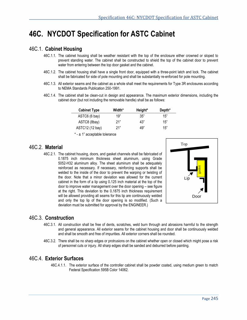
Specification 46C: NYCDOT Specification for ASTC Cabinet
Page 245
46C. NYCDOT Specification for ASTC Cabinet
46C.1. Cabinet Housing 46C.1.1. The cabinet housing shall be weather resistant with the top of the enclosure either crowned or sloped to
prevent standing water. The cabinet shall be constructed to shield the top of the cabinet door to prevent water from entering between the top door gasket and the cabinet.
46C.1.2. The cabinet housing shall have a single front door, equipped with a three-point latch and lock. The cabinet shall be fabricated for side of pole mounting and shall be substantially re-enforced for pole mounting.
46C.1.3. All exterior seams and the cabinet as a whole shall meet the requirements for Type 3R enclosures according to NEMA Standards Publication 250-1991.
46C.1.4. The cabinet shall be clean-cut in design and appearance. The maximum exterior dimensions, including the cabinet door (but not including the removable handle) shall be as follows:
Cabinet Type Width* Height* Depth*
ASTC6 (6 bay) 19” 35” 15”
ASTC8 (8bay) 21” 43” 15”
ASTC12 (12 bay) 21” 49” 15”
* - ± 1” acceptable tolerance
46C.2. Material 46C.2.1. The cabinet housing, doors, and gasket channels shall be fabricated of
0.1875 inch minimum thickness sheet aluminum, using Grade 5052-H32 aluminum alloy. The sheet aluminum shall be adequately reinforced as necessary. If necessary, reinforcing supports shall be welded to the inside of the door to prevent the warping or twisting of the door. Note that a minor deviation was allowed for the current cabinet in the form of a lip using 0.125 inch material at the top of the door to improve water management over the door opening – see figure at the right. This deviation to the 0.1875 inch thickness requirement will be allowed providing all seams for this lip are continuously welded and only the top lip of the door opening is so modified. (Such a deviation must be submitted for approval by the ENGINEER.)
46C.3. Construction 46C.3.1. All construction shall be free of dents, scratches, weld burn through and abrasions harmful to the strength
and general appearance. All exterior seams for the cabinet housing and door shall be continuously welded and shall be smooth and free of impurities. All exterior corners shall be rounded.
46C.3.2. There shall be no sharp edges or protrusions on the cabinet whether open or closed which might pose a risk of personnel cuts or injury. All sharp edges shall be sanded and deburred before painting.
46C.4. Exterior Surfaces 46C.4.1.1. The exterior surface of the controller cabinet shall be powder coated, using medium green to match
Federal Specification 595B Color 14062.
g
ask
et
Door
Lip
Top

NYCDOT Specifications for Traffic Signals & ITS Systems November 2013
Page 246
46C.5. Gasketing 46C.5.1. The housing shall have a door, securely gasketed, which shall include substantially the full area of the front
of the cabinet. Gasketing shall be provided on all door openings and shall be of dust-tight permanent type that will not peel off or deteriorate. Gaskets shall be ¼ inch minimum thickness closed cell neoprene and shall be installed with contact cement for a permanent bond. The mating surface shall be sprayed or otherwise coated with a silicon lubricant to prevent sticking to the mating metal surface.
46C.5.2. The gasket material shall not be damaged by normal cabinet cleaning agents and solvents normally used to remove graffiti from the exterior of the cabinet.
46C.5.3. Gasket material shall be UV resistant.
46C.5.4. The design of the door and gasket shall be such that the integrity of the gasket material shall not be required to ensure that the internal cabinet assemblies are protected from water damage under adverse environmental conditions. Cabinet door assemblies shall be designed in such a way that damaged gaskets do not allow water to enter the cabinet.
46C.5.5. Gasket material shall be continuous along the entire top of the cabinet door with no seams or joints in this section.
46C.6. Cabinet Door 46C.6.1. The cabinet door shall be hinged on the right side when facing the cabinet. The door hinge shall be
continuous (piano) and bolted to the cabinet and door utilizing ¼”-20 stainless steel carriage bolts and Nylock nuts. The hinge shall be made of 0.075 inch stainless steel and shall have a 3 inch open width with a ¼ inch diameter stainless steel carriage hinge pin. The hinge pin shall be capped top and bottom by weld to render it tamper proof. The hinge leafs shall not be surface mounted on the outside of the cabinet. They shall be mounted between the door and the cabinet. The cabinet door hinges shall be bolted to the cabinet housing in a manner that prevents unauthorized personnel from removing the door with commonly available tools.
46C.6.2. The cabinet shall be equipped with an automatic, self-engaging catch to hold the door open at 135 degrees
( 25 degrees). The catch shall be capable of holding the door open in 140 miles per hour wind coming at an incidence angle of 90 degrees referenced to the plane of the door. A means shall be provided to minimize the accidental release of the doorstop. The catch shall also be easily and reliably disengaged when closing the door so that the door and catch are not damaged.
46C.6.3. The door shall be furnished with a three-point latching mechanism. The latching mechanism shall be a three-point draw roller type. Push rods shall be turned edgewise at the outward supports and shall be ¼”x¾” inch stainless steel, minimum. Rollers shall have a minimum diameter of 7/8 inch and shall be made of nylon. The center catch shall be fabricated from 0.134 inch stainless steel minimum. Stainless steel compensating wear guards shall be used at contact point for the three point latching; these shall be pop or blind riveted to the cabinet.
46C.6.4. The three-point locking mechanism shall be fabricated so that it may be actuated by rotating a removable 5/8 inch hex key door handle. The hex socket and locking cam shall rotate on a ½ inch minimum diameter shaft. The socket, shaft and hex key shall be fabricated from stainless steel, grade 2011P3 aluminum, or other material plated to prevent corrosion. The socket and shaft shall be field-replaceable with common tools. The socket head shall be protected from being rotated with a pipe wrench or similar tool. Designs shall be subject to approval by NYCDOT prior to fabrication. One (1) hex wrench shall be provided with each cabinet.
46C.7. Water Management 46C.7.1. The cabinet shall be constructed such that defective, aged, and damaged gasket material shall not allow
water to enter the cabinet in any areas that might cause damage to the equipment or wiring mounted inside or the operation of the signals.
46C.7.2. The cabinet shall properly manage any condensation which may occur internally such that moisture cannot damage any of the internal cabinet assemblies, subassemblies, wiring or devices.
Specification 46C: NYCDOT Specification for ASTC Cabinet
Page 247
46C.7.3. There shall be no holes, seams, or attachments to the top of the cabinet that might cause water to leak for any reason.
46C.7.4. Weep holes approximately 3/16 inch in diameter shall be drilled in the bottom floor of the cabinet such that water does not accumulate in the cabinet.
46C.8. Door Lock 46C.8.1. The lock for the cabinet door shall be of the self-locking, heavy duty, pin tumbler, cylinder rim type. It shall be
the Corbin No. 1548RS 7/8, keyed for a DT-9 key, with dust cover. Two DT-9 keys, constructed of brass or stainless steel are to be furnished with each cabinet. When the door is closed and latched, with the key removed, the door shall lock.
46C.8.2. During the installation of the lock, good grade of commercial silicone will be put around the cylinder to form a weather resistant barrier between the front of the lock and the inside of the cabinet door. A stainless steel lock protector plate shall be installed over the rear of the lock to prevent the rear of the lock from being punched out from the front of the cabinet.
46C.9. Cabinet Ventilation 46C.9.1. Each cabinet shall be provided with louvered vents in the cabinet door for fresh air. The vents shall be
screened against the entrance to remove dust and foreign matter, with a removable and replaceable air filter 16”x6”x1” deep to filter incoming air. The filter shall be Eco Air5 type disposable filter or equivalent which is currently used and stocked by NYCDOT. The filter shall be a UL classified air filter-Class 2 644N.
46C.9.2. The filter shall overlap the vents by at least 1 inch and shall be held firmly in place with bottom and side brackets and a spring-loaded upper clamp. Provisions shall be made in the design of the vents to prevent snow and rain from being blown through the vents into the cabinet
46C.9.3. The bottom filter bracket shall be formed into a water resistant sump with drain holes to the outside. The louvered vents shall be designed and constructed so that a stream of water from a pressure head, such as a Rainbird sprinkler or other type of water spray test, will not enter the cabinet. The louvered area shall be less than the filtered area.
46C.10. Cabinet Mounting 46C.10.1. The cabinet shall be mounted on the side of a pole.
46C.10.2. The mounting area shall include reinforcement angle or other stiffening techniques to prevent the back of the cabinet from deforming when attached to the pole.
46C.11. Labeling 46C.11.1. The cabinet shall be furnished with a metal plate embossed with the following two (2) lines of text:
TRAFFIC CONTROL NEW YORK CITY
46C.11.2. Alternatively, the information noted above may be permanently etched or embossed into the cabinet door in such a manner as to be clearly visible on the exterior of the cabinet.
46C.11.3. If a plate is used, it shall be 11 inches in length and 5 inches tall and welded to the outside of the front door with the center of the plate located at the vertical centerline and midway between the top and the middle of the door. This plate shall be painted with the same green paint as the exterior of the cabinet. The text shall have letters that are 0.875 inch in height; the information noted above shall be embossed in a manner
5 Eco-Air Products, Inc., San Diego, CA 92126, 619-271-8111

NYCDOT Specifications for Traffic Signals & ITS Systems November 2013
Page 248
which allows this information to be read even after several coats of paint have been added to the cabinet. The welding for this plate shall be neat in appearance.
46C.11.4. The controller cabinet shall also be identified by model number, a serial number, and NYCDOT on a metal plate visible on the inside of the cabinet. Consecutive serial numbers shall also be stamped on the metal name identification plate and fastened to the inside of the cabinet by rivets which shall not protrude or otherwise be visible on the exterior of the cabinet.
46C.11.5. NYCDOT requires that each separate procurement contract or construction contract have serial numbers which are unique and identifiable. The Contractor shall work with the City to establish a numbering scheme that allows the City and its maintenance contractors to quickly identify the specific contract which provided the controllers. This requirement shall be true for all subassemblies as well so that the City can identify the origin of the part and determine which contractor is responsible for its maintenance.
END OF SPECIFICATIONS FOR ASTC CABINET
Specification 47
NYCDOT Specification for Steel Junction Box
Date of Revision Revised by Description
2/3/09 New spec.
Rev1.0

NYCDOT Specifications for Traffic Signals & ITS Systems November 2013
Page 250
NYCDOT SPECIFICATION FOR STEEL JUNCTION BOX .................................................................................................. 251 47.47.1. GENERAL .................................................................................................................................................................... 251 47.2. CONSTRUCTION ........................................................................................................................................................... 251

Specification 47: NYCDOT Specification for NYCDOT Steel Junction Box
Page 251
NYCDOT Specification for Steel Junction Box 47.
47.1. General 47.1.1. The junction box shall be an off the shelf commercially available unit that is rated for use as an electrical
junction box. The box shall be suitable for use in an outdoor environment and rated as a NEMA/EEMAC type 4 enclosures. The box shall provide protection against dust, dirt and oil.
47.2. Construction 47.2.1. The junction box shall be constructed of 14 gauge steel with seem continuously welded and ground smooth
with no holes or knockouts. The box shall be equipped with a heavy gauge continuous hinge with a stainless steel hinge pin on the door. The box shall have an oil resistant gasket on the door which shall be constructed with a reinforcement return lid around the entire edge of the door. The return lip shall overlap the opening of the box to cover the seam between door and box. The door shall be fastened on three sides with stainless steel clamps to ensure a water resistant seal. The finish of the box shall comply with ANSI 61 gray polyester power paint inside and out over phosphatized surfaces.
Top View Clamp Side View
Hinge side view
END OF SPECIFICATIONS FOR STEEL JUNCTION BOX


Specification 48
NYCDOT Specification for NYCWiN Modem and Cabinet Top Antenna Installation
Date of Revision Revised by Description
2/8/12 New Specification

NYCDOT Specifications for Traffic Signals & ITS Systems November 2013
Page 254
NYCDOT SPECIFICATION FOR NYCWIN MODEM AND CABINET TOP ANTENNA INSTALLATION ............................ 255 48.48.1. GENERAL .................................................................................................................................................................... 255 48.2. ANTENNA INSTALLATION ............................................................................................................................................... 255 48.3. MODEM INSTALLATION ................................................................................................................................................. 256 48.4. ASTC AUTO CONFIGURE MODE .................................................................................................................................... 257 48.5. OTHER THAN ASTC INSTALLATIONS ............................................................................................................................. 257

Specification 48: NYCDOT Spec for NYCWIN Modem and Cabinet Top Antenna Installation
Page 255
NYCDOT Specification for NYCWiN Modem and 48.Cabinet Top Antenna Installation
48.1. General 48.1.1. The modem and antenna combination are used to provide Ethernet or serial communications to any field
equipment via the city owned NYCWIN network. The unit will auto configure to any Ethernet device that responses to broadcast ping. All serial and non-broadcast ping connects shall be configured manually by the Department or as directed by the Engineer.
48.2. Antenna Installation 48.2.1. The antenna shall be mounted on the top of the equipment cabinet near the center line of the cabinet width
wise and near the front of cabinet depth wise or as directed by the Engineer.
48.2.2. A hole 7/8” is drilled in the top of the cabinet. The antenna is seal against water leakage into the cabinet using a bead of silicon to the underside of the antenna before installation the antenna is secured by tightening the nut on the mounting stud of the antenna once the mounting stud is passed though the 7/8” hole in the cabinet top.

NYCDOT Specifications for Traffic Signals & ITS Systems November 2013
Page 256
48.3. Modem installation 48.3.1. The modem will provide wireless communications for the automated traffic signal control system operated
by the NYCDOT, allowing ASTCs at all street intersections to make real-time controls/changes to traffic signals from the remote Traffic Monitoring Centers (TMC).
48.3.2. Place the modem on shelf in the cabinet or in a convenient place not on the floor of the cabinet in the vertical position. Connect the external power supply to modem, before turning on the power. Connect the Cat 5 Ethernet cable or serial cable between the modem and equipment (for ASTC unit, plug the cable into the ‘system’ port only. Make sure the Cat 5 cable is plugged into LAN1. If there are 2 ASTC at this location the first ASTC is in LAN1 and the second in LAN2). All other equipment plugs in to the 4 switched ports in a group on the front panel or the 4 serial ports on the rear. Ensure that the Cat 5 cable will not get caught in the door mechanism.

Specification 48: NYCDOT Spec for NYCWIN Modem and Cabinet Top Antenna Installation
Page 257
48.4. ASTC auto configure Mode 48.4.1. Plug the modem power supply into the 120 VAC outlet. Verify that the Power LED is illuminated.
48.4.2. Wait 1 to 3 minutes for the modem auto-detect/auto-configure process to complete, then verify that all LEDs in front of the modem are illuminated as shown in the image shown below, indicating that the device has already connected to the NYCWiN wireless network, the device has been detected, and the modem has been successfully auto-configured. Note most installs have one ASTC which means LED4 will not come on. All other LEDs should come on.
• LED #1 is on – PPP user is configured • LED #2 is on – PPP connection is up • LED #3 is on – ATC1 IPSEC tunnel is up • LED #4 is on – ATC2 IPSEC tunnel is up
48.4.3. Inform NYCDOT TMC that the location is installed and ready for the next stage – to conduct the end-to-end system integration and communication verifications of the specific ASTC. If any integration issue experienced, troubleshooting with joint efforts between all related parties: NYCDOT, Northrop Grumman Corp. and other parties. Record the serial number of the modem along with the other requested info on the city supplied installation sheet.
48.5. Other than ASTC Installations 48.5.1. All other installations other than ASTC are limited to antenna installation and modem installation and
configuration and commissioning on network shall be as directed by the Engineer.
END OF SPECIFICATIONS FOR NYCWIN MODEM AND CABINET TO ANTENNA INSTALLATION

Specification 58
NYCDOT Specification for Vehicle Detector Loop Wire Sealant
Date of Revision Revised by Description
5/16/06 Revised Soft copy

NYCDOT Specifications for Traffic Signals & ITS Systems November 2013
Page 260
58. NYCDOT SPECIFICATION FOR VEHICLE DETECTOR LOOP WIRE SEALANT ............................................................. 261 58.1. SCOPE ........................................................................................................................................................................ 261 58.2. GENERAL .................................................................................................................................................................... 261 58.3. PHYSICAL PROPERTIES ........................................................................................................................................ 261 58.4. CERTIFICATION ............................................................................................................................................................ 262 58.5. PACKAGING ................................................................................................................................................................. 262 58.6. MEASUREMENT ........................................................................................................................................................... 262

Specification 58: NYCDOT Specification for Vehicle Detector Loop Wire Sealant
Page 261
58. NYCDOT Specification for Vehicle Detector Loop Wire Sealant
58.1. Scope 58.1.1. This specification describes the minimum design, installation and functional performance requirements of a
flexible traffic detector loop wire encapsulant intended for sealing and protecting vehicle detector loop wires installed ¼” to 3/8” wide and 1½” to 2½” deep.
58.1.2. The encapsulant is intended to provide compressive yield strength to withstand normal vehicular traffic as well as sufficient flexibility to withstand normal movement in asphaltic and concrete pavements, while protecting the loop wire from moisture penetration, fracture and shear.
58.2. General 58.2.1. The encapsulant shall be one-part elastomeric compound requiring no mixing, measuring or application of
heat prior to or during its installation.
58.2.2. The encapsulant shall, within its stated shelf life in original undamaged packaging, cure only in the presence of moisture. The rate of cure will, therefore, depend upon temperature and relative humidity at the time of installation. Cool, dry weather will slow curing whereas warm, humid weather will accelerate curing.
58.2.3. The encapsulant shall be designed to enable vehicular traffic to pass over the properly filled saw cut immediately after installation without tracking or stringing of the material. The encapsulant shall form a surface skin allowing exposure to vehicular traffic within 30 minutes at 75º F and completely cure to a tough, rubber-like consistence in two (2) to seven (7) days after installation.
58.2.4. Properly installed and cured encapsulant shall exhibit resistance to effects of weather, vehicular abrasion, motor oils, gasoline, antifreeze solution, brake fluid, de-icing chemicals and salt normally encountered in such a manner that the performance of the vehicle detector loop wire is not adversely affected.
58.2.5. The cured encapsulant shall be temperature stable and exhibit no degradation in performance throughout the ambient temperature ranges experiences within the continental Unites States, Alaska, Hawaii and Puerto Rico.
58.2.6. The encapsulant shall exhibit minimal shrinkage during or after its installation, and in no manner effect the performance characteristics of the material.
58.2.7. The encapsulant shall be designed to permit clean-up of material and application equipment with non-flammable solvents such as 1,1,1-trichloroethane or Scotch-Grip brand Solvent No. 4 (prior to curing of encapsulant). Should any encapsulant material be allowed to cure in the application nozzle, it shall be able to be pulled out as a solid plug.
58.2.8. The encapsulant shall have a minimum shelf life in undamaged original containers when stored in cool, dry environment as follows: 9 months after receipt when packaged in one quart cartridges; 12 months after when packaged in 5 U.S. gallons by commercially available quart-size caulking guns. The 5-U.S gallon pails shall contain 4.5 gallons of encapsulant in order to permit application by commercially available pumps.
58.2.9. The encapsulant shall be designed for roadway installation when the surface temperature is between 40º F and 140º F.
58.3. PHYSICAL PROPERTIES 58.3.1. The encapsulant shall have the following physical properties in its uncured and cured states.
48.5.1.1. Physical properties of the uncured (wet) encapsulant:
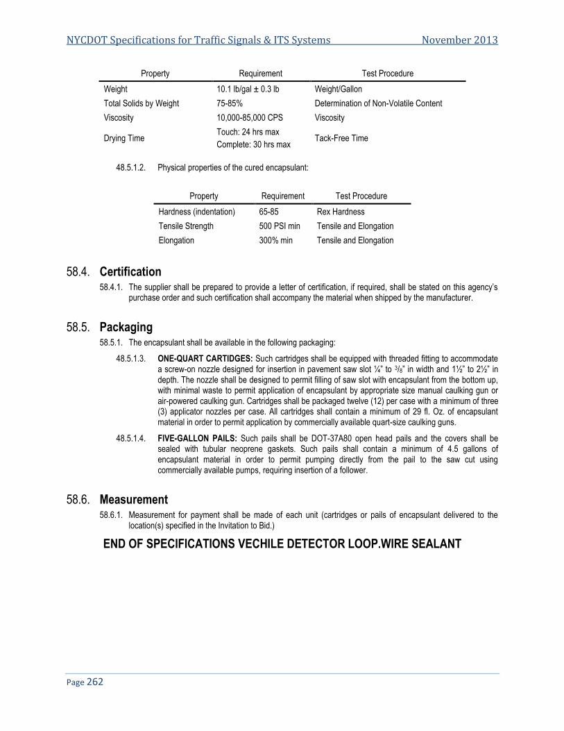
NYCDOT Specifications for Traffic Signals & ITS Systems November 2013
Page 262
Property Requirement Test Procedure
Weight 10.1 lb/gal ± 0.3 lb Weight/Gallon
Total Solids by Weight 75-85% Determination of Non-Volatile Content
Viscosity 10,000-85,000 CPS Viscosity
Drying Time Touch: 24 hrs max
Complete: 30 hrs max Tack-Free Time
48.5.1.2. Physical properties of the cured encapsulant:
Property Requirement Test Procedure
Hardness (indentation) 65-85 Rex Hardness
Tensile Strength 500 PSI min Tensile and Elongation
Elongation 300% min Tensile and Elongation
58.4. Certification 58.4.1. The supplier shall be prepared to provide a letter of certification, if required, shall be stated on this agency’s
purchase order and such certification shall accompany the material when shipped by the manufacturer.
58.5. Packaging 58.5.1. The encapsulant shall be available in the following packaging:
48.5.1.3. ONE-QUART CARTIDGES: Such cartridges shall be equipped with threaded fitting to accommodate a screw-on nozzle designed for insertion in pavement saw slot ¼” to 3/8” in width and 1½” to 2½” in depth. The nozzle shall be designed to permit filling of saw slot with encapsulant from the bottom up, with minimal waste to permit application of encapsulant by appropriate size manual caulking gun or air-powered caulking gun. Cartridges shall be packaged twelve (12) per case with a minimum of three (3) applicator nozzles per case. All cartridges shall contain a minimum of 29 fl. Oz. of encapsulant material in order to permit application by commercially available quart-size caulking guns.
48.5.1.4. FIVE-GALLON PAILS: Such pails shall be DOT-37A80 open head pails and the covers shall be sealed with tubular neoprene gaskets. Such pails shall contain a minimum of 4.5 gallons of encapsulant material in order to permit pumping directly from the pail to the saw cut using commercially available pumps, requiring insertion of a follower.
58.6. Measurement 58.6.1. Measurement for payment shall be made of each unit (cartridges or pails of encapsulant delivered to the
location(s) specified in the Invitation to Bid.)
END OF SPECIFICATIONS VECHILE DETECTOR LOOP.WIRE SEALANT

Specification 61A
NYCDOT Specification for ASTC Input File Devices
Date of Revision Revised by Description

NYCDOT Specifications for Traffic Signals & ITS Systems November 2013
Page 264
61A. NYCDOT SPECIFICATION FOR ASTC INPUT FILE DEVICES .......................................................................................... 265

Specification 61A: NYCDOT Specification for ASTC Input File Devices
Page 265
61A. NYCDOT Specification for ASTC Input File Devices Please see ASTC specification. for
Loop Amp DC Isolator AC Isolator I/O Card Other input file cards
END OF SPECIFICATIONS FOR ASTC INPUT FILE DEVICES


Specification 62
NYCDOT Specification for Radar Vehicle Detector (RVD)
Date of Revision Revised by Description

NYCDOT Specifications for Traffic Signals & ITS Systems November 2013
Page 268
62. NYCDOT SPECIFICATION FOR RADAR VEHICLE DETECTOR (RVD) ............................................................................ 269 62.1. GENERAL INFORMATION ............................................................................................................................................... 269 62.2. DESCRIPTION .............................................................................................................................................................. 269 62.3. ENVIRONMENTAL CONDITIONS AND PROTECTION ........................................................................................................... 269 62.4. MICROWAVE TRANSMISSION ........................................................................................................................................ 270 62.5. FUNCTIONAL CHARACTERISTICS ................................................................................................................................... 270 62.6. ELECTRICAL ................................................................................................................................................................ 272 62.7. INSTALLATION .............................................................................................................................................................. 273 62.8. TRAINING (TRAINING IS ONLY REQUIRED WHEN SPECIFIED)........................................................................................... 274 62.9. COMMUNICATIONS ....................................................................................................................................................... 274 62.10. EQUIPMENT AND LABELING........................................................................................................................................... 274 62.11. QUALITY ASSURANCE .................................................................................................................................................. 275 62.12. DOCUMENTATION ........................................................................................................................................................ 275 62.13. GUARANTEE ................................................................................................................................................................ 276 62.14. CRATING ..................................................................................................................................................................... 276 62.15. DELIVERY.................................................................................................................................................................... 276

Specification 62: NYCDOT Specification for Radar Vehicle Detector (RVD)
Page 269
62. NYCDOT Specification for Radar Vehicle Detector (RVD)
62.1. General Information 62.1.1. The purpose of this Specification is to describe the minimum requirements of a Radar Vehicle Detector (RVD).
62.1.2. The RVD unit shall be easy to install and remove, and shall be fully programmable to support a variety of applications.
62.1.3. All equipment and component parts furnished shall be new, be of the latest design and manufacture, and be in an operable condition at the time of delivery and installation. All parts shall be of high quality workmanship, and no part or attachment shall be substituted or applied contrary to the manufacturer's recommendations and standard practices.
62.1.4. The design shall be such as to prevent reversed assembly or improper installation of connectors, fasteners, etc. Each item of equipment shall be designed to protect personnel from exposure to high voltage during equipment operation, adjustments, and maintenance. The designed Mean Time Between Failures (MTBF) of the RVD unit, operating continuously in their application, shall be 10 years or longer. The manufacturer of the RVD unit must provide references to show that it has been deployed in operational systems for over three years.
62.2. Description 62.2.1. Under this Specification, the Contractor shall furnish: microwave sensors; wireless data transmitters, receivers
and associated antennas; power supplies; surge arrestors; cables and connectors to provide loop emulation contact closure outputs into an Advanced Solid State Traffic Controller (ASTC) through the cabinet input file in accordance with the contract documents or as directed by the Engineer. The input file and ASTC will be furnished under a separate contract and shall be installed under another Bid Item.
62.2.2. Each sensor shall be a self-contained microwave sensor integrated with a wireless data transmitter and a wireless antenna as a single unit, which detects and monitors roadway traffic and transmits sensor information to a wireless data receiver. The sensor shall be a true presence detector which can provide presence, volume, lane occupancy, and speed information on at least eight discreet detection zones from a side-fire or forward-looking location. The sensor information shall be available via loop emulation contact closure outputs for up to 8 detection zones. The sensor shall also provide the information via RS-232 or RS-485 asynchronous serial communications using an open protocol. The wireless data transmitter shall transmit the sensor information to an associated wireless receiver housed in an ASTC cabinet as shown on the contract documents or as directed by the Engineer.
62.2.3. The wireless data receiver and its reporting transmitters shall be configured for point-to-multipoint communications. Each receiver shall simultaneously communicate with up to 8 transmitters. The receiver shall be mounted in the ASTC input file and accommodate up to 16 detection zones in a loop emulation configuration. The receiver shall also be capable of providing loop emulation speed trap contact closure outputs for up to 8 detection zones into the ASTC input file. The type of configuration shall be user selectable.
62.2.4. The microwave sensors, wireless data transmitters and receivers and associated wireless antennas, power supplies, surge arrestors, cables, and connectors shall be furnished and delivered as a complete factory tested assembly unless otherwise noted in the contract documents. The Contractor shall provide software, firmware, and any equipment required to setup, calibrate, and operate the microwave sensors, wireless data transmitters and receivers.
62.3. Environmental Conditions and Protection 62.3.1. Except as stated otherwise herein, the equipment shall meet or exceed all its specified requirements during
and after subjecting to any combination of the following:

NYCDOT Specifications for Traffic Signals & ITS Systems November 2013
Page 270
• Ambient temperature range of -37º C to 74º C (-35º F to 165º F) • Relative humidity from 5 to 95 percent, non-condensing • Winds up to 160 Km/h (100 MPH) • Rain and other precipitation up to 100 mm/h (4 inch/h) • Power surge of ±1kV surge (rise time = 1.2 µsec, hold = 50 µsec) applied in differential mode to all
lines, power and output, as defined by IEC 1000-4-5 and EN 61000-4-5 standards.
62.3.2. The design shall be inherently temperature compensated to prevent abnormal operation.
62.3.3. The circuit design shall include such compensation as is necessary to overcome adverse effects due to temperature in the specified environmental range.
62.3.4. Printed Circuit boards shall be conformably coated for protection against humidity. Except as may be otherwise stated herein for a particular item, no item, component, or subassembly shall emit a noise level exceeding the peak level of 55 dB when measured at a distance of one meter away from its surface. The microwave radar detector shall be resistant to vibration in accordance with IEC 68-2-30 (test Fc), NEMA TS-1 (Section 2.1.12), or approved equivalent. The microwave detector shall be resistant to shock in accordance with IEC 68-2-27 (test a), NEMA TS-1 (Section 2.1.13), or approved equivalent.
62.4. Microwave Transmission 62.4.1. The microwave radar detector shall transmit on a frequency band of 10.5 GHz to 24 GHZ or another approved
spectral band. It shall comply with the limits for a Class A digital device, pursuant to Part 15 of the FCC rules or the appropriate Spectrum Management Authority. The RVD shall not interfere with any known equipment. Transmitter power shall not exceed 10 mW.
62.4.1.1. AREA OF COVERAGE - The RVD's field of view shall cover an area defined by an oval shaped beam and its maximum detection range shall be as follows:
• Elevation Beam Width 40 to 65 degrees • Azimuth Beam Width 6 to 15 degrees • Minimum Range 10 to 200 feet
62.4.1.2. DETECTION ZONES - The maximum number of detection zones defined shall be no less than eight (8). The range limits of each zone shall be user defined in 7 ft. resolution.
62.5. Functional Characteristics 62.5.1. The RVD shall be a true presence detector. It shall be suitable for mounting on roadside poles or on overhead
structures and provide the following: • Presence indication of moving or stopped vehicles in its detection zones, provided by contact closure
to existing controllers. • Traffic data, periodically accumulated over user defined time intervals in a 10 to 600 sec range,
transmitted via serial communications lines to other systems. • Traffic data shall be available simultaneously with detection zone contact closures • Side-fired configuration data shall include the following in each of up to 8 detection zones (lanes): • Volume • Lane occupancy • Average speed • Vehicle classification by length shall have a minimum of 4 user defined classes. • RVD on overhead structures (forward-looking configuration) shall monitor traffic in one lane and be
capable of providing the following data: • Volume, occupancy, average speed and travel direction in the lane • Per vehicle speed, direction and length measurements • Binning of Volume data in up to 7 speed bins and up to 7 length bins • RVD shall allow the user to define the contents of transmitted data • RVD shall provide Fail-Safe indication by a contact pair and by serial data • RVD shall provide remote indication of input (battery) voltage by serial data

Specification 62: NYCDOT Specification for Radar Vehicle Detector (RVD)
Page 271
62.5.2. Measurement Accuracy
62.5.2.1. The detector shall identify vehicle presence within each detection zone with a 95% accuracy or greater, independent of the vehicle's direction of travel through the detection zone. The following error levels shall be achievable, depending on mounting configurations.
• Parameter Side-fired error Overhead error • Presence ±5% +/-2% • Volume ±5% +/-2% • Lane Occupancy ±5% +/-2% • Average Speed ±10% +/-2% • Per Vehicle Speed NA +/-2% • Length Classification limits ±10% +/-10% • Time event 10ms • Input Voltage ±2% +/-2%
62.5.2.2. Test data demonstrating or proving performance shall be provided via the following test plan.
62.5.2.2.1. RVD Pole Deployment Test Plan
Unit: ________ Serial No.: _________ Location: __________
Scope - This plan is proposed for the verification of proper deployment of a Side-fired Radar Vehicle Detection Station (RDVS). It is assumed that the testing/installing parties have been properly trained by manufacturer's personnel. It is also assumed that the RVD unit was installed per the instructions in the manufacturer’s User Manual, using the most up to date Setup software.
Test Procedure - Power the RVD unit with suitable power and connect its serial port to the COM1 port of a portable PC, running the setup software.
Self-Test - Start the Self-Test program in the RVD Setup program TOOLS menu. The program will run for about 20 seconds and produce a screen report: Any report except “System is OK” can be considered a failed test. Pass______ Fail______
Volume Test - Select and activate Clear Counters in the VERIFY menu. After the beep is sounded (total counts on the screen are cleared) start a manual count on all lanes or on each lane separately until at least 50 vehicles and stop counting at the next beep (total counts are updated). Compare the manual count to the RVD count. If the difference is within 10% of the total, the test has been passed.
Manual Total Count RVD Total Count % Difference Pass______ Fail______ (Optional) Manual L1 Count RVD L1 Count % Difference Pass______ Fail______ Manual L2 Count RVD L2 Count % Difference Pass______ Fail______ Manual L3 Count RVD L3 Count % Difference Pass______ Fail______ Manual L4 Count RVD L4 Count % Difference Pass______ Fail______ Manual L5 Count RVD L5 Count % Difference Pass______ Fail______ Manual L6 Count RVD L6 Count % Difference Pass______ Fail______
Speed Test - Set the RVD Message Period in the SETUP menu to 180 Seconds. The test should be performed when traffic is flowing and not stop-and-go. Using a radar/laser gun aimed at the first lane only, measure speed of as many vehicles you can within the measurement period (defined from beep to beep), taking care to measure the speed at ranges where the radar angle is about 20 degrees with the road. Average the speed-readings from the radar gun. If Lane 1 Volume exceeds 50 vehicles and Lane 1 speed compares with the radar gun average speed within ± 15% the test was passed: Pass______ Fail______
62.5.2.2.2. Performance Maintenance
The RVD shall not require cleaning or adjustment to maintain performance. It also shall not rely on battery backup to store configuration information.

NYCDOT Specifications for Traffic Signals & ITS Systems November 2013
Page 272
Once the sensor is calibrated, it shall not need recalibration to maintain performance unless the roadway configuration changes. In that case, the RVD’s remote connectivity shall allow operators to reconfigure and recalibrate the sensor automatically.
62.5.3. Mechanical
62.5.3.1. The microwave radar detector shall be enclosed in a rugged weather resistant box and sealed to protect the unit from wind up to 90 mph, dust and airborne particles, and exposure to moisture (NEMA type 3R enclosure).
62.5.3.2. Maximum overall dimensions, including fittings: 24x16x18.5 cm (9.5 x 6.25 x 7 in.)
62.5.3.3. Maximum weight of the microwave radar detector assembly 2.2kg (5 pounds)
62.5.3.4. The mounting assembly shall have all coated steel, stainless steel, or aluminum construction, and shall support a load of 20 pounds. The mounting assembly shall incorporate a ball-joint, or other approved mechanism that can be tilted in both axes then locked into place, to provide the optimum area of coverage.
62.6. Electrical 62.6.1. The RVD unit shall be operable from both 12-24 VAC/DC dissipating no more than 4.5W, or 95-135 VAC @
60 Hz. Power supply shall be obtained from the power distribution assembly within the controller cabinet, or any convenient power source.
62.6.2. The RVD unit shall include Power Management features, allowing remote shutdown or cyclical shutdown of the unit.
62.6.3. The RVD unit shall include a Low-Voltage disconnect feature for battery protection.
62.6.4. Cable
62.6.4.1. Connection between the RVD unit and the cabinet equipment shall be provided by a single, MS connector terminated cable. The cable shall provide power to the unit, output contact closure wire pairs rated at 300V AC/DC 100 mA for each of the required detection zones and serial data interface.
62.6.4.2. The cable shall be UV-resistant and provide multiple twisted pairs of stranded size 20 or 22 AWG wire with a common shield rated at 300 V with a temperature rating of 105º C.
62.6.4.3. The MS connector pins must be crimped to the cable conductors and assembled and tested prior to installation and pulling of cable on site. This cable will be 30 ft long unless otherwise stated. There shall also be provisions to supply just the connectors if so requested.
62.6.5. Electrical Isolation And Surge Protection - All power lines, contact closures and serial port shall be isolated. Power lines and serial port shall be surge protected within the unit.
62.6.6. Data Interface - Data communications shall be full duplex asynchronous, able to support the NTCIP protocol 1209 for TSS. It shall be configurable as:
• Opto-isolated RS-485 or RS-232 port at rates from 2400 up to 115200 bits per second • Serial data format shall be standard binary NRZ 8 bits data, 1 stop bit, No parity. • Both point-to-point and Multi-dropped configurations are supported • An integral Digital Spread Spectrum radio modem shall be available as an option • Ethernet port (TCP/IP) shall be available as an option
62.6.7. Input File Cards
62.6.7.1. The RVD unit manufacturer shall provide an optional input file card compatible with 170, 2070, NEMA TS1, NEMA TS2 and NYC ASTC input file racks. The input file card shall translate per vehicle data packets or real-time true presence packets from the RVD into corresponding contact closure outputs. Operators shall be able to assign any contact closure output channel to any lane or detection zone. These settings shall be saved in non-volatile memory on the input file card for complete recovery in case of power failure. The input file card shall support Dual Loop (Speed Trap) emulation, as well as the following modes of operation:

Specification 62: NYCDOT Specification for Radar Vehicle Detector (RVD)
Page 273
• Pulse (a single 125 ms output pulse for each vehicle) • Presence (an output pulse corresponding to the duration of each vehicle in the
detection zone with a resolution of 2.5 ms) • Actuation (true presence output in real time with 2.5 ms resolution) • Single Loop Speed (duration of the pulse corresponds directly to the speed of the
vehicle, speed (mph) = 13.64/duration in seconds)
62.6.7.2. The input file card shall receive data packets over an RS-485 bus at any of the following baud rates: 9600, 19200, 38400, 57600 and 115200. The input file card shall also auto-baud and auto-detect an RVD over wired and wireless communication channels that have a maximum latency of 500 ms.
62.6.7.3. The Input file card shall comply with the NEMA TS2-1998 Traffic Controller Assemblies with NTCIP Requirements (Section 2.8 specification). Documentation and results of the NEMA TS2-1998 test shall be provided.
62.6.7.4. Additionally, the input file card shall comply with the EN 61000-4-5 Class 4 lightning surge protection test specification. Documentation and results of the EN 61000-4-5 Class 4 test shall be provided.
62.6.8. Configuration Software - A portable PC based diagnostic and configuration software package, which operates with latest available MS Windows on any Windows compatible portable PC, shall be provided. The software package shall comply with the following requirements:
62.6.8.1. The software package shall provide for the setup, configuration, calibration and operation of the sensors, wireless data transmitters and receivers. The software shall be provided on a Compact Disk (CD) as a complete installation package.
62.6.8.2. The software shall provide both manual and automatic setup and calibration. The software shall fully support the programming of all parameters in the unit including type of protocol and detection zones. The software shall also display real-time presence in the programmed detector zones and shall report the accumulated data over the reporting interval for all programmed zones including volume, average occupancy and average speed and vehicle classification.
62.6.8.3. The software shall save the configuration data for each sensor, wireless data transmitter and receiver to a backup file that can be read on any portable PC running the configuration software.
62.6.8.4. The software shall be able to display the real-time spread spectrum radio signal levels for all available hopping patterns and automatically or manually select and optimum pattern at the receiver end.
62.6.8.5. The software shall be able to setup, configure, calibrate and operate the sensor from a local portable PC as the serial communications is established at the pole base or from a remote portable PC as the serial communications is established at the receiver end. The software on the remote portable PC shall be able to configure and operate multiple reporting sensors and retrieve detection data from them at the receiver end.
62.7. Installation 62.7.1. The RVD unit shall be mounted in either Side-fired or Forward-looking configuration on poles or sign
structures at the specified locations, using the supplied mounting brackets. The brackets shall be pole mounted with approved ¾ inch wide Stainless Steel Banding or wall/structure mounted using supplied mounting holes (2) and approved hardware.
62.7.2. In the Forward-looking configurations the detector will be mounted over the center of each lane. The RVD mode of operation, detection zones and other calibration and set up will be performed using a MS Windows based software and a portable PC. The software shall be user friendly, good visibility outdoors in bright sunny days, allow verification of correct setup, and diagnostics. It shall include facilities for saving verification data and collected data as well as saving and retrieving sensor setup from disk file.

NYCDOT Specifications for Traffic Signals & ITS Systems November 2013
Page 274
62.8. Training (Training Is Only Required When Specified) 62.8.1. Work under this Specification shall consist of providing qualified instructors and all materials for training
Department's and other designated personnel in the operation and maintenance of the RVD. All training sessions shall be conducted locally.
62.8.2. Training shall consist of formal classroom lectures as well as "hands-on" training, working with the actual equipment. One day shall be provided for a training session. A "day" of training shall consist of 7 hours. The attendance of each session shall be of no more than 6 people.
62.9. Communications 62.9.1. The sensor shall support the National Transportation Communications for ITS Protocol (NTCIP), the Point-to-
Point Protocol (PPP), and the Ethernet protocol. The protocol shall support the sensor setup and configuration either from a local portable PC or from a remote location. Complete protocol descriptions shall be supplied with the submittal for the sensor. These protocol descriptions shall be complete and adequate for future development of software to retrieve the information from the sensor.
62.9.2. Digital Spread Spectrum Radio Modem Specifications (Only Required When Specified)
• Technology Frequency Hopping Spread Spectrum Radio • Frequency band 902-928MHz ISM band • Mode Slave or repeater operation • Hopping pattern 64 pseudo-random sequences selectable • Transmitter power 1 mW, 10 mW, 100 mW or 1 W selectable • Antenna Integral whip or external whip/Yagi antenna • Range up to 30 km (18 miles) depending on power, antenna and line of sight • Error detection CRC-16 • Network addressing Up to 65535 addresses • Encryption Up to 65535 combinations • Interface Asynchronous, AT Command set, transparent data set • Licensing FCC rules Part 15 approval. License free operation in the US • Temperature range -37° C to 70° C (-35º F to 158º F) • Added power consumption typically 1 W when this option is selected
62.10. Equipment and Labeling 62.10.1. All equipment shall be clearly and permanently labeled. Marker strips shall be used and located on the
subject equipment. The strips shall be made of material that can be legibly written on with pencil or ballpoint pen.
62.10.2. NYC Name Plate
62.10.2.1. The sensor enclosure shall either be dye stamped with, or contain a name plate permanently affixed on, the outside containing the following two (2) lines of text:
TRAFFIC CONTROL NEW YORK CITY
62.10.2.2. The text shall be evenly centered on the outside of the sensor enclosure in such a manner as to be clearly visible on the exterior of the sensor enclosure. Dye stamping is the preferred method.
62.10.2.3. Each assembly and subassembly shall be clearly and permanently labeled as the property of NEW YORK CITY with a unique and consecutive serial number and make and model number and manufacturer’s name as approved by the Engineer. These shall be visible from the exterior of the equipment and without disassembly of the unit. There shall be a permanent label next to the MS connecter in lettering at least ¾ inch tall stating the operating voltage requirements example 12 VDC or 120 VDC

Specification 62: NYCDOT Specification for Radar Vehicle Detector (RVD)
Page 275
62.11. Quality Assurance 62.11.1. Unless otherwise specified, the Contractor shall be responsible for all inspection requirements prior to
submission for the City of New York inspection and acceptance. The City of New York reserves the right to perform any additional inspections deemed necessary to assure that the equipment conforms to the requirements specified herein. The City of New York reserves the right to have its representatives witness all factory tests. The results of each test shall be compared with the requirements specified herein. Failure to conform to requirements for any test shall be counted as a defect, and the equipment shall be subject to rejection. Rejected equipment may be offered again for retest provided all non-compliance has been corrected and re-tested by the Contractor. Final inspection and acceptance of equipment shall be made after delivery at destination specified unless otherwise stated.
62.11.2. The equipment covered by this Specification shall be subjected to design approval tests to determine conformance with all applicable requirements. Design approval tests shall be conducted by the Contractor on three samples of microwave sensors, wireless data transmitters and receivers to determine if the design of the equipment meets the requirements of this specification. The design approval test of the microwave sensor, wireless data transmitter and receiver shall be at a site in NYC as required by the Engineer. The Contractor shall furnish and install the sample sensors, wireless transmitters and receivers, all mounting hardware, and provide all test equipment and personnel required to perform the testing. The Contractor shall use an ASTC traffic controller and cabinet to be provided by the Engineer during the testing. All testing and manual count analysis shall be performed in the presence of the Engineer. The test, at a minimum, shall demonstrate the following using test equipment furnished by the Contractor:
62.11.3. Configuration of the installation using a portable PC.
62.11.4. Storage of configuration data in nonvolatile memory.
62.11.5. Downloading previously stored configuration data.
62.11.6. Detecting vehicles to the accuracy specified in this special specification across eight lanes of traffic.
62.11.7. The test shall compare volume and occupancy measurements against manual counts and detector data as measured by a properly functioning 6 foot loop, and speed measurements against a radar gun data. The unit shall operate within the tolerances included herein specifications for volume, occupancy and speed.
62.11.8. A test car of known length shall be driven through the detection zone and its calculated presence, based on the known vehicle length and speed, compared to that of the measured pulses. This measurement shall be repeated a total of ten times with a minimum of twice in each detection zone.
62.11.9. Demonstration of wireless transmitter output power and receiver sensitivity, transmission and reception of microwave sensor configuration and detection data between the transmitter and the receiver.
62.11.10. Demonstration of transmission and reception of detection data between the receivers, ASTC input file and ASTC controller. Volume, occupancy and speed measurements shall be compared against the ASTC detector log. The test shall verify to the satisfaction of the Engineer that the detection data for each lane is properly routed from the receiver to ASTC input file.
62.11.11. For Articles from 61A.11.2.4. to 61A.11.2.7. a pulse counter shall be used to measure the widths of the pulses. For D. and E. a minimum of 150 readings measurements shall be made. If conditions permit, the test shall be made during the test period in rain, snow, fog and wind.
62.11.12. Three (3) randomly selected samples shall be delivered for inspection and testing within forty five (45) consecutive calendar days after approval from the NYCDOT Engineer. The city reserves the right to retest the product at any time or remove the product from the QPL list at any time. This approval shall otherwise remain in effect until there is a change in the product, spec. or as directed by the engineer.
62.12. Documentation 62.12.1. The Contractor shall provide complete maintenance and operation manual, which includes schematics,
component layout, bill of materials with generic manufacturer’s part numbers, assembly and disassembly instructions, calibration procedures, exploded assembly drawings, protocol documentation, and complete

NYCDOT Specifications for Traffic Signals & ITS Systems November 2013
Page 276
instructions for the installation and use of the portable PC setup and calibration procedures. Documentation shall be bound. A soft copy shall also be supplied in CD form. They shall have the right to copy and distribute this documentation to anyone working on any city or state project within the confines of NYC.
62.12.2. The Contractor shall provide the setup and configuration software on a CD including automatic installation and removal procedures along with the Contractor supplied equipment without additional charges. The City shall have the right to copy and install the software as necessary to support the setup, maintenance, and operation of the microwave sensor, wireless transmitter and receiver for NYCDOT or contract maintenance personnel.
62.13. Guarantee 62.13.1. The Contractor guarantees that all equipment including all parts thereof are of the first quality throughout and
comply in all respects or are fully equal to standards called for in the specification. The Contractor further guarantees all equipment, and all parts thereof against any defects of workmanship, construction and materials, and guarantees to repair or replace without cost to the City of New York any article that had become defective, and not proven to have been caused by negligence on the part of the user, within a period of twenty four (24) months of in service operation following the initial date equipment is installed, tested, placed in service, and accepted by the Engineer. However, said guarantee shall not exceed three (3) years from the date of acceptance. A guarantee certificate shall be supplied for each component from the designated depot repair site indicating the start and end dates of the warranty. The guarantee certificate shall name NYCDOT as the recipient of the service. NYCDOT shall have the right to transfer this service to other private parties who may be contracted to perform overall maintenance.
62.13.2. The guarantee shall include repair and/or replacement of all failed components via a factory authorized depot repair service. All items sent to the depot for repair shall be returned within two weeks of the date of receipt at the facility. The depot location shall be in the United States. Repairs shall not require more than two (2) weeks from date of receipt and the provider of the warranty shall be responsible for all shipping costs. The depot maintainer designated for each component shall be authorized by the original manufacturer to supply this service.
62.13.3. In the event of failure on the part of the Contractor to replace or put in first-class condition any such articles within thirty (30) calendar days from the date of notice, the City of New York may have the work done by others and deduct the cost thereof from any payments owed the Contractor, or if there be no outstanding payments due, the Contractor agrees to pay the City of New York such costs.
62.14. Crating 62.14.1. Each complete microwave sensor, wireless data transmitter, power supply unit, antenna, surge arrester,
wireless data receiver and expansion cards, and cables shall be packed in an approved shipping carton. The packaging shall be such as to prevent damage during delivery or storage to a height of fifteen (15) feet.
62.14.2. The cartons shall be plainly identified at the top end and one side as to the type of equipment, purchase order numbers, manufacturer's name and the year of manufacture.
62.15. Delivery 62.15.1. All deliveries except samples shall be made to the Department’s Warehouse (loading bays 5 and 6) at 66-26
Metropolitan Ave in Middle Village (Queens), NY 11379, any other locations within the limits of the City of New York designated by the Department, or as directed by the Engineer. Material/equipment will be accepted between the hours of 8:00 AM and 12:00 PM with unloading to be completed before 3:00 PM, Monday thru Friday, except holidays. The Contractor must notify the Department at least 24 hours in advance of delivery.
62.15.2. The production samples shall be delivered to the NYCDOT ITS LAB room 122 34-02 Queens Boulevard, Long Island City (Queens), NY 11101, within delivery time frame as directed by the Engineer.
END OF SPECIFICATIONS FOR RADAR VEHICLE DETECTOR

Specification 62A
NYCDOT Specification for Radar Vehicle Detector (RVD) with Wireless Radio
REVISED BY DATE REASON
J. Ornas T 4 Spec
Add Bluetooth

NYCDOT Specifications for Traffic Signals & ITS Systems November 2013
Page 278
62A. NYCDOT SPECIFICATION FOR RADAR VEHICLE DETECTOR (RVD) WITH WIRELESS RADIO ................................. 279 62A.1. DESCRIPTION .............................................................................................................................................................. 279 62A.2. CONSTRUCTION ........................................................................................................................................................... 279 62A.3. ELECTRICAL ................................................................................................................................................................ 285 62A.4. QUALITY ASSURANCE .................................................................................................................................................. 288 62A.5. GUARANTEE ................................................................................................................................................................ 290 62A.6. CRATING ..................................................................................................................................................................... 290 62A.7. DELIVERY.................................................................................................................................................................... 290 62A.8. TRAINING .................................................................................................................................................................... 291

Specification 62A: NYCDOT Spec for Radar Vehicle Detector (RVD) with Wireless Radio
Page 279
62A. NYCDOT Specification for Radar Vehicle Detector (RVD) with Wireless Radio
62A.1. Description 62A.1.1. Under this Specification, the Contractor shall furnish a microwave sensor assembly including a microwave
sensor, a sensor cabinet and associated cabinet equipment, a wireless data transmitter, a wireless data receiver and expansion cards, antennas, surge arrestors, cables, and connectors to provide loop emulation contact closure outputs into an Advanced Solid-State Traffic Controller (ASTC) through the cabinet input file in accordance with the contract documents or as directed by the Engineer. The input file and ASTC will be furnished under a separate contract and shall be installed under another bid item in this Specification. The Contractor shall provide input devices suitable for mounting in the ASTC input file to support 8 or more detection zones as necessary to support the number of detection zones shown for the installation on the supplied drawing if no drawing is supplied, the full 8 channels shall be supported.
62A.1.2. The sensor unit shall be a self-contained microwave sensor integrated with a wireless data transmitter and an antenna either as a single unit within a single enclosure or as separate components installed in the sensor cabinet, which detects and monitors roadway traffic and transmits sensor information to a wireless data receiver. The sensor shall be a true presence detector which can provide presence, volume, lane occupancy, and speed information on at least eight discreet detection zones from a side-fire or forward-looking location. The sensor information shall be available via loop emulation contact closure outputs for up to 8 detection zones. The sensor shall also provide the information via RS-232 asynchronous serial communications using an open protocol or a proprietary protocol that NYCDOT has the right to make freely available to future perspective bidders and Contractors. The wireless data transmitter shall transmit the sensor information to an associated wireless receiver housed in an ASTC cabinet as shown on the contract documents or as directed by the Engineer.
62A.1.3. The wireless data receiver and its reporting transmitters shall be configured for point-to-multipoint communications. Each receiver shall simultaneously communicate with up to 8 transmitters. The receiver shall be mounted in the ASTC input file and accommodate up to 20 detection zones in a loop emulation configuration. The receiver shall also be capable of providing loop emulation speed trap contact closure outputs for up to 10 speed traps into the ASTC input file. The type of configuration shall be user selectable.
62A.1.4. The microwave sensor, wireless data transmitter and receiver, antennas, surge arrestors, cables, and connectors shall be furnished and delivered as a complete factory tested assembly unless otherwise noted in the contract documents. The sensor cabinet and associated cabinet equipment shall be furnished and delivered as a complete assembly with all internal hardware and wiring factory installed and tested, and all mounting hardware required to complete the installation. The Contractor shall provide software, firmware, and any equipment required to setup, calibrate, and operate the microwave sensors, wireless data transmitters and receivers.
62A.2. Construction 62A.2.1. All of the components, including all incidental components and cables, shall be supplied to accomplish a fully
operational installation. All equipment and component parts furnished shall be new and of the latest design. All parts shall be of high quality workmanship, and no part or attachment shall be substituted or applied contrary to the manufacturer's recommendations and standard practices. The design life of all components, operating 24 hours per day 365 days per year, shall be 10 years minimum.
62A.2.2. The microwave sensor, wireless data transmitter and receiver shall be fully compatible with each other and shall be supplied from the same manufacturer or a third party manufacturer as approved by the Engineer. The wireless data receiver shall be fully compatible with the ASTC input file as specified in New York City Department of Transportation (NYCDOT) ASTC Procurement Specification Version 2.6 Sections 2.5, 2.6, 2.7, 2.8.6, 3.4.1, 3.10.3, 3.10.5 and 5.11.

NYCDOT Specifications for Traffic Signals & ITS Systems November 2013
Page 280
62A.2.3. Prior to commencing work on this item, the Contractor shall provide the Engineer with evidence of the microwave sensor manufacturer either having provided at least three successful detector installations of fifty or more sensors identical to the model proposed in an operational system of similar scope over three (3) years, or the experience of comparable system complexity as judged by the Engineer. The submittal shall include the names and phone numbers of users familiar with the installations.
62A.2.4. Functional Requirements
62A.2.4.1. Microwave Sensor
62A.2.4.1.1. The microwave sensor shall be designed for mounting on a site specific basis as shown in the contract documents or as directed by the Engineer from a side-fire or forward-looking position on a traffic signal pole, street light pole, sign structure vertical support pole or chord member, or vertical concrete or steel surface. The material of the structure to which it is mounted shall not affect its operation. The sensor shall comply with the following functional requirements:
• The sensor shall comply with the limits of Part 15 of the FCC rules for low-power, unlicensed, continuous microwave transmitter operation. The unit shall not interfere with any known equipment.
• In a side-fired position, the sensor shall support at least eight lanes of traffic over a maximum range of 200 feet from the microwave sensor when the sensor is mounted at least 17 feet higher than the roadway surface and at a distance of minimum 15 feet from the edge of the closest travel lane. The shoulder or parking lane shall not be considered as a travel lane.
• The width and location of the detection zones shall be fully programmable locally via an RS-232 serial port using a portable PC. The sensor shall retain all fine-tuning and configuration data in nonvolatile memory. The serial port shall be located in the sensor cabinet as specified herein. An interface cable shall be provided between the sensor cabinet and the sensor unit.
• The detection zones shall be programmable remotely via the wireless link using the RS-232 serial port on the wireless data receiver inside the ASTC cabinet.
• Time resolution of the sensor shall be 10 milliseconds or less.
• The sensor shall be programmed to provide loop emulation volume, occupancy, and speed trap data via contact closure outputs for eight detection zones using the wireless link to a remote ASTC controller. The volume, occupancy and speed data shall be also available via the RS-232 port through the interface cable when access to such data at the sensor cabinet is required. It is not required that the sensor provide the data via the wireless link and via the interface cable simultaneously. The wireless link may be disabled if access to the data at the sensor cabinet is established through the interface cable.
• The reporting interval shall be set within the range of 10 to 900 seconds in increments of ten seconds. The sensor shall support both contention and polled-response modes. In contention mode the sensor shall report volume, average occupancy, and average speed over the reporting interval at the end of the interval. In polled-response mode, a communication address shall be assigned to the unit via its setup program. Upon receiving a command with the appropriate address, the sensor shall respond with the accumulated volume, average occupancy, and average speed in the period since the last poll request is issued.
• Support for the National Transportation Communications for ITS Protocol (NTCIP) is optional and not required for this project. However, if the unit is capable of supporting NTCIP, then the Management Information Base (MIB) shall not be proprietary. The vendor shall indicate how their unit supports the NTCIP for the collection of the volume, occupancy, and speeds for each of the detection zones and how to use NTCIP to configure the unit. An electronic copy of the MIB shall be

Specification 62A: NYCDOT Spec for Radar Vehicle Detector (RVD) with Wireless Radio
Page 281
provided upon award of the contract and may be published by the City for use on future contracts. The protocol shall support the sensor setup and configuration from a local portable PC and from a remote location. Complete protocol descriptions shall be supplied with the submittal for the sensor. These protocol descriptions shall be complete and adequate for future development of software to retrieve the information from the sensor. The microwave sensor shall be capable of being configured as a stand-alone detector from which a remote location shall be able to retrieve the collected data and sensor status through a serial connection. The remote location shall also be able to command the sensor to change the sensor setup (for example, reset clock). The microwave sensor may support both Simple Network Management Protocol (SNMP) and Simple Transportation Management Protocol (STMP) protocols over the serial interface. If the vendor elects to provide custom objects for the control of the microwave sensor, such custom objects shall be well documented and shall be publicly available. Proprietary protocols are not allowed unless NYCDOT has the right to make this information freely available to future perspective bidders and Contractors.
• The sensor shall support a multi-drop configuration and enable a group of sensors within a range of at least 1000 ft.
• The sensor shall be able to locally store vehicle volume, occupancy, and speed data for each detection zone in 1 to 60-minute intervals for a minimum of 10 days.
• Removal of the sensor unit for firmware upgrade is not allowed. The sensor firmware shall be upgradeable via the RS-232 serial interface using a portable PC by connecting to either the serial port inside the sensor cabinet or the extended serial cable at the pole base.
62A.2.4.1.2. Performance requirements - The sensor shall be capable of detecting vehicles traveling in either direction towards or away from the sensor in the detection zone as programmed by the user. The sensor shall operate in all traffic conditions from 10 mph to 100 mph. The accuracy specified herein shall be met for all vehicles traveling in rain, snow, fog, and winds up to 100 mph. The presence of median barriers, guide rails, and other obstacles separated from the travel lane by more than 10 feet shall not degrade the accuracy.
• Presence within the detection zone shall be accurate to within 5% of ground truth.
• Per lane volume count data shall be accurate to within 5% of ground truth vehicle count, where ground truth is provided by manual counts.
• Lane occupancy shall be accurate within 20% of occupancy as measured by a properly functioning 6x6 foot inductive loop. For instance, if true occupancy is 20% as measured by a 6x6 foot inductive loop, reported occupancy from microwave sensor shall be within the 16% to 24% range.
• Speed shall be accurate within 10% of true speed as measured by a radar or
laser gun when speed is above 30 mph, and within 20% of true speed as measured by a radar or laser gun when speed is equal to or less than 30 mph. For instance, if true speed averages 50 mph, reported speed shall be 45 to 55 mph.
• The sensor shall be able to differentiate long and mid-size vehicles from short vehicles and provide a count for each category via the serial interface. The three categories shall be programmable using the portable PC configuration software.
62A.2.4.1.3. The above criteria shall be met for at least 90% of samples collected and without the need for any reconfiguration to the microwave sensor. The automatic calibration capability shall automatically ensure that the sensor shall meet the performance requirements specified herein. The Contractor shall provide the Engineer with certificates of compliance for the above requirements. NYCDOT reserves the right to verify all test results.

NYCDOT Specifications for Traffic Signals & ITS Systems November 2013
Page 282
62A.2.4.2. Wireless Data Transmitter and Receiver
62A.2.4.2.1. The wireless data transmitter shall consist of an internal modem housed in the sensor enclosure or an external modem installed in the sensor cabinet. The wireless data receiver shall be designed for mounting in the input file in the ASTC cabinet. The wireless data transmitter and receiver shall comply with the following functional requirements:
• The wireless data transmitter and receiver shall comply with Part 15 of the FCC rules and utilize license-free Frequency Hopping Spread Spectrum (FHSS) technology using 902-928 MHz frequency band. Frequency shall not interfere with the toll tag readers or any other known devices.
• The wireless data receiver and its reporting transmitters shall be configured as point-to-multipoint communications. Up to 8 transmitters shall communicate to one receiver simultaneously and shall operate properly at a distance of at least 1000 ft. The receiver and its reporting transmitters shall be fully operational in an overlapping area where other transmitters and/or receivers present when they operate at different frequency patterns. Mean Time Between Failures (MTBF) of the wireless transmitter and receiver shall be no less than 90,000 hours.
• The wireless data transmitter shall collect, convert, and transmit detection data for up to 8 detection zones from the microwave sensor to the wireless data receiver.
• The wireless data transmitter shall be capable of being configured as a repeater and installed between the upstream transmitter and the receiver as necessary when lack of line-of-sight or long transmission distance occurs between them. The repeater shall relay signals from the upstream transmitter to the receiver and vice versa. Utilizing the repeater shall be transparent to both the upstream transmitter and the receiver and shall meet all functional requirements contained herein.
• The wireless data receiver shall receive data from up to 8 transmitters with up to 20 detection zones and process and convert the data to contact closure outputs that emulate up to 20 loops. The receiver shall also be capable of emulating loops in a speed trap configuration for up to 10 speed traps.
• The delay between a vehicle presence in the detection zone and an emulated contact closure output to the input file shall not be greater than 1 second.
• The wireless data receiver shall be configured as a Type 170 input file card, which shall be rack mountable on the ASTC input file as a plug-in unit. No rewiring of the ASTC cabinet shall be allowed. The receiver card shall output four (4) channels to the input file through its 22-Pin edge connector. Expansion cards shall be used in the case that more than 4 channels are needed. Each expansion card shall output two or four channels to the input file through its 22-Pin edge connector. Each receiver or expansion card shall use either one or two slots on the input file rack. The connection between the extension card and the receiver card shall be daisy-chained and accessible in the front. All input file plug-in cards shall support hot insertion and removal and it shall not be necessary to power down the cabinet when installing or replacing the cards. Such hot insertion and removal shall not damage the device, subject the operator to hazardous voltages, or cause improper controller operation.
• The loop emulation shall fully support speed trap pairs such that both emulations accurately portray the contact closures in a manner that allows the controller to develop vehicle length and speed measurements in addition to volume and occupancy when trap pairs are deployed. Each receiver card shall support 2 traps for 4 channels, and each expansion card shall support either 1 trap or 2 traps dependent on the number of channels it provides.
• Each receiver and expansion card shall also be capable of being configured for single loop emulation card that only send volume and occupancy contact closure
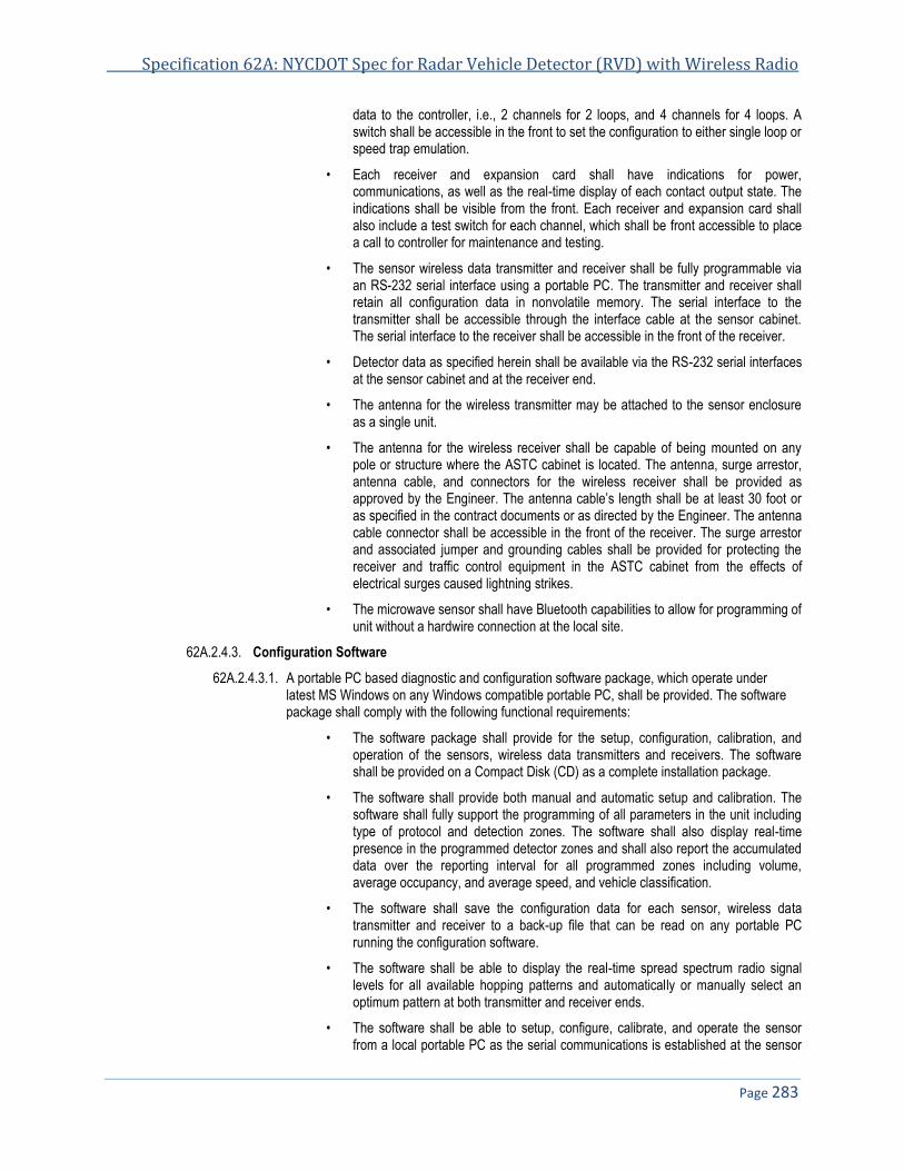
Specification 62A: NYCDOT Spec for Radar Vehicle Detector (RVD) with Wireless Radio
Page 283
data to the controller, i.e., 2 channels for 2 loops, and 4 channels for 4 loops. A switch shall be accessible in the front to set the configuration to either single loop or speed trap emulation.
• Each receiver and expansion card shall have indications for power, communications, as well as the real-time display of each contact output state. The indications shall be visible from the front. Each receiver and expansion card shall also include a test switch for each channel, which shall be front accessible to place a call to controller for maintenance and testing.
• The sensor wireless data transmitter and receiver shall be fully programmable via an RS-232 serial interface using a portable PC. The transmitter and receiver shall retain all configuration data in nonvolatile memory. The serial interface to the transmitter shall be accessible through the interface cable at the sensor cabinet. The serial interface to the receiver shall be accessible in the front of the receiver.
• Detector data as specified herein shall be available via the RS-232 serial interfaces at the sensor cabinet and at the receiver end.
• The antenna for the wireless transmitter may be attached to the sensor enclosure as a single unit.
• The antenna for the wireless receiver shall be capable of being mounted on any pole or structure where the ASTC cabinet is located. The antenna, surge arrestor, antenna cable, and connectors for the wireless receiver shall be provided as approved by the Engineer. The antenna cable’s length shall be at least 30 foot or as specified in the contract documents or as directed by the Engineer. The antenna cable connector shall be accessible in the front of the receiver. The surge arrestor and associated jumper and grounding cables shall be provided for protecting the receiver and traffic control equipment in the ASTC cabinet from the effects of electrical surges caused lightning strikes.
• The microwave sensor shall have Bluetooth capabilities to allow for programming of unit without a hardwire connection at the local site.
62A.2.4.3. Configuration Software
62A.2.4.3.1. A portable PC based diagnostic and configuration software package, which operate under latest MS Windows on any Windows compatible portable PC, shall be provided. The software package shall comply with the following functional requirements:
• The software package shall provide for the setup, configuration, calibration, and operation of the sensors, wireless data transmitters and receivers. The software shall be provided on a Compact Disk (CD) as a complete installation package.
• The software shall provide both manual and automatic setup and calibration. The software shall fully support the programming of all parameters in the unit including type of protocol and detection zones. The software shall also display real-time presence in the programmed detector zones and shall also report the accumulated data over the reporting interval for all programmed zones including volume, average occupancy, and average speed, and vehicle classification.
• The software shall save the configuration data for each sensor, wireless data transmitter and receiver to a back-up file that can be read on any portable PC running the configuration software.
• The software shall be able to display the real-time spread spectrum radio signal levels for all available hopping patterns and automatically or manually select an optimum pattern at both transmitter and receiver ends.
• The software shall be able to setup, configure, calibrate, and operate the sensor from a local portable PC as the serial communications is established at the sensor
NYCDOT Specifications for Traffic Signals & ITS Systems November 2013
Page 284
cabinet or from a remote portable PC as the serial communications is established at the receiver end. The software on the remote portable PC shall be able to configure and operate multiple reporting sensors and retrieve detection data from them at the receiver end. Configuring one sensor shall not disturb the operation of other reporting sensors.
62A.2.5. Mechanical Requirements
62A.2.5.1. Microwave Sensor
62A.2.5.1.1. The sensor enclosure shall be a weather resistant box of cast aluminum, stainless steel, or polycarbonate meeting minimum NEMA requirements for a 4X Type enclosure and suitable for mounting on either a pole or other structure fabricated out of aluminum, steel, concrete, stone, or wood. The cables and harness shall enter at the rear and/or the bottom of the enclosure with sealing gaskets at entry points to prevent air and moisture entry. Maximum overall dimensions including fittings shall not exceed 14 in x 11 in x 6 in. Maximum weight of the sensor including wireless transmitter and antenna shall not exceed 5 pounds.
62A.2.5.2. Sensor Cabinet
62A.2.5.2.1. Outside dimensions of the cabinet shall not exceed 8 inches high, 8 inches wide and 7 inches deep or as approved by the Engineer. All dimensions are outside finished measurements. Maximum weight of the sensor cabinet shall not exceed 5 pounds. The cabinet material shall be at least 0.125 inches thick and adequately reinforced. The cabinet shall be furnished with a color approved by the Engineer.
62A.2.5.2.2. Cabinet housing shall be weather resistant, non-corrosive, water and dust resistant, and fabricated from reinforced polycarbonate (or other material as approved by the Engineer) meeting as a minimum NEMA requirements for a 4X Type enclosure. All construction shall be free of dents, scratches, and abrasions harmful to the strength and general appearance. There shall be no sharp edges or protrusions on the cabinet whether open or closed which might pose a risk of personnel cuts or injury. All sharp edges shall be sanded and de-burred.
62A.2.5.2.3. The sensor cabinet shall include a ½” standard electrical weather resistant connector mounting hole at the bottom of the box and a 1½” electrical conduit entry hole. The 1½” hole shall have room around it to allow installation of a standard traffic cast aluminum lock nut (see the specification drawing SE-010). The cabinet shall have two flared leg mount bracket suitable for use with ¾” stainless steel banding. The bracket shall be threaded with threaded 5⁄16"-18 center hole. Slot length shall be 0.81" and accept strap up to 3⁄4". The cabinet shall be installed with strap to secure to 4" O.D. or larger poles. All cables and harness shall enter the cabinet with sealing gaskets at entry points to prevent air and moisture entry.
62A.2.5.2.4. The cabinet housing shall have a door, securely gasketed, which shall include substantially the full area of the front of the cabinet. The design of the door and gasket shall be such that the integrity of the gasket material shall not be required to ensure that the internal cabinet equipment and cabling are protected from water damage under adverse environmental conditions. Cabinet door assemblies shall be designed in such a way that damaged gaskets do not allow water to enter the cabinet. Gasket material shall be continuous along the entire top of the cabinet door with no seams or joints in this section. Gasketing shall be provided on all door openings with contact cement for a permanent bond and shall be of dust-tight permanent type that will not peel off or deteriorate. The gasket material shall be UV resistant and shall not be damaged by normal cabinet cleaning agents and solvents normally used to remove graffiti from the exterior of the cabinet.
62A.2.5.2.5. The door shall be equipped with one (1) stainless steel padlock latch on the right side of the cabinet when looking at the front of the cabinet. A padlock with two (2) keys shall be provided with each cabinet or as directed by the Engineer.
62A.2.5.2.6. The cabinet shall be pre-installed with a 1/8” minimum thickness aluminum back panel. The removal of aluminum back panel shall not be required when accessing either electrical entry point. All mounting hardware shall be appropriately sized stainless steel hardware.

Specification 62A: NYCDOT Spec for Radar Vehicle Detector (RVD) with Wireless Radio
Page 285
62A.2.5.2.7. The sensor cabinet shall not be used for any other equipment such as data converters, transformers, etc.
62A.2.5.3. Wireless Data Receiver and Expansion Cards
62A.2.5.3.1. The wireless receiver and expansion cards shall be designed for mounting into a Type 170 input file rack and shall comply with NYCDOT ASTC Procurement Specification Version 2.6 Section 2.8.6.
62A.2.5.4. Wireless Antenna for Wireless Data Receiver
62A.2.5.4.1. The wireless antenna for the wireless data receiver shall be designed for mounting on a traffic signal, streetlight, or wood pole or a traffic signal mast arm. The antenna shall be provided as recommended by the manufacturer and as approved by the Engineer. All antenna mounting hardware shall be vandal proof and approved by the Engineer.
62A.2.5.5. Surge Arrestor for Wireless Data Receiver
62A.2.5.5.1. The surge arrestor for the wireless data receiver shall be provided for surface mounting inside the ASTC cabinet as approved by the Engineer. Maximum overall dimensions including fittings shall not exceed 3 in x 2.5 in x 1 in. Maximum weight shall not exceed 0.7 pounds.
62A.2.6. Environmental Requirements
62A.2.6.1. The design for the microwave sensor, wireless data transmitter, antenna, surge arrestor, wireless data receiver and expansion cards, and associated devices in the sensor cabinet shall meet all its specified requirements without the need to reprogram during and after being subjected to any combination of the following conditions:
• The ambient temperature range shall be between –34 F and 165 F. • Relative humidity from 5 to 95 %, non-condensing.
62A.2.6.2. The microwave sensor and wireless antenna shall also meet the following requirements: • Precipitation (rain or snow) up to 100 millimeters per hour. • Vibration: NEMA TS2 – 2.1.9 or approved equivalent. • Shock: NEMA TS2 – 2.1.10 or approved equivalent.
62A.2.7. Equipment Labeling
62A.2.7.1. The sensor cabinet shall also be identified by model number, a serial number and NYCDOT on a permanent metal plate visible on the inside of the cabinet. Consecutive serial numbers shall also be stamped on the metal name identification plate and fastened to the inside of the cabinet by rivets which shall not protrude or otherwise be visible on the exterior of the cabinet. Approval is required by the Engineer.
62A.2.7.2. All equipment shall be clearly and permanently labeled as the property of NEW YORK CITY with a unique and consecutive serial number and make and model number and manufacturer’s name as approved by the Engineer. These shall be visible from the exterior of the equipment and without disassembly of the unit.
62A.2.7.3. NYCDOT requires that each separate procurement contract or construction contract have serial numbers which are unique and identifiable. The Contractor shall work with the Engineer to establish a numbering scheme that allows NYCDOT and its maintenance Contractors to quickly identify the specific contract which provided the equipment. This shall be required for all equipment furnished under this Specification so that the City can identify the origin of the part and determine which Contractor is responsible for its maintenance.
62A.3. Electrical 62A.3.1. Power Requirements
62A.3.1.1. Microwave Sensor - The sensor unit shall operate on 115 20 VAC @ 60 Hz power and consume no more than 10 W. Surge protection shall comply with NEMA TS2-2.1.7 & 2.1.8.

NYCDOT Specifications for Traffic Signals & ITS Systems November 2013
Page 286
62A.3.1.2. Sensor Cabinet - The sensor cabinet shall be furnished with the following equipment pre-installed on the cabinet back plane:
62A.3.1.2.1. The incoming power conductors shall be terminated at a screw type terminal block with pressure pad rated for solid wire. The terminal block shall be mounted onto the aluminum back panel and shall not require encircling the wire around the screw. The screws shall be of Brass with nickel plating rated for 30 Amps @ 120 VAC and be able to accept a 2c-10b power cable (Item 60000B).
62A.3.1.2.2. One (1) AC surge protector installed on the incoming power line. The surge protector shall be capable of reducing the effect of transient voltages applied to the AC line and provide filtering. Gas-discharge devices shall not be used in the protector. The surge protector shall be epoxy-encapsulated in a flame-retardant material and enclosed in a metal housing. The surge protector shall be wired to the load side of the circuit breaker and wiring to and from the surge protector shall be kept as short as possible.
Normal Mode Surge Protection (Line to Neutral)
Peak Current 20 Kilo-amperes (8x20 microsecond wave shape)
Life Test 5x maximum voltage clamp change before and after 25 20 Kilo-ampere surges (8x20 millisecond wave shape)
Clamp Voltage 300 Volts Max at 20 Kilo-ampere surge; Voltage across device never exceeds 300 V during surge.
Response Time Less than 5 ns
Common Mode Surge Protection (Neutral to Earth Ground)
Clamp Voltage 700 Volts max at 20 Kilo-amperes maximum (8x20 microsecond wave shape)
Operating Characteristics
Temperature Range -40 to +85 Celsius
Continuous Service Current 10 Amperes maximum at 120 VAC 60 Hz through series filter
MIL-STD 220 Insertion Loss Specification for Series Filter
Frequency of Applied Signal Insertion Loss (dB)
60 Hz 0
10KHz 34
50KHz 55
100KHz 76
500KHz 76
2MHz 68
5MHz 58
10MHz 58
20MHz 63
62A.3.1.2.3. One (1) AC circuit breaker rated for 15 Amps. The circuit breaker shall be an automatic trip,
short delay and trip indicating type approved and listed by UL. The trip and frame size shall be plainly and permanently marked. The circuit breaker shall be a magnetic switch type breaker with overload trip point unaffected by temperature. Minimum interrupting capacity shall be 5000 Amps, RMS.
62A.3.1.2.4. One (1) RS-232 serial port for connection with a portable PC. The serial port shall be metal shell 9-pin “D” subminiature type connector with male contacts that have 15 millionths of an inch minimum gold plating in the mating area. The connector shall be equipped with two screw sockets to accept commonly used screw down retention hardware. The construction shall be such that the retention nuts which are affixed to the connectors shall not come loose or

Specification 62A: NYCDOT Spec for Radar Vehicle Detector (RVD) with Wireless Radio
Page 287
unscrew. The connector shall be electrically isolated from the power line and surge protected within the sensor unit.
62A.3.1.2.5. The AC+ of the incoming power terminal block shall be connected to the AC circuit breaker input. The breaker load side shall feed the AC surge protector. The AC surge protector load side shall be connected to the sensor unit via an appropriately sized in-line fuse. The in-line fuse holders/fuses shall be Bussmann Type HEB, 600V with type KTK fuses or approved equal. The natural and ground wires shall be connected to the AC surge protector using approved connectors. All AC and equipment ground wiring shall be bounded together using an approved connector. All internal cabinet wiring shall be rated for 30 Amps and shall be approved and listed by UL. Drawings for the cabinet equipment layout shall be submitted to the Engineer for review and approval as part of the cabinet shop drawing submission specified herein.
62A.3.1.3. Wireless Data Receiver and Expansion Cards
62A.3.1.3.1. The wireless data receiver and expansion cards shall comply with the transient and power interruption requirements specified in NYCDOT ASTC Procurement Specification Version 2.6 Section 3.4.1.
62A.3.1.3.2. The receiver and expansion cards shall not draw more than 100 mA of current for one slot, and no more than 200 mAmp for two slots on the ASTC input file from the 24 VDC power supply.
62A.3.1.3.3. The receiver and expansion cards shall use the Type 170 22-Pin edge connector. Pin C on the 22-pin edge connector shall cause the unit to execute a system reset for electronics, and pins F, S, W, and Y shall be used for 4 loop emulation outputs to the ASTC controller. The remaining pins shall conform to ASTC standard for input file wiring. All outputs shall be optically isolated.
62A.3.1.3.4. In the event of an interruption in power to the sensor, transmitter, or receiver, the unit shall automatically recover within three minutes after power has been restored such that all configuration parameters are returned to their last known configuration before power disruption. No manual intervention shall be required.
62A.3.2. Cables
62A.3.2.1. Interface Cable
62A.3.2.1.1. A 3 foot composite shielded interface cable shall be provided with each microwave sensor to provide power from the sensor cabinet to the microwave sensor unit and the RS-232 serial interface. The cable shall be designed for outside use, shall use stranded wire and shall connect the microwave sensor to the sensor cabinet with no additional splices for all project locations. All cable conductors on the non-connectorized side shall be clearly labeled and color-coded for function and voltage. Unused wires shall be clearly labeled and fully covered with a Scotch #33 electrical tape or approved equivalent.
62A.3.2.1.2. The cable shall terminate in a metal MS connector rated for outdoor usage on the sensor side. The sensor cabinet (non-connectorized) side of the cable shall be made as an assembly with a weather resistant ½” connector preinstalled at the ½” connector entry point at the bottom of the sensor cabinet and the cable shall be pre-installed at the factory and terminated at respective locations inside the sensor cabinet specified elsewhere. The interface cable shall also meet the requirements as noted below. A suitable cord end connector shall be provided for cabinet entry.
62A.3.2.2. Extended RS-232 Serial Cable - Twenty five (25) feet long RS-232 serial cable shall be provided with each sensor assembly for connection to the RS-232 serial port in the sensor cabinet. The cable shall be equipped with one female metal shell 9-pin “D” subminiature type connector at each end. The connectors shall be equipped with two holding screws and shall mate with the serial connector in the sensor cabinet.
62A.3.2.3. All cables shall be of sufficient length such that the cable and connector are not strained during normal operation. Cables shall be covered with an outer jacket and shall remain flexible at all ambient temperatures.

NYCDOT Specifications for Traffic Signals & ITS Systems November 2013
Page 288
62A.3.2.4. All cables shall include sufficient slack to allow easy insertion and removal under adverse conditions without the need to remove other equipment to gain access to the cable.
62A.3.2.5. All cables shall be clearly labeled and permanently affixed at the termination connector so as to clearly indicate the insertion orientation and intended socket/plug or device. Labels shall be legible and match the Contractor supplied wiring diagrams.
62A.3.2.6. Cables shall be protected from damage caused by contact with sharp edges during shipping, servicing, and normal use.
62A.3.2.7. Cables shall not become “stiff” and difficult to manipulate at ambient temperatures normally experienced in New York City.
62A.3.2.8. Cables shall be UV-resistant and provide multiple twisted pairs of stranded size 20 or 22 AWG wire with a common shield rated at 300V with a temperature rating of 105 C.
62A.3.2.9. The MS connector pins must be crimped to the cable conductors and assembled and tested prior to installation.
62A.3.2.10. Coaxial Cables - Thirty (30) feet of coaxial cable type LMR 400-DB or approved equal shall be provided with each microwave sensor. The cable shall be supplied in one length equal to the number of units on the order. Cable lengths over 100 foot shall be on a spool. A pair (2) of type N connectors shall be provided with each 30 foot length of cable the connectors shall uninstall. The connectors shall be of the crimp type requiring solder free installation. The connectors shall be Times microwave part number EZ-400-NMH-D or approved equal using a hex crimper with a diameter of 00.049 crimping die and not requiring crimping of the center conductor pin of the connector. Each 30 foot cable assembly shall be provided with a (1) cord end connector for pole entry type Hubbell/Kellems SHC1023 Strain Relief Cord Connector or approved equal.
62A.3.3. Printed Circuit Board (PCB)
62A.3.3.1. All printed circuit wiring shall be protected from damage which might be caused by short circuits in the field wiring, overloads, insertion and removal of assemblies and subassemblies, water entry to the cabinet, moisture, and defective components. Under no circumstances shall any field wiring error, equipment failure or other circuit failure cause damage to the current traces or connections on any printed circuit board. Special attention must be paid to all connectors and traces used for low current monitoring to ensure that printed circuit wiring cannot be damaged. The Contractor shall ensure that the conformal coating and masking are such that moisture cannot induce damage to the printed circuit wiring. All printed circuit boards shall meet the following requirements to enhance reliability:
• All plated-through holes and exposed circuit traces shall be plated with solder.
• Both sides of the printed circuit board shall be covered with a solder mask material.
• The circuit reference designation for all components and the polarity of all capacitors and diodes shall be clearly marked adjacent to the component. Pin #1 for all integrated circuit packages shall be designated on both sides of all printed circuit boards.
• All electrical mating surfaces shall be gold plated.
• All printed circuit board assemblies shall be coated on both sides with a clear moisture-proof and fungus-proof sealant with a UV tracer.
• All components and wire harnesses shall be mounted to the PCB using plated holes. "Piggy back" connections or jumper wires shall not be acceptable.
62A.4. Quality Assurance 62A.4.1. Unless otherwise specified, the Contractor shall be responsible for all inspection requirements prior to
submission for the City of New York inspection and acceptance. The City of New York reserves the right to perform any additional inspections deemed necessary to assure that the equipment conforms to the requirements specified herein. The City of New York reserves the right to have its representatives witness all
Specification 62A: NYCDOT Spec for Radar Vehicle Detector (RVD) with Wireless Radio
Page 289
factory tests. The results of each test performed by the manufacturer shall be compared with the requirements specified herein. Failure to conform to requirements for any test shall be counted as a defect, and the equipment shall be subject to rejection. Rejected equipment may be offered again for retest provided all non-compliance has been corrected and re-tested by the Contractor. Final inspection and acceptance of equipment shall be made after delivery at destination specified unless otherwise stated.
62A.4.2. All equipment furnished under this Specification shall be approved by NYCDOT prior to the purchase. The Contractor shall submit the manufacturer names, equipment model numbers, catalog cut sheets, and other descriptive materials for all equipment and components proposed under this pay item for approval by the CITY.
62A.4.3. The Contractor may provide demonstration showing conformance to the NTCIP requirements specified herein. This shall be performed using an NTCIP tester such as NTester (Trevilon) or Device Tester (Intelligent Devices) and appropriate test scripts. The test procedure and test scripts shall be submitted to the City for approval prior to the demonstration.
62A.4.4. Three (3) randomly selected samples shall be delivered for inspection and testing within forty five (45) consecutive calendar days after notice from NYC Department of Transportation and upon receipt of this notice, the Contractor shall also submit six (6) complete sets of working drawings to the Department. Failure to submit the samples and drawings within the time specified will be sufficient reason to declare the Contractor not in compliance and ineligible for award of Contract.
62A.4.5. Documentation and Shop Drawings
62A.4.5.1. The Contractor shall provide complete maintenance and operation manual, which includes schematics, component layout, bill of materials with generic manufacturer’s part numbers, assembly and disassembly instructions, calibration procedures, exploded assembly drawings, protocol documentation, and complete instructions for the installation and use of the portable PC setup and calibration procedures. Documentation shall be bound.
62A.4.5.2. The Contractor shall provide the setup and configuration software on a Compact Disk (CD) including automatic installation and removal procedures along with the Contractor supplied equipment without additional charges. The Department shall have the right to copy and install the software as necessary to support the setup, maintenance, and operation of the microwave sensor, wireless transmitter and receiver for NYCDOT or contract maintenance personnel.
62A.4.5.3. The Contractor shall prepare shop drawings detailing the complete microwave sensor, wireless data transmitter and receiver assembly, all components to be supplied and the mounting hardware. These drawings shall detail typical placement of each sensor at all structure mounting and aiming configurations and show the proposed height the unit is mounted at, the proposed detection zone and hardware mounting methods. These drawings shall include details of the installation of the interface cable from the sensor to the sensor cabinet, including the RS-232 and contact closure output terminations. These drawings shall also detail typical installations of the wireless data receiver and associated equipment at the ASTC cabinet. All drawings shall not exceed 11”x17” and shall foldout where required. An electronic version of the drawings shall be provided on a CD based on AutoCAD 2000 (or latest version) application software for a personal computer.
62A.4.5.4. The number of hard copies of the documentation to be provided shall be at least one per trainee and not less than 10 with each order. The documentation shall also be provided on CD and the NYCDOT shall have the right to make whatever copies are necessary to support the use and maintenance of the sensor, wireless transmitter and receiver.
62A.4.5.5. All protocols used for the setup, configuration, and operation of the microwave sensor, wireless data transmitter and receiver shall be fully and completely documented. Undocumented messages and data elements are prohibited. This information shall include all messages, configuration information, timing, and sequences of messages. Such information shall be complete and cover all aspects of the sensor operation and wireless communications including setup and error conditions.
62A.4.5.6. Reproducible shop drawings of the electrical schematics and mechanical details for the unit and all mounting configurations shall be supplied to the Engineer and/or with the delivery of the equipment.

NYCDOT Specifications for Traffic Signals & ITS Systems November 2013
Page 290
62A.5. Guarantee 62A.5.1. The Contractor guarantees that all articles of equipment including all parts thereof are of the first quality
throughout and comply in all respects or are fully equal to standards called for in the specification. The Contractor further guarantees all equipment, and all parts thereof against any defects of workmanship, construction and materials, and guarantees to repair or replace without cost to the City of New York any article that had become defective, and not proven to have been caused by negligence on the part of the user, within a period of twenty four (24) months of in service operation following the initial date equipment is installed, tested, placed in service, and accepted by the Engineer. However, said guarantee shall not exceed three (3) years from the date of acceptance. A guarantee certificate shall be supplied for each component from the designated depot repair site indicating the start and end dates of the warranty. The guarantee certificate shall name NYCDOT as the recipient of the service. NYCDOT shall have the right to transfer this service to other private parties who may be contracted to perform overall maintenance.
62A.5.2. The guarantee shall include repair and/or replacement of all failed components via a factory authorized depot repair service. All items sent to the depot for repair shall be returned within two weeks of the date of receipt at the facility. The depot location shall be in the United States. Repairs shall not require more than two (2) weeks from date of receipt and the provider of the warranty shall be responsible for all shipping costs. The depot maintainer designated for each component shall be authorized by the original manufacturer to supply this service.
62A.5.3. In the event of failure on the part of the Contractor to replace or put in first-class condition any such articles within thirty (30) calendar days from the date of notice, the City of New York may have the work done by others and charge the cost to money due, or if there be no money due, the Contractor agrees to pay the City of New York such costs.
62A.6. Crating 62A.6.1. Each complete microwave sensor, antenna, surge arrester, wireless data receiver and expansion cards, and
associated equipment and cables shall be packed in an approved shipping carton. The packaging shall be such as to prevent damage during delivery or storage to a height of fifteen (15) feet.
62A.6.2. The cartons shall be plainly identified at the top end and one side as to the type of equipment, purchase order numbers, manufacturer's name and the year of manufacture.
62A.7. Delivery 62A.7.1. All deliveries except samples shall be made to the Department’s Warehouse (loading bays 5 and 6) at 66-26
Metropolitan Ave in Middle Village (Queens), NY 11379, any other locations within the limits of the City of New York designated by the Department, or as directed by the Engineer. Material/equipment will be accepted between the hours of 8:00 AM and 12:00 PM with unloading to be completed before 3:00 PM, Monday thru Friday, except holidays. The Contractor must notify the Department at least 24 hours in advance of delivery.
62A.7.2. The production samples shall be delivered to the NYCDOT ITS LAB room 122 34-02 Queens Boulevard, Long Island City (Queens), NY 11101, within delivery time frame as directed by the Engineer.
62A.7.3. The Contractor shall deliver material to a designated storage point and shall unload and stack material under the direction of the warehouse supervision.
62A.7.4. The Contractor shall furnish all labor, dunnage, blocking, wedges and other equipment necessary for the safe delivery, stacking and storing of material under this Specification to a height of fifteen (15) feet, satisfactory to the Department.
62A.7.5. The Contractor shall pre-pay all transportation, handling and delivery charges associated with this Specification including repair return and delivery.

Specification 62A: NYCDOT Spec for Radar Vehicle Detector (RVD) with Wireless Radio
Page 291
62A.8. Training 62A.8.1. The Contractor shall provide training courses at a location in NYC to be designated by the Department over a
1 day period of 7 hours for two (2) identical training sessions. Each of the training sessions shall accommodate up to 10 people. Qualified representatives of the Contractor and sensor manufacturer shall teach the course. The course shall cover all aspects of sensor mounting, configuration, operation and maintenance with hands on demonstration of all topics using actual sensors and test equipment. The Contractor shall furnish all course materials for each individual and supply all necessary demonstration sensor and test equipment for the course. A course outline shall be furnished to the Engineer for approval 30 days prior to the start of the course.
END OF SPECIFICATIONS FOR RADAR VEHICLE DETECTOR WITH WIRELESS RADIO


Specification 62BIU
NYCDOT Specification for Radar Vehicle Detector (RVD) Bus Interface Unit (BIU)
Date of Revision Revised by Description
5/20/09 New spec

NYCDOT Specifications for Traffic Signals & ITS Systems November 2013
Page 294
62BIU. NYCDOT SPECIFICATION FOR RADAR VEHICLE DETECTOR (RVD) BUS INTERFACE UNIT (BIU) .................. 295 62BIU.1. GENERAL .................................................................................................................................................................... 295 62BIU.2. DESIGN ....................................................................................................................................................................... 295 62BIU.3. SIGNAL INPUTS ............................................................................................................................................................ 296 62BIU.4. ISOLATED INPUTS ........................................................................................................................................................ 296 62BIU.5. POWER ....................................................................................................................................................................... 296 62BIU.6. OPERATION ................................................................................................................................................................. 296 62BIU.7. BIU-S EXTERNAL INPUTS VIA SERIAL CONNECTOR ........................................................................................................ 296

Spec 62BIU: NYCDOT Spec for Radar Vehicle Detector (RVD) Bus Interface Unit (BIU)
Page 295
62BIU. NYCDOT Specification for Radar Vehicle Detector (RVD) Bus Interface Unit (BIU)
62BIU.1. General 62BIU.1.1. The Bus Interface Unit (BIU) shall be of the NEMA TS 2 type meeting all minimum requirement set forth
by NEMA in Technical Spec. #2 dated 2003 and all requirements of NYC ASTC procurement spec version 3.13.3 dated Nov 2009. In addition to those requirements this BIU will add the following functionality to the standard NYC BIU. Running at 60HZ as opposed to industry standard 10 HZ BIU, the detector BIU will add an extra RS232 Port for mapping System detector inputs (Ports 33-64) from an external serial source which in this case is a wireless microwave sensor commonly used within NYC.
62BIU.2. Design 62BIU.2.1. The BIU shall be used in place of a standard ASTC BIU taking the same space and maintain full
operational functionality. The BIU utilizes a 32-bit processor and is in full compliance with NEMA TS2 Standards for the interface, power, environmental, electrical and physical hardware requirements. The BIU is powered by the same 24 VDC power supply as a standard BIU external to the ASTC Controller Unit. The front panel contains a handle for easy removal and insertion of the unit, power on and transmit status indicators, a 15-pin female Port 1 connector and an optional RS232 connector. The BIU interfaces to the Port 1 facilities termination panel through a 15-pin metal shell D sub miniature type connector that is equipped with latching blocks. Connection to the Terminal and Facilities (TF) backpanel or card rack is provided by a 64 pin DIN 41612 type B series connector.

NYCDOT Specifications for Traffic Signals & ITS Systems November 2013
Page 296
62BIU.3. Signal Inputs 62BIU.3.1. Each BIU provides eight DC inputs, four optically isolated inputs, 24 assignable input/output pins, 15 DC
outputs and four address select inputs.
62BIU.4. Isolated Inputs 62BIU.4.1. Four optically isolated inputs for use with pedestrian detector inputs or remote hardwired interconnect
inputs. The optic inputs are intended for direct connection to 12VAC from the cabinet power supply when used with pedestrian pushbuttons. 120VAC interconnect inputs are interfaced through external 27KΩ, 1 Watt resistors. Temperature: -30° F to 165° F (-34° C to 74° C)
62BIU.5. Power 62BIU.5.1. 18 to 30 VDC, 200 mA
62BIU.6. Operation 62BIU.6.1. The TS2 Controller Unit communicates through the BIUs based on the digital addressing of each BIU.
Each BIU shall be capable of having their logical position and subsequent cabinet functions, assignable through specific address select inputs. This cabinet function flexibility allows for cabinet expansion, enhances reliability and provides a standard interface with the NYC ASTC.
62BIU.7. BIU-S External Inputs via Serial Connector 62BIU.7.1. The ‘S’ option for the NYC Bus Interface Unit adds a second serial port to the front panel of the BIU, a 9-
pin D substandard RS232 port. The purpose of this second port is to allow input of data from an external input aggregator, such as a detector hub, to be routed to the TS2 Type 1 traffic controller. Depending on the mapping defined in the BIU firmware, these inputs can be used for a wide range of purposes. One currently available mapping can handle the serial signal from a wireless microwave sensor/detector hub, mapping the hub’s 32 outputs to the BIU’s Detector 33 through 64 inputs. This is an easy and efficient way to bring other types of detection, particularly mid-block volume data, into a TS2 controller for Adaptive Control scenarios.
END OF SPECIFICATIONS RADAR VEHICLE DETECTOR BUS INTERFACE UNIT (BIU)

Specification 63
NYCDOT Specification for a Wireless Battery-Powered Magnetometer Vehicle Detection System for Presence
Detection Applications
Date of Revision Revised by Description
3/23/2010 New spec

NYCDOT Specifications for Traffic Signals & ITS Systems November 2013
Page 298
63. NYCDOT SPECIFICATION FOR A WIRELESS BATTERY-POWERED MAGNETOMETER VEHICLE DETECTION SYSTEM FOR PRESENCE DETECTION APPLICATIONS ................................................................................................. 299
63.1. OVERVIEW .................................................................................................................................................................. 299 63.2. FUNCTIONAL CAPABILITIES ........................................................................................................................................... 299 63.3. SENSOR HARDWARE .................................................................................................................................................... 301 63.4. ACCESS POINT (AP) HARDWARE .................................................................................................................................. 301 63.5. REPEATER (RP) HARDWARE ........................................................................................................................................ 302 63.6. CONTACT CLOSURE INTERFACE (CCI) CARD HARDWARE............................................................................................... 302 63.7. LIMITED WARRANTY ..................................................................................................................................................... 303 63.8. MAINTENANCE AND SUPPORT ....................................................................................................................................... 303 63.9. SUPPLIED EQUIPMENT ................................................................................................................................................. 303
Spec 63: NYCDOT Spec for a Wireless Battery-Powered VDS for Presence Detection Apps
Page 299
63. NYCDOT Specification for a Wireless Battery-Powered Magnetometer Vehicle Detection System for Presence Detection Applications
63.1. Overview 63.1.1. This specification sets forth the minimum requirements for a system to detect vehicles on a roadway by using
battery-powered magnetometer-type sensors that communicate by radio to a roadside communications hub before the data is relayed to a local traffic controller and, optionally, a central software system or a data server, as may be desired.
63.1.2. The detection system shall provide accurate roadway information, as needed to support traffic signal control.
63.1.3. The Wireless Battery-Powered Magnetometer Vehicle Detection System shall consist of one or more of the following:
63.1.3.1. Battery-powered sensors installed in-pavement in each traffic lane
63.1.3.2. Access Points (APs) mounted on the side of the roadway, serving as the communications hub for the installation
63.1.3.3. Optional wireless Repeaters (RPs) mounted on the side of the roadway, serving to extend the radio range of an AP.
63.1.3.4. Contact Closure Interface (CCI) cards to support the interface between an AP and a standard traffic controller using contact closure signals
63.1.3.5. Software to control and configure the sensors, APs, and RPs
63.1.3.6. Software to store and retrieve detection data.
63.1.4. Communications between the sensors and the AP or RP and between the RP and AP shall be via radio.
63.1.5. Detection data shall be relayed from each AP to a local traffic controller for real-time vehicle presence detection using contact closure signals.
63.1.6. As an option, data shall be capable of being relayed from each AP to a central software system or central server over standard IP (Internet Protocol) networks.
63.2. Functional Capabilities 63.2.1. Each sensor shall be installed in the roadway using the following procedure:
63.2.1.1. The roadway shall be core drilled to provide a 4” diameter hole, 2.25” deep.
63.2.1.2. A small layer of sand or epoxy sufficient to cover the bottom of the hole shall be applied.
63.2.1.3. The sensor shall then be placed on top of this layer of sand in the correct orientation as clearly marked on the sensor.
63.2.1.4. The sensor shall be fully encapsulated with the epoxy to the lip of the cored hole.
63.2.2. Each sensor shall detect a vehicle by measuring changes in the earth’s magnetic field near the sensor as caused by a stopped or passing vehicle (i.e., magnetometer-type detection).
63.2.2.1. The sensor shall sample the earth’s magnetic field at a rate of 128 Hz.
63.2.2.2. The sensor shall communicate time-stamped ON and OFF vehicle detection events.
63.2.2.3. As an option, the sensor shall provide a mode where the complete X-Y-Z magnetic signatures of detected vehicles are transmitted as data.
63.2.2.4. Each sensor shall automatically recalibrate in the event of a detector lock.

NYCDOT Specifications for Traffic Signals & ITS Systems November 2013
Page 300
63.2.3. Each sensor shall communicate by radio to a nearby AP or RP.
63.2.3.1. Each sensor shall transmit its detection data within 150 ms of a detected event.
63.2.3.2. Each sensor shall automatically re-transmit a detected event if no acknowledgement is received from the AP.
63.2.3.3. Each sensor may stop retransmission after 8 attempts.
63.2.3.4. Each sensor shall transmit a unique identifying code.
63.2.3.5. Each sensor shall respond within 100 seconds when the AP is powered on.
63.2.3.6. When no AP or RP is present or powered on, the sensors are not required to detect vehicles.
63.2.4. The radio links between each sensor and AP or RP and between each RP and AP shall conform to the following:
63.2.4.1. The physical layer of the radio links (i.e., the over-the-air data rate(s), modulation type(s), forward error correction, bit interleaving, channel coding, and other aspects of the transmitted signal) shall conform to published standards (e.g., IEEE, ITU-T, etc.).
63.2.4.2. The center frequencies, bandwidths, and transmit power levels of the radio links shall allow operation in an unlicensed frequency band.
63.2.4.3. Frequency channels shall be employed by the sensors, APs, and RPs to avoid interference with other devices operating in the unlicensed band.
63.2.4.3.1. Frequency channels shall be user-configurable.
63.2.4.3.2. At least 16 frequency channels shall be supported.
63.2.4.4. The link budget (i.e., transmit power plus transmit antenna gain plus receive antenna gain minus receive sensitivity, where receive sensitivity shall assume a 1% packet error rate) for all radio links shall be 93 dB or greater.
63.2.4.5. The maximum distance between a sensor installed in the roadway and an AP or an RP with a clear line-of-sight between devices shall be:
63.2.4.5.1. At least 150 feet/45.7 meters for an AP or RP installed 24 feet/7.3 meters above the roadway.
63.2.4.5.2. At least 100 feet/30.5 meters for an AP or RP installed 18 feet/5.5 meters above the roadway.
63.2.4.5.3. At least 75 feet/22.9 meters for an AP or RP installed 12 feet/3.7 meters above the roadway.
63.2.4.5.4. The maximum distance between an AP and an RP shall be at least 750 feet/228.6 meters when both units are installed 18 feet/5.5 meters above the roadway and with a clear line-of-sight between devices.
63.2.5. Each installation of the Wireless Battery-Powered Magnetometer Vehicle Detection System shall consist of one or more sensors installed in each traffic lane where presence detection is required, avoiding sources of magnetic noise such as underground power cables, overhead high tension power cables, light rail or subway tracks, and power generation stations and sub-stations.
63.2.5.1. The sensors shall be located as specified by the intersection plans, with each sensor’s supporting AP or RP installed no farther than the maximum range indicated in Article 63.2.4.5.
63.2.5.2. After losing radio contact because of stopped vehicles over or near the sensor, each sensor shall be capable of re-establishing the radio link with its supporting AP or RP in less than 2 seconds.
63.2.6. Each sensor in an installation shall be capable of being individually configured with its own sensitivity level.
63.2.6.1. A single sensor shall be capable of being configured with a sensitivity level that approximates the detection zone of a standard 6’ x 6’ (1.8m x 1.8m) inductive loop.
63.2.6.2. Each sensor shall be capable of being configured with relatively higher or lower sensitivity levels as may be required to detect bicycles, motorcycles, or light rail.

Spec 63: NYCDOT Spec for a Wireless Battery-Powered VDS for Presence Detection Apps
Page 301
63.2.6.3. Up to two sensors properly configured shall be capable of detecting bicycles in a designated bicycle lane.
63.2.7. An AP shall support the relay of sensor detection data through several interfaces as required by the application.
63.2.7.1. Detection data shall be communicated to a standard roadside traffic controller via Contact Closure Interface cards capable of being installed in standard contact closure input shelves, where the following controller types shall be supported:
63.2.7.1.1. Type 170
63.2.7.1.2. Type 2070 ATC
63.2.7.1.3. NEMA TS1
63.2.7.1.4. NEMA TS2
63.2.7.1.5. NYC ASTC
63.2.7.2. As an option, detection data shall be communicated over TCP/IP via an integrated 10/100BaseT Ethernet interface.
63.2.7.3. As an option, detection data shall be communicated as IP data over GSM-based cellular data services via an integrated GPRS cellular modem.
63.2.7.4. As an option, detection data shall be communicated as IP data over CDMA-based cellular data services via an integrated 1xRTT cellular modem.
63.2.7.5. The AP shall be capable of simultaneously communicating detection data via the contact closure interface, optional Ethernet interface, and optional cellular data modem interface.
63.2.8. Each sensor, AP, and RP shall be capable of accepting software and firmware upgrades.
63.2.9. The Wireless Battery-Powered Magnetometer Vehicle Detection System shall provide software operating on conventional portable PCs:
63.2.9.1. To support configuration of a sensor.
63.2.9.2. To support configuration of an AP.
63.2.9.3. To support configuration of an RP.
63.2.9.4. To store and retrieve detection data.
63.3. Sensor Hardware 63.3.1. All sensor components shall be contained within a single housing.
63.3.1.1. The sensor housing shall conform to NEMA Type 6P and IEC P68 standards.
63.3.1.2. The sensor components shall be fully encapsulated within the housing to prevent moisture from degrading the components.
63.3.1.3. The sensor housing shall be capable of being installed in a 4 inch (10 cm) diameter hole approximately 2 ¼ inch (5.7 cm) deep.
63.3.2. A sensor shall operate at temperatures from -37° F to 176° F (-38.3° C to 80° C).
63.3.3. A sensor shall be battery-powered with an average lifetime of ten (10) years when the sensor is configured for and operating under normal traffic conditions.
63.4. Access Point (AP) Hardware 63.4.1. An AP shall support at least 48 sensors.
63.4.2. An AP shall be factory-configurable to support at least two (2) different power options:

NYCDOT Specifications for Traffic Signals & ITS Systems November 2013
Page 302
63.4.2.1. Power shall be supplied via an isolated nominal 48 VDC (36-58 VDC) input, consuming a maximum of 3 W and providing 1500 V isolation and 5 kV surge protection.
63.4.2.2. Power shall be supplied via a non-isolated nominal 12 VDC (10-15 VDC) input, consuming a maximum of 2W.
63.4.3. An AP shall operate at temperatures from -37° F to 176° F (-38.3° C to 80° C).
63.4.4. All AP components shall be contained within a single housing.
63.4.4.1. The AP housing shall conform to NEMA Type 4X and IEC IP67 standards.
63.5. Repeater (RP) Hardware 63.5.1. An RP shall support at least 10 sensors.
63.5.2. An RP shall be battery-powered.
63.5.3. The RP battery shall be field replaceable.
63.5.4. An RP shall operate at temperatures from -37° F to 176° F (-38.3° C to 80° C).
63.5.5. All RP components shall be contained within a single housing.
63.5.5.1.1. The RP housing shall conform to NEMA Type 4X and IEC IP67 standards.
63.6. Contact Closure Interface (CCI) Card Hardware 63.6.1. Each CCI card shall provide detector data as contact closure signals to the traffic controller.
63.6.1.1. A CCI card shall directly plug in to standard 170/2070 input files or NEMA detector racks.
63.6.1.2. One or more CCI cards shall provide up to 256 channels of detection data from a single AP’s supported sensors, where each channel comprises an optically isolated contact closure relay and, if configured for TS2 operation, an additional contact closure relay to indicate the channel status.
63.6.2. Each CCI card shall be configurable.
63.6.2.1. A CCI card shall provide contact closure signals in either presence or pulse mode.
63.6.2.2. A CCI card shall provide up to 31 seconds of delay timing.
63.6.2.3. A CCI card shall provide up to 7.5 seconds of extension (carryover) timing.
63.6.3. The CCI card front panel shall provide status LEDs to monitor:
63.6.3.1. Detection channel status
63.6.3.2. Line Quality
63.6.3.3. Fault Monitor.
63.6.4. The CCI card front panel shall provide switches to select and configure:
63.6.4.1. Presence or pulse mode
63.6.4.2. Delay timing
63.6.4.3. Extension timing.
63.6.5. A CCI card shall be powered by the traffic controller backplane via an 11-26 VDC input.
63.6.6. A CCI card shall be surge protected to GR-1089 standards.
63.6.7. A CCI card shall operate at temperatures from -37° F to 176° F (-38.3° C to 80° C).
63.6.8. A CCI card shall operate in humidity up to 95% (non-condensing).

Spec 63: NYCDOT Spec for a Wireless Battery-Powered VDS for Presence Detection Apps
Page 303
63.7. Limited Warranty 63.7.1. The supplier shall provide a limited two-year warranty for the Wireless Battery-Powered Magnetometer
Vehicle Detection System.
63.7.2. During the warranty period, technical support shall be available from the supplier via telephone within 24 hours of the time a call is made by a user, where this support shall be provided by factory-authorized personnel or factory-authorized installers.
63.7.3. During the warranty period, standard updates to the software shall be available from the supplier without charge.
63.8. Maintenance and Support 63.8.1. The supplier shall maintain a sufficient inventory of parts to provide support and maintenance of the system,
where these parts shall be available for delivery within 30 days of receipt of a purchase order by the supplier at the supplier’s then-current pricing and terms of sale.
63.8.2. The supplier shall maintain an ongoing program for customer support for the system via telephone, email, or trained personnel sent to the installation upon receipt of a purchase order at the supplier’s then-current pricing and terms of sale for technical support services.
63.8.3. Installation and/or training support shall be provided by a factory-authorized representative.
63.9. Supplied Equipment 63.9.1. Each order shall consist of the following minimum equipment to make a system:
63.9.1.1. One (1) Access point for contact closure serial interface for data collection
63.9.1.2. One (1) Access point mounting bracket
63.9.1.3. One (1) Master card for ASTC input rack
63.9.1.4. Four (4) Flush mounted wireless roadway sensor for stop bar detection
63.9.1.5. Four (4) Tubes of epoxy road way sealant
63.9.1.6. One (1) Epoxy dispenser gun (on orders over 5 systems 1 gun for the first 5 and one gun for every 5 after that
63.9.1.7. 25 foot cat 5 cable with RJ 45 booted connectors straight though connectors. Color is All Black UV Resistant outdoor/ underground direct burial rated
63.9.2. On orders that require additional roadway sensors, one tube of epoxy sealant shall be furnished for each roadway sensor.
63.9.3. On runs over 100 feet from the roadway sensor to the access point, a repeater shall be furnished.
END OF SPECIFICATIONS FOR A WIRELESS BATTERY-POWERED MAGNETOMETER VEHICLE DETECTION SYSTEM FOR PRESENCE DETECTION APPLICATIONS


Specification 64A
NYCDOT Specification for 16”x16” Polycarbonate Pedestrian Signal Housing with LED Lens
Date of Revision Revised by Description
5/1/2010 Electronic version
NYCDOT Specifications for Traffic Signals & ITS Systems November 2013
Page 306
64A. NYCDOT SPECIFICATION FOR 16”X16” POLYCARBONATE PEDESTRIAN SIGNAL HOUSING WITH LED LENS .... 307 64A.1. GENERAL .................................................................................................................................................................... 307 64A.2. HOUSING .................................................................................................................................................................... 308 64A.3. PAINTING .................................................................................................................................................................... 309 64A.4. VISOR (THIS SECTION INTENTIONALLY LEFT BLANK) ...................................................................................................... 309 64A.5. LENS........................................................................................................................................................................... 309 64A.6. OPTICAL SYSTEM (THIS SECTION INTENTIONALLY LEFT BLANK) ...................................................................................... 309 64A.7. GASKETS .................................................................................................................................................................... 309 64A.8. ELECTRICAL REQUIREMENTS ........................................................................................................................................ 310 64A.9. TESTING...................................................................................................................................................................... 310 64A.10. MATERIAL ................................................................................................................................................................... 310 64A.11. MISCELLANEOUS ......................................................................................................................................................... 310 64A.12. GUARANTEES AND WARRANTIES................................................................................................................................... 311 64A.13. SAMPLES .................................................................................................................................................................... 311 64A.14. DELIVERY, HANDLING AND TRANSPORTATION ................................................................................................................ 312 64A.15. POLYCARBONATE CASE-MATERIAL TESTS AND MATERIALS ............................................................................................ 312
Spec 64A: NYCDOT Spec for 16”x16” Polycarbonate Pedestrian Signal Housing with LED Lens
Page 307
64A. NYCDOT Specification for 16”x16” Polycarbonate Pedestrian Signal Housing with LED Lens
64A.1. General 64A.1.1. This Specification is for the production of a pedestrian signal electrically operated on 124 VAC 60 Hz. The
pedestrian signal shall be so designed that when mounted its orientation may be adjusted without removal from the brackets. The assembly shall display the International symbols “Upraised Hand” and “Walking Man” symbol in quantities detailed in the bid schedule. These messages shall be in the sequence and flashing schedule as developed by engineers. The material used in the unit shall be top quality, weather and sunlight resistant polycarbonate which has been high-pressure molded.
64A.1.2. The Contractor shall personally inspect and become familiar with the New York City approved-parts, brackets, assemblies and accessories prior to the submission of a bid. This is necessary so that the design of the signal will be compatible with the New York City approved parts and assemblies. The plastic unit, in total, will be interchangeable with currently used bracket equipment without any modifications or use of any additional parts. The pedestrian signal must be a functionally approved equal to the first designed for NYC.
64A.1.3. The Pedestrian Signal shall be completely assembled, and shall include: housing, an LED lens (by an approved manufacturer), "Marathon" type terminal block or approved equal, and all necessary wiring.
64A.1.4. Any part not mentioned in this specification, but necessary for the satisfactory functioning of the signal, shall be furnished by the Contractor as though that part was specified.
64A.1.5. This specification is not intended to include any proprietary items, circuits or devices which would preclude an equipment manufacturer from producing equipment to meet these requirements. All the tolerances, ratings and technically defined criteria contained within these specifications are considered to be within the current state of the art and are, now being met by commercially available equipment. All work shall be of the best character, including all labor, materials, plant tools, supplies and other means to furnish ail the equipment required by the specifications, contract drawing and other data provided.
64A.1.6. The Contractor would be held liable for and shall be solely responsible for any claims made against the City of New York and/or their agents and employees for any infringement of its patents by the use of equipment furnished by him or any part thereof for the use of patented tools, articles, appliances, structures, materials, devices of any process or method connected with the work or by use of any materials used upon the work he shall save harmless and indemnify the City of New York and their agents, servants and employees from and against all costs, expenses and damages which the City of New York and their agents shall incur or be obliged to pay by reason of any such infringement of claim and shall defend all such claims in connection with any alleged infringement.
64A.1.7. Should any equipment, or part, furnished by the Contractor be involved in a lawsuit or proceeding and should it be held to constitute infringement and its use be enjoined, then the Contractor, within a reasonable time afar request by the Department, and at the Department’s own expense, shall either secure for the City the right to continue using said equipment or replace it with non-infringing equipment at the Contractor's expense. This shall be done in a manner satisfactory to the Department. Should this not be accomplished, the City of New York has the right to revert to the next lowest bidder for equipment
64A.1.8. Interpretations Of Apparent Omissions - The apparent silence of the specification as to any detail, or the apparent omission from them of a detailed description concerning any work to be done and materials to be furnished, shall be regarded as meaning that only the best general practice is to prevail and that only the best material and workmanship is to be used. Materials supplied by and at the expense of the Contractor shall be the best of their respective lands suitable for use under the conditions prevailing in this work and shall conform to the latest specifications of the Electrical and Electronics Engineers, the Electronics Industries Association, the standard specifications of the American Society for Testing and Materials, the American Standards Association, and to the regulations of the National Board of Fire Underwriters, as they apply. If any of the requirements herein specified or shown on the plans conflict with or vary from any of above-mentioned specifications forming part of this Specification shall supersede the above-mentioned specification. All materials used shall be subject to the approval of the Engineer.

NYCDOT Specifications for Traffic Signals & ITS Systems November 2013
Page 308
64A.1.9. The Department reserves the right to reject any materials which are not approved by the Engineer.
64A.1.10. Any request by the Contractor for a variation from any provision in these specifications or on the drawings shall be made by letter to the Engineer clearly stating the page and paragraph, or drawing number he proposes to modify and what he proposes to substitute in lieu thereof.
64A.2. Housing
64A.2.1. Each pedestrian signal assembly shall consist of: a housing, LED pedestrian lens, “Marathon” type terminal block or approved equal, gaskets, and electrical system including the wiring.
64A.2.2. The housing shall be designed to accommodate the electrical and optical elements of the pedestrian signal in a weather resistant enclosure.
64A.2.3. The overall dimensions of the pedestrian signal housing shall be approximately 18½” wide and 9" deep including visor. The height of the housing, between the crests of the top and bottom serrated surfaces of the mounting bracket connections, shall be 163/8".
64A.2.4. The back of the housing shall be designed to provide sufficient clearance for orienting the signals when mounting two signals on City of New York Type "VB-2P" brackets.
64A.2.5. The top and bottom of the housing compartments shall have 2" diameter openings, concentric with the vertical geometric center line of the signal. There shall be a bossed ring, 9/32" wide, cast integrally with the housing compartment, around each of these 2" opening. The outside surfaces of the bosses shall have 72 clean and sharp identical serrations to mesh with those on the serrated tee on the specification drawing SE-007 brackets "VB-P" and "VB-2P", as detailed on the specification drawing set SE-021. The crest of the serrations shall be 3/8" from the outside surface of the signal housing.
64A.2.6. An Ethylene Propylene Diene Monomer (EPDM) gasket shall be provided for maintaining a sealed water resistant compartment when the door is bolted shut.
64A.2.7. The signal, especially the door hinges, shall be designed to withstand the reaction of the door dropping freely from the closed to completely open positions. The hinge attaching the door to the housing will be of such a design to provide strength and capability of replacement in the field. Approval of design to be made before sample is fabricated. All steel in hinges to be type 303 stainless steel.
64A.2.8. The door of the housing shall be made from polycarbonate. The door shall be held dosed by captured ¼”-20 stainless steel machine bolt with a tamper proof design. This design should be with a hexagonal indentation with a raised center. The size and type of the tool used to open the signal will be as commonly carried by technicians in the field. The machine bolts shall fit into brass bushings which are securely set into the polycarbonate housing. The use of hexagonal socket wrench shall be required to open the signal for bulb replacement and cleaning socket wrench shall be 0.187" across the flats and one Allen wrench supplied for every 50 pedestrian signals.
64A.2.9. The housing shall be manufactured from the finest weather resistant polycarbonate. UV stabilizers must be used when available to reduce color change due to exposure to the elements.
64A.2.10. Wherever practicable aluminum components of the polycarbonate signal should be interchangeable with the units currently in use.
64A.2.11. Alternative housing designs and construction will be considered for approval by the Engineer. All construction shall be free of defects in manufacturing harmful to the strength and general appearance of the pedestrian signal.
64A.2.12. All seams shall be of weather resistant construction and mechanically sound.
64A.2.13. Material certificates from the manufacturer shall be furnished certifying that all materials used in the construction of the housing complies with the requirements of these specifications.
64A.2.14. Reinforcement of the housing shall be made at the serrated rings, and hinges and where the bolts used to close the unit are located.
Spec 64A: NYCDOT Spec for 16”x16” Polycarbonate Pedestrian Signal Housing with LED Lens
Page 309
64A.2.15. The housing top shall be fabricated so as to prevent standing of water, and shall be so constructed so as to shield the top of the housing door, thereby preventing water from entering between the top door gasket and the cabinet.
64A.2.16. Door opening will have required fabrication to increase strength around the opening. An arrangement to be provided at top of housing that will prevent dust, liquids and other debris from dropping into enclosure when the door is opened.
64A.2.17. The manufacturer developing the pedestrian signal design is directed to consider the heat buildup inside the housing and its effect on all parts. Techniques are required to dissipate excess heat; they are to be submitted prior to sample submission for review and approval.
64A.2.18. Gaskets shall be provided around all door openings. The gaskets shall be of a dust-tight permanent type that will not peel off or deteriorate. Gaskets shall be closed cell EPDM material and shall be installed with contact cement for a permanent bond to the full periphery of the opening. The mating surface of gaskets shall be sprayed with lubricant to prevent sticking to said mating surface. Lubricant to be that suggested by industry for the said usage.
64A.3. Painting
64A.3.1. The housing should be made from a polycarbonate material which is a cast solid yellow. Thus this material should not need to be painted.
64A.3.2. The door shall be made of polycarbonate with a yellow color that is integral throughout. The color of the finished surface shall be as follows:
• All surfaces of the housing and door - yellow to match Federal Specification 595, color 13538. • All polycarbonate material should have any colored pigment UV stabilized if available.
64A.3.3. The material should have strength tests performed or physical properties certified by the manufacturer of the plastic.
64A.3.4. Quality of workmanship must be open for inspection and approval by the Department, prior to the issuance of purchase order. The Contractor must demonstrate their ability to produce such a unit within the given time schedule as noted in bid schedule.
64A.3.5. The signal shall meet or exceed the salt spray and weatherometer requirements of the Federal Specification TT-P-1416.
64A.4. Visor (This Section Intentionally Left Blank)
64A.5. Lens 64A.5.1. The lens shall conform to NYCDOT Specifications for LED Pedestrian Signal Module (Specification 64B).
64A.6. Optical System (This Section Intentionally Left Blank)
64A.7. Gaskets 64A.7.1. A continuous EPDM gasket shall be securely cemented to the door or housing of the signal. The gasket
shall be large enough to adequately insure a positive water resistant and dust-proof seal around the entire door opening when the door is bolted shut.
64A.7.2. A rectangular gasket for the perimeter of the lens assembly if required shall be fabricated from neoprene. No voids or gaps shall be in the gasket. The gasket shall provide a water resistant and light-proof seal satisfactory to the Department.

NYCDOT Specifications for Traffic Signals & ITS Systems November 2013
Page 310
64A.7.3. An EPDM 80 Durometer ring gasket, approximately 1/8" thick, 17/8" inside diameter, and 2½” outside diameter, shall be furnished for each signal to provide a water resistant seal between the inside of the top of the signal and the City of New York bracket connecting fittings.
64A.8. Electrical Requirements 64A.8.1. The electrical system shall consist of a ”Marathon” type terminal block or approved equal and connecting
wires.
64A.8.2. A four (4) point ”Marathon” type terminal block or approved equal with pressure type terminals designed for two (2) size 14 AWG conductors shall be rigidly fastened to the inside of the housing. The terminal block shall be readily accessible for installing wiring from the front of the signal when the door is open, and for wiring signal from either top or bottom wire entrance openings.
64A.8.3. (THIS SECTION INTENTIONALLY LEFT BLANK)
64A.8.4. Each pedestrian signal shall be completely wired internally, ready for connection to the field wiring. The signal shall be wired with size 16 AWG conductors. The wiring shall have the conductors identified in plain English with hot stamped sleeve type permanent markings. All conductors shall be color-coded and provided with tab terminals and spade lugs or approved terminal fit tags for each connection, and attached to the terminal block. The white insulated leads shall be securely connected to the threaded sleeves of the sockets for the common connections (group side of power) and the black insulated leads shall be securely connected to the center contract of each lamp socket. The common ground shall terminate on the block.
64A.8.5. Modern and state-of-the art practices shall be employed in the design of the equipment. A prime consideration in the design of the signal shall be energy conservation, also the environmental provisions which shall prevent change in operating characteristics within the projected life of the equipment.
64A.8.6. The signal shall be designed to operate at an input of 120 VAC nominal and shall operate dynamically within specified tolerances at input voltages form 102 VAC to 138 VAC.
64A.9. Testing 64A.9.1. Testing shall be as required in the NYSDOT Specification for LED Pedestrian Lenses (Specification 64B).
64A.10. Material 64A.10.1. The material shall be as specified herein, except that the requirements for plastic, ceramic, fungus
resistance, and metals are not applicable to material enclosed within hermetically sealed devices. When a definite material is not specified, a suitable material shall be used. Materials enclosed within a hermetically sealed device shall be non-combustible, non-gassing, and low vapor-pressure material.
64A.10.2. Source Documentation - All individual components supplied in devices manufactured under this specification shall be provided with source documentation. Such documentation shall be traceable to the manufacturer of the individual component to insure quality compliance.
64A.10.3. Documentation records need not be supplied, unless requested on an individual basis, and are to be kept available for inspection by representatives of the City for the guarantee period.
64A.11. Miscellaneous 64A.11.1. Personnel Safety - To the highest practicable degree, the equipment shall be engineered for simplicity and
ease of human operation and maintenance. Provisions for personnel safety shall be designed into the signal. The design shall be such as to prevent reversed assembly or installation or connectors, fasteners, etc., where possible malfunction or personnel hazards might occur.
64A.11.2. Nameplate - A metal or plastic nameplate with name of manufacturer, date of production and marking "Property of City of N.Y." shall be securely fastened to inside of housing.
Spec 64A: NYCDOT Spec for 16”x16” Polycarbonate Pedestrian Signal Housing with LED Lens
Page 311
64A.12. Guarantees and Warranties 64A.12.1. The purpose of this section is to present requirements of the Contractor's guarantee for equipment provided
in this Specification. It is the intent of this section to establish quality requirements of the equipment by requiring the Contractor to provide replacement parts as specified. The intent is to influence design of equipment to provide the City of New York with equipment having a minimum design life of ten (10) years. Given the total functional nature of these specifications and the design, latitude permitted to encourage Contractor toward the application of state-of-the art advances, these guarantees are considered minimum assurance that sound design practices shall be used.
64A.12.2. While all equipment shall meet the requirements set forth in the specifications, the final determination of its acceptance will be on the basis of actual satisfactory performance as determined by the Department.
64A.12.3. Replacement parts for the equipment proposed shall be available for a period of at least ten (10) years from date of purchase.
64A.12.4. The Contractor guarantees that all articles of equipment, including all parts thereof are of first quality throughout and comply in all respects or are fully equal to standards called for to this bid. The Contractor further guarantees all equipment, and all parts thereof, against any defects of workmanship, construction and materials and guarantees to repair or replace, without cost to the City of New York, any article that has become defective, not proven to have been caused by negligence on the part of the user, within a period of twelve (12) months of in-service operation following the initial date equipment is installed and placed in service. However, said guarantee shall not exceed three (3) years from acceptance.
64A.12.5. The Contractor shall bear the total cost of delivery and transportation related to the repair of Contractor's supplied equipment during the terms of the guarantee. The City shall reserve the sole right to determine unsuitability of the Contractor supplied equipment within the guarantee period.
64A.12.6. In the event of failure on the part of the Contractor to replace or put in first-class condition any such articles within thirty (30) calendar days from the date of notice, the City may have work done by other an charge the cost to money due, or that may become due to the Contractor, or if there be no money due, the Contractor agrees to pay the City such costs.
64A.12.7. Replacement Components - No component or part of this device shall be of such design, fabrication, nomenclature, or other identification as to preclude the purchase of said component from any wholesale distributor, or from the factory.
64A.12.8. Original Equipment Manufacturer (OEM) - No component may be included in any device, the purchase of which by the City would be prevented by an OEM agreement between the component manufacturer and the manufacturer of the device covered by this specification.
64A.12.9. Replacement - The design of the device shall be such that the replacement of any component available from the component manufacturer will not degrade the proper performance or operation of the device. In no case may any component be included in the assembly of any device covered by the requirements of a particular component from a group of the same number, or other individually tailored assembly.
64A.12.10. All sizes, threading, bolts and nuts to be made using U.S. standards and not metric measurements and sizes.
64A.13. Samples 64A.13.1. Prior to the award of purchase contract, two (2) complete working samples of the signal shall be shipped by
the Contractor to the Department. These samples are to be shipped within Ninety (90) days after notification by the City of New York, General Services. Samples will be examined by the Department personnel. Performance tests will be made. Accompanying the samples the Contractor shall submit six (6) complete sets of working drawings.
64A.13.2. Failure to submit the samples and drawings within the time specified will be grounds to consider the Contractor in default. The cost of freight and transportation of these samples shall be borne by the Contractor. The City of New York s not be responsible for loss or damage to samples while is its possession.
NYCDOT Specifications for Traffic Signals & ITS Systems November 2013
Page 312
64A.13.3. Sample delivery will be made to the Department’s Warehouse (loading bays 5 and 6) at 66-26 Metropolitan Avenue, Middle Village (Queens), NY 11379. Approval of sample does not relieve Contractor to fulfill the items of the specification in total.
64A.14. Delivery, Handling and Transportation 64A.14.1. The Contractor shall make all deliveries to the Department’s Warehouse (loading bays 5 and 6) at 66-26
Metropolitan Ave in Middle Village (Queens), NY 11379, any other locations within the limits of the City of New York designated by the Department, or as directed by the Engineer. Material/equipment will be accepted between the hours of 8:00 AM and 12:00 PM with unloading to be completed before 3:00 PM, Monday thru Friday, except holidays. The Contractor must notify the Department at least 24 hours in advance of delivery.
64A.14.2. The Contractor shall deliver material into the designated storage and/or installation point and shall unload and stack this material under the direction of the warehouse supervisor.
64A.14.3. Each complete unit shall be plainly identified on packing carton at the top end and one side with the type of unit, model unit, model number, manufacturer's name, purchase order number, year of manufacture.
64A.14.4. The supplier is responsible for delivering the equipment in an acceptable condition. The Contractor is responsible for the prompt repair or replacement of any articles received in an unsatisfactory condition at the delivery destination. Claims against transportation companies for damages in transit or for any additional charges resulting from inadequate packaging, packing, and marking are the Contractor's responsibility. Compliance with the packaging, packing, and marking requirements and specifications does not relieve the Contractor of his responsibility for the safe delivery of contract articles to the delivery destination.
64A.14.5. Quantities and timing of deliveries shall be as noted in the bid schedule or instructions to manufacturer.
64A.14.6. Packing carton used in shipping each unit shall be strong enough to permit stacking units up to 8 feet. Cartons to be marked as detailed in Article 64A.14.3.
64A.14.7. The following shall be supplied upon date of delivery of the order:
64A.14.7.1. Instruction manuals showing the installation, maintenance and operational techniques and containing all drawings necessary with parts lists description for the proper repair and maintenance of the equipment. The quantity to be supplied shall be thirty (30).
64A.14.7.2. One reproducible drawing of each diagram contained in the instruction manual required for the proper repair and maintenance of the equipment shall be supplied with the manuals. Final tracings furnished by the Contractor to the City shall be on reproduction film; 0.003" Polyester Sensitized Film, with black line on glossy side, other side matte. Micro-film will not be accepted.
64A.15. Polycarbonate Case-Material Tests and Materials 64A.15.1. The case will be made from a rigid structural expanded polycarbonate foam which contains glass fibers. The
minimum wall thickness shall be ¼”. Sufficient reinforcing ribs will be integrally cast with the case to maximize strength.
64A.15.2. The case, at its full thickness, will be self-extinguishing and will not burn when an applied flame is removed.
64A.15.3. The color pigment will be UV stabilized and integral with the material.
64A.15.4. Corners will have a 1" radius and the sides and top will have a slight taper to allow water runoff.
64A.15.5. The door will be fastened closed with captive tamper proof stainless steel screws. The screws will be button head type with standard allen key inserts. These screws will mate with brass inserts within the case. The brass inserts will be heat welded into reinforced corners of the cabinet.
64A.15.6. There will 72 serrations at top and bottom holes located at the centerline of the cabinet. These serrations will match the currently used mounting hardware which contains 72 serrations and allow rigid positioning in all 72 directions. For reasons of strength these serrations must be integrally cast with the case. Mechanically fastened machined rings will not be permitted

Spec 64A: NYCDOT Spec for 16”x16” Polycarbonate Pedestrian Signal Housing with LED Lens
Page 313
64A.15.7. The expanded foam with glass fibers must be equivalent to or surpass those specific strength and property tests of General Electric FL-900 formulation. The material tests must be certified by the manufacturer using ASTM testing methods, as indicated it the following table:
Property ASTM Test Method Rating
Physical Specific Gravity D792 1.21
Water Absorption (24 hrs @ 73º F) D570 0.15%
Thermal Coefficient of Thermal Expansion D696 3.75x10 in/F
Flammability Rating UL94 94V-0 to 94-5V
Electrical Arc Resistance (Tungsten Electrode) D495 120
Mechanical
Tensile Strength (Yield) D638 9,000 PSI
Flexural Strength D790 13,200 PSI
Compressive Strength D695 12,500 PSI
Shear Strength D732 6,000 PSI
Deformation Under 4,000 PSI Load @ 73º F D621 0.2%
END OF SPECIFICATIONS FOR 16”x16”POLYCARBONATE PEDESTRIAN SIGNAL HOUSING WITH LED LENS


Specification 64B
NYCDOT Specification for 16”x16” LED Pedestrian Signal Module
Date of Revision Revised by Description
5/10/2006 No outline peds

NYCDOT Specifications for Traffic Signals & ITS Systems November 2013
Page 316
64B. NYCDOT SPECIFICATION FOR 16”X16” LED PEDESTRIAN SIGNAL MODULE ............................................................ 317 64B.1. GENERAL .................................................................................................................................................................... 317 64B.2. INSTALLATION .............................................................................................................................................................. 317 64B.3. LED SIGNAL LENS ....................................................................................................................................................... 317 64B.4. LED SIGNAL MODULE CONSTRUCTION ......................................................................................................................... 317 64B.5. ENVIRONMENTAL REQUIREMENTS ................................................................................................................................. 318 64B.6. LUMINOUS INTENSITY ................................................................................................................................................... 318 64B.7. CHROMATICITY ............................................................................................................................................................ 318 64B.8. ELECTRICAL ................................................................................................................................................................ 318 64B.9. QUALITY ASSURANCE .................................................................................................................................................. 319 64B.10. PRODUCTION QUALITY ASSURANCE .............................................................................................................................. 319 64B.11. DESIGN QUALIFICATION TESTING .................................................................................................................................. 319 64B.12. WARRANTY ................................................................................................................................................................. 320

Specification 64B: NYCDOT Specification for 16”x16” LED Pedestrian Signal Module
Page 317
64B. NYCDOT Specification for 16”x16” LED Pedestrian Signal Module
64B.1. General 64B.1.1. This material specification is for Light Emitting Diode (LED) pedestrian signals for use in the City of New
York. The signals shall utilize the universal symbols of the “Upraised Hand” and “Walking Man” in LEDs. These LEDs shall conform to the color requirements of the Institute of Transportation Engineers (ITE) Standards “Pedestrian Traffic Control Signal Indication”6 and the latest addition Manual or Uniform Traffic Controls Devices (MUTCD).
64B.2. Installation 64B.2.1. LED pedestrian signals shall be designed as retrofit replacements for the existing housings.
64B.2.2. LED pedestrian signals shall not require special tools for installation.
64B.2.3. LED pedestrian signals shall fit into the existing traffic housings currently utilized by the City of New York without any modification to the housing.
64B.2.4. LED pedestrian signals shall be weather resistant, fit securely in the housing and shall connect directly to existing electrical wiring.
64B.2.5. Installation of a retrofit replacement LED pedestrian signal module into the existing signal housing shall only require the removal of the existing optical unit components, i.e., lens, lamps, gaskets, and reflectors. The existing front grid shall be removed.
64B.2.6. Each retrofit kit shall include all necessary components to complete conversion including one piece gasket.
64B.2.7. All components removed from the existing signal housing shall become the property of the Contractor.
64B.3. LED Signal Lens 64B.3.1. The lens of the LED pedestrian signals shall be field replaceable.
64B.3.2. The lens of the LED pedestrian signals shall be of polymeric material, UV stabilized and a minimum 1/8” thick.
64B.3.3. The lens shall be dispersive to aid in legibility at a distance of 100 feet.
64B.4. LED Signal Module Construction 64B.4.1. The LED pedestrian signal (including the “Upraised Hand” and “Walking Man”) shall be a single, self-
contained device, not requiring on-site assembly for installation into the existing traffic signal housing. Both the power supply and circuit board shall be integral to the signal.
64B.4.2. All Portland Orange LEDs shall be “AllnGap” technology or equal, and rated for 100,000 hours or more at 25º C (77º F) and 20 mAmp. “AlGaAs” technology is not acceptable.
64B.4.3. All white LEDs shall be “InGaN” technology or equal.
64B.4.4. The “Upraised Hand” portion of the pedestrian signal shall be a full hand and the “Walking Man” portion shall be a full walking man or incandescent look. Outline figures are not acceptable.
6 Pedestrian Traffic Control Signal Indications - Part 2: Light Emitting Diode (LED) Pedestrian Signal
Modules - A Purchase Specification of the Institute of Transportation Engineers, prepared by the ITE Joint Industry and Traffic Engineering Council Committee.
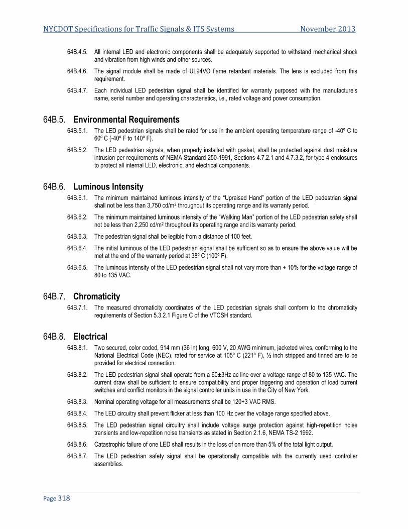
NYCDOT Specifications for Traffic Signals & ITS Systems November 2013
Page 318
64B.4.5. All internal LED and electronic components shall be adequately supported to withstand mechanical shock and vibration from high winds and other sources.
64B.4.6. The signal module shall be made of UL94VO flame retardant materials. The lens is excluded from this requirement.
64B.4.7. Each individual LED pedestrian signal shall be identified for warranty purposed with the manufacture’s name, serial number and operating characteristics, i.e., rated voltage and power consumption.
64B.5. Environmental Requirements 64B.5.1. The LED pedestrian signals shall be rated for use in the ambient operating temperature range of -40º C to
60º C (-40º F to 140º F).
64B.5.2. The LED pedestrian signals, when properly installed with gasket, shall be protected against dust moisture intrusion per requirements of NEMA Standard 250-1991, Sections 4.7.2.1 and 4.7.3.2, for type 4 enclosures to protect all internal LED, electronic, and electrical components.
64B.6. Luminous Intensity 64B.6.1. The minimum maintained luminous intensity of the “Upraised Hand” portion of the LED pedestrian signal
shall not be less than 3,750 cd/m2 throughout its operating range and its warranty period.
64B.6.2. The minimum maintained luminous intensity of the “Walking Man” portion of the LED pedestrian safety shall not be less than 2,250 cd/m2 throughout its operating range and its warranty period.
64B.6.3. The pedestrian signal shall be legible from a distance of 100 feet.
64B.6.4. The initial luminous of the LED pedestrian signal shall be sufficient so as to ensure the above value will be met at the end of the warranty period at 38º C (100º F).
64B.6.5. The luminous intensity of the LED pedestrian signal shall not vary more than + 10% for the voltage range of 80 to 135 VAC.
64B.7. Chromaticity 64B.7.1. The measured chromaticity coordinates of the LED pedestrian signals shall conform to the chromaticity
requirements of Section 5.3.2.1 Figure C of the VTCSH standard.
64B.8. Electrical 64B.8.1. Two secured, color coded, 914 mm (36 in) long, 600 V, 20 AWG minimum, jacketed wires, conforming to the
National Electrical Code (NEC), rated for service at 105º C (221º F), ½ inch stripped and tinned are to be provided for electrical connection.
64B.8.2. The LED pedestrian signal shall operate from a 60±3Hz ac line over a voltage range of 80 to 135 VAC. The current draw shall be sufficient to ensure compatibility and proper triggering and operation of load current switches and conflict monitors in the signal controller units in use in the City of New York.
64B.8.3. Nominal operating voltage for all measurements shall be 120+3 VAC RMS.
64B.8.4. The LED circuitry shall prevent flicker at less than 100 Hz over the voltage range specified above.
64B.8.5. The LED pedestrian signal circuitry shall include voltage surge protection against high-repetition noise transients and low-repetition noise transients as stated in Section 2.1.6, NEMA TS-2 1992.
64B.8.6. Catastrophic failure of one LED shall results in the loss of on more than 5% of the total light output.
64B.8.7. The LED pedestrian safety signal shall be operationally compatible with the currently used controller assemblies.

Specification 64B: NYCDOT Specification for 16”x16” LED Pedestrian Signal Module
Page 319
64B.8.7.1. The City of New York utilizes ASTC load switches. The LED pedestrian signal shall be operationally compatible with both types to allow for potential upgrades in the future.
64B.8.7.2. The LED signal module shall be operationally compatible with voltage threshold of conflict monitors.
64B.8.8. The LED pedestrian signal including its circuitry must meet Federal Communications Commission (FCC) Title 47, Subpart B, Section 15 regulations concerning the emissions of noise.
64B.8.9. The LED pedestrian signal shall provide a power factor of 0.90 of greater over the operating voltage range and temperature range specified above.
64B.8.10. Total harmonic distortion (current and voltage) induced into an AC power line by an LED pedestrian signal shall not exceed 20% over the operating voltage range and temperature range specified above.
64B.9. Quality Assurance 64B.9.1. LED pedestrian signals manufactured in accordance with a vendor quality assurance (QA) program
including both design and production quality assurances. All QA process and test results documentation described below shall be kept on file for a minimum of seven years.
64B.10. Production Quality Assurance 64B.10.1. The City reserves the right to retest or withdraw approval at any time or any time a change is made in the
product. The specific values of the test results with the corresponding serial numbers are to be documented for each LED pedestrian signal. Failure to meet requirements of any of the tests shall be cause for rejection. This document must be provided with each shipment. The following Production Quality Assurance tests shall be performed on each new LED pedestrian signal prior to shipment:
64B.10.1.1. Signal Burn-in-All LED pedestrian signals shall be energized for a minimum of 24 hours, at 100% duty cycle, in an ambient temperature of 60º C (140º F).
64B.10.1.2. After burn-in, all LED pedestrian signals shall be tested for rated maintained minimum luminous intensity. Each shall be energized at the nominal operating voltage for a five-minute stabilization period before measurements are made. The ambient temperature for this measurement shall be 25º C (77º F). A two point measurement (one for the Portland orange LEDs and one for the white LEDs) with a correlation to the intensity requirements defined in this specification may be used.
64B.10.1.3. After burn-in, all LED pedestrian signals shall be tested for power factor and shall meet the requirements defined in this specification.
64B.10.1.4. After burn-in, all LED pedestrian signals shall be measured for current flow in amperes. The measured current value shall not exceed 110% of the design qualification measurements (described in the next section).
64B.10.1.5. All LED pedestrian signals shall be visually inspected for any exterior damage or assembly anomalies. Careful attention shall be paid to the surface of the lens to ensure there are no scratches, cracks, chips, discoloration or other defects.
64B.11. Design Qualification Testing 64B.11.1. Design Qualification testing described below shall be performed and the resulting data shall be submitted to
the Department for approval. All Design Qualification testing shall be performed after a burn-in module energized for a minimum of 24 hours, at 100% duty cycle, in an ambient temperature of 60º C (140º F). Signals submitted for test shall be representative of typical production units.
64B.11.2. Documentation of each of these test results shall be submitted in a binder with tabs labeled with the corresponding letter of the test described below:
64B.11.2.1. The LED pedestrian signals shall be tested for rated initial luminous intensity. These measurements shall be recorded at an ambient temperature of 25º C after the signal has operated for 30 minutes.

NYCDOT Specifications for Traffic Signals & ITS Systems November 2013
Page 320
64B.11.2.2. The LED pedestrian signals shall be measured for current flow in amperes by an independent testing laboratory.
64B.11.2.3. The LED pedestrian signals shall be tested for wattage by an independent testing laboratory.
64B.11.2.4. The LED pedestrian signals shall be measured for chromaticity per the requirements defined in this specification using a spectroradiometer at an ambient temperature of 25º C (77º F).
64B.11.2.5. The LED pedestrian signals shall be measured for power factor per the requirements defined in this specification by an independent testing laboratory.
64B.11.2.6. The LED pedestrian signals shall be measured for total harmonic distortion per the requirements defined in this specification by an independent testing laboratory.
64B.11.2.7. The LED pedestrian signals shall be tested for electronic noise per the requirements defined in this specification with reference to a Class A emission limits referenced FCC Title 47 Subpart B, Section 15 by an independent testing laboratory.
64B.11.2.8. The LED pedestrian signals shall be tested for compatibility with the controller unit monitor and both types of load switches used in the City of New York.
64B.11.2.9. The LED pedestrian signals shall be tested for transient immunity (e.g. Early electronic component morality failures, component reliability problems). Using NEMA Standard TS-2, 1992 Section 2.1.8 by an independent testing laboratory.
64B.11.2.10. Mechanical vibration testing shall be performed on the LED pedestrian signals, by an independent testing laboratory, in accordance with MIL-STD-883, Test Method 2007, using three 4 minute cycles along each x, y, and z axis, at a force of 2.5 Gs, with a frequency sweep from 2 Hz to 120 Hz. The loosening of the lens, of any internal components, or any other physical damage shall be cause for rejection.
64B.11.2.11. Temperature cycling shall be performed on the LED pedestrian signals by an independent testing laboratory, in accordance with MIL-STD-833, Test Method 1010 using the temperature range of -40º C to 60º C (-40º F to 140º F), twenty cycles (minimum) with a thirty minute transfer time between temperature extremes and with a thirty minute dwell time at each extreme shall be performed. Modules under testing that fail to function properly or that show evidence of cracking of the lens or housing shall be rejected.
64B.11.2.12. Moisture resistance testing shall be performed on the LED pedestrian signals with gasket, by an independent testing laboratory, in accordance with NEMA Standard 250-1991 for Type 4 enclosures. Any evidence of internal moisture after testing shall be cause for rejection.
64B.12. Warranty 64B.12.1. Manufacturers shall provide a Certificate of Compliance to this specification for each shipment of pedestrian
signals.
64B.12.2. Manufacturers shall provide (within 48 hours) a replacement for any LED pedestrian signal that fails to function in accordance with this specification or does not exhibit the luminous intensity defined in this specification.
64B.12.3. The term of this warranty shall be seven years from the date of installation.
END OF SPECIFICATIONS FOR 16”x16” LED PEDESTRIAN SIGNAL MODULE

Specification 64D
NYCDOT Specification for 16”x18” Polycarbonate Pedestrian Signal Housing with LED Lens
Date of Revision Revised by Description
1/16/2010 New Spec

NYCDOT Specifications for Traffic Signals & ITS Systems November 2013
Page 322
64D. NYCDOT SPECIFICATION FOR 16”X18” POLYCARBONATE PEDESTRIAN SIGNAL HOUSING WITH LED LENS .... 323 64D.1. GENERAL .................................................................................................................................................................... 323 64D.2. INTERPRETATIONS OF APPARENT OMISSIONS ................................................................................................................ 323 64D.3. HOUSING .................................................................................................................................................................... 324 64D.4. PAINTING .................................................................................................................................................................... 325 64D.5. VISOR ......................................................................................................................................................................... 325 64D.6. LENS........................................................................................................................................................................... 325 64D.7. GASKETS .................................................................................................................................................................... 325 64D.8. ELECTRICAL REQUIREMENTS ........................................................................................................................................ 326 64D.9. TESTING...................................................................................................................................................................... 326 64D.10. MATERIAL ................................................................................................................................................................... 326 64D.11. SOURCE DOCUMENTATION ........................................................................................................................................... 326 64D.12. MISCELLANEOUS ......................................................................................................................................................... 326 64D.13. NAMEPLATE ................................................................................................................................................................ 327 64D.14. GUARANTEES AND WARRANTIES................................................................................................................................... 327 64D.15. REPLACEMENT COMPONENTS ...................................................................................................................................... 327 64D.16. REPLACEMENT ............................................................................................................................................................ 327 64D.17. SAMPLES ................................................................................................................................................................. 328 64D.18. DELIVERY HANDLING AND TRANSPORTATION ................................................................................................................. 328 64D.19. POLYCARBONATE CASE-MATERIAL TESTS AND MATERIALS ............................................................................................ 328

Spec 64D: NYCDOT Spec for 16”x18” Polycarbonate Pedestrian Signal Housing with LED Lens
Page 323
64D. NYCDOT Specification for 16”x18” Polycarbonate Pedestrian Signal Housing with LED Lens
64D.1. General 64D.1.1. These specifications are for the production of a pedestrian signal electrically operated on 120 volt 60 HZ
alternating current. The pedestrian signal shall be so designed that when mounted its orientation may be adjusted without removal from the brackets. The assembly shall display the International “Upraised Hand” and “Walking Man” symbol in quantities detailed in the bid schedule. These messages shall be in the sequence and flashing schedule as developed by the Engineers. The material used in the unit shall be top quality, weather and sunlight resistant polycarbonate which has been high-pressure molded.
64D.1.2. The Contractor shall personally inspect and become familiar with the New York City approved parts, brackets, assemblies and accessories prior to the submission of a bid. This is necessary so that the design of the signal will be compatible with the New York City approved parts and assemblies. The plastic unit, in total, will be interchangeable with currently used bracket equipment without any modifications or use of any additional parts. The pedestrian signal must be a functionally approved equal to the first designed for NYC.
64D.1.3. The Pedestrian Signal shall be completely assembled, and shall include housing, An LED lens (by an approved manufacturer), "Marathon" type terminal block or approved equal, and all necessary wiring.
64D.1.4. Any part not mentioned in this specification, but necessary for the satisfactory functioning of the signal, shall be furnished by the Contractor as though that part was specified.
64D.1.5. This specification is not intended to include any proprietary items, circuits or devices which would preclude an equipment manufacturer from producing equipment to meet these requirements. All the tolerances, ratings and technically defined criteria contained within these specifications are considered to be within the current state of the art and are, now being met by commercially available equipment. All work shall be of the best character, including all labor, materials, plant tools, supplies and other means to furnish ail the equipment required by the specifications, contract drawing and other data provided.
64D.1.6. The Contractor would be held liable for and shall be solely responsible for any claims made against the City of New York and/or their agents and employees for any by infringement it of patents by the use of equipment furnished by him or any part thereof or e use of patented tools, articles, appliances, structures, materials, devices of any process or method connected with the work or by use of any materials used upon the work. The Contractor shall save harmless and indemnify the City of New York and their agents, servants and employees from and against all costs, expenses and damages which the City of New York and their agents shall incur or be obliged to pay by reason of any such infringement of claim and shall defend all such claims in connection with any alleged infringement.
64D.1.7. Should any equipment, or part, furnished by the Contractor be involved in a lawsuit or proceeding and should it be held to constitute infringement and its use be enjoined, then the Contractor, within a reasonable time after request by the Department, and at the Contractor's own expense, shall either secure for the City the right to continue using said equipment or replace it with non-infringing equipment at the Contractor's expense. This shall be done in a manner satisfactory to the Department. Should this not be accomplished, the City of New York has the right to revert to the next lowest bidder for equipment.
64D.2. Interpretations of Apparent Omissions 64D.2.1. The apparent silence of the specification as to any detail, or the apparent omission from them of a detailed
description concerning any work to be done and materials to be furnished, shall be regarded as meaning that only the best general practice is to prevail and that only the best material and workmanship is to be used. Materials supplied by and at the expense of the Contractor shall be the best of their respective lands suitable for use under the conditions prevailing in this work and shall conform to the latest specifications of the Electrical and Electronics Engineers (EEE), the Electronics Industries Association (EIA), the standard specifications of the American Society for Testing and Materials (ASTM), the American Standards

NYCDOT Specifications for Traffic Signals & ITS Systems November 2013
Page 324
Association (ASA), and to the regulations of the National Fire Protection Association (NFPA), as they apply. If any of the requirements herein specified or shown on the plans conflict with or vary from any of above mentioned specifications forming part of this Specification shall supersede the above mentioned specification. All materials used shall be subject to the approval of the Engineer.
64D.2.2. The City reserves the right to reject any materials which are not approved the Engineer.
64D.2.3. Any request by the Contractor for a variation from any provision in these specifications or on the drawings shall be made by letter to the Engineer clearly stating the page and paragraph, or drawing number he proposes to modify and what he proposes to substitute in lieu thereof.
64D.3. Housing 64D.3.1. Each pedestrian signal assembly shall consist of: a housing, LED pedestrian lens, “Marathon” type terminal
block or approved equal, gaskets, and electrical system including the wiring.
64D.3.2. The housing shall be designed to accommodate the electrical and optical elements of the pedestrian signal in a weather resistant enclosure.
64D.3.3. The overall dimensions of the pedestrian signal housing shall be approximately 18½” wide and 9" deep not including optional visor. The height of the housing, between the crests of the top and bottom serrated surfaces of the mounting bracket connections, shall be 16 3/8".
64D.3.4. The back of the housing shall be designed to provide sufficient clearance for orienting the signals when mounting two signals on City of New York Type "VB-2P" brackets.
64D.3.5. The top and bottom of the housing compartments shall have 2" diameter openings, concentric with the vertical geometric center line of the signal. There shall be a bossed ring, 9/32" wide, cast integrally with the housing compartment, around each of these 2" openings. The outside surfaces of the bosses shall have 72 clean and sharp identical serrations to mesh with those on the serrated tee on the standard brackets "VB" and "VB-P" and "VB-2P", as detailed on the specification drawing SE-021. The crest of the serrations shall be 3/8" from the outside surface of the signal housing.
64D.3.6. An Ethylene Propylene Diene Monomer (EPDM) gasket shall be provided for maintaining a sealed water resistant compartment when the door is bolted shut.
64D.3.7. The signal, especially the door hinges, shall be designed to withstand the reaction of the door dropping freely from the closed to completely open positions. The hinge attaching the door to the housing will be of such a design to provide strength and capability of replacement in the field. Approval of design to be made before sample is fabricated. All steel in hinge to be type 303 stainless steel.
64D.3.8. The door of the housing shall be made from polycarbonate. The door shall be held closed by captured ¼” stainless steel machine bolt with a tamper proof design at mid-point on side of door frame and 2 stainless steel wing bolts at the top of frame. This design should be with a hexagonal indentation with a raised center. The size and type of the tool used to open the signal will be as commonly carried by technicians in the field. The machine bolts shall fit into brass bushings which are securely set into the polycarbonate housing. The use of hexagonal socket wrench shall be required to open the signal for bulb replacement and cleaning Socket wrench shall be 0.187" across the flats and one Allen “T” handle wrench supplied for every 50 Pedestrian Signals.
64D.3.9. The housing shall be manufactured from the finest weather resistant polycarbonate. UV stabilizers must be used when available to reduce color change due to exposure to the elements.
64D.3.10. Alternative Housing designs and construction will be considered for approval by the Engineer. All construction shall be free of defects in manufacture harmful to the strength and general appearance of the pedestrian signal.
64D.3.11. All seams shall be of weather resistant construction and mechanically sound.
64D.3.12. Material certificates from the manufacturer shall be furnished certifying that all materials used in the construction of the housing comply with the requirements of these specifications.
64D.3.13. Reinforcement of the housing shall be made at the serrated rings, and hinges and where the bolts used to close the unit are located.

Spec 64D: NYCDOT Spec for 16”x18” Polycarbonate Pedestrian Signal Housing with LED Lens
Page 325
64D.3.14. The Housing top shall be fabricated so as to prevent standing of water, and shall be so constructed so as to shield the top of the housing door, thereby preventing water from entering between the top door gasket and the cabinet.
64D.3.15. Door opening will have required fabrication to increase strength around the opening. An arrangement is to be provided at top of housing that will prevent dust, liquids and other debris from dropping into enclosure when the door is opened.
64D.3.16. The manufacturer developing the Pedestrian Signal design is directed to consider the heat buildup inside the housing and its effect on all parts. Techniques are required to dissipate excess heat. They are to be submitted prior to sample submission for review and approval.
64D.3.17. Gaskets shall be provided around all door openings. Gaskets shall be of a dust-tight permanent type that will not peel off or deteriorate. Gaskets shall be dosed cell EPDM material and shall be installed with contact cement for a permanent bond to the full periphery of the opening. The mating surface of gaskets shall be sprayed with lubricant to prevent sticking to said mating surface. Lubricant is to be that suggested by industry for the said usage.
64D.4. Painting 64D.4.1. The housing should be made from a polycarbonate material which is a cast solid yellow. Thus this material
should not need to be painted.
64D.4.2. The door shall be made of polycarbonate with a yellow color that is integral throughout. The color of the finished surface shall be as follows: All surfaces of the housing and door yellow to match Federal Specification 595, color 13538.
64D.4.3. All polycarbonate material should have any colored pigment UV stabilized if available.
64D.4.4. The material should have strength tests performed or physical properties certified by the manufacturer of the plastic.
64D.4.5. Quality of workmanship must be open for inspection and approval by the Department, prior to the issuance of purchase order. The Contractor must demonstrate their ability to produce such a unit within the given time schedule as noted in bid schedule.
64D.4.6. The signal shall meet or exceed the salt spray and weathermometer requirements of the Federal Specification TT-P-1416.
64D.5. Visor 64D.5.1. At the city option the visor shall be available for both factory or field installation. All mounting holes shall be
included on all housing so visors can be added at a later date in the field.
64D.6. Lens 64D.6.1. The lens shall conform to NYCDOT Specification for the LED Pedestrian Signal (Specification 65D).
64D.7. Gaskets 64D.7.1. A continuous EPDM gasket shall be securely cemented to the door or housing of the signal. The gasket
shall be large enough to adequately insure a positive water resistant and dust-proof seal around the entire door opening when the door is bolted shut.
64D.7.2. A rectangular gasket for the perimeter of the lens assembly if required shall be fabricated from neoprene. No voids or gaps shall be in the gasket. The gasket shall provide a water resistant and light-proof seal satisfactory to the department.
64D.7.3. An EPDM 80 Durometer ring gasket, approximately 1/8" thick, 17/8" inside diameter, and 2½” outside diameter, shall be furnished for each signal to provide a water resistant seal between the inside of the top of the signal and the City of New York bracket connecting fittings.
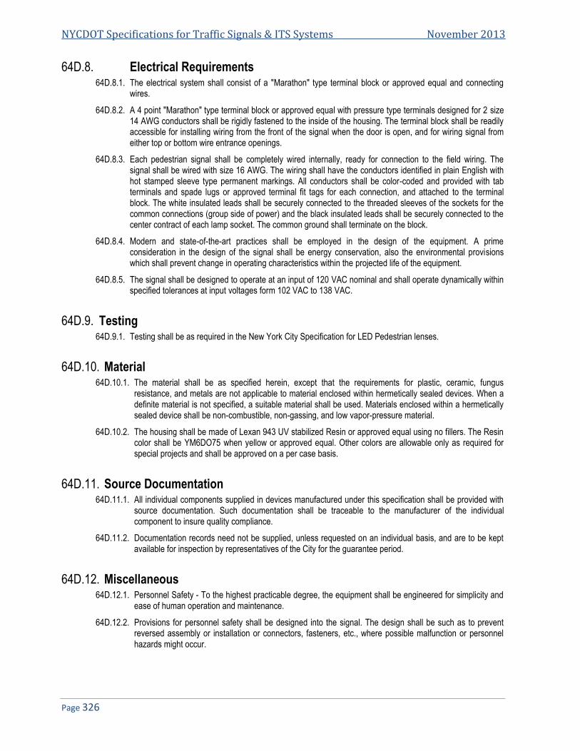
NYCDOT Specifications for Traffic Signals & ITS Systems November 2013
Page 326
64D.8. Electrical Requirements 64D.8.1. The electrical system shall consist of a "Marathon" type terminal block or approved equal and connecting
wires.
64D.8.2. A 4 point "Marathon" type terminal block or approved equal with pressure type terminals designed for 2 size 14 AWG conductors shall be rigidly fastened to the inside of the housing. The terminal block shall be readily accessible for installing wiring from the front of the signal when the door is open, and for wiring signal from either top or bottom wire entrance openings.
64D.8.3. Each pedestrian signal shall be completely wired internally, ready for connection to the field wiring. The signal shall be wired with size 16 AWG. The wiring shall have the conductors identified in plain English with hot stamped sleeve type permanent markings. All conductors shall be color-coded and provided with tab terminals and spade lugs or approved terminal fit tags for each connection, and attached to the terminal block. The white insulated leads shall be securely connected to the threaded sleeves of the sockets for the common connections (group side of power) and the black insulated leads shall be securely connected to the center contract of each lamp socket. The common ground shall terminate on the block.
64D.8.4. Modern and state-of-the-art practices shall be employed in the design of the equipment. A prime consideration in the design of the signal shall be energy conservation, also the environmental provisions which shall prevent change in operating characteristics within the projected life of the equipment.
64D.8.5. The signal shall be designed to operate at an input of 120 VAC nominal and shall operate dynamically within specified tolerances at input voltages form 102 VAC to 138 VAC.
64D.9. Testing 64D.9.1. Testing shall be as required in the New York City Specification for LED Pedestrian lenses.
64D.10. Material 64D.10.1. The material shall be as specified herein, except that the requirements for plastic, ceramic, fungus
resistance, and metals are not applicable to material enclosed within hermetically sealed devices. When a definite material is not specified, a suitable material shall be used. Materials enclosed within a hermetically sealed device shall be non-combustible, non-gassing, and low vapor-pressure material.
64D.10.2. The housing shall be made of Lexan 943 UV stabilized Resin or approved equal using no fillers. The Resin color shall be YM6DO75 when yellow or approved equal. Other colors are allowable only as required for special projects and shall be approved on a per case basis.
64D.11. Source Documentation 64D.11.1. All individual components supplied in devices manufactured under this specification shall be provided with
source documentation. Such documentation shall be traceable to the manufacturer of the individual component to insure quality compliance.
64D.11.2. Documentation records need not be supplied, unless requested on an individual basis, and are to be kept available for inspection by representatives of the City for the guarantee period.
64D.12. Miscellaneous 64D.12.1. Personnel Safety - To the highest practicable degree, the equipment shall be engineered for simplicity and
ease of human operation and maintenance.
64D.12.2. Provisions for personnel safety shall be designed into the signal. The design shall be such as to prevent reversed assembly or installation or connectors, fasteners, etc., where possible malfunction or personnel hazards might occur.

Spec 64D: NYCDOT Spec for 16”x18” Polycarbonate Pedestrian Signal Housing with LED Lens
Page 327
64D.13. Nameplate 64D.13.1. A metal or plastic nameplate with name of manufacturer, date of production and marking "Property of City
of N.Y." shall be securely fastened to inside of housing.
64D.14. Guarantees and Warranties 64D.14.1. The purpose of this section is to present requirements of the Contractor's guarantee for equipment
provided in this Specification. It is the intent of this section to establish quality requirements of the equipment by requiring the Contractor to provide replacement parts as specified. The intent is to influence design of equipment to provide the City of New York with equipment having a minimum design life of ten (10) years. Given the total functional nature of these specifications and the design, latitude permitted to encourage Contractor toward the application of state-of-the-art advances, these guarantees are considered minimum assurance that sound design practices shall be used.
64D.14.2. While all equipment shall meet the requirements set forth in the specifications, the final determination of its acceptance will be on the basis of actual satisfactory performance as determined by the Department.
64D.14.3. Replacement parts for the equipment proposed shall be available for a period of at least ten (10) years from date of purchase.
64D.14.4. The Contractor guarantees that all articles of equipment, including all parts thereof are of first quality throughout and comp1y in all respects or are fully equal to standards called for to this bid. The Contractor further guarantees all equipment, and all parts thereof, against any defects of workmanship, construction and materials and guarantees to repair or replace, without cost to the City of New York, any article that has become defective, not proven to have been caused by negligence on the part of the user, within a period of twelve (12) months of in-service operation following the initial date equipment is installed and placed in service. However, said guarantee shall not exceed three (3) years from acceptance.
64D.14.5. The Contractor shall bear the total cost of delivery and transportation related to the repair of Contractor's supplied equipment during the terms of the guarantee. The City shall reserve the sole right to determine unsuitability of the Contractor supplied equipment within the guarantee period.
64D.14.6. In the event of failure on the part of the Contractor to replace or put in first-class condition any such articles within thirty (30) calendar days from the date of notice, the City may have work done by other an charge the cost to money due, or that may become due to the Contractor, or if there be no money due, the Contractor agrees to pay the City such costs.
64D.15. Replacement Components 64D.15.1. No component or part of this device shall be of such design, fabrication, nomenclature, or other
identification as to preclude the purchase of said component from any wholesale distributor, or from the factory.
64D.15.2. Original Equipment Manufacturer (OEM) - No component may be included in any device, the purchase of which by the City would be prevented by an OEM agreement between the component manufacturer and the manufacturer of the device covered by this specification.
64D.16. Replacement 64D.16.1. The design of the device shall be such that the replacement of any component available from the
component manufacturer will not degrade the proper performance or operation of the device. In no case may any component be included in the assembly of any device covered by the requirements of a particular component from a group of the same number, or other individually tailored assembly.
64D.16.2. All sizes, threading, bolts and nuts to be made using U.S. standards and not metric measurements and sizes.

NYCDOT Specifications for Traffic Signals & ITS Systems November 2013
Page 328
64D.17. SAMPLES 64D.17.1. Prior to the award of purchase contract, two (2) complete working samples of the signal shall be shipped by
the Contractor to the Department. These samples are to be shipped within Ninety (90) days after notification by the City of New York, General Services. Samples will be examined by the Department personnel and those of the Department Inspection unit. Performance tests will be made. Accompanying the samples the Contractor shall submit six (6) complete sets of working drawings.
64D.17.2. Failure to submit the samples and drawings within the time specified will be grounds to consider the Contractor in default. The cost of freight and transportation of these samples shall be borne by the Contractor. The City of New York s not be responsible for loss or damage to samples while is its possession.
64D.17.3. Sample delivery will be made to the NYCDOT ITS LAB room 122 34-02 Queens Boulevard, NY 11101.. Approval of sample does not relieve Contractor to fulfill the items of the specification in total.
64D.18. Delivery Handling and Transportation 64D.18.1. The Contractor shall make all deliveries to the Department’s Warehouse (loading bays 5 and 6) at 66-26
Metropolitan Avenue, Middle Village (Queens)NY 11379 any other locations within the limits of the City of New York designated by the Department, or as directed by the Engineer. Material will be accepted between the hours of 8:00 AM and 12:00 PM with unloading to be completed before 3:00 PM, Monday through Friday, except holidays. The Contractor shall notify the Department at least 24 hours in advance of delivery..
64D.18.2. The Contractor shall deliver material into the designated storage and/or installation point and shall unload and stack this material under the direction of the warehouse supervisor.
64D.18.3. Each complete unit shall be plainly identified on packing carton at the top end and one side with the type of unit, model unit, model number, manufacturer's name, purchase order number, year of manufacture.
64D.18.4. The supplier is responsible for delivering the equipment in an acceptable condition. The Contractor is responsible for the prompt repair or replacement of any articles received in an unsatisfactory condition at the delivery destination. Claims against transportation companies for damages in transit or for any additional charges resulting from inadequate packaging, packing, and marking are the Contractor's responsibility. Compliance with the packaging, packing, and marking requirements and specifications does not relieve the Contractor of his responsibility for the safe delivery of contract articles to the delivery destination.
64D.18.5. Quantities and timing of deliveries shall be as noted in the bid schedule or instructions to manufacturer.
64D.18.6. The following shall be supplied upon date of delivery of the order.
64D.18.7. Instruction manuals showing the installation, maintenance and operational techniques and containing all drawings necessary with parts lists description, for the proper repair, and maintenance of the equipment. The quantity to be supplied shall be thirty (30).
64D.18.8. One AutoCAD drawing of each diagram contained in the instruction manual. Packing carton used in shipping each unit shall be strong enough permit stacking units up to 8 feet.
64D.19. Polycarbonate Case-Material Tests and Materials 64D.19.1. The case will be made from rigid structural expanded polycarbonate foam which contains glass fibers. The
minimum wall thickness shall be ¼”. Sufficient reinforcing ribs will be integrally cast with the case to maximize strength.
64D.19.2. The case, at its full thickness, will be self-extinguishing and will not burn when an applied flame is removed.
64D.19.3. The color pigment will be LTV stabilized and integral with the material.
64D.19.4. Corners will have a 1" radius and the sides and top will have a slight taper to allow water runoff.

Spec 64D: NYCDOT Spec for 16”x18” Polycarbonate Pedestrian Signal Housing with LED Lens
Page 329
64D.19.5. The door will be fastened closed with captive tamper proof stainless steel screws. The screws will be button head type with standard Allen key inserts. These screws will mate with brass inserts within the case. The brass inserts will be heat welded into reinforced corners of the cabinet
64D.19.6. There will 72 serrations at top and bottom holes located at the centerline of the cabinet. These serrations will match the currently used mounting hardware which contains 72 serrations and allow rigid positioning in all 72 directions. For reasons of strength these serrations must be integrally cast with the case. Mechanically fastened machined rings will not be permitted.
64D.19.7. A certificate of compliance shall be submitted that the manufactured product has been test to meet the following properties using the recommended test procedure consistent with use of Lexan resin 943.
Physical Properties English Test method
Specific Gravity 1.21 g/cc ASTM D 792
Density 0.04397 lb/in³ ASTM D 792
Water Absorption 0.150 % 24 hrs; ASTM D 570
Water Absorption at Saturation 0.350 % ASTM D 570
0.580 % @Temperature 212º F
ASTM D 570
Linear Mold Shrinkage 0.00500 - 0.00700 in/in @Thickness 0.126 in
flow; SABIC Method
Melt Flow 10.0 g/10 min @Load 2.65 lb,
Temperature 572º F
ASTM D 1238
Mechanical Properties English Test method
Hardness, Rockwell M 70.0 ASTM D 785 Hardness, Rockwell R 118 ASTM D 785 Tensile Strength at Break 7980 PSI Type I, 50 mm/min; ASTM D 638 Tensile Strength, Yield 8990 PSI Type I, 50 mm/min; ASTM D 638 Elongation at Break 90.0 % Type I, 50 mm/min; ASTM D 638 Elongation at Yield 7.00 % Type I, 50 mm/min; ASTM D 638 Flexural Modulus 325 ksi 1.3 mm/min, 50 mm span; ASTM D 790 Flexural Yield Strength 13200 PSI 1.3 mm/min, 50 mm span; ASTM D 790 Izod Impact, Unnotched 60.02 ft-lb/in
@Temperature 73.4º F ASTM D 4812
Tensile Impact Strength 250 ft-lb/in² Type S; ASTM D 1822 Falling Dart Impact 125 ft-lb ASTM D 3029 Taber Abrasion, mg/1000 Cycles 10.0 CS-17, 1 kg; ASTM D 1044 Izod Impact, Notched 12.0 ft-lb/in
@Temperature 73.4º F ASTM D 256
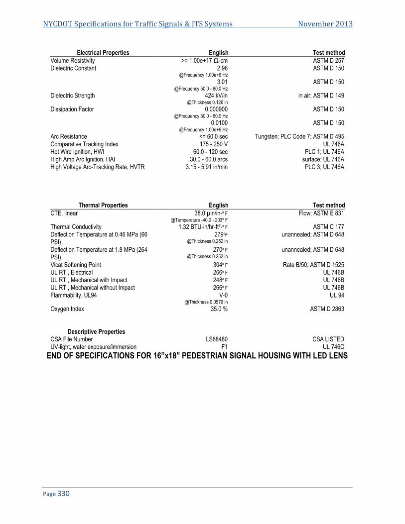
NYCDOT Specifications for Traffic Signals & ITS Systems November 2013
Page 330
Electrical Properties English Test method
Volume Resistivity >= 1.00e+17 Ω-cm ASTM D 257 Dielectric Constant 2.96
@Frequency 1.00e+6 Hz ASTM D 150
3.01 @Frequency 50.0 - 60.0 Hz
ASTM D 150
Dielectric Strength 424 kV/in @Thickness 0.126 in
in air; ASTM D 149
Dissipation Factor 0.000900 @Frequency 50.0 - 60.0 Hz
ASTM D 150
0.0100 @Frequency 1.00e+6 Hz
ASTM D 150
Arc Resistance <= 60.0 sec Tungsten; PLC Code 7; ASTM D 495 Comparative Tracking Index 175 - 250 V UL 746A Hot Wire Ignition, HWI 60.0 - 120 sec PLC 1; UL 746A High Amp Arc Ignition, HAI 30.0 - 60.0 arcs surface; UL 746A High Voltage Arc-Tracking Rate, HVTR 3.15 - 5.91 in/min PLC 3; UL 746A
Thermal Properties English Test method
CTE, linear 38.0 µin/in-º F @Temperature -40.0 - 203º F
Flow; ASTM E 831
Thermal Conductivity 1.32 BTU-in/hr-ft²-º F ASTM C 177 Deflection Temperature at 0.46 MPa (66 PSI)
279ºF @Thickness 0.252 in
unannealed; ASTM D 648
Deflection Temperature at 1.8 MPa (264 PSI)
270º F @Thickness 0.252 in
unannealed; ASTM D 648
Vicat Softening Point 304º F Rate B/50; ASTM D 1525 UL RTI, Electrical 266º F UL 746B UL RTI, Mechanical with Impact 248º F UL 746B UL RTI, Mechanical without Impact 266º F UL 746B Flammability, UL94 V-0
@Thickness 0.0579 in UL 94
Oxygen Index 35.0 % ASTM D 2863
Descriptive Properties CSA File Number LS88480 CSA LISTED UV-light, water exposure/immersion F1 UL 746C
END OF SPECIFICATIONS FOR 16”x18” PEDESTRIAN SIGNAL HOUSING WITH LED LENS

Specification 65D
NYCDOT Specification for 16”x18” LED Pedestrian Hand/Person/Countdown Module
Date of Revision Revised by Description
1/16/2010 New Spec
NYCDOT Specifications for Traffic Signals & ITS Systems November 2013
Page 332
65D. NYCDOT SPECIFICATION FOR 16”X18” LED PEDESTRIAN HAND/PERSON/COUNTDOWN MODULE, (16”X18” NYC PEDESTRIAN COUNTDOWN SIGNAL) ............................................................................................................................... 333
65D.1. OVERVIEW .................................................................................................................................................................. 333 65D.2. PHYSICAL AND MECHANICAL REQUIREMENTS ................................................................................................................ 333 65D.3. PHOTOMETRIC REQUIREMENTS .................................................................................................................................... 335 65D.4. ELECTRICAL ................................................................................................................................................................ 337 65D.5. QUALITY ASSURANCE .................................................................................................................................................. 339 65D.6. WARRANTY REQUIREMENTS......................................................................................................................................... 344 65D.7. ATTACHMENT 1 ........................................................................................................................................................... 344 65D.8. TABLE 3: LED MODULE SUPPLIER CHECKLIST .............................................................................................................. 345

Spec 65D: NYCDOT Spec for 16”x18” LED Pedestrian Hand/Person/Countdown Module
Page 333
65D. NYCDOT Specification for 16”x18” LED Pedestrian Hand/Person/Countdown Module, (16”x18” NYC Pedestrian Countdown Signal)
65D.1. Overview 65D.1.1. The purpose of this specification is to provide the minimum performance requirements for LED pedestrian
signal modules (hereafter called module or modules) with “Walking Person”, “Upraised Hand”, and “Countdown Digit” icons. This specification includes the following sizes (nominal message bearing surface) 16”x18”. This specification refers to definitions and practices described in Pedestrian Traffic Control Signal Indications (PTCSI) Part 2: Light Emitting Diode (LED) Pedestrian Traffic Signal Modules (PTCSI), adopted March 19, 2004 and published in the Equipment and Materials Standards of the Institute of Transportation Engineers (ITE) and contains additional requirements to ensure optimum long term reliability and performance.
65D.2. Physical and Mechanical Requirements 65D.2.1. General
65D.2.1.1. Usage: Modules shall fit into pedestrian signal housings manufactured in accordance with NYCDOT Specifications 64D without modification to the housing.
65D.2.1.2. The sizes of the message bearing surfaces shall be in accordance with the dimensions given in Table 1.
Table 1—Dimensions of Hand/Person Signal Sizes
Message Bearing Surface Height X Width
Minimum Message Size Height X Width
16" x 18" 11" x 7"
65D.2.1.3. All countdown display digits shall be 9” in height to allow for use in all size crosswalks to comply with
MUTCD recommendations.
65D.2.2. The LED Signal Module
65D.2.2.1. The module shall be capable of replacing the optical component of the pedestrian indication.
65D.2.2.2. The lens may have a textured outer surface to reduce glare.
65D.2.2.3. The module lens may be a replaceable part, without the need to replace the complete module.
65D.2.2.4. Icons that are printed on the lens shall be on the interior surfaces in order to prevent scratching and abrasion to the icons.
65D.2.2.5. All icons and numbers shall have a uniform appearance. Both the incandescent and pixilated type are acceptable.
65D.2.2.6. All LEDs utilized to illuminate the “Upraised Hand” and “Walking Person” icons shall be LEDs that have been manufactured utilizing material that has industry acceptance as being suitable for uses in outdoor applications. At no time is the use of LEDs that utilize AlGaAs technology acceptable.
65D.2.2.7. The configurations of the “Walking Person” icon, “Upraised Hand” icon and “Countdown Digits” are illustrated in Figure 1, Figure 2, and Figure 3 respectively. All icons shall meet the minimum size requirements of Table 1.
65D.2.2.8. The LED countdown display shall consist of two “7-segment” digits forming the time display. The countdown shall be capable of displaying the digits 0 through 99.

NYCDOT Specifications for Traffic Signals & ITS Systems November 2013
Page 334
Figure 1—Walking Person icon Figure 2— Upraised Hand icon
Figure 3—Countdown Display

Spec 65D: NYCDOT Spec for 16”x18” LED Pedestrian Hand/Person/Countdown Module
Page 335
65D.2.3. Environmental Requirements
65D.2.3.1. All exposed components of a module shall be suitable for prolonged exposure to the environment,
without appreciable degradation that would interfere with function or appearance. As a minimum, selected materials shall be rated for service for a period of a minimum of sixty (60) months in a south-facing Arizona Desert installation.
65D.2.3.2. A module shall be rated for use throughout an ambient operating temperature range, measured at the exposed rear of the module, of -40° C to 74° C (-40° F to 165° F).
65D.2.3.3. A module shall be protected against dust and moisture intrusion, including rain and blowing rain per Mil-STD-810F Method 506.4 Procedure 1 requirements.
65D.2.4. Construction
65D.2.4.1. The module shall be a single, self-contained device, not requiring on-site assembly for installation into existing traffic signal housing.
65D.2.4.2. The assembly and manufacturing process for the module shall be designed to assure all internal LED and electronic components are adequately supported to withstand mechanical shock and vibration from high winds and other sources.
65D.2.5. Materials
65D.2.5.1. Materials used for the lens and module construction shall conform to ASTM specifications for the materials, where applicable.
65D.2.5.2. Enclosures containing either the power supply or electronic components of the signal module shall be made of UL94 flame retardant materials. The module lens is excluded from this requirement.
65D.2.6. Module Identification
65D.2.6.1. Each module shall be identified on the backside with the manufacturer’s name, model, operating characteristics and serial number. The operating characteristics identified shall include the nominal operating voltage and stabilized power consumption, in watts and Volt-Amperes and statement of FCC compliance. The main module label which includes the module’s serial number (or date code) and the model number shall be attached using polyester or vinyl self-adhesive labels. The use of paper labels is not acceptable. Each unit shall have a separate label that can be written with a ballpoint pen stating the following:
Company installed___________________ Date installed_______________________
65D.2.6.2. Modules shall have a prominent and permanent vertical indexing indicator, i.e., UP Arrow, or the word UP or TOP, for correct indexing and orientation in the signal housing.
65D.2.6.3. Modules conforming to all requirements of this specification shall have a statement on an attached label which states conformance to the latest New York City Pedestrian Signal Specification.
65D.3. Photometric Requirements 65D.3.1. Luminance, Uniformity and Distribution
65D.3.1.1. For a minimum period of eighty four (84) months, the minimum maintained luminance values for the modules at 25° C (77º F), when measured normal to the plane of the icon surface, shall not be less than:
Walking Person: 5300 cd/m2 Upraised Hand: 3750 cd/m2 Countdown Digits: 3750 cd/m2
65D.3.1.1.1. The luminance of the emitting surface, measured at angles from the normal of the surface, may decrease linearly to a value of 50% of the values listed above at an angle of 15 degrees.
65D.3.1.1.2. The light output requirements in this specification apply to pedestrian signal heads without any visors, hooded or louvered (egg-crate). Addition of such visors may affect the light output of the signal head.

NYCDOT Specifications for Traffic Signals & ITS Systems November 2013
Page 336
65D.3.1.2. The uniformity of the “Walking Person”, “Upraised Hand”, and “Countdown Digit” icons’ luminance shall meet a ratio of not more than 1 to 5 between the minimum and maximum luminance values, as measured in 0.5 in. diameter spots.
65D.3.1.3. When operating within the temperature range specified in Article 65D.2.3.2., the average luminance of the module shall not exceed three times the maintained minimum luminance of the modules, as defined in Article 65D.3.1.1.
65D.3.2. Chromaticity
65D.3.2.1. The standard colors for the LED Pedestrian Signal Module shall be White for the Walking Person and Portland Orange for the Upraised Hand and countdown digit icons. The colors for these icons shall conform to the following color regions, based on the 1931 CIE chromaticity diagram:
65D.3.2.1.1. Walking Person — White: Blue boundary: x = 0.280. 1st Green boundary: 0.280 ≤ x < 0.400 y = 0.7917x + 0.0983 2nd Green boundary: 0.400 ≤ x < 0.450 y = 0.4600x + 0.2310 Yellow boundary: x = 0.450 1st Purple boundary: 0.450 ≤ x < 0.400 y = 0.4600x + 0.1810 2nd Purple boundary: 0.400 ≤ x < 0.280 y = 0.7917x + 0.0483
White
Point x y
1 0.280 0.320
2 0.400 0.415
3 0.450 0.438
4 0.450 0.388
5 0.400 0.365
6 0.280 0.270
65D.3.2.1.2. Upraised Hand and Countdown Digits—Portland Orange:
Yellow boundary: y = 0.390 White boundary: 0.600 ≤ x ≤ 0.680 y = 0.990 – x Red boundary: y = 0.331
Portland Orange
Point x y
1 0.6095 0.390
2 0.600 0.390
3 0.659 0.331
4 0.669 0.331
65D.3.2.2. The color regions are illustrated in Attachment 1.
65D.3.3. Color Uniformity
65D.3.3.1. The uniformity of the emitted colors shall be such that any color measurement within a 12mm (0.5 in.) spot on the emitting surface shall fall within the following regions around the average measured color of the entire emitting surface:
65D.3.3.1.1. Walking Person (White Color) - ;
04.022
yx
Spec 65D: NYCDOT Spec for 16”x18” LED Pedestrian Hand/Person/Countdown Module
Page 337
where Δx and Δy are the differences in the chromaticity coordinates of the measured colors to the coordinates of the average color, using the CIE 1931 Chromaticity Diagram and a 2 degree Standard Observer.
65D.3.3.1.2. Upraised Hand and Countdown Digits (Portland Orange Color) - The dominant wavelength for all individual color measurements shall be within ±3 nm of the dominant wavelength for the average of all the individual color measurements.
65D.4. Electrical 65D.4.1. General
65D.4.1.1. All wiring shall meet the requirements of Section 13.02 of the VTCSH standard. Secured, color coded, 600 V, 18 AWG jacketed wires, 1 meter (39 inch) in length, conforming to the NFPA 70, National Electrical Code, and rated for service at 105° C, shall be provided. The end of each wire shall be stripped 3/8 inch and soldered to form a solid connection point.
65D.4.1.2. The following color scheme shall be used for the module’s AC power leads: Orange for the “Upraised Hand”, Blue for the “Walking Person” and White for common. The countdown portion of the LED module shall be internally wired to the incoming Hand/Person power.
65D.4.1.3. The AC power leads shall exit the module via a rubber grommetted strain relief. The leads shall be separate at the point at which they leave the module.
65D.4.1.4. All external wiring utilized in the modules shall be anti-capillary type wire to prevent the wicking of moisture to the interior of the module.
65D.4.1.5. The “Upraised Hand” and “Walking Person” icons shall utilize separate power supplies. The countdown module must have its own power supply but may take the incoming AC power from the hand/person AC signal lines. All power supplies shall be located inside the signal module.
65D.4.1.6. All power supplies shall be conformal coated for additional protection.
65D.4.2. Voltage Range
65D.4.2.1. LED signal modules shall operate from a 603 Hz AC line power over a voltage range from 80 to 135 VAC RMS. Nominal operating voltage for all measurements shall be 120 ± 3VAC RMS, unless otherwise specified.
65D.4.2.2. Fluctuations in line voltage over the range of 80 to 135 VAC shall not affect luminous intensity by more
than 10 percent.
65D.4.2.3. The module circuitry shall prevent flicker of the LED output at frequencies less than 100 Hz over the voltage range specified in Article 65D.4.2.1.
65D.4.2.4. Low Voltage Turn OFF: There shall be no visible illumination from the LED signal module when the applied voltage is less than 35 VAC.
65D.4.2.5. Turn-ON and Turn-OFF Time: A module shall reach 90% of full illumination (Turn-ON) within 75 msec of the application of the nominal operating voltage. The signal shall cease emitting visible illumination (Turn-OFF) within 75 msec of the removal of the nominal operating voltage.
65D.4.2.6. Default Condition: Applies to modules that have both the “Walking Person” and the “Upraised Hand” as one module. For abnormal conditions when nominal voltage is applied to the unit across the two-phase wires or simultaneously to both “Upraised Hand” and “Walking Person” icons, the pedestrian signal unit shall default to the “Upraised Hand” symbol. For units that contain a countdown module the countdown shall display a “0” then blank.
65D.4.3. Transient Voltage Protection
65D.4.3.1. The on-board circuitry of the module shall include voltage surge protection, to withstand high-repetition noise transients and low-repetition high-energy transients as stated in Section 2.1.8, NEMA Standard TS 2-2003.
65D.4.4. Electronic Noise

NYCDOT Specifications for Traffic Signals & ITS Systems November 2013
Page 338
65D.4.4.1. The LED signal and associated on-board circuitry shall meet the requirements of the Federal Communication Commission (FCC) Title 47, Subpart B, Section 15 regulations concerning the emission of electronic noise by Class A digital devices.
65D.4.5. Power Factor (PF), AC Harmonics And Power
65D.4.5.1. Modules shall provide a power factor of 0.90 or greater when operated at nominal operating voltage and 25º C (77º F).
65D.4.5.2. Total harmonic distortion induced into an AC power line by a module at nominal operating voltage, and at 25º C (77º F), shall not exceed 20%.
65D.4.5.3. Typical Power at 25º C (77º F) for the Pedestrian Signal Modules shall be 10 W for the hand, and 8 W for the person.
65D.4.6. Controller Assembly Compatibility
65D.4.6.1. The current draw for “Upraised Hand” and “Walking Person” icons shall be sufficient to ensure compatibility and proper triggering and operation of load current switches and conflict monitors in signal controller units.
65D.4.6.2. Off State Voltage Decay: When the “Upraised Hand” or “Walking Person” icon is switched from the
On-state to the Off-state, the terminal voltage shall decay to a value less than 10 VAC RMS in less than 100 milliseconds when driven by a maximum allowed load switch leakage current of 10 mAmp peak (7.1 mAmp AC).
65D.4.7. Countdown Drive Circuitry
65D.4.7.1. The countdown portion of the signal shall have a high Off-state input impedance so as not to provide a load indication to conflict monitors and interfere with the monitoring of the pedestrian signal. The input impedance of the countdown circuitry shall maintain a voltage reading above 25 VAC to the conflict monitor for up to four units connected on the same channel.
65D.4.7.2. The Countdown Timer drive circuitry shall not be damaged when subjected to defective load switches providing a half wave signal input.
65D.4.7.3. The countdown module shall be compatible with all traffic signal controllers that are fully compliant to NEMA TS-1, NEMA TS-2, Type 170, and Type 2070 traffic signal controller specifications.
65D.4.7.4. The countdown module shall have an internal conflict monitor circuit preventing any possible conflicts between the Hand/Person signal indications and the Countdown Timer display. It shall be impossible for the display to countdown during a solid “Upraised Hand” indication.
65D.4.8. Countdown Functionality
65D.4.8.1. Per MUTCD Manual 2003 edition, with revisions 1 and 2 incorporated dated December 2007, section 4E.07: “Countdown displays should ONLY be used during the “Clearance Cycle”. They should NOT be used during the walk interval nor during the yellow change interval of a concurrent vehicular phase”.
65D.4.8.2. The countdown timer module shall have a micro-processor capable of recording the pedestrian crossing timing when connected to a traffic controller. It shall be capable of displaying the digits 0 through 99.
65D.4.8.3. When connected, the module shall blank out the display during the initial cycle while it records the countdown time using the Walk (Walking Person) & Don’t Walk (Flashing Upraised Hand) signal indications. The “Upraised Hand” and “Walking Person” icons shall be displayed as normal during this cycle.
65D.4.8.4. The countdown timer module shall continuously monitor the traffic controller for any changes to the pedestrian phase time and re-program itself automatically if needed.
65D.4.8.5. The countdown module shall register the time for the walk and clearance intervals individually and shall begin counting down at the beginning of the pedestrian clearance interval. The countdown module shall display the numerals in a continuous display and shall not flash during the countdown.
65D.4.8.6. When the flashing “Upraised Hand” becomes solid, the module shall display 0 for one second and then blank-out. The display shall remain dark until the beginning of the next countdown.

Spec 65D: NYCDOT Spec for 16”x18” LED Pedestrian Hand/Person/Countdown Module
Page 339
65D.4.8.7. In the event of a pre-emption sequence, the countdown module shall skip the pre-empted clearance time and reach “0” at the same time as the flashing “Upraised Hand” becomes solid and then remain dark until the next cycle.
65D.4.8.8. In the cycle following a pre-emption call, the signal shall display the correct time and not be affected by the reduced previous cycle. The countdown shall remain synchronized with the signal indications and always reach “0” at the same time as the flashing “Upraised Hand” becomes solid.
65D.4.8.9. The countdown timer shall be capable of Displaying 2 consecutive complete Pedestrian Phases outputted by the traffic controller (no steady “Upraised Hand” signal between cycles).
NOTE: When a controller is programmed with the option to serve a second consecutive pedestrian phase (walk followed by flashing don’t walk) if a pedestrian activates a pedestrian button during the clearance interval, and the controller is set to allow a second consecutive phase, the countdown will blank out during the walk, and restart counting down the correct time during the flashing don’t walk, just as in a regular PED phase.
65D.4.8.10. The countdown module shall not display an erroneous or conflicting time when subjected to defective load switches. Should there be a short power interruption during the PED clearance interval or if voltage is applied to both the hand and person simultaneously, the display will go to “0” then blank.
65D.5. Quality Assurance 65D.5.1. Samples
65D.5.1.1. Samples shall be submitted within seven (7) business days of request. The samples will be inspected, tested, and evaluated for conformity to the specifications. Samples must be actual production unit modules and not a prototype or test unit. If Bidder fails to submit a sample for evaluation, or if the sample does not conform to the specification, the Bid will be rejected. Each module submitted shall be accompanied with a complete circuit schematic for the unit, one standard catalog cut and one manufacturer’s technical specification sheet for the unit, and specification describing individual LED light sources used in the unit. The manufacturer shall provide a certificate of compliance for LED pedestrian safety signals manufactured in accordance with vendor quality assurance (QA) program including both design and production quality assurances. All QA Process and Test results documentation described below shall be kept on file for a minimum of seven years.
65D.5.2. Production Quality Assurance
65D.5.2.1. The following Production Quality Assurance tests shall be performed on each new LED pedestrian signal prior to shipment. The specific values of the test results with the corresponding serial number are to be documented for each LED pedestrian signal. Failure to meet requirements of any of the tests shall be cause for rejection. This document must be provided with each shipment. Signal Burn-in-hours, at 100% duty cycle, in an ambient temperature of 60º C (140º F). After burn-in, all LED pedestrian signals shall be tested for rated Maintained minimum. All LED pedestrian signals shall be energized for a minimum of 24 luminous intensity. Each shall be energized at the nominal operating voltage for a five-minute stabilization period before measurements are made. The ambient temperature for this measurement shall be +25º C (+77º F). A two point measurement (one for the Portland Orange LEDs and one for the white LEDs) with a correlation to the intensity requirements defined in this specification may be used. After burn-ins, all LED pedestrian signals shall be tested for power factor and shall meet the requirements defined in this specification.
65D.5.2.2. After burn-in, all pedestrian signals shall be measured for current flow in amperes. The measured current value shall not exceed 110% of the design qualifications measurements (described in the next section). All LED pedestrian signals shall be visually inspected for any exterior damage or assembly anomalies. Careful attention shall be paid to the surface of the lens to ensure there are no scratches, cracks, chips, discoloration or defects.
65D.5.2.3. Production Tests & Inspections
65D.5.2.3.1. Production Test Requirements: All modules shall undergo the following Production Testing & Inspection prior to shipment. Failure of a module to meet the requirements of Production Testing & Inspection shall be cause for rejection. Test results shall be maintained per the requirement of Article 65D.5.1.1. All Production Tests shall be performed at an ambient temperature of 25º C (77º F) and at the nominal operating voltage of 120 VAC.
NYCDOT Specifications for Traffic Signals & ITS Systems November 2013
Page 340
65D.5.2.3.2. Production Luminance Test: “Upraised Hand”/“Walking Person”/“Digit” icons shall be tested for maintained minimum luminance. Any measurement with a correlation to the luminance requirements of Article 65D.3.1.1. may be used. Modules that do not meet the maintained minimum luminance requirements as per Article 65D.3.1.1. shall be rejected.
65D.5.2.3.3. Power Factor: “Upraised Hand”/“Walking Person” icons shall be tested for power factor per the requirements of Article 65D.4.5.1. A commercially available power factor meter may be used to perform this measurement. Failure of a module to meet the requirements for power factor (Article 65D.4.5.1.) shall be cause for rejection of the module.
65D.5.2.3.4. Current Consumption Measurement: “Upraised Hand”/“Walking Person” icons shall be measured for current flow in Amperes. The measured current values shall be compared against the design current values from design qualification measurements in Article 65D.5.2.7.1. A measured current consumption in excess of 120% of the design qualification current value for an ambient temperature of 25º C (77º F) shall be cause for rejection of the module.
65D.5.2.3.5. Visual Inspection: All modules shall be visually inspected for any exterior physical damage or assembly anomalies. Careful attention shall be paid to the surface of the lens to ensure there are no scratches (abrasions), cracks, chips, discoloration, or other defects. The presence of any such defects shall be cause for rejection of the module. The Module shall be inspected in the street under all weather and light conditions at City discretion by at least four (4) staff members of NYCDOT. The purpose of the inspection is to visually observe the light output and form of raised hand and walking man. The City reserves the right to reject based on this inspection.
65D.5.2.4. Design Qualification Testing
65D.5.2.4.1. Design Qualification Testing shall be performed on the “Upraised Hand”/“Walking Person” icons of new module designs, and when a major design change has been implemented on existing “Upraised Hand”/“Walking Person” pedestrian signal designs. Modules used in design qualification testing shall be representative of the manufacturer’s proposed normal production.
65D.5.2.4.1.1. Testing shall be performed once every five (5) years or when the module design or LED technology has been changed. Test data shall be retained by the module manufacturer in accordance with Article 65D.5.1. or for sixty (60) months following final production of a specific design, whichever is longer.
65D.5.2.4.1.2. Six (6) modules shall be used in Design Qualification Testing. All six (6) modules shall be subjected to conditioning (Article 65D.5.2.4.2.), followed by the Environmental Tests (Article 65D.5.2.5.). Following the Environmental Tests, three (3) modules shall undergo Photometric & Colorimetric Tests (Article 65D.5.2.6.). The remaining three (3) modules shall undergo the Electrical Tests (Article 65D.5.2.7.) and Controller Compatibility Tests (Article 65D.5.2.7.11.). Tests shall be conducted in the order described herein, unless otherwise specified.
65D.5.2.4.1.3. In order for a module design to be considered acceptable for marking with the label described in Article 65D.2.6.1., all tested modules must comply with the acceptance/rejection criteria for the Environmental Tests (Article 65D.5.2.5.), Photometric & Colorimetric Tests (Article 65D.5.2.6.), Electrical Tests (Article 65D.5.2.7.), and Controller Assembly Compatibility Tests (Article 65D.5.2.7.11.).
65D.5.2.4.2. Conditioning: Modules shall be energized for a minimum of 24 hours, at 100% duty cycle, in an ambient temperature of 60° C (140° F).
65D.5.2.5. Environmental Testing
65D.5.2.5.1. Mechanical Vibration Testing: Three (3) modules shall be tested per MIL-STD-883, Test Method 2007, using three 4-minute cycles along each x, y, and z axis, at a force of 2.5 Gs, with a frequency sweep from 2 Hz to 120 Hz.
65D.5.2.5.2. Temperature Cycling: Temperature cycling shall be performed per MIL-STD-883, Test method 1010. The temperature range shall be per Article 65D.2.3.2. A minimum of 20 cycles shall be performed with a 30-minute transfer time between temperature extremes and a 30-minute dwell time at each temperature. Modules under test shall be non-operating.

Spec 65D: NYCDOT Spec for 16”x18” LED Pedestrian Hand/Person/Countdown Module
Page 341
65D.5.2.5.3. Moisture Resistance: Moisture resistance testing shall be performed on a sample of three modules per MIL-STD-810F, Procedure I, Rain and Blowing Rain. The test shall be conducted on a stand-alone unit, without a protective housing. The rainfall rate shall be 1.7 mm/min (4 in/hr) and droplet size shall predominantly be between 0.5 mm and 4.5 mm. The module shall be rotated through 120 degrees and the duration of the test shall be 30 minutes. The module shall be energized throughout the test. The water shall be at 25° C (77º F). The wind velocity shall be 80 km/hr (50 mph). Any evidence of internal moisture into the module shall be cause for rejection.
65D.5.2.5.4. UV Stabilization: Documentation may be provided that clearly demonstrates that the external lens complies with the requirements of Article 65D.2.5.1.
65D.5.2.5.5. Environmental Tests Evaluation: At the conclusion of the Environmental Tests, all the modules will be visually inspected for damage.
65D.5.2.5.6. Acceptance/Rejection Criteria: The loosening of the lens, or any internal components, or evidence of other physical damage, such as cracking of the module lens or housing, presence of internal moisture after testing, a change in haze of >15%,or if the module extinguished itself shall be considered a failure for the proposed design.
65D.5.2.6. Photometric & Colorimetric Tests
65D.5.2.6.1. Three (3) of the modules that were subjected to the Environmental Tests shall undergo Photometric & Colorimetric Tests. Unless otherwise specified, these tests shall be performed with the modules energized at nominal operating voltage (120 VAC).
65D.5.2.6.2. Maintained Minimum Luminance: The sample set shall be tested for maintained minimum
luminance at both 25 C (77º F) and 74 C (165º F). Prior to making measurements, each module shall be operated at a 100% duty cycle for a minimum of 60 minutes at the test temperature.
65D.5.2.6.3. For elevated temperature testing at 74 C (165º F), the modules to be tested shall be mounted in a temperature-testing chamber so that the external surface of the emitting lens is outside the chamber and all portions behind the lens are within the chamber at a temperature of 74º C (165º
F). The air temperature in front of the lens of the module shall be maintained at a minimum of 49
C (120 F) during the elevated temperature testing.
65D.5.2.6.3.1. Measurements shall be made using a luminance meter located on the physical axis of the module lens at a distance such that the selected aperture samples a spot size of 12mm (0.5 inch) at the lens surface. The position of the luminance meter shall be translated from side to side and up and down, so as to sample nine points across the emitting surface of the module.
65D.5.2.6.3.2. The luminance values for the nine points shall be recorded and the average value calculated.
65D.5.2.6.3.3. Modules for which the calculated average value of luminance does not meet the requirements of Article 65D.3.1.1. shall be rejected.
65D.5.2.6.4. Luminance Uniformity: The sample set shall be tested in accordance with the requirements of
Article 65D.3.1.2., using the recorded values of luminance, at a testing temperature of 25 C (77º F). The highest and lowest values of luminance shall be recorded and compared. Modules not meeting requirements of Article 65D.3.1.2. shall be rejected.
65D.5.2.6.4.1. Maximum Luminance: The sample set shall be tested in accordance with the requirements of Article 65D.3.1.3., using the recorded values of luminance, at testing temperatures of
25 C (77º F) and 74 C (165º F). Modules for which the calculated average value of the luminance exceeds the limit established in Article 65D.3.1.3., at either or both temperature levels, shall be rejected.
65D.5.2.6.5. Chromaticity: From the sample set, two (2) modules shall be measured for chromaticity per the requirements of Article 65D.3.2. Prior to making measurements, each module shall be operated at a 100% duty cycle for a minimum of 60 minutes at 25° C (77° F). Color measurements shall be made using a spectro-radiometer with a maximum bandwidth of 4 mm, or a colorimeter that has a measurement uncertainty of less than 2.5% over the emission bandwidth of the icon under measurement.

NYCDOT Specifications for Traffic Signals & ITS Systems November 2013
Page 342
65D.5.2.6.5.1. Measurements shall be made by locating the instrument on the axis normal to the emitting surface of the icon, at a distance such that the meter samples a spot size of 12mm (0.5 inch) at the lens surface. The position of the instrument shall be translated from side to side and up and down, so as to sample nine points across the emitting surface of the module.
65D.5.2.6.5.2. The chromaticity coordinates of the emitted light at the nine points shall be recorded and the average value calculated. In addition, the dominant wavelengths for the nine sampled points of the hand icon shall be calculated and recorded.
65D.5.2.6.5.3. Modules for which the calculated average chromaticity coordinates do not meet the requirements of Article 65D.3.2. shall be rejected.
65D.5.2.6.5.4. Color Uniformity: The sample set shall be tested in accordance with the requirements of Article 65D.3.3., using the recorded values of the chromaticity coordinates (“Upraised Hand”/“Walking Person” icon) or the dominant wavelengths (hand-Portland orange icon), from Article 65D.5.2.6.5. Modules not meeting requirements of Article 65D.3.3. shall be rejected.
65D.5.2.6.6. Photometric & Colorimetric Tests Evaluation: At the conclusion of the Photometric & Colorimetric Tests, the measurement data shall be compared to the requirements of Article 65D.3.1.trought Article 65D.3.3.
65D.5.2.6.7. Acceptance/Rejection Criteria: The failure of any module to meet all of the requirements for maintained minimum luminance (Article 65D.3.1.1.) and maximum permissible luminance (Article
65D.3.1.3.) at 25 C (77º F) and/or 74 C, (165º F) and the requirements for luminance uniformity
(Article 65D.3.1.2.), chromaticity (Article 65D.3.2.), and color uniformity (Article 65D.3.3.) at 25 C (77º F), shall be considered a failure of the proposed design.
65D.5.2.7. Electrical Testing
65D.5.2.7.1. Current Consumption: The sample set shall be measured for current flow in Amperes. The measured current values shall be used for quality comparison of Production Quality Assurance current measurements on production modules.
65D.5.2.7.2. Temperature vs. Power Consumption: The sample set shall be tested to measure the change in power consumption in Watts versus the change in temperature over the specified operating temperature range. This data shall be recorded and may be made available to all end users.
65D.5.2.7.3. Power Consumption vs. Long-Term Life: If the rated power consumption of the module at 25° C (77º F) and 74º C (165º F) will change more than 10% over time, the manufacturer may provide documentation showing the projected power consumption in Watts of the module over a period of sixty (60) months from the date of installation. This documentation may include data for the following temperature points: 0° C (32º F), 25° C (77º F), 50º C (122º F) and 74º C (165º F).
65D.5.2.7.4. Power Factor (PF): The sample set shall be measured for power factor per the requirements of Article 65D.4.5.1. A commercially available power factor meter may be used to perform this measurement. The PF shall be calculated separately for each of the icons for the module.
65D.5.2.7.5. Total Harmonic Distortion (THD): The sample set shall be measured for total harmonic distortion per the requirements of Article 65D.4.5.2. A commercially available total harmonic distortion meter may be used to perform this measurement. The THD shall be measured for each of the icons for the module.
65D.5.2.7.6. Low Voltage Turn-Off: The sample set shall be measured to ensure compliance with the low voltage turn-off requirement of Article 65D.4.2.4. To test for this condition each icon must first be fully illuminated at the nominal operating voltage. The applied voltage shall then be reduced to the point where there is no visible illumination. This point must be greater than 35 VAC RMS AC.
65D.5.2.7.7. Turn-On and Turn-Off Times: The sample set shall be measured to ensure compliance with the turn-on and turn-off requirements of Article 65D.4.2.5. The measurement shall be conducted using a two channel oscilloscope to measure the time delay between when the module is energized at 120 VAC RMS and when the light output reaches 90% of full output. A photo-multiplier tube shall be used to measure the light output of the module. The same apparatus shall be used to measure the time delay between when the module is de-energized and when the light

Spec 65D: NYCDOT Spec for 16”x18” LED Pedestrian Hand/Person/Countdown Module
Page 343
output reaches 0% of full output. The time in msec shall be plotted in the X axis and light output shall be plotted in the Y axis.
65D.5.2.7.7.1. A module not reaching 90% nominal light output within 75 msec at start-up or still showing light output 75 msec after being de-energized shall be deemed to have failed this test.
65D.5.2.7.8. Electronic Noise: From the sample set, a sample of two (2) modules shall be tested. The modules shall be tested for conformance with the requirements of a Class A digital device, as specified in FCC Title 47, Subpart B, Section 15.109(b).
65D.5.2.7.9. Nondestructive Transient Immunity: The sample set shall be tested for transient immunity using the procedure described in Section 2.1.8, NEMA Standard TS 2-2003. Failure to meet these requirements shall be cause for rejection.
65D.5.2.7.10. Electrical Tests Evaluation: At the conclusion of the Electrical Tests, the measurement data shall be compared to the requirements of Article 65D.4.2. through Article 65D.4.5.
65D.5.2.7.10.1. Acceptance/Rejection Criteria: The failure of any module to meet the applicable requirements of Article 65D.4.2. through Article 65D.4.5. shall be considered a failure of the proposed design.
65D.5.2.7.11. Controller Assembly Compatibility: Due to the low load current draw and high off-state impedance of modules, testing shall be performed to ensure the module design is compatible and operates properly with load current switches and conflict monitors in NEMA and Type 170 traffic signal control units. Before performing the following tests, the manufacturer should ascertain which type of signal controller unit(s) the procuring traffic authority customer has in use and tailor these tests to meet the requirements of that type and model of controller unit(s).
65D.5.2.7.11.1. Load Switch Compatibility: The sample set shall be tested for compatibility and proper operation with load current switches. Each module shall be connected to a variable ac voltage supply. The AC line current into the module shall be monitored for sufficient current draw to ensure proper load switch operation while the voltage is varied from 80 to 135 VAC RMS. Failure of the current draw to ensure proper load current switch operation shall be cause for rejection.
65D.5.2.7.11.2. Signal Conflict Monitor (MMU – Malfunctioning Monitoring Unit) Compatibility: The sample set shall be tested for compatibility and proper operation with signal conflict
monitors. Each module shall be operated from a 135 VAC RMS supply. A 19.5 k resistor shall be wired in series in the hot line between the module and the AC power
supply. A single-pole-single-throw switch shall be wired in parallel across the 19.5 k
resistor. A 220 k shunt resistor shall be wired between the hot line connection and the neutral line connection on the module. Conflict monitor compatibility shall be tested by
measuring the voltage decay across the 220 k shunt resistor as follows: The single-
pole-single-throw switch shall be closed, shorting out the 19.5 k resistor, allowing the AC power supply to illuminate the module. Next the switch shall be opened, and the
voltage across the 220 k shunt resistor shall be measured for a decay to a value equal to or less than 10 VAC RMS within a time period equal to or less than 100 milliseconds. This test shall be repeated a sufficient number of times to ensure that testing occurs at
the peak of the AC line voltage cycle. A voltage decay across the 220 k shunt resistor to a value greater than 10 VAC RMS or a decay time to 10 VAC RMS greater than 100 milliseconds shall be cause for rejection.
65D.5.2.7.11.3. Controller Assembly Compatibility Evaluation: At the conclusion of the Controller Assembly Compatibility Tests, the measurement data shall be compared to the requirements of the specific make and model Controller Assembly with which the module design is intended to operate.
65D.5.2.7.11.4. Acceptance/Rejection Criteria: Failure of the module to draw sufficient current to ensure compatibility with the load current switches in the appropriate Controller Assembly (Article 65D.4.6.1.) and/or failure of the circuit voltage to decay to a value equal to or less than 10VAC RMS within a time period equal to or less than 100 milliseconds (Article 65D.4.6.2.) shall be considered a failure of the proposed design.

NYCDOT Specifications for Traffic Signals & ITS Systems November 2013
Page 344
65D.6. Warranty Requirements
65D.6.1. Manufacturers shall provide a written warranty issued by the factory located in the NAFTA country of module origin with the following minimum provisions:
65D.6.2. Modules shall, at the manufacturer’s option, be repaired or replaced if the module fails to function as intended due to workmanship or material defects within the first eighty four (84) months from the date of delivery.
65D.6.3. Modules shall, at the manufacturer’s option, be repaired or replaced if the module exhibits luminous intensities less than the minimum specified values within the first eighty four (84) months of the date of delivery.
65D.7. Attachment 1 65D.7.1. 1931 CEI Chromaticity Diagram
Color Regions for Pedestrian Traffic Control Signal Indications
(1931 CIE Chromticity Diagram)
0.00
0.10
0.20
0.30
0.40
0.50
0.60
0.70
0.80
0.90
0.00 0.10 0.20 0.30 0.40 0.50 0.60 0.70 0.80
x
y
490
500
510
White:
1) x = 0.280
2) y = 0.7917*x + 0.0983
3) y = 0.4600*x + 0.2310
4) x = 0.450
5) y = 0.4600*x + 0.1810
6) y = 0.7917*x + 0.0483
1
2
34
5
6
1
2
3
Portland Orange:
1) y = 0.390
2) y = 0.990 - x
3) y = 0.331

Spec 65D: NYCDOT Spec for 16”x18” LED Pedestrian Hand/Person/Countdown Module
Page 345
65D.8. Table 3: LED Module Supplier Checklist 65D.8.1. Below checklist must be completed and provided with the formal submission. Substantiation data must be
submitted in book form and electronic (disc) format. In all cases the substantiation data being submitted must be indexed and tabulated referencing the appropriate article number. When required, complete ETL test reports must be submitted. A certificate of compliance shall be submitted indicating that the unit meets Spec, including but not limited to the check list and testing has been done as required in the Spec.
65D.8.1.1. Vendor / Manufacturer Information:
Distributor Name: Address: City: State: Contact Name: Contact Phone No. Manufacturer Name: Address: City: State: Contact Name: Contact Phone No.
Section Requirements Per ITE PTCSI Part 2 LED Pedestrian Signal
Modules, March 19, 2004, With Higher Intensity and Countdown As Supplemented by this Document
Comply
Y / N Substantiation Requirements
65D.1.2 Manufacturers Requirements
65D.2. Physical & Mechanical Requirements - Summary
65D.2.1.1 Stand-alone units shall fit into PTCSI approved Pedestrian signal housings without modification to the housing.
65D.2.1.2 Installation of LED modules shall not require special tooling and shall connect directly to the exiting electrical wiring system.
65D.2.1.3 Message bearing surface complies with sizes listed in Table 1
65D.2.1.4 All countdown digits shall be a minimum of 9 inches tall
65D.2.2.1 LED module shall be capable of replacing existing optical components of the conventional signal head
65D.2.2.2 Lens Outer surface textured to reduce glare
65D.2.2.4 Printed icons shall be on the inner surface of the lens
65D.2.2.5 All icons shall have a uniform incandescent appearance
65D.2.2.6 The LEDS shall be suitable for outdoor applications and not be AlGaAs Technology
Provide a copy of the Data Sheet for the LEDs utilized in the Traffic Module
65D.2.2.7 All icons comply with minimum sizes listed in Table 1
65D.2.2.8 Countdown, if specified consists of two “7 segment” digits capable of displaying 0 through 99
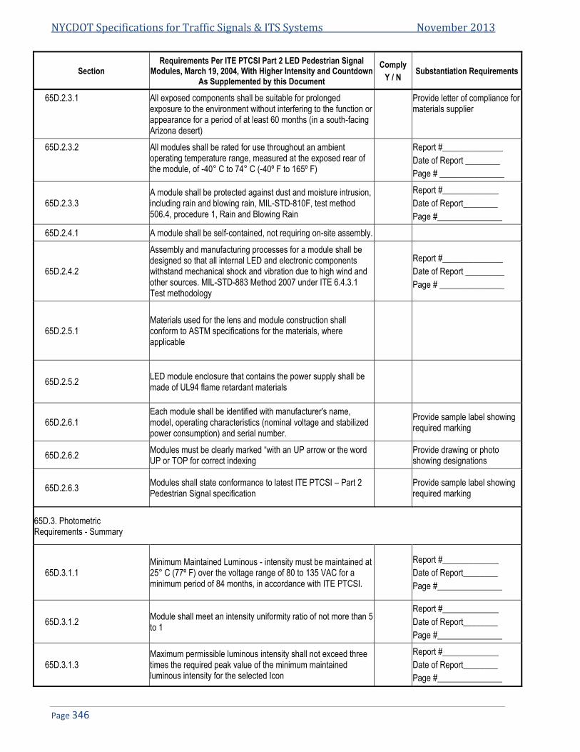
NYCDOT Specifications for Traffic Signals & ITS Systems November 2013
Page 346
Section Requirements Per ITE PTCSI Part 2 LED Pedestrian Signal
Modules, March 19, 2004, With Higher Intensity and Countdown As Supplemented by this Document
Comply
Y / N Substantiation Requirements
65D.2.3.1 All exposed components shall be suitable for prolonged exposure to the environment without interfering to the function or appearance for a period of at least 60 months (in a south-facing Arizona desert)
Provide letter of compliance for materials supplier
65D.2.3.2 All modules shall be rated for use throughout an ambient operating temperature range, measured at the exposed rear of the module, of -40° C to 74° C (-40º F to 165º F)
Report #______________
Date of Report ________
Page # _______________
65D.2.3.3 A module shall be protected against dust and moisture intrusion, including rain and blowing rain, MIL-STD-810F, test method 506.4, procedure 1, Rain and Blowing Rain
Report #_____________
Date of Report________
Page #_______________
65D.2.4.1 A module shall be self-contained, not requiring on-site assembly.
65D.2.4.2
Assembly and manufacturing processes for a module shall be designed so that all internal LED and electronic components withstand mechanical shock and vibration due to high wind and other sources. MIL-STD-883 Method 2007 under ITE 6.4.3.1 Test methodology
Report #______________
Date of Report _________
Page # _______________
65D.2.5.1 Materials used for the lens and module construction shall conform to ASTM specifications for the materials, where applicable
65D.2.5.2 LED module enclosure that contains the power supply shall be made of UL94 flame retardant materials
65D.2.6.1 Each module shall be identified with manufacturer's name, model, operating characteristics (nominal voltage and stabilized power consumption) and serial number.
Provide sample label showing required marking
65D.2.6.2 Modules must be clearly marked “with an UP arrow or the word UP or TOP for correct indexing
Provide drawing or photo showing designations
65D.2.6.3 Modules shall state conformance to latest ITE PTCSI – Part 2 Pedestrian Signal specification
Provide sample label showing required marking
65D.3. Photometric Requirements - Summary
65D.3.1.1 Minimum Maintained Luminous - intensity must be maintained at 25° C (77º F) over the voltage range of 80 to 135 VAC for a minimum period of 84 months, in accordance with ITE PTCSI.
Report #_____________
Date of Report________
Page #_______________
65D.3.1.2 Module shall meet an intensity uniformity ratio of not more than 5 to 1
Report #_____________
Date of Report________
Page #_______________
65D.3.1.3 Maximum permissible luminous intensity shall not exceed three times the required peak value of the minimum maintained luminous intensity for the selected Icon
Report #_____________
Date of Report________
Page #_______________

Spec 65D: NYCDOT Spec for 16”x18” LED Pedestrian Hand/Person/Countdown Module
Page 347
Section Requirements Per ITE PTCSI Part 2 LED Pedestrian Signal
Modules, March 19, 2004, With Higher Intensity and Countdown As Supplemented by this Document
Comply
Y / N Substantiation Requirements
65D.3.2.1
Color regions: the measured chromaticity coordinates of modules shall conform to the requirements of 3.2. using White for the walking person and Portland Orange for the upraised hand / countdown
Report #_____________
Date of Report________
Page #_______________
65D.3.3
Color Uniformity: The dominant wavelength for the Portland Orange color measurement of a portion of the emitting surface of a module shall be within ±3 nm of the dominant wavelength for the average color measurement of the emitting surface as a whole. For the walking person the uniformity shall be calculated utilizing the formula provides in Article 65D.3.3.
Report #_____________
Date of Report________
Page #_______________
65D.4. Electrical Requirements – Summary
65D.4.1.1 General: Wire consist of secured, color coded, 600 V, jacketed wires, a minimum length of 39", 20 AWG, 105° C rated, conforming to NFPA 70.
Provide wire specification
65D.4.1.2 Wire color shall be blue for walking person, orange for the hand and white for the AC common with the countdown internally wired
65D.4.1.3 AC wires shall enter the housing vie a rubber grommetted strain relief, and shall be skinned 3/8” and tinned
65D.4.1.3.1 All external wiring shall be anti-capillary type wire Provide wire specification
65D.4.1.4
Hand / Person Icons shall utilize separate power supplies. Countdown module must have separate power supply but may take power from the incoming Hand/ Person power wires. All power supplies shall be located internal to the module
65D.4.1.4.1 All power supplies shall be located internal to the module and be conformal coated
65D.4.2.1 Voltage range of 80 to 135 VAC RMS, operate off a 60±3 Hz AC line.
Report #_____________ Date of Report________ Page #_______________
65D.4.2.2 Fluctuations over the voltage range of 80 to 135 VAC shall not affect the luminous intensity by more than + or – 10
Report #_____________
Date of Report________
Page #_______________
65D.4.2.3 The module shall prevent flicker of the LED output at frequencies less than 100 Hz over the voltage range of 80 to 135 VAC RMS
65D.4.2.4 Low voltage turn OFF: there shall be no visible illumination from the LED signal module when the applied voltage is less than 35 VAC
Report #_____________
Date of Report________
Page #_______________
65D.4.2.5
Turn ON time: A module shall reach 90 % of full illumination within 75 msec of the application of the nominal operating voltage, Turn OFF time: The signal shall cease emitting visible illumination within 75 msec of the removal of the nominal operating voltage.
Report #_____________
Date of Report________
Page #_______________

NYCDOT Specifications for Traffic Signals & ITS Systems November 2013
Page 348
Section Requirements Per ITE PTCSI Part 2 LED Pedestrian Signal
Modules, March 19, 2004, With Higher Intensity and Countdown As Supplemented by this Document
Comply
Y / N Substantiation Requirements
65D.4.2.6
For abnormal conditions when nominal voltage is applied to the phase wires of the hand / person icons, the display will default to the hand signal, the countdown under this condition will display 0 then blank
65D.4.3.1 Transient Voltage Protection: LED module shall withstand NEMA standard TS-2-2003, section 2.1.8
Report #_____________
Date of Report________
Page #_______________
65D.4.4.1 Emission of Electronic noise shall meet FCC Title 47, Subpart B, section 15 for class A digital device
Report #_____________ Date of Report________ Page #_______________
65D.4.5.1 Power Factor of .90 or greater at nominal voltage and 25° C
Report #_____________
Date of Report________
Page #_______________
65D.4.5.2 THD shall not exceed 20% at 25° C
Report #_____________
Date of Report________
Page #_______________
65D.4.5.3 Typical Power at 25° C shall meet the requirements shown of 10 W for the hand and 8 W for the person
Report #_____________
Date of Report________
Page #_______________
65D.4.6.1 Sufficient current draw to ensure compatibility and proper triggering and operation of the load switches and conflict monitors in signal controller units.
Report #_____________
Date of Report________
Page #_______________
65D.4.6.2 Off state Voltage Decay: Voltage shall decay to less than 10 VAC RMS in less than 100 ms when switched from On to OFF state if maximum load switch leakage current is 10 mAmp peak.
Report #_____________
Date of Report________
Page #_______________
65D.4.7 Countdown Drive Circuitry (when required)
65D.4.7.1 Countdown timer shall have high off-state impedance to allow for 4 units to be connected to the same channel
65D.4.7.2 Countdown shall not be damaged when exposed to defective Load switch providing a half wave input
65D.4.7.3 Countdown shall be compatible with MENA TS-1, TS-2, Type 170 and Type 2070 signal controllers
65D.4.7.4 Countdown shall have an internal conflict monitor making it impossible to display a countdown during a solid hand indication
65D.4.8 Countdown Functionality (when required)
65D.4.8.1 Countdown only displays during the Pedestrian Clearance Interval
65D.4.8.2 Countdown shall have microprocessor capable of recording the pedestrian crossing timing when connected to traffic controller
65D.4.8.3 Countdown shall be blank during first cycle after connection while recording time required for countdown

Spec 65D: NYCDOT Spec for 16”x18” LED Pedestrian Hand/Person/Countdown Module
Page 349
Section Requirements Per ITE PTCSI Part 2 LED Pedestrian Signal
Modules, March 19, 2004, With Higher Intensity and Countdown As Supplemented by this Document
Comply
Y / N Substantiation Requirements
65D.4.8.4 Countdown monitors controller for changes and reprograms automatically if needed
65D.4.8.5 Countdown begins count at start of the pedestrian clearance interval
65D.4.8.6 When flashing hand becomes solid countdown displays “0” for 1 second when hand becomes solid then goes blank
65D.4.8.7 Upon pre-emption the countdown skips the clearance time and reaches “0” at the same time the hand becomes solid.
65D.4.8.8 Countdown returns to normal operation after pre-emption
65D.4.8.9 Countdown shall be capable of timing 2 consecutive complete pedestrian cycles (no hand signal) outputted by the traffic controller
65D.4.8.10 Countdown shall not display erroneous time when connected to a defective load switch
65D.5.0 Quality Assurance
65D.5.1.2 Vendor Records maintained for 7 years
65D.5.2 Modules identified with information required per section 2.6 Provide Samples or drawing of the labels
65D.5.3 All modules are tested and inspected per the production test requirements of section 5.3
65D.5.4
ETL Test Report must be supplied for all products demonstrating compliance to the design qualification requirements of section 5.4 of this document and section 6.4 of the ITE PTCSI LED Pedestrian Traffic Signal Module Adopted March 19, 2004
Report # ______________
Date of Report _________
65D.6.1.1Warranty Requirements
Manufacturer shall issue a written warranty statement, stating compliance to the warranty requirements of this document
Attach Manufacturer’s Warranty Statement
65D.6.1.2 Module to be repaired or replaced if the module fails to function as a result of workmanship or material defects within 84 months of date of delivery
Attach Manufacturer’s Warranty Statement
65D.6.1.3 Module that fail to comply with the minimum intensity requirements within the first 84 months shall at the manufacturer’s option, be repaired or replaced
Attach Manufacturer’s Warranty Statement
END OF SPECIFICATIONS FOR 16”x18” LED PEDESTRIAN HAND/PERSON/COUNTDOWN MODULE


Specification 65E
NYCDOT Specification for 16”x18” LED Pedestrian Signal Module
Date of Revision Revised by Description
5/10/2010 16”x18”

NYCDOT Specifications for Traffic Signals & ITS Systems November 2013
Page 352
65E. NYCDOT SPECIFICATION FOR 16”X18” LED PEDESTRIAN SIGNAL MODULE ............................................................ 353 65E.1. GENERAL .................................................................................................................................................................... 353 65E.2. INSTALLATION ............................................................................................................................................................. 353 65E.3. LED SIGNAL LENS ....................................................................................................................................................... 353 65E.4. LED SIGNAL MODULE CONSTRUCTION ......................................................................................................................... 353 65E.5. ENVIRONMENTAL REQUIREMENTS ................................................................................................................................ 354 65E.6. LUMINOUS INTENSITY................................................................................................................................................... 354 65E.7. CHROMATICITY ............................................................................................................................................................ 354 65E.8. ELECTRICAL ................................................................................................................................................................ 354 65E.9. QUALITY ASSURANCE .................................................................................................................................................. 355 65E.10. PRODUCTION QUALITY ASSURANCE ............................................................................................................................. 355 65E.11. DESIGN QUALIFICATION TESTING ................................................................................................................................. 355 65E.12. WARRANTY ................................................................................................................................................................. 356
Specification 65E: NYCDOT Spec for NYCDOT 16”x18” LED Pedestrian Signal Module
Page 353
65E. NYCDOT Specification for 16”x18” LED Pedestrian Signal Module
65E.1. General 65E.1.1. This material specification is for Light Emitting Diode (LED) pedestrian signals for use in the City of New
York. The signals shall utilize the universal symbols of the “Upraised Hand” and “Walking Man” in LEDs. These LEDs shall conform to the color requirements of the Institute of Transportation Engineers (ITE) Standards “Pedestrian Traffic Control Signal Indication” and the Manual on Uniform Traffic Controls Devices (MUTCD).
65E.2. Installation 65E.2.1. LED pedestrian signal shall be designed as retrofit replacements for the existing housings.
65E.2.2. LED pedestrian signals shall not require special tools for installation.
65E.2.3. LED pedestrian signals shall fit into the existing 16” x 18” traffic housings currently utilized by the City of New York without any modification to the housing.
65E.2.4. LED pedestrian signals shall be weather- resistant, fit securely in the housing and shall connect directly to existing electrical wiring.
65E.2.5. Installation of a retrofit replacement LED signal module into the existing signal housing shall only require the removal of the existing optical unit components, i.e., lens, lamps, gaskets, and reflectors. The existing front grid shall be removed.
65E.2.6. Each retrofit kit shall include all necessary components to complete conversion, including one piece gasket.
65E.2.7. All components remover from the existing signal housing shall become the property of the Contractor.
65E.3. LED Signal Lens 65E.3.1. The lens of the LED pedestrian signals shall be field replaceable.
65E.3.2. The lens of the LED pedestrian signals shall be of polymeric material, UV stabilized and a minimum 1/8” thick.
65E.3.3. The lens shall be dispersive to aid in legibility at a distance of 100 feet.
65E.4. LED Signal Module Construction 65E.4.1. The LED pedestrian signal (including the “Upraised Hand” and “Walking Man”) shall be a signal, self-
contained device, not requiring on-site assembly for installation into the existing traffic signal housing. Both the power supply and circuit board shall be integral to the signal.
65E.4.2. All Portland Orange LEDs shall be “AllnGap” technology or equal, and rated for 100,000 hours or more at 25º C (77º F) and 20 mAmp. “AlGaAs” technology is not acceptable.
65E.4.3. All white LEDs shall be “InGaN” technology or equal.
65E.4.4. The “Upraised Hand” portion of the pedestrian signal shall be a full hand and the “Walking Man” portion shall be a full walking man or incandescent look. Outline figures are not acceptable.
65E.4.5. All internal LED and electronic components shall be adequately supported to withstand mechanical shock and vibration from high winds and other sources.
65E.4.6. The signal module shall be made of UL94VO flame retardant materials. The lens is excluded from this requirement.
65E.4.7. Each individual LED pedestrian signal shall be identified for warranty purposed with the manufacture’s name, serial number and operating characteristics, i.e., rated voltage and power consumption.

NYCDOT Specifications for Traffic Signals & ITS Systems November 2013
Page 354
65E.5. Environmental Requirements 65E.5.1. The LED pedestrian signals shall be rated for use in the ambient operating temperature range of -40ºC to
60ºC (-40ºF to 140ºF).
65E.5.2. The LED pedestrian signals, when properly installed with gasket, shall be protected against dust moisture intrusion per requirements of NEMA Standard 250-1991, Sections 4.7.2.1 and 4.7.3.2, for type 4 enclosures to protect all internal LED, electronic, and electrical components.
65E.6. Luminous Intensity 65E.6.1. The minimum maintained luminous intensity of the “Upraised Hand” portion of the LED pedestrian signal
shall not be less than 3,750 cd/m2 throughout its operating range and its warranty period.
65E.6.2. The minimum maintained luminous intensity of the “Walking Man” portion of the LED pedestrian safety shall not be less than 2,250 cd/m2 throughout its operating range and its warranty period.
65E.6.3. The pedestrian signal shall be legible from a distance of 100 feet.
65E.6.4. The initial luminous of the LED pedestrian signal shall be sufficient so as to ensure the above value will be met at the end of the warranty period at 38ºC (82º F).
65E.6.5. The luminous intensity of the LED pedestrian signal shall not vary more than + 10% for the voltage range of 80 to 135 VAC.
65E.7. Chromaticity 65E.7.1. The measured chromaticity coordinates of the LED pedestrian signals shall conform to the chromaticity
requirements of Section 5.3.2.1 Figure C of the Vehicle Traffic Control Signal Head (VTCSH) standard.
65E.8. Electrical 65E.8.1. Two secured, color coded, 914 mm (36in) long, 600 V, 20 AWG minimum, jacketed wires, conforming to the
National Electrical Code (NEC), rated for service at +105ºc, ½ in stripped and tinned are to be provided for electrical connection.
65E.8.2. The LED pedestrian signal shall operate from a 60±3Hz ac line over a voltage range of 80 to 135 VAC. The current draw shall be sufficient to ensure compatibility and proper triggering and operation of load current switches and conflict monitors in the signal controller units in use in the City of New York.
65E.8.3. Nominal operating voltage for all measurements shall be 120±3 VAC RMS.
65E.8.4. The LED circuitry shall prevent flicker at less than 100Hz over the voltage range specified above.
65E.8.5. The LED pedestrian signal circuitry shall include voltage surge protection against high-repetition noise transients and low-repetition noise transients as stated in Section 2.1.6, NEMA TS-2 1992.
65E.8.6. Catastrophic failure of one LED shall results in the loss of on more than 5% of the total light output.
65E.8.7. The LED pedestrian signal shall be operationally compatible with the currently used controller assemblies.
65E.8.7.1. The City of New York utilizes ASTC. The LED pedestrian signal shall be operationally compatible with both types to allow for potential upgrades in the future.
65E.8.7.2. The LED signal module shall be operationally compatible with voltage threshold of conflict monitors.
65E.8.8. The LED pedestrian signal including its circuitry must meet Federal Communications Commission (FCC) Title 47, Subpart B, Section 15 regulations concerning the emissions of noise.
65E.8.9. The LED pedestrian signal shall provide a power factor of 0.90 of greater over the operating voltage range and temperature range specified above.
65E.8.10. Total harmonic distortion (current and voltage) induced into an AC power line by an LED pedestrian signal shall not exceed 20% over the operating voltage range and temperature range specified above.

Specification 65E: NYCDOT Spec for NYCDOT 16”x18” LED Pedestrian Signal Module
Page 355
65E.9. Quality Assurance 65E.9.1. LED pedestrian signals manufactured in accordance with a vendor quality assurance (QA) program including
both design and production quality assurances. All QA process and test results documentation describe below shall be kept on file for a minimum of seven years.
65E.10. Production Quality Assurance 65E.10.1. The following Production Quality Assurance tests shall be performed on each new LED pedestrian signal
prior to shipment. The specific values of the test results with the corresponding serial number are to be documented for each LED pedestrian signal. Failure to meet requirements of any of the tests shall be cause for rejection. This document must be provided with each shipment. The city reserves the right to retest or withdraw approval at any time or any time a change is made in the product.
65E.10.2. Signal Burn-in-All LED pedestrian signals shall be energized for a minimum of 24 hours, at 100% duty cycle, in an ambient temperature of 60º C (140º F).
65E.10.3. After burn-in, all LED pedestrian signals shall be tested for rated maintained minimum luminous intensity. Each shall be energized at the nominal operating voltage for a five-minute stabilization period before measurements are made. The ambient temperature for this measurement shall be 25º C (77º F). A two point measurement (one for the Portland orange LEDs and one for the white LEDs) with a correlation to the intensity requirements defined in this specification may be used.
65E.10.4. After burn-in, all LED pedestrian signals shall be tested for power factor and shall meet the requirements defined in this specification.
65E.10.5. After burn-in, all LED pedestrian signals shall be measured for current flow in amperes. The measured current value shall not exceed 110% of the design qualification measurements (described in the next section).
65E.10.6. All LED pedestrian signals shall be visually inspected for any exterior damage or assembly anomalies. Careful attention shall be paid to the surface of the lens to ensure there are no scratches, cracks, chips, discoloration or other defects.
65E.11. Design Qualification Testing 65E.11.1. Design Qualification testing described below shall be performed and the resulting data shall be submitted to
the Department for approval. All Design Qualification testing shall be performed after a burn-in module energized for a minimum of 24 hours, at 100% duty cycle, in an ambient temperature of 60º C (140º F). Signals submitted for test shall be representative of typical production units.
65E.11.2. Documentation of each of these test results shall be submitted in a binder with tabs labeled with the corresponding letter of the test described below.
65E.11.2.1. The LED pedestrian signals shall be tested for rated initial luminous intensity. These measurements shall be recorded at an ambient temperature of 25º C (77º F) after the signal has operated for 30 minutes.
65E.11.2.2. The LED pedestrian safety signals shall be measured for current flow in amperes by an independent testing laboratory.
65E.11.2.3. The LED pedestrian signals shall be tested for wattage by an independent testing laboratory.
65E.11.2.4. The LED pedestrian signals shall be measured for chromaticity per the requirements defined in this specification using a spectroradiometer at an ambient temperature of 25ºC(77ºF)
65E.11.2.5. The LED pedestrian signals shall be measured for power factor per the requirements defined in this specification by an independent testing laboratory.
65E.11.2.6. The LED pedestrian signals shall be measured for total harmonic distortion per the requirements defined in this specification by an independent testing laboratory.
65E.11.2.7. The LED pedestrian signals shall be tested for electronic noise per the requirements defined in this specification with reference to a Class A emission limits referenced FCC Title 47 Subpart B, Section 15 by an independent testing laboratory.

NYCDOT Specifications for Traffic Signals & ITS Systems November 2013
Page 356
65E.11.2.8. The LED pedestrian signals shall be tested for compatibility with the controller unit monitor and both types of load switches used in the City of New York.
65E.11.2.9. The LED pedestrian signals shall be tested for transient immunity (e.g. Early electronic component morality failures, component reliability problems). Using NEMA Standard TS-2, 1992 Section 2.1.8 by an independent testing laboratory.
65E.11.2.10. Mechanical vibration testing shall be performed on the LED pedestrian signals, by an independent testing laboratory, in accordance with MIL-STD-883, Test Method 2007, using three 4 minute cycles along each x, y, and z axis, at a force of 2.5 Gs, with a frequency sweep from 2 Hz to 120 Hz. The loosening of the lens, of any internal components, or any other physical damage shall be cause for rejection.
65E.11.2.11. Temperature cycling shall be performed on the LED pedestrian signals by an independent testing laboratory, in accordance with MIL-STD-833, Test Method 1010. Using the temperature range of -40º C to 60º C (-40º F to 140º F), twenty cycles (minimum) with a thirty minute transfer time between temperature extremes and with a thirty minute dwell time at each extreme shall be performed. Modules under test fail to function properly or that show evidence of cracking of the lens or housing shall be rejected.
65E.11.2.12. Moisture resistance testing shall be performed on the LED pedestrian signals with gasket, by an independent testing laboratory, in accordance with NEMA Standard 250-1991 for Type 4 enclosures. Any evidence of internal moisture after testing shall be cause for rejection.
65E.12. Warranty
65E.12.1. Manufacturers shall provide a Certificate of Compliance to this specification for each shipment of pedestrian signals.
65E.12.2. Manufacturers shall provide (within 48 hours) a replacement for any LED signal that fails to function in accordance with this specification or does not exhibit the luminous intensity defined in this specification.
65E.12.3. The term of this warranty shall be seven years from the date of installation.
END OF SPECIFICATIONS FOR NYCDOT 16”x18” LED PEDESTRIAN SIGNAL MODULE

Specification 66
NYCDOT Specification for 16”x16” LED Pedestrian Hand/Person/Countdown Module
Date of Revision Revised by Description
5/12/2010 New Spec

NYCDOT Specifications for Traffic Signals & ITS Systems November 2013
Page 358
NYCDOT SPECIFICATION FOR 16”X16” LED PEDESTRIAN HAND/PERSON/COUNTDOWN MODULE (NYCDOT 66.PEDESTRIAN COUNTDOWN SIGNAL) ............................................................................................................................... 359
66.1. OVERVIEW .................................................................................................................................................................. 359 66.2. PHYSICAL AND MECHANICAL REQUIREMENTS ................................................................................................................ 359 66.3. PHOTOMETRIC REQUIREMENTS .................................................................................................................................... 361 66.4. ELECTRICAL ................................................................................................................................................................ 363 66.5. QUALITY ASSURANCE .................................................................................................................................................. 365 66.6. WARRANTY REQUIREMENTS......................................................................................................................................... 370 66.7. ATTACHMENT 1 ........................................................................................................................................................... 370

Spec 66: NYCDOT Spec for 16”x18” LED Pedestrian Hand/Person/Countdown Module
Page 359
NYCDOT Specification for 16”x16” LED Pedestrian 66.Hand/Person/Countdown Module
(NYCDOT Pedestrian Countdown Signal)
66.1. Overview The purpose of this specification is to provide the minimum performance requirements for LED pedestrian 66.1.1.
signal modules (hereafter called module or modules) with “Walking Person”, “Upraised Hand”, and “Countdown Digit” icons. This specification includes the following sizes (nominal message bearing surface) 16”x16”. This specification refers to definitions and practices described in Pedestrian Traffic Control Signal Indications (PTCSI) Part 2: Light Emitting Diode (LED) Pedestrian Traffic Signal Modules (PTCSI), adopted March 19, 2004 and published in the Equipment and Materials Standards of the Institute of Transportation Engineers (ITE) and contains additional requirements to ensure optimum long term reliability and performance.
66.2. Physical and Mechanical Requirements General 66.2.1.
Usage: Modules shall fit into pedestrian signal housings manufactured in accordance with NYCDOT 66.2.1.1.Specifications 64B without modification to the housing.
The sizes of the message bearing surfaces shall be in accordance with the dimensions given in Table 1. 66.2.1.2.Table 1—Dimensions of Hand/Person Signal Sizes
Message Bearing Surface Height X Width
Minimum Message Size Height X Width
16" x 16" 11" x 7"
All countdown display digits shall be 9” in height to allow for use in all size crosswalks to comply with 66.2.1.3.MUTCD recommendations.
The LED Signal Module 66.2.2.
The module shall be capable of replacing the optical component of the pedestrian indication. 66.2.2.1.
The lens may have a textured outer surface to reduce glare. 66.2.2.2.
The module lens may be a replaceable part, without the need to replace the complete module. 66.2.2.3.
Icons that are printed on the lens shall be on the interior surfaces in order to prevent scratching and 66.2.2.4.abrasion to the icons.
All icons and numbers shall have a uniform appearance. Both the incandescent and pixilated type are 66.2.2.5.acceptable.
All LEDs utilized to illuminate the “Upraised Hand” and “Walking Person” icons shall be LEDs that have 66.2.2.6.been manufactured utilizing material that has industry acceptance as being suitable for uses in outdoor applications. At no time is the use of LEDs that utilize AlGaAs technology acceptable.
The configurations of the “Walking Person” icon, “Upraised Hand” icon and “countdown digits” are 66.2.2.7.illustrated in Figure 1, Figure 2, and Figure 3 respectively. All icons shall meet the minimum size requirements of Table 1.
The LED countdown display shall consist of two “7-segment” digits forming the time display. The 66.2.2.8.countdown shall be capable of displaying the digits 0 through 99.

NYCDOT Specifications for Traffic Signals & ITS Systems November 2013
Page 360
Figure 1—Walking Person icon Figure 2— Upraised Hand icon
Figure 3—Countdown Display
Spec 66: NYCDOT Spec for 16”x18” LED Pedestrian Hand/Person/Countdown Module
Page 361
Environmental Requirements 66.2.3.
All exposed components of a module shall be suitable for prolonged exposure to the environment, 66.2.3.1.without appreciable degradation that would interfere with function or appearance. As a minimum, selected materials shall be rated for service for a period of a minimum of sixty (60) months in a south-facing Arizona Desert installation.
A module shall be rated for use throughout an ambient operating temperature range, measured at the 66.2.3.2.exposed rear of the module, of -40° C to 74° C (-40° F to 165° F).
A module shall be protected against dust and moisture intrusion, including rain and blowing rain per 66.2.3.3.Mil-STD-810F Method 506.4 Procedure 1 requirements.
Construction 66.2.4.
The module shall be a single, self-contained device, not requiring on-site assembly for installation into 66.2.4.1.an existing traffic signal housing.
The assembly and manufacturing process for the module shall be designed to assure all internal LED 66.2.4.2.and electronic components are adequately supported to withstand mechanical shock and vibration from high winds and other sources.
Materials 66.2.5.
Materials used for the lens and module construction shall conform to ASTM specifications for the 66.2.5.1.materials, where applicable.
Enclosures containing either the power supply or electronic components of the signal module shall be 66.2.5.2.made of UL94 flame retardant materials. The module lens is excluded from this requirement.
Module Identification 66.2.6.
Each module shall be identified on the backside with the manufacturer’s name, model, operating 66.2.6.1.characteristics and serial number. The operating characteristics identified shall include the nominal operating voltage and stabilized power consumption, in watts and Volt-Amperes and statement of FCC compliance. The main module label which includes the module’s serial number (or date code) and the model number shall be attached using polyester or vinyl self-adhesive labels. The use of paper labels is not acceptable. Each unit shall have a separate label that can be written with a ballpoint pen stating the following:
Company installed___________________ Date installed_______________________
Modules shall have a prominent and permanent vertical indexing indicator, i.e., UP Arrow, or the word 66.2.6.2.UP or TOP, for correct indexing and orientation in the signal housing.
Modules conforming to all requirements of this specification shall have a statement on an attached 66.2.6.3.label which states conformance to the latest New York City Pedestrian Signal Specification.
66.3. Photometric Requirements Luminance, Uniformity and Distribution 66.3.1.
For a minimum period of eighty four (84) months, the minimum maintained luminance values for the 66.3.1.1.modules at 25° C (77º F), when measured normal to the plane of the icon surface, shall not be less than:
Walking Person: 5300 cd/m2 Upraised Hand: 3750 cd/m2 Countdown Digits: 3750 cd/m2
The luminance of the emitting surface, measured at angles from the normal of the surface, may 66.3.1.1.1.decrease linearly to a value of 50% of the values listed above at an angle of 15 degrees.
The light output requirements in this specification apply to pedestrian signal heads without any 66.3.1.1.2.visors, hooded or louvered (egg-crate). Addition of such visors may affect the light output of the signal head.

NYCDOT Specifications for Traffic Signals & ITS Systems November 2013
Page 362
The uniformity of the “Walking Person”, “Upraised Hand”, and “countdown digit” icons’ luminance shall 66.3.1.2.meet a ratio of not more than 1 to 5 between the minimum and maximum luminance values, as measured in 0.5 in. diameter spots.
When operating within the temperature range specified in Article 66.2.3.2., the average luminance of 66.3.1.3.the module shall not exceed three times the maintained minimum luminance of the modules, as defined in Article 66.3.1.1.
Chromaticity 66.3.2.
The standard colors for the LED Pedestrian Signal Module shall be White for the Walking Person and 66.3.2.1.Portland Orange for the Upraised Hand and countdown digit icons. The colors for these icons shall conform to the following color regions, based on the 1931 CIE chromaticity diagram:
Walking Person — White: 66.3.2.1.1.Blue boundary: x = 0.280. 1st Green boundary: 0.280 ≤ x < 0.400 y = 0.7917x + 0.0983 2nd Green boundary: 0.400 ≤ x < 0.450 y = 0.4600x + 0.2310 Yellow boundary: x = 0.450 1st Purple boundary: 0.450 ≤ x < 0.400 y = 0.4600x + 0.1810 2nd Purple boundary: 0.400 ≤ x < 0.280 y = 0.7917x + 0.0483
White
Point x y
1 0.280 0.320
2 0.400 0.415
3 0.450 0.438
4 0.450 0.388
5 0.400 0.365
6 0.280 0.270
Upraised Hand and Countdown Digits—Portland Orange: 66.3.2.1.2.
Yellow boundary: y = 0.390 White boundary: 0.600 ≤ x ≤ 0.680 y = 0.990 – x Red boundary: y = 0.331
Portland Orange
Point x y
1 0.6095 0.390
2 0.600 0.390
3 0.659 0.331
4 0.669 0.331
The color regions are illustrated in Attachment 1. 66.3.2.2.
Color Uniformity 66.3.3.
The uniformity of the emitted colors shall be such that any color measurement within a 12 mm (0.5 66.3.3.1.inch) spot on the emitting surface shall fall within the following regions around the average measured color of the entire emitting surface:
Walking Person (White Color) - ; 66.3.3.1.1.
04.022
yx

Spec 66: NYCDOT Spec for 16”x18” LED Pedestrian Hand/Person/Countdown Module
Page 363
where Δx and Δy are the differences in the chromaticity coordinates of the measured colors to the coordinates of the average color, using the CIE 1931 Chromaticity Diagram and a 2 degree Standard Observer.
Upraised Hand and Countdown Digits (Portland Orange Color) - The dominant wavelength for 66.3.3.1.2.all individual color measurements shall be within ±3 nm of the dominant wavelength for the average of all the individual color measurements.
66.4. Electrical General 66.4.1.
All wiring shall meet the requirements of Section 13.02 of the VTCSH standard. Secured, color coded, 66.4.1.1.600V, 18 AWG jacketed wires, 1 meter (39 inch) in length, conforming to the NFPA 70, National Electrical Code, and rated for service at 105° C, shall be provided. The end of each wire shall be stripped 3/8 inch and soldered to form a solid connection point.
The following color scheme shall be used for the module’s AC power leads: Orange for the “Upraised 66.4.1.2.Hand”, Blue for the “Walking Person”, and White for common. The countdown portion of the LED module shall be internally wired to the incoming Hand/Person power.
The AC power leads shall exit the module via a rubber grommetted strain relief. The leads shall be 66.4.1.3.separate at the point at which they leave the module.
All external wiring utilized in the modules shall be anti-capillary type wire to prevent the wicking of 66.4.1.4.moisture to the interior of the module.
The “Upraised Hand” and “Walking Person” icons shall utilize separate power supplies. The countdown 66.4.1.5.module must have its own power supply but may take the incoming AC power from the hand/person AC signal lines. All power supplies shall be located inside the signal module.
All power supplies shall be conformal coated for additional protection. 66.4.1.6.
Voltage Range 66.4.2.
LED signal modules shall operate from a 603 Hz AC line power over a voltage range from 80 to 135 66.4.2.1.VAC RMS. Nominal operating voltage for all measurements shall be 120 ± 3VAC RMS, unless otherwise specified.
Fluctuations in line voltage over the range of 80 to 135 VAC shall not affect luminous intensity by more 66.4.2.2.
than 10 percent.
The module circuitry shall prevent flicker of the LED output at frequencies less than 100 Hz over the 66.4.2.3.voltage range specified in Article 66.4.2.1.
Low Voltage Turn OFF: There shall be no visible illumination from the LED signal module when the 66.4.2.4.applied voltage is less than 35 VAC.
Turn-ON and Turn-OFF Time: A module shall reach 90% of full illumination (turn-ON) within 75 msec of 66.4.2.5.the application of the nominal operating voltage. The signal shall cease emitting visible illumination (Turn-OFF) within 75 msec of the removal of the nominal operating voltage.
Default Condition: Applies to modules that have both the “Walking Person” and the “Upraised Hand” as 66.4.2.6.one module. For abnormal conditions when nominal voltage is applied to the unit across the two-phase wires or simultaneously to both “Upraised Hand” and “Walking Person” icons, the pedestrian signal unit shall default to the “Upraised Hand” symbol. For units that contain a countdown module the countdown shall display a “0” then blank.
Transient Voltage Protection 66.4.3.
The on-board circuitry of the module shall include voltage surge protection, to withstand high-repetition 66.4.3.1.noise transients and low-repetition high-energy transients as stated in Section 2.1.8, NEMA Standard TS 2-2003.

NYCDOT Specifications for Traffic Signals & ITS Systems November 2013
Page 364
Electronic Noise 66.4.4.
The LED signal and associated on-board circuitry shall meet the requirements of the Federal 66.4.4.1.Communication Commission (FCC) Title 47, Subpart B, Section 15 regulations concerning the emission of electronic noise by Class A digital devices.
Power Factor (PF), AC Harmonics And Power 66.4.5.
Modules shall provide a power factor of 0.90 or greater when operated at nominal operating voltage 66.4.5.1.and 25º C (77º F).
Total harmonic distortion induced into an AC power line by a module at nominal operating voltage, and 66.4.5.2.at 25º C (77º F), shall not exceed 20%.
Typical Power at 25º C (77º F) for the Pedestrian Signal Modules shall be 10W for the hand, and 8W 66.4.5.3.for the person.
Controller Assembly Compatibility 66.4.6.
The current draw for “Upraised Hand” and “Walking Person” icons shall be sufficient to ensure 66.4.6.1.compatibility and proper triggering and operation of load current switches and conflict monitors in signal controller units.
Off State Voltage Decay: When the “Upraised Hand” or “Walking Person” icon is switched from the 66.4.6.2.On-state to the Off-state, the terminal voltage shall decay to a value less than 10 VAC RMS in less than 100 msec when driven by a maximum allowed load switch leakage current of 10 mAmp peak (7.1 mAmp AC).
Countdown Drive Circuitry 66.4.7.
The countdown portion of the signal shall have a high Off-state input impedance so as not to provide a 66.4.7.1.load indication to conflict monitors and interfere with the monitoring of the pedestrian signal. The input impedance of the countdown circuitry shall maintain a voltage reading above 25 VAC to the conflict monitor for up to four units connected on the same channel.
The Countdown Timer drive circuitry shall not be damaged when subjected to defective load switches 66.4.7.2.providing a half wave signal input.
The countdown module shall be compatible with all traffic signal controllers that are fully compliant to 66.4.7.3.NEMA TS-1, NEMA TS-2, Type 170, and Type 2070 traffic signal controller specifications.
The countdown module shall have an internal conflict monitor circuit preventing any possible conflicts 66.4.7.4.between the Hand/Person signal indications and the Countdown Timer display. It shall be impossible for the display to countdown during a solid “Upraised Hand” indication.
Countdown Functionality 66.4.8.
Per MUTCD Manual 2003 edition, with revisions 1 and 2 incorporated dated December 2007, section 66.4.8.1.4E.07: “Countdown displays should ONLY be used during the “Clearance Cycle”. They should NOT be used during the walk interval nor during the yellow change interval of a concurrent vehicular phase”.
The countdown timer module shall have a micro-processor capable of recording the pedestrian 66.4.8.2.crossing timing when connected to a traffic controller. It shall be capable of displaying the digits 0 through 99.
When connected, the module shall blank out the display during the initial cycle while it records the 66.4.8.3.countdown time using the Walk (Walking Person) & Don’t Walk (Flashing Upraised Hand) signal indications. The “Upraised Hand” and “Walking Person” icons shall be displayed as normal during this cycle.
The countdown timer module shall continuously monitor the traffic controller for any changes to the 66.4.8.4.pedestrian phase time and re-program itself automatically if needed.
The countdown module shall register the time for the walk and clearance intervals individually and shall 66.4.8.5.begin counting down at the beginning of the pedestrian clearance interval. The countdown module shall display the numerals in a continuous display and shall not flash during the countdown.

Spec 66: NYCDOT Spec for 16”x18” LED Pedestrian Hand/Person/Countdown Module
Page 365
When the flashing “Upraised Hand” becomes solid, the module shall display 0 for one second and then 66.4.8.6.blank-out. The display shall remain dark until the beginning of the next countdown.
In the event of a pre-emption sequence, the countdown module shall skip the pre-empted clearance 66.4.8.7.time and reach “0” at the same time as the flashing “Upraised Hand” becomes solid and then remain dark until the next cycle.
In the cycle following a pre-emption call, the signal shall display the correct time and not be affected by 66.4.8.8.the reduced previous cycle. The countdown shall remain synchronized with the signal indications and always reach “0” at the same time as the flashing “Upraised Hand” becomes solid.
The countdown timer shall be capable of Displaying 2 consecutive complete Pedestrian Phases 66.4.8.9.outputted by the traffic controller (no steady “Upraised Hand” signal between cycles).
NOTE: When a controller is programmed with the option to serve a second consecutive pedestrian 66.4.8.10.phase (walk followed by flashing don’t walk) if a pedestrian activates a pedestrian button during the clearance interval, and the controller is set to allow a second consecutive phase, the countdown will blank out during the walk , and restart counting down the correct time during the flashing don’t walk, just as in a regular PED phase.
The countdown module shall not display an erroneous or conflicting time when subjected to defective 66.4.8.11.load switches. Should there be a short power interruption during the PED clearance interval or if voltage is applied to both the hand and person simultaneously, the display will go to “0” then blank.
66.5. Quality Assurance Samples 66.5.1.
Samples shall be submitted within seven (7) business days of request. The samples will be inspected, 66.5.1.1.tested, and evaluated for conformity to the specifications. Samples must be actual production unit modules and not a prototype or test unit. If Bidder fails to submit a sample for evaluation, or if the sample does not conform to the specification, the Bid will be rejected. Each module submitted shall be accompanied with a complete circuit schematic for the unit, one standard catalog cut and one manufacturer’s technical specification sheet for the unit, and specification describing individual LED light sources used in the unit. The manufacturer shall provide a certificate of compliance for LED pedestrian safety signals manufactured in accordance with vendor quality assurance (QA) program including both design and production quality assurances. All QA Process and Test results documentation described below shall be kept on file for a minimum of seven years.
Production Quality Assurance 66.5.2.
The following Production Quality Assurance tests shall be performed on each new LED pedestrian 66.5.2.1.signal prior to shipment. The specific values of the test results with the corresponding serial number are to be documented for each LED pedestrian signal. Failure to meet requirements of any of the tests shall be cause for rejection. This document must be provided with each shipment. Signal Burn-in-hours, at 100% duty cycle, in an ambient temperature of 60º C (140º F). After burn-in, all LED pedestrian signals shall be tested for rated Maintained minimum. All LED pedestrian signals shall be energized for a minimum of 24 luminous intensity. Each shall be energized at the nominal operating voltage for a five-minute stabilization period before measurements are made. The ambient temperature for this measurement shall be 25º C (77º F). A two point measurement (one for the Portland Orange LEDs and one for the white LEDs) with a correlation to the intensity requirements defined in this specification may be used. After burn-ins, all LED pedestrian signals shall be tested for power factor and shall meet the requirements defined in this specification.
After burn-in, all pedestrian signals shall be measured for current flow in amperes. The measured 66.5.2.2.current value shall not exceed 110% of the design qualifications measurements (described in the next section). All LED pedestrian signals shall be visually inspected for any exterior damage or assembly anomalies. Careful attention shall be paid to the surface of the lens to ensure there are no scratches, cracks, chips, discoloration or defects.
Production Tests & Inspections 66.5.2.3.
Production Test Requirements: All modules shall undergo the following Production Testing & 66.5.2.3.1.Inspection prior to shipment. Failure of a module to meet the requirements of Production

NYCDOT Specifications for Traffic Signals & ITS Systems November 2013
Page 366
Testing & Inspection shall be cause for rejection. Test results shall be maintained per the requirement of Article 66.5.1. All Production Tests shall be performed at an ambient temperature of 25º C (77º F) and at the nominal operating voltage of 120 VAC.
Production Luminance Test: “Upraised Hand”/“Walking Person”/“Digit” icons shall be tested for 66.5.2.3.2.maintained minimum luminance. Any measurement with a correlation to the luminance requirements of Article 66.3.1.1. may be used. Modules that do not meet the maintained minimum luminance requirements as per Article 66.3.1.1. shall be rejected.
Power Factor: “Upraised Hand”/“Walking Person” icons shall be tested for power factor per the 66.5.2.3.3.requirements of Article 66.4.5.1. A commercially available power factor meter may be used to perform this measurement. Failure of a module to meet the requirements for power factor (Article 66.4.5.1.) shall be cause for rejection of the module.
Current Consumption Measurement: “Upraised Hand”/“Walking Person” icons shall be 66.5.2.3.4.measured for current flow in Amperes. The measured current values shall be compared against the design current values from design qualification measurements in Article 66.5.2.7.1. A measured current consumption in excess of 120% of the design qualification current value for an ambient temperature of 25º C (77º F) shall be cause for rejection of the module.
Visual Inspection: All modules shall be visually inspected for any exterior physical damage or 66.5.2.3.5.assembly anomalies. Careful attention shall be paid to the surface of the lens to ensure there are no scratches (abrasions), cracks, chips, discoloration, or other defects. The presence of any such defects shall be cause for rejection of the module. The Module shall be inspected in the street under all weather and light conditions at City discretion by at least four (4) staff members of NYCDOT. The purpose of the inspection is to visually observe the light output and form of raised hand and walking man. The City reserves the right to reject based on this inspection.
Design Qualification Testing 66.5.2.4.
Design Qualification Testing - shall be performed on the “Upraised Hand”/“Walking Person” 66.5.2.4.1.icons of new module designs, and when a major design change has been implemented on existing “Upraised Hand”/“Walking Person” pedestrian signal designs. Modules used in design qualification testing shall be representative of the manufacturer’s proposed normal production.
66.5.2.4.1.1. Testing shall be performed once every five (5) years or when the module design or LED technology has been changed. Test data shall be retained by the module manufacturer in accordance with Article 66.5.1. or for sixty (60) months following final production of a specific design, whichever is longer.
66.5.2.4.1.2. Six (6) modules shall be used in Design Qualification Testing. All six (6) modules shall be subjected to conditioning (Article 66.5.2.4.2.), followed by the Environmental Tests (Article 66.5.2.5.). Following the Environmental Tests, three (3) modules shall undergo Photometric & Colorimetric Tests (Article 66.5.2.6.). The remaining three (3) modules shall undergo the Electrical Tests (Article 66.5.2.7.) and Controller Compatibility Tests (Article 66.5.2.7.11.). Tests shall be conducted in the order described herein, unless otherwise specified.
66.5.2.4.1.3. In order for a module design to be considered acceptable for marking with the label described in Article 66.2.6.1., all tested modules must comply with the acceptance/rejection criteria for the Environmental Tests (Article 66.5.2.5.), Photometric & Colorimetric Tests (Article 66.5.2.6.), Electrical Tests (Article 66.5.2.7.), and Controller Assembly Compatibility Tests (Article 66.5.2.7.11.).
Conditioning - Modules shall be energized for a minimum of 24 hours, at 100% duty cycle, in an 66.5.2.4.2.ambient temperature of 60° C (140° F).
Environmental Testing: 66.5.2.5.
Mechanical Vibration Testing: Three (3) modules shall be tested per MIL-STD-883, Test Method 66.5.2.5.1.2007, using three 4-minute cycles along each x, y, and z axis, at a force of 2.5 Gs, with a frequency sweep from 2 Hz to 120 Hz.
Temperature Cycling: Temperature cycling shall be performed per MIL-STD-883, Test method 66.5.2.5.2.1010. The temperature range shall be per Article 66.2.3.2. A minimum of 20 cycles shall be
Spec 66: NYCDOT Spec for 16”x18” LED Pedestrian Hand/Person/Countdown Module
Page 367
performed with a 30-minute transfer time between temperature extremes and a 30-minute dwell time at each temperature. Modules under test shall be non-operating.
Moisture Resistance: Moisture resistance testing shall be performed on a sample of three 66.5.2.5.3.modules per MIL-STD-810F, Procedure I, Rain and Blowing Rain. The test shall be conducted on a stand-alone unit, without a protective housing. The rainfall rate shall be 1.7 mm/min (4 in/hr) and droplet size shall predominantly be between 0.5 mm and 4.5 mm. The module shall be rotated through 120 degrees and the duration of the test shall be 30 minutes. The module shall be energized throughout the test. The water shall be at 25° C (77º F). The wind velocity shall be 80 km/hr (50 mph). Any evidence of internal moisture into the module shall be cause for rejection.
UV Stabilization: Documentation may be provided that clearly demonstrates that the external 66.5.2.5.4.lens complies with the requirements of Article 66.2.5.1.
Environmental Tests Evaluation: At the conclusion of the Environmental Tests, all the modules 66.5.2.5.5.will be visually inspected for damage.
Acceptance/Rejection Criteria: The loosening of the lens, or any internal components, or 66.5.2.5.6.evidence of other physical damage, such as cracking of the module lens or housing, presence of internal moisture after testing, a change in haze of >15%,or if the module extinguished itself shall be considered a failure for the proposed design.
Photometric & Colorimetric Tests 66.5.2.6.
Three (3) of the modules that were subjected to the Environmental Tests shall undergo 66.5.2.6.1.Photometric & Colorimetric Tests. Unless otherwise specified, these tests shall be performed with the modules energized at nominal operating voltage (120 VAC).
Maintained Minimum Luminance: The sample set shall be tested for maintained minimum 66.5.2.6.2.
luminance at both 25C (77º F) and 74C (165º F). Prior to making measurements, each module shall be operated at a 100% duty cycle for a minimum of 60 minutes at the test temperature.
For elevated temperature testing at 74 C (165º F), the modules to be tested shall be mounted 66.5.2.6.3.in a temperature-testing chamber so that the external surface of the emitting lens is outside the chamber and all portions behind the lens are within the chamber at a temperature of 74º C (165º F). The air temperature in front of the lens of the module shall be maintained at a
minimum of 49 C (120 F) during the elevated temperature testing.
66.5.2.6.3.1. Measurements shall be made using a luminance meter located on the physical axis of the module lens at a distance such that the selected aperture samples a spot size of 12mm (0.5 inch) at the lens surface. The position of the luminance meter shall be translated from side to side and up and down, so as to sample nine points across the emitting surface of the module.
66.5.2.6.3.2. The luminance values for the nine points shall be recorded and the average value calculated.
66.5.2.6.3.3. Modules for which the calculated average value of luminance does not meet the requirements of Article 66.3.1.1. shall be rejected.
Luminance Uniformity: The sample set shall be tested in accordance with the requirements of 66.5.2.6.4.
Article 66.3.1.2., using the recorded values of luminance, at a testing temperature of 25 C (77º F). The highest and lowest values of luminance shall be recorded and compared. Modules not meeting requirements of Article 66.3.1.2. shall be rejected.
66.5.2.6.4.1. Maximum Luminance: The sample set shall be tested in accordance with the requirements of Article 66.3.1.3., using the recorded values of luminance, at testing
temperatures of 25 C (77º F) and 74 C (165º F). Modules for which the calculated average value of the luminance exceeds the limit established in Article 66.3.1.3., at either or both temperature levels, shall be rejected.
Chromaticity: From the sample set, two (2) modules shall be measured for chromaticity per the 66.5.2.6.5.requirements of Article 66.3.2. Prior to making measurements, each module shall be operated at a 100% duty cycle for a minimum of 60 minutes at 25° C (77° F). Color measurements shall

NYCDOT Specifications for Traffic Signals & ITS Systems November 2013
Page 368
be made using a spectro-radiometer with a maximum bandwidth of 4 mm, or a colorimeter that has a measurement uncertainty of less than 2.5% over the emission bandwidth of the icon under measurement.
66.5.2.6.5.1. Measurements shall be made by locating the instrument on the axis normal to the emitting surface of the icon, at a distance such that the meter samples a spot size of 12 mm (0.5 inch) at the lens surface. The position of the instrument shall be translated from side to side and up and down, so as to sample nine points across the emitting surface of the module.
66.5.2.6.5.2. The chromaticity coordinates of the emitted light at the nine points shall be recorded and the average value calculated. In addition, the dominant wavelengths for the nine sampled points of the hand icon shall be calculated and recorded.
66.5.2.6.5.3. Modules for which the calculated average chromaticity coordinates do not meet the requirements of Article 66.3.2. shall be rejected.
66.5.2.6.5.4. Color Uniformity: The sample set shall be tested in accordance with the requirements of Article 66.3.3., using the recorded values of the chromaticity coordinates (“Upraised Hand”/“Walking Person” icon) or the dominant wavelengths (hand-Portland orange icon), from Article 66.5.2.6.5. Modules not meeting requirements of Article 66.3.3. shall be rejected.
Photometric & Colorimetric Tests Evaluation: At the conclusion of the Photometric & 66.5.2.6.6.Colorimetric Tests, the measurement data shall be compared to the requirements of Article 66.3.1. through Article 66.3.3.
Acceptance/Rejection Criteria: The failure of any module to meet all of the requirements for 66.5.2.6.7.maintained minimum luminance (Article 66.3.1.1.) and maximum permissible luminance (Article
66.3.1.3.) at 25 C (77º F) and/or 74 C, (165º F) and the requirements for luminance uniformity
(Article 66.3.1.2.), chromaticity (Article 66.3.2.), and color uniformity (Article 66.3.3.) at 25 C (77º F), shall be considered a failure of the proposed design.
Electrical Testing 66.5.2.7.
Current Consumption: The sample set shall be measured for current flow in Amperes. The 66.5.2.7.1.measured current values shall be used for quality comparison of Production Quality Assurance current measurements on production modules.
Temperature vs. Power Consumption: The sample set shall be tested to measure the change in 66.5.2.7.2.power consumption in Watts versus the change in temperature over the specified operating temperature range. This data shall be recorded and may be made available to all end users.
Power Consumption vs. Long-Term Life: If the rated power consumption of the module at 25° C 66.5.2.7.3.(77º F) and 74ºC (165ºF) will change more than 10% over time, the manufacturer may provide documentation showing the projected power consumption in Watts of the module over a period of sixty (60) months from the date of installation. This documentation may include data for the following temperature points: 0° C (32º F), 25° C (77º F), 50º C (122º F) and 74º C (165º F).
Power Factor (PF): The sample set shall be measured for power factor per the requirements of 66.5.2.7.4.Article 66.4.5.1. A commercially available power factor meter may be used to perform this measurement. The PF shall be calculated separately for each of the icons for the module.
Total Harmonic Distortion (THD): The sample set shall be measured for total harmonic distortion 66.5.2.7.5.per the requirements of Article 66.4.5.2. A commercially available total harmonic distortion meter may be used to perform this measurement. The THD shall be measured for each of the icons for the module.
Low Voltage Turn-Off: The sample set shall be measured to ensure compliance with the low 66.5.2.7.6.voltage turn-off requirement of Article 66.4.2.4. To test for this condition each icon must first be fully illuminated at the nominal operating voltage. The applied voltage shall then be reduced to the point where there is no visible illumination. This point must be greater than 35 VAC RMS AC.
Turn-On and Turn-Off Times: The sample set shall be measured to ensure compliance with the 66.5.2.7.7.turn-on and turn-off requirements of Article 66.4.2.5. The measurement shall be conducted
Spec 66: NYCDOT Spec for 16”x18” LED Pedestrian Hand/Person/Countdown Module
Page 369
using a two channel oscilloscope to measure the time delay between when the module is energized at 120 VAC RMS and when the light output reaches 90% of full output. A photo-multiplier tube shall be used to measure the light output of the module. The same apparatus shall be used to measure the time delay between when the module is de-energized and when the light output reaches 0% of full output. The time in msec shall be plotted in the X axis and light output shall be plotted in the Y axis.
66.5.2.7.7.1. A module not reaching 90% nominal light output within 75 msec at start-up or still showing light output 75 msec after being de-energized shall be deemed to have failed this test.
Electronic Noise: From the sample set, a sample of two (2) modules shall be tested. The 66.5.2.7.8.modules shall be tested for conformance with the requirements of a Class A digital device, as specified in FCC Title 47, Subpart B, Section 15.109(b).
Nondestructive Transient Immunity: The sample set shall be tested for transient immunity using 66.5.2.7.9.the procedure described in Section 2.1.8, NEMA Standard TS 2-2003. Failure to meet these requirements shall be cause for rejection.
Electrical Tests Evaluation: At the conclusion of the Electrical Tests, the measurement data 66.5.2.7.10.shall be compared to the requirements of Article 66.4.2. through Article 66.4.5.
66.5.2.7.10.1. Acceptance/Rejection Criteria: The failure of any module to meet the applicable requirements of Article 66.4.2. through Article 66.4.5. shall be considered a failure of the proposed design.
Controller Assembly Compatibility: Due to the low load current draw and high off-state 66.5.2.7.11.impedance of modules, testing shall be performed to ensure the module design is compatible and operates properly with load current switches and conflict monitors in NEMA and Type 170 traffic signal control units. Before performing the following tests, the manufacturer should ascertain which type of signal controller unit(s) the procuring traffic authority customer has in use and tailor these tests to meet the requirements of that type and model of controller unit(s).
66.5.2.7.11.1. Load Switch Compatibility: The sample set shall be tested for compatibility and proper operation with load current switches. Each module shall be connected to a variable ac voltage supply. The AC line current into the module shall be monitored for sufficient current draw to ensure proper load switch operation while the voltage is varied from 80 to 135 VAC RMS. Failure of the current draw to ensure proper load current switch operation shall be cause for rejection.
66.5.2.7.11.2. Signal Conflict Monitor (MMU – Malfunctioning Monitoring Unit) Compatibility: The sample set shall be tested for compatibility and proper operation with signal conflict
monitors. Each module shall be operated from a 135 VAC RMS supply. A 19.5 k resistor shall be wired in series in the hot line between the module and the AC power
supply. A single-pole-single-throw switch shall be wired in parallel across the 19.5 k
resistor. A 220 k shunt resistor shall be wired between the hot line connection and the neutral line connection on the module. Conflict monitor compatibility shall be tested by
measuring the voltage decay across the 220 k shunt resistor as follows: The single-
pole-single-throw switch shall be closed, shorting out the 19.5 k resistor, allowing the AC power supply to illuminate the module. Next the switch shall be opened, and the
voltage across the 220 k shunt resistor shall be measured for a decay to a value equal to or less than 10 VAC RMS within a time period equal to or less than 100 milliseconds. This test shall be repeated a sufficient number of times to ensure that testing occurs at
the peak of the AC line voltage cycle. A voltage decay across the 220 k shunt resistor to a value greater than 10 VAC RMS or a decay time to 10 VAC RMS greater than 100 msec shall be cause for rejection.
66.5.2.7.11.3. Controller Assembly Compatibility Evaluation: At the conclusion of the Controller Assembly Compatibility Tests, the measurement data shall be compared to the requirements of the specific make and model Controller Assembly with which the module design is intended to operate.
66.5.2.7.11.4. Acceptance/Rejection Criteria: Failure of the module to draw sufficient current to ensure compatibility with the load current switches in the appropriate Controller Assembly

NYCDOT Specifications for Traffic Signals & ITS Systems November 2013
Page 370
(Article 66.4.6.1.) and/or failure of the circuit voltage to decay to a value equal to or less than 10VAC RMS within a time period equal to or less than 100 msec (Article 66.4.6.2.) shall be considered a failure of the proposed design.
66.6. Warranty Requirements 66.6.1. Manufacturers shall provide a written warranty issued by the factory located in the NAFTA country of module
origin with the following minimum provisions:
66.6.2. Modules shall, at the manufacturer’s option, be repaired or replaced if the module fails to function as intended due to workmanship or material defects within the first eighty four (84) months from the date of delivery.
66.6.3. Modules shall, at the manufacturer’s option, be repaired or replaced if the module exhibits luminous intensities less than the minimum specified values within the first eighty four (84) months of the date of delivery.
66.7. Attachment 1 66.7.1. 1931 CEI Chromaticity Diagram
Color Regions for Pedestrian Traffic Control Signal Indications
(1931 CIE Chromticity Diagram)
0.00
0.10
0.20
0.30
0.40
0.50
0.60
0.70
0.80
0.90
0.00 0.10 0.20 0.30 0.40 0.50 0.60 0.70 0.80
x
y
490
500
510
White:
1) x = 0.280
2) y = 0.7917*x + 0.0983
3) y = 0.4600*x + 0.2310
4) x = 0.450
5) y = 0.4600*x + 0.1810
6) y = 0.7917*x + 0.0483
1
2
34
5
6
1
2
3
Portland Orange:
1) y = 0.390
2) y = 0.990 - x
3) y = 0.331

Spec 66: NYCDOT Spec for 16”x18” LED Pedestrian Hand/Person/Countdown Module
Page 371
66.7.2. Vendor / Manufacturer Information:
66.7.2.1. Distributor Name: • Address: • City: • State: • Contact Name: • Contact Phone No.
66.7.2.2. Manufacturer: • Name: • Address: • City: • State: • Contact Name: • Contact Phone No.
66.7.3. Table 3: LED Module Supplier Checklist
66.7.3.1. Below checklist must be completed and provided with the formal submission. Substantiation data must be submitted in book form and electronic (disc) format. In all cases the substantiation data being submitted must be indexed and tabulated referencing the appropriate article number. When required, complete ETL test reports must be submitted. A certificate of compliance shall be submitted indicating that the unit meets Spec, including but not limited to the check list and testing has been done as required in the Spec.
Section Requirements Per ITE PTCSI Part 2 LED Pedestrian Signal
Modules, March 19, 2004, With Higher Intensity and Countdown As Supplemented by this Document
Comply
Y / N Substantiation Requirements
66.1.2 Manufacturers Requirements
66.2. Physical & Mechanical Requirements - Summary
66.2.1.1 Stand-alone units shall fit into PTCSI approved Pedestrian signal housings without modification to the housing.
66.2.1.2 Installation of LED modules shall not require special tooling and shall connect directly to the exiting electrical wiring system.
66.2.1.3 Message bearing surface complies with sizes listed in Table 1
66.2.1.4 All countdown digits shall be a minimum of 9 inches tall
66.2.2.1 LED module shall be capable of replacing existing optical components of the conventional signal head
66.2.2.2 Lens Outer surface textured to reduce glare
66.2.2.4 Printed icons shall be on the inner surface of the lens
66.2.2.5 All icons shall have a uniform incandescent appearance
66.2.2.6 The LEDS shall be suitable for outdoor applications and not be AlGaAs Technology
Provide a copy of the Data Sheet for the LEDs utilized in the Traffic Module
66.2.2.7 All icons comply with minimum sizes listed in Table 1
66.2.2.8 Countdown, if specified consists of two “7 segment” digits capable of displaying 0 through 99

NYCDOT Specifications for Traffic Signals & ITS Systems November 2013
Page 372
Section Requirements Per ITE PTCSI Part 2 LED Pedestrian Signal
Modules, March 19, 2004, With Higher Intensity and Countdown As Supplemented by this Document
Comply
Y / N Substantiation Requirements
66.2.3.1 All exposed components shall be suitable for prolonged exposure to the environment without interfering to the function or appearance for a period of at least 60 months (in a south-facing Arizona desert)
Provide letter of compliance for materials supplier
66.2.3.2 All modules shall be rated for use throughout an ambient operating temperature range, measured at the exposed rear of the module, of -40° C to 74° C (-40º F to 165º F)
Report #______________
Date of Report ________
Page # _______________
66.2.3.3 A module shall be protected against dust and moisture intrusion, including rain and blowing rain, MIL-STD-810F, test method 506.4, procedure 1, Rain and Blowing Rain
Report #_____________
Date of Report________
Page #_______________
66.2.4.1 A module shall be self-contained, not requiring on-site assembly.
66.2.4.2
Assembly and manufacturing processes for a module shall be designed so that all internal LED and electronic components withstand mechanical shock and vibration due to high wind and other sources. MIL-STD-883 Method 2007 under ITE 6.4.3.1 Test methodology
Report #______________
Date of Report _________
Page # _______________
66.2.5.1 Materials used for the lens and module construction shall conform to ASTM specifications for the materials, where applicable
66.2.5.2 LED module enclosure that contains the power supply shall be made of UL94 flame retardant materials
66.2.6.1 Each module shall be identified with manufacturer's name, model, operating characteristics (nominal voltage and stabilized power consumption) and serial number.
Provide sample label showing required marking
66.2.6.2 Modules must be clearly marked “with an UP arrow or the word UP or TOP for correct indexing
Provide drawing or photo showing designations
66.2.6.3 Modules shall state conformance to latest ITE PTCSI – Part 2 Pedestrian Signal specification
Provide sample label showing required marking
66.3. Photometric Requirements - Summary
66.3.1.1 Minimum Maintained Luminous - intensity must be maintained at +25° C (77º F) over the voltage range of 80 to 135 VAC for a minimum period of 84 months, in accordance with ITE PTCSI.
Report #_____________
Date of Report________
Page #_______________
66.3.1.2 Module shall meet an intensity uniformity ratio of not more than 5 to 1
Report #_____________
Date of Report________
Page #_______________
66.3.1.3 Maximum permissible luminous intensity shall not exceed three times the required peak value of the minimum maintained luminous intensity for the selected Icon
Report #_____________
Date of Report________
Page #_______________

Spec 66: NYCDOT Spec for 16”x18” LED Pedestrian Hand/Person/Countdown Module
Page 373
Section Requirements Per ITE PTCSI Part 2 LED Pedestrian Signal
Modules, March 19, 2004, With Higher Intensity and Countdown As Supplemented by this Document
Comply
Y / N Substantiation Requirements
66.3.2.1
Color regions: the measured chromaticity coordinates of modules shall conform to the requirements of 3.2. using White for the walking person and Portland Orange for the upraised hand / countdown
Report #_____________
Date of Report________
Page #_______________
66.3.3
Color Uniformity: The dominant wavelength for the Portland Orange color measurement of a portion of the emitting surface of a module shall be within + or - 3 nm of the dominant wavelength for the average color measurement of the emitting surface as a whole. For the walking person the uniformity shall be calculated utilizing the formula provides in Article 66.3.3.
Report #_____________
Date of Report________
Page #_______________
66.4. Electrical Requirements – Summary
66.4.1.1 General: Wire consist of secured, color coded, 600 V, jacketed wires, a minimum length of 39", 20 AWG, 105° C rated, conforming to NFPA 70.
Provide wire specification
66.4.1.2 Wire color shall be blue for walking person, orange for the hand and white for the AC common with the countdown internally wired
66.4.1.3 AC wires shall enter the housing vie a rubber grommetted strain relief, and shall be skinned 3/8” and tinned
66.4.1.3.1 All external wiring shall be anti-capillary type wire Provide wire specification
66.4.1.4
Hand / Person Icons shall utilize separate power supplies. Countdown module must have separate power supply but may take power from the incoming Hand/ Person power wires. All power supplies shall be located internal to the module
66.4.1.4.1 All power supplies shall be located internal to the module and be conformal coated
66.4.2.1 Voltage range of 80 to 135 VAC RMS, operate off a 60±3 Hz AC line.
Report #_____________ Date of Report________ Page #_______________
66.4.2.2 Fluctuations over the voltage range of 80 to 135 VAC shall not affect the luminous intensity by more than + or – 10
Report #_____________
Date of Report________
Page #_______________
66.4.2.3 The module shall prevent flicker of the LED output at frequencies less than 100 Hz over the voltage range of 80 to 135 VAC RMS
66.4.2.4 Low voltage turn OFF: there shall be no visible illumination from the LED signal module when the applied voltage is less than 35 VAC
Report #_____________
Date of Report________
Page #_______________
66.4.2.5
Turn ON time: A module shall reach 90 % of full illumination within 75 msec of the application of the nominal operating voltage, Turn OFF time: The signal shall cease emitting visible illumination within 75 msec of the removal of the nominal operating voltage.
Report #_____________
Date of Report________
Page #_______________
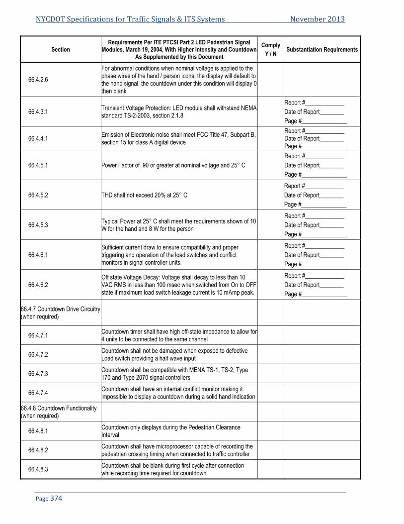
NYCDOT Specifications for Traffic Signals & ITS Systems November 2013
Page 374
Section Requirements Per ITE PTCSI Part 2 LED Pedestrian Signal
Modules, March 19, 2004, With Higher Intensity and Countdown As Supplemented by this Document
Comply
Y / N Substantiation Requirements
66.4.2.6
For abnormal conditions when nominal voltage is applied to the phase wires of the hand / person icons, the display will default to the hand signal, the countdown under this condition will display 0 then blank
66.4.3.1 Transient Voltage Protection: LED module shall withstand NEMA standard TS-2-2003, section 2.1.8
Report #_____________
Date of Report________
Page #_______________
66.4.4.1 Emission of Electronic noise shall meet FCC Title 47, Subpart B, section 15 for class A digital device
Report #_____________ Date of Report________ Page #_______________
66.4.5.1 Power Factor of .90 or greater at nominal voltage and 25° C
Report #_____________
Date of Report________
Page #_______________
66.4.5.2 THD shall not exceed 20% at 25° C
Report #_____________
Date of Report________
Page #_______________
66.4.5.3 Typical Power at 25° C shall meet the requirements shown of 10 W for the hand and 8 W for the person
Report #_____________
Date of Report________
Page #_______________
66.4.6.1 Sufficient current draw to ensure compatibility and proper triggering and operation of the load switches and conflict monitors in signal controller units.
Report #_____________
Date of Report________
Page #_______________
66.4.6.2 Off state Voltage Decay: Voltage shall decay to less than 10 VAC RMS in less than 100 msec when switched from On to OFF state if maximum load switch leakage current is 10 mAmp peak.
Report #_____________
Date of Report________
Page #_______________
66.4.7 Countdown Drive Circuitry (when required)
66.4.7.1 Countdown timer shall have high off-state impedance to allow for 4 units to be connected to the same channel
66.4.7.2 Countdown shall not be damaged when exposed to defective Load switch providing a half wave input
66.4.7.3 Countdown shall be compatible with MENA TS-1, TS-2, Type 170 and Type 2070 signal controllers
66.4.7.4 Countdown shall have an internal conflict monitor making it impossible to display a countdown during a solid hand indication
66.4.8 Countdown Functionality (when required)
66.4.8.1 Countdown only displays during the Pedestrian Clearance Interval
66.4.8.2 Countdown shall have microprocessor capable of recording the pedestrian crossing timing when connected to traffic controller
66.4.8.3 Countdown shall be blank during first cycle after connection while recording time required for countdown

Spec 66: NYCDOT Spec for 16”x18” LED Pedestrian Hand/Person/Countdown Module
Page 375
Section Requirements Per ITE PTCSI Part 2 LED Pedestrian Signal
Modules, March 19, 2004, With Higher Intensity and Countdown As Supplemented by this Document
Comply
Y / N Substantiation Requirements
66.4.8.4 Countdown monitors controller for changes and reprograms automatically if needed
66.4.8.5 Countdown begins count at start of the pedestrian clearance interval
66.4.8.6 When flashing hand becomes solid countdown displays “0” for 1 second when hand becomes solid then goes blank
66.4.8.7 Upon pre-emption the countdown skips the clearance time and reaches “0” at the same time the hand becomes solid.
66.4.8.8 Countdown returns to normal operation after pre-emption
66.4.8.9 Countdown shall be capable of timing 2 consecutive complete pedestrian cycles (no hand signal) outputted by the traffic controller
66.4.8.10 Countdown shall not display erroneous time when connected to a defective load switch
66.5 Quality Assurance
66.5.1.2 Vendor Records maintained for 7 years
66.5.2 Modules identified with information required per section 2.6 Provide Samples or drawing of the labels
66.5.3 All modules are tested and inspected per the production test requirements of section 5.3
66.5.4
ETL Test Report must be supplied for all products demonstrating compliance to the design qualification requirements of section 5.4 of this document and section 6.4 of the ITE PTCSI LED Pedestrian Traffic Signal Module Adopted March 19, 2004
Report # ______________
Date of Report _________
66.6.1.1Warranty Requirements Manufacturer shall issue a written warranty statement, stating compliance to the warranty requirements of this document
Attach Manufacturer’s Warranty Statement
66.6.1.2 Module to be repaired or replaced if the module fails to function as a result of workmanship or material defects within 84 months of date of delivery
Attach Manufacturer’s Warranty Statement
66.6.1.3 Module that fail to comply with the minimum intensity requirements within the first 84 months shall at the manufacturer’s option, be repaired or replaced
Attach Manufacturer’s Warranty Statement
END OF SPECIFICATIONS FOR 16”x18” PEDESTRIAN HAND/PERSON/COUNTDOWN MODULE


Specification 110
NYCDOT Specification for High Temperature Non-Copper Nickel Anti-Seize Compound
Date of Revision Revised by Description
5/3/2006 Signal Spec
NYCDOT Specifications for Traffic Signals & ITS Systems November 2013
Page 378
NYCDOT SPECIFICATION FOR HIGH TEMPERATURE NON-COPPER NICKEL ANTI-SEIZE COMPOUND ................. 379 110.110.1. GENERAL .................................................................................................................................................................... 379 110.2. COMPOUND FORMULATION .......................................................................................................................................... 379 110.3. INTENDED USE ............................................................................................................................................................ 379 110.4. MSDS ........................................................................................................................................................................ 379
Spec 110: NYCDOT Specification for High Temperature Non-Copper Nickel Anti-Seize Compound
Page 379
NYCDOT Specification for High Temperature 110.Non-Copper Nickel Anti-Seize Compound
110.1. General 110.1.1. This specification is for a high temperature non-copper, nickel anti seize compound for use on traffic signal
and street lighting equipment in NYC.
110.2. Compound Formulation 110.2.1. The Anti-seize compound shall be a nickel-based formula free from copper, lead, sulfides and chlorides.
The compound shall be rated for use up to 2400º F and rated for use in an outdoor environment subject to chemicals, paints, salt water and direct sunlight.
110.3. Intended Use 110.3.1. This compound will be used to ensure that bolts and fitting made of cast iron, steel, aluminum and
stainless steel can be disabled or removed without damage due to corrosion or reaction between dissimilar metals. The compound shall be in paste form and easily applied by brushing on parts prior to assembly. The compound shall be non-hardening under all conditions and act as a lubricant adding in ease of assembly. This compound shall be unaffected by acids, oxidation and chemical corrosion.
110.4. MSDS 110.4.1. An MSDS shall be available for this product.
END OF SPECIFICATIONS FOR HIGH TEMPERATURE NON-COPPER NICKEL ANTI-SEIZE COMPOUND


Specification 111
NYCDOT Specification for Water Resistant Wire Connectors
Date of Revision Revised by Description
5/3/2006 New Spec

NYCDOT Specifications for Traffic Signals & ITS Systems November 2013
Page 382
111. NYCDOT SPECIFICATION FOR WATER RESISTANT WIRE CONNECTORS .................................................................. 383 111.1. GENERAL .................................................................................................................................................................... 383 111.2. DESCRIPTION .............................................................................................................................................................. 383

Specification 111: NYCDOT Specification for Water Resistant Wire Connectors
Page 383
111. NYCDOT Specification for Water Resistant Wire Connectors
111.1. General 111.1.1. This specification is for a water resistant wire connector to ensure good conductivity when used in the
extreme conditions encountered when used in the pole bases and underground pull box locations as found on the street light and signal systems in NYC.
111.2. Description 111.2.1. The wire connector shall be of the twist on direct burial Pressure type and certified as such by Canadian
Standards Association (CSA). These connectors shall be filled with a non-drying silicone sealant rated for -45º F to 400º F without hardening or liquefying. The connector shall be rated for use up to 167ºF and be rated for copper to copper connections only at 600 VAC or less. The connector shall be color coded light blue, yellow, red and blue for size selection and shall accommodate the following wire configuration by color.
111.2.1.1. Light Blue Connectors
Light Blue Connectors
3-6 #22 3 #18 w/1-2 #10 2 #14 w/1 #8 or 10
2-6 #18 or #20 4 #18 w/1-2 #12, #14 or #16 3 #14 w/1 #10 or #12
1-6 #14 or #16 4 #18 w/1 #10 3 #14 w/2 #12
1-3 #10 or #12 5 #18 w/1 #14 or #16 4 #14 w/1 #12
4 #12 solid 1 #16 w/1-4 #12 or #14 1 #12 w/1 #8 or #10
1 #22 w/2-5 #20 1 #16 w/1-2 #10 2 #12 w/1 #10
1 #22 w/1-5 #16 or #18 2 #16 w/1-4 #14 1 #22 w/1 #16 & #18
2 #22 w/1-4 #16, #18 or #20 2 #16 w/1-3 #12 1 #22 w/1-2 #16 & 1 #20
3 #22 w/1-3 #16, #18 or #20 2 #16 w/1-2 #10 1 #16 w/1 #10 or #12 & 1-2 #14
4 #22 w/1-2 #16, #18 or #20 3 #16 w/1-3 #14 1-2 #16 w/1 #10 & #12
1 #20 w/1-4 #14, #16 or #18 3 #16 w/1-2 #10 or #12 2 #16 w/1-2 #12 & 1 #14
2 #20 w/1-3 #14, #16 or #18 4 #16 w/1-2 #12 or #14 2 #16 w/1 #12 & 2 #14
3 #20 w/1-2 #14, #16 or #18 4 #16 w/1 #10 3 #16 w/1 #10 or #12 & 1 #14
4 #20 w/1-2 #14, #16 or #18 5 #16 w/1 #14 4 #16 w/1 #10 & #12
1 #18 w/1-4 #12 or #14 5 #16 solid w/1 #10 solid 2 #14 w/1 #10 & 1-2 #12
1-2 #18 w/1-2 #10 1 #14 solid w/1-3 #12 2 #14 w/1 #10 & #12
2 #18 w/1-4 #12, #14 or #16 1 #14 w/1-2 #10
3 #18 w/1-3 #12, #14 or #16 2 #14 w/1-2 #12
111.2.1.2. Yellow Connectors
Yellow Connectors
4-5 #18 3-5 #16 2-4 #14
2 #12 2 #16 w/2 #18 3 #16 w/1 #18
1 #14 w/1-3 #16 or #18 2 #14 w/1-2 #16 or #18 3 #14 w/1 #16 or #18
1 #12 w/1 #14, #16, #18 or #20 1 #10 w/1 #14 2 #12 w/1 #16, #18, or #20
111.2.1.3. Red Connectors
Red Connectors
2-5 #14 2-4 #12 2 #10
1 #12 w/2-4 #16 1 #12 w/1-4 #14 2 #12 w/1-2 #14, #16 or #18
3 #12 w/1-2 #16 or #18 3 #12 w/1 #14 1 #10 w/1-3 #14
1 #10 w/1-2 #12 2 #10 w/1 #14

NYCDOT Specifications for Traffic Signals & ITS Systems November 2013
Page 384
111.2.1.4. Blue Connectors
Blue Connectors
1-2 #6 2-3 #8 2-5 #10 Solid
3-6 #12 Sol 5-6 #14 Solid 1 #6 w/1-4 #14 Solid
1 #6 w/1-4 #12 1 #6 w/1-3 #10 1 #6 w/1-2 #8
1 #6 w/1 #12 w/1-4 #14 1 #6 w/2 #12 w/1-3 #14 1 #6 w/3 #12 w/1-2 #14
1 #6 w/1 #10 w/1-4 #14 1 #6 w/1 #10 w/1-3 #12 1 #6 w/2 #10 w/1-2 #14
1 #6 w/2 #10 w/1 #12 1 #6 w/1 #8 w/1-4 #14 1 #6 w/1 #8 w/1-2 #12
1 #6 w/1 #8 w/1 #10 2 #6 w/1 #14 or #12 1 #8 w/1-5 #14 or #12
1 #8 w/1-3 #10 1 #8 w/1 #12 w/1-4 #14 1 #8 w/2 #12 w/1-3 #14
1 #8 w/3 #12 w/1-2 #14 1 #8 w/4 #12 w/1 #14 1 #8 w/1 #10 w/1-4 #14
1 #8 w/1 #10 w/1-4 #12 1 #8 w/2 #10 w/1-3 #14 1 #8 w/2 #10 w/1-2 #12
1 #8 w/3 #10 w/1 #14 2 #8 w/1-4 #14 2 #8 w/1-3 #12
2 #8 w/1-2 #10 2 #8 w/1 #12 w/1-3 #14 2 #8 w/2 #12 w/1 #14
2 #8 w/1 #10 w/1-3 #14 2 #8 w/1 #10 w/1-2 #12 3 #8 w/1-2 #14
1 #10 w/3-5 #14 1 #10 w/2-4 #12 1 #10 w/1 #12 w/1-4 #14
1 #10 w/2 #12 w/1-3 #14 1 #10 w/3 #12 w/1-2 #14 1 #10 w/4 #12 w/1 #14
2 #10 w/1-4 #14 2 #10 w/1-3 #12 2 #10 w/2 #12 w/1-2 #14
2 #10 w/3 #12 w/1 #14 2 #10 w/1 #12 w/1-3 #14 3 #10 w/1-3 #14
3 #10 w/1 #12 w/1-2 #14 3 #10 w/2 #12 w/1 #14 4 #10 w/1-2 #14
4 #10 w/1 #12 4 #10 w/1 #12 w/1 #14 1 #12 w/4-5 #14 Solid
2 #12 w/2-4 #14 Solid 3 #12 w/1-3 #14 Solid 4 #12 w/1 #14 Solid
END OF SPECIFICATIONS FOR WATER RESISTAN WIRE CONNETORS

Specification 121
NYCDOT Specification for LED Speed Display Sign
Date of Revision Revised by Description
5/3/2006 New Spec

NYCDOT Specifications for Traffic Signals & ITS Systems November 2013
Page 386
NYCDOT SPECIFICATION FOR LED SPEED DISPLAY SIGN ........................................................................................... 387 121.121.1. SCOPE ........................................................................................................................................................................ 387 121.2. DISPLAY ...................................................................................................................................................................... 387 121.3. POWER SOURCE ......................................................................................................................................................... 387 121.4. CENTRAL PROCESSING UNIT ........................................................................................................................................ 387 121.5. RADAR TRANSDUCER .................................................................................................................................................. 388 121.6. SIGN CASE .................................................................................................................................................................. 388 121.7. GUARANTEE ................................................................................................................................................................ 389 121.8. PACKAGING ................................................................................................................................................................. 389 121.9. SAMPLES .................................................................................................................................................................... 389 121.10. TESTS......................................................................................................................................................................... 390 121.11. PROGRAMMING AND SOFTWARE ................................................................................................................................... 390 121.12. DELIVERY.................................................................................................................................................................... 390

Specification 121: NYCDOT Specification for LED Speed Display Sign
Page 387
NYCDOT Specification for LED Speed Display Sign 121.
121.1. Scope 121.1.1. This specification defines the characteristics and features of an LED, two-digit, speed display sign capable of
displaying speeds between ten miles per hour (10 mph) and ninety-nine miles per hour (99 mph). The sign shall be equipped with a “K” band traffic radar operating in an “approach only” mode such that only the speeds of vehicles approaching the sign, and exceeding the lower practical limit of ten miles per hour (10 mph), will be displayed. The unit shall not record false speeds due to opposite direction traffic. The sign case shall have a thirty six inch by six inch (36”x6”) static word sign with the legend “YOUR SPEED IS” screened on high-intensity retro-reflective sheeting (or approved equal) installed by the Contractor. The sign shall feature a photosensitive circuit such that the brightness of the LED display is automatically variable and consistent with ambient illumination on the face of the display, and the display is legible during both daytime and nighttime operations. The unit shall be capable of recording and storing vehicle and speed data by date and time of day, which can be accessed locally via a portable PC and/or remotely via cell phone.
121.2. Display 121.2.1. Description: The display shall consist of an LED, two-digit speed display and static word sign with 36” wide
by 6” high legend “YOUR SPEED IS”.
121.2.2. LED Display Panels: The LED display panels shall be a minimum of 18” in height. Display panels shall be one hundred percent (100%) solid state with no moving parts or switches, shall be identical, mutually interchangeable, and replaceable without the necessity of field hardware or programming modifications. Each panel shall contain the driver circuitry necessary to operate its associated LEDs; there shall be no separate driver boards between the display panels and the central processing unit (CPU). The LED display shall provide for a minimum legibility distance of six hundred feet (600’).
121.2.3. Pixels: Individual pixels shall consist of two (2) pairs of LEDs. The LEDs shall be 17 ITE amber (590 nm) ultra-bright, based upon AllnGaP technology, shall be rated for 100,000 hours of operation, and shall have an
operating temperature range of -22 F to 160 F.
121.2.4. Display Power Supply: The display power supply shall be a 110 VAC input/12 DC output power supply sufficient to operate the CPU and LED display during conditions of both daylight and darkness. The display power supply shall be suitably regulated and temperature stable, fully operational in conditions of 0-95%
relative humidity, non-condensing, and in the temperature range of –30 F to 160 F.
121.3. Power Source 121.3.1. Description: The power for the sign shall be 110 VAC provided by the customer and wired into the terminal
block located within the weather resistant junction box on the sign case. The weather resistant junction box shall contain the terminal strip and a 10 Amp breaker for the 110 VAC power supply for the sign. Wiring shall be in accordance with the wiring diagram provided with each unit.
121.4. Central Processing Unit 121.4.1. Description: The CPU shall consist of a single printed circuit board which shall contain all of the operational
parameters of the speed display system. The CPU shall be a 100% solid state, conformally coated unit with no moving parts or switches. The CPU shall be operable in 0-95% non-condensing humidity conditions at
temperatures ranging from –30 F to 160 F. The CPU shall be capable of retaining the operational parameters for the sign in the event of an interruption of power to the sign, and shall return the sign to fully operational status when power is restored. The unit shall be capable of recording and storing vehicle and speed data by date and time of day which can be accessed locally via a portable PC and/or remotely via cell phone. Basic information should include total vehicles and their recorded speeds (in daily and/or hourly increments), average speeds and the number of vehicles exceeding the legal speed limit.
NYCDOT Specifications for Traffic Signals & ITS Systems November 2013
Page 388
121.5. Radar Transducer 121.5.1. Description: The radar unit shall be low power, “K” band standard traffic radar operating in an “approach
only” mode. The unit shall not record false speeds due to opposite direction traffic. The unit shall operate at voltages between 8 VDC and 16 VDC, and shall be capable of measuring vehicular speeds between 10 MPH99 mph within 1 MPH. The radar shall have an effective range of at least 600’ and shall be unaffected by normal radio frequency transmissions. The radar unit should be easily accessible for alignment in the field and to facilitate maintenance. The unit shall be fully adjustable to allow for shorting radar pickup zone as per field condition from 50’ to 600’ by tilting radar unit up and down. Adjustment shall also be available for side to side alignment.
121.6. Sign Case 121.6.1. Description: The sign case shall be weather resistant and of seamless, molded, cross-linked polyethylene
construction, welded aluminum, or approved equal. The front of the display shall be covered with a clear, transparent, matte finished polycarbonate lens 0.236” in thickness (or approved equal). The lens shall be suitably stabilized to resist degradation due to exposure to ultraviolet radiation, and shall be silk screened on the front surface with a flat black ink to increase contrast, enhance legibility, and reduce secular glare from solar illumination and/or vehicle headlamps (or approved equal). The lens shall exhibit a nominal glare index of 93% (or approved equal). The sign case shall contain all of the electronic and radar components necessary for the operation of the speed display sign.
121.6.2. Sign Case Assembly: The sign case assembly shall consist of the sign case and necessary brackets to facilitate the mounting of the assembly by means of “U” bolts (or approved equal) on the shaft of a pole or on a cantilevered mast arm above a roadway. The Contractor shall supply details to mount the sign on the mast arm of the type “M-2A” pole used in New York City (see standard drawing MISC-002_2) and calculate the effects of the weight and wind load of the sign case on the mast arm. The maximum weight of the assembly shall not exceed 80 lb. The sign case assembly shall be delivered as a unit with all necessary mounting brackets so that installation requires only supplying 110 VAC service to the weather resistant junction box.
121.6.3. Training/Installation: The Contractor shall provide training to the Department on procedures required to program the units, properly install and align the units (to insure that recorded speeds are accurate) and in the use of the data collection features. The Contractor shall be present at a field installation of the pre-production sample (and as required for additional installations) to insure the range and directionality of the radar results in accurate speed recordings.
121.6.4. Mounting Brackets: The sign shall be finished with 3 sign mount brackets that are adjustable to allow level mounting on a standard NYC traffic “M-2A” mast arm.

Specification 121: NYCDOT Specification for LED Speed Display Sign
Page 389
121.7. Guarantee 121.7.1. The Contractor guarantees that all articles of equipment including all parts thereof are of first quality
throughout and comply in all respects or are fully equal to standards called for in the specification. The Contractor further guarantees all equipment, and all parts thereof, against any defects of workmanship, construction and materials, and guarantees to repair or replace without cost to the City of New York any article that has become defective, and not proven to have been caused by negligence on the part of the user, within a period of twelve (12) months of in-service operation following the initial date of equipment is installed and placed in service. However, said guarantee shall not exceed three (3) years from date of acceptance.
121.8. Packaging 121.8.1. Each complete unit shall be individually packed in a test carton, which shall be such as to prevent damage
during delivery or storage.
121.8.2. Item left intentionally blank.
121.8.3. The cartons shall be plainly identified at the top end and one side as to the type of equipment, purchase order numbers, manufacturer’s name, year of manufacture and consecutive serial numbers. The serial number on the carton shall be the same as the one that appears on the manufacturer‘s nameplates permanently attached in a conspicuous location on the unit.
121.9. Samples 121.9.1. Two complete pre-production samples shall be delivered for inspection and testing within thirty (30)
consecutive calendar days after notice from the City of New York. Upon receipt of this notice, the Contractor shall also submit six (6) complete sets of working drawings to the City of New York. Failure to submit the samples and drawings within the time specified will be sufficient reason to declare the Contractor in default. The sample and drawings shall be delivered to the Department’s Warehouse (loading bays 5 and 6) at 66-26 Metropolitan Avenue, Middle Village (Queens) NY 11379. The Contractor shall be present at a field installation of a pre-production sample to insure the range and directionality of the unit results in accurate speed recordings.

NYCDOT Specifications for Traffic Signals & ITS Systems November 2013
Page 390
121.10. Tests 121.10.1. The City may employ any organization it may deem qualified to perform any test required to determine
compliance of the Contractor’s product with this specification. The costs of such tests are to be borne by the successful bidder.
121.11. Programming and Software 121.11.1. A copy of any software needed for programming or maintenance shall be supplied one copy per ten units
in CD electronic format. If any programming tool or devise (programmer) is needed except for standard windows portable PC, it shall also be supplied in the same quantities as software.
121.12. Delivery 121.12.1. The Contractor shall make all deliveries to the Department’s Warehouse (loading bays 5 and 6) at 66-26
Metropolitan Ave in Middle Village (Queens), NY 11379, any other locations within the limits of the City of New York designated by the Department, or as directed by the Engineer. Material/equipment will be accepted between the hours of 8:00 AM and 12:00 PM with unloading to be completed before 3:00 PM, Monday thru Friday, except holidays. The Contractor must notify the Department at least 24 hours in advance of delivery.
121.12.2. The Contractor shall deliver material into the designated storage point; and shall unload and stack this material under the direction of the Warehouse Supervisor.
121.12.3. The Contractor shall furnish all labor, dunnage, blocking, wedges, and other equipment necessary for the safe delivery stacking and storing of material under this Specification satisfactory to the Warehouse Supervisor.
121.12.4. Quantities and timing of deliveries shall be as noted in the Bid Schedule.
121.12.5. The Contractor shall pay all transportation and delivery charges associated with this Specification.
END OF SPECIFICATIONS FOR LED SPEED DISPLAY SIGN

Specification 122
NYCDOT Specification for Battery Backup System Class 1 – 2 hour unit Class 2 – 6 hour unit
Date of Revision Revised by Description
5/4/2004 Rev A: contract Pin 84104MBTR705 425 units original Spec
6/25/2005 Rev B: Added communications spec
10/15/2005 Rev C: Added Class 2 BBS
4/30/2007
Rev D: Added retesting of approved units for communications protocol compliance & TS 2.
Added 6 hr protocol
2/30/2010 Rev E: allow gel cells

NYCDOT Specifications for Traffic Signals & ITS Systems November 2013
Page 392
122. NYCDOT SPECIFICATION FOR BATTERY BACKUP SYSTEM ........................................................................................ 393 122.1. BATTERY BACKUP SYSTEM (BBS) ................................................................................................................................ 393 122.2. CABINET HOUSING....................................................................................................................................................... 399 122.3. DELIVERY.................................................................................................................................................................... 402 122.4. SAMPLE TESTING ........................................................................................................................................................ 403 122.5. GUARANTEE ................................................................................................................................................................ 403 122.6. PACKAGING ................................................................................................................................................................. 403 122.7. SAMPLES .................................................................................................................................................................... 404

Specification 122: NYCDOT Specification for Battery Backup System (BBS)
Page 393
122. NYCDOT Specification for Battery Backup System
122.1. Battery Backup System (BBS) 122.1.1. General
122.1.1.1. The purpose of this specification is to identify the requirements for the provision of uninterruptible, reliable, emergency power to a traffic controlled intersection in the event of a power failure or power interruption. The uninterruptible power supply shall be provide battery power to traffic controlled intersections for a period of time designated by the Department. The transfer from utility power to battery power shall not interfere with the normal operations of the traffic controller, conflict monitor or any other peripheral devices within the traffic control system. The Battery Back-up System (BBS) system shall be comprised of and shall include, as a minimum, all of the following:
• Inverter/Charger (Uninterrupted Power Supply (UPS)), • Power Transfer Switch (PTS), • Batteries, • A separate Manually Operated Non-electronic Bypass Switch (MBPS), • All necessary hardware (including cabinet) and interconnect wiring to make the unit fully
operational.
122.1.1.2. The system shall be capable of providing power for full operation, flashing mode operation, and a combination of both full and flash mode operation of an intersection. The operation of the flash mode shall be field programmable to activate at various times, battery capacities, or alarm conditions locally using the touch pad and remotely using a standard RS-232 (DB-9) serial interface and an Ethernet
122.1.1.3. The Ethernet port (RJ45) interface: A 12 foot long RS2329 (DB-9) shall be provided with each unit to interconnect with the ASTC traffic controller. The outer shell on the DB-9 shall be removable to allow for cable installation though a standard 1½” chase nipple. A BBS to lap top cable shall be provided for 10% of the units.
122.1.1.4. The BBS shall include field programmability via touch pad, RS232 interface, and Ethernet; communications on the RS232-port must be in ASCII formats. The RS-232 port for serial communications shall use a DB-9 connector installed on the front panel of the BBS. The communications shall be through a terminal type interface with settings: 2400 bits per second, 8 Bit, No Parity and 1 Stop Bit. No custom software shall be required to communicate with the BBS other than standard Terminal Emulation Software. The bit rate on the RS-232 port shall be configurable up to 9600 bps and shall default to 2400 bps.
122.1.1.5. The Ethernet port (RJ45) shall support 10/100 Mbps Ethernet communications and shall be an internet ready device. The system shall be designed for outdoor applications and meet the environmental requirements as detailed herein. The unit shall be designed for 24x7 unattended operations such that operator intervention shall not be required to restore normal operation after any type of power interruption, power failure, or external (RS-232 and Ethernet) interface transaction.
122.1.1.6. Clarification of terms: note that the term Contractor and Vendor and Bidder are used interchangeably within this document. They all refer to the entity which enters into a contract to supply the BBS to the City of New York.
122.1.2. System Capacity and Runtimes
122.1.2.1. The procurement contract shall identify the Class BBS that is to be supplied. This specification describes the requirements for Class 1 and Class 2 BBS in terms of backup time and capacity.
122.1.2.2. The Class 1 BBS shall be configured such that it provides a minimum of two (2) hours of full run-time operation for an intersection using LED and/or incandescent traffic and pedestrian signals with a 750 watt load.
122.1.2.3. The Class 2 BBS shall provide a minimum of six hours of full run-operation with a 750 watt load. The UPS shall include an inverter that can deliver 2000 VA/1500 Watts with 80% minimum inverter efficiency. The actual load at any given intersection will determine battery sizing.

NYCDOT Specifications for Traffic Signals & ITS Systems November 2013
Page 394
122.1.3. Relay Contacts
122.1.3.1. The UPS shall provide the user with 6 sets of Normally Open (N/O) and Normally Closed (N/C) panel-mounted, potential free, and fully programmable relay contacts rated 1 Amp, 120 VAC and labeled C1 through C6. Relays shall provide reliable operation for currents from 10 mAmp at 24VDC to 1 Amp at 120 VAC. Each relay’s setting shall be programmable to activate under any number of conditions locally using the touch pad or remotely using the RS-232 interface. The available settings for the relays are outlined below. No more than 50 % of contacts can be solid state relays
122.1.3.2. Relay contacts C1 through C6 can be independently configured to activate under any of the following conditions:
122.1.3.2.1. ON BATTERY, relay activates when BBS switches to battery power.
122.1.3.2.2. LOW BATERY, relay activates when batteries have reached a certain level of remaining useful capacity while on battery power. This number is adjustable from 0 to 100% or if setting is in volts 42 to 55 VDC
122.1.3.2.3. TIMER, relay activates after being on battery power for a given amount of time. This number is adjustable from 0 to 8 hours.
122.1.3.2.4. ALARM, relay activates after a specific or general alarm is detected. These alarm conditions include: line frequency, low output voltage, no temperature probe, overload, batteries not connected, high temperature, and low temperature. The relay can be programmed to activate when any of these alarm conditions is met, or when a specific condition is met.
122.1.3.2.5. FAULT, relay activates after a specific or general fault is detected. These fault conditions include: short circuit, low battery voltage, high battery voltage, high internal temperature, and excessive overload. The relay can be programmed to activate when any of these fault conditions is met, or when a specific condition is met.
122.1.3.2.6. OFF, relay is disabled and will not activate under any condition
122.1.3.3. Default Relay Settings
122.1.3.3.1. Relay C1 shall be set to activate whenever the UPS transfers to battery power and shall be labeled “ON BATT”
122.1.3.3.2. Relays C2 and C3 shall be set to activate whenever the batteries reach 40% (about 47 VDC) of remaining useful capacity and shall be labeled “LOW BATT”.
122.1.3.3.3. Relays C4 and C5 shall be set to activate whenever the UPS has been on battery power for 2 hours and shall be labeled “TIMER”.
122.1.3.3.4. Relay C6 shall be set to activate when any alarm condition is detected and shall be labeled “ALARM”
122.1.4. Operation
122.1.4.1. The Manual Bypass Switch shall be rated at 240 VAC, 40 Amps minimum.
122.1.4.2. The BBS shall use a temperature compensated battery charging system. The charging system shall
compensate over a wide range of 2.5 to 4 mV/C/Cell. The charger shall be rated 10 Amps at 48 VDC. The temperature sensor shall be external to the UPS unit. The temperature sensor shall be supplied with 2 meters (6’ 6”) of wire. Batteries shall not be charged when battery temperature
exceeds 50º C 3º C (122º F ± 5º F).
122.1.4.3. When utilizing battery power, the BBS output voltage shall be between 110 VAC and 125 VAC, pure sine wave output with Total Harmonic Distortion (THD) < 3% at 60 Hz ±3 Hz. Note that whenever the AC input power line is present, the BBS is required to track the power line frequency precisely; it shall not drift or insert or drop cycles such that equipment which uses the AC power line for timing accuracy is unaffected by buck or boost operations of the BBS. In this case, the presence of AC power is considered any voltage above 75 VAC RMS.
Specification 122: NYCDOT Specification for Battery Backup System (BBS)
Page 395
122.1.4.4. In the event of UPS failure, battery failure or complete battery discharge, the power transfer switch shall revert to the N/C (and de-energized) state, where utility power is supplying the cabinet.
122.1.5. Environmental
122.1.5.1. The BBS system shall meet NEMA TS-2-2003 Environmental standard except as noted in this document or as directed by the Engineer.
122.1.5.2. The operating temperature for both the inverter/charger (UPS); power transfer switch (PTS), all electronics, and manual bypass switch (MBPS) shall be -37º C to 74º C (98º F to 165º F) with a relative humidity of 5% to 95% non-condensing. The BBS system shall maintain all software programming and structural integrity when a vibration of 5 to 30HZ at up to 0.5 G is applied. The BBS system shall also not sustain any permanent damage that makes the system inoperable when a shock of 10 Gs is applied. For detailed testing instruction please refer to NEMA TS-2-2003.
122.1.6. Product Compatibility
122.1.6.1. BBS shall be compatible with all of the following for normal three color operation, flashing operation mode or a combination of both normal and flash mode operation:
• New York ASTC System • Type 332 cabinets, • Type 170 controllers, • Type 2070 controllers, • NEMA TS1 Controllers, • NEMA TS2 Controllers. • Electro mechanical controller
122.1.7. Loss/Restoration of Utility Power
122.1.7.1. In the event the BBS senses the utility line voltage is outside the Hi and Low Limits (100 & 130 VAC [± 2 VAC] respectively set as default), the BBS shall transfer the load to battery power.
122.1.7.2. Following a low line event, the BBS shall return to line mode when the utility power has been restored to above 105 VAC for more than 30 seconds. This line qualification time can be adjusted to 3, 10 or 30 seconds locally using the touch pad or remotely using the RS-232 and Ethernet interfaces.
122.1.7.3. Following a high line event, the BBS shall return to line mode when the utility power has been restored to below 125 VAC for more than 30 seconds. This line qualification time can be adjusted to 3, 10 or 30 seconds locally using the touch pad or remotely using the RS-232 and Ethernet interfaces.
122.1.7.4. The maximum transfer time allowed, from disruption of normal utility line voltage to stabilized inverter line voltage from batteries, shall be 65 milliseconds. The same maximum allowable transfer time shall also apply when switching from inverter line voltage to utility line voltage.
122.1.8. Power Grid Isolation and Lighting Protection
122.1.8.1. The BBS shall be equipped to prevent a malfunction feedback to the cabinet or from feeding back to the utility service per UL 1778, Section 48 "Back-feed Protection Test". The upstream back feed voltage from BBS system shall be less than 1 VAC for the protection of the traffic engineer or a technician.
122.1.8.2. The BBS shall have lightning surge protection compliant with IEEE/ANSI C.62.41 for 2000 VAC.
122.1.9. Functionality, Displays, Controls, Diagnostics and Maintenance
122.1.9.1. The BBS shall include an LCD display to indicate current battery charge status, various input/output voltages, power output, battery temperature, date, time and settings of the various field programmable relays. The same parameters shall be available via RS-232 and Ethernet interfaces for remote monitoring.
122.1.9.2. The UPS shall provide the power and the temperature control for an external fan in a separate battery cabinet. The temperature setting shall be adjustable from the touch pad or remotely via RS-232 and

NYCDOT Specifications for Traffic Signals & ITS Systems November 2013
Page 396
Ethernet interfaces The temperature range shall be from 20º C to 55º C in 1º C increments (68º F to 131º F in 2º F increments).
122.1.9.3. The BUCK or BOOST mode shall be provided in case of extended power variations.
122.1.9.4. The BBS shall be provided with a resettable inverter event counter and a cumulative inverter timer that is accessible via the LCD screen or remotely via RS-232 and Ethernet interfaces.
122.1.9.5. The BBS shall be equipped with an event log for at minimum the last 100 events. The events shall be time and date stamped. The event log shall be retrievable via RS-232 and Ethernet (RJ45) interfaces and the last event in the log shall be viewable from the LCD screen.
122.1.9.6. The BBS shall be capable of performing a SELF-TEST, locally from the BBS front panel LCD, or remotely via RS-232 and Ethernet interfaces. The duration of the SELF-TEST shall be programmable in 1-minute increments from 1 minute to 4 hours.
122.1.9.7. Certain maintenance controls such as Battery Test, BBS inverter ON/OFF viewing the Event log and changing default settings shall be password protected. The BBS shall be provided with a default password. The user can change the password in order to restrict access to sensitive functions.
122.1.9.8. The BBS shall be easily replaced and installed (complete turnkey system with all necessary hardware). The BBS shall not require any special tools for installation. The manual bypass switch shall allow replacement of the BBS without having to drop power to the intersection.
122.1.10. Commutations Protocol
122.1.10.1. The BBS units must be able to use the existing communications protocol in use within the City of New York for battery backup. The BBS is required to interact with the City’s ASTC controllers in the same manner as the unit already installed in the field. The Management Information Base (MIB) communications protocol shall be provide by the city as a standalone set of documents by written request only. The request shall be made to NYCDOT ITS Lab room 122, 3402 Queens Boulevard, Long Island City, NY 11101.
122.1.10.2. The City does not guarantee the accuracy of the existing manufacturer’s documentation or protocol information; it is the responsibility of the BBS supplier under this Specification to make any and all necessary field evaluations and measurements to ensure compatible operation.
122.1.10.3. The interfaces (both RS-232 serial and Ethernet) to the BBS shall automatically start and recover from any combination of power conditions, interface interactions, or any other event within the BBS or other events which may occur on the external interfaces to the BBS including but not limited to interface connection disruption, bad or distorted data, improper character sequences, static discharge, power interruptions, or power sequencing of the ASTC. The BBS shall include internal time-out circuits and time out software such that it can always recover from such events and resume normal operation through the external interfaces without operator intervention.
122.1.11. Battery System
122.1.11.1. Individual batteries shall be 12 V and shall be easily replaced and commercially available off the shelf. The batteries and cabling shall be interchangeable with the current units used within the City of New York. Connector type and battery info available upon request.
122.1.11.2. The battery system used in the BBS shall consist of a minimum of 4 batteries for the Class 1 unit and a minimum of 12 batteries for Class 2 unit. Batteries shall be provided with quick disconnect terminal connectors at the end of the battery cable and a keyed battery cable harness for easy field installation.
122.1.11.3. Individual batteries shall be: • Voltage rating: 12 VDC type • Amp-hour rating: 50 Ah minimum at the 20 hr rate, to 1.75 V per cell. • Group size: 22 minimum • Max. Discharge Current shall be 600 Amp. • Short Circuit current shall be 2200 Amp • Dimensions shall not exceed 8.1”H x 9”W x 5.5”D

Specification 122: NYCDOT Specification for Battery Backup System (BBS)
Page 397
• Heat Resistant rating: Extreme • Hydrogen Emission rating: Low • Terminals must be Threaded Insert, #10-32 UNF.
122.1.11.4. Batteries used for BBS shall consist of 4 batteries. All batteries must meet their specifications out of the box immediately after the initial 24-hour top off charge. Batteries that require cycling to meet the Amp-Hour (AH) rating specifications after being shipped from the manufacturer are not acceptable.
122.1.11.5. Batteries shall be deep discharge, sealed, prismatic lead-calcium based Gelled Electrolyte/Valve Regulated Lead Acid (GEL/VRLA). Batteries designed for continuous cycle applications, such as solar, are not acceptable. The battery must be specifically designed for Standby Applications.
122.1.11.6. Batteries shall be certified by the manufacturer to operate over an ambient temperature range of –40° C to 74° C (-40º F to 165º F).
122.1.11.7. Batteries shall have a manufacturers’ warranty of 5 years, full replacement, plus 1 additional year when a battery balancer is used. The warranty shall cover any battery that does not meet 80% of its original reserve capability during the warranty period. Pro-rata warranties are not acceptable.
122.1.11.8. The percent of reserve capability shall be based on a Conductance/Impedance Test, comparable with the original/new battery impedance level provided by the manufacturer.
122.1.11.9. The batteries shall be provided with appropriate interconnect wiring and corrosion-resistant mounting trays, shelves and/or brackets appropriate for the cabinet into which they will be installed.
122.1.11.10. Batteries shall indicate maximum recharge data and recharging cycles upon delivery from the manufacturer.
122.1.11.11. Recharge time for the battery, from protective low cutoff to 80% or more of full battery charge capacity, shall not exceed twenty (20) hours.
122.1.11.12. The external battery cabinet shall be vented through the use of louvered vents, filter, and one thermostatically controlled fan operated from the BBS. The fan turn on temperature shall be programmable and have a temperature sensor in the cabinet.
122.1.12. Service and Warranty
122.1.12.1. Manufacturer shall provide a two (2) year factory-repair warranty for parts and labor on the BBS.
122.1.12.2. Manufacturer shall provide 24 hour trouble shooting via toll-free number.
122.1.12.3. Manufacturer shall make field maintenance available via 24 hour customer service toll-free number.
122.1.13. Specifications
122.1.13.1. Input Specifications • Nominal Input Voltage 120 VAC, Single Phase • Input Voltage Range 120 VAC ± 25% • Input Frequency 60 Hz ± 5%
122.1.13.2. Output Specifications • Nominal Output Voltage 120 VAC, Single Phase • Power Rating 2 KVA (1500 Watts) • Output Frequency 60 Hz (± 5%) • Voltage Wave Form Sine Wave, THD < 3% • Efficiency (nominal) 95-97%
122.1.13.3. Mechanical Size • Inverter / Charger 17” wide x 6.00” ± 1.00” high (3U) x 10” deep • PTS Assembly 17” wide x 3.5” ± ½” high (2U) x 7” deep • Weight Under 55 Lbs
122.1.14. Serial Numbers
122.1.14.1. Each unit shall have a metal tag permanently fastened to the door on the inside.

NYCDOT Specifications for Traffic Signals & ITS Systems November 2013
Page 398
122.1.14.2. Each tag shall have the following info: Manufactures name and serial number.
122.1.14.3. The serial number shall follow the following format: BBS-2004-00001.
122.1.14.4. The year shall be the year the order was placed and the numbers shall continue starting with number one.
122.1.15. Specific Electrical Requirements
122.1.15.1. The BBS shall be subjected to the test procedures for the complete equipment cabinet as described in NEMA TS2-2003 Section 2. The environmental requirements of TS2-2003 Section 2 shall apply to the BBS except as noted herein.
122.1.15.2. All circuits shall commence operation on or before 95 volts as the applied voltage is brought from 0 to 100 V at a rate of 1 (± 0.5) volts per second.7
122.1.15.3. All circuits shall suspend operation on or below 95 volts as the applied voltage is brought from 120 to 0 V at rate of 1 (± 0.5) volts per second8.
122.1.15.4. All circuits, memory, clocks, and functions of the BBS shall not be corrupted by slowly varying input voltages, transients, and power outages as specified herein. The BBS shall include properly designed reset circuits that shall ensure that the device starts correctly and shuts down correctly without operator intervention regardless of the fluctuations on the AC power line or the conditions of its batteries. That is, if the batteries are fully discharged, operator intervention shall not be required for the BBS to restore normal operation and commence charging its batteries once power is restored.
122.1.15.5. The BBS shall function properly during and after power interruptions (from an electromechanical contact) which cycle the power on for 560 msec and off for 375 msec for a period of 2 min. Prior to this test, the BBS shall have completed its initialization and shall be communicating with the ASTC. Note that functioning properly is defined as continuing to communicate with the ASTC without interruption or anomalies of any kind.
122.1.15.6. The BBS shall be unaffected by transient voltages normally experienced on commercial power lines.
122.1.15.7. The BBS shall be subjected to the discharge of a 25 µF capacitor charged to ± 2000 V onto the AC line of the cabinet at its Main breaker. The capacitor shall be discharged at the specified voltage, a total of 50 times, at a rate of once every 10 sec. [Note that tests shall be performed with both +2000 and –2000 V.] The equipment under test, to be in compliance, will function normally during and after the test. Applied line voltage for this test shall be 120 ± 12 VAC. [Note: during all testing, the ENGINEER shall determine the voltages under which this test is performed.]
122.1.15.8. The BBS shall be subjected to a transient voltage of ± 300 V synchronously applied to the AC line of the cabinet at its main breaker. The transient voltage shall be moved uniformly over the full AC waveform once every second. The transient voltage may also be applied constantly at any point on the AC waveform. The transient voltage shall have a peak noise power of 5 kW with a pulse rise time of 500 nsec. The applied line voltage for this test shall be 120 ± 12 VAC. The equipment that is being tested to be in compliance will function normally during and after the test.
122.1.15.9. All equipment shall be capable of normal operation following rapid opening and closing of electromechanical contacts in series with the applied line voltage for any number of occurrences. Line voltage shall mean any line voltage over which the unit is required to function properly.
122.1.15.10. All equipment shall be capable of normal operation after having been in a dry, cold state when a
minimum of 95 V is applied. A dry cold state is defined as having been placed in a state of -4 F and less than 10% humidity for a period of at least five (5) hours without applied power.
7 Note that this test shall be performed – and it is assumed that the BBS shall provide power from its internal
batteries until the line voltage reaches the criteria for transfer to line power.
8 Note that this test shall be performed – and it is assumed that the BBS shall switch to its internal batteries once the
line voltage falls below the configured transfer level.
Specification 122: NYCDOT Specification for Battery Backup System (BBS)
Page 399
122.1.15.11. The BBS shall include electrostatic discharge (ESD) protection to IEC 61000-4-2 (ESD) at ±15 kV (air) and at ±8 kV (contact) for the front mounted serial interface ports, the Ethernet port, and the various operator controls.
122.1.15.12. The equipment shall be subjected to NEMA specified shock and vibration prior to be submitted to temperature and humidity testing.
122.2. Cabinet Housing 122.2.1. Housing
122.2.1.1. The cabinet housing shall be weather resistant, rainproof; with the top of the enclosure crowned or sloped to prevent standing water and shall be constructed to shield the top of the cabinet door to prevent water from entering between the top door gasket and the cabinet.
122.2.1.2. The cabinet housing shall have a single front door, equipped with a three-point latch and lock. The cabinet shall be fabricated for side of pole mounting and shall be suitably re-enforced for both pole mounting and base mounting. Under certain circumstances, the cabinet may be mounted on its bottom to a pedestal flange or concrete base.
122.2.1.3. All exterior seams and the cabinet as a whole shall meet the requirements for Type 3R enclosures according to NEMA Standards Publication 250-1991.
122.2.1.4. The cabinet shall be clean-cut in design and appearance. The maximum exterior dimensions, including the cabinet door (but not including the removable handle) shall be as follows:
Cabinet class Dimension (high x wide x deep)
Class 1 23” x 19”±1” x 15”±1”
Class 2 49” x 21.5”±1” x 15”±1”
122.2.2. Material
122.2.2.1. The cabinet housing, doors, and gasket channels shall be fabricated of 3/16” minimum thickness aluminum sheet, using Grade 5052-H32 aluminum alloy. The sheet aluminum shall be adequately reinforced as necessary. If necessary, reinforcing supports shall be welded to the inside of the door to prevent the warping or twisting of the door.
122.2.2.2. A certificate of compliance from the manufacturer shall be furnished certifying that the material used in the construction of the cabinet housing complies with the requirements above.
122.2.2.3. All case materials used shall be non-corrosive (e.g. aluminum, stainless steel).
122.2.2.4. All hardware as a minimum shall be 18/8 stainless steel.
122.2.2.5. Self-tapping sheet metal screws shall not be used.
122.2.2.6. Only threaded inserts, quarter-turn fasteners or captive nuts with lock washers shall be used for all hardware. Where captive nuts are used, they shall be installed in such a manner as to eliminate the possibility of damage during installation or removal.
122.2.2.7. Where threaded inserts are be used, the Vendor shall indicate the method used to ensure the integrity of the installation process. Threaded inserts shall not be used where they might be damaged in shipping or handling.
122.2.2.8. Rivets of any kind shall not be used except as specified herein.
122.2.3. Construction
122.2.3.1. All construction shall be free of dents, scratches, weld burn through and abrasions harmful to the strength and general appearance. All exterior seams for the cabinet housing and door shall be continuously welded and shall be smooth and free of impurities. All exterior corners shall be rounded.

NYCDOT Specifications for Traffic Signals & ITS Systems November 2013
Page 400
122.2.3.2. Two holes for 1½” diameter conduit entry shall be located in the upper section of the cabinet in an area along the back of the cabinet. The conduit entry holes shall be located by the City and pre-punched by the Contractor prior to the delivery of the cabinet.
122.2.3.3. There shall be no sharp edges or protrusions on the cabinet whether open or closed which might pose a risk of personnel cuts or injury. All sharp edges shall be sanded and deburred before painting.
122.2.4. Exterior Surfaces
122.2.4.1. The exterior surface of the controller cabinet shall be powder coated, using medium green to match Federal Specification 595B Color 14062.
122.2.5. Gasketing
122.2.5.1. The housing shall have a door, securely gasketed, which shall include substantially the full area of the front of the cabinet. Gasketing shall be provided on all door openings and shall be of dust-tight permanent type that shall not peel off or deteriorate. Gaskets shall be ¼”minimum thickness closed cell neoprene and shall be installed with contact cement for a permanent bond. The mating surface shall be sprayed with a silicon lubricant to prevent sticking to the mating metal surface.
122.2.5.2. The gasket material shall not be damaged by normal cabinet cleaning agents and solvents normally used to remove graffiti from the exterior of the cabinet.
122.2.5.3. Gasket material shall be UV resistant.
122.2.5.4. Gasket shall be continuous along the top of the door with no seams along the top.
122.2.6. Cabinet Door
122.2.6.1. The cabinet door shall be hinged on the right side when facing the cabinet. The door hinge shall be continuous and bolted (piano) to the cabinet and door utilizing ¼”-20 stainless steel carriage bolts and nylock nuts. The hinge shall be made of 0.075” stainless steel and shall have a 3” open width with a ¼” diameter stainless steel carriage hinge pin. The hinge pin shall be capped top and bottom by weld to render it tamper proof. The hinge leafs shall not be surface mounted on the outside of the cabinet. They shall be mounted between the door and the cabinet. The cabinet door hinges shall be bolted to the cabinet housing in a manner that prevents unauthorized personnel from removing the door with commonly available tools.
122.2.6.2. The cabinet shall be equipped with an automatic, self-engaging catch to hold the door open at 135º 25º. The catch shall be capable of holding the door open in a 140 MPH wind coming at an incidence angle of 90º referenced to the plane of the door. A means shall be provided to minimize the accidental release of the doorstop.
122.2.6.3. The door shall be furnished with a three-point latching mechanism. The latching mechanism shall be a three-point draw roller type. Push rods shall be turned edgewise at the outward supports and shall be ¼”x¾” stainless steel, minimum. Rollers shall have a minimum diameter of 7/8” inch and shall be made of nylon. The center catch shall be fabricated from 0.134” stainless steel minimum. Stainless steel compensating wear guards shall be used at contact point for the three point latching.
122.2.6.4. The three-point locking mechanism shall be fabricated so that it may be actuated by rotating a removable 5/8” hex key door handle. The hex socket and locking cam shall rotate on a ½” minimum diameter shaft. The socket, shaft and hex key shall be fabricated from stainless steel, grade 2011P3 aluminum, or other material plated to prevent corrosion. The socket and shaft shall be field-replaceable with common tools. The socket head shall be protected from being rotated with a pipe wrench or similar tool. Designs shall be subject to approval by NYCDOT prior to fabrication. One (1) hex wrench shall be provided with each cabinet.
122.2.7. Water Management
122.2.7.1. The cabinet shall also properly manage any condensation which may occur internally such that such moisture cannot damage any of the internal cabinet assemblies, subassemblies, wiring or devices. Water weep holes shall be provided in the bottom of the cabinet to drain any collected moisture.
Specification 122: NYCDOT Specification for Battery Backup System (BBS)
Page 401
122.2.7.2. There shall be no holes, seams, or attachments to the top of the cabinet that might cause water to leak for any reason.
122.2.7.3. The CONTRACTOR shall recognize that mounting holes will be field drilled by the Contractor in the re-enforced mounting areas on the back of the cabinet along the top and bottom edges. These mounting areas must be good surfaces to allow the Contractor to water resistant the mounting.
122.2.8. Door Lock
122.2.8.1. The lock for the cabinet door shall be of the self-locking, heavy duty, pin tumbler, cylinder rim type. It shall be the Corbin No. 1548RS 7/8, keyed for a DT-9 key, with dust cover. Two DT-9 keys, constructed of brass or stainless steel are to be furnished with each cabinet. When the door is closed and latched, with the key removed, the door shall lock.
122.2.8.2. During the installation of the lock, good grade of commercial silicone will be put around the cylinder to form a weather resistant barrier between the front of the lock and the inside of the cabinet door. A stainless steel lock protector plate shall be installed over the rear of the lock to prevent the rear of the lock from being punched out from the front of the cabinet.
122.2.9. Cabinet Ventilation
122.2.9.1. Each cabinet shall be provided with louvered vents in the cabinet door for fresh air. The vents shall be screened against the entrance to remove dust and foreign matter, with a removable and replaceable air filter 16”x6”x1” deep to filter incoming air. The filter shall be Eco Air type disposable filter or equivalent [reference: Eco-Air Products, Inc., San Diego, CA 92126, 619-271-8111] which is currently used and stocked by the CITY. The filter shall be a UL classified air filter-Class 2 644N.
122.2.9.2. The filter shall overlap the vents by at least 1 inch and shall be held firmly in place with bottom and side brackets and a spring-loaded upper clamp. Provisions shall be made in the design of the vents to prevent snow and rain from being blown through the vents into the cabinet.
122.2.9.3. The bottom filter bracket shall be formed into a water resistant sump with drain holes to the outside. The louvered vents shall be designed and constructed so that a stream of water from a pressure head, such as a “Rain Bird” sprinkler or other type of water spray test, will not enter the cabinet. The louvered area shall be less than the filtered area.
122.2.10. Cabinet Exhaust Fan
122.2.10.1. Each cabinet shall be equipped with an electric exhaust fan, Comair Rotron No MU2B1 or equal, with ball bearings and a capacity not less than 100 cubic feet per minute. The cabinet shall be provided with a 30 square inch minimum screened exhaust vent. The exhaust fan and exhaust vent shall be located in the underside of the top of the cabinet and completely wired and interconnected.
122.2.10.2. The area of the exhaust vent and the exhaust fan shall be designed to prevent snow or rain from reaching the fan area and from entering the cabinet’s main area regardless of whether the fan is operating. Design of this area should include baffling to block the entrance of moisture yet provide adequate ventilation. This area should also be sloped to drain any moisture that may get into this area to the outside of the cabinet.
122.2.10.3. The fan shall be capable of operating continuously for a minimum of 20,000 hours in a 50 C (122 F) environment without the need for after-installation maintenance, excluding filter replacement. The cabinet fan circuit shall be fused using a 0.25 Amp time-delay fuse and be labeled as such. The fan terminals shall be insulated or covered so that no parts having line voltage are exposed. The fan fuse shall be located in the vicinity of the fan, and shall be attached to the cabinet housing.
122.2.10.4. The fan shall be screened or otherwise protected to prevent personal injury or the inadvertent encroachment of wires or other internal elements which might be damaged or interfere with the operation of the fan
122.2.10.5. Each cabinet shall be provided with a thermostat to control the operation of the fan or cooling system.
The thermostat turn-on point shall be fixed at 85 F with a differential of not more than +5 F between automatic turn-on and turn-off. The thermostat shall be located on the inside top portion of the cabinet not lower than 6” from the top of the cabinet. All fan control contacts shall be protected by Radio
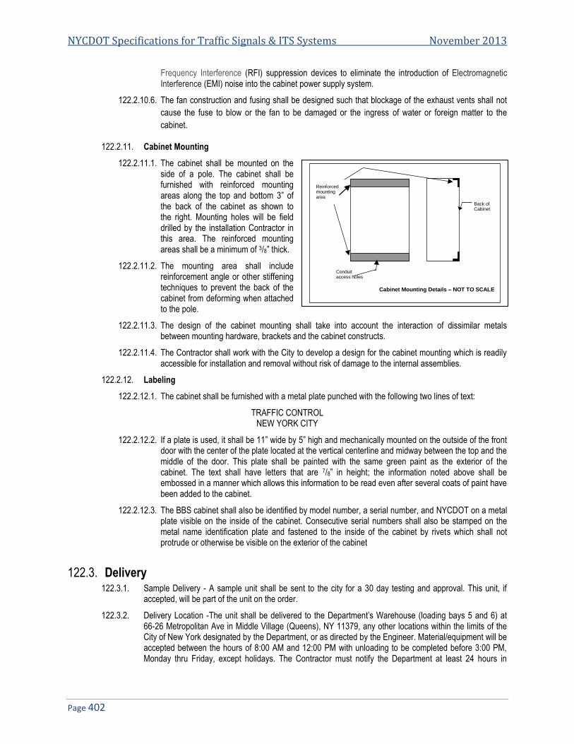
NYCDOT Specifications for Traffic Signals & ITS Systems November 2013
Page 402
Frequency Interference (RFI) suppression devices to eliminate the introduction of Electromagnetic Interference (EMI) noise into the cabinet power supply system.
122.2.10.6. The fan construction and fusing shall be designed such that blockage of the exhaust vents shall not
cause the fuse to blow or the fan to be damaged or the ingress of water or foreign matter to the
cabinet.
122.2.11. Cabinet Mounting
122.2.11.1. The cabinet shall be mounted on the side of a pole. The cabinet shall be furnished with reinforced mounting areas along the top and bottom 3” of the back of the cabinet as shown to the right. Mounting holes will be field drilled by the installation Contractor in this area. The reinforced mounting areas shall be a minimum of 3/8” thick.
122.2.11.2. The mounting area shall include reinforcement angle or other stiffening techniques to prevent the back of the cabinet from deforming when attached to the pole.
122.2.11.3. The design of the cabinet mounting shall take into account the interaction of dissimilar metals between mounting hardware, brackets and the cabinet constructs.
122.2.11.4. The Contractor shall work with the City to develop a design for the cabinet mounting which is readily accessible for installation and removal without risk of damage to the internal assemblies.
122.2.12. Labeling
122.2.12.1. The cabinet shall be furnished with a metal plate punched with the following two lines of text:
TRAFFIC CONTROL NEW YORK CITY
122.2.12.2. If a plate is used, it shall be 11” wide by 5” high and mechanically mounted on the outside of the front door with the center of the plate located at the vertical centerline and midway between the top and the middle of the door. This plate shall be painted with the same green paint as the exterior of the cabinet. The text shall have letters that are 7/8” in height; the information noted above shall be embossed in a manner which allows this information to be read even after several coats of paint have been added to the cabinet.
122.2.12.3. The BBS cabinet shall also be identified by model number, a serial number, and NYCDOT on a metal plate visible on the inside of the cabinet. Consecutive serial numbers shall also be stamped on the metal name identification plate and fastened to the inside of the cabinet by rivets which shall not protrude or otherwise be visible on the exterior of the cabinet
122.3. Delivery 122.3.1. Sample Delivery - A sample unit shall be sent to the city for a 30 day testing and approval. This unit, if
accepted, will be part of the unit on the order.
122.3.2. Delivery Location -The unit shall be delivered to the Department’s Warehouse (loading bays 5 and 6) at 66-26 Metropolitan Ave in Middle Village (Queens), NY 11379, any other locations within the limits of the City of New York designated by the Department, or as directed by the Engineer. Material/equipment will be accepted between the hours of 8:00 AM and 12:00 PM with unloading to be completed before 3:00 PM, Monday thru Friday, except holidays. The Contractor must notify the Department at least 24 hours in
Back of Cabinet
Conduit access holes
Cabinet Mounting Details – NOT TO SCALE
Reinforced mounting area

Specification 122: NYCDOT Specification for Battery Backup System (BBS)
Page 403
advance of delivery. The Contractor shall furnish all labor, dunnage, blocking, wedges and equipment necessary for the safe delivery stacking and storing of material to a height of fifteen (15) feet.
122.4. Sample Testing 122.4.1. Acceptance Documentation - The manufacturer shall summit the following documents at acceptance
testing.
122.4.1.1. Names of 4 sources of replacement batteries listing the Battery Consul International (BCI) group number of supplied batteries, the outside case dimensions and amp hour ratings. If the batteries are relabeled to house brand, the original manufacturer shall be provided along with original manufacturer’s part number.
122.4.1.2. Certificate of compliance of environmental requirements.
122.4.1.3. Letter of compliance of Article 122.1.8. power grid isolation and lighting protection.
122.4.1.4. Certificate of battery testing with test results of sample unit batteries to ensure random battery selection. The use of matched set batteries is strictly prohibited.
122.4.2. Test Procedure - The following outline shall be used to test the battery backup system. The outline shown below is only an overview; it shall be the responsibility of the supplier to develop a complete test and inspection procedure in accordance with the requirements noted herein.
122.4.2.1. The sample shall be inspected to ensure that it conforms to each requirement stated herein. This shall take the form of a requirement traceability matrix where each requirement is identified, and the sample is compared to the specification requirements.
122.4.2.2. A sample of the gasket material shall be subjected to destructive testing using graffiti remover.
122.4.2.3. There shall be a timed 2 hour class 1, and a timed 6 hour class 2 run tests using the following format:
122.4.2.3.1. The battery back-up unit will be tested with both LED and Incandescent lamps and a combination of both.
122.4.2.3.2. The unit is to run for 2 hrs. (for class 1) running a standard 2 phase 3 color intersection which is the type that is most common within the City.
122.5. Guarantee 122.5.1. The Contractor guarantees that all articles of equipment including all parts thereof are of first quality
throughout and comply in all respects or are fully equal to standards called for in the specification. The Contractor further guarantees all equipment, and all parts thereof, against any defects of workmanship, construction and materials, and guarantees to repair or replace without cost to the City of New York any article that has become defective, and not proven to have been caused by negligence on the part of the user, within a period of twelve (12) months of in-service operation following the initial date of equipment is installed and placed in service. However, said guarantee shall not exceed three (3) years from date of acceptance.
122.6. Packaging 122.6.1. Each complete unit shall be individually packed in a test carton, which shall be such as to prevent damage
during delivery or storage.
122.6.2. Item left intentionally blank.
122.6.3. The cartons shall be plainly identified at the top end and one side as to the type of equipment, purchase order numbers, manufacturer’s name, year of manufacture and consecutive serial numbers. The serial number on the carton shall be the same as the one that appears on the manufacturer‘s nameplates, permanently attached in a conspicuous location on the unit.

NYCDOT Specifications for Traffic Signals & ITS Systems November 2013
Page 404
122.7. Samples 122.7.1. Two complete pre-production samples shall be delivered for inspection and testing within thirty (30)
consecutive calendar days after notice from the City of New York. Upon receipt of this notice, the Contractor shall also submit six (6) complete sets of working drawings to the City of New York. Failure to submit the samples and drawings within the time specified will be sufficient reason to declare the Contractor in default. The sample and drawings shall be delivered to the Department’s Warehouse at 66-26 Metropolitan Avenue (loading bays 5 and 6) at Middle Village (Queens), Ny 11379.
122.7.2. The unit is to run for 6 hrs. (for class 2) on a large intersection.
122.7.3. The units will be tested to insure compliance with the specification using the following static load as the test load: 8 incandescent lamps which are 68 W each, and 8 pedestrian heads displaying the “Upraised Hand”/”Walking Man” symbols drawing 15 W each, and a dummy load to simulate the controller of an additional 68 W incandescent lamp and a 15 W LED signal displaying red. Thus, the total load for the purpose of the “hold-up” time test shall be 747 W ±1%.
122.7.4. 8 signal heads with Red (15 W) and green (15 W) LEDs and incandescent ambers (68 W) and 8 pedestrian LED heads (15 W man & 15 W hand).
122.7.5. For this test it will be assumed that only one color per head will be on at a time and in the case of the 3 color head, the one with the highest draw will be on at all times and there will be a traffic controller. This will yield the following loads:
Signal heads 8 x 68 W = 544 W Pedestrian heads 8 x 15 W = 120 W Total Load 664 W
122.7.6. For this test, the traffic controller will be replaced by a 68 W bulb and a 15 W LED.
122.7.7. The total load for the 2 or 6 hour test will be 747 W (±1%).
122.7.8. This test will be done at a City facility at room temperature (65º F to 75º F).
122.7.9. The units will be delivered to the City charged and ready to be tested the morning of the test and a representative from the winning bidder will be required to attend. The unit will be left at that time for the rest of the approval process which is to verify compliance with the specification.
END OF SPECIFICATIONS FOR BATTERY BACKUP SYSTEM

Specification 132
NYCDOT Specification for Fiber Optic Installation
Date of Revision Revised by Description
6/21/2008 New Spec
NYCDOT Specifications for Traffic Signals & ITS Systems November 2013
Page 406
NYCDOT SPECIFICATION FOR FIBER OPTIC INSTALLATION ....................................................................................... 407 132.132.1. GENERAL REQUIREMENTS ........................................................................................................................................... 407 132.2. APPLICABLE STANDARDS ............................................................................................................................................. 407 132.3. FIBER OPTIC CONDUCTOR QUALIFICATIONS .................................................................................................................. 407 132.4. GENERAL SYSTEM CONSTRUCTION .............................................................................................................................. 408 132.5. CABLE INSTALLATION ................................................................................................................................................... 408 132.6. FIBER OPTIC INNERDUCT, 1 CHANNEL .......................................................................................................................... 410 132.7. GALVANIZED STEEL CONDUIT MULTIDUCT WITH 4 DUCTS .............................................................................................. 411 132.8. PVC MULTIDUCT CONDUIT WITH 4 DUCT ...................................................................................................................... 412

Specification 132: NYCDOT Specification for Fiber Optic Installation
Page 407
NYCDOT Specification for Fiber Optic Installation 132.
132.1. General Requirements 132.1.1. The following provides the minimum standards and qualifications necessary to provide a fiber optic
communication link between Field Intelligent Transportation System (ITS) equipment, City buildings and Traffic Monitoring Center (TMC).
132.1.2. Materials and equipment shall be the standard products of a manufacturer regularly engaged in the manufacturing of products used for outdoor fiber optic system installations. All materials and equipment furnished shall be new, of first quality, of latest design and be completely free from defects in material and poor workmanship. All like pieces of equipment shall be of the same type and manufacture to assure uniformity, interchangeability of components, single responsibility, and most satisfactory service.
132.1.3. Each major component of equipment shall have the manufacturer's name, address, type or style, model or serial number and catalog number on a plate secured to the equipment.
132.1.4. The fiber optic installation shall be in accordance with accepted industry practices and standards, manufacturer’s recommendations and in compliance with all codes governing the installation within NYC.
132.1.5. The contractors shall comply with the latest revision of the NYCDOT Specifications for Traffic Signals & ITS Systems. All omissions and contradictions shall be reported to the Engineer for direction.
132.1.6. The Contractor shall furnish and install all necessary miscellaneous equipment to make a complete and operating system. The cost for all materials and labor not specifically itemized shall be considered incidental to the various items of work.
132.2. Applicable Standards 132.2.1. Materials and equipment supplied as part of the fiber optic system shall comply with the latest issue of the
following documents: • RUS Rural Utility Service Material Acceptance List • REA Specifications for Filled Fiber Optic Cables • EIA-STD-RS-455 Standard Test Procedures for Fiber Optic Fibers, Cables, Transducers,
Connecting and Terminating Devices • MIL-STD-202 Test Methods for Electronic and Electrical Component Parts • MIL-STD-454 Standard General Requirements for Electronic Equipment • MIL-STD-810 Environmental Test Methods and Engineering Guidelines • EIA/TIA-598 Tube and Fiber Color Code • EIA-568-A Fiber Optic Cable Testing Procedures • NFPA-70-1993 National Electrical Code Article 770, Optical Fiber Cable
132.3. Fiber Optic Conductor Qualifications 132.3.1. Any project requiring the opening of the fiber optic cable jacket, installation of fiber optic connectors, splicing
fibers, or the testing of any fiber optic cable, drop cable, or patch cords shall have at least one supervising fiber optic technician assigned to it. Supervising fiber optic technicians shall meet the following minimum requirements.
132.3.1.1. Supervising fiber optic technicians shall have certification level 2 IMSA or equal.
132.3.1.2. NYCDOT shall be able to document a minimum of one year of work experience where the splicing, termination, and testing of fiber optic cable with an optical time domain reflectometer (OTDR) and power meter was a primary job responsibility. Technicians, performing fiber optic work such as cable cleaning, splicing, connectorizing and terminations shall have certification level 1 IMSA or equal.
132.3.1.3. All fiber optic technicians shall carry evidence of their qualifications on their person at all times when working on the project.

NYCDOT Specifications for Traffic Signals & ITS Systems November 2013
Page 408
132.4. General System Construction 132.4.1. Entry into controller cabinets from the trunk cable shall be made via the specified drop cable. The drop cable
will be spliced to the trunk cable in a specified splice enclosure. The drop cable inside of the cabinet shall be fitted with a fan-out kit and the fan-out kit shall be connectorized and terminated in the specified termination panel.
132.5. Cable Installation 132.5.1. General Provisions
132.5.1.1. Both aerial and conduit installations shall comply with no load and applied load bend radii specified below:
132.5.1.1.1. No fiber optic cable shall be installed prior to the Engineer acknowledging the cable delivered to the project is acceptable based upon the Contractor completing the pre-installation testing given in these specifications.
132.5.1.1.2. Fiber optic cable installed in conduit shall be in accordance with the following: • No more than two 90 degree changes in direction per cable pull. • Circuitous pulls and pulls exceeding 1000’ (300 m) shall be made by back feeding or center
feeding of cable. • After installation, there shall be no tension except due to cable weight. • Tension of cable shall be monitored with a tensiometer during installation. • The applied tension shall not exceed 400 lb (182 kgs). • The central strength member and the aramid yarn shall be directly attached to the pulling
eye. "Basket grip" or "Chinese finger" type attachments to the outer jacket of the cable will not be permitted. A breakaway swivel shall be used on all pulls.
132.5.1.1.3. Fiber optic cable installed aerially shall be provided with a sag of 3%-5% unless existing cables will be sharing the pole in which case a sag matching the existing cables shall be provided.
132.5.1.1.4. Splicing Reels of Cable - The method of joining two reels of fiber optic cable shall be fusion splicing all of the trunk cable fibers of one reel to the corresponding fibers in the second reel. All splices for joining two fiber reels of trunk cable together shall be made in the splice enclosure at the last intersection the interconnect cable passed through. In other words, when a reel runs out of cable, any excess beyond the last traffic signal intersection splice point shall be cut off and disposed of by the Contractor. The splice joining the two cable reels together shall be made in the intersection splice enclosure that contains the drop cable to trunk cable splice. Cost for the quantity of cut off fiber optic cable and for the additional 16 splices beyond the four splices required to install the drop cable shall be INCIDENTAL to the cost of the fiber optic cable. It shall be the Contractor's responsibility to calculate his cost to join fiber optic reels on the project based upon the reel lengths that he orders. Where interconnect system length permits, the Contractor can avoid the cost of joining cable reels together by ordering a single reel of sufficient length to extend from one end of project to the other.
132.5.1.2. The only place where fibers that are not used for interconnection can be cut is where it is necessary to splice two reels of cable together. This practice of cutting unused fibers shall be kept to a minimum and shall not occur more than once per every mile (1600 m).
132.5.2. Cable Cleaning
132.5.2.1. Loose tube cable will require the Contractor to use a De-Gel solvent to remove water blocking gel from exposed fibers and/or buffer tubes prior to placement of fan-out kits, splicing or termination of each fiber. The solvent chosen for this task shall dissolve the gel and allow for a complete removal of all solvent residues. The solvent shall not remove any of the color from individual fiber or buffer tubes and shall not prove harmful to the outer PE jacket of the cable itself. 3M's part number 4414 "filled cable cleaning kit" or approved equal shall be utilized at every opening of the cable. Cost for De-Gel solvent and cleaning of fibers shall be incidental to the cost of the cable.

Specification 132: NYCDOT Specification for Fiber Optic Installation
Page 409
132.5.2.1.1. Where armored cable is specified it shall be on the RUS acceptable material list.
132.5.2.1.2. Where self-supporting cable is specified the messenger cable shall ¼” (6 mm) and shall be on the RUS acceptable material list.
132.5.2.1.3. Documentation shall be provided showing RUS acceptance.
132.5.2.1.4. Cables shall be packaged wound on non-returnable wood spools or reels. The diameter of the drum shall be a minimum of 20 times the diameter of the cable. Each reel shall contain only one continuous length of cable. Labels shall be attached to the reel showing length, cable identification name and number, and date of manufacture.
The outer ends of the cable shall be securely fastened to the reel head so as to prevent the cable from becoming loose during transit. Both ends of the cable shall extend a minimum of 10 feet (3 m) into the inside of the cable reel to provide access for testing. Test tails shall be secured to the inside of the reel in such a manner that they will not become loose during transportation. End seals shall be applied to each end of the cable to prevent the intrusion of moisture into the cable.
Documentation shall accompany each reel documenting the attenuation of each cable fiber in db/km.
All fiber optic cable to be used as part of the traffic signal system shall be rated for outdoor use unless specifically noted in the plans.
132.5.2.1.5. Fiber optic cable rip cords shall be provided and made from either standard telco nylon material or from braided Kevlar. No un-braided Kevlar will be accepted.
Cable Jacketing shall be permanently labeled approximately every two feet with the cable manufacturer's name, cable type, fiber count, manufacturing date, and incremental cable length. Cable length shall refer to the cable sheath length.
132.5.3. Interconnect Miscellaneous: Fan-out Kit,
132.5.3.1. Fan-out kits shall be provided for loose tube drop cable terminal ends that need to be fitted with connectors. The fan-out kit can be an individual buffer tube kit, multiple buffer tube kit or spider design kit. All fan-out kits shall have a minimum of 24" (610 mm) of tubing covering each fiber when installation is complete. Prior to any work the Contractor shall submit for approval; catalog cut sheets, general specifications, and standard operating procedures for the kit that is to be utilized on the project. Only one type of fan-out kit may be used throughout the project. Fan-out kits shall be rated for outdoor use -40º F to 158º F (-40º C to 70º C). Since only 4 drop cable fibers are required for daisy chain communication, all extra drop cable fibers at the cabinet end shall be inserted into the fan-out kit, connectorized and terminated in the termination panel for future use.
132.5.4. Drop Cables Interconnect Miscellaneous: Drop Cable,
132.5.4.1. Drop cables for loose tube fiber optic cables shall be paid on a linear measurement basis and shall be made from the same glass and cable manufacturer that provides the trunk cable. Since only 4 fibers are required for daisy chain communication, unused drop cable fibers (2 fibers) shall be left for future use. Spare drop cable fibers at the splice enclosure end shall be placed inside of the enclosure with sufficient excess to provide 2 service loops. Spare drop cable fibers at the controller end shall be inserted into the fan-out kit, connectorized and terminated in the cabinet termination panel. Note: Drop cables routed down through a pole from aerial interconnect shall be provided with strain relief (cable support assembly) per the installation details. Cost of the cable support assembly shall be incidental to the bid item price of the drop cable. A minimum of 10 ft (3 m ) slack drop cable shall be provided in the each controller cabinet. Slack drop cable shall be coiled and bound to the cabinet via tie wrap or other approved means.
132.5.5. Interconnect Miscellaneous: Fiber Optic Patch Cord, 4 Fiber
132.5.5.1. A four fiber patch cord shall be provided between each fiber optic transceiver and each termination panel. The fibers shall be either multi-mode or single mode as required to match the trunk cable and transceiver. Patch cords shall be fitted with SC/PC type connectors unless the proposed/existing

NYCDOT Specifications for Traffic Signals & ITS Systems November 2013
Page 410
equipment requires a different connector. Connectors shall be attached to the patch cords using an epoxy crimped methodology where the Kevlar is crimped to the connector. Cost for supplying and installing connectors on all ends of the patch cord shall be incidental to the bid item price of the Patch Cord. The Contractor at his option may supply four separate one fiber patch cords, however, only one 4 fiber patch cord quantity will be provided at each controller.
132.5.6. Interconnect Miscellaneous: Termination Panel
132.5.6.1. Termination panels used in NEMA cabinets shall be a model WCH-02P as manufactured by Siecor or equal approved. The NEMA cabinet termination panel shall be attached to the side of the cabinet in a place that provides most room for making connections. After attaching the termination panel on the wall of the cabinet or support member, no sharp objects such as screws shall protrude outside of the cabinet that might cause injury to pedestrians. Termination panels used in 170/ITS cabinets shall be mounted within the 19" (483 mm) cage and shall be model CCH02U as manufactured by Siecor or equal approved. All costs including materials, tools and labor to provide and install a termination panel shall be included in the bid item price for each Termination Panel.
132.5.7. Trench for Fiber Optic Cable
132.5.7.1. The Contractor shall place warning tape magnetic type directly above all new conduits containing fiber optic cables. The tape shall be clearly label Fiber optic cable. The warning tape shall be placed between 6" and 12" below finished grade with a tape length equal to the length of the conduit or cable. The tape shall be dielectric polyolefin film tape, 0.1 mm thick and 3" wide, orange in color. Materials and ink colors shall be used that will not change when exposed to acids and other destructive substances commonly found in soil.
132.5.7.2. Payment shall be made at the contract unit price bid per foot, Trench for Fiber Optic Cable and shall include all costs for trenching, the warning tape, backfilling and restoration.
132.5.8. Pullboxes
132.5.8.1. Pull boxes shall meet all requirements for pull boxes as per the NYCDOT Specifications for Traffic Signal and ITS Systems. The boxes shall be of sufficient size to insure minimum bend radius requires plus 6”.
132.5.9. Splice Boot
132.5.9.1. Each splice boot and at least 2 spare entry ports are to be left in all splice boot with room to splice the additional cables or as directed by print or the engineer.
132.6. Fiber Optic Innerduct, 1 Channel 132.6.1. General - This work shall consist of furnishing and installing fiber optic innerduct at locations shown in the
Contract Documents and/or as directed by the Engineer.
132.6.2. Materials - All materials furnished, assembled, fabricated or installed under this Specification shall be new, corrosion resistant and in strict accordance with the details shown on the plans and in the
132.6.3. Specifications
132.6.3.1. The fiber optic innerduct shall be an individual channel conduit liner as specified on the plans and in the Specifications. The color of the innerduct shall be as indicated on the plans. The Contractor shall install the innerduct between pullboxes as shown on the plans. The innerduct shall have an inner diameter of 1 inch nominal and the outer diameter shall be such as to allow for the installation of four (4) channels within a 4” NPS conduit.
132.6.3.2. The innerduct shall be fabricated out of high molecular weight, high density polyethylene (HDPE) which shall conform to the following material requirements:
• Density: 0.946 g/cc (ASTM D4883). • Melt Index: 0.25 g/cc (ASTM D1238). • Tensile strength at yield: 22.6 MPa (ASTM D638). • Elongation at break: 800 % minimum (ASTM D638).

Specification 132: NYCDOT Specification for Fiber Optic Installation
Page 411
• Flexural Modulus: 827 MPa (ASTM D790). • Hardness (Shore D): 68. • Deflection temperature at 294 N: 69º C. • Environmental stress crack resistance - Condition B: 1000 hrs minimum (ASTM D1693). • Brittleness Temp: -118º C (225º F) maximum (ASTM D746). • Cell Classification: 335440A (ASTM D3035).
132.6.3.3. The Contractor shall provide a drag line through the entire length of each of the individual channels of innerduct installed. The drag line shall be muletape or mylar tape and shall have tensile strength of 4.5 kN minimum. Fiber Optic Innerduct, 1 Channel shall be accepted upon the basis of the manufacturer’s certification that it meets the requirements of this specification.
132.6.4. Construction Details
132.6.4.1. The innerduct shall be installed in conduits where specified in the contract plans. Prior to the installation of the innerduct, the Contractor shall clean all existing conduit and pullboxes as required and as specified under separate contract items. If existing pullboxes require resetting or other modifications, this work shall be completed prior to the installation of innerduct into the subject pullbox and/or as directed by the Engineer. Channels of the same color entering a pullbox from different sides shall be aligned so that cables in a specific channel can be directly pulled through the box without crossing cables installed in other channels. The innerduct shall run continuously through pullboxes, except at locations where slack fiber optic cable will be stored. At these pullboxes, the innerduct shall be extended at least six inches into the pullbox and secured or anchored in an approved method to prevent movement during cable pulling operations. (If this occurs, the innerduct shall be reconnected to form a continuous run using manufacturer approved compression couplings.) All proposed fiber optic cable lubricants shall be compatible with the innerduct material and shall be an approved product of the innerduct manufacturer. The Contractor shall provide certification of the lubricant compatibility to the Engineer for approval prior to installation. The Contractor shall pull the specified innerducts in accordance with manufacturer recommended installation procedures. The installation procedures shall be delivered to the Engineer a minimum of ten working days prior to the start of installation. Guide wheels, bending shoes or quadrant guides shall be used to achieve a smooth transition from road grade to conduit depth. The innerduct shall have a 24 ½” bend radius minimum. The Contractor shall fill the end of the innerducts with scrap cables or equivalent in order to avoid collapsing of the innerduct within compression grips. The Contractor shall apply manufacturer approved pulling lubricants as necessary to ensure smooth, even pulls. The maximum pulling force shall be 4.4 kN. At all locations where innerduct will terminate, the Contractor shall install sealing and termination plugs on all innerduct channels in order to prevent water and foreign matter ingress. The plugs shall be installed immediately after the innerduct is installed. If the Contractor's proposed fiber optic installation schedule coincides closely with the innerduct installation, the Engineer may waive end plug requirement for innerduct channels to be used in this project. Each of the innerducts shall be tested for clear bore and proper installation by the Contractor in the presence of the Engineer.
132.6.5. Method Of Measurement
132.6.5.1. The Fiber Optic Innerduct will be measured for payment as the number of linear feet of innerduct furnished and installed. The linear measurement will include the 6” extensions into the pullbox.
132.6.6. Basis Of Payment
132.6.6.1. The unit price bid per foot of Fiber Optic Innerduct shall include the cost of furnishing all labor, materials, and equipment necessary to complete the work.
132.6.6.2. All conduit and necessary pullbox cleaning will be paid for under separate contract items.
132.7. Galvanized Steel Conduit Multiduct with 4 Ducts 132.7.1. Description - This work shall consist of furnishing and installing galvanized steel conduit muptiduct with 4
ducts in accordance with the plans and as directed by the Engineer.

NYCDOT Specifications for Traffic Signals & ITS Systems November 2013
Page 412
132.7.2. Materials
132.7.2.1. The galvanized steel conduit muptiduct with 4 ducts shall consist of a galvanized steel outerduct with four (4) 1 ¼ NPS PVC innerducts.
132.7.2.2. The outerduct and associated fittings, couplings and expansion fittings shall conform to the requirements of NYCDOT SPEC. The conduit shall have a nominal outer dimension of 4”.
132.7.2.3. The innerduct assembly shall consist of four (4) PVC ducts. Each duct shall be a nominal 1 ¼” NPS
132.7.2.4. The PVC innerduct assembly shall be pre-assembled in the factory and factory inserted into the outerduct.
132.7.2.5. Innerducts and any spacers used internally shall all be dielectric. Internal spacers shall hold the innerducts in a proper spacing and alignment and be certified to withstand all handling pressures and stresses. Innerduct bends shall be tested for cut through resistance in accordance with Bellcore Standard TR-TSY-000356, minimum demonstrated cut through resistance 100 minutes or greater.
132.7.2.6. Each innerduct is to have a factory installed gasket assembly to provide a water and airtight sealing system.
132.7.2.7. The innerduct shall have an airburst rating of 1.4 MPa.
132.7.2.8. The innerduct shall be free from holes, splits, blisters, inclusions and other performance affecting imperfections.
132.7.2.9. Innerducts shall be pre-lubricated during the manufacturing process to provide a dynamic coefficient of friction of 0.06 to 0.09 in accordance with Bellcore Standard GR-TSY-356-CORE, Oct.1995, Section 4.1.5.
132.7.2.10. The lubricant shall be compatible with the proposed fiber optic cable jacket.
132.7.2.11. The innerduct to be provided shall be solid colors for duct identification. The colors shall be stable to fading in storage and resistant to discoloration in the buried environment. The colors of the innerducts to be provided shall be white, gray, orange and green.
132.7.2.12. Operating temperature range -20° C to 60° C (-4º F to 140º F).
132.7.2.13. The coupling system shall be designed to allow the innerducts to float within their seals to provide a non-binding, flexible connection to eliminate binding forces between the outer and innerducts and shall be stable to fading in storage and resistant to discoloration in the buried environment. The colors of the innerducts to be provided shall be white, gray, orange and green.
132.8. PVC Multiduct Conduit with 4 Duct 132.8.1. The purpose of these specifications is to describe minimum acceptable design requirements forPVC
multiduct conduit with 4 inner ducts, as specified, for the installation of fiber optic cable.
132.8.2. General
132.8.2.1. The PVC, Schedule 80 Type, multiduct conduit shall be a 4.75” minimum diameter outer conduit with four, 1 ¼” preassembled inner ducts. The outer conduit shall use a bell and spigot type connection.
132.8.2.2. This conduit design is for underground installation only, and shall not be installed above ground or on structures.
132.8.2.3. The outer conduit shall conform to 4” Schedule 80 Conduit for performance standards.
132.8.2.4. The outer conduit, inner ducts, and any spacers used internally or externally, and any straps shall be all dielectric.
132.8.2.5. The complete conduit assembly includes a locator wire for a conduit detection system.
132.8.2.6. The construction and testing of the conduit shall comply with all applicable Electronic Industry Standards (EIA/TIA), National Electrical Manufactures Association (NEMA), International Telegraph
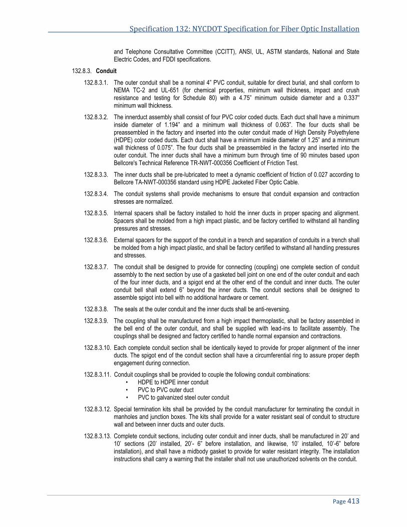
Specification 132: NYCDOT Specification for Fiber Optic Installation
Page 413
and Telephone Consultative Committee (CCITT), ANSI, UL, ASTM standards, National and State Electric Codes, and FDDI specifications.
132.8.3. Conduit
132.8.3.1. The outer conduit shall be a nominal 4” PVC conduit, suitable for direct burial, and shall conform to NEMA TC-2 and UL-651 (for chemical properties, minimum wall thickness, impact and crush resistance and testing for Schedule 80) with a 4.75” minimum outside diameter and a 0.337” minimum wall thickness.
132.8.3.2. The innerduct assembly shall consist of four PVC color coded ducts. Each duct shall have a minimum inside diameter of 1.194” and a minimum wall thickness of 0.063”. The four ducts shall be preassembled in the factory and inserted into the outer conduit made of High Density Polyethylene (HDPE) color coded ducts. Each duct shall have a minimum inside diameter of 1.25” and a minimum wall thickness of 0.075”. The four ducts shall be preassembled in the factory and inserted into the outer conduit. The inner ducts shall have a minimum burn through time of 90 minutes based upon Bellcore's Technical Reference TR-NWT-000356 Coefficient of Friction Test.
132.8.3.3. The inner ducts shall be pre-lubricated to meet a dynamic coefficient of friction of 0.027 according to Bellcore TA-NWT-000356 standard using HDPE Jacketed Fiber Optic Cable.
132.8.3.4. The conduit systems shall provide mechanisms to ensure that conduit expansion and contraction stresses are normalized.
132.8.3.5. Internal spacers shall be factory installed to hold the inner ducts in proper spacing and alignment. Spacers shall be molded from a high impact plastic, and be factory certified to withstand all handling pressures and stresses.
132.8.3.6. External spacers for the support of the conduit in a trench and separation of conduits in a trench shall be molded from a high impact plastic, and shall be factory certified to withstand all handling pressures and stresses.
132.8.3.7. The conduit shall be designed to provide for connecting (coupling) one complete section of conduit assembly to the next section by use of a gasketed bell joint on one end of the outer conduit and each of the four inner ducts, and a spigot end at the other end of the conduit and inner ducts. The outer conduit bell shall extend 6” beyond the inner ducts. The conduit sections shall be designed to assemble spigot into bell with no additional hardware or cement.
132.8.3.8. The seals at the outer conduit and the inner ducts shall be anti-reversing.
132.8.3.9. The coupling shall be manufactured from a high impact thermoplastic, shall be factory assembled in the bell end of the outer conduit, and shall be supplied with lead-ins to facilitate assembly. The couplings shall be designed and factory certified to handle normal expansion and contractions.
132.8.3.10. Each complete conduit section shall be identically keyed to provide for proper alignment of the inner ducts. The spigot end of the conduit section shall have a circumferential ring to assure proper depth engagement during connection.
132.8.3.11. Conduit couplings shall be provided to couple the following conduit combinations: • HDPE to HDPE inner conduit • PVC to PVC outer duct • PVC to galvanized steel outer conduit
132.8.3.12. Special termination kits shall be provided by the conduit manufacturer for terminating the conduit in manholes and junction boxes. The kits shall provide for a water resistant seal of conduit to structure wall and between inner ducts and outer ducts.
132.8.3.13. Complete conduit sections, including outer conduit and inner ducts, shall be manufactured in 20’ and 10’ sections (20’ installed, 20’- 6” before installation, and likewise, 10’ installed, 10’-6” before installation), and shall have a midbody gasket to provide for water resistant integrity. The installation instructions shall carry a warning that the installer shall not use unauthorized solvents on the conduit.

NYCDOT Specifications for Traffic Signals & ITS Systems November 2013
Page 414
132.8.3.14. Complete conduit rigid bend sections, including outer conduit and high temperature burn through resistant inner duct, shall be manufactured, and shall be complete with bell and spigot. Standard bend sections shall be available in the following sizes:
Radius (feet) Bend (degrees)
4 11 1/4
4 22 1/2
4 45
4 90
132.8.4. Conduit Detection System
132.8.4.1. A conduit detection system shall be installed in all underground sections of the installed conduit. The system shall consist of a locator wire installed in the underground sections of the conduit.
132.8.4.2. The locator wire shall be 1 type XHHW-2 insulation, 12 gauge. The cable shall be placed in the white inner duct (with the "L" fiber optic cable). The details of installation are included in the contract documents.
132.8.5. Color Coding And Labeling
132.8.5.1. Innerducts shall be distinguishable from each other by color coding, as indicated in the contract documents. The entire duct shall be colored by industry standard coloring additive to the duct material, not by an external applied coloring.
132.8.5.2. The outer duct shall have a longitudinal print line that denotes, "Install This Side Up” to allow for the proper alignment of the inner ducts. The outer duct shall be marked with data to trace the plant location, date, shift, and machine used in the manufacturing process.
132.8.6. Shipping
132.8.6.1. The conduit shall be packaged for shipment at the factory. The conduit shall be assembled into manageable bundles. Each section of conduit shall be shipped with protective caps over each end of the section. Conduit that arrives at the job site without the protective cover in place over both ends will be rejected by the Engineer.
132.8.7. Miscellaneous
132.8.7.1. Cleave Tool - Cleave tools are used during splicing to cut the individual SM or MM fibers as close to a perfect 90 degree angle as possible, thus allowing the highest core to core alignment and therefore the lowest dB splice loss. The manufacturers of cleave tools have established "end angle" cleave averages that are based on a minimum of 150 cuts utilizing a minimum of 10 cutters. Based on these test results cleave tools shall have minimum end angle averages as follows: <0.70 degree average with no cut of the 150 cleaves exceeding 1.5 degree will be allowed. Prior to the splicing of any fiber cable, the Contractor shall submit the part number and manufacturer of the cleave tool along with an "end angle" distribution chart which demonstrates the actual 150 cut end angles, such as Siecor part number FBC-005 or Alcoa Fujikura CO12 or equal. The Contractor shall purchase a cleave tool that meets this specification to be left in good working condition with the maintaining agency for maintenance of the fiber system.
132.8.7.2. Mechanical Splice Tool Kit
132.8.7.2.1. A mechanical splice tool kit shall include all the tools necessary for the assembly of a mechanical splice. The tools shall allow for easy completion of cable preparation, removal of fiber coating, cleaning and cleaving, prior to completing the splice. Mechanical splice kits typically include a connector assembly tool, cleave tool, No-Nik fiber stripper, micro-strip precision stripper, cable stripper, telecommunication snips, 20X magnifier, lint-free cloth, protective carrying case and manual.
132.8.7.2.2. A cleave tool shall be included in the mechanical splice kit in addition to the one which will be purchased separately. The Contractor shall purchase a pre-assembled mechanical splice kit

Specification 132: NYCDOT Specification for Fiber Optic Installation
Page 415
that meets this specification, similar to 3M 2530 Fiber Splice Preparation Kit, Siecor TKT-100-02 or approved equal, to be left in good working condition with the maintaining agency for maintenance of the fiber system.
132.8.7.3. Fiber Optic Termination Tool Kit
132.8.7.3.1. A termination tool kit shall include all tools and materials listed below necessary to terminate the connectors used as part of this project. Termination kits shall include a hot melt oven, crimp tool, one-step lap film, polishing jig, polishing pad, cooling stand, connector holder, stripping collar, scribe carbide, bottle of 99% isopropyl alcohol, snips, cable stripper, No-Nik stripper, view scope, lint-free cloth and pipe cleaners, jewelers loupe, pocket ruler and instruction manuals. The Contractor shall purchase a pre-assembled termination tool kit that meets this specification, similar to 3M 6150-A Termination Kit, Siecor TKT-025 or approved equal, to be left in good working condition with the maintaining agency for maintenance of the fiber system. The entire kit shall come in a hard side carrying case.
132.8.7.4. Optical Time Domain Reflectometer (OTDR)
132.8.7.4.1. The Optical Time Domain Reflectometer (OTDR) shall be supplied with the following features as a minimum:
• Field interchangeable source modules for single mode and multi-mode fiber analysis of optical links from 300 ft (100 m) to 15,000 ft (5 km) in length
• Minimum of 3 user selectable pulse widths per wavelength • Auto mode button for one button testing • Auto mode or simplified mode for trace naming and storing • Dual trace analysis mode • Event table display • Internal hard drive for trace storage • Electronic format • Peripheral support for keyboard, mouse, VGA monitor and printer • Individual and batch printing modes • PC based emulation software for latest version of Windows (to be included with
OTDR) • System shall be software upgradeable • Internal Battery with AC adapter/battery charger • Internal or external printer • Bi-directional analysis through emulation software or internal to OTDR
132.8.7.5. Pole Entrance Fitting - A pole entrance fitting shall be provided in accordance with the enclosed details to allow fiber optic cable entrance into both existing and proposed steel poles. In proposed poles, the Contractor shall have the 1½” entrance holes shown in the details.
132.8.7.6. Optical Time Domain Reflectometer (OTDR) Testing
132.8.7.6.1. All links shall be tested with an OTDR that are 1,000 ft or longer for the 850 nm and 1,310 nm wavelengths. Links which are in excess of 3,280 ft shall include 1,550 nm testing on SM fibers. OTDR testing shall be in one direction following worst case wavelength selection when there are no splice points or interconnect points in the link.
132.8.7.6.2. Any link, which is longer than 1,000 ft and has splice points or interconnect points in said link, shall be tested bi-directionally using worst case wavelengths. Links that are longer than 3,280 ft shall include testing at the 1,550 nm wavelength for SM fibers.
132.8.7.6.3. All fiber shall be tested for attenuation loss using an OTDR set to 2-Point loss measurement parameters. Marker points shall be placed at the beginning and end of each backscatter signature recorded by the OTDR. The manufacturer's instructional guide can be used to determine proper placement of these markers. The OTDR display shall be recorded electronically with identification and numbering, sequences to be pre-approved by the Engineer. Each trace must contain as a minimum: cable/sheath length (not optical fiber length), 2-point dB loss, attenuation in dB/mile (dB/km), fiber type, wavelength used, pulse

NYCDOT Specifications for Traffic Signals & ITS Systems November 2013
Page 416
width selection, and fiber/cable identification. The stored fiber trace shall allow full manipulation of the trace when viewed with the PC emulation software. Both a hard copy print-out and electronic copy of each trace shall be submitted to the Engineer for approval.
132.8.7.6.4. Links that contain splice points or interconnect points shall also contain an additional "Events Display Table" to accompany the OTDR trace. This display shall show the distance to the events, distance between multiple events, each events loss in dB, and a description of the event (reflective event, non-reflective event, gains and cable end). All attenuation event loss readings shall be in the Least Square Average (LSA) () mode of the OTDR. 2-Point attenuation measurements at events are not acceptable. Proper pulse width selection is required to minimize attenuation dead zone effect (10ns pulse: MM dead zone=23 ft, SM dead zone=33 ft ).
132.8.7.6.5. All costs to perform the above testing shall be included in the bid lump sum price for Fiber Optic Cable Testing. Any link that fails the above tests shall be replaced and retested at the Contractor's expense.
132.8.7.7. Fiber Optic Transceiver Single Mode - Communications on the fiber optic cable shall require fiber optic transceivers. The controllers are to be equipped with transceivers capable of communications with the signal system controllers. It is the Contractor's responsibility to install and activate each of these modems in the controller housing and contact the manufacturer for replacement panels if necessary. Price for the controllers is itemized separately.
132.8.7.8. Abrasion Protection - The abrasion protector shall be designed to protect All Dielectric Self Supporting (ADSS) jackets from abrasion. The device shall be made of black low density polyethylene and shall have a maximum length of 8 feet long or as designated on the plans. The diameter shall be consistent with the cable to be provided under fiber items. The tube shall be slit from end to end to allow application on completed fiber installations.
132.8.7.9. Incidental Items - As detailed on the plans, miscellaneous material such as and not limited to threaded rods, hex nuts, flat washers, nylon locknuts, galvanized steel plates, galvanized steel angles, and malleable iron pipe straps shall be provided as incidental to the cable bid item.
132.8.8. Construction Detail
132.8.8.1. The Contractor shall prepare a shop drawing submittal which will include copies of descriptive literature for every component to be included in the fiber optic cable plant to be installed under this Specification. Included in the submittal, shall be a certificate of compliance certifying that the cable complies with the material requirements as detailed in the material section of this specification. If the Engineer determines that the certificate of compliance is not acceptable, the Contractor shall be required to perform factory testing on exact samples of cables being proposed for the project.
132.8.8.2. In addition, the submittal shall include a complete installation plan which shall detail construction methods to be utilized. Prior to the submittal of this plan, the Contractor shall walk the length of the installation run with the Engineer for the purpose of establishing exact locations for the fiber optic support assemblies. In addition, exact locations for the splice enclosures and/or slack loops (8’ minimum) shall be determined during this walk-through. The plan shall be designed to minimize the number of fiber optic splices required. Approximately every 600 ft, a 2 turn loop of cable with a 3.25 ft (1 m) diameter shall be installed. The purpose of this loop is to provide slack cable which can be utilized to repair future breaks. The loop shall be supported with UV rated tie wraps with sufficient strength to support the loop. Exact location of the loops shall be determined during the walk through.
132.8.8.3. The contract includes fiber optic splices at designated points along the run. The number of splices indicated on the plans shall not be increased without the approval of the engineer. However, the Contractor shall be able to propose alternate locations for the splices, based on the installation plan to be provided. Splices are paid for under a separate bid item. However, if more are needed then approved by the Engineer, the additional splices shall be completed as part of the cost for the cable installation to be paid under this bid item. If less splices are required, the Contractor shall be paid for the actual number of splices completed. Sixteen feet (5 m) of slack cable shall be provided at each splice point or as indicated on the contract plans.

Specification 132: NYCDOT Specification for Fiber Optic Installation
Page 417
132.8.8.4. The shop drawing submittal must be approved by the Engineer prior to installation of any of the material covered under this bid item on the project site. Upon arrival of the cable at the job site and prior to installation, a physical inspection of the cable and reel shall be performed. All of the fibers shall be tested with a field OTDR for attenuation to confirm that the cable meets requirements. Test results shall be recorded, dated, compared and filed with the copy accompanying the shipping reel in a weather resistant envelope. Attenuation deviations from the shipping records greater than 5 percent shall be brought to the attention of the Engineer.
132.8.8.5. The cable shall not be installed until completion of these test sequences and written approval from the Engineer is obtained. Copies of traces and test results shall be submitted to the Engineer. If the OTDR test results are unsatisfactory, the reel of fiber optic cable shall be considered unacceptable and all records corresponding to that reel of cable shall be marked accordingly. Prior to the installation of the actual cable, all preparatory work involving the installation of supports, conduits, pull boxes, trenching, and man-holes shall have been completed.
132.8.8.6. The cable shall be installed utilizing methods that will not exceed the rated pulling strength of the cable and shall be consistent with the manufacturer’s published procedures. After each segment between splices of the cable is installed, the OTDR test shall be repeated with the cable installed in place. The test shall indicate that attenuation is still within tolerance of the specifications for all fibers. If any fibers fail the test, the cable shall be removed from the job site and replaced with an entirely new cable, at the Contractor’s expense.
132.8.9. Method Of Measurement
132.8.9.1. Fiber optic cable will be measured by the number of feet of cable actually installed, as to be verified by the sequential length markings on the cable, in accordance with the contract documents and as directed by the Engineer.
132.8.10. Basis Of Payment
132.8.10.1. The unit price bid shall include the cost of all equipment, material, supports, testing, and labor detailed in the contract documents including all support assemblies, dead ends, and abrasion protectors. Lengths of cable shall be eligible for payment after the installed cable OTDR testing has been completed.
END OF SPECIFICATIONS FOR FIBER OPTIC INSTALLATION

Specification 133
NYCDOT Specification for Single Mode Fiber Optic Cable with Non Metal Jacket
Date of Revision Revised by Description
6/23/2008 New Spec
1/29/2009 Revise Spec
NYCDOT Specifications for Traffic Signals & ITS Systems November 2013
Page 420
133. NYCDOT SPECIFICATION FOR SINGLE MODE FIBER OPTIC CABLE WITH NON METAL JACKET ........................... 421 133.1. GENERAL .................................................................................................................................................................... 421 133.2. DESCRIPTION .............................................................................................................................................................. 421 133.3. MATERIALS ................................................................................................................................................................. 421 133.4. CONSTRUCTION DETAILS: ............................................................................................................................................ 425

Spec 133: NYCDOT Specification for Single Mode Fiber Optic Cable with Non Metal Jacket
Page 421
133. NYCDOT Specification for Single Mode Fiber Optic Cable with Non Metal Jacket
133.1. General 133.1.1. The cable will be used in harsh overhead and underground environment in NYC for Traffic control, ITS and
general building-to-building communications. The cable shall be rated for direct burial and for exposed environment where exposed to UV rays. The cable shall be rodent resistant.
133.2. Description 133.2.1. This work shall consist of furnishing and installing single mode fiber optic cable used for the communications
backbone, distribution network and equipment drops, passive components and miscellaneous equipment necessary for a complete cable plant as shown in the plans and/or as directed by the Engineer. Backbone, data distribution and equipment drops refer to the functional application of the cable, as defined below, and not the type of cable. The quantity of fibers contained in each cable shall be in accordance with the plans.
133.3. Materials 133.3.1. The single mode fiber optic cable shall incorporate a water swellable tape, loose buffer tube cable design.
The fiber optic cable shall be suitable for installation in conduit or lashed to messenger cable in an outside cable plant environment. The cable shall be all dielectric and shall consist of the number of fibers specified in the plans.
133.3.2. The cable shall meet the requirements of the United States Department of Agriculture Rural Utility Service (RUS) 7 CFR1755.900, the requirements of ANSI/ICEA Standard for Fiber Optic Outside Plant Communications Cable, ANSI/ICEA S-87-640-1999 and shall be new, unused and of current design and manufacturer. The cable manufacturer shall have had a minimum of three years of experience manufacturing fiber optic cable of a similar design. Proof of this experience shall be submitted to the Engineer as part of the ten-day submission.
133.3.3. The cable shall meet the following requirements:
133.3.3.1. Optical Requirements
133.3.3.1.1. The fibers shall meet the requirements of EIA/TIA-492CAAB “Detail Specifications for Class IVa Dispersion-Unshifted Single Mode Optical Fiber Cable with Low Water Peak” and ITU recommendation G.652.D, “Characteristics of Single-Mode Optical Fiber Cable”.
133.3.3.1.2. Maximum attenuation at 1310 nm 0.4 decibels/kilometer (dB/km) 1383 nm 0.4 dB/km 1550 nm 0.3 dB/km 1625 nm 0.3 dB/km
Fiber attenuation shall be uniform with no discontinuities greater than 0.05 dB at 1,310 nm and 1,550 nm. The attenuation measurements shall be in accordance with the latest revisions of EIA/TIA 455 Standards FOTP-20, 59, 61 and 78. The average change in attenuation at extreme operational temperatures (-40° C to 70° C [-40º F to 158º F]) shall not exceed 0.05 dB/cm at 1,550 nm. The magnitude of the maximum attenuation change of each individual fiber shall not be greater than 0.15 dB/km at 1,550 nm. The change in attenuation measurements shall be in accordance with EIA/TIA Standard FOTP-3.

NYCDOT Specifications for Traffic Signals & ITS Systems November 2013
Page 422
133.3.3.1.3. The macrobending attenuation shall not exceed the following under the stated conditions:
Condition Wavelength Maximum attenuation
1 turn, 32±2 mm OD mandrel 1550 nm 0.50 dB 100 turns, 50±2 mm OD mandrel 1310 nm 0.05 dB 100 turns, 50±2 mm OD mandrel 1550 nm 0.10 dB 100 turns, 60±2 mm OD mandrel 1550 nm 0.05 dB 100 turns, 60±2 mm OD mandrel 1625 nm 0.05 dB
133.3.3.1.4. Water immersion at 23º C±2º C ≤ 0.5 dB/km at 1,310; 1,550 and 1,625 nm
133.3.3.1.5. Cutoff Wavelength: ≤1260 nm.
133.3.3.1.6. Mode-Field Diameter: 9.2±0.4 nm at 1,310 nm.
10.4±0.5 nm at 1,550 nm. 133.3.3.1.7. Zero Dispersion Wavelength: 1,312±10 nm.
133.3.3.1.8. Zero Dispersion Slope: <0.092 ps/(nm*km).
133.3.3.1.9. Total Dispersion: ≤3.5 ps/(nm*km) at 1,285-1,330 nm.
≤18 ps/(nm*km) at 1,550 nm. <22 ps/(nm*km) at 1,625 nm.
133.3.3.1.10. Polarization Mode Dispersion: ≤0.2 ps/(nm*km).
133.3.3.2. Mechanical Requirements
133.3.3.2.1. Fibers - All optical fibers shall be Corning, OSF or Sumitomo single mode glass fibers or approved equivalent. All fibers within a given cable shall be from the same manufacturer, and shall contain no factory splices. Each fiber shall conform to the following minimum requirements:
• Typical Core Diameter: 8.3 nm • Cladding Diameter: 125.0±1.0 nm • Core-to-Cladding Concentricity: ±0.8 nm • Cladding Non-Circularity: ±1.0%
133.3.3.2.2. Color Coding - Each fiber shall have a color coating applied to it by the manufacturer. The coating shall not affect the optical characteristics of the fiber. The basic color configuration shall be as follows, in accordance with EIA/TIA-598-B:
Blue Slate Yellow Orange White Violet Green Red Rose Brown Black Aqua
The nominal colored fiber diameter shall be 250 nm.
133.3.3.2.3. Primary Coating - Each fiber shall have a dual layered, UV acrylate coating applied to it by the manufacturer. The coating shall be mechanically strippable without damaging the fiber. The
coating diameter shall be 24510 nm.
133.3.3.2.4. Central Strength Member - The central strength member shall consist of a dielectric, glass-reinforced plastic rod.
133.3.3.2.5. Buffering - All fibers shall be enclosed in non-conductive loose buffer tubes. Each buffer tube shall contain a maximum of 12 fibers. The fiber shall not adhere to the inside of the buffer tube. Each buffer tube containing fibers shall be color coded in a similar scheme as the fiber color. The basic color configuration shall be as follows, in accordance with EIA/TIA 598-B:
Blue Slate Yellow Orange White Violet Green Red Rose Brown Black Aqua
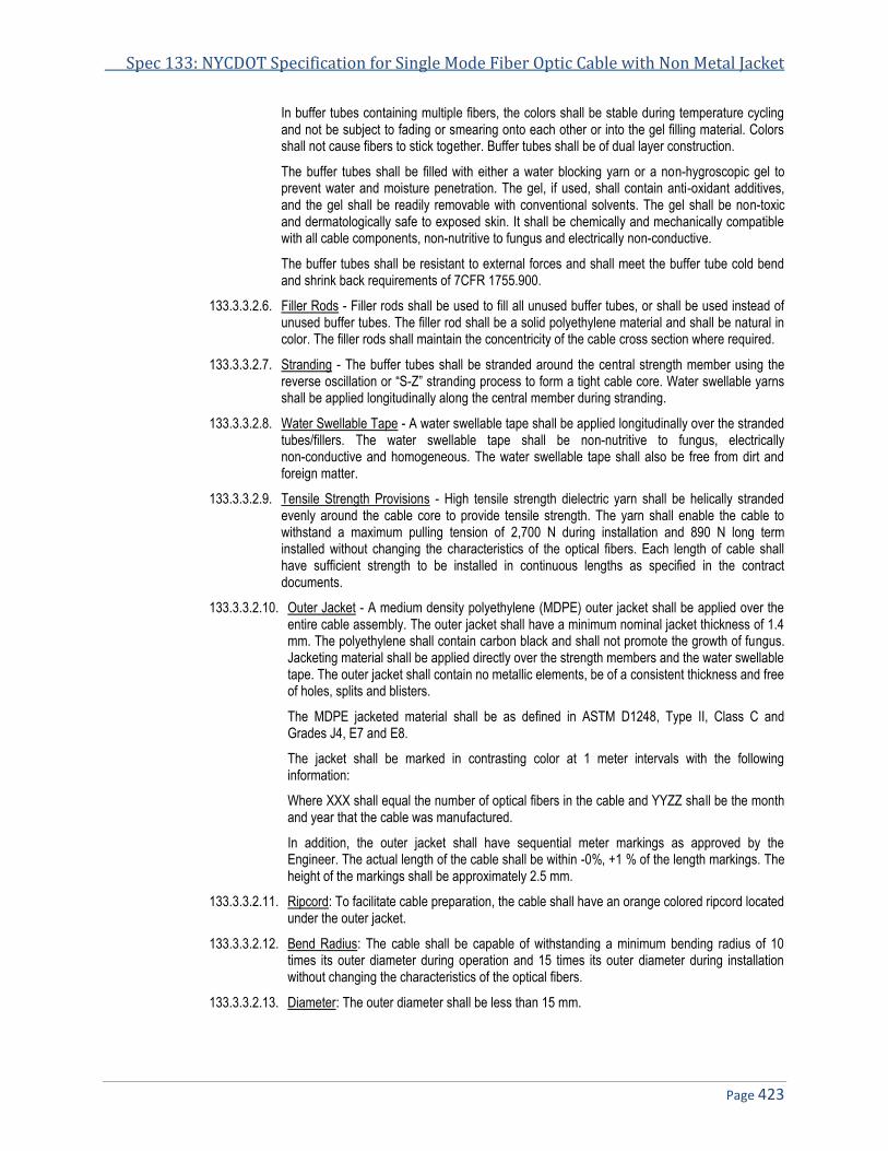
Spec 133: NYCDOT Specification for Single Mode Fiber Optic Cable with Non Metal Jacket
Page 423
In buffer tubes containing multiple fibers, the colors shall be stable during temperature cycling and not be subject to fading or smearing onto each other or into the gel filling material. Colors shall not cause fibers to stick together. Buffer tubes shall be of dual layer construction.
The buffer tubes shall be filled with either a water blocking yarn or a non-hygroscopic gel to prevent water and moisture penetration. The gel, if used, shall contain anti-oxidant additives, and the gel shall be readily removable with conventional solvents. The gel shall be non-toxic and dermatologically safe to exposed skin. It shall be chemically and mechanically compatible with all cable components, non-nutritive to fungus and electrically non-conductive.
The buffer tubes shall be resistant to external forces and shall meet the buffer tube cold bend and shrink back requirements of 7CFR 1755.900.
133.3.3.2.6. Filler Rods - Filler rods shall be used to fill all unused buffer tubes, or shall be used instead of unused buffer tubes. The filler rod shall be a solid polyethylene material and shall be natural in color. The filler rods shall maintain the concentricity of the cable cross section where required.
133.3.3.2.7. Stranding - The buffer tubes shall be stranded around the central strength member using the reverse oscillation or “S-Z” stranding process to form a tight cable core. Water swellable yarns shall be applied longitudinally along the central member during stranding.
133.3.3.2.8. Water Swellable Tape - A water swellable tape shall be applied longitudinally over the stranded tubes/fillers. The water swellable tape shall be non-nutritive to fungus, electrically non-conductive and homogeneous. The water swellable tape shall also be free from dirt and foreign matter.
133.3.3.2.9. Tensile Strength Provisions - High tensile strength dielectric yarn shall be helically stranded evenly around the cable core to provide tensile strength. The yarn shall enable the cable to withstand a maximum pulling tension of 2,700 N during installation and 890 N long term installed without changing the characteristics of the optical fibers. Each length of cable shall have sufficient strength to be installed in continuous lengths as specified in the contract documents.
133.3.3.2.10. Outer Jacket - A medium density polyethylene (MDPE) outer jacket shall be applied over the entire cable assembly. The outer jacket shall have a minimum nominal jacket thickness of 1.4 mm. The polyethylene shall contain carbon black and shall not promote the growth of fungus. Jacketing material shall be applied directly over the strength members and the water swellable tape. The outer jacket shall contain no metallic elements, be of a consistent thickness and free of holes, splits and blisters.
The MDPE jacketed material shall be as defined in ASTM D1248, Type II, Class C and Grades J4, E7 and E8.
The jacket shall be marked in contrasting color at 1 meter intervals with the following information:
Where XXX shall equal the number of optical fibers in the cable and YYZZ shall be the month and year that the cable was manufactured.
In addition, the outer jacket shall have sequential meter markings as approved by the Engineer. The actual length of the cable shall be within -0%, +1 % of the length markings. The height of the markings shall be approximately 2.5 mm.
133.3.3.2.11. Ripcord: To facilitate cable preparation, the cable shall have an orange colored ripcord located under the outer jacket.
133.3.3.2.12. Bend Radius: The cable shall be capable of withstanding a minimum bending radius of 10 times its outer diameter during operation and 15 times its outer diameter during installation without changing the characteristics of the optical fibers.
133.3.3.2.13. Diameter: The outer diameter shall be less than 15 mm.
NYCDOT Specifications for Traffic Signals & ITS Systems November 2013
Page 424
133.3.3.2.14. Manufacturer's Certification: The following tests shall be performed and the results documented for a cable meeting the requirements herein. The cable manufacturer shall certify that each reel of cable that is furnished meets or exceeds the following test requirements as defined in EIA/TIA-455B “Standard Test Procedures for Fiber Optic Fibers, Cables, Transducers, Sensors, Connecting and Terminating Devices and Other Fiber Optic Components” Fiber Optic Test Procedures (FOTP):
133.3.3.2.14.1. Fluid Penetration: When tested in accordance with FOTP-82, a one meter length of unaged cable shall withstand a one meter static head or equivalent continuous pressure of water for one hour without leakage through the open cable end.
133.3.3.2.14.2. Filling Compound Flow: When tested in accordance with FOTP-81, the cable shall exhibit no flow (drip or leak) of filling or flooding compound at 70° C.
133.3.3.2.14.3. Compressive Load: The cable shall withstand a minimum compressive load of 22 N/mm applied uniformly over the length of the sample. The cable shall be tested in accordance with FOTP-41, with the load applied at the rate of 2.5 mm/minute. The load shall be maintained for one minute and then decreased to 11 N/mm. The 11 N/mm load shall be maintained for 10 minutes. The magnitude of the attenuation change at 1,550 nm shall not exceed 0.4 dB prior to release of the 11 N/mm load. The repeatability of the measurement system is typically 0.05 dB or less. No fibers shall exhibit a measurable change in attenuation after load removal.
133.3.3.2.14.4. Tensile Loading and Bending: When tested in accordance with FOTP-33, using a maximum mandrel and sheath diameter of 560 mm the cable shall withstand a tensile load of 2,700 N. The change in attenuation shall not exceed 0.2 dB during loading and 0.1 dB after loading at 1,550 nm.
133.3.3.2.14.5. Low or High Temperature Bending: When tested in accordance with FOTP-37, the cable shall withstand four full turns around a mandrel of < 10 times the cable diameter after conditioning for four hours at test temperatures of -30º C to 60º C. Neither the inner or outer surfaces of the jacket shall exhibit visible cracks, splits, tears or other openings. Optical continuity shall be maintained throughout the test.
133.3.3.2.14.6. Impact Resistance: When tested in accordance with FOTP-25, the cable shall withstand 25 impact cycles. The change in attenuation shall not exceed 0.2 dB at 1,550 nm. The cable jacket shall exhibit no cracking or splitting upon completion of the test.
133.3.3.2.14.7. Cable Flexibility: When tested in accordance with FOTP-104, the cable shall withstand 25 mechanical flexing cycles at a rate of 30" per cycles per minute with a sheath diameter not greater than 20 times the cable diameter. The fibers shall not experience an attenuation change greater than 0.1 dB at 1,550 nm. The cable jacket shall exhibit no cracking or splitting when observed under five times magnification.
133.3.3.2.14.8. Temperature cycling: When tested in accordance with FOTP-3, the change in attenuation at extreme operational temperatures (-40º C to 70º C) shall not exceed 0.2 dB/km at 1,550 nm.
133.3.3.2.14.9. Cable Twist: When tested in accordance with FOTP-85, a length of cable no longer than 4 meters shall withstand 10 cycles of mechanical twisting. The change in attenuation shall not exceed 0.1 dB at 1,550 nm.
133.3.3.2.15. Factory Testing: Prior to shipment from the factory each fiber shall be attenuation tested at both 1,310 nm and 1,550 nm. The test results for each reel shall be provided to the Engineer for each reel furnished at least five-working days prior to installation.
133.3.3.2.16. Environmental Requirements: The cable shall meet all of its specified requirements during and after being subjected to any combination of the following requirements:
Temperature, shipping storage and operation -50° C to 70° C
Installation -30° C to 70° C
Relative humidity from 0% to 95%, non-condensing
133.3.3.2.17. Delivery: The cable shall be delivered on reels without splices. Three (3) meters of each end
of the cable shall be accessible for testing at the Contractors facility prior to installation. Both
Spec 133: NYCDOT Specification for Single Mode Fiber Optic Cable with Non Metal Jacket
Page 425
ends of the cable shall be sealed to prevent moisture ingress. A durable weather resistant tag or label on each reel shall contain the following information:
• Manufacturer’s name. • Cable type. • Length of cable contained on the reel in meters. • Reel number.
Attached to the reel in a weather resistant envelope shall be the shipping record. The shipping record shall contain the following in addition to the above information:
• Date of manufacture. • Date cable tested. • Cable characteristics (size, attenuation for each fiber). • Cable reel identification number.
133.3.3.2.18. Fiber Optic Connectors: Fiber Optic Connectors shall be furnished and installed incidental to the cost of installing fiber optic cables. The connectors shall be factory installed. Field installation of connectors shall only be permitted with the express consent of the Engineer and will be considered on a case by case basis. The connectors shall meet the following requirements:
• Type ST twist lock (bayonet). • Uses ceramic ferrules • Fiber secured within the ferrule with epoxy, as specified by the connector or epoxy
manufacturer. • Operating Temperature: -20o C to +70o C • Insertion loss: 0.5 dB maximum • Return loss: 55 dB minimum
133.4. Construction Details: 133.4.1. General
133.4.1.1. All fibers in the fiber optic cable shall be spliced, terminated, or both in the field cabinets and pull boxes designated in these contract documents or as directed by the Engineer. The Contractor shall furnish all equipment required for the installation and testing of the cable.
133.4.1.2. The Contractor shall provide all passive components required to form a complete cable plant including, but not limited to, connectors and breakout kits and ancillary components required for the installation of the cable plants including terminators, moisture and water sealants cable caps and cable management devices such as devices for the racking of slack cable in pull boxes. The components supplied shall be commercially available state-of-the-art components suitable for this application.
133.4.1.3. The backbone, distribution and drop optical fiber cable designations used in the plans indicate the function of the fibers contained in the cable and not the type of cable.
133.4.1.4. Backbone fiber carries data and video between hubs, hubs and the Joint Traffic Management Center (JTMC) and cable terminations and hubs.
133.4.1.5. Distribution fiber carries video from CCTV installations and data from field devices to hubs.
133.4.1.6. Drop cable connects field devices to the distribution optical fiber cable.
133.4.2. Preinstallation Requirements - The Contractor shall be entirely responsible for the fiber optic cable security and adherence to these specifications, from its manufacturer to the time the network is accepted by the State. Prior to installation of the cable the Contractor shall submit a Cable Plant Installation Plan and proof of appropriate training for personnel who will be installing the fiber.

NYCDOT Specifications for Traffic Signals & ITS Systems November 2013
Page 426
133.4.3. Cable Plant Design Submission - The Contractor shall submit the Cable Plant Design Submission to the Engineer for approval. The Engineer shall have thirty (30) working days to review this submission. The submission shall include the following:
133.4.3.1. Catalog cuts and shop drawings for all cable, connectors, splice equipment, splice enclosures, splice trays and cable installation and test equipment of adequate detail to verify compliance with the specifications.
133.4.3.2. b. Manufacturer’s recommended cable installation techniques such that the optical and mechanical characteristics of the cables are not degraded at the time of installation. The proposed recommendation shall include the following:
133.4.3.2.1. Cable manufacturer’s approved pulling lubricants for use on the cable and method of application. No other lubricants will be permitted.
133.4.3.2.2. Installation set-up including size and types of rollers, feeder guides, tension gauge make and model number, attachment of pulling jig to jacket and direction of pull.
133.4.3.2.3. Maximum pulling tensions, which shall specify both pulling from the cable conductors and for pulling from the outer jacket.
133.4.3.2.4. Minimum bending radii, which shall specify a radius both the installation and for long term installation.
133.4.3.2.5. Method to pull multiple cables.
133.4.3.2.6. Method to seal unterminated cable against water ingress.
133.4.3.2.6.1. Proposed splice locations and amount of slack proposed for each splicing location. This shall be shown by line diagrams using a computer graphics program. The drawings shall be on 11”x17” sheets.
133.4.3.2.6.2. Splice material manufacturer’s recommended procedures for installation of the splices and to flash test enclosure.
133.4.3.2.6.3. Expected attenuation between end points of all fibers. Including in the attenuation calculation shall be losses resulting from splices and connectors.
133.4.3.2.7. No fiber optic cable shall be installed until the items listed above have been submitted and approved by the Engineer.
133.4.4. Experience Requirements - Personnel involved in the installation, splicing and testing of the fiber optic cable shall meet the following requirements:
133.4.4.1. A minimum of five (5) years of experience in the installation of fiber optic cables, including fusion splicing, terminating and testing single mode fibers.
133.4.4.2. Installed five systems where fiber optic cables are outdoors in conduit and where the systems have been in continuous satisfactory operation for at least two years.
133.4.4.3. The Contractor shall submit as proof resumes of the personnel listing their names and project worked on and the names of references who can be contacted regarding the installed fiber optic systems. Personnel shall meet the following requirements:
133.4.4.3.1. Splicers shall have been trained and certified in fiber optic splicing procedures by the manufacturer of the fiber splice material to be used.
133.4.4.3.2. Installers shall have been trained and certified in fiber optic cable installation and handling procedures by the manufacturer of the fiber optic cable to be used.
133.4.4.3.3. Personnel involved in testing shall have been trained and certified by the manufacturer of the fiber optic cable test equipment to be used, in fiber optic cable testing procedures.
133.4.4.4. Proof of the appropriate training shall be submitted to the Engineer for approval a minimum of twenty (20) working days prior to start of installation.

Spec 133: NYCDOT Specification for Single Mode Fiber Optic Cable with Non Metal Jacket
Page 427
133.4.5. Installation Requirements - All fiber optic cable installed underground shall be placed in conduit. No direct burial of cable will be permitted. The cables shall be installed as shown in the plans and in accordance with the approved cable plant installation plan.
133.4.6. Installation - Fiber optic cable shall be installed in accordance with the approved manufacturer’s recommendations. In addition the following requirements shall be met:
133.4.6.1. The number of pullboxes and their locations shall be as shown on the plans. The Contractor may be required to install the cable in one pullbox at a time. The direction of the cable pull shall be determined by the Contractor and shall require the approval of the Engineer.
133.4.6.2. A minimum of 30 m of cable slack, or as approved by the Engineer, shall be provided in pullboxes containing splices for the cable to be spliced or otherwise designated on the plans or as directed by the Engineer. Additional slack, as indicated on the approved cable installation plan, may be provided for closure preparation and splicing.
133.4.6.3. Drip loops shall be provided in aerial installations in accordance with the manufacturer’s recommendation.
133.4.6.4. No fiber optic cable shall be pulled through more than one 90 degree bend unless so indicated on the approved plans or specifically approved by the Engineer.
133.4.6.5. The cable shall not be pulled over edges or corners, over or around obstructions, or through unnecessary curves or bends.
133.4.6.6. The cable shall be looped in and out of cabinets and pull boxes to provide adequate slack and the least amount of stress on the fibers. The Contractor shall ensure that the cable is not damaged during storage or installation.
133.4.6.7. Fiber optic cable ends shall be kept sealed at all times during installation, using a method recommended by the cable manufacturer and approved by the Engineer. The cable end shall remain sealed until the Contractor terminates the fiber cables. Cables that are not immediately terminated shall have a minimum of two meters of slack.
133.4.6.8. When using lubricants, the Contractor shall adhere to the cable manufacturer’s requirements for the proper amount, application tools and method, and removal of the lubricant from the exposed cable.
133.4.6.9. Optical fiber cable shall be installed in continuous lengths without intermediate splices throughout the project except where splices are indicated on the approved cable plant submission or approved by the Engineer. Splices shall only be in reenterable splice enclosures mounted in pullboxes, junction boxes and underground vaults.
133.4.6.10. The fiber optic drop cable shall be spliced to either the backbone or distribution cable at the locations indicated on the plans or as directed by the Engineer.
133.4.6.11. The maximum pulling tensions and minimum bending radii shall not be violated at any time during installation. The Contractor shall consult with the Engineer concerning existing conduit, pullboxes, and risers, which could force the violation of the minimum bending radius for the fiber optic cable. The Contractor shall obtain approval from the Engineer if modifications to these existing facilities are required. Violation of these parameters shall be cause for rejection of the installed cable.
133.4.6.12. Prior to any installation of cable, the Contractor shall clean existing conduit in accordance with the requirements of these special provisions.
133.4.6.13. Slack cable and innerduct where pulled through a pullbox shall be racked to the pullbox wall.
133.4.6.14. All optical fibers shall be spliced to provide continuous runs. Where a fiber distribution/backbone fiber is spliced to a drop fiber, the distribution/backbone fiber beyond the splice point shall be a continuous fiber length to the end of the cable run.
133.4.6.15. Prior to splicing the Contractor shall test each fiber of the installed cable for continuity, anomalies (events above 0.3 dB) and attenuation using an Optical Time Domain Reflectometer (OTDR) at wavelengths of 1,310 nm and 1,550 nm.
NYCDOT Specifications for Traffic Signals & ITS Systems November 2013
Page 428
133.4.7. Termination Requirements - The connector loss for complete connection to the terminal equipment shall not exceed a mean of 0.5 dB. No connector losses above 1.0 dB shall be permitted. Connectors shall be qualified and accepted on the basis of connector-to-connector mating using similar fibers. Unused optical fiber cables shall be properly protected with sealed end caps.
133.4.8. Testing Requirements (Fiber Optic Cable Pole Installation Test):
133.4.8.1. All optical fiber links, including all dark/spare fibers, shall undergo the following tests after installation of all connectors and splices. A link is defined as a continuous length of fiber including all splices and connectors and for fibers broken by an intermediate splice to a drop cable, the length of fiber from the break to each end. The Contractor shall provide all connectors and splices necessary to perform the required tests:
133.4.8.1.1. Using an OTDR test each link in both directions at 1,310 nm and 1,550 for fiber attenuation, continuity, length, and anomalies. Each optical fiber shall meet the following acceptance criteria:
133.4.8.1.1.1. Attenuation: Average for both directions shall not exceed 0.4 dB/km + 0.1 dB/splice + 0.5 dB/connector. The number of splices and cable attenuation shall be based upon the approved cable plant layout.
133.4.8.1.1.2. Anomalies: No event shall exceed 0.3 dB. If any event is detected that value, the Contractor shall repair or replace that section of cable. A section of fiber is defined as the length of fiber between two adjacent splices, termination panels or splice and termination panel.
133.4.8.1.2. Using an optical source and a power meter measure the attenuation from both ends. The measured attenuation shall be meet the criteria defined for the attenuation using the OTDR.
133.4.8.2. All cable that fails to meet the aforementioned requirements shall be replaced.
133.4.8.3. The Contractor shall submit to the Engineer a tabulated list of fibers and the actual end-to-end measured values from the above tests and all traces and loss length printouts. Each fiber shall be listed according to the color code and link. This test data shall be the basis of acceptance for the fiber.
133.4.9. Documentation Requirements - Ten (10) complete sets of Operation and Maintenance manuals shall be provided. The manuals shall, as a minimum, include the following:
• Complete and accurate as-built diagrams showing the fiber optic cable plant and locations of all splices.
• Complete performance data from the Fiber Optic Cable Pole Installation Test for each link including the OTDR traces and attenuation measured with the optical source and power meter.
• Installation, splicing, terminating and testing procedures. • Complete parts list including names of vendors. • Complete maintenance and trouble-shooting procedures.
END OF SPECIFICATIONS FOR SINGLE MODE FIBER OPTIC CABLE WITH NON METAL JACKET

Specification 133A
NYCDOT Specification for Single Mode Flexible Fiber Optic Cable
Date of Revision Revised by Description
5/18/2010 New Spec
NYCDOT Specifications for Traffic Signals & ITS Systems November 2013
Page 430
133A. NYCDOT SPECIFICATION FOR SINGLE MODE FLEXIBLE FIBER OPTIC CABLE ......................................................... 431 133A.1. GENERAL .................................................................................................................................................................... 431 133A.2. DESCRIPTION .............................................................................................................................................................. 431 133A.3. MATERIALS ................................................................................................................................................................. 431 133A.4. REQUIREMENTS ........................................................................................................................................................... 431 133A.5. FIBER CHARACTERISTICS ............................................................................................................................................. 433 133A.6. MECHANICAL AND ENVIRONMENTAL PERFORMANCE ...................................................................................................... 433 133A.7. TIA/EIA-598 OPTICAL FIBER CABLE COLOR CODING .................................................................................................... 434 133A.8. PREPARATION FOR DELIVERY ....................................................................................................................................... 434

Specification 133A: NYCDOT Specification for Single Mode Flexible Fiber Optic Cable
Page 431
133A. NYCDOT Specification for Single Mode Flexible Fiber Optic Cable
133A.1. General 133A.1.1. The cable will be used in harsh overhead and underground environment in NYC for Traffic control, ITS and
general building to building communications. The cable shall be rated for direct burial and for exposed environment where exposed to UV rays. The cable shall be rodent resistant.
133A.2. Description
133A.2.1. This work shall consist of furnishing and installing single mode fiber optic cable used for the communications backbone, distribution network and equipment drops, passive components and miscellaneous equipment necessary for a complete cable plant as shown in the plans and/or as directed by the Engineer. Backbone, data distribution and equipment drops refer to the functional application of the cable, as defined below, and not the type of cable. The quantity of fibers contained in each cable shall be in accordance with the plans.
133A.3. Materials
133A.3.1. The single mode fiber optic cable shall incorporate a water swellable tape, loose buffer tube cable design. The fiber optic cable shall be suitable for installation in conduit or lashed to messenger cable in an outside cable plant environment. The cable shall be all dielectric and shall consist of the number of fibers specified in the plans.
133A.3.2. The cable shall meet the requirements of the United States Department of Agriculture Rural Utility Service (RUS) 7 CFR1755.900, the requirements of ANSI/ICEA Standard for Fiber Optic Outside Plant Communications Cable, ANSI/ICEA S-87-640-1999, TIA/EIA FOTP Standards 455 and UL 1666 and shall be new, unused and of current design and manufacturer. The cable manufacturer shall have had a minimum of three years of experience manufacturing fiber optic cable of a similar design. Proof of this experience shall be submitted to the Engineer as part of the ten-day submission.
133A.4. Requirements 133A.4.1. This document contains test values for all-important mechanical, optical, and environmental parameters and
as such, is the basis for all-incoming inspection and acceptance.
133A.4.1.1. Cable Cross Section (Representation of standard construction)
Cross Section Components
Central Member Water Swellable yarns Gel Filled Loose Tube Filler Rod Binder Threads Water Blocking Core Tape Strength Elements Ripcord Outer Jacket

NYCDOT Specifications for Traffic Signals & ITS Systems November 2013
Page 432
133A.4.1.2. Overall Cable Construction
Buffer tube High Modulus Polymeric material. Dimension: 2.8 mm, nominal. Tube and fiber color code per EIA/TIA-598
Filling Compound non-toxic and dermatological safe antioxidant hydrocarbon based gel. Dielectric Central strength member with water swellable yarns. An up-coat of polymer (if necessary per construction)
Cable Core The cable elements are stranded around the CSM, using reverse oscillation. Moisture Resistance: A water blocking tape is applied over the cable core to prevent water ingress and migration with a nominal of 25% overlap. Non-wicking binder yarns are applied over the core tape.
Cable Strength Circumferential strength members are placed over the cable core and under the outer sheath.
Outer Sheath UV Resistant Black Riser Rated PVC. (or color per customer request) A ripcord is applied under the outer sheath.
Cable Markings Indent printed- Manufacture name, FIBER OPTIC CABLE, # of fibers-fiber type , TELEPHONE HANDSET SYMBOL, MM/YY (Month & Year of manufacture), OFNR C(ETL)US, sequentially marked.
Nominal Cable Dimensions & Weights
No. of
Fibers
No. of Fibers per
Tube
Cable
OD (mm)
Cable
OD (in.)
Weight KG/KM
6 6 11.3 .443 122
8 8 11.3 .443 122
12 6 11.3 .443 120
12 12 11.3 .443 122
16 8 11.3 .443 120
18 6 11.3 .443 118
24 6 11.3 .443 116
24 12 11.3 .443 120
30 6 11.3 .443 114
36 6 12.0 .473 133
36 12 11.3 .443 118
48 6 13.9 .548 173
48 12 11.3 .443 116
60 12 11.3 .443 114
72 12 12.0 .473 132
84 12 13.0 .513 151
96 12 13.9 .548 172
108 12 15.1 .593 204
120 12 16.0 .628 232
132 12 16.8 .663 260
144 12 17.7 .698 291
192 12 17.9 .704 251
216 12 18.6 .734 277
288 12 21.4 .844 364

Specification 133A: NYCDOT Specification for Single Mode Flexible Fiber Optic Cable
Page 433
133A.5. Fiber Characteristics
Fiber Type Singlemode*
Maximum Attenuation @ 1310/1550nm .35/.25 dB/km
Core Diameter, nominal 8.3 µm
Cladding Diameter 125.0 ± 1.0 µm
Primary Coating Diameter 245 ± 10 µm
Maximum Dispersion Slope 0.092 ps/nm2-km
Fiber Cutoff Wavelength 1,150-1,350nm
Cabled Cutoff Wavelength <1260nm
Mode Field Diameter @ 1,310nm 9.2 ± 0.4µm
Mode Field Diameter @ 1,550nm 10.5 ± 1.0µm
Cladding Non-circularity <1%
Core/Clad Offset .80 µm
Zero Dispersion Wavelength 1,300-1,322nm
Numerical Aperture 0.13
Group Refractive Index @ 1,310/1,550nm 1.467/1.4675
Proof Test 100 kPSI
133A.6. Mechanical and Environmental Performance 133A.6.1. Maximum Tensile Load for:
Installation: 2,700N / 6,07lbf Long Term: 8,90N / 2,00lbf
133A.6.2. Minimum bending radius: Loaded: 20 x diameter Unloaded: 10 x diameter
133A.6.3. Crush Resistance: 220N/cm
133A.6.4. Impact Resistance: 25 Impacts (min.)
133A.6.5. Flexing, ±90°: 25 Cycles (min.)
133A.6.6. Temperature Rating: Operation, -40° C to 70° C Installation, -20° C to 55° C Storage, -40° C to 70° C
133A.6.7. Twist Test: 25 Cycles (min.)

NYCDOT Specifications for Traffic Signals & ITS Systems November 2013
Page 434
133A.7. TIA/EIA-598 Optical Fiber Cable Color Coding 133A.7.1. The fiber optic cable color code is based on the 10 colors that are used for plastic insulated conductor
copper cables. Two more colors (Rose and Aqua) have been added to bring the optical fiber color code to 12. The following fiber color code is for 12 fiber strands.
Fiber Number Color Code Color
1 blue
2 orange
3 green
4 brown
5 slate
6 white
7 red
8 black
9 yellow
10 violet
11 rose
12 aqua
133A.7.2. For cables that consist of more than 12 strands, the color code repeats itself. Each group of 12 strands is identified with some other means such as:
133A.7.2.1. Multiple buffer tubes each with 12 or less strands either numbered or colored following the same color code, e.g., 1st tube is blue, 2nd is orange, etc.
133A.7.2.2. 24 strand groups with the color code repeating with some variation, e.g., the 1st group of 12 strands are solid colors and the 2nd group are solid colors with a stripe or some other identifying mark.
133A.8. Preparation for Delivery
133A.8.1. The cable shall be packaged to preclude the inducement of damage due to handling and transportation, and shall be in accordance with the best commercial practices available.
END OF SPECIFICATIONS FOR SINGLE MODE FLEXIBLE FIBER OPTIC CABLE

Specification 134
NYCDOT Specification for Single Mode Reduced Size Flexible Fiber Optic Cable
Date of Revision Revised by Description
12/4/2012 New Spec
NYCDOT Specifications for Traffic Signals & ITS Systems November 2013
Page 436
134. NYCDOT SPECIFICATION FOR SINGLE MODE REDUCED SIZE FLEXIBLE FIBER OPTIC CABLE ............................. 437 134.1. GENERAL .................................................................................................................................................................... 437 134.2. DESCRIPTION .............................................................................................................................................................. 437 134.3. APPLICATIONS ............................................................................................................................................................. 437 134.4. PERFORMANCE ........................................................................................................................................................... 437 134.5. TENSILE RATING .......................................................................................................................................................... 438 134.6. TEMPERATURE RANGE................................................................................................................................................. 438 134.7. BUFFER TUBE ............................................................................................................................................................. 438 134.8. TIA/EIA-598 OPTICAL FIBER CABLE COLOR CODING .................................................................................................... 439 134.9. PREPARATION FOR DELIVERY ....................................................................................................................................... 439

Spec 134: NYCDOT Spec for Single Mode Reduced Size Flexible Fiber Optic Cable
Page 437
134. NYCDOT Specification for Single Mode Reduced Size Flexible Fiber Optic Cable
134.1. General 134.1.1. The cable will be used in harsh outside plant overhead and underground environment in NYC for Traffic
control, ITS and general building to building communications.t The cable shall be rated for direct burial and for exposed environment where exposed to UV rays .
134.2. Description 134.2.1. The cable shall be single mode fiber optic cable used for the communications backbone, distribution
network and equipment drops, passive components and miscellaneous equipment necessary for a complete cable plant as shown in the plans and as directed by the Engineer. The quantity of fibers contained in each cable shall be in accordance with the plans or bid documents.
134.3. Applications 134.3.1. The reduced diameter Gel filled fiber optic cable shall be a single mode Compact, Bend-Optimized single
jacket Solution for the Outside Plant multi-purpose loose tube cable offering a 19% reduction in diameter and 30% reduction in weight over standard loose tube designs while meeting or exceeding RUS/RDUP and GR20, G.652.D SSMF and G.657.A2. industry standards. This product platform shall be of the type to reduce the cable bend radius for use in tight spaces such as smaller pedestals, hand holes and cold temperature performance. The cable shall have dual rip cords for easy jacket removal
134.4. Performance 134.4.1. The Fiber optic cable shall comply with the following standards:
• ICEA640 • RUS 7 CFR 1755 • Telcordia GR-20 • IEC 60794-3-11
Count #

NYCDOT Specifications for Traffic Signals & ITS Systems November 2013
Page 438
Central Member Water Swellable yarns Gel Filled Loose Tube Filler Rod Binder Threads Water Blocking Core Tape Strength Elements Ripcord Outer Jacket
134.5. Tensile Rating • Maximum installation load: 600 lbf (2670 N) • Maximum operation load: 180 lbf (800 N)
134.6. Temperature Range • Shipping and Storage: -40º F to +167º F (-40º C to +75º C) • Installation: -22ºF to +140º F (-30º C to +60º C) • Operation: -40º F to +158º F (-40º C to +70 º C)
134.7. Buffer Tube • Buffer tube diameter shall be 2.0mm • Bend radius of 20mm

Spec 134: NYCDOT Spec for Single Mode Reduced Size Flexible Fiber Optic Cable
Page 439
134.8. TIA/EIA-598 Optical Fiber Cable Color Coding 134.8.1. The fiber shall have a permanently embedded colored buffer that can only be removed by stripping the
buffer from the fiber. The fiber optic cable color code is based on the 10 colors that are used for plastic insulated conductor copper cables. Two more colors(Rose and Aqua) have been added to bring the optical fiber color code to 12. The following fiber color code is for 12 fiber strands.
Fiber Number Color Code Color
1 blue
2 orange
3 green
4 brown
5 slate
6 white
7 red
8 black
9 yellow
10 violet
11 rose
12 aqua
134.8.2. For cables that consist of more than 12 strands, the color code repeats itself. Each group of 12 strands is identified with some other means such as:
134.8.2.1. Multiple buffer tubes each with 12 or less strands either numbered or colored following the same color code, e.g., 1st tube is blue, 2nd is orange, etc.
134.8.2.2. 24 strand groups with the color code repeating with some variation, e.g., the 1st group of 12 strands are solid colors and the 2nd group are solid colors with a stripe or some other identifying mark.
134.9. Preparation for Delivery 134.9.1. The cable shall be packaged to preclude the inducement of damage due to handling and transportation,
and shall be in accordance with the best commercial practices available. The max reel diameter shall not exceed 48” and the footage shall be 10,000 Ft. per reel unless otherwise stated at the time of the order.
END OF SPECIFICATIONSSINGLE MODE REDUCER SIZE FLEXIBLE FIBER OPTIC CABLE


Specification 140B
NYCDOT Specification for School Zone Flasher with 120 VAC Electromechanical Time Switch
Date of Revision Revised by Description
1/23/2010 Original Spec
NYCDOT Specifications for Traffic Signals & ITS Systems November 2013
Page 442
140B. NYCDOT SPECIFICATION FOR SCHOOL ZONE FLASHER WITH 120 VAC ELECTROMECHANICAL TIME SWITCH 443 140B.1. GENERAL .................................................................................................................................................................... 443 140B.2. OPERATION ................................................................................................................................................................. 443 140B.3. TIME SWITCH .............................................................................................................................................................. 443 140B.4. 204 FLASHER .............................................................................................................................................................. 443 140B.5. CABINET HOUSING....................................................................................................................................................... 443 140B.6. MATERIAL ................................................................................................................................................................... 444 140B.7. CONSTRUCTION ........................................................................................................................................................... 444 140B.8. EXTERIOR SURFACES .................................................................................................................................................. 444 140B.9. GASKETING ................................................................................................................................................................. 444 140B.10. CABINET DOOR ........................................................................................................................................................... 445 140B.11. WATER MANAGEMENT ................................................................................................................................................. 445 140B.12. DOOR LOCK ................................................................................................................................................................ 446 140B.13. CABINET VENTILATION ................................................................................................................................................. 446 140B.14. CABINET MOUNTING .................................................................................................................................................... 446 140B.15. LABELING .................................................................................................................................................................... 447 140B.16. CABINET INSTALLATION KIT .......................................................................................................................................... 447 140B.17. CABINET EQUIPMENT ................................................................................................................................................... 447 140B.18. PANEL LAYOUT ............................................................................................................................................................ 448 140B.19. WARRANTY ................................................................................................................................................................. 449

Spec 140B: NYCDOT Spec for School Zone Flasher with 120 VAC Electromechanical Controller
Page 443
140B. NYCDOT Specification for School Zone Flasher with 120 VAC Electromechanical Time Switch
140B.1. General 140B.1.1. The School Zone Flash Controller will provide control of flashing beacon signals to warn motorists
approaching a school zone area to reduce speed to posted limits. The controller shall consist of an ELECTROMECHANICAL time switch, NYC #204 flasher modules, surge suppresser, circuit breaker, 2 switches and terminal block. The Controller shall be housed in a NEMA weather resistant 3R enclosure.
140B.2. Operation 140B.2.1. The flash controller shall provide control of the school zone beacons 24 hrs a day, 7 days a week. There
shall be a 7-day calendar that permits different ON/OFF schedules on different days of the week; maximum of four ON/OFF operations per day and 28 per week; three hour minimum and 21 hour maximum ON or OFF time per day. Independent four pole design allows for single pole single throw (SPST), double pole single throw (DPST) or single pole double throw (SPDT) switching. Manual override lever temporarily reverses switch operation without permanently disturbing preset schedule. Switch slider bar assures positive switching. The timer shall be powered by a heavy duty industrial type synchronous motor. Heavy duty terminals accommodate up to size 8 AWG wire. In the event of a power outage, the timer shall be equipped with a spring wound carry-over to take over during power outage, keeping control running up to 10 hours. Only two hour wind up required for each hour of power outage. There shall be two manual function electrical switches to provide the following operation, always in an UP position, time control in DOWN position. The second switch shall be beacon signal ON/OFF. In all cases switch position shall not affect time of day of timer. The units shall be powered by a 120 VAC 60HZ power source.
140B.3. Time Switch 140B.3.1. The Time switch shall be a 7-Day General Purpose Time Control with (4PST-4 NO, 2 NO-2NC) switch.
Contacts to be rated at (40 A tungsten, 40 A noninductive) per pole up to 277 VAC. Time switch shall also be enclosed NEMA 3 outdoor metal enclosure inside the controller cabinet. The timer shall be equipped with a spring wound carry-over to take over during power outage, keeping time up to 10 hours. Only two hour wind up required for each hour of power outage.
140B.4. 204 Flasher 140B.4.1. The Cabinet shall be supplied with a solid state flasher in accordance with New York State Transportation
Management Equipment Specifications, June 14, 2012, CHAPTER 7
140B.4.2. Detailed Specification on Solid State Flasher Relay and Solid State Switch Model 204. The Flasher shall be supported not relying on the socket to support the flasher.
140B.5. Cabinet Housing 140B.5.1. The cabinet housing shall be weather resistant, rainproof, with the top of the enclosure sloped to prevent
standing water. The cabinet shall be constructed to shield the top of the cabinet door to prevent water from entering between the top door gasket and the cabinet.
140B.5.2. The cabinet housing shall have a single front door, equipped with a three-point latch and lock. The cabinet shall be fabricated for side of pole mounting and shall be suitably reinforced for both pole mounting and base mounting. Under certain circumstances, the cabinet may be mounted on its bottom to a pedestal flange or concrete base.

NYCDOT Specifications for Traffic Signals & ITS Systems November 2013
Page 444
140B.5.3. All exterior seams and the cabinet as a whole shall meet the requirements for Type 3R enclosures according to NEMA Standards Publication 250-1991.
140B.5.4. The maximum exterior dimensions, including the cabinet door (but not including the removable handle) shall be 23” High x 20” Wide x 15” Deep
140B.5.5. No part of the cabinet shell assembly including any protrusions from the power supply and power distribution assembly shall extend further than 7/8” in front of the plane formed by the front of the cabinet shell. No part of the cabinet door or any attachment to it shall extend further than 1” from the door into the areas of the controller, detector rack, power supply or power distribution areas, when the door is closed. No part of the cabinet door or attachment to it shall extend further than 2¼” in any area when the door is closed. Tolerance for all of the dimensions is ± 0.175”. All equipment shall be arranged inside the cabinet such that door hardware shall never cause damage to any internal device or subassembly. All cables shall be arranged in a manner such that they are not damaged or stressed when the door is closed.
140B.6. Material 140B.6.1. The cabinet housing, doors, and gasket channels shall be fabricated of 1/8” minimum thickness aluminum
sheet, using Grade 5052-H32 aluminum alloy. The sheet aluminum shall be adequately reinforced as necessary. If necessary, reinforcing supports shall be welded to the inside of the door to prevent the warping or twisting of the door.
140B.7. Construction 140B.7.1. All construction shall be free of dents, scratches, weld burn-through and abrasions harmful to the strength
and general appearance. All exterior seams for the cabinet housing and door shall be continuously welded and shall be smooth and free of impurities. All exterior corners shall be rounded.
140B.7.2. An area shall be provided within the lower center portion of the rear cabinet wall for wire and cable entrances. This area shall not be less than 6”x 4½” on the centerline of the width of the cabinet. One hole for 1½” diameter conduit entry shall be located in this area. The conduit entry holes shall be located by the City and pre-punched by the Contractor prior to the delivery of the cabinet.
140B.7.3. There shall be no sharp edges or protrusions on the cabinet whether open or closed which might pose a risk of personnel cuts or injury. All sharp edges shall be sanded and deburred before painting.
140B.8. Exterior Surfaces 140B.8.1. The exterior surface of the controller cabinet shall be powder coated, using medium green to match
Federal Specification 595B Color 14062.
140B.9. Gasketing 140B.9.1. The housing shall have a door, securely gasketed, which shall include substantially the full area of the
front of the cabinet. Gasketing shall be provided on all door openings and shall be of dust-tight permanent type that will not peel off or deteriorate. Gaskets shall be ¼” minimum thickness closed cell neoprene and

Spec 140B: NYCDOT Spec for School Zone Flasher with 120 VAC Electromechanical Controller
Page 445
shall be installed with contact cement for a permanent bond. The mating surface shall be sprayed or otherwise coated with a silicon lubricant to prevent sticking to the mating metal surface.
140B.9.2. The gasket material shall not be damaged by normal cabinet cleaning agents and solvents normally used to remove graffiti from the exterior of the cabinet.
140B.9.3. Gasket material shall be UV resistant.
140B.9.4. The design of the door and gasket shall be such that the integrity of the gasket material shall not be required to ensure that the internal cabinet assemblies are protected from water damage under adverse environmental conditions. Cabinet door assemblies shall be designed in such a way that damaged gaskets do not allow water to enter the cabinet.
140B.9.5. Gasket material shall be continuous along the entire top of the cabinet door with no seams or joints in this section.
140B.10. Cabinet Door 140B.10.1. The cabinet door shall be hinged on the right side when facing the cabinet. The door hinge shall be
continuous and bolted (piano) to the cabinet and door utilizing ¼”-20 stainless steel carriage bolts and nylock nuts. The hinge shall be made of 0.075” stainless steel and shall have a 3” open width with a ¼” diameter stainless steel carriage hinge pin. The hinge pin shall be capped top and bottom by weld to render it tamper proof. The hinge leafs shall not be surface mounted on the outside of the cabinet. They shall be mounted between the door and the cabinet. The cabinet door hinges shall be bolted to the cabinet housing in a manner that prevents unauthorized personnel from removing the door with commonly available tools.
140B.10.2. The cabinet shall be equipped with an automatic, self-engaging catch to hold the door open at 135 degrees ± 25 degrees. The catch shall be capable of holding the door open in a 140 MPH wind coming at an incidence angle of 90 degrees referenced to the plane of the door. A means shall be provided to minimize the accidental release of the doorstop. The catch shall also be easily and reliably disengaged when closing the door so that the door and catch are not damaged.
140B.10.3. The door shall be furnished with a three-point latching mechanism. The latching mechanism shall be a three-point draw roller type. Push rods shall be turned edgewise at the outward supports and shall be ¼”x¾” stainless steel, minimum. Rollers shall have a minimum diameter of 7/8” and shall be made of nylon. The center catch shall be fabricated from 0.134” stainless steel minimum. Stainless steel compensating wear guards shall be used at contact point for the three point latching; these shall be pop or blind riveted to the cabinet.
140B.10.4. The three-point locking mechanism shall be fabricated so that it may be actuated by rotating a removable 5/8” hex key door handle. The hex socket and locking cam shall rotate on a ½” minimum diameter shaft. The socket, shaft and hex key shall be fabricated from stainless steel, grade 2011P3 aluminum, or other material plated to prevent corrosion. The socket and shaft shall be field-replaceable with common tools. The socket head shall be protected from being rotated with a pipe wrench or similar tool. Designs shall be subject to approval by NYCDOT prior to fabrication. Note that the removable hex handle should not be provided; the City has sufficient handles for its maintenance needs.
140B.11. Water Management 140B.11.1. The cabinet shall be constructed such that defective, aged, and damaged gasket material shall not allow
water to enter the cabinet in any areas that might cause damage to the equipment or wiring mounted inside or the operation of the signals.
140B.11.2. The cabinet shall properly manage any condensation which may occur internally such that moisture cannot damage any of the internal cabinet assemblies, subassemblies, wiring or devices.
140B.11.3. There shall be no holes, seams, or attachments to the top of the cabinet that might cause water to leak for any reason.

NYCDOT Specifications for Traffic Signals & ITS Systems November 2013
Page 446
140B.11.4. The Contractor shall recognize that mounting holes will be field drilled by an Installation Contractor in the re-enforced mounting areas on the back of the cabinet along the top and bottom edges. These mounting areas must be smooth surfaces to allow the Installation Contractor to water resist the mounting.
140B.11.5. Weep holes approximately 3/16” in diameter shall be drilled in the bottom floor of the cabinet such that water does not accumulate in the cabinet. Weep holes shall be located so as to prevent damage to internal assemblies and wiring in the event of vandals.
140B.12. Door Lock 140B.12.1. The lock for the cabinet door shall be of the self-locking, heavy duty, pin tumbler, cylinder rim type. It shall
be the Corbin No. 1548RS 7/8, keyed for a DT-9 key, with dust cover. Two DT-9 keys, constructed of brass or stainless steel are to be furnished with each cabinet. When the door is closed and latched, with the key removed, the door shall lock.
140B.12.2. During the installation of the lock, good grade of commercial silicone will be put around the cylinder to form a weather resistant barrier between the front of the lock and the inside of the cabinet door. A stainless steel lock protector plate shall be installed over the rear of the lock to prevent the rear of the lock from being punched out from the front of the cabinet.
140B.13. Cabinet Ventilation 140B.13.1. Venting of the cabinet shall be across the top of the rear of the cabinet and set in to the back of the box
to form a pocket of vent area at least 1 ½”x18” The vent area shall be on the top of the pocket. The vent shall be protected to prevent dirt, insects, rain snow and debris from entering the cabinet.
140B.14. Cabinet Mounting 140B.14.1. The cabinet shall be mounted on the side of a pole. The cabinet shall be furnished with reinforced
mounting areas along the top and bottom 3” of the back of the cabinet as shown to below. Mounting holes will be field drilled by the installation Contractor in this area. The reinforced mounting areas shall be a minimum of 3/8” thick.
140B.14.2. The mounting area shall include reinforcement angle or other stiffening techniques to prevent the back of the cabinet from deforming when attached to the pole.
140B.14.3. The 3” mounting area at the top shall be accessible with the equipment removed from the shelf; Back of Cabinet Conduit access holes.
Cabinet Mounting Details – NOT TO SCALE
140B.14.4. Equipment located in the lower section of the cabinet shall not need to be removed to gain access to the mounting bolts along the bottom rear of the cabinet.
140B.14.5. The design of the cabinet mounting shall take into account the interaction of dissimilar metals between mounting hardware, brackets and the cabinet constructs.

Spec 140B: NYCDOT Spec for School Zone Flasher with 120 VAC Electromechanical Controller
Page 447
140B.14.6. The Contractor shall work with the City to develop a design for the cabinet mounting which is readily accessible for installation and removal without risk of damage to the internal assemblies. Further, it is necessary to tighten the mounting hardware without removing the cabinet assemblies.
140B.15. Labeling
140B.15.1. The cabinet shall be furnished with a metal plate embossed with the following two (2) lines of text:
TRAFFIC CONTROL NEW YORK CITY
140B.15.2. Alternatively, the information noted above may be permanently etched or embossed into the cabinet door in such a manner as to be clearly visible on the exterior of the cabinet.
140B.15.3. If a plate is used, it shall be 11” in length and 5” tall and welded the outside of the front door with the center of the plate located at the vertical centerline and midway between the top and the middle of the door. This plate shall be painted with the same green paint as the exterior of the cabinet. The text shall have letters that are 7/8” in height; the information noted above shall be embossed in a manner which allows this information to be read even after several coats of paint have been added to the cabinet. The welding for this plate shall be neat in appearance.
140B.15.4. The controller cabinet shall also be identified by a model number, a serial number, and NYCDOT on a metal plate visible on the inside of the cabinet. Consecutive serial numbers shall also be stamped on the metal name identification plate and fastened to the inside of the cabinet by rivets which shall not protrude or otherwise be visible on the exterior of the cabinet.
140B.15.5. NYCDOT requires that each separate procurement contract or construction contract have serial numbers which are unique and identifiable. The serial number shall identify the part name, date of contract and serial number. The format for this Specification is as follows SZF-2010-00001 with consecutive numbering at 00001-XXXXX
140B.16. Cabinet Installation Kit
140B.16.1. Each cabinet shall be supplied with a cabinet installation kit. All mounting hardware shall be stainless steel unless otherwise noted. Each kit shall consist of the following:
140B.16.1.1. Five 3/8”-16x1¾” long carriage bolts with hex nuts, flat washers and lock washers for each bolt. One 0.364” ID x 1½” OD x ¼” thick neoprene sealing washer shall be supplied for each bolt.
140B.16.1.2. Two 3/8”-16 acorn nuts shall be supplied with each cabinet. One lock nut of cast aluminum material for pipe size 1½” national pipe straight (NPS) cut tread; taper cut treads are not acceptable. Lock nuts shall be Marbleize Co. # TA 2178 or GTE #HN-150 or approved equal. One schedule 80, 1½”x1½” long nipple with a NPS cut tread. The locknut shall be free turning by hand only for the length of the nipple with no binding or rough spots. The nipple must also tread into a field taped 1½” NPS hole freely using hand pressure with no tools. This nipple shall have a chamfered outside edge and a round inside edge on both ends. One cast aluminum chase nipple 1 ½”x13/8” long (see the specification drawing SE-009.) Both nipples shall have a neoprene gasket with a 2½” OD x 17/8” ID x 1/8” thick supplied.
140B.16.1.3. A tube of paintable clear silicone sealer (APX 2.5 Ounce squeeze tube) shall be supplied for each controller. These tubes shall be shipped separately from the controller. Boxes of the silicone sealer shall be clearly labeled as to date of manufacture and usable life.
140B.17. Cabinet Equipment
140B.17.1. A mounting panel 12” high by 17” wide shall be fabricated of 3/16” thickness aluminum sheet, using Grade 5052-H32 aluminum alloy. The panel shall be fastened to the rear of the cabinet by ¼” Stainless Steel

NYCDOT Specifications for Traffic Signals & ITS Systems November 2013
Page 448
mounting studs and a space left behind the panel to conceal wiring, switches, and flasher sockets behind the panel.
140B.18. Panel Layout
140B.18.1. The incoming power conductors shall be terminated at a screw type terminal block with pressure pad rated for solid wire. The terminal block shall be mounted onto the aluminum back panel and shall not require encircling the wire around the screw. The screws shall be of brass with nickel plating rated for 30 amps at 120V and be able to accept a 2C-10B power cable as per NYCDOT Specification 4B.
140B.18.2. One (1) AC surge protector installed on the incoming power line. The surge protector shall be capable of reducing the effect of transient voltages applied to the AC line and provide filtering. Gas-discharge devices shall not be used in the protector. The surge protector shall be epoxy-encapsulated in a flame-retardant material and enclosed in a metal housing. The surge protector shall be wired to the load side of the circuit breaker and wiring to and from the surge protector shall be kept as short as possible.
Normal Mode Surge Protection (Line to Neutral)
Peak Current 20 kA (8x20 µsec waveshape)
Life Test 5x maximum voltage clamp change before and after 25 20 kA surges (8x20 msec waveshape)
Clamp Voltage 300 V Max at 20 kA surge; Voltage across device never exceeds 300 V during surge.
Response Time Less than 5 nsec
Common Mode Surge Protection (Neutral to Earth Ground)
Clamp Voltage 700 V max at 20 kA maximum (8x20 µsec waveshape)
Operating Characteristics
Temperature Range -40º C to 85º C
Continuous Service Current 10 A maximum at 120 VAC 60 Hz through series filter

Spec 140B: NYCDOT Spec for School Zone Flasher with 120 VAC Electromechanical Controller
Page 449
MIL-STD 220 Insertion Loss Specification for Series Filter
Frequency of Applied Signal Insertion Loss (dB)
60 Hz 0
10KHz 34
50KHz 55
100KHz 76
500KHz 76
2MHz 68
5MHz 58
10MHz 58
20MHz 63
140B.18.3. One (1) AC circuit breaker rated for 15 A. The circuit breaker shall be an automatic trip, short delay and trip indicating type approved and listed by UL. The trip and frame size shall be plainly and permanently marked. The circuit breaker shall be a magnetic switch type breaker with overload trip point unaffected by temperature. Minimum interrupting capacity shall be 5000 A RMS.
140B.18.4. A copper ground bar shall be provided on the side wall of the cabinet lock side.
140B.18.5. The time switch shall be mounted on the door and secured to the door using a minimum of three ¼”-20 stainless steel mounting studs and nuts with lock washers. The wiring from the time switch to the mounting panel shall be 14 ga. Four conductor cable types SOOW service cord. Suitable cord end connectors shall be provided to fasten the cord at each end.
140B.18.6. All cabinet wiring shall be rated for 90ºC and a minimum of 14 ga.
140B.19. Warranty
140B.19.1. The controller and all components within the cabinet shall be warranteed for parts and labor to repair or replace for a period of 12 months from the date of installation. In the case of spare equipment, the warranty shall be 12 months from the delivery date to the city.
END OF SPECIFICATIONS FOR SCHOOL FLASHER WITH 120 VAC ELECTROMECHANICAL CONTROLLER

Specification 151
NYCDOT Specification for 900 MHz RF Wireless Bridge Radio
Date of Revision Revised by Description
1/4/2013 New Specification

NYCDOT Specifications for Traffic Signals & ITS Systems November 2013
Page 452
151. NYCDOT SPECIFICATION FOR 900 MHZ RF WIRELESS BRIDGE RADIO ..................................................................... 453

Specification 151: NYCDOT Specification for 900 MHz RF Wireless Bridge Radio
Page 453
151. NYCDOT Specification for 900 MHz RF Wireless Bridge Radio
151.1.1. A wireless 902MHZ -928MHZ ISM radio link shall be supplied with each reader. The Radio shall be 100% complete to operate out of the box with no programming (matched pair).
151.1.2. The radio shall provide serial communications RS232/RS 422 housed in a NEMA 4 weather proof enclosure. The radio shall provide 256 bit data encryption and supply a minimum power output 1 mW and a max of 1 W. A weather proof dipole antennas 2.1 db gain shall be providing for each of the 2 radios equipped with an RPTNC type connecter. The radio shall be rated for us in an outdoor environment from -40º C to 85º C (-40º F to 185º F) and be equipped with a suitable power supply.
END OF SPECIFICATIONS FOR 900 MHZ WIRELESS BRIDGE RADIO

Specification 170
NYCDOT Specification for Equipment Cabinet
Date of Revision Revised by Description
4/8/2008 New Spec

NYCDOT Specifications for Traffic Signals & ITS Systems November 2013
Page 456
NYCDOT SPECIFICATION FOR EQUIPMENT CABINET ................................................................................................... 457 170.170.1. CABINET ..................................................................................................................................................................... 457 170.2. CABINET CONFIGURATION ............................................................................................................................................ 460 170.3. DELIVERY LOCATION .................................................................................................................................................... 462

Specification 170: NYCDOT Specification for Equipment Cabinet
Page 457
NYCDOT Specification for Equipment Cabinet 170.
170.1. Cabinet 170.1.1. Cabinet Housing
170.1.1.1. The cabinet housing shall be weather resistant with the top of the enclosure either crowned or sloped to prevent standing water. The cabinet shall be constructed to shield the top of the cabinet door to prevent water from entering between the top door gasket and the cabinet.
170.1.1.2. The equipment contained within the cabinet shall determine the size of the cabinet, available from 3 standard sizes listed below. An alternate size may be used only by written submission and approval by the Engineer.
170.1.1.3. The cabinet housing shall have a single front door, equipped with a three-point latch and lock. The cabinet shall be fabricated for side of pole mounting and shall be suitably re-enforced for both pole mounting.
170.1.1.4. All exterior seams and the cabinet as a whole shall meet the requirements for Type 3R enclosures according to NEMA Standards Publication 250-1991.
170.1.1.5. The cabinet shall be clean-cut in design and appearance. The maximum exterior dimensions, including the cabinet door (but not including the removable handle) shall be as follows:
Cabinet Type Height* Width* Depth*
ASTC 6 (6 bay) 35” 19.5” 15”
ASTC 8 (8 bay) 43” 21.5” 15”
ASTC 12 (12 bay) 49” 21.5” 15”
Battery Backup 23” 19” 15”
License Plate Recognition (LPR) 24” 18” 10”
* - ± 1” acceptable tolerance
170.1.2. Material
170.1.2.1. The cabinet housing, doors, and gasket channels shall be fabricated of 3/16” minimum thickness sheet aluminum, using Grade 5052-H32 aluminum alloy. The sheet aluminum shall be adequately reinforced as necessary. If necessary, reinforcing supports shall be welded to the inside of the door to prevent the warping or twisting of the door. (Note that a minor deviation was allowed for the current cabinet in the form of a lip using 1/8” material at the top of the door to improve water management over the door opening – see figure at the right. This deviation to the 3/16” thickness requirement will be allowed providing all seams for this lip are continuously welded and only the top lip of the door opening is so modified. (Such a deviation must be submitted for approval by the Engineer.)
170.1.3. Construction
170.1.3.1. All construction shall be free of dents, scratches, weld burn-through and abrasions harmful to the strength and general appearance. All exterior seams for the cabinet housing and door shall be continuously welded and shall be smooth and free of impurities. All exterior corners shall be rounded.
170.1.3.2. There shall be no sharp edges or protrusions on the cabinet whether open or closed which might pose a risk of personnel cuts or injury. All sharp edges shall be sanded and deburred before painting.
g
ask
et
Door
Lip
Top

NYCDOT Specifications for Traffic Signals & ITS Systems November 2013
Page 458
170.1.4. Exterior Surfaces
170.1.4.1. The exterior surface of the controller cabinet shall be powder coated, using medium green to match Federal Specification 595B Color 14062.
170.1.5. Gasketing
170.1.5.1. The housing shall have a door, securely gasketed, which shall include substantially the full area of the front of the cabinet. Gasketing shall be provided on all door openings and shall be of dust-tight permanent type that will not peel off or deteriorate. Gaskets shall be ¼” minimum thickness closed cell neoprene and shall be installed with contact cement for a permanent bond. The mating surface shall be sprayed or otherwise coated with a silicon lubricant to prevent sticking to the mating metal surface.
170.1.5.2. The gasket material shall not be damaged by normal cabinet cleaning agents and solvents normally used to remove graffiti from the exterior of the cabinet.
170.1.5.3. Gasket material shall be UV resistant.
170.1.5.4. The design of the door and gasket shall be such that the integrity of the gasket material shall not be required to ensure that the internal cabinet assemblies are protected from water damage under adverse environmental conditions. Cabinet door assemblies shall be designed in such a way that damaged gaskets do not allow water to enter the cabinet.
170.1.5.5. Gasket material shall be continuous along the entire top of the cabinet door with no seams or joints in this section.
170.1.6. Cabinet Door
170.1.6.1. The cabinet door shall be hinged on the right side when facing the cabinet. The door hinge shall be continuous and bolted (piano) to the cabinet and door utilizing ¼”-20 stainless steel carriage bolts and Nylock nuts. The hinge shall be made of 0.075” stainless steel and shall have a 3” open width with a ¼” diameter stainless steel carriage hinge pin. The hinge pin shall be capped top and bottom by weld to render it tamper proof. The hinge leafs shall not be surface mounted on the outside of the cabinet. They shall be mounted between the door and the cabinet. The cabinet door hinges shall be bolted to the cabinet housing in a manner that prevents unauthorized personnel from removing the door with commonly available tools.
170.1.6.2. The cabinet shall be equipped with an automatic, self-engaging catch to hold the door open at 135
degrees 25 degrees. The catch shall be capable of holding the door open in a 140 MPH wind coming at an incidence angle of 90 degrees referenced to the plane of the door. A means shall be provided to minimize the accidental release of the doorstop. The catch shall also be easily and reliably disengaged when closing the door so that the door and catch are not damaged.
170.1.6.3. The door shall be furnished with a three-point latching mechanism. The latching mechanism shall be a three-point draw roller type. Push rods shall be turned edgewise at the outward supports and shall be ¼”x¾” stainless steel, minimum. Rollers shall have a minimum diameter of 7/8” and shall be made of nylon. The center catch shall be fabricated from 0.134” stainless steel minimum. Stainless steel compensating wear guards shall be used at contact point for the three point latching; these shall be pop or blind riveted to the cabinet.
170.1.6.4. The three-point locking mechanism shall be fabricated so that it may be actuated by rotating a removable 5/8” hex key door handle. The hex socket and locking cam shall rotate on a ½” minimum diameter shaft. The socket, shaft and hex key shall be fabricated from stainless steel, grade 2011P3 aluminum, or other material plated to prevent corrosion. The socket and shaft shall be field-replaceable with common tools. The socket head shall be protected from being rotated with a pipe wrench or similar tool. Designs shall be subject to approval by NYCDOT prior to fabrication. One (1) hex wrench shall be provided with each cabinet.
170.1.7. Water Management

Specification 170: NYCDOT Specification for Equipment Cabinet
Page 459
170.1.7.1. The cabinet shall be constructed such that defective, aged, and damaged gasket material shall not allow water to enter the cabinet in any areas that might cause damage to the equipment or wiring mounted inside or the operation of the signals.
170.1.7.2. The cabinet shall be constructed such that defective, aged, and damaged gasket material shall not allow water to enter the cabinet in any areas that might cause damage to the equipment or wiring mounted inside or the operation of the signals.
170.1.7.3. The cabinet shall properly manage any condensation which may occur internally such that moisture cannot damage any of the internal cabinet assemblies, subassemblies, wiring or devices.
170.1.7.4. There shall be no holes, seams, or attachments to the top of the cabinet that might cause water to leak for any reason.
170.1.7.5. Weep holes approximately 3/16” in diameter shall be drilled in the bottom floor of the cabinet such that water does not accumulate in the cabinet.
170.1.8. Door Lock
170.1.8.1. The lock for the cabinet door shall be of the self-locking, heavy duty, pin tumbler, cylinder rim type. It shall be the Corbin No. 1548RS 7/8, keyed for a DT-9 key, with dust cover. Two DT-9 keys, constructed of brass or stainless steel are to be furnished with each cabinet. When the door is closed and latched, with the key removed, the door shall lock.
170.1.8.2. During the installation of the lock, good grade of commercial silicone will be put around the cylinder to form a weather resistant barrier between the front of the lock and the inside of the cabinet door. A stainless steel lock protector plate shall be installed over the rear of the lock to prevent the rear of the lock from being punched out from the front of the cabinet.
170.1.9. Cabinet Ventilation
170.1.9.1. Each cabinet shall be provided with louvered vents in the cabinet door for fresh air. The vents shall be screened against the entrance to remove dust and foreign matter, with a removable and replaceable air filter 16”x6”x1” deep to filter incoming air. The filter shall be Eco Air9 type disposable filter or equivalent which is currently used and stocked by the NYCDOT. The filter shall be a UL classified air filter-Class 2 644N.
170.1.9.2. The filter shall overlap the vents by at least 1” and shall be held firmly in place with bottom and side brackets and a spring-loaded upper clamp. Provisions shall be made in the design of the vents to prevent snow and rain from being blown through the vents into the cabinet.
170.1.9.3. The bottom filter bracket shall be formed into a water resistant sump with drain holes to the outside. The louvered vents shall be designed and constructed so that a stream of water from a pressure head, such as a “Rain Bird” sprinkler or other type of water spray test, will not enter the cabinet. The louvered area shall be less than the filtered area.
170.1.10. Cabinet Mounting
170.1.10.1. The cabinet shall be mounted on the side of a pole. The cabinet shall be furnished with reinforced mounting areas along the top and bottom 3”of the back of the cabinet as shown to below. Mounting holes will be field drilled by the installation Contractor in this area. The reinforced mounting areas shall be a minimum of 3/8” thick.
170.1.10.2. The mounting area shall include reinforcement angle or other stiffening techniques to prevent the back of the cabinet from deforming when attached to the pole.
170.1.10.3. The 3” mounting area at the top shall be accessible with the equipment removed from the shelf; Back of Cabinet Conduit access holes.
170.1.11. Labeling
9 Eco-Air Products, Inc., San Diego, CA 92126, 619-271-8111

NYCDOT Specifications for Traffic Signals & ITS Systems November 2013
Page 460
170.1.11.1. The cabinet shall be furnished with a metal plate embossed with the following two (2) lines of text:
TRAFFIC CONTROL NEW YORK CITY
170.1.11.2. Alternatively, the information noted above may be permanently etched or embossed into the cabinet door in such a manner as to be clearly visible on the exterior of the cabinet.
170.1.11.3. If a plate is used, it shall be 11” in length and 5” tall and welded to the outside of the front door with the center of the plate located at the vertical centerline and midway between the top and the middle of the door. This plate shall be painted with the same green paint as the exterior of the cabinet. The text shall have letters that are 7/8” in height; the information noted above shall be embossed in a manner which allows this information to be read even after several coats of paint have been added to the cabinet. The welding for this plate shall be neat in appearance.
170.1.11.4. The controller cabinet shall also be identified by model number, a serial number, and NYCDOT on a metal plate visible on the inside of the cabinet. Consecutive serial numbers shall also be stamped on the metal name identification plate and fastened to the inside of the cabinet by rivets which shall not protrude or otherwise be visible on the exterior of the cabinet.
170.1.11.5. NYCDOT requires that each separate procurement contract or construction contract have serial numbers which are unique and identifiable. The Contractor shall work with the City to establish a numbering scheme that allows the City and its maintenance Contractors to quickly identify the specific contract which provided the controllers. This requirement shall be true for all subassemblies as well so that the City can identify the origin of the part and determine which Contractor is responsible for its maintenance.
170.2. Cabinet Configuration 170.2.1. Minimum Requirement - Every cabinet shall contain the following as a minimum requirement:
• Mounting panel made of same material as cabinet. • 4 outlets in a 1900 box with raised cover mounted to the panel one must be GFR. • Bottom tray to raise equipment level with door opening. • 15 Amp circuit breaker meeting UL class CTL requirements. • 15 Amp surge suppresser meeting requirements of IEC61000-4-5 and UL 1449. • Lighting suppression for cameras, modems and other lighting sensitive equipment. • Low Profile antenna for Wireless modems if used. • All above shall be panel mounted. • Every cabinet shall have at least 1 removable aluminum shelf. • Any required terminal blocks for equipment connection. • Any required cabling and wiring to make equipment contained within the cabinet operational. • At least one cabinet grounding bar, copper 15 screw terminals. • Installation kit. • All cabinet wiring shall be rated for 90º C (194º F) and a minimum of 14 ga. • Fan with thermostat if required.
170.2.2. Installation Kit - Each cabinet shall be supplied with a cabinet installation kit. All mounting hardware shall be stainless steel unless otherwise noted. Each kit shall consist of the following:
170.2.2.1. Five 3/8”-16x1¾” long carriage bolts with hex nuts, flat washers and lock washers for each bolt. One 1½” OD x 0.364” ID x 1/8” thick neoprene sealing washer shall be supplied for each bolt.
170.2.2.2. Two 3/8”-16 acorn nuts shall be supplied with each cabinet. One lock nut of cast aluminum material for pipe size 1½” national pipe straight (NPS) cut tread; taper cut treads are not acceptable. Lock nuts shall be Marbleize Co. # TA 2178 or GTE #HN-150 or approved equal. One schedule 80, 1½”x1½” long nipple with a NPS cut tread. The locknut shall be free turning by hand only for the length of the nipple with no binding or rough spots. The nipple must also be tread into a field taped 1½” NPS hole freely using hand pressure with no tools. This nipple shall have a chamfered outside edge and a round inside edge on both ends. One cast aluminum chase nipple 1½”x13/8” long (see the

Specification 170: NYCDOT Specification for Equipment Cabinet
Page 461
specification drawing SE-009). Both nipples shall have a 2½” OD x17/8” ID x 1/8” thick neoprene gasket supplied.
170.2.2.3. A tube of paintable clear silicone sealer (APX 2.5 ounce squeeze tube) shall be supplied for each controller. These tubes shall be shipped separately from the controller. Boxes of the silicone sealer shall be clearly labeled as to date of manufacture and usable life.
170.2.3. Surge Suppression and Circuit Breaker
170.2.3.1. One (1) AC surge protector installed on the incoming power line. The surge protector shall be capable of reducing the effect of transient voltages applied to the AC line and provide filtering. Gas-discharge devices shall not be used in the protector. The surge protector shall be epoxy-encapsulated in a flame-retardant material and enclosed in a metal housing. The surge protector shall be wired to the load side of the circuit breaker and wiring to and from the surge protector shall be kept as short as possible.
Normal Mode Surge Protection (Line to Neutral)
Peak Current 20 kA (8x20 µsec waveshape)
Life Test 5x maximum voltage clamp change before and after 25 20 kA surges (8x20 msec waveshape)
Clamp Voltage 300 V Max at 20 kA surge; Voltage across device never exceeds 300 V during surge.
Response Time Less than 5 nsec
Common Mode Surge Protection (Neutral to Earth Ground)
Clamp Voltage 700 V max at 20 kA maximum (8x20 µsec waveshape)
Operating Characteristics
Temperature Range -40º C to 85º C
Continuous Service Current 10 Amperes maximum at 120 VAC 60 Hz through series filter
MIL-STD 220 Insertion Loss Specification for Series Filter
Frequency of Applied Signal Insertion Loss (dB)
60 Hz 0
10 KHz 34
50 KHz 55
100 KHz 76
500 KHz 76
2 MHz 68
5 MHz 58
10 MHz 58
20 MHz 63
170.2.3.2. One (1) AC circuit breaker rated for 15 Amp. The circuit breaker shall be an automatic trip, short
delay and trip indicating type approved and listed by UL. The trip and frame size shall be plainly and permanently marked. The circuit breaker shall be a magnetic switch type breaker with overload trip point unaffected by temperature. Minimum interrupting capacity shall be 5,000 Amp RMS.
170.2.4. Cabinet Exhaust Fan
170.2.4.1. Each cabinet maybe be equipped with an electric exhaust fan if required for temperature control if heated generated from equipment contained within the enclosure, Comair Rotron No. MU2B1 or equal, with ball bearings and a capacity not less than 100 cubic feet per minute. The cabinet shall be provided with a 30 in2 minimum screened exhaust vent. The exhaust fan and exhaust vent shall be located in the underside of the top of the cabinet and completely wired and interconnected.

NYCDOT Specifications for Traffic Signals & ITS Systems November 2013
Page 462
170.2.4.2. The area of the exhaust vent and the exhaust fan shall be designed to prevent snow or rain from reaching the fan area and from entering the cabinet’s main area regardless of whether the fan is operating. Design of this area shall include baffling to block the entrance of moisture yet provide adequate ventilation. This area shall also be sloped to drain any moisture that may get into this area to the outside of the cabinet.
170.2.4.3. The fan shall be capable of operating continuously for a minimum of 20,000 hours in a 50º C (122º F) environment without the need for after-installation maintenance, excluding filter replacement. The cabinet fan circuit shall be fused using a 0.25 Amp time-delay fuse and be labeled as such. The fan terminals shall be insulated or covered so that no parts having line voltage are exposed. The fan fuse shall be located in the vicinity of the fan, and shall be attached to the cabinet housing.
170.2.4.4. The fan shall be screened or otherwise protected to prevent personal injury or the inadvertent encroachment of wires or other internal elements which might be damaged or interfere with the operation of the fan.
170.2.4.5. Each cabinet shall be provided with a thermostat to control the operation of the fan or cooling system. The thermostat turn-on point shall be fixed at 85° F with a differential of not more than +5º F between automatic turn-on and turn-off. The thermostat shall be located on the inside top portion of the cabinet not lower than 6” from the top of the cabinet and mounted so that the air temperature within the cabinet is accurately monitored (±3° F). All fan control contacts shall be protected by Radio Frequency Interference (RFI) suppression devices to eliminate the introduction of Electromagnetic Interference (EMI) noise into the cabinet power supply system.
170.2.4.6. The fan construction and fusing shall be designed such that blockage of the exhaust vents shall not cause the fuse to blow or the fan to be damaged or the ingress of water or foreign matter to the cabinet.
170.3. Delivery Location 170.3.1. The unit shall be delivered to the Department’s Warehouse (loading bays 5 and 6) at 66-26 Metropolitan Ave
in Middle Village (Queens), NY 11379, any other locations within the limits of the City of New York designated by the Department, or as directed by the Engineer. Material/equipment will be accepted between the hours of 8:00 AM and 12:00 PM with unloading to be completed before 3:00 PM, Monday thru Friday, except holidays. The Contractor must notify the Department at least 24 hours in advance of delivery. The Contractor shall furnish all labor, dunnage, blocking, wedges and equipment necessary for the safe delivery stacking and storing of material to a height of fifteen (15) feet.
END OF SPECIFICATIONS FOR EQUIPMENT CABINET