Embed Size (px)
Citation preview

9”/Min
1.1”/Min
0.050”/MPG
0.0001”/MPG
0.0001”~0.0035“
0.0001”
0.9(passes)
x1,x5,x10
DW-618M.1A618.2A618.618CIIPRECISION SURFACE & GRINDER
Distance from Table Surface toSpindle Centerline
Hand feed per graduation
7”
0.2”
15.7”
DESCRIPTION MODELSPECIFICATIONS
DW-2A618
0.001”
Hand feed per graduation
25 in/min
Hand feed per revolution
6”x18“
18.7”
6.3“
6”x18“
19”
19“
3-82 FT/Min
7”
ø8” x 0.5 “x 1.25” (203x12.7x31.75mm)
3000/3600rpm
3HP (2.3kw)
1HP
25W
40W
400W
2002/2288 LBS
61”x51”x87”
Table Size
Max. Grinding Length
Max. Grinding Width
Standard Mag Chuck Size
Manual Travel
Hydraullc Traverse
Hydraulic feed (table speed)approx.
Manual Travel
Auto cross feed Travel (2A&CII)
Continuous cross feed (approx.)50/60HZ
Handwheel per Revolution
Rapid traverse(approx.)
Slow traverse(approx.)
Auto downfeed rate
Jog
Pre-set spark out times
Manual pulse generator
Wheel Size (dia x width x bore)
Speed (50Hz/60Hz)
Spindle driver motor
Hydraulic motor
Cross feed motor
Elevating Motor
Rapid hand elevatipn servo motor
Net weight/gross weight( approx).
Length x width x height.
DW-618M DW-1A618
--
--
0.050”
0.0001”
--
--
--
--
(2A&CII)
GeneralCapacity
LongitudinalMovement
CrossMovement
Motor
Weight
Packing Size
VerticalDownfeed
GrindingWheel
DW-618CII

1 2
Affordable and easy to operate, the Supertec 618 series of surface grinders are designed and built for accuracy, durability and smooth performance. Available in 5 different models, these machines offer many features and solutions to increase your productivity.
Stringent Quality Control toSupertec Specifications:
Work table flatness:0.00012”Parallelism of longitudinal movement:0.0001”/18”Parallelism of cross movement:0.0000080”/6”Run-out of wheel taper:0.000060”
Hand Feed Surface Grinder
Hydraulic Table Travel Grinder
Hydraulic Table and Cross Feed Grinder
Hydraulic Table,Cross and Down Feed Grinder
Hydraulic Table, Cross and Down Feed Grinder,and Slicer
Smooth Ball Way Table
The ball way table travels on hardened and ground guideways to ensure smooth, easy movement of table for better quality surface finish and longer way life.
Hand Scraped Double V Base and Saddle Ways
Cross way surfaces are hand scraped and Turcite coated for absolute flatness and high wear resistance. Thus, lt assures a smoother saddle movement for higher accuracy and longer life.
Precision Cartridge Spindle for High Accuracy
High rigidity spindle with preloaded class 7(P4) bearings and run-out of spindle taper less than 0.000030”T.I.R. provides quiet, vibration free operation for better workpiece accuracy and surface finish. The catridge type spindle is interchangeable for easy maintenance and field replacement.Spindle bearings are grease sealed for life.
Powerful 3HP Low Vibration Spindle Motor
3 HP V3 grade spindle motor accembly is dynamically balanced for low vibration and powerful output to achieve precision work standards and better grinding capability.
FEATURES
DW-618M
DW-1A618
DW-2A618
DW-618CII
DW-618CXII
The FinestSolution
Rugged Construction
All castings are heat tempered and stress relieved twice during the manufacruring process to assure stability of the machine structure and resist deflection under load.Massive one-piece cast column is heavily ribbed for rigidity.Hardened & ground tool steel column ways with cast spindle slide is precision fit for smooth gravity downfeed.
0.000050” Micro Downfeed and Crossfeed
Optional down feed and cross feed micrometer attachments are calibrated to 0.000050”. Finer adjustment by engaging worm gear allows higher grinding tolerance with ease. (standard on CII)
Table Reversal MechanismThe table reversal is hydraulically powered and actuated by non-contact proximity switches. Table speed and stroke are infinitely variable and can be easily adjusted for ease of operation and higher grinding effciency. (except 618M)
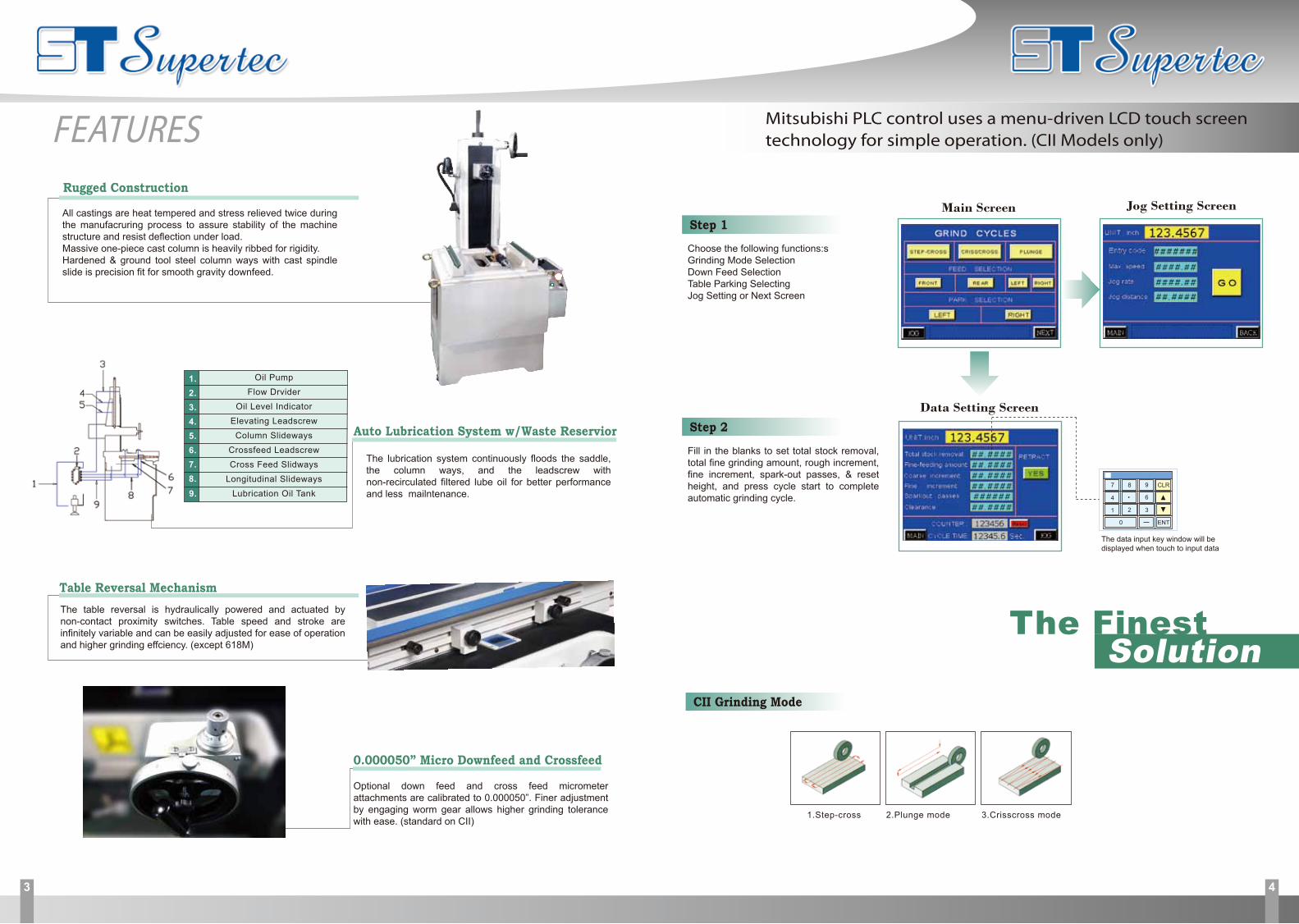
Choose the following functions:sGrinding Mode SelectionDown Feed SelectionTable Parking SelectingJog Setting or Next Screen
Step 1
Step 2
Fill in the blanks to set total stock removal, total fine grinding amount, rough increment, fine increment, spark-out passes, & reset height, and press cycle start to complete automatic grinding cycle.
Mitsubishi PLC control uses a menu-driven LCD touch screentechnology for simple operation. (CII Models only)
The data input key window will be displayed when touch to input data
Data Setting Screen
Main Screen Jog Setting Screen
CLR
ENT
1 2 3
4 6
7 8 9
0
Auto Lubrication System w/Waste Reservior
The lubrication system continuously floods the saddle, the column ways, and the leadscrew with non-recirculated filtered lube oil for better performance and less mailntenance.
Oil PumpFlow Drvider
Oil Level IndicatorElevating Leadscrew
Column SlidewaysCrossfeed LeadscrewCross Feed Slidways
Longitudinal SlidewaysLubrication Oil Tank
1.2.3.4.5.6.7.8.9.
3 4
FEATURES
CII Grinding Mode
1.Step-cross 2.Plunge mode 3.Crisscross mode

5 6
OPTIONAL ACCESSORIES
STANDARD ACCESSORIES
Quantity
1 pc
1 set
1 set
1 set
1 set
1 set
Quantity
1 set
1 set
1 set
1 set
1 set
1 set
Description
Grinding Wheel
Wheel Flange
Wheel Extractor
Bolts and Pads
Splash Guard (Except 618M)
Operator’s Manual & Parts List
Description
Dust Guard
Diamond Dresser
Balancing Arbor
Touch-up Paint
Tool Box With Tools
0.000050” Micro Downfeed (CII only)
*Factory installation required+Must order splash guard when ordering any coolant system (618M only)
MAGNETIC CHUCKS AND CONTROL
Electromagnetic Chuck
Auto. Demagnizer (*)
Permanent Magnetic Chuck 6” x 18”
COOLANT SYSTEMS AND DUSTCOLLECTOR
Coolant System (+)
Dust Collector
Splash Guard
Coolant System W/Magmeyic Separator & Paper Filter (+)
Combination Coolant & Dust Collector (+)
40L
SONY DIGITAL READOUT SYSTEM
Elevating
X & Y Axis
OTHER ACCESSORIES
Manual Parallent Dressing Attchment (*)
Balancing Stand
Spare Grinding
Spare Wheel Flange
Micro Downfeed 0.000050” (*)
Micro Crossfeed 0.000050” (*)
Universal Wheel Guard
8”X½” X1¼”
One Axis Digital Readout (*)
Two Axis Digital Readout (*)
20L/min,80L
50L
PERMISSIBLE LOADS
DIMENSIONAL DRAWINGS
Grinding Without Magnetic Chuck
Grinding With Magnetic Chuck
The total suggedted maximun loads of working table shown as follows:A=Magneyic chuck B=Workpiece C=A+B
A lbs(kg)
B lbs(kg)
C lbs(kg)
66 (30)
396 (180)
462 (210)
MODEL DW-618M DW-1A618DW-2A618 DW-618CII
MODEL DW-618M DW-1A618DW-2A618 DW-618CII
A
B
C
D
E
The FinestSolution
6” x 18”
52”(1320mm) 70”(1770mm) 70”(1770mm)
52”(1320mm) 70”(1770mm) 88”(2230mm)28”(720mm) 28”(720mm) 28”(720mm)
76”(1940mm) 76”(1940mm) 76”(1940mm)
43”(1100mm) 68”(1730mm) 64”(1620mm)