Embed Size (px)
Citation preview

Specifications for Structural ConcreteAn ACI Standard
Reported by ACI Committee 301
ACI 301M-05
Jon B. Ardahl Marwan A. Daye Clifford Gordon† David K. Maxwell
Domingo J. Carreira* Mario R. Diaz David P. Gustafson* Timothy L. Moore
Oleh B. Ciuk James A. Farny* Jerry A. Holland Jerry Parnes
Steven R. Close* W. Bryant Frye Roy H. Keck* Aimee Pergalsky
D. Gene Daniel Richard D. Gaynor James A. Lee James M. Shilstone, Sr.
Voting Subcommittee Members
James E. Anderson Gene Hightower G. Michael Robinson Daniel J. Stanley
Ramon L. Carrasquillo Narendra V. Jadhav Edward D. Russell Bruce A. Suprenant
Paul A. Decker Michael L. Leming Mehmet A. Samee Robert L. Teerman
Dan Ellery† William M. Klorman W. Thomas Scott Michael A. Whisonant
Alphonse E. Engelman Mark A. Payne William C. Sherman Michelle L. Wilson
Thomas M. Greene Kenneth B. Rear Douglas J. Sordyl Richard M. Wing
Consulting Members
Jeffrey W. Coleman Gilbert J. Haddad Ross S. Martin Joseph A. McElroy
Steven H. Gebler Atilano Lamana Bryant Mather† Carlos Videla
W. Calvin McCallChair
Colin L. LoboSecretary
*Subcommittee chair.†Deceased.
This specification is a Reference Specification that the Engineer or Archi-tect can make applicable to any construction project by citing it in theProject Specifications. The Architect/Engineer supplements the provisionsof this Reference Specification as needed by designating or specifying indi-vidual project requirements.
The document covers materials and proportioning of concrete; reinforc-ing and prestressing steels; production, placing, finishing, and curing ofconcrete; and formwork design and construction. Methods of treatment ofjoints and embedded items, repair of surface defects, and finishing offormed and unformed surfaces are specified. Separate sections are devotedto architectural concrete, lightweight concrete, mass concrete, prestressedconcrete, and shrinkage-compensating concrete. Provisions governing test-ing, evaluation, and acceptance of concrete as well as acceptance of thestructures are included.
Keywords: admixture; aggregate; air entrainment; architectural concrete;cement; cementitious materials; cold weather; compressive strength;concrete; concrete construction; concrete durability; concrete slab; consoli-dation; conveyor; curing; density; exposed-aggregate finish; finish; floors;formwork; grout; grouting; hot-weather; inspection; joint (construction,contraction, and isolation); lightweight concrete; mix; mixture proportion;placing; prestressed concrete; prestressing steel; reinforced concrete; rein-forcement; repair; reshoring; shoring; shrinkage-compensating concrete;specification; subgrade; temperature; test; tolerance; water-cementitiousmaterial ratio; welded wire reinforcement.
30
ACI 301M-05 supersedes ACI 301M-99 and became effective October 17, 2005.Copyright © 2005, American Concrete Institute.All rights reserved including rights of reproduction and use in any form or by any
means, including the making of copies by any photo process, or by electronic ormechanical device, printed, written, or oral, or recording for sound or visual reproductionor for use in any knowledge or retrieval system or device, unless permission in writingis obtained from the copyright proprietors.
NOTES TO SPECIFIERThis specification is incorporated by reference in the
project specifications using the wording in P3 of the prefaceand including the information from the mandatory, optional,and submittal checklists following the specification.
PREFACEP1. ACI Specification 301M is intended to be used by
reference or incorporation in its entirety in the Project Spec-ification. Do not copy individual Parts, Sections, Articles, orParagraphs into the Project Specification, because takingthem out of context may change their meaning.
P2. If Sections or Parts of ACI Specification 301M arecopied into the Project Specification or any other document,
1M-1

301M-2 ACI STANDARD
do not refer to them as an ACI Specification, because thespecification has been altered.
P3. A statement such as the following will serve to makeACI Specification 301M a part of the Project Specification:
“Work on (Project Title) shall conform to all requirementsof ACI 301M-05 published by the American Concrete Insti-tute, Farmington Hills, Michigan, except as modified bythese Contract Documents.”
P4. Each technical Section of ACI Specification 301M iswritten in the three-part Section format of the ConstructionSpecifications Institute, as adapted for ACI requirements.The language is imperative and terse.
P5. The Specification is written to the Contractor. When aprovision of this specification requires action on theContractor’s part, the verb “shall” is used. If the Contractoris allowed to exercise an option, the verb “may” or, whenlimited alternatives are available, the conjunctive phrase“shall either... or...” is used. Statements provided in the spec-ification as information to the contractor use the verbs “may”or “will.” Informational statements typically identify activi-ties or options that “will” be taken or “may” be taken by theOwner or the Architect/Engineer.
CONTENTSPreface, p. 301M-1
SPECIFICATION:Section 1—General requirements, p. 301M-3
1.1—Scope1.1.1— Work specified1.1.2— Work not specified
1.2—Definitions1.3—Reference standards and cited publications
1.3.1—Reference standards1.3.2—Cited publications1.3.3—Field references
1.4—Standards-producing organizations1.5—Submittals
1.5.1—General1.5.2—Testing agency reports
1.6—Quality assurance1.6.1—General1.6.2—Testing agencies1.6.3—Testing responsibilities of Contractor1.6.4—Testing responsibilities of Owner’s testing agency1.6.5—Tests on hardened concrete in-place1.6.6—Evaluation of concrete strength tests1.6.7—Acceptance of concrete strength1.6.8—Field acceptance of concrete
1.7—Acceptance of structure1.7.1—General1.7.2—Dimensional tolerances1.7.3—Appearance1.7.4—Strength of structure1.7.5—Durability
1.8—Protection of in-place concrete1.8.1—Loading and support of concrete1.8.2—Protection from mechanical injury
Section 2—Formwork and formwork accessories, p. 301M-10
2.1—General2.1.1—Description2.1.2—Submittals
2.2—Products2.2.1—Materials2.2.2—Performance and design requirements2.2.3—Fabrication and manufacture
2.3—Execution2.3.1—Construction and erection of formwork2.3.2—Removal of formwork2.3.3—Reshoring and backshoring2.3.4—Strength of concrete required for removal of
formwork
Section 3—Reinforcement and reinforcement supports, p. 301M-13
3.1—General3.1.1—Submittals, data, and drawings3.1.2—Materials delivery, storage, and handling
3.2—Products3.2.1—Materials3.2.2—Fabrication
3.3—Execution3.3.1—Preparation3.3.2—Placement
Section 4—Concrete mixtures, p. 301M-164.1—General
4.1.1—Description4.1.2—Submittals4.1.3—Quality control4.1.4—Materials storage and handling
4.2—Products4.2.1—Materials4.2.2—Performance and design requirements4.2.3—Proportioning
4.3—Execution4.3.1—Measuring, batching, and mixing4.3.2—Delivery
Section 5—Handling, placing, and constructing,p. 301M-20
5.1—General5.1.1—Description5.1.2—Submittals5.1.3—Delivery, storage, and handling
5.2—Products5.2.1—Materials5.2.2—Performance and design requirements
5.3—Execution5.3.1—Preparation5.3.2—Placement of concrete5.3.3—Finishing formed surfaces5.3.4—Finishing unformed surfaces5.3.5—Sawed contraction joints5.3.6—Curing and protection5.3.7—Repair of surface defects
SPECIFICATIONS FOR STRUCTURAL CONCRETE 301M-3
Section 6—Architectural concrete, p. 301M-266.1—General
6.1.1—Description6.1.2—Submittals6.1.3—Quality assurance6.1.4—Product delivery, storage, and handling6.1.5—Project conditions
6.2—Products6.2.1—Materials6.2.2—Performance and design requirements
6.3—Execution6.3.1—Preparation6.3.2—Proportioning concrete mixtures6.3.3—Consolidation6.3.4—Formwork monitoring6.3.5—Formwork removal6.3.6—Repair of tie holes and surface defects6.3.7—Finishing
Section 7—Lightweight concrete, p. 301M-287.1—General
7.1.1—Description7.1.2—Submittals7.1.3—Product delivery, storage, and handling
7.2—Products7.2.1—Aggregates7.2.2—Performance and design requirements7.2.3—Mixtures7.2.4—Batching and mixing
7.3—Execution7.3.1—Consolidation7.3.2—Finishing7.3.3—Field quality control
Section 8—Mass concrete, p. 301M-298.1—General
8.1.1—Description8.1.2—Submittals
8.2—Products8.2.1—Materials8.2.2—Performance and design requirements
8.3—Execution8.3.1—Placement8.3.2—Curing and protection
Section 9—Prestressed concrete, p. 301M-299.1—General
9.1.1—Description9.1.2—Submittals9.1.3—Quality control9.1.4—Product delivery, handling, and storage
9.2—Products9.2.1—Materials9.2.2—Proportioning of concrete and grout mixtures
9.3—Execution9.3.1—Inspection9.3.2—Preparation9.3.3—Placement9.3.4—Tensioning
Section 10—Shrinkage-compensating concrete,p. 301M-32
10.1—General10.1.1—Scope10.1.2—General requirements10.1.3—Submittals
10.2—Products10.2.1—Materials10.2.2—Performance and design requirements10.2.3—Proportioning10.2.4—Reinforcement10.2.5—Isolation-joint filler materials
10.3—Execution10.3.1—Reinforcement10.3.2—Placing10.3.3—Isolation joints10.3.4—Curing
NOTES TO SPECIFIER:Foreword to checklists, p. 301M-35
Mandatory requirements checklist, p. 301M-37
Optional requirements checklist, p. 301M-38
Submittals checklist, p. 301M-45
SECTION 1—GENERAL REQUIREMENTS1.1—Scope
1.1.1 Work specified—This Specification covers cast-in-place structural concrete.
Provisions of this Specification shall govern except whereother provisions are specified in the Contract Documents.
1.1.2 Work not specified—The following subjects are notin the scope of this specification:• Precast concrete products;• Heavyweight shielding concrete;• Slipformed paving concrete;• Terrazzo;• Insulating concrete;• Refractory concrete;• Shotcrete;• Slipformed concrete walls; and• Tilt-up concrete construction.
1.2—Definitionsacceptable or accepted—acceptable to or accepted by the
Architect/Engineer.ACI Concrete Field Testing Technician Grade 1—a
person who has demonstrated knowledge and ability toperform and record the results of ASTM standard tests onfreshly mixed concrete and to make and cure test specimens.Such knowledge and ability shall be demonstrated bypassing prescribed written and performance examinationsand having credentials that are current with the AmericanConcrete Institute.
Architect/Engineer or Engineer/Architect—the Archi-tect, Engineer, architectural firm, engineering firm, or archi-tectural and engineering firm issuing project drawings and
301M-4 ACI STANDARD
specifications or administering work under the ContractDocuments.
architectural concrete—concrete that is exposed as aninterior or exterior surface in the completed structure and isdesignated as architectural concrete in the Contract Documents;contributes to visual character of the completed structure andtherefore requires special care in the selection of the concretematerials, forming, placing, and finishing to obtain thedesired architectural appearance.
backshores—shores placed snugly under a concrete slabor structural member after the original formwork and shoreshave been removed from a small area at a time, withoutallowing the slab or member to deflect, or support its ownweight or existing construction loads from above.
cement, expansive—a cement that, when mixed withwater, produces a paste that, after setting, tends to increase involume to a significantly greater degree than does portlandcement paste; used to compensate for volume decrease dueto shrinkage or to induce tensile stress in reinforcement.
cement, expansive Type K—a mixture of portlandcement, anhydrous tetracalcium trialuminate sulfate (C4A3S•), calcium sulfate (CaSO4), and lime (CaO); the C4A3Sis a constituent of a separately burned clinker that is inter-ground with portland cement, or alternatively, is formedsimultaneously with the portland-cement clinker compoundsduring the burning process.
Contract Documents—a set of documents supplied byOwner to Contractor as the basis for construction; thesedocuments contain contract forms, contract conditions,specifications, drawings, addenda, and contract changes.
Contractor—the person, firm, or entity under contract forconstruction of the Work.
duct—a conduit (plain or corrugated) to accommodateprestressing steel for post-tensioned concrete.
exposed to public view—situated so that it can be seenfrom a public location after completion of the building.
high-early-strength concrete—concrete that is capableof attaining specified strength at an earlier age than 28 daysthrough the use of high-early-strength cement or admixtures.
lightweight concrete—concrete of substantially lowerdensity than normalweight concrete.
mass concrete—any volume of concrete with dimensionslarge enough to require that measures be taken to cope withgeneration of heat from hydration of the cement and atten-dant volume change to minimize cracking.
mass concrete, plain—Mass concrete containing no rein-forcement or less reinforcement than necessary to be consid-ered reinforced mass concrete.
mass concrete, reinforced—mass concrete containingadequate prestressed or nonprestressed reinforcement to acttogether with the concrete in resisting forces including thoseinduced by temperature and shrinkage.
normalweight concrete—concrete having a density ofapproximately 2400 kg/m3 made with gravel or crushedstone aggregates.
Owner—the corporation, association, partnership,individual, public body, or authority for whom the Work isconstructed.
permitted—accepted or acceptable to the Architect/Engineer; usually pertains to a request by the Contractor, orto an item specified in the Contract Documents.
post-tensioning—a method of prestressing reinforcedconcrete in which tendons are tensioned after the concretehas hardened.
prestressed concrete—concrete in which internal stressesof sufficient magnitude and distribution are introduced tocounteract to a desired degree the tensile stresses resultingfrom the service loads; in reinforced concrete, the prestressis commonly introduced by tensioning the tendons.
project drawings—graphic presentation of projectrequirements.
project specifications—the written document that detailsrequirements for the Work in accordance with serviceparameters and other specific criteria.
reference specification—a standardized mandatory-language document prescribing materials, dimensions, andworkmanship, incorporated by reference in Contract Docu-ments, with information in the Mandatory RequirementsChecklist required to be provided in the Project Specification.
reference standards—standardized mandatory-languagedocuments of a technical society, organization, or association,including codes of local or federal authorities, which areincorporated by reference in Contract Documents.
required—required in this Specification or the ContractDocuments.
reshores—shores placed snugly under a stripped concreteslab or other structural member after the original forms andshores have been removed from a large area, thus requiringthe new slab or structural member to deflect and support itsown weight and existing construction loads applied beforethe installation of the reshores.
sheathing, prestressing—a material encasing prestressingsteel to prevent bonding of the prestressing steel with thesurrounding concrete, to provide corrosion protection, and tocontain the corrosion-inhibiting coating.
sheathing, wood formwork—the materials forming thecontact face of forms; also called lagging or sheeting.
shop drawing—a drawing that provides details for aparticular task that is developed by the Contractor andreviewed by the Engineer. The shop drawing is prepared to therequirements of the project drawings and project specifications.
shore—a temporary support designed to support form-work, fresh concrete, and construction loads from above forrecently built structures that have not developed full designstrength.
shrinkage-compensating concrete—a concrete madeusing an expansive cement that increases in volume aftersetting, designed to induce compressive stresses in elasticallyrestrained concrete to approximately offset the tensilestresses resulting from drying shrinkage.
strength test—the average of the compressive strengths oftwo or more cylinders made from the same sample ofconcrete and tested at 28 days or at the specified test age.
structural lightweight concrete—Structural concrete madewith lightweight aggregate; the equilibrium density, as
SPECIFICATIONS FOR STRUCTURAL CONCRETE 301M-5
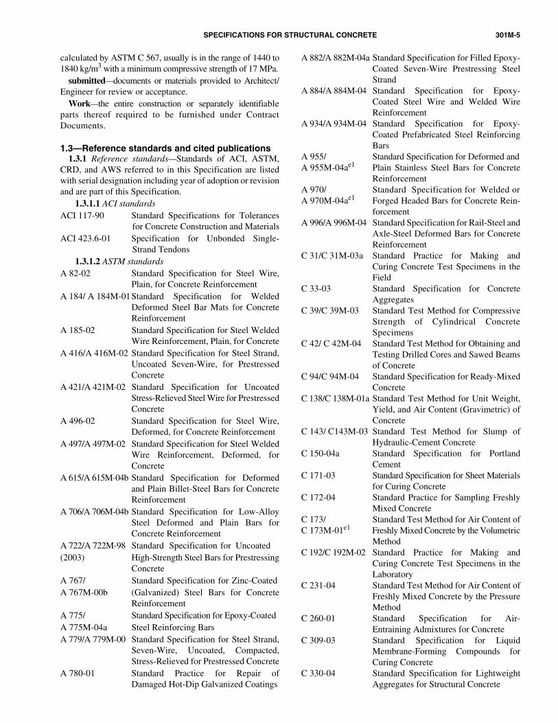
calculated by ASTM C 567, usually is in the range of 1440 to1840 kg/m3 with a minimum compressive strength of 17 MPa.
submitted—documents or materials provided to Architect/Engineer for review or acceptance.
Work—the entire construction or separately identifiableparts thereof required to be furnished under ContractDocuments.
1.3—Reference standards and cited publications1.3.1 Reference standards—Standards of ACI, ASTM,
CRD, and AWS referred to in this Specification are listedwith serial designation including year of adoption or revisionand are part of this Specification.
1.3.1.1 ACI standardsACI 117-90 Standard Specifications for Tolerances
for Concrete Construction and MaterialsACI 423.6-01 Specification for Unbonded Single-
Strand Tendons1.3.1.2 ASTM standards
A 82-02 Standard Specification for Steel Wire,Plain, for Concrete Reinforcement
A 184/ A 184M-01Standard Specification for WeldedDeformed Steel Bar Mats for ConcreteReinforcement
A 185-02 Standard Specification for Steel WeldedWire Reinforcement, Plain, for Concrete
A 416/A 416M-02 Standard Specification for Steel Strand,Uncoated Seven-Wire, for PrestressedConcrete
A 421/A 421M-02 Standard Specification for UncoatedStress-Relieved Steel Wire for PrestressedConcrete
A 496-02 Standard Specification for Steel Wire,Deformed, for Concrete Reinforcement
A 497/A 497M-02 Standard Specification for Steel WeldedWire Reinforcement, Deformed, forConcrete
A 615/A 615M-04b Standard Specification for Deformedand Plain Billet-Steel Bars for ConcreteReinforcement
A 706/A 706M-04b Standard Specification for Low-AlloySteel Deformed and Plain Bars forConcrete Reinforcement
A 722/A 722M-98 Standard Specification for Uncoated(2003) High-Strength Steel Bars for Prestressing
ConcreteA 767/ Standard Specification for Zinc-CoatedA 767M-00b (Galvanized) Steel Bars for Concrete
ReinforcementA 775/ Standard Specification for Epoxy-CoatedA 775M-04a Steel Reinforcing BarsA 779/A 779M-00 Standard Specification for Steel Strand,
Seven-Wire, Uncoated, Compacted,Stress-Relieved for Prestressed Concrete
A 780-01 Standard Practice for Repair ofDamaged Hot-Dip Galvanized Coatings
A 882/A 882M-04a Standard Specification for Filled Epoxy-Coated Seven-Wire Prestressing SteelStrand
A 884/A 884M-04 Standard Specification for Epoxy-Coated Steel Wire and Welded WireReinforcement
A 934/A 934M-04 Standard Specification for Epoxy-Coated Prefabricated Steel ReinforcingBars
A 955/ Standard Specification for Deformed andA 955M-04ae1 Plain Stainless Steel Bars for Concrete
ReinforcementA 970/ Standard Specification for Welded orA 970M-04ae1 Forged Headed Bars for Concrete Rein-
forcementA 996/A 996M-04 Standard Specification for Rail-Steel and
Axle-Steel Deformed Bars for ConcreteReinforcement
C 31/C 31M-03a Standard Practice for Making andCuring Concrete Test Specimens in theField
C 33-03 Standard Specification for ConcreteAggregates
C 39/C 39M-03 Standard Test Method for CompressiveStrength of Cylindrical ConcreteSpecimens
C 42/ C 42M-04 Standard Test Method for Obtaining andTesting Drilled Cores and Sawed Beamsof Concrete
C 94/C 94M-04 Standard Specification for Ready-MixedConcrete
C 138/C 138M-01a Standard Test Method for Unit Weight,Yield, and Air Content (Gravimetric) ofConcrete
C 143/ C143M-03 Standard Test Method for Slump ofHydraulic-Cement Concrete
C 150-04a Standard Specification for PortlandCement
C 171-03 Standard Specification for Sheet Materialsfor Curing Concrete
C 172-04 Standard Practice for Sampling FreshlyMixed Concrete
C 173/ Standard Test Method for Air Content ofC 173M-01e1 Freshly Mixed Concrete by the Volumetric
MethodC 192/C 192M-02 Standard Practice for Making and
Curing Concrete Test Specimens in theLaboratory
C 231-04 Standard Test Method for Air Content ofFreshly Mixed Concrete by the PressureMethod
C 260-01 Standard Specification for Air-Entraining Admixtures for Concrete
C 309-03 Standard Specification for LiquidMembrane-Forming Compounds forCuring Concrete
C 330-04 Standard Specification for LightweightAggregates for Structural Concrete

301M-6 ACI STANDARD
C 387-04 Standard Specification for Packaged,Dry, Combined Materials for Mortar andConcrete
C 404-03 Standard Specification for Aggregatesfor Masonry Grout
C 494/C 494M-04 Standard Specification for ChemicalAdmixtures for Concrete
C 567-04 Standard Test Method for DeterminingDensity of Structural LightweightConcrete
C 595-03 Standard Specification for BlendedHydraulic Cements
C 597-02 Standard Test Method for Pulse VelocityThrough Concrete
C 618-03 Standard Specification for Coal Fly Ashand Raw or Calcined Natural Pozzolanfor Use in Concrete
C 684-99 (2003) Standard Test Method for Making,Accelerated Curing, and TestingConcrete Compression Test Specimens
C 685/C 685M-01 Standard Specification for ConcreteMade By Volumetric Batching andContinuous Mixing
C 803/C 803M-03 Standard Test Method for PenetrationResistance of Hardened Concrete
C 805-02 Standard Test Method for ReboundNumber of Hardened Concrete
C 845-04 Standard Specification for ExpansiveHydraulic Cement
C 873-04 Standard Test Method for CompressiveStrength of Concrete Cylinders Cast inPlace in Cylindrical Molds
C 878/C 878M-03 Standard Test Method for RestrainedExpansion of Shrinkage-CompensatingConcrete
C 881/C 881M-02 Standard Specification for Epoxy-Resin-Base Bonding Systems for Concrete
C 900-01 Standard Test Method for PulloutStrength of Hardened Concrete
C 928-00 Standard Specification for Packaged,Dry, Rapid Hardening CementitiousMaterials for Concrete Repairs
C 939-02 Standard Test Method for Flow of Groutfor Preplaced-Aggregate Concrete (FlowCone Method)
C 989-04 Standard Specification for GroundGranulated Blast-Furnace Slag for Usein Concrete and Mortars
C 1017/ Standard Specification for ChemicalC 1017M-03 Admixtures for Use in Producing
Flowing ConcreteC 1012-04 Standard Test Method for Length
Change of Hydraulic-Cement MortarsExposed to a Sulfate Solution
C 1059-99 Standard Specification for Latex Agentsfor Bonding Fresh to Hardened Concrete
C 1064/ Standard Test Methods for Temperature
C 1064M-04 of Freshly Mixed Portland CementConcrete
C 1074-04 Standard Practice for Estimating ConcreteStrength by the Maturity Method
C 1077-02 Standard Practice for LaboratoriesTesting Concrete and Concrete Aggre-gates for Use in Construction andCriteria for Laboratory Evaluation
C 1107-02 Standard Specification for PackagedDry, Hydraulic Cement Grout (Nonshrink)
C1157-03 Standard Performance Specification forHydraulic Cement
C 1218/ Standard Test Method for Water-Soluble C 1218M-99 Chloride in Mortar and ConcreteC 1240-04 Standard Specification for Silica Fume
Used in Cementitious MixturesC 1315-03 Standard Specification for Liquid
Membrane-Forming Compounds HavingSpecial Properties for Curing and SealingConcrete
C 1602/ Standard Specification for Mixing Water C 1602M-04 Used in the Production of Hydraulic
Cement ConcreteD 98-98 Standard Specification for Calcium
ChlorideD 994-98 (2003) Standard Specification for Preformed
Expansion Joint Filler for Concrete(Bituminous Type)
D 1621-04 Standard Test Methods for CompressiveProperties of Rigid Cellular Plastics
D 1751-99 Standard Specification for PreformedExpansion Joint Fillers for ConcretePaving and Structural Construction(Non-extruding and Resilient BituminousTypes)
D 1752-04 Standard Specification for PreformedSponge Rubber and Cork ExpansionJoint Fillers for Concrete Paving andStructural Construction
D 3575-00e1 Standard Test Methods for FlexibleCellular Materials Made from OlefinPolymers
E 329-03 Standard Specification for AgenciesEngaged in the Testing and/or Inspectionof Materials Used in Construction
E 1155-96(2001) Standard Test Method for DeterminingFF Floor Flatness and FL Floor LevelnessNumbers
1.3.1.3 Other referenced standards—Other standardsreferenced in this Specification:ANSI/ AWS D1.4-98 Structural Welding Code—Rein-
forcing SteelCRD-C 513-74 Specification for Rubber WaterstopsCRD-C 572-74 Specification for Polyvinyl chloride
Waterstops1.3.2 Cited publications—Publications cited in this
Specification:

SPECIFICATIONS FOR STRUCTURAL CONCRETE 301M-7
ACI 318M-05 Building Code Requirements for StructuralConcrete
ACI CP1-04 ACI Certification Concrete Field TestingTechnician—Grade I
ACI CP10-95 ACI Certification Flatwork Technicianand Flatwork Finisher
ACI SP-15 (05) Field Reference Manual: Specifications forStructural Concrete (ACI 301-05) withSelected ACI References
CRSI MSP-2-01 Manual of Standard Practice, 27thEdition, Voluntary CertificationProgram for Fusion-Bonded EpoxyCoating Applicator Plants
1.3.3 Field references—Keep in Contractor’s field officea copy of the following reference:ACI SP-15 Field Reference Manual: Specifications for
Structural Concrete (ACI 301-05) withSelected ACI References.
1.4—Standards-producing organizationsAbbreviations for and complete names and addresses of
organizations issuing documents referred to in this Specificationare listed:
American Concrete Institute (ACI)P.O. Box 9094Farmington Hills, MI 48333-9094
ASTM International100 Barr Harbor DriveWest Conshohocken, PA 19428
American Welding Society (AWS)550 Northwest 42nd AvenueMiami, FL 33126
Concrete Reinforcing Steel Institute (CRSI)933 N. Plum Grove RoadSchaumburg, IL 60173
U.S. Army Corps of Engineers [COE(CRD)]Waterways Experiment Station3909 Halls Ferry RoadVicksburg, MS 39180
National Ready Mixed Concrete Association (NRMCA)900 Spring StreetSilver Spring, MD 20910
1.5—Submittals1.5.1 General—Unless otherwise specified, submittals
required in this Specification shall be submitted for reviewand acceptance.
1.5.2 Testing agency reports—Testing agencies willreport results of concrete and concrete materials tests andinspections performed during the course of the Work to theOwner, Architect/Engineer, Contractor, and the concretesupplier. Strength test reports will include location in the
Work where the batch represented by test was deposited andthe batch ticket number. Reports of strength tests will includedetailed information of storage and curing of specimens beforetesting. Final reports will be provided within seven days oftest completion.
1.6—Quality assurance1.6.1 General—Concrete materials and operations may be
tested and inspected by the Owner as work progresses.Failure to detect defective work or material will not preventrejection if a defect is discovered later nor shall it obligatethe Architect/Engineer for final acceptance.
1.6.2 Testing agencies—Agencies that test concrete materialsshall meet the requirements of ASTM C 1077. Testingagencies that test reinforcing steel shall meet the requirementsof ASTM E 329. Testing agencies shall be accepted by theArchitect/Engineer before performing any work. Field tests ofconcrete required in 1.6.3 and 1.6.4 shall be made by an ACI
1.6.3 Testing responsibilities of Contractor
Concrete Field Testing Technician Grade 1 certified in accor-dance with ACI CP1 or equivalent. Equivalent certificationprograms shall include requirements for written and perfor-mance examinations as stipulated in ACI publication CP1.
1.6.3.1 Submit data on qualifications of proposed testingagency for acceptance. Use of testing services will not relievethe Contractor of the responsibility to furnish materials andconstruction in compliance with the Contract Documents.
1.6.3.2 Duties and responsibilities—Unless otherwisespecified in the Contract Documents, the Contractor shallassume the duties and responsibilities given in 1.6.3.2.athrough 1.6.3.2.g:
1.6.3.2.a Qualify proposed materials and establishmixture proportions.
1.6.3.2.b Allow access to the project site or to thesource of materials and assist Owner’s testing agency inobtaining and handling samples at the project site or at thesource of materials.
1.6.3.2.c Advise Owner’s testing agency at least 24 hin advance of operations to allow for completion of qualitytests and for assignment of personnel.
1.6.3.2.d Provide and maintain adequate facilities onthe project site for safe storage and initial curing of concretetest specimens as required by ASTM C 31M for the sole useof the testing agency.
1.6.3.2.e Submit test data and documentation onconcrete ingredient materials and mixture proportions.
1.6.3.2.f Submit quality-control program of theconcrete supplier and provide copies of test reportspertaining to the Work.
1.6.3.2.g When specified or permitted to base concreteacceptance on accelerated strength testing, submit correlationdata for the standard 28-day compressive strength based onat least 15 sets of test data in accordance with 1.6.4.2.e withconcrete made with the same materials encompassing arange of at least the required average strength f ′cr , plus orminus 7 MPa.
1.6.3.3 Tests required of Contractor’s testing agency—Unless otherwise specified in the Contract Documents, the

301M-8 ACI STANDARD
1.6.4 Testing responsibilities of Owner’s testing agency
Contractor shall provide, at no cost to the Owner, the necessarytesting services given in 1.6.3.3.a and 1.6.3.3.b:
1.6.3.3.a Qualification of proposed materials andestablishment of concrete mixtures.
1.6.3.3.b Other testing services needed or required byContractor.
1.6.4.1 Unless otherwise specified in the ContractDocuments, the Owner’s testing agency will provide thenecessary services given in 1.6.4.1.a through 1.6.4.1.c:
1.6.4.1.a Representatives of the Owner’s testingagency will inspect, sample, and test materials and production ofconcrete as required by the Architect/Engineer. When itappears that material furnished or work performed by theContractor fails to conform to Contract Documents, thetesting agency will immediately report such deficiency to theArchitect/Engineer, Contractor, and concrete supplier.
1.6.4.1.b The testing agency and its representatives arenot authorized to revoke, alter, relax, enlarge, or release anyrequirement of the Contract Documents, nor to accept orreject any portion of the Work.
1.6.4.1.c The testing agency will report test andinspection results that pertain to the Work to the Architect/Engineer, Contractor, and concrete supplier within sevendays after tests and inspections are performed.
1.6.4.2 Testing services—When required by the Owneror the Architect/Engineer, the Owner’s testing agency willperform the following testing services given in 1.6.4.2.athrough 1.6.4.2.i at no cost to the Contractor:
1.6.4.2.a Review and check-test proposed materialsfor compliance with Contract Documents.
1.6.4.2.b Review and check-test proposed concretemixture as required by the Architect/Engineer.
1.6.4.2.c Obtain production samples of materials atplants or stockpiles during the course of the Work and testfor compliance with the Contract Documents.
1.6.4.2.d Obtain samples in accordance with ASTM C172. Select the truckloads or batches of concrete to be testedon a random basis, using random numbers selected beforecommencement of concrete placement.
Obtain at least one composite sample for each 76 m3, orfraction thereof, of each concrete mixture placed in any oneday. When the total quantity of a given concrete mixture isless than 38 m3, the strength tests may be waived by theArchitect/Engineer.
1.6.4.2.e Conduct concrete strength tests duringconstruction in accordance with the following procedures:• Mold and cure a minimum of three cylinders from each
sample in accordance with ASTM C 31M. Record anydeviations from the ASTM requirements in the testreport.
• Test cylinders in accordance with ASTM C 39M. Testone specimen at seven days for information, and test aminimum of two specimens at 28 days for acceptance,unless otherwise specified. The compressive strengthtest results for acceptance shall be the average of thecompressive strengths from the specimens tested at 28days. If a specimen in a test shows evidence of
improper sampling, molding, or testing, discard thespecimen and consider the strength of the remainingcylinder or cylinders to be the test result. If all specimensin a test show defects, discard the entire test.
• When accelerated testing of concrete is specified orpermitted as an alternative to standard testing, mold andcure two specimens from each composite sample inaccordance with ASTM C 684, following the procedurespecified by the Architect/Engineer. Make at least oneaccelerated strength test from each composite sample in1.6.4.2.d and one standard cured 28-day compressive-strength test for at least every other accelerated strengthtest in accordance with ASTM C 31M. Use these testresults to maintain and update the correlation betweenaccelerated and standard 28-day compressive-strengthtests.
1.6.4.2.f Determine slump of each composite sampletaken in accordance with 1.6.4.2.d and whenever consistency ofconcrete appears to vary, using ASTM C 143M.
1.6.4.2.g Determine the temperature of each compositesample taken in accordance with 1.6.4.2.d using ASTM C1064M.
1.6.4.2.h Determine the air content of normalweightconcrete using ASTM C 231, C 173M, or C 138M for eachcomposite sample taken in accordance with 1.6.4.2.d or asdirected by the Architect/Engineer. Additional tests may beperformed as necessary.
1.6.4.2.i When the Contract Documents indicateconcrete will be exposed to deicing salts, air content testswill be made on samples from the first three batches in theplacement and until three consecutive batches have aircontents within the range specified in 4.2.2.4, at which time
every fifth batch will be tested. This test frequency will bemaintained until a batch is not within the range specified in4.2.2.4, at which time testing of each batch will be resumeduntil three consecutive batches have air contents within therange specified in 4.2.2.4. Additional tests may be performedas necessary for control. These air content tests may be takenon composite samples in 1.6.4.2.d or on samples from thebatch at any time after discharge of 0.1 m3 of concrete.1.6.4.3 Additional testing services—When required bythe Architect/Engineer, the Owner’s testing agency willperform the following testing services at no cost to theContractor:• Inspect the concrete batching, mixing, and delivery
operations;• Inspect forms, foundation preparation, reinforcing
steel, embedded items, reinforcing steel placement, andconcrete placing, finishing, and curing operations;
• Sample concrete at point of placement and other locationsas directed by the Architect/Engineer and performrequired tests;
• Review the manufacturer’s report for each shipment ofcement, reinforcing steel, and prestressing tendons, andconduct laboratory tests or spot checks of the materialsreceived for compliance with specifications; and
• Other testing or inspection services as required by theArchitect/Engineer.
SPECIFICATIONS FOR STRUCTURAL CONCRETE 301M-9
1.6.4.4 Other testing services as needed—The Contractorshall pay for the following testing services performed, whennecessary, by the Owner’s testing agency:• Additional testing and inspection required because of
changes in materials or mixture proportions requestedby the Contractor; and
• Additional testing of materials or concrete occasionedby failure to meet specification requirements.
1.6.5 Tests on hardened concrete in-place1.6.5.1 General—When needed, tests on hardened concrete
will be performed by the Owner’s testing agency. Testing shallbe at the Contractor’s expense when this Specification requiressuch tests to verify the strength of the structure. The Owner willpay costs if tests are at the Owner’s request and not required bythis Specification.
1.6.5.2 Nondestructive tests—Use of the reboundhammer in accordance with ASTM C 805, pulse-velocitymethod in accordance with ASTM C 597, or other nonde-structive tests may be permitted by the Architect/Engineerfor evaluating the uniformity and relative concrete strengthin place, or for selecting areas to be cored.
1.6.5.3 Core tests1.6.5.3.a Where required by the Architect/Engineer,
obtain cores in accordance with ASTM C 42M. Wipe coressurface-dry immediately after coring and allow to dry in airfor a period not exceeding one hour after drilling. Seal coresin plastic bags or nonabsorbent containers until testing. Endpreparation of cores shall be completed within 48 h afterdrilling. Test cores not earlier than 48 h after drilling or lastwetting and not later than seven days after the cores weredrilled from the structure.
1.6.5.3.b At least three representative cores shall betaken from each area of in-place concrete that is consideredpotentially deficient. The location of cores shall be determinedby the Architect/Engineer to impair the strength of thestructure as little as possible. If, before testing, cores showevidence of having been damaged subsequent to or duringremoval from the structure, replacement cores shall be taken.
1.6.5.3.c Fill core holes with low-slump concrete ormortar of a strength equal to or greater than the originalconcrete.
1.6.6 Evaluation of concrete strength tests1.6.6.1 Standard molded and cured strength speci-
mens—Test results from standard molded and cured testcylinders shall be evaluated separately for each specifiedconcrete mixture. Evaluation will be valid only if tests havebeen conducted in accordance with procedures specified. Forevaluation, each specified mixture shall be represented by atleast five tests.
1.6.6.2 Nondestructive tests—Test results will be evaluatedby the Architect/Engineer and will be valid only if tests havebeen conducted using properly calibrated equipment inaccordance with recognized standard procedures and anacceptable correlation between test results and concretecompressive strength has been established and is submitted.
1.6.6.3 Core tests—Core test results will be evaluated bythe Architect/Engineer and will be valid only if tests havebeen conducted in accordance with specified procedures.
1.6.7 Acceptance of concrete strength1.6.7.1 Standard molded and cured strength specimens—
The strength level of concrete will be considered satisfactorywhen: the averages of all sets of three consecutive compressivestrength test results molded and cured in accordance with therequirements of ASTM C 31M equal or exceed fc′ ; and noindividual strength test result falls below fc′ by more than3.5 MPa when fc′ is 35 MPa or less, or by more than 0.10fc′when fc′ is more than 35 MPa. These criteria also apply toaccelerated strength testing unless another basis for acceptanceis specified in the Contract Documents.
1.6.7.2 Nondestructive tests—Nondestructive tests shallnot be used as the sole basis for accepting or rejectingconcrete, but may be used, when permitted, to evaluateconcrete where standard molded and cured cylinders haveyielded results not meeting the criteria in 1.6.7.1.
1.6.7.3 Core tests—Strength level of concrete in the arearepresented by core tests will be considered adequate whenthe average compressive strength of the cores is equal to atleast 85% of fc′ , and if no single core is less than 75% of thespecified compressive strength fc′ .
1.6.8 Field acceptance of concrete1.6.8.1 Air content—Concrete not within the limits of
air-entrainment indicated in 4.2.2.4 and tested in accordancewith 1.6.4.2.h shall not be used in the Work.
1.6.8.2 Slump—Concrete not within the slump limits of4.2.2.2 shall not be used in the Work.
1.6.8.3 Temperature—Concrete not within temperaturelimits of 4.2.2.8 shall not be used in the Work.
1.7—Acceptance of structure1.7.1 General—Completed concrete work shall conform
to applicable requirements of this Specification and theContract Documents.
1.7.1.1 Concrete work that fails to meet one or morerequirements of the Contract Documents but subsequently isrepaired to bring the concrete into compliance will beaccepted.
1.7.1.2 Concrete work that fails to meet one or morerequirements of the Contract Documents and cannot bebrought into compliance may be rejected.
1.7.1.3 Repair rejected concrete work by removing andreplacing or by reinforcing with additional construction asrequired by the Architect/Engineer. To bring rejected workinto compliance, use repair methods that will maintain specifiedstrength and meet applicable requirements for function,durability, dimensional tolerances, and appearance asdetermined by the Architect/Engineer.
1.7.1.4 Submit for acceptance the proposed repair methods,materials, and modifications needed to repair the concrete workto meet the requirements of Contract Documents.
1.7.1.5 Contractor shall pay all costs to bring concrete workinto compliance with requirements of Project Specification.
1.7.1.6 Concrete members cast in the wrong locationmay be rejected.
1.7.2 Dimensional tolerances1.7.2.1 Formed surfaces resulting in concrete outlines
smaller than permitted by the tolerances of ACI 117 may be

301M-10 ACI STANDARD
considered deficient in strength and subject to the provisionsof 1.7.4.
1.7.2.2 Formed surfaces resulting in concrete outlineslarger than permitted by ACI 117 may be rejected. Removeexcess materials when required by the Architect/Engineer.
1.7.2.3 Inaccurately formed concrete surfaces thatexceed ACI 117 tolerances may be rejected.
1.7.2.4 Finished slabs exceeding the tolerances in 5.3.4.3
may be corrected provided they are brought into compliancewith 1.7.3, 1.7.4, and 1.7.5.1.7.2.5 Concrete with tolerances and defects exceedingthe limitations of 2.2.2.4 may be rejected.
1.7.3 Appearance1.7.3.1 Concrete not meeting the requirements of 5.3.3 or
5.3.4 shall be brought into compliance in accordance with 1.7.1.
1.7.4 Strength of structure1.7.4.1 Criteria for determining potential strengthdeficiency—Strength will be considered deficient andconcrete work will be rejected when the work fails to complywith requirements that control the strength of the structureincluding, but not limited to, the conditions given in 1.7.4.1.athrough 1.7.4.1.f:
1.7.4.1.a Concrete strength failing to comply withrequirements of 1.6.7.
1.7.4.1.b Reinforcing steel size, quantity, grade, position,or arrangement at variance with the requirements of Section3 or other Contract Documents.
1.7.4.1.c Concrete elements that differ from therequired dimensions or location.
1.7.4.1.d Curing not performed in accordance withContract Documents.
1.7.4.1.e Inadequate protection of concrete from extremetemperature and other adverse environmental conditions duringearly stages of hardening and strength development.
1.7.4.1.f Mechanical injury, construction fires, orpremature removal of formwork resulting in deficientstrength.
1.7.4.2 Action required when strength is potentiallydeficient—When strength of the structure is consideredpotentially deficient, the actions given in 1.7.4.2.a through1.7.4.2.e may be required by the Architect/Engineer:
1.7.4.2.a Structural analysis or additional testing, or both.1.7.4.2.b Core tests.1.7.4.2.c If testing is inconclusive or impractical or if
structural analysis does not confirm the safety of thestructure, load tests may be required and their resultsevaluated in accordance with ACI 318M.
1.7.4.2.d Concrete work rejected by structural analysisor by results of a load test shall be strengthened with additionalconstruction when required by the Architect/Engineer, orreplaced.
1.7.4.2.e Document all repair work proposed to bringstrength-deficient concrete work into compliance withContract Documents, and submit the documentation to theArchitect/Engineer for acceptance.
1.7.5 Durability1.7.5.1 Criteria for determining potential durability
deficiency—Durability of concrete work will be considered
deficient and the concrete work will be rejected when it failsto comply with the requirements that control durability of thestructure, including, but not limited to, the conditions givenin 1.7.5.1a through 1.7.5.1.f:
1.7.5.1.a Strength failing to comply with 1.6.7.1.7.5.1.b Materials for concrete not conforming to the
requirements in 4.2.1.1, 4.2.1.2, 4.2.1.3, and 4.2.1.4.
1.7.5.1.c Concrete not conforming to the air-entrain-ment requirements in Contract Documents or the air contentlimits of Table 4.2.2.4.
1.7.5.1.d Curing not in accordance with ContractDocuments.
1.7.5.1.e Inadequate protection of concrete from detri-mental temperature and other detrimental environmentalconditions during early stages of hardening and strengthdevelopment.
1.7.5.1.f Concrete exceeding the maximum allowablechloride-ion content requirements in Table 4.2.2.6.
1.7.5.2 Action required when durability is potentiallydeficient—When durability of the structure is consideredto be potentially deficient, the actions given in 1.7.5.2.athrough 1.7.5.2.e may be required by the Architect/Engineer:
1.7.5.2.a Obtain and test samples of the ingredientmaterials used in the concrete.
1.7.5.2.b Obtain samples of concrete from the structure bycoring, sawing, or other acceptable means.
1.7.5.2.c Laboratory evaluation of concrete andconcrete materials to assess the ability of concrete to resistweathering action, chemical attack, abrasion, or other deteri-oration, and to protect reinforcement and embedments fromcorrosion.
1.7.5.2.d Repair or replace concrete rejected fordurability deficiency as directed by the Architect/Engineer.
1.7.5.2.e Document repair work to bring concretework into compliance with Contract Documents andsubmit the documentation to the Architect/Engineer foracceptance.
1.8—Protection of in-place concrete1.8.1 Loading and support of concrete—Do not allow
construction loads to exceed the superimposed load that thestructural member, with necessary supplemental support, iscapable of supporting safely and without damage orunacceptable deflections.
1.8.2 Protection from mechanical injury—During thecuring period, protect concrete from damaging mechanicaldisturbances, including load-induced stresses, shock, andharmful vibration. Protect concrete surfaces from damage byconstruction traffic, equipment, materials, rain or runningwater, and other adverse weather conditions.
SECTION 2—FORMWORK AND FORMWORK ACCESSORIES
2.1—General2.1.1 Description—This section covers design,
construction, and treatment of formwork to confine andshape concrete to the required dimensions.
2.1.2 Submittals

SPECIFICATIONS FOR STRUCTURAL CONCRETE 301M-11
2.2.2.4 Maximum deflection of facing materials reflectedon concrete surfaces exposed to public view shall be 1/240of the span between structural members of the formwork.For architectural concrete, see 6.2.2.1.a.
2.1.2.1 Submit the data required in 2.1.2.1.a through2.1.2.1.f unless otherwise specified:
2.1.2.1.a Formwork facing materials—Data on form-facing materials proposed for smooth-form finish if differentfrom that specified in 2.2.1.1.
2.1.2.1.b Construction and contraction joints—Locationof construction and contraction joints proposed if different fromthose indicated in the Contract Documents.
2.1.2.1.c Testing for formwork removal—Data onmethod for determining strength of concrete for removal offormwork in accordance with 2.3.4.2 when a method otherthan field-cured cylinders is proposed.
2.1.2.1.d Formwork removal plans—Detail plans forformwork removal operations when removal of forms atconcrete strengths lower than that specified in 2.3.2.5 isproposed.
2.1.2.1.e Reshoring and backshoring plans—Whenreshoring or backshoring is required or permitted, submitprocedures and plans of operations, before use, sealed by aprofessional Engineer licensed in the state where workwill be performed. Indicate on shop drawings the magnitude ofconstruction loads permitted during reshoring or back-shoring.
2.1.2.1.f Data on formwork release agent or form linerproposed for use with each formed surface.
2.1.2.2 Submit data required in 2.1.2.2.a through2.1.2.2.e when required by the Contract Documents:
2.1.2.2.a Shop drawings for formwork sealed by aprofessional Engineer licensed in the state where the workwill be done.
2.1.2.2.b Calculations for formwork, reshoring andbackshoring, sealed by a professional Engineer licensed inthe state where the work will be done.
2.1.2.2.c Manufacturer’s data and samples of form ties.2.1.2.2.d Manufacturer’s data and samples of
expansion joint materials.2.1.2.2.e Manufacturer’s data and samples of waterstops.
2.2—Products2.2.1 Materials
2.2.1.1 Form-facing materials—Materials for formfaces in contact with concrete shall meet 5.3.3.5 and thefollowing requirements unless otherwise specified in
Contract Documents.• For rough-form finish—No form-facing material isspecified.• For smooth-form finish—Use plywood, tempered
concrete-form-grade hardboard, metal, plastic, paper,or other acceptable materials capable of producing thedesired finish for form-facing materials. Form-facingmaterials shall produce a smooth, uniform texture onthe concrete. Do not use form-facing materials withraised grain, torn surfaces, worn edges, dents, or otherdefects that will impair the texture of concrete surfaces.2.2.1.2 Formwork accessories—Use commercially
manufactured accessories for formwork accessories that arepartially or wholly embedded in concrete, including ties andhangers. Do not use nonfabricated wire form ties. Where
indicated in the Contract Documents, use form ties with integralwater barrier plates in walls or other acceptable positivewater barriers.
2.2.1.3 Formwork release agents—Use commerciallymanufactured formwork release agents that prevent form-work absorption of moisture, prevent bond with concrete,and do not stain the concrete surfaces.
2.2.1.4 Expansion joint filler—Premolded expansion jointfiller shall conform to ASTM D 994, D 1751, or D 1752.
2.2.1.5 Other embedded items—Use waterstops, sleeves,inserts, anchors, and other embedded items of the materialand design indicated in the Contract Documents. Waterstopmaterials shall meet requirements of CRD C 513 for rubberwaterstop, or CRD C 572 for polyvinyl chloride waterstop.Splice the waterstops and use molded pieces as recom-mended by the manufacturer.
2.2.2 Performance and design requirements2.2.2.1 Design and engineering of formwork shall be the
responsibility of the Contractor. When required by theContract Documents, design calculations for formwork andformwork drawings shall be sealed by a professional Engineerlicensed in the state where the Work will be done.
2.2.2.2 Design formwork, shores, reshores, and back-shores to support all loads transmitted to them and to complywith the requirements of the applicable building code.Design formwork to withstand the pressure resulting fromplacement and vibration of concrete and to maintainspecified tolerances.
2.2.2.3 Do not use earth cuts as forms for vertical or slopingsurfaces unless required or permitted by Contract Documents.
2.2.2.5 Formed construction and contraction joints2.2.2.5.a Locate and form construction joints that least
impair strength of the structure and meet the requirements of5.3.2.6.
2.2.2.5.b Unless otherwise specified or permitted,locate and detail formed construction joints to the followingrequirements:• Locate construction joints within the middle third of the
spans of slabs, beams, and girders. When a beam inter-sects a girder within this region, offset the joint in thegirder a distance equal to or greater than twice thewidth of the beam;
• Locate joints in walls and columns at the underside ofslabs, beams, or girders and at the tops of footings orslabs; and
• Make joints perpendicular to the main reinforcement.2.2.2.5.c Provide keyways where indicated on
Contract Documents. Unless otherwise specified, longitu-dinal keyways indicated on the Contract Documents, shall bea minimum of 40 mm deep in joints in walls and betweenwalls and slabs or footings.
2.2.2.5.d Provide construction and contraction jointswhere indicated on the Contract Documents. Submit for

301M-12 ACI STANDARD
slabs, and in-place structural members until concrete hasreached fc′ , in accordance with 2.3.4. If a lower compressive
acceptance the location of construction and contraction jointsdiffering from those indicated on the Contract Documents.
2.2.2.6 For a smooth-form finish, set the facing materialsin an orderly and symmetrical arrangement, and keep thenumber of seams to a practical minimum. Facing materialsshall be supported with studs or other backing capable ofmaintaining deflections within the tolerances specified in2.2.2.4.
2.2.3 Fabrication and manufacture2.2.3.1 Formwork shall be tight to prevent loss of mortar
from concrete.2.2.3.2 Place 20 mm minimum chamfer strips in the
corners of formwork to produce beveled edges on permanentlyexposed surfaces unless otherwise specified. Do not bevelreentrant corners or edges of formed joints of concrete unlessspecified in the Contract Documents.
2.2.3.3 Inspect formwork and remove deleterious materialimmediately before concrete is placed. Provide temporaryopenings where needed at the base of column and wall form-work to facilitate cleaning and inspection.
2.2.3.4 Fabricate form ties so ends or end fasteners canbe removed with minimum spalling at the faces of concrete.After the ends or end fasteners of form ties have beenremoved, terminate the embedded portion of ties not lessthan two diameters, or twice the minimum cross-sectionaldimension of the tie, from the formed concrete surface. Thisdistance shall be a minimum of 20 mm. Repair tie holes inaccordance with 5.3.7.2.
2.2.3.5 Locate waterstops in joints where indicated onContract Documents. Use pieces of premolded waterstopwith a maximum practicable length to create the minimumnumber of end joints. Make joints in waterstops in accordancewith the manufacturer’s recommendations. Ensure that jointsdevelop effective watertightness equal to the continuous water-stop material, permanently develop not less than 50% of thestrength of the parent section and permanently retain flexibility.
2.3—Execution2.3.1 Construction and erection of formwork
2.3.1.1 At construction joints, lap contact surface of theform sheathing for flush surfaces exposed to view over the hard-ened concrete in the previous placement. Ensure formwork issealed against hardened concrete to prevent offsets or loss ofmortar at construction joints and to maintain a true surface.
2.3.1.2 Unless otherwise specified in the ContractDocuments, construct formwork so concrete surfacesconform to the tolerance limits of ACI 117. The class ofsurface for offset between adjacent pieces of formworkfacing material shall be Class B for surfaces permanentlyexposed to public view and Class D for surfaces that will bepermanently concealed, unless otherwise specified.
2.3.1.3 Provide positive means of adjustment (such aswedges or jacks) of shores and struts. Do not make adjustmentsin the formwork after concrete has reached its time of initialsetting. Brace formwork securely against lateral deflectionand lateral instability.
2.3.1.4 To maintain specified tolerances, camber form-work to compensate for anticipated deflections in formwork
during concrete placement. Set formwork and intermediatescreed strips for slabs accurately to produce designatedelevations and contours of the finished surface beforeremoval of formwork. Ensure that edge forms and screedstrips are strong enough to support vibrating screeds or rollerpipe screeds when the finish specified requires the use ofsuch equipment.
2.3.1.5 When formwork is cambered, set screeds to thesame camber to maintain specified concrete thickness.
2.3.1.6 Fasten form wedges in place after final adjustmentof forms and before concrete placement.
2.3.1.7 Anchor formwork to shores, supporting surfaces,or members to prevent upward or lateral movement of theformwork system during concrete placement.
2.3.1.8 Construct formwork for wall openings to facilitateremoval and to counteract swelling of wood formwork.
2.3.1.9 Provide runways for moving equipment andsupport runways directly on the formwork or structuralmember without resting on the reinforcing steel.
2.3.1.10 Place sleeves, inserts, anchors, and embeddeditems required for adjoining work or for support of adjoiningwork before concrete placement.
2.3.1.11 Position and support expansion joint materials,waterstops, and other embedded items to prevent displacement.Fill voids in sleeves, inserts, and anchor slots temporarily withreadily removable material to prevent entry of concreteinto voids.
2.3.1.12 Clean surfaces of formwork and embeddedmaterials of mortar, grout, and foreign materials beforeconcrete is placed.
2.3.1.13 Cover surfaces of formwork with an acceptablematerial that will prevent bond with the concrete. A field-applied formwork release agent or a factory-applied liner maybe used. If a formwork release agent is used, apply to thesurfaces of the formwork in accordance with the manufacturer’srecommendations before placing reinforcing steel. Do not allowformwork release agent to puddle in the forms. Do not allowformwork release agent to contact reinforcing steel or hardenedconcrete against which fresh concrete is to be placed.
2.3.2 Removal of formwork2.3.2.1 When formed surfaces require finishing, remove
forms as soon as removal operations will not damageconcrete.
2.3.2.2 Remove top forms on sloping surfaces ofconcrete as soon as removal will not allow concrete to sag.Perform needed repairs or treatment required at once andfollow immediately with specified curing.
2.3.2.3 Loosen wood formwork for wall openings assoon as loosening operations will not damage concrete.
2.3.2.4 Do not damage concrete during removal of form-work for columns, walls, sides of beams, and other parts notsupporting the weight of the concrete. Perform needed repairand treatment required on vertical surfaces at once andfollow immediately with specified curing.
2.3.2.5 Unless otherwise specified, leave formwork andshoring in place to support the weight of concrete in beams,
SPECIFICATIONS FOR STRUCTURAL CONCRETE 301M-13
t
This section covers materials, fabrication, placement, andolerances of reinforcement and reinforcement accessories.
2.3.4.2.b through 2.3.4.2.d, submit data using project materialsto demonstrate correlation of measurements on the structure
C 900.2.3.4.2.d Maturity method in accordance with ASTM
C 1074.2.3.5 Field quality control
2.3.5.1 Establish and maintain survey controls andbenchmarks in an undisturbed condition until final completion
with the compressive strength of laboratory-cured moldedcylinders or drilled cores. Submit correlation data on theproposed alternative method for determining strength to theArchitect/Engineer.
2.3.4.2.a Tests of cast-in-place cylinders in accordancewith ASTM C 873. This is limited to slabs with concretedepths from 125 to 300 mm.
2.3.4.2.b Penetration resistance in accordance withASTM C 803M.
2.3.4.2.c Pullout strength in accordance with ASTM
strength is proposed for removal of formwork and shoring,submit detailed plans for review and acceptance. When
2.3.4.1 When removal of formwork or reshoring is basedon concrete reaching a specified compressive strength,concrete will be presumed to have reached this strength
shores and other vertical supports are arranged to allow theform-facing material to be removed without loosening ordisturbing the shores and supports, the facing material maybe removed at an earlier age unless otherwise specified.
2.3.2.6 Construct formwork to permit easy removal.2.3.3 Reshoring and backshoring
2.3.3.1 Submittals for reshoring and backshoring operationsshall comply with 2.1.2.1.e and 2.1.2.2.b.
2.3.3.2 During reshoring and backshoring, do not allowconcrete in beam, slab, column, or any structural member tobe loaded with combined dead and construction loads inexcess of the loads permitted by the Architect/Engineer forthe concrete compressive strength at the time of reshoringand backshoring.
2.3.3.3 Place reshores and backshores in sequence withstripping operations.
2.3.3.4 Tighten reshores and backshores to carry therequired loads without overstressing the concrete members.Leave them in place until tests required by 2.3.4 indicate thatthe concrete compressive strength has attained the minimumvalue specified in 2.3.2.5.
2.3.3.5 For floors supporting shores under newly placedconcrete, either leave the original supporting shores in place,or install reshores or backshores. The shoring system and thesupporting slabs shall resist the anticipated loads. Locatereshores and backshores directly under a shore position or asindicated on formwork shop drawings.
2.3.3.6 In multistory buildings, place reshoring or back-shoring over a sufficient number of stories to distribute theweight of newly placed concrete, forms, and constructionlive loads such that the design loads of the floors supportingthe shores, reshores or backshores are not exceeded.
2.3.4 Strength of concrete required for removal offormwork
when test cylinders, field cured the same as the concrete theyrepresent, have reached the compressive strength specifiedfor removal of formwork or reshoring. Mold cylinders inaccordance with ASTM C 31M, and cure them under thesame conditions for moisture and temperature as used for theconcrete they represent. Test cylinders in accordance withASTM C 39M.
2.3.4.2 Alternatively, when specified or permitted, usemethods in 2.3.4.2 b through 2.3.4.2.d to evaluate concretestrength for formwork removal. Before using methods in
and acceptance of the project.2.3.5.2 Variations from plumb and designated building
lines shall not exceed the tolerances specified in ACI 117.
SECTION 3—REINFORCEMENT AND REINFORCEMENT SUPPORTS
3.1—General
3.1.1 Submittals, data, and drawings—Unless otherwiserequired by Contract Documents, submit data and drawingsspecified in 3.1.1.1 through 3.1.1.3 for review and acceptancebefore fabrication and execution:
3.1.1.1 Submit the data specified in 3.1.1.1.a through3.1.1.1g unless otherwise specified:
placement tolerances.3.1.1.3.b Inspection and quality-control program of
3.1.1.1.a Reinforcement—Submit manufacturer’scertified test report.
3.1.1.1.b Placing drawings—Submit placing drawingsshowing fabrication dimensions and placement locations ofreinforcement and reinforcement supports.
3.1.1.1.c Splices—Submit a list of splices and requestto use splices not indicated in Contract Documents.
3.1.1.1.d Mechanical splices—Submit request to usemechanical splices not shown on the project drawings.
3.1.1.1.e Column dowels—Submit request to placecolumn dowels without the use of templates.
3.1.1.1.f Field bending—Submit request and procedure tofield bend or straighten reinforcement partially embeddedin concrete.
3.1.1.1.g Certification—Submit copy of current CRSIPlant Certification Manual.
3.1.1.2 Submit the data specified in 3.1.1.2.a through3.1.1.2.b when required:
3.1.1.2.a Welding—Submit description of reinforcementweld locations, welding procedures, and welder certificationwhen welding is permitted in accordance with 3.2.2.2.
3.1.1.2.b Supports—If coated reinforcement is required,submit description of reinforcement supports and materials forfastening coated reinforcement not described in 3.3.2.4.
3.1.1.3 Submit the data specified in 3.1.1.3.a through
3.1.1.3.b when alternatives are proposed:3.1.1.3.a Reinforcement relocation—Submit a requestto relocate any reinforcement that exceeds specified
plants applying epoxy coating if proposed plant is not certifiedin accordance with the CRSI Certification Program.
3.1.2 Materials delivery, storage, and handling
301M-14 ACI STANDARD
3.1.2.1 Prevent bending, coating with earth, oil, or othermaterial, or otherwise damaging the reinforcement.
3.1.2.2 When handling coated reinforcement, use equip-
D1.4. Do not weld crossing bars (tack welding) for assembly
ment having contact areas padded to avoid damaging thecoating. Lift bundles of coated reinforcement at multiple pickuppoints to prevent bar-to-bar abrasion from sags in the bundles.Do not drop or drag coated reinforcement. Store coatedreinforcement on cribbing that will not damage the coating.
3.2—Products3.2.1 Materials
3.2.1.1 Reinforcing bars—Reinforcement shall bedeformed bars, except spirals and welded wire reinforce-ment, which may be plain. Reinforcement shall be thegrades, types, and sizes required by Contract Documents andshall conform to one of the following:• ASTM A 615M;• ASTM A 706M;• ASTM A 970M; or• ASTM A 996M, rail-steel bars shall be Type R.
3.2.1.2 Coated reinforcing bars—Use zinc or epoxy-coatedreinforcing bars as specified in the Contract Documents.
3.2.1.2.a Zinc-coated (galvanized) reinforcing bars shallconform to ASTM A 767M. Repair coating damage due toshipping, handling, and placing in accordance with ASTM A780. The maximum total damaged areas shall not exceed 2% ofthe surface area in each 300 mm linear increment of each bar.
3.2.1.2.b Epoxy-coated reinforcing bars shall conformto ASTM A 775M or ASTM A 934M as specified in theContract Documents.
Coatings shall be applied in plants that are certified in accor-dance with the Concrete Reinforcing Steel Institute (CRSI)Certification Program or an equivalent program acceptable tothe Architect/Engineer.
Repair damaged areas with patching material conforming toASTM A 775M or ASTM A 934M as applicable and inaccordance with the material manufacturer’s writtenrecommendations. Repair coating damage due to shipping,handling, and placing. The maximum total damaged areasshall not exceed 2% of the surface area in each 300 mmlinear increment of each bar. Fading of the coating color willnot be cause for rejection of epoxy-coated reinforcing bars.
3.2.1.3 Stainless steel bars—Stainless steel bars shallconform to ASTM A 955M.
3.2.1.4 Bar mats—Bar mats shall conform to ASTMA 184M:
3.2.1.5 Wire—Use plain or deformed wire as indicatedon Contract Documents. Plain wire may be used for spirals.
3.2.1.5.a Plain wire shall conform to ASTM A 82.3.2.1.5.b Deformed wire size MD 25 and larger shall
conform to ASTM A 496.3.2.1.5.c Epoxy-coated wire shall conform to ASTM A
884M. The maximum total damaged areas, including areasrepaired at the manufacturing facility, shall not exceed 2% ofthe surface area in each 300 mm linear increment of eachwire. Repair all damaged areas.
3.2.1.5.d For wire with fy exceeding 420 MPa, fy shallcorrespond to a strain of 0.35%.
3.2.1.6 Welded wire reinforcement—Use welded wire rein-forcement specified in Contract Documents and conforming toone of the specifications given in 3.2.1.6.a through 3.2.1.6.c.
3.2.1.6.a Plain welded wire reinforcement—ASTM A185, with welded intersections spaced not farther apart than300 mm in the direction of principal reinforcement.
3.2.1.6.b Deformed welded wire reinforcement—ASTMA 497M, with welded intersections spaced not farther apart than16 in. in the direction of principal reinforcement.
3.2.1.6.c Epoxy-coated welded wire reinforcement—ASTM A 884M, the maximum total damaged areas,including areas repaired at the manufacturing facility, shallnot exceed 2% of the surface area in each linear foot of eachwire. Repair all damaged areas.
3.2.1.6.d For welded wire reinforcement with fyexceeding 420 MPa, fy shall correspond to a strain of 0.35%.
3.2.1.7 Wire-reinforcement supports—Unless otherwisespecified or permitted, use wire-reinforcement supportscomplying with Class 1, maximum protection, or Class 2,moderate protection, as indicated in Chapter 3 of the CRSIManual of Standard Practice.
3.2.1.8 Coated wire-reinforcement supports3.2.1.8.a For epoxy-coated reinforcement—Use wire-
reinforcement supports coated with dielectric material,including epoxy or another polymer for a minimumdistance of 50 mm from the point of contact with epoxy-coated reinforcement.
3.2.1.8.b For zinc-coated reinforcement—Use galvanizedwire-reinforcement supports or wire-reinforcement supportscoated with dielectric material.
3.2.1.9 Precast concrete reinforcement supports—Useconcrete supports that have a surface area of not less than2600 mm2 and have a compressive strength equal to or greaterthan the specified compressive strength of the concretebeing placed.
3.2.2 Fabrication3.2.2.1 Reinforcement—Bend reinforcement cold unless
heating is permitted. Fabricate reinforcement in accordancewith fabricating tolerances of ACI 117.
3.2.2.2 Welding3.2.2.2.a When welding of reinforcement is specified
or permitted, comply with the requirements of ANSI/AWS
of reinforcement, supports, or embedded items.3.2.2.2.b After completing welds on zinc-coated
(galvanized) or epoxy-coated reinforcement, repair coatingdamage in accordance with requirements in 3.2.1.2.a or3.2.1.2.b, respectively. Coat welds and steel splice devices usedto splice reinforcement with the same material used for repair ofcoating damage.
3.3—Execution3.3.1 Preparation
3.3.1.1 When concrete is placed, reinforcement shall befree of materials deleterious to bond. Reinforcement withrust, mill scale, or a combination of both will be consideredsatisfactory, provided the minimum nominal dimensions,nominal weight, and the minimum average height of

SPECIFICATIONS FOR STRUCTURAL CONCRETE 301M-15
3.3.2.4.a Use precast concrete reinforcement supportsto support reinforcement from the ground or a mud mat.
3.3.2.4.b Use reinforcement supports made of concrete,metal, or plastic to support uncoated reinforcement.
3.3.2.4.c Use wire reinforcement supports that are galva-nized, coated with dielectric material, or made of dielectricmaterial to support zinc-coated (galvanized) reinforcement.
3.3.2.4.d Reinforcement and embedded steel items usedwith zinc-coated (galvanized) reinforcement shall be zinc-coated (galvanized) or coated with nonmetallic materials.
3.3.2.4.e Support epoxy-coated reinforcement oncoated wire reinforcement supports or on reinforcementsupports made of dielectric material. Use coatings or mate-rials compatible with concrete.
3.3.2.4.f When precast concrete reinforcement supportswith embedded tie wires or dowels are used with epoxy-coated reinforcement, use wires or dowels coated withdielectric material.
3.3.2.4.g Reinforcement used as supports with epoxy-coated reinforcement shall be epoxy coated.
3.3.2.4.h In walls reinforced with epoxy-coated rein-forcement, use spreader bars that are epoxy coated. Propri-etary combination bar clips and spreaders used in walls withepoxy-coated reinforcement shall be made of corrosion-resistant material or coated with dielectric material.
3.3.2.4.i Fasten epoxy-coated reinforcement with tiewires coated with epoxy or other polymer.
3.3.2.5 Welded wire reinforcement—For slabs onground, extend welded wire reinforcement to within 50 mmof the concrete edge. Lap splice edges and ends of welded
deformations of a hand-wire-brushed test specimen are notless than the applicable ASTM specification requirements.
3.3.2 Placement3.3.2.1 Tolerances—Place, support, and fasten reinforce-
ment as shown on the project drawings. Do not exceed theplacing tolerances specified in ACI 117 before concrete isplaced. Placing tolerances shall not reduce cover requirementsexcept as specified in ACI 117.
3.3.2.2 Reinforcement relocation—When it is necessaryto move reinforcement beyond the specified placing tolerancesto avoid interference with other reinforcement, conduits, orembedded items, submit the resulting reinforcementarrangement for acceptance.
3.3.2.3 Concrete cover—Unless otherwise specified,minimum concrete cover for reinforcement shall be as indicatedin Table 3.3.2.3.
For bundled bars, minimum concrete cover shall be equalto the equivalent diameter of the bundle but need not begreater than 50 mm; except the minimum cover shall not beless than specified in Table 3.3.2.3. The equivalent diameterof the bundle shall be computed based on the total area of thebundle. Tolerances on minimum concrete cover shall meetthe requirements of ACI 117.
3.3.2.4 Reinforcement supports—Unless otherwisepermitted, use the reinforcement supports given in 3.3.2.4.athrough 3.3.2.4.i:
wire reinforcement sheets as shown on the project drawings.Unless otherwise specified or permitted, do not extend
welded wire reinforcement through contraction joints.Support welded wire reinforcement during placing ofconcrete to maintain positioning in the slab. Do not placewelded wire reinforcement on grade and subsequently raiseinto position in concrete.
3.3.2.6 Column dowels—Furnish and use templates forplacement of column dowels unless otherwise permitted.
3.3.2.7 Splices—Make splices as indicated on the projectdrawings unless otherwise permitted. Mechanical splices forreinforcement not shown on the project drawings shall not beused unless accepted by the Architect/Engineer. Removereinforcement coating in the area of the mechanical splice ifrequired by the splice manufacturer. After installingmechanical splices on zinc-coated (galvanized) or epoxy-coated reinforcement, repair coating damage and areas ofremoved coating in accordance with 3.2.1.2.a or 3.2.1.2.b.Coat exposed parts of mechanical splices used on coatedbars with the same material used to repair coating damage.
3.3.2.8 Field bending or straightening—When permitted,bend or straighten reinforcement partially embedded inconcrete in accordance with procedures 3.3.2.8.a through3.3.2.8.c. Reinforcing bar sizes No. 10 through 16 may bebent cold the first time, provided reinforcing bar temperature
Table 3.3.2.3—Minimum concrete cover for reinforcementMinimum concrete cover for reinforcement, except for extremely corrosive atmospheres, other severe exposures, or additional fire protection, shall be as follows:
Minimum cover, mm
Slabs and joists
Top and bottom bars for dry conditions
No. 36 bars and smaller 20 mm
No. 43 and 57 bars 40 mm
Formed concrete surfaces exposed to earth, water, or weather, and over or in contact with sewage and for bottoms bearing on work mat, or slabs supporting earth cover
No. 16 bars and smaller, MW 200 or MD 200 wire and smaller 40 mm
No. 19 through 57 bars, MW 290 or MD 290 wire 50 mm
Beams and columns, formed
For dry conditions
Stirrups, spirals, and ties 40 mm
Principal reinforcement 50 mm
Exposed to earth, water, sewage, or weather
Stirrups and ties 50 mm
Principal reinforcement 65 mm
Walls
For dry conditions
No. 36 bars and smaller 20 mm
No. 43 and 57 bars 40 mm
Formed concrete surfaces exposed to earth, water, sewage, weather, or in contact with ground 50 mm
Footings and base slabs
At formed surfaces and bottoms bearing on concrete work mat 50 mm
At unformed surfaces and bottoms in contact with earth 75 mm
Top of footings Same as slabs
Over top of piles 50 mm
301M-16 ACI STANDARD
is above 0 °C. For other bar sizes, preheat reinforcing barsbefore bending.
3.3.2.8.a Preheating—Apply heat by any method thatdoes not harm the reinforcing bar material or cause damage tothe concrete. Preheat a length of reinforcing bar equal to atleast five bar diameters in each direction from the center of thebend but do not extend preheating below the surface of theconcrete. Do not allow the temperature of the reinforcing bar atthe concrete interface to exceed 260 °C. The preheat temperatureof the reinforcing bar shall be between 590 and 650 °C.Maintain the preheat temperature until bending or straighteningis complete. Measure the preheat temperature by temperaturemeasurement crayons, contact pyrometer, or other acceptablemethods. Do not artificially cool heated reinforcing bars untilthe temperature of the bar is less than 320 °C.
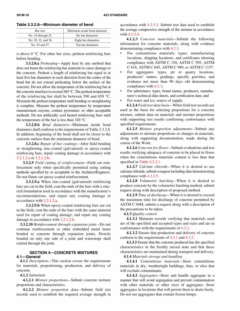
3.3.2.8.b Bend diameters—Minimum inside benddiameters shall conform to the requirements of Table 3.3.2.8.In addition, beginning of the bend shall not be closer to theconcrete surface than the minimum diameter of bend.
3.3.2.8.c Repair of bar coatings—After field bendingor straightening zinc-coated (galvanized) or epoxy-coatedreinforcing bars, repair coating damage in accordance with3.2.1.2.a or 3.2.1.2.b.
3.3.2.9 Field cutting of reinforcement—Field cut rein-forcement only when specifically permitted using cuttingmethods specified by or acceptable to the Architect/Engineer.Do not flame cut epoxy-coated reinforcement.
3.3.2.9.a When zinc-coated (galvanized) reinforcingbars are cut in the field, coat the ends of the bars with a zinc-rich formulation used in accordance with the manufacturer’srecommendations, and repair any coating damage inaccordance with 3.2.1.2.a.
3.3.2.9.b When epoxy-coated reinforcing bars are cutin the field, coat the ends of the bars with the same materialused for repair of coating damage, and repair any coatingdamage in accordance with 3.2.1.2.b.
3.3.2.10 Reinforcement through expansion joint—Do notcontinue reinforcement or other embedded metal itemsbonded to concrete through expansion joints. Dowelsbonded on only one side of a joint and waterstops shallextend through the joint.
SECTION 4—CONCRETE MIXTURES4.1—General
4.1.1 Description—This section covers the requirementsfor materials, proportioning, production, and delivery ofconcrete.
4.1.2 Submittals4.1.2.1 Mixture proportions—Submit concrete mixture
proportions and characteristics.4.1.2.2 Mixture proportion data—Submit field test
records used to establish the required average strength in
Table 3.3.2.8—Minimum diameter of bend
Bar size Minimum inside bend diameter
No. 10 through 25 Six bar diameters
No. 29, 32, and 36 Eight bar diameters
No. 43 and 57 Ten bar diameters
accordance with 4.2.3.3. Submit test data used to establishthe average compressive strength of the mixture in accordancewith 4.2.3.4.
4.1.2.3 Concrete materials—Submit the followinginformation for concrete materials, along with evidence
demonstrating compliance with 4.2.1:• For cementitious materials: types, manufacturinglocations, shipping locations, and certificates showingcompliance with ASTM C 150, ASTM C 595, ASTMC 618, ASTM C 845, ASTM C 989, or ASTM C 1157.
• For aggregates: types, pit or quarry locations,producers’ names, gradings, specific gravities, andevidence not more than 90 days old demonstratingcompliance with 4.2.1;
• For admixtures: types, brand names, producers, manufac-turer’s technical data sheets, and certification data; and
• For water and ice: source of supply.4.1.2.4 Field test data basis—When field test records are
used as the basis for selecting proportions for a concretemixture, submit data on materials and mixture proportionswith supporting test results confirming conformance withspecified requirements.
4.1.2.5 Mixture proportion adjustments—Submit anyadjustments to mixture proportions or changes in materials,along with supporting documentation, made during thecourse of the Work.
4.1.2.6 Concrete for floors—Submit evaluations and testresults verifying adequacy of concrete to be placed in floorswhen the cementitious materials content is less than thatspecified in Table 4.2.2.1.
4.1.2.7 Calcium chloride—When it is desired to usecalcium chloride, submit a request including data demonstratingcompliance with 4.2.2.5.
4.1.2.8 Volumetric batching—When it is desired to
produce concrete by the volumetric batching method, submitrequest along with description of proposed method.4.1.2.9 Time of discharge—When it is desired to exceed
the maximum time for discharge of concrete permitted byASTM C 94M, submit a request along with a description ofthe precautions to be taken.4.1.3 Quality control4.1.3.1 Maintain records verifying that materials used
are of the specified and accepted types and sizes and are inconformance with the requirements of 4.2.1.
4.1.3.2 Ensure that production and delivery of concreteconform to the requirements of 4.3.1 and 4.3.2.
4.1.3.3 Ensure that the concrete produced has the specifiedcharacteristics in the freshly mixed state and that thesecharacteristics are maintained during transport and delivery.
4.1.4 Materials storage and handling4.1.4.1 Cementitious materials—Store cementitious
materials in dry, weathertight buildings, bins, or silos thatwill exclude contaminants.
4.1.4.2 Aggregates—Store and handle aggregate in amanner that will avoid segregation and prevent contaminationwith other materials or other sizes of aggregates. Storeaggregates in locations that will permit them to drain freely.Do not use aggregates that contain frozen lumps.

SPECIFICATIONS FOR STRUCTURAL CONCRETE 301M-17
Contract Documents for particular parts of the Work, use thetypes specified. Use of calcium chloride or other admixturescontaining chloride ions shall be subject to the limitations in4.2.2.6. When accepted, add calcium chloride into the
concrete mixture in solution form only.have a slump of 50 to 100 mm before the admixture is addedand a maximum slump of 200 mm at the point of deliveryafter the admixture is added unless otherwise specified.
4.2.2.3 Size of coarse aggregate—Unless otherwisespecified or permitted, nominal maximum size of coarseaggregate shall not exceed three-fourths of the minimumclear spacing between reinforcing bars, one-fifth of thenarrowest dimension between sides of forms, or one-third ofthe thickness of slabs or toppings.
4.2.2.4 Air content—Unless otherwise specified,concrete shall be air-entrained and the air content at the point
4.2.1.1.b Blended hydraulic cement conforming toASTM C 595 or C 1157. For the sections of the structure thatare designated as subject to deicing chemicals, submit certi-fication on the composition of the cement verifying that theconcrete mixture meets the requirements of Table 4.2.2.9.
4.2.1.1.c Hydraulic cement conforming to ASTM C1157. For sections of the structure that will be subjected todeicing chemicals, submit certification on the compositionof the cement verifying that the concrete mixture meets therequirements of Table 4.2.2.9.
4.2.1.1.d Pozzolanic mineral admixture conforming toASTM C 618. When fly ash is used, the minimum amountshall be 15% by weight of the total cementitious materialsunless otherwise specified.
4.2.1.1.e Ground-granulated blast-furnace slag conform-ing to ASTM C 989.
4.2.1.1.f Silica fume conforming to ASTM C 1240.4.2.1.1.g Use cementitious materials that are of the
same brand and type and from the same plant of manufactureas the cementitious materials used in the concrete represented bythe submitted field test records or used in the trial mixtures.
4.2.1.2 Aggregates—Aggregates shall conform toASTM C 33 unless otherwise specified. When a single sizeor a combination of two or more sizes of coarse aggregatesare used, the final grading shall conform to the gradingrequirements of ASTM C 33 unless otherwise specified orpermitted. Aggregates used in concrete shall be obtainedfrom the same sources and have the same size ranges as theaggregates used in the concrete represented by submittedhistorical data or used in trial mixtures.
4.2.1.3 Water and ice—Mixing water for concrete andwater used to make ice shall meet the requirements ofASTM C 1602M. Use potable water unless alternative sourcesof water complying with ASTM C 1602M are permitted.
4.2.1.4 Admixtures—When required or permitted,admixtures shall meet the requirements of the following:• Air-entraining admixtures—ASTM C 260;• Chemical admixtures—ASTM C 494M;• Chemical admixtures for use in producing flowing
concrete—ASTM C 1017M; and• Calcium chloride—ASTM D 98.
Admixtures used in concrete shall be the same as thoseused in the concrete represented by submitted field testrecords or used in trial mixtures.
4.2.1.5 Change of materials—When changes in brand,type, size, or source of cementitious materials, aggregates,water, ice, or admixtures are proposed, submit new fielddata, data from new trial mixtures, or other evidence that thechange will not adversely affect the relevant properties of theconcrete. Data shall be submitted for acceptance beforechanges are made.
4.2.1.1.a Portland cement conforming to ASTM C 150.
4.1.4.3 Water and ice—Protect mixing water and icefrom contamination during storage and delivery.
4.1.4.4 Admixtures—Protect stored admixtures againstcontamination, evaporation, or damage. Provide agitatingequipment for admixtures used in the form of suspensions ornonstable solutions to ensure uniform distribution of theingredients. Protect liquid admixtures from freezing andfrom temperature changes that would adversely affect theircharacteristics.
4.2—Products4.2.1 Materials
4.2.1.1 Cementitious materials—Use ASTM C 150Type I or Type II cement unless one or a combination of thecementitious materials given in 4.2.1.1.a through 4.2.1.1.fare specified or permitted:
4.2.2 Performance and design requirements4.2.2.1 Cementitious-material content—The cementitious-
material content shall be adequate for concrete to satisfy thespecified requirements for strength, water-cementitiousmaterial ratio, durability, and finishing ability. For concreteused in floors, cementitious-material content shall not be lessthan indicated in Table 4.2.2.1 unless otherwise accepted.Acceptance of a lower cementitious-material content will becontingent upon verification that concrete mixtures with thelower cementitious-material content will meet the specifiedstrength requirements and will produce concrete with equalfinish quality, appearance, durability, and surface hardness.When a history of finishing quality is not available, evaluatethe proposed mixture by placing concrete in a slab at theproject site using project materials, equipment, and personnel.The slab shall be at least 2.5 x 2.5 m and have an acceptablethickness. Slump shall not exceed the specified slump.Submit evaluation results for acceptance.
4.2.2.2 Slump—Unless otherwise specified or permitted,concrete shall have, at the point of delivery, a slump of100 mm. Determine the slump by ASTM C 143M. Slumptolerances shall meet the requirements of ACI 117. Whenuse of a Type I or II plasticizing admixture conforming toASTM C 1017M or when a Type F or G high-range water-reducing admixture conforming to ASTM C 494M ispermitted to increase the slump of concrete, concrete shall
of delivery shall conform to the requirements of Table 4.2.2.4for severe exposure. For specified compressive strengthsabove 35 MPa, the air contents indicated in Table 4.2.2.4may be reduced by 1%. Measure air content in accordancewith either ASTM C 138M, C 173M, or C 231.
4.2.2.5 Admixtures—When admixtures are specified in
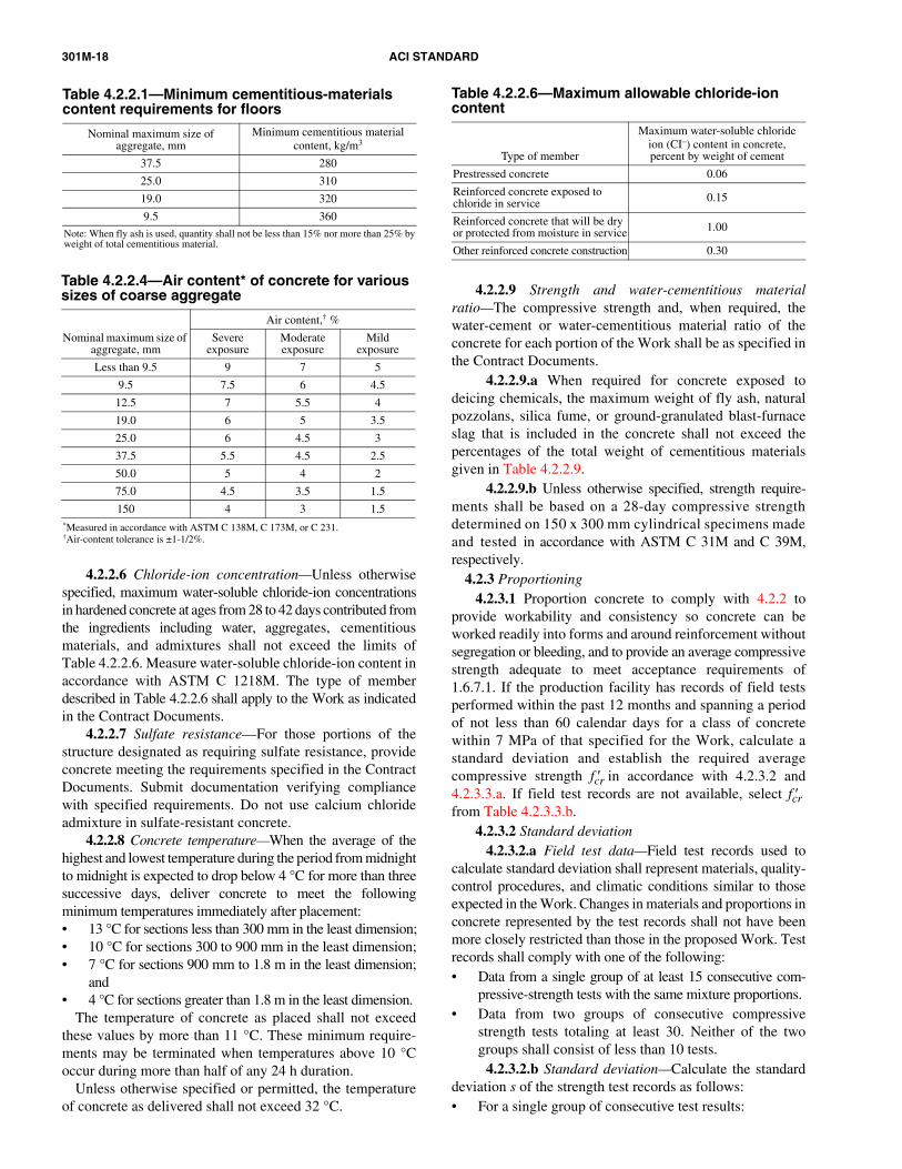
301M-18 ACI STANDARD
Table 4.2.2.4—Air content* of concrete for various sizes of coarse aggregate
Nominal maximum size of aggregate, mm
Air content,† %
Severeexposure
Moderate exposure
Mildexposure
Less than 9.5 9 7 5
9.5 7.5 6 4.5
12.5 7 5.5 4
19.0 6 5 3.5
25.0 6 4.5 3
37.5 5.5 4.5 2.5
50.0 5 4 2
75.0 4.5 3.5 1.5
150 4 3 1.5*Measured in accordance with ASTM C 138M, C 173M, or C 231.†Air-content tolerance is ±1-1/2%.
4.2.2.6 Chloride-ion concentration—Unless otherwisespecified, maximum water-soluble chloride-ion concentrations
and• 4 °C for sections greater than 1.8 m in the least dimension.
The temperature of concrete as placed shall not exceedthese values by more than 11 °C. These minimum require-ments may be terminated when temperatures above 10 °Coccur during more than half of any 24 h duration.
Unless otherwise specified or permitted, the temperatureof concrete as delivered shall not exceed 32 °C.
4.2.2.9 Strength and water-cementitious materialratio—The compressive strength and, when required, thewater-cement or water-cementitious material ratio of theconcrete for each portion of the Work shall be as specified inthe Contract Documents.
4.2.2.9.a When required for concrete exposed todeicing chemicals, the maximum weight of fly ash, naturalpozzolans, silica fume, or ground-granulated blast-furnace
Table 4.2.2.6—Maximum allowable chloride-ion content
Type of member
Maximum water-soluble chloride ion (CI–) content in concrete,percent by weight of cement
Prestressed concrete 0.06
Reinforced concrete exposed to chloride in service 0.15
Reinforced concrete that will be dry or protected from moisture in service 1.00
Other reinforced concrete construction 0.30
records shall comply with one of the following:
Table 4.2.2.1—Minimum cementitious-materials content requirements for floors
Nominal maximum size ofaggregate, mm
Minimum cementitious material content, kg/m3
37.5 280
25.0 310
19.0 320
9.5 360
Note: When fly ash is used, quantity shall not be less than 15% nor more than 25% byweight of total cementitious material.
in hardened concrete at ages from 28 to 42 days contributed fromthe ingredients including water, aggregates, cementitiousmaterials, and admixtures shall not exceed the limits ofTable 4.2.2.6. Measure water-soluble chloride-ion content inaccordance with ASTM C 1218M. The type of memberdescribed in Table 4.2.2.6 shall apply to the Work as indicatedin the Contract Documents.
4.2.2.7 Sulfate resistance—For those portions of thestructure designated as requiring sulfate resistance, provideconcrete meeting the requirements specified in the ContractDocuments. Submit documentation verifying compliancewith specified requirements. Do not use calcium chlorideadmixture in sulfate-resistant concrete.
4.2.2.8 Concrete temperature—When the average of thehighest and lowest temperature during the period from midnight
to midnight is expected to drop below 4 °C for more than threesuccessive days, deliver concrete to meet the followingminimum temperatures immediately after placement:• 13 °C for sections less than 300 mm in the least dimension;• 10 °C for sections 300 to 900 mm in the least dimension;• 7 °C for sections 900 mm to 1.8 m in the least dimension;slag that is included in the concrete shall not exceed thepercentages of the total weight of cementitious materialsgiven in Table 4.2.2.9.
4.2.2.9.b Unless otherwise specified, strength require-ments shall be based on a 28-day compressive strengthdetermined on 150 x 300 mm cylindrical specimens madeand tested in accordance with ASTM C 31M and C 39M,respectively.
4.2.3 Proportioning4.2.3.1 Proportion concrete to comply with 4.2.2 to
provide workability and consistency so concrete can beworked readily into forms and around reinforcement withoutsegregation or bleeding, and to provide an average compressivestrength adequate to meet acceptance requirements of1.6.7.1. If the production facility has records of field testsperformed within the past 12 months and spanning a periodof not less than 60 calendar days for a class of concretewithin 7 MPa of that specified for the Work, calculate astandard deviation and establish the required averagecompressive strength f ′cr in accordance with 4.2.3.2 and4.2.3.3.a. If field test records are not available, select f ′crfrom Table 4.2.3.3.b.
4.2.3.2 Standard deviation4.2.3.2.a Field test data—Field test records used to
calculate standard deviation shall represent materials, quality-control procedures, and climatic conditions similar to thoseexpected in the Work. Changes in materials and proportions inconcrete represented by the test records shall not have beenmore closely restricted than those in the proposed Work. Test
• Data from a single group of at least 15 consecutive com-pressive-strength tests with the same mixture proportions.
• Data from two groups of consecutive compressivestrength tests totaling at least 30. Neither of the twogroups shall consist of less than 10 tests.
4.2.3.2.b Standard deviation—Calculate the standarddeviation s of the strength test records as follows:• For a single group of consecutive test results:
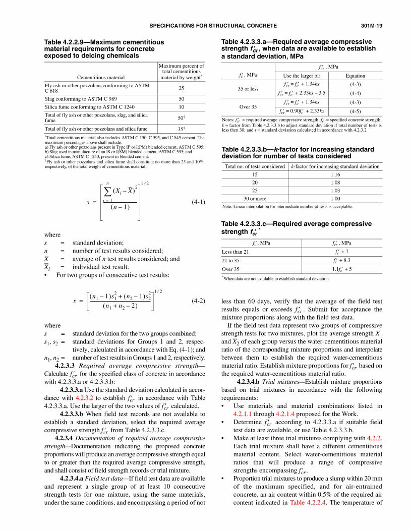
SPECIFICATIONS FOR STRUCTURAL CONCRETE 301M-19
Table 4.2.2.9—Maximum cementitiousmaterial requirements for concreteexposed to deicing chemicals
Cementitious material
Maximum percent oftotal cementitious
material by weight*
Fly ash or other pozzolans conforming to ASTMC 618 25
Slag conforming to ASTM C 989 50
Silica fume conforming to ASTM C 1240 10
Total of fly ash or other pozzolans, slag, and silica fume 50†
Total of fly ash or other pozzolans and silica fume 35†
*Total cementitious material also includes ASTM C 150, C 595, and C 845 cement. Themaximum percentages above shall include:a) Fly ash or other pozzolans present in Type IP or I(PM) blended cement, ASTM C 595;b) Slag used in manufacture of an IS or I(SM) blended cement, ASTM C 595; andc) Silica fume, ASTM C 1240, present in blended cement.†Fly ash or other pozzolans and silica fume shall constitute no more than 25 and 10%,respectively, of the total weight of cementitious material.
cr4.2.3.4 Documentation of required average compressive
strength—Documentation indicating the proposed concreteproportions will produce an average compressive strength equal
to or greater than the required average compressive strength,and shall consist of field strength records or trial mixture.4.2.3.4.a Field test data—If field test data are available
Table 4.2.3.3.a—Required average compressive strength f ′cr , when data are available to establisha standard deviation, MPa
fc′ , MPa
fcr′ , MPa
Use the larger of: Equation
35 or lessfcr′ = fc′ + 1.34ks (4-3)
fcr′ = fc′ + 2.33ks – 3.5 (4-4)
Over 35fcr′ = fc′ + 1.34ks (4-3)
fcr′ = 0.90fc′ + 2.33ks (4-5)
Notes: f ′cr = required average compressive strength; fc′ = specified concrete strength;k = factor from Table 4.2.3.3.b to adjust standard deviation if total number of tests isless then 30; and s = standard deviation calculated in accordance with 4.2.3.2
and represent a single group of at least 10 consecutivestrength tests for one mixture, using the same materials,under the same conditions, and encompassing a period of not
Table 4.2.3.3.c—Required average compressive strength fcr′
*
fc′ , MPa fcr′ , MPa
Less than 21 fc′ + 7
21 to 35 fc′ + 8.3
Over 35 1.1fc′ + 5
*When data are not available to establish standard deviation.
less than 60 days, verify that the average of the field testresults equals or exceeds f ′cr . Submit for acceptance themixture proportions along with the field test data.
If the field test data represent two groups of compressivestrength tests for two mixtures, plot the average strength X1
Table 4.2.3.3.b—k-factor for increasing standard deviation for number of tests considered
Total no. of tests considered k-factor for increasing standard deviation
15 1.16
20 1.08
25 1.03
30 or more 1.00
Note: Linear interpolation for intermediate number of tests is acceptable.
(4-1)wheres = standard deviation;n = number of test results considered;X = average of n test results considered; andXi = individual test result.• For two groups of consecutive test results:
(4-2)
wheres = standard deviation for the two groups combined;s1, s2 = standard deviations for Groups 1 and 2, respec-
tively, calculated in accordance with Eq. (4-1); andn1, n2 = number of test results in Groups 1 and 2, respectively.
4.2.3.3 Required average compressive strength—Calculate f ′cr for the specified class of concrete in accordancewith 4.2.3.3.a or 4.2.3.3.b:
4.2.3.3.a Use the standard deviation calculated in accor-dance with 4.2.3.2 to establish f ′cr in accordance with Table4.2.3.3.a. Use the larger of the two values of f ′cr calculated.
4.2.3.3.b When field test records are not available toestablish a standard deviation, select the required averagecompressive strength f ′ from Table 4.2.3.3.c.
s
Xi X–( )2
i = 1
n
∑
n 1–( )------------------------------
1 2⁄
=
sn1 1–( )s1
2 n2 1–( )s22+
n1 n2 2–+( )------------------------------------------------------
1 2⁄
=
and X2 of each group versus the water-cementitious materialratio of the corresponding mixture proportions and interpolatebetween them to establish the required water-cementitiousmaterial ratio. Establish mixture proportions for f ′cr based onthe required water-cementitious material ratio.
4.2.3.4.b Trial mixtures—Establish mixture proportionsbased on trial mixtures in accordance with the followingrequirements:• Use materials and material combinations listed in
4.2.1.1 through 4.2.1.4 proposed for the Work.• Determine f ′cr according to 4.2.3.3.a if suitable field
test data are available, or use Table 4.2.3.3.b.• Make at least three trial mixtures complying with 4.2.2.
Each trial mixture shall have a different cementitiousmaterial content. Select water-cementitious materialratios that will produce a range of compressivestrengths encompassing f ′cr .
• Proportion trial mixtures to produce a slump within 20 mmof the maximum specified, and for air-entrainedconcrete, an air content within 0.5% of the required aircontent indicated in Table 4.2.2.4. The temperature of

301M-20 ACI STANDARD
satisfy the requirements of this Specification.4.3.1.3 Prepackaged dry materials used in concrete—If
packaged dry-combined materials are used, they shall
accordance with ASTM C 94M. Do not exceed the specifiedwater-cementitious material ratio or slump. Do not add waterto concrete delivered in equipment not acceptable for mixing.After plasticizing or high-range water-reducing admixtures
the freshly mixed concrete shall be recorded and shallbe within 6 °C of the intended maximum temperatureof the concrete as mixed and delivered.
• For each trial mixture, make and cure three compressivestrength cylinders for each test age in accordance withASTM C 192M. Test for compressive strength inaccordance with ASTM C 39M at 28 days or at the testage specified in the Contract Documents.
• From results of these tests, plot a curve showing therelationship between water-cementitious material ratioand compressive strength.
• From the curve of water-cementitious material ratioversus compressive strength, select the water-cementitiousmaterial ratio corresponding to f ′cr . This is the maximumwater-cementitious material ratio that may be used toestablish mixture proportions, unless a lower water-cementitious material ratio is specified in 4.2.2.8.
• Establish mixture proportions so that the maximumwater-cementitious material ratio is not exceeded whenslump is at the maximum specified.4.2.3.5 Field verification of adequacy of selected mixture
proportions—Using materials and mixture proportionsaccepted for use in the Work, verify that the concrete can beadequately placed using the intended placing method. Placethe concrete mixture using project equipment and personnel.Verify that the slump and air content obtained at the form areacceptable. Make suitable corrections to the placing methodsor to the mixture proportions, if needed. Submit anyadjustments to the mixture proportions to the Architect/Engineer for review and acceptance.
4.2.3.6 Revisions to concrete mixtures—When 15consecutive compressive strength test results become availablefrom the field, calculate the actual average compressivestrength and standard deviation. Calculate a revised value forf ′cr in accordance with 4.2.3.3.a. Verify that both of therequirements of 1.6.7.1 are met.
4.2.3.6.a When the actual average compressivestrength X exceeds the revised value of f ′cr and requirementsof 1.6.7.1 are met, f ′cr may be decreased. The revised mixtureshall meet the requirements of 4.2.2.
4.2.3.6.b If the actual average compressive strength Xis less than the revised value of f ′cr , or if either of the tworequirements in 1.6.7.1 are not met, take immediate steps toincrease average compressive strength of the concrete.
4.2.3.6.c Submit revised mixture proportions foracceptance before placing in the Work.
4.3—Execution4.3.1 Measuring, batching, and mixing—Production facilities
shall produce concrete of the specified quality andconforming to this Specification.
4.3.1.1 Ready-mixed and site-produced concrete—Unless otherwise specified, measure, batch, and mixconcrete materials and concrete in conformance with ASTMC 94M.
4.3.1.2 Concrete produced by volumetric batching andcontinuous mixing—When concrete made by volumetricbatching and continuous mixing is acceptable, it shall
conform to the requirements of ASTM C 685M and shall
conform to the requirements of ASTM C 387 and shallsatisfy the requirements of this Specification.
4.3.2 Delivery—Concrete shall possess the specifiedcharacteristics in the freshly mixed state at the point ofplacing. Transport and deliver concrete in equipmentconforming to the requirements of ASTM C 94M.
4.3.2.1 Slump adjustment—When concrete arrives at thepoint of delivery with a slump below that which will result inthe specified slump at the point of placement and is unsuitablefor placing at that slump, the slump may be adjusted to therequired value by adding water up to the amount allowed inthe accepted mixture proportions unless otherwise specifiedby the Architect/Engineer. Addition of water shall be in
are added to the concrete at the site to achieve flowableconcrete, do not add water to the concrete. Measure slump andair content of air-entrained concrete after slump adjustment toverify compliance with specified requirements.
4.3.2.2 Time of discharge—Time for completion ofdischarge shall comply with ASTM C 94M unless otherwisepermitted. When discharge is permitted after more than90 min have elapsed since batching or after the drum hasrevolved 300 revolutions, verify that air content of air-entrained concrete, slump, and temperature of concrete areas specified.
SECTION 5—HANDLING, PLACING,AND CONSTRUCTING
5.1—General5.1.1 Description—This section covers the production of
cast-in-place structural concrete. Included are methods andprocedures for obtaining quality concrete through properhandling, placing, finishing, curing, and repair of surfacedefects.
5.1.2 Submittals5.1.2.1 Submit the following data unless otherwise
specified:5.1.2.1.a Field control test reports—Maintain and
submit accurate records of test and inspection reports.5.1.2.1.b Conveying equipment—Submit description
of conveying equipment.5.1.2.1.c Temperature measurement—Submit proposed
method of measuring concrete surface temperature changes.5.1.2.1.d Repair methods—When stains, rust, efflores-
cence, and surface deposits must be removed as described in5.3.7.7, submit the proposed method of removal.
5.1.2.1.e Qualifications of finishers—Submit quali-fications of the finishing contractor and of flatwork finisherswho will perform the Work as stipulated in 5.3.4.1.
5.1.2.2 Submit the data specified in 5.1.2.2.a through5.1.2.2.g when required:

SPECIFICATIONS FOR STRUCTURAL CONCRETE 301M-21
5.1.2.3.e Moisture-preserving method—When amoisture-preserving method other than specified in 5.3.6.4.is proposed, submit request of the proposed method.
5.1.2.2.a Drawings and data—Submit shop drawingsand data for review as required by the Contract Documents.
5.1.2.2.b Placement notification—When ContractDocuments require advance notification of concrete placement,submit notification at least 24 h in advance.
5.1.2.2.c Preplacement requirements—Submit, whenrequired, request for acceptance of preplacement activities.
5.1.2.2.d Wet-weather placement—When placement isscheduled during wet weather, submit, when required,request for acceptance of protection.
5.1.2.2.e Hot-weather placement—When placement ofconcrete exceeding 32 °C is desired as described in 5.3.2.1.c,submit, when required, request for placement along withproposed precautions.
5.1.2.2.f Matching sample finish—When required byContract Documents, submit sample finish as described in5.3.3.
5.1.2.2.g Exposed-aggregate surface—When anexposed-aggregate surface is specified and a surfaceretarder is proposed to be used, submit specification andmanufacturer’s data for the retarder and the proposedmethod of using retarder.
5.1.2.3 When alternatives are proposed, submit the dataspecified in 5.1.2.3.a through 5.1.2.3.g:
5.1.2.3.a Construction joints—Submit information foracceptance of proposed location and treatment of constructionjoints not indicated on the project drawings.
5.1.2.3.b Two-course slabs—When a bonding agentother than cement grout is proposed, submit specificationand manufacturer’s data for bonding agent.
5.1.2.3.c Underwater placement—When underwaterplacement is planned, submit request for acceptance ofproposed method.
5.1.2.3.d Contraction joints—When contraction jointsother than those indicated on the Contract Documents areproposed, submit request of location.
5.1.2.3.f Coated ties—When coated form ties describedin 5.3.7.2 are proposed to preclude the requirement to patch tieholes, submit proposed coated tie description.
5.1.2.3.g Repair materials—When a repair materialdescribed in 5.2.1.3 is proposed, submit the repair materialspecification, manufacturer’s data on the proposed patchingmaterial, and the proposed preparation and applicationprocedure.
5.1.3 Delivery, storage, and handling5.1.3.1 Delivery—Place concrete within the time limits
required in 4.3.2.2.5.1.3.2 Storage and handling—Store and handle products to
retain original quality. Do not use products stored beyond themanufacturer’s recommended shelf life.
5.2—Products5.2.1 Materials
5.2.1.1 Curing compounds—Use curing compounds thatconform to ASTM C 309 or ASTM C 1315.
5.2.1.2 Waterproof sheet materials—Use waterproofsheet materials that conform to ASTM C 171.
5.2.1.3 Proprietary patching materials—Use acceptableproprietary patching materials complying with 5.3.7.6.
5.2.1.4 Bonding grout—Use bonding grout in accordancewith 5.3.7.4.
5.2.1.5 Site-mixed portland-cement repair mortar—Userepair mortar in accordance with 5.3.7.5.
5.2.2 Performance and design requirements5.2.2.1 Construction and contraction joints—Make and
locate construction and contraction joints that are proposed,but not indicated on the project drawings, in accordance with2.2.2.5. Do not impair strength of the structure with joints.
5.3—Execution5.3.1 Preparation
5.3.1.1 Do not place concrete until data on materials and
mixture proportions are accepted.5.3.1.2 Remove hardened concrete and foreign materials
from the inner surfaces of conveying equipment.5.3.1.3 Before placing concrete in forms, complete the
following:• Comply with formwork requirements specified inSection 2;• Remove snow, ice, frost, water, and other foreign materials
from surfaces, including reinforcement and embeddeditems, against which concrete will be placed;
• Comply with reinforcing steel placement requirementsspecified in Section 3;
• Position and secure in place expansion joint materials,anchors, and other embedded items; and
• Obtain acceptance of finished preparation.5.3.1.4 Before placing a concrete slab on ground,
remove foreign materials from the subgrade and completethe following:• Subgrade shall be well drained and of uniform load-
bearing nature;• In-place density of subgrade soils shall be uniform
throughout the area and at least the minimum requiredby Contract Documents;
• Subgrade shall be free from frost and ice; and• Subgrade shall be moist with no free water and no
muddy or soft spots.5.3.1.5 When high evaporative conditions necessitate
protection of concrete immediately after placing or finishing,make provisions in advance of concrete placement for wind-breaks, shading, fogging, sprinkling, ponding, or wet covering.
5.3.1.6 During ambient temperature conditionsdescribed in 4.2.2.8, make provisions in advance of concreteplacement to maintain the temperature of the concrete asspecified in 5.3.2.1.b. Use heating, covering, or other meansadequate to maintain required temperature without over-heating or drying of concrete due to concentration of heat.Do not use combustion heaters unless precautions are takento prevent exposure of the concrete to exhaust gasescontaining carbon dioxide.
5.3.2 Placement of concrete5.3.2.1 Weather considerations

301M-22 ACI STANDARD
meeting the requirements of 2.2.1.1. Unless otherwise specified,produce as-cast form finishes in accordance with the
laitance, loosened particles of aggregate, or damagedconcrete at the surface; or
• Use portland-cement grout of the same proportions as
the mortar in the concrete in an acceptable manner.5.3.3 Finishing formed surfaces5.3.3.1 General—After removal of forms, give each
formed surface one or more of the finishes described in5.3.3.2, 5.3.3.3, or 5.3.3.4. When Contract Documents do notspecify a finish, finish surfaces as required by 5.3.3.5.
5.3.3.2 Matching sample finish—When the finish isrequired by the Contract Documents to match a sample panelfurnished to the Contractor, reproduce the sample finish onan area at least 9 m2 in a location designated by the Architect/Engineer. Obtain acceptance before proceeding with thatfinish in the specified locations.
5.3.3.3 As-cast finishes—Use form-facing materials
quality of concrete. Do not use aluminum pipes or chutes.5.3.2.3 Conveying equipment—Use acceptable
conveying equipment of a size and design that will preventcold joints from occurring. Clean conveying equipmentbefore each placement.
5.3.2.3.a Use belt conveyors that are horizontal or at aslope that will not cause excessive segregation or loss ofingredients. Protect concrete to minimize drying and effectsof temperature rise. Use an acceptable discharge baffle orhopper at the discharge end to prevent segregation. Do not
5.3.2.1.a Wet weather—Do not begin to place concretewhile rain, sleet, or snow is falling unless adequate protection isprovided and, when required, acceptance of protection isobtained. Do not allow rain water to increase mixing wateror to damage the surface of the concrete.
5.3.2.1.b Cold weather—Concrete temperatures andambient temperatures shall meet minimum temperaturerequirements of 4.2.2.8.
5.3.2.1.c Hot weather—The temperature of concrete asplaced shall not exceed 32 °C unless otherwise specified orpermitted. Loss of slump, flash set, or cold joints due totemperature of concrete as placed will not be acceptable.When temperature of concrete exceeds 32 °C, obtainacceptance, when required, of proposed precautionarymeasures. When temperature of steel reinforcement, embed-ments, or forms is greater than 50 ºC, fog steel reinforcement,embedments, and forms with water immediately before placingconcrete. Remove standing water before placing concrete.
5.3.2.2 Conveying—Rapidly convey concrete frommixer to the place of final deposit by methods that preventsegregation or loss of ingredients and ensure the required
allow mortar to adhere to the return length of the belt.5.3.2.3.b Use metal or metal-lined chutes having
rounded bottoms, and sloped between one vertical to twohorizontal and one vertical to three horizontal. Chutes longerthan 6 m long and chutes not meeting slope requirementsmay be used provided the discharge is into a hopper beforedistributing into the forms.
5.3.2.3.c Use pumping equipment that permits place-ment rates that avoid cold joints and prevents segregation indischarge of pumped concrete.
5.3.2.4 Depositing—Deposit concrete continuously inone layer or in layers to have fresh concrete deposited on in-place concrete that is still plastic. Do not deposit freshconcrete on concrete that has hardened sufficiently to causeformation of seams or planes of weakness within the section,unless construction joint requirements of 5.3.2.6 are met. Donot use concrete that has surface-dried, partially hardened, orcontains foreign material. When temporary spreaders areused in the forms, remove the spreaders as their servicebecomes unnecessary. Spreaders made of metal or concretemay be left in place if prior acceptance is obtained. Do notplace concrete over columns and walls until concrete incolumns and walls is no longer plastic and has been in placeat least 1 h. Do not subject concrete to any procedure that willcause segregation. Deposit concrete as near as practicable to thefinal position to avoid segregation. Place concrete for beams,girders, brackets, column capitals, haunches, and drop
panels at the same time as concrete for slabs. When under-water placement is required or permitted, place concrete byan acceptable method. Deposit fresh concrete so concreteenters the mass of previously placed concrete from within,displacing water with a minimum disturbance to the surfaceof concrete.
5.3.2.5 Consolidating—Consolidate concrete by vibration.Thoroughly work concrete around reinforcement andembedded items and into corners of forms, eliminating airand stone pockets that may cause honeycombing, pitting, orplanes of weakness. Use internal vibrators of the largest sizeand power that can properly be used in the Work as describedin Table 5.3.2.5. Use immersion-type vibrators with nonmetallicheads when consolidating concrete around epoxy-coatedreinforcement. Workers shall be experienced in use of thevibrators. Do not use vibrators to move concrete withinthe forms.
5.3.2.6 Construction joints and other bonded joints—Locate construction joints as indicated on the project drawingsor as accepted in accordance with 5.1.2.3.a. Formed constructionjoints shall meet requirements of 2.2.2.5. Remove laitance andthoroughly clean and dampen construction joints beforeplacement of fresh concrete. When bond is required orpermitted, use one of the following methods:• Use an acceptable adhesive applied in accordance with
the manufacturer’s recommendations;
• Use an acceptable surface retarder in accordance withmanufacturer’s recommendations;• Roughen the surface in an acceptable manner that
exposes the aggregate uniformly and does not leave
requirements given in 5.3.3.3.a through 5.3.3.3.c:5.3.3.3.a Rough-form finish—Patch tie holes and
defects. Chip or rub off fins exceeding 13 mm in height.Leave surfaces with the texture imparted by the forms.
5.3.3.3.b Smooth-form finish—Patch tie holes anddefects. Remove fins exceeding 3 mm in height.
5.3.3.3.c Architectural finishes—Produce architecturalfinishes including special textured finishes, exposed-aggregate finish, and aggregate transfer finish in accordancewith Section 6.

SPECIFICATIONS FOR STRUCTURAL CONCRETE 301M-23
5.3.4.2 Finishes and tolerances
surface. Finish slab surfaces in accordance with one of thefinishes in 5.3.4.2, as designated in the Contract Documents. Usequalified flatwork finishers acceptable to the Architect/Engineer.Unless otherwise permitted, a minimum of one finisher orfinishing supervisor shall be a certified ACI Flatwork ConcreteFinisher/Technician or a certified ACI Flatwork Technician asdefined in ACI CP 10 or equivalent.
5.3.4.2.a Scratch finish—Place, consolidate, strikeoff,and level concrete, eliminating high spots and low spots.Roughen the surface with stiff brushes or rakes before thefinal set. Produce a finish that will meet conventional bull-floated tolerance requirements of ACI 117.
5.3.4.2.b Float finish—Place, consolidate, strikeoff, andlevel concrete, eliminating high spots and low spots. Do not
refloat the slab immediately to a uniform texture.5.3.4.2.c Trowel finish—Float concrete surface, then
work concrete further until it is ready for floating. Beginfloating with a hand float, a bladed power float equipped withfloat shoes, or a powered disk float when the bleedwater sheenhas disappeared, and the surface has stiffened sufficiently topermit the operation. Produce a finish that will meet conven-tional straightedged tolerance requirements of ACI 117, then
power-trowel the surface. Hand-trowel the surface smoothand free of trowel marks. Continue hand-troweling until aringing sound is produced as the floor is troweled. Tolerance
Table 5.3.2.5—Range of characteristics, performance, and applications of internal vibratorsColumn 1 Column 2 Column 3 Column 4 Column 5 Column 6 Column 7 Column 8 Column 9
GroupDiameter of head, mm
Frequency,vibrations per
min (Hz)
Eccentric moment,mm-kg
Average amplitude,
mmCentrifugal force, kN
Radius of action, mm
Rate of concrete placement, m3/h
per vibrator Application
1 20 to 40 9000 to 15,000(150 to 250) 0.4 to 1.2 0.4 to 0.8 0.4 to 1.8 75 to 150 1 to 4 Plastic and flowing concrete in very
thin members and confined places
2 30 to 65 8500 to 12,500(140 to 210) 0.9 to 2.9 0.5 to 1.0 1.3 to 4.0 125 to 250 2 to 8
Plastic concrete in thin walls, columns, beams, precast piles, thin slabs, and along construction joints
3 50 to 90 8000 to 12,000(130 to 200) 2.3 to 8.1 0.6 to 1.3 3.1 to 8.9 175 to 350 5 to 15
Stiff plastic concrete (<75 mm slump) in general construction such as walls,columns, beams, prestressed piles, and heavy slabs
4 75 to 150 7000 to 10,500(120 to 180) 8.1 to 29 0.8 to 1.5 6.7 to 18 300 to 500 11 to 31
Mass and structural concrete of 0 to50 mm slump deposited in quantities up to 3 m3 in relatively open forms of heavy construction
5 125 to 175 5500 to 8500(90 to 140) 26 to 40 1.0 to 2.0 11 to 27 400 to 600 19 to 38 Mass concrete in gravity dams, large
piers, massive walls, etc.
Column 3—While vibrator is operating in concrete.Column 4—Computed eccentric moment ef, mm-kg, where e = distance from center of gravity of eccentric to its center of rotation, mm, and f = force of gravity of eccentric, kg.Column 5—Measured or computed peak amplitude while operating in air (deviating from point of rest), a = ew/(W + w), mm, where W = mass of shell and other nonmoving parts, kg, and w = mass of eccentric, kg.Column 6—Computed centrifugal force of vibrator, F = 4π2n2ew/(1 × 106), kN, where n = frequency of vibrator while operating in concrete, Hz.Column 7—Radius over which concrete is fully consolidated.Column 8—Assumes insertion spacing is 1-1/2 times radius of action, and that vibrator operates 2/3 of time concrete is being placed.Column 7 and 8—These ranges reflect capacity of vibrator, mixture workability, degree of consolidation desired, and other construction conditions.
5.3.3.4 Rubbed finishes—Remove forms as early aspermitted by 2.3.2. Produce one of the finishes given in5.3.3.4.a through 5.3.3.4.c on concrete specified to have asmooth form finish:
5.3.3.4.a Smooth-rubbed finish—Remove forms asearly as permitted by 2.3.2, and perform necessary patching.Produce finish on hardened concrete no later than the dayfollowing formwork removal. Wet the surface and rub itwith carborundum brick or other abrasive until uniformcolor and texture are produced. Use no cement grout otherthan cement paste drawn from the concrete itself by therubbing process.
5.3.3.4.b Grout-cleaned finish—Begin cleaning
operations after contiguous surfaces to be cleaned arecompleted and accessible. Do not clean surfaces as workprogresses. Wet the surface and apply grout consisting ofone part portland cement and one and one-half parts finesand with enough water to produce the consistency of thickpaint. Match color of surrounding concrete. Scrub grout intovoids, and remove excess grout. When grout whitens, rub thesurface and keep the surface damp for 36 h afterward.5.3.3.4.c Cork-floated finish—Perform necessaryrepairs. Remove ties, burrs, and fins. Wet the surface andapply stiff grout of one part portland cement and one partfine sand, filling voids. Match color of surrounding concrete.Use enough water to produce a stiff consistency. Compressgrout into voids by grinding the surface with a slow-speedgrinder. Produce the final finish with cork float, using aswirling motion.
5.3.3.5 Unspecified finishes—When a specific finish isnot specified in Contract Documents for a concrete surface,apply the following finishes:• Rough-form finish on concrete surfaces not exposed to
public view; and
• Smooth-form finish on concrete surfaces exposed topublic view.
5.3.4 Finishing unformed surfaces5.3.4.1 Placement—Place concrete at a rate that allows
spreading, straightedging, and darbying or bullfloating beforebleed water appears. Strike smooth the top of walls, buttresses,horizontal offsets, and other similar unformed surfaces and floatthem to a texture consistent with finish of adjacent formed

301M-24 ACI STANDARD
900 m2 in total project area, measure floor finish tolerances in
for concrete floors shall be conventional straightedged tolerancein accordance with ACI 117 unless otherwise specified.
provide the specified minimum thickness. Begin final floatingand finishing immediately after application of the dry-shake.After selected material is embedded by the two floatings,complete operation with a broomed, floated, or troweled
5.3.4.2.d Broom or belt finish—Immediately afterconcrete has received a floated finish, give the concretesurface a coarse transverse scored texture by drawing a broomor burlap belt across the surface.
5.3.4.2.e Dry-shake finish—Blend metallic or mineralaggregate specified in Contract Documents with portlandcement in the proportions recommended by the aggregatemanufacturer, or use bagged, premixed material specified inContract Documents as recommended by the manufacturer.Float-finish the concrete surface. Apply approximately two-thirds of the blended material required for coverage to thesurface by a method that ensures even coverage without segre-gation. Float-finish the surface after application of the firstdry-shake. Apply the remaining dry-shake material at rightangles to the first application and in locations necessary to
finish, as specified in the Contract Documents.5.3.4.2.f Heavy-duty topping for two-course slabs—
For heavy-duty topping mixture, use the materials andmethods specified in Contract Documents. Place andconsolidate concrete for the base slab, and screed concreteto the specified depth below the top of the finished surface.Topping placed the same day as the base slab shall be placedas soon as bleedwater in the base slab has disappeared andthe surface will support a person without appreciable inden-tation. When topping placement is deferred, brush thesurface with a coarse wire broom to remove laitance andscratch the surface when concrete is plastic. Wet-cure thebase slab at least three days. Before placing the topping,clean the base slab surface thoroughly of contaminants andloose mortar or aggregate. Dampen the surface, leaving itfree of standing water. Immediately before placing topping,scrub into the slab surface a coat of bonding grout consistingof equal parts of cement and fine sand with enough water tomake a creamy mixture. Do not allow grout to set or drybefore topping is placed. Bonding agents other than cementgrout may be used with prior acceptance. Spread, compact,and float the topping mixture. Check for flatness of surfaceand complete operation with a floated, troweled, or broomfinish as specified in the Contract Documents.
5.3.4.2.g Topping for two-course slab not intended forheavy-duty service—Preparation of base slab, selection oftopping material, mixing, placing, consolidating, andfinishing operations shall be as specified in Section5.3.4.2.f, except that the aggregate need not be selected forspecial wear resistance.
5.3.4.2.h Nonslip finish—Where a nonslip finish isrequired, give the surface a broom or belt finish or a dry-shake application of crushed aluminum oxide or other abrasiveparticles, as specified in the Contract Documents. Rate ofapplication shall be not less than 1.2 kg/m2.
5.3.4.2.i Exposed-aggregate finish—Immediatelyafter surface of the concrete has been leveled to meet the
conventional straightedged tolerance requirements of ACI117 and the bleedwater sheen has disappeared, spreadaggregate of the color and size specified in ContractDocuments uniformly over the surface to provide completecoverage to a depth of one stone. Tamp the aggregate lightlyto embed aggregate in the surface. Float the surface until theembedded stone is fully coated with mortar and the surfacehas been finished to meet the conventional straightedgedtolerance requirements of ACI 117. After the matrix hashardened sufficiently to prevent dislodgment of the aggre-gate, apply water carefully and brush the surface with a fine-bristled brush to expose the aggregate without dislodging it.When specified or permitted, a surface retarder sprayed onfreshly floated concrete surface may be used to extend theworking time for the exposure of aggregate.
5.3.4.2.j Nonspecified finish—When the type of finish isnot specified in Contract Documents, use one of the followingappropriate finishes and accompanying tolerances.• Scratch finish—For surfaces intended to receive bonded
cementitious mixtures;• Float finish—For walks, drives, steps, ramps, and for
surfaces intended to receive waterproofing, roofing,insulation, or sand-bed terrazzo; or
• Trowel finish—For floors intended as walking surfaces,floors in manufacturing, storage, and warehousingareas, or for reception of floor coverings.5.3.4.3 Measuring tolerances for slabs
5.3.4.3.a Measure slabs for suspended floors andslabs-on-ground to verify compliance with the tolerancerequirements of ACI 117 as specified in 5.3.4.2.a through5.3.4.2.c. Measure floor finish tolerances within 72 h afterslab finishing and before removal of supporting formwork orshoring.
5.3.4.3.b Unless otherwise specified in the ContractDocuments, for residential floors and nonresidential floorinstallations 900 m2 or less in total project area, measurefloor finish tolerances in accordance with the “10-ft straightedge method” in ACI 117.
5.3.4.3.c Unless otherwise specified in the ContractDocuments, for nonresidential floor installations exceeding
accordance with ASTM E 1155 and the F-number system inACI 117.
5.3.5 Sawed contraction joints—Where saw-cut joints arerequired or permitted, start cutting as soon as concrete hashardened sufficiently to prevent dislodgment of aggregates.Saw a continuous slot to a depth of one-fourth the thickness ofthe slab but not less than 25 mm. Complete sawing within 12 hafter placement. If an alternative method, timing, or depth isproposed for saw cutting, submit detailed procedure plansfor review and acceptance.
5.3.6 Curing and protection5.3.6.1 Curing—Cure concrete in accordance with
5.3.6.2 or 5.3.6.3 for a minimum of seven days after place-ment. Cure high-early-strength concrete for a minimum ofthree days after placement. Alternatively, moisture retentionmeasures may be terminated when:

SPECIFICATIONS FOR STRUCTURAL CONCRETE 301M-25
patched plus another 150 mm around the patch area perimeter.Prepare bonding grout according to 5.3.7.4. Thoroughlybrush grout into the surface. When the bond coat begins tolose water sheen, apply patching mortar prepared in accordancewith 5.3.7.5, and thoroughly consolidate mortar into place.Strikeoff mortar, leaving the patch slightly higher than thesurrounding surface to compensate for shrinkage. Leave the
angles to each other. The material applied in each coat shallnot be less than 0.2 L/m2 of area. Do not use curingcompound on any surface where concrete or other materialwill be bonded, unless the curing compound will not preventbond or unless measures are to be taken to completelyremove the curing compound from areas to receive bondedapplications; or
f. Application of other accepted moisture-retainingmethod.
5.3.6.5 Protection—Immediately after placement,protect concrete from premature drying, excessively hot orcold temperatures, and mechanical injury. Protect concreteduring the curing period such that the concrete temperaturedoes not fall below the requirements of 4.2.2.8.
Maintain the concrete protection to prevent freezing of the
concrete and to ensure the necessary strength developmentfor structural safety. Remove protection in such a mannerthat the maximum decrease in temperature measured at thesurface of the concrete in a 24 h period shall not exceed thefollowing:• 28 °C for sections less than 300 mm in the least dimension;• 22 °C for sections from 300 to 900 mm in the least
dimension;• 17 ºC for sections 900 mm to 1.8 m in the least
water than is necessary for handling and placing. Mix therepair mortar and manipulate the mortar frequently with atrowel without adding water.
5.3.7.6 Repair materials other than site-mixed portland-cement mortar—Acceptable repair materials other than site-mixed portland-cement mortar may be used for repair. Use
a. Tests made on at least two cylinders kept adjacent to thestructure and cured by the same methods as the structureindicate that 70% of fc′ , as determined in accordance withASTM C 39M, has been attained;
b. The compressive strength of laboratory-cured cylinders,representative of the in-place concrete, exceeds 85% fc′ ,provided the temperature of the in-place concrete has beenmaintained at 10 °C or higher during curing; or
c. Strength of concrete reaches fc′ as determined byaccepted nondestructive test methods meeting the require-ments of 2.3.4.2.
ASTM C 309 or C 1315. Apply the compound in accordancewith manufacturer’s recommendation as soon as water sheenhas disappeared from the concrete surface and after finishingoperations. The application rate shall not be less than 0.2 L/m2.For rough surfaces such as those specified in 5.3.4.2.a and5.3.4.2.d, apply curing compound in two applications at right
When one of the curing procedures in 5.3.6.4 is usedinitially, the curing procedure may be replaced by one of theother procedures when concrete is one day old, provided theconcrete is not permitted to become surface-dry at any time.Use a curing procedure of 5.3.6.4 that supplies additionalwater during the entire curing period for concrete containingsilica fume and when specified in the Contract Documents.
5.3.6.2 Unformed concrete surfaces—Apply one of theprocedures in 5.3.6.4 after completion of placement andfinishing of concrete surfaces that are not in contact with forms.
5.3.6.3 Formed concrete surfaces—Keep absorbentwood forms wet until they are removed. After formworkremoval, cure concrete by one of the methods in 5.3.6.4.
5.3.6.4 Preservation of moisture—After placing andfinishing, use one or more of the following methods topreserve moisture in concrete:
a. Ponding, continuous fogging, or continuous sprinkling;b. Application of mats or fabric kept continuously wet;c. Continuous application of steam (under 66 °C);d. Application of sheet materials conforming to ASTM C 171;e. Application of a curing compound conforming to
dimension; or• 11 ºC for sections greater than 1.8 m in the least
dimension.Measure concrete temperature using a method acceptable
to the Architect/Engineer, and record the concrete tempera-ture. When the surface temperature of the concrete is within11 °C of the ambient or surrounding temperature, protectionmeasures may be removed.
5.3.7 Repair of surface defects5.3.7.1 General—Repair tie holes and surface defects
immediately after formwork removal. Where the concretesurface will be textured by sandblasting or bush-hammering,repair surface defects before texturing.
5.3.7.2 Repair of tie holes—Plug tie holes except wherestainless steel ties, noncorroding ties, or acceptably coatedties are used. When portland-cement patching mortarconforming to 5.3.7.5 is used for plugging, clean anddampen tie holes before applying the mortar. When othermaterials are used, apply them in accordance with manufac-turer’s recommendations.
5.3.7.3 Repair of surface defects other than tie holes—Outline honeycombed or otherwise defective concrete with a13 to 20 mm deep saw cut and remove such concrete downto sound concrete. When chipping is necessary, leavechipped edges perpendicular to the surface or slightlyundercut. Do not feather edges. Dampen the area to be
patch undisturbed for 1 h before finishing. Keep the patchdamp for seven days.
5.3.7.4 Preparation of bonding grout—For bondinggrout, mix approximately one part cement and one part finesand with water to the consistency of thick cream.
5.3.7.5 Site-mixed portland-cement repair mortar—Mixrepair mortar using the same materials as concrete to bepatched with no coarse aggregate. Do not use more than onepart cement to two and one-half parts sand by damp loosevolume. For repairs in exposed concrete, make a trial batchand check color compatibility of repair material withsurrounding concrete. When the repair is too dark, substitutewhite portland cement for a part of the gray cement toproduce a color closely matching surrounding concrete. Usea repair mortar at a stiff consistency with no more mixing
301M-26 ACI STANDARD
acceptable relation to openings, building corners, andother architectural features.
6.2.2.1.d Where panels for as-cast surfaces are separatedby recessed or emphasized joints, provide in the structural
Type III. The type, grade, and class shall be appropriate forthe application as specified in ASTM C 881M;
• Shrinkage-compensating or nonshrink portland-cementgrout conforming to ASTM C 1107; and
• Packaged, dry concrete repair materials conforming toASTM C 928.5.3.7.7 Removal of stains, rust, efflorescence, and
surface deposits—Remove stains, rust, efflorescence, andsurface deposits considered objectionable by the Architect/Engineer by acceptable methods.
SECTION 6—ARCHITECTURAL CONCRETE6.1—General
6.1.1 Description6.1.1.1 Scope—This section covers construction of
architectural concrete as designated in Contract Documents.6.1.1.2 Coordination—Provide coordination between this
Work and work of other trades, and other concrete work on thestructure. Integrate this Work into the structure. Preventdamage or defects that will lessen the quality of the surface.
6.1.1.3 General requirements—Architectural concrete shall
repair materials in accordance with manufacturer’srecommendations. Materials include, but are not limited to,5.3.7.6.a and 5.3.7.6.b:
5.3.7.6.a Shotcrete;5.3.7.6.b Commercial patching products, including:
• Portland-cement mortar modified with a latex bondingagent conforming to ASTM C 1059 Type II;
• Epoxy mortars and epoxy compounds that are moisture-insensitive during application and after curing, thatembody an epoxy binder conforming to ASTM C 881M,
otherwise specified:6.1.2.1.a Drawings and data—Submit shop drawings
comply with the requirements of Sections 1 through 5 unlessotherwise indicated in Contract Documents and in this section.
6.1.2 Submittals6.1.2.1 Submit the data specified in 6.1.2.1.a unless
of forms for architectural concrete. Show jointing of facingpanels; locations and details of form ties and recesses; anddetails of joints, anchorages, and other accessories.
6.1.2.2 Submit the data specified in 6.1.2.2.a through6.1.2.2.c when required:
6.1.2.2.a Mock-ups—When Contract Documents requirefull-scale mock-ups of structural items, submit a request foracceptance of the proposed location at the project site.
6.1.2.2.b Special finishes—Submit, when required,mock-ups or sample panels of aggregate transfer and otherspecial finishes.
6.1.2.2.c Exposed-aggregate finishes—Submit, whenrequired, the proposed method of producing exposed-aggregate finishes.
6.1.2.3 Review of submittals—Do not construct formsuntil submittals have been accepted. Do not place concreteuntil submitted plans for batching, mixing, placing, andcuring have been accepted.
6.1.3 Quality assurance6.1.3.1 Concrete construction technical specialists—For
architectural concrete operations listed in Project Specifi-
cations, provide a technical specialist trained or approved bythe specialty item manufacturer. The specialist shall be on theproject site during the first three days of construction opera-tions using the specialty item and at other times required bythe Project Specifications to provide technical assistance.
6.1.3.2 Preconstruction conference—A preconstructionconference shall be held for this phase of the Work. Organi-zation and procedures shall be established and agreed to byall individuals involved with this phase of the Work.
6.1.3.3 Samples and mock-up—Make full-scale mock-upsof structural items when specified in Contract Documents.Use the same equipment, materials, and procedures that willbe used in the final work. Make mock-ups at acceptable loca-tions on the project site. Use mock-ups as samples of requiredquality of finished construction.
6.1.4 Product delivery, storage, and handling6.1.4.1 Aggregates—Deliver each size of aggregate to
the mixer at uniform moisture content throughout each day’sconcrete production.
6.1.5 Project conditions6.1.5.1 Environmental conditions—Protect architectural
concrete from damage, disfigurement, and discolorationfrom construction to acceptance.
6.2—Products6.2.1 Materials
6.2.1.1 Curing water and coverings—Use curing waterand coverings that will not stain the concrete.
6.2.1.2 Reinforcement supports and spacers—Use stainlesssteel, plastic, or plastic-coated reinforcement supports andspacers near exposed surfaces, except that plastic-coatedproducts shall not be used near surfaces that are to be sand-blasted.
6.2.1.3 Formwork—Use formwork that is watertight.6.2.2 Performance and design requirements
6.2.2.1 Formwork6.2.2.1.a Design forms to produce the required finish.
Limit deflection of facing materials between studs anddeflection of studs and walers to 0.0025 times the clear span(L/400).
6.2.2.1.b Where natural plywood form finish, grout-cleaned finish, smooth-rubbed finish, or other finish isrequired, form faces shall be smooth and forms shall be trueto line and grade. Surfaces produced shall require only minordressing to arrive at true surfaces. Where an as-cast finish isrequired, construct and install the forms so that no dressingwill be required in the finishing operation to match theaccepted sample.
6.2.2.1.c Where as-cast surfaces, including naturalplywood form finish, are specified, ensure that the panelsare orderly in arrangement, with joints planned in an
design of the forms the locations of ties within the joints sopatches of tie holes will be in the recessed or emphasizedjoints, unless otherwise specified.
SPECIFICATIONS FOR STRUCTURAL CONCRETE 301M-27
6.2.2.1.e Do not reuse forms with surface wear, tears,or defects that lessen the quality of the surface. Thoroughlyclean and properly coat forms before reuse.
6.3—Execution6.3.1 Preparation—Thoroughly clean and inspect formwork
and batching, mixing, conveying, and placing equipment beforeuse. Do not use equipment for other concrete constructionduring architectural concrete operations.
6.3.2 Proportioning concrete mixtures—Maintain desig-nated colors and uniformity of color, except when notrequired by Contract Documents. For a concrete mixture ofa specified color, use the same materials and proportionsthroughout the project. Avoid changes in quantity ofcementitious materials per unit volume of concrete. Useonly one type and one brand of cement from one mill, onlyone source and one nominal maximum size of coarseaggregate, only one source of fine aggregate, and onlyone placing consistency. For architectural concrete withexterior exposure, use air-entrained concrete with a water-cementitious material ratio not exceeding 0.45 by weight.Air content shall comply with Table 4.2.2.4.
6.3.3 Consolidation—Do not allow vibrators to contactformwork for exposed concrete surfaces. Where a smooth-rubbed or similar finish is specified, work the coarse aggregateback from the forms by spading or form vibration, leaving afull surface of mortar but avoiding surface voids.
6.3.4 Formwork monitoring—During concrete placement,continuously observe formwork. If deviations from desiredelevation, alignment, plumbness, or camber are observed, or ifweakness develops and the falsework shows undue settlementor distortion, stop work, remove the affected construction if itis unacceptably damaged, and strengthen the falsework.
6.3.5 Formwork removal—Prevent damage to concretefrom formwork removal. Do not pry against face of concrete.Use only wooden wedges to separate forms from concrete.
6.3.6 Repair of tie holes and surface defects6.3.6.1 Repair area—Where as-cast finishes are
specified, the total area requiring repair shall not exceed0.2 m2 in each 100 m2 of as-cast surface. This is in additionto tie-hole patches, if Contract Documents permit ties to fallwithin as-cast areas.
6.3.6.2 Color match—Repairs in as-cast architecturalconcrete shall match color and texture of surrounding surfaces.Determine by trial the mixture of repair mortar to obtain a colormatch with the concrete when both repair and concrete arecured and dry. After initial set, dress surfaces of repairs manuallyto obtain texture matching the surrounding surfaces.
6.3.6.3 Exposed aggregate—Any finishing processintended to expose aggregate on the surface shall showaggregate faces in patched areas. The outer 25 mm of patchshall contain the same aggregates as the surroundingconcrete. In aggregate transfer finish, the patching mixtureshall contain the same selected colored aggregates. Afterpatches have been cured thoroughly, expose the aggregatestogether with the aggregates of adjoining surfaces by thesame process of mortar removal.
6.3.6.4 Curing of patches—Cure patches in architecturalconcrete surfaces for seven days. Protect patches frompremature drying.
6.3.7 Finishing—Finishes shall comply with one of thefinishes specified in 6.3.7.1 through 6.3.7.4 or other finishesas indicated in the Contract Documents:
6.3.7.1 Textured finishes—Use textured forms or texturedform liners of plastic, wood, or sheet metal. Secure liner panelsin forms by cementing or stapling. Do not permit impressionsof nail heads, screw heads, or washers to be imparted to thesurface of the concrete. Seal edges of textured panels to eachother or to divider strips to prevent bleeding of cement paste.Use a sealant that will not stain the concrete surface.
6.3.7.2 Aggregate transfer finishes—Produce aggregatetransfer and special finishes that duplicate the mockups orsample panels that were prepared in advance and accepted.
6.3.7.3 Exposed-aggregate finishes—Expose aggregateby an acceptable method including blasting, bush-hammering, or a surface retarder. Provide a concrete surfacethat will duplicate the mockups or sample panels that were
6.3.7.3.a Scrubbed finish—Provide a scrubbed finishon partially hardened concrete. Wet the concrete surfacethoroughly and scrub with fiber or wire brushes, using waterfreely, until surface mortar is removed and aggregate isuniformly exposed. Then rinse with clear water. If portionsof the surface have become too hard to permit uniformaggregate exposure, use dilute hydrochloric acid (1 part
prepared in advance and accepted.
commercial muriatic acid diluted with four to 10 parts water)to remove the excess surface mortar after the concrete hasbeen in place at least 14 days. Remove the acid from thefinished surface with clean water within 15 min afterapplication. To facilitate aggregate exposure, cast concreteagainst form faces coated with a surface retarder applied inaccordance with the manufacturer’s recommendations.
6.3.7.3.b Blast finish—Sandblast or waterblast theconcrete surface to a degree sufficient to expose aggregates.Blast surfaces with the same specified blast finish at the sameage of the concrete. Use stainless steel or plastic reinforcementsupports and spacers near concrete surfaces to be blasted.Protect adjacent materials and inserts during abrasive blastingoperations. Unless otherwise specified in the ContractDocuments, degree of blasting shall be light and shall exposefine aggregate with occasional exposure of coarse aggregate,to produce a uniform color, and not exceed a reveal of 1.5 mm.
6.3.7.3.c Tooled finish—Dress the thoroughly curedconcrete surface with electric, air, or hand tools to a uniformtexture, as specified by Contract Documents.
6.3.7.3.d When blasted or tooled finishes are specified,remove surface mortar to the degree specified in ContractDocuments.
6.3.7.4 Applied finishes—When finishes of stucco,cementitious coatings, or similar troweled materials arespecified, prepare the surface of concrete to ensurepermanent adhesion of the finish. When concrete is less than24 h old, roughen it with a heavy wire brush or scoring tool.When concrete is older than 24 h, roughen the surfacemechanically or by etching with acid. After roughening,

301M-28 ACI STANDARD
shall be designated in Contract Documents. Lightweightconcrete shall comply with the requirements of Sections 1through 5 unless otherwise specified in this section.
7.1.2 Submittals7.1.2.1 Review of submittals—Obtain the Architect/
Engineer’s acceptance of required submittals beforeplacing concrete.
7.1.3 Product delivery, storage, and handling7.1.3.1 Aggregate storage—Unless otherwise specified
wash the surface free of dust, acid, surface retarder, and otherforeign material before final finish is applied.
SECTION 7—LIGHTWEIGHT CONCRETE7.1—General
7.1.1 Description—This section covers requirements forstructural lightweight concrete. Portions of structures to belightweight concrete under the provisions of this section
or permitted, prewet dry lightweight aggregate and leaveaggregates in the stockpile after prewetting for at least 12 hbefore using. Follow lightweight aggregate supplier’srecommendations for storage, handling, prewetting, anddraining, if applicable.
7.1.3.2 Aggregate handling—Do not allow machinery torun over lightweight aggregates.
7.2—Products7.2.1 Aggregates—Fine and coarse lightweight aggregates
for lightweight concrete shall conform to ASTM C 330.Normalweight aggregate used in lightweight concrete shallconform to 4.2.1.2.
7.2.2 Performance and design requirements7.2.2.1 Concrete exposed to weather—When specified
in the Contract Documents, entrain air in lightweightconcrete subject to potentially destructive exposure (otherthan wear or loading), including exposure to freezing-and-thawing, severe weather, or deicer chemicals. Use 6 ± 1.5%air content when the nominal maximum size of aggregate isgreater than 9.5 mm. Use 7.5 ± 1.5% air content when thenominal maximum size is 9.5 mm or less. Determine the aircontent by the volumetric methods of ASTM C 173M. Selectconcrete mixture proportions for air-entrained concrete toprovide the specified compressive strength fc′ , specified inthe Contract Documents.
7.2.2.2 Floors—For troweled floors, the slump ofstructural lightweight concrete placed by pump shall notexceed 125 mm at the point of placement. For otherfloors, slump of lightweight concrete shall not exceed100 mm at the point of placement.
7.2.3 Mixtures7.2.3.1 Density—Proportion lightweight concrete
mixtures to meet the specified equilibrium density deter-mined by the calculated equilibrium method in ASTM C 567unless otherwise specified or permitted. Correlate equilibriumdensity with the fresh bulk density of concrete. Use the freshbulk density as the basis for acceptance during construction.Submit test results and correlation for review.
7.2.3.2 Proportioning—Determine the quantity ofcementitious materials needed to attain the specified strength
for lightweight concrete in accordance with 4.2.3. Relatestrength to cementitious materials content of the concrete.
7.2.4 Batching and mixing
7.2.4.1 Procedure—When batching and mixing proceduresare at variance with this Specification, submit recommendationsto the Architect/Engineer for acceptance.
7.2.4.2 Low-absorption aggregate—Batch and mixaggregate that has been shown to absorb less than 2% waterby weight during the first hour after inundation, as requiredby 4.3.1. Test aggregate for water absorption with theminimum moisture content likely to occur on the project.Predampening may be used to achieve this condition.
7.2.4.3 High-absorption aggregate—Batch and mixconcrete made with lightweight aggregates absorbing 2% ormore water by weight as specified in 7.2.4.3.a and 7.2.4.3.b:
7.2.4.3.a First add aggregate to approximately 80% ofthe mixing water and mix for a minimum of 1-1/2 min in astationary mixer or 15 revolutions at mixing speed in atransit mixer.
7.2.4.3.b Then add admixtures, cement, and the with-held portion of mixing water and complete the mixing inaccordance with 4.3.1.
7.2.4.4 Slump adjustment—When permitted, add wateror air-entraining admixture to the mixture to bring themixture to the specified slump after transport. For pumpedconcrete, increase slump of concrete entering the pump tomaintain the specified slump at point of placement, as longas the requirements of 4.3.2.1 are met.
Prewet lightweight aggregate in accordance with 7.1.3.1unless otherwise specified. For pumped concrete, prewettingshall be sufficient to ensure that slump loss through the pumpline does not exceed 100 mm.
7.3—Execution7.3.1 Consolidation—Do not vibrate lightweight concrete
to the extent that large particles of aggregate float to thesurface.
7.3.2 Finishing—Do not work lightweight concrete to theextent that mortar is driven down and lightweight aggregateappears at the surface.
7.3.3 Field quality control
7.3.3.1 Additional testing
7.3.3.1.a Density—Acceptance of lightweight concretein the field will be based on fresh bulk density measured inaccordance with ASTM C 138M. The fresh bulk densityrequired in the field shall be that corresponding to the specifiedequilibrium density. When the fresh bulk density varies bymore than plus or minus 50 kg/m3 from the required freshbulk density, adjust the mixture as promptly as conditionspermit to bring the density to the desired level. Do not useconcrete for which fresh bulk density varies by more thanplus or minus 65 kg/m3 from the required fresh bulk density.
7.3.3.1.b Air content—Determine the air content of thelightweight concrete sample for each strength test inaccordance with ASTM C 173M.
SPECIFICATIONS FOR STRUCTURAL CONCRETE 301M-29
SECTION 8—MASS CONCRETE8.1—General
8.1.1 Description8.1.1.1 Scope—This section covers requirements for
mass concrete as designated in Contract Documents.8.1.1.2 General requirements—Mass concrete, either
plain or reinforced, shall comply with the requirements ofSections 1 through 5 unless otherwise specified in this section.
8.1.2 Submittals—Comply with 4.1.2 and the followingrequirements:
8.1.2.1 Cementitious materials—Submit brand names,manufacturer’s certifications, and test data on heat of hydration.
8.2—Products8.2.1 Materials
8.2.1.1 Cementitious materials—Comply with 4.2.1.1,8.2.1.1.a, and 8.2.1.1.b:
8.2.1.1.a Do not use ASTM C 150 Type III cement.8.2.1.1.b Unless otherwise specified or permitted, use
moderate heat of hydration portland cement, blendedhydraulic cement with moderate or low heat of hydrationproperties, or portland cement with fly ash, pozzolan, orground-granulated blast-furnace slag.
8.2.1.2 Admixtures—Comply with 4.2.1.4 and thefollowing requirements:
8.2.1.2.a Do not use calcium chloride or otheraccelerating admixtures unless specifically permitted.
8.2.1.2.b Use an acceptable retarding admixture,pretested with project materials under project conditions,whenever prevailing temperature conditions make it neces-sary to prevent cold joints due to the quantity of concreteplaced, to offset the effects of high concrete temperature, topermit revibration of the concrete, or to reduce the maximumtemperature and rate of temperature rise.
8.2.2 Performance and design requirements8.2.2.1 Cementitious materials content—Use the
minimum cementitious material content required to attain fc′ ,desired durability, and properties as specified in 4.2.2.
8.2.2.2 Slump—Unless otherwise permitted or specified,the slump of mass concrete shall conform to the following:• For plain mass concrete, a maximum slump of 75 mm; and• For reinforced mass concrete, the requirements of 4.2.2.2.
8.3—Execution8.3.1 Placement
8.3.1.1 Placing temperatures—Unless otherwise permittedor specified, the temperature of concrete at the point ofplacement shall not exceed 21 °C or be less than 2 °C.Concrete placed in cold weather shall meet the requirementsof 4.2.2.8.
8.3.1.2 Slump—Slump of the concrete when placed shallmeet the tolerances of ACI 117.
8.3.1.3 Consolidation—Place concrete in layers not morethan 450 mm thick. Extend vibrator heads into the previouslyplaced layer of plastic concrete.
8.3.2 Curing and protection8.3.2.1 Preservation of moisture
8.3.2.1.a Cure mass concrete for the minimum curingperiod specified in 5.3.6 unless Contract Documents requirelonger curing.
8.3.2.1.b When a specific curing method is not specifiedin the Contract Documents, preserve the moisture either bymaintaining the forms in place or, for surfaces not in contactwith forms, by applying one of the procedures specified in5.3.6.4.
8.3.2.2 Cold weather concrete placement—Protect theconcrete from freezing and moisture loss for the requiredcuring period in accordance with 5.3.6.1. Do not use steamor other curing methods that will add heat to the concrete.
8.3.2.3 Hot-weather concrete placement—Keep forms andexposed concrete continuously wet during the curing periodwhenever the surrounding air temperature is above 32 °C.
8.3.2.4 Control of concrete surface temperature—Unless otherwise specified, cool the concrete gradually sothat the drop in concrete surface temperature during and at theconclusion of the specified curing period does not exceed11 °C in any 24 h period.
SECTION 9—PRESTRESSED CONCRETE9.1—General
9.1.1 Description—This section covers requirements for site-cast, post-tensioned, and prestressed structural concretemembers. Post-tensioned concrete shall comply with therequirements in Sections 1 through 5 unless otherwise specified.
9.1.2 Submittals9.1.2.1 Required submittals before execution of the
Work are specified in 9.1.2.1.a through 9.1.2.1.c:9.1.2.1.a Drawings—Installation drawings of post-
tensioned concrete construction providing the followinginformation in addition to that required by Section 2 andSection 3:• Sizes and heights of tendon supports, including bars,
and chairs;• The location of tendons throughout their length;• Size, details, location, materials, and stress grade (where
applicable) for tendons and accessories, includinganchorages and couplers;
• Jacking procedures, stressing sequence, and tensioningforces;
• Values of the wobble and curvature coefficients andanchorage set assumed, and calculated tendon elonga-tions; and
• Details of reinforcing steel to prevent bursting andspalling.
The installation drawings shall be sealed by a professionalengineer licensed in the state where the Work will beperformed when specific tendon locations, stressingsequences, and elongations are not shown on the ContractDocuments or when deviations from the tendon sizes ortendon locations shown on the Contract Documents areproposed.
9.1.2.1.b Gauge pressures and calibration curves forthe specific jacks and gauges to be used. Calibrations shall bewithin 6 months of use.
301M-30 ACI STANDARD
9.1.2.1.c Grout mixture proportions and test datademonstrating compliance with 9.2.2.2.
9.1.2.2 Optional submittals—Submit the informationspecified in 9.1.2.2.a through 9.1.2.2.c when required by theContract Documents:
9.1.2.2.a Test data substantiating the expected curva-ture and wobble coefficients and expected anchorage set.
9.1.2.2.b Results of tests required in 9.1.3.1, includingdemonstration of compliance with 9.2.1.5 through 9.2.1.7.
9.1.2.2.c Jack clearances.
9.1.2.3 Required submittals during the execution of theWork are specified in 9.1.2.3.a and 9.1.2.3.b.9.1.2.3.a Certified mill test reports for a sample repre-
senting each production lot from which the prestressing steelwas taken.
unbonded tendons, test a third sample in accordance with9.1.3.1.c.
Specification of 9.2.1.1. Test tendon assembly with amethod that will allow accurate determination of yieldstrength, breaking strength, and elongation of the specimento ensure compliance with 9.2.1.5, or 9.2.1.6, and 9.2.1.7.
9.1.3.1.c Cyclic test for unbonded tendons—Perform acyclic test on a representative tendon assembly that shallwithstand, without failure, 500,000 cycles from 60 to 66%and back to 60% of its breaking strength. Test single elementtendons using one strand, bar, or wire as a complete tendonassembly. Systems using multiple strands, wires, or barsmay be tested using a prototype tendon provided the
• ASTM A 421M;• ASTM A 722M;• ASTM A 779M; or• ASTM A 882M.
Tendons shall be fabricated in Post Tensioning Institute(PTI) certified plants.
Prestressing steel shall be clean and free of excessive rust,scale, oil, dirt, and pitting. A light coating of rust is permissible.
9.2.1.2 Protection of unbonded tendons—Protect unbondedsingle-strand tendons against corrosion in accordance with ACI423.6, “Specification for Unbonded Single-Strand Tendons.”The protection shall be continuous over the entire length to beunbonded and shall prevent intrusion of cement paste or loss of
assembly has not less than 10% of the full-sized tendon.9.1.3.1.d Grout testing—The Owner’s testing agency
will test the grout for strength and fluidity daily in accor-dance with ASTM C 1107.
9.1.3.2 Tolerances—Comply with the tolerances givenin 9.1.3.2.a and 9.1.3.2.b.
9.1.3.2.a Bearing surface between anchorage andconcrete shall be concentric with the tendon. The bearing plateor anchorage shall be perpendicular within plus or minus 1degree to the direction of the tendon at the anchorage.
9.1.3.2.b Place tendons and anchorages within the
9.1.3.1.b Static test—Test prestressed reinforcementspecimens in accordance with the appropriate ASTM
9.1.2.3.b Stressing records required in 9.3.4.3 for reviewbefore trimming extensions of tendons past anchorages.
9.1.3 Quality control9.1.3.1 Testing—Test materials in accordance with the
requirements of 9.1.3.1.a through 9.1.3.1.d. Include in thereport a detailed description of test procedures and apparatusas well as test results.
9.1.3.1.a Test assembly—Test, in accordance with
9.1.3.1.b, two specimens of each tendon size at least 3 m long and complete with standard production-quality anchorages. Fortolerances of ACI 117 for reinforcement placement,distance between reinforcement, and concrete cover.These tolerances apply separately to both vertical andhorizontal dimensions and may be different for eachdirection except that in slabs the horizontal toleranceshall not exceed 25 mm in 4.5 m of tendon length.
9.1.4 Product delivery, handling, and storage—Deliver,handle, and store materials in a manner that preventsmechanical damage and corrosion. Store cement andpremixed grout to prevent hydration during storage. Onlyuse cement that has been properly stored for grouting.
9.2—Products9.2.1 Materials—Use materials that comply with the
requirements of 9.2.1.1 through 9.2.1.8:9.2.1.1 Prestressing tendons—Prestressed reinforce-
ment shall be of the type and strength required by theContract Documents and shall conform to one of thefollowing specifications:• ASTM A 416M;
coating materials during concrete placement.9.2.1.3 Ducts for bonded tendons
9.2.1.3.a Duct-forming materials shall not react withalkalies in the cement, shall be strong enough to retain theirshape and resist damage during construction, and shallprevent the intrusion of water from the cement paste. Duct-forming material left in place shall not directly or indirectlycause electrolytic action or deterioration. Ducts shall becorrugated or otherwise capable of transmitting forces fromthe grout to the surrounding concrete.
9.2.1.3.b The inside diameter of the duct shall be atleast 6 mm larger than the wire, bar, or strand and shall havean inside cross-sectional area at least twice that of the netarea of the prestressed reinforcement.
9.2.1.3.c Ducts shall have grout holes or vents at eachend and at each intended high point. Provide drain holes ateach intended low point if the tendon will be subjected tofreezing after placing and before grouting.
9.2.1.4 Sheathing for unbonded tendons9.2.1.4.a In accordance with ACI 423.6, sheathing for
unbonded tendons shall have sufficient strength and waterresistance to prevent damage or deterioration during trans-portation, storage at project site, installation, and concreteplacement. The sheathing shall be continuous over theunbonded length of the tendons. The sheathing shall preventthe intrusion of water from the cement paste and the escapeof coating material.
9.2.1.4.b When specified in the Contract Documentsand for applications in corrosive environments, the sheathingshall be connected to stressing, intermediate, and fixed

SPECIFICATIONS FOR STRUCTURAL CONCRETE 301M-31
times the tendon cross-sectional area, in which case fineaggregate may be added to the mixture. Fly ash or other
be less than specified in Section 9.2.1.1, and shall be deter-mined by tests on representative samples of the material inaccordance with its ASTM standard. Anchorages thatdevelop less than 100% of the actual breaking strength shallbe used only where the bond length provided is equal to orgreater than the bond length required to develop 100% of the
actual breaking strength of the tendon. Provide the requiredbond length between the anchorage and the zone where the fullprestressing force is required under service and factored loads.9.2.1.6 Anchorages for unbonded tendons—Anchoragesfor unbonded tendons shall develop at least 95% of the actualbreaking strength of the prestressed reinforcement withoutexceeding anticipated set. Total elongation of the tendonunder ultimate load shall be not less than 2% when measuredover a minimum gauge length of 3 m.
9.2.1.7 Couplers —Use couplers only where indicatedon the Contract Documents or as acceptable. All couplersshall develop strength in excess of the actual breakingstrength of the prestressing steel without exceeding antici-pated set of either the couplers or the prestressed reinforce-ment, and shall not reduce the ductility of the tendon belowthe minimum 2% elongation specified in 9.2.1.6. Enclosecouplers in housings that permit necessary movementsduring stressing. For bonded tendons, provide fittings toallow complete grouting of all the couplers components.
9.2.1.8 Sleeves and gaskets—Connect sheathing at jointswith leak tight sleeves or gaskets.
9.2.2 Proportioning of concrete and grout mixtures—Comply with 9.2.2.1 through 9.2.2.2.f for concrete and groutmixtures.
9.2.2.1 Concrete—Proportion concrete mixtures incompliance with Section 4.
anchorages to provide full encapsulation of the prestressingsteel in accordance with ACI 423.6.
9.2.1.5 Anchorages for bonded tendons—Anchoragesfor bonded tendons tested in an unbonded state shall develop95% of the actual breaking strength of the prestressed rein-forcement, without exceeding anticipated set. The actualbreaking strength of the prestressed reinforcement shall not
9.2.2.2 Grout9.2.2.2.a Unless otherwise permitted or specified,
grout shall consist of a mixture of cement and water unlessthe gross inside cross-sectional area of the duct exceeds four
pozzolans conforming to ASTM C 618 or ground granulatedblast-furnace slag (GGBFS) conforming to ASTM C 989may be added in accordance with the strength requirementsof 9.2.2.2.e. The maximum water-soluble chloride ionconcentration in the hardened grout shall be in accordancethe prestressed concrete requirements of 4.2.2.6.
9.2.2.2.b When required by the Contract Documents,add an acceptable shrinkage-compensating or expandingadmixture to produce an unrestrained expansion of the
the grout shall be verified in accordance with ASTM C 939,and the efflux time of the grout sample immediately aftermixing shall be less than 25 s. Water content shall be theminimum necessary for proper placement, and the water-cementitious material ratio shall not exceed 0.45 by weight.
9.2.2.2.f Mix the grout in a mechanical mixer capableof continuous mixing that will produce a grout free of lumpsand undispersed cement. Pass the grout through the 1.18 mmsieve into pumping equipment that has provisions forrecirculation. Begin pumping grout as soon after mixing as
mixture of between 0 and 5% by volume of the grout.9.2.2.2.c Do not use admixtures containing more than
trace (from impurities, not as an intended ingredient) amountsof chlorides, fluorides, aluminum, zinc, or nitrates. Other
admixtures may be used, provided acceptable tests or perfor-mance records show conclusively that the admixtures willhave no harmful effects on the tendons, accessories, or grout.
9.2.2.2.d Use fine aggregate conforming to ASTM C 404,Size No. 2, except that all material shall pass the 1.18 mm sieve.
9.2.2.2.e Proportion grout to achieve a minimumcompressive strength of 17 MPa at seven days and 35 MPa at28 days when tested in accordance with Section 12.5 of ASTMC 1107, and have a consistency that will facilitate placement.When required by the Contract Documents, the consistency of
possible. Continue pumping as long as the grout retains therequired consistency. Discard grout that has partially set.
9.3—Execution9.3.1 Inspection—Conduct a visual inspection to ensure
that the requirements of this Specification and the ContractDocuments are met. Inspection shall include, but not belimited to, the following:• Cleanliness of material and formwork;• Location of materials and formwork;• Proper tensioning of prestressing tendons; and• Proper grouting of grouted tendons.
9.3.2 Preparation9.3.2.1 Tendons and concrete
9.3.2.1.a Keep tendons dry and water out of the ducts.Maintain concrete around grouted tendons at a temperatureof 4 °C or higher for at least three days before grouting.
9.3.2.1.b Keep ducts free of grease, oil, paint, andother foreign matter. A light coat of rust on the prestressedreinforcement is permissible, provided loose rust has beenremoved and the surface is not pitted.
9.3.2.1.c Keep tendons for use in unbonded construc-tion clean and undamaged, and protect them with a perma-nent, continuous coating specified in 9.2.1.2.
9.3.2.1.d When parts of the tendon extend beyond theends of the member, or when tendons are outside theconcrete of the post-tensioned element, cover the exposed orspecified parts of the tendon with an additional coating. Thecoating may be shop or field-applied, and can be plastic,epoxy, or other acceptable material.
9.3.2.1.e Keep end anchorages that will be perma-nently protected with concrete free of loose rust, grease, oil,and other foreign matter.
9.3.2.1.f Protect grout fittings and ducts for bondedtendons from collapse, obstructions, and other damagebefore and during concrete placement. Before placingconcrete, examine the duct and grout fittings for holes, andrepair any holes located. If the tendon remains ungrouted for

301M-32 ACI STANDARD
within six months before use. The pressure gauge shall havegraduations no larger than 0.7 MPa. Apply the jacking forcerequired to produce the prestressing force shown on theContract Documents or Installation Drawings and measurethe tendon elongation. Verify that the prestressing force isadequate by comparing the measured elongations to thecalculated elongations. If the measured elongations differfrom the calculated elongations by more than 7%, determineand correct the cause of the discrepancy. Elongation calculationsshall be based on average values of load-elongation curvesfor the prestressed reinforcement used. For each tendon,keep and submit a record of the measured elongations andthe gauge pressure readings. Do not remove stressing tails,grout ducts, or grout stressing pockets until the Architect/Engineer has reviewed the elongation records.
9.3.4.4 Prestress loss—The total loss of prestressing forcein any post-tensioned element due to unreplaced brokentendons shall not exceed 2% of the total prestressing force.
9.3.4.5 Formwork
more than 28 days from the time of tendon placement,provide acceptable temporary corrosion protection.
9.3.2.2 Grouting—Provide a dependable high-pressurewater supply of sufficient volume before beginning thegrouting operation.
9.3.3 Placement9.3.3.1 Tendons and accessories—Place tendons and
anchorages within the tolerances of 9.1.3.2. Firmly supporttendons to prevent displacement during concrete placement.
9.3.3.2 Grout9.3.3.2.a For bonded-tendon construction, grout shall
fill all voids between prestressed reinforcement, ducts, andanchorage fittings. Continue injection until grout of the sameconsistency as the grout injected flows from vent and drainopenings without the presence of air bubbles. Close vent anddrain openings progressively in the direction of the flow. Aftervent and drain openings have been closed, raise the groutingpressure to at least 0.35 MPa and plug the injection hole.
9.3.3.2.b In the event of a blockage or an interruption ofgrouting, remove grout from the duct by flushing with water.
9.3.4 Tensioning9.3.4.1 Sequence—Stress tendons in the sequence at the
concrete compressive strength and at the construction stageindicated in the Contract Documents.
9.3.4.2 Tensioning multiple-strand tendons—Tensiontendons composed of multiple strands in a common ductsimultaneously unless the tendon is designed for the strandsto be stressed individually.
9.3.4.3 Prestressing force—Tension the prestressedreinforcement using hydraulic jacks equipped with apressure gauge calibrated to the jack within an accuracy ofplus or minus 2%. Calibrate the gauge or dynamometer
9.3.4.5.a Ensure that formwork does not restrain elasticshortening, deflection, or camber resulting from application ofthe prestressing force, and is sufficiently rigid to preventdisplacement of the tendons beyond the tolerances of 9.1.3.2.Anchor tendon supports to the formwork to maintain thetendon profile during concrete placement.
9.3.4.5.b Do not remove formwork supports untilsufficient prestressing force has been applied to support thedead load, formwork, and anticipated construction loads.When a structure will be post-tensioned in two directions,formwork shall support the load that is redistributed by thepartially completed stressing operation.
9.3.4.6 Prevention of damage to tendons—Do not exposetendons to mechanical damage, welding sparks, flame, orelectric ground currents. Do not conduct burning andwelding operations in the vicinity of tendons, except aspermitted by 9.3.4.7.
9.3.4.7 Trimming of tendons—Surplus lengths oftendons beyond anchorages may be removed by either rapidoxyacetylene burning, abrasive wheel, or shears unless theprocedure is contrary to the recommendations of theprestressed reinforcement or anchorage manufacturer.
SECTION 10—SHRINKAGE-COMPENSATING CONCRETE
10.1—General10.1.1 Scope—This section covers shrinkage-compen-
sating concrete using expansive cement conforming toASTM C 845, Type E-1.
10.1.2 General requirements—Portions of structures to beconstructed using shrinkage-compensating concrete underthe provisions of this section shall be designated in theContract Documents. Shrinkage-compensating concreteshall comply with the requirements of Sections 1 through 5unless otherwise specified in this section.
10.1.3 Submittals10.1.3.1 Review of submittals—Obtain the Architect/
Engineer’s acceptance of required submittals before placingconcrete.
10.1.3.2 Submit expansion test results measured inaccordance with ASTM C 878 for the concrete mixtureproportions.
10.1.3.3 Submit placing sequence.
10.2—Products10.2.1 Materials
10.2.1.1 Cementitious materials10.2.1.1.a Unless otherwise specified, the cement shall
comply with ASTM C 845, Type E-1 (K).10.2.1.1.b When permitted, silica fume shall comply
with ASTM C 1240.10.2.1.1.c Unless otherwise specified, do not use fly
ash or ground-granulated blast-furnace slag.10.2.1.2 Admixtures
10.2.1.2.a Do not use accelerating admixtures oradmixtures containing calcium chloride unless otherwisespecified or permitted.
10.2.1.2.b Do not change type, brand, or dosage rate ofadmixtures without evaluating the revised concrete mixturefor expansion as measured in accordance with ASTM C 878Munless permitted.
10.2.2 Performance and design requirements—Complywith 4.2.2 and 10.2.2.1 through 10.2.2.3:
SPECIFICATIONS FOR STRUCTURAL CONCRETE 301M-33
10.2.2.1 Minimum cement content—Cement contentshall not be less than 335 kg/m3.
10.2.2.2 Expansion—Unless otherwise specified, theconcrete expansion shall be a minimum of 0.03% and amaximum of 0.10%, measured in accordance with ASTMC 878M.
10.2.2.3 Slump—Unless otherwise specified orpermitted, the slump shall not exceed 150 mm at the pointof placement.
10.2.3 Proportioning—Comply with 4.2.3 and 10.2.3.1through 10.2.3.3.
10.2.3.1 When laboratory trial mixtures are used, stopthe mixer after the initial mixing cycle and cover the labora-tory concrete mixer for 20 min unless otherwise specified.After this time period, add water, as necessary, to producethe maximum specified slump within 20 mm. The concreteshall then be mixed for an additional 2 min.
10.2.3.2 For the proposed concrete mixture, providelaboratory test results for three expansion bars cast and testedin accordance with ASTM C 878M. Record the expansion testresults and submit for acceptance.
10.2.3.3 Revisions to concrete mixtures—When concretemixture proportions are revised in accordance with 4.2.3.6,evaluate the effect on expansion by performing laboratorytests on three expansion bars cast with the revised concretemixture in accordance with ASTM C 878M. Submit testresults along with the revised mixture proportions.
10.2.4 Reinforcement—Use deformed bars or deformedwelded-wire reinforcement meeting the requirements of 3.2at the amounts specified in the Contract Documents.
10.2.5 Isolation-joint filler materials—Unless otherwisespecified, use compressible isolation-joint filler material thatdoes not develop a stress greater than 0.17 MPa at 50% strainwhen tested in accordance with ASTM D 1621 or D 3575.
10.3—Execution10.3.1 Reinforcement
10.3.1.1 Place reinforcement on supports that are rigidand spaced adequately to ensure proper positioning of thereinforcement during placement.
10.3.1.2 Unless otherwise specified, position reinforcement50 mm from the top surface for reinforced slabs on ground.
10.3.2 Placing
10.3.2.1 Placing sequence—Sequence of concrete place-ments shall permit the previous placements to have two adja-cent edges free to expand.
10.3.2.2 Unless otherwise specified or permitted, theminimum time between casting adjoining sections shall be72 h.
10.3.3 Isolation joints—Provide isolation joints at junctionswith columns, walls, drains, or any other rigid obstructionin the structure, in accordance with the Contract Documents.
10.3.4 Curing—Unless otherwise specified, wet-cureshrinkage-compensating concrete for a minimum of sevendays in accordance with 5.3.6.4 a or b.

301M-34 ACI STANDARD

SPECIFICATIONS FOR STRUCTURAL CONCRETE 301M-35
NOTES TO SPECIFIER:
FOREWORD TO CHECKLISTSF1. This Foreword is included for explanatory purposes
only; it does not form a part of Specification ACI 301M.F2. ACI Specification 301M may be referenced by the
Specifier in the Project Specification for any buildingproject, together with supplementary requirements for thespecific project. Responsibilities for project participantsmust be defined in the Project Specification. The ACISpecification cannot and does not address responsibilitiesfor any project participant other than the Contractor.
F3. Checklists do not form a part of ACI Specification301M. Checklists assist the Specifier in selecting and specifyingproject requirements in the Project Specification.
F4. Building codes set minimum requirements necessaryto protect the public. ACI Specification 301M may stipulaterequirements more restrictive than the minimum. The Specifiershall make adjustments to the needs of a particular project byreviewing each of the items in the checklists and includingthose the Specifier selects as mandatory requirements in theProject Specification.
F5. The Mandatory Requirements Checklist indicateswork requirements regarding specific qualities, procedures,materials, and performance criteria that are not defined inACI Specification 301M.
F6. The Optional Requirements Checklist identifies Specifierchoices and alternatives. The checklists identify theSections, Parts, and Articles of the reference specificationand the action required or available to the Specifier.
F7. Recommended References—Documents and publicationsthat are referenced in the Checklists of ACI Specification 301Mare listed. These references provide guidance to the Specifier andare not considered to be part of ACI Specification 301M.
American Concrete Institute (ACI)ACI 117R Commentary on Standard Specifications for
Tolerances for Concrete Construction andMaterials
ACI 201.2R Guide to Durable ConcreteACI 207.2R Effect of Restraint, Volume Change, and
Reinforcement on Cracking of MassConcrete
ACI 211.1 Standard Practice for Selecting Proportions forNormal, Heavyweight, and Mass Concrete
ACI 222R Protection of Metals in Concrete AgainstCorrosion
ACI 223 Standard Practice for the Use of ShrinkageCompensating Concrete
ACI 225R Guide to the Selection and Use of HydraulicCements
ACI 228.1R In-Place Methods to Estimate Concrete StrengthACI 302.1R Guide for Concrete Floor and Slab
ConstructionACI 303R Guide to Cast-In-Place Architectural Concrete
PracticeACI 303.1 Standard Specification for Cast-In-Place
Architectural Concrete
ACI 305R Hot Weather ConcretingACI 306.1 Standard Specification for Cold Weather
ConcretingACI 308.1 Standard Practice for Curing ConcreteACI 311.1R ACI Manual of Concrete Inspection—
SP-2 (99)ACI 311.4R Guide for Concrete InspectionACI 311.5R Guide for Plant Inspection and Field Testing
of Ready-Mixed ConcreteACI 318M Building Code Requirements for Structural
Concrete and Commentary (ACI 318M-05)ACI 347 Guide to Formwork for ConcreteACI CP 10 Craftsman Workbook for ACI Certification of
Concrete Flat Work Technician/Finisher
ASTM InternationalASTM C 441 Test Method for Effectiveness of Pozzolans
or Ground Blast-Furnace Slag in PreventingExcessive Expansion of Concrete Due tothe Alkali-Silica Reaction
ASTM D 698 Standard Test Methods for LaboratoryCompaction Characteristics of SoilUsing Standard Effort [12,400 ft-lbf/ft3
(600 kN-m/m3)]ASTM D 1557 Standard Test Method for Laboratory
Compaction Characteristics of SoilUsing Modified Effort [56,000 ft-lbf/ft3
(2,700 kN-m/m3)]
National Ready Mixed Concrete Association (NRMCA)Quality Control Manual, Section 3—Certification of ReadyMixed Concrete Production Facilities
Portland Cement Association (PCA)PCA Design and Control of Concrete Mixtures, 14th Edition
Wire Reinforcement Institute (WRI)WRI Manual of Standard Practice
Guidance for evaluating the degree of rusting on strand isgiven in “Evaluation of Degree of Rusting on PrestressedConcrete Strand,” by A. S. Sason, PCI Journal, V. 37, No. 3,May-June 1992, pp. 25-30.
The above publications may be obtained from thefollowing organizations (additional references can be foundin Section 1.3 of the Specification):
American Concrete Institute (ACI)P.O. Box 9094Farmington Hills, MI 48333-9094
ASTM International100 Barr Harbor Dr.West Conshohocken, PA 19428

301M-36 ACI STANDARD
ssociation
National Ready Mixed Concrete A90 Spring St.Silver Spring, MD 20910Prestressed Concrete Institute209 W. Jackson Blvd Ste. 500Chicago, IL 60606
Portland Cement Association5420 Old Orchard RoadSkokie, IL 60076
Wire Reinforcement Institute, Inc.942 Main St., Suite 300Hartford, CT 06103
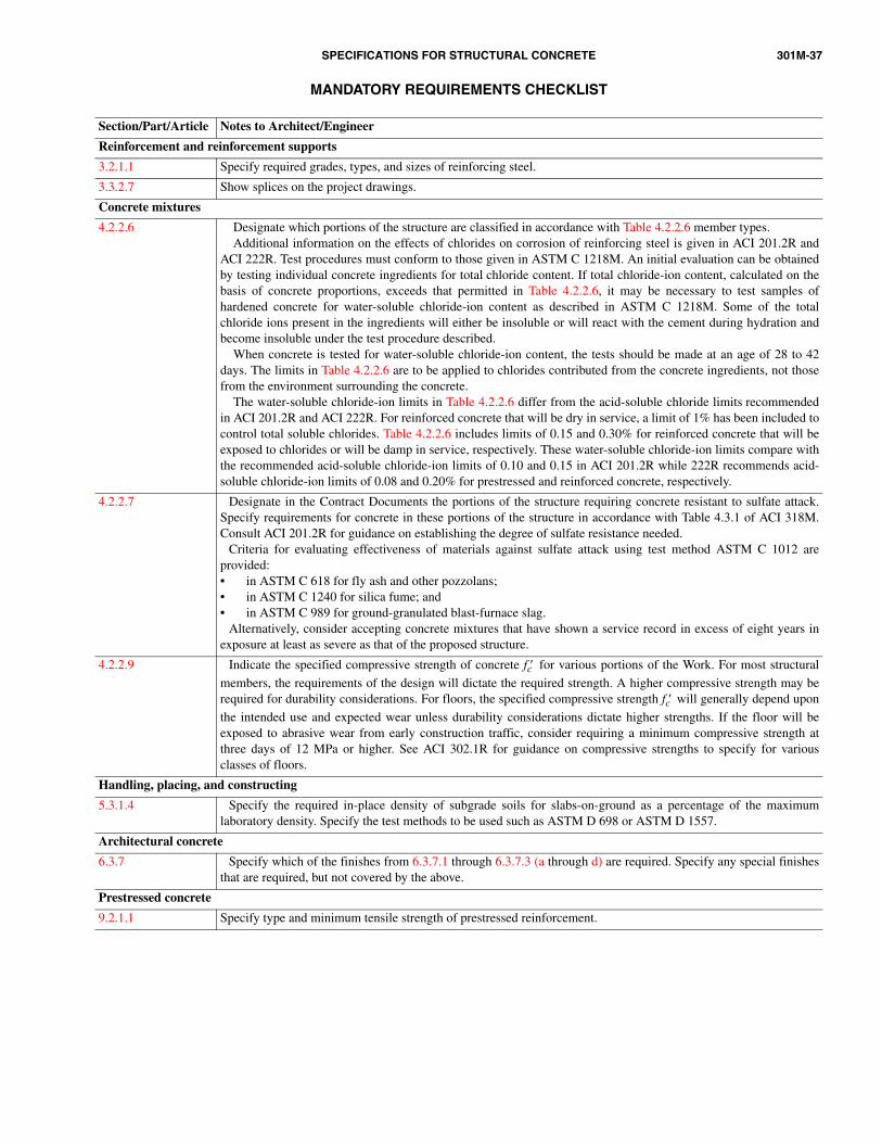
SPECIFICATIONS FOR STRUCTURAL CONCRETE 301M-37
MANDATORY REQUIREMENTS CHECKLIST
Section/Part/Article Notes to Architect/Engineer
Reinforcement and reinforcement supports
3.2.1.1 Specify required grades, types, and sizes of reinforcing steel.
3.3.2.7 Show splices on the project drawings.
Concrete mixtures
4.2.2.6 Designate which portions of the structure are classified in accordance with Table 4.2.2.6 member types.Additional information on the effects of chlorides on corrosion of reinforcing steel is given in ACI 201.2R and
ACI 222R. Test procedures must conform to those given in ASTM C 1218M. An initial evaluation can be obtainedby testing individual concrete ingredients for total chloride content. If total chloride-ion content, calculated on thebasis of concrete proportions, exceeds that permitted in Table 4.2.2.6, it may be necessary to test samples ofhardened concrete for water-soluble chloride-ion content as described in ASTM C 1218M. Some of the totalchloride ions present in the ingredients will either be insoluble or will react with the cement during hydration andbecome insoluble under the test procedure described.
When concrete is tested for water-soluble chloride-ion content, the tests should be made at an age of 28 to 42days. The limits in Table 4.2.2.6 are to be applied to chlorides contributed from the concrete ingredients, not thosefrom the environment surrounding the concrete.
The water-soluble chloride-ion limits in Table 4.2.2.6 differ from the acid-soluble chloride limits recommendedin ACI 201.2R and ACI 222R. For reinforced concrete that will be dry in service, a limit of 1% has been included tocontrol total soluble chlorides. Table 4.2.2.6 includes limits of 0.15 and 0.30% for reinforced concrete that will beexposed to chlorides or will be damp in service, respectively. These water-soluble chloride-ion limits compare withthe recommended acid-soluble chloride-ion limits of 0.10 and 0.15 in ACI 201.2R while 222R recommends acid-soluble chloride-ion limits of 0.08 and 0.20% for prestressed and reinforced concrete, respectively.
4.2.2.7 Designate in the Contract Documents the portions of the structure requiring concrete resistant to sulfate attack.Specify requirements for concrete in these portions of the structure in accordance with Table 4.3.1 of ACI 318M.Consult ACI 201.2R for guidance on establishing the degree of sulfate resistance needed.
Criteria for evaluating effectiveness of materials against sulfate attack using test method ASTM C 1012 areprovided:• in ASTM C 618 for fly ash and other pozzolans;• in ASTM C 1240 for silica fume; and• in ASTM C 989 for ground-granulated blast-furnace slag.
Alternatively, consider accepting concrete mixtures that have shown a service record in excess of eight years inexposure at least as severe as that of the proposed structure.
4.2.2.9 Indicate the specified compressive strength of concrete fc′ for various portions of the Work. For most structural
members, the requirements of the design will dictate the required strength. A higher compressive strength may berequired for durability considerations. For floors, the specified compressive strength fc′ will generally depend upon
the intended use and expected wear unless durability considerations dictate higher strengths. If the floor will beexposed to abrasive wear from early construction traffic, consider requiring a minimum compressive strength atthree days of 12 MPa or higher. See ACI 302.1R for guidance on compressive strengths to specify for variousclasses of floors.
Handling, placing, and constructing
5.3.1.4 Specify the required in-place density of subgrade soils for slabs-on-ground as a percentage of the maximumlaboratory density. Specify the test methods to be used such as ASTM D 698 or ASTM D 1557.
Architectural concrete
6.3.7 Specify which of the finishes from 6.3.7.1 through 6.3.7.3 (a through d) are required. Specify any special finishesthat are required, but not covered by the above.
Prestressed concrete
9.2.1.1 Specify type and minimum tensile strength of prestressed reinforcement.

301M-38 ACI STANDARD
OPTIONAL REQUIREMENTS CHECKLIST
Section/Part/Article Notes to Architect/Engineer
General requirements
1.6.3.2, 1.6.3.3, 1.6.4.1
Specify if other testing arrangements are required, such as Owner’s testing agency establishing mixtureproportions or any testing responsibilities of the Owner’s testing agency that will be performed by the Contractor’stesting agency.
1.6.3.2.g, 1.6.4.2.e If accelerated testing of concrete is specified or permitted as an alternative to standard testing, specify theprocedure from ASTM C 684 that is to be followed. Specify when compressive test specimens are to be tested ifother than seven and 28 days.
1.6.4.3 Specify additional testing services desired for the Work, if applicable. Note that these additional testing servicesare to be performed by the Owner’s testing laboratory; hence, the term “will” is used in place of “shall” in 1.6.4.3.Refer to ACI 311.1R (SP-2), ACI 311.4R, and ACI 311.5R for specific inspection items that may be appropriate.
When it is necessary or desirable to know properties of concrete at the point of placement or at locations otherthan the delivery point, specify that concrete is to be sampled at these other locations for testing. See the discussionunder Optional Requirements in Section 4.2.2.2.
1.6.5.2 Specify if nondestructive tests will be permitted to evaluate uniformity or relative in-place strength of concrete.Refer to ACI 228.1R for guidance on nondestructive test methods.
1.6.7.1 If another basis for acceptance of concrete strength level is required for accelerated strength testing, specify thebasis for acceptance.
Formwork and formwork accessories
2.1.2.1 Review the list of submittal items and specify in Contract Documents the items that need not be submitted.
2.1.2.2 Review the list of submittal items and specify in Contract Documents the items to be submitted.
2.2.1.1 Specify other materials for form faces in contact with concrete.
2.2.1.2 Indicate where walls require form ties with a positive water-barrier.
2.2.2.1 Specify if calculations and drawings for formwork must be sealed by a licensed Engineer.
2.2.2.3 Specify if earth cuts will be permitted or required.
2.2.2.4 Specify more or less stringent limitations on deflection of facing materials when needed. Refer to ACI 347 forfurther guidance.
2.2.2.5.b Specify or allow alternative locations for formed construction joints when necessary to facilitate formworkremoval or accelerate construction, provided that the alternative joint locations do not adversely affect the strengthof the structure.
2.2.2.5.c Specify keyway depths other than 40 mm when required.
2.2.3.2 Specify if chamfer strips are not required on exterior corners of permanently exposed surfaces. Specify if bevelsare required on re-entrant corners of concrete or on edges of formed concrete joints.
2.3.1.2 Specify tolerance limits required to be different than those of ACI 117. Specify when a more or less restrictivetolerance for abrupt offset is required. Refer to ACI 347 and the Commentary to ACI 117 for further guidance.
2.3.2.5 Specify the minimum compressive strength for removal of forms supporting the weight of concrete if differentthan fc′ . Specify if nonload-carrying form-facing material is not permitted to be removed at an earlier age than the
load-carrying portion of the formwork.
2.3.4.2 Specify if the alternative methods for evaluating concrete strength for formwork removal are permitted.
Reinforcement and reinforcement supports
3.1.1 Specify if the submittals listed in 3.1.1.1 through 3.1.1.3 are not required to be submitted. Otherwise, they will berequired to be submitted.
3.2.1.1 For headed bars, specify type of steel for reinforcing bars:• Low-alloy steel (ASTM A 706M);• Carbon steel (ASTM A 615M). For carbon steel (ASTM A 615M) also specify grade; and• Rail steel or axle steel deformed bars (ASTM A 996M).
3.2.1.2 Specify if coated reinforcing bars are required and, if so, whether the coating is to be zinc or epoxy.
3.2.1.2.a For zinc-coated reinforcing bars conforming to ASTM A 767M, specify the class of coating, whether galvanizing is tobe performed before or after fabrication, and indicate which bars require special finished bend diameters (usually smallersizes used for stirrup and ties).
Avoid mixing galvanized and nongalvanized reinforcing steel or other embedded steel that could result in galvanic cells.
3.2.1.2.b Specify the ASTM specification to which epoxy-coated reinforcing bars are to conform.
3.2.1.4 Specify which of the three combinations will apply.
3.2.1.5 Specify plain or deformed wire and, if required, epoxy-coated wire.

SPECIFICATIONS FOR STRUCTURAL CONCRETE 301M-39
OPTIONAL REQUIREMENTS CHECKLIST (cont.)
Section/Part/Article Notes to Architect/Engineer3.2.1.6 Specify plain or deformed welded wire reinforcement and, if required, epoxy-coated wire reinforcement. Refer to
“WRI Manual of Standard Practice” for additional guidance.
3.2.1.7 Specify if wire reinforcement supports are required or permitted.
3.2.2.2 Specify if bar welds are required or permitted. If required or permitted, specify any desired requirements for preparationfor welding (such as removal of zinc or epoxy coating) more stringent than those in AWS D1.4.
Specify desired requirements for chemical composition of reinforcing bars more stringent than those of thereferenced ASTM specifications.
Specify special heat treatment of welded assemblies, if required. Specify supplementary requirements for weldingof wire to wire, and welding of wire or welded wire reinforcement to reinforcing bars or structural steels.
3.3.2.3 Specify special cover requirements for corrosive atmosphere, other severe exposures, or fire protection not covered inTable 3.3.2.3. Some concrete covers in Table 3.3.2.3 may exceed minimum concrete covers required by ACI 318M.Concrete covers used for design must agree with the covers specified in Table 3.3.2.3.
3.3.2.4 Specify if the methods of support are to be other than those indicated in 3.3.2.4.a through 3.3.2.4.i.
3.3.2.5 Specify where reinforcement may extend through contraction joints, including saw-cut joints.
3.3.2.8 Specify if bending or straightening reinforcement partially embedded in concrete is permitted.
3.3.2.9 Specify if field cutting of reinforcement is permitted and specify cutting methods to be used.Concrete mixtures4.2.1.1 Specify the other standards that the cementitious material may be required or permitted to conform to if cement
other than ASTM C 150 Type I or Type II is required or permitted. Specify if ASTM C 150 cement with ASTM C618 pozzolanic materials, ASTM C 989 ground-granulated blast-furnace slag, or ASTM C 1240 silica fume, isrequired. Specify the class of pozzolan or grade of slag that is required. Specify if ASTM C 595 blended hydrauliccement or C 1157 hydraulic cement are required or permitted. Use ACI 318M and ACI 225R to determine what willbe acceptable for the project conditions.
ASTM C 1157 is a performance specification for hydraulic cement. Requirements for physical properties of thecement are specified in ASTM C 1157; however, there are no restrictions on the composition of the cement or itsconstituents. When using ASTM C 1157, the Architect/Engineer should consider whether any additional limits onphysical properties or constituents should be specified.
If it is suspected that concrete will be exposed to sulfates in service, evaluate the water-soluble sulfates in the soiland groundwater. Use the criteria of ACI 318M, Section 4.3.1 and Table 4.3.1, to determine the cement type to use.Use any of the cements in ACI 318M, Table 4.3.1 for concrete exposed to sea water. Verify the availability of thecement specified. Do not use ASTM C 595, Type S and SA. Specify if less than 15% fly ash is permitted. In someinstances, using less than 15% fly ash can increase the concrete’s susceptibility to excessive expansions caused byalkali-silica reactivity (ASR). If a smaller percentage of fly ash is proposed for use, the proposed project mixture offly ash and portland cement from the same source should be tested and compared to a control mixture using only theportland cement in accordance with ASTM C 441. The project mixture should be considered acceptable, providedthe average length increase of the project mixture does not exceed that of the control mixture. For projects whereexpansions due to ASR may be critical, consider requiring the test comparison at some frequency during the Work,such as every three months. If reactive aggregates are available and may be used, specify the use of naturalpozzolan, fly ash, slag, or silica fume in an amount shown to be effective in mitigating harmful expansions due toalkali-silica reactivity. Alternatively, specify a low-alkali cement be used as described in the Optional RequirementsChecklist for 4.2.1.2.
4.2.1.2 If aggregates are to conform to a specification other than ASTM C 33 for grading, deleterious substances, orsoundness, specify the other requirements.
Specify the test for determining conformance to requirements for cleanliness, and specify grading beperformed on samples obtained from the aggregates at the point of batching.
Specify any additional requirements for aggregate such as hardness, color, mineralogical composition, texture,or shape (crushed or gravel).
If concrete will be exposed to wetting, extended exposure to humid atmosphere, or in contact with moist ground,specify the use of aggregates that do not contain materials deleteriously reactive with alkalies in the cement;however, such aggregates may be used with cement containing less than 0.60% alkalies such as (Na2O +
0.658K2O) or with a material such as natural pozzolan, fly ash, slag, or silica fume in an amount shown to be
effective in preventing harmful expansion due to alkali-aggregate reaction in accordance with ASTM C 441.
4.2.1.4 Specify the admixtures listed in 4.2.1.4 that are required. Indicate the parts of the Work in which each type ofadmixture should or may be used.
4.2.2.1 Specify if less than 15% or more than 25% fly ash is permitted in floors. If more than 25% is permitted, ahistory should be available demonstrating the finishing ability of the proposed concrete mixture.
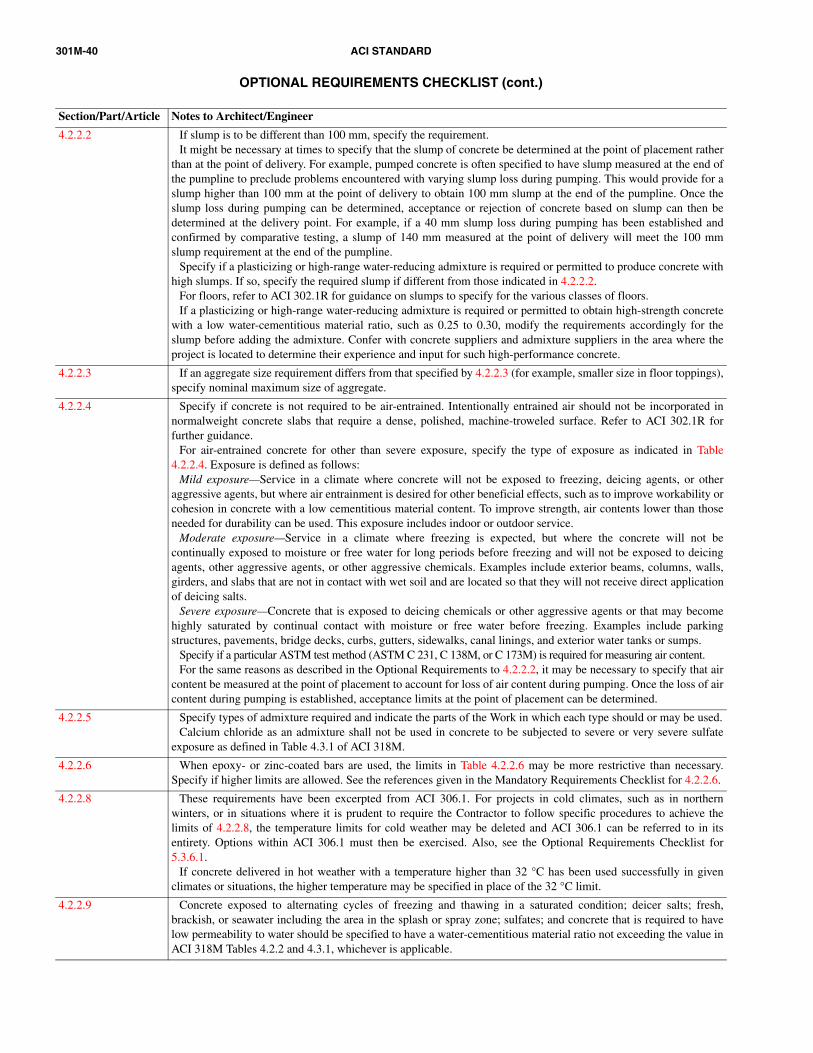
301M-40 ACI STANDARD
OPTIONAL REQUIREMENTS CHECKLIST (cont.)
Section/Part/Article Notes to Architect/Engineer
4.2.2.2 If slump is to be different than 100 mm, specify the requirement.It might be necessary at times to specify that the slump of concrete be determined at the point of placement rather
than at the point of delivery. For example, pumped concrete is often specified to have slump measured at the end ofthe pumpline to preclude problems encountered with varying slump loss during pumping. This would provide for aslump higher than 100 mm at the point of delivery to obtain 100 mm slump at the end of the pumpline. Once theslump loss during pumping can be determined, acceptance or rejection of concrete based on slump can then bedetermined at the delivery point. For example, if a 40 mm slump loss during pumping has been established andconfirmed by comparative testing, a slump of 140 mm measured at the point of delivery will meet the 100 mmslump requirement at the end of the pumpline.
Specify if a plasticizing or high-range water-reducing admixture is required or permitted to produce concrete withhigh slumps. If so, specify the required slump if different from those indicated in 4.2.2.2.
For floors, refer to ACI 302.1R for guidance on slumps to specify for the various classes of floors.If a plasticizing or high-range water-reducing admixture is required or permitted to obtain high-strength concrete
with a low water-cementitious material ratio, such as 0.25 to 0.30, modify the requirements accordingly for theslump before adding the admixture. Confer with concrete suppliers and admixture suppliers in the area where theproject is located to determine their experience and input for such high-performance concrete.
4.2.2.3 If an aggregate size requirement differs from that specified by 4.2.2.3 (for example, smaller size in floor toppings),specify nominal maximum size of aggregate.
4.2.2.4 Specify if concrete is not required to be air-entrained. Intentionally entrained air should not be incorporated innormalweight concrete slabs that require a dense, polished, machine-troweled surface. Refer to ACI 302.1R forfurther guidance.
For air-entrained concrete for other than severe exposure, specify the type of exposure as indicated in Table4.2.2.4. Exposure is defined as follows:
Mild exposure—Service in a climate where concrete will not be exposed to freezing, deicing agents, or otheraggressive agents, but where air entrainment is desired for other beneficial effects, such as to improve workability orcohesion in concrete with a low cementitious material content. To improve strength, air contents lower than thoseneeded for durability can be used. This exposure includes indoor or outdoor service.
Moderate exposure—Service in a climate where freezing is expected, but where the concrete will not becontinually exposed to moisture or free water for long periods before freezing and will not be exposed to deicingagents, other aggressive agents, or other aggressive chemicals. Examples include exterior beams, columns, walls,girders, and slabs that are not in contact with wet soil and are located so that they will not receive direct applicationof deicing salts.
Severe exposure—Concrete that is exposed to deicing chemicals or other aggressive agents or that may becomehighly saturated by continual contact with moisture or free water before freezing. Examples include parkingstructures, pavements, bridge decks, curbs, gutters, sidewalks, canal linings, and exterior water tanks or sumps.
Specify if a particular ASTM test method (ASTM C 231, C 138M, or C 173M) is required for measuring air content.For the same reasons as described in the Optional Requirements to 4.2.2.2, it may be necessary to specify that air
content be measured at the point of placement to account for loss of air content during pumping. Once the loss of aircontent during pumping is established, acceptance limits at the point of placement can be determined.
4.2.2.5 Specify types of admixture required and indicate the parts of the Work in which each type should or may be used.Calcium chloride as an admixture shall not be used in concrete to be subjected to severe or very severe sulfate
exposure as defined in Table 4.3.1 of ACI 318M.
4.2.2.6 When epoxy- or zinc-coated bars are used, the limits in Table 4.2.2.6 may be more restrictive than necessary.Specify if higher limits are allowed. See the references given in the Mandatory Requirements Checklist for 4.2.2.6.
4.2.2.8 These requirements have been excerpted from ACI 306.1. For projects in cold climates, such as in northernwinters, or in situations where it is prudent to require the Contractor to follow specific procedures to achieve thelimits of 4.2.2.8, the temperature limits for cold weather may be deleted and ACI 306.1 can be referred to in itsentirety. Options within ACI 306.1 must then be exercised. Also, see the Optional Requirements Checklist for5.3.6.1.
If concrete delivered in hot weather with a temperature higher than 32 °C has been used successfully in givenclimates or situations, the higher temperature may be specified in place of the 32 °C limit.
4.2.2.9 Concrete exposed to alternating cycles of freezing and thawing in a saturated condition; deicer salts; fresh,brackish, or seawater including the area in the splash or spray zone; sulfates; and concrete that is required to havelow permeability to water should be specified to have a water-cementitious material ratio not exceeding the value inACI 318M Tables 4.2.2 and 4.3.1, whichever is applicable.

SPECIFICATIONS FOR STRUCTURAL CONCRETE 301M-41
OPTIONAL REQUIREMENTS CHECKLIST (cont.)
Section/Part/Article Notes to Architect/Engineer
4.2.2.9.a Specify those areas that will be exposed to deicing chemicals and must comply with the limitations in Table 4.2.2.9.
4.2.2.9.b If the test specimen is to be other than a 150 x 300 mm cylindrical specimen, specify the size of the specimen. If age attest is to be other than 28 days, specify age at test. If a different test method is required, specify the test method.
4.2.3.4.b Specify the test ages, if other than 28 days, for trial mixture proportioning.
4.3.1.1 If concrete materials are to be specified, measured, batched, or mixed other than in conformance with ASTM C 94M,specify how these procedures are to be accomplished.
Specify if the ready-mixed concrete production facility must be certified by the NRMCA Program forCertification of Ready-Mixed Concrete Production Facilities or an equivalent program.
4.3.2.1 Specify when slump adjustment by addition of water at the project site is not permitted.
4.3.2.2 If shorter or longer time for completion of discharge is required or permitted, specify maximum time.
Handling, placing, and constructing
5.1.2.1 Specify if submittals listed in 5.1.2.1.a through 5.1.2.1.e are not required to be submitted.
5.1.2.2.a Specify if shop drawings must be submitted.
5.1.2.2.b Specify if advance notification of concrete placement is required.
5.1.2.2.c Specify if a request for acceptance of preplacement activities must be submitted. When necessary, specify apreconstruction conference be held before the start of construction activities.
5.1.2.2.d Specify if a request for acceptance of wet-weather protection must be submitted.
5.1.2.2.e Specify if a request for acceptance of hot-weather precautions must be submitted.
5.1.2.2.f Specify if samples finished in accordance with 5.3.3.2 must be submitted.
5.1.2.2.g Specify if an exposed-aggregate surface is required.
5.3.2.1.c If concrete temperatures higher than 32 °C are acceptable, based on location, relative humidity, and pastexperience, specify a higher allowable concrete temperature in hot weather. Review the ACI 305R report forguidance to specify a higher temperature.
5.3.2.6 Specify if bond is required at construction joints.
5.3.3.2 Specify if the finish is required to match that of a sample panel to be furnished for comparison purposes. Specifythe sample finish location and the in-place finish location.
5.3.3.3 Specify more restrictive tolerances for as-cast form finishes as needed based on importance of surface appearance.See Optional Requirements Checklist for 2.3.1.2 for additional guidance.
5.3.3.5 Specify if finishes other than those in 5.3.3.5 are required.
5.3.4.1 Specify which of the finishes or combination of finishes in 5.3.4.2 are required. If this is not done, the finishes willbe as required in 5.3.4.2.j.
Specify when more or less certified flatwork concrete finishers may be required or permitted. More stringentqualifications for the finishing contractor and finishers may be appropriate where floor serviceability is significantto the Owner and for large floor projects with specific requirements for flatness, heavy loading, frequent lift trucktraffic, or automated warehouse truck traffic. For such projects, specify that the finishing contractors use qualifiedflatwork finishers who are skilled in the specific type of Work required.
5.3.4.2.c Specify more restrictive tolerances if applicable. The conventional straightedged tolerance from ACI 117 appliesto most general floor construction. For floors requiring tighter tolerances, such as in areas housing sensitive test ormonitoring equipment, specify either “flat” or “very flat” floor tolerances from ACI 117. Refer to the commentaryfor ACI 117 and ACI 302.1R for more guidance.
Specify tolerances that may be more or less restrictive when applicable.
5.3.4.2.e For dry-shake finishes, specify the metallic or mineral aggregate, the final finishing method, and the location.
5.3.4.2.f For heavy-duty topping for two-course slabs, specify the materials, the final finishing method, and the location.
5.3.4.2.h For nonslip finishes, specify the location. Where abrasive particles other than crushed aluminum oxides are to beused, specify the other abrasive particles.
5.3.4.2.i For exposed-aggregate finishes, specify the location, color, surface retarder, and size of aggregate. (Usually 9.5 to 16 mm.)
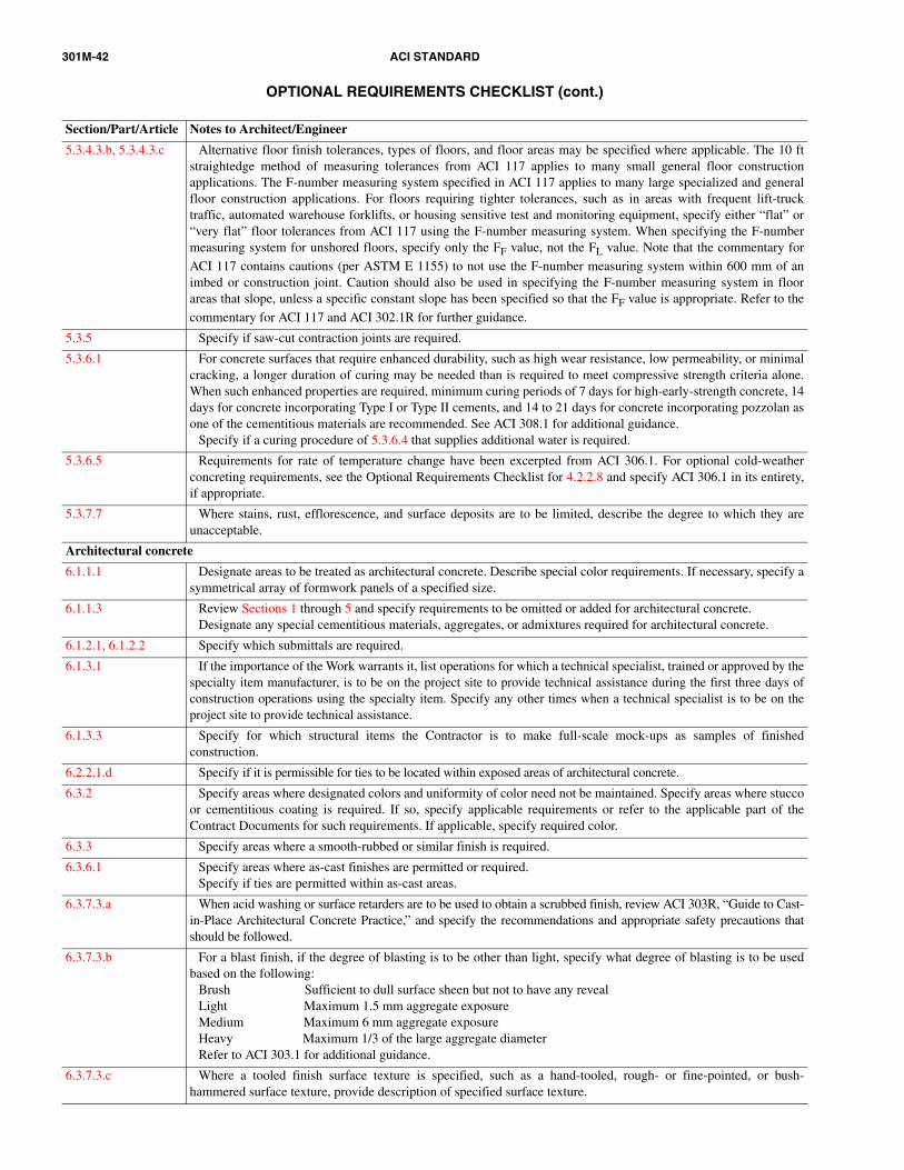
301M-42 ACI STANDARD
OPTIONAL REQUIREMENTS CHECKLIST (cont.)
Section/Part/Article Notes to Architect/Engineer
5.3.4.3.b, 5.3.4.3.c Alternative floor finish tolerances, types of floors, and floor areas may be specified where applicable. The 10 ftstraightedge method of measuring tolerances from ACI 117 applies to many small general floor constructionapplications. The F-number measuring system specified in ACI 117 applies to many large specialized and generalfloor construction applications. For floors requiring tighter tolerances, such as in areas with frequent lift-trucktraffic, automated warehouse forklifts, or housing sensitive test and monitoring equipment, specify either “flat” or“very flat” floor tolerances from ACI 117 using the F-number measuring system. When specifying the F-numbermeasuring system for unshored floors, specify only the FF value, not the FL value. Note that the commentary for
ACI 117 contains cautions (per ASTM E 1155) to not use the F-number measuring system within 600 mm of animbed or construction joint. Caution should also be used in specifying the F-number measuring system in floorareas that slope, unless a specific constant slope has been specified so that the FF value is appropriate. Refer to the
commentary for ACI 117 and ACI 302.1R for further guidance.
5.3.5 Specify if saw-cut contraction joints are required.
5.3.6.1 For concrete surfaces that require enhanced durability, such as high wear resistance, low permeability, or minimalcracking, a longer duration of curing may be needed than is required to meet compressive strength criteria alone.When such enhanced properties are required, minimum curing periods of 7 days for high-early-strength concrete, 14days for concrete incorporating Type I or Type II cements, and 14 to 21 days for concrete incorporating pozzolan asone of the cementitious materials are recommended. See ACI 308.1 for additional guidance.
Specify if a curing procedure of 5.3.6.4 that supplies additional water is required.
5.3.6.5 Requirements for rate of temperature change have been excerpted from ACI 306.1. For optional cold-weatherconcreting requirements, see the Optional Requirements Checklist for 4.2.2.8 and specify ACI 306.1 in its entirety,if appropriate.
5.3.7.7 Where stains, rust, efflorescence, and surface deposits are to be limited, describe the degree to which they areunacceptable.
Architectural concrete
6.1.1.1 Designate areas to be treated as architectural concrete. Describe special color requirements. If necessary, specify asymmetrical array of formwork panels of a specified size.
6.1.1.3 Review Sections 1 through 5 and specify requirements to be omitted or added for architectural concrete.Designate any special cementitious materials, aggregates, or admixtures required for architectural concrete.
6.1.2.1, 6.1.2.2 Specify which submittals are required.
6.1.3.1 If the importance of the Work warrants it, list operations for which a technical specialist, trained or approved by thespecialty item manufacturer, is to be on the project site to provide technical assistance during the first three days ofconstruction operations using the specialty item. Specify any other times when a technical specialist is to be on theproject site to provide technical assistance.
6.1.3.3 Specify for which structural items the Contractor is to make full-scale mock-ups as samples of finishedconstruction.
6.2.2.1.d Specify if it is permissible for ties to be located within exposed areas of architectural concrete.
6.3.2 Specify areas where designated colors and uniformity of color need not be maintained. Specify areas where stuccoor cementitious coating is required. If so, specify applicable requirements or refer to the applicable part of theContract Documents for such requirements. If applicable, specify required color.
6.3.3 Specify areas where a smooth-rubbed or similar finish is required.
6.3.6.1 Specify areas where as-cast finishes are permitted or required.Specify if ties are permitted within as-cast areas.
6.3.7.3.a When acid washing or surface retarders are to be used to obtain a scrubbed finish, review ACI 303R, “Guide to Cast-in-Place Architectural Concrete Practice,” and specify the recommendations and appropriate safety precautions thatshould be followed.
6.3.7.3.b For a blast finish, if the degree of blasting is to be other than light, specify what degree of blasting is to be usedbased on the following:
Brush Sufficient to dull surface sheen but not to have any revealLight Maximum 1.5 mm aggregate exposureMedium Maximum 6 mm aggregate exposureHeavy Maximum 1/3 of the large aggregate diameterRefer to ACI 303.1 for additional guidance.
6.3.7.3.c Where a tooled finish surface texture is specified, such as a hand-tooled, rough- or fine-pointed, or bush-hammered surface texture, provide description of specified surface texture.
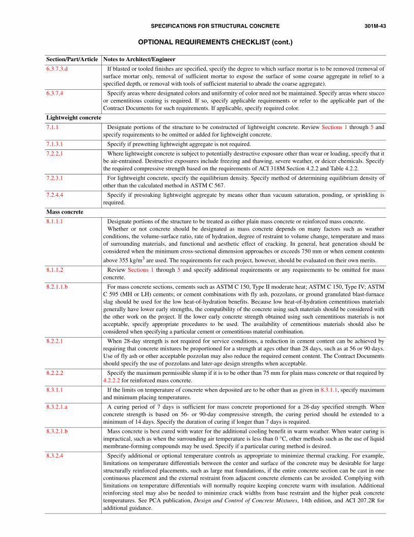
SPECIFICATIONS FOR STRUCTURAL CONCRETE 301M-43
OPTIONAL REQUIREMENTS CHECKLIST (cont.)
Section/Part/Article Notes to Architect/Engineer
6.3.7.3.d If blasted or tooled finishes are specified, specify the degree to which surface mortar is to be removed (removal ofsurface mortar only, removal of sufficient mortar to expose the surface of some coarse aggregate in relief to aspecified depth, or removal with tools of sufficient material to abrade the coarse aggregate).
6.3.7.4 Specify areas where designated colors and uniformity of color need not be maintained. Specify areas where stuccoor cementitious coating is required. If so, specify applicable requirements or refer to the applicable part of theContract Documents for such requirements. If applicable, specify required color.
Lightweight concrete
7.1.1 Designate portions of the structure to be constructed of lightweight concrete. Review Sections 1 through 5 andspecify requirements to be omitted or added for lightweight concrete.
7.1.3.1 Specify if prewetting lightweight aggregate is not required.
7.2.2.1 Where lightweight concrete is subject to potentially destructive exposure other than wear or loading, specify that itbe air-entrained. Destructive exposures include freezing and thawing, severe weather, or deicer chemicals. Specifythe required compressive strength based on the requirements of ACI 318M Section 4.2.2 and Table 4.2.2.
7.2.3.1 For lightweight concrete, specify the equilibrium density. Specify method of determining equilibrium density ofother than the calculated method in ASTM C 567.
7.2.4.4 Specify if presoaking lightweight aggregate by means other than vacuum saturation, ponding, or sprinkling isrequired.
Mass concrete
8.1.1.1 Designate portions of the structure to be treated as either plain mass concrete or reinforced mass concrete.Whether or not concrete should be designated as mass concrete depends on many factors such as weather
conditions, the volume-surface ratio, rate of hydration, degree of restraint to volume change, temperature and massof surrounding materials, and functional and aesthetic effect of cracking. In general, heat generation should beconsidered when the minimum cross-sectional dimension approaches or exceeds 750 mm or when cement contents
above 355 kg/m3 are used. The requirements for each project, however, should be evaluated on their own merits.
8.1.1.2 Review Sections 1 through 5 and specify additional requirements or any requirements to be omitted for massconcrete.
8.2.1.1.b For mass concrete sections, cements such as ASTM C 150, Type II moderate heat; ASTM C 150, Type IV; ASTMC 595 (MH or LH) cements; or cement combinations with fly ash, pozzolans, or ground granulated blast-furnaceslag should be used for the low heat-of-hydration benefits. Because low heat-of-hydration cementitious materialsgenerally have lower early strengths, the compatibility of the concrete using such materials should be considered withthe other work on the project. If the lower early concrete strength obtained using such cementitious materials is notacceptable, specify appropriate procedures to be used. The availability of cementitious materials should also beconsidered when specifying a particular cement or cementitious material combination.
8.2.2.1 When 28-day strength is not required for service conditions, a reduction in cement content can be achieved byrequiring that concrete mixtures be proportioned for a strength at ages other than 28 days, such as at 56 or 90 days.Use of fly ash or other acceptable pozzolan may also reduce the required cement content. The Contract Documentsshould specify the use of pozzolans and later-age design strengths when acceptable.
8.2.2.2 Specify the maximum permissible slump if it is to be other than 75 mm for plain mass concrete or that required by4.2.2.2 for reinforced mass concrete.
8.3.1.1 If the limits on temperature of concrete when deposited are to be other than as given in 8.3.1.1, specify maximumand minimum placing temperatures.
8.3.2.1.a A curing period of 7 days is sufficient for mass concrete proportioned for a 28-day specified strength. Whenconcrete strength is based on 56- or 90-day compressive strength, the curing period should be extended to aminimum of 14 days. Specify the duration of curing if longer than 7 days is required.
8.3.2.1.b Mass concrete is best cured with water for the additional cooling benefit in warm weather. When water curing isimpractical, such as when the surrounding air temperature is less than 0 °C, other methods such as the use of liquidmembrane-forming compounds may be used. Specify if a particular curing method is desired.
8.3.2.4 Specify additional or optional temperature controls as appropriate to minimize thermal cracking. For example,limitations on temperature differentials between the center and surface of the concrete may be desirable for largestructurally reinforced placements, such as large mat foundations, if the entire concrete section can be cast in onecontinuous placement and the external restraint from adjacent concrete elements can be avoided. Complying withlimitations on temperature differentials will normally require keeping concrete warm with insulation. Additionalreinforcing steel may also be needed to minimize crack widths from base restraint and the higher peak concretetemperatures. See PCA publication, Design and Control of Concrete Mixtures, 14th edition, and ACI 207.2R foradditional guidance.
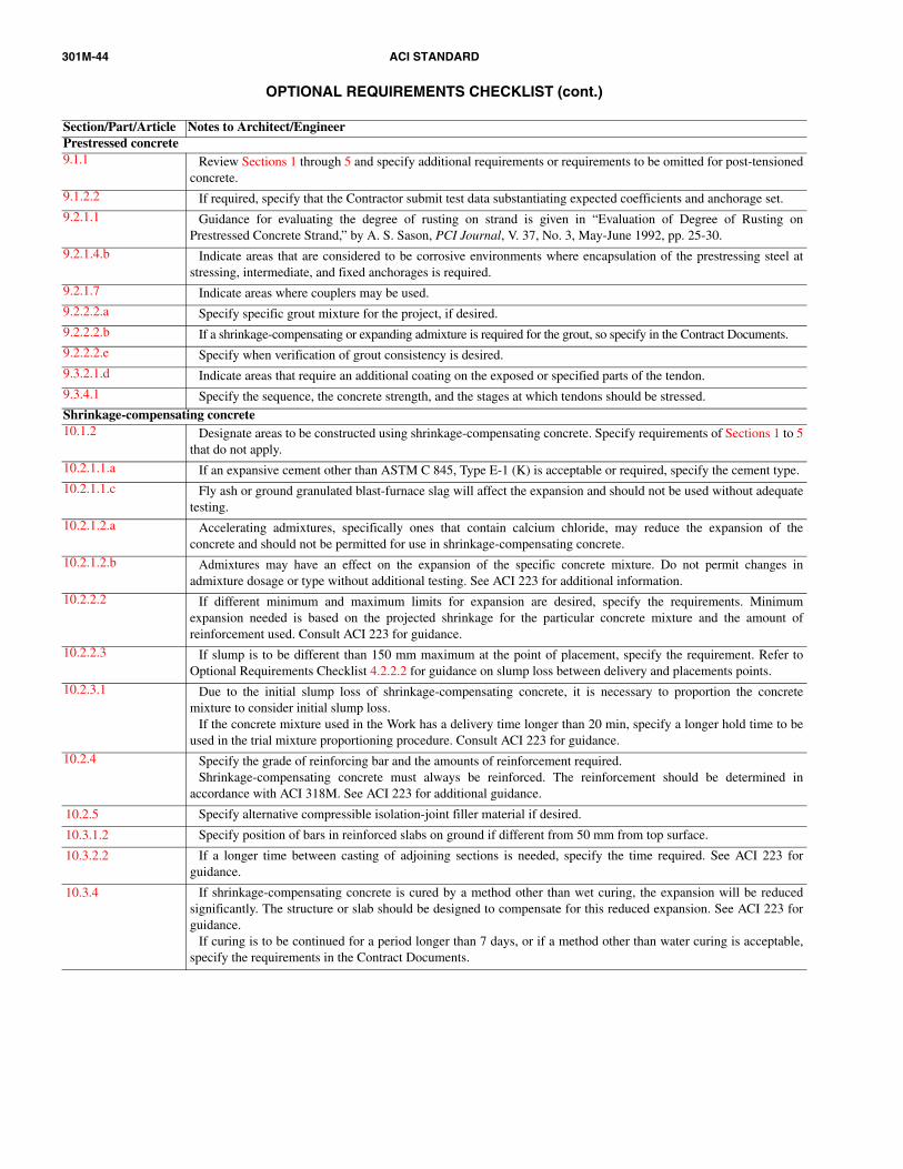
301M-44 ACI STANDARD
OPTIONAL REQUIREMENTS CHECKLIST (cont.)
Section/Part/Article Notes to Architect/EngineerPrestressed concrete9.1.1 Review Sections 1 through 5 and specify additional requirements or requirements to be omitted for post-tensioned
concrete.9.1.2.2 If required, specify that the Contractor submit test data substantiating expected coefficients and anchorage set.9.2.1.1 Guidance for evaluating the degree of rusting on strand is given in “Evaluation of Degree of Rusting on
Prestressed Concrete Strand,” by A. S. Sason, PCI Journal, V. 37, No. 3, May-June 1992, pp. 25-30.9.2.1.4.b Indicate areas that are considered to be corrosive environments where encapsulation of the prestressing steel at
stressing, intermediate, and fixed anchorages is required.9.2.1.7 Indicate areas where couplers may be used.9.2.2.2.a Specify specific grout mixture for the project, if desired.9.2.2.2.b If a shrinkage-compensating or expanding admixture is required for the grout, so specify in the Contract Documents.9.2.2.2.e Specify when verification of grout consistency is desired.9.3.2.1.d Indicate areas that require an additional coating on the exposed or specified parts of the tendon.9.3.4.1 Specify the sequence, the concrete strength, and the stages at which tendons should be stressed.Shrinkage-compensating concrete10.1.2 Designate areas to be constructed using shrinkage-compensating concrete. Specify requirements of Sections 1 to 5
that do not apply.10.2.1.1.a If an expansive cement other than ASTM C 845, Type E-1 (K) is acceptable or required, specify the cement type.10.2.1.1.c Fly ash or ground granulated blast-furnace slag will affect the expansion and should not be used without adequate
testing.10.2.1.2.a Accelerating admixtures, specifically ones that contain calcium chloride, may reduce the expansion of the
concrete and should not be permitted for use in shrinkage-compensating concrete.10.2.1.2.b Admixtures may have an effect on the expansion of the specific concrete mixture. Do not permit changes in
admixture dosage or type without additional testing. See ACI 223 for additional information.10.2.2.2 If different minimum and maximum limits for expansion are desired, specify the requirements. Minimum
expansion needed is based on the projected shrinkage for the particular concrete mixture and the amount ofreinforcement used. Consult ACI 223 for guidance.
10.2.2.3 If slump is to be different than 150 mm maximum at the point of placement, specify the requirement. Refer toOptional Requirements Checklist 4.2.2.2 for guidance on slump loss between delivery and placements points.
10.2.3.1 Due to the initial slump loss of shrinkage-compensating concrete, it is necessary to proportion the concretemixture to consider initial slump loss.
If the concrete mixture used in the Work has a delivery time longer than 20 min, specify a longer hold time to beused in the trial mixture proportioning procedure. Consult ACI 223 for guidance.
10.2.4 Specify the grade of reinforcing bar and the amounts of reinforcement required.Shrinkage-compensating concrete must always be reinforced. The reinforcement should be determined in
accordance with ACI 318M. See ACI 223 for additional guidance.
10.2.5 Specify alternative compressible isolation-joint filler material if desired.
10.3.1.2 Specify position of bars in reinforced slabs on ground if different from 50 mm from top surface.
10.3.2.2 If a longer time between casting of adjoining sections is needed, specify the time required. See ACI 223 forguidance.
10.3.4 If shrinkage-compensating concrete is cured by a method other than wet curing, the expansion will be reducedsignificantly. The structure or slab should be designed to compensate for this reduced expansion. See ACI 223 forguidance.
If curing is to be continued for a period longer than 7 days, or if a method other than water curing is acceptable,specify the requirements in the Contract Documents.

SPECIFICATIONS FOR STRUCTURAL CONCRETE 301M-45
SUBMITTALS CHECKLIST
NOTE: The items listed will be submitted by the Contractor and reviewed by the Architect/Engineer.Notify the Contractor of acceptance or rejection after review of submittals. All submittals and responses should be retained in files for
future reference during the Work. Some submittal requirements shown will apply only when optional requirements are selected and writteninto the Project Specifications. Once optional requirements have been selected, review the Section/Part/Article indicated for the submittalitem to see if it applies.
Section/Part/Article Submittal items and notes to Architect/Engineer
General requirements
1.6.3.1 Proposed testing agency.
1.6.3.2.e Test data and documentation on materials and concrete mixtures.
1.6.3.2.f Quality-control program of the concrete supplier.
1.6.3.2.g Request to use accelerated testing and correlation data.
1.6.4.1.c Test and inspection results.
1.7.1.4 Proposed repair methods, materials, and modifications to the Work.
1.7.4.2.e Description of repair work performed to bring strength-deficient concrete into compliance with the ContractDocuments.
1.7.5.2.e Description of repair performed to bring potentially nondurable concrete into compliance with the ContractDocuments.
Formwork and formwork accessories
2.1.2.1.a Data on formwork facing materials if different from that specified in 2.2.1.1.
2.1.2.1.b Data on proposed departure from location or detail of construction and contraction joints shown on the projectdrawings.
2.1.2.1.c Correlation data for alternative methods of determining strength of concrete for formwork removal. Refer to ACI228.1R for recommendations on developing suitable correlation data.
2.1.2.1.d Detailed plan for formwork removal at a lower compressive strength than specified.
2.1.2.1.e Plan and procedures for installation and removal of reshoring and backshoring. See ACI 347 for guidance on itemsto consider.
2.1.2.1.f Data on formwork release agent or formwork liners.
2.1.2.2.a Shop drawings for formwork.
2.1.2.2.b Calculations for formwork, reshoring, and backshoring.
2.1.2.2.c Data and samples of form ties.
2.1.2.2.d Data and samples of expansion joint materials.
2.1.2.2.e Data and samples of waterstops.
2.2.2.3 Request to use earth cuts as form surfaces.
2.2.2.5.b Alternative location and details of construction joints.
2.2.2.5.d Alternative locations and details for formed construction and contraction joints.
2.3.2.5 Detailed plan for formwork removal at a lower compressive strength than fc′ .
2.3.4.2 Data correlating alternative concrete strength-measuring methods for formwork removal.Refer to ACI 228.1R for recommendations on developing suitable correlation data.
Reinforcement and reinforcement supports
3.1.1.1.a Certified test reports on materials.
3.1.1.1.b Placing drawings showing fabrication dimensions and locations for placement of reinforcement and supports.
3.1.1.1.c List of splices and request to use splices not shown on the project drawings.
3.1.1.1.d Request to use mechanical splices not shown on the project drawings.
3.1.1.1.e Request for placement of column dowels without the use of templates.
3.1.1.1.f Request and procedure to field bend or straighten partially embedded reinforcement.
3.1.1.1.g Copy CRSI Plant Certification.
3.1.1.2.a Description of reinforcement weld locations, weld procedures, and welder qualifications.
3.1.1.2.b Proposed supports for coated reinforcement and materials for fastening coated reinforcement not covered in 3.3.2.4.
3.1.1.3.a, 3.3.2.2 When the Contractor finds it necessary to move reinforcement beyond the specified placing tolerances to avoidinterference with other reinforcement, conduits, or embedded items, review a submittal showing the resultingarrangement of reinforcement.
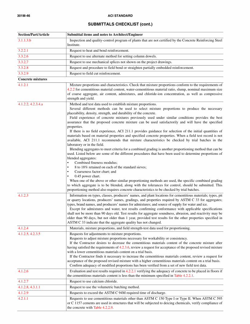
301M-46 ACI STANDARD
SUBMITTALS CHECKLIST (cont.)
Section/Part/Article Submittal items and notes to Architect/Engineer
3.1.1.3.b Inspection and quality-control program of plants that are not certified by the Concrete Reinforcing SteelInstitute.
3.2.2.1 Request to heat and bend reinforcement.
3.3.2.6 Request to use alternate method for setting column dowels.
3.3.2.7 Request to use mechanical splices not shown on the project drawings.
3.3.2.8 Request and procedure to field bend or straighten partially embedded reinforcement.
3.3.2.9 Request to field cut reinforcement.
Concrete mixtures
4.1.2.1 Mixture proportions and characteristics. Check that mixture proportions conform to the requirements of4.2.2 for cementitious material content, water-cementitious material ratio, slump, nominal maximum sizeof coarse aggregate, air content, admixtures, and chloride-ion concentration, as well as compressivestrength and yield.
4.1.2.2, 4.2.3.4.a Method and test data used to establish mixture proportions.Several different methods can be used to select mixture proportions to produce the necessary
placeability, density, strength, and durability of the concrete.Field experience of concrete mixtures previously used under similar conditions provides the best
assurance that the proposed concrete mixture can be used satisfactorily and will have the specifiedproperties.
If there is no field experience, ACI 211.1 provides guidance for selection of the initial quantities ofmaterials based on material properties and specified concrete properties. When a field test record is notavailable, ACI 211.1 recommends that mixture characteristics be checked by trial batches in thelaboratory or in the field.
Blending aggregates to meet criteria for a combined grading is another proportioning method that can beused. Listed below are some of the different procedures that have been used to determine proportions ofblended aggregates:• Combined fineness modulus;• 8 to 18% retained on each of the standard sieves;• Coarseness factor chart; and• 0.45 power chart.
When one of the above or other similar proportioning methods are used, the specific combined gradingto which aggregate is to be blended, along with the tolerances for control, should be submitted. Thisproportioning method also requires concrete characteristics to be checked by trial batches.
4.1.2.3 Information on types, classes, producers’ names, and plant locations for cementitious materials; types, pitor quarry locations, producers’ names, gradings, and properties required by ASTM C 33 for aggregates;types, brand names, and producers’ names for admixtures; and source of supply for water and ice.
Except for admixtures and water, test results confirming conformance with applicable specificationsshall not be more than 90 days old. Test results for aggregate soundness, abrasion, and reactivity may beolder than 90 days, but not older than 1 year, provided test results for the other properties specified inASTM C 33 indicate that the aggregate quality has not changed.
4.1.2.4 Materials, mixture proportions, and field strength-test data used for proportioning.
4.1.2.5, 4.2.3.5 Requests for adjustments to mixture proportions.Requests to adjust mixture proportions necessary for workability or consistency.If the Contractor desires to decrease the cementitious materials content of the concrete mixture after
having satisfied the requirements of 4.2.3.6, review a request for acceptance of the proposed revised mixturewith a lower cementitious materials content on a trial basis.
If the Contractor finds it necessary to increase the cementitious materials content, review a request foracceptance of the proposed revised mixture with a higher cementitious materials content on a trial basis.
Confirm adequacy of modified proportions has been verified from a set of new field test data.
4.1.2.6 Evaluation and test results required in 4.2.2.1 verifying the adequacy of concrete to be placed in floors ifthe cementitious materials content is less than the minimum specified in Table 4.2.2.1.
4.1.2.7 Request to use calcium chloride.
4.1.2.8, 4.3.1.1 Request to use the volumetric batching method.
4.1.2.9 Requests to exceed the ASTM C 94M required time of discharge.
4.2.1.1 Requests to use cementitious materials other than ASTM C 150 Type I or Type II. When ASTM C 595or C 1157 cements are used in structures that will be subjected to deicing chemicals, verify compliance ofthe concrete with Table 4.2.2.9.

SPECIFICATIONS FOR STRUCTURAL CONCRETE 301M-47
SUBMITTALS CHECKLIST (cont.)
Section/Part/Article Submittal items and notes to Architect/Engineer
4.2.1.3 Request to use alternative sources of water.
4.2.1.4 Request to use admixtures.
4.2.1.5 Request to change materials and data verifying that properties of the concrete mixture conform to therequirements of 4.2.2.
4.2.2.1 Request to use a lower cementitious material content.
4.2.2.2 Request to use a slump other than that specified.
4.2.2.7 Documentation indicating compliance with the specified requirements for sulfate resistance. Documentation mayinclude test results on the cementitious material to be used in the proposed concrete mixture in accordance withASTM C 1012. Alternatively, evidence of adequate sulfate resistance of at least 8-year old existing structures inexposures at least as severe as the proposed structure may be accepted. The level of sulfate ions in the soil or waterof the existing structure should be comparable to the exposure of the proposed structure as provided by theArchitect/Engineer.
4.2.3.6.c Revised mixture proportions based on revised value of f ′cr .
Handling, placing, and constructing
5.1.2.1.a Test and inspection records.
5.1.2.1.b Description of conveying equipment.
5.1.2.1.c Proposed method of measuring concrete surface temperature changes.
5.1.2.1.d Proposed method for removal of stains, rust, efflorescence, and surface deposits.
5.1.2.1.e Qualifications of finishing contractor and flatwork finishers.
5.1.2.2.a Shop drawings of placing, handling, and constructing methods.
5.1.2.2.b Advance notification of forthcoming placement. Arrange for tests and inspection to be properly coordinated.
5.1.2.2.c Request for acceptance of preplacement activities to ensure the preplacement activities are properly inspected, ifnecessary.
5.1.2.2.d, 5.3.2.1.a Proposed wet-weather protection activities.
5.1.2.2.e Proposed precautions for placement of concrete hotter than 32 °C.
5.1.2.2.f Sample finish.
5.1.2.2.g, 5.3.4.2.i Specification and manufacturer’s data for surface retarder used in producing exposed-aggregate finish along withmethod of use.
5.1.2.3.a Proposed location and treatment of construction joints not shown on the project drawings. Review proposedmethods for preparing the surface and the use of portland-cement grout.
5.1.2.3.b Bonding agents other than cement grout for two-course slabs.
5.1.2.3.c, 5.3.2.4 Proposed method for underwater placement.
5.1.2.3.d Proposed location of contraction joints not indicated on the project drawings.
5.1.2.3.e Proposed methods of curing other than those of 5.3.6.4.
5.1.2.3.f Description of proposed coated form ties.
5.1.2.3.g, 5.2.1.3, 5.3.7.6
Specification and data and methods of use for any proposed repair material other than site-mixed portland-cementmortar described in 5.3.7.5 (see 5.3.7.6). For patches in exposed concrete, exercise caution when using the materialsdescribed in 5.3.7.6, particularly with regard to both possible color changes from weathering and delamination dueto differing coefficients of thermal expansion. Ensure that the material, including ASTM type or class, isappropriate for the moisture and thermal conditions of exposure.
5.3.2.1.c Request to exceed 32 °C concrete temperature, along with proposed precautionary measures and supporting data.
5.3.2.6 Proposed materials and methods to prepare the concrete surface to achieve bond.
5.3.4.2.f Request to use bonding agents other than cement grout.
5.3.5 Detailed plan for alternative saw-cutting method, such as shallow-cut and dry-cut method. See ACI 302.1R forfurther guidance.
5.3.6.4 Proposed methods of curing other than those listed in 5.3.6.4.a through e.
5.3.6.5 Method of measuring concrete surface temperature.
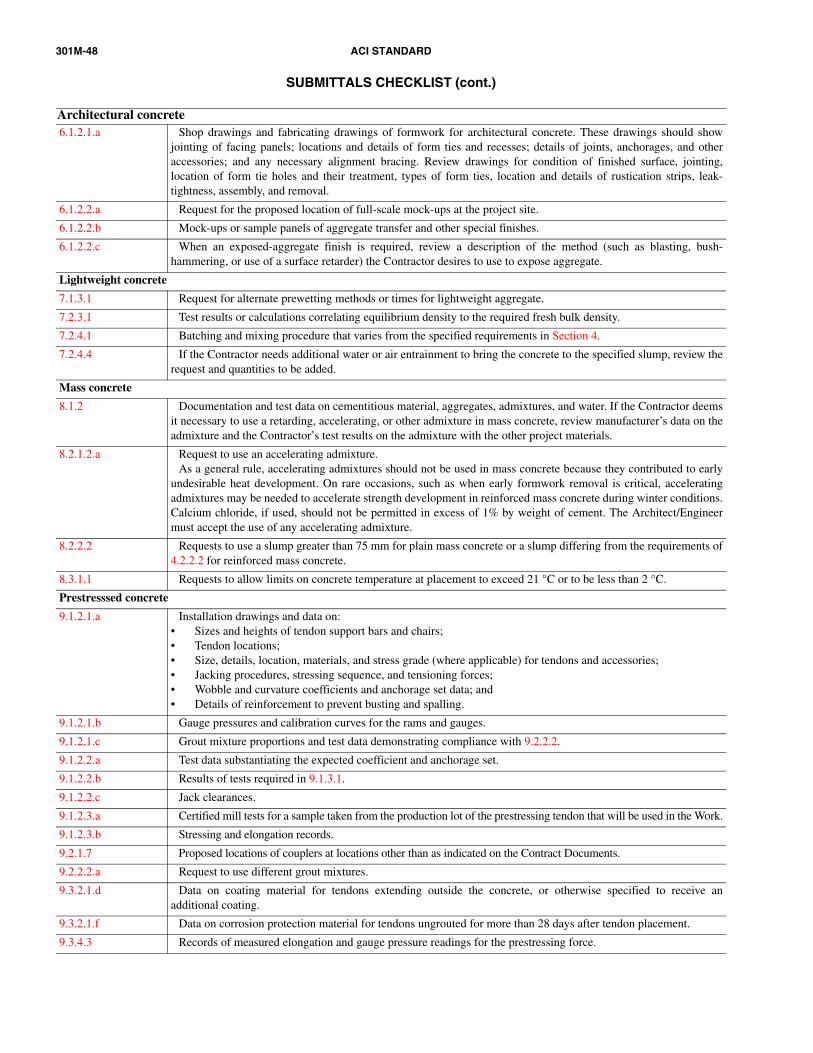
301M-48 ACI STANDARD
SUBMITTALS CHECKLIST (cont.)
Architectural concrete6.1.2.1.a Shop drawings and fabricating drawings of formwork for architectural concrete. These drawings should show
jointing of facing panels; locations and details of form ties and recesses; details of joints, anchorages, and otheraccessories; and any necessary alignment bracing. Review drawings for condition of finished surface, jointing,location of form tie holes and their treatment, types of form ties, location and details of rustication strips, leak-tightness, assembly, and removal.
6.1.2.2.a Request for the proposed location of full-scale mock-ups at the project site.
6.1.2.2.b Mock-ups or sample panels of aggregate transfer and other special finishes.
6.1.2.2.c When an exposed-aggregate finish is required, review a description of the method (such as blasting, bush-hammering, or use of a surface retarder) the Contractor desires to use to expose aggregate.
Lightweight concrete
7.1.3.1 Request for alternate prewetting methods or times for lightweight aggregate.
7.2.3.1 Test results or calculations correlating equilibrium density to the required fresh bulk density.
7.2.4.1 Batching and mixing procedure that varies from the specified requirements in Section 4.
7.2.4.4 If the Contractor needs additional water or air entrainment to bring the concrete to the specified slump, review therequest and quantities to be added.
Mass concrete
8.1.2 Documentation and test data on cementitious material, aggregates, admixtures, and water. If the Contractor deemsit necessary to use a retarding, accelerating, or other admixture in mass concrete, review manufacturer’s data on theadmixture and the Contractor’s test results on the admixture with the other project materials.
8.2.1.2.a Request to use an accelerating admixture.As a general rule, accelerating admixtures should not be used in mass concrete because they contributed to early
undesirable heat development. On rare occasions, such as when early formwork removal is critical, acceleratingadmixtures may be needed to accelerate strength development in reinforced mass concrete during winter conditions.Calcium chloride, if used, should not be permitted in excess of 1% by weight of cement. The Architect/Engineermust accept the use of any accelerating admixture.
8.2.2.2 Requests to use a slump greater than 75 mm for plain mass concrete or a slump differing from the requirements of4.2.2.2 for reinforced mass concrete.
8.3.1.1 Requests to allow limits on concrete temperature at placement to exceed 21 °C or to be less than 2 °C.
Prestresssed concrete
9.1.2.1.a Installation drawings and data on:• Sizes and heights of tendon support bars and chairs;• Tendon locations;• Size, details, location, materials, and stress grade (where applicable) for tendons and accessories;• Jacking procedures, stressing sequence, and tensioning forces;• Wobble and curvature coefficients and anchorage set data; and• Details of reinforcement to prevent busting and spalling.
9.1.2.1.b Gauge pressures and calibration curves for the rams and gauges.
9.1.2.1.c Grout mixture proportions and test data demonstrating compliance with 9.2.2.2.
9.1.2.2.a Test data substantiating the expected coefficient and anchorage set.
9.1.2.2.b Results of tests required in 9.1.3.1.
9.1.2.2.c Jack clearances.
9.1.2.3.a Certified mill tests for a sample taken from the production lot of the prestressing tendon that will be used in the Work.
9.1.2.3.b Stressing and elongation records.
9.2.1.7 Proposed locations of couplers at locations other than as indicated on the Contract Documents.
9.2.2.2.a Request to use different grout mixtures.
9.3.2.1.d Data on coating material for tendons extending outside the concrete, or otherwise specified to receive anadditional coating.
9.3.2.1.f Data on corrosion protection material for tendons ungrouted for more than 28 days after tendon placement.
9.3.4.3 Records of measured elongation and gauge pressure readings for the prestressing force.

SPECIFICATIONS FOR STRUCTURAL CONCRETE 301M-49
SUBMITTALS CHECKLIST (cont.)
Shrinkage-compensating concrete
10.1.3.2 Expansion test results for the proposed concrete mixtures.
10.1.3.3 Proposed sequences of concrete placements.It is critical that the concrete be placed in such manner that will permit the placement to expand. Consult ACI 223
for guidance.
10.2.1.1.c Request to use silica fume.
10.2.3.2 Expansion test results for the proposed concrete mixtures.
10.2.3.3 Proportions and expansion test results for revised mixture proportions.


![MagnumStone - Masters Concrete€¦ · ACI-318, Building Code Requirements for Structural Concrete (ACI 318-02) and Commentary (ACI 318R-02), American Concrete Institute, 2002.]](https://img.dokumen.tips/doc/110x75/5e8f550e805e3d1975788f43/magnumstone-masters-aci-318-building-code-requirements-for-structural-concrete.jpg)