Embed Size (px)
Citation preview

SPE-14-8-116/D/EW Page 1 of 26
SPECIFICATION
Part No. : TG.08.0113
Description
: Monopole Passive Antenna
Broadband frequency range for cellular and GNSS
Features :
High efficiency at 698 to 960MHz, 1561MHz,
1575.42MHz, 1602MHz, 1710 to 2700MHz.
360∘rotatable with durable brass hinge.
Compatible with:
- 2G ( GSM / DCS / PCS )
- 3G ( CDMA / WCDMA / UMTS / HSPA )
- 4G (700LTE / 2700LTE )
- GNSS ( GPS / GLONASS / Galileo / BeiDou)
Standard with SMA(M) connector
Low profile with 72 ± 1.5mm Length
RoHs Compliant

SPE-14-8-116/D/EW Page 2 of 26
1. Introduction
The compact TG.08 with hinged rotatable SMA connector, is an impressively
high efficiency monopole antenna, which provides wide coverage among
cellular and GNSS frequencies.
With its cellular and GNSS function, plus compact design, TG.08 can fit and
function perfectly with routers, vehicle tracking devices, telematics devices,
and remote monitoring systems. It is also ideal for use with cellular modules
with Assisted GPS functionality that can be implemented in various devices.
This 72mm long monopole antenna works efficiently from 700MHz to 2700MHz,
widely covering 4G/3G/2G bands, as well as GPS/GLONASS/Galileo /BeiDou. At
its maximum efficiency when connected to ground plane, it can achieve 73%
and 67% at GPS and LTE bands, respectively.
As all monopole antennas, TG.08 works best while connecting directly to the
ground-plane of the device main-board, or with the device's metal enclosure.
The robust brass hinge enables TG.08 to be oriented in all directions, providing
users to maximize performance with minimum effort.
TG.08, the small antenna with surprisingly large efficiency, is surely the best
candidate in the market for Cellular/GNSS combination terminal antennas.

SPE-14-8-116/D/EW Page 3 of 26
2. Specification
Parameter
Straight Position
Band 700LTE GSM BEIDOU GPS/
GALILEO GLONASS DCS PCS
UMTS/
HSPA 2700LTE
Frequency (MHz) 703~
803
824~
960 1561 1575.42 1602
1710~
1880
1850~
1990
1920~
2170
2490~
2690
Average Gain (dBi)
In Free Space
-9.69 -8.70 -5.77 -5.44 -4.92 -3.84 -3.45 -3.62 -4.39
Efficiency (%) 10.75 13.50 26.48 28.56 32.24 41.40 45.18 43.46 36.73
Peak Gain (dBi) -6.46 -4.93 -1.42 -1.07 -0.61 -0.02 0.66 0.33 0.36
Return Loss (dB) < -2 < -3 < -6 < -6 < -10 < -10 < -10 < -8 < 4
Average Gain (dBi)
With 15x9cm Ground
-1.72 -4.35 -1.73 -1.67 -1.54 -1.38 -1.33 -1.70 -1.60
Efficiency (%) 67.86 37.27 67.08 68.13 70.22 72.83 73.67 67.77 69.40
Peak Gain (dBi) 1.24 -1.28 1.99 1.98 1.86 2.48 2.79 2.79 3.25
Return Loss (dB) < -5 < -8
Average Gain (dBi)
On 30x30cmGround Metal Edge
-1.75 -2.55 -1.37 -1.34 -1.37 -1.31 -1.31 -1.70 -2.75
Efficiency (%) 66.98 56.27 73.02 73.38 72.97 74.02 74.05 67.83 53.12
Peak Gain (dBi) 1.53 0.13 3.95 3.86 3.82 2.82 3.22 3.20 2.22
Return Loss (dB) < -5 < -9
Average Gain (dBi)
On 30x30cmGround Metal Center
-4.59 -3.46 -2.79 -2.82 -2.89 -2.71 -2.71 -2.94 -2.65
Efficiency (%) 35.71 45.52 52.63 52.25 51.38 53.68 53.56 50.89 54.39
Peak Gain (dBi) -0.65 0.77 1.98 1.88 1.61 3.16 2.56 2.33 3.26
Return Loss (dB) < -2 <-4
Bent Position
Average Gain (dBi)
In Free Space
-10.74 -10.14 -5.81 -5.48 -4.99 -4.03 -3.71 -4.00 -4.80
Efficiency (%) 8.44 9.70 26.27 28.29 31.68 39.58 42.60 39.93 33.53
Peak Gain (dBi) -7.22 -5.54 -1.63 -1.29 -0.75 0.06 0.94 0.69 0.46
Return Loss (dB) < -2 <-3 <-10 <-10 <-10 <-10 <-10 <-8 <-4
Average Gain (dBi)
With 15x9cm Ground
-1.72 -4.35 -1.73 -1.67 -1.54 -1.38 -1.33 -1.70 -1.60
Efficiency (%) 67.86 37.27 67.08 68.13 70.22 72.83 73.67 67.77 69.40
Peak Gain (dBi) 1.24 -1.28 1.99 1.98 1.86 2.48 2.79 2.79 3.25
Return Loss (dB) < -5 <-8

SPE-14-8-116/D/EW Page 4 of 26
Average Gain (dBi)
On 30x30cm ground Metal Edge
-2.98 -2.87 -1.46 -1.43 -1.42 -1.26 -1.31 -1.81 -3.01
Efficiency (%) 50.73 52.04 71.38 71.90 72.16 74.96 74.01 66.35 50.02
Peak Gain (dBi) 0.74 0.65 3.47 3.51 3.56 3.03 3.56 3.62 2.69
Return Loss (dB) < -5 <-8
Average Gain (dBi)
On 30x30cmGround Metal Center
-8.87 -6.76 -2.61 -2.63 -2.71 -2.80 -3.03 -3.47 -3.29
Efficiency (%) 13.53 21.31 54.89 54.63 53.54 52.53 49.87 45.22 46.93
Peak Gain (dBi) -4.74 -1.92 1.96 1.89 2.00 3.01 2.26 1.79 2.58
Return Loss (dB) <-2 <-3
Radiation Omni-directional
Polarization Linear
Impedance 50 Ω
Input Power 10W
MECHANICAL
Antenna length 72mm
Antenna Diameter 10mm
Casing POM
Connector SMA(M)
Weight 6g
Recommended Torque for Mounting 0.9N·m
Max. Torque for Mounting 1.176N·m
ENVIRONMENTAL
Operation Temperature -40°C ~ + 85°C
Storage Temperature -40°C ~ + 85°C
Humidity Non-condensing 65°C 95% RH
SPE-14-8-116/D/EW Page 5 of 26
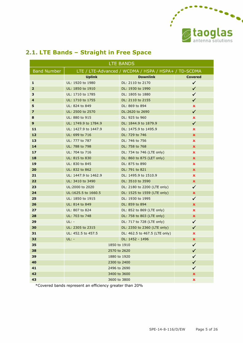
2.1. LTE Bands – Straight in Free Space
LTE BANDS
Band Number LTE / LTE-Advanced / WCDMA / HSPA / HSPA+ / TD-SCDMA
Uplink Downlink Covered
1 UL: 1920 to 1980 DL: 2110 to 2170 2 UL: 1850 to 1910 DL: 1930 to 1990 3 UL: 1710 to 1785 DL: 1805 to 1880 4 UL: 1710 to 1755 DL: 2110 to 2155 5 UL: 824 to 849 DL: 869 to 894 7 UL: 2500 to 2570 DL:2620 to 2690 8 UL: 880 to 915 DL: 925 to 960 9 UL: 1749.9 to 1784.9 DL: 1844.9 to 1879.9 11 UL: 1427.9 to 1447.9 DL: 1475.9 to 1495.9 12 UL: 699 to 716 DL: 729 to 746 13 UL: 777 to 787 DL: 746 to 756 14 UL: 788 to 798 DL: 758 to 768 17 UL: 704 to 716 DL: 734 to 746 (LTE only) 18 UL: 815 to 830 DL: 860 to 875 (LET only) 19 UL: 830 to 845 DL: 875 to 890 20 UL: 832 to 862 DL: 791 to 821 21 UL: 1447.9 to 1462.9 DL: 1495.9 to 1510.9 22 UL: 3410 to 3490 DL: 3510 to 3590 23 UL:2000 to 2020 DL: 2180 to 2200 (LTE only) 24 UL:1625.5 to 1660.5 DL: 1525 to 1559 (LTE only) 25 UL: 1850 to 1915 DL: 1930 to 1995 26 UL: 814 to 849 DL: 859 to 894 27 UL: 807 to 824 DL: 852 to 869 (LTE only) 28 UL: 703 to 748 DL: 758 to 803 (LTE only) 29 UL: - DL: 717 to 728 (LTE only) 30 UL: 2305 to 2315 DL: 2350 to 2360 (LTE only) 31 UL: 452.5 to 457.5 DL: 462.5 to 467.5 (LTE only) 32 UL: - DL: 1452 - 1496 35 1850 to 1910 38 2570 to 2620 39 1880 to 1920 40 2300 to 2400 41 2496 to 2690 42 3400 to 3600 43 3600 to 3800
*Covered bands represent an efficiency greater than 20%

SPE-14-8-116/D/EW Page 6 of 26
2.2. LTE Bands – Straight on Edge of 300*300mm Ground
Plane
LTE BANDS
Band Number LTE / LTE-Advanced / WCDMA / HSPA / HSPA+ / TD-SCDMA
Uplink Downlink Covered
1 UL: 1920 to 1980 DL: 2110 to 2170 2 UL: 1850 to 1910 DL: 1930 to 1990 3 UL: 1710 to 1785 DL: 1805 to 1880 4 UL: 1710 to 1755 DL: 2110 to 2155 5 UL: 824 to 849 DL: 869 to 894 7 UL: 2500 to 2570 DL:2620 to 2690 8 UL: 880 to 915 DL: 925 to 960 9 UL: 1749.9 to 1784.9 DL: 1844.9 to 1879.9 11 UL: 1427.9 to 1447.9 DL: 1475.9 to 1495.9 12 UL: 699 to 716 DL: 729 to 746 13 UL: 777 to 787 DL: 746 to 756 14 UL: 788 to 798 DL: 758 to 768 17 UL: 704 to 716 DL: 734 to 746 (LTE only) 18 UL: 815 to 830 DL: 860 to 875 (LET only) 19 UL: 830 to 845 DL: 875 to 890 20 UL: 832 to 862 DL: 791 to 821 21 UL: 1447.9 to 1462.9 DL: 1495.9 to 1510.9 22 UL: 3410 to 3490 DL: 3510 to 3590 23 UL:2000 to 2020 DL: 2180 to 2200 (LTE only) 24 UL:1625.5 to 1660.5 DL: 1525 to 1559 (LTE only) 25 UL: 1850 to 1915 DL: 1930 to 1995
26 UL: 814 to 849 DL: 859 to 894 27 UL: 807 to 824 DL: 852 to 869 (LTE only) 28 UL: 703 to 748 DL: 758 to 803 (LTE only) 29 UL: - DL: 717 to 728 (LTE only) 30 UL: 2305 to 2315 DL: 2350 to 2360 (LTE only) 31 UL: 452.5 to 457.5 DL: 462.5 to 467.5 (LTE only) 32 UL: - DL: 1452 - 1496 35 1850 to 1910 38 2570 to 2620 39 1880 to 1920 40 2300 to 2400 41 2496 to 2690 42 3400 to 3600 43 3600 to 3800
*Covered bands represent an efficiency greater than 20%

SPE-14-8-116/D/EW Page 7 of 26
2.3. LTE Bands – Bent in Free Space
LTE BANDS
Band Number LTE / LTE-Advanced / WCDMA / HSPA / HSPA+ / TD-SCDMA
Uplink Downlink Covered
1 UL: 1920 to 1980 DL: 2110 to 2170 2 UL: 1850 to 1910 DL: 1930 to 1990 3 UL: 1710 to 1785 DL: 1805 to 1880 4 UL: 1710 to 1755 DL: 2110 to 2155 5 UL: 824 to 849 DL: 869 to 894 7 UL: 2500 to 2570 DL:2620 to 2690 8 UL: 880 to 915 DL: 925 to 960 9 UL: 1749.9 to 1784.9 DL: 1844.9 to 1879.9 11 UL: 1427.9 to 1447.9 DL: 1475.9 to 1495.9 12 UL: 699 to 716 DL: 729 to 746 13 UL: 777 to 787 DL: 746 to 756 14 UL: 788 to 798 DL: 758 to 768 17 UL: 704 to 716 DL: 734 to 746 (LTE only) 18 UL: 815 to 830 DL: 860 to 875 (LET only) 19 UL: 830 to 845 DL: 875 to 890 20 UL: 832 to 862 DL: 791 to 821 21 UL: 1447.9 to 1462.9 DL: 1495.9 to 1510.9 22 UL: 3410 to 3490 DL: 3510 to 3590 23 UL:2000 to 2020 DL: 2180 to 2200 (LTE only) 24 UL:1625.5 to 1660.5 DL: 1525 to 1559 (LTE only) 25 UL: 1850 to 1915 DL: 1930 to 1995 26 UL: 814 to 849 DL: 859 to 894 27 UL: 807 to 824 DL: 852 to 869 (LTE only) 28 UL: 703 to 748 DL: 758 to 803 (LTE only) 29 UL: - DL: 717 to 728 (LTE only) 30 UL: 2305 to 2315 DL: 2350 to 2360 (LTE only) 31 UL: 452.5 to 457.5 DL: 462.5 to 467.5 (LTE only) 32 UL: - DL: 1452 - 1496 35 1850 to 1910 38 2570 to 2620 39 1880 to 1920 40 2300 to 2400 41 2496 to 2690 42 3400 to 3600 43 3600 to 3800
*Covered bands represent an efficiency greater than 20%

SPE-14-8-116/D/EW Page 8 of 26
2.4. LTE Bands – Bent on Edge of 300*300mm Ground plane
LTE BANDS
Band Number LTE / LTE-Advanced / WCDMA / HSPA / HSPA+ / TD-SCDMA
Uplink Downlink Covered
1 UL: 1920 to 1980 DL: 2110 to 2170 2 UL: 1850 to 1910 DL: 1930 to 1990 3 UL: 1710 to 1785 DL: 1805 to 1880 4 UL: 1710 to 1755 DL: 2110 to 2155 5 UL: 824 to 849 DL: 869 to 894 7 UL: 2500 to 2570 DL:2620 to 2690 8 UL: 880 to 915 DL: 925 to 960 9 UL: 1749.9 to 1784.9 DL: 1844.9 to 1879.9
11 UL: 1427.9 to 1447.9 DL: 1475.9 to 1495.9 12 UL: 699 to 716 DL: 729 to 746 13 UL: 777 to 787 DL: 746 to 756 14 UL: 788 to 798 DL: 758 to 768 17 UL: 704 to 716 DL: 734 to 746 (LTE only) 18 UL: 815 to 830 DL: 860 to 875 (LET only) 19 UL: 830 to 845 DL: 875 to 890 20 UL: 832 to 862 DL: 791 to 821 21 UL: 1447.9 to 1462.9 DL: 1495.9 to 1510.9 22 UL: 3410 to 3490 DL: 3510 to 3590 23 UL:2000 to 2020 DL: 2180 to 2200 (LTE only) 24 UL:1625.5 to 1660.5 DL: 1525 to 1559 (LTE only) 25 UL: 1850 to 1915 DL: 1930 to 1995 26 UL: 814 to 849 DL: 859 to 894 27 UL: 807 to 824 DL: 852 to 869 (LTE only) 28 UL: 703 to 748 DL: 758 to 803 (LTE only) 29 UL: - DL: 717 to 728 (LTE only) 30 UL: 2305 to 2315 DL: 2350 to 2360 (LTE only) 31 UL: 452.5 to 457.5 DL: 462.5 to 467.5 (LTE only) 32 UL: - DL: 1452 - 1496 35 1850 to 1910 38 2570 to 2620 39 1880 to 1920 40 2300 to 2400 41 2496 to 2690 42 3400 to 3600 43 3600 to 3800
*Covered bands represent an efficiency greater than 20%

SPE-14-8-116/D/EW Page 9 of 26
3. Antenna Characteristics
3.1. Testing setup
Antenna Straight Position
a) In free space b) With 15*9cm Ground c) With 30*30cm Ground
Metal Edge
d) With 30*30cm Ground
Metal Center
Antenna Bent Position
a) In free space b) With 15*9cm Ground c) With 30*30cm Ground
Metal Edge
d) With 30*30cm Ground
Metal Center
Figure.1 Measurement environments

SPE-14-8-116/D/EW Page 10 of 26
3.2. Return loss
Figure2. Return loss of TG.08 antenna with straight Position
Figure3. Return loss of TG.08 antenna with bent Position

SPE-14-8-116/D/EW Page 11 of 26
3.3. Efficiency
Figure4. Efficiency of TG.08 antenna with straight Position
Figure5. Efficiency of TG.08 antenna with bent Position

SPE-14-8-116/D/EW Page 12 of 26
3.4. Peak gain
Figure6. Peak gain of TG.08 antenna with straight Position
Figure7. Peak gain of TG.08 antenna with bent Position

SPE-14-8-116/D/EW Page 13 of 26
3.5. Average gain
Figure8. Average gain of TG.08 with antenna straight Position
Figure9. Average gain of TG.08 antenna with bent Position

SPE-14-8-116/D/EW Page 14 of 26
4. Antenna Radiation Patterns
The antenna radiation patterns were measured in a CTIA certified ETS Anechoic Chamber. The measurement setups are shown below.
Antenna with Straight Position
In free space On 15x9cm ground plane
On 30x30cm metal ground center On 30x30cm metal ground edge
Z
X
Y
Z
X
Y
Z
X
Y
Z
X
Y

SPE-14-8-116/D/EW Page 15 of 26
Antenna with Bent Position
In free space On 15x9cm ground plane
On 30x30cm metal ground center On 30x30cm metal ground edge
Figure.10. Testing Setup in ETS Anechoic Chamber
Z
X
Y
Z
X
Y
Z
X
Y
Z
X
Y

SPE-14-8-116/D/EW Page 16 of 26
4.1. 2D Radiation pattern (Straight Position in free space)
XY Plane
XZ Plane
YZ Plane
X
Y
X
Y
X
Y
X
Y
Z
X
Z
X
Z
X
Z
X
Z
Y
Z
Y
Z
Y
Z
Y

SPE-14-8-116/D/EW Page 17 of 26
4.2. 2D Radiation pattern (Straight Position with 15x9cm
ground)
XY Plane
XZ Plane YZ Plane
X
Y
X
Y
X
Y
X
Y
Z
X
Z
X
Z
X
Z
X
Z
Y
Z
Y
Z
Y
Z
Y

SPE-14-8-116/D/EW Page 18 of 26
4.3. 2D Radiation pattern (Straight Position with 30x30cm
Metal Ground Edge)
XY Plane
XZ Plane YZ Plane
X
Y
X
Y
X
Y
X
Y
Z
X
Z
X
Z
X
Z
X
Z
Y
Z
Y
Z
Y
Z
Y

SPE-14-8-116/D/EW Page 19 of 26
4.4. 2D Radiation pattern (Straight Position with 30x30cm
metal ground center)
XY Plane
XZ Plane YZ Plane
X
Y
X
Y
X
Y
X
Y
Z
X
Z
X
Z
X
Z
X
Z
Y
Z
Y
Z
Y
Z
Y

SPE-14-8-116/D/EW Page 20 of 26
4.5. 2D Radiation pattern (Bent Position in free space)
XY Plane
XZ Plane YZ Plane
X
Y
X
Y
X
Y
X
Y
Z
X
Z
X
Z
X
Z
X
Z
Y
Z
Y
Z
Y
Z
Y

SPE-14-8-116/D/EW Page 21 of 26
4.6. 2D Radiation pattern (Bent Position with 15x9cm
ground)
XY Plane
XZ Plane YZ Plane
X
Y
X
Y
X
Y
X
Y
Z
X
Z
X
Z
X
Z
X
Z
Y
Z
Y
Z
Y
Z
Y

SPE-14-8-116/D/EW Page 22 of 26
4.7. 2D Radiation pattern (Bent Position with 30x30cm
metal ground edge)
XY Plane XZ Plane
YZ Plane
X
Y
X
Y
X
Y
X
Y
Z
X
Z
X
Z
X
Z
X
Z
Y
Z
Y
Z
Y
Z
Y

SPE-14-8-116/D/EW Page 23 of 26
4.8. 4.8 2D Radiation pattern (Bent Position with 30*30cm
metal ground center)
XY Plane XZ Plane
YZ Plane
X
Y
X
Y
X
Y
X
Y
Z
X
Z
X
Z
X
Z
X
Z
Y
Z
Y
Z
Y
Z
Y

SPE-14-8-116/D/EW Page 24 of 26
5. Installation

SPE-14-8-116/D/EW Page 25 of 26
D02
D02
Housing POM Black
Hinge
Name Material Finish QTY
1
1
1
2 Brass Ni Plated
001013F000002A
P/N
000613F000002A
000713G000002ACap 13 POM Orange
SMA(M) ST 14 Brass Ni Plated200213F000002A
D03
6. Drawing

SPE-14-8-116/D/EW Page 26 of 26
7. Packaging
Taoglas makes no warranties based on the accuracy or completeness of the contents of this document and reserves the right to make changes to specifications and product descriptions at any time without notice. Taoglas reserves all rights to this document and the information contained herein. Reproduction, use or disclosure to third parties without express permission is strictly prohibited. Copyright © Taoglas Ltd.